JP7404102B2 - gaming machine - Google Patents
gaming machine Download PDFInfo
- Publication number
- JP7404102B2 JP7404102B2 JP2020027656A JP2020027656A JP7404102B2 JP 7404102 B2 JP7404102 B2 JP 7404102B2 JP 2020027656 A JP2020027656 A JP 2020027656A JP 2020027656 A JP2020027656 A JP 2020027656A JP 7404102 B2 JP7404102 B2 JP 7404102B2
- Authority
- JP
- Japan
- Prior art keywords
- performance
- executed
- effect
- vibration
- jackpot
- Prior art date
- Legal status (The legal status is an assumption and is not a legal conclusion. Google has not performed a legal analysis and makes no representation as to the accuracy of the status listed.)
- Active
Links
- 230000000694 effects Effects 0.000 claims description 1904
- 238000004519 manufacturing process Methods 0.000 claims description 404
- 238000000034 method Methods 0.000 description 650
- 230000008569 process Effects 0.000 description 636
- 230000009467 reduction Effects 0.000 description 263
- 238000012545 processing Methods 0.000 description 181
- 238000012790 confirmation Methods 0.000 description 179
- 230000008859 change Effects 0.000 description 156
- 230000015654 memory Effects 0.000 description 128
- 238000003860 storage Methods 0.000 description 113
- 230000004048 modification Effects 0.000 description 104
- 238000012986 modification Methods 0.000 description 104
- 238000010586 diagram Methods 0.000 description 61
- 230000007704 transition Effects 0.000 description 56
- 238000004904 shortening Methods 0.000 description 49
- 230000008901 benefit Effects 0.000 description 48
- 238000011084 recovery Methods 0.000 description 48
- 238000001514 detection method Methods 0.000 description 40
- 230000033001 locomotion Effects 0.000 description 36
- 239000000872 buffer Substances 0.000 description 33
- 230000007423 decrease Effects 0.000 description 32
- 230000006870 function Effects 0.000 description 32
- 238000011161 development Methods 0.000 description 30
- PCHJSUWPFVWCPO-UHFFFAOYSA-N gold Chemical compound [Au] PCHJSUWPFVWCPO-UHFFFAOYSA-N 0.000 description 30
- 229910052737 gold Inorganic materials 0.000 description 30
- 239000010931 gold Substances 0.000 description 30
- 239000000725 suspension Substances 0.000 description 28
- 230000002829 reductive effect Effects 0.000 description 23
- 230000004044 response Effects 0.000 description 22
- 239000003086 colorant Substances 0.000 description 18
- 230000001960 triggered effect Effects 0.000 description 14
- 238000004458 analytical method Methods 0.000 description 13
- 238000009795 derivation Methods 0.000 description 13
- 238000010304 firing Methods 0.000 description 13
- 238000007781 pre-processing Methods 0.000 description 11
- 208000001613 Gambling Diseases 0.000 description 9
- 238000012544 monitoring process Methods 0.000 description 9
- 238000003825 pressing Methods 0.000 description 8
- 230000002844 continuous effect Effects 0.000 description 7
- 239000011521 glass Substances 0.000 description 7
- RYGMFSIKBFXOCR-UHFFFAOYSA-N Copper Chemical compound [Cu] RYGMFSIKBFXOCR-UHFFFAOYSA-N 0.000 description 6
- 230000005540 biological transmission Effects 0.000 description 6
- 229910052802 copper Inorganic materials 0.000 description 6
- 239000010949 copper Substances 0.000 description 6
- 238000005034 decoration Methods 0.000 description 6
- 239000012536 storage buffer Substances 0.000 description 6
- 230000009471 action Effects 0.000 description 5
- OMFRMAHOUUJSGP-IRHGGOMRSA-N bifenthrin Chemical compound C1=CC=C(C=2C=CC=CC=2)C(C)=C1COC(=O)[C@@H]1[C@H](\C=C(/Cl)C(F)(F)F)C1(C)C OMFRMAHOUUJSGP-IRHGGOMRSA-N 0.000 description 5
- 238000005259 measurement Methods 0.000 description 5
- 101150005096 AKR1 gene Proteins 0.000 description 4
- 101150061934 AKR2 gene Proteins 0.000 description 4
- 101100215787 Arabidopsis thaliana AKR2A gene Proteins 0.000 description 4
- 101100121101 Fragaria ananassa GALUR gene Proteins 0.000 description 4
- 101100215778 Neurospora crassa (strain ATCC 24698 / 74-OR23-1A / CBS 708.71 / DSM 1257 / FGSC 987) ptr-1 gene Proteins 0.000 description 4
- BQCADISMDOOEFD-UHFFFAOYSA-N Silver Chemical compound [Ag] BQCADISMDOOEFD-UHFFFAOYSA-N 0.000 description 4
- 230000005856 abnormality Effects 0.000 description 4
- 238000004891 communication Methods 0.000 description 4
- 238000013461 design Methods 0.000 description 4
- 230000006872 improvement Effects 0.000 description 4
- 229910052709 silver Inorganic materials 0.000 description 4
- 239000004332 silver Substances 0.000 description 4
- 238000007792 addition Methods 0.000 description 3
- 238000005520 cutting process Methods 0.000 description 3
- 230000014509 gene expression Effects 0.000 description 3
- 238000012360 testing method Methods 0.000 description 3
- 230000000007 visual effect Effects 0.000 description 3
- 238000013019 agitation Methods 0.000 description 2
- 230000015572 biosynthetic process Effects 0.000 description 2
- 230000004397 blinking Effects 0.000 description 2
- 238000004590 computer program Methods 0.000 description 2
- 230000003247 decreasing effect Effects 0.000 description 2
- 230000003111 delayed effect Effects 0.000 description 2
- 238000005401 electroluminescence Methods 0.000 description 2
- 239000000284 extract Substances 0.000 description 2
- 230000001151 other effect Effects 0.000 description 2
- 238000012805 post-processing Methods 0.000 description 2
- 230000000717 retained effect Effects 0.000 description 2
- 230000000638 stimulation Effects 0.000 description 2
- 239000000758 substrate Substances 0.000 description 2
- 229920003002 synthetic resin Polymers 0.000 description 2
- 239000000057 synthetic resin Substances 0.000 description 2
- 241000722921 Tulipa gesneriana Species 0.000 description 1
- 235000005811 Viola adunca Nutrition 0.000 description 1
- 240000009038 Viola odorata Species 0.000 description 1
- 235000013487 Viola odorata Nutrition 0.000 description 1
- 235000002254 Viola papilionacea Nutrition 0.000 description 1
- 238000013459 approach Methods 0.000 description 1
- 239000004020 conductor Substances 0.000 description 1
- 238000010924 continuous production Methods 0.000 description 1
- 239000004148 curcumin Substances 0.000 description 1
- 238000012938 design process Methods 0.000 description 1
- 238000003745 diagnosis Methods 0.000 description 1
- 230000029087 digestion Effects 0.000 description 1
- 230000005484 gravity Effects 0.000 description 1
- 238000005286 illumination Methods 0.000 description 1
- 238000002347 injection Methods 0.000 description 1
- 239000007924 injection Substances 0.000 description 1
- 230000002452 interceptive effect Effects 0.000 description 1
- 230000000670 limiting effect Effects 0.000 description 1
- 239000004973 liquid crystal related substance Substances 0.000 description 1
- 230000007246 mechanism Effects 0.000 description 1
- 239000000203 mixture Substances 0.000 description 1
- 230000006855 networking Effects 0.000 description 1
- 229920003217 poly(methylsilsesquioxane) Polymers 0.000 description 1
- 239000002151 riboflavin Substances 0.000 description 1
- 238000010187 selection method Methods 0.000 description 1
- 238000003756 stirring Methods 0.000 description 1
- 230000002195 synergetic effect Effects 0.000 description 1
Images


Description
本発明は、遊技者にとって有利な有利状態に制御可能な遊技機に関する。 The present invention relates to a gaming machine that can be controlled to advantageous conditions that are advantageous to players.
パチンコ遊技機等の遊技機において、打球発射ハンドルに振動手段を設ける技術が提案されている(例えば特許文献1)。 2. Description of the Related Art In gaming machines such as pachinko gaming machines, a technique has been proposed in which a vibrating means is provided in a ball firing handle (for example, Patent Document 1).
特許文献1に記載された技術では、振動による演出の興趣向上に改善の余地があった。
In the technique described in
この発明は、上記実状に鑑みてなされたものであり、振動による演出を実行する場合に遊技興趣を向上させる遊技機の提供を目的とする。 The present invention has been made in view of the above-mentioned circumstances, and aims to provide a gaming machine that improves the game's interest when performing effects using vibrations.
(A)演出識別情報の可変表示を行い、遊技者にとって有利な有利状態に制御可能な遊技機であって、
遊技者が操作可能な操作手段と、
演出を実行可能な演出制御手段と、を備え、
前記演出制御手段は、
前記有利状態に制御されることを示唆するリーチ演出を実行可能であり、
前記リーチ演出を開始した後に特定演出を実行可能であり、
前記リーチ演出が実行される可変表示の開始に対応する第1タイミングと、前記リーチ演出が実行される可変表示の開始よりも前の第2タイミングと、を含む複数のタイミングにて前記操作手段を振動させる所定振動演出を実行可能であり、
前記特定演出の実行期間である特定演出期間にて前記操作手段を振動させる特殊振動演出を実行可能であり、
前記特殊振動演出として、
前記特定演出期間であって前記特定演出が開始されるタイミングにて前記操作手段とは異なる演出用可動体の動作に対応させた第1特殊振動演出を実行可能であり、
前記特定演出期間であって前記第1特殊振動演出が実行されるタイミングよりも後のタイミングにて画像表示に対応させた第2特殊振動演出を実行可能であり、
前記所定振動演出が実行されないときよりも、前記所定振動演出が実行されるときの方が、前記有利状態に制御される割合が高く、
前記所定振動演出と前記第1特殊振動演出とで、態様が異なり、
前記所定振動演出と前記第2特殊振動演出とで、態様が異なり、
前記第1特殊振動演出と前記第2特殊振動演出とで、態様が異なる、
ことを特徴とする。
さらに、(1)上記目的を達成するため、本願発明に係る遊技機は、第1識別情報の可変表示および第2識別情報の可変表示を実行し、特定表示結果(例えば、大当り図柄)が導出表示されたときに有利な有利状態(例えば、大当り遊技状態)に制御可能な遊技機であって、遊技者が操作可能な操作手段(例えばスティックコントローラ31A、プッシュボタン31Bなど)と、前記操作手段が振動する振動演出として、所定振動演出(例えば操作部演出パターンに含まれる振動パターンによる振動モータ131の駆動など)と特殊振動演出(例えば可変表示演出制御パターンに含まれる振動制御データによる振動モータ131の駆動など)とを実行可能な振動演出実行手段(例えばステップAKS203にて決定された操作部演出制御パターンや可変表示演出制御パターンの振動制御データを用いてステップS172の可変表示中演出処理を実行する演出制御用CPU120など)と、前記所定振動演出に伴い前記操作手段を発光させる発光演出(例えば操作部演出パターンに含まれる発光色によるレバーランプ9B1およびボタンランプ9B2の発光など)を実行可能な発光演出実行手段(例えばステップAKS203にて決定された操作部演出制御パターンのランプ制御データを用いてステップS172の可変表示中演出処理を実行する演出制御用CPU120など)と、遊技の進行に応じて特定演出(例えばSPリーチAのリーチ演出、大当り確定報知、大当り種別抽選など)を実行可能な特定演出実行手段(例えばステップAKS203にて決定された可変表示演出制御パターンに基づいてステップS172の可変表示中演出処理を実行する演出制御用CPU120など)と、を備え、前記所定振動演出が実行されないときよりも、前記所定振動演出が実行されるときの方が、前記有利状態に制御される割合が高く(例えば操作部演出パターンなどに応じた大当り信頼度など)、前記所定振動演出に伴う前記発光演出の発光態様と、該所定振動演出が実行されたタイミングとに応じて、前記有利状態に制御される割合が異なり(例えば操作部演出パターンに含まれる発光色と操作部演出パターンの用途に応じた大当り信頼度など)、前記振動演出実行手段は、前記特定演出の実行に伴い前記特殊振動演出を実行可能であり(例えば期間AKZ01~AKZ05における振動演出の実行など)、前記所定振動演出と、前記特殊振動演出とで振動態様が異なる(例えば振動パターンAKV41~AKV44とは異なる振動パターンAKV01~AKV03など)、
可変表示が開始されるタイミングにおいて所定振動演出を実行可能であり、(ここで、可変表示が開始されるタイミングは、例えばタイミングAKT01~AKT03、AKT11などであればよい。)
さらに、通常状態よりも可変表示が実行されやすい特別状態(例えば、時短状態)に制御可能な状態制御手段(例えば、図8-17に示すように、遊技制御用マイクロコンピュータ100におけるステップ100IWS166、ステップ100IWS173を実行する部分、図8-19に示すように、遊技制御用マイクロコンピュータ100におけるステップ100IWS537を実行する部分)と、可変表示が実行されることにもとづいて数値情報を更新可能な更新手段(例えば、図8-13に示すように、遊技制御用マイクロコンピュータ100におけるステップ100IWS71を実行する部分)と、を備え、状態制御手段は、更新手段が更新した数値情報が特別回数に対応する特定値となることによって特別条件が成立したときに特別状態に制御可能であり(例えば、図8-13に示すように、遊技制御用マイクロコンピュータ100におけるステップ100IWS74、ステップ100IWS75を実行する部分、図8-17に示すように、遊技制御用マイクロコンピュータ100におけるステップ100IWS172、ステップ100IWS173を実行する部分)、更新手段は、第1識別情報の可変表示が実行される場合と第2識別情報の可変表示が実行される場合とで数値情報を更新する(例えば、図8-13に示すように、遊技制御用マイクロコンピュータ100におけるステップ100IWS71を実行する部分)ことを特徴とする。
このような構成によれば、振動演出の振動態様や発光演出の発光態様、振動演出の実行タイミングに注目させて、遊技興趣を向上させることができる。さらに、遊技者の救済を好適に実現できる。具体的には、遊技状態が変化して、いずれの識別情報の可変表示が実行される状況であっても数値情報の更新が継続するので遊技者が救済されやすくなり、遊技の意欲を高めることができる。
(A) A gaming machine that variably displays performance identification information and can be controlled to an advantageous state that is advantageous to the player,
An operation means that can be operated by a player;
A production control means capable of executing production;
The performance control means is
It is possible to execute a reach effect that suggests that the game is controlled to the advantageous state,
A specific performance can be executed after starting the reach performance,
The operating means is operated at a plurality of timings including a first timing corresponding to the start of the variable display at which the ready-to-reach effect is executed, and a second timing before the start of the variable display at which the ready-to-reach effect is executed. It is possible to perform a predetermined vibration production that vibrates,
It is possible to execute a special vibration performance in which the operating means is vibrated during a specific performance period that is an execution period of the specific performance,
As the special vibration performance,
A first special vibration performance that corresponds to the operation of a performance movable body different from the operating means can be executed at a timing when the specific performance is started during the specific performance period,
A second special vibration performance corresponding to image display can be executed at a timing later than the timing at which the first special vibration performance is executed during the specific performance period,
The ratio of being controlled to the advantageous state is higher when the predetermined vibration effect is executed than when the predetermined vibration effect is not executed,
The predetermined vibration performance and the first special vibration performance are different in form,
The predetermined vibration performance and the second special vibration performance are different in form,
The first special vibration performance and the second special vibration performance have different aspects,
It is characterized by
Furthermore, (1) in order to achieve the above object, the gaming machine according to the present invention executes variable display of first identification information and variable display of second identification information, and derives a specific display result (for example, a jackpot symbol). A gaming machine that can be controlled to an advantageous state (for example, a jackpot game state) that is advantageous when displayed, and includes operation means (for example, a
A predetermined vibration effect can be executed at the timing at which the variable display starts (here, the timing at which the variable display starts may be, for example, timings AKT01 to AKT03, AKT11, etc.).
Furthermore, a state control means (for example, as shown in FIG. 8-17, step 100IWS166, step 100IWS173, as shown in FIG. For example, as shown in FIG. 8-13, the state control means includes a part that executes step 100IWS71 in the
According to such a configuration, it is possible to improve the game interest by drawing attention to the vibration mode of the vibration effect, the light emission mode of the light emission effect, and the execution timing of the vibration effect. Furthermore, relief for the player can be suitably realized. Specifically, even if the gaming state changes and any identification information is displayed variably, the numerical information continues to be updated, making it easier for the player to be rescued and increasing his or her desire to play. Can be done.
また、後述する発明を実施するための形態には、以下の手段Aに係る発明が含まれる。従来より遊技機において特開2005-95449号公報に示されているような、通常状態よりも可変表示が実行されやすい特別状態に制御可能な遊技機が知られている。例えば、特許文献1には、通常の遊技状態で実行された特図ゲームの回数(可変表示の実行回数)が1000回(特別回数)に達しても大当り(有利状態)が発生しないときには(特別条件の成立)、遊技状態が確変状態に制御され、特図ゲームの結果として大当りとすることが決定される確率が1/100程度に高められ、以降の特図ゲームでは大当りが発生しやすくなることが記載されている。また、特許文献1には、通常の遊技状態で特図ゲームの回数(可変表示の実行回数)が1000回に達しても大当りが生じなかったときに、確変状態の代わりに時短状態を発生させるものとしてもよいことが記載されている。
Further, the embodiments for carrying out the invention described below include the invention related to the following means A. 2. Description of the Related Art Conventionally, gaming machines have been known that can be controlled to a special state in which a variable display is more easily executed than in a normal state, as shown in Japanese Patent Laid-Open No. 2005-95449. For example,
しかし、従来の遊技機では、可変表示の実行回数が特別回数に達するときや、その前後の期間における興趣の検討が不十分であった。 However, in conventional gaming machines, there has been insufficient consideration of interest when the number of executions of the variable display reaches a special number, and during the period before and after that.
そこで、この発明は、興趣に富む遊技機を提供することを目的とする。 Therefore, an object of the present invention is to provide a gaming machine that is rich in interest.
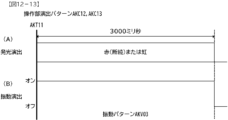
(手段A)第1識別情報の可変表示および第2識別情報の可変表示を実行し、特定表示結果(例えば、大当り図柄)が導出表示されたことにもとづいて有利な有利状態(例えば、大当り遊技状態)に制御可能な遊技機であって、通常状態よりも可変表示が実行されやすい特別状態(例えば、時短状態)に制御可能な状態制御手段(例えば、図14-17に示すように、遊技制御用マイクロコンピュータ100におけるステップ100IWS166、ステップ100IWS173を実行する部分、図14-19に示すように、遊技制御用マイクロコンピュータ100におけるステップ100IWS537を実行する部分)と、可変表示が実行されることにもとづいて数値情報を更新可能な更新手段(例えば、図14-13に示すように、遊技制御用マイクロコンピュータ100におけるステップ100IWS71を実行する部分)と、を備え、状態制御手段は、更新手段が更新した数値情報が、可変表示の実行回数としての特別回数に対応する特定値となることによって特別条件が成立したときに特別状態に制御可能であり(例えば、図14-13に示すように、遊技制御用マイクロコンピュータ100におけるステップ100IWS74、ステップ100IWS75を実行する部分、図14-17に示すように、遊技制御用マイクロコンピュータ100におけるステップ100IWS170、ステップ100IWS173を実行する部分)、更新手段は、第1識別情報の可変表示が実行される場合と第2識別情報の可変表示が実行される場合とで数値情報を更新し(例えば、図14-13に示すように、遊技制御用マイクロコンピュータ100におけるステップ100IWS71を実行する部分)、可変表示が実行されているときに所定示唆演出(例えば、予告演出)を実行可能な所定示唆演出実行手段(例えば、図14-49に示すように、演出制御用CPU120におけるステップ108IWS811を実行する部分)と、特別条件が成立したことにもとづいて、特別状態の制御が開始される旨を報知する特別報知演出(例えば、図14-52(C1),(C2)に示すように背景画像が変化する、図14-53(B)に示すように変動開始時にブラックアウトする、図14-54(C)に示すように変動終了時にブラックアウトする等)を実行可能な特別報知演出実行手段と(例えば、図14―23に示すように、演出制御用CPU120がステップ100IWS638を実行する部分)、をさらに備え、所定示唆演出実行手段は、特別条件が成立する前の期間において、所定示唆演出を実行する割合が共通である(例えば、図14―44に示すように、演出制御用CPU120がステップ108IWS802Aを実行する部分。図14-50参照)。
そのような構成によれば、特別報知演出が突然実行されることにより遊技者に意外性を与えて、興趣を向上させることができる。
(Means A) Variable display of the first identification information and variable display of the second identification information are performed, and based on the derivation and display of a specific display result (for example, a jackpot symbol), an advantageous advantageous state (for example, a jackpot game A game machine that can be controlled to a special state (for example, a time saving state) in which variable display is more likely to be executed than a normal state (for example, a game machine as shown in FIGS. 14-17). Based on the part that executes step 100IWS166 and step 100IWS173 in the control microcomputer 100 (as shown in FIG. 14-19, the part that executes step 100IWS537 in the game control microcomputer 100) and the variable display. update means that can update the numerical information (for example, as shown in FIG. When the numerical information becomes a specific value corresponding to the special number of times as the number of executions of the variable display, the special state can be controlled when the special condition is satisfied (for example, as shown in Figure 14-13, the game control As shown in FIG. 14-17, the part that executes step 100IWS74 and step 100IWS75 in the
According to such a configuration, by suddenly executing the special notification effect, it is possible to give surprise to the player and increase interest.
(基本説明)
まず、パチンコ遊技機1の基本的な構成及び制御(一般的なパチンコ遊技機の構成及び制御でもある。)について説明する。
(Basic explanation)
First, the basic configuration and control of the pachinko gaming machine 1 (also the configuration and control of a general pachinko gaming machine) will be explained.
(パチンコ遊技機1の構成等)
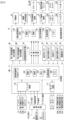
図1は、パチンコ遊技機1の正面図であり、主要部材の配置レイアウトを示す。パチンコ遊技機(遊技機)1は、大別して、遊技盤面を構成する遊技盤(ゲージ盤)2と、遊技盤2を支持固定する遊技機用枠(台枠)3とから構成されている。遊技盤2には、遊技領域が形成され、この遊技領域には、遊技媒体としての遊技球が、所定の打球発射装置から発射されて打ち込まれる。
(Configuration of
FIG. 1 is a front view of a
なお、特別図柄の「可変表示」とは、例えば、複数種類の特別図柄を変動可能に表示することである(後述の他の図柄についても同じ)。変動としては、複数の図柄の更新表示、複数の図柄のスクロール表示、1以上の図柄の変形、1以上の図柄の拡大/縮小などがある。特別図柄や後述の普通図柄の変動では、複数種類の特別図柄又は普通図柄が更新表示される。後述の飾り図柄の変動では、複数種類の飾り図柄がスクロール表示又は更新表示されたり、1以上の飾り図柄が変形や拡大/縮小されたりする。なお、変動には、ある図柄を点滅表示する態様も含まれる。可変表示の最後には、表示結果として所定の特別図柄が停止表示(導出または導出表示などともいう)される(後述の他の図柄の可変表示についても同じ)。なお、可変表示を変動表示、変動と表現する場合がある。 Note that "variable display" of special symbols means, for example, displaying a plurality of types of special symbols in a variable manner (the same applies to other symbols described later). The variations include updated display of a plurality of symbols, scroll display of a plurality of symbols, deformation of one or more symbols, enlargement/reduction of one or more symbols, and the like. In the variation of special symbols and normal symbols described below, a plurality of types of special symbols or normal symbols are updated and displayed. In the variation of decorative patterns described below, a plurality of types of decorative patterns are scrolled or updated, or one or more decorative patterns are deformed or enlarged/reduced. Note that the variation also includes a mode in which a certain symbol is displayed blinking. At the end of the variable display, a predetermined special symbol is stopped and displayed (also referred to as derivation or derivation display) as a display result (the same applies to the variable display of other symbols described later). Note that the variable display may be expressed as a variable display or fluctuation.
なお、第1特別図柄表示装置4Aにおいて可変表示される特別図柄を「第1特図」ともいい、第2特別図柄表示装置4Bにおいて可変表示される特別図柄を「第2特図」ともいう。また、第1特図を用いた特図ゲームを「第1特図ゲーム」といい、第2特図を用いた特図ゲームを「第2特図ゲーム」ともいう。なお、特別図柄の可変表示を行う特別図柄表示装置は1種類であってもよい。
The special symbol variably displayed on the first special
遊技盤2における遊技領域の中央付近には画像表示装置5が設けられている。画像表示装置5は、例えばLCD(液晶表示装置)や有機EL(Electro Luminescence)等から構成され、各種の演出画像を表示する。画像表示装置5は、プロジェクタおよびスクリーンから構成されていてもよい。画像表示装置5には、各種の演出画像が表示される。
An
例えば、画像表示装置5の画面上では、第1特図ゲームや第2特図ゲームと同期して、特別図柄とは異なる複数種類の装飾識別情報としての飾り図柄(数字などを示す図柄など)の可変表示が行われる。ここでは、第1特図ゲームまたは第2特図ゲームに同期して、「左」、「中」、「右」の各飾り図柄表示エリア5L、5C、5Rにおいて飾り図柄が可変表示(例えば上下方向のスクロール表示や更新表示)される。なお、同期して実行される特図ゲームおよび飾り図柄の可変表示を総称して単に可変表示ともいう。
For example, on the screen of the
画像表示装置5の画面上には、実行が保留されている可変表示に対応する保留表示や、実行中の可変表示に対応するアクティブ表示を表示するための表示エリアが設けられていてもよい。保留表示およびアクティブ表示を総称して可変表示に対応する可変表示対応表示ともいう。
A display area may be provided on the screen of the
保留されている可変表示の数は保留記憶数ともいう。第1特図ゲームに対応する保留記憶数を第1保留記憶数、第2特図ゲームに対応する保留記憶数を第2保留記憶数ともいう。第1保留記憶数と第2保留記憶数との合計を合計保留記憶数ともいう。 The number of pending variable displays is also called the number of pending memories. The number of pending memories corresponding to the first special figure game is also referred to as the first number of pending memories, and the number of pending memories corresponding to the second special figure game is also referred to as the second number of pending memories. The sum of the first number of pending memories and the second number of pending memories is also referred to as the total number of pending memories.
遊技盤2の所定位置には、複数のLEDを含んで構成された第1保留表示器25Aと第2保留表示器25Bとが設けられている。第1保留表示器25Aは、LEDの点灯個数によって、第1保留記憶数を表示する。第2保留表示器25Bは、LEDの点灯個数によって、第2保留記憶数を表示する。
A
画像表示装置5の下方には、入賞球装置6Aと、可変入賞球装置6Bとが設けられている。
Below the
入賞球装置6Aは、例えば所定の玉受部材によって常に遊技球が進入可能な一定の開放状態に保たれる第1始動入賞口を形成する。第1始動入賞口に遊技球が進入したときには、所定個(例えば3個)の賞球が払い出されるとともに、第1特図ゲームが開始され得る。
The winning
可変入賞球装置6B(普通電動役物)は、ソレノイド81(図3参照)によって閉鎖状態と開放状態とに変化する第2始動入賞口を形成する。可変入賞球装置6Bは、例えば、一対の可動翼片を有する電動チューリップ型役物を備え、ソレノイド81がオフ状態であるときに可動翼片が垂直位置となることにより、当該可動翼片の先端が入賞球装置6Aに近接し、第2始動入賞口に遊技球が進入しない閉鎖状態になる(第2始動入賞口が閉鎖状態になるともいう。)。その一方で、可変入賞球装置6Bは、ソレノイド81がオン状態であるときに可動翼片が傾動位置となることにより、第2始動入賞口に遊技球が進入できる開放状態になる(第2始動入賞口が開放状態になるともいう。)。第2始動入賞口に遊技球が進入したときには、所定個(例えば3個)の賞球が払い出されるとともに、第2特図ゲームが開始され得る。なお、可変入賞球装置6Bは、閉鎖状態と開放状態とに変化するものであればよく、電動チューリップ型役物を備えるものに限定されない。
The variable prize winning
遊技盤2の所定位置(図1に示す例では、遊技領域の左右下方4箇所)には、所定の玉受部材によって常に一定の開放状態に保たれる一般入賞口10が設けられる。この場合には、一般入賞口10のいずれかに進入したときには、所定個数(例えば10個)の遊技球が賞球として払い出される。
At predetermined positions on the game board 2 (in the example shown in FIG. 1, four locations on the left and right lower sides of the game area), general winning
入賞球装置6Aと可変入賞球装置6Bの下方には、大入賞口を有する特別可変入賞球装置7が設けられている。特別可変入賞球装置7は、ソレノイド82(図3参照)によって開閉駆動される大入賞口扉を備え、その大入賞口扉によって開放状態と閉鎖状態とに変化する特定領域としての大入賞口を形成する。
A special variable winning
一例として、特別可変入賞球装置7では、大入賞口扉用(特別電動役物用)のソレノイド82がオフ状態であるときに大入賞口扉が大入賞口を閉鎖状態として、遊技球が大入賞口に進入(通過)できなくなる。その一方で、特別可変入賞球装置7では、大入賞口扉用のソレノイド82がオン状態であるときに大入賞口扉が大入賞口を開放状態として、遊技球が大入賞口に進入しやすくなる。
As an example, in the special variable winning
大入賞口に遊技球が進入したときには、所定個数(例えば14個)の遊技球が賞球として払い出される。大入賞口に遊技球が進入したときには、例えば第1始動入賞口や第2始動入賞口および一般入賞口10に遊技球が進入したときよりも多くの賞球が払い出される。
When game balls enter the grand prize opening, a predetermined number (for example, 14) of game balls are paid out as prize balls. When the game ball enters the big winning hole, more prize balls are paid out than when the game ball enters the first starting winning hole, the second starting winning hole, and the general winning
一般入賞口10を含む各入賞口に遊技球が進入することを「入賞」ともいう。特に、始動口(第1始動入賞口、第2始動入賞口)への入賞を始動入賞ともいう。
Entering the game ball into each winning hole including the general winning
遊技盤2の所定位置(図1に示す例では、遊技領域の左側方)には、普通図柄表示器20が設けられている。一例として、普通図柄表示器20は、7セグメントのLEDなどからなり、特別図柄とは異なる複数種類の普通識別情報としての普通図柄の可変表示を行う。普通図柄は、「0」~「9」を示す数字や「-」などの点灯パターンなどにより表される。普通図柄には、LEDを全て消灯したパターンが含まれてもよい。このような普通図柄の可変表示は、普図ゲームともいう。
A
画像表示装置5の左方には、遊技球が通過可能な通過ゲート41が設けられている。遊技球が通過ゲート41を通過したことに基づき、普図ゲームが実行される。
A
普通図柄表示器20の上方には、普図保留表示器25Cが設けられている。普図保留表示器25Cは、例えば4個のLEDを含んで構成され、実行が保留されている普図ゲームの数である普図保留記憶数をLEDの点灯個数により表示する。
A normal
遊技盤2の表面には、上記の構成以外にも、遊技球の流下方向や速度を変化させる風車および多数の障害釘が設けられている。遊技領域の最下方には、いずれの入賞口にも進入しなかった遊技球が取り込まれるアウト口が設けられている。
In addition to the above structure, the surface of the
遊技機用枠3の左右上部位置には、効果音等を再生出力するためのスピーカ8L、8Rが設けられており、さらに遊技領域周辺部には、遊技効果用の遊技効果ランプ9が設けられている。遊技効果ランプ9は、LEDを含んで構成されている。
遊技盤2の所定位置(図1では図示略)には、演出に応じて動作する可動体32が設けられている。
A
遊技機用枠3の右下部位置には、遊技球を打球発射装置により遊技領域に向けて発射するために遊技者等によって操作される打球操作ハンドル(操作ノブ)が設けられている。
At the lower right position of the
遊技領域の下方における遊技機用枠3の所定位置には、賞球として払い出された遊技球や所定の球貸機により貸し出された遊技球を、打球発射装置へと供給可能に保持(貯留)する打球供給皿(上皿)が設けられている。上皿の下方には、上皿満タン時に賞球が払い出される打球供給皿(下皿)が設けられている。
At a predetermined position of the
遊技領域の下方における遊技機用枠3の所定位置には、遊技者が把持して傾倒操作が可能なスティックコントローラ31Aが取り付けられている。スティックコントローラ31Aには、遊技者が押下操作可能なトリガボタンが設けられている。スティックコントローラ31Aに対する操作は、コントローラセンサユニット35A(図3参照)により検出される。
A
遊技領域の下方における遊技機用枠3の所定位置には、遊技者が押下操作などにより所定の指示操作を可能なプッシュボタン31Bが設けられている。プッシュボタン31Bに対する操作は、プッシュセンサ35B(図3参照)により検出される。
At a predetermined position of the
パチンコ遊技機1では、遊技者の動作(操作等)を検出する検出手段として、スティックコントローラ31Aやプッシュボタン31Bが設けられるが、これら以外の検出手段が設けられていてもよい。
In the
図2は、パチンコ遊技機1の背面斜視図である。パチンコ遊技機1の背面には、基板ケース201に収納された主基板11が搭載されている。主基板11には、設定キー51や設定切替スイッチ52が設けられている。設定キー51は、設定変更状態または設定確認状態に切り替えるための錠スイッチとして機能する。設定切替スイッチ52は、設定変更状態において大当りの当選確率や出玉率等の設定値を変更するための設定スイッチとして機能する。設定キー51や設定切替スイッチ52は、例えば電源基板17の所定位置といった、主基板11の外部に取り付けられてもよい。
FIG. 2 is a rear perspective view of the
主基板11の背面中央には、表示モニタ29が配置され、表示モニタ29の側方には表示切替スイッチ30が配置されている。表示モニタ29は、例えば7セグメントのLED表示装置を用いて、構成されていればよい。表示モニタ29および表示切替スイッチ30は、遊技機用枠3を開放した状態で遊技盤2の裏面側を視認した場合に、主基板11を視認する際の正面に配置されている。
A display monitor 29 is arranged at the center of the back surface of the
表示モニタ29は、例えば連比や役比、ベースなどの入賞情報を表示可能である。連比は、賞球合計数のうち第1大入賞口および第2大入賞口(アタッカー)への入賞による賞球数が占める割合である。役比は、賞球合計数のうち第2始動入賞口(電チュー)への入賞による賞球数と第1大入賞口および第2大入賞口(アタッカー)への入賞による賞球数が占める割合である。ベースは、打ち出した遊技球数に対する賞球合計数が占める割合である。設定変更状態や設定確認状態であるときに、表示モニタ29は、パチンコ遊技機1における設定値を表示可能である。表示モニタ29は、設定変更状態や設定確認状態であるときに、変更や確認の対象となる設定値などを表示可能であればよい。
The display monitor 29 can display winning information such as consecutive ratios, winning ratios, and bases. The consecutive ratio is the ratio of the number of prize balls that land in the first prize winning hole and the second prize winning hole (attacker) out of the total number of prize balls. The winning ratio is determined by the number of prize balls that land in the second starting prize opening (electronic chew) and the number of prize balls that land in the first and second prize openings (attacker) out of the total number of prize balls. It is a percentage. The base is the ratio of the total number of prize balls to the number of game balls launched. When in the setting change state or setting confirmation state, the display monitor 29 can display the setting values in the
設定キー51や設定切替スイッチ52は、遊技機用枠3を閉鎖した状態であるときに、パチンコ遊技機1の正面側から操作が不可能となっている。遊技機用枠3には、ガラス窓を有するガラス扉枠3aが回動可能に設けられ、ガラス扉枠3aにより遊技領域を開閉可能に構成されている。ガラス扉枠3aを閉鎖したときに、ガラス窓を通して遊技領域を透視可能である。
The setting
パチンコ遊技機1において、縦長の方形枠状に形成された外枠1aの右端部には、セキュリティカバー500Aが取り付けられている。セキュリティカバー500Aは、遊技機用枠3を閉鎖したときに、設定キー51や設定切替スイッチ52を含む基板ケース201の右側部を、背面側から被覆する。セキュリティカバー500Aは、短片500Aaおよび長片500Abを含む略L字状の部材であり、透明性を有する合成樹脂により構成されていればよい。
In the
(遊技の進行の概略)
パチンコ遊技機1が備える打球操作ハンドルへの遊技者による回転操作により、遊技球が遊技領域に向けて発射される。遊技球が通過ゲート41を通過すると、普通図柄表示器20による普図ゲームが開始される。なお、前回の普図ゲームの実行中の期間等に遊技球が通過ゲート41を通過した場合(遊技球が通過ゲート41を通過したが当該通過に基づく普図ゲームを直ちに実行できない場合)には、当該通過に基づく普図ゲームは所定の上限数(例えば4)まで保留される。
(Outline of game progress)
A game ball is launched toward a game area by a player's rotational operation of a ball-hitting operation handle provided in the
この普図ゲームでは、特定の普通図柄(普図当り図柄)が停止表示されれば、普通図柄の表示結果が「普図当り」となる。その一方、確定普通図柄として、普図当り図柄以外の普通図柄(普図ハズレ図柄)が停止表示されれば、普通図柄の表示結果が「普図ハズレ」となる。「普図当り」となると、可変入賞球装置6Bを所定期間開放状態とする開放制御が行われる(第2始動入賞口が開放状態になる)。
In this general pattern game, if a specific normal pattern (a pattern per normal pattern) is stopped and displayed, the display result of the normal pattern becomes ``a common pattern hit''. On the other hand, if a normal symbol other than the regular symbol (ordinary symbol losing symbol) is stopped and displayed as a confirmed ordinary symbol, the display result of the ordinary symbol becomes "ordinary symbol losing". When it becomes a "normal map hit", opening control is performed to keep the variable winning
入賞球装置6Aに形成された第1始動入賞口に遊技球が進入すると、第1特別図柄表示装置4Aによる第1特図ゲームが開始される。
When the game ball enters the first starting winning hole formed in the winning
可変入賞球装置6Bに形成された第2始動入賞口に遊技球が進入すると、第2特別図柄表示装置4Bによる第2特図ゲームが開始される。
When a game ball enters the second starting winning hole formed in the variable winning
なお、特図ゲームの実行中の期間や、後述する大当り遊技状態や小当り遊技状態に制御されている期間に、遊技球が始動入賞口へ進入(入賞)した場合(始動入賞が発生したが当該始動入賞に基づく特図ゲームを直ちに実行できない場合)には、当該進入に基づく特図ゲームは所定の上限数(例えば4)までその実行が保留される。 In addition, if the game ball enters the starting prize opening (wins) during the period when the special drawing game is being executed or during the period when it is controlled in the jackpot game state or small winning game state (described later) (the starting prize has occurred) If the special pattern game based on the starting prize cannot be executed immediately), the execution of the special pattern game based on the entry is suspended until a predetermined upper limit number (for example, 4).
特図ゲームにおいて、確定特別図柄として特定の特別図柄(大当り図柄、例えば「7」、後述の大当り種別に応じて実際の図柄は異なる。)が停止表示されれば、「大当り」となり、大当り図柄とは異なる所定の特別図柄(小当り図柄、例えば「2」)が停止表示されれば、「小当り」となる。また、大当り図柄や小当り図柄とは異なる特別図柄(ハズレ図柄、例えば「-」)が停止表示されれば「ハズレ」となる。 In the special pattern game, if a specific special pattern (a jackpot pattern, e.g. "7", the actual pattern differs depending on the jackpot type described later) is stopped and displayed as a confirmed special pattern, it becomes a "jackpot" and the jackpot pattern If a predetermined special symbol (a small winning symbol, for example "2") different from the above is stopped and displayed, it becomes a "small winning". Further, if a special symbol (a losing symbol, for example "-") different from the jackpot symbol or the small winning symbol is stopped and displayed, it becomes a "loser".
特図ゲームでの表示結果が「大当り」になった後には、遊技者にとって有利な有利状態として大当り遊技状態に制御される。特図ゲームでの表示結果が「小当り」になった後には、小当り遊技状態に制御される。 After the display result in the special figure game becomes a "jackpot", the game is controlled to be in a jackpot game state as an advantageous state for the player. After the display result in the special figure game becomes a "small win", the game is controlled to a small win game state.
大当り遊技状態では、特別可変入賞球装置7により形成される大入賞口が所定の態様で開放状態となる。当該開放状態は、所定期間(例えば29秒間や1.8秒間)の経過タイミングと、大入賞口に進入した遊技球の数が所定個数(例えば9個)に達するまでのタイミングと、のうちのいずれか早いタイミングまで継続される。前記所定期間は、1ラウンドにおいて大入賞口を開放することができる上限期間であり、以下、開放上限期間ともいう。このように大入賞口が開放状態となる1のサイクルをラウンド(ラウンド遊技)という。大当り遊技状態では、当該ラウンドが所定の上限回数(15回や2回)に達するまで繰り返し実行可能となっている。
In the jackpot game state, the jackpot formed by the special variable winning
大当り遊技状態においては、遊技者は、遊技球を大入賞口に進入させることで、賞球を得ることができる。従って、大当り遊技状態は、遊技者にとって有利な状態である。大当り遊技状態におけるラウンド数が多い程、また、開放上限期間が長い程遊技者にとって有利となる。 In the jackpot game state, the player can receive a prize ball by entering the game ball into the jackpot opening. Therefore, the jackpot gaming state is an advantageous state for the player. The greater the number of rounds in the jackpot gaming state and the longer the open upper limit period, the more advantageous it is for the player.
なお、「大当り」には、大当り種別が設定されている。例えば、大入賞口の開放態様(ラウンド数や開放上限期間)や、大当り遊技状態後の遊技状態(通常状態、時短状態、確変状態など)を複数種類用意し、これらに応じて大当り種別が設定されている。大当り種別として、多くの賞球を得ることができる大当り種別や、賞球の少ない大当り種別、または、ほとんど賞球を得ることができない大当り種別が設けられていてもよい。 In addition, the jackpot type is set in "Jackpot". For example, we prepare multiple types of opening modes for the jackpot (number of rounds and maximum opening period) and gaming states after the jackpot gaming state (normal state, time-saving state, variable probability state, etc.), and set the jackpot type accordingly. has been done. As the jackpot types, there may be provided a jackpot type in which many prize balls can be obtained, a jackpot type in which few prize balls can be obtained, or a jackpot type in which few prize balls can be obtained.
小当り遊技状態では、特別可変入賞球装置7により形成される大入賞口が所定の開放態様で開放状態となる。例えば、小当り遊技状態では、一部の大当り種別のときの大当り遊技状態と同様の開放態様(大入賞口の開放回数が上記ラウンド数と同じであり、かつ、大入賞口の閉鎖タイミングも同じ等)で大入賞口が開放状態となる。なお、大当り種別と同様に、「小当り」にも小当り種別を設けてもよい。
In the small winning game state, the big winning opening formed by the special variable winning
大当り遊技状態が終了した後は、上記大当り種別に応じて、時短状態や確変状態に制御されることがある。 After the jackpot gaming state ends, depending on the above-mentioned jackpot type, it may be controlled to a time saving state or a variable probability state.
時短状態では、平均的な特図変動時間(特図を変動させる期間)を通常状態よりも短縮させる制御(時短制御)が実行される。時短状態では、平均的な普図変動時間(普図を変動させる期間)を通常状態よりも短縮させたり、普図ゲームで「普図当り」となる確率を通常状態よりも向上させる等により、第2始動入賞口に遊技球が進入しやすくなる制御(高開放制御、高ベース制御)も実行される。時短状態は、特別図柄(特に第2特別図柄)の変動効率が向上する状態であるので、遊技者にとって有利な状態である。 In the time-saving state, control (time-saving control) is executed to shorten the average special symbol variation time (period for varying the special symbol) compared to the normal state. In the short time state, by shortening the average fluctuation time (period for changing the general pattern) than in the normal state, and by increasing the probability of hitting the normal pattern in the general drawing game compared to the normal state, etc. Control (high opening control, high base control) that makes it easier for game balls to enter the second starting prize opening is also executed. The time saving state is a state in which the variation efficiency of the special symbols (especially the second special symbol) is improved, so it is an advantageous state for the player.
確変状態(確率変動状態)では、時短制御に加えて、表示結果が「大当り」となる確率が通常状態よりも高くなる確変制御が実行される。確変状態は、特別図柄の変動効率が向上することに加えて「大当り」となりやすい状態であるので、遊技者にとってさらに有利な状態である。 In the variable probability state (probability variable state), in addition to the time saving control, variable probability control is executed in which the probability that the displayed result is a "jackpot" is higher than in the normal state. The variable probability state is a state that is more advantageous to the player because it improves the efficiency of changing the special symbols and is also a state where it is easy to hit the jackpot.
時短状態や確変状態は、所定回数の特図ゲームが実行されたことと、次回の大当り遊技状態が開始されたこと等といった、いずれか1つの終了条件が先に成立するまで継続する。所定回数の特図ゲームが実行されたことが終了条件となるものを、回数切り(回数切り時短、回数切り確変等)ともいう。 The time saving state and the variable probability state continue until any one of the end conditions is met first, such as the execution of the special figure game a predetermined number of times and the start of the next jackpot game state. A condition where the termination condition is that the special figure game has been executed a predetermined number of times is also called number-cutting (number-cutting time reduction, number-cutting probability variable, etc.).
通常状態とは、遊技者にとって有利な大当り遊技状態等の有利状態、時短状態、確変状態等の特別状態以外の遊技状態のことであり、普図ゲームにおける表示結果が「普図当り」となる確率および特図ゲームにおける表示結果が「大当り」となる確率などのパチンコ遊技機1が、パチンコ遊技機1の初期設定状態(例えばシステムリセットが行われた場合のように、電源投入後に所定の復帰処理を実行しなかったとき)と同一に制御される状態である。
A normal state is a gaming state other than a special state such as an advantageous state such as a jackpot game state that is advantageous to the player, a time saving state, or a variable probability state, and the display result in the Fuzu game is "Fuzu hit". The
確変制御が実行されている状態を高確状態、確変制御が実行されていない状態を低確状態ともいう。時短制御が実行されている状態を高ベース状態、時短制御が実行されていない状態を低ベース状態ともいう。これらを組み合わせて、時短状態は低確高ベース状態、確変状態は高確高ベース状態、通常状態は低確低ベース状態などともいわれる。高確状態かつ低ベース状態は高確低ベース状態ともいう。 A state in which variable probability control is being executed is also referred to as a high probability state, and a state in which variable probability control is not executed is also referred to as a low probability state. A state in which time saving control is being executed is also referred to as a high base state, and a state in which time saving control is not being executed is also referred to as a low base state. Combining these, the time-saving state is also called a low-probability high-base state, the variable-probability state is a high-probability high-base state, and the normal state is called a low-probability low-base state. The high certainty state and low base state is also referred to as the high certainty low base state.
小当り遊技状態が終了した後は、遊技状態の変更が行われず、特図ゲームの表示結果が「小当り」となる以前の遊技状態に継続して制御される(但し、「小当り」発生時の特図ゲームが、上記回数切りにおける上記所定回数目の特図ゲームである場合には、当然遊技状態が変更される)。なお、特図ゲームの表示結果として「小当り」がなくてもよい。 After the small hit game state ends, the game state is not changed, and the display result of the special figure game continues to be controlled to the previous game state when it became a "small win" (However, if a "small win" occurs) If the special figure game of the hour is the special figure game of the predetermined number of times in the above-mentioned number cut, the game state is naturally changed). It should be noted that the display result of the special figure game does not need to be a "small win".
なお、遊技状態は、大当り遊技状態中に遊技球が特定領域(例えば、大入賞口内の特定領域)を通過したことに基づいて、変化してもよい。例えば、遊技球が特定領域を通過したとき、その大当り遊技状態後に確変状態に制御してもよい。 Note that the gaming state may change based on the game ball passing through a specific area (for example, a specific area within the big winning opening) during the jackpot gaming state. For example, when the game ball passes through a specific area, the control may be changed to a variable probability state after the jackpot game state.
(演出の進行など)
パチンコ遊技機1では、遊技の進行に応じて種々の演出(遊技の進行状況を報知したり、遊技を盛り上げたりする演出)が実行される。当該演出について以下説明する。なお、当該演出は、画像表示装置5に各種の演出画像を表示することによって行われるが、当該表示に加えて、または当該表示に代えて、スピーカ8L、8Rからの音声出力、遊技効果ランプ9の点灯や消灯、可動体32の動作、あるいは、これらの一部または全部を含む任意の演出装置を用いた演出として行われてもよい。
(Progress of production, etc.)
In the
遊技の進行に応じて実行される演出として、画像表示装置5に設けられた「左」、「中」、「右」の飾り図柄表示エリア5L、5C、5Rでは、第1特図ゲームまたは第2特図ゲームが開始されることに対応して、飾り図柄の可変表示が開始される。第1特図ゲームや第2特図ゲームにおいて表示結果(確定特別図柄ともいう。)が停止表示されるタイミングでは、飾り図柄の可変表示の表示結果となる確定飾り図柄(3つの飾り図柄の組合せ)も停止表示(導出)される。
As a performance executed according to the progress of the game, the "left", "middle", "right" decorative
飾り図柄の可変表示が開始されてから終了するまでの期間では、飾り図柄の可変表示の態様が所定のリーチ態様となる(リーチが成立する)ことがある。ここで、リーチ態様とは、画像表示装置5の画面上にて停止表示された飾り図柄が後述の大当り組合せの一部を構成しているときに未だ停止表示されていない飾り図柄については可変表示が継続している態様などのことである。
During the period from when the variable display of the decorative symbols starts until it ends, the mode of the variable display of the decorative symbols may become a predetermined reach mode (reach is established). Here, the reach mode refers to the variable display of decorative symbols that are not yet displayed while the decorative symbols that are stopped and displayed on the screen of the
また、飾り図柄の可変表示中に上記リーチ態様となったことに対応してリーチ演出が実行される。パチンコ遊技機1では、演出態様に応じて表示結果(特図ゲームの表示結果や飾り図柄の可変表示の表示結果)が「大当り」となる割合(大当り信頼度、大当り期待度とも呼ばれる。)が異なる複数種類のリーチ演出が実行される。リーチ演出には、例えば、ノーマルリーチと、ノーマルリーチよりも大当り信頼度の高いスーパーリーチと、がある。
Furthermore, a ready-to-win effect is executed in response to the above-mentioned ready-to-win mode being set during the variable display of the decorative symbols. In the
特図ゲームの表示結果が「大当り」となるときには、画像表示装置5の画面上において、飾り図柄の可変表示の表示結果として、予め定められた大当り組合せとなる確定飾り図柄が導出される(飾り図柄の可変表示の表示結果が「大当り」となる)。一例として、「左」、「中」、「右」の飾り図柄表示エリア5L、5C、5Rにおける所定の有効ライン上に同一の飾り図柄(例えば、「7」等)が揃って停止表示される。
When the display result of the special figure game becomes a "jackpot", a fixed decorative pattern that becomes a predetermined jackpot combination is derived as a display result of the variable display of decorative patterns on the screen of the image display device 5 (decorative pattern). The display result of the variable display of symbols is a "jackpot"). As an example, the same decorative symbols (for example, "7", etc.) are all stopped and displayed on predetermined valid lines in the "left", "middle", and "right" decorative
大当り遊技状態の終了後に確変状態に制御される「確変大当り」である場合には、奇数の飾り図柄(例えば、「7」等)が揃って停止表示され、大当り遊技状態の終了後に確変状態に制御されない「非確変大当り(通常大当り)」である場合には、偶数の飾り図柄(例えば、「6」等)が揃って停止表示されるようにしてもよい。この場合、奇数の飾り図柄を確変図柄、偶数の飾り図柄を非確変図柄(通常図柄)ともいう。非確変図柄でリーチ態様となった後に、最終的に「確変大当り」となる昇格演出を実行するようにしてもよい。 In the case of a "probable variable jackpot" that is controlled to a variable probability state after the end of the jackpot gaming state, odd-numbered decorative symbols (for example, "7", etc.) are stopped and displayed, and the variable probability state is changed after the jackpot gaming state ends. In the case of an uncontrolled "uncertain variable jackpot (normal jackpot)", even-numbered decorative symbols (for example, "6", etc.) may be stopped and displayed all together. In this case, the odd-numbered decorative patterns are also referred to as variable probability patterns, and the even-numbered decorative patterns are also referred to as non-probable variable patterns (normal patterns). After reaching the reach mode with non-probability variable symbols, a promotion performance that ultimately becomes a "probability variable jackpot" may be executed.
特図ゲームの表示結果が「小当り」となるときには、画像表示装置5の画面上において、飾り図柄の可変表示の表示結果として、予め定められた小当り組合せとなる確定飾り図柄(例えば、「1 3 5」等)が導出される(飾り図柄の可変表示の表示結果が「小当り」となる)。一例として、「左」、「中」、「右」の飾り図柄表示エリア5L、5C、5Rにおける所定の有効ライン上にチャンス目を構成する飾り図柄が停止表示される。なお、特図ゲームの表示結果が、一部の大当り種別(小当り遊技状態と同様の態様の大当り遊技状態の大当り種別)の「大当り」となるときと、「小当り」となるときとで、共通の確定飾り図柄が導出表示されてもよい。
When the display result of the special figure game becomes a "small win", on the screen of the
特図ゲームの表示結果が「ハズレ」となる場合には、飾り図柄の可変表示の態様がリーチ態様とならずに、飾り図柄の可変表示の表示結果として、非リーチ組合せの確定飾り図柄(「非リーチハズレ」ともいう。)が停止表示される(飾り図柄の可変表示の表示結果が「非リーチハズレ」となる)ことがある。また、表示結果が「ハズレ」となる場合には、飾り図柄の可変表示の態様がリーチ態様となった後に、飾り図柄の可変表示の表示結果として、大当り組合せでない所定のリーチ組合せ(「リーチハズレ」ともいう)の確定飾り図柄が停止表示される(飾り図柄の可変表示の表示結果が「リーチハズレ」となる)こともある。 If the display result of the special pattern game is a "lose", the mode of variable display of the decorative pattern does not become the reach mode, and the display result of the variable display of the decorative pattern is the fixed decorative pattern of the non-reach combination (" ) may be stopped and displayed (the display result of the variable display of decorative symbols may be "non-reach loss"). In addition, if the display result is a "lose", after the variable display mode of the decorative design becomes the reach mode, a predetermined reach combination that is not a jackpot combination ("reach loss") is displayed as the display result of the variable display of the decorative symbol. The fixed decorative pattern (also referred to as "decorative pattern") may be stopped and displayed (the display result of the variable display of the decorative pattern may be "reach loss").
パチンコ遊技機1が実行可能な演出には、上記の可変表示対応表示(保留表示やアクティブ表示)を表示することも含まれる。また、他の演出として、例えば、大当り信頼度を予告する予告演出等が飾り図柄の可変表示中に実行される。予告演出には、実行中の可変表示における大当り信頼度を予告する予告演出や、実行前の可変表示(実行が保留されている可変表示)における大当り信頼度を予告する先読予告演出がある。先読予告演出として、可変表示対応表示(保留表示やアクティブ表示)の表示態様を通常とは異なる態様に変化させる演出が実行されるようにしてもよい。
The performances that can be performed by the
また、画像表示装置5において、飾り図柄の可変表示中に飾り図柄を一旦仮停止させた後に可変表示を再開させることで、1回の可変表示を擬似的に複数回の可変表示のように見せる擬似連演出を実行するようにしてもよい。
In addition, in the
大当り遊技状態中にも、大当り遊技状態を報知する大当り中演出が実行される。大当り中演出としては、ラウンド数を報知する演出や、大当り遊技状態の価値が向上することを示す昇格演出が実行されてもよい。また、小当り遊技状態中にも、小当り遊技状態を報知する小当り中演出が実行される。なお、小当り遊技状態中と、一部の大当り種別(小当り遊技状態と同様の態様の大当り遊技状態の大当り種別で、例えばその後の遊技状態を高確状態とする大当り種別)での大当り遊技状態とで、共通の演出を実行することで、現在が小当り遊技状態中であるか、大当り遊技状態中であるかを遊技者に分からないようにしてもよい。そのような場合であれば、小当り遊技状態の終了後と大当り遊技状態の終了後とで共通の演出を実行することで、高確状態であるか低確状態であるかを識別できないようにしてもよい。 Even during the jackpot game state, a jackpot performance for notifying the jackpot game state is executed. As the jackpot performance, a performance that notifies the number of rounds or a promotion performance that indicates that the value of the jackpot game state is improved may be executed. Further, even during the small winning game state, a small winning performance for notifying the small winning gaming state is executed. In addition, the jackpot game during the small win game state and some jackpot types (jackpot type of the jackpot game state in the same manner as the small win game state, for example, the jackpot type that makes the subsequent gaming state a high probability state). By performing a common performance depending on the state, the player may not be able to tell whether the player is currently in a small win game state or a jackpot game state. In such a case, by executing a common performance after the end of the small win gaming state and after the end of the jackpot gaming state, it is possible to make it impossible to distinguish between a high probability state and a low probability state. It's okay.
また、例えば特図ゲーム等が実行されていないときには、画像表示装置5にデモ(デモンストレーション)画像が表示される(客待ちデモ演出が実行される)。 Further, for example, when a special figure game or the like is not being executed, a demonstration image is displayed on the image display device 5 (a customer waiting demonstration effect is executed).
(基板構成)
パチンコ遊技機1には、例えば図3に示すような主基板11、演出制御基板12、音声制御基板13、ランプ制御基板14、中継基板15などが搭載されている。その他にも、パチンコ遊技機1の背面には、例えば払出制御基板、情報端子基板、発射制御基板などといった、各種の基板が配置されている。さらには、電源基板17も搭載されている。各種制御基板は、導体パターンが形成されて電気部品を実装可能なプリント配線板などの電子回路基板だけでなく、電子回路基板に電気部品が実装されて特定の電気的機能を実現するように構成された電子回路実装基板を含む概念である。
(Substrate configuration)
The
パチンコ遊技機1では、商用電源などの外部電源におけるAC100Vといった交流電源からの電力を、電源基板17により主基板11や演出制御基板12などの各種制御基板を含めた電気部品に供給可能である。電源基板17は、例えば交流(AC)を直流(DC)に変換するための整流回路、所定の直流電圧を特定の直流電圧(例えば直流12Vや直流5Vなど)に変換するための電源回路などを備えている。
In the
主基板11は、メイン側の制御基板であり、パチンコ遊技機1における上記遊技の進行(特図ゲームの実行(保留の管理を含む)、普図ゲームの実行(保留の管理を含む)、大当り遊技状態、小当り遊技状態、遊技状態など)を制御する機能を有する。主基板11は、遊技制御用マイクロコンピュータ100、スイッチ回路110、ソレノイド回路111などを有する。
The
主基板11に搭載された遊技制御用マイクロコンピュータ100は、例えば1チップのマイクロコンピュータであり、ROM(Read Only Memory)101と、RAM(Random Access Memory)102と、CPU(Central Processing Unit)103と、乱数回路104と、I/O(Input/Output port)105とを備える。
The
CPU103は、ROM101に記憶されたプログラムを実行することにより、遊技の進行を制御する処理(主基板11の機能を実現する処理)を行う。このとき、ROM101が記憶する各種データ(後述の変動パターン、後述の演出制御コマンド、後述の各種決定を行う際に参照される各種テーブルなどのデータ)が用いられ、RAM102がメインメモリとして使用される。RAM102は、その一部または全部がパチンコ遊技機1に対する電力供給が停止しても、所定期間記憶内容が保存されるバックアップRAMとなっている。なお、ROM101に記憶されたプログラムの全部または一部をRAM102に展開して、RAM102上で実行するようにしてもよい。
The
乱数回路104は、遊技の進行を制御するときに使用される各種の乱数値(遊技用乱数)を示す数値データを更新可能にカウントする。遊技用乱数は、CPU103が所定のコンピュータプログラムを実行することで更新されるもの(ソフトウェアで更新されるもの)であってもよい。
The
I/O105は、例えば各種信号(後述の検出信号)が入力される入力ポートと、各種信号(第1特別図柄表示装置4A、第2特別図柄表示装置4B、普通図柄表示器20、第1保留表示器25A、第2保留表示器25B、普図保留表示器25Cなどを制御(駆動)する信号、ソレノイド駆動信号)を伝送するための出力ポートとを含んで構成される。
The I/
スイッチ回路110は、遊技球検出用の各種スイッチ(ゲートスイッチ21、始動口スイッチ(第1始動口スイッチ22Aおよび第2始動口スイッチ22B)、カウントスイッチ23)からの検出信号(遊技球が通過または進入してスイッチがオンになったことを示す検出信号など)を取り込んで遊技制御用マイクロコンピュータ100に伝送する。検出信号の伝送により、遊技球の通過または進入が検出されたことになる。
The
スイッチ回路110には、電源基板17からのリセット信号、電源断信号、クリア信号が取り込まれて遊技制御用マイクロコンピュータ100に伝送される。リセット信号は、遊技制御用マイクロコンピュータ100などの制御回路を動作停止状態とするための動作停止信号であり、電源監視回路、ウォッチドッグタイマ内蔵IC、システムリセットICのいずれかを用いて出力可能であればよい。電源断信号は、パチンコ遊技機1において用いられる所定電源電圧が所定値を超えるとオフ状態となり、所定電源電圧が所定値以下になった期間が電断基準時間以上まで継続したときにオン状態となる。クリア信号は、例えば電源基板17に設けられたクリアスイッチに対する押下操作などに応じてオン状態となる。
A reset signal, a power-off signal, and a clear signal from the
ソレノイド回路111は、遊技制御用マイクロコンピュータ100からのソレノイド駆動信号(例えば、ソレノイド81やソレノイド82をオンする信号など)を、普通電動役物用のソレノイド81や大入賞口扉用のソレノイド82に伝送する。
The
主基板11には、表示モニタ29、表示切替スイッチ30、設定キー51、設定切替スイッチ52、扉開放センサ90が接続されている。扉開放センサ90は、ガラス扉枠3aを含めた遊技機用枠3の開放を検知する。
A
主基板11(遊技制御用マイクロコンピュータ100)は、遊技の進行の制御の一部として、遊技の進行に応じて演出制御コマンド(遊技の進行状況等を指定(通知)するコマンド)を演出制御基板12に供給する。主基板11から出力された演出制御コマンドは、中継基板15により中継され、演出制御基板12に供給される。当該演出制御コマンドには、例えば主基板11における各種の決定結果(例えば、特図ゲームの表示結果(大当り種別を含む。)、特図ゲームを実行する際に使用される変動パターン(詳しくは後述))、遊技の状況(例えば、可変表示の開始や終了、大入賞口の開放状況、入賞の発生、保留記憶数、遊技状態)、エラーの発生等を指定するコマンド等が含まれる。
The main board 11 (game control microcomputer 100) is a production control board that sends production control commands (commands that specify (notify) the progress of the game, etc.) according to the progress of the game as part of the control of the progress of the game. Supply to 12. The production control command output from the
演出制御基板12は、主基板11とは独立したサブ側の制御基板であり、演出制御コマンドを受信し、受信した演出制御コマンドに基づいて演出(遊技の進行に応じた種々の演出であり、可動体32の駆動、エラー報知、電断復旧の報知等の各種報知を含む)を実行する機能を有する。
The
演出制御基板12には、演出制御用CPU120と、ROM121と、RAM122と、表示制御部123と、乱数回路124と、I/O125とが搭載されている。
The
演出制御用CPU120は、ROM121に記憶されたプログラムを実行することにより、表示制御部123とともに演出を実行するための処理(演出制御基板12の上記機能を実現するための処理であり、実行する演出の決定等を含む)を行う。このとき、ROM121が記憶する各種データ(各種テーブルなどのデータ)が用いられ、RAM122がメインメモリとして使用される。
The
演出制御用CPU120は、コントローラセンサユニット35Aやプッシュセンサ35Bからの検出信号(遊技者による操作を検出したときに出力される信号であり、操作内容を適宜示す信号)に基づいて演出の実行を表示制御部123に指示することもある。
The
表示制御部123は、VDP(Video Display Processor)、CGROM(Character Generator ROM)、VRAM(Video RAM)などを備え、演出制御用CPU120からの演出の実行指示に基づき、演出を実行する。
The
表示制御部123は、演出制御用CPU120からの演出の実行指示に基づき、実行する演出に応じた映像信号を画像表示装置5に供給することで、演出画像を画像表示装置5に表示させる。表示制御部123は、さらに、演出画像の表示に同期した音声出力や、遊技効果ランプ9の点灯/消灯を行うため、音指定信号(出力する音声を指定する信号)を音声制御基板13に供給したり、ランプ信号(ランプの点灯/消灯態様を指定する信号)をランプ制御基板14に供給したりする。また、表示制御部123は、可動体32を動作させる信号を当該可動体32または当該可動体32を駆動する駆動回路に供給する。
The
音声制御基板13は、スピーカ8L、8Rを駆動する各種回路を搭載しており、当該音指定信号に基づきスピーカ8L、8Rを駆動し、当該音指定信号が指定する音声をスピーカ8L、8Rから出力させる。
The
ランプ制御基板14は、遊技効果ランプ9を駆動する各種回路を搭載しており、当該ランプ信号に基づき遊技効果ランプ9を駆動し、当該ランプ信号が指定する態様で遊技効果ランプ9を点灯/消灯する。このようにして、表示制御部123は、音声出力、ランプの点灯/消灯を制御する。
The
なお、音声出力、ランプの点灯/消灯の制御(音指定信号やランプ信号の供給等)、可動体32の制御(可動体32を動作させる信号の供給等)は、演出制御用CPU120が実行するようにしてもよい。
Note that the
乱数回路124は、各種演出を実行するために使用される各種の乱数値(演出用乱数)を示す数値データを更新可能にカウントする。演出用乱数は、演出制御用CPU120が所定のコンピュータプログラムを実行することで更新されるもの(ソフトウェアで更新されるもの)であってもよい。
The
演出制御基板12に搭載されたI/O125は、例えば主基板11などから伝送された演出制御コマンドを取り込むための入力ポートと、各種信号(映像信号、音指定信号、ランプ信号)を伝送するための出力ポートとを含んで構成される。
The I/
演出制御基板12、音声制御基板13、ランプ制御基板14といった、主基板11以外の基板をサブ基板ともいう。パチンコ遊技機1のようにサブ基板が機能別に複数設けられていてもよいし、1のサブ基板が複数の機能を有するように構成してもよい。
Boards other than the
(動作)
次に、パチンコ遊技機1の動作(作用)を説明する。
(motion)
Next, the operation (function) of the
(主基板11の主要な動作)
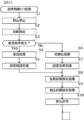
まず、主基板11における主要な動作を説明する。パチンコ遊技機1に対して電力供給が開始されると、遊技制御用マイクロコンピュータ100が起動し、CPU103によって遊技制御メイン処理が実行される。図4は、主基板11におけるCPU103が実行する遊技制御メイン処理を示すフローチャートである。
(Main operations of main board 11)
First, the main operations of the
図4に示す遊技制御メイン処理において、CPU103は、まず、割込禁止に設定する(ステップS1)。続いて、必要な初期設定を行う(ステップS2)。初期設定には、スタックポインタの設定、内蔵デバイス(CTC(カウンタ/タイマ回路)、パラレル入出力ポート等)のレジスタ設定、RAM102をアクセス可能状態にする設定等が含まれる。
In the game control main process shown in FIG. 4, the
次いで、復旧条件が成立したか否かを判定する(ステップS3)。復旧条件は、クリア信号がオフ状態であり、バックアップデータがあり、バックアップRAMが正常である場合に、成立可能である。パチンコ遊技機1の電力供給が開始されたときに、例えば電源基板17に設けられたクリアスイッチが押下操作されていれば、オン状態のクリア信号が遊技制御用マイクロコンピュータ100に入力される。このようなオン状態のクリア信号が入力されている場合には、ステップS3にて復旧条件が成立していないと判定すればよい。バックアップデータは、遊技制御用のバックアップRAMとなるRAM102に保存可能であればよい。ステップS3では、バックアップデータの有無やデータ誤りの有無などを確認あるいは検査して、復旧条件が成立し得るか否かを判定すればよい。
Next, it is determined whether the recovery conditions are satisfied (step S3). The recovery condition can be satisfied when the clear signal is off, there is backup data, and the backup RAM is normal. If, for example, a clear switch provided on the
復旧条件が成立した場合には(ステップS3;Yes)、復旧処理(ステップS4)を実行した後に、設定確認処理(ステップS5)を実行する。ステップS4の復旧処理により、RAM102の記憶内容に基づいて作業領域の設定が行われる。RAM102に記憶されたバックアップデータを用いて作業領域を設定することで、電力供給が停止したときの遊技状態に復旧し、例えば特別図柄の変動中であった場合には、停止前の状態から特別図柄の変動を再開可能であればよい。
If the recovery condition is satisfied (step S3; Yes), the setting confirmation process (step S5) is executed after executing the recovery process (step S4). Through the recovery process in step S4, a work area is set based on the contents stored in the
復旧条件が成立しなかった場合には(ステップS3;No)、初期化処理(ステップS6)を実行した後に、設定変更処理(ステップS7)を実行する。ステップS6の初期化処理は、RAM102に記憶されるフラグ、カウンタ、バッファをクリアするクリア処理を含み、クリア処理の実行により作業領域に初期値が設定される。
If the recovery condition is not satisfied (step S3; No), initialization processing (step S6) is performed, and then setting change processing (step S7) is performed. The initialization process in step S6 includes a clear process for clearing the flags, counters, and buffers stored in the
ステップS5の設定確認処理では、予め定められた設定確認条件が成立したか否かを判定する。設定確認条件は、例えば電力供給が開始されたときに、扉開放センサ90からの検出信号がオン状態であるとともに設定キー51がオン操作されている場合に成立する。ステップS5の設定確認処理が実行されるのは、ステップS3において、クリア信号がオフ状態であることを含めた復旧条件が成立した場合である。したがって、設定確認条件が成立し得るのは、クリア信号がオフ状態である場合となるので、クリア信号がオフ状態であることも、設定確認条件に含めることができる。
In the setting confirmation process of step S5, it is determined whether predetermined setting confirmation conditions are satisfied. The setting confirmation condition is satisfied, for example, when the detection signal from the door
ステップS5の設定確認処理において設定確認条件が成立した場合には、パチンコ遊技機1において設定されている設定値を確認可能な設定確認状態となり、主基板11から演出制御基板12に対して、設定確認開始コマンドが送信される。設定確認状態においては、パチンコ遊技機1にて設定されている設定値を表示モニタ29の表示により確認することが可能となっている。設定確認状態を終了するときには、主基板11から演出制御基板12に対して、設定確認終了コマンドが送信される。
If the setting confirmation conditions are satisfied in the setting confirmation process in step S5, the setting confirmation state is reached in which the setting values set in the
パチンコ遊技機1が設定確認状態であるときには、パチンコ遊技機1における遊技の進行を停止させる遊技停止状態としてもよい。遊技停止状態であるときには、打球操作ハンドルの操作による遊技球の発射、各種スイッチによる遊技球の検出などが停止され、また、第1特別図柄表示装置4Aや第2特別図柄表示装置4B、普通図柄表示器20において、ハズレ図柄などを停止表示したり、ハズレ図柄とは異なる遊技停止状態に対応した表示が行われたりするように制御すればよい。設定確認状態が終了するときには、これに伴う遊技停止状態も終了すればよい。
When the
ステップS7の設定変更処理では、予め定められた設定変更条件が成立したか否かを判定する。設定変更条件は、例えば電力供給が開始されたときに、扉開放センサ90からの検出信号がオン状態であるとともに設定キー51がオン操作されている場合に成立する。設定変更条件は、クリア信号がオン状態であることを含んでいてもよい。
In the setting change process of step S7, it is determined whether predetermined setting change conditions are satisfied. The setting change condition is satisfied, for example, when the detection signal from the door
ステップS7の設定変更処理において設定変更条件が成立した場合には、パチンコ遊技機1において設定されている設定値を変更可能な設定変更状態となり、主基板11から演出制御基板12に対して、設定変更開始コマンドが送信される。設定変更状態においては、表示モニタ29に設定値が表示され、設定切替スイッチ52の操作を検出するごとに表示モニタ29に表示している数値を順次更新して表示する。その後、設定キー51が遊技場の係員などによる操作でオフとなったことに基づいて、表示モニタ29に表示されている設定値をRAM102のバックアップ領域に格納(更新記憶)するとともに、表示モニタ29を消灯させる。設定変更状態を終了するときには、主基板11から演出制御基板12に対して、設定変更終了コマンドが送信される。
If the setting change conditions are satisfied in the setting change process in step S7, the setting change state is entered in which the setting values set in the
パチンコ遊技機1が設定変更状態であるときには、設定確認状態であるときと同様に、パチンコ遊技機1を遊技停止状態としてもよい。設定変更状態が終了するときには、これに伴う遊技停止状態も終了すればよい。
When the
演出制御基板12側では、設定確認開始コマンドや設定変更開始コマンドを受信すると、設定確認中である旨や設定変更中である旨を報知する制御が行われてもよい。例えば、画像表示装置5において所定の画像を表示したり、スピーカ8L、8Rから所定の音を出力したり、遊技効果ランプ9といった発光部材を所定の態様により発光させたりしてもよい。
On the
クリア信号は、例えば電源基板17に設けられたクリアスイッチの押下操作などによりオン状態となる。したがって、電力供給が開始されたときに、扉開放センサ90からの検出信号がオンであるとともに設定キー51がオンである場合には、クリアスイッチがオンであればステップS6の初期化処理とともにステップS7の設定変更処理が実行されて設定変更状態に制御可能となり、クリアスイッチがオフであればステップS4の復旧処理とともにステップS5の設定確認処理が実行されて設定確認状態に制御可能となる。電力供給が開始されたときに、扉開放センサ90からの検出信号がオフである場合、または設定キー51がオフである場合には、クリアスイッチがオンであればステップS6の初期化処理が実行される一方で設定変更状態には制御されず、クリアスイッチがオフであればステップS4の復旧処理が実行される一方で設定確認状態には制御されない。
The clear signal is turned on, for example, by pressing down a clear switch provided on the
設定確認処理または設定変更処理を実行した後に、CPU103は、乱数回路104を初期設定する乱数回路設定処理を実行する(ステップS8)。そして、所定時間(例えば2ms)毎に定期的にタイマ割込がかかるように遊技制御用マイクロコンピュータ100に内蔵されているCTCのレジスタの設定を行い(ステップS9)、割込みを許可する(ステップS10)。その後、ループ処理に入る。以後、所定時間(例えば2ms)ごとにCTCから割込み要求信号がCPU103へ送出され、CPU103は定期的にタイマ割込み処理を実行することができる。
After executing the setting confirmation process or the setting change process, the
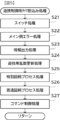
こうした遊技制御メイン処理を実行したCPU103は、CTCからの割込み要求信号を受信して割込み要求を受け付けると、図5のフローチャートに示す遊技制御用タイマ割込み処理を実行する。図5に示す遊技制御用タイマ割込み処理を開始すると、CPU103は、まず、所定のスイッチ処理を実行することにより、スイッチ回路110を介してゲートスイッチ21、第1始動口スイッチ22A、第2始動口スイッチ22B、カウントスイッチ23といった各種スイッチからの検出信号の受信の有無を判定する(ステップS21)。続いて、所定のメイン側エラー処理を実行することにより、パチンコ遊技機1の異常診断を行い、その診断結果に応じて必要ならば警告を発生可能とする(ステップS22)。この後、所定の情報出力処理を実行することにより、例えばパチンコ遊技機1の外部に設置されたホール管理用コンピュータに供給される大当り情報(大当りの発生回数等を示す情報)、始動情報(始動入賞の回数等を示す情報)、確率変動情報(確変状態となった回数等を示す情報)などのデータを出力する(ステップS23)。
When the
情報出力処理に続いて、主基板11の側で用いられる遊技用乱数の少なくとも一部をソフトウェアにより更新するための遊技用乱数更新処理を実行する(ステップS24)。この後、CPU103は、特別図柄プロセス処理を実行する(ステップS25)。CPU103がタイマ割込み毎に特別図柄プロセス処理を実行することにより、特図ゲームの実行および保留の管理や、大当り遊技状態や小当り遊技状態の制御、遊技状態の制御などが実現される。
Following the information output process, a gaming random number updating process is executed to update at least a part of the gaming random numbers used on the
特別図柄プロセス処理に続いて、普通図柄プロセス処理が実行される(ステップS26)。CPU103がタイマ割込み毎に普通図柄プロセス処理を実行することにより、ゲートスイッチ21からの検出信号に基づく(通過ゲート41に遊技球が通過したことに基づく)普図ゲームの実行および保留の管理や、「普図当り」に基づく可変入賞球装置6Bの開放制御などを可能にする。普図ゲームの実行は、普通図柄表示器20を駆動することにより行われ、普図保留表示器25Cを点灯させることにより普図保留数を表示する。
Following the special symbol process, the normal symbol process is executed (step S26). The
普通図柄プロセス処理を実行した後、遊技制御用タイマ割込み処理の一部として、電断が発生したときの処理、賞球を払い出すための処理等などが行われてもよい。その後、CPU103は、コマンド制御処理を実行する(ステップS27)。CPU103は、上記各処理にて演出制御コマンドを送信設定することがある。ステップS27のコマンド制御処理では、送信設定された演出制御コマンドを演出制御基板12などのサブ側の制御基板に対して伝送させる処理が行われる。コマンド制御処理を実行した後には、割込みを許可してから、遊技制御用タイマ割込み処理を終了する。
After executing the normal symbol process processing, processing when a power outage occurs, processing for paying out prize balls, etc. may be performed as part of the game control timer interrupt processing. After that, the
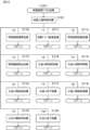
図6は、特別図柄プロセス処理として、図5に示すステップS25にて実行される処理の一例を示すフローチャートである。この特別図柄プロセス処理において、CPU103は、まず、始動入賞判定処理を実行する(ステップS101)。
FIG. 6 is a flowchart showing an example of the process executed in step S25 shown in FIG. 5 as the special symbol process process. In this special symbol process, the
始動入賞判定処理では、始動入賞の発生を検出し、RAM102の所定領域に保留情報を格納し保留記憶数を更新する処理が実行される。始動入賞が発生すると、表示結果(大当り種別を含む)や変動パターンを決定するための乱数値が抽出され、保留情報として記憶される。また、抽出した乱数値に基づいて、表示結果や変動パターンを先読判定する処理が実行されてもよい。保留情報や保留記憶数を記憶した後には、演出制御基板12に始動入賞の発生、保留記憶数、先読判定等の判定結果を指定するための演出制御コマンドを送信するための送信設定が行われる。こうして送信設定された始動入賞時の演出制御コマンドは、例えば特別図柄プロセス処理が終了した後、図5に示すステップS27のコマンド制御処理が実行されることなどにより、主基板11から演出制御基板12に対して伝送される。
In the starting winning determination process, a process is executed to detect the occurrence of a starting winning, store pending information in a predetermined area of the
ステップS101にて始動入賞判定処理を実行した後、CPU103は、RAM102に設けられた特図プロセスフラグの値に応じて、ステップS110~S120の処理のいずれかを選択して実行する。なお、特別図柄プロセス処理の各処理(ステップS110~S120)では、各処理に対応した演出制御コマンドを演出制御基板12に送信するための送信設定が行われる。
After executing the starting winning determination process in step S101, the
ステップS110の特別図柄通常処理は、特図プロセスフラグの値が“0”(初期値)のときに実行される。この特別図柄通常処理では、保留情報の有無などに基づいて、第1特図ゲームまたは第2特図ゲームを開始するか否かの判定が行われる。また、特別図柄通常処理では、表示結果決定用の乱数値に基づき、特別図柄や飾り図柄の表示結果を「大当り」または「小当り」とするか否かや「大当り」とする場合の大当り種別を、その表示結果が導出表示される以前に決定(事前決定)する。さらに、特別図柄通常処理では、決定された表示結果に対応して、特図ゲームにおいて停止表示させる確定特別図柄(大当り図柄や小当り図柄、ハズレ図柄のいずれか)が設定される。その後、特図プロセスフラグの値が“1”に更新され、特別図柄通常処理は終了する。なお、第2特図を用いた特図ゲームが第1特図を用いた特図ゲームよりも優先して実行されるようにしてもよい(特図2優先消化ともいう)。また、第1始動入賞口および第2始動入賞口への遊技球の入賞順序を記憶し、入賞順に特図ゲームの開始条件を成立させるようにしてもよい(入賞順消化ともいう)。
The special symbol normal process in step S110 is executed when the value of the special symbol process flag is "0" (initial value). In this special symbol normal processing, it is determined whether or not to start the first special symbol game or the second special symbol game based on the presence or absence of reservation information. In addition, in the special symbol normal processing, based on the random value for determining the display result, it is determined whether the display result of the special symbol or decorative symbol is a "big hit" or "small win" and the type of jackpot when it is determined to be a "jackpot". is determined (pre-determined) before the display result is derived and displayed. Furthermore, in the special symbol normal processing, a confirmed special symbol (any of a jackpot symbol, a small prize symbol, or a losing symbol) to be stopped and displayed in the special symbol game is set in accordance with the determined display result. After that, the value of the special symbol process flag is updated to "1", and the special symbol normal processing ends. Note that the special pattern game using the second special pattern may be executed with priority over the special pattern game using the first special pattern (also referred to as
乱数値に基づき各種の決定を行う場合には、ROM101に格納されている各種のテーブル(乱数値と比較される決定値が決定結果に割り当てられているテーブル)が参照される。主基板11における他の決定、演出制御基板12における各種の決定についても同じである。演出制御基板12においては、各種のテーブルがROM121に格納されている。
When making various decisions based on random numbers, various tables (tables in which decision values to be compared with random numbers are assigned to decision results) stored in the
ステップS111の変動パターン設定処理は、特図プロセスフラグの値が“1”のときに実行される。この変動パターン設定処理には、表示結果を「大当り」または「小当り」とするか否かの事前決定結果等に基づき、変動パターン決定用の乱数値を用いて変動パターンを複数種類のいずれかに決定する処理などが含まれている。変動パターン設定処理では、変動パターンを決定したときに、特図プロセスフラグの値が“2”に更新され、変動パターン設定処理は終了する。 The variation pattern setting process in step S111 is executed when the value of the special figure process flag is "1". In this fluctuation pattern setting process, based on the pre-determined result of whether the display result will be a "big hit" or "small hit", a random value for determining the fluctuation pattern is used to select one of multiple types of fluctuation patterns. It includes the process of determining the In the variation pattern setting process, when the variation pattern is determined, the value of the special figure process flag is updated to "2", and the variation pattern setting process ends.
変動パターンは、特図ゲームの実行時間(特図変動時間)(飾り図柄の可変表示の実行時間でもある)や、飾り図柄の可変表示の態様(リーチの有無等)、飾り図柄の可変表示中の演出内容(リーチ演出の種類等)を指定するものであり、可変表示パターンとも呼ばれる。 The variation pattern includes the execution time of the special figure game (special figure variation time) (also the execution time of the variable display of decorative symbols), the variable display mode of the ornamental symbols (the presence or absence of reach, etc.), and the variable display period of the decorative symbols. It specifies the content of the performance (type of reach performance, etc.), and is also called a variable display pattern.
ステップS112の特別図柄変動処理は、特図プロセスフラグの値が“2”のときに実行される。この特別図柄変動処理には、第1特別図柄表示装置4Aや第2特別図柄表示装置4Bにおいて特別図柄を変動させるための設定を行う処理や、その特別図柄が変動を開始してからの経過時間を計測する処理などが含まれている。また、計測された経過時間が変動パターンに対応する特図変動時間に達したか否かの判定も行われる。そして、特別図柄の変動を開始してからの経過時間が特図変動時間に達したときには、特図プロセスフラグの値が“3”に更新され、特別図柄変動処理は終了する。
The special symbol variation process in step S112 is executed when the value of the special symbol process flag is "2". This special symbol variation process includes a process of making settings for varying the special symbol in the first special
ステップS113の特別図柄停止処理は、特図プロセスフラグの値が“3”のときに実行される。この特別図柄停止処理には、第1特別図柄表示装置4Aや第2特別図柄表示装置4Bにて特別図柄の変動を停止させ、特別図柄の表示結果となる確定特別図柄を停止表示(導出)させるための設定を行う処理が含まれている。そして、表示結果が「大当り」である場合には特図プロセスフラグの値が“4”に更新される。その一方で、大当りフラグがオフであり、表示結果が「小当り」である場合には、特図プロセスフラグの値が“8”に更新される。また、表示結果が「ハズレ」である場合には、特図プロセスフラグの値が“0”に更新される。表示結果が「小当り」または「ハズレ」である場合、時短状態や確変状態に制御されているときであって、回数切りの終了成立する場合には、遊技状態も更新される。特図プロセスフラグの値が更新されると、特別図柄停止処理は終了する。
The special symbol stop process in step S113 is executed when the value of the special symbol process flag is "3". In this special symbol stopping process, the fluctuation of the special symbol is stopped in the first special
ステップS114の大当り開放前処理は、特図プロセスフラグの値が“4”のときに実行される。この大当り開放前処理には、表示結果が「大当り」となったことなどに基づき、大当り遊技状態においてラウンドの実行を開始して大入賞口を開放状態とするための設定を行う処理などが含まれている。大入賞口を開放状態とするときには、大入賞口扉用のソレノイド82に対してソレノイド駆動信号を供給する処理が実行される。このときには、例えば大当り種別がいずれであるかに対応して、大入賞口を開放状態とする開放上限期間や、ラウンドの上限実行回数を設定する。これらの設定が終了すると、特図プロセスフラグの値が“5”に更新され、大当り開放前処理は終了する。
The jackpot opening preprocessing in step S114 is executed when the value of the special figure process flag is "4". This jackpot opening pre-processing includes processing to start a round in the jackpot game state and set the jackpot opening state based on the display result being a "jackpot", etc. It is. When the big winning opening is opened, a process is executed to supply a solenoid drive signal to the
ステップS115の大当り開放中処理は、特図プロセスフラグの値が“5”のときに実行される。この大当り開放中処理には、大入賞口を開放状態としてからの経過時間を計測する処理や、その計測した経過時間やカウントスイッチ23によって検出された遊技球の個数などに基づいて、大入賞口を開放状態から閉鎖状態に戻すタイミングとなったか否かを判定する処理などが含まれている。そして、大入賞口を閉鎖状態に戻すときには、大入賞口扉用のソレノイド82に対するソレノイド駆動信号の供給を停止させる処理などを実行した後、特図プロセスフラグの値が“6”に更新し、大当り開放中処理を終了する。
The jackpot opening process in step S115 is executed when the value of the special figure process flag is "5". This jackpot opening process includes a process of measuring the elapsed time since the jackpot opening is opened, and a process of measuring the elapsed time from when the jackpot opening is opened, and based on the measured elapsed time and the number of game balls detected by the
ステップS116の大当り開放後処理は、特図プロセスフラグの値が“6”のときに実行される。この大当り開放後処理には、大入賞口を開放状態とするラウンドの実行回数が設定された上限実行回数に達したか否かを判定する処理や、上限実行回数に達した場合に大当り遊技状態を終了させるための設定を行う処理などが含まれている。そして、ラウンドの実行回数が上限実行回数に達していないときには、特図プロセスフラグの値が“5”に更新される一方、ラウンドの実行回数が上限実行回数に達したときには、特図プロセスフラグの値が“7”に更新される。特図プロセスフラグの値が更新されると、大当り解放後処理は終了する。 The jackpot opening process in step S116 is executed when the value of the special figure process flag is "6". This jackpot opening process includes a process to determine whether the number of rounds to open the jackpot has reached the set upper limit number of runs, and a process to enter the jackpot game state when the upper limit number of runs has been reached. This includes processing to make settings for terminating the process. When the number of executions of the round has not reached the upper limit number of executions, the value of the special figure process flag is updated to "5", while when the number of executions of the round has reached the upper limit number of executions, the value of the special figure process flag is updated to "5". The value is updated to "7". When the value of the special figure process flag is updated, the jackpot release post-processing ends.
ステップS117の大当り終了処理は、特図プロセスフラグの値が“7”のときに実行される。この大当り終了処理には、大当り遊技状態の終了を報知する演出動作としてのエンディング演出が実行される期間に対応した待ち時間が経過するまで待機する処理や、大当り遊技状態の終了に対応して確変制御や時短制御を開始するための各種の設定を行う処理などが含まれている。こうした設定が行われたときには、特図プロセスフラグの値が“0”に更新され、大当り終了処理は終了する。 The jackpot end process in step S117 is executed when the value of the special figure process flag is "7". This jackpot ending process includes a process of waiting until the waiting time corresponding to the period in which the ending performance is executed as a performance operation to notify the end of the jackpot gaming state, and a process of waiting until the waiting time corresponding to the end of the jackpot gaming state has changed. It includes processing to perform various settings for starting control and time-saving control. When such settings are made, the value of the special figure process flag is updated to "0", and the jackpot ending process ends.
ステップS118の小当り開放前処理は、特図プロセスフラグの値が“8”のときに実行される。この小当り開放前処理には、表示結果が「小当り」となったことに基づき、小当り遊技状態において大入賞口を開放状態とするための設定を行う処理などが含まれている。このときには、特図プロセスフラグの値が“9”に更新され、小当り開放前処理は終了する。 The small hit opening preprocessing in step S118 is executed when the value of the special figure process flag is "8". This small win opening pre-processing includes processing for setting the large winning opening to be open in the small winning gaming state based on the display result being "small winning". At this time, the value of the special figure process flag is updated to "9", and the small hit release preprocessing ends.
ステップS119の小当り開放中処理は、特図プロセスフラグの値が“9”のときに実行される。この小当り開放中処理には、大入賞口を開放状態としてからの経過時間を計測する処理や、その計測した経過時間などに基づいて、大入賞口を開放状態から閉鎖状態に戻すタイミングとなったか否かを判定する処理などが含まれている。大入賞口を閉鎖状態に戻して小当り遊技状態の終了タイミングとなったときには、特図プロセスフラグの値が“10”に更新され、小当り開放中処理は終了する。 The small winning opening process in step S119 is executed when the value of the special figure process flag is "9". This small win opening process includes a process that measures the elapsed time since the big winning opening was opened, and a timing to return the big winning opening from the open state to the closed state based on the measured elapsed time. This includes processing to determine whether or not the When the big prize opening is returned to the closed state and the end timing of the small winning game state comes, the value of the special figure process flag is updated to "10", and the small winning opening process ends.
ステップS120の小当り終了処理は、特図プロセスフラグの値が“10”のときに実行される。この小当り終了処理には、小当り遊技状態の終了を報知する演出動作が実行される期間に対応した待ち時間が経過するまで待機する処理などが含まれている。ここで、小当り遊技状態が終了するときには、小当り遊技状態となる以前のパチンコ遊技機1における遊技状態を継続させる。小当り遊技状態の終了時における待ち時間が経過したときには、特図プロセスフラグの値が“0”に更新され、小当り終了処理は終了する。
The small hit end process of step S120 is executed when the value of the special figure process flag is "10". This small win ending process includes a process of waiting until a waiting time corresponding to a period in which a performance operation to notify the end of the small win game state has elapsed. Here, when the small winning gaming state ends, the gaming state in the
パチンコ遊技機1は、設定値に応じて大当りの当選確率や出玉率が変わる構成とされている。例えば、特別図柄プロセス処理の特別図柄通常処理において、設定値に応じた表示結果判定テーブル(当選確率)を用いることにより、大当りの当選確率や出玉率が変わるようになっている。例えば設定値は1~6の6段階からなり、6が最も大当りの当選確率が高く、6、5、4、3、2、1の順に値が小さくなるほど大当りの当選確率が低くなる。この例において、設定値として6が設定されている場合には遊技者にとって最も有利度が高く、6、5、4、3、2、1の順に値が小さくなるほど有利度が段階的に低くなる。設定値に応じて大当りの当選確率が変われば、出玉率も設定値に応じて変わってもよい。大当りの当選確率は設定値にかかわらず一定であるのに対し、大当り遊技状態におけるラウンド数が設定値に応じて変わってもよい。パチンコ遊技機1は、遊技者にとっての有利度が異なる複数の設定値のうちいずれかを設定可能に構成されていればよい。パチンコ遊技機1において設定されている設定値は、主基板11の側から演出制御基板12の側へ設定値指定コマンドが送信されることにより通知される。
The
図7は、表示結果判定テーブルの構成例を示している。図7(A)は、変動特図が第1特図である場合に用いられる第1特図用表示結果判定テーブルの構成例を示し、図7(B)は、変動特図が第2特図である場合に用いられる第2特図用表示結果判定テーブルの構成例を示している。表示結果判定テーブルは、ROM101に記憶されているデータの集まりである。表示結果判定テーブルでは、設定値に応じて、乱数値MR1と比較される当り判定値が特別図柄の可変表示結果である特図表示結果に割り当てられている。乱数値MR1は、表示結果決定用の乱数値であり、0~65535の範囲でランダムに値が更新される。表示結果判定テーブルとして、第1特図と第2特図とで共通の表示結果判定テーブルを用いるようにしてもよい。
FIG. 7 shows an example of the configuration of the display result determination table. FIG. 7(A) shows a configuration example of the display result determination table for the first special symbol used when the variable special symbol is the first special symbol, and FIG. 7(B) shows a configuration example of the display result determination table for the first special symbol used when the variable special symbol is the second A configuration example of a second special figure display result determination table used in the case of a figure is shown. The display result determination table is a collection of data stored in the
表示結果判定テーブルにおいては、遊技状態が確変状態(高確状態)であるときに、通常状態または時短状態(低確状態)であるときよりも多くの判定値が、「大当り」の特図表示結果に割り当てられている。これにより、パチンコ遊技機1において確変制御が行われる確変状態といった高確状態であるときには、通常状態または時短状態といった低確状態であるときに比べて、大当り遊技状態に制御すると決定される確率が高くなる。
In the display result judgment table, when the gaming state is in a variable probability state (high probability state), more judgment values are displayed as special symbols for "jackpot" than when the gaming state is in the normal state or time saving state (low probability state). assigned to the result. As a result, when the
第1特図用表示結果判定テーブルにおいては、遊技状態や設定値にかかわらず、特図表示結果を「小当り」として小当り遊技状態に制御すると決定される確率が同一値となるように判定値が割り当てられている。第2特図用表示結果判定テーブルにおいては、遊技状態や設定値にかかわらず、特図表示結果を「小当り」として小当り遊技状態に制御すると決定される確率が第1特図用表示結果判定テーブルとは異なる同一値となるように判定値が割り当てられている。なお、設定値に応じて特図表示結果を「小当り」として小当り遊技状態に制御すると決定される確率を異ならせてもよい。変動特図にかかわらず特図表示結果を「小当り」として小当り遊技状態に制御すると決定される確率を同一確率としてもよい。 In the first special figure display result determination table, the probability that the special figure display result will be determined as a "small hit" and controlled to a small win gaming state is determined to be the same value, regardless of the gaming state or setting value. A value has been assigned. In the second special figure display result determination table, the first special figure display result is the probability that the special figure display result will be determined as a "small hit" and will be controlled in a small win game state, regardless of the gaming state or setting value. Judgment values are assigned so that they are the same value but different from those in the judgment table. In addition, the probability that the special figure display result is determined to be a "small win" and controlled to a small win gaming state may be varied depending on the set value. Regardless of the variable special figure, the probability of determining that the special figure display result will be a "small win" and control to a small win game state may be set to be the same probability.
第1特図用表示結果判定テーブルおよび第2特図用表示結果判定テーブルでは、遊技状態が通常状態または時短状態の場合に、当り判定値のうち1020から1237までの範囲が、設定値にかかわらず大当りを判定するための大当り判定値の共通数値範囲に設定されている。設定値が1の場合は、1020から1237までが「大当り」に割り当てられ、大当りを判定するための大当り判定値の共通数値範囲のみが設定されている一方で、設定値2~設定値6の場合は、大当り判定値の共通数値範囲から連続するように、1238から各設定値に応じた数値範囲が大当り判定値の非共通数値範囲に設定されている。
In the display result determination table for the first special figure and the display result determination table for the second special figure, when the gaming state is the normal state or the time saving state, the range from 1020 to 1237 of the hit judgment values is determined regardless of the set value. It is set to a common numerical range of jackpot determination values for determining jackpots. When the setting value is 1, 1020 to 1237 are assigned to "jackpot", and only the common numerical range of jackpot judgment values for determining jackpots is set, while setting
第1特図用表示結果判定テーブルおよび第2特図用表示結果判定テーブルでは、遊技状態が確変状態の場合に、当り判定値のうち1020から1346までの範囲が、設定値にかかわらず大当りを判定するための大当り判定値の共通数値範囲に設定されている。設定値が1の場合は、1020から1346までが「大当り」に割り当てられることで、大当りを判定するための大当り判定値の共通数値範囲のみが設定され、その一方で、設定値2~設定値6の場合は、大当り判定値の共通数値範囲から連続するように、1346から各設定値に応じた数値範囲が大当り判定値の非共通数値範囲に設定される。
In the display result determination table for the first special figure and the display result determination table for the second special figure, when the gaming state is in a variable probability state, the range from 1020 to 1346 among the hit determination values indicates that the jackpot will be won regardless of the set value. It is set to a common numerical range of jackpot judgment values for judgment. When the setting value is 1, by assigning 1020 to 1346 to "jackpot", only the common numerical range of jackpot judgment values for determining jackpots is set, while on the other hand, setting
第1特図用表示結果判定テーブルでは、遊技状態が通常状態または時短状態である場合に、当り判定値のうち32767から33094までの範囲が、設定値にかかわらず小当りを判定するための小当り判定値の共通数値範囲に設定されている。小当り判定値は、設定値が1~6のいずれである場合にも、大当り判定値の共通数値範囲および非共通数値範囲とは異なる数値範囲に設定されている。これにより、小当り判定値の数値範囲が各設定値に応じて変化する大当り判定値の範囲に重複することが防止されている。 In the display result determination table for the first special figure, when the gaming state is the normal state or the time saving state, the range from 32767 to 33094 of the hit determination values is the small value for determining a small hit regardless of the setting value. It is set to a common numerical range of hit judgment values. The small hit determination value is set to a numerical range different from the common numerical range and non-common numerical range of the jackpot determination value, regardless of the set value from 1 to 6. This prevents the numerical range of the small hit determination value from overlapping the range of the jackpot determination value, which changes according to each set value.
第1特図用表示結果判定テーブルでは、遊技状態が確変状態である場合に、遊技状態が通常状態または時短状態である場合と同じく、当り判定値のうち32767から33094までの範囲が、設定値にかかわらず小当りを判定するための小当り判定値の共通数値範囲に設定されている。小当り判定値は、設定値が1~6のいずれである場合にも、大当り判定値の共通数値範囲および非共通数値範囲とは異なる数値範囲に設定されている。これにより、小当り判定値の数値範囲が各設定値に応じて変化する大当り判定値の範囲に重複することが防止されている。 In the display result determination table for the first special figure, when the gaming state is in the variable probability state, the range from 32767 to 33094 of the hit judgment values is set to It is set to a common numerical range of the small hit determination value for determining a small hit regardless of the number of small hits. The small hit determination value is set to a numerical range different from the common numerical range and non-common numerical range of the jackpot determination value, regardless of the set value from 1 to 6. This prevents the numerical range of the small hit determination value from overlapping the range of the jackpot determination value, which changes according to each set value.
第2特図用表示結果判定テーブルでは、遊技状態が通常状態または時短状態である場合に、当り判定値のうち32767から33421までの範囲が、設定値にかかわらず小当りを判定するための小当り判定値の共通数値範囲に設定されている。小当り判定値は、設定値が1~6のいずれである場合にも、大当り判定値の共通数値範囲および非共通数値範囲とは異なる数値範囲に設定されている。これにより、小当り判定値の数値範囲が各設定値に応じて変化する大当り判定値の範囲に重複することが防止されている。 In the display result determination table for the second special figure, when the gaming state is the normal state or the time saving state, the range from 32767 to 33421 of the hit determination values is the small value for determining a small hit regardless of the set value. It is set to a common numerical range of hit judgment values. The small hit determination value is set to a numerical range different from the common numerical range and non-common numerical range of the jackpot determination value, regardless of the set value from 1 to 6. This prevents the numerical range of the small hit determination value from overlapping the range of the jackpot determination value, which changes according to each set value.
第2特図用表示結果判定テーブルでは、遊技状態が確変状態である場合に、遊技状態が通常状態または時短状態である場合と同じく、当り判定値のうち32767から33421までの範囲が、設定値にかかわらず小当りを判定するための小当り判定値の共通数値範囲に設定されている。小当り判定値は、設定値が1~6のいずれである場合にも、大当り判定値の共通数値範囲および非共通数値範囲とは異なる数値範囲に設定されている。これにより、小当り判定値の数値範囲が各設定値に応じて変化する大当り判定値の範囲に重複することが防止されている。 In the display result determination table for the second special figure, when the gaming state is in the variable probability state, the range from 32767 to 33421 of the hit judgment values is the set value, just as when the gaming state is in the normal state or time saving state. It is set to a common numerical range of the small hit determination value for determining a small hit regardless of the number of small hits. The small hit determination value is set to a numerical range different from the common numerical range and non-common numerical range of the jackpot determination value, regardless of the set value from 1 to 6. This prevents the numerical range of the small hit determination value from overlapping the range of the jackpot determination value, which changes according to each set value.
パチンコ遊技機1に設定可能な設定値は、5個以下や7個以上であってもよい。パチンコ遊技機1に設定される設定値が小さいほど遊技者にとって有利となるようにしてもよい。パチンコ遊技機1に設定される設定値に応じて遊技性が変化するようにしてもよい。例えば、パチンコ遊技機1に設定される設定値が1である場合は、通常状態での大当り確率が1/320、確変状態が65%の割合でループする遊技性(いわゆる確変ループタイプ)とし、パチンコ遊技機1に設定されている設定値が2である場合は、通常状態での大当り確率が1/200、大当り遊技中に遊技球が、特別可変入賞球装置7の内部に設けられた所定スイッチを通過することに基づいて大当り遊技終了後の遊技状態を確変状態に制御する一方で、変動特図に応じて大当り遊技中に遊技球が所定スイッチを通過する割合が異なる遊技性(いわゆるV確変タイプ)とし、パチンコ遊技機1に設定されている設定値が3である場合は、大当り確率が1/320で小当り確率が1/50であり、高ベース中(時短制御中)に遊技球が特別可変入賞球装置7の内部に設けられた所定スイッチを通過することに基づいて大当り遊技状態に制御する遊技性(いわゆる1種2種混合タイプ)としてもよい。パチンコ遊技機1に設定されている設定値が1~3のいずれかである場合は遊技性が同一であるが、これら設定値が1~3のいずれかである場合よりも大当り確率や小当り確率が高い一方で大当り遊技中に獲得可能な賞球数が少ない設定(例えば、パチンコ遊技機1に設定されている設定値が4~6のいずれかである場合)を設けてもよい。設定値に応じて遊技性を変化させる場合は、共通のスイッチを異なる用途に使用してもよい。具体的には、設定値が1~3の場合は、特別可変入賞球装置7内に設けられた所定スイッチを演出用スイッチ(遊技球が所定領域を通過する毎に所定の演出を実行するためのスイッチ)として使用し、設定値が4~6の場合は、所定スイッチを遊技用スイッチ(遊技球が所定スイッチを通過したことに基づいて遊技状態を確変状態や大当り遊技状態に制御するためのスイッチ)として使用してもよい。
The number of setting values that can be set in the
大当り種別は、大当り種別判定テーブルにおける判定値の割当てに基づいて、設定値に応じて異なる割合で決定されてもよい。あるいは、大当り種別は、設定値にかかわらず共通の割合で決定されてもよい。変動パターンは、変動パターン判定テーブルにおける判定値の割当てに基づいて、設定値に応じて異なる割合で決定されてもよい。あるいは、変動パターンは、設定値にかかわらず共通の割合で決定されてもよい。設定値に応じてノーマルリーチやスーパーリーチの実行割合が異なることで、ノーマルリーチやスーパーリーチが実行される頻度により設定値が示唆されてもよい。あるいは、設定値にかかわらずノーマルリーチやスーパーリーチの実行割合は共通であってもよい。その他、設定値に応じて、異なる割合で任意の設定示唆演出を実行可能としたものであってもよい。 The jackpot type may be determined at different ratios depending on the setting value based on the allocation of judgment values in the jackpot type judgment table. Alternatively, the jackpot type may be determined by a common ratio regardless of the setting value. The variation pattern may be determined at different rates depending on the set value, based on the allocation of determination values in the variation pattern determination table. Alternatively, the variation pattern may be determined at a common rate regardless of the set value. The setting value may be suggested by the frequency with which normal reach and super reach are performed by varying the execution rate of normal reach and super reach depending on the setting value. Alternatively, the execution rate of normal reach and super reach may be the same regardless of the setting value. In addition, it may be possible to perform arbitrary setting suggestion effects at different rates depending on the setting value.
(演出制御基板12の主要な動作)
次に、演出制御基板12における主要な動作を説明する。演出制御基板12では、電源基板等から電源電圧の供給を受けると、演出制御用CPU120が起動して、図8のフローチャートに示すような演出制御メイン処理を実行する。図8に示す演出制御メイン処理を開始すると、演出制御用CPU120は、まず、所定の初期化処理を実行して(ステップS71)、RAM122のクリアや各種初期値の設定、また演出制御基板12に搭載されたCTC(カウンタ/タイマ回路)のレジスタ設定等を行う。また、初期動作制御処理を実行する(ステップS72)。初期動作制御処理では、可動体32を駆動して初期位置に戻す制御、所定の動作確認を行う制御といった可動体32の初期動作を行う制御が実行される。
(Main operations of the production control board 12)
Next, the main operations in the
その後、タイマ割込みフラグがオンとなっているか否かの判定を行う(ステップS73)。タイマ割込みフラグは、例えばCTCのレジスタ設定に基づき、所定時間(例えば2ミリ秒)が経過するごとにオン状態にセットされる。このとき、タイマ割込みフラグがオフであれば(ステップS73;No)、ステップS73の処理を繰り返し実行して待機する。 Thereafter, it is determined whether the timer interrupt flag is on (step S73). The timer interrupt flag is set to an on state every time a predetermined time (for example, 2 milliseconds) elapses, based on, for example, a register setting of the CTC. At this time, if the timer interrupt flag is off (step S73; No), the process of step S73 is repeatedly executed and the process waits.
また、演出制御基板12の側では、所定時間が経過するごとに発生するタイマ割込みとは別に、主基板11からの演出制御コマンドを受信するための割込みが発生する。この割込みは、例えば主基板11からの演出制御INT信号がオン状態となることにより発生する割込みである。演出制御INT信号がオン状態となることによる割込みが発生すると、演出制御用CPU120は、自動的に割込み禁止に設定するが、自動的に割込み禁止状態にならないCPUを用いている場合には、割込み禁止命令(DI命令)を発行することが望ましい。演出制御用CPU120は、演出制御INT信号がオン状態となることによる割込みに対応して、例えば所定のコマンド受信割込み処理を実行する。このコマンド受信割込み処理では、I/O125に含まれる入力ポートのうちで、中継基板15を介して主基板11から送信された制御信号を受信する所定の入力ポートより、演出制御コマンドを取り込む。このとき取り込まれた演出制御コマンドは、例えばRAM122に設けられた演出制御コマンド受信用バッファに格納する。その後、演出制御用CPU120は、割込み許可に設定してから、コマンド受信割込み処理を終了する。
Furthermore, on the side of the
ステップS73にてタイマ割込みフラグがオンである場合には(ステップS73;Yes)、タイマ割込みフラグをクリアしてオフ状態にするとともに(ステップS74)、コマンド解析処理を実行する(ステップS75)。コマンド解析処理では、例えば主基板11の遊技制御用マイクロコンピュータ100から送信されて演出制御コマンド受信用バッファに格納されている各種の演出制御コマンドを読み出した後に、その読み出された演出制御コマンドに対応した設定や制御などが行われる。例えば、どの演出制御コマンドを受信したかや演出制御コマンドが特定する内容等を演出制御プロセス処理等で確認できるように、読み出された演出制御コマンドをRAM122の所定領域に格納したり、RAM122に設けられた受信フラグをオンしたりする。また、演出制御コマンドが遊技状態を特定する場合、遊技状態に応じた背景の表示を表示制御部123に指示してもよい。
If the timer interrupt flag is on in step S73 (step S73; Yes), the timer interrupt flag is cleared and turned off (step S74), and command analysis processing is executed (step S75). In the command analysis process, for example, after reading various production control commands transmitted from the
ステップS75にてコマンド解析処理を実行した後には、演出制御プロセス処理を実行する(ステップS76)。演出制御プロセス処理では、例えば画像表示装置5の表示領域における演出画像の表示動作、スピーカ8L、8Rからの音声出力動作、遊技効果ランプ9および装飾用LEDといった装飾発光体における点灯動作、可動体32の駆動動作といった、各種の演出装置を動作させる制御が行われる。また、各種の演出装置を用いた演出動作の制御内容について、主基板11から送信された演出制御コマンド等に応じた判定や決定、設定などが行われる。
After executing the command analysis process in step S75, the production control process process is executed (step S76). In the effect control process processing, for example, the display operation of the effect image in the display area of the
ステップS76の演出制御プロセス処理に続いて、演出用乱数更新処理が実行され(ステップS77)、演出制御基板12の側で用いられる演出用乱数の少なくとも一部がソフトウェアにより更新される。その後、ステップS73の処理に戻る。ステップS73の処理に戻る前に、他の処理が実行されてもよい。
Following the performance control process processing in step S76, a performance random number update process is executed (step S77), and at least a portion of the performance random numbers used on the
図9は、演出制御プロセス処理として、図8のステップS76にて実行される処理の一例を示すフローチャートである。図9に示す演出制御プロセス処理において、演出制御用CPU120は、まず、先読予告設定処理を実行する(ステップS161)。先読予告設定処理では、例えば、主基板11から送信された始動入賞時の演出制御コマンドに基づいて、先読予告演出を実行するための判定や決定、設定などが行われる。また、当該演出制御コマンドから特定される保留記憶数に基づき保留表示を表示するための処理が実行される。
FIG. 9 is a flowchart showing an example of the process executed in step S76 of FIG. 8 as the production control process process. In the performance control process shown in FIG. 9, the
ステップS161の処理を実行した後、演出制御用CPU120は、例えばRAM122に設けられた演出プロセスフラグの値に応じて、以下のようなステップS170~S177の処理のいずれかを選択して実行する。
After executing the process of step S161, the
ステップS170の可変表示開始待ち処理は、演出プロセスフラグの値が“0”(初期値)のときに実行される処理である。この可変表示開始待ち処理は、主基板11から可変表示の開始を指定するコマンドなどを受信したか否かに基づき、画像表示装置5における飾り図柄の可変表示を開始するか否かを判定する処理などを含んでいる。画像表示装置5における飾り図柄の可変表示を開始すると判定された場合、演出プロセスフラグの値を“1”に更新し、可変表示開始待ち処理を終了する。
The variable display start waiting process in step S170 is a process that is executed when the value of the production process flag is "0" (initial value). This variable display start waiting process is a process of determining whether or not to start variable display of decorative patterns on the
ステップS171の可変表示開始設定処理は、演出プロセスフラグの値が“1”のときに実行される処理である。この可変表示開始設定処理では、演出制御コマンドにより特定される表示結果や変動パターンに基づいて、飾り図柄の可変表示の表示結果(確定飾り図柄)、飾り図柄の可変表示の態様、リーチ演出や各種予告演出などの各種演出の実行の有無やその態様や実行開始タイミングなどを決定する。そして、その決定結果等を反映した演出制御パターン(表示制御部123に演出の実行を指示するための制御データの集まり)を設定する。その後、設定した演出制御パターンに基づいて、飾り図柄の可変表示の実行開始を表示制御部123に指示し、演出プロセスフラグの値を“2”に更新し、可変表示開始設定処理を終了する。表示制御部123は、飾り図柄の可変表示の実行開始の指示により、画像表示装置5において、飾り図柄の可変表示を開始させる。
The variable display start setting process in step S171 is a process that is executed when the value of the production process flag is "1". In this variable display start setting process, based on the display result and fluctuation pattern specified by the production control command, the display result of the variable display of the decorative pattern (determined decorative pattern), the mode of variable display of the decorative pattern, the reach effect, etc. It determines whether or not various performances such as preview performances are to be executed, their mode, execution start timing, and the like. Then, a performance control pattern (a collection of control data for instructing the
ステップS172の可変表示中演出処理は、演出プロセスフラグの値が“2”のときに実行される処理である。この可変表示中演出処理において、演出制御用CPU120は、表示制御部123を指示することで、ステップS171にて設定された演出制御パターンに基づく演出画像を画像表示装置5の表示画面に表示させることや、可動体32を駆動させること、音声制御基板13に対する指令(効果音信号)の出力によりスピーカ8L、8Rから音声や効果音を出力させること、ランプ制御基板14に対する指令(電飾信号)の出力により遊技効果ランプ9や装飾用LEDを点灯/消灯/点滅させることといった、飾り図柄の可変表示中における各種の演出制御を実行する。こうした演出制御を行った後、例えば演出制御パターンから飾り図柄の可変表示終了を示す終了コードが読み出されたこと、あるいは、主基板11から確定飾り図柄を停止表示させることを指定するコマンドを受信したことなどに対応して、飾り図柄の表示結果となる確定飾り図柄を停止表示させる。確定飾り図柄を停止表示したときには、演出プロセスフラグの値が“3”に更新され、可変表示中演出処理は終了する。
The variable display effect processing in step S172 is a process that is executed when the value of the effect process flag is "2". In this variable display performance process, the
ステップS173の特図当り待ち処理は、演出プロセスフラグの値が“3”のときに実行される処理である。この特図当り待ち処理において、演出制御用CPU120は、主基板11から大当り遊技状態または小当り遊技状態を開始することを指定する演出制御コマンドの受信があったか否かを判定する。そして、大当り遊技状態または小当り遊技状態を開始することを指定する演出制御コマンドを受信したきに、そのコマンドが大当り遊技状態の開始を指定するものであれば、演出プロセスフラグの値を“6”に更新する。これに対して、そのコマンドが小当り遊技状態の開始を指定するものであれば、演出プロセスフラグの値を小当り中演出処理に対応した値である“4”に更新する。また、大当り遊技状態または小当り遊技状態を開始することを指定するコマンドを受信せずに、当該コマンドの受信待ち時間が経過したときには、特図ゲームにおける表示結果が「ハズレ」であったと判定して、演出プロセスフラグの値を初期値である“0”に更新する。演出プロセスフラグの値を更新すると、特図当り待ち処理を終了する。
The special figure hit waiting process in step S173 is a process that is executed when the value of the production process flag is "3". In this special figure winning waiting process, the
ステップS174の小当り中演出処理は、演出プロセスフラグの値が“4”のときに実行される処理である。この小当り中演出処理において、演出制御用CPU120は、例えば小当り遊技状態における演出内容に対応した演出制御パターン等を設定し、その設定内容に基づく小当り遊技状態における各種の演出制御を実行する。また、小当り中演出処理では、例えば主基板11から小当り遊技状態を終了することを指定するコマンドを受信したことに対応して、演出プロセスフラグの値を小当り終了演出に対応した値である“5”に更新し、小当り中演出処理を終了する。
The small hit performance process in step S174 is a process that is executed when the value of the performance process flag is "4". In this small win performance processing, the
ステップS175の小当り終了演出処理は、演出プロセスフラグの値が“5”のときに実行される処理である。この小当り終了演出処理において、演出制御用CPU120は、例えば小当り遊技状態の終了などに対応した演出制御パターン等を設定し、その設定内容に基づく小当り遊技状態の終了時における各種の演出制御を実行する。その後、演出プロセスフラグの値を初期値である“0”に更新し、小当り終了演出処理を終了する。
The small hit end production process in step S175 is a process that is executed when the value of the production process flag is "5". In this small hit end performance process, the
ステップS176の大当り中演出処理は、演出プロセスフラグの値が“6”のときに実行される処理である。この大当り中演出処理において、演出制御用CPU120は、例えば大当り遊技状態における演出内容に対応した演出制御パターン等を設定し、その設定内容に基づく大当り遊技状態における各種の演出制御を実行する。また、大当り中演出処理では、例えば主基板11から大当り遊技状態を終了することを指定するコマンドを受信したことに対応して、演出プロセスフラグの値をエンディング演出処理に対応した値である“7”に更新し、大当り中演出処理を終了する。
The jackpot performance process in step S176 is a process that is executed when the value of the performance process flag is "6". In this jackpot performance process, the
ステップS177のエンディング演出処理は、演出プロセスフラグの値が“7”のときに実行される処理である。このエンディング演出処理において、演出制御用CPU120は、例えば大当り遊技状態の終了などに対応した演出制御パターン等を設定し、その設定内容に基づく大当り遊技状態の終了時におけるエンディング演出の各種の演出制御を実行する。その後、演出プロセスフラグの値を初期値である“0”に更新し、エンディング演出処理を終了する。
The ending effect processing in step S177 is a process that is executed when the value of the effect process flag is "7". In this ending performance processing, the
(基本説明の変形例)
この発明は、上記基本説明で説明したパチンコ遊技機1に限定されず、本発明の趣旨を逸脱しない範囲で、様々な変形および応用が可能である。
(Variation of basic explanation)
This invention is not limited to the
上記基本説明のパチンコ遊技機1は、入賞の発生に基づいて所定数の遊技媒体を景品として払い出す払出式遊技機であったが、遊技媒体を封入し入賞の発生に基づいて得点を付与する封入式遊技機であってもよい。
The
特別図柄の可変表示中に表示されるものは1種類の図柄(例えば、「-」を示す記号)だけで、当該図柄の表示と消灯とを繰り返すことによって可変表示を行うようにしてもよい。さらに可変表示中に当該図柄が表示されるものも、可変表示の停止時には、当該図柄が表示されなくてもよい(表示結果としては「-」を示す記号が表示されなくてもよい)。 Only one type of symbol (for example, a symbol indicating "-") may be displayed during the variable display of the special symbol, and the variable display may be performed by repeatedly displaying and extinguishing the symbol. Further, even if the symbol is displayed during the variable display, the symbol does not need to be displayed when the variable display is stopped (the symbol indicating "-" does not need to be displayed as a display result).
上記基本説明では、遊技機としてパチンコ遊技機1を示したが、メダルが投入されて所定の賭け数が設定され、遊技者による操作レバーの操作に応じて複数種類の図柄を回転させ、遊技者によるストップボタンの操作に応じて図柄を停止させたときに停止図柄の組合せが特定の図柄の組み合わせになると、所定数のメダルが遊技者に払い出されるゲームを実行可能なスロット機(例えば、ビッグボーナス、レギュラーボーナス、RT、AT、ART、CZ(以下、ボーナス等)のうち1以上を搭載するスロット機)にも本発明を適用可能である。
In the above basic explanation, the
本発明を実現するためのプログラムおよびデータは、パチンコ遊技機1に含まれるコンピュータ装置などに対して、着脱自在の記録媒体により配布・提供される形態に限定されるものではなく、予めコンピュータ装置などの有する記憶装置にインストールしておくことで配布される形態を採っても構わない。さらに、本発明を実現するためのプログラムおよびデータは、通信処理部を設けておくことにより、通信回線等を介して接続されたネットワーク上の、他の機器からダウンロードすることによって配布する形態を採っても構わない。
The program and data for realizing the present invention are not limited to the form in which they are distributed and provided to a computer device included in the
そして、ゲームの実行形態も、着脱自在の記録媒体を装着することにより実行するものだけではなく、通信回線等を介してダウンロードしたプログラムおよびデータを、内部メモリ等に一旦格納することにより実行可能とする形態、通信回線等を介して接続されたネットワーク上における、他の機器側のハードウェア資源を用いて直接実行する形態としてもよい。さらには、他のコンピュータ装置等とネットワークを介してデータの交換を行うことによりゲームを実行するような形態とすることもできる。 The game can be executed not only by attaching a removable recording medium, but also by temporarily storing the program and data downloaded via a communication line in internal memory, etc. It may also be executed directly using hardware resources of other devices on a network connected via a communication line or the like. Furthermore, the game may be executed by exchanging data with other computer devices via a network.
なお、本明細書において、演出の実行割合などの各種割合の比較の表現(「高い」、「低い」、「異ならせる」などの表現)は、一方が「0%」の割合であることを含んでもよい。例えば、一方が「0%」の割合で、他方が「100%」の割合または「100%」未満の割合であることも含む。 In addition, in this specification, expressions that compare various proportions such as the execution rate of production (expressions such as "higher", "lower", "different", etc.) do not mean that one is a proportion of "0%". May include. For example, one of the ratios is "0%" and the other is "100%" or a ratio of less than "100%".
(設定示唆演出に関する特徴部の説明)
以下、パチンコ遊技機1における設定示唆演出に関する特徴部について説明する。この特徴部では、可変表示の実行中に、所定割合でパチンコ遊技機1における設定値を示唆する設定示唆演出を実行可能である。
(Explanation of features related to setting suggestion effects)
Hereinafter, the characteristic parts regarding the setting suggestion performance in the
図10-1は、可変表示開始設定処理として、演出制御プロセス処理のステップS171にて実行される処理の一例を示すフローチャートである。可変表示開始設定処理では、停止図柄決定処理が実行される(ステップS201)。停止図柄決定処理では、飾り図柄の可変表示における最終停止図柄といった、飾り図柄の可変表示において停止表示される飾り図柄の組合せが決定される。停止図柄決定処理に続いて、予告演出決定処理が実行される(ステップS202)。予告演出決定処理は、有利示唆演出に含まれる予告演出を決定可能とする。 FIG. 10-1 is a flowchart showing an example of the process executed in step S171 of the production control process process as the variable display start setting process. In the variable display start setting process, a stop symbol determination process is executed (step S201). In the stop symbol determination process, a combination of decorative symbols to be stopped and displayed in the variable display of decorative symbols, such as the final stop symbol in the variable display of decorative symbols, is determined. Following the stop symbol determination process, a preview performance determination process is executed (step S202). The preview performance determination process allows the preview performance included in the advantageous suggestion performance to be determined.
予告演出決定処理が実行された後には、演出制御パターンを予め用意された複数パターンのいずれかに決定する(ステップS203)。演出制御パターンは、特図変動時演出制御パターン、予告演出制御パターン、その他、各種の演出実行を制御するための制御パターンなどを含んでいればよい。例えば変動パターン指定コマンドで示された変動パターンなどに対応して、複数用意された特図変動時演出制御パターンのいずれかを選択し、使用パターンとしてセットする。また、ステップS202の予告演出決定処理による決定結果に対応して、複数用意された予告演出制御パターンのいずれかを選択し、使用パターンとしてセットしてもよい。なお、特図変動時演出制御パターン、予告演出制御パターンとして、別個の演出制御パターンをセットするものに限定されず、各演出の実行設定の組合せに対応した1の演出制御パターンをセットするものであってもよい。 After the preview performance determination process is executed, the performance control pattern is determined to be one of a plurality of patterns prepared in advance (step S203). The performance control pattern may include a special symbol variation performance control pattern, a preview performance control pattern, and other control patterns for controlling various performance executions. For example, in response to a variation pattern indicated by a variation pattern designation command, one of a plurality of prepared special symbol variation performance control patterns is selected and set as the pattern to be used. Further, one of the plurality of prepared preview performance control patterns may be selected and set as the pattern to be used in accordance with the determination result of the preview performance determination process in step S202. In addition, the performance control pattern at the time of special figure change and the advance notice performance control pattern are not limited to those that set separate performance control patterns, but one performance control pattern that corresponds to the combination of execution settings of each performance. There may be.
ステップS203により演出制御パターンが決定されると、例えば変動パターン指定コマンドにより指定された変動パターンに対応して、RAM122の所定領域(演出制御タイマ設定部など)に設けられた演出制御プロセスタイマの初期値を設定する(ステップS204)。また、画像表示装置5の画面上にて飾り図柄などの変動を開始させるための設定を行う(ステップS205)。このときには、ステップS203にて決定された演出制御パターン(特図変動時演出制御パターン)に含まれる表示制御データが指定する表示制御指令を表示制御部123のVDPに対して伝送させることなどにより、画像表示装置5の画面上に設けられた「左」、「中」、「右」の各飾り図柄表示エリア5L、5C、5Rにて飾り図柄の変動を開始させればよい。
When the production control pattern is determined in step S203, for example, the initial stage of the production control process timer provided in a predetermined area of the RAM 122 (production control timer setting section, etc.) corresponds to the variation pattern specified by the variation pattern specification command. A value is set (step S204). Further, settings are made to start changing decorative patterns and the like on the screen of the image display device 5 (step S205). At this time, by transmitting a display control command specified by the display control data included in the production control pattern (special figure variation production control pattern) determined in step S203 to the VDP of the
続いて、可変表示開始時の保留表示更新設定を行う(ステップS206)。例えば、画像表示装置5の画面上に設けられた保留表示エリアにおいて、保留番号「1」に対応した表示部位(左端の表示部位)を消去(消化)するとともに、他の保留番号「2」~「4」などに対応した表示部位にある保留表示を1つずつ左方向に移動(シフト)させる。これにより、保留表示のシフトが行われる。画像表示装置5の画面上に設けられたアクティブ表示部では、保留表示エリアにおいて消去(消化)した保留表示に対応したアクティブ表示が行われるようにすればよい。なお、保留記憶数が「0」であるときに、第1始動入賞や第2始動入賞の発生に基づいて直ちに可変表示が開始される場合には、保留表示を更新することなく、アクティブ表示エリアにおけるアクティブ表示を更新するための設定が行われてもよい。その後、演出プロセスフラグの値を可変表示中演出処理に対応した値である“2”に更新してから(ステップS207)、可変表示開始設定処理を終了する。
Subsequently, the pending display update setting at the time of starting the variable display is performed (step S206). For example, in the hold display area provided on the screen of the
図10-2は、停止図柄決定処理として、可変表示開始設定処理のステップS201にて実行される処理の一例を示すフローチャートである。停止図柄決定処理では、スーパーリーチのリーチ演出が実行されるか否かを判定する(ステップS221)。スーパーリーチのリーチ演出が実行されるか否かは、例えば主基板11から伝送された変動パターン指定コマンドで示された変動パターンに基づいて判定可能である。
FIG. 10-2 is a flowchart showing an example of the process executed in step S201 of the variable display start setting process as the stop symbol determination process. In the stop symbol determination process, it is determined whether a super reach effect is to be executed (step S221). Whether or not the super reach effect is executed can be determined based on the variation pattern indicated by the variation pattern designation command transmitted from the
スーパーリーチのリーチ演出が実行されない場合には(ステップS221;No)、非リーチ時やノーマルリーチ時の最終停止図柄を決定して(ステップS222)、停止図柄決定処理を終了する。非リーチ時には、可変表示結果が「ハズレ」になる。ノーマルリーチ時には、可変表示結果が「大当り」になる場合と、可変表示結果が「ハズレ」になる場合とが含まれている。飾り図柄の可変表示の態様がリーチ態様とならない非リーチ時には、最終停止図柄として、非リーチ組合せの確定飾り図柄が停止表示される。非リーチ時の最終停止図柄は、「左」および「右」の飾り図柄表示エリア5L、5Rで異なる(不一致の)飾り図柄となるように決定される。可変表示結果が「ハズレ」になるノーマルリーチ時には、リーチハズレ時の最終停止図柄として、リーチハズレ組合せの確定飾り図柄が停止表示される。リーチハズレ時の最終停止図柄は、「左」および「右」の飾り図柄表示エリア5L、5Rで同一の(一致する)飾り図柄となるように決定される。可変表示結果が「大当り」になるノーマルリーチ時には、大当り時の最終停止図柄として、大当り組合せの確定飾り図柄が停止表示される。大当り時の最終停止図柄は、「左」、「中」、「右」の飾り図柄表示エリア5L、5C、5Rにて同一の(一致する)飾り図柄となるように決定される。
If the super reach effect is not executed (step S221; No), the final stop symbol at the time of non-reach or normal reach is determined (step S222), and the stop symbol determination process is ended. When there is no reach, the variable display result will be "losing". At the time of normal reach, there are cases where the variable display result is a "jackpot" and cases where the variable display result is a "loss". When the variable display mode of the decorative symbols is not a ready-to-reach mode, a determined decorative symbol of a non-reachable combination is stopped and displayed as the final stop symbol. The final stop symbol at the time of non-reach is determined so that the "left" and "right" decorative
スーパーリーチのリーチ演出が実行される場合には(ステップS221;Yes)、スーパーリーチ時の最終停止図柄を決定する(ステップS223)。スーパーリーチ時には、可変表示結果が「大当り」になる場合と、可変表示結果が「ハズレ」になる場合とが含まれている。可変表示結果が「ハズレ」になるスーパーリーチ時には、リーチハズレ時の最終停止図柄として、リーチハズレ組合せの確定飾り図柄が停止表示される。可変表示結果が「大当り」になる大当り時には、大当り時の最終停止図柄として、大当り組合せの確定飾り図柄が停止表示される。 When the reach effect of super reach is executed (step S221; Yes), the final stop symbol at the time of super reach is determined (step S223). At the time of super reach, there are cases where the variable display result becomes a "jackpot" and cases where the variable display result becomes a "loss". At the time of super reach where the variable display result is "lose", the determined decorative symbol of the reach loss combination is stopped and displayed as the final stop symbol at the time of reach loss. At the time of a jackpot where the variable display result is a "jackpot", the final decorative symbol of the jackpot combination is stopped and displayed as the final stop symbol at the time of the jackpot.
スーパーリーチ時には、可変表示結果が「大当り」になるか「ハズレ」になるかにかかわらず、「左」および「右」の飾り図柄表示エリア5L、5Rで同一の(一致する)飾り図柄が、確定飾り図柄として停止表示される。このようなリーチハズレ組合せや大当り組合せを構成する左右の飾り図柄は、リーチ図柄ともいう。リーチ図柄として決定可能な飾り図柄は、例えば1~7の数字に対応する7種類の飾り図柄といった、複数種類の飾り図柄を含んでいればよい。数字に対応する飾り図柄は、数字を示す演出画像のみであってもよいし、数字に加えて各種のキャラクタを示す演出画像であってもよい。リーチ図柄は、リーチ図柄決定用の乱数値を示す数値データに基づいて、ROM121に予め記憶されて用意されたリーチ図柄決定テーブルを参照することなどにより、複数の飾り図柄のいずれかに決定されるようにすればよい。リーチ図柄決定用の乱数値を示す数値データは、RAM122に設けられたランダムカウンタや乱数回路124の一方または両方を用いて、更新可能であればよい。
At the time of super reach, regardless of whether the variable display result is a "jackpot" or a "loss", the same (matching) decorative pattern will be displayed in the "left" and "right" decorative
リーチ図柄決定テーブルでは、可変表示結果が「ハズレ」であるか「大当り」であるかに応じて、リーチ図柄となる飾り図柄に割り当てられた判定値の個数が異なっていてもよい。例えば、可変表示結果が「ハズレ」である場合には、1の数字に対応する飾り図柄の決定割合が最も高くなり、2の数字、3の数字、4の数字、5の数字、6の数字となるに従って、飾り図柄の決定割合が低くなり、7の数字に対応する飾り図柄の決定割合が最も低くなる。これに対し、可変表示結果が「大当り」である場合には、1の数字に対応する飾り図柄の決定割合が最も低くなり、2の数字、3の数字、4の数字、5の数字、6の数字となるに従って、飾り図柄の決定割合が高くなり、7の数字に対応する飾り図柄の決定割合が最も高くなる。このような決定割合の設定では、7の数字に対応する飾り図柄がリーチ図柄として停止表示された場合に、可変表示結果が「大当り」となり大当り遊技状態に制御される割合が最も高くなり、6の数字、5の数字、4の数字、3の数字、2の数字となるに伴い、リーチ図柄として停止表示された場合の可変表示結果が「大当り」となり大当り遊技状態に制御される割合が低くなり、1の数字に対応する飾り図柄がリーチ図柄として停止表示された場合の可変表示結果が「大当り」となり大当り遊技状態に制御される割合が最も低くなる。なお、リーチ図柄決定テーブルでは、可変表示結果が「ハズレ」であるか「大当り」であるかにかかわらず、リーチ図柄となる飾り図柄に割り当てられた判定値の個数が同じであってもよい。リーチ図柄となる飾り図柄ごとに割り当てられた判定値の個数が異なってもよいし、リーチ図柄となる飾り図柄にかかわらず割り当てられた判定値の個数が同じであってもよい。大当り種別に応じて、リーチ図柄となる飾り図柄の決定割合が異なってもよい。
In the ready-to-win symbol determination table, the number of determination values assigned to decorative symbols that are ready-to-win symbols may vary depending on whether the variable display result is a "loss" or a "jackpot." For example, when the variable display result is a "lose", the determination rate of the decorative pattern corresponding to the
ステップS223に続いて、決定されたリーチ図柄は7の数字に対応する飾り図柄であるか否かを判定する(ステップS224)。このとき、リーチ図柄が7以外の数字に対応する飾り図柄であれば(ステップS224;No)、停止図柄決定処理を終了する。リーチ図柄が7の数字に対応する飾り図柄である場合には(ステップS224;Yes)、設定示唆演出を実行するか否かに応じた設定示唆演出の有無を決定する(ステップS225)。設定示唆演出は、設定示唆演出実行決定用の乱数値を示す数値データに基づいて、ROM121に予め記憶されて用意された設定示唆演出実行決定テーブルを参照することなどにより、実行の有無が決定されるようにすればよい。設定示唆演出実行決定用の乱数値を示す数値データは、RAM122に設けられたランダムカウンタや乱数回路124の一方または両方を用いて、更新可能であればよい。設定示唆演出の有無として、設定示唆演出を実行しない「演出なし」、または、設定示唆演出を実行する「演出あり」のうちで、いずれかに決定される。
Following step S223, it is determined whether the determined ready-to-reach symbol is a decorative symbol corresponding to the number 7 (step S224). At this time, if the ready-to-reach symbol is a decorative symbol corresponding to a number other than 7 (step S224; No), the stop symbol determination process is ended. If the ready-to-reach symbol is a decorative symbol corresponding to the number 7 (step S224; Yes), the presence or absence of a setting suggestion performance is determined depending on whether or not the setting suggestion performance is to be executed (step S225). Whether or not to execute the setting suggestion effect is determined by referring to a setting suggestion effect execution determination table stored in advance in the
ステップS225の決定結果に基づいて、設定示唆演出を実行する「演出あり」に決定されたか否かを判定する(ステップS226)。設定示唆演出を実行しない「演出なし」に決定された場合には(ステップS226;No)、停止図柄決定処理を終了する。「演出あり」に決定された場合には(ステップS226;Yes)、パチンコ遊技機1に設定されている設定値を特定する(ステップS227)。演出制御用CPU120は、パチンコ遊技機1の電源投入時に、主基板11の側から送信された設定値通知コマンドを受信し、通知された設定値をRAM122の所定領域に格納すればよい。これにより、ステップS227では、RAM122に格納されている設定値を特定すればよい。
Based on the determination result in step S225, it is determined whether or not it has been determined that the setting suggestion effect is to be performed (with effect) (step S226). If it is determined that the setting suggestion performance is not executed (step S226; No), the stop symbol determination process is ended. If it is determined that "with effect" (step S226; Yes), the setting value set in the
ステップS227に続いて、設定示唆パターンを決定してから(ステップS228)、停止図柄決定処理を終了する。設定示唆パターンは、設定示唆パターン決定用の乱数値を示す数値データに基づいて、ROM121に予め記憶されて用意された設定示唆パターン決定テーブルを参照することなどにより、複数の設定示唆パターンのうちいずれかに決定されるようにすればよい。設定示唆パターン決定用の乱数値を示す数値データは、RAM122に設けられたランダムカウンタや乱数回路124の一方または両方を用いて、更新可能であればよい。
Following step S227, a setting suggestion pattern is determined (step S228), and then the stop symbol determination process is ended. The setting suggestion pattern is selected from among a plurality of setting suggestion patterns by referring to a setting suggestion pattern determination table stored in advance in the
図10-3は、設定示唆演出実行決定テーブルに関する設定例を示している。例えばROM121には、設定示唆演出実行決定テーブルとして、図10-3に示す決定テーブルTA01を構成するテーブルデータが予め記憶されている。停止図柄決定処理のステップS225では、決定テーブルTA01を参照することなどにより、設定示唆演出の有無が決定される。決定テーブルTA01では、可変表示結果が「ハズレ」であるか「大当り」であるかに応じて、設定示唆演出の有無に割り当てられた判定値の個数が異なっている。例えば、可変表示結果が「大当り」である場合には、可変表示結果が「ハズレ」である場合よりも、設定示唆演出を実行する「演出あり」の決定割合が高くなる。このような決定割合の設定では、設定示唆演出が実行された場合に、設定示唆演出が実行されない場合よりも、可変表示結果が「大当り」となり大当り遊技状態に制御される割合が高くなる。なお、設定示唆演出実行決定テーブルでは、可変表示結果が「ハズレ」であるか「大当り」であるかにかかわらず、設定示唆演出の有無に割り当てられた判定値の個数が同じであってもよい。
FIG. 10-3 shows a setting example regarding the setting suggestion effect execution determination table. For example, the
図10-4(A)は、設定示唆パターンの構成例を示している。この実施例では、複数の設定示唆パターンとして、4つのパターンRE-0~パターンRE3が設けられている。これらの設定示唆パターンは、図柄表示色を変化させるか否かや、変化させる場合の表示色に応じて、示唆内容が異なっている。図柄表示色は、リーチ図柄として停止表示された飾り図柄の表示色であり、通常表示色となる赤色の他に、銅色、銀色、金色を含む示唆表示色に変化可能である。パターンRE-0は、図柄表示色を変化させず、遊技者にとって有利な設定値である期待度が低いことを示唆する。パターンRE-1は、図柄表示色を銅色に変化させ、設定値が2以上であることの確定を示唆する。パターンRE-2は、図柄表示色を銀色に変化させ、遊技者にとって有利な設定値である期待度が高いことを示唆する。パターンRE-3は、図柄表示色を金色に変化させ、最高の設定値となる6であることの確定を示唆する。このように、リーチ図柄を用いた設定示唆演出では、図柄表示色が変化したか否かや、変化後の図柄表示色に応じて、パチンコ遊技機1における設定値に関する示唆を行うことができる。
FIG. 10-4(A) shows a configuration example of a setting suggestion pattern. In this embodiment, four patterns RE-0 to RE3 are provided as the plurality of setting suggestion patterns. These setting suggestion patterns have different suggestion contents depending on whether or not to change the symbol display color and the display color when changing. The symbol display color is the display color of the decorative symbol that is stopped and displayed as a ready-to-reach symbol, and can be changed to a suggested display color including copper, silver, and gold in addition to red, which is the normal display color. Pattern RE-0 does not change the symbol display color and suggests that the level of expectation, which is a set value advantageous to the player, is low. Pattern RE-1 changes the symbol display color to copper, indicating that the set value is 2 or more. Pattern RE-2 changes the symbol display color to silver, suggesting that the level of expectation is high, which is an advantageous setting value for the player. Pattern RE-3 changes the symbol display color to gold, indicating that 6 is the highest set value. In this manner, in the setting suggestion performance using the ready-to-reach symbols, it is possible to make suggestions regarding the setting values in the
図10-4(B)は、設定示唆パターン決定テーブルに関する設定例を示している。例えばROM121には、設定示唆パターン決定テーブルとして、図10-4(B)に示す決定テーブルTA11を構成するテーブルデータが予め記憶されている。停止図柄決定処理のステップS228では、決定テーブルTA11を参照することなどにより、設定示唆パターンが決定される。決定テーブルTA11では、パチンコ遊技機1において設定されている設定値に応じて、設定示唆パターンの決定結果に割り当てられた判定値の個数が異なっている部分がある。
FIG. 10-4(B) shows a setting example regarding the setting suggestion pattern determination table. For example, the
リーチ図柄を用いた設定示唆演出が実行される場合に、リーチ図柄が7の数字に対応した飾り図柄となることから、大当り遊技状態に制御される割合が高い。そして、設定示唆演出がパターンRE-0で実行される場合は遊技者にとって有利な設定値である期待度が低く、設定示唆演出がパターンRE-1で実行される場合は設定値が2以上であることが確定する。また、設定示唆演出がパターンRE-2で実行される場合は遊技者にとって有利な設定値である期待度が高く、設定示唆演出がパターンRE-3で実行される場合は最高の設定値となる6であることが確定する。このように、飾り図柄の可変表示の態様がリーチ態様となった場合のリーチ図柄には、7以外の数に対応した飾り図柄といった大当り遊技状態の制御に関する示唆を行う図柄表示態様と、7の数字に対応した飾り図柄といった大当り遊技状態の制御に関する示唆を行うとともにパチンコ遊技機1において設定されている設定値に関する示唆を行う図柄表示態様とが含まれている。リーチ図柄が7の数字に対応した飾り図柄の場合には、リーチ図柄が通常表示色で表示されることで大当り遊技状態の制御に関する示唆を行った後に、図柄表示色が変更されることで、大当り遊技状態の制御に関する示唆を継続して行うとともに設定値に関する示唆を行うことになる。
When a setting suggestion performance using a ready-to-win symbol is executed, since the ready-to-win symbol is a decorative symbol corresponding to the
設定示唆演出は、パチンコ遊技機1において設定されている設定値に応じて、演出態様が異なるように実行可能である。例えば、パチンコ遊技機1において設定されている設定値が1である場合には、設定示唆パターンがパターンRE-1に決定されないので、図柄表示色が銅色に変更されることがない。このように、パチンコ遊技機1において設定されている設定値が1以外であるか否かに応じて、リーチ図柄が7の数字に対応する飾り図柄である場合の図柄表示態様として、図柄表示色が銅色に変更されるか否かが異なる。パチンコ遊技機1において設定されている設定値が6以外である場合には、設定示唆パターンがパターンRE-3に決定されないので、図柄表示色が金色に変更されることがない。このように、パチンコ遊技機において設定されている設定値が6であるか否かに応じて、リーチ図柄が7の数字に対応する飾り図柄である場合の図柄表示態様として、図柄表示色が金色に変更されるか否かが異なる。
The setting suggestion performance can be executed in different manners depending on the setting values set in the
設定示唆演出は、リーチ図柄として停止表示された飾り図柄の表示色である図柄表示色を変更するものに代えて、あるいは、図柄表示色を変更するものに加えて、リーチ図柄として停止表示された飾り図柄の形状や模様といった、リーチ態様における任意の態様を変更するものであってもよい。あるいは、背景画像や外枠画像その他の任意の演出画像の表示、スピーカ8L、8Rによる音声の出力、遊技効果ランプ9や装飾用LEDといった装飾発光体の点灯、演出用可動部材の動作、これらの一部または全部の組合せといった、任意の演出装置による演出態様を変更するものであってもよい。設定示唆演出その他のパチンコ遊技機1における任意の演出は、演出制御に関連する任意のデータ、演出制御に関連しない任意のデータ、あるいは、これらを組み合わせたデータが、演出実行用として予め定められた単一または複数の条件式を満足する場合に、実行可能であればよい。図柄表示色を変更する演出は、変更演出ともいう。
The setting suggestion effect is instead of changing the display color of a decorative pattern that is stopped and displayed as a ready-to-reach symbol, or in addition to changing the display color of a decorative symbol that is stopped and displayed as a ready-to-reach symbol. Any aspect of the reach aspect, such as the shape or pattern of the decorative pattern, may be changed. Alternatively, the display of background images, outer frame images, and other arbitrary performance images, the output of audio from the
複数の設定示唆パターンには、大当り遊技状態に制御される場合にのみ決定可能なパターンと、大当り遊技状態に制御されない場合にも決定可能なパターンとが、含まれていてもよい。例えば、パターンRE-0とパターンRE-1は、可変表示結果が「ハズレ」である場合にも、所定割合で決定可能となるのに対し、パターンRE-2とパターンRE-3は、可変表示結果が「大当り」である場合にのみ所定割合で決定可能となり、可変表示結果が「ハズレ」である場合には決定不可能となるようにしてもよい。この場合に、パターンRE-2は、パチンコ遊技機1において設定されている設定値にかかわらず、共通の割合で決定されるのに対し、パターンRE-3は、パチンコ遊技機1において設定されている設定値に応じて、異なる割合で決定されてもよい。
The plurality of setting suggestion patterns may include patterns that can be determined only when controlled to a jackpot gaming state and patterns that can be determined even when not controlled to a jackpot gaming state. For example, patterns RE-0 and RE-1 can be determined at a predetermined rate even if the variable display result is a "loss", whereas patterns RE-2 and RE-3 can be determined with variable display It may be possible to make the decision possible at a predetermined rate only when the result is a "jackpot", and to make it impossible to decide when the variable display result is a "loss". In this case, pattern RE-2 is determined at a common rate regardless of the setting value set in
図10-5は、可変表示中演出処理として、演出制御プロセス処理のステップS172にて実行される処理の一例を示すフローチャートである。可変表示中演出処理では、例えば演出制御プロセスタイマのタイマ値などに基づいて、変動パターンに対応した可変表示時間である特図変動時間が経過したか否かを判定する(ステップS241)。可変表示時間が経過していないと判定された場合には(ステップS241;No)、可変表示の進行に伴い各種演出を実行するための制御が行われる。演出制御用CPU120は、可変表示開始設定処理のステップS203にて決定された演出制御パターンから読み出した制御データに基づいて、各種指令を作成する。この指令を、表示制御部123や音声制御基板13、ランプ制御基板14などに対して伝送させる。これにより、画像表示装置5の画面上に所定の演出画像を表示させることや、スピーカ8L、8Rから所定の効果音を出力させること、遊技効果ランプ9および装飾用LEDを点灯や消灯や点滅させること、可動体32などの演出用可動部材を動作させること、あるいは、これらの一部または全部を組み合わせることで、所定の演出装置にて各種演出を実行できればよい。
FIG. 10-5 is a flowchart showing an example of the process executed in step S172 of the performance control process process as the variable display process. In the variable display production process, it is determined whether or not a special figure variation time, which is a variable display time corresponding to the variation pattern, has elapsed, based on the timer value of the production control process timer, for example (step S241). If it is determined that the variable display time has not elapsed (step S241; No), control is performed to execute various effects as the variable display progresses. The
可変表示中演出処理では、予告演出期間であるか否かを判定する(ステップS242)。予告演出期間である場合には(ステップS242;Yes)、予告演出を実行する制御が行われる(ステップS243)。予告演出期間ではない場合や(ステップS242;No)、ステップS243の制御を行った後には、リーチ演出期間であるか否かを判定する(ステップS244)。リーチ演出期間である場合には(ステップS244;Yes)、リーチ演出を実行する制御が行われる(ステップS245)。ステップS245の制御により、リーチ図柄となる飾り図柄が停止表示されてから、図柄表示色の変更後におけるリーチ演出を実行する場合に、大当り遊技状態の制御に関する示唆を行うとともに、パチンコ遊技機1の設定値に関する示唆を行うことができる。
In the variable display performance process, it is determined whether or not it is a preview performance period (step S242). If it is the preview performance period (step S242; Yes), control is performed to execute the preview performance (step S243). If it is not the preview performance period (step S242; No), or after performing the control in step S243, it is determined whether it is the ready-to-reach performance period (step S244). If it is the ready-to-win effect period (step S244; Yes), control is performed to execute the ready-to-win effect (step S245). By the control in step S245, when executing the ready-to-win effect after changing the symbol display color after the decorative symbols that become ready-to-win symbols are stopped and displayed, suggestions regarding the control of the jackpot gaming state are made, and the
リーチ演出期間ではない場合や(ステップS244;No)、ステップS245の制御を行った後には、変更演出期間であるか否かを判定する(ステップS246)。変更演出期間は、リーチ図柄を用いた設定示唆演出が実行される場合に、図柄表示色を変更する演出の実行期間として、予め定められていればよい。変更演出期間である場合には(ステップS246;Yes)、変更演出を実行する制御が行われる(ステップS247)。変更演出期間ではない場合や(ステップS246;No)、ステップS247の制御を行った後には、例えば変動パターンに対応して決定された演出制御パターンにおける設定などに基づいて、その他、飾り図柄の可変表示動作を含めた可変表示中における演出を実行するための制御を行ってから(ステップS248)、可変表示中演出処理を終了する。 If it is not the ready-to-win performance period (step S244; No), or after performing the control in step S245, it is determined whether or not it is the change performance period (step S246). The change performance period may be predetermined as an execution period of a performance that changes the symbol display color when a setting suggestion performance using a ready-to-win symbol is executed. If it is the change performance period (step S246; Yes), control is performed to execute the change performance (step S247). If it is not the change performance period (step S246; No), or after the control in step S247 is performed, the decorative pattern may be changed in other ways based on the settings in the performance control pattern determined corresponding to the variation pattern, for example. After performing control to execute the effect during the variable display including the display operation (step S248), the effect processing during the variable display is ended.
変更演出期間は、変更演出の演出態様に応じて、異なる時間長に設定されてもよい。例えばパターンRE-0の場合には変更演出期間が最も短い第1期間に設定され、パターンRE-1の場合には変更演出期間が第1期間よりも長い第2期間に設定され、パターンRE-2の場合には変更演出期間が第2期間よりも長い第3期間に設定され、パターンRE-3の場合には変更演出期間が最も長い第4期間に設定されてもよい。一般的に遊技者は、有利なことを報知する演出(有利な演出)が実行された場合、その演出の画像または動画を、遊技者が所有する携帯端末にて撮影し、それをSNS(Social Networking Service)等の会員登録制のウェブサイトや、インターネット動画供給サイト等に投稿する傾向にある。しかしながら、このような有利な演出の実行期間が短いと、適切な撮影時間を確保できないという問題が生じる。その一方で、不利な場合にも行われることの多い演出(不利な演出)については、撮影意欲を喚起しないため、不利な演出の実行期間が長いと、かえって遊技者に不快感を与えてしまうという問題がある。そこで、有利な演出についての実行期間を長くして撮影時間を確保するとともに、不利な演出については有利な演出よりも実行期間を短くして不快感を低減させるようにする。これにより、遊技者にとって有利な演出が実行された場合に、遊技者が見逃すことを防止できるとともに、撮影時間を確保することができる。また、撮影時間を確保できることにより、撮影された画像や動画がインターネット上で遊技者により公開され、パチンコ遊技機1に対する公衆の興味を高めることができる。加えて、多くの場合に、どの遊技場のどのパチンコ遊技機1にて撮影したものかも含めて公開されることにより、遊技場側からすれば、遊技者により遊技場の宣伝が行われたことになる。このように、パチンコ遊技機1の設定値に関する示唆が行われた場合に撮影時間を確保することにより、遊技者のみならず、遊技場側にも相乗的な効果をもたらすことになる。
The change performance period may be set to different lengths of time depending on the performance mode of the change performance. For example, in the case of pattern RE-0, the change effect period is set to the shortest first period, and in the case of pattern RE-1, the change effect period is set to the second period, which is longer than the first period, and pattern RE- In the case of
可変表示時間が経過した場合には(ステップS241;Yes)、主基板11から伝送される図柄確定コマンドの受信があったか否かを判定する(ステップS249)。図柄確定コマンドの受信がなければ(ステップS249;No)、可変表示中演出処理を終了して待機する。なお、可変表示時間が経過した後、図柄確定コマンドを受信することなく所定時間が経過した場合には、図柄確定コマンドを正常に受信できなかったことに対応して、所定のエラー処理が実行されるようにしてもよい。図柄確定コマンドの受信があった場合には(ステップS249;Yes)、飾り図柄の可変表示において表示結果となる最終停止図柄(確定飾り図柄)を導出表示させる制御を行う(ステップS250)。続いて、大当り開始指定コマンド受信待ち時間として予め定められた一定時間を設定する(ステップS251)。また、演出プロセスフラグの値を特図当り待ち処理に対応した値である“3”に更新してから(ステップS252)、可変表示中演出処理を終了する。
If the variable display time has elapsed (step S241; Yes), it is determined whether or not a symbol confirmation command transmitted from the
図10-6は、設定示唆演出の実行例を示している。図10-6(A)は、飾り図柄の可変表示の態様がリーチ態様でリーチ成立となる演出実行例HD101を示している。「左」と「右」の飾り図柄表示エリア5L、5Rには7の数字に対応する飾り図柄が停止表示されることで、リーチ成立となりノーマルリーチのリーチ演出が実行される。図10-6(B)は、ノーマルリーチのリーチ演出がスーパーリーチのリーチ演出に移行するリーチ発展となる演出実行例HD102を示している。画像表示装置5の表示画面では飾り図柄が縮小表示され、スーパーリーチのリーチ演出における演出画像の表示が行われる。図10-6(C)は、設定示唆演出となる変更演出が実行される演出実行例HD103を示している。停止表示されているリーチ図柄に重畳して、変更演出に対応する演出表示が表示される。また、「図柄表示色変更!!」といったメッセージを報知する演出画像が表示されることで、図柄表示色を変更する示唆が行われる。
FIG. 10-6 shows an example of execution of setting suggestion effect. FIG. 10-6(A) shows an example of performance execution HD101 in which the variable display mode of the decorative symbol is in a ready-to-win mode and a ready-to-win is achieved. Decorative symbols corresponding to the
図10-6(D1)は、パターンRE-0により図柄表示色が変化しない演出実行例HD111を示している。図10-6(D2)は、パターンRE-1により図柄表示色が銅色に変化する演出実行例HD112を示している。図10-6(D3)は、パターンRE-2により図柄表示色が銀色に変化する演出実行例HD113を示している。図10-6(D4)は、パターンRE-3により図柄表示色が金色に変化する演出実行例HD113を示している。演出実行例HD111では、パターンRE-0によりリーチ図柄の表示色が変化せず、通常表示色である赤色のまま変更されない。このように図柄表示色が変更されない失敗演出(ガセ演出)が実行され、遊技者にとって有利な設定値である期待度が低いことを示唆する。演出実行例HD112では、パターンRE-1によりリーチ図柄の表示色が銅色に変更されることで、設定値が2以上であることの確定を示唆する。演出実行例HD113では、パターンRE-2によりリーチ図柄の表示色が銀色に変更されることで、遊技者にとって有利な設定値である期待度が高いことを示唆する。演出実行例HD114では、パターンRE-3によりリーチ図柄の表示色が金色に変更されることで、最高の設定値となる6の確定を示唆する。 FIG. 10-6 (D1) shows a performance execution example HD111 in which the symbol display color does not change due to pattern RE-0. FIG. 10-6 (D2) shows an effect execution example HD112 in which the symbol display color changes to copper color by pattern RE-1. FIG. 10-6 (D3) shows an effect execution example HD113 in which the symbol display color changes to silver according to pattern RE-2. FIG. 10-6 (D4) shows an effect execution example HD113 in which the symbol display color changes to gold according to pattern RE-3. In the performance execution example HD111, the display color of the ready-to-win symbol does not change due to the pattern RE-0, and remains unchanged at the normal display color of red. In this way, a failed performance (falsified performance) in which the symbol display color is not changed is executed, suggesting that the level of expectation, which is a set value advantageous to the player, is low. In the effect execution example HD112, the display color of the ready-to-reach symbol is changed to copper color by pattern RE-1, thereby indicating that the set value is 2 or more. In the performance execution example HD113, the display color of the ready-to-win symbol is changed to silver by pattern RE-2, which suggests that the level of expectation is high, which is an advantageous setting value for the player. In the effect execution example HD114, the display color of the ready-to-reach symbol is changed to gold by pattern RE-3, thereby suggesting that 6, which is the highest set value, is confirmed.
設定示唆演出は、リーチ図柄の表示色を変更可能な変更演出の他にも、例えば擬似連演出や先読み予告演出など、任意の演出によって大当り期待度を示唆するとともに、パチンコ遊技機1の設定値に関する示唆を行うことができるようにしてもよい。可変表示の実行中に、大当り遊技状態の制御に関する示唆を行った後に、パチンコ遊技機1の設定値に関する示唆を行うことができる演出であってもよい。任意の演出を実行する場合に、大当り遊技状態の制御に関する示唆を行った後、大当り遊技状態の制御に関する示唆を継続して行う場合と、大当り遊技状態の制御に関する示唆を継続して行うとともにパチンコ遊技機1の設定値に関する示唆を行う場合とを含むものであってもよい。任意の演出を実行する場合に、大当り遊技状態の制御に関する示唆を行った後、その示唆が終了する場合と、大当り遊技状態の制御に関する示唆を継続して行うとともにパチンコ遊技機1の設定値に関する示唆を行う場合とを含むものであってもよい。
Setting suggestion effects include not only changing effects that can change the display color of the reach symbols, but also suggesting the expected level of jackpot through arbitrary effects such as pseudo-continuous effects and look-ahead preview effects, as well as setting values of the
パチンコ遊技機1の設定値に関する示唆は、パチンコ遊技機1における設定値を示唆するものに限定されず、例えばパチンコ遊技機1における設定値が変更されたか否かを示唆するものであってもよい。例えば、複数の設定示唆パターンは、パチンコ遊技機1における設定値が変更されたか否かに応じて、決定割合が異なるパターンが含まれてもよい。パチンコ遊技機1における設定値が変更された場合に、高い割合で決定されるパターンの演出態様による示唆が行われることで、設定値の変更があったことを遊技者が認識できるように、演出を多様化して遊技興趣を向上させることができる。
The suggestion regarding the setting value of the
可変表示の実行中には、大当り遊技状態の制御に関する示唆を行う一方で、パチンコ遊技機1の設定値に関する示唆を行わないようにしてもよい。その後、可変表示の表示結果が「大当り」となった場合に、大当り開始演出(ファンファーレ演出)や大当り中演出(第1ラウンドや第2ラウンドに対応する演出など)の実行に伴い、パチンコ遊技機1の設定値に関する示唆を行うようにしてもよい。大当り遊技状態の制御に関する示唆を行うことなく、パチンコ遊技機1の設定値に関する示唆が行われる場合があってもよい。
While the variable display is being executed, suggestions regarding the control of the jackpot gaming state may be made, but suggestions regarding the set values of the
大当り遊技状態の制御に関する示唆の一部または全部に代えて、あるいは、大当り遊技状態の制御に関する示唆の一部または全部とともに、大当り遊技状態とは異なる遊技者にとって有利な状態の制御に関する示唆を行うものであってもよい。例えば、大当り遊技状態の終了後に制御される確変状態に関する示唆を行うものであってもよい。その他、有利状態として、遊技者にとって有利な任意の遊技価値が付与される状態に関して、制御されるか否かなどに応じた示唆を行うものであってもよい。 Instead of part or all of the suggestions regarding the control of the jackpot gaming state, or together with some or all of the suggestions regarding the control of the jackpot gaming state, suggestions are made regarding the control of a state that is advantageous to the player and is different from the jackpot gaming state. It may be something. For example, it may provide a suggestion regarding a variable probability state that is controlled after the end of the jackpot gaming state. In addition, as an advantageous state, a suggestion may be made depending on whether or not to be controlled regarding a state in which an arbitrary game value advantageous to the player is awarded.
(特徴部10SHの説明)
次に、この実施の形態の特徴部10SHについて説明する。
(Explanation of characteristic part 10SH)
Next, the characteristic part 10SH of this embodiment will be explained.
特徴部10SHに係る遊技機は、遊技者にとって有利な有利状態に制御可能な遊技機である。例えば、パチンコ遊技機1は、前述のとおり、遊技者にとって有利な大当り遊技状態に制御可能である。
The gaming machine according to the feature section 10SH is a gaming machine that can be controlled to an advantageous state that is advantageous to the player. For example, as described above, the
特徴部10SHに係る遊技機は、遊技者が操作可能な操作手段を備える。例えば、パチンコ遊技機1は、遊技者が押下操作等により所定の指示操作を可能なプッシュボタン31Bを備える。
The gaming machine according to the feature section 10SH includes an operation means that can be operated by a player. For example, the
特徴部10SHに係る遊技機は、操作手段が振動する振動演出を実行可能な振動演出実行手段を備える。例えば、演出制御用CPU120は、プッシュボタン31Bが振動する振動演出を実行可能である。
The gaming machine according to the feature section 10SH includes a vibration performance execution means capable of executing a vibration performance in which the operating means vibrates. For example, the
特徴部10SHに係る遊技機は、遊技者の視線を操作手段に誘導する視線誘導演出を実行可能な視線誘導演出実行手段を備える。例えば、演出制御用CPU120は、遊技者の視線をプッシュボタン31Bに誘導する視線誘導演出を実行可能である。
The gaming machine according to the feature section 10SH includes a line-of-sight guide performance execution means that can execute a line-of-sight guide performance for guiding the player's line of sight to the operating means. For example, the
特徴部10SHに係る遊技機は、振動演出が実行されないときよりも、振動演出が実行されるときの方が、有利状態に制御される期待度が高い。例えば、パチンコ遊技機1は、振動演出が実行されないときよりも、振動演出が実行されるときの方が、大当り信頼度が高い。
The gaming machine according to the feature part 10SH is expected to be controlled in an advantageous state when the vibration effect is executed than when the vibration effect is not executed. For example, in the
特徴部10SHに係る振動演出実行手段は、第1タイミングと、第1タイミングよりも後の第2タイミングと、において、振動演出を実行可能である。例えば、演出制御用CPU120は、飾り図柄の可変表示が開始されたタイミングT1と、リーチが成立したタイミングT2と、のうちのいずれかのタイミングと、タイミングT1、タイミングT2よりも後の、ノーマルリーチのリーチ演出を実行中のタイミングT3と、スーパーリーチのリーチ演出を実行中のタイミングT4と、のうちのいずれかのタイミングと、において、振動演出を実行可能である。
The vibration effect execution means related to the characteristic part 10SH can execute the vibration effect at the first timing and at the second timing after the first timing. For example, the
特徴部10SHに係る振動演出実行手段は、第1タイミングであるか第2タイミングであるかにかかわらず、共通の態様で振動演出を実行可能である。例えば、演出制御用CPU120は、タイミングT1とタイミングT2とのうちのいずれかのタイミングであるか、タイミングT3とタイミングT4とのうちのいずれかのタイミングであるか、にかかわらず、プッシュボタン31Bの振動時間と発光色とが共通する態様で振動演出を実行可能である。
The vibration effect execution means related to the characteristic part 10SH can execute the vibration effect in a common manner regardless of whether it is the first timing or the second timing. For example, the
特徴部10SHに係る視線誘導演出実行手段は、第1タイミングにおいて視線誘導演出を実行しない。例えば、演出制御用CPU120は、タイミングT1とタイミングT2とにおいて視線誘導演出を実行しない。
The line-of-sight guidance performance execution means related to the feature section 10SH does not execute the line-of-sight guidance performance at the first timing. For example, the
特徴部10SHに係る視線誘導演出実行手段は、第2タイミングにおいて振動演出が実行される前に視線誘導演出を実行可能である。例えば、演出制御用CPU120は、タイミングT3とタイミングT4とにおいて振動演出が実行される前に視線誘導演出を実行可能である。
The line-of-sight guidance performance execution means related to the feature section 10SH can execute the line-of-sight guidance performance before the vibration performance is executed at the second timing. For example, the
特徴部10SHに係る振動演出実行手段は、視線誘導演出が実行されているときに振動演出を実行可能である。例えば、演出制御用CPU120は、視線誘導演出が実行されているときに振動演出を実行可能である。
The vibration effect execution means related to the feature section 10SH is capable of executing the vibration effect when the line-of-sight guidance effect is being executed. For example, the
特徴部10SHに係る遊技機は、振動演出とも視線誘導演出とも異なる特定演出を実行可能な特定演出実行手段を備える。例えば、演出制御用CPU120は、スーパーリーチのリーチ演出を実行可能である。
The gaming machine according to the feature section 10SH includes a specific performance execution means capable of executing a specific performance different from the vibration performance and the eye-guide performance. For example, the
特徴部10SHに係る振動演出実行手段は、特定演出が実行されているときに振動演出を実行可能である。例えば、演出制御用CPU120は、スーパーリーチのリーチ演出が実行されているときに振動演出を実行可能である。
The vibration effect execution means related to the feature section 10SH is capable of executing a vibration effect when a specific effect is being executed. For example, the
特徴部10SHに係る遊技機は、表示を行う表示手段を備える。例えば、パチンコ遊技機1は、各種の演出画像を表示する画像表示装置5を備える。
The gaming machine according to the feature section 10SH includes a display means for displaying. For example, the
特徴部10SHに係る視線誘導演出の表示は、所定情報の表示よりもプライオリティが低く、所定情報とは異なる情報の表示よりもプライオリティが高い。例えば、視線誘導演出の演出画像は、常時小図柄や保留数表示、各種のエラー報知よりもプライオリティが低く、保留表示やアクティブ表示、背景画像、飾り図柄よりもプライオリティが高い。 The display of the line-of-sight guiding effect related to the characteristic portion 10SH has a lower priority than the display of predetermined information, and has a higher priority than the display of information different from the predetermined information. For example, the performance image for the eye-guiding performance has a lower priority than a constant small pattern, a pending number display, and various error notifications, and a higher priority than a pending display, an active display, a background image, and a decorative pattern.
(パチンコ遊技機1の構成等)
図11-1は、特徴部10SHに係るパチンコ遊技機1の正面図であり、主要部材の配置レイアウトを示す。
(Configuration of
FIG. 11-1 is a front view of the
プッシュボタン31Bは、透光性のある部材によって形成されており、プッシュボタン31Bの内部には遊技効果用の遊技効果ランプ9Bが設けられている。このような構成によれば、遊技効果ランプ9Bが点灯することにより、プッシュボタン31Bを発光させることができる。
The
また、プッシュボタン31Bは、振動モータ131の駆動により、振動可能に構成されている。振動モータ131は、例えば、重心に偏りがある錘がモータ軸に設けられた偏心モータで構成され、プッシュボタン31Bの内部や接近した位置に設けられる。なお、プッシュボタン31Bの振動態様を多彩にするために、複数の振動モータ131を設けるようにしてもよい。
Further, the
遊技領域の下方における遊技機用枠3の所定位置には、遊技効果用の遊技効果ランプ9L、9Rが設けられている。遊技効果ランプ9Lは、プッシュボタン31Bの左側に設けられており、パチンコ遊技機1の中央から外側に向かって左右に延びている。同様に、遊技効果ランプ9Rは、プッシュボタン31Bの右側に設けられており、パチンコ遊技機1の中央から外側に向かって左右に延びている。遊技効果ランプ9L、9Rには、遊技効果ランプ9L、9Rの延在方向に沿って、複数のLEDが内蔵されている。
(基板構成)
図11-2は、特徴部10SHに係るパチンコ遊技機1に搭載された各種の制御基板等を示す構成図である。
(Substrate configuration)
FIG. 11-2 is a configuration diagram showing various control boards etc. installed in the
表示制御部123は、演出画像の表示に同期して遊技効果ランプ9B、9L、9Rの点灯/消灯を行うため、ランプ信号をランプ制御基板14に供給する。ランプ制御基板14は、遊技効果ランプ9B、9L、9Rを駆動する各種回路を搭載しており、ランプ信号に基づき遊技効果ランプ9B、9L、9Rを駆動し、ランプ信号が指定する態様で遊技効果ランプ9B、9L、9Rを点灯/消灯する。このようにして、表示制御部123は、ランプの点灯/消灯を制御する。なお、ランプの点灯/消灯の制御は、演出制御用CPU120が実行するようにしてもよい。
The
パチンコ遊技機1には、例えば、モータ制御基板130が搭載されている。表示制御部123は、演出画像の表示に同期して振動モータ131を駆動するため、モータ信号をモータ制御基板130に供給する。モータ制御基板130は、振動モータ131を駆動する各種回路を搭載しており、モータ信号が指定する態様で振動モータ131を駆動する。このようにして、表示制御部123は、振動モータ131を制御する。なお、振動モータ131の制御は、演出制御用CPU120が実行するようにしてもよい。
For example, a
(可変表示開始設定処理)
図11-3は、特徴部10SHに係る可変表示開始設定処理の一例を示すフローチャートである。演出制御用CPU120は、図9の可変表示開始設定処理にて、図11-3に示す処理を実行する。
(Variable display start setting process)
FIG. 11-3 is a flowchart illustrating an example of variable display start setting processing related to the feature section 10SH. The
まず、演出制御用CPU120は、これから実行する可変表示の変動パターン、及びこれから実行する可変表示の表示結果に基づいて、最終停止図柄を決定する(ステップ10SHS1)。変動パターン及び表示結果は、可変表示開始時に主基板11から伝送され、コマンド解析処理で解析された演出制御コマンドによって特定される。最終停止図柄は、変動パターンと表示結果との組み合わせに応じてROM121に予め用意されており、抽選等により決定される。抽選は、ここでは、乱数値、及びROM121に予め用意されたテーブルによる決定方法をいう。乱数値は、乱数回路124又は演出用乱数更新処理で更新される演出用乱数の1つを使用する。
First, the
その後、演出制御用CPU120は、振動演出の実行の有無と、振動演出を実行するときの振動演出の実行パターンと、を決定する(ステップ10SHS2)。振動演出とは、プッシュボタン31Bが振動する演出である。この実施の形態の演出制御用CPU120は、予告演出と連動しない振動演出を実行可能である。ステップ10SHS2の処理では、演出制御用CPU120は、乱数値、及びROM121に予め用意されたテーブルによる抽選により、振動演出の実行の有無と、振動演出を実行するときの振動演出の実行パターンと、を決定する。
After that, the
ステップ10SHS2の抽選において参照されるテーブルでは、振動演出が実行されるときには振動演出が実行されないときよりも大当り信頼度が高くなり、振動演出を実行するときには振動演出の実行パターンに応じて大当り信頼度が異なるように、乱数値と比較される決定値が、振動演出の有無と、振動演出を実行するときの振動演出の実行パターンと、の決定結果に割り当てられていればよい。
In the table referenced in the lottery in
ここで、ある演出Aの大当り信頼度は、例えば、(表示結果が「大当り」となるときに演出Aが実行される確率)×(表示結果が「大当り」となる確率)/{(表示結果が「大当り」となるときに演出Aが実行される確率)×(表示結果が「大当り」となる確率)+(表示結果が「大当り」とならないときに演出Aが実行される確率)×(表示結果が「大当り」とならない確率)}によって算出される。 Here, the jackpot reliability of a certain performance A is, for example, (probability that performance A will be executed when the display result is a "jackpot") x (probability that the display result will be a "jackpot")/{(display result Probability that effect A will be executed when is a “jackpot”) × (probability that the display result will be a “jackpot”) + (probability that effect A will be executed when the display result is not a “jackpot”) x ( Probability that the display result will not be a "jackpot")]
したがって、ステップ10SHS2の抽選において参照されるテーブルでは、振動演出の実行パターンに応じた大当り信頼度が所定の値となるように、表示結果が「大当り」となるときに各実行パターンの振動演出が実行される確率と、表示結果が「大当り」とならないときに各実行パターンの振動演出が実行される確率と、が規定されていればよい。 Therefore, in the table referred to in the lottery in step 10SHS2, the vibration effect of each execution pattern is set so that the jackpot reliability according to the execution pattern of the vibration effect becomes a predetermined value when the display result becomes "jackpot". It is sufficient that the probability of execution and the probability that the vibration performance of each execution pattern is executed when the display result does not become a "jackpot" are stipulated.
(振動演出の内容と大当り信頼度)
図11-4は、振動演出の内容と大当り信頼度の一例を示す説明図である。この実施の形態の演出制御用CPU120は、振動演出の実行タイミングと、振動演出によるプッシュボタン31Bの振動時間と、振動演出によるプッシュボタン31Bの発光色と、の組み合わせに応じて、実行パターンSE1~SE10の複数種類の振動演出を実行可能である。
(Contents of vibration performance and jackpot reliability)
FIG. 11-4 is an explanatory diagram showing an example of the content of the vibration performance and the jackpot reliability. The
この実施の形態の演出制御用CPU120は、飾り図柄の可変表示が開始されたタイミングT1と、リーチが成立したタイミングT2と、のうちのいずれかのタイミングにおいて、振動演出を実行可能である。即ち、演出制御用CPU120は、飾り図柄の可変表示が開始されたタイミングT1において振動演出を実行するときには、リーチが成立したタイミングT2において振動演出を実行しない。また、演出制御用CPU120は、リーチが成立したタイミングT2において振動演出を実行するときには、飾り図柄の可変表示が開始されたタイミングT1において振動演出を実行しない。この実施の形態の演出制御用CPU120は、飾り図柄の可変表示が開始されたタイミングT1における振動演出として、実行パターンSE1~SE3の振動演出を実行可能である。また、この実施の形態の演出制御用CPU120は、リーチが成立したタイミングT2における振動演出として、実行パターンSE4の振動演出を実行可能である。
The
また、この実施の形態の演出制御用CPU120は、タイミングT1、タイミングT2よりも後の、ノーマルリーチのリーチ演出を実行中のタイミングT3と、スーパーリーチのリーチ演出を実行中のタイミングT4と、のうちのいずれかのタイミングにおいて、振動演出を実行可能である。即ち、演出制御用CPU120は、ノーマルリーチのリーチ演出を実行中のタイミングT3において振動演出を実行するときには、スーパーリーチのリーチ演出を実行中のタイミングT4において振動演出を実行しない。また、演出制御用CPU120は、スーパーリーチのリーチ演出を実行中のタイミングT4において振動演出を実行するときには、ノーマルリーチのリーチ演出を実行中のタイミングT3において振動演出を実行しない。この実施の形態の演出制御用CPU120は、ノーマルリーチのリーチ演出を実行中のタイミングT3における振動演出として、実行パターンSE5~SE7の振動演出を実行可能である。また、この実施の形態の演出制御用CPU120は、スーパーリーチのリーチ演出を実行中のタイミングT4における振動演出として、実行パターンSE8~SE10の振動演出を実行可能である。
In addition, the
このような構成によれば、スーパーリーチのリーチ演出が実行されているときに振動演出が実行されることがあるため、興趣を向上させることができる。 According to such a configuration, since the vibration effect may be performed while the super reach effect is being performed, it is possible to improve the interest.
また、この実施の形態の演出制御用CPU120は、飾り図柄の可変表示が開始されたタイミングT1であるか、ノーマルリーチのリーチ演出を実行中のタイミングT3であるか、スーパーリーチのリーチ演出を実行中のタイミングT4であるか、にかかわらず、プッシュボタン31Bを1.5秒間にわたり振動させると共にプッシュボタン31Bを白色に発光させる態様の振動演出と、プッシュボタン31Bを3秒間にわたり振動させると共にプッシュボタン31Bを赤色に発光させる態様の振動演出と、を実行可能である。この実施の形態の演出制御用CPU120は、プッシュボタン31Bを1.5秒間にわたり振動させると共にプッシュボタン31Bを白色に発光させる態様の振動演出として、実行パターンSE1、SE5、SE8の振動演出を実行可能である。また、この実施の形態の演出制御用CPU120は、プッシュボタン31Bを3秒間にわたり振動させると共にプッシュボタン31Bを赤色に発光させる態様の振動演出として、実行パターンSE2、SE6、SE9の振動演出を実行可能である。
In addition, the
また、この実施の形態の演出制御用CPU120は、振動演出を実行可能ないずれのタイミングであるかにかかわらず、プッシュボタン31Bを3秒間にわたり振動させると共にプッシュボタン31Bを虹色に発光させる態様の振動演出を実行可能である。この実施の形態の演出制御用CPU120は、プッシュボタン31Bを3秒間にわたり振動させると共にプッシュボタン31Bを虹色に発光させる態様の振動演出として、実行パターンSE3、SE4、SE7、SE10の振動演出を実行可能である。
In addition, the
そして、この実施の形態では、プッシュボタン31Bを1.5秒間にわたり振動させると共にプッシュボタン31Bを白色に発光させる態様の振動演出が実行されるときよりも、プッシュボタン31Bを3秒間にわたり振動させると共にプッシュボタン31Bを赤色に発光させる態様の振動演出が実行されるときの方が、大当り信頼度が高い。また、この実施の形態では、プッシュボタン31Bを3秒間にわたり振動させると共にプッシュボタン31Bを虹色に発光させる態様の振動演出の大当り信頼度は100%であり、表示結果が「大当り」となることを確定的に報知する。
In this embodiment, the
このような構成によれば、プッシュボタン31Bが振動したときに、プッシュボタン31Bが何色に発光しているかと、プッシュボタン31Bが何秒間にわたって振動するかに注目させることができる。
According to such a configuration, when the
また、この実施の形態では、プッシュボタン31Bを1.5秒間にわたり振動させると共にプッシュボタン31Bを白色に発光させる態様の振動演出が実行されるときと、プッシュボタン31Bを3秒間にわたり振動させると共にプッシュボタン31Bを赤色に発光させる態様の振動演出が実行されるときには、その振動演出の実行タイミングによって、大当り信頼度が異なる。例えば、同じ態様の振動演出であっても、ノーマルリーチのリーチ演出を実行中のタイミングT3において実行されるときよりも、飾り図柄の可変表示が開始されたタイミングT1において実行されるときの方が、大当り信頼度が高い。また、同じ態様の振動演出であっても、飾り図柄の可変表示が開始されたタイミングT1において実行されるときよりも、スーパーリーチのリーチ演出を実行中のタイミングT4において実行されるときの方が、大当り信頼度が高い。
In addition, in this embodiment, when a vibration effect is executed in which the
このような構成によれば、飾り図柄の可変表示が開始されたタイミングT1において振動演出が実行されることに対する期待感を高めることができる。また、タイミングT1において振動演出が実行されなかったときに飾り図柄の可変表示の態様が所定のリーチ態様となった場合、ノーマルリーチのリーチ演出を実行中のタイミングT3ではなく、スーパーリーチのリーチ演出を実行中のタイミングT4において振動演出が実行されることに対する期待感を高めることができる。そして、実際に、ノーマルリーチのリーチ演出を実行中のタイミングT3において振動演出が実行されなかったときには、スーパーリーチのリーチ演出を実行中のタイミングT4において振動演出が実行されることに対する期待感をより高めることができる。 According to such a configuration, it is possible to increase the expectation that the vibration effect will be executed at the timing T1 when the variable display of the decorative pattern is started. In addition, if the variable display mode of the decorative pattern becomes the predetermined reach mode when the vibration effect is not executed at timing T1, the super reach effect will be used instead of the normal reach effect at timing T3 when the normal reach effect is being executed. It is possible to increase expectations for the vibration performance to be performed at timing T4 during execution. In fact, when the vibration effect is not executed at timing T3 when the reach effect of normal reach is being executed, expectations are further increased for the vibration effect to be executed at timing T4 when the reach effect of super reach is being executed. be able to.
なお、ノーマルリーチのリーチ演出を実行中のタイミングT3において実行可能な振動演出の大当り信頼度は、ノーマルリーチの信頼度よりも高くなっていればよい。また、複数種類のノーマルリーチのリーチ演出を実行可能であり、ノーマルリーチのリーチ演出の種類によって大当り信頼度が異なる場合、ノーマルリーチのリーチ演出を実行中のタイミングT3において実行可能な振動演出の大当り信頼度は、そのときに実行されているノーマルリーチのリーチ演出の大当り信頼度よりも高くなっているか、いずれの種類のノーマルリーチのリーチ演出の大当り信頼度よりも高くなっていればよい。 Note that the jackpot reliability of the vibrating performance that can be executed at timing T3 while the normal reach performance is being executed may be higher than the reliability of the normal reach performance. In addition, if it is possible to execute multiple types of normal reach reach effects and the jackpot reliability differs depending on the type of normal reach reach effect, the jackpot reliability of the vibration effect that can be executed at timing T3 while the normal reach reach effect is being executed is , it is sufficient that the reliability is higher than the jackpot reliability of the normal reach reach performance being executed at that time, or higher than the jackpot reliability of any type of normal reach reach performance.
同様に、スーパーリーチのリーチ演出を実行中のタイミングT4において実行可能な振動演出の大当り信頼度は、スーパーリーチの信頼度よりも高くなっていればよい。また、複数種類のスーパーリーチのリーチ演出を実行可能であり、スーパーリーチのリーチ演出の種類によって大当り信頼度が異なる場合、スーパーリーチのリーチ演出を実行中のタイミングT4において実行可能な振動演出の大当り信頼度は、そのときに実行されているスーパーリーチのリーチ演出の大当り信頼度よりも高くなっているか、いずれの種類のスーパーリーチのリーチ演出の大当り信頼度よりも高くなっていればよい。 Similarly, the jackpot reliability of the vibrating effect that can be executed at timing T4 while the super reach effect is being executed may be higher than the reliability of the super reach effect. In addition, if it is possible to perform multiple types of super reach reach effects and the jackpot reliability differs depending on the type of super reach reach effect, the vibration effect jackpot that can be executed at timing T4 while the super reach reach effect is being executed. The reliability only needs to be higher than the jackpot reliability of the super reach reach performance being executed at that time, or higher than the jackpot reliability of any type of super reach reach performance.
このような構成によれば、ノーマルリーチのリーチ演出を実行中のタイミングT3において実行可能な振動演出や、スーパーリーチのリーチ演出を実行中のタイミングT4において実行可能な振動演出を、チャンスアップの演出とすることができる。 According to such a configuration, a vibration performance that can be performed at timing T3 when a normal reach reach performance is being performed, or a vibration performance that can be performed at timing T4 when a super reach reach performance is being performed, can be used as a chance-up performance. can do.
また、この実施の形態では、リーチが成立したタイミングT2において振動演出が実行されるときには、必ず、プッシュボタン31Bを3秒間にわたり振動させると共にプッシュボタン31Bを虹色に発光させる態様の振動演出が実行され、表示結果が「大当り」となることが確定的に報知される。
In addition, in this embodiment, when the vibration effect is executed at timing T2 when reach is established, the vibration effect is always executed in such a manner that the
このような構成によれば、飾り図柄の可変表示が開始されたタイミングT1ではなく、リーチが成立したタイミングT2において振動演出が実行されることに対する期待感を高めることができる。そして、実際に、飾り図柄の可変表示が開始されたタイミングT1において振動演出が実行されなかったときには、リーチが成立したタイミングT2において振動演出が実行されることに対する期待感をより高めることができる。 According to such a configuration, it is possible to increase the expectation that the vibration effect will be executed at the timing T2 when the reach is established, rather than at the timing T1 when the variable display of the decorative symbols is started. In fact, when the vibrating effect is not executed at the timing T1 when variable display of decorative symbols is started, expectations for the vibrating effect to be executed at the timing T2 when a reach is achieved can be further enhanced.
このように、この実施の形態では、飾り図柄の可変表示の進行に伴って、振動演出が実行されることに対する期待感を複雑に変化させていくことができる。 In this manner, in this embodiment, as the variable display of decorative symbols progresses, expectations for the execution of the vibration effect can be changed in a complex manner.
また、プッシュボタン31Bを3秒間にわたり振動させると共にプッシュボタン31Bを虹色に発光させる態様の振動演出が実行される確率を、他の態様の振動演出が実行される確率と比較して十分に低く規定することにより、表示結果が「大当り」となることが確定的に報知されたときの興趣を高めることができる。
Furthermore, the probability that a vibration effect in which the
また、この実施の形態では、振動演出としてプッシュボタン31Bを振動させるときには、プッシュボタン31Bを必ず発光させている。
Further, in this embodiment, when the
このような構成によれば、プッシュボタン31Bが振動していることを視覚的に認識させることができ、プッシュボタン31Bが振動していることを認識させる機会を高めることができる。
According to such a configuration, it is possible to visually recognize that the
図11-3の説明に戻り、その後、演出制御用CPU120は、ステップ10SHS2の決定結果によれば、今回の可変表示における、ノーマルリーチのリーチ演出を実行中のタイミングT3と、スーパーリーチのリーチ演出を実行中のタイミングT4と、のうちのいずれかのタイミングにおいて、振動演出を実行するか否かを判定する(ステップ10SHS3)。
Returning to the explanation of FIG. 11-3, after that, according to the determination result in step 10SHS2, the
そして、ノーマルリーチのリーチ演出を実行中のタイミングT3と、スーパーリーチのリーチ演出を実行中のタイミングT4と、のうちのいずれかのタイミングにおいて、振動演出を実行する場合(ステップ10SHS3;Yes)、演出制御用CPU120は、視線誘導演出の実行の有無を決定する(ステップ10SHS4)。視線誘導演出とは、遊技者の視線をプッシュボタン31Bに誘導する演出である。ステップ10SHS4の処理では、演出制御用CPU120は、乱数値、及びROM121に予め用意されたテーブルによる抽選により、視線誘導演出の実行の有無を決定する。ステップ10SHS4の処理にて参照されるテーブルでは、視線誘導演出の有無の決定割合が、いずれの態様の振動演出が実行されるかにかかわらず設定されている。つまり、演出制御用CPU120は、今回の振動演出がいずれの態様であるかにかかわらず同じ割合で、視線誘導演出の有無を決定する。
Then, if the vibration effect is executed at either timing T3 when the normal reach reach effect is being executed or timing T4 when the super reach reach effect is being executed (step 10SHS3; Yes), the effect The
このように、この実施の形態では、ノーマルリーチのリーチ演出を実行中のタイミングT3と、スーパーリーチのリーチ演出を実行中のタイミングT4と、のうちのいずれかのタイミングにおいて、振動演出を実行する場合に、視線誘導演出を実行可能である。 As described above, in this embodiment, when the vibration effect is executed at either timing T3 when the normal reach effect is being executed or timing T4 when the super reach effect is being executed. It is possible to perform eye-direction effects.
このような構成によれば、振動演出が実行される前にプッシュボタン31Bに注目させることができるので、振動演出による興趣を十分に高めることができる。
According to such a configuration, it is possible to draw attention to the
一方、飾り図柄の可変表示が開始されたタイミングT1と、リーチが成立したタイミングT2と、のうちのいずれかのタイミングにおいて、振動演出を実行する場合、視線誘導演出を実行しない。 On the other hand, when performing the vibration performance at either timing T1 when variable display of decorative symbols is started or timing T2 when reach is established, the line-of-sight guidance performance is not performed.
ここで、表示結果が導出表示されるときに、「はずれ」の表示結果が表示された後、救済演出が実行されて、真の表示結果が導出表示されることがある。そのため、前回の可変表示の表示結果が導出表示されて、今回の可変表示が開始されているにもかかわらず、飾り図柄の可変表示が開始されたタイミングT1において視線誘導演出が実行されると、前回の可変表示において救済演出が実行されているかのような誤解を与えてしまう可能性がある。これに対し、この実施の形態では、飾り図柄の可変表示が開始されたタイミングT1においては視線誘導演出を実行しないので、そのような誤解を与えてしまうことを防止することができる。 Here, when the display result is derived and displayed, after the display result of "missing" is displayed, a relief effect may be executed and the true display result may be derived and displayed. Therefore, even though the display result of the previous variable display has been derived and displayed and the current variable display has started, if the eye guidance effect is executed at timing T1 when the variable display of the decorative pattern is started, There is a possibility that the previous variable display may give the misunderstanding that a relief effect is being executed. In contrast, in this embodiment, the line-of-sight guiding effect is not performed at the timing T1 when the variable display of the decorative pattern is started, so it is possible to prevent such misunderstanding from occurring.
また、リーチが成立したタイミングT2において視線誘導演出が実行されると、飾り図柄の可変表示の態様が所定のリーチ態様となったことを適切に認識させることができない可能性がある。これに対し、この実施の形態では、リーチが成立したタイミングT2においては視線誘導演出を実行しないので、飾り図柄の可変表示の態様が所定のリーチ態様となったことを適切に認識させることができる。 Furthermore, if the line-of-sight guide performance is executed at timing T2 when a reach is achieved, there is a possibility that it may not be possible to appropriately recognize that the variable display mode of the decorative pattern has become a predetermined reach mode. On the other hand, in this embodiment, since the line-of-sight guide effect is not performed at timing T2 when a reach is achieved, it is possible to appropriately recognize that the variable display mode of the decorative pattern has become a predetermined reach mode. .
図11-3の説明に戻り、ノーマルリーチのリーチ演出を実行中のタイミングT3と、スーパーリーチのリーチ演出を実行中のタイミングT4と、のうちのいずれかのタイミングにおいて、振動演出を実行しない場合(ステップ10SHS3;No)、又はステップ10SHS4の処理を実行した後、演出制御用CPU120は、リーチ演出等のその他の演出の実行の有無や、実行する演出の態様等を決定する(ステップ10SHS5)。具体的には、抽選により予告演出等の各種演出の実行の有無やその態様等を決定する。このとき、今回の表示結果や今回の変動パターン等に応じて抽選での決定割合を異ならせることにより、予告演出等の実行の有無やその態様に応じて大当り信頼度を異ならせる。また、今回のパターンがリーチを指定するものである場合には、その変動パターンが指定するリーチ演出を実行すると決定する。
Returning to the explanation of FIG. 11-3, if the vibration effect is not executed at either timing T3 when the normal reach reach effect is being executed or timing T4 when the super reach reach effect is being executed ( After executing the process of step 10SHS3; No) or step 10SHS4, the
その後、演出制御用CPU120は、実行すると決定した演出の開始タイミングを設定する(10SHS6)。具体的に、演出制御用CPU120は、今回の変動パターンに対応する特図変動時間に応じたタイマ値を、演出制御プロセスタイマに初期値として設定すると共に、実行すると決定した演出の種類や態様等を特定する演出特定データと、演出の実行タイミングを演出制御プロセスタイマのタイマ値との比較により示す実行タイミング特定タイマ値と、を対応付けてRAM122のタイマ値格納領域に格納する。演出制御用CPU120は、実行すると決定した演出が複数ある場合には、各演出について、演出特定データと実行タイミング特定タイマ値とをタイマ値格納領域に格納する。
Thereafter, the
その後、演出制御用CPU120は、今回の変動パターンが指定する態様、且つ、決定した最終停止図柄を導出する飾り図柄の可変表示の実行開始の指示を表示制御部123に供給する(10SHS7)。表示制御部123は、指示を受け、飾り図柄の可変表示を開始させる。なお、このとき、可変表示対応表示の表示を更新してもよい。
Thereafter, the
その後、演出プロセスフラグの値を「2」に更新してから(ステップ10SHS8)、可変表示開始設定処理を終了する。 Thereafter, the value of the production process flag is updated to "2" (step 10SHS8), and the variable display start setting process is ended.
(振動演出と視線誘導演出の実行タイミングと演出期間)
図11-5は、振動演出と視線誘導演出の実行タイミングと演出期間の一例を示す図である。演出制御用CPU120は、前述のとおり、飾り図柄の可変表示が開始されたタイミングT1と、リーチが成立したタイミングT2と、のうちのいずれかのタイミングにおいて、振動演出を実行可能である。また、演出制御用CPU120は、前述のとおり、ノーマルリーチのリーチ演出を実行中のタイミングT3と、スーパーリーチのリーチ演出を実行中のタイミングT4と、のうちのいずれかのタイミングにおいて、振動演出を実行可能である。
(Execution timing and duration of vibration effects and line-of-sight guide effects)
FIG. 11-5 is a diagram illustrating an example of the execution timing and performance period of the vibration performance and the eye-guide performance. As described above, the
また、演出制御用CPU120は、前述のとおり、ノーマルリーチのリーチ演出を実行中のタイミングT3と、スーパーリーチのリーチ演出を実行中のタイミングT4と、のうちのいずれかのタイミングにおいて振動演出を実行する場合、その前に視線誘導演出を実行可能である。
Further, as described above, the
この実施の形態の演出制御用CPU120は、ノーマルリーチのリーチ演出を実行中のタイミングT3において振動演出を実行する前に視線誘導演出を実行する場合、タイミングT3の4秒前に視線誘導演出を開始し、タイミングT3となったときに振動演出を開始する。同様に、この実施の形態の演出制御用CPU120は、スーパーリーチのリーチ演出を実行中のタイミングT4において振動演出を実行する前に視線誘導演出を実行する場合、タイミングT4の4秒前に視線誘導演出を開始し、タイミングT4となったときに振動演出を開始する。この実施の形態の視線誘導演出の演出期間は、5秒間である。したがって、振動演出は、最初の1秒間、視線誘導演出が実行されているときに実行されることになる。
If the
このような構成によれば、振動演出と視線誘導演出との一体感が生じるため、演出効果を高めることができる。 According to such a configuration, a sense of unity is created between the vibration performance and the line-of-sight guidance performance, so that the performance effect can be enhanced.
(演出動作例)
図11-6、図11-7は、振動演出と視線誘導演出の演出動作例を示す図である。この演出動作例では、スーパーリーチのリーチ演出を実行中のタイミングT4において振動演出を実行する例について説明する。
(Example of production operation)
FIG. 11-6 and FIG. 11-7 are diagrams illustrating an example of the production operation of the vibration production and the eye-guiding production. In this performance operation example, an example will be described in which a vibration performance is executed at timing T4 during execution of a super reach performance.
演出制御用CPU120は、複数種類のスーパーリーチのリーチ演出を実行可能である。演出制御用CPU120は、スーパーリーチのリーチ演出において、そのスーパーリーチの種類に対応する背景画像を表示する。この例では、図11-6(A)に示すように、スーパーリーチの種類に対応する背景画像として、「山の景色」の背景画像10SHYが表示されている。
The
また、演出制御用CPU120は、スーパーリーチのリーチ演出を開始すると、リーチが成立したときに停止表示された飾り図柄を縮小させて表示する。この例では、図11-6(A)に示すように、リーチが成立したときに「左」の飾り図柄表示エリア5Lに停止表示された飾り図柄を縮小させた「左」のリーチ飾り図柄10SH5Lと、リーチが成立したときに「右」の飾り図柄表示エリア5Rに停止表示された飾り図柄を縮小させた「右」のリーチ飾り図柄10SH5Rと、が表示されている。
In addition, when the super reach effect is started, the
また、画像表示装置5の画面の左下隅部には、「左」、「中」、「右」の飾り図柄表示エリア5L、5C、5Rよりも小さい小図柄表示エリア10SHKが設けられている。小図柄表示エリア10SHKでは、特別図柄や飾り図柄の可変表示と同期して、小図柄の可変表示が行われる。小図柄を示す演出画像は、報知情報画像ともいう。したがって、画像表示装置5の画面上に設けられた小図柄表示エリア10SHKでは、報知情報画像となる小図柄を示す演出画像の可変表示が行われ、表示結果となる確定小図柄を示す演出画像が導出される。
Further, in the lower left corner of the screen of the
このように、画像表示装置5の画面上では、飾り図柄とは異なる小図柄の可変表示が行われる。飾り図柄の可変表示が開始されてから表示結果となる確定飾り図柄が導出されるまでの期間では、小図柄の可変表示が一定の表示態様で継続して行われ、画面上から消えたり遮蔽物で遮蔽されたりすることがない。したがって、小図柄表示エリア10SHKは、常に視認可能となるように構成され、遊技者は、小図柄表示エリア10SHKにおける小図柄の可変表示を、常に視認することができる。小図柄表示エリア10SHKにて可変表示される小図柄は、常時小図柄あるいは演出用小図柄ともいう。小図柄表示エリア10SHKでは、例えば、飾り図柄において数字を示す部位と同様に数字を示す図柄といった、複数種類の飾り図柄のそれぞれと一部又は全部が共通する表示態様で、各々が識別可能な複数種類の小図柄を示す演出画像が、報知情報画像として可変表示されてもよい。なお、小図柄は、飾り図柄が非表示のときのみ表示されるようにしてもよい。例えば、飾り図柄の可変表示がリーチ態様で表示された後に、かかる飾り図柄の可変表示に代えて、図11-6(A)に示すように、小図柄の可変表示が画像表示装置5の画面の左下隅部に表示されるようにしてもよい。
In this way, on the screen of the
なお、特別図柄と飾り図柄、更には普通図柄に次ぐ第4図柄が設けられ、特別図柄や飾り図柄の可変表示と同期して、第4図柄の可変表示が行われることがある。第4図柄の可変表示は、例えば、画像表示装置5の画面上又は画面外に設けられた第4図柄表示エリアにて、特定の表示色で一定の時間間隔にて表示と非表示とを繰り返す表示制御を継続することによって実現される。但し、第4図柄の可変表示における表示結果と比べた場合に、小図柄の可変表示における表示結果は、遊技者が認識し易い態様で表示されるようにしてもよい。
Note that a fourth symbol is provided next to the special symbol, the decorative symbol, and the normal symbol, and the variable display of the fourth symbol may be performed in synchronization with the variable display of the special symbol or the decorative symbol. The variable display of the fourth symbol is, for example, repeated display and non-display in a specific display color at regular time intervals in a fourth symbol display area provided on or off the screen of the
また、第1特別図柄表示装置4Aや第2特別図柄表示装置4Bは、例えば、図11-1に示すように、パチンコ遊技機1における遊技領域の右側方といった、画像表示装置5の表示画面とは離れた位置に設けられている。そのため、画像表示装置5における表示による演出に注目している遊技者は、第1特別図柄表示装置4Aや第2特別図柄表示装置4Bにおける表示状態を確認し難くなり、特別図柄の可変表示が進行中であるか否かや、表示結果が導出されたか否かを認識することが困難になる場合がある。これに対し、画像表示装置5の画面上に設けられた小図柄表示エリア10SHKにおいて小図柄の可変表示を行い、その表示結果を導出することで、可変表示が進行中であるか否かや、表示結果が導出されたか否かを、遊技者が認識し易い態様で表示することができる。
Further, the first special
また、この例では、実行が保留されている可変表示に対応する保留表示を表示するための保留表示エリア10SHHと、実行中の可変表示に対応するアクティブ表示を表示するためのアクティブ表示エリア10SHAと、が表示されている。なお、スーパーリーチのリーチ演出が実行されているときには、保留表示エリア10SHHとアクティブ表示エリア10SHAとを表示しないようにしてもよい。 In addition, in this example, there is a pending display area 10SHH for displaying a pending display corresponding to a variable display whose execution is pending, and an active display area 10SHA for displaying an active display corresponding to a variable display currently being executed. , is displayed. Note that when the super reach effect is being executed, the hold display area 10SHH and the active display area 10SHA may not be displayed.
また、画像表示装置5の画面の左隅部には、保留数表示エリア10SHHSが設けられている。保留数表示エリア10SHHSでは、保留表示エリア10SHHと同様、特図ゲームに対応する飾り図柄の可変表示の保留数が特定可能に表示される。その表示態様は、算用数字で表示される態様である。
Furthermore, a pending number display area 10SHHS is provided at the left corner of the screen of the
そして、演出制御用CPU120は、前述のとおり、スーパーリーチのリーチ演出を実行中のタイミングT4の4秒前になると、視線誘導演出を実行する。演出制御用CPU120は、視線誘導演出として、例えば、視覚的な演出効果を利用して遊技者の視線をプッシュボタン31Bに誘導する演出を実行する。
Then, as described above, the
この例では、演出制御用CPU120は、まず、図11-6(B)に示すように、ハンマーを持ったキャラクタを模したキャラクタ画像10SHCと、プッシュボタン31Bを模したボタン画像10SHBと、を表示する。
In this example, the
そして、演出制御用CPU120は、図11-6(B)~(D)に示すように、キャラクタがハンマーを振り上げる動作を行うようにキャラクタ画像10SHCの態様を変化させる。このとき、演出制御用CPU120は、キャラクタがハンマーを振り上げる動作に合わせて、図11-6(B)~(D)に示すように、遊技効果ランプ9L、9Rに内蔵されているLEDを、内側から外側に光点が移動するように点灯させる。
Then, the
その後、演出制御用CPU120は、図11-7(E)、(F)に示すように、キャラクタがハンマーを振り下ろす動作を行うようにキャラクタ画像10SHCの態様を変化させる。このとき、演出制御用CPU120は、キャラクタがハンマーを振り下ろす動作に合わせて、図11-7(E)、(F)に示すように、遊技効果ランプ9L、9Rに内蔵されているLEDを、外側から内側に光点が移動するように点灯させる。
Thereafter, the
その後、演出制御用CPU120は、図11-7(G)に示すように、タイミングT4となったときに、キャラクタが振り下ろしたハンマーがボタン画像10SHBにぶつかり、ボタン画像10SHBから星を模した複数の「星」のエフェクト画像10SHSが飛び散るように各種画像の態様を変化させる。また、演出制御用CPU120は、図11-7(G)に示すように、タイミングT4となったときに、振動演出を開始し、プッシュボタン31Bを振動させると共に、プッシュボタン31Bに内蔵されている遊技効果ランプ9Bと、遊技効果ランプ9L、9Rと、を点灯させる。
After that, as shown in FIG. 11-7 (G), the
そして、タイミングT4の1秒後、演出制御用CPU120は、図11-7(H)に示すように、視線誘導演出を終了する。その後、演出制御用CPU120は、振動演出によるプッシュボタン31Bの振動時間が経過したときに、振動演出を終了し、プッシュボタン31Bの振動を停止させると共に、プッシュボタン31Bに内蔵されている遊技効果ランプ9Bと、遊技効果ランプ9L、9Rと、を消灯させる。
Then, one second after timing T4, the
ここで、プッシュボタン31Bは、例えば、図11-1に示すように、パチンコ遊技機1における遊技領域の下方といった、画像表示装置5の表示画面とは離れた位置に設けられている。そのため、画像表示装置5における表示による演出に注目している遊技者は、プッシュボタン31Bの状態を確認し難くなり、プッシュボタン31Bが振動しているか否かや、プッシュボタン31Bが点灯しているか否かを認識することが困難になる場合がある。これに対し、振動演出が実行される前に、画像表示装置5の画面上にて視線誘導演出を実行することで、プッシュボタン31Bが振動する前にプッシュボタン31Bに注目させることができ、プッシュボタン31Bの振動を好適に認識させて振動演出による興趣を十分に高めることができる。
Here, the
なお、視線誘導演出の表示のプライオリティは、常時小図柄や保留数表示よりも低く設定されている。このプライオリティの設定は、複数のレイヤのうち、常時小図柄や保留数表示を表示するレイヤよりも背面側のレイヤにて、視線誘導演出の表示を行うことにより実現可能である。 It should be noted that the priority of the display of the line-of-sight guidance effect is set lower than that of the constant small symbol and the display of the number of reservations. This priority setting can be realized by displaying the line-of-sight guiding effect on a layer on the back side of the layer that constantly displays the small symbols and the number of reservations among the plurality of layers.
この例では、図11-7(G)に示すように、小図柄表示エリア10SHKに表示されている常時小図柄よりも背面側に「星」のエフェクト画像10SHSが表示されており、視線誘導演出の表示である「星」のエフェクト画像10SHSは、常時小図柄よりもプライオリティが低いといえる。 In this example, as shown in Figure 11-7 (G), a "star" effect image 10SHS is displayed on the back side of the small symbol always displayed in the small symbol display area 10SHK, creating an eye-guiding effect. It can be said that the "star" effect image 10SHS that is displayed has a lower priority than the regular small symbol.
また、この例では、図11-7(G)に示すように、保留数表示エリア10SHHSに表示されている保留数表示よりも背面側に「星」のエフェクト画像10SHSが表示されており、視線誘導演出の表示である「星」のエフェクト画像10SHSは、保留数表示よりもプライオリティが低いといえる。 In addition, in this example, as shown in Figure 11-7 (G), the "star" effect image 10SHS is displayed on the back side of the pending number display displayed in the pending number display area 10SHHS, and the line of sight is It can be said that the "star" effect image 10SHS, which is the display of the guidance effect, has a lower priority than the display of the number of reservations.
一方、視線誘導演出の表示のプライオリティは、保留表示やアクティブ表示、背景画像、飾り図柄よりも高く設定されている。このプライオリティの設定は、複数のレイヤのうち、背景画像や飾り図柄を表示するレイヤよりも前面側のレイヤにて、視線誘導演出の表示を行うことにより実現可能である。 On the other hand, the priority of the display of the line-of-sight guidance effect is set higher than that of the pending display, active display, background image, and decorative pattern. This priority setting can be realized by displaying the line-of-sight guiding effect on a layer that is in front of a layer that displays a background image or a decorative pattern among a plurality of layers.
この例では、図11-6(B)~図11-7(G)に示すように、「山の景色」の背景画像10SHYよりも前面側にキャラクタ画像10SHCとボタン画像10SHBが表示されており、視線誘導演出の表示であるキャラクタ画像10SHCとボタン画像10SHBは、「山の景色」の背景画像10SHYよりもプライオリティが高いといえる。 In this example, as shown in Figures 11-6(B) to 11-7(G), a character image 10SHC and a button image 10SHB are displayed in front of the "mountain scenery" background image 10SHY. It can be said that the character image 10SHC and the button image 10SHB, which are the display of the line-of-sight guiding effect, have a higher priority than the background image 10SHY of "mountain scenery".
また、この例では、図11-6(D)に示すように、「左」のリーチ飾り図柄10SH5Lと「右」のリーチ飾り図柄10SH5Rよりも前面側にキャラクタ画像10SHCのハンマーが表示されており、視線誘導演出の表示であるキャラクタ画像10SHCは、「左」のリーチ飾り図柄10SH5Lと「右」のリーチ飾り図柄10SH5Rよりもプライオリティが高いといえる。 Additionally, in this example, as shown in Figure 11-6(D), the hammer of the character image 10SHC is displayed in front of the "left" reach decoration pattern 10SH5L and the "right" reach decoration pattern 10SH5R. It can be said that the character image 10SHC, which is the display of the line-of-sight guiding effect, has a higher priority than the "left" ready-to-reach decorative pattern 10SH5L and the "right" ready-to-reach decorative symbol 10SH5R.
また、この例では、図11-6(D)に示すように、「左」のリーチ飾り図柄10SH5Lと「右」のリーチ飾り図柄10SH5Rよりも前面側に「星」のエフェクト画像10SHSが表示されており、視線誘導演出の表示である「星」のエフェクト画像10SHSは、「左」のリーチ飾り図柄10SH5Lと「右」のリーチ飾り図柄10SH5Rよりもプライオリティが高いといえる。 Additionally, in this example, as shown in Figure 11-6(D), the "star" effect image 10SHS is displayed in front of the "left" reach decoration pattern 10SH5L and the "right" reach decoration pattern 10SH5R. Therefore, it can be said that the "star" effect image 10SHS, which is the display of the eye-guiding effect, has a higher priority than the "left" reach decoration pattern 10SH5L and the "right" reach decoration pattern 10SH5R.
また、この例では、図11-6(G)に示すように、保留表示エリア10SHHに表示されている保留表示よりも前面側に「星」のエフェクト画像10SHSが表示されており、視線誘導演出の表示である「星」のエフェクト画像10SHSは、保留表示よりもプライオリティが高いといえる。 In addition, in this example, as shown in Figure 11-6 (G), a "star" effect image 10SHS is displayed in front of the hold display displayed in the hold display area 10SHH, and the eye guidance effect is It can be said that the "star" effect image 10SHS that is displayed has a higher priority than the pending display.
また、この例では、図11-6(G)に示すように、アクティブ表示エリア10SHAに表示されているアクティブ表示よりも前面側に「星」のエフェクト画像10SHSが表示されており、視線誘導演出の表示である「星」のエフェクト画像10SHSは、アクティブ表示よりもプライオリティが高いといえる。 In addition, in this example, as shown in Figure 11-6 (G), a "star" effect image 10SHS is displayed in front of the active display displayed in the active display area 10SHA, and the eye-guiding effect is It can be said that the "star" effect image 10SHS that is displayed has a higher priority than the active display.
このような構成によれば、視線誘導演出が実行されているときに、常時小図柄や保留数表示の視認性を好適に確保しつつ、視線誘導演出の視認性を目立たせることができる。 According to such a configuration, when the line-of-sight guide performance is being performed, the visibility of the line-of-sight guide performance can be made conspicuous while ensuring the visibility of the small symbols and the pending number display at all times.
また、この例では、図11-6(B)~図11-7(G)に示すように、視線誘導演出が実行されているときに、視線誘導演出の表示と、視線誘導演出の表示よりもプライオリティが高い常時小図柄や保留数表示と、を明るく表示し、その他の表示を暗く表示している。 In addition, in this example, as shown in Figures 11-6 (B) to 11-7 (G), when the line-of-sight guide effect is being executed, the display of the line-of-sight guide effect and the display of the line-of-sight guide effect Also, small symbols and pending number display, which have high priority, are displayed brightly, and other displays are displayed darkly.
このような構成によれば、視線誘導演出が実行されているときに、常時小図柄や保留数表示の視認性をより好適に確保しつつ、視線誘導演出の視認性をより目立たせることができる。 According to such a configuration, when the line-of-sight guide performance is being performed, it is possible to better ensure the visibility of the small design and the pending number display at all times, and to make the visibility of the line-of-sight guide performance more noticeable. .
(特徴部10SHの変形例)
特徴部10SHに係る発明は、上記実施の形態で説明したパチンコ遊技機1に限定されず、本発明の趣旨を逸脱しない範囲で、様々な変形及び応用が可能である。
(Modified example of characteristic part 10SH)
The invention related to the characteristic part 10SH is not limited to the
例えば図11-3のステップ10SHS4の処理にて参照されるテーブルにおいて、視線誘導演出の有無の決定割合が、いずれの態様の振動演出が実行されるかに応じて設定されていてもよい。この場合に、演出制御用CPU120は、今回の振動演出が、プッシュボタン31Bを1.5秒間にわたり振動させると共にプッシュボタン31Bを白色に発光させる態様の振動演出であるか、プッシュボタン31Bを3秒間にわたり振動させると共にプッシュボタン31Bを赤色に発光させる態様の振動演出であるか、プッシュボタン31Bを3秒間にわたり振動させると共にプッシュボタン31Bを虹色に発光させる態様の振動演出であるか、に応じて異なる割合で、視線誘導演出の有無を決定してもよい。ここでは、プッシュボタン31Bを3秒間にわたり振動させると共にプッシュボタン31Bを赤色に発光させる態様の振動演出が実行される場合に、視線誘導演出を実行し易い。また、プッシュボタン31Bを3秒間にわたり振動させると共にプッシュボタン31Bを虹色に発光させる態様の振動演出が実行される場合には、視線誘導演出を必ず実行する。つまり、視線誘導演出が実行される場合の方が、実行されない場合よりも、より大当り信頼度が高い振動演出の実行割合が高い。このような構成によれば、視線誘導演出が実行されることによって、より大当り信頼度が高い振動演出が実行されることに対する期待感を向上させることができる。
For example, in the table referred to in the process of step 10SHS4 in FIG. 11-3, the determination ratio of whether or not to use the eye-guide effect may be set depending on which type of vibration effect is to be executed. In this case, the
演出制御用CPU120は、予告演出と連動する振動演出を実行可能とするようにしてもよい。この場合には、予告演出と連動する振動演出として、連動する予告演出と、振動演出によるプッシュボタン31Bの振動時間と、振動演出によるプッシュボタン31Bの発光色と、の組み合わせに応じて、複数種類の振動演出を実行可能であってもよい。演出制御用CPU120は、可動体32の動作態様により、実行中の可変表示における大当り信頼度を予告する役物予告演出を実行可能である。そして、演出制御用CPU120は、高信頼度の役物予告演出と連動する振動演出を実行可能である。この振動演出は、可動体32の動作に同期させてプッシュボタン31Bを振動させると共に、プッシュボタン31Bを白色に発光させる演出である。なお、この場合における振動演出の大当り信頼度は、連動する役物予告演出の大当り信頼度よりも高くなっていればよい。このような構成によれば、振動演出を、役物予告演出におけるチャンスアップの演出とすることができる。
The
また、演出制御用CPU120は、高信頼度のその他の予告演出と連動する振動演出を実行可能であってもよい。この振動演出は、予告演出にて表示される映像に同期させてプッシュボタン31Bを振動させると共に、プッシュボタン31Bを白色に発光させる演出である。なお、この場合における振動演出の大当り信頼度は、連動する予告演出の大当り信頼度よりも高くなっていればよい。このような構成によれば、振動演出を、予告演出におけるチャンスアップの演出とすることができる。
Moreover, the
また、パチンコ遊技機1は、大当り組合せとなる確定飾り図柄が導出された後に、例えば、特定の通過ゲートや入賞口といったパチンコ遊技機1の遊技領域に設けられた特定の領域を遊技球が通過したことにより、大当り遊技状態が開始されるものであってもよい。その場合、演出制御用CPU120は、特定の領域を通過した遊技球が検出されたときに、大当り遊技状態にて実行されるラウンドの上限回数を報知するラウンド抽選演出を実行可能である。そして、演出制御用CPU120は、ラウンド抽選演出と連動する振動演出を実行可能であってもよい。この振動演出は、ラウンド抽選演出においてラウンドの上限回数が報知されるときに、プッシュボタン31Bを3秒間にわたり振動させると共にプッシュボタン31Bを白色に発光させる態様の演出であり、大当り遊技状態にて実行されるラウンドの上限回数が、複数の選択肢のうちの最小ラウンド数ではないことを報知する。あるいは、振動演出として、ラウンド抽選演出においてラウンドの上限回数が報知されるときに、プッシュボタン31Bを3秒間にわたり振動させると共にプッシュボタン31Bを虹色に発光させる態様の演出を実行することで、大当り遊技状態にて実行されるラウンドの上限回数が、複数の選択肢のうちの最高ラウンド数であることを確定的に報知してもよい。このような構成によれば、ラウンド抽選演出と連動する振動演出に対する注目を高めることができる。
In addition, in the
演出制御用CPU120は、エラー報知処理を実行可能であってもよい。エラー報知処理では、主基板11からエラーが発生したことを通知するエラーコマンドを受信したときや、演出制御基板12におけるエラーが検出されたときに、エラーに対応するエラー報知を実行する。エラー報知処理では、エラーが検出されたときに、エラーに対応したエラー報知画像を画像表示装置5に表示する処理や、エラー報知音声をスピーカ8L、8Rから出力する処理が実行されればよい。演出制御用CPU120は、視線誘導演出を実行しているときに、エラーに対応したエラー報知画像を画像表示装置5に表示可能である。その場合、視線誘導演出の表示は、エラー報知画像の表示よりもプライオリティが低ければよい。このような構成によれば、エラー報知画像を表示するときに視線誘導演出が実行されていても、エラー報知画像の視認性を好適に確保することができる。
The
振動演出におけるプッシュボタン31Bの振動時間は、視線誘導演出が実行されるときと、視線誘導演出が実行されないときとで、異なっていてもよい。例えば、視線誘導演出が実行されるときには、視線誘導演出が実行されないときよりも、振動演出におけるプッシュボタン31Bの振動時間が長くなるようにすれば、視線誘導演出が実行されて振動演出が実行されたときの興趣を向上させることができる。また、例えば、視線誘導演出が実行されないときには、視線誘導演出が実行されるときよりも、振動演出におけるプッシュボタン31Bの振動時間が長くなるようにすれば、視線誘導演出が実行されなかったとしても、プッシュボタン31Bが振動していることを認識させ易い。
The vibration time of the
振動演出におけるプッシュボタン31Bの振動時間は、あるタイミングを基準にして、その基準となるタイミングよりも前のタイミングと、基準となるタイミングよりも後のタイミングと、において異なるようにしてもよい。例えば、振動演出におけるプッシュボタン31Bの振動時間を、リーチが成立したタイミングT2を基準にして、タイミングT2よりも前のタイミングとなる飾り図柄の可変表示が開始されたタイミングT1では1.5秒間とし、タイミングT2よりも後のタイミングとなるノーマルリーチのリーチ演出を実行中のタイミングT3やスーパーリーチのリーチ演出を実行中のタイミングT4では3秒間とする等、あるタイミングを基準にして、その基準となるタイミングよりも前のタイミングにおける振動時間よりも、基準となるタイミングよりも後のタイミングにおける振動時間の方が、長くなるようにすればよい。このような構成によれば、基準となるタイミングよりも後に振動演出が実行されたときの演出効果を高めることができる。
The vibration time of the
プッシュボタン31Bの振動の強さに応じて、振動演出の大当り信頼度が異なるようにしてもよい。例えば、プッシュボタン31Bを、第1の強さで振動させるときと、第1の強さよりも大きい第2の強さで振動させるときと、があり、プッシュボタン31Bを第2の強さで振動させるときには、プッシュボタン31Bを第1の強さで振動させるときよりも、振動演出の大当り信頼度が高くなるようにすればよい。このような構成によれば、プッシュボタン31Bが振動したときの振動の強さに注目させることができる。
Depending on the strength of vibration of the
振動演出の実行パターンと大当り信頼度は、第1機種のパチンコ遊技機1と、第1機種とは異なる第2機種のパチンコ遊技機1とで、共通していてもよい。このような構成によれば、第1機種のパチンコ遊技機1と、第2機種のパチンコ遊技機1と、において、それぞれ実行される振動演出の実行パターンと大当り信頼度のばらつきをなくすことができ、遊技者の違和感が生じないようにすることができる。
The execution pattern of the vibration performance and the jackpot reliability may be the same between the first model
実行前の可変表示における大当り信頼度を予告する先読み予告演出として振動演出を実行するようにしてもよい。このような構成によれば、振動演出を実行する機会を増やすことができる。 A vibration performance may be executed as a pre-read preview performance that foretells the jackpot reliability in the variable display before execution. According to such a configuration, it is possible to increase opportunities to perform vibration effects.
これに加えて、先読み予告演出として振動演出を実行する場合には、先読み予告演出としての振動演出におけるプッシュボタン31Bの振動態様が、第1態様であるときと、第2態様であるときとで、先読み予告の対象となる実行前の可変表示における大当り信頼度が異なっていてもよい。例えば、先読み予告演出としての振動演出におけるプッシュボタン31Bの振動態様が、所定時間にわたって継続して振動する態様であるときと、所定時間にわたって振動のオンとオフとを繰り返す態様であるときとで、先読み予告の対象となる実行前の可変表示における大当り信頼度が異なるようにする。このような構成によれば、先読み予告演出としての振動演出に対する注目を高めることができる。
In addition to this, when performing a vibration effect as a pre-reading notice effect, the vibration mode of the
あるいは、先読み予告演出として振動演出を実行する場合には、先読み予告演出としての振動演出の実行タイミングは、実行中の可変表示における大当り信頼度を予告する予告演出としての振動演出を実行可能な複数のタイミングのうち、いずれか一のタイミングでのみ実行可能としてもよい。例えば、先読み予告演出としての振動演出は、飾り図柄の可変表示が開始されたタイミングT1でのみ実行可能とする。このような構成によれば、先読み予告としての振動演出を実行可能なタイミングとは異なるタイミングにおいて振動演出が実行されたときに、実行中の可変表示における大当り信頼度を予告する予告演出として振動演出が実行されたことを好適に認識させることができる。 Alternatively, when performing a vibration performance as a pre-read preview performance, the execution timing of the vibration performance as a pre-read preview performance may be set to multiple times that can execute the vibration performance as a preview performance that foretells the jackpot reliability in the variable display being executed. It may be possible to execute only one of the timings. For example, the vibration performance as a pre-read preview performance can be performed only at timing T1 when variable display of decorative symbols is started. According to such a configuration, when the vibration effect is executed at a timing different from the timing at which the vibration effect as a pre-read notice can be executed, the vibration effect is executed as a preview effect to foretell the jackpot reliability in the variable display being executed. It is possible to appropriately recognize that the execution has been carried out.
実行中の可変表示における大当り信頼度を予告する予告演出としての振動演出を実行可能なタイミングにおいて、先読み予告演出として振動演出を実行する場合には、実行中の可変表示における大当り信頼度を予告する予告演出としての振動演出におけるプッシュボタン31Bの振動時間や振動態様と、先読み予告演出としての振動演出におけるプッシュボタン31Bの振動時間や振動態様とを、異ならせてもよい。例えば、飾り図柄の可変表示が開始されたタイミングT1において先読み予告演出としての振動演出を実行可能とする場合、実行中の可変表示における大当り信頼度を予告する予告演出としての振動演出におけるプッシュボタン31Bの振動時間を3秒間とし、先読み予告演出としての振動演出におけるプッシュボタン31Bの振動時間を1.5秒間とする。あるいは、実行中の可変表示における大当り信頼度を予告する予告演出としての振動演出におけるプッシュボタン31Bの振動態様を所定時間にわたって継続して振動する態様とし、先読み予告演出としての振動演出におけるプッシュボタン31Bの振動態様を所定時間にわたって振動のオンとオフとを繰り返す態様とする。このような構成によれば、実行中の可変表示における大当り信頼度を予告する予告演出としての振動演出を実行可能なタイミングにおいて、先読み予告演出としての振動演出を実行可能とする場合に、いずれの振動演出が実行されたのかを容易に認識させることができる。
When performing a vibration performance as a preview performance at a timing when a vibration performance is possible as a preview performance that foretells the reliability of a jackpot in the variable display that is being executed, the reliability of a jackpot in the variable display that is being executed is announced. The vibration time and vibration mode of the
第1機種のパチンコ遊技機1と、第1機種とは異なる第2機種のパチンコ遊技機1とで、振動演出の実行パターンと大当り信頼度とを共通にする場合には、特定タイミングにおいて実行される振動演出について、第1機種のパチンコ遊技機1にて実行される振動演出の態様と、第2機種のパチンコ遊技機1にて実行される振動演出の態様と、が異なっていても、大当り信頼度が共通していてもよい。例えば、リーチが成立したタイミングT2において実行される振動演出について、第1機種のパチンコ遊技機1にて実行される特定演出におけるプッシュボタン31Bの発光態様と、第2機種のパチンコ遊技機1にて実行される振動演出におけるプッシュボタン31Bの発光態様と、が異なっていても、大当り信頼度は100%とする。このような構成によれば、パチンコ遊技機1の機種が異なっていても、特定のタイミングにおいて振動演出が実行されることに対する期待感を高めることができる。
When the first model of
振動演出におけるプッシュボタン31Bの振動時間は、例えば、視線誘導演出が実行されないときであれば、そのときに実行される演出の映像に合うように調整されるようにしてもよい。例えば、リーチが成立したタイミングT2において、リーチが成立したことを報知する報知演出を実行する場合、報知演出の映像が表示されている期間においてプッシュボタン31Bを振動させる振動演出とする。このような構成によれば、視線誘導演出が実行されない場合でも、振動演出と、そのときに実行されている演出との一体感が生じるため、演出効果を高めることができる。
The vibration time of the
第1機種のパチンコ遊技機1と、第1機種とは異なる第2機種のパチンコ遊技機1とで、振動演出の実行パターンと大当り信頼度とを共通にする場合には、同じ実行パターンの振動演出について、大当り信頼度の下限値のみを保障するようにしてもよい。このような構成によれば、例えば、振動演出を他の演出のチャンスアップの演出として実行するような場合に、他の演出の大当り信頼度との関係において、振動演出の大当り信頼度を柔軟に調整しつつも、遊技者の違和感が生じ難くすることができる。
When the first model of
振動演出を、タイミングT1~T4とは異なるタイミングにおいて実行可能であってもよい。例えば、演出制御用CPU120は、飾り図柄の可変表示の態様がリーチ態様となった後に、大当り組合せでない所定のリーチ組合せの飾り図柄を仮停止表示した後、そのリーチ態様よりも大当り信頼度の高いリーチ態様に発展することを煽る煽り演出を実行可能である。煽り演出が実行された後、大当り信頼度の高いリーチ態様に発展する場合と、大当り信頼度の高いリーチ態様に発展せずに表示結果が「はずれ」となる場合と、がある。大当り信頼度の高いリーチ態様に発展する場合、演出制御用CPU120は、煽り演出の演出結果として大当り信頼度の高いリーチ態様に発展することを報知する煽り成功演出を実行する。一方、大当り信頼度の高いリーチ態様に発展せずに表示結果が「はずれ」となる場合、演出制御用CPU120は、煽り演出の演出結果として大当り信頼度の高いリーチ態様に発展しないことを報知する煽り失敗演出を実行する。このような煽り演出を実行するにあたり、演出制御用CPU120は、煽り成功演出を実行するタイミングにおいて、振動演出を実行可能である。このような構成によれば、煽り成功演出が実行されたときの興趣を向上させることができる。
The vibration effect may be executable at a timing different from timings T1 to T4. For example, after the variable display mode of the decorative symbols becomes a ready-to-win mode, the
煽り成功演出を実行するタイミングにおいて実行可能な振動演出におけるプッシュボタン31Bの振動時間は、煽り成功演出の映像に合うように調整されるようにしてもよい。このような構成によれば、煽り成功演出が実行されたときの興趣をより向上させることができる。
The vibration time of the
煽り成功演出を実行するタイミングにおいて実行可能な振動演出におけるプッシュボタン31Bの発光色は、他のタイミングにおいて実行可能な複数種類の実行パターンの振動演出のうち、大当り信頼度が最も低い実行パターンの振動演出におけるプッシュボタン31Bを発光色と同じ発光色としてもよい。このような構成によれば、煽り成功演出が実行されたときに、大当り信頼度の高いリーチ態様に発展しても表示結果が「はずれ」となる可能性があるところ、大当り信頼度を過度に高めてしまうことを抑制することができる。
The emitted light color of the
また、演出制御用CPU120は、表示結果が「大当り」となる場合、飾り図柄の可変表示の表示結果となる確定飾り図柄を停止表示する直前のタイミングにおいて、振動演出を実行可能である。このような構成によれば、確定飾り図柄が停止表示される直前のタイミングにおける興趣を向上させることができるだけでなく、振動演出そのものに対する期待感が高まり、その他のタイミングにおいても、振動演出が実行されたときの興趣を向上させることができる。
In addition, when the display result is a "jackpot", the
第1機種のパチンコ遊技機1と、第1機種とは異なる第2機種のパチンコ遊技機1とで、振動演出の実行パターンと大当り信頼度とを共通にする場合には、遊技者に対する有利度が異なる複数種類の大当り種別のうち、有利度が最も高い大当り種別とは異なる大当り種別の「大当り」となる場合にも、振動演出におけるプッシュボタン31Bの発光色が「虹色」となり得るようにする。このような構成によれば、振動演出におけるプッシュボタン31Bの発光色が「虹色」となったときに、有利度が最も高い大当り種別の「大当り」となるかのような誤解を与えないようにすることができる。
When the first model of
大当り種別の別による遊技者に対する有利度が2種類しかない場合には、振動演出におけるプッシュボタン31Bの発光色が「虹色」となる実行パターンを設けないようにしてもよい。このような構成によれば、振動演出においてプッシュボタン31Bが「虹色」に発光したにもかかわらず、遊技者に対する有利度が低い大当り種別の「大当り」となることを防止することができ、振動演出に対する期待感が損なわれてしまうことを防止することができる。
If there are only two types of advantages for the player depending on the jackpot type, an execution pattern in which the emitted light color of the
演出制御用CPU120は、視線誘導演出として、聴覚的な演出効果を利用して遊技者の視線をプッシュボタン31Bに誘導するようにしてもよい。例えば、演出制御用CPU120は、振動演出が実行されているときに特定の効果音を出力するようにした上で、視線誘導演出として、その特定の効果音を、小さい音量から徐々に大きい音量に変化するように出力する。このような構成によれば、視覚的な演出効果を利用した視線誘導演出を認識困難な遊技者を、操作手段が振動する前に操作手段に注目させることができる。
The
設定値に応じて大当りの当選確率が変わる構成とする場合には、同じ実行パターンの振動演出であっても、第1設定値であるときと、第1設定値とは異なる第2設定値であるときとで、その実行パターンの振動演出の大当り信頼度が異なっていてもよい。例えば、同じ実行パターンの振動演出であっても、設定値「6」であるときには、設定値「1」であるときよりも、その実行パターンの振動演出の大当り信頼度が高くなっていればよい。このような構成によれば、振動演出が実行されて表示結果が「大当り」となった場合、有利度の高い設定値であることに対する期待感を高めることができる。 If the configuration is such that the probability of winning the jackpot changes depending on the setting value, even if the vibration performance has the same execution pattern, the first setting value and the second setting value different from the first setting value may be used. The jackpot reliability of the vibration performance of the execution pattern may be different depending on the time. For example, even if the vibration effect has the same execution pattern, when the setting value is "6", the jackpot reliability of the vibration effect of that execution pattern may be higher than when the setting value is "1". . According to such a configuration, when the vibration effect is executed and the display result is a "jackpot", it is possible to increase expectations that the set value is highly advantageous.
設定値に応じて大当りの当選確率が変わる構成とする場合には、第1設定値であるときと、第1設定値とは異なる第2設定値であるときとで、振動演出におけるプッシュボタン31Bの振動時間や発光色が異なっていてもよい。このような構成によれば、振動演出によって、設定値を示唆することができる。例えば、「1」~「3」のうちのいずれかの設定値であるときと、「4」~「6」のうちのいずれかの設定値であるときとで、振動演出におけるプッシュボタン31Bの振動時間や発光色が異なっていればよい。このような構成によれば、振動演出によって、遊技者にとって最も有利度の高い設定値「6」である可能性のある高設定であるか否かを示唆することができる。また、例えば、奇数の設定値であるときと、偶数の設定値であるときとで、振動演出におけるプッシュボタン31Bの振動時間や発光色が異なっていればよい。このような構成によれば、振動演出によって、遊技者にとって最も有利度の高い設定値「6」である可能性のある偶数の設定値であるか否かを示唆することができる。
In the case where the probability of winning the jackpot changes depending on the set value, the
リーチが成立したタイミングT2においても、プッシュボタン31Bを1.5秒間にわたり振動させると共にプッシュボタン31Bを白色に発光させる態様の振動演出と、プッシュボタン31Bを3秒間にわたり振動させると共にプッシュボタン31Bを赤色に発光させる態様の振動演出と、を実行可能としてもよい。このような構成によれば、リーチが成立したタイミングT2においても、振動演出が実行されることに対する注目のみならず、振動演出が実行されたときの態様に注目させることができる。
At timing T2 when reach is established, the
リーチが成立したタイミングT2においても、プッシュボタン31Bを1.5秒間にわたり振動させると共にプッシュボタン31Bを白色に発光させる態様の振動演出と、プッシュボタン31Bを3秒間にわたり振動させると共にプッシュボタン31Bを赤色に発光させる態様の振動演出と、を実行可能とする場合には、飾り図柄の可変表示が開始されたタイミングT1と、リーチが成立したタイミングT2と、のいずれのタイミングにおいても振動演出が実行されることがあってもよい。その場合、タイミングT1とタイミングT2とのいずれのタイミングにおいてもプッシュボタン31Bを3秒間にわたり振動させると共にプッシュボタン31Bを虹色に発光させる態様の振動演出が実行されなかったとしても、タイミングT1における振動演出の実行パターンと、タイミングT2における振動演出の実行パターンとの組み合わせが、特定の組み合わせとなることによって、表示結果が「大当り」となることを確定的に報知するようにしてもよい。このような構成によれば、飾り図柄の可変表示が開始されたタイミングT1において振動演出が実行されたときに、プッシュボタン31Bを3秒間にわたり振動させると共にプッシュボタン31Bを虹色に発光させる態様の振動演出が実行されなかったとしても、リーチが成立したタイミングT2において振動演出が実行されることに対する期待感を高めることができるだけでなく、タイミングT2における振動演出の態様に対する注目をより高めることができる。
At timing T2 when reach is achieved, the
ノーマルリーチのリーチ演出を実行中のタイミングT3と、スーパーリーチのリーチ演出を実行中のタイミングT4と、のいずれのタイミングにおいても振動演出が実行されることがあってもよい。その場合、タイミングT3とタイミングT4とのいずれのタイミングにおいてもプッシュボタン31Bを3秒間にわたり振動させると共にプッシュボタン31Bを虹色に発光させる態様の振動演出が実行されなかったとしても、タイミングT3における振動演出の実行パターンと、タイミングT4における振動演出の実行パターンとの組み合わせが、特定の組み合わせとなることによって、表示結果が「大当り」となることを確定的に報知するようにしてもよい。このような構成によれば、ノーマルリーチのリーチ演出を実行中のタイミングT3において振動演出が実行されたときに、プッシュボタン31Bを3秒間にわたり振動させると共にプッシュボタン31Bを虹色に発光させる態様の振動演出が実行されなかったとしても、スーパーリーチのリーチ演出を実行中のタイミングT4において振動演出が実行されることに対する期待感を高めることができるだけでなく、タイミングT4における振動演出の態様に対する注目をより高めることができる。
The vibration effect may be executed at either timing T3 when the normal reach effect is being executed and timing T4 when the super reach effect is being executed. In that case, even if the vibration effect in which the
表示結果が「大当り」となることを確定的に報知する態様の振動演出におけるプッシュボタン31Bの振動時間や振動態様は、表示結果が「大当り」となることを確定的に報知しない態様の振動演出におけるプッシュボタン31Bの振動時間や振動態様とは異なるようにしてもよい。例えば、表示結果が「大当り」となることを確定的に報知する態様の振動演出におけるプッシュボタン31Bの振動時間を、表示結果が「大当り」となることを確定的に報知しない態様の振動演出におけるプッシュボタン31Bの振動時間よりも長い振動時間とする。あるいは、表示結果が「大当り」となることを確定的に報知しない態様の振動演出におけるプッシュボタン31Bの振動態様が単調であるのに対し、表示結果が「大当り」となることを確定的に報知する態様の振動演出では、プッシュボタン31Bを所定の拍子に合わせて振動させる。このような構成によれば、表示結果が「大当り」となることを確定的に報知する態様の振動演出が、特別な振動演出であることを認識させ易くすることができる。
The vibration duration and vibration mode of the
ノーマルリーチのリーチ演出を実行中のタイミングT3や、スーパーリーチのリーチ演出を実行中のタイミングT4において振動演出を実行する場合、視線誘導演出が必ず実行されるようにしてもよい。このような構成によれば、リーチ演出が実行されていることに起因する、表示結果が「大当り」となることに対する期待感を、操作手段の振動が好適に認識されることにより、好適に高めることができる。 When the vibration effect is executed at timing T3 when the normal reach effect is being executed or at timing T4 when the super reach effect is being executed, the line-of-sight guidance effect may be always executed. According to such a configuration, the vibration of the operating means is suitably recognized, thereby suitably increasing the expectation that the display result will be a "jackpot" due to the execution of the reach effect. be able to.
飾り図柄の可変表示が開始されたタイミングT1と、リーチが成立したタイミングT2と、のうちのいずれかのタイミングにおいて、振動演出を実行する場合に、ノーマルリーチのリーチ演出を実行中のタイミングT3と、スーパーリーチのリーチ演出を実行中のタイミングT4と、のうちのいずれかのタイミングにおいて、振動演出を実行可能としてもよい。その場合、タイミングT3やタイミングT4において実行される振動演出におけるッシュボタン31Bの振動時間や発光色が、タイミングT1やタイミングT2において実行される振動演出におけるプッシュボタン31Bの振動時間や発光色よりも成り下がらないように、換言すれば、タイミングT3やタイミングT4において実行される振動演出の大当り信頼度が、タイミングT1やタイミングT2において実行される振動演出の大当り信頼度よりも成り下がらないように、タイミングT3やタイミングT4において実行可能な振動演出の実行パターンを制限するようにしてもよい。例えば、タイミングT1において、実行パターンSE2の振動演出が実行されるときには、タイミングT3において実行パターンSE5の振動演出が実行されることと、タイミングT4において実行パターンSE8の振動演出が実行されることと、を制限する。このような構成によれば、一の可変表示において複数回の振動演出が実行される場合に、大当り信頼度の信憑性を下げないようにすることができる。
When performing a vibration effect at either timing T1 when the variable display of the decorative symbol is started or timing T2 when a reach is achieved, a timing T3 when the reach effect of the normal reach is being executed; The vibration effect may be made possible to be performed at any one of the timing T4 and the time when the super reach effect is being executed. In that case, the vibration time and emitted light color of the
予告演出に連動する振動演出を実行可能とする場合には、予告演出に連動する振動演出の態様と、予告演出に連動しない振動演出の態様と、が異なっていてもよい。例えば、予告演出に連動する振動演出では、連動する予告演出において流れる音楽の拍子に合わせてプッシュボタン31Bを振動させる。また、例えば、役物予告演出に連動する振動演出では、役物が動作するときの効果音に合わせてプッシュボタン31Bを振動させる。また、例えば、予告演出に連動する振動演出では、予告演出に連動しない振動演出におけるプッシュボタン31Bの発光色とは異なる色で、プッシュボタン31Bを発光させる。このような構成によれば、振動演出が実行されたときに、その振動演出が、予告演出に連動するものであるか、予告演出に連動しないものであるか、を認識させ易くすることができる。
When it is possible to perform a vibration performance that is linked to a preview performance, the mode of the vibration performance that is linked to the preview performance may be different from the mode of the vibration performance that is not linked to the preview performance. For example, in a vibration performance linked to a preview performance, the
プレゼントボックス演出を実行可能としてもよい。その場合、プレゼントボックスが開くと、開いたプレゼントボックスから、図11-6(B)に示すような、ハンマーを持ったキャラクタが飛び出し、視線誘導演出が実行されるようにしてもよい。このような構成によれば、プレゼントボックス演出が実行されることに起因して、視線誘導演出が実行されて振動演出が実行されることに対する期待感を高めることができる。 It may also be possible to perform a present box effect. In that case, when the present box is opened, a character holding a hammer as shown in FIG. 11-6(B) may jump out of the opened present box, and a line-of-sight guiding effect may be performed. According to such a configuration, since the present box effect is executed, it is possible to increase expectations for the execution of the line-of-sight guidance effect and the vibration effect.
プッシュボタン31Bを操作させる操作演出を実行可能である場合に、この操作演出では、プッシュボタン31Bの操作が有効な操作有効期間において、プッシュボタン31Bの操作が有効であることを報知するために、プッシュボタン31Bを点灯させるようにしてもよい。その場合、振動演出におけるプッシュボタン31Bを点灯態様とは異なる態様で、プッシュボタン31Bを点灯させる。例えば、振動演出においてプッシュボタン31Bを点灯させる場合には、プッシュボタン31Bを振動させる3秒間にわたり連続してプッシュボタン31Bを赤色に発光させる振動演出用の点灯態様となるように制御してもよい。これに対し、操作演出においてプッシュボタン31Bを点灯させる場合には、操作有効期間であるときにプッシュボタン31Bを150ミリ秒ごとに赤色の発光(点灯)と非発光(消灯)とで切り替えるボタン操作示唆用の点灯態様となるように制御してもよい。このような構成によれば、プッシュボタン31Bの操作が有効であることを好適に報知することができる。なお、スティックコントローラ31Aの操作レバーの操作が有効なレバー操作有効期間において、操作レバーの操作が有効であることを報知するために、スティックコントローラ31Aの操作レバーを点灯させるようにしてもよい。この場合には、レバー操作有効期間であるときにスティックコントローラ31Aの操作レバーを発光させるレバー操作示唆用の点灯態様となるように制御すればよい。レバー操作示唆用の点灯態様は、ボタン操作示唆用の点灯態様と共通の点灯態様であってもよいし、ボタン操作示唆用の点灯態様とは異なる点灯態様であってもよい。
When it is possible to perform an operation effect that causes the
例えば、特図ゲーム等が実行されていないときには、プッシュボタン31B等が遊技者によって操作されることにより、例えば、実行される演出の音量設定、出力される楽曲や背景の種類の設定、画像表示装置5の輝度設定、遊技効果ランプ9等の各種ランプの輝度設定等、演出に関する設定が変更可能であってもよい。なお、例えば、メニュー画面からいずれの演出設定を変更するのかを選択可能としてもよいし、遊技者が望む変更項目に対応して異なる操作を行うようにし、その操作に対応する設定が変更されるようにしてもよい。また、特図ゲーム等が実行されていないときに、演出に関する設定を変更可能であることを報知するために、プッシュボタン31Bを点灯させるようにしてもよい。その場合、振動演出におけるプッシュボタン31Bを点灯態様や、操作演出におけるプッシュボタン31Bを点灯態様とは異なる態様でプッシュボタン31Bを点灯させる。このような構成によれば、演出に関する設定を変更可能であることを好適に報知することができる。
For example, when a special figure game or the like is not being executed, the
(特徴部10SHに係る手段の説明)
特徴部10SHに関連して、遊技者にとって有利な有利状態に制御可能であり、遊技者が操作可能な操作手段が振動する振動演出を実行可能な遊技機が提案されている(例えば、特開2019-051075号公報参照)。
(Description of means related to characteristic part 10SH)
In relation to the characteristic part 10SH, a gaming machine has been proposed that can be controlled to an advantageous state advantageous to the player and can execute a vibration effect in which an operating means that can be operated by the player vibrates (for example, (See Publication No. 2019-051075).
一般的に、遊技者は、可変表示や各種演出が表示されている表示手段を視ながら遊技を行っている。そのため、操作手段が遊技者の視界に入っていない場合、振動演出が実行されても操作手段が振動していることを認識させることができない可能性がある。その場合、振動演出による興趣を十分に高めることができない。 Generally, a player plays a game while viewing a display means on which a variable display or various effects are displayed. Therefore, if the operating means is not within the player's field of vision, there is a possibility that the player may not be able to recognize that the operating means is vibrating even if a vibration effect is executed. In that case, it is not possible to sufficiently increase the interest through vibration effects.
そこで、振動演出が実行される前に遊技手段に注目させ、振動演出による興趣を十分に高めるため、特徴部10SHに係る手段1の遊技機は、遊技者にとって有利な有利状態に制御可能な遊技機であって(例えば、パチンコ遊技機1は、遊技者にとって有利な大当り遊技状態に制御可能であること等)、遊技者が操作可能な操作手段と(例えば、パチンコ遊技機1は、遊技者が押下操作等により所定の指示操作を可能なプッシュボタン31Bを備えること等)、前記操作手段が振動する振動演出を実行可能な振動演出実行手段と(例えば、演出制御用CPU120は、プッシュボタン31Bが振動する振動演出を実行可能であること等)、遊技者の視線を前記操作手段に誘導する視線誘導演出を実行可能な視線誘導演出実行手段と(例えば、演出制御用CPU120は、遊技者の視線をプッシュボタン31Bに誘導する視線誘導演出を実行可能であること等)、を備え、前記振動演出が実行されないときよりも、前記振動演出が実行されるときの方が、前記有利状態に制御される期待度が高く(例えば、パチンコ遊技機1は、振動演出が実行されないときよりも、振動演出が実行されるときの方が、大当り信頼度が高いこと等)、前記振動演出実行手段は、第1タイミングと、該第1タイミングよりも後の第2タイミングと、において、前記振動演出を実行可能であり(例えば、演出制御用CPU120は、飾り図柄の可変表示が開始されたタイミングT1と、リーチが成立したタイミングT2と、のうちのいずれかのタイミングと、タイミングT1、タイミングT2よりも後の、ノーマルリーチのリーチ演出を実行中のタイミングT3と、スーパーリーチのリーチ演出を実行中のタイミングT4と、のうちのいずれかのタイミングと、において、振動演出を実行可能であること等)、前記第1タイミングであるか前記第2タイミングであるかにかかわらず、共通の態様で前記振動演出を実行可能であり(例えば、演出制御用CPU120は、タイミングT1とタイミングT2とのうちのいずれかのタイミングであるか、タイミングT3とタイミングT4とのうちのいずれかのタイミングであるか、にかかわらず、プッシュボタン31Bの振動時間と発光色とが共通する態様で振動演出を実行可能であること等)、前記視線誘導演出実行手段は、前記第1タイミングにおいて前記視線誘導演出を実行せず(例えば、演出制御用CPU120は、タイミングT1とタイミングT2とにおいて視線誘導演出を実行しないこと等)、前記第2タイミングにおいて前記振動演出が実行される前に前記視線誘導演出を実行可能である(例えば、演出制御用CPU120は、タイミングT3とタイミングT4とにおいて振動演出が実行される前に視線誘導演出を実行可能であること等)、ことを特徴とする。
Therefore, in order to attract attention to the gaming means before the vibration performance is executed and to sufficiently increase the interest of the vibration performance, the gaming machine of the
このような構成によれば、振動演出が実行される前に操作手段に注目させ、振動演出による興趣を十分に高めることができる。 According to such a configuration, it is possible to draw attention to the operating means before the vibration performance is executed, and to sufficiently increase the interest of the vibration performance.
特徴部10SHに係る手段2の遊技機は、手段1の遊技機において、前記振動演出実行手段は、前記視線誘導演出が実行されているときに前記振動演出を実行可能である(例えば、演出制御用CPU120は、視線誘導演出が実行されているときに振動演出を実行可能であること等)、ようにしてもよい。
In the gaming machine of
このような構成によれば、振動演出と視線誘導演出との一体感が生じるため、演出効果を高めることができる。 According to such a configuration, a sense of unity is created between the vibration performance and the line-of-sight guidance performance, so that the performance effect can be enhanced.
特徴部10SHに係る手段3の遊技機は、手段1又は手段2の遊技機において、前記振動演出とも前記視線誘導演出とも異なる特定演出を実行可能な特定演出実行手段(例えば、演出制御用CPU120は、スーパーリーチのリーチ演出を実行可能であること等)、を備え、前記振動演出実行手段は、前記特定演出が実行されているときに前記振動演出を実行可能である(例えば、演出制御用CPU120は、スーパーリーチのリーチ演出が実行されているときに振動演出を実行可能であること等)、ようにしてもよい。
In the gaming machine of
このような構成によれば、特定演出が実行されているときに振動演出が実行されることがあるため、興趣を向上させることができる。 According to such a configuration, since the vibration effect may be executed when the specific effect is being executed, it is possible to improve the interest.
特徴部10SHに係る手段4の遊技機は、手段1から手段3のいずれかの遊技機において、表示を行う表示手段(例えば、パチンコ遊技機1は、各種の演出画像を表示する画像表示装置5を備えること等)、を備え、前記視線誘導演出の表示は、所定情報の表示よりもプライオリティが低く、該所定情報とは異なる情報の表示よりもプライオリティが高い(例えば、視線誘導演出の演出画像は、常時小図柄や保留数表示、各種のエラー報知よりもプライオリティが低く、保留表示やアクティブ表示、背景画像、飾り図柄よりもプライオリティが高いこと等)、ようにしてもよい。
The gaming machine of the
このような構成によれば、視線誘導演出が実行されているときに、所定情報の視認性を好適に確保しつつ、視線誘導演出の視認性を目立たせることができる。 According to such a configuration, when the line-of-sight guidance effect is being performed, it is possible to suitably ensure the visibility of the predetermined information while making the visibility of the line-of-sight guide effect noticeable.
特徴部10SHに係る手段5の遊技機は、手段1から手段4のいずれかの遊技機において、前記振動演出実行手段は、第1態様の前記振動演出と、該第1態様よりも前記有利状態に制御される期待度が高いことを示唆する第2態様の前記振動演出と、を実行可能であり(例えば、演出制御用CPU120は、プッシュボタン31Bを1.5秒間にわたり振動させると共にプッシュボタン31Bを白色に発光させる態様の振動演出と、プッシュボタン31Bを3秒間にわたり振動させると共にプッシュボタン31Bを赤色に発光させる態様の振動演出と、を実行可能であり、プッシュボタン31Bを1.5秒間にわたり振動させると共にプッシュボタン31Bを白色に発光させる態様の振動演出が実行されるときよりも、プッシュボタン31Bを3秒間にわたり振動させると共にプッシュボタン31Bを赤色に発光させる態様の振動演出が実行されるときの方が、大当り信頼度が高いこと等)、前記視線誘導演出が実行される場合、前記第1態様の振動演出よりも前記第2態様の振動演出の方が実行され易い(例えば、パチンコ遊技機1においては、視線誘導演出が実行される場合、プッシュボタン31Bを1.5秒間にわたり振動させると共にプッシュボタン31Bを白色に発光させる態様の振動演出よりも、プッシュボタン31Bを3秒間にわたり振動させると共にプッシュボタン31Bを赤色に発光させる態様の振動演出の方が実行され易いこと等)、ようにしてもよい。
The gaming machine of the
このような構成によれば、視線誘導演出が実行されることによって、第2態様の振動演出が実行されることに対する期待感を向上させることができる。 According to such a configuration, by executing the line-of-sight guidance effect, it is possible to improve expectations for the execution of the vibration effect of the second aspect.
(特徴部の関連付けに係る説明)
特徴部10SHに係る各構成は、他の特徴部に係る各構成の一部又は全部と、適宜、組み合わせられてもよい。このように組み合わせられた特徴部、あるいは組み合わせられていない個別の特徴部について、他の特徴部に係る各構成の一部又は全部と、適宜、組み合わせられてもよい。
(Explanation regarding association of characteristic parts)
Each configuration related to the characteristic portion 10SH may be combined with a part or all of the configurations related to other characteristic portions as appropriate. Features combined in this way, or individual features that are not combined, may be combined with some or all of the configurations of other features, as appropriate.
(特徴部48AK~50AKの説明)
図12-1は、特徴部48AK~50AKに関する演出装置の構成例を示している。この構成例において、画像表示装置5の表示画面と重複する前方側の下方縁部である下端前方には、可動演出装置となる演出用の可動体32が設けられている。可動体32は、例えばリンク機構を介して動作用モータに連結されていればよい。可動体32は、動作用モータからの動力が伝達されることにより、画像表示装置5の前方側にて、初期位置と、初期位置とは異なる位置とに変更可能となる。可動体32は、例えば動作用ソレノイド、その他の一般的なアクチュエータからの動力により位置を変更可能となるものであってもよい。
(Explanation of characteristic parts 48AK to 50AK)
FIG. 12-1 shows an example of the configuration of the presentation device regarding the characteristic parts 48AK to 50AK. In this configuration example, a
可動体32は、枠部と窓部とを備えている。可動体32の枠部は、装飾部材を用いて構成され、遊技者が画像表示装置5の表示画面を視認できないように被覆可能な構成を有している。可動体32の窓部は、透過性のあるガラスまたは合成樹脂を用いて、あるいは単純な開口として形成され、遊技者が画像表示装置5の表示画面を視認できるように透視可能な構成を有している。
The
遊技効果ランプ9は、上枠ランプ9Cを構成する複数のLEDと、左枠ランプ9Mを構成する複数のLEDと、右枠ランプ9Nを構成する複数のLEDとを含んでいればよい。上枠ランプ9Cは、遊技機用枠3において、遊技領域の上方における所定位置に設けられる。左枠ランプ9Mは、遊技機用枠3において、遊技領域の左方における所定位置に設けられる。右枠ランプ9Nは、遊技機用枠3において、遊技領域の右方における所定位置に設けられる。
The
遊技効果ランプ9は、レバーランプ9B1を構成する複数のLEDと、ボタンランプ9B2を構成する複数のLEDとを含んでいればよい。レバーランプ9B1は、スティックコントローラ31Aの操作桿(操作レバー)に内蔵されている複数のLEDにより構成される。ボタンランプ9B2は、プッシュボタン31Bの内部に設けられている複数のLEDにより構成される。スティックコントローラ31Aの操作レバーやプッシュボタン31Bは、一部または全部が透光性のある部材によって形成されていればよい。これにより、レバーランプ9B1が点灯することで、スティックコントローラ31Aの操作レバーを発光させることができる。また、ボタンランプ9B2が点灯することで、プッシュボタン31Bを発光させることができる。
The
例えばスティックコントローラ31Aの操作レバーとプッシュボタン31Bとは、一体的に形成され、振動モータ131の駆動により、スティックコントローラ31Aの操作レバーおよびプッシュボタン31Bが振動可能に構成されている。振動モータ131は、プッシュボタン31Bの内部や近接した位置に設けられてもよいし、スティックコントローラ31Aの操作レバーに内蔵されたり、操作レバーの根本位置に設けられたりしてもよい。スティックコントローラ31Aの操作レバーおよびプッシュボタン31Bの振動態様を多様化するために、複数の振動モータ131を設けるようにしてもよい。
For example, the operating lever and
パチンコ遊技機1では、可変表示結果が所定割合で「大当り」となり大当り遊技状態に制御されることを示唆する示唆演出として、振動演出に伴う発光演出が含まれる操作部演出を実行可能である。操作部演出に含まれる振動演出では、振動モータ131の駆動により、スティックコントローラ31Aの操作レバーおよびプッシュボタン31Bが、振動パターンに応じた振動態様で振動する。操作部演出に含まれる発光演出では、レバーランプ9B1およびボタンランプ9B2の点灯により、スティックコントローラ31Aの操作レバーおよびプッシュボタン31Bを、振動演出に伴い発光させる。なお、操作部演出に含まれる発光演出では、レバーランプ9B1とボタンランプ9B2とのうち一方の点灯により、スティックコントローラ31Aの操作レバーとプッシュボタン31Bとのうち一方を、振動演出に伴い発光させてもよい。例えば、ボタンランプ9B2のみの点灯により、プッシュボタン31Bのみを、振動演出に伴い発光させてもよい。
In the
図12-2(A)は、操作部演出を実行するために用いられる操作部演出パターンの設定例を示している。この設定例では、複数の操作部演出パターンとして、操作部演出パターンAKC01~AKC03、AKC11~ACK13、AKC21、AKC22、AKC31、AKC32、AKC41が予め用意されている。各操作部演出パターンに対応して、発光色、振動パターン、大当り信頼度、用途が設定されている。操作部演出パターンに対応した発光色は、操作部演出に含まれる発光演出において、スティックコントローラ31Aの操作レバーおよびプッシュボタン31Bを発光させる場合の発光態様を示している。操作部演出パターンに対応した振動パターンは、操作部演出に含まれる振動演出において、スティックコントローラ31Aの操作レバーおよびプッシュボタン31Bが振動する場合の振動態様を示している。操作部演出パターンに対応した大当り信頼度は、操作部演出パターンに応じた操作部演出が実行された場合に、可変表示結果が「大当り」となり大当り遊技状態に制御される割合を示している。操作部演出パターンに対応した用途は、操作部演出が実行されるタイミングを、操作部演出パターンごとに示している。
FIG. 12-2(A) shows a setting example of an operation section performance pattern used to execute the operation section performance. In this setting example, as a plurality of operation section performance patterns, operation section performance patterns AKC01 to AKC03, AKC11 to ACK13, AKC21, AKC22, AKC31, AKC32, and AKC41 are prepared in advance. Light emitting color, vibration pattern, jackpot reliability, and purpose are set corresponding to each operating part performance pattern. The light emission color corresponding to the operation section performance pattern indicates the light emission mode when the operation lever and
操作部演出は、例えば、事前変動開始時、対象変動開始時、リーチ成立時、リーチ発展時、当否報知煽り時といった、可変表示の進行に伴う複数のタイミングにて実行可能である。事前変動開始時は、操作部演出による示唆の対象となる可変表示よりも前に実行される可変表示の開始に対応するタイミングである。対象変動開始時は、操作部演出による示唆の対象となる可変表示の開始に対応するタイミングである。リーチ成立時は、可変表示がリーチ態様になる場合と対応したタイミングである。リーチ発展時は、スーパーリーチのリーチ演出に伴い発展演出が実行される場合と対応したタイミングである。発展演出は、ノーマルリーチのリーチ演出が実行された後に、スーパーリーチのリーチ演出が実行されること(リーチの発展)を報知する演出である。当否報知煽り時は、スーパーリーチのリーチ演出を実行中に、可変表示結果が「大当り」となるか否かを報知する当否報知演出より前の煽り演出と対応したタイミングである。 The operation section performance can be executed at a plurality of timings as the variable display progresses, for example, at the start of preliminary variation, at the start of target variation, at the time of establishing a reach, at the time of development of a reach, and at the time of triggering a win/fail notification. The pre-variation start time is a timing corresponding to the start of the variable display that is executed before the variable display that is the target of the suggestion by the operation section performance. The start of the target variation is the timing corresponding to the start of the variable display that is the target of suggestion by the operation section performance. When the reach is achieved, the timing corresponds to the case where the variable display becomes the reach mode. When the reach is developed, the timing corresponds to the case where the development performance is executed in conjunction with the reach performance of the super reach. The development performance is a performance that notifies that the super reach performance will be executed after the normal reach performance is executed (reach development). The win/fail notification inciting time corresponds to the inciting performance before the win/fail notification performance that notifies whether the variable display result is a "jackpot" while executing the super reach reach effect.
図12-2(A)に示した設定例では、複数のタイミングに応じた操作部演出の実行に使用可能な複数の操作部演出パターンが、予め用意されている。また、操作部演出を実行可能な複数のタイミングに応じて、異なる操作部演出パターンが使用可能となるように設定されている。 In the setting example shown in FIG. 12-2(A), a plurality of operation section effect patterns that can be used to execute operation section effects according to a plurality of timings are prepared in advance. Furthermore, it is set so that different operation section performance patterns can be used depending on a plurality of timings at which the operation section performance can be executed.
スーパーリーチのリーチ演出が実行される場合には、ノーマルリーチのリーチ演出だけが実行されてスーパーリーチのリーチ演出が実行されない場合などに比べて、大当り信頼度が高くなる。スーパーリーチのリーチ演出が実行されて大当り組合せの確定飾り図柄が導出されるか否かに応じて、大当り遊技状態に制御されるか否かを報知できる。スーパーリーチのリーチ演出は、例えばSPリーチAを含めた複数のリーチ演出が予め用意されていればよい。それぞれのリーチ演出は、互いに演出態様が異なる演出を含むものであればよい。それぞれのリーチ演出は、互いに演出態様が共通の演出を含んでいてもよい。それぞれのリーチ演出に応じた大当り信頼度となるように、可変表示結果が「大当り」である場合の決定割合と、可変表示結果が「大当り」ではない場合の決定割合とが、設定されていればよい。変動パターン決定用の乱数値を用いて、変動パターン決定テーブルを参照することにより決定された変動パターンに応じて、リーチ演出の有無、スーパーリーチのリーチ演出の有無、リーチ演出における演出態様などが、設定可能になればよい。 When the reach effect of super reach is executed, the reliability of the jackpot is higher than when only the reach effect of normal reach is executed and the reach effect of super reach is not executed. It is possible to notify whether or not the jackpot game state is controlled depending on whether or not the reach performance of super reach is executed and the determined decorative pattern of the jackpot combination is derived. For the super reach effect, for example, a plurality of reach effects including SP reach A may be prepared in advance. Each reach performance may include performances that have different performance modes from each other. Each reach performance may include a performance with a common performance mode. In order to have jackpot reliability according to each reach effect, the determination ratio when the variable display result is a "jackpot" and the determination ratio when the variable display result is not a "jackpot" must be set. Bye. Depending on the fluctuation pattern determined by referring to the fluctuation pattern determination table using a random value for determining the fluctuation pattern, the presence or absence of a reach effect, the presence or absence of a super reach effect, the presentation mode of the reach effect, etc. It would be nice if it were configurable.
操作部演出は、例えばリーチ演出など、可変表示を含めた遊技の進行に応じて実行可能な特定演出にかかわらず、可変表示結果が「大当り」となるか否かに応じた所定割合で、実行の有無を決定可能である。このような特定演出にかかわらず実行可能な操作部演出は、単体操作部演出ともいう。これに対し、特定演出に伴いスティックコントローラ31Aの操作レバーおよびプッシュボタン31Bを、発光させたり振動させたりする演出を実行する場合がある。このような特定演出に伴う発光や振動による演出は、特定連動演出ともいう。
The operation section performance is executed at a predetermined rate depending on whether or not the variable display result becomes a "jackpot", regardless of specific performances that can be executed according to the progress of the game, including variable displays, such as reach performances, for example. It is possible to determine the presence or absence of Such an operation part performance that can be executed regardless of the specific performance is also referred to as a single operation part performance. On the other hand, in some cases, a performance is performed in which the operating lever and
図12-2(B)は、特定連動演出を実行する場合の設定例を示している。この設定例では、SPリーチAのリーチ演出における可動体動作、画像表示、楽曲再生、あるいは、大当り確定報知、大当り種別抽選CH1、CH2といった、複数の特定演出に伴い特定連動演出を実行する場合の発光色や振動パターンが設定されている。特定連動演出における発光色は、特定演出の内容に対応して設定され、特定演出の一部としてスティックコントローラ31Aの操作レバーおよびプッシュボタン31Bを発光させることができればよい。特定連動演出における振動パターンは、特定演出の内容に対応して設定され、特定演出の一部としてスティックコントローラ31Aの操作レバーおよびプッシュボタン31Bを振動させることができればよい。このように、特定連動演出は、特定演出の一部として実行可能なので、大当り信頼度は特定演出と共通であり、独自の大当り信頼度が設定されたものではない。特定連動演出におけるスティックコントローラ31Aの操作レバーおよびプッシュボタン31Bの振動は、特定演出の実行に伴い実行可能な特殊振動演出に含まれる。特定連動演出におけるスティックコントローラ31Aの操作レバーおよびプッシュボタン31Bの発光は、特定演出の実行に伴い実行可能な特定発光演出に含まれる。
FIG. 12-2(B) shows an example of settings when executing a specific linked effect. In this setting example, when executing a specific interlocking effect in conjunction with multiple specific effects, such as moving body movement, image display, music playback in the reach effect of SP Reach A, or jackpot confirmation notification, jackpot type lottery CH1, CH2, etc. Emission color and vibration pattern are set. The light emitting color in the specific interlocking performance is set in accordance with the content of the specific performance, and it is only necessary that the operating lever and
SPリーチAのリーチ演出は、例えば大当り信頼度が40%程度であればよい。大当り種別抽選CH1は、ラウンド数が最小(例えば4ラウンドなど)となる第1大当り種別とは異なる大当り種別になる場合に実行可能な抽選演出であればよい。大当り種別抽選CH2は、ラウンド数が最大(例えば16ラウンドなど)の第2大当り種別となる場合に実行可能な抽選演出であればよい。なお、大当り種別抽選CH1、CH2は、大当り遊技状態の終了後における時短制御や確変制御の有無や終了条件に応じた大当り種別に関する抽選演出であってもよいし、大当り遊技状態において先に報知したラウンド数よりも増加したラウンド数となるランクアップの有無や増加量に関する抽選演出であってもよい。大当り種別抽選CH1、CH2として、V入賞アタッカーにおけるV入賞口に入賞した遊技球に基づいて、大当り遊技状態の終了後には確変状態に制御可能となる場合に、V入賞アタッカーの開放有無や開放時間、開放回数、あるいは、確変制御の終了条件などに応じて、有利度が異なる大当り遊技状態に関する抽選演出を実行可能であってもよい。V入賞アタッカーに遊技球が進入することによるV入賞の発生に基づいて、小当り遊技状態から大当り遊技状態に制御可能となる場合に、V入賞アタッカーの開放有無や開放時間、開放回数、あるいは、V入賞の発生後に制御される大当り遊技状態のラウンド数などに応じて、有利度が異なる小当り遊技状態や大当り遊技状態に関する抽選演出を実行可能であってもよい。 The reach performance of SP reach A only needs to have a jackpot reliability of about 40%, for example. The jackpot type lottery CH1 may be any lottery effect that can be executed when the jackpot type is different from the first jackpot type in which the number of rounds is the minimum (for example, 4 rounds). The jackpot type lottery CH2 may be any lottery effect that can be executed when the second jackpot type has the maximum number of rounds (for example, 16 rounds). Incidentally, the jackpot type lottery CH1 and CH2 may be a lottery performance regarding the jackpot type according to the presence or absence of time saving control or probability change control after the end of the jackpot gaming state, and the termination conditions, or may be a drawing performance regarding the jackpot type that was announced earlier in the jackpot gaming state. It may be a lottery effect regarding whether or not there is a rank increase and the amount of increase resulting in the number of rounds being increased from the number of rounds. As jackpot type lottery CH1 and CH2, based on the game ball that entered the V-winning hole in the V-winning attacker, if it is possible to control the probability variable state after the end of the jackpot gaming state, whether or not the V-winning attacker is opened or not and the opening time , the number of openings, or the termination condition of probability variable control, it may be possible to execute a lottery effect regarding jackpot game states with different advantages. Based on the occurrence of a V winning due to the game ball entering the V winning attacker, when it is possible to control from a small winning gaming state to a jackpot gaming state, whether or not the V winning winning attacker is released, the opening time, the number of openings, or, Depending on the number of rounds of the jackpot gaming state that is controlled after the occurrence of a V winning prize, it may be possible to execute a lottery performance regarding a small winning gaming state or a jackpot gaming state with different degrees of advantage.
V入賞アタッカーを開放可能な遊技状態が開始されるまでは、振動弱監視状態に制御され、その後、V入賞アタッカーを開放可能な遊技状態の開始からV入賞アタッカーに遊技球が進入することによるV入賞の発生までの期間において、振動強監視状態に制御されるとともに、スティックコントローラ31Aの操作レバーおよびプッシュボタン31Bを振動させないように制御してもよい。そして、V入賞が発生した場合には、振動弱監視状態に制御されるとともに、スティックコントローラ31Aの操作レバーおよびプッシュボタン31Bの振動を含めた演出が実行されてもよい。振動強監視状態は振動エラーを検出しやすい状態であり、振動弱監視状態は振動強監視状態よりも振動エラーを検出しにくい状態である。遊技者が振動を発生させることによる不正のおそれが多い期間において、振動強監視状態に制御する。これに対し、遊技者が振動を発生させることによる不正のおそれが少ない期間において、振動弱監視状態に制御する。振動エラーが検出された場合には、演出制御用CPU120の制御などにより、警報画像の表示、警報音出力、警報ランプの点灯、警報信号の出力、あるいは、これらの一部または全部の組合せといった、異常の発生を報知する制御が実行可能であればよい。振動エラーが検出された場合には、遊技制御用マイクロコンピュータ100におけるCPU103の制御などにより、パチンコ遊技機1を遊技停止状態としてもよい。これにより、適切に振動の監視を行うとともに不適切な異常判定によって振動エラーが報知されたり遊技停止状態となることによる遊技興趣の低下を抑制できる。
Until the game state in which the V-winning attacker can be released is started, it is controlled to a weak vibration monitoring state, and after that, from the start of the gaming state in which the V-winning attacker can be released, the V is caused by the game ball entering the V-winning attacker. During the period until the winning occurs, the controller may be controlled to a strong vibration monitoring state, and the operating lever and
図12-3は、振動パターンの設定内容を示している。スティックコントローラ31Aの操作レバーおよびプッシュボタン31Bの振動態様に応じて、複数の振動パターンが予め用意されている。図12-3(A)は、操作部演出に含まれる振動演出を実行するために用いられる振動パターンAKV01~AKV03、AKV11、AKV12、AKV21、AKV22、AKV31を示している。図12-3(B)は、特定連動演出に含まれる特殊振動演出を実行するために用いられる振動パターンAKV41~AKV44を示している。
FIG. 12-3 shows the settings of the vibration pattern. A plurality of vibration patterns are prepared in advance depending on the vibration mode of the operating lever and
振動パターンAKV01では、300ミリ秒ごとにオン期間とオフ期間を交互に3回繰り返す振動態様となる。振動パターンAKV01による振動演出は、事前変動開始時に実行可能な操作部演出パターンAKC01による操作部演出に含まれている。その一方で、振動パターンAKV01による振動演出は、事前変動開始時とは異なるタイミングにおいて実行可能な操作部演出には含まれていない。操作部演出パターンAKC01による操作部演出では、振動演出に伴いスティックコントローラ31Aの操作レバーおよびプッシュボタン31Bを発光させる発光演出における発光色が白色になる。
The vibration pattern AKV01 has a vibration mode in which on-periods and off-periods are alternately repeated three times every 300 milliseconds. The vibration performance based on the vibration pattern AKV01 is included in the operation unit performance based on the operation unit performance pattern AKC01 that can be executed at the start of the pre-variation. On the other hand, the vibration performance using the vibration pattern AKV01 is not included in the operation section performance that can be executed at a timing different from the start of the preliminary fluctuation. In the operation section performance based on the operation section performance pattern AKC01, the light emission color in the light emission performance in which the operating lever and
振動パターンAKV02では、1500ミリ秒にわたりオン期間が継続する振動態様となる。振動パターンAKV02による振動演出は、事前変動開始時に実行可能な操作部演出パターンAKC02、AKC03による操作部演出に含まれている。また、振動パターンAKV02による振動演出は、対象変動開始時に実行可能な操作部演出パターンAKC11による操作部演出に含まれている。他方において、振動パターンAKV02による振動演出は、事前変動開始時や対象変動開始時とは異なるタイミングにおいて実行可能な操作部演出には含まれていない。操作部演出パターンAKC02による操作部演出では、振動演出に伴いスティックコントローラ31Aの操作レバーおよびプッシュボタン31Bを発光させる発光演出における発光色が赤色になる。操作部演出パターンAKC03による操作部演出では、振動演出に伴いスティックコントローラ31Aの操作レバーおよびプッシュボタン31Bを発光させる発光演出における発光色が虹色になる。操作部演出パターンAKC11による操作部演出では、振動演出に伴いスティックコントローラ31Aの操作レバーおよびプッシュボタン31Bを発光させる発光演出における発光色が白色になる。
In the vibration pattern AKV02, the on-period continues for 1500 milliseconds. The vibration performance based on the vibration pattern AKV02 is included in the operation unit performance based on the operation unit performance patterns AKC02 and AKC03 that can be executed at the start of the pre-variation. Further, the vibration performance based on the vibration pattern AKV02 is included in the operation unit performance based on the operation unit performance pattern AKC11 that can be executed at the start of the target variation. On the other hand, the vibration effect based on the vibration pattern AKV02 is not included in the operation unit effects that can be executed at a timing different from the start of the preliminary variation or the start of the target variation. In the operation section performance using the operation section performance pattern AKC02, the light emitting color in the light emission performance in which the operating lever and
振動パターンAKV03では、3000ミリ秒にわたりオン期間が継続する振動態様となる。振動パターンAKV03による振動演出は、対象変動開始時に実行可能な操作部演出パターンAKC12、AKC13による操作部演出に含まれている。その一方で、振動パターンAKV03による操作部演出は、対象変動開始時とは異なるタイミングにおいて実行可能な操作部演出には含まれていない。操作部演出パターンAKC12による操作部演出では、振動演出に伴いスティックコントローラ31Aの操作レバーおよびプッシュボタン31Bを発光させる発光演出における発光色が赤色になる。操作部演出パターンAKC13による操作部演出では、振動演出に伴いスティックコントローラ31Aの操作レバーおよびプッシュボタン31Bを発光させる発光演出における発光色が虹色になる。
In the vibration pattern AKV03, the on-period continues for 3000 milliseconds. The vibration performance based on the vibration pattern AKV03 is included in the operation unit performance based on the operation unit performance patterns AKC12 and AKC13 that can be executed at the start of the target variation. On the other hand, the operation section performance using the vibration pattern AKV03 is not included in the operation section performance that can be executed at a timing different from the start of the target variation. In the operation section performance based on the operation section performance pattern AKC12, the light emission color in the light emission performance in which the operating lever and
振動パターンAKV11では、リーチ成立時の演出AKR1にあわせたオン期間の振動態様となる。振動パターンAKV11による振動演出は、リーチ成立時に実行可能な操作部演出パターンAKC21による操作部演出に含まれている。その一方で、振動パターンAKV11による振動演出は、リーチ成立時とは異なるタイミングにおいて実行可能な操作部演出には含まれていない。操作部演出パターンAKC21による操作部演出では、振動演出に伴いスティックコントローラ31Aの操作レバーおよびプッシュボタン31Bを発光させる発光演出における発光色が桃色になる。
The vibration pattern AKV11 has an on-period vibration mode that matches the effect AKR1 when a reach is established. The vibration performance based on the vibration pattern AKV11 is included in the operation unit performance based on the operation unit performance pattern AKC21 that can be executed when a reach is achieved. On the other hand, the vibration effect based on the vibration pattern AKV11 is not included in the operation section effects that can be executed at a timing different from when a reach is established. In the operation section performance based on the operation section performance pattern AKC21, the light emission color in the light emission performance in which the operating lever and
振動パターンAKV12では、リーチ成立時の演出AKR2にあわせたオン期間の振動態様となる。振動パターンAKV12による振動演出は、リーチ成立時に実行可能な操作部演出パターンAKC22による操作部演出に含まれている。その一方で、振動パターンAKV12による振動演出は、リーチ成立時とは異なるタイミングにおいて実行可能な操作部演出には含まれていない。操作部演出パターンAKC22による操作部演出では、振動演出に伴いスティックコントローラ31Aの操作レバーおよびプッシュボタン31Bを発光させる発光演出における発光色が橙色になる。
The vibration pattern AKV12 has a vibration mode during the on period that matches the effect AKR2 when a reach is achieved. The vibration performance based on the vibration pattern AKV12 is included in the operation unit performance based on the operation unit performance pattern AKC22 that can be executed when a reach is established. On the other hand, the vibration performance using the vibration pattern AKV12 is not included in the operation unit performance that can be executed at a timing different from when a reach is established. In the operation section performance using the operation section performance pattern AKC22, the light emission color in the light emission performance in which the operating lever and
なお、リーチ成立時の操作部演出に含まれる振動演出として、リーチ成立時とは異なるタイミングにおいて実行可能な操作部演出に含まれる振動演出と、共通する振動パターンによる演出が実行されてもよい。例えば、リーチ成立時に実行可能な操作部演出パターンAKC21による操作部演出に含まれる振動演出として、振動パターンAKV02による振動演出を実行可能であってもよい。また、リーチ成立時に実行可能な操作部演出パターンAKC22による操作部演出に含まれる振動演出として、振動パターンAKV03による振動演出を実行可能であってもよい。これらの場合には、リーチ成立時に実行される操作部演出と、事前変動開始時や対象変動開始時に実行される操作部演出とで、振動演出の振動態様が共通である場合を設けることになる。このように、操作部演出を実行するタイミングが異なる場合に、振動演出の振動態様が共通であることで、演出の制御負担や制御データの増大を、防止できるようにしてもよい。 Note that as the vibration performance included in the operation unit performance when a reach is established, a performance based on a vibration pattern that is common to the vibration performance included in the operation unit performance that can be executed at a timing different from when a reach is established may be performed. For example, as a vibration performance included in the operation unit performance based on the operation unit performance pattern AKC21 that can be executed when a reach is established, a vibration performance based on the vibration pattern AKV02 may be executable. Further, as a vibration performance included in the operation unit performance based on the operation unit performance pattern AKC22 that can be executed when a reach is established, a vibration performance based on the vibration pattern AKV03 may be executable. In these cases, there will be a case where the vibration mode of the vibration effect is the same between the operation part effect executed when a reach is established and the operation part effect executed at the start of the preliminary variation or the start of the target variation. . In this way, even when the timings for executing the operation section effects are different, by making the vibration modes of the vibration effects common, it may be possible to prevent an increase in the control burden and control data for the effects.
振動パターンAKV21では、リーチ発展時の演出AKS1にあわせたオン期間の振動態様となる。振動パターンAKV21による振動演出は、リーチ発展時に実行可能な操作部演出パターンAKC31による操作部演出に含まれている。その一方で、振動パターンAKV21による振動演出は、リーチ発展時とは異なるタイミングにおいて実行可能な操作部演出には含まれていない。操作部演出パターンAKC31による操作部演出では、振動演出に伴いスティックコントローラ31Aの操作レバーおよびプッシュボタン31Bを発光させる発光演出における発光色が白色になる。
The vibration pattern AKV21 has a vibration mode during the on period that matches the effect AKS1 at the time of reach development. The vibration performance based on the vibration pattern AKV21 is included in the operation unit performance based on the operation unit performance pattern AKC31 that can be executed at the time of reach development. On the other hand, the vibration performance using the vibration pattern AKV21 is not included in the operation unit performance that can be executed at a timing different from when the reach is developed. In the operation section performance based on the operation section performance pattern AKC31, the light emission color in the light emission performance in which the operating lever and
振動パターンAKV22では、リーチ発展時の演出AKS2にあわせたオン期間の振動態様となる。振動パターンAKV22による振動演出は、リーチ発展時に実行可能な操作部演出パターンAKC32による操作部演出に含まれている。その一方で、振動パターンAKV22による振動演出は、リーチ発展時とは異なるタイミングにおいて実行可能な操作部演出には含まれていない。操作部演出パターンAKC32による操作部演出では、振動演出に伴いスティックコントローラ31Aおよびプッシュボタン31Bを発光させる発光演出における発光色が白色になる。
The vibration pattern AKV22 has a vibration mode during the on period that matches the effect AKS2 at the time of reach development. The vibration performance based on the vibration pattern AKV22 is included in the operation unit performance based on the operation unit performance pattern AKC32 that can be executed when the reach is developed. On the other hand, the vibration performance using the vibration pattern AKV22 is not included in the operation section performance that can be executed at a timing different from when the reach is developed. In the operation section performance based on the operation section performance pattern AKC32, the light emission color in the light emission performance in which the
なお、リーチ発展時の操作部演出に含まれる振動演出として、リーチ発展時とは異なるタイミングにおいて実行可能な操作部演出に含まれる振動演出と、共通する振動パターンによる演出が実行されてもよい。例えば、リーチ発展時に実行可能な操作部演出パターンAKC31による操作部演出に含まれる振動演出として、振動パターンAKV02による振動演出を実行可能であってもよい。また、リーチ発展時に実行可能な操作部演出パターンAKC32による操作部演出に含まれる振動演出として、振動パターンAKV03による振動演出を実行可能であってもよい。これらの場合には、リーチ発展時に実行される操作部演出と、事前変動開始時や対象変動開始時に実行される操作部演出とで、振動演出の振動態様が共通である場合を設けることになる。このように、操作部演出を実行するタイミングが異なる場合に、振動演出の振動態様が共通であることで、演出の制御負担や制御データの増大を、防止できるようにしてもよい。 Note that as the vibration performance included in the operation unit performance when the reach is developed, a performance using a vibration pattern that is common to the vibration performance included in the operation unit performance that can be executed at a timing different from when the reach is developed may be executed. For example, as a vibration performance included in the operation unit performance based on the operation unit performance pattern AKC31 that can be executed at the time of reach development, a vibration performance based on the vibration pattern AKV02 may be executable. Further, as a vibration performance included in the operation unit performance based on the operation unit performance pattern AKC32 that can be executed at the time of reach development, a vibration performance based on the vibration pattern AKV03 may be executable. In these cases, there will be a case where the vibration mode of the vibration effect is common between the operation part effect executed at the time of reach development and the operation part effect executed at the start of pre-variation or target variation. . In this way, even when the timings for executing the operation section effects are different, by making the vibration modes of the vibration effects common, it may be possible to prevent an increase in the control burden and control data for the effects.
振動パターンAKV31では、1500ミリ秒以上にわたりオン期間が継続する振動態様となる。例えば、1500ミリ秒にわたりオン期間が継続した後に、有効検出期間においてスティックコントローラ31Aの操作レバーまたはプッシュボタン31Bに対する操作となる遊技者の動作が検出されるまで、さらにオン期間が継続する振動態様となればよい。振動パターンAKV31による振動演出は、当否報知煽り時に実行可能な操作部演出パターンAKC41による操作部演出に含まれている。その一方で、振動パターンAKV31による振動演出は、当否報知煽り時とは異なるタイミングにおいて実行可能な操作部演出には含まれていない。操作部演出パターンAKC41による操作部演出では、振動演出に伴いスティックコントローラ31Aおよびプッシュボタン31Bを発光させる発光演出における発光色が金色になる。
In the vibration pattern AKV31, the on-period continues for 1500 milliseconds or more. For example, after the on-period continues for 1500 milliseconds, the on-period continues further until the player's action of operating the operating lever or
なお、振動パターンAKV31による振動演出が実行される場合に、有効検出期間を設けるか否かは、例えばリーチ演出の種類といった、可変表示に伴い実行される演出の種類に応じて、異ならせてもよい。有効検出期間を設ける場合には、スティックコントローラ31Aの操作レバーやプッシュボタン31Bを150ミリ秒ごとに金色の発光(点灯)と非発光(消灯)とで切り替える操作示唆用の発光態様となるように制御してもよい。なお、有効検出期間を設けない場合には、スティックコントローラ31Aの操作レバーやプッシュボタン31Bを振動させる期間にわたり連続して金色に発光させる振動演出用の発光態様となるように制御してもよい。これに対し、有効検出期間を設ける場合には、スティックコントローラ31Aの操作レバーやプッシュボタン31Bを150ミリ秒ごとに金色とは異なる赤色の発光(点灯)と非発光(消灯)とで切り替える操作示唆用の発光態様となるように制御してもよい。150ミリ秒ごとに発光と非発光とで切り替える発光態様の発光演出を実行することにより、振動演出を実行しつつ、スティックコントローラ31Aの操作レバーやプッシュボタン31Bを操作する動作が有効であることを、遊技者に対して示唆することができる。あるいは、ランプ制御データを設定可能な複数のランプレイヤを用いて、発光制御の優先度を異ならせてもよい。例えば、第1ランプレイヤには通常操作示唆用の発光態様として、スティックコントローラ31Aの操作レバーやプッシュボタン31Bを150ミリ秒ごとに赤色の発光(点灯)と非発光(消灯)とで切り替える発光態様とするランプ制御データを設定する。第2ランプレイヤには特別操作示唆用の発光態様として、スティックコントローラ31Aの操作レバーやプッシュボタン31Bを5000ミリ秒の有効検出期間にわたり連続して金色に発光させる発光態様とするランプ制御データを設定する。そして、第2ランプレイヤに設定されたランプ制御データによるレバーランプ9B1およびボタンランプ9B2の発光制御を、第1ランプレイヤに設定されたランプ制御データによるレバーランプ9B1およびボタンランプ9B2の発光制御よりも優先して実行する。これにより、通常操作示唆用の発光態様よりも、特別操作示唆用の発光態様の方が、優先的に発光演出の発光態様となるように制御してもよい。
In addition, when a vibration effect using the vibration pattern AKV31 is executed, whether or not to provide an effective detection period may be changed depending on the type of effect executed in conjunction with the variable display, such as the type of reach effect. good. If a valid detection period is provided, the operation lever or
スーパーリーチとなる複数のリーチ演出は、大当り信頼度が比較的に高い強SPリーチと、大当り信頼度が比較的に低い弱SPリーチとを含んでいてもよい。強SPリーチのリーチ演出では、スティックコントローラ31Aの操作レバーまたはプッシュボタン31Bに対する操作となる遊技者の動作が検出されることによる動作検出演出を実行した後に当否報知演出が実行される。このような強SPリーチのリーチ演出に応じた振動演出が実行される場合には、有効検出期間においてスティックコントローラ31Aの操作レバーまたはプッシュボタン31Bに対する操作となる遊技者の動作が検出されるまでオン期間が継続する振動態様となればよい。弱SPリーチのリーチ演出では、動作検出演出を実行せずに当否報知演出が実行される。このような弱SPリーチのリーチ演出に応じた振動演出が実行される場合には、当否報知演出より1500ミリ秒以上前に、振動パターンAKV31による振動態様となればよい。なお、強SPリーチのリーチ演出が実行される場合の操作部演出と、弱SPリーチのリーチ演出が実行される場合の操作演出とで、振動演出の振動態様が異なる場合を設けてもよい。例えば、強SPリーチのリーチ演出が実行される場合の操作部演出に含まれる振動演出として、有効検出期間である5000ミリ秒にわたり連続してスティックコントローラ31Aの操作レバーやプッシュボタン31Bを振動させるオン期間となる振動態様に制御してもよい。あるいは、強SPリーチのリーチ演出が実行される場合の操作部演出に含まれる振動演出として、有効検出期間であるときにスティックコントローラ31Aの操作レバーやプッシュボタン31Bを150ミリ秒ごとに振動させるオン期間と振動させないオフ期間とで切り替える振動態様に制御してもよい。これに対し、弱SPリーチのリーチ演出が実行される場合の操作部演出に含まれる振動演出として、スティックコントローラ31Aの操作レバーやプッシュボタン31Bを2000ミリ秒にわたり連続して振動させるオン期間となる振動態様に制御してもよい。強SPリーチのリーチ演出が実行される場合の操作部演出と、弱SPリーチのリーチ演出が実行される場合の操作演出とで、発光演出の発光態様が異なる場合を設けてもよい。例えば、強SPリーチのリーチ演出が実行される場合の操作部演出に含まれる発光演出として、有効検出期間であるときにスティックコントローラ31Aの操作レバーやプッシュボタン31Bを150ミリ秒ごとに金色の発光(点灯)と非発光(消灯)とで切り替える発光態様となるように制御してもよい。これに対し、弱SPリーチのリーチ演出が実行される場合の操作部演出に含まれる発光演出として、スティックコントローラ31Aの操作レバーやプッシュボタン31Bを振動させる2000ミリ秒にわたり連続してスティックコントローラ31Aの操作レバーやプッシュボタン31Bを金色に発光させる発光態様となるように制御してもよい。
The plurality of reach performances that become super reach may include a strong SP reach with relatively high jackpot reliability and a weak SP reach with relatively low jackpot reliability. In the strong SP reach performance, a win/fail notification performance is executed after a motion detection performance is executed by detecting a player's motion that is an operation on the operating lever or
振動パターンAKV41では、SPリーチAのリーチ演出における可動体動作と連動したオン期間の振動態様となる。振動パターンAKV42では、SPリーチAのリーチ演出における画面表示と連動したオン期間の振動態様となる。振動パターンAKV43では、SPリーチAのリーチ演出における楽曲再生と連動したオン期間の振動態様となる。振動パターンAKV44では、3000ミリ秒以上にわたりオン期間が継続する振動態様となる。 The vibration pattern AKV41 has a vibration mode during the on period that is linked to the movement of the movable body in the reach effect of SP reach A. The vibration pattern AKV42 has a vibration mode during the on period that is linked to the screen display in the SP reach A reach effect. The vibration pattern AKV43 has a vibration mode during the on period that is linked to music playback in the SP reach A reach effect. The vibration pattern AKV44 has a vibration mode in which the on period continues for 3000 milliseconds or more.
振動パターンAKV41による振動は、SPリーチAのリーチ演出における可動体動作とともに実行される特定連動演出に含まれた特殊振動演出となる。SPリーチAのリーチ演出における可動体動作とともに実行される特定連動演出では、スティックコントローラ31Aの操作レバーおよびプッシュボタン31Bの振動に伴い特定発光演出における発光色が青色になる。振動パターンAKV42による振動は、SPリーチAのリーチ演出における画像表示とともに実行される特定連動演出に含まれた特殊振動演出となる。SPリーチAのリーチ演出における画像表示とともに実行される特定連動演出では、スティックコントローラ31Aの操作レバーおよびプッシュボタン31Bの振動に伴い特定発光演出における発光色が金色になる。振動パターンAKV43による振動は、SPリーチAのリーチ演出における楽曲再生とともに実行される特定連動演出に含まれた特殊振動演出となる。SPリーチAのリーチ演出における楽曲再生とともに実行される特定連動演出では、スティックコントローラ31Aの操作レバーおよびプッシュボタン31Bの振動に伴い特定発光演出における発光色が青色から赤色を経て金色へと変化する。
The vibration caused by the vibration pattern AKV41 becomes a special vibration performance included in a specific interlocking performance that is executed together with the movable body movement in the reach performance of SP reach A. In the specific interlocking effect executed together with the movable body movement in the reach effect of SP reach A, the light emitting color in the specific light emitting effect becomes blue as the operating lever and
振動パターンAKV44による振動は、大当り確定報知とともに実行される特定連動演出に含まれた特殊振動演出となる場合と、大当り種別抽選CH1、CH2とともに実行される特定連動演出に含まれた特殊振動演出となる場合と、がある。大当り確定報知とともに実行される特定連動演出では、スティックコントローラ31Aの操作レバーおよびプッシュボタン31Bの振動に伴い特定発光演出における発光色が虹色になる。大当り種別抽選CH1とともに実行される特定連動演出では、スティックコントローラ31Aの操作レバーおよびプッシュボタン31Bの振動に伴い特定発光演出における発光色が白色になる。大当り種別抽選CH2とともに実行される特定連動演出では、スティックコントローラ31Aの操作レバーおよびプッシュボタン31Bの振動に伴い特定発光演出における発光色が虹色になる。
The vibration by the vibration pattern AKV44 may be a special vibration effect included in a specific interlocking effect executed together with jackpot confirmation notification, or a special vibration effect included in a specific interlocking effect executed together with jackpot type lottery CH1, CH2. There are cases where this happens. In the specific interlocking effect executed together with the jackpot confirmation notification, the light emitted in the specific light emitting effect becomes a rainbow color as the operating lever of the
図12-4は、スティックコントローラ31Aの操作レバーおよびプッシュボタン31Bを、振動および発光させることによる演出の実行例を示している。ここでは、スティックコントローラ31Aの操作レバーおよびプッシュボタン31Bの発光色に応じて、複数の演出実行例AKA01~AKA07が示されている。なお、スティックコントローラ31Aの操作レバーに設けられたレバーランプ9B1と、プッシュボタン31Bに設けられたボタンランプ9B2とは、通常発光状態において、発光輝度が低く設定された通常発光輝度で、発光色が白色になるように発光していればよい。あるいは、通常発光状態において、レバーランプ9B1とボタンランプ9B2とが発光しない非発光に設定されてもよい。
FIG. 12-4 shows an example of performing an effect by causing the operating lever and
演出実行例AKA01は、スティックコントローラ31Aの操作レバーおよびプッシュボタン31Bを白色に発光させる発光演出を実行する場合である。操作部演出パターンAKC01、AKC11、AKC31、AKC32のいずれかによる操作部演出を実行する場合には、発光色が白色になる。操作部演出パターンAKC01は、事前変動開始時に操作部演出を実行する場合に使用可能である。操作部演出パターンAKC11は、対象変動開始時に操作部演出を実行する場合に使用可能である。操作部演出パターンAKC31、AKC32は、いずれもリーチ発展時に操作部演出を実行する場合に使用可能である。操作部演出パターンAKC01、AKC11、AKC31、AKC32による操作部演出は、いずれも大当り信頼度が50%以上である。操作部演出パターンAKC01による操作部演出は、振動パターンAKV01による振動演出を含んでいる。操作部演出パターンAKC11による操作部演出は、振動パターンAKV02による振動演出を含んでいる。操作部演出パターンAKC31による操作部演出は、振動パターンAKV21による振動演出を含んでいる。操作部演出パターンAKC32による操作部演出は、振動パターンAKV22による振動演出を含んでいる。特定演出として大当り種別抽選CH1を実行する場合にも、発光色が白色になる。
A production execution example AKA01 is a case where a light emission production is executed in which the operating lever and
演出実行例AKA02は、スティックコントローラ31Aの操作レバーおよびプッシュボタン31Bを赤色に発光させる発光演出を実行する場合である。操作部演出パターンAKC02、AKC12のいずれかによる操作部演出を実行する場合には、発光色が赤色になる。操作部演出パターンAKC02は、事前変動開始時に操作部演出を実行する場合に使用可能である。操作部演出パターンAKC12は、対象変動開始時に操作部演出を実行する場合に使用可能である。操作部演出パターンAKC02、AKC12による操作部演出は、いずれも大当り信頼度が70%以上である。操作部演出パターンAKC02による操作部演出は、振動パターンAKV02による振動演出を含んでいる。操作部パターンAKC12による操作部演出は、振動パターンAKV03による振動演出を含んでいる。特定演出としてSPリーチAの楽曲再生を実行する場合にも、発光色が赤色になる演出期間を含んでいる。
A production execution example AKA02 is a case where a light emission production is executed in which the operating lever and
演出実行例AKA03は、スティックコントローラ31Aの操作レバーおよびプッシュボタン31Bを虹色に発光させる発光演出を実行する場合である。操作部演出パターンAKC03、AKC13のいずれかによる操作部演出を実行する場合には、発光色が虹色になる。操作部演出パターンAKC03は、事前変動開始時に操作部演出を実行する場合に使用可能である。操作部演出パターンAKC13は、対象変動開始時に操作部演出を実行する場合に使用可能である。操作部演出パターンAKC03、AKC13による操作部演出は、いずれも大当り信頼度が100%である。操作部演出パターンAKC03による操作部演出は、振動パターンAKV02による振動演出を含んでいる。操作部演出パターンAKC13による操作部演出は、振動パターンAKV03による振動演出を含んでいる。特定演出として大当り確定報知や大当り種別抽選CH2を実行する場合にも、発光色が虹色になる。
A production execution example AKA03 is a case where a light emission production is executed in which the operating lever and
演出実行例AKA04は、スティックコントローラ31Aの操作レバーおよびプッシュボタン31Bを桃色に発光させる発光演出を実行する場合である。操作部演出パターンAKC21による操作部演出を実行する場合には、発光色が桃色になる。操作部演出パターンAKC21は、リーチ発展時に操作部演出を実行する場合に使用可能である。操作部演出パターンAKC21による操作部演出は、大当り信頼度が100%である。操作部演出パターンAKC21による操作部演出は、振動パターンAKV11による振動演出を含んでいる。
A production execution example AKA04 is a case where a light emission production is executed in which the operation lever and
演出実行例AKA05は、スティックコントローラ31Aの操作レバーおよびプッシュボタン31Bを橙色に発光させる発光演出を実行する場合である。操作部演出パターンAKC22による操作部演出を実行する場合には、発光色が橙色になる。操作部演出パターンAKC22は、リーチ発展時に操作部演出を実行する場合に使用可能である。操作部演出パターンAKC22による操作部演出は、大当り信頼度が100%である。操作部演出パターンAKC22による操作部演出は、振動パターンAKV12による振動演出を含んでいる。
Effect execution example AKA05 is a case where a light emission effect is executed in which the operating lever and
演出実行例AKV06は、スティックコントローラ31Aの操作レバーおよびプッシュボタン31Bを青色に発光させる発光演出を実行する場合である。操作部演出を実行する場合に、発光色が青色になることはない。特定演出としてSPリーチAの可動体動作を実行する場合に、発光色が青色になる。また、特定演出としてSPリーチAの楽曲再生を実行する場合にも、発光色が青色になる演出期間を含んでいる。
Effect execution example AKV06 is a case where a light emission effect is executed in which the operating lever and
演出実行例AKV07は、スティックコントローラ31Aの操作レバーおよびプッシュボタン31Bを金色に発光させる発光演出を実行する場合である。操作部演出パターンAKC41による操作部演出を実行する場合には、発光色が金色になる。操作部演出パターンAKC41は、当否報知煽り時に操作部演出を実行する場合に使用可能である。操作部演出パターンAKC41による操作部演出は、大当り信頼度が100%である。操作部演出パターンAKC41による操作部演出は、振動パターンAKV31による振動演出を含んでいる。特定演出としてSPリーチAの画像表示を実行する場合に、発光色が金色になる。また、特定演出としてSPリーチAの楽曲再生を実行する場合にも、発光色が金色になる演出期間を含んでいる。
Effect execution example AKV07 is a case where a light emission effect is executed in which the operating lever and
このように、スティックコントローラ31Aの操作レバーおよびプッシュボタン31Bの発光色は、操作部演出の実行タイミングや大当り信頼度、振動演出における振動態様に応じて、異なる場合や、共通する場合がある。発光色の他に、例えば、発光時間、発光回数(点滅回数)、発光周期(点滅周期)、発光輝度といった、任意の発光態様は、操作部演出の実行タイミングや大当り信頼度、振動演出における振動態様に応じて、異なる場合や、共通する場合があってもよい。
In this way, the emitted light colors of the operating lever and
操作部演出は、事前変動開始時に実行される場合に、先読予告演出や連続予告演出として実行可能である。先読予告演出は、示唆の対象となる可変表示よりも前に可変表示結果が「大当り」となるか否かを示唆する。連続予告演出は、可変表示結果が「大当り」となるか否かを、示唆の対象となる可変表示以前に実行される複数回の可変表示にわたり連続して示唆する。連続予告演出は、保留記憶数ごとの連続演出パターンを用いて実行可能である。ここでの保留記憶数は、始動入賞時の特図保留記憶数であればよい。保留記憶数ごとの連続演出パターンとしては、残余回数ごとの演出態様に応じて、複数の連続演出パターンが予め用意されている。残余回数は、始動入賞時の特図保留記憶数が設定され、可変表示が実行されるごとに1減算される。そして、示唆の対象となる可変表示が実行される場合には、残余回数が「0」になる。 When executed at the start of advance variation, the operation section performance can be executed as a pre-read preview performance or a continuous preview performance. The pre-read preview performance suggests whether or not the variable display result will be a "jackpot" before the variable display that is the target of the suggestion. The continuous preview performance continuously suggests whether or not the variable display result will be a "jackpot" over a plurality of variable displays executed before the variable display that is the target of the suggestion. The continuous preview performance can be executed using continuous performance patterns for each number of pending memories. The number of reserved memories here may be the number of special symbols reserved at the time of starting winnings. As a continuous performance pattern for each number of pending memories, a plurality of continuous performance patterns are prepared in advance according to the performance mode for each remaining number of times. The remaining number of times is set to the number of reserved special symbols stored at the time of starting winning, and is subtracted by 1 each time the variable display is executed. Then, when the variable display to be suggested is executed, the remaining number of times becomes "0".
図12-5は、連続予告演出を実行するために用いられる連続演出パターンの設定例を示している。連続演出パターンは、例えば連続演出パターン決定用の乱数値を用いて、保留記憶数に応じた連続演出パターン決定テーブルを参照し、入賞時判定結果に応じて、乱数値に一致する決定値が割り当てられている決定結果を判定することにより、決定されるようにすればよい。 FIG. 12-5 shows an example of setting a continuous effect pattern used to execute continuous preview effects. For the continuous performance pattern, for example, a random value for determining the continuous performance pattern is used, a continuous performance pattern determination table is referred to according to the number of reserved memories, and a determined value that matches the random value is assigned according to the winning determination result. The decision may be made by determining the decision result that has been determined.
図12-5(A)は、保留記憶数が「2」である場合に使用可能な連続演出パターンAKD01~AKD06を示している。連続演出パターンAKD01による連続予告演出では、残余回数が「1」であるときに操作部演出パターンAKC01による操作部演出が実行され、残余回数が「0」であるときに操作部演出パターンAKC11による操作部演出が実行される。連続演出パターンAKD02による連続予告演出では、残余回数が「1」であるときに操作部演出パターンAKC01による操作部演出が実行され、残余回数が「0」であるときに操作部演出パターンAKC12による操作部演出が実行される。連続演出パターンAKD03による連続予告演出では、残余回数が「1」であるときに操作部演出パターンAKC02による操作部演出が実行され、残余回数が「0」であるときに操作部演出パターンAKC12による操作部演出が実行される。連続演出パターンAKD04による連続予告演出では、残余回数が「1」であるときに操作部演出パターンAKC01による操作部演出が実行され、残余回数が「0」であるときに操作部演出パターンAKC13による操作部演出が実行される。連続演出パターンAKD05による連続予告演出では、残余回数が「1」であるときに操作部演出パターンAKC02による操作部演出が実行され、残余回数が「0」であるときに操作部演出パターンAKC13による操作部演出が実行される。連続演出パターンAKD06による連続予告演出では、残余回数が「1」であるときに操作部演出パターンAKC03による操作部演出が実行され、残余回数が「0」であるときに操作部演出パターンAKC13による操作部演出が実行される。 FIG. 12-5(A) shows continuous effect patterns AKD01 to AKD06 that can be used when the number of pending memories is "2". In the continuous preview performance using the continuous performance pattern AKD01, when the remaining number of times is "1", the operation part performance according to the operation part performance pattern AKC01 is executed, and when the remaining number of times is "0", the operation part performance according to the operation part performance pattern AKC11 is executed. The part performance is performed. In the continuous preview performance using the continuous performance pattern AKD02, when the remaining number of times is "1", the operation part performance according to the operation part performance pattern AKC01 is executed, and when the remaining number of times is "0", the operation part performance according to the operation part performance pattern AKC12 is executed. The part performance is performed. In the continuous preview performance using the continuous performance pattern AKD03, when the remaining number of times is "1", the operation part performance according to the operation part performance pattern AKC02 is executed, and when the remaining number of times is "0", the operation part performance according to the operation part performance pattern AKC12 is executed. The part performance is performed. In the continuous preview performance using the continuous performance pattern AKD04, when the remaining number of times is "1", the operation part performance according to the operation part performance pattern AKC01 is executed, and when the remaining number of times is "0", the operation part performance according to the operation part performance pattern AKC13 is executed. The part performance is executed. In the continuous preview performance using the continuous performance pattern AKD05, when the remaining number of times is "1", the operation part performance according to the operation part performance pattern AKC02 is executed, and when the remaining number of times is "0", the operation part performance according to the operation part performance pattern AKC13 is executed. The part performance is executed. In the continuous preview performance using the continuous performance pattern AKD06, when the remaining number of times is "1", the operation part performance according to the operation part performance pattern AKC03 is executed, and when the remaining number of times is "0", the operation part performance according to the operation part performance pattern AKC13 is executed. The part performance is executed.
図12-5(B)は、保留記憶数が「3」である場合に使用可能な連続演出パターンAKD11~AKD16を示している。連続演出パターンAKD11~AKD16による連続予告演出では、残余回数が「2」または「1」であるときに、連続演出パターンAKC01~AKC03のいずれかによる操作部演出が実行され、残余回数が「0」であるときに、連続演出パターンAKC11~AKC13のいずれかによる操作部演出が実行される。 FIG. 12-5(B) shows continuous effect patterns AKD11 to AKD16 that can be used when the number of pending memories is "3". In the continuous preview performance using the continuous performance patterns AKD11 to AKD16, when the remaining number of times is "2" or "1", the operation section performance according to any of the continuous performance patterns AKC01 to AKC03 is executed, and the remaining number of times is "0". When this is the case, the operation section performance according to any one of the continuous performance patterns AKC11 to AKC13 is executed.
図12-5(C)は、保留記憶数が「4」である場合に使用可能な連続演出パターンAKD21~AKD26を示している。連続演出パターンAKD21~AKD26による連続予告演出では、残余回数が「1」~「3」のいずれかであるときに、連続演出パターンAKC01~AKC03のいずれかによる操作部演出が実行され、残余回数が「0」であるときに、連続演出パターンAKC11~AKC13のいずれかによる操作部演出が実行される。 FIG. 12-5(C) shows continuous effect patterns AKD21 to AKD26 that can be used when the number of pending memories is "4". In the continuous preview performance using continuous performance patterns AKD21 to AKD26, when the remaining number of times is one of "1" to "3", the operation section performance according to any of the continuous performance patterns AKC01 to AKC03 is executed, and the remaining number of times is one of "1" to "3". When the value is "0", the operation section performance according to any one of the continuous performance patterns AKC11 to AKC13 is executed.
図12-6は、先読予告設定処理として、図9のステップS161にて実行可能な処理の一例を示すフローチャートである。図12-6に示す先読予告設定処理において、演出制御用CPU120は、先読予告条件が成立したか否かを判定する(ステップAKS101)。先読予告条件は、連続予告演出となる先読予告演出を実行可能になる条件として、予め設定されていればよい。ステップAKS101では、始動入賞時に伝送される演出制御コマンド(始動口入賞指定コマンド、保留記憶数通知コマンド、入賞時判定結果コマンド)を受信したか否かを判定する。コマンド受信がない場合には、先読予告条件は不成立であると判定する。コマンド受信がある場合には、受信したコマンドによる通知内容を特定し、例えば入賞時判定結果コマンドによる通知内容として、入賞時判定結果を特定する。
FIG. 12-6 is a flowchart showing an example of the process that can be executed in step S161 of FIG. 9 as the prefetch notice setting process. In the pre-read notice setting process shown in FIG. 12-6, the
入賞時判定結果は、始動入賞時に抽出された遊技用乱数を用いて、可変表示結果が「大当り」に決定されるか否かや、変動パターンが特定の変動パターンに決定されるか否かを、特別図柄プロセス処理のステップS101にて実行される始動入賞判定処理により判定した結果であればよい。入賞時判定結果として、例えば、大当り、ハズレ時スーパーリーチ確定、ハズレ時リーチ確定、ハズレ時一般のうち、いずれかを示す場合があればよい。大当りの入賞時判定結果は、表示結果決定用の乱数値が大当り判定範囲内である場合に対応して、大当り遊技状態に制御される場合に対応した判定結果である。ハズレ時スーパーリーチ確定の入賞時判定結果は、大当り遊技状態に制御されない場合に対応した判定結果に含まれ、変動パターン決定用の乱数値がハズレ時のスーパーリーチ確定範囲内である場合に対応した判定結果である。ハズレ時リーチ確定の入賞時判定結果は、大当り遊技状態に制御されない場合に対応した判定結果に含まれ、変動パターン決定用の乱数値がハズレ時のリーチ確定範囲内である場合に対応した判定結果である。ハズレ時一般の入賞時判定結果は、大当り遊技状態に制御されない場合に対応した判定結果に含まれ、変動パターン決定用の乱数値がハズレ時のスーパーリーチ確定範囲内でもリーチ確定範囲内でもない場合に対応した判定結果である。 The winning determination result uses the gaming random numbers extracted at the start of winning to determine whether the variable display result is determined to be a "jackpot" or whether the fluctuation pattern is determined to be a specific fluctuation pattern. , the result determined by the starting winning determination process executed in step S101 of the special symbol process process may be used. The winning determination result may indicate, for example, any one of the following: jackpot, super reach confirmed in case of loss, reach confirmed in case of loss, and general in case of loss. The jackpot winning determination result corresponds to the case where the random number value for determining the display result is within the jackpot determination range, and corresponds to the case where the game is controlled to a jackpot gaming state. The determination result at the time of winning when the super reach is confirmed in the event of a loss is included in the determination result corresponding to the case where it is not controlled by the jackpot gaming state, and it corresponds to the case where the random value for determining the fluctuation pattern is within the confirmed super reach in the event of a loss. This is the judgment result. The determination result at the time of winning when the reach at the time of loss is confirmed is included in the determination result corresponding to the case where the jackpot gaming state is not controlled, and the determination result corresponding to the case where the random value for determining the fluctuation pattern is within the reach determined range at the time of loss. It is. In the case of a loss, the general winning judgment result is included in the judgment result corresponding to the case where it is not controlled by the jackpot gaming state, and the random value for determining the fluctuation pattern is neither within the super reach confirmed range nor within the reach confirmed range at the time of loss. This is the judgment result corresponding to.
入賞時判定結果が大当り、ハズレ時スーパーリーチ確定のいずれかである場合に、先読予告条件が成立可能であればよい。また、今回の入賞時判定結果が大当り、ハズレ時スーパーリーチ確定のいずれかであるとともに、保留記憶に対応する前回までの入賞時判定結果が、すべてハズレ時一般である場合に、先読予告条件が成立可能であってもよい。なお、既に連続予告演出となる先読予告演出の実行が開始されるように設定されている場合には、先読予告条件が成立しないように制限してもよい。 It is only necessary that the pre-reading notice condition can be established when the winning determination result is either a jackpot or a losing super reach. In addition, if the current prize winning determination result is either jackpot or loss super reach confirmed, and all previous winning prize determination results corresponding to the pending memory are all loss general. may be possible. Note that if the execution of a pre-read notice performance that is a continuous notice performance has already been set to start, a restriction may be made so that the pre-read notice condition is not satisfied.
先読予告条件が成立しない場合には(ステップAKS101;No)、先読予告設定処理を終了する。先読予告条件が成立した場合には(ステップAKS101;Yes)、先読予告実行の有無を決定する(ステップAKS102)。例えば、先読予告実行決定用の乱数値を示す数値データを抽出し、入賞時判定結果に応じて、ROM121に予め記憶されて用意された先読予告実行決定テーブルを参照することなどにより、先読予告実行の有無として、先読予告演出を実行するか否かを決定すればよい。ステップAKS102では、先読予告演出を実行しない場合における「実行なし」、あるいは先読予告演出を実行する場合における「実行あり」のうちで、いずれかに決定される。このときの決定結果について、「実行あり」に決定されたか否かを判定する(ステップAKS103)。
If the pre-read notice condition is not satisfied (step AKS101; No), the pre-read notice setting process is ended. If the pre-read notice condition is satisfied (step AKS101; Yes), it is determined whether or not to execute the pre-read notice (step AKS102). For example, by extracting numerical data indicating a random number value for determining the execution of advance notice, and referring to the advance notice execution determination table stored in advance in the
先読予告演出を実行しない「実行なし」に決定された場合には(ステップAKS103;No)、先読予告設定処理を終了する。先読予告演出を実行する「実行あり」に決定された場合には(ステップAKS103;Yes)、残余回数を設定する(ステップAKS104)。ステップAKS104では、保留記憶数を残余回数として設定すればよい。続いて、連続演出パターンを決定する(ステップAKS105)。例えば、連続演出パターン決定用の乱数値を示す数値データを抽出し、入賞時判定結果に応じて、ROM121に予め記憶されて用意された連続演出パターン決定テーブルを参照することなどにより、連続演出パターンを複数パターンのいずれかに決定すればよい。
If it is determined that the pre-read preview effect is not executed (step AKS103; No), the pre-read preview setting process is ended. If it is determined that the pre-read preview effect is to be executed (step AKS103; Yes), the remaining number of times is set (step AKS104). In step AKS104, the number of pending memories may be set as the remaining number of times. Subsequently, a continuous performance pattern is determined (step AKS105). For example, by extracting numerical data indicating a random number value for determining a continuous performance pattern, and referring to a continuous performance pattern determination table stored in advance in the
ステップAKS105にて連続演出パターンを決定した後には、先読予告中設定を行い(ステップAKS106)、先読予告設定処理を終了する。ステップAKS106では、例えばRAM122の所定領域(演出制御フラグ設定部など)に設けられた先読予告中フラグをオン状態にセットすればよい。 After determining the continuous performance pattern in step AKS105, a pre-read notice setting is performed (step AKS106), and the pre-read notice setting process is ended. In step AKS106, for example, a pre-read preview flag provided in a predetermined area of the RAM 122 (effect control flag setting section, etc.) may be set to an on state.
このような先読予告設定処理では、入賞時判定結果が大当り、ハズレ時スーパーリーチ確定のいずれかである場合に、ステップAKS101における先読予告条件が成立可能となり、ステップAKS102による先読予告実行の有無やステップAKS105による連続演出パターンを、決定可能になる。そして、入賞時判定結果が大当りの場合には、入賞時判定結果がハズレ時スーパーリーチ確定の場合よりも高い割合で、ステップAKS102により先読予告演出を実行する「実行あり」に決定されてもよい。また、ステップAKS105では、入賞時判定結果が大当りの場合に、入賞時判定結果がハズレ時スーパーリーチ確定の場合とは異なる割合で、連続演出パターンが決定されるようにすればよい。こうして、先読判定結果となる入賞時判定結果に基づいて、先読予告演出となる連続予告演出を実行可能であればよい。 In such a pre-read notice setting process, if the winning determination result is either a jackpot or a loss-winning super reach, the pre-read notice condition in step AKS101 can be satisfied, and the pre-read notice execution in step AKS102 can be performed. It becomes possible to determine the presence or absence and the continuous performance pattern based on step AKS105. Then, if the winning judgment result is a jackpot, even if step AKS102 determines to execute the pre-read preview effect at a higher rate than when the winning judgment result is a loss and the super reach is confirmed. good. Further, in step AKS105, the continuous performance pattern may be determined at a different rate when the winning determination result is a jackpot than when the winning determination result is a loss and super reach is confirmed. In this way, it is only necessary to be able to execute a continuous preview performance that is a pre-read preview performance based on the winning determination result that is a pre-read determination result.
図12-7は、可変表示開始設定処理として、図9のステップS171にて実行可能な処理の一例を示すフローチャートである。図12-7に示す可変表示開始設定処理において、演出制御用CPU120は、飾り図柄の可変表示結果としての確定飾り図柄となる最終停止図柄などを決定する(ステップAKS201)。演出制御用CPU120は、主基板11から伝送された変動パターン指定コマンドで示された変動パターンや、可変表示結果通知コマンドで示された可変表示結果といった、可変表示内容に基づいて、最終停止図柄を決定すればよい。変動パターン指定コマンドや表示結果通知コマンドは、特別図柄プロセス処理のステップS111にて変動パターン設定処理が実行されたときに、特別図柄の変動開始時におけるコマンドの送信設定が行われることなどにより、主基板11から演出制御基板12に対して送信される。変動パターン指定コマンドは、使用パターンとして決定された変動パターンを指定する演出制御コマンドである。可変表示結果通知コマンドは、特図表示結果決定用の乱数値を用いて決定された可変表示結果を指定する演出制御コマンドである。一例として、変動パターンや可変表示結果の組合せに応じた可変表示内容には、「非リーチ(ハズレ)」、「リーチ(ハズレ)」、「非確変(大当り)」、「確変(大当り)」があればよい。
FIG. 12-7 is a flowchart showing an example of a process that can be executed in step S171 of FIG. 9 as the variable display start setting process. In the variable display start setting process shown in FIG. 12-7, the
可変表示内容が「非リーチ(ハズレ)」の場合には、飾り図柄の可変表示状態がリーチ状態にはならずに、非リーチ組合せの確定飾り図柄が停止表示されて、可変表示の表示結果が「ハズレ」となる。可変表示内容が「リーチ(ハズレ)」の場合には、飾り図柄の可変表示状態がリーチ状態となった後に、リーチハズレ組合せの確定飾り図柄が停止表示されて、可変表示の表示結果が「ハズレ」となる。可変表示内容が「非確変(大当り)」の場合には、可変表示の表示結果が「大当り」となり、大当り遊技状態の終了後における遊技状態が時短状態となる。可変表示内容が「確変(大当り)」の場合には、可変表示の表示結果が「大当り」となり、大当り遊技状態の終了後における遊技状態が確変状態となる。 If the variable display content is "Non-reach (lose)", the variable display state of the decorative symbol will not change to the reach state, and the fixed decorative symbol of the non-reach combination will be stopped and displayed, and the display result of the variable display will be It becomes a “lose”. If the variable display content is "Reach (Lose)", after the variable display state of the decorative symbol becomes the "Reach" state, the determined decorative symbol of the Reach Loss combination will be stopped and displayed, and the display result of the variable display will be "Lose". becomes. When the variable display content is "non-probable change (jackpot)", the display result of the variable display becomes "jackpot", and the gaming state after the end of the jackpot gaming state becomes a time-saving state. When the variable display content is "probability variable (jackpot)", the display result of the variable display becomes "jackpot", and the gaming state after the end of the jackpot gaming state becomes a probability variable state.
ステップAKS201では、例えば可変表示内容が「非確変(大当り)」である場合に、最終停止図柄として同一の偶数図柄で揃った確定飾り図柄の組合せを決定する。また、可変表示内容が「確変(大当り)」である場合には、最終停止図柄として同一の奇数図柄で揃った確定飾り図柄の組合せを決定可能であればよい。可変表示内容が「リーチ(ハズレ)」の場合には、最終停止図柄としてリーチはずれ組合せとなる確定飾り図柄の組合せを決定する。可変表示内容が「非リーチ(ハズレ)」の場合には、最終停止図柄として非リーチはずれ組合せとなる確定飾り図柄の組合せを決定する。確定飾り図柄の組合せを決定するときには、例えば図柄決定用の乱数値となる数値データを抽出し、可変表示内容に応じて、ROM121に予め記憶されて用意された図柄決定テーブルを参照することで、飾り図柄の停止図柄を決定すればよい。
In step AKS201, for example, when the variable display content is "non-probable change (jackpot)", a combination of fixed ornamental symbols that are the same even numbered symbols is determined as the final stop symbol. In addition, when the variable display content is "probable change (jackpot)", it is sufficient if it is possible to determine a combination of determined ornamental symbols that are the same odd-numbered symbols as the final stop symbol. When the variable display content is "reach (lose)", a combination of fixed ornamental symbols that is a combination that is out of reach is determined as the final stop symbol. If the variable display content is "non-reach (lose)", a combination of fixed decorative symbols that will be a non-reach (loss) combination is determined as the final stop symbol. When determining a combination of fixed decorative symbols, for example, by extracting numerical data that is a random number value for determining the symbol, and referring to a symbol determination table prepared in advance stored in the
最終停止図柄などを決定した後には、操作部演出を決定する(ステップAKS202)。ステップAKS202では、先読予告演出を実行中であるか否かを判定する。例えば先読予告中フラグがオンである場合に、先読予告演出を実行中であると判定すればよい。先読予告演出を実行中である場合には、残余回数を1減算して、減算後の残余回数と連続演出パターンに応じて、操作部演出パターンを決定すればよい。連続演出パターンは、先読予告設定処理のステップAKS105にて決定されたものが、RAM122の所定領域に記憶されていればよい。減算後の残余回数が「0」である場合には、先読予告中フラグをクリアしてオフ状態にすればよい。
After determining the final stop symbol, etc., the operation section performance is determined (step AKS202). In step AKS202, it is determined whether or not a pre-read preview effect is being executed. For example, if the pre-read preview flag is on, it may be determined that the pre-read preview effect is being executed. When the pre-read preview performance is being executed, the remaining number of times may be subtracted by 1, and the operating section performance pattern may be determined according to the remaining number of times after the subtraction and the continuous performance pattern. The continuous effect pattern determined in step AKS105 of the advance notice setting process may be stored in a predetermined area of the
ステップAKS202では、先読予告演出を実行中でないと判定された場合に、今回の可変表示に対応した操作部演出の有無や操作部演出パターンを、所定割合で決定すればよい。例えば、操作部演出決定用の乱数値を示す数値データを抽出し、可変表示結果が「大当り」となるか否かに応じて、RAM121に予め記憶されて用意された操作部演出決定テーブルを参照することなどにより、操作部演出を実行するか否かという操作部演出の有無と、操作部演出を実行する場合に用いられる操作部演出パターンとを、決定することができればよい。今回の可変表示に対応した操作部演出は、先読予告演出を実行中でないと判定された場合に実行可能となり、先読予告演出を実行中であると判定された場合には実行不可となる。したがって、今回の可変表示に対応した操作部演出は、先読予告演出に含まれる操作部演出が実行される可変表示という範囲において、その可変表示の実行中には実行不可となるように、限界となる制限が設けられる。
In step AKS202, if it is determined that the prefetch preview performance is not being executed, the presence or absence of the operation section performance and the operation section performance pattern corresponding to the current variable display may be determined at a predetermined ratio. For example, extract numerical data indicating a random number value for determining the operation part performance, and refer to the operation part performance determination table stored in advance in the
ステップAKS202では、変動パターンに基づいて特定演出に伴い特殊振動演出を含む特定連動演出が実行される場合には、操作部演出の実行を制限してもよい。例えば、SPリーチAのリーチ演出が実行される場合には、いずれのタイミングでも操作部演出を実行しないと決定することで、操作部演出の実行を制限してもよい。この場合には、SPリーチAのリーチ演出が実行される可変表示という範囲において、その可変表示を実行中には全部の操作部演出が実行不可となるように、限界となる制限が設けられる。あるいは、SPリーチAのリーチ演出が実行される場合には、対象変動開始時やリーチ成立時に対応するタイミングにおいて操作部演出を所定割合で実行することに決定可能である一方で、リーチ発展時や当否報知煽り時に対応するタイミングにおいて操作部演出を実行しないと決定することで、操作部演出の実行を制限してもよい。この場合には、SPリーチAのリーチ演出が実行される可変表示という範囲において、その可変表示の実行中には一部の操作部演出が実行不可となるように、限界となる制限が設けられる。その他、特定演出が実行される可変表示という範囲において、その可変表示の実行中には一部または全部の操作部演出が実行されにくいように、限界となる制限が設けられてもよい。このように、ステップAKS202により操作部演出を決定する演出制御用CPU120は、特殊振動演出が実行される場合に、振動演出を含む操作部演出の実行を制限することができる。
In step AKS202, when a specific interlocking effect including a special vibration effect is executed in conjunction with a specific effect based on the variation pattern, execution of the operation part effect may be restricted. For example, when the SP reach A reach effect is executed, the execution of the operation unit effect may be limited by determining not to execute the operation unit effect at any timing. In this case, within the scope of the variable display in which the SP reach A reach effect is executed, a limit is set such that all operation section effects cannot be executed while the variable display is being executed. Alternatively, when the reach effect of SP reach A is executed, it is possible to decide to execute the operation part effect at a predetermined rate at the timing corresponding to the start of target fluctuation or when the reach is established, while it is possible to decide to execute the operation part effect at a predetermined rate at the timing corresponding to the start of target fluctuation or when the reach is established. Execution of the operation section performance may be restricted by determining not to perform the operation section performance at the timing corresponding to the time when the success/failure notification is triggered. In this case, within the scope of the variable display where the reach effect of SP reach A is executed, a limit is set so that some operation part effects cannot be performed while the variable display is being executed. . In addition, within the scope of the variable display in which a specific performance is performed, a limit may be set so that it is difficult for some or all of the operation part performances to be performed while the variable display is being performed. In this way, the
なお、ステップAKS202により操作部演出を決定する場合のうち、変動パターンまたは入賞時判定結果などに基づいて特定演出とは異なる特別演出が実行される場合には、特別演出が実行されない場合よりも、可変表示の実行中に一部または全部の操作部演出が実行されやすいように、操作部演出の決定割合が設定されてもよい。 In addition, in the case where the operation part performance is determined in step AKS202, when a special performance different from the specific performance is executed based on the fluctuation pattern or the winning determination result, etc., the performance is lower than when the special performance is not executed. The determination ratio of the operation section effects may be set so that some or all of the operation section effects are likely to be executed during execution of the variable display.
操作部演出を決定した後には、演出制御パターンを予め用意された複数パターンのいずれかに決定する(ステップAKS203)。例えば、演出制御用CPU120は、変動パターン指定コマンドで示された変動パターンなどに対応して、複数用意された演出制御パターン(可変表示演出制御パターン)のいずれかを選択し、使用パターンとしてセットする。また、演出制御用CPU120は、ステップAKS202により決定された操作部演出に対応して、複数用意された演出制御パターン(操作部演出制御パターン)のいずれかを選択し、使用パターンとしてセットしてもよい。また、例えばRAM122の所定領域(演出制御タイマ設定部など)に設けられた演出制御プロセスタイマの初期値を設定する(ステップAKS204) 。そして、画像表示装置5の画面上にて飾り図柄などの変動を開始させる(ステップAKS205)。このときには、例えばステップAKS203にて決定された演出制御パターン(可変表示演出制御パターン)に含まれる表示制御データが指定する表示制御指令を表示制御部123のVDPに対して伝送させることなどにより、画像表示装置5の画面上に設けられた「左」、「中」、「右」の各飾り図柄表示エリア5L、5C、5Rにて飾り図柄の変動を開始させればよい。
After determining the operation part performance, the performance control pattern is determined to be one of a plurality of patterns prepared in advance (step AKS203). For example, the
変動開始の設定を行った後には、可変表示の開始に対応して、保留表示などを更新するための設定を行う(ステップAKS206)。保留表示などを更新した後には、演出プロセスフラグの値を可変表示中演出処理に対応した値である“2”に更新してから(ステップAKS207)、可変表示開始設定処理を終了する。 After setting the start of variation, settings are made to update the pending display and the like in response to the start of the variable display (step AKS206). After updating the pending display, etc., the value of the production process flag is updated to "2", which is the value corresponding to the production process during variable display (step AKS207), and then the variable display start setting process is ended.
図12-8は、演出制御パターンの構成例を示している。演出制御パターンは、図12-8(A)に示す可変表示演出制御パターンと、図12-8(B)に示す操作部演出制御パターンと、を含んでいる。図12-8(A)に示す可変表示演出制御パターンは、変動パターン指定コマンドで示された変動パターンなどに対応して、飾り図柄の可変表示が開始されてから終了するまでに各種演出の実行を制御するために用いられる制御データを含んでいる。図12-8(B)に示す操作部演出制御パターンは、操作部演出の実行を制御するために用いられる制御データを含んでいる。 FIG. 12-8 shows a configuration example of the production control pattern. The effect control pattern includes a variable display effect control pattern shown in FIG. 12-8(A) and an operation section effect control pattern shown in FIG. 12-8(B). The variable display effect control pattern shown in FIG. 12-8(A) executes various effects from the start to the end of the variable display of decorative symbols in response to the variable pattern indicated by the variable pattern specification command. Contains control data used to control the The operating section effect control pattern shown in FIG. 12-8(B) includes control data used to control the execution of the operating section effect.
可変表示演出制御パターンは、例えば、演出制御プロセスタイマ判定値、表示制御データ、音声制御データ、ランプ制御データ、操作検出制御データ、振動制御データ、終了コードなどを含んだプロセスデータから構成されている。演出制御プロセスタイマ判定値は、演出制御プロセスタイマの格納値である演出制御プロセスタイマ値と比較される値(判定値)であって、各演出動作の実行時間(演出時間)に対応した判定値が予め設定されている。なお、演出制御プロセスタイマ判定値に代えて、例えば主基板11から所定の演出制御コマンドを受信したことや、演出制御用CPU120において演出動作を制御するための処理として所定の処理が実行されたことといった、所定の制御内容や処理内容に対応して、演出制御の切替タイミング等を示すデータが設定されていてもよい。
The variable display production control pattern is composed of process data including, for example, production control process timer judgment value, display control data, audio control data, lamp control data, operation detection control data, vibration control data, end code, etc. . The production control process timer judgment value is a value (judgment value) that is compared with the production control process timer value that is the stored value of the production control process timer, and is a judgment value that corresponds to the execution time (production time) of each production operation. is set in advance. In addition, instead of the performance control process timer judgment value, for example, the reception of a predetermined performance control command from the
表示制御データには、例えば飾り図柄の可変表示中における各飾り図柄の変動態様を示すデータといった、画像表示装置5の画面上における演出画像の表示態様を示すデータが含まれている。すなわち、表示制御データは、画像表示装置5の画面上における演出画像の表示動作を指定するデータである。音声制御データには、例えば飾り図柄の可変表示に連動した効果音等の出力態様を示すデータといった、スピーカ8L、8Rからの音声出力態様を示すデータが含まれている。すなわち、音声制御データは、スピーカ8L、8Rからの音声出力動作を指定するデータである。可変表示演出制御パターンのランプ制御データには、例えば遊技効果ランプ9や装飾用LEDといった発光体について、飾り図柄の可変表示中における発光駆動態様を示すデータが含まれている。すなわち、可変表示演出制御パターンのランプ制御データは、飾り図柄の可変表示中における発光体の発光態様を指定するデータである。
The display control data includes data indicating the display mode of the effect image on the screen of the
操作検出制御データには、例えばスティックコントローラ31Aの操作レバーに対する傾倒操作やトリガボタンに対する指示操作、あるいはプッシュボタン31Bに対する押下操作といった、遊技者の動作を有効に検出する有効検出期間や、各々の動作を有効に検出した場合における演出動作の制御内容等を指定するデータといった、遊技者の動作検出に応じた演出動作態様を示すデータが含まれている。可変表示演出制御パターンの振動制御データには、例えば飾り図柄の可変表示中における振動モータ131のオン期間や駆動態様を示すデータが含まれている。すなわち、可変表示演出制御パターンの振動制御データは、変動パターンに対応した飾り図柄の可変表示中において、スティックコントローラ31Aの操作レバーおよびプッシュボタン31Bの振動態様を指定するデータである。
The operation detection control data includes an effective detection period for effectively detecting the player's movements, such as a tilting operation on the operating lever of the
なお、これらの制御データは、全ての演出制御パターンに含まれなければならないものではなく、各演出制御パターンによる演出動作の内容に応じて、一部の制御データを含んで構成される演出制御パターンがあってもよい。また、演出制御パターンに含まれる複数種類のプロセスデータでは、各タイミングで実行される演出動作の内容に応じて、それぞれのプロセスデータを構成する制御データの種類が異なっていてもよい。すなわち、表示制御データや音声制御データ、ランプ制御データ、操作検出制御データ、振動制御データの全部を含んで構成されたプロセスデータもあれば、これらの一部を含んで構成されたプロセスデータもあってよい。さらに、例えば可動体32の動作態様を示す可動体制御データといった、その他の各種制御データが含まれることがあってもよい。
Note that these control data do not have to be included in all production control patterns, but production control patterns that include some control data depending on the content of production operation by each production control pattern. There may be. Further, among the plurality of types of process data included in the production control pattern, the types of control data forming each process data may be different depending on the content of the production operation executed at each timing. In other words, some process data includes all of display control data, audio control data, lamp control data, operation detection control data, and vibration control data, while others include only a portion of these data. It's fine. Furthermore, various other control data such as movable body control data indicating the operation mode of the
演出制御プロセス処理のステップS172における可変表示中演出処理では、演出制御プロセスタイマ値が更新されるごとに、演出制御プロセスタイマ判定値のいずれかと合致したか否かの判定を行い、合致した場合には、対応する各種の制御データに応じた演出動作の制御を行う。こうして、演出制御用CPU120は、演出制御パターンに含まれるプロセスデータ#1~プロセスデータ#n(nは任意の整数)の内容に従って、演出装置(画像表示装置5、スピーカ8L、8R、遊技効果ランプ9や装飾用LED等の発光体、振動モータ131、可動体32など)の制御を進行させる。なお、各プロセスデータ#1~プロセスデータ#nにおいて、演出制御プロセスタイマ判定値#1~#nと対応付けられた表示制御データ#1~表示制御データ#n、音声制御データ#1~音声制御データ#n、ランプ制御データ#1~ランプ制御データ#n、操作検出制御データ#1~操作検出制御データ#n、振動制御データ#1~振動制御データ#nは、演出装置における演出動作の制御内容を示し、演出制御の実行を指定する演出制御実行データ#1~演出制御実行データ#nを構成する。
In the variable display performance process in step S172 of the performance control process process, each time the performance control process timer value is updated, it is determined whether or not it matches any of the performance control process timer judgment values. controls performance operations according to various types of corresponding control data. In this way, the
操作部演出制御パターンは、例えば、演出制御プロセスタイマ判定値、ランプ制御データ、振動制御データなどを含んだプロセスデータから構成されている。操作部演出制御パターンのランプ制御データには、例えばレバーランプ9B1およびボタンランプ9B2といった、操作部演出における発光体の点灯動作態様を示すデータが含まれている。すなわち、操作部演出制御パターンのランプ制御データは、操作部演出に含まれる発光演出において、スティックコントローラ31Bの操作レバーおよびプッシュボタン31Bを発光させる場合の発光態様を指定するデータである。操作部演出制御パターンの振動制御データには、例えば振動モータ131の駆動といった、操作部演出における振動発生装置のオン期間や駆動態様を示すデータが含まれている。すなわち、操作部演出制御パターンの振動制御データは、操作部演出に含まれる振動演出において、スティックコントローラ31Bの操作レバーおよびプッシュボタン31Bを振動させる場合の振動態様を指定するデータである。
The operation section production control pattern is composed of process data including, for example, production control process timer judgment value, lamp control data, vibration control data, and the like. The lamp control data of the operation section performance control pattern includes data indicating the lighting operation mode of the light emitters in the operation section performance, such as the lever lamp 9B1 and the button lamp 9B2. That is, the lamp control data of the operation section effect control pattern is data that specifies the light emission mode when the operation lever and
図12-9は、振動演出実行例AKE01において、操作部演出を実行可能なタイミングの設定例を示している。タイミングAKT01~AKT03は、事前変動となる飾り図柄の可変表示が開始される場合に対応して、事前変動開始時の操作部演出を実行可能なタイミングである。例えば先読予告設定処理のステップAKS105にて連続演出パターンを決定した場合には、残余回数に応じて、事前変動開始時となるタイミングAKT01~AKT03の一部または全部において、操作部演出を実行することができる。例えば、残余回数が「3」である場合にはタイミングAKT01において操作部演出を実行可能であり、残余回数が「2」である場合にはタイミングAKT02において操作部演出を実行可能であり、残余回数が「1」である場合にはタイミングAKT03において操作部演出を実行可能である。 FIG. 12-9 shows an example of setting the timing at which the operation section effect can be executed in the vibration effect execution example AKE01. Timings AKT01 to AKT03 correspond to the case where the variable display of the decorative pattern that becomes the preliminary variation is started, and is the timing at which the operation unit performance at the start of the preliminary variation can be executed. For example, when a continuous performance pattern is determined in step AKS105 of the pre-read notice setting process, the operation part performance is executed in some or all of the timings AKT01 to AKT03, which are the start of advance fluctuations, depending on the remaining number of times. be able to. For example, when the remaining number of times is "3", the operation part effect can be executed at timing AKT01, and when the remaining number of times is "2", the operation part effect can be executed at timing AKT02, and the remaining number of times is is "1", the operation section effect can be executed at timing AKT03.
図12-9に示すタイミングAKT11は、対象変動となる飾り図柄の可変表示が開始される場合に対応して、対象変動開始時の操作部演出を実行可能なタイミングである。例えば先読予告設定処理のステップAKS105にて連続演出パターンを決定した場合には、事前変動開始時となるタイミングAKT01~AKT03の一部または全部において、残余回数に応じた操作部演出パターンによる操作部演出を実行した後、対象変動開始時となるタイミングAKT11では、残余回数が「0」に応じた操作部演出パターンによる操作部演出を実行することができる。また、対象変動開始時となるタイミングAKT11において、操作部演出を実行可能になる場合がある。具体的には、ステップAKS202により、操作部演出パターンAKC11~AKC13のいずれかに決定された場合に、対象変動開始時となるタイミングAKT11において、決定された操作部演出パターンによる操作部演出を実行することができる。 Timing AKT11 shown in FIG. 12-9 corresponds to the case where the variable display of the decorative pattern that becomes the target change is started, and is the timing at which the operation unit performance at the start of the target change can be executed. For example, when a continuous performance pattern is determined in step AKS105 of the prefetch notice setting process, the operation part according to the operation part performance pattern according to the remaining number of times is used in some or all of the timings AKT01 to AKT03, which are the start of advance fluctuations. After the performance is executed, at timing AKT11 when the target variation starts, the operation unit performance can be performed using the operation unit performance pattern according to the remaining number of times “0”. Further, at timing AKT11, which is the start of the target variation, the operation section effect may become executable. Specifically, when one of the operation section performance patterns AKC11 to AKC13 is determined in step AKS202, the operation section performance based on the determined operation section performance pattern is executed at timing AKT11, which is the start of the target variation. be able to.
タイミングAKT01~AKT03あるいはタイミングAKT11のように、飾り図柄の可変表示が開始される場合に対応したタイミングは、飾り図柄の可変表示が開始されると同時に操作部演出を実行可能であってもよいし、飾り図柄の可変表示が開始されてから一定期間が経過したときに操作部演出を実行可能であってもよい。このように、飾り図柄の可変表示が開始される場合に対応したタイミングは、飾り図柄の可変表示が開始されることにより到達可能な任意のタイミングであればよい。 Timings such as timings AKT01 to AKT03 or timing AKT11, which correspond to the case where the variable display of decorative symbols is started, may be such that the operation section performance can be executed at the same time as the variable display of decorative symbols is started. , the operation section effect may be executed when a certain period of time has elapsed since the variable display of the decorative pattern was started. In this way, the timing corresponding to the case where the variable display of the decorative symbols is started may be any timing that can be reached by starting the variable display of the decorative symbols.
図12-9に示すタイミングAKT12~AKT14は、今回の可変表示に対応した操作部演出として、リーチ成立時の操作部演出、リーチ発展時の操作部演出、当否報知煽り時の操作部演出を、それぞれ実行可能なタイミングである。例えば可変表示開始設定処理のステップAKS202にて決定された操作部演出パターンにより、リーチ成立時となるタイミングAKT12において操作部演出を実行可能になる場合と、リーチ発展時となるタイミングAKT13において操作部演出を実行可能になる場合と、当否報知煽り時となるタイミングAKT14において操作部演出を実行可能になる場合とがある。具体的には、ステップAKS202により、操作部演出パターンAKC21、AKC22のいずれかに決定された場合に、リーチ成立時となるタイミングAKT12において、決定された操作部演出パターンによる操作部演出を実行することができる。また、ステップAKS202により、操作部演出パターンAKC31、AKC32のいずれかに決定された場合に、リーチ発展時となるタイミングAKT13において、決定された操作部演出パターンによる操作部演出を実行することができる。あるいは、ステップASK202により、操作部演出パターンAKC41に決定された場合に、当否報知煽り時となるタイミングAKT14において、決定された操作部演出パターンによる操作部演出を実行することができる。 Timings AKT12 to AKT14 shown in Figure 12-9 are the operation section effects corresponding to the current variable display, including the operation section presentation when a reach is established, the operation section presentation when a reach is developed, and the operation section presentation when a win/fail notification is triggered. Each timing is feasible. For example, depending on the operation section effect pattern determined in step AKS202 of the variable display start setting process, the operation section effect can be executed at timing AKT12 when a reach is established, and the operation section effect can be executed at timing AKT13 when a reach is established. There are cases where it becomes possible to execute the operation part effect, and cases where it becomes possible to execute the operation section effect at the timing AKT14 when the success/failure notification is triggered. Specifically, when one of the operation section performance patterns AKC21 and AKC22 is determined in step AKS202, the operation section performance based on the determined operation section performance pattern is executed at timing AKT12 when a reach is established. Can be done. Furthermore, when either of the operation section performance patterns AKC31 and AKC32 is determined in step AKS202, the operation section performance according to the determined operation section performance pattern can be executed at timing AKT13 when the reach is developed. Alternatively, when the operation section performance pattern AKC41 is determined in step ASK202, the operation section performance according to the determined operation section performance pattern can be executed at timing AKT14, which is the time for inciting the success/failure notification.
図12-10は、操作部演出パターンAKC01による操作部演出の制御例を示している。操作部演出パターンAKC01による操作部演出は、図12-10(A)に示す発光色が白色になる発光演出と、図12-10(B)に示す振動パターンAKV01による振動演出と、を含み、事前変動開始時となるタイミングAKT01~AKT03にて実行可能である。振動パターンAKV01による振動演出は、図12-10(B)に示すように、300ミリ秒ごとにオン期間とオフ期間を交互に3回繰り返す振動態様となる。この振動演出に伴う発光演出は、図12-10(A)に示すように、振動演出のオン期間にあわせて、レバーランプ9B1およびボタンランプ9B2が白色で発光する。振動演出のオフ期間では、レバーランプ9B1およびボタンランプ9B2が非発光となり消灯すればよい。振動演出のオン期間にあわせて発光色が白色になる発光演出は、300ミリ秒のオン期間において、例えば30ミリ秒ごとに白色の発光輝度が高い第1輝度と発光輝度が低い第2輝度とを交互に繰り返すことで、白色の発光輝度が周期的に変化してもよい。 FIG. 12-10 shows an example of controlling the operation section performance using the operation section performance pattern AKC01. The operation unit performance based on the operation unit performance pattern AKC01 includes a light emission performance in which the emitted light color is white as shown in FIG. 12-10(A), and a vibration performance based on the vibration pattern AKV01 shown in FIG. 12-10(B), This can be executed at timings AKT01 to AKT03, which are the start of preliminary fluctuation. As shown in FIG. 12-10(B), the vibration effect produced by the vibration pattern AKV01 is a vibration mode in which on-periods and off-periods are alternately repeated three times every 300 milliseconds. As shown in FIG. 12-10(A), the light emission effect accompanying this vibration effect is such that the lever lamp 9B1 and the button lamp 9B2 emit white light in accordance with the ON period of the vibration effect. During the off period of the vibration effect, the lever lamp 9B1 and the button lamp 9B2 do not emit light and may be turned off. The light emitting effect in which the emitted light color becomes white according to the on period of the vibration effect is that during the on period of 300 ms, for example, the first brightness of the white light emitting brightness is high and the second brightness is low. By repeating this alternately, the white light emission brightness may change periodically.
図12-11は、操作部演出パターンAKC02、AKC03による操作部演出の制御例を示している。操作部演出パターンAKC02による操作部演出は、図12-11(A)に示す発光色が赤色になる発光演出と、図12-11(B)に示す振動パターンAKV02による振動演出と、を含み、事前変動開始時となるタイミングAKT01~AKT03にて実行可能である。操作部演出パターンAKC03による操作部演出は、図12-11(A)に示す発光色が虹色になる発光演出と、図12-11(B)に示す振動パターンAKV02による振動演出と、を含み、事前変動開始時となるタイミングAKT01~AKT03にて実行可能である。振動パターンAKV02による振動演出は、図12-11(B)に示すように、1500ミリ秒のオン期間が継続する振動態様となる。この振動演出に伴う発光演出は、図12-11(A)に示すように、振動演出のオン期間にあわせて、操作部演出パターンAKC02であればレバーランプ9B1およびボタンランプ9B2が赤色で連続的に発光し、操作部演出パターンAKC03であればレバーランプ9B1およびボタンランプ9B2が虹色で発光する。例えばレバーランプ9B1およびボタンランプ9B2を構成する複数のLEDは、赤、赤紫、青紫、青、緑、黄、橙の発光色が、経過時間や発光位置に応じて遷移させて発光することで、レバーランプ9B1およびボタンランプ9B2が虹色で発光すればよい。レバーランプ9B1およびボタンランプ9B2における発光位置は、例えばレバーランプ9B1の上部と下部と、ボタンランプ9B2の全体といった、複数の区画を指定可能であり、各区画に応じて発光時間や発光色、発光輝度の一部または全部を設定可能であればよい。 FIG. 12-11 shows an example of controlling the operation section performance using the operation section performance patterns AKC02 and AKC03. The operation unit performance based on the operation unit performance pattern AKC02 includes a light emission performance in which the emitted light color becomes red as shown in FIG. 12-11(A), and a vibration performance based on the vibration pattern AKV02 shown in FIG. 12-11(B), This can be executed at timings AKT01 to AKT03, which are the start of preliminary fluctuation. The operation unit performance based on the operation unit performance pattern AKC03 includes a light emission performance in which the emitted light color is rainbow-colored as shown in FIG. 12-11(A), and a vibration performance based on the vibration pattern AKV02 shown in FIG. 12-11(B). , can be executed at timings AKT01 to AKT03, which are the start of preliminary fluctuation. As shown in FIG. 12-11(B), the vibration performance using the vibration pattern AKV02 is a vibration mode in which the ON period continues for 1500 milliseconds. As shown in FIG. 12-11(A), the light emission effect accompanying this vibration effect is such that the lever lamp 9B1 and button lamp 9B2 are continuously displayed in red in accordance with the ON period of the vibration effect if the operation part effect pattern AKC02 is used. In the case of the operation section effect pattern AKC03, the lever lamp 9B1 and the button lamp 9B2 emit light in rainbow colors. For example, the plurality of LEDs that make up the lever lamp 9B1 and the button lamp 9B2 emit light in red, red-purple, blue-violet, blue, green, yellow, and orange colors that change depending on the elapsed time and the light-emitting position. , the lever lamp 9B1 and the button lamp 9B2 may emit light in rainbow colors. The light emitting position of the lever lamp 9B1 and the button lamp 9B2 can be specified in multiple sections, for example, the upper and lower parts of the lever lamp 9B1 and the entire button lamp 9B2, and the light emitting time, emitting color, and emitting light can be specified depending on each section. It is sufficient if part or all of the brightness can be set.
図12-12は、操作部演出パターンAKC11による操作部演出の制御例を示している。操作部演出パターンAKC11による操作部演出は、図12-12(A)に示す発光色が白色になる発光演出と、図12-12(B)に示す振動パターンAKV02による振動演出と、を含み、対象変動開始時となるタイミングAKT11にて実行可能である。振動パターンAKV02による振動演出は、図12-12(B)に示すように、1500ミリ秒のオン期間が継続する振動態様となる。この振動演出に伴う発光演出は、図12-12(A)に示すように、振動演出のオン期間にあわせて、レバーランプ9B1およびボタンランプ9B2が白色で発光する。振動演出のオン期間にあわせて発光色が白色になる発光演出は、1500ミリ秒のオン期間において、例えば30ミリ秒ごとに白色の発光輝度が高い第1輝度と発光輝度が低い第2輝度とを交互に繰り返すことで、白色の発光輝度が周期的に変化してもよい。 FIG. 12-12 shows an example of controlling the operation section performance using the operation section performance pattern AKC11. The operation unit performance based on the operation unit performance pattern AKC11 includes a light emission performance in which the emitted light color is white as shown in FIG. 12-12(A), and a vibration performance based on the vibration pattern AKV02 shown in FIG. 12-12(B), This can be executed at timing AKT11, which is the start of the target variation. As shown in FIG. 12-12(B), the vibration performance using the vibration pattern AKV02 is a vibration mode in which the ON period continues for 1500 milliseconds. As shown in FIG. 12-12(A), the light emission effect accompanying this vibration effect is such that the lever lamp 9B1 and the button lamp 9B2 emit white light in accordance with the ON period of the vibration effect. The light emitting effect in which the emitted light color changes to white according to the on period of the vibration effect is that during the on period of 1500 ms, for example, the first brightness of the white light emitting brightness is high and the second brightness is low. By repeating this alternately, the white light emission brightness may change periodically.
図12-13は、操作部演出パターンAKC12、AKC13による操作部演出の制御例を示している。操作部演出パターンAKC12による操作部演出は、図12-13(A)に示す発光色が赤色になる発光演出と、図12-13(B)に示す振動パターンAKV03による振動演出と、を含み、対象変動開始時となるタイミングAKT11にて実行可能である。操作部演出パターンAKC13による操作部演出は、図12-13(A)に示す発光色が虹色になる発光演出と、図12-13(B)に示す振動パターンAKV03による振動演出と、を含み、対象変動開始時となるタイミングAKT11にて実行可能である。振動パターンAKV03による振動演出は、図12-13(B)に示すように、3000ミリ秒のオン期間が継続する振動態様となる。この振動演出に伴う発光演出は、図12-13(A)に示すように、振動演出のオン期間にあわせて、操作部演出パターンAKC12であればレバーランプ9B1およびボタンランプ9B2が赤色で断続的に発光し、操作部演出パターンAKC13であればレバーランプ9B1およびボタンランプ9B2が虹色で発光する。例えばレバーランプ9B1およびボタンランプ9B2は、振動演出のオン期間において、20ミリ秒ごとに赤色の発光輝度が高い第1輝度と発光輝度が低い第2輝度とを交互に繰り返すことで、赤色の発光輝度が周期的に変化してもよい。この場合には、操作部演出パターンAKC11による操作部演出に含まれる発光演出よりも、操作部演出パターンAKC12による操作部演出に含まれる発光演出の方が、短い周期で発光輝度を変化させる発光態様となる。このように、発光演出の演出態様として、発光色だけでなく発光周期を異ならせることにより、大当り信頼度を示唆できるようにしてもよい。なお、振動演出のオン期間において、例えば20ミリ秒ごとに赤色の発光と非発光とを交互に繰り返すことで、赤色で断続的に発光してもよい。発光演出の演出態様として、発光周期は共通である一方で、発光色を異ならせることにより、大当り信頼度を示唆可能であってもよい。こうして、例えば発光演出における発光色が異なる場合に、発光周期を共通化することで、発光演出の制御負担を軽減できればよい。 FIGS. 12-13 show an example of controlling the operation section performance using the operation section performance patterns AKC12 and AKC13. The operation unit performance based on the operation unit performance pattern AKC12 includes a light emission performance in which the emitted light color becomes red as shown in FIG. 12-13(A), and a vibration performance based on the vibration pattern AKV03 shown in FIG. 12-13(B), This can be executed at timing AKT11, which is the start of the target variation. The operation unit performance based on the operation unit performance pattern AKC13 includes a light emission performance in which the emitted light color is rainbow-colored as shown in FIG. 12-13(A), and a vibration performance based on the vibration pattern AKV03 shown in FIG. 12-13(B). , can be executed at timing AKT11, which is the start of the target variation. As shown in FIG. 12-13(B), the vibration performance using the vibration pattern AKV03 is a vibration mode in which the ON period continues for 3000 milliseconds. As shown in FIG. 12-13 (A), the light emission effect accompanying this vibration effect is such that the lever lamp 9B1 and the button lamp 9B2 are intermittently red in accordance with the ON period of the vibration effect if the operation part effect pattern is AKC12. In the case of the operation section effect pattern AKC13, the lever lamp 9B1 and the button lamp 9B2 emit light in rainbow colors. For example, the lever lamp 9B1 and the button lamp 9B2 can emit red light by alternately repeating a first brightness with high red light emission brightness and a second brightness with low light emission brightness every 20 milliseconds during the ON period of the vibration effect. The brightness may change periodically. In this case, the light emission effect included in the operation section effect according to the operation section effect pattern AKC12 is a light emission mode in which the luminance brightness is changed in a shorter cycle than the light emission effect included in the operation section effect according to the operation section effect pattern AKC11. becomes. In this manner, the reliability of the jackpot may be suggested by varying not only the color of the light emitted but also the period of the light emitted as a display mode of the light emitting effect. Note that during the on-period of the vibration effect, red light may be emitted intermittently, for example, by alternately repeating red light emission and non-light emission every 20 milliseconds. As a presentation mode of the light emitting effect, while the light emitting cycle is the same, the reliability of the jackpot may be suggested by changing the light emitting color. In this way, for example, when the light emitting colors in the light emitting effect are different, the burden of controlling the light emitting effect can be reduced by making the light emitting period common.
図12-14は、操作部演出パターンAKC21による操作部演出の制御例を示している。操作部演出パターンAKC21による操作部演出は、リーチ成立時となるタイミングAKT12において、図12-14(A)に示すリーチ成立時演出となる演出AKR1に対応して実行可能であり、図12-14(B)に示す発光色が桃色になる発光演出と、図12-14(C)に示す振動パターンAKV11による振動演出と、を含む。リーチ成立時演出となる演出AKR1は、例えば画像表示装置5の表示画面において、リーチラインを示す演出画像を表示する演出であってもよいし、リーチ成立に応じた背景画像を表示する演出であってもよく、その他、リーチ成立に伴う任意の演出であればよい。振動パターンAKV11による振動演出は、図12-14(C)に示すように、所定時間(例えば100ミリ秒)ごとにオン期間とオフ期間を交互に複数回繰り返す振動態様となる。この振動演出に伴う発光演出は、図12-14(B)に示すように、振動演出のオン期間にあわせて、レバーランプ9B1およびボタンランプ9B2が桃色で発光する。振動演出のオフ期間では、レバーランプ9B1およびボタンランプ9B2が非発光となり消灯すればよい。
FIG. 12-14 shows an example of controlling the operation section performance using the operation section performance pattern AKC21. The operation unit performance according to the operation unit performance pattern AKC21 can be executed at timing AKT12 when a reach is established, corresponding to the performance AKR1 which is a performance when a reach is established as shown in FIG. This includes a light emission effect in which the light emission color is pink as shown in (B), and a vibration effect using the vibration pattern AKV11 shown in FIG. 12-14 (C). The performance AKR1, which is a performance when a reach is established, may be, for example, a performance that displays a performance image indicating a reach line on the display screen of the
図12-15は、操作部演出パターンAKC22による操作部演出の制御例を示している。操作部演出パターンAKC22による操作部演出は、リーチ成立時となるタイミングAKT12において、図12-15(A)に示すリーチ成立時演出となる演出AKR2に対応して実行可能であり、図12-15(B)に示す発光色が橙色になる発光演出と、図12-15(C)に示す振動パターンAKV12による振動演出と、を含む。リーチ成立時演出となる演出AKR2は、例えば画像表示装置5の表示画面において、リーチラインを示す演出画像を表示する演出であってもよいし、リーチ成立に応じた背景画像を表示する演出であってもよく、その他、リーチ成立に伴う任意の演出であればよい。リーチ成立時演出となる演出AKR1と演出AKR2とで、演出態様が異なっていればよい。振動パターンAKV12による振動演出は、図12-15(C)に示すように、第1振動オン時間(例えば100ミリ秒)のオン期間と第1振動オフ時間(例えば100ミリ秒)のオフ期間を交互に2回繰り返した後、第2振動オン時間(例えば250ミリ秒)のオン期間と、第3振動オン時間(例えば500ミリ秒)のオン期間とを含む振動態様となる。この振動演出に伴う発光演出は、図12-15(B)に示すように、振動演出のオン期間にあわせて、レバーランプ9B1およびボタンランプ9B2が橙色で発光する。振動演出のオフ期間では、レバーランプ9B1およびボタンランプ9B2が非発光となり消灯すればよい。また、振動演出のオン期間が異なる振動オン時間となる場合に、レバーランプ9B1およびボタンランプ9B2の発光パターンを異ならせてもよい。例えば、第1振動オン時間のオン期間では、レバーランプ9B1およびボタンランプ9B2が連続的に橙色で発光する。これに対し、第2振動オン時間や第3振動オン時間のオン期間では、レバーランプ9B1およびボタンランプ9B2が断続的に橙色で発光する。レバーランプ9B1およびボタンランプ9B2は、第2振動オン時間や第3振動オン時間のオン期間において、20ミリ秒ごとに橙色の発光と非発光とを交互に繰り返すことで、橙色で断続的に発光すればよい。
FIG. 12-15 shows an example of controlling the operation section performance using the operation section performance pattern AKC22. The operation section performance according to the operation section performance pattern AKC22 can be executed at timing AKT12 when a reach is established, corresponding to the performance AKR2 which is a performance when a reach is established as shown in FIG. 12-15 (A), This includes a light emitting effect in which the emitted light color is orange as shown in (B), and a vibration effect using the vibration pattern AKV12 as shown in FIG. 12-15(C). The performance AKR2, which is a performance when a reach is established, may be, for example, a performance that displays a performance image indicating a reach line on the display screen of the
操作部演出パターンAKC31、AKC32による操作部演出は、リーチ発展時となるタイミングAKT13において、リーチ発展時演出となる演出AKS1、AKS2に対応して実行可能であり、発光色が白色になる発光演出と、振動パターンAKV21、AKV22による振動演出と、を含む。振動パターンAKV21による振動演出は、操作部演出パターンAKC31の場合に、演出AKS1にあわせたオン期間の振動態様となる。振動パターンAKV22による振動演出は、操作部演出パターンAKC32の場合に、演出AKS2にあわせたオン期間の振動態様となる。これらの振動演出に伴う発光演出は、操作部演出パターンAKC31、AKC32のいずれの場合にも、振動演出のオン期間にあわせて、レバーランプ9B1およびボタンランプ9B2が白色で発光する。 The operation unit performance using the operation unit performance patterns AKC31 and AKC32 can be executed at timing AKT13, which is when the reach is developed, corresponding to the performances AKS1 and AKS2 that are the effects when the reach is developed, and is a light emission performance in which the emitted light color is white. , vibration effects using vibration patterns AKV21 and AKV22. In the case of the operation section performance pattern AKC31, the vibration effect based on the vibration pattern AKV21 has a vibration mode during the on period that matches the effect AKS1. In the case of the operation section effect pattern AKC32, the vibration effect based on the vibration pattern AKV22 has a vibration mode during the on period that matches the effect AKS2. Regarding the light emitting effects accompanying these vibration effects, in both of the operation section effect patterns AKC31 and AKC32, the lever lamp 9B1 and the button lamp 9B2 emit white light in accordance with the ON period of the vibration effects.
操作部演出パターンAKC41による操作部演出は、当否報知煽り時となるタイミングAKT14において、当否煽り演出に対応して実行可能であり、発光色が金色になる発光演出と、振動パターンAKV31による振動演出と、を含む。振動パターンAKV31による振動演出は、オン期間が1500ミリ秒以上の振動態様となる。この振動演出に伴う発光演出は、振動演出のオン期間にあわせて、レバーランプ9B1およびボタンランプ9B2が金色で発光する。 The operation unit performance using the operation unit performance pattern AKC41 can be executed corresponding to the success/failure agitation performance at timing AKT14, which is the time of the success/failure notification agitation, and includes a light emitting performance in which the emitted light color is gold, and a vibration performance using the vibration pattern AKV31. ,including. The vibration effect produced by the vibration pattern AKV31 has a vibration mode in which the on period is 1500 milliseconds or more. In the light emission effect accompanying this vibration effect, the lever lamp 9B1 and the button lamp 9B2 emit gold light in accordance with the ON period of the vibration effect.
図12-12および図12-13に示すように、対象変動開始時となるタイミングAKT11において実行可能な操作部演出のうちで、振動演出に伴う発光演出の発光態様は、発光色が白色になる場合と、発光色が白色とは異なる赤色や虹色になる場合と、を含み、発光色が白色になる場合には振動パターンAKV02による振動演出が実行され、発光色が赤色や虹色になる場合には振動パターンAKV02とは異なる振動パターンAKV03による振動演出が実行される。したがって、発光色が白色になる場合と、発光色が赤色や虹色になる場合とで、振動演出の振動態様が異なる。このように、操作部演出を実行するタイミングが共通である場合に、発光演出の発光態様に応じて、振動演出の振動態様が異なることで、スティックコントローラ31Aやプッシュボタン31Bといった操作部材を用いた演出を適切に多様化して、遊技興趣を向上させることができる。なお、発光色が赤色になる場合と、発光色が虹色になる場合とでは、いずれも共通の振動パターンAKV03による振動演出が実行される。つまり、発光色が赤色になる場合と、発光色が虹色になる場合とで、振動演出の振動態様が共通である。こうして、操作部演出を実行するタイミングが共通である場合に、発光演出の発光態様にかかわらず、振動演出の振動態様が共通である場合を設けてもよい。
As shown in Figures 12-12 and 12-13, among the operation effects that can be executed at timing AKT11, which is the start of the target change, the light emission color of the light emission effect accompanying the vibration effect is white. This includes cases where the emitted light color becomes red or rainbow-colored, which is different from white, and when the emitted light color becomes white, a vibration effect using vibration pattern AKV02 is executed, and the emitted light color becomes red or rainbow-colored. In this case, a vibration effect using a vibration pattern AKV03 different from the vibration pattern AKV02 is executed. Therefore, the vibration mode of the vibration effect differs depending on whether the emitted light color is white or the emitted color is red or rainbow colored. In this way, when the timing for executing the operation part effect is the same, the vibration mode of the vibration effect is different depending on the light emission mode of the light emission effect, so that the operation member such as the
対象変動開始時となるタイミングAKT11において実行可能な操作部演出は、操作部演出パターンAKC11による操作部演出といった、振動パターンAKV02による振動演出に伴い発光色が白色になる発光演出を実行するものを含んでいる。リーチ発展時となるタイミングAKT13において実行可能な操作部演出は、操作部演出パターンAKC31、AKC32による操作部演出といった、振動パターンAKV21、AKV22による振動演出に伴い発光色が白色になる発光演出が実行されるものを含んでいる。このように、対象変動開始時となるタイミングAKT11において実行される操作部演出と、リーチ発展時となるタイミングAKT13において実行される操作部演出とで、発光色が共通である白色になり、振動演出の振動態様が異なる場合を設けている。こうして、操作部演出を実行するタイミングが異なる場合に、発光演出の発光態様が共通であるのに対し、振動演出の振動態様が異なることで、スティックコントローラ31Aやプッシュボタン31Bといった操作部材を用いた演出を適切に多様化して、遊技興趣を向上させることができる。なお、対象変動開始時となるタイミングAKT11において実行可能な操作部演出は、操作部演出パターンAKC12、AKC13による操作部演出といった、発光色が赤色や虹色になる発光演出を実行するものも含んでいる。この場合のように、対象変動開始時となるタイミングAKT11において実行される操作部演出と、リーチ発展時となるタイミングAKT13において実行される操作部演出とで、発光演出の発光態様が異なり、振動演出の振動態様も異なる場合を設けてもよい。発光色が白色になる場合のように、対象変動開始時となるタイミングAKT11において実行される操作部演出は、リーチ発展時となるタイミングAKT13において実行される操作部演出と、発光演出の発光態様が共通であるものを含んでいる。また、発光色が赤色や虹色になる場合のように、対象変動開始時となるタイミングAKT11において実行される操作部演出は、リーチ発展時となるタイミングAKT13において実行される操作部演出と、発光演出の発光態様が異なるものを含んでいてもよい。リーチ発展時となるタイミングAKT13において実行される操作部演出は、対象変動開始時となるタイミングAKT11において実行される操作部演出と、発光演出の発光態様が異なるものを含んでいなくてもよい。
The operation unit effects that can be executed at the timing AKT11, which is the start of the target variation, include those that execute a light emission effect in which the emitted light color becomes white in accordance with the vibration effect based on the vibration pattern AKV02, such as the operation unit effect using the operation unit effect pattern AKC11. I'm here. The operation part effects that can be executed at the timing AKT13, which is when the reach is developed, include the operation part effects using the operation part effect patterns AKC31 and AKC32, and the light emission effect in which the emitted light color becomes white along with the vibration effect using the vibration patterns AKV21 and AKV22. Contains things that In this way, the operation section effect executed at timing AKT11, which is the start of target variation, and the operation section effect executed at timing AKT13, which is when the reach develops, have the same luminescent color, white, and the vibration effect. A case is provided in which the vibration mode of is different. In this way, when the timing of executing the operation part effects is different, the light emission mode of the light emission effect is the same, but the vibration mode of the vibration effect is different, so that it is possible to use operating members such as the
リーチ成立時となるタイミングAKT12において実行可能な操作部演出は、操作部演出パターンAKC21、AKC22による操作部演出といった、振動パターンAKV11、AKV12による振動演出に伴い発光色が桃色や橙色になる発光演出を実行するものを含んでいる。これらの操作部演出は、いずれも大当り信頼度が100%である。当否報知煽り時となるタイミングAKT14において実行可能な操作部演出は、操作部演出パターンAKC41による操作部演出といった、振動パターンAKV31による振動演出に伴い発光色が金色になる発光演出を実行するものを含んでいる。この操作部演出は、大当り信頼度が100%である。このように、リーチ成立時となるタイミングAKT12において実行される操作部演出と、当否報知煽り時となるタイミングAKT14において実行される操作部演出とで、大当り信頼度が100%で共通となり、振動演出の振動態様が異なる場合を設けている。また、リーチ成立時となるタイミングAKT12において実行される操作部演出と、当否報知煽り時となるタイミングAKT14において実行される操作部演出とで、発光色が異なり、振動演出の振動態様が異なる。こうして、操作部演出を実行するタイミングが異なる場合に、大当り信頼度が共通であるのに対し、振動演出の振動態様が異なることで、あるいは、発光演出の発光態様が異なることで、スティックコントローラ31Aやプッシュボタン31Bといった操作部材を用いた演出を適切に多様化して、遊技興趣を向上させることができる。
The operation part effects that can be executed at the timing AKT12, which is when the reach is established, include the operation part effect using the operation part effect patterns AKC21 and AKC22, and the light emitting effect in which the emitted light color becomes pink or orange due to the vibration effect using the vibration patterns AKV11 and AKV12. Contains what to do. All of these operation section performances have a jackpot reliability of 100%. The operation section effects that can be executed at the timing AKT14, which is the timing for inciting the success or failure notification, include those that execute a light emitting effect in which the emitted light color becomes golden along with the vibration effect using the vibration pattern AKV31, such as the operation section effect using the operation section effect pattern AKC41. I'm here. This operation section performance has a jackpot reliability of 100%. In this way, the jackpot reliability is common at 100% between the operation part performance executed at timing AKT12 when reach is established and the operation part performance performed at timing AKT14 when the win/fail notification is triggered, and the vibration performance A case is provided in which the vibration mode of is different. Further, the operation section effect executed at timing AKT12 when a reach is established and the operation section effect executed at timing AKT14 when a win/fail notification is activated have different luminescent colors and different vibration modes of the vibration effect. In this way, when the timing of executing the operation part effects is different, the jackpot reliability is the same, but the
対象変動開始となるタイミングAKT11において実行可能な操作部演出は、操作部演出パターンAKC11~AKC13による操作部演出といった、振動パターンAKV02、AKV03による振動演出に伴い発光色が白色や赤色や虹色になる発光演出を実行するものを含んでいる。リーチ成立時となるタイミングAKT12において実行可能な操作部演出は、操作部演出パターンAKC21、AKC22による操作部演出といった、振動パターンAKV11、AKV12による振動演出に伴い発光色が桃色や橙色になる発光演出を実行するものを含んでいる。このように、対象変動開始時となるタイミングAKT11において実行される操作部演出と、リーチ成立時となるタイミングAKT12において実行される操作部演出とで、発光演出の発光態様が異なり、振動演出の振動態様が異なる場合を設けている。こうして、操作部演出を実行するタイミングが異なる場合に、発光演出の発光態様が異なり、振動演出の振動態様が異なることで、スティックコントローラ31Aやプッシュボタン31Bといった操作部材を用いた演出を適切に多様化して、遊技興趣を向上させることができる。
The operation unit effects that can be executed at the timing AKT11 when the target change starts are the operation unit effects based on the operation unit effect patterns AKC11 to AKC13, and the emitted light color becomes white, red, or rainbow color due to the vibration effects based on the vibration patterns AKV02 and AKV03. It includes something that executes a light-emitting effect. The operation part effects that can be executed at the timing AKT12, which is when the reach is established, include the operation part effect using the operation part effect patterns AKC21 and AKC22, and the light emitting effect in which the emitted light color becomes pink or orange due to the vibration effect using the vibration patterns AKV11 and AKV12. Contains what to do. In this way, the light emitting mode of the light emission effect is different between the operation part effect executed at timing AKT11, which is the start of target variation, and the operation part effect executed at timing AKT12, which is when the reach is established, and the vibration effect of the vibration effect is different. There are cases where the aspects are different. In this way, when the timing of executing the operation part effects is different, the light emission mode of the light emission effect is different, and the vibration mode of the vibration effect is different, so that the effects using the operation members such as the
リーチ成立時となるタイミングAKT12において実行可能な操作部演出は、操作部演出パターンAKC21、AKC22による操作部演出といった、振動パターンAKV11、AKV12による振動演出に伴い発光色が桃色や橙色になる発光演出を実行するものを含んでいる。リーチ発展時となるタイミングAKT13において実行可能な操作部演出は、操作部演出パターンAKC31、AKC32による操作部演出といった、振動パターンAKV21、AKV22による振動演出に伴い発光色が白色になる発光演出を実行するものを含んでいる。このように、リーチ成立時となるタイミングAKT12において実行される操作部演出と、リーチ発展時となるタイミングAKT13において実行される操作部演出とで、発光演出の発光態様が異なり、振動演出の振動態様が異なる場合を設けている。こうして、操作部演出を実行するタイミングが異なる場合に、発光演出の発光態様が異なること、あるいは、振動演出の振動態様が異なることで、スティックコントローラ31Aやプッシュボタン31Bといった操作部材を用いた演出を適切に多様化して、遊技興趣を向上させることができる。なお、リーチ成立時となるタイミングAKT12において実行可能な操作部演出は、発光色が白色になる発光演出を実行するものを含んでいてもよい。また、リーチ発展時となるタイミングAKT13において実行可能な操作部演出は、発光色が桃色や橙色になる発光演出を実行するものを含んでいてもよい。これらにより、操作部演出を実行するタイミングが異なる場合には、発光演出の発光態様が共通でも、振動演出の振動態様が異なることで、スティックコントローラ31Aやプッシュボタン31Bといった操作部材を用いた演出を適切に多様化して、遊技興趣を向上させることができる。
The operation part effects that can be executed at the timing AKT12, which is when the reach is established, include the operation part effect using the operation part effect patterns AKC21 and AKC22, and the light emitting effect in which the emitted light color becomes pink or orange due to the vibration effect using the vibration patterns AKV11 and AKV12. Contains what to do. The operation part effects that can be executed at timing AKT13, which is when the reach develops, include the operation part effects using the operation part effect patterns AKC31 and AKC32, and the light emission effect in which the emitted light color becomes white in accordance with the vibration effects based on the vibration patterns AKV21 and AKV22. contains things. In this way, the light emission mode of the light emission effect is different between the operation section effect executed at timing AKT12 when a reach is established and the operation section effect executed at timing AKT13 when a reach is developed, and the vibration mode of the vibration effect is different. There are cases where the values are different. In this way, when the timing of executing the operation section effects is different, the light emitting mode of the light emission effect is different, or the vibration mode of the vibration effect is different, so that the effect using the operation members such as the
事前変動開始時となるタイミングAKT01~AKT03において操作部演出が実行された場合の大当り信頼度は、操作部演出パターンに応じて、50%以上、70%以上、100%のいずれかとなる。対象変動開始時となるタイミングAKT11において操作部演出が実行された場合の大当り信頼度は、操作部演出パターンに応じて、50%以上、70%以上、100%のいずれかとなる。リーチ成立時となるタイミングAKT12において操作部演出が実行された場合の大当り信頼度は、操作部演出パターンにかかわらず100%となる。リーチ発展時となるタイミングAKT13において操作部演出が実行された場合の大当り信頼度は、操作部演出パターンにかかわらず50%以上となる。当否報知煽り時となるタイミングAKT14において操作部演出が実行された場合の大当り信頼度は100%となる。したがって、操作部演出が実行された場合の大当り信頼度は、振動演出に伴う発光演出の発光態様と、振動演出が実行されたタイミングとに応じて、異なる場合がある。また、振動演出に伴う発光演出の発光態様に応じて、振動演出の振動態様が異なる場合がある。なお、振動演出の振動態様は、オン期間の長さに応じた振動の時間、振動モータ131の駆動による振動強度、オン期間とオフ期間の組合せ、振動強度における強振動と弱振動の組合せ、その他、スティックコントローラ31Aの操作レバーやプッシュボタン31Bといった操作部材を振動させる任意の振動パターンが異なることにより、異ならせることができればよい。
The reliability of the jackpot when the operation section performance is executed at timings AKT01 to AKT03, which are the start of advance fluctuation, is 50% or more, 70% or more, or 100%, depending on the operation section performance pattern. The reliability of the jackpot when the operation section performance is executed at timing AKT11, which is the start of the target variation, is 50% or more, 70% or more, or 100%, depending on the operation section performance pattern. When the operation section performance is executed at timing AKT12 when a reach is established, the jackpot reliability is 100% regardless of the operation section performance pattern. When the operation section performance is executed at the timing AKT13 when the reach is developed, the jackpot reliability is 50% or more regardless of the operation section performance pattern. When the operation section performance is executed at timing AKT14, which is the time of triggering the win/fail notification, the reliability of the jackpot is 100%. Therefore, the jackpot reliability when the operation part performance is executed may differ depending on the light emission mode of the light emission performance accompanying the vibration performance and the timing at which the vibration performance is performed. Furthermore, the vibration mode of the vibration effect may differ depending on the light emission mode of the light emission effect accompanying the vibration effect. In addition, the vibration mode of the vibration production includes the vibration time according to the length of the on period, the vibration intensity due to the drive of the
遊技の進行に応じて実行可能な複数の特定演出は、SPリーチAのリーチ演出における可動体動作、画像表示、楽曲再生、あるいは、大当り確定報知、大当り種別抽選CH1、CH2を含んでいる。SPリーチAのリーチ演出は、例えば大当り信頼度が40%程度である。そのため、操作部演出による振動演出が実行される方が、SPリーチAのリーチ演出が実行されるよりも、大当り信頼度が高くなり、実行された際に大当り遊技状態に制御される割合が高くなる。SPリーチAのリーチ演出における可動体動作、画像表示、楽曲再生は、いずれもリーチ演出の一部として実行されるので、個別に大当り信頼度を有するものではない。また、大当り確定報知は、可変表示結果が「大当り」となることを確定的に報知する演出である。大当り種別抽選CH1、CH2は、大当り遊技状態に制御される場合に対応して、ラウンド数などに応じた大当り種別の抽選演出である。大当り確定報知や大当り種別抽選CH1、CH2は、可変表示結果が「大当り」となり大当り遊技状態に制御されることを、遊技者が疑いなく認識し得る点において、SPリーチAのリーチ演出などのような大当り信頼度を有する演出とは相違している。このように、複数の特定演出のうちで、大当り信頼度を有する特定演出について、その特定演出が実行されるよりも、操作部演出による振動演出が実行される方が、大当り信頼度が高くなるように設定されていればよい。また、操作部演出による振動演出が実行されないときよりも、操作部演出による振動演出が実行されるときの方が、大当り信頼度が高くなるように設定されている。 The plurality of specific performances that can be executed according to the progress of the game include movable body movement, image display, music playback, jackpot confirmation notification, and jackpot type lottery CH1 and CH2 in the SP reach A reach performance. The reach effect of SP reach A has a jackpot reliability of about 40%, for example. Therefore, when the vibration effect is executed by the operation part effect, the reliability of the jackpot is higher than when the reach effect of SP reach A is executed, and when it is executed, the rate of being controlled to the jackpot gaming state is higher. Become. The movable body movement, image display, and music playback in the SP reach A reach effect are all executed as part of the reach effect, so they do not individually have jackpot reliability. Further, the jackpot confirmation notification is an effect that definitely informs that the variable display result is a "jackpot". The jackpot type lottery CH1, CH2 is a lottery performance of the jackpot type according to the number of rounds, etc., corresponding to the case where the jackpot game state is controlled. Jackpot confirmation notification and jackpot type lottery CH1 and CH2 are similar to the reach effect of SP Reach A in that the variable display result is a "jackpot" and the player can undoubtedly recognize that the jackpot gaming state is controlled. This is different from a performance that has a high reliability of hitting a jackpot. In this way, among a plurality of specific performances, for a specific performance that has jackpot reliability, the jackpot reliability will be higher if the vibration performance by the operation part performance is executed than if the specific performance is executed. It is sufficient if it is set as follows. Further, the reliability of the jackpot is set to be higher when the vibration effect based on the operation unit effect is executed than when the vibration effect based on the operation unit effect is not executed.
図12-16は、遊技効果ランプ9を発光させることによる演出の実行例を示している。遊技効果ランプ9は、レバーランプ9B1やボタンランプ9B2とは異なる上枠ランプ9C、左枠ランプ9M、右枠ランプ9Nを含んでいる。ここでは、発光による演出の実行態様に応じて、複数の演出実行例AKF01~AKF04が示されている。
FIGS. 12-16 show an example of performing an effect by causing the
演出実行例AKF01は、画像表示装置5の背景表示が白色の表示色である場合に、上枠ランプ9C、左枠ランプ9M、右枠ランプ9Nを、背景表示にあわせた白色に発光させる一方で、スティックコントローラ31Aの操作レバーおよびプッシュボタン31Bを、操作部演出における発光演出により赤色に発光させている。例えば操作部演出パターンAKC02、AKC12のいずれかによる操作部演出は、振動演出に伴い発光色が赤色になる発光演出を含んでいる。
Effect execution example AKF01 causes the
演出実行例AKF02は、画像表示装置5の背景表示が赤色の表示色である場合に、上枠ランプ9C、左枠ランプ9M、右枠ランプ9Nを、背景表示にあわせた赤色に発光させる一方で、スティックコントローラ31Aの操作レバーおよびプッシュボタン31Bを、操作部演出における発光演出により虹色に発光させている。例えば操作部演出パターンAKC03、AKC13のいずれかによる操作部演出は、振動演出に伴い発光色が虹色になる発光演出を含んでいる。
Effect execution example AKF02 causes the
演出実行例AKF03は、画像表示装置5の背景表示が左側から右側に向かって黒色から白色の表示色に変化する場合に、上枠ランプ9C、左枠ランプ9M、右枠ランプ9Nを、背景表示にあわせた黒色から白色に変化するよう発光させる一方で、スティックコントローラ31Aの操作レバーおよびプッシュボタン31Bを、操作部演出における発光演出により白色に発光させている。例えば操作部演出パターンAKC01、AKC11、AKC31、AKC32のいずれかによる操作部演出は、振動演出に伴い発光色が白色になる発光演出を含んでいる。
In the production execution example AKF03, when the background display of the
演出実行例AKF04は、画像表示装置5の文字表示が青色の表示色である場合に、上枠ランプ9C、左枠ランプ9M、右枠ランプ9Nを、文字表示にあわせた青色に発光させる一方で、スティックコントローラ31Aの操作レバーおよびプッシュボタン31Bを、操作部演出における発光演出により白色に発光させている。例えば操作部演出パターンAKC01、AKC11、AKC31、AKC32のいずれかによる操作部演出は、振動演出に伴い発光色が白色になる発光演出を含んでいる。
Effect execution example AKF04 causes the
例えば画像表示装置5の背景表示や文字表示、その他、任意の演出画像を表示することによる所定演出は、飾り図柄の可変表示を含めた遊技の進行に応じて実行可能である。演出制御プロセス処理のステップS172にて実行される可変表示中演出処理では、可変表示開始設定処理のステップAKS203にて決定された可変表示演出制御パターンから読み出した制御データを用いて、可変表示などの遊技の進行に応じて所定演出を実行する制御が行われる。この制御データには、画像表示装置5の表示を制御するための表示制御データと、上枠ランプ9C、左枠ランプ9M、右枠ランプ9Nの発光を制御するランプ制御データとが、含まれている。こうした所定演出を実行中に、操作部演出が実行された場合には、レバーランプ9B1およびボタンランプ9B2により、スティックコントローラ31Aの操作レバーおよびプッシュボタン31Bを、操作部演出における振動演出に伴う発光演出の発光態様で発光可能である。演出制御プロセス処理のステップS172にて実行される可変表示中演出処理では、可変表示開始設定処理のステップAKS203にて決定された操作部演出制御パターンから読み出した制御データを用いて、操作部演出を実行する制御が行われる。この制御データには、レバーランプ9B1、ボタンランプ9B2の発光を制御するランプ制御データと、振動モータ131を駆動することによりスティックコントローラ31Aの操作レバーおよびプッシュボタン31Bの振動を制御する振動制御データとが、含まれている。このような操作部演出における振動演出に伴う発光演出に対し、上枠ランプ9C、左枠ランプ9M、右枠ランプ9Nは、所定演出に伴い操作部演出の発光演出とは異なる発光態様で発光可能である。このように、スティックコントローラ31Aの操作レバーやプッシュボタン31Bといった操作部材と、上枠ランプ9C、左枠ランプ9M、右枠ランプ9Nなど他の発光部材とで、発光態様を異ならせることにより、発光による演出を適切に多様化して、遊技興趣を向上させることができる。
For example, a predetermined effect by displaying a background display, character display, or any other effect image on the
所定演出は、画像表示装置5の画面表示に加えて、あるいは、画像表示装置5の画面表示に代えて、スピーカ8L、8Rの音声出力により実行可能であってもよい。この場合に、上枠ランプ9C、左枠ランプ9M、右枠ランプ9Nを、例えばBGMなどの音声出力にあわせた発光色に発光させる一方で、スティックコントローラ31Aの操作レバーおよびプッシュボタン31Bを、操作部演出における発光演出の発光色に発光させてもよい。例えば、スピーカ8L、8Rにより遊技者が赤色の印象を受けるメッセージとなる音声を出力する場合に、上枠ランプ9C、左枠ランプ9M、右枠ランプ9Nを、音声出力にあわせた赤色に発光させる一方で、スティックコントローラ31Aの操作レバーおよびプッシュボタン31Bを、操作部演出における発光演出により白色に発光させることがあってもよい。このようにしても、スティックコントローラ31Aの操作レバーやプッシュボタン31Bといった操作部材と、上枠ランプ9C、左枠ランプ9M、右枠ランプ9Nなど他の発光部材とで、発光態様を異ならせることにより、発光による演出を適切に多様化して、遊技興趣を向上させることができる。所定演出は、画像表示装置5の画面表示を暗転させるとともに、スピーカ8L、8Rによる音声出力の停止に加えて、上枠ランプ9C、左枠ランプ9M、右枠ランプ9Nなどを非発光(消灯)としてもよい。この所定演出が実行される場合に、スティックコントローラ31Aの操作レバーおよびプッシュボタン31Bを、操作部演出における振動演出により振動させてもよい。こうした所定演出の実行中に操作部演出が実行されることにより、スティックコントローラ31Aの操作レバーやプッシュボタン31Bといった操作部材を振動させる振動演出に対して、遊技者の注目度がより一層に高められて、遊技興趣を向上させることができる。
In addition to or in place of the screen display of the
図12-17は、振動演出実行例AKE02において、特定連動演出を実行可能な演出期間の設定例を示している。期間AKZ01は、SPリーチAのリーチ演出における可動体動作に伴い、振動パターンAKV41による特殊振動演出を含む特定連動演出が実行可能となる期間である。期間AKZ01において実行可能な特定連動演出は、振動パターンAKV41による特殊振動演出に伴い、スティックコントローラ31Aの操作レバーおよびプッシュボタン31Bの発光色が青色になる特定発光演出を含んでいる。期間AKZ02は、SPリーチAのリーチ演出における画像表示に伴い、振動パターンAKV42による特殊振動演出を含む特定連動演出が実行可能となる期間である。期間AKZ02において実行可能な特定連動演出は、振動パターンAKV42による特殊振動演出に伴いスティックコントローラ31Aの操作レバーおよびプッシュボタン31Bの発光色が金色になる特定発光演出を含んでいる。期間AKZ03は、SPリーチAのリーチ演出における楽曲再生に伴い、振動パターンAKV43による特殊振動演出を含む特定連動演出が実行可能となる期間である。期間AKZ03において実行可能な特定連動演出は、振動パターンAKV43による特殊振動演出に伴いスティックコントローラ31Aの操作レバーおよびプッシュボタン31Bの発光色が青色から赤色を経て金色に変化する特定発光演出を含んでいる。
FIG. 12-17 shows an example of setting a performance period in which a specific interlocking performance can be executed in the vibration performance execution example AKE02. The period AKZ01 is a period in which a specific interlocking performance including a special vibration performance using the vibration pattern AKV41 can be executed in conjunction with the movable body movement in the SP reach-A reach performance. The specific interlocking effect that can be executed during the period AKZ01 includes a specific light emission effect in which the light emission color of the operating lever and
期間AKZ04は、大当り確定報知に伴い、振動パターンAKV44による特殊振動演出を含む特定連動演出が実行可能となる期間である。期間AKZ04において実行可能な特定連動演出は、振動パターンAKV44による特殊振動演出に伴いスティックコントローラ31Aの操作レバーおよびプッシュボタン31Bの発光色が虹色になる特定発光演出を含んでいる。なお、大当り確定報知は、飾り図柄の表示結果となる確定飾り図柄を停止表示すること、リーチ演出において味方キャラクタが敵方キャラクタとのバトルに勝利する場面の演出画像を表示すること、スピーカ8L、8Rにより大当り確定の報知音を出力すること、遊技効果ランプ9に含まれる大当り確定の報知ランプを点灯させること、あるいは、これらの一部または全部の組合せにより、遊技者が大当りを認識可能な任意の報知を実行する場合であればよい。
The period AKZ04 is a period in which a specific interlocking performance including a special vibration performance using the vibration pattern AKV44 can be executed in response to the jackpot confirmation notification. The specific interlocking effects that can be executed during the period AKZ04 include a specific light emission effect in which the operating lever and
なお、当否報知煽り時となるタイミングAKT14において実行される操作部演出パターンAKC41による操作部演出に続けて、大当り確定報知に伴う期間AKZ04における特定連動演出が実行されてもよい。この場合には、操作部演出により遊技者の期待感を高めたまま、大当り確定報知に伴う特定連動演出を実行することで、演出の印象を高めて、遊技興趣を向上させることができる。このような操作部演出に続けて特定連動演出を実行する場合に、操作部演出と、特定連動演出とで、振動演出や特殊振動演出の振動態様を異ならせたり、発光演出や特定発光演出の発光態様を異ならせたりしてもよい。例えば振動演出と特殊振動演出とで、振動強度を異ならせてもよい。発光演出と特定発光演出とで、発光輝度を異ならせてもよい。こうした振動態様や発光態様を異ならせて演出のメリハリを持たせることで、操作部演出と特定連動演出との区別を容易に認識可能にして、演出を適切に多様化し、遊技興趣を向上させることができる。 It should be noted that, following the operation section performance according to the operation section performance pattern AKC41 executed at the timing AKT14 when the win/fail notification is triggered, a specific interlocking performance during the period AKZ04 accompanying the jackpot confirmation notification may be performed. In this case, by executing a specific interlocking performance in conjunction with jackpot confirmation notification while the player's expectation is heightened by the operation section performance, it is possible to enhance the impression of the performance and improve the interest in the game. When performing a specific interlocking effect following such an operation section effect, the vibration mode of the vibration effect or special vibration effect may be different between the operation section effect and the specific interlocking effect, or the light emitting effect or specific light emitting effect may be different. The light emission mode may also be made different. For example, the vibration intensity may be made different between the vibration effect and the special vibration effect. The light emission brightness may be made different between the light emission effect and the specific light emission effect. By varying the vibration mode and light emitting mode to give a sharp presentation, it is possible to easily distinguish between the operation section presentation and the specific interlocking presentation, thereby appropriately diversifying the presentation and improving the enjoyment of the game. Can be done.
期間AKZ05は、大当り種別抽選CH1、CH2に伴い、振動パターンAKV44による特殊振動演出を含む特定連動演出が実行可能となる期間である。期間AKZ05において実行可能な特定連動演出は、大当り種別抽選CH1が実行される場合に、振動パターンAKV44による特殊振動演出に伴いスティックコントローラ31Aの操作レバーおよびプッシュボタン31Bの発光色が白色になる特定発光演出を含んでいる。期間AKZ05において実行可能な特定連動演出は、大当り種別抽選CH2が実行される場合に、振動パターンAKV44による特殊振動演出に伴いスティックコントローラ31Aの操作レバーおよびプッシュボタン31Bの発光色が虹色になる特定発光演出を含んでいる。
The period AKZ05 is a period in which a specific interlocking performance including a special vibration performance using the vibration pattern AKV44 can be executed in conjunction with the jackpot type lottery CH1 and CH2. The specific interlocking effect that can be executed during period AKZ05 is a specific light emission in which when the jackpot type lottery CH1 is executed, the light emission color of the operating lever of the
図12-18~図12-20は、SPリーチAのリーチ演出が実行される場合を示している。図12-18は、SPリーチAのリーチ演出における可動体動作が実行される場合の演出実行例AKG01~AKG03を示している。図12-19は、SPリーチAのリーチ演出における画像表示が実行される場合の演出実行例AKG11~AKG13を示している。図12-20は、SPリーチAのリーチ演出における楽曲再生が実行される場合の演出実行例AKG21~AKG23を示している。 FIGS. 12-18 to 12-20 show the case where SP reach A reach effect is executed. FIG. 12-18 shows performance execution examples AKG01 to AKG03 when the movable body motion in the SP reach A reach performance is executed. FIG. 12-19 shows performance execution examples AKG11 to AKG13 when the image display in the SP reach A reach performance is executed. FIG. 12-20 shows performance execution examples AKG21 to AKG23 when music reproduction is executed in the SP reach A reach performance.
飾り図柄の可変表示がリーチ態様となり、ノーマルリーチのリーチ演出が実行されているときには、可動体32の位置が初期位置から変更されない。可動体32の初期位置は、画像表示装置5の表示画面に対して下端前方となる位置であればよい。続いて、リーチ発展によりSPリーチAのリーチ演出が開始されると、演出実行例AKG01のように、可動体32の位置が、初期位置から変更されることで、可動体動作が行われる。このときには、可動体32の位置が初期位置から上方に直線移動あるいは平行移動することで変更され、可動体32の内側に設けられた窓部に対応する画像表示装置5の表示位置では、「SPリーチA」といったメッセージを示す演出画像が表示される。その後、可動体32の位置変更が継続することで、演出実行例AKG02のように、可動体32の位置が、画像表示装置5の表示画面における中央付近を通過する。このときには、可動体32の窓部に対応する画像表示装置5の表示位置では、「この変動は・・・」といったメッセージを示す演出画像が表示される。
When the variable display of the decorative pattern is in the ready-to-reach mode and the normal ready-to-reach presentation is being executed, the position of the
演出実行例AKG01、AKG02のような可動体動作となる可動体32の位置変更に伴い、特定連動演出を実行して、スティックコントローラ31Aの操作レバーおよびプッシュボタン31Bを、振動とともに発光させる。SPリーチAのリーチ演出における可動体動作とともに実行される特定連動演出は、図12-17に示された期間AKZ01において、振動パターンAKV41による特殊振動演出と、発光色が青色になる特定発光演出と、を含んでいる。さらに可動体32の位置変更が継続して、演出実行例AKG03のように、可動体32の位置が、画像表示装置5の表示画面における上端前方に達したときには、期間AKZ01における特定連動演出が終了する。なお、例えば可動体32の位置が初期位置である表示画面に対して下端前方から上端前方に達するまでに対応する期間AKZ01は2500ミリ秒であり、この期間AKZ01にわたり連続してスティックコントローラ31Aの操作レバーやプッシュボタン31Bを振動させるオン期間となる振動態様で特殊振動演出を実行してもよい。あるいは、期間AKZ01であるときに、スティックコントローラ31Aの操作レバーやプッシュボタン31Bを250ミリ秒ごとに振動させるオン期間と振動させないオフ期間とで切り替える振動態様で特殊振動演出を実行してもよい。また、期間AKZ01にわたり連続してスティックコントローラ31Aの操作レバーやプッシュボタン31Bを青色に発光させる発光態様で特定発光演出を実行してもよい。あるいは、期間AKZ01であるときに、スティックコントローラ31Aの操作レバーやプッシュボタン31Bを250ミリ秒ごとに青色の発光(点灯)と非発光(消灯)とで切り替える発光態様で特定発光演出を実行してもよい。
With the change in the position of the
演出実行例AKG01~AKG03のようなSPリーチAのリーチ演出における可動体動作が実行される場合に、上枠ランプ9C、左枠ランプ9M、右枠ランプ9Nは、例えば可動体32の位置が変更されることに伴い、下方から上方に向かい発光色や発光輝度が次第に変化する発光パターンで発光してもよい。例えば、上枠ランプ9C、左枠ランプ9M、右枠ランプ9Nは、可動体32の位置が変更されるときに、発光色が青色になり、発光輝度が高さと時間に応じてウェーブ状に変化するように発光すればよい。
When the movable body movement in the reach performance of SP reach A such as production execution examples AKG01 to AKG03 is executed, the position of the
演出実行例AKG03のように可動体動作が終了した後に、SPリーチAのリーチ演出における画像表示として、演出実行例AKG11のように、画像表示装置5の表示画面における演出画像の表示が行われる。このときには、例えば「激アツ」というメッセージを示す文字表示が、金色の表示色で行われる。また、演出実行例AKG12のように、文字表示の周囲にエフェクト画像を付加して表示することができる。
After the movable body movement is completed as in the performance execution example AKG03, a performance image is displayed on the display screen of the
演出実行例AKG11、AKG12のような画像表示となる演出画像の表示に伴い、特定連動演出を実行して、スティックコントローラ31Aの操作レバーおよびプッシュボタン31Bを、振動とともに発光させる。SPリーチAのリーチ演出における画像表示とともに実行される特定連動演出は、図12-17に示された期間AKZ02において、振動パターンAKV42による特殊振動演出と、発光色が金色になる特定発光演出と、を含んでいる。メッセージを示す文字表示が終了して、演出実行例AKG13のように、文字表示とは異なるリーチ演出における演出画像の表示が開始されたときには、期間AKZ02における特定連動演出が終了する。なお、例えば「激アツ」というメッセージを示す文字表示に対応する期間AKZ02は1000ミリ秒であり、この期間AKZ02にわたり連続してスティックコントローラ31Aの操作レバーやプッシュボタン31Bを振動させるオン期間となる振動態様で特殊振動演出を実行してもよい。また、期間AKZ02であるときに、スティックコントローラ31Aの操作レバーやプッシュボタン31Bを10ミリ秒ごとに金色の発光輝度が高い第1輝度と発光輝度が低い第2輝度とを交互に繰り返す発光態様で特定発光演出を実行してもよい。
Along with the display of performance images such as the performance execution examples AKG11 and AKG12, a specific linked performance is executed to cause the operating lever and
演出実行例AKG11~AKG13のようなSPリーチAのリーチ演出における画像表示が実行される場合に、上枠ランプ9C、左枠ランプ9M、右枠ランプ9Nは、例えば画像表示装置5の表示画面における画像表示や、スティックコントローラ31Aの操作レバーおよびプッシュボタン31Bの発光色にあわせて、発光色が金色になればよい。例えば演出実行例AKG11、AKG12のような画像表示となる演出画像の表示に伴い、上枠ランプ9C、左枠ランプ9M、右枠ランプ9Nは、発光色が金色になり、演出実行例AKG13のような演出画像の表示が開始されたときには、金色とは異なる発光色で発光すればよい。
When the image display in the reach effect of SP reach A like effect execution examples AKG11 to AKG13 is executed, the
演出実行例AKG13のような演出画像の表示が開始された後に、SPリーチAのリーチ演出における楽曲再生として、演出実行例AKG21のように、スピーカ8L、8Rにより楽曲フレーズPH01の音声を出力させる。続いて、演出実行例AKG22のように、スピーカ8L、8Rにより楽曲フレーズPH02の音声を出力させる。その後、演出実行例AKG23のように、スピーカ8L、8Rにより楽曲フレーズPH03の音声を出力させる。このように、演出の進行に応じて複数の楽曲フレーズPH01~PH03の音声を順番に出力させることで、SPリーチAのリーチ演出における全体の楽曲再生を実行できればよい。
After the display of the performance image as in the performance execution example AKG13 is started, the sound of the music phrase PH01 is outputted by the
演出実行例AKG21~AKG23のような楽曲再生となる音声の出力に伴い、特定連動演出を実行して、スティックコントローラ31Aの操作レバーおよびプッシュボタン31Bを、振動とともに発光させる。SPリーチAのリーチ演出における楽曲再生とともに実行される特定連動演出は、図12-17に示された期間AKZ03において、振動パターンAKV43による特殊振動演出と、発光色が青色から赤色に変化し、さらに赤色から金色に変化する特定発光演出と、を含んでいる。演出実行例AKG21では、楽曲フレーズPH01の音声出力に対応して、発光色が青色になる特定発光演出を実行する。演出実行例AKG22では、楽曲フレーズPH02の音声出力に対応して、発光色が赤色になる特定発光演出を実行する。演出実行例AKG23では、楽曲フレーズPH03の音声出力に対応して、発光色が金色になる特定発光演出を実行する。このように、演出の進行に応じて複数の楽曲フレーズPH01~PH03の音声が順番に出力されることに伴い、発光色が複数色に変化する特定発光演出を実行できればよい。
In conjunction with the output of the sound that plays music such as the performance execution examples AKG21 to AKG23, a specific interlocking performance is executed to cause the operating lever and
図12-21は、楽曲再生実行例AKH01として、演出の進行に伴い音階が順番に変化する場合を示している。この場合には、例えば図12-21(A)に示すように、楽曲再生に伴い特定連動演出を実行可能な期間AKZ03において、ド、レ、ミ、ファ、ソ、ラ、シ、ドの各音階に対応する音声が、スピーカ8L、8Rにより出力される。ここで、最後に出力されるドの音階は、最初に出力されるドの音階よりも、1オクターブ高い音程であればよい。
FIG. 12-21 shows a music reproduction execution example AKH01 in which the musical scale changes in order as the performance progresses. In this case, for example, as shown in FIG. 12-21(A), during the period AKZ03 during which the specific interlocking effect can be executed as the music is played, each of C, R, E, F, G, A, C, and C is displayed. Sound corresponding to the musical scale is output by the
このような楽曲再生に伴う特定連動演出は、図12-21(B)に示すように発光色が変化する特定発光演出となる発光演出と、図12-21(C)に示す振動パターンによる特殊振動演出となる振動演出と、を含み、楽曲再生に対応した期間AKZ03において実行可能である。図12-21(C)に示す振動演出は、各音階に対応する音声の出力期間にあわせて、オン期間とオフ期間を交互に複数回繰り返す振動態様となる。この特殊振動演出に伴う特定発光演出は、図12-21(B)に示すように、各音階に対応する音声の出力期間および特殊振動演出のオン期間にあわせて、レバーランプ9B1およびボタンランプ9B2の発光色が、青色と赤色と金色とで順番に変化する。音声出力の停止期間および特殊振動演出のオフ期間では、レバーランプ9B1およびボタンランプ9B2が非発光となり消灯すればよい。なお、各音階に対応する音声の出力期間では、音階ごとに特定発光演出の発光態様を異ならせてもよい。例えば、最初に出力されるドの音階である期間にわたり連続してスティックコントローラ31Aの操作レバーやプッシュボタン31Bを青色に発光させる。次に、レの音階である期間においてスティックコントローラ31Aの操作レバーやプッシュボタン31Bを赤色の発光輝度が高い第1輝度と発光輝度が低い第2輝度とを交互に繰り返す発光態様で発光させる。その後、ミの音階である期間においてスティックコントローラ31Aの操作レバーやプッシュボタン31Bを金色の発光(点灯)と非発光(消灯)とで切り替える発光態様で発光させる。このように、各音階に応じた発光色ごとに発光量が異なる発光態様となることで、演出を適切に多様化して、遊技興趣を向上させることができる。
Such specific interlocking effects that accompany music playback include a specific light emission effect in which the emitted light color changes as shown in Figure 12-21 (B), and a special light emission effect that uses a vibration pattern as shown in Figure 12-21 (C). It includes a vibration effect, which is a vibration effect, and can be executed in a period AKZ03 corresponding to music playback. The vibration effect shown in FIG. 12-21(C) has a vibration mode in which on-periods and off-periods are alternately repeated a plurality of times in accordance with the output period of the audio corresponding to each scale. As shown in FIG. 12-21(B), the specific light emission effect accompanying this special vibration effect is performed by the lever lamp 9B1 and the button lamp 9B2 in accordance with the output period of the sound corresponding to each scale and the ON period of the special vibration effect. The emitted light color changes sequentially from blue to red to gold. During the stop period of the audio output and the off period of the special vibration effect, the lever lamp 9B1 and the button lamp 9B2 do not emit light and need only be turned off. Note that during the audio output period corresponding to each scale, the light emission mode of the specific light emission effect may be made different for each scale. For example, the operating lever or
SPリーチAのリーチ演出は、変動パターン指定コマンドで指定された変動パターンなどに対応して、可変表示演出制御パターンから読み出した制御データを用いることにより、実行可能に制御される。図12-8(A)に示された可変表示演出制御パターンは、ランプ制御データや振動制御データにより、SPリーチAのリーチ演出における可動体動作、画像表示、楽曲再生などの特定演出に伴い、特定連動演出を実行可能に設定されている。特定連動演出では、振動パターンAKV41~AKV44のいずれかによる特殊振動演出を実行可能である。これらの振動パターンAKV41~AKV44のいずれかによる特殊振動演出と、操作部演出における振動パターンによる振動演出とでは、振動態様が異なる。このように、特定演出にかかわらず実行可能な操作部演出における振動演出と、特定演出の実行に伴い実行可能な特定連動演出における特殊振動演出とで、振動態様が異なることで、スティックコントローラ31Aやプッシュボタン31Bといった操作部材を用いた演出を適切に多様化して、遊技興趣を向上させることができる。
The reach performance of SP reach A is executable controlled by using control data read from the variable display performance control pattern in accordance with the variation pattern specified by the variation pattern designation command. The variable display effect control pattern shown in FIG. 12-8(A) uses lamp control data and vibration control data to perform specific effects such as movable body movement, image display, and music playback in the reach effect of SP Reach A. It is set to be able to execute specific linked effects. In the specific interlocking performance, it is possible to execute a special vibration performance using any of the vibration patterns AKV41 to AKV44. The vibration mode is different between the special vibration performance using any of these vibration patterns AKV41 to AKV44 and the vibration performance using the vibration pattern in the operation section performance. In this way, the vibration mode is different between the vibration performance in the operation part performance that can be executed regardless of the specific performance and the special vibration performance in the specific linked performance that can be executed in conjunction with the execution of the specific performance, so that the
操作部演出を実行する場合には、スティックコントローラ31Aの操作レバーおよびプッシュボタン31Bを振動させる振動演出に伴い、レバーランプ9B1およびボタンランプ9B2を用いてスティックコントローラ31Aの操作レバーおよびプッシュボタン31Bを発光させる発光演出が実行される。特定連動演出を実行する場合には、スティックコントローラ31Aの操作レバーおよびプッシュボタン31Bを振動させる特殊振動演出に伴い、レバーランプ9B1およびボタンランプ9B2を用いてスティックコントローラ31Aの操作レバーおよびプッシュボタン31Bを発光させる特定発光演出が実行される。スティックコントローラ31Aの操作レバーおよびプッシュボタン31Bといった操作部材の振動と発光を含んだ演出を実行することにより、例えば画像表示装置5の表示画面における画像表示に注目していた遊技者は、画像表示とは異なる操作部材の振動や発光を認識することで、演出の意外性が高められる。
When performing the operation section effect, the operation lever and
図12-17に示された期間AKZ01では、SPリーチAのリーチ演出における可動物動作となる可動体32の動作に伴い、振動パターンAKV41による特殊振動演出を含む特定連動演出が実行可能となる。このように、可動体32の動作期間中において特殊振動演出を実行できることで、スティックコントローラ31Aやプッシュボタン31Bといった操作部材を用いた演出を適切に多様化して、遊技興趣を向上させることができる。
In the period AKZ01 shown in FIG. 12-17, with the movement of the
図12-17に示された期間AKZ04では、大当り確定報知に伴い、振動パターンAKV44による特殊振動演出を含む特定連動演出が実行可能となる。このように、大当り遊技状態に制御されることの報知に伴い特殊振動演出を実行できることで、スティックコントローラ31Aやプッシュボタン31Bといった操作部材を用いた演出を適切に多様化して、遊技興趣を向上させることができる。
In the period AKZ04 shown in FIGS. 12-17, in response to the jackpot confirmation notification, a specific linked performance including a special vibration performance using the vibration pattern AKV44 becomes executable. In this way, by being able to perform a special vibration effect in conjunction with the notification that the jackpot game state is being controlled, the effects using operating members such as the
特定連動演出は、振動パターンAKV41~AKV44のいずれかによる特殊振動演出に伴い、レバーランプ9B1およびボタンランプ9B2が発光することによる特定発光演出を含んでいる。そして、操作部演出における振動演出に伴う発光演出と、特定連動演出における特殊振動演出に伴う特定発光演出とでは、発光色などの発光態様が異なる。このように、操作部演出と特定連動演出とに応じて発光態様を異ならせることで、スティックコントローラ31Aやプッシュボタン31Bといった操作部材を用いた演出を適切に多様化して、遊技興趣を向上させることができる。
The specific interlocking performance includes a specific light emission performance in which the lever lamp 9B1 and the button lamp 9B2 emit light in conjunction with the special vibration performance based on any of the vibration patterns AKV41 to AKV44. The light emitting performance accompanying the vibration performance in the operation section performance and the specific light emission performance accompanying the special vibration performance in the specific interlocking performance are different in light emitting manner such as emitted light color. In this way, by changing the light emission mode depending on the operation section performance and the specific interlocking performance, the performance using the operation members such as the
図12-10および図12-11に示すように、事前変動開始時となるタイミングAKT01~AKT03において実行可能な操作部演出のうちで、振動演出に伴う発光演出の発光態様は、発光色が白色になる場合と、発光色が白色とは異なる赤色や虹色になる場合とを含み、発光色が白色になる場合には振動パターンAKV01による振動演出が実行され、発光色が赤色や虹色になる場合には振動パターンAKV02による振動演出が実行される。図12-12および図12-13に示すように、対象変動開始時となるタイミングAKT11において実行可能な操作部演出のうちで、振動演出に伴う発光演出の発光態様は、発光色が白色になる場合と、発光色が白色とは異なる赤色や虹色になる場合とを含み、発光色が白色になる場合には振動パターンAKV02による振動演出が実行され、発光色が赤色や虹色になる場合には振動パターンAKV03による振動演出が実行される。したがって、事前変動開始時となるタイミングAKT01~AKT03において実行可能な操作部演出の振動演出と、対象変動開始時となるタイミングAKT11において実行可能な操作部演出の振動演出とで、実行されるタイミングが異なるとともに、振動態様が異なる。また、事前変動開始時となるタイミングAKT01において実行可能な操作部演出の振動演出と、対象変動開始時となるタイミングAKT11において実行可能な操作部演出の振動演出とで、発光色が白色と赤色と虹色のいずれかになることで、発光演出の発光態様が共通である。このように、操作部演出を実行するタイミングが異なる場合に、振動演出の振動態様が異なる一方で、発光演出の発光態様が共通になる場合を設けることで、スティックコントローラ31Aやプッシュボタン31Bといった操作部材を用いた演出を適切に多様化して、遊技興趣を向上させることができる。
As shown in Figures 12-10 and 12-11, among the operation effects that can be executed at timings AKT01 to AKT03, which are the start of advance fluctuations, the light emission mode of the light emission effect accompanying the vibration effect is such that the emitted light color is white. This includes cases where the emitted light color becomes red or rainbow color, which is different from white, and when the emitted color becomes white, a vibration effect using vibration pattern AKV01 is executed, and the emitted color becomes red or rainbow color. If so, a vibration effect using vibration pattern AKV02 is executed. As shown in Figures 12-12 and 12-13, among the operation effects that can be executed at timing AKT11, which is the start of the target change, the light emission color of the light emission effect accompanying the vibration effect is white. This includes cases where the emitted light color is red or rainbow-colored, which is different from white, and when the emitted color is white, a vibration effect using vibration pattern AKV02 is executed, and the emitted color becomes red or rainbow-colored. A vibration effect using vibration pattern AKV03 is executed. Therefore, the timing to be executed is different between the vibration effects of the operation part effect that can be executed at the timings AKT01 to AKT03, which are the start of the preliminary fluctuation, and the vibration effects of the operation part effect, which can be executed at the timing AKT11, which is the start of the target variation. In addition to being different, the vibration modes are also different. In addition, the emitted light color is white and red for the vibration effect of the operation unit effect that can be executed at timing AKT01, which is the start of the preliminary variation, and the vibration effect of the operation unit effect, which can be executed at timing AKT11, which is the start of the target variation. By being one of the rainbow colors, the light emission mode of the light emission effect is common. In this way, by providing a case in which the vibration mode of the vibration effect is different while the light emission mode of the light emission effect is the same when the timing of executing the operation part effect is different, operations such as the
事前変動開始時となるタイミングAKT01~AKT03において実行可能な操作部演出の振動演出は、先読判定結果となる入賞時判定結果に基づいて、対象変動開始時となるタイミングAKT11において操作部演出が実行される可変表示より前の可変表示において実行される。このように、操作部演出が実行されるタイミングを異ならせることで、スティックコントローラ31Aやプッシュボタン31Bといった操作部材を用いた演出を適切に多様化して、遊技興趣を向上させることができる。
The vibration effect of the operation part effect that can be executed at the timings AKT01 to AKT03, which are the start of the preliminary variation, is executed at the timing AKT11, which is the start of the target variation, based on the winning judgment result, which is the pre-read judgment result. Executed in the variable display before the variable display to be executed. In this way, by varying the timing at which the operation unit performances are performed, it is possible to appropriately diversify the performances using the operation members such as the
図12-10および図12-11に示すように、事前変動開始時となるタイミングAKT01~AKT03において実行可能な操作部演出のうちで、振動演出に伴う発光演出の発光態様は、発光色が白色になる場合と、発光色が白色とは異なる赤色や虹色になる場合とを含み、発光色が白色になる場合には振動パターンAKV01による振動演出が実行され、発光色が赤色や虹色になる場合には振動パターンAKV02による振動演出が実行される。したがって、発光色が白色になる場合と、発光色が赤色や虹色になる場合とで、振動演出の振動態様が異なる。このように、操作部演出を実行するタイミングが共通である場合に、発光演出の発光態様に応じて、振動演出の振動態様が異なることで、スティックコントローラ31Aやプッシュボタン31Bといった操作部材を用いた演出を適切に多様化して、遊技興趣を向上させることができる。なお、発光色が赤色になる場合と、発光色が虹色になる場合とでは、いずれも共通の振動パターンAKV02による振動演出が実行される。したがって、発光色が赤色になる場合と、発光色が虹色になる場合とで、振動演出の振動態様が共通である。このように、操作部演出を実行するタイミングが共通である場合に、発光演出の発光態様にかかわらず、振動演出の振動態様が共通である場合を設けてもよい。
As shown in Figures 12-10 and 12-11, among the operation effects that can be executed at timings AKT01 to AKT03, which are the start of advance fluctuations, the light emission mode of the light emission effect accompanying the vibration effect is such that the emitted light color is white. This includes cases where the emitted light color becomes red or rainbow color, which is different from white, and when the emitted color becomes white, a vibration effect using vibration pattern AKV01 is executed, and the emitted color becomes red or rainbow color. If so, a vibration effect using vibration pattern AKV02 is executed. Therefore, the vibration mode of the vibration effect differs depending on whether the emitted light color is white or the emitted color is red or rainbow colored. In this way, when the timing for executing the operation part effect is the same, the vibration mode of the vibration effect is different depending on the light emission mode of the light emission effect, so that the operation member such as the
連続予告演出を実行するために用いられる連続演出パターンは、残余回数が「0」以外の場合と、残余回数が「0」の場合とに応じて、発光演出における発光色が異なる操作部演出パターンを含むものがある。例えば図12-5(A)に示された連続演出パターンAKD02は、残余回数が「1」である場合の操作部演出パターンAKC01と、残余回数が「0」の場合の操作部演出パターンAKC12と、を含んでいる。操作部演出パターンAKC01による操作部演出は、発光色が白色になる発光演出を含んでいる。操作部演出パターンAKC12による操作部演出は、発光色が赤色になる発光演出を含んでいる。したがって、事前変動開始時となるタイミングAKT01~AKT03において実行可能な操作部演出の振動演出に伴う発光演出と、対象変動開始時となるタイミングAKT11において実行可能な操作部演出の振動演出に伴う発光演出とで、発光態様が異なる。このように、操作部演出を実行するタイミングが異なる場合に、発光演出の発光態様が異なる場合を設けることで、スティックコントローラ31Aやプッシュボタン31Bといった操作部材を用いた演出を適切に多様化して、遊技興趣を向上させることができる。
The continuous performance pattern used to execute the continuous preview performance is an operation part performance pattern in which the light emitting color differs depending on whether the remaining number of times is other than "0" or when the remaining number of times is "0". There are some that include. For example, the continuous performance pattern AKD02 shown in FIG. 12-5(A) is the operation part performance pattern AKC01 when the remaining number of times is "1", and the operation part performance pattern AKC12 when the remaining number of times is "0". , contains. The operation section performance based on the operation section performance pattern AKC01 includes a light emission performance in which the emitted light color is white. The operation section performance based on the operation section performance pattern AKC12 includes a light emission performance in which the emitted light color becomes red. Therefore, the light emission effect accompanied by the vibration effect of the operation part effect that can be executed at the timings AKT01 to AKT03, which are the start of the preliminary fluctuation, and the light emission effect accompanying the vibration effect of the operation element effect, which can be executed at the timing AKT11, which is the time when the target change starts. The light emission mode differs between the two. In this way, by providing cases in which the light emission mode of the light emission effect is different when the timing of executing the operation part effect is different, the effect using the operation members such as the
連続予告演出を実行するために用いられる連続演出パターンでは、残余回数が多い場合に対応する操作部演出パターンの大当り信頼度よりも、残余回数が少ない場合に対応する操作部演出パターンの大当り信頼度の方が、低下したものになることを防止するように設定されている。例えば図12-5(A)に示された連続演出パターンにおいて、残余回数が「1」である場合の操作部演出パターンAKC02であれば、残余回数が「0」である場合の操作部演出パターンとして、操作部演出パターンAKC11になることを防止するように設定されている。残余回数が「1」である場合の操作部演出パターンAKC03であれば、残余回数が「0」である場合の操作部演出パターンとして、操作部演出パターンAKC11や操作部演出パターンAKC12になることを防止するように設定されている。これにより、事前変動開始時に大当り信頼度が高い操作部演出が先に実行されたにもかかわらず、対象変動開始時などに大当り信頼度が低い操作部演出が後に実行されることを防止するので、遊技者の期待感を低下させることがなく、遊技興趣の低下を防止することができる。 In the continuous performance pattern used to execute the continuous preview performance, the jackpot reliability of the operation unit performance pattern corresponding to the case where the remaining number of times is small is higher than the jackpot reliability of the operation unit performance pattern corresponding to the case where the remaining number of times is large. is set to prevent it from becoming worse. For example, in the continuous performance pattern shown in FIG. 12-5(A), if the operation part performance pattern is AKC02 when the remaining number of times is "1", the operation part performance pattern when the remaining number of times is "0". This is set to prevent the operation section performance pattern AKC11 from occurring. If the operation part performance pattern AKC03 is when the remaining number of times is "1", the operation part performance pattern AKC11 or the operation part performance pattern AKC12 will be used as the operation part performance pattern when the remaining number of times is "0". It is set to prevent. This prevents the operation section effect with low jackpot reliability from being executed later, such as at the start of the target variation, even though the operation section effect with high jackpot reliability is executed first at the start of the preliminary variation. Therefore, it is possible to prevent a decrease in interest in the game without lowering the player's expectations.
また、図12-10および図12-11に示すように、事前変動開始時となるタイミングAKT01~AKT03において実行可能な操作部演出のうちで、振動演出に伴う発光演出の発光態様は、発光色が白色になる場合と、発光色が白色とは異なる赤色や虹色になる場合とを含み、発光色が白色になる場合には振動パターンAKV01による振動演出のオン期間とオフ期間にあわせて発光と非発光とが繰り返され、発光色が赤色になる場合には振動パターンAKV02による振動演出のオン期間にあわせて連続的に発光する。図12-12および図12-13に示すように、対象変動開始時となるタイミングAKT11において実行可能な操作部演出のうちで、振動演出に伴う発光演出の発光態様は、発光色が白色になる場合と、発光色が白色とは異なる赤色や虹色になる場合とを含み、発光色が白色になる場合には振動パターンAKV02による振動演出のオン期間にあわせて発光し、発光色が赤色になる場合には振動パターンAKV03による振動演出のオン期間にあわせて断続的に発光する。振動パターンAKV01~AKV03による振動演出では互いにオン期間の設定が異なるので、発光演出における発光期間といった発光態様が異なることになる。このようにしても、操作部演出を実行するタイミングが異なる場合に、発光演出の発光態様が異なる場合を設けることができればよい。 In addition, as shown in Figures 12-10 and 12-11, among the operation effects that can be executed at timings AKT01 to AKT03, which are the start of advance fluctuation, the light emission mode of the light emission effect accompanying the vibration effect is Including cases where the emitted light is white, and cases where the emitted light color is red or rainbow color different from white, when the emitted light color is white, the emitted light is emitted in accordance with the on period and off period of the vibration effect by the vibration pattern AKV01. and non-emission are repeated, and when the emitted light color becomes red, it emits light continuously in accordance with the ON period of the vibration effect by the vibration pattern AKV02. As shown in Figures 12-12 and 12-13, among the operation effects that can be executed at timing AKT11, which is the start of the target change, the light emission color of the light emission effect accompanying the vibration effect is white. This includes cases where the emitted light color is different from white, such as red or rainbow color, and when the emitted color is white, the emitted light is emitted in accordance with the on period of the vibration effect by vibration pattern AKV02, and the emitted light color becomes red. In this case, the light is emitted intermittently in accordance with the ON period of the vibration effect based on the vibration pattern AKV03. Since the vibration effects using the vibration patterns AKV01 to AKV03 have different on-period settings, the light emission modes such as the light emission period in the light emission effects will differ. Even in this case, it is only necessary to provide a case where the light emission mode of the light emission effect is different when the timing of executing the operation section effect is different.
(特徴部48AK~50AKの変形例)
操作部演出について、実行されるタイミング、振動演出の振動態様、発光演出の発光態様、大当り信頼度は、パチンコ遊技機1の仕様などに応じて、任意に設定可能である。特定連動演出について、実行されるタイミング、特殊振動演出の振動態様、特定発光演出の発光態様、大当り信頼度は、パチンコ遊技機1の仕様などに応じて、任意に設定可能である。
(Modified examples of characteristic parts 48AK to 50AK)
Regarding the operation part performance, the execution timing, the vibration mode of the vibration display, the light emission mode of the light emission display, and the jackpot reliability can be arbitrarily set according to the specifications of the
操作部演出について、実行されるタイミング、振動演出の振動態様、発光演出の発光態様、大当り信頼度は、パチンコ遊技機1の設定値に応じて異ならせてもよいし、パチンコ遊技機1の設定値に応じて異なる割合で決定されてもよい。特定連動演出について、実行されるタイミング、特殊振動演出の振動態様、特定発光演出の発光態様、大当り信頼度は、パチンコ遊技機1の設定値に応じて異ならせてもよいし、パチンコ遊技機1の設定値に応じて異なる割合で決定されてもよい。その他、操作部演出について、実行されるタイミング、振動演出の振動態様、発光演出の発光態様、大当り信頼度は、パチンコ遊技機1における遊技に関する任意の有利度に応じて異ならせてもよいし、そのような有利度に応じて異なる割合で決定されてもよい。特定連動演出について、実行されるタイミング、特殊振動演出の振動態様、特定発光演出の発光態様、大当り信頼度は、パチンコ遊技機1における遊技に関する任意の有利度に応じて異ならせてもよいし、そのような有利度に応じて異なる割合で決定されてもよい。
Regarding the operation part effects, the execution timing, the vibration mode of the vibration effect, the light emission mode of the light emission effect, and the jackpot reliability may be varied depending on the setting values of the
操作部演出を実行するタイミングが異なる場合と共通である場合とで、振動演出の振動態様が異なる場合と共通である場合、発光演出の発光態様が異なる場合と共通である場合、大当り信頼度が異なる場合と共通である場合など、各場合の組合せは、パチンコ遊技機1の仕様などに応じて、任意に設定可能である。操作部演出と特定連動演出とで、実行されるタイミングが異なる場合と共通である場合、振動演出や特殊振動演出の振動態様が異なる場合と共通である場合、発光演出や特定発光演出の発光態様が異なる場合と共通である場合など、各場合の組合せは、パチンコ遊技機1の仕様などに応じて、任意に設定可能である。なお、振動演出の振動態様が異なる場合に、発光演出の発光態様を共通化することで、発光演出の制御負担を軽減できればよい。発光演出の発光態様が異なる場合に、振動演出の振動態様を共通化することで、振動演出の制御負担を軽減できればよい。振動演出における一部の振動態様が異なる場合に、その振動演出における他の振動態様を共通化することで、振動演出の制御負担を軽減できればよい。例えば、振動演出における振動強度が異なる場合に、振動演出における振動周期を共通化することで、振動演出の制御負担を軽減できればよい。発光演出における一部の発光態様が異なる場合に、その発光演出にける他の発光態様を共通化することで、発光演出の制御負担を軽減できればよい。例えば、発光演出における発光色が異なる場合に、発光演出における発光周期を共通化することで、発光演出の制御負担を軽減できればよい。特殊振動演出の振動態様や、特定発光演出の発光態様についても、同様の共通化により、制御負担を軽減できればよい。
If the timing of executing the operation part effect is different or the same, if the vibration mode of the vibration effect is different or the same, or if the light emission mode of the light emission effect is different or the same, the jackpot reliability will be Combinations in each case, such as different cases and common cases, can be arbitrarily set according to the specifications of the
可変表示の実行中に加えて、あるいは、可変表示の実行中に代えて、小当り遊技状態や大当り遊技状態といった任意の遊技状態に制御されている場合に、操作部演出や特定連動演出を実行可能にしてもよい。例えば小当り遊技状態に制御されている場合には、V入賞アタッカーの開放有無や開放時間、開放回数、あるいは、V入賞の発生後に制御される大当り遊技状態のラウンド数などに応じて、所定割合で操作部演出を実行可能であってもよい。大当り遊技状態に制御される場合には、大当り遊技状態の終了後における時短制御や確変制御の有無や終了条件、大当り遊技状態において先に報知したラウンド数よりも増加したラウンド数となるランクアップの有無や増加量などに応じて、所定割合で操作部演出を実行可能であってもよい。小当り遊技状態や大当り遊技状態における可動物動作、画像表示、楽曲再生といった、特定演出に伴い特定連動演出を実行可能であってもよい。 In addition to or instead of executing the variable display, when the game is controlled to be in any game state such as a small win game state or a jackpot game state, the operation section performance or specific interlocking performance is executed. It may be possible. For example, when the game is controlled to be a small winning game state, a predetermined percentage is determined depending on whether or not the V winning attacker is opened, the opening time, the number of times the player is opened, or the number of rounds in the jackpot gaming state that is controlled after the occurrence of the V winning attacker. It may also be possible to perform the operation section performance with. When controlled in a jackpot gaming state, the presence or absence of time-saving control or probability change control after the jackpot gaming state ends, the termination conditions, and the rank-up that will result in an increased number of rounds than the number of rounds announced earlier in the jackpot gaming state. It may also be possible to perform the operation section effect at a predetermined rate depending on the presence or absence, amount of increase, etc. It may be possible to execute a specific interlocking performance in conjunction with a specific performance, such as movable object movement, image display, and music playback in a small winning game state or a jackpot gaming state.
特定連動演出を実行可能な特定演出は、可変表示の実行に応じて実行可能な任意の演出であってもよいし、可変表示の実行にかかわらず実行可能な任意の演出であってもよい。例えば、リーチ演出とは異なり、所定割合で可変表示の表示結果が「大当り」となり大当り遊技状態に制御されることを示唆する示唆演出が実行される場合に、一部または全部の演出期間において特定連動演出を実行可能であってもよい。 The specific performance that can be executed as a specific interlocking performance may be any performance that can be executed depending on the execution of the variable display, or may be any performance that can be executed regardless of the execution of the variable display. For example, unlike a reach effect, if a variable display result at a predetermined rate becomes a "jackpot" and a suggestion effect is executed that suggests that the game will be controlled to a jackpot gaming state, a certain It may also be possible to perform linked effects.
任意の演出状態に制御されている場合に、操作部演出や特定連動演出を実行可能にしてもよい。例えば特別演出モードとなる演出状態に制御されている場合には、特別演出モードとは異なる演出モードとなる演出状態に制御されている場合よりも、高い割合で操作部演出や特定連動演出を実行可能であってもよい。 When controlled to an arbitrary performance state, an operation section performance or a specific interlocking performance may be made executable. For example, when the production state is controlled to be a special production mode, the operation part production or specific linked production is performed at a higher rate than when the production state is controlled to a production state that is a production mode different from the special production mode. It may be possible.
振動や発光による演出を実行可能な操作部材は、遊技者の動作を検出可能に構成された任意の動作検出部材であればよい。例えば回動操作が可能なジョグダイアルに対する操作を検出するセンサであってもよいし、タッチパネルに対する接触操作や押圧操作を検出するものであってもよい。また、例えば赤外線センサや超音波センサ、CCDセンサ、CMOSセンサのように、遊技者による所定の動作を検出できるセンサを用いてもよい。所定のカメラを用いて遊技者の手などを撮影した結果を解析(ビデオ式モーションキャプチャ)して、遊技者による動作を検出できるようにしてもよい。その他、遊技者による所定の動作を機械的、電気的、あるいは、電磁的に、検出できる任意の構成であればよい。このような動作検出部材とともに、遊技者が手などを接触可能な接触部材を設けて、動作検出部材とともに、あるいは、動作検出部材とは別に、接触部材を振動させたり発光させたりしてもよい。 The operating member capable of performing effects using vibrations or light emission may be any motion detecting member configured to be able to detect the player's motion. For example, it may be a sensor that detects an operation on a jog dial that can be rotated, or it may be a sensor that detects a contact operation or a pressing operation on a touch panel. Furthermore, a sensor capable of detecting a predetermined action by a player may be used, such as an infrared sensor, an ultrasonic sensor, a CCD sensor, or a CMOS sensor. The player's actions may be detected by analyzing the results of photographing the player's hands or the like using a predetermined camera (video motion capture). In addition, any configuration that can mechanically, electrically, or electromagnetically detect a predetermined action by a player may be used. Along with such a motion detection member, a contact member that can be touched by a player's hand or the like may be provided, and the contact member may vibrate or emit light together with the motion detection member or separately from the motion detection member. .
操作部演出に含まれる振動演出は、特徴部48AKにおける振動演出と、特徴部49AKにおける所定振動演出と、特徴部50AKにおける第1振動演出および第2振動演出と、に対応し得る。操作部演出に含まれる振動演出のうち、事前変動開始時となるタイミングAKT01~AKT03において実行可能な操作部演出に含まれる振動演出は、特徴部50AKにおける第1振動演出に対応し得る。操作部演出に含まれる振動演出のうち、対象変動開始時となるタイミングAKT11において実行可能な操作部演出に含まれる振動演出は、特徴部50AKにおける第2振動演出に対応し得る。操作部演出に含まれる発光演出は、特徴部48AKにおける振動演出に伴う発光演出と、特徴部49AKにおける所定振動演出に伴う発光演出と、特徴部50AKにおける第1振動演出および第2振動演出に伴う発光演出とに、対応し得る。操作部演出に含まれる発光演出のうち、事前変動開始時となるタイミングAKT01~AKT03において実行可能な操作部演出に含まれる振動演出に伴う発光演出は、特徴部50AKにおける第1振動演出に伴う発光演出に対応し得る。操作部演出に含まれる発光演出のうち、対象変動開始時となるタイミングAKT11において実行可能な操作部演出に含まれる振動演出に伴う発光演出は、特徴部50AKにおける第2振動演出に伴う発光演出に対応し得る。特定連動演出に含まれる特殊振動演出は、特徴部49AKにおける特殊振動演出に対応し得る。 The vibration effects included in the operation section effects can correspond to the vibration effects in the feature part 48AK, the predetermined vibration effects in the feature part 49AK, and the first vibration effect and the second vibration effect in the feature part 50AK. Among the vibration effects included in the operation section effects, the vibration effects included in the operation section effects that can be executed at the timings AKT01 to AKT03, which are the pre-variation start times, can correspond to the first vibration effects in the characteristic section 50AK. Among the vibration effects included in the operation unit effects, the vibration effects included in the operation unit effects that can be executed at the timing AKT11 when the target variation starts can correspond to the second vibration effect in the characteristic unit 50AK. The light emitting effects included in the operation part effects include a light emitting effect accompanying the vibration effect in the feature part 48AK, a light emitting effect accompanying a predetermined vibration effect in the feature part 49AK, and a light emission effect accompanying the first vibration effect and the second vibration effect in the feature part 50AK. Compatible with light emitting effects. Among the light emitting effects included in the operation section effects, the light emitting effects associated with the vibration effects included in the operation effect that can be executed at timings AKT01 to AKT03, which are the start of advance fluctuations, are the light emitting effects associated with the first vibration effect in the feature section 50AK. Can be adapted to performances. Among the light emitting effects included in the operation section effects, the light emitting effects associated with the vibration effects included in the operation effects that can be executed at timing AKT11, which is the start of target variation, are the light emitting effects associated with the second vibration effect in the feature section 50AK. I can handle it. The special vibration performance included in the specific interlocking performance can correspond to the special vibration performance in the feature section 49AK.
また、上記した各特徴部や変形例においては、時短状態(高ベース状態)への移行については、必ず特別可変入賞球装置7が作動する大当り状態や小当り状態を経由して移行する形態を例示しているが、本発明はこれに限定されるものではなく、例えば、特別図柄として時短図柄が導出表示された場合に、特別可変入賞球装置7を作動させることなく時短状態(高ベース状態)に移行するようにしてもよい。
In addition, in each of the above-mentioned characteristic parts and modified examples, the transition to the time saving state (high base state) is always performed through the jackpot state or small win state in which the special variable winning
尚、上記した時短図柄としては、これらの時短図柄をはずれ図柄の一部としてもよいし、小当り図柄の一部としてもよい。 In addition, as the above-mentioned time-saving symbols, these time-saving symbols may be part of the winning symbol or may be a part of the small winning symbol.
また、時短図柄の導出表示に関する抽選処理を行う場合には、これらの抽選処理に、時短図柄抽選用の専用の乱数を用いて抽選を実行してもよいし、はずれ図柄の抽選乱数や大当り図柄の抽選乱数や小当り図柄の抽選乱数、大当り抽選判定用乱数、転落抽選の抽選乱数等の他の抽選を行う乱数を用いて抽選を行うようにしてもよい。 In addition, when performing lottery processing related to the derivation display of time-saving symbols, the lottery may be performed using special random numbers for the time-saving symbol lottery, or lottery random numbers for losing symbols or jackpot symbols may be used for these lottery processing. The lottery may be performed using other random numbers for performing a lottery, such as a lottery random number for small winning symbols, a random number for jackpot lottery determination, a lottery random number for a falling lottery.
また、これら時短図柄については、複数種類の図柄であってよいとともに、その他の図柄である小当り図柄やはずれ図柄で表示される図柄の組み合わせと併用してもよい。尚、この場合、併用する小当り図柄によって時短状態の移行の有無を決定してもよい。但し、時短図柄に当選した場合に、更に抽選によって時短状態への移行の有無を抽選することや、時短回数を抽選することは行わない。 Further, these time-saving symbols may be of a plurality of types, and may be used in combination with a combination of symbols displayed as other symbols, such as small winning symbols and losing symbols. In this case, whether or not to shift to the time saving state may be determined based on the small winning symbols used together. However, when the time saving symbol is won, there is no further lottery to determine whether or not there will be a transition to the time saving state, nor will there be a lottery to determine the number of time reductions.
また、時短図柄の抽選を行う場合であって、設定値を変更可能である場合には、設定値に応じて時短図柄の抽選確率は変化しない、つまり、全ての設定値において時短図柄の抽選確率は同一とするが、これら時短図柄の抽選確率を第1特図と第2特図とで異なる確率としてもよい。 In addition, when drawing a time-saving symbol, if the setting value can be changed, the lottery probability of the time-saving symbol does not change according to the setting value, that is, the lottery probability of the time-saving symbol at all setting values. are the same, but the lottery probabilities of these time-saving symbols may be different between the first special symbol and the second special symbol.
また、時短図柄の抽選を行う場合の乱数取得のタイミングについては、専用の乱数を使用する場合であっても、他の乱数を使用する場合であっても、始動口(第1始動入賞口、第2始動入賞口)への入賞時でよい。 In addition, regarding the timing of obtaining random numbers when drawing time-saving symbols, whether using a special random number or another random number, the starting opening (first starting winning opening), It is sufficient to win at the time of winning in the second starting prize opening).
また、時短図柄の抽選を行う場合の当選については、専用の乱数(時短抽選乱数)を用いる場合は専用の乱数(時短抽選乱数)による抽選結果を当選値とし、時短図柄の抽選に小当り図柄乱数を用いる場合は特定の小当り図柄乱数値を当選値とし、時短図柄の抽選に転落抽選判定値用乱数を用いる場合は転落抽選判定値用乱数を当選値とすることができるとともに、構造物を用いた抽選、例えば、特別可変入賞球装置7内部に時短領域を設け、該時短領域を遊技球が通過したことを時短図柄の当選としてもよい。
In addition, for winnings when drawing time-saving symbols, if special random numbers (time-saving random numbers) are used, the winning value is the lottery result using the dedicated random numbers (time-saving random numbers), and the small winning symbol is used in the time-saving symbol lottery. When using random numbers, the random number of a specific small winning symbol can be used as the winning value, and when the random number for the fall lottery judgment value is used for the time saving symbol lottery, the random number for the fall lottery judgment value can be used as the winning value. For example, a time saving area may be provided inside the special variable prize winning
尚、時短図柄の抽選を、構造物を用いて行う場合において小当り図柄が時短図柄を併用する際に、時短状態の可変表示回数(時短回数)は、時短領域の通過の有無で変化しないようにする。 In addition, when drawing time-saving symbols using structures, when the small winning symbol is used in conjunction with the time-saving symbol, the variable number of times the time-saving state is displayed (time-saving number) is set so that it does not change depending on whether or not the time-saving area is passed. Make it.
また、時短図柄の抽選を行う場合の当選については、時短図柄の抽選にはずれ図柄乱数を用いる場合は特定のはずれ図柄乱数値を当選値とし、時短図柄の抽選に大当り図柄乱数を用いる場合は特定の大当り図柄乱数値を当選値とすることができる。但し、これらの乱数値を当選値とする場合には、設定によって大当り確率以外の性能に差異がでることから、設定値の変更が不能なものに限り可能である。 In addition, regarding winning when a time-saving symbol is drawn, if a winning symbol random number is used in the time-saving symbol lottery, a specific losing symbol random number is used as the winning value, and if a jackpot symbol random number is used in the time-saving symbol lottery, a specific winning symbol is used as the winning value. The jackpot symbol random number value can be used as the winning value. However, if these random numbers are used as winning values, performance other than the jackpot probability will vary depending on the settings, so this is only possible if the set values cannot be changed.
また、時短図柄の抽選結果の判定タイミングは、大当り判定後のタイミングにおいて実行すればよい。尚、時短図柄の抽選は、抽選に使用する乱数値がいずれの乱数値であっても、時短状態(高ベース)や高確率時においては実行せずに、低確率低ベース状態においてのみ実行する。但し、既に、時短状態となっている状態で、時短図柄が導出表示された場合に、時短回数の再セットや抽選しないことのずれであっても、遊技機毎に決まっていればよい。 Moreover, the determination timing of the lottery result of the time-saving symbol may be executed at the timing after the jackpot determination. In addition, the time-saving symbol lottery is not executed in the time-saving state (high base) or in the high probability state, but only in the low probability low base state, no matter which random number is used for the lottery. . However, if the time saving symbol is derived and displayed in a time saving state, even if the number of time saving times is reset or the lottery is not selected, this may be determined for each gaming machine.
また、時短図柄が導出表示されたときの時短回数については、当選値(図柄)と遊技状態毎に応じて、予め定められた複数の時短回数をもつことができる。また、時短図柄毎に時短の付与条件を異なるようにすることもできる。 Further, the number of time saving times when the time saving symbols are derived and displayed can be a plurality of predetermined times depending on the winning value (symbol) and each gaming state. Further, the time-saving granting conditions can be made different for each time-saving symbol.
また、時短図柄に応じて時短回数が異なるときには、特図1と特図2で、時短図柄の振り分け抽選を変更することができる。
In addition, when the number of time-saving symbols differs depending on the time-saving symbol, the lottery for distributing the time-saving symbol can be changed between the
また、同一の時短図柄が導出表示されたときでも、その時の遊技状態に応じて付与される時短回数が異なるようにしてもよい。ただし、遊技状態に対して予め定められたものであることを要する。 Further, even when the same time-saving symbol is derived and displayed, the number of time-savings awarded may be different depending on the gaming state at that time. However, it is required that it be predetermined for the gaming state.
また、低確率低ベース状態における時短図柄の抽選結果として「時短回数0回」の抽選結果を含めることができる。 Moreover, a lottery result of "time saving number of times" can be included as a lottery result of a time saving symbol in a low probability low base state.
また、時短終了図柄の導出抽選(時短終了抽選)を実行し、時短回数を時短開始後において時短終了図柄が導出表示されるまで、或いは大当り図柄が導出表示されるまでの回数としてもよい。つまり、時短の回数を設定せずに、原則、無制限としてもよい。 In addition, a drawing lottery for the time-saving end symbol (time-saving end lottery) may be executed, and the number of time-saving times may be set as the number of times after the time-saving start until the time-saving end symbol is derived and displayed, or until a jackpot symbol is derived and displayed. In other words, the number of time reductions may not be set, but may be unlimited in principle.
また、時短図柄により制御される時短状態と、大当りの発生によって制御される時短状態とで、時短回数や付与条件を異なるようにしてもよい。 Further, the number of times of time saving and the granting conditions may be different between the time saving state controlled by the time saving symbol and the time saving state controlled by the occurrence of a jackpot.
また、時短図柄が導出表示された場合において時短状態に制御されるタイミングは、時短図柄の図柄確定時間が経過した時点となる。但し、時短図柄の抽選に小当り図柄乱数を用いる場合にあって、小当りに当選して時短状態に移行する場合には、小当りの動作終了時が時短状態に制御されるタイミングとなる。 Furthermore, when the time-saving symbol is derived and displayed, the timing at which the time-saving state is controlled is when the symbol confirmation time of the time-saving symbol has elapsed. However, in the case where a small winning symbol random number is used for the lottery of time saving symbols, if the small winning is won and the time saving state is entered, the end of the small winning operation is the timing at which the time saving state is controlled.
また、構造物を用いた抽選の場合に時短状態に制御されるタイミングは、構造物を動作させる遊技状態(例えば、小当り状態)における構造物の動作終了時のタイミングとなる。 Further, in the case of a lottery using a structure, the timing at which the time saving state is controlled is the timing at which the operation of the structure ends in a game state in which the structure is operated (for example, a small winning state).
また、大当り後において所定の可変表示回数に亘って高確率低ベース状態に制御される遊技機(所謂、規定回数確変機(ST機))の場合に、遊技場の開店時に高確率低ベース状態であり、該高確率低ベース状態が規定回数の可変表示が実行されて終了した後、時短状態に制御するようにしてもよい。 In addition, in the case of a gaming machine that is controlled to a high probability low base state for a predetermined variable display number of times after hitting a jackpot (so-called fixed number fixed variable display machine (ST machine)), the high probability low base state is controlled when the gaming hall opens. After the high probability low base state is finished after variable display has been performed a predetermined number of times, the time saving state may be controlled.
また、時短リミッタ機能を搭載する場合にあって、時短図柄が導出表示された場合には、時短リミッタの回数を更新する。 In addition, when a time-saving limiter function is installed and a time-saving symbol is derived and displayed, the number of times of the time-saving limiter is updated.
また、時短図柄の図柄確定時間を、他の図柄の図柄確定時間と異なる時間としてもよい。 Further, the symbol confirmation time of the time saving symbol may be set to be a different time from the symbol confirmation time of other symbols.
(特徴部48AKの課題解決手段および効果)
遊技者にとって有利な有利状態に制御可能な遊技機であって、遊技者が操作可能な操作手段と、操作手段が振動する振動演出を実行可能な振動演出実行手段と、振動演出に伴い操作手段を発光させる発光演出を実行可能な発光演出実行手段と、を備え、振動演出が実行されないときよりも、振動演出が実行されるときの方が、有利状態に制御される割合が高く、振動演出に伴う発光演出の発光態様と、該振動演出が実行されたタイミングとに応じて、有利状態に制御される割合が異なり、振動演出に伴う発光演出の発光態様に応じて、該振動演出の振動態様が異なる。ここで、有利状態は、例えば大当り遊技状態などであればよい。遊技機は、例えばパチンコ遊技機1などであればよい。操作手段は、例えばスティックコントローラ31A、プッシュボタン31Bなどであればよい。振動演出は、例えば操作部演出パターンに含まれる振動パターンによる振動モータ131の駆動などであればよい。振動演出実行手段は、例えばステップAKS203にて決定された操作部演出制御パターンの振動制御データを用いてステップS172の可変表示中演出処理を実行する演出制御用CPU120などであればよい。発光演出は、例えば操作部演出パターンに含まれる発光色によるレバーランプ9B1およびボタンランプ9B2の発光などであればよい。発光演出実行手段は、例えばステップAKS203にて決定された操作部演出制御パターンのランプ制御データを用いてステップS172の可変表示中演出処理を実行する演出制御用CPU120などであればよい。振動演出が実行されたときの方が有利状態に制御される割合が高いことは、例えば操作部演出パターンなどに応じた大当り信頼度などであればよい。発光演出の発光態様と振動演出が実行されたタイミングとに応じて有利状態に制御される割合が異なることは、例えば操作部演出パターンに含まれる発光色と操作部演出パターンの用途に応じた大当り信頼度などであればよい。発光演出の発光態様に応じて振動演出の振動態様が異なることは、例えば操作部演出パターンAKC01~AKC03、AKC11~AKC13に含まれる発光色と振動パターンAKV01~AKV03などであればよい。
このような構成によれば、振動演出の振動態様や発光演出の発光態様、振動演出の実行タイミングに注目させて、遊技興趣を向上させることができる。
(Problem solving means and effects of characteristic part 48AK)
A gaming machine that can be controlled to an advantageous state that is advantageous to a player, and includes an operation means that can be operated by the player, a vibration performance execution means that can perform a vibration performance in which the operation means vibrates, and an operation means that is accompanied by the vibration performance. and a light emitting effect execution means capable of executing a light emitting effect that emits light. The rate at which the vibration effect is controlled to an advantageous state varies depending on the light emission mode of the light emission effect accompanying the vibration effect and the timing at which the vibration effect is executed. The aspects are different. Here, the advantageous state may be, for example, a jackpot game state. The gaming machine may be, for example, the
According to such a configuration, it is possible to improve the game interest by drawing attention to the vibration mode of the vibration effect, the light emission mode of the light emission effect, and the execution timing of the vibration effect.
振動演出実行手段は、可変表示が開始されるタイミングにおいて振動演出を実行可能であってもよい。ここで、可変表示が開始されるタイミングは、例えばタイミングAKT01~AKT03、AKT11などであればよい。
このような構成においては、振動演出を実行可能なタイミングを多様化して、遊技興趣を向上させることができる。
The vibration effect execution means may be capable of executing the vibration effect at the timing when the variable display is started. Here, the timing at which variable display is started may be, for example, timings AKT01 to AKT03, AKT11, etc.
In such a configuration, it is possible to increase the interest in the game by diversifying the timing at which vibration effects can be performed.
振動演出実行手段は、可変表示がリーチ態様になるタイミングにおいて振動演出を実行可能であってもよい。ここで、可変表示がリーチ態様になるタイミングは、例えばタイミングAKT12などであればよい。
このような構成においては、振動演出を実行可能なタイミングを多様化して、遊技興趣を向上させることができる。
The vibration effect execution means may be capable of executing the vibration effect at a timing when the variable display becomes a ready-to-reach mode. Here, the timing at which the variable display becomes the ready mode may be, for example, timing AKT12.
In such a configuration, it is possible to diversify the timing at which vibration effects can be performed, thereby increasing the interest in the game.
振動演出実行手段は、可変表示がリーチ態様となった後に発展演出が実行されるタイミングにおいて振動演出を実行可能であってもよい。ここで、発展演出が実行されるタイミングは、例えばタイミングAKT13などであればよい。
このような構成においては、振動演出を実行可能なタイミングを多様化して、遊技興趣を向上させることができる。
The vibration performance execution means may be capable of executing the vibration performance at a timing when the development performance is executed after the variable display becomes the ready-to-win mode. Here, the timing at which the development effect is executed may be, for example, timing AKT13.
In such a configuration, it is possible to increase the interest in the game by diversifying the timing at which vibration effects can be performed.
振動演出実行手段は、有利状態に制御されるか否かを報知する報知演出が実行されるタイミングにおいて振動演出を実行可能であってもよい。ここで、報知演出が実行されるタイミングは、例えばタイミングAKT14などであればよい。
このような構成においては、振動演出を実行可能なタイミングを多様化して、遊技興趣を向上させることができる。
The vibration performance execution means may be capable of executing the vibration performance at a timing at which a notification performance for notifying whether or not the control is to be controlled in an advantageous state is executed. Here, the timing at which the notification effect is executed may be, for example, timing AKT14.
In such a configuration, it is possible to increase the interest in the game by diversifying the timing at which vibration effects can be performed.
可変表示が開始されるタイミングにおいて実行可能な振動演出に伴う発光演出の発光態様は、第1発光態様と、該第1発光態様とは異なる第2発光態様とを含み、発光演出が第1発光態様で実行される場合と、発光演出が第2発光態様で実行される場合とで、振動演出の振動態様が異なってもよい。ここで、第1発光態様は、例えば発光色が白色の場合であればよい。第2発光態様は、例えば発光色が赤色や虹色の場合であればよい。振動態様が異なることは、例えば振動パターンAKV03とは異なる振動パターンAKV02の場合などであればよい。
このような構成においては、振動演出の振動態様や発光演出の発光態様を多様化して、遊技興趣を向上させることができる。
The light emitting mode of the light emitting effect accompanying the vibration effect that can be executed at the timing when the variable display starts includes a first light emitting mode and a second light emitting mode different from the first light emitting mode, and the light emitting effect is the first light emitting mode. The vibration mode of the vibration effect may be different between when the light emission effect is executed in the second light emission mode and when the light emission effect is executed in the second light emission mode. Here, the first light emission mode may be, for example, a case where the light emission color is white. The second light emission mode may be, for example, a case where the light emission color is red or a rainbow color. The vibration mode may be different as long as the vibration pattern AKV02 is different from the vibration pattern AKV03, for example.
In such a configuration, the vibration mode of the vibration effect and the light emission mode of the light emission effect can be diversified to improve the game's interest.
可変表示が開始されるタイミングにおいて実行される振動演出と、可変表示がリーチ態様となった後に発展演出が実行されるタイミングにおいて実行される振動演出とで、発光演出の発光態様が共通であり、振動態様が異なってもよい。ここで、発光態様が共通であることは、例えば発光色が白色の場合などであればよい。振動態様が異なることは、例えば振動パターンAKV21、AKV22とは異なる振動パターンAKV02の場合などであればよい。
このような構成においては、タイミングに応じた振動演出の振動態様を多様化して、遊技興趣を向上させることができる。
The light emission mode of the light emission effect is common between the vibration effect executed at the timing when the variable display starts and the vibration effect executed at the timing when the development effect is executed after the variable display becomes the reach mode, The vibration mode may be different. Here, the light emission mode may be common as long as the light emission color is white, for example. The vibration mode may be different as long as the vibration pattern AKV02 is different from the vibration patterns AKV21 and AKV22, for example.
In such a configuration, it is possible to increase the interest in the game by diversifying the vibration mode of the vibration effect depending on the timing.
可変表示がリーチ態様になるタイミングにおいて実行される振動演出と、報知演出が実行されるタイミングにおいて実行される振動演出とで、実行された際に有利状態に制御される割合は共通であり、振動態様が異なってもよい。ここで、有利状態に制御される割合が共通であることは、例えば大当り信頼度が100%である場合などであればよい。振動態様が異なることは、例えば振動パターンAKV31とは異なる振動パターンAKV11、AKV12の場合などであればよい。
このような構成においては、タイミングに応じた振動演出の振動態様を多様化して、遊技興趣を向上させることができる。
The vibration effect that is executed at the timing when the variable display becomes the ready-to-reach mode and the vibration effect that is executed at the timing when the notification effect is executed have the same ratio of being controlled to an advantageous state when they are executed. The aspects may be different. Here, the common ratio of being controlled to an advantageous state may be the case, for example, if the jackpot reliability is 100%. The vibration modes may be different as long as the vibration patterns AKV11 and AKV12 are different from the vibration pattern AKV31, for example.
In such a configuration, it is possible to increase the interest in the game by diversifying the vibration mode of the vibration effect depending on the timing.
可変表示が開始されるタイミングにおいて実行される振動演出と、可変表示がリーチ態様になるタイミングにおいて実行される振動演出とで、発光演出の発光態様が異なり、振動態様が異なってもよい。ここで、発光態様が異なることは、例えば発光色が桃色や橙色の場合とは異なる白色や赤色や虹色の場合などであればよい。異なる振動態様は、例えば振動パターンAKV11、AKV12とは異なる振動パターンAKV02、AKV03の場合などであればよい。
このような構成においては、タイミングに応じた振動演出の振動態様や発光演出の発光態様を多様化して、遊技興趣を向上させることができる。
The light emission mode of the light emission effect may be different between the vibration effect executed at the timing when the variable display starts and the vibration effect executed at the timing when the variable display becomes the ready mode, and the vibration mode may be different. Here, the light emission mode may be different as long as, for example, the light emission color is white, red, or rainbow-colored, which is different from pink or orange. The different vibration modes may be, for example, vibration patterns AKV02 and AKV03 that are different from vibration patterns AKV11 and AKV12.
In such a configuration, it is possible to increase the interest in the game by diversifying the vibration mode of the vibration effect and the light emission mode of the light emission effect depending on the timing.
可変表示がリーチ態様になるタイミングにおいて実行される振動演出と、可変表示がリーチ態様となった後に発展演出が実行されるタイミングにおいて実行される振動演出とで、振動態様が異なってもよい。ここで、振動態様が異なることは、例えば振動パターンAKV21、AKV22とは異なる振動パターンAKV11、AKV12の場合などであればよい。
このような構成においては、タイミングに応じた振動演出の振動態様を多様化して、遊技興趣を向上させることができる。
The vibration mode may be different between the vibration effect executed at the timing when the variable display becomes the ready-to-reach mode and the vibration effect executed at the timing when the advanced effect is executed after the variable display becomes the ready-to-reach mode. Here, the vibration mode may be different as long as the vibration patterns AKV11 and AKV12 are different from the vibration patterns AKV21 and AKV22, for example.
In such a configuration, it is possible to increase the interest in the game by diversifying the vibration mode of the vibration effect depending on the timing.
操作手段を発光させる第1発光手段と、第1発光手段とは異なる第2発光手段と、遊技の進行に応じて所定演出を実行可能な所定演出実行手段と、を備え、所定演出の実行中に振動演出が実行された場合に、第1発光手段は振動演出に伴う発光演出の発光態様で発光可能であり、第2発光手段は所定演出に伴い発光演出とは異なる発光態様で発光可能であってもよい。ここで、第1発光手段は、例えばレバーランプ9B1、ボタンランプ9B2などであればよい。第2発光手段は、例えば上枠ランプ9C、左枠ランプ9M、右枠ランプ9Nなどであればよい。所定演出は、例えば背景画像や文字画像の表示などであればよい。所定演出実行手段は、例えば画像表示装置5などであればよい。振動演出に応じた発光態様は、例えば操作部演出パターンに含まれる発光色などであればよい。所定演出に応じた発光態様は、例えば可変表示演出制御パターンに含まれるランプ制御データに応じた発光態様などであればよい。
このような構成においては、第1発光手段や第2発光手段による発光態様を多様化して、遊技興趣を向上させることができる。
A first light emitting means for causing the operating means to emit light, a second light emitting means different from the first light emitting means, and a predetermined effect executing means capable of executing a predetermined effect according to the progress of the game, and the game is performed while the predetermined effect is being executed. When a vibration effect is executed, the first light emitting means can emit light in a light emitting manner of a light emitting effect accompanying the vibration effect, and the second light emitting means can emit light in a light emitting manner different from the light emitting effect in accordance with a predetermined effect. There may be. Here, the first light emitting means may be, for example, the lever lamp 9B1 or the button lamp 9B2. The second light emitting means may be, for example, the
In such a configuration, it is possible to diversify the light emission modes of the first light emitting means and the second light emitting means, thereby improving the interest in the game.
遊技者の視線を操作手段に誘導する視線誘導演出を実行可能な視線誘導演出実行手段を備え、振動演出実行手段は、第1タイミングと、該第1タイミングよりも後の第2タイミングと、において、振動演出を実行可能であり、第1タイミングであるか第2タイミングであるかにかかわらず、共通の振動態様で振動演出を実行可能であり、視線誘導演出実行手段は、第1タイミングにおいて視線誘導演出を実行せず、第2タイミングにおいて振動演出が実行される前に視線誘導演出を実行可能であってもよい。ここで、視線誘導演出実行手段は、例えば遊技効果ランプ9L、9Rなどであればよい。第1タイミングは、例えばタイミングT1、T2などであればよい。第2タイミングは、例えばタイミングT3、T4などであればよい。共通の振動態様は、例えば振動時間が1.5秒や3秒である場合などであればよい。第1タイミングにおいて視線誘導演出を実行しない場合は、例えばステップ10SHS3にてタイミングT1、T2の場合などであればよい。第2タイミングにおいて視線誘導演出を実行可能な場合は、例えばステップ10SHS3にてタイミングT3、T4の場合などであればよい。
このような構成においては、操作手段の振動を好適に認識させて振動演出による興趣を十分に高めることができる。
The vibrating effect execution means is provided with a line-of-sight guide effect execution means capable of executing a line-of-sight guide effect for guiding the player's line of sight to the operating means, and the vibration effect execution means is configured to perform a line-of-sight guide effect at a first timing and at a second timing subsequent to the first timing. , the vibration effect can be executed in a common vibration mode regardless of whether it is at the first timing or the second timing, and the line-of-sight guide effect execution means It may also be possible to perform the line-of-sight guidance performance before the vibration performance is performed at the second timing without performing the guidance performance. Here, the line-of-sight guiding effect execution means may be, for example, the
In such a configuration, the vibration of the operating means can be suitably recognized, and the excitement of the vibration effect can be sufficiently increased.
(特徴部49AKの課題解決手段および効果)
遊技者にとって有利な有利状態に制御可能な遊技機であって、遊技者が操作可能な操作手段と、操作手段が振動する振動演出として、所定振動演出と特殊振動演出とを実行可能な振動演出実行手段と、所定振動演出に伴い操作手段を発光させる発光演出を実行可能な発光演出実行手段と、遊技の進行に応じて特定演出を実行可能な特定演出実行手段と、を備え、所定振動演出が実行されないときよりも、所定振動演出が実行されるときの方が、有利状態に制御される割合が高く、所定振動演出に伴う発光演出の発光態様と、該所定振動演出が実行されたタイミングとに応じて、有利状態に制御される割合が異なり、振動演出実行手段は、特定演出の実行に伴い特殊振動演出を実行可能であり、所定振動演出と、特殊振動演出とで振動態様が異なる。ここで、有利状態は、例えば大当り遊技状態などであればよい。遊技機は、例えばパチンコ遊技機1などであればよい。操作手段は、例えばスティックコントローラ31A、プッシュボタン31Bなどであればよい。所定振動演出は、例えば操作部演出パターンに含まれる振動パターンによる振動モータ131の駆動などであればよい。特殊振動演出は、例えば可変表示演出制御パターンに含まれる振動制御データによる振動モータ131の駆動などであればよい。振動演出実行手段は、例えばステップAKS203にて決定された操作部演出制御パターンや可変表示演出制御パターンの振動制御データを用いてステップS172の可変表示中演出処理を実行する演出制御用CPU120などであればよい。発光演出は、例えば操作部演出パターンに含まれる発光態色によるレバーランプ9B1およびボタンランプ9B2の発光などであればよい。発光演出実行手段は、例えばステップAKS203にて決定された操作部演出制御パターンのランプ制御データを用いてステップS172の可変表示中演出処理を実行する演出制御用CPU120などであればよい。特定演出は、例えばSPリーチAのリーチ演出、大当り確定報知、大当り種別抽選などであればよい。特定演出実行手段は、例えばステップAKS203にて決定された可変表示演出制御パターンに基づいてステップS172の可変表示中演出処理を実行する演出制御用CPU120などであればよい。所定振動演出が実行されるときの方が有利状態に制御される割合が高いことは、例えば操作部演出パターンなどに応じた大当り信頼度などであればよい。発光演出の発光態様と所定振動演出が実行されたタイミングとに応じて有利状態に制御される割合が異なることは、例えば操作部演出パターンに含まれる発光色と操作部演出パターンの用途に応じた大当り信頼度などであればよい。特殊振動演出を実行可能であることは、例えば期間AKZ01~AKZ05における振動演出の実行などであればよい。所定振動演出と特殊振動演出とで振動態様が異なることは、例えば振動パターンAKV41~AKV44とは異なる振動パターンAKV01~AKV03などであればよい。
このような構成によれば、振動演出の振動態様や発光演出の発光態様、振動演出の実行タイミングに注目させて、遊技興趣を向上させることができる。
(Problem solving means and effects of characteristic part 49AK)
A gaming machine that can be controlled to an advantageous state that is advantageous to a player, and includes an operation means that can be operated by the player, and a vibration production that can perform a predetermined vibration production and a special vibration production as a vibration production in which the operation means vibrates. The predetermined vibration effect includes an execution means, a light emission effect execution means capable of executing a light emission effect in which the operating means emits light in accordance with a predetermined vibration effect, and a specific effect execution means capable of executing a specific effect according to the progress of the game. The rate of being controlled to an advantageous state is higher when a predetermined vibration effect is executed than when it is not executed. The ratio of being controlled to an advantageous state differs depending on the situation, and the vibration performance execution means can execute a special vibration performance in conjunction with the execution of a specific performance, and the vibration mode is different between the predetermined vibration performance and the special vibration performance. . Here, the advantageous state may be, for example, a jackpot game state. The gaming machine may be, for example, the
According to such a configuration, it is possible to improve the game interest by drawing attention to the vibration mode of the vibration effect, the light emission mode of the light emission effect, and the execution timing of the vibration effect.
振動演出実行手段は、可変表示が開始されるタイミングにおいて所定振動演出を実行可能であってもよい。ここで、可変表示が開始されるタイミングは、例えばタイミングAKT01~AKT03、AKT11などであればよい。
このような構成においては、振動演出を実行可能なタイミングを多様化して、遊技興趣を向上させることができる。
The vibration effect execution means may be capable of executing a predetermined vibration effect at the timing when the variable display is started. Here, the timing at which variable display is started may be, for example, timings AKT01 to AKT03, AKT11, etc.
In such a configuration, it is possible to increase the interest in the game by diversifying the timing at which vibration effects can be performed.
振動演出実行手段は、可変表示がリーチ態様になるタイミングにおいて所定振動演出を実行可能であってもよい。ここで、可変表示がリーチ態様になるタイミングは、例えばタイミングAKT12などであればよい。
このような構成においては、振動演出を実行可能なタイミングを多様化して、遊技興趣を向上させることができる。
The vibration performance execution means may be capable of executing a predetermined vibration performance at a timing when the variable display becomes a ready-to-win mode. Here, the timing at which the variable display becomes the ready mode may be, for example, timing AKT12.
In such a configuration, it is possible to increase the interest in the game by diversifying the timing at which vibration effects can be performed.
振動演出実行手段は、可変表示がリーチ態様となった後に発展演出が実行されるタイミングにおいて所定振動演出を実行可能であってもよい。ここで、発展演出が実行されるタイミングは、例えばタイミングAKT13などであればよい。
このような構成においては、振動演出を実行可能なタイミングを多様化して、遊技興趣を向上させることができる。
The vibration performance execution means may be capable of executing a predetermined vibration performance at a timing when an advanced performance is executed after the variable display becomes a ready-to-win mode. Here, the timing at which the development effect is executed may be, for example, timing AKT13.
In such a configuration, it is possible to increase the interest in the game by diversifying the timing at which vibration effects can be performed.
振動演出実行手段は、有利状態に制御されるか否かを報知する報知演出が実行されるタイミングにおいて所定振動演出を実行可能であってもよい。ここで、報知演出が実行されるタイミングは、例えばタイミングAKT14などであればよい。
このような構成においては、振動演出を実行可能なタイミングを多様化して、遊技興趣を向上させることができる。
The vibration performance execution means may be capable of executing a predetermined vibration performance at a timing at which a notification performance for notifying whether or not the vehicle is controlled to be in an advantageous state is executed. Here, the timing at which the notification effect is executed may be, for example, timing AKT14.
In such a configuration, it is possible to diversify the timing at which vibration effects can be performed, thereby increasing the interest in the game.
可変表示が開始されるタイミングにおいて実行可能な所定振動演出に伴う発光演出の発光態様は、第1発光態様と、該第1発光態様とは異なる第2発光態様とを含み、発光演出が第1発光態様で実行される場合と、発光演出が第2発光態様で実行される場合とで、所定振動演出の振動態様が異なってもよい。ここで、第1発光態様は、例えば発光色が白色の場合であればよい。第2発光態様は、例えば発光色が赤色や虹色の場合であればよい。異なる振動態様は、例えば振動パターンAKV03とは異なる振動パターンAKV02などであればよい。
このような構成においては、振動演出の振動態様や発光演出の発光態様を多様化して、遊技興趣を向上させることができる。
The light emitting mode of the light emitting effect accompanying the predetermined vibration effect that can be executed at the timing when the variable display starts includes a first light emitting mode and a second light emitting mode different from the first light emitting mode, and the light emitting mode is the first light emitting mode. The vibration mode of the predetermined vibration effect may be different between the case where the light emission effect is executed in the light emission mode and the case where the light emission effect is executed in the second light emission mode. Here, the first light emission mode may be, for example, a case where the light emission color is white. The second light emission mode may be, for example, a case where the light emission color is red or a rainbow color. The different vibration mode may be, for example, a vibration pattern AKV02 different from the vibration pattern AKV03.
In such a configuration, the vibration mode of the vibration effect and the light emission mode of the light emission effect can be diversified to improve the game's interest.
可変表示が開始されるタイミングにおいて実行される所定振動演出と、可変表示がリーチ態様となった後に発展演出が実行されるタイミングにおいて実行される所定振動演出とで、発光演出の発光態様が共通であり、振動態様が異なってもよい。ここで、発光態様が共通であることは、例えば発光色が白色の場合などであればよい。振動態様が異なることは、例えば振動パターンAKV21、AKV22とは異なる振動パターンAKV02の場合などであればよい。
このような構成においては、タイミングに応じた振動演出の振動態様を多様化して、遊技興趣を向上させることができる。
The light emission mode of the light emission effect is common between the predetermined vibration effect executed at the timing when the variable display starts and the predetermined vibration effect executed at the timing when the development effect is executed after the variable display becomes the reach mode. Yes, the vibration mode may be different. Here, the light emission mode may be common as long as the light emission color is white, for example. The vibration mode may be different as long as the vibration pattern AKV02 is different from the vibration patterns AKV21 and AKV22, for example.
In such a configuration, it is possible to increase the interest in the game by diversifying the vibration mode of the vibration effect depending on the timing.
可変表示がリーチ態様になるタイミングにおいて実行される所定振動演出と、報知演出が実行されるタイミングにおいて実行される所定振動演出とで、実行された際に有利状態に制御される割合は共通であり、振動態様が異なってもよい。ここで、有利状態に制御される割合が共通であることは、例えば大当り信頼度が100%である場合などであればよい。振動態様が異なることは、例えば振動パターンAKV31とは異なる振動パターンAKV11、AKV12の場合などであればよい。
このような構成においては、タイミングに応じた振動演出の振動態様を多様化して、遊技興趣を向上させることができる。
The predetermined vibration effect that is executed at the timing when the variable display becomes the ready-to-reach mode and the predetermined vibration effect that is executed at the timing when the notification effect is executed have the same ratio of being controlled to an advantageous state when executed. , the vibration mode may be different. Here, the common ratio of being controlled to an advantageous state may be the case, for example, if the jackpot reliability is 100%. The vibration modes may be different as long as the vibration patterns AKV11 and AKV12 are different from the vibration pattern AKV31, for example.
In such a configuration, it is possible to increase the interest in the game by diversifying the vibration mode of the vibration effect depending on the timing.
可変表示が開始されるタイミングにおいて実行される所定振動演出と、可変表示がリーチ態様になるタイミングにおいて実行される所定振動演出とで、発光演出の発光態様が異なり、振動態様が異なってもよい。ここで、発光態様が異なることは、例えば発光色が桃色や橙色の場合とは異なる白色や赤色や虹色の場合などであればよい。異なる振動態様は、例えば振動パターンAKV11、AKV12とは異なる振動パターンAKV02、AKV03の場合などであればよい。
このような構成においては、タイミングに応じた振動演出の振動態様や発光演出の発光態様を多様化して、遊技興趣を向上させることができる。
The predetermined vibration effect executed at the timing when the variable display starts and the predetermined vibration effect executed at the timing when the variable display becomes the ready mode may have different light emission modes and vibration modes. Here, the light emission mode may be different as long as, for example, the light emission color is white, red, or rainbow-colored, which is different from pink or orange. The different vibration modes may be, for example, vibration patterns AKV02 and AKV03 that are different from vibration patterns AKV11 and AKV12.
In such a configuration, the vibration mode of the vibration effect and the light emission mode of the light emission effect can be diversified depending on the timing, thereby improving the interest in the game.
可変表示がリーチ態様になるタイミングにおいて実行される所定振動演出と、可変表示がリーチ態様となった後に発展演出が実行されるタイミングにおいて実行される所定振動演出とで、振動態様が異なってもよい。ここで、異なる振動態様は、例えば振動パターンAKV21、AKV22とは異なる振動パターンAKV11、AKV12などであればよい。
このような構成においては、タイミングに応じた振動演出の振動態様を多様化して、遊技興趣を向上させることができる。
The vibration mode may be different between the predetermined vibration effect that is executed at the timing when the variable display becomes the reach mode and the predetermined vibration effect that is executed at the timing when the development effect is executed after the variable display becomes the reach mode. . Here, the different vibration modes may be, for example, vibration patterns AKV11 and AKV12 that are different from the vibration patterns AKV21 and AKV22.
In such a configuration, it is possible to increase the interest in the game by diversifying the vibration mode of the vibration effect depending on the timing.
操作手段を発光させる第1発光手段と、第1発光手段とは異なる第2発光手段と、遊技の進行に応じて所定演出を実行可能な所定演出実行手段と、を備え、所定演出の実行中に所定振動演出が実行された場合に、第1発光手段は所定振動演出に伴う発光演出の発光態様で発光可能であり、第2発光手段は所定演出に伴い発光演出とは異なる発光態様で発光可能であってもよい。ここで、第1発光手段は、例えばレバーランプ9B1、ボタンランプ9B2などであればよい。第2発光手段は、例えば上枠ランプ9C、左枠ランプ9M、右枠ランプ9Nなどであればよい。所定演出は、例えば背景画像や文字画像の表示などであればよい。所定演出実行手段は、例えば画像表示装置5などであればよい。振動演出に応じた発光態様は、例えば操作部演出パターンに含まれる発光色などであればよい。所定演出に応じた発光態様は、例えば可変表示演出制御パターンに含まれるランプ制御データに応じた発光態様などであればよい。
このような構成においては、第1発光手段や第2発光手段による発光態様を多様化して、遊技興趣を向上させることができる。
A first light emitting means for causing the operating means to emit light, a second light emitting means different from the first light emitting means, and a predetermined effect executing means capable of executing a predetermined effect according to the progress of the game, and the game is performed while the predetermined effect is being executed. When a predetermined vibration effect is executed, the first light emitting means can emit light in a light emitting manner of a light emitting effect accompanying the predetermined vibration effect, and the second light emitting means can emit light in a light emitting manner different from the light emitting effect in accordance with the predetermined effect. It may be possible. Here, the first light emitting means may be, for example, the lever lamp 9B1 or the button lamp 9B2. The second light emitting means may be, for example, the
In such a configuration, it is possible to diversify the light emission modes of the first light emitting means and the second light emitting means, thereby improving the interest in the game.
遊技者の視線を操作手段に誘導する視線誘導演出を実行可能な視線誘導演出実行手段を備え、振動演出実行手段は、第1タイミングと、該第1タイミングよりも後の第2タイミングと、において、所定振動演出を実行可能であり、第1タイミングであるか第2タイミングであるかにかかわらず、共通の振動態様で所定振動演出を実行可能であり、視線誘導演出実行手段は、第1タイミングにおいて視線誘導演出を実行せず、第2タイミングにおいて所定振動演出が実行される前に視線誘導演出を実行可能であってもよい。ここで、視線誘導演出実行手段は、例えば遊技効果ランプ9L、9Rなどであればよい。第1タイミングは、例えばタイミングT1、T2などであればよい。第2タイミングは、例えばタイミングT3、T4などであればよい。共通の振動態様は、例えば振動時間が1.5秒や3秒である場合などであればよい。第1タイミングにおいて視線誘導演出を実行しない場合は、例えばステップ10SHS3にてタイミングT1、T2の場合などであればよい。第2タイミングにおいて視線誘導演出を実行可能な場合は、例えばステップ10SHS3にてタイミングT3、T4の場合などであればよい。
このような構成においては、操作手段の振動を好適に認識させて振動演出による興趣を十分に高めることができる。
The vibrating effect execution means is provided with a line-of-sight guide effect execution means capable of executing a line-of-sight guide effect for guiding the player's line of sight to the operating means, and the vibration effect execution means is configured to perform a line-of-sight guide effect at a first timing and at a second timing subsequent to the first timing. , the predetermined vibration effect can be executed in a common vibration mode regardless of whether it is at the first timing or the second timing, and the line-of-sight guide effect execution means is capable of executing the predetermined vibration effect at the first timing or the second timing. It may also be possible to perform the eye-gaze guidance performance before the predetermined vibration performance is performed at the second timing without performing the eye-gaze guidance performance. Here, the line-of-sight guiding effect execution means may be, for example, the
In such a configuration, the vibration of the operating means can be suitably recognized, and the excitement of the vibration effect can be sufficiently increased.
所定振動演出が実行される方が、特定演出が実行されるよりも、有利状態に制御される割合が高くてもよい。ここで、有利状態に制御される割合は、例えばSPリーチAのリーチ演出が実行される場合よりも高い50%以上の大当り期待度などであればよい。
このような構成においては、所定振動演出に対する遊技者の期待感を高めて、遊技興趣を向上させることができる。
The ratio of being controlled to an advantageous state may be higher when the predetermined vibration effect is executed than when the specific effect is executed. Here, the ratio of being controlled to an advantageous state may be, for example, a jackpot expectation level of 50% or more, which is higher than when the SP reach A reach effect is executed.
In such a configuration, it is possible to increase the player's expectations for the predetermined vibration effect and improve the interest in the game.
特定演出実行手段は、特定演出として可動部材を動作させる演出を実行可能であり、振動演出実行手段は、可動部材の動作期間中において特殊振動演出を実行可能であってもよい。ここで、可動部材を動作させる演出は、例えば演出実行例AKG01~AKG03などであればよい。可動部材の動作期間中における特殊振動演出は、例えば振動パターンAKV41による振動演出などであればよい。
このような構成においては、振動演出を多様化して、遊技興趣を向上させることができる。
The specific performance execution means may be able to execute a performance that causes the movable member to operate as the specific performance, and the vibration performance execution unit may be capable of executing a special vibration performance during the operation period of the movable member. Here, the effect of moving the movable member may be, for example, effect execution examples AKG01 to AKG03. The special vibration effect during the operation period of the movable member may be, for example, a vibration effect using the vibration pattern AKV41.
In such a configuration, it is possible to diversify the vibration effects and improve the interest in the game.
振動演出実行手段は、有利状態に制御されることの報知に伴い特殊振動演出を実行可能であってもよい。ここで、有利状態に制御されることの報知は、例えば大当り確定報知などであればよい。この報知に伴う特殊振動演出は、例えば振動パターンAKV44による振動演出などであればよい。
このような構成においては、振動演出を多様化して、遊技興趣を向上させることができる。
The vibration performance execution means may be capable of executing a special vibration performance upon notification of being controlled to an advantageous state. Here, the notification of being controlled to be in an advantageous state may be, for example, jackpot confirmation notification. The special vibration effect accompanying this notification may be, for example, a vibration effect using a vibration pattern AKV44.
In such a configuration, it is possible to diversify the vibration effects and improve the interest in the game.
発光演出実行手段は、特殊振動演出に伴い操作手段を発光させる特定発光演出を実行可能であり、所定振動演出に伴う発光演出と、特殊振動演出に伴う特定発光演出とで、発光態様が異なってもよい。ここで、特定発光演出は、例えば可変表示演出制御パターンに含まれるランプ制御データによるレバーランプ9B1、ボタンランプ9B2の発光などであればよい。発光態様が異なることは、例えば発光色が青色や金色や青色から赤色を経て金色に変化する場合とは異なる発光色が白色や赤色や虹色の場合などであればよい。
このような構成によれば、振動演出に伴う発光演出を多様化して、遊技興趣を向上させることができる。
The light emitting effect execution means is capable of executing a specific light emitting effect in which the operating means emits light in accordance with the special vibration effect, and the light emission mode is different between the light emitting effect accompanying the predetermined vibration effect and the specific light emitting effect accompanying the special vibration effect. Good too. Here, the specific light emission effect may be, for example, light emission of the lever lamp 9B1 and the button lamp 9B2 based on the lamp control data included in the variable display effect control pattern. The light emission mode may be different, for example, if the light emission color is white, red, or rainbow-colored, which is different from the case where the light emission color is blue, gold, or changes from blue to gold through red.
According to such a configuration, it is possible to diversify the light emitting effects accompanying the vibration effects and improve the interest in the game.
特殊振動演出が実行される場合に、所定振動演出の実行を制限する制限手段を備えてもよい。ここで、制限手段は、例えばステップAKS202により操作部演出を決定するときの演出制御用CPU120などであればよい。
このような構成によれば、振動演出を適切に実行して、遊技興趣を向上させることができる。
When the special vibration performance is executed, a restriction means for restricting the execution of the predetermined vibration performance may be provided. Here, the limiting means may be, for example, the
According to such a configuration, it is possible to appropriately perform the vibration effect and improve the interest in the game.
(特徴部50AKの課題解決手段および効果)
遊技者にとって有利な有利状態に制御可能な遊技機であって、遊技者が操作可能な操作手段と、操作手段が振動する振動演出として、第1振動演出と第2振動演出とを実行可能な振動演出実行手段と、振動演出に伴い操作手段を発光させる発光演出を実行可能な発光演出実行手段と、を備え、振動演出が実行されないときよりも、振動演出が実行されるときの方が、有利状態に制御される割合が高く、振動演出に伴う発光演出の発光態様に応じて、有利状態に制御される割合が異なり、第1振動演出と、第2振動演出とで、実行されるタイミングが異なるとともに、振動態様が異なり、第1振動演出と、第2振動演出とで、発光演出の発光態様が共通である。ここで、有利状態は、例えば大当り遊技状態などであればよい。遊技機は、例えばパチンコ遊技機1などであればよい。操作手段は、例えばスティックコントローラ31A、プッシュボタン31Bなどであればよい。第1振動演出は、例えば操作部演出パターンAKC01~AKC03に含まれる振動パターンAKV01、AKV02による振動モータ131の駆動などであればよい。第2振動演出は、例えば操作部演出パターンAKC11~AKC13に含まれる振動パターンAKV02、AKV03による駆動モータ131の駆動などであればよい。振動演出実行手段は、例えばステップAKS203にて決定された操作部演出制御パターンの振動制御データを用いてステップS172の可変表示中演出処理を実行する演出制御用CPU120などであればよい。発光演出は、例えば操作部演出パターンに含まれる発光色によるレバーランプ9B1およびボタンランプ9B2の発光などであればよい。発光演出実行手段は、例えばステップAKS203にて決定された操作部演出制御パターンのランプ制御データを用いてステップS172の可変表示中演出処理を実行する演出制御用CPU120などであればよい。振動演出が実行されたときの方が有利状態に制御される割合が高いことは、例えば操作部演出パターンなどに応じた大当り信頼度などであればよい。振動演出に伴う発光演出の発光態様に応じて有利状態に制御される割合が異なることは、例えば操作部演出パターンに含まれる発光色に応じた大当り信頼度などであればよい。第1振動演出と第2振動演出とで実行されるタイミングが異なることは、例えば対象変動開始のタイミングAKT11とは異なる事前変動開始のタイミングAKT01~AKT03などであればよい。第1振動演出と第2振動演出とで振動態様が異なることは、例えば振動パターンAKV03とは異なる振動パターンAKV01などであればよい。第1振動演出と第2振動演出とで発光演出の発光態様が共通であることは、例えば操作部演出パターンAKC01~AKC03、AKC11~AKC13に含まれる発光色が白色や赤色や虹色である場合などであればよい。
このような構成によれば、振動演出の振動態様や発光演出の発光態様、振動演出の実行タイミングに注目させて、遊技興趣を向上させることができる。
(Problem solving means and effects of characteristic part 50AK)
A gaming machine that can be controlled to an advantageous state that is advantageous to a player, and has an operation means that can be operated by the player, and is capable of performing a first vibration performance and a second vibration performance as a vibration performance in which the operation means vibrates. The apparatus includes a vibration performance execution means and a light emission performance execution means capable of executing a light emission performance that causes the operating means to emit light in conjunction with the vibration performance, and when the vibration performance is performed, the vibration performance is better than when the vibration performance is not performed. The ratio of being controlled to an advantageous state is high, and the ratio of being controlled to an advantageous state is different depending on the light emission mode of the light emission performance accompanying the vibration performance, and the timing at which the first vibration performance and the second vibration performance are executed is different. are different, and the vibration modes are different, and the light emission mode of the light emission effect is common between the first vibration effect and the second vibration effect. Here, the advantageous state may be, for example, a jackpot game state. The gaming machine may be, for example, the
According to such a configuration, it is possible to improve the game interest by drawing attention to the vibration mode of the vibration effect, the light emission mode of the light emission effect, and the execution timing of the vibration effect.
振動演出実行手段は、可変表示が開始されるタイミングにおいて第2振動演出を実行可能であってもよい。ここで、可変表示が開始されるタイミングは、例えば対象変動開始のタイミングAKT11などであればよい。
このような構成においては、振動演出を実行可能なタイミングを多様化して、遊技興趣を向上させることができる。
The vibration effect execution means may be capable of executing the second vibration effect at the timing when the variable display is started. Here, the timing at which the variable display is started may be, for example, the timing AKT11 at which the target variation starts.
In such a configuration, it is possible to increase the interest in the game by diversifying the timing at which vibration effects can be performed.
振動演出実行手段は、可変表示がリーチ態様になるタイミングにおいて第2振動演出を実行可能であってもよい。ここで、可変表示がリーチ態様になるタイミングは、例えばタイミングAKT12などであればよい。
このような構成においては、振動演出を実行可能なタイミングを多様化して、遊技興趣を向上させることができる。
The vibration performance execution means may be capable of executing the second vibration performance at a timing when the variable display becomes a ready-to-reach mode. Here, the timing at which the variable display becomes the ready mode may be, for example, timing AKT12.
In such a configuration, it is possible to increase the interest in the game by diversifying the timing at which vibration effects can be performed.
振動演出実行手段は、可変表示がリーチ態様となった後に発展演出が実行されるタイミングにおいて第2振動演出を実行可能であってもよい。ここで、発展演出が実行されるタイミングは、例えばタイミングAKT13などであればよい。
このような構成においては、振動演出を実行可能なタイミングを多様化して、遊技興趣を向上させることができる。
The vibration performance execution means may be capable of executing the second vibration performance at a timing when the development performance is executed after the variable display becomes the ready-to-win mode. Here, the timing at which the development effect is executed may be, for example, timing AKT13.
In such a configuration, it is possible to diversify the timing at which vibration effects can be performed, thereby increasing the interest in the game.
振動演出実行手段は、有利状態に制御されるか否かを報知する報知演出が実行されるタイミングにおいて第2振動演出を実行可能であってもよい。ここで、報知演出が実行されるタイミングは、例えばタイミングAKT14などであればよい。
このような構成においては、振動演出を実行可能なタイミングを多様化して、遊技興趣を向上させることができる。
The vibration performance execution means may be capable of executing the second vibration performance at a timing at which a notification performance for notifying whether or not the control is controlled to be in an advantageous state is executed. Here, the timing at which the notification effect is executed may be, for example, timing AKT14.
In such a configuration, it is possible to increase the interest in the game by diversifying the timing at which vibration effects can be performed.
可変表示が開始されるタイミングにおいて実行可能な第2振動演出に伴う発光演出の発光態様は、第1発光態様と、該第1発光態様とは異なる第2発光態様とを含み、発光演出が第1発光態様で実行される場合と、発光演出が第2発光態様で実行される場合とで、第2振動演出の振動態様が異なってもよい。ここで、第1発光態様は、例えば発光色が白色の場合であればよい。第2発光態様は、例えば発光色が赤色や虹色の場合であればよい。振動態様が異なることは、例えば振動パターンAKV03とは異なる振動パターンAKV02の場合などであればよい。
このような構成においては、振動演出の振動態様や発光演出の発光態様を多様化して、遊技興趣を向上させることができる。
The light emitting mode of the light emitting effect accompanying the second vibration effect that can be executed at the timing when the variable display is started includes a first light emitting mode and a second light emitting mode different from the first light emitting mode, and the light emitting mode is different from the first light emitting mode. The vibration mode of the second vibration effect may be different between when the light emission effect is executed in one light emission mode and when the light emission effect is executed in the second light emission mode. Here, the first light emission mode may be, for example, a case where the light emission color is white. The second light emission mode may be, for example, a case where the light emission color is red or a rainbow color. The vibration mode may be different as long as the vibration pattern AKV02 is different from the vibration pattern AKV03, for example.
In such a configuration, the vibration mode of the vibration effect and the light emission mode of the light emission effect can be diversified to improve the game's interest.
可変表示が開始されるタイミングにおいて実行される第2振動演出と、可変表示がリーチ態様となった後に発展演出が実行されるタイミングにおいて実行される第2振動演出とで、発光演出の発光態様が共通であり、振動態様が異なってもよい。ここで、発光態様が共通であることは、例えば発光色が白色の場合などであればよい。振動態様が異なることは、例えば振動パターンAKV21、AKV22とは異なる振動パターンAKV02の場合などであればよい。
このような構成においては、タイミングに応じた振動演出の振動態様を多様化して、遊技興趣を向上させることができる。
The light emitting mode of the light emitting effect is changed by the second vibration effect that is executed at the timing when the variable display starts, and the second vibration effect that is executed at the timing when the development effect is executed after the variable display becomes the reach mode. They are common, and the vibration modes may be different. Here, the light emission mode may be common as long as the light emission color is white, for example. The vibration mode may be different as long as the vibration pattern AKV02 is different from the vibration patterns AKV21 and AKV22, for example.
In such a configuration, it is possible to increase the interest in the game by diversifying the vibration mode of the vibration effect depending on the timing.
可変表示がリーチ態様になるタイミングにおいて実行される第2振動演出と、報知演出が実行されるタイミングにおいて実行される第2振動演出とで、実行された際に有利状態に制御される割合は共通であり、振動態様が異なってもよい。ここで、有利状態に制御される割合が共通であることは、例えば大当り信頼度が100%である場合などであればよい。振動態様が異なることは、例えば振動パターンAKV31とは異なる振動パターンAKV11、AKV12の場合などであればよい。
このような構成においては、タイミングに応じた振動演出の振動態様を多様化して、遊技興趣を向上させることができる。
The second vibration performance that is executed at the timing when the variable display becomes the ready-to-reach mode and the second vibration performance that is executed at the timing when the notification performance is executed have the same ratio of being controlled to an advantageous state when executed. , and the vibration modes may be different. Here, the common ratio of being controlled to an advantageous state may be the case, for example, if the jackpot reliability is 100%. The vibration modes may be different as long as the vibration patterns AKV11 and AKV12 are different from the vibration pattern AKV31, for example.
In such a configuration, it is possible to increase the interest in the game by diversifying the vibration mode of the vibration effect depending on the timing.
可変表示が開始されるタイミングにおいて実行される第2振動演出と、可変表示がリーチ態様になるタイミングにおいて実行される第2振動演出とで、発光演出の発光態様が異なり、振動態様が異なってもよい。ここで、発光態様が異なることは、例えば発光色が桃色や橙色の場合とは異なる白色や赤色や虹色の場合などであればよい。異なる振動態様は、例えば振動パターンAKV11、AKV12とは異なる振動パターンAKV02、AKV03の場合などであればよい。
このような構成においては、タイミングに応じた振動演出の振動態様や発光演出の発光態様を多様化して、遊技興趣を向上させることができる。
The light emission mode of the light emission effect is different between the second vibration effect executed at the timing when the variable display starts and the second vibration effect executed at the timing when the variable display becomes the reach mode, and even if the vibration mode is different. good. Here, the light emission mode may be different as long as, for example, the light emission color is white, red, or rainbow-colored, which is different from pink or orange. The different vibration modes may be, for example, vibration patterns AKV02 and AKV03 that are different from vibration patterns AKV11 and AKV12.
In such a configuration, the vibration mode of the vibration effect and the light emission mode of the light emission effect can be diversified depending on the timing, thereby improving the interest in the game.
可変表示がリーチ態様になるタイミングにおいて実行される第2振動演出と、可変表示がリーチ態様となった後に発展演出が実行されるタイミングにおいて実行される第2振動演出とで、振動態様が異なってもよい。ここで、振動態様が異なることは、例えば振動パターンAKV21、AKV22とは異なる振動パターンAKV11、AKV12の場合などであればよい。
このような構成においては、タイミングに応じた振動演出の振動態様を多様化して、遊技興趣を向上させることができる。
The vibration mode is different between the second vibration effect executed at the timing when the variable display becomes the reach mode and the second vibration effect executed at the timing when the development effect is executed after the variable display becomes the reach mode. Good too. Here, the vibration mode may be different as long as the vibration patterns AKV11 and AKV12 are different from the vibration patterns AKV21 and AKV22, for example.
In such a configuration, it is possible to increase the interest in the game by diversifying the vibration mode of the vibration effect depending on the timing.
操作手段を発光させる第1発光手段と、第1発光手段とは異なる第2発光手段と、遊技の進行に応じて所定演出を実行可能な所定演出実行手段と、を備え、所定演出の実行中に第2振動演出が実行された場合に、第1発光手段は第2振動演出に伴う発光演出の発光態様で発光可能であり、第2発光手段は所定演出に伴い発光演出とは異なる発光態様で発光可能であってもよい。ここで、第1発光手段は、例えばレバーランプ9B1、ボタンランプ9B2などであればよい。第2発光手段は、例えば上枠ランプ9C、左枠ランプ9M、右枠ランプ9Nなどであればよい。所定演出は、例えば背景画像や文字画像の表示などであればよい。所定演出実行手段は、例えば画像表示装置5などであればよい。振動演出に応じた発光態様は、例えば操作部演出パターンに含まれる発光色などであればよい。所定演出に応じた発光態様は、例えば可変表示演出制御パターンに含まれるランプ制御データに応じた発光態様などであればよい。
このような構成においては、第1発光手段や第2発光手段による発光態様を多様化して、遊技興趣を向上させることができる。
A first light emitting means for causing the operating means to emit light, a second light emitting means different from the first light emitting means, and a predetermined effect executing means capable of executing a predetermined effect according to the progress of the game, and the game is performed while the predetermined effect is being executed. When the second vibration effect is executed, the first light emitting means can emit light in the light emission mode of the light emission effect accompanying the second vibration effect, and the second light emitting means can emit light in a light emission mode different from the light emission effect according to the predetermined effect. It may also be possible to emit light. Here, the first light emitting means may be, for example, the lever lamp 9B1 or the button lamp 9B2. The second light emitting means may be, for example, the
In such a configuration, it is possible to diversify the light emission modes of the first light emitting means and the second light emitting means, thereby improving the interest in the game.
遊技者の視線を操作手段に誘導する視線誘導演出を実行可能な視線誘導演出実行手段を備え、振動演出実行手段は、第1タイミングと、該第1タイミングよりも後の第2タイミングと、において、第2振動演出を実行可能であり、第1タイミングであるか第2タイミングであるかにかかわらず、共通の振動態様で第2振動演出を実行可能であり、視線誘導演出実行手段は、第1タイミングにおいて視線誘導演出を実行せず、第2タイミングにおいて第2振動演出が実行される前に視線誘導演出を実行可能であってもよい。ここで、視線誘導演出実行手段は、例えば遊技効果ランプ9L、9Rなどであればよい。第1タイミングは、例えばタイミングT1、T2などであればよい。第2タイミングは、例えばタイミングT3、T4などであればよい。共通の振動態様は、例えば振動時間が1.5秒や3秒である場合などであればよい。第1タイミングにおいて視線誘導演出を実行しない場合は、例えばステップ10SHS3にてタイミングT1、T2の場合などであればよい。第2タイミングにおいて視線誘導演出を実行可能な場合は、例えばステップ10SHS3にてタイミングT3、T4の場合などであればよい。
このような構成においては、操作手段の振動を好適に認識させて振動演出による興趣を十分に高めることができる。
The vibrating effect execution means is provided with a line-of-sight guide effect execution means capable of executing a line-of-sight guide effect that guides the player's line of sight to the operating means, and the vibration effect execution means is configured to perform a line-of-sight guide effect at a first timing and at a second timing subsequent to the first timing. , the second vibration performance can be executed in a common vibration mode regardless of whether it is the first timing or the second timing, and the eye guidance performance execution means It may be possible to perform the eye-gaze guidance performance without performing the eye-gaze guidance performance at one timing and before the second vibration performance is performed at the second timing. Here, the line-of-sight guiding effect execution means may be, for example, the
In such a configuration, the vibration of the operating means can be suitably recognized, and the excitement of the vibration performance can be sufficiently increased.
振動演出実行手段は、先読判定結果に基づいて、第2振動演出が実行される可変表示より前の可変表示において第1振動演出を実行可能であってもよい。ここで、保留記憶に対応する可変表示より前の可変表示は、例えば事前変動となる可変表示などであればよい。 The vibration performance execution means may be capable of executing the first vibration performance in the variable display before the variable display in which the second vibration performance is executed, based on the pre-read determination result. Here, the variable display before the variable display corresponding to the pending storage may be, for example, a variable display that is a prior change.
第1振動演出に伴う発光演出の発光態様は、第1振動時発光態様と、該第1振動時発光態様とは異なる第2振動時発光態様とを含み、発光演出が第1振動時発光態様で実行されるときと、発光演出が第2振動時発光態様で実行されるときとで、第1振動演出の振動態様が異なってもよい。ここで、第1振動時発光態様は、例えば発光色が白色の場合であればよい。第2振動時発光態様は、例えば発光色が赤色や虹色の場合であればよい。振動態様が異なることは、例えば振動パターンAKV02とは異なる振動パターンAKV01の場合などであればよい。
このような構成においては、振動演出の振動態様や発光演出の発光態様を多様化して、遊技興趣を向上させることができる。
The light emitting mode of the light emitting effect accompanying the first vibration effect includes a light emitting mode during the first vibration and a light emitting mode during the second vibration which is different from the light emitting mode during the first vibration, and the light emitting effect is the light emitting mode during the first vibration. The vibration mode of the first vibration effect may be different between when the light emission effect is executed in the second vibration mode and when the light emission effect is executed in the second vibration light emission mode. Here, the light emission mode during the first vibration may be, for example, a case where the light emission color is white. The light emitting mode during the second vibration may be, for example, a case where the emitted light color is red or a rainbow color. The vibration mode may be different as long as the vibration pattern AKV01 is different from the vibration pattern AKV02, for example.
In such a configuration, the vibration mode of the vibration effect and the light emission mode of the light emission effect can be diversified to improve the game's interest.
第1振動演出に伴う発光演出と、第2振動演出に伴う発光演出とで、発光態様が異なってもよい。ここで、発光態様が異なることは、例えば連続演出パターンに応じて残余回数が「0」以外の場合に残余回数が「0」の場合とは異なる操作部演出パターンの発光色となる場合などであればよい。
このような構成においては、振動演出に伴う発光演出の発光態様を多様化して、遊技興趣を向上させることができる。
The light emission mode may be different between the light emission effect accompanying the first vibration effect and the light emission effect accompanying the second vibration effect. Here, the light emission mode is different because, for example, when the remaining number of times is other than "0" depending on the continuous effect pattern, the light emission color of the operation part effect pattern is different from when the remaining number of times is "0". Good to have.
In such a configuration, the light emission mode of the light emission effect accompanying the vibration effect can be diversified to improve the game's interest.
(特徴部48AK~50AKの関連付けに係る説明)
特徴部48AK~50AKに係る各構成は、他の特徴部に係る各構成の一部又は全部と、適宜、組み合わせられてもよい。このように組み合わせられた特徴部、あるいは組み合わせられていない個別の特徴部について、他の特徴部に係る各構成の一部又は全部と、適宜、組み合わせられてもよい。
(Explanation regarding association of characteristic parts 48AK to 50AK)
Each configuration related to the characteristic parts 48AK to 50AK may be combined with a part or all of each configuration related to other characteristic parts as appropriate. Features combined in this way, or individual features that are not combined, may be combined with some or all of the configurations of other features, as appropriate.
本発明は、以上に説明したものに限られるものではない。また、その具体的な構成は上述の実施形態や後述の他の形態例に加えて、本発明の要旨を逸脱しない範囲における変更や追加があっても本発明に含まれる。 The present invention is not limited to what has been described above. In addition, the specific configuration is included in the present invention, in addition to the above-described embodiments and other embodiments described below, even if there are changes or additions within the scope of the present invention.
また、上述した実施の形態及び各変形例に示した構成、後述の形態例及び各変形例に示した構成のうち、全部または一部の構成を任意に組み合わせることとしてもよい。 Further, all or some of the configurations shown in the embodiment and each modification example described above, and the configurations shown in the embodiment example and each modification example described below may be combined arbitrarily.
なお、今回開示された上述の実施形態及び後述の形態はすべての点で例示であって制限的なものではないと考えられるべきである。本発明の範囲は上述の説明及び後述の説明ではなく特許請求の範囲によって示され、特許請求の範囲と均等の意味および範囲内での全ての変更が含まれることが意図される。 It should be noted that the above-described embodiments and the later-described embodiments disclosed this time are illustrative in all respects and should not be considered restrictive. The scope of the present invention is indicated by the claims rather than the above description and the following description, and it is intended that all changes within the meaning and range equivalent to the claims are included.
本発明の遊技機としては、他にも、第1識別情報の可変表示および第2識別情報の可変表示を実行し、特定表示結果(例えば、大当り図柄)が導出表示されたときに有利な有利状態(例えば、大当り遊技状態)に制御可能な遊技機であって、遊技者が操作可能な操作手段(例えばスティックコントローラ31A、プッシュボタン31Bなど)と、前記操作手段が振動する振動演出として、所定振動演出(例えば操作部演出パターンに含まれる振動パターンによる振動モータ131の駆動など)と特殊振動演出(例えば可変表示演出制御パターンに含まれる振動制御データによる振動モータ131の駆動など)とを実行可能な振動演出実行手段(例えばステップAKS203にて決定された操作部演出制御パターンや可変表示演出制御パターンの振動制御データを用いてステップS172の可変表示中演出処理を実行する演出制御用CPU120など)と、前記所定振動演出に伴い前記操作手段を発光させる発光演出(例えば操作部演出パターンに含まれる発光色によるレバーランプ9B1およびボタンランプ9B2の発光など)を実行可能な発光演出実行手段(例えばステップAKS203にて決定された操作部演出制御パターンのランプ制御データを用いてステップS172の可変表示中演出処理を実行する演出制御用CPU120など)と、遊技の進行に応じて特定演出(例えばSPリーチAのリーチ演出、大当り確定報知、大当り種別抽選など)を実行可能な特定演出実行手段(例えばステップAKS203にて決定された可変表示演出制御パターンに基づいてステップS172の可変表示中演出処理を実行する演出制御用CPU120など)と、を備え、前記所定振動演出が実行されないときよりも、前記所定振動演出が実行されるときの方が、前記有利状態に制御される割合が高く(例えば操作部演出パターンなどに応じた大当り信頼度など)、前記所定振動演出に伴う前記発光演出の発光態様と、該所定振動演出が実行されたタイミングとに応じて、前記有利状態に制御される割合が異なり(例えば操作部演出パターンに含まれる発光色と操作部演出パターンの用途に応じた大当り信頼度など)、前記振動演出実行手段は、前記特定演出の実行に伴い前記特殊振動演出を実行可能であり(例えば期間AKZ01~AKZ05における振動演出の実行など)、前記所定振動演出と、前記特殊振動演出とで振動態様が異なる(例えば振動パターンAKV41~AKV44とは異なる振動パターンAKV01~AKV03など)、
可変表示が開始されるタイミングにおいて所定振動演出を実行可能であり、(ここで、可変表示が開始されるタイミングは、例えばタイミングAKT01~AKT03、AKT11などであればよい。)
さらに、
通常状態よりも可変表示が実行されやすい特別状態(例えば、時短状態)に制御可能な状態制御手段(例えば、図8-17に示すように、遊技制御用マイクロコンピュータ100におけるステップ100IWS166、ステップ100IWS173を実行する部分、図8-19に示すように、遊技制御用マイクロコンピュータ100におけるステップ100IWS537を実行する部分)と、可変表示が実行されることにもとづいて数値情報を更新可能な更新手段(例えば、図8-13に示すように、遊技制御用マイクロコンピュータ100におけるステップ100IWS71を実行する部分)と、を備え、状態制御手段は、更新手段が更新した数値情報が特別回数に対応する特定値となることによって特別条件が成立したときに特別状態に制御可能であり(例えば、図8-13に示すように、遊技制御用マイクロコンピュータ100におけるステップ100IWS74、ステップ100IWS75を実行する部分、図8-17に示すように、遊技制御用マイクロコンピュータ100におけるステップ100IWS172、ステップ100IWS173を実行する部分)、更新手段は、第1識別情報の可変表示が実行される場合と第2識別情報の可変表示が実行される場合とで数値情報を更新する(例えば、図8-13に示すように、遊技制御用マイクロコンピュータ100におけるステップ100IWS71を実行する部分)遊技機が挙げられる。
このような構成によれば、振動演出の振動態様や発光演出の発光態様、振動演出の実行タイミングに注目させて、遊技興趣を向上させることができる。さらに、遊技者の救済を好適に実現できる。具体的には、遊技状態が変化して、いずれの識別情報の可変表示が実行される状況であっても数値情報の更新が継続するので遊技者が救済されやすくなり、遊技の意欲を高めることができる。
In addition, the gaming machine of the present invention executes variable display of the first identification information and variable display of the second identification information, and provides an advantageous advantage when a specific display result (for example, a jackpot symbol) is derived and displayed. It is a gaming machine that can be controlled to a state (for example, a jackpot game state), and includes an operation means (for example, a
A predetermined vibration effect can be executed at the timing at which the variable display starts (here, the timing at which the variable display starts may be, for example, timings AKT01 to AKT03, AKT11, etc.).
moreover,
State control means (for example, as shown in FIG. 8-17, step 100IWS166 and step 100IWS173 in the
According to such a configuration, it is possible to improve the game interest by drawing attention to the vibration mode of the vibration effect, the light emission mode of the light emission effect, and the execution timing of the vibration effect. Furthermore, relief for the player can be suitably realized. Specifically, even if the gaming state changes and any identification information is displayed variably, the numerical information continues to be updated, making it easier for the player to be rescued and increasing his or her desire to play. Can be done.
つまり、所定振動演出が有利状態に制御される割合が高い発光態様、振動演出の実行タイミングで実行されるかどうかや、特定演出の実行に伴って特殊振動演出が実行されるかどうかに注目させることができるので、遊技興趣を向上させることができるとともに、第1識別情報の可変表示が実行される場合と第2識別情報の可変表示が実行される場合とで数値情報が更新されるため、例えば第1識別情報の可変表示と第2識別情報の可変表示のいずれか一方が実行されたときのみ数値情報を更新するようにした場合よりも数値情報が特別回数に到達しやすくなって遊技者が救済されやすくなるので、遊技意欲を高めることができる。すなわち、遊技場に設置したときに遊技者の興味をひきやすく遊技者の遊技意欲を向上できる遊技機を提供することができる In other words, attention will be paid to the light emitting mode that has a high rate of controlling a predetermined vibration effect to an advantageous state, whether or not it is executed at the execution timing of the vibration effect, and whether or not a special vibration effect is executed in conjunction with the execution of a specific effect. This makes it possible to improve gaming interest, and the numerical information is updated between when variable display of the first identification information is executed and when variable display of the second identification information is executed. For example, if the numerical information is updated only when either the variable display of the first identification information or the variable display of the second identification information is executed, the numerical information will more easily reach the special number of times, and the player Since it becomes easier for players to recover, their desire to play can be increased. In other words, it is possible to provide a gaming machine that can easily attract players' interest and increase their desire to play when installed in a gaming parlor.
また、振動演出と更新手段の数値情報とを関連付けてもよい。例えば、数値情報が特別回数に達したときに振動演出を実行するようにしてもよい。そうすることで、特定回数に達したことをわかりやすく報知することが可能となる。 Further, the vibration effect and the numerical information of the updating means may be associated with each other. For example, a vibration effect may be performed when the numerical information reaches a special number of times. By doing so, it becomes possible to notify in an easy-to-understand manner that the specified number of times has been reached.
さらに、興趣を向上させることが可能な遊技機の他の一例として、第1識別情報の可変表示および第2識別情報の可変表示を実行し、特定表示結果(例えば、大当り図柄)が導出表示されたことにもとづいて有利な有利状態(例えば、大当り遊技状態)に制御可能な遊技機であって、通常状態よりも可変表示が実行されやすい特別状態(例えば、時短状態)に制御可能な状態制御手段(例えば、図14-17に示すように、遊技制御用マイクロコンピュータ100におけるステップ100IWS166、ステップ100IWS173を実行する部分、図14-19に示すように、遊技制御用マイクロコンピュータ100におけるステップ100IWS537を実行する部分)と、可変表示が実行されることにもとづいて数値情報を更新可能な更新手段(例えば、図14-13に示すように、遊技制御用マイクロコンピュータ100におけるステップ100IWS71を実行する部分)と、を備え、状態制御手段は、更新手段が更新した数値情報が、可変表示の実行回数としての特別回数に対応する特定値となることによって特別条件が成立したときに特別状態に制御可能であり(例えば、図14-13に示すように、遊技制御用マイクロコンピュータ100におけるステップ100IWS74、ステップ100IWS75を実行する部分、図14-17に示すように、遊技制御用マイクロコンピュータ100におけるステップ100IWS170、ステップ100IWS173を実行する部分)、更新手段は、第1識別情報の可変表示が実行される場合と第2識別情報の可変表示が実行される場合とで数値情報を更新し(例えば、図14-13に示すように、遊技制御用マイクロコンピュータ100におけるステップ100IWS71を実行する部分)、可変表示が実行されているときに所定示唆演出(例えば、予告演出)を実行可能な所定示唆演出実行手段(例えば、図14-49に示すように、演出制御用CPU120におけるステップ108IWS811を実行する部分)と、特別条件が成立したことにもとづいて、特別状態の制御が開始される旨を報知する特別報知演出(例えば、図14-52(C1),(C2)に示すように背景画像が変化する、図14-53(B)に示すように変動開始時にブラックアウトする、図14-54(C)に示すように変動終了時にブラックアウトする等)を実行可能な特別報知演出実行手段と(例えば、図14―23に示すように、演出制御用CPU120がステップ100IWS638を実行する部分)、をさらに備え、所定示唆演出実行手段は、特別条件が成立する前の期間において、所定示唆演出を実行する割合が共通である(例えば、図14―44に示すように、演出制御用CPU120がステップ108IWS802Aを実行する部分。図14-50参照)遊技機が挙げられる。以下にこの遊技機の形態例を他の形態例として説明する。
Furthermore, as another example of a gaming machine that can improve interest, a variable display of the first identification information and a variable display of the second identification information are executed, and a specific display result (for example, a jackpot symbol) is derived and displayed. A gaming machine that can be controlled to an advantageous state (for example, a jackpot game state) based on the situation, and that can be controlled to a special state (for example, a time-saving state) in which variable display is more likely to be executed than in a normal state. Means (for example, as shown in FIG. 14-17, the part that executes step 100IWS166 and step 100IWS173 in the
(他の形態例) (Other form examples)
(主基板11の主要な動作)
まず、主基板11における主要な動作を説明する。パチンコ遊技機1に対して電力供給が開始されると、遊技制御用マイクロコンピュータ100が起動し、CPU103によって遊技制御メイン処理が実行される。図13は、主基板11におけるCPU103が実行する遊技制御メイン処理を示すフローチャートである。
(Main operations of main board 11)
First, the main operations of the
図13に示す遊技制御メイン処理では、CPU103は、まず、割込禁止に設定する(ステップS901)。続いて、必要な初期設定を行う(ステップS902)。初期設定には、スタックポインタの設定、内蔵デバイス(CTC(カウンタ/タイマ回路)、パラレル入出力ポート等)のレジスタ設定、RAM102をアクセス可能状態にする設定等が含まれる。
In the game control main process shown in FIG. 13, the
次いで、クリアスイッチからの出力信号がオンであるか否かを判定する(ステップS903)。クリアスイッチは、例えば電源基板に搭載されている。クリアスイッチがオンの状態で電源が投入されると、出力信号(クリア信号)が入力ポートを介して遊技制御用マイクロコンピュータ100に入力される。クリアスイッチからの出力信号がオンである場合(ステップS903;Yes)、初期化処理(ステップS908)を実行する。初期化処理では、CPU103は、RAM102に記憶されるフラグ、カウンタ、バッファをクリアするRAMクリア処理を行い、作業領域に初期値を設定する。
Next, it is determined whether the output signal from the clear switch is on (step S903). The clear switch is mounted on, for example, a power supply board. When the power is turned on with the clear switch on, an output signal (clear signal) is input to the
また、CPU103は、初期化を指示する演出制御コマンドを演出制御基板12に送信する(ステップS909)。演出制御用CPU120は、当該演出制御コマンドを受信すると、例えば画像表示装置5において、遊技機の制御の初期化がなされたことを報知するための画面表示を行う。
Further, the
クリアスイッチからの出力信号がオンでない場合には(ステップS903;No)、RAM102(バックアップRAM)にバックアップデータが保存されているか否かを判定する(ステップS904)。不測の停電等(電断)によりパチンコ遊技機1への電力供給が停止したときには、CPU103は、当該電力供給の停止によって動作できなくなる直前に、電源供給停止時処理を実行する。この電源供給停止時処理では、RAM102にデータをバックアップすることを示すバックアップフラグをオンする処理、RAM102のデータ保護処理等が実行される。データ保護処理には、誤り検出符号(チェックサム、パリティビット等)の付加、各種データをバックアップする処理が含まれる。バックアップされるデータには、遊技を進行するための各種データ(各種フラグ、各種タイマの状態等を含む)の他、バックアップフラグの状態や誤り検出符号も含まれる。ステップS904では、バックアップフラグがオンであるか否かを判定する。バックアップフラグがオフでRAM102にバックアップデータが記憶されていない場合(ステップS904;No)、初期化処理(ステップS908)を実行する。
If the output signal from the clear switch is not on (step S903; No), it is determined whether backup data is stored in the RAM 102 (backup RAM) (step S904). When the power supply to the
RAM102にバックアップデータが記憶されている場合(ステップS904;Yes)、CPU103は、バックアップしたデータのデータチェックを行い(誤り検出符号を用いて行われる)、データが正常か否かを判定する(ステップS905)。ステップS905では、例えば、パリティビットやチェックサムにより、RAM102のデータが、電力供給停止時のデータと一致するか否かを判定する。これらが一致すると判定された場合、RAM102のデータが正常であると判定する。
If the backup data is stored in the RAM 102 (step S904; Yes), the
RAM102のデータが正常でないと判定された場合(ステップS905;No)、内部状態を電力供給停止時の状態に戻すことができないので、初期化処理(ステップS908)を実行する。
If it is determined that the data in the
RAM102のデータが正常であると判定された場合(ステップS905;Yes)、CPU103は、主基板11の内部状態を電力供給停止時の状態に戻すための復旧処理(ステップS906)を行う。復旧処理では、CPU103は、RAM102の記憶内容(バックアップしたデータの内容)に基づいて作業領域の設定を行う。これにより、電力供給停止時の遊技状態に復旧し、特別図柄の変動中であった場合には、後述の遊技制御用タイマ割込み処理の実行によって、復旧前の状態から特別図柄の変動が再開されることになる。
If it is determined that the data in the
そして、CPU103は、電断からの復旧を指示する演出制御コマンドを演出制御基板12に送信する(ステップS907)。これに合わせて、バックアップされている電断前の遊技状態を指定する演出制御コマンドや、特図ゲームの実行中であった場合には当該実行中の特図ゲームの表示結果を指定する演出制御コマンドを送信するようにしてもよい。これらコマンドは、後述の特別図柄プロセス処理で送信設定されるコマンドと同じコマンドを使用できる。演出制御用CPU120は、電断からの復旧時を特定する演出制御コマンドを受信すると、例えば画像表示装置5において、電断からの復旧がなされたこと又は電断からの復旧中であることを報知するための画面表示を行う。演出制御用CPU120は、演出制御コマンドに基づいて、適宜の画面表示を行うようにしてもよい。
Then, the
復旧処理または初期化処理を終了して演出制御基板12に演出制御コマンドを送信した後には、CPU103は、乱数回路104を初期設定する乱数回路設定処理を実行する(ステップS9010)。そして、所定時間(例えば2ms)毎に定期的にタイマ割込がかかるように遊技制御用マイクロコンピュータ100に内蔵されているCTCのレジスタの設定を行い(ステップS9011)、割込みを許可する(ステップS9012)。その後、ループ処理に入る。以後、所定時間(例えば2ms)ごとにCTCから割込み要求信号がCPU103へ送出され、CPU103は定期的にタイマ割込み処理を実行することができる。
After completing the restoration process or the initialization process and transmitting the production control command to the
次に、この実施の形態の特徴部108IWにおける実施例1に係る遊技機につき、図14-1~図14-47を参照して説明する。 Next, a gaming machine according to Example 1 in the feature section 108IW of this embodiment will be described with reference to FIGS. 14-1 to 14-47.
(盤面構成)
図14-1は、特徴部108IWにおけるパチンコ遊技機の正面図である。特徴部108IWにおけるパチンコ遊技機1では、図1に示したパチンコ遊技機1の盤面構成に加えて、図14-1に示すように、普図保留表示器25Cの下方に右打ちLED100IW10が設けられている。また、図14-1に示すように、画像表示装置5の右方に右打ち報知LED100IW20が設けられている。
(Board configuration)
FIG. 14-1 is a front view of the pachinko gaming machine in the characteristic part 108IW. In the
また、図14-1に示すように、画像表示装置5の左方および右方にそれぞれ第4図柄表示器100IW21a,21bが設けられている。このうち、画像表示装置5の左方に設けられた第4図柄表示器100IW21aは、第1特別図柄の変動表示に同期して第4図柄の変動表示を実行する表示器である。また、画像表示装置5の右方に設けられた第4図柄表示器100IW21bは、第2特別図柄の変動表示に同期して第4図柄の変動表示を実行する表示器である。本例では、第4図柄表示器100IW21a,21bは、それぞれ上下に配置された2つのLEDで構成され、それら2つのLEDが交互に点灯および消灯を繰り返すことによって第4図柄の変動表示が実行される。
Further, as shown in FIG. 14-1, fourth symbol displays 100IW21a and 21b are provided on the left and right sides of the
また、図14-1に示すように、本特徴部108IWにおけるパチンコ遊技機1では、図1に示した通過ゲート41に代えて、画像表示装置5の右方に、遊技球が通過可能な通過ゲート100IW41が設けられている。本特徴部108IWでは、遊技球が通過ゲート100IW41を通過したことに基づき、普図ゲームが実行される。従って、本特徴部108IWでは、確変状態や時短状態においては、普図当り確率が高まるのであるから、遊技領域の右方を狙って発射操作(右打ち操作)を行った方が有利である。一方、本特徴部108IWでは、通常状態においては、遊技領域の左方を狙って発射操作(左打ち操作)を行った方が有利である。
In addition, as shown in FIG. 14-1, in the
(大当り確率、時短はずれ確率)
図14-2および図14-3は、設定値ごとの大当り確率および時短はずれ確率を説明するための説明図である。このうち、図14-2は、第1特別図柄の変動表示が実行される場合の大当り確率および時短はずれ確率を示している。また、図14-3は、第2特別図柄の変動表示が実行される場合の大当り確率および時短はずれ確率を示している。本例では、遊技者にとって有利度が異なる(本例では、大当り確率が異なる)複数の設定値のうちいずれかの設定値に設定可能に構成されており、パチンコ遊技機1への電源投入時に設定確認処理や設定変更処理を実行し、現在の設定値を確認したり設定値を変更したりすることが可能である。また、図14-2および図14-3に示すように、本例では、設定値「1」~「6」の6段階に設定変更可能に構成する場合が示されている。なお、6段階に設定変更可能である場合にかぎらず、例えば、2~5段階に設定変更可能に構成したり、7段階以上に設定変更可能に構成したりしてもよい。
(Jackpot probability, time saving probability)
FIGS. 14-2 and 14-3 are explanatory diagrams for explaining the jackpot probability and time-saving loss probability for each set value. Of these, FIG. 14-2 shows the jackpot probability and the short-time loss probability when the variable display of the first special symbol is executed. Moreover, FIG. 14-3 shows the jackpot probability and the short-time loss probability when the variable display of the second special symbol is executed. In this example, the setting value can be set to any one of a plurality of setting values that have different advantages for the player (in this example, different jackpot probabilities), and when the power is turned on to the
図14-2(A)および図14-3(A)に示すように、第1特別図柄の変動表示を実行する場合および第2特別図柄の変動表示を実行する場合ともに、非確変状態(低確率状態(通常状態や時短状態))では、設定値「1」の場合が大当り確率「205/65536」と最も低く(約1/319)、遊技者にとって最も不利な設定となっている。そして、設定値「2」、設定値「3」、設定値「4」、設定値「5」の順に大当り確率が高くなり、設定値「6」の場合が大当り確率「242/65536」と最も高く(約1/270)、遊技者にとって最も有利な設定となっている。 As shown in Figures 14-2 (A) and 14-3 (A), both when executing the variable display of the first special symbol and when executing the variable display of the second special symbol, the non-probability variable state (low In the probability state (normal state or time saving state), the setting value "1" has the lowest jackpot probability of "205/65536" (approximately 1/319), making it the most disadvantageous setting for the player. The jackpot probability increases in the order of setting value "2", setting value "3", setting value "4", and setting value "5", and for setting value "6", the jackpot probability is "242/65536", which is the highest. This setting is high (approximately 1/270) and is the most advantageous setting for the player.
また、図14-2(B)および図14-3(B)に示すように、第1特別図柄の変動表示を実行する場合および第2特別図柄の変動表示を実行する場合ともに、確変状態(高確率状態)では、設定値「1」の場合が大当り確率「2050/65536」と最も低く(約1/32)、遊技者にとって最も不利な設定となっている。そして、設定値「2」、設定値「3」、設定値「4」、設定値「5」の順に大当り確率が高くなり、設定値「6」の場合が大当り確率「2420/65536」と最も高く(約1/27)、遊技者にとって最も有利な設定となっている。また、図14-2および図14-3に示すように、本例では、確変状態では、非確変状態と比較して大当り確率が10倍に高められている。 In addition, as shown in FIGS. 14-2(B) and 14-3(B), both when executing the variable display of the first special symbol and when executing the variable display of the second special symbol, the probability variable state ( In the high probability state), the setting value "1" has the lowest jackpot probability of "2050/65536" (approximately 1/32), making it the most disadvantageous setting for the player. The jackpot probability increases in the order of setting value "2", setting value "3", setting value "4", and setting value "5", and for setting value "6", the jackpot probability is "2420/65536", which is the highest. This setting is high (about 1/27) and is the most advantageous setting for the player. Furthermore, as shown in FIGS. 14-2 and 14-3, in this example, the jackpot probability is increased 10 times in the variable probability state compared to the non-probable variable state.
また、図14-2に示すように、第1特別図柄の変動表示を実行する場合には、設定値「1」~「6」のいずれであるかに関係なく(さらに、確変状態であるか非確変状態であるかに関係なく)、時短はずれ確率が「164/65536」と一定である(約1/400)。また、図14-3に示すように、第2特別図柄の変動表示を実行する場合には、設定値「1」~「6」のいずれであるかに関係なく(さらに、確変状態であるか非確変状態であるかに関係なく)、時短はずれ確率が「328/65536」と一定である(約1/200)。すなわち、本例では、時短はずれ判定用の判定値は、設定値によらず共通である。 In addition, as shown in Figure 14-2, when performing a variable display of the first special symbol, regardless of the setting value "1" to "6" (in addition, whether it is in a variable state or not) (regardless of whether the state is in a variable state or not), the probability of time saving failure is constant at "164/65536" (approximately 1/400). In addition, as shown in Figure 14-3, when performing a variable display of the second special symbol, regardless of whether the setting value is "1" to "6" (in addition, whether it is in a variable state or not), (regardless of whether the state is non-deterministic or not), the probability of time saving failure is constant at "328/65536" (approximately 1/200). That is, in this example, the determination value for determining the time saving deviation is the same regardless of the set value.
上記のように設定値に応じて大当り確率を異ならせる一方で時短はずれ確率は一定となるように構成する場合であっても、図14-2および図14-3に示すように、時短なしはずれ確率を設定値「1」~「6」で異ならせることによって、設定値ごとの判定値数が整合するように構成すればよい。 Even if the jackpot probability is varied according to the setting value as described above, while the probability of losing time is constant, as shown in Figures 14-2 and 14-3, By varying the probabilities between set values "1" to "6", the number of determination values for each set value may be made consistent.
なお、さらに小当り遊技状態に制御可能に構成してもよい。小当りも決定可能に構成する場合、例えば、設定値「1」~「6」のいずれであるかに関係なく、小当り確率が一定となるように構成すればよい。 In addition, it may be further configured to be controllable to a small winning gaming state. If the configuration is such that the small win can also be determined, for example, the configuration may be such that the small win probability is constant regardless of the set value "1" to "6".
また、小当りも決定可能に構成する場合、小当りを契機として時短状態に制御する時短付き小当りがあるように構成してもよい。 In addition, in the case where the small win can also be determined, the structure may be such that there is a small win with time saving that controls the time saving state using the small win as an opportunity.
なお、図14-2および図14-3に示した例は一例であり、大当り確率や時短はずれ確率の設定の仕方として様々な態様が考えられる。例えば、本例では、図14-2および図14-3に示すように、第1特別図柄の変動表示を実行する場合には時短はずれ確率が約1/400であり、第2特別図柄の変動表示を実行する場合には時短はずれ確率が約1/200である場合を示したが、逆に、第1特別図柄の変動表示を実行する場合には時短はずれ確率が約1/200であり、第2特別図柄の変動表示を実行する場合には時短はずれ確率が約1/400であるように構成してもよい。 Note that the examples shown in FIGS. 14-2 and 14-3 are just examples, and various ways of setting the jackpot probability and time-saving loss probability are possible. For example, in this example, as shown in FIGS. 14-2 and 14-3, when performing the variable display of the first special symbol, the time saving probability is approximately 1/400, and the variation of the second special symbol is approximately 1/400. In the case where the display is executed, the probability of time saving failure is approximately 1/200, but on the contrary, when the variable display of the first special symbol is executed, the time saving failure probability is approximately 1/200, When performing a variable display of the second special symbol, the time saving probability may be configured to be approximately 1/400.
(大当り種別判定テーブル)
図14-4は、ROM101に記憶されている大当り種別判定テーブルを示す説明図である。このうち、図14-4(A)は、第1特別図柄用の大当り種別判定テーブルの具体例を示している。また、図14-4(B)は、第2特別図柄用の大当り種別判定テーブルの具体例を示している。
(Jackpot type determination table)
FIG. 14-4 is an explanatory diagram showing a jackpot type determination table stored in the
図14-4(A)に示すように、第1特別図柄用の大当り種別判定テーブルは、可変表示結果を大当り図柄にする旨の判定がなされたときに、種別判定用の乱数にもとづいて、大当りの種別を「通常大当り」、「確変大当り」、または「突然確変大当り」のいずれかに決定するために参照されるテーブルである。 As shown in FIG. 14-4 (A), the jackpot type determination table for the first special symbol is based on the random number for type determination when it is determined that the variable display result will be a jackpot symbol. This is a table that is referred to to determine the type of jackpot as one of "normal jackpot", "probable variable jackpot", or "sudden probability variable jackpot".
図14-4(B)に示すように、第2特別図柄用の大当り種別判定テーブルは、可変表示結果を大当り図柄にする旨の判定がなされたときに、種別判定用の乱数にもとづいて、大当りの種別を「通常大当り」、「確変大当り」、または「突然確変大当り」のいずれかに決定するために参照されるテーブルである。 As shown in FIG. 14-4 (B), the jackpot type determination table for the second special symbol is based on the random number for type determination when it is determined that the variable display result is a jackpot symbol. This is a table that is referred to to determine the type of jackpot as one of "normal jackpot", "probable variable jackpot", or "sudden probability variable jackpot".
「通常大当り」とは、15ラウンドの大当り遊技状態に制御し、その大当り遊技状態の終了後に時短状態に移行させる大当りである。時短状態に移行すると、100回の変動表示を終了するか、次の大当りが発生するまで時短状態を維持する。 "Normal jackpot" is a jackpot that controls the jackpot game state for 15 rounds and shifts to the time saving state after the jackpot game state ends. When the time saving state is entered, the time saving state is maintained until the 100-time variation display is completed or the next jackpot occurs.
「確変大当り」とは、15ラウンドの大当り遊技状態に制御し、その大当り遊技状態の終了後に確変状態に移行させる大当りである。確変状態に移行すると、100回の変動表示を終了するか、次の大当りが発生するまで確変状態を維持する。なお、本例では、確変状態に制御される場合には時短状態にも制御される。 A "variable probability jackpot" is a jackpot that is controlled to a jackpot gaming state for 15 rounds and then shifts to a variable probability state after the jackpot gaming state ends. Once the state changes to the variable probability state, the variable probability state is maintained until the 100 variable displays are completed or the next jackpot occurs. In addition, in this example, when controlled to the variable probability state, it is also controlled to the time saving state.
「突然確変大当り」とは、2ラウンドの大当り遊技状態に制御し、その大当り遊技状態の終了後に確変状態に移行させる大当りである。確変状態に移行すると、100回の変動表示を終了するか、次の大当りが発生するまで確変状態を維持する。なお、本例では、確変状態に制御される場合には時短状態にも制御される。 "Suddenly variable probability jackpot" is a jackpot that is controlled to a two-round jackpot gaming state and then shifts to a variable probability state after the jackpot gaming state ends. Once the state changes to the variable probability state, the variable probability state is maintained until the 100 variable displays are completed or the next jackpot occurs. In addition, in this example, when controlled to the variable probability state, it is also controlled to the time saving state.
なお、本例では、「通常大当り」および「確変大当り」となる場合には、大当り遊技中の15ラウンドの各ラウンドにおいて、29秒間を経過するか所定数(本例では、10個)の遊技球が入賞するまで大入賞口が開放状態に制御される(従って、大入賞口の長期間の開放が15回行われる)。一方、「突然確変大当り」となる場合には、大当り遊技の2ラウンドの各ラウンドにおいて、極めて短い0.5秒間にわたって大入賞口が開放状態に制御される(従って、大入賞口の短期間の開放が2回行われる)。従って、「突然確変大当り」となる場合には、実質的に大入賞口への入賞は殆ど期待できず、確変状態に突然移行したように見せることができる。 In addition, in this example, in the case of "normal jackpot" and "probable variable jackpot", in each of the 15 rounds during the jackpot game, 29 seconds elapse or a predetermined number of games (10 in this example) are played. The grand prize opening is controlled to be open until a ball wins (therefore, the long opening of the grand prize opening is performed 15 times). On the other hand, in the case of a "suddenly variable jackpot", the jackpot is controlled to be open for an extremely short period of 0.5 seconds in each of the two rounds of the jackpot game (therefore, the jackpot is kept open for a short period of time). (opening is done twice). Therefore, in the case of a "suddenly variable probability jackpot", it is virtually impossible to expect a prize to enter the big winning hole, and it can be made to appear as if the state has suddenly shifted to a variable probability state.
図14-4(A)に示すように、本例では、第1特別図柄の変動表示が実行されて大当りとなる場合には、40%の確率で「通常大当り」と決定され、40%の確率で「確変大当り」と決定され、20%の確率で「突然確変大当り」と決定される。また、図14-4(B)に示すように、本例では、第2特別図柄の変動表示が実行されて大当りとなる場合には、40%の確率で「通常大当り」と決定され、55%の確率で「確変大当り」と決定され、5%の確率で「突然確変大当り」と決定される。 As shown in Figure 14-4 (A), in this example, when the variable display of the first special symbol is executed and results in a jackpot, it is determined that it is a "normal jackpot" with a 40% probability; A ``probability variable jackpot'' is determined with a probability of 20%, and a ``sudden probability variable jackpot'' is determined with a probability of 20%. In addition, as shown in Figure 14-4 (B), in this example, when the variable display of the second special symbol is executed and a jackpot occurs, it is determined that it is a "normal jackpot" with a probability of 40%, and the 55 A ``probability variable jackpot'' is determined with a probability of 5%, and a ``sudden probability variable jackpot'' is determined with a 5% probability.
(時短種別判定テーブル)
図14-5は、ROM101に記憶されている時短種別判定テーブルを示す説明図である。このうち、図14-5(A)は、第1特別図柄用の時短種別判定テーブルの具体例を示している。また、図14-5(B)は、第2特別図柄用の時短種別判定テーブルの具体例を示している。
(Time saving type determination table)
FIG. 14-5 is an explanatory diagram showing a time saving type determination table stored in the
図14-5(A)に示すように、第1特別図柄用の大当り種別判定テーブルは、可変表示結果を時短はずれ図柄にする旨の判定がなされたときに、種別判定用の乱数にもとづいて、時短種別を「時短はずれA」、「時短はずれB」、または「時短はずれC」のいずれかに決定するために参照されるテーブルである。 As shown in Figure 14-5 (A), the jackpot type determination table for the first special symbol is based on the random number for type determination when it is determined that the variable display result is a time-saving losing symbol. , is a table that is referred to in order to determine the time saving type as one of "time saving difference A", "work time saving difference B", or "work time saving difference C".
図14-5(B)に示すように、第2特別図柄用の大当り種別判定テーブルは、可変表示結果を時短はずれ図柄にする旨の判定がなされたときに、種別判定用の乱数にもとづいて、時短種別を「時短はずれA」、「時短はずれB」、または「時短はずれC」のいずれかに決定するために参照されるテーブルである。 As shown in Figure 14-5 (B), the jackpot type determination table for the second special symbol is based on the random number for type determination when it is determined that the variable display result is a time-saving losing symbol. , is a table that is referred to in order to determine the time saving type as one of "time saving difference A", "work time saving difference B", or "work time saving difference C".
図14-5(A),(B)に示すように、本例では、第1特別図柄の変動表示が実行されて時短はずれとなる場合、および第2特別図柄の変動表示が実行されて時短はずれとなる場合のいずれにおいても、1/3の確率で「時短はずれA」と決定され、1/3の確率で「時短はずれB」と決定され、1/3の確率で「時短はずれC」と決定される。 As shown in FIGS. 14-5 (A) and (B), in this example, when the variable display of the first special symbol is executed and the time is shortened, and when the variable display of the second special symbol is executed and the time is shortened. In any case, there is a probability of 1/3 that it is determined to be a "time saving error A", a 1/3 probability that it is determined to be a "time saving error B", and a 1/3 probability that it is a "time saving error C". It is determined that
なお、図14-5に示した例は一例では、時短種別の決定の仕方として様々な態様が考えられる。例えば、第1特別図柄の変動表示で時短はずれと決定する場合には「時短はずれC」の決定確率を高くする一方で、第2特別図柄の変動表示で時短はずれと決定する場合には「時短はずれA」の決定確率を高くするなど、第1特別図柄の変動表示を実行する場合と第2特別図柄の変動表示を実行する場合とで時短種別の決定割合を異ならせてもよい。 Note that the example shown in FIG. 14-5 is just one example, and various ways of determining the time saving type can be considered. For example, if it is determined that the first special symbol is a change in time saving, the probability of determining ``time saving C'' is increased, but if it is determined that the second special symbol is a change in time saving, it is determined that the time saving is incorrect. The determination rate of the time saving type may be made different between the case where the variable display of the first special symbol is executed and the case where the variable display of the second special symbol is executed, such as by increasing the probability of determining ``missing A''.
また、例えば、救済時短経由の時短状態中も時短はずれを決定可能に構成する場合、時短はずれとなっても一律に時短回数カウンタなどを上書きしないように構成してもよいし、時短はずれ図柄の種類によって時短回数カウンタなどを上書きする場合と上書きしない場合とがあるように構成してもよい。 Further, for example, if the configuration is configured such that the time reduction can be determined even during the time reduction state via the rescue time reduction, it may be configured so that the time reduction number counter etc. is not uniformly overwritten even if the time reduction is exceeded, or the time reduction failure symbol Depending on the type, the time saving counter etc. may be overwritten or not overwritten in some cases.
図14-6は、時短種別を説明するための説明図である。図14-6に示すように、本例では、通常状態中では、「時短はずれA」となる場合に時短回数100回の時短状態に制御され、「時短はずれB」となる場合に時短回数50回の時短状態に制御され、「時短はずれC」となる場合に時短回数30回の時短状態に制御される。また、時短状態中では、「時短はずれA」となる場合に次回大当りとなるまで時短状態に制御され、「時短はずれB」となる場合に時短回数200回の時短状態に制御され、「時短はずれC」となる場合に時短回数100回の時短状態に制御される。また、通常状態および時短状態中において、救済時短となる場合に、時短回数800回の時短状態に制御される。 FIG. 14-6 is an explanatory diagram for explaining the time saving types. As shown in FIG. 14-6, in this example, in the normal state, when the "time saving difference A" occurs, the time reduction state is controlled to 100 times, and when the "time saving difference B" occurs, the time reduction state is controlled to a time reduction state of 50 times. The time saving state is controlled to a time saving state of 30 times, and in the case of "time saving failure C", the time saving state is controlled to a time saving state of 30 time saving times. In addition, in the time saving state, when it becomes "time saving loss A", the time saving state is controlled until the next jackpot, and when it becomes "time saving loss B", it is controlled to the time saving state with 200 time saving times, and "time saving loss C'', the time saving state is controlled to a time saving state of 100 time saving times. In addition, in the normal state and the time saving state, in the case of saving time saving, the time saving state is controlled to the time saving state of 800 time saving times.
なお、本例では、後述するように、確変状態中では時短はずれと決定される場合はない。また、本例では、後述するように、救済時短による時短状態中でも時短はずれと決定される場合はない。また、本例では、後述するように、救済時短により時短回数800回の時短状態に制御された後、800回の変動表示を終了しても大当りが発生しなかった場合には、再び救済時短により時短回数800回の時短状態(救済時短)に制御される。そのため、救済時短による時短回数は、実質的に次回の大当りが発生するまでとなる。 In addition, in this example, as will be described later, there is no case where it is determined that the time saving is off in a variable probability state. Furthermore, in this example, as will be described later, there is no case where it is determined that the time saving is canceled even in the time saving state due to the relief time saving. In addition, in this example, as will be described later, after the time reduction is controlled to a time reduction state of 800 time reductions due to the relief time reduction, if a jackpot does not occur even after 800 fluctuation displays are completed, the relief time reduction is resumed. Accordingly, the time saving state (relief time saving) is controlled to the number of time saving times of 800 times. Therefore, the number of time reductions due to relief time reduction is essentially until the next jackpot occurs.
ここで、設定値毎の救済時短到達率について説明する。救済時短到達率とは、救済時短を経由した時短状態に制御される割合である。救済時短を経由した時短状態は、大当り遊技状態に制御されることなくn回(本例では800回)の変動を行うことにより制御されるものであるから、救済時短到達率Kは、以下のようにして算出できる。
K=(1-ML)n={(P-1)÷P}n
(K=救済時短到達率、P=大当り確率MLの分母、n=作動回数)
Here, the relief time reduction attainment rate for each setting value will be explained. The relief time reduction attainment rate is the rate at which the time reduction state is controlled via the relief time reduction. The time saving state via the relief time saving is not controlled by the jackpot gaming state, but is controlled by changing n times (800 times in this example), so the relief time saving attainment rate K is as follows. It can be calculated as follows.
K=(1-ML)n={(P-1)÷P}n
(K=Relief time saving attainment rate, P=Denominator of jackpot probability ML, n=Number of operations)
具体的には、例えば、設定値「1」であれば大当り確率MLが約1/319であるから救済時短到達率Kは8.1%となり、設定値「2」であれば大当り確率MLが約1/310であるから救済時短到達率Kは7.5%となり、設定値「3」であれば大当り確率MLが約1/300であるから救済時短到達率Kは6.9%となり、設定値「4」であれば大当り確率MLが約1/290であるから救済時短到達率Kは6.3%となり、設定値「5」であれば大当り確率MLが約1/280であるから救済時短到達率Kは5.7%となり、設定値「6」であれば大当り確率MLが約1/270であるから救済時短到達率Kは5.1%となる。 Specifically, for example, if the setting value is "1", the jackpot probability ML is approximately 1/319, so the relief time saving attainment rate K is 8.1%, and if the setting value is "2", the jackpot probability ML is approximately 1/319. Since it is about 1/310, the rescue time saving attainment rate K is 7.5%, and if the setting value is "3", the jackpot probability ML is about 1/300, so the rescue time saving attainment rate K is 6.9%, If the setting value is "4", the jackpot probability ML is about 1/290, so the relief time saving attainment rate K is 6.3%, and if the setting value is "5", the jackpot probability ML is about 1/280. The rescue time saving attainment rate K is 5.7%, and if the setting value is "6", the jackpot probability ML is about 1/270, so the rescue time saving attainment rate K is 5.1%.
このように、大当り確率が低い設定値である程、救済時短到達率が高くなっている。これにより、大当り確率が低い設定値であっても遊技者を救済することができる。 In this way, the lower the set value of the jackpot probability, the higher the relief time shortening attainment rate. Thereby, even if the jackpot probability is set to a low value, it is possible to rescue the player.
また、時短はずれとなる場合の時短回数の制御の仕方は、図14-6に示したものにかぎられない。例えば、同じ時短はずれ図柄が導出表示される場合であっても、通常状態中と時短状態中とで時短回数100回で同じであるように制御するように構成してもよい。また、例えば、同じ時短はずれ図柄が導出表示される場合であっても、通常状態中であれば時短回数100回に制御され、時短状態中であれば時短回数0回に制御される(すなわち、時短状態から通常状態に転落する)ように構成してもよい。そのように時短はずれとなる場合の時短回数の制御の仕方として様々な態様が考えられる。 Further, the method of controlling the number of time reductions when the time reduction is delayed is not limited to that shown in FIG. 14-6. For example, even if the same time saving pattern is derived and displayed, the control may be configured such that the number of time saving times is the same (100) in the normal state and in the time saving state. Also, for example, even if the same time saving symbol is derived and displayed, if it is in the normal state, the number of time savings is controlled to be 100 times, and if it is in the time saving state, it is controlled to be 0 times (i.e. It may also be configured such that the current state falls from the time saving state to the normal state. There are various possible ways to control the number of time reductions when the time reduction is delayed in this way.
(変動パターンテーブル)
図14-7および図14-8は、特徴部108IWにおける変動パターンテーブルの具体例を示す説明図である。このうち、図14-7(A)は、大当り用の変動パターンテーブルAの具体例を示している。また、図14-7(B)は、通常状態時のはずれ用の変動パターンテーブルBの具体例を示している。また、図14-7(C)は、大当り経由で制御された時短状態時のはずれ用の変動パターンテーブルCの具体例を示している。また、図14-7(D)は、時短はずれ経由で制御された時短状態時のはずれ用の変動パターンテーブルDの具体例を示している。
(Fluctuation pattern table)
FIGS. 14-7 and 14-8 are explanatory diagrams showing specific examples of variation pattern tables in the feature section 108IW. Among these, FIG. 14-7(A) shows a specific example of the fluctuation pattern table A for jackpot. Further, FIG. 14-7(B) shows a specific example of the fluctuation pattern table B for deviations in the normal state. Further, FIG. 14-7(C) shows a specific example of the fluctuation pattern table C for the loss during the time saving state controlled via the jackpot. Further, FIG. 14-7(D) shows a specific example of the variation pattern table D for the time-saving state time control controlled via the time-saving difference.
また、図14-8(E)は、救済時短経由で制御された時短状態時のはずれ用の変動パターンテーブルEの具体例を示している。また、図14-8(F),(G)は、救済時短となる直前10変動以内のはずれ用の変動パターンテーブルF,Gの具体例を示している。このうち、図14-8(F)に示す変動パターンテーブルFは、保留記憶数(例えば、合算保留記憶数)が3以下である場合に選択される救済時短直前用の変動パターンテーブルである。また、図14-8(G)に示す変動パターンテーブルFは、保留記憶数(例えば、合算保留記憶数)が4以上である場合に選択される救済時短直前用の変動パターンテーブルである。 Further, FIG. 14-8(E) shows a specific example of the variation pattern table E for failures in the time-saving state controlled via the relief time-saving method. Further, FIGS. 14-8(F) and (G) show specific examples of variation pattern tables F and G for deviations within the last 10 variations that shorten the relief time. Among these, the variation pattern table F shown in FIG. 14-8(F) is a variation pattern table immediately before relief time reduction that is selected when the number of pending memories (for example, the total number of pending memories) is 3 or less. Further, the variation pattern table F shown in FIG. 14-8 (G) is a variation pattern table immediately before relief time reduction that is selected when the number of pending memories (for example, the total number of pending memories) is 4 or more.
また、図14-8(H)は、確変状態時のはずれ用の変動パターンテーブルHの具体例を示している。ただし、本例では、確変状態や時短状態であっても、保留記憶数が1以上でない場合(保留記憶がない場合)には、変動パターンテーブルBを用いて変動パターンが決定される。 Further, FIG. 14-8 (H) shows a specific example of a fluctuation pattern table H for failure in a variable probability state. However, in this example, even in the variable probability state or the time saving state, if the number of pending memories is not 1 or more (if there is no pending memory), the variation pattern is determined using the variation pattern table B.
また、図14-8(I)は、救済時短となる変動表示のはずれ用の変動パターンテーブルIの具体例を示している。また、図14-8(J)は、救済時短となる変動表示の大当り用の変動パターンテーブルJの具体例を示している。 Further, FIG. 14-8(I) shows a specific example of the variation pattern table I for the deviation of the variation display, which shortens the relief time. Further, FIG. 14-8 (J) shows a specific example of a fluctuation pattern table J for a jackpot with a fluctuation display that shortens the rescue time.
図14-7(A)に示すように、本例では、大当りとなる場合には、変動パターンとして、変動パターンPB2-1(ノーマルリーチ)、変動パターンPB2-2(スーパーリーチα)、変動パターンPB2-3(スーパーリーチβ)のいずれかに決定される。 As shown in FIG. 14-7(A), in this example, in the case of a jackpot, the variation patterns include variation pattern PB2-1 (normal reach), variation pattern PB2-2 (super reach α), variation pattern PB2 -3 (super reach β).
また、図14-7(B)に示すように、本例では、通常状態時にはずれとなる場合には、変動パターンとして、変動パターンPA1-1(通常変動)、変動パターンPA2-1(ノーマルリーチ)、変動パターンPA2-2(スーパーリーチα)、変動パターンPA2-3(スーパーリーチβ)のいずれかに決定される。 In addition, as shown in FIG. 14-7 (B), in this example, when there is a deviation in the normal state, the variation patterns are variation pattern PA1-1 (normal variation), variation pattern PA2-1 (normal reach). , variation pattern PA2-2 (super reach α), or variation pattern PA2-3 (super reach β).
また、図14-7(C)に示すように、本例では、大当り経由で制御された時短状態時にはずれとなる場合には、変動パターンとして、変動パターンPA1-2(超短縮変動)、変動パターンPA1-3(短縮変動)、変動パターンPA2-1(ノーマルリーチ)、変動パターンPA2-2(スーパーリーチα)、変動パターンPA2-3(スーパーリーチβ)のいずれかに決定される。 In addition, as shown in FIG. 14-7 (C), in this example, if there is a deviation during the time-saving state controlled via the jackpot, the variation pattern PA1-2 (ultra shortening variation), variation pattern PA1-2 (super shortening variation), The pattern is determined to be one of pattern PA1-3 (shortening variation), variation pattern PA2-1 (normal reach), variation pattern PA2-2 (super reach α), and variation pattern PA2-3 (super reach β).
また、図14-7(D)に示すように、本例では、時短はずれ経由で制御された時短状態時にはずれとなる場合には、変動パターンとして、変動パターンPA1-2(超短縮変動)、変動パターンPA1-3(短縮変動)、変動パターンPA2-1(ノーマルリーチ)、変動パターンPA2-2(スーパーリーチα)、変動パターンPA2-3(スーパーリーチβ)のいずれかに決定される。 In addition, as shown in FIG. 14-7 (D), in this example, when there is a deviation during the time saving state controlled via the time saving deviation, the variation pattern is the variation pattern PA1-2 (ultra shortening variation), The variation pattern PA2-3 (shortened variation), the variation pattern PA2-1 (normal reach), the variation pattern PA2-2 (super reach α), or the variation pattern PA2-3 (super reach β) is determined.
また、図14-8(E)に示すように、本例では、救済時短経由で制御された時短状態時にはずれとなる場合には、変動パターンとして、変動パターンPA1-4(極超短縮変動)、変動パターンPA2-1(ノーマルリーチ)、変動パターンPA2-2(スーパーリーチα)、変動パターンPA2-3(スーパーリーチβ)のいずれかに決定される。 In addition, as shown in FIG. 14-8 (E), in this example, if there is a deviation in the time saving state controlled via the relief time saving, the variation pattern PA1-4 (extremely shortened variation) is used as the variation pattern. , variation pattern PA2-1 (normal reach), variation pattern PA2-2 (super reach α), or variation pattern PA2-3 (super reach β).
図14-7(C)、図14-7(D)、および図14-8(E)に示すように、本例では、時短状態時には、変動パターンPA1-2(超短縮変動)や、変動パターンPA1-3(短縮変動)、変動パターンPA1-4(極超短縮変動)が決定される割合が高く、通常状態時と比べて平均した変動時間が短くなっている。さらに、同じ時短状態時であっても、時短はずれ経由で制御された時短状態時には、大当り経由で制御された時短状態時と比べて、変動パターンPA1-2(超短縮変動)の選択確率が80%と高くなっており、平均した変動時間が短くなっている。また、救済時短経由で制御された時短状態時には、変動パターンPA1-4(極超短縮変動)の選択割合が99%と高くなっており、時短はずれ経由や大当り経由で制御された時短状態時と比べて、さらに平均した変動時間が短くなっている。このような構成により、変動表示の実行回数が所定回数(本例では900回)に達して救済時短となった場合(すなわち長期間大当りが発生していない場合)には、変動パターンPA1-4(極超短縮変動)により変動表示が実行される割合が高くなり、次の大当りに制御されるまでの期間が短縮されることになるため、興趣の低下を抑えることができる。 As shown in FIGS. 14-7(C), 14-7(D), and 14-8(E), in this example, in the time shortening state, the variation pattern PA1-2 (very shortened variation) and the variation pattern Pattern PA1-3 (shortening variation) and variation pattern PA1-4 (extremely shortening variation) are determined at a high rate, and the average variation time is shorter than in the normal state. Furthermore, even in the same time-saving state, when the time-saving state is controlled via a time-saving error, the selection probability of variation pattern PA1-2 (ultra-shortening variation) is 80% compared to when the time-saving state is controlled via a jackpot. %, and the average fluctuation time is short. In addition, in the time saving state controlled via relief time saving, the selection rate of variation pattern PA1-4 (extremely shortening variation) is as high as 99%, compared to the time saving state controlled via time saving or jackpot. In comparison, the average fluctuation time is even shorter. With this configuration, when the number of executions of the fluctuation display reaches a predetermined number (900 times in this example) and the relief time is shortened (that is, when no jackpot has occurred for a long period of time), the fluctuation pattern PA1-4 (Extremely shortened variation) increases the rate at which variable display is executed, and the period until the next jackpot is controlled is shortened, so it is possible to suppress a decrease in interest.
また、図14-7(C)、図14-7(D)、および図14-8(E)に示すように、本例では、と比べて、変動パターンPA1-2(超短縮変動)の選択確率が80%と高くなっており、平均した変動時間が短くなっている。また、救済時短経由で制御された時短状態時には、時短はずれ経由または大当り経由で制御された時短状態時とは異なり、変動パターンPA2-2(スーパーリーチα)や変動パターンPA2-3(スーパーリーチβ)に決定される場合はなく、スーパーリーチが実行される場合はない。すなわち、救済時短経由で制御された時短状態時には、時短はずれ経由または大当り経由で制御された時短状態時とは異なり、はずれ時にスーパーリーチが実行される場合がなく、平均した変動時間が短くなっている。このような構成により、変動表示の実行回数が所定回数(本例では900回)に達して救済時短となった場合(すなわち長期間大当りが発生していない場合)には、スーパーリーチではずれとはならないため、興趣の低下を抑えることができる。また、次の大当りに制御されるまでの期間が短縮されることになるため、興趣の低下を抑えることができる。なお、本例では、救済時短経由で制御された時短状態においては、はずれ時にスーパーリーチが実行されないが、実行されるように構成してもよい。例えば、救済時短経由で制御された時短状態においては、時短はずれ経由または大当り経由で制御された時短状態時よりも、低い割合で、はずれ時にスーパーリーチが実行されるようにしてもよい。このような構成により、変動表示の実行回数が所定回数(本例では900回)に達して救済時短となった場合(すなわち長期間大当りが発生していない場合)には、スーパーリーチではずれとなるとなる割合が低くなるため、興趣の低下を抑えることができる。 In addition, as shown in FIGS. 14-7(C), 14-7(D), and 14-8(E), in this example, compared to The selection probability is high at 80%, and the average fluctuation time is short. Also, in the time saving state controlled via the relief time saving, unlike the time saving state controlled via the time saving or jackpot, the variation pattern PA2-2 (super reach α) and the variation pattern PA2-3 (super reach β ), and there is no case where a super reach is executed. In other words, in the time saving state controlled via the relief time reduction, unlike the time saving state controlled via the time reduction loss or jackpot, the super reach is not executed at the time of loss, and the average fluctuation time is shortened. There is. With this configuration, when the number of executions of the fluctuation display reaches a predetermined number (900 times in this example) and the rescue time is shortened (that is, when no jackpot has occurred for a long period of time), it is determined that the super reach has failed. This prevents the user from losing interest in the game. Furthermore, since the period until the next jackpot is controlled is shortened, a decrease in interest can be suppressed. In addition, in this example, in the time saving state controlled via the rescue time saving, super reach is not executed at the time of failure, but it may be configured so that it is executed. For example, in a time saving state controlled via a relief time saving, super reach may be executed at a lower rate than in a time saving state controlled via a time saving loss or a jackpot. With this configuration, when the number of executions of the fluctuation display reaches a predetermined number (900 times in this example) and the rescue time is shortened (that is, when no jackpot has occurred for a long period of time), it is determined that the super reach has failed. Since the ratio of such events is lowered, a decline in interest can be suppressed.
また、図14-8(F)に示すように、本例では、救済時短となる直前10変動以内にはずれとなる場合には、保留記憶数(例えば、合算保留記憶数)が3以下であれば、変動パターンとして、変動パターンPA1-3(短縮変動)、または変動パターンPA2-1(ノーマルリーチ)のいずれかに決定され、変動パターンPA1-3(短縮変動)に決定される確率が95%と高くなっている。また、図14-8(G)に示すように、本例では、救済時短となる直前10変動以内にはずれとなる場合には、保留記憶数(例えば、合算保留記憶数)が4以上であれば、変動パターンとして、変動パターンPA1-1(通常変動)、または変動パターンPA2-1(ノーマルリーチ)のいずれかに決定され、変動パターンPA1-1(通常変動)に決定される確率が95%と高くなっている。 In addition, as shown in Figure 14-8 (F), in this example, if the failure occurs within 10 fluctuations immediately before the shortening of the rescue time, even if the number of pending memories (for example, the total number of pending memories) is 3 or less, For example, the fluctuation pattern is determined to be either the fluctuation pattern PA1-3 (shortened fluctuation) or the fluctuation pattern PA2-1 (normal reach), and the probability of determining the fluctuation pattern PA1-3 (shortened fluctuation) is 95%. It's getting expensive. In addition, as shown in Figure 14-8 (G), in this example, if the failure occurs within 10 fluctuations immediately before the shortening of the rescue time, even if the number of pending memories (for example, the total number of pending memories) is 4 or more. For example, the fluctuation pattern is determined to be either the fluctuation pattern PA1-1 (normal fluctuation) or the fluctuation pattern PA2-1 (normal reach), and the probability of determining the fluctuation pattern PA1-1 (normal fluctuation) is 95%. It's getting expensive.
また、図14-8(F),(G)に示すように、救済時短となる直前10変動以内にはずれとなる場合には、変動パターンPA2-2(スーパーリーチα)や変動パターンPA2-3(スーパーリーチβ)に決定される場合はなく、スーパーリーチが実行される場合はない。このような構成により、救済時短となる直前の期間においてスーパーリーチの変動表示が実行されたものの大当りとならないときの興趣の低下を抑えることができる。なお、救済時短となる直前10変動以内にはずれとなる場合にも、変動パターンPA2-2(スーパーリーチα)や変動パターンPA2-3(スーパーリーチβ)に決定されるようにしてもよい。例えば、救済時短となる直前10変動以内においては、救済時短となる直前10変動より前の期間(すなわち図14-7(C)に示す変動パターンテーブルCを用いる期間)よりも、低い割合で、はずれ時に変動パターンPA2-2(スーパーリーチα)や変動パターンPA2-3(スーパーリーチβ)に決定されるようにしてもよい。 In addition, as shown in Figures 14-8 (F) and (G), if the deviation occurs within 10 fluctuations immediately before the shortening of the relief time, fluctuation pattern PA2-2 (super reach α) or fluctuation pattern PA2-3 There is no case where (super reach β) is determined, and there is no case where super reach is executed. With such a configuration, it is possible to suppress a decrease in interest when a variable display of the super reach is executed in the period immediately before the relief time is shortened, but a jackpot does not occur. Incidentally, even if the deviation occurs within 10 fluctuations immediately before the relief time is shortened, the fluctuation pattern PA2-2 (super reach α) or the fluctuation pattern PA2-3 (super reach β) may be determined. For example, within the 10 fluctuations immediately before the shortening of the relief time, the ratio is lower than the period before the 10 fluctuations immediately before the shortening of the relief time (that is, the period using the fluctuation pattern table C shown in FIG. 14-7(C)). The variation pattern PA2-2 (super reach α) or the variation pattern PA2-3 (super reach β) may be determined at the time of a miss.
また、図14-8(H)に示すように、本例では、確変状態時にはずれとなる場合には、変動パターンとして、変動パターンPA1-2(超短縮変動)、変動パターンPA2-1(ノーマルリーチ)、変動パターンPA2-2(スーパーリーチα)、変動パターンPA2-3(スーパーリーチβ)のいずれかに決定される。 In addition, as shown in FIG. 14-8 (H), in this example, if there is a deviation in the variable probability state, the variation patterns are variation pattern PA1-2 (ultra shortening variation), variation pattern PA2-1 (normal reach variation), and variation pattern PA2-1 (normal reach variation). ), variation pattern PA2-2 (super reach α), or variation pattern PA2-3 (super reach β).
図14-8(H)に示すように、本例では、確変状態時には、90%の高い確率で変動パターンPA1-2(超短縮変動)が決定され、時短状態時よりもさらに平均した変動時間が短くなっている。 As shown in Figure 14-8 (H), in this example, in the variable probability state, the variation pattern PA1-2 (ultra-shortened variation) is determined with a high probability of 90%, and the average variation time is even more than that in the short time state. is shorter.
また、図14-8(I)に示すように、本例では救済時短となる変動表示であって、はずれとなる場合には、変動パターンとして、変動パターンPA3-1(突入はずれ)に決定される。すなわち、変動パターンPA3-1(突入はずれ)は、救済時短とならない変動表示には用いられず、救済時短となる変動表示(はずれ)にのみ用いられる救済時短時専用の変動パターンである。本例では、変動パターンが変動パターンPA3-1(突入はずれ)に決定された場合には、後述するように、時短状態(すなわち救済時短)に制御される旨を報知する時短突入演出(例えば、図14-38(G),(H)参照)が実行される。このような構成により、救出時短となって時短状態に制御されることを遊技者に明確に報知することができるとともに、救出時短となった際の興趣を向上させることができる。 In addition, as shown in FIG. 14-8 (I), in this example, the variation display shortens the rescue time, and if the result is a failure, the variation pattern PA3-1 (injection failure) is determined as the variation pattern. Ru. In other words, the variation pattern PA3-1 (missing entry) is a variation pattern dedicated to saving time saving, which is not used for a variation display that does not shorten rescue time, but is used only for a variation display (missing) that shortens rescue time. In this example, when the fluctuation pattern is determined to be the fluctuation pattern PA3-1 (missing entry), as will be described later, a time-saving entry effect (for example, (See FIGS. 14-38(G) and (H)) is executed. With such a configuration, it is possible to clearly notify the player that the rescue time is shortened and the game is controlled to be in a time-saving state, and it is also possible to improve the interest when the rescue time is shortened.
また、図14-8(J)に示すように、本例では救済時短となる変動表示であって、大当りはずれとなる場合には、変動パターンとして、変動パターンPA3-2(突入見せかけ大当り)決定される。すなわち、変動パターンPA3-2(突入見せかけ大当り)は、救済時短とならない変動表示には用いられず、救済時短となる変動表示(大当り)にのみ用いられる救済時短時専用の変動パターンである。本例では、変動パターンPA3-2(突入見せかけ大当り)に決定された場合には、後述するように、時短状態(すなわち救済時短)に制御される旨を報知する時短突入演出(例えば、図14-38(G),(H)参照)と共通の態様の演出(例えば、図14-41(G’)参照)を実行した後に、大当りとなることを報知する演出(例えば、図14-41(H’)参照)が実行される。このような構成により、遊技者が救済時短となったことを一旦認識した後に、大当りとなることが報知されるため、遊技者に意外性を与えることができ、興趣を向上させることができる。 In addition, as shown in Figure 14-8 (J), in this example, if the variation display shortens the relief time and the jackpot is missed, the variation pattern PA3-2 (pretend jackpot) is determined as the variation pattern. be done. That is, the variation pattern PA3-2 (rushing fake jackpot) is a variation pattern dedicated to saving time that is not used for a variation display that does not shorten the rescue time, but is used only for a variation display that shortens the rescue time (jackpot). In this example, when the variation pattern PA3-2 (pretend jackpot) is determined, as will be described later, a time-saving entry effect (for example, Fig. 14 -38 (G), (H)) and the same type of performance (for example, see Figure 14-41 (G')), a performance that notifies you of a jackpot (for example, Figure 14-41) (H')) is executed. With such a configuration, after the player once recognizes that the rescue time has been shortened, he is informed that he will win the jackpot, so it is possible to give the player a sense of surprise and improve his interest.
なお、図14-7および図14-8に示した変動パターンテーブルの設定の仕方は一例であり、様々な態様が考えられる。例えば、時短状態中に時短はずれとなって再び時短状態に制御される場合には、図14-7(C)に示す大当り経由で制御された時短状態時のはずれ用の変動パターンテーブルCと同じテーブルを用いて変動パターンを決定するように構成してもよい。 Note that the method of setting the fluctuation pattern table shown in FIGS. 14-7 and 14-8 is an example, and various methods are possible. For example, if there is a time-saving error during the time-saving state and the time-saving state is controlled again, it is the same as the fluctuation pattern table C for the time-saving state controlled via jackpot shown in Figure 14-7 (C). The variation pattern may be determined using a table.
また、例えば、時短はずれとなった場合のうち次回大当りまで時短状態継続となる場合(本例では、時短状態中に時短はずれAとなる場合)のみ、図14-7(C)に示す大当り経由で制御された時短状態時のはずれ用の変動パターンテーブルCと同じテーブルを用いて変動パターンを決定するように構成してもよい。 In addition, for example, only when the time saving state is continued until the next jackpot (in this example, when the time saving state becomes A during the time saving state) in the case where the time saving is missed, the jackpot shown in Figure 14-7 (C) can be achieved. The variation pattern may be determined using the same table as the variation pattern table C for the time-saving state controlled by .
また、本例では、図14-8(E)に示すように、救済時短経由の時短状態中は1.5秒の極超短縮変動の変動パターンPA1-4の選択割合が高く、変動表示の消化速度が早いことから、実行可能な予告演出や先読み予告演出の種類が少ない。例えば、救済時短経由の時短状態中である場合には、画像表示装置5の表示画面の端部においてエフェクト画像を表示する演出や、ランプやLEDを点灯させる演出、所定の演出音や通常とは異なる変動停止音を出力する演出などが実行される。
In addition, in this example, as shown in Figure 14-8 (E), during the time saving state via relief time saving, the selection rate of the variation pattern PA1-4 of extremely shortening variation of 1.5 seconds is high, and the variation display Because the digestion speed is fast, there are few types of executable preview performances and advance preview performances. For example, when in a time saving state via relief time saving, an effect image may be displayed at the edge of the display screen of the
また、本例では、救済時短経由の時短状態中専用の変動パターンテーブルEを設ける場合を示しているが、救済時短経由の時短状態中専用の変動パターンテーブルEを設けず、例えば、大当り経由の時短状態中の変動パターンテーブルC(図14-7(C)参照)を用いて変動パターンを決定するように構成してもよい。 In addition, in this example, a case is shown in which a variation pattern table E is provided exclusively during the time saving state via relief time saving, but the variation pattern table E is not provided exclusively during the time saving state via relief time saving, and for example, when The variation pattern may be determined using the variation pattern table C (see FIG. 14-7(C)) during the time saving state.
また、本例では、救済時短となるまでの残りの変動回数が10回以下となると変動パターンテーブルF,G(図14-8(F),(G)参照)に切り替える場合を示しているが、そのような態様にかぎられない。例えば、救済時短となるまでの残り変動回数が少なくなるに従って徐々にリーチ割合が少なくなるように変動パターンテーブルを切り替えるように構成してもよいし、残り変動回数100回や200回など区切りの回数の場合のみ変動パターンテーブルを切り替えて残り変動回数を示唆可能に構成してもよい。 Additionally, in this example, when the remaining number of fluctuations until the relief time is shortened is 10 or less, the case is shown in which the changeover pattern tables are switched to fluctuation pattern tables F and G (see Figures 14-8 (F) and (G)). , but is not limited to such embodiments. For example, the variation pattern table may be configured to be switched so that the reach ratio gradually decreases as the number of remaining variations until the relief time becomes short becomes smaller, or the number of breaks such as 100 or 200 remaining variations may be configured. It may be configured such that the remaining number of fluctuations can be suggested by switching the fluctuation pattern table only in this case.
また、本例では、大当り経由の時短状態と、はずれ時短経由の時短状態と、救済時短経由の時短状態とで、異なる変動パターンテーブルを用いる(すなわち平均した変動時間が異なる)ように構成されているが、そのような態様にかぎられない。例えば、いずれの場合も同じ変動パターンテーブルを用いる(すなわち平均した変動時間が同じとなる)ようにしてもよいし、救済時短経由の時短状態の方が、大当り経由やはずれ時短経由の時短状態よりも、平均した変動時間が長くなるようにしてもよい。 Furthermore, in this example, the configuration is such that different fluctuation pattern tables are used (that is, the average fluctuation times are different) for the time saving state via jackpot, the time saving state via losing time saving, and the time saving state via rescue time saving. However, it is not limited to such an embodiment. For example, the same fluctuation pattern table may be used in both cases (that is, the average fluctuation time is the same), or the time saving state via relief time saving is better than the time saving state via jackpot or loss time saving. Alternatively, the average fluctuation time may be made longer.
(演出制御コマンド)
図14-9および図14-10は、演出制御用CPU120に送出される演出制御コマンドの内容の一例を示す説明図である。図14-9および図14-10に示す例において、コマンド80XX(H)は、特別図柄の可変表示に対応して画像表示装置5において可変表示される飾り図柄の変動パターンを指定する演出制御コマンド(変動パターンコマンド)である。なお、変動パターンを指定する演出制御コマンドは、変動開始を指定するためのコマンドでもある。従って、演出制御用CPU120は、コマンド80XX(H)のいずれかを受信すると、画像表示装置5において飾り図柄の可変表示を開始するように制御する。
(Production control command)
FIGS. 14-9 and 14-10 are explanatory diagrams showing an example of the content of the production control command sent to the
コマンド9000(H)は、変動パターンコマンドで指定する飾り図柄の可変表示の表示結果をはずれ(時短なし)とすることを指定する演出制御コマンド(表示結果1指定コマンド)(はずれ指定コマンド))である。
Command 9000 (H) is a production control command (
コマンド9001(H)は、変動パターンコマンドで指定する飾り図柄の可変表示の表示結果を時短はずれAとすることを指定する演出制御コマンド(表示結果2指定コマンド)(時短はずれA指定コマンド))である。コマンド9002(H)は、変動パターンコマンドで指定する飾り図柄の可変表示の表示結果を時短はずれBとすることを指定する演出制御コマンド(表示結果3指定コマンド)(時短はずれB指定コマンド))である。コマンド9003(H)は、変動パターンコマンドで指定する飾り図柄の可変表示の表示結果を時短はずれCとすることを指定する演出制御コマンド(表示結果4指定コマンド)(時短はずれC指定コマンド))である。
Command 9001 (H) is an effect control command (
コマンド9004(H)は、変動パターンコマンドで指定する飾り図柄の可変表示の表示結果を通常大当りとすることを指定する演出制御コマンド(表示結果5指定コマンド(通常大当り指定コマンド))である。コマンド9005(H)は、変動パターンコマンドで指定する飾り図柄の可変表示の表示結果を確変大当りとすることを指定する演出制御コマンド(表示結果6指定コマンド(確変大当り指定コマンド))である。コマンド9006(H)は、変動パターンコマンドで指定する飾り図柄の可変表示の表示結果を突然確変大当りとすることを指定する演出制御コマンド(表示結果7指定コマンド(突然確変大当り指定コマンド))である。
Command 9004 (H) is a performance control command (
コマンド95XX(H)は、救済時短となるまでの残りの変動回数(126回以下の回数)を指定する演出制御コマンド(救済時短回数1指定コマンド)である。本例では、救済時短回数1指定コマンドのEXTデータに救済時短となるまでの残りの変動回数(126回以下の回数)に応じた値がセットされる。例えば、救済時短となるまでの残りの変動回数が1回である場合には、救済時短回数1指定コマンドとしてコマンド9501(H)が送信され、残りの変動回数が126回である場合には、救済時短回数1指定コマンドとしてコマンド957E(H)が送信される。なお、本例では、救済時短となるまでの残りの変動回数が127回以上の回数である場合には、EXTデータに最大値の7F(H)がセットされ、救済時短回数1指定コマンドとして一律にコマンド957F(H)が送信される。
Command 95XX(H) is an effect control command (relief
コマンド96XX(H)は、救済時短となるまでの残りの変動回数(100回単位の回数)を指定する演出制御コマンド(救済時短回数2指定コマンド)である。本例では、救済時短回数2指定コマンドのEXTデータに救済時短となるまでの残りの変動回数(100回単位の回数)に応じた値がセットされる。例えば、救済時短となるまでの残りの変動回数が100回である場合には、救済時短回数2指定コマンドとしてコマンド9601(H)が送信され、残りの変動回数が800回である場合には、救済時短回数1指定コマンドとしてコマンド9608(H)が送信される。
Command 96XX(H) is an effect control command (relief
コマンド97XX(H)は、電源復旧時の救済時短となるまでの残りの変動回数(100回単位の回数)を指定する演出制御コマンド(復旧時救済時短回数指定コマンド)である。本例では、電源復旧時に復旧時救済時短回数指定コマンドのEXTデータに救済時短となるまでの残りの変動回数に応じた値がセットされて送信される。例えば、電源復旧時に救済時短となるまでの残りの変動回数が100回以下である場合には、復旧時救済時短回数指定コマンドとしてコマンド9701(H)が送信され、残りの変動回数が701回以上かつ800回以下である場合には、復旧時救済時短回数指定コマンドとしてコマンド9708(H)が送信される。 Command 97XX(H) is an effect control command (relief time reduction number designation command) that specifies the remaining number of fluctuations (number of times in units of 100) until the rescue time is shortened at the time of power restoration. In this example, when the power is restored, a value corresponding to the remaining number of fluctuations until the rescue time is shortened is set in the EXT data of the command for specifying the number of times to shorten the rescue time at the time of restoration and is transmitted. For example, if the remaining number of fluctuations until the rescue time is shortened when the power is restored is 100 or less, command 9701 (H) is sent as a command to specify the number of times that the rescue time is shortened at the time of restoration, and the remaining number of fluctuations is 701 or more. If the number of times is 800 or less, a command 9708 (H) is sent as a command for specifying the number of times to save time during recovery.
なお、本例では、救済時短となるまでの残りの変動回数を1回単位で特定可能に送信できるのは126回までで、127回以上の残り回数である場合には100回単位で特定可能に送信する場合を示しているが、そのような態様にかぎられない。例えば、2つのコマンドを組み合わせて送信して、127回以上の残り回数の場合であっても1回単位で特定可能に送信できるようにしてもよい。 In addition, in this example, the number of remaining fluctuations until the relief time is shortened can be transmitted in units of 126 times, and if the remaining number of fluctuations is 127 times or more, it can be specified in units of 100 times. Although the example is shown in which the information is sent to the Internet, the present invention is not limited to such a mode. For example, a combination of two commands may be transmitted so that even if the remaining number of commands is 127 or more, the commands can be transmitted in a specific manner.
コマンドA000(H)は、第1特別図柄の可変表示の停止を特定可能であるとともに図柄確定期間が20秒であることを特定可能な演出制御コマンド(第1図柄確定A指定コマンド)である。コマンドA001(H)は、第1特別図柄の可変表示の停止を特定可能であるとともに図柄確定期間が10秒であることを特定可能な演出制御コマンド(第1図柄確定B指定コマンド)である。コマンドA002(H)は、第1特別図柄の可変表示の停止を特定可能であるとともに図柄確定期間が0.5秒であることを特定可能な演出制御コマンド(第1図柄確定C指定コマンド)である。 Command A000(H) is an effect control command (first symbol confirmation A designation command) that can specify the stop of the variable display of the first special symbol and also specify that the symbol confirmation period is 20 seconds. Command A001 (H) is an effect control command (first symbol confirmation B designation command) that can specify the stop of the variable display of the first special symbol and also specify that the symbol confirmation period is 10 seconds. Command A002 (H) is a production control command (first symbol confirmation C specified command) that can specify the stop of the variable display of the first special symbol and also specify that the symbol confirmation period is 0.5 seconds. be.
コマンドA100(H)は、第2特別図柄の可変表示の停止を特定可能であるとともに図柄確定期間が20秒であることを特定可能な演出制御コマンド(第2図柄確定A指定コマンド)である。コマンドA101(H)は、第2特別図柄の可変表示の停止を特定可能であるとともに図柄確定期間が10秒であることを特定可能な演出制御コマンド(第2図柄確定B指定コマンド)である。コマンドA102(H)は、第2特別図柄の可変表示の停止を特定可能であるとともに図柄確定期間が0.5秒であることを特定可能な演出制御コマンド(第2図柄確定C指定コマンド)である。 Command A100 (H) is a performance control command (second symbol confirmation A designation command) that can specify the stop of the variable display of the second special symbol and also specify that the symbol confirmation period is 20 seconds. Command A101 (H) is an effect control command (second symbol confirmation B designation command) that can specify the stop of the variable display of the second special symbol and also specify that the symbol confirmation period is 10 seconds. Command A102 (H) is a production control command (second symbol confirmation C designation command) that can specify the stop of the variable display of the second special symbol and also specify that the symbol confirmation period is 0.5 seconds. be.
コマンドB000(H)は、大当り遊技の開始を指定する演出制御コマンド(大当り開始指定コマンド:ファンファーレ指定コマンド)である。コマンドB001(H)は、大当り遊技の終了を指定する演出制御コマンド(大当り終了指定コマンド:エンディング指定コマンド)である。 Command B000 (H) is an effect control command (jackpot start specification command: fanfare specification command) that specifies the start of a jackpot game. Command B001 (H) is a production control command (jackpot end specification command: ending specification command) that specifies the end of the jackpot game.
コマンドB1XX(H)は、大当り遊技中のラウンド中の表示を指定する演出制御コマンド(大入賞口開放中表示コマンド)である。なお、「XX」に表示するラウンド数が設定される。コマンドB2XX(H)は、大当り遊技中のラウンド後の表示(ラウンド間のインターバルの表示)を指定する演出制御コマンド(大入賞口開放後表示コマンド)である。 Command B1XX(H) is an effect control command (big winning opening display command) that specifies the display during a round during the jackpot game. Note that the number of rounds to be displayed is set in "XX". Command B2XX(H) is an effect control command (display command after opening of the jackpot opening) that specifies the display after the round (display of the interval between rounds) during the jackpot game.
コマンドB400(H)は、大入賞口に遊技球が入賞したことを指定する演出制御コマンド(大入賞口入賞指定コマンド)である。 Command B400 (H) is a performance control command (big winning opening winning designation command) that specifies that a game ball has won in the big winning opening.
コマンドC000(H)は、第1保留記憶数が1増加したことを指定する演出制御コマンド(第1保留記憶数加算指定コマンド)である。コマンドC001(H)は、第2保留記憶数が1増加したことを指定する演出制御コマンド(第2保留記憶数加算指定コマンド)である。コマンドC100(H)は、第1保留記憶数が1減少したことを指定する演出制御コマンド(第1保留記憶数減算指定コマンド)である。コマンドC101(H)は、第2保留記憶数が1減少したことを指定する演出制御コマンド(第2保留記憶数減算指定コマンド)である。 Command C000 (H) is an effect control command (first pending memory number addition designation command) that specifies that the first pending memory number is increased by one. Command C001 (H) is an effect control command (second pending memory number addition designation command) that specifies that the second pending memory number is increased by one. Command C100 (H) is an effect control command (first pending memory number subtraction designation command) that specifies that the first pending memory number is decreased by one. Command C101 (H) is an effect control command (second pending memory number subtraction designation command) that specifies that the second pending memory number is decreased by one.
コマンドE000(H)は、遊技状態が通常状態に制御されることを指定する演出制御コマンド(通常状態指定コマンド)である。コマンドE001(H)は、大当り遊技終了時に遊技状態が時短状態に制御されることを指定する演出制御コマンド(時短状態A指定コマンド)である。コマンドE002(H)は、時短はずれ時に遊技状態が時短状態に制御されることを指定する演出制御コマンド(時短状態B指定コマンド)である。コマンドE003(H)は、救済時短時に遊技状態が時短状態に制御されることを指定する演出制御コマンド(時短状態C指定コマンド)である。コマンドE004(H)は、遊技状態が確変状態に制御されることを指定する演出制御コマンド(確変状態指定コマンド)である。 Command E000(H) is an effect control command (normal state designation command) that designates that the gaming state is controlled to the normal state. Command E001 (H) is a performance control command (time saving state A designation command) that specifies that the gaming state is controlled to a time saving state at the end of the jackpot game. Command E002 (H) is an effect control command (time saving state B designation command) that specifies that the gaming state is controlled to the time saving state when the time saving is over. Command E003 (H) is an effect control command (time saving state C designation command) that specifies that the gaming state is controlled to be in a time saving state during rescue time saving. Command E004 (H) is a performance control command (probability variable state designation command) that specifies that the gaming state is controlled to a probability variable state.
コマンドE100(H)は、右打ち報知を開始することを指定する演出制御コマンド(右打ち報知開始指定コマンド)である。コマンドE101(H)は、右打ち報知を終了することを指定する演出制御コマンド(右打ち報知終了指定コマンド)である。 Command E100 (H) is a production control command (right-handed hitting notification start designation command) that specifies to start right-handed hitting notification. Command E101 (H) is a production control command (right-handed hitting notification end designation command) that specifies ending the right-handed hitting notification.
コマンドF000(H)は、客待ちデモンストレーションの表示を開始することを指定する演出制御コマンド(客待ちデモ指定コマンド)である。客待ちデモ指定コマンドは、例えば、図柄確定期間の終了時および大当り遊技の終了時に、保留記憶が記憶されていない場合(すなわち合算保留記憶数が0の場合)に送信される。また、客待ちデモ指定コマンドは、例えば、電源投入時にも送信される(初期化処理および復旧処理のいずれが実行される場合にも送信される)。また、例えば、設定変更処理を実行する設定変更モードまたは設定確認処理を実行する設定確認モードに移行される場合には、各モードの終了後に設定値指定コマンドが送信され、その後、客待ちデモ指定コマンドが送信される。なお、復旧処理または設定確認処理が実行される場合には、大当り遊技、小当り遊技および特図ゲームがいずれも実行されていないときであって、かつ保留記憶が記憶されていないときに、客待ちデモ指定コマンドが送信される。後述するように、演出制御用CPU120は、客待ちデモ指定コマンドを受信した場合には、始動入賞時の演出制御コマンド等の他のコマンドを受信することなく10秒が経過すると、救済時短機能が搭載されていることを示すテロップ表示を開始する(本例では抽選によりテロップ表示を行うか否かを決定する)。また、客待ちデモ指定コマンドを受信してから他のコマンドを受信することなく3分が経過すると、デモンストレーションムービーの再生を行う。
Command F000(H) is an effect control command (customer waiting demonstration designation command) that specifies to start displaying a customer waiting demonstration. The customer waiting demonstration designation command is transmitted, for example, at the end of the symbol confirmation period and at the end of the jackpot game, when no pending memory is stored (that is, when the total number of pending memories is 0). Further, the customer waiting demo designation command is transmitted, for example, when the power is turned on (it is transmitted when either the initialization process or the recovery process is executed). Also, for example, when transitioning to a setting change mode that executes setting change processing or a setting confirmation mode that executes setting confirmation processing, a setting value specification command is sent after each mode ends, and then a customer waiting demo specification Command is sent. In addition, when the recovery process or setting confirmation process is executed, the customer A waiting demo specification command is sent. As described later, when the
コマンドF1XX(H)は、設定されている設定値を指定する演出制御コマンド(設定値指定コマンド)である。なお、「XX」には設定値に相当する値が設定される。 Command F1XX (H) is a production control command (setting value designation command) that designates the set value that has been set. Note that "XX" is set to a value corresponding to the set value.
演出制御基板12に搭載されている演出制御用CPU120(具体的には、演出制御用CPU120)は、主基板11に搭載されている遊技制御用マイクロコンピュータ100から上述した演出制御コマンドを受信すると図14-9および図14-10に示された内容に応じて画像表示装置5の表示状態を変更するとともに、ランプの表示状態を変更し、音声制御基板13に対して音番号データを出力する。なお、図14-9および図14-10に示された演出制御コマンド以外の演出制御コマンドも主基板11から演出制御基板12に送信される。例えば、大当り遊技に関するより詳細な演出制御コマンドや遊技状態を示す演出制御コマンド(例えば、初期化コマンドを示す演出制御コマンド)も主基板11から演出制御基板12に送信される。
When the production control CPU 120 (specifically, production control CPU 120) mounted on the
(遊技制御メイン処理)
図14-11は、特徴部108IWにおける遊技制御メイン処理を示すフローチャートである。本例において、ステップS1~S7の処理、ステップS8~S9の処理、およびステップS10~S12の処理は、図13で示したそれらの処理と同様である。
(Game control main processing)
FIG. 14-11 is a flowchart showing the game control main processing in the feature section 108IW. In this example, the processing in steps S1 to S7, the processing in steps S8 to S9, and the processing in steps S10 to S12 are the same as those shown in FIG. 13.
本例では、ステップS7において電断からの復旧を指示する演出制御コマンドを送信すると、CPU103は、救済時短となるまでの残りの変動回数をカウントするための救済時短回数カウンタの値を確認し、現在の救済時短回数カウンタの値に応じた値をセットして復旧時救済時短回数指定コマンドを演出制御用CPU120に送信する制御を行う(ステップ100IWS11)。例えば、現在の救済時短回数カウンタの値が100以下である場合には、CPU10は、復旧時救済時短回数指定コマンドとしてコマンド9701(H)を送信する制御を行う。また、例えば、現在の救済時短回数カウンタの値が701以上かつ800以下である場合には、CPU10は、復旧時救済時短回数指定コマンドとしてコマンド9708(H)を送信する制御を行う。従って、本例では、遊技機への電源投入時にRAMクリア処理が実行されず復旧処理が実行された場合には、復旧時救済時短回数指定コマンドが送信されて、現在の救済時短までの残りの変動回数が通知される。また、復旧処理により復旧された保留記憶(すなわち電断前に記憶されていた保留記憶)にもとづいて変動表示が実行されることによって、救済時短となり得る。このような構成により、電断前に救済時短となる変動表示に対応する保留記憶が記憶されている状況において、電断が発生した際の遊技者の不利益の発生を抑えることができる。
In this example, when the effect control command instructing recovery from power outage is transmitted in step S7, the
なお、本例では、電断復旧時に復旧時のコマンドとは別に復旧時救済時短回数指定コマンドを送信する場合を示しているが、そのような態様にかぎられない。例えば、ステップS7で送信される復旧時のコマンド(例えば、電源投入指定コマンド)のEXTデータに救済時短となるまでの残り回数に応じた値をセットして送信するように構成してもよい。 Note that although this example shows a case where a recovery time reduction number specifying command is transmitted separately from the recovery command at the time of power outage recovery, the present invention is not limited to such an embodiment. For example, a value corresponding to the remaining number of times until the rescue time is shortened may be set in the EXT data of the recovery command (for example, power-on designation command) transmitted in step S7, and then transmitted.
また、ステップS9において初期化を指示する演出制御コマンドを送信すると、CPU103は、救済時短回数カウンタに「800」をセットする(ステップ100IWS12)。従って、本例では、遊技機への電源投入時にRAMクリア処理が実行された場合には、救済時短回数カウンタに「800」がセットされる。すなわち、本例では、遊技機への電源投入時にRAMクリア処理が実行された後、800回の変動表示を実行しても大当りも時短はずれも発生しなかった場合には、救済時短となり時短状態に制御されることになる。なお、本例では、ステップS9において送信する初期化を指示する演出制御コマンドにもとづいて、救済時短回数カウンタにセットする初期値を特定可能である。
Further, when the production control command instructing the initialization is transmitted in step S9, the
なお、本例では、遊技機への電源投入時にRAMクリア処理が実行されたときに救済時短回数カウンタに「800」をセットして初期設定する場合を示しているが、そのような態様にかぎらず、RAMクリア処理が実行されたときに救済時短回数カウンタの初期設定を行わないように構成してもよい。例えば、RAMクリア処理が実行されたときに、時短状態であることを示す時短フラグA~Cや、時短状態中の変動表示の実行回数をカウントするための時短回数カウンタ、保留記憶を初期化する一方で、救済時短回数カウンタの値を復旧するようにしてもよい。そのように構成すれば、前日の救済時短回数カウンタの値の続きの状態から遊技を開始できるので、救済時短となるまでの投資額を減らすことができ、遊技者にとって不利にならないように構成することができる。また、意図的に救済時短回数カウンタが初期化されることを防ぐことができ、遊技者に対する救済度合いを高めることができる。 In addition, in this example, when the RAM clearing process is executed when the power is turned on to the gaming machine, the rescue time reduction counter is set to "800" and initialized. First, the configuration may be such that the rescue time reduction counter is not initialized when the RAM clear process is executed. For example, when the RAM clearing process is executed, the time saving flags A to C indicating the time saving state, the time saving number counter for counting the number of executions of the variable display during the time saving state, and the pending memory are initialized. On the other hand, the value of the relief time reduction counter may be restored. With such a configuration, the game can be started from the continuation of the value of the previous day's relief time reduction counter, so the investment amount until the relief time is shortened can be reduced, and the configuration is such that it is not disadvantageous to the player. be able to. Further, it is possible to prevent the rescue time reduction number counter from being initialized intentionally, and it is possible to increase the degree of rescue for the player.
また、上記のように構成する場合、クリアスイッチのオンを検出(ステップS3のY)してRAMクリア処理が実行されたときにのみ救済時短回数カウンタの初期設定を行わないように構成し、RAM異常を検出(ステップS4,S5のN)してRAMクリア処理が実行されたときには、救済時短回数カウンタの初期設定を行うように構成してもよい。 In addition, in the case of the above configuration, the configuration is such that the initial setting of the rescue time reduction counter is not performed only when the ON of the clear switch is detected (Y in step S3) and the RAM clearing process is executed. When an abnormality is detected (N in steps S4 and S5) and the RAM clearing process is executed, the rescue time saving counter may be initialized.
(特別図柄通常処理)
図14-12および図14-13は、特別図柄プロセス処理における特別図柄通常処理(ステップS110)を示すフローチャートである。特別図柄通常処理において、CPU103は、合算保留記憶数の値を確認する(ステップ100IWS51)。具体的には、第1保留記憶数と第2保留記憶数との合計数をカウントするための合算保留記憶数カウンタのカウント値を確認する。合算保留記憶数が0でなければ、CPU103は、第2保留記憶数が0であるか否かを確認する(ステップ100IWS52)。具体的には、第2保留記憶数をカウントするための第2保留記憶数カウンタの値が0であるか否かを確認する。第2保留記憶数が0でなければ、CPU103は、特別図柄ポインタ(第1特別図柄について特別図柄プロセス処理を行っているのか第2特別図柄について特別図柄プロセス処理を行っているのかを示すフラグ)に「第2」を示すデータを設定する(ステップ100IWS53)。第2保留記憶数が0であれば(すなわち、第1保留記憶数のみが溜まっている場合)には、CPU103は、特別図柄ポインタに「第1」を示すデータを設定する(ステップ100IWS54)。
(Special design normal processing)
FIGS. 14-12 and 14-13 are flowcharts showing special symbol normal processing (step S110) in the special symbol process processing. In the special symbol normal processing, the
この特徴部108IWでは、ステップ100IWS52~S54の処理が実行されることによって、第1特別図柄の変動表示に対して、第2特別図柄の変動表示が優先して実行される。言い換えれば、第2特別図柄の変動表示を開始させるための第2の開始条件が第1特別図柄の変動表示を開始させるための第1の開始条件に優先して成立するように制御される。 In this feature section 108IW, by executing the processing of steps 100IWS52 to S54, the variable display of the second special symbol is executed with priority over the variable display of the first special symbol. In other words, the second start condition for starting the variable display of the second special symbol is controlled to be satisfied in priority to the first start condition for starting the variable display of the first special symbol.
なお、本例で示した態様にかぎらず、例えば、第1始動入賞口および第2始動入賞口に遊技球が入賞した順に第1特別図柄の変動表示および第2特別図柄の変動表示を実行するように構成してもよい。 In addition, the aspect shown in this example is not limited, and for example, the variable display of the first special symbol and the variable display of the second special symbol may be executed in the order in which the game ball wins in the first starting winning hole and the second starting winning hole. It may be configured as follows.
次いで、CPU103は、RAM102において、特別図柄ポインタが示す方の保留記憶数=1に対応する保存領域に格納されている各乱数値を読み出してRAM102の乱数バッファ領域に格納する(ステップ100IWS55)。具体的には、CPU103は、特別図柄ポインタが「第1」を示している場合には、第1保留記憶数バッファにおける第1保留記憶数=1に対応する保存領域に格納されている各乱数値を読み出してRAM102の乱数バッファ領域に格納する。また、CPU103は、特別図柄ポインタが「第2」を示している場合には、第2保留記憶数バッファにおける第2保留記憶数=1に対応する保存領域に格納されている各乱数値を読み出してRAM102の乱数バッファ領域に格納する。
Next, the
そして、CPU103は、特別図柄ポインタが示す方の保留記憶数カウンタのカウント値を1減算し、かつ、各保存領域の内容をシフトする(ステップ100IWS56)。具体的には、CPU103は、特別図柄ポインタが「第1」を示している場合には、第1保留記憶数カウンタのカウント値を1減算し、かつ、第1保留記憶数バッファにおける各保存領域の内容をシフトする。また、特別図柄ポインタが「第2」を示している場合に、第2保留記憶数カウンタのカウント値を1減算し、かつ、第2保留記憶数バッファにおける各保存領域の内容をシフトする。
Then, the
すなわち、CPU103は、特別図柄ポインタが「第1」を示している場合に、RAM102の第1保留記憶数バッファにおいて第1保留記憶数=n(n=2,3,4)に対応する保存領域に格納されている各乱数値を、第1保留記憶数=n-1に対応する保存領域に格納する。また、特別図柄ポインタが「第2」を示す場合に、RAM102の第2保留記憶数バッファにおいて第2保留記憶数=n(n=2,3,4)に対応する保存領域に格納されている各乱数値を、第2保留記憶数=n-1に対応する保存領域に格納する。
That is, when the special symbol pointer indicates "first", the
よって、各第1保留記憶数(または、各第2保留記憶数)に対応するそれぞれの保存領域に格納されている各乱数値が抽出された順番は、常に、第1保留記憶数(または、第2保留記憶数)=1,2,3,4の順番と一致するようになっている。 Therefore, the order in which each random value stored in each storage area corresponding to each first pending memory number (or each second pending memory number) is extracted is always based on the first pending memory number (or each second pending memory number). The second pending storage number) is arranged to match the order of 1, 2, 3, and 4.
そして、CPU103は、合算保留記憶数の値を1減らす。すなわち、合算保留記憶数カウンタのカウント値を1減算する(ステップ100IWS57)。なお、CPU103は、カウント値が1減算される前の合算保留記憶数カウンタの値をRAM102の所定の領域に保存する。
Then, the
次いで、CPU103は、乱数バッファ領域から当り判定用乱数を読み出し(ステップ100IWS61)、大当り判定モジュールを実行する(ステップ100IWS62)。なお、この場合、CPU103は、始動入賞判定処理(ステップS101)で抽出し第1保留記憶バッファや第2保留記憶バッファにあらかじめ格納した当り判定用乱数を読み出し、大当り判定を行う。大当り判定モジュールは、あらかじめ決められている大当り判定値(図14-2および図14-3参照)と当り判定用乱数とを比較し、それらが一致したら大当りとすることに決定する処理を実行するプログラムである。すなわち、大当り判定の処理を実行するプログラムである。この場合、CPU103は、確変状態であることを示す確変フラグがセットされていなければ(低確率状態であれば)、低確率用の大当り判定値(図14-2(A)および図14-3(A)参照)を用いて大当り判定を行う。また、CPU103は、確変フラグがセットされていれば(高確率状態であれば)、高確率用の大当り判定値(図14-2(B)および図14-3(B)参照)を用いて大当り判定を行う。CPU103は、当り判定用乱数の値が図14-2および図14-3に示すいずれかの大当り判定値に一致すると、特別図柄に関して大当りとすることに決定する。
Next, the
大当りとすることに決定した場合には(ステップ100IWS63のY)、CPU103は、大当りであることを示す大当りフラグをセットする(ステップ100IWS64)。そして、CPU103は、乱数バッファ領域に格納された種別判定用乱数の値と一致する値に対応した種別(通常大当りや、確変大当り、突然確変大当り)を大当りの種別に決定する(ステップ100IWS65)。なお、この場合、CPU103は、始動入賞判定処理(ステップS101)で抽出し第1保留記憶バッファや第2保留記憶バッファにあらかじめ格納した種別判定用乱数を読み出し、大当り種別の決定を行う。そして、ステップ100IWS84に移行する。
If it is determined to be a jackpot (Y in step 100IWS63), the
一方、大当りとすることに決定しなかった場合には(ステップ100IWS63のN)、CPU103は、時短状態中の変動表示の実行回数をカウントするための時短回数カウンタの値が0であるか否かを確認する(ステップ100IWS66)。時短回数カウンタの値が0でなければ、CPU103は、時短回数カウンタの値を1減算し(ステップ100IWS67)、減算後の時短回数カウンタの値が0となっているか否かを確認する(ステップ100IWS68)。減算後の時短回数カウンタの値が0となっていれば、CPU103は、変動終了時に時短状態を終了することを示す時短終了フラグをセットする(ステップ100IWS69)。
On the other hand, if it is not determined to be a jackpot (N in
なお、本例では、ステップ100IWS70以降の救済時短までの変動回数のカウント処理の前にステップ100IWS66~S69を実行して時短回数カウンタの減算処理を行う場合を示しているが、そのような処理態様にかぎられない。例えば、ステップ100IWS70以降の救済時短までの変動回数のカウント処理を実行した後に時短回数カウンタの減算処理を実行するように構成してもよい。この場合、例えば、救済時短となる変動表示である場合には、時短回数カウンタに「800」をセット(ステップ100IWS172参照)した後に減算処理を実行してしまうと時短回数カウンタの値が1余分に減算されてしまうことから、救済時短となる変動表示では減算処理の後に再び時短回数カウンタの値を1加算するように構成してもよい。また、あらかじめ時短回数カウンタに1多い「901」をセットするように構成してもよい。
Note that this example shows a case where steps 100IWS66 to S69 are executed to subtract the time reduction counter before the process of counting the number of fluctuations until the relief time reduction after step 100IWS70, but such a processing mode is not applicable. Not limited to. For example, the process of subtracting the time saving number counter may be performed after the process of counting the number of fluctuations up to the time saving time reduction after step 100IWS70 is executed. In this case, for example, in the case of a variable display that results in a relief time reduction, if the subtraction process is executed after setting the time saving number counter to "800" (see
次いで、CPU103は、救済時短回数カウンタの値が0であるか否かを確認する(ステップ100IWS70)。救済時短回数カウンタの値が0であれば、ステップ100IWS79に移行する。救済時短回数カウンタの値が0でなければ、CPU103は、救済時短回数カウンタの値を1減算する(ステップ100IWS71)。なお、本例では、ステップ100IWS71の処理が実行されることによって、遊技状態が通常状態、時短状態、または確変状態のいずれであるかに関係なく、一律に救済時短回数カウンタの値が更新される。また、本例では、ステップ100IWS71の処理が実行されることによって、第1特別図柄の変動表示が実行される場合であるか第2特別図柄の変動表示が実行される場合であるかに関係なく、一律に救済時短回数カウンタの値が更新される。
Next, the
次いで、CPU103は、減算後の救済時短回数カウンタの値が127以上であるか否かを確認する(ステップ100IWS72)。減算後の救済時短回数カウンタの値が126以下であれば(ステップ100IWS72のN)、CPU103は、救済時短回数カウンタの値に応じた値をEXTデータにセットして、救済時短回数1指定コマンドを演出制御用CPU120に送信する制御を行う(ステップ100IWS73)。例えば、救済時短回数カウンタの値が1である場合には、CPU103は、救済時短回数1指定コマンドとしてコマンド9501(H)を送信する制御を行う。また、救済時短回数カウンタの値が126である場合には、CPU103は、救済時短回数1指定コマンドとしてコマンド957E(H)を送信する制御を行う。
Next, the
次いで、CPU103は、減算後の救済時短回数カウンタの値が0となっているか否かを確認する(ステップ100IWS74)。減算後の救済時短回数カウンタの値が0となっていなければ、ステップ100IWS79に移行する。減算後の救済時短回数カウンタの値が0となっていれば、CPU103は、救済時短が発生したことにもとづき変動終了時に時短状態に制御することを示す救済時短決定フラグをセットする(ステップ100IWS75)。そして、ステップ100IWS84に移行する。
Next, the
一方、減算後の救済時短回数カウンタの値が127以上であれば(ステップ100IWS72のY)、CPU103は、EXTデータとして一律に7F(H)をセットして、救済時短回数1指定コマンドとしてコマンド957F(H)を演出制御用CPU120に送信する制御を行う(ステップ100IWS76)。次いで、CPU103は、救済時短までの残りの変動回数が100回単位の回数(本例では、100回、200回、300回、400回、500回、600回、700回、または800回)となっているか否かを確認する(ステップ100IWS77)。なお、救済時短までの残りの変動回数が100回単位の回数となっているか否かは、救済時短回数カウンタの値を確認することにより判定できる。救済時短までの残りの変動回数が100回単位の回数となっていれば、CPU103は、救済時短回数カウンタの値に応じた値をEXTデータにセットして、救済時短回数2指定コマンドを演出制御用CPU120に送信する制御を行う(ステップ100IWS78)。例えば、救済時短回数カウンタの値が100である場合には、CPU103は、救済時短回数2指定コマンドとしてコマンド9601(H)を送信する制御を行う。また、救済時短回数カウンタの値が800である場合には、CPU103は、救済時短回数2指定コマンドとしてコマンド9608(H)を送信する制御を行う。そして、ステップ100IWS79に移行する。
On the other hand, if the value of the relief time reduction number counter after the subtraction is 127 or more (Y in step 100IWS72), the
なお、本例では、遊技制御用マイクロコンピュータ100(具体的には、CPU103)側で救済時短までの残り変動回数をカウントし、救済時短回数1指定コマンドや救済時短回数2指定コマンドを送信する場合を示しているが、そのような態様にかぎられない。例えば、演出制御用CPU120側で救済時短までの残り変動回数をカウントして後述する煽り演出やカウントダウン演出、エフェクト演出を実行するように構成してもよい。
In addition, in this example, when the game control microcomputer 100 (specifically, the CPU 103) side counts the number of fluctuations remaining until the relief time reduction, and sends the relief
また、例えば、後述するように救済時短となったタイミングで救済時短回数カウンタの設定(「800」をセット)も行い、救済時短を連続して発生可能な構成においては、1回目に救済時短となったときのみ救済時短回数1指定コマンドや救済時短回数2指定コマンドを送信するように構成し、2回目以降に救済時短となったときには救済時短回数1指定コマンドや救済時短回数2指定コマンドを送信しないように構成してもよい。
For example, as described later, the rescue time reduction count counter is set (set to "800") at the timing when the rescue time reduction occurs, and in a configuration where relief time reduction can occur continuously, the rescue time reduction is The configuration is configured so that the command to specify the number of
次いで、CPU103は、救済時短経由で制御された時短状態であることを示す時短フラグCがセットされているか否かを確認する(ステップ100IWS79)。時短フラグCがセットされていれば(すなわち、救済時短経由の時短状態であれば)、ステップ100IWS84に移行する。本例では、ステップ100IWS79の処理が実行されることによって、救済時短経由の時短状態中である場合には、ステップ100IWS81の以降の時短はずれの判定処理を行うことなく、そのまま時短なしのはずれとすることに決定される。
Next, the
なお、救済時短経由の時短状態中だけでなく、大当り経由の時短中および時短はずれ経由の時短状態中も含めて時短状態中は一律に時短はずれと決定しないように構成してもよい。すなわち、時短フラグCがセットされている場合だけでなく、時短フラグAや時短フラグBがセットされている場合も、一律にステップ100IWS81以降の時短はずれの判定処理を行わないようにし、そのまま時短なしのはずれとすることに決定してもよい。 It should be noted that the configuration may be such that the time saving state is not uniformly determined as a time saving failure not only during the time saving state via the rescue time saving, but also during the time saving state via the jackpot and the time saving state via the time saving loss. In other words, not only when the time saving flag C is set, but also when the time saving flag A and the time saving flag B are set, the process for determining whether the time saving is not achieved after step 100IWS81 is not performed, and the time saving is not performed as it is. You may decide to set it as an outlier.
また、逆に、救済時短経由の時短状態中であっても、ステップ100IWS81以降の処理を実行して時短はずれを決定可能に構成してもよい。また、同じ変動表示で救済時短と時短はずれとが両方発生する場合があるように構成してもよい。この場合、例えば、救済時短を優先して時短状態に制御するように構成してもよいし、時短はずれを優先した時短状態に制御するように構成してもよい。 Conversely, even in the time saving state via relief time saving, the process from step 100IWS81 onward may be executed to determine the time saving deviation. Further, it may be configured such that both a relief time reduction and a time reduction deviation may occur in the same variable display. In this case, for example, it may be configured to control to a time saving state with priority given to saving time, or it may be configured to control to a time saving state giving priority to a time saving error.
時短フラグCがセットされていなければ(すなわち、救済時短経由の時短状態でなければ)、CPU103は、確変フラグがセットされているか否かを確認する(ステップ100IWS80)。確変フラグがセットされていれば(すなわち、確変状態であれば)、ステップ100IWS84に移行する。本例では、ステップ100IWS80の処理が実行されることによって、確変状態中である場合には、ステップ100IWS81の以降の時短はずれの判定処理を行うことなく、そのまま時短なしのはずれとすることに決定される。
If the time saving flag C is not set (that is, if the time saving state is not via the relief time saving), the
確変フラグがセットされていなければ(すなわち、確変状態でなければ)、CPU103は、時短はずれとするか否かを決定するための時短はずれ判定テーブルを用いて、時短はずれ判定用乱数にもとづく抽選処理を行い、時短はずれとするか否かを決定する(ステップ100IWS81)。この場合、特別図柄ポインタの値が「第1」を示している場合には、第1特別図柄用の時短はずれ判定テーブルを選択し、約1/400の確率で時短はずれとすることに決定する(図14-2参照)。また、特別図柄ポインタの値が「第2」を示している場合には、第2特別図柄用の時短はずれ判定テーブルを選択し、約1/200の確率で時短はずれとすることに決定する(図14-3参照)。
If the probability variation flag is not set (that is, if it is not in a probability variation state), the
時短はずれとすることに決定した場合には(ステップ100IWS82のY)、CPU103は、乱数バッファ領域に格納された種別判定用乱数の値と一致する値に対応した種別(時短はずれAや、時短はずれB、時短はずれC)を時短はずれの種別に決定する(ステップ100IWS83)。なお、この場合、CPU103は、始動入賞判定処理(ステップS101)で抽出し第1保留記憶バッファや第2保留記憶バッファにあらかじめ格納した種別判定用乱数を読み出し、時短種別の決定を行う。そして、ステップ100IWS84に移行する。
If it is determined that the time reduction is not achieved (Y in step 100IWS82), the
なお、ステップ100IWS83では、ステップ100IWS65の大当り種別判定で用いられる種別判定用乱数と共通の種別判定用乱数を用いて時短種別判定が行われる。さらに、小当りも判定するように構成するとともに小当り種別も判定するように構成する場合には、大当り種別判定および時短種別判定に加えて小当り種別判定においても共通の種別判定用乱数を用いて判定処理を行うように構成すればよい。 In addition, in step 100IWS83, time saving type determination is performed using a type determination random number common to the type determination random number used in the jackpot type determination in step 100IWS65. Furthermore, when configured to determine both the small hit and the small hit type, a common random number for type determination is used in the small hit type determination in addition to the jackpot type determination and time saving type determination. The configuration may be such that the determination process is performed based on the determination process.
次いで、CPU103は、大当り種別および時短種別の決定結果に応じた特別図柄の停止図柄を決定する(ステップ100IWS84)。この場合、例えば、通常大当りとすることに決定した場合には特別図柄の停止図柄を「3」と決定し、確変大当りとすることに決定した場合には特別図柄の停止図柄を「7」と決定し、突然確変大当りとすることに決定した場合には特別図柄の停止図柄を「9」と決定し、時短はずれAとすることに決定した場合には特別図柄の停止図柄を「2」と決定し、時短はずれBとすることに決定した場合には特別図柄の停止図柄を「4」と決定し、時短はずれCとすることに決定した場合には特別図柄の停止図柄を「6」と決定し、はずれ(時短なし)とすることに決定した場合には特別図柄の停止図柄を「-」と決定する。また、CPU103は、決定した特別図柄の停止図柄をRAM102に設けられた停止図柄記憶領域に記憶させる(ステップ100IWS85)。
Next, the
そして、CPU103は、特別図柄プロセスフラグの値を変動パターン設定処理(ステップS111)に対応した値に更新する(ステップ100IWS86)。
Then, the
(変動パターン設定処理)
図14-14は、特別図柄プロセス処理における変動パターン設定処理(ステップS111)を示すフローチャートである。変動パターン設定処理において、遊技制御用マイクロコンピュータ100(具体的には、CPU103)は、まず、大当りフラグがセットされているか否かを確認する(ステップ100IWS1701)。大当りフラグがセットされていれば、CPU103は、救済時短回数カウンタの値が0であるか否かを確認する(ステップ100IWS1701A)。救済時短回数カウンタの値が0である場合(すなわち救済時短となる変動表示であって、大当りとなる場合)には、CPU103は、変動パターンを決定するためのテーブルとして、図14-8(J)に示す救済時短変動大当り用の変動パターンテーブルJを選択する(ステップ100IWS1701B)。救済時短回数カウンタの値が0ではない場合には、CPU103は、変動パターンを決定するためのテーブルとして、図14-7(A)に示す大当り用の変動パターンテーブルAを選択する(ステップ100IWS1702)。
(Fluctuation pattern setting process)
FIG. 14-14 is a flowchart showing the variation pattern setting process (step S111) in the special symbol process process. In the fluctuation pattern setting process, the game control microcomputer 100 (specifically, the CPU 103) first checks whether the jackpot flag is set (step 100IWS1701). If the jackpot flag is set, the
大当りフラグがセットされていなければ(すなわち、はずれであれば)、CPU103は、救済時短回数カウンタの値が0であるか否かを確認する(ステップ100IWS1702A)。救済時短回数カウンタの値が0である場合(すなわち救済時短となる変動表示であって、はずれとなる場合)には、CPU103は、変動パターンを決定するためのテーブルとして、図14-8(I)に示す救済時短変動はずれ用の変動パターンテーブルIを選択する(ステップ100IWS1702B)。救済時短回数カウンタの値が0ではない場合には、CPU103は、救済時短回数カウンタの値が10以下であるか否かを確認する(ステップ100IWS1703)。救済時短回数カウンタの値が10以下であれば(すなわち、救済時短となるまでの残りの変動回数が10回以下となっていれば)、CPU103は、合算保留記憶数カウンタの値が3以下となっているか否かを確認する。なお、本例で示した態様にかぎらず、例えば、第1保留記憶数カウンタや第2保留記憶数カウンタの値が3以下となっているか否かを確認するように構成してもよい。
If the jackpot flag is not set (that is, if it is a loss), the
合算保留記憶数カウンタの値が3以下となっていれば(ステップ100IWS1704のY)、CPU103は、変動パターンを決定するためのテーブルとして、図14-8(F)に示す救済時短直前のはずれ用の変動パターンテーブルFを選択する(ステップ100IWS1705)。合算保留記憶数カウンタの値が4以上となっていれば(ステップ100IWS1704のN)、CPU103は、変動パターンを決定するためのテーブルとして、図14-8(G)に示す救済時短直前のはずれ用の変動パターンテーブルGを選択する(ステップ100IWS1706)。
If the value of the total pending memory number counter is 3 or less (Y in
救済時短回数カウンタの値が10以下でなければ(ステップ100IWS1703のN)、CPU103は、確変フラグがセットされているか否かを確認する(ステップ100IWS1707)。確変フラグがセットされていれば(すなわち、確変状態であれば)、CPU103は、変動パターンを決定するためのテーブルとして、図14-8(H)に示す確変状態時のはずれ用の変動パターンテーブルHを選択する(ステップ100IWS1708)。ただし、この場合、CPU103は、合算保留記憶数カウンタの値を確認し、合算保留記憶数カウンタの値が1以上であることを条件に変動パターンテーブルHを選択し、合算保留記憶数カウンタの値が0であれば(すなわち、保留記憶がなければ)、図14-7(B)に示す通常状態時のはずれ用の変動パターンテーブルBを選択する。
If the value of the relief time reduction counter is not 10 or less (N in step 100IWS1703), the
確変フラグがセットされていなければ、CPU103は、大当り経由で制御された時短状態であることを示す時短フラグAがセットされているか否かを確認する(ステップ100IWS1709)。時短フラグAがセットされていれば(すなわち、大当り経由で制御された時短状態であれば)、CPU103は、変動パターンを決定するためのテーブルとして、図14-7(C)に示す大当り経由で制御された時短状態時のはずれ用の変動パターンテーブルCを選択する(ステップ100IWS1710)。ただし、この場合、CPU103は、合算保留記憶数カウンタの値を確認し、合算保留記憶数カウンタの値が1以上であることを条件に変動パターンテーブルCを選択し、合算保留記憶数カウンタの値が0であれば(すなわち、保留記憶がなければ)、図14-7(B)に示す通常状態時のはずれ用の変動パターンテーブルBを選択する。
If the probability change flag is not set, the
時短フラグAがセットされていなければ、CPU103は、時短はずれ経由で制御された時短状態であることを示す時短フラグBがセットされているか否かを確認する(ステップ100IWS1711)。時短フラグBがセットされていれば(すなわち、時短はずれ経由で制御された時短状態であれば)、CPU103は、変動パターンを決定するためのテーブルとして、図14-7(D)に示す時短はずれ経由で制御された時短状態時のはずれ用の変動パターンテーブルDを選択する(ステップ100IWS1712)。ただし、この場合、CPU103は、合算保留記憶数カウンタの値を確認し、合算保留記憶数カウンタの値が1以上であることを条件に変動パターンテーブルDを選択し、合算保留記憶数カウンタの値が0であれば(すなわち、保留記憶がなければ)、図14-7(B)に示す通常状態時のはずれ用の変動パターンテーブルBを選択する。
If the time-saving flag A is not set, the
時短フラグBがセットされていなければ、CPU103は、救済時短経由で制御された時短状態であることを示す時短フラグCがセットされているか否かを確認する(ステップ100IWS1713)。時短フラグCがセットされていれば(すなわち、救済時短経由で制御された時短状態であれば)、CPU103は、変動パターンを決定するためのテーブルとして、図14-8(E)に示す救済時短経由で制御された時短状態時のはずれ用の変動パターンテーブルEを選択する(ステップ100IWS1714)。
If the time-saving flag B is not set, the
時短フラグCもセットされていなければ(すなわち、通常状態であれば)、CPU103は、変動パターンを決定するためのテーブルとして、図14-7(B)に示す通常状態時のはずれ用の変動パターンテーブルBを選択する(ステップ100IWS1715)。
If the time saving flag C is also not set (that is, in the normal state), the
次に、CPU103は、ステップ100IWS1701B,S1702,S1702B,S1705,S1706,S1708,S1710,S1712,S1714,S1715にて使用することに決定した変動パターンテーブルと、第1特別図柄判定用バッファに格納されている変動パターン決定用乱数とにもとづいて、図14-7および図14-8に示した変動パターンのいずれとするのかを決定する(ステップ100IWS1716)。本例では、変動パターンを決定することによって、第1特別図柄や第2特別図柄の変動時間が決定される。なお、変動時間を決定したあと、決定した変動時間が設定されている変動パターンを複数の変動パターンの中から選択するようにしてもよい。
Next, the
変動パターンを決定すると、CPU103は、決定した変動パターンを示す変動パターンコマンドを演出制御用CPU120に送信する制御を行う(ステップ100IWS1717)。
After determining the fluctuation pattern, the
また、ステップ100IWS1716にて第1特別図柄や第2特別図柄の変動時間(変動パターン)を決定すると、CPU103は、決定した変動時間を示す変動時間データを変動時間タイマに設定して変動時間の計測を開始するとともに(ステップ100IWS1718)、第1特別図柄表示装置4Aでの第1特別図柄の変動表示または第2特別図柄表示装置4Bでの第2特別図柄の変動表示を開始する(ステップ100IWS1719)。そして、CPU103は、特別図柄プロセスフラグの値を特別図柄変動処理に対応した値に更新する(ステップ100IWS1720)。
Further, when the fluctuation time (fluctuation pattern) of the first special symbol or the second special symbol is determined in step 100IWS1716, the
(特別図柄変動処理)
図14-15は、特別図柄プロセス処理における特別図柄変動処理(ステップS112)を示すフローチャートである。特別図柄変動処理において、遊技制御用マイクロコンピュータ100(具体的には、CPU103)は、まず、まだ送信していなければ、大当りとするか否かの決定結果、大当り種別の決定結果、および時短種別の決定結果にもとづいて、いずれかの表示結果指定コマンド(表示結果1指定コマンド~表示結果7指定コマンド)を演出制御用CPU120に対して送信する制御を行う(ステップ100IWS1121)。
(Special symbol variation processing)
FIG. 14-15 is a flowchart showing the special symbol variation process (step S112) in the special symbol process process. In the special symbol variation process, the game control microcomputer 100 (specifically, the CPU 103) first sends the result of the decision as to whether or not it will be a jackpot, the result of the decision as to the type of jackpot, and the time saving type, if it has not yet been sent. Based on the determination result, control is performed to transmit any of the display result designation commands (
次いで、CPU103は、変動時間タイマを1減算し(ステップ100IWS1122)、変動時間タイマがタイムアウトしたら(ステップ100IWS1123)、CPU103は、時短はずれとすることに決定した場合であるか否かを確認する(ステップ100IWS1124)。なお、時短はずれとすることに決定した場合であるか否かは、例えば、ステップ100IWS85で停止図柄記憶領域に記憶した特別図柄の停止図柄を確認することにより判定できる。
Next, the
時短はずれとすることに決定した場合であれば、CPU103は、右打ちLED100IW10の点灯を開始する制御を行う(ステップ100IWS1125)。また、CPU103は、右打ち報知開始指定コマンドを演出制御用CPU120に送信する制御を行う(ステップ100IWS1126)。
If it is determined to skip the time saving, the
ステップ100IWS1125の処理が実行されることによって、本例では、時短はずれ図柄が導出表示される場合には、その図柄確定期間の開始時に右打ちLED100IW10の点灯が開始される。 By executing the process of step 100IWS1125, in this example, when a time saving losing symbol is derived and displayed, the lighting of the right hit LED 100IW10 is started at the start of the symbol determination period.
次いで、CPU103は、時短フラグAまたは時短フラグBがセットされているか否かを確認する(ステップ100IWS1127)。時短フラグAおよび時短フラグBのいずれもセットされていなければ(すなわち、通常状態であれば)、CPU103は、第1特別図柄や第2特別図柄の停止図柄の確定表示期間を計測するための図柄確定期間タイマに「20秒」に応じた値をセットする(ステップ100IWS1128)。また、CPU103は、図柄確定期間が20秒であることを特定可能な第1図柄確定A指定コマンドまたは第2図柄確定A指定コマンドを演出制御用CPU120に送信する制御を行う(ステップ100IWS1129)。この場合、特別図柄ポインタの値が「第1」を示す値である場合には第1図柄確定A指定コマンドを送信する制御を行い、特別図柄ポインタの値が「第2」を示す値である場合には第2図柄確定A指定コマンドを送信する制御を行う。そして、ステップ100IWS1139に移行する。
Next, the
時短フラグAまたは時短フラグBがセットされていれば(すなわち、時短状態であれば)、CPU103は、第1特別図柄や第2特別図柄の停止図柄の確定表示期間を計測するための図柄確定期間タイマに「10秒」に応じた値をセットする(ステップ100IWS1130)。また、CPU103は、図柄確定期間が10秒であることを特定可能な第1図柄確定B指定コマンドまたは第2図柄確定B指定コマンドを演出制御用CPU120に送信する制御を行う(ステップ100IWS1131)。この場合、特別図柄ポインタの値が「第1」を示す値である場合には第1図柄確定B指定コマンドを送信する制御を行い、特別図柄ポインタの値が「第2」を示す値である場合には第2図柄確定B指定コマンドを送信する制御を行う。そして、ステップ100IWS1139に移行する。
If the time saving flag A or the time saving flag B is set (that is, if it is in a time saving state), the
時短はずれとすることに決定した場合でなければ(ステップ100IWS1124のN)、CPU103は、救済時短決定フラグがセットされているか否かを確認する(ステップ100IWS1132)。救済時短決定フラグがセットされていれば、CPU103は、右打ちLED100IW10の点灯を開始する制御を行う(ステップ100IWS1133)。また、CPU103は、右打ち報知開始指定コマンドを演出制御用CPU120に送信する制御を行う(ステップ100IWS1134)。
If it is not decided to cancel the time saving (N in step 100IWS1124), the
ステップ100IWS1133の処理が実行されることによって、本例では、救済時短となる場合には、その図柄確定期間の開始時に右打ちLED100IW10の点灯が開始される。 In this example, when the relief time is shortened by executing the process of step 100IWS1133, lighting of the right-handed LED 100IW10 is started at the start of the symbol determination period.
次いで、CPU103は、第1特別図柄や第2特別図柄の停止図柄の確定表示期間を計測するための図柄確定期間タイマに「20秒」に応じた値をセットする(ステップ100IWS1135)。また、CPU103は、図柄確定期間が20秒であることを特定可能な第1図柄確定A指定コマンドまたは第2図柄確定A指定コマンドを演出制御用CPU120に送信する制御を行う(ステップ100IWS1136)。この場合、特別図柄ポインタの値が「第1」を示す値である場合には第1図柄確定A指定コマンドを送信する制御を行い、特別図柄ポインタの値が「第2」を示す値である場合には第2図柄確定A指定コマンドを送信する制御を行う。そして、ステップ100IWS1139に移行する。
Next, the
救済時短決定フラグがセットされていなければ(ステップ100IWS1132のN)、CPU103は、第1特別図柄や第2特別図柄の停止図柄の確定表示期間を計測するための図柄確定期間タイマに「0.5秒」に応じた値をセットする(ステップ100IWS1137)。また、CPU103は、図柄確定期間が0.5秒であることを特定可能な第1図柄確定C指定コマンドまたは第2図柄確定C指定コマンドを演出制御用CPU120に送信する制御を行う(ステップ100IWS1138)。この場合、特別図柄ポインタの値が「第1」を示す値である場合には第1図柄確定C指定コマンドを送信する制御を行い、特別図柄ポインタの値が「第2」を示す値である場合には第2図柄確定C指定コマンドを送信する制御を行う。そして、ステップ100IWS1139に移行する。
If the relief time shortening determination flag is not set (N in
そして、CPU103は、特別図柄プロセスフラグの値を特別図柄停止処理(ステップS113)に対応した値に更新する(ステップ100IWS1139)。
Then, the
(特別図柄停止処理)
図14-16および図14-17は、特別図柄プロセス処理における特別図柄停止処理(ステップS113)を示すフローチャートである。特別図柄停止処理において、CPU103は、まず、図柄確定期間タイマの値を1減算し(ステップ100IWS131)、減算後の図柄確定期間タイマの値が0となっているか否かを確認する(ステップ100IWS132)。
(Special pattern stop processing)
FIGS. 14-16 and 14-17 are flowcharts showing the special symbol stop process (step S113) in the special symbol process process. In the special symbol stop process, the
減算後の図柄確定期間タイマの値が0となっていなければ(すなわち、まだ第1特別図柄や第2特別図柄の停止図柄の確定表示期間を終了していなければ)、特別図柄停止処理を終了する。減算後の図柄確定期間タイマの値が0となっていれば(すなわち、第1特別図柄や第2特別図柄の停止図柄の確定表示期間を終了していれば)、CPU103は、大当りフラグがセットされているか否かを確認する(ステップ100IWS133)。大当りフラグがセットされている場合には、CPU103は、セットされていれば、確変フラグや、時短フラグA、時短フラグB、時短フラグC、確変状態中の変動表示の実行回数をカウントするための確変回数カウンタ、時短状態中の変動表示の実行回数をカウントするための時短回数カウンタをリセットする(ステップ100IWS134)。
If the value of the symbol confirmation period timer after the subtraction is not 0 (that is, if the fixed display period of the stop symbols of the first special symbol and the second special symbol has not yet ended), the special symbol stop processing ends. do. If the value of the symbol confirmation period timer after the subtraction is 0 (that is, if the fixed display period of the stop symbols of the first special symbol and the second special symbol has ended), the
次いで、CPU103は、救済時短回数カウンタに「800」をセットする(ステップ100IWS135)。従って、本例では、大当りを契機として救済時短回数カウンタに「800」がセットされ、大当り遊技終了後に800回の変動表示を実行しても次の大当りも時短はずれも発生しなかった場合には、救済時短となり時短状態に制御されることになる。
Next, the
なお、本例では、ステップ100IWS135の処理を実行することによって、大当りとなった場合に、その大当りのファンファーレ期間の開始時に救済時短回数カウンタに「800」をセットして初期設定する場合を示しているが、そのような態様にかぎられない。例えば、大当り遊技のラウンド中に救済時短回数カウンタに「800」をセットしてもよく、大当り遊技のエンディング期間の開始時や終了時に救済時短回数カウンタに「800」をセットして初期設定するように構成してもよい。 In addition, this example shows a case where, when a jackpot is achieved by executing the process of step 100IWS135, the rescue time shortening counter is initialized by setting "800" at the start of the fanfare period of the jackpot. However, it is not limited to such an embodiment. For example, the relief time reduction counter may be set to "800" during a round of a jackpot game, and the relief time reduction counter may be initialized to "800" at the start or end of the ending period of a jackpot game. It may be configured as follows.
次いで、CPU103は、右打ちLED100IW10の点灯を開始する制御を行う(ステップ100IWS136)。また、CPU103は、右打ち報知開始指定コマンドを演出制御用CPU120に送信する制御を行う(ステップ100IWS137)。
Next, the
次いで、CPU103は、大当り開始指定コマンドを演出制御用CPU120に対して送信する制御を行う(ステップ100IWS138)。次いで、CPU103は、特別可変入賞球装置7を開状態に制御するまでの大入賞口開放前時間(ファンファーレ時間)を計測するための大入賞口開放前時間タイマをセットする(ステップ100IWS139)。そして、CPU103は、特別図柄プロセスフラグの値を大当り開放前処理(ステップS144)に対応した値に更新する(ステップ100IWS140)。
Next, the
大当りフラグがセットされていなければ(ステップ100IWS133のN)、CPU103は、時短終了フラグがセットされているか否かを確認する(ステップ100IWS141)。時短終了フラグがセットされていれば、CPU103は、時短終了フラグをリセットする(ステップ100IWS142)。次いで、CPU103は、時短フラグCがセットされているか否かを確認する(ステップ100IWS143)。時短フラグCがセットされていれば、CPU103は、救済時短回数カウンタに「800」をセットする(ステップ100IWS144)。
If the jackpot flag is not set (N in step 100IWS133), the
本例では、後述するように、救済時短となった場合には時短回数800回の時短状態に制御される(ステップ100IWS172,S173参照)。ステップ100IWS143,S144の処理が実行されることによって、本例では、救済時短を契機として時短状態に制御された場合には、その後、大当りや時短はずれとなることなく800回の変動表示を実行したことを契機として救済時短回数カウンタに「800」がセットされる。そして、その後、800回の変動表示を実行しても次の大当りや時短はずれが発生しなかった場合には、2回目の救済時短となり時短状態に制御されることになる。なお、本例では、救済時短を契機とする時短状態においては時短はずれが発生しないが、発生する場合があるとともに発生時には救済時短回数カウンタの値がリセットされる(すなわち「800」がセットされる)ようにしてもよい。 In this example, as will be described later, when the relief time is shortened, the time saving state is controlled to a time saving state of 800 time saving times (see steps 100IWS172 and S173). By executing the processing in steps 100IWS143 and S144, in this example, if the time saving state is controlled to be shortened by taking the relief time shortening as an opportunity, the fluctuation display is executed 800 times without hitting the jackpot or losing the time shortening. Taking this as an opportunity, "800" is set in the relief time reduction counter. Thereafter, if the next jackpot or time saving error does not occur even after performing the variable display 800 times, the second relief time saving occurs and the time saving state is controlled. In addition, in this example, a time reduction error does not occur in a time reduction state triggered by a relief time reduction, but it may occur, and when it occurs, the value of the relief time reduction number counter is reset (that is, "800" is set). ).
次いで、CPU103は、セットされているいずれかの時短フラグ(時短フラグA~Cのいずれか)をリセットし、時短状態を終了する(ステップ100IWS145)。そして、ステップ100IWS150に移行する。
Next, the
時短終了フラグがセットされていなければ(ステップ100IWS141のN)、CPU103は、確変回数カウンタの値が0であるか否かを確認する(ステップ100IWS146)。確変回数カウンタの値が0であれば、ステップ100IWS153に移行する。確変回数カウンタの値が0でなければ、CPU103は、確変回数カウンタの値を1減算し(ステップ100IWS147)、減算後の確変回数カウンタの値が0となっているか否かを確認する(ステップ100IWS148)。減算後の確変回数カウンタの値が0となっていれば、CPU10は、確変フラグおよび時短フラグAをリセットし、確変状態を終了する(ステップ100IWS149)。そして、ステップ100IWS150に移行する。
If the time saving end flag is not set (N in step 100IWS141), the
次いで、CPU103は、右打ちLED100IW10の点灯を終了する制御を行う(ステップ100IWS150)。また、CPU103は、右打ち報知終了指定コマンドを演出制御用CPU120に送信する制御を行う(ステップ100IWS151)。また、CPU103は、通常状態指定コマンドを演出制御用CPU120に送信する制御を行う(ステップ100IWS152)。そして、ステップ100IWS153に移行する。
Next, the
なお、本例では、ステップ100IWS141~S152の処理が実行されることによって、時短最終変動や確変最終変動において図柄確定期間の終了時に通常状態に移行するとともに右打ち報知を終了する場合を示しているが、そのような態様にかぎられない。例えば、時短最終変動や確変最終変動において変動開始時や図柄確定期間の開始時に通常状態に移行して右打ち報知を終了するように構成してもよい。 In addition, this example shows a case in which the process of steps 100IWS141 to S152 is executed, thereby transitioning to the normal state at the end of the symbol confirmation period in the time shortening final fluctuation or the probability changing final fluctuation, and ending the right hit notification. However, it is not limited to such an embodiment. For example, in the time-saving final fluctuation or the probability-variable final fluctuation, it may be configured to shift to the normal state and end the right-hit notification at the start of the fluctuation or the start of the symbol confirmation period.
また、本例では、確変最終変動において確変状態を終了するとともに時短状態も終了する場合を示しているが、そのような態様にかぎらず、確変状態のみを終了して時短状態は継続するように構成してもよい。 In addition, this example shows a case where the definite variable state ends and the time saving state also ends in the definite variable final fluctuation, but this is not the only case; it is also possible to end only the definite variable state and continue the time saving state. may be configured.
次いで、CPU103は、時短はずれとすることに決定した場合であるか否かを確認する(ステップ100IWS153)。なお、時短はずれとすることに決定した場合であるか否かは、例えば、ステップ100IWS85で停止図柄記憶領域に記憶した特別図柄の停止図柄を確認することにより判定できる。
Next, the
時短はずれとすることに決定した場合であれば、CPU103は、時短フラグAまたは時短フラグBがセットされているか否かを確認する(ステップ100IWS154)。時短フラグAおよび時短フラグBのいずれもセットされていなければ(すなわち、通常状態であれば)、CPU103は、時短はずれAであれば(ステップ100IWS155のY)、時短回数カウンタに「100」をセットする(ステップ100IWS156)。そして、ステップ100IWS165に移行する。
If it is decided to skip the time saving, the
時短はずれAでなければ、CPU103は、時短はずれBであれば(ステップ100IWS157のY)、時短回数カウンタに「50」をセットする(ステップ100IWS158)。そして、ステップ100IWS165に移行する。
If the time saving is not A, and if the time saving is B (Y in step 100IWS157), the
時短はずれBでもなければ(すなわち、時短はずれCであれば)、CPU103は、時短回数カウンタに「30」をセットする(ステップ100IWS159)。そして、ステップ100IWS165に移行する。
If the time saving is not B (that is, the time saving is C), the
時短フラグAまたは時短フラグBがセットされていれば(すなわち、時短状態であれば)、CPU103は、時短はずれAであれば(ステップ100IWS160のY)、時短回数カウンタの値を0にリセットする(ステップ100IWS161)。そして、ステップ100IWS165に移行する。
If the time saving flag A or the time saving flag B is set (that is, if it is in a time saving state), the
時短はずれAでなければ、CPU103は、時短はずれBであれば(ステップ100IWS162のY)、時短回数カウンタに「200」をセットする(ステップ100IWS163)。そして、ステップ100IWS165に移行する。
If the time saving is not A, and if the time saving is B (Y in step 100IWS162), the
時短はずれBでもなければ(すなわち、時短はずれCであれば)、CPU103は、時短回数カウンタに「100」をセットする(ステップ100IWS164)。そして、ステップ100IWS165に移行する。
If the time saving is not B (that is, the time saving is C), the
次いで、CPU103は、セットされていれば、時短フラグAをリセットする(ステップ100IWS165)。また、CPU103は、時短フラグBをセットし、時短状態に制御する(ステップ100IWS166)。
Next, the
次いで、CPU103は、救済時短回数カウンタに「800」をセットする(ステップ100IWS167)。従って、本例では、時短はずれを契機として救済時短回数カウンタに「800」がセットされ、時短はずれ後に800回の変動表示を実行しても次の大当りも時短はずれも発生しなかった場合には、救済時短となり時短状態に制御されることになる。
Next, the
次いで、CPU103は、時短状態B指定コマンドを演出制御用CPU120に送信する制御を行う(ステップ100IWS168)。
Next, the
ステップ100IWS166,S168の処理が実行されることによって、本例では、時短はずれ図柄が導出表示された場合には、その図柄確定期間の終了時に時短状態に制御されるとともに、時短状態B指定コマンドが送信されることによって時短はずれ経由の時短状態に応じた背景画像に切り替えられる。 In this example, by executing the processing in steps 100IWS166 and S168, when a time-saving losing symbol is derived and displayed, the time-saving state is controlled at the end of the symbol confirmation period, and the time-saving state B designation command is executed. By transmitting the image, the background image is switched to a background image corresponding to the time saving state via time saving.
時短はずれとすることに決定した場合でなければ(ステップ100IWS153のN)、CPU103は、救済時短決定フラグがセットされているか否かを確認する(ステップ100IWS170)。救済時短決定フラグがセットされていれば、CPU103は、救済時短決定フラグをリセットし(ステップ100IWS171)、時短回数カウンタに「800」をセットする(ステップ100IWS172)とともに、救済時短回数カウンタに「800」をセットする(ステップ100IWS172A)。また、CPU103は、時短フラグCをセットし、時短状態に制御する(ステップ100IWS173)。また、CPU103は、時短状態C指定コマンドを演出制御用CPU120に送信する制御を行う(ステップ100IWS174)。
If it is not decided to skip the time saving (N in step 100IWS153), the
なお、本例では、救済時短となったタイミングで時短状態に制御するとともに救済時短回数カウンタの設定(「800」をセット)も行うことにより救済時短を連続して発生させることが可能となり、救済時短が一度発生すれば大当りが発生するまで時短状態を継続するように構成しているが、そのような態様にかぎられない。例えば、救済時短となったタイミングでは時短状態に制御するだけで救済時短回数カウンタの設定は行わず、その後、800回の変動表示を終了して通常状態に制御するタイミングで救済時短回数カウンタを設定する(ステップ100IWS144参照)ようにしてもよい。 In addition, in this example, by controlling the time saving state at the timing when the relief time becomes short and also setting the relief time shortening counter (set to "800"), it is possible to cause the relief time shortening to occur continuously. Although the time saving state is configured so that once the time saving occurs, the time saving state continues until the jackpot occurs, but the present invention is not limited to such an embodiment. For example, at the timing when the rescue time is shortened, the rescue time shortening counter is not set, only the time saving state is controlled, and after that, the rescue time shortening counter is set at the timing when the 800-time fluctuation display ends and control is returned to the normal state. (see step 100IWS144).
また、本例では、救済時短回数カウンタを設定する際に「800」をセットし、変動表示を実行するごとに救済時短回数カウンタの値を1ずつ減算して救済時短回数カウンタの値が「0」となったことにもとづいて救済時短を発生させる場合を示しているが、そのような態様にかぎられない。例えば、救済時短回数カウンタを設定する際に「0」をセットし、変動表示を実行するごとに救済時短回数カウンタの値を1ずつ加算して救済時短回数カウンタの値が「800」となったことにもとづいて救済時短を発生させるように構成してもよい。 In addition, in this example, when setting the relief time reduction number counter, "800" is set, and each time the variable display is executed, the value of the relief time reduction number counter is subtracted by 1, so that the value of the relief time reduction number counter becomes "0". ”, but the present invention is not limited to such an embodiment. For example, when setting the relief time reduction counter, set it to 0, and each time you execute the variable display, the value of the relief time reduction counter is incremented by 1, so that the value of the relief time reduction counter becomes 800. It may be configured to shorten the relief time based on this.
また、本例では、救済時短となる場合に図柄確定期間として通常よりも長い20秒間をセットしてモード移行演出などの演出期間を確保する場合を示したが、図柄確定期間中は画像表示装置5において飾り図柄を表示せず、小図柄のみを表示して、その小図柄が演出役物などにより隠蔽されることがないように構成してもよい。
In addition, in this example, when the relief time is shortened, the symbol confirmation period is set to 20 seconds, which is longer than usual, to secure a production period such as mode transition production, but during the symbol confirmation period, the image display device In
また、本例では、ステップ100IWS172の処理が実行されることによって、救済時短が発生するまでの変動回数と同じ800回を時短回数としてセットする場合を示しているが、そのような態様にかぎられない。例えば、ステップ100IWS172において時短回数カウンタに「800」よりも大きい値をセットしてもよいし、少ない値をセットしてもよい。 Furthermore, in this example, a case is shown in which the process of step 100IWS172 is executed to set the number of time reductions to 800, which is the same as the number of fluctuations until relief time reduction occurs, but this is not limited to such an aspect. do not have. For example, in step 100IWS172, a value larger than "800" may be set in the time saving number counter, or a value smaller than "800" may be set.
また、ステップ100IWS172において、複数種類の時短回数に応じた値を時短回数カウンタにセット可能に構成してもよい。例えば、1回目に救済時短となった場合には時短回数カウンタに「100」をセットし、2回目に救済時短となった場合には時短回数カウンタに「800」をセットするように構成してもよい。 Further, in step 100IWS172, the time saving counter may be configured to be able to set values corresponding to a plurality of types of time saving times. For example, if the time saving is shortened the first time, the time saving counter is set to ``100'', and if the saving time is shortened the second time, the time saving counter is set to ``800''. Good too.
また、例えば、乱数にもとづく抽選処理を行って時短回数を決定するように構成し、ステップ100IWS172において、抽選処理で決定した時短回数に応じた値を時短回数カウンタにセットするように構成してもよい。この場合、例えば、時短回数として、10%の確率で100回と決定し、90%の確率で800回と決定するように構成してもよい。また、時短回数を抽選処理により決定する場合、大当り種別や時短種別の決定に用いる種別判定用乱数を兼用で用いて時短回数を決定してもよいし、専用の乱数を用いて時短回数を決定してもよい。 Alternatively, for example, a lottery process based on random numbers may be performed to determine the number of time reductions, and in step 100IWS172, a value corresponding to the number of time reductions determined by the lottery process may be set in the time reduction counter. good. In this case, for example, the number of time reductions may be determined to be 100 times with a probability of 10%, and 800 times with a probability of 90%. In addition, when the number of time savings is determined by lottery processing, the number of time savings may be determined by using the type determination random number used for determining the jackpot type and time saving type, or the number of time savings may be determined using a dedicated random number. You may.
そして、CPU103は、特別図柄プロセスフラグの値を特別図柄通常処理(ステップS110)に対応した値に更新する(ステップ100IWS175)。
Then, the
(外部出力信号)
図14-18は、パチンコ遊技機1から外部出力される外部出力信号の例を示す説明図である。図14-18に示すように、本例では、外部出力信号として、大当り1信号、大当り2信号、大当り3信号、大当り4信号、および変動停止信号が出力される。このうち、大当り1信号は、大当り遊技中に外部出力される信号である。また、大当り2信号は、大当り遊技中および時短状態中に外部出力される信号である。また、大当り3信号は、時短はずれの図柄確定期間中に外部出力される信号である。また、大当り4信号は、救済時短となった変動表示の図柄確定期間中に外部出力される信号である。また、変動停止信号は、図柄確定期間の開始時に外部出力される信号である。
(External output signal)
FIGS. 14-18 are explanatory diagrams showing examples of external output signals externally output from the
本例では、大当り遊技終了時に時短状態に移行される場合に加えて、時短はずれ図柄が導出表示された場合にも時短状態に移行される場合があるので、時短はずれ図柄が導出表示された場合には、その図柄確定期間の終了時に大当り2信号の外部出力が開始される。また、救済時短となった場合にも時短状態に移行される場合があるので、救済時短となる変動表示のはずれ図柄が導出表示された場合には、その図柄確定期間の終了時に大当り2信号の外部出力が開始される。
In this example, in addition to the case where the time saving state is entered at the end of the jackpot game, the time saving state may also be entered when the time saving winning symbol is derived and displayed, so if the time saving winning symbol is derived and displayed. At the end of the symbol determination period, external output of the
なお、大当り3信号および大当り4信号は、図柄確定期間中だけでなく大当り遊技中も出力するように構成してもよい。また、本例では、時短はずれとなった場合と救済時短となった場合とで別々の外部出力信号(大当り3信号と大当り4信号)を出力する場合を示しているが、兼用の外部出力信号を出力するように構成してもよい。
Note that the
また、大当り3信号や大当り4信号は、図柄確定期間中の変動停止信号を出力した後のタイミングで出力するように構成してもよい。
Further, the
例えば、はずれ図柄の図柄確定期間の開始時に変動停止信号を出力し、変動停止信号を出力した後の図柄確定期間中に大当り3信号を出力するようにしてもよいし、救済時短となる変動表示の図柄確定期間の開始時に変動停止信号を出力し、変動停止信号を出力した後の図柄確定期間中に大当り4信号を出力するようにしてもよい。このような構成により、変動停止信号と大当り3信号または大当り4信号とを同時に出力する場合に外部で信号の取りこぼしが発生することを回避することができる。
For example, a fluctuation stop signal may be output at the start of the symbol confirmation period for a losing symbol, and three jackpot signals may be output during the symbol confirmation period after outputting the fluctuation stop signal, or a variation display that shortens the relief time. A fluctuation stop signal may be output at the start of the symbol determination period, and four jackpot signals may be output during the symbol determination period after outputting the fluctuation stop signal. With such a configuration, when outputting the fluctuation stop signal and the
また、大当り3信号は、時短はずれ経由の時短状態中も継続して出力するように構成してもよい。また、大当り4信号は、救済時短経由の時短状態中も継続して出力するように構成してもよい。そのように構成すれば、時短状態中もその時短の種類を好適に判別可能とすることができる。
Further, the
(大当り終了処理)
図14-19は、特別図柄プロセス処理における大当り終了処理(ステップS117)を示すフローチャートである。大当り終了処理において、CPU103は、大当り終了表示タイマが設定されているか否か確認し(ステップ100IWS531)、大当り終了表示タイマが設定されている場合には、ステップ100IWS535に移行する。大当り終了表示タイマが設定されていない場合には、CPU103は、大当りフラグをリセットし(ステップ100IWS532)、大当り終了指定コマンドを送信する制御を行う(ステップ100IWS533)。そして、CPU103は、大当り終了表示タイマに、画像表示装置5において大当り終了表示が行われている時間(大当り終了表示時間)に対応する表示時間に相当する値を設定し(ステップ100IWS534)、処理を終了する。
(Jackpot end processing)
FIG. 14-19 is a flowchart showing the jackpot end process (step S117) in the special symbol process process. In the jackpot end processing, the
ステップ100IWS535では、CPU103は、大当り終了表示タイマの値を1減算する。そして、CPU103は、大当り終了表示タイマの値が0になっているか否か、すなわち大当り終了表示時間が経過したか否か確認する(ステップ100IWS536)。経過していなければ処理を終了する。
In step 100IWS535, the
大当り終了表示時間が経過していれば(ステップ100IWS536のY)、CPU103は、時短フラグAをセットし、時短状態に制御する(ステップ100IWS537)。次いで、CPU103は、今回終了する大当りが通常大当りであるか否かを確認する(ステップ100IWS538)。なお、通常大当りであるか否かは、例えば、ステップ100IWS85で停止図柄記憶領域に記憶した特別図柄の停止図柄を確認することにより判定できる。通常大当りであれば、CPU103は、時短回数カウンタに「100」をセットする(ステップ100IWS539)。また、CPU103は、時短状態A指定コマンドを演出制御用CPU120に送信する制御を行う(ステップ100IWS540)。
If the jackpot end display time has elapsed (Y in step 100IWS536), the
通常大当りでなければ(すなわち、確変大当りまたは突然確変大当りであれば)、CPU103は、確変フラグをセットし、確変状態に制御する(ステップ100IWS541)。また、CPU103は、確変回数カウンタに「100」をセットする(ステップ100IWS542)。また、CPU103は、確変状態指定コマンドを演出制御用CPU120に送信する制御を行う(ステップ100IWS543)。
If it is not a normal jackpot (that is, if it is a probability variable jackpot or a sudden probability variable jackpot), the
そして、CPU103は、特別図柄プロセスフラグの値を、特別図柄通常処理(ステップS110)に応じた値に更新する(ステップ100IWS544)。
Then, the
(状態遷移)
次に、本特徴部108IWにおける状態遷移について説明する。図14-20は、本特徴部108IWにおける状態遷移を説明するための状態遷移図である。図14-20に示すように、通常状態において、確変大当りまたは突然確変大当りとなった場合には確変状態に制御され(ステップ100IWS541~S542参照)、通常大当りとなった場合には時短状態A(大当り経由の時短状態)に制御される(ステップ100IWS537~S539参照)。また、通常状態において、はずれとなる場合であっても、時短はずれ図柄が導出表示される場合には時短状態B(時短はずれ経由の時短状態)に制御される(ステップ100IWS166参照)。さらに、はずれとなる場合であっても、救済時短となった場合(RAMクリア処理後や、大当りまたは時短はずれ後、次の大当りや時短はずれが発生することなく、変動回数が800回に到達した場合)には時短状態C(救済時短経由の時短状態)に制御される(ステップ100IWS173参照)。
(state transition)
Next, the state transition in this feature section 108IW will be explained. FIG. 14-20 is a state transition diagram for explaining state transitions in the feature section 108IW. As shown in FIG. 14-20, in the normal state, if a variable probability jackpot or a sudden variable probability jackpot occurs, the control is controlled to a variable probability state (see
また、図14-20に示すように、確変状態において、確変大当りまたは突然確変大当りとなった場合には再び確変状態に制御され(ステップ100IWS541~S542参照)、通常大当りとなった場合には時短状態A(大当り経由の時短状態)に制御される(ステップ100IWS537~S539参照)。一方、確変状態においては時短はずれ図柄が導出表示される場合はなく(ステップ100IWS80のY参照)、救済時短となる場合もない。また、確変状態において、大当りが発生することなく100回の変動表示を終了した場合には通常状態に制御される(ステップ100IWS146~S149参照)。
In addition, as shown in FIG. 14-20, in the variable probability state, if a probability variable jackpot or a sudden probability variable jackpot occurs, the control is again controlled to the variable probability state (see
また、図14-20に示すように、時短状態Aにおいて、確変大当りまたは突然確変大当りとなった場合には確変状態に制御され(ステップ100IWS541~S542参照)、通常大当りとなった場合には再び時短状態A(大当り経由の時短状態)に制御される(ステップ100IWS537~S539参照)。また、時短状態Aにおいて、はずれとなる場合であっても、時短はずれ図柄が導出表示される場合には時短状態B(時短はずれ経由の時短状態)に制御される(ステップ100IWS166参照)。また、時短状態Aにおいて、大当りが発生することなく100回の変動表示を終了した場合には通常状態に制御される(ステップ100IWS66~S69,S145参照)。一方、時短状態Aにおいて救済時短となる場合はない。
In addition, as shown in FIG. 14-20, in the time saving state A, if a probability variable jackpot or a sudden probability variable jackpot occurs, the control is controlled to a variable probability state (see
また、図14-20に示すように、時短状態Bにおいて、確変大当りまたは突然確変大当りとなった場合には確変状態に制御され(ステップ100IWS541~S542参照)、通常大当りとなった場合には時短状態A(大当り経由の時短状態)に制御される(ステップ100IWS537~S539参照)。また、時短状態Bにおいて、はずれとなる場合であっても、時短はずれ図柄が導出表示される場合には再び時短状態B(時短はずれ経由の時短状態)に制御される(ステップ100IWS166参照)。また、時短状態Aにおいて、大当りが発生することなく30回、50回、100回、または200回の変動表示を終了した場合には通常状態に制御される(ステップ100IWS66~S69,S145参照)。ただし、時短状態中に時短はずれAとなって時短状態Bに制御された場合には、次回の大当りが発生するまで時短状態Bが継続される(ステップ100IWS160,S161参照)。一方、時短状態Bにおいて救済時短となる場合はない。
In addition, as shown in FIG. 14-20, in the time saving state B, if a probability variable jackpot or a sudden probability variable jackpot occurs, the control is controlled to a variable probability state (see
また、図14-20に示すように、時短状態Cにおいて、確変大当りまたは突然確変大当りとなった場合には確変状態に制御され(ステップ100IWS541~S542参照)、通常大当りとなった場合には時短状態A(大当り経由の時短状態)に制御される(ステップ100IWS537~S539参照)。一方、時短状態Cにおいては時短はずれ図柄が導出表示される場合はない(ステップ100IWS79のY参照)。また、時短状態Cにおいて、大当りが発生することなく800回の変動表示を終了した場合には、再び時短状態C(救済時短経由の時短状態)に制御される(ステップ100IWS170~S173参照)。
In addition, as shown in FIG. 14-20, in the time saving state C, if a probability variable jackpot or a sudden probability variable jackpot occurs, the control is controlled to a variable probability state (see
なお、本例では、時短状態A中に時短はずれ図柄が導出表示された場合に一律に時短状態Bに移行する場合を示しているが、そのような制御態様にかぎられない。例えば、現在の時短回数の残り回数と決定した時短種別に対応した時短回数とを比較し、現在の時短回数の残り回数の方が多ければ、そのまま現在の時短状態Aを継続するように構成してもよい。 In addition, although this example shows a case where the time saving state B is uniformly transferred when a time saving missed symbol is derived and displayed during the time saving state A, the control mode is not limited to such a control mode. For example, it is configured to compare the remaining number of current time saving times with the number of time saving times corresponding to the determined time saving type, and if the remaining number of current time saving times is greater, the current time saving state A is continued as is. It's okay.
なお、本例では、時短状態B中に通常大当りが発生した場合に一律に時短状態Aに移行する場合を示しているが、そのような制御態様にかぎられない。例えば、現在の時短回数の残り回数と通常大当り対応した時短回数(本例では、100回)とを比較し、現在の時短回数の残り回数の方が多ければ、そのまま現在の時短状態Bを継続するように構成してもよい。 In addition, although this example shows a case where when a normal jackpot occurs during time saving state B, the time saving state A is uniformly shifted to, but the control mode is not limited to such a control mode. For example, compare the remaining number of times of the current time saving number and the number of time saving times corresponding to the normal jackpot (in this example, 100 times), and if the remaining number of times of the current time saving number is greater, continue the current time saving state B. It may be configured to do so.
また、本例では、時短状態C中には時短はずれ図柄が導出表示される場合はない(ステップ100IWS79のY参照)ように構成する場合を示しているが、そのような態様にかぎらず、例えば、時短状態C中であっても時短はずれと決定可能に構成してもよい。
Further, in this example, a case is shown in which the time saving losing symbol is not derived and displayed during the time saving state C (see Y in
また、本例では、確変状態に制御されると、100回の変動表示を実行したことにもとづいて確変状態を終了する場合を示しているが、そのような態様にかぎられない。例えば、変動表示ごとに確変状態を終了するか否かを抽選処理により決定するように構成し、確変状態を終了すると決定したことにもとづいて確変状態を終了するように構成してもよい。
Further, in this example, when the variable probability state is controlled, the variable probability state is terminated based on the execution of the
(演出制御メイン処理)
次に、演出制御手段の動作について説明する。図14-21は、特徴部108IWにおける演出制御メイン処理の具体例を示すフローチャートである。図14-21において、ステップS71~S76の処理は、図6で示したそれらの処理と同様である。
(Main processing for production control)
Next, the operation of the production control means will be explained. FIG. 14-21 is a flowchart showing a specific example of the production control main processing in the feature section 108IW. In FIG. 14-21, the processes in steps S71 to S76 are similar to those shown in FIG.
次いで、演出制御用CPU120は、小図柄プロセス処理を実行する(ステップ087IWS701)。本例では、ステップ087IWS701の小図柄プロセス処理が実行されることによって、画像表示装置5において、飾り図柄の変動表示とは別に、第1特別図柄および第2特別図柄の変動表示と同期して、画像表示装置5において、左中右の飾り図柄を縮小した態様の小図柄の変動表示が実行される。
Next, the
次いで、演出制御用CPU120は、第4図柄プロセス処理を実行する(ステップ100IWS702)。本例では、ステップ100IWS702の第4図柄プロセス処理が実行されることによって、画像表示装置5において、飾り図柄の変動表示とは別に、第1特別図柄および第2特別図柄の変動表示と同期して第4図柄の変動表示が実行される。なお、本例では、第1特別図柄の変動表示が実行される場合には、画像表示装置5の左方に設けられた第4図柄表示器100IW21aにおいて第4図柄の変動表示が実行される。また、第2特別図柄の変動表示が実行される場合には、画像表示装置5の右方に設けられた第4図柄表示器100IW21bにおいて第4図柄の変動表示が実行される。
Next, the
そして、ステップS77の処理は、図6で示したステップS77の処理と同様である。 The process in step S77 is the same as the process in step S77 shown in FIG.
第4図柄の変動表示が実行される場合には、第4図柄表示器100IW21a,21bにおいて、上下に配置された2つのLEDが交互に点灯および消灯を繰り返すことによって第4図柄の変動表示が実行される。 When the variable display of the fourth symbol is executed, the two LEDs arranged above and below alternately turn on and off in the fourth symbol display device 100IW21a, 21b, thereby executing the variable display of the fourth symbol. be done.
また、変動時間を終了した場合には、図柄確定期間の開始時に第4図柄の停止図柄を確定表示させる。この場合、大当りとなる場合には大当り図柄として上下に配置された2つのLEDが赤色で点灯された状態で停止表示される。また、時短はずれとなる場合には時短はずれ図柄として上下に配置された2つのLEDが青色で点灯された状態で停止表示される。また、はずれ(時短なし)となる場合にははずれ図柄(時短なし)として上下に配置された2つのLEDが消灯された状態で停止表示される。 Further, when the variation time ends, the fourth symbol, the stop symbol, is displayed as a fixed symbol at the start of the symbol confirmation period. In this case, when a jackpot occurs, two LEDs arranged above and below are stopped and displayed in red as a jackpot symbol. In addition, when the time saving is over, two LEDs arranged above and below are stopped and displayed in a blue light state as a time saving lapse symbol. In addition, in the case of a loss (no time saving), the two LEDs arranged above and below are stopped and displayed as a loss symbol (no time saving) in a state where they are turned off.
なお、第4図柄の停止図柄の態様は、本例で示した態様にかぎらず、例えば、大当り種別や時短種別も区別可能な態様で第4図柄の停止図柄を導出表示するように構成してもよい。 In addition, the mode of the stop symbol of the fourth symbol is not limited to the mode shown in this example, for example, the stop symbol of the fourth symbol may be derived and displayed in a manner that can distinguish the jackpot type and the time saving type. Good too.
また、本例では、第4図柄の時短はずれ図柄として専用の図柄を設ける場合を示しているが、そのような態様にかぎらず、大当りの場合と時短はずれの場合とで第4図柄の停止図柄を共通の図柄としてもよい。 In addition, in this example, a case is shown in which a special symbol is provided as the time saving loss symbol of the 4th symbol, but the stop symbol of the 4th symbol is not limited to such an embodiment. may be used as a common pattern.
(コマンド解析処理)
次に、演出制御手段の動作について説明する。図14-22~図14-23は、コマンド解析処理(ステップS75)の具体例を示すフローチャートである。主基板11から受信された演出制御コマンドは受信コマンドバッファに格納されるが、コマンド解析処理では、演出制御用CPU120は、コマンド受信バッファに格納されているコマンドの内容を確認する。
(Command analysis processing)
Next, the operation of the production control means will be explained. FIGS. 14-22 and 14-23 are flowcharts showing specific examples of the command analysis process (step S75). The production control command received from the
コマンド解析処理において、演出制御用CPU120は、まず、コマンド受信バッファに受信コマンドが格納されているか否か確認する(ステップ100IWS611)。格納されているか否かは、コマンド受信個数カウンタの値と読出ポインタとを比較することによって判定される。両者が一致している場合が、受信コマンドが格納されていない場合である。コマンド受信バッファに受信コマンドが格納されている場合には、演出制御用CPU120は、コマンド受信バッファから受信コマンドを読み出す(ステップ100IWS612)。なお、読み出したら読出ポインタの値を+2しておく(ステップ100IWS613)。+2するのは2バイト(1コマンド)ずつ読み出すからである。
In the command analysis process, the
受信した演出制御コマンドが変動パターンコマンドであれば(ステップ100IWS614)、演出制御用CPU120は、受信した変動パターンコマンドを、RAM122に形成されている変動パターンコマンド格納領域に格納する(ステップ100IWS615)。そして、変動パターンコマンド受信フラグをセットする(ステップ100IWS616)。
If the received effect control command is a variable pattern command (step 100IWS614), the
受信した演出制御コマンドが表示結果指定コマンドであれば(ステップ100IWS617)、演出制御用CPU120は、受信した表示結果指定コマンドを、RAM122に形成されている表示結果指定コマンド格納領域に格納する(ステップ100IWS618)。
If the received production control command is a display result specification command (step 100IWS617), the
受信した演出制御コマンドがいずれかの図柄確定指定コマンド(第1図柄確定A指定コマンド、第1図柄確定B指定コマンド、第1図柄確定C指定コマンド、第2図柄確定A指定コマンド、第2図柄確定B指定コマンド、第2図柄確定C指定コマンド)であれば(ステップ100IWS619)、演出制御用CPU120は、受信した図柄確定指定コマンドに応じた確定コマンド受信フラグをセットする(ステップ100IWS620)。例えば、第1図柄確定A指定コマンドを受信した場合には、第1確定Aコマンド受信フラグをセットする。また、例えば、第1図柄確定B指定コマンドを受信した場合には、第1確定Bコマンド受信フラグをセットする。また、例えば、第1図柄確定C指定コマンドを受信した場合には、第1確定Cコマンド受信フラグをセットする。また、例えば、第2図柄確定A指定コマンドを受信した場合には、第2確定Aコマンド受信フラグをセットする。また、例えば、第2図柄確定B指定コマンドを受信した場合には、第2確定Bコマンド受信フラグをセットする。また、例えば、第2図柄確定C指定コマンドを受信した場合には、第2確定Cコマンド受信フラグをセットする。
The received production control command is one of the symbol confirmation designation commands (first symbol confirmation A specification command, first symbol confirmation B specification command, first symbol confirmation C specification command, second symbol confirmation A specification command, second symbol confirmation B designation command, second symbol confirmation C designation command) (step 100IWS619), the
受信した演出制御コマンドが大当り開始指定コマンドであれば(ステップ100IWS621)、演出制御用CPU120は、大当り開始指定コマンド受信フラグをセットする(ステップ100IWS622)。受信した演出制御コマンドが大当り終了指定コマンドであれば(ステップ100IWS623)、演出制御用CPU120は、大当り終了指定コマンド受信フラグをセットする(ステップ100IWS624)。
If the received performance control command is a jackpot start designation command (step 100IWS621), the
受信した演出制御コマンドが救済時短回数1指定コマンドであれば(ステップ100IWS625)、演出制御用CPU120は、受信した救済時短回数1指定コマンドを、RAM122に形成されている救済時短回数1指定コマンド格納領域に格納する(ステップ100IWS626)。
If the received production control command is a rescue
受信した演出制御コマンドが救済時短回数2指定コマンドであれば(ステップ100IWS627)、演出制御用CPU120は、受信した救済時短回数2指定コマンドを、RAM122に形成されている救済時短回数2指定コマンド格納領域に格納する(ステップ100IWS628)。
If the received effect control command is a relief
受信した演出制御コマンドが復旧時救済時短回数指定コマンドであれば(ステップ100IWS629)、演出制御用CPU120は、受信した復旧時救済時短回数指定コマンドにもとづいて、画像表示装置5において、救済時短までの回数に応じた初期出目を表示する制御を行う(ステップ100IWS630)。例えば、受信した復旧時救済時短回数指定コマンドのEXTデータが「01(H)」である場合(救済時短となるまでの残り変動回数が100回以下である場合)、初期出目として「112」と表示し、救済時短となるまでの残り変動回数が100回以下であることを示唆する。また、例えば、受信した復旧時救済時短回数指定コマンドのEXTデータが「02(H)」である場合(救済時短となるまでの残り変動回数が101回以上かつ200回以下である場合)、初期出目として「223」と表示し、救済時短となるまでの残り変動回数が101回以上かつ200回以下であることを示唆する。また、例えば、受信した復旧時救済時短回数指定コマンドのEXTデータが「08(H)」である場合(救済時短となるまでの残り変動回数が701回以上かつ800回以下である場合)、初期出目として「889」と表示し、救済時短となるまでの残り変動回数が701回以上かつ800回以下であることを示唆する。
If the received effect control command is a command to specify the number of times to shorten the rescue time at the time of recovery (step 100 IWS629), the
なお、電源復旧時に残り変動回数を示唆する初期出目を表示する場合にかぎらず、例えば、電源復旧後1回目の変動表示において、救済時短となるまでの残り変動回数を示唆する表示を行ったり、残り変動回数を示唆する図柄の組み合わせを表示したりしてもよい。また、例えば、電源復旧後1~100変動以内に、救済時短となるまでの残り変動回数を示唆する表示を行ったり、残り変動回数を示唆する図柄の組み合わせを表示したりするなど、電源復旧後比較的早い段階で示唆表示を行うように構成してもよい。また、初期出目による救済時短となるまでの残り変動回数の示唆を行わないように構成してもよい(例えば、後述する実施例2の構成においては、初期出目による救済時短となるまでの残り変動回数の示唆を行わないようにしてもよい)。 In addition to displaying the initial result indicating the number of fluctuations remaining when power is restored, for example, in the first fluctuation display after power restoration, a display indicating the number of fluctuations remaining until the relief time is shortened may be displayed. , a combination of symbols indicating the remaining number of fluctuations may be displayed. In addition, for example, within 1 to 100 fluctuations after the power is restored, a display suggesting the number of fluctuations remaining until the relief time is shortened, or a combination of symbols suggesting the number of remaining fluctuations, etc. The configuration may be such that the suggestion display is performed at a relatively early stage. Further, the configuration may be such that the number of remaining changes until the rescue time is shortened due to the initial roll is not suggested (for example, in the configuration of Example 2 described later, the number of remaining changes until the rescue time is shortened due to the initial roll is not indicated). (The remaining number of fluctuations may not be suggested).
受信した演出制御コマンドが通常状態指定コマンドであれば(ステップ100IWS631)、演出制御用CPU120は、画像表示装置5において、通常状態に応じた背景画像(例えば、海モードに応じた青色の背景画像)に切り替える制御を行う(ステップ100IWS632)。
If the received production control command is a normal state designation command (step 100IWS631), the
受信した演出制御コマンドが時短状態A指定コマンドであれば(ステップ100IWS633)、演出制御用CPU120は、画像表示装置5において、時短状態A(大当り経由の時短状態)に応じた背景画像(例えば、夕日モードに応じた黄色の背景画像)に切り替える制御を行う(ステップ100IWS634)。
If the received performance control command is a time-saving state A designation command (step 100 IWS633), the
受信した演出制御コマンドが時短状態B指定コマンドであれば(ステップ100IWS635)、演出制御用CPU120は、画像表示装置5において、時短状態B(時短はずれ経由の時短状態)に応じた背景画像(例えば、森林モードに応じた緑色の背景画像)に切り替える制御を行う(ステップ100IWS636)。
If the received production control command is a time saving state B designation command (step 100 IWS635), the
受信した演出制御コマンドが時短状態C指定コマンドであれば(ステップ100IWS637)、演出制御用CPU120は、画像表示装置5において、時短状態C(救済時短経由の時短状態)に応じた背景画像(例えば、みかん畑モードに応じた橙色の背景画像)に切り替える制御を行う(ステップ100IWS638)。
If the received production control command is a time saving state C designation command (step 100 IWS637), the
本例では、ステップ100IWS633~S638の処理が実行されることによって、同じ時短状態であっても、大当り経由の時短状態、時短はずれ経由の時短状態、または救済時短経由の時短状態のいずれであるかに応じて異なる背景画像を表示する。このような構成により、遊技状態の違いを遊技者に明確に報知することができ、興趣を向上させることができる。 In this example, by executing the processing of steps 100IWS633 to S638, even if the time saving state is the same, it is determined whether it is a time saving state via jackpot, a time saving state via time saving, or a time saving state via rescue time saving. Display different background images depending on the With such a configuration, it is possible to clearly notify the player of the difference in gaming status, and it is possible to increase interest.
なお、本例で示した態様にかぎらず、大当り経由の時短状態、時短はずれ経由の時短状態、または救済時短経由の時短状態のいずれであるかに関係なく、共通の背景画像を表示するように構成してもよい。例えば、ステップ100IW634とステップ100IWS636とステップ100IWS638とで共通の背景画像を表示して、大当り経由の時短状態と時短はずれ経由の時短状態と救済時短経由の時短状態とで共通の背景画像を表示するように構成してもよい。 In addition, not limited to the mode shown in this example, a common background image is displayed regardless of the time saving state via jackpot, time saving state via time saving loss, or time saving state via rescue time saving. may be configured. For example, a common background image is displayed in step 100IW634, step 100IWS636, and step 100IWS638, and a common background image is displayed in the time saving state via jackpot, the time saving state via time saving, and the time saving state via rescue time saving. It may be configured as follows.
受信した演出制御コマンドが確変状態指定コマンドであれば(ステップ100IWS639)、演出制御用CPU120は、画像表示装置5において、確変状態に応じた背景画像(例えば、炎モードに応じた赤色の背景画像)に切り替える制御を行う(ステップ100IWS640)。
If the received production control command is a probability variable state designation command (step 100 IWS639), the
受信した演出制御コマンドが右打ち報知開始指定コマンドであれば(ステップ100IWS641)、演出制御用CPU120は、右打ち報知LED100IW20の点灯を開始する制御を行う(ステップ100IWS642)。なお、本例では、右打ち報知開始指定コマンドは、時短はずれ図柄が導出表示される場合や救済時短となる場合には、その図柄確定期間の開始時に送信されるので(ステップ100IWS1126,S1134参照)、図柄確定期間の開始時に右打ち報知LED100IW20の点灯が開始される。
If the received production control command is a right-handed notification start designation command (step 100IWS641), the
受信した演出制御コマンドが右打ち報知終了指定コマンドであれば(ステップ100IWS643)、演出制御用CPU120は、右打ち報知LED100IW20の点灯を終了する制御を行う(ステップ100IWS644)。
If the received production control command is a right-handed hitting notification end designation command (step 100IWS643), the
受信した演出制御コマンドがその他のコマンドであれば、演出制御用CPU120は、受信した演出制御コマンドを記憶したり、受信した演出制御コマンドに応じたフラグをセットしたりする処理を実行する(ステップ100IWS645)。例えば、大入賞口入賞指定コマンドを受信した場合であれば、大入賞口に入賞したことを示す大入賞口入賞フラグをセットする。そして、ステップ100IWS611に移行する。
If the received production control command is another command, the
(客待ちデモ演出制御処理)
図14-24は、客待ちデモ演出制御処理を示すフローチャートである。上述したように、本例では、図柄確定期間の終了時および大当り遊技の終了時に、保留記憶が記憶されていない場合(すなわち合算保留記憶数が0の場合)に、主基板11から演出制御基板12に対して客待ちデモ指定コマンドが送信される。
(Customer waiting demonstration performance control process)
FIG. 14-24 is a flowchart showing the customer waiting demonstration performance control process. As mentioned above, in this example, at the end of the symbol confirmation period and at the end of the jackpot game, if no pending memory is stored (that is, when the total number of pending memories is 0), the performance control board is transferred from the
客待ちデモ指定コマンドを受信した場合、演出制御用CPU120は、客待ちデモ指定コマンドを受信してから、始動入賞時の演出制御コマンド等の他のコマンドを受信することなく、10秒が経過すると(ステップ105IWS250のY)、テロップ表示実行抽選処理を実行する(ステップ105IWS251)。
When the customer waiting demo designation command is received, the
本例では、変動表示が行われていない期間において、救済時短機能を搭載していることを示すテロップ表示を行うことが可能である。ステップ105IWS251では、テロップ表示を行うか否かを抽選により決定する。
In this example, it is possible to display a telop indicating that the rescue time saving function is installed during a period when no variable display is performed. In
図14-25は、テロップ表示実行抽選テーブルおよびテロップ態様決定抽選テーブルの具体例を示す説明図である。図14-25のうち、図14-25(A)は、設定値が「1」に設定されているときに用いるテロップ表示実行抽選テーブルであり、図14-25(B)は、設定値が「6」に設定されているときに用いるテロップ表示実行抽選テーブルである。 FIGS. 14-25 are explanatory diagrams showing specific examples of the telop display execution lottery table and the telop mode determination lottery table. Among Figures 14-25, Figure 14-25 (A) is a subtitle display execution lottery table used when the setting value is set to "1", and Figure 14-25 (B) is This is a telop display execution lottery table used when the number is set to "6".
図14-25(A),(B)に示すように、本例では、救済時短までの残り回数によって、客待ち中にテロップ表示を行う割合が異なるように構成されている。このような構成により、客待ち中のテロップ表示の有無によって救済時短までの残り回数を示唆することができる。 As shown in FIGS. 14-25 (A) and (B), in this example, the ratio of displaying telops while waiting for a customer is configured to vary depending on the number of times remaining until the rescue time is shortened. With this configuration, it is possible to indicate the remaining number of times until relief time is shortened based on the presence or absence of a telop display while waiting for a customer.
また、図14-25(A),(B)に示すように、本例では、設定値によって、客待ち中にテロップ表示を行う割合が異なるように構成されている。このような構成により、客待ち中のテロップ表示の有無によって有利な設定値に設定されているかを示唆することができる。 Furthermore, as shown in FIGS. 14-25 (A) and (B), in this example, the ratio of displaying subtitles while waiting for a customer is configured to vary depending on the set value. With this configuration, it is possible to indicate whether an advantageous setting value has been set based on the presence or absence of a telop display while waiting for a customer.
なお、図14-25には、説明を簡略化するために、設定値1と設定値6の例が示されているが、各設定値に対応するテーブルを設けるようにしてもよいし、複数の設定値(例えば、設定値1~3)に対応するテーブルを設けるようにしてもよい。
Note that although FIG. 14-25 shows an example of setting
テロップ表示を実行すると決定すると(ステップ105IWS252のY)、演出制御用CPU120は、テロップ表示態様決定抽選処理を実行する(ステップ105IWS253)。そして、テロップ表示を開始する(ステップ105IWS254)。
When it is determined to execute the telop display (Y in step 105IWS252), the
本例では、赤色の演出態様と青色の演出態様とによりテロップ表示を行うことが可能である。ステップ105IWS253では、テロップ表示の演出態様を抽選により決定する。
In this example, it is possible to display a telop using a red presentation mode and a blue presentation mode. In
図14-25(C)は、設定値が「1」に設定されているときに用いるテロップ態様決定抽選テーブルであり、図14-25(D)は、設定値が「6」に設定されているときに用いるテロップ態様決定抽選テーブルである。 Figure 14-25 (C) is a subtitle mode determination lottery table used when the setting value is set to "1", and Figure 14-25 (D) is a drawing table for determining the telop format used when the setting value is set to "6". This is a lottery table for determining the telop format used when
図14-25(C),(D)に示すように、本例では、救済時短までの残り回数によって、客待ち中に表示されるテロップ表示の演出態様が異なるように構成されている。このような構成により、客待ち中のテロップ表示の演出態様によって救済時短までの残り回数を示唆することができる。 As shown in FIGS. 14-25(C) and (D), in this example, the presentation mode of the telop displayed while waiting for a customer is configured to differ depending on the number of times remaining until the rescue time is shortened. With this configuration, it is possible to indicate the remaining number of times until the rescue time is shortened by the display mode of the telop while waiting for a customer.
また、図14-25(C),(D)に示すように、本例では、設定値によって、客待ち中に表示されるテロップ表示の演出態様の割合が異なるように構成されている。このような構成により、客待ち中のテロップ表示の演出態様によって有利な設定値に設定されているかを示唆することができる。 Furthermore, as shown in FIGS. 14-25(C) and (D), in this example, the ratio of the performance mode of the telop display displayed while waiting for a customer is configured to vary depending on the set value. With this configuration, it is possible to suggest whether or not an advantageous setting value has been set depending on the presentation mode of the telop display while waiting for a customer.
そして、客待ちデモ指定コマンドを受信してから、始動入賞時の演出制御コマンド等の他のコマンドを受信することなく、3分が経過すると(ステップ105IWS255のY)、演出制御用CPU120は、デモンストレーションムービーの再生を行う(ステップ105IWS256)。
Then, after receiving the customer waiting demonstration designation command, if 3 minutes have passed without receiving any other commands such as the performance control command at the time of starting winning (Y in
なお、客待ち中のテロップ表示やデモンストレーションムービーの再生は、始動入賞時の演出制御コマンド等を受信したときに終了する。 Note that the telop display and the reproduction of the demonstration movie while waiting for the customer end when the performance control command etc. at the time of starting winning is received.
図14-26は、テロップ表示の演出態様の具体例を説明するための説明図である。図14-26に示す例では、(A)(B)(C)の順、または(A)(D)(E)の順に画面が遷移する。 FIG. 14-26 is an explanatory diagram for explaining a specific example of the presentation mode of telop display. In the example shown in FIG. 14-26, the screen changes in the order of (A), (B), and (C), or in the order of (A), (D), and (E).
図14-26(A)に示すように、図柄確定期間が経過した時点で保留記憶が記憶されていなければ、主基板11から演出制御基板12に対して客待ちデモ指定コマンドが送信される。
As shown in FIG. 14-26(A), if the pending memory is not stored when the symbol confirmation period has elapsed, a customer waiting demonstration designation command is transmitted from the
そして、演出制御基板12側で客待ちデモ指定コマンドを受信してから、始動入賞時の演出制御コマンド等の他のコマンドを受信することなく、10秒が経過し、客待ち中のテロップ表示を行うと決定すると、画像表示装置5において、救済時短機能を搭載していることを示すテロップ表示が表示される。
After receiving the customer waiting demonstration designation command on the
このとき、青色の演出態様によりテロップ表示を表示することに決定されている場合には、縁が青色のテロップ表示108IW001が表示される(図14-26(B)の例では、縁が白抜きの態様となっている)。また、赤色の演出態様によりテロップ表示を表示することに決定されている場合には、縁が赤色のテロップ表示108IW002が表示される(図14-26(D)の例では、縁が黒塗りの態様となっている)。 At this time, if it is decided to display the telop display according to the blue presentation mode, the telop display 108IW001 with blue edges is displayed (in the example of Figure 14-26 (B), the edges are white). ). In addition, if it is decided to display a caption display based on the red presentation mode, the caption display 108IW002 with a red edge is displayed (in the example of FIG. 14-26(D), the edge is painted black). ).
そして、演出制御基板12側で客待ちデモ指定コマンドを受信してから、始動入賞時の演出制御コマンド等の他のコマンドを受信することなく、3分が経過すると、画像表示装置5において、デモンストレーションムービーの再生が行われる。なお、図14-26(C),(E)に示すように、デモンストレーションムービーの再生中もテロップ表示は継続して表示される。
Then, after receiving the customer waiting demonstration designation command on the
(先読予告設定処理)
図14-27は、図7に示された演出制御プロセス処理における先読予告設定処理(ステップS161)を示すフローチャートである。
(Pre-read notice setting process)
FIG. 14-27 is a flowchart showing the advance notice setting process (step S161) in the production control process shown in FIG.
本例では、特別図柄プロセス処理における始動入賞判定処理(ステップS101)では、始動入賞の発生を検出し、RAM102の所定領域に保留情報を格納し保留記憶数を更新する処理が実行される。始動入賞が発生すると、表示結果(大当り種別を含む)や変動パターンを決定するための乱数値が抽出され、保留情報として記憶される。また、抽出した乱数値に基づいて、表示結果や変動パターンを先読み判定する処理が実行される。そして、保留情報や保留記憶数を記憶した後には、演出制御基板12に始動入賞の発生、保留記憶数、先読み判定等の判定結果を指定するための演出制御コマンドを送信するための送信設定が行われる。こうして送信設定された始動入賞時の演出制御コマンドは、例えば特別図柄プロセス処理が終了した後、図4に示すステップS27のコマンド制御処理が実行されることなどにより、主基板11から演出制御基板12に対して伝送される。
In this example, in the starting winning determination process (step S101) in the special symbol process process, a process is executed to detect the occurrence of a starting winning, store pending information in a predetermined area of the
先読予告設定処理(ステップS161)では、例えば、主基板11から送信された始動入賞時の演出制御コマンドに基づいて、先読み予告演出を実行するための判定や決定、設定などが行われる。
In the pre-read preview setting process (step S161), for example, based on the performance control command at the time of start-up winning that is transmitted from the
例えば、図14-27に示すように、演出制御用CPU120は、始動入賞時の演出制御コマンド(例えば、始動入賞の発生、保留記憶数、先読み判定等の判定結果を指定するための演出制御コマンド)を受信しているか否かを確認する(ステップ108IWS701)。
For example, as shown in FIG. 14-27, the
始動入賞時の演出制御コマンドを受信している場合には、演出制御用CPU120は、新たに始動入賞時の演出制御コマンドを受信した保留記憶を含む保留記憶数が救済時短までの残り回数よりも多いか否かを判定する(ステップ108IWS702)。すなわち、始動入賞の発生によって新たに記憶された保留記憶に対応する変動表示が救済時短となった後に実行されるものであるか否かを判定する。そして、保留記憶数が救済時短までの残り回数よりも多くない場合、すなわち始動入賞の発生によって新たに記憶された保留記憶に対応する変動表示が救済時短となった後に実行されるものである場合には、先読予告設定処理を終了する。
If the production control command at the time of starting a winning prize has been received, the
本例では、ステップ108IWS702の処理を実行することにより、救済時短となる前に記憶された保留記憶に対応する変動表示のうち、救済時短となるときの変動表示を予告対象とする先読み予告演出を実行可能である一方、救済時短となるときの変動表示より後の変動表示を予告対象とする先読み予告演出の実行を制限する。すなわち、遊技状態が変化する救済時短を跨いで先読み予告演出を実行することを制限するように構成されている。このような構成により、制御処理の煩雑化を回避することができるとともに、演出内容に矛盾が生じることを回避することができる。 In this example, by executing the process in step 108IWS702, a look-ahead preview effect is created that targets the variable display when the relief time becomes short among the variable displays corresponding to the suspended memory stored before the relief time becomes short. While it is possible to execute it, it restricts the execution of a look-ahead preview effect that targets a variable display subsequent to the variable display when the relief time is shortened. In other words, it is configured to restrict the execution of the pre-read preview performance across the relief time reduction period where the gaming state changes. With such a configuration, it is possible to avoid complication of the control process, and it is also possible to avoid inconsistencies in the presentation contents.
保留記憶数が救済時短までの残り回数よりも多い場合、すなわち始動入賞の発生によって新たに記憶された保留記憶に対応する変動表示が救済時短となる前に実行されるものである場合には、演出制御用CPU120は、先読み予告演出の実行の有無、実行する場合の演出種別および演出態様を決定する(ステップ108IWS703)。
If the number of pending memories is greater than the remaining number of times until the relief time is shortened, that is, if the variable display corresponding to the newly stored pending memory due to the occurrence of a starting winning is executed before the relief time is shortened, The
図14-28は、先読予告演出実行決定テーブル、先読予告演出種別決定テーブルおよび先読予告演出態様決定テーブルの具体例を示す説明図である。ステップ108IWS703では、図14-28に示す各テーブルを用いて先読み予告演出の実行の有無、実行する場合の演出種別および演出態様を決定する。 FIG. 14-28 is an explanatory diagram showing a specific example of a pre-read preview performance execution determination table, a pre-read preview performance type determination table, and a pre-read preview performance mode determination table. In step 108 IWS703, each table shown in FIG. 14-28 is used to determine whether or not to execute a pre-read preview effect, and if so, the effect type and effect mode.
具体的には、遊技状態が時短状態Cとは異なる状態である場合には、図14-28(A)に示す先読予告演出実行決定テーブルを用いて、先読み予告演出の実行の有無を決定し、遊技状態が時短状態Cである場合には、図14-28(B)に示す先読予告演出実行決定テーブルを用いて、先読み予告演出の実行の有無を決定する。 Specifically, when the gaming state is different from the time-saving state C, it is determined whether or not to execute the pre-read notice effect using the pre-read notice effect execution determination table shown in FIG. 14-28(A). However, when the gaming state is the time saving state C, it is determined whether or not to execute the pre-read notice performance using the pre-read notice performance execution determination table shown in FIG. 14-28(B).
図14-28(A),(B)に示すように、本例では、表示結果が大当りとなる場合とはずれとなる場合とのいずれの場合にも、先読み予告演出を実行可能であり、大当りとなる場合の方が、はずれとなる場合よりも、先読み予告演出を実行する割合が高くなるように構成されている。よって、先読み予告演出が実行されることにより、大当りとなる期待度が高いことが示唆されることになる。 As shown in Figures 14-28 (A) and (B), in this example, the pre-read preview performance can be executed in both cases where the display result is a jackpot and a jackpot. The configuration is such that the rate at which the pre-read preview effect is executed is higher when the result is a failure than when the result is a failure. Therefore, by executing the look-ahead preview performance, it is suggested that the expectation level of a jackpot is high.
このような構成において、さらに、図14-28(A),(B)に示すように、時短状態Cの方が、時短状態C以外の遊技状態のときよりも、表示結果がはずれとなる場合に、先読み予告演出を実行する割合が低くなるように構成されている。このような構成により、時短状態Cの場合(すなわち長期間大当りが発生していない場合)には、先読み予告演出が実行されたものの大当りとならないときの興趣の低下を抑えることができる。 In such a configuration, as shown in FIGS. 14-28 (A) and (B), there is a case where the displayed result is lower in time saving state C than in gaming states other than time saving state C. In addition, the system is configured so that the rate at which the pre-read preview effect is executed is low. With such a configuration, in the case of time saving state C (that is, when no jackpot has occurred for a long period of time), it is possible to suppress a decrease in interest when a jackpot does not occur even though the advance notice performance is executed.
ステップ108IWS703において、先読み予告演出の実行を決定すると、遊技状態が時短状態Cとは異なる状態である場合には、図14-28(C)に示す先読予告演出種別決定テーブルを用いて、実行する先読み予告演出の演出種別を決定し、遊技状態が時短状態Cである場合には、図14-28(D)に示す先読予告演出種別決定テーブルを用いて、実行する先読み予告演出の演出種別を決定する。具体的には、演出種別として、チャンス目演出と保留変化演出とのいずれかに決定する。 In step 108 IWS703, when it is decided to execute the pre-read preview performance, if the gaming state is different from the time saving state C, the pre-read preview performance type determination table shown in FIG. 14-28(C) is used to execute When the performance type of the pre-reading notice performance to be executed is determined and the gaming state is the time saving state C, the effect of the pre-reading notice performance to be executed is determined using the pre-reading notice performance type determination table shown in FIG. 14-28 (D). Decide on the type. Specifically, the performance type is determined to be either a chance performance or a pending change performance.
チャンス目演出は、先読み予告演出の対象となる変動表示の前に実行される変動表示の表示結果がチャンス目(本例では「778」)となることによって、先読み予告演出の対象となる変動表示が大当りとなることを示唆する演出である。チャンス目演出では、例えば、表示結果がチャンス目(本例では「778」)となるか否かを煽る演出が実行される。また、例えば、赤色の演出態様によりチャンス目演出が実行される場合には、赤色のチャンス目(本例では「778」)が停止表示され、青色の演出態様によりチャンス目演出が実行される場合には、青色のチャンス目(本例では「778」)が停止表示される。 The chance eye effect is a variable display that is the target of the look-ahead notice effect when the display result of the change display that is executed before the change display that is the target of the look-ahead notice effect becomes a chance eye (in this example, "778"). This is a performance that suggests that this will be a jackpot. In the chance effect, for example, an effect is performed to incite whether or not the display result will be a chance result ("778" in this example). Also, for example, when a chance eye effect is executed using a red effect mode, a red chance eye effect ("778" in this example) is stopped and displayed, and when a chance eye effect is executed using a blue effect mode. , a blue chance number (“778” in this example) is stopped and displayed.
保留変化演出は、先読み予告演出の対象となる変動表示に対応する保留表示が通常態様とは異なる表示態様により表示されることにより、先読み予告演出の対象となる変動表示が大当りとなることを示唆する演出である。また、例えば、赤色の演出態様により保留変化演出が実行される場合には、赤色の保留表示が表示され、青色の演出態様により保留変化演出が実行される場合には、青色の保留表示が表示される。 The pending change performance suggests that the variable display that is the target of the advance preview performance will be a jackpot by displaying the pending display that corresponds to the variable display that is the target of the advance preview performance in a display mode that is different from the normal display mode. It is a performance that Also, for example, when a pending change performance is executed in a red production mode, a red pending display is displayed, and when a pending change production is executed in a blue production mode, a blue pending display is displayed. be done.
図14-29は、先読み予告演出の各演出種別の具体例を説明するための説明図である。図14-29のうち、図14-29(A1)~(E1)は、チャンス目演出の具体例を示すものであり、図14-29(A2)~(B2)は、保留変化演出の具体例を示すものである。 FIG. 14-29 is an explanatory diagram for explaining specific examples of each type of advance notice performance. Among Figures 14-29, Figures 14-29 (A1) to (E1) show specific examples of the chance effect, and Figures 14-29 (A2) to (B2) show specific examples of the hold change effect. This is an example.
先読み予告演出として、チャンス目演出が実行される場合には、図14-29(A1)に示すように一の変動表示が開始された後、図14-29(B1),(C1)に示すように、左右の飾り図柄が停止表示される。そして、図14-29(D1)に示すように、中央の飾り図柄が、チャンス目「778」となる「7」と、チャンス目「778」とはならない「6」とのいずれで停止するかを煽る演出が実行される。その後、図14-29(E1)に示すように、中央の飾り図柄が「7」が停止して、チャンス目「778」が停止表示されると、保留記憶のうちに大当りとなる変動表示に対応する保留記憶が存在する可能性が示唆されることになる。なお、煽る演出が実行された後に、チャンス目「778」とは異なる図柄(例えば、「768」など)が停止表示される場合があるようにしてもよい。 When a chance effect is executed as a look-ahead preview effect, the first variable display starts as shown in Figure 14-29 (A1), and then as shown in Figures 14-29 (B1) and (C1). The left and right decorative patterns are displayed in a stopped state. Then, as shown in Figure 14-29 (D1), the central decorative pattern stops at either "7", which is the chance number "778", or "6", which is not the chance number "778". A performance that provokes this is carried out. After that, as shown in Figure 14-29 (E1), when the central decorative pattern "7" stops and the chance number "778" stops displaying, a fluctuating display that becomes a jackpot is displayed while it is being held in memory. This suggests the possibility that a corresponding retained memory exists. Note that after the inciting effect is executed, a symbol different from the chance number "778" (for example, "768", etc.) may be stopped and displayed.
先読み予告演出として、保留変化演出が実行される場合には、図14-29(A2),(B2)に示すように、始動入賞が発生したときに、新たな保留表示が通常態様とは異なる表示態様(例えば赤色)で表示され、当該保留表示に対応する保留記憶にもとづいて大当りとなる変動表示が実行される可能性が示唆されることになる。本例では、保留表示の表示態様はアクティブ表示の表示態様として引き継がれる。なお、保留変化演出については、図14-29に示す態様に限らず、新たな保留表示が通常態様により表示され、その後、対応する保留表示およびアクティブ表示の表示が終了するまでの任意のタイミングにおいて通常態様とは異なる表示態様に変化するようにしてもよい。 When a hold change effect is executed as a look-ahead preview effect, as shown in FIGS. 14-29 (A2) and (B2), when a starting winning occurs, a new hold display is different from the normal mode. It is displayed in a display mode (for example, red), suggesting the possibility that a fluctuating display that results in a jackpot will be executed based on the pending memory corresponding to the pending display. In this example, the display mode of the pending display is taken over as the display mode of the active display. Note that the hold change effect is not limited to the mode shown in Figure 14-29, but can be performed at any timing after a new hold display is displayed in the normal mode and thereafter until the display of the corresponding hold display and active display ends. The display mode may be changed to a different display mode from the normal mode.
図14-30は、大当り経由の時短状態と救済経由の時短状態とにおける変動期間と先読み予告演出の実行期間とを説明するためのタイムチャートである。図14-30のうち、図14-30(A)は、大当り経由の時短状態における変動期間と先読み予告演出の実行期間とを説明するためのタイムチャートであり、図14-30(B)は、救済経由の時短状態における変動期間と先読み予告演出の実行期間とを説明するためのタイムチャートである。図14-30(A),(B)に示す例では、同じタイミングで始動入賞が発生するものとする。 FIG. 14-30 is a time chart for explaining the fluctuation period and the execution period of the pre-read preview performance in the time-saving state via jackpot and the time-saving state via rescue. Among FIGS. 14-30, FIG. 14-30(A) is a time chart for explaining the fluctuation period in the time-saving state via jackpot and the execution period of the look-ahead preview performance, and FIG. 14-30(B) is , is a time chart for explaining the fluctuation period in the time saving state via relief and the execution period of the pre-read notice performance. In the examples shown in FIGS. 14-30(A) and (B), it is assumed that starting winnings occur at the same timing.
図14-30(A)に示すように、先読み予告演出としてチャンス目演出を実行する場合には、始動入賞が発生した時点から先読み対象の変動表示が開始されるまでに実行される変動表示において、チャンス目図柄が停止するか否かを煽る演出が実行され、その後チャンス目図柄が停止表示される。このような煽る演出が含まれるため、チャンス目演出を実行する場合には、少なくとも一の変動表示中に所定期間(例えば、2秒間)の実行期間を確保する必要がある。 As shown in Figure 14-30 (A), when performing a chance effect as a look-ahead preview effect, in the variable display that is executed from the time when the starting prize occurs until the variable display of the look-ahead target starts. , an effect is performed to incite whether or not the chance pattern will stop, and then the chance pattern will be stopped and displayed. Since such an inciting effect is included, when executing the chance effect, it is necessary to ensure an execution period of a predetermined period (for example, 2 seconds) during at least one fluctuating display.
一方、図14-30(A)に示すように、先読み予告演出として、保留変化演出を実行する場合には、始動入賞が発生したタイミング、または始動入賞が発生した時点から先読み対象の変動表示が終了するまでの複数の変動表示に亘る任意のタイミングにおいて、保留表示(またはアクティブ表示)の表示態様が変化する。そして、変化後の表示態様による保留表示およびアクティブ表示の表示は、先読み対象の変動表示が終了するまで継続される実行される。すなわち、保留変化演出を実行する場合には、始動入賞が発生した時点から先読み対象の変動表示が終了するまでの任意のタイミングで実行することができ、さらに先読み対象の変動表示が終了するまで継続することができる。 On the other hand, as shown in Figure 14-30 (A), when executing a pending change effect as a pre-reading notice effect, the variable display of the pre-reading target is displayed at the timing when a starting prize occurs or from the time when a starting winning occurs. The display mode of the pending display (or active display) changes at any timing over a plurality of variable displays until the display ends. Then, the pending display and active display according to the changed display mode are continued until the variable display of the prefetch target is completed. In other words, when executing a pending change effect, it can be executed at any timing from the time when a starting prize occurs until the variable display of the pre-read target ends, and it continues until the variable display of the pre-read target ends. can do.
このように、先読み予告演出でも、チャンス目演出と保留変化演出とでは、実行期間が異なる。すなわち、チャンス目演出が一の変動表示中の所定期間(例えば、2秒間)において実行されるのに対し、保留変化演出は複数の変動表示に亘って実行される。 In this way, even in the look-ahead preview performance, the execution period is different between the chance performance and the pending change performance. That is, while the chance effect is executed during a predetermined period (for example, 2 seconds) during one variable display, the pending change effect is executed over a plurality of variable displays.
また、上述したように、大当り経由の時短状態においては、はずれ時に極超短縮変動(1.5秒)は実行されず、主として短縮変動(5秒)が実行されるが、救済経由の時短状態においては、はずれ時に主として極超短縮変動(1.5秒)が実行される。そのため、図14-30に示すように、救済経由の時短状態においては、チャンス目演出を実行する期間を確保することが困難である。 In addition, as mentioned above, in the time saving state via jackpot, the extremely shortening variation (1.5 seconds) is not executed at the time of loss, and the shortening variation (5 seconds) is mainly executed, but in the time saving state via relief In this case, an extremely short variation (1.5 seconds) is mainly performed when the time is off. Therefore, as shown in FIG. 14-30, in the time saving state via relief, it is difficult to secure a period for executing the chance effect.
そこで、本例では、図14-28(C),(D)に示すように、大当り経由の時短状態においては、先読み予告演出として、チャンス目演出と保留変化演出との両方を実行可能である一方、救済経由の時短状態においては、先読み予告演出として、チャンス目演出の実行を制限し、保留変化演出のみ実行可能としている。このような構成により、遊技状態に応じて好適に先読み予告演出を実行することができる。 Therefore, in this example, as shown in FIGS. 14-28 (C) and (D), in the time-saving state via jackpot, it is possible to execute both the chance effect and the pending change effect as the look-ahead preview effect. On the other hand, in the time-saving state via relief, the execution of the chance effect is restricted as a look-ahead preview effect, and only the pending change effect can be executed. With such a configuration, it is possible to suitably execute a pre-read preview performance depending on the gaming state.
また、ステップ108IWS703において、先読み予告演出の実行を決定すると、遊技状態が時短状態Cとは異なる状態である場合には、図14-28(E)に示す先読予告演出態様決定テーブルを用いて、実行する先読み予告演出の演出態様を決定し、遊技状態が時短状態Cである場合には、図14-28(D)に示す先読予告演出種別決定テーブルを用いて、実行する先読み予告演出の演出種別を決定する。具体的には、赤色の演出態様と青色の演出態様とのいずれかに決定する。 Further, in step 108IWS703, when it is decided to execute the pre-read notice performance, if the gaming state is different from the time-saving state C, the pre-read notice performance mode determination table shown in FIG. 14-28(E) is used. , determines the performance mode of the pre-read preview performance to be executed, and when the gaming state is time saving state C, the pre-read preview performance type determination table shown in FIG. 14-28 (D) is used to determine the pre-read preview performance to be executed. Determine the type of performance. Specifically, either the red presentation mode or the blue presentation mode is determined.
図14-28(E),(F)に示すように、本例では、赤色の演出態様と、青色の演出態様とにより先読み予告演出を実行可能であり、大当りとなる場合の方が、はずれとなる場合よりも、赤色の演出態様により先読み予告演出を実行する割合が高くなるように構成されている。よって、赤色の演出態様の先読み予告演出が実行されることにより、大当りとなる期待度が高いことが示唆されることになる。 As shown in FIGS. 14-28 (E) and (F), in this example, it is possible to perform a look-ahead preview performance using the red performance mode and the blue performance mode, and the case of a jackpot is better than the case of a miss. The configuration is such that the rate at which the pre-read preview effect is executed is higher due to the red effect mode than in the case of . Therefore, by executing the pre-read preview performance in the red performance mode, it is suggested that the expectation level of a jackpot is high.
このような構成において、さらに、図14-28(E),(F)に示すように、時短状態Cのときには、赤色の演出態様でのみ先読み予告演出を実行するように構成されている。このような構成により、時短状態Cの場合(すなわち長期間大当りが発生していない場合)には、大当り期待度が低い青色の演出態様により先読み予告演出が実行されるときの興趣の低下を抑えることができる。なお、本例では、時短状態Cのときには、赤色の演出態様でのみ先読み予告演出を実行するが、はずれ時には99%の割合で先読み予告演出を実行しない。そのため、赤色の演出態様で先読み予告演出が実行されたものの表示結果がはずれと場合が頻発しないように構成されている。 In such a configuration, as shown in FIGS. 14-28(E) and (F), when in the time saving state C, the pre-read preview effect is executed only in the red effect mode. With this configuration, in the case of time-saving state C (that is, when no jackpot has occurred for a long period of time), the decrease in interest when the pre-read preview performance is executed is suppressed by the blue production mode with low jackpot expectation. be able to. In this example, when in the time saving state C, the pre-read preview effect is executed only in the red effect mode, but when the time is off, the pre-read preview effect is not executed at a rate of 99%. Therefore, the configuration is such that cases in which the display result is incorrect even though the pre-read preview effect is executed in the red effect mode do not occur frequently.
本例では、図14-28に示すような決定割合とすることにより、時短状態Cである場合(すなわち長期間大当りが発生していない場合)と、時短状態Cではない場合とで、先読み予告演出の実行割合や、演出種別および演出態様の割合を異ならせることができ、興趣を向上させることができる。 In this example, by setting the determination ratio as shown in Figure 14-28, the pre-read notice can be used in the case of time-saving state C (that is, when no jackpot has occurred for a long period of time) and in the case of not time-saving state C. The performance execution ratio, the type of performance, and the ratio of performance modes can be varied, and the interest can be improved.
なお、本例では、後述するように、救済時短となるまでの残りの変動回数が10回以下となると、予告演出の実行を制限する(期待度が高い予告演出のみを実行しないようにしてもよい)ように構成しているが、先読み予告演出についても実行を制限する(例えば、実行割合を低下させる(または実行しない)ようにしてもよい。この場合、はずれの場合の先読み予告演出の実行割合を低下させる(または実行しない)ように構成してもよいし、期待度が高い種別の先読み予告演出の実行割合を低下させる(または実行しない)ようにしてもよい。 In addition, in this example, as will be described later, when the number of fluctuations remaining until the relief time is shortened is 10 or less, execution of the preview performance is restricted (even if only the preview performance with high expectations is not executed). However, the execution of the pre-read preview effect may also be restricted (for example, the execution rate may be lowered (or not executed). In this case, the execution of the pre-read preview effect in the event of a failure may be restricted. It may be configured such that the ratio is lowered (or not executed), or the execution ratio of pre-fetch preview performances of types with high expectations may be lowered (or not executed).
また、図14-28に示す例に限らず、例えば、時短状態Cであっても、大当りや時短はずれとなる変動表示が実行される場合には、先読み予告演出の実行を制限しないようにしてもよい。 In addition, not limited to the example shown in FIG. 14-28, for example, even in time-saving state C, if a variable display that results in a jackpot or a time-saving loss is executed, the execution of the look-ahead preview effect is not restricted. Good too.
ステップ108IWS704の処理が終了すると、演出制御用CPU120は、決定した内容にもとづいて先読み予告演出の実行設定を行う(ステップ108IWS704)。例えば、チャンス目演出を実行すると決定した場合には、ステップ108IWS704において、チャンス目演出の実行設定として、チャンス目フラグをセットする。そして、後述する可変表示開始設定処理のステップ108IWS809~S810において、チャンス目フラグがセットされている場合に、チャンス目演出を含むプロセステーブルを選択することにより、チャンス目演出を実行する。なおチャンス目フラグは、先読み対象となる変動表示の直前の変動表示が実行されるとリセットされる。
When the processing in step 108IWS704 is completed, the
また、例えば、保留変化演出を実行すると決定した場合には、ステップ108IWS704において、始動入賞時のコマンドに対応する保留表示の表示態様を変化させることにより、保留変化演出を実行する。 Further, for example, when it is determined to execute the hold change effect, in step 108IWS704, the hold change effect is executed by changing the display mode of the hold display corresponding to the command at the time of starting winning.
(可変表示開始設定処理)
図14-31は、図7に示された演出制御プロセス処理における可変表示開始設定処理(ステップS171)を示すフローチャートである。可変表示開始設定処理において、演出制御用CPU120は、まず、変動パターンコマンド格納領域から変動パターンコマンドを読み出す(ステップ100IWS801)。次いで、演出制御用CPU120は、ステップ100IWS801で読み出した変動パターンコマンド、および表示結果指定コマンド格納領域に格納されているデータ(すなわち、受信した表示結果指定コマンド)に応じて飾り図柄の表示結果(停止図柄)を決定する(ステップ100IWS802)。すなわち、演出制御用CPU120によってステップ100IWS802の処理が実行されることによって、可変表示パターン決定手段が決定した可変表示パターン(変動パターン)に応じて、識別情報の可変表示の表示結果(飾り図柄の停止図柄)を決定する表示結果決定手段が実現される。なお、変動パターンコマンドで擬似連が指定されている場合には、演出制御用CPU120は、ステップ100IWS802において、擬似連中の仮停止図柄としてチャンス目図柄(例えば、「223」や「445」のように、リーチとならないものの大当り図柄と1つ図柄がずれている図柄の組み合わせ)も決定する。なお、演出制御用CPU120は、決定した飾り図柄の停止図柄を示すデータを飾り図柄表示結果格納領域に格納する。なお、ステップ100IWS802において、演出制御用CPU120は、受信した変動パターンコマンドにもとづいて大当りであるか否かを判定し、変動パターンコマンドのみにもとづいて飾り図柄の停止図柄を決定するようにしてもよい。
(Variable display start setting process)
FIG. 14-31 is a flowchart showing the variable display start setting process (step S171) in the production control process shown in FIG. In the variable display start setting process, the
ステップ100IWS802では、演出制御用CPU120は、受信した表示結果指定コマンドが「通常大当り」を示している場合には、演出制御用CPU120は、停止図柄として3図柄が同じ偶数図柄で揃った飾り図柄の組合せ(通常大当り図柄)を決定する。また、受信した表示結果指定コマンドが「確変大当り」を示している場合には、演出制御用CPU120は、停止図柄として3図柄が同じ奇数図柄で揃った飾り図柄の組合せ(確変大当り図柄)を決定する。また、受信した表示結果指定コマンドが「突然確変大当り」を示している場合には、演出制御用CPU120は、停止図柄として「135」の飾り図柄の組合せ(突然確変大当り図柄)を決定する。
In step 100IWS802, if the received display result designation command indicates a "normal jackpot", the
そして、「はずれ」の場合には、上記以外の飾り図柄の組み合わせを決定する。ただし、リーチ演出を伴う場合には、左右の2図柄が揃った飾り図柄の組み合わせを決定する。また、はずれであっても、「時短はずれ」である場合には、特殊図柄(例えば、星図柄)を含むはずれ図柄の飾り図柄の組み合わせを決定する。なお、時短種別に応じて異なる特殊図柄(例えば、ハート型図柄や菱形図柄)を含むはずれ図柄の飾り図柄の組み合わせを決定するように構成してもよい。また、チャンス目演出の実行設定が行われている場合には、チャンス目図柄(本例では「778」)の飾り図柄の組み合わせを決定する。 Then, in the case of "missing", a combination of decorative symbols other than the above is determined. However, if a reach effect is involved, a combination of decorative symbols in which the two left and right symbols are aligned is determined. Moreover, even if it is a loss, if it is a "time-saving loss", a combination of decorative symbols of the loss symbol including a special symbol (for example, a star symbol) is determined. In addition, it may be configured to determine a combination of decorative symbols of missed symbols including special symbols (for example, a heart-shaped symbol or a diamond-shaped symbol) that differ depending on the time saving type. In addition, when the execution setting of the chance eye effect is performed, the combination of decorative symbols of the chance eye pattern (in this example, "778") is determined.
演出制御用CPU120は、例えば、停止図柄を決定するための乱数を抽出し、飾り図柄の組合せを示すデータと数値とが対応付けられている停止図柄決定テーブルを用いて、飾り図柄の停止図柄を決定する。すなわち、抽出した乱数に一致する数値に対応する飾り図柄の組合せを示すデータを選択することによって停止図柄を決定する。
For example, the
なお、飾り図柄についても、大当りを想起させるような停止図柄(左中右が全て同じ図柄で揃った図柄の組み合わせ)を大当り図柄という。また、大当り図柄ののうち、確変大当りを想起させるような停止図柄(左中右が全て同じ奇数図柄で揃った図柄の組み合わせ)を確変大当り図柄という。また、大当り図柄ののうち、通常大当り(非確変大当り)を想起させるような停止図柄(左中右が全て同じ偶数図柄で揃った図柄の組み合わせ)を非確変大当り図柄という。また、はずれを想起させるような停止図柄をはずれ図柄という。 Regarding the decorative patterns, a stop pattern that reminds you of a jackpot (a combination of patterns whose left, middle, and right sides are all the same pattern) is called a jackpot pattern. Also, among the jackpot symbols, a stop symbol (a combination of symbols whose left, middle, and right sides are all the same odd-numbered symbols) that is reminiscent of a probability-variable jackpot is called a probability-variable jackpot symbol. Also, among the jackpot symbols, a stop symbol (a combination of symbols whose left, middle, and right sides are all the same even-numbered symbols) that is reminiscent of a regular jackpot (non-probable variable jackpot) is called a non-probable variable jackpot symbol. Also, a stop symbol that reminds you of a miss is called a miss symbol.
次いで、演出制御用CPU120は、変動表示中に実行する予告演出の実行設定を行う(ステップ108IWS802A)。予告演出として、例えば、変動開始後にカウントダウンが開始され、カウント数が「0」になったときに大当り期待度を示唆する演出画像が表示されるタイマ演出を実行可能とし、ステップ108IWS802Aでは、タイマ演出の実行設定を行うようにしてもよい。
Next, the
図14-32は、予告演出実行決定テーブルおよび予告演出態様決定テーブルの具体例を示す説明図である。ステップ108IWS802Aでは、救済時短までの残り回数が10回を超えている場合には、図14-32(A)に示す予告演出実行決定テーブルを用いて予告演出の実行の有無を決定し、救済時短までの残り回数が10回以下の場合には、図14-32(B)に示す予告演出実行決定テーブルを用いて予告演出の実行の有無を決定する。また、予告演出を実行すると決定すると、救済時短までの残り回数が10を超えている場合には、図14-32(C)に示す予告演出態様決定テーブルを用いて予告演出の演出態様を決定し、救済時短までの残り回数が10以下の場合には、図14-32(D)に示す予告演出態様決定テーブルを用いて予告演出の態様を決定する。 FIG. 14-32 is an explanatory diagram showing a specific example of the preview performance execution determination table and the preview performance mode determination table. In step 108 IWS802A, if the remaining number of times until the relief time is shortened exceeds 10, it is determined whether or not to execute the advance notice performance using the advance notice performance execution determination table shown in FIG. 14-32 (A), and the relief time is shortened. If the remaining number of times is 10 or less, it is determined whether or not to execute the preview performance using the preview performance execution determination table shown in FIG. 14-32(B). In addition, when it is decided to execute a preview performance, if the remaining number of times until the rescue time is shortened exceeds 10, the performance mode of the preview performance is determined using the preview performance mode determination table shown in Figure 14-32 (C). However, if the remaining number of times until the rescue time is shortened is 10 or less, the mode of the preview performance is determined using the preview performance mode determination table shown in FIG. 14-32(D).
図14-32(A),(B)に示すように、本例では、表示結果が大当りとなる場合とはずれとなる場合とのいずれの場合にも、予告演出を実行可能であり、大当りとなる場合の方が、はずれとなる場合よりも、予告演出を実行する割合が高くなるように構成されている。よって、予告演出が実行されることにより、大当りとなる期待度が高いことが示唆されることになる。 As shown in Figures 14-32 (A) and (B), in this example, the preview effect can be executed both when the display result is a jackpot and when it is a loss. It is configured such that the proportion of execution of the preview performance is higher when the result is a success than when the result is a failure. Therefore, by executing the preview performance, it is suggested that there is a high degree of expectation of a jackpot.
このような構成において、さらに、図14-32(A),(B)に示すように、救済時短となる前の所定期間(本例では、救済時短までの残り回数が10以下の期間)の方が、該所定期間の前の期間(本例では、救済時短までの残り回数が10を超えている期間)よりも、表示結果がはずれとなる場合に、予告演出を実行する割合が低くなるように構成されている。このような構成により、救済時短となる前の所定期間(本例では、救済時短までの残り回数が10以下の期間であって、後述するカウントダウン演出やエフェクト演出が実行される期間)において予告演出が実行されたものの大当りとならないときの興趣の低下を抑えることができる。 In such a configuration, as shown in FIGS. 14-32 (A) and (B), the predetermined period before the relief time is shortened (in this example, the period in which the remaining number of times until the relief time is shortened is 10 or less). In this case, the proportion of execution of the preview effect is lower when the display result is wrong than in the period before the predetermined period (in this example, the period in which the remaining number of times until the rescue time is shortened exceeds 10). It is configured as follows. With this configuration, the preview performance is performed during a predetermined period before the rescue time is shortened (in this example, the period in which the remaining number of times until the rescue time is shortened is 10 or less, and the countdown performance and effect performance described later are executed). It is possible to suppress a decrease in interest when the game is executed but does not result in a jackpot.
また、救済時短となる前の所定期間(本例では、救済時短までの残り回数が10以下の期間)においては、後述するカウントダウン演出やエフェクト演出が実行されるが、このときに予告演出としてタイマ演出を実行することを制限することにより、カウンタを示す数値が複数表示されることを避けることができ、互いに妨げとなることを防止することができる。 In addition, during a predetermined period before the rescue time is shortened (in this example, a period in which the remaining number of times until the rescue time is shortened is 10 or less), a countdown performance and effect performance, which will be described later, are executed, but at this time, the timer is activated as a preview performance. By restricting the execution of the effect, it is possible to avoid displaying a plurality of numerical values indicating the counter, and it is possible to prevent them from interfering with each other.
図14-32(C),(D)に示すように、本例では、赤色の演出態様(例えば、赤色の演出画像が表示される)と、青色の演出態様(例えば、青色の演出画像が表示される)とにより予告演出を実行可能であり、大当りとなる場合の方が、はずれとなる場合よりも、赤色の演出態様により予告演出を実行する割合が高くなるように構成されている。よって、赤色の演出態様の予告演出が実行されることにより、大当りとなる期待度が高いことが示唆されることになる。 As shown in FIGS. 14-32(C) and (D), in this example, there is a red presentation mode (for example, a red presentation image is displayed) and a blue presentation mode (for example, a blue presentation image is displayed). The system is configured such that the preview performance is executed in a red performance mode at a higher rate in the case of a jackpot than in the case of a loss. Therefore, by executing the preview presentation in the red presentation mode, it is suggested that the expectation level of a jackpot is high.
このような構成において、さらに、図14-32(C),(D)に示すように、救済時短となる前の所定期間(本例では、救済時短までの残り回数が10以下の期間)の方が、該所定期間の前の期間(本例では、救済時短までの残り回数が10を超えている期間)よりも、表示結果がはずれとなる場合に、赤色の演出態様により予告演出を実行する割合が低くなるように構成されている。このような構成により、救済時短となる前の所定期間(本例では、救済時短までの残り回数が10以下の期間)において赤色の演出態様により予告演出が実行されたものの大当りとならないときの興趣の低下を抑えることができる。 In such a configuration, as shown in FIGS. 14-32 (C) and (D), the predetermined period before the relief time is shortened (in this example, the period in which the remaining number of times until the relief time is shortened is 10 or less) If the display result is lower than the period before the predetermined period (in this example, the period in which the remaining number of times until the rescue time is shortened is more than 10), a preview effect is executed using the red effect mode. It is structured so that the percentage of With this configuration, the interest when the preview performance is executed in the red performance mode during the predetermined period before the rescue time is shortened (in this example, the period in which the remaining number of times until the rescue time is shortened is 10 or less) but does not result in a jackpot. can suppress the decline in
なお、大当り期待度が異なる複数種別の予告演出を実行可能に構成している場合には、大当り期待度が高い種別の予告演出(例えば、大当り期待度が5段階に分類される場合には、大当り期待度が4段階目以上の種別の予告演出)のみ、救済時短となる前の所定期間(本例では、救済時短までの残り回数が10以下の期間)において、実行を制限するようにしてもよい。 In addition, if the configuration is such that multiple types of preview performances with different jackpot expectations can be executed, the preview performances of types with high jackpot expectations (for example, if the jackpot expectations are classified into 5 levels, The execution is limited only for the type of preview performance where the jackpot expectation level is 4th level or higher) during the predetermined period before the relief time is shortened (in this example, the period in which the remaining number of times until the relief time is shortened is 10 or less). Good too.
また、図14-32に示す例に限らず、例えば、救済時短までの残り回数が10以下であっても、大当りや時短はずれとなる変動表示が実行される場合には、予告演出の実行を制限しないようにしてもよい。 In addition, not limited to the example shown in Figure 14-32, for example, even if the remaining number of times until relief time reduction is 10 or less, if a fluctuating display that results in a jackpot or time reduction is executed, a preview effect may be executed. You may choose not to limit it.
また、上述したように、本例では、時短状態Cの場合には、先読み予告演出の実行を制限するように構成しているが、予告演出についても実行を制限する(例えば、実行割合を低下させる(または実行しない)ようにしてもよい。この場合、はずれの場合の予告演出の実行割合を低下させる(または実行しない)ように構成してもよいし、期待度が高い種別の予告演出の実行割合を低下させる(または実行しない)ようにしてもよい。 In addition, as described above, in this example, in the case of time saving state C, the execution of the pre-read preview effect is restricted, but the execution of the preview effect is also restricted (for example, the execution rate is reduced). In this case, it may be configured to reduce the execution rate (or not execute) of the preview performance in case of a failure, or to reduce the execution rate of the preview performance for types with high expectations. The execution rate may be lowered (or not executed).
次いで、演出制御用CPU120は、救済時短となるまでの残りの変動回数が100回、200回、300回、400回、500回、600回、700回、または800回であるか否かを確認する(ステップ100IWS803)。なお、救済時短となるまでの残りの変動回数が100回、200回、300回、400回、500回、600回、700回、または800回であるか否かは、例えば、救済時短回数2指定コマンドを受信しているか否かを確認することにより判定できる。
Next, the
救済時短となるまでの残りの変動回数が100回、200回、300回、400回、500回、600回、700回、または800回であれば、演出制御用CPU120は、救済時短となるまでの残りの変動回数に応じた煽り演出を含むプロセステーブルを選択する(ステップ100IWS804)。例えば、受信した救済時短回数2指定コマンドのEXTデータが「01(H)」である場合(救済時短となるまでの残り変動回数が100回である場合)、残りの変動回数「100回」に応じた煽り演出を含むプロセステーブルを選択する。また、例えば、受信した救済時短回数2指定コマンドのEXTデータが「08(H)」である場合(救済時短となるまでの残り変動回数が800回である場合)、残りの変動回数「800回」に応じた煽り演出を含むプロセステーブルを選択する。そして、ステップ108IWS812に移行する。
If the remaining number of fluctuations until the relief time is shortened is 100, 200, 300, 400, 500, 600, 700, or 800, the
救済時短となるまでの残りの変動回数が100回、200回、300回、400回、500回、600回、700回、および800回のいずれでもなければ、演出制御用CPU120は、救済時短となるまでの残りの変動回数が0となっているか否かを確認する(ステップ108IWS805)。なお、救済時短となるまでの残りの変動回数が0となっているか否かは、例えば、受信した救済時短回数1指定コマンドのEXTデータの値が0となっているか否かを確認することにより判定できる。
If the remaining number of fluctuations until the relief time is shortened is none of 100, 200, 300, 400, 500, 600, 700, and 800, the
救済時短となるまでの残りの変動回数が0となっている場合には、演出制御用CPU120は、表示結果が大当りであるか否かを確認する(ステップ108IWS806A)。表示結果が大当りではない場合には、演出制御用CPU120は、救済時短により時短状態に制御されることを報知する時短突入演出を含むプロセステーブルを選択する(ステップ100IWS806B)。このような構成により、救済時短として時短状態に制御されることを時短突入演出により遊技者に明確に報知することができ、救済時短となる際の興趣を向上させることができる。
If the remaining number of fluctuations until the rescue time is shortened is 0, the
一方、表示結果が大当りである場合には、演出制御用CPU120は、時短突入演出と共通の態様の演出を実行した後に大当りとなることを報知する時短突入見せかけ演出を含むプロセステーブルを選択する(ステップ100IWS806C)。そして、ステップ108IWS812に移行する。このような構成により、遊技者が救済時短となるまで残り変動回数が0となったことを一旦認識した後に、大当りとなることが報知されるため、遊技者に意外性を与えることができ、興趣を向上させることができる。
On the other hand, if the display result is a jackpot, the
なお、本例では、救済時短の変動回数に到達したときに表示結果が大当りとなる場合には、専用の救済時短変動大当り用変動パターンを用いて時短突入見せかけ演出が実行されるが、そのような態様にかぎらず、例えば、救済時短の変動回数に到達したとき以外では実行されない、3つの飾り図柄が揃ったまま変動する全回転演出(すなわち大当り確定となる)が実行されるようにしてもよい。このように構成することにより、遊技者に意外性や特別感を与えることができ、興趣を向上させることができる。 In addition, in this example, if the displayed result becomes a jackpot when the number of fluctuations in relief time saving is reached, a time saving rush effect is executed using a dedicated relief time saving fluctuation jackpot variation pattern. For example, even if a full rotation effect (that is, a jackpot is confirmed) is executed, which is not executed except when the number of variations of relief time reduction is reached, in which the three decorative symbols are aligned and vary. good. By configuring the game in this way, it is possible to give the player a sense of surprise and specialness, and it is possible to increase interest.
また、例えば、救済時短の変動回数に到達したときに表示結果が大当りとなる場合に、通常と同様の大当り用の変動パターンを用いるようにしてもよいし、変動時間が短いリーチ演出を指定する変動パターンを用いるように構成してもよい。 Also, for example, if the display result is a jackpot when the number of fluctuations in the relief time reduction is reached, the same fluctuation pattern for the jackpot as usual may be used, or a reach effect with a short fluctuation time may be specified. It may be configured to use a variation pattern.
また、本例では、救済時短の変動回数に到達したときに表示結果がはずれとなる場合には、専用の救済時短変動はずれ用変動パターンが用いられるが、そのような態様にかぎらず、例えば、通常と同様のはずれ用の変動パターンを用いるようにしてもよいし、変動時間が短いリーチ演出を指定する変動パターンを用いるように構成してもよい。このように構成することにより、救済時短の変動回数に到達するときと到達する前とで変動パターンを共通化することができ、データ容量を削減することができる。なお、この場合には、図柄確定期間を経過すると、時短状態Cに移行され、画像表示装置5において、時短状態C(救済時短経由の時短状態)に応じた背景画像(本例では、橙色の表示色の背景画像)に切り替えられる(ステップ078IWS638参照)ため、この背景画像の変化によって救済時短により時短状態に制御されることを報知することができる。
In addition, in this example, if the display result is a failure when the number of fluctuations in relief time saving is reached, a dedicated fluctuation pattern for relief time saving fluctuation is used; It may be possible to use a variation pattern for losing the same as usual, or it may be configured to use a variation pattern that specifies a reach effect with a short variation time. By configuring in this way, it is possible to make the fluctuation pattern common between when and before reaching the number of fluctuations for saving time reduction, and it is possible to reduce the data capacity. In this case, when the symbol confirmation period has elapsed, the time saving state C is entered, and the
救済時短となるまでの残りの変動回数が0となっていない場合には、演出制御用CPU120は、救済時短となるまでの残りの変動回数が10回以下となっているか否かを確認する(ステップ108IWS807)。なお、救済時短となるまでの残りの変動回数が10回以下となっているか否かは、例えば、受信した救済時短回数1指定コマンドのEXTデータの値が10以下となっているか否かを確認することにより判定できる。
If the remaining number of fluctuations until the relief time is shortened is not 0, the
救済時短となるまでの残りの変動回数が10回以下となっていれば、演出制御用CPU120は、救済時短となるまでの残りの変動回数に応じたカウントダウン演出およびエフェクト演出を含むプロセステーブルを選択する(ステップ108IWS808)。例えば、受信した救済時短回数1指定コマンドのEXTデータが「0A(H)」である場合(救済時短となるまでの残り変動回数が10回である場合)、救済時短となるまでのカウント数「10」に応じたカウントダウン演出およびエフェクト演出を含むプロセステーブルを選択する。また、例えば、受信した救済時短回数1指定コマンドのEXTデータが「01(H)」である場合(救済時短となるまでの残り変動回数が1回である場合)、救済時短となるまでのカウント数「1」に応じたカウントダウン演出およびエフェクト演出を含むプロセステーブルを選択する。そして、ステップ108IWS812に移行する。
If the remaining number of fluctuations until the relief time is shortened is 10 or less, the
本例では、救済変動となるまでの残りの変動回数が10回以下となっているときには、カウントダウン演出およびエフェクト演出が実行されるように構成されている。このような構成により、遊技者に救済変動となることを期待させることができ、興趣を向上させることができる。また、救済変動となる直前で遊技者が遊技を終了することによる遊技者の不利益の発生を抑制することができる。 In this example, when the number of fluctuations remaining until the relief fluctuation is reached is 10 or less, the countdown performance and the effect performance are executed. With such a configuration, it is possible to make the player expect a relief change, and it is possible to increase interest. Furthermore, it is possible to suppress the occurrence of disadvantages to the player due to the player ending the game immediately before the relief fluctuation occurs.
なお、本例では、救済時短回数1指定コマンドや救済時短回数2指定コマンドのEXTデータにもとづいて救済時短となるまでの残りの変動回数を判定して、煽り演出やカウントダウン演出を実行する場合を示しているが、そのような態様にかぎられない。例えば、背景画像を指定する背景指定コマンドを送信するように構成する場合、背景指定コマンドのEXTデータに救済時短となるまでの残りの変動回数に応じた値をセットして送信するように構成してもよい。そして、演出制御用CPU120側では、受信した背景指定コマンドのEXTデータにもとづいて残りの変動回数を判定して、煽り演出やカウントダウン演出を実行するように構成してもよい。
In addition, in this example, the remaining number of fluctuations until the rescue time is shortened is determined based on the EXT data of the rescue
また、本例では、救済変動となるまでの残りの変動回数が10回以下となっているときには、必ずカウントダウン演出およびエフェクト演出が実行されるように構成されているが、抽選により実行するか否かを決定するようにしてもよい。また、例えば、救済変動となるまでの残りの変動回数が10回以下となっていないときに、いわゆるガセのカウントダウン演出およびエフェクト演出(例えば、カウントダウン演出およびエフェクト演出と共通の態様により実行されるが、カウント数「0」に応じたカウントダウン演出およびエフェクト演出まで継続して実行されることなく、途中で中断される。図14-42参照)を抽選により実行するか否かを決定するようにしてもよい。この場合には、救済変動となるまでの残りの変動回数が10回以下となっているときの方が、10回以下となっていないときよりも、カウントダウン演出およびエフェクト演出(本物と偽物とを含む)が実行される割合が高くなるようにしてもよい。このような構成により、遊技者に救済変動となることを期待させることができ、興趣を向上させることができる。また、救済変動となる直前で遊技者が遊技を終了することによる遊技者の不利益の発生を抑制することができる。 In addition, in this example, when the number of fluctuations remaining until the relief fluctuation is 10 or less, the countdown performance and effect performance are always executed, but whether or not they are executed by lottery is determined. It may also be possible to decide whether In addition, for example, when the number of fluctuations remaining before becoming a relief fluctuation is not 10 or less, so-called fake countdown performances and effect performances (for example, although they are executed in the same manner as countdown performances and effect performances, , the countdown performance and effect performance corresponding to the count number "0" are not continuously executed, but are interrupted in the middle (see Figure 14-42). Good too. In this case, when the number of fluctuations remaining until the rescue fluctuation is 10 or less is better than when it is not 10 or less. ) may be executed at a higher rate. With such a configuration, it is possible to make the player expect a relief change, and it is possible to increase interest. Furthermore, it is possible to suppress the occurrence of disadvantages to the player due to the player ending the game immediately before the relief fluctuation occurs.
救済時短となるまでの残りの変動回数が10回以下でもなければ(ステップ108IWS807のN)、演出制御用CPU120は、チャンス目演出の実行設定が行われているか否かを確認し(ステップ108IWS809)、チャンス目演出の実行設定が行われている場合には、演出制御用CPU120は、チャンス目演出(チャンス目となるか否かを煽る演出を含む)を含むプロセステーブルを選択する(ステップ108IWS810)。なお、チャンス目演出の実行設定が行われていない場合に、チャンス目となるか否かを煽る演出を実行した後にチャンス目図柄が停止表示されない演出(いわゆるガセのチャンス目演出)を抽選により実行するか否かを決定するようにしてもよい。
If the remaining number of fluctuations until the relief time is shortened is not less than 10 (N in step 108IWS807), the
チャンス目演出の実行設定がされていない場合には、演出制御用CPU120は、変動パターンに応じたプロセステーブルを選択する(ステップ108IWS811)。そして、ステップ108IWS812に移行する。
If the chance production is not set to be executed, the
次いで、演出制御用CPU120は、選択したプロセステーブルのプロセスデータ1におけるプロセスタイマをスタートさせる(ステップ108IWS812)。
Next, the
プロセステーブルとは、演出制御用CPU120が演出装置の制御を実行する際に参照するプロセスデータが設定されたテーブルである。すなわち、演出制御用CPU120は、プロセステーブルに設定されているプロセスデータに従って画像表示装置5等の演出装置(演出用部品)の制御を行う。プロセステーブルは、プロセスタイマ設定値と表示制御実行データ、ランプ制御実行データおよび音番号データの組み合わせが複数集まったデータで構成されている。表示制御実行データには、飾り図柄の可変表示の可変表示時間(変動時間)中の変動態様を構成する各変動の態様を示すデータ等が記載されている。具体的には、画像表示装置5の表示画面の変更に関わるデータが記載されている。また、プロセスタイマ設定値には、その変動の態様での変動時間が設定されている。演出制御用CPU120は、プロセステーブルを参照し、プロセスタイマ設定値に設定されている時間だけ表示制御実行データに設定されている変動の態様で飾り図柄を表示させる制御を行う。また、プロセステーブルは、演出制御基板12におけるROMに格納されている。また、プロセステーブルは、各変動パターンに応じて用意されている。
The process table is a table in which process data referred to by the
なお、リーチ演出を伴う変動パターンについて演出制御を実行する場合に用いられるプロセステーブルには、変動開始から所定時間が経過したときに左図柄を停止表示させ、さらに所定時間が経過すると右図柄を停止表示させることを示すプロセスデータが設定されている。なお、停止表示させる図柄をプロセステーブルに設定するのではなく、決定された停止図柄、擬似連や滑り演出における仮停止図柄に応じて、図柄を表示するための画像を合成して生成するようにしてもよい。 In addition, the process table used when executing performance control for a fluctuation pattern that involves a reach performance has a function that stops displaying the left symbol when a predetermined time has elapsed from the start of the fluctuation, and stops displaying the right symbol when a further predetermined time has elapsed. Process data indicating display is set. In addition, instead of setting the symbols to be stopped and displayed in the process table, images for displaying the symbols are synthesized and generated according to the determined stopping symbols and the temporary stopping symbols in pseudo-runs and sliding effects. It's okay.
また、演出制御用CPU120は、プロセスデータ1の内容(表示制御実行データ1、ランプ制御実行データ1、音番号データ1)に従って演出装置(演出用部品としての画像表示装置5、演出用部品としての各種ランプおよび演出用部品としてのスピーカ8L,8R)の制御を実行する(ステップ108IWS813)。例えば、画像表示装置5において変動パターンに応じた画像を表示させるために、表示制御部123に指令を出力する。また、各種ランプを点灯/消灯制御を行わせるために、ランプ制御基板14に対して制御信号(ランプ制御実行データ)を出力する。また、スピーカ8L,8Rからの音声出力を行わせるために、音声制御基板13に対して制御信号(音番号データ)を出力する。
In addition, the
なお、この特徴部108IWでは、演出制御用CPU120は、変動パターンコマンドに1対1に対応する変動パターンによる飾り図柄の可変表示が行われるように制御するが、演出制御用CPU120は、変動パターンコマンドに対応する複数種類の変動パターンから、使用する変動パターンを選択するようにしてもよい。
In addition, in this characteristic part 108IW, the
次いで、演出制御用CPU120は、変動時間タイマに、変動パターンコマンドで特定される変動時間に相当する値を設定する(ステップ108IWS814)。
Next, the
そして、演出制御用CPU120は、演出制御プロセスフラグの値を可変表示中演出処理(ステップS172)に対応した値にする(ステップ108IWS815)。
Then, the
(可変表示中演出処理)
図14-33および図14-34は、図7に示された演出制御プロセス処理における可変表示中演出処理(ステップS172)を示すフローチャートである。可変表示中演出処理において、演出制御用CPU120は、まず、プロセスタイマの値を1減算するとともに(ステップ100IWS841)、変動時間タイマの値を1減算する(ステップ100IWS842)。プロセスタイマがタイムアウトしたら(ステップ100IWS843)、プロセスデータの切替を行う。すなわち、プロセステーブルにおける次に設定されているプロセスタイマ設定値をプロセスタイマに設定する(ステップ100IWS844)。また、その次に設定されている表示制御実行データ、ランプ制御実行データおよび音番号データにもとづいて演出装置に対する制御状態を変更する(ステップ100IWS845)。
(Variable display processing)
14-33 and FIG. 14-34 are flowcharts showing the variable display effect processing (step S172) in the effect control process shown in FIG. In the variable display performance processing, the
次いで、演出制御用CPU120は、第1図柄確定A指定コマンドまたは第2図柄確定A指定コマンドを受信したか否かを確認する(ステップ100IWS846)。具体的には、コマンド解析処理において第1確定Aコマンド受信フラグまたは第2確定Aコマンド受信フラグがセットされているか否かを確認する。第1図柄確定A指定コマンドまたは第2図柄確定A指定コマンドを受信していれば、演出制御用CPU120は、モード移行演出(時短状態(時短モード)に移行することを報知する演出)および右打ち報知に応じたプロセステーブルを選択する(ステップ100IWS847)。次いで、演出制御用CPU120は、選択したプロセステーブルのプロセスデータ1におけるプロセスタイマをスタートさせる(ステップ100IWS848)。また、演出制御用CPU120は、プロセスデータ1の内容(表示制御実行データ1、ランプ制御実行データ1、音番号データ1)に従って演出装置(演出用部品としての画像表示装置5、演出用部品としての各種ランプおよび演出用部品としてのスピーカ8L,8R)の制御を実行する(ステップ100IWS849)。また、演出制御用CPU120は、演出制御手段側で図柄確定期間を計測するための確定演出期間タイマに20秒に応じた値をセットする(ステップ100IWS850)。そして、ステップ100IWS862に移行する。
Next, the
なお、本例では、第1図柄確定A指定コマンドまたは第2図柄確定A指定コマンドを受信した場合には、通常状態中に時短はずれとなった場合と救済時短となった場合とがあるのであるが、ステップ100IWS847では、通常状態中に時短はずれとなった場合には時短はずれ用のモード移行演出および右打ち報知に応じたプロセステーブルを選択し、救済時短となった場合には救済時短用のモード移行演出および右打ち報知に応じたプロセステーブルを選択する。なお、救済時短となって第1図柄確定A指定コマンドまたは第2図柄確定A指定コマンドを受信した場合であるか否かは、例えば、受信した救済時短回数1指定コマンドのEXTデータが「00(H)」となっているか否かを確認することにより判定できる。
In addition, in this example, when the first symbol confirmation A designation command or the second symbol confirmation A designation command is received, there are cases where the time shortening occurs during the normal state and cases where the rescue time shortens. However, in step 100IWS847, if the time saving is missed during the normal state, a mode transition effect for the time saving is missed and a process table corresponding to the right hit notification is selected, and if the saving time becomes short, the process table for the relief time saving is selected. Select a process table according to the mode transition effect and right-handed notification. In addition, whether or not the first symbol confirmation A designation command or the second symbol confirmation A designation command is received due to the relief time reduction is determined, for example, if the EXT data of the received relief
第1図柄確定A指定コマンドおよび第2図柄確定A指定コマンドのいずれも受信していなければ、演出制御用CPU120は、第1図柄確定B指定コマンドまたは第2図柄確定B指定コマンドを受信したか否かを確認する(ステップ100IWS851)。具体的には、コマンド解析処理において第1確定Bコマンド受信フラグまたは第2確定Bコマンド受信フラグがセットされているか否かを確認する。第1図柄確定B指定コマンドまたは第2図柄確定B指定コマンドを受信していれば、演出制御用CPU120は、継続演出(時短状態が継続することを報知する演出)に応じたプロセステーブルを選択する(ステップ100IWS852)。次いで、演出制御用CPU120は、選択したプロセステーブルのプロセスデータ1におけるプロセスタイマをスタートさせる(ステップ100IWS853)。また、演出制御用CPU120は、プロセスデータ1の内容(表示制御実行データ1、ランプ制御実行データ1、音番号データ1)に従って演出装置(演出用部品としての画像表示装置5、演出用部品としての各種ランプおよび演出用部品としてのスピーカ8L,8R)の制御を実行する(ステップ100IWS854)。また、演出制御用CPU120は、演出制御手段側で図柄確定期間を計測するための確定演出期間タイマに10秒に応じた値をセットする(ステップ100IWS855)。そして、ステップ100IWS862に移行する。
If neither the first symbol confirmation A specification command nor the second symbol confirmation A specification command has been received, the
第1図柄確定B指定コマンドおよび第2図柄確定B指定コマンドのいずれも受信していなければ、演出制御用CPU120は、第1図柄確定C指定コマンドまたは第2図柄確定C指定コマンドを受信したか否かを確認する(ステップ100IWS856)。具体的には、コマンド解析処理において第1確定Cコマンド受信フラグまたは第2確定Cコマンド受信フラグがセットされているか否かを確認する。第1図柄確定C指定コマンドまたは第2図柄確定C指定コマンドを受信していれば、ステップ100IWS858に移行する。
If neither the first symbol confirmation B designation command nor the second symbol confirmation B designation command has been received, the
第1図柄確定C指定コマンドおよび第2図柄確定C指定コマンドのいずれも受信していなければ、演出制御用CPU120は、変動時間タイマがタイムアウトしているか否かを確認する(ステップ100IWS857)。変動時間タイマがタイムアウトしていなければ、処理を終了する。
If neither the first symbol confirmation C designation command nor the second symbol confirmation C designation command has been received, the
第1図柄確定C指定コマンドまたは第2図柄確定C指定コマンドを受信した場合(ステップ100IWS856のY)、または変動時間タイマがタイムアウトしている場合(ステップ100IWS857のY)、演出制御用CPU120は、通常の図柄確定表示に応じたプロセステーブルを選択する(ステップ100IWS858)。次いで、演出制御用CPU120は、選択したプロセステーブルのプロセスデータ1におけるプロセスタイマをスタートさせる(ステップ100IWS859)。また、演出制御用CPU120は、プロセスデータ1の内容(表示制御実行データ1、ランプ制御実行データ1、音番号データ1)に従って演出装置(演出用部品としての画像表示装置5、演出用部品としての各種ランプおよび演出用部品としてのスピーカ8L,8R)の制御を実行する(ステップ100IWS860)。また、演出制御用CPU120は、演出制御手段側で図柄確定期間を計測するための確定演出期間タイマに0.5秒に応じた値をセットする(ステップ100IWS861)。そして、ステップ100IWS862に移行する。
When the first symbol confirmation C designation command or the second symbol confirmation C designation command is received (Y at step 100IWS856), or when the variable time timer has timed out (Y at step 100IWS857), the
なお、本例では、図柄確定指定コマンドを受信した場合に加えて、変動時間タイマがタイムアウトした場合にも(ステップ100IWS857参照)、ステップ100IWS858以降の処理に移行して図柄確定期間に移行するのであるが、通常は図柄確定指定コマンドを取りこぼさなければ、ステップ100IWS857でYと判定されてステップ100IWS858以降の処理に移行する場合はない。 In addition, in this example, in addition to when the symbol confirmation designation command is received, also when the variable time timer times out (see step 100IWS857), the process moves to steps 100IWS858 and subsequent steps to enter the symbol confirmation period. However, normally, unless the symbol confirmation designation command is missed, there is no case where a determination of Y is made in step 100IWS857 and the process proceeds to steps 100IWS858 and subsequent steps.
そして、演出制御用CPU120は、演出制御プロセスフラグの値を特図当り待ち処理(ステップS173)に応じた値に更新する(ステップ100IWS862)。
Then, the
(特図当り待ち処理)
図14-35は、図7に示された演出制御プロセス処理における特図当り待ち処理(ステップS173)を示すフローチャートである。特図当り待ち処理において、演出制御用CPU120は、まず、確定演出期間タイマの値を1減算し(ステップ100IWS871)、減算後の確定演出期間タイマの値がタイムアウトしているか否かを確認する(ステップ100IWS872)。減算後の確定演出期間タイマの値がタイムアウトしていなければ、プロセスタイマの値を1減算し(ステップ100IWS873)、プロセスデータnの内容(表示制御実行データn、ランプ制御実行データn、音番号データn)に従って演出装置(演出用部品としての画像表示装置5、演出用部品としての各種ランプおよび演出用部品としてのスピーカ8L,8R)の制御を実行する(ステップ100IWS874)。
(Special drawing waiting process)
FIG. 14-35 is a flowchart showing the special symbol hit waiting process (step S173) in the performance control process shown in FIG. In the special figure waiting process, the
また、演出制御用CPU120は、プロセスタイマがタイムアウトしたら(ステップ100IWS875)、プロセスデータの切替を行う(ステップ100IWS876)。また、演出制御用CPU120は、プロセステーブルにおける次に設定されているプロセスタイマ設定値をプロセスタイマに設定し、プロセスタイマをスタートさせる(ステップ087IWS877)。
Furthermore, when the process timer times out (step 100IWS875), the
次いで、演出制御用CPU120は、飾り図柄の停止図柄の確定表示中であるか否かを確認する(ステップ100IWS878)。飾り図柄の停止図柄の確定表示中であれば、そのまま処理を終了する。飾り図柄の停止図柄の確定表示中でなければ、演出制御用CPU120は、決定されている停止図柄(はずれ図柄(時短なし)、時短はずれ図柄、大当り図柄)を停止表示させる制御を行う(ステップ100IWS879)。
Next, the
ステップ100IWS879の処理で大当り図柄を停止表示した場合には(ステップ100IWS880のY)、演出制御用CPU120は、大当り図柄を確定表示したことを示す大当り停止フラグをセットする(ステップ100IWS881)。そして、処理を終了する。
When the jackpot symbol is stopped and displayed in the process of step 100IWS879 (Y in step 100IWS880), the
減算後の確定演出期間タイマの値がタイムアウトしていれば(すなわち、図柄確定期間を経過していれば)、演出制御用CPU120は、大当り停止フラグがセットされているか否かを確認する(ステップ100IWS882)。大当り停止フラグがセットされていれば、演出制御用CPU120は、大当り開始指定コマンドを受信したか否かを確認する(ステップ100IWS883)。なお、大当り開始指定コマンドを受信したか否かは、例えば、大当り開始指定コマンド受信フラグ(ステップ100IWS622参照)がセットされているか否かを確認することにより判定できる。大当り開始指定コマンドを受信していなければ、そのまま処理を終了する。
If the value of the confirmed production period timer after the subtraction has timed out (that is, if the symbol confirmation period has passed), the
大当り開始指定コマンドを受信していれば、演出制御用CPU120は、大当り停止フラグをリセットする(ステップ100IWS884)。次いで、演出制御用CPU120は、モード移行演出(確変状態(確変モード)や時短状態(時短モード)に移行することを報知する演出)および右打ち報知を含む大当り中演出に応じたプロセステーブルを選択する(ステップ100IWS885)。そして、演出制御用CPU120は、プロセスタイマ設定値をプロセスタイマに設定することによってプロセスタイマをスタートさせ(ステップ100IWS886)、プロセスデータ1の内容(表示制御実行データ1、ランプ制御実行データ1、音番号データ1)に従って演出装置(演出用部品としての画像表示装置5、演出用部品としての各種ランプ、および演出用部品としてのスピーカ27)の制御を実行する(ステップ100IWS887)。
If the jackpot start designation command has been received, the
そして、演出制御用CPU120は、演出制御プロセスフラグの値を大当り中演出処理に応じた値に更新する(ステップ100IWS888)。
Then, the
大当り停止フラグがセットされていなければ(すなわち、はずれ図柄(時短なし)または時短はずれ図柄を停止表示した場合であれば)、演出制御用CPU120は、演出制御プロセスフラグの値を可変表示開始待ち処理(ステップS170)に応じた値に更新する(ステップ100IWS889)。
If the jackpot stop flag is not set (that is, if the losing symbol (no time saving) or the time reducing symbol is stopped and displayed), the
(演出実行タイミング)
次に、救済時短となる変動表示を実行する際の演出の実行タイミングについて説明する。図14-36は、救済時短となる変動表示を実行する際の演出の実行タイミングを説明するためのタイミングチャートである。図14-36に示すように、救済時短となる変動表示の直前の変動表示(救済時短回数カウンタの値が1)では、特別図柄および飾り図柄の変動表示を終了し、はずれ図柄(時短なし)が停止表示されると、0.5秒間の図柄確定期間にわたってはずれ図柄(時短なし)が確定表示される(ステップ100IWS1137参照)。次いで、変動表示の開始時に救済時短回数カウンタの値が0となり救済時短となる変動表示(ステップ100IWS74,S75参照)では、特別図柄の変動表示中に画像表示装置5において時短突入演出が実行される(ステップ108IWS806B参照)。そして、特別図柄の変動表示を終了し、はずれ図柄(時短なし)が停止表示されると、20秒間の図柄確定期間にわたってはずれ図柄(時短なし)が確定表示される(ステップ100IWS1135参照)。また、図柄確定期間において、図14-36に示すように、画像表示装置5においてモード移行演出が実行される(ステップ100IWS847参照)。次いで、図柄確定期間中において所定期間(例えば、10秒)が経過すると、図14-36に示すように、画像表示装置5において、右打ち報知が開始される(ステップ100IWS847参照)。次いで、図柄確定期間を経過すると、時短状態Cに移行され、図14-36に示すように、画像表示装置5において、時短状態C(救済時短経由の時短状態)に応じた背景画像(本例では、橙色の表示色の背景画像)に切り替えられる(ステップ100IWS638参照)。このような構成により、通常状態で時短状態(救済時短)の制御が開始される旨を報知するための期間を確保することができ、遊技状態を切り替える際の演出の明確化が図れるとともに、興趣を向上させることができる。
(Production execution timing)
Next, the execution timing of the effect when executing the variable display that shortens the relief time will be explained. FIG. 14-36 is a timing chart for explaining the execution timing of the effect when executing the variable display that shortens the rescue time. As shown in Figure 14-36, in the variation display immediately before the variation display that results in a relief time reduction (the value of the relief time reduction counter is 1), the variation display of the special symbol and decorative symbol ends, and the missing symbol (no time reduction) is displayed. When is stopped and displayed, a missed symbol (no time saving) is confirmed and displayed for a symbol confirmation period of 0.5 seconds (see
(演出例)
次に、救済時短である時短状態Cに移行するまでの演出態様の具体例について説明する。図14-37~図14-40は、時短状態に移行するまでの演出態様の具体例を説明するための説明図である。なお、図14-37~図14-40において、(A)(B)(C)の順に演出画面が遷移する。
(Example of production)
Next, a specific example of the performance mode until the transition to the time saving state C, which is a relief time saving mode, will be explained. FIGS. 14-37 to 14-40 are explanatory diagrams for explaining specific examples of presentation modes up to the transition to the time saving state. Note that in FIGS. 14-37 to 14-40, the effect screen changes in the order of (A), (B), and (C).
図14-37(A)に示すように、救済時短までの残り変動回数が100回転ごとに図柄の停止時に表示される。本例では、画像表示装置5において、飾り図柄100IW100が画面中央に表示され、右上に小図柄100IW101が表示される。そして、例えば、救済時短への移行まで残り800回転のときに、飾り図柄100IW100および小図柄100IW101が停止してはずれ図柄(本例では、「134」の図柄の組み合わせ)が導出表示されたとする。このとき、左上方に「あと800回転で救済時短開始!」という残り回転数表示100IW102が表示される。また、このとき、救済時短に関する説明(例えば、救済時短機能や救済時短での演出の説明)がテロップ表示100IW103により画面の下方に表示される。このような構成により、救済時短を備えた遊技機の仕様について遊技者の理解度を高めることができる。
As shown in FIG. 14-37(A), the number of remaining fluctuations until the relief time is shortened is displayed every 100 revolutions when the symbol stops. In this example, in the
また、図14-37(B)に示すように、例えば、救済時短への移行まで残り700回転のときに、飾り図柄100IW100および小図柄100IW101が停止してはずれ図柄(本例では、「423」の図柄の組み合わせ)が導出表示されたとする。このとき、図14-37(A)と同様に、左上方に「あと700回転で救済時短開始!」という残り回転数表示100IW102が表示される。また、このとき、救済時短に関する説明(例えば、救済時短機能や救済時短での演出の説明)がテロップ表示100IW103により画面の下方に表示される。 In addition, as shown in FIG. 14-37(B), for example, when there are 700 rotations remaining until the transition to the relief time saving mode, the decorative pattern 100IW100 and the small pattern 100IW101 stop and the missing pattern (in this example, "423") It is assumed that a combination of symbols) is derived and displayed. At this time, similar to FIG. 14-37(A), a remaining rotation number display 100IW102 is displayed in the upper left corner saying, "Relief time saving starts in 700 rotations!". Further, at this time, an explanation regarding saving time saving (for example, an explanation of a saving time saving function and an effect of saving saving time) is displayed at the bottom of the screen by means of a telop display 100IW103.
なお、本例では、図14-37(A),(B)に示すように、救済時短までの残り変動回数を示唆する煽り演出を100変動ごとに毎回実行する場合を示しているが、そのような態様にかぎられない。例えば、救済時短までの残り回数が400回~800回までは煽り演出を実行せず、残り回数が300回以下(従って、残り回数が300回、200回、100回)のときに煽り演出を実行するように構成してもよい。 In addition, in this example, as shown in Figures 14-37 (A) and (B), a case is shown in which an inciting effect indicating the number of remaining fluctuations until the relief time is shortened is executed every 100 fluctuations. It is not limited to such an aspect. For example, the incitement effect is not executed when the remaining number of times until the rescue time is shortened is 400 to 800 times, and the incitement effect is performed when the remaining number of times is 300 times or less (therefore, the remaining number of times is 300, 200, or 100 times). It may be configured to run.
また、その残り変動回数となったときに必ず煽り演出を実行するのではなく、例えば、救済時短回数2指定コマンドを受信すると、乱数にもとづく抽選処理を行い、煽り演出を実行すると決定した場合に図14-37(A),(B)に示す態様で煽り演出を実行するように構成してもよい。また、この場合、救済時短となるまでの残り変動回数が少なくなるに従って煽り演出の実行割合が高くなるように構成することが望ましい。
In addition, instead of always executing the inciting effect when the remaining number of fluctuations is reached, for example, when a command to specify the number of
そして、図14-37(C)~図14-38(E)に示すように、救済時短への移行まで残り10回転以降は、残りの回転数に応じたカウントダウン表示100IW104Aが画面中央に表示される。例えば、カウントダウン表示100IW104Aでは、図柄の変動表示が終了して図柄が停止するたびに「10」から「1」までカウントダウンする様子が表示される。なお、各図でははずれ図柄(本例では、「653」「844」「123」の図柄の組み合わせ)が導出表示された例を示している。 Then, as shown in Figures 14-37 (C) to 14-38 (E), after 10 revolutions remain until the transition to short rescue time, a countdown display 100IW104A corresponding to the number of remaining revolutions is displayed in the center of the screen. Ru. For example, in the countdown display 100IW104A, a countdown from "10" to "1" is displayed each time the fluctuating display of symbols ends and the symbols stop. Each figure shows an example in which out-of-place symbols (in this example, a combination of symbols "653", "844", and "123") are derived and displayed.
また、図14-37(C)~図14-38(E)に示すように、救済時短への移行まで残り10回転以降は、残りの回転数に応じた範囲のエフェクト表示100IW104Bが表示される。本例では、残りの回転数が少なくなるにつれて(すなわち救済時短が近づくにつれて)、エフェクト表示100IW104Bが表示される範囲が広くなる(表示される数が多くなる)ように表示される。 In addition, as shown in Figures 14-37 (C) to 14-38 (E), after 10 revolutions remain until the transition to relief time reduction, effect display 100IW104B is displayed in a range corresponding to the number of remaining revolutions. . In this example, the effect display 100IW104B is displayed so that the range in which it is displayed becomes wider (the number of effects displayed increases) as the remaining number of revolutions decreases (that is, as the time for relief approaches the time).
そして、図14-38(E)に示すように、救済時短への移行まで残り1回転になり、飾り図柄100IW100および小図柄100IW101の変動表示し、図柄が停止してはずれ図柄(本例では、「123」の図柄の組み合わせ)が導出表示されたとする。 Then, as shown in FIG. 14-38 (E), there is one rotation left until the transition to relief time saving, and the decorative pattern 100IW100 and the small pattern 100IW101 are displayed in a variable manner, and the pattern stops and the missing pattern (in this example, It is assumed that a combination of symbols "123" is derived and displayed.
次いで、図14-38(F)に示すように、救済時短への移行まで残り0回転になり、飾り図柄100IW100および小図柄100IW101の変動表示(すなわち救済時短となる変動表示)が開始されると、図14-38(G)に示すように、時短状態(救済時短)に制御される旨を報知する時短突入演出が開始され、画像表示装置5において時短突入演出表示100IW104Cが表示される。このような構成により、時短状態(救済時短)に制御されることを遊技者に明確に報知することができ、時短状態(救済時短)となった際の興趣を向上させることができる。
Next, as shown in FIG. 14-38 (F), when there are 0 rotations remaining until the transition to the relief time reduction, the variable display of the decorative symbols 100IW100 and the small symbols 100IW101 (that is, the variable display that reduces the relief time) starts. , as shown in FIG. 14-38 (G), a time-saving entry effect is started to notify that the time-saving state (relief time reduction) is being controlled, and a time-saving entry effect display 100IW104C is displayed on the
また、図14-38(G)に示すように、時短突入演出が開始されると、飾り図柄100IW100が表示されず、小図柄100IW101のみが表示される。そして、図14-38(H)に示すように、図柄の停止時に飾り図柄100IW100が表示されず、小図柄100IW101(本例では、「254」の図柄の組み合わせ)のみが導出表示される。 Further, as shown in FIG. 14-38(G), when the time-saving rush effect is started, the decorative pattern 100IW100 is not displayed, and only the small pattern 100IW101 is displayed. Then, as shown in FIG. 14-38(H), when the symbols are stopped, the decorative symbols 100IW100 are not displayed, and only the small symbols 100IW101 (in this example, a combination of "254" symbols) are derived and displayed.
なお、時短突入演出において、プリペイドカード取り忘れの注意喚起報知や、のめり込み防止注意喚起報知といった、一般的に初当りのエンディング期間で行われる報知を行うようにしてもよいし、遊技機メーカのロゴを表示するようにしてもよい。この場合、時短突入演出における報知時には、初当りのエンディング期間における報知時と共通の態様で行う報知するようにしてもよいし、簡略化した態様で報知するようにしてもよい。また、これらの報知について、時短突入演出では行わず、救済時短により時短状態に移行した後、一回目の大当りのエンディング期間で行うようにしてもよい。 In addition, in the time-saving production, it is also possible to make notifications that are generally carried out during the ending period of the first win, such as a warning notification for forgetting to take out a prepaid card or a warning notification to prevent getting hooked, or the logo of the gaming machine manufacturer. may be displayed. In this case, the notification in the time-saving rush performance may be made in the same manner as in the ending period of the first win, or may be made in a simplified manner. Further, these notifications may not be made during the time-saving rush effect, but may be made during the ending period of the first jackpot after transitioning to the time-saving state due to the relief time reduction.
そして、図14-39(I)に示すように、図柄の確定期間に移行すると、「激熱!」というモード演出開始表示100IW105が表示され、モード移行演出が開始される。なお、以降、モード移行演出でも、飾り図柄100IW100は表示されず、小図柄100IW101のみが表示される。 Then, as shown in FIG. 14-39 (I), when the symbol determination period begins, a mode performance start display 100IW105 of "Very hot!" is displayed, and the mode transition performance is started. Note that from now on, even in the mode transition performance, the decorative pattern 100IW100 is not displayed, and only the small pattern 100IW101 is displayed.
次いで、図14-39(J)に示すように、モード移行演出が開始されると、プッシュボタン31B(図14-1参照)を操作(押下)することを示唆する操作示唆画像100IW106が表示される。例えば、操作示唆画像100IW106では、プッシュボタン31Bの押下を促す画像とともに「押せ」という文字が表示される。
Next, as shown in FIG. 14-39 (J), when the mode transition effect is started, an operation suggestion image 100IW 106 that suggests operating (pressing) the
そして、図14-39(K)に示すように、操作示唆画像100IW106が表示されたときにプッシュボタン31Bが操作されるか、または、操作示唆画像100IW106の表示から所定時間が経過すると、「V STOCK×1」という文字表示100IW107が表示され、救済時短が開始することが報知される。また、右打ちを指示する右打ち指示表示100IW108が小図柄100IW101の隣に表示される。
Then, as shown in FIG. 14-39(K), when the
なお、本例では、大当りとなった場合にも図14-39(K)と同様に「V STOCK×1」という文字表示を表示する演出を実行するように構成することができる。この場合、例えば、遊技制御用マイクロコンピュータ100(具体的には、CPU103)は、始動入賞判定処理(ステップS101)において、大当りとなるか否かや変動パターン種別の先読み判定処理を行い、先読み判定結果を特定可能な先読み判定結果指定コマンドを送信する。そして、演出制御用CPU120は、受信した先読み判定結果指定コマンドにもとづいて、図14-39(K)と同様の態様の演出(いわゆる保留連演出)を実行する。例えば、受信した先読み判定結果指定コマンドにもとづいて、保留記憶の中に大当りとなるものが1つあると特定した場合には、「V STOCK×1」という文字表示を表示することにより保留連演出を実行する。また、例えば、受信した先読み判定結果指定コマンドにもとづいて、保留記憶の中に大当りとなるものが2つあると特定した場合には、「V STOCK×2」という文字表示を表示することにより保留連演出を実行する。
In addition, in this example, even in the case of a jackpot, it is possible to perform an effect of displaying the characters "V STOCK x 1", similar to FIG. 14-39(K). In this case, for example, the game control microcomputer 100 (specifically, the CPU 103) performs a pre-reading judgment process on whether or not there will be a jackpot and the type of variation pattern in the starting winning judgment process (step S101), and Sends a prefetch judgment result designation command that allows the result to be specified. Then, the
一方、救済時短となった場合には、その後、救済時短経由の時短状態中には変動時間が1.5秒と極めて短い変動表示が実行される割合が高い(図14-8(E)参照)のであるから、変動表示の消化が極めて早く、比較的早いタイミングで大当りが発生しやすい。そのため、救済時短となった変動表示(本例では、図柄確定期間)においては、特に先読み判定結果を確認することなく、図14-39(K)に示す「V STOCK×1」という文字表示を表示する演出が実行される。従って、図14-39(K)に示す「V STOCK×1」という文字表示を表示する演出は、擬似的な保留連演出と同様の態様の演出になっているとともに、救済時短となったことを報知する演出になっている。 On the other hand, in the case of shortening the rescue time, there is a high probability that a fluctuation display with an extremely short fluctuation time of 1.5 seconds will be executed during the time shortening state via the shortening of rescue time (see Figure 14-8 (E)). ), the fluctuating display is digested extremely quickly, and it is easy to hit the jackpot relatively quickly. Therefore, in the variable display where the relief time is shortened (in this example, the symbol confirmation period), the character display "V STOCK x 1" shown in Figure 14-39 (K) is displayed without particularly checking the look-ahead judgment result. The effect to be displayed is executed. Therefore, the effect of displaying the characters "V STOCK x 1" shown in Figure 14-39 (K) is similar to the pseudo-hold continuous effect, and also shortens the rescue time. The performance is intended to inform the public.
「V STOCK×1」という文字表示100IW107の表示タイミングから右打ち指示表示100IW108の表示を開始する場合を示したが、右打ち指示表示100IW108の表示開始タイミングは、本例で示したものにかぎられない。例えば、図14-38(H)に示す停止図柄の確定表示のタイミングから右打ち指示表示100IW108の表示を開始してもよく、様々な態様が考えられる。 Although the case where the display of the right-hand hitting instruction display 100IW108 starts from the display timing of the character display 100IW107 that reads "V STOCK x 1" has been shown, the display start timing of the right-hand hitting instruction display 100IW108 is limited to that shown in this example. do not have. For example, the display of the right hit instruction display 100IW108 may be started from the timing of the final display of the stop symbol shown in FIG. 14-38(H), and various modes are possible.
そして、図14-39(L)に示すように、救済時短での演出モードを選択するモード選択画面100IW109が表示される。例えば、モードA~Dのうちのいずれかを選択する画面が表示される。モードの選択はスティックコントローラ31Aの操作によりカーソルを移動させることにより行われ、プッシュボタン31Bの操作により確定する。なお、演出モードを選択せずに所定時間が経過したときはカーソルが一致している演出モードに自動的に確定する。また、モード選択画面100IW109が表示されているときも、右打ち指示表示100IW108が小図柄100IW101の隣に表示されたままとなる。
Then, as shown in FIG. 14-39(L), a mode selection screen 100IW109 for selecting a rescue time saving effect mode is displayed. For example, a screen for selecting one of modes A to D is displayed. The mode selection is performed by moving the cursor by operating the
そして、図14-40(M)に示すように、演出モードの選択が終了すると、救済時短が開始されることを報知する開始報知画面100IW110が表示される。例えば、「救済短突入」という文字が表示される。そして、次変動が開始されると時短状態Cに移行し、救済時短が開始される。 Then, as shown in FIG. 14-40(M), when the selection of the performance mode is completed, a start notification screen 100IW110 is displayed to notify that the relief time reduction will start. For example, the words "relief short rush" are displayed. Then, when the next fluctuation is started, a transition is made to the time saving state C, and the relief time saving is started.
次に、時短突入見せかけ演出の演出態様について説明する。図14-41は、時短突入見せかけ演出の演出態様の具体例を説明するための説明図である。図14-41に示す例は、図14-37(A)~(D)の例に続いて行われるものである。 Next, the production mode of the time-saving rush production will be explained. FIG. 14-41 is an explanatory diagram for explaining a specific example of the performance mode of the time-saving rush performance. The example shown in FIG. 14-41 follows the example shown in FIGS. 14-37(A) to (D).
図14-41(E)に示すように、救済時短への移行まで残り1回転になり、飾り図柄100IW100および小図柄100IW101の変動表示し、図柄が停止してはずれ図柄(本例では、「123」の図柄の組み合わせ)が導出表示されたとする。 As shown in Fig. 14-41 (E), there is one rotation left until the transition to relief time saving, the decorative pattern 100IW100 and the small pattern 100IW101 are displayed in a variable manner, and the pattern stops and the missing pattern (in this example, "123 It is assumed that the symbol combination ``'' is derived and displayed.
次いで、図14-41(F’)に示すように、救済時短への移行まで残り0回転になり、飾り図柄100IW100および小図柄100IW101の変動表示が開始される。なお、この変動表示は、救済時短が成立するものではあるが、表示結果が大当りである。そのため、表示結果が導出表示された後には、救済時短により時短状態に移行することはなく、大当り遊技に移行することになる。 Next, as shown in FIG. 14-41 (F'), there are 0 rotations remaining until the transition to the rescue time saving mode, and the variable display of the decorative pattern 100IW100 and the small pattern 100IW101 is started. It should be noted that although this variable display can shorten the rescue time, the display result is a jackpot. Therefore, after the display result is derived and displayed, the game does not shift to a time saving state due to relief time saving, but shifts to a jackpot game.
次いで、図14-41(G’)に示すように、時短突入見せかけ演出が開始され、画像表示装置5において時短突入演出と共通の態様の時短突入演出表示100IW104Cが表示される。なお、図14-41(G’)に示すように、時短突入見せかけ演出が開始されると、時短突入演出が開始されたときと同様に、飾り図柄100IW100が表示されず、小図柄100IW101のみが表示される。
Next, as shown in FIG. 14-41 (G'), the time-saving rush performance is started, and the time-saving rush performance display 100IW104C having the same aspect as the time-saving rush performance is displayed on the
そして、図14-41(H)に示すように、時短突入演出表示100IW104Cの表示が終了すると、図柄の停止時に飾り図柄100IW100が表示されず、小図柄100IW101(本例では、「254」の図柄の組み合わせ)のみが導出表示される。飾り図柄100IW100および小図柄100IW101の変動表示が停止して、大当り図柄(本例では、「777」の図柄の組み合わせ)が導出表示される。その後、大当り遊技に移行する。このような構成により、遊技者が救済時短の成立を一旦認識した後に、大当りとなることが報知されるため、遊技者に意外性を与えることができ、興趣を向上させることができる。 Then, as shown in FIG. 14-41 (H), when the display of the time-saving effect display 100IW104C ends, the decorative pattern 100IW100 is not displayed when the pattern stops, and the small pattern 100IW101 (in this example, the symbol "254" combinations) are derived and displayed. The variable display of the decorative pattern 100IW100 and the small pattern 100IW101 is stopped, and the jackpot pattern (in this example, a combination of "777" symbols) is derived and displayed. After that, the game shifts to a jackpot game. With this configuration, after the player once recognizes that the relief time reduction has been achieved, he is informed that he has won the jackpot, so it is possible to give the player a sense of surprise and increase his interest.
なお、本特徴部108IWの構成を、小当り遊技中に役物中の特定領域(V入賞領域)に遊技球が入賞(V入賞)したことにもとづいて大当り遊技に制御する役物遊技も実行可能に構成した遊技機に適用する場合には、救済時短となる変動表示の表示結果が小当りとなるときに、時短突入見せかけ演出を実行して、小当りとなることを報知するようにしてもよい。 In addition, the configuration of this feature section 108IW can also be used to execute a bonus game in which the game ball is controlled to be a jackpot game based on a game ball winning a prize (V prize) in a specific area (V prize winning area) in a prize object during a small prize game. When applied to a gaming machine that is configured to enable this, when the display result of the variable display that shortens the rescue time is a small hit, a time saving effect is executed to notify that a small hit has occurred. Good too.
次に、いわゆるガセのカウントダウン演出およびエフェクト演出の演出態様について説明する。図14-42は、いわゆるガセのカウントダウン演出およびエフェクト演出の演出態様の具体例を説明するための説明図である。 Next, the so-called fake countdown performance and effect performance will be explained. FIG. 14-42 is an explanatory diagram for explaining a specific example of a so-called fake countdown performance and effect performance.
図14-42(A)~(C)に示すように、救済時短への移行まで残り49回転となる時点で、いわゆるガセのカウントダウン演出が実行されることにより、残りの回転数が10回の場合に応じたカウントダウン表示100IW104Aが画面中央に表示される。そして、図柄の変動表示が終了して図柄が停止するたびに「10」からカウントダウンする様子が表示される。 As shown in Figures 14-42 (A) to (C), when there are 49 rotations remaining until the transition to the rescue time reduction mode, a so-called false countdown effect is executed, so that the number of remaining rotations is reduced to 10 rotations. A countdown display 100IW104A depending on the situation is displayed at the center of the screen. Then, each time the variable display of the symbols ends and the symbols stop, a countdown from "10" is displayed.
また、図14-42(A)~(C)に示すように、救済時短への移行まで残り49回転となる時点で、いわゆるガセのエフェクト演出が実行されることにより、残りの回転数が10回の場合に応じた範囲のエフェクト表示100IW104Bが表示される。そして、図柄の変動表示が終了して図柄が停止するたびに、エフェクト表示100IW104Bが表示される範囲が広くなる(表示される数が多くなる)ように表示される。 In addition, as shown in Figures 14-42 (A) to (C), when there are 49 rotations remaining until the transition to the rescue time reduction mode, a so-called fake effect is executed, so that the remaining rotation speed is reduced to 10. Effect display 100IW104B is displayed in a range depending on the number of times. Then, each time the variable display of the symbols ends and the symbols stop, the effect display 100IW 104B is displayed so that the range in which it is displayed becomes wider (the number of effects displayed increases).
そして、図14-42(E)に示すように、カウントダウン表示100IW104Aおよびエフェクト表示100IW104Bは、救済時短への移行まで残りの回転数が1回の場合に応じた態様で表示される前に、表示が終了される。このとき、救済時短への移行まで残りの回転数は0ではないため、時短突入演出が実行されることもない。 As shown in FIG. 14-42(E), the countdown display 100IW104A and the effect display 100IW104B are is terminated. At this time, since the number of rotations remaining until the transition to rescue time saving is not 0, the time saving entry effect is not executed.
図14-42に示すような、いわゆるガセのカウントダウン演出およびエフェクト演出を実行可能に構成する場合には、図14-37(A),(B)に示すような、救済時短までの残り変動回数を示唆する煽り演出を実行しないようにしてもよい。このような構成により、カウントダウン表示100IW104Aやエフェクト表示100IW104Bが表示されたときに、本物か偽物かを簡単に見分けられないようにすることができる。 When configuring so-called fake countdown effects and effect effects as shown in Figure 14-42 to be executable, the number of fluctuations remaining until the relief time is shortened as shown in Figures 14-37 (A) and (B). You may choose not to perform any inciting effects that suggest this. With such a configuration, when the countdown display 100IW104A or the effect display 100IW104B is displayed, it is possible to make it difficult to easily distinguish whether it is genuine or fake.
なお、本例では、図柄の停止時に救済時短までの残り回転数や救済時短での演出の説明、カウントダウン表示を行っているが、図柄の変動開始時や変動中に行ってよい。 In this example, when the symbol stops, the number of rotations remaining until the rescue time is shortened, the effect of the rescue time is shortened, and a countdown is displayed, but it may be displayed when the symbol starts changing or during the change.
また、本例では、救済時短となる変動表示において図柄確定期間を20秒間確保してモード移行演出や右打ち報知を実行する場合を示しているが、図柄確定期間は通常の0.5秒のままでモード移行演出などを行うことなく、そのまま救済時短経由の時短状態に移行するように構成してもよい。 In addition, this example shows a case where a pattern confirmation period is secured for 20 seconds in a variable display that shortens the relief time, and mode transition effects and right hit notifications are executed, but the pattern confirmation period is the usual 0.5 seconds. It may be configured to directly shift to the time-saving state via the relief time-saving mode without performing any mode transition effect or the like.
また、本例では、RAMクリア処理の実行時や大当り時、時短はずれ時に救済時短回数カウンタを「800」に初期設定する場合を示しているが、例えば、ストーリー系の演出(例えば、ストーリーリーチ演出や、高速変動とするかなどのストーリー)を実行するように構成する場合、そのストーリーの選択バッファやストーリーカウンタもクリアするように構成してもよい。また、救済時短の発動時にストーリーを設定可能に構成したり、遊技状態に応じて異なるストーリーを設定可能に構成したりしてもよい。 In addition, this example shows a case where the rescue time reduction counter is initially set to "800" when executing the RAM clearing process, when a jackpot is hit, or when the time reduction is missed. If the configuration is configured to execute a story (such as a story with high-speed fluctuation, etc.), the selection buffer and story counter of that story may also be cleared. Further, it may be configured such that a story can be set when the relief time reduction is activated, or a different story can be set depending on the game state.
(変形例1)
上記の特徴部108IWでは、救済時短となる変動表示において図柄確定期間として通常の0.5秒間よりも長い20秒間を設定し、その図柄確定期間においてモード移行演出や右打ち報知を実行する場合を示したが、そのような処理態様にかぎられない。例えば、図柄確定期間としては通常と同様に0.5秒間を設定し、その後、次変動を開始するまでの延期期間を設け、その延期期間においてモード移行演出や右打ち報知を実行するように構成してもよい。以下、次変動を開始するまでの延期期間を設けてモード移行演出や右打ち報知を実行する変形例1について説明する。
(Modification 1)
In the feature section 108IW, the symbol confirmation period is set to 20 seconds, which is longer than the normal 0.5 seconds, in the variable display that shortens the rescue time, and the mode transition performance and right hit notification are executed during the symbol confirmation period. Although shown, the processing mode is not limited to this. For example, the pattern confirmation period is set to 0.5 seconds as usual, and then a postponement period is set until the next variation starts, and the mode transition effect and right-hand hit notification are executed during the postponement period. You may. Hereinafter, a first modification will be described in which a postponement period is provided until the start of the next variation and the mode transition effect and right-handed hit notification are executed.
図14-43は、変形例1における特別図柄プロセス処理の一例を示すフローチャートである。図14-43に示すように、変形例1では、特別図柄プロセス処理において、図5に示した処理に加えて、次変動延期処理(ステップ100IWS114)が含まれる。なお、変形例1において、始動入賞判定処理(ステップ100IWS101)は、図5に示した始動入賞判定処理(ステップ101)と同様の処理が実行される。
FIG. 14-43 is a flowchart showing an example of special symbol process processing in
変形例1において、特別図柄通常処理(ステップ100IWS110)は、特図プロセスフラグの値が“0”のときに実行される。また、変動パターン設定処理(ステップ100IWS111)は、特図プロセスフラグの値が“1”のときに実行される。また、特別図柄変動処理(ステップ100IWS112)は、特図プロセスフラグの値が“2”のときに実行される。また、特別図柄停止処理(ステップ100IWS113)は、特図プロセスフラグの値が“3”のときに実行される。
In
また、次変動延期処理(ステップ100IWS114)は、特図プロセスフラグの値が“4”のときに実行される。 Further, the next variation postponement process (step 100IWS114) is executed when the value of the special figure process flag is "4".
また、大当り開放前処理(ステップ100IWS115)は、特図プロセスフラグの値が“5”のときに実行される。また、大当り開放中処理(ステップ100IWS116)は、特図プロセスフラグの値が“6”のときに実行される。また、大当り開放後処理(ステップ100IWS117)は、特図プロセスフラグの値が“7”のときに実行される。また、大当り終了処理(ステップ100IWS118)は、特図プロセスフラグの値が“8”のときに実行される。 Moreover, the jackpot opening preprocessing (step 100IWS115) is executed when the value of the special figure process flag is "5". Further, the jackpot opening process (step 100IWS116) is executed when the value of the special figure process flag is "6". Further, the jackpot release post-processing (step 100IWS117) is executed when the value of the special figure process flag is "7". Moreover, the jackpot end process (step 100IWS118) is executed when the value of the special figure process flag is "8".
また、小当り開放前処理(ステップ100IWS119)は、特図プロセスフラグの値が“9”のときに実行される。また、小当り開放中処理(ステップ100IWS120)は、特図プロセスフラグの値が“10”のときに実行される。また、小当り終了処理(ステップ100IWS121)は、特図プロセスフラグの値が“11”のときに実行される。 Moreover, the small hit opening preprocessing (step 100IWS119) is executed when the value of the special figure process flag is "9". Moreover, the small hit opening process (step 100IWS120) is executed when the value of the special figure process flag is "10". Moreover, the small hit end process (step 100IWS121) is executed when the value of the special figure process flag is "11".
変形例1では、特別図柄通常処理(ステップ100IWS110)および変動パターン設定処理(ステップ100IWS111)は、図5で示した特別図柄通常処理(ステップS110)および変動パターン設定処理(ステップS111)の処理と同様である。また、変形例1では、特別図柄変動処理(ステップ100IWS112)および特別図柄停止処理(ステップ100IWS113)において、救済時短となった場合であっても図柄確定期間として通常と同じ0.5秒間をセットし、第1図柄確定C指定コマンドまたは第2図柄確定C指定コマンドを送信する点で、図5で示した特別図柄変動処理(ステップS112)および特別図柄停止処理(ステップS113)とは異なっている。
In modification example 1, the special symbol normal process (step 100IWS110) and the variation pattern setting process (step 100IWS111) are the same as the special symbol normal process (step S110) and the variation pattern setting process (step S111) shown in FIG. It is. In addition, in
なお、変形例1において、大当り開放前処理(ステップ100IWS115)~小当り終了処理(ステップ100IWS121)は、図5に示した大当り開放前処理(ステップS114)~小当り終了処理(ステップS120)の処理と同様である。
In addition, in
図14-44は、変形例1における特別図柄停止処理(ステップ100IWS113)を示すフローチャートである。変形例1において、特別図柄停止処理のステップ100IWS131~S171の処理は、図14-16および図14-17に示したそれらの処理と同様である。変形例1では、ステップ100IWS171で救済時短決定フラグをリセットすると、CPU103は、次変動を開始するまでの延期期間を計測するための延期期間計測タイマに所定の延期期間(本例では、20秒間)に相当する値をセットする(ステップ100IWS171A)。そして、CPU103は、特別図柄プロセスフラグの値を次変動延期処理(ステップ100IWS114)に対応した値に更新する(ステップ100IWS171B)。なお、ステップ100IWS175の処理は、図14-17に示した処理と同様である。
FIG. 14-44 is a flowchart showing the special symbol stop processing (step 100IWS113) in modification example 1. In
図14-45は、変形例1における次変動延期処理(ステップ100IWS114)を示すフローチャートである。次変動延期処理において、CPU103は、まず、延期期間計測タイマの値を1減算し(ステップ100IWS191)、減算後の延期期間計測タイマの値が0となっているか否かを確認する(ステップ100IWS192)。減算後の延期期間計測タイマの値が0となっていなければ、処理を終了する。
FIG. 14-45 is a flowchart showing the next change postponement process (step 100IWS114) in modification example 1. In the next change postponement process, the
減算後の延期期間計測タイマの値が0となっていれば、CPU103は、時短回数カウンタに「800」をセットする(ステップ100IWS193)とともに、救済時短回数カウンタに「800」をセットする(ステップ100IWS193A)。また、CPU103は、時短フラグCをセットし、時短状態に制御する(ステップ100IWS194)。また、CPU103は、時短状態C指定コマンドを演出制御用CPU120に送信する制御を行う(ステップ100IWS195)。
If the value of the postponement period measurement timer after the subtraction is 0, the
そして、CPU103は、特別図柄プロセスフラグの値を特別図柄通常処理(ステップ100IWS110)に対応した値に更新する(ステップ100IWS196)。
Then, the
なお、変形例1では、次変動延期処理において、次変動を開始するまでの延期期間(本例では、20秒間)を経過したタイミングで時短状態に移行する場合を示しているが、そのような態様にかぎられない。例えば、次変動延期処理において右打ち報知を行うとともに、次変動を開始するまでの延期期間の開始時や延期期間の途中で時短状態に移行するように構成してもよい。すなわち、次変動延期処理において時短状態に制御するととともに右打ち報知に行うように構成してもよいし、時短状態には制御せずに右打ち報知のみを行うように構成してもよく、様々な態様が考えられる。
In addition, in
また、変形例1では、次変動延期処理において延期期間として一律に20秒間を計測する場合を示したが、そのような態様にかぎられない。例えば、救済時短となったタイミングで救済時短回数カウンタの設定(「800」をセット)も行い、救済時短を連続して発生可能に構成する場合、通常状態中に救済時短となった場合と時短状態中に救済時短となった場合とで異なる延期期間を設定してもよい。例えば、時短状態中に救済時短となる場合には、通常状態中に救済時短となる場合と比較して短い延期期間を設定して次変動延期処理において計測し、2回目以降の救済時短となる場合には延期期間が短くなるように構成してもよい。 Further, in the first modification, a case is shown in which 20 seconds is uniformly measured as the postponement period in the next change postponement process, but the present invention is not limited to such an embodiment. For example, if you also set the relief time reduction count counter (set to "800") at the timing when the relief time reduction occurs, and you configure the system so that the relief time reduction can occur continuously, you can set the relief time reduction counter at the timing when the relief time reduction occurs and the time reduction A different postponement period may be set depending on the case where the relief time is shortened during the state. For example, if the relief time is shortened during the time saving state, a shorter postponement period is set compared to when the relief time is shortened during the normal state, and it is measured in the next change postponement process, and the relief time is shortened from the second time onward. In some cases, the postponement period may be shortened.
また、次変動延期処理の実行中は画像表示装置5において飾り図柄を表示せず、小図柄のみを表示して、その小図柄が演出役物などにより隠蔽されることがないように構成してもよい。
Further, during the execution of the next fluctuation postponement process, the
また、変形例1では救済時短となる場合に次変動延期処理を実行して次変動を開始するまでの期間を延長する場合を示したが、そのような態様にかぎらず、時短はずれの変動表示においても適用し、変形例1と同様の次変動延期処理を実行して次変動を開始するまでの期間を延長するように構成してもよい。
In addition, in modification example 1, when the relief time is shortened, the next change postponement process is executed to extend the period until the next change is started. The present invention may also be applied to a configuration in which the next variation postponement process similar to
また、上記のように、時短はずれの変動表示においても適用する場合、図14-17で示したステップ100IWS154~S168の処理も次変動延期処理で実行するように構成してもよい。そのように構成すれば、時短はずれとなる場合の変動表示の図柄確定期間を通常の変動表示と同じ0.5秒間に共通化することができ、右打ち報知などに関する処理も救済時短などの場合と同じプロセスにおいて実行することができる。 Further, as described above, when the present invention is also applied to the display of fluctuations in time reduction, the processing of steps 100IWS154 to S168 shown in FIG. 14-17 may also be configured to be executed in the next fluctuation postponement processing. With such a configuration, the symbol confirmation period for the fluctuating display in the event of a time shortening can be made common to 0.5 seconds, which is the same as the normal fluctuating display, and processing related to right hit notification etc. can also be done in the case of relief time shortening, etc. can be executed in the same process.
図14-46は、変形例1における救済時短となる変動表示を実行する際の演出の実行タイミングを説明するためのタイミングチャートである。図14-46に示すように、変形例1では、救済時短となる変動表示の直前の変動表示(救済時短回数カウンタの値が1)では、特別図柄および飾り図柄の変動表示を終了し、はずれ図柄(時短なし)が停止表示されると、0.5秒間の図柄確定期間にわたってはずれ図柄(時短なし)が確定表示される(ステップ100IWS1137参照)。次いで、変動表示の開始時に救済時短回数カウンタの値が0となり救済時短となる変動表示(ステップ100IWS74,S75参照)では、特別図柄の変動表示中に画像表示装置5において時短突入演出が実行される(ステップ108IWS806B参照)。そして、特別図柄の変動表示を終了し、はずれ図柄(時短なし)が停止表示されると、通常と同じ0.5秒間の図柄確定期間にわたってはずれ図柄(時短なし)が確定表示される(ステップ078IWS1135参照)。次いで、0.5秒間の図柄確定期間を終了すると、図14-46に示すように、20秒間の次変動延期期間に移行する(ステップ100IWS114参照)。そして、次変動延期期間において、図14-46に示すように、画像表示装置5においてモード移行演出が実行される。次いで、次変動延期期間中において所定期間(例えば、10秒)が経過すると、図14-46に示すように、画像表示装置5において、右打ち報知が開始される。次いで、次変動延期期間を経過すると、時短状態Cに移行され、図14-46に示すように、画像表示装置5において、時短状態C(救済時短経由の時短状態)に応じた背景画像(本例では、橙色の表示色の背景画像)に切り替えられる。
FIG. 14-46 is a timing chart for explaining the execution timing of the effect when executing the variable display that shortens the relief time in
変形例1のように構成する場合には、はずれ図柄の図柄確定期間の開始時に変動停止信号を出力し、図柄確定期間を経過した後、次変動延期処理の開始時(すなわち次変動延期期間の開始時)に、大当り4信号を出力するようにしてもよい。ここでの大当り4信号は、救済時短となった変動表示の図柄確定期間後、次変動延期期間中に外部出力される信号となる。このような構成により、変動停止信号と大当り4信号とを同時に出力する場合に外部で信号の取りこぼしが発生することを回避することができる。
In the case of configuring as in
また、変形例1のように構成する場合には、次変動延期処理の開始時(すなわち次変動延期期間の開始時)に、遊技者が右打ちを行うと想定される遊技状態中であることを示す試験信号や外部出力信号を出力するようにしてもよいし、右打ち報知を開始するようにしてもよい。このような構成により、適切なタイミングで右打ちに関する信号の出力や右打ち報知を行うことができる。
Furthermore, in the case of the configuration as in
(変形例2~4)
また、上記の特徴部108IWでは、救済時短にもとづき制御された時短状態中には一律に変動パターンテーブルE(図14-8(E)参照)を選択して1.5秒の高速変動の変動表示を実行する場合を示しているが、そのような態様にかぎられない。以下、救済時短にもとづく時短状態中の変動パターンの選択方法を異ならせる変形例2~4について説明する。図14-47は、変形例8-37は、救済時短にもとづく時短状態中の変動パターンの選択方法の変形例2~4を説明するための説明図である。
(
In addition, in the above characteristic part 108IW, during the time saving state controlled based on the relief time reduction, the variation pattern table E (see FIG. 14-8 (E)) is uniformly selected to cause the high-speed variation of 1.5 seconds. Although the case where the display is executed is shown, it is not limited to such a mode.
まず、図14-47(A)を用いて、変形例2における救済時短にもとづく時短状態中の変動パターンの選択方法について説明する。上記の特徴部108IWでは、RAMクリア処理後に(大当りや時短はずれとなることなく)800回の変動表示を実行する場合であるか、大当りまたは時短はずれとなった後に(次の大当りや時短はずれとなることなく)800回の変動表示を実行する場合であるかを区別することなく、一律に救済時短となる10変動前から変動パターンテーブルF,G(図14-8(F),(G)参照)を選択し5秒または12秒の変動表示を高い割合で実行してカウントダウン演出およびエフェクト演出を実行し、救済時短となって時短状態に制御された後は一律に変動パターンテーブルE(図14-8(E)参照)を選択し1.5秒の高速変動の変動表示を実行するように構成しているが、そのような態様にかぎられない。
First, using FIG. 14-47(A), a method of selecting a variation pattern during a time saving state based on relief time saving in
例えば、図14-47の変形例2で示すように、RAMクリア処理後に800回の変動表示を実行して救済時短となる場合については、救済時短となる10変動前から1変動前であっても変動パターンテーブルB(図14-7(B)参照)を選択して通常と同様の変動表示を実行し、救済時短にもとづき時短状態に制御された後は変動パターンテーブルC(図14-7(C)参照)を選択して大当り経由時の時短状態と同様の変動パターンを選択して5秒の変動表示を高い割合で実行するように構成してもよい。
For example, as shown in
また、例えば、図14-47の変形例3で示すように、大当りとなった後に800回の変動表示を実行して救済時短となる場合について、その800回目の変動表示を実行する際に変動パターンテーブルI(図14-8(I)参照)から救済時短変動はずれ用の変動パターン(例えば、変動パターンPA3-1)を選択して、変動時間が25秒間の変動表示を実行する。なお、上記の特徴部108IWでは、変動表示中に時短突入演出を実行し、図柄確定期間においてモード移行演出や右打ち報知を実行するように構成しているが、例えば、25秒間の変動表示中においてモード移行演出や右打ち報知を実行するように構成してもよい(従って、この場合、図柄確定期間は通常と同様に0.5秒間確保すればよい)。
For example, as shown in
なお、図14-47の変形例2や変形例3では、RAMクリア処理後に救済時短となる場合と大当り後に救済時短となる場合とで、救済時短となる変動表示における変動パターンの選択割合と異ならせて演出を異ならせることができるとともに、救済時短経由の時短状態に移行した後の変動表示における変動パターンの選択割合と異ならせて演出を異ならせることができる。
In addition, in
また、例えば、図14-47の変形例4で示すように、救済時短となる10変動前から1変動前であっても変動パターンテーブルB(図14-7(B)参照)を選択して通常と同様の変動表示を実行し、1回目の救済時短にもとづく時短状態中は変動パターンテーブルC(図14-7(C)参照)を選択して大当り経由時の時短状態と同様の変動パターンを選択して5秒の変動表示を高い割合で実行し、2回目の救済時短にもとづく時短状態中において変動パターンテーブルE(図14-8(E)参照)を選択し1.5秒の高速変動の変動表示を実行するように構成してもよい。
(実施例2)
For example, as shown in
(Example 2)
次に、この実施の形態の特徴部108IWにおける実施例2に係る遊技機につき、図14-48~図14-54を参照して説明する。なお、実施例2については、主として実施例1と相違する部分について説明する。 Next, a gaming machine according to a second embodiment of the feature section 108IW of this embodiment will be described with reference to FIGS. 14-48 to 14-54. In addition, regarding the second embodiment, mainly the parts different from the first embodiment will be explained.
実施例2では、原則的に救済時短となるまでの残りの変動回数や救済時短が近いことは示唆されない。そのため、実施例2では、実施例1の図14-8(F)に示すような変動パターンテーブルFや、図14-8(G)に示すような変動パターンテーブルGのように、救済時短直前用の変動パターンテーブルは設けられていない。すなわち、救済時短直前のみ図14-8(F),(G)に示す変動パターンテーブルを用いて変動パターンを決定すれば、変動パターンの傾向によって、救済時短直前であることを遊技者に気づかれてしまう可能性があるが、そのような変動パターンテーブルを用いないことで、気づかれてしまうことを防ぐことができる。 In the second embodiment, in principle, there is no indication that the number of fluctuations remaining until the relief time is shortened or that the relief time is soon shortened. Therefore, in the second embodiment, the fluctuation pattern table F as shown in FIG. 14-8(F) of the first embodiment and the fluctuation pattern table G as shown in FIG. 14-8(G) are used immediately before the relief time is shortened. No variation pattern table is provided for this purpose. In other words, if the fluctuation pattern is determined using the fluctuation pattern tables shown in FIGS. 14-8 (F) and (G) only immediately before the relief time is shortened, the player will not be aware of the fact that the relief time is about to be shortened due to the tendency of the fluctuation pattern. However, by not using such a variation pattern table, it is possible to prevent this from being noticed.
また、実施例2では、救済時短となる変動表示には、救済時短時の専用変動パターンではなく、救済時短とならない変動表示でも用いられる変動パターン(例えば、変動パターンPA1-1(通常変動))が用いられる。そのため、実施例2では、実施例1の図14-8(I)に示すような変動パターンテーブルIや、図14-8(J)に示すような変動パターンテーブルJのように、救済時短となるときの変動用の変動パターンテーブルは設けられていない。このような構成により、救済時短となるときと救済時短となる前とで変動パターンの共通化を図ることができ、データ容量を削減することができる。 In addition, in the second embodiment, the variation display that shortens the rescue time is not a dedicated variation pattern for shortening the rescue time, but a variation pattern that is also used for a variation display that does not shorten the rescue time (for example, variation pattern PA1-1 (normal variation)). is used. Therefore, in the second embodiment, the variation pattern table I as shown in FIG. 14-8(I) of the first embodiment and the variation pattern table J as shown in FIG. 14-8(J) are used to reduce the relief time. There is no variation pattern table provided for variations when this occurs. With such a configuration, it is possible to make the variation pattern common between when the relief time is shortened and before the relief time is shortened, and the data capacity can be reduced.
(実施例2における変動パターン設定処理)
次に、実施例2における変動パターン設定処理について説明する。図14-48は、実施例2における変動パターン設定処理(ステップS111)を示すフローチャートである。変動パターン設定処理において、遊技制御用マイクロコンピュータ100(具体的には、CPU103)は、まず、大当りフラグがセットされているか否かを確認する(ステップ100IWS1701)。大当りフラグがセットされていれば、CPU103は、変動パターンを決定するためのテーブルとして、図14-7(A)に示す大当り用の変動パターンテーブルAを選択する(ステップ100IWS1702)。
(Variation pattern setting process in Example 2)
Next, the variation pattern setting process in the second embodiment will be explained. FIG. 14-48 is a flowchart showing the variation pattern setting process (step S111) in the second embodiment. In the fluctuation pattern setting process, the game control microcomputer 100 (specifically, the CPU 103) first checks whether the jackpot flag is set (step 100IWS1701). If the jackpot flag is set, the
大当りフラグがセットされていなければ(すなわち、はずれであれば)、CPU103は、確変フラグがセットされているか否かを確認する(ステップ100IWS1707)。確変フラグがセットされていれば(すなわち、確変状態であれば)、CPU103は、変動パターンを決定するためのテーブルとして、図14-8(H)に示す確変状態時のはずれ用の変動パターンテーブルHを選択する(ステップ100IWS1708)。ただし、この場合、CPU103は、合算保留記憶数カウンタの値を確認し、合算保留記憶数カウンタの値が1以上であることを条件に変動パターンテーブルHを選択し、合算保留記憶数カウンタの値が0であれば(すなわち、保留記憶がなければ)、図14-7(B)に示す通常状態時のはずれ用の変動パターンテーブルBを選択する。
If the jackpot flag is not set (that is, if it is a loss), the
確変フラグがセットされていなければ、CPU103は、大当り経由で制御された時短状態であることを示す時短フラグAがセットされているか否かを確認する(ステップ100IWS1709)。時短フラグAがセットされていれば(すなわち、大当り経由で制御された時短状態であれば)、CPU103は、変動パターンを決定するためのテーブルとして、図14-7(C)に示す大当り経由で制御された時短状態時のはずれ用の変動パターンテーブルCを選択する(ステップ100IWS1710)。ただし、この場合、CPU103は、合算保留記憶数カウンタの値を確認し、合算保留記憶数カウンタの値が1以上であることを条件に変動パターンテーブルCを選択し、合算保留記憶数カウンタの値が0であれば(すなわち、保留記憶がなければ)、図14-7(B)に示す通常状態時のはずれ用の変動パターンテーブルBを選択する。
If the probability change flag is not set, the
時短フラグAがセットされていなければ、CPU103は、時短はずれ経由で制御された時短状態であることを示す時短フラグBがセットされているか否かを確認する(ステップ100IWS1711)。時短フラグBがセットされていれば(すなわち、時短はずれ経由で制御された時短状態であれば)、CPU103は、変動パターンを決定するためのテーブルとして、図14-7(D)に示す時短はずれ経由で制御された時短状態時のはずれ用の変動パターンテーブルDを選択する(ステップ100IWS1712)。ただし、この場合、CPU103は、合算保留記憶数カウンタの値を確認し、合算保留記憶数カウンタの値が1以上であることを条件に変動パターンテーブルDを選択し、合算保留記憶数カウンタの値が0であれば(すなわち、保留記憶がなければ)、図14-7(B)に示す通常状態時のはずれ用の変動パターンテーブルBを選択する。
If the time-saving flag A is not set, the
時短フラグBがセットされていなければ、CPU103は、救済時短経由で制御された時短状態であることを示す時短フラグCがセットされているか否かを確認する(ステップ100IWS1713)。時短フラグCがセットされていれば(すなわち、救済時短経由で制御された時短状態であれば)、CPU103は、変動パターンを決定するためのテーブルとして、図14-8(E)に示す救済時短経由で制御された時短状態時のはずれ用の変動パターンテーブルEを選択する(ステップ100IWS1714)。
If the time-saving flag B is not set, the
時短フラグCもセットされていなければ(すなわち、通常状態であれば)、CPU103は、変動パターンを決定するためのテーブルとして、図14-7(B)に示す通常状態時のはずれ用の変動パターンテーブルBを選択する(ステップ100IWS1715)。
If the time saving flag C is also not set (that is, in the normal state), the
次に、CPU103は、ステップ100IWS1702,S1708,S1710,S1712,S1714,S1715にて使用することに決定した変動パターンテーブルと、第1特別図柄判定用バッファに格納されている変動パターン決定用乱数とにもとづいて、図14-7および図14-8に示した変動パターンのいずれとするのかを決定する(ステップ100IWS1716)。
Next, the
変動パターンを決定すると、CPU103は、決定した変動パターンを示す変動パターンコマンドを演出制御用CPU120に送信する制御を行う(ステップ100IWS1717)。
After determining the fluctuation pattern, the
また、ステップ100IWS1716にて第1特別図柄や第2特別図柄の変動時間(変動パターン)を決定すると、CPU103は、決定した変動時間を示す変動時間データを変動時間タイマに設定して変動時間の計測を開始するとともに(ステップ100IWS1718)、第1特別図柄表示装置4Aでの第1特別図柄の変動表示または第2特別図柄表示装置4Bでの第2特別図柄の変動表示を開始する(ステップ100IWS1719)。そして、CPU103は、特別図柄プロセスフラグの値を特別図柄変動処理に対応した値に更新する(ステップ100IWS1720)。
Further, when the fluctuation time (fluctuation pattern) of the first special symbol or the second special symbol is determined in step 100IWS1716, the
(実施例2における客待ちデモ演出制御処理)
上述したように、実施例2では、原則的に救済時短となるまでの残りの変動回数や救済時短が近いことは示唆されない。そのため、客待ちデモ指定コマンドを受信したことにもとづいて救済時短機能を備えていることを示すテロップ表示は行われるが(図14-26参照)、このテロップ表示の実行の有無や演出態様によって救済時短となるまでの残りの変動回数や救済時短が近いことは示唆されない。すなわち、実施例2では、客待ちデモ指定コマンドを受信したことにもとづいて、常に共通の態様により救済時短を説明するテロップ表示が行われる。
(Customer waiting demonstration performance control process in Example 2)
As described above, in the second embodiment, in principle, there is no indication that the number of fluctuations remaining until the relief time is shortened or that the relief time is soon shortened. Therefore, based on the reception of the customer waiting demonstration designation command, a caption indicating that the rescue time saving function is provided is displayed (see Figure 14-26). There is no indication that the number of fluctuations remaining until the time is shortened or that the time for relief is near. That is, in the second embodiment, based on the reception of the customer waiting demonstration designation command, a telop explaining the reduction in relief time is always displayed in a common manner.
なお、実施例2においても、テロップ表示の実行の有無や演出態様によって救済時短となるまでの残りの変動回数や救済時短が近いことを示唆可能としてもよい。ただし、救済時短となる前の所定期間(例えば、残り変動回数が10回以下の期間)においては、それ以前の期間よりも、テロップ表示の実行が制限される(例えば、実行割合が低下する、または実行しない)ようにすることが望ましい。このように構成することにより、救済時短となったときに背景画像の変化(すなわち救済時短による時短制御が開始される旨の報知)が突然実行されることになるため、遊技者に意外性を与えて、興趣を向上させることができる。 In the second embodiment as well, it may be possible to suggest the number of fluctuations remaining until the rescue time is shortened or that the rescue time is soon to be shortened, depending on whether or not the telop display is executed and the presentation mode. However, during a predetermined period before the relief time is shortened (for example, a period in which the remaining number of fluctuations is 10 or less), the execution of the caption display is more restricted than in the period before that (for example, the execution rate decreases, (or not) is desirable. With this configuration, when the rescue time is shortened, a change in the background image (i.e., a notification that time saving control is to be started due to the rescue time shortening) is suddenly executed, giving the player a surprise. You can improve your interest by giving.
(実施例2における可変表示開始設定処理)
次に、実施例2における可変表示開始設定処理について説明する。図14-49は、実施例2における可変表示開始設定処理(ステップS171)を示すフローチャートである。可変表示開始設定処理において、演出制御用CPU120は、まず、変動パターンコマンド格納領域から変動パターンコマンドを読み出す(ステップ100IWS801)。次いで、演出制御用CPU120は、ステップ100IWS801で読み出した変動パターンコマンド、および表示結果指定コマンド格納領域に格納されているデータ(すなわち、受信した表示結果指定コマンド)に応じて飾り図柄の表示結果(停止図柄)を決定する(ステップ100IWS802)。
(Variable display start setting process in Example 2)
Next, variable display start setting processing in the second embodiment will be described. FIG. 14-49 is a flowchart showing the variable display start setting process (step S171) in the second embodiment. In the variable display start setting process, the
次いで、演出制御用CPU120は、変動表示中に実行する予告演出の実行設定を行う(ステップ108IWS802A)。予告演出として、例えば、変動開始後にカウントダウンが開始され、カウント数が「0」になったときに大当り期待度を示唆する演出画像が表示されるタイマ演出を実行可能とし、ステップ108IWS802Aでは、タイマ演出の実行設定を行うようにしてもよい。
Next, the
図14-50は、実施例2における予告演出実行決定テーブルおよび予告演出態様決定テーブルの具体例を示す説明図である。実施例2のステップ108IWS802Aでは、救済時短までの残り回数に関わらず、図14-50(A)に示す予告演出実行決定テーブルを用いて予告演出の実行の有無を決定する。また、予告演出を実行すると決定すると、図14-50(B)に示す予告演出態様決定テーブルを用いて予告演出の演出態様を決定する。 FIG. 14-50 is an explanatory diagram showing a specific example of the preview performance execution determination table and the preview performance mode determination table in the second embodiment. In step 108IWS802A of the second embodiment, regardless of the remaining number of times until the rescue time is shortened, it is determined whether or not to execute the preview performance using the preview performance execution determination table shown in FIG. 14-50(A). Further, when it is determined to execute the preview performance, the performance mode of the preview performance is determined using the preview performance mode determination table shown in FIG. 14-50(B).
実施例2では、図14-50(A),(B)に示すように、救済時短までの残り回数がいずれの場合にも、予告演出の実行の有無と実行する場合の演出態様とが、共通の割合により決定されるように構成されている。また、実施例2でも、実施例1と同様に、救済時短となって時短状態Cに移行されると、画像表示装置5において、時短状態C(救済時短経由の時短状態)に応じた背景画像(本例では、橙色の表示色の背景画像)に切り替えられるように構成されている(ステップ078IWS638参照)。このような構成により、背景画像の変化(すなわち救済時短による時短制御が開始される旨の報知)が突然実行されることになるため、遊技者に意外性を与えて、興趣を向上させることができる。
In the second embodiment, as shown in FIGS. 14-50 (A) and (B), regardless of the number of times remaining until the rescue time is shortened, whether or not the preview effect is executed and the mode of effect when executed are as follows. It is configured to be determined by a common ratio. Also, in the second embodiment, when the relief time is shortened and the transition is made to the time saving state C, as in the first embodiment, a background image corresponding to the time saving state C (the time saving state via the relief time saving) is displayed on the
上述したように、実施例2では、原則的に救済時短となるまでの残りの変動回数や救済時短が近いことは示唆されないため、救済時短となるまでの残り変動回数に応じた煽り演出や、カウントダウン演出、エフェクト演出を実行するための処理や、救済時短までの回数に応じた初期出目を表示するための処理は省略される。 As mentioned above, in the second embodiment, in principle, there is no indication that the remaining number of fluctuations until the relief time is shortened or that the relief time is near, so the inciting performance according to the remaining number of fluctuations until the relief time is shortened, Processing for executing a countdown presentation, effect presentation, and processing for displaying an initial roll according to the number of times until the rescue time is shortened are omitted.
なお、実施例2においても、救済時短となるまでの残り変動回数に応じた煽り演出や、カウントダウン演出、エフェクト演出を実行可能としてもよい。ただし、救済時短となる前の所定期間(例えば、残り変動回数が10回以下の期間)においては、それ以前の期間よりも、煽り演出や、カウントダウン演出、エフェクト演出の実行が制限される(例えば、実行割合が低下する、または実行しない)ようにすることが望ましい。このように構成することにより、背景画像の変化(すなわち救済時短による時短制御が開始される旨の報知)が突然実行されることになるため、遊技者に意外性を与えて、興趣を向上させることができる。 In the second embodiment as well, it may be possible to perform an inciting effect, a countdown effect, and an effect effect according to the number of remaining fluctuations until the relief time is shortened. However, during a predetermined period before the relief time is shortened (for example, a period in which the number of fluctuations remaining is 10 or less), the execution of incitement effects, countdown effects, and effect effects are more restricted than in the previous period (for example, , the execution rate is reduced, or it is not executed at all). With this configuration, a change in the background image (i.e., a notification that time saving control is to be started due to relief time saving) is suddenly executed, giving the player a sense of surprise and increasing interest. be able to.
また、上述したように、実施例2では、救済時短となる変動表示には、救済時短時の専用変動パターンではなく、救済時短とならない変動表示でも用いられる変動パターン(例えば、変動パターンPA1-1(通常変動))が用いられる。そのため、実施例2では、時短突入演出や時短突入見せかけ演出を実行するための処理は省略される。このような構成により、例えば、変動パターンPA1-1(通常変動)の変動表示が行われた後に、背景画像の変化(すなわち救済時短による時短制御が開始される旨の報知)が突然実行されることになるため、遊技者に意外性を与えて、興趣を向上させることができる。 Further, as described above, in the second embodiment, the variation display that shortens the rescue time is not a dedicated variation pattern for shortening the rescue time, but a variation pattern that is also used for a variation display that does not shorten the rescue time (for example, the variation pattern PA1-1). (normal fluctuation)) is used. Therefore, in the second embodiment, the process for executing the time-saving rush effect or the time-saving rush effect is omitted. With such a configuration, for example, after the fluctuation display of the fluctuation pattern PA1-1 (normal fluctuation) is performed, a change in the background image (i.e., notification that time saving control by saving time saving is to be started) is suddenly executed. Therefore, it is possible to provide surprise to the players and increase their interest.
次いで、演出制御用CPU120は、変動パターンに応じたプロセステーブルを選択する(ステップ108IWS811)。そして、ステップ108IWS812に移行する。
Next, the
次いで、演出制御用CPU120は、選択したプロセステーブルのプロセスデータ1におけるプロセスタイマをスタートさせる(ステップ108IWS812)。
Next, the
次いで、演出制御用CPU120は、変動時間タイマに、変動パターンコマンドで特定される変動時間に相当する値を設定する(ステップ108IWS814)。
Next, the
そして、演出制御用CPU120は、演出制御プロセスフラグの値を可変表示中演出処理(ステップS172)に対応した値にする(ステップ108IWS815)。
Then, the
(実施例2における演出実行タイミング)
次に、実施例2における救済時短となる変動表示を実行する際の演出の実行タイミングについて説明する。図14-51は、実施例2における救済時短となる変動表示を実行する際の演出の実行タイミングを説明するためのタイミングチャートである。
(Production execution timing in Example 2)
Next, the execution timing of the effect when executing the variable display that shortens the rescue time in the second embodiment will be explained. FIG. 14-51 is a timing chart for explaining the execution timing of the effect when executing the variable display that shortens the rescue time in the second embodiment.
図14-51に示すように、救済時短となる変動表示の直前の変動表示(救済時短回数カウンタの値が1)では、特別図柄および飾り図柄の変動表示が開始されてから特図変動時間(例えば12秒)が経過すると終了し、はずれ図柄(時短なし)が停止表示されると、0.5秒間の図柄確定期間にわたってはずれ図柄(時短なし)が確定表示される(ステップ100IWS1137参照)。次いで、変動表示の開始時に救済時短回数カウンタの値が0となり救済時短となる変動表示(ステップ100IWS74,S75参照)でも、直前の変動表示と同様に、特別図柄および飾り図柄の変動表示が開始されてから特図変動時間(例えば12秒)が経過すると終了し、はずれ図柄(時短なし)が停止表示されると、0.5秒間の図柄確定期間にわたってはずれ図柄(時短なし)が確定表示される(ステップ100IWS1137参照)。そして、図柄確定期間を経過すると、時短状態Cに移行され、図14-51に示すように、画像表示装置5において、時短状態C(救済時短経由の時短状態)に応じた背景画像(本例では、橙色の表示色の背景画像)に切り替えられる(ステップ100IWS638参照)。このような構成により、遊技者に意外性を与えることができるとともに、演出が煩雑化してしまうことを防ぐことができる。また、遊技状態の変化を遊技者に明確に報知することができ、救済時短となった際の興趣を向上させることができる。
As shown in Figure 14-51, in the variable display immediately before the variable display that shortens the rescue time (the value of the rescue time shortening counter is 1), the special symbol variable time ( For example, after 12 seconds have elapsed, the winning symbol (no time saving) is stopped and displayed, and the losing symbol (no time saving) is confirmed and displayed for a symbol confirmation period of 0.5 seconds (see
また、図14-51に示すように、時短状態Cに移行してから所定回(例えば3回)の変動表示が実行される期間において、右打ち報知が実行される(図14-52(C1)参照)。このような構成により、時短状態Cへの移行に関する演出が煩雑になることを抑えながらも、右打ちを行う遊技状態であることを遊技者に認識させることができ、遊技者の不利益の発生を抑えることができる。 In addition, as shown in FIG. 14-51, during a period in which variable display is performed a predetermined number of times (for example, three times) after transitioning to time-saving state C, right-handed hit notification is performed (FIG. 14-52 (C1 )reference). With such a configuration, it is possible to make the player aware that the player is in a right-handed playing state while suppressing the complexity of the presentation related to the transition to the time-saving state C, thereby preventing the occurrence of disadvantages for the player. can be suppressed.
(実施例2における演出例)
次に、実施例2における救済時短である時短状態Cに移行するまでの演出態様の具体例について説明する。図14-52は、時短状態に移行するまでの演出態様の具体例を説明するための説明図である。なお、図14-52において、(A)(B)(C)の順に演出画面が遷移する。
(Example of production in Example 2)
Next, a specific example of the performance mode until the transition to the time saving state C, which is the relief time saving in the second embodiment, will be explained. FIG. 14-52 is an explanatory diagram for explaining a specific example of the performance mode until the transition to the time saving state. In FIG. 14-52, the effect screen changes in the order of (A), (B), and (C).
実施例2では、図14-52(A)に示すように、救済時短となる変動表示が開始されて特図変動時間(例えば12秒)が経過すると、図14-52(B)に示すように、飾り図柄100IW100および小図柄100IW101がはずれ図柄の組み合わせで導出表示される。 In the second embodiment, as shown in FIG. 14-52 (A), when the special figure fluctuation time (for example, 12 seconds) has elapsed after the start of the variable display that shortens the relief time, the display is displayed as shown in FIG. 14-52 (B). Then, a decorative pattern 100IW100 and a small pattern 100IW101 are derived and displayed in a combination of missed patterns.
そして、図柄確定期間が経過して次の変動表示が開始されると、図14-52(C1)に示すように、画像表示装置5において、時短状態C(救済時短経由の時短状態)に応じた背景画像(本例では、橙色の表示色の背景画像)に切り替えられるとともに、右打ち報知が実行される。 Then, when the symbol confirmation period has elapsed and the next variable display is started, as shown in FIG. The background image is switched to a background image with a display color of orange (in this example, a background image with an orange display color), and right-handed hitting notification is executed.
なお、図柄確定期間が経過した時点で保留記憶が記憶されていない場合には、図14-52(C2)に示すように、客待ちデモ指定コマンドを受信したことにもとづいて、画像表示装置5において、時短状態C(救済時短経由の時短状態)に応じた背景画像(本例では、橙色の表示色の背景画像)に切り替えられるとともに、右打ち報知が実行されるようにしてもよい。
Note that if the pending memory is not stored after the symbol confirmation period has passed, as shown in FIG. 14-52 (C2), the
また、図14-52(C1),(C2)に示すタイミングにおいて、図14-37(A),(B)に示すようなテロップ表示100IW103による救済時短に関する説明(例えば、救済時短機能や救済時短での演出の説明)を行うようにしてもよい。また、救済時短となるまでの残りの変動回数や救済時短が近いことを示唆する演出は実行しないが、任意のタイミングで、図14-37(A),(B)に示すようなテロップ表示100IW103を表示するようにしてもよい。そのような構成によれば、遊技機の仕様について遊技者の理解度を高めることができる。
Furthermore, at the timings shown in FIGS. 14-52 (C1) and (C2), an explanation regarding saving time saving by the
図14-52に示すような構成により、背景画像の変化(すなわち救済時短による時短制御が開始される旨の報知)が突然実行されることになるため、遊技者に意外性を与えて、興趣を向上させることができる。 With the configuration shown in Figure 14-52, a change in the background image (i.e., notification that time saving control will start due to relief time saving) is suddenly executed, giving the player a sense of surprise and increasing their interest. can be improved.
また、遊技状態の変化を遊技者に明確に報知することができ、救済時短が成立した際の興趣を向上させることができる。また、救済時短が成立するときと成立する前とで変動パターンの共通化を図ることができ、データ容量を削減することができる。 In addition, it is possible to clearly notify the player of a change in the game state, and it is possible to improve interest when the relief time is shortened. Further, it is possible to make the variation pattern common between when the relief time reduction is established and before it is established, and the data capacity can be reduced.
なお、実施例2における救済時短である時短状態Cに移行するまでの演出態様は、図14-52に示すものに限られない。例えば、図14-53に示す変形例1や、図14-53に示す変形例2のようなものであってもよい。
It should be noted that the performance mode until the transition to the time saving state C, which is the relief time saving in the second embodiment, is not limited to that shown in FIG. 14-52. For example, a
(実施例2における演出例[変形例1])
図14-53は、実施例2の変形例1における救済時短に移行するまでの演出態様の具体例を説明するための説明図である。
(Example of production in Example 2 [Modification 1])
FIG. 14-53 is an explanatory diagram for explaining a specific example of the performance mode up to the transition to saving time saving in
図14-53に示す変形例1では、図14-53(A)に示すように、救済時短となる変動表示の直前の変動表示が停止された後、救済時短となる変動表示が開始されると、図14-53(B)に示すように、画像表示装置5において直前に表示されていた演出表示(例えば、飾り図柄100IW100など)を視認困難とする時短突入演出(ブラックアウト演出)が実行される。
In modification example 1 shown in FIG. 14-53, as shown in FIG. 14-53 (A), after the variable display immediately before the variable display that shortens the relief time is stopped, the variable display that shortens the relief time is started. Then, as shown in FIG. 14-53 (B), a time-saving effect (blackout effect) is executed that makes it difficult to see the effect display (for example, decorative pattern 100IW100, etc.) that was displayed immediately before on the
そして、特図変動時間(例えば12秒)が経過すると、図14-53(C)に示すように、ブラックアウト状態が解消されるとともに、飾り図柄100IW100および小図柄100IW101がはずれ図柄の組み合わせで導出表示される。 Then, when the special symbol fluctuation time (for example, 12 seconds) has elapsed, as shown in Figure 14-53 (C), the blackout state is resolved, and the decorative symbol 100IW100 and the small symbol 100IW101 are removed and derived by the combination of symbols. Is displayed.
そして、図柄確定期間が経過して次の変動表示が開始されると、図14-53(D)に示すように、画像表示装置5において、時短状態C(救済時短経由の時短状態)に応じた背景画像(本例では、橙色の表示色の背景画像)に切り替えられるとともに、右打ち報知が実行される。なお、ブラックアウト状態が解消される図14-53(C)のタイミングにおいて、時短状態(救済時短)の制御が開始される旨を報知する画像表示や演出音の出力などが行われるようにしてもよい。 Then, when the symbol confirmation period has elapsed and the next variable display is started, as shown in FIG. The background image is switched to a background image with a display color of orange (in this example, a background image with an orange display color), and right-handed hitting notification is executed. In addition, at the timing shown in FIG. 14-53 (C) when the blackout state is resolved, an image display or a sound effect is output to notify that the time saving state (relief time saving) control is to be started. Good too.
このような構成により、遊技者に意外性を与えることができ、興趣を向上させることができる。なお、図14-53に示すような演出は、例えば、可変表示開始設定処理において、救済時短となる変動表示であるときに、時短突入演出(ブラックアウト演出)を含むプロセステーブルを選択することにより実現することができる。 With such a configuration, it is possible to provide surprise to the player and increase interest. Note that the effect shown in FIG. 14-53 can be created, for example, by selecting a process table that includes a time-saving effect (blackout effect) when the variable display is a variable display that shortens the rescue time in the variable display start setting process. It can be realized.
(実施例2における演出例[変形例2])
図14-54は、実施例2の変形例2における救済時短に移行するまでの演出態様の具体例を説明するための説明図である。
(Example of production in Example 2 [Modification 2])
FIG. 14-54 is an explanatory diagram for explaining a specific example of the performance mode up to the transition to saving time saving in
図14-54に示す変形例2では、図14-54(A)に示すように、救済時短となる変動表示が開始されて、特図変動時間(例えば、12秒)のうちの所定期間(例えば、8秒)が経過すると、図14-54(B)に示すように、画像表示装置5において、飾り図柄100IW100がはずれ図柄の組み合わせで仮停止表示される。ただし、図14-54(B)に示すタイミングでは、特図変動時間が経過していないため、小図柄100IW101は変動表示している。
In modification example 2 shown in FIG. 14-54, as shown in FIG. 14-54 (A), a variable display that shortens the rescue time is started, and a predetermined period (for example, 12 seconds) of the special figure variable time (12 seconds) is started. For example, after 8 seconds have elapsed, as shown in FIG. 14-54(B), on the
そして、図14-54(C)に示すように、画像表示装置5において、直前に表示されていた演出表示(例えば、飾り図柄100IW100など)を視認困難とする時短突入演出(ブラックアウト演出)が実行される。また、時短突入演出(ブラックアウト演出)が実行されている状態で特図変動時間が経過し、小図柄100IW101がはずれ図柄の組み合わせで導出表示される。時短突入演出(ブラックアウト演出)は、図柄確定期間も継続して実行される。
Then, as shown in FIG. 14-54(C), on the
そして、図柄確定期間が経過して次の変動表示が開始されると、図14-54(D)に示すように、画像表示装置5において、ブラックアウト状態が解消されるとともに、時短状態C(救済時短経由の時短状態)に応じた背景画像(本例では、橙色の表示色の背景画像)に切り替えられる。また、図14-54(D)に示すように、右打ち報知が実行される。
Then, when the symbol confirmation period has elapsed and the next variable display is started, the blackout state is resolved in the
このような構成により、遊技者に意外性を与えることができ、興趣を向上させることができる。なお、図14-53に示すような演出は、例えば、可変表示開始設定処理において、救済時短となる変動表示であるときに、時短突入演出(ブラックアウト演出)を含むプロセステーブルを選択することにより実現することができる。 With such a configuration, it is possible to provide surprise to the player and increase interest. Note that the effect shown in FIG. 14-53 can be created, for example, by selecting a process table that includes a time-saving effect (blackout effect) when the variable display is a variable display that shortens the rescue time in the variable display start setting process. It can be realized.
なお、図14-53(C),(D)、図14-54(C),(D)等のタイミングにおいて、図14-37(A),(B)に示すようなテロップ表示100IW103による救済時短に関する説明(例えば、救済時短機能や救済時短での演出の説明)を行うようにしてもよい。そのような構成によれば、遊技機の仕様について遊技者の理解度を高めることができる。
In addition, at the timings shown in FIGS. 14-53 (C), (D), and FIGS. 14-54 (C), (D), the relief by the
上記に示した特徴部108IWの実施例1では、救済時短となる前の期間(例えば救済変動となるまでの残り変動回数が10以下の期間)において、スーパーリーチとなる変動パターンに決定することと、予告演出を実行すると決定することとが制限されるように構成される一方、実施例2では、いずれも制限されないように構成されているが、これらを組み合わせて、例えば、救済時短となる前の期間(例えば救済変動となるまでの残り変動回数が10以下の期間)においては、例えば、変動パターンPA1-1(通常変動)に決定し、予告演出のうち期待度があまり高くない種別の予告演出を実行可能とするようにしてもよい。すなわち、スーパーリーチとなる変動パターンに決定することを制限するとともに、予告演出のうち期待度が高い種別の予告演出を実行することを制限するようにしてもよい。 In the first embodiment of the characteristic part 108IW shown above, a variation pattern that becomes a super reach is determined in a period before the relief time becomes short (for example, a period in which the number of remaining variations until a relief variation occurs is 10 or less). , deciding to execute a notice performance is restricted, while in the second embodiment, it is configured so that neither of them is restricted, but by combining these, for example, before the relief time is shortened. In the period (for example, a period in which the number of fluctuations remaining before becoming a relief fluctuation is 10 or less), for example, the fluctuation pattern PA1-1 (normal fluctuation) is determined, and the preview of the type of preview performance for which the expectation level is not very high is determined. The performance may be made executable. In other words, it may be possible to limit the determination of a variation pattern that is a super reach, and to restrict the execution of a type of preview performance with a high degree of expectation among the preview performances.
また、上記に示した特徴部108IWおよび各変形例では、救済時短となるまでの残りの変動回数や救済時短が近いことを示唆する演出(救済示唆演出ともいう)として、煽り演出やカウントダウン演出、エフェクト演出が実行されたり、救済時短までの回数に応じた初期出目や客待ち中のテロップ表示(例えば、図14-26に示すテロップ表示108IW101)が表示されたりするが、そのような態様にかぎられない。例えば、変動表示中や変動停止中の任意のタイミングにおいて、可動体32を動作させる動作演出や、装飾用LED等の発光体を特定態様(例えばレインボーに発光させる)とする発光演出、可動体32やスティックコントローラ31A、プッシュボタン31B等を振動させる振動演出等の実行頻度や実行態様によって、救済時短となるまでの残りの変動回数や救済時短が近いことが示唆されるようにしてもよい。
In addition, in the characteristic part 108IW and each modification shown above, the number of fluctuations remaining until the relief time is shortened and the effect that suggests that the relief time is near (also referred to as a relief suggestion effect) include an inciting effect, a countdown effect, Effects may be executed, initial results may be displayed depending on the number of times until the rescue time is shortened, and a subtitle display while waiting for a customer (for example, subtitle display 108IW101 shown in Figure 14-26) may be displayed. Unlimited. For example, an operation effect in which the
また、上記に示した特徴部108IWおよび各変形例では、電源投入時に送信される演出制御コマンド(例えば、電断からの復旧を指示する演出制御コマンドや、初期化を指示する演出制御コマンド)を、演出制御基板12側で正常に受信できなかった場合(例えば、コマンド取りこぼしや、コマンド化けが発生した場合)には、遊技状態を指定するコマンドや変動パターンを指定するコマンド等にもとづいて、通常の演出は実行可能とするものの、救済時短となるまでの残りの変動回数や救済時短が近いことを示唆する救済示唆演出は実行しないようにしてもよい(なお、一度大当りが発生した後は実行可能としてよい)。このような構成により、誤った救済示唆演出により遊技者に期待を持たせてしまうことを防ぐことができる。
In addition, in the feature section 108IW and each modified example shown above, the effect control command (for example, the effect control command to instruct recovery from a power outage or the effect control command to instruct initialization) that is transmitted when the power is turned on. , If the
また、上記に示した特徴部108IWおよび各変形例では、救済時短までの変動回数を指定する救済時短回数1指定コマンドや救済時短回数2指定コマンド(本例では変動表示が実行される度に送信される)を正常に受信できなかった場合には、救済示唆演出を実行しないようにしてもよい。この場合には、救済時短回数1指定コマンドや救済時短回数2指定コマンドを正常に受信できなかった変動表示中のみ救済示唆演出を実行しないようにしてもよいし、次の大当りが発生するまで救済示唆演出を実行しないようにしてもよい。また、例えば、正常に受信できなかった場合には、救済時短となる残りの変動回数が多いこと(すなわち救済時短近くないこと)を示唆する演出態様や実行割合で救済示唆演出を実行するようにしてもよい。このような構成により、誤った救済示唆演出により遊技者に期待を持たせてしまうことを防ぐことができる。
In addition, in the feature section 108IW and each modified example shown above, a rescue
また、上記に示した特徴部108IWおよび各変形例では、変動表示結果にもとづいて大当り遊技に制御する遊技機に適用する場合を示したが、そのような態様にかぎられない。例えば、小当り遊技中に役物中の特定領域(V入賞領域)に遊技球が入賞(V入賞)したことにもとづいて大当り遊技に制御する役物遊技も実行可能に構成した遊技機に、上記に示した特徴部108IWおよび各変形例で示した救済時短経由の時短状態に制御する構成を適用してもよい。 In addition, although the feature section 108IW and each modified example shown above are applied to a gaming machine that controls a jackpot game based on a variable display result, the present invention is not limited to such an embodiment. For example, a gaming machine configured to be able to execute a jackpot game that controls a jackpot game based on a game ball winning a prize (V winning area) in a specific area (V winning area) of a jackpot during a small winning game; The configuration for controlling the time saving state via the relief time saving shown in the feature section 108IW and each modification shown above may be applied.
また、上記に示した特徴部108IWおよび各変形例では、救済時短となるまでの変動回数が800回で固定である場合を示したが、そのような態様にかぎられない。例えば、RAMクリア処理実行時であるか大当り発生時であるかに応じて救済時短回数カウンタにセットする値を「800」または「900」に切り替えたり、ランダムに救済時短回数カウンタにセットする値を「800」または「900」に切り替えたりしてもよい。 Further, in the characteristic portion 108IW and each modification shown above, the number of fluctuations until the relief time is shortened is fixed at 800 times, but the present invention is not limited to such an embodiment. For example, the value set in the relief time reduction counter may be switched to "800" or "900" depending on whether the RAM clearing process is executed or a jackpot occurs, or the value set in the relief time reduction counter may be randomly set. It may be switched to "800" or "900".
なお、上記に示した特徴部108IWおよび各変形例では、救済時短の発生のたびに時短フラグCをセットする場合を示したが、そのような態様に限られない。例えば、再度移行した2回目の救済時短でセットする時短フラグ(第4数値)は1回目の救済時短にセットする時短フラグ(第3数値)と、を異ならせてもよい。 In addition, although the characteristic part 108IW and each modification shown above showed the case where the time saving flag C is set every time the relief time saving occurs, it is not limited to such an aspect. For example, the time saving flag (fourth numeric value) that is set when the second time saving time is transferred again may be different from the time saving flag (third numeric value) that is set when the first time saving time is being saved.
なお、上記に示した特徴部108IWおよび各変形例では、大当り後の時短状態と救済時短とで異なる演出(変動パターン)とする場合を示したが、そのような態様に限られない。例えば、大当り後の時短状態と救済時短とで同一の演出(変動パターン)としてもよい。具体的には、大当り後の時短状態の終了間際と救済時短の開始間際として同一の報知(図14-39(K)の報知や、将来的な大当り獲得を示唆する報知など)を行ってもよい。 In addition, in the characteristic part 108IW and each modification shown above, the case where the time saving state after a jackpot and the rescue time saving state are different effects (fluctuation patterns) is shown, but it is not limited to such an aspect. For example, the same performance (fluctuation pattern) may be used for the time saving state after the jackpot and the rescue time saving state. Specifically, even if the same notification (such as the notification in Figure 14-39 (K) or notification suggesting future jackpot acquisition) is made just before the end of the time saving state after a jackpot and just before the start of the relief time saving, good.
なお、上記に示した特徴部108IWおよび各変形例では、時短はずれの時短状態と救済時短とで異なる演出(変動パターン)とする場合を示したが、そのような態様に限られない。例えば、時短はずれの時短状態と救済時短とで同一の演出(変動パターン)としてもよい。具体的には、時短はずれの時短状態の終了間際と救済時短の開始間際として同一の報知(図14-39(K)の報知や、将来的な大当り獲得を示唆する報知など)を行ってもよい。 In addition, although the characteristic part 108IW and each modification shown above have shown the case where the time-saving state of time-saving failure and the relief time-saving state are different effects (fluctuation patterns), it is not limited to such an aspect. For example, the same effect (variation pattern) may be used for the time saving state where the time saving is missed and the rescue time saving state. Specifically, even if the same notification (such as the notification in Figure 14-39 (K) or the notification suggesting future jackpot acquisition) is made just before the end of the time saving state when the time saving is missed and just before the start of the relief time saving, good.
以上に説明したように、本特徴部108IWおよび各変形例には、以下に示す(手段1A)~(手段8A)に示す遊技機の構成が開示されている。 As explained above, the present feature section 108IW and each modification disclose the configurations of the gaming machine shown below (means 1A) to (means 8A).
(手段1A)第1識別情報の可変表示および第2識別情報の可変表示を実行し、特定表示結果(例えば、大当り図柄)が導出表示されたことにもとづいて有利な有利状態(例えば、大当り遊技状態)に制御可能な遊技機であって、通常状態よりも可変表示が実行されやすい特別状態(例えば、時短状態)に制御可能な状態制御手段(例えば、図14-17に示すように、遊技制御用マイクロコンピュータ100におけるステップ100IWS166、ステップ100IWS173を実行する部分、図14-19に示すように、遊技制御用マイクロコンピュータ100におけるステップ100IWS537を実行する部分)と、可変表示が実行されることにもとづいて数値情報を更新可能な更新手段(例えば、図14-13に示すように、遊技制御用マイクロコンピュータ100におけるステップ100IWS71を実行する部分)と、を備え、状態制御手段は、更新手段が更新した数値情報が、可変表示の実行回数としての特別回数に対応する特定値となることによって特別条件が成立したときに特別状態に制御可能であり(例えば、図14-13に示すように、遊技制御用マイクロコンピュータ100におけるステップ100IWS74、ステップ100IWS75を実行する部分、図14-17に示すように、遊技制御用マイクロコンピュータ100におけるステップ100IWS170、ステップ100IWS173を実行する部分)、更新手段は、第1識別情報の可変表示が実行される場合と第2識別情報の可変表示が実行される場合とで数値情報を更新し(例えば、図14-13に示すように、遊技制御用マイクロコンピュータ100におけるステップ100IWS71を実行する部分)、可変表示が実行されているときに所定示唆演出(例えば、予告演出)を実行可能な所定示唆演出実行手段(例えば、図14-49に示すように、演出制御用CPU120におけるステップ108IWS811を実行する部分)と、特別条件が成立したことにもとづいて、特別状態の制御が開始される旨を報知する特別報知演出(例えば、図14-52(C1),(C2)に示すように背景画像が変化する、図14-53(B)に示すように変動開始時にブラックアウトする、図14-54(C)に示すように変動終了時にブラックアウトする等)を実行可能な特別報知演出実行手段と(例えば、図14―23に示すように、演出制御用CPU120がステップ100IWS638を実行する部分)、をさらに備え、所定示唆演出実行手段は、特別条件が成立する前の期間において、所定示唆演出を実行する割合が共通である(例えば、図14―44に示すように、演出制御用CPU120がステップ108IWS802Aを実行する部分。図14-50参照)。そのような構成によれば、特別報知演出が突然実行されることにより遊技者に意外性を与えて、興趣を向上させることができる。
(Means 1A) Variable display of the first identification information and variable display of the second identification information are performed, and based on the derivation and display of a specific display result (for example, a jackpot symbol), an advantageous advantageous state (for example, a jackpot game A game machine that can be controlled to a special state (for example, a time saving state) in which variable display is more likely to be executed than a normal state (for example, a game machine as shown in FIGS. 14-17). Based on the part that executes step 100IWS166 and step 100IWS173 in the control microcomputer 100 (as shown in FIG. 14-19, the part that executes step 100IWS537 in the game control microcomputer 100) and the variable display. update means that can update the numerical information (for example, as shown in FIG. When the numerical information becomes a specific value corresponding to the special number of times as the number of executions of the variable display, the special state can be controlled when the special condition is satisfied (for example, as shown in Figure 14-13, the game control As shown in FIG. 14-17, the part that executes step 100IWS74 and step 100IWS75 in the
(手段2A)手段1Aにおいて、特別報知演出実行手段は、特別条件が成立する可変表示が開始されるときに、特別報知演出を実行可能であり、特別報知演出は、表示手段において特別報知演出が開始される前に表示されている演出表示を視認困難とする態様である(例えば、図14-53(B)に示すように変動開始時にブラックアウトする)。そのような構成によれば、遊技者に意外性を与えることができ、興趣を向上させることができる。 (Means 2A) In the means 1A, the special notification performance execution means is capable of executing the special notification performance when the variable display in which the special condition is satisfied is started, and the special notification performance is such that the special notification performance is executed in the display means. This is a mode in which the effect display displayed before the start is difficult to see (for example, as shown in FIG. 14-53(B), it is blacked out at the start of the fluctuation). According to such a configuration, it is possible to provide surprise to the player and increase interest.
(手段3A)手段1Aにおいて、第1識別情報の可変表示および第2識別情報の可変表示に対応する演出用識別情報(例えば、飾り図柄)の可変表示を実行可能な演出用可変表示実行手段を備え、特別報知演出実行手段は、特別条件が成立する可変表示が終了するときに、特別報知演出を実行可能であり、特別報知演出は、演出用識別情報を視認困難とする態様である(例えば、図14-54(C)に示すように変動終了時にブラックアウトする)。そのような構成によれば、遊技者に意外性を与えることができ、興趣を向上させることができる。 (Means 3A) In the means 1A, a variable display execution means capable of variable displaying identification information for presentation (for example, a decorative pattern) corresponding to the variable display of the first identification information and the variable display of the second identification information is provided. In addition, the special notification performance execution means can execute the special notification performance when the variable display in which the special condition is satisfied ends, and the special notification performance is in a mode that makes the performance identification information difficult to see (for example, , blackout occurs at the end of the fluctuation as shown in Figure 14-54(C)). According to such a configuration, it is possible to provide surprise to the player and increase interest.
(手段4A)手段1Aにおいて、特別報知演出実行手段は、特別条件が成立する可変表示より後の可変表示が実行されているときに、特別報知演出を実行可能であり、特別報知演出は、表示手段における背景表示を特別状態に対応する背景表示に変更する態様である(例えば、図14-52(C1)に示すように次の変動表示が実行されるときに背景画像(橙)が表示される)。そのような構成によれば、遊技者に意外性を与えることができ、興趣を向上させることができる。また、演出が煩雑化してしまうことを防ぐことができる。
(
(手段5A)手段1Aから手段4Aのいずれかにおいて、特別条件が成立したことにもとづく特別状態に関する説明演出を実行可能な説明演出実行手段を備える(例えば、図14-52(C1),(C2)、図14-53(D)、図14-54(D)に示すタイミングにおいて、図14-37(A),(B)に示すようなテロップ表示100IW103による説明を行う)。そのような構成によれば、遊技機の仕様について遊技者の理解度を高めることができる。
(Means 5A) Any one of the means 1A to 4A is provided with an explanatory effect execution means capable of executing an explanatory effect regarding the special state based on the establishment of the special condition (for example, FIGS. 14-52 (C1), (C2) ), at the timings shown in FIGS. 14-53 (D) and 14-54 (D), an explanation will be given using the
(手段6A)手段1Aから手段5Aのいずれかにおいて、複数の可変表示パターンから可変表示パターンを決定する可変表示パターン決定手段(例えば、遊技制御用マイクロコンピュータ100が、図14-48に示す変動パターン設定処理を実行する部分)を備え、可変表示パターン決定手段は、特別条件が成立するときに、特別条件が成立する前においても決定可能な可変表示パターン(例えば、変動パターンPA1-1(通常変動))に決定し、特別報知演出実行手段は、特別条件が成立する可変表示の表示結果として非特定表示結果(例えば、はずれ図柄)が導出表示された後に、特別報知演出を実行可能である。そのような構成によれば、特別条件の成立により特別状態に制御されていることを遊技者に報知することができるとともに、遊技状態の変化を遊技者に明確に報知することができ、特別条件が成立した際の興趣を向上させることができる。
(
(手段7A)手段1Aから手段6Aのいずれかにおいて、始動条件が成立するとともに開始条件が成立することにもとづいて可変表示を実行可能な可変表示実行手段(例えば、遊技制御用マイクロコンピュータ100がステップS112を実行する部分)と、始動条件が成立したが開始条件が成立しないときに可変表示に関する情報を保留情報として記憶可能な保留記憶手段(例えば、第1保留記憶数バッファおよび第2保留記憶数バッファ)と、電力供給が停止しても更新手段が更新する数値情報と保留記憶手段が記憶する保留情報とを保持可能なバックアップ記憶手段(例えば、RAM102)と、所定条件が成立したときに、バックアップ記憶手段の記憶内容を初期化する初期化処理を実行可能な初期化手段(例えば、遊技制御用マイクロコンピュータ100がステップS8を実行する部分)と、電力供給が開始されたときに、バックアップ記憶手段の記憶内容にもとづいて更新手段が更新する数値情報と保留記憶手段が記憶する保留情報とを復旧する復旧処理を実行可能な復旧手段(例えば、遊技制御用マイクロコンピュータ100がステップS6を実行する部分)と、を備える。そのような構成によれば、初期化処理により制御の最適化を図りつつ、電力供給が停止する前に特別回数目の可変表示に対応する保留記憶が記憶されている状況において、電断が発生した際の遊技者の不利益の発生を抑えることができる。
(Means 7A) In any of the means 1A to 6A, a variable display execution means capable of executing a variable display based on the establishment of the start condition and the establishment of the start condition (for example, the
(手段8A)手段1Aから手段6Aのいずれかにおいて、特別状態に制御されていることを特定可能な特別状態情報(例えば、時短フラグA~Cの状態)を記憶可能な状態記憶手段と、特別状態において可変表示が実行された回数を特定可能な実行回数情報(例えば、時短回数カウンタの値)を記憶可能な実行回数記憶手段と、電力供給が停止しても特別状態情報と実行回数情報と数値情報とを保持可能なバックアップ記憶手段(例えば、RAM102)と、所定条件が成立したときに、バックアップ記憶手段の記憶内容を初期化する初期化処理を実行可能な初期化手段(例えば、遊技制御用マイクロコンピュータ100がステップS8を実行する部分)と、を備え、初期化手段は、所定条件が成立したときに、バックアップ記憶手段により特別状態情報と実行回数情報と数値情報とが保持されている場合に、初期化処理において、該特別状態情報と該実行回数情報とを初期化する一方、該数値情報を初期化しない(例えば、時短フラグA~Cの状態と時短回数カウンタの値とを初期化する一方、救済時短回数カウンタの値は初期化しない(すなわち電断前の値を設定する))。そのような構成によれば、意図的に数値情報が初期化されることを防ぐことができ、遊技者に対する救済度合いを高めることができる。
(Means 8A) In any of the means 1A to 6A, a state storage means capable of storing special state information (for example, the state of time saving flags A to C) that can specify that the special state is being controlled; Execution count storage means capable of storing execution count information (for example, the value of a time saving count counter) that can specify the number of times variable display has been executed in a state, and special status information and execution count information that can be stored even when power supply is stopped. A backup storage means (e.g. RAM 102) capable of holding numerical information, and an initialization means (e.g. game control (a part in which the
また、本特徴部108IWおよび各変形例には、以下に示す(手段1B)~(手段5B)に示す遊技機の構成が開示されている。 Further, in this feature section 108IW and each modification, configurations of gaming machines shown below (Means 1B) to (Means 5B) are disclosed.
(手段1B)第1識別情報の可変表示および第2識別情報の可変表示を実行し、特定表示結果(例えば、大当り図柄)が導出表示されたことにもとづいて有利な有利状態(例えば、大当り遊技状態)に制御可能な遊技機であって、通常状態よりも可変表示が実行されやすい特別状態(例えば、時短状態)に制御可能な状態制御手段(例えば、図14-17に示すように、遊技制御用マイクロコンピュータ100におけるステップ100IWS166、ステップ100IWS173を実行する部分、図14-19に示すように、遊技制御用マイクロコンピュータ100におけるステップ100IWS537を実行する部分)と、可変表示が実行されることにもとづいて数値情報を更新可能な更新手段(例えば、図14-13に示すように、遊技制御用マイクロコンピュータ100におけるステップ100IWS71を実行する部分)と、所定可変表示パターンと該所定可変表示パターンよりも可変表示期間が長い特定可変表示パターン(例えば、変動パターンPA2-2(スーパーリーチα)や変動パターンPA2-3(スーパーリーチβ))とを含む複数の可変表示パターンから可変表示パターンを決定する可変表示パターン決定手段(例えば、遊技制御用マイクロコンピュータ100が、図14-14に示す変動パターン設定処理を実行する部分)と、を備え、状態制御手段は、更新手段が更新した数値情報が、可変表示の実行回数としての特別回数に対応する特定値となることによって特別条件が成立したときに特別状態に制御可能であり(例えば、図14-13に示すように、遊技制御用マイクロコンピュータ100におけるステップ100IWS74、ステップ100IWS75を実行する部分、図14-17に示すように、遊技制御用マイクロコンピュータ100におけるステップ100IWS170、ステップ100IWS173を実行する部分)、更新手段は、第1識別情報の可変表示が実行される場合と第2識別情報の可変表示が実行される場合とで数値情報を更新し(例えば、図14-13に示すように、遊技制御用マイクロコンピュータ100におけるステップ100IWS71を実行する部分)、可変表示パターン決定手段は、可変表示の表示結果が特定表示結果となる場合と特定表示結果とならない場合とのいずれの場合にも、特定可変表示パターンに決定可能であり(例えば、図14-7(A),(B)に示すように、変動パターンPA2-2(スーパーリーチα)や変動パターンPA2-3(スーパーリーチβ)は、大当りの場合とはずれの場合とのいずれの場合にも決定され得る)、可変表示の表示結果が特定表示結果となる場合に、所定可変表示パターンよりも特定可変表示パターンに決定する割合が高く(例えば、図14-7(A)に示すように、変動パターンPA2-2(スーパーリーチα)や変動パターンPA2-3(スーパーリーチβ)は、変動パターンPA1-1(通常変動)よりも、大当りの場合に決定される割合が高い)、特別条件が成立する前の所定期間の方が、該所定期間の前の期間よりも、可変表示の表示結果が特定表示結果とならない場合に、特定可変表示パターンに決定する割合が低い(例えば、図14-8(F),(G)に示すように、救済時短となる直前においては、変動パターンPA2-2(スーパーリーチα)や変動パターンPA2-3(スーパーリーチβ)に決定する割合が低い)。そのような構成によれば、特別条件が成立する前の所定期間において特定可変表示パターンによる可変表示が実行されたものの特定表示結果が導出表示されないときの興趣の低下を抑えることができる。
(Means 1B) Variable display of the first identification information and variable display of the second identification information are performed, and an advantageous advantageous state (for example, a jackpot game A game machine that can be controlled to a special state (for example, a time saving state) in which variable display is more likely to be executed than a normal state (for example, a game machine as shown in FIGS. 14-17). Based on the part that executes step 100IWS166 and step 100IWS173 in the control microcomputer 100 (as shown in FIG. 14-19, the part that executes step 100IWS537 in the game control microcomputer 100) and the variable display. (For example, as shown in FIG. 14-13, the part that executes step 100IWS71 in the game control microcomputer 100), a predetermined variable display pattern, and a predetermined variable display pattern that is more variable than the predetermined variable display pattern. A variable display that determines a variable display pattern from a plurality of variable display patterns including specific variable display patterns with long display periods (for example, variable pattern PA2-2 (super reach α) and variable pattern PA2-3 (super reach β)) pattern determining means (for example, a part in which the
(手段2B)手段1Bにおいて、特別条件の成立に関連する示唆演出(例えば、カウントダウン演出やエフェクト演出、客待ち中のテロップ表示)を実行可能な示唆演出実行手段を備え、示唆演出実行手段は、特別条件が成立する前の所定期間の方が、該所定期間の前の期間よりも、示唆演出を実行する割合が高い(例えば、図14-31に示すように、演出用制御CPU120がステップ108IWS807~S809を実行する部分。また、演出用制御CPU120が105IWS251を実行する部分)。そのような構成によれば、遊技者に特別条件の成立を期待させることができ、興趣を向上させることができる。また、特別条件が成立する直前で遊技者が遊技を終了することによる遊技者の不利益の発生を抑制することができる。
(Means 2B) The means 1B includes a suggestive performance execution means capable of executing a suggestive performance related to the establishment of the special condition (for example, a countdown performance, an effect performance, and a caption display while waiting for a customer), and the suggestive performance execution means includes: In the predetermined period before the special condition is satisfied, the ratio of execution of the suggestive effect is higher than in the period before the predetermined period (for example, as shown in FIG. ~The part where S809 is executed. Also, the part where the
(手段3B)手段1Bまたは手段2Bにおいて、特別条件が成立したことにもとづく特別状態に関する説明演出(例えば、図14-37(A),(B)に示すようにテロップ表示100IW103による説明を行う)を実行可能な説明演出実行手段(例えば、図14-31に示すように、演出制御用CPU120がステップ108IWS803~S804を実行する部分)を備える。そのような構成によれば、遊技機の仕様について遊技者の理解度を高めることができる。
(Means 3B) In means 1B or 2B, an explanation performance regarding the special state based on the establishment of the special condition (for example, an explanation is given using the
(手段4B)手段1Bから手段3Bのいずれかにおいて、可変表示が実行されているときに特定表示結果が導出表示されることを予告する予告演出(例えば、タイマ演出)を実行可能な予告演出実行手段を備え、予告演出実行手段は、可変表示の表示結果が特定表示結果となる場合と特定表示結果とならない場合とのいずれの場合にも、予告演出を実行可能であり、可変表示の表示結果が特定表示結果となる場合の方が、特定表示結果とならない場合よりも、予告演出を実行する割合が高く、特別条件が成立する前の所定期間(例えば、救済時短までの残り回数が10以下の期間)の方が、該所定期間の前の期間よりも、可変表示の表示結果が特定表示結果とならない場合に、予告演出を実行する割合が低い(例えば、図14-31に示すように、演出制御用CPU120がステップ108IWS802Aを実行する部分。図14-32(A),(B)参照)。そのような構成によれば、特別条件が成立する前の所定期間において予告演出が実行されたものの特定表示結果が導出表示されないときの興趣の低下を抑えることができる。
(
(手段5B)手段1Bから手段4Bのいずれかにおいて、可変表示が実行されているときに特定表示結果が導出表示されることを予告する予告演出(例えば、タイマ演出)を実行可能な予告演出実行手段を備え、予告演出実行手段は、可変表示の表示結果が特定表示結果となる場合と特定表示結果とならない場合とのいずれの場合にも、特定態様(例えば、演出態様「赤」)と所定態様(例えば、演出態様「青」)とにより予告演出を実行可能であり、可変表示の表示結果が特定表示結果となる場合に、所定態様よりも特定態様により予告演出を実行する割合が高く、特別条件が成立する前の所定期間(例えば、救済時短までの残り回数が10以下の期間)の方が、該所定期間の前の期間よりも、可変表示の表示結果が特定表示結果とならない場合に、特定態様により予告演出を実行する割合が低い(例えば、図14-31に示すように、演出制御用CPU120がステップ108IWS802Aを実行する部分。図14-32(C),(D)参照)。そのような構成によれば、特別条件が成立する前の所定期間において特定態様により予告演出が実行されたものの特定表示結果が導出表示されないときの興趣の低下を抑えることができる。
(Means 5B) In any of the means 1B to 4B, execution of a notice effect capable of executing a notice effect (for example, a timer effect) that foretells that a specific display result will be derived and displayed when the variable display is being executed. The preview effect executing means is configured to display a specific mode (for example, the effect mode "red") and a predetermined display mode in both cases where the display result of the variable display is a specific display result and when the display result is not a specific display result. If the display result of the variable display is a specific display result, the proportion of the preview effect that is executed in the specific mode is higher than that in the predetermined mode. If the display result of the variable display does not become the specific display result during the predetermined period before the special condition is established (for example, the period when the remaining number of times until the relief time is shortened is 10 or less) than in the period before the predetermined period. , the proportion of execution of preview effects is low depending on the specific mode (for example, as shown in FIG. 14-31, the portion where the
また、本特徴部108IWおよび各変形例には、以下に示す(手段1C)~(手段8C)に示す遊技機の構成が開示されている。 Further, in this feature section 108IW and each modification, configurations of gaming machines shown below (means 1C) to (means 8C) are disclosed.
(手段1C)第1識別情報の可変表示および第2識別情報の可変表示を実行し、特定表示結果(例えば、大当り図柄)が導出表示されたことにもとづいて有利な有利状態(例えば、大当り遊技状態)に制御可能な遊技機であって、通常状態よりも可変表示が実行されやすい特別状態(例えば、時短状態)に制御可能な状態制御手段(例えば、図14-17に示すように、遊技制御用マイクロコンピュータ100におけるステップ100IWS166、ステップ100IWS173を実行する部分、図14-19に示すように、遊技制御用マイクロコンピュータ100におけるステップ100IWS537を実行する部分)と、可変表示が実行されることにもとづいて数値情報を更新可能な更新手段(例えば、図14-13に示すように、遊技制御用マイクロコンピュータ100におけるステップ100IWS71を実行する部分)と、特殊可変表示パターン(例えば、変動パターンPA3-1(突入はずれ))を含む複数の可変表示パターンから可変表示パターンを決定する可変表示パターン決定手段(例えば、遊技制御用マイクロコンピュータ100が、図14-14に示す変動パターン設定処理を実行する部分)と、を備え、状態制御手段は、更新手段が更新した数値情報が、可変表示の実行回数としての特別回数に対応する特定値となることによって特別条件が成立したときに特別状態に制御可能であり(例えば、図14-13に示すように、遊技制御用マイクロコンピュータ100におけるステップ100IWS74、ステップ100IWS75を実行する部分、図14-17に示すように、遊技制御用マイクロコンピュータ100におけるステップ100IWS170、ステップ100IWS173を実行する部分)、更新手段は、第1識別情報の可変表示が実行される場合と第2識別情報の可変表示が実行される場合とで数値情報を更新し(例えば、図14-13に示すように、遊技制御用マイクロコンピュータ100におけるステップ100IWS71を実行する部分)、可変表示パターン決定手段は、特別条件が成立するときに、特殊可変表示パターンに決定可能であり、特別条件が成立する前において、特殊可変表示パターンに決定せず(例えば、図14-14に示すように、遊技制御用マイクロコンピュータ100におけるステップ108IWS1701A,S1701Bを実行する部分)、特殊可変表示パターンによる可変表示が実行されているときに、特別状態に制御される旨を報知する特定報知演出を実行可能な特定報知演出実行手段(例えば、図14-31に示すように、遊技制御用マイクロコンピュータ100におけるステップ108IWS806Bを実行する部分。図14-38(G),(H)参照)をさらに備える。そのような構成によれば、特別条件の成立により特別状態に制御されることを遊技者に明確に報知することができ、特別条件が成立した際の興趣を向上させることができる。
(Means 1C) Variable display of the first identification information and variable display of the second identification information are performed, and an advantageous advantageous state (for example, a jackpot game A game machine that can be controlled to a special state (for example, a time saving state) in which variable display is more likely to be executed than a normal state (for example, a game machine as shown in FIGS. 14-17). Based on the part that executes step 100IWS166 and step 100IWS173 in the control microcomputer 100 (as shown in FIG. 14-19, the part that executes step 100IWS537 in the game control microcomputer 100) and the variable display. an updating means (for example, the part that executes step 100IWS71 in the
(手段2C)手段1Cにおいて、特定報知演出実行手段は、特別条件が成立する可変表示が実行され、該可変表示の表示結果として非特定表示結果が導出表示されるときに、特定報知演出を実行可能であり、特別条件が成立する可変表示が実行され、該可変表示の表示結果として特定表示結果が導出表示されるときに、特定報知演出と共通の態様の演出を実行した後に、特定表示結果が導出表示される旨を報知する特殊報知演出を実行可能な特殊報知演出実行手段(例えば、図14-31に示すように、遊技制御用マイクロコンピュータ100におけるステップ108IWS806Cを実行する部分。図14-41(G’),(H’)参照)を備える。そのような構成によれば、遊技者が特別条件の成立を一旦認識した後に、有利状態に制御されることが報知されるため、遊技者に意外性を与えることができ、興趣を向上させることができる。
(Means 2C) In the means 1C, the specific notification performance execution means executes the specific notification performance when a variable display in which a special condition is satisfied is executed and a non-specific display result is derived and displayed as a display result of the variable display. When a variable display is executed in which the special condition is satisfied and a specific display result is derived and displayed as the display result of the variable display, the specific display result is A special notification performance execution means capable of executing a special notification performance that notifies that the is derived and displayed (for example, as shown in FIG. 14-31, a part that executes step 108IWS806C in the
(手段3C)手段1Cまたは手段2Cにおいて、特別条件が成立する可変表示が実行され、該可変表示の表示結果として特定表示結果が導出表示されるときに、特別条件が成立する前には実行されない態様により特定表示結果が導出表示される旨を報知する所定報知演出(例えば、全回転演出)を実行可能な所定報知演出実行手段を備える。そのような構成によれば、遊技者に意外性や特別感を与えることができ、興趣を向上させることができる。 (Means 3C) In means 1C or 2C, when a variable display in which a special condition is satisfied is executed and a specific display result is derived and displayed as a display result of the variable display, the execution is not performed before the special condition is satisfied. It is provided with a predetermined notification performance execution means capable of executing a predetermined notification performance (for example, a full rotation performance) for notifying that a specific display result is derived and displayed depending on the mode. According to such a configuration, it is possible to give the player a sense of surprise and specialness, and it is possible to increase interest.
(手段4C)手段1Cまたは手段2Cにおいて、特別条件が成立する可変表示が実行され、該可変表示の表示結果として特定表示結果が導出表示されるときに、特別条件が成立する前と共通の態様により特定表示結果が導出表示される旨を報知する報知演出を実行可能な報知演出実行手段(例えば、救済時短回数カウンタの値が0の場合にも、値が0ではない場合と同様に、変動パターンPB2-2(スーパーリーチα)や変動パターンPB2-3(スーパーリーチβ)に決定されることによって実現される)を備える。そのような構成によれば、特別条件が成立するときと成立する前とで可変表示パターンを共通化することができ、データ容量を削減することができる。 (Means 4C) In means 1C or means 2C, when a variable display in which a special condition is satisfied is executed and a specific display result is derived and displayed as a display result of the variable display, the same aspect as before the special condition is satisfied. (For example, even if the value of the relief time reduction counter is 0, the same way as when the value is not 0, there is a variation This is realized by determining pattern PB2-2 (super reach α) and variable pattern PB2-3 (super reach β). According to such a configuration, the variable display pattern can be shared between when the special condition is satisfied and before it is satisfied, and the data capacity can be reduced.
(手段5C)手段1Cから手段4Cのいずれかにおいて、特別条件が成立するときの可変表示の表示結果の表示期間(例えば、20秒)は、特別条件が成立する前の可変表示の表示結果の表示期間(例えば、0.5秒)よりも長く(例えば、図14-15に示すように、遊技制御用マイクロコンピュータ100がステップ100IWS1135を実行する部分。図14-36参照)、特別条件が成立するときの可変表示の表示結果の表示期間において、特別状態の制御が開始される旨を報知する報知演出(例えば、モード移行演出)を実行可能な報知演出実行手段(例えば、図14-33に示すように、演出制御用CPU120がステップ100IWS847を実行する部分)を備える。そのような構成によれば、通常状態で報知演出を実行するための期間を確保することができ、遊技状態を切り替える際の演出の明確化が図れるとともに、興趣を向上させることができる。
(
(手段6C)手段1Cから手段5Cのいずれかにおいて、特別条件が成立するときの可変表示の表示結果の表示期間の開始時に、該表示期間の開始に対応する特定信号(例えば、変動停止信号)を出力し、該特定信号を出力した後に、特別状態の制御に対応する特別信号(例えば、大当り4信号)を出力する信号出力手段を備える(例えば、図14-18参照)。そのような構成によれば、特定信号と特別信号とを同時に出力する場合に外部で信号の取りこぼしが発生することを回避することができる。
(Means 6C) In any one of the means 1C to the
(手段7C)手段6Cにおいて、信号出力手段は、特別条件が成立するときの可変表示の表示結果の表示期間が経過した後に実行される特別処理(例えば、図14-45に示す次変動延期処理)の開始時に、特別信号を出力する。そのような構成によれば、特定信号と特別信号とを同時に出力する場合に外部で信号の取りこぼしが発生することを回避することができる。 (Means 7C) In means 6C, the signal output means performs special processing (for example, the next fluctuation postponement process shown in FIG. ) outputs a special signal at the start of According to such a configuration, when outputting the specific signal and the special signal at the same time, it is possible to avoid failure of a signal to be received externally.
(手段8C)手段1Cから手段6Cのいずれかにおいて、特定経路(例えば、左打ちによる経路)を通過する遊技媒体が通過可能な位置に設けられた第1通過領域(例えば、第1始動入賞口)と、特別経路(例えば、右打ちによる経路)を通過する遊技媒体が通過可能な位置に設けられた第2通過領域(例えば、第2始動入賞口)と、識別情報の可変表示として、第1始動条件が成立することにもとづく第1識別情報の可変表示と、第2始動条件が成立することにもとづく第2識別情報の可変表示と、を実行可能な可変表示実行手段(例えば、遊技制御用マイクロコンピュータ100がステップS112を実行する部分)と、特別経路へ向けて遊技媒体を発射すべき旨を特定可能な特別出力(例えば、遊技者が右打ちを行うと想定される遊技状態中であることを示す試験信号または外部出力信号の出力や、右打ちを行う状態であることの報知)を実行可能な特別出力手段と、を備え、第1始動条件は、第1通過領域を遊技媒体が通過することにもとづいて成立し、第2始動条件は、第2通過領域を遊技媒体が通過することにもとづいて成立し、特別出力手段は、特別条件が成立するときの可変表示の表示結果の表示期間が経過した後に実行される特別処理(例えば、図14-45に示す次変動延期処理)の開始時に、特別出力を実行可能である。そのような構成によれば、適切なタイミングで特別経路へ向けて遊技媒体を発射すべき旨を特定可能な特別出力を実行することができる。
(Means 8C) In any of the means 1C to 6C, a first passage area (for example, a first starting prize opening ), a second passage area (for example, a second starting prize opening) provided at a position where game media passing through a special route (for example, a right-handed route) can pass, and a second passage area (for example, a second starting prize opening) as a variable display of identification information. Variable display execution means (for example, game control (where the
また、本特徴部108IWおよび各変形例には、以下に示す(手段1D)~(手段5D)に示す遊技機の構成が開示されている。 Further, in this feature section 108IW and each modification, the configurations of the gaming machine shown below (means 1D) to (means 5D) are disclosed.
(手段1D)第1識別情報の可変表示および第2識別情報の可変表示を実行し、特定表示結果(例えば、大当り図柄)が導出表示されたことにもとづいて有利な有利状態(例えば、大当り遊技状態)に制御可能な遊技機であって、通常状態よりも可変表示が実行されやすい特別状態(例えば、時短状態)に制御可能な状態制御手段(例えば、図14-17に示すように、遊技制御用マイクロコンピュータ100におけるステップ100IWS166、ステップ100IWS173を実行する部分、図14-19に示すように、遊技制御用マイクロコンピュータ100におけるステップ100IWS537を実行する部分)と、可変表示が実行されることにもとづいて数値情報を更新可能な更新手段(例えば、図14-13に示すように、遊技制御用マイクロコンピュータ100におけるステップ100IWS71を実行する部分)と、複数の可変表示パターンから可変表示パターンを決定する可変表示パターン決定手段(例えば、遊技制御用マイクロコンピュータ100が、図14-48に示す変動パターン設定処理を実行する部分)と、を備え、状態制御手段は、更新手段が更新した数値情報が、可変表示の実行回数としての特別回数に対応する特定値となることによって特別条件が成立したときに特別状態に制御可能であり(例えば、図14-13に示すように、遊技制御用マイクロコンピュータ100におけるステップ100IWS74、ステップ100IWS75を実行する部分、図14-17に示すように、遊技制御用マイクロコンピュータ100におけるステップ100IWS170、ステップ100IWS173を実行する部分)、更新手段は、第1識別情報の可変表示が実行される場合と第2識別情報の可変表示が実行される場合とで数値情報を更新し(例えば、図14-13に示すように、遊技制御用マイクロコンピュータ100におけるステップ100IWS71を実行する部分)、可変表示パターン決定手段は、特別条件が成立するときに、特別条件が成立する前においても決定可能な可変表示パターン(例えば、変動パターンPA1-1(通常変動))に決定し、特別条件が成立する可変表示の表示結果として非特定表示結果(例えば、はずれ図柄)が導出表示された後に、特別状態の制御が開始される旨を報知する特別報知演出(例えば、救済時短に対応する背景画像(橙)の表示)を実行可能な特別報知演出実行手段(例えば、演出制御用CPU120がステップ100IWS638を実行する部分)をさらに備える。そのような構成によれば、遊技状態の変化を遊技者に明確に報知することができ、特別条件が成立した際の興趣を向上させることができる。また、特別条件が成立するときと成立する前とで可変表示パターンの共通化を図ることができ、データ容量を削減することができる。
(Means 1D) Variable display of the first identification information and variable display of the second identification information are performed, and an advantageous advantageous state (for example, a jackpot game A game machine that can be controlled to a special state (for example, a time saving state) in which variable display is more likely to be executed than a normal state (for example, a game machine as shown in FIGS. 14-17). Based on the part that executes step 100IWS166 and step 100IWS173 in the control microcomputer 100 (as shown in FIG. 14-19, the part that executes step 100IWS537 in the game control microcomputer 100) and the variable display. an updating means that can update numerical information (for example, as shown in FIG. 14-13, a part that executes step 100IWS71 in the game control microcomputer 100); and a variable means that determines a variable display pattern from a plurality of variable display patterns. display pattern determining means (for example, a part in which the
(手段2D)手段1Dにおいて、始動条件が成立するとともに開始条件が成立することにもとづいて可変表示を実行可能な可変表示実行手段(例えば、遊技制御用マイクロコンピュータ100がステップS112を実行する部分)と、始動条件が成立したが開始条件が成立しないときに可変表示に関する情報を保留情報として記憶可能な保留記憶手段(例えば、第1保留記憶数バッファや第2保留記憶数バッファ)と、保留記憶手段に記憶された保留情報に対応する可変表示を予告対象とする先読み予告演出(例えば、チャンス目演出や保留変化演出)を実行可能な先読み予告実行手段と、を備え、先読み予告実行手段は、特別条件が成立する前に記憶された保留情報に対応する可変表示のうち、特別条件が成立するときの可変表示を予告対象とする先読み予告演出を実行可能である一方、特別条件が成立する可変表示より後の可変表示を予告対象とする先読み予告演出の実行を制限する(例えば、図14-27に示すように、演出制御用CPU120がステップ108IWS702を実行する部分)。そのような構成によれば、制御処理が複雑化してしまうことを回避することができるとともに、演出内容に矛盾が生じることを回避することができる。
(Means 2D) In means 1D, a variable display execution means capable of executing a variable display based on the establishment of the start condition and the establishment of the start condition (for example, a portion where the
(手段3D)手段1Dまたは手段2Dにおいて、特別報知演出実行手段は、特別条件が成立する可変表示より後の可変表示が実行されているときに、特別報知演出を実行可能であり、特別報知演出は、表示手段における背景表示を特別状態に対応する背景表示に変更する態様である(例えば、図14-52(C1)参照)。そのような構成によれば、遊技者に意外性を与えて興趣を向上させることができるとともに、演出が煩雑化してしまうことを防ぐことができる。 (Means 3D) In the means 1D or 2D, the special notification performance execution means is capable of executing the special notification performance when a variable display subsequent to the variable display for which the special condition is satisfied is executed, and executes the special notification performance. This is a mode in which the background display on the display means is changed to the background display corresponding to the special state (see, for example, FIG. 14-52 (C1)). According to such a configuration, it is possible to increase the interest of the player by providing surprise to the player, and it is also possible to prevent the performance from becoming complicated.
(手段4D)手段1Dから手段3Dのいずれかにおいて、特別条件の成立に関連する示唆演出(例えば、カウントダウン演出やエフェクト演出、客待ち中のテロップ表示など)を実行可能な示唆演出実行手段を備え、示唆演出実行手段は、特別条件が成立する前の所定期間において、示唆演出の実行を制限する。そのような構成によれば、特別報知演出が突然実行されることになるため、遊技者に意外性を与えて興趣を向上させることができる。 (Means 4D) Any one of the means 1D to 3D includes a means for executing a suggestive effect that can execute a suggestive effect related to the establishment of the special condition (for example, a countdown effect, an effect effect, a caption display while waiting for a customer, etc.) The suggestive effect execution means limits execution of the suggestive effect during a predetermined period before the special condition is satisfied. According to such a configuration, since the special notification effect is suddenly executed, it is possible to provide surprise to the player and increase interest.
(手段5D)手段1Dから手段4Dのいずれかにおいて、特別条件が成立したことにもとづく特別状態に関する説明演出を実行可能な説明演出実行手段(例えば、図14-52(C1),(C2)、図14-53(D)、図14-54(D)に示すタイミングにおいて、図14-37(A),(B)に示すようなテロップ表示100IW103による説明を行う)を備える。そのような構成によれば、遊技機の仕様について遊技者の理解度を高めることができる。
(Means 5D) In any of the means 1D to 4D, an explanatory effect execution means (for example, FIGS. 14-52 (C1), (C2), At the timings shown in FIGS. 14-53 (D) and 14-54 (D), explanations will be given using the
また、本特徴部108IWおよび各変形例には、以下に示す(手段1E)~(手段4E)に示す遊技機の構成が開示されている。 Further, in this feature section 108IW and each modification, the configurations of the gaming machine shown below (means 1E) to (means 4E) are disclosed.
(手段1E-1)第1識別情報の可変表示および第2識別情報の可変表示を実行し、特定表示結果(例えば、大当り図柄)が導出表示されたことにもとづいて有利な有利状態(例えば、大当り遊技状態)に制御可能な遊技機であって、通常状態よりも可変表示が実行されやすい特別状態(例えば、時短状態)に制御可能な状態制御手段(例えば、図14-17に示すように、遊技制御用マイクロコンピュータ100におけるステップ100IWS166、ステップ100IWS173を実行する部分、図14-19に示すように、遊技制御用マイクロコンピュータ100におけるステップ100IWS537を実行する部分)と、可変表示が実行されることにもとづいて数値情報を更新可能な更新手段(例えば、図14-13に示すように、遊技制御用マイクロコンピュータ100におけるステップ100IWS71を実行する部分)と、所定可変表示パターンと該所定可変表示パターンよりも可変表示期間が短縮された短縮可変表示パターン(例えば、変動パターンPA1-4(極超短縮変動))とを含む複数の可変表示パターンから可変表示パターンを決定する可変表示パターン決定手段(例えば、遊技制御用マイクロコンピュータ100が、図14-14に示す変動パターン設定処理を実行する部分)と、を備え、状態制御手段は、可変表示の表示結果として特定表示結果が導出表示されたことにもとづいて有利状態に制御された後に特別状態に制御可能であり(例えば、図14-19に示すように、遊技制御用マイクロコンピュータ100がステップ100IWS537を実行する部分)、更新手段が更新した数値情報が、可変表示の実行回数としての特別回数に対応する特定値となることによって特別条件が成立したときに特別状態に制御可能であり(例えば、図14-13に示すように、遊技制御用マイクロコンピュータ100におけるステップ100IWS74、ステップ100IWS75を実行する部分、図14-17に示すように、遊技制御用マイクロコンピュータ100におけるステップ100IWS170、ステップ100IWS173を実行する部分)、更新手段は、第1識別情報の可変表示が実行される場合と第2識別情報の可変表示が実行される場合とで数値情報を更新し(例えば、図14-13に示すように、遊技制御用マイクロコンピュータ100におけるステップ100IWS71を実行する部分)、可変表示パターン決定手段は、特別条件が成立したときに制御される特別状態の方が、有利状態に制御された後に制御される特別状態よりも、可変表示の表示結果が非特定表示結果となる場合に短縮可変表示パターンに決定する割合が高い(例えば、図14-14に示すように、遊技制御用マイクロコンピュータ100におけるステップ108IWS1714を実行する部分。図14-7(C),図14-8(E)参照)。そのような構成によれば、可変表示の実行回数が特定回数に達した場合には、短縮可変表示パターンにより可変表示が実行される割合が高くなり、次の有利状態に制御されるまでの期間が短縮されることになるため、興趣の低下を抑えることができる。
(Means 1E-1) Perform variable display of the first identification information and variable display of the second identification information, and based on the derivation and display of a specific display result (for example, a jackpot symbol), an advantageous advantageous state (for example, A gaming machine that can be controlled to a jackpot game state), and a state control means that can be controlled to a special state (for example, a time saving state) in which a variable display is more likely to be executed than a normal state (for example, as shown in FIGS. 14-17). , a part that executes step 100IWS166 and step 100IWS173 in the
(手段1E-2)第1識別情報の可変表示および第2識別情報の可変表示を実行し、特定表示結果(例えば、大当り図柄)が導出表示されたことにもとづいて有利な有利状態(例えば、大当り遊技状態)に制御可能な遊技機であって、通常状態よりも可変表示が実行されやすい特別状態(例えば、時短状態)に制御可能な状態制御手段(例えば、図14-17に示すように、遊技制御用マイクロコンピュータ100におけるステップ100IWS166、ステップ100IWS173を実行する部分、図14-19に示すように、遊技制御用マイクロコンピュータ100におけるステップ100IWS537を実行する部分)と、可変表示が実行されることにもとづいて数値情報を更新可能な更新手段(例えば、図14-13に示すように、遊技制御用マイクロコンピュータ100におけるステップ100IWS71を実行する部分)と、リーチ演出の実行に対応する特定可変表示パターン(例えば、変動パターンPA2-2(スーパーリーチα)や変動パターンPA2-3(スーパーリーチβ))を含む複数の可変表示パターンから可変表示パターンを決定する可変表示パターン決定手段(例えば、遊技制御用マイクロコンピュータ100が、図14-14に示す変動パターン設定処理を実行する部分)と、を備え、状態制御手段は、可変表示の表示結果として特定表示結果が導出表示されたことにもとづいて有利状態に制御された後に特別状態に制御可能であり(例えば、図14-19に示すように、遊技制御用マイクロコンピュータ100がステップ100IWS537を実行する部分)、更新手段が更新した数値情報が、可変表示の実行回数としての特別回数に対応する特定値となることによって特別条件が成立したときに特別状態に制御可能であり(例えば、図14-13に示すように、遊技制御用マイクロコンピュータ100におけるステップ100IWS74、ステップ100IWS75を実行する部分、図14-17に示すように、遊技制御用マイクロコンピュータ100におけるステップ100IWS170、ステップ100IWS173を実行する部分)、更新手段は、第1識別情報の可変表示が実行される場合と第2識別情報の可変表示が実行される場合とで数値情報を更新し(例えば、図14-13に示すように、遊技制御用マイクロコンピュータ100におけるステップ100IWS71を実行する部分)、可変表示パターン決定手段は、特別条件が成立したときに制御される特別状態の方が、有利状態に制御された後に制御される特別状態よりも、可変表示の表示結果が非特定表示結果となる場合に特定可変表示パターンに決定する割合が低い(例えば、図14-14に示すように、遊技制御用マイクロコンピュータ100におけるステップ108IWS1714を実行する部分。図14-7(C),図14-8(E)参照)。そのような構成によれば、可変表示の実行回数が特定回数に達した場合には、特定可変表示パターンによる可変表示の表示結果が非特定表示結果となる割合が低くなるため、興趣の低下を抑えることができる。
(Means 1E-2) Perform variable display of the first identification information and variable display of the second identification information, and based on the derivation and display of a specific display result (for example, a jackpot symbol), an advantageous advantageous state (for example, A gaming machine that can be controlled to a jackpot game state), and a state control means that can be controlled to a special state (for example, a time saving state) in which a variable display is more likely to be executed than a normal state (for example, as shown in FIGS. 14-17). , a part that executes step 100IWS166 and step 100IWS173 in the
(手段2E)手段1Eにおいて、有利状態に制御された後に制御される特別状態と、特別条件が成立したときに制御される特別状態とで、表示手段において異なる背景表示を表示可能な背景表示手段(例えば、図14-23に示すように、演出制御用CPU120におけるステップ100IWS634,S638を実行する部分)を備える。そのような構成によれば、遊技状態の違いを遊技者に明確に報知することができ、興趣を向上させることができる。 (Means 2E) In means 1E, background display means is capable of displaying different background displays on the display means for a special state that is controlled after being controlled to an advantageous state and a special state that is controlled when a special condition is established. (For example, as shown in FIG. 14-23, a part that executes steps 100IWS634 and S638 in the production control CPU 120) is provided. According to such a configuration, it is possible to clearly notify the player of the difference in the gaming state, and it is possible to increase interest.
(手段3E)手段1Eまたは手段2Eにおいて、始動条件が成立するとともに開始条件が成立することにもとづいて可変表示を実行可能な可変表示実行手段(例えば、遊技制御用マイクロコンピュータ100がステップS112を実行する部分)と、始動条件が成立したが開始条件が成立しないときに可変表示に関する情報を保留情報として記憶可能な保留記憶手段(例えば、第1保留記憶数バッファや第2保留記憶数バッファ)と、保留記憶手段に記憶された保留情報に対応する可変表示を予告対象とする先読み予告演出(例えば、チャンス目演出や保留変化演出)を実行可能な先読み予告実行手段と、を備え、先読み予告実行手段は、有利状態に制御された後に制御される特別状態と、特別条件が成立したときに制御される特別状態とで、先読み予告演出を実行する割合と、複数種類のうちのいずれの先読み予告演出を実行するかの割合と、が異なる(例えば、図14-27に示すように、演出制御用CPU120がステップ108IWS703を実行する部分。図14-28(A),(B)参照)。そのような構成によれば、有利状態に制御された後に制御される特別状態と、特別条件が成立したときに制御される特別状態とで、先読み予告演出の実行頻度と実行される種類とを異ならせることができ、興趣を向上させることができる。
(Means 3E) In the means 1E or 2E, a variable display execution means capable of executing a variable display based on the establishment of the start condition and the establishment of the start condition (for example, the
(手段4E)手段1Eから手段3Eのいずれかにおいて、始動条件が成立するとともに開始条件が成立することにもとづいて可変表示を実行可能な可変表示実行手段(例えば、遊技制御用マイクロコンピュータ100がステップS112を実行する部分)と、始動条件が成立したが開始条件が成立しないときに可変表示に関する情報を保留情報として記憶可能な保留記憶手段(例えば、第1保留記憶数バッファや第2保留記憶数バッファ)と、保留記憶手段に記憶された保留情報に対応する可変表示を予告対象とする先読み予告演出(例えば、チャンス目演出や保留変化演出)を実行可能な先読み予告実行手段と、を備え、先読み予告実行手段は、特別条件が成立する前に記憶された保留情報に対応する可変表示のうち、特別条件が成立するときの可変表示を予告対象とする先読み予告演出を実行可能である一方、特別条件が成立する可変表示より後の可変表示を予告対象とする先読み予告演出の実行を制限する(例えば、図14-27に示すように、演出制御用CPU120がステップ108IWS702を実行する部分)。そのような構成によれば、制御処理の煩雑化を回避することができるとともに、演出内容に矛盾が生じることを回避することができる。
(Means 4E) In any of the means 1E to 3E, a variable display execution means (for example, the
また、本特徴部108IWおよび各変形例には、以下に示す(手段1a)~(手段10a)に示す遊技機の構成が開示されている。 Further, in this feature section 108IW and each modification, the configurations of the gaming machine shown in (Means 1a) to (Means 10a) shown below are disclosed.
(手段1a)第1識別情報の可変表示および第2識別情報の可変表示を実行し、特定表示結果(例えば、大当り図柄)が導出表示されたことにもとづいて有利な有利状態(例えば、大当り遊技状態)に制御可能な遊技機であって、通常状態よりも可変表示が実行されやすい特別状態(例えば、時短状態)に制御可能な状態制御手段(例えば、図14-17に示すように、遊技制御用マイクロコンピュータ100におけるステップ100IWS166、ステップ100IWS173を実行する部分、図14-19に示すように、遊技制御用マイクロコンピュータ100におけるステップ100IWS537を実行する部分)と、可変表示が実行されることにもとづいて数値情報を更新可能な更新手段(例えば、図14-13に示すように、遊技制御用マイクロコンピュータ100におけるステップ100IWS71を実行する部分)と、を備え、状態制御手段は、更新手段が更新した数値情報が特別回数に対応する特定値となることによって特別条件が成立したときに特別状態に制御可能であり(例えば、図14-13に示すように、遊技制御用マイクロコンピュータ100におけるステップ100IWS74、ステップ100IWS75を実行する部分、図14-17に示すように、遊技制御用マイクロコンピュータ100におけるステップ100IWS172、ステップ100IWS173を実行する部分)、更新手段は、第1識別情報の可変表示が実行される場合と第2識別情報の可変表示が実行される場合とで数値情報を更新する(例えば、図14-13に示すように、遊技制御用マイクロコンピュータ100におけるステップ100IWS71を実行する部分)ことを特徴とする。そのような構成によれば、遊技者の救済を好適に実現できる。具体的には、遊技状態が変化して、いずれの識別情報の可変表示が実行される状況であっても数値情報の更新が継続するので遊技者が救済されやすくなり、遊技の意欲を高めることができる。
(Means 1a) Variable display of the first identification information and variable display of the second identification information are performed, and an advantageous advantageous state (for example, a jackpot game A gaming machine that can be controlled to a special state (for example, a time saving state) in which variable display is more likely to be executed than a normal state (for example, a gaming machine as shown in FIGS. 14-17) Based on the part that executes step 100IWS166 and step 100IWS173 in the control microcomputer 100 (as shown in FIG. 14-19, the part that executes step 100IWS537 in the game control microcomputer 100) and the variable display. update means that can update the numerical information (for example, as shown in FIG. When the special condition is satisfied by the numerical information becoming a specific value corresponding to the special number of times, the special state can be controlled (for example, as shown in FIG. 14-13, step 100IWS74 in the
なお、本例では、大当りが発生したときに救済時短回数カウンタに初期値をセットする場合を示しているが、そのような態様にかぎられない。例えば、複数種類の大当り(時短が付与されない大当り、遊技球の獲得数が少ない大当り、第2特別図柄での大当りなど)を設け、一部の大当りについては救済時短回数カウンタの初期値をセットしないように構成してもよい。 In addition, although this example shows a case where an initial value is set in the rescue time reduction counter when a jackpot occurs, the present invention is not limited to such an embodiment. For example, multiple types of jackpots (jackpots that do not give time savings, jackpots with a small number of game balls acquired, jackpots with the second special symbol, etc.) are provided, and for some jackpots, the initial value of the relief time savings counter is not set. It may be configured as follows.
なお、本例では、通常状態では主に第1特別図柄を変動する場合を示しているが、そのような態様にかぎられない。例えば、保留記憶の数を増やして通常状態で第1特別図柄と第2特別図柄のいずれも変動するように構成してもよい。 In addition, although this example shows a case where the first special symbol mainly changes in the normal state, it is not limited to such a mode. For example, the number of pending memories may be increased so that both the first special symbol and the second special symbol fluctuate in the normal state.
(手段2a)手段1aにおいて、特別条件は、可変表示の表示結果として特定表示結果とは異なる所定表示結果(例えば、はずれ図柄)が特別回数連続して導出表示されたことにもとづいて成立する(例えば、例えば、図14-13に示すように、遊技制御用マイクロコンピュータ100におけるステップ100IWS63、ステップ100IWS71、ステップ100IWS74、ステップ100IWS75を実行する部分、図14-17に示すように、遊技制御用マイクロコンピュータ100におけるステップ100IWS172、ステップ100IWS173を実行する部分)ように構成されていてもよい。そのような構成によれば、遊技者にとって不利な表示結果が連続して導出表示されたときに救済されるので、遊技の興趣の低下を抑制できる。
(Means 2a) In means 1a, the special condition is established based on the fact that a predetermined display result different from the specific display result (for example, a missed symbol) is derived and displayed a special number of times in succession as a display result of the variable display ( For example, as shown in FIG. 14-13, the part that executes step 100IWS63, step 100IWS71, step 100IWS74, and step 100IWS75 in the
(手段3a)手段1aまたは手段2aにおいて、更新手段は、通常状態とは異なる状態(例えば、確変状態、時短状態)においても可変表示が実行された場合に数値情報を更新する(例えば、図14-17に示すように、遊技制御用マイクロコンピュータ100におけるステップ100IWS173を実行する部分)ように構成されていてもよい。そのような構成によれば、遊技者の救済を好適に実現できる。具体的には、数値情報の更新が公平に行われるとともに、一旦特別状態に制御された後も再度特別状態に制御できるので、実質的に有利状態に制御されるまで特別状態に制御可能であり、これにより、遊技者の投資を抑制でき、遊技者にとって不利になることを防止できる。
(
なお、本例では、低確率低ベース(通常状態)、高確率高ベース(確変状態)、低確率高ベース(時短状態)で救済時短回数カウンタを更新する場合を示しているが、そのような態様にかぎられない。例えば、低確率低ベース(通常状態)、高確率高ベース(確変状態)、低確率高ベース(時短状態)、高確率低ベース(潜伏確変)の4状態の全てで救済時短回数カウンタを更新するように構成してもよい。この場合、確変状態において通常状態への転落抽選を実行する遊技機にも適用することが可能である。 Note that this example shows the case where the relief time reduction counter is updated on a low probability low base (normal state), a high probability high base (probable variable state), and a low probability high base (time saving state). It is not limited to the form. For example, the relief time reduction counter is updated in all four states: low probability low base (normal state), high probability high base (probable variable state), low probability high base (time saving state), and high probability low base (latent probability variable). It may be configured as follows. In this case, it is also possible to apply the present invention to a gaming machine that performs a lottery in which a probability change state falls to a normal state.
なお、本例では、第2特別図柄を優先消化する場合を示しているが、そのような態様にかぎられない。例えば、第1始動入賞口に可変入賞球装置6Bを設けるとともに、小当りが頻発する高確率低ベース(小当りRUSH)を設ける、遊技球の入賞順に消化する、第1特別図柄と第2特別図柄が同時変動するように構成してもよい。
Although this example shows a case where the second special symbol is given priority, the present invention is not limited to such an embodiment. For example, a variable winning
なお、本例では、第1特別図柄と第2特別図柄を設ける場合を示しているが、そのような態様にかぎられない。例えば、第1特別図柄のみを設けるように構成してもよい。 Although this example shows a case where a first special symbol and a second special symbol are provided, the present invention is not limited to such an embodiment. For example, only the first special symbol may be provided.
(手段4a)手段1aから手段3aのいずれかにおいて、更新手段は、所定条件が成立したときに数値情報を初期値に設定する(例えば、図14-16に示すように、遊技制御用マイクロコンピュータ100におけるステップ100IWS135を実行する部分、ステップ100IWS144を実行する部分、図14-17に示すように、遊技制御用マイクロコンピュータ100におけるステップ100IWS167を実行する部分)ように構成されていてもよい。そのような構成によれば、有利状態に制御されたときは遊技者にとって有利な状況となり、遊技者を救済する必要がなくなるので、必要以上に射幸性が高くなることを防止できる。
(Means 4a) In any of the means 1a to 3a, the updating means sets the numerical information to an initial value when a predetermined condition is satisfied (for example, as shown in FIGS. 14-16, a microcomputer for
(手段5a)手段4aにおいて、所定条件は、有利状態に制御されることである(例えば、図14-16に示すように、遊技制御用マイクロコンピュータ100におけるステップ100IWS135を実行する部分)ように構成されていてもよい。そのような構成によれば、有利状態に制御されたときは遊技者にとって有利な状況となり、遊技者を救済する必要がなくなるので、必要以上に射幸性が高くなることを防止できる。 (Means 5a) In the means 4a, the predetermined condition is to be controlled in an advantageous state (for example, as shown in FIGS. 14-16, the part that executes step 100IWS135 in the game control microcomputer 100) is configured. may have been done. According to such a configuration, when the game is controlled to be in an advantageous state, the situation becomes advantageous for the player, and there is no need to rescue the player, so it is possible to prevent gambling from becoming unnecessarily high.
(手段6a)手段4aにおいて、状態制御手段は、通常状態において特定表示結果とは異なる特別表示結果(例えば、時短はずれ)が導出表示されたときに特別状態に制御可能であり(例えば、図14-17に示すように、遊技制御用マイクロコンピュータ100におけるステップ100IWS166を実行する部分)、所定条件は、特別表示結果が導出表示されることである(例えば、図14-17に示すように、遊技制御用マイクロコンピュータ100におけるステップ100IWS167を実行する部分)ように構成されていてもよい。そのような構成によれば、特別状態に制御されたときは遊技者にとって有利な状況となり、遊技者を救済する必要がなくなるので、必要以上に射幸性が高くなることを防止できる。 (Means 6a) In the means 4a, the state control means is capable of controlling the state to a special state when a special display result (e.g., time saving error) different from the specific display result is derived and displayed in the normal state (e.g., FIG. 14 As shown in FIG. 14-17, the part that executes step 100IWS166 in the game control microcomputer 100), the predetermined condition is that a special display result is derived and displayed (for example, as shown in FIG. 14-17, The part that executes step 100IWS167 in the control microcomputer 100) may be configured as follows. According to such a configuration, when the special state is controlled, the situation becomes advantageous for the player and there is no need to rescue the player, so it is possible to prevent gambling from becoming more intense than necessary.
(手段7a)手段4aにおいて、所定条件は、可変表示が特別回数実行されることである(例えば、図14-16に示すように、遊技制御用マイクロコンピュータ100におけるステップ100IWS144を実行する部分)ように構成されていてもよい。そのような構成によれば、実質的に、次回の有利状態まで特別状態に制御することが可能になるので、遊技者の救済度合いを高めることができる。 (Means 7a) In the means 4a, the predetermined condition is that the variable display is executed a special number of times (for example, as shown in FIG. 14-16, the part that executes step 100IWS144 in the game control microcomputer 100). It may be configured as follows. According to such a configuration, it becomes possible to substantially control the special state until the next advantageous state, so that the degree of relief for the player can be increased.
(手段8a)手段4aにおいて、電力供給が停止されているときに、電力供給が停止しても更新手段が更新する数値情報を保持可能なバックアップ記憶手段(例えば、RAM102)を備え、更新手段は、特定条件が成立(例えば、初期化処理の実行)したときにバックアップ記憶手段が保持している数値情報を初期値に設定し(例えば、図14-11に示すように、遊技制御用マイクロコンピュータ100におけるステップ100IWS12を実行する部分)、所定条件は、特定条件が成立することである(例えば、図14-11に示すように、遊技制御用マイクロコンピュータ100におけるステップ100IWS8およびステップ100IWS12を実行する部分)ように構成されていてもよい。そのような構成によれば、遊技場において初期化を行ったときに、特別回数までの数値情報が保持されてしまうと遊技場にとって不利益になりすぎる可能性があるので、遊技場にとって運用しやすくすることができる。 (Means 8a) In the means 4a, when the power supply is stopped, a backup storage means (for example, RAM 102) capable of retaining the numerical information to be updated by the updating means even if the power supply is stopped, and the updating means , when a specific condition is satisfied (for example, execution of initialization processing), the numerical information held in the backup storage means is set to an initial value (for example, as shown in Figure 14-11, the game control microcomputer 100), the predetermined condition is that a specific condition is satisfied (for example, as shown in FIG. ) may be configured as follows. According to such a configuration, if the numerical information up to the special number of times is retained when initialization is performed at the gaming parlor, it may be too disadvantageous for the gaming parlor. It can be made easier.
(手段9a)手段1aから手段8aのいずれかにおいて、可変表示に対応した演出制御手段(例えば、図7に示すように、演出制御用CPU120におけるステップS170~S172を実行する部分)を備え、状態制御手段は、特別回数の可変表示が実行されたことにもとづいて特別回数以上の特定期間の特別状態に制御可能であり(例えば、図14-13に示すように、遊技制御用マイクロコンピュータ100におけるステップ100IWS74、ステップ100IWS75を実行する部分、図14-17に示すように、遊技制御用マイクロコンピュータ100におけるステップ100IWS172を実行する部分)、特別状態において特別回数の可変表示が実行されたことにもとづいて再度特定期間の特別状態に制御可能であり(例えば、図14-13に示すように、遊技制御用マイクロコンピュータ100におけるステップ100IWS74、ステップ100IWS75を実行する部分、図14-17に示すように、遊技制御用マイクロコンピュータ100におけるステップ100IWS172を実行する部分)、演出制御手段は、第1回数目の特定期間と第2回数目の特定期間とで異なる演出を実行する(例えば、図14-47の変形例4に示す部分)ように構成されていてもよい。そのような構成によれば、第2回数目の特定期間において特別状態に制御されているときには長期にわたって有利状態に制御されていない状況なので、可変表示の実行時間を短縮するなどの手段を講じることにより演出態様に変化を加えることによって、遊技の興趣が低下することを抑制することができる。
(Means 9a) Any one of the means 1a to 8a is provided with an effect control means (for example, as shown in FIG. 7, a part that executes steps S170 to S172 in the effect control CPU 120) corresponding to variable display, and the state The control means can control the special state for a specific period of more than the special number of times based on the variable display of the special number of times being executed (for example, as shown in FIG. 14-13, The part that executes Step 100IWS74 and Step 100IWS75 (as shown in FIG. 14-17, the part that executes Step 100IWS172 in the gaming control microcomputer 100) It is possible to control the special state again for a specific period (for example, as shown in FIG. 14-13, the part that executes steps 100IWS74 and 100IWS75 in the
(手段10a)手段1aから手段8aのいずれかにおいて、可変表示に対応した演出制御手段(例えば、図7に示すように、演出制御用CPU120におけるステップS170~S172を実行する部分)を備え、状態制御手段は、特別回数の可変表示が実行されたことにもとづいて特別回数以上の特定期間の特別状態に制御可能であり(例えば、図14-13に示すように、遊技制御用マイクロコンピュータ100におけるステップ100IWS74、ステップ100IWS75を実行する部分、図14-17に示すように、遊技制御用マイクロコンピュータ100におけるステップ100IWS172を実行する部分)、特別状態において特別回数の可変表示が実行されたことにもとづいて再度特定期間の特別状態に制御可能であり(例えば、図14-13に示すように、遊技制御用マイクロコンピュータ100におけるステップ100IWS74、ステップ100IWS75を実行する部分、図14-17に示すように、遊技制御用マイクロコンピュータ100におけるステップ100IWS172を実行する部分)、演出制御手段は、第1回数目の特定期間と第2回数目の特定期間とで共通の演出を実行する(例えば、図14-47の変形例2および変形例3に示す部分)ように構成されていてもよい。そのような構成によれば、第2回数目の特定期間において特別状態に制御されているときには長期にわたって有利状態に制御されていない状況なので、あえて同一の演出を実行することで長期にわたって有利状態に制御されていない状況であることを必要以上に遊技者に意識させないようにすることができ、遊技の興趣が低下することを抑制することができる。
(Means 10a) Any one of the means 1a to 8a is provided with an effect control means (for example, as shown in FIG. 7, a part that executes steps S170 to S172 in the effect control CPU 120) corresponding to variable display, and the state The control means can control the special state for a specific period of more than the special number of times based on the variable display of the special number of times being executed (for example, as shown in FIG. 14-13, The part that executes Step 100IWS74 and Step 100IWS75 (as shown in FIG. 14-17, the part that executes Step 100IWS172 in the gaming control microcomputer 100) It is possible to control the special state again for a specific period (for example, as shown in FIG. 14-13, the part that executes steps 100IWS74 and 100IWS75 in the
また、本特徴部108IWおよび各変形例には、以下に示す(手段1b-1)、(手段1b-2)~(手段5b)に示す遊技機の構成が開示されている。 Further, in this feature section 108IW and each modification, the configurations of gaming machines shown below (means 1b-1), (means 1b-2) to (means 5b) are disclosed.
(手段1b-1)第1識別情報の可変表示および第2識別情報の可変表示を実行し、特定表示結果(例えば、大当り図柄)が導出表示されたことにもとづいて有利な有利状態(例えば、大当り遊技状態)に制御可能な遊技機であって、第1経路(例えば、左打ちによる経路)と第2経路(例えば、右打ちによる経路)とに遊技媒体を打ち分け可能な遊技領域と、通常状態よりも可変表示が実行されやすい特別状態(例えば、時短状態)に制御可能な状態制御手段(例えば、図14-17に示すように、遊技制御用マイクロコンピュータ100におけるステップ100IWS166、ステップ100IWS173を実行する部分、図14-19に示すように、遊技制御用マイクロコンピュータ100におけるステップ100IWS537を実行する部分)と、可変表示が実行されることにもとづいて数値情報を更新可能な更新手段(例えば、図14-13に示すように、遊技制御用マイクロコンピュータ100におけるステップ100IWS71を実行する部分)と、可変表示の制御と有利状態の制御とを含む複数種類の処理を実行するために必要となる遊技進行状態を示すデータ値を更新し、該データ値に対応する処理を実行する処理実行手段(例えば、図5に示すように、遊技制御用マイクロコンピュータ100におけるステップS25を実行する部分)と、を備え、状態制御手段は、更新手段が更新した数値情報が特別回数に対応する特定値となることによって特別条件が成立したときに特別状態に制御可能であり(例えば、図14-13に示すように、遊技制御用マイクロコンピュータ100におけるステップ100IWS74、ステップ100IWS75を実行する部分、図14-17に示すように、遊技制御用マイクロコンピュータ100におけるステップ100IWS172、ステップ100IWS173を実行する部分)、更新手段は、第1識別情報の可変表示が実行される場合と第2識別情報の可変表示が実行される場合とで数値情報を更新し(例えば、図14-13に示すように、遊技制御用マイクロコンピュータ100におけるステップ100IWS71を実行する部分)、処理実行手段は、データ値が第1数値のときに可変表示に関する第1処理を実行し(例えば、図5に示すように、遊技制御用マイクロコンピュータ100におけるステップS110~S113を実行する部分)、データ値が第1数値と異なる第2数値のときに有利状態に関する第2処理を実行し(例えば、図5に示すように、遊技制御用マイクロコンピュータ100におけるステップS114~S117を実行する部分)、データ値が第1数値および第2数値と異なる第3数値のときに状態制御手段が特別条件の成立にもとづく特別状態に制御するための第3処理を実行し(例えば、図14-43に示すように、遊技制御用マイクロコンピュータ100におけるステップ100IWS114を実行する部分)、通常状態においては第1経路へ遊技媒体を発射して遊技が行われ、特別状態においては第2経路へ遊技媒体を発射して遊技が行われ、第3処理の実行中において第2経路へ遊技媒体を発射すべき旨の発射促進報知を実行する発射促進報知手段(図14-46参照)を備えたことを特徴とする。そのような構成によれば、新たな機能が搭載されて仕様が複雑になったとしても好適な制御を可能にすることができる。例えば、特別状態に制御される前に第2経路への発射促進報知を行うことにより、特別状態に制御されるときに早めに発射促進報知に関する演出などを実行することができる。
(Means 1b-1) Perform variable display of the first identification information and variable display of the second identification information, and based on the derivation and display of a specific display result (for example, a jackpot symbol), an advantageous advantageous state (for example, a gaming machine that can be controlled to a jackpot gaming state), and a gaming area that can play game media separately into a first route (for example, a left-handed route) and a second route (for example, a right-handed route); State control means (for example, as shown in FIG. 14-17, step 100IWS166 and step 100IWS173 in the
(手段1b-2)第1識別情報の可変表示および第2識別情報の可変表示を実行し、特定表示結果(例えば、大当り図柄)が導出表示されたことにもとづいて有利な有利状態(例えば、大当り遊技状態)に制御可能な遊技機であって、通常状態よりも可変表示が実行されやすい特別状態(例えば、時短状態)に制御可能な状態制御手段(例えば、図14-17に示すように、遊技制御用マイクロコンピュータ100におけるステップ100IWS166、ステップ100IWS173を実行する部分、図14-19に示すように、遊技制御用マイクロコンピュータ100におけるステップ100IWS537を実行する部分)と、可変表示が実行されることにもとづいて数値情報を更新可能な更新手段(例えば、図14-13に示すように、遊技制御用マイクロコンピュータ100におけるステップ100IWS71を実行する部分)と、可変表示の制御と有利状態の制御とを含む複数種類の処理を実行するために必要となる遊技進行状態を示すデータ値を更新し、該データ値に対応する処理を実行する処理実行手段(例えば、図5に示すように、遊技制御用マイクロコンピュータ100におけるステップS25を実行する部分)と、を備え、状態制御手段は、更新手段が更新した数値情報が特別回数に対応する特定値となることによって特別条件が成立したときに特別状態に制御可能であり(例えば、図14-13に示すように、遊技制御用マイクロコンピュータ100におけるステップ100IWS74、ステップ100IWS75を実行する部分、図14-17に示すように、遊技制御用マイクロコンピュータ100におけるステップ100IWS172、ステップ100IWS173を実行する部分)、更新手段は、第1識別情報の可変表示が実行される場合と第2識別情報の可変表示が実行される場合とで数値情報を更新し(例えば、図14-13に示すように、遊技制御用マイクロコンピュータ100におけるステップ100IWS67を実行する部分)、処理実行手段は、データ値が第1数値のときに可変表示に関する第1処理を実行し(例えば、図5に示すように、遊技制御用マイクロコンピュータ100におけるステップS110~S113を実行する部分)、データ値が第1数値と異なる第2数値のときに有利状態に関する第2処理を実行し(例えば、図5に示すように、遊技制御用マイクロコンピュータ100におけるステップS114~S117を実行する部分)、データ値が第1数値および第2数値と異なる第3数値のときに状態制御手段が特別条件の成立にもとづく特別状態に制御するための第3処理を実行し(例えば、図14-43に示すように、遊技制御用マイクロコンピュータ100におけるステップ100IWS114を実行する部分)、第3処理の実行中に特別状態に制御されることを報知する報知演出を実行する演出実行手段(図14-46参照)を備えたことを特徴とする。そのような構成によれば、新たな機能が搭載されて仕様が複雑になったとしても好適な制御を可能にすることができる。例えば、特別状態に制御される前に第2経路への発射促進報知を行うことにより、特別状態に制御されるときに早めに発射促進報知に関する演出などを実行することができる。
(Means 1b-2) Perform variable display of the first identification information and variable display of the second identification information, and based on the derivation and display of a specific display result (for example, a jackpot symbol), an advantageous state (for example, A gaming machine that can be controlled to a jackpot game state), and a state control means that can be controlled to a special state (for example, a time saving state) in which a variable display is more likely to be executed than a normal state (for example, as shown in FIGS. 14-17). , a part that executes step 100IWS166 and step 100IWS173 in the
なお、本例では、大当りに関する処理を優先する場合を示しているが、そのような態様にかぎられない。例えば、変動表示に関する処理や救済時短に関する処理を優先するように構成してもよい。 Although this example shows a case where priority is given to processing related to jackpots, the present invention is not limited to such an embodiment. For example, the configuration may be such that priority is given to processing related to variable display or processing related to saving time.
なお、本例では、第3処理である次変動延期処理において右打ち報知する場合を示しているが、そのような態様にかぎられない。例えば、右打ち報知を行わずに時短状態に移行することを示唆するモード移行演出のみを実行するように構成してもよい。 In addition, although this example shows a case where a right hit is notified in the next fluctuation postponement process which is the third process, it is not limited to such an aspect. For example, it may be configured such that only a mode transition effect suggesting a shift to a time saving state is executed without giving a right-handed hit notification.
(手段2b)手段1b-1、手段1b-2において、処理実行手段は、特別条件が成立する可変表示において特定表示結果が導出表示される場合は第1処理の後に第2処理を実行する(例えば、図14-16に示すように、遊技制御用マイクロコンピュータ100におけるステップ100IWS133でYのときは、ステップ100IWS140を実行し、ステップ100IWS114が実行されない部分)ように構成されていてもよい。そのような構成によれば、有利状態の制御を優先するので、遊技者にとって不利な結果にならず、遊技の興趣の低下を抑制できる。
(Means 2b) In the means 1b-1 and 1b-2, the processing execution means executes the second processing after the first processing when the specific display result is derived and displayed in the variable display where the special condition is satisfied ( For example, as shown in FIGS. 14-16, when step 100IWS133 in the
(手段3b)手段1b-1、手段1b-2または手段2bにおいて、更新手段は、可変表示が開始されるときに数値情報を更新し(例えば、図14-13に示すように、遊技制御用マイクロコンピュータ100におけるステップ100IWS71を実行する部分)、処理実行手段は、更新手段が更新した数値情報が特定値となったときに特別情報を第1情報から第2情報に変更し(例えば、図14-17に示すように、遊技制御用マイクロコンピュータ100におけるステップ100IWS173を実行する部分)、状態制御手段が特別状態に制御するときに特別情報を第2情報から第1情報に変更し(例えば、図14-16に示すように、遊技制御用マイクロコンピュータ100におけるステップ100IWS145を実行する部分)、特別情報が第1情報のときと第2情報のときとで異なる処理を実行する(例えば、例えば、図14-14に示すように、遊技制御用マイクロコンピュータ100におけるステップ100IWS1714を実行する部分)ように構成されていてもよい。そのような構成によれば、特別情報の管理により、特別状態に移行させる処理を好適に実行できる。
(Means 3b) In the means 1b-1, the means 1b-2, or the means 2b, the updating means updates the numerical information when the variable display is started (for example, as shown in FIG. 14-13, for game control The processing execution means changes the special information from the first information to the second information when the numerical information updated by the updating means becomes a specific value (for example, the part that executes step 100IWS71 in the microcomputer 100). 17, the part that executes step 100IWS173 in the game control microcomputer 100) changes the special information from the second information to the first information when the state control means controls the special state (for example, as shown in FIG. 14-16, the part that executes step 100IWS145 in the game control microcomputer 100) executes different processing when the special information is the first information and when the special information is the second information (for example, as shown in FIG. As shown in 14-14, the part that executes step 100IWS1714 in the
(手段4b)手段3bにおいて、可変表示の可変表示パターンを決定する可変表示パターン決定手段(例えば、図5に示すように、遊技制御用マイクロコンピュータ100におけるステップS111を実行する部分)を備え、可変表示パターン決定手段は、特別情報が第1情報のときと第2情報のときとで異なる可変表示パターンに決定する(例えば、図14-14に示すように、遊技制御用マイクロコンピュータ100におけるステップ100IWS1714を実行する部分)ように構成されていてもよい。そのような構成によれば、特別回数の可変表示が実行されたときに好適に演出を実行できる。 (Means 4b) The means 3b includes a variable display pattern determining means (for example, as shown in FIG. 5, a part that executes step S111 in the game control microcomputer 100) for determining a variable display pattern of the variable display, and The display pattern determining means determines a variable display pattern that is different when the special information is the first information and when the special information is the second information (for example, as shown in FIG. (the part that executes) may be configured as follows. According to such a configuration, when the variable display of the special number of times is executed, the effect can be suitably executed.
(手段5b)手段3bにおいて、可変表示の可変表示パターンを決定する可変表示パターン決定手段(例えば、図5に示すように、遊技制御用マイクロコンピュータ100におけるステップS111を実行する部分)を備え、可変表示パターン決定手段は、特別情報が第1情報のときと第2情報のときとで表示結果の確定時間が異なる可変表示パターンに決定する(例えば、図14-15に示すように、遊技制御用マイクロコンピュータ100におけるステップ100IWS1128、ステップ100IWS1130を実行する部分)ように構成されていてもよい。そのような構成によれば、特別回数の可変表示が実行されたときに好適に演出を実行できる。
(Means 5b) In the means 3b, a variable display pattern determining means (for example, as shown in FIG. 5, a part that executes step S111 in the game control microcomputer 100) for determining a variable display pattern of the variable display, The display pattern determining means determines a variable display pattern in which the finalization time of the display result is different depending on whether the special information is the first information or the second information (for example, as shown in FIGS. 14-15, (a portion of the
また、本特徴部108IWおよび各変形例には、以下に示す(手段1c)~(手段6c)に示す遊技機の構成が開示されている。 Further, in this feature section 108IW and each modification, the configurations of the gaming machine shown below (means 1c) to (means 6c) are disclosed.
(手段1c)第1識別情報の可変表示および第2識別情報の可変表示を実行し、特定表示結果(例えば、大当り図柄)が導出表示されたことにもとづいて有利な有利状態(例えば、大当り遊技状態)に制御可能な遊技機であって、遊技の制御を行うことが可能な遊技制御手段(例えば、図5に示すように、演出制御用CPU120におけるステップS25を実行する部分)と、可変表示に対応した演出を制御する演出制御手段(例えば、図7に示すように、演出制御用CPU120におけるステップS170~S172を実行する部分、図14-31に示すように、演出制御用CPU120におけるステップ108IWS811を実行する部分)と、を備え、遊技制御手段は、通常状態よりも可変表示が実行されやすい特別状態(例えば、時短状態)に制御可能な状態制御手段(例えば、図14-17に示すように、遊技制御用マイクロコンピュータ100におけるステップ100IWS166、ステップ100IWS173を実行する部分、図14-19に示すように、遊技制御用マイクロコンピュータ100におけるステップ100IWS537を実行する部分)と、可変表示が実行されることにもとづいて数値情報を更新可能な更新手段(例えば、図14-13に示すように、遊技制御用マイクロコンピュータ100におけるステップ100IWS71を実行する部分)と、状態制御手段が制御している状態を特定可能な状態情報を制御する状態情報制御手段と、を含み、状態制御手段は、可変表示の表示結果として特定表示結果が導出表示されたことにもとづいて有利状態に制御された後に特別状態に制御可能であり(例えば、図14-12に示すように、遊技制御用マイクロコンピュータ100におけるステップ100IWS64を実行する部分)、更新手段が更新した数値情報が特別回数に対応する特定値となることによって特別条件が成立したときに特別状態に制御可能であり(例えば、図14-13に示すように、遊技制御用マイクロコンピュータ100におけるステップ100IWS74、ステップ100IWS75を実行する部分、図14-17に示すように、遊技制御用マイクロコンピュータ100におけるステップ100IWS172、ステップ100IWS173を実行する部分)、更新手段は、第1識別情報の可変表示が実行される場合と第2識別情報の可変表示が実行される場合とで数値情報を更新し(例えば、図14-13に示すように、遊技制御用マイクロコンピュータ100におけるステップ100IWS71を実行する部分)、状態情報制御手段は、通常状態のときに状態情報を第1数値とし(例えば、図14-16に示すように、遊技制御用マイクロコンピュータ100におけるステップ100IWS145、ステップ100IWS149を実行する部分、すなわち時短フラグAもCもセットされておらず、それぞれに対応するデータが「0」)、可変表示の表示結果として特定表示結果が導出表示されたことにもとづいて有利状態に制御された後に特別状態に制御されたときに状態情報を第2数値とし(例えば、図14-19に示すように、遊技制御用マイクロコンピュータ100におけるステップ100IWS537を実行する部分、すなわち時短フラグAがセットされており、時短フラグAに対応するデータが「1」)、特別条件が成立したことにもとづいて特別状態に制御されたときは状態情報を第1数値および第2数値と異なる第3数値とし(例えば、図14-17に示すように、遊技制御用マイクロコンピュータ100におけるステップ100IWS173を実行する部分、すなわち時短フラグCがセットされており、時短フラグCに対応するデータが「1」)、遊技制御手段は、演出制御手段に特定情報を送信可能であり、特別状態であるときに、状態情報が第2数値である場合と第3数値である場合と、に応じた特定情報を送信可能である(例えば、図14-10に示す部分、図14-19に示すように、遊技制御用マイクロコンピュータ100におけるステップ100IWS540を実行する部分、図14-17に示すように、遊技制御用マイクロコンピュータ100におけるステップ100IWS174を実行する部分)ことを特徴とする。そのような構成によれば、新たな機能が搭載されて仕様が複雑になったとしても好適な制御を可能にすることができる。例えば、異なる遊技状態を好適に識別できるので制御が容易になり、その際に特定情報も変更すれば、演出制御手段が異なる演出を実行する場合は好適に演出を実行できる。
(Means 1c) Variable display of the first identification information and variable display of the second identification information are performed, and an advantageous advantageous state (for example, a jackpot game It is a gaming machine that can control the state), and includes a game control means that can control the game (for example, as shown in FIG. 5, the part that executes step S25 in the performance control CPU 120), and a variable display. Production control means (for example, as shown in FIG. 7, the part that executes steps S170 to S172 in the
なお、本例では、特定情報として、時短状態A指定コマンドや時短状態C指定コマンドを送信する場合を示したが、そのような態様にかぎられない。例えば、背景指定コマンドや変動パターンコマンドを、大当り経由の時短状態中や、時短はずれ経由の時短状態中、救済時短経由の時短状態中であることを特定可能な態様で送信するように構成してもよい。また、例えば、大当りとなるときに遊技状態に応じて異なる態様で大当り開始指定コマンド(ファンファーレ指定コマンド)や大当り終了指定コマンド(エンディング指定コマンド)を送信し、いずれのコマンドを受信したかに応じてファンファーレ期間やエンディング期間が変化するように構成してもよい。 Although this example shows a case where a time-saving state A designation command and a time-saving state C designation command are transmitted as the specific information, the present invention is not limited to such an embodiment. For example, the background specification command and the fluctuation pattern command are configured to be transmitted in a manner that allows it to be specified that the user is in a time saving state via a jackpot, a time saving state via a time reduction loss, or a time saving state via a relief time reduction. Good too. For example, when a jackpot occurs, a jackpot start designation command (fanfare designation command) and a jackpot end designation command (ending designation command) are transmitted in different ways depending on the gaming state, and depending on which command is received, The fanfare period and ending period may be configured to change.
(手段2c)手段1cにおいて、状態情報制御手段は、特別条件が成立したことにもとづいて特別状態に制御された後に再度特別条件が成立したときは状態情報を第1数値、第2数値および第3数値と異なる第4数値とする(例えば、遊技制御用マイクロコンピュータ100におけるステップ100IWS166を実行する部分)ように構成されていてもよい。そのような構成によれば、新たな機能が搭載されて仕様が複雑になったとしても好適な制御を可能にすることができる。例えば、異なる遊技状態を好適に識別できるので制御が容易になり、その際に特定情報も変更すれば、演出制御手段が異なる演出を実行する場合は好適に演出を実行できる。 (Means 2c) In the means 1c, when the special condition is established again after the special condition is controlled based on the establishment of the special condition, the status information control means changes the status information to the first numerical value, the second numerical value, and the second numerical value. It may be configured to have a fourth numerical value different from the third numerical value (for example, the part that executes step 100IWS166 in the game control microcomputer 100). According to such a configuration, even if a new function is installed and the specifications become complicated, suitable control can be performed. For example, since different game states can be suitably identified, control becomes easy, and if the specific information is also changed at that time, when the performance control means executes a different performance, the performance can be suitably executed.
(手段3c)手段1cまたは手段2cにおいて、演出制御手段は、状態制御手段が、特定表示結果が導出表示されたことにもとづいて特別状態に制御したときと、状態制御手段が、特別条件が成立したことにもとづいて特別状態に制御したときと、で異なる演出を実行可能である(例えば、演出制御用CPU120は、ステップ100IWS634,S638を実行する部分)ように構成されていてもよい。そのような構成によれば、特別条件が成立して制御された特別状態での可変表示を効率良く消化できるので、状況に応じた演出を実行することが可能になり、遊技の興趣を向上させることができる。
(Means 3c) In the means 1c or 2c, the effect control means controls when the state control means performs control to a special state based on the specific display result being derived and displayed, and when the state control means realizes that the special condition is satisfied. It may be configured such that a different effect can be executed when the special state is controlled based on what has happened (for example, the
(手段4c)手段1cから手段3cのいずれかにおいて、演出制御手段は、状態制御手段が、特定表示結果が導出表示されたことにもとづいて特別状態に制御したときと、状態制御手段が、特別条件が成立したことにもとづいて特別状態に制御したときと、で共通の演出を実行可能である(例えば、演出制御用CPU120は、ステップ100IWS634とステップ100IWS638とで共通の背景画像を表示する)ように構成されていてもよい。そのような構成によれば、特別条件が成立して制御された特別状態での演出を毎回同一にすることが可能になり、これにより、新規の演出を必要としないので開発費の増大を防止するとともに、遊技者を混乱させないので遊技の興趣を向上させることができる。
(Means 4c) In any of the means 1c to 3c, the effect control means controls the special state when the state control means performs control to a special state based on the derivation and display of a specific display result; It is possible to execute a common effect when controlling to a special state based on the fulfillment of a condition (for example, the
(手段5c)手段1cから手段4cのいずれかにおいて、状態制御手段は、通常状態において特定表示結果とは異なる特別表示結果(例えば、時短はずれ)が導出表示されたときに特別状態に制御可能であり(例えば、図14-17に示すように、遊技制御用マイクロコンピュータ100におけるステップ100IWS166を実行する部分)、演出制御手段は、状態制御手段が、特別表示結果が導出表示されたことにもとづいて特別状態に制御したときと、状態制御手段が、特別条件が成立したことにもとづいて特別状態に制御したときと、で異なる演出を実行可能である(例えば、演出制御用CPU120は、ステップ100IWS636,S638を実行する部分)ように構成されていてもよい。そのような構成によれば、特別条件が成立して制御された特別状態での可変表示を効率良く消化できるので、状況に応じた演出を実行することが可能になり、遊技の興趣を向上させることができる。
(Means 5c) In any of the means 1c to 4c, the state control means is capable of controlling to the special state when a special display result (for example, a time saving error) different from the specific display result is derived and displayed in the normal state. Yes (for example, as shown in FIGS. 14-17, the part that executes step 100IWS166 in the game control microcomputer 100), the production control means, based on the state control means deriving and displaying the special display result. Different effects can be executed when the special state is controlled and when the state control means controls the special state based on the establishment of the special condition (for example, the
(手段6c)手段1cから手段4cのいずれかにおいて状態制御手段は、通常状態において特定表示結果とは異なる特別表示結果が導出表示されたときに特別状態に制御可能であり、演出制御手段は、状態制御手段が、特別表示結果が導出表示されたことにもとづいて特別状態に制御したときと、状態制御手段が、特別条件が成立したことにもとづいて特別状態に制御したときと、で共通の演出を実行可能である(例えば、演出制御用CPU120は、ステップ100IWS636とステップ100IWS638とで共通の背景画像を表示する)ように構成されていてもよい。そのような構成によれば、特別条件が成立して制御された特別状態での演出を毎回同一にすることが可能になり、これにより、新規の演出を必要としないので開発費の増大を防止するとともに、遊技者を混乱させないので遊技の興趣を向上させることができる。
(Means 6c) In any one of the means 1c to 4c, the state control means is capable of controlling to a special state when a special display result different from the specific display result is derived and displayed in the normal state, and the effect control means: When the state control means controls the special state based on the derivation and display of the special display result, and when the state control means controls the special state based on the establishment of the special condition, It may be configured such that the performance can be executed (for example, the
また、本特徴部108IWおよび各変形例には、以下に示す(手段1d)~(手段4d)に示す遊技機の構成が開示されている。 Further, in this feature section 108IW and each modification, the configurations of the gaming machine shown below (means 1d) to (means 4d) are disclosed.
(手段1d)第1識別情報の可変表示および第2識別情報の可変表示を実行し、特定表示結果(例えば、大当り図柄)が導出表示されたことにもとづいて有利な有利状態(例えば、大当り遊技状態)に制御可能な遊技機であって、遊技の制御を行うことが可能な遊技制御手段(例えば、図5に示すように、演出制御用CPU120におけるステップS25を実行する部分)と、可変表示に対応した演出を制御する演出制御手段(例えば、図7に示すように、演出制御用CPU120におけるステップS170~S172を実行する部分、図14-31に示すように、演出制御用CPU120におけるステップ108IWS811を実行する部分)と、を備え、遊技制御手段は、通常状態よりも可変表示が実行されやすい特別状態(例えば、時短状態)に制御可能な状態制御手段(例えば、図14-17に示すように、遊技制御用マイクロコンピュータ100におけるステップ100IWS166、ステップ100IWS173を実行する部分、図14-19に示すように、遊技制御用マイクロコンピュータ100におけるステップ100IWS537を実行する部分)と、可変表示が実行されることにもとづいて数値情報を更新可能な更新手段(例えば、図14-13に示すように、遊技制御用マイクロコンピュータ100におけるステップ100IWS71を実行する部分)と、電力供給が停止されているときに、可変表示の実行回数に関する数値情報を保持可能なバックアップ記憶手段(例えば、RAM102)と、を含み、状態制御手段は、更新手段が更新した数値情報が特別回数に対応する特定値となることによって特別条件が成立したときに特別状態に制御可能であり(例えば、図14-13に示すように、遊技制御用マイクロコンピュータ100におけるステップ100IWS74、ステップ100IWS75を実行する部分、図14-17に示すように、遊技制御用マイクロコンピュータ100におけるステップ100IWS172、ステップ100IWS173を実行する部分)、更新手段は、第1識別情報の可変表示が実行される場合と第2識別情報の可変表示が実行される場合とで数値情報を更新し(例えば、図14-13に示すように、遊技制御用マイクロコンピュータ100におけるステップ100IWS71を実行する部分)、遊技制御手段は、電力供給が開始されたときに所定情報を演出制御手段に送信可能であり(例えば、図14-11に示すように、遊技制御用マイクロコンピュータ100におけるステップ100IWS11を実行する部分)、演出制御手段は、所定情報を受信したことにもとづいて、電力供給が開始された後の所定期間において可変表示の実行回数に関する示唆演出を実行可能である(例えば、図14-22に示すように、演出制御用CPU120におけるステップ100IWS630を実行する部分)ことを特徴とする。そのような構成によれば、新たな機能が搭載されて仕様が複雑になったとしても好適な制御を可能にすることができる。例えば、遊技者に遊技場の営業開始から遊技を行わせる動機を与えることになり、遊技機の稼働率を上昇させることができる。
(Means 1d) Variable display of the first identification information and variable display of the second identification information are performed, and an advantageous advantageous state (for example, a jackpot game It is a gaming machine that can control the state), and includes a game control means that can control the game (for example, as shown in FIG. 5, the part that executes step S25 in the performance control CPU 120), and a variable display. Production control means (for example, as shown in FIG. 7, the part that executes steps S170 to S172 in the
なお、本例では、可変表示の実行回数に関する示唆演出として初期出目を示しているが、そのような態様にかぎられない。例えば、背景の変化、100回転までの変動中演出、デモ画面やメニュー画面での表示による示唆演出を実行するように構成してもよい。 Note that in this example, the initial roll is shown as a suggestion effect regarding the number of executions of the variable display, but the present invention is not limited to such an aspect. For example, it may be configured to perform a background change, a fluctuating effect up to 100 revolutions, and a suggestive effect by displaying on a demo screen or menu screen.
なお、初期化を指定するコマンド(図14-12のS9)を送信したときに、演出制御用CPU120は救済時短までの回数を初期値として認識して演出を実行するように構成してもよい。
In addition, when transmitting the command specifying initialization (S9 in FIG. 14-12), the
(手段2d)手段1dにおいて、遊技制御手段は、電力供給が開始されたときにバックアップ記憶手段が保持している数値情報を特定可能な特定情報を演出制御手段に送信可能である(例えば、図14-11に示すように、遊技制御用マイクロコンピュータ100におけるステップ100IWS11を実行する部分)ように構成されていてもよい。そのような構成によれば、新たな機能が搭載されて仕様が複雑になったとしても好適な制御を可能にすることができる。例えば、遊技者に遊技場の営業開始から遊技を行わせる動機を与えることになり、遊技機の稼働率を上昇させるとともに処理負担の増加を抑えることができる。
(Means 2d) In the means 1d, the game control means can transmit specific information that can specify numerical information held by the backup storage means to the performance control means when power supply is started (for example, in FIG. As shown in 14-11, the part that executes step 100IWS11 in the
なお、本例では、復旧時に救済時短回数カウンタの値を特定可能なコマンドを送信する場合を示しているが、そのような態様にかぎられない。例えば、100回転単位で1~99回転が特定可能、100~199回転が特定可能、・・・500~599回転が特定可能というように所定範囲であることを特定可能なコマンドを送信する、救済時短回数カウンタの値が128以上は特定不能であるが127以下は特定可能なコマンドを送信するように構成してもよい。 Note that although this example shows a case where a command that can specify the value of the rescue time reduction counter is transmitted at the time of recovery, the present invention is not limited to such an embodiment. For example, sending a command that can specify a predetermined range, such as specifying 1 to 99 rotations in units of 100 rotations, specifying 100 to 199 rotations, specifying 500 to 599 rotations, etc. It may be configured such that when the time saving number counter value is 128 or more, it cannot be specified, but when the value is 127 or less, a command that can be specified is transmitted.
(手段3d)手段1dまたは手段2dにおいて、遊技制御手段は、可変表示が実行されたことに関連して特定情報を演出制御手段に送信可能であり(例えば、図14-14に示すように、遊技制御用マイクロコンピュータ100におけるステップ100IWS1717を実行する部分)、演出制御手段は、特別条件の成立にもとづいて特別状態に制御されることに関連する特別演出を特定情報にもとづいて実行可能であり(例えば、図14-31に示すように、演出制御用CPU120におけるステップ100IWS804を実行する部分)、特定情報として、可変表示の実行回数と特別回数との差分が所定値以下であることを特定可能な第1特定情報(例えば、図14-9に示すように、救済時短回数1指定コマンド)と、可変表示の実行回数と特別回数との差分が所定値より大きいことを特定可能な第2特定情報と、を含む(例えば、図14-9に示すように、救済時短回数2指定コマンド)ように構成されていてもよい。そのような構成によれば、新たな機能が搭載されて仕様が複雑になったとしても好適な制御を可能にすることができる。例えば、遊技者に機能の示唆を定期的に行うことにより、知らずに損失を与えるリスクを低減するとともに特定情報に関する処理を好適に実現できる。
(Means 3d) In the means 1d or 2d, the game control means can transmit specific information to the performance control means in relation to the execution of the variable display (for example, as shown in FIG. 14-14, The part that executes step 100IWS1717 in the game control microcomputer 100), the performance control means can execute a special performance related to being controlled to a special state based on the establishment of special conditions based on specific information ( For example, as shown in FIG. 14-31, the part that executes step 100IWS804 in the production control CPU 120) can specify, as specific information, that the difference between the number of executions of variable display and the special number of times is less than a predetermined value. First specific information (for example, as shown in FIG. 14-9, a command specifying the number of rescue time reduction times 1) and second specific information that can specify that the difference between the number of executions of the variable display and the special number of times is larger than a predetermined value. (For example, as shown in FIG. 14-9, a relief
なお、本例では、可変表示の実行回数と特別回数との差分が所定値より大きいときに第2特定情報である救済時短回数2指定コマンドを送信する場合を示しているが、そのような態様にかぎられない。例えば、可変表示の実行回数と特別回数との差分が所定値より大きいときに第2特定情報である救済時短回数2指定コマンドを送信しないように構成してもよい。
Note that this example shows a case where the second specific information, the relief
(手段4d)手段1dから手段3dのいずれかにおいて、演出制御手段は、特別回数より少ない第1所定回数の可変表示が実行されたことにもとづいて特別条件が成立したときに特別状態に制御されることを示唆する示唆演出を実行可能であり(例えば、図14-33に示すように、演出制御用CPU120におけるステップ100IWS847を実行する部分、図14-39(I)~図14-40(M))、特別回数の可変表示が実行されるよりも前に第1所定回数より少ない第2所定回数の可変表示が実行される毎に示唆演出を実行可能である(例えば、図14-31に示すように、演出制御用CPU120におけるステップ100IWS804を実行する部分、図14-37(A)~図14-38(F))ように構成されていてもよい。そのような構成によれば、新たな機能が搭載されて仕様が複雑になったとしても好適な制御を可能にすることができる。例えば、遊技者に機能の示唆を定期的に行うことにより、知らずに損失を与えるリスクを低減できる。
(Means 4d) In any of the means 1d to 3d, the production control means is controlled to be in a special state when a special condition is satisfied based on the first predetermined number of variable displays being executed, which is smaller than the special number of times. (For example, as shown in FIG. 14-33, the part that executes step 100IWS847 in the
なお、本例では、救済時短回数カウンタのカウント値にもとづいて演出を実行する場合を示しているが、そのような態様にかぎられない。例えば、救済時短回数カウンタをリセットした後に演出制御用CPU120が変動回数をカウントして演出を実行するように構成してもよい。
Note that although this example shows a case where the effect is executed based on the count value of the relief time reduction counter, the present invention is not limited to such an aspect. For example, the
また、本特徴部108IWおよび各変形例には、以下に示す(手段1e-1)、(手段1e-2)に示す遊技機の構成が開示されている。 Further, in this feature section 108IW and each modification, the configurations of the gaming machine shown below (means 1e-1) and (means 1e-2) are disclosed.
(手段1e-1)第1識別情報の可変表示および第2識別情報の可変表示を実行し、特定表示結果(例えば、大当り図柄)が導出表示されたことにもとづいて有利な有利状態(例えば、大当り遊技状態)に制御可能な遊技機であって、遊技の制御を行うことが可能な遊技制御手段(例えば、図5に示すように、演出制御用CPU120におけるステップS25を実行する部分)と、可変表示に対応した演出を制御する演出制御手段(例えば、図7に示すように、演出制御用CPU120におけるステップS170~S172を実行する部分、図14-31に示すように、演出制御用CPU120におけるステップ108IWS811を実行する部分)と、を備え、遊技制御手段は、通常状態よりも可変表示が実行されやすい特別状態(例えば、時短状態)に制御可能な状態制御手段(例えば、図14-17に示すように、遊技制御用マイクロコンピュータ100におけるステップ100IWS166、ステップ100IWS173を実行する部分、図14-19に示すように、遊技制御用マイクロコンピュータ100におけるステップ100IWS537を実行する部分)と、可変表示が実行されることにもとづいて数値情報を更新可能な更新手段(例えば、図14-13に示すように、遊技制御用マイクロコンピュータ100におけるステップ100IWS71を実行する部分)と、電力供給が停止されているときに、可変表示の実行回数に関する数値情報を保持可能なバックアップ記憶手段(例えば、RAM102)と、所定条件が成立したときに、所定表示結果が連続して導出表示された回数に関する情報を含むバックアップ記憶手段の記憶内容を初期化可能な初期化手段(例えば、図14-14に示すように、遊技制御用マイクロコンピュータ100におけるステップS8を実行する部分)と、を含み、状態制御手段は、更新手段が更新した数値情報が特別回数に対応する特定値となることによって特別条件が成立したときに特別状態に制御可能であり(例えば、図14-13に示すように、遊技制御用マイクロコンピュータ100におけるステップ100IWS74、ステップ100IWS75を実行する部分、図14-17に示すように、遊技制御用マイクロコンピュータ100におけるステップ100IWS172、ステップ100IWS173を実行する部分)、更新手段は、第1識別情報の可変表示が実行される場合と第2識別情報の可変表示が実行される場合とで数値情報を更新し(例えば、図14-13に示すように、遊技制御用マイクロコンピュータ100におけるステップ100IWS71を実行する部分)、演出制御手段は、バックアップ記憶手段の記憶内容が初期化された後に特定表示結果が導出表示されるよりも前に特別条件の成立にもとづいて状態制御手段により特別状態に制御されるときと、バックアップ記憶手段の記憶内容が初期化された後に特定表示結果が導出表示されてから特別条件の成立にもとづいて状態制御手段により特別状態に制御されるときと、において特別状態に制御されるときに異なる演出を実行する(例えば、図14-47の変形例2および変形例3に示す部分)ことを特徴とする。そのような構成によれば、新たな機能が搭載されて仕様が複雑になったとしても好適な制御を可能にすることができる。例えば、バックアップ記憶手段の記憶内容が初期化されたことを把握できるので、設定値の推測などの要素が増えて遊技の興趣を向上させることができる。
(Means 1e-1) Perform variable display of the first identification information and variable display of the second identification information, and based on the derivation and display of a specific display result (for example, a jackpot symbol), an advantageous state (for example, A game machine that can be controlled to a jackpot game state), and a game control means that can control the game (for example, as shown in FIG. 5, the part that executes step S25 in the performance control CPU 120); Production control means that controls production corresponding to variable display (for example, as shown in FIG. 7, the part that executes steps S170 to S172 in the
(手段1e-2)第1識別情報の可変表示および第2識別情報の可変表示を実行し、特定表示結果(例えば、大当り図柄)が導出表示されたことにもとづいて有利な有利状態(例えば、大当り遊技状態)に制御可能な遊技機であって、遊技の制御を行うことが可能な遊技制御手段(例えば、図5に示すように、演出制御用CPU120におけるステップS25を実行する部分)と、可変表示に対応した演出を制御する演出制御手段(例えば、図7に示すように、演出制御用CPU120におけるステップS170~S172を実行する部分、図14-31に示すように、演出制御用CPU120におけるステップ108IWS811を実行する部分)と、を備え、遊技制御手段は、通常状態よりも可変表示が実行されやすい特別状態(例えば、時短状態)に制御可能な状態制御手段(例えば、図14-17に示すように、遊技制御用マイクロコンピュータ100におけるステップ100IWS166、ステップ100IWS173を実行する部分、図14-19に示すように、遊技制御用マイクロコンピュータ100におけるステップ100IWS537を実行する部分)と、可変表示が実行されることにもとづいて数値情報を更新可能な更新手段(例えば、図14-13に示すように、遊技制御用マイクロコンピュータ100におけるステップ100IWS71を実行する部分)と、電力供給が停止されているときに、可変表示の実行回数に関する数値情報を保持可能なバックアップ記憶手段(例えば、RAM102)と、所定条件が成立したときに、所定表示結果が連続して導出表示された回数に関する情報を含むバックアップ記憶手段の記憶内容を初期化可能な初期化手段(例えば、図14-14に示すように、遊技制御用マイクロコンピュータ100におけるステップS8を実行する部分)と、を含み、状態制御手段は、更新手段が更新した数値情報が特別回数に対応する特定値となることによって特別条件が成立したときに特別状態に制御可能であり(例えば、図14-13に示すように、遊技制御用マイクロコンピュータ100におけるステップ100IWS74、ステップ100IWS75を実行する部分、図14-17に示すように、遊技制御用マイクロコンピュータ100におけるステップ100IWS172、ステップ100IWS173を実行する部分)、更新手段は、第1識別情報の可変表示が実行される場合と第2識別情報の可変表示が実行される場合とで数値情報を更新し(例えば、図14-13に示すように、遊技制御用マイクロコンピュータ100におけるステップ100IWS71を実行する部分)、演出制御手段は、バックアップ記憶手段の記憶内容が初期化された後に特定表示結果が導出表示されるよりも前に特別条件の成立にもとづいて状態制御手段により特別状態に制御されるときと、バックアップ記憶手段の記憶内容が初期化された後に特定表示結果が導出表示されてから特別条件の成立にもとづいて状態制御手段により特別状態に制御されるときと、において特別状態に制御された後に異なる演出を実行する(例えば、図14-47の変形例2および変形例3に示す部分)ことを特徴とする。そのような構成によれば、新たな機能が搭載されて仕様が複雑になったとしても好適な制御を可能にすることができる。例えば、バックアップ記憶手段の記憶内容が初期化されたことを把握できるので、設定値の推測などの要素が増えて遊技の興趣を向上させることができる。
(Means 1e-2) Perform variable display of the first identification information and variable display of the second identification information, and based on the derivation and display of a specific display result (for example, a jackpot symbol), an advantageous state (for example, A game machine that can be controlled to a jackpot game state), and a game control means that can control the game (for example, as shown in FIG. 5, the part that executes step S25 in the performance control CPU 120); Production control means that controls production corresponding to variable display (for example, as shown in FIG. 7, the part that executes steps S170 to S172 in the
なお、本例では、RAMクリア後は変動パターンテーブルBのみを用いる場合を示しているが、そのような態様にかぎられない。例えば、大当り後と同様に複数の変動パターンテーブルと用いるように構成してもよい。 Note that although this example shows a case where only the variation pattern table B is used after the RAM is cleared, the present invention is not limited to such an embodiment. For example, it may be configured to be used with a plurality of fluctuation pattern tables as in the case after a jackpot.
なお、本特徴部108IWおよび各変形例において、以下の(手段1f)~(手段15h)に示す遊技機の構成を適用してもよい。 Note that the configurations of the gaming machine shown in the following (means 1f) to (means 15h) may be applied to this feature section 108IW and each modification.
(手段1f)第1識別情報の可変表示および第2識別情報の可変表示を実行し、特定表示結果が導出表示されたことにもとづいて有利な有利状態に制御可能な遊技機であって、通常状態よりも可変表示が実行されやすい特別状態に制御可能な状態制御手段と、可変表示が実行されることにもとづいて数値情報を更新可能な更新手段と、を備え、状態制御手段は、可変表示の表示結果として特定表示結果が導出表示されたことにもとづいて有利状態に制御された後に特別状態に制御可能であり、更新手段が更新した数値情報が、可変表示の実行回数としての特別回数に対応する特定値となることによって特別条件が成立したときに特別状態に制御可能であり、更新手段は、第1識別情報の可変表示が実行される場合と第2識別情報の可変表示が実行される場合とで数値情報を更新し、有利状態は、特定有利状態と特別有利状態とを含む複数種類あり、複数種類のうちのいずれの有利状態に制御されるかにより、該有利状態に制御された後に制御される特別状態の有利度が異なり、特別有利状態に制御された後に制御される特別状態の有利度は、特定有利状態に制御された後に制御される特別状態の有利度よりも高く、特別条件が成立したときに制御される特別状態の有利度は、特定有利状態に制御された後に制御される特別状態の有利度よりも高い。そのような構成によれば、遊技者の救済度合いを高めることができる。 (Means 1f) A gaming machine that executes variable display of first identification information and variable display of second identification information, and that can be controlled to an advantageous advantageous state based on a specific display result being derived and displayed. A state control means capable of controlling to a special state in which the variable display is more likely to be executed than the state, and an updating means capable of updating numerical information based on the execution of the variable display, the state control means controlling the variable display. It is possible to control to a special state after being controlled to an advantageous state based on a specific display result derived and displayed as a display result of The update means can be controlled to a special state when a special condition is satisfied by becoming a corresponding specific value, and the updating means can be controlled to be in a special state when a variable display of the first identification information is executed and when a variable display of the second identification information is executed. There are multiple types of advantageous states, including specific advantageous states and special advantageous states, and depending on which of the plurality of types of advantageous states is controlled, the numerical information is updated. The advantage of the special state that is controlled after being controlled to a particularly advantageous state is different, and the advantage of the special state that is controlled after being controlled to a particularly advantageous state is higher than the advantage of the special state that is controlled after being controlled to a specific advantageous state. The degree of advantage of the special state that is controlled when the special condition is satisfied is higher than the degree of advantage of the special state that is controlled after being controlled to a specific advantageous state. According to such a configuration, it is possible to increase the degree of relief for the player.
なお、本特徴部108IWおよび各変形例において、手段1fの遊技機を適用するには、例えば、特別有利状態を確変大当り、特定有利状態を通常大当りとし、確変時短後の時短状態を通常大当り後の時短状態よりも有利度を高くし、救済時短の時短状態は通常大当り後の時短状態よりも有利度を高くするように構成すればよい。 In addition, in this characteristic part 108IW and each modification, in order to apply the gaming machine of the means 1f, for example, the special advantageous state is set as a definite variable jackpot, the specific advantageous state is set as a normal jackpot, and the time saving state after a fixed variable time reduction is set as after a normal jackpot. It may be configured such that the advantage is higher than the time saving state of , and the time saving state of relief time saving is more advantageous than the time saving state after a normal jackpot.
(手段2f)手段1fにおいて、第1識別情報の可変表示を契機として有利状態に制御されるときと、第2識別情報の可変表示を契機として有利状態に制御されるときとで、有利状態に制御された後に特別有利度の特別状態に制御される割合が異なり、第1識別情報の可変表示を契機として有利状態に制御されるときと、第2識別情報の可変表示を契機として有利状態に制御されるときとで、特別条件が成立するための可変表示の実行回数が特別回数で共通である。そのような構成によれば、第1識別情報の可変表示を行う場合と第2識別情報の可変表示を行う場合とで異なる遊技性を発揮することにより興趣を高めつつ、第1識別情報の可変表示を行う場合と第2識別情報の可変表示を行う場合とで特別回数が共通であることにより射幸性が過度に高まることを抑制することができる。 (Means 2f) In the means 1f, the advantageous state is controlled when the variable display of the first identification information triggers the advantageous state and when the variable display of the second identification information triggers the control into the advantageous state. The rate at which the vehicle is controlled to a special state with a special advantage after being controlled is different; when it is controlled to an advantageous state triggered by the variable display of the first identification information, and when it is controlled to an advantageous state triggered by the variable display of the second identification information. The number of executions of the variable display for the special condition to be satisfied is the same as the special number of times when the control is performed. According to such a configuration, the first identification information can be changed while increasing the interest by providing different gameplay characteristics depending on whether the first identification information is variably displayed or the second identification information is variably displayed. Since the special number of times is the same in both cases of displaying and variable displaying of the second identification information, it is possible to prevent gambling from increasing excessively.
なお、本特徴部108IWおよび各変形例において、手段2fの遊技機を適用するには、例えば、大当り後の時短状態での特別有利度(次回大当りまで時短継続)になる割合を第1特別図柄と第2特別図柄とで異ならせ、第1特別図柄にもとづいて大当りに制御されるときと第2特別図柄にもとづいて大当りに制御されるときとで救済時短に制御される条件となる800回の変動回数が共通になるように構成すればよい。 In addition, in this characteristic part 108IW and each modification, in order to apply the gaming machine of means 2f, for example, the rate of special advantage in the time saving state after a jackpot (time saving continues until the next jackpot) is set to the first special symbol. and the second special symbol, and 800 times, which is the condition that the relief time is controlled to be shortened when controlled to be a jackpot based on the first special symbol and when controlled to be a jackpot based on the second special symbol. The structure may be configured so that the number of fluctuations is the same.
(手段3f)手段1fまたは手段2fにおいて、有利状態に制御される確率が第1確率である不利設定値と、第1確率よりも有利状態に制御される確率が高い第2確率である有利設定値とを含む複数の設定値のうちからいずれかの設定値を設定可能な設定手段を備え、不利設定値に設定されている方が、有利設定値に設定されているよりも、特別条件が成立しやすく、特別条件が成立したときに制御される特別状態の有利度は、有利状態に制御された後に制御される特別状態の有利度よりも高い。そのような構成によれば、不利設定値が設定されているときであっても、特別条件が成立したときに制御される特別状態の有利度は、有利状態に制御された後に制御される特別状態の有利度よりも高いことにより、より効果的に遊技者を救済することができる。 (Means 3f) In means 1f or 2f, an unfavorable setting value having a first probability of being controlled to an advantageous state, and an advantageous setting having a second probability of being controlled to an advantageous state higher than the first probability. The special condition is provided with a setting means that can set any one of a plurality of setting values including The advantage of a special state that is easy to establish and is controlled when a special condition is satisfied is higher than the advantage of a special state that is controlled after being controlled to an advantageous state. According to such a configuration, even when an unfavorable set value is set, the advantage of the special state that is controlled when the special condition is satisfied is the same as the advantage of the special state that is controlled after being controlled to an advantageous state. By having a higher advantage than the state, it is possible to rescue the player more effectively.
なお、本特徴部108IWおよび各変形例において、手段3fの遊技機を適用するには、例えば、遊技者にとって有利度が異なる(本例では、大当り確率が異なる)複数の設定値のうちいずれかの設定値に設定可能にし、パチンコ遊技機1への電源投入時に設定確認処理や設定変更処理を実行し、現在の設定値を確認したり設定値を変更したりすることが可能にする。例えば、設定値「1」~「6」の6段階に設定変更可能にする。そして、不利な設定(例えば「1」)に設定されている方が、有利な設定値(例えば「6」)に設定されているよりも、救済時短に制御される条件となる変動回数を少なくし、救済時短での有利度を大当り後の時短状態の有利度よりも高くなるように構成すればよい。なお、不利な設定(例えば「1」)に設定されている方が、有利な設定値(例えば「6」)に設定されているよりも、救済時短到達率が高く、救済時短は、常に時短回数800回(実質次回大当りまで)となるため、大当り経由の時短状態(例えば、通常大当り後には時短回数100回となる)よりも有利度が高くなるものであってもよい。
In addition, in this characteristic part 108IW and each modification, in order to apply the gaming machine of means 3f, for example, one of a plurality of setting values that have different advantages for the player (in this example, different jackpot probabilities) The setting value can be set to the setting value, and setting confirmation processing and setting change processing are executed when the power is turned on to the
(手段4f)手段1fから手段3fのいずれかにおいて、有利状態に制御される確率が異なる複数の設定値のうちからいずれかの設定値を設定可能な設定手段を備え、有利状態に制御された後に複数種類のうちのいずれの有利度の特別状態に制御されるかが、いずれの設定値が設定されているときも共通であり、特別条件が成立したときに制御される特別状態の有利度は、いずれの設定値が設定されているときにも共通である。そのような構成によれば、設定される設定値による射幸性の向上を抑制することができ、健全な遊技性を実現することができる。 (Means 4f) Any one of the means 1f to 3f is provided with a setting means capable of setting any one of a plurality of setting values having different probabilities of being controlled to an advantageous state, and the control is controlled to an advantageous state. Which of the multiple types of advantageous special states will be controlled later is the same regardless of which setting value is set, and the advantageousness of the special state that will be controlled when the special condition is met. is common when any setting value is set. According to such a configuration, it is possible to suppress the improvement in the gambling experience due to the setting value that is set, and it is possible to realize a healthy gaming experience.
なお、本特徴部108IWおよび各変形例において、手段4fの遊技機を適用するには、例えば、遊技者にとって有利度が異なる(本例では、大当り確率が異なる)複数の設定値のうちいずれかの設定値に設定可能にし、パチンコ遊技機1への電源投入時に設定確認処理や設定変更処理を実行し、現在の設定値を確認したり設定値を変更したりすることが可能にする。例えば、設定値「1」~「6」の6段階に設定変更可能にする。そして、大当り後に複数種類の時短状態のいずれに制御されるかをいずれの設定値が設定されているときにも共通にし、救済時短での有利度もいずれの設定値が設定されているときにも共通にするように構成すればよい。
In addition, in this characteristic part 108IW and each modification, in order to apply the gaming machine of the means 4f, for example, one of a plurality of setting values that have different advantages for the player (in this example, different jackpot probabilities) The setting value can be set to the setting value, and setting confirmation processing and setting change processing are executed when the power is turned on to the
(手段5f)手段1fから手段4fのいずれかにおいて、第1識別情報の可変表示を契機として有利状態に制御されるときと、第2識別情報の可変表示を契機として有利状態に制御されるときとで、複数種類のうちのいずれの有利状態に制御されるかの割合が異なり、第1識別情報の可変表示に対応して特別条件が成立するときと、第2識別情報の可変表示に対応して特別条件が成立するときとで、特別条件が成立した後に制御される特別状態の有利度が共通である。そのような構成によれば、第1識別情報の可変表示を行う場合と第2識別情報の可変表示を行う場合とで異なる遊技性を発揮しつつも、特別条件が成立したときに制御される特別状態の有利度は、いずれの設定値が設定されているときにも共通であることにより射幸性の向上を抑制しつつ、適切な救済度合いとすることができる。 (Means 5f) When any of the means 1f to 4f is controlled to an advantageous state by the variable display of the first identification information, and when it is controlled to the advantageous state by the variable display of the second identification information. The ratio of which of the plurality of types of advantageous states is controlled differs depending on the case, and when the special condition is satisfied corresponding to the variable display of the first identification information, and when the special condition is satisfied corresponding to the variable display of the second identification information. The advantage of the special state that is controlled after the special condition is satisfied is the same when the special condition is satisfied. According to such a configuration, different gameplay characteristics are achieved depending on whether the first identification information is variably displayed and the second identification information is variably displayed, and the game is controlled when the special condition is satisfied. Since the advantage of the special state is the same regardless of the set value, it is possible to suppress the increase in gambling quality and provide an appropriate degree of relief.
なお、本特徴部108IWおよび各変形例において、手段5fの遊技機を適用するには、例えば、第1特別図柄により大当りが発生するときと、第2特別図柄により大当りが発生するときとで、通常大当りと確変大当りのそれぞれに制御される割合を異ならせ、第1特別図柄にもとづいて救済時短に制御されるときと第2特別図柄にもとづいて救済時短に制御されるときとで救済時短での有利度が共通になるように構成すればよい。 In addition, in this feature part 108IW and each modification, in order to apply the gaming machine of the means 5f, for example, when a jackpot occurs due to the first special symbol and when a jackpot occurs due to the second special symbol, The ratios controlled for the normal jackpot and the variable probability jackpot are different, and the relief time is shortened when the relief time is controlled to be short based on the first special symbol and when the relief time is controlled to be shortened based on the second special symbol. The configuration may be such that the advantages of the two are common.
(手段6f)手段1fから手段5fのいずれかにおいて、所定可変表示パターンと該所定可変表示パターンよりも可変表示期間が短縮された短縮可変表示パターンとを含む複数の可変表示パターンから可変表示パターンを決定する可変表示パターン決定手段を備え、可変表示パターン決定手段は、特別条件が成立したときに制御される特別状態の方が、有利状態に制御された後に制御される特別状態よりも、可変表示の表示結果が非特定表示結果となる場合に、短縮可変表示パターンに決定する割合が高い。そのような構成によれば、興趣の低下を抑制することができる。 (Means 6f) In any one of the means 1f to 5f, a variable display pattern is selected from a plurality of variable display patterns including a predetermined variable display pattern and a shortened variable display pattern whose variable display period is shorter than that of the predetermined variable display pattern. The variable display pattern determining means is configured to determine a variable display pattern in a special state that is controlled when a special condition is established, than in a special state that is controlled after being controlled to an advantageous state. When the display result is a non-specific display result, there is a high probability that the shortened variable display pattern will be selected. According to such a configuration, a decrease in interest can be suppressed.
なお、本特徴部108IWおよび各変形例において、手段6fの遊技機は、例えば、図14-8(E)の変動パターンテーブルEを用いる構成にもとづく。 In addition, in this characteristic part 108IW and each modification, the gaming machine of the means 6f is based on the configuration using the variation pattern table E shown in FIG. 14-8(E), for example.
(手段7f)手段1fから手段6fのいずれかにおいて、リーチ演出の実行に対応する特定可変表示パターンを含む複数の可変表示パターンから可変表示パターンを決定する可変表示パターン決定手段を備え、可変表示パターン決定手段は、特別条件が成立したときに制御される特別状態の方が、有利状態に制御された後に制御される特別状態よりも、可変表示の表示結果が非特定表示結果となる場合に、特定可変表示パターンに決定する割合が低い。そのような構成によれば、興趣の低下を抑制することができる。 (Means 7f) Any one of the means 1f to 6f includes a variable display pattern determining means for determining a variable display pattern from a plurality of variable display patterns including a specific variable display pattern corresponding to execution of a reach effect, and the variable display pattern The determining means is configured to determine whether the display result of the variable display is a non-specific display result in a special state that is controlled when the special condition is satisfied than in a special state that is controlled after the special condition is controlled to be an advantageous state. The proportion of specific variable display patterns is low. According to such a configuration, a decrease in interest can be suppressed.
なお、本特徴部108IWおよび各変形例において、手段7fの遊技機は、例えば、図14-8(E)の変動パターンテーブルEを用いる構成にもとづく。 In addition, in the present characteristic part 108IW and each modification, the gaming machine of the means 7f is based on, for example, a configuration using the variation pattern table E shown in FIG. 14-8(E).
(手段8f)手段1fから手段7fのいずれかにおいて、更新手段は、特別状態において可変表示が実行されることにもとづいて数値情報とは異なる特定数値情報を更新可能であり、状態制御手段は、特別情報を設定することにより特別状態に制御可能であるとともに、該特別情報の設定を解除することにより特別状態を終了可能であり、特別状態において特定数値情報が所定回数に対応する所定値となったことにもとづいて特別状態を終了し、電力供給が停止しても更新手段が更新する数値情報および特定数値情報と、特別情報の設定情報とを保持可能なバックアップ記憶手段と、所定条件が成立したときに、バックアップ記憶手段の記憶内容を初期化可能な初期化手段と、を備え、初期化手段は、所定条件が成立したときに、特別情報の設定情報と特定数値情報とを初期化し、数値情報を初期化しない。そのような構成によれば、所定条件が成立した場合にも、遊技者の救済度合いを高めることができる。 (Means 8f) In any of the means 1f to 7f, the updating means can update specific numerical information different from numerical information based on variable display being executed in the special state, and the state controlling means By setting special information, it is possible to control the special state, and by canceling the setting of the special information, the special state can be terminated, and in the special state, the specific numerical information becomes a predetermined value corresponding to a predetermined number of times. a backup storage means capable of retaining the numerical information and specific numerical information updated by the updating means and the setting information of the special information even if the updating means terminates the special state based on the fact that the power supply is stopped; and a predetermined condition is satisfied. initializing means capable of initializing the storage contents of the backup storage means when a predetermined condition is satisfied; Do not initialize numerical information. According to such a configuration, even when the predetermined condition is satisfied, the degree of relief for the player can be increased.
なお、本特徴部108IWおよび各変形例において、手段8fの遊技機は、例えば、図14-11に示す初期化処理において、時短フラグA~Cと時短回数カウンタの値とを初期化する一方、救済時短回数カウンタの値は初期化しないように構成すればよい。 In addition, in the present characteristic part 108IW and each modification, the gaming machine of the means 8f initializes the time saving flags A to C and the value of the time saving number counter in the initialization process shown in FIG. 14-11, for example, while The value of the relief time reduction counter may be configured not to be initialized.
(手段1g)第1識別情報の可変表示および第2識別情報の可変表示を実行し、特定表示結果が導出表示されたことにもとづいて有利な有利状態に制御可能な遊技機であって、通常状態よりも可変表示が実行されやすい特別状態に制御可能な状態制御手段と、可変表示が実行されることにもとづいて数値情報を更新可能な更新手段と、始動条件が成立するとともに開始条件が成立することにもとづいて可変表示を実行可能な可変表示実行手段と、始動条件が成立したが開始条件が成立しないときに可変表示に関する情報を保留情報として記憶可能な保留記憶手段と、電力供給が停止されているときに、数値情報と保留情報とを保持可能なバックアップ記憶手段と、所定条件が成立したときに、バックアップ記憶手段の記憶内容を初期化可能な初期化手段と、電力供給が開始されたときに、バックアップ記憶手段の記憶内容にもとづいて更新手段が更新する数値情報と保留記憶手段が記憶する保留情報とを復旧する復旧制御を実行可能な復旧手段と、を備え、状態制御手段は、更新手段が更新した数値情報が、可変表示の実行回数としての特別回数に対応する特定値となることによって特別条件が成立したときに特別状態に制御可能であり、復旧制御が実行された後、復旧された保留情報に対応する可変表示の実行にもとづいて特別条件が成立したときに特別状態に制御可能であり、更新手段は、第1識別情報の可変表示が実行される場合と第2識別情報の可変表示が実行される場合とで数値情報を更新する。そのような構成によれば、初期化による制御の最適化を図りつつ、遊技者の不利益の発生を抑制することができる。 (Means 1g) A gaming machine that executes variable display of first identification information and variable display of second identification information, and that can be controlled to an advantageous advantageous state based on the derived and displayed specific display result, A state control means capable of controlling to a special state in which the variable display is more likely to be executed than the state, an updating means capable of updating numerical information based on execution of the variable display, and a start condition established when a start condition is satisfied. a variable display execution means capable of executing a variable display based on a start condition; a hold storage means capable of storing information regarding the variable display as hold information when a start condition is met but the start condition is not satisfied; a backup storage means capable of retaining numerical information and pending information; an initialization means capable of initializing the storage contents of the backup storage means when a predetermined condition is met; and power supply is started. and a recovery means capable of executing recovery control for restoring the numerical information updated by the update means and the pending information stored in the pending storage means based on the storage contents of the backup storage device, and the state control device includes: , the numerical information updated by the updating means becomes a specific value corresponding to the special number of times as the number of executions of the variable display, so that the special state can be controlled when the special condition is satisfied, and after the recovery control is executed. , when a special condition is established based on the execution of the variable display corresponding to the restored pending information, the updating means can be controlled to a special state when the variable display of the first identification information is executed and the second identification information. Numerical information is updated when variable display of identification information is executed. According to such a configuration, it is possible to optimize the control by initialization while suppressing the occurrence of disadvantages to the player.
なお、本特徴部108IWおよび各変形例において、手段1gの遊技機を適用するには、例えば、初期化処理を実行するときは救済時短カウンタと保留記憶をリセットする一方で、電断復旧時は救済時短カウンタと保留記憶を復旧し、復旧時の保留記憶に対応する変動表示が800変動目になって救済時短に制御される条件が成立したときに救済時短に制御可能となるように構成すればよい。 In addition, in this characteristic part 108IW and each modification, in order to apply the gaming machine of means 1g, for example, when executing the initialization processing, the relief time saving counter and the pending memory are reset, while when recovering from a power outage, the Restore the relief time reduction counter and pending memory, and configure the system so that when the fluctuation display corresponding to the pending memory at the time of recovery reaches the 800th variation and the conditions for the relief time reduction control are met, the relief time reduction control becomes possible. Bye.
(手段2g)手段1gにおいて、第1識別情報の可変表示を契機として有利状態に制御されるときと、第2識別情報の可変表示を契機として有利状態に制御されるときとで、有利状態に制御された後に特別有利度の特別状態に制御される割合が異なり、第1識別情報の可変表示を契機として有利状態に制御されるときと、第2識別情報の可変表示を契機として有利状態に制御されるときとで、特別条件が成立するための可変表示の実行回数が特別回数で共通である。そのような構成によれば、第1識別情報の可変表示を行う場合と第2識別情報の可変表示を行う場合とで異なる遊技性を発揮することにより興趣を高めつつ、第1識別情報の可変表示を行う場合と第2識別情報の可変表示を行う場合とで特別回数が共通であることにより射幸性が過度に高まることを抑制することができる。 (Means 2g) In the means 1g, an advantageous state is achieved when controlled to an advantageous state triggered by the variable display of the first identification information and when controlled to an advantageous state triggered by the variable display of the second identification information. The rate at which the vehicle is controlled to a special state with a special advantage after being controlled is different; when it is controlled to an advantageous state triggered by the variable display of the first identification information, and when it is controlled to an advantageous state triggered by the variable display of the second identification information. The number of executions of the variable display for the special condition to be satisfied is the same as the special number of times when the control is performed. According to such a configuration, the first identification information can be changed while increasing the interest by providing different gameplay characteristics depending on whether the first identification information is variably displayed or the second identification information is variably displayed. Since the special number of times is the same in both cases of displaying and variable displaying of the second identification information, it is possible to prevent gambling from increasing excessively.
なお、本特徴部108IWおよび各変形例において、手段2gの遊技機を適用するには、例えば、大当り後の時短状態での特別有利度(次回大当りまで時短継続)になる割合を第1特別図柄と第2特別図柄とで異ならせ、第1特別図柄にもとづいて大当りに制御されるときと第2特別図柄にもとづいて大当りに制御されるときとで、救済時短に制御される条件となる変動回数が共通になるように構成すればよい。 In addition, in this characteristic part 108IW and each modification, in order to apply the gaming machine of means 2g, for example, the rate of special advantage in the time saving state after a jackpot (time saving continues until the next jackpot) is set to the first special symbol. and the second special symbol, and the variation that becomes the condition for controlling the relief time to be shortened depending on when the jackpot is controlled based on the first special symbol and when the jackpot is controlled based on the second special symbol. The configuration may be such that the number of times is the same.
(手段3g)手段1gまたは手段2gにおいて、有利状態に制御される確率が第1確率である不利設定値と、第1確率よりも有利状態に制御される確率が高い第2確率である有利設定値とを含む複数の設定値のうちからいずれかの設定値を設定可能な設定手段を備え、不利設定値に設定されている方が、有利設定値に設定されているよりも、特別条件が成立しやすく、特別条件が成立したときに制御される特別状態の有利度は、有利状態に制御された後に制御される特別状態の有利度よりも高い。そのような構成によれば、不利設定値が設定されているときであっても、特別条件が成立したときに制御される特別状態の有利度は、有利状態に制御された後に制御される特別状態の有利度よりも高いことにより、より効果的に遊技者を救済することができる。 (Means 3g) In the means 1g or 2g, there is an unfavorable setting value in which the probability of being controlled into an advantageous state is a first probability, and an advantageous setting where the probability of being controlled in an advantageous state is a second probability that is higher than the first probability. The special condition is provided with a setting means that can set any one of a plurality of setting values including The advantage of a special state that is easy to establish and is controlled when a special condition is satisfied is higher than the advantage of a special state that is controlled after being controlled to an advantageous state. According to such a configuration, even when an unfavorable set value is set, the advantage of the special state that is controlled when the special condition is satisfied is the same as the advantage of the special state that is controlled after being controlled to an advantageous state. By having a higher advantage than the state, it is possible to rescue the player more effectively.
なお、本特徴部108IWおよび各変形例において、手段3gの遊技機を適用するには、例えば、遊技者にとって有利度が異なる(本例では、大当り確率が異なる)複数の設定値のうちいずれかの設定値に設定可能にし、パチンコ遊技機1への電源投入時に設定確認処理や設定変更処理を実行し、現在の設定値を確認したり設定値を変更したりすることが可能にする。例えば、設定値「1」~「6」の6段階に設定変更可能にする。そして、不利な設定(例えば「1」)に設定されている方が、有利な設定値(例えば「6」)に設定されているよりも、救済時短までの変動回数を少なくし、救済時短での有利度を大当り後の時短状態の有利度よりも高くなるように構成すればよい。なお、不利な設定(例えば「1」)に設定されている方が、有利な設定値(例えば「6」)に設定されているよりも、はずれとなる確率が高いのであるから救済時短となりやすく、救済時短は、常に時短回数800回(実質次回大当りまで)となるため、大当り経由の時短状態(例えば、通常大当り後には時短回数100回となる)よりも有利度が高くなるものであってもよい。
In addition, in this characteristic part 108IW and each modification, in order to apply the gaming machine of the means 3g, for example, one of a plurality of setting values that have different advantages for the player (in this example, different jackpot probabilities) The setting value can be set to the setting value, and setting confirmation processing and setting change processing are executed when the power is turned on to the
(手段4b)手段1gから手段3gのいずれかにおいて、有利状態に制御される確率が異なる複数の設定値のうちからいずれかの設定値を設定可能な設定手段を備え、有利状態に制御された後に複数種類のうちのいずれの有利度の特別状態に制御されるかが、いずれの設定値が設定されているときも共通であり、特別条件が成立したときに制御される特別状態の有利度は、いずれの設定値が設定されているときにも共通である。そのような構成によれば、設定される設定値による射幸性の向上を抑制することができ、健全な遊技性を実現することができる。 (Means 4b) Any one of the means 1g to 3g is provided with a setting means capable of setting any one of a plurality of setting values having different probabilities of being controlled to an advantageous state, and the control is controlled to an advantageous state. Which of the multiple types of advantageous special states will be controlled later is the same regardless of which setting value is set, and the advantageousness of the special state that will be controlled when the special condition is met. is common when any setting value is set. According to such a configuration, it is possible to suppress the improvement in the gambling experience due to the setting value that is set, and it is possible to realize a healthy gaming experience.
なお、本特徴部108IWおよび各変形例において、手段4gの遊技機を適用するには、例えば、遊技者にとって有利度が異なる(本例では、大当り確率が異なる)複数の設定値のうちいずれかの設定値に設定可能にし、パチンコ遊技機1への電源投入時に設定確認処理や設定変更処理を実行し、現在の設定値を確認したり設定値を変更したりすることが可能にする。例えば、設定値「1」~「6」の6段階に設定変更可能にする。そして、大当り後に複数種類の時短状態のいずれに制御されるかをいずれの設定値が設定されているときにも共通にし、救済時短での有利度もいずれの設定値が設定されているときにも共通にするように構成すればよい。
In addition, in this characteristic part 108IW and each modification, in order to apply the gaming machine of the means 4g, for example, one of a plurality of setting values that have different advantages for the player (in this example, different jackpot probabilities) The setting value can be set to the setting value, and setting confirmation processing and setting change processing are executed when the power is turned on to the
(手段5g)手段1gから手段4gのいずれかにおいて、第1識別情報の可変表示を契機として有利状態に制御されるときと、第2識別情報の可変表示を契機として有利状態に制御されるときとで、複数種類のうちのいずれの有利状態に制御されるかの割合が異なり、第1識別情報の可変表示に対応して特別条件が成立するときと、第2識別情報の可変表示に対応して特別条件が成立するときとで、特別条件が成立した後に制御される特別状態の有利度が共通である。そのような構成によれば、第1識別情報の可変表示を行う場合と第2識別情報の可変表示を行う場合とで異なる遊技性を発揮しつつも、特別条件が成立したときに制御される特別状態の有利度は、いずれの設定値が設定されているときにも共通であることにより射幸性の向上を抑制しつつ、適切な救済度合いとすることができる。 (Means 5g) When any of the means 1g to 4g is controlled to an advantageous state by the variable display of the first identification information, and when it is controlled to the advantageous state by the variable display of the second identification information. The ratio of which of the plurality of types of advantageous states is controlled differs depending on the case, and when the special condition is satisfied corresponding to the variable display of the first identification information, and when the special condition is satisfied corresponding to the variable display of the second identification information. The advantage of the special state that is controlled after the special condition is satisfied is the same when the special condition is satisfied. According to such a configuration, different gameplay characteristics are achieved depending on whether the first identification information is variably displayed and the second identification information is variably displayed, and the game is controlled when the special condition is satisfied. Since the advantage of the special state is the same regardless of the set value, it is possible to suppress the increase in gambling quality and provide an appropriate degree of relief.
なお、本特徴部108IWおよび各変形例において、手段5gの遊技機を適用するには、例えば、第1特別図柄により大当りが発生するときと、第2特別図柄により大当りが発生するときとで、通常大当りと確変大当りのそれぞれに制御される割合を異ならせ、第1特別図柄にもとづいて救済時短に制御されるときと第2特別図柄にもとづいて救済時短に制御されるときとで救済時短での有利度が共通になるように構成すればよい。 In addition, in this characteristic part 108IW and each modification, in order to apply the gaming machine of the means 5g, for example, when a jackpot occurs due to the first special symbol and when a jackpot occurs due to the second special symbol, The ratios controlled for the normal jackpot and the variable probability jackpot are different, and the relief time is shortened when the relief time is controlled to be short based on the first special symbol and when the relief time is controlled to be shortened based on the second special symbol. The configuration may be such that the advantages of the two are common.
(手段6g)手段1gから手段5gのいずれかにおいて、所定可変表示パターンと該所定可変表示パターンよりも可変表示期間が短縮された短縮可変表示パターンとを含む複数の可変表示パターンから可変表示パターンを決定する可変表示パターン決定手段を備え、可変表示パターン決定手段は、特別条件が成立したときに制御される特別状態の方が、有利状態に制御された後に制御される特別状態よりも、可変表示の表示結果が非特定表示結果となる場合に、短縮可変表示パターンに決定する割合が高い。そのような構成によれば、興趣の低下を抑制することができる。 (Means 6g) In any one of the means 1g to 5g, a variable display pattern is selected from a plurality of variable display patterns including a predetermined variable display pattern and a shortened variable display pattern whose variable display period is shorter than that of the predetermined variable display pattern. The variable display pattern determining means is configured to determine a variable display pattern in a special state that is controlled when a special condition is established, than in a special state that is controlled after being controlled to an advantageous state. When the display result is a non-specific display result, there is a high probability that the shortened variable display pattern will be selected. According to such a configuration, a decrease in interest can be suppressed.
なお、本特徴部108IWおよび各変形例において、手段6gの遊技機は、例えば、図14-8(E)の変動パターンテーブルEを用いる構成にもとづく。 In addition, in this characteristic part 108IW and each modification, the gaming machine of the means 6g is based on a configuration using the variation pattern table E of FIG. 14-8(E), for example.
(手段7g)手段1gから手段6gのいずれかにおいて、リーチ演出の実行に対応する特定可変表示パターンを含む複数の可変表示パターンから可変表示パターンを決定する可変表示パターン決定手段を備え、可変表示パターン決定手段は、特別条件が成立したときに制御される特別状態の方が、有利状態に制御された後に制御される特別状態よりも、可変表示の表示結果が非特定表示結果となる場合に、特定可変表示パターンに決定する割合が低い。そのような構成によれば、興趣の低下を抑制することができる。 (Means 7g) Any one of the means 1g to 6g includes a variable display pattern determining means for determining a variable display pattern from a plurality of variable display patterns including a specific variable display pattern corresponding to execution of a reach effect, and the variable display pattern The determining means is configured to determine whether the display result of the variable display is a non-specific display result in a special state that is controlled when the special condition is satisfied than in a special state that is controlled after the special condition is controlled to be an advantageous state. The proportion of specific variable display patterns is low. According to such a configuration, a decrease in interest can be suppressed.
なお、本特徴部108IWおよび各変形例において、手段7gの遊技機は、例えば、図14-8(E)の変動パターンテーブルEを用いる構成にもとづく。 In addition, in the present characteristic part 108IW and each modification, the gaming machine of the means 7g is based on, for example, a configuration using the fluctuation pattern table E shown in FIG. 14-8(E).
(手段8g)手段1gから手段7gのいずれかにおいて、更新手段は、特別状態において可変表示が実行されることにもとづいて数値情報とは異なる特定数値情報を更新可能であり、状態制御手段は、特別情報を設定することにより特別状態に制御可能であるとともに、該特別情報の設定を解除することにより特別状態を終了可能であり、特別状態において特定数値情報が所定回数に対応する所定値となったことにもとづいて特別状態を終了し、電力供給が停止しても更新手段が更新する数値情報および特定数値情報と、特別情報の設定情報とを保持可能なバックアップ記憶手段と、所定条件が成立したときに、バックアップ記憶手段の記憶内容を初期化可能な初期化手段と、を備え、初期化手段は、所定条件が成立したときに、特別情報の設定情報と特定数値情報とを初期化し、数値情報を初期化しない。そのような構成によれば、所定条件が成立した場合にも、遊技者の救済度合いを高めることができる。 (Means 8g) In any of the means 1g to 7g, the updating means can update specific numerical information different from numerical information based on variable display being executed in the special state, and the state controlling means By setting special information, it is possible to control the special state, and by canceling the setting of the special information, the special state can be terminated, and in the special state, the specific numerical information becomes a predetermined value corresponding to a predetermined number of times. a backup storage means capable of retaining the numerical information and specific numerical information updated by the updating means and the setting information of the special information even if the updating means terminates the special state based on the fact that the power supply is stopped; and a predetermined condition is satisfied. initializing means capable of initializing the storage contents of the backup storage means when a predetermined condition is satisfied; Do not initialize numerical information. According to such a configuration, even when the predetermined condition is satisfied, the degree of relief for the player can be increased.
なお、本特徴部108IWおよび各変形例において、手段8gの遊技機は、例えば、図14-11に示す初期化処理において、時短フラグA~Cと時短回数カウンタの値とを初期化する一方、救済時短回数カウンタの値は初期化しないように構成すればよい。 In addition, in the present characteristic part 108IW and each modification, the gaming machine of the means 8g initializes the time saving flags A to C and the value of the time saving number counter in the initialization process shown in FIG. 14-11, for example, while The value of the relief time reduction counter may be configured not to be initialized.
(手段1h)第1識別情報の可変表示および第2識別情報の可変表示を実行し、特定表示結果が導出表示されたことにもとづいて有利な有利状態に制御可能な遊技機であって、通常状態よりも可変表示が実行されやすい特別状態に制御可能な状態制御手段と、可変表示が実行されることにもとづいて数値情報を更新可能な更新手段と、を備え、状態制御手段は、更新手段が更新した数値情報が、可変表示の実行回数としての特別回数に対応する特定値となることによって特別条件が成立したときに特別状態に制御可能であり、更新手段は、第1識別情報の可変表示が実行される場合と第2識別情報の可変表示が実行される場合とで数値情報を更新し、特別条件の成立に関連する示唆演出を実行可能な示唆演出実行手段をさらに備え、示唆演出実行手段は、可変表示の実行回数に応じて、複数の演出態様のうちのいずれにより示唆演出を実行するかの割合が異なり、示唆演出の演出態様は、特別条件が成立するまでの期間を示唆する態様である。そのような構成によれば、示唆演出の演出態様に注目させて興趣を向上できるとともに、遊技機の稼働を促進することができる。 (Means 1h) A gaming machine that executes variable display of first identification information and variable display of second identification information, and that can be controlled to an advantageous state based on the derived and displayed specific display result, A state control means capable of controlling to a special state in which a variable display is more likely to be executed than a state, and an update means capable of updating numerical information based on execution of the variable display, the state control means comprising an update means. The numerical information updated by the first identification information becomes a specific value corresponding to a special number of times as the number of executions of the variable display, so that the update means can be controlled to a special state when the special condition is satisfied, and the updating means The system further includes a suggestion performance execution means capable of updating the numerical information depending on whether the display is executed or when the variable display of the second identification information is executed, and is capable of executing a suggestion production related to the establishment of the special condition. In the execution means, the ratio of which of the plurality of presentation modes is used to execute the suggestion effect varies depending on the number of executions of the variable display, and the presentation mode of the suggestion presentation suggests a period until the special condition is satisfied. This is the mode of doing so. According to such a configuration, it is possible to improve interest by drawing attention to the performance mode of the suggestive performance, and to promote the operation of the gaming machine.
なお、本特徴部108IWおよび各変形例において、手段1hの遊技機を適用するには、例えば、救済時短に制御される条件となる変動回数を示唆する態様のカウントダウン演出を実行するか否かの割合を救済時短カウンタのカウント値に応じて変化させるように構成すればよい。また、手段1hの遊技機は、例えば、図14-25に示すテーブルを用いて、客待ち中のテロップ表示の実行の有無と演出態様とを決定する構成により実現することができる。 In addition, in this characteristic part 108IW and each modification, in order to apply the gaming machine of the means 1h, for example, it is necessary to decide whether or not to execute a countdown effect that suggests the number of fluctuations that is a condition for controlling to shorten the rescue time. The ratio may be configured to change according to the count value of the relief time saving counter. Further, the gaming machine of the means 1h can be realized by, for example, using a table shown in FIGS. 14-25 to determine whether or not to display a telop while waiting for a customer and the performance mode.
(手段2h)手段1hにおいて、示唆演出の演出態様は、特別条件が成立するまでの可変表示の実行回数を特定可能な態様である。そのような構成によれば、特別条件が成立するまでの可変表示の実行回数を遊技者に明確に報知することができる。 (Means 2h) In the means 1h, the presentation mode of the suggestive presentation is such that the number of executions of the variable display until the special condition is satisfied can be specified. According to such a configuration, it is possible to clearly notify the player of the number of executions of the variable display until the special condition is satisfied.
なお、本特徴部108IWおよび各変形例において、手段2hの遊技機は、例えば、救済時短に制御される条件となる変動回数を示唆する態様のカウントダウン演出を実行することにもとづく。 In addition, in this characteristic part 108IW and each modification, the gaming machine of the means 2h is based on, for example, executing a countdown performance in a mode that suggests the number of fluctuations that is a condition for controlling to shorten the rescue time.
(手段3h)手段1hまたは手段2hにおいて、示唆演出は、特定画像を表示する演出であり、特定画像は、色および大きさの少なくともいずれかが異なる複数の態様により表示され、いずれの態様で表示されるかにより示唆する特別条件が成立するまでの期間が異なる。そのような構成によれば、特定画像の態様に注目させて興趣を向上させることができる。 (Means 3h) In the means 1h or 2h, the suggestive effect is an effect that displays a specific image, and the specific image is displayed in a plurality of modes in which at least one of color and size is different, and in which mode it is displayed. The period until the suggested special conditions come into effect differs depending on whether the special conditions are met. According to such a configuration, it is possible to draw attention to the aspect of a specific image and improve interest.
なお、本特徴部108IWおよび各変形例において、手段3hの遊技機は、例えば、図14-25に示すテーブルを用いて、客待ち中のテロップ表示の実行の有無と演出態様を決定する構成にもとづく。また、手段3hの遊技機を適用するために、例えば、カウントダウン演出の画像においてカウントダウンする数字の色や大きさが救済時短カウンタのカウント値に応じて異なるように構成してもよい。 In addition, in this characteristic part 108IW and each modification, the gaming machine of the means 3h is configured to determine whether or not to display a subtitle while waiting for a customer and the presentation mode, using the table shown in FIG. 14-25, for example. Based on. Further, in order to apply the gaming machine of the means 3h, for example, the color and size of the numbers counting down in the image of the countdown effect may be configured to differ depending on the count value of the relief time saving counter.
(手段4h)手段1hから手段3hのいずれかにおいて、始動条件が成立するとともに開始条件が成立することにもとづいて可変表示を実行可能な可変表示実行手段と、始動条件が成立したが開始条件が成立しないときに可変表示に関する情報を保留情報として記憶可能な保留記憶手段と、可変表示が実行されておらず保留記憶手段に保留記憶が記憶されていないときに、所定画像を表示可能な所定画像表示手段と、を備え、示唆演出実行手段は、所定画像が表示されているときに、示唆演出を実行可能であり、特別条件が成立するまでの可変表示の実行回数に応じて、所定画像が表示されているときに、示唆演出を実行する割合が異なる。そのような構成によれば、示唆演出の実行の有無に注目させて興趣を向上させることができるとともに、遊技機の稼働を促進することができる。 (Means 4h) In any of the means 1h to 3h, there is a variable display execution means capable of executing a variable display based on the establishment of the starting condition and the establishment of the starting condition; Suspension storage means capable of storing information regarding the variable display as suspension information when the variable display is not established, and a predetermined image capable of displaying a predetermined image when the variable display is not executed and no suspension storage is stored in the suspension storage means. The suggestive effect execution means is capable of executing the suggestive effect when the predetermined image is displayed, and displays the predetermined image according to the number of executions of the variable display until the special condition is satisfied. When displayed, the rate at which the suggestive effects are executed differs. According to such a configuration, it is possible to increase interest by drawing attention to whether or not the suggestive performance is being executed, and it is also possible to promote the operation of the gaming machine.
なお、本特徴部108IWおよび各変形例において、手段4hの遊技機は、例えば、図14-25に示すテーブルを用いて、客待ち中のテロップ表示の実行の有無を決定する構成にもとづく。 In this feature section 108IW and each modification, the gaming machine of the means 4h is based on a configuration that uses, for example, a table shown in FIGS. 14-25 to determine whether or not to display a telop while waiting for a customer.
(手段5h)手段1hから手段4hのいずれかにおいて、始動条件が成立するとともに開始条件が成立することにもとづいて可変表示を実行可能な可変表示実行手段と、始動条件が成立したが開始条件が成立しないときに可変表示に関する情報を保留情報として記憶可能な保留記憶手段と、可変表示が実行されておらず保留記憶手段に保留記憶が記憶されていないときに、所定画像を表示可能な所定画像表示手段と、を備え、示唆演出実行手段は、所定画像が表示されているときに、示唆演出を実行可能であり、特別条件が成立するまでの可変表示の実行回数に応じて、所定画像が表示されているときに、所定態様により示唆演出を実行する割合が異なる。そのような構成によれば、示唆演出の態様の有無に注目させて興趣を向上させることができるとともに、遊技機の稼働を促進することができる。 (Means 5h) In any of the means 1h to 4h, there is a variable display execution means capable of executing a variable display based on the establishment of the starting condition and the establishment of the starting condition; Suspension storage means capable of storing information regarding the variable display as suspension information when the variable display is not established, and a predetermined image capable of displaying a predetermined image when the variable display is not executed and no suspension storage is stored in the suspension storage means. The suggestive effect execution means is capable of executing the suggestive effect when the predetermined image is displayed, and displays the predetermined image according to the number of executions of the variable display until the special condition is satisfied. When displayed, the rate at which the suggestion effect is executed differs depending on the predetermined mode. According to such a configuration, it is possible to improve interest by drawing attention to the presence or absence of the mode of suggestive performance, and it is also possible to promote the operation of the gaming machine.
なお、本特徴部108IWおよび各変形例において、手段5hの遊技機は、例えば、図14-25に示すテーブルを用いて、客待ち中のテロップ表示の演出態様を決定する構成にもとづく。 In this feature section 108IW and each modification, the gaming machine of the means 5h is based on a configuration in which, for example, the table shown in FIGS. 14-25 is used to determine the performance mode of the telop display while waiting for a customer.
(手段6h)手段1hから手段5hのいずれかにおいて、始動条件が成立するとともに開始条件が成立することにもとづいて可変表示を実行可能な可変表示実行手段と、始動条件が成立したが開始条件が成立しないときに可変表示に関する情報を保留情報として記憶可能な保留記憶手段と、可変表示が実行されておらず保留記憶手段に保留記憶が記憶されていないときに、所定画像を表示可能な所定画像表示手段と、を備え、示唆演出実行手段は、所定画像が表示されているときに、操作手段が操作されたことの検出と所定領域を遊技媒体が通過したことの検出との少なくともいずれかが行われたことにもとづいて、示唆演出を実行可能である。そのような構成によれば、実際に遊技を行う遊技者に対して示唆演出を行うことができ、遊技機の稼働を促進することができる。 (Means 6h) In any of the means 1h to 5h, there is a variable display execution means capable of executing a variable display based on the establishment of the starting condition and the establishment of the starting condition; Suspension storage means capable of storing information regarding the variable display as suspension information when the variable display is not established, and a predetermined image capable of displaying a predetermined image when the variable display is not executed and no suspension storage is stored in the suspension storage means. display means, and the suggestive performance execution means detects that the operation means has been operated or that the game medium has passed through the predetermined area when the predetermined image is displayed. Suggestive effects can be performed based on what has been done. According to such a configuration, it is possible to provide a suggestive effect to a player who actually plays a game, and it is possible to promote the operation of the gaming machine.
なお、本特徴部108IWおよび各変形例において、手段6hの遊技機を適用するには、例えば、デモ状態に移行したときに、打球操作ハンドル(操作ノブ)30の操作または始動口で遊技球が検出された場合に、救済時短までの残り回数を示唆するテロップ表示を実行するように構成すればよい。 In addition, in this characteristic part 108IW and each modification, in order to apply the game machine of the means 6h, for example, when the game machine shifts to the demonstration state, the game ball is activated by operating the ball-hitting operation handle (operation knob) 30 or by the starting port. If detected, it may be configured to display a telop indicating the remaining number of times until the relief time is shortened.
(手段7h)手段1hから手段6hのいずれかにおいて、有利状態に制御される確率が異なる複数の設定値のうちからいずれかの設定値を設定可能な設定手段を備え、示唆演出実行手段は、いずれの設定値に設定されているかに応じて、示唆演出を実行する割合が異なる。そのような構成によれば、示唆演出の実行の有無に注目させることにより興趣を向上させることができるとともに、設定値が示唆されることにより遊技機の稼働を促進することができる。 (Means 7h) Any of the means 1h to 6h includes a setting means capable of setting any one of a plurality of setting values having different probabilities of being controlled to an advantageous state, and the suggestive effect execution means: Depending on which setting value is set, the rate at which the suggestive effect is executed differs. According to such a configuration, it is possible to improve interest by drawing attention to whether or not the suggestion effect is to be executed, and it is also possible to promote the operation of the gaming machine by suggesting the set value.
なお、本特徴部108IWおよび各変形例において、手段7hは、図14-25に示すテーブルを用いて、客待ち中のテロップ表示の実行の有無を決定する構成にもとづく。 In this feature section 108IW and each modification, the means 7h is based on a configuration that uses the table shown in FIGS. 14-25 to determine whether or not to display a subtitle while waiting for a customer.
(手段8h)手段1hから手段7hのいずれかにおいて、有利状態に制御される確率が異なる複数の設定値のうちからいずれかの設定値を設定可能な設定手段を備え、示唆演出実行手段は、いずれの設定値に設定されているかに応じて、特定態様により示唆演出を実行する割合が異なる。そのような構成によれば、示唆演出の態様に注目させることにより興趣を向上させることができるとともに、設定値が示唆されることにより遊技機の稼働を促進することができる。 (Means 8h) Any one of the means 1h to 7h includes a setting means capable of setting any one of a plurality of setting values having different probabilities of being controlled to an advantageous state, and the suggestive effect execution means: Depending on which setting value is set, the rate at which the suggestion effect is executed differs depending on the specific mode. According to such a configuration, it is possible to improve the player's interest by drawing attention to the mode of the suggestion effect, and it is also possible to promote the operation of the gaming machine by suggesting the set value.
なお、本特徴部108IWおよび各変形例において、手段8hは、図14-25に示すテーブルを用いて、客待ち中のテロップ表示の実行の有無と演出態様とを決定する構成にもとづく。 In this feature section 108IW and each modification, the means 8h is based on a configuration that uses the table shown in FIGS. 14-25 to determine whether or not to display a telop while waiting for a customer, and the presentation mode.
(手段9h)手段1hから手段6hのいずれかにおいて、有利状態に制御される確率が異なる複数の設定値のうちからいずれかの設定値を設定可能な設定手段と、設定されている設定値を示唆する設定示唆演出を実行可能な設定示唆演出実行手段と、を備え、設定示唆演出実行手段は、いずれの設定値に設定されているかに応じて、設定示唆演出を実行する割合が異なり、示唆演出実行手段は、いずれの設定値に設定されている場合にも、示唆演出を実行する割合が共通である。そのような構成によれば、示唆演出の実行の有無に注目させることにより興趣を向上させることができるとともに、制御の複雑化を抑制することができる。 (Means 9h) In any of the means 1h to 6h, a setting means capable of setting any one of a plurality of setting values having different probabilities of being controlled to an advantageous state, and Setting suggestion performance execution means capable of executing a suggested setting suggestion performance; The effect executing means has the same rate of executing the suggested effect regardless of the setting value. According to such a configuration, it is possible to improve interest by drawing attention to whether or not the suggestive effect is being executed, and it is also possible to suppress complexity of control.
なお、本特徴部108IWおよび各変形例において、手段9hの遊技機を適用するには、例えば、遊技者にとって有利度が異なる(本例では、大当り確率が異なる)複数の設定値のうちいずれかの設定値に設定可能にし、パチンコ遊技機1への電源投入時に設定確認処理や設定変更処理を実行し、現在の設定値を確認したり設定値を変更したりすることが可能にする。例えば、設定値「1」~「6」の6段階に設定変更可能にする。そして、設定値を示唆する演出(例えば、設定値に応じて実行割合が異なる演出)を実行可能とする一方で、いずれの設定値が設定されている場合にも客待ち中のテロップ表示の実行割合が共通になるように構成すればよい。
In addition, in this characteristic part 108IW and each modification, in order to apply the gaming machine of the means 9h, for example, one of a plurality of setting values that have different advantages for the player (in this example, different jackpot probabilities) is required. The setting value can be set to the setting value, and setting confirmation processing and setting change processing are executed when the power is turned on to the
(手段10h)手段1hから手段6h、および手段9hのいずれかにおいて、有利状態に制御される確率が異なる複数の設定値のうちからいずれかの設定値を設定可能な設定手段と、設定されている設定値を示唆する設定示唆演出を実行可能な設定示唆演出実行手段と、を備え、設定示唆演出実行手段は、いずれの設定値に設定されているかに応じて、特定態様により設定示唆演出を実行する割合が異なり、示唆演出実行手段は、いずれの設定値に設定されている場合にも、特定態様により示唆演出を実行する割合が共通である。そのような構成によれば、示唆演出の態様に注目させることにより興趣を向上させることができるとともに、制御の複雑化を抑制することができる。 (Means 10h) Any one of the means 1h to 6h and the means 9h includes a setting means capable of setting any one of a plurality of setting values having different probabilities of being controlled to an advantageous state; a setting suggestion performance execution means capable of executing a setting suggestion performance suggesting a setting value, and the setting suggestion performance execution means executes a setting suggestion performance in a specific manner depending on which setting value is set. The rate at which the suggestion effect is executed is different, and the rate at which the suggestion effect is executed is the same depending on the specific mode, regardless of the set value of the suggestion effect execution means. According to such a configuration, it is possible to improve interest by drawing attention to the mode of the suggestive performance, and it is also possible to suppress complication of control.
なお、本特徴部108IWおよび各変形例において、手段10hの遊技機を適用するには、例えば、遊技者にとって有利度が異なる(本例では、大当り確率が異なる)複数の設定値のうちいずれかの設定値に設定可能にし、パチンコ遊技機1への電源投入時に設定確認処理や設定変更処理を実行し、現在の設定値を確認したり設定値を変更したりすることが可能にする。例えば、設定値「1」~「6」の6段階に設定変更可能にする。そして、設定値を示唆する演出(例えば、設定値に応じて実行割合が異なる演出)を実行可能とする一方で、いずれの設定値が設定されている場合にも赤色の演出態様による客待ち中のテロップ表示の実行割合が共通になるように構成すればよい。
In addition, in this characteristic part 108IW and each modification, in order to apply the gaming machine of the means 10h, for example, one of a plurality of setting values that have different advantages for the player (in this example, different jackpot probabilities) The setting value can be set to the setting value, and setting confirmation processing and setting change processing are executed when the power is turned on to the
(手段11h)手段1hから手段10hのいずれかにおいて、示唆演出実行手段は、電力供給が開始されたときに初期化処理が実行された場合と復旧処理が実行された場合とで、電力供給が開始された後の特定期間において示唆演出を実行する割合が異なる。そのような構成によれば、示唆演出の実行の有無に注目させることにより興趣を向上させることができるとともに、遊技機の稼働を促進することができる。 (Means 11h) In any of the means 1h to 10h, the suggestive performance execution means determines whether the power supply is performed depending on whether the initialization process is executed when the power supply is started or the recovery process is executed. The rate at which the suggestion effect is executed during a specific period after the start is different. According to such a configuration, it is possible to improve interest by drawing attention to whether or not the suggestive performance is being executed, and it is also possible to promote the operation of the gaming machine.
なお、本特徴部108IWおよび各変形例において、手段11cの遊技機を適用するには、例えば、初期化処理後と電断復旧後とで客待ち中のテロップ表示やカウントダウン演出の実行割合が異なるように構成すればよい。 In addition, in this characteristic part 108IW and each modification, in order to apply the gaming machine of the means 11c, for example, the execution rate of the ticker display and countdown effect while waiting for a customer is different after the initialization process and after the power outage recovery. You can configure it like this.
(手段12h)手段1hから手段11hのいずれかにおいて、特殊可変表示パターンを含む複数の可変表示パターンから可変表示パターンを決定する可変表示パターン決定手段を備え、可変表示パターン決定手段は、特別条件が成立するときに、特殊可変表示パターンに決定可能であり、特別条件が成立する前において、特殊可変表示パターンに決定せず、特殊可変表示パターンによる可変表示が実行されているときに、特別状態に制御される旨を報知する特定報知演出を実行可能な特定報知演出実行手段をさらに備える。そのような構成によれば、特別条件の成立により特別状態に制御されることを遊技者に報知できるとともに、遊技状態の変化を遊技者に明確に報知でき、特別条件が成立した際の興趣を向上させることができる。 (Means 12h) Any one of the means 1h to 11h includes variable display pattern determining means for determining a variable display pattern from a plurality of variable display patterns including a special variable display pattern, and the variable display pattern determining means is configured to When the special variable display pattern is established, the special variable display pattern can be determined, and the special variable display pattern is not determined before the special condition is satisfied, and the special state is set when variable display using the special variable display pattern is being executed. The device further includes a specific notification performance execution means capable of executing a specific notification performance for notifying that the device is controlled. According to such a configuration, it is possible to inform the player that the special state is controlled due to the establishment of the special condition, and also to clearly inform the player of the change in the gaming state, and to increase the interest when the special condition is satisfied. can be improved.
なお、本特徴部108IWおよび各変形例において、手段12hの遊技機は、例えば、図14-8(I)に示す救済時短変動はずれ用パターンテーブルを用いる構成にもとづく。 In addition, in the present characteristic part 108IW and each modification, the gaming machine of the means 12h is based on a configuration using a pattern table for relief time saving fluctuation failure shown in FIG. 14-8(I), for example.
(手段13h)手段1hから手段12hのいずれかにおいて、所定可変表示パターンと該所定可変表示パターンよりも可変表示期間が長い特定可変表示パターンとを含む複数の可変表示パターンから可変表示パターンを決定する可変表示パターン決定手段を備え、可変表示パターン決定手段は、可変表示の表示結果が特定表示結果となる場合と特定表示結果とならない場合とのいずれの場合にも、特定可変表示パターンに決定可能であり、可変表示の表示結果が特定表示結果となる場合に、所定可変表示パターンよりも特定可変表示パターンに決定する割合が高く、特別条件が成立する前の所定期間の方が、該所定期間の前の期間よりも、可変表示の表示結果が特定表示結果とならない場合に、特定可変表示パターンに決定する割合が低い。そのような構成によれば、興趣の低下を抑制することができる。 (Means 13h) In any of the means 1h to 12h, a variable display pattern is determined from a plurality of variable display patterns including a predetermined variable display pattern and a specific variable display pattern having a longer variable display period than the predetermined variable display pattern. A variable display pattern determining means is provided, and the variable display pattern determining means is capable of determining a specific variable display pattern in both cases where the display result of the variable display is a specific display result and when the display result is not a specific display result. Yes, when the display result of a variable display becomes a specific display result, the proportion of the specific variable display pattern being determined is higher than that of the predetermined variable display pattern, and the predetermined period before the special condition is satisfied is longer than the predetermined period. Compared to the previous period, when the display result of variable display does not result in a specific display result, the ratio of determining the specific variable display pattern is lower. According to such a configuration, a decrease in interest can be suppressed.
なお、本特徴部108IWおよび各変形例において、手段13hの遊技機は、例えば、図14-8(F),(G)に示す変動パターンテーブルを用いる構成にもとづく。 In addition, in the present characteristic part 108IW and each modification, the gaming machine of the means 13h is based on a configuration using the fluctuation pattern table shown in FIGS. 14-8(F) and (G), for example.
(手段14h)手段1hから手段13hのいずれかにおいて、可変表示が実行されているときに特定表示結果が導出表示されることを予告する予告演出を実行可能な予告演出実行手段を備え、予告演出実行手段は、可変表示の表示結果が特定表示結果となる場合と特定表示結果とならない場合とのいずれの場合にも、予告演出を実行可能であり、可変表示の表示結果が特定表示結果となる場合の方が、特定表示結果とならない場合よりも、予告演出を実行する割合が高く、特別条件が成立する前の所定期間の方が、該所定期間の前の期間よりも、可変表示の表示結果が特定表示結果とならない場合に、予告演出を実行する割合が低い。そのような構成によれば、興趣の低下を抑制することができる。 (Means 14h) Any one of the means 1h to 13h is provided with a notice effect execution means capable of executing a notice effect for notifying that a specific display result will be derived and displayed when the variable display is being executed, The execution means can execute the preview effect in both cases where the display result of the variable display becomes a specific display result and when the display result does not become a specific display result, and the display result of the variable display becomes the specific display result. In this case, the proportion of execution of the preview effect is higher than in the case where no specific display result is obtained, and the predetermined period before the special condition is met is higher than the period before the predetermined period. When the result is not a specific display result, the ratio of executing preview effects is low. According to such a configuration, a decrease in interest can be suppressed.
なお、本特徴部108IWおよび各変形例において、手段14hの遊技機は、例えば、図14-32に示すテーブルを用いて、予告演出の実行の有無を決定する構成にもとづく。 In this feature section 108IW and each modification, the gaming machine of the means 14h is based on a configuration in which, for example, a table shown in FIG. 14-32 is used to determine whether or not to execute a preview performance.
(手段15h)手段1hから手段14hのいずれかにおいて、可変表示が実行されているときに特定表示結果が導出表示されることを予告する予告演出を実行可能な予告演出実行手段を備え、予告演出実行手段は、可変表示の表示結果が特定表示結果となる場合と特定表示結果とならない場合とのいずれの場合にも、特定態様と所定態様とにより予告演出を実行可能であり、可変表示の表示結果が特定表示結果となる場合に、所定態様よりも特定態様により予告演出を実行する割合が高く、特別条件が成立する前の所定期間の方が、該所定期間の前の期間よりも、可変表示の表示結果が特定表示結果とならない場合に、特定態様により予告演出を実行する割合が低い。そのような構成によれば、興趣の低下を抑制することができる。 (Means 15h) Any one of the means 1h to 14h is provided with a notice effect execution means capable of executing a notice effect for notifying that a specific display result will be derived and displayed when the variable display is being executed, The execution means is capable of executing the preview effect according to the specific mode and the predetermined mode in both cases where the display result of the variable display is a specific display result and when the display result is not a specific display result, and the display of the variable display When the result is a specific display result, the proportion of preview effects executed in the specific mode is higher than in the predetermined mode, and the predetermined period before the special condition is established is more variable than the period before the predetermined period. When the display result of the display does not become a specific display result, the proportion of execution of the preview performance depending on the specific mode is low. According to such a configuration, a decrease in interest can be suppressed.
なお、本特徴部108IWおよび各変形例において、手段15hの遊技機は、例えば、図14-32に示すテーブルを用いて、予告演出の実行の有無と演出態様とを決定する構成にもとづく。 In the present feature section 108IW and each modification, the gaming machine of the means 15h is based on a configuration in which, for example, the table shown in FIG. 14-32 is used to determine whether or not to execute a preview performance and the performance mode.
1 … パチンコ遊技機
2 … 遊技盤
3 … 遊技機用枠
4A、4B … 特別図柄表示装置
5 … 画像表示装置
6A … 入賞球装置
6B … 可変入賞球装置
7 … 特別可変入賞球装置
8L、8R … スピーカ
9 … 遊技効果ランプ
10 … 一般入賞口
11 … 主基板
12 … 演出制御基板
13 … 音声制御基板
14 … ランプ制御基板
15 … 中継基板
20 … 普通図柄表示器
21 … ゲートスイッチ
22A、22B … 始動口スイッチ
23 … カウントスイッチ
30 … 打球操作ハンドル
31A … スティックコントローラ
31B … プッシュボタン
32 … 可動体
100 … 遊技制御用マイクロコンピュータ
101、121 … ROM
102、122 … RAM
103 … CPU
104、124 … 乱数回路
105、125 … I/O
120 … 演出制御用CPU
123 … 表示制御部
1...
102, 122...RAM
103...CPU
104, 124...
120... CPU for production control
123...Display control section
Claims (1)
遊技者が操作可能な操作手段と、
演出を実行可能な演出制御手段と、を備え、
前記演出制御手段は、
前記有利状態に制御されることを示唆するリーチ演出を実行可能であり、
前記リーチ演出を開始した後に特定演出を実行可能であり、
前記リーチ演出が実行される可変表示の開始に対応する第1タイミングと、前記リーチ演出が実行される可変表示の開始よりも前の第2タイミングと、を含む複数のタイミングにて前記操作手段を振動させる所定振動演出を実行可能であり、
前記特定演出の実行期間である特定演出期間にて前記操作手段を振動させる特殊振動演出を実行可能であり、
前記特殊振動演出として、
前記特定演出期間であって前記特定演出が開始されるタイミングにて前記操作手段とは異なる演出用可動体の動作に対応させた第1特殊振動演出を実行可能であり、
前記特定演出期間であって前記第1特殊振動演出が実行されるタイミングよりも後のタイミングにて画像表示に対応させた第2特殊振動演出を実行可能であり、
前記所定振動演出が実行されないときよりも、前記所定振動演出が実行されるときの方が、前記有利状態に制御される割合が高く、
前記所定振動演出と前記第1特殊振動演出とで、態様が異なり、
前記所定振動演出と前記第2特殊振動演出とで、態様が異なり、
前記第1特殊振動演出と前記第2特殊振動演出とで、態様が異なる、
ことを特徴とする遊技機。 A gaming machine that variably displays production identification information and can be controlled to an advantageous state advantageous to a player,
an operation means that can be operated by a player;
A production control means capable of executing production;
The performance control means is
It is possible to execute a reach effect that suggests that the advantageous state is controlled,
A specific performance can be executed after starting the reach performance,
The operating means is operated at a plurality of timings including a first timing corresponding to the start of the variable display at which the ready-to-reach effect is executed, and a second timing before the start of the variable display at which the ready-to-reach effect is executed. It is possible to perform a predetermined vibration production that vibrates,
It is possible to execute a special vibration performance in which the operating means is vibrated during a specific performance period that is an execution period of the specific performance,
As the special vibration performance,
A first special vibration performance that corresponds to the operation of a performance movable body different from the operating means can be executed at a timing when the specific performance is started during the specific performance period,
A second special vibration performance corresponding to image display can be executed at a timing later than the timing at which the first special vibration performance is executed during the specific performance period,
The ratio of being controlled to the advantageous state is higher when the predetermined vibration effect is executed than when the predetermined vibration effect is not executed,
The predetermined vibration performance and the first special vibration performance are different in form,
The predetermined vibration performance and the second special vibration performance are different in form,
The first special vibration performance and the second special vibration performance have different aspects,
A gaming machine characterized by:
Priority Applications (1)
| Application Number | Priority Date | Filing Date | Title |
|---|---|---|---|
| JP2020027656A JP7404102B2 (en) | 2020-02-21 | 2020-02-21 | gaming machine |
Applications Claiming Priority (1)
| Application Number | Priority Date | Filing Date | Title |
|---|---|---|---|
| JP2020027656A JP7404102B2 (en) | 2020-02-21 | 2020-02-21 | gaming machine |
Publications (3)
| Publication Number | Publication Date |
|---|---|
| JP2021129856A JP2021129856A (en) | 2021-09-09 |
| JP2021129856A5 JP2021129856A5 (en) | 2023-05-17 |
| JP7404102B2 true JP7404102B2 (en) | 2023-12-25 |
Family
ID=77551667
Family Applications (1)
| Application Number | Title | Priority Date | Filing Date |
|---|---|---|---|
| JP2020027656A Active JP7404102B2 (en) | 2020-02-21 | 2020-02-21 | gaming machine |
Country Status (1)
| Country | Link |
|---|---|
| JP (1) | JP7404102B2 (en) |
Citations (3)
| Publication number | Priority date | Publication date | Assignee | Title |
|---|---|---|---|---|
| JP2016041171A (en) | 2014-08-18 | 2016-03-31 | 株式会社藤商事 | Game machine |
| JP2016086890A (en) | 2014-10-30 | 2016-05-23 | 京楽産業.株式会社 | Game machine |
| JP2018134173A (en) | 2017-02-21 | 2018-08-30 | 株式会社高尾 | Pinball game machine |
-
2020
- 2020-02-21 JP JP2020027656A patent/JP7404102B2/en active Active
Patent Citations (3)
| Publication number | Priority date | Publication date | Assignee | Title |
|---|---|---|---|---|
| JP2016041171A (en) | 2014-08-18 | 2016-03-31 | 株式会社藤商事 | Game machine |
| JP2016086890A (en) | 2014-10-30 | 2016-05-23 | 京楽産業.株式会社 | Game machine |
| JP2018134173A (en) | 2017-02-21 | 2018-08-30 | 株式会社高尾 | Pinball game machine |
Also Published As
| Publication number | Publication date |
|---|---|
| JP2021129856A (en) | 2021-09-09 |
Similar Documents
| Publication | Publication Date | Title |
|---|---|---|
| JP7155079B2 (en) | game machine | |
| JP7346695B2 (en) | gaming machine | |
| JP2021037068A (en) | Game machine | |
| JP7351754B2 (en) | gaming machine | |
| JP7351755B2 (en) | gaming machine | |
| JP7351756B2 (en) | gaming machine | |
| JP7387478B2 (en) | gaming machine | |
| JP2021037066A (en) | Game machine | |
| JP2021029864A (en) | Game machine | |
| JP7387477B2 (en) | gaming machine | |
| JP7370843B2 (en) | gaming machine | |
| JP7370842B2 (en) | gaming machine | |
| JP7370844B2 (en) | gaming machine | |
| JP7433879B2 (en) | gaming machine | |
| JP7433878B2 (en) | gaming machine | |
| JP7433880B2 (en) | gaming machine | |
| JP7387444B2 (en) | gaming machine | |
| JP7326185B2 (en) | game machine | |
| JP7399731B2 (en) | gaming machine | |
| JP7413051B2 (en) | gaming machine | |
| JP7404102B2 (en) | gaming machine | |
| JP7464402B2 (en) | Gaming Machines | |
| JP2021029865A (en) | Game machine | |
| JP7447342B2 (en) | gaming machine | |
| JP7366773B2 (en) | gaming machine |
Legal Events
| Date | Code | Title | Description |
|---|---|---|---|
| A621 | Written request for application examination |
Free format text: JAPANESE INTERMEDIATE CODE: A621 Effective date: 20221110 |
|
| A521 | Request for written amendment filed |
Free format text: JAPANESE INTERMEDIATE CODE: A523 Effective date: 20230509 |
|
| A131 | Notification of reasons for refusal |
Free format text: JAPANESE INTERMEDIATE CODE: A131 Effective date: 20230725 |
|
| A521 | Request for written amendment filed |
Free format text: JAPANESE INTERMEDIATE CODE: A523 Effective date: 20230922 |
|
| TRDD | Decision of grant or rejection written | ||
| A01 | Written decision to grant a patent or to grant a registration (utility model) |
Free format text: JAPANESE INTERMEDIATE CODE: A01 Effective date: 20231212 |
|
| A61 | First payment of annual fees (during grant procedure) |
Free format text: JAPANESE INTERMEDIATE CODE: A61 Effective date: 20231213 |
|
| R150 | Certificate of patent or registration of utility model |
Ref document number: 7404102 Country of ref document: JP Free format text: JAPANESE INTERMEDIATE CODE: R150 |