JP7399050B2 - Standard parts monitoring system - Google Patents
Standard parts monitoring system Download PDFInfo
- Publication number
- JP7399050B2 JP7399050B2 JP2020143450A JP2020143450A JP7399050B2 JP 7399050 B2 JP7399050 B2 JP 7399050B2 JP 2020143450 A JP2020143450 A JP 2020143450A JP 2020143450 A JP2020143450 A JP 2020143450A JP 7399050 B2 JP7399050 B2 JP 7399050B2
- Authority
- JP
- Japan
- Prior art keywords
- guide
- tool
- measuring means
- sensor
- measuring
- Prior art date
- Legal status (The legal status is an assumption and is not a legal conclusion. Google has not performed a legal analysis and makes no representation as to the accuracy of the status listed.)
- Active
Links
- 238000012544 monitoring process Methods 0.000 title description 4
- 239000000835 fiber Substances 0.000 claims description 42
- 230000003287 optical effect Effects 0.000 claims description 12
- 238000012545 processing Methods 0.000 claims description 11
- 238000004891 communication Methods 0.000 claims description 2
- 230000008054 signal transmission Effects 0.000 claims description 2
- 238000005259 measurement Methods 0.000 description 25
- 239000000758 substrate Substances 0.000 description 11
- 239000013307 optical fiber Substances 0.000 description 9
- 238000004080 punching Methods 0.000 description 9
- 238000000034 method Methods 0.000 description 8
- 238000003825 pressing Methods 0.000 description 7
- 238000005452 bending Methods 0.000 description 6
- 238000000151 deposition Methods 0.000 description 6
- 239000000463 material Substances 0.000 description 6
- 238000013461 design Methods 0.000 description 5
- 238000006073 displacement reaction Methods 0.000 description 5
- 230000035882 stress Effects 0.000 description 5
- 229910052751 metal Inorganic materials 0.000 description 4
- 239000002184 metal Substances 0.000 description 4
- 230000006835 compression Effects 0.000 description 3
- 238000007906 compression Methods 0.000 description 3
- 239000004020 conductor Substances 0.000 description 3
- 230000008021 deposition Effects 0.000 description 3
- 238000000465 moulding Methods 0.000 description 3
- 230000010355 oscillation Effects 0.000 description 3
- 230000001133 acceleration Effects 0.000 description 2
- 230000008901 benefit Effects 0.000 description 2
- 230000005540 biological transmission Effects 0.000 description 2
- 230000008859 change Effects 0.000 description 2
- 238000006243 chemical reaction Methods 0.000 description 2
- 238000010276 construction Methods 0.000 description 2
- 238000005520 cutting process Methods 0.000 description 2
- 230000006378 damage Effects 0.000 description 2
- 238000001514 detection method Methods 0.000 description 2
- 238000010586 diagram Methods 0.000 description 2
- 239000003989 dielectric material Substances 0.000 description 2
- 238000007599 discharging Methods 0.000 description 2
- 230000005489 elastic deformation Effects 0.000 description 2
- 238000005516 engineering process Methods 0.000 description 2
- 230000001939 inductive effect Effects 0.000 description 2
- 238000001746 injection moulding Methods 0.000 description 2
- 239000011159 matrix material Substances 0.000 description 2
- BASFCYQUMIYNBI-UHFFFAOYSA-N platinum Chemical compound [Pt] BASFCYQUMIYNBI-UHFFFAOYSA-N 0.000 description 2
- 239000004065 semiconductor Substances 0.000 description 2
- 238000010146 3D printing Methods 0.000 description 1
- 238000002679 ablation Methods 0.000 description 1
- 239000000853 adhesive Substances 0.000 description 1
- 238000004026 adhesive bonding Methods 0.000 description 1
- 230000001070 adhesive effect Effects 0.000 description 1
- 230000032683 aging Effects 0.000 description 1
- 239000003570 air Substances 0.000 description 1
- 238000005229 chemical vapour deposition Methods 0.000 description 1
- 229920001940 conductive polymer Polymers 0.000 description 1
- 238000012937 correction Methods 0.000 description 1
- 230000008878 coupling Effects 0.000 description 1
- 238000010168 coupling process Methods 0.000 description 1
- 238000005859 coupling reaction Methods 0.000 description 1
- 239000003599 detergent Substances 0.000 description 1
- 238000004512 die casting Methods 0.000 description 1
- 239000006185 dispersion Substances 0.000 description 1
- 238000009826 distribution Methods 0.000 description 1
- 230000000694 effects Effects 0.000 description 1
- 238000011156 evaluation Methods 0.000 description 1
- 239000007789 gas Substances 0.000 description 1
- 238000002347 injection Methods 0.000 description 1
- 239000007924 injection Substances 0.000 description 1
- 238000009434 installation Methods 0.000 description 1
- 239000011810 insulating material Substances 0.000 description 1
- 230000003993 interaction Effects 0.000 description 1
- 239000007788 liquid Substances 0.000 description 1
- 238000003754 machining Methods 0.000 description 1
- 230000014759 maintenance of location Effects 0.000 description 1
- 238000004519 manufacturing process Methods 0.000 description 1
- 239000000203 mixture Substances 0.000 description 1
- 238000012986 modification Methods 0.000 description 1
- 230000004048 modification Effects 0.000 description 1
- 238000009740 moulding (composite fabrication) Methods 0.000 description 1
- 239000002105 nanoparticle Substances 0.000 description 1
- 230000000737 periodic effect Effects 0.000 description 1
- 238000005240 physical vapour deposition Methods 0.000 description 1
- 229910052697 platinum Inorganic materials 0.000 description 1
- 230000010287 polarization Effects 0.000 description 1
- 238000007639 printing Methods 0.000 description 1
- 230000008569 process Effects 0.000 description 1
- 230000004044 response Effects 0.000 description 1
- 238000000926 separation method Methods 0.000 description 1
- 239000007787 solid Substances 0.000 description 1
- 238000000638 solvent extraction Methods 0.000 description 1
- 238000012546 transfer Methods 0.000 description 1
- 238000007738 vacuum evaporation Methods 0.000 description 1
- 238000003466 welding Methods 0.000 description 1
Images


Classifications
-
- B—PERFORMING OPERATIONS; TRANSPORTING
- B23—MACHINE TOOLS; METAL-WORKING NOT OTHERWISE PROVIDED FOR
- B23Q—DETAILS, COMPONENTS, OR ACCESSORIES FOR MACHINE TOOLS, e.g. ARRANGEMENTS FOR COPYING OR CONTROLLING; MACHINE TOOLS IN GENERAL CHARACTERISED BY THE CONSTRUCTION OF PARTICULAR DETAILS OR COMPONENTS; COMBINATIONS OR ASSOCIATIONS OF METAL-WORKING MACHINES, NOT DIRECTED TO A PARTICULAR RESULT
- B23Q17/00—Arrangements for observing, indicating or measuring on machine tools
- B23Q17/22—Arrangements for observing, indicating or measuring on machine tools for indicating or measuring existing or desired position of tool or work
- B23Q17/2216—Arrangements for observing, indicating or measuring on machine tools for indicating or measuring existing or desired position of tool or work for adjusting the tool into its holder
-
- B—PERFORMING OPERATIONS; TRANSPORTING
- B21—MECHANICAL METAL-WORKING WITHOUT ESSENTIALLY REMOVING MATERIAL; PUNCHING METAL
- B21D—WORKING OR PROCESSING OF SHEET METAL OR METAL TUBES, RODS OR PROFILES WITHOUT ESSENTIALLY REMOVING MATERIAL; PUNCHING METAL
- B21D37/00—Tools as parts of machines covered by this subclass
- B21D37/10—Die sets; Pillar guides
- B21D37/12—Particular guiding equipment, e.g. pliers; Special arrangements for interconnection or cooperation of dies
-
- G—PHYSICS
- G01—MEASURING; TESTING
- G01B—MEASURING LENGTH, THICKNESS OR SIMILAR LINEAR DIMENSIONS; MEASURING ANGLES; MEASURING AREAS; MEASURING IRREGULARITIES OF SURFACES OR CONTOURS
- G01B7/00—Measuring arrangements characterised by the use of electric or magnetic techniques
- G01B7/16—Measuring arrangements characterised by the use of electric or magnetic techniques for measuring the deformation in a solid, e.g. by resistance strain gauge
- G01B7/18—Measuring arrangements characterised by the use of electric or magnetic techniques for measuring the deformation in a solid, e.g. by resistance strain gauge using change in resistance
-
- B—PERFORMING OPERATIONS; TRANSPORTING
- B21—MECHANICAL METAL-WORKING WITHOUT ESSENTIALLY REMOVING MATERIAL; PUNCHING METAL
- B21C—MANUFACTURE OF METAL SHEETS, WIRE, RODS, TUBES OR PROFILES, OTHERWISE THAN BY ROLLING; AUXILIARY OPERATIONS USED IN CONNECTION WITH METAL-WORKING WITHOUT ESSENTIALLY REMOVING MATERIAL
- B21C51/00—Measuring, gauging, indicating, counting, or marking devices specially adapted for use in the production or manipulation of material in accordance with subclasses B21B - B21F
-
- B—PERFORMING OPERATIONS; TRANSPORTING
- B23—MACHINE TOOLS; METAL-WORKING NOT OTHERWISE PROVIDED FOR
- B23Q—DETAILS, COMPONENTS, OR ACCESSORIES FOR MACHINE TOOLS, e.g. ARRANGEMENTS FOR COPYING OR CONTROLLING; MACHINE TOOLS IN GENERAL CHARACTERISED BY THE CONSTRUCTION OF PARTICULAR DETAILS OR COMPONENTS; COMBINATIONS OR ASSOCIATIONS OF METAL-WORKING MACHINES, NOT DIRECTED TO A PARTICULAR RESULT
- B23Q17/00—Arrangements for observing, indicating or measuring on machine tools
- B23Q17/002—Arrangements for observing, indicating or measuring on machine tools for indicating or measuring the holding action of work or tool holders
- B23Q17/005—Arrangements for observing, indicating or measuring on machine tools for indicating or measuring the holding action of work or tool holders by measuring a force, a pressure or a deformation
-
- B—PERFORMING OPERATIONS; TRANSPORTING
- B23—MACHINE TOOLS; METAL-WORKING NOT OTHERWISE PROVIDED FOR
- B23Q—DETAILS, COMPONENTS, OR ACCESSORIES FOR MACHINE TOOLS, e.g. ARRANGEMENTS FOR COPYING OR CONTROLLING; MACHINE TOOLS IN GENERAL CHARACTERISED BY THE CONSTRUCTION OF PARTICULAR DETAILS OR COMPONENTS; COMBINATIONS OR ASSOCIATIONS OF METAL-WORKING MACHINES, NOT DIRECTED TO A PARTICULAR RESULT
- B23Q17/00—Arrangements for observing, indicating or measuring on machine tools
- B23Q17/24—Arrangements for observing, indicating or measuring on machine tools using optics or electromagnetic waves
- B23Q17/2452—Arrangements for observing, indicating or measuring on machine tools using optics or electromagnetic waves for measuring features or for detecting a condition of machine parts, tools or workpieces
- B23Q17/2457—Arrangements for observing, indicating or measuring on machine tools using optics or electromagnetic waves for measuring features or for detecting a condition of machine parts, tools or workpieces of tools
-
- B—PERFORMING OPERATIONS; TRANSPORTING
- B23—MACHINE TOOLS; METAL-WORKING NOT OTHERWISE PROVIDED FOR
- B23Q—DETAILS, COMPONENTS, OR ACCESSORIES FOR MACHINE TOOLS, e.g. ARRANGEMENTS FOR COPYING OR CONTROLLING; MACHINE TOOLS IN GENERAL CHARACTERISED BY THE CONSTRUCTION OF PARTICULAR DETAILS OR COMPONENTS; COMBINATIONS OR ASSOCIATIONS OF METAL-WORKING MACHINES, NOT DIRECTED TO A PARTICULAR RESULT
- B23Q17/00—Arrangements for observing, indicating or measuring on machine tools
- B23Q17/24—Arrangements for observing, indicating or measuring on machine tools using optics or electromagnetic waves
- B23Q17/2452—Arrangements for observing, indicating or measuring on machine tools using optics or electromagnetic waves for measuring features or for detecting a condition of machine parts, tools or workpieces
- B23Q17/2476—Arrangements for observing, indicating or measuring on machine tools using optics or electromagnetic waves for measuring features or for detecting a condition of machine parts, tools or workpieces of clamping devices, e.g. work or tool holders
-
- B—PERFORMING OPERATIONS; TRANSPORTING
- B29—WORKING OF PLASTICS; WORKING OF SUBSTANCES IN A PLASTIC STATE IN GENERAL
- B29C—SHAPING OR JOINING OF PLASTICS; SHAPING OF MATERIAL IN A PLASTIC STATE, NOT OTHERWISE PROVIDED FOR; AFTER-TREATMENT OF THE SHAPED PRODUCTS, e.g. REPAIRING
- B29C45/00—Injection moulding, i.e. forcing the required volume of moulding material through a nozzle into a closed mould; Apparatus therefor
- B29C45/17—Component parts, details or accessories; Auxiliary operations
- B29C45/76—Measuring, controlling or regulating
- B29C45/7653—Measuring, controlling or regulating mould clamping forces
-
- B—PERFORMING OPERATIONS; TRANSPORTING
- B30—PRESSES
- B30B—PRESSES IN GENERAL
- B30B15/00—Details of, or accessories for, presses; Auxiliary measures in connection with pressing
- B30B15/0094—Press load monitoring means
-
- B—PERFORMING OPERATIONS; TRANSPORTING
- B30—PRESSES
- B30B—PRESSES IN GENERAL
- B30B15/00—Details of, or accessories for, presses; Auxiliary measures in connection with pressing
- B30B15/04—Frames; Guides
- B30B15/041—Guides
-
- G—PHYSICS
- G01—MEASURING; TESTING
- G01B—MEASURING LENGTH, THICKNESS OR SIMILAR LINEAR DIMENSIONS; MEASURING ANGLES; MEASURING AREAS; MEASURING IRREGULARITIES OF SURFACES OR CONTOURS
- G01B11/00—Measuring arrangements characterised by the use of optical techniques
- G01B11/16—Measuring arrangements characterised by the use of optical techniques for measuring the deformation in a solid, e.g. optical strain gauge
- G01B11/161—Measuring arrangements characterised by the use of optical techniques for measuring the deformation in a solid, e.g. optical strain gauge by interferometric means
-
- G—PHYSICS
- G01—MEASURING; TESTING
- G01B—MEASURING LENGTH, THICKNESS OR SIMILAR LINEAR DIMENSIONS; MEASURING ANGLES; MEASURING AREAS; MEASURING IRREGULARITIES OF SURFACES OR CONTOURS
- G01B7/00—Measuring arrangements characterised by the use of electric or magnetic techniques
- G01B7/16—Measuring arrangements characterised by the use of electric or magnetic techniques for measuring the deformation in a solid, e.g. by resistance strain gauge
- G01B7/18—Measuring arrangements characterised by the use of electric or magnetic techniques for measuring the deformation in a solid, e.g. by resistance strain gauge using change in resistance
- G01B7/20—Measuring arrangements characterised by the use of electric or magnetic techniques for measuring the deformation in a solid, e.g. by resistance strain gauge using change in resistance formed by printed-circuit technique
-
- G—PHYSICS
- G01—MEASURING; TESTING
- G01B—MEASURING LENGTH, THICKNESS OR SIMILAR LINEAR DIMENSIONS; MEASURING ANGLES; MEASURING AREAS; MEASURING IRREGULARITIES OF SURFACES OR CONTOURS
- G01B7/00—Measuring arrangements characterised by the use of electric or magnetic techniques
- G01B7/16—Measuring arrangements characterised by the use of electric or magnetic techniques for measuring the deformation in a solid, e.g. by resistance strain gauge
- G01B7/22—Measuring arrangements characterised by the use of electric or magnetic techniques for measuring the deformation in a solid, e.g. by resistance strain gauge using change in capacitance
-
- G—PHYSICS
- G05—CONTROLLING; REGULATING
- G05B—CONTROL OR REGULATING SYSTEMS IN GENERAL; FUNCTIONAL ELEMENTS OF SUCH SYSTEMS; MONITORING OR TESTING ARRANGEMENTS FOR SUCH SYSTEMS OR ELEMENTS
- G05B2219/00—Program-control systems
- G05B2219/30—Nc systems
- G05B2219/45—Nc applications
- G05B2219/45131—Turret punch press
Description
本発明は、基準部品を監視するシステムに関し、特に、プレス加工と成形との少なくとも一方に使用されるプレス装置内の工具の位置ずれを測定するシステムであって、案内手段の変形と、偏向と、ひずみとの少なくともいずれかが測定されるシステムに関するものである。 The present invention relates to a system for monitoring a reference part, and more particularly, to a system for measuring positional deviation of a tool in a press machine used for at least one of press working and forming, and the present invention relates to a system for monitoring a reference part. , strain, and/or strain are measured.
プレス工具は、油圧プレス、空気圧プレス、及び/又は機械プレスで使用され、部品、特に板金部品を打抜き、ピアス、曲げ、成形、パンチングなどにより大量に製造する。スタンプ、プレス、又は成形のための機械加工装置は、スタンピング工具、プレス工具、射出成形工具、又はダイキャスト工具のいずれかで構成されている。一般的に、工具は、複数の板部を備え、これらは工具の片側(上型、下型)とも呼ばれ、互いに相対移動可能で、少なくとも第1部分と第2部分、特にパンチング又は打抜きのダイ又はモールドから構成されている。作業ストローク中の第一の部品と第二の部品の移動は、案内手段によって、二つの部品のそれぞれの仕切り面が互いに押し付けられた閉位置から開位置に、またその逆の閉位置に案内される。案内手段は、例えば第1部分に取り付けられ、対応する案内、特に第2部分に設けられた案内ブシュに導かれる案内柱部を備える。案内柱部及び案内ブシュは、工具の少なくとも2つの部分を正確に案内し、それらが閉位置で正確に中心に位置決め可能であるように整列させるために使用される案内手段を形成する。したがって、工具とダイセット、特に第1部分と第2部分の表面対及び支持面の平行度は、第1部分と第2部分が互いに一致及び/又は一致して位置決めされていることを確認するために監視される。さらに、案内手段の直交性も同様に確保可能である。 Press tools are used in hydraulic, pneumatic, and/or mechanical presses to produce parts, especially sheet metal parts, in large quantities by stamping, piercing, bending, forming, punching, etc. Machining equipment for stamping, pressing, or molding consists of either stamping tools, pressing tools, injection molding tools, or die casting tools. Generally, the tool comprises a plurality of plate parts, also called sides of the tool (upper die, lower die), which are movable relative to each other and have at least a first part and a second part, in particular for punching or punching. It consists of a die or a mold. The movement of the first part and the second part during the working stroke is guided by the guiding means from a closed position in which the respective partitioning surfaces of the two parts are pressed against each other to an open position and vice versa. Ru. The guide means comprises, for example, a guide post mounted on the first part and guided into a corresponding guide, in particular a guide bush provided on the second part. The guide post and the guide bush form guide means used to precisely guide the at least two parts of the tool and align them so that they can be accurately centered in the closed position. Accordingly, the parallelism of the tool and die set, particularly the surface pairs and support surfaces of the first and second parts, ensures that the first and second parts are positioned coincident and/or coincident with each other. be monitored for. Furthermore, the orthogonality of the guide means can be ensured as well.
案内柱部は、第1部分から突出した円形の円筒体として形成されることが知られている。第2部分に設けられた案内ブシュは、ロール体を有するケージによって形成されることがある。ここで、ロール体は、特に列に挿入されている、複数のボール又はローラであってよい。重要なことは、第2部分の対応する案内ブシュ内の案内柱のクリアランスなく構成されている案内手段が、工作部材に高い品質要求があるパンチング又は成形工具に使用されることである。 It is known that the guide post is formed as a circular cylinder protruding from the first part. The guide bush provided in the second part may be formed by a cage with a rolled body. Here, the roll body can be a plurality of balls or rollers, in particular inserted in rows. It is important that the guide means, which is constructed without clearance of the guide column in the corresponding guide bush of the second part, is used for punching or forming tools with high quality requirements for the workpiece.
閉じたり開いたりする動作の間、工具の第1部分と第2部分が互いに正確に位置合わせされることをさらに保証するために、追加のセンタリング装置を設けることがある。それにもかかわらず、プレス中に工具の部品に作用する力は、工具自体だけでなく、案内手段にも変形をもたらす。 Additional centering devices may be provided to further ensure that the first and second parts of the tool are accurately aligned with each other during the closing and opening operations. Nevertheless, the forces acting on the parts of the tool during pressing lead to deformations not only in the tool itself, but also in the guiding means.
特許文献1は、プレス機によって発生するプレス加工力、被加工材によって発生する反力、及び結果として工具の弾性変形をもたらす変形反応によって発生するプレス加工時に発生する工具のひずみを測定するプレス成形装置及び方法に関するものである。当該文献から、プレス成形中に発生する前記部材のひずみの大きさを決定するために、制御されるべきプレス部材、特にプレスのパンチ及び/又はプレスダイの内部に、ひずみ測定ユニットが設けられることが知られている。ひずみ測定ユニットは、圧電センサ、ひずみゲージ、又は光ファイバを用いたFBGセンサ(ファイバーブラッググレーティングセンサ)として提供してもよく、プレス成形機のパンチ及び/又はプレスダイのいずれかに発生するひずみを測定するように構成可能である。しかしながら、工具に関する表面対の平行度及び/又は案内手段が長方形をなさなくなってくることは、例えば、工具がプレス装置に取り付けられている場合にも同様に発生する可能性があり、開示された方法では検出できない。
特許文献2には、プレス装置のクッションパッドの傾きを検出して決定する方法が記載されている。複数の異なる水平位置の高さ位置検出器によって検出された垂直方向の複数のそれぞれの高さ位置に関する情報は、ダイクッション装置のクッションパッドの傾きを計算するために使用可能である。 Patent Document 2 describes a method of detecting and determining the inclination of a cushion pad of a press device. Information regarding a plurality of respective vertical height positions detected by the height position detector at a plurality of different horizontal positions can be used to calculate the tilt of the cushion pad of the die cushion apparatus.
特許文献3は、工具ホルダの均等性を達成するためにプレスの偏向を補正又は調整する装置について説明している。この装置は、パスセンサ又は曲げセンサで構成されていて、特に弾性変形が最も大きい位置に局所的に取り付けられている。 US Pat. No. 5,001,300 describes a device for correcting or adjusting the deflection of a press to achieve uniformity of the tool holder. This device consists of a path sensor or a bending sensor, which is locally attached especially at the location where the elastic deformation is greatest.
要約すると、プレス装置の動作中に発生する変形を検出する検出手段をプレス装置のプレス工具及び/又はプレス装置のフレームに設けることは、先行技術においてよく知られている。しかしながら、プレス装置の案内柱部や案内ブシュのような案内手段に関連する検出手段はほとんど知られていない。プレス装置への取り付け時及び動作中の工具の誤差又は位置ずれは、プレス成形品の不正確な寸法をもたらし、成形又はプレス工具の破損又は破壊をもたらし、又は少なくとも成形又はプレス工具の摩耗の増加をもたらし、最終的には工具を交換する必要性によって費用の増加をもたらすおそれがある。特に、表面対及び/又は支持面の平行度の偏差、並びに案内柱部の直角度の偏差は、成形品の精度に重大な問題を引き起こす可能性がある。 In summary, it is well known in the prior art to provide the press tool of a press device and/or the frame of the press device with detection means for detecting deformations occurring during operation of the press device. However, detection means related to guide means such as guide columns and guide bushes of press machines are hardly known. Errors or misalignment of the tool during installation on the press equipment and during operation can result in inaccurate dimensions of the stamped part, breakage or destruction of the forming or pressing tool, or at least increased wear of the forming or pressing tool. This can ultimately lead to increased costs due to the need to replace tools. In particular, deviations in the parallelism of the surface pairs and/or support surfaces, as well as deviations in the perpendicularity of the guide post portions, can cause serious problems with the precision of the molded part.
そこで、本発明の課題は、プレス装置の段取り時や運転中に工具の位置ずれを測定するシステムを提供することにある。以下、プレス装置という用語は、プレス機、成形機などにも関係する。特に、このシステムは、油雰囲気や洗剤に耐えうる堅牢性を有し、成形工具やプレス工具の高加速度、高速度、高ストローク周波数での動作にも対応可能である。本発明の別の課題は、案内手段の変形を高精度に決定するだけでなく、変形の方向を検出するシステムを提供することである。 SUMMARY OF THE INVENTION An object of the present invention is therefore to provide a system for measuring positional deviation of a tool during setup or operation of a press machine. Hereinafter, the term press device also relates to press machines, molding machines, etc. In particular, the system is robust enough to withstand oil atmospheres and detergents, and is capable of operating forming tools and press tools at high accelerations, high speeds, and high stroke frequencies. Another object of the invention is to provide a system that not only determines the deformation of the guide means with high precision, but also detects the direction of the deformation.
これらの課題は、請求項1に係るシステムによって解決される。
These problems are solved by the system according to
本発明によれば、プレス装置に使用される基準部品の位置ずれを測定するシステムにより、これらの問題を解決可能である。以下、基準部品とは、プレス装置、例えばパンチング工具や射出成形工具などの工具を案内する案内柱部及び案内ブシュのような案内手段を、指す。これらの案内手段は、工具内での案内を行うだけでなく、工具の動的挙動、特にダイ及び/又は母型として構成された工具の動的挙動に大きな影響を与える。母型の軸線とプレス装置のダイの軸線とがもはや整列していないダイの傾斜のような問題は、異なる原因があるだろう。例えば、工具、特に工具の部品は、互いに整合するように取り付けられてないと、案内柱部の応力及び偏向につながる。さらに、工具の操作中に、問題が発生することがある。例えば、バックラッシュのために、あるいは熱の影響のために、一致している状態からのずれになるおそれがある。また、パンチング工具の長さに沿った不均一なパンチング力のために、あるいは工具の部品の一つの傾斜のため、そのようなずれになるおそれがある。ダイプレス又はモールドプレスは、経年変化により案内のある程度のクリアランスを示すおそれがあり、したがって、工具の片側同士が互いにもはや一致せず、操作中に案内柱部の曲げが生じることがある。本発明によるシステムは、案内手段、特にプレス装置内の案内柱部及び/又は案内ブシュにおいて、案内手段に直接、偏向、変形及び/又は長方形をなさなくなることのようなずれを測定し、監視するように構成されている。さらに、当該システムは、案内柱の表面温度と同様に、偏向、変形及び/又はずれの方向を測定するように適合されている。したがって、測定手段は、案内手段、特に案内柱部に搭載されている。ここで、測定手段は、固定される態様で、又は代替実施形態では固定から解除可能に、搭載されている。 According to the present invention, these problems can be solved by a system that measures the positional deviation of a reference component used in a press machine. Hereinafter, the reference component refers to a press device, for example, a guide means such as a guide column and a guide bush that guide a tool such as a punching tool or an injection molding tool. These guiding means not only provide guidance within the tool, but also have a significant influence on the dynamic behavior of the tool, in particular of a tool configured as a die and/or a matrix. Problems such as die tilt, where the axis of the master die and the axis of the die of the press are no longer aligned, may have different causes. For example, tools, particularly parts of tools, that are not mounted in alignment with one another can lead to stresses and deflections in the guide posts. Additionally, problems may occur during operation of the tool. For example, due to backlash or due to thermal effects, there may be deviations from coincidence. Such misalignment can also occur due to non-uniform punching forces along the length of the punching tool or due to the inclination of one of the parts of the tool. Die presses or mold presses may exhibit some clearance of the guides due to aging, so that the sides of the tool no longer match each other and bending of the guide posts may occur during operation. The system according to the invention measures and monitors deviations, such as deflections, deformations and/or out-of-rectangularity, directly in the guide means, in particular in the guide columns and/or guide bushes in the press device. It is configured as follows. Furthermore, the system is adapted to measure the direction of deflection, deformation and/or shear as well as the surface temperature of the guide post. The measuring means are therefore mounted on the guide means, in particular on the guide post. Here, the measuring means are mounted in a fixed manner or, in an alternative embodiment, releasably.
さらなる破損を回避するために間に合うタイミングでの介入を可能にするために、好ましくは早期の段階で、構造物の変形、偏向、又はずれを検出して監視するために、構造物に埋め込まれる、又は取り付けられるタイプのセンサを含む、複数のタイプの測定手段が知られている。これらの目的のための手段としては、ひずみゲージセンサ、圧電センサ、及び光ファイバセンサが知られている。 embedded in the structure to detect and monitor deformations, deflections or displacements of the structure, preferably at an early stage, to enable timely intervention to avoid further damage; Several types of measuring means are known, including or attached type sensors. Strain gauge sensors, piezoelectric sensors, and optical fiber sensors are known as means for these purposes.
本発明によるプレス装置における工具の位置ずれを測定するシステムは、偏向、変形、及び/又は位置ずれ、並びに応力及び/又は温度を監視する測定手段を備え、案内手段、特に案内柱部に直接搭載されている。本発明の一実施形態によれば、少なくとも1つの案内柱部の自由端から長手方向の穴部が提供され、好ましくは、止まり穴又は案内柱部の長手方向軸と同軸の貫通孔として構成される。長手方向穴部は、測定手段を収容するように構成されていて、長手方向穴部の直径d1は、案内柱部の直径に比べて小さい。特に、長手方向の穴の直径d1は、0.1mmから10.0mmの範囲である。 The system for measuring tool misalignment in a press device according to the invention comprises measuring means for monitoring deflection, deformation and/or misalignment as well as stress and/or temperature and is mounted directly on the guide means, in particular on the guide column. has been done. According to an embodiment of the invention, a longitudinal hole is provided from the free end of the at least one guide post, preferably configured as a blind hole or a through hole coaxial with the longitudinal axis of the guide post. Ru. The longitudinal hole is configured to accommodate the measuring means, and the diameter d1 of the longitudinal hole is small compared to the diameter of the guide post. In particular, the longitudinal hole diameter d1 ranges from 0.1 mm to 10.0 mm.
好適な測定手段の一つとして、表面に応力を検出する素子を備えるひずみゲージがある。一般的に、ひずみゲージは薄い金属パターンや半導体で構成されていて、変形させると抵抗値や容量などが大きく変化する。この変形は通常、ひずみの測定、つまりひずみゲージが取り付けられた構造物にかかる力の測定と考えられている。応力変化の正確で再現性のある測定を行うために、構造物にひずみゲージセンサが取り付けられていて、例えば加速度、圧力、張力、及び力を測定することが知られている。ひずみゲージの異なるタイプは、半導体ひずみゲージ、ナノ粒子ひずみゲージ及び/又は静電容量ひずみゲージ、並びに光ファイバに沿ったひずみを測定するファイバ光学センシングなどが知られている。 One suitable measuring means is a strain gauge that has an element on its surface that detects stress. Generally, strain gauges are made of thin metal patterns or semiconductors, and when they are deformed, their resistance and capacitance change significantly. This deformation is usually thought of as a measurement of strain, that is, a measurement of the force exerted on the structure to which the strain gauge is attached. In order to make accurate and reproducible measurements of stress changes, it is known to mount strain gauge sensors on structures to measure, for example, acceleration, pressure, tension, and force. Different types of strain gauges are known, such as semiconductor strain gauges, nanoparticle strain gauges and/or capacitive strain gauges, and fiber optic sensing, which measures strain along optical fibers.
本発明の一実施形態によれば、測定手段は、ひずみゲージセンサとして構成されていて、ここで、少なくとも1つのひずみゲージは、センサを形成する柱状基板に取り付けられていて、少なくとも1つの案内柱部の長手方向の穴部内に収容可能である。柱状基板と少なくとも1つのひずみゲージは、適切な技術を用いて一体的に製造されてもよい。しかし、それらは別々に製造され、その後、溶接、接着、又は他の公知の技術によって互いに連結されてもよい。さらに、柱状基体は、可撓性円筒として構成され、少なくとも1つの案内柱の長手方向穴部内の任意の適切な位置に配置され得る。有利には、柱状基材は、案内柱部よりも小さい剛性を有するように構成してもよく、特に、剛性は、案内柱部の剛性よりも少なくとも1桁程度低い。したがって、案内柱部の変形は、抵抗又は損失なしに基板に伝達される。好ましくは、柱状基体は、長手方向の穴部の上端から下端まで、特に、案内柱部の自由端から、工具の第1部分及び/又は第2部分の止まり穴又はその軸受の端まで延在する円筒として構成され、この円筒は、案内柱部の自由端から、工具の第1部分及び/又は第2部分の止まり穴又はその軸受の端まで延在する。ひずみゲージセンサは、保持手段を介して、案内柱部の長手方向穴部、特に上端部又は自由端部、及び反対側の端部、特に下端部に固定されて設けられている。保持手段は、ねじ山、クランプ手段、接着剤などとして提供してもよい。 According to one embodiment of the invention, the measuring means are configured as a strain gauge sensor, wherein at least one strain gauge is attached to a columnar substrate forming the sensor and at least one guide column. can be accommodated within the longitudinal hole of the section. The columnar substrate and the at least one strain gauge may be manufactured integrally using suitable techniques. However, they may also be manufactured separately and then connected to each other by welding, gluing, or other known techniques. Furthermore, the columnar substrate is configured as a flexible cylinder and can be placed in any suitable position within the longitudinal bore of the at least one guide column. Advantageously, the columnar substrate may be configured to have a lower stiffness than the guide post, in particular the stiffness is at least an order of magnitude lower than the stiffness of the guide post. Therefore, the deformation of the guide post is transmitted to the substrate without resistance or loss. Preferably, the columnar base extends from the upper end to the lower end of the longitudinal bore, in particular from the free end of the guide post to the end of the blind bore of the first and/or second part of the tool or its bearing. The cylinder is configured as a cylinder extending from the free end of the guide post part to the end of the blind bore of the first and/or second part of the tool or its bearing. The strain gauge sensor is fixedly provided in the longitudinal hole of the guide column part, in particular in the upper or free end, and in the opposite end, in particular in the lower end, via a holding means. The retention means may be provided as threads, clamping means, adhesive or the like.
ひずみゲージは、印刷された、蒸着された、又はレーザ構造のひずみゲージとして設計可能である。ひずみゲージセンサの一実施形態では、導電性材料の3D印刷技術が、ひずみゲージセンサの印刷に使用される。センサ構造を基板材料に直接印刷することにより、高い設計自由度と柔軟性が達成される。 The strain gauges can be designed as printed, vapor deposited or laser structured strain gauges. In one embodiment of the strain gauge sensor, 3D printing technology of conductive materials is used to print the strain gauge sensor. By printing the sensor structure directly onto the substrate material, a high degree of design freedom and flexibility is achieved.
適切な堆積方法は、センサの柱状構造の基板表面に堆積マスクを適用し、堆積マスクの開口部によって露出された基板表面の少なくとも一部分に、応力の関数として変化する電気抵抗を有するひずみゲージ材料を堆積することを備える。成膜は、化学的気相成長及び/又は物理的気相成長によって実施可能である。成膜方法は、レーザパターン化されたマスクと、誘電体材料の蒸着層と、スパッタリングされた導電膜とを使用して、様々な組成の基板表面上に高感度のひずみゲージを製造可能である。 A suitable deposition method involves applying a deposition mask to the substrate surface of the sensor columnar structure and applying a strain gauge material having an electrical resistance that varies as a function of stress to at least a portion of the substrate surface exposed by an opening in the deposition mask. Provide for depositing. Film deposition can be performed by chemical vapor deposition and/or physical vapor deposition. The deposition method uses a laser-patterned mask, a deposited layer of dielectric material, and a sputtered conductive film to fabricate highly sensitive strain gauges on substrate surfaces of various compositions. .
ひずみゲージはまた、均質な導電性フィルムのレーザ材料除去によって製造してもよい。ここで、最初のステップでは、導電性フィルムは、例えば真空蒸着によって基板表面上に均質に堆積される。次のステップでは、測定構造が絶縁材料を挟んで形成されるように、導電性材料が除去される。 Strain gauges may also be manufactured by laser material ablation of homogeneous conductive films. Here, in a first step, a conductive film is deposited homogeneously on the substrate surface, for example by vacuum evaporation. In the next step, the conductive material is removed so that the measurement structure is formed with an insulating material in between.
抵抗値の変化を正確に検出するために、4個のひずみゲージをブリッジ配置で接続し、中心端子間の差動電圧を測定することが知られている。好ましくは、少なくとも2つのひずみゲージセンサは、曲げ力を受ける少なくとも1つの案内柱部の長手方向の穴部に収容されている柱状基板の対向しあう側部に取り付けられていて、対向する対が圧縮又は引張状態にあり、所与のひずみに対する最大の差動電圧を与えるようになっている。場合によっては、金属導体の抵抗に対する温度の影響を、例えば誤差要因として考慮すること、又は全てのひずみゲージ及び/又はひずみゲージセンサのある構成を提供することが必要であるかもしれない。 In order to accurately detect changes in resistance, it is known to connect four strain gauges in a bridge arrangement and measure the differential voltage between their center terminals. Preferably, the at least two strain gauge sensors are mounted on opposite sides of a columnar substrate housed in a longitudinal hole of the at least one guide post subjected to bending forces, with opposing pairs It is in compression or tension to provide the maximum differential voltage for a given strain. In some cases it may be necessary to take into account the influence of temperature on the resistance of metal conductors, for example as an error factor, or to provide a certain configuration of all strain gauges and/or strain gauge sensors.
測定手段としてひずみゲージセンサを使用すると、これらのセンサとその応用が最先端であるため、簡単な方法で確立できること、サイズの制約を考慮する必要がないこと、その製造が安価であり、センサ設計の柔軟性が高く、これらの検出要素をほぼあらゆる表面に印刷可能であることなど、いくつかの大きな利点がある。 The use of strain gauge sensors as a measurement means means that these sensors and their applications are state-of-the-art, that they can be established in a simple manner, that size constraints do not have to be taken into account, that their manufacture is cheap, and that sensor design They have several significant advantages, including their high flexibility and the ability to print these sensing elements on almost any surface.
本発明による別の実施形態では、少なくとも1つの案内柱部の長手方向の穴部に挿入されている測定手段は、静電容量センサとして構成されている。静電容量センサは、第1端面を有する第1円筒と、第2端面を有する第2円筒とを備え、長手方向穴部に挿入され、第1端面と第2端面とが所定の距離だけ互いに平行に配向するように保持手段によってそれぞれ案内柱部の端部に固定されている。好ましくは、第1端面及び第2端面は、静電容量センサの容量と同様に端面の面積が増加するように、第1円筒及び第2円筒に円筒を斜めに切断することによって生成される。第1円筒と第2円筒は、静電容量板部、特に液体、気体、空気、又は固体のような誘電体によって互いに短い距離を隔てられた、例えば金属又は導電性ポリマーの2つの導電要素を表す。2つの導電性要素の間の距離、特に1つの静電容量板部としての第1端面と、別の静電容量板部としての第2端面との間の距離は、外力によって導入された静電容量センサを備えた少なくとも1つの案内柱の変形によって変化する。代替的に、静電容量板部の追加の形態を、特に狭い穴用に、提供可能である。例えば、長手方向の静電容量板部は、2つの嵌合櫛構造及びその変形例をなしてもよい。静電容量センサの静電容量板部は、静電容量板部間の距離に影響を与える案内手段の変形又は位置ずれに起因する移動及び回転が起こるだろう。距離の変化を生じさせる変形は、静電容量の電気抵抗値の変動を測定することによって検出可能であり、変位の大きさに関して、好ましくは変位又は偏向の方向に関して評価可能である。 In a further embodiment according to the invention, the measuring means inserted into the longitudinal bore of the at least one guide post is configured as a capacitive sensor. The capacitive sensor includes a first cylinder having a first end surface and a second cylinder having a second end surface, and is inserted into a longitudinal hole, and the first end surface and the second end surface are separated from each other by a predetermined distance. They are respectively fixed to the ends of the guide pillars by holding means so as to be oriented parallel to each other. Preferably, the first end face and the second end face are produced by diagonally cutting the cylinder into a first cylinder and a second cylinder such that the area of the end face increases as well as the capacitance of the capacitive sensor. The first cylinder and the second cylinder include two electrically conductive elements, for example metal or conductive polymer, separated from each other by a short distance by a capacitive plate, in particular a dielectric material such as a liquid, gas, air or solid. represent. The distance between two electrically conductive elements, in particular the distance between a first end face as one capacitive plate part and a second end face as another capacitive plate part, is determined by the electrostatic force introduced by an external force. varies by deformation of at least one guide post with capacitive sensor. Alternatively, additional configurations of capacitive plates can be provided, especially for narrow holes. For example, the longitudinal capacitive plates may have two interlocking comb structures and variations thereof. The capacitive plates of the capacitive sensor will undergo movement and rotation due to deformation or misalignment of the guide means, which will affect the distance between the capacitive plates. The deformation causing the change in distance can be detected by measuring the variation in the electrical resistance of the capacitance and can be evaluated with respect to the magnitude of the displacement, preferably with respect to the direction of the displacement or deflection.
電気抵抗値の変動は、所定の周波数又は基準周波数の元信号として発振器で生成された既知の矩形信号に対して、充放電過程の静電容量電圧ステップ応答を測定することにより決定される。静電容量値の変動は、静電容量センサの静電容量板部間の距離に直接関連している。本実施形態によれば、充放電動作を決定するために、抵抗値は等しいが、含まれる静電容量の容量値が異なる抵抗器をそれぞれ含む2つの基本的なRC回路、特に基準静電容量と変形を受ける静電容量が使用される。静電容量板の面積と含まれる抵抗器の抵抗値は一定であるため、静電容量板間の距離のばらつきは、検出される信号にばらつきを生じさせる。これらは、元の信号と基準となる静電容量との関係で正確に測定可能である。 The variation in the electrical resistance value is determined by measuring the capacitance voltage step response during the charging and discharging process with respect to a known rectangular signal generated by an oscillator as the original signal at a predetermined frequency or a reference frequency. The variation in capacitance value is directly related to the distance between the capacitive plates of the capacitive sensor. According to the present embodiment, in order to determine the charging/discharging operation, two basic RC circuits each containing resistors of equal resistance value but different capacitance values of the included capacitances, in particular a reference capacitance A capacitance that undergoes deformation is used. Since the area of the capacitive plates and the resistance value of the included resistor are constant, variations in the distance between the capacitive plates cause variations in the detected signal. These can be accurately measured based on the relationship between the original signal and the reference capacitance.
いわゆる変形後周波数と基準周波数との差を利用することによる利点は、起こりうるすべての誤差の発生源を最小化することである。発振回路の発振周波数は、電極間の電気抵抗成分に加えて、電極間の誘導成分と容量成分を含むインピーダンスに応じた周波数であることが知られている。誘導成分と抵抗成分は一定であるため、発振周波数は回路の容量変化の影響を受けるだけである。変形後の周波数と基準周波数との差は、変形前と変形後のセンサユニットの電気容量のみの差に実質的に対応していて、したがって、静電容量センサユニットの板間距離に直接関係する。この差を測定設定とすることで、信号ノイズや外部誤差源を最小限に抑制可能である。 The advantage of using the difference between the so-called deformed frequency and the reference frequency is that it minimizes all possible sources of error. It is known that the oscillation frequency of an oscillation circuit is a frequency that corresponds to an impedance that includes an inductive component and a capacitive component between the electrodes in addition to the electrical resistance component between the electrodes. Since the inductive and resistive components are constant, the oscillation frequency is only affected by changes in circuit capacitance. The difference between the frequency after deformation and the reference frequency substantially corresponds to the difference only in the capacitance of the sensor unit before and after deformation, and is therefore directly related to the interplate distance of the capacitive sensor unit. . By using this difference as the measurement setting, signal noise and external error sources can be suppressed to a minimum.
本発明による別の実施形態では、少なくとも1つの案内柱部の長手方向の穴部に収容されている測定手段は、ファイバ光学センサとして構成されている。ファイバ光学センサは、少なくとも1つの案内柱部に設けられた長手方向の穴部内に収容可能な光ファイバに沿ったひずみを測定するように構成されている。一般に、光学センサ装置は、光のいくつかの特性における変調又は変調を検出することに基づいている。透過光又は反射光は、その振幅、位相、周波数及び/又は偏光状態の変化によって変調される可能性がある。ファイバ光学センサは、電磁干渉に対して影響を受けにくく、化学的に不活性であり、高温に耐え、潜在的に小型軽量であるだけでなく、優れた伝送能力を示し、単一の光ファイバに沿って複数の測定点を提供可能であり、これは、大きな空間分解能を有する分散測定を提供するために多重化可能である。 In a further embodiment according to the invention, the measuring means accommodated in the longitudinal bore of the at least one guide post is configured as a fiber optic sensor. The fiber optic sensor is configured to measure strain along an optical fiber receivable within a longitudinal hole in the at least one guide post. Generally, optical sensor devices are based on detecting modulations or modulations in some property of light. The transmitted or reflected light can be modulated by changing its amplitude, phase, frequency and/or polarization state. Fiber optical sensors are not only less susceptible to electromagnetic interference, chemically inert, resistant to high temperatures, and potentially smaller and lighter, but also exhibit superior transmission capabilities and can be connected to a single optical fiber. Multiple measurement points can be provided along the line, which can be multiplexed to provide dispersion measurements with large spatial resolution.
一般的に、光ファイバセンサは、少なくとも1本の測定ファイバと、光接続と、処理ユニットとを備える変換器を一体又は分離して備えるものである。 In general, fiber optic sensors have integrated or separate transducers with at least one measuring fiber, an optical connection and a processing unit.
案内柱部の変形を測定する光ファイバセンサの1つの設計は、測定ファイバと呼ばれる1つのファイバが、柱部形状の構造物自体と機械的に接触するように構成されている。それは、その両端が取り付けられていて、好ましくは、それらの間に予め装填されている。あるいは、1本以上の測定ファイバを設けてもよい。柱状構造物の変形による測定手段の曲げにより、1本の測定ファイバは伸長する。測定ファイバは、測定ファイバの長さに沿って複数の光反射を実施することにより、複数の測定点を提供するように構成可能である。 One design of a fiber optic sensor for measuring the deformation of a guide post is configured such that one fiber, called the measurement fiber, is in mechanical contact with the post-shaped structure itself. It is attached at both ends and preferably preloaded between them. Alternatively, one or more measurement fibers may be provided. The bending of the measuring means due to the deformation of the columnar structure causes one measuring fiber to elongate. The measurement fiber can be configured to provide multiple measurement points by performing multiple light reflections along the length of the measurement fiber.
測定手段の別の実施形態では、測定手段は、別のファイバ、いわゆる基準ファイバを備え、このファイバは、同じ柱状構造内に緩く配置され、したがって、その長さは、変形及び/又は曲げによって影響を受けない。測定ファイバ及び基準ファイバは、1つの測定手段、特に1つの柱状構造物内で実施可能である。有利にも、この実施形態では、長さの温度誘起変化は、測定ファイバ及び参照ファイバに対してそれぞれ等しいので、それ以上の温度補償を考慮する必要はない。 In another embodiment of the measuring means, the measuring means comprises another fiber, a so-called reference fiber, which is loosely arranged in the same columnar structure and whose length is therefore not affected by deformation and/or bending. I don't receive it. The measuring fiber and the reference fiber can be implemented in one measuring means, in particular in one columnar structure. Advantageously, in this embodiment, the temperature-induced changes in length are equal for the measurement fiber and the reference fiber, respectively, so no further temperature compensation needs to be considered.
代替的に、測定ファイバは測定手段に実装され、一方、基準ファイバは、測定手段のために必要な空間が小さくなるように独立して配置可能である。光源からの光は、案内要素によってセンサに導かれ、案内要素によって処理ユニットに戻される。ここで、案内要素は、少なくとも光ファイバ及び光結合手段である。 Alternatively, the measuring fiber is mounted on the measuring means, while the reference fiber can be arranged independently so that less space is required for the measuring means. Light from the light source is guided by the guiding element to the sensor and returned by the guiding element to the processing unit. Here, the guiding element is at least an optical fiber and an optical coupling means.
測定手段の処理ユニットは、ファブリ-ペロー干渉計のような干渉計と、測定ファイバからの光信号を電気信号に変換する変換器ユニットと、受信した信号をさらに処理する電気信号プロセッサとを備えてよい。一実施形態によれば、ファブリ-ペロー干渉計は、1つ又は複数の、又は連続的な波長分布で使用するように構成してもよい。これにより、使用される光の波長よりも大きい値を有する測定ファイバの伸びの絶対的な測定が可能になる。 The processing unit of the measurement means comprises an interferometer, such as a Fabry-Perot interferometer, a converter unit for converting the optical signal from the measurement fiber into an electrical signal, and an electrical signal processor for further processing the received signal. good. According to one embodiment, a Fabry-Perot interferometer may be configured for use with one or more or continuous wavelength distributions. This allows an absolute measurement of the elongation of the measuring fiber with a value greater than the wavelength of the light used.
別の設計は、ひずみと温度の両方を測定するべくファイバブラッググレーティング技術に基づいていて、光ファイバは、特定の波長で案内モードの光信号を他のモードに回折させるように、コアに内接する周期的な屈折率摂動パターンと一緒に使用される。ファイバ光学センサの他の設計は、光と測定物の間に相互作用領域を提供するために提案されている。 Another design is based on fiber Bragg grating technology to measure both strain and temperature, where the optical fiber is inscribed in the core to diffract the optical signal of the guided mode into other modes at specific wavelengths. Used in conjunction with periodic index perturbation patterns. Other designs of fiber optic sensors have been proposed to provide an interaction region between the light and the object to be measured.
別のタイプのファイバ光学センサは低コヒーレンス干渉計であり、低コヒーレンス光源の電力を、ファイバ結合器を介して干渉計の測定ファイバと参照ファイバに分割することに基づいている。構造物内の反射器で反射された光は測定ファイバで再集光され、測定ファイバと基準ファイバの両方からの光はファイバカプラで逆結合され、その一部は検出器に向けて方向が変えられる。光源のコヒーレンス長は有限であるため、構造体反射鏡と参照鏡で反射された光の光路長がコヒーレンス長以下に異なる場合にのみ、光干渉が発生する。 Another type of fiber optic sensor is a low coherence interferometer, which is based on splitting the power of a low coherence light source into the interferometer's measurement and reference fibers via a fiber coupler. The light reflected by the reflector in the structure is refocused on the measurement fiber, and the light from both the measurement and reference fibers is decoupled at the fiber coupler, some of which is redirected towards the detector. It will be done. Since the coherence length of the light source is finite, optical interference occurs only when the optical path lengths of the light reflected by the structure reflecting mirror and the reference mirror differ by less than or equal to the coherence length.
本発明の一実施形態によれば、測定手段は、電気的特性、例えば抵抗及び/又は容量を変調するセンサユニットとして構成され、したがって、パッシブとして提供される。これらのセンサは、電気エネルギーによって電力を供給され、生成された信号は、特に増幅器及び処理ユニットによって送信及び処理される。センサユニットと電源及び/又は処理ユニットとの接続は、ワイヤバウンド転送又はワイヤレス転送によって提供されてよい。 According to one embodiment of the invention, the measuring means are configured as a sensor unit that modulates an electrical property, for example resistance and/or capacitance, and is therefore provided as passive. These sensors are powered by electrical energy and the signals generated are transmitted and processed, inter alia, by amplifiers and processing units. The connection between the sensor unit and the power supply and/or processing unit may be provided by wirebound or wireless transfer.
本発明の好ましい実施形態によれば、システムの測定手段は、工具の第1部分に関して、少なくとも案内支柱の変形、偏向及び/又は長方形をなさなくなってくること、特にずれの大きさ及びずれの方向を決定するように適合されている。偏差は、工具のセットアップ中及びプレス装置の動作中に決定可能である。 According to a preferred embodiment of the invention, the measuring means of the system are adapted to determine, with respect to the first part of the tool, at least the deformation, deflection and/or rectangularity of the guide column, in particular the magnitude of the deviation and the direction of the deviation. is adapted to determine the The deviation can be determined during tool setup and press equipment operation.
さらに、測定手段は、無線伝送を介して信号を伝送するために処理ユニットに接続されるように適合されている。 Furthermore, the measuring means are adapted to be connected to the processing unit for transmitting the signal via wireless transmission.
別の実施形態では、温度は、特に白金抵抗温度計を使用して、当該技術分野で知られている測定手段及び測定方法によって測定可能である。温度は、案内柱部の変形の測定から独立して検出される。したがって、温度補正は、評価ユニット又は処理ユニットを介して、ひずみゲージ抵抗、光構造、波長及び/又は容量からの信号に直接適用可能である。 In another embodiment, temperature can be measured by measurement means and methods known in the art, particularly using a platinum resistance thermometer. The temperature is detected independently of the measurement of the deformation of the guide post. Temperature correction can therefore be applied directly to the signals from the strain gauge resistance, optical structure, wavelength and/or capacitance via the evaluation or processing unit.
本発明によれば、案内柱部に作用する変形の方向は、案内柱部内の測定手段の幾何学的な整列によって計算可能であり、変形の大きさは、その長手方向の延長及び/又は圧縮に基づいて評価可能である。さらに、工具に対する測定手段の配向は、機械的に画定可能であり、及び/又は、実行される較正ステップによって決定可能である。検出された変形の方向を工具の座標系に整列させることにより、案内柱部の基部をそのソケット内に正確に整列可能である。 According to the invention, the direction of the deformation acting on the guide post part can be calculated by the geometrical alignment of the measuring means in the guide post part, and the magnitude of the deformation can be determined by its longitudinal extension and/or compression. can be evaluated based on Furthermore, the orientation of the measuring means with respect to the tool can be defined mechanically and/or determined by a calibration step performed. By aligning the direction of the detected deformation with the coordinate system of the tool, the base of the guide post can be accurately aligned within its socket.
本発明によるプレス装置における工具の位置ずれを測定するシステムの実施形態を、図面を参照して以下にさらに詳細に説明する。 Embodiments of the system for measuring tool misalignment in a press device according to the invention will be described in more detail below with reference to the drawings.
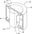
図1に示すのは、工具2を備えるプレス装置1のダイセット構造である。工具(型)2は、工具2の複雑さに応じて、少なくとも第1部分3又は第1モールドの片側と第2部分4又は第2モールドの片側、特に打抜き又はパンチングのダイ又はモールドを備える複数の板部を備える。図1において、ダイセット構造は、8で示された母型と、9で示されたダイ案内板部を備え、工具2の第1部分3及び第2部分4は、案内手段によって、閉じた位置から開いた位置へ、またその逆に開いた位置から閉じた位置へと、互いに相対的に案内される方法で移動可能である。一般に、案内手段は、高い案内精度が要求される場合に、工具又は射出成形モールドの構造物と、機械装置と、装置構造物とにおいて、使用される。
What is shown in FIG. 1 is a die set structure of a
工具2において、案内柱10を支持可能である第1部分3は、対応する案内、例えばケージ内のボール軸受によって案内柱10が導かれている案内柱10を受けるための特定の案内ブシュ12を備える第2部分4から分離可能である。
In the tool 2, the first part 3, which is capable of supporting a
ダイセット構造が成形操作に使用される場合には、工具2の閉位置に充填されている第1部分3と第2部分4との少なくとも一方の分離面にモールドを取り付けて、モールド内に押し込まれる鋳造材料のように、特に水平方向に、成形されるべき材料で充填可能である。モールドを開いた後、いわゆるプリフォームをモールドから取り外し可能である。 If the die set structure is used in a molding operation, a mold is attached to the separation surface of at least one of the first part 3 and second part 4 filled in the closed position of the tool 2 and the die set is pressed into the mold. It can be filled with the material to be shaped, especially in the horizontal direction, like a molded material. After opening the mold, the so-called preform can be removed from the mold.
さらに、ダイセット構造は、打抜きと、パンチングとの少なくとも一方に使用可能である。 Further, the die set structure can be used for die cutting and/or punching.
プレス装置1に工具2をセットする際には、表面の対と支持面の平行性を注意深く維持されなければならない。図1に示すように、工具2は、ダイ案内板部9に案内されたダイ5、特にプレス工具やパンチからさらに構成されている。この図に示すように、板部3、4の整合性からのずれ、工具2の案内のバックラッシュ、又は案内手段の支持部の角度のずれは、母型軸6の傾斜をもたらす可能性がある。さらに、案内手段、特に案内支柱10が偏向及び/又は長方形をなさなくなってきている場合には、第1部分3と第2部分4とが相互の整合性からさらにずれて、不整合が生じる可能性がある。
When setting the tool 2 in the
本発明によれば、案内柱部10のような基準部品の位置ずれを測定する測定手段が、提供される。したがって、案内柱部10の一端、例えば自由端から延在し、案内柱部軸線16と同軸に延在する長手方向の穴部14が設けられていて、この長手方向の穴部14の直径が案内柱部10の直径よりも小さくなっている。長手方向の穴部14に挿入されているのは、後に詳述する測定手段(図示せず)である。
According to the present invention, a measuring means is provided for measuring the displacement of a reference component such as the
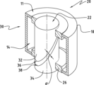
図2は、本発明の第1実施形態による測定手段20を通る縦断面の斜視図である。測定手段20は、ひずみゲージ24の形態の表面検出要素が取り付けられてひずみゲージセンサを形成する柱状構造体22を備える。測定手段20は、案内柱部10の長手方向の穴部14内に挿入され、保持要素によって案内柱部10の端部領域に固定されて取り付けられるように構成されている。したがって、柱状構造体22の端部領域には、柱状構造体22が長手方向穴部14内に完全に押し込まれたときに案内柱部10の端面11に対して当接する環状要素26が設けられ、これは、例えば圧入によって、所定の位置に固定されて取り付けられるようになっていてもよい。
FIG. 2 is a perspective view of a longitudinal section through the measuring means 20 according to the first embodiment of the invention. The measuring means 20 comprises a
柱状構造体22の外周には、少なくとも1つのひずみゲージ24が設けられている。好ましくは、2つのひずみゲージ24は、案内柱部10の偏向方向に応じて圧縮及び張力を共に検出可能に、柱部状構造物22の対向し合う両側に一対で取り付けられている。
At least one
図3は、第1実施形態と同様の要素が同等に特徴付けられる本発明の第2実施形態による測定手段20を示す。測定手段20は、第1円筒32及び第2円筒34を備える静電容量センサ30として構成されていて、第1円筒32の第1表面は、第1静電容量板部36を提供し、第2円筒34の第2表面は、距離dによって互いに分離されている第2静電容量板部38を提供する。静電容量センサ30が長手方向穴部14に任意の適切な方法で埋め込まれている案内柱部10が変形又は偏向を受けると、第1静電容量板部36と、第2静電容量板部38との少なくとも一方は、移動と回転との少なくとも一方が起こり、これは距離dに影響を与え、それによって直接、静電容量センサ30の決定された容量46に影響を与える。
FIG. 3 shows a measuring means 20 according to a second embodiment of the invention, in which similar elements as in the first embodiment are equally characterized. The measuring means 20 is configured as a
図4a及び図4bは、本発明の第3の実施形態による測定手段20を示す。図4a及び図4bは、光ファイバセンサ40が案内柱部軸16と同軸の長手方向の穴部14内に埋め込まれた案内柱部10を模式的に示す。ファイバセンサ40は、光ファイバセンサとして構成され、特に、ファブリ-ペロー干渉計のような干渉計と、光信号を電気信号に変換する変換器と、プロセッサとを持つ処理ユニット42を備える干渉計センサとして構成されている。例えば、低コヒーレンス光源(図示せず)からの光は、測定手段20の内部に配置された測定ファイバ44と参照ファイバ46とに分割される。測定ファイバ44は、屈曲時に測定ファイバ44が伸長するように測定手段20に接続されている。図4aは、案内柱部10を直線状にした状態を示す。図4bは、光ファイバセンサ40、47によって検出可能な偏向を受ける案内柱部10を示す。
Figures 4a and 4b show a measuring means 20 according to a third embodiment of the invention. 4a and 4b schematically show a
特定の、手段、材料、及び実施形態を参照して、本開示を説明したが、当該技術分野の当業者は、上述の説明から、本開示の本質的な特徴を容易に確認可能である。また、様々な変更及び修正が、特許請求の範囲に記載されているように、様々な用途及び特徴に適応させるために行われてよい。
本願発明の実施形態を別の観点で列挙する。
1) プレス装置(1)内の工具(2)の位置ずれを測定するシステムであって、
工具(2)は、案内手段に案内されて互いが相対移動可能な第1部分(3)と第2部分(4)とを少なくとも備え、
案内手段は、第1部分(3)に設けられている少なくとも案内柱部(10)を備え、その第1部分(3)が第2部分(4)内に設けられている案内ブシュ(12)に導かれていて、当該システムが、工具(2)の位置ずれを測定するために設けられている測定手段(20)を備え、
測定手段(20)が案内手段に直接設けられていることを特徴とする、当該システム。
2) 測定手段(20)が、少なくとも1つの案内柱部(10)に取り付けられている、上述の1)に記載のシステム。
3) 測定手段(20)が、少なくとも1つの案内柱部(10)内に設けられている長手方向の穴部(14)に取り付けられている、上述の1)又は2)に記載のシステム。
4) 測定手段(20)が、保持要素(26)によって、長手方向の穴部(14)内にしっかりと固定されている、上述の3)に記載のシステム。
5) 測定手段(20)が、柱状構造(22)と、柱状構造(22)に取り付けられている少なくとも1つのひずみゲージ(26)とを備えるひずみゲージセンサ(24)として作られている、上述の1)から4)のいずれか一つに記載のシステム。
6) 一対のひずみゲージ(24)が、柱状構造(22)の対向しあう側部に取り付けられている、上述の5)に記載のシステム。
7) 測定手段(20)は、第1静電容量板部(36)を持つ第1円筒部(32)と、第2静電容量板部(38)を持つ第2円筒部(34)とを、互いに距離(d)離して、備える静電容量センサ(30)として作られている、上述の1)から4)のいずれか一つに記載のシステム。
8) 測定手段(20)は、ファイバ光学センサ(40)として作られている、上述の1)から4)のいずれか一つに記載のシステム。
9) ファイバ光学センサ(40)は、干渉計センサとして、特には、低いコヒーレンス干渉計センサとして、作られている、上述の8)に記載のシステム。
10) 測定手段(20)は、工具(2)の第1部分(3)について、少なくとも案内柱部(10)の長方形をなす状態からのゆがみと、ずれとの少なくとも一方を、特には、ずれの大きさ及びずれの方向を決定すべく適合されている、上述の1)から9)のいずれか一つに記載のシステム。
11) 測定手段(20)は、工具(2)のセットアップ中のずれを決定すべく作られている、上述の1)から10)のいずれか一つに記載のシステム。
12) 測定手段(20)は、無線通信を介しての信号伝送をする処理ユニットに接続されるべく適合されている、上述の1)から11)のいずれか一つに記載のシステム。
13) 測定手段(20)は、測定手段(20)が取り付けられている、少なくとも1つの案内柱部(10)の温度を決定すべく作られている、上述の1)から12)のいずれか一つに記載のシステム。
Although the disclosure has been described with reference to specific instruments, materials, and embodiments, those skilled in the art can readily ascertain essential features of the disclosure from the foregoing description. Also, various changes and modifications may be made to adapt the invention to various uses and features, as described in the claims.
Embodiments of the present invention will be enumerated from another perspective.
1) A system for measuring positional deviation of a tool (2) in a press device (1), comprising:
The tool (2) includes at least a first portion (3) and a second portion (4) that are movable relative to each other while being guided by a guide means,
The guide means comprises at least a guide column (10) provided in a first part (3), the first part (3) of which is provided in a second part (4) of a guide bush (12). , the system comprising measuring means (20) arranged for measuring the displacement of the tool (2);
The system, characterized in that the measuring means (20) are arranged directly on the guiding means.
2) System according to 1) above, wherein the measuring means (20) are attached to at least one guide post (10).
3) System according to 1) or 2) above, wherein the measuring means (20) are mounted in a longitudinal hole (14) provided in the at least one guide post (10).
4) System according to 3) above, in which the measuring means (20) is firmly fixed in the longitudinal hole (14) by means of a retaining element (26).
5) as above, wherein the measuring means (20) are made as a strain gauge sensor (24) comprising a columnar structure (22) and at least one strain gauge (26) attached to the columnar structure (22); The system according to any one of 1) to 4).
6) The system according to 5) above, wherein a pair of strain gauges (24) are attached to opposite sides of the columnar structure (22).
7) The measuring means (20) includes a first cylindrical part (32) having a first capacitance plate part (36) and a second cylindrical part (34) having a second capacitance plate part (38). The system according to any one of 1) to 4) above, being constructed as a capacitive sensor (30) comprising, at a distance (d) apart from each other.
8) System according to any one of 1) to 4) above, wherein the measuring means (20) is made as a fiber optic sensor (40).
9) System according to 8) above, wherein the fiber optical sensor (40) is made as an interferometric sensor, in particular as a low coherence interferometric sensor.
10) The measuring means (20) measures at least one of the distortion and deviation of the guide column (10) from the rectangular state of the first portion (3) of the tool (2), particularly the deviation. The system according to any one of 1) to 9) above, adapted to determine the magnitude and direction of the deviation.
11) System according to any one of 1) to 10) above, wherein the measuring means (20) are designed to determine deviations during the set-up of the tool (2).
12) The system according to any one of 1) to 11) above, wherein the measuring means (20) is adapted to be connected to a processing unit for signal transmission via wireless communication.
13) The measuring means (20) is configured to determine the temperature of the at least one guide post (10) to which the measuring means (20) is attached, according to any one of 1) to 12) above. The system described in one.
Claims (10)
案内手段と、前記案内手段に案内されて互いが相対移動可能な第1部分(3)及び第2部分(4)を備える、前記工具(2)と、
前記工具(2)を案内する案内手段であって、前記案内手段は、前記第1部分(3)に設けられている案内柱部(10)を少なくとも1つと、前記工具(2)の前記第2部分(4)に設けられていて前記少なくとも1つの前記案内柱部(10)を受けるように構成された案内とを備える、前記案内手段と、
前記工具(2)の位置ずれを検出すべく設けられている測定手段(20)と
を備え、
前記測定手段(20)が、前記工具(2)の前記第1部分に対する前記案内柱部(10)の長方形をなす状態からの大きさ及び方向における変形と、偏向と、ずれとの中の少なくとも1つを検出すべく搭載されていること
を特徴とする、プレス装置(1)内の工具(2)の位置ずれを測定するシステム。 A system for measuring the positional deviation of a tool (2) in a press device (1), the system comprising:
the tool (2) comprising a guide means, and a first part (3) and a second part (4) that are movable relative to each other while being guided by the guide means;
A guide means for guiding the tool (2), the guide means including at least one guide column part (10) provided in the first part (3) and the guide column part (10) provided in the first part (3); said guide means comprising a guide provided in two parts (4) and configured to receive said at least one said guide post (10) ;
Measuring means (20) provided to detect a positional deviation of the tool (2);
Equipped with
The measuring means (20) causes at least one of deformation in magnitude and direction, deflection, and deviation of the guide post (10) from the rectangular state with respect to the first portion of the tool (2). A system for measuring the positional deviation of a tool (2) in a press device (1) , characterized in that it is mounted to detect one .
Applications Claiming Priority (2)
| Application Number | Priority Date | Filing Date | Title |
|---|---|---|---|
| CH12572019 | 2019-10-03 | ||
| CH01257/19 | 2019-10-03 |
Publications (3)
| Publication Number | Publication Date |
|---|---|
| JP2021058932A JP2021058932A (en) | 2021-04-15 |
| JP2021058932A5 JP2021058932A5 (en) | 2023-04-14 |
| JP7399050B2 true JP7399050B2 (en) | 2023-12-15 |
Family
ID=69190584
Family Applications (1)
| Application Number | Title | Priority Date | Filing Date |
|---|---|---|---|
| JP2020143450A Active JP7399050B2 (en) | 2019-10-03 | 2020-08-27 | Standard parts monitoring system |
Country Status (4)
| Country | Link |
|---|---|
| US (1) | US11628532B2 (en) |
| EP (1) | EP3799970B1 (en) |
| JP (1) | JP7399050B2 (en) |
| CN (1) | CN112611314A (en) |
Citations (3)
| Publication number | Priority date | Publication date | Assignee | Title |
|---|---|---|---|---|
| JP2002337000A (en) | 2001-04-05 | 2002-11-26 | Kramski Gmbh | Guide arrangement for machine tool |
| JP2013052428A (en) | 2011-09-05 | 2013-03-21 | Toyota Motor Corp | Press apparatus |
| JP6259897B1 (en) | 2016-12-02 | 2018-01-10 | 三菱長崎機工株式会社 | Press machine with screwless tie rod |
Family Cites Families (10)
| Publication number | Priority date | Publication date | Assignee | Title |
|---|---|---|---|---|
| US3425260A (en) * | 1966-08-18 | 1969-02-04 | Atlas Chain Co Ltd | Double action press tool |
| SU572318A1 (en) * | 1976-03-22 | 1977-09-15 | Паневежский Завод Точной Механики | Guiding unit of die set |
| US4491027A (en) * | 1983-01-31 | 1985-01-01 | Tetrahedron Associates, Inc. | Wide-range load cell |
| DE4415577B4 (en) * | 1994-05-03 | 2007-02-22 | Müller Weingarten AG | Device for compensation or targeted adjustment of deflections in presses of the forming technology |
| JP3645762B2 (en) * | 1999-10-18 | 2005-05-11 | トヨタ自動車株式会社 | Diagnosis method and apparatus for press machine |
| ES2585452T3 (en) * | 2006-01-13 | 2016-10-06 | Nippon Steel & Sumitomo Metal Corporation | Die molding equipment that has means to measure the amount of unit deformation |
| CA2738821C (en) * | 2008-10-07 | 2013-08-06 | Nippon Steel Corporation | Method and apparatus for judging fracture of metal stamped product, program and computer-readable recording medium |
| CN106457343B (en) * | 2014-05-19 | 2019-12-10 | 日本制铁株式会社 | press molding method and press molding die |
| JP6002205B2 (en) * | 2014-12-26 | 2016-10-05 | アイダエンジニアリング株式会社 | Cushion pad tilt confirmation device and method |
| DE102015106933A1 (en) * | 2015-05-04 | 2016-11-10 | Technische Universität Darmstadt | Machine element with a sensor device and method for producing a machine element |
-
2020
- 2020-08-27 JP JP2020143450A patent/JP7399050B2/en active Active
- 2020-08-28 US US17/005,430 patent/US11628532B2/en active Active
- 2020-09-29 EP EP20198867.2A patent/EP3799970B1/en active Active
- 2020-10-09 CN CN202011071898.3A patent/CN112611314A/en active Pending
Patent Citations (3)
| Publication number | Priority date | Publication date | Assignee | Title |
|---|---|---|---|---|
| JP2002337000A (en) | 2001-04-05 | 2002-11-26 | Kramski Gmbh | Guide arrangement for machine tool |
| JP2013052428A (en) | 2011-09-05 | 2013-03-21 | Toyota Motor Corp | Press apparatus |
| JP6259897B1 (en) | 2016-12-02 | 2018-01-10 | 三菱長崎機工株式会社 | Press machine with screwless tie rod |
Also Published As
| Publication number | Publication date |
|---|---|
| US20210101243A1 (en) | 2021-04-08 |
| EP3799970A1 (en) | 2021-04-07 |
| US11628532B2 (en) | 2023-04-18 |
| EP3799970B1 (en) | 2024-05-01 |
| JP2021058932A (en) | 2021-04-15 |
| CN112611314A (en) | 2021-04-06 |
Similar Documents
| Publication | Publication Date | Title |
|---|---|---|
| EP3076124B1 (en) | Tactile probing system | |
| JP5069106B2 (en) | Sensor module for detection head of tactile 3D coordinate measuring machine | |
| EP3111181B1 (en) | Strain-based sensing of mirror position | |
| JP2625333B2 (en) | Linear measuring device | |
| US8887584B2 (en) | Load measuring apparatus | |
| US10036766B2 (en) | Method for producing a force-measuring element | |
| CN101498571B (en) | Measuring apparatus | |
| JP3517185B2 (en) | Scale member, manufacturing method thereof, and displacement meter using the same | |
| JP7399050B2 (en) | Standard parts monitoring system | |
| US11346733B2 (en) | Measuring element, measuring system, and method of providing a measuring element for measurement forces | |
| JP4344850B2 (en) | Micro material testing equipment | |
| US7187107B2 (en) | Closed-loop feedback control positioning stage | |
| CN1916578A (en) | Strain type force sensor for multiple components | |
| JP3124659B2 (en) | Calibration method of flatness measuring device | |
| KR20180096913A (en) | 3-axis strain sensor and manufacturing method of the same | |
| JP2021058932A5 (en) | ||
| JP6333970B2 (en) | Equipment for measuring the size and / or shape of machine parts | |
| US11016115B2 (en) | Measuring device for measuring the space of two selected points on a shaping machine or handling apparatus | |
| JP2631299B2 (en) | Weight detector | |
| CN209920482U (en) | Molding machine and operating device for molding machine | |
| JP7254997B2 (en) | Measuring head and method for adjusting its temperature characteristics | |
| JP5291517B2 (en) | Inner dimension measuring instrument | |
| EP3933365A1 (en) | Force sensor assembly and a method for measuring a force | |
| JP2022120303A (en) | Coating device and blade measurement equipment | |
| KR100776391B1 (en) | Capacitance type displacement gauge and method for measuring deformation of a specimen using the same |
Legal Events
| Date | Code | Title | Description |
|---|---|---|---|
| A521 | Request for written amendment filed |
Free format text: JAPANESE INTERMEDIATE CODE: A523 Effective date: 20230406 |
|
| A621 | Written request for application examination |
Free format text: JAPANESE INTERMEDIATE CODE: A621 Effective date: 20230406 |
|
| A871 | Explanation of circumstances concerning accelerated examination |
Free format text: JAPANESE INTERMEDIATE CODE: A871 Effective date: 20230406 |
|
| A131 | Notification of reasons for refusal |
Free format text: JAPANESE INTERMEDIATE CODE: A131 Effective date: 20230705 |
|
| A521 | Request for written amendment filed |
Free format text: JAPANESE INTERMEDIATE CODE: A523 Effective date: 20230831 |
|
| TRDD | Decision of grant or rejection written | ||
| A01 | Written decision to grant a patent or to grant a registration (utility model) |
Free format text: JAPANESE INTERMEDIATE CODE: A01 Effective date: 20231115 |
|
| A61 | First payment of annual fees (during grant procedure) |
Free format text: JAPANESE INTERMEDIATE CODE: A61 Effective date: 20231205 |
|
| R150 | Certificate of patent or registration of utility model |
Ref document number: 7399050 Country of ref document: JP Free format text: JAPANESE INTERMEDIATE CODE: R150 |