JP7393875B2 - Anti-glare film, method for producing anti-glare film, optical member and image display device - Google Patents
Anti-glare film, method for producing anti-glare film, optical member and image display device Download PDFInfo
- Publication number
- JP7393875B2 JP7393875B2 JP2019075132A JP2019075132A JP7393875B2 JP 7393875 B2 JP7393875 B2 JP 7393875B2 JP 2019075132 A JP2019075132 A JP 2019075132A JP 2019075132 A JP2019075132 A JP 2019075132A JP 7393875 B2 JP7393875 B2 JP 7393875B2
- Authority
- JP
- Japan
- Prior art keywords
- glare
- layer
- film
- fine particles
- glare layer
- Prior art date
- Legal status (The legal status is an assumption and is not a legal conclusion. Google has not performed a legal analysis and makes no representation as to the accuracy of the status listed.)
- Active
Links
- 238000004519 manufacturing process Methods 0.000 title claims description 22
- 230000003287 optical effect Effects 0.000 title claims description 21
- 238000000576 coating method Methods 0.000 claims description 82
- 239000011248 coating agent Substances 0.000 claims description 81
- 229920005989 resin Polymers 0.000 claims description 80
- 239000011347 resin Substances 0.000 claims description 80
- 239000010419 fine particle Substances 0.000 claims description 67
- 239000002245 particle Substances 0.000 claims description 52
- 239000002904 solvent Substances 0.000 claims description 45
- 239000000758 substrate Substances 0.000 claims description 38
- 239000000463 material Substances 0.000 claims description 29
- 239000007788 liquid Substances 0.000 claims description 20
- 238000001035 drying Methods 0.000 claims description 12
- VYPSYNLAJGMNEJ-UHFFFAOYSA-N Silicium dioxide Chemical compound O=[Si]=O VYPSYNLAJGMNEJ-UHFFFAOYSA-N 0.000 claims description 5
- 229920002050 silicone resin Polymers 0.000 claims description 4
- 239000000377 silicon dioxide Substances 0.000 claims 2
- 239000010410 layer Substances 0.000 description 210
- 239000010408 film Substances 0.000 description 171
- 239000003795 chemical substances by application Substances 0.000 description 33
- YXFVVABEGXRONW-UHFFFAOYSA-N Toluene Chemical compound CC1=CC=CC=C1 YXFVVABEGXRONW-UHFFFAOYSA-N 0.000 description 30
- ZWEHNKRNPOVVGH-UHFFFAOYSA-N 2-Butanone Chemical compound CCC(C)=O ZWEHNKRNPOVVGH-UHFFFAOYSA-N 0.000 description 27
- 239000000243 solution Substances 0.000 description 22
- PPBRXRYQALVLMV-UHFFFAOYSA-N Styrene Chemical compound C=CC1=CC=CC=C1 PPBRXRYQALVLMV-UHFFFAOYSA-N 0.000 description 18
- 230000000052 comparative effect Effects 0.000 description 17
- 239000000945 filler Substances 0.000 description 15
- 238000000034 method Methods 0.000 description 15
- NIXOWILDQLNWCW-UHFFFAOYSA-N acrylic acid group Chemical group C(C=C)(=O)O NIXOWILDQLNWCW-UHFFFAOYSA-N 0.000 description 13
- 239000000843 powder Substances 0.000 description 13
- XEKOWRVHYACXOJ-UHFFFAOYSA-N Ethyl acetate Chemical compound CCOC(C)=O XEKOWRVHYACXOJ-UHFFFAOYSA-N 0.000 description 12
- 239000004215 Carbon black (E152) Substances 0.000 description 11
- 229930195733 hydrocarbon Natural products 0.000 description 11
- 150000002430 hydrocarbons Chemical class 0.000 description 11
- 150000002576 ketones Chemical class 0.000 description 11
- 229920003023 plastic Polymers 0.000 description 11
- 239000000047 product Substances 0.000 description 10
- CSCPPACGZOOCGX-UHFFFAOYSA-N Acetone Chemical compound CC(C)=O CSCPPACGZOOCGX-UHFFFAOYSA-N 0.000 description 9
- UHOVQNZJYSORNB-UHFFFAOYSA-N Benzene Chemical compound C1=CC=CC=C1 UHOVQNZJYSORNB-UHFFFAOYSA-N 0.000 description 9
- KFZMGEQAYNKOFK-UHFFFAOYSA-N Isopropanol Chemical compound CC(C)O KFZMGEQAYNKOFK-UHFFFAOYSA-N 0.000 description 9
- 229920006026 co-polymeric resin Polymers 0.000 description 8
- 229920003229 poly(methyl methacrylate) Polymers 0.000 description 8
- 239000004926 polymethyl methacrylate Substances 0.000 description 8
- 239000004925 Acrylic resin Substances 0.000 description 7
- 239000002985 plastic film Substances 0.000 description 7
- 230000001681 protective effect Effects 0.000 description 7
- 229920002284 Cellulose triacetate Polymers 0.000 description 6
- LFQSCWFLJHTTHZ-UHFFFAOYSA-N Ethanol Chemical compound CCO LFQSCWFLJHTTHZ-UHFFFAOYSA-N 0.000 description 6
- OKKJLVBELUTLKV-UHFFFAOYSA-N Methanol Chemical compound OC OKKJLVBELUTLKV-UHFFFAOYSA-N 0.000 description 6
- BAVYZALUXZFZLV-UHFFFAOYSA-N Methylamine Chemical compound NC BAVYZALUXZFZLV-UHFFFAOYSA-N 0.000 description 6
- CTQNGGLPUBDAKN-UHFFFAOYSA-N O-Xylene Chemical compound CC1=CC=CC=C1C CTQNGGLPUBDAKN-UHFFFAOYSA-N 0.000 description 6
- DKGAVHZHDRPRBM-UHFFFAOYSA-N Tert-Butanol Chemical compound CC(C)(C)O DKGAVHZHDRPRBM-UHFFFAOYSA-N 0.000 description 6
- ZMANZCXQSJIPKH-UHFFFAOYSA-N Triethylamine Chemical compound CCN(CC)CC ZMANZCXQSJIPKH-UHFFFAOYSA-N 0.000 description 6
- NNLVGZFZQQXQNW-ADJNRHBOSA-N [(2r,3r,4s,5r,6s)-4,5-diacetyloxy-3-[(2s,3r,4s,5r,6r)-3,4,5-triacetyloxy-6-(acetyloxymethyl)oxan-2-yl]oxy-6-[(2r,3r,4s,5r,6s)-4,5,6-triacetyloxy-2-(acetyloxymethyl)oxan-3-yl]oxyoxan-2-yl]methyl acetate Chemical compound O([C@@H]1O[C@@H]([C@H]([C@H](OC(C)=O)[C@H]1OC(C)=O)O[C@H]1[C@@H]([C@@H](OC(C)=O)[C@H](OC(C)=O)[C@@H](COC(C)=O)O1)OC(C)=O)COC(=O)C)[C@@H]1[C@@H](COC(C)=O)O[C@@H](OC(C)=O)[C@H](OC(C)=O)[C@H]1OC(C)=O NNLVGZFZQQXQNW-ADJNRHBOSA-N 0.000 description 6
- 239000000853 adhesive Substances 0.000 description 6
- 230000001070 adhesive effect Effects 0.000 description 6
- 239000000203 mixture Substances 0.000 description 6
- 229920000098 polyolefin Polymers 0.000 description 6
- 239000002994 raw material Substances 0.000 description 6
- NIXOWILDQLNWCW-UHFFFAOYSA-M Acrylate Chemical compound [O-]C(=O)C=C NIXOWILDQLNWCW-UHFFFAOYSA-M 0.000 description 5
- NTIZESTWPVYFNL-UHFFFAOYSA-N Methyl isobutyl ketone Chemical compound CC(C)CC(C)=O NTIZESTWPVYFNL-UHFFFAOYSA-N 0.000 description 5
- UIHCLUNTQKBZGK-UHFFFAOYSA-N Methyl isobutyl ketone Natural products CCC(C)C(C)=O UIHCLUNTQKBZGK-UHFFFAOYSA-N 0.000 description 5
- 230000002776 aggregation Effects 0.000 description 5
- 150000004945 aromatic hydrocarbons Chemical class 0.000 description 5
- 239000004927 clay Substances 0.000 description 5
- BGTOWKSIORTVQH-UHFFFAOYSA-N cyclopentanone Chemical compound O=C1CCCC1 BGTOWKSIORTVQH-UHFFFAOYSA-N 0.000 description 5
- 239000003085 diluting agent Substances 0.000 description 5
- 239000004973 liquid crystal related substance Substances 0.000 description 5
- 238000002834 transmittance Methods 0.000 description 5
- 150000003672 ureas Chemical class 0.000 description 5
- KWOLFJPFCHCOCG-UHFFFAOYSA-N Acetophenone Chemical compound CC(=O)C1=CC=CC=C1 KWOLFJPFCHCOCG-UHFFFAOYSA-N 0.000 description 4
- 229920000178 Acrylic resin Polymers 0.000 description 4
- YNQLUTRBYVCPMQ-UHFFFAOYSA-N Ethylbenzene Chemical compound CCC1=CC=CC=C1 YNQLUTRBYVCPMQ-UHFFFAOYSA-N 0.000 description 4
- URLKBWYHVLBVBO-UHFFFAOYSA-N Para-Xylene Chemical group CC1=CC=C(C)C=C1 URLKBWYHVLBVBO-UHFFFAOYSA-N 0.000 description 4
- JHIVVAPYMSGYDF-UHFFFAOYSA-N cyclohexanone Chemical compound O=C1CCCCC1 JHIVVAPYMSGYDF-UHFFFAOYSA-N 0.000 description 4
- HJOVHMDZYOCNQW-UHFFFAOYSA-N isophorone Chemical compound CC1=CC(=O)CC(C)(C)C1 HJOVHMDZYOCNQW-UHFFFAOYSA-N 0.000 description 4
- IVSZLXZYQVIEFR-UHFFFAOYSA-N m-xylene Chemical group CC1=CC=CC(C)=C1 IVSZLXZYQVIEFR-UHFFFAOYSA-N 0.000 description 4
- 238000005259 measurement Methods 0.000 description 4
- CERQOIWHTDAKMF-UHFFFAOYSA-M methacrylate group Chemical group C(C(=C)C)(=O)[O-] CERQOIWHTDAKMF-UHFFFAOYSA-M 0.000 description 4
- FDPIMTJIUBPUKL-UHFFFAOYSA-N pentan-3-one Chemical compound CCC(=O)CC FDPIMTJIUBPUKL-UHFFFAOYSA-N 0.000 description 4
- 238000012360 testing method Methods 0.000 description 4
- 239000010936 titanium Substances 0.000 description 4
- DKPFZGUDAPQIHT-UHFFFAOYSA-N Butyl acetate Natural products CCCCOC(C)=O DKPFZGUDAPQIHT-UHFFFAOYSA-N 0.000 description 3
- LYCAIKOWRPUZTN-UHFFFAOYSA-N Ethylene glycol Chemical compound OCCO LYCAIKOWRPUZTN-UHFFFAOYSA-N 0.000 description 3
- DNIAPMSPPWPWGF-UHFFFAOYSA-N Propylene glycol Chemical compound CC(O)CO DNIAPMSPPWPWGF-UHFFFAOYSA-N 0.000 description 3
- 239000012790 adhesive layer Substances 0.000 description 3
- 238000004220 aggregation Methods 0.000 description 3
- 239000011247 coating layer Substances 0.000 description 3
- 210000002858 crystal cell Anatomy 0.000 description 3
- FUZZWVXGSFPDMH-UHFFFAOYSA-M hexanoate Chemical compound CCCCCC([O-])=O FUZZWVXGSFPDMH-UHFFFAOYSA-M 0.000 description 3
- 150000003949 imides Chemical class 0.000 description 3
- VLKZOEOYAKHREP-UHFFFAOYSA-N n-Hexane Chemical compound CCCCCC VLKZOEOYAKHREP-UHFFFAOYSA-N 0.000 description 3
- 239000000126 substance Substances 0.000 description 3
- 229920001187 thermosetting polymer Polymers 0.000 description 3
- 239000002562 thickening agent Substances 0.000 description 3
- ARXJGSRGQADJSQ-UHFFFAOYSA-N 1-methoxypropan-2-ol Chemical compound COCC(C)O ARXJGSRGQADJSQ-UHFFFAOYSA-N 0.000 description 2
- VTYYLEPIZMXCLO-UHFFFAOYSA-L Calcium carbonate Chemical compound [Ca+2].[O-]C([O-])=O VTYYLEPIZMXCLO-UHFFFAOYSA-L 0.000 description 2
- LRHPLDYGYMQRHN-UHFFFAOYSA-N N-Butanol Chemical compound CCCCO LRHPLDYGYMQRHN-UHFFFAOYSA-N 0.000 description 2
- IMNFDUFMRHMDMM-UHFFFAOYSA-N N-Heptane Chemical compound CCCCCCC IMNFDUFMRHMDMM-UHFFFAOYSA-N 0.000 description 2
- 239000004820 Pressure-sensitive adhesive Substances 0.000 description 2
- XLOMVQKBTHCTTD-UHFFFAOYSA-N Zinc monoxide Chemical compound [Zn]=O XLOMVQKBTHCTTD-UHFFFAOYSA-N 0.000 description 2
- HVVWZTWDBSEWIH-UHFFFAOYSA-N [2-(hydroxymethyl)-3-prop-2-enoyloxy-2-(prop-2-enoyloxymethyl)propyl] prop-2-enoate Chemical compound C=CC(=O)OCC(CO)(COC(=O)C=C)COC(=O)C=C HVVWZTWDBSEWIH-UHFFFAOYSA-N 0.000 description 2
- 150000001252 acrylic acid derivatives Chemical class 0.000 description 2
- 239000000654 additive Substances 0.000 description 2
- 238000005054 agglomeration Methods 0.000 description 2
- 230000004931 aggregating effect Effects 0.000 description 2
- 239000012298 atmosphere Substances 0.000 description 2
- TZCXTZWJZNENPQ-UHFFFAOYSA-L barium sulfate Chemical compound [Ba+2].[O-]S([O-])(=O)=O TZCXTZWJZNENPQ-UHFFFAOYSA-L 0.000 description 2
- OSGAYBCDTDRGGQ-UHFFFAOYSA-L calcium sulfate Chemical compound [Ca+2].[O-]S([O-])(=O)=O OSGAYBCDTDRGGQ-UHFFFAOYSA-L 0.000 description 2
- 238000010523 cascade reaction Methods 0.000 description 2
- 150000001875 compounds Chemical class 0.000 description 2
- 230000001186 cumulative effect Effects 0.000 description 2
- 230000003247 decreasing effect Effects 0.000 description 2
- 230000007547 defect Effects 0.000 description 2
- IEJIGPNLZYLLBP-UHFFFAOYSA-N dimethyl carbonate Chemical compound COC(=O)OC IEJIGPNLZYLLBP-UHFFFAOYSA-N 0.000 description 2
- UHESRSKEBRADOO-UHFFFAOYSA-N ethyl carbamate;prop-2-enoic acid Chemical compound OC(=O)C=C.CCOC(N)=O UHESRSKEBRADOO-UHFFFAOYSA-N 0.000 description 2
- 238000001125 extrusion Methods 0.000 description 2
- 238000010438 heat treatment Methods 0.000 description 2
- 239000003999 initiator Substances 0.000 description 2
- 239000011159 matrix material Substances 0.000 description 2
- 230000007246 mechanism Effects 0.000 description 2
- QSHDDOUJBYECFT-UHFFFAOYSA-N mercury Chemical compound [Hg] QSHDDOUJBYECFT-UHFFFAOYSA-N 0.000 description 2
- 229910052753 mercury Inorganic materials 0.000 description 2
- 150000002734 metacrylic acid derivatives Chemical class 0.000 description 2
- 230000000474 nursing effect Effects 0.000 description 2
- 229940078552 o-xylene Drugs 0.000 description 2
- 239000008188 pellet Substances 0.000 description 2
- 230000035699 permeability Effects 0.000 description 2
- 229920001225 polyester resin Polymers 0.000 description 2
- 239000004645 polyester resin Substances 0.000 description 2
- -1 polyhydric alcohols Chemical class 0.000 description 2
- 239000011148 porous material Substances 0.000 description 2
- 239000011241 protective layer Substances 0.000 description 2
- 239000012798 spherical particle Substances 0.000 description 2
- 239000010409 thin film Substances 0.000 description 2
- 239000013008 thixotropic agent Substances 0.000 description 2
- 230000009974 thixotropic effect Effects 0.000 description 2
- 239000012224 working solution Substances 0.000 description 2
- 239000008096 xylene Substances 0.000 description 2
- JYEUMXHLPRZUAT-UHFFFAOYSA-N 1,2,3-triazine Chemical compound C1=CN=NN=C1 JYEUMXHLPRZUAT-UHFFFAOYSA-N 0.000 description 1
- XNWFRZJHXBZDAG-UHFFFAOYSA-N 2-METHOXYETHANOL Chemical compound COCCO XNWFRZJHXBZDAG-UHFFFAOYSA-N 0.000 description 1
- POAOYUHQDCAZBD-UHFFFAOYSA-N 2-butoxyethanol Chemical compound CCCCOCCO POAOYUHQDCAZBD-UHFFFAOYSA-N 0.000 description 1
- ZNQVEEAIQZEUHB-UHFFFAOYSA-N 2-ethoxyethanol Chemical compound CCOCCO ZNQVEEAIQZEUHB-UHFFFAOYSA-N 0.000 description 1
- LWRBVKNFOYUCNP-UHFFFAOYSA-N 2-methyl-1-(4-methylsulfanylphenyl)-2-morpholin-4-ylpropan-1-one Chemical compound C1=CC(SC)=CC=C1C(=O)C(C)(C)N1CCOCC1 LWRBVKNFOYUCNP-UHFFFAOYSA-N 0.000 description 1
- NZWQIIXJBLUGCX-UHFFFAOYSA-N 2-methylprop-2-enoic acid 1,3,5-triazinane-2,4,6-trione Chemical compound CC(=C)C(O)=O.O=C1NC(=O)NC(=O)N1 NZWQIIXJBLUGCX-UHFFFAOYSA-N 0.000 description 1
- FJKROLUGYXJWQN-UHFFFAOYSA-N 4-hydroxybenzoic acid Chemical compound OC(=O)C1=CC=C(O)C=C1 FJKROLUGYXJWQN-UHFFFAOYSA-N 0.000 description 1
- NDWUBGAGUCISDV-UHFFFAOYSA-N 4-hydroxybutyl prop-2-enoate Chemical compound OCCCCOC(=O)C=C NDWUBGAGUCISDV-UHFFFAOYSA-N 0.000 description 1
- GZVHEAJQGPRDLQ-UHFFFAOYSA-N 6-phenyl-1,3,5-triazine-2,4-diamine Chemical compound NC1=NC(N)=NC(C=2C=CC=CC=2)=N1 GZVHEAJQGPRDLQ-UHFFFAOYSA-N 0.000 description 1
- 239000005995 Aluminium silicate Substances 0.000 description 1
- RGSFGYAAUTVSQA-UHFFFAOYSA-N Cyclopentane Chemical compound C1CCCC1 RGSFGYAAUTVSQA-UHFFFAOYSA-N 0.000 description 1
- ZAFNJMIOTHYJRJ-UHFFFAOYSA-N Diisopropyl ether Chemical compound CC(C)OC(C)C ZAFNJMIOTHYJRJ-UHFFFAOYSA-N 0.000 description 1
- YCKRFDGAMUMZLT-UHFFFAOYSA-N Fluorine atom Chemical compound [F] YCKRFDGAMUMZLT-UHFFFAOYSA-N 0.000 description 1
- 241000871495 Heeria argentea Species 0.000 description 1
- HEFNNWSXXWATRW-UHFFFAOYSA-N Ibuprofen Chemical compound CC(C)CC1=CC=C(C(C)C(O)=O)C=C1 HEFNNWSXXWATRW-UHFFFAOYSA-N 0.000 description 1
- 239000004640 Melamine resin Substances 0.000 description 1
- 229920000877 Melamine resin Polymers 0.000 description 1
- AMLMZFCHLPFOEL-UHFFFAOYSA-N OC(=O)C=C.O=C1NC(=O)NC(=O)N1 Chemical compound OC(=O)C=C.O=C1NC(=O)NC(=O)N1 AMLMZFCHLPFOEL-UHFFFAOYSA-N 0.000 description 1
- 239000005062 Polybutadiene Substances 0.000 description 1
- 239000004721 Polyphenylene oxide Substances 0.000 description 1
- XBDQKXXYIPTUBI-UHFFFAOYSA-M Propionate Chemical compound CCC([O-])=O XBDQKXXYIPTUBI-UHFFFAOYSA-M 0.000 description 1
- 229920000297 Rayon Polymers 0.000 description 1
- GWEVSGVZZGPLCZ-UHFFFAOYSA-N Titan oxide Chemical compound O=[Ti]=O GWEVSGVZZGPLCZ-UHFFFAOYSA-N 0.000 description 1
- 239000006096 absorbing agent Substances 0.000 description 1
- 238000010521 absorption reaction Methods 0.000 description 1
- KXKVLQRXCPHEJC-UHFFFAOYSA-N acetic acid trimethyl ester Natural products COC(C)=O KXKVLQRXCPHEJC-UHFFFAOYSA-N 0.000 description 1
- 239000002253 acid Substances 0.000 description 1
- 238000007605 air drying Methods 0.000 description 1
- 150000001298 alcohols Chemical class 0.000 description 1
- 150000001338 aliphatic hydrocarbons Chemical class 0.000 description 1
- 229920000180 alkyd Polymers 0.000 description 1
- ZIXLDMFVRPABBX-UHFFFAOYSA-N alpha-methylcyclopentanone Natural products CC1CCCC1=O ZIXLDMFVRPABBX-UHFFFAOYSA-N 0.000 description 1
- 235000012211 aluminium silicate Nutrition 0.000 description 1
- 150000001412 amines Chemical class 0.000 description 1
- 230000003373 anti-fouling effect Effects 0.000 description 1
- 239000002519 antifouling agent Substances 0.000 description 1
- 239000003963 antioxidant agent Substances 0.000 description 1
- 239000011324 bead Substances 0.000 description 1
- 230000008901 benefit Effects 0.000 description 1
- 239000011230 binding agent Substances 0.000 description 1
- 230000005540 biological transmission Effects 0.000 description 1
- 238000007664 blowing Methods 0.000 description 1
- UBLMQJHQMRREBE-UHFFFAOYSA-N butane-1,1-diol;propane-1,2,3-triol Chemical compound CCCC(O)O.OCC(O)CO UBLMQJHQMRREBE-UHFFFAOYSA-N 0.000 description 1
- 239000006227 byproduct Substances 0.000 description 1
- 229910000019 calcium carbonate Inorganic materials 0.000 description 1
- 238000007385 chemical modification Methods 0.000 description 1
- 238000006243 chemical reaction Methods 0.000 description 1
- 239000007795 chemical reaction product Substances 0.000 description 1
- 239000003153 chemical reaction reagent Substances 0.000 description 1
- 238000004040 coloring Methods 0.000 description 1
- 229920001577 copolymer Polymers 0.000 description 1
- 125000004122 cyclic group Chemical group 0.000 description 1
- 230000006866 deterioration Effects 0.000 description 1
- 125000004386 diacrylate group Chemical group 0.000 description 1
- GUJOJGAPFQRJSV-UHFFFAOYSA-N dialuminum;dioxosilane;oxygen(2-);hydrate Chemical compound O.[O-2].[O-2].[O-2].[Al+3].[Al+3].O=[Si]=O.O=[Si]=O.O=[Si]=O.O=[Si]=O GUJOJGAPFQRJSV-UHFFFAOYSA-N 0.000 description 1
- 238000007607 die coating method Methods 0.000 description 1
- 238000007865 diluting Methods 0.000 description 1
- 239000002270 dispersing agent Substances 0.000 description 1
- 238000009826 distribution Methods 0.000 description 1
- 230000000694 effects Effects 0.000 description 1
- 239000008151 electrolyte solution Substances 0.000 description 1
- 238000010894 electron beam technology Methods 0.000 description 1
- 239000003822 epoxy resin Substances 0.000 description 1
- 150000002148 esters Chemical class 0.000 description 1
- RTZKZFJDLAIYFH-UHFFFAOYSA-N ether Substances CCOCC RTZKZFJDLAIYFH-UHFFFAOYSA-N 0.000 description 1
- 150000002170 ethers Chemical class 0.000 description 1
- 229910052731 fluorine Inorganic materials 0.000 description 1
- 239000011737 fluorine Substances 0.000 description 1
- 230000004313 glare Effects 0.000 description 1
- 239000011521 glass Substances 0.000 description 1
- 150000002334 glycols Chemical class 0.000 description 1
- 238000007756 gravure coating Methods 0.000 description 1
- LNEPOXFFQSENCJ-UHFFFAOYSA-N haloperidol Chemical compound C1CC(O)(C=2C=CC(Cl)=CC=2)CCN1CCCC(=O)C1=CC=C(F)C=C1 LNEPOXFFQSENCJ-UHFFFAOYSA-N 0.000 description 1
- 239000011229 interlayer Substances 0.000 description 1
- 230000001678 irradiating effect Effects 0.000 description 1
- 239000012948 isocyanate Substances 0.000 description 1
- 150000002513 isocyanates Chemical class 0.000 description 1
- NLYAJNPCOHFWQQ-UHFFFAOYSA-N kaolin Chemical compound O.O.O=[Al]O[Si](=O)O[Si](=O)O[Al]=O NLYAJNPCOHFWQQ-UHFFFAOYSA-N 0.000 description 1
- 238000010030 laminating Methods 0.000 description 1
- 238000000691 measurement method Methods 0.000 description 1
- GDOPTJXRTPNYNR-UHFFFAOYSA-N methyl-cyclopentane Natural products CC1CCCC1 GDOPTJXRTPNYNR-UHFFFAOYSA-N 0.000 description 1
- 239000011259 mixed solution Substances 0.000 description 1
- 238000002156 mixing Methods 0.000 description 1
- 239000000178 monomer Substances 0.000 description 1
- 125000003518 norbornenyl group Chemical group C12(C=CC(CC1)C2)* 0.000 description 1
- TVMXDCGIABBOFY-UHFFFAOYSA-N octane Chemical compound CCCCCCCC TVMXDCGIABBOFY-UHFFFAOYSA-N 0.000 description 1
- TWNQGVIAIRXVLR-UHFFFAOYSA-N oxo(oxoalumanyloxy)alumane Chemical compound O=[Al]O[Al]=O TWNQGVIAIRXVLR-UHFFFAOYSA-N 0.000 description 1
- 239000012466 permeate Substances 0.000 description 1
- 239000000049 pigment Substances 0.000 description 1
- 239000004014 plasticizer Substances 0.000 description 1
- 229920000058 polyacrylate Polymers 0.000 description 1
- 229920006122 polyamide resin Polymers 0.000 description 1
- 229920002857 polybutadiene Polymers 0.000 description 1
- 239000004417 polycarbonate Substances 0.000 description 1
- 229920000515 polycarbonate Polymers 0.000 description 1
- 229920005668 polycarbonate resin Polymers 0.000 description 1
- 239000004431 polycarbonate resin Substances 0.000 description 1
- 150000004291 polyenes Chemical class 0.000 description 1
- 229920000647 polyepoxide Polymers 0.000 description 1
- 229920000570 polyether Polymers 0.000 description 1
- 229920001721 polyimide Polymers 0.000 description 1
- 239000009719 polyimide resin Substances 0.000 description 1
- 229920001296 polysiloxane Polymers 0.000 description 1
- 229920005990 polystyrene resin Polymers 0.000 description 1
- 229920006295 polythiol Polymers 0.000 description 1
- IFIDXBCRSWOUSB-UHFFFAOYSA-M potassium;1,5-dichloro-4,6-dioxo-1,3,5-triazin-2-olate Chemical compound [K+].ClN1C(=O)[N-]C(=O)N(Cl)C1=O IFIDXBCRSWOUSB-UHFFFAOYSA-M 0.000 description 1
- 230000009467 reduction Effects 0.000 description 1
- 238000011160 research Methods 0.000 description 1
- 238000004062 sedimentation Methods 0.000 description 1
- 229910052814 silicon oxide Inorganic materials 0.000 description 1
- 239000007787 solid Substances 0.000 description 1
- 238000004528 spin coating Methods 0.000 description 1
- 238000005507 spraying Methods 0.000 description 1
- 150000005846 sugar alcohols Polymers 0.000 description 1
- 238000004381 surface treatment Methods 0.000 description 1
- 239000004094 surface-active agent Substances 0.000 description 1
- 239000000454 talc Substances 0.000 description 1
- 229910052623 talc Inorganic materials 0.000 description 1
- 229920002803 thermoplastic polyurethane Polymers 0.000 description 1
- XOLBLPGZBRYERU-UHFFFAOYSA-N tin dioxide Chemical compound O=[Sn]=O XOLBLPGZBRYERU-UHFFFAOYSA-N 0.000 description 1
- 229910001887 tin oxide Inorganic materials 0.000 description 1
- OGIDPMRJRNCKJF-UHFFFAOYSA-N titanium oxide Inorganic materials [Ti]=O OGIDPMRJRNCKJF-UHFFFAOYSA-N 0.000 description 1
- 238000000411 transmission spectrum Methods 0.000 description 1
- 238000011282 treatment Methods 0.000 description 1
- 239000006097 ultraviolet radiation absorber Substances 0.000 description 1
- 229940042596 viscoat Drugs 0.000 description 1
- XLYOFNOQVPJJNP-UHFFFAOYSA-N water Substances O XLYOFNOQVPJJNP-UHFFFAOYSA-N 0.000 description 1
- 239000011787 zinc oxide Substances 0.000 description 1
Images


Classifications
-
- G—PHYSICS
- G02—OPTICS
- G02B—OPTICAL ELEMENTS, SYSTEMS OR APPARATUS
- G02B1/00—Optical elements characterised by the material of which they are made; Optical coatings for optical elements
- G02B1/10—Optical coatings produced by application to, or surface treatment of, optical elements
- G02B1/11—Anti-reflection coatings
-
- B—PERFORMING OPERATIONS; TRANSPORTING
- B32—LAYERED PRODUCTS
- B32B—LAYERED PRODUCTS, i.e. PRODUCTS BUILT-UP OF STRATA OF FLAT OR NON-FLAT, e.g. CELLULAR OR HONEYCOMB, FORM
- B32B27/00—Layered products comprising a layer of synthetic resin
- B32B27/18—Layered products comprising a layer of synthetic resin characterised by the use of special additives
-
- B—PERFORMING OPERATIONS; TRANSPORTING
- B32—LAYERED PRODUCTS
- B32B—LAYERED PRODUCTS, i.e. PRODUCTS BUILT-UP OF STRATA OF FLAT OR NON-FLAT, e.g. CELLULAR OR HONEYCOMB, FORM
- B32B7/00—Layered products characterised by the relation between layers; Layered products characterised by the relative orientation of features between layers, or by the relative values of a measurable parameter between layers, i.e. products comprising layers having different physical, chemical or physicochemical properties; Layered products characterised by the interconnection of layers
- B32B7/02—Physical, chemical or physicochemical properties
- B32B7/023—Optical properties
-
- C—CHEMISTRY; METALLURGY
- C08—ORGANIC MACROMOLECULAR COMPOUNDS; THEIR PREPARATION OR CHEMICAL WORKING-UP; COMPOSITIONS BASED THEREON
- C08J—WORKING-UP; GENERAL PROCESSES OF COMPOUNDING; AFTER-TREATMENT NOT COVERED BY SUBCLASSES C08B, C08C, C08F, C08G or C08H
- C08J7/00—Chemical treatment or coating of shaped articles made of macromolecular substances
- C08J7/04—Coating
-
- G—PHYSICS
- G02—OPTICS
- G02B—OPTICAL ELEMENTS, SYSTEMS OR APPARATUS
- G02B5/00—Optical elements other than lenses
- G02B5/02—Diffusing elements; Afocal elements
-
- G—PHYSICS
- G02—OPTICS
- G02B—OPTICAL ELEMENTS, SYSTEMS OR APPARATUS
- G02B5/00—Optical elements other than lenses
- G02B5/02—Diffusing elements; Afocal elements
- G02B5/0205—Diffusing elements; Afocal elements characterised by the diffusing properties
- G02B5/021—Diffusing elements; Afocal elements characterised by the diffusing properties the diffusion taking place at the element's surface, e.g. by means of surface roughening or microprismatic structures
- G02B5/0226—Diffusing elements; Afocal elements characterised by the diffusing properties the diffusion taking place at the element's surface, e.g. by means of surface roughening or microprismatic structures having particles on the surface
-
- G—PHYSICS
- G02—OPTICS
- G02B—OPTICAL ELEMENTS, SYSTEMS OR APPARATUS
- G02B5/00—Optical elements other than lenses
- G02B5/02—Diffusing elements; Afocal elements
- G02B5/0273—Diffusing elements; Afocal elements characterized by the use
- G02B5/0294—Diffusing elements; Afocal elements characterized by the use adapted to provide an additional optical effect, e.g. anti-reflection or filter
-
- G—PHYSICS
- G02—OPTICS
- G02B—OPTICAL ELEMENTS, SYSTEMS OR APPARATUS
- G02B5/00—Optical elements other than lenses
- G02B5/30—Polarising elements
-
- G—PHYSICS
- G02—OPTICS
- G02B—OPTICAL ELEMENTS, SYSTEMS OR APPARATUS
- G02B5/00—Optical elements other than lenses
- G02B5/30—Polarising elements
- G02B5/3025—Polarisers, i.e. arrangements capable of producing a definite output polarisation state from an unpolarised input state
- G02B5/3033—Polarisers, i.e. arrangements capable of producing a definite output polarisation state from an unpolarised input state in the form of a thin sheet or foil, e.g. Polaroid
-
- G—PHYSICS
- G02—OPTICS
- G02F—OPTICAL DEVICES OR ARRANGEMENTS FOR THE CONTROL OF LIGHT BY MODIFICATION OF THE OPTICAL PROPERTIES OF THE MEDIA OF THE ELEMENTS INVOLVED THEREIN; NON-LINEAR OPTICS; FREQUENCY-CHANGING OF LIGHT; OPTICAL LOGIC ELEMENTS; OPTICAL ANALOGUE/DIGITAL CONVERTERS
- G02F1/00—Devices or arrangements for the control of the intensity, colour, phase, polarisation or direction of light arriving from an independent light source, e.g. switching, gating or modulating; Non-linear optics
- G02F1/01—Devices or arrangements for the control of the intensity, colour, phase, polarisation or direction of light arriving from an independent light source, e.g. switching, gating or modulating; Non-linear optics for the control of the intensity, phase, polarisation or colour
- G02F1/13—Devices or arrangements for the control of the intensity, colour, phase, polarisation or direction of light arriving from an independent light source, e.g. switching, gating or modulating; Non-linear optics for the control of the intensity, phase, polarisation or colour based on liquid crystals, e.g. single liquid crystal display cells
- G02F1/133—Constructional arrangements; Operation of liquid crystal cells; Circuit arrangements
- G02F1/1333—Constructional arrangements; Manufacturing methods
- G02F1/1335—Structural association of cells with optical devices, e.g. polarisers or reflectors
- G02F1/133502—Antiglare, refractive index matching layers
-
- G—PHYSICS
- G02—OPTICS
- G02F—OPTICAL DEVICES OR ARRANGEMENTS FOR THE CONTROL OF LIGHT BY MODIFICATION OF THE OPTICAL PROPERTIES OF THE MEDIA OF THE ELEMENTS INVOLVED THEREIN; NON-LINEAR OPTICS; FREQUENCY-CHANGING OF LIGHT; OPTICAL LOGIC ELEMENTS; OPTICAL ANALOGUE/DIGITAL CONVERTERS
- G02F1/00—Devices or arrangements for the control of the intensity, colour, phase, polarisation or direction of light arriving from an independent light source, e.g. switching, gating or modulating; Non-linear optics
- G02F1/01—Devices or arrangements for the control of the intensity, colour, phase, polarisation or direction of light arriving from an independent light source, e.g. switching, gating or modulating; Non-linear optics for the control of the intensity, phase, polarisation or colour
- G02F1/13—Devices or arrangements for the control of the intensity, colour, phase, polarisation or direction of light arriving from an independent light source, e.g. switching, gating or modulating; Non-linear optics for the control of the intensity, phase, polarisation or colour based on liquid crystals, e.g. single liquid crystal display cells
- G02F1/133—Constructional arrangements; Operation of liquid crystal cells; Circuit arrangements
- G02F1/1333—Constructional arrangements; Manufacturing methods
- G02F1/1335—Structural association of cells with optical devices, e.g. polarisers or reflectors
- G02F1/133528—Polarisers
Description
本発明は、防眩性フィルム、防眩性フィルムの製造方法、光学部材および画像表示装置に関する。 The present invention relates to an anti-glare film, a method for producing an anti-glare film, an optical member, and an image display device.
陰極管表示装置(CRT)、液晶表示装置(LCD)、プラズマディスプレイパネル(PDP)およびエレクトロルミネッセンスディスプレイ(ELD)等の、様々な画像表示装置には、前記画像表示装置表面における蛍光灯や太陽光等の外光の反射や像の映り込みによるコントラスト低下を防止するための防眩(アンチグレア)処理が施され、特に、画像表示装置の大画面化が進むのに伴い、防眩性のフィルムを装着した画像表示装置が増大している。 Various image display devices, such as a cathode tube display (CRT), a liquid crystal display (LCD), a plasma display panel (PDP), and an electroluminescent display (ELD), are equipped with fluorescent lamps or sunlight on the surface of the image display device. Anti-glare films are used to prevent contrast reduction due to the reflection of external light and image reflections.In particular, as the screens of image display devices become larger, anti-glare films are being used. The number of image display devices worn is increasing.
防眩性フィルムについて記載された文献は多数あるが、例えば、特許文献1および2等がある。 There are many documents describing anti-glare films, for example, Patent Documents 1 and 2.
防眩性フィルムは、視認性の観点から、外光の反射による映り込みが抑制されている必要がある。 From the viewpoint of visibility, the anti-glare film needs to suppress glare caused by reflection of external light.
例えば、近年、パブリックインフォメーションディスプレイ(PID)の需要が増えてきている。PIDは、屋外で使用される場合も多い。屋外でディスプレイ(画像表示装置)を使用した場合、屋内での使用よりも、外光の反射による映り込みが起こりやすい。映り込みが起こった場合、映像が視認しづらくなるおそれがある。 For example, demand for public information displays (PIDs) has been increasing in recent years. PIDs are often used outdoors. When a display (image display device) is used outdoors, reflections from outside light are more likely to occur than when used indoors. If reflection occurs, the image may become difficult to view.
そこで、本発明は、映り込みが抑制された防眩性フィルム、防眩性フィルムの製造方法、光学部材および画像表示装置の提供を目的とする。 SUMMARY OF THE INVENTION Therefore, an object of the present invention is to provide an anti-glare film in which reflections are suppressed, a method for producing an anti-glare film, an optical member, and an image display device.
前記目的を達成するために、本発明の防眩性フィルムは、
光透過性基材(A)上に防眩層(B)が積層された防眩性フィルムであって、
前記防眩性フィルムにおける前記防眩層(B)側の最表面に凹凸が形成され、
前記凹凸が、下記数式(1)および(2)を満たすことを特徴とする。
Ry≧1.7 (1)
θa≧0.7 (2)
前記数式(1)において、Ryは、前記凹凸の凸部の最大高さ[μm]であり、
前記数式(2)において、θaは、前記凹凸の平均傾斜角[°]である。
In order to achieve the above object, the anti-glare film of the present invention has the following features:
An anti-glare film in which an anti-glare layer (B) is laminated on a light-transparent substrate (A),
Irregularities are formed on the outermost surface of the anti-glare layer (B) side of the anti-glare film,
The unevenness is characterized in that it satisfies the following formulas (1) and (2).
Ry≧1.7 (1)
θa≧0.7 (2)
In the formula (1), Ry is the maximum height [μm] of the convex portion of the unevenness,
In the formula (2), θa is the average inclination angle [°] of the unevenness.
本発明の防眩性フィルムの製造方法は、
前記光透過性基材(A)上に、前記防眩層(B)を、前記数式(1)および(2)を満たすように形成する防眩層(B)形成工程を含み、
前記防眩層(B)形成工程が、前記光透過性基材(A)上に塗工液を塗工する塗工工程と、塗工した前記塗工液を乾燥させて塗膜を形成する塗膜形成工程とを含み、
前記塗工液が、樹脂と、溶媒とを含むことを特徴とする本発明の防眩性フィルムの製造方法である。
The method for producing an anti-glare film of the present invention includes:
A step of forming an anti-glare layer (B) in which the anti-glare layer (B) is formed on the light-transmissive substrate (A) so as to satisfy the formulas (1) and (2),
The anti-glare layer (B) forming step includes a coating step of coating a coating solution on the light-transmitting substrate (A), and drying the applied coating solution to form a coating film. A coating film forming step,
The method for producing an anti-glare film of the present invention is characterized in that the coating liquid contains a resin and a solvent.
本発明の光学部材は、本発明の防眩性フィルムを含む光学部材である。 The optical member of the present invention is an optical member containing the antiglare film of the present invention.
本発明の画像表示装置は、本発明の防眩性フィルム、または本発明の光学部材を含む画像表示装置である。 The image display device of the present invention is an image display device including the antiglare film of the present invention or the optical member of the present invention.
本発明によれば、映り込みが抑制された防眩性フィルム、光学部材および画像表示装置を提供することができる。 According to the present invention, it is possible to provide an anti-glare film, an optical member, and an image display device in which reflection is suppressed.
つぎに、本発明について、例を挙げてさらに具体的に説明する。ただし、本発明は、以下の説明により、なんら限定されない。 Next, the present invention will be explained in more detail by giving examples. However, the present invention is not limited in any way by the following explanation.
本発明の防眩性フィルムは、例えば、前記防眩層(B)が微粒子を含んでいてもよい。 In the antiglare film of the present invention, for example, the antiglare layer (B) may contain fine particles.
本発明の防眩性フィルムは、例えば、前記防眩層(B)における、前記光透過性基材(A)と反対側の面上に凹凸が形成され、前記微粒子の重量平均粒子径が、前記防眩層(B)の最大厚みから前記凹凸の凸部の最大高さを差し引いた厚みよりも大きくてもよい。 In the anti-glare film of the present invention, for example, irregularities are formed on the surface of the anti-glare layer (B) opposite to the light-transmitting substrate (A), and the weight average particle diameter of the fine particles is It may be larger than the maximum thickness of the anti-glare layer (B) minus the maximum height of the convex portions of the unevenness.
本発明の防眩性フィルムは、例えば、前記微粒子の重量平均粒子径が、4~9μmの範囲であってもよい。 In the antiglare film of the present invention, for example, the fine particles may have a weight average particle diameter in the range of 4 to 9 μm.
本発明の防眩性フィルムは、例えば、前記防眩層(B)における前記光透過性基材(A)と反対側の面上に、さらに、他の層が積層されていてもよい。 In the anti-glare film of the present invention, for example, another layer may be further laminated on the surface of the anti-glare layer (B) opposite to the light-transmitting substrate (A).
本発明の防眩性フィルムは、例えば、光透過性基材(A)上に防眩層(B)および他の層が前記順序で積層された防眩性フィルムであって、前記他の層の最表面に凹凸が形成され、前記凹凸が、下記数式(1)および(2)を満たすことを特徴とする防眩性フィルムであってもよい。
Ry≧1.7 (1)
θa≧0.7 (2)
前記数式(1)において、Ryは、前記凹凸の凸部の最大高さ[μm]であり、
前記数式(2)において、θaは、前記凹凸の平均傾斜角[°]である。
The anti-glare film of the present invention is, for example, an anti-glare film in which an anti-glare layer (B) and another layer are laminated in the above order on a light-transmitting substrate (A), and the other layer is laminated in the above order. The anti-glare film may be characterized in that unevenness is formed on the outermost surface of the film, and the unevenness satisfies the following formulas (1) and (2).
Ry≧1.7 (1)
θa≧0.7 (2)
In the formula (1), Ry is the maximum height [μm] of the convex portion of the unevenness,
In the formula (2), θa is the average inclination angle [°] of the unevenness.
本発明の防眩性フィルムの製造方法は、例えば、前記防眩層(B)形成工程が、さらに、前記塗膜を硬化させる硬化工程を含んでいてもよい。 In the method for producing an anti-glare film of the present invention, for example, the anti-glare layer (B) forming step may further include a curing step of curing the coating film.
本発明の防眩性フィルムの製造方法は、例えば、前記塗工液が、微粒子を含んでいてもよい。 In the method for producing an anti-glare film of the present invention, for example, the coating liquid may contain fine particles.
本発明の光学部材は、例えば、偏光板であってもよい。 The optical member of the present invention may be, for example, a polarizing plate.
本発明の画像表示装置は、例えば、パブリックインフォメーションディスプレイであってもよい。 The image display device of the present invention may be, for example, a public information display.
[1.防眩性フィルム]
本発明の防眩性フィルムは、前述のとおり、光透過性基材(A)上に防眩層(B)が積層された防眩性フィルムであって、前記防眩性フィルムにおける前記防眩層(B)側の最表面に凹凸が形成され、前記凹凸が、下記数式(1)および(2)を満たすことを特徴とする。
Ry≧1.7 (1)
θa≧0.7 (2)
前記数式(1)において、Ryは、前記凹凸の凸部の最大高さ[μm]であり、
前記数式(2)において、θaは、前記凹凸の平均傾斜角[°]である。
[1. Anti-glare film]
As described above, the anti-glare film of the present invention is an anti-glare film in which an anti-glare layer (B) is laminated on a light-transmitting substrate (A), It is characterized in that unevenness is formed on the outermost surface on the layer (B) side, and the unevenness satisfies the following formulas (1) and (2).
Ry≧1.7 (1)
θa≧0.7 (2)
In the formula (1), Ry is the maximum height [μm] of the convex portion of the unevenness,
In the formula (2), θa is the average inclination angle [°] of the unevenness.
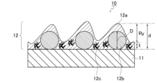
図1の断面図に、本発明の防眩性フィルムの構成の一例を示す。図示のとおり、この防眩性フィルム10は、光透過性基材(A)11の一方の面に、防眩層(B)12が積層されている。防眩層(B)12は、樹脂層12a中に微粒子12bおよびチキソトロピー付与剤12cが含まれている。防眩性フィルム10における防眩層(B)12側の最表面(防眩層(B)12の、光透過性基材(A)11と反対側の表面)には、凹凸が形成されている。前記凹凸の凸部の最大高さRyは、1μm以上である。前記凹凸の平均傾斜角θa(図示せず)は、0.7°以上である。また、微粒子12bの粒子径Dは、防眩層(B)の最大厚みdからRyを差し引いた膜厚tよりも大きい。ただし、図1は例示であって、本発明はこれに限定されない。例えば、本発明の防眩性フィルムは、微粒子およびチキソトロピー付与剤を、それぞれ、含んでいてもよいし、含んでいなくてもよい。また、図1では、微粒子12bの粒子径Dが防眩層(B)の膜厚tよりも大きいが、本発明は、これに限定されない。
The cross-sectional view of FIG. 1 shows an example of the structure of the anti-glare film of the present invention. As shown in the figure, in this
図3の断面図に、本発明の防眩性フィルムではない防眩性フィルムの構成の一例を示す。この防眩性フィルムは、凹凸の最大高さRyが1.7μm未満であることと、凹凸の平均系射角θa(図示せず)が0.7°未満であること以外は、図1の防眩性フィルムと同様である。 The cross-sectional view of FIG. 3 shows an example of the structure of an anti-glare film that is not the anti-glare film of the present invention. This anti-glare film has the same characteristics as shown in Fig. 1 except that the maximum height Ry of the unevenness is less than 1.7 μm and the average incident angle θa (not shown) of the unevenness is less than 0.7°. It is the same as the anti-glare film.
また、図2の断面図に、本発明の防眩性フィルムの構成の別の一例を示す。図示のとおり、この防眩性フィルム10は、防眩層(B)12における光透過性基材(A)11と反対側の面上に、さらに、他の層13が積層されている。他の層13は特に限定されず、例えば、低屈折率層、反射防止層、高屈折率層、ハードコート層、粘着剤層等であってもよい。これ以外は、図2の防眩性フィルム10の構成は、図1の防眩性フィルム10と同様である。また、図2において、防眩性フィルム10における防眩層(B)12側の最表面(他の層13の、光透過性基材(A)11と反対側の表面)には、凹凸が形成されている。前記凹凸の凸部の最大高さRyは、1.7μm以上である。前記凹凸の平均傾斜角θa(図示せず)は、0.7°以上である。防眩性フィルム10における、光透過性基材(A)11以外の部分(防眩層(B)12および他の層13)の最大高さは、図においてdで表している。また、防眩層(B)12における、光透過性基材(A)11と反対側(他の層13側)の面上には、凹凸が形成されている。防眩層(B)12の最大厚みd’から防眩層(B)12の前記凹凸の最大高さRy’を差し引いた膜厚は、図においてtで表している。図示のとおり、tは、d’-Ry’に等しいとともに、d-Ryに等しい。微粒子12bの粒子径Dは、図1の場合と同様に、膜厚tよりも大きいが、前述のとおり、本発明はこれに限定されない。また、図1の場合と同様に、防眩層(B)12は、微粒子およびチキソトロピー付与剤を、それぞれ、含んでいてもよいし、含んでいなくてもよい。また、他の層13は、図2では一層であるが、複数の層でもよい。なお、他の層13が存在しない場合は、図1に示したとおり、Ry’はRyに等しく、d’はdに等しい。
Further, the cross-sectional view of FIG. 2 shows another example of the structure of the anti-glare film of the present invention. As shown in the figure, in this
以下、前記光透過性基材(A)、前記防眩層(B)および前記他の層のそれぞれについて、さらに例を挙げて説明する。なお、以下においては、主に、前記防眩層(B)が防眩性ハードコート層である場合について説明するが、本発明はこれには限定されない。 Hereinafter, each of the light-transmitting substrate (A), the anti-glare layer (B), and the other layer will be further explained by giving examples. In addition, although the case where the said anti-glare layer (B) is an anti-glare hard coat layer is mainly demonstrated below, this invention is not limited to this.
前記光透過性基材(A)は、特に制限されないが、例えば、透明プラスチックフィルム基材等があげられる。前記透明プラスチックフィルム基材は、特に制限されないが、可視光の光線透過率に優れ(好ましくは光線透過率90%以上)、透明性に優れるもの(好ましくはヘイズ値1%以下のもの)が好ましく、例えば、特開2008-90263号公報に記載の透明プラスチックフィルム基材があげられる。前記透明プラスチックフィルム基材としては、光学的に複屈折の少ないものが好適に用いられる。本発明の防眩性フィルムは、例えば、保護フィルムとして偏光板に使用することもでき、この場合には、前記透明プラスチックフィルム基材としては、トリアセチルセルロース(TAC)、ポリカーボネート、アクリル系ポリマー、環状ないしノルボルネン構造を有するポリオレフィン等から形成されたフィルムが好ましい。また、本発明において、後述するように、前記透明プラスチックフィルム基材は、偏光子自体であってもよい。このような構成であると、TAC等からなる保護層を不要とし偏光板の構造を単純化できるので、偏光板もしくは画像表示装置の製造工程数を減少させ、生産効率の向上が図れる。また、このような構成であれば、偏光板を、より薄層化することができる。なお、前記透明プラスチックフィルム基材が偏光子である場合には、前記防眩層(B)および前記反射防止層(C)が、保護層としての役割を果たすことになる。また、このような構成であれば、防眩性フィルムは、例えば、液晶セル表面に装着される場合、カバープレートとしての機能を兼ねることになる。 The light-transmitting substrate (A) is not particularly limited, and examples thereof include transparent plastic film substrates and the like. The transparent plastic film substrate is not particularly limited, but preferably has excellent visible light transmittance (preferably 90% or more light transmittance) and excellent transparency (preferably haze value 1% or less). , for example, the transparent plastic film base material described in JP-A-2008-90263. As the transparent plastic film base material, one having optically low birefringence is suitably used. The anti-glare film of the present invention can also be used, for example, as a protective film in a polarizing plate. In this case, the transparent plastic film base material may include triacetyl cellulose (TAC), polycarbonate, acrylic polymer, A film formed from polyolefin or the like having a cyclic or norbornene structure is preferred. Furthermore, in the present invention, as described later, the transparent plastic film base material may be a polarizer itself. With such a configuration, the structure of the polarizing plate can be simplified by eliminating the need for a protective layer made of TAC or the like, thereby reducing the number of manufacturing steps for the polarizing plate or the image display device, and improving production efficiency. Moreover, with such a configuration, the polarizing plate can be made thinner. In addition, when the said transparent plastic film base material is a polarizer, the said antiglare layer (B) and the said antireflection layer (C) will play a role as a protective layer. Further, with such a configuration, the anti-glare film also functions as a cover plate when it is attached to the surface of the liquid crystal cell, for example.
本発明において、前記光透過性基材(A)の厚みは、特に制限されないが、強度、取り扱い性などの作業性および薄層性などの点を考慮すると、例えば、10~500μm、20~300μm、または30~200μmの範囲である。前記光透過性基材(A)の屈折率は、特に制限されない。前記屈折率は、例えば、1.30~1.80または1.40~1.70の範囲である。 In the present invention, the thickness of the light-transmitting substrate (A) is not particularly limited, but in consideration of workability such as strength and handleability, and thin layer property, the thickness is, for example, 10 to 500 μm, 20 to 300 μm. , or in the range of 30 to 200 μm. The refractive index of the light-transmitting substrate (A) is not particularly limited. The refractive index is, for example, in the range of 1.30 to 1.80 or 1.40 to 1.70.
本発明の防眩性フィルムは、例えば、前記光透過性基材(A)に含まれる樹脂が、アクリル樹脂を含んでいてもよい。 In the antiglare film of the present invention, for example, the resin contained in the light-transmitting substrate (A) may include an acrylic resin.
本発明の防眩性フィルムは、例えば、前記光透過性基材(A)が、アクリルフィルムであってもよい。 In the anti-glare film of the present invention, for example, the light-transmitting substrate (A) may be an acrylic film.
また、本発明の防眩性フィルムは、前述のとおり、前記防眩層(B)側の最表面に凹凸が形成され、前記凹凸の最大高さRyが、1.7μm以上である。前記最大高さRyは、例えば、2.0μm以上または2.3μm以上であってもよく、例えば、9μm以下、8μm以下、7μm以下、または6μm以下であってもよい。前記最大高さRyは、例えば、1.7~9μm、1.7~8μm、2.0~7μm、または2.3~6μmであってもよい。Ryは、映り込み抑制の観点からは、大きいことが好ましいが、後述するヘイズ値の観点からは、大きすぎないことが好ましい。本発明において、前記最大高さRyは、JIS B 0601(1994年版)に基づく数値とする。Ryの測定方法は、特に限定されないが、例えば、後述する実施例に記載の測定方法により測定することができる。 Further, as described above, in the anti-glare film of the present invention, irregularities are formed on the outermost surface on the anti-glare layer (B) side, and the maximum height Ry of the irregularities is 1.7 μm or more. The maximum height Ry may be, for example, 2.0 μm or more or 2.3 μm or more, and may be, for example, 9 μm or less, 8 μm or less, 7 μm or less, or 6 μm or less. The maximum height Ry may be, for example, 1.7 to 9 μm, 1.7 to 8 μm, 2.0 to 7 μm, or 2.3 to 6 μm. Ry is preferably large from the viewpoint of suppressing reflections, but preferably not too large from the viewpoint of haze value, which will be described later. In the present invention, the maximum height Ry is a value based on JIS B 0601 (1994 edition). Although the method for measuring Ry is not particularly limited, it can be measured, for example, by the measuring method described in the Examples below.
なお、本発明の防眩性フィルムにおいて、「防眩層(B)側の最表面」は、前記防眩層(B)側の最も外側の表面である。具体的には、「防眩層(B)側の最表面」は、前記他の層が存在しない場合(例えば図1)は、前記防眩層(B)における前記光透過性基材(A)と反対側の表面である。また、「防眩層(B)側の最表面」は、前記他の層が存在する場合(例えば図2)は、前記他の層における前記光透過性基材(A)と反対側の最も外側の表面である。 In addition, in the anti-glare film of the present invention, "the outermost surface on the anti-glare layer (B) side" is the outermost surface on the anti-glare layer (B) side. Specifically, "the outermost surface on the anti-glare layer (B) side" refers to the light-transmitting substrate (A) in the anti-glare layer (B) when the other layer is not present (for example, FIG. ) and the opposite surface. In addition, "the outermost surface on the anti-glare layer (B) side" refers to the outermost surface of the other layer on the side opposite to the light-transmitting substrate (A) when the other layer is present (for example, FIG. 2). This is the outer surface.
また、本発明の防眩性フィルムは、前述のとおり、前記防眩層(B)側の最表面の凹凸形状において、平均傾斜角θa(°)が0.7以上である。前記平均傾斜角θaは、例えば、0.7°以上、0.8°以上、0.9°以上、または1.0°以上であってもよく、8°以下、7°以下、6°以下、または5°以下であってもよい。前記平均傾斜角θaは、例えば、0.7~8°、0.7~7°、0.7~6°、0.7~5°、0.8~8°、0.8~7°、0.8~6°、0.8~5°、0.9~8°、0.9~7°、0.9~6°、0.9~5°、1.0~8°、1.0~7°、1.0~6°、または1.0~5°であってもよい。θaは、映り込み抑制の観点からは、大きいことが好ましいが、後述するヘイズ値の観点からは、大きすぎないことが好ましい。ここで、前記平均傾斜角θaは、下記数式(3)で定義される値である。前記平均傾斜角θaは、例えば、後述の実施例に記載の方法により測定することができる。
平均傾斜角θa=tan-1Δa (3)
Further, as described above, in the anti-glare film of the present invention, the average inclination angle θa (°) of the uneven shape of the outermost surface on the anti-glare layer (B) side is 0.7 or more. The average inclination angle θa may be, for example, 0.7° or more, 0.8° or more, 0.9° or more, or 1.0° or more, and 8° or less, 7° or less, or 6° or less. , or 5° or less. The average inclination angle θa is, for example, 0.7-8°, 0.7-7°, 0.7-6°, 0.7-5°, 0.8-8°, 0.8-7°. , 0.8-6°, 0.8-5°, 0.9-8°, 0.9-7°, 0.9-6°, 0.9-5°, 1.0-8°, It may be 1.0-7°, 1.0-6°, or 1.0-5°. Although θa is preferably large from the viewpoint of suppressing reflections, it is preferable that θa is not too large from the viewpoint of haze value, which will be described later. Here, the average inclination angle θa is a value defined by the following formula (3). The average inclination angle θa can be measured, for example, by the method described in Examples below.
Average inclination angle θa=tan -1 Δa (3)
前記数式(3)において、Δaは、下記数式(4)に示すように、JIS B 0601(1994年度版)に規定される粗さ曲線の基準長さLにおいて、隣り合う山の頂点と谷の最下点との差(高さh)の合計(h1+h2+h3・・・+hn)を前記基準長さLで割った値である。前記粗さ曲線は、断面曲線から、所定の波長より長い表面うねり成分を位相差補償形高域フィルタで除去した曲線である。また、前記断面曲線とは、対象面に直角な平面で対象面を切断したときに、その切り口に現れる輪郭である。
Δa=(h1+h2+h3・・・+hn)/L (4)
In the above formula (3), Δa is the distance between the peaks and valleys of adjacent peaks in the standard length L of the roughness curve specified in JIS B 0601 (1994 edition), as shown in the formula (4) below. This is the value obtained by dividing the total (h1+h2+h3...+hn) of the difference (height h) from the lowest point by the reference length L. The roughness curve is a curve obtained by removing surface waviness components longer than a predetermined wavelength from a cross-sectional curve using a phase difference compensating high-pass filter. Further, the cross-sectional curve is a contour that appears at a cut end when the target surface is cut by a plane perpendicular to the target surface.
Δa=(h1+h2+h3...+hn)/L (4)
本発明の防眩性フィルムは、例えば、へイズ値が、例えば、4%以上、6%以上、10%以上、または15%以上であってもよく、例えば、50%以下、40%以下、35%以下、または30%未満であってもよい。前記ヘイズ値は、例えば、4~50%、6~40%、10~40%、さらに15~40%、または15~35%であってもよい。前記ヘイズ値とは、JIS K 7136(2000年版)に準じた防眩性フィルム全体のヘイズ値(曇度)である。一般に、防眩性フィルムにおいて、前記ヘイズ値が大きいと、映り込みを抑制しやすい。しかし、前記ヘイズ値が大きすぎると、画像が不鮮明になる、暗所でのコントラストが低下する等、表示特性が低下しやすい。しかし、本発明によれば、Ryおよびθaが前記数式(1)および(2)を満たすことにより、前記ヘイズ値が、例えば、50%以下、40%以下、35%以下、または30%未満と小さくても、映り込みを抑制できるのである。なお、前記ヘイズ値をなるべく小さくするためには、Ryおよびθaの調整以外に、後述する樹脂と微粒子との屈折率差がなるべく小さく(例えば0.001~0.02の範囲に)なるように、前記微粒子と前記樹脂とを選択すればよい。 The anti-glare film of the present invention may have a haze value of, for example, 4% or more, 6% or more, 10% or more, or 15% or more, for example, 50% or less, 40% or less, It may be 35% or less, or less than 30%. The haze value may be, for example, 4 to 50%, 6 to 40%, 10 to 40%, further 15 to 40%, or 15 to 35%. The haze value is the haze value (cloudiness) of the entire anti-glare film according to JIS K 7136 (2000 edition). Generally, in an anti-glare film, when the haze value is large, reflections are easily suppressed. However, if the haze value is too large, display characteristics tend to deteriorate, such as images becoming unclear and contrast in dark places decreasing. However, according to the present invention, Ry and θa satisfy the formulas (1) and (2), so that the haze value is, for example, 50% or less, 40% or less, 35% or less, or less than 30%. Even if it is small, it can suppress reflections. In addition, in order to make the haze value as small as possible, in addition to adjusting Ry and θa, the difference in refractive index between the resin and the fine particles, which will be described later, should be made as small as possible (for example, in the range of 0.001 to 0.02). , the fine particles and the resin may be selected.
本発明の防眩性フィルムは、例えば、前記防眩層(B)が、樹脂およびフィラーを含んでいてもよい。前記フィラーが、微粒子およびチキソトロピー付与剤(thixotropic agent)の少なくとも一方を含んでいてもよい。 In the antiglare film of the present invention, for example, the antiglare layer (B) may contain a resin and a filler. The filler may include at least one of fine particles and a thixotropic agent.
本発明の防眩性フィルムは、例えば、前記防眩層(B)に含まれる前記樹脂が、アクリレート樹脂(アクリル樹脂ともいう)を含んでいてもよい。 In the anti-glare film of the present invention, for example, the resin contained in the anti-glare layer (B) may include an acrylate resin (also referred to as acrylic resin).
本発明の防眩性フィルムは、例えば、前記防眩層(B)に含まれる前記樹脂が、ウレタンアクリレート樹脂を含んでいてもよい。 In the anti-glare film of the present invention, for example, the resin contained in the anti-glare layer (B) may contain a urethane acrylate resin.
本発明の防眩性フィルムは、例えば、前記防眩層(B)に含まれる前記樹脂が、硬化型ウレタンアクリレート樹脂および多官能アクリレートの共重合物であってもよい。 In the anti-glare film of the present invention, for example, the resin contained in the anti-glare layer (B) may be a copolymer of a curable urethane acrylate resin and a polyfunctional acrylate.
本発明の防眩性フィルムは、例えば、前記防眩層(B)が、樹脂およびフィラーを含む防眩層形成材料を用いて形成されており、前記防眩層(B)が、前記フィラーが凝集することによって、前記防眩層(B)の表面に凸状部を形成する凝集部を有していてもよい。また、前記凸状部を形成する凝集部において、前記フィラーが、前記防眩層(B)の面方向における一方向に複数集まった状態で存在していてもよい。本発明の画像表示装置は、例えば、前記フィラーが複数集まった一方向と、前記ブラックマトリックスパターンの長辺方向とが一致するように、前記本発明の防眩性フィルムが配置されていてもよい。 In the antiglare film of the present invention, for example, the antiglare layer (B) is formed using an antiglare layer forming material containing a resin and a filler, and the antiglare layer (B) is formed using an antiglare layer forming material containing a resin and a filler. The antiglare layer (B) may have an agglomerated portion that forms a convex portion on the surface of the antiglare layer (B) by aggregating. Further, in the agglomerated portion forming the convex portion, a plurality of the fillers may be present in a state where they are gathered in one direction in the surface direction of the anti-glare layer (B). In the image display device of the present invention, the anti-glare film of the present invention may be arranged such that, for example, one direction in which the plurality of fillers are gathered coincides with the long side direction of the black matrix pattern. .
本発明の防眩性フィルムにおいて、前記チキソトロピー付与剤は、例えば、有機粘土、酸化ポリオレフィンおよび変性ウレアからなる群から選択される少なくとも一つであってもよい。また、前記チキソトロピー付与剤は、例えば、増粘剤であってもよい。 In the antiglare film of the present invention, the thixotropy imparting agent may be, for example, at least one selected from the group consisting of organic clay, oxidized polyolefin, and modified urea. Moreover, the thixotropy imparting agent may be, for example, a thickener.
本発明の防眩性フィルムにおいて、前記防眩層(B)の前記樹脂100重量(質量)部に対し、例えば、前記チキソトロピー付与剤が0.2~5重量部の範囲で含まれていてもよい。 In the anti-glare film of the present invention, for example, the thixotropy imparting agent may be contained in a range of 0.2 to 5 parts by weight based on 100 parts by weight (mass) of the resin of the anti-glare layer (B). good.
本発明の防眩性フィルムにおいて、前記防眩層(B)の前記樹脂100重量部に対し、前記微粒子は、例えば、0.2~12重量部または0.5~12重量部の範囲で含まれていてもよい。 In the anti-glare film of the present invention, the fine particles are contained in an amount of, for example, 0.2 to 12 parts by weight or 0.5 to 12 parts by weight based on 100 parts by weight of the resin of the anti-glare layer (B). It may be
本発明の防眩性フィルムの製造方法において、さらに、前記防眩層形成材料中における前記樹脂100重量部に対する前記微粒子の重量部数を調整することにより、前記防眩性フィルムの表面形状を調整してもよい。 In the method for producing an anti-glare film of the present invention, the surface shape of the anti-glare film is further adjusted by adjusting the number of parts by weight of the fine particles based on 100 parts by weight of the resin in the anti-glare layer forming material. It's okay.
前記防眩層(B)は、例えば、後述するように、前記樹脂、前記フィラーおよび溶媒を含む塗工液を、前記光透過性基材(A)の少なくとも一方の面に塗工して塗膜を形成し、次いで、前記塗膜から前記溶媒を除去することで形成される。前記樹脂は、例えば、熱硬化性樹脂、紫外線や光で硬化する電離放射線硬化性樹脂があげられる。前記樹脂として、市販の熱硬化型樹脂や紫外線硬化型樹脂等を用いることも可能である。 The anti-glare layer (B) can be formed, for example, by applying a coating liquid containing the resin, the filler and a solvent to at least one surface of the light-transmitting substrate (A), as described below. It is formed by forming a film and then removing the solvent from the coating. Examples of the resin include thermosetting resins and ionizing radiation-curable resins that are cured by ultraviolet light or light. As the resin, it is also possible to use commercially available thermosetting resins, ultraviolet curable resins, and the like.
前記熱硬化型樹脂や紫外線硬化型樹脂としては、例えば、熱、光(紫外線等)または電子線等により硬化するアクリレート基およびメタクリレート基の少なくとも一方の基を有する硬化型化合物が使用でき、例えば、シリコーン樹脂、ポリエステル樹脂、ポリエーテル樹脂、エポキシ樹脂、ウレタン樹脂、アルキッド樹脂、スピロアセタール樹脂、ポリブタジエン樹脂、ポリチオールポリエン樹脂、多価アルコール等の多官能化合物のアクリレートやメタクリレート等のオリゴマーまたはプレポリマー等があげられる。これらは、1種類を単独で用いてもよく、2種類以上を併用してもよい。 As the thermosetting resin or the ultraviolet curable resin, for example, a curable compound having at least one of an acrylate group and a methacrylate group that is cured by heat, light (such as ultraviolet rays), or electron beam, etc. can be used, for example, Silicone resins, polyester resins, polyether resins, epoxy resins, urethane resins, alkyd resins, spiroacetal resins, polybutadiene resins, polythiol polyene resins, oligomers or prepolymers such as acrylates and methacrylates of polyfunctional compounds such as polyhydric alcohols, etc. can give. These may be used alone or in combination of two or more.
前記樹脂には、例えば、アクリレート基およびメタクリレート基の少なくとも一方の基を有する反応性希釈剤を用いることもできる。前記反応性希釈剤は、例えば、特開2008-88309号公報に記載の反応性希釈剤を用いることができ、例えば、単官能アクリレート、単官能メタクリレート、多官能アクリレート、多官能メタクリレート等を含む。前記反応性希釈剤としては、3官能以上のアクリレート、3官能以上のメタクリレートが好ましい。これは、防眩層(B)の硬度を、優れたものにできるからである。前記反応性希釈剤としては、例えば、ブタンジオールグリセリンエーテルジアクリレート、イソシアヌル酸のアクリレート、イソシアヌル酸のメタクリレート等もあげられる。これらは、1種類を単独で用いてもよく、2種類以上を併用してもよい。 For example, a reactive diluent having at least one of an acrylate group and a methacrylate group can also be used in the resin. The reactive diluent can be, for example, the reactive diluent described in JP-A No. 2008-88309, and includes, for example, monofunctional acrylate, monofunctional methacrylate, polyfunctional acrylate, polyfunctional methacrylate, and the like. As the reactive diluent, trifunctional or higher functional acrylates or trifunctional or higher functional methacrylates are preferred. This is because the hardness of the anti-glare layer (B) can be made excellent. Examples of the reactive diluent include butanediol glycerol ether diacrylate, isocyanuric acid acrylate, isocyanuric acid methacrylate, and the like. These may be used alone or in combination of two or more.
前記防眩層(B)を形成するための微粒子は、形成される防眩層(B)表面を凹凸形状にして防眩性を付与し、また、前記防眩層(B)のヘイズ値を制御することを主な機能とする。前記防眩層(B)のヘイズ値は、前記微粒子と前記樹脂との屈折率差を制御することで、設計することができる。前記微粒子としては、例えば、無機微粒子と有機微粒子とがある。前記無機微粒子は、特に制限されず、例えば、酸化ケイ素粒子、酸化チタン粒子、酸化アルミニウム粒子、酸化亜鉛粒子、酸化錫粒子、炭酸カルシウム粒子、硫酸バリウム粒子、タルク粒子、カオリン粒子、硫酸カルシウム粒子等があげられる。また、前記有機微粒子は、特に制限されず、例えば、ポリメチルメタクリレート樹脂粉末(PMMA粒子)、シリコーン樹脂粉末、ポリスチレン樹脂粉末、ポリカーボネート樹脂粉末、アクリルスチレン樹脂粉末、ベンゾグアナミン樹脂粉末、メラミン樹脂粉末、ポリオレフィン樹脂粉末、ポリエステル樹脂粉末、ポリアミド樹脂粉末、ポリイミド樹脂粉末、ポリフッ化エチレン樹脂粉末等があげられる。これらの無機微粒子および有機微粒子は、一種類を単独で使用してもよいし、二種類以上を併用してもよい。 The fine particles for forming the anti-glare layer (B) impart anti-glare properties by making the surface of the anti-glare layer (B) uneven, and also increase the haze value of the anti-glare layer (B). Its main function is to control. The haze value of the anti-glare layer (B) can be designed by controlling the refractive index difference between the fine particles and the resin. Examples of the fine particles include inorganic fine particles and organic fine particles. The inorganic fine particles are not particularly limited, and include, for example, silicon oxide particles, titanium oxide particles, aluminum oxide particles, zinc oxide particles, tin oxide particles, calcium carbonate particles, barium sulfate particles, talc particles, kaolin particles, calcium sulfate particles, etc. can be given. The organic fine particles are not particularly limited, and include, for example, polymethyl methacrylate resin powder (PMMA particles), silicone resin powder, polystyrene resin powder, polycarbonate resin powder, acrylic styrene resin powder, benzoguanamine resin powder, melamine resin powder, polyolefin. Examples include resin powder, polyester resin powder, polyamide resin powder, polyimide resin powder, polyfluoroethylene resin powder, and the like. These inorganic fine particles and organic fine particles may be used alone or in combination of two or more types.
前記微粒子の粒子径(D)(重量平均粒子径)は、特に限定されないが、例えば、2~10μmの範囲内である。前記微粒子の重量平均粒子径を、前記範囲とすることで、例えば、より防眩性に優れ、かつ映り込みが抑制された防眩性フィルムとすることができる。斜め方向からの映り込み抑制の観点からは、前記微粒子の重量平均粒子径が小さすぎないことが好ましい。正面方向からの映り込み抑制の観点からは、前記微粒子の重量平均粒子径が大きすぎないことが好ましい。前記微粒子の重量平均粒子径は、例えば、4μm以上であってもよく、例えば、9μm以下、または8μm以下であってもよい。前記微粒子の重量平均粒子径は、例えば、4~9μm、または4~8μmであってもよい。なお、前記微粒子の重量平均粒子径は、例えば、コールターカウント法により測定できる。例えば、細孔電気抵抗法を利用した粒度分布測定装置(商品名:コールターマルチサイザー、ベックマン・コールター社製)を用い、微粒子が前記細孔を通過する際の微粒子の体積に相当する電解液の電気抵抗を測定することにより、前記微粒子の数と体積を測定し、重量平均粒子径を算出する。 The particle diameter (D) (weight average particle diameter) of the fine particles is not particularly limited, but is, for example, within the range of 2 to 10 μm. By setting the weight average particle diameter of the fine particles within the above range, for example, an antiglare film with better antiglare properties and suppressed reflection can be obtained. From the viewpoint of suppressing reflection from an oblique direction, it is preferable that the weight average particle diameter of the fine particles is not too small. From the viewpoint of suppressing reflection from the front direction, it is preferable that the weight average particle diameter of the fine particles is not too large. The weight average particle diameter of the fine particles may be, for example, 4 μm or more, and may be, for example, 9 μm or less, or 8 μm or less. The weight average particle diameter of the fine particles may be, for example, 4 to 9 μm or 4 to 8 μm. Note that the weight average particle diameter of the fine particles can be measured, for example, by the Coulter counting method. For example, using a particle size distribution measuring device (trade name: Coulter Multisizer, manufactured by Beckman Coulter) that uses the pore electrical resistance method, an electrolyte solution corresponding to the volume of the fine particles when they pass through the pores is measured. By measuring electrical resistance, the number and volume of the fine particles are measured, and the weight average particle diameter is calculated.
前記微粒子の形状は、特に制限されず、例えば、ビーズ状の略球形であってもよく、粉末等の不定形のものであってもよいが、略球形のものが好ましく、より好ましくは、アスペクト比が1.5以下の略球形の微粒子であり、最も好ましくは球形の微粒子である。 The shape of the fine particles is not particularly limited, and may be, for example, approximately spherical in the form of beads, or irregularly shaped such as powder, but is preferably approximately spherical, and more preferably has an aspect ratio. The particles are approximately spherical particles with a ratio of 1.5 or less, and most preferably spherical particles.
前記防眩層(B)における前記微粒子の含有率は、特に限定されないが、例えば、前記防眩層(B)の表面形状を考慮して適宜設定することができる。なお、前記微粒子の含有率(前記樹脂に対する重量部数)および重量平均粒子径と、前記防眩層(B)の表面形状との関係については、後述する。 The content of the fine particles in the anti-glare layer (B) is not particularly limited, but can be appropriately set, for example, taking into consideration the surface shape of the anti-glare layer (B). The relationship between the content of the fine particles (parts by weight relative to the resin) and the weight average particle diameter, and the surface shape of the anti-glare layer (B) will be described later.
前記防眩層(B)において、前記フィラーが、微粒子およびチキソトロピー付与剤であってもよい。前記チキソトロピー付与剤は、単独で含んでいてもよいし、前記微粒子に加え、さらに、前記チキソトロピー付与剤を含んでいてもよい。前記チキソトロピー付与剤を含むことで、前記微粒子の凝集状態の制御を容易に行うことができる。前記チキソトロピー付与剤としては、例えば、有機粘土、酸化ポリオレフィン、変性ウレア等があげられる。 In the antiglare layer (B), the filler may be fine particles and a thixotropy imparting agent. The thixotropy imparting agent may be contained alone, or may be further contained in addition to the fine particles. By including the thixotropy imparting agent, the aggregation state of the fine particles can be easily controlled. Examples of the thixotropy-imparting agent include organic clay, oxidized polyolefin, and modified urea.
前記有機粘土は、前記樹脂との親和性を改善するために、有機化処理した層状粘土であることが好ましい。前記有機粘土は、自家調製してもよいし、市販品を用いてもよい。前記市販品としては、例えば、ルーセンタイトSAN、ルーセンタイトSTN、ルーセンタイトSEN、ルーセンタイトSPN、ソマシフME-100、ソマシフMAE、ソマシフMTE、ソマシフMEE、ソマシフMPE(商品名、いずれもコープケミカル株式会社製);エスベン、エスベンC、エスベンE、エスベンW、エスベンP、エスベンWX、エスベンN-400、エスベンNX、エスベンNX80、エスベンNO12S、エスベンNEZ、エスベンNO12、エスベンNE、エスベンNZ、エスベンNZ70、オルガナイト、オルガナイトD、オルガナイトT(商品名、いずれも株式会社ホージュン製);クニピアF、クニピアG、クニピアG4(商品名、いずれもクニミネ工業株式会社製);チクソゲルVZ、クレイトンHT、クレイトン40(商品名、いずれもロックウッド アディティブズ社製)等があげられる。 It is preferable that the organic clay is a layered clay that has been subjected to an organic treatment in order to improve its affinity with the resin. The organic clay may be prepared in-house or a commercially available product may be used. Examples of the commercially available products include Lucentite SAN, Lucentite STN, Lucentite SEN, Lucentite SPN, Somasif ME-100, Somasif MAE, Somasif MTE, Somasif MEE, Somasif MPE (trade names, all manufactured by Co-op Chemical Co., Ltd.) ); Esben, Esben C, Esben E, Esben W, Esben P, Esben WX, Esben N-400, Esben NX, Esben NX80, Esben NO12S, Esben NEZ, Esben NO12, Esben NE, Esben NZ, Esben NZ70, Olga Knight, Organite D, Organite T (trade names, all manufactured by Hojun Co., Ltd.); Kunipia F, Kunipia G, Kunipia G4 (trade names, all manufactured by Kunimine Industries Co., Ltd.); Thixogel VZ, Clayton HT, Clayton 40 (Product names, all manufactured by Rockwood Additives).
前記酸化ポリオレフィンは、自家調製してもよいし、市販品を用いてもよい。前記市販品としては、例えば、ディスパロン4200-20(商品名、楠本化成株式会社製)、フローノンSA300(商品名、共栄社化学株式会社製)等があげられる。 The oxidized polyolefin may be prepared in-house or a commercially available product may be used. Examples of the commercially available products include Disparon 4200-20 (trade name, manufactured by Kusumoto Kasei Co., Ltd.), Fluonon SA300 (trade name, manufactured by Kyoeisha Chemical Co., Ltd.), and the like.
前記変性ウレアは、イソシアネート単量体あるいはそのアダクト体と有機アミンとの反応物である。前記変性ウレアは、自家調製してもよいし、市販品を用いてもよい。前記市販品としては、例えば、BYK410(ビッグケミー社製)等があげられる。 The modified urea is a reaction product of an isocyanate monomer or its adduct and an organic amine. The modified urea may be prepared in-house or a commercially available product may be used. Examples of the commercially available products include BYK410 (manufactured by Big Chemie).
前記チキソトロピー付与剤は、一種類を単独で使用してもよいし、二種類以上を併用してもよい。 The thixotropy imparting agent may be used alone or in combination of two or more.
前記防眩層(B)における前記チキソトロピー付与剤の割合は、前記樹脂100重量部に対し、0.2~5重量部の範囲が好ましく、より好ましくは、0.4~4重量部の範囲である。 The proportion of the thixotropy imparting agent in the anti-glare layer (B) is preferably in the range of 0.2 to 5 parts by weight, more preferably in the range of 0.4 to 4 parts by weight, based on 100 parts by weight of the resin. be.
前記防眩層(B)の最大厚み(d’)は、特に制限されないが、3~12μmの範囲内にあることが好ましい。前記防眩層(B)の最大厚み(d’)を、前記範囲とすることで、例えば、防眩性フィルムにおけるカールの発生を防ぐことができ、搬送性不良等の生産性の低下の問題を回避できる。また、前記厚み(d)が前記範囲にある場合、前記微粒子の重量平均粒子径(D)は、前述のように、4~9μmの範囲内にあることが好ましい。前記防眩層(B)の最大厚み(d’)と、前記微粒子の重量平均粒子径(D)とが、前述の組み合わせであることで、防眩性に優れる防眩性フィルムとすることができる。前記防眩層(B)の最大厚み(d’)は、より好ましくは、4~8μmの範囲内である。 The maximum thickness (d') of the anti-glare layer (B) is not particularly limited, but is preferably within the range of 3 to 12 μm. By setting the maximum thickness (d') of the anti-glare layer (B) within the above range, it is possible to prevent, for example, curling in the anti-glare film, thereby reducing productivity problems such as poor conveyance. can be avoided. Further, when the thickness (d) is within the above range, the weight average particle diameter (D) of the fine particles is preferably within the range of 4 to 9 μm, as described above. Since the maximum thickness (d') of the anti-glare layer (B) and the weight average particle diameter (D) of the fine particles are in the above-mentioned combination, an anti-glare film with excellent anti-glare properties can be obtained. can. The maximum thickness (d') of the anti-glare layer (B) is more preferably within the range of 4 to 8 μm.
前記防眩層(B)の厚み(d’)と前記微粒子の重量平均粒子径(D)との比D/d’は、例えば、1以下、1未満、0.98以下、0.96以下、0.93以下、または0.90以下であってもよく、0.5以上、0.6以上、0.7以上、または0.8以上であってもよい。このような関係にあることにより、より防眩性に優れ、かつ映り込みが抑制された防眩性フィルムとすることができる。例えば、D/d’が大きいと、Ryおよびθaが大きくなりやすい傾向がある。 The ratio D/d' between the thickness (d') of the anti-glare layer (B) and the weight average particle diameter (D) of the fine particles is, for example, 1 or less, less than 1, 0.98 or less, 0.96 or less , 0.93 or less, or 0.90 or less, 0.5 or more, 0.6 or more, 0.7 or more, or 0.8 or more. By having such a relationship, it is possible to obtain an anti-glare film that has better anti-glare properties and suppresses reflections. For example, when D/d' is large, Ry and θa tend to become large.
本発明における防眩性フィルムでは、例えば、前記防眩層(B)は、前記フィラーが凝集することによって、前記防眩層(B)の表面に凸状部を形成する凝集部を有しており、前記凸状部を形成する凝集部において、前記フィラーが、前記防眩層(B)の面方向における一方向に、複数集まった状態で存在してもよい。これにより、例えば、蛍光灯の映り込み等を防止することができる。ただし、本発明の防眩性フィルムは、これに限定されない。 In the anti-glare film of the present invention, for example, the anti-glare layer (B) has an agglomerated part that forms a convex part on the surface of the anti-glare layer (B) by aggregating the filler. In addition, in the agglomerated portion forming the convex portion, a plurality of the fillers may be present in a state in which they are gathered in one direction in the surface direction of the anti-glare layer (B). This makes it possible to prevent, for example, reflections of fluorescent lights. However, the anti-glare film of the present invention is not limited to this.
前記防眩層(B)の表面形状は、例えば、前記防眩層(B)の最大厚みd’から防眩層(B)の前記凹凸の最大高さRy’を差し引いた膜厚tと、前記微粒子の重量平均粒子径Dとを調整することで設計できる。具体的には、例えば、前記防眩層(B)の膜厚tに対して前記微粒子の重量平均粒子径Dが相対的に大きいと、前記Ryおよびθaが大きくなりやすい。膜厚tは、例えば、前記樹脂の塗工厚みによって調整できる。また、前記防眩層形成材料中における前記樹脂100重量部に対する前記微粒子の重量部数を調整することによっても、前記防眩層(B)の表面形状を設計できる。例えば、前記微粒子の重量部数が前記樹脂に対し相対的に多いと、θaが大きくなりやすい傾向がある。 The surface shape of the anti-glare layer (B) is, for example, a film thickness t obtained by subtracting the maximum height Ry' of the irregularities of the anti-glare layer (B) from the maximum thickness d' of the anti-glare layer (B), It can be designed by adjusting the weight average particle diameter D of the fine particles. Specifically, for example, when the weight average particle diameter D of the fine particles is relatively large with respect to the film thickness t of the antiglare layer (B), the Ry and θa tend to become large. The film thickness t can be adjusted by, for example, the coating thickness of the resin. The surface shape of the anti-glare layer (B) can also be designed by adjusting the number of parts by weight of the fine particles relative to 100 parts by weight of the resin in the anti-glare layer forming material. For example, when the number of parts by weight of the fine particles is relatively large relative to the resin, θa tends to become large.
また、本発明の防眩性フィルムは、例えば、前記光透過性基材(A)と前記防眩層(B)との間に、前記光透過性基材(A)由来の樹脂と、前記防眩層(B)由来の樹脂とを含む中間層を有していてもよい。この中間層の厚みの制御により、前記防眩層(B)の表面形状を制御することができる。例えば、前記中間層の厚みを大きくすると、前記Ryおよびθaが大きくなりやすく、前記中間層の厚みを小さくすると、前記Ryおよびθaが小さくなりやすい。 Further, the anti-glare film of the present invention may include, for example, a resin derived from the light-transmissive base material (A) and a resin derived from the light-transparent base material (A) between the light-transparent base material (A) and the anti-glare layer (B). It may have an intermediate layer containing a resin derived from the anti-glare layer (B). By controlling the thickness of this intermediate layer, the surface shape of the antiglare layer (B) can be controlled. For example, when the thickness of the intermediate layer is increased, the Ry and θa tend to increase, and when the thickness of the intermediate layer is decreased, the Ry and θa tend to decrease.
本発明において、前記中間層(浸透層、相溶層ともいう)が形成されるメカニズムは、特に限定されないが、例えば、本発明者の防眩性フィルムの製造方法における前記乾燥工程で形成される。具体的には、例えば、前記乾燥工程において、前記防眩層(B)形成用の塗工液が前記光透過性基材(A)に浸透し、前記光透過性基材(A)由来の樹脂と、前記防眩層(B)由来の樹脂とを含む前記中間層が形成される。前記中間層に含まれる樹脂は、特に限定されず、例えば、前記光透過性基材(A)に含まれる樹脂と前記防眩層(B)に含まれる樹脂とが単に混合(相溶)されたものでもよい。また、前記中間層に含まれる樹脂は、例えば、前記光透過性基材(A)に含まれる樹脂と前記防眩層(B)に含まれる樹脂との、少なくとも一方が、加熱、光照射等により化学変化していてもよい。 In the present invention, the mechanism by which the intermediate layer (also referred to as a permeable layer or a compatible layer) is formed is not particularly limited, but for example, it is formed in the drying step in the method for producing an anti-glare film of the present inventor. . Specifically, for example, in the drying step, the coating liquid for forming the anti-glare layer (B) permeates the light-transmitting base material (A), and the The intermediate layer containing a resin and a resin derived from the anti-glare layer (B) is formed. The resin contained in the intermediate layer is not particularly limited, and for example, the resin contained in the light-transmitting base material (A) and the resin contained in the anti-glare layer (B) are simply mixed (compatible). It may be something you have. Further, the resin contained in the intermediate layer may be heated, irradiated with light, etc. at least one of the resin contained in the light-transmitting base material (A) and the resin contained in the anti-glare layer (B). It may be chemically changed by
下記数式(5)で定義される前記中間層の厚み比率Rは、特に限定されないが、例えば、0.10~0.80であり、例えば、0.15以上、0.20以上、0.25以上、0.30以上、0.40以上、または0.45以上であってもよく、例えば、0.75以下、0.70以下、0.65以下、0.60以下、0.50以下、0.40以下、0.45以下、または0.30以下であってもよい。前記中間層の厚み比率Rは、例えば、0.15~0.75、0.20~0.70、0.25~0.65、0.30~0.60、0.40~0.50、0.45~0.50、0.15~0.45、0.15~0.40、0.15~0.30、または0.20~0.30であってもよい。前記中間層は、例えば、防眩性フィルムの断面を、透過型電子顕微鏡(TEM)で観察することで、確認することができ、厚みを測定することができる。
R=[DC/(DC+DB)] (5)
前記数式(5)において、DBは、前記防眩性層(B)の厚み[μm]であり、DCは、前記中間層の厚み[μm]である。
The thickness ratio R of the intermediate layer defined by the following formula (5) is not particularly limited, but is, for example, 0.10 to 0.80, for example, 0.15 or more, 0.20 or more, 0.25 or more, 0.30 or more, 0.40 or more, or 0.45 or more, for example, 0.75 or less, 0.70 or less, 0.65 or less, 0.60 or less, 0.50 or less, It may be 0.40 or less, 0.45 or less, or 0.30 or less. The thickness ratio R of the intermediate layer is, for example, 0.15 to 0.75, 0.20 to 0.70, 0.25 to 0.65, 0.30 to 0.60, 0.40 to 0.50. , 0.45 to 0.50, 0.15 to 0.45, 0.15 to 0.40, 0.15 to 0.30, or 0.20 to 0.30. The intermediate layer can be confirmed and its thickness can be measured, for example, by observing a cross section of the anti-glare film with a transmission electron microscope (TEM).
R=[ DC /( DC + DB )] (5)
In the formula (5), D B is the thickness [μm] of the antiglare layer (B), and D C is the thickness [μm] of the intermediate layer.
また、防眩層(B)の表面形状は、防眩層形成材料に含まれるフィラーの凝集状態を制御することによっても設計することができる。前記フィラーの凝集状態は、例えば、前記フィラーの材質(例えば、微粒子表面の化学的修飾状態、溶媒や樹脂に対する親和性等)、樹脂(バインダー)または溶媒の種類、組合せ等により制御できる。また、前記チキソトロピー付与剤により、前記微粒子の凝集状態を精密にコントロールすることができる。 Moreover, the surface shape of the anti-glare layer (B) can also be designed by controlling the agglomeration state of the filler contained in the anti-glare layer forming material. The aggregation state of the filler can be controlled by, for example, the material of the filler (for example, the chemical modification state of the surface of the fine particles, the affinity for solvents and resins, etc.), the type and combination of the resin (binder) or solvent, and the like. Furthermore, the thixotropy imparting agent allows precise control of the agglomeration state of the fine particles.
なお、本発明の防眩性フィルムは、前記凸状部が、なだらかな形状となり、外観欠点となる防眩層(B)表面の突起状物の発生を防止できるものであってもよいが、これに限定されない。また、本発明の防眩性フィルムは、例えば、防眩層(B)の厚み方向に直接または間接的に重なる位置で、前記微粒子が多少存在していてもよい。 In addition, in the anti-glare film of the present invention, the convex portions may have a gentle shape to prevent the occurrence of protrusions on the surface of the anti-glare layer (B) that would cause defects in appearance. It is not limited to this. Further, in the anti-glare film of the present invention, some of the fine particles may be present, for example, at positions directly or indirectly overlapping the anti-glare layer (B) in the thickness direction.
前記他の層は、特に限定されず、例えば、前述のとおり、低屈折率層、反射防止層、高屈折率層、ハードコート層、粘着剤層等であってもよい。また、前記他の層は、一層でも複数の層でもよく、複数の場合は、一種類でも複数種類でもよい。例えば、前記他の層は、厚みおよび屈折率を厳密に制御した光学薄膜もしくは前記光学薄膜を二層以上積層したものであってもよい。 The other layers are not particularly limited, and may be, for example, a low refractive index layer, an antireflection layer, a high refractive index layer, a hard coat layer, an adhesive layer, etc., as described above. Further, the other layer may be one layer or a plurality of layers, and in the case of a plurality of layers, one type or a plurality of types may be used. For example, the other layer may be an optical thin film whose thickness and refractive index are strictly controlled, or a stack of two or more optical thin films.
[2.防眩性フィルムの製造方法]
本発明の防眩性フィルムの製造方法は、特に制限されず、どのような方法で製造されてもよいが、前記本発明の防眩性フィルムの製造方法により製造することが好ましい。
[2. Manufacturing method of anti-glare film]
The method for producing the anti-glare film of the present invention is not particularly limited and may be produced by any method, but it is preferably produced by the method for producing the anti-glare film of the present invention.
前記防眩性フィルムの製造方法は、例えば、以下のようにして行うことができる。 The method for manufacturing the anti-glare film can be carried out, for example, as follows.
まず、前記光透過性基材(A)上に、前記防眩層(B)を、前記数式(1)および(2)を満たすように形成する(防眩層(B)形成工程)。これにより、前記光透過性基材(A)と前記防眩層(B)との積層体を製造する。前記防眩層(B)形成工程は、前述のとおり、前記光透過性基材(A)上に塗工液を塗工する塗工工程と、塗工した前記塗工液を乾燥させて塗膜を形成する塗膜形成工程とを含む。また、例えば、前述のとおり、前記防眩層(B)形成工程が、さらに、前記塗膜を硬化させる硬化工程を含んでいてもよい。前記硬化は、例えば、前記乾燥の後に行なうことができるが、これに限定されない。前記硬化は、例えば、加熱、光照射等により行うことができる。前記光は、特に限定されないが、例えば、紫外線等であってもよい。前記光照射の光源も特に限定されないが、例えば、高圧水銀ランプ等であってもよい。 First, the anti-glare layer (B) is formed on the light-transmissive substrate (A) so as to satisfy the formulas (1) and (2) (anti-glare layer (B) forming step). Thereby, a laminate of the light-transmitting substrate (A) and the anti-glare layer (B) is manufactured. As described above, the anti-glare layer (B) forming step includes a coating step of coating a coating solution on the light-transmitting substrate (A), and a coating step of drying the coated coating solution. and a coating film forming step of forming a film. Furthermore, for example, as described above, the antiglare layer (B) forming step may further include a curing step of curing the coating film. The curing can be performed, for example, after the drying, but is not limited thereto. The curing can be performed by heating, light irradiation, etc., for example. The light is not particularly limited, and may be, for example, ultraviolet light. The light source for the light irradiation is also not particularly limited, and may be, for example, a high-pressure mercury lamp.
前記塗工液は、前述のとおり、樹脂と、溶媒とを含む。前記塗工液は、例えば、前記樹脂、前記粒子、前記チキソトロピー付与剤および前記溶媒を含む防眩層形成材料(塗工液)であってもよい。 As described above, the coating liquid includes a resin and a solvent. The coating liquid may be, for example, an anti-glare layer forming material (coating liquid) containing the resin, the particles, the thixotropy imparting agent, and the solvent.
前記塗工液は、チキソ性を示していることが好ましく、下記式で規定されるTi値が、1.3~3.5の範囲にあることが好ましく、より好ましくは1.4~3.2の範囲であり、さらに好ましくは1.5~3の範囲である。
Ti値=β1/β2
上記式中、β1はHAAKE社製レオストレスRS6000を用いてずり速度20(1/s)の条件で測定される粘度、β2はHAAKE社製レオストレスRS6000を用いてずり速度200(1/s)の条件で測定される粘度である。
The coating liquid preferably exhibits thixotropic properties, and preferably has a Ti value defined by the following formula in the range of 1.3 to 3.5, more preferably 1.4 to 3. It is in the range of 2, more preferably in the range of 1.5 to 3.
Ti value = β1/β2
In the above formula, β1 is the viscosity measured at a shear rate of 20 (1/s) using Rheostress RS6000 manufactured by HAAKE, and β2 is the viscosity measured at a shear rate of 200 (1/s) using Rheostress RS6000 manufactured by HAAKE. This is the viscosity measured under the following conditions.
Ti値が、1.3以上であれば、外観欠点が生じたり、防眩性、白ボケについての特性が悪化したりする問題が起こりにくい。また、Ti値が、3.5以下であれば、前記粒子が凝集せずに分散状態となる等の問題が起こりにくい。 If the Ti value is 1.3 or more, problems such as appearance defects and deterioration of anti-glare properties and white blurring properties are unlikely to occur. Further, if the Ti value is 3.5 or less, problems such as the particles not agglomerating and becoming dispersed are less likely to occur.
また、前記塗工液は、チキソトロピー付与剤を含んでいても含んでいなくてもよいが、チキソトロピー付与剤を含む方が、チキソ性を示しやすいため好ましい。また、前述のように、前記塗工液が前記チキソトロピー付与剤を含むことで、前記粒子の沈降を防止する効果(チキソトロピー効果)が得られる。さらに、前記チキソトロピー付与剤自体のせん断凝集により、防眩性フィルムの表面形状を、さらに広い範囲で自在に制御することも可能である。 Further, the coating liquid may or may not contain a thixotropy-imparting agent, but it is preferable to include a thixotropy-imparting agent because it tends to exhibit thixotropy. Further, as described above, when the coating liquid contains the thixotropy imparting agent, an effect of preventing sedimentation of the particles (thixotropic effect) can be obtained. Furthermore, by shear aggregation of the thixotropy imparting agent itself, it is also possible to freely control the surface shape of the antiglare film over a wider range.
前記溶媒は、特に制限されず、種々の溶媒を使用可能であり、一種類を単独で使用してもよいし、二種類以上を併用してもよい。前記樹脂の組成、前記粒子および前記チキソトロピー付与剤の種類、含有量等に応じて、本発明の防眩性フィルムを得るために、最適な溶媒種類や溶媒比率を適宜選択してもよい。溶媒としては、特に限定されないが、例えば、メタノール、エタノール、イソプロピルアルコール(IPA)、ブタノール、t-ブチルアルコール(TBA)、2-メトキシエタノール等のアルコール類;アセトン、メチルエチルケトン、メチルイソブチルケトン、シクロペンタノン等のケトン類;酢酸メチル、酢酸エチル、酢酸ブチル等のエステル類;ジイソプロピルエーテル、プロピレングリコールモノメチルエーテル等のエーテル類;エチレングリコール、プロピレングリコール等のグリコール類;エチルセロソルブ、ブチルセロソルブ等のセロソルブ類;ヘキサン、ヘプタン、オクタン等の脂肪族炭化水素類;ベンゼン、トルエン、キシレン等の芳香族炭化水素類等があげられる。また、例えば、前記溶媒が、炭化水素溶媒と、ケトン溶媒とを含んでいてもよい。前記炭化水素溶媒は、例えば、芳香族炭化水素であってもよい。前記芳香族炭化水素は、例えば、トルエン、o-キシレン、m-キシレン、p-キシレン、エチルベンゼン、およびベンゼンからなる群から選択される少なくとも一つであってもよい。前記ケトン溶媒は、例えば、シクロペンタノン、およびアセトン、メチルエチルケトン、メチルイソブチルケトン、ジエチルケトン、シクロヘキサノン、イソホロン、アセトフェノンからなる群から選択される少なくとも一つであってもよい。前記溶媒は、例えば、チキソトロピー付与剤(例えば増粘剤)を溶解させるために、前記炭化水素溶媒(例えばトルエン)を含むことが好ましい。前記溶媒は、例えば、前記炭化水素溶媒と、前記ケトン溶媒とを、90:10~10:90の質量比で混合した溶媒であってもよい。前記炭化水素溶媒と、前記ケトン溶媒との質量比は、例えば、80:20~20:80、70:30~30:70、または40:60~60:40等であってもよい。この場合において、例えば、前記炭化水素溶媒がトルエンであり、前記ケトン溶媒がメチルエチルケトンであってもよい。また、前記溶媒は、例えば、トルエンを含むとともに、さらに、酢酸エチル、酢酸ブチル、IPA、メチルイソブチルケトン、メチルエチルケトン、メタノール、エタノール、およびTBAからなる群から選択される少なくとも一つを含んでいてもよい。 The solvent is not particularly limited, and various solvents can be used, and one type may be used alone or two or more types may be used in combination. Depending on the composition of the resin, the types and contents of the particles and the thixotropy-imparting agent, the optimal solvent type and solvent ratio may be appropriately selected in order to obtain the antiglare film of the present invention. Examples of the solvent include, but are not limited to, alcohols such as methanol, ethanol, isopropyl alcohol (IPA), butanol, t-butyl alcohol (TBA), and 2-methoxyethanol; acetone, methyl ethyl ketone, methyl isobutyl ketone, and cyclopentane. Ketones such as non; Esters such as methyl acetate, ethyl acetate, and butyl acetate; Ethers such as diisopropyl ether and propylene glycol monomethyl ether; Glycols such as ethylene glycol and propylene glycol; Cellosolves such as ethyl cellosolve and butyl cellosolve; Examples include aliphatic hydrocarbons such as hexane, heptane, and octane; aromatic hydrocarbons such as benzene, toluene, and xylene. Further, for example, the solvent may include a hydrocarbon solvent and a ketone solvent. The hydrocarbon solvent may be, for example, an aromatic hydrocarbon. The aromatic hydrocarbon may be, for example, at least one selected from the group consisting of toluene, o-xylene, m-xylene, p-xylene, ethylbenzene, and benzene. The ketone solvent may be, for example, cyclopentanone and at least one selected from the group consisting of acetone, methyl ethyl ketone, methyl isobutyl ketone, diethyl ketone, cyclohexanone, isophorone, and acetophenone. Preferably, the solvent includes the hydrocarbon solvent (eg toluene), for example in order to dissolve the thixotropic agent (eg thickener). The solvent may be, for example, a mixture of the hydrocarbon solvent and the ketone solvent at a mass ratio of 90:10 to 10:90. The mass ratio of the hydrocarbon solvent to the ketone solvent may be, for example, 80:20 to 20:80, 70:30 to 30:70, or 40:60 to 60:40. In this case, for example, the hydrocarbon solvent may be toluene, and the ketone solvent may be methyl ethyl ketone. Further, the solvent may contain, for example, toluene, and further contain at least one selected from the group consisting of ethyl acetate, butyl acetate, IPA, methyl isobutyl ketone, methyl ethyl ketone, methanol, ethanol, and TBA. good.
光透過性基材(A)として、例えば、アクリルフィルムを採用して中間層(浸透層)を形成する場合は、アクリルフィルム(アクリル樹脂)に対する良溶媒が好適に使用できる。その溶媒としては、例えば、前述のとおり、炭化水素溶媒と、ケトン溶媒とを含む溶媒でもよい。前記炭化水素溶媒は、例えば、芳香族炭化水素であってもよい。前記芳香族炭化水素は、例えば、トルエン、o-キシレン、m-キシレン、p-キシレン、エチルベンゼン、およびベンゼンからなる群から選択される少なくとも一つであってもよい。前記ケトン溶媒は、例えば、シクロペンタノン、アセトン、メチルエチルケトン、メチルイソブチルケトン、ジエチルケトン、シクロヘキサノン、イソホロン、およびアセトフェノンからなる群から選択される少なくとも一つであってもよい。前記溶媒は、例えば、前記炭化水素溶媒と、前記ケトン溶媒とを、90:10~10:90の質量比で混合した溶媒であってもよい。前記炭化水素溶媒と、前記ケトン溶媒との質量比は、例えば、80:20~20:80、70:30~30:70、または40:60~60:40等であってもよい。この場合において、例えば、前記炭化水素溶媒がトルエンであり、前記ケトン溶媒がメチルエチルケトンであってもよい。 For example, when an acrylic film is used as the light-transmitting substrate (A) to form an intermediate layer (permeation layer), a good solvent for the acrylic film (acrylic resin) can be suitably used. The solvent may be, for example, a solvent containing a hydrocarbon solvent and a ketone solvent, as described above. The hydrocarbon solvent may be, for example, an aromatic hydrocarbon. The aromatic hydrocarbon may be, for example, at least one selected from the group consisting of toluene, o-xylene, m-xylene, p-xylene, ethylbenzene, and benzene. The ketone solvent may be, for example, at least one selected from the group consisting of cyclopentanone, acetone, methyl ethyl ketone, methyl isobutyl ketone, diethyl ketone, cyclohexanone, isophorone, and acetophenone. The solvent may be, for example, a mixture of the hydrocarbon solvent and the ketone solvent at a mass ratio of 90:10 to 10:90. The mass ratio of the hydrocarbon solvent to the ketone solvent may be, for example, 80:20 to 20:80, 70:30 to 30:70, or 40:60 to 60:40. In this case, for example, the hydrocarbon solvent may be toluene, and the ketone solvent may be methyl ethyl ketone.
光透過性基材(A)として、例えば、トリアセチルセルロース(TAC)を採用して中間層(浸透層)を形成する場合は、TACに対する良溶媒が好適に使用できる。その溶媒としては、例えば、酢酸エチル、メチルエチルケトン、シクロペンタノンなどをあげることができる。 For example, when triacetyl cellulose (TAC) is used as the light-transmitting substrate (A) to form an intermediate layer (permeation layer), a good solvent for TAC can be suitably used. Examples of the solvent include ethyl acetate, methyl ethyl ketone, and cyclopentanone.
また、溶媒を適宜選択することによって、チキソトロピー付与剤を含有する場合において防眩層形成材料(塗工液)へのチキソ性を良好に発現させることができる。例えば、有機粘土を用いる場合には、トルエンおよびキシレンを好適に、単独使用または併用することができ、例えば、酸化ポリオレフィンを用いる場合には、メチルエチルケトン、酢酸エチル、プロピレングリコールモノメチルメーテルを好適に、単独使用または併用することができ、例えば、変性ウレアを用いる場合には、酢酸ブチルおよびメチルイソブチルケトンを好適に、単独使用または併用することができる。 In addition, by appropriately selecting the solvent, it is possible to make the anti-glare layer forming material (coating liquid) exhibit good thixotropy when it contains a thixotropy imparting agent. For example, when using organoclay, toluene and xylene can be preferably used alone or in combination; for example, when using oxidized polyolefin, methyl ethyl ketone, ethyl acetate, propylene glycol monomethyl ether can preferably be used alone. They can be used or used in combination. For example, when using modified urea, butyl acetate and methyl isobutyl ketone can be suitably used alone or in combination.
前記防眩層形成材料には、各種レベリング剤を添加することができる。前記レベリング剤としては、塗工ムラ防止(塗工面の均一化)を目的に、例えば、フッ素系またはシリコーン系のレベリング剤を用いることができる。本発明では、防眩層(B)表面に防汚性が求められる場合、または、後述のように反射防止層(低屈折率層)や層間充填剤を含む層が防眩層(B)上に形成される場合などに応じて、適宜レベリング剤を選定することができる。本発明では、例えば、前記チキソトロピー付与剤を含ませることで塗工液にチキソ性を発現させることができるため、塗工ムラが発生しにくい。この場合、例えば、前記レベリング剤の選択肢を広げられるという優位点を有している。 Various leveling agents can be added to the anti-glare layer forming material. As the leveling agent, for example, a fluorine-based or silicone-based leveling agent can be used for the purpose of preventing uneven coating (uniform coating surface). In the present invention, when antifouling properties are required on the surface of the anti-glare layer (B), or as described below, an anti-reflection layer (low refractive index layer) or a layer containing an interlayer filler is provided on the anti-glare layer (B). The leveling agent can be selected as appropriate depending on the case where the layer is formed. In the present invention, for example, by including the thixotropy imparting agent, the coating liquid can exhibit thixotropy, so that coating unevenness is less likely to occur. In this case, for example, there is an advantage that the options for the leveling agent can be expanded.
前記レベリング剤の配合量は、前記樹脂100重量部に対して、例えば、5重量部以下、好ましくは0.01~5重量部の範囲である。 The blending amount of the leveling agent is, for example, 5 parts by weight or less, preferably in the range of 0.01 to 5 parts by weight, based on 100 parts by weight of the resin.
前記防眩層形成材料には、必要に応じて、性能を損なわない範囲で、顔料、充填剤、分散剤、可塑剤、紫外線吸収剤、界面活性剤、防汚剤、酸化防止剤等が添加されてもよい。これらの添加剤は一種類を単独で使用してもよく、また二種類以上併用してもよい。 If necessary, pigments, fillers, dispersants, plasticizers, ultraviolet absorbers, surfactants, antifouling agents, antioxidants, etc. may be added to the anti-glare layer forming material within a range that does not impair performance. may be done. These additives may be used alone or in combination of two or more.
前記防眩層形成材料には、例えば、特開2008-88309号公報に記載されるような、従来公知の光重合開始剤を用いることができる。 For the anti-glare layer forming material, a conventionally known photopolymerization initiator as described in JP-A No. 2008-88309, for example, can be used.
前記塗工液を前記光透過性基材(A)上に塗工して塗膜を形成する方法としては、例えば、ファンテンコート法、ダイコート法、スピンコート法、スプレーコート法、グラビアコート法、ロールコート法、バーコート法等の塗工法を用いることができる。 Examples of the method for forming a coating film by coating the coating liquid on the light-transmitting substrate (A) include fountain coating, die coating, spin coating, spray coating, and gravure coating. Coating methods such as , roll coating, bar coating, etc. can be used.
つぎに、前述のとおり、前記塗膜を乾燥および硬化させ、防眩層(B)を形成する。前記乾燥は、例えば、自然乾燥でもよいし、風を吹きつけての風乾であってもよいし、加熱乾燥であってもよいし、これらを組み合わせた方法であってもよい。 Next, as described above, the coating film is dried and cured to form an anti-glare layer (B). The drying may be, for example, natural drying, air drying by blowing wind, heat drying, or a combination of these methods.
前記防眩層(B)形成用の塗工液の乾燥温度は、例えば、30~200℃の範囲であってもよい。前記乾燥温度は、例えば、40℃以上、50℃以上、60℃以上、70℃以上、80℃以上、90℃以上、または100℃以上であってもよく、190℃以下、180℃以下、170℃以下、160℃以下、150℃以下、140℃以下、135℃以下、130℃以下、120℃以下、または110℃以下であってもよい。乾燥時間は特に限定されないが、例えば、30秒以上、40秒以上、50秒以上、または60秒以上であってもよく、150秒以下、130秒以下、110秒以下、または90秒以下であってもよい。 The drying temperature of the coating liquid for forming the antiglare layer (B) may be, for example, in the range of 30 to 200°C. The drying temperature may be, for example, 40°C or higher, 50°C or higher, 60°C or higher, 70°C or higher, 80°C or higher, 90°C or higher, or 100°C or higher, 190°C or lower, 180°C or lower, or 170°C or lower. It may be below 160°C, below 150°C, below 140°C, below 135°C, below 130°C, below 120°C, or below 110°C. The drying time is not particularly limited, but may be, for example, 30 seconds or more, 40 seconds or more, 50 seconds or more, or 60 seconds or more, and 150 seconds or less, 130 seconds or less, 110 seconds or less, or 90 seconds or less. It's okay.
前記塗膜の硬化手段は、特に制限されないが、紫外線硬化が好ましい。エネルギー線源の照射量は、紫外線波長365nmでの積算露光量として、50~500mJ/cm2が好ましい。照射量が、50mJ/cm2以上であれば、硬化が十分に進行しやすく、形成される防眩層(B)の硬度が高くなりやすい。また、500mJ/cm2以下であれば、形成される防眩層(B)の着色を防止することができる。 The means for curing the coating film is not particularly limited, but ultraviolet curing is preferred. The irradiation amount of the energy ray source is preferably 50 to 500 mJ/cm 2 as a cumulative exposure amount at an ultraviolet wavelength of 365 nm. When the irradiation amount is 50 mJ/cm 2 or more, curing is likely to proceed sufficiently, and the hardness of the anti-glare layer (B) to be formed is likely to be high. Moreover, if it is 500 mJ/cm 2 or less, coloring of the anti-glare layer (B) to be formed can be prevented.
以上のようにして、前記光透過性基材(A)と前記防眩層(B)との積層体を製造できる。この積層体を、そのまま本発明の防眩性フィルムとしてもよいし、例えば、前記防眩層(B)上に前記他の層を形成して本発明の防眩性フィルムともよい。前記他の層の形成方法は特に限定されず、例えば、一般的な低屈折率層、反射防止層、高屈折率層、ハードコート層、粘着剤層等の形成方法と同様またはそれに準じた方法で行うことができる。 In the manner described above, a laminate of the light-transmitting substrate (A) and the anti-glare layer (B) can be manufactured. This laminate may be used as the anti-glare film of the present invention as it is, or may be used as the anti-glare film of the present invention by forming the other layer on the anti-glare layer (B), for example. The method of forming the other layer is not particularly limited, and for example, a method similar to or similar to the method of forming a general low refractive index layer, antireflection layer, high refractive index layer, hard coat layer, adhesive layer, etc. It can be done with
[3.光学部材および画像表示装置]
本発明の光学部材は、特に限定されないが、例えば、偏光板であってもよい。前記偏光板も、特に限定されないが、例えば、本発明の防眩性フィルムおよび偏光子を含んでいてもよいし、さらに、他の構成要素を含んでいてもよい。前記偏光板の各構成要素は、例えば、接着剤または粘着剤等により貼り合わせられていてもよい。
[3. Optical members and image display devices]
The optical member of the present invention is not particularly limited, but may be, for example, a polarizing plate. The polarizing plate is also not particularly limited, but may include, for example, the antiglare film and polarizer of the present invention, and may further include other components. Each component of the polarizing plate may be bonded together using, for example, an adhesive or a pressure-sensitive adhesive.
本発明の画像表示装置も特に限定されず、どのような画像表示装置でもよいが、例えば、液晶表示装置、有機EL表示装置等があげられる。 The image display device of the present invention is not particularly limited, and may be any image display device, including, for example, a liquid crystal display device, an organic EL display device, and the like.
本発明の画像表示装置は、例えば、本発明の防眩性フィルムを視認側表面に有する画像表示装置であって、前記画像表示装置がブラックマトリックスパターンを有していてもよい。 The image display device of the present invention is, for example, an image display device having the anti-glare film of the present invention on the viewing side surface, and the image display device may have a black matrix pattern.
本発明の防眩性フィルムは、例えば、前記光透過性基材(A)側を、粘着剤や接着剤を介して、LCDに用いられている光学部材に貼り合せることができる。なお、この貼り合わせにあたり、前記光透過性基材(A)表面に対し、前述のような各種の表面処理を行ってもよい。前述のとおり、本発明の防眩性フィルムの製造方法によれば、防眩性フィルムの表面形状を広い範囲で自在に制御可能である。このため、前記防眩性フィルムを、接着剤や粘着剤などを用いて他の光学部材と積層することによって得ることができる光学特性は、前記防眩性フィルムの表面形状に対応した広い範囲にわたる。 The anti-glare film of the present invention can be bonded, for example, to an optical member used in an LCD via a pressure-sensitive adhesive or an adhesive on the light-transmitting substrate (A) side. In addition, in this bonding, the surface of the light-transmitting substrate (A) may be subjected to various surface treatments as described above. As described above, according to the method for producing an anti-glare film of the present invention, the surface shape of the anti-glare film can be freely controlled over a wide range. Therefore, the optical properties that can be obtained by laminating the anti-glare film with other optical members using an adhesive or adhesive can be obtained over a wide range depending on the surface shape of the anti-glare film. .
前記光学部材としては、例えば、偏光子または偏光板があげられる。偏光板は、偏光子の片側または両側に透明保護フィルムを有するという構成が一般的である。偏光子の両面に透明保護フィルムを設ける場合は、表裏の透明保護フィルムは、同じ材料であってもよいし、異なる材料であってもよい。偏光板は、通常、液晶セルの両側に配置される。また、偏光板は、2枚の偏光板の吸収軸が互いに略直交するように配置される。 Examples of the optical member include a polarizer or a polarizing plate. A polarizing plate generally has a structure in which a transparent protective film is provided on one or both sides of a polarizer. When providing transparent protective films on both sides of the polarizer, the front and back transparent protective films may be made of the same material or may be made of different materials. Polarizing plates are typically placed on both sides of the liquid crystal cell. Moreover, the polarizing plates are arranged so that the absorption axes of the two polarizing plates are substantially orthogonal to each other.
前記防眩性フィルムを積層した偏光板の構成は、特に制限されないが、例えば、前記防眩性フィルムの上に、透明保護フィルム、前記偏光子および前記透明保護フィルムを、この順番で積層した構成でもよいし、前記防眩性フィルム上に、前記偏光子、前記透明保護フィルムを、この順番で積層した構成でもよい。 The structure of the polarizing plate in which the anti-glare film is laminated is not particularly limited, but for example, a structure in which a transparent protective film, the polarizer, and the transparent protective film are laminated in this order on the anti-glare film. Alternatively, the polarizer and the transparent protective film may be laminated in this order on the anti-glare film.
本発明の画像表示装置は、前記防眩性フィルムを特定の方向で配置する以外は、従来の画像表示装置と同様の構成である。例えば、LCDの場合、液晶セル、偏光板等の光学部材、および必要に応じ照明システム(バックライト等)等の各構成部品を適宜に組み立てて駆動回路を組み込むこと等により製造できる。 The image display device of the present invention has the same configuration as a conventional image display device except that the anti-glare film is arranged in a specific direction. For example, in the case of an LCD, it can be manufactured by appropriately assembling each component such as a liquid crystal cell, optical members such as a polarizing plate, and, if necessary, a lighting system (such as a backlight), and incorporating a drive circuit.
本発明の防眩性フィルムによれば、例えば、強い外光を散乱させ、反射を抑制することができるため、屋外でも映り込みを抑制できる。このため、本発明の画像表示装置は、例えば、屋外用のパブリックインフォメーションディスプレイ等として好適に使用できる。ただし、本発明の画像表示装置は、この用途に限定されず、他の任意の用途に使用可能である。その用途としては、例えば、パソコンモニター、ノートパソコン、コピー機等のOA機器、携帯電話、時計、デジタルカメラ、携帯情報端末(PDA)、携帯ゲーム機等の携帯機器、ビデオカメラ、テレビ、電子レンジ等の家庭用電気機器、バックモニター、カーナビゲーションシステム用モニター、カーオーディオ等の車載用機器、商業店舗用インフォメーション用モニター等の展示機器、監視用モニター等の警備機器、介護用モニター、医療用モニター等の介護・医療機器等があげられる。 According to the anti-glare film of the present invention, for example, strong external light can be scattered and reflection can be suppressed, so that reflection can be suppressed even outdoors. Therefore, the image display device of the present invention can be suitably used as, for example, an outdoor public information display. However, the image display device of the present invention is not limited to this application, and can be used for any other application. Its uses include, for example, computer monitors, notebook computers, office equipment such as copy machines, mobile phones, watches, digital cameras, personal digital assistants (PDAs), portable devices such as portable game consoles, video cameras, televisions, and microwave ovens. household electrical equipment such as back monitors, car navigation system monitors, car audio and other in-vehicle equipment, display equipment such as information monitors for commercial stores, security equipment such as surveillance monitors, nursing care monitors, and medical monitors. Nursing care and medical equipment, etc.
つぎに、本発明の実施例について、比較例と併せて説明する。ただし、本発明は、以下の実施例および比較例により制限されない。 Next, examples of the present invention will be described together with comparative examples. However, the present invention is not limited to the following examples and comparative examples.
なお、以下の実施例および比較例において、物質の部数は、特に断らない限り、質量部(重量部)である。 In addition, in the following Examples and Comparative Examples, parts of substances are parts by mass (parts by weight) unless otherwise specified.
<製造例1>基材フィルムAの作製
まず、特開2010-284840号公報の製造例1と同様の方法で、押出反応機を2台直列に並べたタンデム型反応押出機を用いてイミド化ポリメタクリル酸メチル樹脂を製造した。タンデム型反応押出機は、第1押出機、第2押出機共に直径75mm、L/D(押出機の長さLと直径Dの比)が74の同方向噛合型二軸押出機を用いた。第1押出機原料供給口への原料樹脂の供給には、定重量フィーダー(クボタ(株)製)を用いた。第1押出機および第2押出機における各ベントの減圧度は-0.095MPaとした。第1押出機と第2押出機との接続には、直径38mm、長さ2mの配管を用いた。第1押出機の樹脂吐出口と第2押出機の原料供給口とを接続する部品内圧力制御機構には、定流圧力弁を用いた。また、第1押出機出口、第1押出機と第2押出機との接続部品中央部、および第2押出機出口には、それぞれ樹脂圧力計を設けた。この樹脂圧力計は、第1押出機の樹脂の吐出口と第2押出機原料供給口とを接続する部品内の圧力調整のために、または押出変動を見極めるために用いることができる。
<Production Example 1> Production of base film A First, in the same manner as in Production Example 1 of JP-A No. 2010-284840, imidization was performed using a tandem reaction extruder in which two extrusion reactors were arranged in series. A polymethyl methacrylate resin was produced. The tandem reaction extruder used was a co-intermeshing twin-screw extruder with a diameter of 75 mm for both the first extruder and the second extruder, and an L/D (ratio of extruder length L to diameter D) of 74. . A constant weight feeder (manufactured by Kubota Corporation) was used to supply the raw material resin to the raw material supply port of the first extruder. The degree of vacuum in each vent in the first extruder and second extruder was −0.095 MPa. A pipe with a diameter of 38 mm and a length of 2 m was used to connect the first extruder and the second extruder. A constant flow pressure valve was used as an internal pressure control mechanism connecting the resin discharge port of the first extruder and the raw material supply port of the second extruder. Further, resin pressure gauges were provided at the outlet of the first extruder, at the center of the connecting part between the first extruder and the second extruder, and at the outlet of the second extruder. This resin pressure gauge can be used to adjust the pressure within a component that connects the resin discharge port of the first extruder and the second extruder raw material supply port, or to determine extrusion fluctuations.
前記イミド化ポリメタクリル酸メチル樹脂の製造は、以下のようにして行った。まず、第1押出機に、原料樹脂であるポリメタクリル酸メチル樹脂(Mw:10.5万)と、イミド化剤であるモノメチルアミンとを投入し、イミド樹脂中間体1を製造した。このとき、押出機最高温部温度を280℃、スクリュー回転数は55rpm、原料樹脂供給量は150kg/時間、モノメチルアミンの添加量は原料樹脂100部に対して2.0部とした。また、第2押出機原料供給口直前に設置した定流圧力弁により、第1押出機モノメチルアミン圧入部圧力を8MPaになるように調整した。つぎに、イミド樹脂中間体1を第2押出機内に移行させ、リアベントおよび真空ベントで、残存しているイミド化反応試剤及び副生成物を脱揮した。その後、エステル化剤として炭酸ジメチルとトリエチルアミンとの混合溶液を添加しイミド樹脂中間体2を製造した。このとき、第2押出機の各バレル温度を260℃、スクリュー回転数は55rpm、炭酸ジメチルの添加量は原料樹脂100部に対して3.2部、トリエチルアミンの添加量は原料樹脂100部に対して0.8部とした。さらに、ベントでエステル化剤を除去した後、ストランドダイから押し出し、水槽で冷却した後、ペレタイザーでペレット化することで、目的物であるイミド化ポリメタクリル酸メチル樹脂を得た。このイミド化ポリメタクリル酸メチル樹脂のイミド化率は3.7%、酸価は0.29mmol/gであった。 The imidized polymethyl methacrylate resin was produced as follows. First, polymethyl methacrylate resin (Mw: 105,000) as a raw material resin and monomethylamine as an imidizing agent were charged into a first extruder to produce imide resin intermediate 1. At this time, the maximum temperature of the extruder was 280° C., the screw rotation speed was 55 rpm, the feed rate of raw resin was 150 kg/hour, and the amount of monomethylamine added was 2.0 parts per 100 parts of raw resin. Furthermore, the pressure at the monomethylamine press-in section of the first extruder was adjusted to 8 MPa using a constant flow pressure valve installed immediately before the raw material supply port of the second extruder. Next, the imide resin intermediate 1 was transferred into the second extruder, and the remaining imidization reaction reagent and byproducts were devolatilized using a rear vent and a vacuum vent. Thereafter, a mixed solution of dimethyl carbonate and triethylamine was added as an esterifying agent to produce imide resin intermediate 2. At this time, the temperature of each barrel of the second extruder was 260°C, the screw rotation speed was 55 rpm, the amount of dimethyl carbonate added was 3.2 parts per 100 parts of raw resin, and the amount of triethylamine added was per 100 parts of raw resin. The total amount was 0.8 parts. Furthermore, after removing the esterifying agent with a vent, it was extruded through a strand die, cooled in a water tank, and then pelletized with a pelletizer to obtain the target imidized polymethyl methacrylate resin. The imidization rate of this imidized polymethyl methacrylate resin was 3.7%, and the acid value was 0.29 mmol/g.
つぎに、前記イミド化ポリメタクリル酸メチル樹脂100重量部およびトリアジン系紫外線吸収剤(アデカ社製、商品名:T-712)0.62重量部を、2軸混練機にて220℃にて混合し、樹脂ペレットを作製した。この樹脂ペレットを、100.5kPa、100℃で12時間乾燥させ、単軸の押出機にてダイス温度270℃でTダイから押出してフィルム状に成形した(厚み160μm)。さらに、前記フィルムを、150℃の雰囲気下で前記フィルムの搬送方向に延伸し、厚み80μmとした。つぎに、前記フィルムを、150℃の雰囲気下で前記フィルムの搬送方向と直交する方向に延伸し、厚み40μmの基材フィルムA((メタ)アクリル系樹脂フィルム)を得た。得られた基材フィルムAの波長380nmの光の透過率は8.5%、面内位相差Reは0.4nm、厚み方向位相差Rthは0.78nmであった。また得られた基材フィルムAの透湿度は、61g/m2・24hrであった。なお、光透過率は、日立ハイテク(株)社製の分光光度計(装置名称;U-4100)を用いて波長範囲200nm~800nmで透過率スペクトルを測定し、波長380nmにおける透過率を読み取った。また、位相差値は、王子計測機器(株)製 商品名「KOBRA21-ADH」を用いて、波長590nm、23℃で測定した。透湿度は、JIS K 0208に準じた方法により、温度40℃、相対湿度92%の条件で測定した。 Next, 100 parts by weight of the imidized polymethyl methacrylate resin and 0.62 parts by weight of a triazine ultraviolet absorber (manufactured by Adeka, trade name: T-712) were mixed at 220°C in a twin-screw kneader. Then, resin pellets were produced. The resin pellets were dried at 100.5 kPa and 100° C. for 12 hours, and extruded from a T-die using a single-screw extruder at a die temperature of 270° C. to form a film (thickness: 160 μm). Further, the film was stretched in the transport direction of the film in an atmosphere at 150°C to have a thickness of 80 μm. Next, the film was stretched in a direction perpendicular to the transport direction of the film in an atmosphere at 150° C. to obtain a base film A ((meth)acrylic resin film) having a thickness of 40 μm. The obtained base film A had a transmittance of 8.5% for light at a wavelength of 380 nm, an in-plane retardation Re of 0.4 nm, and a thickness direction retardation Rth of 0.78 nm. Moreover, the moisture permeability of the obtained base film A was 61 g/m 2 ·24 hr. The light transmittance was determined by measuring the transmittance spectrum in the wavelength range of 200 nm to 800 nm using a spectrophotometer (device name: U-4100) manufactured by Hitachi High-Technology Co., Ltd., and reading the transmittance at a wavelength of 380 nm. . Further, the phase difference value was measured at a wavelength of 590 nm and 23° C. using a product name “KOBRA21-ADH” manufactured by Oji Scientific Instruments Co., Ltd. The moisture permeability was measured by a method according to JIS K 0208 at a temperature of 40° C. and a relative humidity of 92%.
[塗工液1]
ペンタエリスリトールトリアクリレート(PETA)(大阪有機化学工業社製、商品名:ビスコート#300、濃度80%)60部、15官能ウレタンアクリルオリゴマー(新中村化学社製、商品名:NK オリゴ UA-53H、重量平均分子量:2300、濃度100%)40部、4-ヒドロキシブチルアクリレート(大阪有機化学工業社製、商品名:4-HBA、濃度100%)20部、レベリング剤(DIC社製、商品名:GRANDIC PC-4100)1部、光重合開始剤(BASFジャパン社製、商品名:イルガキュア907)5部、架橋アクリルスチレン共重合樹脂の微粒子(積水化成品社製、商品名:SSX1055QXE、重量平均粒子径:5.5μm)8部、増粘剤(チキソトロピー付与剤、クニミネ工業社製、商品名:スメクトンSANをトルエンにて濃度を6%に調整したもの)2.5部を混合し、固形分濃度が40%且つ、トルエンとメチルエチルケトンのトータル量が7:3になるように希釈し、塗工液1(防眩層形成用組成物)を調製した。
[Coating liquid 1]
60 parts of pentaerythritol triacrylate (PETA) (manufactured by Osaka Organic Chemical Industry Co., Ltd., trade name: Viscoat #300, concentration 80%), 15-functional urethane acrylic oligomer (manufactured by Shin-Nakamura Chemical Co., Ltd., trade name: NK Oligo UA-53H, Weight average molecular weight: 2300, concentration 100%) 40 parts, 4-hydroxybutyl acrylate (manufactured by Osaka Organic Chemical Industry Co., Ltd., trade name: 4-HBA, concentration 100%) 20 parts, leveling agent (manufactured by DIC Corporation, trade name: GRANDIC PC-4100) 1 part, photopolymerization initiator (manufactured by BASF Japan, trade name: Irgacure 907), 5 parts, crosslinked acrylic styrene copolymer resin particles (manufactured by Sekisui Plastics Co., Ltd., trade name: SSX1055QXE, weight average particles) 8 parts (diameter: 5.5 μm) and 2.5 parts of a thickener (thixotropy agent, manufactured by Kunimine Kogyo Co., Ltd., trade name: Smectone SAN adjusted to a concentration of 6% with toluene) were mixed to obtain a solid content. Coating liquid 1 (composition for forming an anti-glare layer) was prepared by diluting the solution so that the concentration was 40% and the total amount of toluene and methyl ethyl ketone was 7:3.
[塗工液2]
塗工液1の架橋アクリルスチレン共重合樹脂の微粒子を、重量平均粒子径が3.0μmである架橋アクリルスチレン共重合樹脂の微粒子6部に変更したこと以外は塗工液1と同様にして塗工液2(防眩層形成用組成物)を調製した。
[Coating liquid 2]
Coating was carried out in the same manner as Coating Solution 1, except that the fine particles of cross-linked acrylic styrene copolymer resin in Coating Solution 1 were changed to 6 parts of fine particles of cross-linked acrylic styrene copolymer resin having a weight average particle diameter of 3.0 μm. Working solution 2 (composition for forming an anti-glare layer) was prepared.
[塗工液3]
塗工液1の架橋アクリルスチレン共重合樹脂の微粒子を、重量平均粒子径が8.0μmである架橋アクリルスチレン共重合樹脂の微粒子20部に変更したこと以外は塗工液1と同様にして塗工液3(防眩層形成用組成物)を調製した。
[Coating liquid 3]
Coating was carried out in the same manner as Coating Solution 1, except that the fine particles of cross-linked acrylic styrene copolymer resin in Coating Solution 1 were changed to 20 parts of cross-linked acrylic styrene copolymer resin particles having a weight average particle diameter of 8.0 μm. Working solution 3 (composition for forming an anti-glare layer) was prepared.
<測定方法>
[表面形状測定]
防眩性フィルムの防眩層が形成されていない面に、松浪ガラス工業(株)製のガラス板(厚み1.3mm)を粘着剤で貼り合わせ、高精度微細形状測定器(商品名;サーフコーダET4000、(株)小坂研究所製)を用いて、カットオフ値0.8mmの条件で前記防眩層(B)の表面形状を測定し、最大高さおよび平均傾斜角を算出した。さらに、前記最大高さおよび平均傾斜角を任意の10点で測定した平均値を、それぞれ最大高さRyおよび平均傾斜角θaとした。なお、前記高精度微細形状測定器は、前記最大高さRy、および前記平均傾斜角θaを自動算出する。また、前記最大高さRyおよび前記平均傾斜角θaの測定方法および算出方法は、JIS B 0601(1994年版)に基づくものである。
<Measurement method>
[Surface shape measurement]
A glass plate (thickness 1.3 mm) manufactured by Matsunami Glass Industry Co., Ltd. was attached to the surface of the anti-glare film on which the anti-glare layer was not formed using an adhesive, and a high-precision fine shape measuring device (product name: Surf The surface shape of the anti-glare layer (B) was measured using a Coda ET4000 (manufactured by Kosaka Institute Co., Ltd.) at a cutoff value of 0.8 mm, and the maximum height and average inclination angle were calculated. Furthermore, the average values of the maximum height and average inclination angle measured at ten arbitrary points were defined as the maximum height Ry and the average inclination angle θa, respectively. Note that the high-precision fine shape measuring device automatically calculates the maximum height Ry and the average inclination angle θa. Furthermore, the method for measuring and calculating the maximum height Ry and the average inclination angle θa are based on JIS B 0601 (1994 edition).
[映り込み]
(1)防眩性フィルムの防眩層が形成されていない面に、黒色アクリル板(三菱レイヨン(株)製、厚み2.0mm)を粘着剤で貼り合わせ、裏面の反射をなくしたサンプルを作製した。
(2)一般的にディスプレイを用いるオフィス環境下(約1000Lx)において、前記サンプルを、正面方向の50cm離れた位置から蛍光灯(三波長光源)で照らし、前記サンプルの防眩性を、正面方向の50cm離れた位置から下記の基準で目視にて判定した。
判定基準
◎ :防眩性に優れ、写り込む蛍光灯の輪郭の像を残さない。
○ :◎より防眩性は劣るが、問題なく映り込み防止可能である。
△ :○より防眩性は劣るが、蛍光灯の輪郭がややぼやける。
× :蛍光灯の輪郭がぼやけず、はっきりと映り込んでしまう。
[Reflection]
(1) A black acrylic plate (manufactured by Mitsubishi Rayon Co., Ltd., thickness 2.0 mm) was pasted with adhesive on the side of the anti-glare film on which the anti-glare layer was not formed to eliminate reflection on the back side. Created.
(2) In an office environment where a display is generally used (approximately 1000 Lx), the sample was illuminated with a fluorescent lamp (three wavelength light source) from a position 50 cm away from the front, and the anti-glare property of the sample was evaluated in the front direction. Judgment was made visually from a distance of 50 cm using the following criteria.
Judgment criteria ◎: Excellent anti-glare properties and does not leave an image of the outline of the fluorescent light reflected in the image.
○: Anti-glare properties are inferior to ◎, but reflections can be prevented without any problem.
△: The anti-glare property is inferior to ○, but the outline of the fluorescent lamp is slightly blurred.
×: The outline of the fluorescent light is not blurred and is reflected clearly.
[斜め映り込み]
蛍光灯を、サンプルの正面から30°傾斜した方向の50cm離れた位置から照射したことと、サンプルの正面から30°傾斜した方向の50cm離れた位置から下記の基準で目視にて判定したこと以外は、映り込み試験と同様にして斜め映り込み試験を行った。
判定基準
◎ :防眩性に優れ、写り込む蛍光灯の輪郭の像を残さない。
○ :◎より防眩性は劣るが、問題なく映り込み防止可能である。
△ :○より防眩性は劣るが、蛍光灯の輪郭がややぼやける。
× :蛍光灯の輪郭がぼやけず、はっきりと映り込んでしまう。
[Diagonal reflection]
Except for the fact that the fluorescent lamp was irradiated from a position 50 cm away from the front of the sample at an angle of 30°, and the judgment was made visually from a position 50 cm away from the front of the sample at an angle of 30° using the following criteria. conducted an oblique reflection test in the same manner as the reflection test.
Judgment criteria ◎: Excellent anti-glare properties and does not leave an image of the outline of the fluorescent light reflected in the image.
○: Anti-glare properties are inferior to ◎, but reflections can be prevented without any problems.
△: The anti-glare property is inferior to ○, but the outline of the fluorescent lamp is slightly blurred.
×: The outline of the fluorescent light is not blurred and is reflected clearly.
[膜厚t]
前記高精度微細形状測定器(商品名;サーフコーダET4000、(株)小坂研究所製)により、前記最大高さRyの測定点と同じ10点で前記防眩層(B)の最大厚みを測定した。前記10点での最大厚みの測定値の平均値を、前記防眩層(B)の最大厚みdとした。前記最大厚みdから前記最大高さRyを差し引いた数値を前記防眩層(B)の膜厚tとした。なお、前記高精度微細形状測定器は、前記最大厚みd、および前記膜厚tを自動算出する。また、本実施例および比較例において、前記最大厚みdは、微粒子の重量平均粒子径とほぼ等しいため、前記重量平均粒子径から前記最大高さRyを差し引いた数値を近似的に膜厚tとすることができる。
[Film thickness t]
The maximum thickness of the anti-glare layer (B) was measured at the same 10 points as the measurement points of the maximum height Ry using the high-precision micro-shape measuring device (trade name: Surfcorder ET4000, manufactured by Kosaka Institute Co., Ltd.). did. The average value of the maximum thickness measurements at the 10 points was defined as the maximum thickness d of the anti-glare layer (B). The value obtained by subtracting the maximum height Ry from the maximum thickness d was defined as the film thickness t of the anti-glare layer (B). Note that the high-precision fine shape measuring device automatically calculates the maximum thickness d and the film thickness t. In addition, in the present example and comparative example, the maximum thickness d is approximately equal to the weight average particle diameter of the fine particles, so the value obtained by subtracting the maximum height Ry from the weight average particle diameter is approximately the film thickness t. can do.
[ヘイズ値]
へイズ値の測定方法は、JIS K 7136(2000年版)のヘイズ(曇度)に準じ、ヘイズメーター((株)村上色彩技術研究所製、商品名「HM-150」)を用い、防眩性フィルムを単体でセットして測定した。
[Haze value]
The method for measuring the haze value is based on JIS K 7136 (2000 edition) haze (cloudiness) using a haze meter (manufactured by Murakami Color Research Institute Co., Ltd., product name "HM-150"). Measurement was carried out by setting a single film.
[実施例1]
製造例1の基材(光透過性基材(A))の一方の面に塗工液1を塗布(塗工)し、塗布層(塗工層)を形成した。その後、前記塗工層を90℃で1分間加熱して乾燥させ、塗膜を形成した。その後、前記塗膜に、高圧水銀ランプにて積算光量300mJ/cm2の紫外線を照射して硬化させ、防眩層(B)を形成することにより、目的とする防眩性フィルムを得た。防眩層(B)の最大高さRy値は、4.6μmであった。また、本実施例において、防眩層(B)は、防眩性ハードコート層である。以下の各実施例および比較例においても同様である。
[Example 1]
Coating liquid 1 was applied (coated) to one side of the substrate (light-transmissive substrate (A)) of Production Example 1 to form a coating layer (coating layer). Thereafter, the coating layer was dried by heating at 90° C. for 1 minute to form a coating film. Thereafter, the coating film was cured by irradiating ultraviolet rays with a cumulative light intensity of 300 mJ/cm 2 using a high-pressure mercury lamp to form an anti-glare layer (B), thereby obtaining the desired anti-glare film. The maximum height Ry value of the anti-glare layer (B) was 4.6 μm. Moreover, in this example, the anti-glare layer (B) is an anti-glare hard coat layer. The same applies to each of the following Examples and Comparative Examples.
[実施例2]
塗膜の厚みを変更することにより、防眩層(B)の最大高さRy値を2.6μmとしたこと以外は実施例1と同様にして防眩性フィルムを得た。
[Example 2]
An antiglare film was obtained in the same manner as in Example 1 except that the maximum height Ry value of the antiglare layer (B) was set to 2.6 μm by changing the thickness of the coating film.
[実施例3]
塗膜の厚みを変更することにより、防眩層(B)の最大高さRy値を1.8μmとしたこと以外は実施例1と同様にして防眩性フィルムを得た。
[Example 3]
An antiglare film was obtained in the same manner as in Example 1 except that the maximum height Ry value of the antiglare layer (B) was set to 1.8 μm by changing the thickness of the coating film.
[比較例1]
塗膜の厚みを変更することにより、防眩層(B)の最大高さRy値を1.1μmとしたこと以外は実施例1と同様にして防眩性フィルムを得た。
[Comparative example 1]
An antiglare film was obtained in the same manner as in Example 1, except that the maximum height Ry value of the antiglare layer (B) was set to 1.1 μm by changing the thickness of the coating film.
[比較例2]
実施例2の防眩性フィルムにおける防眩層(A)上に、塗工液1から架橋アクリルスチレン共重合樹脂の微粒子(積水化成品社製、商品名:SSX1055QXE、平均粒径:5.5μm)8部を抜いた塗工液を再度上塗りした。その後、前記上塗りした層を、実施例1と同様の方法により乾燥し硬化させ、防眩層を形成した。この防眩層の最大高さRy値は、0.64μmであった。
[Comparative example 2]
Fine particles of cross-linked acrylic styrene copolymer resin (manufactured by Sekisui Plastics Co., Ltd., trade name: SSX1055QXE, average particle size: 5.5 μm) were added on the anti-glare layer (A) of the anti-glare film of Example 2 from coating solution 1. ) The remaining 8 parts of the coating solution was used for topcoating again. Thereafter, the top coated layer was dried and cured in the same manner as in Example 1 to form an anti-glare layer. The maximum height Ry value of this anti-glare layer was 0.64 μm.
[比較例3]
塗工液1を塗工液2に変更し、防眩層(B)の最大高さRy値を1.5μmとしたこと以外は実施例1と同様にして防眩性フィルムを得た。
[Comparative example 3]
An antiglare film was obtained in the same manner as in Example 1 except that Coating Solution 1 was changed to Coating Solution 2 and the maximum height Ry value of the antiglare layer (B) was set to 1.5 μm.
[比較例4]
塗膜の厚みを変更することにより、防眩層(B)の最大高さRy値を1.1μmとしたこと以外は比較例3と同様にして防眩性フィルムを得た。
[Comparative example 4]
An antiglare film was obtained in the same manner as in Comparative Example 3, except that the maximum height Ry value of the antiglare layer (B) was set to 1.1 μm by changing the thickness of the coating film.
[比較例5]
塗膜の厚みを変更することにより、防眩層(B)の最大高さRy値を2.4μmとしたこと以外は比較例3と同様にして防眩性フィルムを得た。つぎに、この防眩性フィルムにおける防眩層(A)上に、塗工液1から架橋アクリルスチレン共重合樹脂の微粒子(積水化成品社製、商品名:SSX1055QXE、平均粒径:5.5μm)8部を抜いた塗工液を再度上塗りした。その後、前記上塗りした層を、実施例1と同様の方法により乾燥し硬化させ、防眩層を形成した。この防眩層の最大高さRy値は、0.55μmであった。
[Comparative example 5]
An antiglare film was obtained in the same manner as Comparative Example 3 except that the maximum height Ry value of the antiglare layer (B) was set to 2.4 μm by changing the thickness of the coating film. Next, fine particles of cross-linked acrylic styrene copolymer resin (manufactured by Sekisui Plastics Co., Ltd., trade name: SSX1055QXE, average particle size: 5.5 μm) are coated on the anti-glare layer (A) of this anti-glare film. ) The remaining 8 parts of the coating solution was used for topcoating again. Thereafter, the top coated layer was dried and cured in the same manner as in Example 1 to form an anti-glare layer. The maximum height Ry value of this anti-glare layer was 0.55 μm.
[実施例4]
塗工液1を塗工液3に変更し、防眩層(B)の最大高さRy値を6.9μmとしたこと以外は実施例1と同様にして防眩性フィルムを得た。
[Example 4]
An antiglare film was obtained in the same manner as in Example 1 except that Coating Solution 1 was changed to Coating Solution 3 and the maximum height Ry value of the antiglare layer (B) was set to 6.9 μm.
[実施例5]
塗工液1を塗工液3に変更し、防眩層(B)の最大高さRy値を4.5μmとしたこと以外は実施例1と同様にして防眩性フィルムを得た。
[Example 5]
An antiglare film was obtained in the same manner as in Example 1 except that Coating Solution 1 was changed to Coating Solution 3 and the maximum height Ry value of the antiglare layer (B) was set to 4.5 μm.
[実施例6]
塗工液1を塗工液3に変更し、防眩層(B)の最大高さRy値を2.6μmとしたこと以外は実施例1と同様にして防眩性フィルムを得た。
[Example 6]
An antiglare film was obtained in the same manner as in Example 1 except that Coating Solution 1 was changed to Coating Solution 3 and the maximum height Ry value of the antiglare layer (B) was set to 2.6 μm.
[実施例7]
塗膜の厚みを変更することにより、防眩層(B)の最大高さRy値を1.8μmとしたこと以外は実施例4と同様にして防眩性フィルムを得た。
[Example 7]
An antiglare film was obtained in the same manner as in Example 4, except that the maximum height Ry value of the antiglare layer (B) was set to 1.8 μm by changing the thickness of the coating film.
[比較例6]
塗膜の厚みを変更することにより、防眩層(B)の最大高さRy値を1.2μmとしたこと以外は実施例4と同様にして防眩性フィルムを得た。
[Comparative example 6]
An antiglare film was obtained in the same manner as in Example 4, except that the maximum height Ry value of the antiglare layer (B) was set to 1.2 μm by changing the thickness of the coating film.
[比較例7]
実施例6の防眩性フィルムにおける防眩層(A)上に、塗工液1から架橋アクリルスチレン共重合樹脂の微粒子(積水化成品社製、商品名:SSX1055QXE、平均粒径:5.5μm)8部を抜いた塗工液を再度上塗りした。その後、前記上塗りした層を、実施例1と同様の方法により乾燥し硬化させ、防眩層を形成した。この防眩層の最大高さRy値は、0.77μmであった。
[Comparative Example 7]
Fine particles of cross-linked acrylic styrene copolymer resin (manufactured by Sekisui Plastics Co., Ltd., trade name: SSX1055QXE, average particle size: 5.5 μm) were added on the anti-glare layer (A) of the anti-glare film of Example 6 from Coating Solution 1. ) The remaining 8 parts of the coating solution was used for topcoating again. Thereafter, the top coated layer was dried and cured in the same manner as in Example 1 to form an anti-glare layer. The maximum height Ry value of this anti-glare layer was 0.77 μm.
前記実施例1~7および比較例1~7における膜厚t(防眩層(B)の最大厚みから凹凸の凸部の最大高さを差し引いた厚み)、最表面の凹凸の凸部の最大高さRy、最表面の凹凸の平均傾斜角θa、ヘイズ値、映り込み試験結果および斜め映り込み試験結果を、下記表1にまとめて示す。 Film thickness t (thickness obtained by subtracting the maximum height of the convex portions of the unevenness from the maximum thickness of the anti-glare layer (B)) in Examples 1 to 7 and Comparative Examples 1 to 7, the maximum of the convex portions of the unevenness on the outermost surface The height Ry, the average inclination angle θa of the irregularities on the outermost surface, the haze value, the results of the reflection test, and the results of the oblique reflection test are summarized in Table 1 below.

前記表1に示したとおり、Ryおよびθaが本発明の要件を満たす実施例1~7は、映り込みが抑制されていた。これに対し、Ryおよびθaが本発明の範囲外である比較例2、5および7は、正面方向および斜め方向の映り込みが顕著であった。また、θaが本発明の要件を満たすがRyが本発明の範囲外である比較例1、3、4および6は、斜め方向の映り込みが顕著であった。 As shown in Table 1 above, in Examples 1 to 7 in which Ry and θa met the requirements of the present invention, reflection was suppressed. On the other hand, in Comparative Examples 2, 5, and 7, in which Ry and θa were outside the range of the present invention, reflections in the front direction and diagonal direction were significant. Further, in Comparative Examples 1, 3, 4, and 6, in which θa satisfies the requirements of the present invention but Ry is outside the range of the present invention, reflections in oblique directions were significant.
以上、説明したとおり、本発明によれば、映り込みが抑制された防眩性フィルム、光学部材および画像表示装置を提供することができる。本発明の防眩性フィルムによれば、例えば、強い外光を散乱させ、反射を抑制することができるため、屋外でも映り込みを抑制できる。このため、本発明は、例えば、屋外用のパブリックインフォメーションディスプレイ等の画像表示装置に好適に使用できる。ただし、本発明は、この用途に限定されず、広範な用途に使用可能である。 As described above, according to the present invention, it is possible to provide an antiglare film, an optical member, and an image display device in which reflection is suppressed. According to the anti-glare film of the present invention, for example, strong external light can be scattered and reflection can be suppressed, so that reflection can be suppressed even outdoors. Therefore, the present invention can be suitably used in image display devices such as outdoor public information displays, for example. However, the present invention is not limited to this application and can be used in a wide range of applications.
10 防眩性フィルム
11 光透過性基材(A)
12 防眩層(B)
12a 樹脂層
12b 粒子
12c チキソトロピー付与剤
13 他の層
Ry 最表面の凹凸の凸部の最大高さ
d 光透過性基材(A)以外の最大厚み
D 微粒子の粒子径
Ry’ 防眩層(B)の凹凸の凸部の最大高さ
d’ 防眩層(B)の最大厚み
t 防眩層(B)の膜厚(d’-Ry’)
10
12 Anti-glare layer (B)
Claims (10)
前記防眩性フィルムにおける前記防眩層(B)側の最表面に凹凸が形成され、
前記防眩層(B)が、一種類の微粒子を含み(但し、防眩層(B)が、シリカ微粒子またはシリコン樹脂微粒子を含むものを除く)、
前記微粒子の重量平均粒子径が、5.5~9μmの範囲であり、
前記凹凸が、下記数式(1)および(2)を満たすことを特徴とする防眩性フィルム。
9≧Ry≧1.7 (1)
8≧θa≧0.7 (2)
前記数式(1)において、Ryは、前記凹凸の凸部の最大高さ[μm]であり、
前記数式(2)において、θaは、前記凹凸の平均傾斜角[°]である。 An anti-glare film in which an anti-glare layer (B) is laminated on a light-transparent substrate (A),
Irregularities are formed on the outermost surface of the anti-glare layer (B) side of the anti-glare film,
The anti-glare layer (B) contains one type of fine particles (excluding those in which the anti-glare layer (B) contains silica fine particles or silicone resin fine particles) ,
The weight average particle diameter of the fine particles is in the range of 5.5 to 9 μm ,
An anti-glare film characterized in that the unevenness satisfies the following formulas (1) and (2).
9≧Ry≧1.7 (1)
8≧θa≧0.7 (2)
In the formula (1), Ry is the maximum height [μm] of the convex portion of the unevenness,
In the formula (2), θa is the average inclination angle [°] of the unevenness.
前記微粒子の重量平均粒子径が、前記防眩層(B)の最大厚みから前記凹凸の凸部の最大高さを差し引いた厚みよりも大きい請求項1記載の防眩性フィルム。 Irregularities are formed on the surface of the anti-glare layer (B) opposite to the light-transmissive base material (A),
The anti-glare film according to claim 1, wherein the weight average particle diameter of the fine particles is larger than the maximum thickness of the anti-glare layer (B) minus the maximum height of the convex portions of the irregularities.
前記防眩層(B)が、一種類の微粒子を含み(但し、防眩層(B)が、シリカ微粒子またはシリコン樹脂微粒子を含むものを除く)、
前記微粒子の重量平均粒子径が、5.5~9μmの範囲であり、
前記他の層の最表面に凹凸が形成され、
前記凹凸が、下記数式(1)および(2)を満たすことを特徴とする防眩性フィルム。
9≧Ry≧1.7 (1)
8≧θa≧0.7 (2)
前記数式(1)において、Ryは、前記凹凸の凸部の最大高さ[μm]であり、
前記数式(2)において、θaは、前記凹凸の平均傾斜角[°]である。 An anti-glare film in which an anti-glare layer (B) and other layers are laminated in the above order on a light-transmitting substrate (A),
The anti-glare layer (B) contains one type of fine particles (excluding those in which the anti-glare layer (B) contains silica fine particles or silicone resin fine particles) ,
The weight average particle diameter of the fine particles is in the range of 5.5 to 9 μm ,
unevenness is formed on the outermost surface of the other layer,
An anti-glare film characterized in that the unevenness satisfies the following formulas (1) and (2).
9≧Ry≧1.7 (1)
8≧θa≧0.7 (2)
In the formula (1), Ry is the maximum height [μm] of the convex portion of the unevenness,
In the formula (2), θa is the average inclination angle [°] of the unevenness.
前記防眩層(B)形成工程が、前記光透過性基材(A)上に塗工液を塗工する塗工工程と、塗工した前記塗工液を乾燥させて塗膜を形成する塗膜形成工程とを含み、
前記塗工液が、樹脂と、溶媒と、微粒子とを含むことを特徴とする請求項1から4のいずれか一項に記載の防眩性フィルムの製造方法。 A step of forming an anti-glare layer (B) in which the anti-glare layer (B) is formed on the light-transmissive substrate (A) so as to satisfy the formulas (1) and (2),
The anti-glare layer (B) forming step includes a coating step of coating a coating solution on the light-transmitting substrate (A), and drying the applied coating solution to form a coating film. A coating film forming step,
The method for producing an anti-glare film according to any one of claims 1 to 4, wherein the coating liquid contains a resin, a solvent, and fine particles.
Priority Applications (7)
| Application Number | Priority Date | Filing Date | Title |
|---|---|---|---|
| JP2019075132A JP7393875B2 (en) | 2019-04-10 | 2019-04-10 | Anti-glare film, method for producing anti-glare film, optical member and image display device |
| CN202080027544.0A CN113661418B (en) | 2019-04-10 | 2020-04-08 | Antiglare film, process for producing antiglare film, optical member, and image display |
| PCT/JP2020/015837 WO2020209288A1 (en) | 2019-04-10 | 2020-04-08 | Anti-glare film, method for manufacturing anti-glare film, optical member, and image display device |
| KR1020217031811A KR20210149719A (en) | 2019-04-10 | 2020-04-08 | Anti-glare film, manufacturing method of anti-glare film, optical member and image display device |
| SG11202111128WA SG11202111128WA (en) | 2019-04-10 | 2020-04-08 | Anti-glare film, method for producing anti-glare film, optical member, and image display device |
| TW109112227A TW202040166A (en) | 2019-04-10 | 2020-04-10 | Anti-glare film, method for manufacturing anti-glare film, optical member, and image display device |
| JP2022149065A JP2022183161A (en) | 2019-04-10 | 2022-09-20 | Anti-glare film, manufacturing method therefor, optical member, and image display device |
Applications Claiming Priority (1)
| Application Number | Priority Date | Filing Date | Title |
|---|---|---|---|
| JP2019075132A JP7393875B2 (en) | 2019-04-10 | 2019-04-10 | Anti-glare film, method for producing anti-glare film, optical member and image display device |
Related Child Applications (1)
| Application Number | Title | Priority Date | Filing Date |
|---|---|---|---|
| JP2022149065A Division JP2022183161A (en) | 2019-04-10 | 2022-09-20 | Anti-glare film, manufacturing method therefor, optical member, and image display device |
Publications (2)
| Publication Number | Publication Date |
|---|---|
| JP2020173340A JP2020173340A (en) | 2020-10-22 |
| JP7393875B2 true JP7393875B2 (en) | 2023-12-07 |
Family
ID=72751865
Family Applications (2)
| Application Number | Title | Priority Date | Filing Date |
|---|---|---|---|
| JP2019075132A Active JP7393875B2 (en) | 2019-04-10 | 2019-04-10 | Anti-glare film, method for producing anti-glare film, optical member and image display device |
| JP2022149065A Pending JP2022183161A (en) | 2019-04-10 | 2022-09-20 | Anti-glare film, manufacturing method therefor, optical member, and image display device |
Family Applications After (1)
| Application Number | Title | Priority Date | Filing Date |
|---|---|---|---|
| JP2022149065A Pending JP2022183161A (en) | 2019-04-10 | 2022-09-20 | Anti-glare film, manufacturing method therefor, optical member, and image display device |
Country Status (6)
| Country | Link |
|---|---|
| JP (2) | JP7393875B2 (en) |
| KR (1) | KR20210149719A (en) |
| CN (1) | CN113661418B (en) |
| SG (1) | SG11202111128WA (en) |
| TW (1) | TW202040166A (en) |
| WO (1) | WO2020209288A1 (en) |
Families Citing this family (1)
| Publication number | Priority date | Publication date | Assignee | Title |
|---|---|---|---|---|
| JP2021124616A (en) * | 2020-02-05 | 2021-08-30 | 日東電工株式会社 | Antiglare hard coat film, manufacturing method of antiglare hard coat film, optical member and image display apparatus |
Citations (6)
| Publication number | Priority date | Publication date | Assignee | Title |
|---|---|---|---|---|
| JP2013105160A (en) | 2011-11-16 | 2013-05-30 | Fujifilm Corp | Optical film, polarizer, picture display unit, and optical film manufacturing method |
| JP2013231877A (en) | 2012-04-27 | 2013-11-14 | Fujifilm Corp | Light-diffusible anti-reflection film, manufacturing method of light-diffusible anti-reflection film, polarizing plate, and image display device |
| WO2017188186A1 (en) | 2016-04-25 | 2017-11-02 | 大日本印刷株式会社 | Touch panel, display device, optical sheet, and optical sheet sorting method |
| WO2018021388A1 (en) | 2016-07-29 | 2018-02-01 | 大日本印刷株式会社 | Character-blurring evaluation method, optical member, and display device |
| WO2018116998A1 (en) | 2016-12-19 | 2018-06-28 | 日本製紙株式会社 | Hardcoat film |
| WO2018207590A1 (en) | 2017-05-12 | 2018-11-15 | ソニー株式会社 | Display device |
Family Cites Families (13)
| Publication number | Priority date | Publication date | Assignee | Title |
|---|---|---|---|---|
| JP4059710B2 (en) | 2001-10-23 | 2008-03-12 | シャープ株式会社 | Antiglare film, polarizing element, and display device manufacturing method |
| CN100523875C (en) * | 2006-03-28 | 2009-08-05 | 日东电工株式会社 | Hard-coated antiglare film, method of manufacturing the same, optical device, polarizing plate, and image display |
| JP2008304638A (en) * | 2007-06-06 | 2008-12-18 | Sony Corp | Anti-glare film and manufacturing method thereof, polarizer and display device |
| JP2009109683A (en) | 2007-10-30 | 2009-05-21 | Tsujiden Co Ltd | Antiglare and anti-newton film |
| JP5525886B2 (en) * | 2009-03-30 | 2014-06-18 | 富士フイルム株式会社 | Anti-glare film manufacturing method, anti-glare film, polarizing plate, image display device, and transmissive / semi-transmissive liquid crystal display device |
| JP5352316B2 (en) * | 2009-03-30 | 2013-11-27 | 富士フイルム株式会社 | Light scattering film, polarizing plate, image display device, and transmissive / semi-transmissive liquid crystal display device |
| JP5398521B2 (en) * | 2009-09-17 | 2014-01-29 | 三菱レイヨン株式会社 | Matte sheet manufacturing method |
| TWI454753B (en) * | 2010-04-19 | 2014-10-01 | Tomoegawa Co Ltd | Optical laminate, polarizing plate, display device, and method for making an optical laminate |
| JP5909454B2 (en) * | 2012-03-30 | 2016-04-26 | 富士フイルム株式会社 | Anti-glare film, method for producing the same, polarizing plate, and image display device |
| WO2015137196A1 (en) * | 2014-03-14 | 2015-09-17 | 日本電気硝子株式会社 | Display cover member and method for manufacturing same |
| JP2016035574A (en) * | 2014-08-01 | 2016-03-17 | 日東電工株式会社 | Anti-glare film and image display device |
| JP6458408B2 (en) * | 2014-08-28 | 2019-01-30 | 大日本印刷株式会社 | Evaluation method of glare generation of anti-glare film |
| JP6488829B2 (en) * | 2015-03-31 | 2019-03-27 | 大日本印刷株式会社 | Display device with touch panel and optical film |
-
2019
- 2019-04-10 JP JP2019075132A patent/JP7393875B2/en active Active
-
2020
- 2020-04-08 SG SG11202111128WA patent/SG11202111128WA/en unknown
- 2020-04-08 KR KR1020217031811A patent/KR20210149719A/en not_active Application Discontinuation
- 2020-04-08 CN CN202080027544.0A patent/CN113661418B/en active Active
- 2020-04-08 WO PCT/JP2020/015837 patent/WO2020209288A1/en active Application Filing
- 2020-04-10 TW TW109112227A patent/TW202040166A/en unknown
-
2022
- 2022-09-20 JP JP2022149065A patent/JP2022183161A/en active Pending
Patent Citations (6)
| Publication number | Priority date | Publication date | Assignee | Title |
|---|---|---|---|---|
| JP2013105160A (en) | 2011-11-16 | 2013-05-30 | Fujifilm Corp | Optical film, polarizer, picture display unit, and optical film manufacturing method |
| JP2013231877A (en) | 2012-04-27 | 2013-11-14 | Fujifilm Corp | Light-diffusible anti-reflection film, manufacturing method of light-diffusible anti-reflection film, polarizing plate, and image display device |
| WO2017188186A1 (en) | 2016-04-25 | 2017-11-02 | 大日本印刷株式会社 | Touch panel, display device, optical sheet, and optical sheet sorting method |
| WO2018021388A1 (en) | 2016-07-29 | 2018-02-01 | 大日本印刷株式会社 | Character-blurring evaluation method, optical member, and display device |
| WO2018116998A1 (en) | 2016-12-19 | 2018-06-28 | 日本製紙株式会社 | Hardcoat film |
| WO2018207590A1 (en) | 2017-05-12 | 2018-11-15 | ソニー株式会社 | Display device |
Also Published As
| Publication number | Publication date |
|---|---|
| JP2022183161A (en) | 2022-12-08 |
| TW202040166A (en) | 2020-11-01 |
| CN113661418A (en) | 2021-11-16 |
| SG11202111128WA (en) | 2021-11-29 |
| JP2020173340A (en) | 2020-10-22 |
| CN113661418B (en) | 2023-12-05 |
| KR20210149719A (en) | 2021-12-09 |
| WO2020209288A1 (en) | 2020-10-15 |
Similar Documents
| Publication | Publication Date | Title |
|---|---|---|
| JP6153723B2 (en) | Method for producing antiglare film, antiglare film, polarizing plate and image display device | |
| WO2013002353A1 (en) | Antiglare film, polarizing plate, image display apparatus and process for manufacturing antiglare film | |
| JP2010085759A (en) | Antiglare film, antireflective film, polarizing plate and image display device | |
| JP7428468B2 (en) | Antireflection film, antireflection film manufacturing method, optical member, and image display device | |
| US8208100B2 (en) | Light-scattering film, polarizing plate and liquid crystal display device | |
| WO2021157664A1 (en) | Anti-glare hard coating film, method for manufacturing anti-glare hard coating film, optical member, and image display device | |
| KR20110037838A (en) | Hard-coated antiglare film, polarizing plate and image display including the same, and method for producing the same | |
| JP6641323B2 (en) | Method for producing antiglare film, antiglare film, polarizing plate, and image display device | |
| JP2007058204A (en) | Anti-glare hard coat film and display device using the same | |
| WO2020204148A1 (en) | Light diffusion film, light diffusion film production method, optical member, display panel for image display device, and image display device | |
| JP2014029457A (en) | Image display device, anti-glare film, and manufacturing method of anti-glare film | |
| WO2020111176A1 (en) | Anti-glare film, method for manufacturing anti-glare film, and optical member and image display device | |
| JP6105930B2 (en) | Method for producing antiglare film, antiglare film, coating liquid, polarizing plate and image display device | |
| JP2022183161A (en) | Anti-glare film, manufacturing method therefor, optical member, and image display device | |
| JP6666871B2 (en) | Method for producing anti-glare film, anti-glare film, coating liquid, polarizing plate and image display device | |
| JP7343273B2 (en) | Anti-glare film, method for producing anti-glare film, optical member and image display device | |
| JP5136327B2 (en) | Antiglare film, method for producing the same, and transmissive liquid crystal display | |
| WO2021095745A1 (en) | Anti-glare film, method for designing anti-glare film, method for producing anti-glare film, optical member, and image display device | |
| WO2021095746A1 (en) | Antiglare film, antiglare film design method, antiglare film manufacturing method, optical member, and image display device | |
| TWI834758B (en) | Anti-glare film, manufacturing method of anti-glare film, optical component and image display device |
Legal Events
| Date | Code | Title | Description |
|---|---|---|---|
| A621 | Written request for application examination |
Free format text: JAPANESE INTERMEDIATE CODE: A621 Effective date: 20211119 |
|
| A131 | Notification of reasons for refusal |
Free format text: JAPANESE INTERMEDIATE CODE: A131 Effective date: 20220201 |
|
| A601 | Written request for extension of time |
Free format text: JAPANESE INTERMEDIATE CODE: A601 Effective date: 20220328 |
|
| A521 | Request for written amendment filed |
Free format text: JAPANESE INTERMEDIATE CODE: A523 Effective date: 20220530 |
|
| A02 | Decision of refusal |
Free format text: JAPANESE INTERMEDIATE CODE: A02 Effective date: 20220621 |
|
| A521 | Request for written amendment filed |
Free format text: JAPANESE INTERMEDIATE CODE: A523 Effective date: 20220920 |
|
| C60 | Trial request (containing other claim documents, opposition documents) |
Free format text: JAPANESE INTERMEDIATE CODE: C60 Effective date: 20220920 |
|
| A911 | Transfer to examiner for re-examination before appeal (zenchi) |
Free format text: JAPANESE INTERMEDIATE CODE: A911 Effective date: 20220928 |
|
| C21 | Notice of transfer of a case for reconsideration by examiners before appeal proceedings |
Free format text: JAPANESE INTERMEDIATE CODE: C21 Effective date: 20221004 |
|
| A912 | Re-examination (zenchi) completed and case transferred to appeal board |
Free format text: JAPANESE INTERMEDIATE CODE: A912 Effective date: 20221111 |
|
| C211 | Notice of termination of reconsideration by examiners before appeal proceedings |
Free format text: JAPANESE INTERMEDIATE CODE: C211 Effective date: 20221115 |
|
| C22 | Notice of designation (change) of administrative judge |
Free format text: JAPANESE INTERMEDIATE CODE: C22 Effective date: 20230404 |
|
| C22 | Notice of designation (change) of administrative judge |
Free format text: JAPANESE INTERMEDIATE CODE: C22 Effective date: 20230411 |
|
| A521 | Request for written amendment filed |
Free format text: JAPANESE INTERMEDIATE CODE: A523 Effective date: 20230928 |
|
| A61 | First payment of annual fees (during grant procedure) |
Free format text: JAPANESE INTERMEDIATE CODE: A61 Effective date: 20231127 |
|
| R150 | Certificate of patent or registration of utility model |
Ref document number: 7393875 Country of ref document: JP Free format text: JAPANESE INTERMEDIATE CODE: R150 |