JP7384377B2 - 耐振ケース及びそれを備えたコンデンサ装置 - Google Patents
耐振ケース及びそれを備えたコンデンサ装置 Download PDFInfo
- Publication number
- JP7384377B2 JP7384377B2 JP2019101019A JP2019101019A JP7384377B2 JP 7384377 B2 JP7384377 B2 JP 7384377B2 JP 2019101019 A JP2019101019 A JP 2019101019A JP 2019101019 A JP2019101019 A JP 2019101019A JP 7384377 B2 JP7384377 B2 JP 7384377B2
- Authority
- JP
- Japan
- Prior art keywords
- case
- vibration
- capacitor
- axial direction
- engaging
- Prior art date
- Legal status (The legal status is an assumption and is not a legal conclusion. Google has not performed a legal analysis and makes no representation as to the accuracy of the status listed.)
- Active
Links
- 239000003990 capacitor Substances 0.000 title claims description 113
- 230000002093 peripheral effect Effects 0.000 claims description 34
- 238000007789 sealing Methods 0.000 claims description 14
- 239000011347 resin Substances 0.000 claims description 4
- 229920005989 resin Polymers 0.000 claims description 4
- 229910052751 metal Inorganic materials 0.000 claims description 3
- 239000002184 metal Substances 0.000 claims description 3
- 210000000078 claw Anatomy 0.000 description 5
- 239000004734 Polyphenylene sulfide Substances 0.000 description 2
- 229920000069 polyphenylene sulfide Polymers 0.000 description 2
- 238000005476 soldering Methods 0.000 description 2
- 229910052782 aluminium Inorganic materials 0.000 description 1
- XAGFODPZIPBFFR-UHFFFAOYSA-N aluminium Chemical compound [Al] XAGFODPZIPBFFR-UHFFFAOYSA-N 0.000 description 1
- 239000011248 coating agent Substances 0.000 description 1
- 238000000576 coating method Methods 0.000 description 1
- 239000013013 elastic material Substances 0.000 description 1
- 239000003792 electrolyte Substances 0.000 description 1
- 239000012212 insulator Substances 0.000 description 1
- 238000004519 manufacturing process Methods 0.000 description 1
- 230000013011 mating Effects 0.000 description 1
- 238000000465 moulding Methods 0.000 description 1
- 238000004804 winding Methods 0.000 description 1
Images


Description
前記上ケース部を閉じた際に、前記第2係合部の下端が前記下ケース部の下面に対して略同一面上に配される構成とし、前記下ケース部の下面の軸方向の両端にそれぞれ切欠き部を設け、各前記切欠き部には配線基板に半田付けされる金属片からなる固定部を設け、
前記上ケース部が前記下ケース部の軸方向の一端面を覆う端子カバー部を有し、前記端子カバー部が前記上ケース部の下端から軸方向に延びて下方に折曲可能に形成されることを特徴としている。
2、2’ 電解コンデンサ
3 本体ケース
3a 開口部
4 封止体
5 リード端子
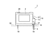
10 耐振ケース
11 下ケース部
11a 下面
12、22 周壁
12a 第1係合部
14、24 側壁部
14a、24a、27a 溝部
14b 係止爪
15、25 係止部
16、17 切欠き部
18 固定部
20、27b ヒンジ部
21 上ケース部
23 延設部
23a 第2係合部
26 保持片
27 端子カバー部
30 配線基板
Claims (7)
- 柱状のコンデンサを横置き状態で保持して配線基板に固定される耐振ケースにおいて、上面を開口してコンデンサが載置される下ケース部と、前記下ケース部に対して開閉可能に配されるとともにコンデンサの上方を覆う上ケース部とを備え、前記下ケース部が下面上に第1係合部を有するとともに、前記上ケース部が前記第1係合部に係合して閉じられた状態を保持する第2係合部を有し、
前記上ケース部を閉じた際に、前記第2係合部の下端が前記下ケース部の下面に対して略同一面上に配される構成とし、前記下ケース部の下面の軸方向の両端にそれぞれ切欠き部を設け、各前記切欠き部には配線基板に半田付けされる金属片からなる固定部を設け、
前記上ケース部が前記下ケース部の軸方向の一端面を覆う端子カバー部を有し、前記端子カバー部が前記上ケース部の下端から軸方向に延びて下方に折曲可能に形成されることを特徴とする耐振ケース。 - 前記下ケース部の軸方向の一端部に配される側壁部と、前記上ケース部の軸方向の他端部に配される保持片とを備え、前記保持片は前記上ケース部の周壁から前記側壁部に向かって軸方向に延び、下方に折り曲げ可能に形成されることを特徴とする請求項1に記載の耐振ケース。
- 前記第2係合部の少なくとも一部が前記保持片よりも前記側壁部から軸方向に離れて配されることを特徴とする請求項2に記載の耐振ケース。
- 前記下ケース部及び前記上ケース部の少なくとも一方が、軸方向の他端部に配されるとともに周壁から径方向内側に延びる係止部を有することを特徴とする請求項2または請求項3に記載の耐振ケース。
- 前記下ケース部及び前記上ケース部が樹脂成形品により薄肉のヒンジ部を介して一体に形成されることを特徴とする請求項1~請求項4のいずれかに記載の耐振ケース。
- 請求項1~請求項5のいずれかに記載の耐振ケースと、コンデンサ素子を収納した筒状の本体ケースの一端を弾性体の封止体により封止されるコンデンサとを備えたことを特徴とするコンデンサ装置。
- 前記封止体が前記本体ケースから軸方向外側に突出することを特徴とする請求項6に記載のコンデンサ装置。
Priority Applications (1)
| Application Number | Priority Date | Filing Date | Title |
|---|---|---|---|
| JP2019101019A JP7384377B2 (ja) | 2019-05-30 | 2019-05-30 | 耐振ケース及びそれを備えたコンデンサ装置 |
Applications Claiming Priority (1)
| Application Number | Priority Date | Filing Date | Title |
|---|---|---|---|
| JP2019101019A JP7384377B2 (ja) | 2019-05-30 | 2019-05-30 | 耐振ケース及びそれを備えたコンデンサ装置 |
Publications (2)
| Publication Number | Publication Date |
|---|---|
| JP2020194938A JP2020194938A (ja) | 2020-12-03 |
| JP7384377B2 true JP7384377B2 (ja) | 2023-11-21 |
Family
ID=73547671
Family Applications (1)
| Application Number | Title | Priority Date | Filing Date |
|---|---|---|---|
| JP2019101019A Active JP7384377B2 (ja) | 2019-05-30 | 2019-05-30 | 耐振ケース及びそれを備えたコンデンサ装置 |
Country Status (1)
| Country | Link |
|---|---|
| JP (1) | JP7384377B2 (ja) |
Citations (4)
| Publication number | Priority date | Publication date | Assignee | Title |
|---|---|---|---|---|
| JP2003197470A (ja) | 2001-12-28 | 2003-07-11 | Elna Co Ltd | チップ型アルミニウム電解コンデンサおよび回路基板装置 |
| JP2013098206A (ja) | 2011-10-28 | 2013-05-20 | Panasonic Corp | キャパシタモジュール |
| JP2015122405A (ja) | 2013-12-24 | 2015-07-02 | カヤバ工業株式会社 | 電子機器 |
| JP2016146445A (ja) | 2015-02-09 | 2016-08-12 | 日本ケミコン株式会社 | モジュール |
-
2019
- 2019-05-30 JP JP2019101019A patent/JP7384377B2/ja active Active
Patent Citations (4)
| Publication number | Priority date | Publication date | Assignee | Title |
|---|---|---|---|---|
| JP2003197470A (ja) | 2001-12-28 | 2003-07-11 | Elna Co Ltd | チップ型アルミニウム電解コンデンサおよび回路基板装置 |
| JP2013098206A (ja) | 2011-10-28 | 2013-05-20 | Panasonic Corp | キャパシタモジュール |
| JP2015122405A (ja) | 2013-12-24 | 2015-07-02 | カヤバ工業株式会社 | 電子機器 |
| JP2016146445A (ja) | 2015-02-09 | 2016-08-12 | 日本ケミコン株式会社 | モジュール |
Also Published As
| Publication number | Publication date |
|---|---|
| JP2020194938A (ja) | 2020-12-03 |
Similar Documents
| Publication | Publication Date | Title |
|---|---|---|
| JP6582016B2 (ja) | 電気接続箱 | |
| US10770876B2 (en) | Electrical connection box and ground connection structure thereof | |
| JP4850577B2 (ja) | 電線と電子部品内蔵ユニットとの接続構造 | |
| US20070093131A1 (en) | Connector | |
| JP6537483B2 (ja) | 電源接続システム | |
| JP5788658B2 (ja) | コネクタ | |
| JP2018142571A (ja) | 蓄電ユニット | |
| US11539149B2 (en) | Terminal block with a removable busbar assembly | |
| US20190020146A1 (en) | Waterproof structure of connector | |
| JP2012243546A (ja) | 防水コネクタ | |
| JP5233294B2 (ja) | 電子部品 | |
| JP7134792B2 (ja) | シールドコネクタ | |
| JP7384377B2 (ja) | 耐振ケース及びそれを備えたコンデンサ装置 | |
| JP6238874B2 (ja) | 電気接続箱 | |
| JP2014060073A (ja) | コネクタ | |
| JP2023001851A (ja) | バスバカバーおよびバスバの配索構造 | |
| JP2014139517A (ja) | 液面検出装置 | |
| JP5851869B2 (ja) | 電気接続箱 | |
| JP6550777B2 (ja) | モジュール及びモジュールの製造方法 | |
| JP6047843B2 (ja) | 端子カバー | |
| CN113904162B (zh) | 连接器 | |
| JP2020194939A (ja) | 耐振ケースを備えたコンデンサ装置及び耐振ケース | |
| JP6183007B2 (ja) | コンデンサモジュールおよびその製造方法 | |
| JP7383442B2 (ja) | 電気接続箱 | |
| JP2011019343A (ja) | カバー |
Legal Events
| Date | Code | Title | Description |
|---|---|---|---|
| A621 | Written request for application examination |
Free format text: JAPANESE INTERMEDIATE CODE: A621 Effective date: 20220421 |
|
| A977 | Report on retrieval |
Free format text: JAPANESE INTERMEDIATE CODE: A971007 Effective date: 20230418 |
|
| A131 | Notification of reasons for refusal |
Free format text: JAPANESE INTERMEDIATE CODE: A131 Effective date: 20230523 |
|
| A521 | Request for written amendment filed |
Free format text: JAPANESE INTERMEDIATE CODE: A523 Effective date: 20230704 |
|
| A131 | Notification of reasons for refusal |
Free format text: JAPANESE INTERMEDIATE CODE: A131 Effective date: 20230919 |
|
| A521 | Request for written amendment filed |
Free format text: JAPANESE INTERMEDIATE CODE: A523 Effective date: 20231010 |
|
| TRDD | Decision of grant or rejection written | ||
| A01 | Written decision to grant a patent or to grant a registration (utility model) |
Free format text: JAPANESE INTERMEDIATE CODE: A01 Effective date: 20231024 |
|
| A61 | First payment of annual fees (during grant procedure) |
Free format text: JAPANESE INTERMEDIATE CODE: A61 Effective date: 20231101 |
|
| R150 | Certificate of patent or registration of utility model |
Ref document number: 7384377 Country of ref document: JP Free format text: JAPANESE INTERMEDIATE CODE: R150 |