JP7371663B2 - inspection system - Google Patents
inspection system Download PDFInfo
- Publication number
- JP7371663B2 JP7371663B2 JP2021075301A JP2021075301A JP7371663B2 JP 7371663 B2 JP7371663 B2 JP 7371663B2 JP 2021075301 A JP2021075301 A JP 2021075301A JP 2021075301 A JP2021075301 A JP 2021075301A JP 7371663 B2 JP7371663 B2 JP 7371663B2
- Authority
- JP
- Japan
- Prior art keywords
- flow rate
- container
- inspection
- section
- exhaust
- Prior art date
- Legal status (The legal status is an assumption and is not a legal conclusion. Google has not performed a legal analysis and makes no representation as to the accuracy of the status listed.)
- Active
Links
Images

Classifications
-
- G—PHYSICS
- G01—MEASURING; TESTING
- G01M—TESTING STATIC OR DYNAMIC BALANCE OF MACHINES OR STRUCTURES; TESTING OF STRUCTURES OR APPARATUS, NOT OTHERWISE PROVIDED FOR
- G01M3/00—Investigating fluid-tightness of structures
- G01M3/02—Investigating fluid-tightness of structures by using fluid or vacuum
- G01M3/26—Investigating fluid-tightness of structures by using fluid or vacuum by measuring rate of loss or gain of fluid, e.g. by pressure-responsive devices, by flow detectors
- G01M3/32—Investigating fluid-tightness of structures by using fluid or vacuum by measuring rate of loss or gain of fluid, e.g. by pressure-responsive devices, by flow detectors for containers, e.g. radiators
- G01M3/3209—Details, e.g. container closure devices
-
- G—PHYSICS
- G01—MEASURING; TESTING
- G01M—TESTING STATIC OR DYNAMIC BALANCE OF MACHINES OR STRUCTURES; TESTING OF STRUCTURES OR APPARATUS, NOT OTHERWISE PROVIDED FOR
- G01M3/00—Investigating fluid-tightness of structures
- G01M3/02—Investigating fluid-tightness of structures by using fluid or vacuum
- G01M3/26—Investigating fluid-tightness of structures by using fluid or vacuum by measuring rate of loss or gain of fluid, e.g. by pressure-responsive devices, by flow detectors
-
- H—ELECTRICITY
- H10—SEMICONDUCTOR DEVICES; ELECTRIC SOLID-STATE DEVICES NOT OTHERWISE PROVIDED FOR
- H10P—GENERIC PROCESSES OR APPARATUS FOR THE MANUFACTURE OR TREATMENT OF DEVICES COVERED BY CLASS H10
- H10P72/00—Handling or holding of wafers, substrates or devices during manufacture or treatment thereof
- H10P72/06—Apparatus for monitoring, sorting, marking, testing or measuring
- H10P72/0616—Monitoring of warpages, curvatures, damages, defects or the like
-
- G—PHYSICS
- G01—MEASURING; TESTING
- G01M—TESTING STATIC OR DYNAMIC BALANCE OF MACHINES OR STRUCTURES; TESTING OF STRUCTURES OR APPARATUS, NOT OTHERWISE PROVIDED FOR
- G01M3/00—Investigating fluid-tightness of structures
- G01M3/02—Investigating fluid-tightness of structures by using fluid or vacuum
- G01M3/26—Investigating fluid-tightness of structures by using fluid or vacuum by measuring rate of loss or gain of fluid, e.g. by pressure-responsive devices, by flow detectors
- G01M3/32—Investigating fluid-tightness of structures by using fluid or vacuum by measuring rate of loss or gain of fluid, e.g. by pressure-responsive devices, by flow detectors for containers, e.g. radiators
- G01M3/3236—Investigating fluid-tightness of structures by using fluid or vacuum by measuring rate of loss or gain of fluid, e.g. by pressure-responsive devices, by flow detectors for containers, e.g. radiators by monitoring the interior space of the containers
- G01M3/3254—Investigating fluid-tightness of structures by using fluid or vacuum by measuring rate of loss or gain of fluid, e.g. by pressure-responsive devices, by flow detectors for containers, e.g. radiators by monitoring the interior space of the containers using a flow detector
-
- H—ELECTRICITY
- H10—SEMICONDUCTOR DEVICES; ELECTRIC SOLID-STATE DEVICES NOT OTHERWISE PROVIDED FOR
- H10P—GENERIC PROCESSES OR APPARATUS FOR THE MANUFACTURE OR TREATMENT OF DEVICES COVERED BY CLASS H10
- H10P72/00—Handling or holding of wafers, substrates or devices during manufacture or treatment thereof
- H10P72/06—Apparatus for monitoring, sorting, marking, testing or measuring
- H10P72/0604—Process monitoring, e.g. flow or thickness monitoring
-
- H—ELECTRICITY
- H10—SEMICONDUCTOR DEVICES; ELECTRIC SOLID-STATE DEVICES NOT OTHERWISE PROVIDED FOR
- H10P—GENERIC PROCESSES OR APPARATUS FOR THE MANUFACTURE OR TREATMENT OF DEVICES COVERED BY CLASS H10
- H10P72/00—Handling or holding of wafers, substrates or devices during manufacture or treatment thereof
- H10P72/10—Handling or holding of wafers, substrates or devices during manufacture or treatment thereof using carriers specially adapted therefor, e.g. front opening unified pods [FOUP]
- H10P72/19—Handling or holding of wafers, substrates or devices during manufacture or treatment thereof using carriers specially adapted therefor, e.g. front opening unified pods [FOUP] closed carriers
- H10P72/1924—Handling or holding of wafers, substrates or devices during manufacture or treatment thereof using carriers specially adapted therefor, e.g. front opening unified pods [FOUP] closed carriers characterised by atmosphere control
-
- H—ELECTRICITY
- H10—SEMICONDUCTOR DEVICES; ELECTRIC SOLID-STATE DEVICES NOT OTHERWISE PROVIDED FOR
- H10P—GENERIC PROCESSES OR APPARATUS FOR THE MANUFACTURE OR TREATMENT OF DEVICES COVERED BY CLASS H10
- H10P72/00—Handling or holding of wafers, substrates or devices during manufacture or treatment thereof
- H10P72/30—Handling or holding of wafers, substrates or devices during manufacture or treatment thereof for conveying, e.g. between different workstations
- H10P72/34—Handling or holding of wafers, substrates or devices during manufacture or treatment thereof for conveying, e.g. between different workstations the wafers being stored in a carrier, involving loading and unloading
- H10P72/3404—Storage means
Landscapes
- Physics & Mathematics (AREA)
- General Physics & Mathematics (AREA)
- Examining Or Testing Airtightness (AREA)
- Warehouses Or Storage Devices (AREA)
- Container, Conveyance, Adherence, Positioning, Of Wafer (AREA)
Description
本発明は、容器が載置される載置台、及び当該載置台に載置された容器に対して気体の供給を行う気体供給装置を備えた容器収容設備にて、気体の流れの検査を行う検査システムに関する。 The present invention inspects the flow of gas in a container storage facility equipped with a mounting table on which a container is placed and a gas supply device that supplies gas to the container placed on the mounting table. Regarding inspection systems.
このような検査システムの一例が、下記の特許文献1に開示されている。以下、「背景技術」及び「発明が解決しようとする課題」の説明では、特許文献1における符号を括弧内に引用する。
An example of such an inspection system is disclosed in
特許文献1には、載置台(3)に載置された容器(F)の容器流入部(24)に接続されるように載置台(3)に配置された給気部(30)と、当該給気部に接続された給気配管(34)と、当該給気配管を通って給気部(30)に供給される気体の流量を制御する給気流量制御部(32)と、載置台(3)に載置された容器(F)の容器流出部(26)に接続されるように載置台(3)に配置された排気部(31)と、当該排気部に接続された排気配管(35)と、を備えた容器収容設備(1)が開示されている。そして、この容器収容設備(1)で用いられる検査システムは、排気配管(35)を流動する気体の流量を検出するセンサ(33)を備えている(特許文献1の図1及び図2参照)。
特許文献1の容器(F)は、一部が開口した本体部(21)と、当該本体部の開口を塞ぐように配置された蓋部(22)と、を備えている。このような容器(F)の内部に気体が供給される場合、容器(F)の内部で気体が飽和状態となった後も気体の供給が維持されると、本体部(21)と蓋部(22)との隙間から気体が漏れ出す。このとき、容器(F)が破損している場合等には、気体の漏れ量が多くなる。これを利用して、特許文献1の検査システムは、センサ(33)にて検出された流量が、規定の閾値以上である場合には気体の流れが正常であると判定し、上記の閾値未満である場合には気体の流れが異常であると判定する。
The container (F) of
ところで、特許文献1の検査システムは、容器流入部(24)に給気部(30)が適切に接続されていると共に、容器流出部(26)に排気部(31)が適切に接続されていることを前提として、気体の流れの検査を行うものである。そのため、載置台(3)の異常や載置台(3)における容器(F)の位置ずれに起因して、容器流入部(24)に給気部(30)が適切に接続されていない場合、又は、容器流出部(26)に排気部(31)が適切に接続されていない場合には、気体の流れの検査を適切に行うことができない。
By the way, in the inspection system of
そこで、容器が載置される載置台の異常又は載置台における容器の位置ずれの有無を適切に検査できる検査システムの実現が望まれる。 Therefore, it is desired to realize an inspection system that can appropriately inspect the presence or absence of an abnormality in the mounting table on which the container is placed or the presence or absence of displacement of the container on the mounting table.
上記に鑑みた、検査システムの特徴構成は、
容器が載置される載置台と、前記載置台に載置された前記容器に対して気体の供給を行う気体供給装置と、を備えた容器収容設備にて、前記気体の流れの検査を行う検査システムであって、
前記載置台に載置可能に構成された検査ユニットと、判定部と、を備え、
前記容器は、前記気体の流入口が形成された容器流入部を備え、
前記気体供給装置は、前記載置台に載置された前記容器の前記容器流入部に接続されるように前記載置台に配置された給気部と、前記給気部に接続された給気配管と、前記給気配管を通って前記給気部に供給される前記気体の流量が規定の給気流量となるように、前記気体の流量を制御する給気流量制御部と、を備え、
前記検査ユニットは、当該検査ユニットが前記載置台に載置された状態で前記給気部に接続される検査流入部と、前記検査流入部から流入した前記気体の流量である流入流量を測定する流入流量測定部と、を備え、
前記判定部は、前記給気流量と前記流入流量との差に基づいて、前記給気部と前記検査流入部との接続部分における前記気体の漏れ状態を判定し、
前記検査ユニットは、前記検査流入部に接続された流入配管を更に備え、
前記流入流量測定部は、前記流入配管を流動する前記気体の前記流入流量を測定し、
前記流入配管は、前記流入流量測定部による前記流入流量の測定箇所に対して下流側で大気開放されている点にある。
In view of the above, the characteristic configuration of the inspection system is as follows:
Inspecting the flow of the gas in a container storage facility that includes a mounting table on which a container is placed and a gas supply device that supplies gas to the container placed on the mounting table. An inspection system,
An inspection unit configured to be placed on the mounting table, and a determination unit,
The container includes a container inflow portion in which an inflow port for the gas is formed,
The gas supply device includes an air supply section arranged on the mounting table so as to be connected to the container inflow section of the container placed on the mounting table, and an air supply pipe connected to the air supply section. and an air supply flow rate control unit that controls the flow rate of the gas so that the flow rate of the gas supplied to the air supply unit through the air supply pipe becomes a specified air supply flow rate,
The inspection unit measures an inspection inflow section connected to the air supply section while the inspection unit is placed on the mounting table, and an inflow flow rate that is the flow rate of the gas flowing from the inspection inflow section. An inflow flow rate measuring section;
The determining unit determines a leakage state of the gas at a connecting portion between the air supply unit and the inspection inflow unit based on a difference between the air supply flow rate and the inflow flow rate ,
The inspection unit further includes an inflow pipe connected to the inspection inflow section,
The inflow flow rate measurement unit measures the inflow flow rate of the gas flowing through the inflow pipe,
The inflow pipe is open to the atmosphere on the downstream side of the point where the inflow flow rate is measured by the inflow flow rate measuring section .
この特徴構成によれば、容器の代わりに検査ユニットを載置台に載置することで、給気配管、給気部、検査流入部の順に気体が流動する。このとき、給気部と検査流入部とが適切に接続されていない場合には、給気部と検査流入部とが適切に接続されている場合と比べて、給気流量が同一とすると、給気部と検査流入部との接続部分における気体の漏れ量が多くなるのに起因して流入流量が減少する。これにより、本特徴構成によれば、給気流量と流入流量との差に基づいて、給気部と検査流入部とが適切に接続されているか否かを判定することができる。ここで、検査ユニットは、容器流入部の代わりに給気部に接続される検査流入部を備えている。そのため、上記のように、容器の代わりに検査ユニットを載置台に載置して、給気部と検査流入部とが適切に接続されているか否かを判定することにより、載置台の異常又は載置台における容器の位置ずれの有無を適切に検査できる。 According to this characteristic configuration, by placing the inspection unit on the mounting table instead of the container, gas flows in the order of the air supply pipe, the air supply section, and the inspection inflow section. At this time, if the air supply part and the test inflow part are not properly connected, compared to the case where the air supply part and the test inflow part are properly connected, assuming that the air supply flow rate is the same, The inflow flow rate decreases due to an increase in the amount of gas leaking at the connection between the air supply section and the inspection inflow section. Thereby, according to the present characteristic configuration, it can be determined whether the air supply section and the test inflow section are appropriately connected based on the difference between the air supply flow rate and the inflow flow rate. Here, the inspection unit includes an inspection inlet connected to the air supply instead of the container inlet. Therefore, as mentioned above, by placing the inspection unit on the mounting table instead of the container and determining whether or not the air supply part and the inspection inflow part are properly connected, it is possible to detect abnormalities in the mounting table. It is possible to appropriately inspect whether the container is misaligned on the mounting table.
また、検査システムの特徴構成は、
容器が載置される載置台と、前記載置台に載置された前記容器から気体の排出を行う気体排出装置と、を備えた容器収容設備にて、前記気体の流れの検査を行う検査システムであって、
前記載置台に載置可能に構成された検査ユニットと、判定部と、を備え、
前記容器は、前記気体の流出口が形成された容器流出部を備え、
前記気体排出装置は、前記載置台に載置された前記容器の前記容器流出部に接続されるように前記載置台に配置された排気部と、前記排気部に接続された排気配管と、前記排気部から前記排気配管に流動する前記気体の流量が規定の排気流量となるように、前記気体の流量を制御する排気流量制御部と、を備え、
前記検査ユニットは、当該検査ユニットが前記載置台に載置された状態で前記排気部に接続される検査流出部と、前記検査流出部へ流動する前記気体の流量である流出流量を測定する流出流量測定部と、を備え、
前記判定部は、前記排気流量と前記流出流量との差に基づいて、前記排気部と前記検査流出部との接続部分における前記気体の漏れ状態を判定し、
前記検査ユニットは、前記検査流出部に接続された流出配管を更に備え、
前記流出流量測定部は、前記流出配管を流動する前記気体の前記流出流量を測定し、
前記流出配管は、前記流出流量測定部による前記流出流量の測定箇所に対して上流側で大気開放されている点にある。
In addition, the characteristic configuration of the inspection system is as follows:
An inspection system for inspecting the flow of gas in a container accommodation facility that includes a mounting table on which a container is placed and a gas exhaust device that discharges gas from the container placed on the mounting table. And,
An inspection unit configured to be placed on the mounting table, and a determination unit,
The container includes a container outlet in which an outlet for the gas is formed,
The gas exhaust device includes: an exhaust section arranged on the mounting table so as to be connected to the container outflow section of the container mounted on the mounting table; an exhaust pipe connected to the exhaust section; an exhaust flow rate control unit that controls the flow rate of the gas so that the flow rate of the gas flowing from the exhaust unit to the exhaust pipe becomes a specified exhaust flow rate,
The inspection unit includes an inspection outflow section that is connected to the exhaust section when the inspection unit is placed on the mounting table, and an outflow section that measures the outflow flow rate that is the flow rate of the gas flowing to the inspection outflow section. A flow rate measuring section;
The determination unit determines a leakage state of the gas at a connection portion between the exhaust part and the inspection outflow part based on the difference between the exhaust flow rate and the outflow flow rate,
The inspection unit further includes an outflow pipe connected to the inspection outflow section,
The outflow flow rate measurement unit measures the outflow flow rate of the gas flowing through the outflow pipe,
The outflow piping is open to the atmosphere on the upstream side of the point where the outflow flow rate is measured by the outflow flow rate measuring section .
この特徴構成によれば、容器の代わりに検査ユニットを載置台に載置することで、検査流出部、排気部、排気配管の順に気体が流動する。このとき、排気部と検査流出部とが適切に接続されていない場合には、排気部と検査流出部とが適切に接続されている場合と比べて、排気流量が同一とすると、排気部と検査流出部との接続部分における気体の漏れ量が多くなるのに起因して流出流量が減少する。これにより、本特徴構成によれば、排気流量と流出流量との差に基づいて、排気部と検査流出部とが適切に接続されているか否かを判定することができる。ここで、検査ユニットは、容器流出部の代わりに排気部に接続される検査流出部を備えている。そのため、上記のように、容器の代わりに検査ユニットを載置台に載置して、排気部と検査流出部とが適切に接続されているか否かを判定することにより、載置台の異常又は載置台における容器の位置ずれの有無を適切に検査できる。 According to this characteristic configuration, by placing the inspection unit on the mounting table instead of the container, the gas flows in the order of the inspection outflow section, the exhaust section, and the exhaust pipe. At this time, if the exhaust part and the inspection outflow part are not properly connected, compared to the case where the exhaust part and the inspection outflow part are properly connected, assuming the same exhaust flow rate, the exhaust part and the inspection outflow part are The outflow flow rate decreases due to an increase in the amount of gas leaking at the connection with the inspection outflow section. Thereby, according to the present characteristic configuration, it is possible to determine whether or not the exhaust part and the inspection outflow part are appropriately connected based on the difference between the exhaust flow rate and the outflow flow rate. Here, the inspection unit includes an inspection outlet connected to the exhaust instead of the container outlet. Therefore, as described above, by placing the inspection unit on the mounting table instead of the container and determining whether or not the exhaust part and the inspection outflow part are properly connected, it is possible to detect abnormalities on the mounting table or It is possible to appropriately inspect the presence or absence of misalignment of the container on the placement stand.
以下では、実施形態に係る検査システム100について、図面を参照して説明する。検査システム100は、容器収容設備10にて気体の流れの検査を行うシステムである。
Below, an
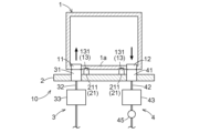
まず、容器収容設備10について説明する。図1に示すように、本実施形態では、容器収容設備10は、容器1が載置される載置台2と、当該載置台2に載置された容器1に対して気体の供給を行う気体供給装置3と、載置台2に載置された容器1から気体の排出を行う気体排出装置4と、を備えている。
First, the
容器1は、内部に規定の気体(例えば、窒素ガス、清浄空気等)を供給可能に構成された密閉容器である。本実施形態では、容器1は、当該容器1が載置台2に載置された場合に当該載置台2に対向する底部1aを備えている。本例では、容器1は、FOUP(Front Opening Unified Pod)と称される正面開口式の密閉容器である。
The
本実施形態では、容器1は、気体の流入口が形成された容器流入部11と、気体の流出口が形成された容器流出部12と、を備えている。本実施形態では、容器流入部11及び容器流出部12は、容器1の底部1aを鉛直方向(図1における上下方向)に貫通した状態で、底部1aに固定されている。つまり、容器流入部11及び容器流出部12は、容器1の内部と外部とを連通するように配置されている。また、図示は省略するが、本実施形態では、複数の容器流入部11と、複数の容器流出部12とが設けられている。
In this embodiment, the
載置台2は、容器1を下方から支持するように構成されている。本実施形態では、載置台2は、水平方向(図1における左右方向)に延在する板状に形成されている。また、本実施形態では、図示は省略するが、複数の載置台2が鉛直方向及び水平方向に並んで配置されている。
The mounting table 2 is configured to support the
本実施形態では、載置台2は、容器1を載置台2における規定の位置に案内する案内部21を備えている。本実施形態では、案内部21は、載置台2の上面から上方に突出するように形成された複数のピン211を含む。
In this embodiment, the mounting table 2 includes a
本実施形態では、容器1は、載置台2の案内部21に案内される容器被案内部13を備えている。本実施形態では、容器被案内部13は、複数のピン211にそれぞれ係合する複数の容器凹部131を含む。複数の容器凹部131は、容器1の底部1aの下面が上方に窪むように形成されている。
In this embodiment, the
気体供給装置3は、給気部31と、給気配管32と、給気流量制御部33と、を備えている。本実施形態では、複数の載置台2のそれぞれに対して、複数の給気部31、給気配管32、及び給気流量制御部33が設けられている。つまり、本実施形態では、給気部31が載置台2の数の倍数設けられ、給気配管32及び給気流量制御部33のそれぞれが載置台2と同数設けられている。
The
給気部31は、載置台2に載置された容器1の容器流入部11に接続可能に構成されている。上述したように、本実施形態では、複数の容器流入部11が設けられているため、複数の容器流入部11のそれぞれに対応するように、容器流入部11と同数の給気部31が設けられている。給気部31は、載置台2に配置されている。本実施形態では、給気部31は、載置台2から上方に突出した状態で、載置台2に固定されている。容器1が載置台2に載置されると、当該容器1の容器流入部11と当該載置台2に配置された給気部31とが互いに連通した状態となる。
The
給気配管32は、給気部31に接続されている。本実施形態では、給気配管32は、複数の給気部31に接続されるように分岐している。給気配管32は、供給源(図示を省略)から放出された気体が給気部31に向かって流動するように構成されている。そのため、給気部31に容器流入部11が接続された場合、供給源から放出された気体が、給気配管32、給気部31、容器流入部11の順に流動して、容器1の内部に供給される。なお、本実施形態では、容器流入部11は、ばね等の付勢体によって閉鎖状態となるように付勢された流入用開閉弁(図示を省略)を備えている。そして、給気部31に容器流入部11が接続された状態で、当該容器流入部11から気体が噴出されると、当該気体の圧力により流入用開閉弁が開放状態となり、気体が容器1の内部に供給される。
The
給気流量制御部33は、給気配管32を通って給気部31に供給される気体の流量が規定の給気流量Qm1となるように、気体の流量を制御する。本例では、給気流量制御部33は、給気配管32を流動する気体の質量流量を測定して、当該質量流量を制御するマスフローコントローラ(Mass Flow Controller)である。
The air supply flow
気体排出装置4は、排気部41と、排気配管42と、排気流量制御部43と、を備えている。本実施形態では、複数の載置台2のそれぞれに対して、複数の排気部41、排気配管42、及び排気流量制御部43が設けられている。つまり、本実施形態では、排気部41が載置台2の数の倍数設けられ、排気配管42及び排気流量制御部43のそれぞれが載置台2と同数設けられている。
The
排気部41は、載置台2に載置された容器1の容器流出部12に接続可能に構成されている。上述したように、本実施形態では、複数の容器流出部12が設けられているため、複数の容器流出部12のそれぞれに対応するように、容器流出部12と同数の排気部41が設けられている。排気部41は、載置台2に配置されている。本実施形態では、排気部41は、載置台2から上方に突出した状態で、載置台2に固定されている。容器1が載置台2に載置されると、当該容器1の容器流出部12と当該載置台2に配置された排気部41とが互いに連通した状態となる。
The
排気配管42は、排気部41に接続されている。本実施形態では、排気配管42は、複数の排気部41に接続されるよう分岐している。排気配管42は、排気部41から排気された気体が流動するように構成されている。排気配管42には、排気部41から排気配管42に向けた気流を生成する気流生成部45が設けられている。本例では、気流生成部45は、流体を高速で噴射することで負圧を生成させるエジェクタである。
The
排気部41に容器流出部12が接続された状態で、気流生成部45により気流が生成された場合、容器1の内部の気体が、容器流出部12、排気部41、排気配管42の順に流動して、容器1の内部から排出される。なお、本実施形態では、容器流出部12は、ばね等の付勢体によって閉鎖状態となるように付勢された流出用開閉弁(図示を省略)を備えている。そして、排気部41に容器流出部12が接続された状態で、気流生成部45により気流が生成されると、容器1の内部の気体の圧力により流出用開閉弁が開放状態となり、容器1の内部の気体が容器流出部12を通って排気配管42へ流動する。
When the
排気流量制御部43は、排気部41から排気配管42に流動する気体の流量が規定の排気流量Qm3となるように、気体の流量を制御する。本実施形態では、排気流量制御部43は、排気配管42における気流生成部45よりも上流側に配置されている。本例では、排気流量制御部43は、排気配管42を流動する気体の流量を測定する流量計と、排気配管42を流動する気体の流量を調整するニードルバルブと、を備えている。
The exhaust flow
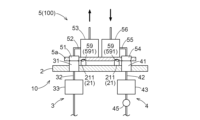
次に、検査システム100について説明する。図2に示すように、検査システム100は、載置台2に載置可能に構成された検査ユニット5を備えている。
Next, the
本実施形態では、検査ユニット5は、検査流入部51と、流入配管52と、流入流量測定部53と、検査流出部54と、流出配管55と、流出流量測定部56と、を備えている。
In this embodiment, the
検査流入部51は、検査ユニット5が載置台2に載置された状態で給気部31に接続される。検査流出部54は、検査ユニット5が載置台2に載置された状態で排気部41に接続される。検査ユニット5が載置台2に載置されると、当該載置台2に配置された給気部31と検査流入部51とが互いに連通した状態となると共に、当該載置台2に配置された排気部41と検査流出部54とが互いに連通した状態となる。
The
本実施形態では、検査流入部51は、容器流入部11と同じ形状及び構造を有している。具体的には、本実施形態では、検査流入部51も上記の流入用開閉弁を備えている。また、本実施形態では、容器流入部11と同数の検査流入部51が設けられている。そして、これらの複数の検査流入部51の互いの位置関係が、複数の容器流入部11の互いの位置関係と同一となるように、複数の検査流入部51が配置されている。
In this embodiment, the
また、本実施形態では、検査流出部54は、容器流出部12と同じ形状及び構造を有している。具体的には、本実施形態では、検査流出部54も上記の流出用開閉弁を備えている。また、本実施形態では、容器流出部12と同数の検査流出部54が設けられている。そして、これらの複数の検査流出部54の互いの位置関係が、複数の容器流出部12の互いの位置関係と同一となるように、複数の検査流出部54が配置されている。
Further, in this embodiment, the
流入配管52は、検査流入部51に接続されている。本実施形態では、流入配管52は、複数の検査流入部51に接続されるように分岐している。流出配管55は、検査流出部54に接続されている。本実施形態では、流出配管55は、複数の検査流出部54に接続されるように分岐している。
The
流入流量測定部53は、検査流入部51から流入した気体の流量である流入流量Qm2を測定可能に構成されている。本実施形態では、流入流量測定部53は、流入配管52を流動する気体の流入流量Qm2を測定する。本例では、流入流量測定部53は、流入配管52を流動する気体の質量流量を測定するマスフローメータ(Mass Flow Meter)である。
The inflow flow
流出流量測定部56は、検査流出部54へ流動する気体の流量である流出流量Qm4を測定可能に構成されている。本実施形態では、流出流量測定部56は、流出配管55を流動する気体の流出流量Qm4を測定する。本例では、流出流量測定部56は、流出配管55を流動する気体の流量を測定する流量計と、流出配管55を流動する気体の流量を調整するニードルバルブと、を備えている。
The outflow flow
本実施形態では、流入配管52は、流入流量測定部53による流入流量Qm2の測定箇所に対して下流側で大気開放されている。そのため、本実施形態では、給気部31に検査流入部51が接続された場合、供給源から放出された気体が、給気配管32、給気部31、検査流入部51、流入配管52の順に流動した後、大気に放出される。
In this embodiment, the
また、本実施形態では、流出配管55は、流出流量測定部56による流出流量Qm4の測定箇所に対して上流側で大気開放されている。そのため、本実施形態では、排気部41に検査流出部54が接続された状態で、気流生成部45により気流が生成された場合、流出配管55における大気開放された部分の周囲の気体が流出配管55に吸引された後、検査流出部54、排気部41、排気配管42の順に流動する。
Further, in this embodiment, the
本実施形態では、検査ユニット5は、載置台2に載置される基部5aを備えている。図示の例では、基部5aは、水平方向(図2における左右方向)に延在する板状に形成されている。本実施形態では、検査流入部51及び検査流出部54は、基部5aを鉛直方向(図2における上下方向)に貫通した状態で、基部5aに固定されている。また、流入流量測定部53及び流出流量測定部56は、基部5aに載置された状態で、基部5aに固定されている。
In this embodiment, the
また、本実施形態では、検査ユニット5は、載置台2の案内部21に案内される検査被案内部59を備えている。検査被案内部59は、容器被案内部13と同じ形状及び構造を有している。本実施形態では、検査被案内部59は、載置台2における複数のピン211にそれぞれ係合する複数の検査凹部591を含む。複数の検査凹部591は、検査ユニット5の基部5aの下面が上方に窪むように形成されている。
Furthermore, in this embodiment, the
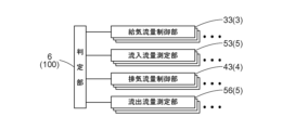
図3に示すように、検査システム100は、判定部6を備えている。本実施形態では、判定部6は、給気流量制御部33、流入流量測定部53、排気流量制御部43、及び流出流量測定部56と通信可能に構成されている。判定部6は、例えば、容器収容設備10の制御ユニット(図示を省略)に備えられると好適である。或いは、判定部6は、検査ユニット5に備えられていても良い。
As shown in FIG. 3, the
判定部6は、給気流量制御部33から給気流量Qm1を取得すると共に、流入流量測定部53から流入流量Qm2を取得する。そして、判定部6は、給気流量Qm1と流入流量Qm2との差に基づいて、給気部31と検査流入部51との接続部分における気体の漏れ状態を判定する。
The
検査ユニット5が載置台2に載置された状態において、給気部31と検査流入部51とが適切に接続されていない場合には、給気部31と検査流入部51とが適切に接続されている場合と比べて、給気流量Qm1が同一とすると、給気部31と検査流入部51との接続部分における気体の漏れ量が多くなるのに起因して流入流量Qm2が減少する。これにより、給気流量Qm1と流入流量Qm2との差に基づいて、給気部31と検査流入部51とが適切に接続されているか否かを判定することができる。ここで、検査ユニット5は、容器流入部11の代わりに給気部31に接続される検査流入部51を備えている。そのため、上記のように、容器1の代わりに検査ユニット5を載置台2に載置して、給気部31と検査流入部51とが適切に接続されているか否かを判定することにより、載置台2の異常又は載置台2における容器1の位置ずれの有無を適切に検査できる。
When the
本実施形態では、判定部6は、排気流量制御部43から排気流量Qm3を取得すると共に、流出流量測定部56から流出流量Qm4を取得する。そして、判定部6は、排気流量Qm3と流出流量Qm4との差に基づいて、排気部41と検査流出部54との接続部分における気体の漏れ状態を判定する。
In this embodiment, the
検査ユニット5が載置台2に載置された状態において、排気部41と検査流出部54とが適切に接続されていない場合には、排気部41と検査流出部54とが適切に接続されている場合と比べて、排気流量Qm3が同一とすると、排気部41と検査流出部54との接続部分における気体の漏れ量が多くなるのに起因して流出流量Qm4が減少する。これにより、排気流量Qm3と流出流量Qm4との差に基づいて、排気部41と検査流出部54とが適切に接続されているか否かを判定することができる。ここで、検査ユニット5は、容器流出部12の代わりに排気部41に接続される検査流出部54を備えている。そのため、上記のように、容器1の代わりに検査ユニット5を載置台2に載置して、排気部41と検査流出部54とが適切に接続されているか否かを判定することにより、載置台2の異常又は載置台2における容器1の位置ずれの有無を適切に検査できる。
If the
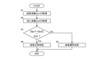
以下では、判定部6による判定処理について、図4及び図5を参照して説明する。図4及び図5のそれぞれは、判定部6による判定処理の一例を示すフローチャートである。具体的には、図4は、判定部6が給気部31と検査流入部51との接続部分における気体の漏れ状態を判定する処理の一例を示すフローチャートである。そして、図5は、判定部6が排気部41と検査流出部54との接続部分における気体の漏れ状態を判定する処理の一例を示すフローチャートである。
Below, the determination processing by the
図4に示すように、給気の判定において、まず、判定部6は、給気流量制御部33から給気流量Qm1を取得する(ステップ#1)。次に、判定部6は、流入流量測定部53から流入流量Qm2を取得する(ステップ#2)。
As shown in FIG. 4, in determining the air supply, the
続いて、判定部6は、給気流量Qm1と流入流量Qm2との差が規定の第1閾値TH1未満(|Qm1-Qm2|<TH1)であるか否かを判断する(ステップ#3)。
Subsequently, the
判定部6は、給気流量Qm1と流入流量Qm2との差が第1閾値TH1未満(|Qm1-Qm2|<TH1)であると判断した場合(ステップ#3:Yes)、給気部31と検査流入部51とが適切に接続されて、給気が正常に行われていると判定する(ステップ#4)。
If the
一方、判定部6は、給気流量Qm1と流入流量Qm2との差が第1閾値TH1以上(|Qm1-Qm2|≧TH1)であると判断した場合(ステップ#3:No)、給気部31と検査流入部51とが適切に接続されておらず、給気に異常が生じていると判定する(ステップ#5)。
On the other hand, if the determining
図5に示すように、排気の判定において、まず、判定部6は、排気流量制御部43から排気流量Qm3を取得する(ステップ#11)。次に、判定部6は、流出流量測定部56から流出流量Qm4を取得する(ステップ#12)。
As shown in FIG. 5, in the exhaust determination, first, the
続いて、判定部6は、排気流量Qm3と流出流量Qm4との差が規定の第2閾値TH2未満(|Qm3-Qm4|<TH2)であるか否かを判断する(ステップ#13)。
Subsequently, the
判定部6は、排気流量Qm3と流出流量Qm4との差が第2閾値TH2未満(|Qm3-Qm4|<TH2)であると判断した場合(ステップ#13:Yes)、排気部41と検査流出部54とが適切に接続されて、排気が正常に行われていると判定する(ステップ#14)。
When determining that the difference between the exhaust flow rate Qm3 and the outflow flow rate Qm4 is less than the second threshold value TH2 (|Qm3-Qm4|<TH2) (step #13: Yes), the
一方、判定部6は、排気流量Qm3と流出流量Qm4との差が第2閾値TH2以上(|Qm3-Qm4|≧TH2)であると判断した場合(ステップ#13:No)、排気部41と検査流出部54とが適切に接続されておらず、排気に異常が生じていると判定する(ステップ#15)。
On the other hand, if the
〔その他の実施形態〕
(1)上記の実施形態では、判定部6が、給気部31と検査流入部51との接続部分における気体の漏れ状態と、排気部41と検査流出部54との接続部分における気体の漏れ状態との双方を判定する構成を例として説明した。しかし、そのような構成に限定されることなく、判定部6が、給気部31と検査流入部51との接続部分における気体の漏れ状態と、排気部41と検査流出部54との接続部分における気体の漏れ状態とのいずれか一方のみを判定する構成としても良い。
[Other embodiments]
(1) In the above embodiment, the
(2)上記の実施形態では、気体供給装置3が複数の給気部31を備えた構成を例として説明したが、給気部31の数は限定されない。例えば、気体供給装置3が給気部31を1つのみ備えた構成であっても良い。この構成では、容器1が容器流入部11を1つのみ備えていると共に、検査ユニット5が検査流入部51を1つのみ備えていると好適である。また、上記の実施形態では、気体排出装置4が複数の排気部41を備えた構成を例として説明したが、排気部41の数は限定されない。例えば、気体排出装置4が排気部41を1つのみ備えた構成であっても良い。この構成では、容器1が容器流出部12を1つのみ備えていると共に、検査ユニット5が検査流出部54を1つのみ備えていると好適である。
(2) In the above embodiment, the configuration in which the
(3)上記の実施形態では、載置台2が案内部21としての複数のピン211を備え、容器1が容器被案内部13としての複数の容器凹部131を備えた構成を例として説明した。しかし、そのような構成に限定されることなく、例えば、載置台2が案内部21として、容器1に側方から当接して当該容器1の水平方向の移動を規制する規制部材を備えた構成としても良い。この構成では、規制部材が、検査ユニット5の一部(例えば、基部5a)に側方から当接し、検査ユニット5の水平方向の移動を規制すると好適である。また、載置台2が案内部21を備えず、容器1が容器被案内部13を備えていない構成としても良い。
(3) In the above embodiment, an example has been described in which the mounting table 2 is provided with a plurality of
(4)上記の実施形態では、検査流入部51が容器流入部11と同じ形状及び構造を有する構成を例として説明した。しかし、そのような構成に限定されることなく、検査流入部51と容器流入部11との形状及び構造の少なくとも一部が異なっていても良い。また、上記の実施形態では、検査流出部54が容器流出部12と同じ形状及び構造を有する構成を例として説明した。しかし、そのような構成に限定されることなく、検査流出部54と容器流出部12との形状及び構造の少なくとも一部が異なっていても良い。
(4) In the above embodiment, the
(5)上記の実施形態では、流入配管52が流入流量測定部53による流入流量Qm2の測定箇所に対して下流側で大気開放され、流出配管55が流出流量測定部56による流出流量Qm4の測定箇所に対して上流側で大気開放されている構成を例として説明した。しかし、そのような構成に限定されることなく、例えば、流入配管52における流入流量測定部53による流入流量Qm2の測定箇所に対して下流側の部分と、流出配管55における流出流量測定部56による流出流量Qm4の測定箇所に対して上流側の部分とが、それらの配管とは異なる接続配管に接続され、当該接続配管が大気開放されている構成としても良い。或いは、流入配管52と流出配管55とが接続配管によって互いに接続されていても良い。この場合において、接続配管が、分岐して当該分岐部分が待機開放されていても良い。
(5) In the above embodiment, the
(6)なお、上述した各実施形態で開示された構成は、矛盾が生じない限り、他の実施形態で開示された構成と組み合わせて適用することも可能である。その他の構成に関しても、本明細書において開示された実施形態は全ての点で単なる例示に過ぎない。したがって、本開示の趣旨を逸脱しない範囲内で、適宜、種々の改変を行うことが可能である。 (6) Note that the configurations disclosed in each of the embodiments described above can be applied in combination with the configurations disclosed in other embodiments as long as no contradiction occurs. Regarding other configurations, the embodiments disclosed herein are merely illustrative in all respects. Therefore, various modifications can be made as appropriate without departing from the spirit of the present disclosure.
〔上記実施形態の概要〕
以下では、上記において説明した検査システムの概要について説明する。
[Summary of the above embodiment]
Below, an overview of the inspection system described above will be explained.
検査システムは、
容器が載置される載置台と、前記載置台に載置された前記容器に対して気体の供給を行う気体供給装置と、を備えた容器収容設備にて、前記気体の流れの検査を行う検査システムであって、
前記載置台に載置可能に構成された検査ユニットと、判定部と、を備え、
前記容器は、前記気体の流入口が形成された容器流入部を備え、
前記気体供給装置は、前記載置台に載置された前記容器の前記容器流入部に接続されるように前記載置台に配置された給気部と、前記給気部に接続された給気配管と、前記給気配管を通って前記給気部に供給される前記気体の流量が規定の給気流量となるように、前記気体の流量を制御する給気流量制御部と、を備え、
前記検査ユニットは、当該検査ユニットが前記載置台に載置された状態で前記給気部に接続される検査流入部と、前記検査流入部から流入した前記気体の流量である流入流量を測定する流入流量測定部と、を備え、
前記判定部は、前記給気流量と前記流入流量との差に基づいて、前記給気部と前記検査流入部との接続部分における前記気体の漏れ状態を判定する。
The inspection system is
Inspecting the flow of the gas in a container storage facility that includes a mounting table on which a container is placed and a gas supply device that supplies gas to the container placed on the mounting table. An inspection system,
An inspection unit configured to be placed on the mounting table, and a determination unit,
The container includes a container inflow portion in which an inflow port for the gas is formed,
The gas supply device includes an air supply section arranged on the mounting table so as to be connected to the container inflow section of the container placed on the mounting table, and an air supply pipe connected to the air supply section. and an air supply flow rate control unit that controls the flow rate of the gas so that the flow rate of the gas supplied to the air supply unit through the air supply pipe becomes a specified air supply flow rate,
The inspection unit measures an inspection inflow section connected to the air supply section while the inspection unit is placed on the mounting table, and an inflow flow rate that is the flow rate of the gas flowing from the inspection inflow section. An inflow flow rate measuring section;
The determining section determines a leakage state of the gas at a connection portion between the air supply section and the inspection inflow section based on a difference between the air supply flow rate and the inflow flow rate.
この構成によれば、容器の代わりに検査ユニットを載置台に載置することで、給気配管、給気部、検査流入部の順に気体が流動する。このとき、給気部と検査流入部とが適切に接続されていない場合には、給気部と検査流入部とが適切に接続されている場合と比べて、給気流量が同一とすると、給気部と検査流入部との接続部分における気体の漏れ量が多くなるのに起因して流入流量が減少する。これにより、本構成によれば、給気流量と流入流量との差に基づいて、給気部と検査流入部とが適切に接続されているか否かを判定することができる。ここで、検査ユニットは、容器流入部の代わりに給気部に接続される検査流入部を備えている。そのため、上記のように、容器の代わりに検査ユニットを載置台に載置して、給気部と検査流入部とが適切に接続されているか否かを判定することにより、載置台の異常又は載置台における容器の位置ずれの有無を適切に検査できる。 According to this configuration, by placing the inspection unit on the mounting table instead of the container, gas flows in the order of the air supply pipe, the air supply section, and the inspection inflow section. At this time, if the air supply part and the test inflow part are not properly connected, compared to the case where the air supply part and the test inflow part are properly connected, assuming that the air supply flow rate is the same, The inflow flow rate decreases due to an increase in the amount of gas leaking at the connection between the air supply section and the inspection inflow section. Thereby, according to this configuration, it can be determined whether the air supply part and the test inflow part are appropriately connected based on the difference between the air supply flow rate and the inflow flow rate. Here, the inspection unit includes an inspection inlet connected to the air supply instead of the container inlet. Therefore, as mentioned above, by placing the inspection unit on the mounting table instead of the container and determining whether or not the air supply part and the inspection inflow part are properly connected, it is possible to detect abnormalities in the mounting table. It is possible to appropriately inspect whether the container is misaligned on the mounting table.
ここで、前記載置台は、前記容器を前記載置台における規定の位置に案内する案内部を備え、
前記容器は、前記案内部に案内される容器被案内部を備え、
前記検査ユニットは、前記容器被案内部と同じ形状及び構造を有し、前記案内部に案内される検査被案内部を備え、
前記検査流入部は、前記容器流入部と同じ形状及び構造を有していると好適である。
Here, the placing table includes a guide portion that guides the container to a prescribed position on the placing table,
The container includes a container guided part guided by the guide part,
The inspection unit includes an inspection guided part that has the same shape and structure as the container guided part and is guided by the guide part,
Preferably, the inspection inlet has the same shape and structure as the container inlet.
この構成によれば、検査ユニットを載置台に載置した場合に、載置台に載置された容器の容器被案内部が載置台の案内部により案内されるのと同様に、検査ユニットの検査被案内部が載置台の案内部により案内される。
また、本構成によれば、検査ユニットを載置台に載置した場合に、載置台に載置された容器の容器流入部に給気部が接続されるのと同様に、検査ユニットの検査流入部に給気部が接続される。
このように、本構成によれば、載置台に容器を載置している状況を精度良く再現した状態で、気体の流れの検査を行うことができる。
According to this configuration, when the inspection unit is placed on the mounting table, the container guided part of the container placed on the mounting table is guided by the guide part of the mounting table. The guided part is guided by the guide part of the mounting table.
Further, according to this configuration, when the inspection unit is placed on the mounting table, the air supply section is connected to the container inflow section of the container placed on the mounting table. The air supply section is connected to the section.
In this manner, according to the present configuration, the gas flow can be inspected while accurately reproducing the situation in which the container is placed on the mounting table.
また、前記検査ユニットは、前記検査流入部に接続された流入配管を更に備え、
前記流入流量測定部は、前記流入配管を流動する前記気体の前記流入流量を測定し、
前記流入配管は、前記流入流量測定部による前記流入流量の測定箇所に対して下流側で大気開放されていると好適である。
Further, the inspection unit further includes an inflow pipe connected to the inspection inflow section,
The inflow flow rate measurement unit measures the inflow flow rate of the gas flowing through the inflow pipe,
It is preferable that the inflow pipe is open to the atmosphere on the downstream side of the point where the inflow flow rate is measured by the inflow flow rate measuring section.
一般的に、容器収容設備の容器は、当該容器の内部で気体が飽和状態となった後も気体の供給が維持されると、隙間から気体が漏れ出すように構成されている。つまり、気体の流動経路における容器流入部の下流側において大気開放されている。本構成によれば、流入配管が、流入流量測定部による流入流量の測定箇所に対して下流側で大気開放されている。これにより、載置台に容器を載置している状況を精度良く再現した状態で、気体の流れの検査を行うことができる。 Generally, a container of a container storage facility is configured such that gas leaks out from a gap if the supply of gas is maintained even after the inside of the container becomes saturated with gas. That is, the downstream side of the container inflow portion in the gas flow path is opened to the atmosphere. According to this configuration, the inflow pipe is opened to the atmosphere on the downstream side of the point where the inflow flow rate is measured by the inflow flow rate measuring section. Thereby, the gas flow can be inspected while accurately reproducing the situation in which the container is placed on the mounting table.
また、前記容器収容設備は、前記載置台に載置された前記容器から前記気体の排出を行う気体排出装置を更に備え、
前記容器は、前記気体の流出口が形成された容器流出部を更に備え、
前記気体排出装置は、前記載置台に載置された前記容器の前記容器流出部に接続されるように、前記載置台に配置された排気部と、前記排気部に接続された排気配管と、前記排気部から前記排気配管に流動する前記気体の流量が規定の排気流量となるように、前記気体の流量を制御する排気流量制御部と、を備え、
前記検査ユニットは、当該検査ユニットが前記載置台に載置された状態で前記排気部に接続される検査流出部と、前記検査流出部へ流動する前記気体の流量である流出流量を測定する流出流量測定部と、を更に備え、
前記判定部は、前記排気流量と前記流出流量との差に基づいて、前記排気部と前記検査流出部との接続部分における前記気体の漏れ状態を判定すると好適である。
Further, the container storage equipment further includes a gas exhaust device that discharges the gas from the container placed on the mounting table,
The container further includes a container outlet in which an outlet for the gas is formed,
The gas exhaust device includes an exhaust section arranged on the mounting table so as to be connected to the container outflow section of the container placed on the mounting table, and an exhaust pipe connected to the exhaust section. an exhaust flow rate control unit that controls the flow rate of the gas so that the flow rate of the gas flowing from the exhaust unit to the exhaust pipe becomes a specified exhaust flow rate,
The inspection unit includes an inspection outflow section that is connected to the exhaust section when the inspection unit is placed on the mounting table, and an outflow section that measures the outflow flow rate that is the flow rate of the gas flowing to the inspection outflow section. further comprising a flow rate measuring section;
Preferably, the determination unit determines a leakage state of the gas at a connection portion between the exhaust part and the inspection outflow part based on a difference between the exhaust flow rate and the outflow flow rate.
この構成によれば、容器の代わりに検査ユニットを載置台に載置することで、検査流出部、排気部、排気配管の順に気体が流動する。このとき、排気部と検査流出部とが適切に接続されていない場合には、排気部と検査流出部とが適切に接続されている場合と比べて、排気流量が同一とすると、排気部と検査流出部との接続部分における気体の漏れ量が多くなるのに起因して流出流量が減少する。これにより、本構成によれば、排気流量と流出流量との差に基づいて、排気部と検査流出部とが適切に接続されているか否かを判定することができる。ここで、検査ユニットは、容器流出部の代わりに排気部に接続される検査流出部を備えている。そのため、上記のように、容器の代わりに検査ユニットを載置台に載置して、給気部と検査流入部とが適切に接続されているか否かを判定することに加えて、排気部と検査流出部とが適切に接続されているか否かも判定することにより、載置台の異常又は載置台における容器の位置ずれの有無をより詳細に検査できる。 According to this configuration, by placing the inspection unit on the mounting table instead of the container, the gas flows in the order of the inspection outflow section, the exhaust section, and the exhaust pipe. At this time, if the exhaust part and the inspection outflow part are not properly connected, compared to the case where the exhaust part and the inspection outflow part are properly connected, assuming the same exhaust flow rate, the exhaust part and the inspection outflow part are The outflow flow rate decreases due to an increase in the amount of gas leaking at the connection with the inspection outflow section. Thereby, according to this configuration, it can be determined whether the exhaust part and the inspection outflow part are appropriately connected based on the difference between the exhaust flow rate and the outflow flow rate. Here, the inspection unit includes an inspection outlet connected to the exhaust instead of the container outlet. Therefore, as mentioned above, in addition to placing the inspection unit on the mounting table instead of the container and determining whether the air supply section and the inspection inflow section are properly connected, By also determining whether or not the test outflow portion is properly connected, it is possible to inspect in more detail whether there is an abnormality in the mounting table or a positional shift of the container on the mounting table.
検査システムは、
容器が載置される載置台と、前記載置台に載置された前記容器から気体の排出を行う気体排出装置と、を備えた容器収容設備にて、前記気体の流れの検査を行う検査システムであって、
前記載置台に載置可能に構成された検査ユニットと、判定部と、を備え、
前記容器は、前記気体の流出口が形成された容器流出部を備え、
前記気体排出装置は、前記載置台に載置された前記容器の前記容器流出部に接続されるように前記載置台に配置された排気部と、前記排気部に接続された排気配管と、前記排気部から前記排気配管に流動する前記気体の流量が規定の排気流量となるように、前記気体の流量を制御する排気流量制御部と、を備え、
前記検査ユニットは、当該検査ユニットが前記載置台に載置された状態で前記排気部に接続される検査流出部と、前記検査流出部へ流動する前記気体の流量である流出流量を測定する流出流量測定部と、を備え、
前記判定部は、前記排気流量と前記流出流量との差に基づいて、前記排気部と前記検査流出部との接続部分における前記気体の漏れ状態を判定する。
The inspection system is
An inspection system for inspecting the flow of gas in a container accommodation facility that includes a mounting table on which a container is placed and a gas exhaust device that discharges gas from the container placed on the mounting table. And,
An inspection unit configured to be placed on the mounting table, and a determination unit,
The container includes a container outlet in which an outlet for the gas is formed,
The gas exhaust device includes: an exhaust section arranged on the mounting table so as to be connected to the container outflow section of the container mounted on the mounting table; an exhaust pipe connected to the exhaust section; an exhaust flow rate control unit that controls the flow rate of the gas so that the flow rate of the gas flowing from the exhaust unit to the exhaust pipe becomes a specified exhaust flow rate,
The inspection unit includes an inspection outflow section that is connected to the exhaust section when the inspection unit is placed on the mounting table, and an outflow section that measures the outflow flow rate that is the flow rate of the gas flowing to the inspection outflow section. A flow rate measuring section;
The determining section determines a leakage state of the gas at a connection portion between the exhaust section and the inspection outflow section based on a difference between the exhaust flow rate and the outflow flow rate.
この構成によれば、容器の代わりに検査ユニットを載置台に載置することで、検査流出部、排気部、排気配管の順に気体が流動する。このとき、排気部と検査流出部とが適切に接続されていない場合には、排気部と検査流出部とが適切に接続されている場合と比べて、排気流量が同一とすると、排気部と検査流出部との接続部分における気体の漏れ量が多くなるのに起因して流出流量が減少する。これにより、本構成によれば、排気流量と流出流量との差に基づいて、排気部と検査流出部とが適切に接続されているか否かを判定することができる。ここで、検査ユニットは、容器流出部の代わりに排気部に接続される検査流出部を備えている。そのため、上記のように、容器の代わりに検査ユニットを載置台に載置して、排気部と検査流出部とが適切に接続されているか否かを判定することにより、載置台の異常又は載置台における容器の位置ずれの有無を適切に検査できる。 According to this configuration, by placing the inspection unit on the mounting table instead of the container, the gas flows in the order of the inspection outflow section, the exhaust section, and the exhaust pipe. At this time, if the exhaust part and the inspection outflow part are not properly connected, compared to the case where the exhaust part and the inspection outflow part are properly connected, assuming the same exhaust flow rate, the exhaust part and the inspection outflow part are The outflow flow rate decreases due to an increase in the amount of gas leaking at the connection with the inspection outflow section. Thereby, according to this configuration, it can be determined whether the exhaust part and the inspection outflow part are appropriately connected based on the difference between the exhaust flow rate and the outflow flow rate. Here, the inspection unit includes an inspection outlet connected to the exhaust instead of the container outlet. Therefore, as described above, by placing the inspection unit on the mounting table instead of the container and determining whether or not the exhaust part and the inspection outflow part are properly connected, it is possible to detect abnormalities on the mounting table or It is possible to appropriately inspect the presence or absence of misalignment of the container on the placement stand.
ここで、前記載置台は、前記容器を前記載置台における規定の位置に案内する案内部を備え、
前記容器は、前記案内部に案内される容器被案内部を備え、
前記検査ユニットは、前記容器被案内部と同じ形状及び構造を有し、前記案内部に案内される検査被案内部を備え、
前記検査流出部は、前記容器流出部と同じ形状及び構造を有していると好適である。
Here, the placing table includes a guide portion that guides the container to a prescribed position on the placing table,
The container includes a container guided part guided by the guide part,
The inspection unit includes an inspection guided part that has the same shape and structure as the container guided part and is guided by the guide part,
Preferably, the inspection outlet has the same shape and structure as the container outlet.
この構成によれば、検査ユニットを載置台に載置した場合に、載置台に載置された容器の容器被案内部が載置台の案内部により案内されるのと同様に、検査ユニットの検査被案内部が載置台の案内部により案内される。
また、本構成によれば、検査ユニットを載置台に載置した場合に、載置台に載置された容器の容器流出部に排気部が接続されるのと同様に、検査ユニットの検査流出部に排気部が接続される。
このように、本構成によれば、載置台に容器を載置している状況を精度良く再現した状態で、気体の流れの検査を行うことができる。
According to this configuration, when the inspection unit is placed on the mounting table, the container guided part of the container placed on the mounting table is guided by the guide part of the mounting table. The guided part is guided by the guide part of the mounting table.
Further, according to this configuration, when the inspection unit is placed on the mounting table, the inspection outlet of the inspection unit is connected to the container outlet of the container placed on the mounting table. The exhaust section is connected to.
In this manner, according to the present configuration, the gas flow can be inspected while accurately reproducing the situation in which the container is placed on the mounting table.
また、前記検査ユニットは、前記検査流出部に接続された流出配管を更に備え、
前記流出流量測定部は、前記流出配管を流動する前記気体の前記流出流量を測定し、
前記流出配管は、前記流出流量測定部による前記流出流量の測定箇所に対して上流側で大気開放されていると好適である。
Further, the inspection unit further includes an outflow pipe connected to the inspection outflow section,
The outflow flow rate measurement unit measures the outflow flow rate of the gas flowing through the outflow pipe,
It is preferable that the outflow piping is open to the atmosphere on the upstream side of the point where the outflow flow rate is measured by the outflow flow rate measuring section.
一般的に、容器収容設備の容器は、当該容器の内部で気体が飽和状態となった後も気体の供給が維持されると、隙間から気体が漏れ出すように構成されている。つまり、気体の流動経路における容器流出部の上流側において大気開放されている。本構成によれば、流出配管が、流出流量測定部による流出流量の測定箇所に対して上流側で大気開放されている。これにより、載置台に容器を載置している状況を精度良く再現した状態で、気体の流れの検査を行うことができる。 Generally, a container of a container storage facility is configured such that gas leaks out from a gap if the supply of gas is maintained even after the inside of the container becomes saturated with gas. In other words, the upstream side of the container outlet in the gas flow path is open to the atmosphere. According to this configuration, the outflow pipe is opened to the atmosphere on the upstream side of the point where the outflow flow rate is measured by the outflow flow rate measuring section. Thereby, the gas flow can be inspected while accurately reproducing the situation in which the container is placed on the mounting table.
本開示に係る技術は、容器が載置される載置台、及び当該載置台に載置された容器に対して気体の供給を行う気体供給装置を備えた容器収容設備にて、気体の流れの検査を行う検査システムに利用することができる。 The technology according to the present disclosure is directed to a container storage facility that is equipped with a mounting table on which a container is placed and a gas supply device that supplies gas to the container placed on the mounting table. It can be used in an inspection system that performs inspections.
100 :検査システム
10 :容器収容設備
1 :容器
11 :容器流入部
12 :容器流出部
2 :載置台
3 :気体供給装置
31 :給気部
32 :給気配管
33 :給気流量制御部
4 :気体排出装置
41 :排気部
42 :排気配管
43 :排気流量制御部
5 :検査ユニット
51 :検査流入部
53 :流入流量測定部
54 :検査流出部
56 :流出流量測定部
6 :判定部
100 : Inspection system 10 : Container accommodation equipment 1 : Container 11 : Container inflow part 12 : Container outflow part 2 : Mounting table 3 : Gas supply device 31 : Air supply part 32 : Air supply piping 33 : Supply air flow rate control part 4 : Gas discharge device 41: Exhaust section 42: Exhaust pipe 43: Exhaust flow rate control section 5: Inspection unit 51: Inspection inflow section 53: Inflow flow rate measurement section 54: Inspection outflow section 56: Outflow flow rate measurement section 6: Judgment section
Claims (7)
前記載置台に載置可能に構成された検査ユニットと、判定部と、を備え、
前記容器は、前記気体の流入口が形成された容器流入部を備え、
前記気体供給装置は、前記載置台に載置された前記容器の前記容器流入部に接続されるように前記載置台に配置された給気部と、前記給気部に接続された給気配管と、前記給気配管を通って前記給気部に供給される前記気体の流量が規定の給気流量となるように、前記気体の流量を制御する給気流量制御部と、を備え、
前記検査ユニットは、当該検査ユニットが前記載置台に載置された状態で前記給気部に接続される検査流入部と、前記検査流入部から流入した前記気体の流量である流入流量を測定する流入流量測定部と、を備え、
前記判定部は、前記給気流量と前記流入流量との差に基づいて、前記給気部と前記検査流入部との接続部分における前記気体の漏れ状態を判定し、
前記検査ユニットは、前記検査流入部に接続された流入配管を更に備え、
前記流入流量測定部は、前記流入配管を流動する前記気体の前記流入流量を測定し、
前記流入配管は、前記流入流量測定部による前記流入流量の測定箇所に対して下流側で大気開放されている、検査システム。 Inspecting the flow of the gas in a container storage facility that includes a mounting table on which a container is placed and a gas supply device that supplies gas to the container placed on the mounting table. An inspection system,
An inspection unit configured to be placed on the mounting table, and a determination unit,
The container includes a container inflow portion in which an inflow port for the gas is formed,
The gas supply device includes an air supply section arranged on the mounting table so as to be connected to the container inflow section of the container placed on the mounting table, and an air supply pipe connected to the air supply section. and an air supply flow rate control unit that controls the flow rate of the gas so that the flow rate of the gas supplied to the air supply unit through the air supply pipe becomes a specified air supply flow rate,
The inspection unit measures an inspection inflow section connected to the air supply section while the inspection unit is placed on the mounting table, and an inflow flow rate that is the flow rate of the gas flowing from the inspection inflow section. An inflow flow rate measuring section;
The determining unit determines a leakage state of the gas at a connecting portion between the air supply unit and the inspection inflow unit based on a difference between the air supply flow rate and the inflow flow rate,
The inspection unit further includes an inflow pipe connected to the inspection inflow section,
The inflow flow rate measurement unit measures the inflow flow rate of the gas flowing through the inflow pipe,
In the inspection system, the inflow piping is opened to the atmosphere on the downstream side of a point where the inflow flow rate is measured by the inflow flow rate measuring section .
前記容器は、前記案内部に案内される容器被案内部を備え、
前記検査ユニットは、前記容器被案内部と同じ形状及び構造を有し、前記案内部に案内される検査被案内部を備え、
前記検査流入部は、前記容器流入部と同じ形状及び構造を有している、請求項1に記載の検査システム。 The placing table includes a guide portion that guides the container to a prescribed position on the placing table,
The container includes a container guided part guided by the guide part,
The inspection unit includes an inspection guided part that has the same shape and structure as the container guided part and is guided by the guide part,
The inspection system of claim 1, wherein the inspection inlet has the same shape and structure as the container inlet.
前記容器は、前記気体の流出口が形成された容器流出部を更に備え、
前記気体排出装置は、前記載置台に載置された前記容器の前記容器流出部に接続されるように、前記載置台に配置された排気部と、前記排気部に接続された排気配管と、前記排気部から前記排気配管に流動する前記気体の流量が規定の排気流量となるように、前記気体の流量を制御する排気流量制御部と、を備え、
前記検査ユニットは、当該検査ユニットが前記載置台に載置された状態で前記排気部に接続される検査流出部と、前記検査流出部へ流動する前記気体の流量である流出流量を測定する流出流量測定部と、を更に備え、
前記判定部は、前記排気流量と前記流出流量との差に基づいて、前記排気部と前記検査流出部との接続部分における前記気体の漏れ状態を判定する、請求項1又は2に記載の検査システム。 The container storage equipment further includes a gas exhaust device that discharges the gas from the container placed on the mounting table,
The container further includes a container outlet in which an outlet for the gas is formed,
The gas exhaust device includes an exhaust section arranged on the mounting table so as to be connected to the container outflow section of the container placed on the mounting table, and an exhaust pipe connected to the exhaust section. an exhaust flow rate control unit that controls the flow rate of the gas so that the flow rate of the gas flowing from the exhaust unit to the exhaust pipe becomes a specified exhaust flow rate,
The inspection unit includes an inspection outflow section that is connected to the exhaust section when the inspection unit is placed on the mounting table, and an outflow section that measures the outflow flow rate that is the flow rate of the gas flowing to the inspection outflow section. further comprising a flow rate measuring section;
The inspection according to claim 1 or 2 , wherein the determination unit determines a leakage state of the gas at a connection portion between the exhaust part and the inspection outflow part based on a difference between the exhaust flow rate and the outflow flow rate. system.
前記載置台に載置可能に構成された検査ユニットと、判定部と、を備え、
前記容器は、前記気体の流出口が形成された容器流出部を備え、
前記気体排出装置は、前記載置台に載置された前記容器の前記容器流出部に接続されるように前記載置台に配置された排気部と、前記排気部に接続された排気配管と、前記排気部から前記排気配管に流動する前記気体の流量が規定の排気流量となるように、前記気体の流量を制御する排気流量制御部と、を備え、
前記検査ユニットは、当該検査ユニットが前記載置台に載置された状態で前記排気部に接続される検査流出部と、前記検査流出部へ流動する前記気体の流量である流出流量を測定する流出流量測定部と、を備え、
前記判定部は、前記排気流量と前記流出流量との差に基づいて、前記排気部と前記検査流出部との接続部分における前記気体の漏れ状態を判定し、
前記検査ユニットは、前記検査流出部に接続された流出配管を更に備え、
前記流出流量測定部は、前記流出配管を流動する前記気体の前記流出流量を測定し、
前記流出配管は、前記流出流量測定部による前記流出流量の測定箇所に対して上流側で大気開放されている、検査システム。 An inspection system for inspecting the flow of gas in a container accommodation facility that includes a mounting table on which a container is placed and a gas exhaust device that discharges gas from the container placed on the mounting table. And,
An inspection unit configured to be placed on the mounting table, and a determination unit,
The container includes a container outlet in which an outlet for the gas is formed,
The gas exhaust device includes: an exhaust section arranged on the mounting table so as to be connected to the container outflow section of the container mounted on the mounting table; an exhaust pipe connected to the exhaust section; an exhaust flow rate control unit that controls the flow rate of the gas so that the flow rate of the gas flowing from the exhaust unit to the exhaust pipe becomes a specified exhaust flow rate,
The inspection unit includes an inspection outflow section that is connected to the exhaust section when the inspection unit is placed on the mounting table, and an outflow section that measures the outflow flow rate that is the flow rate of the gas flowing to the inspection outflow section. A flow rate measuring section;
The determination unit determines a leakage state of the gas at a connection portion between the exhaust part and the inspection outflow part based on the difference between the exhaust flow rate and the outflow flow rate,
The inspection unit further includes an outflow pipe connected to the inspection outflow section,
The outflow flow rate measurement unit measures the outflow flow rate of the gas flowing through the outflow pipe,
In the inspection system, the outflow piping is opened to the atmosphere on an upstream side with respect to a point where the outflow flow rate is measured by the outflow flow rate measuring section .
前記容器は、前記案内部に案内される容器被案内部を備え、
前記検査ユニットは、前記容器被案内部と同じ形状及び構造を有し、前記案内部に案内される検査被案内部を備え、
前記検査流出部は、前記容器流出部と同じ形状及び構造を有している、請求項5に記載の検査システム。 The placing table includes a guide portion that guides the container to a prescribed position on the placing table,
The container includes a container guided part guided by the guide part,
The inspection unit includes an inspection guided part that has the same shape and structure as the container guided part and is guided by the guide part,
6. The inspection system of claim 5, wherein the inspection outlet has the same shape and structure as the container outlet.
Priority Applications (5)
| Application Number | Priority Date | Filing Date | Title |
|---|---|---|---|
| JP2021075301A JP7371663B2 (en) | 2021-04-27 | 2021-04-27 | inspection system |
| TW111115266A TWI922661B (en) | 2021-04-27 | 2022-04-21 | Inspection system |
| US17/729,610 US11982594B2 (en) | 2021-04-27 | 2022-04-26 | Inspection system |
| CN202210452143.0A CN115248097A (en) | 2021-04-27 | 2022-04-27 | Inspection system |
| KR1020220051826A KR20220147534A (en) | 2021-04-27 | 2022-04-27 | Inspection system |
Applications Claiming Priority (1)
| Application Number | Priority Date | Filing Date | Title |
|---|---|---|---|
| JP2021075301A JP7371663B2 (en) | 2021-04-27 | 2021-04-27 | inspection system |
Publications (2)
| Publication Number | Publication Date |
|---|---|
| JP2022169329A JP2022169329A (en) | 2022-11-09 |
| JP7371663B2 true JP7371663B2 (en) | 2023-10-31 |
Family
ID=83694075
Family Applications (1)
| Application Number | Title | Priority Date | Filing Date |
|---|---|---|---|
| JP2021075301A Active JP7371663B2 (en) | 2021-04-27 | 2021-04-27 | inspection system |
Country Status (4)
| Country | Link |
|---|---|
| US (1) | US11982594B2 (en) |
| JP (1) | JP7371663B2 (en) |
| KR (1) | KR20220147534A (en) |
| CN (1) | CN115248097A (en) |
Families Citing this family (3)
| Publication number | Priority date | Publication date | Assignee | Title |
|---|---|---|---|---|
| JP7433398B1 (en) | 2022-10-21 | 2024-02-19 | 株式会社アマダ | Press brake and press brake control method |
| KR102622458B1 (en) * | 2022-11-15 | 2024-01-09 | 멜콘 주식회사 | System for detecting error of substrate processing system and method for detecting error of substrate processing system |
| JP7849131B2 (en) * | 2023-09-28 | 2026-04-21 | 芝浦メカトロニクス株式会社 | Wafer storage container processing device |
Citations (2)
| Publication number | Priority date | Publication date | Assignee | Title |
|---|---|---|---|---|
| JP2015012040A (en) | 2013-06-26 | 2015-01-19 | 株式会社ダイフク | Inspection device for article storage facility |
| JP2015095287A (en) | 2013-11-08 | 2015-05-18 | 日産自動車株式会社 | Fuel cell system |
Family Cites Families (3)
| Publication number | Priority date | Publication date | Assignee | Title |
|---|---|---|---|---|
| JPS612936U (en) | 1984-06-12 | 1986-01-09 | 横河電機株式会社 | Multi-strike type ink ribbon printer |
| JPH0612936U (en) * | 1992-07-20 | 1994-02-18 | 株式会社神戸製鋼所 | Oil leak detection device for oil supply piping |
| JP6409579B2 (en) | 2015-01-08 | 2018-10-24 | 村田機械株式会社 | Purge stocker and operation method of purge stocker |
-
2021
- 2021-04-27 JP JP2021075301A patent/JP7371663B2/en active Active
-
2022
- 2022-04-26 US US17/729,610 patent/US11982594B2/en active Active
- 2022-04-27 KR KR1020220051826A patent/KR20220147534A/en active Pending
- 2022-04-27 CN CN202210452143.0A patent/CN115248097A/en active Pending
Patent Citations (2)
| Publication number | Priority date | Publication date | Assignee | Title |
|---|---|---|---|---|
| JP2015012040A (en) | 2013-06-26 | 2015-01-19 | 株式会社ダイフク | Inspection device for article storage facility |
| JP2015095287A (en) | 2013-11-08 | 2015-05-18 | 日産自動車株式会社 | Fuel cell system |
Also Published As
| Publication number | Publication date |
|---|---|
| CN115248097A (en) | 2022-10-28 |
| KR20220147534A (en) | 2022-11-03 |
| US20220341810A1 (en) | 2022-10-27 |
| JP2022169329A (en) | 2022-11-09 |
| US11982594B2 (en) | 2024-05-14 |
| TW202242367A (en) | 2022-11-01 |
Similar Documents
| Publication | Publication Date | Title |
|---|---|---|
| JP7371663B2 (en) | inspection system | |
| KR101008241B1 (en) | An abnormality detection method of a fluid supply system using a flow control device having a pressure sensor | |
| CN110487488A (en) | The device and method of full-automation detection fuel cell pile air-tightness | |
| CN110987324A (en) | A kind of fuel cell air tightness test equipment and test method | |
| CN115413309B (en) | Gas supply control device | |
| US9645000B2 (en) | Measurement device and purge gas flow rate measuring method | |
| US10006894B2 (en) | Flow measuring device and flow measuring system | |
| CN111272341A (en) | Battery box electrolyte leakage detection device and electrolyte leakage detection method | |
| JP5679367B2 (en) | Battery box airtight inspection device | |
| KR102487786B1 (en) | VOC Leakage Gas Detection equipment for battery using vacuum chamber and Detection method using the same | |
| JP5816842B2 (en) | Gas leak detection system for fuel cell system | |
| JP5355199B2 (en) | Airtight test apparatus and airtight test method | |
| TWI922661B (en) | Inspection system | |
| JP2012078225A (en) | Battery box airtightness inspection device | |
| CN109297654B (en) | A production information management system for combustible gas intelligent monitor | |
| JP2005315784A (en) | Leak detecting method, and detector therefor | |
| CN216621723U (en) | A one-way valve performance and long-term action life test device | |
| CN214471595U (en) | Air tightness detection device | |
| CN209857482U (en) | A waterway system and semiconductor production equipment | |
| KR101985809B1 (en) | Leakage testing equipment for electrostatic chuck | |
| KR20220135290A (en) | Carrier for measurement and wafer transfer system including the same | |
| CN108267280A (en) | Air-tightness detection method and air-tightness detection device | |
| KR20250104798A (en) | Leakage detection system for detection object | |
| CN223656633U (en) | A clamping detection device and machine tool | |
| JP2003254855A (en) | Leakage-detecting apparatus |
Legal Events
| Date | Code | Title | Description |
|---|---|---|---|
| A621 | Written request for application examination |
Free format text: JAPANESE INTERMEDIATE CODE: A621 Effective date: 20230130 |
|
| A871 | Explanation of circumstances concerning accelerated examination |
Free format text: JAPANESE INTERMEDIATE CODE: A871 Effective date: 20230317 |
|
| A131 | Notification of reasons for refusal |
Free format text: JAPANESE INTERMEDIATE CODE: A131 Effective date: 20230425 |
|
| A521 | Request for written amendment filed |
Free format text: JAPANESE INTERMEDIATE CODE: A523 Effective date: 20230620 |
|
| TRDD | Decision of grant or rejection written | ||
| A01 | Written decision to grant a patent or to grant a registration (utility model) |
Free format text: JAPANESE INTERMEDIATE CODE: A01 Effective date: 20230919 |
|
| A61 | First payment of annual fees (during grant procedure) |
Free format text: JAPANESE INTERMEDIATE CODE: A61 Effective date: 20231002 |
|
| R150 | Certificate of patent or registration of utility model |
Ref document number: 7371663 Country of ref document: JP Free format text: JAPANESE INTERMEDIATE CODE: R150 |