JP7366270B2 - Outdoor unit packing equipment - Google Patents

Outdoor unit packing equipment Download PDF

Info

Publication number
JP7366270B2
JP7366270B2 JP2022534506A JP2022534506A JP7366270B2 JP 7366270 B2 JP7366270 B2 JP 7366270B2 JP 2022534506 A JP2022534506 A JP 2022534506A JP 2022534506 A JP2022534506 A JP 2022534506A JP 7366270 B2 JP7366270 B2 JP 7366270B2
Authority
JP
Japan
Prior art keywords
cut
side wall
raised
outdoor unit
cushioning material
Prior art date
Legal status (The legal status is an assumption and is not a legal conclusion. Google has not performed a legal analysis and makes no representation as to the accuracy of the status listed.)
Active
Application number
JP2022534506A
Other languages
Japanese (ja)
Other versions
JPWO2022009277A1 (en
JPWO2022009277A5 (en
Inventor
大輝 藤田
俊行 久保野
未帆 杉本
Current Assignee (The listed assignees may be inaccurate. Google has not performed a legal analysis and makes no representation or warranty as to the accuracy of the list.)
Mitsubishi Electric Corp
Original Assignee
Mitsubishi Electric Corp
Priority date (The priority date is an assumption and is not a legal conclusion. Google has not performed a legal analysis and makes no representation as to the accuracy of the date listed.)
Filing date
Publication date
Application filed by Mitsubishi Electric Corp filed Critical Mitsubishi Electric Corp
Publication of JPWO2022009277A1 publication Critical patent/JPWO2022009277A1/ja
Publication of JPWO2022009277A5 publication Critical patent/JPWO2022009277A5/ja
Application granted granted Critical
Publication of JP7366270B2 publication Critical patent/JP7366270B2/en
Active legal-status Critical Current
Anticipated expiration legal-status Critical

Links

Images

Classifications

    • BPERFORMING OPERATIONS; TRANSPORTING
    • B65CONVEYING; PACKING; STORING; HANDLING THIN OR FILAMENTARY MATERIAL
    • B65DCONTAINERS FOR STORAGE OR TRANSPORT OF ARTICLES OR MATERIALS, e.g. BAGS, BARRELS, BOTTLES, BOXES, CANS, CARTONS, CRATES, DRUMS, JARS, TANKS, HOPPERS, FORWARDING CONTAINERS; ACCESSORIES, CLOSURES, OR FITTINGS THEREFOR; PACKAGING ELEMENTS; PACKAGES
    • B65D81/00Containers, packaging elements, or packages, for contents presenting particular transport or storage problems, or adapted to be used for non-packaging purposes after removal of contents
    • B65D81/02Containers, packaging elements, or packages, for contents presenting particular transport or storage problems, or adapted to be used for non-packaging purposes after removal of contents specially adapted to protect contents from mechanical damage
    • B65D81/05Containers, packaging elements, or packages, for contents presenting particular transport or storage problems, or adapted to be used for non-packaging purposes after removal of contents specially adapted to protect contents from mechanical damage maintaining contents at spaced relation from package walls, or from other contents
    • B65D81/107Containers, packaging elements, or packages, for contents presenting particular transport or storage problems, or adapted to be used for non-packaging purposes after removal of contents specially adapted to protect contents from mechanical damage maintaining contents at spaced relation from package walls, or from other contents using blocks of shock-absorbing material
    • B65D81/113Containers, packaging elements, or packages, for contents presenting particular transport or storage problems, or adapted to be used for non-packaging purposes after removal of contents specially adapted to protect contents from mechanical damage maintaining contents at spaced relation from package walls, or from other contents using blocks of shock-absorbing material of a shape specially adapted to accommodate contents

Landscapes

  • Engineering & Computer Science (AREA)
  • Mechanical Engineering (AREA)
  • Buffer Packaging (AREA)
  • Packaging Of Machine Parts And Wound Products (AREA)

Description

本開示は、冷凍サイクル装置を構成する室外機の梱包に用いられる室外機の梱包装置に関するものである。 The present disclosure relates to an outdoor unit packaging device used for packaging an outdoor unit that constitutes a refrigeration cycle device.

従来、冷凍サイクル装置の室外機を保管し、あるいは、輸送する際には、室外機は梱包装置で梱包される。この梱包装置は、室外機の天面部を覆う上部段ボール材と、上部段ボール材と室外機の天面部との間に配置される上部緩衝材とを有する。また、梱包装置は、室外機の底部を覆う下部段ボール材と、下部段ボール材と室外機の底部との間に配置される下部緩衝材とを有する。上部段ボール材及び上部緩衝材は、室外機の上部を覆う上部梱包材を構成し、下部段ボール材及び下部緩衝材は、室外機の下部を覆う下部梱包材を構成する。そして、梱包装置は、下部段ボール材及び上部段ボール材の外側からバンド部材が掛けられており、上部梱包材と下部梱包材とはバンド部材によって固定されている。 Conventionally, when storing or transporting an outdoor unit of a refrigeration cycle device, the outdoor unit is packed using a packing device. This packaging device includes an upper corrugated cardboard material that covers the top surface of the outdoor unit, and an upper cushioning material that is disposed between the upper corrugated cardboard material and the top surface of the outdoor unit. The packaging device also includes a lower corrugated cardboard material that covers the bottom of the outdoor unit, and a lower cushioning material that is disposed between the lower corrugated cardboard material and the bottom of the outdoor unit. The upper cardboard material and the upper cushioning material constitute an upper packaging material that covers the upper part of the outdoor unit, and the lower cardboard material and the lower cushioning material constitute a lower packaging material that covers the lower part of the outdoor unit. In the packaging device, a band member is hung from the outside of the lower corrugated cardboard material and the upper corrugated cardboard material, and the upper packaging material and the lower packaging material are fixed by the band member.

ルームエアコン等に用いられる室外機を梱包する梱包装置は、室外機の排水に用いられるドレン排水管が室外機の筐体と共に梱包されているものがある。このような梱包装置は、室外機の下部を覆う下部緩衝材に穴が形成されており、ドレン排水管は、この穴の部分に収納され、梱包されている(例えば、特許文献1参照)。 BACKGROUND OF THE INVENTION Some packaging devices for packaging outdoor units used in room air conditioners and the like include a drain pipe used for draining water from the outdoor unit and a casing of the outdoor unit. In such a packaging device, a hole is formed in the lower cushioning material that covers the lower part of the outdoor unit, and the drain pipe is housed in the hole and packed (for example, see Patent Document 1).

実開平7-40538号公報Utility Model Publication No. 7-40538

特許文献1の梱包装置のような下部緩衝材の穴の部分にドレン排水管を収納する梱包装置は、物流の荷扱い上、梱包材と室外機の筐体とを固定し保持するバンド部材が作業者によって故意に引っ張られた場合、下部梱包材とドレン排水管とが破損する恐れがある。より詳細には、物流の荷扱い上、作業者によってバンド部材が故意に引っ張られた場合、下部緩衝材のドレン排水管を収納する穴とバンド部材との間の、下部緩衝材の壁が薄い箇所が、バンド部材に対抗できずに凹んで破損するおそれがある。また、下部段ボール材は、下部緩衝材の壁が薄い箇所が、バンド部材に対抗できずに凹んで破損することによって、バンド部材に対抗できず、下部緩衝材と共に凹んで破損する恐れがある。さらに、下部梱包材の破損によって、作業者のバンド部材を引っ張る力が、バンド部材を介してドレン排水管に及ぶためドレン排水管も破損する恐れがある。 A packaging device that stores a drain pipe in a hole in a lower cushioning material, such as the packaging device of Patent Document 1, has a band member that fixes and holds the packaging material and the casing of the outdoor unit for logistics purposes. If pulled intentionally by a worker, the lower packaging material and drain pipe may be damaged. More specifically, if the band member is intentionally pulled by a worker during logistics handling, the wall of the lower cushioning material between the hole that accommodates the drain pipe in the lower cushioning material and the band member may be thin. There is a risk that the portion may not be able to oppose the band member and may become dented and damaged. Furthermore, the lower corrugated cardboard material may not be able to stand up to the band member and may dent and be damaged together with the lower cushioning material because the thin wall of the lower cushioning material is not able to stand against the band member and is damaged. Furthermore, if the lower packaging material is damaged, the force of the operator pulling the band member is applied to the drain pipe via the band member, so there is a risk that the drain pipe may also be damaged.

本開示は、上記のような課題を解決するためのもので、バンド部材が引っ張られた場合でも、ドレン排水管が破損しない室外機の梱包装置を提供することにある。 The present disclosure is intended to solve the above-mentioned problems, and it is an object of the present disclosure to provide an outdoor unit packing device in which a drain pipe is not damaged even when a band member is pulled.

本開示の室外機の梱包装置は、室外機の筐体からドレン水を排水するために筐体に取り付けられるドレン排水管を備えた室外機の梱包装置であって、室外機の底部が載置される一対の下部緩衝材と、上面が開口した箱状に形成されており、一対の下部緩衝材が収納される下部段ボール材と、下部段ボール材を介して一対の下部緩衝材の双方と対向するように、下部段ボール材の外側から掛けられ、下部段ボール材が、室外機が載置された一対の下部緩衝材を覆う状態を維持するバンド部材と、を備え、一対の下部緩衝材は、互いに対向する内側面部をそれぞれ有し、下部段ボール材は、一対の下部緩衝材が載置される矩形状の底板部と、底板部の4辺に設けられて側壁を構成する複数の側壁部と、を有し、底板部は、底板部から切り起こされて形成された複数の切起こし部及び1つ以上の管用切起こし部を有し、複数の切起こし部は、一対の下部緩衝材が底板部に載置された場合に、一対の下部緩衝材の水平方向の移動を規制するように、複数の切起こし部のそれぞれの側方の側縁部と、内側面部とが対向するように形成されており、管用切起こし部は、ドレン排水管の水平方向の移動を規制するように、底板部に載置された下部緩衝材の内側面部と向かい合う位置に形成されており、管用切起こし部と、複数の切起こし部のうち管用切起こし部に隣接して設けられた第1切起こし部と、第1切起こし部の側縁部と対向する内側面部を構成する第1内側面部と、複数の側壁部のうち管用切起こし部に最も近い位置に形成された第1側壁部と、底板部とによって、ドレン排水管を収納するための収納空間が形成されたものである。 The outdoor unit packing device of the present disclosure is an outdoor unit packing device including a drain drain pipe attached to the casing of the outdoor unit for draining drain water from the casing of the outdoor unit, in which the bottom of the outdoor unit is placed. A pair of lower cushioning materials, which are formed into a box shape with an open top surface, and a lower cardboard material in which the pair of lower cushioning materials are housed, and a pair of lower cushioning materials facing both through the lower cardboard material. a band member hung from the outside of the lower corrugated cardboard material to maintain a state in which the lower corrugated cardboard material covers the pair of lower cushioning materials on which the outdoor unit is placed, the pair of lower cushioning materials; The lower corrugated cardboard material has a rectangular bottom plate part on which a pair of lower cushioning materials are placed, and a plurality of side wall parts provided on four sides of the bottom plate part and forming side walls. , the bottom plate part has a plurality of cut and raised parts cut and raised from the bottom plate part and one or more cut and raised parts for pipes, and the plurality of cut and raised parts are formed by a pair of lower cushioning materials. In order to restrict horizontal movement of the pair of lower cushioning materials when placed on the bottom plate portion, the lateral edges of each of the plurality of cut and raised portions are arranged so as to face the inner side surface portion. The cut-and-raised part for the pipe is formed at a position facing the inner surface part of the lower cushioning material placed on the bottom plate part so as to restrict the horizontal movement of the drain pipe. a first cut-and-raised part provided adjacent to the cut-and-raised part for pipes among the plurality of cut-and-raised parts; and a first inner side face part that constitutes an inner side face part facing the side edge of the first cut-and-raised part. A storage space for storing the drain pipe is formed by the first side wall portion, which is formed at a position closest to the cut-and-raised portion for the pipe among the plurality of side wall portions, and the bottom plate portion.

本開示に係る室外機の梱包装置は、管用切起こし部と、複数の切起こし部のうち管用切起こし部に隣接して設けられた第1切起こし部と、第1切起こし部の側縁部と対向する内側面部を構成する第1内側面部と、複数の側壁部のうち管用切起こし部に最も近い位置に形成された第1側壁部と、底板部とによって、ドレン排水管を収納するための収納空間が形成されたものである。梱包装置は、下部緩衝材にドレン排水管を収納するための穴を形成する必要がなく、穴とバンド部材との間の下部緩衝材の壁が薄い箇所が存在しない。そのため、梱包装置は、バンド部材が引っ張られた場合でも、下部緩衝材が破損しにくい。そして、梱包装置は、ドレン排水管が一対の下部梱包材によって保護され、作業者のバンド部材を引っ張る力が、バンド部材を介してドレン排水管に及ぶことがないためドレン排水管の破損を防ぐことができる。 A packing device for an outdoor unit according to the present disclosure includes a cut-and-raised part for pipes, a first cut-and-raised part provided adjacent to the cut-and-raised part for pipes among the plurality of cut-and-raised parts, and a side edge of the first cut-and-raised part. The drain drain pipe is housed by the first inner side face part forming the inner face part facing the part, the first side wall part formed at the position closest to the cut and raised part for the pipe among the plurality of side wall parts, and the bottom plate part. A storage space has been created for the purpose. In the packaging device, there is no need to form a hole in the lower cushioning material for accommodating the drain pipe, and there is no part where the wall of the lower cushioning material is thin between the hole and the band member. Therefore, in the packaging device, even when the band member is pulled, the lower cushioning material is unlikely to be damaged. In addition, in the packaging device, the drain drain pipe is protected by a pair of lower packing materials, and the force of the operator pulling the band member does not reach the drain drain pipe via the band member, thereby preventing damage to the drain drain pipe. be able to.

実施の形態1に係る梱包装置の前面側の斜視図である。1 is a perspective view of the front side of the packaging device according to Embodiment 1. FIG. 実施の形態1に係る梱包装置の背面側の斜視図である。FIG. 2 is a perspective view of the back side of the packaging device according to the first embodiment. 図1の梱包装置の分解斜視図である。FIG. 2 is an exploded perspective view of the packaging device of FIG. 1; 図3の右下部緩衝材及び左下部緩衝材の拡大図である。4 is an enlarged view of the lower right cushioning material and the lower left cushioning material of FIG. 3. FIG. 図3の下部段ボール材の斜視図である。FIG. 4 is a perspective view of the lower corrugated cardboard material of FIG. 3; 図5の下部段ボール材の展開図である。FIG. 6 is a developed view of the lower corrugated cardboard material of FIG. 5; 下部梱包材と室外機の斜視図である。It is a perspective view of a lower packaging material and an outdoor unit. ドレン排水管が収納された下部梱包材の平面図である。FIG. 7 is a plan view of the lower packaging material in which the drain pipe is housed. 比較例に係る下部梱包材の上面図である。FIG. 7 is a top view of a lower packaging material according to a comparative example. 実施の形態2に係る下部段ボール材の展開図である。FIG. 7 is a developed view of the lower corrugated cardboard material according to the second embodiment. 変形例に係る管用切起こし部を有する下部段ボール材の上面図である。It is a top view of the lower corrugated board material which has the cut-and-raised part for pipe|tubes based on a modification.

以下、本開示の実施の形態に係る室外機150の梱包装置100について図面等を参照しながら説明する。以下の図面において、同一の符号を付したものは、同一又はこれに相当するものであり、以下に記載する実施の形態の全文において共通することとする。そして、明細書全文に表されている構成要素の形態は、あくまでも例示であって、明細書に記載された形態に限定するものではない。また、図面では各構成部材の大きさの関係が実際のものとは異なる場合がある。なお、本実施の形態において、理解を容易にするために方向を表す用語(例えば「上」、「下」、「右」、「左」、「前」、「後」など)を適宜用いるが、これは説明のためのものであって、これらの用語は本願発明を限定するものではない。 Hereinafter, a packing apparatus 100 for an outdoor unit 150 according to an embodiment of the present disclosure will be described with reference to the drawings and the like. In the following drawings, the same reference numerals are the same or equivalent, and are common throughout the entire embodiment described below. The forms of the constituent elements shown in the entire specification are merely examples, and are not limited to the forms described in the specification. Further, in the drawings, the size relationship of each component may differ from the actual one. Note that in this embodiment, terms indicating directions (for example, "upper", "lower", "right", "left", "front", "rear", etc.) are used as appropriate to facilitate understanding. , this is for illustrative purposes only, and these terms are not intended to limit the present invention.

実施の形態1.
[梱包装置100の構成]
図1は、実施の形態1に係る梱包装置100の前面側の斜視図である。図2は、実施の形態1に係る梱包装置100の背面側の斜視図である。図3は、図1の梱包装置100の分解斜視図である。図1~図3を参照して梱包装置100の各部の構成を説明する。なお、図1以下の図面において示すX軸、Y軸、Z軸は、室外機150の熱交換器180が配置される側を梱包装置100の背面側とし、梱包装置100を梱包装置100の前面側から見た場合の軸方向を表すものとする。そのため、X軸は、X1側を左、X2側を右として梱包装置100の左右の幅方向を示す。また、Y軸は、Y1側を前側、Y2側を後側として梱包装置100の前後の奥行方向を示す。さらに、Z軸は、Z1側を上、Z2側を下として梱包装置100の上下方向を示すものである。
Embodiment 1.
[Configuration of packaging device 100]
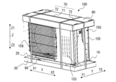
FIG. 1 is a perspective view of the front side of the packaging device 100 according to the first embodiment. FIG. 2 is a perspective view of the back side of the packaging device 100 according to the first embodiment. FIG. 3 is an exploded perspective view of the packaging apparatus 100 of FIG. 1. The configuration of each part of the packaging device 100 will be explained with reference to FIGS. 1 to 3. Note that the X-axis, Y-axis, and Z-axis shown in the drawings below in FIG. It represents the axial direction when viewed from the side. Therefore, the X axis indicates the left and right width directions of the packaging device 100 with the X1 side on the left and the X2 side on the right. Further, the Y axis indicates the front and rear depth direction of the packaging device 100, with the Y1 side as the front side and the Y2 side as the rear side. Further, the Z axis indicates the vertical direction of the packaging apparatus 100 with the Z1 side being the top and the Z2 side being the bottom.

[梱包装置100の被包装体]
梱包装置100に梱包される被包装体は、冷凍サイクル装置の室外機150である。冷凍サイクル装置は、例えば、冷蔵庫あるいは冷凍庫、自動販売機、空気調和装置、冷凍装置、給湯器などの、冷凍用途または空調用途に使用される。
[Object to be packaged in packaging device 100]
The object to be packed in the packing device 100 is an outdoor unit 150 of a refrigeration cycle device. Refrigeration cycle devices are used for refrigeration or air conditioning applications, such as refrigerators or freezers, vending machines, air conditioners, refrigeration equipment, water heaters, and the like.

室外機150は、筐体155を有する。室外機150の筐体155は、室外機150の外郭を構成する。筐体155は、板金製であり、底面を構成する底部151と、底面と対向する天面を構成する天面部152と、底部151と天面部152との間の側壁を形成する筐体側壁部153とを有し、略直方体形状に構成されている。室外機150の前面(Y1)側の筐体側壁部153には、空気の吹出口となる吹出口158が形成されている。 Outdoor unit 150 has a housing 155. The casing 155 of the outdoor unit 150 constitutes the outer shell of the outdoor unit 150. The housing 155 is made of sheet metal, and includes a bottom part 151 forming a bottom surface, a top surface part 152 forming a top surface opposite to the bottom surface, and a case side wall part forming a side wall between the bottom part 151 and the top surface part 152. 153, and is configured in a substantially rectangular parallelepiped shape. A blowout port 158 serving as an air blowout port is formed in the housing side wall portion 153 on the front (Y1) side of the outdoor unit 150.

室外機150の底部151には、筐体側壁部153が取り付けられ、底部151の下面部には、左右方向(X軸方向)に間隔を開けて配置された2つの脚部154が設けられている。脚部154は、室外機150を設置場所に固定する際に筐体155の土台となる。図3及び図4に示すように、脚部154は、室外機150の前後方向(Y軸方向)に延びるように形成されており、脚部154の先端は筐体155の前側(Y1側)と背面側(Y2側)とに位置している。 A housing side wall 153 is attached to the bottom 151 of the outdoor unit 150, and two legs 154 are provided on the lower surface of the bottom 151 at intervals in the left-right direction (X-axis direction). There is. The leg portions 154 serve as the base of the housing 155 when the outdoor unit 150 is fixed to the installation location. As shown in FIGS. 3 and 4, the legs 154 are formed to extend in the front-rear direction (Y-axis direction) of the outdoor unit 150, and the tips of the legs 154 are located on the front side (Y1 side) of the housing 155. and the back side (Y2 side).

室外機150は、熱交換器180と、送風機(図示は省略)と、圧縮機(図示は省略)とを有する。熱交換器180は、内部を流れる冷媒と、熱交換器180の周りの空気との熱交換を行い、蒸発器又は凝縮器として機能する。この熱交換器180は、筐体側壁部153に形成された開口部153aから露出するように筐体155内に配置されている。この開口部153aは、室外機150の背面(Y2)側に形成されている。 The outdoor unit 150 includes a heat exchanger 180, a blower (not shown), and a compressor (not shown). The heat exchanger 180 exchanges heat between the refrigerant flowing therein and the air around the heat exchanger 180, and functions as an evaporator or a condenser. This heat exchanger 180 is arranged within the housing 155 so as to be exposed through an opening 153a formed in the housing side wall 153. This opening 153a is formed on the back (Y2) side of the outdoor unit 150.

室外機150は、ドレン排水管90を有する。ドレン排水管90は室外機150の底部151に取り付けられ、室外機150の内部で冷房運転時又は暖房運転時に結露等により発生したドレン水を室外機150の外部へ排出するための部品である。室外機150の筐体155は、底部151にドレン水を排水するための排水穴(図示は省略)が設けられている。そして、ドレン排水管90は、筐体155の排水穴に一端が固定され、他端に、排水穴からの排水を特定の位置に導くためのドレンホースが接続される。 The outdoor unit 150 has a drain pipe 90. The drain pipe 90 is attached to the bottom 151 of the outdoor unit 150 and is a component for discharging drain water generated by condensation or the like inside the outdoor unit 150 during cooling or heating operation to the outside of the outdoor unit 150. A housing 155 of the outdoor unit 150 is provided with a drainage hole (not shown) at the bottom 151 for draining drain water. One end of the drain pipe 90 is fixed to the drain hole of the housing 155, and the other end is connected to a drain hose for guiding water from the drain hole to a specific position.

ドレン排水管90は、室外機150の筐体155の外部側から底部151に形成された排水穴と連通するように接続される筐体側接続部91と、筐体側接続部91に連通するホース側接続部92とが一体的に形成された構成を有している。筐体側接続部91は、排水穴との連通部分からホース側接続部92との連通口部分に向かって径が小さくなるように漏斗状に形成されている。ホース側接続部92は、ドレンホースとの接続部分であり、ドレンホースの管内に挿入されるように管状に形成されている。 The drain pipe 90 has a housing side connection part 91 connected to communicate with a drain hole formed in the bottom part 151 from the outside of the housing 155 of the outdoor unit 150, and a hose side connected to the housing side connection part 91. It has a configuration in which the connecting portion 92 is integrally formed. The housing side connecting portion 91 is formed in a funnel shape such that the diameter decreases from the communicating portion with the drain hole toward the communicating port portion with the hose side connecting portion 92. The hose side connection part 92 is a connection part with a drain hose, and is formed into a tubular shape so as to be inserted into the pipe of the drain hose.

[梱包装置100]
梱包装置100は、室外機150の筐体155からドレン水を排水するために筐体155に取り付けられるドレン排水管90を備えた室外機150を梱包する梱包装置である。梱包装置100は、被梱包体である室外機150を保護するものであり、室外機150を荷扱い時の接触から保護する耐衝撃性と、室外機150にかかる圧力から保護する耐圧性とを有するものである。梱包装置100は、図1~図3に示すように、被包装体となる室外機150の底部151が載置される右下部緩衝材10及び左下部緩衝材20と、右下部緩衝材10及び左下部緩衝材20が載置される下部段ボール材30とを有する。
[Packing device 100]
The packing device 100 is a packing device for packing an outdoor unit 150, which includes a drain pipe 90 attached to a casing 155 for draining drain water from the casing 155 of the outdoor unit 150. The packing device 100 protects the outdoor unit 150, which is an object to be packed, and has impact resistance to protect the outdoor unit 150 from contact during handling, and pressure resistance to protect the outdoor unit 150 from pressure applied to it. It is something that you have. As shown in FIGS. 1 to 3, the packaging device 100 includes a lower right cushioning material 10 and a lower left cushioning material 20 on which the bottom part 151 of an outdoor unit 150 serving as an object to be packed is placed, and a lower right cushioning material 10 and a lower right cushioning material 10 and a lower left cushioning material 20. It has a lower corrugated cardboard material 30 on which the left lower cushioning material 20 is placed.

また、梱包装置100は、室外機150の天面部152に載置される上部緩衝材40及び上部緩衝材50と、上部緩衝材40及び上部緩衝材50に載置される上部段ボール材60とを有する。また、梱包装置100は、熱交換器180を覆うことで、物流における荷扱い時の接触から熱交換器180を保護し、熱交換器180に係る圧力から熱交換器180を保護する背面梱包材80を有する。さらに、梱包装置100は、下部段ボール材30と上部段ボール材60の外側に掛けられるバンド部材70を有する。 The packaging device 100 also includes an upper cushioning material 40 and an upper cushioning material 50 placed on the top surface part 152 of the outdoor unit 150, and an upper corrugated cardboard material 60 placed on the upper cushioning material 40 and the upper cushioning material 50. have The packaging device 100 also includes a back packaging material that covers the heat exchanger 180 to protect the heat exchanger 180 from contact during cargo handling during distribution, and protects the heat exchanger 180 from pressure related to the heat exchanger 180. It has 80. Furthermore, the packaging device 100 includes a band member 70 that is hung on the outside of the lower corrugated cardboard material 30 and the upper corrugated cardboard material 60.

(右下部緩衝材10及び左下部緩衝材20)
図4は、図3の右下部緩衝材10及び左下部緩衝材20の拡大図である。図3及び図4を用いて右下部緩衝材10及び左下部緩衝材20について説明する。なお、図3及び図4は、右下部緩衝材10及び左下部緩衝材20の大まかな構成を概念的に示した図であり、表面の凹凸等を省略している。
(Lower right cushioning material 10 and lower left cushioning material 20)
FIG. 4 is an enlarged view of the lower right cushioning material 10 and the lower left cushioning material 20 of FIG. The lower right cushioning material 10 and the lower left cushioning material 20 will be explained using FIGS. 3 and 4. Note that FIGS. 3 and 4 are diagrams conceptually showing the rough configurations of the lower right cushioning material 10 and the lower left cushioning material 20, and omit surface irregularities and the like.

右下部緩衝材10及び左下部緩衝材20は、室外機150の底部151が載置される一対の下部緩衝材である。右下部緩衝材10及び左下部緩衝材20は、互いに室外機150の幅方向(X軸方向)に間を空けて配置される。右下部緩衝材10及び左下部緩衝材20はそれぞれ、発泡スチロール等の合成樹脂材を略直方体状に成形したものである。 The lower right cushioning material 10 and the lower left cushioning material 20 are a pair of lower cushioning materials on which the bottom 151 of the outdoor unit 150 is placed. The lower right cushioning material 10 and the lower left cushioning material 20 are arranged with a gap between them in the width direction (X-axis direction) of the outdoor unit 150. The lower right cushioning material 10 and the lower left cushioning material 20 are each formed from a synthetic resin material such as styrene foam into a substantially rectangular parallelepiped shape.

右下部緩衝材10は、上面部11aと、底面部11bと、前面側の壁面及び後面側の壁面をそれぞれ形成する2つの側面部11cと、外側面部11dと、内側面部11eとを有する六面体である。上面部11aは、右下部緩衝材10の天面を構成し、底面部11bは右下部緩衝材10の底面を構成する。そして、2つの側面部11cと、外側面部11dと、内側面部11eとは、右下部緩衝材10の側壁を構成する。 The lower right cushioning material 10 is a hexahedron having an upper surface portion 11a, a bottom surface portion 11b, two side surfaces 11c forming a front wall surface and a rear wall surface, respectively, an outer surface portion 11d, and an inner surface portion 11e. be. The upper surface portion 11a constitutes the top surface of the lower right cushioning material 10, and the bottom surface portion 11b constitutes the bottom surface of the lower right cushioning material 10. The two side surfaces 11c, the outer side surface 11d, and the inner side surface 11e constitute a side wall of the lower right cushioning material 10.

なお、図4では、上面部11a、底面部11b、2つの側面部11c、外側面部11d及び内側面部11eはそれぞれ、平面で構成されているように記載されている。しかし、上面部11a、底面部11b、2つの側面部11c、外側面部11d及び内側面部11eは、平面を構成する形態に限定されるものではない。上面部11a、底面部11b、2つの側面部11c、外側面部11d及び内側面部11eにはそれぞれ、凹凸が設けられてもよい。また、壁面によって構成される角部は、面取りされていてもよい。 In addition, in FIG. 4, the top surface part 11a, the bottom surface part 11b, the two side surfaces 11c, the outer surface part 11d, and the inner surface part 11e are each described as being comprised by a plane. However, the top surface portion 11a, the bottom surface portion 11b, the two side surfaces 11c, the outer surface portion 11d, and the inner surface portion 11e are not limited to the form forming a plane. The top surface portion 11a, the bottom surface portion 11b, the two side surfaces 11c, the outer surface portion 11d, and the inner surface portion 11e may each be provided with unevenness. Furthermore, the corner portion formed by the wall surface may be chamfered.

同様に、左下部緩衝材20は、上面部21aと、底面部21bと、前面側の壁面及び後面側の壁面をそれぞれ形成する2つの側面部21cと、外側面部21dと、内側面部21eとを有する六面体である。上面部21aは、左下部緩衝材20の天面を構成し、底面部21bは左下部緩衝材20の底面を構成する。そして、2つの側面部21cと、外側面部21dと、内側面部21eとは、左下部緩衝材20の側壁を構成する。 Similarly, the lower left cushioning material 20 includes an upper surface portion 21a, a bottom surface portion 21b, two side surfaces 21c forming a front wall surface and a rear wall surface, respectively, an outer surface portion 21d, and an inner surface portion 21e. It is a hexahedron with The upper surface portion 21a constitutes the top surface of the lower left cushioning material 20, and the bottom surface portion 21b constitutes the bottom surface of the lower left cushioning material 20. The two side surfaces 21c, the outer side surface 21d, and the inner side surface 21e constitute a side wall of the lower left cushioning material 20.

図4では、上面部21a、底面部21b、2つの側面部21c、外側面部21d及び内側面部21eはそれぞれ、平面で構成されているように記載されている。しかし、上面部21a、底面部21b、2つの側面部21c、外側面部21d及び内側面部21eは、平面を構成する形態に限定されるものではない。上面部21a、底面部21b、2つの側面部21c、外側面部21d及び内側面部21eにはそれぞれ、凹凸が設けられてもよい。また、壁面によって構成される角部は、面取りされていてもよい。 In FIG. 4, the top surface portion 21a, the bottom surface portion 21b, the two side surfaces 21c, the outer surface portion 21d, and the inner surface portion 21e are each illustrated as being configured as a plane. However, the top surface portion 21a, the bottom surface portion 21b, the two side surface portions 21c, the outer surface portion 21d, and the inner surface portion 21e are not limited to a form that constitutes a plane. The top surface portion 21a, the bottom surface portion 21b, the two side surfaces 21c, the outer surface portion 21d, and the inner surface portion 21e may each be provided with unevenness. Moreover, the corner portion formed by the wall surface may be chamfered.

一対の下部緩衝材である右下部緩衝材10及び左下部緩衝材20は、下部段ボール材30の後述する底板部31に載置された場合に、内側面部11eと内側面部21eとが互いに対向している。 When the lower right cushioning material 10 and the lower left cushioning material 20, which are a pair of lower cushioning materials, are placed on the bottom plate portion 31 (described later) of the lower corrugated cardboard material 30, the inner side surface portion 11e and the inner side surface portion 21e face each other. ing.

右下部緩衝材10は、上面部11aに凹部12が形成されており、同様に、左下部緩衝材20は、上面部21aに凹部22が形成されている。凹部12及び凹部22は、上面部11a及び上面部21aから内側に凹んだ溝状に形成された部分であり、梱包装置100の短手方向(Y軸方向)に延びるように形成されている。室外機150が右下部緩衝材10及び左下部緩衝材20に載置された状態では、凹部12及び凹部22には、室外機150の底部151に設けられた脚部154が挿入されており、凹部12及び凹部22内に脚部154が配置されている。 The lower right cushioning material 10 has a recess 12 formed in the upper surface portion 11a, and similarly, the lower left cushioning material 20 has a recess 22 formed in the upper surface portion 21a. The recessed portion 12 and the recessed portion 22 are groove-shaped portions that are recessed inward from the upper surface portion 11a and the upper surface portion 21a, and are formed to extend in the lateral direction (Y-axis direction) of the packaging device 100. When the outdoor unit 150 is placed on the lower right cushioning material 10 and the lower left cushioning material 20, the legs 154 provided on the bottom 151 of the outdoor unit 150 are inserted into the recesses 12 and 22, Legs 154 are disposed within the recesses 12 and 22.

(下部段ボール材30)
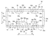
図5は、図3の下部段ボール材30の斜視図である。図6は、図5の下部段ボール材30の展開図である。図3、図5及び図6を用いて下部段ボール材30について説明する。なお、図2及び図3に示すように、右下部緩衝材10、左下部緩衝材20、及び、下部段ボール材30は、室外機150の下部を覆う、下部梱包材130である。
(Lower cardboard material 30)
FIG. 5 is a perspective view of the lower corrugated cardboard material 30 of FIG. 3. FIG. 6 is a developed view of the lower corrugated cardboard material 30 of FIG. The lower corrugated cardboard material 30 will be explained using FIGS. 3, 5, and 6. Note that, as shown in FIGS. 2 and 3, the lower right cushioning material 10, the lower left cushioning material 20, and the lower corrugated cardboard material 30 are the lower packaging material 130 that covers the lower part of the outdoor unit 150.

下部段ボール材30は、右下部緩衝材10及び左下部緩衝材20の底面及び側面を被うように形成されたトレイ型の段ボール材である。下部段ボール材30は、上面が開口した箱状に形成されており、右下部緩衝材10及び左下部緩衝材20の一対の下部緩衝材が収納される。梱包装置100において、下部段ボール材30は、右下部緩衝材10及び左下部緩衝材20の外側に被せられる。下部段ボール材30は、下部段ボール材30の外側に掛けられるバンド部材70によって、室外機150が載置された右下部緩衝材10及び左下部緩衝材20を覆う状態が維持される。 The lower corrugated cardboard material 30 is a tray-shaped corrugated cardboard material formed to cover the bottom and side surfaces of the lower right cushioning material 10 and the lower left cushioning material 20. The lower corrugated cardboard material 30 is formed into a box shape with an open top surface, and accommodates a pair of lower cushioning materials, the lower right cushioning material 10 and the lower left cushioning material 20. In the packaging device 100, the lower corrugated cardboard material 30 is placed over the outer sides of the lower right cushioning material 10 and the lower left cushioning material 20. The lower corrugated cardboard material 30 is maintained in a state of covering the lower right cushioning material 10 and the lower left cushioning material 20 on which the outdoor unit 150 is placed by the band member 70 hung on the outside of the lower corrugated cardboard material 30 .

下部段ボール材30は、一対の下部緩衝材である右下部緩衝材10及び左下部緩衝材20が載置される平板状の底板部31を有する。この底板部31は、平面視で矩形状に形成されている。下部段ボール材30の底板部31は、底板部31から切り起こされて形成された複数の切起こし部35と1つの管用切起こし部36とを有している。なお、管用切起こし部36は、1つ以上形成されていればよく、1つに限定されるものではない。切起こし部35及び管用切起こし部36の構成については後述する。 The lower corrugated cardboard material 30 has a flat bottom plate portion 31 on which the lower right cushioning material 10 and the lower left cushioning material 20, which are a pair of lower cushioning materials, are placed. This bottom plate portion 31 is formed into a rectangular shape in plan view. The bottom plate part 31 of the lower corrugated cardboard material 30 has a plurality of cut-and-raised parts 35 and one pipe-use cut-and-raised part 36 formed by cutting and raising the bottom plate part 31 . Note that the number of cut and raised pipe portions 36 is not limited to one, as long as one or more are formed. The configurations of the cut-and-raise portion 35 and the pipe cut-and-raise portion 36 will be described later.

下部段ボール材30は、底板部31の4辺に設けられて側壁を構成する複数の側壁部を有する。複数の側壁部は、後述する一対の長辺側壁部32と、一対の短辺側壁部33とによって構成される。 The lower corrugated cardboard material 30 has a plurality of side wall portions that are provided on four sides of the bottom plate portion 31 and constitute side walls. The plurality of side wall portions are constituted by a pair of long side wall portions 32 and a pair of short side wall portions 33, which will be described later.

下部段ボール材30は、底板部31の長手方向(X軸方向)の縁部31aに沿って設けられ、この縁部31aを境にして底板部31に対して角度をつけて折り曲げられる長辺側壁部32を有する。下部段ボール材30は、下部段ボール材30の短手方向(Y軸方向)において互いに対向するように、一対の長辺側壁部32が設けられている。底板部31に対して、折り曲げられた一対の長辺側壁部32は、それぞれ底板部31の長手方向(X軸方向)に延びるように形成されており、また、底板部31から上方(Z1方向)に延びるように形成されている。 The lower corrugated cardboard material 30 is a long side wall that is provided along the edge 31a in the longitudinal direction (X-axis direction) of the bottom plate part 31 and is bent at an angle with respect to the bottom plate part 31 with this edge 31a as a border. It has a section 32. The lower corrugated cardboard material 30 is provided with a pair of long side wall portions 32 so as to face each other in the lateral direction (Y-axis direction) of the lower corrugated cardboard material 30 . A pair of long side wall portions 32 bent with respect to the bottom plate portion 31 are formed to extend in the longitudinal direction (X-axis direction) of the bottom plate portion 31, and also extend upward from the bottom plate portion 31 (in the Z1 direction). ).

2つの長辺側壁部32のうち、下部段ボール材30の前方の側壁を構成するものが第1長辺側壁部32aであり、下部段ボール材30の後方の側壁を構成するものが第2長辺側壁部32bである。第1長辺側壁部32aと第2長辺側壁部32bとは、それぞれ底板部31の縁部31aを境に折り曲げられ、互いに対向するように下部段ボール材30の側壁を構成する。なお、第1長辺側壁部32aは、室外機150の吹出口158が形成されている側の面の側壁であり、第2長辺側壁部32bは、室外機150の熱交換器180が外部に露出している側の面の側壁である。 Of the two long side wall parts 32, the one that constitutes the front side wall of the lower corrugated cardboard material 30 is the first long side wall part 32a, and the one that constitutes the rear side wall of the lower corrugated cardboard material 30 is the second long side wall part 32a. This is the side wall portion 32b. The first long side wall portion 32a and the second long side wall portion 32b are respectively bent at the edge 31a of the bottom plate portion 31, and constitute side walls of the lower corrugated cardboard material 30 so as to face each other. Note that the first long side wall portion 32a is a side wall on the side where the air outlet 158 of the outdoor unit 150 is formed, and the second long side wall portion 32b is a side wall on the side where the air outlet 158 of the outdoor unit 150 is formed. This is the side wall of the side surface that is exposed.

下部段ボール材30は、底板部31の短手方向(Y軸方向)の縁部31bに沿って設けられ、この縁部31bを境にして底板部31に対して角度をつけて折り曲げられる短辺側壁部33を有する。下部段ボール材30は、下部段ボール材30の長手方向(X軸方向)において互いに対向するように、一対の短辺側壁部33が設けられている。底板部31に対して、折り曲げられた一対の短辺側壁部33は、それぞれ底板部31の短手方向(Y軸方向)に延びるように形成されており、また、底板部31から上方(Z1方向)に延びるように形成されている。 The lower corrugated cardboard material 30 is provided along an edge 31b in the transverse direction (Y-axis direction) of the bottom plate 31, and has a short side that is bent at an angle with respect to the bottom plate 31 with this edge 31b as a border. It has a side wall portion 33. The lower corrugated cardboard material 30 is provided with a pair of short side wall portions 33 so as to face each other in the longitudinal direction (X-axis direction) of the lower corrugated cardboard material 30. A pair of short side wall portions 33 that are bent with respect to the bottom plate portion 31 are formed to extend in the short direction (Y-axis direction) of the bottom plate portion 31, and also extend upward from the bottom plate portion 31 (Z1 direction).

2つの短辺側壁部33のうち、下部段ボール材30の左側の側壁を構成するものが第1短辺側壁部33aであり、下部段ボール材30の右側の側壁を構成するものが第2短辺側壁部33bである。第1短辺側壁部33aと第2短辺側壁部33bとは、組み立てられた下部段ボール材30において、第1長辺側壁部32aと第2長辺側壁部32bとの間に形成されている。第1短辺側壁部33aと第2短辺側壁部33bとは、それぞれ底板部31の縁部31bを境に折り曲げられ、互いに対向するように下部段ボール材30の側壁を構成する。 Of the two short side wall portions 33, the one that constitutes the left side wall of the lower corrugated cardboard material 30 is the first short side wall portion 33a, and the one that constitutes the right side wall of the lower corrugated cardboard material 30 is the second short side. This is the side wall portion 33b. The first short side wall 33a and the second short side wall 33b are formed between the first long side wall 32a and the second long side wall 32b in the assembled lower corrugated cardboard material 30. . The first short side wall portion 33a and the second short side wall portion 33b are respectively bent at the edge 31b of the bottom plate portion 31, and constitute side walls of the lower corrugated cardboard material 30 so as to face each other.

下部段ボール材30は、一枚の板状の下部段ボール材30の短辺側壁部33と長辺側壁部32とを折り曲げて接続させ、下部段ボール材30の側壁を形成することで、底板部31を底面とした器状に形成される。 The lower corrugated cardboard material 30 is formed by bending and connecting the short side wall portion 33 and the long side wall portion 32 of the lower corrugated cardboard material 30 in the form of a single plate to form the side wall of the lower corrugated cardboard material 30. It is formed into a bowl shape with a bottom.

(切起こし部35の構成)
複数の切起こし部35は、一対の下部緩衝材が底板部31に載置された場合に、一対の下部緩衝材の水平方向の移動を規制するように、複数の切起こし部35のそれぞれの側方の短辺側縁部35bと、内側面部21eとが対向するように形成されている。または、複数の切起こし部35は、一対の下部緩衝材が底板部31に載置された場合に、一対の下部緩衝材の水平方向の移動を規制するように、複数の切起こし部35のそれぞれの側方の短辺側縁部35bと、内側面部11eとが対向するように形成されている。短辺側縁部35bと内側面部21eとは当接してもよく、また、短辺側縁部35bと内側面部11eとは当接してもよい。
(Configuration of cut-and-raise portion 35)
Each of the plurality of cut-and-raised portions 35 is configured to restrict horizontal movement of the pair of lower cushioning materials when the pair of lower cushioning materials are placed on the bottom plate portion 31. The lateral short side edge portion 35b and the inner side surface portion 21e are formed to face each other. Alternatively, when the pair of lower cushioning materials is placed on the bottom plate section 31, the plurality of cut-and-raised sections 35 are configured to restrict horizontal movement of the pair of lower cushioning materials. Each short side edge 35b and the inner side surface 11e are formed to face each other. The short side edge 35b and the inner side surface 21e may be in contact with each other, and the short side edge 35b and the inner side surface 11e may be in contact with each other.

切起こし部35は、底板部31から切り起こしにより形成される部分である。切起こし部35は、右下部緩衝材10及び左下部緩衝材20が底板部31に載置された状態において右下部緩衝材10と左下部緩衝材20との間に形成されている。切起こし部35は、切り起こされた状態では板面が長辺側壁部32の第1長辺側壁部32aと対向する。あるいは、切起こし部35は、切り起こされた状態では板面が長辺側壁部32の第2長辺側壁部32bと対向する。 The cut-and-raised portion 35 is a portion formed by cutting and raising the bottom plate portion 31 . The cut-and-raised portion 35 is formed between the lower right cushioning material 10 and the lower left cushioning material 20 when the lower right cushioning material 10 and the lower left cushioning material 20 are placed on the bottom plate part 31. The cut and raised portion 35 has a plate surface facing the first long side wall portion 32a of the long side wall portion 32 in the cut and raised state. Alternatively, the cut and raised portion 35 has a plate surface facing the second long side wall portion 32b of the long side wall portion 32 in the cut and raised state.

図5及び図6に示すように、下部段ボール材30の底板部31には、底板部31の短手方向(Y軸方向)に沿って一対の切起こし部35が形成されている。短手方向(Y軸方向)に形成された一対の切起こし部35は、図6に示すように、左前切起こし部351と左後切起こし部353とから構成される。あるいは、短手方向(Y軸方向)に形成された一対の切起こし部35は、右前切起こし部352と右後切起こし部354とから構成されている。 As shown in FIGS. 5 and 6, a pair of cut and raised portions 35 are formed in the bottom plate portion 31 of the lower corrugated cardboard material 30 along the lateral direction (Y-axis direction) of the bottom plate portion 31. As shown in FIGS. As shown in FIG. 6, the pair of cut-and-raise portions 35 formed in the transverse direction (Y-axis direction) includes a left front cut-and-raise portion 351 and a left rear cut-and-raise portion 353. Alternatively, the pair of cut-and-raise portions 35 formed in the transverse direction (Y-axis direction) includes a right front cut-and-raise portion 352 and a right rear cut-and-raise portion 354 .

左前切起こし部351及び左後切起こし部353は、長手方向(X軸方向)において、それぞれ短辺側壁部33である第1短辺側壁部33aから同じ距離の位置に形成されている。ただし、一対の切起こし部35は、当該構成に形成されていなくてもよい。たとえば、左前切起こし部351及び左後切起こし部353は、長手方向(X軸方向)において、第1短辺側壁部33aから異なる距離の位置に形成されてもよい。一対の切起こし部35である左前切起こし部351及び左後切起こし部353は、左下部緩衝材20が下部段ボール材30に配置された状態で、左下部緩衝材20の内側面部21eと当接する位置に形成されていればよい。 The left front cut-and-raise portion 351 and the left rear cut-and-raise portion 353 are formed at the same distance from the first short side wall portion 33a, which is the short side wall portion 33, in the longitudinal direction (X-axis direction). However, the pair of cut and raised portions 35 may not be formed in this configuration. For example, the left front cut-and-raise portion 351 and the left rear cut-and-raise portion 353 may be formed at different distances from the first short side wall portion 33a in the longitudinal direction (X-axis direction). The left front cut-and-raise portion 351 and the left rear cut-and-raise portion 353, which are the pair of cut-and-raise portions 35, are in contact with the inner surface portion 21e of the left lower cushioning material 20 when the left lower cushioning material 20 is placed on the lower corrugated cardboard material 30. It suffices if they are formed in a position where they are in contact with each other.

同様に、右前切起こし部352及び右後切起こし部354は、長手方向(X軸方向)において、それぞれ短辺側壁部33である第2短辺側壁部33bから同じ距離の位置に形成されている。ただし、一対の切起こし部35は、当該構成に形成されていなくてもよい。たとえば、右前切起こし部352及び右後切起こし部354は、長手方向(X軸方向)において、第2短辺側壁部33bから異なる距離の位置に形成されてもよい。一対の切起こし部35である右前切起こし部352及び右後切起こし部354は、右下部緩衝材10が下部段ボール材30に配置された状態で、右下部緩衝材10の内側面部11eと当接する位置に形成されていればよい。 Similarly, the right front cut-and-raised portion 352 and the right rear cut-and-raised portion 354 are formed at the same distance from the second short-side side wall portion 33b, which is the short-side side wall portion 33, in the longitudinal direction (X-axis direction). There is. However, the pair of cut and raised portions 35 may not be formed in this configuration. For example, the right front cut-and-raise portion 352 and the right rear cut-and-raise portion 354 may be formed at different distances from the second short side wall portion 33b in the longitudinal direction (X-axis direction). The front right cut and raise part 352 and the right rear cut and raise part 354, which are the pair of cut and raise parts 35, contact the inner surface part 11e of the lower right cushioning material 10 when the lower right cushioning material 10 is placed on the lower corrugated cardboard material 30. It suffices if they are formed in a position where they are in contact with each other.

左前切起こし部351及び右前切起こし部352の2つの切起こし部35は、第1長辺側壁部32aに沿って並んで形成されている。長手方向(X軸方向)において一対の切起こし部35である左前切起こし部351と右前切起こし部352とは、長手方向(X軸方向)において互いに間隔を空けて形成されている。 The two cut-and-raise portions 35, the left front cut-and-raise portion 351 and the right front cut-and-raise portion 352, are formed side by side along the first long side wall portion 32a. The left front cut-and-raise portion 351 and the right front cut-and-raise portion 352, which are the pair of cut-and-raise portions 35 in the longitudinal direction (X-axis direction), are formed with an interval from each other in the longitudinal direction (X-axis direction).

同様に、左後切起こし部353及び右後切起こし部354の2つの切起こし部35は、第2長辺側壁部32bに沿って並んで形成されている。長手方向(X軸方向)において一対の切起こし部35である左後切起こし部353と右後切起こし部354とは、長手方向(X軸方向)において互いに間隔を空けて形成されている。 Similarly, the two cut-and-raise portions 35, the left rear cut-and-raise portion 353 and the right rear cut-and-raise portion 354, are formed side by side along the second long side wall portion 32b. The left rear cut-and-raise portion 353 and the right rear cut-and-raise portion 354, which are the pair of cut-and-raise portions 35 in the longitudinal direction (X-axis direction), are formed with an interval from each other in the longitudinal direction (X-axis direction).

切起こし部35は、底板部31から切り起こされて形成される。左前切起こし部351及び右前切起こし部352は、切り起こされると、隣接する第1長辺側壁部32aと対向する。また、左後切起こし部353及び右後切起こし部354は、切り起こされると、隣接する第2長辺側壁部32bと対向する。切起こし部35は、底板部31から切り起こされると矩形の板状に形成され、底板部31から上方(Z1方向)に延びる壁を構成する。 The cut and raised portion 35 is formed by cutting and raising the bottom plate portion 31 . When cut and raised, the left front cut and raise portion 351 and the right front cut and raise portion 352 face the adjacent first long side wall portion 32a. Further, when the left rear cut-and-raise portion 353 and the right rear cut-and-raise portion 354 are cut and raised, they face the adjacent second long side wall portion 32b. The cut and raised portion 35 is formed into a rectangular plate shape when cut and raised from the bottom plate portion 31, and constitutes a wall extending upward (in the Z1 direction) from the bottom plate portion 31.

左前切起こし部351及び右前切起こし部352は、図6に示すように、切起こし部35を構成する四辺のうち、長手方向(X軸方向)に延び第1長辺側壁部32aに最も近い一辺を構成する谷折部35cが切り残されており、底板部31と接続している。切起こし部35の谷折部35cは切起こし部35の基部であり、底板部31を垂直方向に見た平面視において、隣接する第1長辺側壁部32aの基部32cと平行に形成されている。そのため、切起こし部35が底板部31に対して垂直となるように切起こされた場合には、切起こし部35と、第1長辺側壁部32aとは平行な壁を構成する。 As shown in FIG. 6, the left front cut-and-raised portion 351 and the right-hand front cut-and-raised portion 352 extend in the longitudinal direction (X-axis direction) and are closest to the first long side wall portion 32a among the four sides that constitute the cut-and-raised portion 35. A valley fold portion 35c constituting one side is left uncut and connected to the bottom plate portion 31. The valley fold portion 35c of the cut and raised portion 35 is the base of the cut and raised portion 35, and is formed parallel to the base portion 32c of the adjacent first long side wall portion 32a in a plan view when the bottom plate portion 31 is viewed in the vertical direction. There is. Therefore, when the cut-and-raised portion 35 is cut and raised perpendicularly to the bottom plate portion 31, the cut-and-raised portion 35 and the first long side wall portion 32a form parallel walls.

同様に、左後切起こし部353及び右後切起こし部354は、図6に示すように、切起こし部35を構成する四辺のうち、長手方向(X軸方向)に延び第2長辺側壁部32bに最も近い一辺を構成する谷折部35cが切り残されており、底板部31と接続している。切起こし部35の谷折部35cは切起こし部35の基部であり、底板部31を垂直方向に見た平面視において、隣接する第2長辺側壁部32bの基部32cと平行に形成されている。そのため、切起こし部35が底板部31に対して垂直となるように切起こされた場合には、切起こし部35と、第2長辺側壁部32bとは平行な壁を構成する。 Similarly, as shown in FIG. 6, the left rear cut-and-raised portion 353 and the right rear-cut-and-raised portion 354 extend in the longitudinal direction (X-axis direction) of the four sides forming the cut-and-raised portion 35, A valley fold portion 35c constituting one side closest to the portion 32b is left uncut and is connected to the bottom plate portion 31. The valley fold part 35c of the cut and raised part 35 is the base of the cut and raised part 35, and is formed in parallel with the base part 32c of the adjacent second long side wall part 32b in a plan view when the bottom plate part 31 is viewed in the vertical direction. There is. Therefore, when the cut and raised portion 35 is cut and raised perpendicularly to the bottom plate portion 31, the cut and raised portion 35 and the second long side wall portion 32b form parallel walls.

切起こし部35は、残る三辺のうち、一辺を構成する長辺縁部35aと、二辺を構成する短辺側縁部35bとが、底板部31から切り離される。長辺縁部35aは、谷折部35cと対向する一辺を構成し、2つの短辺側縁部35bは、谷折部35cと長辺縁部35aとの両端部をそれぞれ結び、互いに対向する二辺を構成する。 Of the remaining three sides of the cut-and-raised portion 35, a long side edge 35a forming one side and a short side edge 35b forming two sides are cut off from the bottom plate portion 31. The long side edge 35a constitutes one side facing the valley fold 35c, and the two short side edges 35b connect both ends of the valley fold 35c and the long side edge 35a, and are opposed to each other. It forms two sides.

図6に示すように、下部段ボール材30の短手方向(Y軸方向)において、長辺縁部35aが、下部段ボール材30の中央側に位置し、谷折部35cが下部段ボール材30の縁部31a側に位置している。ただし、切起こし部35の構成は、当該構成に限定されるもではなく、下部段ボール材30の短手方向(Y軸方向)において、長辺縁部35aが、下部段ボール材30の縁部31a側に位置し、谷折部35cが下部段ボール材30の中央側に位置してもよい。 As shown in FIG. 6, in the transverse direction (Y-axis direction) of the lower corrugated cardboard material 30, the long edge portion 35a is located on the center side of the lower corrugated cardboard material 30, and the valley fold portion 35c is located on the center side of the lower corrugated cardboard material 30. It is located on the edge 31a side. However, the configuration of the cut and raised portion 35 is not limited to this configuration, and in the transverse direction (Y-axis direction) of the lower corrugated cardboard material 30, the long edge 35a is the edge 31a of the lower corrugated cardboard material 30. The valley fold portion 35c may be located on the center side of the lower corrugated cardboard material 30.

切起こし部35は、長辺縁部35aと2つの短辺側縁部35bとが、底板部31から切り離され、谷折部35cで折り目が内側になるように切起こし部35を折ることで、底板部31から切り起こされる。短辺側縁部35bは、切起こし部35の側方の側縁部を形成する。長辺縁部35aは、切起こし部35の上方の縁部を形成する。 The cut-and-raised portion 35 is formed by separating the long side edge 35a and the two short-side edges 35b from the bottom plate portion 31, and folding the cut-and-raised portion 35 so that the crease is on the inside at the valley fold portion 35c. , are cut and raised from the bottom plate portion 31. The short side edge portion 35b forms a lateral side edge portion of the cut and raised portion 35. The long edge portion 35a forms an upper edge of the cut and raised portion 35.

切起こし部35が、底板部31から切起こされると、底板部31には、貫通孔である切起こし孔部35dが形成される。切起こし部35は、矩形状に形成されているが、切起こし部35の形状は、当該形状に限定されるものではない。切起こし部35は、右下部緩衝材10及び左下部緩衝材20の側面と当接し、右下部緩衝材10及び左下部緩衝材20の水平方向の移動を規制できればよく、例えば、半円形状、円弧形状、矩形以外の多角形状、等他の形状に形成されてもよい。 When the cut-and-raised portion 35 is cut and raised from the bottom plate portion 31, a cut-and-raised hole portion 35d, which is a through hole, is formed in the bottom plate portion 31. Although the cut and raised portion 35 is formed in a rectangular shape, the shape of the cut and raised portion 35 is not limited to this shape. The cut-and-raised portion 35 only needs to be able to contact the side surfaces of the lower right cushioning material 10 and the lower left cushioning material 20 and restrict the movement of the lower right cushioning material 10 and the lower left cushioning material 20 in the horizontal direction, and may have a semicircular shape, for example. It may also be formed in other shapes such as a circular arc shape or a polygonal shape other than a rectangle.

切起こし部35の長辺縁部35aと谷折部35cとの間の距離T1は、例えば、長辺側壁部32の基部32cから上端部までの距離T2よりも小さく形成されている。すなわち、切起こし部35の壁の高さは長辺側壁部32の壁の高さよりも小さくなるように形成されている。ただし、切起こし部35の壁の高さは、当該大きさに限定されるものではない。例えば、切起こし部35の長辺縁部35aと谷折部35cとの間の距離T1は、長辺側壁部32の基部32cから上端部までの距離T2と同じか、距離T2よりも大きく形成されてもよい。 The distance T1 between the long side edge 35a of the cut and raised portion 35 and the valley fold portion 35c is, for example, smaller than the distance T2 from the base 32c of the long side wall portion 32 to the upper end. That is, the height of the wall of the cut and raised portion 35 is formed to be smaller than the height of the wall of the long side wall portion 32. However, the height of the wall of the cut and raised portion 35 is not limited to this size. For example, the distance T1 between the long side edge 35a of the cut and raised portion 35 and the valley fold portion 35c is the same as the distance T2 from the base 32c to the upper end of the long side wall portion 32, or is formed larger than the distance T2. may be done.

なお、切起こし部35は、図5及び図6では、梱包装置100の長手方向(X軸方向)に沿って、2つ形成されている。しかし、長手方向(X軸方向)に沿って形成された2つの切起こし部35の間に、後述する管用切起こし部36が形成されていない場合には、切起こし部35は、底板部31の長手方向(X軸方向)に沿って、大きなものが1つ設けられてもよい。すなわち、切起こし部35は、右下部緩衝材10と左下部緩衝材20との間に延びる1つの切起こし部35として形成されてもよい。 Note that, in FIGS. 5 and 6, two cut-and-raised portions 35 are formed along the longitudinal direction (X-axis direction) of the packaging device 100. However, if a cut-and-raised section 36 for a pipe, which will be described later, is not formed between two cut-and-raised sections 35 formed along the longitudinal direction (X-axis direction), the cut-and-raised section 35 One large one may be provided along the longitudinal direction (X-axis direction). That is, the cut-and-raised portion 35 may be formed as one cut-and-raised portion 35 extending between the lower right cushioning material 10 and the lower left cushioning material 20.

(管用切起こし部36の構成)
管用切起こし部36は、底板部31から切り起こしにより形成される部分である。管用切起こし部36は、ドレン排水管90の水平方向の移動を規制するように、底板部31に載置された左下部緩衝材20の内側面部21eと向かい合う位置に形成されている。より詳細には、管用切起こし部36は、ドレン排水管90の左右方向(X軸方向)の移動を規制するように、底板部31に載置された左下部緩衝材20の内側面部21eと向かい合う位置に形成されている。
(Configuration of pipe cutting and raising part 36)
The pipe cut-and-raise portion 36 is a portion formed by cutting and raising the bottom plate portion 31 . The pipe cutting and raising part 36 is formed at a position facing the inner side surface part 21e of the lower left cushioning material 20 placed on the bottom plate part 31 so as to restrict horizontal movement of the drain pipe 90. More specifically, the pipe cutting and raising part 36 is connected to the inner surface part 21e of the lower left cushioning material 20 placed on the bottom plate part 31 so as to restrict movement of the drain pipe 90 in the left-right direction (X-axis direction). They are formed in opposite positions.

管用切起こし部36は、右下部緩衝材10及び左下部緩衝材20が底板部31に載置された状態において右下部緩衝材10と左下部緩衝材20との間に形成されている。また、管用切起こし部36は、長手方向(X軸方向)において、左前切起こし部351と、右前切起こし部352との間に形成されている。管用切起こし部36は、左前切起こし部351に隣接して設けられている。 The pipe cutting and raising part 36 is formed between the right lower cushioning material 10 and the left lower cushioning material 20 in a state where the right lower cushioning material 10 and the left lower cushioning material 20 are placed on the bottom plate part 31. Further, the tube cut-and-raise portion 36 is formed between the left front cut-and-raise portion 351 and the right front cut-and-raise portion 352 in the longitudinal direction (X-axis direction). The pipe cut-and-raise portion 36 is provided adjacent to the left front cut-and-raise portion 351 .

管用切起こし部36は、下部段ボール材30を平面視した場合に、下部段ボール材30の長手方向(X軸方向)に対して、斜めに形成されている。管用切起こし部36は、切り起こされた状態では、水平方向において、隣接する長辺側壁部32の第1長辺側壁部32aと斜めに対向する。あるいは、管用切起こし部36は、切り起こされた状態では、水平方向において、隣接する長辺側壁部32の第2長辺側壁部32bと斜めに対向してもよい。管用切起こし部36は、底板部31から切り起こされると矩形の板状に形成され、底板部31から上方(Z1方向)に延びる壁を構成する。 The pipe cutting and raising portion 36 is formed obliquely with respect to the longitudinal direction (X-axis direction) of the lower corrugated cardboard material 30 when the lower corrugated cardboard material 30 is viewed from above. In the cut and raised state, the pipe cutting and raising portion 36 obliquely faces the first long side wall portion 32a of the adjacent long side wall portion 32 in the horizontal direction. Alternatively, in the cut and raised state, the pipe cutting and raising portion 36 may obliquely face the second long side wall portion 32b of the adjacent long side wall portion 32 in the horizontal direction. When cut and raised from the bottom plate part 31, the pipe cut and raised part 36 is formed into a rectangular plate shape, and constitutes a wall extending upward (in the Z1 direction) from the bottom plate part 31.

管用切起こし部36は、水平方向において、右下部緩衝材10側の端部が第1長辺側壁部32a側に位置し、左下部緩衝材20側の端部が第2長辺側壁部32b側に位置している。また、管用切起こし部36は、水平方向において、第1長辺側壁部32a側の端部が、第2短辺側壁部33b側に位置し、第2長辺側壁部32b側の端部が第1短辺側壁部33a側に位置している。 In the horizontal direction, the cut-and-raised section 36 for pipes has an end on the lower right cushioning material 10 side located on the first long side wall section 32a, and an end on the lower left cushioning material 20 side located on the second long side wall section 32b. Located on the side. Further, in the horizontal direction, the cut-and-raised portion 36 for pipes has an end on the first long side wall 32a side located on the second short side wall 33b, and an end on the second long side wall 32b side. It is located on the first short side wall portion 33a side.

すなわち、管用切起こし部36は、左下部緩衝材20側の短辺側縁部36bと第1長辺側壁部32aとの間の距離が、右下部緩衝材10側の短辺側縁部36bと第1長辺側壁部32aとの間の距離よりも大きくなるように形成されている。左下部緩衝材20側の短辺側縁部36bと第1長辺側壁部32aとの間の距離は、左前切起こし部351と第1長辺側壁部32aとの間の距離よりも大きく形成されてもよい。この場合、管用切起こし部36は、長手方向(X軸方向)において、板面が切起こし部35の短辺側縁部35bと対向する。 That is, in the pipe cut-and-raised portion 36, the distance between the short side edge 36b on the left lower cushioning material 20 side and the first long side wall 32a is equal to the distance between the short side edge 36b on the right lower cushioning material 10 side. and the first long side wall portion 32a. The distance between the short side edge 36b on the left lower cushioning material 20 side and the first long side wall 32a is formed to be larger than the distance between the left front cut and raised portion 351 and the first long side wall 32a. may be done. In this case, the plate surface of the tube cut-and-raised portion 36 faces the short side edge 35b of the cut-and-raised portion 35 in the longitudinal direction (X-axis direction).

管用切起こし部36は、図6に示すように、谷折部36cが切り残されており、谷折部36cを基部として底板部31と接続している。谷折部36cは、管用切起こし部36を構成する四辺のうち、下部段ボール材30の長手方向(X軸方向)対して斜めに延びる。谷折部36cは、切起こし部35と対向し、切起こし部35に最も近い一辺を構成する。 As shown in FIG. 6, the pipe cut and raised portion 36 has a valley fold portion 36c left uncut, and is connected to the bottom plate portion 31 using the valley fold portion 36c as a base. The valley fold portion 36c extends diagonally with respect to the longitudinal direction (X-axis direction) of the lower corrugated cardboard material 30 among the four sides forming the cut and raised portion 36 for pipe. The valley fold portion 36c faces the cut and raised portion 35 and constitutes one side closest to the cut and raised portion 35.

管用切起こし部36は、残る三辺のうち、一辺を構成する長辺縁部36aと、二辺を構成する短辺側縁部36bとが、底板部31から切り離される。長辺縁部36aは、谷折部36cと対向する一辺を構成し、2つの短辺側縁部36bは、谷折部36cと長辺縁部36aとの両端部をそれぞれ結び、互いに対向する二辺を構成する。 Of the three remaining sides of the pipe cutting and raising part 36, a long side edge 36a forming one side and a short side edge 36b forming two sides are cut off from the bottom plate part 31. The long side edge 36a constitutes one side facing the valley fold 36c, and the two short side edges 36b connect both ends of the valley fold 36c and the long side edge 36a, and are opposed to each other. It forms two sides.

図6に示すように、下部段ボール材30の短手方向(Y軸方向)において、長辺縁部36aが、下部段ボール材30の中央側に位置し、谷折部36cが下部段ボール材30の縁部31a側に位置している。ただし、管用切起こし部36の構成は、当該構成に限定されるもではなく、下部段ボール材30の短手方向(Y軸方向)において、長辺縁部36aが、下部段ボール材30の縁部31a側に位置し、谷折部36cが下部段ボール材30の中央側に位置してもよい。 As shown in FIG. 6, in the transverse direction (Y-axis direction) of the lower corrugated cardboard material 30, the long edge portion 36a is located on the center side of the lower corrugated cardboard material 30, and the valley fold portion 36c is located on the center side of the lower corrugated cardboard material 30. It is located on the edge 31a side. However, the configuration of the pipe cutting and raising part 36 is not limited to this configuration, and in the lateral direction (Y-axis direction) of the lower corrugated cardboard material 30, the long edge 36a is the edge of the lower corrugated cardboard material 30. The valley fold portion 36c may be located on the center side of the lower corrugated cardboard material 30.

管用切起こし部36は、長辺縁部36aと2つの短辺側縁部36bとが、底板部31から切り離され、谷折部36cで折り目が内側になるように管用切起こし部36を折ることで、底板部31から切り起こされる。短辺側縁部36bは、管用切起こし部36の側方の側縁部を形成する。長辺縁部36aは、管用切起こし部36の上方の縁部を形成する。 The pipe cutting and raising part 36 is cut and raised so that the long side edge 36a and the two short side edges 36b are separated from the bottom plate part 31, and the crease is on the inside at the valley fold part 36c. This causes the bottom plate portion 31 to be cut and raised. The short side edge portion 36b forms a lateral side edge portion of the pipe cut and raised portion 36. The long edge portion 36a forms an upper edge of the pipe cut and raised portion 36.

図3に示すように、管用切起こし部36が、底板部31から切起こされると、底板部31には、貫通孔である切起こし孔部36dが形成される。管用切起こし部36は、矩形状に形成されているが、管用切起こし部36の形状は、当該形状に限定されるものではない。管用切起こし部36は、例えば、半円形状、円弧形状、矩形以外の多角形状、等他の形状に形成されてもよい。 As shown in FIG. 3, when the tube cut-and-raise portion 36 is cut and raised from the bottom plate portion 31, a cut-and-raise hole portion 36d, which is a through hole, is formed in the bottom plate portion 31. Although the pipe cutting and raising part 36 is formed in a rectangular shape, the shape of the pipe cutting and raising part 36 is not limited to this shape. The pipe cutting and raising portion 36 may be formed in other shapes, such as a semicircular shape, an arc shape, a polygonal shape other than a rectangle, and the like.

管用切起こし部36の長辺縁部36aと谷折部36cとの間の距離は、例えば、長辺側壁部32の基部32cから上端部までの距離よりも小さく形成されている。すなわち、管用切起こし部36の壁の高さは長辺側壁部32の壁の高さよりも小さくなるように形成されている。ただし、管用切起こし部36の壁の高さは、当該大きさに限定されるものではない。例えば、管用切起こし部36の長辺縁部36aと谷折部36cとの間の距離は、長辺側壁部32の基部32cから上端部までの距離と同じか、長辺側壁部32の基部32cから上端部までの距離よりも大きく形成されてもよい。 The distance between the long edge portion 36a and the valley fold portion 36c of the pipe cut and raised portion 36 is, for example, smaller than the distance from the base portion 32c to the upper end portion of the long side wall portion 32. That is, the height of the wall of the pipe cut and raised portion 36 is formed to be smaller than the height of the wall of the long side wall portion 32. However, the height of the wall of the tube cut-and-raise portion 36 is not limited to this size. For example, the distance between the long edge portion 36a and the valley fold portion 36c of the pipe cut and raised portion 36 is the same as the distance from the base 32c to the upper end of the long side wall portion 32, or The distance may be greater than the distance from 32c to the upper end.

(上部緩衝材40及び上部緩衝材50)
図3に戻り、上部緩衝材40及び上部緩衝材50は、発泡スチロール材を略直方体状に成形したものである。上部緩衝材40及び上部緩衝材50は、室外機150の幅方向(X軸方向)において、室外機150の天面部152の両肩に被せられる。上部緩衝材40及び上部緩衝材50は、室外機150の天面部152が嵌るように、下面側にそれぞれ天面部152の形状に沿った凹部(図示は省略)が形成されている。上部緩衝材40及び上部緩衝材50は、室外機150の天面部152の端縁部及び角部と当接する部分を中心に肉厚に形成されている。
(Top cushioning material 40 and top cushioning material 50)
Returning to FIG. 3, the upper cushioning material 40 and the upper cushioning material 50 are made of styrofoam material molded into a substantially rectangular parallelepiped shape. The upper cushioning material 40 and the upper cushioning material 50 are placed over both shoulders of the top surface portion 152 of the outdoor unit 150 in the width direction (X-axis direction) of the outdoor unit 150. The upper cushioning material 40 and the upper cushioning material 50 each have a recess (not shown) formed on the lower surface side thereof along the shape of the top surface part 152 so that the top surface part 152 of the outdoor unit 150 fits therein. The upper cushioning material 40 and the upper cushioning material 50 are formed to be thick mainly at the portions that contact the edges and corners of the top surface portion 152 of the outdoor unit 150.

上部緩衝材40及び上部緩衝材50は、図3に示すように、天面部152の中央付近と対向する部分に切り欠き部41及び切り欠き部51が形成されてもよい。上部緩衝材40及び上部緩衝材50に切り欠き部41及び切り欠き部51が形成されることで、上部緩衝材40及び上部緩衝材50を構成する材料の量を削減することができる。なお、上部緩衝材40及び上部緩衝材50は、別体として説明しているが、1つの部材として形成されてもよい。 As shown in FIG. 3, the upper cushioning material 40 and the upper cushioning material 50 may have a notch 41 and a notch 51 formed in a portion facing the vicinity of the center of the top surface portion 152. By forming the cutout portion 41 and the cutout portion 51 in the upper cushioning material 40 and the upper cushioning material 50, the amount of materials forming the upper cushioning material 40 and the upper cushioning material 50 can be reduced. Although the upper cushioning material 40 and the upper cushioning material 50 are described as separate bodies, they may be formed as one member.

(上部段ボール材60)
上部段ボール材60は、上部緩衝材40及び上部緩衝材50の上面及び側面を被うように形成されたトレイ型の段ボール材であり、上部緩衝材40及び上部緩衝材50の外側に被せられる。なお、図3に示すように、上部緩衝材40、上部緩衝材50、及び、上部段ボール材60は、室外機150の上部を覆う、上部梱包材140である。上部段ボール材60は、上部緩衝材40及び上部緩衝材50に載置される平板状の天板部61を有する。この天板部61は、平面視で矩形状に形成されている。
(Top cardboard material 60)
The upper corrugated cardboard material 60 is a tray-shaped corrugated cardboard material formed to cover the top and side surfaces of the upper cushioning material 40 and the upper cushioning material 50, and is placed on the outside of the upper cushioning material 40 and the upper cushioning material 50. Note that, as shown in FIG. 3, the upper cushioning material 40, the upper cushioning material 50, and the upper corrugated cardboard material 60 are the upper packaging material 140 that covers the upper part of the outdoor unit 150. The upper corrugated cardboard material 60 has a flat top plate portion 61 placed on the upper cushioning material 40 and the upper cushioning material 50. This top plate portion 61 is formed into a rectangular shape in plan view.

また、上部段ボール材60は、天板部61の長手方向(X軸方向)の縁部に沿って、天板部61の長手方向(X軸方向)に延びるように形成された対向する2つの長辺側壁部62を有する。また、上部段ボール材60は、天板部61の短手方向(Y軸方向)の縁部に沿って、天板部61の短手方向(Y軸方向)に延びるように形成された対向する2つの短辺側壁部63を有する。 Further, the upper corrugated cardboard material 60 has two opposing parts formed so as to extend in the longitudinal direction (X-axis direction) of the top plate part 61 along the edges in the longitudinal direction (X-axis direction) of the top plate part 61. It has a long side wall portion 62 . Moreover, the upper corrugated cardboard material 60 is formed along the edges of the top plate 61 in the lateral direction (Y-axis direction) to extend in the lateral direction (Y-axis direction) of the top plate 61. It has two short side wall parts 63.

上部段ボール材60は、一枚の板状の上部段ボール材60の短辺側壁部63と長辺側壁部62とを折り曲げて接続させ、上部段ボール材60の側壁を形成することによって、天板部61を底面とした器状に形成されている。 The upper corrugated cardboard material 60 is constructed by bending and connecting the short side wall portion 63 and the long side wall portion 62 of the single plate-shaped upper corrugated cardboard material 60 to form the side wall of the upper corrugated cardboard material 60, thereby forming a top plate portion. It is formed into a container shape with 61 as the bottom surface.

(背面梱包材80)
背面梱包材80は、室外機150の背面側から室外機150の熱交換器180を覆う。室外機150を梱包する際には、熱交換器180は、室外機150の背面側から背面梱包材80によって覆われる。背面梱包材80は、被梱包体である熱交換器180を外的要因から保護するものであり、例えば、物流における荷扱い時の接触から被梱包体を保護する耐衝性と、被梱包体に係る圧力から被梱包体を保護する耐圧性とを有するものである。
(Back packaging material 80)
The back packing material 80 covers the heat exchanger 180 of the outdoor unit 150 from the back side of the outdoor unit 150. When packing the outdoor unit 150, the heat exchanger 180 is covered with the back packing material 80 from the back side of the outdoor unit 150. The back packaging material 80 protects the heat exchanger 180, which is the object to be packed, from external factors, and has, for example, impact resistance to protect the object to be packed from contact during handling during logistics, It has pressure resistance that protects the packaged object from the pressure related to.

熱交換器180がフィンアンドチューブ型の熱交換器である場合、熱交換器180は、間隔を置いて並列に配置された複数の板状フィンと、複数の板状フィンと交差する複数の伝熱管と、を有する。特に、フィンが板状のフィンである場合に、フィンは接触により変形しやすい。背面梱包材80は、熱交換器180を構成する板状のフィンを覆うことで、板状のフィンへの接触を防止することができ、これらの変形を防ぐことができる。 When the heat exchanger 180 is a fin-and-tube type heat exchanger, the heat exchanger 180 includes a plurality of plate-shaped fins arranged in parallel at intervals and a plurality of transmission lines that intersect with the plurality of plate-shaped fins. It has a heat tube. In particular, when the fin is a plate-like fin, the fin is easily deformed by contact. By covering the plate-shaped fins constituting the heat exchanger 180, the back packaging material 80 can prevent contact with the plate-shaped fins, thereby preventing deformation thereof.

背面梱包材80は、板状に形成されている。背面梱包材80の素材は、例えば、段ボール材から形成されている。しかし、背面梱包材80の素材は、段ボール材に限定されるものではなく、例えば、樹脂材等から形成されてもよい。 The back packaging material 80 is formed into a plate shape. The material of the back packaging material 80 is, for example, made of corrugated cardboard. However, the material of the back packaging material 80 is not limited to corrugated cardboard, and may be made of, for example, a resin material.

背面梱包材80は、室外機150の包装状態において、上部が上部段ボール材60で固定され、下部が下部段ボール材30で固定される。なお、背面梱包材80は、梱包装置100の必須の構成要素ではなく、梱包装置100は、背面梱包材80を有してもよく、背面梱包材80を有さなくてもよい。 In the packaged state of the outdoor unit 150, the back packing material 80 has an upper portion fixed with the upper corrugated cardboard material 60 and a lower portion fixed with the lower corrugated cardboard material 30. Note that the back packaging material 80 is not an essential component of the packaging device 100, and the packaging device 100 may or may not have the back packaging material 80.

(バンド部材70)
図1及び図2に戻り、バンド部材70は、室外機150に右下部緩衝材10及び左下部緩衝材20並びに上部緩衝材40及び上部緩衝材50が嵌めこまれ、それらを下部段ボール材30及び上部段ボール材60で覆った状態を維持するためのものである。バンド部材70は、下部段ボール材30を介して一対の下部緩衝材の双方と対向するように、下部段ボール材30の外側から掛けられ、下部段ボール材30が、室外機150が載置された一対の下部緩衝材を覆う状態を維持する。
(Band member 70)
Returning to FIGS. 1 and 2, the band member 70 has the lower right cushioning material 10, the lower left cushioning material 20, the upper cushioning material 40, and the upper cushioning material 50 fitted into the outdoor unit 150, and the lower corrugated cardboard material 30 and the upper cushioning material 50 being fitted into the outdoor unit 150. This is to maintain the state covered with the upper corrugated cardboard material 60. The band member 70 is hung from the outside of the lower corrugated cardboard material 30 so as to face both of the pair of lower cushioning materials via the lower corrugated cardboard material 30. Keep the bottom cushioning material covered.

梱包装置100は、室外機150を覆うようにして上部梱包材140と下部梱包材130とが室外機150に充てられ、上部梱包材140及び下部梱包材130がバンド部材70によって拘束されている。また、バンド部材70は、熱交換器180を背面梱包材80で覆った状態を維持するためのものである。 In the packaging device 100, an upper packaging material 140 and a lower packaging material 130 are applied to the outdoor unit 150 so as to cover the outdoor unit 150, and the upper packaging material 140 and the lower packaging material 130 are restrained by the band member 70. Moreover, the band member 70 is for maintaining the state in which the heat exchanger 180 is covered with the back packing material 80.

バンド部材70は、下部段ボール材30及び上部段ボール材60の外側に掛けられる。すなわち、バンド部材70は、例えば、PPバンド(ポリプロピレンバンド)である。バンド部材70は、下部段ボール材30に対して右下部緩衝材10及び左下部緩衝材20とは反対側に配置される。同様に、バンド部材70は、上部段ボール材60に対して上部緩衝材40及び上部緩衝材50とは反対側に配置される。 The band member 70 is hung on the outside of the lower corrugated material 30 and the upper corrugated material 60. That is, the band member 70 is, for example, a PP band (polypropylene band). The band member 70 is arranged on the opposite side of the lower right cushioning material 10 and the lower left cushioning material 20 with respect to the lower corrugated cardboard material 30. Similarly, the band member 70 is disposed on the opposite side of the upper corrugated cardboard material 60 from the upper cushioning material 40 and the upper cushioning material 50.

バンド部材70は、下部段ボール材30の外側から短辺側壁部33と底板部31とに掛けられ、下部段ボール材30が、室外機150が載置された右下部緩衝材10及び左下部緩衝材20を覆う状態を維持するものである。また、バンド部材70は、上部段ボール材60の外側から短辺側壁部33と天板部61とに掛けられ、上部段ボール材60が、室外機150に被せられた上部緩衝材40及び上部緩衝材50を覆う状態を維持するものである。下部段ボール材30及び上部段ボール材60に、このように掛けられるバンド部材70が、後述する長手バンド71である。 The band member 70 is hung from the outside of the lower corrugated cardboard material 30 to the short side wall portion 33 and the bottom plate portion 31, and the lower corrugated cardboard material 30 is connected to the lower right cushioning material 10 on which the outdoor unit 150 is placed and the lower left cushioning material. 20 is kept covered. Further, the band member 70 is hung from the outside of the upper corrugated cardboard material 60 to the short side wall portion 33 and the top plate portion 61, and the upper corrugated cardboard material 60 is connected to the upper cushioning material 40 and the upper cushioning material placed over the outdoor unit 150. 50 is kept covered. The band member 70 that is hung on the lower corrugated cardboard material 30 and the upper corrugated cardboard material 60 in this manner is a longitudinal band 71 that will be described later.

バンド部材70は、下部段ボール材30の外側から長辺側壁部32と底板部31とに掛けられ、下部段ボール材30が、室外機150が載置された右下部緩衝材10及び左下部緩衝材20を覆う状態を維持するものである。また、バンド部材70は、上部段ボール材60の外側から長辺側壁部32と天板部61とに掛けられ、上部段ボール材60が、室外機150に被せられた上部緩衝材40及び上部緩衝材50を覆う状態を維持するものである。下部段ボール材30及び上部段ボール材60に、このように掛けられるバンド部材70が、後述する短手バンド72である。 The band member 70 is hung from the outside of the lower corrugated cardboard material 30 to the long side wall portion 32 and the bottom plate portion 31, and the lower corrugated cardboard material 30 is connected to the lower right cushioning material 10 on which the outdoor unit 150 is placed and the lower left cushioning material. 20 is kept covered. Further, the band member 70 is hung from the outside of the upper corrugated cardboard material 60 to the long side wall portion 32 and the top plate portion 61, and the upper corrugated cardboard material 60 is connected to the upper cushioning material 40 and the upper cushioning material placed over the outdoor unit 150. 50 is kept covered. The band member 70 that is hung on the lower corrugated cardboard material 30 and the upper corrugated cardboard material 60 in this manner is a short band 72 that will be described later.

バンド部材70は、長手バンド71と、短手バンド72とを有する。図1及び図2に示すように、2本の短手バンド72が室外機150の前後方向及び上下方向(Y軸方向及びZ軸方向)に配置されて掛けられており、1本の長手バンド71が幅方向及び上下方向(X軸方向及びZ軸方向)に配置されて掛けられている。すなわち、バンド部材70は、3本使用されている。しかし、使用されるバンド部材70の本数は3本に限定されるものではなく、1本又は2本でもよく、4本以上であってもよい。但し、バンド部材70は、少なくとも1本の長手バンド71を含むものである。なお、短手バンド72は、下部段ボール材30の破損を防ぐため、下部段ボール材30を介して、右下部緩衝材10及び左下部緩衝材20と対向する位置に掛けられるのが望ましい。 Band member 70 has a longitudinal band 71 and a short band 72. As shown in FIGS. 1 and 2, two short bands 72 are arranged and hung in the front-rear direction and up-down direction (Y-axis direction and Z-axis direction) of the outdoor unit 150, and one longitudinal band 71 are arranged and hung in the width direction and the vertical direction (X-axis direction and Z-axis direction). That is, three band members 70 are used. However, the number of band members 70 used is not limited to three, and may be one or two, or four or more. However, the band member 70 includes at least one longitudinal band 71. Note that, in order to prevent damage to the lower corrugated cardboard material 30, the short band 72 is preferably hung at a position facing the lower right cushioning material 10 and the lower left cushioning material 20 via the lower corrugated cardboard material 30.

[梱包作業]
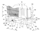
図7は、下部梱包材130と室外機150の斜視図である。図8は、ドレン排水管90が収納された下部梱包材130の平面図である。図3、図7及び図8を用いて、梱包装置100により室外機150を梱包する作業について説明する。上記のような梱包装置100により室外機150を梱包するには、梱包作業者は、切起こし部35及び管用切起こし部36が切起こされた下部段ボール材30を用意する。次に、梱包作業者は、切起こし部35と短辺側壁部33との間に右下部緩衝材10を配置する。同様に、梱包作業者は、切起こし部35と短辺側壁部33との間に左下部緩衝材20を配置する。
[Packing work]
FIG. 7 is a perspective view of the lower packaging material 130 and the outdoor unit 150. FIG. 8 is a plan view of the lower packaging material 130 in which the drain pipe 90 is housed. The operation of packing the outdoor unit 150 using the packing apparatus 100 will be described using FIGS. 3, 7, and 8. In order to pack the outdoor unit 150 using the packaging apparatus 100 as described above, a packing worker prepares the lower corrugated cardboard material 30 in which the cut-and-raised portion 35 and the pipe cut-and-raised portion 36 are cut and raised. Next, the packing worker places the lower right cushioning material 10 between the cut and raised portion 35 and the short side wall portion 33. Similarly, the packing worker places the lower left cushioning material 20 between the cut and raised portion 35 and the short side wall portion 33.

梱包作業者は、右下部緩衝材10の底面部11bを底板部31に載置する。この際、右下部緩衝材10は、第1長辺側壁部32aと、第2長辺側壁部32bと、第2短辺側壁部33bと、切起こし部35との間に配置される。 The packing worker places the bottom part 11b of the lower right cushioning material 10 on the bottom plate part 31. At this time, the lower right cushioning material 10 is arranged between the first long side wall part 32a, the second long side wall part 32b, the second short side wall part 33b, and the cut and raised part 35.

右下部緩衝材10が下部段ボール材30に取り付けられると、右下部緩衝材10の側面部11cは、下部段ボール材30の長辺側壁部32と対向する。右下部緩衝材10の側面部11cと、下部段ボール材30の長辺側壁部32との間の隙間は小さい方が望ましく、側面部11cは、長辺側壁部32と当接していることが更に望ましい。 When the lower right cushioning material 10 is attached to the lower corrugated cardboard material 30, the side surface portion 11c of the lower right cushioning material 10 faces the long side wall portion 32 of the lower corrugated cardboard material 30. It is desirable that the gap between the side surface portion 11c of the lower right cushioning material 10 and the long side wall portion 32 of the lower corrugated cardboard material 30 be small, and it is further preferable that the side surface portion 11c is in contact with the long side wall portion 32. desirable.

また、右下部緩衝材10の外側面部11dは、下部段ボール材30の短辺側壁部33と対向する。右下部緩衝材10の外側面部11dと、下部段ボール材30の短辺側壁部33との間の隙間は小さい方が望ましく、外側面部11dは、短辺側壁部33と当接していることが更に望ましい。 Further, the outer side surface portion 11d of the lower right cushioning material 10 faces the short side wall portion 33 of the lower corrugated cardboard material 30. The gap between the outer side wall 11d of the lower right cushioning material 10 and the short side wall 33 of the lower corrugated cardboard material 30 is desirably small, and it is further preferable that the outer side wall 11d is in contact with the short side wall 33. desirable.

更に、右下部緩衝材10の内側面部11eは、切起こし部35の短辺側縁部35bと対向する。右下部緩衝材10が底板部31に載置された場合に、内側面部11eは、水平方向において、切起こし部35の短辺側縁部35bと対向している。そのため、切起こし部35は、右下部緩衝材10の水平方向の移動を規制する。右下部緩衝材10の内側面部11eと、切起こし部35の短辺側縁部35bとの間の隙間は小さい方が望ましく、内側面部11eは、短辺側縁部35bと当接していることが更に望ましい。 Furthermore, the inner side surface portion 11e of the lower right cushioning material 10 faces the short side edge portion 35b of the cut and raised portion 35. When the lower right cushioning material 10 is placed on the bottom plate portion 31, the inner side surface portion 11e faces the short side edge portion 35b of the cut and raised portion 35 in the horizontal direction. Therefore, the cut and raised portion 35 restricts the movement of the lower right cushioning material 10 in the horizontal direction. It is desirable that the gap between the inner side surface 11e of the lower right cushioning material 10 and the short side edge 35b of the cut and raised portion 35 be small, and the inner side surface 11e should be in contact with the short side edge 35b. is even more desirable.

したがって、右下部緩衝材10が下部段ボール材30に配置されると、右下部緩衝材10は、短手方向(Y軸方向)において、下部段ボール材30の長辺側壁部32によって挟まれる。そのため、右下部緩衝材10は、長辺側壁部32によって短手方向(Y軸方向)の移動が規制される。梱包装置100は、側面部11cと長辺側壁部32との間の隙間が小さいほど、室外機150を右下部緩衝材10に載せる際に右下部緩衝材10がずれてしまうことを抑制することができる。 Therefore, when the lower right cushioning material 10 is placed on the lower corrugated cardboard material 30, the lower right cushioning material 10 is sandwiched between the long side wall portions 32 of the lower corrugated cardboard material 30 in the lateral direction (Y-axis direction). Therefore, the movement of the lower right cushioning material 10 in the lateral direction (Y-axis direction) is restricted by the long side wall portion 32 . The packaging device 100 suppresses the displacement of the lower right cushioning material 10 when the outdoor unit 150 is placed on the lower right cushioning material 10 as the gap between the side surface 11c and the long side wall 32 becomes smaller. I can do it.

また、右下部緩衝材10が下部段ボール材30に配置されると、右下部緩衝材10は、長手方向(X軸方向)において、下部段ボール材30の短辺側壁部33と切起こし部35とによって挟まれる。そのため、右下部緩衝材10は、短辺側壁部33と切起こし部35とによって長手方向(X軸方向)の移動が規制される。梱包装置100は、外側面部11dと短辺側壁部33との間の隙間、及び、内側面部11eと短辺側縁部35bとの間の隙間が小さいほど、室外機150を右下部緩衝材10に載せる際に右下部緩衝材10がずれてしまうことを抑制することができる。 Furthermore, when the lower right cushioning material 10 is placed on the lower corrugated cardboard material 30, the lower right cushioning material 10 is aligned with the short side wall portion 33 and the cut-and-raised portion 35 of the lower corrugated cardboard material 30 in the longitudinal direction (X-axis direction). sandwiched between. Therefore, movement of the lower right cushioning material 10 in the longitudinal direction (X-axis direction) is restricted by the short side wall portion 33 and the cut-and-raised portion 35 . The packaging device 100 moves the outdoor unit 150 into the lower right cushioning material 10 as the gap between the outer side wall 11d and the short side wall 33 and the gap between the inner side wall 11e and the short side edge 35b become smaller. It is possible to prevent the lower right cushioning material 10 from shifting when it is placed on the vehicle.

同様に、梱包作業者は、左下部緩衝材20を、切起こし部35と短辺側壁部33との間に配置し、左下部緩衝材20の底面部21bを底板部31に載置する。この際、左下部緩衝材20は、第1長辺側壁部32aと、第2長辺側壁部32bと、第1短辺側壁部33aと、切起こし部35との間に配置される。 Similarly, the packing worker places the lower left cushioning material 20 between the cut and raised portion 35 and the short side wall portion 33, and places the bottom surface portion 21b of the lower left cushioning material 20 on the bottom plate portion 31. At this time, the lower left cushioning material 20 is arranged between the first long side wall 32a, the second long side wall 32b, the first short side wall 33a, and the cut and raised portion 35.

左下部緩衝材20が下部段ボール材30に取り付けられると、左下部緩衝材20の側面部21cは、下部段ボール材30の長辺側壁部32と対向する。左下部緩衝材20の側面部21cと、下部段ボール材30の長辺側壁部32との間の隙間は小さい方が望ましく、側面部21cは、長辺側壁部32と当接していることが更に望ましい。 When the lower left cushioning material 20 is attached to the lower corrugated cardboard material 30, the side surface portion 21c of the lower left cushioning material 20 faces the long side wall portion 32 of the lower corrugated cardboard material 30. It is desirable that the gap between the side surface portion 21c of the lower left cushioning material 20 and the long side wall portion 32 of the lower corrugated cardboard material 30 is small, and it is further preferable that the side surface portion 21c is in contact with the long side wall portion 32. desirable.

また、左下部緩衝材20の外側面部21dは、下部段ボール材30の短辺側壁部33と対向する。左下部緩衝材20の外側面部21dと、下部段ボール材30の短辺側壁部33との間の隙間は小さい方が望ましく、外側面部21dは、短辺側壁部33と当接していることが更に望ましい。 Further, the outer side surface portion 21d of the lower left cushioning material 20 faces the short side wall portion 33 of the lower corrugated cardboard material 30. It is desirable that the gap between the outer side wall 21d of the lower left cushioning material 20 and the short side wall 33 of the lower corrugated cardboard material 30 is small, and it is further preferable that the outer side wall 21d is in contact with the short side wall 33. desirable.

更に、左下部緩衝材20の内側面部21eは、切起こし部35の短辺側縁部35bと対向する。左下部緩衝材20が底板部31に載置された場合に、内側面部21eは、水平方向において、切起こし部35の短辺側縁部35bと対向している。そのため、切起こし部35は、左下部緩衝材20の水平方向の移動を規制する。左下部緩衝材20の内側面部21eと、切起こし部35の短辺側縁部35bとの間の隙間は小さい方が望ましく、内側面部21eは、短辺側縁部35bと当接していることが更に望ましい。 Further, the inner side surface portion 21e of the lower left cushioning material 20 faces the short side edge portion 35b of the cut and raised portion 35. When the left lower cushioning material 20 is placed on the bottom plate portion 31, the inner side surface portion 21e faces the short side edge portion 35b of the cut and raised portion 35 in the horizontal direction. Therefore, the cut and raised portion 35 restricts the movement of the lower left cushioning material 20 in the horizontal direction. It is desirable that the gap between the inner side surface portion 21e of the left lower cushioning material 20 and the short side edge portion 35b of the cut and raised portion 35 be small, and the inner side surface portion 21e should be in contact with the short side side edge portion 35b. is even more desirable.

したがって、左下部緩衝材20が下部段ボール材30に配置されると、左下部緩衝材20は、短手方向(Y軸方向)において、下部段ボール材30の長辺側壁部32によって挟まれる。そのため、左下部緩衝材20は、長辺側壁部32によって短手方向(Y軸方向)の移動が規制される。梱包装置100は、側面部21cと長辺側壁部32との間の隙間が小さいほど、室外機150を左下部緩衝材20に載せる際に左下部緩衝材20がずれてしまうことを抑制することができる。 Therefore, when the lower left cushioning material 20 is placed on the lower corrugated cardboard material 30, the lower left cushioning material 20 is sandwiched between the long side wall portions 32 of the lower corrugated cardboard material 30 in the lateral direction (Y-axis direction). Therefore, the movement of the lower left cushioning material 20 in the lateral direction (Y-axis direction) is restricted by the long side wall portion 32 . The packaging device 100 suppresses displacement of the lower left cushioning material 20 when the outdoor unit 150 is placed on the lower left cushioning material 20 as the gap between the side surface portion 21c and the long side wall portion 32 becomes smaller. I can do it.

また、左下部緩衝材20が下部段ボール材30に配置されると、左下部緩衝材20は、長手方向(X軸方向)において、下部段ボール材30の短辺側壁部33と切起こし部35とによって挟まれる。そのため、左下部緩衝材20は、短辺側壁部33と切起こし部35とによって長手方向(X軸方向)の移動が規制される。梱包装置100は、外側面部21dと短辺側壁部33との間の隙間、及び、内側面部21eと短辺側縁部35bとの間の隙間が小さいほど、室外機150を左下部緩衝材20に載せる際に左下部緩衝材20がずれてしまうことを抑制することができる。 Further, when the lower left cushioning material 20 is placed on the lower corrugated cardboard material 30, the lower left cushioning material 20 is arranged in the short side wall portion 33 and cut-and-raised portion 35 of the lower corrugated cardboard material 30 in the longitudinal direction (X-axis direction). sandwiched between. Therefore, movement of the lower left cushioning material 20 in the longitudinal direction (X-axis direction) is restricted by the short side wall portion 33 and the cut-and-raised portion 35 . The packaging device 100 moves the outdoor unit 150 closer to the left lower cushioning material 20 as the gap between the outer side wall 21d and the short side wall 33 and the gap between the inner side wall 21e and the short side edge 35b are smaller. It is possible to prevent the lower left cushioning material 20 from shifting when it is placed on the lower left cushioning material 20.

図8に示すように、管用切起こし部36、切起こし部35、長辺側壁部32、左下部緩衝材20、及び、底板部31は、それぞれの壁面によって、下部梱包材130に収納空間38を形成する。梱包作業者は、ドレン排水管90を収納空間38に配置する。 As shown in FIG. 8, the pipe cutting and raising part 36, the cutting and raising part 35, the long side wall part 32, the lower left cushioning material 20, and the bottom plate part 31 have a storage space 38 in the lower packaging material 130 by their respective wall surfaces. form. The packing worker places the drain pipe 90 in the storage space 38.

収納空間38は、管用切起こし部36と、複数の切起こし部35のうち管用切起こし部36に隣接して設けられた第1切起こし部と、第1切起こし部の短辺側縁部35bと対向する内側面部を構成する第1内側面部と、によって形成されている。更に、収納空間38は、複数の側壁部のうち管用切起こし部36に最も近い位置に形成された側壁部と、底板部31とによって、形成されている。 The storage space 38 includes a cut-and-raised part 36 for pipes, a first cut-and-raised part provided adjacent to the cut-and-raised part 36 among the plurality of cut-and-raised parts 35, and a short side edge of the first cut-and-raised part. 35b and a first inner side surface portion forming an opposing inner side surface portion. Furthermore, the storage space 38 is formed by the bottom plate 31 and a side wall portion that is formed at a position closest to the tube cut-and-raise portion 36 among the plurality of side wall portions.

第1切起こし部は、図8に示すように、左前切起こし部351である。第1内側面部は、左下部緩衝材20の内側面部21eである。複数の側壁部は、上述したように、一対の長辺側壁部32及び一対の短辺側壁部33であり、複数の側壁部のうち管用切起こし部36に最も近い位置に形成された第1側壁部は、第1長辺側壁部32aである。 The first cut-and-raise portion is a left front cut-and-raise portion 351, as shown in FIG. The first inner side surface portion is the inner side surface portion 21e of the lower left cushioning material 20. As described above, the plurality of side wall portions are a pair of long side wall portions 32 and a pair of short side wall portions 33, and the first side wall portion is formed at a position closest to the pipe cut and raised portion 36 among the plurality of side wall portions. The side wall portion is a first long side wall portion 32a.

第1側壁部である第1長辺側壁部32aは、底板部31の長手方向(X軸方向)に延びるように形成されている。第1切起こし部である左前切起こし部351と、第1側壁部である第1長辺側壁部32aとは、長手方向(X軸方向)に沿って平行に形成されている。管用切起こし部36は、第1切起こし部である左前切起こし部351と、第1側壁部である第1長辺側壁部32aとの間の空間を介して、第1内側面部である内側面部21eと向かい合う位置に形成されている。 The first long side wall portion 32a, which is the first side wall portion, is formed to extend in the longitudinal direction (X-axis direction) of the bottom plate portion 31. The left front cut-and-raise portion 351, which is the first cut-and-raise portion, and the first long side wall portion 32a, which is the first side wall portion, are formed in parallel along the longitudinal direction (X-axis direction). The cut-and-raised section 36 for pipes is inserted into the inner side, which is the first inner surface section, through the space between the left front cut-and-raised section 351, which is the first cut-and-raised section, and the first long side wall section 32a, which is the first side wall section. It is formed at a position facing the surface portion 21e.

なお、収納空間38は、図8に示すように、室外機150の空気の吹出口158が形成された筐体側壁部153の下方に形成されている。また、収納空間38は、一対の下部緩衝材の間の空間、すなわち、右下部緩衝材10と左下部緩衝材20との間の空間に形成されている。そのため、収納空間38に収納されるドレン排水管90は、右下部緩衝材10と左下部緩衝材20とによって、バンド部材70を介して伝わる作業者の引っ張る力から保護される。また、収納空間38は、少なくとも一部の上方が室外機150の底部151によって覆われている Note that, as shown in FIG. 8, the storage space 38 is formed below the housing side wall portion 153 in which the air outlet 158 of the outdoor unit 150 is formed. Moreover, the storage space 38 is formed in the space between the pair of lower cushioning materials, that is, the space between the lower right cushioning material 10 and the lower left cushioning material 20. Therefore, the drain pipe 90 stored in the storage space 38 is protected from the pulling force of the operator transmitted via the band member 70 by the lower right cushioning material 10 and the lower left cushioning material 20. Furthermore, at least a portion of the upper portion of the storage space 38 is covered by the bottom portion 151 of the outdoor unit 150.

ドレン排水管90は、収納空間38において、ホース側接続部92が下部段ボール材30の長手方向(X軸方向)に対して斜めになるように配置される。また、ドレン排水管90は、収納空間38において、筐体側接続部91が管用切起こし部36及び長辺側壁部32と対向するように配置される。筐体側接続部91は、管用切起こし部36及び長辺側壁部32と当接して水平方向の移動及び回転が規制されることが望ましい。なお、上述したドレン排水管90の収納態様は一例である。ドレン排水管90は、収納空間38に収納されればよい。また、ドレン排水管90は、管用切起こし部36、切起こし部35、長辺側壁部32、及び、左下部緩衝材20の壁面によって、水平方向の移動及び回転が規制されることが望ましい。 The drain pipe 90 is arranged in the storage space 38 so that the hose side connection part 92 is oblique to the longitudinal direction (X-axis direction) of the lower corrugated cardboard material 30. Further, the drain pipe 90 is arranged in the storage space 38 such that the housing-side connecting portion 91 faces the cut-and-raised pipe portion 36 and the long side wall portion 32 . It is desirable that the housing side connecting portion 91 come into contact with the pipe cut and raised portion 36 and the long side wall portion 32 to restrict movement and rotation in the horizontal direction. Note that the above-mentioned housing manner of the drain pipe 90 is an example. The drain pipe 90 may be stored in the storage space 38. Furthermore, it is desirable that horizontal movement and rotation of the drain pipe 90 be restricted by the cut and raised pipe portion 36, the cut and raised portion 35, the long side wall portion 32, and the wall surface of the lower left cushioning material 20.

梱包作業者は、図7に示すように、室外機150の底部151を右下部緩衝材10及び左下部緩衝材20の上に載置する。また、梱包作業者は、室外機150の一対の脚部154をそれぞれ凹部12及び凹部22に嵌入する。そして、梱包作業者は、図3に示すように、背面梱包材80を、下部段ボール材30に配置し、室外機150の天面部152に上部緩衝材40及び上部緩衝材50を載置して、その上に上部段ボール材60を嵌合して覆う。この際、背面梱包材80は、倒れないように上部段ボール材60によって、背面梱包材80の上部が固定される。その後、梱包作業者は、下部段ボール材30と上部段ボール材60との間に1つ又は複数のバンド部材70を掛けて緊縛して固定し、室外機150の梱包作業を終了する。なお、ここで説明した梱包作業の順番は一例であり、各工程の順番が入れ替わってもよい。 The packing worker places the bottom 151 of the outdoor unit 150 on the lower right cushioning material 10 and the lower left cushioning material 20, as shown in FIG. The packing worker also fits the pair of legs 154 of the outdoor unit 150 into the recess 12 and the recess 22, respectively. Then, as shown in FIG. 3, the packing worker places the back packing material 80 on the lower cardboard material 30, places the upper cushioning material 40 and the upper cushioning material 50 on the top surface 152 of the outdoor unit 150, , an upper corrugated cardboard material 60 is fitted and covered thereon. At this time, the upper part of the back packaging material 80 is fixed by the upper cardboard material 60 so that the back packaging material 80 does not fall down. Thereafter, the packing worker wraps one or more band members 70 between the lower corrugated cardboard material 30 and the upper corrugated cardboard material 60, and secures them tightly, thereby finishing the packing work of the outdoor unit 150. Note that the order of the packing operations described here is an example, and the order of each process may be changed.

なお、梱包装置100は、図8に示すように、右下部緩衝材10に、溝部15が形成されてもよい。溝部15は、内側面部11eに形成された凹んだ溝であり、右下部緩衝材10の上下方向(Z軸方向)に延びるように形成された溝である。同様に、梱包装置100は、左下部緩衝材20に、溝部25が形成されてもよい。溝部25は、内側面部21eに形成された凹んだ溝であり、左下部緩衝材20の上下方向(Z軸方向)に延びるように形成された溝である。図8に示すように、梱包装置100は、溝部15及び溝部25に切起こし部35が配置されるように形成されてもよい。 In the packaging device 100, as shown in FIG. 8, a groove 15 may be formed in the lower right cushioning material 10. The groove portion 15 is a recessed groove formed in the inner side surface portion 11e, and is a groove formed so as to extend in the vertical direction (Z-axis direction) of the lower right cushioning material 10. Similarly, in the packaging device 100, the groove portion 25 may be formed in the lower left cushioning material 20. The groove portion 25 is a recessed groove formed in the inner side surface portion 21e, and is a groove formed to extend in the vertical direction (Z-axis direction) of the lower left cushioning material 20. As shown in FIG. 8, the packaging device 100 may be formed such that cut and raised portions 35 are arranged in the groove portions 15 and 25.

図8の左前切起こし部351及び右前切起こし部352に示すように、複数の切起こし部35のうち少なくとも1つの切起こし部35は、短辺側縁部35bが溝部15又は溝部25の内部に配置されるように形成されてもよい。 As shown in the left front cut-and-raised portion 351 and the right-front cut-and-raised portion 352 in FIG. It may be formed so that it is arranged in

[梱包装置100の作用効果]
室外機150の梱包装置100は、管用切起こし部36と、第1切起こし部と、第1内側面部と、第1側壁部と、底板部31とによって形成された、ドレン排水管90を収納するための収納空間38を有している。梱包装置100は、下部緩衝材にドレン排水管90を収納するための穴を形成する必要がなく、穴とバンド部材70との間の下部緩衝材の壁が薄い箇所が存在しない。そのため、梱包装置100は、バンド部材70が引っ張られた場合でも、下部緩衝材が破損しにくい。そして、梱包装置100は、ドレン排水管90が一対の下部緩衝材によって保護され、作業者のバンド部材70を引っ張る力が、バンド部材70を介してドレン排水管90に及ぶことがないためドレン排水管90の破損を防ぐことができる。
[Operations and effects of the packaging device 100]
The packaging device 100 for the outdoor unit 150 stores a drain drain pipe 90 formed by a pipe cut-and-raised portion 36, a first cut-and-raised portion, a first inner surface portion, a first side wall portion, and a bottom plate portion 31. It has a storage space 38 for storage. In the packaging device 100, there is no need to form a hole in the lower cushioning material for accommodating the drain pipe 90, and there is no place where the wall of the lower cushioning material is thin between the hole and the band member 70. Therefore, in the packaging device 100, even when the band member 70 is pulled, the lower cushioning material is unlikely to be damaged. In the packaging device 100, the drain drain pipe 90 is protected by the pair of lower cushioning materials, and the force of the operator pulling the band member 70 does not reach the drain drain pipe 90 via the band member 70. Damage to the tube 90 can be prevented.

図9は、比較例に係る下部梱包材130Lの上面図である。比較例に係る下部梱包材130Lは、従来、一般的に使用されている梱包装置100Lである。ここで、比較例に係る梱包装置100Lについて説明する。 FIG. 9 is a top view of a lower packaging material 130L according to a comparative example. The lower packaging material 130L according to the comparative example is a packaging device 100L that is conventionally and generally used. Here, a packaging device 100L according to a comparative example will be described.

梱包装置100Lは、下部梱包材130Lを構成する右下部緩衝材10にドレン排水管90を収納する貫穴形状部17が設けられている。貫穴形状部17は、右下部緩衝材10に形成された貫通孔である。ドレン排水管90は、室外機150の梱包状態において、右下部緩衝材10に設けられた貫穴形状部17に収納される。 In the packaging device 100L, a through-hole shaped portion 17 for housing a drain pipe 90 is provided in the lower right cushioning material 10 constituting the lower packaging material 130L. The through hole shaped portion 17 is a through hole formed in the lower right cushioning material 10. The drain pipe 90 is housed in the through-hole shaped portion 17 provided in the lower right cushioning material 10 when the outdoor unit 150 is packed.

室外機150が梱包された状態で、ドレン排水管90は、上下を室外機150の底部151と下部段ボール材30の底板部31で挟まれている。また、室外機150が梱包された状態で、ドレン排水管90は、左右前後方向を右下部緩衝材10に設けた貫穴形状部17の内壁により保持される。室外機150が梱包された状態で、ドレン排水管90は、室外機150の底部151、下部段ボール材30の底板部31、及び、貫穴形状部17の内壁によって囲まれるためドレン排水管90は、下部梱包材130から脱落することはない。 When the outdoor unit 150 is packed, the drain pipe 90 is sandwiched between the bottom part 151 of the outdoor unit 150 and the bottom plate part 31 of the lower cardboard material 30 at the top and bottom. In addition, when the outdoor unit 150 is packed, the drain pipe 90 is held in the left-right and front-back directions by the inner wall of the through-hole shaped portion 17 provided in the lower right cushioning material 10. When the outdoor unit 150 is packed, the drain pipe 90 is surrounded by the bottom part 151 of the outdoor unit 150, the bottom plate part 31 of the lower cardboard material 30, and the inner wall of the through-hole shaped part 17. , it will not fall off from the lower packaging material 130.

梱包装置100Lは、物流の荷扱い上、作業者によってバンド部材70が故意に引っ張られた場合に右下部緩衝材10が破損する恐れがある。より詳細には、図9に示すように、右下部緩衝材10は、ドレン排水管90を収納する貫穴形状部17とバンド部材70との間の、右下部緩衝材10の壁が薄い箇所Kが、バンド部材70に対抗できずに凹んで破損するおそれがある。 In the packaging apparatus 100L, there is a risk that the lower right cushioning material 10 may be damaged if the band member 70 is intentionally pulled by an operator during logistics handling. More specifically, as shown in FIG. 9, the lower right cushioning material 10 is located at a portion where the wall of the lower right cushioning material 10 is thin between the through-hole shaped portion 17 that accommodates the drain pipe 90 and the band member 70. K may not be able to oppose the band member 70 and may become dented and damaged.

また、下部段ボール材30は、右下部緩衝材10の壁が薄い箇所Kが、バンド部材70に対抗できずに凹んで破損することによって、バンド部材70に対抗できず、右下部緩衝材10と共に凹んで破損する恐れがある。さらに、梱包装置100Lは、右下部緩衝材10の破損によって、作業者のバンド部材70を引っ張る力が、バンド部材70を介してドレン排水管90に及ぶためドレン排水管90も破損する恐れがある。 In addition, the lower corrugated cardboard material 30 cannot stand up to the band member 70 and is damaged due to the thin wall part K of the lower right cushioning material 10 not being able to stand up to the band member 70 and being damaged together with the lower right cushioning material 10. There is a risk of denting and damage. Furthermore, in the packaging device 100L, if the lower right cushioning material 10 is damaged, the force of the operator pulling the band member 70 will be applied to the drain drain pipe 90 via the band member 70, so there is a risk that the drain drain pipe 90 will also be damaged. .

梱包装置100Lは、右下部緩衝材10にドレン排水管90を収納する貫穴形状部17を設けられている。これに対して、実施の形態1に係る梱包装置100は、上記構成の収納空間38にドレン排水管90が収納されている。上述したように、梱包装置100は、ドレン排水管90が一対の下部緩衝材によって保護され、作業者のバンド部材70を引っ張る力が、バンド部材70を介してドレン排水管90に及ぶことがないためドレン排水管90の破損を防ぐことができる。 In the packaging device 100L, the lower right cushioning material 10 is provided with a through-hole portion 17 for accommodating a drain pipe 90. On the other hand, in the packaging device 100 according to the first embodiment, the drain pipe 90 is housed in the storage space 38 having the above configuration. As described above, in the packaging device 100, the drain pipe 90 is protected by the pair of lower cushioning materials, and the force of the operator pulling the band member 70 does not reach the drain pipe 90 via the band member 70. Therefore, damage to the drain pipe 90 can be prevented.

また、管用切起こし部36は、第1切起こし部と、第1側壁部との間の空間を介して、第1内側面部と対向するように形成されている。そのため、管用切起こし部36は、第1内側面部と共に左右方向(X軸方向)におけるドレン排水管90の移動を規制することができる。 Further, the pipe cut and raised portion 36 is formed to face the first inner side wall portion through a space between the first cut and raised portion and the first side wall portion. Therefore, the pipe cutting and raising part 36 can restrict movement of the drain drain pipe 90 in the left-right direction (X-axis direction) together with the first inner surface part.

また、管用切起こし部36は、下部段ボール材30を平面視した場合に、長手方向(X軸方向)に対して斜めに形成されている。そのため、収納空間38は、ドレン排水管90の筐体側接続部91の形状に沿って、ドレン排水管90を保持することができる。 Further, the tube cut-and-raised portion 36 is formed obliquely with respect to the longitudinal direction (X-axis direction) when the lower corrugated cardboard material 30 is viewed from above. Therefore, the storage space 38 can hold the drain pipe 90 along the shape of the casing-side connecting portion 91 of the drain pipe 90.

また、収納空間38は、室外機150の空気の吹出口158が形成された筐体側壁部153の下方に形成されている。収納空間38は、梱包装置100の前後方向(Y軸方向)において、室外機150の筐体155と下部段ボール材30との間の隙間から作業者が視認できる位置に形成されている。収納空間38が上記位置に形成されていることによって、作業者は、生産上あるいは運搬上、ドレン排水管90の紛失及び破損がないことを視認できる。 Further, the storage space 38 is formed below the housing side wall portion 153 in which the air outlet 158 of the outdoor unit 150 is formed. The storage space 38 is formed at a position that can be visually recognized by the operator from the gap between the casing 155 of the outdoor unit 150 and the lower corrugated cardboard material 30 in the front-rear direction (Y-axis direction) of the packaging device 100. By forming the storage space 38 at the above position, the operator can visually confirm that the drain pipe 90 is not lost or damaged during production or transportation.

また、収納空間38は、少なくとも一部の上方が室外機150の底部151によって覆われている。室外機150の底部151が収納空間38の蓋のような役割を果たすため、収納空間38に収納されたドレン排水管90は、収納空間38に固定され保持される。 Furthermore, at least a portion of the upper portion of the storage space 38 is covered by the bottom portion 151 of the outdoor unit 150. Since the bottom portion 151 of the outdoor unit 150 serves as a lid for the storage space 38, the drain pipe 90 stored in the storage space 38 is fixed and held in the storage space 38.

また、複数の切起こし部35のうち少なくとも1つ切起こし部35は、短辺側縁部35bが溝部15又は溝部25の内部に配置されるように形成されている。梱包装置100は当該構成によって、右下部緩衝材10又は左下部緩衝材20を下部段ボール材30に配置する際に、位置決めが容易になる。 Further, at least one of the plurality of cut and raised portions 35 is formed such that the short side edge portion 35b is disposed inside the groove portion 15 or the groove portion 25. With this configuration, the packaging device 100 facilitates positioning when placing the lower right cushioning material 10 or the lower left cushioning material 20 on the lower corrugated cardboard material 30.

実施の形態2.
図10は、実施の形態2に係る下部段ボール材30の展開図である。実施の形態1では、左前切起こし部351に隣接して管用切起こし部36を設けているが、管用切起こし部36の形成位置は当該位置に限定されるものではない。実施の形態2では、管用切起こし部36の形成位置について説明する。
Embodiment 2.
FIG. 10 is a developed view of the lower corrugated cardboard material 30 according to the second embodiment. In the first embodiment, the pipe cut-and-raise portion 36 is provided adjacent to the left front cut-and-raise portion 351, but the position where the pipe cut-and-raise portion 36 is formed is not limited to this position. In Embodiment 2, the formation position of the pipe cut and raised portion 36 will be described.

管用切起こし部36は、図10に示すように、左前切起こし部351、右前切起こし部352、左後切起こし部353、及び、右後切起こし部354のいずれかの位置に形成されてもよい。管用切起こし部36の形成位置は、切起こし部35の近傍に障害となる部品等がなく、且つ、筐体155と下部段ボール材30との間からドレン排水管90の状態を視認できる位置であればよい。 As shown in FIG. 10, the pipe cut-and-raise portion 36 is formed at any one of a left front cut-and-raise portion 351, a right front cut-and-raise portion 352, a left rear cut-and-raise portion 353, and a right rear cut-and-raise portion 354. Good too. The cut-and-raised portion 36 for the pipe is formed at a position where there are no obstructing parts near the cut-and-raised portion 35 and where the condition of the drain pipe 90 can be visually checked from between the casing 155 and the lower corrugated cardboard material 30. Good to have.

実施の形態1では、室外機150の前面側に収納空間38が設けられているが、収納空間38は、室外機150の後面側に形成されてもよい。すなわち、梱包装置100は、実施の形態1では、室外機150の前面側に位置する切起こし部35の近傍に管用切起こし部36を設けているが、室外機150の後面側に位置する切起こし部35の近傍に管用切起こし部36を設けてもよい。 In the first embodiment, the storage space 38 is provided on the front side of the outdoor unit 150, but the storage space 38 may be formed on the rear side of the outdoor unit 150. That is, in the first embodiment, the packaging device 100 is provided with the cut-and-raised portion 36 for pipes near the cut-and-raised portion 35 located on the front side of the outdoor unit 150; A pipe cutting and raising part 36 may be provided near the raising part 35.

上述したように、収納空間38は、管用切起こし部36と、複数の切起こし部35のうち管用切起こし部36に隣接して設けられた第1切起こし部と、第1切起こし部の短辺側縁部35bと対向する内側面部を構成する第1内側面部と、によって形成されている。更に、収納空間38は、複数の側壁部のうち管用切起こし部36に最も近い位置に形成された側壁部と、底板部31とによって、形成されている。 As described above, the storage space 38 includes the pipe cut-and-raise portion 36, the first cut-and-raise portion provided adjacent to the pipe cut-and-raise portion 36 among the plurality of cut-and-raise portions 35, and the first cut-and-raise portion. It is formed by the short side edge 35b and a first inner side surface that constitutes an opposing inner side surface. Furthermore, the storage space 38 is formed by the bottom plate 31 and a side wall portion that is formed at a position closest to the tube cut-and-raise portion 36 among the plurality of side wall portions.

第1切起こし部は、図10に示すように、右前切起こし部352でもよい。この場合、第1内側面部は、右下部緩衝材10の内側面部11eである。複数の側壁部は、上述したように、一対の長辺側壁部32及び一対の短辺側壁部33であり、複数の側壁部のうち管用切起こし部36に最も近い位置に形成された第1側壁部は、第1長辺側壁部32aである。 The first cut-and-raise portion may be a right front cut-and-raise portion 352, as shown in FIG. In this case, the first inner surface portion is the inner surface portion 11e of the lower right cushioning material 10. As described above, the plurality of side wall portions are a pair of long side wall portions 32 and a pair of short side wall portions 33, and the first side wall portion is formed at a position closest to the pipe cut and raised portion 36 among the plurality of side wall portions. The side wall portion is a first long side wall portion 32a.

第1側壁部である第1長辺側壁部32aは、底板部31の長手方向(X軸方向)に延びるように形成されている。第1切起こし部である右前切起こし部352と、第1側壁部である第1長辺側壁部32aとは、長手方向(X軸方向)に沿って平行に形成されている。管用切起こし部36は、第1切起こし部である右前切起こし部352と、第1側壁部である第1長辺側壁部32aとの間の空間を介して、第1内側面部である内側面部11eと対向するように形成されている。 The first long side wall portion 32a, which is the first side wall portion, is formed to extend in the longitudinal direction (X-axis direction) of the bottom plate portion 31. The front right cut-and-raise portion 352, which is the first cut-and-raise portion, and the first long side wall portion 32a, which is the first side wall portion, are formed in parallel along the longitudinal direction (X-axis direction). The cut-and-raised section 36 for pipes passes through the space between the right front cut-and-raised section 352, which is the first cut-and-raised section, and the first long side wall section 32a, which is the first side wall section. It is formed to face the surface portion 11e.

第1切起こし部は、図10に示すように、左後切起こし部353でもよい。この場合、第1内側面部は、左下部緩衝材20の内側面部21eである。複数の側壁部は、上述したように、一対の長辺側壁部32及び一対の短辺側壁部33であり、複数の側壁部のうち管用切起こし部36に最も近い位置に形成された第1側壁部は、第2長辺側壁部32bである。 The first cut-and-raise portion may be a left rear cut-and-raise portion 353, as shown in FIG. In this case, the first inner surface portion is the inner surface portion 21e of the lower left cushioning material 20. As described above, the plurality of side wall portions are a pair of long side wall portions 32 and a pair of short side wall portions 33, and the first side wall portion is formed at a position closest to the pipe cut and raised portion 36 among the plurality of side wall portions. The side wall portion is the second long side wall portion 32b.

第1側壁部である第2長辺側壁部32bは、底板部31の長手方向(X軸方向)に延びるように形成されている。第1切起こし部である左後切起こし部353と、第1側壁部である第2長辺側壁部32bとは、長手方向(X軸方向)に沿って平行に形成されている。管用切起こし部36は、第1切起こし部である左後切起こし部353と、第1側壁部である第2長辺側壁部32bとの間の空間を介して、第1内側面部である内側面部21eと対向するように形成されている。 The second long side wall portion 32b, which is the first side wall portion, is formed to extend in the longitudinal direction (X-axis direction) of the bottom plate portion 31. The left rear cut-and-raise portion 353, which is the first cut-and-raise portion, and the second long side wall portion 32b, which is the first side wall portion, are formed in parallel along the longitudinal direction (X-axis direction). The cut-and-raised portion 36 for pipes is inserted into the first inner surface portion through a space between the left rear cut-and-raised portion 353, which is the first cut-and-raised portion, and the second long side wall portion 32b, which is the first side wall portion. It is formed to face the inner side surface portion 21e.

第1切起こし部は、図10に示すように、右後切起こし部354でもよい。この場合、第1内側面部は、右下部緩衝材10の内側面部11eである。複数の側壁部は、上述したように、一対の長辺側壁部32及び一対の短辺側壁部33であり、複数の側壁部のうち管用切起こし部36に最も近い位置に形成された第1側壁部は、第2長辺側壁部32bである。 The first cut-and-raise portion may be a right rear cut-and-raise portion 354, as shown in FIG. In this case, the first inner surface portion is the inner surface portion 11e of the lower right cushioning material 10. As described above, the plurality of side wall portions are a pair of long side wall portions 32 and a pair of short side wall portions 33, and the first side wall portion is formed at a position closest to the pipe cut and raised portion 36 among the plurality of side wall portions. The side wall portion is the second long side wall portion 32b.

第1側壁部である第2長辺側壁部32bは、底板部31の長手方向(X軸方向)に延びるように形成されている。第1切起こし部である右後切起こし部354と、第1側壁部である第2長辺側壁部32bとは、長手方向(X軸方向)に沿って平行に形成されている。管用切起こし部36は、第1切起こし部である右後切起こし部354と、第1側壁部である第2長辺側壁部32bとの間の空間を介して、第1内側面部である内側面部11eと対向するように形成されている。 The second long side wall portion 32b, which is the first side wall portion, is formed to extend in the longitudinal direction (X-axis direction) of the bottom plate portion 31. The right rear cut-and-raise portion 354, which is the first cut-and-raise portion, and the second long side wall portion 32b, which is the first side wall portion, are formed in parallel along the longitudinal direction (X-axis direction). The cut-and-raised section 36 for pipes is inserted into the first inner surface section through the space between the right rear cut-and-raise section 354, which is the first cut-and-raised section, and the second long side wall section 32b, which is the first side wall section. It is formed to face the inner side surface portion 11e.

管用切起こし部36が、左後切起こし部353又は右後切起こし部354に隣接して形成されている場合には、収納空間38は、室外機150の空気の吹出口158が形成された面とは反対側の面を構成する筐体側壁部153の下方に形成されている。 When the pipe cut-and-raise portion 36 is formed adjacent to the left rear cut-and-raise portion 353 or the right rear cut-and-raise portion 354, the storage space 38 is formed with the air outlet 158 of the outdoor unit 150. It is formed below the housing side wall portion 153 that constitutes the surface opposite to the surface.

図11は、変形例に係る管用切起こし部36を有する下部段ボール材30の上面図である。図11に示すように、下部段ボール材30は、管用切起こし部36を複数有していてもよい。 FIG. 11 is a top view of a lower corrugated cardboard material 30 having a pipe cut-and-raised portion 36 according to a modified example. As shown in FIG. 11, the lower corrugated cardboard material 30 may have a plurality of cut and raised pipe portions 36.

[梱包装置100の作用効果]
梱包装置100は、右前切起こし部352、左後切起こし部353又は右後切起こし部354に隣接して管用切起こし部36と収納空間38とを設けることができる。梱包装置100は、当該位置に収納空間38を設けることによって、上述したように、作業者のバンド部材70を引っ張る力が、バンド部材70を介してドレン排水管90に及ぶことがないためドレン排水管90の破損を防ぐことができる。
[Operations and effects of the packaging device 100]
The packaging device 100 can provide the pipe cut-and-raise portion 36 and the storage space 38 adjacent to the right front cut-and-raise portion 352, the left rear cut-and-raise portion 353, or the right rear cut-and-raise portion 354. By providing the storage space 38 at this position, the packing device 100 prevents the force of the operator pulling the band member 70 from reaching the drain drain pipe 90 via the band member 70, thereby preventing drain drainage. Damage to the tube 90 can be prevented.

収納空間38は、室外機150の空気の吹出口158が形成された面とは反対側の面を構成する筐体側壁部153の下方に形成されている。収納空間38は、梱包装置100の前後方向(Y軸方向)において、室外機150の筐体155と下部段ボール材30との間の隙間から作業者が視認できる位置に形成されている。収納空間38が上記位置に形成されていることによって、作業者は、生産上あるいは運搬上、ドレン排水管90の紛失及び破損がないことを視認できる。 The storage space 38 is formed below the housing side wall portion 153 that constitutes a surface opposite to the surface on which the air outlet 158 of the outdoor unit 150 is formed. The storage space 38 is formed at a position that can be visually recognized by the operator from the gap between the casing 155 of the outdoor unit 150 and the lower corrugated cardboard material 30 in the front-rear direction (Y-axis direction) of the packaging device 100. By forming the storage space 38 at the above position, the operator can visually confirm that the drain pipe 90 is not lost or damaged during production or transportation.

上記の各実施の形態1~2は、互いに組み合わせて実施することが可能である。また、以上の実施の形態に示した構成は、一例を示すものであり、別の公知の技術と組み合わせることも可能であるし、要旨を逸脱しない範囲で、構成の一部を省略、変更することも可能である。 Each of the first and second embodiments described above can be implemented in combination with each other. Furthermore, the configurations shown in the above embodiments are merely examples, and may be combined with other known techniques, or a part of the configuration may be omitted or changed without departing from the scope of the invention. It is also possible.

10 右下部緩衝材、11a 上面部、11b 底面部、11c 側面部、11d 外側面部、11e 内側面部、12 凹部、15 溝部、17 貫穴形状部、20 左下部緩衝材、21a 上面部、21b 底面部、21c 側面部、21d 外側面部、21e 内側面部、22 凹部、25 溝部、30 下部段ボール材、31 底板部、31a 縁部、31b 縁部、32 長辺側壁部、32a 第1長辺側壁部、32b 第2長辺側壁部、32c 基部、33 短辺側壁部、33a 第1短辺側壁部、33b 第2短辺側壁部、35 切起こし部、35a 長辺縁部、35b 短辺側縁部、35c 谷折部、35d 切起こし孔部、36 管用切起こし部、36a 長辺縁部、36b 短辺側縁部、36c 谷折部、36d 切起こし孔部、38 収納空間、40 上部緩衝材、41 切り欠き部、50 上部緩衝材、51 切り欠き部、60 上部段ボール材、61 天板部、62 長辺側壁部、63 短辺側壁部、70 バンド部材、71 長手バンド、72 短手バンド、80 背面梱包材、90 ドレン排水管、91 筐体側接続部、92 ホース側接続部、100 梱包装置、100L 梱包装置、130 下部梱包材、130L 下部梱包材、140 上部梱包材、150 室外機、151 底部、152 天面部、153 筐体側壁部、153a 開口部、154 脚部、155 筐体、158 吹出口、180 熱交換器、351 左前切起こし部、352 右前切起こし部、353 左後切起こし部、354 右後切起こし部、K 箇所、T1 距離、T2 距離。 Reference Signs List 10 lower right cushioning material, 11a top surface, 11b bottom surface, 11c side surface, 11d outer surface, 11e inner surface, 12 recess, 15 groove, 17 through hole shaped portion, 20 lower left cushioning material, 21a top surface, 21b bottom surface part, 21c side part, 21d outer face part, 21e inner face part, 22 recessed part, 25 groove part, 30 lower corrugated board material, 31 bottom plate part, 31a edge part, 31b edge part, 32 long side wall part, 32a first long side wall part , 32b second long side wall, 32c base, 33 short side wall, 33a first short side wall, 33b second short side wall, 35 cut and raised portion, 35a long edge, 35b short side edge part, 35c valley fold part, 35d cut and raise hole part, 36 cut and raise part for pipe, 36a long edge part, 36b short side edge part, 36c valley fold part, 36d cut and raise hole part, 38 storage space, 40 upper buffer material, 41 notch portion, 50 upper cushioning material, 51 notch portion, 60 upper corrugated cardboard material, 61 top plate portion, 62 long side wall portion, 63 short side wall portion, 70 band member, 71 longitudinal band, 72 short side Band, 80 Back packing material, 90 Drain drain pipe, 91 Housing side connection part, 92 Hose side connection part, 100 Packing device, 100L Packing device, 130 Lower packing material, 130L Lower packing material, 140 Upper packing material, 150 Outdoor unit , 151 Bottom, 152 Top, 153 Housing side wall, 153a Opening, 154 Legs, 155 Housing, 158 Air outlet, 180 Heat exchanger, 351 Left front cut and raise, 352 Right front cut and raise, 353 Left rear Cut and raise part, 354 Right rear cut and raise part, K point, T1 distance, T2 distance.

Claims (7)

室外機の筐体からドレン水を排水するために前記筐体に取り付けられるドレン排水管を備えた室外機の梱包装置であって、
前記室外機の底部が載置される一対の下部緩衝材と、
上面が開口した箱状に形成されており、前記一対の下部緩衝材が収納される下部段ボール材と、
前記下部段ボール材を介して前記一対の下部緩衝材の双方と対向するように、前記下部段ボール材の外側から掛けられ、前記下部段ボール材が、前記室外機が載置された前記一対の下部緩衝材を覆う状態を維持するバンド部材と、
を備え、
前記一対の下部緩衝材は、
互いに対向する内側面部をそれぞれ有し、
前記下部段ボール材は、
前記一対の下部緩衝材が載置される矩形状の底板部と、
前記底板部の4辺に設けられて側壁を構成する複数の側壁部と、
を有し、
前記底板部は、
前記底板部から切り起こされて形成された複数の切起こし部及び1つ以上の管用切起こし部を有し、
前記複数の切起こし部は、
前記一対の下部緩衝材が前記底板部に載置された場合に、前記一対の下部緩衝材の水平方向の移動を規制するように、前記複数の切起こし部のそれぞれの側方の側縁部と、前記内側面部とが対向するように形成されており、
前記管用切起こし部は、
前記ドレン排水管の前記水平方向の移動を規制するように、前記底板部に載置された前記下部緩衝材の前記内側面部と向かい合う位置に形成されており、
前記管用切起こし部と、前記複数の切起こし部のうち前記管用切起こし部に隣接して設けられた第1切起こし部と、前記第1切起こし部の前記側縁部と対向する前記内側面部を構成する第1内側面部と、前記複数の側壁部のうち前記管用切起こし部に最も近い位置に形成された第1側壁部と、前記底板部とによって、前記ドレン排水管を収納するための収納空間が形成された室外機の梱包装置。
An outdoor unit packaging device comprising a drain pipe attached to a casing of the outdoor unit to drain drain water from the casing of the outdoor unit,
a pair of lower cushioning materials on which the bottom of the outdoor unit is placed;
a lower corrugated cardboard material formed in a box shape with an open top surface and housing the pair of lower cushioning materials;
The lower corrugated cardboard material is hung from the outside of the lower corrugated cardboard material so as to face both of the pair of lower cushioning materials via the lower corrugated cardboard material, and the lower corrugated cardboard material is connected to the pair of lower cushioning materials on which the outdoor unit is placed. a band member that maintains a state covering the material;
Equipped with
The pair of lower cushioning materials are
each having inner side surfaces facing each other,
The lower corrugated cardboard material is
a rectangular bottom plate portion on which the pair of lower cushioning materials are placed;
a plurality of side wall portions that are provided on four sides of the bottom plate portion and constitute side walls;
has
The bottom plate portion is
It has a plurality of cut and raised parts formed by cutting and raising from the bottom plate part and one or more cut and raised parts for pipes,
The plurality of cut and raised portions are
side edges of each of the plurality of cut-and-raised portions so as to restrict horizontal movement of the pair of lower cushioning materials when the pair of lower cushioning materials are placed on the bottom plate portion; and the inner surface portion are formed to face each other,
The pipe cut-and-raised portion is
is formed at a position facing the inner side surface of the lower cushioning material placed on the bottom plate so as to restrict movement of the drain pipe in the horizontal direction;
the pipe cut-and-raised part; a first cut-and-raised part provided adjacent to the pipe cut-and-raised part among the plurality of cut-and-raised parts; and the inner side facing the side edge of the first cut-and-raised part. For storing the drain drain pipe by a first inner side surface portion constituting a surface portion, a first side wall portion formed at a position closest to the cut-and-raised portion for the pipe among the plurality of side wall portions, and the bottom plate portion. A packaging device for outdoor units that has a storage space.
前記第1側壁部は、
前記底板部の長手方向に延びるように形成されており、
前記第1切起こし部と、前記第1側壁部とは前記長手方向に沿って平行に形成されており、
前記管用切起こし部は、
前記第1切起こし部と、前記第1側壁部との間の空間を介して、前記第1内側面部と対向するように形成されている請求項1に記載の室外機の梱包装置。
The first side wall portion is
is formed to extend in the longitudinal direction of the bottom plate portion,
The first cut-and-raised portion and the first side wall portion are formed in parallel along the longitudinal direction,
The pipe cut-and-raised portion is
The outdoor unit packaging device according to claim 1, wherein the outdoor unit packaging device is formed to face the first inner side wall through a space between the first cut-and-raised portion and the first side wall.
前記管用切起こし部は、
前記下部段ボール材を平面視した場合に、前記長手方向に対して斜めに形成されている請求項2に記載の室外機の梱包装置。
The pipe cut-and-raised portion is
The outdoor unit packaging device according to claim 2, wherein the lower corrugated cardboard material is formed obliquely with respect to the longitudinal direction when viewed from above.
前記収納空間は、
少なくとも一部の上方が前記底部によって覆われている請求項1~3のいずれか1項に記載の室外機の梱包装置。
The storage space is
The outdoor unit packaging device according to claim 1, wherein at least a portion of the upper portion is covered by the bottom portion.
前記収納空間が、
前記室外機の空気の吹出口が形成された筐体側壁部の下方に形成されている請求項1~4のいずれか1項に記載の室外機の梱包装置。
The storage space is
The outdoor unit packaging device according to any one of claims 1 to 4, wherein the outdoor unit is formed below a side wall of the casing in which the air outlet is formed.
前記収納空間が、
前記室外機の空気の吹出口が形成された面とは反対側の面を構成する筐体側壁部の下方に形成されている請求項1~4のいずれか1項に記載の室外機の梱包装置。
The storage space is
The outdoor unit packaging according to any one of claims 1 to 4, wherein the outdoor unit packaging is formed below a side wall of the casing that constitutes a surface opposite to the surface on which the air outlet of the outdoor unit is formed. Device.
前記内側面部には、凹んだ状態に形成され上下方向に延びるように溝部が形成されており、
前記複数の切起こし部のうち少なくとも1つ切起こし部は、
前記側縁部が前記溝部の内部に配置されるように形成されている請求項1~6のいずれか1項に記載の室外機の梱包装置。
A groove portion is formed in the inner side surface portion so as to be recessed and extend in the vertical direction,
At least one cut-and-raised portion among the plurality of cut-and-raised portions is
The outdoor unit packaging device according to any one of claims 1 to 6, wherein the side edge portion is formed so as to be disposed inside the groove portion.
JP2022534506A 2020-07-06 2020-07-06 Outdoor unit packing equipment Active JP7366270B2 (en)

Applications Claiming Priority (1)

Application Number Priority Date Filing Date Title
PCT/JP2020/026448 WO2022009277A1 (en) 2020-07-06 2020-07-06 Outdoor unit packaging device

Publications (3)

Publication Number Publication Date
JPWO2022009277A1 JPWO2022009277A1 (en) 2022-01-13
JPWO2022009277A5 JPWO2022009277A5 (en) 2022-09-09
JP7366270B2 true JP7366270B2 (en) 2023-10-20

Family

ID=79553086

Family Applications (1)

Application Number Title Priority Date Filing Date
JP2022534506A Active JP7366270B2 (en) 2020-07-06 2020-07-06 Outdoor unit packing equipment

Country Status (2)

Country Link
JP (1) JP7366270B2 (en)
WO (1) WO2022009277A1 (en)

Citations (3)

* Cited by examiner, † Cited by third party
Publication number Priority date Publication date Assignee Title
JP5201433B1 (en) 2011-09-30 2013-06-05 Dic株式会社 RECEPTION LAYER FORMING RESIN COMPOSITION AND RECEPTION SUBSTRATE, PRINTED MATERIAL, CONDUCTIVE PATTERN AND ELECTRIC CIRCUIT OBTAINED USING THE SAME
JP5298667B2 (en) 2008-07-02 2013-09-25 パナソニック株式会社 Air conditioner
WO2020039471A1 (en) 2018-08-20 2020-02-27 三菱電機株式会社 Package for outdoor unit of refrigeration cycle equipment

Family Cites Families (3)

* Cited by examiner, † Cited by third party
Publication number Priority date Publication date Assignee Title
JPS5298667U (en) * 1976-01-17 1977-07-25
JPH05201433A (en) * 1992-01-20 1993-08-10 Sharp Corp Packing material
JPH0930588A (en) * 1995-07-20 1997-02-04 Fujitsu General Ltd Packaging device for air conditioner

Patent Citations (3)

* Cited by examiner, † Cited by third party
Publication number Priority date Publication date Assignee Title
JP5298667B2 (en) 2008-07-02 2013-09-25 パナソニック株式会社 Air conditioner
JP5201433B1 (en) 2011-09-30 2013-06-05 Dic株式会社 RECEPTION LAYER FORMING RESIN COMPOSITION AND RECEPTION SUBSTRATE, PRINTED MATERIAL, CONDUCTIVE PATTERN AND ELECTRIC CIRCUIT OBTAINED USING THE SAME
WO2020039471A1 (en) 2018-08-20 2020-02-27 三菱電機株式会社 Package for outdoor unit of refrigeration cycle equipment

Also Published As

Publication number Publication date
JPWO2022009277A1 (en) 2022-01-13
WO2022009277A1 (en) 2022-01-13

Similar Documents

Publication Publication Date Title
US7648026B2 (en) Packaging assembly for containing and shipping articles
JP5637173B2 (en) Packing material for air conditioner
JP6942260B2 (en) Package of outdoor unit of refrigeration cycle equipment
JP7366270B2 (en) Outdoor unit packing equipment
AU2008325729B2 (en) Cushioning device
JP7333872B2 (en) Outdoor unit packing device
JP7050956B2 (en) Outdoor unit packing device
JP2004217307A (en) Packing device
EP2743595B1 (en) Indoor unit for air-conditioning apparatus
JP7138733B2 (en) Outdoor unit packing device
JP7162752B2 (en) Outdoor unit packing device
JP4680786B2 (en) Packing material
JP7080396B2 (en) Package
WO2024062553A1 (en) Packaging device for outdoor unit
CN214493824U (en) Packaging structure and air conditioner indoor unit with same
JP7066049B2 (en) Packing materials
JP6557865B2 (en) Vacuum cleaner packing equipment
WO2021044615A1 (en) Packaging body
JP2015229502A (en) Packing material
JP6946958B2 (en) Packaging box
JP4338531B2 (en) Packaging equipment
JP4158644B2 (en) Packaging equipment
TWI383926B (en) Packaging assembly for containing and shipping articles
JP2021160761A (en) Cushioning material
JP5473661B2 (en) Packing equipment and inner box

Legal Events

Date Code Title Description
A521 Request for written amendment filed

Free format text: JAPANESE INTERMEDIATE CODE: A523

Effective date: 20220715

A621 Written request for application examination

Free format text: JAPANESE INTERMEDIATE CODE: A621

Effective date: 20220715

TRDD Decision of grant or rejection written
A01 Written decision to grant a patent or to grant a registration (utility model)

Free format text: JAPANESE INTERMEDIATE CODE: A01

Effective date: 20230912

A61 First payment of annual fees (during grant procedure)

Free format text: JAPANESE INTERMEDIATE CODE: A61

Effective date: 20231010

R150 Certificate of patent or registration of utility model

Ref document number: 7366270

Country of ref document: JP

Free format text: JAPANESE INTERMEDIATE CODE: R150