EP2743595B1 - Indoor unit for air-conditioning apparatus - Google Patents
Indoor unit for air-conditioning apparatus Download PDFInfo
- Publication number
- EP2743595B1 EP2743595B1 EP13193559.5A EP13193559A EP2743595B1 EP 2743595 B1 EP2743595 B1 EP 2743595B1 EP 13193559 A EP13193559 A EP 13193559A EP 2743595 B1 EP2743595 B1 EP 2743595B1
- Authority
- EP
- European Patent Office
- Prior art keywords
- indoor unit
- casing
- air
- distal end
- end portion
- Prior art date
- Legal status (The legal status is an assumption and is not a legal conclusion. Google has not performed a legal analysis and makes no representation as to the accuracy of the status listed.)
- Active
Links
- 238000004378 air conditioning Methods 0.000 title claims description 33
- 238000012856 packing Methods 0.000 claims description 4
- 238000009434 installation Methods 0.000 description 3
- 229920006327 polystyrene foam Polymers 0.000 description 3
- 239000012141 concentrate Substances 0.000 description 2
- 239000000463 material Substances 0.000 description 2
- 230000000694 effects Effects 0.000 description 1
- 238000005192 partition Methods 0.000 description 1
Images


Classifications
-
- F—MECHANICAL ENGINEERING; LIGHTING; HEATING; WEAPONS; BLASTING
- F24—HEATING; RANGES; VENTILATING
- F24F—AIR-CONDITIONING; AIR-HUMIDIFICATION; VENTILATION; USE OF AIR CURRENTS FOR SCREENING
- F24F1/00—Room units for air-conditioning, e.g. separate or self-contained units or units receiving primary air from a central station
- F24F1/0007—Indoor units, e.g. fan coil units
- F24F1/0059—Indoor units, e.g. fan coil units characterised by heat exchangers
- F24F1/0063—Indoor units, e.g. fan coil units characterised by heat exchangers by the mounting or arrangement of the heat exchangers
-
- F—MECHANICAL ENGINEERING; LIGHTING; HEATING; WEAPONS; BLASTING
- F24—HEATING; RANGES; VENTILATING
- F24F—AIR-CONDITIONING; AIR-HUMIDIFICATION; VENTILATION; USE OF AIR CURRENTS FOR SCREENING
- F24F13/00—Details common to, or for air-conditioning, air-humidification, ventilation or use of air currents for screening
- F24F13/20—Casings or covers
-
- B—PERFORMING OPERATIONS; TRANSPORTING
- B65—CONVEYING; PACKING; STORING; HANDLING THIN OR FILAMENTARY MATERIAL
- B65D—CONTAINERS FOR STORAGE OR TRANSPORT OF ARTICLES OR MATERIALS, e.g. BAGS, BARRELS, BOTTLES, BOXES, CANS, CARTONS, CRATES, DRUMS, JARS, TANKS, HOPPERS, FORWARDING CONTAINERS; ACCESSORIES, CLOSURES, OR FITTINGS THEREFOR; PACKAGING ELEMENTS; PACKAGES
- B65D81/00—Containers, packaging elements, or packages, for contents presenting particular transport or storage problems, or adapted to be used for non-packaging purposes after removal of contents
- B65D81/02—Containers, packaging elements, or packages, for contents presenting particular transport or storage problems, or adapted to be used for non-packaging purposes after removal of contents specially adapted to protect contents from mechanical damage
- B65D81/05—Containers, packaging elements, or packages, for contents presenting particular transport or storage problems, or adapted to be used for non-packaging purposes after removal of contents specially adapted to protect contents from mechanical damage maintaining contents at spaced relation from package walls, or from other contents
- B65D81/107—Containers, packaging elements, or packages, for contents presenting particular transport or storage problems, or adapted to be used for non-packaging purposes after removal of contents specially adapted to protect contents from mechanical damage maintaining contents at spaced relation from package walls, or from other contents using blocks of shock-absorbing material
- B65D81/113—Containers, packaging elements, or packages, for contents presenting particular transport or storage problems, or adapted to be used for non-packaging purposes after removal of contents specially adapted to protect contents from mechanical damage maintaining contents at spaced relation from package walls, or from other contents using blocks of shock-absorbing material of a shape specially adapted to accommodate contents
-
- B—PERFORMING OPERATIONS; TRANSPORTING
- B65—CONVEYING; PACKING; STORING; HANDLING THIN OR FILAMENTARY MATERIAL
- B65D—CONTAINERS FOR STORAGE OR TRANSPORT OF ARTICLES OR MATERIALS, e.g. BAGS, BARRELS, BOTTLES, BOXES, CANS, CARTONS, CRATES, DRUMS, JARS, TANKS, HOPPERS, FORWARDING CONTAINERS; ACCESSORIES, CLOSURES, OR FITTINGS THEREFOR; PACKAGING ELEMENTS; PACKAGES
- B65D85/00—Containers, packaging elements or packages, specially adapted for particular articles or materials
- B65D85/68—Containers, packaging elements or packages, specially adapted for particular articles or materials for machines, engines or vehicles in assembled or dismantled form
Definitions
- the present invention relates to an indoor unit for an air-conditioning apparatus, and more specifically, the present invention relates to the structure of the side of a casing.
- an indoor unit for an air-conditioning apparatus is fitted with a cushioning member made of polystyrene foam or the like so that load due to vibration, impact, or weight bearing during shipping or transport does not transfer to the indoor unit.
- the indoor unit fitted with such a cushioning member is packed in a corrugated cardboard box or the like and shipped (see Patent Literatures 1 and 2).
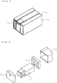
- Fig. 7 is a perspective view showing an example of how an indoor unit for an air-conditioning apparatus according to related art is packed as a whole.
- Fig. 8 is an exploded perspective view showing an example of how the indoor unit for an air-conditioning apparatus according to related art is packed as a whole.
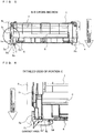
- Fig. 9 is a perspective front view showing the casing of the indoor unit for an air-conditioning apparatus according to related art.
- Fig. 10 is a perspective rear view showing the casing of the indoor unit for an air-conditioning apparatus according to related art.
- Fig. 11 is a cross-sectional view taken along a line D-D of the casing shown in Fig. 9 .
- FIG. 12 is a perspective rear view showing how the indoor unit for an air-conditioning apparatus according to related art is packed as a whole.
- Fig. 13 is a cross-sectional view taken along a line E-E of the casing shown in Fig, 12 .
- Fig. 14 is a detailed view of a portion F of the casing shown in Fig. 13 .
- Fig. 15 is a detailed view of a portion G of the casing shown in Fig. 13 .
- an indoor unit for an air-conditioning apparatus has a cushioning member such as polystyrene foam fitted to the both sides.
- the indoor unit is stored in a corrugated cardboard box in that state, and packed with its outside wrapped with a band.
- the packed indoor unit for an air-conditioning apparatus is usually stacked up in multiple levels and kept in a warehouse or the like.
- GB 2155616A discloses an air conditioning device which comprises an outer housing having a top covering wall 1a adapted for mounting the device on a ceiling, a rear wall 1b and side covering walls.
- a partition member 3 divides the housing into an air intake chamber 4 and an air delivery chamber 5.
- the present invention has been developed to solve the above-mentioned problem. Accordingly, it is an object of the present invention to provide an indoor unit for an air-conditioning apparatus, which prevents a part of its casing from digging into a cushioning member even when the indoor unit is stacked up in its packed state and which, therefore, archives the ease of unpacking.
- An indoor unit for an air-conditioning apparatus includes, on at least one side of a casing, a designed side rib part that is provided so as to protrude along a short direction of the casing, the designed side rib part having a distal end portion that has a linear shape in rear view, and a designed side planar part that is provided so as to protrude along the short direction of the casing, the designed side planar part having a distal end portion that has a substantially rectangular shape in rear view.
- both the distal end portion of the designed side rib part and the distal end portion of the designed side planar part are adapted to have contact with an inner wall of the cushioning member opposite to the distal end portion of the designed side rib part.
- the indoor unit for an air-conditioning apparatus prevents a part of the casing from digging into a cushioning member even when the indoor unit is stacked up in its packed state. Therefore, the ease of unpacking is archived.
- Fig. 1 is a perspective front view showing the casing of an indoor unit for an air-conditioning apparatus according to Embodiment 1 of the present invention.
- Fig. 2 is a perspective rear view showing the casing of the indoor unit for an air-conditioning apparatus according to Embodiment 1 of the present invention.
- Fig. 3 is a cross-sectional view taken along a line A-A of the casing shown in Fig. 1 .
- Fig. 4 is a perspective rear view showing how the indoor unit for an air-conditioning apparatus according to Embodiment 1 of the present invention is packed as a whole.
- an indoor unit 1 for an air-conditioning apparatus includes a casing 5, a design panel 7 mounted on the front of the casing 5, and an installation plate 6 mounted on the rear of the casing 5.
- the indoor unit 1 can be fixed to a wall or the like with the installation plate 6.
- an electric-component-box storage part 5b, and a designed side rib part 5a are provided on the right hand side (hereinafter, referred to as electric-component-box storage side) and the left hand side (hereinafter, referred to as design side), respectively, of the casing 5.
- Various type of machinery such as a heat exchanger and an air sending fan, which are not shown, are provided inside the casing 5. Air that has undergone heat exchange by the heat exchanger is sent indoors by the air sending fan from an air outlet, which is not shown, provided in a lower part of the front of the casing 5.
- the electric-component-box storage part 5b has a box-like shape that conforms to the contours of the electric component box.
- the electric-component-box storage part 5b is formed along the short direction of the casing 5 in such a way that its distal end portion has a substantially rectangular shape in rear view.
- a heat exchanger holding part 5c for holding the heat exchanger is formed on the design side of the casing 5. Accordingly, by taking mold strength and moldability into consideration, the designed side rib part 5a in the form of a protrusion is provided.
- the designed side rib part 5a is provided along the short direction of the casing 5 in such a way that a distal end portion 5a' of the designed side rib part 5a protrudes in a linear shape in rear view.
- the designed side planar part 5d is provided near the designed side rib part 5a.
- the designed side planar part 5d is provided along the short direction of the casing 5 in such a way that a distal end portion 5d' of the designed side planar part 5d protrudes in a substantially rectangular shape in rear view.
- the distal end portion 5d' of the designed side planar part 5d is substantially in parallel to the distal end portion 5a' of the designed side rib part 5a, and protrudes to substantially the same distance as the distal end portion 5a' of the designed side rib part 5a.
- Fig. 5 is a cross-sectional view taken along a line B-B of the casing shown in Fig. 4 .
- Fig. 6 is a detailed view of a portion C of the casing shown in Fig. 5 .
- a cushioning member 4 such as polystyrene foam is fitted to both sides of the indoor unit 1 for an air-conditioning apparatus according to Embodiment 1 during packing.
- the cushioning member 4 is fitted to each side of the indoor unit 1, and has a recessed shape that conforms to the shape of the side of the indoor unit 1 as shown in Fig. 8 , in order to cover a part of the side of the indoor unit 1.
- the cushioning member 4a has an inner wall having the recessed shape.
- the designed side rib part 5a and the designed side planar part 5d are so positioned that when the cushioning member 4 is fitted to the design face side of the indoor unit 1, their respective distal end portions 5a' and 5b' both have contact with an inner wall 4a of the cushioning member 4 opposite to the distal end portion 5a' of the designed side rib part 5a as shown in Figs. 5 and 6 .
- the indoor unit 1 is stored in a corrugated cardboard box, which is not shown, in that state, and is packed with its outside wrapped with a band 3, which is not shown.
- Indoor units each composed of the indoor unit 1 for an air-conditioning apparatus in its packed state are usually stacked up in multiple levels and kept in a warehouse or the like. At this time, the indoor unit 1 is stacked up in such a way that weight acts on the indoor unit 1 in the direction indicated by an arrow in Figs. 5 and 6 . That is, the indoor unit 1 is stacked up with its front at the top and its rear at the bottom. As the indoor unit 1 is stacked up higher and higher, the lower the indoor unit 1 lies in the stack, the greater the weight bearing to the contact area between the inner wall 4a of the cushioning member 4, and the distal end portion 5a' of the designed side rib part 5a and the distal end portion 5d' of the designed side planar part 5d.
- the distal end portion 5d' of the designed side planar part 5d as well as the distal end portion 5a' of the designed side rib part 5a are also in contact with the cushioning member 4. Consequently, the weight bearing on the contact area can be dispersed, which makes it possible to reduce digging of the distal end portion 5a' of the designed side rib part 5a into the cushioning member 4, even for the indoor unit 1 that lies at the lower level of the stack. Moreover, even when vibration or impact is applied to the contact area during transport or the like in addition to weight, such loads acting on the contact area can be dispersed.
- the designed side planar part 5d in addition to the designed side rib part 5a on the design side of the casing 5, the area of contact with the inner wall 4a of the cushioning member 4 fitted to the indoor unit 1 during packing can be increased. Therefore, load due to vibration, impact, or weight bearing during shipping, transport, or the like can be dispersed at the contact area, thereby reducing its digging of the distal end portion 5a' of the designed side rib part 5a into the cushioning material 4.
- the cushioning member 4 can be smoothly removed from the indoor unit 1 during unpacking, and the ease of unpacking is archived.
- the electric-component-box storage side of the casing 5 is provided with the electric-component-box storage part 5b having a substantially rectangular distal end portion. Accordingly, on the electric-component-box storage side, the distal end portion of the electric-component-box storage part 5b is unlikely to dig into the cushioning member 4. Therefore, if only the designed side rib part 5a is provided on the design side of the casing 5, the distal end portion 5a' of the designed side rib part 5a digs into the cushioning member 4 only on the design side, causing only the design side to sag. Consequently, in a case where the indoor unit 1 is stacked up in multiple levels, the stack tilts and collapses.
- the provision of the designed side planar part 5d on the design side makes it possible to reduce tilting and the resulting collapse of the stack.
- Embodiment 1 is directed to the case where the designed side rib part 5a is provided only on one side of the casing 5, the present invention is also applicable to a case where the designed side rib part 5a is provided on each of both sides of the casing 5.
Landscapes
- Engineering & Computer Science (AREA)
- Mechanical Engineering (AREA)
- Chemical & Material Sciences (AREA)
- Combustion & Propulsion (AREA)
- General Engineering & Computer Science (AREA)
- Physics & Mathematics (AREA)
- Thermal Sciences (AREA)
- Packaging Of Machine Parts And Wound Products (AREA)
- Buffer Packaging (AREA)
- Air Filters, Heat-Exchange Apparatuses, And Housings Of Air-Conditioning Units (AREA)
- Packages (AREA)
Description
- The present invention relates to an indoor unit for an air-conditioning apparatus, and more specifically, the present invention relates to the structure of the side of a casing.
- In related art, an indoor unit for an air-conditioning apparatus is fitted with a cushioning member made of polystyrene foam or the like so that load due to vibration, impact, or weight bearing during shipping or transport does not transfer to the indoor unit. The indoor unit fitted with such a cushioning member is packed in a corrugated cardboard box or the like and shipped (see
Patent Literatures 1 and 2). - Hereinafter, how an indoor unit for an air-conditioning apparatus according to related art is packed will be described with reference to
Figs. 7 to 15 . -
Fig. 7 is a perspective view showing an example of how an indoor unit for an air-conditioning apparatus according to related art is packed as a whole.Fig. 8 is an exploded perspective view showing an example of how the indoor unit for an air-conditioning apparatus according to related art is packed as a whole.Fig. 9 is a perspective front view showing the casing of the indoor unit for an air-conditioning apparatus according to related art.Fig. 10 is a perspective rear view showing the casing of the indoor unit for an air-conditioning apparatus according to related art.Fig. 11 is a cross-sectional view taken along a line D-D of the casing shown inFig. 9 .Fig. 12 is a perspective rear view showing how the indoor unit for an air-conditioning apparatus according to related art is packed as a whole.Fig. 13 is a cross-sectional view taken along a line E-E of the casing shown inFig, 12 .Fig. 14 is a detailed view of a portion F of the casing shown inFig. 13 .Fig. 15 is a detailed view of a portion G of the casing shown inFig. 13 . - As shown in
Figs. 7 and 8 , an indoor unit for an air-conditioning apparatus has a cushioning member such as polystyrene foam fitted to the both sides. The indoor unit is stored in a corrugated cardboard box in that state, and packed with its outside wrapped with a band. The packed indoor unit for an air-conditioning apparatus is usually stacked up in multiple levels and kept in a warehouse or the like. -
GB 2155616A partition member 3 divides the housing into anair intake chamber 4 and anair delivery chamber 5. -
- [Patent Literature 1] Japanese Unexamined Patent Application Publication No.
2009-113845 Fig. 3 ) - [Patent Literature 2] Japanese Unexamined Patent Application Publication No.
2008-150068 Fig. 1 ) - In a case where indoor units for air-conditioning apparatuses as described in each of
Patent Literatures Figs. 9 to 11 , the following problem arises when the indoor units are packed and stacked up in multiple levels. - As the indoor units are stacked up higher and higher, the lower an indoor unit lies in the stack, the greater the weight bearing to the indoor unit in the direction indicated by an arrow in
Figs. 13 to 15 . At this time, on one side of the indoor unit, only the designed side rib part is in contact with a surface of a cushioning member opposite to the weight bearing direction. Therefore, the weight bearing concentrates at this contact part, and as the weight bearing increases as the number of stacking levels increases, there is a possibility that the distal end portion of the designed side rib part may dig into the cushioning material. As a result, it is difficult to remove the cushioning member from the indoor unit during unpacking, which compromises the ease of unpacking. - The present invention has been developed to solve the above-mentioned problem. Accordingly, it is an object of the present invention to provide an indoor unit for an air-conditioning apparatus, which prevents a part of its casing from digging into a cushioning member even when the indoor unit is stacked up in its packed state and which, therefore, archives the ease of unpacking.
- An indoor unit for an air-conditioning apparatus according to the present invention includes, on at least one side of a casing, a designed side rib part that is provided so as to protrude along a short direction of the casing, the designed side rib part having a distal end portion that has a linear shape in rear view, and a designed side planar part that is provided so as to protrude along the short direction of the casing, the designed side planar part having a distal end portion that has a substantially rectangular shape in rear view. When the side of the casing is adapted to be fitted to a cushioning member for packing, both the distal end portion of the designed side rib part and the distal end portion of the designed side planar part are adapted to have contact with an inner wall of the cushioning member opposite to the distal end portion of the designed side rib part.
- The indoor unit for an air-conditioning apparatus according to the present invention prevents a part of the casing from digging into a cushioning member even when the indoor unit is stacked up in its packed state. Therefore, the ease of unpacking is archived.
-
- [
Fig. 1] Fig. 1 is a perspective front view showing the casing of an indoor unit for an air-conditioning apparatus according toEmbodiment 1 of the present invention. - [
Fig. 2] Fig. 2 is a perspective rear view showing the casing of the indoor unit for an air-conditioning apparatus according toEmbodiment 1 of the present invention. - [
Fig. 3] Fig. 3 is a cross-sectional view taken along a line A-A of the casing shown inFig. 1 . - [
Fig. 4] Fig. 4 is a perspective rear view showing how the indoor unit for an air-conditioning apparatus according toEmbodiment 1 of the present invention is packed as a whole. - [
Fig. 5] Fig. 5 is a cross-sectional view taken along a line B-B of the casing shown inFig. 4 . - [
Fig. 6] Fig. 6 is a detailed view of a portion C of the casing shown inFig. 5 . - [
Fig. 7] Fig. 7 is a perspective view showing an example of how an indoor unit for an air-conditioning apparatus according to related art is packed as a whole. - [
Fig. 8] Fig. 8 is an exploded perspective view showing an example of how the indoor unit for an air-conditioning apparatus according to related art is packed as a whole. - [
Fig. 9] Fig. 9 is a perspective front view showing the casing of the indoor unit for an air-conditioning apparatus according to related art. - [
Fig. 10] Fig. 10 is a perspective rear view showing the casing of the indoor unit for an air-conditioning apparatus according to related art. - [
Fig. 11] Fig. 11 is a cross-sectional view taken along a line D-D of the casing shown inFig. 9 . - [
Fig. 12] Fig. 12 is a perspective rear view showing how the indoor unit for an air-conditioning apparatus according to related art is packed as a whole. - [
Fig. 13] Fig. 13 is a cross-sectional view taken along a line E-E of the casing shown inFig. 12 . - [
Fig. 14] Fig. 14 is a detailed view of a portion F of the casing shown inFig. 13 . - [
Fig. 15] Fig. 15 is a detailed view of a portion G of the casing shown inFig. 13 . - Embodiments of the present invention will be described below with reference to the drawings.
-
Fig. 1 is a perspective front view showing the casing of an indoor unit for an air-conditioning apparatus according toEmbodiment 1 of the present invention.Fig. 2 is a perspective rear view showing the casing of the indoor unit for an air-conditioning apparatus according toEmbodiment 1 of the present invention.Fig. 3 is a cross-sectional view taken along a line A-A of the casing shown inFig. 1 .Fig. 4 is a perspective rear view showing how the indoor unit for an air-conditioning apparatus according toEmbodiment 1 of the present invention is packed as a whole. - The outward appearance of an
indoor unit 1 for an air-conditioning apparatus according to Embodiment 1 includes acasing 5, adesign panel 7 mounted on the front of thecasing 5, and aninstallation plate 6 mounted on the rear of thecasing 5. Theindoor unit 1 can be fixed to a wall or the like with theinstallation plate 6. When theindoor unit 1 is seen in front view, an electric-component-box storage part 5b, and a designedside rib part 5a are provided on the right hand side (hereinafter, referred to as electric-component-box storage side) and the left hand side (hereinafter, referred to as design side), respectively, of thecasing 5. - Various type of machinery such as a heat exchanger and an air sending fan, which are not shown, are provided inside the
casing 5. Air that has undergone heat exchange by the heat exchanger is sent indoors by the air sending fan from an air outlet, which is not shown, provided in a lower part of the front of thecasing 5. - An electric component box is stored on the electric-component-box storage side of the
casing 5. Accordingly, the electric-component-box storage part 5b has a box-like shape that conforms to the contours of the electric component box. The electric-component-box storage part 5b is formed along the short direction of thecasing 5 in such a way that its distal end portion has a substantially rectangular shape in rear view. - A heat
exchanger holding part 5c for holding the heat exchanger is formed on the design side of thecasing 5. Accordingly, by taking mold strength and moldability into consideration, the designedside rib part 5a in the form of a protrusion is provided. The designedside rib part 5a is provided along the short direction of thecasing 5 in such a way that adistal end portion 5a' of the designedside rib part 5a protrudes in a linear shape in rear view. - As shown in
Fig. 3 , the designed sideplanar part 5d is provided near the designedside rib part 5a. The designed sideplanar part 5d is provided along the short direction of thecasing 5 in such a way that adistal end portion 5d' of the designed sideplanar part 5d protrudes in a substantially rectangular shape in rear view. In rear view, thedistal end portion 5d' of the designed sideplanar part 5d is substantially in parallel to thedistal end portion 5a' of the designedside rib part 5a, and protrudes to substantially the same distance as thedistal end portion 5a' of the designedside rib part 5a. -
Fig. 5 is a cross-sectional view taken along a line B-B of the casing shown inFig. 4 .Fig. 6 is a detailed view of a portion C of the casing shown inFig. 5 . - As shown in
Fig. 4 , a cushioningmember 4 such as polystyrene foam is fitted to both sides of theindoor unit 1 for an air-conditioning apparatus according toEmbodiment 1 during packing. The cushioningmember 4 is fitted to each side of theindoor unit 1, and has a recessed shape that conforms to the shape of the side of theindoor unit 1 as shown inFig. 8 , in order to cover a part of the side of theindoor unit 1. The cushioningmember 4a has an inner wall having the recessed shape. - The designed
side rib part 5a and the designed sideplanar part 5d are so positioned that when the cushioningmember 4 is fitted to the design face side of theindoor unit 1, their respectivedistal end portions 5a' and 5b' both have contact with aninner wall 4a of the cushioningmember 4 opposite to thedistal end portion 5a' of the designedside rib part 5a as shown inFigs. 5 and 6 . Theindoor unit 1 is stored in a corrugated cardboard box, which is not shown, in that state, and is packed with its outside wrapped with aband 3, which is not shown. - Indoor units each composed of the
indoor unit 1 for an air-conditioning apparatus in its packed state are usually stacked up in multiple levels and kept in a warehouse or the like. At this time, theindoor unit 1 is stacked up in such a way that weight acts on theindoor unit 1 in the direction indicated by an arrow inFigs. 5 and 6 . That is, theindoor unit 1 is stacked up with its front at the top and its rear at the bottom. As theindoor unit 1 is stacked up higher and higher, the lower theindoor unit 1 lies in the stack, the greater the weight bearing to the contact area between theinner wall 4a of the cushioningmember 4, and thedistal end portion 5a' of the designedside rib part 5a and thedistal end portion 5d' of the designed sideplanar part 5d. - At this time, if only the
distal end portion 5a' of the designedside rib part 5a is in contact with theinner wall 4a of the cushioningmember 4, the weight bearing concentrates at the contact area. Accordingly, the lower theindoor unit 1 lies in the stack, the greater the amount that thedistal end 5a' of the designedside rib part 5a digs into the cushioningmember 4. - However, in
Embodiment 1, thedistal end portion 5d' of the designed sideplanar part 5d as well as thedistal end portion 5a' of the designedside rib part 5a are also in contact with the cushioningmember 4. Consequently, the weight bearing on the contact area can be dispersed, which makes it possible to reduce digging of thedistal end portion 5a' of the designedside rib part 5a into the cushioningmember 4, even for theindoor unit 1 that lies at the lower level of the stack. Moreover, even when vibration or impact is applied to the contact area during transport or the like in addition to weight, such loads acting on the contact area can be dispersed. - From the foregoing discussion, by providing the designed side
planar part 5d in addition to the designedside rib part 5a on the design side of thecasing 5, the area of contact with theinner wall 4a of the cushioningmember 4 fitted to theindoor unit 1 during packing can be increased. Therefore, load due to vibration, impact, or weight bearing during shipping, transport, or the like can be dispersed at the contact area, thereby reducing its digging of thedistal end portion 5a' of the designedside rib part 5a into thecushioning material 4. - As a result, the cushioning
member 4 can be smoothly removed from theindoor unit 1 during unpacking, and the ease of unpacking is archived. - In
Embodiment 1, the electric-component-box storage side of thecasing 5 is provided with the electric-component-box storage part 5b having a substantially rectangular distal end portion. Accordingly, on the electric-component-box storage side, the distal end portion of the electric-component-box storage part 5b is unlikely to dig into the cushioningmember 4. Therefore, if only the designedside rib part 5a is provided on the design side of thecasing 5, thedistal end portion 5a' of the designedside rib part 5a digs into the cushioningmember 4 only on the design side, causing only the design side to sag. Consequently, in a case where theindoor unit 1 is stacked up in multiple levels, the stack tilts and collapses. - However, the provision of the designed side
planar part 5d on the design side makes it possible to reduce tilting and the resulting collapse of the stack. - While
Embodiment 1 is directed to the case where the designedside rib part 5a is provided only on one side of thecasing 5, the present invention is also applicable to a case where the designedside rib part 5a is provided on each of both sides of thecasing 5. - In addition, the larger the area of the substantially rectangular shape of the
distal end portion 5d' of the designed sideplanar part 5d, the more the load due to vibration, impact, or weight can be dispersed. - 1 indoor unit, 2 corrugated cardboard box, 3 band, 4 cushioning member, 4a inner wall, 5 casing, 5a designed side rib part, 5a' distal end portion, 5b electric-component-box storage part, 5c heat exchanger holding part, 5d designed side planar part, 5d' distal end portion, 6 installation plate, 7 design panel
Claims (3)
- An indoor unit for an air-conditioning apparatus, the indoor unit comprising: on at least one side of a casing (5),
a designed side rib part (5a) that is provided so as to protrude along a short direction of the casing (5), the designed side rib part (5a) having a distal end portion (5a') that has a linear shape in rear view; and
a designed side planar part (5d) that is provided so as to protrude along the short direction of the casing (5), the designed side planar part (5d) having a distal end portion (5d') that has a substantially rectangular shape in rear view, characterized in that when the side of the casing (5) is adapted to be fitted to a cushioning member (4) for packing, both the distal end portion (5a') of the designed side rib part (5a) and the distal end portion (5d') of the designed side planar part (5d) are adapted to have contact with an inner wall (4a) of the cushioning member (4) opposite to the distal end portion (5a') of the designed side rib part (5a). - The indoor unit for an air-conditioning apparatus of claim 1, wherein the distal end portion (5d') of the designed side planar part (5d) protrudes substantially in parallel to the distal end portion (5a') of the designed side rib part (5a).
- The indoor unit for an air-conditioning apparatus of claim 1 or 2, wherein the casing (5) has the designed side rib part (5a) and the designed side planar part (5d) on each of both sides of the casing (5).
Applications Claiming Priority (1)
| Application Number | Priority Date | Filing Date | Title |
|---|---|---|---|
| JP2012270354A JP5713989B2 (en) | 2012-12-11 | 2012-12-11 | Air conditioner indoor unit |
Publications (3)
| Publication Number | Publication Date |
|---|---|
| EP2743595A2 EP2743595A2 (en) | 2014-06-18 |
| EP2743595A3 EP2743595A3 (en) | 2018-03-14 |
| EP2743595B1 true EP2743595B1 (en) | 2020-03-18 |
Family
ID=49626830
Family Applications (1)
| Application Number | Title | Priority Date | Filing Date |
|---|---|---|---|
| EP13193559.5A Active EP2743595B1 (en) | 2012-12-11 | 2013-11-19 | Indoor unit for air-conditioning apparatus |
Country Status (3)
| Country | Link |
|---|---|
| EP (1) | EP2743595B1 (en) |
| JP (1) | JP5713989B2 (en) |
| CN (2) | CN203704144U (en) |
Families Citing this family (3)
| Publication number | Priority date | Publication date | Assignee | Title |
|---|---|---|---|---|
| JP5713989B2 (en) * | 2012-12-11 | 2015-05-07 | 三菱電機株式会社 | Air conditioner indoor unit |
| JP2017081590A (en) * | 2015-10-27 | 2017-05-18 | ダイキン工業株式会社 | Packing buffer material |
| CN106956868B (en) * | 2017-03-07 | 2018-06-05 | 广东美的暖通设备有限公司 | The accommodation method of wind turbine |
Family Cites Families (16)
| Publication number | Priority date | Publication date | Assignee | Title |
|---|---|---|---|---|
| GB2155616B (en) * | 1981-10-21 | 1986-02-26 | Mitsubishi Electric Corp | Air conditioning device |
| JPS63149872U (en) * | 1987-03-25 | 1988-10-03 | ||
| JPH11118218A (en) * | 1997-10-14 | 1999-04-30 | Showa Mfg Co Ltd | Functioning part casing structure of ceiling recessed air cleaner and its packing |
| JPH11115968A (en) * | 1997-10-17 | 1999-04-27 | Chiyoda Container Corp | Packaging structure |
| WO2002103252A2 (en) * | 2001-06-19 | 2002-12-27 | Lg Electronics Inc. | Air conditioner |
| JP2005162318A (en) * | 2003-11-30 | 2005-06-23 | Toshiba Kyaria Kk | Package body |
| JP4599962B2 (en) * | 2004-09-17 | 2010-12-15 | マックス株式会社 | air conditioner |
| JP4696673B2 (en) * | 2005-05-11 | 2011-06-08 | ダイキン工業株式会社 | Air conditioner outdoor unit |
| CN1987221B (en) * | 2005-12-23 | 2010-06-02 | 乐金电子(天津)电器有限公司 | Cold medium tube cover binding structure of indoor machine of air conditioner |
| WO2007097359A1 (en) * | 2006-02-22 | 2007-08-30 | Matsushita Electric Industrial Co., Ltd. | Packaging apparatus |
| JP2008150068A (en) * | 2006-12-15 | 2008-07-03 | Daikin Ind Ltd | Buffer member |
| JP4270303B2 (en) * | 2007-04-27 | 2009-05-27 | ダイキン工業株式会社 | Air conditioner |
| JP4428441B2 (en) * | 2007-11-08 | 2010-03-10 | ダイキン工業株式会社 | Buffer member |
| KR20100055209A (en) * | 2008-11-17 | 2010-05-26 | 엘지전자 주식회사 | Packing box for electric home appliances |
| CN102042664A (en) * | 2009-10-19 | 2011-05-04 | 乐金电子(天津)电器有限公司 | Main pedestal for an indoor unit of a split type air conditioner |
| JP5713989B2 (en) * | 2012-12-11 | 2015-05-07 | 三菱電機株式会社 | Air conditioner indoor unit |
-
2012
- 2012-12-11 JP JP2012270354A patent/JP5713989B2/en active Active
-
2013
- 2013-11-19 EP EP13193559.5A patent/EP2743595B1/en active Active
- 2013-12-10 CN CN201320807150.4U patent/CN203704144U/en not_active Expired - Lifetime
- 2013-12-10 CN CN201310664739.8A patent/CN103868151B/en active Active
Non-Patent Citations (1)
| Title |
|---|
| None * |
Also Published As
| Publication number | Publication date |
|---|---|
| JP2014114059A (en) | 2014-06-26 |
| EP2743595A2 (en) | 2014-06-18 |
| CN203704144U (en) | 2014-07-09 |
| CN103868151A (en) | 2014-06-18 |
| CN103868151B (en) | 2017-01-04 |
| EP2743595A3 (en) | 2018-03-14 |
| JP5713989B2 (en) | 2015-05-07 |
Similar Documents
| Publication | Publication Date | Title |
|---|---|---|
| EP2743595B1 (en) | Indoor unit for air-conditioning apparatus | |
| KR200471021Y1 (en) | Box-type packaging which can control the internal temperature | |
| JP5637173B2 (en) | Packing material for air conditioner | |
| JP6135423B2 (en) | Tray-type packaging box | |
| JP4428441B2 (en) | Buffer member | |
| EP3524533A1 (en) | Packing device | |
| US6401930B1 (en) | Universal handling container | |
| CN211253669U (en) | Packaging structure for air conditioner and air conditioner assembly | |
| JP2020083459A (en) | Packing member | |
| JP2015196531A (en) | Packing material and packing method used for air conditioner | |
| JP2012006636A (en) | Protective member | |
| JP4003716B2 (en) | Packing equipment | |
| CN203698975U (en) | Anti-collision foam insulation box for logistics | |
| CN114933083B (en) | Packaging buffer structure and packaging structure | |
| JP2011255927A (en) | Buffer packing material for bottom of refrigerator, and packing structure for bottom of refrigerator | |
| CN220315703U (en) | Buffer support box | |
| JP7366270B2 (en) | Outdoor unit packing equipment | |
| JP7138733B2 (en) | Outdoor unit packing device | |
| JP5904219B2 (en) | Packing material for air conditioning unit | |
| KR100442327B1 (en) | Packing structure for wall suspending fan | |
| JP2024013599A (en) | Packing material and packing structure for frame body | |
| JP4868996B2 (en) | Packaging box partition structure | |
| JP5124166B2 (en) | Buffer packaging material | |
| JP2017095160A (en) | Packaging material for heat pump unit | |
| TWM329620U (en) | Thin panel package box |
Legal Events
| Date | Code | Title | Description |
|---|---|---|---|
| PUAI | Public reference made under article 153(3) epc to a published international application that has entered the european phase |
Free format text: ORIGINAL CODE: 0009012 |
|
| 17P | Request for examination filed |
Effective date: 20131119 |
|
| AK | Designated contracting states |
Kind code of ref document: A2 Designated state(s): AL AT BE BG CH CY CZ DE DK EE ES FI FR GB GR HR HU IE IS IT LI LT LU LV MC MK MT NL NO PL PT RO RS SE SI SK SM TR |
|
| AX | Request for extension of the european patent |
Extension state: BA ME |
|
| PUAL | Search report despatched |
Free format text: ORIGINAL CODE: 0009013 |
|
| AK | Designated contracting states |
Kind code of ref document: A3 Designated state(s): AL AT BE BG CH CY CZ DE DK EE ES FI FR GB GR HR HU IE IS IT LI LT LU LV MC MK MT NL NO PL PT RO RS SE SI SK SM TR |
|
| AX | Request for extension of the european patent |
Extension state: BA ME |
|
| RIC1 | Information provided on ipc code assigned before grant |
Ipc: F24F 1/00 20110101AFI20180207BHEP Ipc: B65D 81/113 20060101ALI20180207BHEP Ipc: F24F 13/20 20060101ALI20180207BHEP Ipc: B65D 85/68 20060101ALI20180207BHEP |
|
| STAA | Information on the status of an ep patent application or granted ep patent |
Free format text: STATUS: REQUEST FOR EXAMINATION WAS MADE |
|
| R17P | Request for examination filed (corrected) |
Effective date: 20180528 |
|
| RBV | Designated contracting states (corrected) |
Designated state(s): AL AT BE BG CH CY CZ DE DK EE ES FI FR GB GR HR HU IE IS IT LI LT LU LV MC MK MT NL NO PL PT RO RS SE SI SK SM TR |
|
| REG | Reference to a national code |
Ref country code: DE Ref legal event code: R079 Ref document number: 602013066903 Country of ref document: DE Free format text: PREVIOUS MAIN CLASS: F24F0001000000 Ipc: F24F0013200000 |
|
| GRAP | Despatch of communication of intention to grant a patent |
Free format text: ORIGINAL CODE: EPIDOSNIGR1 |
|
| STAA | Information on the status of an ep patent application or granted ep patent |
Free format text: STATUS: GRANT OF PATENT IS INTENDED |
|
| RIC1 | Information provided on ipc code assigned before grant |
Ipc: F24F 13/20 20060101AFI20191001BHEP Ipc: F24F 1/0007 20190101ALI20191001BHEP |
|
| INTG | Intention to grant announced |
Effective date: 20191029 |
|
| GRAS | Grant fee paid |
Free format text: ORIGINAL CODE: EPIDOSNIGR3 |
|
| GRAA | (expected) grant |
Free format text: ORIGINAL CODE: 0009210 |
|
| STAA | Information on the status of an ep patent application or granted ep patent |
Free format text: STATUS: THE PATENT HAS BEEN GRANTED |
|
| AK | Designated contracting states |
Kind code of ref document: B1 Designated state(s): AL AT BE BG CH CY CZ DE DK EE ES FI FR GB GR HR HU IE IS IT LI LT LU LV MC MK MT NL NO PL PT RO RS SE SI SK SM TR |
|
| REG | Reference to a national code |
Ref country code: GB Ref legal event code: FG4D |
|
| REG | Reference to a national code |
Ref country code: DE Ref legal event code: R096 Ref document number: 602013066903 Country of ref document: DE |
|
| REG | Reference to a national code |
Ref country code: AT Ref legal event code: REF Ref document number: 1246348 Country of ref document: AT Kind code of ref document: T Effective date: 20200415 Ref country code: IE Ref legal event code: FG4D |
|
| PG25 | Lapsed in a contracting state [announced via postgrant information from national office to epo] |
Ref country code: FI Free format text: LAPSE BECAUSE OF FAILURE TO SUBMIT A TRANSLATION OF THE DESCRIPTION OR TO PAY THE FEE WITHIN THE PRESCRIBED TIME-LIMIT Effective date: 20200318 Ref country code: NO Free format text: LAPSE BECAUSE OF FAILURE TO SUBMIT A TRANSLATION OF THE DESCRIPTION OR TO PAY THE FEE WITHIN THE PRESCRIBED TIME-LIMIT Effective date: 20200618 Ref country code: RS Free format text: LAPSE BECAUSE OF FAILURE TO SUBMIT A TRANSLATION OF THE DESCRIPTION OR TO PAY THE FEE WITHIN THE PRESCRIBED TIME-LIMIT Effective date: 20200318 |
|
| REG | Reference to a national code |
Ref country code: NL Ref legal event code: MP Effective date: 20200318 |
|
| PG25 | Lapsed in a contracting state [announced via postgrant information from national office to epo] |
Ref country code: BG Free format text: LAPSE BECAUSE OF FAILURE TO SUBMIT A TRANSLATION OF THE DESCRIPTION OR TO PAY THE FEE WITHIN THE PRESCRIBED TIME-LIMIT Effective date: 20200618 Ref country code: GR Free format text: LAPSE BECAUSE OF FAILURE TO SUBMIT A TRANSLATION OF THE DESCRIPTION OR TO PAY THE FEE WITHIN THE PRESCRIBED TIME-LIMIT Effective date: 20200619 Ref country code: SE Free format text: LAPSE BECAUSE OF FAILURE TO SUBMIT A TRANSLATION OF THE DESCRIPTION OR TO PAY THE FEE WITHIN THE PRESCRIBED TIME-LIMIT Effective date: 20200318 Ref country code: LV Free format text: LAPSE BECAUSE OF FAILURE TO SUBMIT A TRANSLATION OF THE DESCRIPTION OR TO PAY THE FEE WITHIN THE PRESCRIBED TIME-LIMIT Effective date: 20200318 Ref country code: HR Free format text: LAPSE BECAUSE OF FAILURE TO SUBMIT A TRANSLATION OF THE DESCRIPTION OR TO PAY THE FEE WITHIN THE PRESCRIBED TIME-LIMIT Effective date: 20200318 |
|
| REG | Reference to a national code |
Ref country code: LT Ref legal event code: MG4D |
|
| PG25 | Lapsed in a contracting state [announced via postgrant information from national office to epo] |
Ref country code: NL Free format text: LAPSE BECAUSE OF FAILURE TO SUBMIT A TRANSLATION OF THE DESCRIPTION OR TO PAY THE FEE WITHIN THE PRESCRIBED TIME-LIMIT Effective date: 20200318 |
|
| PG25 | Lapsed in a contracting state [announced via postgrant information from national office to epo] |
Ref country code: LT Free format text: LAPSE BECAUSE OF FAILURE TO SUBMIT A TRANSLATION OF THE DESCRIPTION OR TO PAY THE FEE WITHIN THE PRESCRIBED TIME-LIMIT Effective date: 20200318 Ref country code: RO Free format text: LAPSE BECAUSE OF FAILURE TO SUBMIT A TRANSLATION OF THE DESCRIPTION OR TO PAY THE FEE WITHIN THE PRESCRIBED TIME-LIMIT Effective date: 20200318 Ref country code: IS Free format text: LAPSE BECAUSE OF FAILURE TO SUBMIT A TRANSLATION OF THE DESCRIPTION OR TO PAY THE FEE WITHIN THE PRESCRIBED TIME-LIMIT Effective date: 20200718 Ref country code: SK Free format text: LAPSE BECAUSE OF FAILURE TO SUBMIT A TRANSLATION OF THE DESCRIPTION OR TO PAY THE FEE WITHIN THE PRESCRIBED TIME-LIMIT Effective date: 20200318 Ref country code: CZ Free format text: LAPSE BECAUSE OF FAILURE TO SUBMIT A TRANSLATION OF THE DESCRIPTION OR TO PAY THE FEE WITHIN THE PRESCRIBED TIME-LIMIT Effective date: 20200318 Ref country code: SM Free format text: LAPSE BECAUSE OF FAILURE TO SUBMIT A TRANSLATION OF THE DESCRIPTION OR TO PAY THE FEE WITHIN THE PRESCRIBED TIME-LIMIT Effective date: 20200318 Ref country code: PT Free format text: LAPSE BECAUSE OF FAILURE TO SUBMIT A TRANSLATION OF THE DESCRIPTION OR TO PAY THE FEE WITHIN THE PRESCRIBED TIME-LIMIT Effective date: 20200812 Ref country code: EE Free format text: LAPSE BECAUSE OF FAILURE TO SUBMIT A TRANSLATION OF THE DESCRIPTION OR TO PAY THE FEE WITHIN THE PRESCRIBED TIME-LIMIT Effective date: 20200318 |
|
| REG | Reference to a national code |
Ref country code: AT Ref legal event code: MK05 Ref document number: 1246348 Country of ref document: AT Kind code of ref document: T Effective date: 20200318 |
|
| REG | Reference to a national code |
Ref country code: DE Ref legal event code: R097 Ref document number: 602013066903 Country of ref document: DE |
|
| PLBE | No opposition filed within time limit |
Free format text: ORIGINAL CODE: 0009261 |
|
| STAA | Information on the status of an ep patent application or granted ep patent |
Free format text: STATUS: NO OPPOSITION FILED WITHIN TIME LIMIT |
|
| PG25 | Lapsed in a contracting state [announced via postgrant information from national office to epo] |
Ref country code: IT Free format text: LAPSE BECAUSE OF FAILURE TO SUBMIT A TRANSLATION OF THE DESCRIPTION OR TO PAY THE FEE WITHIN THE PRESCRIBED TIME-LIMIT Effective date: 20200318 Ref country code: AT Free format text: LAPSE BECAUSE OF FAILURE TO SUBMIT A TRANSLATION OF THE DESCRIPTION OR TO PAY THE FEE WITHIN THE PRESCRIBED TIME-LIMIT Effective date: 20200318 Ref country code: DK Free format text: LAPSE BECAUSE OF FAILURE TO SUBMIT A TRANSLATION OF THE DESCRIPTION OR TO PAY THE FEE WITHIN THE PRESCRIBED TIME-LIMIT Effective date: 20200318 Ref country code: ES Free format text: LAPSE BECAUSE OF FAILURE TO SUBMIT A TRANSLATION OF THE DESCRIPTION OR TO PAY THE FEE WITHIN THE PRESCRIBED TIME-LIMIT Effective date: 20200318 |
|
| 26N | No opposition filed |
Effective date: 20201221 |
|
| PG25 | Lapsed in a contracting state [announced via postgrant information from national office to epo] |
Ref country code: PL Free format text: LAPSE BECAUSE OF FAILURE TO SUBMIT A TRANSLATION OF THE DESCRIPTION OR TO PAY THE FEE WITHIN THE PRESCRIBED TIME-LIMIT Effective date: 20200318 |
|
| PG25 | Lapsed in a contracting state [announced via postgrant information from national office to epo] |
Ref country code: SI Free format text: LAPSE BECAUSE OF FAILURE TO SUBMIT A TRANSLATION OF THE DESCRIPTION OR TO PAY THE FEE WITHIN THE PRESCRIBED TIME-LIMIT Effective date: 20200318 |
|
| PG25 | Lapsed in a contracting state [announced via postgrant information from national office to epo] |
Ref country code: MC Free format text: LAPSE BECAUSE OF FAILURE TO SUBMIT A TRANSLATION OF THE DESCRIPTION OR TO PAY THE FEE WITHIN THE PRESCRIBED TIME-LIMIT Effective date: 20200318 |
|
| REG | Reference to a national code |
Ref country code: CH Ref legal event code: PL |
|
| GBPC | Gb: european patent ceased through non-payment of renewal fee |
Effective date: 20201119 |
|
| PG25 | Lapsed in a contracting state [announced via postgrant information from national office to epo] |
Ref country code: LU Free format text: LAPSE BECAUSE OF NON-PAYMENT OF DUE FEES Effective date: 20201119 |
|
| REG | Reference to a national code |
Ref country code: BE Ref legal event code: MM Effective date: 20201130 |
|
| PG25 | Lapsed in a contracting state [announced via postgrant information from national office to epo] |
Ref country code: CH Free format text: LAPSE BECAUSE OF NON-PAYMENT OF DUE FEES Effective date: 20201130 Ref country code: LI Free format text: LAPSE BECAUSE OF NON-PAYMENT OF DUE FEES Effective date: 20201130 |
|
| PG25 | Lapsed in a contracting state [announced via postgrant information from national office to epo] |
Ref country code: FR Free format text: LAPSE BECAUSE OF NON-PAYMENT OF DUE FEES Effective date: 20201130 Ref country code: IE Free format text: LAPSE BECAUSE OF NON-PAYMENT OF DUE FEES Effective date: 20201119 |
|
| PG25 | Lapsed in a contracting state [announced via postgrant information from national office to epo] |
Ref country code: GB Free format text: LAPSE BECAUSE OF NON-PAYMENT OF DUE FEES Effective date: 20201119 |
|
| PG25 | Lapsed in a contracting state [announced via postgrant information from national office to epo] |
Ref country code: TR Free format text: LAPSE BECAUSE OF FAILURE TO SUBMIT A TRANSLATION OF THE DESCRIPTION OR TO PAY THE FEE WITHIN THE PRESCRIBED TIME-LIMIT Effective date: 20200318 Ref country code: MT Free format text: LAPSE BECAUSE OF FAILURE TO SUBMIT A TRANSLATION OF THE DESCRIPTION OR TO PAY THE FEE WITHIN THE PRESCRIBED TIME-LIMIT Effective date: 20200318 Ref country code: CY Free format text: LAPSE BECAUSE OF FAILURE TO SUBMIT A TRANSLATION OF THE DESCRIPTION OR TO PAY THE FEE WITHIN THE PRESCRIBED TIME-LIMIT Effective date: 20200318 |
|
| PG25 | Lapsed in a contracting state [announced via postgrant information from national office to epo] |
Ref country code: MK Free format text: LAPSE BECAUSE OF FAILURE TO SUBMIT A TRANSLATION OF THE DESCRIPTION OR TO PAY THE FEE WITHIN THE PRESCRIBED TIME-LIMIT Effective date: 20200318 Ref country code: AL Free format text: LAPSE BECAUSE OF FAILURE TO SUBMIT A TRANSLATION OF THE DESCRIPTION OR TO PAY THE FEE WITHIN THE PRESCRIBED TIME-LIMIT Effective date: 20200318 |
|
| PG25 | Lapsed in a contracting state [announced via postgrant information from national office to epo] |
Ref country code: BE Free format text: LAPSE BECAUSE OF NON-PAYMENT OF DUE FEES Effective date: 20201130 |
|
| P01 | Opt-out of the competence of the unified patent court (upc) registered |
Effective date: 20230512 |
|
| PGFP | Annual fee paid to national office [announced via postgrant information from national office to epo] |
Ref country code: DE Payment date: 20230929 Year of fee payment: 11 |