JP7362527B2 - Interlocking disposable wearing article - Google Patents
Interlocking disposable wearing article Download PDFInfo
- Publication number
- JP7362527B2 JP7362527B2 JP2020054784A JP2020054784A JP7362527B2 JP 7362527 B2 JP7362527 B2 JP 7362527B2 JP 2020054784 A JP2020054784 A JP 2020054784A JP 2020054784 A JP2020054784 A JP 2020054784A JP 7362527 B2 JP7362527 B2 JP 7362527B2
- Authority
- JP
- Japan
- Prior art keywords
- region
- waist elastic
- elastic member
- width direction
- bent portion
- Prior art date
- Legal status (The legal status is an assumption and is not a legal conclusion. Google has not performed a legal analysis and makes no representation as to the accuracy of the status listed.)
- Active
Links
- 230000002745 absorbent Effects 0.000 claims description 76
- 239000002250 absorbent Substances 0.000 claims description 76
- 230000000630 rising effect Effects 0.000 claims description 57
- 238000005452 bending Methods 0.000 claims description 56
- 239000006096 absorbing agent Substances 0.000 claims description 19
- 230000000903 blocking effect Effects 0.000 claims description 10
- 210000004013 groin Anatomy 0.000 claims description 5
- 239000010410 layer Substances 0.000 description 74
- 239000004745 nonwoven fabric Substances 0.000 description 65
- 239000000835 fiber Substances 0.000 description 48
- 238000003860 storage Methods 0.000 description 36
- 239000000463 material Substances 0.000 description 31
- 239000002245 particle Substances 0.000 description 19
- 238000005304 joining Methods 0.000 description 16
- 229920000247 superabsorbent polymer Polymers 0.000 description 15
- 238000000034 method Methods 0.000 description 14
- 239000004831 Hot glue Substances 0.000 description 11
- 238000010521 absorption reaction Methods 0.000 description 9
- 230000008602 contraction Effects 0.000 description 9
- 230000000694 effects Effects 0.000 description 9
- 239000007788 liquid Substances 0.000 description 9
- 238000004806 packaging method and process Methods 0.000 description 9
- 238000012360 testing method Methods 0.000 description 9
- 239000000853 adhesive Substances 0.000 description 8
- 230000001070 adhesive effect Effects 0.000 description 8
- XLYOFNOQVPJJNP-UHFFFAOYSA-N water Substances O XLYOFNOQVPJJNP-UHFFFAOYSA-N 0.000 description 8
- 238000003466 welding Methods 0.000 description 8
- -1 polypropylene Polymers 0.000 description 7
- 239000004743 Polypropylene Substances 0.000 description 6
- 239000000470 constituent Substances 0.000 description 6
- 229920001971 elastomer Polymers 0.000 description 6
- 229920001155 polypropylene Polymers 0.000 description 6
- 230000002265 prevention Effects 0.000 description 6
- 210000002700 urine Anatomy 0.000 description 6
- 206010012735 Diarrhoea Diseases 0.000 description 5
- 230000008859 change Effects 0.000 description 5
- 239000000123 paper Substances 0.000 description 5
- 239000002985 plastic film Substances 0.000 description 5
- 239000005871 repellent Substances 0.000 description 5
- 239000005060 rubber Substances 0.000 description 5
- 239000002131 composite material Substances 0.000 description 4
- 239000013013 elastic material Substances 0.000 description 4
- 238000007789 sealing Methods 0.000 description 4
- 229920002994 synthetic fiber Polymers 0.000 description 4
- 239000012209 synthetic fiber Substances 0.000 description 4
- 239000004698 Polyethylene Substances 0.000 description 3
- 230000008901 benefit Effects 0.000 description 3
- 239000011248 coating agent Substances 0.000 description 3
- 238000000576 coating method Methods 0.000 description 3
- 230000006835 compression Effects 0.000 description 3
- 238000007906 compression Methods 0.000 description 3
- 230000007423 decrease Effects 0.000 description 3
- 238000004519 manufacturing process Methods 0.000 description 3
- 230000035699 permeability Effects 0.000 description 3
- 229920006255 plastic film Polymers 0.000 description 3
- 229920000728 polyester Polymers 0.000 description 3
- 229920000573 polyethylene Polymers 0.000 description 3
- 229920005989 resin Polymers 0.000 description 3
- 239000011347 resin Substances 0.000 description 3
- 150000003839 salts Chemical class 0.000 description 3
- 238000007873 sieving Methods 0.000 description 3
- SMZOUWXMTYCWNB-UHFFFAOYSA-N 2-(2-methoxy-5-methylphenyl)ethanamine Chemical compound COC1=CC=C(C)C=C1CCN SMZOUWXMTYCWNB-UHFFFAOYSA-N 0.000 description 2
- NIXOWILDQLNWCW-UHFFFAOYSA-N 2-Propenoic acid Natural products OC(=O)C=C NIXOWILDQLNWCW-UHFFFAOYSA-N 0.000 description 2
- 229920000742 Cotton Polymers 0.000 description 2
- JOYRKODLDBILNP-UHFFFAOYSA-N Ethyl urethane Chemical compound CCOC(N)=O JOYRKODLDBILNP-UHFFFAOYSA-N 0.000 description 2
- FAPWRFPIFSIZLT-UHFFFAOYSA-M Sodium chloride Chemical compound [Na+].[Cl-] FAPWRFPIFSIZLT-UHFFFAOYSA-M 0.000 description 2
- 229920002334 Spandex Polymers 0.000 description 2
- 150000001336 alkenes Chemical class 0.000 description 2
- 239000003795 chemical substances by application Substances 0.000 description 2
- 238000005520 cutting process Methods 0.000 description 2
- 238000001035 drying Methods 0.000 description 2
- 239000006260 foam Substances 0.000 description 2
- 239000012510 hollow fiber Substances 0.000 description 2
- 238000005259 measurement Methods 0.000 description 2
- 239000000203 mixture Substances 0.000 description 2
- JRZJOMJEPLMPRA-UHFFFAOYSA-N olefin Natural products CCCCCCCC=C JRZJOMJEPLMPRA-UHFFFAOYSA-N 0.000 description 2
- 229920002647 polyamide Polymers 0.000 description 2
- 239000000843 powder Substances 0.000 description 2
- 239000002994 raw material Substances 0.000 description 2
- 230000000717 retained effect Effects 0.000 description 2
- 239000004759 spandex Substances 0.000 description 2
- 238000010998 test method Methods 0.000 description 2
- 235000001674 Agaricus brunnescens Nutrition 0.000 description 1
- 208000019901 Anxiety disease Diseases 0.000 description 1
- 229920002785 Croscarmellose sodium Polymers 0.000 description 1
- 239000004952 Polyamide Substances 0.000 description 1
- 229920000297 Rayon Polymers 0.000 description 1
- XSQUKJJJFZCRTK-UHFFFAOYSA-N Urea Chemical compound NC(N)=O XSQUKJJJFZCRTK-UHFFFAOYSA-N 0.000 description 1
- 230000009471 action Effects 0.000 description 1
- 230000001154 acute effect Effects 0.000 description 1
- 239000012790 adhesive layer Substances 0.000 description 1
- 230000036506 anxiety Effects 0.000 description 1
- 238000013459 approach Methods 0.000 description 1
- 230000004888 barrier function Effects 0.000 description 1
- 239000011324 bead Substances 0.000 description 1
- LLSDKQJKOVVTOJ-UHFFFAOYSA-L calcium chloride dihydrate Chemical compound O.O.[Cl-].[Cl-].[Ca+2] LLSDKQJKOVVTOJ-UHFFFAOYSA-L 0.000 description 1
- 229940052299 calcium chloride dihydrate Drugs 0.000 description 1
- 239000004202 carbamide Substances 0.000 description 1
- 229920002301 cellulose acetate Polymers 0.000 description 1
- 229920003174 cellulose-based polymer Polymers 0.000 description 1
- 229920001577 copolymer Polymers 0.000 description 1
- 239000001767 crosslinked sodium carboxy methyl cellulose Substances 0.000 description 1
- 235000010947 crosslinked sodium carboxy methyl cellulose Nutrition 0.000 description 1
- 239000000806 elastomer Substances 0.000 description 1
- 230000007613 environmental effect Effects 0.000 description 1
- 230000029142 excretion Effects 0.000 description 1
- 239000012530 fluid Substances 0.000 description 1
- 229920000578 graft copolymer Polymers 0.000 description 1
- 239000008187 granular material Substances 0.000 description 1
- 230000002209 hydrophobic effect Effects 0.000 description 1
- 230000006872 improvement Effects 0.000 description 1
- 239000011256 inorganic filler Substances 0.000 description 1
- 229910003475 inorganic filler Inorganic materials 0.000 description 1
- 238000005342 ion exchange Methods 0.000 description 1
- 238000004898 kneading Methods 0.000 description 1
- WRUGWIBCXHJTDG-UHFFFAOYSA-L magnesium sulfate heptahydrate Chemical compound O.O.O.O.O.O.O.[Mg+2].[O-]S([O-])(=O)=O WRUGWIBCXHJTDG-UHFFFAOYSA-L 0.000 description 1
- 229940061634 magnesium sulfate heptahydrate Drugs 0.000 description 1
- 230000014759 maintenance of location Effects 0.000 description 1
- 238000012986 modification Methods 0.000 description 1
- 230000004048 modification Effects 0.000 description 1
- 238000000465 moulding Methods 0.000 description 1
- 230000000474 nursing effect Effects 0.000 description 1
- 239000002504 physiological saline solution Substances 0.000 description 1
- 229920006149 polyester-amide block copolymer Polymers 0.000 description 1
- 229920000642 polymer Polymers 0.000 description 1
- 229920005672 polyolefin resin Polymers 0.000 description 1
- 238000005086 pumping Methods 0.000 description 1
- 239000002964 rayon Substances 0.000 description 1
- 238000005070 sampling Methods 0.000 description 1
- 239000011780 sodium chloride Substances 0.000 description 1
- 238000004677 spark ionization mass spectrometry Methods 0.000 description 1
- 238000005507 spraying Methods 0.000 description 1
- 229920003179 starch-based polymer Polymers 0.000 description 1
- 238000003756 stirring Methods 0.000 description 1
- 239000000758 substrate Substances 0.000 description 1
- 229920001059 synthetic polymer Polymers 0.000 description 1
- 238000012546 transfer Methods 0.000 description 1
Images


Classifications
-
- A—HUMAN NECESSITIES
- A61—MEDICAL OR VETERINARY SCIENCE; HYGIENE
- A61F—FILTERS IMPLANTABLE INTO BLOOD VESSELS; PROSTHESES; DEVICES PROVIDING PATENCY TO, OR PREVENTING COLLAPSING OF, TUBULAR STRUCTURES OF THE BODY, e.g. STENTS; ORTHOPAEDIC, NURSING OR CONTRACEPTIVE DEVICES; FOMENTATION; TREATMENT OR PROTECTION OF EYES OR EARS; BANDAGES, DRESSINGS OR ABSORBENT PADS; FIRST-AID KITS
- A61F13/00—Bandages or dressings; Absorbent pads
- A61F13/15—Absorbent pads, e.g. sanitary towels, swabs or tampons for external or internal application to the body; Supporting or fastening means therefor; Tampon applicators
- A61F13/45—Absorbent pads, e.g. sanitary towels, swabs or tampons for external or internal application to the body; Supporting or fastening means therefor; Tampon applicators characterised by the shape
- A61F13/49—Absorbent articles specially adapted to be worn around the waist, e.g. diapers
- A61F13/494—Absorbent articles specially adapted to be worn around the waist, e.g. diapers characterised by edge leakage prevention means
- A61F13/49466—Absorbent articles specially adapted to be worn around the waist, e.g. diapers characterised by edge leakage prevention means the edge leakage prevention means being at the waist region
-
- A—HUMAN NECESSITIES
- A61—MEDICAL OR VETERINARY SCIENCE; HYGIENE
- A61F—FILTERS IMPLANTABLE INTO BLOOD VESSELS; PROSTHESES; DEVICES PROVIDING PATENCY TO, OR PREVENTING COLLAPSING OF, TUBULAR STRUCTURES OF THE BODY, e.g. STENTS; ORTHOPAEDIC, NURSING OR CONTRACEPTIVE DEVICES; FOMENTATION; TREATMENT OR PROTECTION OF EYES OR EARS; BANDAGES, DRESSINGS OR ABSORBENT PADS; FIRST-AID KITS
- A61F13/00—Bandages or dressings; Absorbent pads
- A61F13/15—Absorbent pads, e.g. sanitary towels, swabs or tampons for external or internal application to the body; Supporting or fastening means therefor; Tampon applicators
- A61F13/45—Absorbent pads, e.g. sanitary towels, swabs or tampons for external or internal application to the body; Supporting or fastening means therefor; Tampon applicators characterised by the shape
- A61F13/49—Absorbent articles specially adapted to be worn around the waist, e.g. diapers
- A61F13/49001—Absorbent articles specially adapted to be worn around the waist, e.g. diapers having preferential bending zones, e.g. fold lines or grooves
-
- A—HUMAN NECESSITIES
- A61—MEDICAL OR VETERINARY SCIENCE; HYGIENE
- A61F—FILTERS IMPLANTABLE INTO BLOOD VESSELS; PROSTHESES; DEVICES PROVIDING PATENCY TO, OR PREVENTING COLLAPSING OF, TUBULAR STRUCTURES OF THE BODY, e.g. STENTS; ORTHOPAEDIC, NURSING OR CONTRACEPTIVE DEVICES; FOMENTATION; TREATMENT OR PROTECTION OF EYES OR EARS; BANDAGES, DRESSINGS OR ABSORBENT PADS; FIRST-AID KITS
- A61F13/00—Bandages or dressings; Absorbent pads
- A61F13/15—Absorbent pads, e.g. sanitary towels, swabs or tampons for external or internal application to the body; Supporting or fastening means therefor; Tampon applicators
- A61F13/45—Absorbent pads, e.g. sanitary towels, swabs or tampons for external or internal application to the body; Supporting or fastening means therefor; Tampon applicators characterised by the shape
- A61F13/49—Absorbent articles specially adapted to be worn around the waist, e.g. diapers
- A61F13/49007—Form-fitting, self-adjusting disposable diapers
- A61F13/49009—Form-fitting, self-adjusting disposable diapers with elastic means
- A61F13/49011—Form-fitting, self-adjusting disposable diapers with elastic means the elastic means is located at the waist region
- A61F13/49012—Form-fitting, self-adjusting disposable diapers with elastic means the elastic means is located at the waist region the elastic means being elastic panels
-
- A—HUMAN NECESSITIES
- A61—MEDICAL OR VETERINARY SCIENCE; HYGIENE
- A61F—FILTERS IMPLANTABLE INTO BLOOD VESSELS; PROSTHESES; DEVICES PROVIDING PATENCY TO, OR PREVENTING COLLAPSING OF, TUBULAR STRUCTURES OF THE BODY, e.g. STENTS; ORTHOPAEDIC, NURSING OR CONTRACEPTIVE DEVICES; FOMENTATION; TREATMENT OR PROTECTION OF EYES OR EARS; BANDAGES, DRESSINGS OR ABSORBENT PADS; FIRST-AID KITS
- A61F13/00—Bandages or dressings; Absorbent pads
- A61F13/15—Absorbent pads, e.g. sanitary towels, swabs or tampons for external or internal application to the body; Supporting or fastening means therefor; Tampon applicators
- A61F13/45—Absorbent pads, e.g. sanitary towels, swabs or tampons for external or internal application to the body; Supporting or fastening means therefor; Tampon applicators characterised by the shape
- A61F13/49—Absorbent articles specially adapted to be worn around the waist, e.g. diapers
- A61F13/494—Absorbent articles specially adapted to be worn around the waist, e.g. diapers characterised by edge leakage prevention means
- A61F13/49473—Absorbent articles specially adapted to be worn around the waist, e.g. diapers characterised by edge leakage prevention means the edge leakage prevention means having a continuous closed form, e.g. circle, ellipse, rectangle
-
- A—HUMAN NECESSITIES
- A61—MEDICAL OR VETERINARY SCIENCE; HYGIENE
- A61F—FILTERS IMPLANTABLE INTO BLOOD VESSELS; PROSTHESES; DEVICES PROVIDING PATENCY TO, OR PREVENTING COLLAPSING OF, TUBULAR STRUCTURES OF THE BODY, e.g. STENTS; ORTHOPAEDIC, NURSING OR CONTRACEPTIVE DEVICES; FOMENTATION; TREATMENT OR PROTECTION OF EYES OR EARS; BANDAGES, DRESSINGS OR ABSORBENT PADS; FIRST-AID KITS
- A61F13/00—Bandages or dressings; Absorbent pads
- A61F13/15—Absorbent pads, e.g. sanitary towels, swabs or tampons for external or internal application to the body; Supporting or fastening means therefor; Tampon applicators
- A61F13/51—Absorbent pads, e.g. sanitary towels, swabs or tampons for external or internal application to the body; Supporting or fastening means therefor; Tampon applicators characterised by the outer layers
- A61F13/511—Topsheet, i.e. the permeable cover or layer facing the skin
- A61F13/5116—Topsheet, i.e. the permeable cover or layer facing the skin being formed of multiple layers
-
- A—HUMAN NECESSITIES
- A61—MEDICAL OR VETERINARY SCIENCE; HYGIENE
- A61F—FILTERS IMPLANTABLE INTO BLOOD VESSELS; PROSTHESES; DEVICES PROVIDING PATENCY TO, OR PREVENTING COLLAPSING OF, TUBULAR STRUCTURES OF THE BODY, e.g. STENTS; ORTHOPAEDIC, NURSING OR CONTRACEPTIVE DEVICES; FOMENTATION; TREATMENT OR PROTECTION OF EYES OR EARS; BANDAGES, DRESSINGS OR ABSORBENT PADS; FIRST-AID KITS
- A61F13/00—Bandages or dressings; Absorbent pads
- A61F13/15—Absorbent pads, e.g. sanitary towels, swabs or tampons for external or internal application to the body; Supporting or fastening means therefor; Tampon applicators
- A61F13/45—Absorbent pads, e.g. sanitary towels, swabs or tampons for external or internal application to the body; Supporting or fastening means therefor; Tampon applicators characterised by the shape
- A61F13/49—Absorbent articles specially adapted to be worn around the waist, e.g. diapers
- A61F13/494—Absorbent articles specially adapted to be worn around the waist, e.g. diapers characterised by edge leakage prevention means
- A61F2013/4948—Absorbent articles specially adapted to be worn around the waist, e.g. diapers characterised by edge leakage prevention means the edge leakage prevention means being elastic
Landscapes
- Health & Medical Sciences (AREA)
- Epidemiology (AREA)
- Engineering & Computer Science (AREA)
- Biomedical Technology (AREA)
- Heart & Thoracic Surgery (AREA)
- Vascular Medicine (AREA)
- Life Sciences & Earth Sciences (AREA)
- Animal Behavior & Ethology (AREA)
- General Health & Medical Sciences (AREA)
- Public Health (AREA)
- Veterinary Medicine (AREA)
- Absorbent Articles And Supports Therefor (AREA)
- Orthopedics, Nursing, And Contraception (AREA)
Description
本発明は、テープタイプ使い捨ておむつ等の連結式使い捨て着用物品に関するものである。 The present invention relates to a connected disposable wearing article such as a tape type disposable diaper.
一般的な連結式使い捨て着用物品は、前後方向中央を含む股間部と、前後方向中央より前側に延びる腹側部分と、前後方向中央より後側に延びる背側部分を有し、少なくとも背側部分は、股間部よりも幅方向左右両側に延び出たウイング部分を有している。また、ウイング部分は腹側部分の外面に着脱可能に連結される連結部を有しているとともに、腹側部分の外面は、連結部が連結されるターゲット部を有している。使用時には、ウイング部分を腰の両側から腹側部分の外面に回して、ウイング部分の連結部をターゲット部に連結する。このような連結式使い捨て着用物品は、乳幼児向けとして用いられる他、介護用途(成人用途)でも使用されている(例えば特許文献1参照)。 A typical connected disposable wearing article has a crotch area including the center in the front-rear direction, a ventral part extending forward from the center in the front-rear direction, and a dorsal part extending rearward from the center in the front-rear direction, and at least the dorsal part. has a wing portion that extends from the crotch region to both left and right sides in the width direction. Further, the wing portion has a connecting portion that is removably connected to the outer surface of the ventral portion, and the outer surface of the ventral portion has a target portion to which the connecting portion is connected. In use, the wing portion is rotated from either side of the waist to the outer surface of the ventral portion to connect the connecting portion of the wing portion to the target portion. Such connected disposable wearing articles are used not only for infants but also for nursing care purposes (for adults) (for example, see Patent Document 1).
一般に、連結式使い捨て着用物品は、パンツタイプ使い捨て着用物品と比べて胴周り方向のフィット性に劣るため、特に背中からの漏れを改善するために、背側部分にウエスト弾性部材を有するウエスト伸縮領域を設け、このウエスト伸縮領域と吸収体との間の起き上がり領域を、幅方向両側に設けられた起き上がりギャザーの収縮力を利用して起き上がらせることにより、ウエスト伸縮領域の股間側に貯留空間を形成することが提案されている(例えば特許文献1参照)。 In general, articulated disposable wearable articles have poorer fit around the waist than pants-type disposable wearable articles, so in order to improve leakage from the back in particular, a waist elastic region has a waist elastic member on the back side. A storage space is formed on the crotch side of the waist elastic area by raising the rising area between the waist elastic area and the absorbent body using the contractile force of the rising gathers provided on both sides in the width direction. It has been proposed to do so (for example, see Patent Document 1).
特許文献1記載のものでは、貯留空間の形状・位置を安定維持するためには、起き上がり領域の後縁で屈曲することが重要であるが、使用中又は製品包装時に加わる様々な方向の外力の影響で、屈曲位置が前側にずれて起き上がり領域の前後方向の中間で折癖がつき、この折癖の位置で屈曲しやすくなるおそれがあった。
In the device described in
そこで、本発明の主たる課題は、貯留空間の維持性を向上することにある。 Therefore, the main object of the present invention is to improve the maintainability of the storage space.
上記課題を解決した連結式使い捨て着用物品は以下のとおりである。
<第1の態様>
前後方向中央を含む股間部と、前後方向中央より前側に延びる腹側部分と、前後方向中央より後側に延びる背側部分とを有し、
前記股間部を含む範囲に内蔵された吸収体と、
前記背側部分の両側部に設けられた、前記腹側部分の外面に着脱可能に連結される連結部と、
前記吸収体の後縁の位置よりも後側に延びるエンドフラップと、
前記エンドフラップに固定された、ウエスト弾性部材と、
幅方向両側における排泄物の遮断位置に沿って表面から起き上がる、起き上がりギャザーと、を備え、
前記ウエスト弾性部材を有する部分は、前記ウエスト弾性部材とともに幅方向に収縮しているとともに、幅方向に伸長可能なウエスト伸縮領域を有しており、
前記起き上がりギャザーは、前記遮断位置の幅方向の外側に取り付けられた付根部と、前記付根部から延び出た主部と、前記主部における前端部及び後端部がそれぞれ倒伏状態で固定されて形成された前倒伏部及び後倒伏部と、前記主部における前倒伏部及び後倒伏部間の部分が非固定とされて形成された起き上がり部と、前記起き上がり部の少なくとも先端部に取り付けられたギャザー弾性部材とを有し、
前記起き上がり部の少なくとも先端部は、前記ギャザー弾性部材とともに前後方向に収縮しているとともに、前後方向に伸長可能であり、
一方の前記後倒伏部の前縁から他方の前記後倒伏部の前縁まで幅方向に延びる線状の第1屈曲部と、この第1屈曲部から前側に離れた、幅方向に延びる線状の第2屈曲部とを有し、
前記第1屈曲部の後側に隣接する領域である第1領域と、前記第1屈曲部と前記第2屈曲部との間の領域である第2領域とを有し、
前記ウエスト伸縮領域は、少なくとも左右両側の後倒伏部の間に設けられ、
前記第1屈曲部は、前記第1領域及び前記第2領域よりも低剛性の部分であり、
前記起き上がり部の収縮に伴い、前記第2領域が前記第2屈曲部を起点として起き上がるとともに、前記第1屈曲部で前記第1領域が前記第2領域に対して裏側に屈曲するようになっている、
ことを特徴とする連結式使い捨て着用物品。
The connected disposable wearing article that solves the above problems is as follows.
<First aspect>
It has a crotch area including the center in the front-rear direction, a ventral part extending forward from the center in the front-rear direction, and a dorsal part extending rearward from the center in the front-rear direction,
an absorbent body built into an area including the groin area;
Connecting parts provided on both sides of the dorsal part and removably connected to the outer surface of the ventral part;
an end flap extending rearward from the position of the trailing edge of the absorber;
a waist elastic member fixed to the end flap;
Equipped with rising gathers that rise from the surface along the excrement blocking position on both sides in the width direction,
The portion having the waist elastic member is contracted in the width direction together with the waist elastic member, and has a waist elastic region that can be expanded in the width direction,
The rising gathers include a root portion attached to the outside of the blocking position in the width direction, a main portion extending from the root portion, and a front end and a rear end of the main portion each fixed in a collapsed state. A front folding part and a rear folding part formed, a rising part formed by leaving a portion of the main part between the front folding part and the rear folding part unfixed, and a rising part attached to at least a tip part of the rising part. and a gathered elastic member;
At least a tip end of the rising portion is contracted in the front-back direction together with the gathered elastic member and is expandable in the front-back direction,
a linear first bent portion extending in the width direction from the front edge of one of the rear lodging portions to the front edge of the other rear lodging portion; and a linear first bent portion extending in the width direction away from the first bent portion to the front side. a second bent portion;
It has a first region that is a region adjacent to the rear side of the first bent portion, and a second region that is a region between the first bent portion and the second bent portion,
The waist elastic region is provided at least between the rear lodging portions on both the left and right sides,
The first bent portion is a portion having lower rigidity than the first region and the second region,
As the rising portion contracts, the second region rises from the second bending portion, and the first region bends toward the back side with respect to the second region at the first bending portion. There is,
A connected disposable wearing article characterized by:
(作用効果)
本連結式使い捨て着用物品では、起き上がりギャザーのギャザー弾性部材の収縮力により、第2領域が第2屈曲部を起点として起き上がりつつ、ウエスト伸縮領域のうち第1領域に位置する部分が幅方向の収縮により着用者の肌に押し付けられ、第1屈曲部で第1領域が第2領域に対して裏側に屈曲する。よって、本連結式使い捨て着用物品では、第2領域が起き上がるとともに、それよりも後側の第1領域が着用者の肌に押し付けられる結果、吸収体の後縁及びその前後近傍が吸収体の幅のほぼ全体にわたり窪んで、深く広い貯留空間(ポケット)がしっかりと形成される。また、貯留空間となる窪みのウエスト側には、第2領域が起き上がるとともに、それよりも後側の第1領域が着用者の肌に押し付けられるため、後方への排泄物の移動を堰き止める効果が高く、かつ着用者の身体表面に対するフィット性も良好である。
(effect)
In this connected disposable wearing article, the second region rises from the second bending part due to the contractile force of the gathered elastic member of the rising gathers, and the portion of the waist elastic region located in the first region contracts in the width direction. The first region is pressed against the wearer's skin, and the first region is bent toward the back side with respect to the second region at the first bending portion. Therefore, in this connected disposable wearing article, the second region rises and the first region on the rear side thereof is pressed against the wearer's skin, so that the trailing edge of the absorbent body and its front and rear vicinity become narrower than the width of the absorbent body. It is recessed over almost the entire area, forming a deep and wide storage space (pocket). In addition, on the waist side of the depression that serves as the storage space, the second region rises and the first region on the rear side is pressed against the wearer's skin, which has the effect of blocking the movement of excrement to the rear. It also has a high fit to the wearer's body surface.
そして、第1屈曲部は、その前後両側よりも低剛性の折れやすい部分であるため、屈曲位置が前側にずれにくく、貯留空間の形状・位置が維持されやすいものとなる。また、使用中又は製品包装時に一時的に加わる外力により、屈曲位置が第1屈曲部よりも前側にずれて多少の折癖が付いたとしても、第1屈曲部が折れやすいことに変わりがないため、その外力から解放されたときに屈曲位置が第1屈曲部に戻り、貯留空間の形状・位置が維持されやすい。 Since the first bending part is a part that has lower rigidity and is more easily bent than both its front and rear sides, the bending position is difficult to shift toward the front, and the shape and position of the storage space are easily maintained. In addition, even if the bending position shifts to the front side of the first bending part due to external force temporarily applied during use or product packaging, the first bending part will still be easily bent. Therefore, when the external force is released, the bending position returns to the first bending part, and the shape and position of the storage space are easily maintained.
<第2の態様>
前記ウエスト弾性部材は、前後方向に間隔を空けて配置された幅方向に延びる複数の細長状のウエスト弾性部材であり、
前記第1領域及び前記第2領域はそれぞれ少なくとも一本の前記ウエスト弾性部材を有し、
前記ウエスト弾性部材の表側に隣接する第1シート層と、前記ウエスト弾性部材の裏側に隣接する第2シート層とを有し、
前記第1領域及び前記第2領域には、前記第1屈曲部に隣接する部分からその後側に離れた部分まで前記ウエスト弾性部材を横切って連続する、前記第1シート層及び前記第2シート層の接合部と、前記第1屈曲部に隣接する部分からその前側に離れた部分まで前記ウエスト弾性部材を横切って連続する、前記第1シート層及び前記第2シート層の非接合部とが、幅方向に交互に繰り返すように設けられており、
前記第1屈曲部には、前記接合部が設けられていない、
第1の態様の連結式使い捨て着用物品。
<Second aspect>
The waist elastic members are a plurality of elongated waist elastic members extending in the width direction and arranged at intervals in the front-rear direction,
The first region and the second region each include at least one of the waist elastic members,
a first sheet layer adjacent to the front side of the waist elastic member, and a second sheet layer adjacent to the back side of the waist elastic member,
In the first region and the second region, the first sheet layer and the second sheet layer are continuous across the waist elastic member from a portion adjacent to the first bent portion to a portion remote to the rear side. and a non-joined portion of the first sheet layer and the second sheet layer that continues across the waist elastic member from a portion adjacent to the first bent portion to a portion remote from the front side thereof, They are arranged alternately in the width direction,
The first bent portion is not provided with the joint portion.
The articulated disposable wearing article of the first aspect.
(作用効果)
このような構造を有すると、接合部が存在する部分は相対的に高剛性となり、接合部が存在しない部分は相対的に低剛性となる。この結果、特定の接合部のパターンを採用するだけの簡素な構造で、低剛性の第1屈曲部を形成することができる。さらに、第2領域は幅方向の収縮によって剛性が高くなるため、貯留空間が潰れにくくなる。
(effect)
With such a structure, the part where the joint exists has relatively high rigidity, and the part where no joint exists has relatively low rigidity. As a result, a low-rigidity first bent portion can be formed with a simple structure that only employs a specific joint pattern. Furthermore, since the second region has higher rigidity due to contraction in the width direction, the storage space is less likely to collapse.
<第3の態様>
展開状態における前記ウエスト弾性部材の伸長率は160~230%である、
第2の態様の連結式使い捨て着用物品。
<Third aspect>
The elongation rate of the waist elastic member in the unfolded state is 160 to 230%.
The articulated disposable wearing article of the second aspect.
(作用効果)
ウエスト弾性部材の伸長率は適宜定めることができるが、第2領域の剛性向上の観点から、上記範囲内であることが好ましい。
(effect)
The elongation rate of the waist elastic member can be determined as appropriate, but from the viewpoint of improving the rigidity of the second region, it is preferably within the above range.
<第4の態様>
前記ウエスト弾性部材と、その表裏両側を覆う第1シート層及び第2シート層とを含む伸縮シートが、前記エンドフラップを含む領域に取り付けられており、
前記伸縮シートは、前端部に前記ウエスト弾性部材を有しない縁部を有しており、
前記伸縮シートの前縁が少なくとも前記第2領域の前縁まで前側に延びている、
第1~3のいずれか1つの態様の連結式使い捨て着用物品。
<Fourth aspect>
An elastic sheet including the waist elastic member and a first sheet layer and a second sheet layer covering both the front and back sides of the waist elastic member is attached to a region including the end flap,
The elastic sheet has an edge without the waist elastic member at the front end,
The front edge of the elastic sheet extends forward to at least the front edge of the second region.
The connected disposable wearing article according to any one of the first to third aspects.
(作用効果)
このように、伸縮シートの前縁が少なくとも第2領域の前縁まで前側に延びていると、第2領域の前後方向の全体にわたり伸縮シートが存在し、剛性が高くなる。よって、第2領域がしっかりと起き上がり、貯留空間が潰れにくくなる。
(effect)
In this way, when the front edge of the stretchable sheet extends forward to at least the front edge of the second region, the stretchable sheet is present throughout the entire second region in the front-rear direction, increasing rigidity. Therefore, the second region rises firmly, and the storage space becomes difficult to collapse.
<第5の態様>
前記第2領域は前記吸収体を有しない領域である、
第1~4のいずれか1つの態様の連結式使い捨て着用物品。
<Fifth aspect>
The second region is a region that does not have the absorbent body,
The connected disposable wearing article according to any one of the first to fourth aspects.
(作用効果)
この態様では、第2領域に吸収体を有しないため、第2領域が第2屈曲部で股間側に倒れても厚みがほとんど増加しない利点を有するが、第2領域の剛性が比較的に低いため、第2~4の少なくとも1つの態様と組み合わせると特に好ましい。
(effect)
In this aspect, since the second region does not have an absorbent body, there is an advantage that the thickness hardly increases even if the second region falls toward the groin side at the second bending part, but the rigidity of the second region is relatively low. Therefore, it is particularly preferable to combine it with at least one of the second to fourth aspects.
<第6の態様>
前記吸収体は、前記第2屈曲部の前側に隣接する第3領域に設けられた主吸収体と、前記第2領域に設けられた補助吸収体とを含み、
前記補助吸収体の後縁が前記第2領域の後縁に一致している、
第1~4のいずれか1つの態様の連結式使い捨て着用物品。
<Sixth aspect>
The absorbent body includes a main absorbent body provided in a third region adjacent to the front side of the second bending portion, and an auxiliary absorbent body provided in the second region,
the trailing edge of the auxiliary absorbent core matches the trailing edge of the second region;
The connected disposable wearing article according to any one of the first to fourth aspects.
(作用効果)
本連結式使い捨て着用物品では、第2領域がしっかりと起き上がり、貯留空間が潰れにくくなるとともに、貯留空間に導入した排泄物の液分を第2領域の補助吸収体で吸収・保持することができるようになるだけでなく、第1屈曲部とその前側の部分との剛性の変化が特に大きくなり、屈曲位置がより一層ずれにくくなるため好ましい。
(effect)
In this connected disposable wear article, the second region rises firmly, making the storage space less likely to collapse, and the liquid content of excrement introduced into the storage space can be absorbed and retained by the auxiliary absorbent body in the second region. This is preferable because not only this, but also the change in rigidity between the first bent portion and the portion on the front side thereof becomes particularly large, making it even more difficult for the bent position to shift.
本発明によれば、貯留空間の維持性が向上する、等の利点がもたらされる。 According to the present invention, advantages such as improved maintainability of the storage space are brought about.
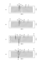
図1~図9はテープタイプ使い捨ておむつの一例を示しており、図中の符号Xは連結テープを除いたおむつの全幅を示しており、符号Lはおむつの全長を示しており、断面図における点模様部分はその表側及び裏側に位置する各構成部材を接合する接合手段としてのホットメルト接着剤を示している。ホットメルト接着剤は、スロット塗布、連続線状又は点線状のビード塗布、スパイラル状、Z状等のスプレー塗布、又はパターンコート(凸版方式でのホットメルト接着剤の転写)等、公知の手法により塗布することができる。これに代えて又はこれとともに、弾性部材の固定部分では、ホットメルト接着剤を弾性部材の外周面に塗布し、弾性部材を隣接部材に固定することができる。ホットメルト接着剤としては、例えばEVA系、粘着ゴム系(エラストマー系)、オレフィン系、ポリエステル・ポリアミド系などの種類のものが存在するが、特に限定無く使用できる。各構成部材を接合する接合手段としてはヒートシールや超音波シール等の素材溶着による手段を用いることもできる。 1 to 9 show an example of a tape-type disposable diaper, and the symbol X in the figures indicates the total width of the diaper excluding the connecting tape, and the symbol L indicates the total length of the diaper, and in the cross-sectional view, The dotted pattern indicates hot melt adhesive as a joining means for joining each component located on the front side and the back side. The hot melt adhesive can be applied by known methods such as slot coating, continuous line or dotted bead coating, spiral or Z-shaped spray coating, or pattern coating (transfer of hot melt adhesive using a letterpress method). Can be applied. Alternatively or additionally, at the fixed portion of the elastic member, a hot melt adhesive can be applied to the outer circumferential surface of the elastic member to secure the elastic member to the adjacent member. Examples of hot melt adhesives include EVA adhesives, adhesive rubber adhesives (elastomer adhesives), olefin adhesives, and polyester/polyamide adhesives, which can be used without particular limitation. As a joining means for joining each component, means by material welding such as heat sealing or ultrasonic sealing can also be used.
このテープタイプ使い捨ておむつは、前後方向LDの中央を含む股間部と、前後方向LDの中央より前側に延びる腹側部分Fと、前後方向LDの中央より後側に延びる背側部分Bとを有している。また、このテープタイプ使い捨ておむつは、股間部を含む範囲に内蔵された吸収体56と、吸収体56の表側を覆う液透過性のトップシート30と、吸収体56の裏側を覆う液不透過性シート11と、液不透過性シートの裏側を覆い、製品外面を構成する外装不織布12とを有するものである。
This tape type disposable diaper has a crotch region including the center in the front-rear direction LD, a ventral part F extending forward from the center in the front-rear direction LD, and a back part B extending rearward from the center in the front-rear direction LD. are doing. In addition, this tape type disposable diaper includes an
以下、各部の素材及び特徴部分について順に説明する。
(吸収体)
吸収体56の形状は図示例のような矩形とするほか、前後方向の中間に脚周りに沿う括れ部を有する形状(砂時計のような形状)とすることができる。符号56xは、吸収体56の全幅を示している。吸収体56は、排泄液を吸収し、保持する部分であり、繊維の集合体により形成することができる。この繊維集合体としては、綿状パルプや合成繊維等の短繊維を積繊したものの他、セルロースアセテート等の合成繊維のトウ(繊維束)を必要に応じて開繊して得られるフィラメント集合体も使用できる。繊維目付けとしては、綿状パルプや短繊維を積繊する場合は、例えば100~300g/m2程度とすることができ、フィラメント集合体の場合は、例えば30~120g/m2程度とすることができる。合成繊維の場合の繊度は、例えば、1~16dtex、好ましくは1~10dtex、さらに好ましくは1~5dtexである。フィラメント集合体の場合、フィラメントは、非捲縮繊維であってもよいが、捲縮繊維であるのが好ましい。
The materials and characteristic parts of each part will be explained in order below.
(Absorber)
The shape of the
吸収体56の剛軟度は特に限定されるものではないが、JIS L 1913:2010「41.5°カンチレバー法」による、吸収体56の前後方向の剛軟度が75mm以上であると、後述する第2領域20の起き上がりが良好となる。
The bending resistance of the
(高吸収性ポリマー粒子)
吸収体56には、その一部又は全部に高吸収性ポリマー粒子を含有させることができる。高吸収性ポリマー粒子とは、「粒子」以外に「粉体」も含む。高吸収性ポリマー粒子としては、この種の吸収性物品に使用されるものをそのまま使用できる。高吸収性ポリマー粒子の粒径は特に限定されないが、例えば500μmの標準ふるい(JIS Z8801-1:2006)を用いたふるい分け(5分間の振とう)、及びこのふるい分けでふるい下に落下する粒子について180μmの標準ふるい(JIS Z8801-1:2006)を用いたふるい分け(5分間の振とう)を行ったときに、500μmの標準ふるい上に残る粒子の割合が30重量%以下で、180μmの標準ふるい上に残る粒子の割合が60重量%以上のものが望ましい。
(Super absorbent polymer particles)
The
高吸収性ポリマー粒子の材料としては、特に限定無く用いることができるが、吸水量が40g/g以上のものが好適である。高吸収性ポリマー粒子としては、でんぷん系、セルロース系や合成ポリマー系などのものがあり、でんぷん-アクリル酸(塩)グラフト共重合体、でんぷん-アクリロニトリル共重合体のケン化物、ナトリウムカルボキシメチルセルロースの架橋物やアクリル酸(塩)重合体などのものを用いることができる。高吸収性ポリマー粒子の形状としては、通常用いられる粉粒体状のものが好適であるが、他の形状のものも用いることができる。 Although any material can be used for the superabsorbent polymer particles without particular limitation, those with a water absorption of 40 g/g or more are preferred. Superabsorbent polymer particles include starch-based, cellulose-based, and synthetic polymer-based particles, including starch-acrylic acid (salt) graft copolymers, saponified starch-acrylonitrile copolymers, and cross-linked sodium carboxymethyl cellulose. Materials such as acrylic acid (salt) and acrylic acid (salt) polymers can be used. The shape of the superabsorbent polymer particles is preferably a commonly used powder or granule, but other shapes can also be used.
高吸収性ポリマー粒子としては、吸水速度が70秒以下、特に40秒以下のものが好適に用いられる。吸水速度が遅すぎると、吸収体56内に供給された液が吸収体56外に戻り出てしまう所謂逆戻りを発生し易くなる。
As the superabsorbent polymer particles, those having a water absorption rate of 70 seconds or less, particularly 40 seconds or less are preferably used. If the water absorption rate is too slow, the liquid supplied into the
また、高吸収性ポリマー粒子としては、ゲル強度が1000Pa以上のものが好適に用いられる。これにより、嵩高な吸収体56とした場合であっても、液吸収後のべとつき感を効果的に抑制できる。
Further, as the superabsorbent polymer particles, those having a gel strength of 1000 Pa or more are preferably used. Thereby, even when the
高吸収性ポリマー粒子の目付け量は、当該吸収体56の用途で要求される吸収量に応じて適宜定めることができる。したがって一概にはいえないが、通常の場合、50~350g/m2とすることができる。
The basis weight of the superabsorbent polymer particles can be determined as appropriate depending on the amount of absorption required for the use of the
(包装シート)
高吸収性ポリマー粒子の抜け出しを防止するため、あるいは吸収体56の形状維持性を高めるために、吸収体56は包装シート58で包んでなる吸収要素50として内蔵させることができる。包装シート58としては、ティッシュペーパ、特にクレープ紙、不織布、ポリラミ不織布、小孔が開いたシート等を用いることができる。ただし、高吸収性ポリマー粒子が抜け出ないシートであるのが望ましい。クレープ紙に換えて不織布を使用する場合、親水性のSMMS(スパンボンド/メルトブローン/メルトブローン/スパンボンド)不織布が特に好適であり、その材質はポリプロピレン、ポリエチレン/ポリプロピレンなどを使用できる。繊維目付けは、5~40g/m2、特に10~30g/m2のものが望ましい。
(packaging sheet)
In order to prevent the superabsorbent polymer particles from slipping out or to improve the shape retention of the
この包装シート58は、図3に示すように、一枚で吸収体56の全体を包む構造とするほか、上下2枚等の複数枚のシートで吸収体56の全体を包むようにしてもよい。包装シート58は省略することもできる。
As shown in FIG. 3, this
(トップシート)
トップシート30は液透過性を有するものであり、例えば、有孔又は無孔の不織布や、多孔性プラスチックシートなどを用いることができる。
(Top sheet)
The
トップシート30は、前後方向LDでは製品前端から後端まで延び、幅方向WDでは吸収体56よりも側方に延びているが、例えば後述する起き上がりギャザー60の起点が吸収体56の側縁よりも幅方向WDの中央側に位置する場合等、必要に応じて、トップシート30の幅を吸収体56の全幅より短くする等、適宜の変形が可能である。
The
(中間シート)
トップシート30を透過した液の逆戻りを防止するために、トップシート30の裏側に中間シート(「セカンドシート」とも呼ばれている)40を設けることができる。中間シート40は省略することもできる。
(intermediate sheet)
In order to prevent the liquid that has passed through the
中間シート40としては、各種の不織布を好適に用いることができ、特に嵩高なエアスルー不織布を好適に用いることができる。エアスルー不織布には芯鞘構造の複合繊維を用いるのが好ましく、この場合芯に用いる樹脂はポリプロピレン(PP)でも良いが剛性の高いポリエステル(PET)が好ましい。目付けは17~80g/m2が好ましく、25~60g/m2がより好ましい。不織布の原料繊維の太さは2.0~10dtexであるのが好ましい。不織布を嵩高にするために、原料繊維の全部又は一部の混合繊維として、芯が中央にない偏芯の繊維や中空の繊維、偏芯且つ中空の繊維を用いるのも好ましい。
As the
図示例の中間シート40は、吸収体56の幅より短く中央に配置されているが、全幅にわたって設けてもよい。また、中間シート40は、おむつの全長にわたり設けてもよいが、図示例のように排泄位置を含む中間部分にのみ設けてもよい。
Although the
(液不透過性シート)
液不透過性シート11は、特に限定されるものではないが、透湿性を有するものが好ましい。液不透過性シート11としては、例えば、ポリエチレンやポリプロピレン等のオレフィン系樹脂中に無機充填剤を混練して、シートを成形した後、一軸又は二軸方向に延伸して得られた微多孔性シートを好適に用いることができる。また、液不透過性シート11としては、不織布を基材として防水性を高めたものも用いることができる。
(liquid impermeable sheet)
The liquid-
液不透過性シート11は、前後方向LD及び幅方向WDにおいて吸収体56と同じか又はより広範囲にわたり延びていることが望ましいが、他の遮水手段が存在する場合等、必要に応じて、前後方向LD及び幅方向WDにおいて吸収体56の端部を覆わない構造とすることもできる。
It is desirable that the liquid-
(外装不織布)
外装不織布12は液不透過性シート11の裏側全体を覆い、製品外面を布のような外観とするものである。不織布は一枚で使用する他、複数枚重ねて使用することもできる。後者の場合、不織布相互をホットメルト接着剤等により接着するのが好ましい。不織布を用いる場合、その構成繊維の繊度が1.6~2.3dtex、目付けが15~25g/m2、かつ厚みが0.3~0.8mmの不織布であると好ましい。
(Exterior nonwoven fabric)
The
(起き上がりギャザー)
トップシート30上を伝わって横方向に移動する排泄物を阻止し、いわゆる横漏れを防止するために、表面の幅方向WDの両側には、排泄物の遮断位置に沿って表面から起き上がる起き上がりギャザー60が設けられていると好ましい。
(get up and gather)
In order to prevent excrement from moving laterally on the
より詳細には、この起き上がりギャザー60は、サイドフラップSFを含む領域に固定された付根部65と、付根部から延び出た主部66と、主部66における前端部及び後端部がそれぞれ倒伏状態で固定されて形成された前倒伏部67f及び後倒伏部67bと、主部66における前倒伏部67f及び後倒伏部67b間の部分が非固定とされて形成された起き上がり部68とを有している。また、起き上がり部68の少なくとも先端部には、ギャザー弾性部材63が取り付けられている。
More specifically, the rising gathers 60 includes a
図示例の起き上がりギャザー60の各部は、ギャザーシート62により形成されており、このギャザーシート62が、主部66の先端(付根部65側と反対側の端)で二つ折りされることにより、自由部分を含む範囲が二層構造となっている。ギャザー弾性部材63は、この二層構造の部分の層間に挟まれている。ギャザー弾性部材63は起き上がり部68にのみ設けることもできるが、図示例のように、前倒伏部67fにおける後端部から後倒伏部67bにおける前端部まで固定されていると、ギャザー弾性部材63の収縮力が起き上がり部68の全体にわたり作用するだけでなく、前倒伏部67f及び後倒伏部67bの端部まで作用するため好ましい。
Each part of the rising gathers 60 in the illustrated example is formed of a gather
ギャザーシート62の内面は、トップシート30の側部上に幅方向WDの接合始端を有し、この接合始端から幅方向外側の部分は各サイドフラップSFの内面、つまり図示例では液不透過性シート11の側部及びその幅方向外側に位置する外装不織布12の側部にホットメルト接着剤などにより接合されている。
The inner surface of the gather
起き上がりギャザー60の接合始端より幅方向内側は、製品前後方向両端部ではトップシート30上に固定されているものの、その間の起き上がり部68は非固定の自由部分である。このため、起き上がり部68がギャザー弾性部材63の収縮力により前後方向に収縮しつつ起き上がるとともに、前後方向に伸長可能となり、身体表面に密着するようになる。また、起き上がり部68がギャザー弾性部材63の収縮力により前後方向に収縮するのにともない、前倒伏部67f及び後倒伏部67bを有する部分が互いに近づくように変形する。
Although the widthwise inner side of the rising gathers 60 from the joining start end is fixed on the
図示しないが、よく知られているように、起き上がりギャザー60の主部66を、幅方向外側の部分から幅方向内側に延在する基端側部分とこの基端側部分の幅方向中央側の端縁から身体側に折り返され幅方向外側に延在する先端側部分とを有する二つ折りした状態で、主部66の前後方向両端部を固定して倒伏部を形成することもできる。
Although not shown in the drawings, as is well known, the
ギャザーシート62の種類は特に限定されないが、通常の場合、液遮断性を確保するために撥水性のものが用いられる。特に、肌触り及び液遮断性を両立できる点で、スパンボンド層間にメルトブローン層を有する不織布(SMS不織布、SMMS不織布、SSMS不織布、SSMMS不織布)が好適である。不織布は一枚で使用する他、複数枚重ねて使用することもできる。後者の場合、不織布相互をホットメルト接着剤等により接着するのが好ましい。
Although the type of gather
ギャザー弾性部材63としては糸ゴム(太さ420~1120dtex程度のスパンデックス糸ゴム)等を用いることができる。ギャザー弾性部材63は、図1及び図2に示すように各複数本設ける他、各1本設けることができる。展開状態におけるギャザー弾性部材63の伸長率は適宜定めることができるが、例えば230~270%程度とすることができる。
As the gather
(サイドフラップ)
図示例のテープタイプ使い捨ておむつは、吸収体56の両方の側縁よりも側方にそれぞれ延出する、吸収体56を有しない一対のサイドフラップSFを有している。サイドフラップSFは、図示例のように、吸収体56を有する部分から連続する素材(外装不織布12等)からなるものであっても、他の素材を取り付けて形成してもよい。
(side flap)
The illustrated tape-type disposable diaper has a pair of side flaps SF that do not have the
(平面ギャザー)
各サイドフラップSFには、糸ゴム等の細長状弾性部材からなるサイド弾性部材64が前後方向LDに沿って伸長された状態で固定されており、これにより各サイドフラップSFの脚周り部分が平面ギャザーとして構成されている。サイド弾性部材64は、図示例のように、ギャザーシート62の接合部分のうち接合始端近傍の幅方向外側において、ギャザーシート62と液不透過性シート11との間に設けるほか、サイドフラップSFにおける液不透過性シート11と外装不織布12との間に設けることもできる。サイド弾性部材64は、図示例のように各側で複数本設ける他、各側に1本のみ設けることもできる。
(Plane gather)
A side
平面ギャザーは、サイド弾性部材64の収縮力が作用する部分(図中ではサイド弾性部材64が図示された部分)である。よって、平面ギャザーの部位にのみサイド弾性部材64が存在する形態の他、平面ギャザーよりも前側、後側又はその両側にわたりサイド弾性部材64が存在しているが、平面ギャザーの部位以外ではサイド弾性部材が一か所又は多数個所で細かく切断されていたり、サイド弾性部材64を挟むシートに固定されていなかったり、あるいはその両方であったりすることにより、平面ギャザー以外の部位に収縮力が作用せず(実質的には、弾性部材を設けないことに等しい)に、平面ギャザーの部位にのみサイド弾性部材64の収縮力が作用する構造も含まれる。
The plane gathers are the portions on which the contractile force of the side
(ウイング部分)
本テープタイプ使い捨ておむつでは、背側部分Bは股間部Mよりも幅方向WD外側に延び出たウイング部分WPを有している。同様に、腹側部分Fも股間部Mよりも幅方向WD外側に延び出たウイング部分WPを有している。これらウイング部分WPは、それ以外の部分と別の部材により形成することもできる。しかし、図示例のようにサイドフラップSFを有する構造において、サイドフラップSFの側部における前後方向LD中間を切断することにより、股間部Mの側縁からウイング部分の下縁までの凹状縁が形成され、その結果としてウイング部分WPが形成されていると、製造が容易であるため好ましい。
(wing part)
In this tape type disposable diaper, the back side portion B has a wing portion WP that extends outward from the crotch portion M in the width direction WD. Similarly, the ventral portion F also has a wing portion WP extending outward from the crotch portion M in the width direction WD. These wing portions WP can also be formed of a member different from the other portions. However, in a structure having side flaps SF as shown in the illustrated example, a concave edge is formed from the side edge of the crotch area M to the lower edge of the wing part by cutting the side part of the side flap SF midway in the front-rear direction LD. It is preferable that the wing portion WP is formed as a result of this because manufacturing is easy.
(連結テープ)
図1、図2及び図5に示すように、背側部分Bにおけるウイング部分WPには、腹側部分Fの外面に対して着脱可能に連結される連結テープ13がそれぞれ設けられている。おむつの装着に際しては、連結テープ13を腰の両側から腹側部分Fの外面に回して、連結テープ13の連結部13Aを腹側部分F外面の適所に連結する。
(Connection tape)
As shown in FIGS. 1, 2, and 5, each wing portion WP in the dorsal portion B is provided with a connecting
連結テープ13は、図5に示すように、ウイング部分WPに固定された基端部13C、及びこの基端部13Cから延び出た本体部13Bをなすシート基材13Sと、このシート基材13Sにおける本体部13Bの幅方向WDの中間部に設けられた、腹側部分Fに対する連結部13Aとを有している。本体部13Bにおける、連結部13Aより基端部13C側が腹側部分Fと連結されない非連結部となり、反対側が摘み部となっている。これら非連結部及び摘み部は、本体部13Bをなすシート基材13Sのみからなっている。
As shown in FIG. 5, the connecting
連結部13Aは、メカニカルファスナー(面ファスナー)のフック材(雄材)からなる。フック材は、その連結面に多数の係合突起を有するものであり、係合突起の形状としては、(A)レ字状、(B)J字状、(C)マッシュルーム状、(D)T字状、(E)ダブルJ字状(J字状のものを背合わせに結合した形状のもの)等が存在するが、いずれの形状であっても良い。
The connecting
また、基端部13Cから本体部13Bまでを形成するシート基材13Sとしては、不織布、プラスチックフィルム、ポリラミ不織布、紙やこれらの複合素材を用いることができる。
Further, as the
図示例の連結部13Aは、ウイング部分WPから突出する連結テープ13のシート基材13S上に設けられているが、ウイング部分WPに直接に設けてもよい。
Although the connecting
(ターゲットシート)
腹側部分Fにおける連結テープ13の連結箇所には、ターゲットシート12Tが設けられている。
(Target sheet)
A
ターゲットシート12Tの素材は特に限定されるものではないが、連結部13Aがフック材の場合、例えば間欠的なパターンの超音波溶着により部分的に繊維相互が溶着された長繊維不織布を用いることができる。この場合、長繊維不織布は、構成繊維の繊度が5~10dtex、目付けが25~40g/m2、かつ厚みが0.3~0.8mmの不織布であると好ましい。
The material of the
また、連結部13Aがフック材の場合、ターゲットシート12Tとして、フック材の係合突起が絡まるようなループ糸がプラスチックフィルムや不織布からなる基材の表面に多数設けられたものを用いることもできる。この具体例は、基材の少なくとも外面にループパイル繊維糸が縫い出された複合的なシート材である。このシート材は、基材の外面、すなわち使い捨ておむつの外面側には、ループパイル繊維糸が緯経方向に間隔を置いて突出され、基材の裏側(着用者側)には、パイル繊維糸が相互に組み合わされ、パイル繊維経糸の交差部列が形成されたものである。
Furthermore, when the connecting
さらに、連結部13Aがフック材であり、腹側部分Fにおける連結テープ13の連結箇所が不織布からなる場合(例えば図示例のように外装不織布12を有する場合)には、外装不織布12の内側に、目盛等の連結位置が印刷等されたプラスチックシート、紙、不織布等のターゲットシート12Tを配置することができる。この場合、使用者は外装不織布12を介して透視されるターゲットシート12Tの位置で、外装不織布12の繊維に連結部13Aのフック材を絡めることにより連結を行うことができる。
Furthermore, when the connecting
一方、連結部13Aが粘着材層の場合には、ターゲットシート12Tとして、粘着性に富むような表面が平滑なプラスチックフィルムの表面に剥離処理を施したものを用いることができる。
On the other hand, when the connecting
(エンドフラップ)
本テープタイプ使い捨ておむつは、吸収体56の前側及び後側にそれぞれ延出する、吸収体56を有しない一対のエンドフラップEFを有している。エンドフラップEFの構成材はおむつの構造によって変化する。例えば、エンドフラップEFは、トップシート30、中間シート40、ギャザーシート62、液不透過性シート11及び外装不織布12のうち、吸収体56の前側及び後側に延びて積層され、かつ互いに接合された部分により形成することができる。図示例と異なり、中間シート40や外装不織布12を備えない場合等には、トップシート30及び液不透過性シート11によりエンドフラップEFが形成される。また、エンドフラップEFを形成するための専用のシートを、吸収体56の前側又は後側に継ぎ足して、エンドフラップEFを形成してもよい。
(end flap)
This tape type disposable diaper has a pair of end flaps EF that do not have an
背側部分BにおけるエンドフラップEFの前後方向LDの寸法は、連結テープ13の基端部13Cの前後方向LDの寸法よりも長いことが好ましい。通常の場合、エンドフラップEFの前後方向LDの寸法は、おむつ全体の前後方向LDの寸法Lの20~25%程度とするのが好ましく、乳幼児用おむつにおいては、80~120mm程度とするのが適当である。
The dimension of the end flap EF in the back side portion B in the longitudinal direction LD is preferably longer than the dimension of the
(ウエスト弾性部材)
図7~図9、並びに図20(a)、図21及び図22に示すように、エンドフラップEFには、ウエスト弾性部材71が固定されている。このウエスト弾性部材71を有する部分には、ウエスト弾性部材71の収縮に伴い幅方向WDに収縮し、図15及び図18等に示すように、表面に襞80が形成されているとともに、幅方向WDに伸長可能なウエスト伸縮領域79が形成されている。ウエスト弾性部材71を有する部分は、その全体がウエスト伸縮領域79となっていても、一部のみがウエスト伸縮領域79となっていてもよい。すなわち、ウエスト弾性部材71を有する部分は、ウエスト弾性部材71の一部(例えば図20に示すように両端部)の伸縮性が切断等の公知の手法により殺されていてもよい。このことからも分かるように、ウエスト伸縮領域79は、すべてのウエスト弾性部材71における伸縮性が殺されていない部分に外接する領域である。
(waist elastic member)
As shown in FIGS. 7 to 9, as well as FIGS. 20(a), 21, and 22, a waist
ウエスト弾性部材71は、それ自体で弾性伸縮する素材であれば特に限定されない。例えば、糸状、紐状等の細長状の弾性材料(例えば太さ420~1120dtex程度のスパンデックス糸ゴム)のほか、網状や、有孔又は無孔のフィルム状の弾性材料、伸縮不織布等を適宜用いることができる。
The waist
ウエスト弾性部材71として細長状の弾性材料を用いる場合、図示例のように、前後方向LDに間隔を空けて配置された幅方向WDに延びる複数の細長状のウエスト弾性部材71と、ウエスト弾性部材71の表側に隣接する第1シート層73と、ウエスト弾性部材71の裏側に隣接する第2シート層74とを備えていると好ましい。
When using an elongated elastic material as the waist
第1シート層73及び第2シート層74は、特に限定されず、例えばエンドフラップEFを構成する他の部材(例えばトップシート30及び液不透過性シート11)を兼用することもできるが、図示例のように、専用の第1シート層73及び第2シート層74を設けることもできる。すなわち、図示例では専用の第1シート層73及び第2シート層74の間にウエスト弾性部材71が固定された伸縮シート70を、エンドフラップEF部に取り付けている。専用の第1シート層73及び第2シート層74としては、各種の不織布を用いることができる。
The
第1シート層73及び第2シート層74は、図9に示すように別々の二枚のシートであってもよいし、図15に示すように二つ折りされた一枚のシートにおける折目の一方側の部分及び他方側の部分であってもよい。
The
弾性部材71としては、3~10mmの前後方向LDの間隔d1で5~15本程度設けることができる。図示例のように、ウエスト伸縮領域79の前縁(最も前側のウエスト弾性部材71)の位置と吸収体56の後縁の位置とが前後方向LDに離間していると、吸収体56の後端部が幅方向WDに収縮しないため好ましい。また、展開状態における弾性部材の伸長率は160~230%程度とすることができる。
Approximately 5 to 15
第1シート層73及び第2シート層74は、前後方向LD及び幅方向WDの両方向に連続的に接合する他、少なくとも一方の方向には間欠的に接合することができる。また、ウエスト弾性部材71を第1シート層73及び第2シート層74に固定する固定部76は、ウエスト弾性部材71の少なくとも両端部に設けられていればよい。
The
図示例のように、ウエスト伸縮領域79よりも前側からウエスト伸縮領域79よりも後側まで線状に連続的又は間欠的に設けられた、第1シート層73及び第2シート層74の接合部75と、ウエスト伸縮領域79よりも前側からウエスト伸縮領域79よりも後側まで線状に連続する、第1シート層73及び第2シート層74の非接合部77とが、幅方向WDに交互に繰り返すように設けられているのは好ましい。これにより、ウエスト伸縮領域79が収縮している状態では、図22(b)(c)及び図24(b)(c)に示すように非接合部77における第1シート層73及び第2シート層74が互いに反対向きに膨らむのに伴い、図18に示すように、ウエスト伸縮領域79よりも前側からウエスト伸縮領域79よりも後側まで連続する襞80が幅方向WDに繰り返し形成される。接合部75は、例えば図23及び図24に示すように、幅方向WDと交差する方向に間欠的に設けられていてもよいが、図20~図22に示すように後述する第1屈曲部以外では、幅方向WDと交差する方向に線状に連続していると好ましい。
As shown in the illustrated example, the joint between the
接合部75の幅75w(接合部75の両側縁から等距離にある点の軌跡(曲線の場合は接線)に対して直交する方向の寸法)は変化しない(一定である)ことが好ましいが、変化してもよい。接合部75の幅75wが変化する場合、最大幅が最小幅の2~5倍であることが好ましい。接合部75の幅75wは適宜定めることができるが、広すぎると通気性が低下し、狭すぎると接合部75の剥がれにより伸縮性が低下して漏れ防止性が低下するため、通常の場合、0.5~2mmであることが好ましい。また、展開状態における非接合部77の幅方向WDの間隔77wは、襞80の高さを定めるものであり、通常の場合4~8mmであると好ましい。
It is preferable that the
ウエスト弾性部材71の固定部76は、ウエスト弾性部材71とともに第1シート層73及び第2シート層74が収縮して、ウエスト伸縮領域79が形成される限り特に限定されない。例えば、図21及び図22に示す例のようにウエスト弾性部材71と交差する方向に連続する接合部75を有する場合、ウエスト弾性部材71と交差する各接合部75が固定部76を兼ねていてもよい。また、図23及び図24に示すようにウエスト弾性部材71と接合部75とが交差しない場合には、接合部75とは別にウエスト伸縮領域79の両端部にのみ固定部76(図示せず)を設けるだけでもよい。
The fixing
接合部75における第1シート層73及び第2シート層74の接合、並びに固定部76におけるウエスト弾性部材71の固定は、ホットメルト接着剤の他、ヒートシールや超音波シール等の溶着手段等、公知の方法により行うことができる。接合部75は、弾性部材を有しない部位で第1シート層73及び第2シート層74が直接的に接合されていてもよいし、第1シート層73及び第2シート層74がウエスト弾性部材71を介して間接的に接合されていてもよい。
The joining of the
伸縮シート70は、図7~図9(a)に示す例のように、トップシート30と外装不織布12との間における適宜の部材間(図示例はトップシート30及び中間シート40と液不透過性シート11との間であるが、液不透過性シート11と外装不織布12との間でもよい)に挟むことができる他、図12~図15に示す例や、図16~図17に示す例のように、最も肌側に位置する最上層として取り付けることもできる。後者の場合、ギャザーシート62を有する部分では、ギャザーシート62よりも上側に伸縮シート70を配置する(つまり全体が最上層となる)他、トップシート30とギャザーシート62との間に配置することもできる。
As shown in the examples shown in FIGS. 7 to 9(a), the
伸縮シート70と、これに重なるエンドフラップEFの部材との接合パターンは、ウエスト伸縮領域79の表面に、伸縮シート70に形成される襞と同様の襞80が形成されると好ましい。例えば、伸縮シート70と、これに重なるエンドフラップEFの部材とは、前後方向LD及び幅方向WDの両方に連続的に接合したり、前後方向LD及び幅方向WDの少なくとも一方に連続的に接合したりすることができる。伸縮シート70と、これに重なるエンドフラップEFの部材(トップシート30等)との接合が、幅方向WDに連続していると、図22(c)に一点鎖線で示すように、伸縮シート70に形成される襞80とウエスト伸縮領域79の表面に形成される襞80とが対応するものとなる。
It is preferable that the joining pattern between the
(貯留空間)
図8に拡大して示すように、一方の後倒伏部67bの前縁から他方の後倒伏部67bの前縁まで幅方向WDに延びる線状の第1屈曲部91と、この第1屈曲部91から前側に離れた、幅方向WDに延びる線状の第2屈曲部92とを有し、第1屈曲部91の後側に隣接する領域である第1領域10と、第1屈曲部91と第2屈曲部92との間の領域である第2領域20とを有し、ウエスト伸縮領域79は、少なくとも左右両側の後倒伏部67bの間に設けられていると好ましい。
(storage space)
As shown in an enlarged view in FIG. 8, a linear first
この場合、起き上がりギャザー60のギャザー弾性部材63の収縮力により、図9(b)に示すように、第2領域20が第2屈曲部を起点として起き上がりつつ、ウエスト伸縮領域79のうち第1領域10に位置する部分が幅方向WDの収縮により着用者の肌に押し付けられ、第1屈曲部で第1領域10が第2領域20に対して裏側に屈曲する。よって、本連結式使い捨て着用物品では、図18及び図19に示すように、第2領域20が起き上がるとともに、それよりも後側の第1領域10が着用者の肌に押し付けられる結果、吸収体56の後縁及びその前後近傍が吸収体56の幅のほぼ全体にわたり窪んで、深く広い貯留空間21(ポケット)がしっかりと形成される。また、貯留空間21となる窪みのウエスト側には、第2領域20が起き上がるとともに、それよりも後側の第1領域10が着用者の肌に押し付けられるため、後方への排泄物の移動を堰き止める効果が高く、かつ着用者の身体表面に対するフィット性も良好である。
In this case, due to the contractile force of the gather
ウエスト伸縮領域79は、少なくとも第1領域10における左右両側の後倒伏部67bの間に設けられていれば、第1領域10にのみ設けられているだけでもよいが、第1領域10及び第2領域20にわたるように設けられていると好ましい。これには、図示例のようにウエスト弾性部材71が第1領域10及び第2領域20別々に設けられている形態のほか、図示しないがシート状の弾性材料を第1領域10及び第2領域20にわたるように設けられている形態も含まれる。
The waist
後倒伏部67bの前縁(第1屈曲部91の位置)が、ウエスト伸縮領域79の前縁よりも前側に位置していると、肌に押し付けられるウエスト伸縮領域79の前縁よりも前に、肌へのフィット性の低い後倒伏部67bが延び出ることになるため、後倒伏部67bを介して漏れが発生するおそれがある。これに対して、図示例のように、ウエスト弾性部材71が第1領域10及び第2領域20に設けられている(つまり、後倒伏部67bの前縁の位置が、ウエスト伸縮領域79の前縁と同じか又はそれよりも後側に位置している)と、肌に押し付けられるウエスト伸縮領域79の前縁よりも前に、肌へのフィット性が低い後倒伏部67bが存在せず、肌へのフィット性が高い起き上がり部68が位置することになる。よって、第2領域20が起き上がるとともに、その両側から続いて起き上がりギャザー60の起き上がり部68が起き上がるため、より漏れ防止性に優れたものとなる。
If the front edge of the
ウエスト伸縮領域79が第1領域10及び第2領域20にわたり設けられている場合、図15及び図18等に示すように、ウエスト伸縮領域79のうち第2領域20に位置する部分が幅方向WDに収縮している状態で、第2領域20の表面には、第1屈曲部91から第2屈曲部92に向かって延びる襞80が、幅方向WDに繰り返し形成されると好ましい。これにより第2領域20の剛性が高くなり、貯留空間21が潰れにくくなる。また、第2領域20の表面に、第1屈曲部91から第2屈曲部92に向かって延びる襞80が、幅方向WDに繰り返し形成されていると、図15(a)(b)に示すように、第2領域20が股間側(吸収体56を有する部分の表面上)に倒れても、隣接する襞80の隙間81により貯留空間21がある程度維持されるようになる。
When the waist
第1屈曲部91の位置と第2屈曲部92の位置との前後方向LDの間隔(第2領域20の前後方向LDの寸法に等しい)は、形成される貯留空間21の深さに影響するため、商品に応じて適宜定めることができる。例えば、通常の場合、第1屈曲部91の位置と第2屈曲部92の位置との前後方向LDの間隔は、10~40mm、特に20~30mmとすることができる。
The distance in the longitudinal direction LD between the position of the first
ウエスト伸縮領域79の前縁の前後方向LDの位置は、適宜定めることができるが、通常の場合、ウエスト伸縮領域79の前縁と吸収体56の後縁との前後方向LDの間隔は、エンドフラップEFの前後方向LDの寸法の0.2~0.5倍であることが好ましい。また、ウエスト伸縮領域79の前縁と後倒伏部67bの前縁との間隔79aは適宜定めることができるが、0~15mm程度であることが好ましい。
The position of the front edge of the waist
ウエスト伸縮領域79は、エンドフラップEFにおける少なくとも左右両側の後倒伏部67bの間に形成されている限り、例えば左右両側の後倒伏部67bの間の一部に設けられているだけでもよい。しかし、図示例のように、ウエスト伸縮領域79が少なくとも左右両側の後倒伏部67bまで延びていると、第2領域20よりも後側における左右の起き上がりギャザー60の間に位置する部分が、幅方向WD全体にわたりしっかりと着用者の肌に押し付けられるようになる。よって、より漏れ防止性に優れたものとなるため好ましい。同様の観点から、ウエスト伸縮領域79の後縁とエンドフラップEFの後縁との前後方向LDの間隔79bは17mm以下であることが好ましい。
As long as the waist
ギャザー弾性部材63は、展開状態で吸収体56上に位置しなくてもよいが、起き上がり部68の少なくとも先端部に取り付けられたギャザー弾性部材63が、吸収体56上に位置すると、起き上がりギャザー60のギャザー弾性部材63の収縮力が、第2領域20に対し、より直接的に作用し、第2領域20が、吸収体56の後縁を起点としてより起き上がりやすくなるため好ましい。
The gather
図10に示す例のように、後倒伏部67bの前縁の位置が、ウエスト伸縮領域79の前縁よりも後側に位置しており、同一の細長状のウエスト弾性部材71が前後方向LDに間隔を空けて4本以上取り付けられた伸縮シート70を用いる場合、後倒伏部67bの前縁の位置とウエスト伸縮領域79の前縁の位置との間の領域に位置する複数本の第1のウエスト弾性部材71aと、それ以外の領域に位置する複数本の第2のウエスト弾性部材71bとをそれぞれ設けるとともに、第1のウエスト弾性部材71aの前後方向LDの間隔を、第2のウエスト弾性部材71bの前後方向LDの間隔の0.4~0.6倍とするのは好ましい。これにより、第2領域20のうちウエスト伸縮領域79と重なる部分に、縦方向に延びる皺が寄るとともに、圧縮により剛性が高くなり、形成される貯留空間21が潰れにくくなるため好ましい。
As in the example shown in FIG. 10, the position of the front edge of the
また、図8に示す例のように、後倒伏部67bの前縁の位置が、ウエスト伸縮領域79の前縁よりも後側に位置しており、同一の細長状のウエスト弾性部材71が前後方向LDに間隔を空けて4本以上取り付けられた伸縮シート70を用いる場合、すべてのウエスト弾性部材71が同一の伸長率となっていても、一部のウエスト弾性部材71の伸長率が他のウエスト弾性部材71の伸長率と異なっていても、すべてのウエスト弾性部材71の伸長率が異なっていてもよい。例えば、後倒伏部67bの前縁の位置とウエスト伸縮領域79の前縁の位置との間の領域に位置する第1のウエスト弾性部材71aと、それ以外の領域に位置する第2のウエスト弾性部材71bとをそれぞれ設けるとともに、第1のウエスト弾性部材71aの伸長率が、第2のウエスト弾性部材71bの伸長率の1.05~1.15倍であるのも好ましい。この場合にも、第2領域20のうちウエスト伸縮領域79と重なる部分に、縦方向に延びる皺が寄るとともに、圧縮により剛性が高くなり、形成される貯留空間21が潰れにくくなるため好ましい。
Further, as in the example shown in FIG. 8, the position of the front edge of the
図示例のように、細長状のウエスト弾性部材71が前後方向LDに間隔を空けて複数本取り付けられた伸縮シート70を用いる場合、伸縮シート70の前端部にウエスト弾性部材71を有しない縁部が不可避的に形成される。ここで、図11に示す例のように、吸収体56の後端部が伸縮シート70の前端部の縁部に重なっていると(吸収体56の後縁が伸縮シート70の前縁に一致していてもよい)、第2領域20の前後方向LDの全体にわたり伸縮シート70が存在し、剛性が高くなる。よって、第2領域20がしっかりと起き上がり、貯留空間21が潰れにくくなる。また、伸縮シート70の前縁と吸収体56の後縁との間に隙間があると、使用者によってはその隙間が薄く漏れやすいように見えることがあるが、吸収体56の後端部が伸縮シート70の前端部の縁部に重なっていると、使用者に不安を与えるような外観とならないため好ましい。
As shown in the illustrated example, when using an
第2領域20は、図8等に示す例のように吸収体56を有しない領域であると、第2領域20が第2屈曲部92で股間側に倒れても厚みがほとんど増加しないため好ましい。しかし、図26に示す例のように、第2屈曲部92の前側に隣接する第3領域33に設けられた主吸収体56Aとは別に、第2領域20に補助吸収体56Bを設けて、第2領域20の剛性を高めることもできる。これにより、第2領域20がしっかりと起き上がり、貯留空間21が潰れにくくなるとともに、貯留空間21に導入した排泄物の液分を第2領域20の補助吸収体56Bで吸収・保持することができる。補助吸収体56Bとしては、主吸収体56Aと同様の素材及び構造を採用することができる。
It is preferable that the
(第1屈曲部)
第1屈曲部91は、第1領域10及び第2領域20よりも低剛性の折れやすい部分であると好ましい。これにより、第1屈曲部91の屈曲位置が前側にずれにくく、貯留空間21の形状・位置が維持されやすいものとなる。また、使用中又は製品包装時に一時的に加わる外力により、屈曲位置が第1屈曲部91よりも前側にずれて多少の折癖が付いたとしても、第1屈曲部91が折れやすいことに変わりがないため、その外力から解放されたときに屈曲位置が第1屈曲部91に戻り、貯留空間21の形状・位置が維持されやすい。なお、各部の剛性は、特許文献1と同様にガーレー法で測定することができる。
(first bending part)
The first
第1屈曲部91は、一方の後倒伏部67bの前縁から他方の後倒伏部67bの前縁まで幅方向WDに延びる線状の部分であり、その前後方向LDの寸法は適宜定めることができる。第1屈曲部91の前後方向LDの寸法は狭いことが好ましく、通常の場合、1~3mm程度であると好ましい。また、図示例の場合、弾性部材の前後方向LDの間隔よりも短いことが好ましい。
The first
第1屈曲部91を、第1領域10及び第2領域20よりも低剛性の部分とする手段は特に限定されないが、代表的に次の二つの手段が考えられる。
Although there are no particular limitations on the means for making the first bent portion 91 a portion with lower rigidity than the
1つ目の手段は、ホットメルト接着剤や溶着等の接合手段が剛性を向上させることを利用し、第1屈曲部91における接合量(接着剤量や溶着量)を、第1領域10及び第2領域20のそれよりも少なくするものである。図8は、その具体例を示しており、ウエスト弾性部材71が、前後方向LDに間隔を空けて配置された幅方向WDに延びる複数の細長状のウエスト弾性部材71であり、第1領域10及び第2領域20はそれぞれ少なくとも一本のウエスト弾性部材71を有し、ウエスト弾性部材71の表側に隣接する第1シート層73と、ウエスト弾性部材71の裏側に隣接する第2シート層74とを有する構造を対象とするものである。すなわち、この例では、第1領域10及び第2領域20には、第1屈曲部91に隣接する部分からその後側に離れた部分までウエスト弾性部材71を横切って連続する、第1シート層73及び第2シート層74の接合部75と、第1屈曲部91に隣接する部分からその前側に離れた部分までウエスト弾性部材71を横切って連続する、第1シート層73及び第2シート層74の非接合部77とが、幅方向WDに交互に繰り返すように設けられている。また、第1屈曲部91には接合部75が設けられていない。
The first method takes advantage of the fact that bonding means such as hot melt adhesive or welding improves rigidity, and the bonding amount (adhesive amount or welding amount) at the
このような構造を有すると、接合部75が存在する部分は相対的に高剛性となり、接合部75が存在しない部分は相対的に低剛性となる。この結果、特定の接合部75のパターンを採用するだけの簡素な構造で、低剛性の第1屈曲部91を形成することができる。さらに、第2領域20は幅方向WDの収縮によって剛性が高くなるため、貯留空間21の維持性もより一層向上する。剛性向上の観点からは、接合部75は第1シート層73及び第2シート層74の溶着によるものであると好ましい。
With such a structure, the portion where the
2つ目の手段は、第1屈曲部91における部材積層数を、第1領域10及び第2領域20のそれよりも少なくするものである。図25は、その具体例を示しており、第1領域10内及び第2領域20内に、伸縮シート70A,70B(図8及び図9等に示される構造のほか、ウレタンフォームや弾性フィルム等であってもよい)がそれぞれ配置され、第1屈曲部91にこれらの伸縮シートが配置されておらず、その結果として、第1屈曲部91における部材積層数が、第1領域10及び第2領域20のそれよりも少なくなっているものである。この場合、伸縮シート70A,70Bが存在する部分は相対的に高剛性となり、伸縮シート70A,70Bが存在しない部分は相対的に低剛性となる。この結果、簡素な構造で、低剛性の第1屈曲部91を形成することができる。さらに、第2領域20は幅方向WDの収縮によって剛性が高くなるため、貯留空間21の維持性もより一層向上する。
The second means is to make the number of laminated members in the first
上述の2つの手段はいずれか一方のみ採用してもよいし、両方を採用してもよい。 Either one or both of the above two means may be employed.
他方、第2領域20に補助吸収体56Bを設ける場合、補助吸収体56Bの後縁が第2領域20の後縁に一致していると、第1屈曲部91とその前側の部分との剛性の変化が特に大きくなり、屈曲位置がより一層ずれにくくなるため好ましい。
On the other hand, in the case where the auxiliary
(第2屈曲部)
第2屈曲部92は、第2領域20及び第2屈曲部92の前側に隣接する第3領域33よりも低剛性の折れやすい部分であると好ましい。これにより、第2屈曲部92の屈曲位置が前側にずれにくく、貯留空間21の形状・位置が維持されやすいものとなる。また、使用中又は製品包装時に一時的に加わる外力により、屈曲位置が第2屈曲部92よりも後側にずれて多少の折癖が付いたとしても、第2屈曲部92が折れやすいことに変わりがないため、その外力から解放されたときに屈曲位置が第2屈曲部92に戻り、貯留空間21の形状・位置が維持されやすい。なお、各部の剛性は、特許文献1と同様にガーレー法で測定することができる。
(Second bent part)
The second
第2屈曲部92は、第1屈曲部91から前側に離れた、幅方向WDに延びる線状の部分であり、その前後方向LDの寸法は適宜定めることができる。第2屈曲部92の前後方向LDの寸法は狭いことが好ましく、通常の場合、1~3mm程度であると好ましい。また、図示例の場合、ウエスト弾性部材71の前後方向LDの間隔よりも短いことが好ましい。
The second
第2屈曲部92を第2領域20よりも低剛性の部分とする手段は特に限定されないが、代表的に次の3つの手段が考えられる。
Although there are no particular limitations on the means for making the second bent portion 92 a portion with lower rigidity than the
1つ目の手段は、第2領域20においてホットメルト接着剤や溶着等の接合手段による剛性向上を利用して、第2屈曲部92を第2領域20よりも低剛性の部分とするものである。図8はその具体例を示しており、ウエスト弾性部材71が、前後方向LDに間隔を空けて配置された幅方向WDに延びる複数の細長状のウエスト弾性部材71であり、第1領域10及び第2領域20はそれぞれ少なくとも一本のウエスト弾性部材71を有し、ウエスト弾性部材71の表側に隣接する第1シート層73と、ウエスト弾性部材71の裏側に隣接する第2シート層74とを有する構造を対象とするものである。そして、この例では、第2領域20には、第2領域20の前縁からウエスト弾性部材71を横切って後側に連続する、第1シート層73及び第2シート層74の接合部75と、第2領域20の前縁からウエスト弾性部材71を横切って後側に連続する、第1シート層73及び第2シート層74の非接合部77とが、幅方向WDに交互に繰り返すように設けられている。
The first method is to make the second bent portion 92 a portion with lower rigidity than the
このような構造を有すると、第2領域20の前縁に接合部75の前縁が位置することになり、接合部75が存在する部分、つまり第2屈曲部92の後側に隣接する部分は接合部75の存在により相対的に高剛性となる。この結果、特定の接合部75のパターンを採用するだけの簡素な構造で、第2領域20の剛性が第2屈曲部92よりも高くなる。さらに、第2領域20は幅方向WDの収縮によっても剛性が高くなるため、貯留空間21が潰れにくくなる。
With such a structure, the front edge of the
2つ目の手段は、第2屈曲部92における部材積層数を、第2領域20のそれよりも少なくすることにより、第2屈曲部92を第2領域20よりも低剛性の部分とするものである。図25はその具体例を示しており、伸縮シート70B(図8及び図9等に示される構造のほか、ウレタンフォームや弾性フィルム等であってもよい)が第2領域20に取り付けられており、伸縮シート70Bの前縁が、第2領域20の前縁に一致しており、第2屈曲部92には、伸縮シート70Bが設けられていない。
The second means is to make the second bent part 92 a part with lower rigidity than the
このような構造を有すると、伸縮シート70Bが位置する部分、つまり第2屈曲部92の後側に隣接する部分は伸縮シート70Bの存在により相対的に高剛性となる。よって、伸縮シート70Bを特定の配置とするだけの簡素な構造で、第2領域20の剛性を第2屈曲部92よりも高くすることができる。さらに、第2領域20は幅方向WDの収縮によっても剛性が高くなるため、貯留空間21が潰れにくくなる。
With such a structure, the portion where the
3つ目の手段は、第2領域20において吸収体56による剛性向上を利用して、第2屈曲部92を第2領域20よりも低剛性の部分とするものである。図26はその具体例を示しており、第2領域20に補助吸収体56Bを設けるとともに、補助吸収体56Bの前縁が第2領域20の前縁に一致している。また、第2屈曲部92は、主吸収体56Aと補助吸収体56Bとの間に位置する、吸収体を有しない部分となっている。このような構造を有すると、補助吸収体56Bが位置する部分、つまり第2屈曲部92の後側に隣接する部分は補助吸収体56Bの存在により相対的に高剛性となる。よって、補助吸収体56Bを設けるだけの簡素な構造で、第2領域20の剛性を第2屈曲部92よりも高くすることができる。
The third means is to make the second bent portion 92 a portion having lower rigidity than the
上述の3つの手段はいずれか1つのみ採用してもよいし、複数採用してもよい。 Any one of the above three means may be employed, or a plurality of them may be employed.
また、第2屈曲部92を第3領域33よりも低剛性の部分とする手段も特に限定されないが、図示例のように、第3領域33において吸収体56による剛性向上を利用して、第2屈曲部92を第3領域33よりも低剛性の部分とするものが好ましい。すなわち、図8等に示す例では、吸収体56(又は図26に示す例では主吸収体56A)の後縁が第3領域33の後縁に一致しており、第2屈曲部92には吸収体56が設けられていない。この場合、吸収体56を有する第3領域33は相対的に剛性が高いのに対して、吸収体56を有しない第2屈曲部92では剛性が低くなるため、吸収体56を特定の配置とするだけの簡素な構造で、第3領域33の剛性を第2屈曲部92よりも高くすることができる。
Further, there are no particular limitations on the means for making the second bent portion 92 a portion with lower rigidity than the
(襞の方向)
図8及び図9等に示す伸縮シート70のように、非接合部77及び接合部75の両側縁は前後方向LDに沿って直線状に設けられていてもよいが、図18、図20(a)、図21、及び図23に示すように、少なくとも一本の非接合部77は、両側縁77sが前後方向LDに対して5~45度の傾斜角度θ(鋭角側交差角のこと。他の傾斜角度に同じ。)を有するように延びた傾斜部72を有するのも好ましい。傾斜部72の傾斜角度θは8~15度であるとより好ましい。ここで、非接合部77の両側縁77sは、接合部75の側縁によって定まる。よって、図20~図22に示すように接合部75がウエスト伸縮領域79よりも前側からウエスト伸縮領域79よりも後側まで連続する場合、非接合部77の両側縁77sは、展開状態における接合部75の側縁を意味する。また、図23及び図24に示すように接合部75がウエスト伸縮領域79よりも前側からウエスト伸縮領域79よりも後側まで間欠的(点線状)に形成される場合、非接合部77の両側縁は、展開状態における接合部75の側縁を、襞80の延びる方向に直線で繋いで形成される仮想線を意味するものとする。また、前後方向LDに対する非接合部77の両側縁77sの傾斜角度θが連続的に変化する場合、例えば図20(d)に示す例のように非接合部77の両側縁77sが円弧状等の曲線をなす場合には、非接合部77の両側縁77sの方向は、接合部75の両側縁77sの接線の方向を意味する。
(fold direction)
As in the
ウエスト伸縮領域79の表面に形成される少なくとも一部の襞80の両側縁は、非接合部77の傾斜部72と対応する部位では、非接合部77の両側縁77sに沿ってほぼ同方向に傾斜するため、隣接する襞80の隙間81に入り込んだ尿や軟便が前後方向LDに移動する場合、傾斜した襞80に衝突することにより移動抵抗を生ずる。そして、隣接する襞80の隙間81は、襞80同様に、ウエスト伸縮領域79よりも前側からウエスト伸縮領域79よりも後側まで連続することになるため、肌に密着される第1領域10において通気性が損なわれることもない。さらに、ウエスト伸縮領域79の襞80は貯留空間21となる窪みに通じているため、外圧(座位や仰臥位となるとき等に発生)により貯留空間21となる窪みの容積が減少すると、窪み内の空気が第1領域10の隣接する襞80の隙間81を通じて押し出され、反対に外圧の開放により貯留空間21となる窪みの容積が増加すると、外部の空気が第1領域10の隣接する襞80の隙間81を通じて窪み内に導入される(ポンプ作用)ため、前述のように漏れ防止性が向上しつつ、通気性は非常に良好となる。
Both side edges of at least some of the
このような観点から、図示例であれば、ウエスト伸縮領域79のうち、少なくとも起き上がりギャザー60の間に位置する非接合部77のすべてが傾斜部72を有していることが好ましく、一方の起き上がりギャザー60の後倒伏部67bから他方の起き上がりギャザー60の後倒伏部67bまでの範囲に位置する非接合部77のすべてが傾斜部72を有することが好ましい。もちろん、傾斜部72を有する非接合部77と、傾斜部72を有しない非接合部77とが一つおきや、複数おきに設けられていてもよい。
From this point of view, in the illustrated example, it is preferable that all of the
図20(a)(b)に示すように、各非接合部77は、その全体が傾斜部72であってもよいし、図20(c)(d)に示すように、一部にのみ傾斜部72を有するだけでもよい。少なくとも第1領域10には傾斜部72を有すると好ましく、図示しないが第1領域10にのみ傾斜部72を有すると特に好ましい。
As shown in FIGS. 20(a) and 20(b), the entirety of each
図20(a)に示す例のように、傾斜部72を有する非接合部77が、幅方向WDの中心よりも右側の領域から、幅方向WDの中心よりも左側の領域にかけて繰り返し形成される場合、右側の領域の傾斜部72及び左側の領域の傾斜部72は、それぞれ、ウエスト側に向かうにつれて幅方向WDの中心側に位置するように傾斜していると、襞80が左右対称的に形成されるとともに、美観に優れるため好ましい。もちろん、図20(c)に示す例のように、右側の領域の傾斜部72及び左側の領域の傾斜部72が、それぞれ、ウエスト側に向かうにつれて幅方向WDの中心から離れるように傾斜していてもよい。
As in the example shown in FIG. 20(a), a
図20(a)及び(c)に示す例のように、襞80が左右対称的に形成されるのは好ましいが、襞80の幅方向WDの位置がずれると、かえって美観に劣るおそれがある。また、そのような正確な襞80の位置決めは製造上困難であることが多い。そこで、図20(b)及び(d)に示す例のように、ウエスト伸縮領域79のすべての非接合部77が互いに平行な傾斜部72を有することも提案される。これにより、左右の対称性はないものの、襞80は整然と形成され、かつ襞80の幅方向WDの位置が多少ずれても見栄えに対する影響は少ないものとなる。
As in the examples shown in FIGS. 20(a) and 20(c), it is preferable that the
図20(a)及び(b)に示す例のように、傾斜部72を有する各非接合部77において、角度が一定の傾斜部72を有するだけでもよいが、図20(c)及び(d)に示す例のように、ウエスト伸縮領域79よりも前側からウエスト伸縮領域79よりも後側に至るまでの少なくとも一か所で、前後方向LDに対する非接合部77の両側縁の角度が変化するのは好ましい。
As shown in the example shown in FIGS. 20(a) and 20(b), each
例えば、図20(c)に示す例では、 傾斜部72を有する非接合部77は、前後方向LDに対して5~45度の傾斜角度θを有するように延びた第1部分P1と、この第1部分P1に対して5~45度の傾斜角度γを有するように延びた第2部分P2とを有するものとなっている。このような第1部分P1及び第2部分P2を有することにより、隙間81に入り込んだ尿や軟便に加わる移動力の方向が、いずれか一方の部分の方向に近い(その傾斜部72を通過しやすい)場合でも、他方の部分の方向は一方の部分の方向よりは移動力の方向に近くないため、他方の部分が尿や軟便の移動に対してより効果的な抵抗となる。第2部分P2は、前後方向LDに対して5~45度の傾斜角度θを有していなくてもよい(図示例は0度)が、有していてもよい。
For example, in the example shown in FIG. 20(c), the
また、図20(d)に示す例では、各非接合部77の両側縁が、その長さ方向の全体にわたり、前後方向LDに対する傾斜角度δが連続的に変化する、つまり円弧状等の曲線状になっている。これにより、隙間81に入り込んだ尿や軟便に加わる移動力の方向が、隙間81のある箇所の方向に近い(その箇所を通過しやすい)場合でも、他の箇所の方向には近くなくなるため、この他の箇所が尿や軟便の移動に対してより効果的な抵抗となる。よって、前述の漏れ防止性がより一層のものとなる。
Further, in the example shown in FIG. 20(d), the inclination angle δ of each
通気性及び漏れ防止性をともに良好なものとするためには、ウエスト伸縮領域79に形成される襞80の剛性は高い方が好ましい。よって、伸縮シート70は、図12~図15に示す例や、図16~図17に示す例のように、最も肌側に位置する最上層として取り付けるよりも、図7~図9(a)に示す例のように、トップシート30と外装不織布12との間における適宜の部材間に挟むのが好ましい。つまり、第1シート層73の上に一層又は複数層のカバーシート層(図示例では中間シート40及びトップシート30)を設けることが好ましく、この場合、図22(b)(c)に一点鎖線で示すように、第1シート層73に対してカバーシート層が接合され、第1シート層73及びカバーシート層が一体として収縮することにより、ウエスト伸縮領域79の表面(カバーシート層からなる)に襞80が形成されることとなる。
In order to improve both breathability and leakage prevention, it is preferable that the
(不織布)
上記説明における不織布としては、部位や目的に応じて公知の不織布を適宜使用することができる。不織布の構成繊維としては、例えばポリエチレン又はポリプロピレン等のオレフィン系、ポリエステル系、ポリアミド系等の合成繊維(単成分繊維の他、芯鞘等の複合繊維も含む)の他、レーヨンやキュプラ等の再生繊維、綿等の天然繊維等、特に限定なく選択することができ、これらを混合して用いることもできる。不織布の柔軟性を高めるために、構成繊維を捲縮繊維とするのは好ましい。また、不織布の構成繊維は、親水性繊維(親水化剤により親水性となったものを含む)であっても、疎水性繊維若しくは撥水性繊維(撥水剤により撥水性となった撥水性繊維を含む)であってもよい。また、不織布は一般に繊維の長さや、シート形成方法、繊維結合方法、積層構造により、短繊維不織布、長繊維不織布、スパンボンド不織布、メルトブローン不織布、スパンレース不織布、サーマルボンド(エアスルー)不織布、ニードルパンチ不織布、ポイントボンド不織布、積層不織布(スパンボンド層間にメルトブローン層を挟んだSMS不織布、SMMS不織布等)等に分類されるが、これらのどの不織布も用いることができる。
(Nonwoven fabric)
As the nonwoven fabric in the above description, any known nonwoven fabric can be used as appropriate depending on the site and purpose. The constituent fibers of the nonwoven fabric include, for example, olefin-based fibers such as polyethylene or polypropylene, synthetic fibers such as polyester-based fibers, and polyamide-based fibers (including single-component fibers as well as composite fibers such as core-sheath fibers), as well as recycled fibers such as rayon and cupro. Fibers, natural fibers such as cotton, etc. can be selected without particular limitation, and a mixture of these can also be used. In order to increase the flexibility of the nonwoven fabric, it is preferable that the constituent fibers be crimped fibers. In addition, even if the constituent fibers of a nonwoven fabric are hydrophilic fibers (including those made hydrophilic by a hydrophilizing agent), they may be hydrophobic fibers or water-repellent fibers (water-repellent fibers made water-repellent by a water-repellent agent). ). In addition, nonwoven fabrics generally vary depending on the fiber length, sheet forming method, fiber binding method, and laminated structure. It is classified into nonwoven fabrics, point bonded nonwoven fabrics, laminated nonwoven fabrics (SMS nonwoven fabrics with a meltblown layer sandwiched between spunbond layers, SMMS nonwoven fabrics, etc.), and any of these nonwoven fabrics can be used.
<明細書中の用語の説明>
明細書中の以下の用語は、明細書中に特に記載が無い限り、以下の意味を有するものである。
<Explanation of terms in the specification>
The following terms in the specification have the following meanings unless otherwise specified in the specification.
・「前後方向」とは図中に符号LDで示す方向(縦方向)を意味し、「幅方向」とは図中にWDで示す方向(左右方向)を意味し、前後方向と幅方向とは直交するものである。 ・"Anteroposterior direction" means the direction indicated by the symbol LD in the figure (vertical direction), and "width direction" means the direction indicated by WD in the figure (horizontal direction), and the longitudinal direction and the width direction are orthogonal.
・「MD方向」及び「CD方向」とは、製造設備における流れ方向(MD方向)及びこれと直交する横方向(CD方向)を意味し、製品の部分によっていずれか一方が前後方向となるものであり、他方が幅方向となるものである。不織布のMD方向は、不織布の繊維配向の方向である。 ・“MD direction” and “CD direction” refer to the flow direction (MD direction) in manufacturing equipment and the lateral direction (CD direction) perpendicular to this, and depending on the part of the product, one of them is the front-back direction. and the other side is in the width direction. The MD direction of the nonwoven fabric is the direction of fiber orientation of the nonwoven fabric.
・「表側」とは、着用した際に着用者の肌に近い方を意味し、「裏側」とは、着用した際に着用者の肌から遠い方を意味する。 - "Front side" means the side closer to the wearer's skin when worn, and "back side" means the side farther from the wearer's skin when worn.
・「表面」とは部材の、着用した際に着用者の肌に近い方の面を意味し、「裏面」とは部材の、着用した際に着用者の肌から遠い方の面を意味する。 ・"Front side" means the side of the member that is closer to the wearer's skin when worn, and "back side" means the side of the member that is farther from the wearer's skin when worn. .
・「伸長率」は、自然長を100%としたときの値を意味する。例えば、伸長率が200%とは、伸長倍率が2倍であることと同義である。 - "Elongation rate" means a value when the natural length is 100%. For example, an extension ratio of 200% is synonymous with an extension ratio of 2 times.
・「ゲル強度」は次のようにして測定されるものである。人工尿(尿素:2wt%、塩化ナトリウム:0.8wt%、塩化カルシウム二水和物:0.03wt%、硫酸マグネシウム七水和物:0.08wt%、及びイオン交換水:97.09wt%を混合したもの)49.0gに、高吸収性ポリマーを1.0g加え、スターラーで攪拌させる。生成したゲルを40℃×60%RHの恒温恒湿槽内に3時間放置したあと常温にもどし、カードメーター(I.techno Engineering社製:Curdmeter-MAX ME-500)でゲル強度を測定する。 - "Gel strength" is measured as follows. Artificial urine (urea: 2 wt%, sodium chloride: 0.8 wt%, calcium chloride dihydrate: 0.03 wt%, magnesium sulfate heptahydrate: 0.08 wt%, and ion exchange water: 97.09 wt%) Add 1.0 g of superabsorbent polymer to 49.0 g of the mixture) and stir with a stirrer. The generated gel was left in a constant temperature and humidity chamber at 40° C. x 60% RH for 3 hours, then returned to room temperature, and the gel strength was measured using a card meter (Curdmeter-MAX ME-500, manufactured by I.techno Engineering).
・「目付け」は次のようにして測定されるものである。試料又は試験片を予備乾燥した後、標準状態(試験場所は、温度23±1℃、相対湿度50±2%)の試験室又は装置内に放置し、恒量になった状態にする。予備乾燥は、試料又は試験片を温度100℃の環境で恒量にすることをいう。なお、公定水分率が0.0%の繊維については、予備乾燥を行わなくてもよい。恒量になった状態の試験片から、試料採取用の型板(100mm×100mm)を使用し、100mm×100mmの寸法の試料を切り取る。試料の重量を測定し、100倍して1平米あたりの重さを算出し、目付けとする。
・“Basic weight” is measured as follows. After pre-drying the sample or test piece, it is left in a test room or apparatus under standard conditions (test location: temperature 23±1°C,
・「厚み」は、自動厚み測定器(KES-G5 ハンディ圧縮計測プログラム)を用い、荷重:0.098N/cm2、及び加圧面積:2cm2の条件下で自動測定する。有孔不織布の厚みは、孔及びその周囲の突出部以外の部分で測定する。 - "Thickness" is automatically measured using an automatic thickness measuring device (KES-G5 Handy Compression Measurement Program) under the conditions of load: 0.098 N/cm 2 and pressurized area: 2 cm 2 . The thickness of the perforated nonwoven fabric is measured at a portion other than the perforations and the protruding parts around them.
・吸水量は、JIS K7223-1996「高吸水性樹脂の吸水量試験方法」によって測定する。 - Water absorption is measured according to JIS K7223-1996 "Water absorption test method for super absorbent resin".
・吸水速度は、2gの高吸収性ポリマー及び50gの生理食塩水を使用して、JIS K7224‐1996「高吸水性樹脂の吸水速度試験法」を行ったときの「終点までの時間」とする。 ・Water absorption rate is the "time to end point" when JIS K7224-1996 "Water absorption rate test method for super absorbent resin" is performed using 2 g of super absorbent polymer and 50 g of physiological saline. .
・不織布の繊維配向の方向とは、不織布の繊維が沿う方向であり、例えば、TAPPI標準法T481の零距離引張強さによる繊維配向性試験法に準じた測定方法や、前後方向及び幅方向の引張強度比から繊維配向方向を決定する簡易的測定方法により判別することができる。 ・The direction of fiber orientation of a nonwoven fabric is the direction along which the fibers of a nonwoven fabric follow. This can be determined by a simple measuring method that determines the fiber orientation direction from the tensile strength ratio.
・「展開状態」とは、収縮や弛み無く平坦に展開した状態を意味する。 - "Unfolded state" means a state in which it is flattened without shrinkage or slack.
・各部の寸法は、特に記載が無い限り、自然長状態ではなく展開状態における寸法を意味する。 - Unless otherwise specified, the dimensions of each part refer to the dimensions in the unfolded state, not in the natural length state.
・試験や測定における環境条件についての記載が無い場合、その試験や測定は、標準状態(試験場所は、温度23±1℃、相対湿度50±2%)の試験室又は装置内で行うものとする。
- If there is no description of the environmental conditions for the test or measurement, the test or measurement shall be conducted in a test room or equipment under standard conditions (test location: temperature 23 ± 1°C,
本発明は、上記例のテープタイプ使い捨ておむつのような連結式使い捨て着用物品に適用できるものである。 The present invention can be applied to connected disposable wearing articles such as the tape type disposable diaper described above.
B…背側部分、EF…エンドフラップ、F…腹側部分、LD…前後方向、SF…サイドフラップ、WD…幅方向、WP…ウイング部分、θ,γ…傾斜角度、10…第1領域、11…液不透過性シート、12…外装不織布、12T…ターゲットシート、13…連結テープ、13A…連結部、13B…本体部、13C…基端部、20…第2領域、21…貯留空間、30…トップシート、33…第3領域、40…中間シート、50…吸収要素、56…吸収体、58…包装シート、60…起き上がりギャザー、62…ギャザーシート、63…ギャザー弾性部材、65…付根部、66…主部、67b…後倒伏部、67f…前倒伏部、68…起き上がり部、70…伸縮シート、71…ウエスト弾性部材、72…傾斜部、73…第1シート層、74…第2シート層、75…接合部、76…固定部、77…非接合部、79…ウエスト伸縮領域、80…襞、81…隙間、91…第1屈曲部、92…第2屈曲部、56A…主吸収体、56B…補助吸収体。
B...Dorsal part, EF...End flap, F...Ventral part, LD...Anteroposterior direction, SF...Side flap, WD...Width direction, WP...Wing part, θ, γ...Inclination angle, 10...First region, DESCRIPTION OF
Claims (5)
前記股間部を含む範囲に内蔵された吸収体と、
前記背側部分の両側部に設けられた、前記腹側部分の外面に着脱可能に連結される連結部と、
前記吸収体の後縁の位置よりも後側に延びるエンドフラップと、
前記エンドフラップに固定された、ウエスト弾性部材と、
幅方向両側における排泄物の遮断位置に沿って表面から起き上がる、起き上がりギャザーと、を備え、
前記ウエスト弾性部材を有する部分は、前記ウエスト弾性部材とともに幅方向に収縮しているとともに、幅方向に伸長可能なウエスト伸縮領域を有しており、
前記起き上がりギャザーは、前記遮断位置の幅方向の外側に取り付けられた付根部と、前記付根部から延び出た主部と、前記主部における前端部及び後端部がそれぞれ倒伏状態で固定されて形成された前倒伏部及び後倒伏部と、前記主部における前倒伏部及び後倒伏部間の部分が非固定とされて形成された起き上がり部と、前記起き上がり部の少なくとも先端部に取り付けられたギャザー弾性部材とを有し、
前記起き上がり部の少なくとも先端部は、前記ギャザー弾性部材とともに前後方向に収縮しているとともに、前後方向に伸長可能であり、
一方の前記後倒伏部の前縁から他方の前記後倒伏部の前縁まで幅方向に延びる線状の第1屈曲部と、この第1屈曲部から前側に離れた、幅方向に延びる線状の第2屈曲部とを有し、
前記第1屈曲部の後側に隣接する領域である第1領域と、前記第1屈曲部と前記第2屈曲部との間の領域である第2領域とを有し、
前記ウエスト伸縮領域は、少なくとも左右両側の後倒伏部の間に設けられ、
前記第1屈曲部は、前記第1領域及び前記第2領域よりも低剛性の部分であり、
前記起き上がり部の収縮に伴い、前記第2領域が前記第2屈曲部を起点として起き上がるとともに、前記第1屈曲部で前記第1領域が前記第2領域に対して裏側に屈曲するようになっており、
前記ウエスト弾性部材は、前後方向に間隔を空けて配置された幅方向に延びる複数の細長状のウエスト弾性部材であり、
前記第1領域及び前記第2領域はそれぞれ少なくとも一本の前記ウエスト弾性部材を有し、
前記ウエスト弾性部材の表側に隣接する第1シート層と、前記ウエスト弾性部材の裏側に隣接する第2シート層とを有し、
前記第1領域及び前記第2領域には、前記第1屈曲部に隣接する部分からその後側に離れた部分まで前記ウエスト弾性部材を横切って連続する、前記第1シート層及び前記第2シート層の接合部と、前記第1屈曲部に隣接する部分からその前側に離れた部分まで前記ウエスト弾性部材を横切って連続する、前記第1シート層及び前記第2シート層の非接合部とが、幅方向に交互に繰り返すように設けられており、
前記第1屈曲部には、前記接合部が設けられていない、
ことを特徴とする連結式使い捨て着用物品。 It has a crotch area including the center in the front-rear direction, a ventral part extending forward from the center in the front-rear direction, and a dorsal part extending rearward from the center in the front-rear direction,
an absorbent body built into an area including the groin area;
Connecting parts provided on both sides of the dorsal part and removably connected to the outer surface of the ventral part;
an end flap extending rearward from the position of the trailing edge of the absorber;
a waist elastic member fixed to the end flap;
Equipped with rising gathers that rise from the surface along the excrement blocking position on both sides in the width direction,
The portion having the waist elastic member is contracted in the width direction together with the waist elastic member, and has a waist elastic region that can be expanded in the width direction,
The rising gathers include a root portion attached to the outside of the blocking position in the width direction, a main portion extending from the root portion, and a front end and a rear end of the main portion each fixed in a collapsed state. A front folding part and a rear folding part formed, a rising part formed by leaving a portion of the main part between the front folding part and the rear folding part unfixed, and a rising part attached to at least a tip part of the rising part. and a gathered elastic member;
At least a tip end of the rising portion is contracted in the front-back direction together with the gathered elastic member and is expandable in the front-back direction,
a linear first bent portion extending in the width direction from the front edge of one of the rear lodging portions to the front edge of the other rear lodging portion; and a linear first bent portion extending in the width direction away from the first bent portion to the front side. a second bent part;
It has a first region that is a region adjacent to the rear side of the first bent portion, and a second region that is a region between the first bent portion and the second bent portion,
The waist elastic region is provided at least between the rear lodging portions on both the left and right sides,
The first bent portion is a portion having lower rigidity than the first region and the second region,
As the rising portion contracts, the second region rises from the second bending portion, and the first region bends toward the back side with respect to the second region at the first bending portion. Ori ,
The waist elastic members are a plurality of elongated waist elastic members extending in the width direction and arranged at intervals in the front-rear direction,
The first region and the second region each include at least one of the waist elastic members,
a first sheet layer adjacent to the front side of the waist elastic member, and a second sheet layer adjacent to the back side of the waist elastic member,
In the first region and the second region, the first sheet layer and the second sheet layer are continuous across the waist elastic member from a portion adjacent to the first bent portion to a portion remote to the rear side. and a non-joined portion of the first sheet layer and the second sheet layer that continues across the waist elastic member from a portion adjacent to the first bent portion to a portion remote from the front side thereof, They are arranged alternately in the width direction,
The first bent portion is not provided with the joint portion.
A connected disposable wearing article characterized by:
請求項1記載の連結式使い捨て着用物品。 The elongation rate of the waist elastic member in the unfolded state is 160 to 230%.
The connected disposable wearing article according to claim 1 .
前記股間部を含む範囲に内蔵された吸収体と、
前記背側部分の両側部に設けられた、前記腹側部分の外面に着脱可能に連結される連結部と、
前記吸収体の後縁の位置よりも後側に延びるエンドフラップと、
前記エンドフラップに固定された、ウエスト弾性部材と、
幅方向両側における排泄物の遮断位置に沿って表面から起き上がる、起き上がりギャザーと、を備え、
前記ウエスト弾性部材を有する部分は、前記ウエスト弾性部材とともに幅方向に収縮しているとともに、幅方向に伸長可能なウエスト伸縮領域を有しており、
前記起き上がりギャザーは、前記遮断位置の幅方向の外側に取り付けられた付根部と、前記付根部から延び出た主部と、前記主部における前端部及び後端部がそれぞれ倒伏状態で固定されて形成された前倒伏部及び後倒伏部と、前記主部における前倒伏部及び後倒伏部間の部分が非固定とされて形成された起き上がり部と、前記起き上がり部の少なくとも先端部に取り付けられたギャザー弾性部材とを有し、
前記起き上がり部の少なくとも先端部は、前記ギャザー弾性部材とともに前後方向に収縮しているとともに、前後方向に伸長可能であり、
一方の前記後倒伏部の前縁から他方の前記後倒伏部の前縁まで幅方向に延びる線状の第1屈曲部と、この第1屈曲部から前側に離れた、幅方向に延びる線状の第2屈曲部とを有し、
前記第1屈曲部の後側に隣接する領域である第1領域と、前記第1屈曲部と前記第2屈曲部との間の領域である第2領域とを有し、
前記ウエスト伸縮領域は、少なくとも左右両側の後倒伏部の間に設けられ、
前記第1屈曲部は、前記第1領域及び前記第2領域よりも低剛性の部分であり、
前記起き上がり部の収縮に伴い、前記第2領域が前記第2屈曲部を起点として起き上がるとともに、前記第1屈曲部で前記第1領域が前記第2領域に対して裏側に屈曲するようになっており、
前記ウエスト弾性部材と、その表裏両側を覆う第1シート層及び第2シート層とを含む伸縮シートが、前記エンドフラップを含む領域に取り付けられており、
前記伸縮シートは、前端部に前記ウエスト弾性部材を有しない縁部を有しており、
前記伸縮シートの前縁が少なくとも前記第2領域の前縁まで前側に延びている、
ことを特徴とする連結式使い捨て着用物品。 It has a crotch area including the center in the front-rear direction, a ventral part extending forward from the center in the front-rear direction, and a dorsal part extending rearward from the center in the front-rear direction,
an absorbent body built into an area including the groin area;
Connecting parts provided on both sides of the dorsal part and removably connected to the outer surface of the ventral part;
an end flap extending rearward from the position of the trailing edge of the absorber;
a waist elastic member fixed to the end flap;
Equipped with rising gathers that rise from the surface along the excrement blocking position on both sides in the width direction,
The portion having the waist elastic member is contracted in the width direction together with the waist elastic member, and has a waist elastic region that can be expanded in the width direction,
The rising gathers include a root portion attached to the outside of the blocking position in the width direction, a main portion extending from the root portion, and a front end and a rear end of the main portion each fixed in a collapsed state. A front folding part and a rear folding part formed, a rising part formed by leaving a portion of the main part between the front folding part and the rear folding part unfixed, and a rising part attached to at least a tip part of the rising part. and a gathered elastic member;
At least a tip end of the rising portion is contracted in the front-back direction together with the gathered elastic member and is expandable in the front-back direction,
a linear first bent portion extending in the width direction from the front edge of one of the rear lodging portions to the front edge of the other rear lodging portion; and a linear first bent portion extending in the width direction away from the first bent portion to the front side. a second bent portion;
It has a first region that is a region adjacent to the rear side of the first bent portion, and a second region that is a region between the first bent portion and the second bent portion,
The waist elastic region is provided at least between the rear lodging portions on both the left and right sides,
The first bent portion is a portion having lower rigidity than the first region and the second region,
As the rising portion contracts, the second region rises from the second bending portion, and the first region bends toward the back side with respect to the second region at the first bending portion. Ori,
An elastic sheet including the waist elastic member and a first sheet layer and a second sheet layer covering both the front and back sides of the waist elastic member is attached to a region including the end flap,
The elastic sheet has an edge without the waist elastic member at the front end,
The front edge of the elastic sheet extends forward to at least the front edge of the second region.
A connected disposable wearing article characterized by :
請求項1~3のいずれか1項に記載の連結式使い捨て着用物品。 The second region is a region that does not have the absorbent body,
The connected disposable wearing article according to any one of claims 1 to 3 .
前記股間部を含む範囲に内蔵された吸収体と、
前記背側部分の両側部に設けられた、前記腹側部分の外面に着脱可能に連結される連結部と、
前記吸収体の後縁の位置よりも後側に延びるエンドフラップと、
前記エンドフラップに固定された、ウエスト弾性部材と、
幅方向両側における排泄物の遮断位置に沿って表面から起き上がる、起き上がりギャザーと、を備え、
前記ウエスト弾性部材を有する部分は、前記ウエスト弾性部材とともに幅方向に収縮しているとともに、幅方向に伸長可能なウエスト伸縮領域を有しており、
前記起き上がりギャザーは、前記遮断位置の幅方向の外側に取り付けられた付根部と、前記付根部から延び出た主部と、前記主部における前端部及び後端部がそれぞれ倒伏状態で固定されて形成された前倒伏部及び後倒伏部と、前記主部における前倒伏部及び後倒伏部間の部分が非固定とされて形成された起き上がり部と、前記起き上がり部の少なくとも先端部に取り付けられたギャザー弾性部材とを有し、
前記起き上がり部の少なくとも先端部は、前記ギャザー弾性部材とともに前後方向に収縮しているとともに、前後方向に伸長可能であり、
一方の前記後倒伏部の前縁から他方の前記後倒伏部の前縁まで幅方向に延びる線状の第1屈曲部と、この第1屈曲部から前側に離れた、幅方向に延びる線状の第2屈曲部とを有し、
前記第1屈曲部の後側に隣接する領域である第1領域と、前記第1屈曲部と前記第2屈曲部との間の領域である第2領域とを有し、
前記ウエスト伸縮領域は、少なくとも左右両側の後倒伏部の間に設けられ、
前記第1屈曲部は、前記第1領域及び前記第2領域よりも低剛性の部分であり、
前記起き上がり部の収縮に伴い、前記第2領域が前記第2屈曲部を起点として起き上がるとともに、前記第1屈曲部で前記第1領域が前記第2領域に対して裏側に屈曲するようになっており、
前記吸収体は、前記第2屈曲部の前側に隣接する第3領域に設けられた主吸収体と、前記第2領域に設けられた補助吸収体とを含み、
前記補助吸収体の後縁が前記第2領域の後縁に一致している、
ことを特徴とする連結式使い捨て着用物品。
It has a crotch area including the center in the front-rear direction, a ventral part extending forward from the center in the front-rear direction, and a dorsal part extending rearward from the center in the front-rear direction,
an absorbent body built into an area including the groin area;
Connecting parts provided on both sides of the dorsal part and removably connected to the outer surface of the ventral part;
an end flap extending rearward from the position of the trailing edge of the absorber;
a waist elastic member fixed to the end flap;
Equipped with rising gathers that rise from the surface along the excrement blocking position on both sides in the width direction,
The portion having the waist elastic member is contracted in the width direction together with the waist elastic member, and has a waist elastic region that can be expanded in the width direction,
The rising gathers include a root portion attached to the outside of the blocking position in the width direction, a main portion extending from the root portion, and a front end and a rear end of the main portion each fixed in a collapsed state. A front folding part and a rear folding part formed, a rising part formed by leaving a portion of the main part between the front folding part and the rear folding part unfixed, and a rising part attached to at least a tip part of the rising part. and a gathered elastic member;
At least a tip end of the rising portion is contracted in the front-back direction together with the gathered elastic member and is expandable in the front-back direction,
a linear first bent portion extending in the width direction from the front edge of one of the rear lodging portions to the front edge of the other rear lodging portion; and a linear first bent portion extending in the width direction away from the first bent portion to the front side. a second bent portion;
It has a first region that is a region adjacent to the rear side of the first bent portion, and a second region that is a region between the first bent portion and the second bent portion,
The waist elastic region is provided at least between the rear lodging portions on both the left and right sides,
The first bent portion is a portion having lower rigidity than the first region and the second region,
As the rising portion contracts, the second region rises from the second bending portion, and the first region bends toward the back side with respect to the second region at the first bending portion. Ori,
The absorbent body includes a main absorbent body provided in a third region adjacent to the front side of the second bending portion, and an auxiliary absorbent body provided in the second region,
the trailing edge of the auxiliary absorbent core matches the trailing edge of the second region;
A connected disposable wearing article characterized by :
Priority Applications (7)
| Application Number | Priority Date | Filing Date | Title |
|---|---|---|---|
| JP2020054784A JP7362527B2 (en) | 2020-03-25 | 2020-03-25 | Interlocking disposable wearing article |
| CN202180018210.1A CN115209852B (en) | 2020-03-25 | 2021-03-09 | Connected disposable wearing article |
| KR1020227030403A KR20220158693A (en) | 2020-03-25 | 2021-03-09 | Connected Disposable Wearables |
| PCT/JP2021/009195 WO2021192999A1 (en) | 2020-03-25 | 2021-03-09 | Connection-type disposable wearable article |
| EP21775868.9A EP4101430A4 (en) | 2020-03-25 | 2021-03-09 | Connection-type disposable wearable article |
| US17/911,748 US20230120091A1 (en) | 2020-03-25 | 2021-03-09 | Attachable-type disposable wearing article |
| TW110110500A TWI843942B (en) | 2020-03-25 | 2021-03-24 | Connected disposable clothing items |
Applications Claiming Priority (1)
| Application Number | Priority Date | Filing Date | Title |
|---|---|---|---|
| JP2020054784A JP7362527B2 (en) | 2020-03-25 | 2020-03-25 | Interlocking disposable wearing article |
Publications (3)
| Publication Number | Publication Date |
|---|---|
| JP2021153713A JP2021153713A (en) | 2021-10-07 |
| JP2021153713A5 JP2021153713A5 (en) | 2023-02-13 |
| JP7362527B2 true JP7362527B2 (en) | 2023-10-17 |
Family
ID=77891973
Family Applications (1)
| Application Number | Title | Priority Date | Filing Date |
|---|---|---|---|
| JP2020054784A Active JP7362527B2 (en) | 2020-03-25 | 2020-03-25 | Interlocking disposable wearing article |
Country Status (7)
| Country | Link |
|---|---|
| US (1) | US20230120091A1 (en) |
| EP (1) | EP4101430A4 (en) |
| JP (1) | JP7362527B2 (en) |
| KR (1) | KR20220158693A (en) |
| CN (1) | CN115209852B (en) |
| TW (1) | TWI843942B (en) |
| WO (1) | WO2021192999A1 (en) |
Families Citing this family (2)
| Publication number | Priority date | Publication date | Assignee | Title |
|---|---|---|---|---|
| JP6488040B1 (en) * | 2018-03-20 | 2019-03-20 | 大王製紙株式会社 | Tape type disposable diaper |
| WO2019181914A1 (en) * | 2018-03-20 | 2019-09-26 | 大王製紙株式会社 | Tape-type disposable diaper |
Citations (4)
| Publication number | Priority date | Publication date | Assignee | Title |
|---|---|---|---|---|
| JP2005161006A (en) | 2003-11-14 | 2005-06-23 | Uni Charm Corp | Disposable wearing article |
| JP2016010442A (en) | 2014-06-27 | 2016-01-21 | ユニ・チャーム株式会社 | Absorbent article |
| JP2017064169A (en) | 2015-09-30 | 2017-04-06 | ユニ・チャーム株式会社 | Disposable wearing article |
| JP2019071956A (en) | 2017-10-12 | 2019-05-16 | ユニ・チャーム株式会社 | Article for wearing |
Family Cites Families (10)
| Publication number | Priority date | Publication date | Assignee | Title |
|---|---|---|---|---|
| CA2143791A1 (en) * | 1994-08-03 | 1996-02-04 | Donald M. Fries | Absorbent article with elasticized side panels connected by a bridge member |
| JP3592591B2 (en) * | 1999-08-27 | 2004-11-24 | ユニ・チャーム株式会社 | Disposable diapers |
| TWM244883U (en) * | 2003-08-29 | 2004-10-01 | Kimberly Clark Co | Three-dimensional, inward leg gather disposable garment |
| US9700465B2 (en) * | 2009-06-02 | 2017-07-11 | The Procter & Gamble Company | Disposable absorbent article with elastically contractible cuffs for better containment of liquid exudates |
| JP5430195B2 (en) * | 2009-03-25 | 2014-02-26 | ユニ・チャーム株式会社 | Absorbent articles |
| JP6002456B2 (en) * | 2012-06-11 | 2016-10-05 | 花王株式会社 | Absorbent articles |
| JP6192045B2 (en) * | 2013-12-25 | 2017-09-06 | 花王株式会社 | Disposable diapers |
| WO2015198928A1 (en) * | 2014-06-27 | 2015-12-30 | ユニ・チャーム株式会社 | Absorbent product |
| JP6212157B2 (en) * | 2016-03-29 | 2017-10-11 | 大王製紙株式会社 | Absorbent articles |
| WO2018074400A1 (en) * | 2016-10-21 | 2018-04-26 | 大王製紙株式会社 | Underpants-type disposable diaper |
-
2020
- 2020-03-25 JP JP2020054784A patent/JP7362527B2/en active Active
-
2021
- 2021-03-09 US US17/911,748 patent/US20230120091A1/en active Pending
- 2021-03-09 KR KR1020227030403A patent/KR20220158693A/en unknown
- 2021-03-09 CN CN202180018210.1A patent/CN115209852B/en active Active
- 2021-03-09 WO PCT/JP2021/009195 patent/WO2021192999A1/en unknown
- 2021-03-09 EP EP21775868.9A patent/EP4101430A4/en active Pending
- 2021-03-24 TW TW110110500A patent/TWI843942B/en active
Patent Citations (4)
| Publication number | Priority date | Publication date | Assignee | Title |
|---|---|---|---|---|
| JP2005161006A (en) | 2003-11-14 | 2005-06-23 | Uni Charm Corp | Disposable wearing article |
| JP2016010442A (en) | 2014-06-27 | 2016-01-21 | ユニ・チャーム株式会社 | Absorbent article |
| JP2017064169A (en) | 2015-09-30 | 2017-04-06 | ユニ・チャーム株式会社 | Disposable wearing article |
| JP2019071956A (en) | 2017-10-12 | 2019-05-16 | ユニ・チャーム株式会社 | Article for wearing |
Also Published As
| Publication number | Publication date |
|---|---|
| WO2021192999A1 (en) | 2021-09-30 |
| EP4101430A4 (en) | 2024-03-20 |
| TWI843942B (en) | 2024-06-01 |
| TW202135754A (en) | 2021-10-01 |
| US20230120091A1 (en) | 2023-04-20 |
| JP2021153713A (en) | 2021-10-07 |
| CN115209852A (en) | 2022-10-18 |
| CN115209852B (en) | 2023-07-14 |
| EP4101430A1 (en) | 2022-12-14 |
| KR20220158693A (en) | 2022-12-01 |
Similar Documents
| Publication | Publication Date | Title |
|---|---|---|
| JP7362527B2 (en) | Interlocking disposable wearing article | |
| JP7455628B2 (en) | Interlocking disposable wearing article | |
| WO2021192998A1 (en) | Connected disposable wearable article | |
| JP2021153714A5 (en) | ||
| JP2021153713A5 (en) | ||
| JP7455630B2 (en) | Interlocking disposable wearing article | |
| JP2021153712A5 (en) | ||
| JP7290971B2 (en) | Articulated disposable wearing article | |
| JP7362528B2 (en) | Interlocking disposable wearing article | |
| JP7290970B2 (en) | Articulated disposable wearing article | |
| JP7453189B2 (en) | Interlocking disposable wearing article | |
| WO2019188564A1 (en) | Stretchable structure for disposable wearable article and underpants-type disposable wearable article having stretchable structure | |
| JP2020156835A5 (en) | ||
| JP2020156834A5 (en) | ||
| JP7506035B2 (en) | Connectable disposable wearable items | |
| JP7528032B2 (en) | Absorbent articles | |
| JP2021153715A5 (en) | ||
| JP6824774B2 (en) | Absorbent article | |
| JP2023009585A5 (en) |
Legal Events
| Date | Code | Title | Description |
|---|---|---|---|
| A521 | Request for written amendment filed |
Free format text: JAPANESE INTERMEDIATE CODE: A523 Effective date: 20230202 |
|
| A621 | Written request for application examination |
Free format text: JAPANESE INTERMEDIATE CODE: A621 Effective date: 20230202 |
|
| A131 | Notification of reasons for refusal |
Free format text: JAPANESE INTERMEDIATE CODE: A131 Effective date: 20230804 |
|
| A521 | Request for written amendment filed |
Free format text: JAPANESE INTERMEDIATE CODE: A523 Effective date: 20230906 |
|
| TRDD | Decision of grant or rejection written | ||
| A01 | Written decision to grant a patent or to grant a registration (utility model) |
Free format text: JAPANESE INTERMEDIATE CODE: A01 Effective date: 20230922 |
|
| A61 | First payment of annual fees (during grant procedure) |
Free format text: JAPANESE INTERMEDIATE CODE: A61 Effective date: 20231004 |
|
| R150 | Certificate of patent or registration of utility model |
Ref document number: 7362527 Country of ref document: JP Free format text: JAPANESE INTERMEDIATE CODE: R150 |