JP7455630B2 - Interlocking disposable wearing article - Google Patents
Interlocking disposable wearing article Download PDFInfo
- Publication number
- JP7455630B2 JP7455630B2 JP2020056600A JP2020056600A JP7455630B2 JP 7455630 B2 JP7455630 B2 JP 7455630B2 JP 2020056600 A JP2020056600 A JP 2020056600A JP 2020056600 A JP2020056600 A JP 2020056600A JP 7455630 B2 JP7455630 B2 JP 7455630B2
- Authority
- JP
- Japan
- Prior art keywords
- waist
- dimensional
- rising
- elastic member
- width direction
- Prior art date
- Legal status (The legal status is an assumption and is not a legal conclusion. Google has not performed a legal analysis and makes no representation as to the accuracy of the status listed.)
- Active
Links
- 230000000630 rising effect Effects 0.000 claims description 66
- 230000002745 absorbent Effects 0.000 claims description 22
- 239000002250 absorbent Substances 0.000 claims description 22
- 230000000903 blocking effect Effects 0.000 claims description 12
- 230000008602 contraction Effects 0.000 claims description 10
- 238000013459 approach Methods 0.000 claims description 3
- 239000004745 nonwoven fabric Substances 0.000 description 40
- 239000000835 fiber Substances 0.000 description 30
- 239000010410 layer Substances 0.000 description 20
- 229920001971 elastomer Polymers 0.000 description 14
- 239000004831 Hot glue Substances 0.000 description 13
- 239000005060 rubber Substances 0.000 description 13
- 239000000463 material Substances 0.000 description 12
- 238000012360 testing method Methods 0.000 description 9
- -1 polyethylene Polymers 0.000 description 8
- 239000000853 adhesive Substances 0.000 description 7
- 230000001070 adhesive effect Effects 0.000 description 7
- 230000000694 effects Effects 0.000 description 7
- 239000004698 Polyethylene Substances 0.000 description 6
- PPBRXRYQALVLMV-UHFFFAOYSA-N Styrene Chemical compound C=CC1=CC=CC=C1 PPBRXRYQALVLMV-UHFFFAOYSA-N 0.000 description 6
- 238000005304 joining Methods 0.000 description 6
- 229920000573 polyethylene Polymers 0.000 description 6
- 230000002265 prevention Effects 0.000 description 6
- 239000005871 repellent Substances 0.000 description 6
- 150000001336 alkenes Chemical class 0.000 description 5
- 239000007788 liquid Substances 0.000 description 5
- JRZJOMJEPLMPRA-UHFFFAOYSA-N olefin Natural products CCCCCCCC=C JRZJOMJEPLMPRA-UHFFFAOYSA-N 0.000 description 5
- XLYOFNOQVPJJNP-UHFFFAOYSA-N water Substances O XLYOFNOQVPJJNP-UHFFFAOYSA-N 0.000 description 5
- 239000006096 absorbing agent Substances 0.000 description 4
- 238000010521 absorption reaction Methods 0.000 description 4
- 239000000470 constituent Substances 0.000 description 4
- 238000000034 method Methods 0.000 description 4
- 229920000728 polyester Polymers 0.000 description 4
- 229920000247 superabsorbent polymer Polymers 0.000 description 4
- 244000043261 Hevea brasiliensis Species 0.000 description 3
- 239000004793 Polystyrene Substances 0.000 description 3
- 239000002174 Styrene-butadiene Substances 0.000 description 3
- 229920006311 Urethane elastomer Polymers 0.000 description 3
- 230000004888 barrier function Effects 0.000 description 3
- MTAZNLWOLGHBHU-UHFFFAOYSA-N butadiene-styrene rubber Chemical compound C=CC=C.C=CC1=CC=CC=C1 MTAZNLWOLGHBHU-UHFFFAOYSA-N 0.000 description 3
- 239000011248 coating agent Substances 0.000 description 3
- 238000000576 coating method Methods 0.000 description 3
- 238000005520 cutting process Methods 0.000 description 3
- 150000002148 esters Chemical class 0.000 description 3
- 229920003052 natural elastomer Polymers 0.000 description 3
- 229920001194 natural rubber Polymers 0.000 description 3
- 229920001296 polysiloxane Polymers 0.000 description 3
- 229920002223 polystyrene Polymers 0.000 description 3
- 229920002635 polyurethane Polymers 0.000 description 3
- 239000004814 polyurethane Substances 0.000 description 3
- 229920005989 resin Polymers 0.000 description 3
- 239000011347 resin Substances 0.000 description 3
- 239000011115 styrene butadiene Substances 0.000 description 3
- 229920003048 styrene butadiene rubber Polymers 0.000 description 3
- 239000004743 Polypropylene Substances 0.000 description 2
- FAPWRFPIFSIZLT-UHFFFAOYSA-M Sodium chloride Chemical compound [Na+].[Cl-] FAPWRFPIFSIZLT-UHFFFAOYSA-M 0.000 description 2
- 229920002334 Spandex Polymers 0.000 description 2
- 230000009471 action Effects 0.000 description 2
- 230000008859 change Effects 0.000 description 2
- 239000003795 chemical substances by application Substances 0.000 description 2
- 238000001035 drying Methods 0.000 description 2
- 238000004519 manufacturing process Methods 0.000 description 2
- 235000012054 meals Nutrition 0.000 description 2
- 238000005259 measurement Methods 0.000 description 2
- 239000000203 mixture Substances 0.000 description 2
- 230000035699 permeability Effects 0.000 description 2
- 239000002985 plastic film Substances 0.000 description 2
- 229920002647 polyamide Polymers 0.000 description 2
- 229920001155 polypropylene Polymers 0.000 description 2
- 238000007789 sealing Methods 0.000 description 2
- 239000004759 spandex Substances 0.000 description 2
- 238000004677 spark ionization mass spectrometry Methods 0.000 description 2
- 229920003051 synthetic elastomer Polymers 0.000 description 2
- 239000005061 synthetic rubber Substances 0.000 description 2
- 238000010998 test method Methods 0.000 description 2
- 229920000742 Cotton Polymers 0.000 description 1
- 239000004952 Polyamide Substances 0.000 description 1
- 229920000297 Rayon Polymers 0.000 description 1
- XSQUKJJJFZCRTK-UHFFFAOYSA-N Urea Chemical compound NC(N)=O XSQUKJJJFZCRTK-UHFFFAOYSA-N 0.000 description 1
- 210000001015 abdomen Anatomy 0.000 description 1
- 230000003187 abdominal effect Effects 0.000 description 1
- 239000012790 adhesive layer Substances 0.000 description 1
- 239000011324 bead Substances 0.000 description 1
- LLSDKQJKOVVTOJ-UHFFFAOYSA-L calcium chloride dihydrate Chemical compound O.O.[Cl-].[Cl-].[Ca+2] LLSDKQJKOVVTOJ-UHFFFAOYSA-L 0.000 description 1
- 229940052299 calcium chloride dihydrate Drugs 0.000 description 1
- 239000004202 carbamide Substances 0.000 description 1
- 229920002301 cellulose acetate Polymers 0.000 description 1
- 239000002131 composite material Substances 0.000 description 1
- 230000006835 compression Effects 0.000 description 1
- 238000007906 compression Methods 0.000 description 1
- 239000000806 elastomer Substances 0.000 description 1
- 230000007613 environmental effect Effects 0.000 description 1
- 230000002209 hydrophobic effect Effects 0.000 description 1
- 230000001976 improved effect Effects 0.000 description 1
- 239000011256 inorganic filler Substances 0.000 description 1
- 229910003475 inorganic filler Inorganic materials 0.000 description 1
- 238000005342 ion exchange Methods 0.000 description 1
- 238000004898 kneading Methods 0.000 description 1
- WRUGWIBCXHJTDG-UHFFFAOYSA-L magnesium sulfate heptahydrate Chemical compound O.O.O.O.O.O.O.[Mg+2].[O-]S([O-])(=O)=O WRUGWIBCXHJTDG-UHFFFAOYSA-L 0.000 description 1
- 229940061634 magnesium sulfate heptahydrate Drugs 0.000 description 1
- 238000000691 measurement method Methods 0.000 description 1
- 238000002156 mixing Methods 0.000 description 1
- 238000012986 modification Methods 0.000 description 1
- 230000004048 modification Effects 0.000 description 1
- 239000002504 physiological saline solution Substances 0.000 description 1
- 229920006255 plastic film Polymers 0.000 description 1
- 229920006149 polyester-amide block copolymer Polymers 0.000 description 1
- 229920000642 polymer Polymers 0.000 description 1
- 229920005672 polyolefin resin Polymers 0.000 description 1
- 239000002964 rayon Substances 0.000 description 1
- 238000005070 sampling Methods 0.000 description 1
- 239000002356 single layer Substances 0.000 description 1
- 239000011780 sodium chloride Substances 0.000 description 1
- 238000005507 spraying Methods 0.000 description 1
- 238000003756 stirring Methods 0.000 description 1
- 229920002994 synthetic fiber Polymers 0.000 description 1
- 239000012209 synthetic fiber Substances 0.000 description 1
- 238000012546 transfer Methods 0.000 description 1
- 210000002700 urine Anatomy 0.000 description 1
- 238000003466 welding Methods 0.000 description 1
Images


Classifications
-
- A—HUMAN NECESSITIES
- A61—MEDICAL OR VETERINARY SCIENCE; HYGIENE
- A61F—FILTERS IMPLANTABLE INTO BLOOD VESSELS; PROSTHESES; DEVICES PROVIDING PATENCY TO, OR PREVENTING COLLAPSING OF, TUBULAR STRUCTURES OF THE BODY, e.g. STENTS; ORTHOPAEDIC, NURSING OR CONTRACEPTIVE DEVICES; FOMENTATION; TREATMENT OR PROTECTION OF EYES OR EARS; BANDAGES, DRESSINGS OR ABSORBENT PADS; FIRST-AID KITS
- A61F13/00—Bandages or dressings; Absorbent pads
- A61F13/15—Absorbent pads, e.g. sanitary towels, swabs or tampons for external or internal application to the body; Supporting or fastening means therefor; Tampon applicators
- A61F13/45—Absorbent pads, e.g. sanitary towels, swabs or tampons for external or internal application to the body; Supporting or fastening means therefor; Tampon applicators characterised by the shape
- A61F13/49—Absorbent articles specially adapted to be worn around the waist, e.g. diapers
- A61F13/494—Absorbent articles specially adapted to be worn around the waist, e.g. diapers characterised by edge leakage prevention means
- A61F13/49406—Absorbent articles specially adapted to be worn around the waist, e.g. diapers characterised by edge leakage prevention means the edge leakage prevention means being at the crotch region
- A61F13/49413—Absorbent articles specially adapted to be worn around the waist, e.g. diapers characterised by edge leakage prevention means the edge leakage prevention means being at the crotch region the edge leakage prevention means being an upstanding barrier
- A61F13/4942—Absorbent articles specially adapted to be worn around the waist, e.g. diapers characterised by edge leakage prevention means the edge leakage prevention means being at the crotch region the edge leakage prevention means being an upstanding barrier the barrier not being integral with the top- or back-sheet
-
- A—HUMAN NECESSITIES
- A61—MEDICAL OR VETERINARY SCIENCE; HYGIENE
- A61F—FILTERS IMPLANTABLE INTO BLOOD VESSELS; PROSTHESES; DEVICES PROVIDING PATENCY TO, OR PREVENTING COLLAPSING OF, TUBULAR STRUCTURES OF THE BODY, e.g. STENTS; ORTHOPAEDIC, NURSING OR CONTRACEPTIVE DEVICES; FOMENTATION; TREATMENT OR PROTECTION OF EYES OR EARS; BANDAGES, DRESSINGS OR ABSORBENT PADS; FIRST-AID KITS
- A61F13/00—Bandages or dressings; Absorbent pads
- A61F13/15—Absorbent pads, e.g. sanitary towels, swabs or tampons for external or internal application to the body; Supporting or fastening means therefor; Tampon applicators
- A61F13/45—Absorbent pads, e.g. sanitary towels, swabs or tampons for external or internal application to the body; Supporting or fastening means therefor; Tampon applicators characterised by the shape
- A61F13/49—Absorbent articles specially adapted to be worn around the waist, e.g. diapers
- A61F13/494—Absorbent articles specially adapted to be worn around the waist, e.g. diapers characterised by edge leakage prevention means
- A61F13/49406—Absorbent articles specially adapted to be worn around the waist, e.g. diapers characterised by edge leakage prevention means the edge leakage prevention means being at the crotch region
- A61F13/49413—Absorbent articles specially adapted to be worn around the waist, e.g. diapers characterised by edge leakage prevention means the edge leakage prevention means being at the crotch region the edge leakage prevention means being an upstanding barrier
-
- A—HUMAN NECESSITIES
- A61—MEDICAL OR VETERINARY SCIENCE; HYGIENE
- A61F—FILTERS IMPLANTABLE INTO BLOOD VESSELS; PROSTHESES; DEVICES PROVIDING PATENCY TO, OR PREVENTING COLLAPSING OF, TUBULAR STRUCTURES OF THE BODY, e.g. STENTS; ORTHOPAEDIC, NURSING OR CONTRACEPTIVE DEVICES; FOMENTATION; TREATMENT OR PROTECTION OF EYES OR EARS; BANDAGES, DRESSINGS OR ABSORBENT PADS; FIRST-AID KITS
- A61F13/00—Bandages or dressings; Absorbent pads
- A61F13/15—Absorbent pads, e.g. sanitary towels, swabs or tampons for external or internal application to the body; Supporting or fastening means therefor; Tampon applicators
- A61F13/45—Absorbent pads, e.g. sanitary towels, swabs or tampons for external or internal application to the body; Supporting or fastening means therefor; Tampon applicators characterised by the shape
- A61F13/49—Absorbent articles specially adapted to be worn around the waist, e.g. diapers
- A61F13/49007—Form-fitting, self-adjusting disposable diapers
- A61F13/49009—Form-fitting, self-adjusting disposable diapers with elastic means
- A61F13/49017—Form-fitting, self-adjusting disposable diapers with elastic means the elastic means being located at the crotch region
-
- A—HUMAN NECESSITIES
- A61—MEDICAL OR VETERINARY SCIENCE; HYGIENE
- A61F—FILTERS IMPLANTABLE INTO BLOOD VESSELS; PROSTHESES; DEVICES PROVIDING PATENCY TO, OR PREVENTING COLLAPSING OF, TUBULAR STRUCTURES OF THE BODY, e.g. STENTS; ORTHOPAEDIC, NURSING OR CONTRACEPTIVE DEVICES; FOMENTATION; TREATMENT OR PROTECTION OF EYES OR EARS; BANDAGES, DRESSINGS OR ABSORBENT PADS; FIRST-AID KITS
- A61F13/00—Bandages or dressings; Absorbent pads
- A61F13/15—Absorbent pads, e.g. sanitary towels, swabs or tampons for external or internal application to the body; Supporting or fastening means therefor; Tampon applicators
- A61F13/45—Absorbent pads, e.g. sanitary towels, swabs or tampons for external or internal application to the body; Supporting or fastening means therefor; Tampon applicators characterised by the shape
- A61F13/49—Absorbent articles specially adapted to be worn around the waist, e.g. diapers
- A61F13/49058—Absorbent articles specially adapted to be worn around the waist, e.g. diapers characterised by the modular concept of constructing the diaper
-
- A—HUMAN NECESSITIES
- A61—MEDICAL OR VETERINARY SCIENCE; HYGIENE
- A61F—FILTERS IMPLANTABLE INTO BLOOD VESSELS; PROSTHESES; DEVICES PROVIDING PATENCY TO, OR PREVENTING COLLAPSING OF, TUBULAR STRUCTURES OF THE BODY, e.g. STENTS; ORTHOPAEDIC, NURSING OR CONTRACEPTIVE DEVICES; FOMENTATION; TREATMENT OR PROTECTION OF EYES OR EARS; BANDAGES, DRESSINGS OR ABSORBENT PADS; FIRST-AID KITS
- A61F13/00—Bandages or dressings; Absorbent pads
- A61F13/15—Absorbent pads, e.g. sanitary towels, swabs or tampons for external or internal application to the body; Supporting or fastening means therefor; Tampon applicators
- A61F13/45—Absorbent pads, e.g. sanitary towels, swabs or tampons for external or internal application to the body; Supporting or fastening means therefor; Tampon applicators characterised by the shape
- A61F13/49—Absorbent articles specially adapted to be worn around the waist, e.g. diapers
- A61F13/494—Absorbent articles specially adapted to be worn around the waist, e.g. diapers characterised by edge leakage prevention means
- A61F13/49406—Absorbent articles specially adapted to be worn around the waist, e.g. diapers characterised by edge leakage prevention means the edge leakage prevention means being at the crotch region
-
- A—HUMAN NECESSITIES
- A61—MEDICAL OR VETERINARY SCIENCE; HYGIENE
- A61F—FILTERS IMPLANTABLE INTO BLOOD VESSELS; PROSTHESES; DEVICES PROVIDING PATENCY TO, OR PREVENTING COLLAPSING OF, TUBULAR STRUCTURES OF THE BODY, e.g. STENTS; ORTHOPAEDIC, NURSING OR CONTRACEPTIVE DEVICES; FOMENTATION; TREATMENT OR PROTECTION OF EYES OR EARS; BANDAGES, DRESSINGS OR ABSORBENT PADS; FIRST-AID KITS
- A61F13/00—Bandages or dressings; Absorbent pads
- A61F13/15—Absorbent pads, e.g. sanitary towels, swabs or tampons for external or internal application to the body; Supporting or fastening means therefor; Tampon applicators
- A61F13/45—Absorbent pads, e.g. sanitary towels, swabs or tampons for external or internal application to the body; Supporting or fastening means therefor; Tampon applicators characterised by the shape
- A61F13/49—Absorbent articles specially adapted to be worn around the waist, e.g. diapers
- A61F13/494—Absorbent articles specially adapted to be worn around the waist, e.g. diapers characterised by edge leakage prevention means
- A61F13/49466—Absorbent articles specially adapted to be worn around the waist, e.g. diapers characterised by edge leakage prevention means the edge leakage prevention means being at the waist region
-
- A—HUMAN NECESSITIES
- A61—MEDICAL OR VETERINARY SCIENCE; HYGIENE
- A61F—FILTERS IMPLANTABLE INTO BLOOD VESSELS; PROSTHESES; DEVICES PROVIDING PATENCY TO, OR PREVENTING COLLAPSING OF, TUBULAR STRUCTURES OF THE BODY, e.g. STENTS; ORTHOPAEDIC, NURSING OR CONTRACEPTIVE DEVICES; FOMENTATION; TREATMENT OR PROTECTION OF EYES OR EARS; BANDAGES, DRESSINGS OR ABSORBENT PADS; FIRST-AID KITS
- A61F13/00—Bandages or dressings; Absorbent pads
- A61F13/15—Absorbent pads, e.g. sanitary towels, swabs or tampons for external or internal application to the body; Supporting or fastening means therefor; Tampon applicators
- A61F13/45—Absorbent pads, e.g. sanitary towels, swabs or tampons for external or internal application to the body; Supporting or fastening means therefor; Tampon applicators characterised by the shape
- A61F13/49—Absorbent articles specially adapted to be worn around the waist, e.g. diapers
- A61F13/494—Absorbent articles specially adapted to be worn around the waist, e.g. diapers characterised by edge leakage prevention means
- A61F2013/4948—Absorbent articles specially adapted to be worn around the waist, e.g. diapers characterised by edge leakage prevention means the edge leakage prevention means being elastic
Landscapes
- Health & Medical Sciences (AREA)
- Epidemiology (AREA)
- Engineering & Computer Science (AREA)
- Biomedical Technology (AREA)
- Heart & Thoracic Surgery (AREA)
- Vascular Medicine (AREA)
- Life Sciences & Earth Sciences (AREA)
- Animal Behavior & Ethology (AREA)
- General Health & Medical Sciences (AREA)
- Public Health (AREA)
- Veterinary Medicine (AREA)
- Absorbent Articles And Supports Therefor (AREA)
Description
本発明は、連結式使い捨て着用物品に関する。 BACKGROUND OF THE INVENTION This invention relates to articulated disposable wearing articles.
連結式使い捨て着用物品においては、表面の幅方向両側に、身体側に起き上がるサイド立体ギャザーがそれぞれ前後方向に沿って延在しているものが一般的となっている(例えば特許文献1、2参照)。このようなサイドギャザーを備えることによって、両サイド立体ギャザー間に排泄物が留まり、特に着用者の脚周り部からの排泄物の漏れが防止される。
In connected disposable wearing articles, it is common to have side three-dimensional gathers that rise toward the body and extend in the front-rear direction on both sides of the front surface in the width direction (for example, see
一般に、連結式使い捨て着用物品は、パンツタイプ使い捨て着用物品と比べて胴周り方向のフィット性に劣るため、背中やお腹からの漏れを改善するために、ウエスト伸縮領域を設けたり、サイド立体ギャザーの起き上がり部の後端部に、身体側に起き上がるウエスト立体ギャザーが幅方向に沿って設けたりすることも知られている(例えば特許文献1参照)。 In general, articulated disposable items have poor fit around the waist compared to pants-type disposable items, so in order to improve leakage from the back and abdomen, they have an elasticated waist area and three-dimensional gathers on the sides. It is also known that a three-dimensional waist gather that rises toward the body is provided along the width direction at the rear end of the riser part (for example, see Patent Document 1).
しかしながら、従来の連結式使い捨て着用物品は、サイド立体ギャザーの起き上がり部よりも後側に隙間が生じやすく、排泄物がウエスト立体ギャザーを越えてしまうと、製品後端から漏れ出てしまう(後漏れ又は背漏れ)という問題点を有していた。 However, in conventional connected disposable wearable articles, gaps tend to form on the rear side of the rising part of the side three-dimensional gathers, and if excrement exceeds the waist three-dimensional gathers, it leaks out from the rear end of the product (rear leakage). or back leakage).
この問題点を解決するために、サイド立体ギャザーの起き上がり部より後側にウエスト立体ギャザーを追加することも考えられたが、後方のウエスト立体ギャザーは起き上がりが不足しやすいという問題点があった。 In order to solve this problem, it has been considered to add waist three-dimensional gathers to the rear side of the rising part of the side three-dimensional gathers, but there was a problem that the rear waist three-dimensional gathers tend to have insufficient rise.
他方、同様の問題(前漏れ又は腹漏れ)は、製品後側だけでなく、製品前側においても生じていた。 On the other hand, similar problems (frontal leakage or abdominal leakage) occurred not only on the rear side of the product but also on the front side of the product.
そこで本発明の主たる課題は、連結式使い捨て着用物品の後漏れ又は前漏れ防止効果を向上することにある。 Therefore, the main object of the present invention is to improve the effect of preventing rear leakage or front leakage of a connected disposable wearing article.
上記課題を解決した連結式使い捨て着用物品は以下のとおりである。
<第1の態様>
前後方向中央を含む股間部と、前後方向中央より前側に延びる腹側部分と、前後方向中央より後側に延びる背側部分とを有し、
前記背側部分の両側部に設けられた、前記腹側部分の外面に着脱可能に連結される連結部を有し、
幅方向両側における第1の遮断位置に沿って表面から起き上がる、サイド立体ギャザーを有し、
前記サイド立体ギャザーは、前記第1の遮断位置の幅方向の外側に取り付けられたサイド付根部と、前記サイド付根部から延び出た第1部分と、前記第1部分における前端部及び後端部がそれぞれ倒伏状態で固定されて形成された第1前倒伏部及び第1後倒伏部と、前記第1部分における第1前倒伏部及び第1後倒伏部間の部分が非固定とされて形成された第1起き上がり部と、前記第1起き上がり部の少なくとも先端部に取り付けられた第1立体弾性部材とを有し、
前記第1起き上がり部の少なくとも先端部は、前記第1立体弾性部材とともに前後方向に収縮しているとともに、前後方向に伸長可能であり、
前記第1前倒伏部の間及び前記第1後倒伏部の間の少なくとも一方における第2の遮断位置に沿って表面から起き上がる、ウエスト立体ギャザーを有し、
前記ウエスト立体ギャザーは、前記第2の遮断位置に沿って取り付けられたウエスト付根部と、前記ウエスト付根部からウエスト縁側に延び出た第2部分と、前記第2部分における幅方向の両端部がそれぞれ倒伏状態で固定されて形成された第2倒伏部と、前記第2部分における第2倒伏部間の部分が非固定とされて形成された第2起き上がり部と、前記第2起き上がり部の少なくとも先端部に取り付けられた第2立体弾性部材とを有し、
前記第2起き上がり部の少なくとも先端部は、前記第2立体弾性部材とともに幅方向に収縮しているとともに、幅方向に伸長可能である、
ことを特徴とする連結式使い捨て着用物品。
The connected disposable wearing article that solves the above problems is as follows.
<First aspect>
It has a crotch area including the center in the front-rear direction, a ventral part extending forward from the center in the front-rear direction, and a dorsal part extending rearward from the center in the front-rear direction,
comprising connecting portions provided on both sides of the dorsal portion and removably connected to the outer surface of the ventral portion;
It has side three-dimensional gathers rising from the surface along the first blocking position on both sides in the width direction,
The side three-dimensional gathers include a side root portion attached to the outside in the width direction of the first blocking position, a first portion extending from the side root portion, and a front end portion and a rear end portion of the first portion. A first front lying part and a first rear lying part are formed by being fixed in a lying state, respectively, and a part of the first part between the first front lying part and the first rear lying part is formed by being unfixed. a first rising portion, and a first three-dimensional elastic member attached to at least a distal end portion of the first rising portion;
At least a distal end portion of the first rising portion is contracted in the front-rear direction together with the first three-dimensional elastic member, and is expandable in the front-rear direction,
a waist three-dimensional gather rising from the surface along a second blocking position in at least one of the first front lodging section and the first rear lodging section;
The three-dimensional waist gathers include a waist root attached along the second blocking position, a second portion extending from the waist root toward the waist edge, and both ends of the second portion in the width direction. A second lying part formed by being fixed in a lying state, a second rising part formed such that a portion between the second falling parts in the second part is not fixed, and at least one of the second rising parts. a second three-dimensional elastic member attached to the tip;
At least the tip of the second rising portion is contracted in the width direction together with the second three-dimensional elastic member, and is expandable in the width direction;
A connected disposable wearing article characterized by:
(作用効果)
本物品のウエスト立体ギャザーは、第2部分がウエスト付根部からウエスト縁側に延び出ていることと、その取付位置が第1前倒伏部の間及び第1後倒伏部の間の少なくとも一方であることとを組み合わせたところに特徴を有する。
すなわち、本ウエスト立体ギャザーは、第2起き上がり部の収縮に伴い第2倒伏部が互いに引き寄せられつつ第2起き上がり部のウエスト縁側が股間側に対して起き上がる。一方、サイド立体ギャザーは、第1起き上がり部の収縮に伴い第1前倒伏部及び第1後倒伏部が互いに引き寄せられつつ第1起き上がり部が起き上がる。ここで、ウエスト立体ギャザーを有する領域は、第1前倒伏部の間及び第1後倒伏部の間の少なくとも一方である。したがって、サイド立体ギャザーによる第1前倒伏部及び第1後倒伏部を互いに引き寄せる作用は、ウエスト立体ギャザーの第2部分をウエスト付根部側に引き寄せる作用も有する。また、第1起き上がり部の収縮及び第2起き上がり部の収縮の方向が交差する部位、つまり第1前倒伏部又は第1後倒伏部のうちウエスト立体ギャザーを有する方は、両方の収縮の影響を受けて装着者の肌側に持ち上がる。
その結果、ウエスト立体ギャザーの第2起き上がり部は、装着者の肌に対する隙間が発生しやすい部位で、隙間の大きさに応じて起き上がり状態が特徴的に変化する。すなわち、当該隙間が小さいうちは、ウエスト立体ギャザーの第2起き上がり部は先端がウエスト縁側に向いており、起き上がり角度も小さく、面で接触する。つまり、漏れのリスクが小さい状態では装着感に優れたフィット性が確保される。一方、当該隙間が大きくなると、ウエスト立体ギャザーの第2起き上がり部は先端側が高く起き上がり、胴周りの締め付けが特に緩くなると、幅方向の中間部が股間側に反り返るか、又は反り返らないものの反り返りに近い状態まで高く起き上がる。つまり、漏れのリスクが大きい状態ではより漏れ防止性に優れた状態に変化する。このようなウエスト立体ギャザーの変化は従来ないものであり、特に経時的な(例えば食事タイミング等による)装着状態の緩みに起因する、後漏れや前漏れに効果的である。
(effect)
The three-dimensional waist gathers of this article have the second part extending from the base of the waist to the edge of the waist, and the attachment position thereof being at least one of between the first front folding part and the first rear folding part. It is characterized by the combination of
That is, in this three-dimensional waist gather, as the second rising part contracts, the second folding parts are drawn toward each other, and the waist edge side of the second rising part rises with respect to the crotch side. On the other hand, in the side three-dimensional gather, the first rising part rises while the first front falling part and the first rear falling part are drawn toward each other as the first rising part contracts. Here, the region having the waist three-dimensional gathers is at least one of the first front lodging portion and the first rear lodging portion. Therefore, the action of the side three-dimensional gathers to draw the first front folding part and the first rear folding part towards each other also has the effect of drawing the second part of the waist three-dimensional gathers toward the waist root part. In addition, the part where the contraction of the first rising part and the contraction of the second rising part intersect, that is, whichever of the first front folding part or the first rear folding part has the waist three-dimensional gathers, is not affected by the contraction of both parts. It then lifts up towards the wearer's skin.
As a result, the second raised portion of the waist three-dimensional gathers is a region where a gap is likely to occur against the wearer's skin, and the raised state changes characteristically depending on the size of the gap. That is, while the gap is small, the tip of the second rising portion of the waist three-dimensional gathers faces toward the waist edge, the rising angle is small, and the two rise in plane. In other words, a comfortable fit is ensured when the risk of leakage is small. On the other hand, when the gap becomes large, the tip side of the second rising part of the waist three-dimensional gathers rises higher, and when the tightening around the torso becomes particularly loose, the middle part in the width direction warps toward the crotch side, or even though it does not warp, it warps. Get up high to a near state. In other words, in a state where the risk of leakage is high, the state changes to a state with better leakage prevention properties. Such a change in the waist three-dimensional gathers is unprecedented, and is particularly effective against rear leakage and front leakage caused by loosening of the wearing condition over time (for example, due to meal timing, etc.).
<第2の態様>
展開状態で、前記ウエスト立体ギャザーは、前記連結部よりもウエスト縁側に位置する前記第2立体弾性部材を有する、
第1の態様の連結式使い捨て着用物品。
<Second aspect>
In the unfolded state, the waist three-dimensional gathers include the second three-dimensional elastic member located closer to the waist edge than the connecting portion;
The articulated disposable wearing article of the first aspect.
(作用効果)
連結式使い捨て着用物品では、連結部(前後方向に複数有する場合は最もウエスト縁側のものを意味する)よりウエスト縁側に位置する領域と、肌との間に隙間が生じやすい。したがって、このような連結式使い捨て着用物品に前述のウエスト立体ギャザーを設けるのは好ましい。
(effect)
In a connected disposable wearing article, a gap is likely to occur between the skin and a region located closer to the waist edge than the connecting portion (if there are multiple connecting portions in the front-rear direction, it means the one closest to the waist edge). Therefore, it is preferable to provide such a connected disposable wearing article with the above-mentioned three-dimensional waist gathers.
<第3の態様>
前記ウエスト立体ギャザーは、前記ウエスト付根部から股間側に延び出た第3部分と、前記第3部分における幅方向の両端部がそれぞれ倒伏状態で固定されて形成された第3倒伏部と、前記第3部分における第3倒伏部間の部分が非固定とされて形成された第3起き上がり部と、前記第3起き上がり部の少なくとも先端部に取り付けられた第3立体弾性部材とを有する、
第1又は2の態様の連結式使い捨て着用物品。
<Third aspect>
The waist three-dimensional gather has a third portion extending from the waist root portion toward the crotch side, a third fallen portion formed by fixing both ends in a fallen state of the third portion in a width direction, a third raised portion formed by leaving a portion of the third portion between the third fallen portions unfixed, and a third three-dimensional elastic member attached to at least a tip end of the third raised portion.
The jointable disposable wearing article according to the first or second aspect.
(作用効果)
本態様のウエスト立体ギャザーは、第2部分の股間側に、反対向きで起き上がる第3部分を設けたところに特徴を有する。これにより、第3部分が排泄物の移動を基本的に阻止し、何らかの原因でそれを乗り越えてしまった排泄物について第2部分が漏れを防止するという、二段階の漏れ防止機能が発揮される。ここで、第2部分が前述のように第3部分と基本的に異なる遮断機能を有するため、単に同一の起き上がり部を二重に設けた場合よりも、漏れ防止性に優れたものとなることはいうまでもない。
(effect)
The three-dimensional waist gathers of this embodiment are characterized in that a third part that rises in the opposite direction is provided on the crotch side of the second part. As a result, a two-stage leak prevention function is achieved, in which the third part basically blocks the movement of excrement, and the second part prevents the leakage of excrement that has crossed over for some reason. . Here, since the second part has a fundamentally different blocking function from the third part as described above, it has better leakage prevention than simply providing the same rising part twice. Needless to say.
<第4の態様>
前記第2立体弾性部材は、前後方向に間隔を空けて複数設けられており、
これら第2立体弾性部材は、ウエスト側のものほど展開状態の伸長率が低い、
第1~3のいずれか1つの態様の連結式使い捨て着用物品。
<Fourth aspect>
A plurality of the second three-dimensional elastic members are provided at intervals in the front-rear direction,
These second three-dimensional elastic members have a lower elongation rate in the unfolded state as they are closer to the waist.
The connected disposable wearing article according to any one of the first to third aspects.
(作用効果)
本態様のように伸長率が異なる複数の第2立体弾性部材が設けられていると、第2起き上がり部の先端側がより反り返りやすくなるため好ましい。
(effect)
It is preferable that a plurality of second three-dimensional elastic members having different elongation rates are provided as in this embodiment, since the tip side of the second rising portion is more likely to warp.
本発明によれば、連結式使い捨て着用物品の後漏れ又は前漏れ防止効果が向上する、等の利点がもたらされる。 According to the present invention, advantages such as an improved effect of preventing rear leakage or front leakage of a connected disposable wearing article are brought about.
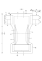
図1~図6には、連結式使い捨て着用物品の一例として、テープタイプ使い捨ておむつが示されている。なお、ホットメルト接着剤による接着箇所のうち説明上必要な箇所については、平面図中には斜線模様及び点模様を、また断面図中には点模様をそれぞれ付している。ホットメルト接着剤は、スロット塗布、連続線状又は点線状のビード塗布、スパイラル状、Z状等のスプレー塗布、又はパターンコート(凸版方式でのホットメルト接着剤の転写)等、公知の手法により塗布することができる。これに代えて又はこれとともに、弾性部材の固定部分では、ホットメルト接着剤を弾性部材の外周面に塗布し、弾性部材を隣接部材に固定することができる。ホットメルト接着剤としては、例えばEVA系、粘着ゴム系(エラストマー系)、オレフィン系、ポリエステル・ポリアミド系などの種類のものが存在するが、特に限定無く使用できる。各構成部材を接合する接合手段としてはヒートシールや超音波シール等の素材溶着による手段を用いることもできる。 1 to 6 show a tape-type disposable diaper as an example of a connected disposable wearing article. It should be noted that, among the places bonded with the hot melt adhesive, necessary for explanation purposes, diagonal lines and dotted patterns are shown in the plan view, and dotted patterns are shown in the cross-sectional view. The hot melt adhesive can be applied by known methods such as slot coating, continuous line or dotted bead coating, spiral or Z-shaped spray coating, or pattern coating (transfer of hot melt adhesive using a letterpress method). Can be applied. Alternatively or additionally, at the fixed portion of the elastic member, a hot melt adhesive can be applied to the outer circumferential surface of the elastic member to secure the elastic member to the adjacent member. Examples of hot melt adhesives include EVA adhesives, adhesive rubber adhesives (elastomer adhesives), olefin adhesives, and polyester/polyamide adhesives, which can be used without particular limitation. As a joining means for joining each component, means by material welding such as heat sealing or ultrasonic sealing can also be used.
このテープタイプ使い捨ておむつは、前後方向LDの中央LCを含む股間部と、前後方向LDの中央LCより前側に延びる腹側部分Fと、前後方向LDの中央LCより後側に延びる背側部分Bとを有している。また、このテープタイプ使い捨ておむつは、股間部を含む範囲に内蔵された吸収体3と、吸収体3の表側を覆う液透過性のトップシート2と、吸収体3の裏側を覆う液不透過性シート1と、液不透過性シート1の裏側を覆い、製品外面を構成する外装不織布12とを有するものである。
This tape type disposable diaper has a crotch area including the center LC in the front-rear direction LD, a ventral part F extending forward from the center LC in the front-rear direction LD, and a back part B extending rearward from the center LC in the front-rear direction LD. It has In addition, this tape type disposable diaper has an
以下、各部の素材及び特徴部分について順に説明する。 The materials and characteristic parts of each part will be explained in order below.
(吸収体)
吸収体3は、パルプ繊維の積繊体、セルロースアセテート等のフィラメントの集合体、あるいは不織布からなる繊維集合層を単層又は複数層有する基本構造を有するものである。吸収体3は、必要に応じて粒子状などの高吸収性ポリマーを繊維集合層中に混合したり、繊維集合層中又は繊維集合層の表面に固着したり、繊維集合層間に層状に介在させたりすることができる。吸収体3は、必要に応じてクレープ紙等の包装シート(図示省略)により包むことができる。また、吸収体3の形状は適宜定めることができるが、図示のように股間部を含む前後方向LDの中間部分の幅がその前後両側よりも狭い砂時計形状(括れ形状)の他、長方形等のように、股間部の前側から後側まで延在する形状が好適である。吸収体3における繊維目付けは100~500g/m2程度、厚みは1~15mm程度とすることができる。また、吸収体3における高吸収性ポリマーの目付けは0~300g/m2程度とすることができる。
(Absorber)
The
(液不透過性シート)
液不透過性シート1は、排泄物の裏面への浸み出しを遮断するものである。液不透過性シート1としては、ポリエチレンフィルム等のプラスチックフィルムの他、ムレ防止の点から遮水性を損なわずに透湿性を備えたシートも用いることができる。この遮水・透湿性シートは、例えばポリエチレンやポリプロピレン等のオレフィン系樹脂中に無機充填材を溶融混練してシートを形成した後、一軸又は二軸方向に延伸することにより得られる微多孔性シートを用いることができる。
(liquid impermeable sheet)
The liquid-
液不透過性シート1は、前後方向LD及び幅方向WDにおいて吸収体3と同じか又はより広範囲にわたり延びていることが望ましいが、他の遮水手段が存在する場合等、必要に応じて、前後方向LD及び幅方向WDにおいて吸収体3の端部を覆わない構造とすることもできる。
It is desirable that the liquid-
おむつ外面を布のような外観及び肌触りとするために、液不透過性シート1の裏面全体を外装不織布12で覆うことができる。外装不織布12は省略することもでき、その場合には、液不透過性シート1が製品外面を形成することになる。
In order to give the outer surface of the diaper a cloth-like appearance and feel, the entire back surface of the liquid-
(トップシート)
トップシート2は液透過性を有するものであり、例えば、有孔又は無孔の不織布や、多孔性プラスチックシートなどを用いることができる。
(Top sheet)
The
トップシート2は、前後方向LDでは製品前端から後端まで延び、幅方向WDでは吸収体3よりも側方に延びているが、例えば後述するサイド立体ギャザー4の起点が吸収体3の側縁よりも幅方向WDの中央側に位置する場合等、必要に応じて、トップシート2の幅を吸収体3の全幅より短くする等、適宜の変形が可能である。
The
(サイドフラップ)
図示例のテープタイプ使い捨ておむつは、吸収体3の側方にそれぞれ延出する、吸収体3を有しない一対のサイドフラップSFを有している。サイドフラップSFは、図示例のように、吸収体3を有する部分から連続する素材(外装不織布12等)からなるものであっても、他の素材を取り付けて形成してもよい。
(side flap)
The illustrated tape-type disposable diaper has a pair of side flaps SF that do not have the
(平面ギャザー)
サイドフラップSFの前後方向LDの中間部には、液不透過性シート1と外装不織布12との間に細長状の脚周り弾性部材7が前後方向LDに沿って伸長状態でホットメルト接着剤等により固定されており、この脚周り弾性部材7の収縮によりサイドフラップSFにはいわゆる平面ギャザーが形成されている。この平面ギャザーにより、おむつの側部が弾性伸縮して脚周りにフィットするようになる。脚周り弾性部材7は脚周りに沿うようにカーブしていてもよい。
(Plane gather)
In the middle part of the side flap SF in the front-rear direction LD, an elongated leg-surrounding
左右各側における脚周り弾性部材7の本数は適宜定めることができるが、1~10本程度、より好ましくは3~8本程度が適当であり、複数本とする場合には、その間隔は2~15mm程度、特に6~10mm程度とするのが好ましい。また、各脚周り弾性部材7としては、糸状、紐状、帯状等に形成された、スチレン系ゴム、オレフィン系ゴム、ウレタン系ゴム、エステル系ゴム、ポリウレタン、ポリエチレン、ポリスチレン、スチレンブタジエン、シリコーン、ポリエステル等、通常使用される素材を用いることができ、太さとしては500~1500dtex程度、天然ゴムの場合0.1~3mm程度、特に0.5~3mm程度が好ましい。また、各脚周り弾性部材7の固定時の伸長率は150~250%程度であるのが好ましい。
The number of leg-surrounding
(ウイング部分)
本テープタイプ使い捨ておむつでは、背側部分Bは股間部よりも幅方向WD外側に延び出たウイング部分を有している。同様に、腹側部分Fも股間部よりも幅方向WD外側に延び出たウイング部分を有している。これらウイング部分は、それ以外の部分と別の部材により形成することもできる。しかし、図示例のようにサイドフラップSFを有する構造において、サイドフラップSFの側部における前後方向LD中間を切断することにより、股間部の側縁からウイング部分の下縁まで続く凹状の脚周り縁Leが形成され、その結果としてウイング部分が形成されていると、製造が容易であるため好ましい。
(wing part)
In this tape type disposable diaper, the back side portion B has a wing portion that extends outward in the width direction WD from the crotch portion. Similarly, the ventral portion F also has a wing portion that extends outward in the width direction WD from the crotch portion. These wing portions can also be formed from a separate member from the other portions. However, in a structure having side flaps SF as shown in the illustrated example, by cutting the middle of the front and back direction LD at the side part of the side flap SF, a concave leg circumferential edge that continues from the side edge of the crotch area to the lower edge of the wing part is formed. It is preferable that Le is formed and a wing portion is formed as a result, since manufacturing is easy.
(連結テープ)
背側部分Bの両側部(図示例ではサイドフラップSFのウイング部分)には、その側縁からそれぞれ突出する連結テープ5が取り付けられるとともに、腹側部分Fの胴周り部表面に幅方向WDに沿ってターゲットシート6が貼着されており、身体への装着に際しては、おむつを身体にあてがった状態で、両側の連結テープ5を腰の各側から腹側外面に回してターゲットシート6に止着する。ターゲットシート6は省略することもでき、その場合には連結テープ5はおむつ外面(図示例の場合外装不織布12)に直に止着される。
(Connection tape)
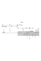
図3に示されるように、連結テープ5は、背側部分Bのウエスト側サイドフラップSFにおけるシート間にホットメルト接着剤等の手段により固定された固定部5fと、サイドフラップSFの側縁のシート間から幅方向WDの外側に突出する突出部5eとを有しており、この突出部5eは先端部5pと、この先端部5pよりも基端側の本体部5bとを有している。連結テープ5の先端部5pの内面には、ターゲットシート6との連結のための連結部9として、表面にフック状突起を多数有するメカニカルファスナーのフック材(面ファスナーの雄材)がそれぞれ取り付けられている。また、ターゲットシート6として、腹側部分Fの外面に、フック状突起が着脱可能に掛止される表面を有するもの(メカニカルファスナー(面ファスナー)の雌材)が取り付けられている。おむつ外面の素材自体をターゲットシート6の代わりに用いたり、フック材に代えて粘着剤層を連結部9として用いるとともに、ターゲットシート6として粘着性に富むような表面が平滑な樹脂テープを用いたりすることができる。
As shown in FIG. 3, the connecting
また、図1に示されるように、連結テープ5には、前後方向LDの中間部における幅方向WDの外側縁から本体部5b内まで幅方向WDに沿うミシン目10が設けられており、このミシン目10を切り離すことにより、図9に示すように各々が固定部、本体部、先端部及び連結部9を備えた上段部及び下段部に分離することができるものである。ミシン目10に代えて、予め切断等により分離されていても良い。このような連結テープ5は、上段部と下段部とを交差させた状態で、腹側部分Fのターゲットシート6に着脱自在に連結することができる。もちろん、このような上下2段分割タイプに限られず、2段分割しないタイプ等、他の公知の連結テープに応用することもできる。
Further, as shown in FIG. 1, the connecting
(サイド立体ギャザー)
図1、図4及び図6にも示されるように、トップシート2上を伝わって横方向に移動する排泄物を阻止し、いわゆる横漏れを防止するために、表面の幅方向WDの両側には、前後方向に延びる第1の遮断位置に沿って表面から起き上がるサイド立体ギャザー4が設けられている。
(Side three-dimensional gathers)
As shown in FIGS. 1, 4, and 6, in order to prevent excrement from moving laterally on the
より詳細には、このサイド立体ギャザー4は、サイドフラップSFを含む領域に固定されたサイド付根部4xと、サイド付根部4xから延び出た第1部分4cと、第1部分4cにおける前端部及び後端部がそれぞれ倒伏状態で固定されて形成された第1前倒伏部4b及び第1後倒伏部4eと、第1部分4cにおける第1前倒伏部4b及び第1後倒伏部4e間の部分が非固定とされて形成された第1起き上がり部4fとを有している。また、第1起き上がり部4fの少なくとも先端部には、第1立体弾性部材4Gが取り付けられている。
More specifically, this side three-dimensional gathers 4 includes a
図示例のサイド立体ギャザー4の各部は、サイド立体シート4sにより形成されており、このサイド立体シート4sが、第1部分4cの先端(サイド付根部4x側と反対側の端)で二つ折りされることにより、自由部分を含む範囲が二層構造となっている。第1立体弾性部材4Gは、この二層構造の部分の層間に挟まれている。第1立体弾性部材4Gは第1起き上がり部4fにのみ設けることもできるが、図示例のように、第1前倒伏部4bにおける後端部から第1後倒伏部4eにおける前端部まで固定されていると、第1立体弾性部材4Gの収縮力が第1起き上がり部4fの全体にわたり作用するだけでなく、第1前倒伏部4b及び第1後倒伏部4eの端部まで作用するため好ましい。
Each part of the illustrated side three-dimensional gathers 4 is formed by a side three-
サイド立体シート4sの内面は、トップシート2の側部上に幅方向WDの接合始端を有し、この接合始端から幅方向WDの外側の部分は各サイドフラップSFの内面、つまり図示例では液不透過性シート1の側部及びその幅方向WDの外側に位置する外装不織布12の側部にホットメルト接着剤などにより接合されている。なお、平面図中の点模様部分はサイド立体ギャザー4の固着部分を示している。
The inner surface of the side three-
サイド立体ギャザー4の接合始端より幅方向WDの内側は、前後方向の両端部ではトップシート2上に固定されているものの、その間の第1起き上がり部4fは非固定の自由部分である。このため、第1起き上がり部4fが第1立体弾性部材4Gの収縮力により前後方向に収縮しつつ起き上がるとともに、前後方向に伸長可能となり、身体表面に密着するようになる。また、第1起き上がり部4fが第1立体弾性部材4Gの収縮力により前後方向に収縮するのにともない、第1前倒伏部4b及び第1後倒伏部4eを有する部分が互いに近づくように変形する。
Although the inner side of the side three-dimensional gathers 4 in the width direction WD from the joining start end is fixed on the
図示しないが、よく知られているように、サイド立体ギャザー4の第1部分4cを、幅方向WDの外側の部分から幅方向WDの内側に延在する基端側部分とこの基端側部分の幅方向WDの中央側の端縁から身体側に折り返され幅方向WDの外側に延在する先端側部分とを有する二つ折りした状態で、第1部分4cの前後方向LDの両端部を固定して倒伏部を形成することもできる。
Although not shown, as is well known, the
サイド立体シート4sの種類は特に限定されないが、通常の場合、液遮断性を確保するために撥水性のものが用いられる。特に、肌触り及び液遮断性を両立できる点で、スパンボンド層間にメルトブローン層を有する不織布(SMS不織布、SMMS不織布、SSMS不織布、SSMMS不織布)が好適である。不織布は一枚で使用する他、複数枚重ねて使用することもできる。後者の場合、不織布相互をホットメルト接着剤等により接着するのが好ましい。
The type of the side three-
第1立体弾性部材4Gとしては、糸状、紐状、帯状等に形成された天然ゴム又は合成ゴム、具体的にはスチレン系ゴム、オレフィン系ゴム、ウレタン系ゴム、エステル系ゴム、ポリウレタン、ポリエチレン、ポリスチレン、スチレンブタジエン、シリコーン、ポリエステル等、通常使用される素材を用いることができる。第1立体弾性部材4Gは、図1及び図2に示すように各複数本間隔を空けて設ける他、各1本設けることができる。展開状態における第1立体弾性部材4Gの伸長率は適宜定めることができるが、例えば太さ420~1120dtex程度のスパンデックス糸ゴムの場合、230~270%程度とすることができる。
The first three-dimensional
(エンドフラップ)
本テープタイプ使い捨ておむつは、吸収体3の前側及び後側にそれぞれ延出する、吸収体3を有しない一対のエンドフラップEFを有している。エンドフラップEFの構成材はおむつの構造によって変化する。図示例では、エンドフラップEFは、液不透過性シート1、外装不織布12、トップシート2及びサイド立体シート4sのうち、吸収体3の前側及び後側に延びて積層され、かつ互いに接合された部分により形成されているが、これに限定されるものではない。エンドフラップEFを形成するための専用のシートを、吸収体3の前側又は後側に継ぎ足して、エンドフラップEFを形成してもよい。
(end flap)
This tape type disposable diaper has a pair of end flaps EF that do not have an
通常の場合、エンドフラップEFの前後方向LDの寸法は、おむつ全体の前後方向LDの寸法の20~25%程度とすることができる。 Normally, the dimension of the end flap EF in the front-rear direction LD can be about 20 to 25% of the dimension of the entire diaper in the front-rear direction LD.
(ウエスト立体ギャザー)
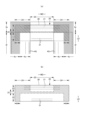
他方、図1、図5及び図6に示すように、図示例の使い捨ておむつの後端部(図示例の場合はエンドフラップEF)には、第1後倒伏部4eの間における第2の遮断位置に沿って表面から起き上がる、ウエスト立体ギャザー20が設けられている。より詳細には、図5及び図6にも示すように、ウエスト立体ギャザー20は、エンドフラップEFにおける第2の遮断位置に沿って取り付けられたウエスト付根部22と、ウエスト付根部22からウエスト縁側に延び出た第2部分23と、第2部分23における幅方向WDの両端部がそれぞれ倒伏状態で固定されて形成された第2倒伏部24と、第2部分23における第2倒伏部24間の部分が非固定とされて形成された第2起き上がり部25とを有している。また、第2起き上がり部25の少なくとも先端部(ウエスト縁側の端部)には、第2立体弾性部材21が取り付けられている。
(Waist three-dimensional gathers)
On the other hand, as shown in FIGS. 1, 5, and 6, the rear end portion of the illustrated disposable diaper (end flap EF in the illustrated example) has a second barrier between the first
また、図示例のウエスト立体ギャザー20はウエスト立体シート26により形成されており、このウエスト立体シート26が折り返されて形成された二層構造を有している。第2立体弾性部材21は、この二層構造の部分の層間に挟まれ、ホットメルト接着剤等により固定されている。第2立体弾性部材21は第2起き上がり部25にのみ設けることもできるが、図示例のように、一方の第2倒伏部24から他方の第2倒伏部24まで固定されていると、第2立体弾性部材21の収縮力が第2起き上がり部25の全体にわたり作用するだけでなく、第2倒伏部24まで作用するため好ましい。
Further, the illustrated waist three-dimensional gathers 20 is formed of a waist three-
図示例のウエスト立体シート26の内面は、エンドフラップEF上に前後方向LDの接合始端を有し、この接合始端から後方の部分はエンドフラップEFの内面、つまり図示例ではトップシート2の表面にホットメルト接着剤などにより接合されている。なお、このトップシート2に対するウエスト立体シート26の固着部分は、図1及び図5(a)に右斜め下向きの斜線で示されている。
The inner surface of the waist three-
ウエスト立体ギャザー20の接合始端よりウエスト縁側は、幅方向WDの両端部ではトップシート2上に固定された第2倒伏部24となっているものの、その間の第2起き上がり部25は非固定の自由部分である。このため、第2起き上がり部25が第2立体弾性部材21の収縮力により幅方向WDに収縮しつつ起き上がるとともに、幅方向WDに伸長可能となり、身体表面に密着するようになる。また、第2起き上がり部25が第2立体弾性部材21の収縮力により幅方向WDに収縮するのにともない、一方の第2倒伏部24を有する部分及び他方の第2倒伏部24を有する部分が互いに近づくように変形する。
The waist edge side from the joint start end of the waist three-dimensional gathers 20 is a second falling
一方、サイド立体ギャザー4は、第1起き上がり部4fの収縮に伴い第1前倒伏部4b及び第1後倒伏部4eが互いに引き寄せられつつ第1起き上がり部4fが起き上がる。ここで、ウエスト立体ギャザー20を有する領域は、第1後倒伏部4eの間に位置する。したがって、サイド立体ギャザー4による第1前倒伏部及び第1後倒伏部4eを互いに引き寄せる作用(図9中の矢印参照)は、ウエスト立体ギャザー20の第2部分23をウエスト付根部22側に引き寄せる作用(図9中の矢印参照)も有する。また、第1起き上がり部4fの収縮及び第2起き上がり部25の収縮の方向が交差する部位、つまり第1前倒伏部又は第1後倒伏部4eのうちウエスト立体ギャザー20を有する方は、両方の収縮の影響を受けて装着者の肌側に持ち上がる。
On the other hand, in the side three-dimensional gathers 4, the first rising
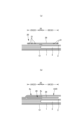
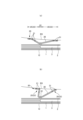
その結果、ウエスト立体ギャザー20の第2起き上がり部25は、装着者の肌に対する隙間が発生しやすい部位で、図7~図8(a)に示すように、製品内面と装着者の肌面BSとの隙間の大きさ応じて起き上がり状態が特徴的に変化する。すなわち、当該隙間が小さいうちは、図7(a)に示すように、ウエスト立体ギャザー20の第2起き上がり部25は先端がウエスト縁側に向いており、起き上がり角度も小さく、面で接触する。つまり、漏れのリスクが小さい状態では装着感に優れたフィット性が確保される。一方、当該隙間が大きくなると、図7(b)に示すように、ウエスト立体ギャザー20の第2起き上がり部25は先端側が高く起き上がり、胴周りの締め付けが特に緩くなると、図8(a)及び図9に示すように、幅方向WDの中間部の先端側が股間側に反り返る(又は反り返らないものの反り返りに近い状態まで高く起き上がる)。つまり、漏れのリスクが大きい状態ではより漏れ防止性に優れた状態に変化する。このようなウエスト立体ギャザー20の変化は従来ないものであり、特に経時的な(例えば食事タイミング等による)装着状態の緩みに起因する、後漏れや前漏れに効果的である。
As a result, the second rising
図示例の第2倒伏部24は、第1後倒伏部4eにおけるトップシート2とサイド立体シート4sとの間に挟まれて両シートに対してホットメルト接着剤等の接合手段により接合された部分であるが、第1後倒伏部4eにおけるサイド立体シート4s上に設けられていてもよい。つまり、図示しないが、サイド立体ギャザー4の上にウエスト立体ギャザー20が設けられていてもよい。
The
ウエスト立体シート26の種類は特に限定されないが、通常の場合、液遮断性を確保するために撥水性のものが用いられる。特に、肌触り及び液遮断性を両立できる点で、スパンボンド層間にメルトブローン層を有する不織布(SMS不織布、SMMS不織布、SSMS不織布、SSMMS不織布)が好適である。不織布は一枚で使用する他、複数枚重ねて使用することもできる。後者の場合、不織布相互をホットメルト接着剤等により接着するのが好ましい。
The type of the waist three-
第2立体弾性部材21としては、糸状、紐状、帯状等に形成された天然ゴム又は合成ゴム、具体的にはスチレン系ゴム、オレフィン系ゴム、ウレタン系ゴム、エステル系ゴム、ポリウレタン、ポリエチレン、ポリスチレン、スチレンブタジエン、シリコーン、ポリエステル等、通常使用される素材を用いることができる。第2立体弾性部材21は、図示例のように複数本間隔を空けて設ける他、1本設けるだけでもよい。展開状態における第2立体弾性部材21の伸長率は適宜定めることができるが、例えば太さ600~1300dtex程度のスパンデックス糸ゴムの場合、130~250%程度、特に160~200%程度とすることができる。
The second three-dimensional
第2立体弾性部材21を前後方向LDに間隔を空けて複数本設ける場合、すべての伸長率を同一にしてもよいが、一部又は全部の伸長率を異なるものとすることができる。例えば、ウエスト縁側のものほど展開状態の伸長率が低くなっていると、第2起き上がり部25の先端側がより反り返りやすくなるため好ましい。
When a plurality of second three-dimensional
第2立体弾性部材21の位置は適宜定めることができるが、先端部(最もウエスト縁側)に位置する第2立体弾性部材21は、ウエスト付根部22の後縁から2~40mm程度離れていると、第2起き上がり部25の先端側がより反り返りやすくなるため好ましい。同様の理由により、先端部(最もウエスト縁側)に位置する第2立体弾性部材21は、エンドフラップEFの前縁から離れていると好ましい。
The position of the second three-dimensional
テープタイプ使い捨ておむつでは、連結部9(前後方向LDに複数有する場合は最もウエスト縁側のものを意味する)よりウエスト縁側に位置する領域と、肌との間に隙間が生じやすい。したがって、展開状態で、ウエスト立体ギャザー20は、連結部9よりもウエスト縁側に位置する第2立体弾性部材21を有すると、前述のウエスト立体ギャザー20の変形が効果的に発現するため好ましい。
In tape-type disposable diapers, a gap is likely to occur between the skin and a region located closer to the waist edge than the connecting portion 9 (if there are multiple connecting portions in the front-rear direction LD, it means the one closest to the waist edge). Therefore, it is preferable for the waist three-dimensional gathers 20 to have the second three-dimensional
図6~図8に示す例のように、ウエスト立体ギャザー20は、ウエスト付根部22から股間側に延び出た第3部分33と、第3部分33における幅方向WDの両端部がそれぞれ倒伏状態で固定されて形成された第3倒伏部34と、第3部分33における第3倒伏部34間の部分が非固定とされて形成された第3起き上がり部35と、第3起き上がり部35の少なくとも先端部に取り付けられた第3立体弾性部材31とを有するのも好ましい。これにより、第3部分33が排泄物の移動を基本的に阻止し、何らかの原因でそれを乗り越えてしまった排泄物について第2部分23が漏れを防止するという、二段階の漏れ防止機能が発揮される。ここで、第2部分23が前述のように第3部分33と基本的に異なる遮断機能を有するため、単に同一の起き上がり部を二重に設けた場合よりも、漏れ防止性に優れたものとなることはいうまでもない。
As shown in the examples shown in FIGS. 6 to 8, the waist three-dimensional gathers 20 has a
もちろん、図10に示す例のように、第3部分33は省略することもできる。また、図8(b)に示す例のように、第2部分23を前後方向LDに間隔を空けて複数設けることもできる。
Of course, the
図示例では、ウエスト立体ギャザーの第3部分33が、サイド立体ギャザー4の第1起き上がり部4fを有する前後方向LDの範囲に位置しているが、第3部分33の一部又は全部が第1倒伏部を有する前後方向LDの範囲に位置していてもよい。前者の場合、第3倒伏部34は、サイド付根部4xを有する領域内に位置することとなるが、後者の場合第1後倒伏部4eを有する領域内に位置していてもよい。
In the illustrated example, the
また、ウエスト立体ギャザーの第3部分33が、サイド立体ギャザー4の第1起き上がり部4fを有する前後方向LDの範囲に位置している場合、第3起き上がり部35と第1起き上がり部4fとはそれらが重なる部分で接合されていないことが好ましいが、接合されていてもよい。
Further, when the
<その他>
上記例は、背側部分Bにのみウエスト立体ギャザー20を設けているが、これに代えて又はこれとともに、腹側部分Fにもウエスト立体ギャザー20を設けることができる。すなわち、第1前倒伏部4bの間及び第1後倒伏部4eの間の少なくとも一方に、ウエスト立体ギャザー20を設けることができる。
<Others>
In the above example, the waist three-dimensional gathers 20 are provided only on the back side portion B, but instead of or in addition to this, the waist three-dimensional gathers 20 may be provided on the ventral side portion F as well. That is, the waist three-dimensional gathers 20 can be provided between at least one of the first front collapsed
上記説明における不織布としては、部位や目的に応じて公知の不織布を適宜使用することができる。不織布の構成繊維としては、例えばポリエチレン又はポリプロピレン等のオレフィン系、ポリエステル系、ポリアミド系等の合成繊維(単成分繊維の他、芯鞘等の複合繊維も含む)の他、レーヨンやキュプラ等の再生繊維、綿等の天然繊維等、特に限定なく選択することができ、これらを混合して用いることもできる。不織布の柔軟性を高めるために、構成繊維を捲縮繊維とするのは好ましい。また、不織布の構成繊維は、親水性繊維(親水化剤により親水性となったものを含む)であっても、疎水性繊維若しくは撥水性繊維(撥水剤により撥水性となった撥水性繊維を含む)であってもよい。また、不織布は一般に繊維の長さや、シート形成方法、繊維結合方法、積層構造により、短繊維不織布、長繊維不織布、スパンボンド不織布、メルトブローン不織布、スパンレース不織布、サーマルボンド(エアスルー)不織布、ニードルパンチ不織布、ポイントボンド不織布、積層不織布(スパンボンド層間にメルトブローン層を挟んだSMS不織布、SMMS不織布等)等に分類されるが、これらのどの不織布も用いることができる。 As the nonwoven fabric in the above description, any known nonwoven fabric can be used as appropriate depending on the site and purpose. The constituent fibers of the nonwoven fabric include, for example, olefin-based fibers such as polyethylene or polypropylene, synthetic fibers such as polyester-based fibers, and polyamide-based fibers (including single-component fibers as well as composite fibers such as core-sheath fibers), as well as recycled fibers such as rayon and cupro. Fibers, natural fibers such as cotton, etc. can be selected without particular limitation, and a mixture of these can also be used. In order to increase the flexibility of the nonwoven fabric, it is preferable that the constituent fibers be crimped fibers. In addition, even if the constituent fibers of a nonwoven fabric are hydrophilic fibers (including those made hydrophilic by a hydrophilizing agent), they may be hydrophobic fibers or water-repellent fibers (water-repellent fibers made water-repellent by a water-repellent agent). ). In addition, nonwoven fabrics generally vary depending on the fiber length, sheet forming method, fiber binding method, and laminated structure. It is classified into nonwoven fabrics, point bonded nonwoven fabrics, laminated nonwoven fabrics (SMS nonwoven fabrics with a meltblown layer sandwiched between spunbond layers, SMMS nonwoven fabrics, etc.), and any of these nonwoven fabrics can be used.
<明細書中の用語の説明>
明細書中の以下の用語は、明細書中に特に記載が無い限り、以下の意味を有するものである。
<Explanation of terms in the specification>
The following terms in the specification have the following meanings unless otherwise specified in the specification.
・「前後方向」とは図中に符号LDで示す方向(縦方向)を意味し、「幅方向」とは図中にWDで示す方向(左右方向)を意味し、前後方向と幅方向とは直交するものである。 ・"Anteroposterior direction" means the direction indicated by the symbol LD in the figure (vertical direction), and "width direction" means the direction indicated by WD in the figure (horizontal direction), and the longitudinal direction and the width direction are orthogonal.
・「MD方向」及び「CD方向」とは、製造設備における流れ方向(MD方向)及びこれと直交する横方向(CD方向)を意味し、製品の部分によっていずれか一方が前後方向となるものであり、他方が幅方向となるものである。不織布のMD方向は、不織布の繊維配向の方向である。繊維配向とは、不織布の繊維が沿う方向であり、例えば、TAPPI標準法T481の零距離引張強さによる繊維配向性試験法に準じた測定方法や、前後方向及び幅方向の引張強度比から繊維配向方向を決定する簡易的測定方法により判別することができる。 ・“MD direction” and “CD direction” refer to the flow direction (MD direction) in manufacturing equipment and the lateral direction (CD direction) perpendicular to this, and depending on the part of the product, one of them is the front-back direction. and the other side is in the width direction. The MD direction of the nonwoven fabric is the direction of fiber orientation of the nonwoven fabric. Fiber orientation is the direction along which the fibers of a nonwoven fabric follow. This can be determined by a simple measurement method that determines the orientation direction.
・「表側」とは、着用した際に着用者の肌に近い方を意味し、「裏側」とは、着用した際に着用者の肌から遠い方を意味する。 - "Front side" means the side closer to the wearer's skin when worn, and "back side" means the side farther from the wearer's skin when worn.
・「表面」とは部材の、着用した際に着用者の肌に近い方の面を意味し、「裏面」とは部材の、着用した際に着用者の肌から遠い方の面を意味する。 ・"Front side" means the side of the member that is closer to the wearer's skin when worn, and "back side" means the side of the member that is farther from the wearer's skin when worn. .
・「伸長率」は、自然長を100%としたときの値を意味する。例えば、伸長率が200%とは、伸長倍率が2倍であることと同義である。 - "Elongation rate" means a value when the natural length is 100%. For example, an extension ratio of 200% is synonymous with an extension ratio of 2 times.
・「ゲル強度」は次のようにして測定されるものである。人工尿(尿素:2wt%、塩化ナトリウム:0.8wt%、塩化カルシウム二水和物:0.03wt%、硫酸マグネシウム七水和物:0.08wt%、及びイオン交換水:97.09wt%を混合したもの)49.0gに、高吸収性ポリマーを1.0g加え、スターラーで攪拌させる。生成したゲルを40℃×60%RHの恒温恒湿槽内に3時間放置したあと常温にもどし、カードメーター(I.techno Engineering社製:Curdmeter-MAX ME-500)でゲル強度を測定する。 - "Gel strength" is measured as follows. Artificial urine (urea: 2 wt%, sodium chloride: 0.8 wt%, calcium chloride dihydrate: 0.03 wt%, magnesium sulfate heptahydrate: 0.08 wt%, and ion exchange water: 97.09 wt%) Add 1.0 g of superabsorbent polymer to 49.0 g of the mixture) and stir with a stirrer. The generated gel was left in a constant temperature and humidity chamber at 40° C. x 60% RH for 3 hours, then returned to room temperature, and the gel strength was measured using a card meter (Curdmeter-MAX ME-500, manufactured by I.techno Engineering).
・「目付け」は次のようにして測定されるものである。試料又は試験片を予備乾燥した後、標準状態(試験場所は、温度23±1℃、相対湿度50±2%)の試験室又は装置内に放置し、恒量になった状態にする。予備乾燥は、試料又は試験片を温度100℃の環境で恒量にすることをいう。なお、公定水分率が0.0%の繊維については、予備乾燥を行わなくてもよい。恒量になった状態の試験片から、試料採取用の型板(100mm×100mm)を使用し、100mm×100mmの寸法の試料を切り取る。試料の重量を測定し、100倍して1平米あたりの重さを算出し、目付けとする。
・“Basic weight” is measured as follows. After pre-drying the sample or test piece, it is left in a test room or apparatus under standard conditions (test location:
・「厚み」は、自動厚み測定器(KES-G5 ハンディ圧縮計測プログラム)を用い、荷重:0.098N/cm 2 、及び加圧面積:2cm 2 の条件下で自動測定する。有孔不織布の厚みは、孔及びその周囲の突出部以外の部分で測定する。 - "Thickness" is automatically measured using an automatic thickness measuring device (KES-G5 Handy Compression Measurement Program) under the conditions of load: 0.098 N/ cm 2 and pressurized area: 2 cm 2 . The thickness of the perforated nonwoven fabric is measured at a portion other than the perforations and the protruding parts around them.
・吸水量は、JIS K7223-1996「高吸水性樹脂の吸水量試験方法」によって測定する。 - Water absorption is measured according to JIS K7223-1996 "Water absorption test method for super absorbent resin".
・吸水速度は、2gの高吸収性ポリマー及び50gの生理食塩水を使用して、JIS K7224‐1996「高吸水性樹脂の吸水速度試験法」を行ったときの「終点までの時間」とする。 ・Water absorption rate is the "time to end point" when JIS K7224-1996 "Water absorption rate test method for super absorbent resin" is performed using 2 g of super absorbent polymer and 50 g of physiological saline. .
・「展開状態」とは、収縮や弛み無く平坦に展開した状態を意味する。 - "Unfolded state" means a state in which it is flattened without shrinkage or slack.
・各部の寸法は、特に記載が無い限り、自然長状態ではなく展開状態における寸法を意味する。 - Unless otherwise specified, the dimensions of each part refer to the dimensions in the unfolded state, not in the natural length state.
・試験や測定における環境条件についての記載が無い場合、その試験や測定は、標準状態(試験場所は、温度23±1℃、相対湿度50±2%)の試験室又は装置内で行うものとする。
- If there is no description of the environmental conditions for the test or measurement, the test or measurement shall be conducted in a test room or equipment under standard conditions (test location:
本発明は、上記例のテープタイプ使い捨ておむつのような連結式使い捨て着用物品に適用できるものである。 The present invention can be applied to connected disposable wearing articles such as the tape type disposable diaper described above.
1…液不透過性シート、10…ミシン目、2…トップシート、3…吸収体、4…サイド立体ギャザー、4G…第1立体弾性部材、4c…第1部分、4e…第1後倒伏部、4f…第1起き上がり部、4x…サイド付根部、5…連結テープ、6…ターゲットシート、9…連結部、20…ウエスト立体ギャザー、21…第2立体弾性部材、22…ウエスト付根部、23…第2部分、24…第2倒伏部、25…第2起き上がり部、26…ウエスト立体シート、31…第3立体弾性部材、33…第3部分、34…第3倒伏部、35…第3起き上がり部、B…背側部分、EF…エンドフラップ、F…腹側部分、LD…前後方向、SF…サイドフラップ、WD…幅方向。
DESCRIPTION OF
Claims (4)
前記背側部分の両側部に設けられた、前記腹側部分の外面に着脱可能に連結される連結部を有し、
幅方向両側における前後方向に延びる第1の遮断位置に沿って表面から起き上がる、サイド立体ギャザーを有し、
前記サイド立体ギャザーは、前記第1の遮断位置の幅方向の外側に取り付けられたサイド付根部と、前記サイド付根部から延び出た第1部分と、前記第1部分における前端部及び後端部がそれぞれ倒伏状態で固定されて形成された第1前倒伏部及び第1後倒伏部と、前記第1部分における第1前倒伏部及び第1後倒伏部間の部分が非固定とされて形成された第1起き上がり部と、前記第1起き上がり部の少なくとも先端部に取り付けられた第1立体弾性部材とを有し、
前記第1起き上がり部の少なくとも先端部は、前記第1立体弾性部材とともに前後方向に収縮しているとともに、前後方向に伸長可能であり、
一方の前記第1後倒伏部と重なる部位から他方の前記第1後倒伏部と重なる部位にわたり設けられた、ウエスト立体ギャザーを有し、
前記ウエスト立体ギャザーは、一方の前記第1後倒伏部と重なる固定部分、他方の前記第1後倒伏部と重なる固定部分、及びこれらを繋ぐ第2の遮断位置に沿って幅方向に連続する固定部分を有するように、裏側に隣接する部材に取り付けられたウエスト付根部と、前記ウエスト付根部と同幅で前記ウエスト付根部から折り返されることなく後側に延び出た第2部分と、前記第2部分における前記第1後倒伏部と重なる幅方向の両端部がそれぞれ倒伏状態で裏側に隣接する部材に固定されて形成された第2倒伏部と、前記第2部分における第2倒伏部間の部分が非固定とされて形成された、前記第2の遮断位置に沿って表面から起き上がる第2起き上がり部と、前記第2起き上がり部の先端部とそれ以外の部分に前後方向に間隔を空けて複数取り付けられた第2立体弾性部材とを有し、
前記第2立体弾性部材は、ウエスト縁側のものほど展開状態の伸長率が低い、
前記第2起き上がり部は、前記第2立体弾性部材の収縮力により前記第2立体弾性部材とともに幅方向に収縮しているとともに、幅方向に伸長可能である、
ことを特徴とする連結式使い捨て着用物品。 It has a crotch area including the center in the front-rear direction, a ventral part extending forward from the center in the front-rear direction, and a dorsal part extending rearward from the center in the front-rear direction,
comprising connecting portions provided on both sides of the dorsal portion and removably connected to the outer surface of the ventral portion;
It has side three-dimensional gathers rising from the surface along the first blocking position extending in the front-rear direction on both sides in the width direction,
The side three-dimensional gathers include a side root portion attached to the outside in the width direction of the first blocking position, a first portion extending from the side root portion, and a front end portion and a rear end portion of the first portion. A first front lying part and a first rear lying part are formed by being fixed in a lying state, respectively, and a part of the first part between the first front lying part and the first rear lying part is formed by being unfixed. a first rising portion, and a first three-dimensional elastic member attached to at least a distal end portion of the first rising portion;
At least a distal end portion of the first rising portion is contracted in the front-rear direction together with the first three-dimensional elastic member, and is expandable in the front-rear direction,
It has a waist three-dimensional gather provided from a region overlapping with one of the first rear lodging portions to a region overlapping with the other first rear lodging portion ,
The waist three-dimensional gathers include a fixed part that overlaps with the first rear collapsed part on one side, a fixed part that overlaps with the first rear collapsed part on the other side, and a fixed part that continues in the width direction along a second blocking position that connects these parts. a waist root portion attached to a member adjacent to the back side so as to have a second portion , a second portion having the same width as the waist root portion and extending rearward from the waist root portion without being folded back ; A second lodging part formed by fixing both ends of the two parts in the width direction overlapping with the first rear lodging part to a member adjacent to the back side in a lying state, and a second lodging part in the second part. a second rising portion rising from the surface along the second blocking position , the portion of which is unfixed; and a distal end portion of the second rising portion and other portions having an interval in the front-rear direction. a plurality of attached second three-dimensional elastic members;
The second three-dimensional elastic member has a lower elongation rate in the unfolded state as it approaches the edge of the waist.
The second rising portion is contracted in the width direction together with the second three-dimensional elastic member due to the contraction force of the second three-dimensional elastic member, and is expandable in the width direction.
A connected disposable wearing article characterized by:
請求項1記載の連結式使い捨て着用物品。 In the unfolded state, the waist three-dimensional gathers include the second three-dimensional elastic member located on the rear side of the connecting portion.
The connected disposable wearing article according to claim 1.
請求項1又は2記載の連結式使い捨て着用物品。 The waist three-dimensional gathers include a third portion extending from the base of the waist toward the crotch side, a third folding portion formed by fixing both widthwise ends of the third portion in a lying state, and the third portion extending from the base of the waist toward the crotch side; a third rising part formed with a portion between the third collapsed parts in the third portion being non-fixed; and a third three-dimensional elastic member attached to at least the tip of the third rising part;
The connected disposable wearing article according to claim 1 or 2.
前記ウエスト付根部は、前記吸収体の後端部上に設けられている、
請求項1~3のいずれか1項に記載の連結式使い捨て着用物品。
An absorbent body is incorporated in an area including the crotch area,
The waist root portion is provided on the rear end portion of the absorbent body.
The jointable disposable wearing article according to any one of claims 1 to 3.
Priority Applications (6)
| Application Number | Priority Date | Filing Date | Title |
|---|---|---|---|
| JP2020056600A JP7455630B2 (en) | 2020-03-26 | 2020-03-26 | Interlocking disposable wearing article |
| CN202180011488.6A CN115038419B (en) | 2020-03-26 | 2021-03-12 | Connected disposable wearing article |
| US17/802,049 US20230126828A1 (en) | 2020-03-26 | 2021-03-12 | Connecting-type disposable wearing article |
| PCT/JP2021/010129 WO2021193151A1 (en) | 2020-03-26 | 2021-03-12 | Connected disposable wearable article |
| EP21775094.2A EP4129258A4 (en) | 2020-03-26 | 2021-03-12 | Connected disposable wearable article |
| TW110110769A TWI845828B (en) | 2020-03-26 | 2021-03-25 | Connected disposable wearable items |
Applications Claiming Priority (1)
| Application Number | Priority Date | Filing Date | Title |
|---|---|---|---|
| JP2020056600A JP7455630B2 (en) | 2020-03-26 | 2020-03-26 | Interlocking disposable wearing article |
Publications (3)
| Publication Number | Publication Date |
|---|---|
| JP2021153796A JP2021153796A (en) | 2021-10-07 |
| JP2021153796A5 JP2021153796A5 (en) | 2022-10-31 |
| JP7455630B2 true JP7455630B2 (en) | 2024-03-26 |
Family
ID=77891793
Family Applications (1)
| Application Number | Title | Priority Date | Filing Date |
|---|---|---|---|
| JP2020056600A Active JP7455630B2 (en) | 2020-03-26 | 2020-03-26 | Interlocking disposable wearing article |
Country Status (6)
| Country | Link |
|---|---|
| US (1) | US20230126828A1 (en) |
| EP (1) | EP4129258A4 (en) |
| JP (1) | JP7455630B2 (en) |
| CN (1) | CN115038419B (en) |
| TW (1) | TWI845828B (en) |
| WO (1) | WO2021193151A1 (en) |
Families Citing this family (2)
| Publication number | Priority date | Publication date | Assignee | Title |
|---|---|---|---|---|
| JP6488040B1 (en) * | 2018-03-20 | 2019-03-20 | 大王製紙株式会社 | Tape type disposable diaper |
| EP3769732B1 (en) * | 2018-03-20 | 2023-12-27 | Daio Paper Corporation | Tape-type disposable diaper |
Citations (5)
| Publication number | Priority date | Publication date | Assignee | Title |
|---|---|---|---|---|
| JP3218752B2 (en) | 1992-11-26 | 2001-10-15 | 富士電機株式会社 | Coin dispenser |
| JP2001293031A (en) | 2000-04-12 | 2001-10-23 | Daio Paper Corp | Disposable absorbent product |
| WO2016051938A1 (en) | 2014-09-30 | 2016-04-07 | ユニ・チャーム株式会社 | Disposable diaper |
| US20180055698A1 (en) | 2015-03-31 | 2018-03-01 | Kimberly-Clark Worldwide, Inc. | Absorbent article with selectively positioned waist containment member |
| WO2020004499A1 (en) | 2018-06-29 | 2020-01-02 | ユニ・チャーム株式会社 | Disposable diaper |
Family Cites Families (10)
| Publication number | Priority date | Publication date | Assignee | Title |
|---|---|---|---|---|
| JP3060466B2 (en) * | 1990-01-23 | 2000-07-10 | 花王株式会社 | Diaper |
| US20060241560A1 (en) * | 2005-04-22 | 2006-10-26 | Chang Kuo-Shu E | Convertible absorbent article with extensible side panels |
| JP5258431B2 (en) | 2008-07-18 | 2013-08-07 | 大王製紙株式会社 | Tape-type disposable diaper |
| JP5091064B2 (en) * | 2008-09-05 | 2012-12-05 | 王子ネピア株式会社 | Absorbent articles |
| US8764722B2 (en) * | 2011-04-28 | 2014-07-01 | Kimberly-Clark Worldwide, Inc. | Absorbent article with cushioned waistband |
| JP5657162B1 (en) | 2014-07-31 | 2015-01-21 | ユニ・チャーム株式会社 | Absorbent articles |
| US10722407B2 (en) * | 2014-10-31 | 2020-07-28 | Kimberly-Clark Worldwide, Inc. | Absorbent article with partial laminate waist elastic member |
| US10470943B2 (en) * | 2015-09-29 | 2019-11-12 | Kimberly-Clark Worldwide, Inc. | Absorbent article with selectively positioned waist containment member having an improved waist seal |
| WO2018217591A1 (en) * | 2017-05-24 | 2018-11-29 | The Procter & Gamble Company | Absorbent article with raisable topsheet |
| GB2584041B (en) * | 2018-01-31 | 2022-11-09 | Kimberly Clark Co | Absorbent pants having a waistband with a rear pocket |
-
2020
- 2020-03-26 JP JP2020056600A patent/JP7455630B2/en active Active
-
2021
- 2021-03-12 WO PCT/JP2021/010129 patent/WO2021193151A1/en unknown
- 2021-03-12 CN CN202180011488.6A patent/CN115038419B/en active Active
- 2021-03-12 EP EP21775094.2A patent/EP4129258A4/en active Pending
- 2021-03-12 US US17/802,049 patent/US20230126828A1/en active Pending
- 2021-03-25 TW TW110110769A patent/TWI845828B/en active
Patent Citations (5)
| Publication number | Priority date | Publication date | Assignee | Title |
|---|---|---|---|---|
| JP3218752B2 (en) | 1992-11-26 | 2001-10-15 | 富士電機株式会社 | Coin dispenser |
| JP2001293031A (en) | 2000-04-12 | 2001-10-23 | Daio Paper Corp | Disposable absorbent product |
| WO2016051938A1 (en) | 2014-09-30 | 2016-04-07 | ユニ・チャーム株式会社 | Disposable diaper |
| US20180055698A1 (en) | 2015-03-31 | 2018-03-01 | Kimberly-Clark Worldwide, Inc. | Absorbent article with selectively positioned waist containment member |
| WO2020004499A1 (en) | 2018-06-29 | 2020-01-02 | ユニ・チャーム株式会社 | Disposable diaper |
Also Published As
| Publication number | Publication date |
|---|---|
| WO2021193151A1 (en) | 2021-09-30 |
| TW202137959A (en) | 2021-10-16 |
| EP4129258A4 (en) | 2024-04-10 |
| CN115038419B (en) | 2023-08-29 |
| US20230126828A1 (en) | 2023-04-27 |
| EP4129258A1 (en) | 2023-02-08 |
| TWI845828B (en) | 2024-06-21 |
| CN115038419A (en) | 2022-09-09 |
| JP2021153796A (en) | 2021-10-07 |
Similar Documents
| Publication | Publication Date | Title |
|---|---|---|
| TWI597055B (en) | Absorbent article | |
| WO2019188562A1 (en) | Stretchable structure for disposable wearable article and underpants-type disposable wearable article having stretchable structure | |
| JP7455630B2 (en) | Interlocking disposable wearing article | |
| JP7349413B2 (en) | Interlocking disposable wearing article | |
| WO2021192999A1 (en) | Connection-type disposable wearable article | |
| WO2021193000A1 (en) | Connecting disposable worn article | |
| JP2021153796A5 (en) | ||
| JP2021153714A5 (en) | ||
| JP2021153713A5 (en) | ||
| JP2021153712A5 (en) | ||
| JP2019000277A (en) | Underpants type disposable diaper | |
| JP7042088B2 (en) | Pad type absorbent article | |
| WO2019188564A1 (en) | Stretchable structure for disposable wearable article and underpants-type disposable wearable article having stretchable structure | |
| TWI474810B (en) | Absorbent items | |
| JP7421973B2 (en) | Disposable wearing items | |
| JP7488711B2 (en) | Connectable disposable wearable items | |
| JP2020156673A (en) | Pad type disposable diaper | |
| WO2023042437A1 (en) | Connection-type disposable wearable article | |
| JP7528032B2 (en) | Absorbent articles | |
| JP7362528B2 (en) | Interlocking disposable wearing article | |
| WO2023281818A1 (en) | Connection-type disposable wearable article | |
| JP7389432B2 (en) | absorbent articles | |
| JP2021153715A5 (en) | ||
| JP2023009585A5 (en) | ||
| JP2023004770A (en) | Articulated disposable diaper |
Legal Events
| Date | Code | Title | Description |
|---|---|---|---|
| A521 | Request for written amendment filed |
Free format text: JAPANESE INTERMEDIATE CODE: A523 Effective date: 20221021 |
|
| A621 | Written request for application examination |
Free format text: JAPANESE INTERMEDIATE CODE: A621 Effective date: 20221021 |
|
| A131 | Notification of reasons for refusal |
Free format text: JAPANESE INTERMEDIATE CODE: A131 Effective date: 20230929 |
|
| A521 | Request for written amendment filed |
Free format text: JAPANESE INTERMEDIATE CODE: A523 Effective date: 20231120 |
|
| TRDD | Decision of grant or rejection written | ||
| A01 | Written decision to grant a patent or to grant a registration (utility model) |
Free format text: JAPANESE INTERMEDIATE CODE: A01 Effective date: 20240301 |
|
| A61 | First payment of annual fees (during grant procedure) |
Free format text: JAPANESE INTERMEDIATE CODE: A61 Effective date: 20240313 |
|
| R150 | Certificate of patent or registration of utility model |
Ref document number: 7455630 Country of ref document: JP Free format text: JAPANESE INTERMEDIATE CODE: R150 |