WO2019188564A1 - Stretchable structure for disposable wearable article and underpants-type disposable wearable article having stretchable structure - Google Patents
Stretchable structure for disposable wearable article and underpants-type disposable wearable article having stretchable structure Download PDFInfo
- Publication number
- WO2019188564A1 WO2019188564A1 PCT/JP2019/011376 JP2019011376W WO2019188564A1 WO 2019188564 A1 WO2019188564 A1 WO 2019188564A1 JP 2019011376 W JP2019011376 W JP 2019011376W WO 2019188564 A1 WO2019188564 A1 WO 2019188564A1
- Authority
- WO
- WIPO (PCT)
- Prior art keywords
- nonwoven fabric
- fabric layer
- holes
- sheet
- stretchable
- Prior art date
Links
Images


Classifications
-
- A—HUMAN NECESSITIES
- A61—MEDICAL OR VETERINARY SCIENCE; HYGIENE
- A61F—FILTERS IMPLANTABLE INTO BLOOD VESSELS; PROSTHESES; DEVICES PROVIDING PATENCY TO, OR PREVENTING COLLAPSING OF, TUBULAR STRUCTURES OF THE BODY, e.g. STENTS; ORTHOPAEDIC, NURSING OR CONTRACEPTIVE DEVICES; FOMENTATION; TREATMENT OR PROTECTION OF EYES OR EARS; BANDAGES, DRESSINGS OR ABSORBENT PADS; FIRST-AID KITS
- A61F13/00—Bandages or dressings; Absorbent pads
- A61F13/15—Absorbent pads, e.g. sanitary towels, swabs or tampons for external or internal application to the body; Supporting or fastening means therefor; Tampon applicators
- A61F13/45—Absorbent pads, e.g. sanitary towels, swabs or tampons for external or internal application to the body; Supporting or fastening means therefor; Tampon applicators characterised by the shape
- A61F13/49—Absorbent articles specially adapted to be worn around the waist, e.g. diapers
- A61F13/496—Absorbent articles specially adapted to be worn around the waist, e.g. diapers in the form of pants or briefs
-
- A—HUMAN NECESSITIES
- A61—MEDICAL OR VETERINARY SCIENCE; HYGIENE
- A61F—FILTERS IMPLANTABLE INTO BLOOD VESSELS; PROSTHESES; DEVICES PROVIDING PATENCY TO, OR PREVENTING COLLAPSING OF, TUBULAR STRUCTURES OF THE BODY, e.g. STENTS; ORTHOPAEDIC, NURSING OR CONTRACEPTIVE DEVICES; FOMENTATION; TREATMENT OR PROTECTION OF EYES OR EARS; BANDAGES, DRESSINGS OR ABSORBENT PADS; FIRST-AID KITS
- A61F13/00—Bandages or dressings; Absorbent pads
- A61F13/15—Absorbent pads, e.g. sanitary towels, swabs or tampons for external or internal application to the body; Supporting or fastening means therefor; Tampon applicators
- A61F13/51—Absorbent pads, e.g. sanitary towels, swabs or tampons for external or internal application to the body; Supporting or fastening means therefor; Tampon applicators characterised by the outer layers
- A61F13/514—Backsheet, i.e. the impermeable cover or layer furthest from the skin
Definitions
- the present invention relates to a stretchable structure of a disposable wearing article and a pants-type disposable wearing article having the stretchable structure.
- a stretchable structure in order to improve the fit of each part.
- a disposable diaper of a pants type or a tape type it is widely performed to provide a stretchable structure in the waistline direction at the waistline part or to provide a stretchable structure in a direction along the leg circumference at the leg circumference part.
- sanitary napkins are also widely used to provide longitudinal stretch structures called three-dimensional gathers and flat gathers (for example, patents). Reference 1 to 3).
- a typical example of such a stretchable structure for a disposable wearing article is an elongated elastic member provided between the overlapping first nonwoven fabric layer and the second nonwoven fabric layer along the stretch direction and spaced from each other. It is to be prepared.
- the first non-woven fabric layer and the second non-woven fabric layer form a planar stretchable region and play a role of covering and concealing the elastic member, and the elastic member built in between the first non-woven fabric layer and the second non-woven fabric layer is elastic stretch It plays the role of generating power for
- the elastic member is fixed in the first nonwoven fabric layer and the second nonwoven fabric layer at least at both ends of the stretchable region in the stretched state.
- the elastic member, the first nonwoven fabric layer, and the second nonwoven fabric layer are integrated, and the first nonwoven fabric layer and the second nonwoven fabric layer are contracted by the contraction force of the elastic member, and include wrinkles (including ridges).
- the elastic member is stretched not only in the natural length state but also in a stretched state
- the elastic member is stretched against the contraction force of the elastic member
- the wrinkles are deployed.
- the first nonwoven fabric layer and the second nonwoven fabric layer are in a developed state having no wrinkles at the limit of elastic elongation, wrinkles are accompanied with the contraction of the elastic member, and wrinkles are most closely gathered in the natural length state.
- an elastic member is extended over the whole expansion-contraction direction of an expansion-contraction area
- region is a 1st nonwoven fabric layer and a 2nd nonwoven fabric layer
- the first nonwoven fabric layer and the second nonwoven fabric layer need to be contracted as the elastic member contracts. That is, it is necessary to join the first nonwoven fabric layer and the second nonwoven fabric layer and to fix the elastic member to the first nonwoven fabric layer and the second nonwoven fabric layer.
- a hot melt adhesive is almost always selected.
- the bonding between the first nonwoven fabric layer and the second nonwoven fabric layer is often performed by welding such as ultrasonic welding in order to reduce the amount of hot melt adhesive used. It is used persistently. For example, by joining the first nonwoven fabric layer and the second nonwoven fabric layer via a hot melt adhesive at the passing position of the elastic member, the first nonwoven fabric layer and the second nonwoven fabric layer can be joined.
- a dual-purpose structure that also serves to fix the elastic member to the nonwoven fabric layer is widely used.
- Patent Documents 7 and 8 are bonded to the first nonwoven fabric layer and the second nonwoven fabric layer by an adhesive applied in the form of a spiral or stripe on the entire surface of one nonwoven fabric layer, and the first nonwoven fabric layer.
- the elastic member is fixed to the second nonwoven fabric layer.
- the formation of the holes in the first nonwoven fabric layer and the second nonwoven fabric layer is performed by melting, cutting out, or punching before or after joining the first nonwoven fabric layer and the second nonwoven fabric layer.
- Patent Document 9 is formed by welding the joint portions of the first nonwoven fabric layer and the second nonwoven fabric layer with an interval in the expansion / contraction direction and the direction orthogonal thereto, and then overlapping the joint portions with holes. To form.
- the wrinkles having the same height are closely arranged at the same height, the wrinkles are not easily crushed in the thickness direction and are not easily collapsed. Moreover, if the tip of the heel is bent with a small radius of curvature, a particularly hard feel is felt when the tip is touched.
- a stretchable structure having sheet joint portions that are intermittently arranged in the orthogonal direction and substantially continuous in the stretchable direction is flexible in the natural length state.
- the first nonwoven fabric layer and the second nonwoven fabric layer can be deformed only along each other at each sheet joining portion.
- the first nonwoven fabric layer and the second nonwoven fabric layer are aligned with each other in a state where the first nonwoven fabric layer and the second nonwoven fabric layer are contracted in accordance with the contraction of the elastic member, including the natural length state, in the sheet bonding portion and the vicinity thereof.
- a wrinkle is formed on both the front and back surfaces in a wavy shape.
- the first nonwoven fabric layer and the second nonwoven fabric generally follow the shapes of the first nonwoven fabric layer and the second nonwoven fabric layer in the sheet joining portion also in the region between adjacent sheet joining portions. Corrugations are formed on both the front and back surfaces of the layers so as to be wavy.
- the rigidity improvement only by the number of nonwoven fabric layers but also a gentle bending (particularly a natural length state) due to the hardness of the sheet joint and the difference in curvature between the first nonwoven fabric layer and the second nonwoven fabric layer
- the touch is smooth, it is easy to be crushed in the thickness direction, and the flexibility of the touch is improved.
- the sheet bonding portion formed at a position that overlaps a large number of holes not only reduces the bonding area, but also loses the position overlapping the holes and becomes dotted, or has a concave missing portion at the edge of the bonding portion. Will be formed. Therefore, there is a possibility that the sheet bonded portion in which the missing portion is generated easily peels due to a decrease in the bonded area. In particular, if the number of holes arranged in a straight line with an interval in the expansion / contraction direction is large, the number of missing parts is inevitably increased. Further, such peeling of the adhesive portion is not preferable because the appearance of the wrinkle is remarkably deteriorated due to the collapse of a part or the whole of the wrinkle.
- the sheet joint portions are intermittently arranged in the orthogonal direction, stress concentrates on the edge of the sheet joint portion when the first nonwoven fabric layer and the second nonwoven fabric layer can be freely deformed in the region between the adjacent sheet joint portions.
- the bonded portion may be more easily peeled off than simply reducing the area of the sheet bonding portion.
- a main problem of the present invention is to provide a stretchable structure for a disposable worn article that is excellent in air permeability and flexibility, and less likely to peel off the sheet joint portion.
- the stretchable structure of the disposable wearing article that has solved the above problems is as follows. ⁇ First aspect> Along the stretch direction, the first nonwoven fabric layer and the second nonwoven fabric layer, which are partly or entirely overlapped, and arranged between the first nonwoven fabric layer and the second nonwoven fabric layer with an interval in the orthogonal direction perpendicular to the stretch direction.
- a plurality of elongated elastic members extending The elastic member is fixed to the first nonwoven fabric layer and the second nonwoven fabric layer at least at both ends in the stretchable direction in the stretchable region,
- the stretchable region has a sheet joining portion in which the first nonwoven fabric layer and the second nonwoven fabric layer are joined via a hot melt adhesive,
- At least one of the first nonwoven fabric layer and the second nonwoven fabric layer is a perforated nonwoven fabric in which holes penetrating in the thickness direction are arranged.
- the hot melt adhesive is applied in a striped pattern that is spaced in the orthogonal direction and substantially linearly continuous in the stretch direction,
- the arrangement of the holes in the stretchable structure is a group of holes arranged in a single wavy shape or chain shape following the stretch direction, and arranged at intervals in the orthogonal direction.
- the gap between the holes at both peak positions in the group of holes in the orthogonal direction is equal to or larger than the application width of the hot melt adhesive;
- the sheet-bonded portion by the hot melt adhesive is formed in a striped pattern spaced in the orthogonal direction orthogonal to the expansion / contraction direction and continuous in the orthogonal direction. Can be secured.
- the arrangement of the holes in the stretchable structure is such that a group of holes arranged in a single wavy shape or a double wavy shape whose peaks are opposite to each other in the stretch direction are arranged at intervals in the orthogonal direction.
- the interval in the orthogonal direction of the holes at both peak positions in the group of holes is the application width of the hot melt adhesive. (Dimension in the orthogonal direction of the coating line. Equal to the maximum dimension in the orthogonal direction of the sheet joint portion).
- the group of holes is wavy like this embodiment, even if a part of the application position of the hot melt adhesive lined up at intervals in the orthogonal direction passes through the group of holes, the number of intersecting holes is small. There will be fewer and non-intersecting holes. As a result, the area of the missing part in the sheet joining part is small and sparse, so that it is difficult to peel off.
- sequence of the hole in an elastic structure means the arrangement
- the hot melt adhesive or the like is “substantially continuous in the stretching direction”, as described in Patent Document 4, at least in a direction perpendicular to the stretching direction (the first nonwoven fabric in the unfolded state).
- Means continuous (continuous without interruption) when viewed from the direction parallel to the layer and the second non-woven fabric layer and perpendicular to the elastic member), so long as the hot melt adhesive or the like continues in the stretch direction (first 1 non-woven fabric layer and second non-woven fabric layer are joined continuously in the stretching direction), hot melt adhesive etc. are intermittently arranged in the stretching direction (first nonwoven fabric layer and second nonwoven fabric layer) Is also included in the form of being intermittently joined in the expansion and contraction direction.
- ⁇ Second aspect> The interval in the orthogonal direction of the holes at both peak positions in the hole group is 1.0 to 6.0 times the application width of the hot melt adhesive.
- the interval in the orthogonal direction between the holes at both peak positions in the group of holes can be determined as appropriate, but it is particularly preferably 1.0 to 6.0 times the application width of the hot melt adhesive.
- the sheet joint is formed by a hot melt adhesive disposed in a portion overlapping the elastic member.
- Such a sheet joint portion can be manufactured by sandwiching an elastic member coated with a hot melt adhesive between the first nonwoven fabric layer and the second nonwoven fabric layer, and is widely used in the field of disposable wearing articles. Yes.
- the force tends to concentrate on the sheet joint portion. That is, it is a structure in which peeling of the above-described sheet joint is likely to be a problem.
- the group of holes is wavy as described above, even if a part of the application position of the hot melt adhesive lined up at intervals in the orthogonal direction passes through the group of holes, they intersect. As a result of the decrease in the number of holes and the occurrence of non-intersecting holes, the sheet joint is less likely to be peeled off.
- the array of holes is an array of holes arranged at intervals in the orthogonal direction, and arranged at intervals in the expansion and contraction direction,
- the diameter of the hole in the perforated nonwoven fabric decreases as it goes from the opposite side to the opposing nonwoven layer side to the opposing nonwoven layer side,
- the elastic structure of the disposable wearing article according to any one of the first to third aspects.
- the arrangement of the holes in the stretchable structure is such that the rows of holes arranged at intervals in the orthogonal direction are arranged at intervals in the stretch direction, and the first nonwoven fabric layer and the second nonwoven fabric layer are arranged along the rows of holes. It becomes easy to bend. As a result, it becomes easy to form a series of wrinkles in which the holes are broken. The ridges are less likely to branch or the valleys are partially widened, and as a whole, well-organized ridges extending along the row of holes are easily formed.
- the kite is more neatly arranged.
- a row of holes is positioned at the bottom between the heel and the heel, and in the natural length, the holes are hidden between the heel and the heel. In the extended state, the hole is exposed. This change not only improves air permeability, but also brings about the advantage that it is easy to appeal to the user that the product is excellent in air permeability due to the change in appearance.
- the diameter of the hole means a dimension in a direction that passes through the center of gravity of the hole and is orthogonal to the expansion / contraction direction (therefore, the diameter is a circle in the case of an ellipse, and the major axis is an ellipse).
- the array of holes is an array of holes arranged at intervals in the orthogonal direction, and arranged at intervals in the expansion and contraction direction,
- the hole has a dimension in the expansion / contraction direction of 0.3 to 3.0 mm and a dimension in the orthogonal direction of 0.3 to 5.0 mm,
- the orthogonal spacing of the holes in the array of holes is 1.0 to 5.0 mm;
- the distance between the holes in the group of holes is 2.5 to 10.0 mm;
- An interval between the sheet joints in the orthogonal direction is 5 to 10 mm;
- the dimension of the sheet joint portion in the orthogonal direction is 0.5 to 5.0 mm.
- the elastic structure of the disposable wearing article according to any one of the first to fourth aspects.
- the interval in the expansion / contraction direction of the holes is 1.0 to 10.0 times the dimension in the expansion / contraction direction of the holes.
- the nonwoven fabric layer on the skin side of the wearer is a nonporous nonwoven fabric
- the opposite nonwoven fabric layer is the porous nonwoven fabric
- the nonwoven fabric layer on the skin side By making the nonwoven fabric layer on the skin side a non-porous nonwoven fabric, it is possible to eliminate the influence of the pores on the touch. Moreover, since only one of the first nonwoven fabric layer and the second nonwoven fabric layer has a hole, the skin is not exposed at the time of wearing, and leakage through the hole can be prevented.
- the wrinkles formed on the skin-side nonwoven fabric layer are thin wrinkles, and the wrinkles formed on the opposite nonwoven fabric layer are thick wrinkles that are gently bent. Therefore, since the contact area between the skin-side nonwoven fabric layer and the skin is small and the gap between the heel and the heel increases, the air permeability is particularly excellent.
- the opposite side of the ridge is unlikely to be deformed to impair the beauty such as falling down, and has excellent shape stability.
- ⁇ Eighth aspect> Along the stretch direction, the first nonwoven fabric layer and the second nonwoven fabric layer, which are partly or entirely overlapped, and arranged between the first nonwoven fabric layer and the second nonwoven fabric layer with an interval in the orthogonal direction perpendicular to the stretch direction.
- a plurality of elongated elastic members extending The elastic member is fixed to the first nonwoven fabric layer and the second nonwoven fabric layer at least at both ends in the stretchable direction in the stretchable region,
- the stretchable region has a sheet joint portion to which the first nonwoven fabric layer and the second nonwoven fabric layer are welded, At least one of the first nonwoven fabric layer and the second nonwoven fabric layer is a perforated nonwoven fabric in which holes penetrating in the thickness direction are arranged.
- the welding is performed in a striped pattern that is spaced in the orthogonal direction and that is linearly continuous in the orthogonal direction;
- the arrangement of the holes in the stretchable structure is such that a group of holes arranged in a single wavy shape or a double wavy shape with opposite peaks in the stretch direction are arranged at intervals in the orthogonal direction.
- the distance between the orthogonal positions of the holes at both peak positions in the hole group is larger than the dimension in the orthogonal direction of the welded portion;
- ⁇ Ninth aspect> An integrated exterior body from the front body to the back body, or an exterior body provided separately for the front body and the back body, and an interior body that is attached to the middle part in the width direction of the exterior body and covers both the front and back of the crotch part
- the exterior body in at least one of the front body and the back body has a stretchable structure according to any one of the first to eighth aspects over at least a width direction range corresponding to the space between the side seal portions in a partial range in the front-rear direction. Is provided so that the expansion / contraction direction of the expansion / contraction region is the width direction, A pants-type disposable wearing article characterized by that.
- the above-described stretchable structure is suitable for an exterior body of a pants-type disposable wearing article.
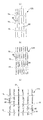
- FIG. 2 is a sectional view taken along line 2-2 of FIG.
- FIG. 3 is a cross-sectional view taken along the line 3-3 in FIG. 1.
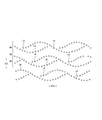
- FIG. 8 (A) 4-4 sectional view of FIG. 8 and (b) 5-5 sectional view of FIG. It is a top view which shows the example of arrangement
- FIG. 3D is a cross-sectional view of a contracted state of a portion passing only through the first hole row. It is a top view which expands and shows the principal part of the exterior body of the expansion
- FIG. 1 It is an expanded sectional view of a perforated nonwoven fabric. It is a top view which expands and shows the principal part of the exterior body of the expansion
- Hot melt adhesives can be applied by known methods such as slot coating, continuous line or dotted line bead coating, spiral coating, Z coating, etc., or pattern coating (transfer of hot melt adhesive in relief printing). Can be applied. Instead of or together with this, at the fixing portion of the elastic member, the hot melt adhesive can be applied to the outer peripheral surface of the elastic member, and the elastic member can be fixed to the adjacent member.
- hot melt adhesives examples include EVA, adhesive rubber (elastomer), olefin, and polyester / polyamide types, which can be used without any particular limitation.
- a joining means for joining the constituent members means by material welding such as heat sealing or ultrasonic sealing can be used.
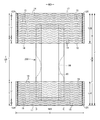
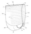
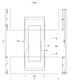
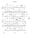
- the pants-type disposable diaper shown in FIGS. 1 to 6 includes a front exterior body 12F constituting the front body F, a rear exterior body 12B constituting the rear body B, and a rear exterior body from the front exterior body 12F through the crotch portion.
- An interior body 200 provided inside the exterior bodies 12F and 12B so as to extend to the body 12B. Both side portions of the front exterior body 12F and both side portions of the rear exterior body 12B are joined to form a side seal portion 12A.
- the openings formed by the front and rear end portions of the exterior bodies 12F and 12B become the waist openings WO through which the wearer's torso passes, and the lower edges of the exterior bodies 12F and 12B and the interior body 200 on both sides in the width direction of the interior body 200.
- the portions surrounded by the side edges are leg openings LO through which the legs pass.
- the interior body 200 is a portion that absorbs and holds excrement such as urine, and the exterior bodies 12F and 12B are portions that support the interior body 200 with respect to the wearer's body.
- the symbol Y in the figure indicates the total length of the diaper in the unfolded state (the length in the front-rear direction from the edge of the waist opening WO of the front body F to the edge of the waist opening WO of the back body B), and the symbol X in the unfolded state. The full width of the diaper is shown.
- the pants-type disposable diaper includes a waist region T defined as a front-rear direction range (a front-rear direction range extending from the waist opening WO to the upper end of the leg opening LO) having the side seal portion 12A, and a portion that forms the leg opening LO.
- An intermediate region L defined as a front-rear direction range (between a front-rear direction region having the side seal portion 12A of the front body F and a front-rear direction region having the side seal portion 12A of the rear body B).
- the waistline region T can be divided into a “waist portion” W that conceptually forms the edge of the waist opening and a “waist lower portion” U that is a lower portion than this.
- the waist opening WO side is more waist-like than the waist opening WO side boundary.
- the waist opening WO side becomes the waist portion W with respect to the absorbent body 56 or the interior body 200.
- These lengths in the front-rear direction vary depending on the size of the product and can be determined as appropriate.
- the waist portion W can be 15 to 40 mm and the waist lower portion U can be 65 to 120 mm.
- both side edges of the intermediate region L are wrapped in a U-shape or a curved shape along the circumference of the leg of the wearer, and this is a portion into which the wearer's leg is put.
- the unfolded pants-type disposable diaper has a substantially hourglass shape as a whole.
- the fixing of the inner body 200 to the outer bodies 12F and 12B is not particularly limited, and can be performed by, for example, a hot melt adhesive.
- the inner surface of the exterior body 12F, 12B is applied to the back surface of the interior body 200, that is, the back surface of the liquid-impermeable sheet 11 in this case and the hot melt adhesive applied to the root portion 65 of the rising gather 60. Is fixed.
- the inner / outer joint part 201 that fixes the inner body 200 and the outer bodies 12F and 12B can be provided in almost the entire region where both overlap, for example, the inner body 200 may be provided in a portion excluding both ends in the width direction. it can.
- the interior body 200 can take any shape, but is rectangular in the illustrated form. As shown in FIGS. 3 to 5, the interior body 200 includes a top sheet 30 on the body side, a liquid-impermeable sheet 11, and an absorbent element 50 interposed therebetween. Yes, it is the main body that takes up the absorption function.
- Reference numeral 40 denotes an intermediate sheet (second sheet) provided between the top sheet 30 and the absorbent element 50 in order to quickly transfer the liquid that has passed through the top sheet 30 to the absorbent element 50. Shows a rising gather 60 that extends from both sides of the interior body 200 so as to contact the legs of the wearer in order to prevent excrement from leaking to both sides of the interior body 200.
- the top sheet 30 has a property of allowing liquid to pass through, and examples thereof include a porous or non-porous nonwoven fabric, a porous plastic sheet, and the like.
- the nonwoven fabric is not particularly limited as to what the raw fiber is.
- synthetic fibers such as olefins such as polyethylene and polypropylene, polyesters and polyamides, recycled fibers such as rayon and cupra, natural fibers such as cotton, and mixed fibers and composite fibers using two or more of them. Etc. can be illustrated.
- the nonwoven fabric may be manufactured by any processing.
- processing method examples include known methods such as a spunlace method, a spunbond method, a thermal bond method, a melt blown method, a needle punch method, an air through method, and a point bond method.
- spunlace method a spunlace method
- thermal bond method a melt blown method
- melt blown method a melt blown method
- needle punch method an air through method
- point bond method a point bond method.
- the spunbond method and spunlace method are preferable.
- the air-through method, point bond method, and thermal bond method are preferable processing methods. .
- the top sheet 30 may be composed of one sheet or may be composed of a laminated sheet obtained by bonding two or more sheets. Similarly, the top sheet 30 may be composed of one sheet or two or more sheets in the planar direction.
- the both sides of the top sheet 30 may be folded back to the back side at the side edge of the absorbent element 50, or may be projected to the side from the side edge of the absorbent element 50 without being folded back.
- the top sheet 30 may be fixed to a member adjacent to the back side by a joining means by material welding such as heat sealing or ultrasonic sealing, or a hot melt adhesive for the purpose of preventing positional deviation with respect to the back side member. desirable.
- the top sheet 30 is fixed to the surface of the intermediate sheet 40 and the surface of the packaging sheet 58 located on the front side of the absorber 56 by a hot melt adhesive applied to the back surface thereof.
- An intermediate sheet (also referred to as “second sheet”) 40 having a higher liquid permeation rate than the top sheet 30 can be provided in order to quickly transfer the liquid that has permeated through the top sheet 30 to the absorber.
- This intermediate sheet 40 not only improves the absorption performance by the absorbent by quickly transferring the liquid to the absorbent body, but also prevents the “reversed” phenomenon of the absorbed liquid from the absorbent body, so that the top sheet 30 is always dried. It can be made into the state which carried out.
- the intermediate sheet 40 can be omitted.
- the intermediate sheet 40 examples include the same material as the top sheet 30, spunlace nonwoven fabric, spunbond nonwoven fabric, SMS nonwoven fabric, pulp nonwoven fabric, mixed sheet of pulp and rayon, point bond nonwoven fabric, or crepe paper.
- an air-through nonwoven fabric is preferable because it is bulky.
- the resin used for the core may be polypropylene (PP), but polyester (PET) having high rigidity is preferable.
- Basis weight is preferably 20 ⁇ 80g / m 2, more preferably 25 ⁇ 60g / m 2.
- the thickness of the raw fiber of the nonwoven fabric is preferably 2.0 to 10 dtex.
- the intermediate sheet 40 in the illustrated form is arranged in the center shorter than the width of the absorbent body 56, but may be provided over the entire width.
- the length in the longitudinal direction of the intermediate sheet 40 may be the same as the entire length of the diaper, may be the same as the length of the absorbent element 50, or may be within a short length range centered on the region that receives the liquid.
- the intermediate sheet 40 may be fixed to a member adjacent to the back side by a bonding means by material welding such as heat sealing or ultrasonic sealing, or a hot melt adhesive for the purpose of preventing positional displacement with respect to the back side member. desirable.
- the intermediate sheet 40 is fixed to the surface of the portion of the packaging sheet 58 located on the front side of the absorbent body 56 with a hot melt adhesive applied to the back surface thereof.
- the material of the liquid-impermeable sheet 11 is not particularly limited.
- a plastic film made of an olefin resin such as polyethylene or polypropylene, a laminated nonwoven fabric provided with a plastic film on the surface of the nonwoven fabric, or a plastic film For example, a laminated sheet in which a nonwoven fabric or the like is laminated and bonded to each other can be exemplified.
- the liquid-impermeable sheet 11 is preferably made of a liquid-impermeable and moisture-permeable material that is preferably used from the viewpoint of preventing stuffiness.
- a microporous plastic film obtained by kneading an inorganic filler in an olefin resin such as polyethylene or polypropylene, forming a sheet, and then stretching in a uniaxial or biaxial direction.
- an olefin resin such as polyethylene or polypropylene
- non-woven fabric using microdenier fibers leakproof reinforcement by reducing the voids of the fibers by applying heat or pressure, and methods such as coating with a superabsorbent resin or hydrophobic resin or water repellent
- a sheet that is liquid-impermeable without using a plastic film can also be used as the liquid-impermeable sheet 11.
- the liquid-impermeable sheet 11 has a width that can be accommodated on the back side of the absorbent element 50 as shown in the drawing, and in order to improve leakage prevention, the liquid-impermeable sheet 11 wraps around both sides of the absorbent element 50 so that the side of the top sheet 30 of the absorbent element 50 It can also extend to both sides.
- the width of this extended portion is suitably about 5 to 20 mm on the left and right.
- the rising gather 60 is for preventing side leakage, extends across the entire front-rear direction LD along both side portions of the interior body 200, and stands up from the side of the interior body 200 to the front side.
- the rising gather 60 in the illustrated example is such that the base side portion rises obliquely toward the center in the width direction, and the tip side portion rises obliquely outward in the width direction from the intermediate portion, but is not limited thereto. However, it is possible to make appropriate changes such as a configuration in which the whole stands up in the center in the width direction.
- the rising gather 60 in the illustrated example folds the belt-shaped gathered nonwoven fabric 62 having a length equal to the length in the front-rear direction of the interior body 200 in the width direction WD at the tip portion and folded in two.
- a plurality of elongated gather elastic members 63 are fixed along the longitudinal direction and spaced apart in the width direction WD between the folded portion and the sheet in the vicinity thereof.
- the base end portion (the end portion on the side opposite to the sheet folding portion in the width direction WD) of the rising gather 60 opposite to the front end portion is fixed to the side portion on the back side of the liquid-impermeable sheet 11 in the interior body 200.
- a portion 65 other than the root portion 65 is a main body portion 66 (a portion on the folded portion side) extending from the root portion 65.
- the main body portion 66 includes a root side portion extending toward the center in the width direction and a tip side portion that is folded back at the tip of the root side portion and extends outward in the width direction.
- This form is a surface contact type rising gather 60, but a line contact type rising gather 60 that is not folded outward in the width direction can also be used.
- the both ends of the front-back direction among the main body parts 66 are set to the fall-down part 67 fixed with respect to the side part surface of the top sheet 30 in a lying state, the front-back direction intermediate part located between these is not fixed.
- the gather elastic member 63 along the front-rear direction LD is fixed in an extended state to at least the tip of the free portion 68.
- the contraction force of the gather elastic member 63 acts so as to bring the both ends in the front-rear direction closer, but the both ends of the main body portion 66 are fixed so as not to stand up.
- the free portion 68 stands up so as to abut on the body side as indicated by an arrow in FIG.
- the free portion 68 stands up so as to open outward in the width direction at and around the crotch portion, so that the rising gather 60 abuts on the surface around the legs.
- the fit is improved.
- the absorption element 50 is not specifically limited, In this example, it has the absorber 56 and the packaging sheet 58 which wraps this absorber 56 whole.
- the packaging sheet 58 can be omitted.
- the absorber 56 can be formed of an aggregate of fibers.
- a filament assembly obtained by opening, as necessary, synthetic fiber tows (fiber bundles) such as cellulose acetate as well as short fibers such as cotton-like pulp and synthetic fibers Can also be used. It is preferable to disperse and hold superabsorbent polymer particles in the absorber 56.
- the absorber 56 may be rectangular, but as shown in FIG. 7, the absorber 56 includes a front end portion, a rear end portion, and a constricted portion 56 ⁇ / b> N that is located between these and narrower than the front end portion and the rear end portion.
- the hourglass shape is preferred because the fit of the absorber 56 and the rising gather 60 around the legs is improved.
- the size of the absorbent body 56 can be appropriately determined as long as it extends to the front, rear, left, and right of the urination port position, but preferably extends to the peripheral portion of the interior body 200 or the vicinity thereof in the front-rear direction LD and the width direction WD.
- Reference numeral 56X indicates the width of the absorber 56.
- the absorber 56 can contain superabsorbent polymer particles in a part or all thereof.
- Superabsorbent polymer particles include “powder” in addition to “particles”.
- the superabsorbent polymer particles 54 those used in this type of disposable diaper can be used as they are.
- the material of the superabsorbent polymer particles can be used without any particular limitation, but those having a water absorption of 40 g / g or more are suitable.
- Superabsorbent polymer particles include starch, cellulose and synthetic polymers, such as starch-acrylic acid (salt) graft copolymer, saponified starch-acrylonitrile copolymer, and sodium carboxymethylcellulose cross-link. Or an acrylic acid (salt) polymer can be used.
- As the shape of the superabsorbent polymer particles a commonly used granular material is suitable, but other shapes can also be used.
- the superabsorbent polymer particles those having a water absorption rate of 70 seconds or less, particularly 40 seconds or less are preferably used. If the water absorption speed is too slow, the liquid supplied into the absorber 56 is likely to cause a so-called reverse return that returns to the outside of the absorber 56.
- the superabsorbent polymer particles those having a gel strength of 1000 Pa or more are preferably used. Thereby, even if it is a case where it is set as the bulky absorber 56, the sticky feeling after liquid absorption can be suppressed effectively.
- the basis weight of the superabsorbent polymer particles can be appropriately determined according to the amount of absorption required for the use of the absorber 56. Therefore, although it cannot be generally stated, it can be 50 to 350 g / m 2 .
- tissue paper particularly crepe paper, non-woven fabric, polylaminated non-woven fabric, a sheet with small holes, or the like can be used.
- the superabsorbent polymer particles be a sheet that does not escape.
- a nonwoven fabric is used in place of the crepe paper, a hydrophilic SMS nonwoven fabric (SMS, SSMMS, etc.) is particularly suitable, and the material can be polypropylene, polyethylene / polypropylene composite material, or the like.
- the basis weight is preferably 5 to 40 g / m 2 , particularly 10 to 30 g / m 2 .
- the packaging form of the packaging sheet 58 can be determined as appropriate, but from the viewpoint of ease of manufacture and prevention of leakage of the superabsorbent polymer particles from the front and rear end edges, the cylinder is formed so as to surround the front and back surfaces and both side surfaces of the absorbent body 56. It is preferable that the front and rear edge portions protrude from the front and rear of the absorbent body 56, and the overlapping portion and the overlapping portion of the front and rear protruding portions are joined by a joining means such as hot melt adhesive or material welding.
- the exterior bodies 12F and 12B include a front exterior body 12F that is a part constituting the front body F and a rear exterior body 12B that is a part constituting the rear body B.
- the front exterior body 12F and the rear exterior body 12B Are not continuous on the crotch side and are spaced apart in the front-rear direction LD (exterior two-split type).
- This separation distance 12d can be, for example, about 40 to 60% of the total length Y.
- the exterior body 12 can also be made into the integral thing which continues between crotches from the front body F to the back body B (exterior integral type).
- the liquid-impermeable sheet 11 is not exposed on the back surface of the interior body 200.
- the cover nonwoven fabric 20 covering the back surface of the interior body 200 is preferably provided between the front exterior body 12F and the interior body 200 and between the rear exterior body 12B and the interior body 200.
- the material of the cover nonwoven fabric 20 is not particularly limited.
- the same material as the outer nonwoven fabric layer 12S or the inner nonwoven fabric layer 12H of the outer package 12 (a porous nonwoven fabric layer or a nonporous nonwoven fabric layer described later) may be used. .
- the front-rear direction range of the cover nonwoven fabric 20 is not particularly limited as long as it has portions overlapping the front exterior body 12F and the rear exterior body 12B, and extends in the front-rear direction LD over the entire front end to rear end of the interior body 200. As shown in FIG. 7, the intermediate position in the front-rear direction of the region where the rear exterior body 12B and the interior body 200 overlap from the front-rear direction intermediate position of the region where the front exterior body 12F and the interior body 200 overlap. It may extend in the front-rear direction LD.
- the exterior bodies 12F and 12B have a waistline portion that is a front-rear direction range corresponding to the waistline region T.
- the front exterior body 12F does not have a portion corresponding to the intermediate region L, but the rear exterior body 12B has a collar cover portion C that extends from the waist region T to the intermediate region L side. is doing.
- the front exterior body 12F is also provided with a collar cover portion that extends from the waistline region T toward the intermediate region L, a configuration that does not provide a collar cover portion while providing a groin cover portion, and the front exterior body 12F and It is not necessary to provide a portion corresponding to the intermediate region L in both of the rear exterior bodies 12B.
- the lower edge of the collar cover portion C is formed in a straight line shape along the width direction WD, similarly to the lower edge of the front exterior body 12F. It can also be a curve that becomes.
- the exterior bodies 12F and 12B are formed with the outer nonwoven fabric layer 12S and the inner nonwoven fabric layer 12H.
- the nonwoven fabric layer 12H is formed by folding one sheet material so that the crease is positioned on the waist opening side, and bonding two sheet materials together as shown in FIG. It can also be formed.
- the innermost portion 12r of these sheet materials can be extended to the end of the interior body 200 on the waist opening WO side (see the example in FIG. 9).
- at least one of the outer nonwoven fabric layer 12S and the inner nonwoven fabric layer 12H may be formed of a sheet material that is partially different from the other portions.
- constituent fibers of the outer nonwoven fabric layer 12S and the inner nonwoven fabric layer 12H for example, synthetic fibers such as olefins such as polyethylene or polypropylene, polyesters, and polyamides (including single-component fibers and composite fibers such as core sheaths)
- synthetic fibers such as olefins such as polyethylene or polypropylene, polyesters, and polyamides (including single-component fibers and composite fibers such as core sheaths)
- regenerated fibers such as rayon and cupra, natural fibers such as cotton, and the like can be selected without particular limitation, and these can also be used as a mixture.
- the constituent fibers are crimped fibers.
- the constituent fibers of the outer nonwoven fabric layer 12S and the inner nonwoven fabric layer 12H may be hydrophilic fibers (including hydrophobic fibers made hydrophilic by a hydrophilizing agent) or hydrophobic fibers or water repellent fibers (water repellent fibers). (Including water-repellent fibers made water-repellent by an agent).
- Nonwoven fabrics are generally short fiber nonwoven fabrics, long fiber nonwoven fabrics, spunbond nonwoven fabrics, meltblown nonwoven fabrics, spunlace nonwoven fabrics, thermal bond (air-through) nonwoven fabrics, needle punches, depending on fiber length, sheet formation method, fiber bonding method, and laminated structure. It is classified as non-woven fabric, point bond non-woven fabric, laminated non-woven fabric (SMS non-woven fabric with a melt-blown layer sandwiched between spunbond layers, SMMS non-woven fabric, etc.). Can do.
- the fineness and basis weight of the constituent fibers of the outer nonwoven fabric layer 12S and the inner nonwoven fabric layer 12H can be determined as appropriate, but in the normal case, they are preferably about 1.8 to 6.0 dtex and about 10 to 30 g / m 2 , respectively.
- At least one of the outer nonwoven fabric layer 12S and the inner nonwoven fabric layer 12H is a perforated nonwoven fabric in which holes 14 penetrating in the thickness direction are scattered.
- the inner nonwoven fabric layer 12H on the skin side of the wearer is a non-porous nonwoven fabric and the outer nonwoven fabric layer 12S is a porous nonwoven fabric, the influence on the touch of the holes 14 is eliminated. Can do.
- the hole 14 is provided in only one of the outer nonwoven fabric layer 12S and the inner nonwoven fabric layer 12H, the skin is not exposed at the time of wearing, and leakage through the hole 14 can be prevented.
- the inner nonwoven fabric layer 12H on the skin side of the wearer may be a perforated nonwoven fabric
- the outer nonwoven fabric layer 12S may be a nonporous nonwoven fabric.
- both the outer nonwoven fabric layer 12S and the inner nonwoven fabric layer 12H are perforated nonwoven fabrics, and the hole 14 of one perforated nonwoven fabric and the hole 14 of the other perforated nonwoven fabric do not overlap. It may be a structure. In this case, higher air permeability can be obtained by making both the outer nonwoven fabric layer 12S and the inner nonwoven fabric layer 12H porous.
- both the outer nonwoven fabric layer 12S and the inner nonwoven fabric layer 12H are perforated nonwoven fabrics, and the holes 14 of one perforated nonwoven fabric and the holes 14 of the other perforated nonwoven fabric are completely or partially. May overlap.
- both the outer nonwoven fabric layer 12S and the inner nonwoven fabric layer 12H are perforated nonwoven fabrics, in most cases (for example, an area of 50% or more), the holes 14 of one perforated nonwoven fabric and the other perforated nonwoven fabric are formed.
- the hole 14 of the porous nonwoven fabric does not overlap, in some cases, the hole 14 of one porous nonwoven fabric and the hole 14 of the other porous nonwoven fabric may overlap.
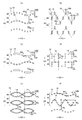
- each hole 14 has a long hole shape as shown in FIG. 10 (b), a true circle shape as shown in FIG. 10 (e), an elliptic shape as shown in FIGS. 10 (a), (d) and (f). Any shape such as a polygon such as a triangle, a rectangle, and a rhombus, a star, and a cloud can be used. As shown in FIG. 10 (c), holes having different shapes may be mixed, but in that case, it is preferable that the dimensions in the expansion / contraction direction are substantially the same, and that all the holes have a single shape. preferable.
- each hole 14 is not particularly limited, but the dimension 14L in the orthogonal direction XD (the dimension of the longest part) is preferably 0.3 to 5.0 mm, particularly preferably 0.6 to 2.0 mm.
- the ED dimension (longest part dimension) 14W is preferably 0.3 to 3.0 mm, particularly preferably 0.4 to 1.5 mm.
- shape of the hole 14 is a long shape in one direction such as a long hole shape, an ellipse shape, a rectangular shape, a rhombus shape, etc.
- the dimension in the longitudinal direction is preferably 1.2 to 2.5 times the dimension (longest dimension) in the direction perpendicular thereto.
- the longitudinal direction of the hole 14 is preferably the front-rear direction LD, but may be the width direction WD or an oblique direction.
- each hole 14 may be determined as appropriate, but the area is preferably about 0.1 to 2.7 mm 2 (particularly 0.1 to 1.0 mm 2 ). It is preferably about 0 to 15.0% (particularly 5.0 to 10.0%).
- the planar arrangement of the holes 14 in one perforated nonwoven fabric is not particularly limited.
- the outer nonwoven fabric layer 12S and the inner nonwoven fabric layer 12H are perforated nonwoven fabrics, the outer nonwoven fabric layer 12S and the inner nonwoven fabric layer 12H have at least one of the size, shape, and arrangement of the holes 14. May be different.
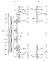
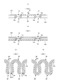
- a group of holes 90 arranged in a single wavy shape following the expansion / contraction direction ED are arranged at intervals in the orthogonal direction XD, and spaced apart so as to form a chain shape following the expansion / contraction direction ED.
- the group of holes 90 arranged side by side can be arranged at intervals in the orthogonal direction XD.
- the group 90 of holes arranged in a chain is not particularly limited as long as the portion where the holes 14 are arranged in a ring is repeated with an interval in the expansion / contraction direction ED.
- the group of holes 90 arranged so as to form a heavy wavy shape can be arranged at intervals in the orthogonal direction XD, or can be a chain as shown in FIG.
- “the group of holes 90 are arranged at intervals in the orthogonal direction XD” means that the non-hole portion 92 that continues straight along the expansion / contraction direction ED between the group of holes 90 adjacent in the orthogonal direction XD. It means having.
- the arrangement shape in the hole group 90 can be determined as long as it is the above-mentioned wave shape, and the arcuate curve peaks and valleys as shown in FIG. 10 (a) repeatedly follow a wave shape, or triangles as shown in FIG. 10 (b).
- a regular shape such as a wave shape, a rectangular wave shape as shown in FIG. 10 (d), a sinusoidal shape like the group of holes 90 in the middle of FIG. 10 (f), at least one of amplitude and wavelength is not shown.
- the interval 14x in the expansion / contraction direction ED of the holes 14 in the hole group 90 may be constant or may be changed and can be determined as appropriate. Considering the improvement in air permeability due to the holes 14, it is desirable that the thickness be in the range of 2.0 to 10 mm, particularly 3.0 to 5.0 mm.
- the outer nonwoven fabric layer 12S and the inner nonwoven fabric layer 12H are easily bent along the row 91 of holes. Therefore, in the arrangement of the holes 14 in the stretchable structure, as shown in the examples shown in FIGS. 10A, 10B, and 10D, the row of holes 91 arranged at intervals in the orthogonal direction XD is spaced from the stretch direction ED. If the holes are lined up, a series of ridges 80 (to be described later) such that the holes 14 are broken are easily formed. As a result, the ridges 80 are less likely to branch or the valleys are partially widened, and as a whole, the well-organized ridges 80 extending along the row of holes 91 are easily formed.
- the interval 14y in the orthogonal direction XD of the holes 14 in each hole row 91 changes as in the example shown in FIGS. 10A and 10B. If it is constant, it is preferable because the ridges 80 are more easily arranged.
- the interval 14y in the orthogonal direction XD of the holes 14 in the hole row 91 is preferably in the range of 0.9 to 8.0 mm, particularly 1.0 to 3.0 mm.
- the interval 14y in the orthogonal direction XD of the holes 14 in the hole row 91 may be longer than or equal to the interval 14x in the expansion / contraction direction ED of the holes 14 in the hole group 90, but short (2 to 2). It is desirable that it is about 5 times.
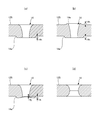
- the cross-sectional shape of the hole 14 is not particularly limited.
- the hole 14 may be a punching type hole whose periphery is formed by a cut end of a fiber as shown in FIG. 16 (d).
- 14 may be a non-punched hole 14 (the edge has a high fiber density) formed by having almost no cut ends of the fiber at the periphery of 14 and a pin inserted between the fibers and spread.
- the punching type hole may be smaller as the diameter of the hole 14 goes to the middle in the thickness direction, or smaller as it goes to the one side in the thickness direction. .
- the non-punched hole 14 is such that the diameter of the hole 14 decreases from the pin insertion side toward the opposite side. This includes a case where the diameter of the hole 14 continues to decrease over the entire thickness direction of the nonwoven fabric layer, and a case where the decrease in the diameter of the hole 14 almost disappears in the middle of the thickness direction.
- a fiber is pushed out to the edge of the hole 14 on the side opposite to the pin insertion side and pushed out to the side opposite to the pin insertion side.
- the part (burr) 14e is formed, and the protrusion 14e is not formed on the pin insertion side, and the fiber is inserted into the edge of the hole 14 on the side opposite to the pin insertion side as shown in FIG.
- the protrusion 14e pushed out to the opposite side is formed, and the pin insertion side includes the protrusion 14e formed by pushing out the fiber to the pin insertion side.
- the protrusion 14 e has a substantially uniform height 14 h as shown in FIG. 16A, and the protrusion 14 e as shown in FIG.
- the protruding portion 14e has a cylindrical shape continuously in the circumferential direction of the hole, the protruding portion 14e of a part or all of the holes 14 is formed only in a part of the circumferential direction of the hole 14. Also good.
- the projecting heights 14h, 14i, and 14j (apparent height when no pressure is measured using an optical microscope) is preferably about 0.2 to 1.2 mm.
- the highest protrusion height 14i in the protrusion 14e is preferably about 1.1 to 1.4 times the lowest protrusion height 14j.
- the protruding height of the protruding portion 14 e may change in the circumferential direction of the hole 14.
- a protruding portion (burr) 14e is formed in which the protruding height i of the opposing portion in the longitudinal direction of the hole 14 is higher than the protruding height j of the opposing portion in the direction orthogonal to the longitudinal direction.
- the protruding portion 14e of the hole 14 may have a fiber density that is lower than that of the surrounding portion, but is preferably the same or higher.
- the fineness, basis weight and thickness of the constituent fibers of the perforated nonwoven fabric can be determined as appropriate, but in the usual case, about 1.8 to 6.0 dtex, about 15 to 25 g / m 2 and about 0.1 to 1.3 mm, respectively. Is preferable.
- the bending resistance in the MD direction (width direction) of the perforated nonwoven fabric is preferably 35 to 100 mm, particularly 40 to 70 mm in a non-porous state before drilling, and 10 to 50 mm in the state after drilling.
- the thickness is preferably 15 to 40 mm.
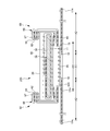
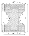
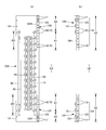
- an elongated elastic member 19 is provided between the outer nonwoven fabric layer 12S and the inner nonwoven fabric layer 12H, and an expansion / contraction region A2 is formed that elastically expands and contracts in the width direction WD as the elastic member 19 expands and contracts. ing. That is, in the stretchable region A2, in the natural length state, the outer nonwoven fabric layer 12S and the inner nonwoven fabric layer 12H are contracted with the contraction of the elastic member and have a large number of wrinkles 80. Further, when the stretchable region A2 is extended in the width direction WD, the outer nonwoven fabric layer 12S and the inner nonwoven fabric layer 12H are extended to a predetermined extension rate that can be extended without wrinkles 80.
- the elastic member 19 can be used in any shape, e.g., a thread shape, a string shape, and a belt shape, as long as it is elongated.
- the elastic member 19 may be made of synthetic rubber or natural rubber.
- the elastic member 19 is fixed to the outer nonwoven fabric layer 12S and the inner nonwoven fabric layer 12H at least at both ends in the stretching direction ED in the stretchable region A2.
- the fixing means for the elastic member 19 is not particularly limited, but it is preferable to use the hot melt adhesive 19H.
- the hot melt adhesive 19H is intermittently applied to the outer peripheral surfaces of both ends of the elastic member 19 in the expansion / contraction direction ED by an application means such as a comb gun or a sure wrap nozzle, the elastic member 19 can be sandwiched between the outer nonwoven fabric layer 12S and the inner nonwoven fabric layer 12H.
- the elastic member 19 is fixed to the outer nonwoven fabric layer 12S and the inner nonwoven fabric layer 12H via the hot melt adhesive 19H only at both ends in the stretching direction ED in the stretchable region.
- the elastic member 19 is applied to the outer nonwoven fabric layer 12S and the inner side. It can also be sandwiched between the nonwoven fabric layers 12H.
- the elastic member 19 is fixed to the outer nonwoven fabric layer 12S and the inner nonwoven fabric layer 12H in the longitudinal direction as well as both ends of the stretching direction ED in the stretchable region A2 at the arrangement site.
- the hot melt adhesive may be continuous in the orthogonal direction XD or may be intermittently disposed in the orthogonal direction XD. Further, in these cases, the continuous portion of the hot melt adhesive may extend over a plurality of elastic members.
- the elastic member 19 that is, the stretchable region at the following site. That is, a plurality of waist elastic members 17 are spaced in the front-rear direction so as to be continuous over the entire width direction WD between the outer nonwoven fabric layer 12S and the inner nonwoven fabric layer 12H in the waist portion W of the exterior bodies 12F and 12B. Attached. Moreover, about the 1 or several arrange
- the waist elastic member 17 has a thickness of 155 to 1880 dtex, particularly about 470 to 1240 dtex (in the case of synthetic rubber.
- the cross-sectional area is 0.05 to 1.5 mm 2 , particularly 0.1 to 1.
- the rubber thread 0mm about 2), 4 is preferably provided about 3 to 22 present at intervals of ⁇ 12 mm, which by extension ratio in the width direction WD of the waist portion W 150 to 400% especially about 220-320% Preferably there is.
- the waist portion W does not need to use the same thickness waist portion elastic member 17 in all of the front-rear direction LD or have the same elongation rate. The thickness and elongation rate may be different.
- a plurality of waist lower part elastic members 15 made of an elongated elastic member are attached at intervals in the front-rear direction between the outer nonwoven fabric layer 12S and the inner nonwoven fabric layer 12H in the waist lower part U of the exterior bodies 12F and 12B. It has been.
- the waist lower elastic member 15 has a thickness of 155 to 1880 dtex, especially about 470 to 1240 dtex (in the case of synthetic rubber.
- the cross-sectional area is 0.05 to 1.5 mm 2 , particularly 0.1 to 1.
- the rubber thread 0mm about 2), 1 ⁇ 15mm, especially 3 to is preferably provided about 5 to 30 yarns at intervals of 8 mm, which by 200 to 350% elongation modulus in the width direction WD of the waist lower portion U, especially It is preferably about 240 to 300%.
- cover elastic members 16 made of an elongated elastic member are attached at intervals in the front-rear direction between the outer nonwoven fabric layer 12S and the inner nonwoven fabric layer 12H in the buttock cover portion C of the rear exterior body 12B. ing.
- the cover elastic member 16 has a thickness of 155 to 1880 dtex, especially about 470 to 1240 dtex (in the case of synthetic rubber.
- the cross-sectional area is 0.05 to 1.5 mm 2 , particularly 0.1 to 1.0 mm. It is preferable to provide about 2 to 10 thread rubbers with an interval of 5 to 40 mm, particularly 5 to 20 mm, and the extension ratio of the cover portion in the width direction WD is 150 to 300%, particularly 180 to 260. % Is preferred.
- a cover portion elastic member When providing an inguinal cover portion on the front exterior body 12F, a cover portion elastic member can be similarly provided.
- Non-stretchable area When the elastic members 15 and 16 are provided in the front-rear direction range having the absorber 56 like the lower waist portion U and the buttock cover portion C in the illustrated example, a part or all of the elastic members 15 and 16 in the width direction WD of the absorber 56.
- the intermediate in the width direction preferably including the entire inner / outer joint portion 201 including part or all of the portion overlapping the absorber 56 and the width direction WD is defined as the non-stretchable region A1, and the width direction Both sides are taken as the stretchable area A2.
- the waist portion W is preferably the stretchable region A2 over the entire width direction WD, but similarly to the waist lower portion U, a non-stretchable region A1 may be provided in the middle in the width direction.
- the stretchable region A2 and the non-stretchable region A1 supply the elastic members 15 and 16 between the inner nonwoven fabric layer 12H and the outer nonwoven fabric layer 12S, and the elastic members 15 and 16 are at least both ends in the stretchable direction ED in the stretchable region A2.
- the elastic members 15 and 16 are pressed and applied at one place in the middle of the width direction in the region that becomes the non-stretchable region A1. It can be constructed by cutting by heating, or by cutting almost the entire elastic members 15 and 16 finely by pressurization and heating, leaving the stretchability in the stretchable region A2 and killing the stretchability in the non-stretchable region A1. . In the former case, as shown in FIG.
- the non-stretchable region A1 has an outer nonwoven fabric in a state in which the uncut stretched region A2 is continuously cut from the elastic members 15 and 16 of the stretchable region A2 to the natural length alone as the unnecessary elastic member 18. In the latter case, it remains between the layer 12S and the inner nonwoven fabric layer 12H.
- the cut residue continuous from the elastic members 15 and 16 in the elastic region A2 and the elastic members 15 and 16 in both elastic regions A2 are continuous.
- the cut piece of the elastic member that is not left is left between the outer nonwoven fabric layer 12 ⁇ / b> S and the inner nonwoven fabric layer 12 ⁇ / b> H in a state where the cut piece of the elastic member is contracted to the natural length alone as an unnecessary elastic member.
- the stretchable region A2 has a sheet joining portion 70 in which the outer nonwoven fabric layer 12S and the inner nonwoven fabric layer 12H are joined via a hot melt adhesive 19H.
- the agent 19H is applied in a striped pattern that is spaced substantially in the orthogonal direction XD and substantially linearly continuous in the expansion / contraction direction ED.
- the sheet joining portion 70 is formed at an interval in at least the orthogonal direction XD orthogonal to the expansion / contraction direction ED, good air permeability and flexibility can be ensured.
- the outer nonwoven fabric layer 12S and the inner nonwoven fabric layer 12H are integrated in each sheet joint portion so that they can be deformed only along each other.
- the outer nonwoven fabric layer 12S and the inner nonwoven fabric layer 12H are in contact with each other in a state where the outer nonwoven fabric layer 12S and the inner nonwoven fabric layer 12H are contracted as the elastic member contracts, including the natural length state.
- the wrinkles 80 are formed on both the front and back surfaces in a corrugated shape.
- the shape of the outer nonwoven fabric layer 12S and the inner nonwoven fabric layer 12H in the sheet bonding portion 70 is generally followed in FIG.
- the outer nonwoven fabric layer 12S and the inner nonwoven fabric layer 12H are wavy so that they are along each other, and ridges 80 are formed on both front and back surfaces.
- Such a ridge 80 bends gently due to the difference in the hardness of the sheet bonding portion 70 and the curvature of the outer nonwoven fabric layer 12S and the inner nonwoven fabric layer 12H, as well as the improvement in rigidity due to the number of nonwoven fabric layers.
- the touch is smooth and is easily crushed in the thickness direction, and the touch flexibility is improved.
- the sheet bonding portion 70 may be continuous over the entire expansion / contraction direction ED of the expansion / contraction region A2, but may be continuous only in a part of the range where the plurality of ridges 80 are formed.
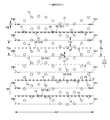
- the hole group 90 is arranged in a wave shape as described above, and both peak positions in the hole group 90 (a cycle in which the total amplitude is minimum when the total amplitude changes).
- the gap 90y in the orthogonal direction XD of the holes 14 at the peak positions of both the peaks and valleys of the sheet is equal to the application width of the hot melt adhesive 19H (the dimension in the orthogonal direction XD of the coating line. .) It ’s bigger.
- the number of the holes 14 intersecting with the hot melt adhesive 19H is reduced and crossed. No holes 14 will be produced.
- the area of the missing portion in the sheet joining portion 70 is small and sparse, so that it is difficult to peel off.
- the hole group 90 is densely arranged in the expansion / contraction direction ED when the interval 14x in the expansion / contraction direction ED of the hole 14 is about 2 to 5 times the dimension 14W of the expansion / contraction direction ED of the hole 14, Highly breathable. Even when the holes 14 are densely arranged in the expansion / contraction direction ED as described above, the hole group 90 has a wave shape as described above, so that the holes 14 are arranged at intervals in the orthogonal direction XD. Even if a part of the application position of the hot melt adhesive 19H passes through the group of holes 90, the number of holes 14 that intersect with each other is reduced, and as a result, non-intersecting holes 14 are generated. It becomes difficult to become.
- the interval 90y in the orthogonal direction XD of the holes 14 at both peak positions in the hole group 90 can be determined as appropriate, but is particularly preferably 1 to 6 times the application width of the hot melt adhesive 19H.
- the arrangement of the holes 14 in the stretchable structure is such that the row 91 of holes arranged at intervals in the orthogonal direction XD is arranged at intervals in the stretch direction ED, the outer nonwoven fabric layer 12S and the inner nonwoven fabric layer 12H are It becomes easy to bend along the row 91 of holes.
- a continuous ridge 80 in which the hole 14 becomes a fold is easily formed. That is, it is difficult for the ridges 80 to branch or the valleys to be partially widened, and as a whole, the well-formed ridges 80 extending along the rows of the holes 14 are easily formed.
- the interval 91 y in the orthogonal direction XD of the holes 14 in the hole row 91 is narrower than the interval 70 y in the orthogonal direction XD of the sheet bonding portion 70, one or more holes 14 exist in the region between the adjacent sheet bonding portions 70. Therefore, it is preferable.
- the interval 91 y in the orthogonal direction XD of the holes 14 in the row of holes 14 is 1/6 or more and less than 1/2 of the interval 70 y in the orthogonal direction XD of the sheet bonding portions 70, Since two or more holes 14 exist in all of the regions, a series of ridges 80 in which the holes 14 are broken are more easily formed. Therefore, it becomes easy to form the collar 80 further arranged.
- the group of holes 90 is wavy, even if the above condition is not satisfied, one or more holes 14 are present in a region between adjacent sheet joining portions 70 to some extent.
- the interval 91 y in the orthogonal direction XD of the holes 14 in the first hole row is longer than the interval in the orthogonal direction XD of the waist elastic member 19.
- the sheet bonding portion 70 is not particularly limited as long as it is formed in a striped pattern that is spaced in the orthogonal direction XD and substantially continuous in the expansion / contraction direction ED.
- the sheet joining portion 70 may be formed only by the hot melt adhesive 19 ⁇ / b> H disposed in a portion overlapping the elastic member 19.
- Such a sheet joint portion 70 can be manufactured by sandwiching the elastic member 19 coated with the hot melt adhesive 19H between the outer nonwoven fabric layer 12S and the inner nonwoven fabric layer 12H, and is widely used in the field of disposable wearing articles. It is used.
- the force tends to concentrate on the sheet joining portion.
- the hole group 90 has a wave shape as described above, even if a part of the application position of the hot melt adhesives 19H and 70H arranged at intervals in the orthogonal direction XD passes through the hole group 90, As a result, the number of intersecting holes 14 is reduced, and holes 14 that do not intersect are also generated. As a result, the sheet bonding portion 70 is not easily peeled off.
- a stretch direction is formed in a region located between the elastic members 19 adjacent to each other in the orthogonal direction XD.
- the sheet joint portion 70 can also be formed by applying the hot melt adhesive 70H in a pattern that is substantially continuous with the ED.
- the hot melt adhesive 19H for fixing both ends of the elastic member 19 may join the outer nonwoven fabric layer 12S and the inner nonwoven fabric layer 12H.
- the dimension 70L of the sheet bonding portion 70 in the orthogonal direction XD can be determined as appropriate, but is preferably short, and is preferably 0.2 to 0.6 times the space 19y between adjacent elastic members 19 in the orthogonal direction XD, particularly 0.3. It is preferable that the ratio is 0.5 times.
- the cross-sectional structure of the hole 14 is not particularly limited, but the diameter of the hole 14 is the non-woven fabric layer side facing from the opposite side of the facing non-woven fabric layer side (for example, in the example shown in FIGS. 11 and 12). If it becomes smaller as it goes from the outer side of the outer nonwoven fabric layer 12S to the inner side), it is easy to bend so that the opposite surface of the nonwoven fabric layer is valley-folded, as in the example shown in FIGS.
- some of the sheet bonding portions 70 may be arranged so as to pass through the holes 14, but in that case, if the sheet bonding portions 70 are formed by the hot melt adhesive 19 ⁇ / b> H, the hot bonding from the holes 14 may be performed.
- the melt adhesive 19H is exposed.
- the hot melt adhesive 19H exposed from the holes 14 is difficult to touch the skin.
- the diameter of the holes 14 of the porous nonwoven fabric is opposite to the opposing nonwoven fabric layer side.
- the wrinkle 80 formed in the inner side nonwoven fabric layer 12H turns into a thin wrinkle, and an outer side nonwoven fabric layer
- the ridges 80 formed in 12S are thick folds that bend gently.
- the contact area between the inner nonwoven fabric layer 12H and the skin is small, and the gap between the heel and the heel increases, so that the air permeability is particularly excellent.
- the ridges 80 of the outer nonwoven fabric layer 12S are less likely to be deformed to impair the beauty such as falling down, and have excellent shape stability.
- the specific dimensions and arrangement of the holes 14 and the sheet bonding portion 70 can be determined as appropriate, but the arrangement of the holes 14 is such that the row of holes 91 arranged at intervals in the orthogonal direction XD is spaced from the expansion / contraction direction ED. In the case where they are lined up, it is particularly preferable that they are within the following ranges.
- seat junction part 70 can also be provided only in the expansion-contraction area
- the sheet joining portion 70 in the above example is a portion where the outer nonwoven fabric layer 12S and the inner nonwoven fabric layer 12H are joined via the hot melt adhesives 19H and 70H, but the outer nonwoven fabric layer 12S and the inner nonwoven fabric layer 12H are welded. It may be a part. That is, at the time of forming the sheet bonding portion 70, the outer nonwoven fabric layer 12S and the inner nonwoven fabric layer 12H may be welded in a striped pattern spaced in the orthogonal direction XD and continuous in the orthogonal direction XD. In this case, the elastic member 19, the outer nonwoven fabric layer 12S, and the inner nonwoven fabric layer 12H may be welded or not welded at the passing position of the elastic member 19.
- the melted portions of the outer nonwoven fabric layer 12S and the inner nonwoven fabric layer 12H are the outer nonwoven fabric layer 12S and the inner nonwoven fabric layer. At least one of 12H is continuous in the orthogonal direction XD.
- “Front-rear direction” means the direction (vertical direction) indicated by LD in the figure
- “width direction” means the direction indicated by WD (left-right direction) in the figure
- the front-rear direction and the width direction are It is orthogonal.
- -"MD direction” and “CD direction” mean the flow direction (MD direction) in production equipment and the transverse direction (CD direction) perpendicular thereto, and either one is the front-rear direction, and the other Is the width direction.
- the MD direction of the nonwoven fabric is the direction of fiber orientation of the nonwoven fabric.
- the fiber orientation is the direction along which the fibers of the nonwoven fabric are aligned. For example, the fiber orientation can be determined from the measurement method according to the TAPPI standard method T481, the fiber orientation test method using the zero-range tensile strength, It can be discriminated by a simple measuring method for determining the orientation direction.
- Center for a closed planar shape means the center of gravity in the case of a figure that does not have a center.
- -“Area ratio” means the ratio of the target portion to the unit area, and is expressed as a percentage by dividing the total area of the target portion (for example, holes) in the target region (for example, non-woven fabric) by the area of the target region. is there.
- the target region In a form in which a large number of target portions are provided at intervals, it is desirable to set the target region to a size that includes 10 or more target portions and obtain the area ratio.
- the area ratio of the holes can be measured by the following procedure using, for example, a trade name VHX-1000 of KEYENCE Corporation, with the measurement condition set to 20 times. (1) Set on a 20x lens and adjust the focus. The position of the nonwoven fabric is adjusted so that the holes are 4 ⁇ 6.
- Elongation rate means a value when the natural length is 100%.
- an expansion rate of 200% is synonymous with an expansion ratio of 2 times.
- ⁇ “Weighing” is measured as follows. After the sample or test piece has been pre-dried, it is left in a test room or apparatus in a standard state (test location is temperature 23 ⁇ 1 ° C., relative humidity 50 ⁇ 2%) to a constant weight. Pre-drying refers to making a sample or test piece constant in an environment at a temperature of 100 ° C. In addition, it is not necessary to perform preliminary drying about the fiber whose official moisture content is 0.0%. From the test piece in a constant weight state, a sample plate (100 mm ⁇ 100 mm) is used to cut a sample having a size of 100 mm ⁇ 100 mm. The weight of the sample is measured, multiplied by 100, and the weight per square meter is calculated and used as the basis weight.
- Thickness is automatically measured using an automatic thickness measuring instrument (KES-G5 handy compression measurement program) under the conditions of load: 0.098 N / cm 2 and pressure area: 2 cm 2 .
- the water absorption rate is the "time to end point" when JIS K7224-1996 "Water absorption rate test method for superabsorbent resin" is performed using 2 g of superabsorbent polymer and 50 g of physiological saline. .
- “Bending softness” means “8.21.1 A method (45 ° cantilever method)” of JIS L 1096: 2010 “Fabric and knitted fabric testing method”.
- the value of the porous nonwoven fabric before punching is the same as the non-porous nonwoven fabric (fiber composition, fineness, basis weight, thickness, etc.).
- Unfolded state means a state of being flattened without contraction or slack.
- the dimensions of each part mean dimensions in the expanded state, not the natural length state.
- test and measurement shall be performed in a test room or equipment in the standard state (test location: temperature 23 ⁇ 1 ° C, relative humidity 50 ⁇ 2%). To do.
- the present invention can be used for general disposable wearing articles such as pants-type disposable diapers and tape-type disposable diapers, pad-type disposable diapers, disposable swimwear, diaper covers, sanitary napkins and the like.
- SYMBOLS 11 Liquid impervious sheet, 12 ... Exterior body, 12A ... Side seal part, 12B ... Rear side exterior body, 12F ... Front side exterior body, 12H ... Inner nonwoven fabric layer, 12S ... Outer nonwoven fabric layer, 14 ... Hole, 14e ... Projection, 18 ... unnecessary elastic member, 19 ... elastic member, 19H, 70H ... hot melt adhesive, 20 ... cover nonwoven fabric, 200 ... interior body, 201 ... inner / outer joint, 30 ... top sheet, 40 ... intermediate sheet, 50 DESCRIPTION OF SYMBOLS ... Absorbing element, 56 ... Absorber, 58 ... Packaging sheet, 60 ... Gathering gather, 62 ...
Abstract
[Problem] To provide a stretchable structure which has good breathability and flexibility and is less prone to separation at sheet joining parts. [Solution] The problem can be solved by a stretchable structure for a disposable wearable article which has thin and long elastic members 19 disposed at intervals in a perpendicular direction XD between an outer nonwoven fabric layer 12S and an inner nonwoven fabric layer 12H and extending in a stretch direction ED. The outer nonwoven fabric layer 12S and the inner nonwoven fabric layer 12H have sheet joining parts 70 at which the outer nonwoven fabric layer 12S and the inner nonwoven fabric layer 12H are joined through hot-melt adhesive 19H, 70H applied in a stripe pattern which is substantially linearly continuous in the stretch direction ED. At least one of the outer nonwoven fabric layer 12S and the inner nonwoven fabric layer 12H is a porous nonwoven fabric, and pores 14 of the stretchable structure are arranged so that groups 90 of pores arranged in a single wave shape continuous in the stretch direction ED are arranged at intervals in the perpendicular direction XD. The distance 90y in the perpendicular direction XD between pores 14 at peak positions in each pore group 90 is greater than the width 70L of the applied hot melt adhesive 19H, 70H.
Description
本発明は、使い捨て着用物品の伸縮構造、及びこの伸縮構造を有するパンツタイプ使い捨て着用物品に関するものである。
The present invention relates to a stretchable structure of a disposable wearing article and a pants-type disposable wearing article having the stretchable structure.
使い捨て着用物品においては、各部のフィット性を改善するために伸縮構造を設けることが一般的となっている。例えば、パンツタイプやテープタイプの使い捨ておむつにおいては、胴周り部に胴周り方向の伸縮構造を設けたり、脚周り部に脚周りに沿う方向の伸縮構造を設けたりすることが広く行われている。さらに、パンツタイプやテープタイプの使い捨ておむつはもちろん、生理用ナプキンを含めた使い捨て着用物品全般にわたり、立体ギャザーや平面ギャザーと呼ばれる前後方向の伸縮構造を設けることも広く行われている(例えば、特許文献1~3参照)。
In disposable wearing articles, it is common to provide a stretchable structure in order to improve the fit of each part. For example, in a disposable diaper of a pants type or a tape type, it is widely performed to provide a stretchable structure in the waistline direction at the waistline part or to provide a stretchable structure in a direction along the leg circumference at the leg circumference part. . Furthermore, in addition to pants-type and tape-type disposable diapers, a wide range of disposable wearing articles including sanitary napkins are also widely used to provide longitudinal stretch structures called three-dimensional gathers and flat gathers (for example, patents). Reference 1 to 3).
このような使い捨て着用物品の伸縮構造の代表的なものは、重なり合う第1不織布層及び第2不織布層の間に、伸縮方向に沿ってかつ互いに間隔を空けて設けられた細長状の弾性部材を備えるものである。第1不織布層及び第2不織布層は面状の伸縮領域を形成するとともに、弾性部材を被覆、隠蔽する役割を担い、第1不織布層及び第2不織布層間に内蔵される弾性部材は、弾性伸縮のための力を生み出す役割を担うものである。弾性部材は、伸縮方向に伸長された状態で、少なくとも伸縮領域の両端部に位置する部分が第1不織布層及び第2不織布層に固定される。この固定により、弾性部材と第1不織布層及び第2不織布層とが一体化され、第1不織布層及び第2不織布層は弾性部材の収縮力により収縮して襞(皺状のものを含む。自然長状態だけでなく、弾性部材が伸長した状態でも形成される。)が形成され、またこの収縮状態から弾性部材の収縮力に抗して伸長されると、襞が展開される。通常、第1不織布層及び第2不織布層は弾性伸長限界では襞が無い展開状態となり、弾性部材の収縮に伴って襞が寄り、自然長状態では最も密に襞が寄る。
A typical example of such a stretchable structure for a disposable wearing article is an elongated elastic member provided between the overlapping first nonwoven fabric layer and the second nonwoven fabric layer along the stretch direction and spaced from each other. It is to be prepared. The first non-woven fabric layer and the second non-woven fabric layer form a planar stretchable region and play a role of covering and concealing the elastic member, and the elastic member built in between the first non-woven fabric layer and the second non-woven fabric layer is elastic stretch It plays the role of generating power for The elastic member is fixed in the first nonwoven fabric layer and the second nonwoven fabric layer at least at both ends of the stretchable region in the stretched state. By this fixing, the elastic member, the first nonwoven fabric layer, and the second nonwoven fabric layer are integrated, and the first nonwoven fabric layer and the second nonwoven fabric layer are contracted by the contraction force of the elastic member, and include wrinkles (including ridges). When the elastic member is stretched not only in the natural length state but also in a stretched state), and when the elastic member is stretched against the contraction force of the elastic member, the wrinkles are deployed. Usually, the first nonwoven fabric layer and the second nonwoven fabric layer are in a developed state having no wrinkles at the limit of elastic elongation, wrinkles are accompanied with the contraction of the elastic member, and wrinkles are most closely gathered in the natural length state.
このような伸縮構造では、第1不織布層及び第2不織布層が互いに自由であると、一方の不織布層が他方の不織布層に対して部分的又は全体的に浮いて不必要な襞や膨らみを生じるおそれがあるため、第1不織布層及び第2不織布層はそのほぼ全体にわたり直接的又は間接的に接合されている必要がある。以下、第1不織布層及び第2不織布層の接合部はシート接合部という。また、弾性部材により伸縮性を生み出すため、弾性部材は伸縮領域の伸縮方向の全体にわたり延在され、かつ少なくとも伸縮領域の伸縮方向の両端部に位置する部分は第1不織布層及び第2不織布層に対して固定され、自然長状態では弾性部材の収縮に伴い第1不織布層及び第2不織布層も収縮されている必要がある。つまり、第1不織布層及び第2不織布層間の接合と、第1不織布層及び第2不織布層に対する弾性部材の固定とが必要となるのである。
In such a stretchable structure, when the first nonwoven fabric layer and the second nonwoven fabric layer are free from each other, one nonwoven fabric layer partially or entirely floats with respect to the other nonwoven fabric layer, thereby causing unnecessary wrinkles and swelling. Since there exists a possibility that it may arise, the 1st nonwoven fabric layer and the 2nd nonwoven fabric layer need to be joined directly or indirectly over the whole. Hereinafter, the joint portion between the first nonwoven fabric layer and the second nonwoven fabric layer is referred to as a sheet joint portion. Moreover, in order to produce elasticity by an elastic member, an elastic member is extended over the whole expansion-contraction direction of an expansion-contraction area | region, and the part located in the both ends of the expansion-contraction direction of an expansion-contraction area | region is a 1st nonwoven fabric layer and a 2nd nonwoven fabric layer In the natural length state, the first nonwoven fabric layer and the second nonwoven fabric layer need to be contracted as the elastic member contracts. That is, it is necessary to join the first nonwoven fabric layer and the second nonwoven fabric layer and to fix the elastic member to the first nonwoven fabric layer and the second nonwoven fabric layer.
現在では、弾性部材を第1不織布層及び第2不織布層に固定する手段としては、ほとんどの場合、ホットメルト接着剤が選択されている。一方、第1不織布層及び第2不織布層間の接合は、ホットメルト接着剤の使用量を低減するために、超音波溶着等の溶着により行うことも多くなってきているが、ホットメルト接着剤も根強く利用されている。例えば、弾性部材の通過位置でホットメルト接着剤を介して第1不織布層及び第2不織布層を接合することにより、第1不織布層及び第2不織布層の接合と、第1不織布層及び第2不織布層に対する弾性部材の固定とを兼ねる兼用構造は広く採用されている。また、伸縮方向に間欠的に配された、伸縮方向と直交する方向(以下、単に直交方向ともいう)に連続するシート接合部で第1不織布層及び第2不織布層が接合された構造や、直交方向における弾性部材の間の位置で直交方向に間欠的に配された、伸縮方向に実質的に連続するシート接合部で第1不織布層及び第2不織布層が接合された構造が知られている。(特許文献1~6参照)
At present, as a means for fixing the elastic member to the first nonwoven fabric layer and the second nonwoven fabric layer, a hot melt adhesive is almost always selected. On the other hand, the bonding between the first nonwoven fabric layer and the second nonwoven fabric layer is often performed by welding such as ultrasonic welding in order to reduce the amount of hot melt adhesive used. It is used persistently. For example, by joining the first nonwoven fabric layer and the second nonwoven fabric layer via a hot melt adhesive at the passing position of the elastic member, the first nonwoven fabric layer and the second nonwoven fabric layer can be joined. A dual-purpose structure that also serves to fix the elastic member to the nonwoven fabric layer is widely used. In addition, a structure in which the first nonwoven fabric layer and the second nonwoven fabric layer are joined at a sheet joining portion that is intermittently arranged in the stretching direction and continues in a direction orthogonal to the stretching direction (hereinafter also simply referred to as an orthogonal direction), A structure is known in which the first nonwoven fabric layer and the second nonwoven fabric layer are joined at a sheet joining portion that is intermittently arranged in the orthogonal direction at a position between the elastic members in the orthogonal direction and that is substantially continuous in the stretching direction. Yes. (See Patent Documents 1 to 6)
他方、主に通気性を改善するために、第1不織布層及び第2不織布層に厚み方向に貫通する孔を設けることが提案されている(例えば特許文献7~9参照)。
On the other hand, in order to mainly improve air permeability, it has been proposed to provide holes penetrating in the thickness direction in the first nonwoven fabric layer and the second nonwoven fabric layer (see, for example, Patent Documents 7 to 9).
このうち、特許文献7,8記載のものは、一方の不織布層の全面にスパイラル状又はストライプ状に塗布された接着剤により、第1不織布層及び第2不織布層の接合と、第1不織布層及び第2不織布層に対する弾性部材の固定とがなされているものである。また、第1不織布層及び第2不織布層における孔の形成は、第1不織布層及び第2不織布層の接合前又は接合後に、溶融、切り抜き、打ち抜きにより行うものである。
Among these, the ones described in Patent Documents 7 and 8 are bonded to the first nonwoven fabric layer and the second nonwoven fabric layer by an adhesive applied in the form of a spiral or stripe on the entire surface of one nonwoven fabric layer, and the first nonwoven fabric layer. And the elastic member is fixed to the second nonwoven fabric layer. Moreover, the formation of the holes in the first nonwoven fabric layer and the second nonwoven fabric layer is performed by melting, cutting out, or punching before or after joining the first nonwoven fabric layer and the second nonwoven fabric layer.
一方、特許文献9記載のものは、伸縮方向及びこれと直交する方向に間隔を空けて第1不織布層及び第2不織布層の接合部を溶着により形成した後、この接合部に重ねて孔を形成するものである。
On the other hand, the one described in Patent Document 9 is formed by welding the joint portions of the first nonwoven fabric layer and the second nonwoven fabric layer with an interval in the expansion / contraction direction and the direction orthogonal thereto, and then overlapping the joint portions with holes. To form.
しかしながら、特許文献7,8記載のものにおいて、接着剤の塗布パターンがスパイラル状である場合、第1不織布層及び第2不織布層の接合が全面となるため、孔以外の部分における通気性が低下するとともに、柔軟性も低下する(剛性が高くなる)おそれがある。
However, in the thing of patent document 7, 8, when the application pattern of an adhesive agent is spiral shape, since the joining of a 1st nonwoven fabric layer and a 2nd nonwoven fabric layer becomes the whole surface, the air permeability in parts other than a hole falls. In addition, there is a risk that flexibility may be reduced (rigidity may be increased).
また、特許文献7,8記載のものにおいて、接着剤の塗布パターンがストライプ状である構造や、特許文献9記載の構造のように、シート接合部が伸縮方向に間欠的に配されている場合、伸縮方向におけるシート接合部の間の部分が互いに反対向きに膨らむことにより襞が形成される。しかし、この伸縮構造は、自然長状態での柔らかさは必ずしも十分ではない。これには、次のような構造上の相違が影響しているものと考えられる。すなわち、この伸縮構造では、自然長状態で伸縮方向に薄い襞が伸縮方向と直交する方向に連続し、その襞の先端が小さな曲率半径で屈曲して素材の折り目を形成するとともに、この折目を有する襞が同じ高さで近接して整列するため、襞は厚み方向に潰れにくく、かつ倒れにくい。しかも、襞の先端が小さな曲率半径で屈曲していると、先端に触れたときに特に硬い感触がするのである。
Moreover, in the thing of patent document 7, 8, when the application | coating pattern of an adhesive is a stripe form, and the structure of patent document 9 WHEREIN: When the sheet | seat junction part is distribute | arranged intermittently in the expansion-contraction direction The portions between the sheet joining portions in the expansion / contraction direction swell in opposite directions to form a wrinkle. However, this stretchable structure is not necessarily sufficiently soft in the natural length state. This can be attributed to the following structural differences. That is, in this stretchable structure, a thin ridge in the stretch direction in a natural length state continues in a direction perpendicular to the stretch direction, and the tip of the fold is bent with a small radius of curvature to form a crease in the material. Since the wrinkles having the same height are closely arranged at the same height, the wrinkles are not easily crushed in the thickness direction and are not easily collapsed. Moreover, if the tip of the heel is bent with a small radius of curvature, a particularly hard feel is felt when the tip is touched.
これに対し、上述の兼用構造等のように、直交方向に間欠的に配された、伸縮方向に実質的に連続するシート接合部を有する伸縮構造は、自然長状態での手触りが柔軟になる特徴を有する。これには、次のような構造上の相違が影響しているものと考えられる。すなわち、シート接合部が伸縮方向に実質的に連続していると、各シート接合部では第1不織布層及び第2不織布層が一体化していることにより互いに沿うようにしか変形できない。この結果、シート接合部及びその近傍では、自然長状態を含め、弾性部材の収縮に伴い第1不織布層及び第2不織布層が収縮した状態で、第1不織布層及び第2不織布層が互いに沿うような波状をなして表裏両面に襞が形成される。また、この影響を受けて、隣り合うシート接合部の間の領域においても、概ね、シート接合部における第1不織布層及び第2不織布層の形状に続くように、第1不織布層及び第2不織布層が互いに沿うような波状をなしてその表裏両面に襞が形成される。そして、このような襞においては、単なる不織布層数による剛性向上だけでなく、シート接合部の硬さ及び第1不織布層及び第2不織布層の曲率の違いにより、緩やかに曲がる(特に自然長状態で従来との違いが顕著となる)結果、手触りが滑らかで、厚み方向に潰れやすくなり、手触りの柔軟性が向上する。
On the other hand, a stretchable structure having sheet joint portions that are intermittently arranged in the orthogonal direction and substantially continuous in the stretchable direction, such as the above-described dual-use structure, is flexible in the natural length state. Has characteristics. This can be attributed to the following structural differences. In other words, when the sheet joining portions are substantially continuous in the expansion and contraction direction, the first nonwoven fabric layer and the second nonwoven fabric layer can be deformed only along each other at each sheet joining portion. As a result, the first nonwoven fabric layer and the second nonwoven fabric layer are aligned with each other in a state where the first nonwoven fabric layer and the second nonwoven fabric layer are contracted in accordance with the contraction of the elastic member, including the natural length state, in the sheet bonding portion and the vicinity thereof. A wrinkle is formed on both the front and back surfaces in a wavy shape. In addition, under this influence, the first nonwoven fabric layer and the second nonwoven fabric generally follow the shapes of the first nonwoven fabric layer and the second nonwoven fabric layer in the sheet joining portion also in the region between adjacent sheet joining portions. Corrugations are formed on both the front and back surfaces of the layers so as to be wavy. And in such a wrinkle, not only the rigidity improvement only by the number of nonwoven fabric layers but also a gentle bending (particularly a natural length state) due to the hardness of the sheet joint and the difference in curvature between the first nonwoven fabric layer and the second nonwoven fabric layer As a result, the touch is smooth, it is easy to be crushed in the thickness direction, and the flexibility of the touch is improved.
しかし、このような伸縮方向に実質的に連続するシート接合部を接着剤で形成すると次のような問題点を有する。すなわち、この場合、接着剤の塗布位置と孔の位置とを正確に合わせることが困難なため、一部の接着剤の塗布線が伸縮方向に間隔を空けて並ぶ多数の孔と重なる可能性がある。そして、このような接着剤の塗布線と多数の孔との重なりがあると、接着剤の塗布線のうち孔と重なる部分では当然に第1不織布層及び第2不織布層が接着されない。つまり、多数の孔と重なる位置に形成されるシート接合部は、単に接着面積が減少するだけでなく、孔と重なる位置が欠落して点線状になったり、接着部分の縁に凹状の欠落部が形成されたりすることになる。よって、欠落部の生じたシート接合部は、接合面積の減少により剥離しやすくなるおそれがある。特に、孔が伸縮方向に間隔を空けて直線的に並ぶ数が多かったりすると、欠落部が増加せざるをえないため、このような接着部分の剥離は問題となりやすい。そして、このような接着部分の剥離が発生すると、襞の一部又は全体の崩れにより、襞の外観が顕著に悪化するため好ましくない。
However, when the sheet joint part substantially continuous in the expansion and contraction direction is formed with an adhesive, there are the following problems. That is, in this case, since it is difficult to accurately match the position of the adhesive and the position of the holes, there is a possibility that some of the adhesive lines overlap with a large number of holes arranged at intervals in the expansion / contraction direction. is there. And when there exists an overlap with such an application line of an adhesive agent and many holes, naturally the 1st nonwoven fabric layer and the 2nd nonwoven fabric layer are not pasted up in the portion which overlaps with a hole among the application lines of an adhesive agent. In other words, the sheet bonding portion formed at a position that overlaps a large number of holes not only reduces the bonding area, but also loses the position overlapping the holes and becomes dotted, or has a concave missing portion at the edge of the bonding portion. Will be formed. Therefore, there is a possibility that the sheet bonded portion in which the missing portion is generated easily peels due to a decrease in the bonded area. In particular, if the number of holes arranged in a straight line with an interval in the expansion / contraction direction is large, the number of missing parts is inevitably increased. Further, such peeling of the adhesive portion is not preferable because the appearance of the wrinkle is remarkably deteriorated due to the collapse of a part or the whole of the wrinkle.
特に、シート接合部を直交方向に間欠配置した場合、隣り合うシート接合部の間の領域では第1不織布層及び第2不織布層が自由に変形できる場合、シート接合部の縁に応力が集中しやすい等の理由で、シート接合部の面積が単に減少するよりも接着部分が剥離しやすくなるおそれがある。
In particular, when the sheet joint portions are intermittently arranged in the orthogonal direction, stress concentrates on the edge of the sheet joint portion when the first nonwoven fabric layer and the second nonwoven fabric layer can be freely deformed in the region between the adjacent sheet joint portions. For reasons such as being easy, the bonded portion may be more easily peeled off than simply reducing the area of the sheet bonding portion.
そこで、本発明の主たる課題は、通気性及び柔軟性に優れるとともに、シート接合部の剥離のおそれが少ない、使い捨て着用物品の伸縮構造を提供することにある。
Therefore, a main problem of the present invention is to provide a stretchable structure for a disposable worn article that is excellent in air permeability and flexibility, and less likely to peel off the sheet joint portion.
上記課題を解決した使い捨て着用物品の伸縮構造等は次記のとおりである。
<第1の態様>
一部又は全部が重なり合う第1不織布層及び第2不織布層と、これら第1不織布層及び第2不織布層の間に伸縮方向と直交する直交方向に間隔を空けて配置された、伸縮方向に沿って延びる複数本の細長状の弾性部材とを有し、
前記弾性部材は、少なくとも伸縮領域における前記伸縮方向の両端部が前記第1不織布層及び第2不織布層に固定されており、
前記伸縮領域は、前記第1不織布層及び第2不織布層がホットメルト接着剤を介して接合されたシート接合部を有しており、
前記第1不織布層及び第2不織布層の少なくとも一方は、厚み方向に貫通する孔が配列された有孔不織布である、
使い捨て着用物品の伸縮構造において、
前記ホットメルト接着剤は、前記直交方向に間隔を空けて、かつ前記伸縮方向に実質的に直線状に連続する縞状パターンで塗布されており、
前記伸縮構造における前記孔の配列は、前記伸縮方向に続く一重の波状又は鎖状をなすように並んだ孔の群が、直交方向に間隔を空けて並ぶものであり、
前記孔の群における両方のピーク位置の孔の直交方向の間隔が、前記ホットメルト接着剤の塗布幅と同じか又はそれよりも大きい、
ことを特徴とする使い捨て着用物品の伸縮構造。 The stretchable structure of the disposable wearing article that has solved the above problems is as follows.
<First aspect>
Along the stretch direction, the first nonwoven fabric layer and the second nonwoven fabric layer, which are partly or entirely overlapped, and arranged between the first nonwoven fabric layer and the second nonwoven fabric layer with an interval in the orthogonal direction perpendicular to the stretch direction. A plurality of elongated elastic members extending
The elastic member is fixed to the first nonwoven fabric layer and the second nonwoven fabric layer at least at both ends in the stretchable direction in the stretchable region,
The stretchable region has a sheet joining portion in which the first nonwoven fabric layer and the second nonwoven fabric layer are joined via a hot melt adhesive,
At least one of the first nonwoven fabric layer and the second nonwoven fabric layer is a perforated nonwoven fabric in which holes penetrating in the thickness direction are arranged.
In the elastic structure of disposable wearing articles,
The hot melt adhesive is applied in a striped pattern that is spaced in the orthogonal direction and substantially linearly continuous in the stretch direction,
The arrangement of the holes in the stretchable structure is a group of holes arranged in a single wavy shape or chain shape following the stretch direction, and arranged at intervals in the orthogonal direction.
The gap between the holes at both peak positions in the group of holes in the orthogonal direction is equal to or larger than the application width of the hot melt adhesive;
A stretchable structure for a disposable wearing article.
(作用効果)
本伸縮構造では、ホットメルト接着剤によるシート接合部が、伸縮方向と直交する直交方向に間隔を空けてかつ直交方向に連続する縞状パターンで形成されているため、良好な通気性、柔軟性を確保することができる。 (Function and effect)
In this stretchable structure, the sheet-bonded portion by the hot melt adhesive is formed in a striped pattern spaced in the orthogonal direction orthogonal to the expansion / contraction direction and continuous in the orthogonal direction. Can be secured.
また、伸縮構造における孔の配列は、伸縮方向に続く一重の波状又はピークが逆向きの二重の波状をなすように並んだ孔の群が、直交方向に間隔を空けて並ぶものである。そして、孔の群における両方のピーク位置(全振幅が変化する場合には、全振幅が最小となる周期の山谷両方のピーク位置)の孔の直交方向の間隔が、ホットメルト接着剤の塗布幅(塗布線の直交方向の寸法。シート接合部の直交方向の最大寸法に等しい。)より大きいものである。孔の群が本態様のような波状をなしていることにより、直交方向に間隔を空けて並ぶホットメルト接着剤の塗布位置の一部が、孔の群を通るとしても、交わる孔の数が少なくなり、交わらない孔も生じるものとなる。この結果、シート接合部における欠落部の面積が小さく、かつ疎らになるため、剥離しやすくなりにくいものとなる。
In addition, the arrangement of the holes in the stretchable structure is such that a group of holes arranged in a single wavy shape or a double wavy shape whose peaks are opposite to each other in the stretch direction are arranged at intervals in the orthogonal direction. And the interval in the orthogonal direction of the holes at both peak positions in the group of holes (when the total amplitude changes, the peak positions of both peaks and valleys with the minimum total amplitude) is the application width of the hot melt adhesive. (Dimension in the orthogonal direction of the coating line. Equal to the maximum dimension in the orthogonal direction of the sheet joint portion). Since the group of holes is wavy like this embodiment, even if a part of the application position of the hot melt adhesive lined up at intervals in the orthogonal direction passes through the group of holes, the number of intersecting holes is small. There will be fewer and non-intersecting holes. As a result, the area of the missing part in the sheet joining part is small and sparse, so that it is difficult to peel off.
なお、「伸縮構造における孔の配列」とは、第1不織布層及び第2不織布層におけるすべての孔を合わせた配列を意味する。よって、例えば第1不織布層及び第2不織布層のいずれか一方のみが有孔不織布の場合には、その有孔不織布における孔の配列に一致するが、第1不織布層及び第2不織布層の両方が有孔不織布の場合には、各不織布層の孔の配列が本態様の条件を満足しなくても、両不織布層のすべての孔を合わせた配列が本態様の条件を満足すればよい。
また、ホットメルト接着剤等が「伸縮方向に実質的に連続」しているとは、特許文献4にも記載のように、対象領域を少なくとも伸縮方向と直交する方向(展開状態で第1不織布層及び第2不織布層に平行で、かつ弾性部材と直交する方向)から見て連続する(途切れなく続く)ことを意味し、その限りにおいて、ホットメルト接着剤等が伸縮方向に連続する(第1不織布層及び第2不織布層が伸縮方向に連続的に接合されている)形態だけでなく、ホットメルト接着剤等が伸縮方向に間欠的に配置される(第1不織布層及び第2不織布層が伸縮方向に間欠的に接合されている)形態も含む意味である。 In addition, "the arrangement | sequence of the hole in an elastic structure" means the arrangement | sequence which match | combined all the holes in a 1st nonwoven fabric layer and a 2nd nonwoven fabric layer. Therefore, for example, when only one of the first nonwoven fabric layer and the second nonwoven fabric layer is a perforated nonwoven fabric, it matches the arrangement of the holes in the perforated nonwoven fabric, but both the first nonwoven fabric layer and the second nonwoven fabric layer. In the case of a perforated nonwoven fabric, even if the arrangement of the holes of each nonwoven fabric layer does not satisfy the conditions of this embodiment, the arrangement of all the holes of both nonwoven fabric layers only needs to satisfy the conditions of this embodiment.
Moreover, as described inPatent Document 4, the hot melt adhesive or the like is “substantially continuous in the stretching direction”, as described in Patent Document 4, at least in a direction perpendicular to the stretching direction (the first nonwoven fabric in the unfolded state). Means continuous (continuous without interruption) when viewed from the direction parallel to the layer and the second non-woven fabric layer and perpendicular to the elastic member), so long as the hot melt adhesive or the like continues in the stretch direction (first 1 non-woven fabric layer and second non-woven fabric layer are joined continuously in the stretching direction), hot melt adhesive etc. are intermittently arranged in the stretching direction (first nonwoven fabric layer and second nonwoven fabric layer) Is also included in the form of being intermittently joined in the expansion and contraction direction.
また、ホットメルト接着剤等が「伸縮方向に実質的に連続」しているとは、特許文献4にも記載のように、対象領域を少なくとも伸縮方向と直交する方向(展開状態で第1不織布層及び第2不織布層に平行で、かつ弾性部材と直交する方向)から見て連続する(途切れなく続く)ことを意味し、その限りにおいて、ホットメルト接着剤等が伸縮方向に連続する(第1不織布層及び第2不織布層が伸縮方向に連続的に接合されている)形態だけでなく、ホットメルト接着剤等が伸縮方向に間欠的に配置される(第1不織布層及び第2不織布層が伸縮方向に間欠的に接合されている)形態も含む意味である。 In addition, "the arrangement | sequence of the hole in an elastic structure" means the arrangement | sequence which match | combined all the holes in a 1st nonwoven fabric layer and a 2nd nonwoven fabric layer. Therefore, for example, when only one of the first nonwoven fabric layer and the second nonwoven fabric layer is a perforated nonwoven fabric, it matches the arrangement of the holes in the perforated nonwoven fabric, but both the first nonwoven fabric layer and the second nonwoven fabric layer. In the case of a perforated nonwoven fabric, even if the arrangement of the holes of each nonwoven fabric layer does not satisfy the conditions of this embodiment, the arrangement of all the holes of both nonwoven fabric layers only needs to satisfy the conditions of this embodiment.
Moreover, as described in
<第2の態様>
前記孔の群における両方のピーク位置の孔の直交方向の間隔が、前記ホットメルト接着剤の塗布幅の1.0~6.0倍である、
第1の態様の使い捨て着用物品の伸縮構造。 <Second aspect>
The interval in the orthogonal direction of the holes at both peak positions in the hole group is 1.0 to 6.0 times the application width of the hot melt adhesive.
The expansion-contraction structure of the disposable wearing article of a 1st aspect.
(作用効果)
孔の群における両方のピーク位置の孔の直交方向の間隔は適宜定めることができるが、ホットメルト接着剤の塗布幅の1.0~6.0倍であると特に好ましい。 (Function and effect)
The interval in the orthogonal direction between the holes at both peak positions in the group of holes can be determined as appropriate, but it is particularly preferably 1.0 to 6.0 times the application width of the hot melt adhesive.
<第3の態様>
前記シート接合部は、前記弾性部材と重なる部位に配置されたホットメルト接着剤により形成されている、
第1又は2の態様の使い捨て着用物品の伸縮構造。 <Third Aspect>
The sheet joint is formed by a hot melt adhesive disposed in a portion overlapping the elastic member.
The elastic structure of the disposable wearing article of the 1st or 2nd aspect.
前記シート接合部は、前記弾性部材と重なる部位に配置されたホットメルト接着剤により形成されている、
第1又は2の態様の使い捨て着用物品の伸縮構造。 <Third Aspect>
The sheet joint is formed by a hot melt adhesive disposed in a portion overlapping the elastic member.
The elastic structure of the disposable wearing article of the 1st or 2nd aspect.
(作用効果)
このようなシート接合部は、ホットメルト接着剤を塗布した弾性部材を第1不織布層及び第2不織布層で挟むことにより製造することができるものであり、使い捨て着用物品の分野では広く用いられている。しかし、このシート接合部の構造では、原理的にシート接合部に力が集中しやすい。つまり、前述のシート接合部の剥離が問題となりやすい構造である。しかし、本態様では、孔の群が前述のように波状をなしているため、直交方向に間隔を空けて並ぶホットメルト接着剤の塗布位置の一部が、孔の群を通るとしても、交わる孔の数が少なくなり、交わらない孔も生じるものとなる結果、シート接合部は剥離しやすくなりにくいものとなる。 (Function and effect)
Such a sheet joint portion can be manufactured by sandwiching an elastic member coated with a hot melt adhesive between the first nonwoven fabric layer and the second nonwoven fabric layer, and is widely used in the field of disposable wearing articles. Yes. However, in this structure of the sheet joint portion, in principle, the force tends to concentrate on the sheet joint portion. That is, it is a structure in which peeling of the above-described sheet joint is likely to be a problem. However, in this aspect, since the group of holes is wavy as described above, even if a part of the application position of the hot melt adhesive lined up at intervals in the orthogonal direction passes through the group of holes, they intersect. As a result of the decrease in the number of holes and the occurrence of non-intersecting holes, the sheet joint is less likely to be peeled off.
<第4の態様>
前記孔の配列は、直交方向に間隔を空けて並ぶ孔の列が、伸縮方向に間隔を空けて並ぶものであり、
前記有孔不織布における前記孔の径が、対向する不織布層側と反対側から対向する不織布層側に向かうにつれて小さくなっている、
第1~3のいずれか1つの態様の使い捨て着用物品の伸縮構造。 <Fourth aspect>
The array of holes is an array of holes arranged at intervals in the orthogonal direction, and arranged at intervals in the expansion and contraction direction,
The diameter of the hole in the perforated nonwoven fabric decreases as it goes from the opposite side to the opposing nonwoven layer side to the opposing nonwoven layer side,
The elastic structure of the disposable wearing article according to any one of the first to third aspects.
(作用効果)
伸縮構造における孔の配列は、直交方向に間隔を空けて並ぶ孔の列が、伸縮方向に間隔を空けて並ぶものであると、第1不織布層及び第2不織布層は孔の列に沿って折れ曲がりやすくなる。この結果、孔が折れ目となるような一続きの襞が形成されやすくなる。襞が枝分かれしたり、谷部が部分的に広くなったりしにくくなり、全体として、孔の列に沿って延びる整った襞が形成されやすくなる。
特に、本態様のように、孔の径が、対向する不織布層側と反対側から対向する不織布層側に向かうにつれて小さくなっていると、対向する不織布層と反対側の面が谷折りとなるように折れやすい。よって、襞はより綺麗に整ったものとなる。また、本態様の伸縮構造で形成される襞では、襞と襞との間の底部に孔の列が位置するようになり、自然長時には孔が襞と襞との間に隠れるものの、使用時などに伸長した状態では孔が露出する。この変化により通気性向上が図られるのはもちろん、外観の変化であることにより通気性に優れた商品であることを使用者に訴求しやすいという利点ももたらされる。
なお、孔の径は、孔の重心を通りかつ伸縮方向と直交する方向の寸法(したがって、円の場合は直径となり、楕円の場合は長径となる)を意味する。 (Function and effect)
The arrangement of the holes in the stretchable structure is such that the rows of holes arranged at intervals in the orthogonal direction are arranged at intervals in the stretch direction, and the first nonwoven fabric layer and the second nonwoven fabric layer are arranged along the rows of holes. It becomes easy to bend. As a result, it becomes easy to form a series of wrinkles in which the holes are broken. The ridges are less likely to branch or the valleys are partially widened, and as a whole, well-organized ridges extending along the row of holes are easily formed.
In particular, as in this embodiment, when the diameter of the hole decreases from the opposite side of the opposing nonwoven fabric layer side toward the opposing nonwoven fabric layer side, the surface opposite to the opposing nonwoven fabric layer is valley-folded. So easy to break. Therefore, the kite is more neatly arranged. In addition, in the heel formed by the stretch structure of this aspect, a row of holes is positioned at the bottom between the heel and the heel, and in the natural length, the holes are hidden between the heel and the heel. In the extended state, the hole is exposed. This change not only improves air permeability, but also brings about the advantage that it is easy to appeal to the user that the product is excellent in air permeability due to the change in appearance.
The diameter of the hole means a dimension in a direction that passes through the center of gravity of the hole and is orthogonal to the expansion / contraction direction (therefore, the diameter is a circle in the case of an ellipse, and the major axis is an ellipse).
<第5の態様>
前記孔の配列は、直交方向に間隔を空けて並ぶ孔の列が、伸縮方向に間隔を空けて並ぶものであり、
前記孔は、前記伸縮方向の寸法が0.3~3.0mm、前記直交方向の寸法が0.3~5.0mmであり、
前記孔の列における前記孔の前記直交方向の間隔が1.0~5.0mmであり、
前記孔の群における前記孔の前記伸縮方向の間隔が2.5~10.0mmであり、
前記直交方向における前記シート接合部の間隔が5~10mmであり、
前記直交方向における前記シート接合部の寸法:0.5~5.0mmである
第1~4のいずれか1つの態様の使い捨て着用物品の伸縮構造。 <Fifth aspect>
The array of holes is an array of holes arranged at intervals in the orthogonal direction, and arranged at intervals in the expansion and contraction direction,
The hole has a dimension in the expansion / contraction direction of 0.3 to 3.0 mm and a dimension in the orthogonal direction of 0.3 to 5.0 mm,
The orthogonal spacing of the holes in the array of holes is 1.0 to 5.0 mm;
The distance between the holes in the group of holes is 2.5 to 10.0 mm;
An interval between the sheet joints in the orthogonal direction is 5 to 10 mm;
The dimension of the sheet joint portion in the orthogonal direction is 0.5 to 5.0 mm. The elastic structure of the disposable wearing article according to any one of the first to fourth aspects.
(作用効果)
孔及びシート接合部の配置は適宜定めることができるが、本態様の範囲内であることが好ましい。 (Function and effect)
Although arrangement | positioning of a hole and a sheet | seat junction part can be determined suitably, it is preferable to be in the range of this aspect.
孔及びシート接合部の配置は適宜定めることができるが、本態様の範囲内であることが好ましい。 (Function and effect)
Although arrangement | positioning of a hole and a sheet | seat junction part can be determined suitably, it is preferable to be in the range of this aspect.
<第6の態様>
前記孔の群は、前記孔の伸縮方向の間隔が前記孔の伸縮方向の寸法の1.0~10.0倍である、
第1~5のいずれか1つの態様の使い捨て着用物品の伸縮構造。 <Sixth aspect>
In the group of holes, the interval in the expansion / contraction direction of the holes is 1.0 to 10.0 times the dimension in the expansion / contraction direction of the holes.
The elastic structure of the disposable wearing article according to any one of the first to fifth aspects.
(作用効果)
孔の群は、孔の伸縮方向間隔が孔の伸縮方向の寸法の1.0倍以下であると、孔が伸縮方向に密に配置されるため、特に通気性が高いものとなる。そして、このように孔が伸縮方向に密に配置されている場合であっても、孔の群が前述のように波状をなしていることにより、直交方向に間隔を空けて並ぶホットメルト接着剤の塗布位置の一部が、孔の群を通るとしても、交わる孔の数が少なくなり、交わらない孔も生じるものとなる結果、シート接合部は剥離しやすくなりにくいものとなる。 (Function and effect)
In the group of holes, when the interval between the expansion and contraction directions of the holes is 1.0 times or less of the dimension in the expansion and contraction direction of the holes, the holes are densely arranged in the expansion and contraction direction, so that the air permeability is particularly high. And even if the holes are densely arranged in the expansion / contraction direction in this way, the hot melt adhesive lined up at intervals in the orthogonal direction because the group of holes is wavy as described above Even if a part of the coating position passes through the group of holes, the number of intersecting holes is reduced and non-intersecting holes are generated. As a result, the sheet joint portion is not easily peeled off.
<第7の態様>
前記第1不織布層及び第2不織布層のうち、装着者の肌側となる不織布層が無孔不織布であり、反対の不織布層が前記有孔不織布である、
第1~6のいずれか1つの態様の使い捨て着用物品の伸縮構造。 <Seventh aspect>
Of the first nonwoven fabric layer and the second nonwoven fabric layer, the nonwoven fabric layer on the skin side of the wearer is a nonporous nonwoven fabric, and the opposite nonwoven fabric layer is the porous nonwoven fabric,
The elastic structure of the disposable wearing article according to any one of the first to sixth aspects.
(作用効果)
肌側の不織布層を無孔不織布とすることにより、孔の肌触りへの影響を無くすことができる。また、第1不織布層及び第2不織布層のうち一方にしか孔がないため、装着時に肌が露出することがなく、孔を通じた漏れを防止することができる。特に、有孔不織布が第4の態様のものであると、肌側の不織布層に形成される襞は薄い襞となり、反対側の不織布層に形成される襞は緩やかに折れ曲がる厚い襞となる。したがって、肌側の不織布層と肌との接触面積が少なく、かつ襞と襞との間の隙間が大きくなるため、特に通気性に優れたものとなる。反対側の襞は、倒れるなどの美観を損ねる変形が発生しにくく、形状安定性に優れたものとなる。
<第8の態様>
一部又は全部が重なり合う第1不織布層及び第2不織布層と、これら第1不織布層及び第2不織布層の間に伸縮方向と直交する直交方向に間隔を空けて配置された、伸縮方向に沿って延びる複数本の細長状の弾性部材とを有し、
前記弾性部材は、少なくとも伸縮領域における前記伸縮方向の両端部が前記第1不織布層及び第2不織布層に固定されており、
前記伸縮領域は、前記第1不織布層及び第2不織布層が溶着されたシート接合部を有しており、
前記第1不織布層及び第2不織布層の少なくとも一方は、厚み方向に貫通する孔が配列された有孔不織布である、
使い捨て着用物品の伸縮構造において、
前記溶着は、前記直交方向に間隔を空けて、かつ前記直交方向に直線状に連続する縞状パターンでなされており、
前記伸縮構造における前記孔の配列は、前記伸縮方向に続く一重の波状又はピークが逆向きの二重の波状をなすように並んだ孔の群が、直交方向に間隔を空けて並ぶものであり、
前記孔の群における両方のピーク位置の孔の直交方向の間隔が、前記溶着がなされた部分の直交方向の寸法よりも大きい、
ことを特徴とする使い捨て着用物品の伸縮構造。 (Function and effect)
By making the nonwoven fabric layer on the skin side a non-porous nonwoven fabric, it is possible to eliminate the influence of the pores on the touch. Moreover, since only one of the first nonwoven fabric layer and the second nonwoven fabric layer has a hole, the skin is not exposed at the time of wearing, and leakage through the hole can be prevented. In particular, when the perforated nonwoven fabric is of the fourth embodiment, the wrinkles formed on the skin-side nonwoven fabric layer are thin wrinkles, and the wrinkles formed on the opposite nonwoven fabric layer are thick wrinkles that are gently bent. Therefore, since the contact area between the skin-side nonwoven fabric layer and the skin is small and the gap between the heel and the heel increases, the air permeability is particularly excellent. The opposite side of the ridge is unlikely to be deformed to impair the beauty such as falling down, and has excellent shape stability.
<Eighth aspect>
Along the stretch direction, the first nonwoven fabric layer and the second nonwoven fabric layer, which are partly or entirely overlapped, and arranged between the first nonwoven fabric layer and the second nonwoven fabric layer with an interval in the orthogonal direction perpendicular to the stretch direction. A plurality of elongated elastic members extending
The elastic member is fixed to the first nonwoven fabric layer and the second nonwoven fabric layer at least at both ends in the stretchable direction in the stretchable region,
The stretchable region has a sheet joint portion to which the first nonwoven fabric layer and the second nonwoven fabric layer are welded,
At least one of the first nonwoven fabric layer and the second nonwoven fabric layer is a perforated nonwoven fabric in which holes penetrating in the thickness direction are arranged.
In the elastic structure of disposable wearing articles,
The welding is performed in a striped pattern that is spaced in the orthogonal direction and that is linearly continuous in the orthogonal direction;
The arrangement of the holes in the stretchable structure is such that a group of holes arranged in a single wavy shape or a double wavy shape with opposite peaks in the stretch direction are arranged at intervals in the orthogonal direction. ,
The distance between the orthogonal positions of the holes at both peak positions in the hole group is larger than the dimension in the orthogonal direction of the welded portion;
A stretchable structure for a disposable wearing article.
(作用効果)
本態様は、シート接合部が溶着によりなされている点で第1の態様と異なるものであるが、その他は作用効果を含めて第1の態様と同様である。 (Function and effect)
This aspect is different from the first aspect in that the sheet bonding portion is formed by welding, but the other aspects are the same as those of the first aspect, including the effects.
本態様は、シート接合部が溶着によりなされている点で第1の態様と異なるものであるが、その他は作用効果を含めて第1の態様と同様である。 (Function and effect)
This aspect is different from the first aspect in that the sheet bonding portion is formed by welding, but the other aspects are the same as those of the first aspect, including the effects.
<第9の態様>
前身頃から後身頃にわたる一体的な外装体、又は前身頃及び後身頃に別々に設けられた外装体と、この外装体の幅方向中間部に取り付けられた、股間部の前後両側にわたる内装体と、前身頃における外装体の両側部と後身頃における外装体の両側部とがそれぞれ接合されたサイドシール部と、ウエスト開口及び左右一対の脚開口とを備え、
前記前身頃及び後身頃の少なくとも一方における前記外装体は、少なくとも前後方向の一部の範囲における前記サイドシール部間に対応する幅方向範囲にわたり、第1~8のいずれか1つの態様の伸縮構造を、その伸縮領域の伸縮方向が幅方向となるように備えている、
ことを特徴とするパンツタイプ使い捨て着用物品。 <Ninth aspect>
An integrated exterior body from the front body to the back body, or an exterior body provided separately for the front body and the back body, and an interior body that is attached to the middle part in the width direction of the exterior body and covers both the front and back of the crotch part A side seal part in which both sides of the outer body of the front body and both sides of the outer body of the back body are joined, a waist opening and a pair of left and right leg openings,
The exterior body in at least one of the front body and the back body has a stretchable structure according to any one of the first to eighth aspects over at least a width direction range corresponding to the space between the side seal portions in a partial range in the front-rear direction. Is provided so that the expansion / contraction direction of the expansion / contraction region is the width direction,
A pants-type disposable wearing article characterized by that.
(作用効果)
前述の伸縮構造は、パンツタイプの使い捨て着用物品の外装体に好適なものである。 (Function and effect)
The above-described stretchable structure is suitable for an exterior body of a pants-type disposable wearing article.
前述の伸縮構造は、パンツタイプの使い捨て着用物品の外装体に好適なものである。 (Function and effect)
The above-described stretchable structure is suitable for an exterior body of a pants-type disposable wearing article.
本発明によれば、良好な通気性及び柔軟性を確保できるとともに、シート接合部の剥離のおそれが少なくなる、等の利点がもたらされる。
According to the present invention, there are advantages such as ensuring good air permeability and flexibility and reducing the possibility of peeling of the sheet joint portion.
以下、パンツタイプ使い捨ておむつの例について、添付図面を参照しつつ詳説する。断面図における点模様部分はその表側及び裏側に位置する各構成部材を接合する接合手段としての接着剤を示している。ホットメルト接着剤は、スロット塗布、連続線状又は点線状のビード塗布、スパイラル状、Z状等のスプレー塗布、又はパターンコート(凸版方式でのホットメルト接着剤の転写)等、公知の手法により塗布することができる。これに代えて又はこれとともに、弾性部材の固定部分では、ホットメルト接着剤を弾性部材の外周面に塗布し、弾性部材を隣接部材に固定することができる。ホットメルト接着剤としては、例えばEVA系、粘着ゴム系(エラストマー系)、オレフィン系、ポリエステル・ポリアミド系などの種類のものが存在するが、特に限定無く使用できる。各構成部材を接合する接合手段としてはヒートシールや超音波シール等の素材溶着による手段を用いることもできる。
Hereinafter, an example of a pants-type disposable diaper will be described in detail with reference to the accompanying drawings. The dotted pattern portion in the cross-sectional view shows an adhesive as a joining means for joining the constituent members located on the front side and the back side. Hot melt adhesives can be applied by known methods such as slot coating, continuous line or dotted line bead coating, spiral coating, Z coating, etc., or pattern coating (transfer of hot melt adhesive in relief printing). Can be applied. Instead of or together with this, at the fixing portion of the elastic member, the hot melt adhesive can be applied to the outer peripheral surface of the elastic member, and the elastic member can be fixed to the adjacent member. Examples of hot melt adhesives include EVA, adhesive rubber (elastomer), olefin, and polyester / polyamide types, which can be used without any particular limitation. As a joining means for joining the constituent members, means by material welding such as heat sealing or ultrasonic sealing can be used.
図1~図6に示されるパンツタイプ使い捨ておむつは、前身頃Fを構成する前側外装体12F及び後身頃Bを構成する後側外装体12Bと、前側外装体12Fから股間部を経て後側外装体12Bまで延在するように外装体12F,12Bの内側に設けられた内装体200とを備えている。前側外装体12Fの両側部と後側外装体12Bの両側部とが接合されて、サイドシール部12Aが形成されている。この結果、外装体12F,12Bの前後端部により形成される開口が装着者の胴を通すウエスト開口WOとなり、内装体200の幅方向両側において外装体12F,12Bの下縁及び内装体200の側縁によりそれぞれ囲まれる部分が脚を通す脚開口LOとなる。内装体200は、尿等の排泄物等を吸収保持する部分であり、外装体12F,12Bは着用者の身体に対して内装体200を支えるための部分である。図中の符号Yは展開状態におけるおむつの全長(前身頃Fのウエスト開口WOの縁から後身頃Bのウエスト開口WOの縁までの前後方向長さ)を示しており、符号Xは展開状態におけるおむつの全幅を示している。
The pants-type disposable diaper shown in FIGS. 1 to 6 includes a front exterior body 12F constituting the front body F, a rear exterior body 12B constituting the rear body B, and a rear exterior body from the front exterior body 12F through the crotch portion. An interior body 200 provided inside the exterior bodies 12F and 12B so as to extend to the body 12B. Both side portions of the front exterior body 12F and both side portions of the rear exterior body 12B are joined to form a side seal portion 12A. As a result, the openings formed by the front and rear end portions of the exterior bodies 12F and 12B become the waist openings WO through which the wearer's torso passes, and the lower edges of the exterior bodies 12F and 12B and the interior body 200 on both sides in the width direction of the interior body 200. The portions surrounded by the side edges are leg openings LO through which the legs pass. The interior body 200 is a portion that absorbs and holds excrement such as urine, and the exterior bodies 12F and 12B are portions that support the interior body 200 with respect to the wearer's body. The symbol Y in the figure indicates the total length of the diaper in the unfolded state (the length in the front-rear direction from the edge of the waist opening WO of the front body F to the edge of the waist opening WO of the back body B), and the symbol X in the unfolded state. The full width of the diaper is shown.
また、本パンツタイプ使い捨ておむつは、サイドシール部12Aを有する前後方向範囲(ウエスト開口WOから脚開口LOの上端に至る前後方向範囲)として定まる胴周り領域Tと、脚開口LOを形成する部分の前後方向範囲(前身頃Fのサイドシール部12Aを有する前後方向領域と後身頃Bのサイドシール部12Aを有する前後方向領域との間)として定まる中間領域Lとを有する。胴周り領域Tは、概念的にウエスト開口の縁部を形成する「ウエスト部」Wと、これよりも下側の部分である「ウエスト下方部」Uとに分けることができる。通常、胴周り領域T内に幅方向WDの伸縮応力が変化する境界(例えば弾性部材の太さや伸長率が変化する)を有する場合は、最もウエスト開口WO側の境界よりもウエスト開口WO側がウエスト部Wとなり、このような境界が無い場合は吸収体56又は内装体200よりもウエスト開口WO側がウエスト部Wとなる。これらの前後方向長さは、製品のサイズによって異なり、適宜定めることができるが、一例を挙げると、ウエスト部Wは15~40mm、ウエスト下方部Uは65~120mmとすることができる。一方、中間領域Lの両側縁は被着者の脚周りに沿うようにコ字状又は曲線状に括れており、ここが装着者の脚を入れる部位となる。この結果、展開状態のパンツタイプ使い捨ておむつは、全体として略砂時計形状をなしている。
The pants-type disposable diaper includes a waist region T defined as a front-rear direction range (a front-rear direction range extending from the waist opening WO to the upper end of the leg opening LO) having the side seal portion 12A, and a portion that forms the leg opening LO. An intermediate region L defined as a front-rear direction range (between a front-rear direction region having the side seal portion 12A of the front body F and a front-rear direction region having the side seal portion 12A of the rear body B). The waistline region T can be divided into a “waist portion” W that conceptually forms the edge of the waist opening and a “waist lower portion” U that is a lower portion than this. Usually, in the case where the waist region WO has a boundary where the stretching stress in the width direction WD changes (for example, the thickness of the elastic member or the elongation rate changes), the waist opening WO side is more waist-like than the waist opening WO side boundary. When there is no such boundary, the waist opening WO side becomes the waist portion W with respect to the absorbent body 56 or the interior body 200. These lengths in the front-rear direction vary depending on the size of the product and can be determined as appropriate. For example, the waist portion W can be 15 to 40 mm and the waist lower portion U can be 65 to 120 mm. On the other hand, both side edges of the intermediate region L are wrapped in a U-shape or a curved shape along the circumference of the leg of the wearer, and this is a portion into which the wearer's leg is put. As a result, the unfolded pants-type disposable diaper has a substantially hourglass shape as a whole.
(内外接合部)
内装体200の外装体12F,12Bに対する固定は、特に限定されず、例えばホットメルト接着剤により行うことができる。図示例では、内装体200の裏面、つまりこの場合は液不透過性シート11の裏面及び起き上がりギャザー60の付根部分65に塗布されたホットメルト接着剤を介して外装体12F,12Bの内面に対して固定されている。この内装体200と外装体12F,12Bとを固定する内外接合部201は、両者が重なる領域のほぼ全体に設けることができ、例えば内装体200の幅方向両端部を除いた部分に設けることもできる。 (Inner / outer joint)
The fixing of theinner body 200 to the outer bodies 12F and 12B is not particularly limited, and can be performed by, for example, a hot melt adhesive. In the illustrated example, the inner surface of the exterior body 12F, 12B is applied to the back surface of the interior body 200, that is, the back surface of the liquid-impermeable sheet 11 in this case and the hot melt adhesive applied to the root portion 65 of the rising gather 60. Is fixed. The inner / outer joint part 201 that fixes the inner body 200 and the outer bodies 12F and 12B can be provided in almost the entire region where both overlap, for example, the inner body 200 may be provided in a portion excluding both ends in the width direction. it can.
内装体200の外装体12F,12Bに対する固定は、特に限定されず、例えばホットメルト接着剤により行うことができる。図示例では、内装体200の裏面、つまりこの場合は液不透過性シート11の裏面及び起き上がりギャザー60の付根部分65に塗布されたホットメルト接着剤を介して外装体12F,12Bの内面に対して固定されている。この内装体200と外装体12F,12Bとを固定する内外接合部201は、両者が重なる領域のほぼ全体に設けることができ、例えば内装体200の幅方向両端部を除いた部分に設けることもできる。 (Inner / outer joint)
The fixing of the
(内装体)
内装体200は任意の形状を採ることができるが、図示の形態では長方形である。内装体200は、図3~図5に示されるように、身体側となるトップシート30と、液不透過性シート11と、これらの間に介在された吸収要素50とを備えているものであり、吸収機能を担う本体部である。符号40は、トップシート30を透過した液を速やかに吸収要素50へ移行させるために、トップシート30と吸収要素50との間に設けられた中間シート(セカンドシート)を示しており、符号60は、内装体200の両脇に排泄物が漏れるのを防止するために、内装体200の両側部から装着者の脚周りに接するように延び出た起き上がりギャザー60を示している。 (Interior body)
Theinterior body 200 can take any shape, but is rectangular in the illustrated form. As shown in FIGS. 3 to 5, the interior body 200 includes a top sheet 30 on the body side, a liquid-impermeable sheet 11, and an absorbent element 50 interposed therebetween. Yes, it is the main body that takes up the absorption function. Reference numeral 40 denotes an intermediate sheet (second sheet) provided between the top sheet 30 and the absorbent element 50 in order to quickly transfer the liquid that has passed through the top sheet 30 to the absorbent element 50. Shows a rising gather 60 that extends from both sides of the interior body 200 so as to contact the legs of the wearer in order to prevent excrement from leaking to both sides of the interior body 200.
内装体200は任意の形状を採ることができるが、図示の形態では長方形である。内装体200は、図3~図5に示されるように、身体側となるトップシート30と、液不透過性シート11と、これらの間に介在された吸収要素50とを備えているものであり、吸収機能を担う本体部である。符号40は、トップシート30を透過した液を速やかに吸収要素50へ移行させるために、トップシート30と吸収要素50との間に設けられた中間シート(セカンドシート)を示しており、符号60は、内装体200の両脇に排泄物が漏れるのを防止するために、内装体200の両側部から装着者の脚周りに接するように延び出た起き上がりギャザー60を示している。 (Interior body)
The
(トップシート)
トップシート30は、液を透過する性質を有するものであり、例えば、有孔又は無孔の不織布や、多孔性プラスチックシートなどを例示することができる。また、このうち不織布は、その原料繊維が何であるかは、特に限定されない。例えば、ポリエチレンやポリプロピレン等のオレフィン系、ポリエステル系、ポリアミド系等の合成繊維、レーヨンやキュプラ等の再生繊維、綿等の天然繊維などや、これらから二種以上が使用された混合繊維、複合繊維などを例示することができる。さらに、不織布は、どのような加工によって製造されたものであってもよい。加工方法としては、公知の方法、例えば、スパンレース法、スパンボンド法、サーマルボンド法、メルトブローン法、ニードルパンチ法、エアスルー法、ポイントボンド法等を例示することができる。例えば、柔軟性、ドレープ性を求めるのであれば、スパンボンド法、スパンレース法が、嵩高性、ソフト性を求めるのであれば、エアスルー法、ポイントボンド法、サーマルボンド法が、好ましい加工方法となる。 (Top sheet)
Thetop sheet 30 has a property of allowing liquid to pass through, and examples thereof include a porous or non-porous nonwoven fabric, a porous plastic sheet, and the like. Of these, the nonwoven fabric is not particularly limited as to what the raw fiber is. For example, synthetic fibers such as olefins such as polyethylene and polypropylene, polyesters and polyamides, recycled fibers such as rayon and cupra, natural fibers such as cotton, and mixed fibers and composite fibers using two or more of them. Etc. can be illustrated. Furthermore, the nonwoven fabric may be manufactured by any processing. Examples of the processing method include known methods such as a spunlace method, a spunbond method, a thermal bond method, a melt blown method, a needle punch method, an air through method, and a point bond method. For example, if flexibility and drapeability are required, the spunbond method and spunlace method are preferable. If bulkiness and softness are required, the air-through method, point bond method, and thermal bond method are preferable processing methods. .
トップシート30は、液を透過する性質を有するものであり、例えば、有孔又は無孔の不織布や、多孔性プラスチックシートなどを例示することができる。また、このうち不織布は、その原料繊維が何であるかは、特に限定されない。例えば、ポリエチレンやポリプロピレン等のオレフィン系、ポリエステル系、ポリアミド系等の合成繊維、レーヨンやキュプラ等の再生繊維、綿等の天然繊維などや、これらから二種以上が使用された混合繊維、複合繊維などを例示することができる。さらに、不織布は、どのような加工によって製造されたものであってもよい。加工方法としては、公知の方法、例えば、スパンレース法、スパンボンド法、サーマルボンド法、メルトブローン法、ニードルパンチ法、エアスルー法、ポイントボンド法等を例示することができる。例えば、柔軟性、ドレープ性を求めるのであれば、スパンボンド法、スパンレース法が、嵩高性、ソフト性を求めるのであれば、エアスルー法、ポイントボンド法、サーマルボンド法が、好ましい加工方法となる。 (Top sheet)
The
また、トップシート30は、1枚のシートからなるものであっても、2枚以上のシートを貼り合せて得た積層シートからなるものであってもよい。同様に、トップシート30は、平面方向に関して、1枚のシートからなるものであっても、2枚以上のシートからなるものであってもよい。
Further, the top sheet 30 may be composed of one sheet or may be composed of a laminated sheet obtained by bonding two or more sheets. Similarly, the top sheet 30 may be composed of one sheet or two or more sheets in the planar direction.
トップシート30の両側部は、吸収要素50の側縁で裏側に折り返しても良く、また折り返さずに吸収要素50の側縁より側方にはみ出させても良い。
The both sides of the top sheet 30 may be folded back to the back side at the side edge of the absorbent element 50, or may be projected to the side from the side edge of the absorbent element 50 without being folded back.
トップシート30は、裏側の部材に対する位置ずれを防止する等の目的で、ヒートシール、超音波シールのような素材溶着による接合手段や、ホットメルト接着剤により裏側に隣接する部材に固定することが望ましい。図示例では、トップシート30はその裏面に塗布されたホットメルト接着剤により中間シート40の表面及び包装シート58のうち吸収体56の表側に位置する部分の表面に固定されている。
The top sheet 30 may be fixed to a member adjacent to the back side by a joining means by material welding such as heat sealing or ultrasonic sealing, or a hot melt adhesive for the purpose of preventing positional deviation with respect to the back side member. desirable. In the illustrated example, the top sheet 30 is fixed to the surface of the intermediate sheet 40 and the surface of the packaging sheet 58 located on the front side of the absorber 56 by a hot melt adhesive applied to the back surface thereof.
(中間シート)
トップシート30を透過した液を速やかに吸収体へ移行させるために、トップシート30より液の透過速度が速い、中間シート(「セカンドシート」とも呼ばれている)40を設けることができる。この中間シート40は、液を速やかに吸収体へ移行させて吸収体による吸収性能を高めるばかりでなく、吸収した液の吸収体からの「逆戻り」現象を防止し、トップシート30上を常に乾燥した状態とすることができる。中間シート40は省略することもできる。 (Intermediate sheet)
An intermediate sheet (also referred to as “second sheet”) 40 having a higher liquid permeation rate than thetop sheet 30 can be provided in order to quickly transfer the liquid that has permeated through the top sheet 30 to the absorber. This intermediate sheet 40 not only improves the absorption performance by the absorbent by quickly transferring the liquid to the absorbent body, but also prevents the “reversed” phenomenon of the absorbed liquid from the absorbent body, so that the top sheet 30 is always dried. It can be made into the state which carried out. The intermediate sheet 40 can be omitted.
トップシート30を透過した液を速やかに吸収体へ移行させるために、トップシート30より液の透過速度が速い、中間シート(「セカンドシート」とも呼ばれている)40を設けることができる。この中間シート40は、液を速やかに吸収体へ移行させて吸収体による吸収性能を高めるばかりでなく、吸収した液の吸収体からの「逆戻り」現象を防止し、トップシート30上を常に乾燥した状態とすることができる。中間シート40は省略することもできる。 (Intermediate sheet)
An intermediate sheet (also referred to as “second sheet”) 40 having a higher liquid permeation rate than the
中間シート40としては、トップシート30と同様の素材や、スパンレース不織布、スパンボンド不織布、SMS不織布、パルプ不織布、パルプとレーヨンとの混合シート、ポイントボンド不織布又はクレープ紙を例示できる。特にエアスルー不織布が嵩高であるため好ましい。エアスルー不織布には芯鞘構造の複合繊維を用いるのが好ましく、この場合芯に用いる樹脂はポリプロピレン(PP)でも良いが剛性の高いポリエステル(PET)が好ましい。目付けは20~80g/m2が好ましく、25~60g/m2がより好ましい。不織布の原料繊維の太さは2.0~10dtexであるのが好ましい。不織布を嵩高にするために、原料繊維の全部又は一部の混合繊維として、芯が中央にない偏芯の繊維や中空の繊維、偏芯且つ中空の繊維を用いるのも好ましい。
Examples of the intermediate sheet 40 include the same material as the top sheet 30, spunlace nonwoven fabric, spunbond nonwoven fabric, SMS nonwoven fabric, pulp nonwoven fabric, mixed sheet of pulp and rayon, point bond nonwoven fabric, or crepe paper. In particular, an air-through nonwoven fabric is preferable because it is bulky. It is preferable to use a core-sheath composite fiber for the air-through nonwoven fabric. In this case, the resin used for the core may be polypropylene (PP), but polyester (PET) having high rigidity is preferable. Basis weight is preferably 20 ~ 80g / m 2, more preferably 25 ~ 60g / m 2. The thickness of the raw fiber of the nonwoven fabric is preferably 2.0 to 10 dtex. In order to make the nonwoven fabric bulky, it is also preferable to use an eccentric fiber, a hollow fiber, or an eccentric and hollow fiber that does not have a core at the center as the mixed fiber of all or part of the raw fiber.
図示の形態の中間シート40は、吸収体56の幅より短く中央に配置されているが、全幅にわたって設けてもよい。中間シート40の長手方向長さは、おむつの全長と同一でもよいし、吸収要素50の長さと同一でもよいし、液を受け入れる領域を中心にした短い長さ範囲内であってもよい。
The intermediate sheet 40 in the illustrated form is arranged in the center shorter than the width of the absorbent body 56, but may be provided over the entire width. The length in the longitudinal direction of the intermediate sheet 40 may be the same as the entire length of the diaper, may be the same as the length of the absorbent element 50, or may be within a short length range centered on the region that receives the liquid.
中間シート40は、裏側の部材に対する位置ずれを防止する等の目的で、ヒートシール、超音波シールのような素材溶着による接合手段や、ホットメルト接着剤により裏側に隣接する部材に固定することが望ましい。図示例では、中間シート40はその裏面に塗布されたホットメルト接着剤により包装シート58のうち吸収体56の表側に位置する部分の表面に固定されている。
The intermediate sheet 40 may be fixed to a member adjacent to the back side by a bonding means by material welding such as heat sealing or ultrasonic sealing, or a hot melt adhesive for the purpose of preventing positional displacement with respect to the back side member. desirable. In the illustrated example, the intermediate sheet 40 is fixed to the surface of the portion of the packaging sheet 58 located on the front side of the absorbent body 56 with a hot melt adhesive applied to the back surface thereof.
(液不透過性シート)
液不透過性シート11の素材は、特に限定されるものではないが、例えば、ポリエチレンやポリプロピレン等のオレフィン系樹脂等からなるプラスチックフィルムや、不織布の表面にプラスチックフィルムを設けたラミネート不織布、プラスチックフィルムに不織布等を重ねて接合した積層シートなどを例示することができる。液不透過性シート11には、ムレ防止の観点から好まれて使用されている液不透過性かつ透湿性を有する素材を用いることが好ましい。透湿性を有するプラスチックフィルムとしては、ポリエチレンやポリプロピレン等のオレフィン系樹脂中に無機充填剤を混練して、シートを成形した後、一軸又は二軸方向に延伸して得られた微多孔性プラスチックフィルムが広く用いられている。この他にも、マイクロデニール繊維を用いた不織布、熱や圧力をかけることで繊維の空隙を小さくすることによる防漏性強化、高吸水性樹脂又は疎水性樹脂や撥水剤の塗工といった方法により、プラスチックフィルムを用いずに液不透過性としたシートも、液不透過性シート11として用いることができる。 (Liquid impervious sheet)
The material of the liquid-impermeable sheet 11 is not particularly limited. For example, a plastic film made of an olefin resin such as polyethylene or polypropylene, a laminated nonwoven fabric provided with a plastic film on the surface of the nonwoven fabric, or a plastic film For example, a laminated sheet in which a nonwoven fabric or the like is laminated and bonded to each other can be exemplified. The liquid-impermeable sheet 11 is preferably made of a liquid-impermeable and moisture-permeable material that is preferably used from the viewpoint of preventing stuffiness. As a plastic film having moisture permeability, a microporous plastic film obtained by kneading an inorganic filler in an olefin resin such as polyethylene or polypropylene, forming a sheet, and then stretching in a uniaxial or biaxial direction. Is widely used. In addition, non-woven fabric using microdenier fibers, leakproof reinforcement by reducing the voids of the fibers by applying heat or pressure, and methods such as coating with a superabsorbent resin or hydrophobic resin or water repellent Thus, a sheet that is liquid-impermeable without using a plastic film can also be used as the liquid-impermeable sheet 11.
液不透過性シート11の素材は、特に限定されるものではないが、例えば、ポリエチレンやポリプロピレン等のオレフィン系樹脂等からなるプラスチックフィルムや、不織布の表面にプラスチックフィルムを設けたラミネート不織布、プラスチックフィルムに不織布等を重ねて接合した積層シートなどを例示することができる。液不透過性シート11には、ムレ防止の観点から好まれて使用されている液不透過性かつ透湿性を有する素材を用いることが好ましい。透湿性を有するプラスチックフィルムとしては、ポリエチレンやポリプロピレン等のオレフィン系樹脂中に無機充填剤を混練して、シートを成形した後、一軸又は二軸方向に延伸して得られた微多孔性プラスチックフィルムが広く用いられている。この他にも、マイクロデニール繊維を用いた不織布、熱や圧力をかけることで繊維の空隙を小さくすることによる防漏性強化、高吸水性樹脂又は疎水性樹脂や撥水剤の塗工といった方法により、プラスチックフィルムを用いずに液不透過性としたシートも、液不透過性シート11として用いることができる。 (Liquid impervious sheet)
The material of the liquid-
液不透過性シート11は、図示のように吸収要素50の裏側に収まる幅とする他、防漏性を高めるために、吸収要素50の両側を回り込ませて吸収要素50のトップシート30側面の両側部まで延在させることもできる。この延在部の幅は、左右それぞれ5~20mm程度が適当である。
The liquid-impermeable sheet 11 has a width that can be accommodated on the back side of the absorbent element 50 as shown in the drawing, and in order to improve leakage prevention, the liquid-impermeable sheet 11 wraps around both sides of the absorbent element 50 so that the side of the top sheet 30 of the absorbent element 50 It can also extend to both sides. The width of this extended portion is suitably about 5 to 20 mm on the left and right.
(起き上がりギャザー)
起き上がりギャザー60は、横漏れを防止するためのものであり、内装体200の両側部に沿って前後方向LDの全体にわたり延在し、内装体200の側部から表側に起立するものである。図示例の起き上がりギャザー60は、付け根側部分が幅方向中央側に向かって斜めに起立し、中間部より先端側部分が幅方向外側に向かって斜めに起立するものであるが、これに限定されるものではなく、全体として幅方向中央側に起立する形態等、適宜の変更が可能である。 (Get up gather)
The rising gather 60 is for preventing side leakage, extends across the entire front-rear direction LD along both side portions of theinterior body 200, and stands up from the side of the interior body 200 to the front side. The rising gather 60 in the illustrated example is such that the base side portion rises obliquely toward the center in the width direction, and the tip side portion rises obliquely outward in the width direction from the intermediate portion, but is not limited thereto. However, it is possible to make appropriate changes such as a configuration in which the whole stands up in the center in the width direction.
起き上がりギャザー60は、横漏れを防止するためのものであり、内装体200の両側部に沿って前後方向LDの全体にわたり延在し、内装体200の側部から表側に起立するものである。図示例の起き上がりギャザー60は、付け根側部分が幅方向中央側に向かって斜めに起立し、中間部より先端側部分が幅方向外側に向かって斜めに起立するものであるが、これに限定されるものではなく、全体として幅方向中央側に起立する形態等、適宜の変更が可能である。 (Get up gather)
The rising gather 60 is for preventing side leakage, extends across the entire front-rear direction LD along both side portions of the
より詳細に説明すると、図示例の起き上がりギャザー60は、内装体200の前後方向長さに等しい長さを有する帯状のギャザー不織布62を、先端となる部分で幅方向WDに折り返して二つに折り重ねるとともに、折り返し部分及びその近傍のシート間に、細長状のギャザー弾性部材63を長手方向に沿って伸長状態で、幅方向WDに間隔を空けて複数本固定してなるものである。起き上がりギャザー60のうち先端部と反対側に位置する基端部(幅方向WDにおいてシート折り返し部分と反対側の端部)は、内装体200における液不透過性シート11より裏側の側部に固定された付根部分65とされ、この付根部分65以外の部分は付根部分65から延び出る本体部分66(折り返し部分側の部分)とされている。また、本体部分66は、幅方向中央側に延びる付け根側部分と、この付け根側部分の先端で折り返され、幅方向外側に延びる先端側部分とを有している。この形態は面接触タイプの起き上がりギャザー60であるが、幅方向外側に折り返されない線接触タイプの起き上がりギャザー60も採用することができる。そして、本体部分66のうち前後方向両端部が倒伏状態でトップシート30の側部表面に対して固定された倒伏部分67とされる一方で、これらの間に位置する前後方向中間部は非固定の自由部分68とされ、この自由部分68の少なくとも先端部に前後方向LDに沿うギャザー弾性部材63が伸長状態で固定されている。
More specifically, the rising gather 60 in the illustrated example folds the belt-shaped gathered nonwoven fabric 62 having a length equal to the length in the front-rear direction of the interior body 200 in the width direction WD at the tip portion and folded in two. In addition to overlapping, a plurality of elongated gather elastic members 63 are fixed along the longitudinal direction and spaced apart in the width direction WD between the folded portion and the sheet in the vicinity thereof. The base end portion (the end portion on the side opposite to the sheet folding portion in the width direction WD) of the rising gather 60 opposite to the front end portion is fixed to the side portion on the back side of the liquid-impermeable sheet 11 in the interior body 200. A portion 65 other than the root portion 65 is a main body portion 66 (a portion on the folded portion side) extending from the root portion 65. The main body portion 66 includes a root side portion extending toward the center in the width direction and a tip side portion that is folded back at the tip of the root side portion and extends outward in the width direction. This form is a surface contact type rising gather 60, but a line contact type rising gather 60 that is not folded outward in the width direction can also be used. And while the both ends of the front-back direction among the main body parts 66 are set to the fall-down part 67 fixed with respect to the side part surface of the top sheet 30 in a lying state, the front-back direction intermediate part located between these is not fixed. The gather elastic member 63 along the front-rear direction LD is fixed in an extended state to at least the tip of the free portion 68.
以上のように構成された起き上がりギャザー60では、ギャザー弾性部材63の収縮力が前後方向両端部を近づけるように作用するが、本体部分66のうち前後方向両端部が起立しないように固定されるのに対して、それらの間は非固定の自由部分68とされているため、自由部分68のみが図3に矢印で示すように身体側に当接するように起立する。特に、付根部分65が内装体200の裏側に位置していると、股間部及びその近傍において自由部分68が幅方向外側に開くように起立するため、起き上がりギャザー60が脚周りに面で当接するようになり、フィット性が向上するようになる。
In the rising gather 60 configured as described above, the contraction force of the gather elastic member 63 acts so as to bring the both ends in the front-rear direction closer, but the both ends of the main body portion 66 are fixed so as not to stand up. On the other hand, since there is a non-fixed free portion 68 between them, only the free portion 68 stands up so as to abut on the body side as indicated by an arrow in FIG. In particular, when the root portion 65 is positioned on the back side of the interior body 200, the free portion 68 stands up so as to open outward in the width direction at and around the crotch portion, so that the rising gather 60 abuts on the surface around the legs. As a result, the fit is improved.
(吸収要素)
吸収要素50は特に限定されるものではないが、本例では吸収体56と、この吸収体56の全体を包む包装シート58とを有するものとなっている。包装シート58は省略することもできる。 (Absorption element)
Although theabsorption element 50 is not specifically limited, In this example, it has the absorber 56 and the packaging sheet 58 which wraps this absorber 56 whole. The packaging sheet 58 can be omitted.
吸収要素50は特に限定されるものではないが、本例では吸収体56と、この吸収体56の全体を包む包装シート58とを有するものとなっている。包装シート58は省略することもできる。 (Absorption element)
Although the
(吸収体)
吸収体56は、繊維の集合体により形成することができる。この繊維集合体としては、綿状パルプや合成繊維等の短繊維を積繊したものの他、セルロースアセテート等の合成繊維のトウ(繊維束)を必要に応じて開繊して得られるフィラメント集合体も使用できる。吸収体56中には高吸収性ポリマー粒子を分散保持させるのが好ましい。 (Absorber)
Theabsorber 56 can be formed of an aggregate of fibers. As this fiber assembly, a filament assembly obtained by opening, as necessary, synthetic fiber tows (fiber bundles) such as cellulose acetate as well as short fibers such as cotton-like pulp and synthetic fibers Can also be used. It is preferable to disperse and hold superabsorbent polymer particles in the absorber 56.
吸収体56は、繊維の集合体により形成することができる。この繊維集合体としては、綿状パルプや合成繊維等の短繊維を積繊したものの他、セルロースアセテート等の合成繊維のトウ(繊維束)を必要に応じて開繊して得られるフィラメント集合体も使用できる。吸収体56中には高吸収性ポリマー粒子を分散保持させるのが好ましい。 (Absorber)
The
吸収体56は長方形形状でも良いが、図7にも示すように、前端部、後端部及びこれらの間に位置し、前端部及び後端部と比べて幅が狭い括れ部56Nとを有する砂時計形状を成していると、吸収体56自体と起き上がりギャザー60の、脚周りへのフィット性が向上するため好ましい。
The absorber 56 may be rectangular, but as shown in FIG. 7, the absorber 56 includes a front end portion, a rear end portion, and a constricted portion 56 </ b> N that is located between these and narrower than the front end portion and the rear end portion. The hourglass shape is preferred because the fit of the absorber 56 and the rising gather 60 around the legs is improved.
また、吸収体56の寸法は排尿口位置の前後左右にわたる限り適宜定めることができるが、前後方向LD及び幅方向WDにおいて、内装体200の周縁部又はその近傍まで延在しているのが好ましい。なお、符号56Xは吸収体56の幅を示している。
Further, the size of the absorbent body 56 can be appropriately determined as long as it extends to the front, rear, left, and right of the urination port position, but preferably extends to the peripheral portion of the interior body 200 or the vicinity thereof in the front-rear direction LD and the width direction WD. . Reference numeral 56X indicates the width of the absorber 56.
(高吸収性ポリマー粒子)
吸収体56には、その一部又は全部に高吸収性ポリマー粒子を含有させることができる。高吸収性ポリマー粒子とは、「粒子」以外に「粉体」も含む。高吸収性ポリマー粒子54としては、この種の使い捨ておむつに使用されるものをそのまま使用できる。 (Superabsorbent polymer particles)
Theabsorber 56 can contain superabsorbent polymer particles in a part or all thereof. Superabsorbent polymer particles include “powder” in addition to “particles”. As the superabsorbent polymer particles 54, those used in this type of disposable diaper can be used as they are.
吸収体56には、その一部又は全部に高吸収性ポリマー粒子を含有させることができる。高吸収性ポリマー粒子とは、「粒子」以外に「粉体」も含む。高吸収性ポリマー粒子54としては、この種の使い捨ておむつに使用されるものをそのまま使用できる。 (Superabsorbent polymer particles)
The
高吸収性ポリマー粒子の材料としては、特に限定無く用いることができるが、吸水量が40g/g以上のものが好適である。高吸収性ポリマー粒子としては、でんぷん系、セルロース系や合成ポリマー系などのものがあり、でんぷん-アクリル酸(塩)グラフト共重合体、でんぷん-アクリロニトリル共重合体のケン化物、ナトリウムカルボキシメチルセルロースの架橋物やアクリル酸(塩)重合体などのものを用いることができる。高吸収性ポリマー粒子の形状としては、通常用いられる粉粒体状のものが好適であるが、他の形状のものも用いることができる。
The material of the superabsorbent polymer particles can be used without any particular limitation, but those having a water absorption of 40 g / g or more are suitable. Superabsorbent polymer particles include starch, cellulose and synthetic polymers, such as starch-acrylic acid (salt) graft copolymer, saponified starch-acrylonitrile copolymer, and sodium carboxymethylcellulose cross-link. Or an acrylic acid (salt) polymer can be used. As the shape of the superabsorbent polymer particles, a commonly used granular material is suitable, but other shapes can also be used.
高吸収性ポリマー粒子としては、吸水速度が70秒以下、特に40秒以下のものが好適に用いられる。吸水速度が遅すぎると、吸収体56内に供給された液が吸収体56外に戻り出てしまう所謂逆戻りを発生し易くなる。
As the superabsorbent polymer particles, those having a water absorption rate of 70 seconds or less, particularly 40 seconds or less are preferably used. If the water absorption speed is too slow, the liquid supplied into the absorber 56 is likely to cause a so-called reverse return that returns to the outside of the absorber 56.
また、高吸収性ポリマー粒子としては、ゲル強度が1000Pa以上のものが好適に用いられる。これにより、嵩高な吸収体56とした場合であっても、液吸収後のべとつき感を効果的に抑制できる。
Further, as the superabsorbent polymer particles, those having a gel strength of 1000 Pa or more are preferably used. Thereby, even if it is a case where it is set as the bulky absorber 56, the sticky feeling after liquid absorption can be suppressed effectively.
高吸収性ポリマー粒子の目付け量は、当該吸収体56の用途で要求される吸収量に応じて適宜定めることができる。したがって一概には言えないが、50~350g/m2とすることができる。
The basis weight of the superabsorbent polymer particles can be appropriately determined according to the amount of absorption required for the use of the absorber 56. Therefore, although it cannot be generally stated, it can be 50 to 350 g / m 2 .
(包装シート)
包装シート58を用いる場合、その素材としては、ティッシュペーパ、特にクレープ紙、不織布、ポリラミ不織布、小孔が開いたシート等を用いることができる。ただし、高吸収性ポリマー粒子が抜け出ないシートであるのが望ましい。クレープ紙に換えて不織布を使用する場合、親水性のSMS不織布(SMS、SSMMS等)が特に好適であり、その材質はポリプロピレン、ポリエチレン/ポリプロピレン複合材などを使用できる。目付けは、5~40g/m2、特に10~30g/m2のものが望ましい。 (Packaging sheet)
When thepackaging sheet 58 is used, as the material, tissue paper, particularly crepe paper, non-woven fabric, polylaminated non-woven fabric, a sheet with small holes, or the like can be used. However, it is desirable that the superabsorbent polymer particles be a sheet that does not escape. When a nonwoven fabric is used in place of the crepe paper, a hydrophilic SMS nonwoven fabric (SMS, SSMMS, etc.) is particularly suitable, and the material can be polypropylene, polyethylene / polypropylene composite material, or the like. The basis weight is preferably 5 to 40 g / m 2 , particularly 10 to 30 g / m 2 .
包装シート58を用いる場合、その素材としては、ティッシュペーパ、特にクレープ紙、不織布、ポリラミ不織布、小孔が開いたシート等を用いることができる。ただし、高吸収性ポリマー粒子が抜け出ないシートであるのが望ましい。クレープ紙に換えて不織布を使用する場合、親水性のSMS不織布(SMS、SSMMS等)が特に好適であり、その材質はポリプロピレン、ポリエチレン/ポリプロピレン複合材などを使用できる。目付けは、5~40g/m2、特に10~30g/m2のものが望ましい。 (Packaging sheet)
When the
包装シート58の包装形態は適宜定めることができるが、製造容易性や前後端縁からの高吸収性ポリマー粒子の漏れ防止等の観点から、吸収体56の表裏面及び両側面を取り囲むように筒状に巻き付け、且つその前後縁部を吸収体56の前後からはみ出させ、巻き重なる部分及び前後はみ出し部分の重なり部分をホットメルト接着剤、素材溶着等の接合手段により接合する形態が好ましい。
The packaging form of the packaging sheet 58 can be determined as appropriate, but from the viewpoint of ease of manufacture and prevention of leakage of the superabsorbent polymer particles from the front and rear end edges, the cylinder is formed so as to surround the front and back surfaces and both side surfaces of the absorbent body 56. It is preferable that the front and rear edge portions protrude from the front and rear of the absorbent body 56, and the overlapping portion and the overlapping portion of the front and rear protruding portions are joined by a joining means such as hot melt adhesive or material welding.
(外装体)
外装体12F,12Bは、前身頃Fを構成する部分である前側外装体12Fと、後身頃Bを構成する部分である後側外装体12Bとからなり、前側外装体12F及び後側外装体12Bは股間側で連続しておらず、前後方向LDに離間されている(外装二分割タイプ)。この離間距離12dは例えば全長Yの40~60%程度とすることができる。また、図8及び図9に示すように、外装体12が、前身頃Fから後身頃Bにかけて股間を通り連続する一体的なものとすることもできる(外装一体タイプ)。 (Exterior body)
The exterior bodies 12F and 12B include a front exterior body 12F that is a part constituting the front body F and a rear exterior body 12B that is a part constituting the rear body B. The front exterior body 12F and the rear exterior body 12B Are not continuous on the crotch side and are spaced apart in the front-rear direction LD (exterior two-split type). This separation distance 12d can be, for example, about 40 to 60% of the total length Y. Moreover, as shown in FIG.8 and FIG.9, the exterior body 12 can also be made into the integral thing which continues between crotches from the front body F to the back body B (exterior integral type).
外装体12F,12Bは、前身頃Fを構成する部分である前側外装体12Fと、後身頃Bを構成する部分である後側外装体12Bとからなり、前側外装体12F及び後側外装体12Bは股間側で連続しておらず、前後方向LDに離間されている(外装二分割タイプ)。この離間距離12dは例えば全長Yの40~60%程度とすることができる。また、図8及び図9に示すように、外装体12が、前身頃Fから後身頃Bにかけて股間を通り連続する一体的なものとすることもできる(外装一体タイプ)。 (Exterior body)
The
外装二分割タイプのパンツタイプ使い捨ておむつでは、前側外装体12F及び後側外装体12Bとの間に内装体200が露出するため、内装体200の裏面に液不透過性シート11が露出しないように、前側外装体12Fと内装体200との間から、後側外装体12Bと内装体200との間にかけて、内装体200の裏面を覆うカバー不織布20を備えていると好ましい。カバー不織布20の素材は特に限定されず、例えば外装体12の外側不織布層12S又は内側不織布層12Hと同様の素材(後述する有孔不織布層でも、無孔不織布層でもよい)とすることができる。カバー不織布20の前後方向範囲は、前側外装体12F及び後側外装体12Bに重なる部分を有している限り特に限定されず、内装体200の前端から後端までの全体にわたり前後方向LDに延在していてもよく、図7に示すように、前側外装体12Fと内装体200とが重なる領域の前後方向中間位置から後側外装体12Bと内装体200とが重なる領域の前後方向中間位置まで前後方向LDに延在していてもよい。
In the exterior two-divided type pants-type disposable diaper, since the interior body 200 is exposed between the front exterior body 12F and the rear exterior body 12B, the liquid-impermeable sheet 11 is not exposed on the back surface of the interior body 200. The cover nonwoven fabric 20 covering the back surface of the interior body 200 is preferably provided between the front exterior body 12F and the interior body 200 and between the rear exterior body 12B and the interior body 200. The material of the cover nonwoven fabric 20 is not particularly limited. For example, the same material as the outer nonwoven fabric layer 12S or the inner nonwoven fabric layer 12H of the outer package 12 (a porous nonwoven fabric layer or a nonporous nonwoven fabric layer described later) may be used. . The front-rear direction range of the cover nonwoven fabric 20 is not particularly limited as long as it has portions overlapping the front exterior body 12F and the rear exterior body 12B, and extends in the front-rear direction LD over the entire front end to rear end of the interior body 200. As shown in FIG. 7, the intermediate position in the front-rear direction of the region where the rear exterior body 12B and the interior body 200 overlap from the front-rear direction intermediate position of the region where the front exterior body 12F and the interior body 200 overlap. It may extend in the front-rear direction LD.
外装体12F,12Bは、胴周り領域Tと対応する前後方向範囲である胴周り部を有する。また、本形態では、前側外装体12Fには中間領域Lと対応する部分を有していないが、後側外装体12Bは胴周り領域Tから中間領域L側に延び出る臀部カバー部Cを有している。図示しないが、前側外装体12Fにも胴周り領域Tから中間領域L側に延び出る鼠蹊カバー部を設けたり、鼠径カバー部は設けるものの臀部カバー部は設けない形態としたり、前側外装体12F及び後側外装体12Bの両方に中間領域Lと対応する部分を設けなくても良い。また、図示例では、臀部カバー部Cの下縁は、前側外装体12Fの下縁と同様、幅方向WDに沿う直線状に形成しているが、幅方向外側に向かうにつれてウエスト開口側に位置するようになる曲線とすることもできる。
The exterior bodies 12F and 12B have a waistline portion that is a front-rear direction range corresponding to the waistline region T. In this embodiment, the front exterior body 12F does not have a portion corresponding to the intermediate region L, but the rear exterior body 12B has a collar cover portion C that extends from the waist region T to the intermediate region L side. is doing. Although not shown, the front exterior body 12F is also provided with a collar cover portion that extends from the waistline region T toward the intermediate region L, a configuration that does not provide a collar cover portion while providing a groin cover portion, and the front exterior body 12F and It is not necessary to provide a portion corresponding to the intermediate region L in both of the rear exterior bodies 12B. Further, in the illustrated example, the lower edge of the collar cover portion C is formed in a straight line shape along the width direction WD, similarly to the lower edge of the front exterior body 12F. It can also be a curve that becomes.
外装体12F,12Bは、図2~図5に示されるように、外側不織布層12S及び内側不織布層12Hにより表裏が形成されている。いうまでもないが、外側不織布層12S及び内側不織布層12Hのいずれか一方が本発明の第1不織布層に相当し、他方が本発明の第2不織布層に相当する、外側不織布層12S及び内側不織布層12Hは、図5に示すように、一枚のシート材をウエスト開口側に折目が位置するように折り畳んで形成する他、図9に示すように、二枚のシート材を貼り合わせて形成することもできる。また、これらシート材のうち最も内側に位置する部分12rを内装体200のウエスト開口WO側の端部まで延在させることもできる(図9例を参照)。また、外側不織布層12S及び内側不織布層12Hの少なくとも一方は、その一部が他の部分と異なるシート材により形成されていても良い。
As shown in FIGS. 2 to 5, the exterior bodies 12F and 12B are formed with the outer nonwoven fabric layer 12S and the inner nonwoven fabric layer 12H. Needless to say, either the outer nonwoven fabric layer 12S or the inner nonwoven fabric layer 12H corresponds to the first nonwoven fabric layer of the present invention, and the other corresponds to the second nonwoven fabric layer of the present invention. As shown in FIG. 5, the nonwoven fabric layer 12H is formed by folding one sheet material so that the crease is positioned on the waist opening side, and bonding two sheet materials together as shown in FIG. It can also be formed. Further, the innermost portion 12r of these sheet materials can be extended to the end of the interior body 200 on the waist opening WO side (see the example in FIG. 9). Further, at least one of the outer nonwoven fabric layer 12S and the inner nonwoven fabric layer 12H may be formed of a sheet material that is partially different from the other portions.
外側不織布層12S及び内側不織布層12Hの構成繊維としては、例えばポリエチレン又はポリプロピレン等のオレフィン系、ポリエステル系、ポリアミド系等の合成繊維(単成分繊維の他、芯鞘等の複合繊維も含む)の他、レーヨンやキュプラ等の再生繊維、綿等の天然繊維等、特に限定なく選択することができ、これらを混合して用いることもできる。不織布層12S,12Hの柔軟性を高めるために、構成繊維を捲縮繊維とするのは好ましい。また、外側不織布層12S及び内側不織布層12Hの構成繊維は、親水性繊維(親水化剤により親水性となった疎水性繊維を含む)であっても、疎水性繊維若しくは撥水性繊維(撥水剤により撥水性となった撥水性繊維を含む)であってもよい。また、不織布は一般に繊維の長さや、シート形成方法、繊維結合方法、積層構造により、短繊維不織布、長繊維不織布、スパンボンド不織布、メルトブローン不織布、スパンレース不織布、サーマルボンド(エアスルー)不織布、ニードルパンチ不織布、ポイントボンド不織布、積層不織布(スパンボンド層間にメルトブローン層を挟んだSMS不織布、SMMS不織布等)等に分類されるが、これらのどの不織布も、外側不織布層12S及び内側不織布層12Hとして用いることができる。
As constituent fibers of the outer nonwoven fabric layer 12S and the inner nonwoven fabric layer 12H, for example, synthetic fibers such as olefins such as polyethylene or polypropylene, polyesters, and polyamides (including single-component fibers and composite fibers such as core sheaths) In addition, regenerated fibers such as rayon and cupra, natural fibers such as cotton, and the like can be selected without particular limitation, and these can also be used as a mixture. In order to increase the flexibility of the nonwoven fabric layers 12S and 12H, it is preferable that the constituent fibers are crimped fibers. Further, the constituent fibers of the outer nonwoven fabric layer 12S and the inner nonwoven fabric layer 12H may be hydrophilic fibers (including hydrophobic fibers made hydrophilic by a hydrophilizing agent) or hydrophobic fibers or water repellent fibers (water repellent fibers). (Including water-repellent fibers made water-repellent by an agent). Nonwoven fabrics are generally short fiber nonwoven fabrics, long fiber nonwoven fabrics, spunbond nonwoven fabrics, meltblown nonwoven fabrics, spunlace nonwoven fabrics, thermal bond (air-through) nonwoven fabrics, needle punches, depending on fiber length, sheet formation method, fiber bonding method, and laminated structure. It is classified as non-woven fabric, point bond non-woven fabric, laminated non-woven fabric (SMS non-woven fabric with a melt-blown layer sandwiched between spunbond layers, SMMS non-woven fabric, etc.). Can do.
外側不織布層12S及び内側不織布層12Hの構成繊維の繊度及び目付けは適宜定めることができるが、通常の場合、それぞれ1.8~6.0dtex程度、10~30g/m2程度であると好ましい。
The fineness and basis weight of the constituent fibers of the outer nonwoven fabric layer 12S and the inner nonwoven fabric layer 12H can be determined as appropriate, but in the normal case, they are preferably about 1.8 to 6.0 dtex and about 10 to 30 g / m 2 , respectively.
(有孔不織布について)
図2、図8、図11及び図12に示すように、外側不織布層12S及び内側不織布層12Hの少なくとも一方は、厚み方向に貫通する孔14が散在する有孔不織布とされる。図11及び図12に示すように、装着者の肌側となる内側不織布層12Hが無孔不織布であり、外側不織布層12Sが有孔不織布であると、孔14の肌触りへの影響を無くすことができる。また、外側不織布層12S及び内側不織布層12Hのうち一方にしか孔14がないため、装着時に肌が露出することがなく、孔14を通じた漏れを防止することができる。図示しないが、装着者の肌側となる内側不織布層12Hを有孔不織布とし、外側不織布層12Sを無孔不織布としてもよい。図13及び図14に示すように、外側不織布層12S及び内側不織布層12Hの両方が有孔不織布であり、一方の有孔不織布の孔14と、他方の有孔不織布の孔14とが重ならない構造であってもよい。この場合、外側不織布層12S及び内側不織布層12Hの両方を有孔不織布とすることにより、より高い通気性を獲得することができる。また、一方の有孔不織布の孔14と、他方の有孔不織布の孔14とが重ならないため、装着時に肌が露出することがなく、孔14を通じた漏れを防止することができる。図15に示すように、外側不織布層12S及び内側不織布層12Hの両方が有孔不織布であり、一方の有孔不織布の孔14と、他方の有孔不織布の孔14とが完全に又は部分的に重なっていてもよい。また、図示しないが、外側不織布層12S及び内側不織布層12Hの両方が有孔不織布である場合において、大部分(例えば50%以上の面積)では、一方の有孔不織布の孔14と他方の有孔不織布の孔14とが重ならないものの、一部では、一方の有孔不織布の孔14と他方の有孔不織布の孔14とが重なっていてもよい。 (About perforated nonwoven fabric)
As shown in FIGS. 2, 8, 11, and 12, at least one of the outernonwoven fabric layer 12S and the inner nonwoven fabric layer 12H is a perforated nonwoven fabric in which holes 14 penetrating in the thickness direction are scattered. As shown in FIGS. 11 and 12, when the inner nonwoven fabric layer 12H on the skin side of the wearer is a non-porous nonwoven fabric and the outer nonwoven fabric layer 12S is a porous nonwoven fabric, the influence on the touch of the holes 14 is eliminated. Can do. Moreover, since the hole 14 is provided in only one of the outer nonwoven fabric layer 12S and the inner nonwoven fabric layer 12H, the skin is not exposed at the time of wearing, and leakage through the hole 14 can be prevented. Although not shown, the inner nonwoven fabric layer 12H on the skin side of the wearer may be a perforated nonwoven fabric, and the outer nonwoven fabric layer 12S may be a nonporous nonwoven fabric. As shown in FIG.13 and FIG.14, both the outer nonwoven fabric layer 12S and the inner nonwoven fabric layer 12H are perforated nonwoven fabrics, and the hole 14 of one perforated nonwoven fabric and the hole 14 of the other perforated nonwoven fabric do not overlap. It may be a structure. In this case, higher air permeability can be obtained by making both the outer nonwoven fabric layer 12S and the inner nonwoven fabric layer 12H porous. Moreover, since the hole 14 of one perforated nonwoven fabric and the hole 14 of the other perforated nonwoven fabric do not overlap, the skin is not exposed at the time of wearing, and leakage through the hole 14 can be prevented. As shown in FIG. 15, both the outer nonwoven fabric layer 12S and the inner nonwoven fabric layer 12H are perforated nonwoven fabrics, and the holes 14 of one perforated nonwoven fabric and the holes 14 of the other perforated nonwoven fabric are completely or partially. May overlap. In addition, although not shown, when both the outer nonwoven fabric layer 12S and the inner nonwoven fabric layer 12H are perforated nonwoven fabrics, in most cases (for example, an area of 50% or more), the holes 14 of one perforated nonwoven fabric and the other perforated nonwoven fabric are formed. Although the hole 14 of the porous nonwoven fabric does not overlap, in some cases, the hole 14 of one porous nonwoven fabric and the hole 14 of the other porous nonwoven fabric may overlap.
図2、図8、図11及び図12に示すように、外側不織布層12S及び内側不織布層12Hの少なくとも一方は、厚み方向に貫通する孔14が散在する有孔不織布とされる。図11及び図12に示すように、装着者の肌側となる内側不織布層12Hが無孔不織布であり、外側不織布層12Sが有孔不織布であると、孔14の肌触りへの影響を無くすことができる。また、外側不織布層12S及び内側不織布層12Hのうち一方にしか孔14がないため、装着時に肌が露出することがなく、孔14を通じた漏れを防止することができる。図示しないが、装着者の肌側となる内側不織布層12Hを有孔不織布とし、外側不織布層12Sを無孔不織布としてもよい。図13及び図14に示すように、外側不織布層12S及び内側不織布層12Hの両方が有孔不織布であり、一方の有孔不織布の孔14と、他方の有孔不織布の孔14とが重ならない構造であってもよい。この場合、外側不織布層12S及び内側不織布層12Hの両方を有孔不織布とすることにより、より高い通気性を獲得することができる。また、一方の有孔不織布の孔14と、他方の有孔不織布の孔14とが重ならないため、装着時に肌が露出することがなく、孔14を通じた漏れを防止することができる。図15に示すように、外側不織布層12S及び内側不織布層12Hの両方が有孔不織布であり、一方の有孔不織布の孔14と、他方の有孔不織布の孔14とが完全に又は部分的に重なっていてもよい。また、図示しないが、外側不織布層12S及び内側不織布層12Hの両方が有孔不織布である場合において、大部分(例えば50%以上の面積)では、一方の有孔不織布の孔14と他方の有孔不織布の孔14とが重ならないものの、一部では、一方の有孔不織布の孔14と他方の有孔不織布の孔14とが重なっていてもよい。 (About perforated nonwoven fabric)
As shown in FIGS. 2, 8, 11, and 12, at least one of the outer
個々の孔14の平面形状(開口形状)は、適宜定めることができる。孔14は、図10(b)に示すような長孔形とするほか、図10(e)に示すような真円形、図10(a)(d)(f)に示すような楕円形、三角形、長方形、ひし形等の多角形、星形、雲形等、任意の形状とすることができる。図10(c)に示すように異なる形状の孔が混在していてもよいが、その場合、伸縮方向の寸法がほぼ同じであることが好ましく、すべての孔が単一の形状であるとより好ましい。個々の孔14の寸法は特に限定されないが、直交方向XDの寸法(最も長い部分の寸法)14Lは0.3~5.0mm、特に0.6~2.0mmとするのが好ましく、伸縮方向EDの寸法(最も長い部分の寸法)14Wは0.3~3.0mm、特に0.4~1.5mmとするのが好ましい。孔14の形状が、長孔形、楕円形、長方形、ひし形等のように一方向に長い形状(一方向の全長がこれと直交する方向の全長よりも長い形状)の場合、長手方向の寸法(最も長い部分の寸法)はこれと直交する方向の寸法(最も長い部分の寸法)の1.2~2.5倍であることが好ましい。また、孔14の形状が一方向に長い形状の場合、孔14の長手方向が前後方向LDであることが望ましいが、幅方向WDや斜め方向であってもよい。
The planar shape (opening shape) of each hole 14 can be determined as appropriate. The hole 14 has a long hole shape as shown in FIG. 10 (b), a true circle shape as shown in FIG. 10 (e), an elliptic shape as shown in FIGS. 10 (a), (d) and (f). Any shape such as a polygon such as a triangle, a rectangle, and a rhombus, a star, and a cloud can be used. As shown in FIG. 10 (c), holes having different shapes may be mixed, but in that case, it is preferable that the dimensions in the expansion / contraction direction are substantially the same, and that all the holes have a single shape. preferable. The dimension of each hole 14 is not particularly limited, but the dimension 14L in the orthogonal direction XD (the dimension of the longest part) is preferably 0.3 to 5.0 mm, particularly preferably 0.6 to 2.0 mm. The ED dimension (longest part dimension) 14W is preferably 0.3 to 3.0 mm, particularly preferably 0.4 to 1.5 mm. When the shape of the hole 14 is a long shape in one direction such as a long hole shape, an ellipse shape, a rectangular shape, a rhombus shape, etc. (a shape in which the total length in one direction is longer than the total length in the direction perpendicular thereto), the dimension in the longitudinal direction The (longest dimension) is preferably 1.2 to 2.5 times the dimension (longest dimension) in the direction perpendicular thereto. Moreover, when the shape of the hole 14 is long in one direction, the longitudinal direction of the hole 14 is preferably the front-rear direction LD, but may be the width direction WD or an oblique direction.
個々の孔14の面積及び面積率は適宜定めればよいが、面積は0.1~2.7mm2(特に0.1~1.0mm2)程度であることが好ましく、面積率は1.0~15.0%(特に5.0~10.0%)程度であることが好ましい。
The area and area ratio of each hole 14 may be determined as appropriate, but the area is preferably about 0.1 to 2.7 mm 2 (particularly 0.1 to 1.0 mm 2 ). It is preferably about 0 to 15.0% (particularly 5.0 to 10.0%).
一枚の有孔不織布における孔14の平面配列は特に限定されるものではない。よって、例えば、図示しないが、外側不織布層12S及び内側不織布層12Hの両方が有孔不織布である場合において、外側不織布層12S及び内側不織布層12Hは孔14の寸法、形状及び配列の少なくとも一つが異なっていてもよい。
The planar arrangement of the holes 14 in one perforated nonwoven fabric is not particularly limited. Thus, for example, although not shown, when both the outer nonwoven fabric layer 12S and the inner nonwoven fabric layer 12H are perforated nonwoven fabrics, the outer nonwoven fabric layer 12S and the inner nonwoven fabric layer 12H have at least one of the size, shape, and arrangement of the holes 14. May be different.
一方、外側不織布層12S及び内側不織布層12Hにおけるすべての孔14を合わせた(つまりすべての孔14を平面投影したときの)配列は、図10(a)~(d)(f)に示すように、伸縮方向EDに続く一重の波状をなすように並んだ孔の群90が、直交方向XDに間隔を空けて並ぶものとするほか、伸縮方向EDに続く鎖状をなすように間隔を空けて並んだ孔の群90が、直交方向XDに間隔を空けて並ぶものとすることができる。鎖状に並ぶ孔の群90は、孔14が環状に並ぶ部分が伸縮方向EDに間隔を空けて繰り返す限り特に限定されず、例えば図10(e)に示すように、ピークが逆向きの二重の波状をなすように並んだ孔の群90が、直交方向XDに間隔を空けて並ぶものとしたり、図19に示すような鎖状としたりすることができる。ここで、「孔の群90が直交方向XDに間隔を空けて並ぶ」とは、直交方向XDに隣り合う孔の群90の間に、伸縮方向EDに沿って真直ぐに連続する無孔部分92を有することを意味する。
On the other hand, an arrangement in which all the holes 14 in the outer nonwoven fabric layer 12S and the inner nonwoven fabric layer 12H are combined (that is, when all the holes 14 are projected on a plane) is as shown in FIGS. 10 (a) to 10 (d). In addition, a group of holes 90 arranged in a single wavy shape following the expansion / contraction direction ED are arranged at intervals in the orthogonal direction XD, and spaced apart so as to form a chain shape following the expansion / contraction direction ED. The group of holes 90 arranged side by side can be arranged at intervals in the orthogonal direction XD. The group 90 of holes arranged in a chain is not particularly limited as long as the portion where the holes 14 are arranged in a ring is repeated with an interval in the expansion / contraction direction ED. For example, as shown in FIG. The group of holes 90 arranged so as to form a heavy wavy shape can be arranged at intervals in the orthogonal direction XD, or can be a chain as shown in FIG. Here, “the group of holes 90 are arranged at intervals in the orthogonal direction XD” means that the non-hole portion 92 that continues straight along the expansion / contraction direction ED between the group of holes 90 adjacent in the orthogonal direction XD. It means having.
孔の群90における配列形状は上記波状である限り適宜定めることができ、図10(a)に示すような円弧曲線の山谷が繰り返し波状に続くものや、図10(b)に示すような三角波状、図10(d)に示すような矩形波状、図10(f)の中段の孔の群90のような正弦曲線状等、規則的な形状の他、図示しないが振幅及び波長の少なくとも一方が規則的又は不規則に変化する形状、その他の不規則な形状とすることができる。
The arrangement shape in the hole group 90 can be determined as long as it is the above-mentioned wave shape, and the arcuate curve peaks and valleys as shown in FIG. 10 (a) repeatedly follow a wave shape, or triangles as shown in FIG. 10 (b). In addition to a regular shape such as a wave shape, a rectangular wave shape as shown in FIG. 10 (d), a sinusoidal shape like the group of holes 90 in the middle of FIG. 10 (f), at least one of amplitude and wavelength is not shown. Can be a regular or irregularly changing shape, or any other irregular shape.
孔の群90における孔14の伸縮方向EDの間隔14xは一定であっても、変化してもよく、適宜定めることができる。孔14による通気性の向上を考慮すると、2.0~10mm、特に3.0~5.0mmの範囲内とすることが望ましい。
The interval 14x in the expansion / contraction direction ED of the holes 14 in the hole group 90 may be constant or may be changed and can be determined as appropriate. Considering the improvement in air permeability due to the holes 14, it is desirable that the thickness be in the range of 2.0 to 10 mm, particularly 3.0 to 5.0 mm.
また、外側不織布層12S及び内側不織布層12Hは孔の列91に沿って折れ曲がりやすくなる。よって、伸縮構造における孔14の配列は、図10(a)(b)(d)に示す例のように、直交方向XDに間隔を空けて並ぶ孔の列91が、伸縮方向EDに間隔を空けて並ぶものであると、孔14が折れ目となるような一続きの襞80(後述する)が形成されやすくなる。この結果、襞80が枝分かれしたり、谷部が部分的に広くなったりしにくくなり、全体として、孔の列91に沿って延びる整った襞80が形成されやすくなる。この傾向は、外側不織布層12S及び内側不織布層12Hの少なくとも一方に孔の列91を有すると強くなる。この場合、図10(d)に示す例のように、各孔の列91における孔14の直交方向XDの間隔14yが変化するよりも、図10(a)(b)に示す例のように一定であると、襞80がより整ったものとなりやすいため好ましい。また、この場合、孔の列91における孔14の直交方向XDの間隔14yは0.9~8.0mm、特に1.0~3.0mmの範囲内であることが望ましい。また、孔の列91における孔14の直交方向XDの間隔14yは、孔の群90における孔14の伸縮方向EDの間隔14xより長くても、同程度であってもよいが、短い(2~5倍程度である)ことが望ましい。
Further, the outer nonwoven fabric layer 12S and the inner nonwoven fabric layer 12H are easily bent along the row 91 of holes. Therefore, in the arrangement of the holes 14 in the stretchable structure, as shown in the examples shown in FIGS. 10A, 10B, and 10D, the row of holes 91 arranged at intervals in the orthogonal direction XD is spaced from the stretch direction ED. If the holes are lined up, a series of ridges 80 (to be described later) such that the holes 14 are broken are easily formed. As a result, the ridges 80 are less likely to branch or the valleys are partially widened, and as a whole, the well-organized ridges 80 extending along the row of holes 91 are easily formed. This tendency becomes stronger when the row 91 of holes is provided in at least one of the outer nonwoven fabric layer 12S and the inner nonwoven fabric layer 12H. In this case, as in the example shown in FIG. 10D, the interval 14y in the orthogonal direction XD of the holes 14 in each hole row 91 changes as in the example shown in FIGS. 10A and 10B. If it is constant, it is preferable because the ridges 80 are more easily arranged. In this case, the interval 14y in the orthogonal direction XD of the holes 14 in the hole row 91 is preferably in the range of 0.9 to 8.0 mm, particularly 1.0 to 3.0 mm. In addition, the interval 14y in the orthogonal direction XD of the holes 14 in the hole row 91 may be longer than or equal to the interval 14x in the expansion / contraction direction ED of the holes 14 in the hole group 90, but short (2 to 2). It is desirable that it is about 5 times.
孔14の断面形状は特に限定されない。例えば、孔14は、図16(d)に示すように周縁が繊維の切断端により形成されている打ち抜きタイプの孔であっても、図16(a)~(c)に示すように、孔14の周縁に繊維の切断端がほとんど無く、ピンが繊維間に挿入されて押し広げられて形成された非打ち抜きタイプの孔14(縁部の繊維密度が高い)であってもよい。打ち抜きタイプの孔は、図16(d)に示すように、孔14の径が厚み方向中間に向かうにつれて小さくなるものであっても、厚み方向一方側に向かうにつれて小さくなるものであってもよい。
The cross-sectional shape of the hole 14 is not particularly limited. For example, as shown in FIGS. 16 (a) to 16 (c), the hole 14 may be a punching type hole whose periphery is formed by a cut end of a fiber as shown in FIG. 16 (d). 14 may be a non-punched hole 14 (the edge has a high fiber density) formed by having almost no cut ends of the fiber at the periphery of 14 and a pin inserted between the fibers and spread. As shown in FIG. 16D, the punching type hole may be smaller as the diameter of the hole 14 goes to the middle in the thickness direction, or smaller as it goes to the one side in the thickness direction. .
非打ち抜きタイプの孔14は、孔14の径がピン挿入側から反対側に向かうにつれて小さくなるものである。これには、孔14の径が不織布層の厚み方向の全体にわたり減少し続けるもののほか、厚み方向の中間で孔14の径の減少がほぼなくなるものも含まれる。このような非打ち抜きタイプの孔には、図16(a)(c)に示すように、ピン挿入側と反対側における孔14の縁部に繊維がピン挿入側と反対側に押し出された突出部(バリ)14eが形成され、ピン挿入側には突出部14eが形成されないものと、図16(b)に示すように、ピン挿入側と反対側における孔14の縁部に繊維がピン挿入側と反対側に押し出された突出部14eが形成されるとともに、ピン挿入側には繊維がピン挿入側に押し出されて形成された突出部14eが形成されるものとが含まれる。さらに、前者のタイプの孔14には、図16(a)に示すように突出部14eの突出高さ14hがほぼ均一であるものと、図16(c)に示すように突出部14eが、突出高さ14iが最も高い対向部分と、これと直交する方向に対向する対向部分であって突出高さ14jが最も低い対向部分とを有するものとが含まれる。突出部14eは孔の周方向に連続して筒状になっていることが望ましいが、一部又は全部の孔14の突出部14eが、孔14の周方向の一部のみに形成されていてもよい。突出高さ14h,14i,14j(光学顕微鏡を用いて測定される圧力を加えない状態での見かけの高さ)は0.2~1.2mm程度であることが好ましい。また、突出部14eにおける、最も高い突出高さ14iは、最も低い突出高さ14jの1.1~1.4倍程度であることが好ましい。突出部14eの突出高さは孔14の周方向に変化してもよい。
The non-punched hole 14 is such that the diameter of the hole 14 decreases from the pin insertion side toward the opposite side. This includes a case where the diameter of the hole 14 continues to decrease over the entire thickness direction of the nonwoven fabric layer, and a case where the decrease in the diameter of the hole 14 almost disappears in the middle of the thickness direction. In such a non-punched hole, as shown in FIGS. 16 (a) and 16 (c), a fiber is pushed out to the edge of the hole 14 on the side opposite to the pin insertion side and pushed out to the side opposite to the pin insertion side. The part (burr) 14e is formed, and the protrusion 14e is not formed on the pin insertion side, and the fiber is inserted into the edge of the hole 14 on the side opposite to the pin insertion side as shown in FIG. The protrusion 14e pushed out to the opposite side is formed, and the pin insertion side includes the protrusion 14e formed by pushing out the fiber to the pin insertion side. Further, in the former type of hole 14, the protrusion 14 e has a substantially uniform height 14 h as shown in FIG. 16A, and the protrusion 14 e as shown in FIG. This includes a facing portion having the highest protruding height 14i and a facing portion facing in a direction perpendicular to the protruding portion and having the lowest protruding height 14j. Although it is desirable that the protruding portion 14e has a cylindrical shape continuously in the circumferential direction of the hole, the protruding portion 14e of a part or all of the holes 14 is formed only in a part of the circumferential direction of the hole 14. Also good. The projecting heights 14h, 14i, and 14j (apparent height when no pressure is measured using an optical microscope) is preferably about 0.2 to 1.2 mm. The highest protrusion height 14i in the protrusion 14e is preferably about 1.1 to 1.4 times the lowest protrusion height 14j. The protruding height of the protruding portion 14 e may change in the circumferential direction of the hole 14.
例えば、図10(a)(b)(d)に示す例のような一方向に長い形状の孔14をピンの挿入により形成すると、孔14の縁部の繊維が外側又は垂直方向に退けられ、孔14の長手方向の対向部分の突出高さiが、長手方向と直交する方向の対向部分の突出高さjよりも高い突出部(バリ)14eが形成される。孔14の突出部14eは、繊維密度がその周囲の部分と比べて低くなっていてもよいが、同程度又は高くなっているのが好ましい。
For example, when a hole 14 having a long shape in one direction as shown in FIGS. 10A, 10B, and 10D is formed by inserting a pin, fibers at the edge of the hole 14 are retracted outward or vertically. A protruding portion (burr) 14e is formed in which the protruding height i of the opposing portion in the longitudinal direction of the hole 14 is higher than the protruding height j of the opposing portion in the direction orthogonal to the longitudinal direction. The protruding portion 14e of the hole 14 may have a fiber density that is lower than that of the surrounding portion, but is preferably the same or higher.
有孔不織布の構成繊維の繊度、目付け及び厚みは適宜定めることができるが、通常の場合、それぞれ1.8~6.0dtex程度、15~25g/m2程度、0.1~1.3mm程度であると好ましい。また、有孔不織布のMD方向(幅方向)の剛軟度は、穿孔加工前の無孔の状態で35~100mm、特に40~70mmであると好ましく、穿孔加工後の状態では10~50mm、特に15~40mmであると好ましい。
The fineness, basis weight and thickness of the constituent fibers of the perforated nonwoven fabric can be determined as appropriate, but in the usual case, about 1.8 to 6.0 dtex, about 15 to 25 g / m 2 and about 0.1 to 1.3 mm, respectively. Is preferable. Further, the bending resistance in the MD direction (width direction) of the perforated nonwoven fabric is preferably 35 to 100 mm, particularly 40 to 70 mm in a non-porous state before drilling, and 10 to 50 mm in the state after drilling. In particular, the thickness is preferably 15 to 40 mm.
(伸縮領域)
外装体12F,12Bには、外側不織布層12S及び内側不織布層12H間に細長状の弾性部材19が設けられ、弾性部材19の伸縮に伴って幅方向WDに弾性伸縮する伸縮領域A2が形成されている。すなわち、この伸縮領域A2は、自然長の状態では外側不織布層12S及び内側不織布層12Hが弾性部材の収縮に伴って収縮し、多数の襞80を有する状態となる。また、この伸縮領域A2を幅方向WDに伸長すると、外側不織布層12S及び内側不織布層12Hが襞80なく伸び切る所定の伸長率まで伸長する。弾性部材19としては、細長状のものであれば、糸状、紐状、帯状を問わず用いることができる。また、弾性部材19としては合成ゴムを用いても、天然ゴムを用いても良い。 (Elastic area)
In the exterior bodies 12F and 12B, an elongated elastic member 19 is provided between the outer nonwoven fabric layer 12S and the inner nonwoven fabric layer 12H, and an expansion / contraction region A2 is formed that elastically expands and contracts in the width direction WD as the elastic member 19 expands and contracts. ing. That is, in the stretchable region A2, in the natural length state, the outer nonwoven fabric layer 12S and the inner nonwoven fabric layer 12H are contracted with the contraction of the elastic member and have a large number of wrinkles 80. Further, when the stretchable region A2 is extended in the width direction WD, the outer nonwoven fabric layer 12S and the inner nonwoven fabric layer 12H are extended to a predetermined extension rate that can be extended without wrinkles 80. The elastic member 19 can be used in any shape, e.g., a thread shape, a string shape, and a belt shape, as long as it is elongated. The elastic member 19 may be made of synthetic rubber or natural rubber.
外装体12F,12Bには、外側不織布層12S及び内側不織布層12H間に細長状の弾性部材19が設けられ、弾性部材19の伸縮に伴って幅方向WDに弾性伸縮する伸縮領域A2が形成されている。すなわち、この伸縮領域A2は、自然長の状態では外側不織布層12S及び内側不織布層12Hが弾性部材の収縮に伴って収縮し、多数の襞80を有する状態となる。また、この伸縮領域A2を幅方向WDに伸長すると、外側不織布層12S及び内側不織布層12Hが襞80なく伸び切る所定の伸長率まで伸長する。弾性部材19としては、細長状のものであれば、糸状、紐状、帯状を問わず用いることができる。また、弾性部材19としては合成ゴムを用いても、天然ゴムを用いても良い。 (Elastic area)
In the
弾性部材19は、少なくとも伸縮領域A2における伸縮方向EDの両端部が外側不織布層12S及び内側不織布層12Hに固定される。弾性部材19の固定手段は特に限定されないが、ホットメルト接着剤19Hを用いることが好ましい。例えば、図17に示すように、コームガンやシュアラップノズル等の塗布手段により、弾性部材19における伸縮方向EDの両端部の外周面にホットメルト接着剤19Hを間欠的に塗布した後、この弾性部材19を外側不織布層12S及び内側不織布層12H間に挟むことができる。この場合、弾性部材19は、その配置部位で、伸縮領域における伸縮方向EDの両端部のみが外側不織布層12S及び内側不織布層12Hにホットメルト接着剤19Hを介して固定される。図11及び図13に示すように、コームガンやシュアラップノズル等の塗布手段により弾性部材19の外周面にホットメルト接着剤を連続的に塗布した後、この弾性部材19を外側不織布層12S及び内側不織布層12H間に挟むこともできる。この場合、弾性部材19は、その配置部位で、伸縮領域A2における伸縮方向EDの両端部はもちろん、その長手方向全体が外側不織布層12S及び内側不織布層12Hに固定される。他には、図示しないが、外側不織布層12S及び内側不織布層12Hの少なくとも一方の対向面における、弾性部材19の伸縮方向EDの両端部の配置位置にホットメルト接着剤を塗布した後、外側不織布層12S及び内側不織布層12Hの間に弾性部材19を挟むこともできる。この場合、ホットメルト接着剤は、直交方向XDに連続していてもよいし、直交方向XDに間欠的に配置されていてもよい。さらに、これらの場合、ホットメルト接着剤の連続部分は複数本の弾性部材にわたっていてもよい。
The elastic member 19 is fixed to the outer nonwoven fabric layer 12S and the inner nonwoven fabric layer 12H at least at both ends in the stretching direction ED in the stretchable region A2. The fixing means for the elastic member 19 is not particularly limited, but it is preferable to use the hot melt adhesive 19H. For example, as shown in FIG. 17, after the hot melt adhesive 19H is intermittently applied to the outer peripheral surfaces of both ends of the elastic member 19 in the expansion / contraction direction ED by an application means such as a comb gun or a sure wrap nozzle, the elastic member 19 can be sandwiched between the outer nonwoven fabric layer 12S and the inner nonwoven fabric layer 12H. In this case, the elastic member 19 is fixed to the outer nonwoven fabric layer 12S and the inner nonwoven fabric layer 12H via the hot melt adhesive 19H only at both ends in the stretching direction ED in the stretchable region. As shown in FIGS. 11 and 13, after hot melt adhesive is continuously applied to the outer peripheral surface of the elastic member 19 by an application means such as a comb gun or a shure wrap nozzle, the elastic member 19 is applied to the outer nonwoven fabric layer 12S and the inner side. It can also be sandwiched between the nonwoven fabric layers 12H. In this case, the elastic member 19 is fixed to the outer nonwoven fabric layer 12S and the inner nonwoven fabric layer 12H in the longitudinal direction as well as both ends of the stretching direction ED in the stretchable region A2 at the arrangement site. Other than that, although not shown in the drawing, after applying a hot melt adhesive to the arrangement positions of both ends of the elastic member 19 in the expansion / contraction direction ED on at least one facing surface of the outer nonwoven fabric layer 12S and the inner nonwoven fabric layer 12H, The elastic member 19 can also be sandwiched between the layer 12S and the inner nonwoven fabric layer 12H. In this case, the hot melt adhesive may be continuous in the orthogonal direction XD or may be intermittently disposed in the orthogonal direction XD. Further, in these cases, the continuous portion of the hot melt adhesive may extend over a plurality of elastic members.
図示例のようなパンツタイプ使い捨ておむつの場合、弾性部材19、すなわち伸縮領域は以下の部位に設けることが望ましい。すなわち、外装体12F,12Bのウエスト部Wにおける外側不織布層12S及び内側不織布層12H間には、幅方向WDの全体にわたり連続するように、複数のウエスト部弾性部材17が前後方向に間隔を空けて取り付けられている。また、ウエスト部弾性部材17のうち、ウエスト下方部Uに隣接する領域に配設される1本又は複数本については、内装体200と重なっていてもよいし、内装体200と重なる幅方向中央部を除いてその幅方向両側にそれぞれ設けてもよい。このウエスト部弾性部材17としては、太さ155~1880dtex、特に470~1240dtex程度(合成ゴムの場合。天然ゴムの場合には断面積0.05~1.5mm2、特に0.1~1.0mm2程度)の糸ゴムを、4~12mmの間隔で3~22本程度設けるのが好ましく、これによるウエスト部Wの幅方向WDの伸長率は150~400%、特に220~320%程度であるのが好ましい。また、ウエスト部Wは、その前後方向LDの全てに同じ太さのウエスト部弾性部材17を用いたり、同じ伸長率にしたりする必要はなく、例えばウエスト部Wの上部と下部で弾性部材17の太さや伸長率が異なるようにしてもよい。
In the case of a pants-type disposable diaper such as the illustrated example, it is desirable to provide the elastic member 19, that is, the stretchable region at the following site. That is, a plurality of waist elastic members 17 are spaced in the front-rear direction so as to be continuous over the entire width direction WD between the outer nonwoven fabric layer 12S and the inner nonwoven fabric layer 12H in the waist portion W of the exterior bodies 12F and 12B. Attached. Moreover, about the 1 or several arrange | positioned by the area | region adjacent to the waist lower part U among the waist part elastic members 17, you may overlap with the interior body 200 or the width direction center which overlaps with the interior body 200 You may provide each in the width direction both sides except a part. The waist elastic member 17 has a thickness of 155 to 1880 dtex, particularly about 470 to 1240 dtex (in the case of synthetic rubber. In the case of natural rubber, the cross-sectional area is 0.05 to 1.5 mm 2 , particularly 0.1 to 1. the rubber thread 0mm about 2), 4 is preferably provided about 3 to 22 present at intervals of ~ 12 mm, which by extension ratio in the width direction WD of the waist portion W 150 to 400% especially about 220-320% Preferably there is. Further, the waist portion W does not need to use the same thickness waist portion elastic member 17 in all of the front-rear direction LD or have the same elongation rate. The thickness and elongation rate may be different.
また、外装体12F,12Bのウエスト下方部Uにおける外側不織布層12S及び内側不織布層12H間には、細長状弾性部材からなるウエスト下方部弾性部材15が複数本、前後方向に間隔を空けて取り付けられている。
Further, a plurality of waist lower part elastic members 15 made of an elongated elastic member are attached at intervals in the front-rear direction between the outer nonwoven fabric layer 12S and the inner nonwoven fabric layer 12H in the waist lower part U of the exterior bodies 12F and 12B. It has been.
ウエスト下方部弾性部材15としては、太さ155~1880dtex、特に470~1240dtex程度(合成ゴムの場合。天然ゴムの場合には断面積0.05~1.5mm2、特に0.1~1.0mm2程度)の糸ゴムを、1~15mm、特に3~8mmの間隔で5~30本程度設けるのが好ましく、これによるウエスト下方部Uの幅方向WDの伸長率は200~350%、特に240~300%程度であるのが好ましい。
The waist lower elastic member 15 has a thickness of 155 to 1880 dtex, especially about 470 to 1240 dtex (in the case of synthetic rubber. In the case of natural rubber, the cross-sectional area is 0.05 to 1.5 mm 2 , particularly 0.1 to 1. the rubber thread 0mm about 2), 1 ~ 15mm, especially 3 to is preferably provided about 5 to 30 yarns at intervals of 8 mm, which by 200 to 350% elongation modulus in the width direction WD of the waist lower portion U, especially It is preferably about 240 to 300%.
また、後側外装体12Bの臀部カバー部Cにおける外側不織布層12S及び内側不織布層12H間には、細長状弾性部材からなるカバー部弾性部材16が複数本、前後方向に間隔を空けて取り付けられている。
Further, a plurality of cover elastic members 16 made of an elongated elastic member are attached at intervals in the front-rear direction between the outer nonwoven fabric layer 12S and the inner nonwoven fabric layer 12H in the buttock cover portion C of the rear exterior body 12B. ing.
カバー部弾性部材16としては、太さ155~1880dtex、特に470~1240dtex程度(合成ゴムの場合。天然ゴムの場合には断面積0.05~1.5mm2、特に0.1~1.0mm2程度)の糸ゴムを、5~40mm、特に5~20mmの間隔で2~10本程度設けるのが好ましく、これによるカバー部の幅方向WDの伸長率は150~300%、特に180~260%であるのが好ましい。
The cover elastic member 16 has a thickness of 155 to 1880 dtex, especially about 470 to 1240 dtex (in the case of synthetic rubber. In the case of natural rubber, the cross-sectional area is 0.05 to 1.5 mm 2 , particularly 0.1 to 1.0 mm. It is preferable to provide about 2 to 10 thread rubbers with an interval of 5 to 40 mm, particularly 5 to 20 mm, and the extension ratio of the cover portion in the width direction WD is 150 to 300%, particularly 180 to 260. % Is preferred.
前側外装体12Fに鼠径カバー部を設ける場合には同様にカバー部弾性部材を設けることができる。
When providing an inguinal cover portion on the front exterior body 12F, a cover portion elastic member can be similarly provided.
(非伸縮領域)
図示例のウエスト下方部Uや臀部カバー部Cのように、吸収体56を有する前後方向範囲に弾性部材15,16を設ける場合には、その一部又は全部において吸収体56の幅方向WDの収縮を防止するために、吸収体56と幅方向WDに重なる部分の一部又は全部を含む幅方向中間(好ましくは内外接合部201の全体を含む)が非伸縮領域A1とされ、その幅方向両側が伸縮領域A2とされる。ウエスト部Wは幅方向WDの全体にわたり伸縮領域A2とされるのが好ましいが、ウエスト下方部Uと同様に、幅方向中間に非伸縮領域A1を設けても良い。 (Non-stretchable area)
When the elastic members 15 and 16 are provided in the front-rear direction range having the absorber 56 like the lower waist portion U and the buttock cover portion C in the illustrated example, a part or all of the elastic members 15 and 16 in the width direction WD of the absorber 56. In order to prevent shrinkage, the intermediate in the width direction (preferably including the entire inner / outer joint portion 201) including part or all of the portion overlapping the absorber 56 and the width direction WD is defined as the non-stretchable region A1, and the width direction Both sides are taken as the stretchable area A2. The waist portion W is preferably the stretchable region A2 over the entire width direction WD, but similarly to the waist lower portion U, a non-stretchable region A1 may be provided in the middle in the width direction.
図示例のウエスト下方部Uや臀部カバー部Cのように、吸収体56を有する前後方向範囲に弾性部材15,16を設ける場合には、その一部又は全部において吸収体56の幅方向WDの収縮を防止するために、吸収体56と幅方向WDに重なる部分の一部又は全部を含む幅方向中間(好ましくは内外接合部201の全体を含む)が非伸縮領域A1とされ、その幅方向両側が伸縮領域A2とされる。ウエスト部Wは幅方向WDの全体にわたり伸縮領域A2とされるのが好ましいが、ウエスト下方部Uと同様に、幅方向中間に非伸縮領域A1を設けても良い。 (Non-stretchable area)
When the
伸縮領域A2及び非伸縮領域A1は、内側不織布層12Hと、外側不織布層12Sとの間に、弾性部材15,16を供給し、弾性部材15,16を伸縮領域A2における少なくとも伸縮方向EDの両端部でホットメルト接着剤を介して固定し、非伸縮領域A1となる領域では固定せず、非伸縮領域A1となる領域において、弾性部材15,16を幅方向中間の1か所で加圧及び加熱により切断するか、又は弾性部材15,16のほぼ全体を加圧及び加熱により細かく切断し、伸縮領域A2に伸縮性を残しつつ非伸縮領域A1では伸縮性を殺すことにより構築することができる。前者の場合、図4に示すように、非伸縮領域A1には、伸縮領域A2の弾性部材15,16から連続する切断残部が不要弾性部材18として単独で自然長まで収縮した状態で、外側不織布層12S及び内側不織布層12H間に残ることとなり、後者の場合、図示しないが、伸縮領域A2の弾性部材15,16から連続する切断残部、及び両方の伸縮領域A2の弾性部材15,16と連続しない弾性部材の切断片が不要弾性部材として単独で自然長まで収縮した状態で、外側不織布層12S及び内側不織布層12H間に残ることになる。
The stretchable region A2 and the non-stretchable region A1 supply the elastic members 15 and 16 between the inner nonwoven fabric layer 12H and the outer nonwoven fabric layer 12S, and the elastic members 15 and 16 are at least both ends in the stretchable direction ED in the stretchable region A2. In the region that becomes the non-stretchable region A1, the elastic members 15 and 16 are pressed and applied at one place in the middle of the width direction in the region that becomes the non-stretchable region A1. It can be constructed by cutting by heating, or by cutting almost the entire elastic members 15 and 16 finely by pressurization and heating, leaving the stretchability in the stretchable region A2 and killing the stretchability in the non-stretchable region A1. . In the former case, as shown in FIG. 4, the non-stretchable region A1 has an outer nonwoven fabric in a state in which the uncut stretched region A2 is continuously cut from the elastic members 15 and 16 of the stretchable region A2 to the natural length alone as the unnecessary elastic member 18. In the latter case, it remains between the layer 12S and the inner nonwoven fabric layer 12H. Although not shown in the drawing, the cut residue continuous from the elastic members 15 and 16 in the elastic region A2 and the elastic members 15 and 16 in both elastic regions A2 are continuous. The cut piece of the elastic member that is not left is left between the outer nonwoven fabric layer 12 </ b> S and the inner nonwoven fabric layer 12 </ b> H in a state where the cut piece of the elastic member is contracted to the natural length alone as an unnecessary elastic member.
(外側不織布層及び内側不織布層の接合構造)
伸縮領域A2は、図11及び図12に示すように、外側不織布層12S及び内側不織布層12Hがホットメルト接着剤19Hを介して接合されたシート接合部70を有しており、このホットメルト接着剤19Hが、直交方向XDに間隔を空けて、かつ伸縮方向EDに実質的に直線状に連続する縞状パターンで塗布されている。この結果、シート接合部70が、少なくとも伸縮方向EDと直交する直交方向XDに間隔を空けて形成されるため、良好な通気性、柔軟性を確保することができる。また、このようにシート接合部が伸縮方向に実質的に連続していると、各シート接合部では外側不織布層12S及び内側不織布層12Hが一体化していることにより互いに沿うようにしか変形できない。この結果、シート接合部70及びその近傍では、自然長状態を含め、弾性部材の収縮に伴い外側不織布層12S及び内側不織布層12Hが収縮した状態で、外側不織布層12S及び内側不織布層12Hが互いに沿うような波状をなして表裏両面に襞80が形成される。また、この影響を受けて、隣り合うシート接合部70の間の領域においても、概ね、シート接合部70における外側不織布層12S及び内側不織布層12Hの形状に続くように、図12(c)に示すように、外側不織布層12S及び内側不織布層12Hが互いに沿うような波状をなしてその表裏両面に襞80が形成される。そして、このような襞80においては、単なる不織布層数による剛性向上だけでなく、シート接合部70の硬さ及び外側不織布層12S及び内側不織布層12Hの曲率の違いにより、緩やかに曲がる(特に自然長状態で従来との違いが顕著となる)結果、手触りが滑らかで、厚み方向に潰れやすくなり、手触りの柔軟性が向上する。シート接合部70は、伸縮領域A2の伸縮方向EDの全体にわたり連続していてもよいが、複数の襞80が形成される一部の範囲のみ連続していてもよい。 (Junction structure of outer nonwoven fabric layer and inner nonwoven fabric layer)
As shown in FIGS. 11 and 12, the stretchable region A2 has asheet joining portion 70 in which the outer nonwoven fabric layer 12S and the inner nonwoven fabric layer 12H are joined via a hot melt adhesive 19H. The agent 19H is applied in a striped pattern that is spaced substantially in the orthogonal direction XD and substantially linearly continuous in the expansion / contraction direction ED. As a result, since the sheet joining portion 70 is formed at an interval in at least the orthogonal direction XD orthogonal to the expansion / contraction direction ED, good air permeability and flexibility can be ensured. In addition, when the sheet joint portions are substantially continuous in the expansion / contraction direction, the outer nonwoven fabric layer 12S and the inner nonwoven fabric layer 12H are integrated in each sheet joint portion so that they can be deformed only along each other. As a result, in the sheet bonding portion 70 and the vicinity thereof, the outer nonwoven fabric layer 12S and the inner nonwoven fabric layer 12H are in contact with each other in a state where the outer nonwoven fabric layer 12S and the inner nonwoven fabric layer 12H are contracted as the elastic member contracts, including the natural length state. The wrinkles 80 are formed on both the front and back surfaces in a corrugated shape. Further, under this influence, in the region between the adjacent sheet bonding portions 70 as well, the shape of the outer nonwoven fabric layer 12S and the inner nonwoven fabric layer 12H in the sheet bonding portion 70 is generally followed in FIG. As shown, the outer nonwoven fabric layer 12S and the inner nonwoven fabric layer 12H are wavy so that they are along each other, and ridges 80 are formed on both front and back surfaces. Such a ridge 80 bends gently due to the difference in the hardness of the sheet bonding portion 70 and the curvature of the outer nonwoven fabric layer 12S and the inner nonwoven fabric layer 12H, as well as the improvement in rigidity due to the number of nonwoven fabric layers. As a result, the touch is smooth and is easily crushed in the thickness direction, and the touch flexibility is improved. The sheet bonding portion 70 may be continuous over the entire expansion / contraction direction ED of the expansion / contraction region A2, but may be continuous only in a part of the range where the plurality of ridges 80 are formed.
伸縮領域A2は、図11及び図12に示すように、外側不織布層12S及び内側不織布層12Hがホットメルト接着剤19Hを介して接合されたシート接合部70を有しており、このホットメルト接着剤19Hが、直交方向XDに間隔を空けて、かつ伸縮方向EDに実質的に直線状に連続する縞状パターンで塗布されている。この結果、シート接合部70が、少なくとも伸縮方向EDと直交する直交方向XDに間隔を空けて形成されるため、良好な通気性、柔軟性を確保することができる。また、このようにシート接合部が伸縮方向に実質的に連続していると、各シート接合部では外側不織布層12S及び内側不織布層12Hが一体化していることにより互いに沿うようにしか変形できない。この結果、シート接合部70及びその近傍では、自然長状態を含め、弾性部材の収縮に伴い外側不織布層12S及び内側不織布層12Hが収縮した状態で、外側不織布層12S及び内側不織布層12Hが互いに沿うような波状をなして表裏両面に襞80が形成される。また、この影響を受けて、隣り合うシート接合部70の間の領域においても、概ね、シート接合部70における外側不織布層12S及び内側不織布層12Hの形状に続くように、図12(c)に示すように、外側不織布層12S及び内側不織布層12Hが互いに沿うような波状をなしてその表裏両面に襞80が形成される。そして、このような襞80においては、単なる不織布層数による剛性向上だけでなく、シート接合部70の硬さ及び外側不織布層12S及び内側不織布層12Hの曲率の違いにより、緩やかに曲がる(特に自然長状態で従来との違いが顕著となる)結果、手触りが滑らかで、厚み方向に潰れやすくなり、手触りの柔軟性が向上する。シート接合部70は、伸縮領域A2の伸縮方向EDの全体にわたり連続していてもよいが、複数の襞80が形成される一部の範囲のみ連続していてもよい。 (Junction structure of outer nonwoven fabric layer and inner nonwoven fabric layer)
As shown in FIGS. 11 and 12, the stretchable region A2 has a
そして、特徴的には、前述のように波状に配列された孔の群90を有するとともに、孔の群90における両方のピーク位置(全振幅が変化する場合には、全振幅が最小となる周期の山谷両方のピーク位置)の孔14の直交方向XDの間隔90yが、ホットメルト接着剤19Hの塗布幅(塗布線の直交方向XDの寸法。シート接合部70の直交方向の最大寸法70Lに等しい。)より大きいものとなっている。これにより、直交方向XDに間隔を空けて並ぶホットメルト接着剤19Hの塗布位置の一部が、孔の群90を通るとしても、ホットメルト接着剤19Hと交わる孔14の数が少なくなり、交わらない孔14も生じるものとなる。この結果、シート接合部70における欠落部の面積が小さく、かつ疎らになるため、剥離しやすくなりにくいものとなる。
Characteristically, the hole group 90 is arranged in a wave shape as described above, and both peak positions in the hole group 90 (a cycle in which the total amplitude is minimum when the total amplitude changes). The gap 90y in the orthogonal direction XD of the holes 14 at the peak positions of both the peaks and valleys of the sheet is equal to the application width of the hot melt adhesive 19H (the dimension in the orthogonal direction XD of the coating line. .) It ’s bigger. As a result, even if a part of the application position of the hot melt adhesive 19H arranged at intervals in the orthogonal direction XD passes through the group of holes 90, the number of the holes 14 intersecting with the hot melt adhesive 19H is reduced and crossed. No holes 14 will be produced. As a result, the area of the missing portion in the sheet joining portion 70 is small and sparse, so that it is difficult to peel off.
孔の群90は、孔14の伸縮方向EDの間隔14xが孔14の伸縮方向EDの寸法14Wの2~5倍程度であると、孔14が伸縮方向EDに密に配置されるため、特に通気性が高いものとなる。そして、このように孔14が伸縮方向EDに密に配置されている場合であっても、孔の群90が前述のように波状をなしていることにより、直交方向XDに間隔を空けて並ぶホットメルト接着剤19Hの塗布位置の一部が、孔の群90を通るとしても、交わる孔14の数が少なくなり、交わらない孔14も生じるものとなる結果、シート接合部70は剥離しやすくなりにくいものとなる。孔の群90における両方のピーク位置の孔14の直交方向XDの間隔90yは適宜定めることができるが、ホットメルト接着剤19Hの塗布幅の1~6倍であると特に好ましい。
Since the hole group 90 is densely arranged in the expansion / contraction direction ED when the interval 14x in the expansion / contraction direction ED of the hole 14 is about 2 to 5 times the dimension 14W of the expansion / contraction direction ED of the hole 14, Highly breathable. Even when the holes 14 are densely arranged in the expansion / contraction direction ED as described above, the hole group 90 has a wave shape as described above, so that the holes 14 are arranged at intervals in the orthogonal direction XD. Even if a part of the application position of the hot melt adhesive 19H passes through the group of holes 90, the number of holes 14 that intersect with each other is reduced, and as a result, non-intersecting holes 14 are generated. It becomes difficult to become. The interval 90y in the orthogonal direction XD of the holes 14 at both peak positions in the hole group 90 can be determined as appropriate, but is particularly preferably 1 to 6 times the application width of the hot melt adhesive 19H.
また、伸縮構造における孔14の配列は、直交方向XDに間隔を空けて並ぶ孔の列91が、伸縮方向EDに間隔を空けて並ぶものであると、外側不織布層12S及び内側不織布層12Hは孔の列91に沿って折れ曲がりやすくなる。この結果、孔14が折れ目となるような一続きの襞80が形成されやすくなる。つまり、襞80が枝分かれしたり、谷部が部分的に広くなったりしにくくなり、全体として、孔14の列に沿って延びる整った襞80が形成されやすくなる。
Further, the arrangement of the holes 14 in the stretchable structure is such that the row 91 of holes arranged at intervals in the orthogonal direction XD is arranged at intervals in the stretch direction ED, the outer nonwoven fabric layer 12S and the inner nonwoven fabric layer 12H are It becomes easy to bend along the row 91 of holes. As a result, a continuous ridge 80 in which the hole 14 becomes a fold is easily formed. That is, it is difficult for the ridges 80 to branch or the valleys to be partially widened, and as a whole, the well-formed ridges 80 extending along the rows of the holes 14 are easily formed.
孔の列91における孔14の直交方向XDの間隔91yは、シート接合部70の直交方向XDの間隔70yより狭いと、隣り合うシート接合部70の間の領域に1つ以上の孔14が存在するため好ましい。例えば、孔14の列における孔14の直交方向XDの間隔91yが、シート接合部70の直交方向XDの間隔70yの1/6以上1/2未満であると、隣り合うシート接合部70の間の領域のすべてに2つ以上の孔14が存在するため、孔14が折れ目となるような一続きの襞80が、より一層形成されやすくなる。よって、より一層整った襞80が形成されやすくなる。また、孔の群90が波状であるため、上記条件を満たさない場合でも、ある程度までであれば、隣り合うシート接合部70の間の領域に1つ以上の孔14が存在する。例えば、図2に示す例では、ウエスト部Wでは、第1の孔列における孔14の直交方向XDの間隔91yは、ウエスト部弾性部材19の直交方向XDの間隔より長いため、シート接合部70が弾性部材19と重なる部位に配置されたホットメルト接着剤19Hにより形成されていると、上記条件を満たさないが、ウエスト部W以外では上記条件を満たすものとなっている。もちろん、伸縮領域A2のすべてが上記間隔91y,70yの大小関係を満たすことが望ましいが、この例のように伸縮領域A2のすべてが上記91y,70yの大小関係を満たす必要はない。
If the interval 91 y in the orthogonal direction XD of the holes 14 in the hole row 91 is narrower than the interval 70 y in the orthogonal direction XD of the sheet bonding portion 70, one or more holes 14 exist in the region between the adjacent sheet bonding portions 70. Therefore, it is preferable. For example, if the interval 91 y in the orthogonal direction XD of the holes 14 in the row of holes 14 is 1/6 or more and less than 1/2 of the interval 70 y in the orthogonal direction XD of the sheet bonding portions 70, Since two or more holes 14 exist in all of the regions, a series of ridges 80 in which the holes 14 are broken are more easily formed. Therefore, it becomes easy to form the collar 80 further arranged. Further, since the group of holes 90 is wavy, even if the above condition is not satisfied, one or more holes 14 are present in a region between adjacent sheet joining portions 70 to some extent. For example, in the example illustrated in FIG. 2, in the waist portion W, the interval 91 y in the orthogonal direction XD of the holes 14 in the first hole row is longer than the interval in the orthogonal direction XD of the waist elastic member 19. Is formed by the hot melt adhesive 19 </ b> H disposed at a portion overlapping the elastic member 19, the above condition is not satisfied, but the above condition is satisfied except for the waist portion W. Of course, it is desirable that all of the expansion / contraction regions A2 satisfy the size relationship of the intervals 91y and 70y, but it is not necessary that all of the expansion / contraction regions A2 satisfy the size relationship of 91y and 70y as in this example.
シート接合部70は、直交方向XDに間隔を空けて、かつ伸縮方向EDに実質的に連続する縞状パターンで形成されている限り特に限定されるものではない。例えば、図11及び図13に示す例のように、シート接合部70は、弾性部材19と重なる部位に配置されたホットメルト接着剤19Hにより形成されているだけでもよい。このようなシート接合部70は、ホットメルト接着剤19Hを塗布した弾性部材19を外側不織布層12S及び内側不織布層12Hで挟むことにより製造することができるものであり、使い捨て着用物品の分野では広く用いられている。しかし、このシート接合部70の構造では、原理的にシート接合部に力が集中しやすい。つまり、前述のシート接合部70の剥離が問題となりやすい構造である。しかし、孔の群90が前述のような波状をなしていると、直交方向XDに間隔を空けて並ぶホットメルト接着剤19H,70Hの塗布位置の一部が、孔の群90を通るとしても、交わる孔14の数が少なくなり、交わらない孔14も生じるものとなる結果、シート接合部70は剥離しやすくなりにくいものとなる。
The sheet bonding portion 70 is not particularly limited as long as it is formed in a striped pattern that is spaced in the orthogonal direction XD and substantially continuous in the expansion / contraction direction ED. For example, as in the example illustrated in FIGS. 11 and 13, the sheet joining portion 70 may be formed only by the hot melt adhesive 19 </ b> H disposed in a portion overlapping the elastic member 19. Such a sheet joint portion 70 can be manufactured by sandwiching the elastic member 19 coated with the hot melt adhesive 19H between the outer nonwoven fabric layer 12S and the inner nonwoven fabric layer 12H, and is widely used in the field of disposable wearing articles. It is used. However, in the structure of the sheet joining portion 70, in principle, the force tends to concentrate on the sheet joining portion. That is, it is a structure in which peeling of the above-described sheet bonding portion 70 is likely to be a problem. However, if the hole group 90 has a wave shape as described above, even if a part of the application position of the hot melt adhesives 19H and 70H arranged at intervals in the orthogonal direction XD passes through the hole group 90, As a result, the number of intersecting holes 14 is reduced, and holes 14 that do not intersect are also generated. As a result, the sheet bonding portion 70 is not easily peeled off.
弾性部材19と重なる部位にホットメルト接着剤19Hを配置するのに代えて(又はこれとともに)図17に示すように、直交方向XDに隣り合う弾性部材19の間に位置する領域に、伸縮方向EDに実質的に連続するパターンでホットメルト接着剤70Hを塗布することにより、シート接合部70を形成することもできる。この他、弾性部材19の両端部を固定するためのホットメルト接着剤19Hが、外側不織布層12S及び内側不織布層12Hを接合していてもよいことはいうまでもない。
As shown in FIG. 17 instead of (or with) the hot melt adhesive 19H disposed in a portion overlapping with the elastic member 19, a stretch direction is formed in a region located between the elastic members 19 adjacent to each other in the orthogonal direction XD. The sheet joint portion 70 can also be formed by applying the hot melt adhesive 70H in a pattern that is substantially continuous with the ED. In addition, it goes without saying that the hot melt adhesive 19H for fixing both ends of the elastic member 19 may join the outer nonwoven fabric layer 12S and the inner nonwoven fabric layer 12H.
直交方向XDにおけるシート接合部70の寸法70Lは適宜定めることができるが、短いことが好ましく、直交方向XDにおける隣り合う弾性部材19の間隔19yの0.2~0.6倍、特に0.3~0.5倍であることが好ましい。
The dimension 70L of the sheet bonding portion 70 in the orthogonal direction XD can be determined as appropriate, but is preferably short, and is preferably 0.2 to 0.6 times the space 19y between adjacent elastic members 19 in the orthogonal direction XD, particularly 0.3. It is preferable that the ratio is 0.5 times.
前述のように孔14の断面構造は特に限定されるものではないが、孔14の径が、対向する不織布層側と反対側から対向する不織布層側(例えば図11及び図12に示す例では外側不織布層12Sの外側から内側)に向かうにつれて小さくなっていると、図12及び図14に示す例のように、対向する不織布層と反対側の面が谷折りとなるように折れやすい。よって、このような孔の断面形状と、直交方向XDに間隔を空けて並ぶ孔の列91が伸縮方向EDに間隔を空けて並ぶ孔14の配列を有する有孔不織布とを組み合わせると、襞80はより綺麗に整ったものとなる。また、この場合に形成される襞80では、襞と襞との間の底部に孔14の列が位置するようになり、図18(a)に示すように、自然長時には孔14が襞と襞との間に隠れるものの、使用時などに伸長した状態では図18(c)に示すように孔14が露出する。この変化により通気性向上が図られるのはもちろん、外観の変化であることにより通気性に優れた商品であることを使用者に訴求しやすいという利点ももたらされる。さらに、一部のシート接合部70は孔14を通るような配置となっていてもよいが、その場合に、シート接合部70がホットメルト接着剤19Hにより形成されていると、孔14からホットメルト接着剤19Hが露出する。しかし、襞と襞との間の底部に孔14の列が位置すると、孔14から露出するホットメルト接着剤19Hが肌に触れにくいという利点も有する。
As described above, the cross-sectional structure of the hole 14 is not particularly limited, but the diameter of the hole 14 is the non-woven fabric layer side facing from the opposite side of the facing non-woven fabric layer side (for example, in the example shown in FIGS. 11 and 12). If it becomes smaller as it goes from the outer side of the outer nonwoven fabric layer 12S to the inner side), it is easy to bend so that the opposite surface of the nonwoven fabric layer is valley-folded, as in the example shown in FIGS. Therefore, when such a cross-sectional shape of the holes is combined with a perforated nonwoven fabric having an array of holes 14 in which the rows 91 of holes arranged at intervals in the orthogonal direction XD are arranged at intervals in the expansion / contraction direction ED, Will be more neatly arranged. In addition, in the ridge 80 formed in this case, the row of holes 14 is positioned at the bottom between the ridges, and as shown in FIG. The hole 14 is exposed as shown in FIG. 18C in a state where it is hidden between the ridges but extended during use. This change not only improves air permeability, but also brings about the advantage that it is easy to appeal to the user that the product is excellent in air permeability due to the change in appearance. Furthermore, some of the sheet bonding portions 70 may be arranged so as to pass through the holes 14, but in that case, if the sheet bonding portions 70 are formed by the hot melt adhesive 19 </ b> H, the hot bonding from the holes 14 may be performed. The melt adhesive 19H is exposed. However, when the row of holes 14 is located at the bottom between the ridges, there is an advantage that the hot melt adhesive 19H exposed from the holes 14 is difficult to touch the skin.
特に、装着者の肌側となる内側不織布層12Hが無孔不織布であり、外側不織布層12Sが有孔不織布である場合に、有孔不織布の孔14の径が、対向する不織布層側と反対側から対向する不織布層側に向かうにつれて小さくなっていると、図12(c)及び図18(b)に示すように、内側不織布層12Hに形成される襞80は薄い襞となり、外側不織布層12Sに形成される襞80は緩やかに折れ曲がる厚い襞となる。したがって、内側不織布層12Hと肌との接触面積が少なく、かつ襞と襞との間の隙間が大きくなるため、特に通気性に優れたものとなる。外側不織布層12Sの襞80は、倒れるなどの美観を損ねる変形が発生しにくく、形状安定性に優れたものとなる。
In particular, when the inner nonwoven fabric layer 12H on the skin side of the wearer is a nonporous nonwoven fabric and the outer nonwoven fabric layer 12S is a porous nonwoven fabric, the diameter of the holes 14 of the porous nonwoven fabric is opposite to the opposing nonwoven fabric layer side. When it becomes small as it goes to the opposing nonwoven fabric layer side from the side, as shown in FIG.12 (c) and FIG.18 (b), the wrinkle 80 formed in the inner side nonwoven fabric layer 12H turns into a thin wrinkle, and an outer side nonwoven fabric layer The ridges 80 formed in 12S are thick folds that bend gently. Accordingly, the contact area between the inner nonwoven fabric layer 12H and the skin is small, and the gap between the heel and the heel increases, so that the air permeability is particularly excellent. The ridges 80 of the outer nonwoven fabric layer 12S are less likely to be deformed to impair the beauty such as falling down, and have excellent shape stability.
また、具体的な孔14及びシート接合部70の寸法・配置は適宜定めることができるが、孔14の配列が、直交方向XDに間隔を空けて並ぶ孔の列91が伸縮方向EDに間隔を空けて並ぶものである場合、以下の範囲内であると特に好ましい。
孔14の伸縮方向EDの寸法14W:0.3~3.0mm(特に0.4~1.5mm)
孔14の直交方向XDの寸法14L:0.3~5.0mm(特に0.6~2.0mm)
孔の列91における孔14の直交方向XDの間隔91y:1.0~5.0mm(特に1.0~3.0mm)
孔の群90における孔の伸縮方向EDの間隔14x:2.5~10.0mm(特に3.0~6.0mm)
直交方向XDにおけるシート接合部70の間隔:5~10mm(特に5.0~7.0mm)
直交方向XDにおけるシート接合部70の寸法70L:0.5~5.0mm(特に1.0~3.0mm) In addition, the specific dimensions and arrangement of theholes 14 and the sheet bonding portion 70 can be determined as appropriate, but the arrangement of the holes 14 is such that the row of holes 91 arranged at intervals in the orthogonal direction XD is spaced from the expansion / contraction direction ED. In the case where they are lined up, it is particularly preferable that they are within the following ranges.
Dimension 14W of expansion / contraction direction ED of hole 14: 0.3 to 3.0 mm (particularly 0.4 to 1.5 mm)
Dimension 14L in the orthogonal direction XD of the hole 14: 0.3 to 5.0 mm (especially 0.6 to 2.0 mm)
Interval 91y in the orthogonal direction XD of theholes 14 in the hole row 91: 1.0 to 5.0 mm (particularly 1.0 to 3.0 mm)
Spacing 14D of hole expansion / contraction direction ED in the group of holes 90: 2.5 to 10.0 mm (particularly 3.0 to 6.0 mm)
Spacing betweensheet joints 70 in the orthogonal direction XD: 5 to 10 mm (especially 5.0 to 7.0 mm)
Dimension 70L of sheet joint 70 in orthogonal direction XD: 0.5 to 5.0 mm (especially 1.0 to 3.0 mm)
孔14の伸縮方向EDの寸法14W:0.3~3.0mm(特に0.4~1.5mm)
孔14の直交方向XDの寸法14L:0.3~5.0mm(特に0.6~2.0mm)
孔の列91における孔14の直交方向XDの間隔91y:1.0~5.0mm(特に1.0~3.0mm)
孔の群90における孔の伸縮方向EDの間隔14x:2.5~10.0mm(特に3.0~6.0mm)
直交方向XDにおけるシート接合部70の間隔:5~10mm(特に5.0~7.0mm)
直交方向XDにおけるシート接合部70の寸法70L:0.5~5.0mm(特に1.0~3.0mm) In addition, the specific dimensions and arrangement of the
Interval 91y in the orthogonal direction XD of the
Spacing 14D of hole expansion / contraction direction ED in the group of holes 90: 2.5 to 10.0 mm (particularly 3.0 to 6.0 mm)
Spacing between
孔14及びシート接合部70は、伸縮領域A2だけに設けることもできるが、図8及び図9に示す例のように、非伸縮領域A1を含むより広範囲の領域にわたり設けることができる。
Although the hole 14 and the sheet | seat junction part 70 can also be provided only in the expansion-contraction area | region A2, as shown in the example shown in FIG.8 and FIG.9, it can be provided over a wider area | region including the non-expandable area | region A1.
上記例のシート接合部70は、外側不織布層12S及び内側不織布層12Hがホットメルト接着剤19H,70Hを介して接合された部分であるが、外側不織布層12S及び内側不織布層12Hが溶着された部分であってもよい。つまり、シート接合部70の形成に際し、外側不織布層12S及び内側不織布層12Hの溶着が、直交方向XDに間隔を空けて、かつ直交方向XDに連続する縞状パターンでなされていてもよい。この場合、弾性部材19の通過位置で弾性部材19と外側不織布層12S及び内側不織布層12Hとが溶着していても、溶着していなくてもよい。いずれにせよ、弾性部材19を介在させた状態で外側不織布層12S及び内側不織布層12Hを溶着するために、外側不織布層12S及び内側不織布層12Hの溶融部分は、外側不織布層12S及び内側不織布層12Hの少なくとも一方で直交方向XDに連続することとなる。
The sheet joining portion 70 in the above example is a portion where the outer nonwoven fabric layer 12S and the inner nonwoven fabric layer 12H are joined via the hot melt adhesives 19H and 70H, but the outer nonwoven fabric layer 12S and the inner nonwoven fabric layer 12H are welded. It may be a part. That is, at the time of forming the sheet bonding portion 70, the outer nonwoven fabric layer 12S and the inner nonwoven fabric layer 12H may be welded in a striped pattern spaced in the orthogonal direction XD and continuous in the orthogonal direction XD. In this case, the elastic member 19, the outer nonwoven fabric layer 12S, and the inner nonwoven fabric layer 12H may be welded or not welded at the passing position of the elastic member 19. In any case, in order to weld the outer nonwoven fabric layer 12S and the inner nonwoven fabric layer 12H with the elastic member 19 interposed, the melted portions of the outer nonwoven fabric layer 12S and the inner nonwoven fabric layer 12H are the outer nonwoven fabric layer 12S and the inner nonwoven fabric layer. At least one of 12H is continuous in the orthogonal direction XD.
<明細書中の用語の説明>
明細書中の以下の用語は、明細書中に特に記載が無い限り、以下の意味を有するものである。 <Explanation of terms in the specification>
The following terms in the specification have the following meanings unless otherwise specified in the specification.
明細書中の以下の用語は、明細書中に特に記載が無い限り、以下の意味を有するものである。 <Explanation of terms in the specification>
The following terms in the specification have the following meanings unless otherwise specified in the specification.
・前後方向」とは図中に符号LDで示す方向(縦方向)を意味し、「幅方向」とは図中にWDで示す方向(左右方向)を意味し、前後方向と幅方向とは直交するものである。
・「MD方向」及び「CD方向」とは、製造設備における流れ方向(MD方向)及びこれと直交する横方向(CD方向)を意味し、いずれか一方が前後方向となるものであり、他方が幅方向となるものである。不織布のMD方向は、不織布の繊維配向の方向である。繊維配向とは、不織布の繊維が沿う方向であり、例えば、TAPPI標準法T481の零距離引張強さによる繊維配向性試験法に準じた測定方法や、前後方向及び幅方向の引張強度比から繊維配向方向を決定する簡易的測定方法により判別することができる。 “Front-rear direction” means the direction (vertical direction) indicated by LD in the figure, “width direction” means the direction indicated by WD (left-right direction) in the figure, and the front-rear direction and the width direction are It is orthogonal.
-"MD direction" and "CD direction" mean the flow direction (MD direction) in production equipment and the transverse direction (CD direction) perpendicular thereto, and either one is the front-rear direction, and the other Is the width direction. The MD direction of the nonwoven fabric is the direction of fiber orientation of the nonwoven fabric. The fiber orientation is the direction along which the fibers of the nonwoven fabric are aligned. For example, the fiber orientation can be determined from the measurement method according to the TAPPI standard method T481, the fiber orientation test method using the zero-range tensile strength, It can be discriminated by a simple measuring method for determining the orientation direction.
・閉じた平面形状に関して「中心」とは、中心を有しない図形の場合には重心意味する。
∙ “Center” for a closed planar shape means the center of gravity in the case of a figure that does not have a center.
・「表側」とはパンツタイプ使い捨ておむつを着用した際に着用者の肌に近い方を意味し、「裏側」とはパンツタイプ使い捨ておむつを着用した際に着用者の肌から遠い方を意味する。
・ "Front side" means the person near the wearer's skin when wearing a pants-type disposable diaper, and "Back" means the person far from the wearer's skin when wearing a pants-type disposable diaper .
・「表面」とは部材の、パンツタイプ使い捨ておむつを着用した際に着用者の肌に近い方の面を意味し、「裏面」とはパンツタイプ使い捨ておむつを着用した際に着用者の肌から遠い方の面を意味する。
・ "Surface" means the surface closer to the wearer's skin when wearing a pants-type disposable diaper, and "Back" refers to the skin of the wearer when wearing a pants-type disposable diaper. It means the far side.
・「面積率」とは単位面積に占める対象部分の割合を意味し、対象領域(例えば不織布)における対象部分(例えば孔)の総和面積を当該対象領域の面積で除して百分率で表すものである。対象部分が間隔を空けて多数設けられる形態では、対象部分が10個以上含まれるような大きさに対象領域を設定して、面積率を求めることが望ましい。例えば、孔の面積率は、例えばKEYENCE社の商品名VHX-1000を使用し、測定条件を20倍として、以下の手順で測定することができる。
(1)20倍のレンズにセットし、ピントを調節する。穴が4×6入るように不織布の位置を調整する。
(2)孔の領域の明るさを指定し、孔の面積を計測する。
(3)「計測・コメント」の「面積計測」の色抽出をクリックする。孔の部分をクリックする。
(4)「一括計測」をクリックし、「計測結果ウィンドを表示」にチェックを入れ、CSVデータで保存をする。 -“Area ratio” means the ratio of the target portion to the unit area, and is expressed as a percentage by dividing the total area of the target portion (for example, holes) in the target region (for example, non-woven fabric) by the area of the target region. is there. In a form in which a large number of target portions are provided at intervals, it is desirable to set the target region to a size that includes 10 or more target portions and obtain the area ratio. For example, the area ratio of the holes can be measured by the following procedure using, for example, a trade name VHX-1000 of KEYENCE Corporation, with the measurement condition set to 20 times.
(1) Set on a 20x lens and adjust the focus. The position of the nonwoven fabric is adjusted so that the holes are 4 × 6.
(2) Specify the brightness of the hole area and measure the area of the hole.
(3) Click the “Area measurement” color extraction in “Measurement / Comments”. Click on the hole.
(4) Click “Batch measurement”, check “Display measurement result window”, and save as CSV data.
・「伸長率」は、自然長を100%としたときの値を意味する。例えば、伸長率が200%とは、伸長倍率が2倍であることと同義である。
・ "Elongation rate" means a value when the natural length is 100%. For example, an expansion rate of 200% is synonymous with an expansion ratio of 2 times.
・「ゲル強度」は次のようにして測定されるものである。人工尿(尿素:2wt%、塩化ナトリウム:0.8wt%、塩化カルシウム二水和物:0.03wt%、硫酸マグネシウム七水和物:0.08wt%、及びイオン交換水:97.09wt%を混合したもの)49.0gに、高吸収性ポリマーを1.0g加え、スターラーで攪拌させる。生成したゲルを40℃×60%RHの恒温恒湿槽内に3時間放置したあと常温にもどし、カードメーター(I.techno Engineering社製:Curdmeter-MAX ME-500)でゲル強度を測定する。
・ "Gel strength" is measured as follows. Artificial urine (urea: 2 wt%, sodium chloride: 0.8 wt%, calcium chloride dihydrate: 0.03 wt%, magnesium sulfate heptahydrate: 0.08 wt%, and ion-exchanged water: 97.09 wt% 1.0 g of a superabsorbent polymer is added to 49.0 g of the mixture) and stirred with a stirrer. The produced gel is left in a constant temperature and humidity chamber of 40 ° C. × 60% RH for 3 hours and then returned to room temperature, and the gel strength is measured with a card meter (I.techno Engineering: Curdmeter-MAX ME-500).
・「目付け」は次のようにして測定されるものである。試料又は試験片を予備乾燥した後、標準状態(試験場所は、温度23±1℃、相対湿度50±2%)の試験室又は装置内に放置し、恒量になった状態にする。予備乾燥は、試料又は試験片を温度100℃の環境で恒量にすることをいう。なお、公定水分率が0.0%の繊維については、予備乾燥を行わなくてもよい。恒量になった状態の試験片から、試料採取用の型板(100mm×100mm)を使用し、100mm×100mmの寸法の試料を切り取る。試料の重量を測定し、100倍して1平米あたりの重さを算出し、目付けとする。
· “Weighing” is measured as follows. After the sample or test piece has been pre-dried, it is left in a test room or apparatus in a standard state (test location is temperature 23 ± 1 ° C., relative humidity 50 ± 2%) to a constant weight. Pre-drying refers to making a sample or test piece constant in an environment at a temperature of 100 ° C. In addition, it is not necessary to perform preliminary drying about the fiber whose official moisture content is 0.0%. From the test piece in a constant weight state, a sample plate (100 mm × 100 mm) is used to cut a sample having a size of 100 mm × 100 mm. The weight of the sample is measured, multiplied by 100, and the weight per square meter is calculated and used as the basis weight.
・「厚み」は、自動厚み測定器(KES-G5 ハンディ圧縮計測プログラム)を用い、荷重:0.098N/cm2、及び加圧面積:2cm2の条件下で自動測定する。
“Thickness” is automatically measured using an automatic thickness measuring instrument (KES-G5 handy compression measurement program) under the conditions of load: 0.098 N / cm 2 and pressure area: 2 cm 2 .
・吸水量は、JIS K7223-1996「高吸水性樹脂の吸水量試験方法」によって測定する。
・ Water absorption is measured according to JIS K7223-1996 “Test method for water absorption of superabsorbent resin”.
・吸水速度は、2gの高吸収性ポリマー及び50gの生理食塩水を使用して、JIS K7224‐1996「高吸水性樹脂の吸水速度試験法」を行ったときの「終点までの時間」とする。
-The water absorption rate is the "time to end point" when JIS K7224-1996 "Water absorption rate test method for superabsorbent resin" is performed using 2 g of superabsorbent polymer and 50 g of physiological saline. .
・「剛軟度」は、JIS L 1096:2010「織物及び編物の生地試験方法」の「8.21.1 A法(45°カンチレバー法)」を意味する。有孔不織布における穿孔加工前(無孔不織布)の値は、穿孔加工前の無孔不織布が入手できない場合には、孔の有無以外(繊維組成、繊度、目付け、厚み等)はすべて同じ不織布を用意して測定を行うものとする。
・ “Bending softness” means “8.21.1 A method (45 ° cantilever method)” of JIS L 1096: 2010 “Fabric and knitted fabric testing method”. When the non-porous nonwoven fabric before punching is not available, the value of the porous nonwoven fabric before punching (non-porous nonwoven fabric) is the same as the non-porous nonwoven fabric (fiber composition, fineness, basis weight, thickness, etc.). Prepare and measure.
・「展開状態」とは、収縮や弛み無く平坦に展開した状態を意味する。
・ "Unfolded state" means a state of being flattened without contraction or slack.
・各部の寸法は、特に記載が無い限り、自然長状態ではなく展開状態における寸法を意味する。
-Unless otherwise specified, the dimensions of each part mean dimensions in the expanded state, not the natural length state.
・試験や測定における環境条件についての記載が無い場合、その試験や測定は、標準状態(試験場所は、温度23±1℃、相対湿度50±2%)の試験室又は装置内で行うものとする。
・ If there is no description about the environmental conditions in the test and measurement, the test and measurement shall be performed in a test room or equipment in the standard state (test location: temperature 23 ± 1 ° C, relative humidity 50 ± 2%). To do.
本発明は、パンツタイプ使い捨ておむつやテープタイプ使い捨ておむつの他、パッドタイプ使い捨ておむつ、使い捨て水着、おむつカバー、生理用ナプキン等、使い捨て着用物品全般に利用できるものである。
The present invention can be used for general disposable wearing articles such as pants-type disposable diapers and tape-type disposable diapers, pad-type disposable diapers, disposable swimwear, diaper covers, sanitary napkins and the like.
11…液不透過性シート、12…外装体、12A…サイドシール部、12B…後側外装体、12F…前側外装体、12H…内側不織布層、12S…外側不織布層、14…孔、14e…突出部、18…不要弾性部材、19…弾性部材、19H,70H…ホットメルト接着剤、20…カバー不織布、200…内装体、201…内外接合部、30…トップシート、40…中間シート、50…吸収要素、56…吸収体、58…包装シート、60…起き上がりギャザー、62…ギャザー不織布、A1…非伸縮領域、A2…伸縮領域、C…臀部カバー部、L…中間領域、LD…前後方向、LO…脚開口、T…胴周り領域、U…ウエスト下方部、W…ウエスト部、WD…幅方向、WO…ウエスト開口、70…シート接合部、XD…直交方向、ED…伸縮方向、80…襞、90…孔の群、91…孔の列、92…無孔部分。
DESCRIPTION OF SYMBOLS 11 ... Liquid impervious sheet, 12 ... Exterior body, 12A ... Side seal part, 12B ... Rear side exterior body, 12F ... Front side exterior body, 12H ... Inner nonwoven fabric layer, 12S ... Outer nonwoven fabric layer, 14 ... Hole, 14e ... Projection, 18 ... unnecessary elastic member, 19 ... elastic member, 19H, 70H ... hot melt adhesive, 20 ... cover nonwoven fabric, 200 ... interior body, 201 ... inner / outer joint, 30 ... top sheet, 40 ... intermediate sheet, 50 DESCRIPTION OF SYMBOLS ... Absorbing element, 56 ... Absorber, 58 ... Packaging sheet, 60 ... Gathering gather, 62 ... Gathered non-woven fabric, A1 ... Non-stretchable region, A2 ... Stretchable region, C ... Gutter cover part, L ... Middle region, LD ... Front-back direction , LO ... leg opening, T ... waist circumference region, U ... waist lower part, W ... waist part, WD ... width direction, WO ... waist opening, 70 ... sheet joint part, XD ... orthogonal direction, ED ... stretching method , 80 ... folds, 90 ... hole group 91 ... rows of apertures, 92 ... imperforate portion.
Claims (9)
- 一部又は全部が重なり合う第1不織布層及び第2不織布層と、これら第1不織布層及び第2不織布層の間に伸縮方向と直交する直交方向に間隔を空けて配置された、伸縮方向に沿って延びる複数本の細長状の弾性部材とを有し、
前記弾性部材は、少なくとも伸縮領域における前記伸縮方向の両端部が前記第1不織布層及び第2不織布層に固定されており、
前記伸縮領域は、前記第1不織布層及び第2不織布層がホットメルト接着剤を介して接合されたシート接合部を有しており、
前記第1不織布層及び第2不織布層の少なくとも一方は、厚み方向に貫通する孔が配列された有孔不織布である、
使い捨て着用物品の伸縮構造において、
前記ホットメルト接着剤は、前記直交方向に間隔を空けて、かつ前記伸縮方向に実質的に直線状に連続する縞状パターンで塗布されており、
前記伸縮構造における前記孔の配列は、前記伸縮方向に続く一重の波状又は鎖状をなすように並んだ孔の群が、直交方向に間隔を空けて並ぶものであり、
前記孔の群における両方のピーク位置の孔の直交方向の間隔が、前記ホットメルト接着剤の塗布幅と同じか又はそれよりも大きい、
ことを特徴とする使い捨て着用物品の伸縮構造。 Along the stretch direction, the first nonwoven fabric layer and the second nonwoven fabric layer, which are partly or entirely overlapped, and arranged between the first nonwoven fabric layer and the second nonwoven fabric layer with an interval in the orthogonal direction perpendicular to the stretch direction. A plurality of elongated elastic members extending
The elastic member is fixed to the first nonwoven fabric layer and the second nonwoven fabric layer at least at both ends in the stretchable direction in the stretchable region,
The stretchable region has a sheet joining portion in which the first nonwoven fabric layer and the second nonwoven fabric layer are joined via a hot melt adhesive,
At least one of the first nonwoven fabric layer and the second nonwoven fabric layer is a perforated nonwoven fabric in which holes penetrating in the thickness direction are arranged.
In the elastic structure of disposable wearing articles,
The hot melt adhesive is applied in a striped pattern that is spaced in the orthogonal direction and substantially linearly continuous in the stretch direction,
The arrangement of the holes in the stretchable structure is a group of holes arranged in a single wavy shape or chain shape following the stretch direction, and arranged at intervals in the orthogonal direction.
The gap between the holes at both peak positions in the group of holes in the orthogonal direction is equal to or larger than the application width of the hot melt adhesive;
A stretchable structure for a disposable wearing article. - 前記孔の群における両方のピーク位置の孔の直交方向の間隔が、前記ホットメルト接着剤の塗布幅の1.0~6.0倍である、
請求項1記載の使い捨て着用物品の伸縮構造。 The interval in the orthogonal direction of the holes at both peak positions in the hole group is 1.0 to 6.0 times the application width of the hot melt adhesive.
The elastic structure of the disposable wearing article according to claim 1. - 前記シート接合部は、前記弾性部材と重なる部位に配置されたホットメルト接着剤により形成されている、
請求項1又は2記載の使い捨て着用物品の伸縮構造。 The sheet joint is formed by a hot melt adhesive disposed in a portion overlapping the elastic member.
The elastic structure of the disposable wearing article according to claim 1 or 2. - 前記孔の配列は、直交方向に間隔を空けて並ぶ孔の列が、伸縮方向に間隔を空けて並ぶものであり、
前記有孔不織布における前記孔の径が、対向する不織布層側と反対側から対向する不織布層側に向かうにつれて小さくなっている、
請求項1~3のいずれか1つの態様の使い捨て着用物品の伸縮構造。 The array of holes is an array of holes arranged at intervals in the orthogonal direction, and arranged at intervals in the expansion and contraction direction,
The diameter of the hole in the perforated nonwoven fabric decreases as it goes from the opposite side to the opposing nonwoven layer side to the opposing nonwoven layer side,
The elastic structure of the disposable wearing article according to any one of claims 1 to 3. - 前記孔の配列は、直交方向に間隔を空けて並ぶ孔の列が、伸縮方向に間隔を空けて並ぶものであり、
前記孔は、前記伸縮方向の寸法が0.3~3.0mm、前記直交方向の寸法が0.3~5.0mmであり、
前記孔の列における前記孔の前記直交方向の間隔が1.0~5.0mmであり、
前記孔の群における前記孔の前記伸縮方向の間隔が2.5~10.0mmであり、
前記直交方向における前記シート接合部の間隔が5~10mmであり、
前記直交方向における前記シート接合部の寸法:0.5~5.0mmである
請求項1~4のいずれか1項に記載の使い捨て着用物品の伸縮構造。 The array of holes is an array of holes arranged at intervals in the orthogonal direction, and arranged at intervals in the expansion and contraction direction,
The hole has a dimension in the expansion / contraction direction of 0.3 to 3.0 mm and a dimension in the orthogonal direction of 0.3 to 5.0 mm,
The orthogonal spacing of the holes in the array of holes is 1.0 to 5.0 mm;
The distance between the holes in the group of holes is 2.5 to 10.0 mm;
An interval between the sheet joints in the orthogonal direction is 5 to 10 mm;
The elastic structure of the disposable wearing article according to any one of claims 1 to 4, wherein the dimension of the sheet joint portion in the orthogonal direction is 0.5 to 5.0 mm. - 前記孔の群は、前記孔の伸縮方向の間隔が前記孔の伸縮方向の寸法の1.0~10.0倍である、
請求項1~5のいずれか1項に記載の使い捨て着用物品の伸縮構造。 In the group of holes, the interval in the expansion / contraction direction of the holes is 1.0 to 10.0 times the dimension in the expansion / contraction direction of the holes.
The elastic structure of the disposable wearing article according to any one of claims 1 to 5. - 前記第1不織布層及び第2不織布層のうち、装着者の肌側となる不織布層が無孔不織布であり、反対の不織布層が前記有孔不織布である、
請求項1~6のいずれか1項に記載の使い捨て着用物品の伸縮構造。 Of the first nonwoven fabric layer and the second nonwoven fabric layer, the nonwoven fabric layer on the skin side of the wearer is a nonporous nonwoven fabric, and the opposite nonwoven fabric layer is the porous nonwoven fabric,
The elastic structure of the disposable wearing article according to any one of claims 1 to 6. - 一部又は全部が重なり合う第1不織布層及び第2不織布層と、これら第1不織布層及び第2不織布層の間に伸縮方向と直交する直交方向に間隔を空けて配置された、伸縮方向に沿って延びる複数本の細長状の弾性部材とを有し、
前記弾性部材は、少なくとも伸縮領域における前記伸縮方向の両端部が前記第1不織布層及び第2不織布層に固定されており、
前記伸縮領域は、前記第1不織布層及び第2不織布層が溶着されたシート接合部を有しており、
前記第1不織布層及び第2不織布層の少なくとも一方は、厚み方向に貫通する孔が配列された有孔不織布である、
使い捨て着用物品の伸縮構造において、
前記溶着は、前記直交方向に間隔を空けて、かつ前記直交方向に直線状に連続する縞状パターンでなされており、
前記伸縮構造における前記孔の配列は、前記伸縮方向に続く一重の波状又はピークが逆向きの二重の波状をなすように並んだ孔の群が、直交方向に間隔を空けて並ぶものであり、
前記孔の群における両方のピーク位置の孔の直交方向の間隔が、前記溶着がなされた部分の直交方向の寸法よりも大きい、
ことを特徴とする使い捨て着用物品の伸縮構造。 Along the stretch direction, the first nonwoven fabric layer and the second nonwoven fabric layer, which are partly or entirely overlapped, and arranged between the first nonwoven fabric layer and the second nonwoven fabric layer with an interval in the orthogonal direction perpendicular to the stretch direction. A plurality of elongated elastic members extending
The elastic member is fixed to the first nonwoven fabric layer and the second nonwoven fabric layer at least at both ends in the stretchable direction in the stretchable region,
The stretchable region has a sheet joint portion to which the first nonwoven fabric layer and the second nonwoven fabric layer are welded,
At least one of the first nonwoven fabric layer and the second nonwoven fabric layer is a perforated nonwoven fabric in which holes penetrating in the thickness direction are arranged.
In the elastic structure of disposable wearing articles,
The welding is performed in a striped pattern that is spaced in the orthogonal direction and that is linearly continuous in the orthogonal direction;
The arrangement of the holes in the stretchable structure is such that a group of holes arranged in a single wavy shape or a double wavy shape with opposite peaks in the stretch direction are arranged at intervals in the orthogonal direction. ,
The distance between the orthogonal positions of the holes at both peak positions in the hole group is larger than the dimension in the orthogonal direction of the welded portion;
A stretchable structure for a disposable wearing article. - 前身頃から後身頃にわたる一体的な外装体、又は前身頃及び後身頃に別々に設けられた外装体と、この外装体の幅方向中間部に取り付けられた、股間部の前後両側にわたる内装体と、前身頃における外装体の両側部と後身頃における外装体の両側部とがそれぞれ接合されたサイドシール部と、ウエスト開口及び左右一対の脚開口とを備え、
前記前身頃及び後身頃の少なくとも一方における前記外装体は、少なくとも前後方向の一部の範囲における前記サイドシール部間に対応する幅方向範囲にわたり、請求項1~8のいずれか1項に記載の伸縮構造を、その伸縮領域の伸縮方向が幅方向となるように備えている、
ことを特徴とするパンツタイプ使い捨て着用物品。 An integrated exterior body from the front body to the back body, or an exterior body provided separately for the front body and the back body, and an interior body that is attached to the middle part in the width direction of the exterior body and covers both the front and back of the crotch part A side seal part in which both sides of the outer body of the front body and both sides of the outer body of the back body are joined, a waist opening and a pair of left and right leg openings,
The exterior body in at least one of the front body and the back body covers at least a width direction range corresponding to the space between the side seal portions in a partial range in the front-rear direction. Equipped with a stretchable structure so that the stretchable direction of the stretchable region is the width direction,
A pants-type disposable wearing article characterized by that.
Applications Claiming Priority (2)
| Application Number | Priority Date | Filing Date | Title |
|---|---|---|---|
| JP2018060909A JP6495505B1 (en) | 2018-03-27 | 2018-03-27 | Stretchable structure of disposable wearing article, and pants-type disposable wearing article having the stretchable structure |
| JP2018-060909 | 2018-03-27 |
Publications (1)
| Publication Number | Publication Date |
|---|---|
| WO2019188564A1 true WO2019188564A1 (en) | 2019-10-03 |
Family
ID=65999232
Family Applications (1)
| Application Number | Title | Priority Date | Filing Date |
|---|---|---|---|
| PCT/JP2019/011376 WO2019188564A1 (en) | 2018-03-27 | 2019-03-19 | Stretchable structure for disposable wearable article and underpants-type disposable wearable article having stretchable structure |
Country Status (2)
| Country | Link |
|---|---|
| JP (1) | JP6495505B1 (en) |
| WO (1) | WO2019188564A1 (en) |
Families Citing this family (1)
| Publication number | Priority date | Publication date | Assignee | Title |
|---|---|---|---|---|
| JP7282568B2 (en) * | 2019-03-29 | 2023-05-29 | ユニ・チャーム株式会社 | LAMINATED PRODUCT, LAMINATED PRODUCTION METHOD, AND LAMINATED PRODUCTION APPARATUS |
Citations (2)
| Publication number | Priority date | Publication date | Assignee | Title |
|---|---|---|---|---|
| WO2017002211A1 (en) * | 2015-06-30 | 2017-01-05 | ユニ・チャーム株式会社 | Absorbent article having slits inclined toward one direction of waist elastic |
| WO2017085806A1 (en) * | 2015-11-18 | 2017-05-26 | ユニ・チャーム株式会社 | Wearable article |
-
2018
- 2018-03-27 JP JP2018060909A patent/JP6495505B1/en active Active
-
2019
- 2019-03-19 WO PCT/JP2019/011376 patent/WO2019188564A1/en active Application Filing
Patent Citations (2)
| Publication number | Priority date | Publication date | Assignee | Title |
|---|---|---|---|---|
| WO2017002211A1 (en) * | 2015-06-30 | 2017-01-05 | ユニ・チャーム株式会社 | Absorbent article having slits inclined toward one direction of waist elastic |
| WO2017085806A1 (en) * | 2015-11-18 | 2017-05-26 | ユニ・チャーム株式会社 | Wearable article |
Also Published As
| Publication number | Publication date |
|---|---|
| JP6495505B1 (en) | 2019-04-03 |
| JP2019170555A (en) | 2019-10-10 |
Similar Documents
| Publication | Publication Date | Title |
|---|---|---|
| JP6065290B2 (en) | Method for forming stretchable structure of absorbent article, and stretchable structure of absorbent article | |
| WO2016158746A1 (en) | Stretchable structure for absorbent article and disposable diaper pants | |
| WO2019188565A1 (en) | Stretchable structure for disposable wearable article and underpants-type disposable wearable article having stretchable structure | |
| JP6362250B2 (en) | Absorbent articles | |
| JP2015171503A5 (en) | ||
| JP6382399B1 (en) | Pants-type disposable diaper | |
| WO2019188562A1 (en) | Stretchable structure for disposable wearable article and underpants-type disposable wearable article having stretchable structure | |
| WO2019188561A1 (en) | Stretchable structure for disposable wearable article and underpants-type disposable wearable article having stretchable structure | |
| WO2019188563A1 (en) | Expandable structure of disposable article of wear, and underpants-type disposable article of wear having said expandable structure | |
| JP2019170730A (en) | Underpants type disposable clothing article | |
| WO2020026683A1 (en) | Elastic structure of disposable wearing article, and pants-type disposable wearing article having said elastic structure | |
| WO2020026684A1 (en) | Disposable wearable article | |
| JP7455628B2 (en) | Interlocking disposable wearing article | |
| JP2020195421A (en) | Disposable wearing article | |
| WO2019188564A1 (en) | Stretchable structure for disposable wearable article and underpants-type disposable wearable article having stretchable structure | |
| JP2020156929A (en) | Underpants type disposable wearing article | |
| JP2020018482A (en) | Disposable wearing article | |
| JP2020018482A5 (en) | ||
| JP6986403B2 (en) | Pants type disposable diapers and their manufacturing methods | |
| WO2019188560A1 (en) | Stretchable structure for disposable wearable article and underpants-type disposable wearable article having stretchable structure | |
| JP2020018483A (en) | Underpants-type disposable wearing article | |
| JP2020156590A (en) | Underpants-type disposable diaper and method of manufacturing thereof | |
| JP2020018389A (en) | Expansion structure of disposable wearing article and pants type disposable wearing article having the expansion structure | |
| JP7362528B2 (en) | Interlocking disposable wearing article | |
| JP7129190B2 (en) | Elastic structure for disposable wearing article, and pants-type disposable wearing article having this elastic structure |
Legal Events
| Date | Code | Title | Description |
|---|---|---|---|
| 121 | Ep: the epo has been informed by wipo that ep was designated in this application |
Ref document number: 19775681 Country of ref document: EP Kind code of ref document: A1 |
|
| NENP | Non-entry into the national phase |
Ref country code: DE |
|
| 122 | Ep: pct application non-entry in european phase |
Ref document number: 19775681 Country of ref document: EP Kind code of ref document: A1 |