JP7129190B2 - Elastic structure for disposable wearing article, and pants-type disposable wearing article having this elastic structure - Google Patents
Elastic structure for disposable wearing article, and pants-type disposable wearing article having this elastic structure Download PDFInfo
- Publication number
- JP7129190B2 JP7129190B2 JP2018060908A JP2018060908A JP7129190B2 JP 7129190 B2 JP7129190 B2 JP 7129190B2 JP 2018060908 A JP2018060908 A JP 2018060908A JP 2018060908 A JP2018060908 A JP 2018060908A JP 7129190 B2 JP7129190 B2 JP 7129190B2
- Authority
- JP
- Japan
- Prior art keywords
- nonwoven fabric
- fabric layer
- holes
- row
- sheet
- Prior art date
- Legal status (The legal status is an assumption and is not a legal conclusion. Google has not performed a legal analysis and makes no representation as to the accuracy of the status listed.)
- Active
Links
Images


Description
本発明は、使い捨て着用物品の伸縮構造、及びこの伸縮構造を有するパンツタイプ使い捨て着用物品に関するものである。 TECHNICAL FIELD The present invention relates to a stretchable structure for a disposable wearing article and a pants-type disposable wearing article having this stretchable structure.
使い捨て着用物品においては、各部のフィット性を改善するために伸縮構造を設けることが一般的となっている。例えば、パンツタイプやテープタイプの使い捨ておむつにおいては、胴周り部に胴周り方向の伸縮構造を設けたり、脚周り部に脚周りに沿う方向の伸縮構造を設けたりすることが広く行われている。さらに、パンツタイプやテープタイプの使い捨ておむつはもちろん、生理用ナプキンを含めた使い捨て着用物品全般にわたり、立体ギャザーや平面ギャザーと呼ばれる前後方向の伸縮構造を設けることも広く行われている(例えば、特許文献1~3参照)。 In disposable wearing articles, it is common to provide an elastic structure in order to improve the fit of each part. For example, in pants-type or tape-type disposable diapers, it is widely practiced to provide the waist portion with a stretchable structure in the waist circumference direction, or the leg portion with a stretchable structure in the direction along the leg circumference. . Furthermore, it is widely practiced to provide a stretchable structure in the front and back direction called a three-dimensional gather or a flat gather (for example, patent References 1-3).
このような使い捨て着用物品の伸縮構造の代表的なものは、重なり合う第1不織布層及び第2不織布層の間に、伸縮方向に沿ってかつ互いに間隔を空けて設けられた細長状の弾性部材を備えるものである。第1不織布層及び第2不織布層は面状の伸縮領域を形成するとともに、弾性部材を被覆、隠蔽する役割を担い、第1不織布層及び第2不織布層間に内蔵される弾性部材は、弾性伸縮のための力を生み出す役割を担うものである。弾性部材は、伸縮方向に伸長された状態で、少なくとも伸縮領域の両端部に位置する部分が第1不織布層及び第2不織布層に固定される。この固定により、弾性部材と第1不織布層及び第2不織布層とが一体化され、第1不織布層及び第2不織布層は弾性部材の収縮力により収縮して襞(皺状のものも含む。自然長状態だけでなく、弾性部材が伸長した状態でも形成される。)が形成され、またこの収縮状態から弾性部材の収縮力に抗して伸長されると、襞が展開される。通常、第1不織布層及び第2不織布層は弾性伸長限界では襞が無い展開状態となり、弾性部材の収縮に伴って襞が寄り、自然長状態では最も密に襞が寄る。 A representative stretchable structure of such a disposable wearing article includes elongated elastic members spaced apart from each other along the direction of stretching between the first nonwoven fabric layer and the second nonwoven fabric layer which overlap each other. Be prepared. The first nonwoven fabric layer and the second nonwoven fabric layer form a planar stretchable region and play a role of covering and hiding the elastic member. It plays a role in generating power for The elastic member is fixed to the first nonwoven fabric layer and the second nonwoven fabric layer at least at the portions located at both ends of the elastic region while being stretched in the elastic direction. By this fixation, the elastic member, the first nonwoven fabric layer and the second nonwoven fabric layer are integrated, and the first nonwoven fabric layer and the second nonwoven fabric layer are contracted by the contractile force of the elastic member to form folds (including wrinkles). The folds are formed not only in the natural length state but also in the stretched state of the elastic member.) are formed, and when stretched from this contracted state against the contractile force of the elastic member, the folds are unfolded. Normally, the first nonwoven fabric layer and the second nonwoven fabric layer are unfolded with no folds at the limit of elastic elongation, and the folds are formed as the elastic member shrinks, and the folds are most densely formed in the natural length state.
このような伸縮構造では、第1不織布層及び第2不織布層が互いに自由であると、一方の不織布層が他方の不織布層に対して部分的又は全体的に浮いて不必要な襞や膨らみを生じるおそれがあるため、第1不織布層及び第2不織布層はそのほぼ全体にわたり直接的又は間接的に接合されている必要がある。以下、第1不織布層及び第2不織布層の接合部はシート接合部という。また、弾性部材により伸縮性を生み出すため、弾性部材は伸縮領域の伸縮方向の全体にわたり延在され、かつ少なくとも伸縮領域の伸縮方向の両端部に位置する部分は第1不織布層及び第2不織布層に対して固定され、自然長状態では弾性部材の収縮に伴い第1不織布層及び第2不織布層も収縮されている必要がある。つまり、第1不織布層及び第2不織布層間の接合と、第1不織布層及び第2不織布層に対する弾性部材の固定とが必要となるのである。 In such a stretchable structure, when the first nonwoven layer and the second nonwoven layer are free from each other, one nonwoven layer partially or wholly floats relative to the other nonwoven layer to eliminate unwanted folds and bulges. Therefore, the first nonwoven layer and the second nonwoven layer must be directly or indirectly bonded over substantially their entirety. Hereinafter, the joining portion between the first nonwoven fabric layer and the second nonwoven fabric layer is referred to as a sheet joining portion. In addition, since the elastic member produces stretchability, the elastic member extends over the entire stretchable region in the stretchable direction, and at least portions located at both ends of the stretchable region in the stretchable direction are the first nonwoven fabric layer and the second nonwoven fabric layer. It is necessary that the first nonwoven fabric layer and the second nonwoven fabric layer are shrunk in accordance with the shrinkage of the elastic member in the natural length state. That is, it is necessary to bond the first nonwoven fabric layer and the second nonwoven fabric layer and to fix the elastic member to the first nonwoven fabric layer and the second nonwoven fabric layer.
現在では、弾性部材を第1不織布層及び第2不織布層に固定する手段としては、ほとんどの場合、ホットメルト接着剤が選択されている。一方、第1不織布層及び第2不織布層間の接合は、ホットメルト接着剤の使用量を低減するために、超音波溶着等の溶着により行うことも多くなってきているが、ホットメルト接着剤も根強く利用されている。例えば、弾性部材の通過位置でホットメルト接着剤を介して第1不織布層及び第2不織布層を接合することにより、第1不織布層及び第2不織布層の接合と、第1不織布層及び第2不織布層に対する弾性部材の固定とを兼ねる兼用構造は広く採用されている。また、伸縮方向に間欠的に配された、伸縮方向と直交する方向(以下、単に直交方向ともいう)に連続するシート接合部で第1不織布層及び第2不織布層が接合された構造や、直交方向における弾性部材の間の位置で直交方向に間欠的に配された、伸縮方向に実質的に連続するシート接合部で第1不織布層及び第2不織布層が接合された構造が知られている。(特許文献1~6参照)
Currently, hot melt adhesives are most often the means of choice for securing elastic members to the first and second nonwoven layers. On the other hand, the bonding between the first nonwoven fabric layer and the second nonwoven fabric layer is often performed by welding such as ultrasonic welding in order to reduce the amount of hot melt adhesive used. It is strongly used. For example, by joining the first nonwoven fabric layer and the second nonwoven fabric layer via a hot-melt adhesive at the passage position of the elastic member, the joining of the first nonwoven fabric layer and the second nonwoven fabric layer and the first nonwoven fabric layer and the second nonwoven fabric layer A double-purpose structure that also serves to fix the elastic member to the nonwoven fabric layer is widely adopted. In addition, a structure in which the first nonwoven fabric layer and the second nonwoven fabric layer are joined at intermittent sheet joints in the stretch direction and continuous in a direction perpendicular to the stretch direction (hereinafter also simply referred to as the orthogonal direction), A structure is known in which a first nonwoven fabric layer and a second nonwoven fabric layer are joined by sheet joining portions that are intermittently arranged in the orthogonal direction at positions between elastic members in the orthogonal direction and are substantially continuous in the stretch direction. there is (See
他方、主に通気性を改善するために、第1不織布層及び第2不織布層に厚み方向に貫通する孔を設けることが提案されている(例えば特許文献7~9参照)。 On the other hand, it has been proposed to provide holes penetrating in the thickness direction in the first nonwoven fabric layer and the second nonwoven fabric layer, mainly to improve breathability (see, for example, Patent Documents 7 to 9).
このうち、特許文献7,8記載のものは、一方の不織布層の全面にスパイラル状又はストライプ状に塗布された接着剤により、第1不織布層及び第2不織布層の接合と、第1不織布層及び第2不織布層に対する弾性部材の固定とがなされているものである。また、第1不織布層及び第2不織布層における孔の形成は、第1不織布層及び第2不織布層の接合前又は接合後に、溶融、切り抜き、打ち抜きにより行うものである。 Among these, the ones described in Patent Documents 7 and 8 are the bonding of the first nonwoven fabric layer and the second nonwoven fabric layer with an adhesive applied in a spiral or stripe pattern on the entire surface of one of the nonwoven fabric layers, and the first nonwoven fabric layer. and fixing the elastic member to the second nonwoven fabric layer. Formation of holes in the first nonwoven fabric layer and the second nonwoven fabric layer is carried out by melting, cutting, or punching before or after joining the first nonwoven fabric layer and the second nonwoven fabric layer.
一方、特許文献9記載のものは、伸縮方向及びこれと直交する方向に間隔を空けて第1不織布層及び第2不織布層の接合部を溶着により形成した後、この接合部に重ねて孔を形成するものである。
On the other hand, in the method described in
しかしながら、特許文献7,8記載のものにおいて、接着剤の塗布パターンがスパイラル状である場合、第1不織布層及び第2不織布層の接合が全面となるため、孔以外の部分における通気性が低下するとともに、柔軟性も低下する(剛性が高くなる)おそれがある。 However, in Patent Documents 7 and 8, when the application pattern of the adhesive is spiral, the first nonwoven fabric layer and the second nonwoven fabric layer are bonded on the entire surface, so the air permeability in areas other than the holes is reduced. At the same time, there is a risk that the flexibility will also decrease (rigidity will increase).
また、特許文献7,8記載のものにおいて、接着剤の塗布パターンがストライプ状である構造や、特許文献9記載の構造のように、シート接合部が伸縮方向に間欠的に配されている場合、伸縮方向におけるシート接合部の間の部分が互いに反対向きに膨らむことにより襞が形成される。しかし、この伸縮構造は、自然長状態での柔らかさは必ずしも十分ではない。これには、次のような構造上の相違が影響しているものと考えられる。すなわち、この伸縮構造では、自然長状態で伸縮方向に薄い襞が伸縮方向と直交する方向に連続し、その襞の先端が小さな曲率半径で屈曲して素材の折り目を形成するとともに、この折目を有する襞が同じ高さで近接して整列するため、襞は厚み方向に潰れにくく、かつ倒れにくい。しかも、襞の先端が小さな曲率半径で屈曲していると、先端に触れたときに特に硬い感触がするのである。
In addition, in the structures described in Patent Documents 7 and 8, the adhesive is applied in a striped pattern, and in the structure described in
これに対し、上述の兼用構造等のように、直交方向に間欠的に配された、伸縮方向に実質的に連続するシート接合部を有する伸縮構造は、自然長状態での手触りが柔軟になる特徴を有する。これには、次のような構造上の相違が影響しているものと考えられる。すなわち、シート接合部が伸縮方向に実質的に連続していると、各シート接合部では第1不織布層及び第2不織布層が一体化していることにより互いに沿うようにしか変形できない。この結果、シート接合部及びその近傍では、自然長状態を含め、弾性部材の収縮に伴い第1不織布層及び第2不織布層が収縮した状態で、第1不織布層及び第2不織布層が互いに沿うような波状をなして表裏両面に襞が形成される。また、この影響を受けて、隣り合うシート接合部の間の領域においても、概ね、シート接合部における第1不織布層及び第2不織布層の形状に続くように、第1不織布層及び第2不織布層が互いに沿うような波状をなしてその表裏両面に襞が形成される。そして、このような襞においては、単なる不織布層数による剛性向上だけでなく、シート接合部の硬さ及び第1不織布層及び第2不織布層の曲率の違いにより、緩やかに曲がる(特に自然長状態で従来との違いが顕著となる)結果、手触りが滑らかで、厚み方向に潰れやすくなり、手触りの柔軟性が向上する。 On the other hand, a stretchable structure having sheet joints that are intermittently arranged in the orthogonal direction and substantially continuous in the stretchable direction, such as the above-mentioned dual-purpose structure, has a soft touch in the natural length state. It has characteristics. This is considered to be due to the following structural differences. That is, if the sheet joints are substantially continuous in the stretching direction, the first nonwoven fabric layer and the second nonwoven fabric layer are integrated at each sheet joint, so that they can only be deformed along each other. As a result, the first nonwoven fabric layer and the second nonwoven fabric layer are shrunk along with the contraction of the elastic member at and near the sheet joints, including the natural length state, so that the first nonwoven fabric layer and the second nonwoven fabric layer follow each other. Folds are formed on both the front and back sides in a wavy shape like this. In addition, under this influence, even in the region between the adjacent sheet joints, the first nonwoven fabric layer and the second nonwoven fabric layer are formed so as to follow the shape of the first nonwoven fabric layer and the second nonwoven fabric layer at the sheet joint. The layers form a wavy pattern along each other, and pleats are formed on both the front and back surfaces. In addition, in such folds, not only the rigidity is improved simply by the number of nonwoven fabric layers, but also the hardness of the sheet joints and the difference in curvature between the first nonwoven fabric layer and the second nonwoven fabric layer result in gentle bending (especially in the natural length state). As a result, the texture is smooth, the texture is easy to crush in the thickness direction, and the flexibility of the texture is improved.
しかし、シート接合部を直交方向に間欠配置した場合、隣り合うシート接合部の間の領域では第1不織布層及び第2不織布層が自由に変形できる。また、厚み方向に貫通する孔が配列された有孔不織布は、単独で変形可能な状態では孔を有する部分が弱く折れ曲がりやすい。このため、直交方向における弾性部材の間の位置で直交方向に間欠的に配された、伸縮方向に実質的に連続するシート接合部を有する伸縮構造において、第1不織布層及び第2不織布層の少なくとも一方に有孔不織布を用いると、有孔不織布における孔を通る部分が折れ曲がりやすいことにより、襞が枝分かれしたり、襞の谷部や山部が部分的に広くなったりする等、全体として整った襞が形成されにくい。 However, when the sheet joints are intermittently arranged in the orthogonal direction, the first nonwoven fabric layer and the second nonwoven fabric layer can be freely deformed in the regions between the adjacent sheet joints. In addition, in a perforated nonwoven fabric in which holes penetrating in the thickness direction are arranged, the portion having the holes is weak and easily bent when deformable by itself. For this reason, in a stretch structure having sheet joints that are intermittently arranged in the orthogonal direction at positions between the elastic members in the orthogonal direction and that are substantially continuous in the stretch direction, the first nonwoven layer and the second nonwoven layer When a perforated nonwoven fabric is used for at least one side, the part passing through the holes in the perforated nonwoven fabric tends to bend, so that the pleats are branched or the troughs and crests of the pleats are partially widened, resulting in an overall uniformity. It is difficult to form folds.
そこで、本発明の主たる課題は、通気性及び柔軟性に優れるとともに、より整った襞が形成される、使い捨て着用物品の伸縮構造を提供することにある。 SUMMARY OF THE INVENTION Accordingly, it is a primary object of the present invention to provide a stretchable structure for a disposable wearing article, which is excellent in breathability and flexibility, and in which more regular folds are formed.
上記課題を解決した使い捨て着用物品の伸縮構造等は次記のとおりである。
<第1の態様>
一部又は全部が重なり合う第1不織布層及び第2不織布層と、これら第1不織布層及び第2不織布層の間に伸縮方向と直交する直交方向に間隔を空けて配置された、伸縮方向に沿って延びる複数本の細長状の弾性部材とを有し、
前記弾性部材は、少なくとも伸縮領域における前記伸縮方向の両端部が前記第1不織布層及び第2不織布層に固定されており、
前記伸縮領域は、前記第1不織布層及び第2不織布層が接合されたシート接合部を有しており、
前記第1不織布層及び第2不織布層の少なくとも一方は、厚み方向に貫通する孔が配列された有孔不織布である、
使い捨て着用物品の伸縮構造において、
前記シート接合部は、前記直交方向に間隔を空けて、かつ前記伸縮方向に実質的に連続する縞状パターンで形成されており、
前記伸縮構造における前記孔の配列は、前記直交方向に間隔を空けて並ぶ孔の列が、伸縮方向に間隔を空けて並ぶものであるとともに、前記孔の径が厚み方向の一方から他方に向かうにつれて小さくなっている第1の孔列と、前記孔の径が厚み方向の他方から一方に向かうにつれて小さくなっている第2の孔列とが、伸縮方向に所定の中心間隔で交互に繰り返すものである、
ことを特徴とする使い捨て着用物品の伸縮構造。
The elastic structure of the disposable wearing article that solves the above problems is as follows.
<First Aspect>
A first nonwoven fabric layer and a second nonwoven fabric layer partially or wholly overlapping each other, and a space between the first nonwoven fabric layer and the second nonwoven fabric layer in a direction orthogonal to the stretch direction, along the stretch direction. and a plurality of elongated elastic members extending along the
The elastic member is fixed to the first nonwoven fabric layer and the second nonwoven fabric layer at least at both ends in the stretching direction of the stretchable region,
The elastic region has a sheet joint portion where the first nonwoven fabric layer and the second nonwoven fabric layer are joined,
At least one of the first nonwoven fabric layer and the second nonwoven fabric layer is a perforated nonwoven fabric in which holes penetrating in the thickness direction are arranged,
In the elastic structure of the disposable wearing article,
The sheet joints are formed in a striped pattern spaced apart in the orthogonal direction and substantially continuous in the stretching direction,
The arrangement of the holes in the stretchable structure is such that the rows of holes spaced apart in the orthogonal direction are spaced in the stretchable direction, and the diameter of the holes extends from one thickness direction to the other. A first row of holes that gradually decreases in diameter and a second row of holes in which the diameter of the holes decreases from the other to the other in the thickness direction, and are alternately repeated at predetermined center intervals in the direction of expansion and contraction. is
An elastic structure for a disposable wearing article characterized by:
(作用効果)
本伸縮構造では、シート接合部が、少なくとも伸縮方向と直交する直交方向に間隔を空けて形成されているため、良好な通気性、柔軟性を確保することができる。
(Effect)
In this stretchable structure, since the sheet joints are formed at intervals in at least the orthogonal direction orthogonal to the stretching direction, good breathability and flexibility can be ensured.
また、伸縮構造における孔の配列は、直交方向に間隔を空けて並ぶ孔の列が、伸縮方向に間隔を空けて並ぶものであると、第1不織布層及び第2不織布層は孔の列に沿って折れ曲がりやすくなる。この結果、孔が折れ目となるような一続きの襞が形成されやすくなる。襞が枝分かれしたり、谷部が部分的に広くなったりしにくくなり、全体として、孔の列に沿って延びる整った襞が形成されやすくなる。 Further, the arrangement of the holes in the stretchable structure is such that the rows of holes spaced in the orthogonal direction are spaced in the stretching direction, and the first nonwoven fabric layer and the second nonwoven fabric layer are aligned in the row of the holes. It becomes easy to bend along. As a result, a series of folds are likely to be formed such that the holes become folds. The folds are less likely to branch and the troughs are less likely to be partially widened, and as a whole, neat folds extending along the rows of holes are more likely to be formed.
ここで、単に、孔の列を有する部分のすべてが等しく折れ曲がりやすいだけであると、すべての列で同じ向きに折れ曲りやすくなる。この場合、例えば自然長の状態(通常、製品を手に取る時はこの状態である)で、第1不織布層及び第2不織布層のいずれか一方の外面から見たときに、ほとんどすべての孔の列が隣り合う襞の間に隠れ、有孔不織布を用いていることが使用者に伝わりにくくなるおそれがある。 Here, if all of the portions having rows of holes are equally prone to bending, all rows are likely to bend in the same direction. In this case, for example, when viewed from the outer surface of either the first non-woven layer or the second non-woven layer in the state of natural length (usually in this state when the product is picked up), almost all the pores There is a possibility that the rows of the folds are hidden between the adjacent folds, making it difficult for the user to understand that the perforated nonwoven fabric is used.
これに対して、本態様のように、厚み方向における孔の径の減少方向が反対となる第1の孔列及び第2の孔列が、伸縮方向に所定の中心間隔で交互に繰り返すものであると、第1の孔列及び第2の孔列は反対向きに折れ曲り、第1の孔列同士及び第2の孔列同士はそれぞれ同じ向きに折れ曲りやすくなる。これは、孔の径が厚み方向の一方側から他方側に向かうにつれて小さくなっている孔の列を有する有効不織布では、その孔の列に沿ってかつ厚み方向の一方側が谷折りとなるように折れやすいことによる。有孔不織布は孔の列に沿って折れ曲がりやすいとはいえ、孔の列があるというだけでは、山折りとなるか谷折りとなるかは強制されるわけではない。そのため、単に孔の列があるというだけでは、伸縮領域を複数設ける場合に山折り部分に位置する孔列が領域によって異なる外観となるおそれがある。また、同じ製品であっても個々に、山折り部分に位置する孔列が異なるおそれもある。しかし、本態様の伸縮構造では、第1の孔列及び第2の孔列で孔の向きが反対であることにより、第1の孔列及び第2の孔列は反対向きに折れ曲り、第1の孔列同士及び第2の孔列同士はそれぞれ同じ向きに折れ曲りやすいため、これらの問題が発生するおそれは少ないものとなる。よって、襞はより綺麗に整ったものとなる。また、例えば自然長の状態で、第1不織布層及び第2不織布層のいずれか一方の外面から見たときに、第1の孔列及び第2の孔列のいずれか一方は隣り合う襞の間、つまり谷折りとなる部分に隠れるものの、他方は山折りとなる部分に位置するため、有孔不織布を用いていることが使用者に伝わりやすくなる。しかも、自然長時には孔が襞と襞との間に隠れるものの、使用時などに伸長した状態では孔が露出する。この変化により通気性向上が図られるのはもちろん、外観の変化であることにより通気性に優れた商品であることを使用者に訴求しやすいという利点ももたらされる。 On the other hand, as in this aspect, the first hole row and the second hole row having opposite diameter decreasing directions in the thickness direction are alternately repeated at a predetermined center interval in the expansion and contraction direction. When there is, the first hole row and the second hole row are likely to bend in opposite directions, and the first hole rows and the second hole rows tend to bend in the same direction. This is because in an effective nonwoven fabric having a row of holes in which the diameter of the holes decreases from one side to the other in the thickness direction, a valley fold is formed along the row of holes and on one side in the thickness direction. due to its fragility. Although perforated non-woven fabrics tend to fold along the rows of holes, the fact that there are rows of holes does not necessarily force the fabric to be mountain-folded or valley-folded. Therefore, if there are simply rows of holes, when a plurality of stretchable regions are provided, there is a risk that the rows of holes located in the mountain-folded portion will have different appearances depending on the region. Further, even if the product is the same, there is a possibility that the rows of holes positioned at the mountain folds may differ from one product to another. However, in the stretchable structure of this aspect, since the directions of the holes are opposite in the first row of holes and the second row of holes, the first row of holes and the second row of holes are bent in opposite directions, Since the first row of holes and the second row of holes are likely to bend in the same direction, these problems are less likely to occur. Therefore, the folds are more neatly arranged. Further, for example, when viewed from the outer surface of either one of the first nonwoven fabric layer and the second nonwoven fabric layer in a state of natural length, either one of the first hole row and the second hole row is positioned between the adjacent folds. Although it is hidden in the middle, ie, the valley fold portion, the other side is located in the mountain fold portion, so that the user can easily understand that the perforated nonwoven fabric is used. Moreover, although the holes are hidden between the folds when it is at its natural length, the holes are exposed when it is stretched during use. This change not only improves breathability, but also has the advantage of easily appealing to users that the product has excellent breathability due to the change in appearance.
なお、「伸縮構造における孔の配列」とは、第1不織布層及び第2不織布層におけるすべての孔を合わせた配列を意味する。よって、例えば第1不織布層及び第2不織布層のいずれか一方のみが有孔不織布の場合には、その有孔不織布における孔の配列に一致するが、第1不織布層及び第2不織布層の両方が有孔不織布の場合には、各不織布層の孔の配列が本態様の条件を満足しなくても、両不織布層のすべての孔を合わせた配列が本態様の条件を満足すればよい。
また、シート接合部が「伸縮方向に実質的に連続」しているとは、特許文献4にも記載のように、対象領域を少なくとも伸縮方向と直交する方向(展開状態で第1不織布層及び第2不織布層に平行で、かつ弾性部材と直交する方向)から見て連続する(途切れなく続く)ことを意味し、その限りにおいて、シート接合部が伸縮方向に連続する(第1不織布層及び第2不織布層が伸縮方向に連続的に接合されている)形態だけでなく、シート接合部が伸縮方向に間欠的に配置される(第1不織布層及び第2不織布層が伸縮方向に間欠的に接合されている)形態も含む意味である。
また、孔の径は、孔の重心を通りかつ伸縮方向と直交する方向の寸法(したがって、円の場合は直径となり、楕円の場合は長径となる)を意味する。さらに、孔の径が厚み方向に減少することには、孔の径が不織布層の厚み方向の全体にわたり減少し続けるもののほか、厚み方向の中間で孔の径の減少がほぼなくなるものも含まれる。
In addition, the "arrangement of holes in the elastic structure" means the arrangement of all the holes in the first nonwoven fabric layer and the second nonwoven fabric layer. Therefore, for example, when only one of the first nonwoven layer and the second nonwoven layer is a perforated nonwoven fabric, the arrangement of the holes in the perforated nonwoven fabric is matched, but both the first nonwoven layer and the second nonwoven layer In the case of a perforated nonwoven fabric, even if the arrangement of the holes in each nonwoven fabric layer does not satisfy the conditions of this embodiment, it is sufficient that the combined arrangement of all the holes of both nonwoven fabric layers satisfies the conditions of this embodiment.
In addition, as described in
The diameter of a hole means the dimension in the direction passing through the center of gravity of the hole and perpendicular to the expansion/contraction direction (therefore, in the case of a circle, it is the diameter, and in the case of an ellipse, it is the major axis). Furthermore, the reduction in the pore diameter in the thickness direction includes pore diameters that continue to decrease throughout the thickness direction of the nonwoven fabric layer, as well as pore diameters that do not substantially decrease in the middle of the thickness direction. .
<第2の態様>
前記第1の孔列及び第2の孔列は、それぞれ、同寸法・同形状の孔が前記直交方向に所定の中心間隔で直線的に並ぶものである、
第1の態様の使い捨て着用物品の伸縮構造。
<Second Aspect>
The first row of holes and the second row of holes each have holes of the same size and shape that are linearly arranged in the orthogonal direction at predetermined center intervals.
The elastic structure of the disposable wearing article of the first aspect.
(作用効果)
第1の孔列及び第2の孔列は本態様のように形成されていると、特に襞が綺麗に整ったものとなりやすい。
(Effect)
When the first row of holes and the second row of holes are formed as in this aspect, the pleats are particularly likely to be neatly arranged.
<第3の態様>
前記シート接合部は、前記弾性部材と重なる部位に配置されたホットメルト接着剤により形成されており、
前記第1の孔列及び前記第2の孔列における孔の前記直交方向の間隔が、前記シート接合部の前記直交方向の間隔より狭い、
第1又は2の態様の使い捨て着用物品の伸縮構造。
<Third Aspect>
The sheet joint portion is formed of a hot-melt adhesive disposed at a portion overlapping with the elastic member,
the spacing in the orthogonal direction between the holes in the first row of holes and the second row of holes is narrower than the spacing in the orthogonal direction between the sheet joints;
The elastic structure of the disposable wearing article of the first or second aspect.
(作用効果)
このようなシート接合部は、ホットメルト接着剤を塗布した弾性部材を第1不織布層及び第2不織布層で挟むことにより製造することができるものであり、使い捨て着用物品の分野では広く用いられている。しかし、このシート接合部の構造では、シート接合部で第1不織布層及び第2不織布層が弾性部材とともに収縮し、繊維構造が密になる。そのため、原理的にシート接合部で襞が分断されやすい。これに対して、本態様のように、第1の孔列及び第2の孔列における孔の直交方向の間隔が、シート接合部の直交方向の間隔より狭いと、隣り合うシート接合部の間の領域のすべてに孔が存在するとともに、その孔が伸縮方向と直交する方向に列をなしているため、シート接合部により区切られた領域のすべてにわたり、襞の形成に関して孔の影響が支配的になるため、シート接合部で襞が分断されやすいにもかかわらず、全体として、孔の列に沿って延びる整った襞が形成されやすくなる。
(Effect)
Such sheet joints can be produced by sandwiching an elastic member coated with a hot-melt adhesive between a first nonwoven fabric layer and a second nonwoven fabric layer, and are widely used in the field of disposable wearing articles. there is However, in this sheet joint structure, the first nonwoven fabric layer and the second nonwoven fabric layer contract together with the elastic member at the sheet joint, resulting in a dense fiber structure. Therefore, in principle, the folds are likely to be split at the sheet joining portion. On the other hand, as in this aspect, when the interval in the orthogonal direction between the holes in the first row of holes and the second row of holes is narrower than the interval in the orthogonal direction between the sheet joints, the gap between the adjacent sheet joints Since there are holes in all of the regions and the holes are arranged in rows in the direction perpendicular to the stretching direction, the influence of the holes on the formation of folds is dominant over all the regions separated by the sheet joints. As a result, even though the folds are likely to be broken at the sheet joint portion, as a whole, neat folds extending along the rows of holes are likely to be formed.
<第4の態様>
前記孔は、前記伸縮方向の寸法が0.3~3.0mm、前記直交方向の寸法が0.3~5.0mmであり、
前記第1の孔列及び第2の孔列における前記孔の前記直交方向の間隔が1.0~5.0mmであり、
前記第1の孔列及び第2の孔列の前記伸縮方向の間隔が2.5~10.0mmであり、
前記直交方向における前記シート接合部の間隔が5~10mmであり、
前記直交方向における前記シート接合部の寸法:0.5~5.0mmである
第1~3のいずれか1つの態様の使い捨て着用物品の伸縮構造。
<Fourth Aspect>
The hole has a dimension in the stretching direction of 0.3 to 3.0 mm and a dimension in the orthogonal direction of 0.3 to 5.0 mm,
the interval in the orthogonal direction between the holes in the first row of holes and the second row of holes is 1.0 to 5.0 mm;
The distance between the first row of holes and the second row of holes in the expansion and contraction direction is 2.5 to 10.0 mm,
The interval between the sheet joints in the orthogonal direction is 5 to 10 mm,
The elastic structure of the disposable wearing article according to any one of
(作用効果)
孔及びシート接合部の配置は適宜定めることができるが、本態様の範囲内であることが好ましい。
(Effect)
The arrangement of the holes and the sheet joints can be determined as appropriate, but is preferably within the scope of this aspect.
<第5の態様>
前記第1不織布層及び第2不織布層の両方が前記有孔不織布であり、前記第1不織布層及び第2不織布層のいずれか一方に前記第1の孔列が設けられるとともに、第1不織布層及び第2不織布層のいずれか他方に前記第2の孔列が設けられている、
第1~4のいずれか1つの態様の使い捨て着用物品の伸縮構造。
<Fifth Aspect>
Both the first nonwoven fabric layer and the second nonwoven fabric layer are perforated nonwoven fabrics, and the first row of holes is provided in one of the first nonwoven fabric layer and the second nonwoven fabric layer, and the first nonwoven fabric layer and the other of the second nonwoven fabric layer is provided with the second row of holes,
The elastic structure of the disposable wearing article according to any one of the first to fourth aspects.
(作用効果)
本態様のように、第1不織布層及び第2不織布層の一方にのみ第1の孔列を、及び他方にのみ第2の孔列を設けると、より一層、第1の孔列及び第2の孔列は反対向きに折れ曲り、第1の孔列同士及び第2の孔列同士はそれぞれ同じ向きに折れ曲りやすくなるため好ましい。
(Effect)
As in this aspect, when only one of the first nonwoven fabric layer and the second nonwoven fabric layer is provided with the first row of holes and only the other is provided with the second row of holes, the first row of holes and the second row of holes are further formed. are bent in opposite directions, and the first hole-rows and the second hole-rows are preferably bent in the same direction.
<第6の態様>
前記第1不織布層及び第2不織布層のうち、装着者の肌側となる不織布層が無孔不織布であり、反対の不織布層が前記有孔不織布である、
第1~5のいずれか1つの態様の使い捨て着用物品の伸縮構造。
<Sixth Aspect>
Of the first nonwoven fabric layer and the second nonwoven fabric layer, the nonwoven fabric layer on the wearer's skin side is a nonporous nonwoven fabric, and the opposite nonwoven fabric layer is the perforated nonwoven fabric.
The elastic structure of the disposable wearing article according to any one of the first to fifth aspects.
(作用効果)
肌側の不織布層を無孔不織布とすることにより、孔の肌触りへの影響を無くすことができる。また、第1不織布層及び第2不織布層のうち一方にしか孔がないため、装着時に肌が露出することがなく、孔を通じた漏れを防止することができる。特に、有孔不織布が第4の態様のものであると、肌側の不織布層に形成される襞は薄い襞となり、反対側の不織布層に形成される襞は緩やかに折れ曲がる厚い襞となる。したがって、肌側の不織布層と肌との接触面積が少なく、かつ襞と襞との間の隙間が大きくなるため、特に通気性に優れたものとなる。反対側の襞は、倒れるなどの美観を損ねる変形が発生しにくく、形状安定性に優れたものとなる。
(Effect)
By using non-porous non-woven fabric for the non-woven fabric layer on the skin side, the influence of the pores on the touch can be eliminated. In addition, since only one of the first nonwoven fabric layer and the second nonwoven fabric layer has holes, the skin is not exposed when worn, and leakage through the holes can be prevented. In particular, when the perforated nonwoven fabric is of the fourth aspect, the folds formed in the nonwoven fabric layer on the skin side are thin folds, and the folds formed in the nonwoven fabric layer on the opposite side are gently folded thick folds. Therefore, the contact area between the nonwoven fabric layer on the skin side and the skin is small, and the gaps between the folds are large, so that the fabric is particularly excellent in breathability. The folds on the opposite side are less likely to be deformed such as to fall down, which impairs the aesthetic appearance, and have excellent shape stability.
<第7の態様>
前身頃から後身頃にわたる一体的な外装体、又は前身頃及び後身頃に別々に設けられた外装体と、この外装体の幅方向中間部に取り付けられた、股間部の前後両側にわたる内装体と、前身頃における外装体の両側部と後身頃における外装体の両側部とがそれぞれ接合されたサイドシール部と、ウエスト開口及び左右一対の脚開口とを備え、
前記前身頃及び後身頃の少なくとも一方における前記外装体は、少なくとも前後方向の一部の範囲における前記サイドシール部間に対応する幅方向範囲にわたり、第1~6のいずれか1つの態様の伸縮構造を、その伸縮領域の伸縮方向が幅方向となるように備えている、
ことを特徴とするパンツタイプ使い捨て着用物品。
<Seventh Aspect>
An integrated outer body extending from the front body to the back body, or an outer body provided separately on the front body and the back body, and an inner body attached to the middle part in the width direction of the outer body and extending over both front and rear sides of the crotch part. , a side seal portion in which both side portions of the exterior body of the front body and both side portions of the exterior body of the back body are respectively joined, a waist opening and a pair of left and right leg openings,
The elastic structure according to any one of the first to sixth aspects, wherein the outer body in at least one of the front body and the back body extends over a width direction range corresponding to the side seal portions in at least a partial range in the front-rear direction. is provided so that the stretching direction of the stretching region is the width direction,
A pants-type disposable wearing article characterized by:
(作用効果)
前述の伸縮構造は、パンツタイプの使い捨て着用物品の外装体に好適なものである。
(Effect)
The stretchable structure described above is suitable for the exterior body of a pants-type disposable wearing article.
本発明によれば、良好な通気性及び柔軟性を確保できるとともに、より整った襞が形成される、等の利点がもたらされる。 ADVANTAGE OF THE INVENTION According to this invention, advantages, such as being able to ensure favorable air permeability and softness|flexibility, and forming more regular folds, are brought about.
以下、パンツタイプ使い捨ておむつの例について、添付図面を参照しつつ詳説する。断面図における点模様部分はその表側及び裏側に位置する各構成部材を接合する接合手段としての接着剤を示している。ホットメルト接着剤は、スロット塗布、連続線状又は点線状のビード塗布、スパイラル状、Z状等のスプレー塗布、又はパターンコート(凸版方式でのホットメルト接着剤の転写)等、公知の手法により塗布することができる。これに代えて又はこれとともに、弾性部材の固定部分では、ホットメルト接着剤を弾性部材の外周面に塗布し、弾性部材を隣接部材に固定することができる。ホットメルト接着剤としては、例えばEVA系、粘着ゴム系(エラストマー系)、オレフィン系、ポリエステル・ポリアミド系などの種類のものが存在するが、特に限定無く使用できる。各構成部材を接合する接合手段としてはヒートシールや超音波シール等の素材溶着による手段を用いることもできる。 An example of a pants-type disposable diaper will be described in detail below with reference to the accompanying drawings. A dot pattern portion in the cross-sectional view indicates an adhesive as a joining means for joining each constituent member positioned on the front side and the back side thereof. The hot melt adhesive is applied by known methods such as slot coating, continuous line or dotted line bead coating, spiral or Z-shaped spray coating, or pattern coating (transfer of hot melt adhesive by letterpress method). can be applied. Alternatively or additionally, at the fixing portion of the elastic member, a hot melt adhesive can be applied to the outer peripheral surface of the elastic member to fix the elastic member to the adjacent member. Hot-melt adhesives include, for example, EVA-based, adhesive rubber-based (elastomer-based), olefin-based, and polyester-polyamide-based adhesives, and can be used without particular limitation. As a joining means for joining each constituent member, a means by material welding such as heat sealing or ultrasonic sealing can be used.
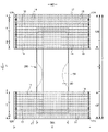
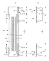
図1~図6に示されるパンツタイプ使い捨ておむつは、前身頃Fを構成する前側外装体12F及び後身頃Bを構成する後側外装体12Bと、前側外装体12Fから股間部を経て後側外装体12Bまで延在するように外装体12F,12Bの内側に設けられた内装体200とを備えている。前側外装体12Fの両側部と後側外装体12Bの両側部とが接合されて、サイドシール部12Aが形成されている。この結果、外装体12F,12Bの前後端部により形成される開口が装着者の胴を通すウエスト開口WOとなり、内装体200の幅方向両側において外装体12F,12Bの下縁及び内装体200の側縁によりそれぞれ囲まれる部分が脚を通す脚開口LOとなる。内装体200は、尿等の排泄物等を吸収保持する部分であり、外装体12F,12Bは着用者の身体に対して内装体200を支えるための部分である。図中の符号Yは展開状態におけるおむつの全長(前身頃Fのウエスト開口WOの縁から後身頃Bのウエスト開口WOの縁までの前後方向長さ)を示しており、符号Xは展開状態におけるおむつの全幅を示している。
The pants-type disposable diaper shown in FIGS. 1 to 6 includes a front
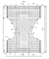
また、本パンツタイプ使い捨ておむつは、サイドシール部12Aを有する前後方向範囲(ウエスト開口WOから脚開口LOの上端に至る前後方向範囲)として定まる胴周り領域Tと、脚開口LOを形成する部分の前後方向範囲(前身頃Fのサイドシール部12Aを有する前後方向領域と後身頃Bのサイドシール部12Aを有する前後方向領域との間)として定まる中間領域Lとを有する。胴周り領域Tは、概念的にウエスト開口の縁部を形成する「ウエスト部」Wと、これよりも下側の部分である「ウエスト下方部」Uとに分けることができる。通常、胴周り領域T内に幅方向WDの伸縮応力が変化する境界(例えば弾性部材の太さや伸長率が変化する)を有する場合は、最もウエスト開口WO側の境界よりもウエスト開口WO側がウエスト部Wとなり、このような境界が無い場合は吸収体56又は内装体200よりもウエスト開口WO側がウエスト部Wとなる。これらの前後方向長さは、製品のサイズによって異なり、適宜定めることができるが、一例を挙げると、ウエスト部Wは15~40mm、ウエスト下方部Uは65~120mmとすることができる。一方、中間領域Lの両側縁は被着者の脚周りに沿うようにコ字状又は曲線状に括れており、ここが装着者の脚を入れる部位となる。この結果、展開状態のパンツタイプ使い捨ておむつは、全体として略砂時計形状をなしている。
In addition, the pants-type disposable diaper has a waist region T defined as a front-rear direction range (a front-rear direction range from the waist opening WO to the upper ends of the leg openings LO) having the
(内外接合部)
内装体200の外装体12F,12Bに対する固定は、特に限定されず、例えばホットメルト接着剤により行うことができる。図示例では、内装体200の裏面、つまりこの場合は液不透過性シート11の裏面及び起き上がりギャザー60の付根部分65に塗布されたホットメルト接着剤を介して外装体12F,12Bの内面に対して固定されている。この内装体200と外装体12F,12Bとを固定する内外接合部201は、両者が重なる領域のほぼ全体に設けることができ、例えば内装体200の幅方向両端部を除いた部分に設けることもできる。
(internal and external joints)
Fixing of the
(内装体)
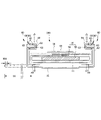
内装体200は任意の形状を採ることができるが、図示の形態では長方形である。内装体200は、図3~図5に示されるように、身体側となるトップシート30と、液不透過性シート11と、これらの間に介在された吸収要素50とを備えているものであり、吸収機能を担う本体部である。符号40は、トップシート30を透過した液を速やかに吸収要素50へ移行させるために、トップシート30と吸収要素50との間に設けられた中間シート(セカンドシート)を示しており、符号60は、内装体200の両脇に排泄物が漏れるのを防止するために、内装体200の両側部から装着者の脚周りに接するように延び出た起き上がりギャザー60を示している。
(inner body)
The
(トップシート)
トップシート30は、液を透過する性質を有するものであり、例えば、有孔又は無孔の不織布や、多孔性プラスチックシートなどを例示することができる。また、このうち不織布は、その原料繊維が何であるかは、特に限定されない。例えば、ポリエチレンやポリプロピレン等のオレフィン系、ポリエステル系、ポリアミド系等の合成繊維、レーヨンやキュプラ等の再生繊維、綿等の天然繊維などや、これらから二種以上が使用された混合繊維、複合繊維などを例示することができる。さらに、不織布は、どのような加工によって製造されたものであってもよい。加工方法としては、公知の方法、例えば、スパンレース法、スパンボンド法、サーマルボンド法、メルトブローン法、ニードルパンチ法、エアスルー法、ポイントボンド法等を例示することができる。例えば、柔軟性、ドレープ性を求めるのであれば、スパンボンド法、スパンレース法が、嵩高性、ソフト性を求めるのであれば、エアスルー法、ポイントボンド法、サーマルボンド法が、好ましい加工方法となる。
(top sheet)
The
また、トップシート30は、1枚のシートからなるものであっても、2枚以上のシートを貼り合せて得た積層シートからなるものであってもよい。同様に、トップシート30は、平面方向に関して、1枚のシートからなるものであっても、2枚以上のシートからなるものであってもよい。
Further, the
トップシート30の両側部は、吸収要素50の側縁で裏側に折り返しても良く、また折り返さずに吸収要素50の側縁より側方にはみ出させても良い。
Both sides of the
トップシート30は、裏側の部材に対する位置ずれを防止する等の目的で、ヒートシール、超音波シールのような素材溶着による接合手段や、ホットメルト接着剤により裏側に隣接する部材に固定することが望ましい。図示例では、トップシート30はその裏面に塗布されたホットメルト接着剤により中間シート40の表面及び包装シート58のうち吸収体56の表側に位置する部分の表面に固定されている。
The
(中間シート)
トップシート30を透過した液を速やかに吸収体へ移行させるために、トップシート30より液の透過速度が速い、中間シート(「セカンドシート」とも呼ばれている)40を設けることができる。この中間シート40は、液を速やかに吸収体へ移行させて吸収体による吸収性能を高めるばかりでなく、吸収した液の吸収体からの「逆戻り」現象を防止し、トップシート30上を常に乾燥した状態とすることができる。中間シート40は省略することもできる。
(intermediate sheet)
An intermediate sheet (also called a “second sheet”) 40 having a faster liquid permeation rate than the
中間シート40としては、トップシート30と同様の素材や、スパンレース不織布、スパンボンド不織布、SMS不織布、パルプ不織布、パルプとレーヨンとの混合シート、ポイントボンド不織布又はクレープ紙を例示できる。特にエアスルー不織布が嵩高であるため好ましい。エアスルー不織布には芯鞘構造の複合繊維を用いるのが好ましく、この場合芯に用いる樹脂はポリプロピレン(PP)でも良いが剛性の高いポリエステル(PET)が好ましい。目付けは20~80g/m2が好ましく、25~60g/m2がより好ましい。不織布の原料繊維の太さは2.0~10dtexであるのが好ましい。不織布を嵩高にするために、原料繊維の全部又は一部の混合繊維として、芯が中央にない偏芯の繊維や中空の繊維、偏芯且つ中空の繊維を用いるのも好ましい。
Examples of the
図示の形態の中間シート40は、吸収体56の幅より短く中央に配置されているが、全幅にわたって設けてもよい。中間シート40の長手方向長さは、おむつの全長と同一でもよいし、吸収要素50の長さと同一でもよいし、液を受け入れる領域を中心にした短い長さ範囲内であってもよい。
The
中間シート40は、裏側の部材に対する位置ずれを防止する等の目的で、ヒートシール、超音波シールのような素材溶着による接合手段や、ホットメルト接着剤により裏側に隣接する部材に固定することが望ましい。図示例では、中間シート40はその裏面に塗布されたホットメルト接着剤により包装シート58のうち吸収体56の表側に位置する部分の表面に固定されている。
The
(液不透過性シート)
液不透過性シート11の素材は、特に限定されるものではないが、例えば、ポリエチレンやポリプロピレン等のオレフィン系樹脂等からなるプラスチックフィルムや、不織布の表面にプラスチックフィルムを設けたラミネート不織布、プラスチックフィルムに不織布等を重ねて接合した積層シートなどを例示することができる。液不透過性シート11には、ムレ防止の観点から好まれて使用されている液不透過性かつ透湿性を有する素材を用いることが好ましい。透湿性を有するプラスチックフィルムとしては、ポリエチレンやポリプロピレン等のオレフィン系樹脂中に無機充填剤を混練して、シートを成形した後、一軸又は二軸方向に延伸して得られた微多孔性プラスチックフィルムが広く用いられている。この他にも、マイクロデニール繊維を用いた不織布、熱や圧力をかけることで繊維の空隙を小さくすることによる防漏性強化、高吸水性樹脂又は疎水性樹脂や撥水剤の塗工といった方法により、プラスチックフィルムを用いずに液不透過性としたシートも、液不透過性シート11として用いることができる。
(liquid-impermeable sheet)
The material of the liquid-
液不透過性シート11は、図示のように吸収要素50の裏側に収まる幅とする他、防漏性を高めるために、吸収要素50の両側を回り込ませて吸収要素50のトップシート30側面の両側部まで延在させることもできる。この延在部の幅は、左右それぞれ5~20mm程度が適当である。
The liquid-
(起き上がりギャザー)
起き上がりギャザー60は、横漏れを防止するためのものであり、内装体200の両側部に沿って前後方向LDの全体にわたり延在し、内装体200の側部から表側に起立するものである。図示例の起き上がりギャザー60は、付け根側部分が幅方向中央側に向かって斜めに起立し、中間部より先端側部分が幅方向外側に向かって斜めに起立するものであるが、これに限定されるものではなく、全体として幅方向中央側に起立する形態等、適宜の変更が可能である。
(Getting up gathers)
The rising gathers 60 are for preventing side leakage, extend along both sides of the
より詳細に説明すると、図示例の起き上がりギャザー60は、内装体200の前後方向長さに等しい長さを有する帯状のギャザー不織布62を、先端となる部分で幅方向WDに折り返して二つに折り重ねるとともに、折り返し部分及びその近傍のシート間に、細長状のギャザー弾性部材63を長手方向に沿って伸長状態で、幅方向WDに間隔を空けて複数本固定してなるものである。起き上がりギャザー60のうち先端部と反対側に位置する基端部(幅方向WDにおいてシート折り返し部分と反対側の端部)は、内装体200における液不透過性シート11より裏側の側部に固定された付根部分65とされ、この付根部分65以外の部分は付根部分65から延び出る本体部分66(折り返し部分側の部分)とされている。また、本体部分66は、幅方向中央側に延びる付け根側部分と、この付け根側部分の先端で折り返され、幅方向外側に延びる先端側部分とを有している。この形態は面接触タイプの起き上がりギャザー60であるが、幅方向外側に折り返されない線接触タイプの起き上がりギャザー60も採用することができる。そして、本体部分66のうち前後方向両端部が倒伏状態でトップシート30の側部表面に対して固定された倒伏部分67とされる一方で、これらの間に位置する前後方向中間部は非固定の自由部分68とされ、この自由部分68の少なくとも先端部に前後方向LDに沿うギャザー弾性部材63が伸長状態で固定されている。
More specifically, the illustrated rising gathers 60 are formed by folding a band-shaped gathered
以上のように構成された起き上がりギャザー60では、ギャザー弾性部材63の収縮力が前後方向両端部を近づけるように作用するが、本体部分66のうち前後方向両端部が起立しないように固定されるのに対して、それらの間は非固定の自由部分68とされているため、自由部分68のみが図3に矢印で示すように身体側に当接するように起立する。特に、付根部分65が内装体200の裏側に位置していると、股間部及びその近傍において自由部分68が幅方向外側に開くように起立するため、起き上がりギャザー60が脚周りに面で当接するようになり、フィット性が向上するようになる。
In the riser gathers 60 configured as described above, the contractile force of the gather
(吸収要素)
吸収要素50は特に限定されるものではないが、本例では吸収体56と、この吸収体56の全体を包む包装シート58とを有するものとなっている。包装シート58は省略することもできる。
(absorbing element)
Although the
(吸収体)
吸収体56は、繊維の集合体により形成することができる。この繊維集合体としては、綿状パルプや合成繊維等の短繊維を積繊したものの他、セルロースアセテート等の合成繊維のトウ(繊維束)を必要に応じて開繊して得られるフィラメント集合体も使用できる。吸収体56中には高吸収性ポリマー粒子を分散保持させるのが好ましい。
(Absorber)
吸収体56は長方形形状でも良いが、図7にも示すように、前端部、後端部及びこれらの間に位置し、前端部及び後端部と比べて幅が狭い括れ部56Nとを有する砂時計形状を成していると、吸収体56自体と起き上がりギャザー60の、脚周りへのフィット性が向上するため好ましい。
The
また、吸収体56の寸法は排尿口位置の前後左右にわたる限り適宜定めることができるが、前後方向LD及び幅方向WDにおいて、内装体200の周縁部又はその近傍まで延在しているのが好ましい。なお、符号56Xは吸収体56の幅を示している。
In addition, the dimensions of the
(高吸収性ポリマー粒子)
吸収体56には、その一部又は全部に高吸収性ポリマー粒子を含有させることができる。高吸収性ポリマー粒子とは、「粒子」以外に「粉体」も含む。高吸収性ポリマー粒子54としては、この種の使い捨ておむつに使用されるものをそのまま使用できる。
(superabsorbent polymer particles)
高吸収性ポリマー粒子の材料としては、特に限定無く用いることができるが、吸水量が40g/g以上のものが好適である。高吸収性ポリマー粒子としては、でんぷん系、セルロース系や合成ポリマー系などのものがあり、でんぷん-アクリル酸(塩)グラフト共重合体、でんぷん-アクリロニトリル共重合体のケン化物、ナトリウムカルボキシメチルセルロースの架橋物やアクリル酸(塩)重合体などのものを用いることができる。高吸収性ポリマー粒子の形状としては、通常用いられる粉粒体状のものが好適であるが、他の形状のものも用いることができる。 Materials for the superabsorbent polymer particles may be used without any particular limitation, but those having a water absorption of 40 g/g or more are suitable. Superabsorbent polymer particles include starch-based, cellulose-based, and synthetic polymer-based particles. and acrylic acid (salt) polymers can be used. As for the shape of the superabsorbent polymer particles, the powder particles that are commonly used are suitable, but other shapes can also be used.
高吸収性ポリマー粒子としては、吸水速度が70秒以下、特に40秒以下のものが好適に用いられる。吸水速度が遅すぎると、吸収体56内に供給された液が吸収体56外に戻り出てしまう所謂逆戻りを発生し易くなる。
As the superabsorbent polymer particles, those having a water absorption rate of 70 seconds or less, particularly 40 seconds or less are preferably used. If the water absorption rate is too slow, the liquid supplied into the
また、高吸収性ポリマー粒子としては、ゲル強度が1000Pa以上のものが好適に用いられる。これにより、嵩高な吸収体56とした場合であっても、液吸収後のべとつき感を効果的に抑制できる。
As the superabsorbent polymer particles, those having a gel strength of 1000 Pa or more are preferably used. As a result, even when the
高吸収性ポリマー粒子の目付け量は、当該吸収体56の用途で要求される吸収量に応じて適宜定めることができる。したがって一概には言えないが、50~350g/m2とすることができる。
The basis weight of the superabsorbent polymer particles can be appropriately determined according to the absorption amount required for the use of the
(包装シート)
包装シート58を用いる場合、その素材としては、ティッシュペーパ、特にクレープ紙、不織布、ポリラミ不織布、小孔が開いたシート等を用いることができる。ただし、高吸収性ポリマー粒子が抜け出ないシートであるのが望ましい。クレープ紙に換えて不織布を使用する場合、親水性のSMS不織布(SMS、SSMMS等)が特に好適であり、その材質はポリプロピレン、ポリエチレン/ポリプロピレン複合材などを使用できる。目付けは、5~40g/m2、特に10~30g/m2のものが望ましい。
(packaging sheet)
When the
包装シート58の包装形態は適宜定めることができるが、製造容易性や前後端縁からの高吸収性ポリマー粒子の漏れ防止等の観点から、吸収体56の表裏面及び両側面を取り囲むように筒状に巻き付け、且つその前後縁部を吸収体56の前後からはみ出させ、巻き重なる部分及び前後はみ出し部分の重なり部分をホットメルト接着剤、素材溶着等の接合手段により接合する形態が好ましい。
The packaging form of the
(外装体)
外装体12F,12Bは、前身頃Fを構成する部分である前側外装体12Fと、後身頃Bを構成する部分である後側外装体12Bとからなり、前側外装体12F及び後側外装体12Bは股間側で連続しておらず、前後方向LDに離間されている(外装二分割タイプ)。この離間距離12dは例えば全長Yの40~60%程度とすることができる。また、図8及び図9に示すように、外装体12が、前身頃Fから後身頃Bにかけて股間を通り連続する一体的なものとすることもできる(外装一体タイプ)。
(Exterior body)
The
外装二分割タイプのパンツタイプ使い捨ておむつでは、前側外装体12F及び後側外装体12Bとの間に内装体200が露出するため、内装体200の裏面に液不透過性シート11が露出しないように、前側外装体12Fと内装体200との間から、後側外装体12Bと内装体200との間にかけて、内装体200の裏面を覆うカバー不織布20を備えていると好ましい。カバー不織布20の素材は特に限定されず、例えば外装体12の外側不織布層12S又は内側不織布層12Hと同様の素材(後述する有孔不織布層でも、無孔不織布層でもよい)とすることができる。カバー不織布20の前後方向範囲は、前側外装体12F及び後側外装体12Bに重なる部分を有している限り特に限定されず、内装体200の前端から後端までの全体にわたり前後方向LDに延在していてもよく、図7に示すように、前側外装体12Fと内装体200とが重なる領域の前後方向中間位置から後側外装体12Bと内装体200とが重なる領域の前後方向中間位置まで前後方向LDに延在していてもよい。
In a pants-type disposable diaper with an exterior that is divided into two parts, the
外装体12F,12Bは、胴周り領域Tと対応する前後方向範囲である胴周り部を有する。また、本形態では、前側外装体12Fには中間領域Lと対応する部分を有していないが、後側外装体12Bは胴周り領域Tから中間領域L側に延び出る臀部カバー部Cを有している。図示しないが、前側外装体12Fにも胴周り領域Tから中間領域L側に延び出る鼠蹊カバー部を設けたり、鼠径カバー部は設けるものの臀部カバー部は設けない形態としたり、前側外装体12F及び後側外装体12Bの両方に中間領域Lと対応する部分を設けなくても良い。また、図示例では、臀部カバー部Cの下縁は、前側外装体12Fの下縁と同様、幅方向WDに沿う直線状に形成しているが、幅方向外側に向かうにつれてウエスト開口側に位置するようになる曲線とすることもできる。
The
外装体12F,12Bは、図2~図5に示されるように、外側不織布層12S及び内側不織布層12Hにより表裏が形成されている。いうまでもないが、外側不織布層12S及び内側不織布層12Hのいずれか一方が本発明の第1不織布層に相当し、他方が本発明の第2不織布層に相当する、外側不織布層12S及び内側不織布層12Hは、図5に示すように、一枚のシート材をウエスト開口側に折目が位置するように折り畳んで形成する他、図9に示すように、二枚のシート材を貼り合わせて形成することもできる。また、これらシート材のうち最も内側に位置する部分12rを内装体200のウエスト開口WO側の端部まで延在させることもできる(図9例を参照)。また、外側不織布層12S及び内側不織布層12Hの少なくとも一方は、その一部が他の部分と異なるシート材により形成されていても良い。
As shown in FIGS. 2 to 5, the
外側不織布層12S及び内側不織布層12Hの構成繊維としては、例えばポリエチレン又はポリプロピレン等のオレフィン系、ポリエステル系、ポリアミド系等の合成繊維(単成分繊維の他、芯鞘等の複合繊維も含む)の他、レーヨンやキュプラ等の再生繊維、綿等の天然繊維等、特に限定なく選択することができ、これらを混合して用いることもできる。不織布層12S,12Hの柔軟性を高めるために、構成繊維を捲縮繊維とするのは好ましい。また、外側不織布層12S及び内側不織布層12Hの構成繊維は、親水性繊維(親水化剤により親水性となったものを含む)であっても、疎水性繊維若しくは撥水性繊維(撥水剤により撥水性となった撥水性繊維を含む)であってもよい。また、不織布は一般に繊維の長さや、シート形成方法、繊維結合方法、積層構造により、短繊維不織布、長繊維不織布、スパンボンド不織布、メルトブローン不織布、スパンレース不織布、サーマルボンド(エアスルー)不織布、ニードルパンチ不織布、ポイントボンド不織布、積層不織布(スパンボンド層間にメルトブローン層を挟んだSMS不織布、SMMS不織布等)等に分類されるが、これらのどの不織布も、外側不織布層12S及び内側不織布層12Hとして用いることができる。
The constituent fibers of the outer
外側不織布層12S及び内側不織布層12Hの構成繊維の繊度及び目付けは適宜定めることができるが、通常の場合、それぞれ1.8~6.0dtex程度、10~30g/m2程度であると好ましい。
The fineness and basis weight of the constituent fibers of the outer
(有孔不織布について)
図2、図8、図11及び図12に示すように、外側不織布層12S及び内側不織布層12Hの少なくとも一方は、厚み方向に貫通する孔14が散在する有孔不織布とされる。図11及び図12に示すように、装着者の肌側となる内側不織布層12Hが無孔不織布であり、外側不織布層12Sが有孔不織布であると、孔14の肌触りへの影響を無くすことができる。また、外側不織布層12S及び内側不織布層12Hのうち一方にしか孔14がないため、装着時に肌が露出することがなく、孔14を通じた漏れを防止することができる。図示しないが、装着者の肌側となる内側不織布層12Hを有孔不織布とし、外側不織布層12Sを無孔不織布としてもよい。図13及び図14に示すように、外側不織布層12S及び内側不織布層12Hの両方が有孔不織布であり、一方の有孔不織布の孔14と、他方の有孔不織布の孔14とが重ならない構造であってもよい。この場合、外側不織布層12S及び内側不織布層12Hの両方を有孔不織布とすることにより、より高い通気性を獲得することができる。また、一方の有孔不織布の孔14と、他方の有孔不織布の孔14とが重ならないため、装着時に肌が露出することがなく、孔14を通じた漏れを防止することができる。図15に示すように、外側不織布層12S及び内側不織布層12Hの両方が有孔不織布であり、一方の有孔不織布の孔14と、他方の有孔不織布の孔14とが完全に又は部分的に重なっていてもよい。また、図示しないが、外側不織布層12S及び内側不織布層12Hの両方が有孔不織布である場合において、大部分(例えば50%以上の面積)では、一方の有孔不織布の孔14と他方の有孔不織布の孔14とが重ならないものの、一部では、一方の有孔不織布の孔14と他方の有孔不織布の孔14とが重なっていてもよい。
(About perforated nonwoven fabric)
As shown in FIGS. 2, 8, 11 and 12, at least one of the outer
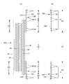
個々の孔14の平面形状(開口形状)は、適宜定めることができる。孔14は、図10(b)に示すような長孔形とするほか、図10(e)(f)に示すような真円形、図10(a)(d)に示すような楕円形、三角形、長方形、ひし形等の多角形、星形、雲形等、任意の形状とすることができる。図10(c)に示すように異なる形状の孔が混在していてもよいが、その場合、伸縮方向の寸法がほぼ同じであることが好ましく、すべての孔が単一の形状であるとより好ましい。個々の孔14の寸法は特に限定されないが、直交方向XDの寸法(最も長い部分の寸法)14Lは0.3~5.0mm、特に0.6~2.0mmとするのが好ましく、伸縮方向EDの寸法(最も長い部分の寸法)14Wは0.3~3.0mm、特に0.4~1.5mmとするのが好ましい。孔14の形状が、長孔形、楕円形、長方形、ひし形等のように一方向に長い形状(一方向の全長がこれと直交する方向の全長よりも長い形状)の場合、長手方向の寸法(最も長い部分の寸法)はこれと直交する方向の寸法(最も長い部分の寸法)の1.2~2.5倍であることが好ましい。また、孔14の形状が一方向に長い形状の場合、孔14の長手方向が前後方向LDであることが望ましいが、幅方向WDや斜め方向であってもよい。
The planar shape (opening shape) of each
個々の孔14の面積及び面積率は適宜定めればよいが、面積は0.1~2.7mm2(特に0.1~1.0mm2)程度であることが好ましく、面積率は1.0~15.0%(特に5.0~10.0%)程度であることが好ましい。
The area and area ratio of each
一枚の有孔不織布における孔14の平面配列は特に限定されるものではない。よって、例えば、図示しないが、外側不織布層12S及び内側不織布層12Hの両方が有孔不織布である場合において、外側不織布層12S及び内側不織布層12Hは孔14の寸法、形状及び配列の少なくとも一つが異なっていてもよい。
The planar arrangement of the
一方、外側不織布層12S及び内側不織布層12Hにおけるすべての孔14を合わせた(つまりすべての孔を平面投影したときの)平面配列は、直交方向XDに間隔を空けて並ぶ孔14の列91,92が、伸縮方向EDに間隔を空けて並ぶものであるとともに、孔14の径が厚み方向の一方から他方に向かうにつれて小さくなっている第1の孔列91と、孔14の径が厚み方向の他方から一方に向かうにつれて小さくなっている第2の孔列92とが、伸縮方向EDに所定の中心間隔で交互に繰り返すものである限り適宜定めることができる。
On the other hand, the planar arrangement of all the
例えば、図10(a)(c)(d)に示すように、すべての孔14の平面配列は、直交方向XDに所定の間隔で直線的に並ぶ孔14の列が伸縮方向EDに所定の間隔を空けて繰り返す行列状であると好ましい。この場合、図10(a)に示すように、孔14の伸縮方向EDの間隔14xが孔14の直交方向XDの間隔14yよりも短い配列とする他、図10(c)に示すように、孔14の伸縮方向EDの間隔14xと孔14の直交方向XDの間隔14yとがほぼ等しい配列、又は図10(d)に示すように、孔14の伸縮方向EDの間隔14xが孔14の直交方向XDの間隔14yよりも長い配列とすることができる。また、図10(b)(e)に示すように、直交方向XDに所定の間隔で直線的に並ぶ孔の列91,92が、伸縮方向EDに間隔を空けてかつ直交方向XDの位置がずれるように並ぶ配列とすることができる。図10(b)に示す例は、隣り合う孔列91,92において孔14の配置が互い違いとなる、いわゆる千鳥状(六角格子状)の配列である。また、図10(f)に示すように、隣り合う孔列91,92の間が直交方向XDに連続する部分を有する限り、孔14が直交方向に沿う中心線を有する波線状に並ぶものも、伸縮方向EDと直交する方向に間隔を空けて並ぶ孔14の列が、伸縮方向EDに間隔を空けて並ぶものに含まれる。
For example, as shown in FIGS. 10(a), 10(c) and 10(d), the planar arrangement of all the
第1の孔列91における孔14の寸法、形状と、第2の孔列92における孔14の寸法、形状とは同じであってもよいが、少なくとも一方が異なっているとより好ましい。
The dimensions and shape of the
第1の孔列91及び第2の孔列92における孔14の直交方向間隔14y及び第1の孔列91と第2の孔列92との伸縮方向間隔14xはそれぞれ一定であっても、変化してもよい。これらは適宜定めることができるが、通気性を考慮すると、それぞれ孔14の直交方向間隔14yは0.9~8.0mm、特に1.0~3.0mmの範囲内とすることが望ましく、第1の孔列91と第2の孔列92との伸縮方向間隔14xは2.0~10mm、特に3.0~5.0mmの範囲内とすることが望ましい。
Even if the
孔14の断面形状は特に限定されない。例えば、孔14は、周縁が繊維の切断端により形成されている打ち抜きタイプの孔であっても、孔14の周縁に繊維の切断端がほとんど無く、ピンが繊維間に挿入されて押し広げられて形成された非打ち抜きタイプの孔14(縁部の繊維密度が高い)であってもよい。
The cross-sectional shape of the
いずれにせよ孔14は、孔14の径がピン挿入側から反対側に向かうにつれて小さくなるものである。これには、孔14の径が不織布層の厚み方向の全体にわたり減少し続けるもののほか、厚み方向の中間で孔14の径の減少がほぼなくなるものも含まれる。このような非打ち抜きタイプの孔には、図16(a)(c)に示すように、ピン挿入側と反対側における孔14の縁部に繊維がピン挿入側と反対側に押し出された突出部(バリ)14eが形成され、ピン挿入側には突出部14eが形成されないものと、図16(b)に示すように、ピン挿入側と反対側における孔14の縁部に繊維がピン挿入側と反対側に押し出された突出部14eが形成されるとともに、ピン挿入側には繊維がピン挿入側に押し出されて形成された突出部14eが形成されるものとが含まれる。さらに、前者のタイプの孔14には、図16(a)に示すように突出部14eの突出高さ14hがほぼ均一であるものと、図16(c)に示すように突出部14eが、突出高さ14iが最も高い対向部分と、これと直交する方向に対向する対向部分であって突出高さ14jが最も低い対向部分とを有するものとが含まれる。突出部14eは孔の周方向に連続して筒状になっていることが望ましいが、一部又は全部の孔14の突出部14eが、孔14の周方向の一部のみに形成されていてもよい。突出高さ14h,14i,14j(光学顕微鏡を用いて測定される圧力を加えない状態での見かけの高さ)は0.2~1.2mm程度であることが好ましい。また、突出部14eにおける、最も高い突出高さ14iは、最も低い突出高さ14jの1.1~1.4倍程度であることが好ましい。突出部14eの突出高さは孔14の周方向に変化してもよい。
In any case, the diameter of the
例えば、図10(a)(b)(d)に示す例のような一方向に長い形状の孔14をピンの挿入により形成すると、孔14の縁部の繊維が外側又は垂直方向に退けられ、孔14の長手方向の対向部分の突出高さiが、長手方向と直交する方向の対向部分の突出高さjよりも高い突出部(バリ)14eが形成される。孔14の突出部14eは、繊維密度がその周囲の部分と比べて低くなっていてもよいが、同程度又は高くなっているのが好ましい。
For example, when a
有孔不織布の構成繊維の繊度、目付け及び厚みは適宜定めることができるが、通常の場合、それぞれ1.8~6.0dtex程度、15~25g/m2程度、0.1~1.3mm程度であると好ましい。また、有孔不織布のMD方向(幅方向)の剛軟度は、穿孔加工前の無孔の状態で35~100mm、特に40~70mmであると好ましく、穿孔加工後の状態では10~50mm、特に15~40mmであると好ましい。 The fineness, basis weight, and thickness of the constituent fibers of the perforated nonwoven fabric can be determined as appropriate, but usually about 1.8 to 6.0 dtex, about 15 to 25 g/m 2 , and about 0.1 to 1.3 mm, respectively. is preferable. In addition, the bending resistance of the perforated nonwoven fabric in the MD direction (width direction) is preferably 35 to 100 mm, particularly 40 to 70 mm in a non-perforated state before perforation, and 10 to 50 mm in a perforated state. In particular, it is preferable that it is 15 to 40 mm.
(伸縮領域)
外装体12F,12Bには、外側不織布層12S及び内側不織布層12H間に細長状の弾性部材19が設けられ、弾性部材19の伸縮に伴って幅方向WDに弾性伸縮する伸縮領域A2が形成されている。すなわち、この伸縮領域A2は、自然長の状態では外側不織布層12S及び内側不織布層12Hが弾性部材の収縮に伴って収縮し、多数の襞80を有する状態となる。また、この伸縮領域A2を幅方向WDに伸長すると、外側不織布層12S及び内側不織布層12Hが襞80なく伸び切る所定の伸長率まで伸長する。弾性部材19としては、細長状のものであれば、糸状、紐状、帯状を問わず用いることができる。また、弾性部材19としては合成ゴムを用いても、天然ゴムを用いても良い。
(stretch area)
An elongated
弾性部材19は、少なくとも伸縮領域A2における伸縮方向EDの両端部が外側不織布層12S及び内側不織布層12Hに固定される。弾性部材19の固定手段は特に限定されないが、ホットメルト接着剤19Hを用いることが好ましい。例えば、図17に示すように、コームガンやシュアラップノズル等の塗布手段により、弾性部材19における伸縮方向EDの両端部の外周面にホットメルト接着剤19Hを間欠的に塗布した後、この弾性部材19を外側不織布層12S及び内側不織布層12H間に挟むことができる。この場合、弾性部材19は、その配置部位で、伸縮領域における伸縮方向EDの両端部のみが外側不織布層12S及び内側不織布層12Hにホットメルト接着剤19Hを介して固定される。図11及び図13に示すように、コームガンやシュアラップノズル等の塗布手段により弾性部材19の外周面にホットメルト接着剤を連続的に塗布した後、この弾性部材19を外側不織布層12S及び内側不織布層12H間に挟むこともできる。この場合、弾性部材19は、その配置部位で、伸縮領域A2における伸縮方向EDの両端部はもちろん、その長手方向全体が外側不織布層12S及び内側不織布層12Hに固定される。他には、図示しないが、外側不織布層12S及び内側不織布層12Hの少なくとも一方の対向面における、弾性部材19の伸縮方向EDの両端部の配置位置にホットメルト接着剤を塗布した後、外側不織布層12S及び内側不織布層12Hの間に弾性部材19を挟むこともできる。この場合、ホットメルト接着剤は、直交方向XDに連続していてもよいし、直交方向XDに間欠的に配置されていてもよい。さらに、これらの場合、ホットメルト接着剤の連続部分は複数本の弾性部材にわたっていてもよい。
The
図示例のようなパンツタイプ使い捨ておむつの場合、弾性部材19、すなわち伸縮領域は以下の部位に設けることが望ましい。すなわち、外装体12F,12Bのウエスト部Wにおける外側不織布層12S及び内側不織布層12H間には、幅方向WDの全体にわたり連続するように、複数のウエスト部弾性部材17が前後方向に間隔を空けて取り付けられている。また、ウエスト部弾性部材17のうち、ウエスト下方部Uに隣接する領域に配設される1本又は複数本については、内装体200と重なっていてもよいし、内装体200と重なる幅方向中央部を除いてその幅方向両側にそれぞれ設けてもよい。このウエスト部弾性部材17としては、太さ155~1880dtex、特に470~1240dtex程度(合成ゴムの場合。天然ゴムの場合には断面積0.05~1.5mm2、特に0.1~1.0mm2程度)の糸ゴムを、4~12mmの間隔で3~22本程度設けるのが好ましく、これによるウエスト部Wの幅方向WDの伸長率は150~400%、特に220~320%程度であるのが好ましい。また、ウエスト部Wは、その前後方向LDの全てに同じ太さのウエスト部弾性部材17を用いたり、同じ伸長率にしたりする必要はなく、例えばウエスト部Wの上部と下部で弾性部材17の太さや伸長率が異なるようにしてもよい。
In the case of a pants-type disposable diaper as shown in the figure, it is desirable to provide the
また、外装体12F,12Bのウエスト下方部Uにおける外側不織布層12S及び内側不織布層12H間には、細長状弾性部材からなるウエスト下方部弾性部材15が複数本、前後方向に間隔を空けて取り付けられている。
In addition, a plurality of waist lower
ウエスト下方部弾性部材15としては、太さ155~1880dtex、特に470~1240dtex程度(合成ゴムの場合。天然ゴムの場合には断面積0.05~1.5mm2、特に0.1~1.0mm2程度)の糸ゴムを、1~15mm、特に3~8mmの間隔で5~30本程度設けるのが好ましく、これによるウエスト下方部Uの幅方向WDの伸長率は200~350%、特に240~300%程度であるのが好ましい。
The lower waist
また、後側外装体12Bの臀部カバー部Cにおける外側不織布層12S及び内側不織布層12H間には、細長状弾性部材からなるカバー部弾性部材16が複数本、前後方向に間隔を空けて取り付けられている。
In addition, a plurality of cover section
カバー部弾性部材16としては、太さ155~1880dtex、特に470~1240dtex程度(合成ゴムの場合。天然ゴムの場合には断面積0.05~1.5mm2、特に0.1~1.0mm2程度)の糸ゴムを、5~40mm、特に5~20mmの間隔で2~10本程度設けるのが好ましく、これによるカバー部の幅方向WDの伸長率は150~300%、特に180~260%であるのが好ましい。
The cover
前側外装体12Fに鼠径カバー部を設ける場合には同様にカバー部弾性部材を設けることができる。
In the case of providing an inguinal cover portion on the front side
(非伸縮領域)
図示例のウエスト下方部Uや臀部カバー部Cのように、吸収体56を有する前後方向範囲に弾性部材15,16を設ける場合には、その一部又は全部において吸収体56の幅方向WDの収縮を防止するために、吸収体56と幅方向WDに重なる部分の一部又は全部を含む幅方向中間(好ましくは内外接合部201の全体を含む)が非伸縮領域A1とされ、その幅方向両側が伸縮領域A2とされる。ウエスト部Wは幅方向WDの全体にわたり伸縮領域A2とされるのが好ましいが、ウエスト下方部Uと同様に、幅方向中間に非伸縮領域A1を設けても良い。
(Non-stretch area)
When the
伸縮領域A2及び非伸縮領域A1は、内側不織布層12Hと、外側不織布層12Sとの間に、弾性部材15,16を供給し、弾性部材15,16を伸縮領域A2における少なくとも伸縮方向EDの両端部でホットメルト接着剤を介して固定し、非伸縮領域A1となる領域では固定せず、非伸縮領域A1となる領域において、弾性部材15,16を幅方向中間の1か所で加圧及び加熱により切断するか、又は弾性部材15,16のほぼ全体を加圧及び加熱により細かく切断し、伸縮領域A2に伸縮性を残しつつ非伸縮領域A1では伸縮性を殺すことにより構築することができる。前者の場合、図4に示すように、非伸縮領域A1には、伸縮領域A2の弾性部材15,16から連続する切断残部が不要弾性部材18として単独で自然長まで収縮した状態で、外側不織布層12S及び内側不織布層12H間に残ることとなり、後者の場合、図示しないが、伸縮領域A2の弾性部材15,16から連続する切断残部、及び両方の伸縮領域A2の弾性部材15,16と連続しない弾性部材の切断片が不要弾性部材として単独で自然長まで収縮した状態で、外側不織布層12S及び内側不織布層12H間に残ることになる。
The stretchable region A2 and the non-stretchable region A1 supply
(外側不織布層及び内側不織布層の接合構造)
伸縮領域A2は、図11及び図12に示すように、外側不織布層12S及び内側不織布層12Hが接合されたシート接合部70を有しており、このシート接合部70が、直交方向XDに間隔を空けて、かつ伸縮方向EDに実質的に連続する縞状パターンで形成されている。このように、シート接合部70が、少なくとも伸縮方向EDと直交する直交方向XDに間隔を空けて形成されているため、良好な通気性、柔軟性を確保することができる。また、このようにシート接合部が伸縮方向に実質的に連続していると、各シート接合部では外側不織布層12S及び内側不織布層12Hが一体化していることにより互いに沿うようにしか変形できない。この結果、シート接合部70及びその近傍では、自然長状態を含め、弾性部材の収縮に伴い外側不織布層12S及び内側不織布層12Hが収縮した状態で、外側不織布層12S及び内側不織布層12Hが互いに沿うような波状をなして表裏両面に襞80が形成される。また、この影響を受けて、隣り合うシート接合部70の間の領域においても、概ね、シート接合部70における外側不織布層12S及び内側不織布層12Hの形状に続くように、図12(c)に示すように、外側不織布層12S及び内側不織布層12Hが互いに沿うような波状をなしてその表裏両面に襞80が形成される。そして、このような襞80においては、単なる不織布層数による剛性向上だけでなく、シート接合部70の硬さ及び外側不織布層12S及び内側不織布層12Hの曲率の違いにより、緩やかに曲がる(特に自然長状態で従来との違いが顕著となる)結果、手触りが滑らかで、厚み方向に潰れやすくなり、手触りの柔軟性が向上する。シート接合部70は、伸縮領域A2の伸縮方向EDの全体にわたり連続していてもよいが、複数の襞80が形成される一部の範囲のみ連続していてもよい。
(Joint structure of outer nonwoven fabric layer and inner nonwoven fabric layer)
As shown in FIGS. 11 and 12, the elastic region A2 has
また、伸縮構造における孔14の配列は、直交方向XDに間隔を空けて並ぶ孔14の列91,92が、伸縮方向EDに間隔を空けて並ぶものであると、外側不織布層12S及び内側不織布層12Hは孔14の列91,92に沿って折れ曲がりやすくなる。この結果、孔14が折れ目となるような一続きの襞80が形成されやすくなる。つまり、襞80が枝分かれしたり、谷部が部分的に広くなったりしにくくなり、全体として、孔14の列に沿って延びる整った襞80が形成されやすくなる。
The arrangement of the
ここで、単に、孔14の列91,92を有する部分のすべてが等しく折れ曲がりやすいだけであると、すべての列91,92で同じ向きに折れ曲りやすくなる。この場合、例えば自然長の状態(通常、製品を手に取る時はこの状態である)で、外側不織布層12S及び内側不織布層12Hのいずれか一方の外面から見たときに、ほとんどすべての孔14の列91,92が隣り合う襞80の間に隠れ、有孔不織布を用いていることが使用者に伝わりにくくなるおそれがある。
Here, if all the portions having the
これに対して、前述のように、外側不織布層12S及び内側不織布層12Hにおけるすべての孔14を合わせた配列に関して、厚み方向における孔14の径の減少方向が反対となる第1の孔列91及び第2の孔列92が、伸縮方向EDに所定の中心間隔で交互に繰り返すものであると、第1の孔列91及び第2の孔列92は反対向きに折れ曲り、第1の孔列91同士及び第2の孔列92同士はそれぞれ同じ向きに折れ曲りやすくなる。これは、孔14の径が厚み方向の一方側から他方側に向かうにつれて小さくなっている孔14の列を有する有効不織布では、その孔14の列に沿ってかつ厚み方向の一方側が谷折りとなるように折れやすいことによる。有孔14不織布は孔14の列に沿って折れ曲がりやすいとはいえ、孔14があるというだけでは、山折りとなるか谷折りとなるかは強制されるわけではない。そのため、単に孔14の列があるというだけでは、列によって孔14の寸法や形状が異なる場合に、伸縮領域A2を複数設ける場合に山折り部分に位置する孔の列が領域によって異なる外観となるおそれがある。また、同じ製品であっても個々に、山折り部分に位置する孔14の列が異なるおそれもある。しかし、本態様の伸縮構造では、第1の孔列91及び第2の孔列92で孔14の向きが反対であることにより、第1の孔列91及び第2の孔列92は反対向きに折れ曲り、第1の孔列91同士及び第2の孔列92同士はそれぞれ同じ向きに折れ曲りやすいため、これらの問題が発生するおそれは少ないものとなる。よって、襞80はより綺麗に整ったものとなる。また、例えば図18(a)に示すように、自然長の状態で、外側不織布層12S及び内側不織布層12Hのいずれか一方の外面から見たときに、第1の孔列91及び第2の孔列92のいずれか一方は隣り合う襞80の間、つまり谷折りとなる部分に隠れるものの、他方は山折りとなる部分に位置するため、有孔不織布を用いていることが使用者に伝わりやすくなる。しかも、自然長時には孔14が襞80と襞80との間に隠れるものの、使用時などに伸長した状態では図18(c)に示すように、孔14が露出する。この変化により通気性向上が図られるのはもちろん、外観の変化であることにより通気性に優れた商品であることを使用者に訴求しやすいという利点ももたらされる。さらに、一部のシート接合部70は孔14を通るような配置となっていてもよいが、その場合に、シート接合部70がホットメルト接着剤19Hにより形成されていると、孔14からホットメルト接着剤19Hが露出する。しかし、襞80と襞80との間の底部に孔14の列が位置すると、孔14から露出するホットメルト接着剤19Hが肌に触れにくいという利点も有する。
On the other hand, as described above, the
第1の孔列91及び第2の孔列92における孔14の直交方向XDの間隔14yは、シート接合部70の直交方向XDの間隔70yより狭いと好ましい。例えば、第1の孔列91及び第2の孔列92における孔14の直交方向XDの間隔14yが、シート接合部70の直交方向XDの間隔70yの1/6以上1/2未満であると、隣り合うシート接合部70の間の領域のすべてに2つ以上の孔14が存在するため、孔14が折れ目となるような一続きの襞80が、より一層形成されやすくなる。よって、より一層整った襞80が形成されやすくなる。また、図2に示す例では、ウエスト部Wでは、第1の孔列91及び第2の孔列92における孔14の直交方向XDの間隔14yは、ウエスト部弾性部材19の直交方向XDの間隔より長いため、シート接合部70が弾性部材19と重なる部位に配置されたホットメルト接着剤19Hにより形成されていると、上記条件を満たさないが、ウエスト部W以外では上記条件を満たすものとなっている。もちろん、伸縮領域A2のすべてが上記間隔14y,70yの大小関係を満たすことが望ましいが、この例のように伸縮領域A2のすべてが上記14y,70yの大小関係を満たす必要はない。
It is preferable that the
シート接合部70は、直交方向XDに間隔を空けて、かつ伸縮方向EDに実質的に連続する縞状パターンで形成されている限り特に限定されるものではない。例えば、図11及び図13に示す例のように、シート接合部70は、弾性部材19と重なる部位に配置されたホットメルト接着剤19Hにより形成されているだけでもよい。このようなシート接合部70は、ホットメルト接着剤19Hを塗布した弾性部材19を外側不織布層12S及び内側不織布層12Hで挟むことにより製造することができるものであり、使い捨て着用物品の分野では広く用いられている。しかし、このシート接合部70の構造では、シート接合部70で外側不織布層12S及び内側不織布層12Hが弾性部材19とともに収縮し、繊維構造が密になる。そのため、図18に示すように、原理的にシート接合部70で襞80が分断されやすい。これに対して、前述のように、少なくとも第1の孔列91及び第2の孔列92における孔14の直交方向XDの間隔14yは、シート接合部70の直交方向XDの間隔70yより狭いと、襞80の形成に関して孔14の影響が支配的になるため、シート接合部70で襞80が分断されやすいにもかかわらず、全体として、孔14の列に沿って延びる整った襞80が形成されやすくなる。
The sheet joints 70 are not particularly limited as long as they are formed in a striped pattern spaced apart in the orthogonal direction XD and substantially continuous in the stretch direction ED. For example, as in the examples shown in FIGS. 11 and 13, the sheet
弾性部材19と重なる部位にホットメルト接着剤19Hを配置するのに代えて(又はこれとともに)図17に示すように、直交方向XDに隣り合う弾性部材19の間に位置する領域に、伸縮方向EDに実質的に連続するシート接合部70を形成することもできる。後者の場合、シート接合部70は、ホットメルト接着剤により形成するほか、ヒートシールや超音波シール等の素材溶着により形成してもよい。この他、弾性部材19の両端部を固定するためのホットメルト接着剤19Hが、外側不織布層12S及び内側不織布層12Hを接合していてもよいことはいうまでもない。
Instead of (or in addition to) arranging the hot melt adhesive 19H in the region overlapping the
直交方向XDにおけるシート接合部70の寸法70Lは適宜定めることができるが、短いことが好ましく、直交方向XDにおける隣り合う弾性部材19の間隔19yの0.2~0.6倍、特に0.3~0.5倍であることが好ましい。
The
図17に示すように、外側不織布層12S及び内側不織布層12Hの両方が有孔不織布であり、外側不織布層12S及び内側不織布層12Hのいずれか一方に第1の孔列91が設けられるとともに、外側不織布層12S及び内側不織布層12Hのいずれか他方に第2の孔列92が設けられているのは一つの好ましい構造である。このように、外側不織布層12S及び内側不織布層12Hの一方にのみ第1の孔列91を、及び他方にのみ第2の孔列92を設けると、より一層、第1の孔列91及び第2の孔列92は反対向きに折れ曲り、第1の孔列91同士及び第2の孔列92同士はそれぞれ同じ向きに折れ曲りやすくなる。
As shown in FIG. 17, both the outer
特に、装着者の肌側となる内側不織布層12Hが無孔不織布であり、外側不織布層12Sが有孔不織布である場合に、有孔不織布の孔14の径が、対向する不織布層側と反対側から対向する不織布層側に向かうにつれて小さくなっていると、図12(c)及び図18(b)に示すように、内側不織布層12Hに形成される襞80は薄い襞となり、外側不織布層12Sに形成される襞80は緩やかに折れ曲がる厚い襞となる。したがって、内側不織布層12Hと肌との接触面積が少なく、かつ襞と襞との間の隙間が大きくなるため、特に通気性に優れたものとなる。外側不織布層12Sの襞80は、倒れるなどの美観を損ねる変形が発生しにくく、形状安定性に優れたものとなる。
In particular, when the inner
また、具体的な孔14及びシート接合部70の寸法・配置は適宜定めることができるが、以下の範囲内であると特に好ましい。
孔14の伸縮方向EDの寸法14W:0.3~3.0mm(特に0.4~1.5mm)
孔14の直交方向XDの寸法14L:0.3~5.0mm(特に0.6~2.0mm)
第1の孔列91及び第2の孔列92における孔14の直交方向XDの間隔14y:1.0~5.0mm(特に1.0~3.0mm)
第1の孔列91及び第2の孔列92の伸縮方向EDの間隔14x:2.5~10.0mm(特に3.0~6.0mm)
直交方向XDにおけるシート接合部70の間隔:5~10mm(特に5~7mm)
直交方向XDにおけるシート接合部70の寸法70L:0.5~5.0mm(特に1~3mm)
Further, although the specific dimensions and arrangement of the
Distance between
孔14及びシート接合部70は、伸縮領域A2だけに設けることもできるが、図8及び図9に示す例のように、非伸縮領域A1を含むより広範囲の領域にわたり設けることができる。
The
<明細書中の用語の説明>
明細書中の以下の用語は、明細書中に特に記載が無い限り、以下の意味を有するものである。
<Description of terms in the specification>
The following terms in the specification have the following meanings unless otherwise specified in the specification.
・前後方向」とは図中に符号LDで示す方向(縦方向)を意味し、「幅方向」とは図中にWDで示す方向(左右方向)を意味し、前後方向と幅方向とは直交するものである。 ・"Front and back direction" means the direction (longitudinal direction) indicated by symbol LD in the figure, and "width direction" means the direction (left and right direction) indicated by WD in the figure, and the front and back direction and the width direction are different. They are orthogonal.
・「MD方向」及び「CD方向」とは、製造設備における流れ方向(MD方向)及びこれと直交する横方向(CD方向)を意味し、いずれか一方が前後方向となるものであり、他方が幅方向となるものである。不織布のMD方向は、不織布の繊維配向の方向である。繊維配向とは、不織布の繊維が沿う方向であり、例えば、TAPPI標準法T481の零距離引張強さによる繊維配向性試験法に準じた測定方法や、前後方向及び幅方向の引張強度比から繊維配向方向を決定する簡易的測定方法により判別することができる。 ・"MD direction" and "CD direction" mean the flow direction (MD direction) and the lateral direction (CD direction) orthogonal to this in the manufacturing equipment, one of which is the front-back direction, and the other is the width direction. The MD direction of a nonwoven fabric is the direction of fiber orientation of the nonwoven fabric. The fiber orientation is the direction along which the fibers of the nonwoven fabric are aligned. It can be determined by a simple measurement method for determining the orientation direction.
・「表側」とはパンツタイプ使い捨ておむつを着用した際に着用者の肌に近い方を意味し、「裏側」とはパンツタイプ使い捨ておむつを着用した際に着用者の肌から遠い方を意味する。 ・"Front side" means the side closer to the wearer's skin when the pants-type disposable diaper is worn, and the "back side" means the side farther from the wearer's skin when the pants-type disposable diaper is worn. .
・「表面」とは部材の、パンツタイプ使い捨ておむつを着用した際に着用者の肌に近い方の面を意味し、「裏面」とはパンツタイプ使い捨ておむつを着用した際に着用者の肌から遠い方の面を意味する。 ・"Front surface" means the side of the member that is closest to the wearer's skin when wearing the pants-type disposable diaper, and the "back surface" means the side that is close to the wearer's skin when wearing the pants-type disposable diaper. means the far side.
・閉じた平面形状に関して「中心」とは、中心を有しない図形の場合には重心意味する。 ・"Center" for a closed planar shape means the center of gravity in the case of a figure that does not have a center.
・「面積率」とは単位面積に占める対象部分の割合を意味し、対象領域(例えば不織布)における対象部分(例えば孔)の総和面積を当該対象領域の面積で除して百分率で表すものである。対象部分が間隔を空けて多数設けられる形態では、対象部分が10個以上含まれるような大きさに対象領域を設定して、面積率を求めることが望ましい。例えば、孔の面積率は、例えばKEYENCE社の商品名VHX-1000を使用し、測定条件を20倍として、以下の手順で測定することができる。
(1)20倍のレンズにセットし、ピントを調節する。穴が4×6入るように不織布の位置を調整する。
(2)孔の領域の明るさを指定し、孔の面積を計測する。
(3)「計測・コメント」の「面積計測」の色抽出をクリックする。孔の部分をクリックする。
(4)「一括計測」をクリックし、「計測結果ウィンドを表示」にチェックを入れ、CSVデータで保存をする。
・"Area ratio" means the ratio of the target portion to the unit area, and is expressed as a percentage by dividing the total area of the target portion (e.g., holes) in the target region (e.g., nonwoven fabric) by the area of the target region. be. In a form in which a large number of target portions are provided at intervals, it is desirable to determine the area ratio by setting the target region to a size that includes 10 or more target portions. For example, the pore area ratio can be measured by using, for example, VHX-1000 (trade name) manufactured by KEYENCE Co. under the following procedure under the measurement condition of 20 times.
(1) Set on a 20x lens and adjust the focus. Adjust the position of the non-woven fabric so that there are 4×6 holes.
(2) Designate the brightness of the area of the hole and measure the area of the hole.
(3) Click the color extraction of "area measurement" of "measurement/comment". Click on the part of the hole.
(4) Click "Batch measurement", check "Display measurement result window", and save as CSV data.
・「伸長率」は、自然長を100%としたときの値を意味する。例えば、伸長率が200%とは、伸長倍率が2倍であることと同義である。 - "Elongation rate" means a value when the natural length is taken as 100%. For example, an elongation rate of 200% is synonymous with an elongation ratio of 2 times.
・「ゲル強度」は次のようにして測定されるものである。人工尿(尿素:2wt%、塩化ナトリウム:0.8wt%、塩化カルシウム二水和物:0.03wt%、硫酸マグネシウム七水和物:0.08wt%、及びイオン交換水:97.09wt%を混合したもの)49.0gに、高吸収性ポリマーを1.0g加え、スターラーで攪拌させる。生成したゲルを40℃×60%RHの恒温恒湿槽内に3時間放置したあと常温にもどし、カードメーター(I.techno Engineering社製:Curdmeter-MAX ME-500)でゲル強度を測定する。 - "Gel strength" is measured as follows. Artificial urine (urea: 2 wt%, sodium chloride: 0.8 wt%, calcium chloride dihydrate: 0.03 wt%, magnesium sulfate heptahydrate: 0.08 wt%, and deionized water: 97.09 wt% 1.0 g of superabsorbent polymer is added to 49.0 g of the mixture) and stirred with a stirrer. The resulting gel is left in a constant temperature and humidity bath at 40° C. and 60% RH for 3 hours, then returned to room temperature, and the gel strength is measured with a card meter (Curdmeter-MAX ME-500 manufactured by I. techno Engineering).
・「目付け」は次のようにして測定されるものである。試料又は試験片を予備乾燥した後、標準状態(試験場所は、温度23±1℃、相対湿度50±2%)の試験室又は装置内に放置し、恒量になった状態にする。予備乾燥は、試料又は試験片を温度100℃の環境で恒量にすることをいう。なお、公定水分率が0.0%の繊維については、予備乾燥を行わなくてもよい。恒量になった状態の試験片から、試料採取用の型板(100mm×100mm)を使用し、100mm×100mmの寸法の試料を切り取る。試料の重量を測定し、100倍して1平米あたりの重さを算出し、目付けとする。
- "Matsuke" is measured as follows. After pre-drying the sample or test piece, it is left in a test room or apparatus under standard conditions (test location: temperature 23±1° C.,
・「厚み」は、自動厚み測定器(KES-G5 ハンディ圧縮計測プログラム)を用い、荷重:0.098N/cm2、及び加圧面積:2cm2の条件下で自動測定する。 - "Thickness" is automatically measured using an automatic thickness gauge (KES-G5 handy compression measurement program) under the conditions of a load of 0.098 N/cm 2 and a pressurized area of 2 cm 2 .
・「剛軟度」は、JIS L 1096:2010「織物及び編物の生地試験方法」の「8.21.1 A法(45°カンチレバー法)」を意味する。有孔不織布における穿孔加工前(無孔不織布)の値は、穿孔加工前の無孔不織布が入手できない場合には、孔の有無以外(繊維組成、繊度、目付け、厚み等)はすべて同じ不織布を用意して測定を行うものとする。 - "Bending resistance" means "8.21.1 Method A (45° cantilever method)" of JIS L 1096:2010 "Testing methods for fabrics and knitted fabrics". The value before perforation processing (non-perforated non-woven fabric) in perforated non-woven fabric is the same non-woven fabric except for the presence or absence of holes (fiber composition, fineness, basis weight, thickness, etc.) shall be prepared and measured.
・吸水量は、JIS K7223-1996「高吸水性樹脂の吸水量試験方法」によって測定する。 ・The amount of water absorption is measured according to JIS K7223-1996 "Testing method for water absorption of superabsorbent resin".
・吸水速度は、2gの高吸収性ポリマー及び50gの生理食塩水を使用して、JIS K7224‐1996「高吸水性樹脂の吸水速度試験法」を行ったときの「終点までの時間」とする。 ・The water absorption rate is the "time to the end point" when JIS K7224-1996 "Test method for water absorption rate of superabsorbent polymer" is performed using 2g of superabsorbent polymer and 50g of physiological saline. .
・「展開状態」とは、収縮や弛み無く平坦に展開した状態を意味する。 - "Unfolded state" means a flat unfolded state without contraction or slack.
・各部の寸法は、特に記載が無い限り、自然長状態ではなく展開状態における寸法を意味する。 ・Unless otherwise specified, the dimensions of each part mean the dimensions in the unfolded state, not in the natural length state.
・試験や測定における環境条件についての記載が無い場合、その試験や測定は、標準状態(試験場所は、温度23±1℃、相対湿度50±2%)の試験室又は装置内で行うものとする。
・If there is no description about environmental conditions for testing and measurement, the test and measurement shall be performed in a laboratory or equipment under standard conditions (test location: temperature 23±1°C,
本発明は、パンツタイプ使い捨ておむつやテープタイプ使い捨ておむつの他、パッドタイプ使い捨ておむつ、使い捨て水着、おむつカバー、生理用ナプキン等、使い捨て着用物品全般に利用できるものである。 INDUSTRIAL APPLICABILITY The present invention can be used for general disposable wearing articles such as underpants-type disposable diapers, tape-type disposable diapers, pad-type disposable diapers, disposable swimsuits, diaper covers, sanitary napkins, and the like.
11…液不透過性シート、12…外装体、12A…サイドシール部、12B…後側外装体、12F…前側外装体、12H…内側不織布層、12S…外側不織布層、14…孔、14e…突出部、18…不要弾性部材、19…弾性部材、19H…ホットメルト接着剤、20…カバー不織布、200…内装体、201…内外接合部、30…トップシート、40…中間シート、50…吸収要素、56…吸収体、58…包装シート、60…起き上がりギャザー、62…ギャザー不織布、A1…非伸縮領域、A2…伸縮領域、C…臀部カバー部、L…中間領域、LD…前後方向、LO…脚開口、T…胴周り領域、U…ウエスト下方部、W…ウエスト部、WD…幅方向、WO…ウエスト開口、70…シート接合部、XD…直交方向、ED…伸縮方向、80…襞、91,92…列、91…第1の孔列、92…第2の孔列。
DESCRIPTION OF
Claims (7)
前記弾性部材は、少なくとも伸縮領域における前記伸縮方向の両端部が前記第1不織布層及び第2不織布層に固定されており、
前記伸縮領域は、前記第1不織布層及び第2不織布層が接合されたシート接合部を有しており、
前記第1不織布層及び第2不織布層の少なくとも一方は、厚み方向に貫通する孔が配列された有孔不織布である、
使い捨て着用物品の伸縮構造において、
前記シート接合部は、前記直交方向に間隔を空けて、かつ前記伸縮方向に実質的に連続する縞状パターンで形成されており、
前記伸縮構造における前記孔の配列は、前記直交方向に間隔を空けて並ぶ孔の列が、伸縮方向に間隔を空けて並ぶものであるとともに、前記孔の径が厚み方向の一方から他方に向かうにつれて小さくなっている第1の孔列と、前記孔の径が厚み方向の他方から一方に向かうにつれて小さくなっている第2の孔列とが、伸縮方向に所定の中心間隔で交互に繰り返すものである、
ことを特徴とする使い捨て着用物品の伸縮構造。 A first nonwoven fabric layer and a second nonwoven fabric layer partially or wholly overlapping each other, and a space between the first nonwoven fabric layer and the second nonwoven fabric layer in a direction orthogonal to the stretch direction, along the stretch direction. and a plurality of elongated elastic members extending along the
The elastic member is fixed to the first nonwoven fabric layer and the second nonwoven fabric layer at least at both ends in the stretching direction of the stretchable region,
The elastic region has a sheet joint portion where the first nonwoven fabric layer and the second nonwoven fabric layer are joined,
At least one of the first nonwoven fabric layer and the second nonwoven fabric layer is a perforated nonwoven fabric in which holes penetrating in the thickness direction are arranged,
In the elastic structure of the disposable wearing article,
The sheet joints are formed in a striped pattern spaced apart in the orthogonal direction and substantially continuous in the stretching direction,
The arrangement of the holes in the stretchable structure is such that the rows of holes spaced apart in the orthogonal direction are spaced in the stretchable direction, and the diameter of the holes extends from one thickness direction to the other. A first row of holes that gradually decreases in diameter and a second row of holes in which the diameter of the holes decreases from the other to the other in the thickness direction, and are alternately repeated at predetermined center intervals in the direction of expansion and contraction. is
An elastic structure for a disposable wearing article characterized by:
請求項1記載の使い捨て着用物品の伸縮構造。 The first row of holes and the second row of holes each have holes of the same size and shape that are linearly arranged in the orthogonal direction at predetermined center intervals.
The elastic structure of the disposable wearing article according to claim 1.
前記第1の孔列及び前記第2の孔列における孔の前記直交方向の間隔が、前記シート接合部の前記直交方向の間隔より狭い、
請求項1又は2記載の使い捨て着用物品の伸縮構造。 The sheet joint portion is formed of a hot-melt adhesive disposed at a portion overlapping with the elastic member,
the spacing in the orthogonal direction between the holes in the first row of holes and the second row of holes is narrower than the spacing in the orthogonal direction between the sheet joints;
The stretchable structure of the disposable wearing article according to claim 1 or 2.
前記第1の孔列及び第2の孔列における前記孔の前記直交方向の間隔が1.0~5.0mmであり、
前記第1の孔列及び第2の孔列の前記伸縮方向の間隔が2.5~10.0mmであり、
前記直交方向における前記シート接合部の間隔が5~10mmであり、
前記直交方向における前記シート接合部の寸法:0.5~5.0mmである
請求項1~3のいずれか1項に記載の使い捨て着用物品の伸縮構造。 The hole has a dimension in the stretching direction of 0.3 to 3.0 mm and a dimension in the orthogonal direction of 0.3 to 5.0 mm,
the interval in the orthogonal direction between the holes in the first row of holes and the second row of holes is 1.0 to 5.0 mm;
The distance between the first row of holes and the second row of holes in the expansion and contraction direction is 2.5 to 10.0 mm,
The interval between the sheet joints in the orthogonal direction is 5 to 10 mm,
The elastic structure of the disposable wearing article according to any one of Claims 1 to 3, wherein the dimension of the sheet joint portion in the orthogonal direction is 0.5 to 5.0 mm.
請求項1~4のいずれか1項に記載の使い捨て着用物品の伸縮構造。 Both the first nonwoven fabric layer and the second nonwoven fabric layer are perforated nonwoven fabrics, and the first row of holes is provided in one of the first nonwoven fabric layer and the second nonwoven fabric layer, and the first nonwoven fabric layer and the other of the second nonwoven fabric layer is provided with the second row of holes,
The elastic structure of the disposable wearing article according to any one of claims 1 to 4.
請求項1~4のいずれか1項に記載の使い捨て着用物品の伸縮構造。 Of the first nonwoven fabric layer and the second nonwoven fabric layer, the nonwoven fabric layer on the wearer's skin side is a nonporous nonwoven fabric, and the opposite nonwoven fabric layer is the perforated nonwoven fabric.
The elastic structure of the disposable wearing article according to any one of claims 1 to 4 .
前記前身頃及び後身頃の少なくとも一方における前記外装体は、少なくとも前後方向の一部の範囲における前記サイドシール部間に対応する幅方向範囲にわたり、請求項1~6のいずれか1項に記載の伸縮構造を、その伸縮領域の伸縮方向が幅方向となるように備えている、
ことを特徴とするパンツタイプ使い捨て着用物品。 An integrated outer body extending from the front body to the back body, or an outer body provided separately on the front body and the back body, and an inner body attached to the middle part in the width direction of the outer body and extending over both front and rear sides of the crotch part. , a side seal portion in which both side portions of the exterior body of the front body and both side portions of the exterior body of the back body are respectively joined, a waist opening and a pair of left and right leg openings,
The outer body of at least one of the front body and the back body is according to any one of claims 1 to 6, covering a width direction range corresponding to between the side seal portions in at least a partial range in the front-rear direction. The elastic structure is provided so that the elastic direction of the elastic region is the width direction,
A pants-type disposable wearing article characterized by:
Priority Applications (1)
| Application Number | Priority Date | Filing Date | Title |
|---|---|---|---|
| JP2018060908A JP7129190B2 (en) | 2018-03-27 | 2018-03-27 | Elastic structure for disposable wearing article, and pants-type disposable wearing article having this elastic structure |
Applications Claiming Priority (1)
| Application Number | Priority Date | Filing Date | Title |
|---|---|---|---|
| JP2018060908A JP7129190B2 (en) | 2018-03-27 | 2018-03-27 | Elastic structure for disposable wearing article, and pants-type disposable wearing article having this elastic structure |
Publications (3)
| Publication Number | Publication Date |
|---|---|
| JP2019170554A JP2019170554A (en) | 2019-10-10 |
| JP2019170554A5 JP2019170554A5 (en) | 2021-03-11 |
| JP7129190B2 true JP7129190B2 (en) | 2022-09-01 |
Family
ID=68166633
Family Applications (1)
| Application Number | Title | Priority Date | Filing Date |
|---|---|---|---|
| JP2018060908A Active JP7129190B2 (en) | 2018-03-27 | 2018-03-27 | Elastic structure for disposable wearing article, and pants-type disposable wearing article having this elastic structure |
Country Status (1)
| Country | Link |
|---|---|
| JP (1) | JP7129190B2 (en) |
Citations (4)
| Publication number | Priority date | Publication date | Assignee | Title |
|---|---|---|---|---|
| JP2012235809A (en) | 2011-05-09 | 2012-12-06 | Unicharm Corp | Wearable article |
| JP2016120031A (en) | 2014-12-24 | 2016-07-07 | ユニ・チャーム株式会社 | Disposable wear product |
| JP2017507254A (en) | 2014-03-26 | 2017-03-16 | 廈門延江新材料股▲ふん▼有限公司 | Solid nonwoven fabric with open pore structure |
| WO2018042555A1 (en) | 2016-08-31 | 2018-03-08 | ユニ・チャーム株式会社 | Method and device for producing sheet-like member for absorbent article |
-
2018
- 2018-03-27 JP JP2018060908A patent/JP7129190B2/en active Active
Patent Citations (4)
| Publication number | Priority date | Publication date | Assignee | Title |
|---|---|---|---|---|
| JP2012235809A (en) | 2011-05-09 | 2012-12-06 | Unicharm Corp | Wearable article |
| JP2017507254A (en) | 2014-03-26 | 2017-03-16 | 廈門延江新材料股▲ふん▼有限公司 | Solid nonwoven fabric with open pore structure |
| JP2016120031A (en) | 2014-12-24 | 2016-07-07 | ユニ・チャーム株式会社 | Disposable wear product |
| WO2018042555A1 (en) | 2016-08-31 | 2018-03-08 | ユニ・チャーム株式会社 | Method and device for producing sheet-like member for absorbent article |
Also Published As
| Publication number | Publication date |
|---|---|
| JP2019170554A (en) | 2019-10-10 |
Similar Documents
| Publication | Publication Date | Title |
|---|---|---|
| JP6495507B1 (en) | Stretchable structure of disposable wearing article, and pants-type disposable wearing article having the stretchable structure | |
| CN107874915B (en) | Disposable wearing article and method for attaching perforated nonwoven fabric | |
| JP2018064869A (en) | Underpants type disposable diaper | |
| JP2018064869A5 (en) | ||
| WO2019188562A1 (en) | Stretchable structure for disposable wearable article and underpants-type disposable wearable article having stretchable structure | |
| WO2019188561A1 (en) | Stretchable structure for disposable wearable article and underpants-type disposable wearable article having stretchable structure | |
| CN107970092B (en) | Pants-type disposable diaper | |
| WO2020026683A1 (en) | Elastic structure of disposable wearing article, and pants-type disposable wearing article having said elastic structure | |
| JP6495506B1 (en) | Stretch structure of disposable wearing article, and pants-type disposable wearing article having this stretchable structure | |
| CN107970090B (en) | Pants-type disposable diaper | |
| JP7129262B2 (en) | Elastic structure for disposable wearing article, and pants-type disposable wearing article having this elastic structure | |
| JP6495505B1 (en) | Stretchable structure of disposable wearing article, and pants-type disposable wearing article having the stretchable structure | |
| JP7129190B2 (en) | Elastic structure for disposable wearing article, and pants-type disposable wearing article having this elastic structure | |
| CN107970093B (en) | Pants-type disposable diaper | |
| JP2018064870A5 (en) | ||
| JP2020156590A (en) | Underpants-type disposable diaper and method of manufacturing thereof | |
| JP5926851B1 (en) | Stretch structure of absorbent article and pants-type disposable diaper | |
| JP6495504B1 (en) | Stretchable structure of disposable wearing article, and pants-type disposable wearing article having the stretchable structure | |
| JP7078433B2 (en) | Pants type disposable wear items | |
| JP7218170B2 (en) | Disposable wearing article | |
| JP7129179B2 (en) | Elastic structure of absorbent article | |
| JP6400656B2 (en) | Pants-type disposable diaper | |
| JP6400655B2 (en) | Pants-type disposable diaper | |
| JP2023009585A (en) | Connection-type disposable wearable article | |
| JP2022035332A5 (en) |
Legal Events
| Date | Code | Title | Description |
|---|---|---|---|
| A521 | Request for written amendment filed |
Free format text: JAPANESE INTERMEDIATE CODE: A523 Effective date: 20210127 |
|
| A621 | Written request for application examination |
Free format text: JAPANESE INTERMEDIATE CODE: A621 Effective date: 20210127 |
|
| A977 | Report on retrieval |
Free format text: JAPANESE INTERMEDIATE CODE: A971007 Effective date: 20220207 |
|
| A131 | Notification of reasons for refusal |
Free format text: JAPANESE INTERMEDIATE CODE: A131 Effective date: 20220218 |
|
| A521 | Request for written amendment filed |
Free format text: JAPANESE INTERMEDIATE CODE: A523 Effective date: 20220406 |
|
| TRDD | Decision of grant or rejection written | ||
| A01 | Written decision to grant a patent or to grant a registration (utility model) |
Free format text: JAPANESE INTERMEDIATE CODE: A01 Effective date: 20220805 |
|
| A61 | First payment of annual fees (during grant procedure) |
Free format text: JAPANESE INTERMEDIATE CODE: A61 Effective date: 20220822 |
|
| R150 | Certificate of patent or registration of utility model |
Ref document number: 7129190 Country of ref document: JP Free format text: JAPANESE INTERMEDIATE CODE: R150 |