JP7218170B2 - Disposable wearing article - Google Patents
Disposable wearing article Download PDFInfo
- Publication number
- JP7218170B2 JP7218170B2 JP2018238632A JP2018238632A JP7218170B2 JP 7218170 B2 JP7218170 B2 JP 7218170B2 JP 2018238632 A JP2018238632 A JP 2018238632A JP 2018238632 A JP2018238632 A JP 2018238632A JP 7218170 B2 JP7218170 B2 JP 7218170B2
- Authority
- JP
- Japan
- Prior art keywords
- nonwoven fabric
- holes
- sheet
- perforated nonwoven
- hole
- Prior art date
- Legal status (The legal status is an assumption and is not a legal conclusion. Google has not performed a legal analysis and makes no representation as to the accuracy of the status listed.)
- Active
Links
Images


Classifications
-
- A—HUMAN NECESSITIES
- A61—MEDICAL OR VETERINARY SCIENCE; HYGIENE
- A61F—FILTERS IMPLANTABLE INTO BLOOD VESSELS; PROSTHESES; DEVICES PROVIDING PATENCY TO, OR PREVENTING COLLAPSING OF, TUBULAR STRUCTURES OF THE BODY, e.g. STENTS; ORTHOPAEDIC, NURSING OR CONTRACEPTIVE DEVICES; FOMENTATION; TREATMENT OR PROTECTION OF EYES OR EARS; BANDAGES, DRESSINGS OR ABSORBENT PADS; FIRST-AID KITS
- A61F13/00—Bandages or dressings; Absorbent pads
- A61F13/15—Absorbent pads, e.g. sanitary towels, swabs or tampons for external or internal application to the body; Supporting or fastening means therefor; Tampon applicators
- A61F13/45—Absorbent pads, e.g. sanitary towels, swabs or tampons for external or internal application to the body; Supporting or fastening means therefor; Tampon applicators characterised by the shape
- A61F13/49—Absorbent articles specially adapted to be worn around the waist, e.g. diapers
-
- A—HUMAN NECESSITIES
- A61—MEDICAL OR VETERINARY SCIENCE; HYGIENE
- A61F—FILTERS IMPLANTABLE INTO BLOOD VESSELS; PROSTHESES; DEVICES PROVIDING PATENCY TO, OR PREVENTING COLLAPSING OF, TUBULAR STRUCTURES OF THE BODY, e.g. STENTS; ORTHOPAEDIC, NURSING OR CONTRACEPTIVE DEVICES; FOMENTATION; TREATMENT OR PROTECTION OF EYES OR EARS; BANDAGES, DRESSINGS OR ABSORBENT PADS; FIRST-AID KITS
- A61F13/00—Bandages or dressings; Absorbent pads
- A61F13/15—Absorbent pads, e.g. sanitary towels, swabs or tampons for external or internal application to the body; Supporting or fastening means therefor; Tampon applicators
- A61F13/51—Absorbent pads, e.g. sanitary towels, swabs or tampons for external or internal application to the body; Supporting or fastening means therefor; Tampon applicators characterised by the outer layers
Description
本発明は、有孔不織布を貼り付けた部分を有する使い捨て着用物品に関するものである。 TECHNICAL FIELD The present invention relates to a disposable wearing article having a portion to which a perforated nonwoven fabric is attached.
使い捨ておむつや生理用ナプキン等の使い捨て着用物品の多くは、布のような外観及び肌触りとするために製品外面や内面等に不織布が使用されている。この不織布としては、繊維間隙以外に孔を有しない無孔不織布の他、表裏に貫通する孔を多数有する有孔不織布が用いられる(特許文献1~4参照)。
2. Description of the Related Art Many disposable wearing articles such as disposable diapers and sanitary napkins use nonwoven fabrics for the outer and inner surfaces of the products in order to make them look and feel like cloth. As the non-woven fabric, non-porous non-woven fabric having holes other than inter-fiber gaps and perforated non-woven fabric having a large number of holes penetrating from the front to the back are used (see
有孔不織布は、通気性や通液性を向上する機能美を付加するものとしても効果があり、したがって孔の存在をより明瞭に視認できることも極めて重要である(視覚的効果)。 Perforated nonwoven fabrics are also effective in adding functional beauty to improve breathability and liquid permeability, so it is extremely important to be able to more clearly see the presence of pores (visual effect).
しかしながら、使い捨て着用物品に用いられる不織布はある程度薄いため、孔がある程度まで小さくなると、孔が周囲の無孔部分に同化することにより、孔の有無を視認しにくくなるという問題点があった。これでは、視覚的効果が十分に発揮されず、通気性や通液性の向上機能が使用者に正しく伝わりにくくなってしまう。 However, since the nonwoven fabric used for disposable wearing articles is thin to some extent, there is a problem that if the pores become small to a certain extent, the pores are assimilated into the surrounding non-porous portion, making it difficult to visually recognize the presence or absence of the pores. In this case, the visual effect is not sufficiently exhibited, and it becomes difficult to correctly convey the function of improving air permeability and liquid permeability to the user.
そこで、本発明の主たる課題は、使い捨て着用物品において外部に露出する有孔不織布の孔の視認性を改善すること等にある。 SUMMARY OF THE INVENTION Accordingly, the main object of the present invention is to improve the visibility of holes in a perforated nonwoven fabric exposed to the outside in a disposable wearing article.
上記課題を解決した本発明の代表的態様は次記のとおりである。
<第1の態様>
表裏に貫通する孔が間隔を空けて多数設けられた有孔不織布を有しており、
前記有孔不織布は、外部に露出する露出面と、他のシートに面する支持面とを有している、
使い捨て着用物品であって、
前記有孔不織布の厚みは0.30~1.5mmであり、
前記孔の最小寸法は0.6~5mmであり、
前記有孔不織布における前記露出面の白色度は70%以上である、
ことを特徴とする使い捨て着用物品。
A representative aspect of the present invention that solves the above problems is as follows.
<First Aspect>
It has a perforated nonwoven fabric in which a large number of holes penetrating on the front and back are provided at intervals,
The perforated nonwoven fabric has an exposed surface exposed to the outside and a support surface facing another sheet,
Disposable wearing articles,
The perforated nonwoven fabric has a thickness of 0.30 to 1.5 mm,
the minimum dimension of the hole is 0.6 to 5 mm;
The whiteness of the exposed surface of the perforated nonwoven fabric is 70% or more,
A disposable wearing article characterized by:
(作用効果)
本発明者は、有孔不織布の孔の視認性について研究するうちに、有孔不織布の露出面の白色度が低いと、孔の視認性が低下することを知見した。その理由は定かではないが、おおむね次のとおりであると考えられる。すなわち、孔の視認性は孔の縁に生ずる陰影の程度により変化し、有孔不織布の白色度が70%未満であると、孔の外側の部分の白色度が低いために、孔の外側の部分と孔の縁に生ずる陰影との差が少なくなり、孔の視認性が低下する。この傾向は、特に有孔不織布の厚み及び孔の最小寸法が上記範囲内にあるときに顕著となる。ここで、有孔不織布の白色度が70%以上であると、孔の外側の部分の白色度が高いために、孔の外側の部分と孔の縁に生ずる陰影との差が大きくなり、不織布がある程度薄く、かつ孔がある程度小さい場合でも、孔を視認しやすくなるのである。本使い捨て着用物品は、このような知見に基づくものであり、上記のとおり、不織布がある程度薄く、かつ孔がある程度小さい場合に、有孔不織布の白色度が70%以上とすることにより、孔の視認性を向上させたところに特徴を有するものである。
(Effect)
The inventors of the present invention have studied the visibility of holes in perforated nonwoven fabrics and found that the visibility of the holes is reduced when the whiteness of the exposed surface of the perforated nonwoven fabric is low. Although the reason is not clear, it is considered to be roughly as follows. That is, the visibility of the holes varies depending on the degree of shadows generated on the edges of the holes. The difference between the part and the shading on the edge of the hole is reduced, and the visibility of the hole is reduced. This tendency is particularly noticeable when the thickness of the perforated nonwoven fabric and the minimum dimension of the pores are within the above ranges. Here, when the whiteness of the perforated nonwoven fabric is 70% or more, the whiteness of the portion outside the holes is high, so that the difference between the portion outside the holes and the shadow generated at the edges of the holes becomes large. Even if the layer is thin to some extent and the holes are small to some extent, the holes are easily visible. The present disposable wearing article is based on such findings. It is characterized by improved visibility.
なお、白色度は、JIS P8148:2001に規定された「ISO白色度(拡散青色光反射率)」により測定される値を意味する。特に、測定対象が有孔不織布の場合には、少なくとも最上面の試験片の孔とその下側に隣接する試験片の孔とが重ならないように積層した試験片束を用いる。同規定では試料寸法が規定されているが、測定装置により測定可能である限り試料寸法の制限はないものとする。製品における有孔不織布の白色度を測定する場合、測定に十分な寸法の試料が得られないときには、同一素材を用いて試料を作製し、白色度を測定することができる。白色度の測定装置としては、例えば日本電色工業株式会社製の簡易型分光色差計NF333や、分光式白色計PF-10型を用いることができる。また、孔の「最小寸法」とは、MD方向の寸法及びCD方向の寸法のうち短い方の寸法を意味する。 In addition, whiteness means the value measured by "ISO whiteness (diffuse blue light reflectance)" defined in JIS P8148:2001. In particular, when the object to be measured is a perforated nonwoven fabric , a stack of test strips is used in which at least the holes of the uppermost test strip do not overlap with the holes of the adjacent test strip below. Although the standard specifies the sample size, there is no limit to the size of the sample as long as it can be measured by the measuring equipment. When measuring the whiteness of a perforated nonwoven fabric in a product, if a sample of sufficient size for measurement cannot be obtained, a sample can be prepared using the same material and the whiteness can be measured. As a whiteness measuring device, for example, a simple spectroscopic color difference meter NF333 manufactured by Nippon Denshoku Industries Co., Ltd. or a spectroscopic whiteness meter PF-10 can be used. Moreover, the "minimum dimension" of the hole means the dimension in the MD direction or the dimension in the CD direction, whichever is shorter.
<第2の態様>
前記有孔不織布は、構成繊維の繊度が1.8~6.0dtex、かつ目付けが15~25g/m2の、白色顔料を含有する不織布である、
第1の態様の使い捨て着用物品。
<Second Aspect>
The perforated nonwoven fabric is a nonwoven fabric containing a white pigment having a fineness of constituent fibers of 1.8 to 6.0 dtex and a basis weight of 15 to 25 g/m 2 .
A disposable wearing article of the first aspect.
(作用効果)
有孔不織布の白色度を上げるためには密度を高くすることもできるが、費用が嵩むだけでなく、柔軟性も低下する。よって、有孔不織布は繊度及び目付けを上記範囲内とし、白色度の不足を酸化チタン等の白色顔料を適量含有させることにより補うことが好ましい。
(Effect)
Density can be increased to increase the whiteness of the perforated nonwoven fabric, but this not only increases cost but also reduces softness. Therefore, it is preferable that the fineness and basis weight of the perforated nonwoven fabric are within the above ranges, and the lack of whiteness is compensated by containing an appropriate amount of white pigment such as titanium oxide.
<第3の態様>
前記有孔不織布における前記露出面と反対側に重なる部分に、前記有孔不織布の露出面から透けて見える表示が印刷されており、
前記有孔不織布の白色度が85%以下である、
第1又は2の態様の連結式使い捨て着用物品。
<Third Aspect>
A display that can be seen through the exposed surface of the perforated nonwoven fabric is printed on a portion of the perforated nonwoven fabric that overlaps the opposite side of the exposed surface,
The whiteness of the perforated nonwoven fabric is 85% or less,
An articulated disposable wearing article of the first or second aspect.
(作用効果)
有孔不織布の白色度が高すぎると、有孔不織布の裏側に重なる部分に、有孔不織布の外面から透けて見える表示が印刷されている場合に、その表示が見えにくくなるおそれがある。よって、有孔不織布の白色度は上記範囲内であると好ましい。
(Effect)
If the whiteness of the perforated nonwoven fabric is too high, when a display that is visible through the outer surface of the perforated nonwoven fabric is printed on the back side of the perforated nonwoven fabric, the display may become difficult to see. Therefore, the whiteness of the perforated nonwoven fabric is preferably within the above range.
<第4の態様>
前記他のシートにおける、前記有孔不織布側の面における少なくとも非着色部分の白色度が70%以上である、
第1~3のいずれか1つの態様の使い捨て着用物品。
<Fourth Aspect>
In the other sheet, the whiteness of at least the non-colored portion on the surface on the perforated nonwoven fabric side is 70% or more.
A disposable wearing article according to any one of
(作用効果)
有孔不織布の支持面に面する他のシートの白色度は特に限定されるものではないが、当該他のシートにおける有孔不織布側の面は、孔を通じて露出する部分である。よって、当該他のシートにおける、有孔不織布側の面における少なくとも非着色部分の白色度が70%以上であると、この白色度の高い部分が孔の内側に露出することにより、孔の内側の部分と孔の縁に生ずる陰影との差が大きくなり、より一層、孔を視認しやすくなる。
(Effect)
The whiteness of the other sheet facing the support surface of the perforated nonwoven fabric is not particularly limited, but the surface of the other sheet on the perforated nonwoven fabric side is the portion exposed through the holes. Therefore, when the whiteness of at least the non-colored portion on the surface of the nonwoven fabric with holes in the other sheet is 70% or more, the portion with high whiteness is exposed to the inside of the holes. The difference between the portion and the shadow generated on the edge of the hole is increased, making the hole even easier to visually recognize.
<第5の態様>
吸収体と、吸収体の裏側を覆う通気性を有する液不透過性シートと、この液不透過性シートの裏側を覆うカバー不織布とを備えた、吸収性物品であって、
前記カバー不織布が前記有孔不織布であり、前記液不透過性シートが前記他のシートである、
第1~4のいずれか1つの態様の使い捨て着用物品。
<Fifth Aspect>
An absorbent article comprising an absorbent body, a breathable liquid-impermeable sheet covering the back side of the absorbent body, and a cover nonwoven fabric covering the back side of the liquid-impermeable sheet,
The cover nonwoven fabric is the perforated nonwoven fabric, and the liquid-impermeable sheet is the other sheet,
A disposable wearing article according to any one of
(作用効果)
吸収性物品においては、吸収体の裏面を通気性の液不透過性シートで覆い、更にその外面をカバー不織布で覆い、布のような外観とすることが一般的であり、通気性の向上の観点からは液不透過性シートだけでなく、カバー不織布の厚み方向の通気性やカバー不織布と液不透過性シートとの間の通気性も重要となる。また、このカバー不織布は製品の外面に露出するため、その見栄えの良さは、製品の機能美を消費者に訴求するものとなる。よって、前述の白色度の有孔不織布はこのようなカバー不織布に適用するのは好ましい。
(Effect)
In absorbent articles, it is common to cover the back surface of the absorbent body with a breathable, liquid-impermeable sheet and further cover the outer surface with a cover nonwoven fabric to give it a cloth-like appearance, which improves breathability. From the viewpoint, not only the liquid-impermeable sheet but also the air permeability in the thickness direction of the cover nonwoven fabric and the air permeability between the cover nonwoven fabric and the liquid-impermeable sheet are important. In addition, since the cover nonwoven fabric is exposed on the outer surface of the product, its good appearance appeals to consumers the functional beauty of the product. Therefore, it is preferable to apply the perforated nonwoven fabric having the aforementioned whiteness to such a cover nonwoven fabric.
<第6の態様>
前記孔は、前後方向及び幅方向のいずれか一方の方向に間隔を空けて並ぶ孔の列が、他方の方向に間隔を空けて並ぶように配列されており、
前記孔の前記一方の方向の間隔が1.0~5.0mmであり、
前記他方の方向の間隔が2.5~10.0mmである、
第1~5のいずれか1つの態様の使い捨て着用物品。
<Sixth Aspect>
The holes are arranged so that rows of holes spaced in one of the front-rear direction and width direction are spaced in the other direction,
the distance between the holes in the one direction is 1.0 to 5.0 mm;
the interval in the other direction is 2.5 to 10.0 mm;
A disposable wearing article according to any one of
(作用効果)
有孔不織布の孔の配列は特に限定されるものではないが、本態様のように細かく、かつ規則性のあるパターンで配列されている場合、孔の視認性が特に重要となる。よって、本態様のような孔の配列において、前述の有孔不織布の白色度等を有するのは好ましい。
(Effect)
The arrangement of the holes in the perforated nonwoven fabric is not particularly limited, but when the holes are arranged in a fine and regular pattern as in this embodiment, the visibility of the holes is particularly important. Therefore, in the arrangement of holes as in this embodiment, it is preferable that the nonwoven fabric has the above-described degree of whiteness and the like of the perforated nonwoven fabric .
<第7の態様>
前記孔は、前後方向及び幅方向のいずれか一方の方向に続く一重の波状又は鎖状をなすように並んだ孔の群が、他方の方向に間隔を空けて並ぶように配列されており、
前記孔の配列は、前記他方の方向に間隔を空けて並ぶ孔の列が、前記一方の方向に間隔を空けて並ぶものであり、
前記孔の列における前記孔の前記他方の方向の間隔が1.0~5.0mmであり、
前記孔の群における前記孔の前記一方の方向の間隔が2.5~10.0mmである、
第1~5のいずれか1つの態様の使い捨て着用物品。
<Seventh Aspect>
The holes are arranged so that a group of holes arranged in a single wave shape or a chain shape continuing in one of the front-rear direction and the width direction are spaced apart in the other direction,
The arrangement of the holes is such that rows of holes spaced apart in the other direction are spaced in the one direction,
the interval in the other direction of the holes in the row of holes is 1.0 to 5.0 mm;
the spacing of the holes in the group of holes in the one direction is 2.5 to 10.0 mm;
A disposable wearing article according to any one of
(作用効果)
有孔不織布の孔の配列は特に限定されるものではないが、本態様のように細かく、かつ美的規則性のあるパターンで配列されている場合、孔の視認性が特に重要となる。よって、本態様のような孔の配列において、前述の有孔不織布の白色度等を有するのは好ましい。
(Effect)
Although the arrangement of the holes in the perforated nonwoven fabric is not particularly limited, the visibility of the holes is particularly important when the holes are arranged in a fine and aesthetically regular pattern as in this embodiment. Therefore, in the arrangement of holes as in this embodiment, it is preferable that the nonwoven fabric has the above-described degree of whiteness and the like of the perforated nonwoven fabric .
本発明によれば、使い捨て着用物品において外部に露出する有孔不織布の孔の視認性が改善する、等の利点がもたらされる。 ADVANTAGE OF THE INVENTION According to this invention, the visibility of the hole of the perforated nonwoven fabric exposed outside in a disposable wearing article is improved, etc. is brought about.
以下、使い捨て着用物品の例について、添付図面を参照しつつ詳説する。断面図における点模様部分はその表側及び裏側に位置する各構成部材を接合する接合手段としての接着剤を示しており、ホットメルト接着剤のベタ、ビード、カーテン、サミット若しくはスパイラル塗布、又はパターンコート(凸版方式でのホットメルト接着剤の転写)などにより、あるいは弾性部材の固定部分はこれに代えて又はこれとともにコームガンやシュアラップ塗布などの弾性部材の外周面への塗布により形成されるものである。ホットメルト接着剤としては、例えばEVA系、粘着ゴム系(エラストマー系)、オレフィン系、ポリエステル・ポリアミド系などの種類のものが存在するが、特に限定無く使用できる。各構成部材を接合する接合手段としてはヒートシールや超音波シール等の素材溶着による手段を用いることもできる。 Examples of disposable wearing articles will be described in detail below with reference to the accompanying drawings. The dotted pattern portion in the cross-sectional view shows the adhesive as a joining means for joining each component located on the front side and the back side, and the hot melt adhesive solid, bead, curtain, summit or spiral coating, or pattern coating (transfer of hot-melt adhesive by letterpress method), etc. Alternatively, or together with this, the fixed portion of the elastic member is formed by coating the outer peripheral surface of the elastic member with a comb gun or Surewrap coating. be. Hot-melt adhesives include, for example, EVA-based, adhesive rubber-based (elastomer-based), olefin-based, and polyester-polyamide-based adhesives, and can be used without particular limitation. As a joining means for joining each constituent member, a means by material welding such as heat sealing or ultrasonic sealing can be used.
また、以下の説明における不織布としては、部位や目的に応じて公知の不織布を適宜使用することができる。不織布の構成繊維としては、例えばポリエチレン又はポリプロピレン等のオレフィン系、ポリエステル系、ポリアミド系等の合成繊維(単成分繊維の他、芯鞘等の複合繊維も含む)の他、レーヨンやキュプラ等の再生繊維、綿等の天然繊維等、特に限定なく選択することができ、これらを混合して用いることもできる。不織布の柔軟性を高めるために、構成繊維を捲縮繊維とするのは好ましい。また、不織布の構成繊維は、親水性繊維(親水化剤により親水性となったものを含む)であっても、疎水性繊維若しくは撥水性繊維(撥水剤により撥水性となった撥水性繊維を含む)であってもよい。また、不織布は一般に繊維の長さや、シート形成方法、繊維結合方法、積層構造により、短繊維不織布、長繊維不織布、スパンボンド不織布、メルトブローン不織布、スパンレース不織布、サーマルボンド(エアスルー)不織布、ニードルパンチ不織布、ポイントボンド不織布、積層不織布(同一又は類似の不織布層が積層されたSSS不織布等の他、異なる不織布層が積層された、スパンボンド層間にメルトブローン層を挟んだSMS不織布、SMMS不織布等)等に分類されるが、これらのどの不織布も用いることができる。 In addition, as the nonwoven fabric in the following description, a known nonwoven fabric can be appropriately used depending on the site and purpose. Constituent fibers of non-woven fabrics include, for example, synthetic fibers such as olefin-based, polyester-based, and polyamide-based fibers such as polyethylene or polypropylene (including composite fibers such as core-sheath fibers in addition to single-component fibers), as well as recycled rayon and cupra. Fibers, natural fibers such as cotton, etc., can be selected without particular limitation, and these can also be mixed and used. In order to increase the softness of the nonwoven fabric, it is preferable to use crimped fibers as the constituent fibers. In addition, even if the constituent fibers of the nonwoven fabric are hydrophilic fibers (including those made hydrophilic by a hydrophilic agent), they may be hydrophobic fibers or water-repellent fibers (water-repellent fibers made water-repellent by a water-repellent agent). including). In addition, nonwoven fabrics are generally classified into short fiber nonwoven fabrics, long fiber nonwoven fabrics, spunbond nonwoven fabrics, meltblown nonwoven fabrics, spunlace nonwoven fabrics, thermal bonded (air-through) nonwoven fabrics, and needle punched nonwoven fabrics, depending on the fiber length, sheet forming method, fiber bonding method, and laminate structure. Non-woven fabrics, point-bonded non-woven fabrics, laminated non-woven fabrics (including SSS non-woven fabrics in which the same or similar non-woven fabric layers are laminated, SMS non-woven fabrics in which different non-woven fabric layers are laminated, in which a meltblown layer is sandwiched between spunbond layers, SMMS non-woven fabrics, etc.), etc. However, any of these nonwoven fabrics can be used.
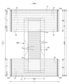
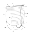
<パンツタイプ使い捨ておむつの例>
図1~図6は、パンツタイプ使い捨ておむつを示している。本パンツタイプ使い捨ておむつは、前身頃Fを構成する前側外装体12F及び後身頃Bを構成する後側外装体12Bと、前側外装体12Fから股間部を経て後側外装体12Bまで延在するように外装体12F,12Bの内側に設けられた内装体200とを備えており、前側外装体12Fの両側部と後側外装体12Bの両側部とが接合されてサイドシール部12Aが形成されることにより、外装体12F,12Bの前後端部により形成される開口が装着者の胴を通すウエスト開口WOとなり、内装体200の幅方向両側において外装体12F,12Bの下縁及び内装体200の側縁によりそれぞれ囲まれる部分が脚を通す脚開口LOとなる。内装体200は、尿等の排泄物等を吸収保持する部分であり、外装体12F,12Bは着用者の身体に対して内装体200を支えるための部分である。また、符号Yは展開状態におけるおむつの全長(前身頃Fのウエスト開口WOの縁から後身頃Bのウエスト開口WOの縁までの前後方向長さ)を示しており、符号Xは展開状態におけるおむつの全幅を示している。
<Example of pants-type disposable diaper>
1 to 6 show pants-type disposable diapers. This pants-type disposable diaper includes a front
また、本例のパンツタイプ使い捨ておむつは、サイドシール部12Aを有する前後方向範囲(ウエスト開口WOから脚開口LOの上端に至る前後方向範囲)として定まる胴周り領域Tと、脚開口LOを形成する部分の前後方向範囲(前身頃Fのサイドシール部12Aを有する前後方向領域と後身頃Bのサイドシール部12Aを有する前後方向領域との間)として定まる中間領域Lとを有する。胴周り領域Tは、概念的にウエスト開口の縁部を形成する「ウエスト部」Wと、これよりも下側の部分である「ウエスト下方部」Uとに分けることができる。通常、胴周り領域T内に幅方向WDの伸縮応力が変化する境界(例えば弾性部材の太さや伸長率が変化する)を有する場合は、最もウエスト開口WO側の境界よりもウエスト開口WO側がウエスト部Wとなり、このような境界が無い場合は吸収体56又は内装体200よりもウエスト開口WO側がウエスト部Wとなる。これらの前後方向長さは、製品のサイズによって異なり、適宜定めることができるが、一例を挙げると、ウエスト部Wは15~40mm、ウエスト下方部Uは65~120mmとすることができる。一方、中間領域Lの両側縁は被着者の脚周りに沿うようにコ字状又は曲線状に括れており、ここが装着者の脚を入れる部位となる。この結果、展開状態のパンツタイプ使い捨ておむつは、全体として略砂時計形状をなしている。
Further, the pants-type disposable diaper of this example forms a waist region T defined as a front-rear direction range (a front-rear direction range from the waist opening WO to the upper ends of the leg openings LO) having the
(内外接合部)
内装体200の外装体12F,12Bに対する固定は、ヒートシール、超音波シールのような素材溶着による接合手段や、ホットメルト接着剤により行うことができる。図示形態では、内装体200の裏面、つまりこの場合は液不透過性シート11の裏面及び側部ギャザー60の付根部分65に塗布されたホットメルト接着剤を介して外装体12F,12Bの内面に対して固定されている。この内装体200と外装体12F,12Bとを固定する内外接合部201は、両者が重なる領域のほぼ全体に設けることができ、例えば内装体200の幅方向両端部を除いた部分に設けることもできる。
(internal and external joints)
Fixing of the
(内装体)
内装体200は任意の形状を採ることができるが、図示の形態では長方形である。内装体200は、図3~図5に示されるように、身体側となるトップシート30と、液不透過性シート11と、これらの間に介在された吸収要素50とを備えているものであり、吸収機能を担う本体部である。符号40は、トップシート30を透過した液を速やかに吸収要素50へ移行させるために、トップシート30と吸収要素50との間に設けられた中間シートを示しており、符号60は、内装体200の両脇に排泄物が漏れるのを防止するために、内装体200の両側部から装着者の脚周りに接するように延び出た側部ギャザー60を示している。
(inner body)
The
(トップシート)
トップシート30は、液を透過する性質を有するものであり、例えば、有孔又は無孔の不織布や、多孔性プラスチックシートなどを例示することができる。
(top sheet)
The
トップシート30の両側部は、吸収要素50の側縁で裏側に折り返しても良く、また折り返さずに吸収要素50の側縁より側方にはみ出させても良い。
Both sides of the
トップシート30は、裏側の部材に対する位置ずれを防止する等の目的で、ヒートシール、超音波シールのような素材溶着による接合手段や、ホットメルト接着剤により裏側に隣接する部材に固定することが望ましい。図示形態では、トップシート30はその裏面に塗布されたホットメルト接着剤により中間シート40の表面及び包装シート58のうち吸収体56の表側に位置する部分の表面に固定されている。
The
(中間シート)
トップシート30を透過した液を速やかに吸収体へ移行させるために、トップシート30より液の透過速度が速い、中間シート(「セカンドシート」とも呼ばれている)40を設けることができる。この中間シート40は、液を速やかに吸収体へ移行させて吸収体による吸収性能を高めるばかりでなく、吸収した液の吸収体からの「逆戻り」現象を防止し、トップシート30上を常に乾燥した状態とすることができる。中間シート40は省略することもできる。
(intermediate sheet)
An intermediate sheet (also called a “second sheet”) 40 having a faster liquid permeation rate than the
中間シート40としては、トップシート30と同様の素材や、スパンレース不織布、スパンボンド不織布、SMS不織布、パルプ不織布、パルプとレーヨンとの混合シート、ポイントボンド不織布又はクレープ紙を例示できる。特にエアスルー不織布が嵩高であるため好ましい。エアスルー不織布には芯鞘構造の複合繊維を用いるのが好ましく、この場合芯に用いる樹脂はポリプロピレン(PP)でも良いが剛性の高いポリエステル(PET)が好ましい。目付けは20~80g/m2が好ましく、25~60g/m2がより好ましい。不織布の原料繊維の太さは2.0~10dtexであるのが好ましい。不織布を嵩高にするために、原料繊維の全部又は一部の混合繊維として、芯が中央にない偏芯の繊維や中空の繊維、偏芯且つ中空の繊維を用いるのも好ましい。
Examples of the
図示の形態の中間シート40は、吸収体56の幅より短く中央に配置されているが、全幅にわたって設けてもよい。中間シート40の長手方向長さは、おむつの全長と同一でもよいし、吸収要素50の長さと同一でもよいし、液を受け入れる領域を中心にした短い長さ範囲内であってもよい。
The
中間シート40は、裏側の部材に対する位置ずれを防止する等の目的で、ヒートシール、超音波シールのような素材溶着による接合手段や、ホットメルト接着剤により裏側に隣接する部材に固定することが望ましい。図示形態では、中間シート40はその裏面に塗布されたホットメルト接着剤により包装シート58のうち吸収体56の表側に位置する部分の表面に固定されている。
The
(液不透過性シート)
液不透過性シート11の素材は、特に限定されるものではないが、例えば、ポリエチレンやポリプロピレン等のオレフィン系樹脂等からなるプラスチックフィルムや、不織布の表面にプラスチックフィルムを設けたラミネート不織布、プラスチックフィルムに不織布等を重ねて接合した積層シートなどを例示することができる。液不透過性シート11には、ムレ防止の観点から好まれて使用されている液不透過性かつ透湿性を有する素材を用いることが好ましい。透湿性を有するプラスチックフィルムとしては、ポリエチレンやポリプロピレン等のオレフィン系樹脂中に無機充填剤を混練して、シートを成形した後、一軸又は二軸方向に延伸して得られた微多孔性プラスチックフィルムが広く用いられている。この他にも、マイクロデニール繊維を用いた不織布、熱や圧力をかけることで繊維の空隙を小さくすることによる防漏性強化、高吸水性樹脂又は疎水性樹脂や撥水剤の塗工といった方法により、プラスチックフィルムを用いずに液不透過性としたシートも、液不透過性シート11として用いることができる。
(liquid-impermeable sheet)
The material of the liquid-
液不透過性シート11は、図示のように吸収要素50の裏側に収まる幅とする他、防漏性を高めるために、吸収要素50の両側を回り込ませて吸収要素50のトップシート30側面の両側部まで延在させることもできる。この延在部の幅は、左右それぞれ5~20mm程度が適当である。
The liquid-
(側部ギャザー)
側部ギャザー60は、内装体200の両側部に沿って前後方向LDの全体にわたり延在し、装着者の脚周りに接して横漏れを防止するために設けられているものであり、一般に立体ギャザーと呼ばれるものや、平面ギャザーと呼ばれるものがこれに含まれる。
(side gather)
The side gathers 60 extend along both sides of the
図3及び図4に示される第1の構造の側部ギャザー60はいわゆる立体ギャザーであり、内装体200の側部から表側に起立するものである。この側部ギャザー60は、付け根側の部分が幅方向中央側に向かって斜めに起立し、中間部より先端側の部分が幅方向外側に向かって斜めに起立するものであるが、これに限定されるものではなく、全体として幅方向中央側に起立する形態等、適宜の変更が可能である。
The side gathers 60 of the first structure shown in FIGS. 3 and 4 are so-called three-dimensional gathers, and stand up from the sides of the
より詳細に説明すると、第1の構造の側部ギャザー60は、内装体200の前後方向長さに等しい長さを有する帯状のギャザー不織布62を、先端となる部分で幅方向WDに折り返して二つに折り重ねるとともに、折り返し部分及びその近傍のシート間に、細長状のギャザー弾性部材63を長手方向に沿って伸長状態で、幅方向WDに間隔を空けて複数本固定してなるものである。側部ギャザー60のうち先端部と反対側に位置する基端部(幅方向WDにおいてシート折り返し部分と反対側の端部)は、内装体200における液不透過性シート11より裏側の側部に固定された付根部分65とされ、この付根部分65以外の部分は付根部分65から延び出る本体部分66(折り返し部分側の部分)とされている。また、本体部分66は、幅方向中央側に向かう付け根側部分と、この付け根側部分の先端から幅方向外側に折り返された先端側部分とからなる。この形態は面接触タイプの側部ギャザー60であるが、幅方向外側に折り返されない線接触タイプの側部ギャザー60も採用することができる。そして、本体部分66のうち前後方向両端部が倒伏状態でトップシート30の側部表面に対して固定された倒伏部分67とされる一方で、これらの間に位置する前後方向中間部は非固定の自由部分68とされ、この自由部分68に前後方向LDに沿うギャザー弾性部材63が伸長状態で固定されている。
More specifically, the side gathers 60 of the first structure are formed by folding a band-shaped gathered
ギャザー不織布62としてはスパンボンド不織布(SS、SSS等)やSMS不織布(SMS、SSMMS等)、メルトブロー不織布等の柔軟で均一性・隠蔽性に優れた不織布に、必要に応じてシリコーンなどにより撥水処理を施したものを好適に用いることができ、繊維目付けは10~30g/m2程度とするのが好ましい。ギャザー弾性部材63としては糸ゴム等を用いることができる。スパンデックス糸ゴムを用いる場合は、太さは470~1240dtexが好ましく、620~940dtexがより好ましい。固定時の伸長率は、150~350%が好ましく、200~300%がより好ましい。また、図示のように、二つに折り重ねたギャザー不織布62の間に防水フィルム64を介在させることもでき、この場合には防水フィルム64の存在部分においてギャザー不織布62を部分的に省略することもできるが、製品の外観及び肌触りを布のようにするためには、図示形態のように、少なくとも側部ギャザー60の基端から先端までの外面がギャザー不織布62で形成されていることが必要である。
As the gathered
側部ギャザー60の自由部分に設けられるギャザー弾性部材63の本数は2~6本が好ましく、3~5本がより好ましい。配置間隔60dは3~10mmが適当である。このように構成すると、ギャザー弾性部材63を配置した範囲で肌に対して面で当たりやすくなる。先端側だけでなく付け根側にもギャザー弾性部材63を配置しても良い。
The number of gather
側部ギャザー60の自由部分68では、ギャザー不織布62の内側層及び外側層の貼り合わせや、その間に挟まれるギャザー弾性部材63の固定に、種々の塗布方法によるホットメルト接着剤及びヒートシールや超音波シール等の素材溶着による固定手段の少なくとも一方を用いることができる。ギャザー不織布62の内側層及び外側層の全面を貼り合わせると柔軟性を損ねるため、ギャザー弾性部材63の接着部以外の部分は接着しないか弱く接着するのが好ましい。図示形態では、コームガンやシュアラップノズル等の塗布手段によりギャザー弾性部材63の外周面にのみホットメルト接着剤を塗布してギャザー不織布62の内側層及び外側層間に挟むことにより、当該ギャザー弾性部材63の外周面に塗布したホットメルト接着剤のみで、ギャザー不織布62の内側層及び外側層へのギャザー弾性部材63の固定と、ギャザー不織布62の内側層及び外側層間の固定とを行う構造となっている。
In the
また、側部ギャザー60に組み込まれる防水フィルム64とギャザー不織布62との固定や、倒伏部分67の内装体200の側部表面への固定に、種々の塗布方法によるホットメルト接着剤、及びヒートシールや超音波シール等の素材溶着による手段の少なくとも一方を用いることができる。図示形態では、防水フィルム64の固定にホットメルト接着剤のスロット塗布を使用している。また、図示形態の倒伏部分67の固定には、ホットメルト接着剤と素材溶着による手段を組み合わせているが、いずれか一方の手段のみで、これらの固定を行うこともできる。
In addition, for fixing the
側部ギャザー60の付根部分65の固定対象は、内装体200におけるトップシート30、液不透過性シート11、吸収要素50等適宜の部材とすることができる。
The
以上のように構成された第1の構造の側部ギャザー60では、ギャザー弾性部材63の収縮力が前後方向両端部を近づけるように作用するが、本体部分66のうち前後方向両端部が起立しないように固定されるのに対して、それらの間は非固定の自由部分とされているため、自由部分のみが図3に示すように身体側に当接するように起立する。特に、付根部分65が内装体200の裏側に位置していると、股間部及びその近傍において側部ギャザー60が幅方向外側に開くように起立するため、側部ギャザー60が脚周りに面で当接するようになり、フィット性が向上するようになる。
In the side gathers 60 having the first structure configured as described above, the contractile force of the gather
第1の構造の側部ギャザー60の寸法は適宜定めることができるが、乳幼児用紙おむつの場合は、例えば図3に示すように、側部ギャザー60の起立高さ(展開状態における本体部分66の幅方向長さ)W6は15~60mm、特に20~40mmであるのが好ましい。また、側部ギャザー60をトップシート30表面と平行になるように、平坦に折り畳んだ状態において最も内側に位置する折り目間の離間距離W3は60~190mm、特に70~140mmであるのが好ましい。
The dimensions of the side gathers 60 of the first structure can be determined as appropriate. The width direction length) W6 is preferably 15 to 60 mm, particularly preferably 20 to 40 mm. When the side gathers 60 are folded flat so as to be parallel to the surface of the
第1の構造の側部ギャザー60は、立体ギャザーのみを含むものとなっているが、立体ギャザー及び平面ギャザーの両方を含むものとしたり、平面ギャザーのみを含むものとしたりすることもできる。図12及び図13は、立体ギャザー及び平面ギャザーの両方を含む、第2の構造の側部ギャザー60を示している。各側部ギャザー60は、内装体200における液不透過性シート11より裏側の側部に固定された付根部分65から、内装体200の側方に突出する第1の部分61(平面ギャザー部分)と、内装体200におけるトップシート30の両側部に固定された付根部分65から、内装体200の表側に突出する第2の部分69(立体ギャザー部分)と含むものである。より詳細には、内装体200の前後方向長さに等しい長さを有する帯状のギャザー不織布62が、付根部分65から側方に延び出て第1の部分61の先端で表側に折り返され、この表側に折り返された部分が第1の部分61を経て第2の部分69に至り、第2の部分69の先端で折り返されている。ギャザー不織布62における折り重なる部分は、対向部分がホットメルト接着剤等により接合される。また、第2の部分69の前後方向両端部は、倒伏状態でトップシート30の側部表面に対して固定された倒伏部分67とされる一方で、これらの間に位置する前後方向中間部は非固定の自由部分68とされる。第1の部分61の少なくとも前後方向中間部、及び第2の部分69の自由部分68には、前後方向LDに沿うギャザー弾性部材63が一本又は幅方向WDに間隔を空けて複数本伸長状態で固定されており、その収縮力により第2の部分69の自由部分68が前後方向LDに収縮して脚周りに接する立体ギャザーとなり、また第1の部分61が前後方向LDに収縮して脚周りに接する平面ギャザーとなる。
The side gathers 60 of the first configuration are intended to include only solid gathers, but may include both solid and planar gathers, or may include planar gathers only. Figures 12 and 13 show a second construction of side gathers 60, including both solid gathers and planar gathers. Each of the side gathers 60 has a first portion 61 (flat gather portion) protruding laterally of the
第2の構造に関する他の点、例えばギャザー不織布62の素材や、ギャザー弾性部材63の素材等は、第1の構造と同様であるため説明を省略する。
Other points regarding the second structure, such as the material of the gathered
(吸収要素)
吸収要素50は、吸収体56と、この吸収体56の全体を包む包装シート58とを有する。包装シート58は省略することもできる。
(absorbing element)
The
(吸収体)
吸収体56は、繊維の集合体により形成することができる。この繊維集合体としては、綿状パルプや合成繊維等の短繊維を積繊したものの他、セルロースアセテート等の合成繊維のトウ(繊維束)を必要に応じて開繊して得られるフィラメント集合体も使用できる。繊維目付けとしては、綿状パルプや短繊維を積繊する場合は、例えば100~300g/m2程度とすることができ、フィラメント集合体の場合は、例えば30~120g/m2程度とすることができる。
(Absorber)
吸収体56は長方形形状でも良いが、図1及び図7にも示すように、前端部、後端部及びこれらの間に位置し、前端部及び後端部と比べて幅が狭い括れ部56Nとを有する砂時計形状を成していると、吸収体56自体と側部ギャザー60の、脚周りへのフィット性が向上するため好ましい。
The
(高吸収性ポリマー粒子)
吸収体56には、その一部又は全部に高吸収性ポリマー粒子を含有させることができる。高吸収性ポリマー粒子とは、「粒子」以外に「粉体」も含む。高吸収性ポリマー粒子としては、この種の使い捨ておむつに使用されるものをそのまま使用できる。
(superabsorbent polymer particles)
(包装シート)
包装シート58を用いる場合、その素材としては、ティッシュペーパ、特にクレープ紙、不織布、ポリラミ不織布、小孔が開いたシート等を用いることができる。ただし、高吸収性ポリマー粒子が抜け出ないシートであるのが望ましい。クレープ紙に換えて不織布を使用する場合、親水性のSMS不織布(SMS、SSMMS等)が特に好適であり、その材質はポリプロピレン、ポリエチレン/ポリプロピレン複合材などを使用できる。目付けは、5~40g/m2、特に10~30g/m2のものが望ましい。
(packaging sheet)
When the
(外装体)
外装体12F,12Bは、前身頃Fを構成する部分である前側外装体12Fと、後身頃Bを構成する部分である後側外装体12Bとからなり、前側外装体12F及び後側外装体12Bは股間側で連続しておらず、前後方向LDに離間されている(外装二分割タイプ)。この離間距離12dは例えば150~250mm程度とすることができる。また、図14及び図15に示すように、外装体12が、前身頃Fから後身頃Bにかけて股間を通り連続する一体的なものとすることもできる(外装一体タイプ)。
(Exterior body)
The
外装体12F,12Bは、胴周り領域Tと対応する前後方向範囲である胴周り部を有する。また、本形態では、前側外装体12Fには中間領域Lと対応する部分を有していないが、後側外装体12Bは胴周り領域Tから中間領域L側に延び出る臀部カバー部Cを有している。図示しないが、前側外装体12Fにも胴周り領域Tから中間領域L側に延び出る鼠蹊カバー部を設けたり、鼠径カバー部は設けるものの臀部カバー部は設けない形態としたり、前側外装体12F及び後側外装体12Bの両方に中間領域Lと対応する部分を設けなくても良い。また、図示形態では、臀部カバー部Cの下縁は、前側外装体12Fの下縁と同様、幅方向WDに沿う直線状に形成しているが、幅方向外側に向かうにつれてウエスト開口側に位置するようになる曲線とすることもできる。
The
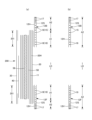
外装体12F,12Bは、図4及び図5に示されるように、外側シート層12S及び内側シート層12Hがホットメルト接着剤や溶着等の接合手段により接合されたものである。外側シート層12Sを形成するシート材及び内側シート層12Hを形成するシート材は、図5に示す形態のように共通の一枚のシート材とする他、個別のシート材とすることもできる。すなわち、前者の場合、ウエスト開口WOの縁(股間側の縁としても良い)で折り返された一枚のシート材の内側の部分及び外側の部分により内側シート層12H及び外側シート層12Sがそれぞれ形成される。なお、前者の形態では、シート材の資材数が少ないという利点があり、後者の形態では内側シート層12H及び外側シート層12Sを貼り合わせる際に位置ずれしにくいという利点がある。
As shown in FIGS. 4 and 5, the
外側シート層12S及び内側シート層12Hに用いるシート材としては、特に限定無く使用できるが不織布が好ましく、不織布を用いる場合、その目付けは10~30g/m2程度とするのが好ましい。
The sheet material used for the
(伸縮領域・非伸縮領域)
外装体12F,12Bには、装着者の胴周りに対するフィット性を高めるために、外側シート層12S及び内側シート層12H間に糸ゴム等の細長状の弾性部材15~19が設けられ、弾性部材の伸縮を伴って幅方向WDに弾性伸縮する伸縮領域が形成されている。この伸縮領域では、自然長の状態では外側シート層12S及び内側シート層12Hが弾性部材の収縮に伴って収縮し、皺又は襞が形成されており、弾性部材の長手方向に伸長すると、外側シート層12S及び内側シート層12Hが皺なく伸び切る所定の伸長率まで伸長が可能である。弾性部材15~19としては、合成ゴムを用いても、天然ゴムを用いても良い。
(stretchable area/non-stretchable area)
The
外装体12F,12Bにおける外側シート層12S及び内側シート層12Hの貼り合わせや、その間に挟まれる弾性部材15~19の固定には、種々の塗布方法によるホットメルト接着剤及びヒートシールや超音波シール等の素材溶着による固定手段の少なくとも一方を用いることができる。外装体12F,12B全面を強固に固定すると柔軟性を損ねるため、弾性部材15~19の接着部以外の部分は接着しないか弱く接着するのが好ましい。図示形態では、コームガンやシュアラップノズル等の塗布手段により弾性部材15~19の外周面にのみホットメルト接着剤を塗布して両シート層12S,12H間に挟むことにより、当該弾性部材15~19の外周面に塗布したホットメルト接着剤のみで、両シート層12S,12Hへの弾性部材15~19の固定と、両シート層12S,12H間の固定とを行う構造となっている。弾性部材15~19は伸縮領域における伸縮方向の両端部のみ、外側シート層12S及び内側シート層12Hに固定することができる。
For bonding the
より詳細には、外装体12F,12Bのウエスト部Wにおける外側シート層12S及び内側シート層12H間には、幅方向WDの全体にわたり連続するように、複数のウエスト部弾性部材17が上下方向に間隔を空けて取り付けられている。また、ウエスト部弾性部材17のうち、ウエスト下方部Uに隣接する領域に配設される1本又は複数本については、内装体200と重なっていてもよいし、内装体200と重なる幅方向中央部を除いてその幅方向両側にそれぞれ設けてもよい。このウエスト部弾性部材17としては、太さ155~1880dtex、特に470~1240dtex程度(合成ゴムの場合。天然ゴムの場合には断面積0.05~1.5mm2、特に0.1~1.0mm2程度)の糸ゴムを、4~12mmの間隔で3~22本程度設けるのが好ましく、これによるウエスト部Wの幅方向WDの伸長率は150~400%、特に220~320%程度であるのが好ましい。また、ウエスト部Wは、その前後方向LDの全てに同じ太さのウエスト部弾性部材17を用いたり、同じ伸長率にしたりする必要はなく、例えばウエスト部Wの上部と下部で弾性部材17の太さや伸長率が異なるようにしてもよい。
More specifically, a plurality of waist
また、外装体12F,12Bのウエスト下方部Uにおける外側シート層12S及び内側シート層12H間には、細長状の弾性部材からなるウエスト下方部弾性部材15,19が複数本、上下方向に間隔を空けて取り付けられている。
Further, a plurality of waist lower
ウエスト下方部弾性部材15,19としては、太さ155~1880dtex、特に470~1240dtex程度(合成ゴムの場合。天然ゴムの場合には断面積0.05~1.5mm2、特に0.1~1.0mm2程度)の糸ゴムを、1~15mm、特に3~8mmの間隔で5~30本程度設けるのが好ましく、これによるウエスト下方部Uの幅方向WDの伸長率は200~350%、特に240~300%程度であるのが好ましい。
The lower waist
また、後側外装体12Bの臀部カバー部Cにおける外側シート層12S及び内側シート層12H間には、細長状の弾性部材からなるカバー部弾性部材16が複数本、上下方向に間隔を空けて取り付けられている。
In addition, a plurality of cover section
カバー部弾性部材16としては、太さ155~1880dtex、特に470~1240dtex程度(合成ゴムの場合。天然ゴムの場合には断面積0.05~1.5mm2、特に0.1~1.0mm2程度)の糸ゴムを、5~40mm、特に5~20mmの間隔で2~10本程度設けるのが好ましく、これによるカバー部の幅方向WDの伸長率は150~300%、特に180~260%であるのが好ましい。
The cover
前側外装体12Fに鼠径カバー部を設ける場合には同様にカバー部弾性部材を設けることができる。
In the case of providing an inguinal cover portion on the front side
図示形態のウエスト下方部Uや臀部カバー部Cのように、吸収体56を有する前後方向範囲に弾性部材15,16,19を設ける場合には、その一部又は全部において吸収体56の幅方向WDの収縮を防止するために、吸収体56と幅方向WDに重なる部分の一部又は全部を含む幅方向中間(好ましくは内外接合部201の全体を含む)が非伸縮領域A1とされ、その幅方向両側が伸縮領域A2とされる。ウエスト部Wは幅方向WDの全体にわたり伸縮領域A2とされるのが好ましいが、ウエスト下方部Uと同様に、幅方向中間に非伸縮領域A1を設けても良い。
When the
伸縮領域A2及び非伸縮領域A1は、内側シート層12Hと、外側シート層12Sとの間に、弾性部材15~17,19を供給し、弾性部材15,16,19を伸縮領域A2における少なくとも伸縮方向の両端部でホットメルト接着剤を介して固定し、非伸縮領域A1となる領域では固定せず、非伸縮領域A1となる領域において、弾性部材15,16,19を幅方向中間の1か所で加圧及び加熱により切断するか、又は弾性部材15,16,19のほぼ全体を加圧及び加熱により細かく切断し、伸縮領域A2に伸縮性を残しつつ非伸縮領域A1では伸縮性を殺すことにより構築することができる。前者の場合、図4に示すように、非伸縮領域A1には、伸縮領域A2の弾性部材15,16,19から連続する切断残部が不要弾性部材18として単独で自然長まで収縮した状態で、外側シート層12S及び内側シート層12H間に残ることとなり、後者の場合、図示しないが、伸縮領域A2の弾性部材15,16,19から連続する切断残部、及び両方の伸縮領域A2の弾性部材15,16,19と連続しない弾性部材の切断片が不要弾性部材として単独で自然長まで収縮した状態で、外側シート層12S及び内側シート層12H間に残ることになる。
The stretchable area A2 and the non-stretchable area A1 supply the
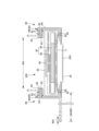
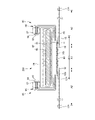
外装二分割タイプのパンツタイプ使い捨ておむつでは、前側外装体12F及び後側外装体12Bとの間に内装体200が露出するため、内装体200の裏面に液不透過性シート11が露出しないように、前側外装体12Fと内装体200との間から、後側外装体12Bと内装体200との間にかけて、内装体200の裏面を覆うカバー不織布20を備えている。また、図7及び図8に示す形態では、外装体12の外側シート層12Sが不織布である場合、この外側シート層12Sが前身頃Fから後身頃Bにかけて股間を通り連続し、内装体200の液不透過性シート11を覆うカバー不織布20となる。カバー不織布20の目付けや厚みは適宜定めることができるが、通常の場合、目付けは15~30g/m2、厚みは0.2~1.2mmであると好ましい。
In a pants-type disposable diaper with an exterior that is divided into two parts, the
カバー不織布20の前後方向範囲は、前側外装体12F及び後側外装体12Bに重なる部分を有している限り特に限定されず、図2、図5、図7、図9及び図10に示すように、内装体200の前端から後端までの全体にわたり前後方向LDに延在していてもよく、図8に示すように、前側外装体12Fと内装体200とが重なる領域の前後方向中間位置から後側外装体12Bと内装体200とが重なる領域の前後方向中間位置まで前後方向LDに延在していてもよい。後者の場合、カバー不織布20と前側外装体12Fとの重なり部分の前後方向長さ20yは、カバー不織布20と後側外装体12Bとの重なり部分の前後方向長さ20yは適宜定めることができるが、通常の場合それぞれ5~40mm程度とすることができる。
The range in the front-rear direction of the
カバー不織布20の幅方向範囲は、液不透過性シート11の裏面露出部分を隠しうる範囲とされる。このため、図示形態では、左右の側部ギャザー60の基端の間に液不透過性シート11が露出するため、少なくとも一方の側部ギャザー60の基端部の裏側から他方の側部ギャザー60の基端部の裏側までの幅方向範囲を覆うようにカバー不織布20が設けられている。これにより、液不透過性シート11をカバー不織布20と側部ギャザー60のギャザー不織布62とで隠蔽することができ、外面から見て、カバー不織布20の幅方向両端部の孔14がギャザー不織布62で隠れることもないものとなる。また、カバー不織布20の幅方向両端部が側部ギャザー60の基端部の裏側を覆うのではなく、ギャザー不織布62がカバー不織布20の幅方向両端部の裏側を覆うようにしても、カバー不織布20とギャザー不織布62とで液不透過性シート11を隠蔽することは可能であり、その場合、ギャザー不織布62の全光線透過率が60~90%であると、ギャザー不織布62がカバー不織布20を隠す部分においても、孔開き不織布の孔14が透けて十分に視認できるため、通気性向上機能を有する部分が側部ギャザー60にまで広がっていることを認識でき、孔14の視覚的効果が十分に発揮されることとなる。
The widthwise range of the
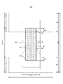
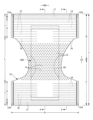
<テープタイプ使い捨ておむつの例>
図16~図20はテープタイプ使い捨ておむつの一例を示しており、図中の符号Xはファスニングテープを除いたおむつの全幅を示しており、符号Yはおむつの全長を示している。このテープタイプ使い捨ておむつは、腹側から背側まで延在する吸収体56と、吸収体56の表側を覆う液透過性のトップシート30と、吸収体56の裏側を覆う液不透過性シート11とを有するものであり、吸収体56の前側及び後側にそれぞれ延出する部分であって、かつ吸収体56を有しない部分であるエンドフラップ部EFと、吸収体56の側縁よりも側方に延出する一対のサイドフラップ部SFを有している。サイドフラップ部SFの前後方向中間には脚周りに沿うくびれが形成されており、このくびれ部分よりも背側にファスニングテープ13がそれぞれ設けられている。
<Example of tape-type disposable diaper>
16 to 20 show an example of a tape-type disposable diaper, where X in the figures indicates the total width of the diaper excluding the fastening tape, and Y indicates the total length of the diaper. This tape-type disposable diaper comprises an
液不透過性シート11の裏面はカバー不織布20により覆われている。カバー不織布20の目付けや厚みは適宜定めることができるが、通常の場合、目付けは15~30g/m2、厚みは0.2~1.2mmであると好ましい。カバー不織布20はおむつの周縁まで延在されており、液不透過性シート11は前後方向にはおむつの前後縁まで延在し、幅方向には吸収体の側縁と外装シートの側縁との間まで延在しているが、カバー不織布20は、必要に応じて前後方向の一部のみとしたり、幅方向の一部のみとしたり、又はその両方としたりすることもできる。例えば、液不透過性シート11の一部がギャザー不織布等の他の素材により覆われている場合には、その部分についてはカバー不織布20を設けない形態とすることもできる。
The rear surface of the liquid
トップシート30及び液不透過性シート11は図示例では長方形であり、吸収要素50よりも前後方向及び幅方向において若干大きい寸法を有しており、トップシート30における吸収要素50の側縁よりはみ出した周縁部と、液不透過性シート11における吸収要素50の側縁よりはみ出した周縁部とがホットメルト接着剤などにより接合されている。
The
また、パンツタイプ使い捨ておむつの場合と同様に、吸収体56は包装シートにより包装した吸収要素としてトップシート及び液不透過性シート間に介在させることができ、トップシート及び吸収要素の間には中間シート40を設けることができる。図示の形態の中間シート40は、吸収要素50の幅より短く中央に配置されているが、全幅にわたって設けてもよい。中間シート40の長手方向長さは、おむつの全長と同一でもよいし、吸収要素50の長さと同一でもよいし、液を受け入れる領域を中心にした短い長さ範囲内であってもよい。さらに、パンツタイプ使い捨ておむつの場合と同様に、排泄物の液分と接触する変色するインジケータを設けることもできる。
In addition, as in the case of pants-type disposable diapers, the
テープタイプ使い捨ておむつの表面の幅方向両側には、側部ギャザー60がそれぞれ設けられている。各側部ギャザー60は、各サイドフラップ部SFに設けられた第1の部分61(平面ギャザー部分)と、トップシート30の両側部上に突出する第2の部分69(立体ギャザー部分)とを含むものである。より詳細には、おむつ全長Yに等しい長さを有する帯状のギャザー不織布62が第1の部分61から第2の部分69にかけて延在されており、第1の部分61では当該ギャザー不織布62がカバー不織布20に対してホットメルト接着剤等により接合されおり、これら不織布の間に、前後方向LDに沿うギャザー弾性部材63が一本又は幅方向WDに間隔を空けて複数本伸長状態で固定され、その収縮力により第1の部分61が前後方向LDに収縮して脚周りに接する平面ギャザーとなる。また、ギャザー不織布62は第1の部分61を付根部分としてそこから幅方向WD中央側に延在する延在部分を有しており、少なくともこの延在部分は先端で折り返されて二層構造とされている。延在部分における前後方向LD両端部はトップシート30に固定された倒伏部分67とされる一方で、これらの間に位置する前後方向LD中間部は非固定の自由部分68とされる。自由部分68には、前後方向LDに沿うギャザー弾性部材63が一本又は幅方向WDに間隔を空けて複数本伸長状態で固定されており、その収縮力により第2の部分69の自由部分68が前後方向LDに収縮して脚周りに接する立体ギャザーとなる。
Side gathers 60 are provided on both sides in the width direction of the surface of the tape-type disposable diaper. Each side gather 60 includes a first portion 61 (planar gather portion) provided in each side flap portion SF and a second portion 69 (three-dimensional gather portion) protruding from both sides of the
図示形態におけるファスニングテープ13は、おむつの側部に固定されたテープ取付部13C、及びこのテープ取付部13Cから突出するテープ本体部13Bをなすシート基材と、このシート基材におけるテープ本体部13Bの幅方向中間部に設けられた、腹側に対する係止部13Aとを有し、この係止部13Aより先端側が摘み部とされたものである。ファスニングテープ13のテープ取付部13Cは、サイドフラップ部における内側層をなすギャザー不織布62及び外側層をなすカバー不織布20間に挟まれ、かつホットメルト接着剤により両不織布62,20に接着されている。また、係止部13Aはテープ本体部13Bの内面に接着剤により接合されている。
The
係止部13Aとしては、メカニカルファスナー(面ファスナー)のフック材(雄材)が好適である。フック材は、その外面側に多数の係合突起を有する。係合突起の形状としては、(A)レ字状、(B)J字状、(C)マッシュルーム状、(D)T字状、(E)ダブルJ字状(J字状のものを背合わせに結合した形状のもの)等が存在するが、いずれの形状であっても良い。もちろん、ファスニングテープ13の係止部として粘着材層を設けることもできる。
A hook member (male member) of a mechanical fastener (surface fastener) is suitable for the locking
また、テープ取付部13Cからテープ本体部13Bまでを形成するシート基材としては、不織布、プラスチックフィルム、ポリラミ不織布、紙やこれらの複合素材を用いることができる。
Further, as the sheet base material forming the
おむつの装着に際しては、背側のサイドフラップ部SFを腹側のサイドフラップ部SFの外側に重ねた状態で、ファスニングテープ13を腹側の外面の適所に係止する。ファスニングテープ13の係止箇所の位置及び寸法は任意に定めることができる。
When the diaper is put on, the
腹側におけるファスニングテープ13の係止箇所には、係止を容易にするためのターゲット有するターゲットシート24を設けるのが好ましい。係止部13Aがフック材の場合、ターゲットシート24としては、フィルム層と、その外面全体に設けられた、係止部13Aのフックが着脱自在に係合する係合層とを有するフィルムタイプのものを好適に用いることができる。この場合における係合層としては、糸で編まれた網状体であってループを有するものがフィルム層上に取り付けられている形態の他、熱可塑性樹脂の不織布層が間欠的な超音波シールによりフィルム層上に取り付けられ、不織布の繊維がループをなす形態が知られているがいずれも好適に用いることができる。また、熱可塑性樹脂の不織布にエンボス加工を施したものでフィルム層が無いフィルムレスタイプのターゲットテープを用いることもできる。これらのターゲットテープでは、ファスニングテープ13のフックがループに絡まる又は引っ掛かることにより、ファスニングテープ13が結合される。
A
係止部13Aが粘着材層の場合には粘着性に富むような表面が平滑なプラスチックフィルムからなるシート基材の表面に剥離処理を施したものを用いることができる。
When the engaging
また、腹側におけるファスニングテープ13の係止箇所が不織布からなる場合、例えば図示形態のカバー不織布20が不織布からなる場合であって、ファスニングテープ13の係止部13Aがフック材の場合には、ターゲットシート24を省略し、フック材をカバー不織布20の不織布に絡ませて係止することもできる。この場合、ターゲットシート24をカバー不織布20と液不透過性シート11との間に設けてもよい。
Further, when the locking portion of the
<有孔不織布>
カバー不織布20は液不透過性シート11の裏側を覆い、液不透過性シート11を覆う部分の少なくとも一部において製品外面を形成するものであるため、通気性の向上を図ることが望ましい。よって、カバー不織布20は、図示例のように表裏に貫通する孔14が間隔を空けて多数設けられた有孔不織布であることが好ましい。図示しないが、通液性を向上させるためにトップシート30を有孔不織布としたり、ギャザー不織布62を有孔不織布としたりすることもできる。
<Perforated nonwoven fabric>
Since the
カバー不織布20は、通気性向上効果を考慮すると図7及び図8に示す例のように孔14が全体にわたり設けられていることが好ましい。しかし、図14に示されるように、カバー不織布20における弾性部材15~18を有しない前後方向中間の領域にのみ孔14を形成する等、一部に孔14の無い領域を有していてもよい。一方、前述のテープタイプ使い捨ておむつでは、図17に示されるように、カバー不織布20における前後方向及び幅方向の全体にわたり孔14を形成することができる。また、前述の外装二分割タイプのパンツタイプ使い捨ておむつでは、図2及び図8に示されるように、孔14の形成領域はカバー不織布20における前側外装体12Fと重なる部分から後側外装体12Bと重なる部分まで続いていることが望ましい。
It is preferable that the
個々の孔14の平面形状(開口形状)は、適宜定めることができる。孔14は、図21(b)及び図22(b)に示すような長孔形とするほか、図21(e)(f)及び図22(e)に示すような真円形、図21(a)(d)及び図22(a)(d)(f)に示すような楕円形、三角形、長方形、ひし形等の多角形、星形、雲形等、任意の形状とすることができる。図21(c)及び図22(c)に示すように異なる形状の孔14が混在していてもよい。個々の孔14の寸法は特に限定されないが、CD方向の寸法(最も長い部分の寸法)14Lは0.6~5.0mm、特に0.7~2.0mmとするのが好ましく、MD方向の寸法(最も長い部分の寸法)14Wは0.6~5.0mm、特に0.6~1.2mmとするのが好ましい。孔14の形状が、長孔形、楕円形、長方形、ひし形等のように一方向に長い形状(一方向の全長がこれと直交する方向の全長よりも長い形状)の場合、MD方向の寸法(最も長い部分の寸法)はこれと直交するCD方向の寸法(最も長い部分の寸法)の1.2~2.5倍であることが好ましい。また、孔14の形状が一方向に長い形状の場合、孔14の長手方向が不織布のMD方向であることが望ましいが、CD方向やこれらに対して傾斜した斜め方向であってもよい。なお、不織布のMD方向は、多くの場合、パンツタイプ使い捨ておむつの外装体12では幅方向WDに等しく、パンツタイプ使い捨ておむつの内装体200では前後方向LDに等しく、テープタイプ使い捨ておむつにおけるファスニングテープ以外の部分では前後方向LDとなる。
The planar shape (opening shape) of each
個々の孔14の面積及び面積率は適宜定めればよいが、面積は0.1~2.7mm2(特に0.1~1.0mm2)程度であることが好ましく、面積率は1.0~15.0%(特に5.0~10.0%)程度であることが好ましい。
The area and area ratio of each
孔14の平面配列は適宜定めることができ、不規則でもよく、模様や文字状等でも良いが、規則的に繰り返される平面配列が好ましい。例えば、図21(a)(c)(d)に示すように、すべての孔14の平面配列は、CD方向に所定の間隔で直線的に並ぶ孔14の列がMD方向に所定の間隔を空けて繰り返す行列状であると好ましい。この場合、図21(a)に示すように、孔14のMD方向の間隔14xが孔14のCD方向の間隔14yよりも短い配列とする他、図21(c)に示すように、孔14のMD方向の間隔14xと孔14のCD方向の間隔14yとがほぼ等しい配列、又は図21(d)に示すように、孔14のMD方向の間隔14xが孔14のCD方向の間隔14yよりも長い配列とすることができる。また、図21(b)(e)に示すように、CD方向に所定の間隔で直線的に並ぶ孔の列91,92が、MD方向に間隔を空けてかつCD方向の位置がずれるように並ぶ配列とすることができる。図21(b)に示す例は、隣り合う孔列91,92において孔14の配置が互い違いとなる、いわゆる千鳥状(六角格子状)の配列である。また、図21(f)に示すように、隣り合う孔列91,92の間がCD方向に連続する部分を有する限り、孔14が直交方向に沿う中心線を有する波線状に並ぶものも、MD方向と直交する方向に間隔を空けて並ぶ孔14の列が、MD方向に間隔を空けて並ぶものに含まれる。
The planar arrangement of the
第1の孔列91における孔14の寸法、形状と、第2の孔列92における孔14の寸法、形状とは同じであってもよいが、少なくとも一方が異なっているとより好ましい。
The dimensions and shape of the
孔14のCD方向間隔14y及びMD方向間隔14xはそれぞれ一定であっても、変化してもよい。これらは適宜定めることができるが、通気性を考慮すると、それぞれ孔14のCD方向間隔14yは0.9~8.0mm、特に1.0~3.0mmの範囲内とすることが望ましく、孔のMD方向間隔14xは2.0~10mm、特に3.0~5.0mmの範囲内とすることが望ましい。特に、孔14のCD方向寸法14Lよりも狭いCD方向間隔14yでCD方向に並ぶ孔14の列がMD方向に所定の間隔で繰り返し、かつそのMD方向間隔14xは孔14のCD方向寸法14Lよりも広い(さらに、孔14のMD方向寸法14Wの3倍以上であるとより好ましい)と、通気性の向上を顕著なものとしつつ、柔らかさや嵩高さも損なわず、また、製造時に重要なMD方向の引張強度の低下がより少ないため好ましい。特にこの場合、孔14の形状をCD方向に細長い形状とすることが好ましい。
The
また、孔14の平面配列は、図22(a)~(d)(f)に示すように、MD方向に続く一重の波状をなすように並んだ孔14の群90が、CD方向に間隔を空けて並ぶものとすることができるほか、MD方向に続く鎖状をなすように間隔を空けて並んだ孔14の群90が、CD方向に間隔を空けて並ぶものとすることができる。鎖状に並ぶ孔14の群90は、孔14が環状に並ぶ部分がMD方向に間隔を空けて繰り返す限り特に限定されず、例えば図22(e)に示すように、ピークが逆向きの二重の波状をなすように並んだ孔14の群90が、CD方向に間隔を空けて並ぶものとしたり、図23に示すような鎖状としたりすることができる。ここで、「孔14の群90がCD方向に間隔を空けて並ぶ」とは、CD方向に隣り合う孔14の群90の間に、MD方向に沿って真直ぐに連続する無孔部分93を有することを意味する。
22(a) to 22(d) and (f), the planar arrangement of the
孔14の群90における配列形状は上記波状である限り適宜定めることができ、図22(a)に示すような円弧曲線の山谷が繰り返し波状に続くものや、図22(b)に示すような三角波状、図22(d)に示すような矩形波状、図22(f)の中段の孔14の群90のような正弦曲線状等、規則的な形状の他、図示しないが振幅及び波長の少なくとも一方が規則的又は不規則に変化する形状、その他の不規則な形状とすることができる。
The arrangement shape of the
孔14の群90における孔14のMD方向の間隔14xは一定であっても、変化してもよく、適宜定めることができる。孔14による通気性の向上を考慮すると、2.0~10mm、特に3.0~5.0mmの範囲内とすることが望ましい。
The
また、図22(d)に示す例のように、各孔14の列94における孔14のCD方向の間隔14yが変化していてもよいし、図22(a)(b)に示す例のように一定であってもよい。孔14の列94における孔14のCD方向の間隔14yは0.9~8.0mm、特に1.0~3.0mmの範囲内であることが望ましい。また、孔14の列94における孔14のCD方向の間隔14yは、孔14の群90における孔14のMD方向の間隔14xより長くても、同程度であってもよいが、短い(2~5倍程度である)ことが望ましい。
Moreover, as in the example shown in FIG. It may be constant as The CD-
孔14の断面形状は特に限定されない。例えば、孔14は、周縁が繊維の切断端により形成されている打ち抜きタイプの孔であっても、孔14の周縁に繊維の切断端がほとんど無く、ピンが繊維間に挿入されて押し広げられて形成された非打ち抜きタイプの孔(縁部の繊維密度が高い)であってもよい。打ち抜きタイプの孔は、図24(d)に示すように、孔14の径が厚み方向中間に向かうにつれて小さくなるものであっても、図示しないが厚み方向一方側に向かうにつれて小さくなるものであってもよい。
The cross-sectional shape of the
非打ち抜きタイプの孔14は、孔14の径がピン挿入側から反対側に向かうにつれて小さくなるものである。これには、孔14の径が不織布層の厚み方向の全体にわたり減少し続けるもののほか、厚み方向の中間で孔14の径の減少がほぼなくなるものも含まれる。このような非打ち抜きタイプの孔には、図24(a)(c)に示すように、ピン挿入側と反対側における孔14の縁部に繊維がピン挿入側と反対側に押し出された突出部(バリ)14eが形成され、ピン挿入側には突出部14eが形成されないものと、図24(b)に示すように、ピン挿入側と反対側における孔14の縁部に繊維がピン挿入側と反対側に押し出された突出部14eが形成されるとともに、ピン挿入側には繊維がピン挿入側に押し出されて形成された突出部14eが形成されるものとが含まれる。さらに、前者のタイプの孔14には、図24(a)に示すように突出部14eの突出高さ14hがほぼ均一であるものと、図24(c)に示すように突出部14eが、突出高さ14iが最も高い対向部分と、これと直交する方向に対向する対向部分であって突出高さ14jが最も低い対向部分とを有するものとが含まれる。突出部14eは孔の周方向に連続して筒状になっていることが望ましいが、一部又は全部の孔14の突出部14eが、孔14の周方向の一部のみに形成されていてもよい。突出高さ14h,14i,14j(光学顕微鏡を用いて測定される圧力を加えない状態での見かけの高さ)は0.2~1.2mm程度であることが好ましい。また、突出部14eにおける、最も高い突出高さ14iは、最も低い突出高さ14jの1.1~1.4倍程度であることが好ましい。突出部14eの突出高さは孔14の周方向に変化してもよい。
The
例えば、図21(a)(b)(d)等に示すような一方向に長い形状の孔14をピンの挿入により形成すると、孔14の縁部の繊維が外側又は垂直方向に退けられ、孔14の長手方向の対向部分の突出高さ14iが、長手方向と直交する方向の対向部分の突出高さ14jよりも高い突出部(バリ)14eが形成される。孔14の突出部14eは、繊維密度がその周囲の部分と比べて低くなっていてもよいが、同程度又は高くなっているのが好ましい。
For example, when a
特に、有孔不織布が、繊度0.1~5.0dtex(より好ましくは1.0~3.0dtex)、目付け15~20g/m2(より好ましくは15~18g/m2)、厚み0.3~0.8mm(より好ましくは0.3~0.6mm)の長繊維不織布である場合、ピンの挿入により孔14を形成すると、孔14の縁部に形成される突出部14eが低くなる。より詳細には、上記特定範囲の長繊維不織布の場合、ピン挿入孔の形成時、繊維が厚み方向に押し出されにくい。これは、ピンの挿入により力が加わる繊維は、不織布全体にわたり絡まりながら連続(連続繊維)しており、ピンの挿入により力が加わる部分の繊維の移動がその外側につながる部分により抑制されるためである。さらに、上述の特定範囲の長繊維不織布は、基本的に適度に低い繊維密度を有するため、厚み方向と直交する方向への繊維の移動が比較的に容易である。この結果、上述の特定範囲の長繊維不織布にピンを挿入し、上述の特定範囲の寸法の孔14を形成すると、ピンの挿入時、ピンの近傍の繊維がピンの挿入方向を中心とした放射方向に押し出されながらピン出口側に向かって移動するため、突出部14eは形成されるもののその高さは低くなる。また、そのため、孔14の縁部には周囲よりも繊維密度の高い高密度部が形成される。そして、この高密度部により、孔の周囲と孔との陰影がより強くなり、孔の視認性が向上するという利点がある。
In particular, the perforated nonwoven fabric has a fineness of 0.1 to 5.0 dtex (more preferably 1.0 to 3.0 dtex), a weight per unit area of 15 to 20 g/m 2 (more preferably 15 to 18 g/m 2 ), and a thickness of 0.5 g/
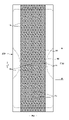
<有孔不織布の接着>
有孔不織布は、外部に露出する露出面と反対側の支持面において、支持面に面する他のシート(有孔不織布がカバーシート20の場合は、液不透過性シート11が他のシートとなる)に対してホットメルト接着剤20Hを介して接着することができる。この接着パターンは特に限定されるものではないが、図11に示されるカバー不織布20と液不透過性シート11との接着構造のように、孔14と重なる領域の周縁部14cより中央側にはホットメルト接着剤20Hがなく、孔14と重なる領域の周縁部14c以外ではホットメルト接着剤20Hが連続面状に存在していると好ましい。孔14と重なる領域の周縁部14cより中央側にはホットメルト接着剤20Hがないため、ホットメルト接着剤20Hによりべとべとした肌触りになりにくく、かつ孔14の周囲の突出部14eは確実に固定される。
<Adhesion of perforated nonwoven fabric>
The perforated nonwoven fabric has another sheet facing the supporting surface on the supporting surface opposite to the exposed surface exposed to the outside (when the perforated nonwoven fabric is the
代表的な接着状態としては、図11(a)(b)に示すように、孔14と重なる領域にはホットメルト接着剤20Hがなく、孔14と重なる領域以外ではホットメルト接着剤20Hが連続面状に存在している状態、図11(c)(d)に示すように、孔14と重なる領域の周縁部14cにホットメルト接着剤20Hがはみ出しているが、孔14と重なる領域の周縁部14cより中央側にはホットメルト接着剤20Hがなく、孔14と重なる領域の周縁部14c以外ではホットメルト接着剤20Hが連続面状に存在している状態を例示することができる。また、孔14と重なる領域の周縁部14cにおけるホットメルト接着剤20Hのはみ出し幅は有孔不織布の厚みの半分以下で、0.5mm以下程度であることが好ましい。また、孔14と重なる領域の面積の80%以上の部分にホットメルト接着剤20Hが存在しないことが望ましい。これらのような接着構造は、例えば特許文献4記載の方法により形成することができる。
As a representative adhesive state, as shown in FIGS. 11A and 11B, there is no hot-melt adhesive 20H in the area overlapping the
<有孔不織布の白色度>
図示例のカバー不織布20のように、外部に露出する露出面を有する有孔不織布において、厚みが0.30~1.5mmであり、かつ孔14の最小寸法(MD方向の寸法及びCD方向の寸法のうち短い方の寸法を意味する。例えばMD方向に沿う長軸を有する楕円孔14の場合はCD方向の寸法を意味し、円の場合は直径を意味する)が0.6~5mmである場合、有孔不織布における露出面の白色度が70%以上であると、孔14の外側の部分の白色度が高いために、孔14の外側の部分と孔14の縁に生ずる陰影との差が大きくなり、孔14を視認しやすくなるため好ましい。
<Whiteness of perforated nonwoven fabric>
Like the
特に好ましい有孔不織布の厚みは0.35~1.2mmである。また、特に好ましい有孔不織布の孔14の最小寸法は0.60~1.2mmである。さらに、特に好ましい有孔不織布の露出面の白色度は73%以上であり、80%以上であるとさらに好ましい。
A particularly preferred thickness of the perforated nonwoven fabric is 0.35 to 1.2 mm. Also, the minimum dimension of the
有孔不織布の白色度を上げるためには密度を高くすることもできるが、費用が嵩むだけでなく、柔軟性も低下する。よって、有孔不織布は、構成繊維の繊度を1.8~6.0dtex程度、かつ目付けを15~25g/m2程度とし、白色度の不足を酸化チタン等の白色顔料を適量含有させることにより補うことが好ましい。このような条件を満たしつつ、十分な強度を有する有孔不織布としては、スパンボンド不織布に孔を形成したものが好適である。 Density can be increased to increase the whiteness of the perforated nonwoven fabric, but this not only increases cost but also reduces softness. Therefore, the perforated nonwoven fabric has a fiber fineness of about 1.8 to 6.0 dtex and a weight per unit area of about 15 to 25 g/m 2 . Supplementation is preferred. As the perforated nonwoven fabric which satisfies these conditions and has sufficient strength, a spunbonded nonwoven fabric having holes formed therein is suitable.
有孔不織布の白色度が高すぎると、有孔不織布の裏側に重なる部分、例えば有孔不織布の支持面に面する他のシート(図示例のように有孔不織布がカバーシート20の場合は、液不透過性シート11が他のシートとなる)に、有孔不織布の外面から透けて見える表示が印刷されている場合に、その表示が見えにくくなるおそれがある。よって、有孔不織布の白色度は85%以下であると好ましい。なお、表示は、装飾のための模様(絵やワンポイントのキャラクター含む)、使用方法や使用補助、サイズ等の機能表示、あるいは製造者や製品名、特徴的機能等の標章表示等であり、適宜の部材に印刷等により付加されるものである。
If the whiteness of the perforated nonwoven fabric is too high, the portion overlapping the back side of the perforated nonwoven fabric, such as another sheet facing the support surface of the perforated nonwoven fabric (if the perforated nonwoven fabric is the
有孔不織布の支持面に面する他のシート(図示例のように有孔不織布がカバーシート20の場合は、液不透過性シート11が他のシートとなる)の白色度は特に限定されるものではないが、当該他のシートにおける有孔不織布側の面は、孔14を通じて露出する部分である。よって、当該他のシートにおける、有孔不織布側の面における少なくとも非着色部分の白色度が、有孔不織布の露出面と同様に70%以上、より好ましくは80%以上であると、この白色度の高い部分が孔14の内側に露出することにより、孔14の内側の部分と孔14の縁に生ずる陰影との差が大きくなり、より一層、孔14を視認しやすくなる。なお、有孔不織布の支持面に面する他のシートには前述のように表示を、印刷等により付加することがあり、このような表示のための着色部分では白色度が70%以上とならないことがある。しかし、着色部分と重なる孔14は、着色部分が背景となって視認性が良好となるため、少なくとも非着色部分(非印刷部分)の白色度が高いことにより、孔14全体としての視認性が向上する。
The whiteness of another sheet facing the support surface of the perforated nonwoven fabric (when the perforated nonwoven fabric is the
<効果確認試験>
表1に示される各種のカバー不織布を用い、図1~図7に示される構造の内装体200を製造し、カバー不織布20の孔14の視認性の良さを、◎…孔をはっきりと識別できる、〇…孔を識別できる、×…孔が周囲に同化して識別しにくい、の三段階で評価した。評価結果を表1に示した。カバー不織布20及び液不透過性シート11の白色度の測定方法は前述のとおりである。なお、本試験の白色度の測定に際しては、日本電色工業株式会社製の簡易型分光色差計NF333を用い、同一の測定面おける5か所(液不透過性シート11の場合は最も白色度が高い非着色部分)で測定を行い、その平均値(N=5)を求めた。また、カバー不織布の孔14の最小寸法は、自然長の状態でマイクロスコープを用いて見かけの寸法を測定した。
<Effect confirmation test>
Using the various cover nonwoven fabrics shown in Table 1, the
表1に示されるように、白色度が70%未満のサンプル5及びサンプル6、並びに白色度は70%以上であるものの孔の最小寸法が0.6mm未満のサンプル7では、孔が周囲と同化して識別しにくい結果となった。これに対して、白色度が70%以上、孔の最小寸法が0.6mm以上のサンプル1~4は、孔の視認性が良好な結果となった。
As shown in Table 1, in

<明細書中の用語の説明>
明細書中の以下の用語は、明細書中に特に記載が無い限り、以下の意味を有するものである。
<Description of terms in the specification>
The following terms in the specification have the following meanings unless otherwise specified in the specification.
・「前後方向」とは図中に符号LDで示す方向(縦方向)を意味し、「幅方向」とは図中にWDで示す方向(左右方向)を意味し、前後方向と幅方向とは直交するものである。 ・"Front-back direction" means the direction (longitudinal direction) indicated by symbol LD in the figure, and "width direction" means the direction (left-right direction) indicated by WD in the figure. are orthogonal.
・「MD方向」及び「CD方向」とは、製造設備における流れ方向(MD方向)及びこれと直交する横方向(CD方向)を意味し、製品の部分によっていずれか一方が前後方向となるものであり、他方が幅方向となるものである。不織布のMD方向は、不織布の繊維配向の方向である。繊維配向とは、不織布の繊維が沿う方向であり、例えば、TAPPI標準法T481の零距離引張強さによる繊維配向性試験法に準じた測定方法や、前後方向及び幅方向の引張強度比から繊維配向方向を決定する簡易的測定方法により判別することができる。 ・"MD direction" and "CD direction" mean the flow direction (MD direction) and the transverse direction (CD direction) perpendicular to this in the manufacturing equipment, and one of them is the front-back direction depending on the part of the product and the other is the width direction. The MD direction of a nonwoven fabric is the direction of fiber orientation of the nonwoven fabric. The fiber orientation is the direction along which the fibers of the nonwoven fabric are aligned. It can be determined by a simple measurement method for determining the orientation direction.
・「表側」とはパンツタイプ使い捨ておむつを着用した際に着用者の肌に近い方を意味し、「裏側」とはパンツタイプ使い捨ておむつを着用した際に着用者の肌から遠い方を意味する。 ・"Front side" means the side closer to the wearer's skin when the pants-type disposable diaper is worn, and the "back side" means the side farther from the wearer's skin when the pants-type disposable diaper is worn. .
・「表面」とは部材の、パンツタイプ使い捨ておむつを着用した際に着用者の肌に近い方の面を意味し、「裏面」とはパンツタイプ使い捨ておむつを着用した際に着用者の肌から遠い方の面を意味する。 ・"Front surface" means the side of the member that is closest to the wearer's skin when wearing the pants-type disposable diaper, and the "back surface" means the side that is close to the wearer's skin when wearing the pants-type disposable diaper. means the far side.
・「面積率」とは単位面積に占める対象部分の割合を意味し、対象領域(例えばカバー不織布)における対象部分(例えば孔)の総和面積を当該対象領域の面積で除して百分率で表すものである。対象部分が間隔を空けて多数設けられる形態では、対象部分が10個以上含まれるような大きさに対象領域を設定して、面積率を求めることが望ましい。例えば、孔の面積率は、例えばKEYENCE社の商品名VHX-1000を使用し、測定条件を20倍として、以下の手順で測定することができる。
(1)20倍のレンズにセットし、ピントを調節する。穴が4×6入るように不織布の位置を調整する。
(2)孔の領域の明るさを指定し、孔の面積を計測する。
(3)「計測・コメント」の「面積計測」の色抽出をクリックする。孔の部分をクリックする。
(4)「一括計測」をクリックし、「計測結果ウィンドを表示」にチェックを入れ、CSVデータで保存をする。
・"Area ratio" means the ratio of the target portion to the unit area, and is expressed as a percentage by dividing the total area of the target portion (e.g., holes) in the target region (e.g., cover nonwoven fabric) by the area of the target region. is. In a form in which a large number of target portions are provided at intervals, it is desirable to determine the area ratio by setting the target region to a size that includes 10 or more target portions. For example, the pore area ratio can be measured by using, for example, VHX-1000 (trade name) manufactured by KEYENCE Co. under the following procedure under the measurement condition of 20 times.
(1) Set on a 20x lens and adjust the focus. Adjust the position of the non-woven fabric so that there are 4×6 holes.
(2) Designate the brightness of the area of the hole and measure the area of the hole.
(3) Click the color extraction of "area measurement" of "measurement/comment". Click on the part of the hole.
(4) Click "Batch measurement", check "Display measurement result window", and save as CSV data.
・「伸長率」は、自然長を100%としたときの値を意味する。例えば、伸長率が200%とは、伸長倍率が2倍であることと同義である。 - "Elongation rate" means a value when the natural length is taken as 100%. For example, an elongation rate of 200% is synonymous with an elongation ratio of 2 times.
・「ゲル強度」は次のようにして測定されるものである。人工尿(尿素:2wt%、塩化ナトリウム:0.8wt%、塩化カルシウム二水和物:0.03wt%、硫酸マグネシウム七水和物:0.08wt%、及びイオン交換水:97.09wt%を混合したもの)49.0gに、高吸収性ポリマーを1.0g加え、スターラーで攪拌させる。生成したゲルを40℃×60%RHの恒温恒湿槽内に3時間放置したあと常温にもどし、カードメーター(I.techno Engineering社製:Curdmeter-MAX ME-500)でゲル強度を測定する。 - "Gel strength" is measured as follows. Artificial urine (urea: 2 wt%, sodium chloride: 0.8 wt%, calcium chloride dihydrate: 0.03 wt%, magnesium sulfate heptahydrate: 0.08 wt%, and deionized water: 97.09 wt% 1.0 g of superabsorbent polymer is added to 49.0 g of the mixture) and stirred with a stirrer. The resulting gel is left in a constant temperature and humidity bath at 40° C. and 60% RH for 3 hours, then returned to room temperature, and the gel strength is measured with a card meter (Curdmeter-MAX ME-500 manufactured by I. techno Engineering).
・「目付け」は次のようにして測定されるものである。試料又は試験片を予備乾燥した後、標準状態(試験場所は、温度23±1℃、相対湿度50±2%)の試験室又は装置内に放置し、恒量になった状態にする。予備乾燥は、試料又は試験片を温度100℃の環境で恒量にすることをいう。なお、公定水分率が0.0%の繊維については、予備乾燥を行わなくてもよい。恒量になった状態の試験片から、試料採取用の型板(100mm×100mm)を使用し、100mm×100mmの寸法の試料を切り取る。試料の重量を測定し、100倍して1平米あたりの重さを算出し、目付けとする。
- "Matsuke" is measured as follows. After pre-drying the sample or test piece, it is left in a test room or apparatus under standard conditions (test location: temperature 23±1° C.,
・「厚み」は、自動厚み測定器(KES-G5 ハンディ圧縮計測プログラム)を用い、荷重:0.098N/cm2、及び加圧面積:2cm2の条件下で自動測定する。有孔不織布の厚みは、孔及びその周囲の突出部以外の部分で測定する。 - "Thickness" is automatically measured using an automatic thickness gauge (KES-G5 handy compression measurement program) under the conditions of a load of 0.098 N/cm 2 and a pressurized area of 2 cm 2 . The thickness of the perforated nonwoven fabric is measured at portions other than the perforations and the protrusions around them.
・吸水量は、JIS K7223-1996「高吸水性樹脂の吸水量試験方法」によって測定する。 ・The amount of water absorption is measured according to JIS K7223-1996 "Testing method for water absorption of superabsorbent resin".
・吸水速度は、2gの高吸収性ポリマー及び50gの生理食塩水を使用して、JIS K7224‐1996「高吸水性樹脂の吸水速度試験法」を行ったときの「終点までの時間」とする。 ・The water absorption rate is the "time to the end point" when JIS K7224-1996 "Test method for water absorption rate of superabsorbent polymer" is performed using 2g of superabsorbent polymer and 50g of physiological saline. .
・「展開状態」とは、収縮や弛み無く平坦に展開した状態を意味する。 - "Unfolded state" means a flat unfolded state without contraction or slack.
・各部の寸法は、特に記載が無い限り、自然長状態ではなく展開状態における寸法を意味する。 ・Unless otherwise specified, the dimensions of each part mean the dimensions in the unfolded state, not in the natural length state.
・「溶融粘度」は、JIS Z 8803に従い、ブルックフィールドB型粘度計(スピンドルNo.027)を用いて、規定の温度で測定されるものである。 - "Melt viscosity" is measured at a specified temperature using a Brookfield type B viscometer (spindle No. 027) according to JIS Z 8803.
・試験や測定における環境条件についての記載が無い場合、その試験や測定は、標準状態(試験場所は、温度23±1℃、相対湿度50±2%)の試験室又は装置内で行うものとする。
・If there is no description about environmental conditions for testing and measurement, the test and measurement shall be performed in a laboratory or equipment under standard conditions (test location: temperature 23±1°C,
本発明は、パンツタイプ使い捨ておむつやテープタイプ使い捨ておむつの他、パッドタイプ使い捨ておむつ、使い捨て水着、おむつカバー、生理用ナプキン等、使い捨て着用物品全般に利用できるものである。 INDUSTRIAL APPLICABILITY The present invention can be used for general disposable wearing articles such as underpants-type disposable diapers, tape-type disposable diapers, pad-type disposable diapers, disposable swimsuits, diaper covers, sanitary napkins, and the like.
11…液不透過性シート、12…外装体、12A…サイドシール部、12B…後側外装体、12F…前側外装体、12H…内側シート層、12S…外側シート層、20…カバー不織布、20H…ホットメルト接着剤、14…孔、14e…突出部、18…不要弾性部材、200…内装体、201…内外接合部、30…トップシート、40…中間シート、50…吸収要素、56…吸収体、58…包装シート、60…側部ギャザー、62…ギャザー不織布、A1…非伸縮領域、A2…伸縮領域、C…臀部カバー部、L…中間領域、LD…前後方向、LO…脚開口、T…胴周り領域、U…ウエスト下方部、W…ウエスト部、WD…幅方向、WO…ウエスト開口、93…無孔部分。
DESCRIPTION OF
Claims (7)
前記有孔不織布は、外部に露出する露出面と、他のシートに接着された支持面とを有している、
使い捨て着用物品であって、
前記有孔不織布の前記孔は、ピンが繊維間に挿入されて押し広げられて形成された非打ち抜きタイプの孔であり、
前記有孔不織布の目付けは15~25g/m 2 であり、
前記有孔不織布の厚みは0.30~1.2mmであり、
前記孔の形状は真円形又は楕円形であり、
前記孔の最小寸法は、0.6~1.2mmであり、
前記有孔不織布における前記露出面の白色度は70%以上であり、
前記他のシートにおける、前記有孔不織布側の面における少なくとも非着色部分の白色度が80%以上であり、
前記孔の外側の部分、前記孔の縁、及び前記孔の内側の部分が外部に露出する、
ことを特徴とする使い捨て着用物品。 It has a perforated nonwoven fabric in which a large number of holes penetrating on the front and back are provided at intervals,
The perforated nonwoven fabric has an exposed surface exposed to the outside and a support surface adhered to another sheet,
Disposable wearing articles,
The holes of the perforated nonwoven fabric are non-punched holes formed by inserting pins between fibers and expanding them,
The perforated nonwoven fabric has a basis weight of 15 to 25 g/m 2 ,
The perforated nonwoven fabric has a thickness of 0.30 to 1.2 mm,
The shape of the hole is a perfect circle or an ellipse,
the minimum dimension of the hole is 0.6 to 1.2 mm;
The whiteness of the exposed surface of the perforated nonwoven fabric is 70% or more ,
In the other sheet, the whiteness of at least the non-colored portion on the surface on the perforated nonwoven fabric side is 80% or more,
An outer portion of the hole, an edge of the hole, and an inner portion of the hole are exposed to the outside.
A disposable wearing article characterized by:
請求項1記載の使い捨て着用物品。 The perforated nonwoven fabric is a nonwoven fabric containing a white pigment and having a fineness of the constituent fibers of 1.8 to 6.0 dtex.
The disposable wearing article according to claim 1.
前記有孔不織布の白色度が85%以下である、
請求項1又は2記載の連結式使い捨て着用物品。 A display that can be seen through the exposed surface of the perforated nonwoven fabric is printed on a portion of the perforated nonwoven fabric that overlaps the opposite side of the exposed surface,
The whiteness of the perforated nonwoven fabric is 85% or less,
The connectable disposable wearing article according to claim 1 or 2.
前記有孔不織布における前記孔の縁部には周囲よりも繊維密度の高い高密度部が形成されている、
請求項1記載の使い捨て着用物品。 The perforated nonwoven fabric is a long fiber nonwoven fabric having a constituent fiber fineness of 0.1 to 5.0 dtex, a basis weight of 15 to 20 g/m 2 and a thickness of 0.3 to 0.8 mm,
A high-density part having a higher fiber density than the surrounding area is formed at the edge of the hole in the perforated nonwoven fabric,
The disposable wearing article according to claim 1.
前記カバー不織布が前記有孔不織布であり、前記液不透過性シートが前記他のシートである、
請求項1~4のいずれか1項に記載の使い捨て着用物品。 An absorbent article comprising an absorbent body, a breathable liquid-impermeable sheet covering the back side of the absorbent body, and a cover nonwoven fabric covering the back side of the liquid-impermeable sheet,
The cover nonwoven fabric is the perforated nonwoven fabric, and the liquid-impermeable sheet is the other sheet,
The disposable wearing article according to any one of claims 1-4.
前記孔の前記一方の方向の間隔が1.0~5.0mmであり、
前記他方の方向の間隔が2.5~10.0mmである、
請求項1~5のいずれか1項に記載の使い捨て着用物品。 The holes are arranged so that rows of holes spaced in one of the front-rear direction and width direction are spaced in the other direction,
the distance between the holes in the one direction is 1.0 to 5.0 mm;
the interval in the other direction is 2.5 to 10.0 mm;
The disposable wearing article according to any one of claims 1-5.
前記孔の配列は、前記他方の方向に間隔を空けて並ぶ孔の列が、前記一方の方向に間隔を空けて並ぶものであり、
前記孔の列における前記孔の前記他方の方向の間隔が1.0~5.0mmであり、
前記孔の群における前記孔の前記一方の方向の間隔が2.5~10.0mmである、
請求項1~5のいずれか1項に記載の使い捨て着用物品。 The holes are arranged so that a group of holes arranged in a single wave shape or a chain shape continuing in one of the front-rear direction and the width direction are spaced apart in the other direction,
The arrangement of the holes is such that rows of holes spaced apart in the other direction are spaced in the one direction,
the interval in the other direction of the holes in the row of holes is 1.0 to 5.0 mm;
the spacing of the holes in the group of holes in the one direction is 2.5 to 10.0 mm;
The disposable wearing article according to any one of claims 1-5.
Priority Applications (4)
| Application Number | Priority Date | Filing Date | Title |
|---|---|---|---|
| JP2018238632A JP7218170B2 (en) | 2018-12-20 | 2018-12-20 | Disposable wearing article |
| PCT/JP2019/047815 WO2020129703A1 (en) | 2018-12-20 | 2019-12-06 | Disposable worn article |
| CN201980079678.4A CN113164299B (en) | 2018-12-20 | 2019-12-06 | Disposable wearing article |
| TW108146559A TWI802776B (en) | 2018-12-20 | 2019-12-19 | Disposable clothing items |
Applications Claiming Priority (1)
| Application Number | Priority Date | Filing Date | Title |
|---|---|---|---|
| JP2018238632A JP7218170B2 (en) | 2018-12-20 | 2018-12-20 | Disposable wearing article |
Publications (3)
| Publication Number | Publication Date |
|---|---|
| JP2020099442A JP2020099442A (en) | 2020-07-02 |
| JP2020099442A5 JP2020099442A5 (en) | 2022-01-04 |
| JP7218170B2 true JP7218170B2 (en) | 2023-02-06 |
Family
ID=71101451
Family Applications (1)
| Application Number | Title | Priority Date | Filing Date |
|---|---|---|---|
| JP2018238632A Active JP7218170B2 (en) | 2018-12-20 | 2018-12-20 | Disposable wearing article |
Country Status (4)
| Country | Link |
|---|---|
| JP (1) | JP7218170B2 (en) |
| CN (1) | CN113164299B (en) |
| TW (1) | TWI802776B (en) |
| WO (1) | WO2020129703A1 (en) |
Citations (3)
| Publication number | Priority date | Publication date | Assignee | Title |
|---|---|---|---|---|
| JP2014226215A (en) | 2013-05-20 | 2014-12-08 | 株式会社リブドゥコーポレーション | Absorbent article |
| US20170258955A1 (en) | 2016-03-09 | 2017-09-14 | The Procter & Gamble Company | Absorbent article with activatable material |
| JP2017537680A (en) | 2014-11-06 | 2017-12-21 | ザ プロクター アンド ギャンブル カンパニー | Patterned perforated web, laminate, and method for producing them |
Family Cites Families (5)
| Publication number | Priority date | Publication date | Assignee | Title |
|---|---|---|---|---|
| US5933841A (en) * | 1996-05-17 | 1999-08-03 | Ameritech Corporation | Structured document browser |
| JPH11299825A (en) * | 1998-04-20 | 1999-11-02 | Uni Charm Corp | Disposable body fluid absorptive article |
| JP2006181294A (en) * | 2004-12-28 | 2006-07-13 | Kao Corp | Top sheet for absorbent article |
| JP6560015B2 (en) * | 2014-05-30 | 2019-08-14 | 花王株式会社 | Disposable diapers |
| JP6351685B2 (en) * | 2016-10-21 | 2018-07-04 | 大王製紙株式会社 | Pants-type disposable diaper |
-
2018
- 2018-12-20 JP JP2018238632A patent/JP7218170B2/en active Active
-
2019
- 2019-12-06 CN CN201980079678.4A patent/CN113164299B/en active Active
- 2019-12-06 WO PCT/JP2019/047815 patent/WO2020129703A1/en active Application Filing
- 2019-12-19 TW TW108146559A patent/TWI802776B/en active
Patent Citations (3)
| Publication number | Priority date | Publication date | Assignee | Title |
|---|---|---|---|---|
| JP2014226215A (en) | 2013-05-20 | 2014-12-08 | 株式会社リブドゥコーポレーション | Absorbent article |
| JP2017537680A (en) | 2014-11-06 | 2017-12-21 | ザ プロクター アンド ギャンブル カンパニー | Patterned perforated web, laminate, and method for producing them |
| US20170258955A1 (en) | 2016-03-09 | 2017-09-14 | The Procter & Gamble Company | Absorbent article with activatable material |
Also Published As
| Publication number | Publication date |
|---|---|
| TW202023505A (en) | 2020-07-01 |
| JP2020099442A (en) | 2020-07-02 |
| TWI802776B (en) | 2023-05-21 |
| CN113164299A (en) | 2021-07-23 |
| CN113164299B (en) | 2022-06-24 |
| WO2020129703A1 (en) | 2020-06-25 |
Similar Documents
| Publication | Publication Date | Title |
|---|---|---|
| RU2723802C1 (en) | Absorbent product | |
| RU2723828C1 (en) | Pants-type disposable diaper | |
| RU2731745C2 (en) | Disposable panty-type diaper | |
| CN107874914B (en) | Disposable wearing article and method for attaching perforated nonwoven fabric | |
| JP6247728B1 (en) | Disposable wearing article and method for attaching perforated nonwoven fabric | |
| JP6207785B1 (en) | Disposable wearing items | |
| JP6767222B2 (en) | Disposable diapers | |
| JP7218170B2 (en) | Disposable wearing article | |
| JP7129262B2 (en) | Elastic structure for disposable wearing article, and pants-type disposable wearing article having this elastic structure | |
| JP6347826B2 (en) | Pants-type disposable diaper | |
| JP2021078872A5 (en) | ||
| JP7129190B2 (en) | Elastic structure for disposable wearing article, and pants-type disposable wearing article having this elastic structure | |
| JP7212804B1 (en) | Disposable wearing article | |
| JP7299332B2 (en) | Stretchable member and disposable wearing article having this stretchable member | |
| JP2020099442A5 (en) | ||
| WO2021100775A1 (en) | Disposable wearable article | |
| JP7129179B2 (en) | Elastic structure of absorbent article | |
| JP2021078871A5 (en) | ||
| JP2023009585A (en) | Connection-type disposable wearable article | |
| CN114599323A (en) | Disposable diaper having a disposable diaper | |
| JP2021078868A5 (en) | ||
| JP2023009585A5 (en) | ||
| JP2019150404A (en) | Tape type disposable diaper |
Legal Events
| Date | Code | Title | Description |
|---|---|---|---|
| A521 | Request for written amendment filed |
Free format text: JAPANESE INTERMEDIATE CODE: A523 Effective date: 20211116 |
|
| A621 | Written request for application examination |
Free format text: JAPANESE INTERMEDIATE CODE: A621 Effective date: 20211116 |
|
| A131 | Notification of reasons for refusal |
Free format text: JAPANESE INTERMEDIATE CODE: A131 Effective date: 20220819 |
|
| A521 | Request for written amendment filed |
Free format text: JAPANESE INTERMEDIATE CODE: A523 Effective date: 20221006 |
|
| TRDD | Decision of grant or rejection written | ||
| A01 | Written decision to grant a patent or to grant a registration (utility model) |
Free format text: JAPANESE INTERMEDIATE CODE: A01 Effective date: 20230106 |
|
| A61 | First payment of annual fees (during grant procedure) |
Free format text: JAPANESE INTERMEDIATE CODE: A61 Effective date: 20230125 |
|
| R150 | Certificate of patent or registration of utility model |
Ref document number: 7218170 Country of ref document: JP Free format text: JAPANESE INTERMEDIATE CODE: R150 |