CN113164299B - Disposable wearing article - Google Patents
Disposable wearing article Download PDFInfo
- Publication number
- CN113164299B CN113164299B CN201980079678.4A CN201980079678A CN113164299B CN 113164299 B CN113164299 B CN 113164299B CN 201980079678 A CN201980079678 A CN 201980079678A CN 113164299 B CN113164299 B CN 113164299B
- Authority
- CN
- China
- Prior art keywords
- nonwoven fabric
- holes
- sheet
- intervals
- gather
- Prior art date
- Legal status (The legal status is an assumption and is not a legal conclusion. Google has not performed a legal analysis and makes no representation as to the accuracy of the status listed.)
- Active
Links
Images


Classifications
-
- A—HUMAN NECESSITIES
- A61—MEDICAL OR VETERINARY SCIENCE; HYGIENE
- A61F—FILTERS IMPLANTABLE INTO BLOOD VESSELS; PROSTHESES; DEVICES PROVIDING PATENCY TO, OR PREVENTING COLLAPSING OF, TUBULAR STRUCTURES OF THE BODY, e.g. STENTS; ORTHOPAEDIC, NURSING OR CONTRACEPTIVE DEVICES; FOMENTATION; TREATMENT OR PROTECTION OF EYES OR EARS; BANDAGES, DRESSINGS OR ABSORBENT PADS; FIRST-AID KITS
- A61F13/00—Bandages or dressings; Absorbent pads
- A61F13/15—Absorbent pads, e.g. sanitary towels, swabs or tampons for external or internal application to the body; Supporting or fastening means therefor; Tampon applicators
- A61F13/45—Absorbent pads, e.g. sanitary towels, swabs or tampons for external or internal application to the body; Supporting or fastening means therefor; Tampon applicators characterised by the shape
- A61F13/49—Absorbent articles specially adapted to be worn around the waist, e.g. diapers
-
- A—HUMAN NECESSITIES
- A61—MEDICAL OR VETERINARY SCIENCE; HYGIENE
- A61F—FILTERS IMPLANTABLE INTO BLOOD VESSELS; PROSTHESES; DEVICES PROVIDING PATENCY TO, OR PREVENTING COLLAPSING OF, TUBULAR STRUCTURES OF THE BODY, e.g. STENTS; ORTHOPAEDIC, NURSING OR CONTRACEPTIVE DEVICES; FOMENTATION; TREATMENT OR PROTECTION OF EYES OR EARS; BANDAGES, DRESSINGS OR ABSORBENT PADS; FIRST-AID KITS
- A61F13/00—Bandages or dressings; Absorbent pads
- A61F13/15—Absorbent pads, e.g. sanitary towels, swabs or tampons for external or internal application to the body; Supporting or fastening means therefor; Tampon applicators
- A61F13/51—Absorbent pads, e.g. sanitary towels, swabs or tampons for external or internal application to the body; Supporting or fastening means therefor; Tampon applicators characterised by the outer layers
Landscapes
- Health & Medical Sciences (AREA)
- Epidemiology (AREA)
- Engineering & Computer Science (AREA)
- Biomedical Technology (AREA)
- Heart & Thoracic Surgery (AREA)
- Vascular Medicine (AREA)
- Life Sciences & Earth Sciences (AREA)
- Animal Behavior & Ethology (AREA)
- General Health & Medical Sciences (AREA)
- Public Health (AREA)
- Veterinary Medicine (AREA)
- Absorbent Articles And Supports Therefor (AREA)
- Laminated Bodies (AREA)
Abstract
In a disposable wearing article, the visual confirmation of the holes of a perforated nonwoven fabric exposed to the outside is improved. The above object is achieved by a disposable wearing article comprising a perforated nonwoven fabric having a plurality of holes penetrating through front and back surfaces thereof at intervals, the perforated nonwoven fabric having an exposed surface exposed to the outside and a supporting surface facing another sheet, the perforated nonwoven fabric having a thickness of 0.30 to 1.5mm, a minimum size of the holes of 0.6 to 5mm, and a whiteness of the exposed surface of the perforated nonwoven fabric of 70% or more.
Description
Technical Field
The present invention relates to a disposable wearing article having a portion to which an apertured nonwoven fabric is attached.
Background
In disposable wearing articles such as disposable diapers and sanitary napkins, nonwoven fabrics are often used on the outer surface and inner surface of the products in order to provide the appearance and feel of the skin like a cloth. As the nonwoven fabric, a non-porous nonwoven fabric having no pores except for fiber gaps and a porous nonwoven fabric having a plurality of pores penetrating through the front and back surfaces is used (see patent documents 1 to 4).
The perforated nonwoven fabric is effective even when added with a functional aesthetic for improving air permeability or liquid permeability, and therefore, it is very important (visual effect) to be able to visually confirm the presence of the perforations more clearly.
However, since the nonwoven fabric used for disposable wearing articles is thin to some extent, if the holes are made small to some extent, the holes are assimilated to the surrounding non-porous portions, which has a problem in that: it is difficult to visually confirm the presence or absence of the holes. Thus, the visual effect is not sufficiently exhibited, and the function of improving the air permeability or the liquid permeability is difficult to be accurately transmitted to the user.
Documents of the prior art
Patent document
Patent document 1: japanese patent laid-open publication No. 2015-128573
Patent document 2: japanese laid-open patent publication No. 2002-178428
Patent document 3: japanese laid-open patent publication No. 2009-136504
Patent document 4: japanese patent laid-open publication No. 2018-51181
Disclosure of Invention
Problems to be solved by the invention
Therefore, a main object of the present invention is to improve the visibility of the holes of a perforated nonwoven fabric exposed to the outside in a disposable wearing article.
Means for solving the problems
A typical embodiment of the present invention that solves the above problems is as follows.
< mode 1 >)
A disposable wearing article having a perforated nonwoven fabric in which a plurality of holes penetrating through front and back surfaces are provided at intervals, the perforated nonwoven fabric comprising: an exposed surface exposed to the outside; and a support surface facing the other sheet, wherein the thickness of the perforated nonwoven fabric is 0.30mm to 1.5mm, the minimum size of the perforations is 0.6mm to 5mm, and the whiteness of the exposed surface of the perforated nonwoven fabric is 70% or more.
(Effect)
The present inventors have studied the visual confirmation of the holes of the perforated nonwoven fabric and found that the visual confirmation of the holes is lowered when the whiteness of the exposed surface of the perforated nonwoven fabric is low. The reason is not clear, but is considered to be as follows. That is, the visibility of the holes varies depending on the degree of the shadow formed at the edge of the hole, and when the whiteness of the apertured nonwoven fabric is less than 70%, the whiteness of the portion outside the hole is low, so that the difference between the shadow formed at the edge of the hole and the portion outside the hole is small, and the visibility of the hole is lowered. This tendency becomes remarkable particularly when the thickness of the apertured nonwoven fabric and the minimum size of the apertures are within the above-mentioned ranges. Here, if the whiteness of the apertured nonwoven fabric is 70% or more, the whiteness of the portion outside the apertures is high, and therefore the difference between the portion outside the apertures and the shadow formed at the edges of the apertures becomes large, and even when the nonwoven fabric is thin to some extent and the apertures are small to some extent, the apertures are easily visually recognized. The disposable wearing article is completed based on the above-mentioned findings, and is characterized in that, when the nonwoven fabric is thin to some extent and the holes are small to some extent, the whiteness of the perforated nonwoven fabric is set to 70% or more, thereby improving the visibility of the holes.
The whiteness is measured according to JIS P8148: 2001 "ISO whiteness (diffuse blue reflectance)". In particular, when the measurement target is a perforated nonwoven fabric, a test piece bundle is used in which: the test piece bundle is formed by stacking test pieces such that at least the hole of the uppermost test piece and the hole of the adjacent test piece on the lower side thereof do not overlap. In this specification, the sample size is specified, but the sample size is not limited as long as the measurement can be performed by the measurement device. In the case of measuring the whiteness of a nonwoven fabric having pores in a product, when a sample having a sufficient size cannot be obtained in the measurement, the whiteness can be measured by preparing the sample from the same material. As the whiteness measuring device, for example, a simple spectrocolorimeter NF333 manufactured by japan electrochromic industries co., or a spectroscopic white color meter PF-10 type can be used. The "minimum dimension" of the hole means the shorter dimension of the dimension in the MD direction and the dimension in the CD direction.
< 2 nd mode >)
The disposable wearing article according to claim 1, wherein the apertured nonwoven fabric has a constituent fiber fineness of 1.8dtex to 6.0dtex and a basis weight of 15g/m2~25g/m2The white pigment-containing nonwoven fabric of (1).
(Effect)
Although the density can be increased in order to increase the whiteness of the apertured nonwoven, this not only increases the cost, but also decreases the flexibility. Therefore, as for the apertured nonwoven fabric, it is preferable that: the fineness and the basis weight are set within the above ranges, and the lack of whiteness is compensated by containing an appropriate amount of a white pigment such as titanium oxide.
< mode 3 >)
The connected disposable wearing article according to claim 1 or 2, wherein a display which is seen through the exposed surface of the perforated nonwoven fabric is printed on a portion overlapping with the opposite side of the exposed surface of the perforated nonwoven fabric, and the whiteness of the perforated nonwoven fabric is 85% or less.
(Effect)
If the whiteness of the apertured nonwoven fabric is too high, if a display which can be seen through from the outer surface of the apertured nonwoven fabric is printed on a portion overlapping the back surface side of the apertured nonwoven fabric, the display may be difficult to see. Therefore, the whiteness of the apertured nonwoven fabric is preferably within the above range.
< 4 th mode >)
A disposable wearing article according to any one of aspects 1 to 3, wherein a whiteness degree of at least a non-colored portion on a surface of the other sheet on the perforated nonwoven fabric side is 70% or more.
(Effect)
The whiteness of the other sheet facing the support surface of the perforated nonwoven fabric is not particularly limited, but the surface of the other sheet on the perforated nonwoven fabric side is a portion exposed through the perforations. Therefore, if the whiteness of at least the non-colored portion on the surface on the perforated nonwoven fabric side of the other sheet is 70% or more, the portion having a high whiteness is exposed inside the perforations, and thus the difference between the portion inside the perforations and the shadow formed at the edges of the perforations becomes large, and the perforations are more easily visually recognized.
< 5 th mode >)
A disposable wearing article according to any one of aspects 1 to 4, comprising: an absorbent body; a liquid-impermeable sheet having air permeability, which covers the back side of the absorbent body; and a cover nonwoven fabric covering the back side of the liquid-impermeable sheet, the cover nonwoven fabric being the porous nonwoven fabric, and the liquid-impermeable sheet being the other sheet.
(Effect)
In a disposable wearing article, generally, the back surface of the absorbent body is covered with a breathable liquid-impermeable sheet, and the back surface of the liquid-impermeable sheet is covered with a hood nonwoven fabric, so that the disposable wearing article has a cloth-like appearance. In addition, since the cover nonwoven fabric is exposed on the outer surface of the product, the aesthetic appearance is an advantage in that consumers can appeal the functional beauty of the product. Therefore, the above-described porous nonwoven fabric having whiteness is preferably applied to such a hood nonwoven fabric.
< 6 th mode >)
The disposable wearing article according to any one of aspects 1 to 5, wherein the holes are arranged in such a manner that: the row of holes arranged at intervals in any one of the front-back direction and the width direction is arranged at intervals in the other direction, the interval of the holes in the one direction is 1.0mm to 5.0mm, and the interval of the holes in the other direction is 2.5mm to 10.0 mm.
(Effect)
The arrangement of the holes of the apertured nonwoven fabric is not particularly limited, but in the case where the apertures are arranged in a fine and regular pattern as in this embodiment, the visual confirmation of the holes is particularly important. Therefore, in the arrangement of the holes as in the present embodiment, it is preferable to have the whiteness and the like of the porous nonwoven fabric.
< 7 th mode >)
A disposable worn article according to any one of modes 1 to 5, wherein the holes are arranged in such a manner that: a group of holes arranged in a single corrugated or chain-like manner continuous in any one of the front-back direction and the width direction are arranged in parallel with a gap in the other direction, and the arrangement of the holes is as follows: the rows of holes arranged at intervals in the other direction are arranged at intervals in the one direction, the intervals of the holes in the rows of holes in the other direction are 1.0mm to 5.0mm, and the intervals of the holes in the group of holes in the one direction are 2.5mm to 10.0 mm.
(Effect)
The arrangement of the holes of the perforated nonwoven fabric is not particularly limited, but in the case where the holes are arranged in a fine and aesthetically regular pattern as in this embodiment, the visual confirmation of the holes is particularly important. Therefore, in the arrangement of the holes as in the present embodiment, it is preferable to have the whiteness and the like of the porous nonwoven fabric.
ADVANTAGEOUS EFFECTS OF INVENTION
According to the invention, the following advantages are achieved: in the disposable wearing article, the visual confirmation of the holes of the perforated nonwoven fabric exposed to the outside is improved.
Drawings
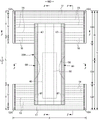
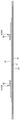
Fig. 1 is a plan view showing an inner surface of a pants-type disposable diaper in an unfolded state.
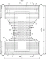
Fig. 2 is a plan view showing an outer surface of the pants-type disposable diaper in an unfolded state.
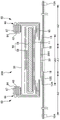
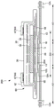
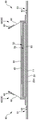
Fig. 3 is a sectional view taken along line 2-2 in fig. 1.
Fig. 4 is a sectional view taken along line 3-3 of fig. 1.
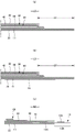
Fig. 5 (a) is a sectional view taken along the line 4-4 in fig. 1, and (b) is a sectional view taken along the line 5-5 in fig. 1.
Fig. 6 is a perspective view (with holes omitted) of a pants-type disposable diaper.
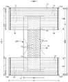
Fig. 7 is a plan view showing the outer surface of the interior body in the expanded state.
Fig. 8 is a plan view showing the outer surface of the interior body in the expanded state together with the outline of the exterior body.
Fig. 9 is a plan view showing an outer surface of the pants-type disposable diaper in an unfolded state.
Fig. 10 (a) is a sectional view taken along line 4-4 of fig. 9, and (b) is a sectional view taken along line 5-5 of fig. 9.
Fig. 11 (a) and (c) are cross-sectional views of bonded portions of the hood nonwoven fabric, and (b) and (d) are plan views.
Fig. 12 is a cross-sectional view taken along line 2-2 of fig. 1, illustrating another manner.
Fig. 13 is a sectional view taken along line 3-3 of fig. 1, showing another mode.
Fig. 14 is a plan view showing an outer surface of a pants-type disposable diaper in an unfolded state.
Fig. 15 (a) is a sectional view taken along line 4-4 of fig. 14, and (b) is a sectional view taken along line 5-5 of fig. 14.
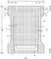
Fig. 16 is a plan view showing the inner surface of the tape-type disposable diaper in an unfolded state.
Fig. 17 is a plan view showing the outer surface of the tape-type disposable diaper in an unfolded state.
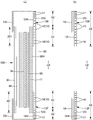
Fig. 18 is a cross-sectional view taken along line 6-6 of fig. 16.
Fig. 19 is a cross-sectional view taken along line 7-7 of fig. 16.
Fig. 20 (a) is a sectional view taken along line 8-8 in fig. 16, (b) is a sectional view taken along line 9-9 in fig. 16, and (c) is a sectional view taken along line 10-10 in fig. 16.
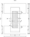
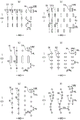
Fig. 21 is an enlarged plan view of important parts showing various patterns of the holes of the perforated nonwoven fabric.
Fig. 22 is an enlarged plan view of important parts showing various patterns of the holes of the perforated nonwoven fabric.
Fig. 23 is an enlarged plan view of an important part of a chain pattern showing the holes of the perforated nonwoven fabric.
Fig. 24 is various cross-sectional views of apertured nonwoven fabrics.
Detailed Description
Next, examples of the disposable wearing article will be described in detail with reference to the drawings. The dotted portion in the cross-sectional view indicates an adhesive as a joining means for joining the respective constituent members positioned on the front and back sides thereof, and is formed by full-surface application of a hot-melt adhesive, linear (ビード) application, curtain (カーテン) application, critical portion (サミット) application or spiral application, pattern application (transfer of a hot-melt adhesive by a relief method), or the like, or a fixed portion of an elastic member is formed by application to the outer peripheral surface of the elastic member by an application gun, size application, or the like, instead of or together with the adhesive. Examples of the hot melt adhesive include EVA adhesives, adhesive rubber adhesives (elastic adhesives), olefin adhesives, and polyester polyamide adhesives, and can be used without particular limitation. As a joining means for joining the respective constituent members, a material-based welding means such as heat sealing or ultrasonic sealing may be employed.
As the nonwoven fabric in the following description, a known nonwoven fabric can be used as appropriate depending on the location and purpose. As the constituent fibers of the nonwoven fabric, for example, synthetic fibers such as olefin-based fibers (e.g., polyethylene, polypropylene, etc.), polyester-based fibers, polyamide-based fibers (composite fibers having a structure such as a core-sheath in addition to single-component fibers), regenerated fibers such as rayon, cuprammonium fiber, etc., natural fibers such as cotton, etc., can be used without particular limitation, and these fibers may be mixed together. In order to improve the flexibility of the nonwoven fabric, the constituent fibers are preferably crimped fibers. The constituent fibers of the nonwoven fabric may be hydrophilic fibers (including fibers having hydrophilicity with a hydrophilic agent), or hydrophobic fibers or water-repellent fibers (including fibers having water repellency with a water-repellent agent). The nonwoven fabric is generally classified into a short fiber nonwoven fabric, a long fiber nonwoven fabric, a spunbond nonwoven fabric, a meltblown nonwoven fabric, a spunlace nonwoven fabric, a hot-rolled (hot-air) nonwoven fabric, a needle-punched nonwoven fabric, a point-bonded nonwoven fabric, a laminated nonwoven fabric (an SSS nonwoven fabric or the like obtained by laminating the same or similar nonwoven fabric layers, an SMS nonwoven fabric or an SMMS nonwoven fabric obtained by laminating different nonwoven fabric layers with a meltblown layer interposed between spunbond layers), and the like according to the length of the fiber, the sheet forming method, the fiber bonding method, or the laminated structure, and any of these may be used.
Example of pants-type Disposable diaper
Fig. 1 to 6 show a pants-type disposable diaper. The pants-type disposable diaper comprises: a front side exterior body 12F constituting a front body portion F; a rear side outer body 12B constituting a rear body portion B; and an interior body 200 provided inside the exterior bodies 12F, 12B so as to extend from the front side exterior body 12F to the rear side exterior body 12B through the crotch portion, both side portions of the front side exterior body 12F and both side portions of the rear side exterior body 12B being joined together to form side seal portions 12A, whereby openings formed by the front and rear end portions of the exterior bodies 12F, 12B become waist openings WO through which the waist of the wearer passes, and portions surrounded by the lower edges of the exterior bodies 12F, 12B and the side edges of the interior body 200 become leg openings LO through which the legs pass on both sides in the width direction of the interior body 200. The inner body 200 is a portion for absorbing and retaining excrement such as urine, and the outer bodies 12F and 12B are portions for supporting the inner body 200 with respect to the body of the wearer. In addition, reference numeral Y denotes the entire length of the diaper in the developed state (the longitudinal length from the edge of the waist opening WO of the front body F to the edge of the waist opening WO of the rear body B), and reference numeral X denotes the full width of the diaper in the developed state.
The pants-type disposable diaper of this example has a waist region T defined as a front-rear direction range (a front-rear direction range from the waist opening WO to the upper end of the leg opening LO) having the side seals 12A, and an intermediate region L defined as a front-rear direction range of a portion forming the leg opening LO (between the front-rear direction region of the front body portion F having the side seals 12A and the front-rear direction region of the rear body portion B having the side seals 12A). The waist region T can be conceptually divided into a "waist portion" W forming an edge portion of the waist opening and a "waist lower portion" U being a portion below the waist opening. In general, in the case where a boundary where the stretching stress in the width direction WD changes (for example, the thickness and the elongation of the elastic member change) is present in the waist region T, a portion closer to the waist opening WO than the boundary closest to the waist opening WO becomes the waist portion W, and in the case where such a boundary is absent, a portion closer to the waist opening WO than the absorbent body 56 or the interior body 200 becomes the waist portion W. The length in the front-back direction thereof may be appropriately determined depending on the size of the product, and for example, the waist portion W may be 15 to 40mm, and the waist lower portion U may be 65 to 120 mm. On the other hand, both side edges of the intermediate region L are narrowed in an コ shape or a curve shape along the leg circumferences of the wearer, and the portions are portions where the legs of the wearer enter. As a result, the pants-type disposable diaper in an unfolded state is formed into a substantially hourglass shape as a whole.
(inner and outer joint part)
The fixation of the interior body 200 to the exterior bodies 12F, 12B may be performed by a bonding means by material fusion such as heat sealing or ultrasonic sealing, or a hot-melt adhesive. In the illustrated embodiment, the inner surfaces of the outer bodies 12F and 12B are fixed to each other by the hot-melt adhesive applied to the back surface of the inner body 200, that is, in this case, the back surface of the liquid-impermeable sheet 11 and the root portion 65 of the side gather portion 60. The inner and outer joint portions 201 that fix the interior body 200 and the exterior bodies 12F, 12B together may be provided over substantially the entire region where the two overlap, and may be provided in portions of the interior body 200 other than both end portions in the width direction, for example.
(inner body)
The inner body 200 may have any shape, but is rectangular in the illustrated embodiment. As shown in fig. 3 to 5, the interior body 200 includes: a topsheet 30 on the body side; a liquid-impermeable sheet 11; and an absorbent member 50 interposed therebetween, the interior body 200 being a main body portion having an absorbent function. Reference numeral 40 denotes an intermediate sheet provided between the top sheet 30 and the absorbent member 50 in order to rapidly move the liquid having permeated the top sheet 30 to the absorbent member 50, and reference numeral 60 denotes side gather portions 60 extending from both side portions of the inner body 200 so as to contact with leg circumferences of the wearer in order to prevent leakage of excrement to both sides of the inner body 200.
(Top sheet)
The top sheet 30 has a liquid-permeable property, and examples thereof include a porous or non-porous nonwoven fabric, a porous plastic sheet, and the like.
Both side portions of the top sheet 30 may be folded back toward the back side at the side edges of the absorbent member 50, or may be extended laterally beyond the side edges of the absorbent member 50 without being folded back.
For the purpose of preventing positional deviation with respect to the back side member, etc., it is desirable that the top sheet 30 is fixed to the member adjacent on the back side by a bonding means based on material fusion such as heat sealing or ultrasonic sealing, or a hot melt adhesive. In the illustrated embodiment, the top sheet 30 is fixed to the front surface of the intermediate sheet 40 and the front surface of the portion of the packaging sheet 58 located on the front surface side of the absorber 56 by a hot melt adhesive applied to the back surface thereof.
(intermediate sheet)
In order to rapidly transfer the liquid having passed through the top sheet 30 to the absorbent member, an intermediate sheet (also referred to as "second sheet") 40 having a liquid passing speed higher than that of the top sheet 30 may be provided. The intermediate sheet 40 not only can rapidly move the liquid toward the absorbent body to improve the absorption performance of the absorbent body, but also can prevent the phenomenon of "back flow" of the absorbed liquid from the absorbent body, and can keep the top sheet 30 in a dry state. The intermediate sheet 40 may also be omitted.
The intermediate sheet 40 may be made of the same material as the top sheet 30, or may be made of spunlace nonwoven fabric, spunbond nonwoven fabric, SMS nonwoven fabric, pulp nonwoven fabric, a mixed sheet of pulp and rayon, point-bond nonwoven fabric, or crepe paper. The air-through nonwoven fabric is particularly bulky and is therefore preferable. In the air-through nonwoven fabric, a composite fiber having a core-sheath structure is preferably used, and in this case, the resin used for the core may be polypropylene (PP), but Polyester (PET) having high rigidity is preferred. The weight per unit area is preferably 20 to 80g/m2More preferably 25 to 60g/m2. The thickness of the raw material fiber of the nonwoven fabric is preferably 2.0 to 10 dtex. In order to make the nonwoven fabric bulky, it is preferable to use a bias fiber, a hollow fiber, or a bias and hollow fiber having no core in the center as a mixed fiber of all or a part of the raw material fibers.
The intermediate sheet 40 in the illustrated embodiment is shorter than the width of the absorber 56 and is disposed at the center, and may be provided over the entire width. The longitudinal length of the intermediate sheet 40 may be the same as the entire length of the diaper, may be the same as the length of the absorbent member 50, or may be within a short length range centered on the liquid-receiving region.
For the purpose of preventing positional deviation or the like of the intermediate sheet 40 with respect to the rear surface side member, it is desirable that the intermediate sheet 40 is fixed to the member adjacent on the rear surface side by a bonding means by material fusion such as heat sealing or ultrasonic sealing, or a hot melt adhesive. In the illustrated embodiment, the intermediate sheet 40 is fixed to the front surface of the portion of the packaging sheet 58 located on the front surface side of the absorber 56 by a hot melt adhesive applied to the back surface thereof.
(liquid-impermeable sheet)
The material of the liquid-impermeable sheet 11 is not particularly limited, and examples thereof include a plastic film made of an olefin resin such as polyethylene or polypropylene, a laminated nonwoven fabric in which a plastic film is provided on the surface of a nonwoven fabric, and a laminate sheet in which a nonwoven fabric and the like are laminated on a plastic film and bonded. As the liquid-impermeable sheet 11, a fabric having liquid-impermeable property and moisture-permeable property is preferably used from the viewpoint of prevention of stuffiness. As a plastic film having moisture permeability, a microporous plastic film obtained as follows is widely used: an inorganic filler is mixed with an olefin resin such as polyethylene or polypropylene to form a sheet, and the sheet is stretched in a uniaxial or biaxial direction. In addition, as the liquid-impermeable sheet 11, a sheet having liquid-impermeability without using a plastic film may be used, and such a sheet is rendered liquid-impermeable by the following method: a non-woven fabric using micro denier fiber is used; the voids of the fibers are reduced by applying heat or pressure, thereby enhancing the leakage prevention; and coating a super absorbent resin or a hydrophobic resin or a water repellent agent.
The liquid-impermeable sheet 11 may be formed to have a width converging on the back surface side of the absorbent member 50 as shown in the figure, and may extend to both sides of the absorbent member 50 and to both side portions of the surface of the absorbent member 50 on the top sheet 30 side in order to improve leakage prevention. The width of the extending portion is preferably about 5 to 20mm on the left and right sides.
(side gather parts)
The side gather portions 60 extend along the entire front-back direction LD along both side portions of the interior body 200, and are provided to contact the periphery of the legs of the wearer to prevent side leakage.
The side gather portion 60 of the 1 st structure shown in fig. 3 and 4 is a so-called three-dimensional gather portion that rises from the side portion to the front side of the interior body 200. The side gather portions 60 are inclined so that the root side portions rise obliquely toward the widthwise central side and the end side portions rise obliquely outward in the widthwise direction relative to the intermediate portions, but the present invention is not limited thereto, and may be appropriately modified such as a mode in which the entire side gather portions rise obliquely toward the widthwise central side.
To explain in more detail, the side gather portion 60 of the 1 st structure is configured as follows: a band-shaped gather nonwoven fabric 62 having a length equal to the length of the interior body 200 in the front-rear direction is folded back in the width direction WD at the end portion and folded into two layers, and a plurality of elongated gather elastic members 63 are fixed between the folded-back portion and the sheet in the vicinity thereof at intervals in the width direction WD in a state of being elongated in the longitudinal direction. A base end portion (an end portion on the opposite side of the sheet folded-back portion in the width direction WD) of the side gather portion 60 on the opposite side to the tip end portion is a root portion 65 fixed to a side portion of the inner body 200 on the back surface side of the liquid-impermeable sheet 11, and a portion other than the root portion 65 is a main body portion 66 (a portion on the folded-back portion side) protruding from the root portion 65. The main body portion 66 is composed of a root side portion toward the center side in the width direction and a tip side portion turned back from the tip of the root side portion toward the outer side in the width direction. This embodiment is a surface contact type side gather portion 60, but a line contact type side gather portion 60 that is not folded back to the outside in the width direction may be used. The main body portion 66 has both longitudinal end portions thereof fixed to the respective side front folded portions 67 of the top sheet 30 in an folded state, and has a longitudinal intermediate portion therebetween fixed to a free portion 68, and the gather portion elastic member 63 extending in the longitudinal direction LD is fixed to the free portion 68 in an extended state.
As the gather portion nonwoven fabric 62, a nonwoven fabric formed by subjecting a nonwoven fabric excellent in softness, uniformity, and hiding property, such as a spunbond nonwoven fabric (SS, SSs, etc.), an SMS nonwoven fabric (SMS, SSMMS, etc.), and a meltblown nonwoven fabric, to water repellent treatment with silicone or the like as necessary can be suitably used, and the basis weight of the fiber is preferably about 10 to 30g/m2. As the gather portion elastic member 63, a rubber thread or the like can be used. When the spandex rubber wire is used, the thickness is preferably 470 to 1240dtex, and more preferably 620 to 940 dtex. The elongation at fixation is preferably 150 to 350%, more preferably 200 to 300%. Further, as shown in the drawing, the waterproof film 64 may be interposed between the gather nonwoven fabrics 62 folded into two layers, and in this case, the gather nonwoven fabrics 62 may be partially omitted in the portions where the waterproof film 64 is present, but in order to achieve the appearance and the texture of the product like a cloth, it is necessary to form at least the outer surfaces of the side gathers 60 from the base end to the tip ends by the gather nonwoven fabrics 62 as shown in the drawing.
The number of gather elastic members 63 provided at the free portion of the side gather portion 60 is preferably 2 to 6, and more preferably 3 to 5. The arrangement interval 60d is preferably 3 to 10 mm. With such a configuration, the skin can be easily brought into surface contact within the range where the gather portion elastic member 63 is disposed. The gather portion elastic member 63 may be arranged not only on the distal end side but also on the proximal end side.
In the free portions 68 of the side gather portions 60, at least one of a hot-melt adhesive by various application methods and a fixing means by material fusion such as heat sealing or ultrasonic sealing can be used for bonding the inner layer and the outer layer of the gather nonwoven fabric 62 and fixing the gather elastic member 63 sandwiched therebetween. Since the flexibility is impaired when the entire surfaces of the inner layer and the outer layer of the gather nonwoven fabric 62 are bonded, it is preferable that the portions other than the bonded portions of the gather elastic members 63 are not bonded or weakly bonded. In the illustrated embodiment, the structure is as follows: by applying the hot melt adhesive only to the outer peripheral surface of the gather elastic member 63 with an application member such as a coating gun or a glue nozzle and sandwiching the gather elastic member 63 between the inner layer and the outer layer of the gather nonwoven fabric 62, the gather elastic member 63 is fixed to the inner layer and the outer layer of the gather nonwoven fabric 62 and the inner layer and the outer layer of the gather nonwoven fabric 62 with the hot melt adhesive only applied to the outer peripheral surface of the gather elastic member 63.
In addition, at least one of a hot melt adhesive by various application methods and a means by material fusion such as heat sealing or ultrasonic sealing can be used for fixing the waterproof film 64 attached to the side gather portion 60 and the gather portion nonwoven fabric 62 and fixing the lying portion 67 to the side surface of the interior body 200. In the illustrated embodiment, the waterproof film 64 is fixed by slit coating using a hot-melt adhesive. Further, the fixing of the falling portion 67 in the illustrated embodiment is performed by a combination of a hot-melt adhesive and a means by material fusion, but may be performed by any means.
The target of fixing the root portion 65 of the side gather portion 60 may be an appropriate member such as the top sheet 30, the liquid-impermeable sheet 11, and the absorbent member 50 in the inner body 200.
In the side gather portion 60 of the 1 st structure configured as described above, the contraction force of the gather portion elastic member 63 acts to bring the both ends in the front-rear direction closer to each other, but the both ends in the front-rear direction in the main body portion 66 are fixed so as not to stand up, but rather, the both ends are formed as an unfixed free portion therebetween, and therefore, as shown in fig. 3, only the free portion stands up so as to abut against the body side. In particular, if the root portion 65 is located on the back side of the inner body 200, the side gather portion 60 rises so as to open outward in the width direction at the crotch portion and the vicinity thereof, and therefore the side gather portion 60 comes into face contact with the periphery of the leg portion, and the fit is improved.
The dimensions of the side gather portion 60 of the structure 1 can be appropriately determined, but in the case of an infant diaper, for example, as shown in fig. 3, the rising height (the width-directional length of the main body portion 66 in the expanded state) W6 of the side gather portion 60 is preferably 15 to 60mm, and particularly preferably 20 to 40 mm. The separation distance W3 between the folding lines positioned on the innermost side in the state where the side gather portion 60 is folded flat parallel to the surface of the top sheet 30 is preferably 60 to 190mm, and particularly preferably 70 to 140 mm.
The side gather portion 60 of the first structure 1 includes only the three-dimensional gather portion, but may include both the three-dimensional gather portion and the planar gather portion, or may include only the planar gather portion. Fig. 12 and 13 show a side gather portion 60 of the 2 nd structure including both a three-dimensional gather portion and a planar gather portion. Each side gather portion 60 includes: a1 st portion 61 (a planar gather portion) protruding to the side of the interior body 200 from a root portion 65 fixed to the side of the interior body 200 on the back surface side of the liquid-impermeable sheet 11; and a2 nd portion 69 (three-dimensional gather portion) projecting from a root portion 65 fixed to both side portions of the top sheet 30 in the interior body 200 toward the front side of the interior body 200. More specifically, a belt-like gather nonwoven fabric 62 having a length equal to the length of the interior body 200 in the front-rear direction is caused to extend laterally from the root portion 65 and to be folded back to the front side at the end of the 1 st section 61, and the folded-back portion to the front side passes through the 1 st section 61 to reach the 2 nd section 69 and is folded back at the end of the 2 nd section 69. The folded portions of the gather nonwoven fabric 62 are bonded together by a hot melt adhesive or the like. The 2 nd portion 69 has both longitudinal ends set as the folded portions 67 fixed to the side surfaces of the top sheet 30 in a folded state, and has a middle longitudinal portion between the longitudinal ends set as a free portion 68 which is not fixed. One or a plurality of gather elastic members 63 along the front-rear direction LD are fixed to at least the front-rear direction intermediate portion of the 1 st portion 61 and the free portion 68 of the 2 nd portion 69 in an extended state, and the free portion 68 of the 2 nd portion 69 contracts in the front-rear direction LD by the contraction force of the gather elastic members to become a three-dimensional gather portion in contact with the leg periphery, and the 1 st portion 61 contracts in the front-rear direction LD to become a planar gather portion in contact with the leg periphery.
Other points related to the 2 nd structure, for example, the material of the gather nonwoven fabric 62, the material of the gather elastic member 63, and the like are the same as those of the 1 st structure, and therefore, description thereof is omitted.
(absorbing Member)
The absorbent member 50 has: an absorber 56; and a wrapping sheet 58 covering the entire absorbent body 56. The wrapping sheet 58 may also be omitted.
(absorber)
The absorbent body 56 may be formed of an aggregate of fibers. As the fiber aggregate, in addition to an aggregate obtained by stacking short fibers such as cotton pulp or synthetic fibers, a filament (filament) aggregate obtained by opening a tow (fiber bundle) of synthetic fibers such as cellulose acetate, if necessary, can be used. The basis weight of the fibers may be, for example, about 100 to 300g/m in the case of stacking cotton pulp or short fibers2In the case of the filament aggregate, the amount of the filament aggregate may be, for example, about 30 to 120g/m2。
The absorbent body 56 may have a rectangular shape, but as shown in fig. 1 and 7, it is preferable to form the absorbent body 56 itself and the side gather portions 60 in an hourglass shape having a front end portion, a rear end portion, and a narrowed portion 56N, the narrowed portion 56N being located between the front end portion and the rear end portion and having a width smaller than the width of the front end portion and the rear end portion, because the fit around the leg portions is improved.
(superabsorbent polymer particles)
The super absorbent polymer particles may be contained in a part or all of the absorbent body 56. The super absorbent polymer particles include "powder" in addition to "particles". As the super absorbent polymer particles, super absorbent polymer particles used in such disposable diapers can be used as they are.
(packaging sheet)
When the packaging sheet 58 is used, a thin paper (particularly crepe paper), a nonwoven fabric, a polyethylene laminated nonwoven fabric, a sheet with small holes, or the like can be used as a material. Among them, a sheet in which the super absorbent polymer particles are not separated is preferable. When a nonwoven fabric is used instead of crepe paper, a hydrophilic SMS nonwoven fabric (SMS, SSMMS, etc.) is particularly suitable, and polypropylene, a polyethylene/polypropylene composite material, or the like can be used as the material. The weight per unit area is preferably 5 to 40g/m2Particularly preferably 10 to 30g/m2。
(outer body)
The outer bodies 12F, 12B are composed of a front side outer body 12F which is a portion constituting the front body portion F, and a rear side outer body 12B which is a portion constituting the rear body portion B, and the front side outer body 12F and the rear side outer body 12B are discontinuous on the crotch side and separated in the front-rear direction LD (outer two-division type). The separation distance 12d may be, for example, about 150 to 250 mm. As shown in fig. 14 and 15, the outer body 12 may be an integral outer body (outer-body type) that continues from the front body portion F to the rear body portion B through the crotch.
The outer cases 12F and 12B have a waist portion corresponding to the waist region T and extending in the front-rear direction. In this embodiment, the front side outer package 12F does not have a portion corresponding to the middle region L, but the rear side outer package 12B has a hip cover portion C extending from the waist region T toward the middle region L. Although not shown, a groin cover portion extending from the waist region T toward the middle region L may be provided on the front side outer cover 12F, a groin cover portion may be provided but no hip cover portion may be provided, or a portion corresponding to the middle region L may not be provided on both the front side outer cover 12F and the rear side outer cover 12B. In the illustrated embodiment, the lower edge of the hip cover section C is formed in a straight line along the width direction WD, similarly to the lower edge of the front outer body 12F, but may be formed in a curved line that is closer to the waist opening side as it goes to the outer side in the width direction.
As shown in fig. 4 and 5, the outer cases 12F and 12B are formed by joining the outer sheet layer 12S and the inner sheet layer 12H together by a joining means such as a hot-melt adhesive or fusion bonding. The sheet forming the outer sheet layer 12S and the sheet forming the inner sheet layer 12H may be a common sheet as in the embodiment shown in fig. 5, or may be separate sheets. That is, in the former case, the inner sheet layer 12H and the outer sheet layer 12S are formed by the inner portion and the outer portion of one sheet folded back at the edge of the waist opening WO (the edge on the crotch side may be used) respectively. In the former system, there is an advantage that the number of sheets is small, and in the latter system, there is an advantage that positional displacement is less likely to occur when the inner sheet layer 12H and the outer sheet layer 12S are bonded.
As for the outer sheet 12S and the inner sheet 12The H sheet can be used without any particular limitation, but a nonwoven fabric is preferable, and when a nonwoven fabric is used, the basis weight is preferably about 10 to 30g/m2。
(expansion region and non-expansion region)
In the outer cases 12F and 12B, in order to improve the fit to the waist of the wearer, elongated elastic members 15 to 19 such as rubber strings are provided between the outer sheet layer 12S and the inner sheet layer 12H, and a stretchable region is formed so as to be elastically stretchable in the width direction WD in accordance with the stretching of the elastic members. In this stretch region, the outer sheet layer 12S and the inner sheet layer 12H contract with contraction of the elastic member in a natural length state, and wrinkles or folds are formed, and when the outer sheet layer 12S and the inner sheet layer 12H are stretched in the longitudinal direction of the elastic member, they can be stretched to a predetermined elongation as follows: they are extremely elongated without wrinkles. As the elastic members 15 to 19, synthetic rubber or natural rubber may be used.
The outer sheets 12F and 12B are bonded to each other by the outer sheet 12S and the inner sheet 12H, and the elastic members 15 to 19 interposed therebetween are fixed by at least one of a hot-melt adhesive by various coating methods and a fixing means by material fusion such as heat sealing or ultrasonic sealing. Since flexibility is impaired when the entire surfaces of the exterior bodies 12F and 12B are firmly fixed, it is preferable that the portions other than the bonded portions of the elastic members 15 to 19 are not bonded or weakly bonded. In the illustrated embodiment, the structure is as follows: the elastic members 15 to 19 are fixed to the two sheet layers 12S and 12H and the two sheet layers 12S and 12H are fixed to each other only by the hot-melt adhesive applied to the outer peripheral surfaces of the elastic members 15 to 19 by applying the hot-melt adhesive only to the outer peripheral surfaces of the elastic members 15 to 19 by applying means such as a coating gun or a glue nozzle and sandwiching the adhesive between the two sheet layers 12S and 12H. The elastic members 15 to 19 may be fixed to the outer sheet layer 12S and the inner sheet layer 12H only at both ends in the stretch direction in the stretch region.
More specifically, the waist elastic members 17 are arranged over the entire width direction WD are attached between the outer sheet 12S and the inner sheet 12H at the waist portion W of the outer casings 12F and 12B at intervals in the vertical direction. Further, 1 or more of the waist elastic members 17 disposed in the region adjacent to the waist lower portion U may overlap the interior body 200, or may be disposed on both sides in the width direction thereof excluding the center in the width direction overlapping the interior body 200. The waist elastic member 17 is preferably provided with about 3 to 22 elastic members having a thickness of 155 to 1880dtex, more preferably about 470 to 1240dtex (in the case of synthetic rubber, in the case of natural rubber, the cross-sectional area is 0.05 to 1.5 mm) at intervals of 4 to 12mm2Particularly preferably about 0.1 to 1.0mm2) The elongation of the waist portion W in the width direction WD based on the arrangement of (1) is preferably 150 to 400%, and particularly preferably about 220 to 320%. In addition, it is not necessary to use waist elastic members 17 having the same thickness or the same elongation in both the front and rear directions LD of the waist portion W, and the elastic members 17 may have different thicknesses or elongations in, for example, the upper and lower portions of the waist portion W.
A plurality of waist lower elastic members 15 and 19 made of an elongated elastic member are attached to the outer sheets 12F and 12B at the waist lower portion U with a gap therebetween in the vertical direction between the outer sheet 12S and the inner sheet 12H.
The elastic members 15, 19 in the lower waist region are preferably provided at intervals of 1 to 15mm, more preferably 3 to 8mm, of about 5 to 30 pieces having a thickness of 155 to 1880dtex, more preferably about 470 to 1240dtex (in the case of synthetic rubber, in the case of natural rubber, the cross-sectional area is 0.05 to 1.5mm2Particularly preferably about 0.1 to 1.0mm2) The rubber thread of (4) preferably has an elongation in the width direction WD of 200 to 350%, particularly preferably about 240 to 300%, based on the arrangement.
Cover elastic members 16 made of a plurality of elongated elastic members are attached to the hip cover C of the rear outer body 12B at intervals in the vertical direction between the outer sheet 12S and the inner sheet 12H.
As a coverThe elastic members 16 are preferably arranged at intervals of 5 to 40mm, particularly preferably 5 to 20mm, and about 2 to 10 elastic members having a thickness of 155 to 1880dtex, particularly preferably about 470 to 1240dtex (in the case of synthetic rubber, in the case of natural rubber, the cross-sectional area is 0.05 to 1.5mm2Particularly preferably about 0.1 to 1.0mm2) The rubber wire according to (2) is preferably set so that the cover portion has an elongation in the width direction WD of 150 to 300%, particularly preferably 180 to 260%.
When the groin cover portion is provided on the front side outer package 12F, the cover portion elastic member may be provided in the same manner.
In the case where the elastic members 15, 16, and 19 are provided in the range in the front-rear direction including the absorbent body 56 as in the waist lower portion U or the hip cover portion C of the illustrated embodiment, in order to prevent contraction of the absorbent body 56 in the width direction WD in a part or all of the range, the middle in the width direction (preferably including the whole of the inner and outer joint portions 201) including a part or all of the portion overlapping the absorbent body 56 in the width direction WD is set as the non-stretchable region a1, and both sides in the width direction are set as the stretchable regions a 2. The entire waist portion W in the width direction WD is preferably set as the stretchable region a2, but a non-stretchable region a1 may be provided at the middle in the width direction as in the waist lower portion U.
The stretch region a2 and the non-stretch region a1 may be formed by: the elastic members 15 to 17, 19 are supplied between the inner sheet 12H and the outer sheet 12S, the elastic members 15, 16, 19 are fixed by a hot melt adhesive at least at both ends in the stretching direction in the stretching region a2, the elastic members 15, 16, 19 are not fixed in the region that becomes the non-stretching region a1, and the elastic members 15, 16, 19 are cut by pressing and heating at one position in the middle in the width direction or almost the entire elastic members 15, 16, 19 are finely cut by pressing and heating in the region that becomes the non-stretching region a1, thereby maintaining the stretchability in the stretching region a2 and eliminating the stretchability in the non-stretching region a 1. In the former case, as shown in fig. 4, in the non-stretch region a1, the remaining portions after cutting continuous with the elastic members 15, 16, 19 of the stretch region a2 remain between the outer sheet 12S and the inner sheet 12H as the extra elastic members 18 in a state of being individually contracted to the natural length, and in the latter case, although not shown, the remaining portions after cutting continuous with the elastic members 15, 16, 19 of the stretch region a2 and the cut pieces of the elastic members not continuous with the elastic members 15, 16, 19 of both the stretch regions a2 remain between the outer sheet 12S and the inner sheet 12H as the extra elastic members in a state of being individually contracted to the natural length.
In the pants-type disposable diaper of the two-piece outer cover type, the inner body 200 is exposed between the front outer body 12F and the rear outer body 12B, and therefore, the pants-type disposable diaper is provided with the hood nonwoven fabric 20 which covers the back surface of the inner body 200 from between the front outer body 12F and the inner body 200 to between the rear outer body 12B and the inner body 200 so as not to expose the liquid impermeable sheet 11 on the back surface of the inner body 200. In the embodiment shown in fig. 7 and 8, when the outer sheet layer 12S of the outer body 12 is a nonwoven fabric, the outer sheet layer 12S is continuous from the front body portion F to the back body portion B through the crotch, and becomes a cover nonwoven fabric 20 covering the liquid-impermeable sheet 11 of the inner body 200. The basis weight and thickness of the hood nonwoven fabric 20 can be appropriately determined, but in a normal case, the basis weight is preferably 15 to 30g/m2The thickness is preferably 0.2 to 1.2 mm.
The front-rear direction range of the cover nonwoven fabric 20 is not particularly limited as long as it has a portion overlapping the front outer cover 12F and the rear outer cover 12B, and may extend in the front-rear direction LD over the entire region from the front end to the rear end of the inner cover 200 as shown in fig. 2, 5, 7, 9, and 10, or may extend in the front-rear direction LD from a front-rear direction intermediate position of a region where the front outer cover 12F overlaps the inner cover 200 to a front-rear direction intermediate position of a region where the rear outer cover 12B overlaps the inner cover 200 as shown in fig. 8. In the latter case, the length 20y in the front-rear direction of the overlapping portion where the hood nonwoven fabric 20 and the front outer casing 12F overlap and the length 20y in the front-rear direction of the overlapping portion where the hood nonwoven fabric 20 and the rear outer casing 12B overlap may be appropriately set, but may be set to about 5 to 40mm in a normal case.
The width-directional range of the cover nonwoven fabric 20 is set to a range in which the exposed portion of the back surface of the liquid-impermeable sheet 11 can be hidden. Therefore, in the illustrated embodiment, since the liquid-impermeable sheet 11 is exposed between the base ends of the left and right side gather portions 60, the hood nonwoven fabric 20 is provided so as to cover at least the width direction range from the back side of the base end of one side gather portion 60 to the back side of the base end of the other side gather portion 60. Thus, the liquid-impermeable sheet 11 can be concealed by the hood nonwoven fabric 20 and the gather nonwoven fabric 62 of the side gathers 60, and the holes 14 at both widthwise ends of the hood nonwoven fabric 20 are not concealed by the gather nonwoven fabric 62 when viewed from the outer surface. In addition, even if the structure is such that the both ends in the width direction of the hood nonwoven fabric 20 cover the back side of the base end portions of the side gathers 60, but the gather nonwoven fabric 62 covers the back side of the both ends in the width direction of the hood nonwoven fabric 20, the liquid-impermeable sheet 11 can be concealed by the hood nonwoven fabric 20 and the gather nonwoven fabric 62, in this case, if the total light transmittance of the gather nonwoven fabric 62 is 60 to 90%, even if the portion of the hood nonwoven fabric 20 which is concealed by the gather nonwoven fabric 62 can be sufficiently visually confirmed through the holes 14 of the open nonwoven fabric, so it can be recognized that the portion having the air permeability improving function is expanded to the side gathers 60, and the visual effect of the holes 14 is sufficiently exerted.
Example of tape-type Disposable diaper
Fig. 16 to 20 show an example of a tape-type disposable diaper, in which reference numeral X represents the full width of the diaper excluding the fastening tape, and reference numeral Y represents the entire length of the diaper. The tape-type disposable diaper comprises: an absorber 56 extending from the ventral side to the dorsal side; a liquid-permeable top sheet 30 covering the front surface side of the absorber 56; and a liquid-impermeable sheet 11 that covers the back surface side of the absorber 56, and further includes: end wing portions EF which are portions projecting toward the front side and the rear side of the absorber 56, respectively, and which are portions not having the absorber 56; and a pair of side flaps SF that extend laterally beyond the side edges of the absorbent body 56. A narrowed portion along the periphery of the leg portion is formed at the middle of the wing portion SF in the front-rear direction, and a fastening tape 13 is provided on the backrest side of the narrowed portion.
The back surface of the liquid-impermeable sheet 11 is covered with a cover nonwoven fabric 20. The basis weight and thickness of the hood nonwoven fabric 20 can be appropriately determined, but in a normal case, the basis weight is preferably 15 to 30g/m2The thickness is preferably 0.2 to 1.2 mm. The cover nonwoven fabric 20 extends to the periphery of the diaper, and the liquid-impermeable sheet 11 extends in the front-rear direction to the front-rear edge of the diaper and in the width direction between the side edge of the absorbent body and the side edge of the exterior sheet, but the cover nonwoven fabric 20 may be set to only a part in the front-rear direction, only a part in the width direction, or only a part in both the front-rear direction and the width direction, as necessary. For example, when a part of the liquid-impermeable sheet 11 is already covered with another material such as a gathered nonwoven fabric, the cover nonwoven fabric 20 may not be provided for the part.
The top sheet 30 and the liquid-impermeable sheet 11 are rectangular in the illustrated example and have a dimension slightly larger than the absorbent member 50 in the front-back direction and the width direction, and the peripheral edge portion of the top sheet 30 extending beyond the side edge of the absorbent member 50 and the peripheral edge portion of the liquid-impermeable sheet 11 extending beyond the side edge of the absorbent member 50 are joined together by a hot-melt adhesive or the like.
Further, as in the case of a pants-type disposable diaper, the absorber 56 may be interposed between the top sheet and the liquid-impermeable sheet as an absorbent member wrapped with a wrapping sheet, and the intermediate sheet 40 may be provided between the top sheet and the absorbent member. The intermediate sheet 40 in the illustrated embodiment is disposed in the center so as to be shorter than the width of the absorbent member 50, but may be provided over the entire width. The longitudinal length of the intermediate sheet 40 may be the same as the entire length of the diaper, may be the same as the length of the absorbent member 50, or may be within a short length range centered on the liquid-receiving region. Further, as in the case of a pants-type disposable diaper, an indicator that changes color when contacted with a liquid component of excrement may be provided.
Side gather portions 60 are provided on both sides in the width direction of the front surface of the tape-type disposable diaper. Each side gather portion 60 includes: a1 st portion 61 (planar gather portion) provided at each flap portion SF; and the 2 nd portion 69 (three-dimensional gather portion) projecting on both side portions of the topsheet 30. More specifically, a belt-like gather nonwoven fabric 62 having a length equal to the diaper total length Y extends from the 1 st portion 61 to the 2 nd portion 69, the gather nonwoven fabric 62 is joined to the hood nonwoven fabric 20 with a hot melt adhesive or the like at the 1 st portion 61, one gather elastic member 63 is fixed between these nonwoven fabrics in an extended state or a plurality of gather elastic members are fixed at intervals in the width direction WD, and the 1 st portion 61 is contracted in the front-rear direction LD by the contraction force thereof to become a planar gather portion contacting the periphery of the leg portion. The gather nonwoven fabric 62 has an extended portion extending from the 1 st portion 61 as a root portion toward the center side in the width direction WD, and at least the extended portion is folded back at the end to have a double-layer structure. Both end portions in the front-rear direction LD of the extension portion are set as falling portions 67 fixed to the top sheet 30, while an intermediate portion in the front-rear direction LD located between the falling portions is set as an unfixed free portion 68. One or a plurality of gather elastic members 63 extending in the front-rear direction LD are fixed to the free portion 68 in an extended state, and the free portion 68 of the 2 nd portion 69 is contracted in the front-rear direction LD by the contraction force thereof to form a three-dimensional gather portion in contact with the periphery of the leg.
The fastening tape 13 in the illustrated embodiment includes: a sheet base material which constitutes a belt attaching portion 13C fixed to a side portion of the diaper and a belt body portion 13B protruding from the belt attaching portion 13C; and a locking portion 13A for the ventral side provided at a widthwise intermediate portion of the belt main body portion 13B in the sheet base material, and a portion closer to the distal end side than the locking portion 13A is set as a grasping portion. The tape attaching portion 13C of the fastening tape 13 is sandwiched between the gather portion nonwoven fabric 62 constituting the inner layer of the flap portion and the cover nonwoven fabric 20 constituting the outer layer of the flap portion, and is bonded to both the nonwoven fabrics 62, 20 by a hot melt adhesive. The locking portion 13A is bonded to the inner surface of the tape main body portion 13B with an adhesive.
As the locking portion 13A, a hook (a projection) of a mechanical fastener (a surface fastener) is preferable. The hook member has a plurality of engaging protrusions on an outer surface side thereof. The shape of the engaging projection includes (a) レ shape, (B) J shape, (C) mushroom shape, (D) T shape, (E) double J shape (shape in which J-shaped structures are joined back to back), and the like, but may be any shape. Of course, an adhesive layer may be provided as the locking portion of the fastening tape 13.
As a sheet base material formed from the tape mounting portion 13C to the tape main body portion 13B, a nonwoven fabric, a plastic film, a polyethylene laminated nonwoven fabric, paper, or a composite material thereof can be used.
When the diaper is worn, the fastening tape 13 is locked at an appropriate position on the outer surface of the abdomen side in a state where the back-side flap portion SF is superposed on the outside of the abdomen-side flap portion SF. The position and size of the locking portion of the fastening tape 13 can be determined arbitrarily.
Preferably, a target piece 24 having a target for facilitating the locking is provided at a portion to be locked to the fastening band 13 on the ventral side. When the locking portion 13A is a hook, a film-type target having the following parts can be suitably used as the target 24: a film layer; and an engaging layer which is provided on the entire outer surface of the film layer and which detachably engages with the hook of the engaging portion 13A. As the engaging layer in this case, in addition to a method of attaching a mesh body woven from a thread and having a structure with loops to the film layer, a method of attaching a nonwoven fabric layer of a thermoplastic resin to the film layer by intermittent ultrasonic sealing and forming the fibers of the nonwoven fabric with loops is known, and any method can be suitably employed. Alternatively, a film-free target tape having no film layer, which is obtained by embossing a nonwoven fabric of thermoplastic resin, may be used. In these target tapes, the hook of the fastening tape 13 is hung on the loop or caught on the loop, thereby being combined with the fastening tape 13.
When the locking portion 13A is an adhesive material layer, a target sheet obtained by applying a peeling treatment to the surface of a sheet base material made of a plastic film having a smooth surface, such as a highly adhesive material, may be used.
In the case where the portion of the abdomen side to be locked with the fastener tape 13 is formed of a nonwoven fabric (for example, the cover nonwoven fabric 20 in the illustrated embodiment is formed of a nonwoven fabric) and the locking portion 13A of the fastener tape 13 is a hook member, the hook member may be hooked on the nonwoven fabric of the cover nonwoven fabric 20 to be locked. In this case, the target sheet 24 may be provided between the cover nonwoven fabric 20 and the liquid-impermeable sheet 11.
< porous nonwoven Fabric >
The hood nonwoven fabric 20 covers the back surface side of the liquid-impermeable sheet 11, and forms the outer surface of the product in at least a part of the portion covering the liquid-impermeable sheet 11, and therefore, it is desirable to improve air permeability. Therefore, the cover nonwoven fabric 20 is preferably a perforated nonwoven fabric in which a plurality of holes 14 penetrating the front and back surfaces are provided at intervals as shown in the illustrated example. Although not shown, the top sheet 30 may be an apertured nonwoven fabric or the gather nonwoven fabric 62 may be an apertured nonwoven fabric in order to improve liquid permeability.
In consideration of the effect of improving air permeability, it is preferable to provide the hole 14 throughout the entire cover nonwoven fabric 20 as in the examples shown in fig. 7 and 8. However, as shown in fig. 14, it is also possible to: the cover nonwoven fabric 20 has holes 14 and the like only in the front-rear direction intermediate region where the elastic members 15 to 18 are not provided, and has a region where the holes 14 are not provided locally. On the other hand, in the tape-type disposable diaper described above, as shown in fig. 17, the holes 14 may be formed over the entire front-back direction and the entire width direction of the cover nonwoven fabric 20. In the pants-type disposable diaper of the exterior two-part type described above, it is preferable that the formation region of the hole 14 is continuous from the portion of the hood nonwoven fabric 20 overlapping the front side outer body 12F to the portion overlapping the rear side outer body 12B as shown in fig. 2 and 8.
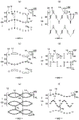
The planar shape (opening shape) of each hole 14 can be determined as appropriate. The holes 14 may be formed in any shape such as a perfect circle as shown in fig. 21 (b) and 22 (e), an ellipse as shown in fig. 21 (a) and (d) and 22 (a), (d) and (f), a polygon such as a rectangle, rhombus, star, or cloud, in addition to the long hole shape as shown in fig. 21 (b) and 22 (b). The holes 14 of different shapes may be mixed together as shown in fig. 21 (c) and 22 (c). The size of each hole 14 is not particularly limited, but the size (the size of the longest portion) 14L in the CD direction is preferably 0.6 to 5.0mm, particularly preferably 0.7 to 2.0mm, and the size (the size of the longest portion) 14W in the MD direction is preferably 0.6 to 5.0mm, particularly preferably 0.6 to 1.2 mm. In the case where the shape of the hole 14 is a shape that is long in one direction (a shape in which the total length in one direction is longer than the total length in a direction perpendicular to the one direction), such as a long hole shape, an oval shape, a rectangular shape, a diamond shape, or the like, it is preferable that the dimension in the MD direction (the dimension of the longest portion) is 1.2 to 2.5 times the dimension in the CD direction perpendicular to the MD direction (the dimension of the longest portion). In the case where the shape of the hole 14 is a shape elongated in one direction, the longitudinal direction of the hole 14 is preferably the MD direction of the nonwoven fabric, but may be the CD direction or an oblique direction inclined with respect thereto. In the MD direction of the nonwoven fabric, the width direction WD is generally the same as the width direction WD in the outer body 12 of the pants-type disposable diaper, the front-back direction LD in the inner body 200 of the pants-type disposable diaper, and the front-back direction LD in the portion other than the fastening tape of the tape-type disposable diaper.
The area and area ratio of each hole 14 may be determined as appropriate, but the area is preferably about 0.1 to 2.7mm2(particularly preferably about 0.1 to 1.0 mm)2) The area ratio is preferably about 1.0 to 15.0% (particularly preferably about 5.0 to 10.0%).
The planar arrangement of the holes 14 may be determined as appropriate, and may be an irregular planar arrangement, or may be a pattern, character, or the like, but a regularly repeated planar arrangement is preferable. For example, as shown in fig. 21 (a), (c), and (d), the planar arrangement of all the holes 14 is preferably in the form of a row or column as follows: the rows of holes 14 arranged linearly at predetermined intervals in the CD direction are repeated at predetermined intervals in the MD direction. In this case, as shown in fig. 21 (a), the interval 14x of the holes 14 in the MD direction may be shorter than the interval 14y of the holes 14 in the CD direction, and the following arrangement may be adopted: as shown in fig. 21 (c), the intervals 14x of the holes 14 in the MD direction and the intervals 14y of the holes 14 in the CD direction are arranged substantially equal to each other; alternatively, as shown in fig. 21 (d), the holes 14 are arranged so that the interval 14x in the MD direction is longer than the interval 14y in the CD direction of the holes 14. As shown in fig. 21 (b) and (e), the following arrangement may be adopted: the rows 91, 92 of holes arranged linearly at predetermined intervals in the CD direction are arranged at intervals in the MD direction and at staggered positions in the CD direction. The example shown in fig. 21 (b) is a so-called staggered (hexagonal lattice) arrangement in which the holes 14 are arranged differently in the adjacent hole rows 91 and 92. As shown in fig. 21 (f), the arrangement includes, as long as there is a portion continuous in the CD direction between the adjacent hole rows 91 and 92: the rows of holes 14 are arranged side by side with intervals in the MD direction, wherein in the rows of holes 14, the holes 14 are arranged side by side in a wavy line shape having center lines along the MD direction and the vertical direction, and are arranged side by side with intervals in the direction perpendicular to the MD direction.
The size and shape of the holes 14 in the 1 st hole row 91 and the size and shape of the holes 14 in the 2 nd hole row 92 may be the same, but more preferably at least one of them is different.
The CD direction interval 14y and the MD direction interval 14x of the holes 14 may be fixed or may vary. These factors can be determined appropriately, but considering air permeability, the CD-direction interval 14y of each hole 14 is preferably in the range of 0.9 to 8.0mm, particularly preferably in the range of 1.0 to 3.0mm, and the MD-direction interval 14x of the hole is preferably in the range of 2.0 to 10mm, particularly preferably in the range of 3.0 to 5.0 mm. In particular, if the rows of holes 14 arranged in the CD direction at CD-direction intervals 14y smaller than the CD-direction dimension 14L of the holes 14 are repeated at predetermined intervals in the MD direction, and the MD-direction intervals 14x of the rows of holes 14 are larger than the CD-direction dimension 14L of the holes 14 (more preferably, 3 times or more the MD-direction dimension 14W of the holes 14), the air permeability can be significantly improved without impairing flexibility and bulkiness, and the reduction in tensile strength in the MD direction, which is important in manufacturing, is also small, which is preferable. In this case, in particular, the hole 14 is preferably formed to have a shape elongated in the CD direction.
In addition, as shown in fig. 22 (a) to (d) and (f), the planar arrangement of the holes 14 may be formed as follows: that is, the group 90 of holes 14 arranged in a single wavy manner continuous in the MD direction may be arranged at intervals in the CD direction, and may be formed in a planar arrangement as follows: the groups 90 of holes 14 arranged at intervals in a chain shape continuous in the MD direction are arranged at intervals in the CD direction. The group 90 of holes 14 arranged in a chain shape is not particularly limited as long as the portions of the holes 14 arranged in a ring shape are repeated at intervals in the MD direction, and may be: for example, as shown in fig. 22 (e), the group 90 of holes 14 arranged in a double-layer corrugated manner with inverted peaks may be arranged at intervals in the CD direction, or may be in a chain shape as shown in fig. 23. Here, "the group 90 of holes 14 are arranged in the CD direction at intervals" means: between the groups 90 of the holes 14 adjacent in the CD direction, there is a non-porous portion 93 straightly continuous in the MD direction.
The arrangement shape of the group 90 of holes 14 may be determined as appropriate as long as it is in the above-described corrugated shape, and may be in a regular shape such as a shape in which the valleys of the circular arc curve repeat and are continuous in a corrugated shape as shown in fig. 22 (a), a triangular wave shape as shown in fig. 22 (b), a rectangular wave shape as shown in fig. 22 (d), a sinusoidal wave shape as shown in the group 90 of holes 14 at the middle stage of fig. 22 (f), or the like, or may be in a shape in which at least one of the amplitude and the wavelength changes regularly or irregularly, or in other irregular shapes, although not shown.
The intervals 14x in the MD direction of the holes 14 in the group 90 of holes 14 may be fixed or may vary, and may be determined as appropriate. In consideration of the improvement in air permeability by the holes 14, the thickness is preferably in the range of 2.0 to 10mm, and particularly preferably in the range of 3.0 to 5.0 mm.
The intervals 14y in the CD direction of the holes 14 in the row 94 of holes 14 may be varied as in the example shown in fig. 22 (d), or may be fixed as in the examples shown in fig. 22 (a) and (b). The interval 14y in the CD direction of the holes 14 in the row 94 of holes 14 is preferably in the range of 0.9 to 8.0mm, and particularly preferably in the range of 1.0 to 3.0 mm. In addition, the spacing 14y in the CD direction of the holes 14 in the row 94 of holes 14 may be longer or may be the same degree as the spacing 14x in the MD direction of the holes 14 in the group 90 of holes 14, but is preferably shorter (about 2 to 5 times).
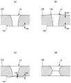
The cross-sectional shape of the hole 14 is not particularly limited. For example, the hole 14 may be a punched type hole whose peripheral edge is formed by the cut end of the fiber, or may be a non-punched type hole (the fiber density of the edge portion is high) as follows: there is almost no cut end of the fiber at the periphery of the hole 14, and the hole is formed by inserting a needle into the inter-fiber spread. As shown in fig. 24 (d), the punching type hole may be a hole in which the diameter of the hole 14 becomes smaller toward the middle in the thickness direction, or may be a hole in which the diameter becomes smaller toward one side in the thickness direction, although not shown.
The non-blanking type hole 14 is a hole in which the diameter of the hole 14 becomes smaller toward the opposite side from the needle insertion side. This includes, among others, a hole in which the diameter of the hole 14 is continuously reduced in the entire thickness direction of the nonwoven fabric layer, and a hole in which the reduction in the diameter of the hole 14 is almost vanished in the middle in the thickness direction. Such non-blanking type holes include the following forms: as shown in fig. 24 (a) and (c), a protruding portion (burr) 14e in which fibers are pushed out to the side opposite to the needle insertion side is formed at the edge portion of the hole 14 opposite to the needle insertion side, and the protruding portion 14e is not formed at the needle insertion side; as shown in fig. 24 (b), a protruding portion 14e in which fibers are pushed out to the side opposite to the needle insertion side is formed at the edge portion of the hole 14 opposite to the needle insertion side, and a protruding portion 14e in which fibers are pushed out to the needle insertion side is formed at the needle insertion side. Further, the former type of hole 14 includes the following forms: as shown in fig. 24 (a), the projection height 14h of the projection 14e is substantially uniform; and, as shown in fig. 24 (c), the protruding portion 14e has an opposing portion with the highest protruding height 14i and an opposing portion with the lowest protruding height 14j, wherein the opposing portion with the lowest protruding height 14j is a portion opposing the opposing portion with the highest protruding height 14i in a direction perpendicular thereto. Preferably, the protruding portion 14e is formed in a cylindrical shape so as to be continuous in the circumferential direction of the hole, but a part or all of the protruding portions 14e of the hole 14 may be formed only in a part of the circumferential direction of the hole 14. The protrusion heights 14h, 14i, and 14j (apparent heights in a state where no pressure is applied, measured by an optical microscope) are preferably about 0.2 to 1.2 mm. The highest projection height 14i of the projections 14e is preferably about 1.1 to 1.4 times the lowest projection height 14 j. The protruding height of the protruding portion 14e may vary in the circumferential direction of the hole 14.
For example, when a hole 14 having a shape elongated in one direction as shown in (a), (b), (d), and the like of fig. 21 is formed by needle insertion, fibers at the edge of the hole 14 recede outward or in the vertical direction, and a protrusion (burr) 14e having a protrusion height 14i at the opposite portion in the longitudinal direction of the hole 14 higher than a protrusion height 14j at the opposite portion in the direction perpendicular to the longitudinal direction is formed. As for the protrusion 14e of the hole 14, the fiber density thereof may be lower than that of the surrounding portion thereof, but preferably to an equal degree or higher.
Particularly, the nonwoven fabric having a nonwoven fabric with pores has a fineness of 0.1 to 5.0dtex (more preferably 1.0 to 3.0dtex) and a weight per unit area of 15 to 20g/m2(more preferably 15 to 18 g/m)2) In the case of a long fiber nonwoven fabric having a thickness of 0.3 to 0.8mm (more preferably 0.3 to 0.6mm), if the holes 14 are formed by inserting needles, the protrusions 14e formed at the edges of the holes 14 become low. More specifically, in the case of the long fiber nonwoven fabric in the above-described specific range, the fibers are less likely to be extruded in the thickness direction when the pin insertion holes are formed. This is because the fibers urged by the insertion of the needles are continuous (continuous fibers) while being entangled in the entire nonwoven fabric, and the movement of the fibers in the portion urged by the insertion of the needles is suppressed by the portion continuous to the outside thereof. In addition, since the long fiber nonwoven fabric in the above-described specific range has a substantially moderately low fiber density, the fibers are relatively easily moved in a direction perpendicular to the thickness direction. As a result, the long fiber nonwoven fabric having the needles inserted into the above-mentioned specific range is formed to have the size of the above-mentioned specific rangeIn the case of the hole 14 (a), when the needle is inserted, the fiber near the needle moves toward the needle outlet side while being pushed out in the radial direction around the needle insertion direction, and therefore, the height of the protrusion 14e is reduced although it is formed. Further, therefore, a high-density portion having a higher fiber density than the surrounding is formed at the edge of the hole 14. Further, the high-density portion has an advantage that the shadow of the hole and the surrounding of the hole is further increased, and the visibility of the hole is improved.
< bonding of perforated non-woven fabrics >
The perforated nonwoven fabric has an exposed surface exposed to the outside and a supporting surface on the opposite side, and can be bonded to another sheet facing the supporting surface (in the case where the perforated nonwoven fabric is the cover sheet 20, the liquid impermeable sheet 11 becomes another sheet) by the hot melt adhesive 20H. The bonding pattern is not particularly limited, but as in the bonding structure of the cover nonwoven fabric 20 and the liquid-impermeable sheet 11 shown in fig. 11, the hot-melt adhesive 20H is preferably absent on the center side of the peripheral edge 14c of the region overlapping the hole 14, and the hot-melt adhesive 20H is preferably present in a continuous surface shape except for the peripheral edge 14c of the region overlapping the hole 14. Since the hot melt adhesive 20H is not present on the center side of the peripheral edge portion 14c of the region overlapping the hole 14, the protrusion portion 14e of the hole 14 is reliably fixed without giving a sticky touch to the skin by the hot melt adhesive 20H.
As a representative bonding state, the following state can be exemplified: as shown in fig. 11 (a) and (b), the hot melt adhesive 20H is not present in the region overlapping the hole 14, and the hot melt adhesive 20H is present in a continuous surface shape except the region overlapping the hole 14; as shown in fig. 11 (c) and (d), the hot melt adhesive 20H overflows the peripheral edge 14c of the region overlapping the hole 14, but the hot melt adhesive 20H does not exist on the center side of the peripheral edge 14c of the region overlapping the hole 14, and the hot melt adhesive 20H exists in a continuous surface shape except the peripheral edge 14c of the region overlapping the hole 14. The width of the hot melt adhesive 20H protruding from the peripheral edge 14c of the region overlapping the hole 14 is preferably not more than half the thickness of the perforated nonwoven fabric and not more than about 0.5 mm. It is desirable that the hot melt adhesive 20H is not present in a portion of 80% or more of the area of the region overlapping the hole 14. These adhesive structures can be formed by a method described in patent document 4, for example.
Whiteness of perforated nonwoven fabrics
In the perforated nonwoven fabric having an exposed surface exposed to the outside, such as the nonwoven cover fabric 20 of the illustrated example, if the whiteness of the exposed surface of the perforated nonwoven fabric is 70% or more, since the whiteness of the portion outside the hole 14 is high, the difference in the shade between the portion outside the hole 14 and the edge of the hole 14 becomes large, and the hole 14 is easily visually recognized, it is preferable if the thickness is 0.30 to 1.5mm, and the minimum dimension (the shorter one of the dimension in the MD direction and the dimension in the CD direction) of the hole 14 is 0.6 to 5 mm.
The thickness of the particularly preferable porous non-woven fabric is 0.35 to 1.2 mm. In addition, the minimum size of the pores 14 of the particularly preferred perforated nonwoven fabric is 0.60 to 1.2 mm. In addition, the whiteness of the exposed surface of the perforated nonwoven fabric is preferably 73% or more, more preferably 80% or more.
Although the density can be increased in order to increase the whiteness of the apertured nonwoven, this not only increases the cost, but also decreases the flexibility. Therefore, as for the apertured nonwoven fabric, it is preferable that: the fineness of the constituent fiber is about 1.8 to 6.0dtex, and the unit area weight is about 15 to 25g/m2And the insufficiency of whiteness is compensated by containing a proper amount of white pigment such as titanium oxide. As the nonwoven fabric having pores satisfying such conditions and having sufficient strength, a nonwoven fabric having pores formed in a spunbond nonwoven fabric is suitable.
If the whiteness of the apertured nonwoven fabric is too high, there is a possibility that it will be difficult to see a display that can be seen through from the outer surface of the apertured nonwoven fabric when the display is printed on a portion overlapping the back side of the apertured nonwoven fabric, for example, on another sheet facing the support surface of the apertured nonwoven fabric (in the case where the apertured nonwoven fabric is the cover sheet 20 as in the illustrated example, the liquid-impermeable sheet 11 becomes another sheet). Therefore, the whiteness of the porous nonwoven fabric is preferably 85% or less. The display is a pattern (including a drawing and a single-point character pattern) for decoration, a functional display such as a use method, a use aid, a size, or a logo display such as a manufacturer, a product name, and a characteristic function, and is attached to an appropriate member by printing or the like.
The whiteness of the other sheet facing the support surface of the perforated nonwoven fabric (in the case where the perforated nonwoven fabric is the cover sheet 20 as in the illustrated example, the liquid-impermeable sheet 11 is the other sheet) is not particularly limited, but the surface of the other sheet on the perforated nonwoven fabric side is a portion where the through-holes 14 are exposed. Therefore, if the whiteness of at least the non-colored portion on the surface on the perforated nonwoven fabric side of the other sheet is 70% or more, more preferably 80% or more, as in the exposed surface of the perforated nonwoven fabric, the portion having a high whiteness is exposed inside the hole 14, and thus the difference in shade between the portion inside the hole 14 and the edge of the hole 14 becomes large, and the hole 14 becomes more easily visible. Further, as described above, a display may be applied to the other sheet facing the support surface of the perforated nonwoven fabric by printing or the like, and the whiteness may not be 70% or more in a colored portion used for such display. However, since the colored portion of the hole 14 overlapping the colored portion serves as a background to improve the visibility, the whiteness of at least the non-colored portion (non-printed portion) is increased, thereby improving the visibility of the entire hole 14.
< test for confirming Effect >
The interior body 200 having the structure shown in fig. 1 to 7 was produced using various nonwoven fabrics shown in table 1, and the visual confirmation of the holes 14 of the nonwoven fabric 20 was evaluated in three grades: pax … clearly identifies the hole; good quality … can identify pores; the x … well was assimilated with the surroundings and was difficult to identify. The evaluation results are shown in table 1. The whiteness degree of the cover nonwoven fabric 20 and the liquid-impermeable sheet 11 is measured as described above. When the whiteness degree of this test was measured, a simple spectrocolorimeter NF333 manufactured by nippon electrochrome industry co was used to measure 5 points (non-colored portions having the highest whiteness degree in the case of the liquid-impermeable sheet 11) on the same measurement surface, and the average value (N is 5) was obtained. In addition, as for the minimum size of the hole 14 of the hood nonwoven fabric, the apparent size was measured in a state of a natural length using a microscope.
As shown in table 1, in samples 5 and 6 having a whiteness of less than 70%, and sample 7 having a whiteness of 70% or more but a minimum size of pores of less than 0.6mm, the pores were assimilated with the surroundings and were difficult to distinguish. On the other hand, in samples 1 to 4 in which the whiteness was 70% or more and the minimum size of the pores was 0.6mm or more, the results were: the hole was visually confirmed well.
[ Table 1]

In the table, PP means polypropylene, PE means polyethylene, and PET means polyethylene terephthalate.
< description of words in the specification >)
Unless otherwise specified in the specification, the following terms in the specification have the following meanings.
"front-rear direction" means a direction (longitudinal direction) indicated by reference symbol LD in the drawing, "width direction" means a direction (left-right direction) indicated by WD in the drawing, and the front-rear direction and the width direction are perpendicular.
"MD direction" and "CD direction" refer to a conveying direction (MD direction) in a manufacturing apparatus and a transverse direction (CD direction) perpendicular to the conveying direction, and depending on parts of a product, either one of them is a front-back direction and the other is a width direction. The MD direction of a nonwoven fabric is the direction in which the fibers of the nonwoven fabric are oriented. The fiber orientation is a direction along which the fibers of the nonwoven fabric are oriented, and can be determined by, for example, the following measurement method: a measurement method according to a fiber orientation test method, wherein the fiber orientation test method is a test method based on a zero distance tensile strength of TAPPI standard method T481; alternatively, a simple measurement method for determining the fiber orientation direction from the ratio of the tensile strength in the front-back direction and the width direction.
"front side" means a side close to the skin of the wearer when the pants-type disposable diaper is worn, and "back side" means a side far from the skin of the wearer when the pants-type disposable diaper is worn.
"front" refers to the surface of the member that is closer to the skin of the wearer when the pants-type disposable diaper is worn, and "back" refers to the surface that is farther from the skin of the wearer when the pants-type disposable diaper is worn.
"area ratio" means a ratio of the target portion to a unit area, and is a ratio expressed by dividing a total area of the target portion (e.g., holes) in a target region (e.g., a hood nonwoven fabric) by an area of the target region in percentage. In the aspect in which a plurality of target portions are provided at intervals, it is desirable that: the target area is set to a size including 10 or more target portions, and the area ratio is obtained. For example, as for the area ratio of the holes, for example, a device under the trade name VHX-1000 by KEYENCE corporation may be used, the measurement conditions are set to 20 times, and the measurement is performed in the following order.
(1) A lens is set to 20 times, and the focal length is adjusted. The position of the nonwoven fabric was adjusted so that 4 × 6 holes were present.
(2) The luminance of the hole region was specified, and the area of the hole was measured.
(3) Click on color extraction of "area measurement" of "measurement/comment". A portion of the hole is tapped.
(4) Click on "measure together", and select "display measurement result window", save as CSV data.
"elongation" means a value when the natural length is 100%. For example, an elongation of 200% means the same as an elongation magnification of 2 times.
"gel strength" is measured as follows. To 49.0g of artificial urine (a mixture of 2 wt% urea, 0.8 wt% sodium chloride, 0.03 wt% calcium chloride dihydrate, 0.08 wt% magnesium sulfate heptahydrate, and 97.09 wt% ion-exchanged water) was added 1.0g of a super absorbent polymer, and the mixture was stirred with a stirrer. The resultant gel was allowed to stand in a constant temperature and humidity bath at 40 ℃ X60% RH for 3 hours and then returned to normal temperature, and the gel strength was measured by a curdometer-MAX ME-500 (manufactured by I.techno Engineering Co.).
"weight per unit area" was measured as follows. The sample or test piece is dried preliminarily and then placed in a laboratory or apparatus in a standard state (the temperature at the test site is 23. + -. 1 ℃ C., and the relative humidity is 50. + -. 2%) to be in a constant state. The preliminary baking means that the sample or the test piece is made constant in an environment at a temperature of 100 ℃. In addition, the fibers having a official moisture regain of 0.0% may not be subjected to preliminary drying. Using a template (100 mm. times.100 mm) for sample selection, a sample having a size of 100 mm. times.100 mm was cut out from the test piece in a constant state. The weight of the sample was measured, and the weight per square meter was calculated as a weight per unit area by 100 times.
"thickness" is measured using an automatic thickness gauge (KES-G5 Portable compression measurement program) at a load of 0.098N/cm2The pressure area is 2cm2Is automatically measured under the conditions of (1). With respect to the thickness of the apertured nonwoven fabric, measurements were made at the apertures and the portions around them other than the protrusions.
The water absorption was measured in accordance with JIS K7223-1996 "method for testing the Water absorption of a super absorbent resin".
The water absorption rate is "time to end point" when JIS K7224-1996 "Water absorption Rate test method for superabsorbent resin" was carried out using 2g of a superabsorbent polymer and 50g of physiological saline.
"expanded state" refers to a state of flat expansion without contraction and relaxation.
Unless otherwise specified, the dimensions of each portion are dimensions in the expanded state, not in the natural length state.
"melt viscosity" was measured according to JIS Z8803 using a Brookfield type B viscometer (spindle No.027) at the specified temperature.
The test or measurement is carried out in a laboratory or apparatus in a standard state (in a test site, the temperature is 23 ± 1 ℃, and the relative humidity is 50 ± 2%) without describing the environmental conditions in the test or measurement.
Industrial applicability
The present invention can be applied to all disposable wearing articles such as a pad type disposable diaper, a disposable swimsuit, a diaper cover, and a sanitary napkin, in addition to a pants type disposable diaper and a tape type disposable diaper.
Description of the reference symbols
11: a liquid-impermeable sheet; 12: an exterior body; 12A: a side seal part; 12B: a rear-side outer housing; 12F: a front side outer package; 12H: an inner sheet layer; 12S: an outer sheet layer; 20: covering non-woven fabrics; 20H: a hot melt adhesive; 14: an aperture; 14 e: a protrusion; 18: redundant elastic members; 200: an interior body; 201: an inner and outer joint portion; 30: a topsheet; 40: an intermediate sheet; 50: an absorbent member; 56: an absorbent body; 58: packaging the sheet; 60: a side gather portion; 62: a pleated portion nonwoven fabric; a1: a non-stretch region; a2: a telescoping region; c: a hip cover part; l: a middle region; LD: a front-back direction; LO: a leg opening; t: a waist region; u: a lower waist portion; w: a waist part; WD: a width direction; WO: a waist opening; 93: a non-porous section.
Claims (7)
1. A disposable wearing article having a perforated nonwoven fabric, a plurality of holes provided at intervals in the perforated nonwoven fabric and penetrating through both front and back surfaces of the nonwoven fabric,
the perforated nonwoven fabric has: an exposed surface exposed to the outside; and a bearing surface facing the other sheet,
it is characterized in that the preparation method is characterized in that,
the thickness of the porous non-woven fabric is 0.30 mm-1.5 mm,
the minimum size of the holes is 0.6 mm-5 mm,
the whiteness of the exposed surface of the perforated nonwoven fabric is 70% or more, and the difference between the shadow formed at the outer portion of the perforation and the shadow formed at the edge of the perforation is increased, thereby improving the visibility of the perforation.
2. The disposable wearing article according to claim 1,
the porous nonwoven fabric has a fiber fineness of 1.8 to 6.0dtex and a basis weight of 15g/m2~25g/m2The nonwoven fabric containing a white pigment of (1).
3. The disposable wearing article according to claim 1 or 2,
a display which can be seen through the exposed surface of the porous nonwoven fabric is printed on a part overlapping with the opposite side of the exposed surface of the porous nonwoven fabric,
the whiteness of the porous non-woven fabric is below 85%.
4. The disposable wearing article according to claim 1 or 2,
the whiteness of at least the non-colored portion on the surface of the other sheet on the non-woven apertured fabric side is 70% or more.
5. The disposable wearing article according to claim 1 or 2,
the disposable wearing article includes: an absorbent body; a liquid-impermeable sheet having air permeability, which covers the back side of the absorbent body; and a cover nonwoven fabric covering the back side of the liquid-impermeable sheet,
the cover nonwoven fabric is the porous nonwoven fabric, and the liquid-impermeable sheet is the other sheet.
6. The disposable wearing article according to claim 1 or 2,
the holes are arranged in such a way that: the rows of holes arranged side by side at intervals in either one of the front-back direction and the width direction are arranged side by side at intervals in the other direction,
the interval of the holes in the one direction is 1.0mm to 5.0mm,
the interval of the holes in the other direction is 2.5 mm-10.0 mm.
7. The disposable wearing article according to claim 1 or 2,
the holes are arranged in such a way that: the holes are arranged in a single corrugated or chain-like manner in the front-back direction or the width direction and are arranged at intervals in the other direction,
the arrangement of the holes is: the rows of holes that are juxtaposed at intervals in the other direction are juxtaposed at intervals in the one direction,
the holes in the row of holes are spaced at intervals of 1.0mm to 5.0mm in the other direction,
the holes in the group of holes are spaced at intervals of 2.5mm to 10.0mm in the one direction.
Applications Claiming Priority (3)
| Application Number | Priority Date | Filing Date | Title |
|---|---|---|---|
| JP2018-238632 | 2018-12-20 | ||
| JP2018238632A JP7218170B2 (en) | 2018-12-20 | 2018-12-20 | Disposable wearing article |
| PCT/JP2019/047815 WO2020129703A1 (en) | 2018-12-20 | 2019-12-06 | Disposable worn article |
Publications (2)
| Publication Number | Publication Date |
|---|---|
| CN113164299A CN113164299A (en) | 2021-07-23 |
| CN113164299B true CN113164299B (en) | 2022-06-24 |
Family
ID=71101451
Family Applications (1)
| Application Number | Title | Priority Date | Filing Date |
|---|---|---|---|
| CN201980079678.4A Active CN113164299B (en) | 2018-12-20 | 2019-12-06 | Disposable wearing article |
Country Status (4)
| Country | Link |
|---|---|
| JP (1) | JP7218170B2 (en) |
| CN (1) | CN113164299B (en) |
| TW (1) | TWI802776B (en) |
| WO (1) | WO2020129703A1 (en) |
Citations (4)
| Publication number | Priority date | Publication date | Assignee | Title |
|---|---|---|---|---|
| CN1235817A (en) * | 1998-04-20 | 1999-11-24 | 龙妮佳股份有限公司 | Disposable liquid absorbing article |
| JP2006181294A (en) * | 2004-12-28 | 2006-07-13 | Kao Corp | Top sheet for absorbent article |
| CN107072835A (en) * | 2014-11-06 | 2017-08-18 | 宝洁公司 | Include the absorbent article of the lamilate towards clothes |
| WO2018074396A1 (en) * | 2016-10-21 | 2018-04-26 | 大王製紙株式会社 | Underpants-type disposable diaper |
Family Cites Families (4)
| Publication number | Priority date | Publication date | Assignee | Title |
|---|---|---|---|---|
| US5933841A (en) * | 1996-05-17 | 1999-08-03 | Ameritech Corporation | Structured document browser |
| JP6305691B2 (en) * | 2013-05-20 | 2018-04-04 | 株式会社リブドゥコーポレーション | Absorbent articles |
| JP6560015B2 (en) * | 2014-05-30 | 2019-08-14 | 花王株式会社 | Disposable diapers |
| BR112018067970A2 (en) * | 2016-03-09 | 2019-02-12 | Procter & Gamble | absorbent article with activatable material |
-
2018
- 2018-12-20 JP JP2018238632A patent/JP7218170B2/en active Active
-
2019
- 2019-12-06 CN CN201980079678.4A patent/CN113164299B/en active Active
- 2019-12-06 WO PCT/JP2019/047815 patent/WO2020129703A1/en active Application Filing
- 2019-12-19 TW TW108146559A patent/TWI802776B/en active
Patent Citations (4)
| Publication number | Priority date | Publication date | Assignee | Title |
|---|---|---|---|---|
| CN1235817A (en) * | 1998-04-20 | 1999-11-24 | 龙妮佳股份有限公司 | Disposable liquid absorbing article |
| JP2006181294A (en) * | 2004-12-28 | 2006-07-13 | Kao Corp | Top sheet for absorbent article |
| CN107072835A (en) * | 2014-11-06 | 2017-08-18 | 宝洁公司 | Include the absorbent article of the lamilate towards clothes |
| WO2018074396A1 (en) * | 2016-10-21 | 2018-04-26 | 大王製紙株式会社 | Underpants-type disposable diaper |
Also Published As
| Publication number | Publication date |
|---|---|
| WO2020129703A1 (en) | 2020-06-25 |
| JP7218170B2 (en) | 2023-02-06 |
| JP2020099442A (en) | 2020-07-02 |
| TWI802776B (en) | 2023-05-21 |
| TW202023505A (en) | 2020-07-01 |
| CN113164299A (en) | 2021-07-23 |
Similar Documents
| Publication | Publication Date | Title |
|---|---|---|
| CN107485490B (en) | Absorbent article | |
| CN105997350B (en) | Stretchable structure of absorbent article and pants-type disposable diaper | |
| JP6362250B2 (en) | Absorbent articles | |
| CN107874914B (en) | Disposable wearing article and method for attaching perforated nonwoven fabric | |
| RU2723828C1 (en) | Pants-type disposable diaper | |
| CN107874915B (en) | Disposable wearing article and method for attaching perforated nonwoven fabric | |
| US11612521B2 (en) | Underpants-type disposable diaper | |
| US10413453B2 (en) | Stretchable structure for absorbent article, absorbent article comprising said stretchable structure, and method for forming stretchable structure for absorbent article | |
| JP6449500B1 (en) | Stretch structure of disposable wearing article, and pants-type disposable wearing article having this stretchable structure | |
| CN114615962A (en) | Disposable wearing article | |
| JP6207785B1 (en) | Disposable wearing items | |
| CN113164299B (en) | Disposable wearing article | |
| CN110691575A (en) | Pants-type disposable diaper | |
| CN114599328A (en) | Disposable diaper having a disposable diaper | |
| JP7129262B2 (en) | Elastic structure for disposable wearing article, and pants-type disposable wearing article having this elastic structure | |
| JP6347826B2 (en) | Pants-type disposable diaper | |
| JP7129190B2 (en) | Elastic structure for disposable wearing article, and pants-type disposable wearing article having this elastic structure | |
| JP2020099442A5 (en) | ||
| CN114599323A (en) | Disposable diaper having a disposable diaper | |
| CN114615960A (en) | Disposable wearing article | |
| CN115038420A (en) | Disposable absorbent article | |
| CN112754775A (en) | Stretchable member and disposable wearing article having the same |
Legal Events
| Date | Code | Title | Description |
|---|---|---|---|
| PB01 | Publication | ||
| PB01 | Publication | ||
| SE01 | Entry into force of request for substantive examination | ||
| SE01 | Entry into force of request for substantive examination | ||
| GR01 | Patent grant | ||
| GR01 | Patent grant |