JP6400656B2 - Pants-type disposable diaper - Google Patents

Pants-type disposable diaper Download PDF

Info

Publication number
JP6400656B2
JP6400656B2 JP2016212773A JP2016212773A JP6400656B2 JP 6400656 B2 JP6400656 B2 JP 6400656B2 JP 2016212773 A JP2016212773 A JP 2016212773A JP 2016212773 A JP2016212773 A JP 2016212773A JP 6400656 B2 JP6400656 B2 JP 6400656B2
Authority
JP
Japan
Prior art keywords
exterior body
sheet
nonwoven fabric
rear direction
waist
Prior art date
Legal status (The legal status is an assumption and is not a legal conclusion. Google has not performed a legal analysis and makes no representation as to the accuracy of the status listed.)
Active
Application number
JP2016212773A
Other languages
Japanese (ja)
Other versions
JP2018068710A (en
JP2018068710A5 (en
Inventor
彩 井手
彩 井手
森 洋介
洋介 森
Current Assignee (The listed assignees may be inaccurate. Google has not performed a legal analysis and makes no representation or warranty as to the accuracy of the list.)
Daio Paper Corp
Original Assignee
Daio Paper Corp
Priority date (The priority date is an assumption and is not a legal conclusion. Google has not performed a legal analysis and makes no representation as to the accuracy of the date listed.)
Filing date
Publication date
Application filed by Daio Paper Corp filed Critical Daio Paper Corp
Priority to JP2016212773A priority Critical patent/JP6400656B2/en
Priority to PCT/JP2017/037314 priority patent/WO2018074400A1/en
Priority to CN201710965775.6A priority patent/CN107970092B/en
Priority to CN201721337348.5U priority patent/CN208611123U/en
Priority to TW106135862A priority patent/TWI744396B/en
Publication of JP2018068710A publication Critical patent/JP2018068710A/en
Publication of JP2018068710A5 publication Critical patent/JP2018068710A5/ja
Application granted granted Critical
Publication of JP6400656B2 publication Critical patent/JP6400656B2/en
Active legal-status Critical Current
Anticipated expiration legal-status Critical

Links

Images

Description

本発明は、パンツタイプ使い捨ておむつに関するものである。   The present invention relates to a pants-type disposable diaper.

パンツタイプ使い捨ておむつは、前身頃及び後身頃を個別又は一体的に構成する外装体と、前身頃から後身頃にわたるように外装体に対して取り付けられた、吸収体を含む内装体とを備え、前身頃の外装体の両側縁部と後身頃の外装体の両側縁部とが接合されてサイドシール部が形成されることにより、ウエスト開口及び左右一対の脚開口が形成されているものが一般的である。   The pants-type disposable diaper includes an exterior body that individually or integrally configures the front body and the back body, and an interior body including an absorbent body that is attached to the exterior body so as to extend from the front body to the back body, Generally, a waist opening and a pair of left and right leg openings are formed by joining the side edges of the outer body of the front body and the side edges of the outer body of the rear body to form a side seal part. Is.

このようなパンツタイプ使い捨ておむつでは、身体へのフィット性を向上させるために、外装体を複数のシート層を有する積層構造とするとともに、そのシート層間に、種々の弾性部材を伸長状態で取り付けることが行われており、中でも、サイドシール部と対応する前後方向範囲として定まる胴周り領域や、前後の胴周り領域の間に位置する中間領域に、幅方向に沿う細長状弾性部材が前後方向に間隔を空けてそれぞれ幅方向に伸長された状態で取り付けられているものは、身体に対するフィット性が比較的に高いものとなっている(例えば特許文献1〜6参照)。   In such a pants-type disposable diaper, in order to improve the fit to the body, the exterior body has a laminated structure having a plurality of sheet layers, and various elastic members are attached in an expanded state between the sheet layers. In particular, an elongated elastic member along the width direction is provided in the front-rear direction in the waist region defined as the front-rear direction range corresponding to the side seal portion and the intermediate region located between the front and rear waist regions. Those that are attached in a state where they are extended in the width direction at intervals are relatively high in fit to the body (see, for example, Patent Documents 1 to 6).

パンツタイプ使い捨ておむつの一形態として、前側外装体の両側部と、後側外装体の両側部とがサイドシール部で接合されて筒状に形成された外装体と、前側外装体から後側外装体内面までにわたり設けられた、排泄物を吸収する内装体とを備え、前側外装体と後側外装体とが股間側で連続せずに前後方向に離間しているものが知られている(例えば特許文献2〜6参照)。このような外装二分割タイプのものは、脚開口を形成するために外装体を切除しなくて済む、又は切除するとしても小面積で済むといった利点がある。すなわち、切離し片(トリム)は廃棄処分されるため、その資材の無駄(トリムロス)を抑えることができるという利点を有している。   As one form of the pants-type disposable diaper, both the side parts of the front exterior body and the both side parts of the rear exterior body are joined at the side seal part to form a cylindrical shape, and the front exterior body to the rear exterior It is provided with an interior body that absorbs excrement provided to the inner surface of the body, and the front exterior body and the rear exterior body are separated in the front-rear direction without being continuous on the crotch side ( For example, see Patent Documents 2 to 6). Such an exterior two-part type has the advantage that the exterior body does not have to be excised in order to form the leg openings, or even if it is excised, only a small area is required. That is, since the separation piece (trim) is discarded, there is an advantage that waste (trim loss) of the material can be suppressed.

外装二分割タイプのパンツタイプ使い捨ておむつは、装着時に内装体の股下部にあたる位置から外装体との交差位置までの距離が長いため、交差位置を支点として内装体が左右に振られやすいことにより、前身頃から後身頃まで連続する一体的な外装体を備えるタイプと比較して内装体が横方向に動きやすい。また、外装二分割タイプのパンツタイプ使い捨ておむつは、外装体の股間側の縁が幅方向に沿う直線状又はそれに近い形状となっており、内装体の側縁と直角又はそれに近い角度で交差する。これらは、外装二分割タイプのパンツタイプ使い捨ておむつでは脚周りのフィット性が不足しがちであることを意味する。   Because the distance from the position corresponding to the crotch part of the interior body to the intersection position with the exterior body is long when the pants type disposable diaper of the exterior split type is installed, the interior body is easily shaken from side to side with the intersection position as a fulcrum, Compared to a type having an integral exterior body that is continuous from the front body to the back body, the interior body is easy to move laterally. In addition, the exterior two-split pants-type disposable diaper has a crotch side edge of the exterior body that is linear or close to the width direction, and intersects the side edge of the interior body at a right angle or an angle close thereto. . These mean that the leg-type disposable diaper of the exterior two-divided type tends to have insufficient fit around the legs.

よって、外装二分割タイプのパンツタイプ使い捨ておむつでは、内装体の両側部から表側に起立する立体ギャザーとして、付け根側部分が幅方向中央側に向かって斜めに起立し、中間部より先端側部分が幅方向外側に向かって斜めに起立する屈曲形態のものを採用し、内装体と外装体の交差部付近でも立体ギャザーを立体的に高く起立させ、脚周りのフィット性を改善することは好ましい。   Therefore, in a pants-type disposable diaper of the exterior two-part type, as a three-dimensional gather that stands up from the both sides of the interior body to the front side, the base side portion stands diagonally toward the center in the width direction, and the tip side portion from the middle portion It is preferable to adopt a bent configuration that rises obliquely toward the outer side in the width direction, and raises the three-dimensional gather in a three-dimensional manner even near the intersection of the interior body and the exterior body to improve the fit around the legs.

しかしながら、外装二分割タイプのパンツタイプ使い捨ておむつにおいて、屈曲形態の立体ギャザーを採用した場合、内装体が横方向に動きやすいという点は改善されないため、立体ギャザーにおける臀裂の両側に位置する部分が、臀裂に向かう傾斜によって反対向き、つまり臀裂側に倒れてしまうことがあった。このような状態は、内装体が臀裂に食い込みやすくなることがあり、臀部のカバーが不十分となるため好ましくない。   However, in a pants-type disposable diaper of the exterior two-part type, when a three-dimensional gather in a bent form is adopted, the point that the inner body is easy to move in the lateral direction is not improved, so the portions located on both sides of the crack in the three-dimensional gather In some cases, the inclination toward the rupture would cause it to fall in the opposite direction, that is, the rupture side. Such a state is not preferable because the interior body may easily bite into the crack and the cover of the heel portion becomes insufficient.

特開2004−073428号公報JP 2004-073428 A 特表2006−525857号公報JP-T-2006-525857 特開2011−147516号公報JP 2011-147516 A 特開2014−028308号公報JP 2014-028308 A 特許第4964993号公報Japanese Patent No. 4964993 特開2015−092947号公報Japanese Patent Laying-Open No. 2015-092947

そこで、本発明の主たる課題は、外装二分割タイプのパンツタイプ使い捨ておむつにおける、立体ギャザーのフィット性の向上と、臀裂両側における立体ギャザーの倒れの防止とを両立すること等にある。   Therefore, the main problem of the present invention is to achieve both the improvement of the fit of the three-dimensional gather and the prevention of the fall of the three-dimensional gather on both sides of the crack in the pants-type disposable diaper of the exterior two-part type.

上記課題を解決した本発明の代表的態様は次記のとおりである。
<第1の態様>
前身頃の少なくとも胴周り部を構成する前側外装体及び後身頃の少なくとも胴周り部を構成する後側外装体とを別々に備え、これら前側外装体及び後側外装体が前後方向中間で前後方向に離間しており、
吸収体を内蔵する内装体が、前記前側外装体から後側外装体にかけて前後方向に延在し、かつ前記前側外装体及び後側外装体にそれぞれ接合され、
前側外装体の両側部と後側外装体の両側部とがそれぞれ接合されたサイドシール部と、ウエスト開口及び左右一対の脚開口とを備えた、
パンツタイプ使い捨ておむつにおいて;
前記内装体は、両側部から立ちあがる立体ギャザーを備えており、
前記立体ギャザーは、前記内装体の表面の両側部から幅方向中央側に延びる付け根側部分、及びこの付け根側部分の先端から幅方向外側に延びる先端側部分とを有する本体部分と、この本体部分における前後方向両端部が倒伏状態で前記内装体の表面に固定された部分である倒伏部分と、前後の倒伏部分の間に位置する非固定の自由部分と、この自由部分の少なくとも先端部に前後方向に沿って設けられたギャザー弾性部材とを有しており、
前記立体ギャザーは、後側の前記倒伏部分の前側に連続又は隣接して、前記先端側部分が倒伏状態で前記付け根側部分に接合され、かつ前記付け根側部分と前記内装体の表面とが接合されていない後側半倒伏部分を有している、
ことを特徴とするパンツタイプ使い捨ておむつ。
A typical aspect of the present invention that solves the above problems is as follows.
<First aspect>
The front exterior body constituting at least the waist circumference part of the front body and the rear exterior body constituting at least the waist circumference part of the rear body are separately provided, and the front exterior body and the rear exterior body are in the front-rear direction in the middle in the front-rear direction. Are separated from each other,
The interior body incorporating the absorber extends in the front-rear direction from the front exterior body to the rear exterior body, and is joined to the front exterior body and the rear exterior body, respectively.
A side seal portion in which both side portions of the front exterior body and both side portions of the rear exterior body are joined, and a waist opening and a pair of left and right leg openings,
In pants-type disposable diapers;
The interior body includes a three-dimensional gather that rises from both sides,
The three-dimensional gather has a main body portion having a base side portion extending from the both sides of the surface of the interior body to the center in the width direction, and a front end side portion extending outward in the width direction from the tip of the base side portion, and the main body portion. The front and rear direction both ends are in a lying state, a lying part fixed to the surface of the interior body, a non-fixed free part located between the front and rear lying parts, and at least the front and back of this free part A gather elastic member provided along the direction,
The three-dimensional gather is continuous or adjacent to the front side of the lodging part on the rear side, the tip side part is joined to the base side part in a lying state, and the base side part and the surface of the interior body are joined. Has a rear half-fallen part,
A pants-type disposable diaper characterized by that.

(作用効果)
本第1の態様では、外装二分割タイプのパンツタイプ使い捨ておむつにおいて、屈曲形態の立体ギャザーを採用したことにより、立体ギャザーのフィット性に優れるものとなるだけでなく、立体ギャザーに上述のような後側半倒伏部分が設けられているため、立体ギャザーの高さが段階的に高くなり、後側半倒伏部分のフィット位置が安定しやすくなるため、内装体が左右に動いても立体ギャザーのフィット位置が大きくぶれることがなく、立体ギャザーの先端側部分が固定されて、臀裂に食い込みにくくなる。
(Function and effect)
In the first aspect, in the exterior two-divided type pants-type disposable diaper, by adopting the three-dimensional gather in the bent form, not only the fit of the three-dimensional gather is excellent, but the three-dimensional gather as described above. Since the rear half-falling part is provided, the height of the three-dimensional gather increases stepwise, and the fitting position of the rear half-falling part becomes easy to stabilize, so even if the interior body moves left and right, The fitting position is not greatly shaken, and the tip side portion of the three-dimensional gather is fixed, so that it is difficult to bite into the crack.

<第2の態様>
前記内装体と前記後側外装体とを接合する内外接合部は、その前後方向の全体にわたり幅方向両端部にわたるように設けられている、
第1の態様のパンツタイプ使い捨ておむつ。
<Second aspect>
The inner and outer joints that join the interior body and the rear exterior body are provided so as to extend across both ends in the width direction across the entire front-rear direction.
The underpants type disposable diaper of a 1st aspect.

(作用効果)
内装体と後側外装体とを接合する内外接合部が本第2の態様の形状となっていると、立体ギャザーの先端側部分と固定された付け根側部分も臀裂方向に倒れにくくなり、内装体が臀裂により一層食い込みにくくなるため好ましい。
(Function and effect)
When the inner and outer joints that join the interior body and the rear exterior body have the shape of the second aspect, the tip side portion and the fixed root side portion of the three-dimensional gather are less likely to fall down in the bursting direction, It is preferable because the inner body is more difficult to bite by cracking.

<第3の態様>
前記吸収体は、前後方向中間に、その前後両側よりも幅の狭い括れ部を有しており、
前記後側半倒伏部分は前記括れ部とは重ならずに前記吸収体上に位置している、
第2の態様のパンツタイプ使い捨ておむつ。
<Third Aspect>
The absorber has a constricted portion having a narrower width than both front and rear sides in the middle in the front-rear direction,
The rear half-falling part is located on the absorber without overlapping the constricted part,
The underpants type disposable diaper of a 2nd aspect.

(作用効果)
後側半倒伏部分の前後方向範囲は適宜定めれば良いが、本第3の態様のようになっていると、特に、内装体が臀裂に食い込みにくくなるため好ましい。
(Function and effect)
The range in the front-rear direction of the rear half-falling portion may be determined as appropriate, but the third embodiment is particularly preferable because the interior body is difficult to bite into the crack.

<第4の態様>
前記後側半倒伏部分は後側外装体の前縁と同じか、又はそれより前後方向中央側に延びている、
第2又は3の態様のパンツタイプ使い捨ておむつ。
<Fourth aspect>
The rear half-falling portion is the same as the front edge of the rear exterior body, or extends to the center in the front-rear direction.
The underpants type disposable diaper of the 2nd or 3rd aspect.

(作用効果)
後側半倒伏部分の前後方向範囲は適宜定めれば良いが、本第3の態様のように後側半倒伏部分が内装体と外装体との交差部分を含むようになっていると、特に、内装体の左右の動きに対しても安定的に内装体の臀裂への食い込みを防止できる。
(Function and effect)
The range in the front-rear direction of the rear half-falling portion may be determined as appropriate, but when the rear half-falling portion includes an intersecting portion between the interior body and the exterior body, as in the third aspect, In addition, it is possible to prevent the inner body from biting into the cracks stably even when the inner body moves left and right.

<第5の態様>
前記後側半倒伏部分は、後側の前記倒伏部分よりも前後方向寸法が長い、
第2〜4のいずれか1つの態様のパンツタイプ使い捨ておむつ。
<Fifth aspect>
The rear half-falling part is longer in the front-rear direction than the rear lying part,
The underpants type disposable diaper of any one aspect of 2nd-4th.

(作用効果)
このような長さ関係になっていると、後側半倒伏部分が特に有効に機能するため好ましい。
(Function and effect)
Such a length relationship is preferable because the rear half-falling portion functions particularly effectively.

<第6の態様>
前記立体ギャザーは、前側の前記倒伏部分の後側に連続又は隣接して、前記付け根側部分が倒伏状態で前記内装体の表面に接合され、かつ先端側部分と付け根側部分とが接合されていない前側半倒伏部分を有している、
第1〜5のいずれか1つの態様のパンツタイプ使い捨ておむつ。
<Sixth aspect>
The three-dimensional gather is continuous or adjacent to the rear side of the lodging portion on the front side, the base side portion is joined to the surface of the interior body in the lying state, and the tip side portion and the base side portion are joined. Has no front half-lodge part,
The underpants type disposable diaper of any one aspect of 1st-5th.

(作用効果)
先端側部分のみが自由になっている前側半倒伏部分と、付け根側部分のみが自由になっている後側半倒伏部分の両方を設けると、立体ギャザーは前後方向に長い範囲にわたり高く起立することができ、かつ先端側部分と付け根側部分のそれぞれが過度に自由となることがないため、脚周り全体のフィット性が良好なものとなる。
(Function and effect)
If both the front half-falling part where only the front end part is free and the rear half-falling part where only the base side part is free are provided, the three-dimensional gather will stand high over a long range in the front-rear direction In addition, since each of the tip side portion and the base side portion is not excessively free, the fit around the legs is good.

以上のとおり、本発明によれば、外装二分割タイプのパンツタイプ使い捨ておむつにおいて、立体ギャザーのフィット性の向上と、臀裂両側における立体ギャザーの倒れの防止とを両立できる、等の利点がもたらされる。   As described above, according to the present invention, in an exterior two-divided type pants-type disposable diaper, there are advantages such as being able to achieve both improved fit of a three-dimensional gather and prevention of a three-dimensional gather from falling on both sides of a crack. It is.

展開状態のパンツタイプ使い捨ておむつの内面を示す、平面図である。It is a top view which shows the inner surface of the underpants type disposable diaper of an expansion | deployment state. 展開状態のパンツタイプ使い捨ておむつの外面を示す、平面図である。It is a top view which shows the outer surface of the underpants type disposable diaper of an unfolded state. 図1の2−2断面図である。It is 2-2 sectional drawing of FIG. 図1の3−3断面図である。FIG. 3 is a 3-3 cross-sectional view of FIG. 1. (a)図1の4−4断面図、及び(b)図1の5−5断面図である。(A) 4-4 sectional drawing of FIG. 1 and (b) 5-5 sectional drawing of FIG. パンツタイプ使い捨ておむつの斜視図(孔省略)である。It is a perspective view (hole omitted) of a pants type disposable diaper. 展開状態の内装体の外面を示す、平面図である。It is a top view which shows the outer surface of the interior body of the expansion | deployment state. 展開状態の内装体の外面を外装体の輪郭とともに示す、平面図である。It is a top view which shows the outer surface of the interior body of a unfolded state with the outline of an exterior body. 展開状態のパンツタイプ使い捨ておむつの外面を要部のみ示す、平面図である。It is a top view which shows only the outer surface of the underpants type disposable diaper of an unfolded state. (a)展開状態のパンツタイプ使い捨ておむつの前側の要部を示す平面図、(b)6−6断面図、(c)7−7断面図である。(A) The top view which shows the principal part of the front side of the underpants type disposable diaper of an expansion | deployment state, (b) 6-6 sectional drawing, (c) 7-7 sectional drawing. (a)展開状態のパンツタイプ使い捨ておむつの後側の要部を示す平面図、(b)6−6断面図、(c)7−7断面図である。(A) The top view which shows the principal part of the rear side of the underpants type disposable diaper of an unfolded state, (b) 6-6 sectional drawing, (c) 7-7 sectional drawing. 他の形態を示す、図1の2−2断面図である。It is 2-2 sectional drawing of FIG. 1 which shows another form. 他の形態を示す、図1の3−3断面図である。It is 3-3 sectional drawing of FIG. 1 which shows another form. 有孔不織布の孔を示す、(a)斜視図、(b)平面図、及び(c)1−1断面図である。It is (a) perspective view, (b) top view, and (c) 1-1 sectional view which show the hole of a perforated nonwoven fabric. 有孔不織布の孔を示す、(a)斜視図、(b)平面図、及び(c)1−1断面図である。It is (a) perspective view, (b) top view, and (c) 1-1 sectional view which show the hole of a perforated nonwoven fabric. 有孔不織布の孔を示す、(a)斜視図、(b)平面図、及び(c)1−1断面図である。It is (a) perspective view, (b) top view, and (c) 1-1 sectional view which show the hole of a perforated nonwoven fabric. 有孔不織布の要部拡大平面図である。It is a principal part enlarged plan view of a perforated nonwoven fabric. カバー不織布の接着部分の(a)(c)断面図、(b)(d)平面図である。It is (a) (c) sectional drawing and (b) (d) top view of the adhesion part of a cover nonwoven fabric. ホットメルト接着剤の塗布時の変化を示す平面図である。It is a top view which shows the change at the time of application | coating of a hot-melt-adhesive. カバー不織布の接着部分の(a)(c)(e)断面図、(b)(d)(f)平面図である。It is (a) (c) (e) sectional drawing of the adhesion part of a cover nonwoven fabric, (b) (d) (f) top view. 表示シートを有する部分の要部を示す断面図である。It is sectional drawing which shows the principal part of the part which has a display sheet. パンツタイプ使い捨ておむつの要部を示す斜視図である。It is a perspective view which shows the principal part of a pants type disposable diaper. 展開状態のパンツタイプ使い捨ておむつの外面を示す、平面図である。It is a top view which shows the outer surface of the underpants type disposable diaper of an unfolded state. (a)図23の4−4断面図、及び(b)図23の5−5断面図である。(A) 4-4 sectional drawing of FIG. 23, (b) 5-5 sectional drawing of FIG.

以下、本発明の実施形態について、添付図面を参照しつつ詳説する。断面図における点模様部分はその表側及び裏側に位置する各構成部材を接合する接合手段としての接着剤を示しており、ホットメルト接着剤のベタ、ビード、カーテン、サミット若しくはスパイラル塗布、又はパターンコート(凸版方式でのホットメルト接着剤の転写)などにより、あるいは弾性部材の固定部分はこれに代えて又はこれとともにコームガンやシュアラップ塗布などの弾性部材の外周面への塗布により形成されるものである。ホットメルト接着剤としては、例えばEVA系、粘着ゴム系(エラストマー系)、オレフィン系、ポリエステル・ポリアミド系などの種類のものが存在するが、特に限定無く使用できる。各構成部材を接合する接合手段としてはヒートシールや超音波シール等の素材溶着による手段を用いることもできる。   Hereinafter, embodiments of the present invention will be described in detail with reference to the accompanying drawings. The dotted pattern in the cross-sectional view shows an adhesive as a joining means for joining the constituent members located on the front side and the back side, and is a solid, bead, curtain, summit or spiral coating of hot melt adhesive, or pattern coating (Transfer of hot melt adhesive in a relief printing method) or the like, or the fixing portion of the elastic member is formed by application to the outer peripheral surface of the elastic member such as a comb gun or a sheath coating instead of or together with this is there. Examples of hot melt adhesives include EVA, adhesive rubber (elastomer), olefin, and polyester / polyamide types, which can be used without any particular limitation. As a joining means for joining the constituent members, means by material welding such as heat sealing or ultrasonic sealing can be used.

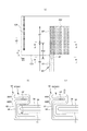
図1〜図13は、パンツタイプ使い捨ておむつの一例を示している。本パンツタイプ使い捨ておむつは、前身頃Fの少なくとも胴周り部を構成する前側外装体12F及び後身頃Bの少なくとも胴周り部を構成する後側外装体12Bと、前側外装体12Fから股間部を経て後側外装体12Bまで延在するように外装体12F,12Bの内側に設けられた内装体200とを備えており、前側外装体12Fの両側部と後側外装体12Bの両側部とが接合されてサイドシール部12Aが形成されることにより、外装体12F,12Bの前後端部により形成される開口が装着者の胴を通すウエスト開口WOとなり、内装体200の幅方向両側において外装体12F,12Bの下縁及び内装体200の側縁によりそれぞれ囲まれる部分が脚を通す脚開口LOとなる。内装体200は、尿等の排泄物等を吸収保持する部分であり、外装体12F,12Bは着用者の身体に対して内装体200を支えるための部分である。また、符号Yは展開状態におけるおむつの全長(前身頃Fのウエスト開口WOの縁から後身頃Bのウエスト開口WOの縁までの前後方向長さ)を示しており、符号Xは展開状態におけるおむつの全幅を示している。   1 to 13 show an example of a pants-type disposable diaper. This pants-type disposable diaper passes through the crotch part from the front exterior body 12F constituting at least the waist part of the front body F, the rear exterior body 12B constituting at least the waist part of the rear body B, and the front exterior body 12F. An interior body 200 provided inside the exterior bodies 12F and 12B so as to extend to the rear exterior body 12B, and both sides of the front exterior body 12F and both sides of the rear exterior body 12B are joined. By forming the side seal portion 12A, the opening formed by the front and rear end portions of the exterior bodies 12F and 12B becomes a waist opening WO through which the wearer's body passes, and the exterior body 12F is formed on both sides in the width direction of the interior body 200. , 12B and the portions surrounded by the side edges of the interior body 200 are leg openings LO through which the legs pass. The interior body 200 is a portion that absorbs and holds excrement such as urine, and the exterior bodies 12F and 12B are portions that support the interior body 200 with respect to the wearer's body. The symbol Y indicates the total length of the diaper in the deployed state (the length in the front-rear direction from the edge of the waist opening WO of the front body F to the edge of the waist opening WO of the back body B), and the symbol X indicates the diaper in the deployed state. The full width of is shown.

本形態のパンツタイプ使い捨ておむつは、サイドシール部12Aを有する前後方向範囲(ウエスト開口WOから脚開口LOの上端に至る前後方向範囲)として定まる胴周り領域Tと、脚開口LOを形成する部分の前後方向範囲(前身頃Fのサイドシール部12Aを有する前後方向領域と後身頃Bのサイドシール部12Aを有する前後方向領域との間)として定まる中間領域Lとを有する。胴周り領域Tは、概念的にウエスト開口の縁部を形成する「ウエスト部」Wと、これよりも下側の部分である「ウエスト下方部」Uとに分けることができる。通常、胴周り領域T内に幅方向WDの伸縮応力が変化する境界(例えば弾性部材の太さや伸長率が変化する)を有する場合は、最もウエスト開口WO側の境界よりもウエスト開口WO側がウエスト部Wとなり、このような境界が無い場合は吸収体56又は内装体200よりもウエスト開口WO側がウエスト部Wとなる。これらの前後方向長さは、製品のサイズによって異なり、適宜定めることができるが、一例を挙げると、ウエスト部Wは15〜40mm、ウエスト下方部Uは65〜120mmとすることができる。一方、中間領域Lの両側縁は被着者の脚周りに沿うようにコ字状又は曲線状に括れており、ここが装着者の脚を入れる部位となる。この結果、展開状態のパンツタイプ使い捨ておむつは、全体として略砂時計形状をなしている。   The pants-type disposable diaper of the present embodiment includes a waist region T defined as a front-rear direction range (a front-rear direction range extending from the waist opening WO to the upper end of the leg opening LO) having the side seal portion 12A, and a portion that forms the leg opening LO. An intermediate region L defined as a front-rear direction range (between a front-rear direction region having the side seal portion 12A of the front body F and a front-rear direction region having the side seal portion 12A of the rear body B). The waistline region T can be divided into a “waist portion” W that conceptually forms the edge of the waist opening and a “waist lower portion” U that is a lower portion than this. Usually, in the case where the waist region WO has a boundary where the stretching stress in the width direction WD changes (for example, the thickness of the elastic member or the elongation rate changes), the waist opening WO side is more waist-like than the waist opening WO side boundary. When there is no such boundary, the waist opening WO side becomes the waist portion W with respect to the absorbent body 56 or the interior body 200. These lengths in the front-rear direction vary depending on the size of the product and can be determined as appropriate. For example, the waist portion W may be 15 to 40 mm, and the waist lower portion U may be 65 to 120 mm. On the other hand, both side edges of the intermediate region L are wrapped in a U-shape or a curved shape along the circumference of the leg of the wearer, and this is a portion into which the wearer's leg is put. As a result, the unfolded pants-type disposable diaper has a substantially hourglass shape as a whole.

(内装体)
内装体200は任意の形状を採ることができるが、図示の形態では長方形である。内装体200は、図3〜図5に示されるように、身体側となるトップシート30と、液不透過性シート11と、これらの間に介在された吸収要素50とを備えているものであり、吸収機能を担う本体部である。符号40は、トップシート30を透過した液を速やかに吸収要素50へ移行させるために、トップシート30と吸収要素50との間に設けられた中間シート(セカンドシート)を示しており、符号60は、内装体200の両脇に排泄物が漏れるのを防止するために、内装体200の両側部から装着者の脚周りに接するように延び出た側部ギャザー60を示している。
(Interior body)
The interior body 200 can take any shape, but is rectangular in the illustrated form. As shown in FIGS. 3 to 5, the interior body 200 includes a top sheet 30 on the body side, a liquid-impermeable sheet 11, and an absorbent element 50 interposed therebetween. Yes, it is the main body that takes up the absorption function. Reference numeral 40 denotes an intermediate sheet (second sheet) provided between the top sheet 30 and the absorbent element 50 in order to quickly transfer the liquid that has passed through the top sheet 30 to the absorbent element 50. These show the side gathers 60 extended from both sides of the interior body 200 so as to contact the circumference of the wearer's leg in order to prevent excrement from leaking to both sides of the interior body 200.

(トップシート)
トップシート30は、液を透過する性質を有するものであり、例えば、有孔又は無孔の不織布や、多孔性プラスチックシートなどを例示することができる。また、このうち不織布は、その原料繊維が何であるかは、特に限定されない。例えば、ポリエチレンやポリプロピレン等のオレフィン系、ポリエステル系、ポリアミド系等の合成繊維、レーヨンやキュプラ等の再生繊維、綿等の天然繊維などや、これらから二種以上が使用された混合繊維、複合繊維などを例示することができる。さらに、不織布は、どのような加工によって製造されたものであってもよい。加工方法としては、公知の方法、例えば、スパンレース法、スパンボンド法、サーマルボンド法、メルトブローン法、ニードルパンチ法、エアスルー法、ポイントボンド法等を例示することができる。例えば、柔軟性、ドレープ性を求めるのであれば、スパンボンド法、スパンレース法が、嵩高性、ソフト性を求めるのであれば、エアスルー法、ポイントボンド法、サーマルボンド法が、好ましい加工方法となる。
(Top sheet)
The top sheet 30 has a property of allowing liquid to pass through, and examples thereof include a porous or non-porous nonwoven fabric, a porous plastic sheet, and the like. Of these, the nonwoven fabric is not particularly limited as to what the raw fiber is. For example, synthetic fibers such as olefins such as polyethylene and polypropylene, polyesters and polyamides, recycled fibers such as rayon and cupra, natural fibers such as cotton, and mixed fibers and composite fibers using two or more of them. Etc. can be illustrated. Furthermore, the nonwoven fabric may be manufactured by any processing. Examples of the processing method include known methods such as a spunlace method, a spunbond method, a thermal bond method, a melt blown method, a needle punch method, an air through method, and a point bond method. For example, if flexibility and drapeability are required, the spunbond method and spunlace method are preferable. If bulkiness and softness are required, the air-through method, point bond method, and thermal bond method are preferable processing methods. .

また、トップシート30は、1枚のシートからなるものであっても、2枚以上のシートを貼り合せて得た積層シートからなるものであってもよい。同様に、トップシート30は、平面方向に関して、1枚のシートからなるものであっても、2枚以上のシートからなるものであってもよい。   The top sheet 30 may be composed of a single sheet or a laminated sheet obtained by bonding two or more sheets. Similarly, the top sheet 30 may be composed of one sheet or two or more sheets in the planar direction.

トップシート30の両側部は、吸収要素50の側縁で裏側に折り返しても良く、また折り返さずに吸収要素50の側縁より側方にはみ出させても良い。   Both side portions of the top sheet 30 may be folded back to the back side at the side edge of the absorbent element 50, or may be projected to the side from the side edge of the absorbent element 50 without being folded back.

トップシート30は、裏側部材に対する位置ずれを防止する等の目的で、ヒートシール、超音波シールのような素材溶着による接合手段や、ホットメルト接着剤により裏側に隣接する部材に固定することが望ましい。図示形態では、トップシート30はその裏面に塗布されたホットメルト接着剤により中間シート40の表面及び包装シート58のうち吸収体56の表側に位置する部分の表面に固定されている。   For the purpose of preventing displacement of the top sheet 30 with respect to the back side member, the top sheet 30 is preferably fixed to a member adjacent to the back side by a joining means by material welding such as heat sealing or ultrasonic sealing, or a hot melt adhesive. . In the illustrated form, the top sheet 30 is fixed to the surface of the intermediate sheet 40 and the surface of the packaging sheet 58 on the front side of the absorbent body 56 by a hot melt adhesive applied to the back surface thereof.

(中間シート)
トップシート30を透過した液を速やかに吸収体へ移行させるために、トップシート30より液の透過速度が速い、中間シート(「セカンドシート」とも呼ばれている)40を設けることができる。この中間シート40は、液を速やかに吸収体へ移行させて吸収体による吸収性能を高め、吸収した液の吸収体からの「逆戻り」現象を防止するためのものである。中間シート40は省略することもできる。
(Intermediate sheet)
An intermediate sheet (also referred to as “second sheet”) 40 having a higher liquid permeation rate than the top sheet 30 can be provided in order to quickly transfer the liquid that has permeated through the top sheet 30 to the absorber. The intermediate sheet 40 is for quickly transferring the liquid to the absorber to enhance the absorption performance by the absorber and preventing the “returning” phenomenon of the absorbed liquid from the absorber. The intermediate sheet 40 can be omitted.

中間シート40としては、トップシート30と同様の素材や、スパンレース、スパンボンド、SMS、パルプ不織布、パルプとレーヨンとの混合シート、ポイントボンド又はクレープ紙を例示できる。特にエアスルー不織布が嵩高であるため好ましい。エアスルー不織布には芯鞘構造の複合繊維を用いるのが好ましく、この場合芯に用いる樹脂はポリプロピレン(PP)でも良いが剛性の高いポリエステル(PET)が好ましい。目付けは17〜80g/m2が好ましく、25〜60g/m2がより好ましい。不織布の原料繊維の太さは2.0〜10dtexであるのが好ましい。不織布を嵩高にするために、原料繊維の全部又は一部の混合繊維として、芯が中央にない偏芯の繊維や中空の繊維、偏芯且つ中空の繊維を用いるのも好ましい。 Examples of the intermediate sheet 40 include the same materials as the top sheet 30, spunlace, spunbond, SMS, pulp nonwoven fabric, mixed sheet of pulp and rayon, point bond, or crepe paper. In particular, an air-through nonwoven fabric is preferable because it is bulky. It is preferable to use a core-sheath composite fiber for the air-through nonwoven fabric. In this case, the resin used for the core may be polypropylene (PP), but polyester (PET) having high rigidity is preferable. Basis weight is preferably 17~80g / m 2, 25~60g / m 2 is more preferable. The thickness of the raw fiber of the nonwoven fabric is preferably 2.0 to 10 dtex. In order to make the nonwoven fabric bulky, it is also preferable to use an eccentric fiber, a hollow fiber, or an eccentric and hollow fiber that does not have a core at the center as the mixed fiber of all or part of the raw fiber.

図示の形態の中間シート40は、吸収体56の幅より短く中央に配置されているが、全幅にわたって設けてもよい。中間シート40の前後方向長さは、おむつの全長と同一でもよいし、吸収要素50の長さと同一でもよいし、液を受け入れる領域を中心にした短い長さ範囲内であってもよい。   The intermediate sheet 40 in the illustrated form is disposed in the center shorter than the width of the absorber 56, but may be provided over the entire width. The length in the front-rear direction of the intermediate sheet 40 may be the same as the entire length of the diaper, may be the same as the length of the absorbent element 50, or may be within a short length range centered on the region that receives the liquid.

中間シート40は、裏側部材に対する位置ずれを防止する等の目的で、ヒートシール、超音波シールのような素材溶着による接合手段や、ホットメルト接着剤により裏側に隣接する部材に固定することが望ましい。図示形態では、中間シート40はその裏面に塗布されたホットメルト接着剤により包装シート58のうち吸収体56の表側に位置する部分の表面に固定されている。   The intermediate sheet 40 is preferably fixed to a member adjacent to the back side by a joining means by material welding such as heat sealing or ultrasonic sealing, or a hot melt adhesive for the purpose of preventing positional displacement with respect to the back side member. . In the illustrated embodiment, the intermediate sheet 40 is fixed to the surface of the portion of the packaging sheet 58 located on the front side of the absorbent body 56 with a hot melt adhesive applied to the back surface thereof.

(液不透過性シート)
液不透過性シート11の素材は、特に限定されるものではないが、例えば、ポリエチレンやポリプロピレン等のオレフィン系樹脂等からなるプラスチックフィルムや、不織布の表面にプラスチックフィルムを設けたラミネート不織布、プラスチックフィルムに不織布等を重ねて接合した積層シートなどを例示することができる。液不透過性シート11には、ムレ防止の観点から好まれて使用されている液不透過性かつ透湿性を有する素材を用いることが好ましい。透湿性を有するプラスチックフィルムとしては、ポリエチレンやポリプロピレン等のオレフィン系樹脂中に無機充填剤を混練して、シートを成形した後、一軸又は二軸方向に延伸して得られた微多孔性プラスチックフィルムが広く用いられている。この他にも、マイクロデニール繊維を用いた不織布、熱や圧力をかけることで繊維の空隙を小さくすることによる防漏性強化、高吸水性樹脂又は疎水性樹脂や撥水剤の塗工といった方法により、プラスチックフィルムを用いずに液不透過性としたシートも、液不透過性シート11として用いることができるが、後述するカバー不織布13とのホットメルト接着剤を介した接着時に十分な接着強度を得るため、樹脂フィルムを用いるのが望ましい。
(Liquid impervious sheet)
The material of the liquid-impermeable sheet 11 is not particularly limited. For example, a plastic film made of an olefin resin such as polyethylene or polypropylene, a laminated nonwoven fabric provided with a plastic film on the surface of the nonwoven fabric, or a plastic film For example, a laminated sheet in which a nonwoven fabric or the like is laminated and bonded to each other can be exemplified. The liquid-impermeable sheet 11 is preferably made of a liquid-impermeable and moisture-permeable material that is preferably used from the viewpoint of preventing stuffiness. As a plastic film having moisture permeability, a microporous plastic film obtained by kneading an inorganic filler in an olefin resin such as polyethylene or polypropylene, forming a sheet, and then stretching in a uniaxial or biaxial direction. Is widely used. In addition, non-woven fabric using microdenier fibers, leakproof reinforcement by reducing the voids of the fibers by applying heat or pressure, and methods such as coating with a superabsorbent resin or hydrophobic resin or water repellent Thus, a sheet that is liquid-impermeable without using a plastic film can also be used as the liquid-impermeable sheet 11, but has sufficient adhesive strength when bonded to the cover nonwoven fabric 13 described later via a hot-melt adhesive. Therefore, it is desirable to use a resin film.

液不透過性シート11は、図示のように吸収要素50の裏側に収まる幅とする他、防漏性を高めるために、吸収要素50の両側を回り込ませて吸収要素50のトップシート30側面の両側部まで延在させることもできる。この延在部の幅は、左右それぞれ5〜20mm程度が適当である。   The liquid-impermeable sheet 11 has a width that can be accommodated on the back side of the absorbent element 50 as shown in the drawing, and in order to improve leakage prevention, the liquid-impermeable sheet 11 wraps around both sides of the absorbent element 50 to form the side surface of the top sheet 30 of the absorbent element 50. It can also extend to both sides. The width of this extended portion is suitably about 5 to 20 mm on each of the left and right sides.

また、液不透過性シート11の内側、特に吸収体56側面に、液分の吸収により色が変化する排泄インジケータを設けることができる。   Moreover, the excretion indicator from which a color changes by absorption of a liquid part can be provided in the inner side of the liquid-impermeable sheet 11, especially the absorber 56 side surface.

(側部ギャザー)
側部ギャザー60は、内装体200の両側部に沿って前後方向LDの全体にわたり延在し、装着者の脚周りに接して横漏れを防止するために設けられているものであり、一般に立体ギャザーと呼ばれるものや、平面ギャザーと呼ばれるものがこれに含まれる。
(Side gather)
The side gathers 60 extend along the both sides of the interior body 200 in the entire front-rear direction LD, and are provided to contact the circumference of the wearer's legs to prevent side leakage. This includes what are called gathers and what are called planar gathers.

図1、図3及び図4に示される第1の形態の側部ギャザー60はいわゆる立体ギャザーであり、内装体200の側部から表側に起立するものである。この側部ギャザー60は、付け根側部分60Bが幅方向中央側に向かって斜めに起立し、中間部より先端側部分60Aが幅方向外側に向かって斜めに起立するものであるが、これに限定されるものではなく、後述する第2の形態のように、全体として幅方向中央側に起立する形態等、適宜の変更が可能である。   The side gathers 60 of the first embodiment shown in FIGS. 1, 3 and 4 are so-called three-dimensional gathers, and stand up from the side of the interior body 200 to the front side. In the side gather 60, the base side portion 60B rises obliquely toward the center in the width direction, and the tip side portion 60A rises obliquely toward the outside in the width direction from the intermediate portion. However, as in a second embodiment to be described later, it is possible to make appropriate changes, such as a configuration in which the entirety stands up in the center in the width direction.

より詳細に説明すると、第1の形態の側部ギャザー60は、内装体200の前後方向長さに等しい長さを有する帯状のギャザー不織布62を、先端となる部分で幅方向WDに折り返して二つに折り重ねるとともに、折り返し部分及びその近傍のシート間に、細長状のギャザー弾性部材63を長手方向に沿って伸長状態で、幅方向WDに間隔を空けて複数本固定してなるものである。側部ギャザー60のうち先端部と反対側に位置する基端部(幅方向WDにおいてシート折り返し部分と反対側の端部)は、内装体200における液不透過性シート11より裏側の側部に固定された付根部分65とされ、この付根部分65以外の部分は付根部分65から延び出る本体部分66(折り返し部分側の部分)とされている。また、本体部分66は、幅方向中央側に延びる付け根側部分60Bと、この付け根側部分60Bの先端で折り返され、幅方向外側に延びる先端側部分60Aとを有している。この形態は面接触タイプの側部ギャザー60であるが、幅方向外側に折り返されない線接触タイプの側部ギャザー60も採用することができる。そして、本体部分66のうち前後方向両端部が倒伏状態でトップシート30の側部表面に対して固定された倒伏部分67とされる一方で、これらの間に位置する前後方向中間部は非固定の自由部分68とされ、この自由部分68の少なくとも先端部に前後方向LDに沿うギャザー弾性部材63が伸長状態で固定されている。なお、ギャザー弾性部材63は、側部ギャザー60の前後端部ではギャザー不織布62に対して非固定とされるが、少なくとも先端部においては倒伏部分67の股間側縁と同じ位置またはそれよりもウエスト寄りの位置まで固定されていると、立体的な起立が安定するため、好ましい。   More specifically, the side gather 60 according to the first embodiment is formed by folding a band-shaped gathered nonwoven fabric 62 having a length equal to the length in the front-rear direction of the interior body 200 in the width direction WD at the tip portion. In addition to being folded into one, a plurality of elongated gather elastic members 63 are fixed along the longitudinal direction and spaced apart in the width direction WD between the folded portion and the sheet in the vicinity thereof. . A base end portion (an end portion opposite to the sheet folding portion in the width direction WD) of the side gather 60 on the side opposite to the front end portion is located on a side portion on the back side of the liquid-impermeable sheet 11 in the interior body 200. A fixed root portion 65 is formed, and a portion other than the root portion 65 is a main body portion 66 (a portion on the folded portion side) extending from the root portion 65. The main body portion 66 includes a root side portion 60B extending toward the center in the width direction, and a tip side portion 60A that is folded back at the tip of the root side portion 60B and extends outward in the width direction. This form is a surface contact type side gather 60, but a line contact type side gather 60 that is not folded outward in the width direction can also be employed. And while the both ends of the front-back direction among the main body parts 66 are set to the fall-down part 67 fixed with respect to the side part surface of the top sheet 30 in a lying state, the front-back direction intermediate part located between these is not fixed. The gather elastic member 63 along the front-rear direction LD is fixed in an extended state to at least the tip of the free portion 68. The gather elastic member 63 is not fixed to the gathered nonwoven fabric 62 at the front and rear end portions of the side gather 60, but at least at the tip portion is the same position as the crotch side edge of the lying portion 67 or the waist. It is preferable that the position is fixed to the close position because the three-dimensional standing is stabilized.

以上のように構成された第1の形態の側部ギャザー60では、細長状弾性部材63の収縮力が前後方向両端部を近づけるように作用するが、本体部分66のうち前後方向両端部が起立しないように固定されるのに対して、それらの間は非固定の自由部分68とされているため、自由部分68のみが図3に示すように身体側に当接するように起立する。特に、付根部分65が内装体200の裏側に位置していると、股間部及びその近傍において自由部分68が幅方向外側に開くように起立するため、側部ギャザー60が脚周りに面で当接するようになり、フィット性が向上するようになる。   In the side gathers 60 of the first embodiment configured as described above, the contraction force of the elongated elastic member 63 acts so that the both ends in the front-rear direction are brought close to each other. In contrast to being fixed so as not to be fixed, there is a non-fixed free part 68 between them, so that only the free part 68 stands up against the body side as shown in FIG. In particular, when the root portion 65 is located on the back side of the interior body 200, the side gathers 60 are faced around the legs because the free portion 68 stands up so as to open outward in the width direction at and around the crotch portion. It comes in contact, and the fit is improved.

本第1の形態の側部ギャザー60のように、本体部分66が、幅方向中央側に延びる付け根側部分60Bと、この付け根側部分60Bの先端で折り返され幅方向外側に延びる先端側部分60Aとからなる屈曲形態では、倒伏部分67で、先端側部分60Aと付け根側部分60Bとが倒伏状態で接合されるとともに、付け根側部分60Bが倒伏状態でトップシート30に接合される。倒伏部分67における対向面の接合には、種々の塗布方法によるホットメルト接着剤、及びヒートシールや超音波シール等の素材溶着による手段の少なくとも一方を用いることができる。この場合において、付け根側部分60B及びトップシート30の接合と、先端側部分60A及び付け根側部分60Bの接合とを同じ手段により行っても、また異なる手段により行っても良い。例えば、付け根側部分60B及びトップシート30の接合をホットメルト接着剤により行い、先端側部分60A及び付け根側部分60Bの接合を素材溶着により行うのは一つの好ましい形態である。   Like the side gather 60 of the first embodiment, the main body portion 66 has a root side portion 60B extending toward the center in the width direction, and a tip side portion 60A that is folded back at the tip of the root side portion 60B and extends outward in the width direction. In the bent form consisting of the above, at the lying portion 67, the tip side portion 60A and the base side portion 60B are joined in the lying down state, and the base side portion 60B is joined to the top sheet 30 in the lying down state. At least one of a hot melt adhesive by various coating methods and a material welding method such as heat sealing or ultrasonic sealing can be used for joining the opposing surfaces in the lying portion 67. In this case, the joining of the base side part 60B and the top sheet 30 and the joining of the tip side part 60A and the base side part 60B may be performed by the same means or by different means. For example, it is one preferable embodiment that the base side portion 60B and the top sheet 30 are joined by a hot melt adhesive, and the tip side portion 60A and the base side portion 60B are joined by material welding.

特に、前側外装体12Fと後側外装体12Bとが前後方向LDに離間する外装二分割タイプのパンツタイプ使い捨ておむつでは、図10に示すように、前側の倒伏部分67の後側に連続又は隣接して、付け根側部分60Bが倒伏状態でトップシート30に接合され、かつ先端側部分60Aと付け根側部分60Bとが接合されない前側半倒伏部分68Fが設けられているのが好ましい。前側半倒伏部分68Fでは、先端側部分60Aのみが自由であり、高さは低いものの細長状弾性部材63の収縮によってトップシート30に対して先端部が確実に立ち上がるため、隙間のできやすい鼠径部に対しても側部ギャザー60のフィット性が良好となるとともに、高さが低いことによりフィット位置が安定するため、内装体200が左右に動いても側部ギャザー60のフィット位置が大きくぶれることがない。また、この場合、前側半倒伏部分68Fは前側外装体12Fの後縁と同じか、又はそれより前後方向中央側に延びていると(すなわち、前側半倒伏部分68Fが前側外装体12Fと内装体200の交差位置を含むようになっていると)、内装体200の左右の動きに対する安定性と、鼠径部に対する側部ギャザー60のフィット性とがともに良好となるため好ましい。通常の場合、前側の倒伏部分67の前後方向長さは内装体200の前後方向長さの0.10〜0.25倍程度で、これに前側半倒伏部分68Fの前後方向長さを足した寸法は、内装体200の前後方向長さの0.15〜0.30倍程度とすることが好ましい。なお、図10中の符号AFは、先端側部分60A及び付け根側部分60Bを接合するホットメルト接着剤を示し、符号BFは、付け根側部分60B及びトップシート30を接合するホットメルト接着剤を示している。   In particular, in an exterior two-divided type pants-type disposable diaper in which the front exterior body 12F and the rear exterior body 12B are separated from each other in the front-rear direction LD, as shown in FIG. The base side portion 60B is preferably joined to the top sheet 30 in the lying state, and the front half-falling portion 68F where the tip side portion 60A and the root side portion 60B are not joined is preferably provided. In the front half-falling portion 68F, only the tip side portion 60A is free, and although the height is low, the tip portion reliably rises with respect to the top sheet 30 due to the contraction of the elongated elastic member 63. However, since the fitting position of the side gathers 60 is good and the fitting position is stable because the height is low, the fitting position of the side gathers 60 greatly fluctuates even if the interior body 200 moves left and right. There is no. Further, in this case, the front half-falling portion 68F is the same as the rear edge of the front exterior body 12F or extends to the center in the front-rear direction (that is, the front half-falling portion 68F is connected to the front exterior body 12F and the interior body). 200 crossing positions) is preferable because both the stability of the interior body 200 with respect to the left and right movement and the fit of the side gathers 60 with respect to the inguinal portion are improved. In the normal case, the length of the front-side lying portion 67 in the front-rear direction is about 0.10 to 0.25 times the length in the front-rear direction of the interior body 200, and the length in the front-rear direction of the front half-falling portion 68F is added thereto. The dimensions are preferably about 0.15 to 0.30 times the length of the interior body 200 in the front-rear direction. 10 indicates a hot-melt adhesive that joins the tip-side portion 60A and the base-side portion 60B, and BF indicates a hot-melt adhesive that joins the base-side portion 60B and the top sheet 30. ing.

また、図11に示すように、後側の倒伏部分67の前側に連続又は隣接して、先端側部分60Aが倒伏状態で付け根側部分60Bに接合され、かつ付け根側部分60Bとトップシート30とが接合されない後側半倒伏部分68Bが設けられていると、付け根側部分60Bのみが自由で先端側部分60Aは固定されていること、並びに側部ギャザー60の高さが段階的に高くなり、後側半倒伏部分68Bのフィット位置が安定しやすくなるため、内装体200が左右に動いても側部ギャザー60のフィット位置が大きくぶれないことによって、立体ギャザーの先端側部分60Aが臀裂に向かう傾斜によって反対向きに倒れにくくなるため好ましい。後側半倒伏部分68Bはお尻の膨らんでいる部分に当接するため、先端側部分60Aが固定されていても、体との間に隙間が生じる心配もない。また、この場合、後側半倒伏部分68Bは後側外装体12Bの前縁と同じか、又はより前後方向中央側に延びていると(すなわち、後側半倒伏部分68Bが後側外装体12Bと内装体200の交差位置を含むようになっていると)、内装体200の左右の動きに対しても安定的に内装体200の臀裂への食い込みを防止できるため好ましい。さらに、この場合、後側半倒伏部分68Bの前後方向長さは、後側の倒伏部分67の前後方向長さよりも長いことが好ましく、通常の場合、後側の倒伏部分67の前後方向長さは内装体200の前後方向長さの0.15〜0.30倍程度で、これに後側半倒伏部分68Bの前後方向長さを足した寸法は、内装体200の前後方向長さの0.20〜0.35倍程度とすることが好ましい。なお、図11中の符号AFは、先端側部分60A及び付け根側部分60Bを接合するホットメルト接着剤を示し、符号BFは、付け根側部分60B及びトップシート30を接合するホットメルト接着剤を示している。   Further, as shown in FIG. 11, the tip side portion 60A is joined to the root side portion 60B in a lying state continuously or adjacent to the front side of the rear side lying portion 67, and the root side portion 60B and the top sheet 30 If the rear half-falling portion 68B is not joined, only the base side portion 60B is free and the tip side portion 60A is fixed, and the height of the side gather 60 is increased stepwise. Since the fitting position of the rear half-falling portion 68B is likely to be stable, the fitting position of the side gathers 60 does not greatly fluctuate even if the interior body 200 moves to the left and right. It is preferable because it is difficult to fall in the opposite direction due to the inclination to go. Since the rear half-falling portion 68B abuts against the bulging portion of the buttocks, there is no fear that a gap will be formed between the tip-side portion 60A and the body. Further, in this case, when the rear half-falling portion 68B is the same as the front edge of the rear exterior body 12B or extends to the center in the front-rear direction (that is, the rear half-falling portion 68B is the rear exterior body 12B). And the position where the interior body 200 is crossed) is preferable because the inner body 200 can be prevented from biting into the cracks in a stable manner even when the interior body 200 moves left and right. Further, in this case, the length in the front-rear direction of the rear half-falling portion 68B is preferably longer than the length in the front-rear direction of the rear-side fallen portion 67. Is about 0.15 to 0.30 times the length in the front-rear direction of the interior body 200, and the dimension obtained by adding the length in the front-rear direction of the rear half-falling portion 68B is 0 of the length in the front-rear direction of the interior body 200 .About 20 to 0.35 times is preferable. 11 indicates a hot-melt adhesive that joins the tip-side portion 60A and the base-side portion 60B, and BF indicates a hot-melt adhesive that joins the base-side portion 60B and the top sheet 30. ing.

ギャザー不織布62としてはスパンボンド不織布(SS、SSS等)やSMS不織布(SMS、SSMMS等)、メルトブロー不織布等の柔軟で均一性・隠蔽性に優れた不織布に、必要に応じてシリコーンなどにより撥水処理を施したものを好適に用いることができ、繊維目付けは10〜30g/m2程度とするのが好ましい。細長状弾性部材63としては糸ゴム等を用いることができる。スパンデックス糸ゴムを用いる場合は、太さは470〜1240dtexが好ましく、620〜940dtexがより好ましい。固定時の伸長率は、150〜350%が好ましく、200〜300%がより好ましい。なお、用語「伸長率」は自然長を100%としたときの値を意味する。また、図示のように、二つに折り重ねたギャザー不織布62の間に防水フィルム64を介在させることもでき、この場合には防水フィルム64の存在部分においてギャザー不織布62を部分的に省略することもできるが、製品の外観及び肌触りを布のようにするためには、図示形態のように、少なくとも側部ギャザー60の基端から先端までの外面がギャザー不織布62で形成されていることが必要である。 The gathered nonwoven fabric 62 is a flexible nonwoven fabric excellent in uniformity and concealment, such as spunbond nonwoven fabric (SS, SSS, etc.), SMS nonwoven fabric (SMS, SSMMS, etc.), melt blown nonwoven fabric, etc. A treated product can be suitably used, and the fiber basis weight is preferably about 10 to 30 g / m 2 . As the elongated elastic member 63, thread rubber or the like can be used. When spandex thread rubber is used, the thickness is preferably 470 to 1240 dtex, more preferably 620 to 940 dtex. The elongation rate at the time of fixation is preferably 150 to 350%, more preferably 200 to 300%. The term “elongation rate” means a value when the natural length is 100%. Moreover, as shown in the drawing, a waterproof film 64 can be interposed between the gathered nonwoven fabrics 62 folded in two. In this case, the gathered nonwoven fabric 62 is partially omitted in the portion where the waterproof film 64 is present. However, in order to make the appearance and feel of the product like a cloth, it is necessary that at least the outer surface from the base end to the tip end of the side gather 60 is formed of the gathered nonwoven fabric 62 as shown in the figure. It is.

側部ギャザー60の自由部分に設けられる細長状弾性部材63の本数は2〜6本が好ましく、3〜5本がより好ましい。配置間隔60dは3〜10mmが適当である。このように構成すると、細長状弾性部材63を配置した範囲で肌に対して面で当たりやすくなる。先端側だけでなく付け根側にも細長状弾性部材63を配置しても良い。   The number of the elongated elastic members 63 provided in the free part of the side gathers 60 is preferably 2 to 6, and more preferably 3 to 5. The arrangement interval 60d is suitably 3 to 10 mm. If comprised in this way, in the range which has arrange | positioned the elongate elastic member 63, it will become easy to hit | skin with respect to skin. The elongated elastic member 63 may be disposed not only at the distal end side but also at the base side.

側部ギャザー60の自由部分68では、ギャザー不織布62の内側層及び外側層の貼り合わせや、その間に挟まれるギャザー弾性部材63の固定に、種々の塗布方法によるホットメルト接着剤及びヒートシールや超音波シール等の素材溶着による固定手段の少なくとも一方を用いることができる。ギャザー不織布62の内側層及び外側層の全面を貼り合わせると柔軟性を損ねるため、ギャザー弾性部材63の接着部以外の部分は接着しないか弱く接着するのが好ましい。図示形態では、コームガンやシュアラップノズル等の塗布手段によりギャザー弾性部材63の外周面にのみホットメルト接着剤を塗布してギャザー不織布62の内側層及び外側層間に挟むことにより、当該ギャザー弾性部材63の外周面に塗布したホットメルト接着剤のみで、ギャザー不織布62の内側層及び外側層への細長状弾性部材の固定と、ギャザー不織布62の内側層及び外側層間の固定とを行う構造となっている。   In the free part 68 of the side gather 60, hot melt adhesives and heat seals and super seals by various coating methods are used to bond the inner layer and the outer layer of the gathered nonwoven fabric 62 and to fix the gather elastic member 63 sandwiched therebetween. At least one of fixing means by material welding such as a sonic seal can be used. Since the flexibility is lost when the entire inner layer and outer layer of the gathered nonwoven fabric 62 are bonded together, it is preferable that portions other than the bonding portion of the gather elastic member 63 are not bonded or are bonded weakly. In the illustrated form, a hot melt adhesive is applied only to the outer peripheral surface of the gathered elastic member 63 by a coating means such as a comb gun or a sure wrap nozzle, and sandwiched between the inner layer and the outer layer of the gathered nonwoven fabric 62, thereby gathering the gathered elastic member 63. Only the hot melt adhesive applied to the outer peripheral surface of the non-woven fabric 62 is used to fix the elongated elastic member to the inner layer and the outer layer of the gathered nonwoven fabric 62 and to fix the inner layer and the outer layer of the gathered nonwoven fabric 62. Yes.

同様に、側部ギャザー60に組み込まれる防水フィルム64とギャザー不織布62との固定や、倒伏部分67の固定についても、種々の塗布方法によるホットメルト接着剤、及びヒートシールや超音波シール等の素材溶着による手段の少なくとも一方を用いることができる。   Similarly, for the fixing of the waterproof film 64 and the gathered nonwoven fabric 62 incorporated in the side gather 60 and the fixing of the lying portion 67, hot melt adhesives by various application methods, and materials such as heat seal and ultrasonic seal At least one of means by welding can be used.

第1の形態の側部ギャザー60の寸法は適宜定めることができるが、乳幼児用途の場合は、例えば図3に示すように、側部ギャザー60の起立高さ(展開状態における本体部分66の幅方向長さ)W2は15〜60mm、特に20〜40mmであるのが好ましい。また、側部ギャザー60をトップシート30表面と平行になるように、平坦に折り畳んだ状態において最も内側に位置する折り目間の離間距離W1は60〜190mm、特に70〜140mmであるのが好ましい。大人用途の場合、側部ギャザー60の起立高さ(展開状態における本体部分66の幅方向長さ)W2は20〜60mm、特に30〜55mmであるのが好ましい。また、側部ギャザー60をトップシート30表面と平行になるように、平坦に折り畳んだ状態において最も内側に位置する折り目間の離間距離W1は110〜190mm、特に120〜150mmであるのが好ましい。   The dimensions of the side gathers 60 of the first embodiment can be determined as appropriate, but in the case of infant use, for example, as shown in FIG. 3, the standing height of the side gathers 60 (the width of the main body portion 66 in the unfolded state). (Directional length) W2 is preferably 15 to 60 mm, particularly preferably 20 to 40 mm. Moreover, it is preferable that the separation distance W1 between the folds located on the innermost side in a state where the side gathers 60 are flatly folded so as to be parallel to the surface of the top sheet 30 is 60 to 190 mm, particularly 70 to 140 mm. In the case of an adult use, the standing height (the length in the width direction of the main body portion 66 in the unfolded state) W2 of the side gathers 60 is preferably 20 to 60 mm, particularly preferably 30 to 55 mm. In addition, the separation distance W1 between the innermost folds in a state where the side gathers 60 are folded flat so as to be parallel to the surface of the top sheet 30 is preferably 110 to 190 mm, particularly preferably 120 to 150 mm.

第1の形態の側部ギャザー60は、立体ギャザーのみを含むものとなっているが、立体ギャザー及び平面ギャザーの両方を含むものとしたり、平面ギャザーのみを含むものとしたりすることもできる。図12及び図13は、立体ギャザー及び平面ギャザーの両方を含む、第2の形態の側部ギャザー60を示している。各側部ギャザー60は、内装体200における液不透過性シート11より裏側の側部に固定された付根部分65から、内装体200の側方に突出する第1の部分61(平面ギャザー部分)と、内装体200におけるトップシート30の両側部に固定された付根部分65から、内装体200の表側に突出する第2の部分69(立体ギャザー部分)と有するものである。より詳細には、内装体200の前後方向長さに等しい長さを有する帯状のギャザー不織布62が、付根部分65から側方に延び出て第1の部分61の先端で表側に折り返され、この表側に折り返された部分が第1の部分61を経て第2の部分69に至り、第2の部分69の先端で折り返されている。ギャザー不織布62における折り重なる部分は、対向部分がホットメルト接着剤等により接合される。また、第2の部分69の前後方向両端部は、倒伏状態でトップシート30の側部表面に対して固定された倒伏部分67とされる一方で、これらの間に位置する前後方向中間部は非固定の自由部分68とされる。第1の部分61の少なくとも前後方向中間部、及び第2の部分69の自由部分68には、前後方向LDに沿うギャザー弾性部材63が一本又は幅方向WDに間隔を空けて複数本伸長状態で固定されており、その収縮力により第2の部分69の自由部分68が前後方向LDに収縮して脚周りに接する立体ギャザーとなり、また第1の部分61が前後方向LDに収縮して脚周りに接する平面ギャザーとなる。   The side gathers 60 of the first embodiment include only a three-dimensional gather, but may include both a three-dimensional gather and a planar gather, or may include only a planar gather. 12 and 13 illustrate a second form of side gather 60 that includes both solid gathers and planar gathers. Each side gather 60 is a first portion 61 (planar gathering portion) that protrudes to the side of the interior body 200 from a root portion 65 fixed to the side portion on the back side of the liquid-impermeable sheet 11 in the interior body 200. And a second portion 69 (a three-dimensional gathered portion) that protrudes from the root portion 65 fixed to both sides of the top sheet 30 in the interior body 200 to the front side of the interior body 200. More specifically, a strip-shaped gathered nonwoven fabric 62 having a length equal to the length in the front-rear direction of the interior body 200 extends laterally from the root portion 65 and is folded back to the front side at the tip of the first portion 61. The portion folded back to the front side reaches the second portion 69 through the first portion 61, and is folded at the tip of the second portion 69. As for the overlapping part in the gathered nonwoven fabric 62, the opposing part is joined by a hot-melt adhesive or the like. Moreover, while the front-rear direction both ends of the 2nd part 69 are set as the fallen part 67 fixed with respect to the side part surface of the top sheet 30 in a lying state, the front-back direction intermediate part located between these is An unfixed free portion 68 is provided. At least in the front-rear direction intermediate portion of the first portion 61 and the free portion 68 of the second portion 69, one or more gather elastic members 63 along the front-rear direction LD are extended or spaced apart in the width direction WD. The free portion 68 of the second portion 69 is contracted in the front-rear direction LD by the contraction force to form a three-dimensional gather that touches around the leg, and the first portion 61 contracts in the front-rear direction LD. A flat gather that touches the surroundings.

第2の形態の側部ギャザー60における立体ギャザーは、全体として幅方向中央側に起立する形態となっているが、これに限定されるものではなく、第1の形態の側部ギャザー60のように屈曲形態とするものとする等、適宜の変更が可能である。第2の形態に関する他の点、例えばギャザー不織布62の素材や、ギャザー弾性部材63の素材等は、第1の形態と同様であるため説明を省略する。   The three-dimensional gather in the side gathers 60 of the second form is a form that rises as a whole in the center in the width direction, but is not limited to this, like the side gathers 60 of the first form. Appropriate changes can be made, such as a bent form. Other points relating to the second embodiment, such as the material of the gathered nonwoven fabric 62 and the material of the gathered elastic member 63, are the same as those in the first embodiment, and thus the description thereof is omitted.

(吸収要素)
吸収要素50は、吸収体56と、この吸収体56の全体を包む包装シート58とを有する。包装シート58は省略することもできる。
(Absorption element)
The absorbent element 50 includes an absorbent body 56 and a packaging sheet 58 that wraps the entire absorbent body 56. The packaging sheet 58 can be omitted.

(吸収体)
吸収体56は、繊維の集合体により形成することができる。この繊維集合体としては、綿状パルプや合成繊維等の短繊維を積繊したものの他、セルロースアセテート等の合成繊維のトウ(繊維束)を必要に応じて開繊して得られるフィラメント集合体も使用できる。繊維目付けとしては、綿状パルプや短繊維を積繊する場合は、例えば100〜300g/m2程度とすることができ、フィラメント集合体の場合は、例えば30〜120g/m2程度とすることができる。合成繊維の場合の繊度は、例えば、1〜16dtex、好ましくは1〜10dtex、さらに好ましくは1〜5dtexである。フィラメント集合体の場合、フィラメントは、非捲縮繊維であってもよいが、捲縮繊維であるのが好ましい。捲縮繊維の捲縮度は、例えば、2.54cm当たり5〜75個、好ましくは10〜50個、さらに好ましくは15〜50個程度とすることができる。また、均一に捲縮した捲縮繊維を用いる場合が多い。吸収体56中には高吸収性ポリマー粒子を分散保持させるのが好ましい。
(Absorber)
The absorber 56 can be formed of an aggregate of fibers. As this fiber assembly, a filament assembly obtained by opening, as necessary, synthetic fiber tows (fiber bundles) such as cellulose acetate as well as short fibers such as cotton-like pulp and synthetic fibers Can also be used. The fiber basis weight can be set to, for example, about 100 to 300 g / m 2 when cotton-like pulp or short fibers are stacked, and in the case of a filament aggregate, for example, about 30 to 120 g / m 2. Can do. The fineness in the case of a synthetic fiber is 1-16 dtex, for example, Preferably it is 1-10 dtex, More preferably, it is 1-5 dtex. In the case of a filament aggregate, the filament may be a non-crimped fiber, but is preferably a crimped fiber. The degree of crimp of the crimped fibers can be, for example, about 5 to 75, preferably 10 to 50, and more preferably about 15 to 50 per 2.54 cm. Further, a crimped fiber that is uniformly crimped is often used. It is preferable to disperse and hold superabsorbent polymer particles in the absorber 56.

吸収体56は長方形形状でも良いが、図1及び図7等にも示すように、前後方向中間に、その前後両側よりも幅が狭い括れ部56Nとを有する砂時計形状をなしていると、吸収体56自体と側部ギャザー60の、脚周りへのフィット性が向上するため好ましい。   The absorber 56 may have a rectangular shape. However, as shown in FIGS. 1 and 7 and the like, if the hourglass shape has a constricted portion 56N having a narrower width than the both front and rear sides, as shown in FIGS. The fit of the body 56 itself and the side gathers 60 around the legs is preferable.

また、吸収体56の寸法は排尿口位置の前後左右にわたる限り適宜定めることができるが、前後方向LD及び幅方向WDにおいて、内装体200の周縁部又はその近傍まで延在しているのが好ましい。なお、符号56Xは吸収体56の全幅を示している。   Further, the size of the absorbent body 56 can be appropriately determined as long as it extends to the front, rear, left, and right of the urination port position, but preferably extends to the peripheral portion of the interior body 200 or the vicinity thereof in the front-rear direction LD and the width direction WD. . Reference numeral 56X indicates the full width of the absorber 56.

(高吸収性ポリマー粒子)
吸収体56には、その一部又は全部に高吸収性ポリマー粒子を含有させることができる。高吸収性ポリマー粒子とは、「粒子」以外に「粉体」も含む。高吸収性ポリマー粒子54としては、この種の使い捨ておむつに使用されるものをそのまま使用でき、例えば500μmの標準ふるい(JIS Z8801−1:2006)を用いたふるい分け(5分間の振とう)でふるい上に残る粒子の割合が30重量%以下のものが望ましく、また、180μmの標準ふるい(JIS Z8801−1:2006)を用いたふるい分け(5分間の振とう)でふるい上に残る粒子の割合が60重量%以上のものが望ましい。
(Superabsorbent polymer particles)
The absorber 56 can contain superabsorbent polymer particles in a part or all thereof. Superabsorbent polymer particles include “powder” in addition to “particles”. As the superabsorbent polymer particles 54, those used for this type of disposable diaper can be used as they are, for example, by sieving (shaking for 5 minutes) using a 500 μm standard sieve (JIS Z8801-1: 2006). The proportion of particles remaining on the top is preferably 30% by weight or less, and the proportion of particles remaining on the screen by sieving (shaking for 5 minutes) using a 180 μm standard sieve (JIS Z8801-1: 2006) 60% by weight or more is desirable.

高吸収性ポリマー粒子の材料としては、特に限定無く用いることができるが、吸水量が40g/g以上のものが好適である。高吸収性ポリマー粒子としては、でんぷん系、セルロース系や合成ポリマー系などのものがあり、でんぷん−アクリル酸(塩)グラフト共重合体、でんぷん−アクリロニトリル共重合体のケン化物、ナトリウムカルボキシメチルセルロースの架橋物やアクリル酸(塩)重合体などのものを用いることができる。高吸収性ポリマー粒子の形状としては、通常用いられる粉粒体状のものが好適であるが、他の形状のものも用いることができる。   The material of the superabsorbent polymer particles can be used without any particular limitation, but those having a water absorption of 40 g / g or more are suitable. High-absorbent polymer particles include starch-based, cellulose-based, and synthetic polymer-based starch-acrylic acid (salt) graft copolymers, saponified starch-acrylonitrile copolymers, and sodium carboxymethylcellulose crosslinks. Or an acrylic acid (salt) polymer can be used. As the shape of the superabsorbent polymer particles, a commonly used granular material is suitable, but other shapes can also be used.

高吸収性ポリマー粒子としては、吸水速度が70秒以下、特に40秒以下のものが好適に用いられる。吸水速度が遅すぎると、吸収体56内に供給された液が吸収体56外に戻り出てしまう所謂逆戻りを発生し易くなる。   As the superabsorbent polymer particles, those having a water absorption rate of 70 seconds or less, particularly 40 seconds or less are preferably used. If the water absorption speed is too slow, the liquid supplied into the absorber 56 is likely to cause a so-called reverse return that returns to the outside of the absorber 56.

また、高吸収性ポリマー粒子としては、ゲル強度が1000Pa以上のものが好適に用いられる。これにより、嵩高な吸収体56とした場合であっても、液吸収後のべとつき感を効果的に抑制できる。   Further, as the superabsorbent polymer particles, those having a gel strength of 1000 Pa or more are preferably used. Thereby, even if it is a case where it is set as the bulky absorber 56, the sticky feeling after liquid absorption can be suppressed effectively.

高吸収性ポリマー粒子の目付け量は、当該吸収体56の用途で要求される吸収量に応じて適宜定めることができる。したがって一概には言えないが、50〜350g/m2とすることができる。ポリマーの目付け量が50g/m2未満では、吸収量を確保し難くなる。350g/m2を超えると、効果が飽和する。 The basis weight of the superabsorbent polymer particles can be appropriately determined according to the amount of absorption required for the use of the absorber 56. Therefore, although it cannot be said unconditionally, it can be set to 50 to 350 g / m 2 . If the amount of polymer is less than 50 g / m 2, it is difficult to secure the absorption amount. When it exceeds 350 g / m 2 , the effect is saturated.

必要であれば、高吸収性ポリマー粒子は、吸収体56の平面方向で散布密度あるいは散布量を調整できる。例えば、液の排泄部位を他の部位より散布量を多くすることができる。男女差を考慮する場合、男用は前側の散布密度(量)を高め、女用は中央部の散布密度(量)を高めることができる。また、吸収体56の平面方向において局所的(例えばスポット状)にポリマーが存在しない部分を設けることもできる。   If necessary, the superabsorbent polymer particles can adjust the spraying density or spraying amount in the plane direction of the absorber 56. For example, it is possible to increase the amount of the liquid excretion site more than other sites. When gender differences are taken into account, men can increase the front spray density (amount), while women can increase the center spray density (amount). In addition, a portion where no polymer exists locally (for example, in a spot shape) in the planar direction of the absorber 56 can also be provided.

(包装シート)
包装シート58を用いる場合、その素材としては、ティッシュペーパ、特にクレープ紙、不織布、ポリラミ不織布、小孔が開いたシート等を用いることができる。ただし、高吸収性ポリマー粒子が抜け出ないシートであるのが望ましい。クレープ紙に換えて不織布を使用する場合、親水性のSMS不織布(SMS、SSMMS等)が特に好適であり、その材質はポリプロピレン、ポリエチレン/ポリプロピレン複合材などを使用できる。目付けは、5〜40g/m2、特に10〜30g/m2のものが望ましい。
(Packaging sheet)
When the packaging sheet 58 is used, as the material, tissue paper, particularly crepe paper, non-woven fabric, polylaminated non-woven fabric, a sheet with small holes, or the like can be used. However, it is desirable that the superabsorbent polymer particles be a sheet that does not escape. When a nonwoven fabric is used in place of the crepe paper, a hydrophilic SMS nonwoven fabric (SMS, SSMMS, etc.) is particularly suitable, and the material can be polypropylene, polyethylene / polypropylene composite material, or the like. The basis weight is preferably 5 to 40 g / m 2 , particularly 10 to 30 g / m 2 .

包装シート58の包装形態は適宜定めることができるが、製造容易性や前後端縁からの高吸収性ポリマー粒子の漏れ防止等の観点から、吸収体56の表裏面及び両側面を取り囲むように筒状に巻き付け、且つその前後縁部を吸収体56の前後からはみ出させ、巻き重なる部分及び前後はみ出し部分の重なり部分をホットメルト接着剤、素材溶着等の接合手段により接合する形態が好ましい。   The packaging form of the packaging sheet 58 can be determined as appropriate, but from the viewpoint of ease of manufacture and prevention of leakage of the superabsorbent polymer particles from the front and rear end edges, the cylinder is formed so as to surround the front and back surfaces and both side surfaces of the absorber 56. It is preferable that the front and rear edge portions protrude from the front and rear of the absorbent body 56, and the overlapping portion and the overlapping portion of the front and rear protruding portions are joined by a joining means such as hot melt adhesive or material welding.

(外装体)
外装体12F,12Bは、図23及び図24に示すような、前身頃Fから後身頃Bにかけて股間を通り連続する一体的な外装体12ではなく、前身頃Fの少なくとも胴周り部を構成する部分である前側外装体12Fと、後身頃Bの少なくとも胴周り部を構成する部分である後側外装体12Bとからなり、前側外装体12F及び後側外装体12Bは股間側で連続しておらず、前後方向LDに離間されたものである。この離間距離12dは例えば150〜250mm程度とすることができる。
(Exterior body)
The exterior bodies 12F and 12B constitute at least the waist part of the front body F, not the integrated exterior body 12 that continues through the crotch from the front body F to the back body B as shown in FIGS. The front exterior body 12F, which is a part, and the rear exterior body 12B, which is a part constituting at least the waist part of the back body B, are continuous on the crotch side. Rather, they are spaced apart in the front-rear direction LD. This separation distance 12d can be about 150 to 250 mm, for example.

外装体12F,12Bは、胴周り領域Tと対応する前後方向範囲である胴周り部を有する。また、本形態では、前側外装体12Fよりも後側外装体12Bの方が前後方向寸法が長くなっており、前側外装体12Fには中間領域Lと対応する部分を有していないが、後側外装体12Bは胴周り領域Tから中間領域L側に延び出た臀部カバー部Cを有している。図示しないが、前側外装体12Fにも胴周り領域Tから中間領域L側に延び出る鼠蹊カバー部を設けたり、鼠径カバー部は設けるものの臀部カバー部は設けない形態としたり、前側外装体12F及び後側外装体12Bの両方に中間領域Lと対応する部分を設けなくても良い。また、図示形態では、臀部カバー部Cの下縁は、前側外装体12Fの下縁と同様、幅方向WDに沿う直線状に形成しているが、幅方向外側に向かうにつれてウエスト開口側に位置するようになる曲線とすることもできる。   The exterior bodies 12 </ b> F and 12 </ b> B have a waistline portion that is a front-rear direction range corresponding to the waistline region T. Further, in this embodiment, the rear exterior body 12B has a longer longitudinal dimension than the front exterior body 12F, and the front exterior body 12F does not have a portion corresponding to the intermediate region L. The side exterior body 12B has a collar cover portion C that extends from the waistline region T to the intermediate region L side. Although not shown, the front exterior body 12F is also provided with a collar cover portion that extends from the waistline region T toward the intermediate region L, a configuration that does not provide a collar cover portion while providing a groin cover portion, and the front exterior body 12F and It is not necessary to provide a portion corresponding to the intermediate region L in both of the rear exterior bodies 12B. In the illustrated embodiment, the lower edge of the buttock cover portion C is formed in a straight line shape along the width direction WD, as with the lower edge of the front exterior body 12F. It can also be a curve that becomes.

臀部カバー部Cの側縁の前後方向寸法は適宜定めればよいが、長すぎると、側縁の脚開口LO側の角がひらひらして外観及び装着感が悪化するおそれがあるため20mm以下であると好ましい。   The front-rear dimension of the side edge of the buttock cover portion C may be determined as appropriate, but if it is too long, the corner of the side edge on the side of the leg opening LO may flutter and the appearance and wearing feeling may be deteriorated. Preferably there is.

外装体12F,12Bは、図4及び図5に示されるように、後述する弾性部材15〜19の外側及び内側にそれぞれ位置する外側シート層12S及び内側シート層12Hがホットメルト接着剤や溶着等の接合手段により接合されたものである。外側シート層12Sを形成するシート材及び内側シート層12Hを形成するシート材は、共通の一枚のシート材とする他、個別のシート材とすることもできる。すなわち、前者の場合、外装体の一部又は全部において、ウエスト開口WOの縁(股間側の縁としても良い)で折り返された一枚のシート材の内側の部分及び外側の部分により内側シート層12H及び外側シート層12Sがそれぞれ形成される。なお、前者の形態では、シート材の資材数が少ないという利点があり、後者の形態では内側シート層12H及び外側シート層12Sを貼り合わせる際に位置ずれしにくいという利点がある。図示形態は後者に相当するものであり、内側シート層12Hを形成するシート材はウエスト開口WOの縁までしか延在していないが、外側シート層12Sを形成するシート材は、内側シート層12Hのシート材のウエスト側の縁を回り込んでその内側に折り返されており、この折り返し部分12rは内装体200のウエスト側端部上までを被覆するように延在されている。   As shown in FIGS. 4 and 5, the outer bodies 12 </ b> F and 12 </ b> B are composed of an outer sheet layer 12 </ b> S and an inner sheet layer 12 </ b> H that are respectively positioned outside and inside elastic members 15 to 19, which will be described later. It is joined by the joining means. The sheet material that forms the outer sheet layer 12S and the sheet material that forms the inner sheet layer 12H may be a single sheet material, or may be individual sheet materials. That is, in the former case, the inner sheet layer is formed by an inner part and an outer part of one sheet material folded at the edge of the waist opening WO (may be an edge on the crotch side) in a part or all of the exterior body. 12H and the outer sheet layer 12S are respectively formed. In the former form, there is an advantage that the number of sheet materials is small, and in the latter form, there is an advantage that misalignment is difficult when the inner sheet layer 12H and the outer sheet layer 12S are bonded together. The illustrated form corresponds to the latter, and the sheet material forming the inner sheet layer 12H extends only to the edge of the waist opening WO, but the sheet material forming the outer sheet layer 12S is the inner sheet layer 12H. The sheet material is wrapped around the waist side edge of the sheet material and folded back inside, and the folded portion 12r extends so as to cover the end of the interior body 200 on the waist side.

外側シート層12S及び内側シート層12Hに用いるシート材としては、特に限定無く使用できるが不織布が好ましく、例えば、ポリエチレンやポリプロピレン等のオレフィン系、ポリエステル系、ポリアミド系等の合成繊維や、これらから二種以上が使用された混合繊維、複合繊維などからなる不織布を使用することができる。さらに、不織布は、どのような加工によって製造されたものであってもよい。加工方法としては、公知の方法、例えば、スパンレース法、スパンボンド法、サーマルボンド法、メルトブローン法、ニードルパンチ法、エアスルー法、ポイントボンド法等を例示することができる。不織布を用いる場合、その目付けは10〜30g/m2程度とするのが好ましい。 The sheet material used for the outer sheet layer 12S and the inner sheet layer 12H can be used without any particular limitation, but is preferably a non-woven fabric. For example, synthetic fibers such as olefins such as polyethylene and polypropylene, polyesters and polyamides, Nonwoven fabrics composed of mixed fibers, composite fibers or the like in which more than one species are used can be used. Furthermore, the nonwoven fabric may be manufactured by any processing. Examples of the processing method include known methods such as a spunlace method, a spunbond method, a thermal bond method, a melt blown method, a needle punch method, an air through method, and a point bond method. When using a nonwoven fabric, the basis weight is preferably about 10 to 30 g / m 2 .

また、外装体12F,12Bの総目付けは20〜60g/m2程度であるのが好ましい。 Moreover, it is preferable that the total weight of the exterior bodies 12F and 12B is about 20 to 60 g / m 2 .

(伸縮領域・非伸縮領域)
外装体12F,12Bには、装着者の胴周りに対するフィット性を高めるために、外側シート層12S及び内側シート層12H間に弾性部材15〜19が設けられ、弾性部材の伸縮を伴って幅方向WDに弾性伸縮する伸縮領域A2が形成されている。この伸縮領域A2では、自然長の状態では外側シート層12S及び内側シート層12Hが弾性部材の収縮に伴って収縮し、皺又は襞が形成されており、弾性部材の長手方向に伸長すると、外側シート層12S及び内側シート層12Hが皺なく伸び切る所定の伸長率まで伸長が可能である。弾性部材15〜19としては、糸ゴム等の細長状弾性部材(図示例)のほか、帯状、網状、フィルム状等、公知の弾性部材を特に限定なく用いることができる。弾性部材15〜19としては合成ゴムを用いても、天然ゴムを用いても良い。
(Extensible / non-extensible area)
The exterior bodies 12F and 12B are provided with elastic members 15 to 19 between the outer sheet layer 12S and the inner sheet layer 12H in order to enhance the fit of the wearer around the torso. An expansion / contraction region A2 that elastically expands / contracts to the WD is formed. In the stretchable region A2, in the natural length state, the outer sheet layer 12S and the inner sheet layer 12H are contracted with the contraction of the elastic member to form wrinkles or wrinkles. The sheet layer 12 </ b> S and the inner sheet layer 12 </ b> H can be stretched to a predetermined stretch rate that can be fully stretched. As the elastic members 15 to 19, well-known elastic members such as a band shape, a net shape, and a film shape can be used without particular limitation in addition to an elongated elastic member (illustrated example) such as rubber thread. As the elastic members 15 to 19, synthetic rubber or natural rubber may be used.

外装体12F,12Bにおける外側シート層12S及び内側シート層12Hの貼り合わせや、その間に挟まれる弾性部材15〜19の固定には、種々の塗布方法によるホットメルト接着剤及びヒートシールや超音波シール等の素材溶着による固定手段の少なくとも一方を用いることができる。外装体12F,12B全面を強固に固定すると柔軟性を損ねるため、弾性部材15〜19の接着部以外の部分は接着しないか弱く接着するのが好ましい。図示形態では、コームガンやシュアラップノズル等の塗布手段により細長状弾性部材15〜19の外周面にのみホットメルト接着剤を塗布して両シート層12S,12H間に挟むことにより、当該細長状弾性部材15〜19の外周面に塗布したホットメルト接着剤のみで、両シート層12S,12Hへの細長状弾性部材15〜19の固定と、両シート層12S,12H間の固定とを行う構造となっている。弾性部材15〜19は伸縮領域における伸縮方向の両端部のみ、外側シート層12S及び内側シート層12Hに固定することができる。   For bonding the outer sheet layer 12S and the inner sheet layer 12H in the exterior bodies 12F and 12B and fixing the elastic members 15 to 19 sandwiched therebetween, hot melt adhesives, heat seals and ultrasonic seals by various coating methods are used. It is possible to use at least one of fixing means such as material welding. Since the flexibility is lost when the entire exterior bodies 12F and 12B are firmly fixed, it is preferable that portions other than the bonded portions of the elastic members 15 to 19 are not bonded or are bonded weakly. In the illustrated embodiment, a hot melt adhesive is applied only to the outer peripheral surfaces of the elongated elastic members 15 to 19 by a coating means such as a comb gun or a sure wrap nozzle, and is sandwiched between the sheet layers 12S and 12H. A structure for fixing the elongated elastic members 15 to 19 to both the sheet layers 12S and 12H and fixing between the sheet layers 12S and 12H only with the hot melt adhesive applied to the outer peripheral surfaces of the members 15 to 19 It has become. The elastic members 15 to 19 can be fixed to the outer sheet layer 12S and the inner sheet layer 12H only at both ends in the expansion / contraction direction in the expansion / contraction region.

図示形態の弾性部材15〜19についてより詳細に説明すると、外装体12F,12Bのウエスト部Wにおける外側シート層12S及び内側シート層12H間には、幅方向WDの全体にわたり連続するように、複数のウエスト部弾性部材17が前後方向に間隔を空けて取り付けられている。また、ウエスト部弾性部材17のうち、ウエスト下方部Uに隣接する領域に配設される1本又は複数本については、内装体200と重なっていてもよいし、内装体200と重なる幅方向中央部を除いてその幅方向両側にそれぞれ設けてもよい。このウエスト部弾性部材17としては、太さ155〜1880dtex、特に470〜1240dtex程度(合成ゴムの場合。天然ゴムの場合には断面積0.05〜1.5mm2、特に0.1〜1.0mm2程度)の糸ゴムを、4〜12mmの間隔で3〜22本程度設けるのが好ましく、これによるウエスト部Wの幅方向WDの伸長率は150〜400%、特に220〜320%程度であるのが好ましい。また、ウエスト部Wは、その前後方向LDの全てに同じ太さのウエスト部弾性部材17を用いたり、同じ伸長率にしたりする必要はなく、例えばウエスト部Wの上部と下部で弾性部材17の太さや伸長率が異なるようにしてもよい。 The elastic members 15 to 19 in the illustrated form will be described in more detail. Between the outer sheet layer 12S and the inner sheet layer 12H in the waist part W of the exterior bodies 12F and 12B, a plurality of elastic members 15 to 19 are continuously provided in the width direction WD. The waist elastic members 17 are attached at intervals in the front-rear direction. Moreover, about the 1 or several arrange | positioned by the area | region adjacent to the waist lower part U among the waist part elastic members 17, you may overlap with the interior body 200 or the width direction center which overlaps with the interior body 200 You may provide each in the width direction both sides except a part. The waist elastic member 17 has a thickness of 155 to 1880 dtex, especially about 470 to 1240 dtex (in the case of synthetic rubber. In the case of natural rubber, the cross-sectional area is 0.05 to 1.5 mm 2 , particularly 0.1 to 1. the rubber thread 0mm approximately 2) is preferably provided about 3 to 22 present at intervals of 4 to 12 mm, which by extension ratio in the width direction WD of the waist portion W is 150% to 400%, especially at about 220 to 320 percent Preferably there is. Further, the waist portion W does not need to use the same thickness waist portion elastic member 17 in all of the front-rear direction LD or have the same elongation rate. The thickness and elongation rate may be different.

また、外装体12F,12Bのウエスト下方部Uにおける外側シート層12S及び内側シート層12H間には、細長状弾性部材からなるウエスト下方部弾性部材15,19が複数本、前後方向に間隔を空けて取り付けられている。   Further, a plurality of waist lower portion elastic members 15 and 19 made of an elongated elastic member are spaced in the front-rear direction between the outer sheet layer 12S and the inner sheet layer 12H in the waist lower portion U of the exterior bodies 12F and 12B. Attached.

ウエスト下方部弾性部材15,19としては、太さ155〜1880dtex、特に470〜1240dtex程度(合成ゴムの場合。天然ゴムの場合には断面積0.05〜1.5mm2、特に0.1〜1.0mm2程度)の糸ゴムを、1〜15mm、特に3〜8mmの間隔で5〜30本程度設けるのが好ましく、これによるウエスト下方部Uの幅方向WDの伸長率は200〜350%、特に240〜300%程度であるのが好ましい。 The waist lower elastic members 15 and 19 have a thickness of 155 to 1880 dtex, especially about 470 to 1240 dtex (in the case of synthetic rubber. In the case of natural rubber, the cross-sectional area is 0.05 to 1.5 mm 2 , particularly 0.1 to the rubber thread of 1.0mm about 2), 1 to 15 mm, particularly preferably to dispose 5-30 present at intervals of 3 to 8 mm, this elongation in the width direction WD of the waist lower portion U by the 200 to 350% In particular, it is preferably about 240 to 300%.

また、後側外装体12Bの臀部カバー部Cにおける外側シート層12S及び内側シート層12H間には、細長状弾性部材からなるカバー部弾性部材16が取り付けられている。   Further, a cover elastic member 16 made of an elongated elastic member is attached between the outer sheet layer 12S and the inner sheet layer 12H in the buttock cover portion C of the rear exterior body 12B.

カバー部弾性部材16としては、太さ155〜1880dtex、特に470〜1240dtex程度(合成ゴムの場合。天然ゴムの場合には断面積0.05〜1.5mm2、特に0.1〜1.0mm2程度)の糸ゴムを、1本、又は前後方向に間隔を空けて複数本設けるのが好ましく、これによる臀部カバー部Cの幅方向WDの伸長率は150〜300%、特に180〜260%であるのが好ましい。 The cover elastic member 16 has a thickness of 155 to 1880 dtex, particularly about 470 to 1240 dtex (in the case of synthetic rubber. In the case of natural rubber, the cross-sectional area is 0.05 to 1.5 mm 2 , particularly 0.1 to 1.0 mm. It is preferable to provide one or a plurality of thread rubbers at intervals in the front-rear direction, and the expansion ratio of the buttock cover portion C in the width direction WD is 150 to 300%, particularly 180 to 260%. Is preferred.

カバー部弾性部材16を設ける場合には、臀部カバー部Cの側縁Csにおける、最も脚開口LO側に位置するカバー部弾性部材16と臀部カバー部Cの脚開口側の縁Ceとの前後方向間隔は、後側外装体12Bの側縁からサイドシール部12Aの幅方向中央側の側縁までの幅方向寸法W3の0.9〜1.1倍であると、臀部カバー部Cの側縁Csの脚開口LO側の角がほとんど目立たないため好ましい。特に、この場合、カバー部弾性部材16は、1本、又は前後方向LDに5mm以下の間隔で2本設けるのが好適である。また、最もウエスト側に位置するカバー部弾性部材16から、そのウエスト側に隣接するウエスト下方部弾性部材15までの前後方向間隔は15mm以上であり、かつ後側外装体12Bにおけるすべての弾性部材の間隔の中で最も広くなっていると、後側外装体12Bにおいてカバー部弾性部材16よりもウエスト側の部分がカバー部弾性部材16よりも脚開口側の部分よりも大きく広がって見えることにより、臀部カバー部Cの側縁Csの脚開口LO側の角の突出が目立ちにくいものとなるため好ましい。   When the cover elastic member 16 is provided, the front-rear direction of the side edge Cs of the buttock cover portion C between the cover elastic member 16 positioned closest to the leg opening LO and the edge Ce of the heel cover portion C on the leg opening side When the distance is 0.9 to 1.1 times the width direction dimension W3 from the side edge of the rear exterior body 12B to the side edge of the side seal part 12A in the width direction center side, the side edge of the buttock cover part C It is preferable because the corner of Cs on the leg opening LO side is hardly noticeable. In particular, in this case, it is preferable to provide one cover part elastic member 16 or two cover parts with an interval of 5 mm or less in the front-rear direction LD. Further, the distance in the front-rear direction from the cover elastic member 16 located on the most waist side to the waist lower elastic member 15 adjacent to the waist side is 15 mm or more, and all the elastic members in the rear exterior body 12B When it is widest in the interval, the portion on the waist side with respect to the cover portion elastic member 16 in the rear exterior body 12B appears to expand more than the portion on the leg opening side with respect to the cover portion elastic member 16, The protrusion of the corner on the leg opening LO side of the side edge Cs of the buttock cover portion C is less noticeable, which is preferable.

ここで、臀部カバー部C内の脚開口LO側にのみカバー部弾性部材16が配置されていると、図22(a)に示すように、臀部カバー部Cがカバー部弾性部材16とともに収縮する際、臀部カバー部Cの脚開口LO側が幅方向WD中央側に引き寄せられるため、臀部カバー部Cの脚開口LO側の縁Ceが幅方向WDに沿う直線状であっても、臀部カバー部Cの脚開口LO側の縁Ceが幅方向WD中央側に向かって斜め下向きに傾斜し、臀溝に対するフィット性が向上する。この際、臀部カバー部Cの側縁Csも幅方向WD中央側に向かって斜め下向きに傾斜するため、臀部カバー部Cの側縁Csの脚開口LO側の角は目立たず、外観が悪化することもない。   Here, when the cover part elastic member 16 is disposed only on the leg opening LO side in the buttock cover part C, the buttock cover part C contracts together with the cover part elastic member 16 as shown in FIG. At this time, since the leg opening LO side of the buttock cover portion C is pulled toward the center side in the width direction WD, even if the edge Ce on the leg opening LO side of the buttock cover portion C is linear along the width direction WD, the buttock cover portion C The edge Ce on the leg opening LO side is inclined obliquely downward toward the center side in the width direction WD, and the fitting property to the ridge groove is improved. At this time, since the side edge Cs of the buttock cover part C is also inclined obliquely downward toward the center side in the width direction WD, the corner on the leg opening LO side of the side edge Cs of the buttock cover part C is not conspicuous and the appearance is deteriorated. There is nothing.

一方、臀部カバー部C内のウエスト側にのみカバー部弾性部材16が配置されている場合には、図22(b)に示すように、臀部カバー部Cがカバー部弾性部材16とともに収縮する際、臀部カバー部Cのウエスト側が幅方向中央側に引き寄せられるため、臀部カバー部Cの脚開口LO側の縁Ceが幅方向WDに沿う直線状であっても、臀部カバー部Cの側縁Csが側方に反り返るとともに、臀部カバー部Cの脚開口LO側の縁Ceが幅方向中央側に向かって斜め下向きに傾斜し、臀溝に対するフィット性が向上する。この際、臀部カバー部Cの側縁Csは側方に反り返るが、臀部カバー部Cの側縁Csの脚開口LO側の角はサイドシール部12Aの側方に大きく突出しないため、臀部カバー部Cの側縁Csの脚開口LO側の角は目立たず、外観が悪化することがない。   On the other hand, when the cover elastic member 16 is disposed only on the waist side in the buttock cover portion C, when the buttock cover portion C contracts together with the cover elastic member 16 as shown in FIG. Since the waist side of the buttock cover portion C is drawn toward the center in the width direction, even if the edge Ce on the leg opening LO side of the buttock cover portion C is linear along the width direction WD, the side edge Cs of the buttock cover portion C Is bent sideways, and the edge Ce on the leg opening LO side of the buttock cover portion C is inclined obliquely downward toward the center in the width direction, thereby improving the fit to the ridge groove. At this time, the side edge Cs of the buttock cover portion C warps sideways, but the corner on the leg opening LO side of the side edge Cs of the buttock cover portion C does not protrude greatly to the side of the side seal portion 12A. The corner on the leg opening LO side of the side edge Cs of C is not conspicuous and the appearance does not deteriorate.

また、臀部カバー部Cの側縁Csにおける前後方向寸法が、後側外装体12Bの側縁からサイドシール部12Aの幅方向WD中央側の側縁までの幅方向寸法W3の0.9〜1.1倍である場合、臀部カバー部Cのカバー部弾性部材16を設けなくてもよい。この場合、ウエスト下方部がウエスト下方部弾性部材15により収縮する影響により、臀部カバー部Cの側縁Csは側方に反り返りやすくなるが、臀部カバー部Cの側縁Csの脚開口LO側の角は、おむつの側縁からほとんど突出しないため、この角は目立たず、外観が悪化することがない。   Moreover, the front-rear direction dimension at the side edge Cs of the collar cover part C is 0.9 to 1 in the width direction dimension W3 from the side edge of the rear exterior body 12B to the side edge of the side seal part 12A in the width direction WD center side. When it is 1 time, it is not necessary to provide the cover part elastic member 16 of the buttock cover part C. In this case, the side edge Cs of the buttock cover portion C tends to warp sideward due to the effect that the waist lower portion is contracted by the waist lower portion elastic member 15, but the side edge Cs of the buttock cover portion C on the leg opening LO side. Since the corner hardly protrudes from the side edge of the diaper, the corner is not noticeable and the appearance is not deteriorated.

前側外装体12Fに鼠径カバー部を設ける場合には同様にカバー部弾性部材を設けることができる。   In the case of providing a groin cover portion on the front exterior body 12F, a cover portion elastic member can be similarly provided.

図示形態のウエスト下方部Uや臀部カバー部Cのように、吸収体56を有する前後方向範囲に弾性部材15,16,19を設ける場合には、その一部又は全部において吸収体56の幅方向WDの収縮を防止するために、吸収体56と幅方向WDに重なる部分の一部又は全部を含む幅方向中間(好ましくは内外接合部201,202の全体を含む)が非伸縮領域A1とされ、その幅方向両側が伸縮領域A2とされる。ウエスト部Wは幅方向WDの全体にわたり伸縮領域A2とされるのが好ましいが、ウエスト下方部Uと同様に、幅方向中間に非伸縮領域A1を設けても良い。   When the elastic members 15, 16, and 19 are provided in the front-rear direction range having the absorber 56 like the waist lower part U and the buttock cover part C in the illustrated form, the width direction of the absorber 56 is partly or entirely. In order to prevent the WD from shrinking, the intermediate in the width direction (preferably including the entire inner and outer joints 201 and 202) including a part or all of the portion overlapping the absorber 56 and the width direction WD is defined as the non-stretchable region A1. The both sides in the width direction are the stretchable regions A2. The waist portion W is preferably the stretchable region A2 over the entire width direction WD, but similarly to the waist lower portion U, a non-stretchable region A1 may be provided in the middle in the width direction.

このような伸縮領域A2及び非伸縮領域A1は、内側シート層12Hと、外側シート層12Sとの間に、弾性部材15〜17,19を供給し、弾性部材15,16,19を伸縮領域A2における少なくとも伸縮方向の両端部でホットメルト接着剤を介して固定し、非伸縮領域A1となる領域では固定せず、非伸縮領域A1となる領域において、弾性部材15,16,19を幅方向中間の1か所で加圧及び加熱により切断するか、又は弾性部材15,16,19のほぼ全体を加圧及び加熱により細かく切断し、伸縮領域A2に伸縮性を残しつつ非伸縮領域A1では伸縮性を殺すことにより構築することができる。前者の場合、図4に示すように、非伸縮領域A1には、伸縮領域A2の弾性部材15,16,19から連続する切断残部が不要弾性部材18として単独で自然長まで収縮した状態で、外側シート層12S及び内側シート層12H間に残ることとなり、後者の場合、図示しないが、伸縮領域A2の弾性部材15,16,19から連続する切断残部、及び両方の伸縮領域A2の弾性部材15,16,19と連続しない弾性部材の切断片が不要弾性部材として単独で自然長まで収縮した状態で、外側シート層12S及び内側シート層12H間に残ることになる。   The stretchable region A2 and the non-stretchable region A1 supply the elastic members 15 to 17, 19 between the inner sheet layer 12H and the outer sheet layer 12S, and the elastic members 15, 16, 19 are stretched in the stretchable region A2. At least both ends in the expansion / contraction direction are fixed via a hot melt adhesive, and are not fixed in the region that becomes the non-stretchable region A1, but the elastic members 15, 16, and 19 are intermediate in the width direction in the region that becomes the non-stretchable region A1. The elastic members 15, 16 and 19 are cut by pressing and heating at one location, or the entire elastic members 15, 16, and 19 are cut finely by pressing and heating, and the stretchable area A2 remains stretchable while the stretchable area A1 is stretched. Can be built by killing sex. In the former case, as shown in FIG. 4, in the non-stretchable region A1, in the state where the remaining cutting portion continuous from the elastic members 15, 16, 19 of the stretchable region A2 is contracted to the natural length alone as the unnecessary elastic member 18, In the latter case, it remains between the outer sheet layer 12S and the inner sheet layer 12H. In the latter case, although not shown in the drawing, the remaining cutting portion continuous from the elastic members 15, 16, and 19 in the expansion / contraction region A2, and the elastic member 15 in both expansion / contraction regions A2 , 16 and 19 are left between the outer sheet layer 12S and the inner sheet layer 12H in a state in which the cut pieces of the elastic member that are not continuous with the unnecessary elastic member are contracted to the natural length alone.

(表示シート)
図2、図5、図7及び図8に示すように、前側外装体12F及び後側外装体12Bの少なくとも一方と内装体200との間には、キャラクター等の表示27を有する表示シート25が介在されており、この表示シート25の表示が外装体12F,12Bを通して透けて見えるようになっていると好ましい。外装体12F,12Bと内装体200との間に表示シート25が介在する形態であると、製造に際して非伸縮領域A1を形成するための弾性部材15,16,19の切断加工を表示シート25のない状態で行うことができるため、表示シート25に切断痕跡を残さずに済み、見栄えの悪化を防止することができる。もちろん、表示シート25は、外側シート層12Sと弾性伸縮部材15,16,19との間や、内側シート層12Hと弾性伸縮部材15,16,19との間に介在させることもできる。表示シート25は省略することもできる。
(Display sheet)
As shown in FIGS. 2, 5, 7, and 8, a display sheet 25 having a display 27 such as a character is provided between at least one of the front exterior body 12 </ b> F and the rear exterior body 12 </ b> B and the interior body 200. It is preferable that the display on the display sheet 25 is seen through the exterior bodies 12F and 12B. When the display sheet 25 is interposed between the exterior bodies 12F and 12B and the interior body 200, the elastic members 15, 16, and 19 for forming the non-stretchable region A1 are cut during the manufacturing process. Since it can carry out in the state which does not leave, it is not necessary to leave the cutting trace in the display sheet 25, and it can prevent the appearance deterioration. Of course, the display sheet 25 can be interposed between the outer sheet layer 12S and the elastic elastic members 15, 16, and 19 or between the inner sheet layer 12H and the elastic elastic members 15, 16, and 19. The display sheet 25 can be omitted.

表示シート25の素材としては、高精細印刷に適している点で樹脂フィルムを使用する。不透明性の高い樹脂フィルムを用いる場合には印刷部を表示シート25の外面に設ける必要があるが、例えば、透明性が高い樹脂フィルムを用いる場合には、表示シート25の内面に印刷部を設けることもできる。   As the material of the display sheet 25, a resin film is used because it is suitable for high-definition printing. When using a highly opaque resin film, it is necessary to provide a printing portion on the outer surface of the display sheet 25. For example, when using a highly transparent resin film, a printing portion is provided on the inner surface of the display sheet 25. You can also.

表示シート25に付加される表示27は特に限定されず、装飾のための模様(絵やワンポイントのキャラクター含む)、使用方法や使用補助、サイズ等の機能表示、あるいは製造者や製品名、特徴的機能等の標章表示等の表示を、印刷等により付加することができる。   The display 27 added to the display sheet 25 is not particularly limited, and functions such as patterns for decoration (including pictures and one-point characters), usage methods, usage assistance, size, etc., manufacturers, product names, and features A display such as a mark display such as an automatic function can be added by printing or the like.

表示シート25の内面及び外面の少なくとも一方は、対向面に対してホットメルト接着剤25Hを介して接着される。   At least one of the inner surface and the outer surface of the display sheet 25 is bonded to the opposing surface via a hot melt adhesive 25H.

表示シート25の寸法は適宜定めれば良いが、通常の場合、表示シート25は内装体200と重なる幅方向範囲内に、内装体200の幅以下で設けられていることが好ましく、具体的には内装体200の幅の50〜100%であると、製造時に内装体200側に貼り付けやすいため好ましい。また、表示シート25の幅25xは後述するカバー不織布13の幅13xよりも広いことが好ましい。   The dimensions of the display sheet 25 may be determined as appropriate. However, in a normal case, the display sheet 25 is preferably provided within the range in the width direction overlapping the interior body 200 so as to be equal to or smaller than the width of the interior body 200. Is preferably 50 to 100% of the width of the interior body 200 because it is easy to stick to the interior body 200 side during production. The width 25x of the display sheet 25 is preferably wider than the width 13x of the cover nonwoven fabric 13 described later.

表示シート25は、図示の後身頃Bに配置された表示シート25のように内装体200と重なる領域内に配置されていてもよいが、少なくとも一方の表示シート25は、液不透過性樹脂フィルムからなり、図示の前身頃Fに配置された表示シート25のように、内装体200と重なる領域から、内装体200のウエスト側の縁よりウエスト開口WO側に延び出たウエスト延出部分12E内まで延びていると、内装体200のウエスト側の端部からウエスト側に漏れ出た尿や軟便を表示シート25で遮断することにより、前側外装体12Fのウエスト延出部分12Eにおける尿や軟便の染み出しを防止することができる。図示形態と異なり、前身頃Fの表示シート25とともに、又はこれに代えて、後身頃Bに配置された表示シート25についても、内装体200と重なる領域からウエスト延出部分12E内まで延ばすことができる。液不透過性樹脂フィルムとしては、液不透過性シート11と同様の素材を選択することができ、液不透過性シート11と同様に、特に透湿性を有するプラスチックフィルムを用いることが好ましい。   The display sheet 25 may be disposed in a region overlapping with the interior body 200 like the display sheet 25 disposed in the rear body B shown in the drawing, but at least one of the display sheets 25 is a liquid-impermeable resin film. In the waist extension portion 12E that extends from the region overlapping the interior body 200 to the waist opening WO side from the region overlapping the interior body 200, like the display sheet 25 disposed in the illustrated front body F. The urine and soft stool leaking from the waist side end of the interior body 200 to the waist side with the display sheet 25, the urine and soft stool in the waist extension portion 12E of the front exterior body 12F Exudation can be prevented. Unlike the illustrated embodiment, the display sheet 25 disposed on the back body B together with or instead of the display body 25 on the front body F may be extended from the region overlapping the interior body 200 into the waist extension portion 12E. it can. As the liquid-impermeable resin film, the same material as that of the liquid-impermeable sheet 11 can be selected. Like the liquid-impermeable sheet 11, it is preferable to use a plastic film having moisture permeability.

表示シート25をウエスト延出部分12E内まで延ばす場合、ウエスト延出部分12Eにおける、内装体200のウエスト側の縁よりウエスト開口WO側に5mm以上離間した位置に、少なくとも表示シート25の幅方向中間部分と対応する幅方向範囲を収縮させる弾性部材が設けられているとさらに好ましい。図示形態では、ウエスト部弾性部材1717がこの配置の弾性部材に該当する。外装体12F,12Bと内装体200とが重なる領域は剛性が高く、曲がりにくいのに対して、ウエスト延出部分12Eは剛性が低く、曲がりやすいため、図21に示すように、ウエスト部弾性部材17により表示シート25がウエスト側ほど幅方向に収縮し、ウエスト延出部分12Eにおける弾性部材と内装体200との間の部分が、内装体200との境界で肌側に折れ曲ることにより、ウエスト延出部分12Eの表示シート25を有する部分が肌側に立ち上がり、尿や軟便の遮断壁が形成される。よって、外装体12F,12Bのウエスト延出部分12Eにおける尿や軟便の染み出し防止性を向上させることができる。この場合、ウエスト延出部分12Eは外側シート層12S及び内側シート層12Hをなす不織布のみから構成されると、外装体12F,12Bと内装体200が重なる領域とウエスト延出部分12Eとの剛性差が大きくなるため、好ましい。また、内装体200のウエスト側縁部のシートの重なり枚数が多いほど、前記の剛性差が大きくなるため好ましく、具体的には3枚以上の枚数差があるとよい。特に、内装体200のウエスト側縁部には少なくともプラスチックフィルムからなる液不透過性シート11が、さらに、クレープ紙からなる包装シート58が存在すると、その剛性が高くなるため好ましい。また、嵩高な中間シート40が内装体200のウエスト側縁部にまで延びているのも好ましい。外装体12F,12Bと内装体200が重なる領域が曲がらないよう、この領域と非伸縮領域A1が一致するように構成するのも好ましい。   When the display sheet 25 is extended into the waist extension part 12E, at least the middle in the width direction of the display sheet 25 is located at a position 5 mm or more away from the edge on the waist side of the interior body 200 toward the waist opening WO in the waist extension part 12E. More preferably, an elastic member for contracting the width direction range corresponding to the portion is provided. In the illustrated form, the waist elastic member 1717 corresponds to the elastic member of this arrangement. The region where the exterior bodies 12F and 12B overlap with the interior body 200 has high rigidity and is difficult to bend, whereas the waist extension portion 12E has low rigidity and is easy to bend. Therefore, as shown in FIG. 17, the display sheet 25 contracts in the width direction toward the waist side, and the portion between the elastic member and the interior body 200 in the waist extension portion 12 </ b> E is bent toward the skin side at the boundary with the interior body 200. A portion having the display sheet 25 of the waist extension portion 12E rises to the skin side, and a barrier wall for urine and loose stool is formed. Accordingly, it is possible to improve the urine and soft stool bleed-out preventing properties at the waist extending portions 12E of the exterior bodies 12F and 12B. In this case, if the waist extension portion 12E is composed of only the nonwoven fabric forming the outer sheet layer 12S and the inner sheet layer 12H, the rigidity difference between the region where the exterior bodies 12F and 12B overlap the interior body 200 and the waist extension portion 12E. Is preferable because it increases. Further, the larger the number of overlapping sheets on the waist side edge portion of the interior body 200, the larger the difference in rigidity described above, and it is preferable that there is a difference of three or more sheets. In particular, it is preferable that the liquid-impermeable sheet 11 made of at least a plastic film and the wrapping sheet 58 made of crepe paper are present at the waist side edge of the interior body 200 because the rigidity thereof is increased. It is also preferable that the bulky intermediate sheet 40 extends to the waist side edge of the interior body 200. It is also preferable that this region and the non-stretchable region A1 coincide with each other so that the region where the exterior bodies 12F and 12B overlap the interior body 200 is not bent.

表示シート25の、ウエスト延出部分12E内に位置する部分の前後方向長さ25yは、特に限定されるものではないが、通常の場合、5mm以上であることが好ましい。また、表示シート25は、少なくとも最も内装体200側に位置する弾性部材(図示形態ではウエスト部弾性部材17のうち最も股間側に位置するもの)まで延びていると、外装体12F,12Bのウエスト延出部分12Eにおける尿や軟便の染み出し防止性を向上させる上で特に好ましい。   The length 25y in the front-rear direction of the portion of the display sheet 25 located in the waist extension portion 12E is not particularly limited, but is usually preferably 5 mm or more. Further, when the display sheet 25 extends to at least the elastic member located closest to the interior body 200 (in the illustrated embodiment, the waist part elastic member 17 located closest to the crotch side), the waist of the exterior bodies 12F and 12B. It is particularly preferable for improving the urine and soft stool bleed-out preventing properties in the extended portion 12E.

(カバー不織布)
外装二分割タイプのパンツタイプ使い捨ておむつでは、前側外装体12F及び後側外装体12Bとの間に内装体200が露出するため、内装体200の裏面に液不透過性シート11が露出しないように、前側外装体12Fと内装体200との間から、後側外装体12Bと内装体200との間にかけて、内装体200の裏面を覆うカバー不織布13を備えている。
(Cover non-woven fabric)
In the exterior two-divided type pants-type disposable diaper, since the interior body 200 is exposed between the front exterior body 12F and the rear exterior body 12B, the liquid-impermeable sheet 11 is not exposed on the back surface of the interior body 200. The cover nonwoven fabric 13 covering the back surface of the interior body 200 is provided between the front exterior body 12F and the interior body 200 and between the rear exterior body 12B and the interior body 200.

カバー不織布13は、表裏に貫通する孔を有しない無孔不織布を用いてもよいが、本形態では、表裏に貫通する孔14が間隔を空けて多数設けられた有孔不織布となっており、表示シート25と液不透過性シート11との間に位置する部分を有するように前後方向LDに延びている。このように、カバー不織布13が表示シート25と液不透過性シート11との間まで延びていると、使い捨ておむつの外部から表示シート25と液不透過性シート11との間まで有孔14不織布内を通じて通気が可能となるため、表示シート25の素材に樹脂フィルムを用いた場合の通気性の低下を防止することができる。   The cover nonwoven fabric 13 may be a non-porous nonwoven fabric having no holes penetrating the front and back, but in this embodiment, the cover nonwoven fabric 13 is a perforated nonwoven fabric provided with a large number of holes 14 penetrating the front and back surfaces, It extends in the front-rear direction LD so as to have a portion located between the display sheet 25 and the liquid-impermeable sheet 11. As described above, when the cover nonwoven fabric 13 extends between the display sheet 25 and the liquid impermeable sheet 11, the perforated 14 nonwoven fabric extends from the outside of the disposable diaper to between the display sheet 25 and the liquid impermeable sheet 11. Since ventilation is possible through the inside, it is possible to prevent a decrease in air permeability when a resin film is used as the material of the display sheet 25.

図示しないが、少なくとも、表示シート25と重なる外装体12F,12Bの股間側の縁からウエスト開口側に表示シート25と液不透過性シート11との間まで延びる、通気性向上専用の有孔不織布を、カバー不織布13とは別に設けても良い。また、前後両方に表示シート25を有する場合、前側外装体12F及び後側外装体12Bのいずれか一方のみ、カバー不織布13が表示シート25と液不透過性シート11との間まで延びているだけでもよい。   Although not shown, at least a perforated nonwoven fabric for improving air permeability extending from the crotch side edge of the exterior body 12F, 12B overlapping the display sheet 25 to the waist opening side between the display sheet 25 and the liquid-impermeable sheet 11 May be provided separately from the cover nonwoven fabric 13. Moreover, when it has the display sheet 25 in both front and back, only the cover nonwoven fabric 13 extends between the display sheet 25 and the liquid-impermeable sheet 11 only in one of the front exterior body 12F and the rear exterior body 12B. But you can.

有孔不織布の繊維の種類や、繊維の結合(交絡)の加工方法は特に限定されず、外装シート12F,12Bの素材と同様のものを適宜選択することができるが、エアスルー不織布を用いることが望ましく、その場合の目付けは20〜40g/m2、厚みは0.3〜1.0mmであると好ましい。 The fiber type of the perforated nonwoven fabric and the processing method of fiber bonding (entanglement) are not particularly limited, and the same material as the material of the exterior sheets 12F and 12B can be selected as appropriate, but an air-through nonwoven fabric is used. Desirably, the basis weight is preferably 20 to 40 g / m 2 and the thickness is preferably 0.3 to 1.0 mm.

カバー不織布13の前後方向範囲は特に限定されず、図2、図5及び図7に示すように、内装体200の前端から後端までの全体にわたり前後方向LDに延在していてもよく、図8に示すように、前側外装体12Fと内装体200とが重なる領域の前後方向中間位置から後側外装体12Bと内装体200とが重なる領域の前後方向中間位置まで前後方向LDに延在していてもよい。表示シート25及びカバー不織布13の重なり部分の前後方向長さ25wは、表示シート25の前後方向長さ25yの25〜100%であることが好ましい。また、図8に示す形態の場合、カバー不織布13と前側外装体12Fとの重なり部分の前後方向長さ13y、及びカバー不織布13と後側外装体12Bとの重なり部分の前後方向長さ13yは適宜定めることができるが、通常の場合それぞれ20〜40mm程度とすることができる。   The front-rear direction range of the cover nonwoven fabric 13 is not particularly limited, and may extend in the front-rear direction LD over the entire interior body 200 from the front end to the rear end, as shown in FIGS. As shown in FIG. 8, it extends in the front-rear direction LD from the front-rear direction intermediate position of the region where the front exterior body 12F and the interior body 200 overlap to the front-rear direction intermediate position of the region where the rear exterior body 12B and the interior body 200 overlap. You may do it. The length 25w in the front-rear direction of the overlapping portion of the display sheet 25 and the cover nonwoven fabric 13 is preferably 25 to 100% of the length 25y in the front-rear direction of the display sheet 25. In the case of the form shown in FIG. 8, the longitudinal length 13y of the overlapping portion of the cover nonwoven fabric 13 and the front exterior body 12F and the longitudinal length 13y of the overlapping portion of the cover nonwoven fabric 13 and the rear exterior body 12B are as follows. Although it can determine suitably, it can be about 20-40 mm in the usual case.

カバー不織布13の幅方向範囲は、液不透過性シート11の裏面露出部分を隠しうる範囲とされる。このため、図示形態では、左右の側部ギャザー60の基端の間に液不透過性シート11が露出するため、少なくとも一方の側部ギャザー60の基端部の裏側から他方の側部ギャザー60の基端部の裏側までの幅方向範囲を覆うようにカバー不織布13が設けられている。これにより、液不透過性シート11をカバー不織布13と側部ギャザー60のギャザー不織布62とで隠蔽することができ、外面から見て、カバー不織布13の幅方向WD両端部の孔14がギャザー不織布62で隠れることもないものとなる。また、カバー不織布13の側縁は、吸収体56の最も幅が狭い部分(括れ部56Nを有しない場合には全幅。括れ部56Nを有する場合には括れ部56Nにおける最も幅が狭い部分)の側縁と同じか又はそれより幅方向中央側に位置していると、カバー不織布13の全体が吸収体56と重なる部分、つまり剛性が高く、皺や折れが発生しにくい部分にのみカバー不織布13が位置することとなるため、カバー不織布13の両側部が前後方向LDに収縮しにくくなり、カバー不織布13の両側部に皺が形成されたり孔14の潰れが発生したりしにくいものとなる。また、カバー不織布13の幅方向両端部が側部ギャザー60の基端部の裏側を覆うのではなく、ギャザー不織布62がカバー不織布13の幅方向両端部の裏側を覆うようにしても、カバー不織布13とギャザー不織布62とで液不透過性シート11を隠蔽することは可能である。この場合、カバー不織布13の両側部がギャザー不織布62により覆われるため、カバー不織布13の両側部が液不透過性シート11から剥がれにくくなるという利点がある。   The range in the width direction of the cover nonwoven fabric 13 is a range in which the exposed back surface portion of the liquid-impermeable sheet 11 can be hidden. For this reason, in the illustrated form, since the liquid-impermeable sheet 11 is exposed between the base ends of the left and right side gathers 60, the back side of the base end part of at least one side gather 60 to the other side gather 60. A cover nonwoven fabric 13 is provided so as to cover the range in the width direction up to the back side of the base end of the cover. Thereby, the liquid-impermeable sheet 11 can be concealed by the cover nonwoven fabric 13 and the gathered nonwoven fabric 62 of the side gather 60, and the holes 14 at both ends in the width direction WD of the cover nonwoven fabric 13 are gathered nonwoven fabric when viewed from the outer surface. At 62, it will not be hidden. Further, the side edge of the cover nonwoven fabric 13 is the narrowest portion of the absorbent body 56 (the full width when the constricted portion 56N is not provided. The narrowest portion of the constricted portion 56N when the constricted portion 56N is provided). If the cover nonwoven fabric 13 is located on the same side as the side edge or on the center side in the width direction, only the portion where the entire cover nonwoven fabric 13 overlaps with the absorbent body 56, that is, the portion that is highly rigid and does not easily wrinkle or break. Therefore, both sides of the cover nonwoven fabric 13 are less likely to shrink in the front-rear direction LD, so that wrinkles are not formed on both sides of the cover nonwoven fabric 13 and the holes 14 are not crushed. Further, the cover nonwoven fabric 13 may be configured such that both ends of the cover nonwoven fabric 13 in the width direction do not cover the back side of the base end portion of the side gather 60 but the gather nonwoven fabric 62 covers the back sides of both ends of the cover nonwoven fabric 13 in the width direction. 13 and the gathered nonwoven fabric 62 can conceal the liquid-impermeable sheet 11. In this case, since both sides of the cover nonwoven fabric 13 are covered with the gathered nonwoven fabric 62, there is an advantage that both sides of the cover nonwoven fabric 13 are hardly peeled off from the liquid-impermeable sheet 11.

カバー不織布13は、前後方向LDの一部に孔14の無い領域を有していてもよいが、通気性向上効果を考慮すると前後方向全体にわたり設けられていることが望ましい。一方、カバー不織布13の幅方向WDの両端部に孔14の無い領域を有している形態では、カッターによる打ち抜き以外の方法で孔14を開けると、後述するように孔14の周囲部14eの繊維が外側又は垂直方向に退けられて孔14の周囲部14eが反り返り、有孔領域の厚みが無孔領域よりも厚くなるため、カバー不織布13の資材をロール状態で保管する際、無孔領域の部分が緩く巻かれた状態になり、両側部の無孔領域に皺や折れが形成されるおそれがある。よって、図示形態のように幅方向WDの全体にわたり孔14が形成されていることが望ましい。なお、カバー不織布13への孔形成をおむつの製造工程において行うことにより、孔のない資材を使用することができ、孔形成部位も任意にコントロールすることが可能となるが、孔形成設備を導入することにより製造全体が大きくなって費用やメンテナンスの負担が大きくなり、また、高速ラインにおいては孔形状や柔らかさの調整が難しくなるといった問題がある。よって、前後方向及び幅方向の全体にわたり孔が形成された資材を用いて製造するのが好ましい。   The cover nonwoven fabric 13 may have a region without the holes 14 in a part of the front-rear direction LD, but it is desirable that the cover nonwoven fabric 13 is provided over the entire front-rear direction in consideration of the effect of improving air permeability. On the other hand, in the form which has the area | region which does not have the hole 14 in the both ends of the width direction WD of the cover nonwoven fabric 13, when the hole 14 is opened by methods other than punching with a cutter, as described later, the peripheral portion 14e of the hole 14 When the fiber is retracted outward or in the vertical direction, the peripheral portion 14e of the hole 14 warps and the thickness of the perforated region becomes thicker than the non-porous region. This part is in a loosely wound state, and wrinkles and folds may be formed in the non-porous regions on both sides. Therefore, it is desirable that the hole 14 is formed over the entire width direction WD as illustrated. In addition, by forming holes in the cover nonwoven fabric 13 in the manufacturing process of the diaper, it is possible to use materials without holes, and it is possible to arbitrarily control the hole forming site. As a result, the entire manufacturing becomes large, and the cost and the burden of maintenance become large, and there is a problem that it is difficult to adjust the hole shape and the softness in the high-speed line. Therefore, it is preferable to manufacture using a material in which holes are formed throughout the front-rear direction and the width direction.

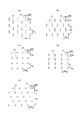
個々の孔14の平面形状(開口形状)は、適宜定めることができ、図17(a)(b)に示すような長孔形とするほか、図17(c)(e)に示すような真円形、図17(d)に示すような楕円形、三角形、長方形、ひし形等の多角形、星形、雲形等、任意の形状とすることができる。個々の孔14の寸法は特に限定されないが、前後方向LDの最大寸法14Lは0.4〜1.8mm、特に0.8〜1.3mmとするのが好ましく、幅方向WDの最大寸法14Wは0.3〜1.5mm、特に0.5〜1.0mmとするのが好ましい。孔14の形状が、長孔形、楕円形、長方形、ひし形等のように一方向に長い形状の場合、長手方向の最大寸法はこれと直交する方向の最大寸法の2.5倍以下であることが好ましい。また、孔14の形状が一方向に長い形状の場合、孔14の長手方向が前後方向LDであることが望ましいが、幅方向WDや斜め方向であってもよい。   The planar shape (opening shape) of each hole 14 can be determined as appropriate, and has a long hole shape as shown in FIGS. 17 (a) and 17 (b), as shown in FIGS. 17 (c) and 17 (e). It can be an arbitrary shape such as a perfect circle, an ellipse as shown in FIG. 17D, a polygon such as a triangle, a rectangle or a rhombus, a star or a cloud. Although the size of each hole 14 is not particularly limited, the maximum dimension 14L in the front-rear direction LD is preferably 0.4 to 1.8 mm, particularly preferably 0.8 to 1.3 mm, and the maximum dimension 14W in the width direction WD is The thickness is preferably 0.3 to 1.5 mm, particularly preferably 0.5 to 1.0 mm. When the shape of the hole 14 is a long shape in one direction such as a long hole shape, an ellipse shape, a rectangle shape, a rhombus shape, etc., the maximum dimension in the longitudinal direction is 2.5 times or less than the maximum dimension in the direction orthogonal thereto. It is preferable. Moreover, when the shape of the hole 14 is long in one direction, the longitudinal direction of the hole 14 is preferably the front-rear direction LD, but may be the width direction WD or an oblique direction.

個々の孔14の面積及び面積率は適宜定めればよいが、面積は0.2〜2.5mm2(特に0.5〜1.5mm2)程度であることが好ましく、面積率は1.0〜15.0%(特に5.0〜10.0%)程度であることが好ましい。 The area and area ratio of each hole 14 may be determined as appropriate, but the area is preferably about 0.2 to 2.5 mm 2 (particularly 0.5 to 1.5 mm 2 ). It is preferably about 0 to 15.0% (particularly 5.0 to 10.0%).

孔14の平面配列は適宜定めることができるが、規則的に繰り返される平面配列が好ましく、図17(a)に示すような斜方格子状や、図17(b)に示すような六角格子状(これらは千鳥状ともいわれる)、図17(c)に示すような正方格子状、図17(d)に示すような矩形格子状、図17(e)に示すような平行体格子(図示のように、多数の平行な斜め方向の列の群が互いに交差するように2群設けられる形態)状等(これらが前後方向LDに対して90度未満の角度で傾斜したものを含む)のように規則的に繰り返されるものの他、孔14の群(群単位の配列は規則的でも不規則でも良く、模様や文字状等でも良い)が規則的に繰り返されるものとすることもできる。   Although the plane arrangement of the holes 14 can be determined as appropriate, a plane arrangement that is regularly repeated is preferable, and an orthorhombic lattice shape as shown in FIG. 17A or a hexagonal lattice shape as shown in FIG. (These are also referred to as a staggered pattern), a square grid pattern as shown in FIG. 17 (c), a rectangular grid pattern as shown in FIG. 17 (d), and a parallel grid as shown in FIG. Thus, a configuration in which two groups are arranged so that a large number of parallel diagonal rows intersect each other) (including those inclined at an angle of less than 90 degrees with respect to the front-rear direction LD) In addition to what is regularly repeated, the group of holes 14 (group unit arrangement may be regular or irregular, and may be a pattern, a character, or the like) may be regularly repeated.

孔14の前後方向間隔14y及び幅方向間隔14xは適宜定めることができるが、通気性を考慮すると、それぞれ0.5〜8mm、特に1〜5mmの範囲内とすることが望ましく、前後方向間隔14yと幅方向間隔14xを平均すると1〜5mmの範囲内とすることが好ましい。特に、図17(d)に示すように、孔14の形状を前後方向LDに細長い形状とするとともに、孔14の前後方向寸法14Lよりも狭い前後方向間隔14yで前後方向に並ぶ孔14の列が幅方向WDに所定の間隔で繰り返し、かつその幅方向間隔14xは孔14の前後方向寸法14Lよりも広い(さらに、孔14の幅方向寸法14Wの3倍以上であるとより好ましい)と、通気性の向上を顕著なものとしつつ、柔らかさや嵩高さも損なわず、また、製造時に重要な前後方向のシートの引っ張り強度の低下がないため好ましい。   The front-rear direction interval 14y and the width-direction interval 14x of the holes 14 can be determined as appropriate. However, in consideration of air permeability, each of the intervals is preferably 0.5 to 8 mm, particularly 1 to 5 mm. When the width direction interval 14x is averaged, it is preferably within a range of 1 to 5 mm. In particular, as shown in FIG. 17 (d), the holes 14 are elongated in the front-rear direction LD, and the holes 14 are arranged in the front-rear direction with a front-rear distance 14y smaller than the front-rear dimension 14L. Is repeated at a predetermined interval in the width direction WD, and the interval 14x in the width direction is wider than the dimension 14L in the front-rear direction of the hole 14 (and more preferably three times or more the dimension 14W in the width direction of the hole 14). It is preferable because the air permeability is remarkably improved, the softness and bulkiness are not impaired, and the tensile strength of the sheet in the front-rear direction which is important at the time of production is not reduced.

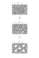
孔14の断面形状としては、図14に示すように孔14の周囲から孔14の縁に近づくにつれて不織布の厚みが薄くなり、孔14の縁が不織布の厚み方向の中間に位置している第1形態、図15に示すように孔14の周囲部14eが表側に反り返っており、かつ反り返り高さ14hがほぼ均一である第2形態、及び図16に示すように孔14の周囲部14eが表側に反り返っているとともに、周囲部14eは反り返り高さ14iが最も高い対向部分と、これと直交する方向に対向する対向部分であって反り返り高さ14jが最も低い部分とを有する高い第3形態のいずれであってもよい。通気性の観点からは孔14を有する部分が周囲と比較して厚くなる第2形態及び第3形態が望ましく、特に第3形態は孔14の周囲部14eの反り返り高さ14i,14jの差により形成される隙間が通気性向上に寄与するため好ましい。第2及び第3の形態において、反り返り高さ14g,14h,14i(光学顕微鏡を用いて測定される圧力を加えない状態での見かけの高さ)は0.2〜1.2mm程度であることが好ましく、第3の形態において最も高い反り返り高さ14iは、最も低い反り返り高さ14jの1.1〜1.4倍程度であることが好ましい。   As shown in FIG. 14, the cross-sectional shape of the hole 14 is such that the thickness of the nonwoven fabric decreases as it approaches the edge of the hole 14 from the periphery of the hole 14, and the edge of the hole 14 is positioned in the middle of the thickness direction of the nonwoven fabric. As shown in FIG. 15, the peripheral portion 14e of the hole 14 is warped to the front side as shown in FIG. 15, and the peripheral portion 14e of the hole 14 is bent as shown in FIG. The third embodiment is a high third mode in which the peripheral portion 14e has a facing portion having the highest warping height 14i and a facing portion facing in a direction orthogonal to the surrounding portion 14b and having the lowest warping height 14j. Any of these may be used. From the viewpoint of air permeability, the second and third forms in which the portion having the hole 14 is thicker than the surroundings are desirable. In particular, the third form is caused by the difference between the warped heights 14i and 14j of the peripheral part 14e of the hole 14. The formed gap is preferable because it contributes to improvement in air permeability. In the second and third embodiments, the warping heights 14g, 14h, 14i (apparent height in a state where no pressure is measured using an optical microscope) is about 0.2 to 1.2 mm. In the third embodiment, the highest curvature height 14i is preferably about 1.1 to 1.4 times the lowest curvature height 14j.

孔14は、縁部が繊維の切断端により形成されている打ち抜き孔14であっても、孔14の縁部に繊維の切断端がほとんど無く、ピンが繊維間に挿入されて押し広げられて形成された非打ち抜き孔14(周囲部の繊維密度が高い)であってもよい。前者は上記第1形態に適しており、後者は上記第2形態・第3形態に適している。例えば、一方向に長い形状の孔14をピンの挿入により形成すると、孔14の周囲部14eの繊維が外側又は垂直方向に退けられて孔14の周囲部14eが反り返るとともに、孔14の長手方向の対向部分の反り返り高さiが、長手方向と直交する方向の対向部分の反り返り高さjよりも高くなる。上記第2形態・第3形態においては、孔14の周囲部14eが表面に反り返っている部分の縁部は、繊維密度がその周囲の部分と比べて低い場合もあるが、同程度又は高くなっているのが好ましい。また、孔14の周囲部14eの繊維同士が融着していることが望ましいが、融着していなくてもよい。   Even if the hole 14 is a punched hole 14 whose edge is formed by a cut end of the fiber, the edge of the hole 14 has almost no cut end of the fiber, and a pin is inserted between the fibers and pushed wide. The formed non-punched holes 14 (the fiber density in the peripheral portion is high) may be used. The former is suitable for the first embodiment, and the latter is suitable for the second and third embodiments. For example, when the hole 14 having a shape long in one direction is formed by inserting a pin, the fibers in the peripheral portion 14e of the hole 14 are retracted outward or in the vertical direction, and the peripheral portion 14e of the hole 14 is warped, and the longitudinal direction of the hole 14 The warping height i of the facing portion is higher than the warping height j of the facing portion in the direction orthogonal to the longitudinal direction. In the second and third embodiments, the edge of the portion where the peripheral portion 14e of the hole 14 is warped to the surface may have a fiber density lower than that of the peripheral portion, but it is the same or higher. It is preferable. Moreover, although it is desirable that the fibers in the peripheral portion 14e of the hole 14 are fused, the fibers may not be fused.

カバー不織布13の内面及び外面は、それぞれ対向面にホットメルト接着剤を介して接着される。カバー不織布13の固定領域は、カバー不織布13の前後方向全体及び幅方向全体とするほか、一部を非固定とすることもできる。例えばカバー不織布13の幅方向両端部が非固定であると、側部ギャザー60の影響で吸収体56の側部がいくらか収縮した状態でもその影響を受けにくくなり、カバー不織布13に皺や折れが形成されにくいという利点がもたらされる。この場合におけるカバー不織布13の幅方向両端部の非固定部分の幅は適宜定めればよいが、例えば3〜10mm、好ましくは5〜8mmとすることができる。   The inner surface and the outer surface of the cover nonwoven fabric 13 are bonded to the opposing surfaces via a hot melt adhesive. The fixing region of the cover nonwoven fabric 13 may be the whole of the cover nonwoven fabric 13 in the front-rear direction and the entire width direction, or may be partially unfixed. For example, when the width direction both ends of the cover nonwoven fabric 13 are not fixed, even if the side portion of the absorbent body 56 is somewhat contracted due to the influence of the side gathers 60, the cover nonwoven fabric 13 is less susceptible to the influence. The advantage is that it is difficult to form. In this case, the widths of the non-fixed portions at both ends in the width direction of the cover nonwoven fabric 13 may be determined as appropriate, but may be 3 to 10 mm, preferably 5 to 8 mm, for example.

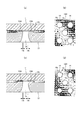
孔14を有するカバー不織布13の場合、一つの好ましい接着構造は、図18に示すように、カバー不織布13の内面及び外面の少なくとも一方の接着領域のうち、孔14と重なる領域の周縁部14iより中央側にはホットメルト接着剤13Hがなく、孔14と重なる領域の周縁部14i以外ではホットメルト接着剤13Hが連続面状に存在しているものである。孔14と重なる領域の周縁部14iより中央側にはホットメルト接着剤13Hがないため、通気性に優れるものとなる。また、肌に触れる面と反対側の面のみ、このような接着構造を有する部分では、ホットメルト接着剤13Hによりべとべとした肌触りになりにくく、かつ孔14の周囲部14eは対向面に確実に固定される。   In the case of the cover nonwoven fabric 13 having the holes 14, as shown in FIG. 18, one preferable adhesive structure is from a peripheral edge portion 14i of a region overlapping the hole 14 in at least one of the inner and outer adhesive regions of the cover nonwoven fabric 13. There is no hot-melt adhesive 13H on the center side, and the hot-melt adhesive 13H is present in a continuous surface except for the peripheral edge portion 14i in the region overlapping the hole 14. Since there is no hot melt adhesive 13H on the center side of the peripheral edge portion 14i in the region overlapping with the hole 14, the air permeability is excellent. Further, only the surface opposite to the surface that touches the skin, the portion having such an adhesive structure is less likely to become sticky to the hot melt adhesive 13H, and the peripheral portion 14e of the hole 14 is securely fixed to the facing surface. Is done.

代表的な接着状態としては、図18(a)(b)に示すように、孔14と重なる領域にはホットメルト接着剤13Hがなく、孔14と重なる領域以外ではホットメルト接着剤13Hが連続面状に存在している状態、図18(c)(d)に示すように、孔14と重なる領域の周縁部14iにホットメルト接着剤13Hがはみ出しているが、孔14と重なる領域の周縁部14iより中央側にはホットメルト接着剤13Hがなく、孔14と重なる領域の周縁部14i以外ではホットメルト接着剤13Hが連続面状に存在している状態を例示することができる。前者の状態は、特に望ましい状態であるが、孔14と重なる領域の周縁部14iは孔14の周囲部14eに近接する部分であり、カバー不織布13は一定の厚みを有するため、後者のようにこの部分にホットメルト接着剤13Hがはみ出していても、肌に触れる面と反対側の面のみ接着した部分において、カバー不織布13における接着面と反対側の面に手で触れたときにホットメルト接着剤13Hに直接触れることはほとんどない。なお、孔14と重なる領域の周縁部14iにおけるホットメルト接着剤13Hのはみ出し幅はカバー不織布13の厚みの半分以下で、0.5mm以下程度であることが好ましい。また、孔14と重なる領域の面積の80%以上の部分にホットメルト接着剤13Hが存在しないことが望ましい。   As a typical adhesion state, as shown in FIGS. 18A and 18B, there is no hot melt adhesive 13H in the region overlapping the hole 14, and the hot melt adhesive 13H is continuous in the region other than the region overlapping the hole 14. As shown in FIGS. 18 (c) and 18 (d), the hot melt adhesive 13 </ b> H protrudes from the peripheral edge portion 14 i of the region overlapping the hole 14, but the peripheral edge of the region overlapping the hole 14. The hot melt adhesive 13H does not exist in the center side from the part 14i, and the hot melt adhesive 13H exists in a continuous surface shape except for the peripheral part 14i in the region overlapping the hole 14. The former state is a particularly desirable state, but the peripheral edge portion 14i of the region overlapping with the hole 14 is a portion close to the peripheral portion 14e of the hole 14, and the cover nonwoven fabric 13 has a certain thickness. Even if the hot melt adhesive 13H protrudes from this portion, only the surface opposite to the surface that touches the skin adheres to the surface of the cover nonwoven fabric 13 that is opposite to the adhesive surface by hand. There is almost no direct contact with the agent 13H. The protruding width of the hot melt adhesive 13H at the peripheral edge portion 14i in the region overlapping with the hole 14 is preferably not more than half the thickness of the cover nonwoven fabric 13 and not more than about 0.5 mm. Further, it is desirable that the hot melt adhesive 13H does not exist in a portion of 80% or more of the area of the region overlapping with the hole 14.

カバー不織布13における孔14の断面形状は限定されるものではないが、前述のように孔14の周囲部14eが液不透過性シート11側に反り返った反り返り部となっていると、液不透過性シート11側と反対側の面から見た孔径の割には液不透過性シート11側から見た孔径が小さくなる。よって、肌に触れる面と反対側の面のみ接着した部分において、接着面と反対側の面に手で触れたときにホットメルト接着剤13Hに触れにくくなる。また、反り返り部は支柱のようにカバー不織布13を対向面に対して支持するため、同じ目付けの無孔不織布と比較して嵩高くなり、通気性にも優れたものとなる。さらに、孔14の周囲部14e以外の領域では、カバー不織布13と液不透過性シート11の接着が浮きやすくなる(図18ではホットメルト接着剤13Hがシート間の空間を隙間なく埋めているように描いているが実際の塗布量は少なく隙間ができやすい)ため、孔14の周囲部14eは確実に接着しつつ、それ以外の領域では不完全な接着となる(実質的な接着面積が小さくなる)ことにより、優れた柔らかさ・ふんわり感を得ることができる。   The cross-sectional shape of the hole 14 in the cover nonwoven fabric 13 is not limited. However, if the peripheral portion 14e of the hole 14 is a warped portion that is warped toward the liquid-impermeable sheet 11 as described above, the liquid-impervious portion. The hole diameter viewed from the liquid-impermeable sheet 11 side is smaller than the hole diameter viewed from the surface on the side opposite to the conductive sheet 11 side. Therefore, in the portion where only the surface opposite to the surface touching the skin is bonded, it becomes difficult to touch the hot melt adhesive 13H when the surface opposite to the bonding surface is touched by hand. Further, since the warped portion supports the cover nonwoven fabric 13 with respect to the facing surface like a support column, the warped portion becomes bulky and excellent in air permeability as compared with a non-porous nonwoven fabric having the same basis weight. Further, in the region other than the peripheral portion 14e of the hole 14, the adhesion between the cover nonwoven fabric 13 and the liquid-impermeable sheet 11 tends to float (in FIG. 18, the hot melt adhesive 13H seems to fill the space between the sheets without any gaps). Although the actual coating amount is small and a gap is easily formed), the peripheral portion 14e of the hole 14 is securely bonded, and incomplete bonding is performed in other regions (substantially small bonding area is small). This makes it possible to obtain excellent softness and softness.

このような接着構造は、有孔不織布における接着面に、エアーを用いずに連続面状にホットメルト接着剤を塗布し、対向面に接着することにより製造することができる。この手法は、有孔不織布における接着面に、エアーを用いずに連続面状にホットメルト接着剤を連続面状に塗布すると、対向面と貼り合わせる前に、ホットメルト接着剤の表面張力により、ホットメルト接着剤における有孔不織布の孔と重なる部分の中央に口(孔)が開いてその開口が有孔不織布の孔の周囲部まで拡大する、との新規な知見に基づくものである。すなわち、このような接着方法を採用すると、図19に矢印で変化を示すように、有孔不織布にホットメルト接着剤13Hを連続面状に塗布した後、対象部材と貼り合わせる前に、ホットメルト接着剤13Hの表面張力により、ホットメルト接着剤13Hにおける有孔不織布の孔14と重なる部分の中央に口(孔)hが開いてその開口hが有孔不織布の孔14の周囲部14eまで拡大する。したがって、有孔不織布を対象部材に接着した後に、図18に示す例のように、孔14内の大部分にホットメルト接着剤13Hがないものとなり、エアーによる孔14からのホットメルト接着剤13Hの抜けや染み出しもないため、接着面と反対側の面に手で触れたときにべとべとした肌触りになりにくいものとなる。   Such an adhesive structure can be produced by applying a hot melt adhesive to the adhesive surface of the perforated nonwoven fabric in the form of a continuous surface without using air, and adhering to the opposing surface. In this method, when the hot melt adhesive is applied to the adhesive surface in the porous nonwoven fabric in a continuous surface shape without using air, the surface tension of the hot melt adhesive is applied before bonding to the opposing surface. This is based on a novel finding that a mouth (hole) is opened at the center of the portion of the hot melt adhesive that overlaps the hole of the perforated nonwoven fabric, and the opening extends to the periphery of the hole of the perforated nonwoven fabric. That is, when such an adhesion method is employed, as indicated by an arrow in FIG. 19, the hot melt adhesive 13H is applied to the perforated nonwoven fabric in a continuous surface and before being bonded to the target member, Due to the surface tension of the adhesive 13H, a mouth (hole) h is opened at the center of the portion of the hot melt adhesive 13H that overlaps the hole 14 of the porous nonwoven fabric, and the opening h expands to the peripheral portion 14e of the hole 14 of the porous nonwoven fabric. To do. Therefore, after bonding the perforated nonwoven fabric to the target member, as shown in the example shown in FIG. 18, there is no hot melt adhesive 13H in most of the holes 14, and the hot melt adhesive 13H from the holes 14 by air is removed. Since there is no omission or exudation, it becomes difficult to feel sticky when touching the surface opposite to the adhesive surface with a hand.

エアーを用いずに連続面状にホットメルト接着剤を塗布するホットメルトアプリケータ170としては、有孔不織布の接着面に塗工ヘッド(ダイ)を接触させ、塗工ヘッドの先端に設けられたCD方向(MD方向(製造ラインの流れ方向)と直交する方向)に沿うスリットからホットメルト接着剤を押し出して塗布を行うスロットコート、あるいは有孔不織布の接着面から塗工ヘッド(ダイ)を浮かせた状態で、塗工ヘッドの先端に設けられたCD方向に沿うスリットからホットメルト接着剤を押し出し、有孔不織布の移送速度との差によりホットメルト接着剤を延伸して極薄フィルム状に塗付する非接触タイプのスロットコートを好適に用いることができる。   As the hot melt applicator 170 for applying the hot melt adhesive in a continuous surface shape without using air, the coating head (die) was brought into contact with the adhesive surface of the perforated nonwoven fabric and provided at the tip of the coating head. The coating head (die) is lifted from the adhesive surface of the slot coat or perforated nonwoven fabric that is applied by extruding the hot melt adhesive from the slit along the CD direction (direction perpendicular to the MD direction (flow direction of the production line)) In this state, the hot melt adhesive is extruded through a slit along the CD direction provided at the tip of the coating head, and the hot melt adhesive is stretched according to the difference from the transfer speed of the perforated nonwoven fabric to be applied in an ultrathin film form. The non-contact type slot coat to be attached can be preferably used.

接着条件は適宜定めることができるが、孔14と重なるホットメルト接着剤13Hを速やかに孔14の周囲部14eに移動させ、孔14の周囲部14eを強固に接着するためには、以下の条件の少なくとも1つを満足することが望ましい。
ホットメルト接着剤の溶融粘度(温度140℃):3,000〜2,600mPa・s
ホットメルト接着剤の溶融粘度(温度160℃):1,150〜1,550mPa・s
有孔不織布に対するホットメルト接着剤の塗布時の温度:110〜150℃
有孔不織布に対するホットメルト接着剤の塗布量:1.0〜8.0g/m2
ホットメルト接着剤の塗布後のオープンタイム:0.1〜1.0秒
The bonding conditions can be determined as appropriate. In order to quickly move the hot melt adhesive 13H overlapping the hole 14 to the peripheral part 14e of the hole 14 and firmly bond the peripheral part 14e of the hole 14, the following conditions are satisfied. It is desirable to satisfy at least one of the following.
Hot melt adhesive melt viscosity (temperature 140 ° C.): 3,000 to 2,600 mPa · s
Melt viscosity of hot melt adhesive (temperature 160 ° C.): 1,150 to 1,550 mPa · s
Temperature at the time of application of the hot melt adhesive to the porous nonwoven fabric: 110 to 150 ° C
Application amount of hot melt adhesive to porous nonwoven fabric: 1.0 to 8.0 g / m 2
Open time after application of hot melt adhesive: 0.1 to 1.0 seconds

孔14を有するカバー不織布13の場合における、他の好ましい接着構造は、図20に示すように、カバー不織布13における孔14の周囲部14eが反り返った反り返り部となっているとともに、反り返り部の少なくとも先端部が、ホットメルト接着剤13Hを介して対向面(この場合、液不透過性シート11)に貼り付けられた接着部となっており、かつこの接着部以外の部分は非接着となっているものである。このような接着構造を有していると、接着面積が小さくなるため柔軟性が損なわれず、かつ孔14の周囲部14eを対向面に確実に固定できる。特に、反り返り部は支柱のようにカバー不織布13を対向面に対して支持するため、同じ目付けの無孔不織布と比較して嵩高くなり、通気性にも優れたものとなる。   In the case of the cover nonwoven fabric 13 having the holes 14, as shown in FIG. 20, as shown in FIG. 20, the peripheral portion 14 e of the hole 14 in the cover nonwoven fabric 13 is a warped return portion, and at least of the warped portion. The front end portion is an adhesive portion attached to the opposite surface (in this case, the liquid-impermeable sheet 11) via the hot melt adhesive 13H, and the portions other than the adhesive portion are non-adhered. It is what. With such an adhesion structure, the adhesion area is reduced, so flexibility is not impaired, and the peripheral portion 14e of the hole 14 can be reliably fixed to the opposing surface. In particular, since the warped portion supports the cover nonwoven fabric 13 with respect to the opposing surface like a support, it is bulky and excellent in air permeability as compared with a non-porous nonwoven fabric having the same basis weight.

代表的な接着状態としては、図20(a)(b)に示すように、反り返り部の先端部のみがホットメルト接着剤13Hを介して対向面に接着されている状態、図20(c)(d)に示すように、反り返り部の全体が、ホットメルト接着剤13Hを介して対向面に接着されている状態、及び図20(e)(f)に示すように、反り返り部のうち、先端部の内側部分より外側全体がホットメルト接着剤13Hを介して対向面に接着され、先端部の内側部分が非接着とされている状態を例示することができる。反り返り部の孔14の内周面、及び対向面における孔14と重なる部位には接着剤が存在しないことが望ましいが、多少はみ出していてもよい。   As a typical adhesion state, as shown in FIGS. 20 (a) and 20 (b), only the tip of the warped portion is adhered to the opposing surface via the hot melt adhesive 13H, and FIG. 20 (c). As shown in (d), the entire warped part is bonded to the opposing surface via the hot melt adhesive 13H, and as shown in FIGS. 20 (e) and 20 (f), A state in which the entire outer side from the inner part of the tip part is bonded to the opposing surface via the hot melt adhesive 13H and the inner part of the tip part is not bonded can be exemplified. Although it is desirable that no adhesive is present on the inner peripheral surface of the hole 14 in the warped portion and the portion overlapping the hole 14 on the opposite surface, it may protrude slightly.

反り返り部の接着状態は、少なくとも先端部がホットメルト接着剤13Hを介して対向面に貼り付けられる限り、図示形態に限定されず、孔14の周方向の少なくとも一部が、上記いずれかの接着状態であればよい。例えば、図15及び図16に示される形態のように、反り返り部が孔14の周方向に連続して筒状になっている場合には、筒状の先端部の周方向全体が上記接着状態にあることが好ましいが、一部は他の接着状態又は非接着となっていても良い。また、反り返り部が孔14の周方向の一部にのみ形成されている場合には、その部分の先端部が上記接着状態となっていればよい。さらに、多数の反り返り部の中に異なる接着状態が混在していてもよい。   The adhesion state of the warped part is not limited to the illustrated form as long as at least the tip part is attached to the opposing surface via the hot melt adhesive 13H, and at least a part of the hole 14 in the circumferential direction is bonded to any one of the above. Any state is acceptable. For example, as shown in FIGS. 15 and 16, when the warped portion is continuously cylindrical in the circumferential direction of the hole 14, the entire circumferential direction of the cylindrical tip portion is in the bonded state. However, some may be in another bonded state or non-bonded. Moreover, when the curvature part is formed only in a part of the circumferential direction of the hole 14, the front-end | tip part of the part should just be the said adhesion state. Furthermore, different adhesion states may be mixed in a large number of warped portions.

(内外接合部)
内装体200の外装体12F,12Bに対する固定は、ヒートシール、超音波シールのような素材溶着による接合手段や、ホットメルト接着剤により行うことができる。図示形態では、内装体200の裏面、つまりこの場合は液不透過性シート11の裏面及び立体ギャザー60の付根部分65に塗布されたホットメルト接着剤を介して外装体12F,12Bの内面に対して固定されている。この内装体200と外装体12F,12Bとを固定する内外接合部201,202は、両者が重なる領域のほぼ全体に設けることができ、例えば内装体200の幅方向両端部を除いた部分に設けることもできる。特に、内外接合部201,202は、カバー不織布13と重なる領域及びこの領域よりも幅方向両側の領域にわたり設けられていると、カバー不織布13の両側部をしっかりと固定することができ、カバー不織布13の両側部が内装体200から剥がれにくくなるため好ましい。
(Inner / outer joint)
The interior body 200 can be fixed to the exterior bodies 12F and 12B by a joining means by material welding such as heat sealing or ultrasonic sealing, or by a hot melt adhesive. In the illustrated form, the inner surface of the exterior body 12F, 12B is applied to the back surface of the interior body 200, that is, the back surface of the liquid-impermeable sheet 11 and the hot melt adhesive applied to the root portion 65 of the three-dimensional gather 60 in this case. Is fixed. Inner and outer joints 201 and 202 for fixing the inner body 200 and the outer bodies 12F and 12B can be provided in almost the entire overlapping region, for example, provided in a portion excluding both ends in the width direction of the inner body 200. You can also. In particular, when the inner and outer joint portions 201 and 202 are provided over a region overlapping with the cover nonwoven fabric 13 and a region on both sides in the width direction than this region, both sides of the cover nonwoven fabric 13 can be firmly fixed, and the cover nonwoven fabric Since both sides of 13 become difficult to peel from the interior body 200, it is preferable.

図9及び図10に示すように、前側外装体12Fの内外接合部201は、ウエスト側では幅方向両端部にわたるように設けられ、前側外装体12Fの股間側の縁に向かうにつれて幅が段階的又は連続的に減少し、前側外装体12Fの股間側の幅方向両端部に非接合部分203が形成されていると好ましい。これにより、前側外装体12Fの股間側の縁が幅方向に沿って直線状又はそれに近い形状で、内装体200の側縁と直角又はそれに近い角度で交差する外装二分割タイプであっても、座位や歩行時における鼠径部のフィット性が向上する。   As shown in FIGS. 9 and 10, the inner / outer joint portion 201 of the front exterior body 12F is provided so as to extend across both ends in the width direction on the waist side, and the width is stepped toward the crotch side edge of the front exterior body 12F. Alternatively, it is preferable that the non-joined portions 203 are formed at both ends in the width direction on the crotch side of the front exterior body 12F. Thereby, the edge of the crotch side of the front exterior body 12F is a straight line shape or a shape close thereto along the width direction, even if it is an exterior two-divided type that intersects the side edge of the interior body 200 at a right angle or an angle close thereto, The fit of the groin is improved during sitting and walking.

非接合部分203の寸法は適宜定めればよいが、乳幼児用途の場合、非接合部分203の前後方向寸法は10〜30mm程度、非接合部分203の幅方向寸法は10〜25mm程度とすることができる。また、大人用途の場合、非接合部分203の前後方向寸法は10〜30mm程度、非接合部分203の幅方向寸法は10〜25mm程度とすることができる。非接合部分203の前縁(曲線の場合は最も前側に位置する部位)は、前側半倒伏部分68Fと重なる位置にあることが好ましく、その中でも特に前側半倒伏部分68Fの後側の部分に位置していることが好ましい。   The dimensions of the non-joined portion 203 may be determined as appropriate, but in the case of infant use, the dimension in the front-rear direction of the non-joined portion 203 is about 10 to 30 mm, and the width direction dimension of the non-joined portion 203 is about 10 to 25 mm. it can. Moreover, in the case of an adult use, the front-back direction dimension of the non-joining part 203 can be about 10-30 mm, and the width direction dimension of the non-joining part 203 can be about 10-25 mm. The front edge of the non-joined portion 203 (the portion located on the most front side in the case of a curve) is preferably located at a position overlapping the front half-falling portion 68F, and in particular, located at the rear portion of the front half-falling portion 68F. It is preferable.

特に、前側外装体12Fのウエスト下方部の伸縮領域A2の弾性部材が、前側外装体12Fの股間側の幅方向両端部に形成された非接合部分203内まで延びており、非接合部分203も幅方向に弾性伸縮するようになっていると、鼠径部のフィット性はより一層好ましいものとなる。また、前述の第1の形態の側部ギャザー60のように屈曲形態を採用し、前側半倒伏部分68Fを設けると、鼠径部のフィット性がさらに良いものとなる。さらに、前述のように、前側半倒伏部分68Fは前側外装体12Fの股間側の縁と同じか、又はより前後方向中央側に延びているとより好ましい。さらに、吸収体56が砂時計形状を成す場合、前側半倒伏部分68Fは、括れ部56Nとは重ならずに前記吸収体上に位置していると、立体ギャザーの根元が安定し、前側半倒伏部分68Fが起立しやすいため好ましい。   In particular, the elastic member in the stretchable region A2 in the lower waist portion of the front exterior body 12F extends into the non-joint portions 203 formed at both widthwise ends on the crotch side of the front exterior body 12F. When it is elastically expanded and contracted in the width direction, the fit of the groin becomes even more preferable. Further, when the bent form is employed as in the first-side side gather 60 described above and the front half-falling part 68F is provided, the fit of the inguinal part is further improved. Further, as described above, it is more preferable that the front half-falling portion 68F is the same as the crotch side edge of the front exterior body 12F or extends more in the front-rear direction center side. Further, when the absorber 56 has an hourglass shape, if the front half-falling portion 68F is positioned on the absorber without overlapping the constricted portion 56N, the base of the three-dimensional gather is stabilized, and the front half-falling portion is stabilized. The portion 68F is preferable because it easily stands up.

一方、後側外装体12Bの内外接合部202は、その前後方向の全体にわたり幅方向両端部にわたるように設けられていると、内装体200が臀裂に食い込みにくくなるため好ましい。この場合、前述の第1の形態の側部ギャザー60のように屈曲形態を採用し、後側半倒伏部分68Bを設けると、立体ギャザーの先端側部分60Aが臀裂に向かう傾斜によって反対向きに倒れにくくなるため好ましい。さらに、前述のように、後側半倒伏部分68Bは後側外装体12Bの前縁と同じか、又はより前後方向LD中央側に延びていると、内装体200の臀裂への食い込み防止性がより一層向上し、臀部カバー部Cを有する場合には臀部カバー部Cがずれにくくなり、臀部被覆の維持性に優れるようになる。後側半倒伏部分68Bの前後方向長さは、後側の倒伏部分67の前後方向長さよりも長いとより好ましい。さらに、吸収体56が砂時計形状をなす場合、後側半倒伏部分68Bは、括れ部56Nとは重ならずに前記吸収体上に位置していると、特に、内装体200が臀裂に食い込みにくくなるため好ましい。   On the other hand, it is preferable that the inner / outer joint portion 202 of the rear exterior body 12B is provided so as to extend across both ends in the width direction across the entire front-rear direction, because the interior body 200 is less likely to bite into the crack. In this case, when the bent form is adopted like the side gathers 60 of the first form described above and the rear half-falling part 68B is provided, the tip side part 60A of the three-dimensional gathers is reversed by the inclination toward the crack. This is preferable because it is difficult to collapse. Further, as described above, when the rear half-falling portion 68B is the same as the front edge of the rear exterior body 12B or extends more in the front-rear direction LD center side, the inner body 200 is prevented from biting into the crack. Is further improved, and when the collar cover portion C is provided, the collar cover portion C is less likely to be displaced, and the maintainability of the collar cover is improved. The length in the front-rear direction of the rear half-falling portion 68B is more preferably longer than the length in the front-rear direction of the rear-side fallen portion 67. Further, when the absorbent body 56 has an hourglass shape, the inner half body 200 bites into the crack particularly when the rear half-falling portion 68B is positioned on the absorbent body without overlapping the constricted portion 56N. Since it becomes difficult, it is preferable.

第1の形態の側部ギャザー60のような屈曲形態を採用する場合、前側半倒伏部分68Fと、後側半倒伏部分68Bの両方を設け、前側半倒伏部分68Fの長さに対する後側半倒伏部分68Bの長さが0.9〜1.5の範囲となるようにすると、立体ギャザーは前後方向に長い範囲にわたり高く起立することができ、かつ先端側部分60Aと付け根側部分60Bのそれぞれが過度に自由となることがないため、脚周り全体のフィット性が良好なものとなる。   When a bent form such as the side gather 60 of the first form is adopted, both the front half-falling portion 68F and the rear half-falling portion 68B are provided, and the rear half-falling with respect to the length of the front half-falling portion 68F is provided. When the length of the portion 68B is in the range of 0.9 to 1.5, the three-dimensional gather can stand up in a long range in the front-rear direction, and each of the tip side portion 60A and the base side portion 60B Since it does not become excessively free, the fit around the entire leg is good.

<明細書中の用語の説明>
明細書中の以下の用語は、明細書中に特に記載が無い限り、以下の意味を有するものである。
<Explanation of terms in the specification>
The following terms in the specification have the following meanings unless otherwise specified in the specification.

・「前後(縦)方向」とは腹側(前側)と背側(後側)を結ぶ方向を意味し、「幅方向」とは前後方向と直交する方向(左右方向)を意味する。   The “front / rear (vertical) direction” means a direction connecting the ventral side (front side) and the back side (rear side), and the “width direction” means a direction (left / right direction) orthogonal to the front / rear direction.

・「表側」とはパンツタイプ使い捨ておむつを着用した際に着用者の肌に近い方を意味し、「裏側」とはパンツタイプ使い捨ておむつを着用した際に着用者の肌から遠い方を意味する。   ・ "Front side" means the person near the wearer's skin when wearing a pants-type disposable diaper, and "Back" means the person far from the wearer's skin when wearing a pants-type disposable diaper .

・「表面」とは部材の、パンツタイプ使い捨ておむつを着用した際に着用者の肌に近い方の面を意味し、「裏面」とはパンツタイプ使い捨ておむつを着用した際に着用者の肌から遠い方の面を意味する。   ・ "Surface" means the surface closer to the wearer's skin when wearing a pants-type disposable diaper, and "Back" refers to the skin of the wearer when wearing a pants-type disposable diaper. It means the far side.

・「面積率」とは単位面積に占める対象部分の割合を意味し、対象領域(例えばカバー不織布)における対象部分(例えば孔)の総和面積を当該対象領域の面積で除して百分率で表すものである。対象部分が間隔を空けて多数設けられる形態では、対象部分が10個以上含まれるような大きさに対象領域を設定して、面積率を求めることが望ましい。例えば、孔の面積率は、例えばKEYENCE社の商品名VHX−1000を使用し、測定条件を20倍として、以下の手順で測定することができる。
(1)20倍のレンズにセットし、ピントを調節する。穴が4×6入るように不織布の位置を調整する。
(2)孔の領域の明るさを指定し、孔の面積を計測する。
(3)「計測・コメント」の「面積計測」の色抽出をクリックする。孔の部分をクリックする。
(4)「一括計測」をクリックし、「計測結果ウィンドを表示」にチェックを入れ、CSVデータで保存をする。
・ "Area ratio" means the ratio of the target portion to the unit area, and is expressed as a percentage by dividing the total area of the target portion (for example, holes) in the target region (for example, cover nonwoven fabric) by the area of the target region. It is. In a form in which a large number of target portions are provided at intervals, it is desirable to set the target region to a size that includes 10 or more target portions and obtain the area ratio. For example, the area ratio of the pores can be measured by the following procedure using, for example, a trade name VHX-1000 of KEYENCE Corporation and measuring conditions 20 times.
(1) Set on a 20x lens and adjust the focus. The position of the nonwoven fabric is adjusted so that the holes are 4 × 6.
(2) Specify the brightness of the hole area and measure the area of the hole.
(3) Click the “Area measurement” color extraction in “Measurement / Comments”. Click on the hole.
(4) Click “Batch measurement”, check “Display measurement result window”, and save as CSV data.

・「伸長率」は、自然長を100%としたときの値を意味する。   “Elongation rate” means a value when the natural length is 100%.

・「ゲル強度」は次のようにして測定されるものである。人工尿(尿素:2wt%、塩化ナトリウム:0.8wt%、塩化カルシウム二水和物:0.03wt%、硫酸マグネシウム七水和物:0.08wt%、及びイオン交換水:97.09wt%を混合したもの)49.0gに、高吸収性ポリマーを1.0g加え、スターラーで攪拌させる。生成したゲルを40℃×60%RHの恒温恒湿槽内に3時間放置したあと常温にもどし、カードメーター(I.techno Engineering社製:Curdmeter−MAX ME−500)でゲル強度を測定する。   -"Gel strength" is measured as follows. Artificial urine (urea: 2 wt%, sodium chloride: 0.8 wt%, calcium chloride dihydrate: 0.03 wt%, magnesium sulfate heptahydrate: 0.08 wt%, and ion-exchanged water: 97.09 wt% 1.0 g of a superabsorbent polymer is added to 49.0 g of the mixture) and stirred with a stirrer. The produced gel is left in a constant temperature and humidity chamber of 40 ° C. × 60% RH for 3 hours and then returned to room temperature, and the gel strength is measured with a card meter (Curdmeter-MAX ME-500, manufactured by I.techno Engineering).

・「目付け」は次のようにして測定されるものである。試料又は試験片を予備乾燥した後、標準状態(試験場所は、温度20±5℃、相対湿度65%以下)の試験室又は装置内に放置し、恒量になった状態にする。予備乾燥は、試料又は試験片を相対湿度10〜25%、温度50℃を超えない環境で恒量にすることをいう。なお、公定水分率が0.0%の繊維については、予備乾燥を行わなくてもよい。恒量になった状態の試験片から米坪板(200mm×250mm、±2mm)を使用し、200mm×250mm(±2mm)の寸法の試料を切り取る。試料の重量を測定し、20倍して1平米あたりの重さを算出し、目付けとする。   ・ "Weight" is measured as follows. After the sample or test piece has been pre-dried, it is left in a test room or apparatus in a standard state (test location is temperature 20 ± 5 ° C., relative humidity 65% or less) to obtain a constant weight. Pre-drying refers to making a sample or test piece constant in an environment where the relative humidity is 10 to 25% and the temperature does not exceed 50 ° C. In addition, it is not necessary to perform preliminary drying about the fiber whose official moisture content is 0.0%. A sample with a size of 200 mm × 250 mm (± 2 mm) is cut out from the test piece in a constant weight using a rice-basis plate (200 mm × 250 mm, ± 2 mm). Measure the weight of the sample, multiply it by 20, calculate the weight per square meter, and use it as the basis weight.

・「厚み」は、自動厚み測定器(KES−G5 ハンディ圧縮計測プログラム)を用い、荷重:0.098N/cm2、及び加圧面積:2cm2の条件下で自動測定する。 -"Thickness" is automatically measured using an automatic thickness measuring instrument (KES-G5 handy compression measurement program) under the conditions of load: 0.098 N / cm 2 and pressure area: 2 cm 2 .

・吸水量は、JIS K7223−1996「高吸水性樹脂の吸水量試験方法」によって測定する。   -The amount of water absorption is measured according to JIS K7223-1996 "Test method for water absorption of superabsorbent resin".

・吸水速度は、2gの高吸収性ポリマー及び50gの生理食塩水を使用して、JIS K7224‐1996「高吸水性樹脂の吸水速度試験法」を行ったときの「終点までの時間」とする。   ・ The water absorption rate is the “time to end point” when JIS K7224-1996 “Test method for water absorption rate of superabsorbent resin” is performed using 2 g of superabsorbent polymer and 50 g of physiological saline. .

・「展開状態」とは、収縮や弛み無く平坦に展開した状態を意味する。   -"Developed state" means a state where the plate is flattened without contraction or slack.

・各部の寸法は、特に記載が無い限り、自然長状態ではなく展開状態における寸法を意味する。   -Unless otherwise specified, the dimensions of each part mean dimensions in a deployed state, not a natural length state.

・試験や測定における環境条件についての記載が無い場合、その試験や測定は、標準状態(試験場所は、温度20±5℃、相対湿度65%以下)の試験室又は装置内で行うものとする。   ・ If there is no description about the environmental conditions in the test and measurement, the test and measurement shall be performed in a test room or equipment in the standard condition (test location is temperature 20 ± 5 ℃, relative humidity 65% or less). .

本発明は、パンツタイプ使い捨ておむつに利用できるものである。   The present invention can be used for a pants-type disposable diaper.

11…液不透過性シート、12B…後側外装体、12E…ウエスト延出部分、12F…前側外装体、12H…内側シート層、12S…外側シート層、13…カバー不織布、14…孔、17…ウエスト部弾性部材、18…不要弾性部材、200…内装体、201,202…内外接合部、203…非接合部分、25…表示シート、30…トップシート、40…中間シート、50…吸収要素、56…吸収体、58…包装シート、60…側部ギャザー、60A…先端側部分、60B…付け根側部分、62…ギャザー不織布、67…倒伏部分、68B…後側半倒伏部分、68F…前側半倒伏部分、A1…非伸縮領域、A2…伸縮領域、L…中間領域、LD…前後方向、T…胴周り領域、U…ウエスト下方部、W…ウエスト部、WO…ウエスト開口。   DESCRIPTION OF SYMBOLS 11 ... Liquid impervious sheet, 12B ... Rear side exterior body, 12E ... Waist extension part, 12F ... Front side exterior body, 12H ... Inner sheet layer, 12S ... Outer sheet layer, 13 ... Cover nonwoven fabric, 14 ... Hole, 17 DESCRIPTION OF SYMBOLS ... West part elastic member, 18 ... Unnecessary elastic member, 200 ... Interior body, 201, 202 ... Inner / outer joint part, 203 ... Non-joining part, 25 ... Display sheet, 30 ... Top sheet, 40 ... Intermediate sheet, 50 ... Absorption element 56 ... absorber, 58 ... packaging sheet, 60 ... side gather, 60A ... tip side portion, 60B ... root side portion, 62 ... gathered nonwoven fabric, 67 ... falling portion, 68B ... rear semi-falling portion, 68F ... front side Semi-inclined portion, A1 ... non-stretchable region, A2 ... stretchable region, L ... intermediate region, LD ... longitudinal direction, T ... waistline region, U ... waist lower part, W ... waist part, WO ... waist opening.

Claims (6)

前身頃の少なくとも胴周り部を構成する前側外装体及び後身頃の少なくとも胴周り部を構成する後側外装体とを別々に備え、これら前側外装体及び後側外装体が前後方向中間で前後方向に離間しており、
吸収体を内蔵する内装体が、前記前側外装体から後側外装体にかけて前後方向に延在し、かつ前記前側外装体及び後側外装体にそれぞれ接合され、
前側外装体の両側部と後側外装体の両側部とがそれぞれ接合されたサイドシール部と、ウエスト開口及び左右一対の脚開口とを備えた、
パンツタイプ使い捨ておむつにおいて;
前記内装体は、両側部から立ちあがる立体ギャザーを備えており、
前記立体ギャザーは、前記内装体の表面の両側部から幅方向中央側に延びる付け根側部分、及びこの付け根側部分の先端から幅方向外側に延びる先端側部分とを有する本体部分と、この本体部分における前後方向両端部で、前記付け根側部分が倒伏状態で前記内装体の表面に接合され、かつ前記先端側部分が倒伏状態で前記付け根側部分に接合された部分である倒伏部分と、前後の倒伏部分の間に位置する非固定の自由部分と、この自由部分の少なくとも先端部に前後方向に沿って設けられたギャザー弾性部材とを有しており、
前記立体ギャザーは、後側の前記倒伏部分の前側に連続又は隣接して、前記先端側部分が倒伏状態で前記付け根側部分に接合され、かつ前記付け根側部分と前記内装体の表面とが接合されていない後側半倒伏部分を有している、
ことを特徴とするパンツタイプ使い捨ておむつ。
The front exterior body constituting at least the waist circumference part of the front body and the rear exterior body constituting at least the waist circumference part of the rear body are separately provided, and the front exterior body and the rear exterior body are in the front-rear direction in the middle in the front-rear direction. Are separated from each other,
The interior body incorporating the absorber extends in the front-rear direction from the front exterior body to the rear exterior body, and is joined to the front exterior body and the rear exterior body, respectively.
A side seal portion in which both side portions of the front exterior body and both side portions of the rear exterior body are joined, and a waist opening and a pair of left and right leg openings,
In pants-type disposable diapers;
The interior body includes a three-dimensional gather that rises from both sides,
The three-dimensional gather has a main body portion having a base side portion extending from the both sides of the surface of the interior body to the center in the width direction, and a front end side portion extending outward in the width direction from the tip of the base side portion, and the main body portion. In the front and rear direction both ends , the root side part is joined to the surface of the interior body in a lying state , and the tip part is a part joined to the root side part in the lying state, It has a non-fixed free part located between the lodging parts, and a gather elastic member provided along the front-rear direction at least at the tip of this free part,
The three-dimensional gather is continuous or adjacent to the front side of the lodging part on the rear side, the tip side part is joined to the base side part in a lying state, and the base side part and the surface of the interior body are joined. Has a rear half-fallen part,
A pants-type disposable diaper characterized by that.
前記内装体と前記後側外装体とを接合する内外接合部は、その前後方向の全体にわたり幅方向両端部にわたるように設けられている、
請求項1記載のパンツタイプ使い捨ておむつ。
The inner and outer joints that join the interior body and the rear exterior body are provided so as to extend across both ends in the width direction across the entire front-rear direction.
The pants-type disposable diaper according to claim 1.
前記吸収体は、前後方向中間に、その前後両側よりも幅の狭い括れ部を有しており、
前記後側半倒伏部分は前記括れ部とは重ならずに前記吸収体上に位置している、
請求項2記載のパンツタイプ使い捨ておむつ。
The absorber has a constricted portion having a narrower width than both front and rear sides in the middle in the front-rear direction,
The rear half-falling part is located on the absorber without overlapping the constricted part,
The pants-type disposable diaper according to claim 2.
前記後側半倒伏部分は後側外装体の前縁と同じか、又はそれより前後方向中央側に延びている、
請求項2又は3記載のパンツタイプ使い捨ておむつ。
The rear half-falling portion is the same as the front edge of the rear exterior body, or extends to the center in the front-rear direction.
A pants-type disposable diaper according to claim 2 or 3.
前記後側半倒伏部分は、後側の前記倒伏部分よりも前後方向寸法が長い、
請求項2〜4のいずれか1項記載のパンツタイプ使い捨ておむつ。
The rear half-falling part is longer in the front-rear direction than the rear lying part,
The underpants type disposable diaper of any one of Claims 2-4.
前記立体ギャザーは、前側の前記倒伏部分の後側に連続又は隣接して、前記付け根側部分が倒伏状態で前記内装体の表面に接合され、かつ先端側部分と付け根側部分とが接合されていない前側半倒伏部分を有している、
請求項1〜5のいずれか1項に記載のパンツタイプ使い捨ておむつ。
The three-dimensional gather is continuous or adjacent to the rear side of the lodging portion on the front side, the base side portion is joined to the surface of the interior body in the lying state, and the tip side portion and the base side portion are joined. Has no front half-lodge part,
The underpants type disposable diaper of any one of Claims 1-5.
JP2016212773A 2016-10-21 2016-10-31 Pants-type disposable diaper Active JP6400656B2 (en)

Priority Applications (5)

Application Number Priority Date Filing Date Title
JP2016212773A JP6400656B2 (en) 2016-10-31 2016-10-31 Pants-type disposable diaper
PCT/JP2017/037314 WO2018074400A1 (en) 2016-10-21 2017-10-16 Underpants-type disposable diaper
CN201710965775.6A CN107970092B (en) 2016-10-21 2017-10-17 Pants-type disposable diaper
CN201721337348.5U CN208611123U (en) 2016-10-21 2017-10-17 Breeches type disposable diaper
TW106135862A TWI744396B (en) 2016-10-21 2017-10-19 Shorts type disposable diapers

Applications Claiming Priority (1)

Application Number Priority Date Filing Date Title
JP2016212773A JP6400656B2 (en) 2016-10-31 2016-10-31 Pants-type disposable diaper

Publications (3)

Publication Number Publication Date
JP2018068710A JP2018068710A (en) 2018-05-10
JP2018068710A5 JP2018068710A5 (en) 2018-06-21
JP6400656B2 true JP6400656B2 (en) 2018-10-03

Family

ID=62113112

Family Applications (1)

Application Number Title Priority Date Filing Date
JP2016212773A Active JP6400656B2 (en) 2016-10-21 2016-10-31 Pants-type disposable diaper

Country Status (1)

Country Link
JP (1) JP6400656B2 (en)

Family Cites Families (3)

* Cited by examiner, † Cited by third party
Publication number Priority date Publication date Assignee Title
US20040243083A1 (en) * 2003-05-27 2004-12-02 The Procter & Gamble Company Disposable pull-on garment having graphic patch
JP6211777B2 (en) * 2013-03-18 2017-10-11 株式会社リブドゥコーポレーション Absorbent articles
JP6342819B2 (en) * 2015-01-09 2018-06-13 大王製紙株式会社 Disposable paper diapers

Also Published As

Publication number Publication date
JP2018068710A (en) 2018-05-10

Similar Documents

Publication Publication Date Title
JP6351685B2 (en) Pants-type disposable diaper
JP2018064869A5 (en)
JP6351686B2 (en) Pants-type disposable diaper
JP6362250B2 (en) Absorbent articles
JP2018064871A5 (en)
WO2018074400A1 (en) Underpants-type disposable diaper
WO2019188562A1 (en) Stretchable structure for disposable wearable article and underpants-type disposable wearable article having stretchable structure
JP7078432B2 (en) Pants type disposable wear items
WO2019188561A1 (en) Stretchable structure for disposable wearable article and underpants-type disposable wearable article having stretchable structure
JP2019170730A5 (en)
WO2019188563A1 (en) Expandable structure of disposable article of wear, and underpants-type disposable article of wear having said expandable structure
JP6404297B2 (en) Pants-type disposable diaper
JP2018064870A5 (en)
JP6396396B2 (en) Pants-type disposable diaper and method for manufacturing the same
WO2018074399A1 (en) Underpants-type disposable diaper
JP2018093948A5 (en)
JP6400656B2 (en) Pants-type disposable diaper
JP6347826B2 (en) Pants-type disposable diaper
JP6400655B2 (en) Pants-type disposable diaper
JP2020156590A (en) Underpants-type disposable diaper and method of manufacturing thereof
JP2018068710A5 (en)
JP2018068709A5 (en)
JP7078433B2 (en) Pants type disposable wear items
JP7129190B2 (en) Elastic structure for disposable wearing article, and pants-type disposable wearing article having this elastic structure

Legal Events

Date Code Title Description
A521 Request for written amendment filed

Free format text: JAPANESE INTERMEDIATE CODE: A523

Effective date: 20180425

A621 Written request for application examination

Free format text: JAPANESE INTERMEDIATE CODE: A621

Effective date: 20180425

A871 Explanation of circumstances concerning accelerated examination

Free format text: JAPANESE INTERMEDIATE CODE: A871

Effective date: 20180425

A975 Report on accelerated examination

Free format text: JAPANESE INTERMEDIATE CODE: A971005

Effective date: 20180507

A131 Notification of reasons for refusal

Free format text: JAPANESE INTERMEDIATE CODE: A131

Effective date: 20180713

A521 Request for written amendment filed

Free format text: JAPANESE INTERMEDIATE CODE: A523

Effective date: 20180807

TRDD Decision of grant or rejection written
A01 Written decision to grant a patent or to grant a registration (utility model)

Free format text: JAPANESE INTERMEDIATE CODE: A01

Effective date: 20180817

A61 First payment of annual fees (during grant procedure)

Free format text: JAPANESE INTERMEDIATE CODE: A61

Effective date: 20180905

R150 Certificate of patent or registration of utility model

Ref document number: 6400656

Country of ref document: JP

Free format text: JAPANESE INTERMEDIATE CODE: R150

R250 Receipt of annual fees

Free format text: JAPANESE INTERMEDIATE CODE: R250

R250 Receipt of annual fees

Free format text: JAPANESE INTERMEDIATE CODE: R250