JP6065290B2 - Method for forming stretchable structure of absorbent article, and stretchable structure of absorbent article - Google Patents
Method for forming stretchable structure of absorbent article, and stretchable structure of absorbent article Download PDFInfo
- Publication number
- JP6065290B2 JP6065290B2 JP2014197469A JP2014197469A JP6065290B2 JP 6065290 B2 JP6065290 B2 JP 6065290B2 JP 2014197469 A JP2014197469 A JP 2014197469A JP 2014197469 A JP2014197469 A JP 2014197469A JP 6065290 B2 JP6065290 B2 JP 6065290B2
- Authority
- JP
- Japan
- Prior art keywords
- elastic
- sheet layer
- roll
- sheet
- elastic member
- Prior art date
- Legal status (The legal status is an assumption and is not a legal conclusion. Google has not performed a legal analysis and makes no representation as to the accuracy of the status listed.)
- Active
Links
- 238000000034 method Methods 0.000 title claims description 50
- 239000002250 absorbent Substances 0.000 title claims description 44
- 230000002745 absorbent Effects 0.000 title claims description 43
- 238000005304 joining Methods 0.000 claims description 44
- 230000008602 contraction Effects 0.000 claims description 39
- 238000003466 welding Methods 0.000 claims description 26
- 238000010438 heat treatment Methods 0.000 claims description 25
- 238000003825 pressing Methods 0.000 claims description 18
- 230000002093 peripheral effect Effects 0.000 claims description 7
- 239000000835 fiber Substances 0.000 description 29
- 239000000463 material Substances 0.000 description 26
- 239000004745 nonwoven fabric Substances 0.000 description 22
- 239000006096 absorbing agent Substances 0.000 description 18
- 239000002245 particle Substances 0.000 description 17
- 238000010521 absorption reaction Methods 0.000 description 15
- 229920000247 superabsorbent polymer Polymers 0.000 description 15
- 239000007788 liquid Substances 0.000 description 14
- -1 polyethylene Polymers 0.000 description 12
- XLYOFNOQVPJJNP-UHFFFAOYSA-N water Substances O XLYOFNOQVPJJNP-UHFFFAOYSA-N 0.000 description 10
- 230000000694 effects Effects 0.000 description 9
- 239000004743 Polypropylene Substances 0.000 description 8
- 238000004806 packaging method and process Methods 0.000 description 8
- 229920001155 polypropylene Polymers 0.000 description 8
- 229920001971 elastomer Polymers 0.000 description 7
- 238000004519 manufacturing process Methods 0.000 description 7
- 239000002985 plastic film Substances 0.000 description 7
- 239000005060 rubber Substances 0.000 description 7
- 239000000853 adhesive Substances 0.000 description 6
- 229920006255 plastic film Polymers 0.000 description 6
- 239000004831 Hot glue Substances 0.000 description 5
- 239000004698 Polyethylene Substances 0.000 description 5
- 230000003187 abdominal effect Effects 0.000 description 5
- 230000001070 adhesive effect Effects 0.000 description 5
- 229920000573 polyethylene Polymers 0.000 description 5
- 229920005989 resin Polymers 0.000 description 5
- 239000011347 resin Substances 0.000 description 5
- 238000007789 sealing Methods 0.000 description 5
- 229920002994 synthetic fiber Polymers 0.000 description 5
- 239000012209 synthetic fiber Substances 0.000 description 5
- 238000012360 testing method Methods 0.000 description 5
- 244000043261 Hevea brasiliensis Species 0.000 description 4
- 239000002131 composite material Substances 0.000 description 4
- 238000005520 cutting process Methods 0.000 description 4
- 229920003052 natural elastomer Polymers 0.000 description 4
- 229920001194 natural rubber Polymers 0.000 description 4
- 229920000728 polyester Polymers 0.000 description 4
- 229920000642 polymer Polymers 0.000 description 4
- 238000003672 processing method Methods 0.000 description 4
- 229920003051 synthetic elastomer Polymers 0.000 description 4
- 239000005061 synthetic rubber Substances 0.000 description 4
- 229920000297 Rayon Polymers 0.000 description 3
- 230000015572 biosynthetic process Effects 0.000 description 3
- 230000006835 compression Effects 0.000 description 3
- 238000007906 compression Methods 0.000 description 3
- 230000035699 permeability Effects 0.000 description 3
- 230000002265 prevention Effects 0.000 description 3
- 239000002964 rayon Substances 0.000 description 3
- 238000012546 transfer Methods 0.000 description 3
- 210000002700 urine Anatomy 0.000 description 3
- 229920000742 Cotton Polymers 0.000 description 2
- 239000004952 Polyamide Substances 0.000 description 2
- FAPWRFPIFSIZLT-UHFFFAOYSA-M Sodium chloride Chemical compound [Na+].[Cl-] FAPWRFPIFSIZLT-UHFFFAOYSA-M 0.000 description 2
- 150000001336 alkenes Chemical class 0.000 description 2
- 238000001035 drying Methods 0.000 description 2
- 230000029142 excretion Effects 0.000 description 2
- 239000004744 fabric Substances 0.000 description 2
- 239000012510 hollow fiber Substances 0.000 description 2
- 239000000155 melt Substances 0.000 description 2
- 229920002647 polyamide Polymers 0.000 description 2
- 229920005672 polyolefin resin Polymers 0.000 description 2
- 238000012545 processing Methods 0.000 description 2
- 230000002787 reinforcement Effects 0.000 description 2
- 230000002940 repellent Effects 0.000 description 2
- 239000005871 repellent Substances 0.000 description 2
- 150000003839 salts Chemical class 0.000 description 2
- 239000007921 spray Substances 0.000 description 2
- 238000005507 spraying Methods 0.000 description 2
- 238000010998 test method Methods 0.000 description 2
- SMZOUWXMTYCWNB-UHFFFAOYSA-N 2-(2-methoxy-5-methylphenyl)ethanamine Chemical compound COC1=CC=C(C)C=C1CCN SMZOUWXMTYCWNB-UHFFFAOYSA-N 0.000 description 1
- NIXOWILDQLNWCW-UHFFFAOYSA-N 2-Propenoic acid Natural products OC(=O)C=C NIXOWILDQLNWCW-UHFFFAOYSA-N 0.000 description 1
- 206010012735 Diarrhoea Diseases 0.000 description 1
- 206010016322 Feeling abnormal Diseases 0.000 description 1
- 206010016334 Feeling hot Diseases 0.000 description 1
- 229920002334 Spandex Polymers 0.000 description 1
- XSQUKJJJFZCRTK-UHFFFAOYSA-N Urea Chemical compound NC(N)=O XSQUKJJJFZCRTK-UHFFFAOYSA-N 0.000 description 1
- 210000001015 abdomen Anatomy 0.000 description 1
- DPXJVFZANSGRMM-UHFFFAOYSA-N acetic acid;2,3,4,5,6-pentahydroxyhexanal;sodium Chemical compound [Na].CC(O)=O.OCC(O)C(O)C(O)C(O)C=O DPXJVFZANSGRMM-UHFFFAOYSA-N 0.000 description 1
- 239000011324 bead Substances 0.000 description 1
- LLSDKQJKOVVTOJ-UHFFFAOYSA-L calcium chloride dihydrate Chemical compound O.O.[Cl-].[Cl-].[Ca+2] LLSDKQJKOVVTOJ-UHFFFAOYSA-L 0.000 description 1
- 229940052299 calcium chloride dihydrate Drugs 0.000 description 1
- 239000004202 carbamide Substances 0.000 description 1
- 239000001768 carboxy methyl cellulose Substances 0.000 description 1
- 229920002301 cellulose acetate Polymers 0.000 description 1
- 229920003174 cellulose-based polymer Polymers 0.000 description 1
- 229920001577 copolymer Polymers 0.000 description 1
- 229920000578 graft copolymer Polymers 0.000 description 1
- 239000008187 granular material Substances 0.000 description 1
- 230000002209 hydrophobic effect Effects 0.000 description 1
- 239000011256 inorganic filler Substances 0.000 description 1
- 229910003475 inorganic filler Inorganic materials 0.000 description 1
- 238000004898 kneading Methods 0.000 description 1
- WRUGWIBCXHJTDG-UHFFFAOYSA-L magnesium sulfate heptahydrate Chemical compound O.O.O.O.O.O.O.[Mg+2].[O-]S([O-])(=O)=O WRUGWIBCXHJTDG-UHFFFAOYSA-L 0.000 description 1
- 229940061634 magnesium sulfate heptahydrate Drugs 0.000 description 1
- 239000004750 melt-blown nonwoven Substances 0.000 description 1
- 238000002844 melting Methods 0.000 description 1
- 230000008018 melting Effects 0.000 description 1
- 230000000474 nursing effect Effects 0.000 description 1
- 230000000149 penetrating effect Effects 0.000 description 1
- 239000002504 physiological saline solution Substances 0.000 description 1
- 239000000843 powder Substances 0.000 description 1
- 230000003014 reinforcing effect Effects 0.000 description 1
- 238000011160 research Methods 0.000 description 1
- 229920006395 saturated elastomer Polymers 0.000 description 1
- 230000009291 secondary effect Effects 0.000 description 1
- 229910052710 silicon Inorganic materials 0.000 description 1
- 239000010703 silicon Substances 0.000 description 1
- 235000019812 sodium carboxymethyl cellulose Nutrition 0.000 description 1
- 229920001027 sodium carboxymethylcellulose Polymers 0.000 description 1
- 239000011780 sodium chloride Substances 0.000 description 1
- 239000007787 solid Substances 0.000 description 1
- 239000004759 spandex Substances 0.000 description 1
- 229920003179 starch-based polymer Polymers 0.000 description 1
- 238000003756 stirring Methods 0.000 description 1
- 229920001059 synthetic polymer Polymers 0.000 description 1
- 230000037303 wrinkles Effects 0.000 description 1
Images


Classifications
-
- A—HUMAN NECESSITIES
- A61—MEDICAL OR VETERINARY SCIENCE; HYGIENE
- A61F—FILTERS IMPLANTABLE INTO BLOOD VESSELS; PROSTHESES; DEVICES PROVIDING PATENCY TO, OR PREVENTING COLLAPSING OF, TUBULAR STRUCTURES OF THE BODY, e.g. STENTS; ORTHOPAEDIC, NURSING OR CONTRACEPTIVE DEVICES; FOMENTATION; TREATMENT OR PROTECTION OF EYES OR EARS; BANDAGES, DRESSINGS OR ABSORBENT PADS; FIRST-AID KITS
- A61F13/00—Bandages or dressings; Absorbent pads
- A61F13/15—Absorbent pads, e.g. sanitary towels, swabs or tampons for external or internal application to the body; Supporting or fastening means therefor; Tampon applicators
- A61F13/15577—Apparatus or processes for manufacturing
- A61F13/15707—Mechanical treatment, e.g. notching, twisting, compressing, shaping
-
- A—HUMAN NECESSITIES
- A61—MEDICAL OR VETERINARY SCIENCE; HYGIENE
- A61F—FILTERS IMPLANTABLE INTO BLOOD VESSELS; PROSTHESES; DEVICES PROVIDING PATENCY TO, OR PREVENTING COLLAPSING OF, TUBULAR STRUCTURES OF THE BODY, e.g. STENTS; ORTHOPAEDIC, NURSING OR CONTRACEPTIVE DEVICES; FOMENTATION; TREATMENT OR PROTECTION OF EYES OR EARS; BANDAGES, DRESSINGS OR ABSORBENT PADS; FIRST-AID KITS
- A61F13/00—Bandages or dressings; Absorbent pads
- A61F13/15—Absorbent pads, e.g. sanitary towels, swabs or tampons for external or internal application to the body; Supporting or fastening means therefor; Tampon applicators
- A61F13/15577—Apparatus or processes for manufacturing
- A61F13/15585—Apparatus or processes for manufacturing of babies' napkins, e.g. diapers
- A61F13/15593—Apparatus or processes for manufacturing of babies' napkins, e.g. diapers having elastic ribbons fixed thereto; Devices for applying the ribbons
-
- A—HUMAN NECESSITIES
- A61—MEDICAL OR VETERINARY SCIENCE; HYGIENE
- A61F—FILTERS IMPLANTABLE INTO BLOOD VESSELS; PROSTHESES; DEVICES PROVIDING PATENCY TO, OR PREVENTING COLLAPSING OF, TUBULAR STRUCTURES OF THE BODY, e.g. STENTS; ORTHOPAEDIC, NURSING OR CONTRACEPTIVE DEVICES; FOMENTATION; TREATMENT OR PROTECTION OF EYES OR EARS; BANDAGES, DRESSINGS OR ABSORBENT PADS; FIRST-AID KITS
- A61F13/00—Bandages or dressings; Absorbent pads
- A61F13/15—Absorbent pads, e.g. sanitary towels, swabs or tampons for external or internal application to the body; Supporting or fastening means therefor; Tampon applicators
- A61F13/15577—Apparatus or processes for manufacturing
- A61F13/15585—Apparatus or processes for manufacturing of babies' napkins, e.g. diapers
-
- A—HUMAN NECESSITIES
- A61—MEDICAL OR VETERINARY SCIENCE; HYGIENE
- A61F—FILTERS IMPLANTABLE INTO BLOOD VESSELS; PROSTHESES; DEVICES PROVIDING PATENCY TO, OR PREVENTING COLLAPSING OF, TUBULAR STRUCTURES OF THE BODY, e.g. STENTS; ORTHOPAEDIC, NURSING OR CONTRACEPTIVE DEVICES; FOMENTATION; TREATMENT OR PROTECTION OF EYES OR EARS; BANDAGES, DRESSINGS OR ABSORBENT PADS; FIRST-AID KITS
- A61F13/00—Bandages or dressings; Absorbent pads
- A61F13/15—Absorbent pads, e.g. sanitary towels, swabs or tampons for external or internal application to the body; Supporting or fastening means therefor; Tampon applicators
- A61F13/15577—Apparatus or processes for manufacturing
- A61F13/15707—Mechanical treatment, e.g. notching, twisting, compressing, shaping
- A61F13/15731—Treating webs, e.g. for giving them a fibrelike appearance, e.g. by embossing
-
- A—HUMAN NECESSITIES
- A61—MEDICAL OR VETERINARY SCIENCE; HYGIENE
- A61F—FILTERS IMPLANTABLE INTO BLOOD VESSELS; PROSTHESES; DEVICES PROVIDING PATENCY TO, OR PREVENTING COLLAPSING OF, TUBULAR STRUCTURES OF THE BODY, e.g. STENTS; ORTHOPAEDIC, NURSING OR CONTRACEPTIVE DEVICES; FOMENTATION; TREATMENT OR PROTECTION OF EYES OR EARS; BANDAGES, DRESSINGS OR ABSORBENT PADS; FIRST-AID KITS
- A61F13/00—Bandages or dressings; Absorbent pads
- A61F13/15—Absorbent pads, e.g. sanitary towels, swabs or tampons for external or internal application to the body; Supporting or fastening means therefor; Tampon applicators
- A61F13/15577—Apparatus or processes for manufacturing
- A61F13/15707—Mechanical treatment, e.g. notching, twisting, compressing, shaping
- A61F13/15739—Sealing, e.g. involving cutting
-
- A—HUMAN NECESSITIES
- A61—MEDICAL OR VETERINARY SCIENCE; HYGIENE
- A61F—FILTERS IMPLANTABLE INTO BLOOD VESSELS; PROSTHESES; DEVICES PROVIDING PATENCY TO, OR PREVENTING COLLAPSING OF, TUBULAR STRUCTURES OF THE BODY, e.g. STENTS; ORTHOPAEDIC, NURSING OR CONTRACEPTIVE DEVICES; FOMENTATION; TREATMENT OR PROTECTION OF EYES OR EARS; BANDAGES, DRESSINGS OR ABSORBENT PADS; FIRST-AID KITS
- A61F13/00—Bandages or dressings; Absorbent pads
- A61F13/15—Absorbent pads, e.g. sanitary towels, swabs or tampons for external or internal application to the body; Supporting or fastening means therefor; Tampon applicators
- A61F13/15577—Apparatus or processes for manufacturing
- A61F13/15707—Mechanical treatment, e.g. notching, twisting, compressing, shaping
- A61F13/15747—Folding; Pleating; Coiling; Stacking; Packaging
-
- A—HUMAN NECESSITIES
- A61—MEDICAL OR VETERINARY SCIENCE; HYGIENE
- A61F—FILTERS IMPLANTABLE INTO BLOOD VESSELS; PROSTHESES; DEVICES PROVIDING PATENCY TO, OR PREVENTING COLLAPSING OF, TUBULAR STRUCTURES OF THE BODY, e.g. STENTS; ORTHOPAEDIC, NURSING OR CONTRACEPTIVE DEVICES; FOMENTATION; TREATMENT OR PROTECTION OF EYES OR EARS; BANDAGES, DRESSINGS OR ABSORBENT PADS; FIRST-AID KITS
- A61F13/00—Bandages or dressings; Absorbent pads
- A61F13/15—Absorbent pads, e.g. sanitary towels, swabs or tampons for external or internal application to the body; Supporting or fastening means therefor; Tampon applicators
- A61F13/45—Absorbent pads, e.g. sanitary towels, swabs or tampons for external or internal application to the body; Supporting or fastening means therefor; Tampon applicators characterised by the shape
- A61F13/49—Absorbent articles specially adapted to be worn around the waist, e.g. diapers
- A61F13/49007—Form-fitting, self-adjusting disposable diapers
- A61F13/49009—Form-fitting, self-adjusting disposable diapers with elastic means
- A61F13/49011—Form-fitting, self-adjusting disposable diapers with elastic means the elastic means is located at the waist region
- A61F13/49012—Form-fitting, self-adjusting disposable diapers with elastic means the elastic means is located at the waist region the elastic means being elastic panels
-
- A—HUMAN NECESSITIES
- A61—MEDICAL OR VETERINARY SCIENCE; HYGIENE
- A61F—FILTERS IMPLANTABLE INTO BLOOD VESSELS; PROSTHESES; DEVICES PROVIDING PATENCY TO, OR PREVENTING COLLAPSING OF, TUBULAR STRUCTURES OF THE BODY, e.g. STENTS; ORTHOPAEDIC, NURSING OR CONTRACEPTIVE DEVICES; FOMENTATION; TREATMENT OR PROTECTION OF EYES OR EARS; BANDAGES, DRESSINGS OR ABSORBENT PADS; FIRST-AID KITS
- A61F13/00—Bandages or dressings; Absorbent pads
- A61F13/15—Absorbent pads, e.g. sanitary towels, swabs or tampons for external or internal application to the body; Supporting or fastening means therefor; Tampon applicators
- A61F13/45—Absorbent pads, e.g. sanitary towels, swabs or tampons for external or internal application to the body; Supporting or fastening means therefor; Tampon applicators characterised by the shape
- A61F13/49—Absorbent articles specially adapted to be worn around the waist, e.g. diapers
- A61F13/49007—Form-fitting, self-adjusting disposable diapers
- A61F13/49009—Form-fitting, self-adjusting disposable diapers with elastic means
- A61F13/49019—Form-fitting, self-adjusting disposable diapers with elastic means the elastic means being placed longitudinally, transversely or diagonally over the article
-
- A—HUMAN NECESSITIES
- A61—MEDICAL OR VETERINARY SCIENCE; HYGIENE
- A61F—FILTERS IMPLANTABLE INTO BLOOD VESSELS; PROSTHESES; DEVICES PROVIDING PATENCY TO, OR PREVENTING COLLAPSING OF, TUBULAR STRUCTURES OF THE BODY, e.g. STENTS; ORTHOPAEDIC, NURSING OR CONTRACEPTIVE DEVICES; FOMENTATION; TREATMENT OR PROTECTION OF EYES OR EARS; BANDAGES, DRESSINGS OR ABSORBENT PADS; FIRST-AID KITS
- A61F13/00—Bandages or dressings; Absorbent pads
- A61F13/15—Absorbent pads, e.g. sanitary towels, swabs or tampons for external or internal application to the body; Supporting or fastening means therefor; Tampon applicators
- A61F13/45—Absorbent pads, e.g. sanitary towels, swabs or tampons for external or internal application to the body; Supporting or fastening means therefor; Tampon applicators characterised by the shape
- A61F13/49—Absorbent articles specially adapted to be worn around the waist, e.g. diapers
- A61F13/496—Absorbent articles specially adapted to be worn around the waist, e.g. diapers in the form of pants or briefs
- A61F13/4963—Absorbent articles specially adapted to be worn around the waist, e.g. diapers in the form of pants or briefs characterized by the seam
-
- A—HUMAN NECESSITIES
- A61—MEDICAL OR VETERINARY SCIENCE; HYGIENE
- A61F—FILTERS IMPLANTABLE INTO BLOOD VESSELS; PROSTHESES; DEVICES PROVIDING PATENCY TO, OR PREVENTING COLLAPSING OF, TUBULAR STRUCTURES OF THE BODY, e.g. STENTS; ORTHOPAEDIC, NURSING OR CONTRACEPTIVE DEVICES; FOMENTATION; TREATMENT OR PROTECTION OF EYES OR EARS; BANDAGES, DRESSINGS OR ABSORBENT PADS; FIRST-AID KITS
- A61F13/00—Bandages or dressings; Absorbent pads
- A61F13/15—Absorbent pads, e.g. sanitary towels, swabs or tampons for external or internal application to the body; Supporting or fastening means therefor; Tampon applicators
- A61F13/56—Supporting or fastening means
- A61F13/5622—Supporting or fastening means specially adapted for diapers or the like
- A61F13/565—Supporting or fastening means specially adapted for diapers or the like pants type diaper
- A61F13/5655—Supporting or fastening means specially adapted for diapers or the like pants type diaper adjustable pants type diapers
-
- B—PERFORMING OPERATIONS; TRANSPORTING
- B29—WORKING OF PLASTICS; WORKING OF SUBSTANCES IN A PLASTIC STATE IN GENERAL
- B29C—SHAPING OR JOINING OF PLASTICS; SHAPING OF MATERIAL IN A PLASTIC STATE, NOT OTHERWISE PROVIDED FOR; AFTER-TREATMENT OF THE SHAPED PRODUCTS, e.g. REPAIRING
- B29C65/00—Joining or sealing of preformed parts, e.g. welding of plastics materials; Apparatus therefor
- B29C65/02—Joining or sealing of preformed parts, e.g. welding of plastics materials; Apparatus therefor by heating, with or without pressure
-
- B—PERFORMING OPERATIONS; TRANSPORTING
- B29—WORKING OF PLASTICS; WORKING OF SUBSTANCES IN A PLASTIC STATE IN GENERAL
- B29C—SHAPING OR JOINING OF PLASTICS; SHAPING OF MATERIAL IN A PLASTIC STATE, NOT OTHERWISE PROVIDED FOR; AFTER-TREATMENT OF THE SHAPED PRODUCTS, e.g. REPAIRING
- B29C65/00—Joining or sealing of preformed parts, e.g. welding of plastics materials; Apparatus therefor
- B29C65/48—Joining or sealing of preformed parts, e.g. welding of plastics materials; Apparatus therefor using adhesives, i.e. using supplementary joining material; solvent bonding
- B29C65/4805—Joining or sealing of preformed parts, e.g. welding of plastics materials; Apparatus therefor using adhesives, i.e. using supplementary joining material; solvent bonding characterised by the type of adhesives
- B29C65/481—Non-reactive adhesives, e.g. physically hardening adhesives
- B29C65/4815—Hot melt adhesives, e.g. thermoplastic adhesives
-
- B—PERFORMING OPERATIONS; TRANSPORTING
- B29—WORKING OF PLASTICS; WORKING OF SUBSTANCES IN A PLASTIC STATE IN GENERAL
- B29C—SHAPING OR JOINING OF PLASTICS; SHAPING OF MATERIAL IN A PLASTIC STATE, NOT OTHERWISE PROVIDED FOR; AFTER-TREATMENT OF THE SHAPED PRODUCTS, e.g. REPAIRING
- B29C66/00—General aspects of processes or apparatus for joining preformed parts
- B29C66/01—General aspects dealing with the joint area or with the area to be joined
- B29C66/05—Particular design of joint configurations
- B29C66/10—Particular design of joint configurations particular design of the joint cross-sections
- B29C66/11—Joint cross-sections comprising a single joint-segment, i.e. one of the parts to be joined comprising a single joint-segment in the joint cross-section
- B29C66/112—Single lapped joints
- B29C66/1122—Single lap to lap joints, i.e. overlap joints
-
- B—PERFORMING OPERATIONS; TRANSPORTING
- B29—WORKING OF PLASTICS; WORKING OF SUBSTANCES IN A PLASTIC STATE IN GENERAL
- B29C—SHAPING OR JOINING OF PLASTICS; SHAPING OF MATERIAL IN A PLASTIC STATE, NOT OTHERWISE PROVIDED FOR; AFTER-TREATMENT OF THE SHAPED PRODUCTS, e.g. REPAIRING
- B29C66/00—General aspects of processes or apparatus for joining preformed parts
- B29C66/40—General aspects of joining substantially flat articles, e.g. plates, sheets or web-like materials; Making flat seams in tubular or hollow articles; Joining single elements to substantially flat surfaces
- B29C66/41—Joining substantially flat articles ; Making flat seams in tubular or hollow articles
- B29C66/43—Joining a relatively small portion of the surface of said articles
- B29C66/433—Casing-in, i.e. enclosing an element between two sheets by an outlined seam
-
- B—PERFORMING OPERATIONS; TRANSPORTING
- B29—WORKING OF PLASTICS; WORKING OF SUBSTANCES IN A PLASTIC STATE IN GENERAL
- B29C—SHAPING OR JOINING OF PLASTICS; SHAPING OF MATERIAL IN A PLASTIC STATE, NOT OTHERWISE PROVIDED FOR; AFTER-TREATMENT OF THE SHAPED PRODUCTS, e.g. REPAIRING
- B29C66/00—General aspects of processes or apparatus for joining preformed parts
- B29C66/70—General aspects of processes or apparatus for joining preformed parts characterised by the composition, physical properties or the structure of the material of the parts to be joined; Joining with non-plastics material
- B29C66/72—General aspects of processes or apparatus for joining preformed parts characterised by the composition, physical properties or the structure of the material of the parts to be joined; Joining with non-plastics material characterised by the structure of the material of the parts to be joined
- B29C66/729—Textile or other fibrous material made from plastics
- B29C66/7294—Non woven mats, e.g. felt
-
- B—PERFORMING OPERATIONS; TRANSPORTING
- B29—WORKING OF PLASTICS; WORKING OF SUBSTANCES IN A PLASTIC STATE IN GENERAL
- B29C—SHAPING OR JOINING OF PLASTICS; SHAPING OF MATERIAL IN A PLASTIC STATE, NOT OTHERWISE PROVIDED FOR; AFTER-TREATMENT OF THE SHAPED PRODUCTS, e.g. REPAIRING
- B29C66/00—General aspects of processes or apparatus for joining preformed parts
- B29C66/80—General aspects of machine operations or constructions and parts thereof
- B29C66/81—General aspects of the pressing elements, i.e. the elements applying pressure on the parts to be joined in the area to be joined, e.g. the welding jaws or clamps
- B29C66/814—General aspects of the pressing elements, i.e. the elements applying pressure on the parts to be joined in the area to be joined, e.g. the welding jaws or clamps characterised by the design of the pressing elements, e.g. of the welding jaws or clamps
- B29C66/8141—General aspects of the pressing elements, i.e. the elements applying pressure on the parts to be joined in the area to be joined, e.g. the welding jaws or clamps characterised by the design of the pressing elements, e.g. of the welding jaws or clamps characterised by the surface geometry of the part of the pressing elements, e.g. welding jaws or clamps, coming into contact with the parts to be joined
- B29C66/81427—General aspects of the pressing elements, i.e. the elements applying pressure on the parts to be joined in the area to be joined, e.g. the welding jaws or clamps characterised by the design of the pressing elements, e.g. of the welding jaws or clamps characterised by the surface geometry of the part of the pressing elements, e.g. welding jaws or clamps, coming into contact with the parts to be joined comprising a single ridge, e.g. for making a weakening line; comprising a single tooth
-
- B—PERFORMING OPERATIONS; TRANSPORTING
- B29—WORKING OF PLASTICS; WORKING OF SUBSTANCES IN A PLASTIC STATE IN GENERAL
- B29C—SHAPING OR JOINING OF PLASTICS; SHAPING OF MATERIAL IN A PLASTIC STATE, NOT OTHERWISE PROVIDED FOR; AFTER-TREATMENT OF THE SHAPED PRODUCTS, e.g. REPAIRING
- B29C66/00—General aspects of processes or apparatus for joining preformed parts
- B29C66/80—General aspects of machine operations or constructions and parts thereof
- B29C66/81—General aspects of the pressing elements, i.e. the elements applying pressure on the parts to be joined in the area to be joined, e.g. the welding jaws or clamps
- B29C66/814—General aspects of the pressing elements, i.e. the elements applying pressure on the parts to be joined in the area to be joined, e.g. the welding jaws or clamps characterised by the design of the pressing elements, e.g. of the welding jaws or clamps
- B29C66/8141—General aspects of the pressing elements, i.e. the elements applying pressure on the parts to be joined in the area to be joined, e.g. the welding jaws or clamps characterised by the design of the pressing elements, e.g. of the welding jaws or clamps characterised by the surface geometry of the part of the pressing elements, e.g. welding jaws or clamps, coming into contact with the parts to be joined
- B29C66/81431—General aspects of the pressing elements, i.e. the elements applying pressure on the parts to be joined in the area to be joined, e.g. the welding jaws or clamps characterised by the design of the pressing elements, e.g. of the welding jaws or clamps characterised by the surface geometry of the part of the pressing elements, e.g. welding jaws or clamps, coming into contact with the parts to be joined comprising a single cavity, e.g. a groove
-
- B—PERFORMING OPERATIONS; TRANSPORTING
- B29—WORKING OF PLASTICS; WORKING OF SUBSTANCES IN A PLASTIC STATE IN GENERAL
- B29C—SHAPING OR JOINING OF PLASTICS; SHAPING OF MATERIAL IN A PLASTIC STATE, NOT OTHERWISE PROVIDED FOR; AFTER-TREATMENT OF THE SHAPED PRODUCTS, e.g. REPAIRING
- B29C66/00—General aspects of processes or apparatus for joining preformed parts
- B29C66/80—General aspects of machine operations or constructions and parts thereof
- B29C66/83—General aspects of machine operations or constructions and parts thereof characterised by the movement of the joining or pressing tools
- B29C66/834—General aspects of machine operations or constructions and parts thereof characterised by the movement of the joining or pressing tools moving with the parts to be joined
- B29C66/8341—Roller, cylinder or drum types; Band or belt types; Ball types
- B29C66/83411—Roller, cylinder or drum types
-
- B—PERFORMING OPERATIONS; TRANSPORTING
- B29—WORKING OF PLASTICS; WORKING OF SUBSTANCES IN A PLASTIC STATE IN GENERAL
- B29C—SHAPING OR JOINING OF PLASTICS; SHAPING OF MATERIAL IN A PLASTIC STATE, NOT OTHERWISE PROVIDED FOR; AFTER-TREATMENT OF THE SHAPED PRODUCTS, e.g. REPAIRING
- B29C66/00—General aspects of processes or apparatus for joining preformed parts
- B29C66/80—General aspects of machine operations or constructions and parts thereof
- B29C66/83—General aspects of machine operations or constructions and parts thereof characterised by the movement of the joining or pressing tools
- B29C66/834—General aspects of machine operations or constructions and parts thereof characterised by the movement of the joining or pressing tools moving with the parts to be joined
- B29C66/8351—Jaws mounted on rollers, cylinders, drums, bands, belts or chains; Flying jaws
- B29C66/83511—Jaws mounted on rollers, cylinders, drums, bands, belts or chains; Flying jaws jaws mounted on rollers, cylinders or drums
-
- A—HUMAN NECESSITIES
- A61—MEDICAL OR VETERINARY SCIENCE; HYGIENE
- A61F—FILTERS IMPLANTABLE INTO BLOOD VESSELS; PROSTHESES; DEVICES PROVIDING PATENCY TO, OR PREVENTING COLLAPSING OF, TUBULAR STRUCTURES OF THE BODY, e.g. STENTS; ORTHOPAEDIC, NURSING OR CONTRACEPTIVE DEVICES; FOMENTATION; TREATMENT OR PROTECTION OF EYES OR EARS; BANDAGES, DRESSINGS OR ABSORBENT PADS; FIRST-AID KITS
- A61F13/00—Bandages or dressings; Absorbent pads
- A61F13/15—Absorbent pads, e.g. sanitary towels, swabs or tampons for external or internal application to the body; Supporting or fastening means therefor; Tampon applicators
- A61F13/15577—Apparatus or processes for manufacturing
- A61F13/15707—Mechanical treatment, e.g. notching, twisting, compressing, shaping
- A61F2013/15715—Shaping or making outer layers
-
- A—HUMAN NECESSITIES
- A61—MEDICAL OR VETERINARY SCIENCE; HYGIENE
- A61F—FILTERS IMPLANTABLE INTO BLOOD VESSELS; PROSTHESES; DEVICES PROVIDING PATENCY TO, OR PREVENTING COLLAPSING OF, TUBULAR STRUCTURES OF THE BODY, e.g. STENTS; ORTHOPAEDIC, NURSING OR CONTRACEPTIVE DEVICES; FOMENTATION; TREATMENT OR PROTECTION OF EYES OR EARS; BANDAGES, DRESSINGS OR ABSORBENT PADS; FIRST-AID KITS
- A61F13/00—Bandages or dressings; Absorbent pads
- A61F13/15—Absorbent pads, e.g. sanitary towels, swabs or tampons for external or internal application to the body; Supporting or fastening means therefor; Tampon applicators
- A61F13/15577—Apparatus or processes for manufacturing
- A61F2013/15821—Apparatus or processes for manufacturing characterized by the apparatus for manufacturing
- A61F2013/15861—Apparatus or processes for manufacturing characterized by the apparatus for manufacturing for bonding
- A61F2013/15878—Apparatus or processes for manufacturing characterized by the apparatus for manufacturing for bonding by thermal bonding
-
- A—HUMAN NECESSITIES
- A61—MEDICAL OR VETERINARY SCIENCE; HYGIENE
- A61F—FILTERS IMPLANTABLE INTO BLOOD VESSELS; PROSTHESES; DEVICES PROVIDING PATENCY TO, OR PREVENTING COLLAPSING OF, TUBULAR STRUCTURES OF THE BODY, e.g. STENTS; ORTHOPAEDIC, NURSING OR CONTRACEPTIVE DEVICES; FOMENTATION; TREATMENT OR PROTECTION OF EYES OR EARS; BANDAGES, DRESSINGS OR ABSORBENT PADS; FIRST-AID KITS
- A61F13/00—Bandages or dressings; Absorbent pads
- A61F13/15—Absorbent pads, e.g. sanitary towels, swabs or tampons for external or internal application to the body; Supporting or fastening means therefor; Tampon applicators
- A61F13/45—Absorbent pads, e.g. sanitary towels, swabs or tampons for external or internal application to the body; Supporting or fastening means therefor; Tampon applicators characterised by the shape
- A61F13/49—Absorbent articles specially adapted to be worn around the waist, e.g. diapers
- A61F13/49007—Form-fitting, self-adjusting disposable diapers
- A61F2013/49042—Form-fitting, self-adjusting disposable diapers with only stretchable part, i.e. part being not elastic but only extensible with not a full recovery of its original length
- A61F2013/49052—Form-fitting, self-adjusting disposable diapers with only stretchable part, i.e. part being not elastic but only extensible with not a full recovery of its original length having a specific direction of stretchability
- A61F2013/49053—Form-fitting, self-adjusting disposable diapers with only stretchable part, i.e. part being not elastic but only extensible with not a full recovery of its original length having a specific direction of stretchability being stretchable in the longitudinal direction or machine direction, i.e. longitudinal
-
- A—HUMAN NECESSITIES
- A61—MEDICAL OR VETERINARY SCIENCE; HYGIENE
- A61F—FILTERS IMPLANTABLE INTO BLOOD VESSELS; PROSTHESES; DEVICES PROVIDING PATENCY TO, OR PREVENTING COLLAPSING OF, TUBULAR STRUCTURES OF THE BODY, e.g. STENTS; ORTHOPAEDIC, NURSING OR CONTRACEPTIVE DEVICES; FOMENTATION; TREATMENT OR PROTECTION OF EYES OR EARS; BANDAGES, DRESSINGS OR ABSORBENT PADS; FIRST-AID KITS
- A61F13/00—Bandages or dressings; Absorbent pads
- A61F13/15—Absorbent pads, e.g. sanitary towels, swabs or tampons for external or internal application to the body; Supporting or fastening means therefor; Tampon applicators
- A61F13/45—Absorbent pads, e.g. sanitary towels, swabs or tampons for external or internal application to the body; Supporting or fastening means therefor; Tampon applicators characterised by the shape
- A61F13/49—Absorbent articles specially adapted to be worn around the waist, e.g. diapers
- A61F2013/49088—Absorbent articles specially adapted to be worn around the waist, e.g. diapers characterized by the leg opening
-
- B—PERFORMING OPERATIONS; TRANSPORTING
- B29—WORKING OF PLASTICS; WORKING OF SUBSTANCES IN A PLASTIC STATE IN GENERAL
- B29C—SHAPING OR JOINING OF PLASTICS; SHAPING OF MATERIAL IN A PLASTIC STATE, NOT OTHERWISE PROVIDED FOR; AFTER-TREATMENT OF THE SHAPED PRODUCTS, e.g. REPAIRING
- B29C65/00—Joining or sealing of preformed parts, e.g. welding of plastics materials; Apparatus therefor
- B29C65/02—Joining or sealing of preformed parts, e.g. welding of plastics materials; Apparatus therefor by heating, with or without pressure
- B29C65/08—Joining or sealing of preformed parts, e.g. welding of plastics materials; Apparatus therefor by heating, with or without pressure using ultrasonic vibrations
- B29C65/083—Joining or sealing of preformed parts, e.g. welding of plastics materials; Apparatus therefor by heating, with or without pressure using ultrasonic vibrations using a rotary sonotrode or a rotary anvil
- B29C65/087—Joining or sealing of preformed parts, e.g. welding of plastics materials; Apparatus therefor by heating, with or without pressure using ultrasonic vibrations using a rotary sonotrode or a rotary anvil using both a rotary sonotrode and a rotary anvil
-
- B—PERFORMING OPERATIONS; TRANSPORTING
- B29—WORKING OF PLASTICS; WORKING OF SUBSTANCES IN A PLASTIC STATE IN GENERAL
- B29C—SHAPING OR JOINING OF PLASTICS; SHAPING OF MATERIAL IN A PLASTIC STATE, NOT OTHERWISE PROVIDED FOR; AFTER-TREATMENT OF THE SHAPED PRODUCTS, e.g. REPAIRING
- B29C65/00—Joining or sealing of preformed parts, e.g. welding of plastics materials; Apparatus therefor
- B29C65/02—Joining or sealing of preformed parts, e.g. welding of plastics materials; Apparatus therefor by heating, with or without pressure
- B29C65/18—Joining or sealing of preformed parts, e.g. welding of plastics materials; Apparatus therefor by heating, with or without pressure using heated tools
-
- B—PERFORMING OPERATIONS; TRANSPORTING
- B29—WORKING OF PLASTICS; WORKING OF SUBSTANCES IN A PLASTIC STATE IN GENERAL
- B29C—SHAPING OR JOINING OF PLASTICS; SHAPING OF MATERIAL IN A PLASTIC STATE, NOT OTHERWISE PROVIDED FOR; AFTER-TREATMENT OF THE SHAPED PRODUCTS, e.g. REPAIRING
- B29C66/00—General aspects of processes or apparatus for joining preformed parts
- B29C66/70—General aspects of processes or apparatus for joining preformed parts characterised by the composition, physical properties or the structure of the material of the parts to be joined; Joining with non-plastics material
- B29C66/71—General aspects of processes or apparatus for joining preformed parts characterised by the composition, physical properties or the structure of the material of the parts to be joined; Joining with non-plastics material characterised by the composition of the plastics material of the parts to be joined
-
- B—PERFORMING OPERATIONS; TRANSPORTING
- B29—WORKING OF PLASTICS; WORKING OF SUBSTANCES IN A PLASTIC STATE IN GENERAL
- B29K—INDEXING SCHEME ASSOCIATED WITH SUBCLASSES B29B, B29C OR B29D, RELATING TO MOULDING MATERIALS OR TO MATERIALS FOR MOULDS, REINFORCEMENTS, FILLERS OR PREFORMED PARTS, e.g. INSERTS
- B29K2995/00—Properties of moulding materials, reinforcements, fillers, preformed parts or moulds
- B29K2995/0037—Other properties
- B29K2995/0046—Elastic
-
- B—PERFORMING OPERATIONS; TRANSPORTING
- B29—WORKING OF PLASTICS; WORKING OF SUBSTANCES IN A PLASTIC STATE IN GENERAL
- B29L—INDEXING SCHEME ASSOCIATED WITH SUBCLASS B29C, RELATING TO PARTICULAR ARTICLES
- B29L2031/00—Other particular articles
- B29L2031/48—Wearing apparel
- B29L2031/4871—Underwear
- B29L2031/4878—Diapers, napkins
Landscapes
- Health & Medical Sciences (AREA)
- Engineering & Computer Science (AREA)
- Heart & Thoracic Surgery (AREA)
- Epidemiology (AREA)
- Biomedical Technology (AREA)
- Vascular Medicine (AREA)
- Life Sciences & Earth Sciences (AREA)
- Animal Behavior & Ethology (AREA)
- General Health & Medical Sciences (AREA)
- Public Health (AREA)
- Veterinary Medicine (AREA)
- Mechanical Engineering (AREA)
- Manufacturing & Machinery (AREA)
- Textile Engineering (AREA)
- Absorbent Articles And Supports Therefor (AREA)
Description
本発明は、重なり合うシート層間に細長状の弾性伸縮部材を有する吸収性物品の伸縮構造の形成方法、及びその製造方法により製造可能な吸収性物品の伸縮構造に関する。 The present invention relates to a method for forming a stretchable structure of an absorbent article having an elongated elastic stretchable member between overlapping sheet layers, and a stretchable structure for an absorbent article that can be manufactured by the manufacturing method.
例えばパンツタイプ使い捨ておむつは、前身頃及び後身頃を有する外装体と、この外装体の内面に固定された、吸収体を含む内装体とを備え、外装体の前身頃と後身頃とが両側部において接合されることにより、ウエスト開口部及び左右一対の脚開口部が形成されているものである。 For example, a pants-type disposable diaper includes an exterior body having a front body and a back body, and an interior body including an absorbent body fixed to the inner surface of the exterior body, and the front body and the back body of the exterior body are on both sides. Are joined together to form a waist opening and a pair of left and right leg openings.
パンツタイプ使い捨ておむつにおいては、身体へのフィット性を向上させるために、外装体における各所に、糸ゴム等の細長状の弾性伸縮部材を周方向に沿って伸長状態で固定し、胴周り方向の伸縮構造を形成することが行われており、中でも、ウエスト開口部の縁部において幅方向に沿うウエスト部弾性伸縮部材、ならびにウエスト部弾性伸縮部材よりも股間側において幅方向に沿うウエスト下方部弾性伸縮部材を備えているものは、身体に対するフィット性が比較的に高く、汎用されている。 In the pants-type disposable diaper, in order to improve the fit to the body, elongated elastic elastic members such as rubber thread are fixed in a stretched state along the circumferential direction at various locations on the exterior body, The elastic structure is formed, and among them, the waist elastic elastic member along the width direction at the edge of the waist opening, and the waist lower elastic along the width direction at the crotch side than the waist elastic elastic member The thing provided with the expansion-contraction member has comparatively high fit with respect to a body, and is used widely.
一方、テープタイプ使い捨ておむつは、股間部と、股間部の前側に延在する腹側部分と、股間部の後側に延在する背側部分と、股間部を含む領域に設けられた吸収体と、背側部分の両側部からそれぞれ突出するファスニングテープと、腹側部分の外面に位置し、ファスニングテープが連結されるターゲットテープとを有しており、身体への装着に際して、ファスニングテープを腰の両側から腹側部分外面に回してターゲットテープに連結する構造を有している。このようなテープタイプ使い捨ておむつは、乳幼児向けとして用いられる他、介護用途(成人用途)で広く使用されている。一般に、テープタイプ使い捨ておむつは、パンツタイプ使い捨ておむつと比べて胴周り方向のフィット性に劣るため、これを改善するために、背側部分やファスニングテープに幅方向に沿って糸ゴム等の細長状の弾性伸縮部材を幅方向に沿って伸長状態で固定し、胴周り方向の伸縮構造を形成することが行われている。 On the other hand, the tape-type disposable diaper is a crotch part, an abdominal part extending to the front side of the crotch part, a back side part extending to the rear side of the crotch part, and an absorber provided in a region including the crotch part And a fastening tape that protrudes from both sides of the back portion and a target tape that is located on the outer surface of the abdominal portion and to which the fastening tape is connected. It has a structure which is connected to the target tape by turning from both sides to the outer surface of the abdominal side. Such a tape-type disposable diaper is used not only for infants but also widely used for nursing care (adult use). In general, tape-type disposable diapers are inferior in fit in the waistline direction compared to pants-type disposable diapers, so in order to improve this, slender shapes such as rubber thread along the width direction on the back side and fastening tape These elastic elastic members are fixed in an extended state along the width direction to form an elastic structure in the trunk periphery direction.
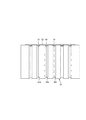
そして、これらの伸縮構造を改善するものとして、図16に示すように、2枚のシート層21,22を伸縮方向及びこれと直交する縦方向に間欠的に接合することにより多数のシート接合部70を形成し、シート層21,22間におけるシート接合部70を通らない(非接合部を通る)ように、両シート層21,22から独立して伸縮自在の複数の細長状の弾性伸縮部材19を配置する伸縮構造(特許文献1参照。以下、縦方向間欠接合形態ともいう。)が提案されている。この先行技術によれば、縦方向にシート接合部70が整列する部分が縦方向に連続する溝となり、その溝間の部分が表裏両側に同程度に膨出する大きな襞80となり、溝により通気性が向上するとともに、襞80によりフンワリ感に優れるものである。図16中の符号75はシート層21,22の溶着部分を示しているが、接着剤を用いてシート接合部70を形成しても襞80の形状は同様となる。
And as what improves these expansion-contraction structures, as shown in FIG. 16, two
しかし、この先行技術においては、襞の形状がもこもことした雲形又は波形となり、見栄え、通気性に劣るという問題点があった。 However, this prior art has a problem in that the shape of the ridge is a cloud shape or a wave shape, which looks ugly and looks and is inferior in air permeability.
一方、2枚のシート層を伸縮方向に間欠的かつ伸縮方向と交差する方向に連続的な接着加工により多数のシート接合部を形成することも知られている(例えば特許文献2参照。以下、縦方向連続接合形態ともいう。)。この形態における接着加工としては、ホットメルト接着剤の他、ヒートシールや超音波シール等の溶着加工が使用される。
On the other hand, it is also known that a large number of sheet joining portions are formed by bonding the two sheet layers intermittently in the expansion / contraction direction and in a direction crossing the expansion / contraction direction (see, for example,
しかし、このような縦方向連続接合形態において、シート接合部に溶着加工を採用すると、シート接合部を横切る弾性伸縮部材が切断されるおそれがあった。 However, in such a longitudinal continuous joining form, when a welding process is employed for the sheet joining portion, there is a possibility that the elastic elastic member across the sheet joining portion is cut.
そこで、本発明の主たる課題は、溶着加工による弾性伸縮部材の切断を防止すること等にある。 Then, the main subject of this invention exists in preventing the cutting | disconnection of the elastic elastic member by a welding process.
上記課題を解決するたに鋭意研究した結果、弾性伸縮部材が加熱により切断されるというよりは、主に過度の加圧により切断されること、及び弾性伸縮部材の無い部位で適切な溶着が可能となる圧力では、弾性伸縮部材に対する加圧が過度となること等の知見を得た。以下の本発明は、この知見に基づくものである。 As a result of earnest research to solve the above problems, it is possible to cut the elastic elastic member mainly by excessive pressurization rather than being cut by heating, and to perform appropriate welding at the site without the elastic elastic member. At the pressure which becomes, the knowledge that the pressurization with respect to an elastic elastic member becomes excessive was acquired. The following present invention is based on this finding.
<請求項1記載の発明>
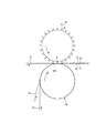
外周面に接合凸部が周方向に間隔を空けて設けられた第1ロールと、この第1ロールに対向する第2ロールとを、それぞれ軸心を中心として互いに反対周りに回転させつつ、
これら第1ロール及び第2ロール間に、第1シート層、第2シート層及びこれらの間にMD方向に連続するように配された細長状の弾性伸縮部材を通して、前記第1ロールの接合凸部及び第2ロールにより挟んで加圧・加熱することにより、第1シート層及び第2シート層の溶着によるシート接合部を前記弾性伸縮部材と交差するように且つMD方向に間隔を空けて形成する、
吸収性物品の伸縮構造の形成方法であって、
前記第1ロール及び第2ロールの回転周期の少なくとも一部の範囲における、前記第1ロール及び第2ロールの少なくとも一方の前記加圧を行う加圧面に、周方向に連続する溝を形成し、
前記溝を有するロールに接触する方のシート層、及び前記弾性伸縮部材を、前記溝を有するロールに巻きかけるように案内し、前記弾性伸縮部材及び溝に接触する方のシート層をライン張力により前記溝内に押え付けた後に、その押え付けた状態で前記加圧・加熱を行い、
前記加圧・加熱のとき、前記弾性伸縮部材の通過部位を、前記溝を含む位置で加圧・加熱し、弾性伸縮部材の非通過部位を前記溝以外の位置で加圧・加熱する、
ことを特徴とする、吸収性物品の伸縮構造の形成方法。
<Invention of
While rotating the first roll provided with bonding convex portions on the outer peripheral surface at intervals in the circumferential direction, and the second roll facing the first roll, respectively, around the axis center opposite to each other,
Between the first roll and the second roll, through the first sheet layer, the second sheet layer, and an elongated elastic elastic member arranged so as to be continuous in the MD direction therebetween, the joint protrusion of the first roll By pressing and heating between the part and the second roll, the sheet joining part formed by welding the first sheet layer and the second sheet layer is formed so as to intersect the elastic elastic member and at an interval in the MD direction. To
A method for forming an elastic structure of an absorbent article,
Forming a groove continuous in the circumferential direction on the pressing surface for applying the pressing of at least one of the first roll and the second roll in a range of at least a part of the rotation period of the first roll and the second roll;
The sheet layer that is in contact with the roll having the groove and the elastic elastic member are guided so as to be wound around the roll having the groove, and the sheet layer that is in contact with the elastic elastic member and the groove is line tensioned. After pressing in the groove, pressurizing and heating in the pressed state,
At the time of the pressurization / heating, the elastic elastic member passing part is pressurized / heated at a position including the groove, and the non-passing part of the elastic elastic member is pressurized / heated at a position other than the groove,
A method for forming a stretchable structure of an absorbent article.
(作用効果)
このように第1ロール及び第2ロールの少なくとも一方の加圧面に、周方向に連続する溝を形成しておき、シート接合部を形成する際、細長状の弾性伸縮部材の通過部位を、溝を含む位置で加圧・加熱し、弾性伸縮部材の非通過部位を溝以外の位置で加圧・加熱すると、弾性伸縮部材の非通過部位で第1シート層及び第2シート層に加わる圧力と、弾性伸縮部材の通過部位で、第1シート層、弾性伸縮部材及び第2シート層に加わる圧力との差が少なくなるため、溶着品質の差が少なくなる一方で、弾性伸縮部材に加わる圧力は低下するため、弾性伸縮部材の切断が発生し難いものとなる。
(Function and effect)
In this way, a groove that is continuous in the circumferential direction is formed on at least one of the pressure surfaces of the first roll and the second roll, and when the sheet joining portion is formed, the passage portion of the elongated elastic elastic member is defined as a groove. And pressurizing and heating the non-passing part of the elastic elastic member at a position other than the groove, and applying pressure to the first sheet layer and the second sheet layer at the non-passing part of the elastic elastic member; Since the difference between the pressure applied to the first sheet layer, the elastic elastic member and the second sheet layer is reduced at the passing portion of the elastic elastic member, the difference in welding quality is reduced, while the pressure applied to the elastic elastic member is Therefore, the elastic elastic member is hardly cut.
<請求項2記載の発明>
外周面に接合凸部が周方向に間隔を空けて設けられた第1ロールと、この第1ロールに対向する第2ロールとを、それぞれ軸心を中心として互いに反対周りに回転させつつ、
これら第1ロール及び第2ロール間に、第1シート層、第2シート層及びこれらの間にMD方向に連続するように配された細長状の弾性伸縮部材を通して、前記第1ロールの接合凸部及び第2ロールにより挟んで加圧・加熱することにより、第1シート層及び第2シート層の溶着によるシート接合部を前記弾性伸縮部材と交差するように且つMD方向に間隔を空けて形成する、
吸収性物品の伸縮構造の形成方法であって、
前記接合凸部は、前記弾性伸縮部材と交差する方向に細長く延びるとともに、前記弾性伸縮部材と交差する部位のCD方向両側から回転方向に突出する突出部分を有しており、
前記第1ロール及び第2ロールの回転周期の少なくとも一部の範囲における、前記第1ロール及び第2ロールの少なくとも一方の前記加圧を行う加圧面に、周方向に連続する溝を形成し、
前記加圧・加熱のとき、前記弾性伸縮部材の通過部位を、前記溝を含む位置で加圧・加熱し、弾性伸縮部材の非通過部位を前記溝以外の位置で加圧・加熱する、
ことを特徴とする吸収性物品の伸縮構造の形成方法。
<Invention of
While rotating the first roll provided with bonding convex portions on the outer peripheral surface at intervals in the circumferential direction, and the second roll facing the first roll, respectively, around the axis center opposite to each other,
Between the first roll and the second roll, through the first sheet layer, the second sheet layer, and an elongated elastic elastic member arranged so as to be continuous in the MD direction therebetween, the joint protrusion of the first roll By pressing and heating between the part and the second roll, the sheet joining part formed by welding the first sheet layer and the second sheet layer is formed so as to intersect the elastic elastic member and at an interval in the MD direction. To
A method for forming an elastic structure of an absorbent article,
The joint projection, together with elongated in a direction intersecting the resilient and elastic members has a protruding portion that protrudes in the rotational direction from the CD opposite sides of a portion intersecting the resilient and elastic members,
Forming a groove continuous in the circumferential direction on the pressing surface for applying the pressing of at least one of the first roll and the second roll in a range of at least a part of the rotation period of the first roll and the second roll;
At the time of the pressurization / heating, the elastic elastic member passing part is pressurized / heated at a position including the groove, and the non-passing part of the elastic elastic member is pressurized / heated at a position other than the groove,
A method for forming a stretchable structure of an absorbent article.
(作用効果)
接合凸部の形状をこのようにすると、弾性伸縮部材が突出部分の間に誘導される結果、弾性伸縮部材の通過部位が溝を含む位置に確実に位置決めされるようになるため好ましい。
(Function and effect)
Such a shape of the joint convex portion is preferable because the elastic elastic member is guided between the protruding portions, so that the passing portion of the elastic elastic member is surely positioned at the position including the groove.
<請求項3記載の発明>
第1シート層と、この第1シート層の一方の面に対向する第2シート層と、これら第1シート層及び第2シート層の間に、伸縮方向に沿ってかつ互いに間隔を空けて設けられた複数本の細長状の弾性伸縮部材とを備えており、
前記第1シート層及び第2シート層が、伸縮方向に間欠的に配された、伸縮方向と交差する方向に連続するシート接合部で溶着されており、
前記弾性伸縮部材が、前記シート接合部と交差する位置で前記第1シート層及び第2シート層に溶着されており、
前記弾性伸縮部材の収縮に伴い前記第1シート層及び第2シート層が収縮することにより、前記第1シート層及び第2シート層におけるシート接合部間に位置する部分が互いに反対向きに膨らんでそれぞれ襞が形成されており、
自然長状態で、前記シート接合部における前記第1シート層及び第2シート層のいずれか一方は、前記弾性伸縮部材の中心と重なる位置の見かけの厚みが、前記弾性伸縮部材を有しない位置の見かけの厚みの80〜100%であり、
前記シート接合部は、前記弾性伸縮部材と交差する方向に細長く延びるとともに、前記弾性伸縮部材と交差する部位の、前記弾性伸縮部材と交差する方向の両側から幅方向一方側に突出する突出部分を有している、
ことを特徴とする吸収性物品の伸縮構造。
<Invention of
The first sheet layer, the second sheet layer facing one surface of the first sheet layer, and the first sheet layer and the second sheet layer are provided along the stretching direction and spaced apart from each other. Provided with a plurality of elongated elastic stretch members,
The first sheet layer and the second sheet layer are intermittently arranged in the expansion / contraction direction, and are welded at a sheet joining portion continuous in a direction intersecting with the expansion / contraction direction,
The elastic elastic member is welded to the first sheet layer and the second sheet layer at a position intersecting the sheet joint portion;
The first sheet layer and the second sheet layer contract with the contraction of the elastic elastic member, so that the portions located between the sheet joint portions in the first sheet layer and the second sheet layer swell in opposite directions. Each has a cocoon,
In the natural length state, any one of the first sheet layer and the second sheet layer in the sheet joining portion has an apparent thickness at a position overlapping with the center of the elastic elastic member. 80% to 100% der of the apparent thickness is,
The sheet joint portion is elongated in a direction intersecting with the elastic elastic member, and has a protruding portion protruding from one side in the width direction from both sides of the direction intersecting the elastic elastic member at a portion intersecting with the elastic elastic member. that has,
An elastic structure of an absorbent article characterized by the above.
(作用効果)
本発明は、縦方向連続接合形態を基本とし、自然長状態で、シート接合部における第1シート層及び第2シート層のいずれか一方は、弾性伸縮部材の中心と重なる位置の見かけの厚みが、弾性伸縮部材を有しない位置の見かけの厚みに対して差が小さい構造を採用したことにより、当該厚み差の小さい方のシート層は弾性伸縮部材を覆う部分が従来よりも厚くなるため、よりクッション性に富む肌触りとなり、弾性伸縮部材の当たりがより柔軟となる。また、使用時にある程度伸長した状態でも同様の結果となる。
(Function and effect)
The present invention is based on the longitudinal continuous joining form, and in the natural length state, any one of the first sheet layer and the second sheet layer in the sheet joining portion has an apparent thickness at a position overlapping the center of the elastic elastic member. By adopting a structure with a small difference with respect to the apparent thickness of the position where there is no elastic elastic member, the sheet layer with the smaller thickness difference has a thicker portion covering the elastic elastic member than the conventional one. It becomes a touch rich in cushioning properties, and the elastic elastic member hits more flexibly. Moreover, the same result is obtained even in a state of being extended to some extent during use.
なお、このような構造は、請求項2記載の方法により形成することができ、加圧・加熱のときに溝に接触する方のシート層が溝に入り込むことにより、弾性伸縮部材を有する部位のシート層が弾性伸縮部材と交差する方向に長くなり、自然長状態や装着状態でも上述のシート層の厚み差が小さいものとなる。
従来の製造方法では、シート接合部の溶着加工に際して、第1シート層及び第2シート層のいずれもが弾性伸縮部材と交差する方向に平坦であるから、自然長状態や装着状態では製造時よりも弾性伸縮部材が大径化すること等により、弾性伸縮部材を有する部位で第1シート層及び第2シート層が伸長されて薄くなり、上記見かけの厚み差が大きくなるものである。
なお、本発明においてシート接合部が連続するとは、第1シート層及び第2シート層と弾性伸縮部材とがそれぞれ溶着して第1シート層及び第2シート層が間接的に溶着することにより溶着が連続する形態を意味する。
また、弾性伸縮部材がシート接合部と交差する位置でシート層に固定されているとは、シート接合部と交差する位置又は他の位置で接着剤等の他の手段により補強されていても良いものである。
また、見かけの厚みは、JIS L 1913:2010に準ずる条件下で、シート接合部において弾性伸縮部材と直交する方向に切断した後、その断面を顕微鏡で100倍に拡大して撮影し、その撮影結果の写真から定規で目視計測するものである。
In addition, such a structure can be formed by the method according to
In the conventional manufacturing method, since both the first sheet layer and the second sheet layer are flat in the direction intersecting the elastic elastic member during the welding process of the sheet joint portion, in the natural length state and the mounted state, it is more However, when the diameter of the elastic elastic member is increased, the first sheet layer and the second sheet layer are elongated and thinned at the portion having the elastic elastic member, and the apparent thickness difference is increased.
In the present invention, the sheet joining portion is continuous means that the first sheet layer and the second sheet layer are welded to each other and the first sheet layer and the second sheet layer are indirectly welded. Means a continuous form.
Further, the fact that the elastic elastic member is fixed to the sheet layer at a position intersecting with the sheet joining portion may be reinforced by other means such as an adhesive at a position intersecting with the sheet joining portion or at another position. Is.
In addition, the apparent thickness was cut in a direction orthogonal to the elastic expansion and contraction member at the sheet joint portion under a condition according to JIS L 1913: 2010, and then the cross section was magnified 100 times with a microscope. The result is visually measured with a ruler.
<請求項4記載の発明>
前記吸収性物品は、前身頃及び後身頃を構成する外装体と、この外装体の内面に固定された、吸収体を含む内装体とを備え、前身頃における外装体の両側部と後身頃における外装体の両側部とがそれぞれ接合されてサイドシール部が形成されることにより、胴周り部が環状に形成されるとともに、ウエスト開口部及び左右一対の脚開口部が形成された、パンツタイプ使い捨ておむつであり、
前記伸縮構造は、前記外装体における少なくとも内装体の幅方向両側を含む領域に、前記弾性伸縮部材が幅方向となるように設けられている、
請求項3記載の吸収性物品の伸縮構造。
<Invention of Claim 4 >
The absorbent article includes an exterior body constituting a front body and a back body, and an interior body including an absorbent body fixed to the inner surface of the exterior body, in both sides of the exterior body in the front body and in the back body A pants-type disposable in which both sides of the exterior body are joined to each other to form a side seal portion, so that the waistline portion is formed in an annular shape, and a waist opening and a pair of left and right leg openings are formed. A diaper,
The stretchable structure is provided in a region including at least both sides in the width direction of the interior body in the exterior body so that the elastic stretchable member is in the width direction.
The elastic structure of the absorbent article according to
(作用効果)
本発明の伸縮構造は、このようにパンツタイプ使い捨ておむつの外装体における少なくとも内装体の幅方向両側に位置する領域に好適なものである。
(Function and effect)
The stretchable structure of the present invention is thus suitable for the region located at least on both sides in the width direction of the interior body in the exterior body of the pants-type disposable diaper.
以上のとおり、本発明によれば、適切な溶着を可能としつつ、弾性伸縮部材の切断が発生し難いものとなる、等の利点がもたらされる。 As described above, according to the present invention, there are advantages such as being able to perform appropriate welding and making it difficult for the elastic elastic member to be cut.
以下、本発明の実施形態について、添付図面を参照しつつ詳説する。
<伸縮構造について>
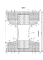
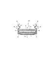
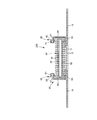
図1〜図8は、パンツタイプ使い捨ておむつの一例100を示している。このパンツタイプ使い捨ておむつ100は、製品外面(裏面)をなす外装体12と、外装体12の内面に貼り付けられた内装体200とから構成されているものである。符号Yはおむつの全長を示しており、符号Xはおむつの全幅を示している。
Hereinafter, embodiments of the present invention will be described in detail with reference to the accompanying drawings.
<About stretchable structure>
1 to 8 show an example 100 of a pants-type disposable diaper. The pants-type
内装体200は、尿等の排泄物等を吸収保持する部分であり、外装体12は着用者に装着するための部分である。なお、断面図における点模様部分は各構成部材を接合する接合部分を示しており、ホットメルト接着剤などのベタ、ビード、カーテン、サミットまたはスパイラル塗布などにより形成されるものである。なお、「前後方向」とは腹側(前側)と背側(後側)を結ぶ方向を意味し、「幅方向」とは前後方向と直交する方向(左右方向)を意味し、「上下方向」とはおむつ100の装着状態、すなわちおむつ100の前身頃両側部と後身頃両側部を重ね合わせるようにおむつ100を股間部で2つに折った際に胴周り方向と直交する方向、換言すればウエスト開口部WO側と股間部側とを結ぶ方向を意味する。
The
(内装体)
内装体200は任意の形状を採ることができるが、図示の形態では長方形である。内装体200は、図3〜図5に示されるように、身体側となる表面シート30と、液不透過性シート11と、これらの間に介在された吸収要素50とを備えているものであり、吸収機能を担う本体部である。符号40は、表面シート30を透過した液を速やかに吸収要素50へ移行させるために、表面シート30と吸収要素50との間に設けられた中間シート(セカンドシート)を示しており、符号60は、内装体200の両脇に排泄物が漏れるのを防止するために、内装体200の両側に設けられた、身体側に起立する立体ギャザー60を示している。
(Interior body)
The
(表面シート)
表面シート30は、液を透過する性質を有するものであり、例えば、有孔又は無孔の不織布や、多孔性プラスチックシートなどを例示することができる。また、このうち不織布は、その原料繊維が何であるかは、特に限定されない。例えば、ポリエチレンやポリプロピレン等のオレフィン系、ポリエステル系、ポリアミド系等の合成繊維、レーヨンやキュプラ等の再生繊維、綿等の天然繊維などや、これらから二種以上が使用された混合繊維、複合繊維などを例示することができる。さらに、不織布は、どのような加工によって製造されたものであってもよい。加工方法としては、公知の方法、例えば、スパンレース法、スパンボンド法、サーマルボンド法、メルトブローン法、ニードルパンチ法、エアスルー法、ポイントボンド法等を例示することができる。例えば、柔軟性、ドレープ性を求めるのであれば、スパンボンド法、スパンレース法が、嵩高性、ソフト性を求めるのであれば、エアスルー法、ポイントボンド法、サーマルボンド法が、好ましい加工方法となる。
(Surface sheet)
The
また、表面シート30は、1枚のシートからなるものであっても、2枚以上のシートを貼り合せて得た積層シートからなるものであってもよい。同様に、表面シート30は、平面方向に関して、1枚のシートからなるものであっても、2枚以上のシートからなるものであってもよい。
Further, the
立体ギャザー60を設ける場合、表面シート30の両側部は、液不透過性シート11と立体ギャザー60との間を通して、吸収要素50の裏側まで回りこませ、液の浸透を防止するために、液不透過性シート11及び立体ギャザー60に対してホットメルト接着剤等により接着するのが好ましい。
When the three-dimensional gather 60 is provided, both sides of the
(中間シート)
表面シート30を透過した液を速やかに吸収体へ移行させるために、表面シート30より液の透過速度が速い、中間シート(「セカンドシート」とも呼ばれている)40を設けることができる。この中間シート40は、液を速やかに吸収体へ移行させて吸収体による吸収性能を高めるばかりでなく、吸収した液の吸収体からの「逆戻り」現象を防止し、表面シート30上を常に乾燥した状態とすることができる。中間シート40は省略することもできる。
(Intermediate sheet)
An intermediate sheet (also referred to as “second sheet”) 40 having a higher liquid permeation rate than the
中間シート40としては、表面シート30と同様の素材や、スパンレース、スパンボンド、SMS、パルプ不織布、パルプとレーヨンとの混合シート、ポイントボンド又はクレープ紙を例示できる。特にエアスルー不織布が嵩高であるため好ましい。エアスルー不織布には芯鞘構造の複合繊維を用いるのが好ましく、この場合芯に用いる樹脂はポリプロピレン(PP)でも良いが剛性の高いポリエステル(PET)が好ましい。目付けは20〜80g/m2が好ましく、25〜60g/m2がより好ましい。不織布の原料繊維の太さは2.2〜10dtexであるのが好ましい。不織布を嵩高にするために、原料繊維の全部又は一部の混合繊維として、芯が中央にない偏芯の繊維や中空の繊維、偏芯且つ中空の繊維を用いるのも好ましい。
Examples of the
図示の形態の中間シート40は、吸収体56の幅より短く中央に配置されているが、全幅にわたって設けてもよい。中間シート40の長手方向長さは、吸収体56の長さと同一でもよいし、液を受け入れる領域を中心にした短い長さ範囲内であってもよい。
The
(液不透過性シート)
液不透過性シート11の素材は、特に限定されるものではないが、例えば、ポリエチレンやポリプロピレン等のオレフィン系樹脂等からなるプラスチックフィルムや、不織布の表面にプラスチックフィルムを設けたラミネート不織布、プラスチックフィルムに不織布等を重ねて接合した積層シートなどを例示することができる。液不透過性シート11には、近年、ムレ防止の観点から好まれて使用されている不透液性かつ透湿性を有する素材を用いることが好ましい。透湿性を有するプラスチックフィルムとしては、ポリエチレンやポリプロピレン等のオレフィン系樹脂中に無機充填剤を混練して、シートを成形した後、一軸又は二軸方向に延伸して得られた微多孔性プラスチックフィルムが広く用いられている。このほかにも、マイクロデニール繊維を用いた不織布、熱や圧力をかけることで繊維の空隙を小さくすることによる防漏性強化、高吸水性樹脂または疎水性樹脂や撥水剤の塗工といった方法により、プラスチックフィルムを用いずに液不透過性としたシートも、液不透過性シート11として用いることができる。
(Liquid impervious sheet)
The material of the liquid-
液不透過性シート11は、防漏性を高めるために、吸収要素50の両側を回りこませて吸収要素50の表面シート30側面の両側部まで延在させるのが好ましい。この延在部の幅は、左右それぞれ5〜20mm程度が適当である。
The liquid-
また、液不透過性シート11の内側、特に吸収体56側面に、液分の吸収により色が変化する排泄インジケータを設けることができる。
Moreover, the excretion indicator from which a color changes by absorption of a liquid part can be provided in the inner side of the liquid-
(立体ギャザー)
立体ギャザー60は、内装体200の両側部に沿って前後方向全体にわたり延在する帯状部材であり、表面シート30上を伝わって横方向に移動する尿や軟便を遮断し、横漏れを防止するために設けられているものである。本実施の形態の立体ギャザー60は、内装体200の側部から起立するように設けられ、付け根側の部分は幅方向中央側に向かって斜めに起立し、中間部より先端側の部分は幅方向外側に向かって斜めに起立するものである。
(Three-dimensional gather)
The three-dimensional gather 60 is a belt-like member that extends over the entire front-rear direction along both side portions of the
より詳細には、立体ギャザー60は、内装体200の前後方向長さに等しい長さを有する帯状のギャザーシート62を幅方向に折り返して二つに折り重ねるとともに、折り返し部分及びその近傍のシート間に、細長状弾性伸縮部材63を長手方向に沿って伸長状態で、幅方向に間隔をあけて複数本固定してなるものである。立体ギャザー60のうち幅方向において折り返し部分と反対側の端部は内装体200の側縁部の裏面に固定された取付部分65とされ、この取付部分65以外の部分は取付部分65から突出する突出部分66(折り返し部分側の部分)とされている。また、突出部分66のうち前後方向両端部は、取付部分65から内装体200の側部を通り表面シート30の側部表面まで延在し且つこの表面シート30の側部表面に対してホットメルト接着剤やヒートシールによる前後固定部67固定された付け根側部分と、この付け根側部分の先端から幅方向外側に折り返され且つ付け根側部分に固定された先端側部分とからなる。突出部分のうち前後方向中間部は非固定の自由部分(内側自由部分)とされ、この自由部分に前後方向に沿う細長状の弾性伸縮部材63が伸長状態で固定されている。
More specifically, the three-dimensional gather 60 folds the belt-shaped gather
ギャザーシート62としてはスパンボンド不織布(SS、SSS等)やSMS不織布(SMS、SSMMS等)、メルトブロー不織布等の柔軟で均一性・隠蔽性に優れた不織布に、必要に応じてシリコンなどにより撥水処理を施したものを好適に用いることができ、繊維目付けは10〜30g/m2程度とするのが好ましい。細長状弾性伸縮部材63としては糸ゴム等を用いることができる。スパンデックス糸ゴムを用いる場合は、太さは470〜1240dtexが好ましく、620〜940dtexがより好ましい。固定時の伸長率は、150〜350%が好ましく、200〜300%がより好ましい。なお、用語「伸長率」は自然長を100%としたときの値を意味する。また、図示のように、二つに折り重ねたギャザーシートの間に防水フィルム64を介在させることもできる。
The gather
立体ギャザー60の自由部分に設けられる細長状弾性伸縮部材63の本数は2〜6本が好ましく、3〜5本がより好ましい。配置間隔60dは3〜10mmが適当である。このように構成すると、細長状弾性伸縮部材63を配置した範囲で肌に対して面で当たりやすくなる。先端側だけでなく付け根側にも細長状弾性伸縮部材63を配置しても良い。
2-6 are preferable and, as for the number of the elongate elastic expansion-
立体ギャザー60の取付部分65の固定対象は、内装体200における表面シート30、液不透過性シート11、吸収要素50等適宜の部材とすることができる。
The fixing target of the
かくして構成された立体ギャザー60では、細長状弾性伸縮部材63の収縮力が前後方向両端部を近づけるように作用するが、突出部分66のうち前後方向両端部が起立しないように固定されるのに対して、それらの間は非固定の自由部分とされているため、自由部分のみが図3に示すように身体側に当接するように起立する。特に、取付部分65が内装体200の裏面側に位置していると、股間部及びその近傍において立体ギャザー60が幅方向外側に開くように起立するため、立体ギャザー60が脚周りに面で当接するようになり、フィット性が向上するようになる。
In the three-dimensional gather 60 thus configured, the contraction force of the elongated elastic
立体ギャザー60の寸法は適宜定めることができるが、乳幼児用紙おむつの場合は、例えば図7に示すように、立体ギャザー60の起立高さ(展開状態における突出部分66の幅方向長さ)66wは15〜60mm、特に20〜40mmであるのが好ましい。また、立体ギャザー60をトップシート30表面と平行になるように、平坦に折り畳んだ状態において最も内側に位置する折り目間の離間距離60dは60〜190mm、特に70〜140mmであるのが好ましい。
The dimensions of the three-dimensional gather 60 can be determined as appropriate. In the case of an infant paper diaper, for example, as shown in FIG. 7, the standing height of the three-dimensional gather 60 (the length in the width direction of the protruding
なお、図示形態と異なり、内装体200の左右各側において立体ギャザーを二重に(二列)設けることもできる。
Note that, unlike the illustrated embodiment, the three-dimensional gathers can be provided in double (two rows) on the left and right sides of the
(吸収要素)
吸収要素50は、吸収体56と、この吸収体56の全体を包む包装シート58とを有する。包装シート58は省略することもできる。
(Absorption element)
The
(吸収体)
吸収体56は、繊維の集合体により形成することができる。この繊維集合体としては、綿状パルプや合成繊維等の短繊維を積繊したものの他、セルロースアセテート等の合成繊維のトウ(繊維束)を必要に応じて開繊して得られるフィラメント集合体も使用できる。繊維目付けとしては、綿状パルプや短繊維を積繊する場合は、例えば100〜300g/m2程度とすることができ、フィラメント集合体の場合は、例えば30〜120g/m2程度とすることができる。合成繊維の場合の繊度は、例えば、1〜16dtex、好ましくは1〜10dtex、さらに好ましくは1〜5dtexである。フィラメント集合体の場合、フィラメントは、非捲縮繊維であってもよいが、捲縮繊維であるのが好ましい。捲縮繊維の捲縮度は、例えば、1インチ当たり5〜75個、好ましくは10〜50個、さらに好ましくは15〜50個程度とすることができる。また、均一に捲縮した捲縮繊維を用いる場合が多い。吸収体56中には高吸収性ポリマー粒子を分散保持させるのが好ましい。
(Absorber)
The
吸収体56は長方形形状でも良いが、図6にも示すように、前端部、後端部及びこれらの間に位置し、前端部及び後端部と比べて幅が狭い括れ部とを有する砂時計形状を成していると、吸収体56自体と立体ギャザー60の、脚周りへのフィット性が向上するため好ましい。
Although the
また、吸収体の寸法は適宜定めることができるが、前後方向及び幅方向において、内装体の周縁部又はその近傍まで延在しているのが好ましい。なお、符号56Xは吸収体56の幅を示している。
Moreover, although the dimension of an absorber can be determined suitably, it is preferable to extend to the peripheral part of the interior body, or its vicinity in the front-back direction and the width direction.
(高吸収性ポリマー粒子)
吸収体56には、その一部又は全部に高吸収性ポリマー粒子を含有させることができる。高吸収性ポリマー粒子とは、「粒子」以外に「粉体」も含む。高吸収性ポリマー粒子の粒径は、この種の吸収性物品に使用されるものをそのまま使用でき、1000μm以下、特に150〜400μmのものが望ましい。高吸収性ポリマー粒子の材料としては、特に限定無く用いることができるが、吸水量が40g/g以上のものが好適である。高吸収性ポリマー粒子としては、でんぷん系、セルロース系や合成ポリマー系などのものがあり、でんぷん−アクリル酸(塩)グラフト共重合体、でんぷん−アクリロニトリル共重合体のケン化物、ナトリウムカルボキシメチルセルロースの架橋物やアクリル酸(塩)重合体などのものを用いることができる。高吸収性ポリマー粒子の形状としては、通常用いられる粉粒体状のものが好適であるが、他の形状のものも用いることができる。
(Superabsorbent polymer particles)
The
高吸収性ポリマー粒子としては、吸水速度が40秒以下のものが好適に用いられる。吸水速度が40秒を超えると、吸収体56内に供給された液が吸収体56外に戻り出てしまう所謂逆戻りを発生し易くなる。
As the superabsorbent polymer particles, those having a water absorption rate of 40 seconds or less are preferably used. When the water absorption speed exceeds 40 seconds, so-called reversion in which the liquid supplied into the
また、高吸収性ポリマー粒子としては、ゲル強度が1000Pa以上のものが好適に用いられる。これにより、嵩高な吸収体56とした場合であっても、液吸収後のべとつき感を効果的に抑制できる。
Further, as the superabsorbent polymer particles, those having a gel strength of 1000 Pa or more are preferably used. Thereby, even if it is a case where it is set as the
高吸収性ポリマー粒子の目付け量は、当該吸収体56の用途で要求される吸収量に応じて適宜定めることができる。したがって一概には言えないが、50〜350g/m2とすることができる。ポリマーの目付け量が50g/m2未満では、吸収量を確保し難くなる。350g/m2を超えると、効果が飽和する。
The basis weight of the superabsorbent polymer particles can be appropriately determined according to the amount of absorption required for the use of the
必要であれば、高吸収性ポリマー粒子は、吸収体56の平面方向で散布密度あるいは散布量を調整できる。たとえば、液の排泄部位を他の部位より散布量を多くすることができる。男女差を考慮する場合、男用は前側の散布密度(量)を高め、女用は中央部の散布密度(量)を高めることができる。また、吸収体56の平面方向において局所的(例えばスポット状)にポリマーが存在しない部分を設けることもできる。
If necessary, the superabsorbent polymer particles can adjust the spraying density or spraying amount in the plane direction of the
(包装シート)
包装シート58を用いる場合、その素材としては、ティッシュペーパ、特にクレープ紙、不織布、ポリラミ不織布、小孔が開いたシート等を用いることができる。ただし、高吸収性ポリマー粒子が抜け出ないシートであるのが望ましい。クレープ紙に換えて不織布を使用する場合、親水性のSMS不織布(SMS、SSMMS等)が特に好適であり、その材質はポリプロピレン、ポリエチレン/ポリプロピレン複合材などを使用できる。目付けは、5〜40g/m2、特に10〜30g/m2のものが望ましい。
(Packaging sheet)
When the
包装シート58の包装形態は適宜定めることができるが、製造容易性や前後端縁からの高吸収性ポリマー粒子の漏れ防止等の観点から、吸収体56の表裏面及び両側面を取り囲むように筒状に巻き付け、且つその前後縁部を吸収体56の前後から食み出させ、この食み出し部分を表裏方向に潰してホットメルト接着剤等の接合手段により接合する形態が好ましい。
The packaging form of the
(外装体)
外装体12は、股間部から腹側に延在する前身頃Fを構成する部分と、股間部から背側に延在する後身頃Bを構成する部分とを有し、これら前身頃Fの両側部と後身頃Bの両側部とが接合されて、図8に示すように、装着者の胴を通すためのウエスト開口部WO及び脚を通すための左右一対の脚開口部LOが形成されているものである。符号12Aは接合部分を示している(以下、この部分をサイドシール部ともいう)。なお、股間部とは、展開状態における前身頃Fのウエスト縁から後身頃Bのウエスト縁までの前後方向中央を意味し、それよりも前側の部分及び後側の部分が前身頃F及び後身頃Bをそれぞれ意味する。
(Exterior body)
The
外装体12は、ウエスト開口部WOから脚開口部LOの上端に至る前後方向範囲として定まる胴周り部Tと、脚開口部LOを形成する部分の前後方向範囲(前身頃Fのサイドシール部12Aを有する前後方向領域と後身頃Bのサイドシール部12Aを有する前後方向領域と間)として定まる中間部Lとを有する。胴周り部Tは、概念的にウエスト開口部の縁部を形成する「ウエスト部」Wと、これよりも下側の部分である「ウエスト下方部」Uとに分けることができる。通常、胴周り部T内に幅方向伸縮応力が変化する境界(例えば弾性伸縮部材の太さや伸長率が変化する)を有する場合は、最もウエスト開口WO側の境界よりもウエスト開口WO側がウエスト部Wとなり、このような境界が無い場合は吸収体56又は内装体200よりもウエスト開口WO側がウエスト部Wとなる。これらの縦方向の長さは、製品のサイズによって異なり、適宜定めることができるが、一例を挙げると、ウエスト部Wは15〜40mm、ウエスト下方部Uは65〜120mmとすることができる。一方、中間部Lの両側縁は被着者の脚周りに沿うように括れており、ここが着用者の脚を入れる部位となる。この結果、外装体12は、全体としては略砂時計形状をなしている。外装体12の括れの程度は適宜定めることができ、図1〜図8に示す形態のように、すっきりとした外観とするために最も幅が狭い部分では内装体200の幅より狭くすることが好ましいが、最も幅が狭い部分でも内装体200の幅以上となるように定めてもよい。
The
外装体12は、図3〜図6に示されるように、二枚のシート材12S,12Hを接合して形成されるものであり、内側に位置する第2シート材12Hはウエスト開口部WOの縁までしか延在していないが、外側に位置する第1シート材12Sは第2シート材12Hのウエスト側の縁を回り込んでその内側に折り返されており、この折り返し部分12rは内装体200のウエスト側端部上までを被覆するように延在されている。
As shown in FIGS. 3 to 6, the
シート材12S,12Hとしては、シート状のものであれば特に限定無く使用できるが、不織布であるのが好ましい。不織布は、その原料繊維が何であるかは特に限定されない。例えば、ポリエチレンやポリプロピレン等のオレフィン系、ポリエステル系、ポリアミド系等の合成繊維、レーヨンやキュプラ等の再生繊維、綿等の天然繊維などや、これらから二種以上が使用された混合繊維、複合繊維などを例示することができる。さらに、不織布は、どのような加工によって製造されたものであってもよい。加工方法としては、公知の方法、例えば、スパンレース法、スパンボンド法、サーマルボンド法、メルトブローン法、ニードルパンチ法、エアスルー法、ポイントボンド法等を例示することができる。
The
そして、外装体12には、胴周りに対するフィット性を高めるために、両シート材12S,12H間に糸ゴム等の細長状の弾性伸縮部材19(ウエスト部弾性伸縮部材17、ウエスト下方部弾性伸縮部材15、中間部弾性伸縮部材16)が所定の伸長率で設けられている。細長状弾性伸縮部材19としては、合成ゴムを用いても、天然ゴムを用いても良い。
And in the
より詳細には、後身頃B及び前身頃Fのウエスト部Wにおける第2シート材12Hの内側面と第1シート材12Sの折り返し部分12rの外側面との間には、幅方向全体にわたり連続するように、複数のウエスト部弾性伸縮部材17が上下方向に間隔を空けて、かつ所定の伸長率で幅方向に沿って伸長された状態で固定されている。また、ウエスト部弾性伸縮部材17のうち、ウエスト下方部Uに隣接する領域に配設される1本または複数本については、内装体200と重なっていてもよいし、内装体200と重なる幅方向中央部を除いてその幅方向両側にそれぞれ設けてもよい。このウエスト部弾性伸縮部材17としては、太さ155〜1880dtex、特に470〜1240dtex程度(合成ゴムの場合。天然ゴムの場合には断面積0.05〜1.5mm2、特に0.1〜1.0mm2程度)の糸ゴムを、4〜12mmの間隔で3〜22本程度、それぞれ伸長率150〜400%、特に220〜320%程度で固定するのが好ましい。また、ウエスト部弾性伸縮部材17は、その全てが同じ太さと伸長率にする必要はなく、例えばウエスト部Wの上部と下部で弾性伸縮部材の太さと伸長率が異なるようにしてもよい。
In more detail, it continues over the whole width direction between the inner surface of the
また、前身頃F及び後身頃Bのウエスト下方部Uにおける第2シート材12Hの外側面と第1シート材12Sの内側面との間には、内装体200と重なる幅方向中央部を除いて、その上側および幅方向両側の各部位に、幅方向全体にわたり連続するように、細長状弾性伸縮部材からなるウエスト下方部弾性伸縮部材15が複数本、上下方向に間隔を空けて、かつ所定の伸長率で幅方向に沿って伸長された状態で固定されている。
Further, between the outer side surface of the
ウエスト下方部弾性伸縮部材15としては、太さ155〜1880dtex、特に470〜1240dtex程度(合成ゴムの場合。天然ゴムの場合には断面積0.05〜1.5mm2、特に0.1〜1.0mm2程度)の糸ゴムを、1〜15mm、特に3〜8mmの間隔で5〜30本程度、それぞれ伸長率200〜350%、特に240〜300%程度で固定するのが好ましい。
The waist downward resilient and
また、前身頃F及び後身頃Bの中間部Lにおける第2シート材12Hの外側面と第1シート材12Sの内側面との間には、内装体200と重なる幅方向中央部を除いて、その幅方向両側の各部位に、幅方向全体にわたり連続するように、細長状弾性伸縮部材からなる中間部弾性伸縮部材16が複数本、上下方向に間隔を空けて、かつ所定の伸長率で幅方向に沿って伸長された状態で固定されている。
In addition, between the outer side surface of the
中間部弾性伸縮部材16としては、太さ155〜1880dtex、特に470〜1240dtex程度(合成ゴムの場合。天然ゴムの場合には断面積0.05〜1.5mm2、特に0.1〜1.0mm2程度)の糸ゴムを、5〜40mm、特に5〜20mmの間隔で2〜10本程度、それぞれ伸長率150〜300%、特に180〜260%で固定するのが好ましい。
The intermediate elastic
なお、図示のように、ウエスト下方部弾性伸縮部材15及び中間部弾性伸縮部材16が、内装体200と重なる部分の一部又は全部を除いてその幅方向両側にそれぞれ設けられていると、内装体200が幅方向に必要以上に収縮することがなく、モコモコと見た目が悪かったり吸収性が低下したりすることがない。この形態には、幅方向両側にのみ弾性伸縮部材が存在する形態の他、内装体200を横切ってその幅方向一方側から他方側まで弾性伸縮部材が存在しているが、内装体200と重なる部分の一部又は全部では弾性伸縮部材が細かく切断され、収縮力が作用せず(実質的には、弾性伸縮部材を設けないことに等しい)に、その幅方向両側のみが収縮力作用部分として構成されている形態も含まれる。もちろんウエスト下方部弾性伸縮部材15及び中間部弾性伸縮部材16の配設形態は上記例に限るものではなく、内装体200と重なる部分を含めて幅方向全体にわたり伸縮力が作用するように、ウエスト下方部弾性伸縮部材15及び中間部弾性伸縮部材16の一部または全部を、内装体200を横切ってその幅方向一方側から他方側まで設けることもできる。
As shown in the figure, when the waist lower elastic
(外装体分割構造)
上述の例では、前身頃Fから後身頃Bまでを一体的な外装体12により連続的に覆っているが、腹側部分の外装体と背側部分の外装体とが股間側で連続しておらず、離間されている形態とすることもでき(図示略)、その場合、内装体の外面のうち、腹側部分の外装体と背側部分の外装体との間に露出する部分を覆う股間部外装体を貼り付けることもできる。股間部外装体としては、前述した外装体に用いられるものと同様の資材を用いることができる。
(External body split structure)
In the above-described example, the front body F to the back body B are continuously covered by the integrated
(伸縮構造について)
図2に示されるパンツタイプ使い捨ておむつにおいては、ウエスト部Wから中間部Lにかけての領域に本発明の伸縮構造が採用されている。すなわち、当該部分は、図6に示すように、第1シート層21及び第2シート層22が、伸縮方向に間欠的に配された、伸縮方向と交差(図示形態では直交)する方向に所定の幅で連続する溶着加工により接合されて、シート接合部70が形成されている。溶着部分は符号75により示されている。
(About stretchable structure)
In the pants-type disposable diaper shown in FIG. 2, the stretchable structure of the present invention is adopted in the region from the waist part W to the intermediate part L. That is, as shown in FIG. 6, the portion is predetermined in a direction in which the
第1シート層21及び第2シート層22の素材は溶着加工により接合される限り特に限定されないが、特に厚み0.1〜1mm、目付10〜20g/m2の不織布であることが望ましい。なお、第1シート層21及び第2シート層22はウエスト下方部U及び中間部Lのように別々のシート材12S,12Hで形成される他、ウエスト部Wのように一枚のシート材12Sを折り返した部分により形成されていても良い。また、第1シート層21及び第2シート層22は一枚のシート材により形成される他、いずれか一方又は両方が複数のシート材の積層体であっても良い。
Although the material of the
溶着加工としては、ヒートシール、超音波溶着等、公知の加工手法を採用することができる。ここで、シート接合部70を形成するための溶着加工が連続するとは、図6(d)に示すように、第1シート層21及び第2シート層22と弾性伸縮部材とがそれぞれ溶着して第1シート層21及び第2シート層22が間接的に溶着することにより溶着が連続する形態を意味する。
As the welding process, a known processing method such as heat sealing or ultrasonic welding can be employed. Here, the welding process for forming the
弾性伸縮部材19は、シート接合部70と交差する位置で、シート接合部を形成するための溶着加工により第1シート層21及び第2シート層22に固定される。つまり、溶着加工により第1シート層21及び第2シート層22が溶けて弾性伸縮部材19に溶着する結果、弾性伸縮部材が溶融しなくても固定される。
The elastic
隣り合う弾性伸縮部材19の間隔19dは適宜定めることができるが、10mmを超えると、縦方向間欠接合形態ほどではないが、襞80の厚みが伸縮方向と交差する方向に変化し、もこもことしてくるため、隣り合う弾性伸縮部材19の間隔19dは10mm以下、特に3〜7mmとすることが好ましい。
The
弾性伸縮部材19の太さ、及び伸長率(伸縮構造を完全に展開した状態における伸長率)は、弾性伸縮部材19の取付位置に応じて適宜選択すれば良く、好ましい範囲については前述のとおりである。総じて、弾性伸縮部材19の太さは300〜1000dtex程度、伸長率は200〜350%程度とすることが望ましい。
The thickness and elongation rate of the elastic elastic member 19 (elongation rate when the elastic structure is fully deployed) may be appropriately selected according to the mounting position of the elastic
以上に述べた伸縮構造では、弾性伸縮部材19の収縮に伴い、図6(b)に示すように、第1シート層21及び第2シート層22におけるシート接合部70間に位置する部分がそれぞれ収縮し、互いに反対向きに膨らんで襞80が形成される。図6(b)は自然長の状態であるが、装着時にはこの状態から弾性伸縮部材19がある程度まで伸長され、図6(c)に示すように、襞80の裾が広がり、それに伴い襞80の高さ80hが低くなる。また、この伸縮構造は、縦方向連続接合形態であるため、シート接合部70に沿って真直ぐに延びる襞80が形成され、通気性、見栄えに優れるものである。
In the expansion / contraction structure described above, as the elastic expansion /
特徴的には、自然長状態で、シート接合部70の第2シート層22における弾性伸縮部材19の中心と重なる位置の見かけの厚みt1が、弾性伸縮部材19を有しない位置の見かけの厚みt2の80〜100%とされる。この範囲はより好ましくは95〜100%である。これにより、当該厚み差の小さい方の第2シート層22は弾性伸縮部材19を覆う部分が従来よりも厚くなるため、よりクッション性に富む肌触りとなり、弾性伸縮部材19の当たりがより柔軟となる。また、使用時にある程度伸長した状態でも同様の結果となる。
Characteristically, in the natural length state, the apparent thickness t1 at a position overlapping the center of the elastic
図示形態では、シート接合部70における第2シート層22の厚み差を少なくしたが、これに代えて又はこれとともに第1シート層21の厚み差を少なくすることも可能である。第1シート層21及び第2シート層22のいずれか一方のみ厚み差を少なくする場合、肌側となるシート層の厚み差を少なくすると装着者の肌触り改善効果が高いものとなる。
In the illustrated embodiment, the thickness difference of the
なお、このような厚み差の少ない構造は、後述の方法により形成することができ、加圧・加熱のときに溝に接触する方のシート層が溝に入り込むことにより、弾性伸縮部材19を有する部位のシート層が弾性伸縮部材19と交差する方向に長くなり、自然長状態や装着状態でも上述のシート層の厚み差が小さいものとなる。
Such a structure having a small thickness difference can be formed by a method described later, and has an elastic
シート接合部70の形状は適宜定めることができるが、伸縮方向と交差(図示形態では直交)する方向に所定の幅で連続する図示形態は一つの好ましい形態である。各シート接合部70の伸縮方向の幅70wは適宜定めることができるが、1〜4mm(好ましくは1〜2mm)程度が好ましい。また、隣り合うシート接合部70の間隔70dは適宜定めることができるが、4〜8mm(好ましくは5〜7mm)程度が好ましい。各シート接合部70の伸縮方向の幅70wは隣り合う襞80の間隔に影響を及ぼすものであり、縦方向連続接合形態のように、形成される襞80が薄い場合にこの幅70wが4mmを超えると、隣り合う襞80の間が広くなり過ぎ、個々の襞80が独立した見栄えとなるだけでなく、厚み方向の圧縮力により襞80が潰れ広がる、倒れる等の変形をするとき、隣り合う襞80が支え合う作用が弱くなる結果、変形に対する抵抗あるいは変更後の復元も弱くなり、結果的にフンワリ感が不十分となる。
Although the shape of the sheet
しかも、単にシート接合部70の伸縮方向の幅70wを1〜4mmとするだけで、隣り合うシート接合部70の間隔70dを4mm未満又は8mm超とした場合には次のようになる。すなわち、隣り合うシート接合部70の間隔は襞80の高さ80hや幅に影響するものであり、2mm程度であると伸縮方向に連続固定した場合と同様の縦方向の連続性に乏しい襞80となってしまい(伸縮方向に間欠的にシート接合部70を設ける意味が無くなる)、3mmでは襞80は伸縮方向と直交する方向に真直ぐに延びるが、隣り合う襞80が支え合う作用は期待できず、フンワリ感は不足する。また、シート接合部70の間隔が8mmを超えると、包装時の圧縮により襞80が不規則に潰れてしまい、製品の見栄えが悪くなる。これに対して、シート接合部70の伸縮方向の幅70wを1〜4mmとし、かつシート接合部70の間隔70dを4〜8mmとしたときに初めて、十分なふんわり感が得られ、また、包装時の圧縮により襞80が不規則に潰れにくいものとなる。また、縦方向連続接合形態において溶着によりシート接合部70を形成すると、溶着部分75の硬質化は避けられないが、シート接合部70の寸法が上記範囲内であると硬質化の影響は少ないものとなる。さらに副次的な効果として、溶着部分75の透明度が高くなり、艶のある溶着部分75がストライプ模様状をなす外観が得られる。
In addition, when the
また、他のシート接合部70の形状としては、後述する手法による製造安定性を向上させるために、後述の図14に示す各種接合凸部により形成される溶着加工部の形状(つまり接合凸部と同じ形状)とするのも一つの好ましい形態である。
Further, as another shape of the
他方、弾性伸縮部材19の固定力が不十分であると、弾性伸縮部材19が抜けてしまうおそれがある。特に、各シート接合部70の伸縮方向の幅70wは狭いことが望ましいが、その場合、弾性伸縮部材19とシート接合部70とが交差する位置が小さくなり、この小さな位置で弾性伸縮部材19を固定することが必要となり、弾性伸縮部材19の固定力の確保が重要となる。
On the other hand, if the fixing force of the elastic
そこで、弾性伸縮部材19をシート接合部70と交差する位置、又は他の位置で第1シート層21及び第2シート層22に対する弾性伸縮部材19の固定を補強することも一つの好ましい形態である。例えば、図9に示すように、第1シート層21及び第2シート層22の少なくとも一方における弾性伸縮部材19の両端部が位置する領域に、補強用のホットメルト接着剤71等の接着剤71を塗布し、この接着剤71により第1シート層21及び第2シート層22に対する弾性伸縮部材19の固定を補強することができる。
Therefore, it is also a preferable form to reinforce the fixing of the elastic
なお、パンツタイプ使い捨ておむつの外装体12の弾性伸縮部材19は、幅方向外側の端部がサイドシール部12Aにおいて強固に固定されるため、サイドシール部12A側の端部領域についてはこれらの固定強化手段を省略するのも一つの好ましい形態である。
In addition, since the elastic expansion /
(その他)
図2に示す例は、パンツタイプ使い捨ておむつの外装体の伸縮領域全体に本発明の伸縮構造を適用した例であるが、図9に示す例のように、パンツタイプ使い捨ておむつのウエスト下方部Uから中間部Lまでの部分にのみ適用したり、ウエスト下方部のみ又は中間部のみに適用したりすることができる。また、中間部Lの弾性伸縮部材16を省略しても良い。また、上述の伸縮構造は、従来の技術の項で述べたテープタイプ使い捨ておむつの背側部分の胴周り部や、立体ギャザー等、他の伸縮部にも適用することができる。
(Other)
The example shown in FIG. 2 is an example in which the stretchable structure of the present invention is applied to the entire stretchable region of the exterior body of the pants-type disposable diaper, but the waist lower part U of the pants-type disposable diaper as in the example shown in FIG. To the middle part L, or only to the waist lower part or only to the middle part. Further, the elastic
<伸縮構造の形成方法について>
次に、図10〜図13に示す吸収性物品の伸縮構造の形成方法について説明する。この伸縮構造の形成方法は、外周面に接合凸部91が周方向に間隔を空けて設けられた第1ロール90と、この第1ロール90に対向する円周面状の外周面を有する第2ロール92とを、それぞれ軸心を中心として互いに反対周りに回転させつつ、これら第1ロール90及び第2ロール92間に、第1シート層21、第2シート層22及びこれらの間にMD方向(シートの移送方向)に連続するように配された細長状の弾性伸縮部材19を通して、第1ロール90の接合凸部91及び第2ロール92により挟んで加圧・加熱することにより、第1シート層21及び第2シート層22の溶着によるシート接合部70を前記弾性伸縮部材19と交差するように且つMD方向に間隔を空けて形成する、ことを基本とするものである。加熱手段は、第1ロール90の超音波振動による摩擦加熱(超音波シール)の他、第1ロール90及び第2ロール92を介しての熱伝達(ヒートシール)とすることもできる。
<About the forming method of the stretchable structure>
Next, the formation method of the elastic structure of the absorbent article shown in FIGS. This stretchable structure is formed by a
特徴的には、第2ロール92の加圧面である外周面に、周方向に連続する溝92dが全周にわたり形成されており、加圧・加熱の際には、図13に示すように、弾性伸縮部材19の通過部位は溝92dを含む位置で加圧・加熱され、弾性伸縮部材19の非通過部位は溝92d以外の位置で加圧・加熱される。これにより、弾性伸縮部材19の非通過部位で第1シート層21及び第2シート層22に加わる圧力と、弾性伸縮部材19の通過部位で、第1シート層21、弾性伸縮部材19及び第2シート層22に加わる圧力との差が少なくなるため、溶着品質の差が少なくなる一方で、弾性伸縮部材19に加わる圧力は低下するため、弾性伸縮部材19の切断が発生し難いものとなる。また、この際、図11〜図13に示すように、溝92dに接触する方の第2シート層22が溝92dに入り込むことにより、弾性伸縮部材19を有する部位の第2シート層22が弾性伸縮部材19と交差する方向に長くなり、前述したように自然長状態や装着状態でも第2シート層22の厚み差が小さいものとなる。
Characteristically, a circumferentially
図示形態では、第2ロール92の加圧面にのみ溝92dを形成しているが、これに代えて又はこれとともに第1ロール90の加圧面(つまり接合凸部91の先端面)に周方向に連続する溝92dを形成しても良い。この場合、第1シート層21は第1ロール90の溝92dに入り込むことにより、弾性伸縮部材19を有する部位の第1シート層21が弾性伸縮部材19と交差する方向に長くなり、前述したように自然長状態や装着状態でも第1シート層21の厚み差が小さいものとなる。また、図示形態では第2ロール92の外周面には凹凸が形成されていないが、第1ロール90の接合凸部91と対応する位置にも接合凸部91を設けることができる。
In the illustrated embodiment, the
なお、図示形態のように、加圧・加熱の前の段階で、図12に示すように弾性伸縮部材19が溝92dを有するロール(図示形態は第2ロール92)に対して巻きかけられるように案内されると、弾性伸縮部材19及び溝92dに接触する方のシート層(図示形態は第2シート層22)がライン張力により溝92d内に押え付けられた状態で、加圧・加熱に移行するようになるため好ましい。また、溝92dに接触しない方のシート層(図示形態は第1シート層21)は、溝92dを有するロールに巻きかけられないように、加熱・加圧位置の接線方向から又は溝92dを有しない方のロール側に巻き掛けられるように案内されるのが好ましい。
As shown in the figure, the elastic
接合凸部91の形状は、図14(a)に示すように、所定の幅で弾性伸縮部材19と交差する方向に細長く延びる形態とする他、図14(b)〜(e)に示す形態とすることもできる。すなわち、図14(b)に示す接合凸部91は、弾性伸縮部材19と交差する方向に細長く延びるとともに、周方向長さが相対的に長い第1の部分91wと、周方向長さが相対的に短い第2の部分91nとを有しており、第1の部分91wが、弾性伸縮部材19の通過部位を含む部位に位置しており、第2の部分91nが、弾性伸縮部材19の通過部位を含まない部位に位置しているものである。接合凸部91の形状をこのようにすると、弾性伸縮部材19の通過部位に加わる圧力をより低くすることができ、切断防止効果がより一層のものとなる。また、溝92dの深くする調整でも同様のことが可能ではあるが、弾性伸縮部材19の通過部位における加圧・加熱が不十分となり易いため、接合凸部91の形状を変更するのは一つの好ましい形態である。図示形態では、第1の部分91wは第2の部分91nに対して回転方向両側に突出しているが、片側のみでも良い。
As shown in FIG. 14 (a), the shape of the joint
図14(c)〜(e)に示すように、接合凸部91は、前記弾性伸縮部材19と交差する方向に細長く延びるとともに、前記弾性伸縮部材19と交差する部位のCD方向(MD方向と直交する方向)両側から回転方向に突出する突出部分91pを有している形状とするのも好ましい形態である。接合凸部91の形状をこのようにすると、弾性伸縮部材19が突出部分91pの間に誘導される結果、弾性伸縮部材19の通過部位が溝92dを含む位置に確実に位置決めされるようになるため好ましい。特に、図14(d)に示すように、突出部分091pの間隔が回転方向側に向かうにつれて連続的(又は断続的でも良い)に拡大する形態が好ましい。突出部分91pの間隔は図示形態のように弾性伸縮部材19の太さ以上とする他、太さ以下としても同様の効果を得ることは可能である。
As shown in FIGS. 14 (c) to 14 (e), the joint
溝92dのCD方向(MD方向と直交する方向)位置は、弾性伸縮部材19の配置形状(MD方向に直線状とするか、又は曲線状とするか)に応じて、図12に示すように周方向に一定の直線状する他、図15に示すように曲線状とすることもできる。また、溝92dの断面形状は特に限定されず、図示形態のような逆三角形状の他、矩形状としたり、半円状又はU字状としたりすることができる。
The position of the
溝92dは、図示形態のように、第1ロール90及び第2ロール92の回転周期の全体(つまり全周)にわたり設ける他、一部の範囲にのみ設けることもできる。例えば、前述のパンツタイプ使い捨ておむつの外装体12における吸収体56と重なる領域等のように、製造上の理由により弾性伸縮部材19を通過させる必要があるものの、弾性伸縮部材19による伸縮が不要な領域があり、このような領域では弾性伸縮部材19を細かく切断することにより伸縮を殺すことが行われている。よって、伸縮を付加する領域では、第1シート層21及び第2シート層22の溶着加工における弾性伸縮部材19の切断を加圧面の溝92dを利用して防止しつつ、伸縮が不要な領域では加圧面に溝92dを設けずに溶着加工を切断に利用し、シート接合部70の形成と弾性伸縮部材19の切断とを同時に行うことができ、製造工程を簡素化することもできる。つまり、第1ロール90及び第2ロール92の回転周期の一部の範囲には溝92dを形成し、かつ他の範囲には溝92dを形成せず、溝92dを形成した範囲では加圧・加熱により弾性伸縮部材19を切断し、溝92dを形成していない範囲では加圧・加熱のときに弾性伸縮部材19を切断しないことが可能である。
The
<明細書中の用語の説明>
明細書中の以下の用語は、明細書中に特に記載が無い限り、以下の意味を有するものである。
・「前後(縦)方向」とは腹側(前側)と背側(後側)を結ぶ方向を意味し、「幅方向」とは前後方向と直交する方向(左右方向)を意味する。
<Explanation of terms in the specification>
The following terms in the specification have the following meanings unless otherwise specified in the specification.
The “front / rear (vertical) direction” means a direction connecting the ventral side (front side) and the back side (rear side), and the “width direction” means a direction (left / right direction) orthogonal to the front / rear direction.
・「伸長率」は、自然長を100%としたときの値を意味する。 “Elongation rate” means a value when the natural length is 100%.
・「ゲル強度」は次のようにして測定されるものである。人工尿(尿素:2wt%、塩化ナトリウム:0.8wt%、塩化カルシウム二水和物:0.03wt%、硫酸マグネシウム七水和物:0.08wt%、イオン交換水:97.09wt%)49.0gに、高吸収性ポリマーを1.0g加え、スターラーで攪拌させる。生成したゲルを40℃×60%RHの恒温恒湿槽内に3時間放置したあと常温にもどし、カードメーター(I.techno Engineering社製:Curdmeter−MAX ME−500)でゲル強度を測定する。 -"Gel strength" is measured as follows. Artificial urine (urea: 2 wt%, sodium chloride: 0.8 wt%, calcium chloride dihydrate: 0.03 wt%, magnesium sulfate heptahydrate: 0.08 wt%, ion-exchanged water: 97.09 wt%) 49 Add 1.0 g of superabsorbent polymer to 0.0 g and stir with a stirrer. The produced gel is left in a constant temperature and humidity chamber of 40 ° C. × 60% RH for 3 hours and then returned to room temperature, and the gel strength is measured with a card meter (Curdmeter-MAX ME-500, manufactured by I.techno Engineering).
・「目付け」は次のようにして測定されるものである。試料又は試験片を予備乾燥した後、標準状態(試験場所は、温度20±5℃、相対湿度65%以下)の試験室又は装置内に放置し、恒量になった状態にする。予備乾燥は、試料又は試験片を相対湿度10〜25%、温度50℃を超えない環境で恒量にすることをいう。なお、公定水分率が0.0%の繊維については、予備乾燥を行わなくてもよい。恒量になった状態の試験片から米坪板(200mm×250mm、±2mm)を使用し、200mm×250mm(±2mm)の寸法の試料を切り取る。試料の重量を測定し、20倍して1平米あたりの重さを算出し、目付けとする。
・ "Weight" is measured as follows. After the sample or test piece has been pre-dried, it is left in a test room or apparatus in a standard state (test location is temperature 20 ± 5 ° C.,
・「厚み」は、自動厚み測定器(KES−G5 ハンディ圧縮計測プログラム)を用い、荷重:10gf/cm2、及び加圧面積:2cm2の条件下で自動測定する。 - "thickness" is used automatic thickness measuring instrument (KES-G5 Handy Compression measurement program), load: 10 gf / cm 2, and the pressure area: automatically measured under the conditions of 2 cm 2.
・吸水量は、JIS K7223−1996「高吸水性樹脂の吸水量試験方法」によって測定する。 -The amount of water absorption is measured according to JIS K7223-1996 "Test method for water absorption of superabsorbent resin".
・吸水速度は、2gの高吸収性ポリマー及び50gの生理食塩水を使用して、JIS K7224‐1996「高吸水性樹脂の吸水速度試験法」を行ったときの「終点までの時間」とする。 ・ The water absorption rate is the “time to end point” when JIS K7224-1996 “Test method for water absorption rate of superabsorbent resin” is performed using 2 g of superabsorbent polymer and 50 g of physiological saline. .
本発明は、上記例のようなパンツタイプ使い捨ておむつに好適なものであるが、テープタイプ若しくはパッドタイプの使い捨ておむつはもちろん、生理用ナプキン等、吸収性物品全般における伸縮構造及びその製造に利用されるものである。 The present invention is suitable for a pants-type disposable diaper as in the above example, but it is used not only for a tape-type or pad-type disposable diaper but also for a stretchable structure in general absorbent articles such as sanitary napkins and the production thereof. Is.
11…液不透過性シート、12…外装体、12A…サイドシール部、12H…第2シート材、12S…第1シート材、12r…折り返し部分、200…内装体、30…トップシート、40…中間シート、50…吸収要素、56…吸収体、58…包装シート、60…立体ギャザー、62…ギャザーシート、70…シート接合部、71…接着剤、75…溶着部分、80…襞、21…第1シート層、22…第2シート層、15…ウエスト下方部弾性伸縮部材、16…中間部弾性伸縮部材、17…ウエスト縁部弾性伸縮部材、19…弾性伸縮部材、90…第1ロール、91…接合凸部、92…第2ロール、92d…溝。
DESCRIPTION OF
Claims (4)
これら第1ロール及び第2ロール間に、第1シート層、第2シート層及びこれらの間にMD方向に連続するように配された細長状の弾性伸縮部材を通して、前記第1ロールの接合凸部及び第2ロールにより挟んで加圧・加熱することにより、第1シート層及び第2シート層の溶着によるシート接合部を前記弾性伸縮部材と交差するように且つMD方向に間隔を空けて形成する、
吸収性物品の伸縮構造の形成方法であって、
前記第1ロール及び第2ロールの回転周期の少なくとも一部の範囲における、前記第1ロール及び第2ロールの少なくとも一方の前記加圧を行う加圧面に、周方向に連続する溝を形成し、
前記溝を有するロールに接触する方のシート層、及び前記弾性伸縮部材を、前記溝を有するロールに巻きかけるように案内し、前記弾性伸縮部材及び溝に接触する方のシート層をライン張力により前記溝内に押え付けた後に、その押え付けた状態で前記加圧・加熱を行い、
前記加圧・加熱のとき、前記弾性伸縮部材の通過部位を、前記溝を含む位置で加圧・加熱し、弾性伸縮部材の非通過部位を前記溝以外の位置で加圧・加熱する、
ことを特徴とする、吸収性物品の伸縮構造の形成方法。 While rotating the first roll provided with bonding convex portions on the outer peripheral surface at intervals in the circumferential direction, and the second roll facing the first roll, respectively, around the axis center opposite to each other,
Between the first roll and the second roll, through the first sheet layer, the second sheet layer, and an elongated elastic elastic member arranged so as to be continuous in the MD direction therebetween, the joint protrusion of the first roll By pressing and heating between the part and the second roll, the sheet joining part formed by welding the first sheet layer and the second sheet layer is formed so as to intersect the elastic elastic member and at an interval in the MD direction. To
A method for forming an elastic structure of an absorbent article,
Forming a groove continuous in the circumferential direction on the pressing surface for applying the pressing of at least one of the first roll and the second roll in a range of at least a part of the rotation period of the first roll and the second roll;
The sheet layer that is in contact with the roll having the groove and the elastic elastic member are guided so as to be wound around the roll having the groove, and the sheet layer that is in contact with the elastic elastic member and the groove is line tensioned. After pressing in the groove, pressurizing and heating in the pressed state,
At the time of the pressurization / heating, the elastic elastic member passing part is pressurized / heated at a position including the groove, and the non-passing part of the elastic elastic member is pressurized / heated at a position other than the groove,
A method for forming a stretchable structure of an absorbent article.
これら第1ロール及び第2ロール間に、第1シート層、第2シート層及びこれらの間にMD方向に連続するように配された細長状の弾性伸縮部材を通して、前記第1ロールの接合凸部及び第2ロールにより挟んで加圧・加熱することにより、第1シート層及び第2シート層の溶着によるシート接合部を前記弾性伸縮部材と交差するように且つMD方向に間隔を空けて形成する、
吸収性物品の伸縮構造の形成方法であって、
前記接合凸部は、前記弾性伸縮部材と交差する方向に細長く延びるとともに、前記弾性伸縮部材と交差する部位のCD方向両側から回転方向に突出する突出部分を有しており、
前記第1ロール及び第2ロールの回転周期の少なくとも一部の範囲における、前記第1ロール及び第2ロールの少なくとも一方の前記加圧を行う加圧面に、周方向に連続する溝を形成し、
前記加圧・加熱のとき、前記弾性伸縮部材の通過部位を、前記溝を含む位置で加圧・加熱し、弾性伸縮部材の非通過部位を前記溝以外の位置で加圧・加熱する、
ことを特徴とする吸収性物品の伸縮構造の形成方法。 While rotating the first roll provided with bonding convex portions on the outer peripheral surface at intervals in the circumferential direction, and the second roll facing the first roll, respectively, around the axis center opposite to each other,
Between the first roll and the second roll, through the first sheet layer, the second sheet layer, and an elongated elastic elastic member arranged so as to be continuous in the MD direction therebetween, the joint protrusion of the first roll By pressing and heating between the part and the second roll, the sheet joining part formed by welding the first sheet layer and the second sheet layer is formed so as to intersect the elastic elastic member and at an interval in the MD direction. To
A method for forming an elastic structure of an absorbent article,
The joint projection, together with elongated in a direction intersecting the resilient and elastic members has a protruding portion that protrudes in the rotational direction from the CD opposite sides of a portion intersecting the resilient and elastic members,
Forming a groove continuous in the circumferential direction on the pressing surface for applying the pressing of at least one of the first roll and the second roll in a range of at least a part of the rotation period of the first roll and the second roll;
At the time of the pressurization / heating, the elastic elastic member passing part is pressurized / heated at a position including the groove, and the non-passing part of the elastic elastic member is pressurized / heated at a position other than the groove,
A method for forming a stretchable structure of an absorbent article.
前記第1シート層及び第2シート層が、伸縮方向に間欠的に配された、伸縮方向と交差する方向に連続するシート接合部で溶着されており、
前記弾性伸縮部材が、前記シート接合部と交差する位置で前記第1シート層及び第2シート層に溶着されており、
前記弾性伸縮部材の収縮に伴い前記第1シート層及び第2シート層が収縮することにより、前記第1シート層及び第2シート層におけるシート接合部間に位置する部分が互いに反対向きに膨らんでそれぞれ襞が形成されており、
自然長状態で、前記シート接合部における前記第1シート層及び第2シート層のいずれか一方は、前記弾性伸縮部材の中心と重なる位置の見かけの厚みが、前記弾性伸縮部材を有しない位置の見かけの厚みの80〜100%であり、
前記シート接合部は、前記弾性伸縮部材と交差する方向に細長く延びるとともに、前記弾性伸縮部材と交差する部位の、前記弾性伸縮部材と交差する方向の両側から幅方向一方側に突出する突出部分を有している、
ことを特徴とする吸収性物品の伸縮構造。 The first sheet layer, the second sheet layer facing one surface of the first sheet layer, and the first sheet layer and the second sheet layer are provided along the stretching direction and spaced apart from each other. Provided with a plurality of elongated elastic stretch members,
The first sheet layer and the second sheet layer are intermittently arranged in the expansion / contraction direction, and are welded at a sheet joining portion continuous in a direction intersecting with the expansion / contraction direction,
The elastic elastic member is welded to the first sheet layer and the second sheet layer at a position intersecting the sheet joint portion;
The first sheet layer and the second sheet layer contract with the contraction of the elastic elastic member, so that the portions located between the sheet joint portions in the first sheet layer and the second sheet layer swell in opposite directions. Each has a cocoon,
In the natural length state, any one of the first sheet layer and the second sheet layer in the sheet joining portion has an apparent thickness at a position overlapping with the center of the elastic elastic member. 80% to 100% der of the apparent thickness is,
The sheet joint portion is elongated in a direction intersecting with the elastic elastic member, and has a protruding portion protruding from one side in the width direction from both sides of the direction intersecting the elastic elastic member at a portion intersecting with the elastic elastic member. that has,
An elastic structure of an absorbent article characterized by the above.
前記伸縮構造は、前記外装体における少なくとも内装体の幅方向両側を含む領域に、前記弾性伸縮部材が幅方向となるように設けられている、
請求項3記載の吸収性物品の伸縮構造。 The absorbent article includes an exterior body constituting a front body and a back body, and an interior body including an absorbent body fixed to the inner surface of the exterior body, in both sides of the exterior body in the front body and in the back body A pants-type disposable in which both sides of the exterior body are joined to each other to form a side seal portion, so that the waistline portion is formed in an annular shape, and a waist opening and a pair of left and right leg openings are formed. A diaper,
The stretchable structure is provided in a region including at least both sides in the width direction of the interior body in the exterior body so that the elastic stretchable member is in the width direction.
The elastic structure of the absorbent article according to claim 3 .
Priority Applications (9)
| Application Number | Priority Date | Filing Date | Title |
|---|---|---|---|
| JP2014197469A JP6065290B2 (en) | 2014-09-26 | 2014-09-26 | Method for forming stretchable structure of absorbent article, and stretchable structure of absorbent article |
| KR1020177007473A KR102388915B1 (en) | 2014-09-26 | 2015-08-19 | Method for forming stretchable structure for absorbent article and stretchable structure for absorbent article |
| EP15843472.0A EP3199132B1 (en) | 2014-09-26 | 2015-08-19 | Method for forming stretchable structure for absorbent article and stretchable structure for absorbent article |
| US15/511,364 US11020281B2 (en) | 2014-09-26 | 2015-08-19 | Method for forming stretchable structure for absorbent article and stretchable structure for absorbent article |
| PCT/JP2015/073222 WO2016047320A1 (en) | 2014-09-26 | 2015-08-19 | Method for forming stretchable structure for absorbent article and stretchable structure for absorbent article |
| RU2017107943A RU2676441C2 (en) | 2014-09-26 | 2015-08-19 | Method for formation of stretching structure for absorbing article and stretching structure for absorbing article |
| BR112017004522-2A BR112017004522B1 (en) | 2014-09-26 | 2015-08-19 | Method for forming extensible structure for absorbent article and extensible structure for absorbent article |
| CN201510542602.4A CN105455954B (en) | 2014-09-26 | 2015-08-28 | Method for forming stretchable structure of absorbent article and stretchable structure thereof |
| CN201520664585.7U CN204971881U (en) | 2014-09-26 | 2015-08-28 | Absorbent articles's extending structure |
Applications Claiming Priority (1)
| Application Number | Priority Date | Filing Date | Title |
|---|---|---|---|
| JP2014197469A JP6065290B2 (en) | 2014-09-26 | 2014-09-26 | Method for forming stretchable structure of absorbent article, and stretchable structure of absorbent article |
Publications (2)
| Publication Number | Publication Date |
|---|---|
| JP2016067436A JP2016067436A (en) | 2016-05-09 |
| JP6065290B2 true JP6065290B2 (en) | 2017-01-25 |
Family
ID=55106312
Family Applications (1)
| Application Number | Title | Priority Date | Filing Date |
|---|---|---|---|
| JP2014197469A Active JP6065290B2 (en) | 2014-09-26 | 2014-09-26 | Method for forming stretchable structure of absorbent article, and stretchable structure of absorbent article |
Country Status (8)
| Country | Link |
|---|---|
| US (1) | US11020281B2 (en) |
| EP (1) | EP3199132B1 (en) |
| JP (1) | JP6065290B2 (en) |
| KR (1) | KR102388915B1 (en) |
| CN (2) | CN204971881U (en) |
| BR (1) | BR112017004522B1 (en) |
| RU (1) | RU2676441C2 (en) |
| WO (1) | WO2016047320A1 (en) |
Families Citing this family (17)
| Publication number | Priority date | Publication date | Assignee | Title |
|---|---|---|---|---|
| WO2016033226A1 (en) | 2014-08-26 | 2016-03-03 | Curt G. Joa, Inc. | Apparatus and methods for securing elastic to a carrier web |
| JP6065290B2 (en) * | 2014-09-26 | 2017-01-25 | 大王製紙株式会社 | Method for forming stretchable structure of absorbent article, and stretchable structure of absorbent article |
| JP6108372B1 (en) * | 2016-01-29 | 2017-04-05 | 大王製紙株式会社 | Stretch structure of absorbent article and manufacturing method thereof |
| JP6074523B1 (en) * | 2016-01-29 | 2017-02-01 | 大王製紙株式会社 | Elastic structure of absorbent articles |
| EP3527181B1 (en) * | 2016-10-11 | 2024-01-10 | Zuiko Corporation | Stretchable sheet, wearable article using same, and stretchable sheet production device |
| WO2018118413A1 (en) | 2016-12-20 | 2018-06-28 | The Procter & Gamble Company | Methods and apparatuses for making elastomeric laminates with elastic strands unwound from beams |
| EP3572053B1 (en) * | 2017-02-23 | 2023-05-17 | Unicharm Corporation | Absorbent article and method and device for manufacturing absorbent article |
| WO2018209631A1 (en) | 2017-05-18 | 2018-11-22 | The Procter & Gamble Company | Absorbent article with belt having zoned elasticity |
| WO2018209629A1 (en) | 2017-05-18 | 2018-11-22 | The Procter & Gamble Company | Absorbent article with belt having profiled elasticity |
| EP3675785B1 (en) | 2017-09-01 | 2021-11-10 | The Procter & Gamble Company | Methods and apparatuses for making elastomeric laminates |
| JP6546237B2 (en) * | 2017-09-27 | 2019-07-17 | 大王製紙株式会社 | Telescopic member and disposable wearing article having the telescopic member |
| JP6503432B1 (en) * | 2017-10-04 | 2019-04-17 | ユニ・チャーム株式会社 | Stretchable sheet and absorbent article |
| JP6972987B2 (en) * | 2017-12-04 | 2021-11-24 | 王子ホールディングス株式会社 | Composite telescopic member |
| WO2019148156A1 (en) | 2018-01-29 | 2019-08-01 | Curt G. Joa, Inc. | Apparatus and method of manufacturing an elastic composite structure for an absorbent sanitary product |
| US11925538B2 (en) | 2019-01-07 | 2024-03-12 | Curt G. Joa, Inc. | Apparatus and method of manufacturing an elastic composite structure for an absorbent sanitary product |
| US11173072B2 (en) | 2019-09-05 | 2021-11-16 | Curt G. Joa, Inc. | Curved elastic with entrapment |
| JP2023079873A (en) * | 2021-11-29 | 2023-06-08 | 大王製紙株式会社 | Pantstype disposable wearing article |
Family Cites Families (19)
| Publication number | Priority date | Publication date | Assignee | Title |
|---|---|---|---|---|
| JP3112710B2 (en) * | 1991-07-15 | 2000-11-27 | ユニ・チャーム株式会社 | Method and apparatus for joining pants-type wearing articles |
| FR2745987B1 (en) * | 1996-03-15 | 1998-06-12 | GATHERING SLIDE AND MANUFACTURING METHOD THEREOF | |
| WO2005025789A1 (en) * | 2003-09-08 | 2005-03-24 | Kao Corporation | Composite extensible member and method of manufacturing the same |
| JP4535771B2 (en) * | 2004-05-14 | 2010-09-01 | 花王株式会社 | Composite elastic member and manufacturing method thereof |
| JP4369941B2 (en) * | 2006-07-31 | 2009-11-25 | 大王製紙株式会社 | Pants-shaped diapers |
| JP5124187B2 (en) * | 2006-09-29 | 2013-01-23 | 大王製紙株式会社 | Stretchable part forming method and apparatus for forming absorbent article |
| JP5124188B2 (en) * | 2006-11-30 | 2013-01-23 | 大王製紙株式会社 | Disposable diapers |
| JP5015551B2 (en) * | 2006-11-06 | 2012-08-29 | 株式会社Wasc基礎地盤研究所 | Quality check method for improved ground and quality check equipment |
| KR101415547B1 (en) * | 2006-11-27 | 2014-07-08 | 가오 가부시키가이샤 | Absorbent article |
| JP4944592B2 (en) * | 2006-12-19 | 2012-06-06 | ユニ・チャーム株式会社 | Absorbent sheet and disposable diaper using the absorbent sheet |
| JP5085239B2 (en) * | 2007-08-31 | 2012-11-28 | 大王製紙株式会社 | Method for forming stretchable part in absorbent article and disposable diaper |
| JP4971109B2 (en) * | 2007-11-14 | 2012-07-11 | 花王株式会社 | Disposable diapers |
| WO2009074923A2 (en) | 2007-12-13 | 2009-06-18 | The Procter & Gamble Company | Absorbent article with composite sheet comprising elastic material |
| JP5102119B2 (en) | 2008-06-10 | 2012-12-19 | 花王株式会社 | Absorbent articles |
| JP5374084B2 (en) | 2008-07-18 | 2013-12-25 | 大王製紙株式会社 | Tape-type disposable diaper |
| JP5762091B2 (en) * | 2011-03-31 | 2015-08-12 | ユニ・チャーム株式会社 | Method for producing elastic sheet |
| CN104302261B (en) * | 2012-05-15 | 2017-03-15 | 宝洁公司 | There is the absorbent article of texture area |
| JP6065290B2 (en) * | 2014-09-26 | 2017-01-25 | 大王製紙株式会社 | Method for forming stretchable structure of absorbent article, and stretchable structure of absorbent article |
| ITUB20150513A1 (en) * | 2015-05-12 | 2015-08-12 | Fameccanica Data Spa | PROCEDURE AND EQUIPMENT FOR THE PRODUCTION OF ABSORBENT HEALTH PRODUCTS AND ABSORBENT HEALTH PRODUCT |
-
2014
- 2014-09-26 JP JP2014197469A patent/JP6065290B2/en active Active
-
2015
- 2015-08-19 KR KR1020177007473A patent/KR102388915B1/en active IP Right Grant
- 2015-08-19 EP EP15843472.0A patent/EP3199132B1/en active Active
- 2015-08-19 US US15/511,364 patent/US11020281B2/en active Active
- 2015-08-19 BR BR112017004522-2A patent/BR112017004522B1/en active IP Right Grant
- 2015-08-19 WO PCT/JP2015/073222 patent/WO2016047320A1/en active Application Filing
- 2015-08-19 RU RU2017107943A patent/RU2676441C2/en active
- 2015-08-28 CN CN201520664585.7U patent/CN204971881U/en active Active
- 2015-08-28 CN CN201510542602.4A patent/CN105455954B/en active Active
Also Published As
| Publication number | Publication date |
|---|---|
| RU2017107943A (en) | 2018-10-26 |
| US11020281B2 (en) | 2021-06-01 |
| CN204971881U (en) | 2016-01-20 |
| EP3199132B1 (en) | 2019-09-11 |
| RU2017107943A3 (en) | 2018-10-26 |
| KR20170063581A (en) | 2017-06-08 |
| WO2016047320A1 (en) | 2016-03-31 |
| BR112017004522A2 (en) | 2018-01-23 |
| EP3199132A1 (en) | 2017-08-02 |
| KR102388915B1 (en) | 2022-04-20 |
| BR112017004522B1 (en) | 2022-06-07 |
| JP2016067436A (en) | 2016-05-09 |
| CN105455954B (en) | 2019-12-31 |
| RU2676441C2 (en) | 2018-12-28 |
| EP3199132A4 (en) | 2018-04-18 |
| CN105455954A (en) | 2016-04-06 |
| US20170281417A1 (en) | 2017-10-05 |
Similar Documents
| Publication | Publication Date | Title |
|---|---|---|
| JP6065290B2 (en) | Method for forming stretchable structure of absorbent article, and stretchable structure of absorbent article | |
| JP6025215B2 (en) | Pants-type disposable diaper | |
| JP6192003B2 (en) | Elastic structure of absorbent articles | |
| JP6446082B2 (en) | Absorbent articles | |
| JP2015171502A5 (en) | ||
| JP4659109B2 (en) | Pants-type disposable diaper | |
| JP2015171503A5 (en) | ||
| JP2015171503A (en) | Underpants type disposable diaper | |
| JP6254625B2 (en) | Stretch structure of absorbent article and pants-type disposable diaper | |
| JP5964389B2 (en) | Pants-type disposable diaper | |
| JP6452123B2 (en) | Elastic structure of absorbent articles | |
| JP6222687B2 (en) | Elastic structure of absorbent articles | |
| WO2019188561A1 (en) | Stretchable structure for disposable wearable article and underpants-type disposable wearable article having stretchable structure | |
| WO2019188562A1 (en) | Stretchable structure for disposable wearable article and underpants-type disposable wearable article having stretchable structure | |
| JP6362260B2 (en) | Pants-type disposable diaper | |
| JP2016067433A5 (en) | ||
| JP6128460B2 (en) | Pants-type disposable diaper | |
| JP6376382B2 (en) | Pants-type disposable diaper | |
| JP7220539B2 (en) | Pants type disposable diaper | |
| JP2018033748A (en) | Underpants type disposable diaper | |
| WO2019188564A1 (en) | Stretchable structure for disposable wearable article and underpants-type disposable wearable article having stretchable structure | |
| JP6084330B2 (en) | Pants-type disposable diaper | |
| JP2016030031A5 (en) | ||
| JP5926851B1 (en) | Stretch structure of absorbent article and pants-type disposable diaper | |
| JP2020018483A (en) | Underpants-type disposable wearing article |
Legal Events
| Date | Code | Title | Description |
|---|---|---|---|
| A131 | Notification of reasons for refusal |
Free format text: JAPANESE INTERMEDIATE CODE: A131 Effective date: 20160311 |
|
| A521 | Request for written amendment filed |
Free format text: JAPANESE INTERMEDIATE CODE: A523 Effective date: 20160421 |
|
| A131 | Notification of reasons for refusal |
Free format text: JAPANESE INTERMEDIATE CODE: A131 Effective date: 20160715 |
|
| A521 | Request for written amendment filed |
Free format text: JAPANESE INTERMEDIATE CODE: A523 Effective date: 20160826 |
|
| TRDD | Decision of grant or rejection written | ||
| A01 | Written decision to grant a patent or to grant a registration (utility model) |
Free format text: JAPANESE INTERMEDIATE CODE: A01 Effective date: 20161125 |
|
| A61 | First payment of annual fees (during grant procedure) |
Free format text: JAPANESE INTERMEDIATE CODE: A61 Effective date: 20161208 |
|
| R150 | Certificate of patent or registration of utility model |
Ref document number: 6065290 Country of ref document: JP Free format text: JAPANESE INTERMEDIATE CODE: R150 |
|
| R250 | Receipt of annual fees |
Free format text: JAPANESE INTERMEDIATE CODE: R250 |
|
| R250 | Receipt of annual fees |
Free format text: JAPANESE INTERMEDIATE CODE: R250 |
|
| R250 | Receipt of annual fees |
Free format text: JAPANESE INTERMEDIATE CODE: R250 |
|
| R250 | Receipt of annual fees |
Free format text: JAPANESE INTERMEDIATE CODE: R250 |
|
| R250 | Receipt of annual fees |
Free format text: JAPANESE INTERMEDIATE CODE: R250 |