JP7358140B2 - gaming machine - Google Patents
gaming machine Download PDFInfo
- Publication number
- JP7358140B2 JP7358140B2 JP2019169040A JP2019169040A JP7358140B2 JP 7358140 B2 JP7358140 B2 JP 7358140B2 JP 2019169040 A JP2019169040 A JP 2019169040A JP 2019169040 A JP2019169040 A JP 2019169040A JP 7358140 B2 JP7358140 B2 JP 7358140B2
- Authority
- JP
- Japan
- Prior art keywords
- display
- mode
- performance
- game
- specific
- Prior art date
- Legal status (The legal status is an assumption and is not a legal conclusion. Google has not performed a legal analysis and makes no representation as to the accuracy of the status listed.)
- Active
Links
Images


Classifications
-
- Y—GENERAL TAGGING OF NEW TECHNOLOGICAL DEVELOPMENTS; GENERAL TAGGING OF CROSS-SECTIONAL TECHNOLOGIES SPANNING OVER SEVERAL SECTIONS OF THE IPC; TECHNICAL SUBJECTS COVERED BY FORMER USPC CROSS-REFERENCE ART COLLECTIONS [XRACs] AND DIGESTS
- Y02—TECHNOLOGIES OR APPLICATIONS FOR MITIGATION OR ADAPTATION AGAINST CLIMATE CHANGE
- Y02E—REDUCTION OF GREENHOUSE GAS [GHG] EMISSIONS, RELATED TO ENERGY GENERATION, TRANSMISSION OR DISTRIBUTION
- Y02E60/00—Enabling technologies; Technologies with a potential or indirect contribution to GHG emissions mitigation
- Y02E60/10—Energy storage using batteries
Landscapes
- Display Devices Of Pinball Game Machines (AREA)
Description
本発明は、パチンコ遊技機等の遊技機に関する。 The present invention relates to a gaming machine such as a pachinko gaming machine.
従来、役物動作後にメーターの変化演出を行う遊技機であって、役物動作前に予告演出を実行するか否かで、役物動作後のメーターの変化度合が異なる遊技機が知られている(例えば、特許文献1参照。)。
Conventionally, there has been known a gaming machine that performs a change effect on a meter after the action of a role object, and the degree of change in the meter after the movement of the role object differs depending on whether or not a preview effect is executed before the movement of the role object. (For example, see
しかしながら、遊技の興趣が不十分であった。 However, the game was not sufficiently interesting.
この発明は、上記の実情に鑑みてなされたものであり、遊技の興趣を向上させることができる遊技機を提供することを目的とする。 The present invention has been made in view of the above-mentioned circumstances, and an object of the present invention is to provide a gaming machine that can improve the interest of gaming.
(A)上記目的を達成するため、本願発明に係る遊技機は、
可変表示を実行し、遊技者にとって有利な有利状態に制御可能な遊技機であって、
予告演出を実行可能であるとともに、前記予告演出に対応して変化演出を実行可能な演出実行手段と、
動作可能に設けられた可動体と、
前記有利状態に制御されるか否かを示唆する特定演出を実行可能な特定演出実行手段と、
前記特定演出の実行中に特定画像と該特定画像とは異なる所定画像とを表示可能な画像表示手段と、を備え、
前記変化演出は、所定表示の表示態様を変化させる第1変化演出と、前記所定表示とは異なる特定表示の表示態様を変化させる第2変化演出とを含み、
前記第1変化演出は、可変表示中に実行される演出であり、前記第2変化演出は、前記有利状態中に実行される演出であり、
前記所定表示の表示態様は、互いに異なる第1所定態様と、第2所定態様と、特定態様と、を含み、
前記演出実行手段は、
前記第1変化演出を実行することにより前記所定表示の表示態様が前記特定態様となったことに対応して遊技者にとって有利な第1の内容を報知する特別演出と、
前記第2変化演出を実行することにより前記特定表示の表示態様を変化させて前記第1の内容とは異なる遊技者にとって有利な第2の内容を報知する所定演出と、
前記第1変化演出が実行されるときと、前記第2変化演出が実行されるときとで、少なくとも一部の演出態様が共通する前記可動体を用いた可動体演出と、
前記可動体演出の実行に対応して該可動体演出の演出効果を高める効果演出と、を実行可能であり、
前記所定表示の表示態様が前記第1所定態様から前記第2所定態様に変化する場合、前記可動体演出を伴わず、
前記所定表示の表示態様が前記第1所定態様または前記第2所定態様から前記特定態様に変化する場合、前記可動体演出を伴い、
前記第1変化演出により前記所定表示の表示態様が前記第1所定態様から前記第2所定態様に変化することなく前記特定態様となったことに対応して前記特別演出が実行されるときと、前記第1変化演出により前記所定表示の表示態様が前記第2所定態様から前記特定態様となったことに対応して前記特別演出が実行されるときと、前記第1変化演出により前記所定表示の表示態様が前記第1所定態様から前記第2所定態様に変化し、前記第2所定態様から前記特定態様となったことに対応して前記特別演出が実行されるときと、で前記特別演出により報知される前記第1の内容の有利度が異なり、
前記特定演出実行手段は、少なくとも第1特定演出および第2特定演出を含む複数種類の前記特定演出を実行可能であり、
前記画像表示手段は、
前記特定画像として、少なくとも、前記第1特定演出の実行中に第1特定画像を表示可能であるとともに前記第2特定演出の実行中に第2特定画像を表示可能であり、
通常態様による前記特定画像と、該通常態様よりも前記有利状態に制御される期待度が高いことを示唆する特別態様による前記特定画像とを表示可能であり、
前記所定画像は、前記有利状態に制御される期待度に関連しない表示態様であり、
前記画像表示手段は、前記特別態様による前記特定画像を表示する場合に第1特殊演出要素を付加して前記特定画像を表示可能である、
ことを特徴とする。
さらに、(1)上記目的を達成するため、本願発明に係る遊技機は、遊技を行い、遊技者にとって有利な有利状態(例えば、大当り遊技状態)に制御可能な遊技機であって、演出を実行可能な演出実行手段(例えば、演出制御用CPU120等)を備え、前記演出実行手段は、第1の状況(例えば、リーチ変動中等)において所定表示(例えば、メーターゲージ部026SHMTGのメーター値、背景画像、アクティブ表示等)の表示態様を変化させる変化演出(例えば、図13-8等に示したメーター演出、図13-14(左側)に示した背景演出、図13-14(右側)に示したアクティブ表示演出等)と、前記所定表示の表示態様が特定態様(例えば、メーター値が「4(MAX)」、背景画像が赤色に変化、アクティブ表示が赤色に変化等)となったことに対応して遊技者にとって有利な第1の内容(例えば、スーパーリーチに発展等)を報知する特別演出と、前記第1の状況とは異なる第2の状況(例えば、小当りRUSH中の小当り入賞、大当り遊技状態のインターバル期間等)において前記所定表示とは異なる特定表示(例えば、総賞球数表示026SH130、ラウンド数表示026SH106等)の表示態様を変化(例えば、当該小当り入賞による賞球数を加算、ラウンド数を1加算等)させて前記第1の内容とは異なる遊技者にとって有利な第2の内容(例えば、総賞球数(又は総賞球数の増加)、次ラウンドへの進行等)を報知する所定演出(例えば、図13-9等に示した総賞球数更新画像026SHKSEFによる総賞球数更新演出、図13-16等に示した026SH32EF02によるラウンド数表示更新演出等)と、を実行可能であり、前記変化演出(例えば、メーター演出等)が実行されるときと、前記所定演出(例えば、総賞球数更新演出等)が実行されるときとで、少なくとも一部の演出態様が共通する特殊演出(例えば、図13-8(B)、図13-9(B)に示した、可動体026SH32を動作させる役物演出等。なお、特殊演出を実施例中は特定演出と呼ぶこともある)が実行され、
前記特定演出の実行に対応して該特定演出の演出効果を高める効果演出を実行可能であり、
さらに、
有利状態に制御されるか否かを示唆する特定演出(例えば、スーパーリーチA~C)を実行可能な特定演出実行手段(例えば、演出制御用CPU120におけるステップ097IWS104でスーパーリーチA~Cを含むプロセステーブルを選択してステップ097IWS106,S305を実行する部分)と、特定演出の実行中に特定画像(例えば、チャンスアップ画像)と該特定画像とは異なる所定画像(例えば、キャラクタ画像097IW11、キャラクタ画像097IW21)とを表示可能な画像表示手段(例えば、演出制御用CPU120におけるステップ097IWS104でスーパーリーチA~Cおよびチャンスアップ演出を含むプロセステーブルを選択してステップ097IWS106,S305を実行する部分)とを備え、特定演出実行手段は、少なくとも第1特定演出(例えば、スーパーリーチA)および第2特定演出(例えば、スーパーリーチB)を含む複数種類の特定演出(例えば、スーパーリーチA~C)を実行可能であり、画像表示手段は、特定画像として、少なくとも、第1特定演出の実行中に第1特定画像(例えば、画像A1、画像A2、画像A3、画像A4)を表示可能であるとともに第2特定演出の実行中に第2特定画像(例えば、画像B1、画像B2、画像B3)を表示可能であり、通常態様(例えば、白色)による特定画像と、該通常態様よりも有利状態に制御される期待度が高いことを示唆する特別態様(例えば、青色、緑色、赤色、虹色)による特定画像とを表示可能であり、所定画像は、有利状態に制御される期待度に関連しない表示態様であり(例えば、図18-9~図18-16に示すように、キャラクタ画像097IW11およびキャラクタ画像097IW21の表示態様は変化しない)、画像表示手段は、特別態様による特定画像を表示する場合に第1特殊演出要素(例えば、青色、緑色、赤色、虹色の表示色のエフェクト画像)を付加して特定画像を表示可能であり、通常態様による特定画像を表示する場合に第1特殊演出要素とは異なる第2特殊演出要素(例えば、白色の表示色のエフェクト画像)を付加して特定画像を表示可能である(図18-9~図18-16参照)ことを特徴とする。
(A) In order to achieve the above object, the gaming machine according to the present invention:
A gaming machine that executes a variable display and can be controlled to an advantageous state advantageous to a player,
A performance execution means capable of executing a preview performance and a changing performance in response to the preview performance;
a movable body that is operable;
A specific performance execution means capable of executing a specific performance that indicates whether or not the control is to be controlled to the advantageous state;
image display means capable of displaying a specific image and a predetermined image different from the specific image during execution of the specific effect;
The change effect includes a first change effect that changes the display mode of a predetermined display, and a second change effect that changes the display mode of a specific display different from the predetermined display,
The first change performance is a performance executed during variable display, the second change performance is a performance executed during the advantageous state,
The display mode of the predetermined display includes a first predetermined mode, a second predetermined mode, and a specific mode that are different from each other,
The performance execution means is
a special performance that notifies a first content advantageous to the player in response to the display mode of the predetermined display changing to the specific mode by executing the first change production;
a predetermined effect that changes the display mode of the specific display by executing the second change effect to notify a second content that is advantageous to the player and is different from the first content;
a movable body performance using the movable body in which at least some performance aspects are common when the first change performance is executed and when the second change performance is executed;
In response to the execution of the movable body performance, it is possible to perform an effect performance that enhances the performance effect of the movable body performance,
When the display mode of the predetermined display changes from the first predetermined mode to the second predetermined mode, without the movable body effect,
When the display mode of the predetermined display changes from the first predetermined mode or the second predetermined mode to the specific mode, accompanied by the movable object effect,
When the special effect is executed in response to the first change effect causing the display mode of the predetermined display to change to the specific mode without changing from the first predetermined mode to the second predetermined mode ; When the special effect is executed in response to the display mode of the predetermined display changing from the second predetermined mode to the specific mode due to the first change effect; when the special effect is executed in response to the display mode changing from the first predetermined mode to the second predetermined mode and changing from the second predetermined mode to the specific mode; The advantageousness of the first content to be notified is different,
The specific performance execution means is capable of executing a plurality of types of specific performances including at least a first specific performance and a second specific performance,
The image display means includes:
As the specific image, at least a first specific image can be displayed while the first specific effect is being executed, and a second specific image can be displayed while the second specific effect is being executed;
It is possible to display the specific image in a normal mode and the specific image in a special mode that suggests that there is a higher expectation of being controlled to the advantageous state than in the normal mode;
The predetermined image is a display mode that is not related to the expectation level controlled to the advantageous state,
The image display means is capable of displaying the specific image by adding a first special effect element when displaying the specific image according to the special mode;
It is characterized by
Furthermore, (1) in order to achieve the above object, the gaming machine according to the present invention is a gaming machine that can play games and be controlled to an advantageous state (for example, a jackpot gaming state) that is advantageous to the player, and that is capable of producing effects. The performance execution means is equipped with an executable performance execution means (for example, a
In response to the execution of the specific production, it is possible to execute an effect production that enhances the production effect of the specific production,
moreover,
A specific performance execution means (for example, a process including super reach A to C at step 097IWS104 in the performance control CPU 120) that can execute a specific performance (for example, super reach A to C) that indicates whether or not the control will be controlled in an advantageous state A part in which a table is selected and steps 097IWS106 and S305 are executed), a specific image (for example, a chance-up image), and a predetermined image different from the specific image (for example, character image 097IW11, character image 097IW21) during execution of a specific effect. ) and an image display means capable of displaying (for example, a part of the
(A)上記目的を達成するため、本願発明に係る遊技機は、
可変表示を実行し、遊技者にとって有利な有利状態に制御可能な遊技機であって、
予告演出を実行可能であるとともに、前記予告演出に対応して変化演出を実行可能な演出実行手段と、
動作可能に設けられた可動体と、
前記有利状態に制御されるか否かを示唆する特定演出を実行可能な特定演出実行手段と、
前記特定演出の実行中に特定画像と該特定画像とは異なる所定画像とを表示可能な画像表示手段と、を備え、
前記変化演出は、所定表示の表示態様を変化させる第1変化演出と、前記所定表示とは異なる特定表示の表示態様を変化させる第2変化演出とを含み、
前記第1変化演出は、可変表示中に実行される演出であり、前記第2変化演出は、前記有利状態中に実行される演出であり、
前記所定表示の表示態様は、互いに異なる第1所定態様と、第2所定態様と、特定態様と、を含み、
前記演出実行手段は、
前記第1変化演出を実行することにより前記所定表示の表示態様が前記特定態様となったことに対応して遊技者にとって有利な第1の内容を報知する特別演出と、
前記第2変化演出を実行することにより前記特定表示の表示態様を変化させて前記第1の内容とは異なる遊技者にとって有利な第2の内容を報知する所定演出と、
前記第1変化演出が実行されるときと、前記第2変化演出が実行されるときとで、少なくとも一部の演出態様が共通する前記可動体を用いた可動体演出と、
前記可動体演出の実行に対応して該可動体演出の演出効果を高める効果演出と、を実行可能であり、
前記第1変化演出により前記所定表示の表示態様が前記第1所定態様から前記特定態様となったことに対応して前記特別演出が実行されるときと、前記第1変化演出により前記所定表示の表示態様が前記第2所定態様から前記特定態様となったことに対応して前記特別演出が実行されるときと、で前記特別演出により報知される前記第1の内容の有利度が異なり、
前記特定演出実行手段は、少なくとも第1特定演出および第2特定演出を含む複数種類の前記特定演出を実行可能であり、
前記画像表示手段は、
前記特定画像として、少なくとも、前記第1特定演出の実行中に第1特定画像を表示可能であるとともに前記第2特定演出の実行中に第2特定画像を表示可能であり、
通常態様による前記特定画像と、該通常態様よりも前記有利状態に制御される期待度が高いことを示唆する特別態様による前記特定画像とを表示可能であり、
前記所定画像は、前記有利状態に制御される期待度に関連しない表示態様であり、
前記画像表示手段は、前記特別態様による前記特定画像を表示する場合に第1特殊演出要素を付加して前記特定画像を表示可能である、
ことを特徴とする。
さらに、(1)上記目的を達成するため、本願発明に係る遊技機は、遊技を行い、遊技者にとって有利な有利状態(例えば、大当り遊技状態)に制御可能な遊技機であって、演出を実行可能な演出実行手段(例えば、演出制御用CPU120等)を備え、前記演出実行手段は、第1の状況(例えば、リーチ変動中等)において所定表示(例えば、メーターゲージ部026SHMTGのメーター値、背景画像、アクティブ表示等)の表示態様を変化させる変化演出(例えば、図13-8等に示したメーター演出、図13-14(左側)に示した背景演出、図13-14(右側)に示したアクティブ表示演出等)と、前記所定表示の表示態様が特定態様(例えば、メーター値が「4(MAX)」、背景画像が赤色に変化、アクティブ表示が赤色に変化等)となったことに対応して遊技者にとって有利な第1の内容(例えば、スーパーリーチに発展等)を報知する特別演出と、前記第1の状況とは異なる第2の状況(例えば、小当りRUSH中の小当り入賞、大当り遊技状態のインターバル期間等)において前記所定表示とは異なる特定表示(例えば、総賞球数表示026SH130、ラウンド数表示026SH106等)の表示態様を変化(例えば、当該小当り入賞による賞球数を加算、ラウンド数を1加算等)させて前記第1の内容とは異なる遊技者にとって有利な第2の内容(例えば、総賞球数(又は総賞球数の増加)、次ラウンドへの進行等)を報知する所定演出(例えば、図13-9等に示した総賞球数更新画像026SHKSEFによる総賞球数更新演出、図13-16等に示した026SH32EF02によるラウンド数表示更新演出等)と、を実行可能であり、前記変化演出(例えば、メーター演出等)が実行されるときと、前記所定演出(例えば、総賞球数更新演出等)が実行されるときとで、少なくとも一部の演出態様が共通する特殊演出(例えば、図13-8(B)、図13-9(B)に示した、可動体026SH32を動作させる役物演出等。なお、特殊演出を実施例中は特定演出と呼ぶこともある)が実行され、
前記特定演出の実行に対応して該特定演出の演出効果を高める効果演出を実行可能であり、
さらに、
有利状態に制御されるか否かを示唆する特定演出(例えば、スーパーリーチA~C)を実行可能な特定演出実行手段(例えば、演出制御用CPU120におけるステップ097IWS104でスーパーリーチA~Cを含むプロセステーブルを選択してステップ097IWS106,S305を実行する部分)と、特定演出の実行中に特定画像(例えば、チャンスアップ画像)と該特定画像とは異なる所定画像(例えば、キャラクタ画像097IW11、キャラクタ画像097IW21)とを表示可能な画像表示手段(例えば、演出制御用CPU120におけるステップ097IWS104でスーパーリーチA~Cおよびチャンスアップ演出を含むプロセステーブルを選択してステップ097IWS106,S305を実行する部分)とを備え、特定演出実行手段は、少なくとも第1特定演出(例えば、スーパーリーチA)および第2特定演出(例えば、スーパーリーチB)を含む複数種類の特定演出(例えば、スーパーリーチA~C)を実行可能であり、画像表示手段は、特定画像として、少なくとも、第1特定演出の実行中に第1特定画像(例えば、画像A1、画像A2、画像A3、画像A4)を表示可能であるとともに第2特定演出の実行中に第2特定画像(例えば、画像B1、画像B2、画像B3)を表示可能であり、通常態様(例えば、白色)による特定画像と、該通常態様よりも有利状態に制御される期待度が高いことを示唆する特別態様(例えば、青色、緑色、赤色、虹色)による特定画像とを表示可能であり、所定画像は、有利状態に制御される期待度に関連しない表示態様であり(例えば、図18-9~図18-16に示すように、キャラクタ画像097IW11およびキャラクタ画像097IW21の表示態様は変化しない)、画像表示手段は、特別態様による特定画像を表示する場合に第1特殊演出要素(例えば、青色、緑色、赤色、虹色の表示色のエフェクト画像)を付加して特定画像を表示可能であり、通常態様による特定画像を表示する場合に第1特殊演出要素とは異なる第2特殊演出要素(例えば、白色の表示色のエフェクト画像)を付加して特定画像を表示可能である(図18-9~図18-16参照)ことを特徴とする。
(A) In order to achieve the above object, the gaming machine according to the present invention:
A gaming machine that executes a variable display and can be controlled to an advantageous state advantageous to a player,
A performance execution means capable of executing a preview performance and a changing performance in response to the preview performance;
a movable body that is operable;
A specific performance execution means capable of executing a specific performance that indicates whether or not the control is to be controlled to the advantageous state;
image display means capable of displaying a specific image and a predetermined image different from the specific image during execution of the specific effect;
The change effect includes a first change effect that changes the display mode of a predetermined display, and a second change effect that changes the display mode of a specific display different from the predetermined display,
The first change performance is a performance executed during variable display, the second change performance is a performance executed during the advantageous state,
The display mode of the predetermined display includes a first predetermined mode, a second predetermined mode, and a specific mode that are different from each other,
The performance execution means is
a special performance that notifies a first content advantageous to the player in response to the display mode of the predetermined display changing to the specific mode by executing the first change production;
a predetermined effect that changes the display mode of the specific display by executing the second change effect to notify a second content that is advantageous to the player and is different from the first content;
a movable body performance using the movable body in which at least some performance aspects are common when the first change performance is executed and when the second change performance is executed;
In response to the execution of the movable body performance, it is possible to perform an effect performance that enhances the performance effect of the movable body performance,
When the special effect is executed in response to the display mode of the predetermined display changing from the first predetermined mode to the specific mode due to the first change effect; The degree of advantage of the first content notified by the special performance is different when the special performance is executed in response to the change of the display mode from the second predetermined mode to the specific mode,
The specific performance execution means is capable of executing a plurality of types of specific performances including at least a first specific performance and a second specific performance,
The image display means includes:
As the specific image, at least a first specific image can be displayed while the first specific effect is being executed, and a second specific image can be displayed while the second specific effect is being executed;
It is possible to display the specific image in a normal mode and the specific image in a special mode that suggests that there is a higher expectation of being controlled to the advantageous state than in the normal mode;
The predetermined image is a display mode that is not related to the expectation level controlled to the advantageous state,
The image display means is capable of displaying the specific image by adding a first special effect element when displaying the specific image according to the special mode;
It is characterized by
Furthermore, (1) In order to achieve the above object, the gaming machine according to the present invention is a gaming machine that can play a game and be controlled to an advantageous state (for example, a jackpot gaming state) that is advantageous to the player, and that has an effect. The performance execution means is equipped with an executable performance execution means (for example, a
In response to the execution of the specific production, it is possible to execute an effect production that enhances the production effect of the specific production,
moreover,
A specific performance execution means (for example, a process including super reach A to C at step 097IWS104 in the performance control CPU 120) that can execute a specific performance (for example, super reach A to C) that indicates whether or not the control will be controlled in an advantageous state A part in which a table is selected and steps 097IWS106 and S305 are executed), a specific image (for example, a chance-up image), and a predetermined image different from the specific image (for example, character image 097IW11, character image 097IW21) during execution of a specific effect. ) and an image display means capable of displaying (for example, a part of the
(2)上記(1)の遊技機は、遊技者にとって有利な有利状態(例えば、大当り遊技状態等)と、前記有利状態とは異なる特殊状態(例えば、小当り遊技状態等)と、前記特殊状態に制御されやすい特別状態(例えば、第2KT状態等)とに、遊技状態を制御可能な状態制御手段(例えば、遊技制御用マイクロコンピュータ100(具体的には、CPU103))を備え、前記第2の状況は、前記特別状態において前記特殊状態に制御されたことに対応して遊技媒体が所定領域を通過したことであり(例えば、小当りRUSH中の小当り入賞等)、前記演出実行手段は、前記所定演出として、前記特別状態において前記特殊状態に制御されたことに対応して遊技媒体が所定領域を通過したことに対応して前記特定表示(例えば、総賞球数表示026SH130等)の表示態様を変化(例えば、当該小当り入賞による賞球数を加算等)させて前記第2の内容(例えば、総賞球数)を報知するものであってもよい。 (2) The gaming machine described in (1) above has an advantageous state that is advantageous to the player (for example, a jackpot gaming state, etc.), a special state different from the advantageous state (for example, a small winning gaming state, etc.), and the special state. A state control means (for example, the game control microcomputer 100 (specifically, the CPU 103)) capable of controlling the game state is provided in a special state that is easily controlled by the state (for example, the second KT state, etc.), and the The second situation is that the game medium passes through a predetermined area in response to being controlled to the special state in the special state (for example, a small winning prize during a small winning RUSH), and the performance execution means As the predetermined effect, the specific display (for example, total prize ball number display 026SH130, etc.) is displayed in response to the game medium passing through a predetermined area in response to being controlled to the special state in the special state. The second content (for example, the total number of prize balls) may be notified by changing the display mode (for example, adding the number of prize balls due to the small winning prize).
このような構成によれば、遊技者にとって有利な有利状態と、有利状態とは異なる特殊状態と、特殊状態に制御されやすい特別状態とに制御可能な遊技機において、興趣を向上させることができる。 According to such a configuration, it is possible to improve interest in a gaming machine that can control an advantageous state that is advantageous to the player, a special state different from the advantageous state, and a special state that is easily controlled by the special state. .
(3)上記(1)または(2)の遊技機において、前記特定演出は、演出用の可動体(例えば、可動体026SH32等)を動作させる演出であってもよい。 (3) In the gaming machine of (1) or (2) above, the specific performance may be a performance that causes a movable body for performance (for example, movable body 026SH32, etc.) to operate.
このような構成によれば、演出用の可動体を用いて、興趣を向上させることができる。 According to such a configuration, it is possible to improve the interest by using the movable body for presentation.
(4)上記(1)から(3)のいずれかの遊技機において、前記演出実行手段は、前記特定演出の実行に対応して該特定演出の演出効果を高める効果演出を実行可能であり、前記第1の状況における前記特定演出の実行に対応して実行される前記効果演出と、前記第2の状況における前記特定演出の実行に対応して実行される前記効果演出と、は演出態様が共通するものであってもよい。上述したように、例えば、図13-9(C)において、総賞球数更新画像026SHKSEFに代えて、図13-8(B)の小判画像026SH32EF01を表示してもよい。 (4) In the gaming machine according to any one of (1) to (3) above, the performance execution means is capable of executing an effect performance that enhances the performance effect of the specific performance in response to the execution of the specific performance, The effect production that is executed in response to the execution of the specific production in the first situation and the effect production that is executed in response to the execution of the specific production in the second situation have different production modes. It may be something in common. As described above, for example, in FIG. 13-9(C), the oval image 026SH32EF01 of FIG. 13-8(B) may be displayed instead of the total award ball count update image 026SHKSEF.
このような構成によれば、興趣の低下を防止することができる。 According to such a configuration, it is possible to prevent a decrease in interest.
(5)上記(1)から(3)のいずれかの遊技機において、前記演出実行手段は、前記特定演出の実行に対応して該特定演出の演出効果を高める効果演出を実行可能であり、前記第1の状況における前記特定演出の実行に対応して実行される前記効果演出と、前記第2の状況における前記特定演出の実行に対応して実行される前記効果演出と、は演出態様の少なくとも一部が異なるものであってもよい。例えば、図13-8(B)の小判画像026SH32EF01と、図13-9(C)の総賞球数更新画像026SHKSEFとは、演出態様の少なくとも一部が異なる。 (5) In the gaming machine according to any one of (1) to (3) above, the performance execution means is capable of executing an effect performance that enhances the performance effect of the specific performance in response to the execution of the specific performance, The effect production that is executed in response to the execution of the specific production in the first situation and the effect production that is executed in response to the execution of the specific production in the second situation are different from each other in production mode. At least a portion may be different. For example, the oval image 026SH32EF01 in FIG. 13-8(B) and the total prize ball number update image 026SHKSEF in FIG. 13-9(C) differ in at least a part of the presentation mode.
このような構成によれば、興趣を向上させることができる。 According to such a configuration, interest can be improved.
(6)また、本願発明に係る遊技機は、遊技を行うことが可能な遊技機(例えば、パチンコ遊技機1、スロット機等)であって、演出を実行可能な演出実行手段(例えば、演出制御用CPU120等)を備え、前記演出実行手段は、所定表示の表示態様(例えば、メーターゲージ部026SHMTGのメーター値、背景画像、アクティブ表示等)を変化させる変化演出(例えば、図13-8等に示したメーター演出、図13-14(左側)に示した背景演出、図13-14(右側)に示したアクティブ表示演出等)と、前記所定表示の表示態様が特定態様(例えば、メーター値が「4(MAX)」、背景画像が赤色に変化、アクティブ表示が赤色に変化等)となったことに対応して遊技者にとって有利な第1の内容(例えば、スーパーリーチに発展等)を報知する特別演出と、前記所定表示とは異なる特定表示(例えば、総賞球数表示026SH130、ラウンド数表示026SH106等)の表示態様を変化(例えば、当該小当り入賞による賞球数を加算、ラウンド数を1加算等)させて前記第1の内容とは異なる遊技者にとって有利な第2の内容(例えば、小当りRUSH中の小当り入賞、大当り遊技状態のインターバル期間等)を報知する所定演出(例えば、図13-9等に示した総賞球数更新画像026SHKSEFによる総賞球数更新演出、図13-16等に示した026SH32EF02によるラウンド数表示更新演出等)と、を実行可能であり、前記変化演出(例えば、メーター演出等)が実行されるときと、前記所定演出(例えば、総賞球数更新演出等)が実行されるときとで、少なくとも一部の演出態様が共通する特定演出(例えば、図13-8(B)、図13-9(B)に示した、可動体026SH32を動作させる役物演出等)が実行されることを特徴とする。
(6) Furthermore, the gaming machine according to the present invention is a gaming machine (for example,
このような構成によれば、興趣を向上させることができる。 According to such a configuration, interest can be improved.
(7)また、本願発明に係る遊技機は、遊技を行うことが可能な遊技機であって、特定演出の実行に対応して変化演出を実行可能な演出実行手段(例えば、演出制御用CPU120等)を備え、前記変化演出は、所定表示(例えば、メーターゲージ部026SHMTGのメーター値、背景画像、アクティブ表示等)の表示態様を変化させる第1変化演出(例えば、図13-8等に示したメーター演出、図13-14(左側)に示した背景演出、図13-14(右側)に示したアクティブ表示演出等)と、前記所定表示とは異なる特定表示(例えば、総賞球数表示026SH130、ラウンド数表示026SH106等)の表示態様を変化させる第2変化演出(例えば、図13-9等に示した総賞球数更新画像026SHKSEFによる総賞球数更新演出、図13-16等に示した026SH32EF02によるラウンド数表示更新演出等)とを含み、前記演出実行手段は、前記第1変化演出を実行することにより前記所定表示の表示態様が特定態様(例えば、メーター値が「4(MAX)」、背景画像が赤色に変化、アクティブ表示が赤色に変化等)となったことに対応して遊技者にとって有利な第1の内容(例えば、スーパーリーチに発展等)を報知する特別演出を実行し、前記第2変化演出を実行することにより前記特定表示の表示態様を変化させて前記第1の内容とは異なる遊技者にとって有利な第2の内容(例えば、総賞球数(又は総賞球数の増加)、次ラウンドへの進行等)を報知することを特徴とする。 (7) Furthermore, the gaming machine according to the present invention is a gaming machine that can play games, and includes a performance execution means (for example, a performance control CPU 120) that can execute a changing performance in response to the execution of a specific performance. etc.), and the change effect includes a first change effect (for example, as shown in FIG. meter effect, background effect shown in Figure 13-14 (left side), active display effect shown in Figure 13-14 (right side), and a specific display different from the predetermined display (for example, total prize pitch display) 026SH130, round number display 026SH106, etc.) (for example, the total award ball number update effect using the total award ball number update image 026SHKSEF shown in Figure 13-9, etc., 026SH32EF02 shown in FIG. )", the background image changes to red, the active display changes to red, etc.), a special effect that notifies the player of the first content that is advantageous to the player (for example, development of super reach, etc.) By executing the second change effect, the display mode of the specific display is changed to provide a second content that is different from the first content and is advantageous to the player (for example, the total number of prize balls (or the total The feature is that the system notifies players of an increase in the number of prize balls (increase in the number of prize balls), progress to the next round, etc.
このような構成によれば、興趣を向上させることができる。 According to such a configuration, interest can be improved.
また、後述する発明を実施するための形態には、以下の手段8~14に係る発明が含まれる。従来より遊技機において特開2015-136430号公報に示されているような、
遊技機として、遊技媒体である遊技球を発射装置によって遊技領域に発射し、遊技領域に設けられている入賞口などの入賞領域に遊技球が入賞すると、所定個の賞球が遊技者に払い出されるものがある。さらに、識別情報を可変表示(「変動」ともいう。)可能な可変表示装置が設けられ、可変表示装置において識別情報の可変表示の表示結果が特定表示結果となった場合に、遊技状態(遊技機の状態。よって、具体的には、遊技機が制御されている状態。)を変更して、所定の遊技価値を遊技者に与えるように構成されたものがある(いわゆるパチンコ機)。
また、所定の遊技媒体を1ゲームに対して所定数の賭数を設定した後、遊技者がスタートレバーを操作することにより可変表示装置による識別情報の可変表示を開始し、遊技者が各可変表示装置に対応して設けられた停止ボタンを操作することにより、その操作タイミングから予め定められた最大遅延時間の範囲内で識別情報の可変表示を停止し、全ての可変表示装置の可変表示を停止したときに導出された表示結果に従って入賞が発生し、入賞に応じて予め定められた所定の遊技媒体が払い出され、特定入賞が発生した場合に、遊技状態を所定の遊技価値を遊技者に与える状態にするように構成されたものがある(いわゆるスロット機)。
なお、遊技価値とは、遊技機の遊技領域に設けられた可変入賞球装置の状態が、打球が入賞しやすい遊技者にとって有利な状態になることや、遊技者にとって有利な状態になるための権利を発生させたりすることや、賞球払出の条件が成立しやすくなる状態になることである。
パチンコ遊技機では、始動入賞口に遊技球が入賞したことにもとづいて可変表示装置において開始される特別図柄(識別情報)の可変表示の表示結果として、あらかじめ定められた特定の表示態様が導出表示された場合に、「大当り」が発生する。なお、導出表示とは、図柄(最終停止図柄)を最終的に停止表示させることである。大当りが発生すると、例えば、大入賞口が所定回数開放して打球が入賞しやすい大当り遊技状態に移行する。そして、各開放期間において、所定個(例えば、10個)の大入賞口への入賞があると大入賞口は閉成する。そして、大入賞口の開放回数は、所定回数(例えば、15ラウンド)に固定されている。なお、各開放について開放時間(例えば、29秒)が決められ、入賞数が所定個に達しなくても開放時間が経過すると大入賞口は閉成する。以下、各々の大入賞口の開放期間をラウンドということがある。また、ラウンドにおける遊技をラウンド遊技ということがある。
また、可変表示装置において、最終停止図柄(例えば、左中右図柄のうち中図柄)となる図柄以外の図柄が、所定時間継続して、特定の表示結果と一致している状態で停止、揺動、拡大縮小もしくは変形している状態、または、複数の図柄が同一図柄で同期して変動したり、表示図柄の位置が入れ替わっていたりして、最終結果が表示される前で大当り発生の可能性が継続している状態(以下、これらの状態をリーチ状態という。)において行われる演出をリーチ演出という。また、リーチ状態やその様子をリーチ態様という。さらに、リーチ演出を含む可変表示をリーチ可変表示という。そして、可変表示装置に変動表示される図柄の表示結果が特定の表示結果でない場合には「はずれ」となり、変動表示状態は終了する。遊技者は、大当りをいかにして発生させるかを楽しみつつ遊技を行う。
そのような遊技機において、特定演出の実行中に特定画像を表示可能とし、通常態様による特定画像と、該通常態様よりも有利状態に制御される期待度が高いことを示唆する特別態様による特定画像とを表示可能とし、特別態様による特定画像を表示する場合に特殊演出要素を付加して特定画像を表示可能とするように構成されたものがある。例えば、特許文献1には、第1トライ演出(特別態様による特定画像)が実行される場合にはトライ情報(特殊演出要素)を表示して特定遊技状態となる可能性が高いことを遊技者に報知し、第1トライ演出よりも特定遊技状態となる可能性の低い第2トライ演出(通常態様による特定画像)が実行される場合には、トライ情報を表示しないことが記載されている。
しかしながら通常態様による特定画像が表示される場合に、特定画像が有利状態に制御される期待度に応じて態様が変化する予告画像であることを遊技者が認識しにくく、特定画像に遊技者を注目させることができない。
Further, the embodiments for carrying out the invention described later include inventions related to
As a game machine, a game ball, which is a game medium, is fired into a game area by a firing device, and when the game ball enters a prize area such as a prize opening provided in the game area, a predetermined number of prize balls are paid out to the player. There are things that can be done. Furthermore, a variable display device capable of variable display (also referred to as "fluctuation") of identification information is provided, and when the display result of the variable display of identification information on the variable display device becomes a specific display result, the gaming state (game There are machines (so-called pachinko machines) that are configured to give a predetermined gaming value to the player by changing the state of the machine (specifically, the state in which the gaming machine is controlled).
In addition, after setting a predetermined number of bets on a predetermined game medium for one game, the player operates the start lever to start variable display of the identification information on the variable display device, and the player By operating the stop button provided corresponding to the display device, the variable display of identification information is stopped within a predetermined maximum delay time from the operation timing, and the variable display of all variable display devices is stopped. A winning occurs according to the display result derived when the game stops, a predetermined game medium is paid out according to the winning, and when a specific winning occurs, the gaming state is changed to a predetermined gaming value to the player. There are some machines that are configured to give the same amount of money to players (so-called slot machines).
Note that gaming value refers to the state of the variable winning ball device installed in the gaming area of the gaming machine that is advantageous to the player who is likely to hit a winning ball, or the state that is advantageous to the player. This means that rights are generated, and that the conditions for paying out prize balls are easily established.
In a pachinko game machine, a predetermined specific display mode is derived and displayed as a display result of the variable display of special symbols (identification information) that is started on the variable display device based on the winning of a game ball in the starting winning hole. A “jackpot” occurs when the Note that the derivation display means to finally stop and display the symbol (final stop symbol). When a jackpot occurs, for example, a jackpot opening is opened a predetermined number of times and the game enters a jackpot game state in which it is easy to hit a winning ball. Then, in each opening period, when a predetermined number (for example, 10) of prizes are won in the big winning hole, the big winning hole is closed. The number of times the big prize opening is opened is fixed to a predetermined number of times (for example, 15 rounds). Note that an opening time (for example, 29 seconds) is determined for each opening, and even if the number of winnings does not reach a predetermined number, the grand prize opening will be closed when the opening time has elapsed. Hereinafter, the opening period of each big prize opening may be referred to as a round. Moreover, a game in a round is sometimes called a round game.
In addition, in the variable display device, a symbol other than the final stop symbol (for example, the center symbol among the left center right symbols) is stopped and shaken continuously for a predetermined period of time in a state that matches a specific display result. The jackpot may occur before the final result is displayed due to movement, scaling, or deformation, or multiple symbols are changing synchronously with the same symbol, or the positions of the displayed symbols are swapped. A performance performed in a state where sex continues (hereinafter, these states are referred to as a reach state) is called a reach performance. In addition, the reach state and its appearance are called the reach mode. Furthermore, a variable display that includes a reach effect is referred to as a variable reach display. Then, if the display result of the symbols variably displayed on the variable display device is not a specific display result, it becomes a "miss" and the variable display state ends. A player plays a game while enjoying finding out how to generate a jackpot.
In such a gaming machine, a specific image can be displayed during execution of a specific effect, and a specific image in a normal mode and a specific mode in a special mode that suggests that there is a higher expectation that the machine will be controlled in a more advantageous state than the normal mode. Some devices are configured to be able to display images, and when displaying a specific image in a special mode, a special effect element is added so that the specific image can be displayed. For example,
However, when a specific image in the normal mode is displayed, it is difficult for the player to recognize that the specific image is a preview image whose mode changes depending on the degree of expectation that the specific image will be controlled to an advantageous state. I can't get attention.
そこで、特定画像が予告画像であることを遊技者に認識させることができ、特定画像に遊技者を注目させることができる遊技機を提供することを目的とする。 Therefore, it is an object of the present invention to provide a gaming machine that can make a player recognize that a specific image is a preview image and can draw the player's attention to the specific image.
(8)本発明による他の遊技機は、遊技を行い、遊技者にとって有利な有利状態(例えば、大当り遊技状態)に制御可能な遊技機であって、有利状態に制御されるか否かを示唆する特定演出(例えば、スーパーリーチA~C)を実行可能な特定演出実行手段(例えば、演出制御用CPU120におけるステップ097IWS104でスーパーリーチA~Cを含むプロセステーブルを選択してステップ097IWS106,S305を実行する部分)と、特定演出の実行中に特定画像(例えば、チャンスアップ画像)と該特定画像とは異なる所定画像(例えば、キャラクタ画像097IW11、キャラクタ画像097IW21)とを表示可能な画像表示手段(例えば、演出制御用CPU120におけるステップ097IWS104でスーパーリーチA~Cおよびチャンスアップ演出を含むプロセステーブルを選択してステップ097IWS106,S305を実行する部分)とを備え、特定演出実行手段は、少なくとも第1特定演出(例えば、スーパーリーチA)および第2特定演出(例えば、スーパーリーチB)を含む複数種類の特定演出(例えば、スーパーリーチA~C)を実行可能であり、画像表示手段は、特定画像として、少なくとも、第1特定演出の実行中に第1特定画像(例えば、画像A1、画像A2、画像A3、画像A4)を表示可能であるとともに第2特定演出の実行中に第2特定画像(例えば、画像B1、画像B2、画像B3)を表示可能であり、通常態様(例えば、白色)による特定画像と、該通常態様よりも有利状態に制御される期待度が高いことを示唆する特別態様(例えば、青色、緑色、赤色、虹色)による特定画像とを表示可能であり、所定画像は、有利状態に制御される期待度に関連しない表示態様であり(例えば、図18-9~図18-16に示すように、キャラクタ画像097IW11およびキャラクタ画像097IW21の表示態様は変化しない)、画像表示手段は、特別態様による特定画像を表示する場合に第1特殊演出要素(例えば、青色、緑色、赤色、虹色の表示色のエフェクト画像)を付加して特定画像を表示可能であり、通常態様による特定画像を表示する場合に第1特殊演出要素とは異なる第2特殊演出要素(例えば、白色の表示色のエフェクト画像)を付加して特定画像を表示可能である(図18-9~図18-16参照)ことを特徴とする。そのような構成によれば、特定画像が予告画像であることを遊技者に認識させることができ、特定画像に遊技者を注目させることができる。
(8) Another gaming machine according to the present invention is a gaming machine that can play a game and be controlled to an advantageous state (for example, a jackpot gaming state) that is advantageous to the player, and is capable of controlling whether or not it is controlled to an advantageous state. A specific performance execution means that can execute the suggested specific performance (for example, super reach A to C) (for example, a process table including super reach A to C is selected in step 097IWS104 in the
(9)上記(8)の遊技機において、画像表示手段は、第1特定演出の実行中に、有利状態に制御される期待度に応じて異なる態様(例えば、青色、緑色、赤色、虹色)により第1特定画像を表示可能であり、第1特定画像の態様に対応した表示態様の第1特殊演出要素(例えば、青色、緑色、赤色、虹色の表示色のエフェクト画像)を付加して第1特定画像を表示可能である(図18-9~図18-16参照)ように構成されていてもよい。そのような構成によれば、付加された第1特殊演出要素の表示態様によって特定画像の態様の違いを強調することができる。 (9) In the gaming machine described in (8) above, the image display means may be displayed in different modes (for example, blue, green, red, rainbow colors, ), the first specific image can be displayed, and a first special effect element (for example, an effect image with display colors of blue, green, red, and rainbow colors) of a display mode corresponding to the mode of the first specific image is added. The first specific image may be displayed (see FIGS. 18-9 to 18-16). According to such a configuration, it is possible to emphasize the difference in the mode of the specific image by the display mode of the added first special effect element.
(10)上記(8)から(9)の遊技機において、画像表示手段は、第1特定画像および第2特定画像として共通態様の画像(例えば、画像X)を表示することが可能であり、共通態様の画像を表示する場合に、共通の第1特殊演出要素(例えば、虹色の表示色のエフェクト画像)を付加して第1特定画像および第2特定画像を表示可能である(図18-4および図18-5参照)ように構成されていてもよい。そのような構成によれば、特定画像として共通態様の画像が表示されたことを遊技者に認識させることができる。 (10) In the gaming machines of (8) to (9) above, the image display means is capable of displaying an image of a common aspect (for example, image X) as the first specific image and the second specific image, When displaying images of a common mode, it is possible to display the first specific image and the second specific image by adding a common first special effect element (for example, an effect image with a rainbow display color) (FIG. 18 18-4 and FIG. 18-5). According to such a configuration, it is possible to make the player recognize that an image of a common mode is displayed as a specific image.
(11)上記(8)から(10)の遊技機において、第1特殊演出要素を付加して特定画像が表示される場合に報知演出(例えば、報知音の出力)を実行可能な報知演出実行手段(例えば、演出制御用CPU120におけるステップ097IWS311を実行する部分)を備え、報知演出実行手段は、第2特殊演出要素を付加して特定画像が表示される場合には報知演出を実行しない(例えば、演出制御用CPU120は、ステップ097IWS310でYのときステップ097IWS311に移行しない)ように構成されていてもよい。そのような構成によれば、有利状態に制御される期待度が高い場合にのみ遊技者に意識させることができる。
(11) In the gaming machines of (8) to (10) above, execution of a notification effect capable of executing a notification effect (for example, outputting a notification sound) when a specific image is displayed with the addition of the first special effect element. The notification effect execution means does not execute the notification effect when the specific image is displayed with the second special effect element added (for example, the part that executes step 097IWS311 in the effect control CPU 120). , the
(12)上記(8)から(11)の遊技機において、画像表示手段は、第2特殊演出要素を付加した特定画像を第1特殊演出要素を付加した特定画像に変化させる演出(例えば、チャンスアップ演出A7,B7,C5)を実行可能である(図18-4~図18-6参照)ように構成されていてもよい。そのような構成によれば、第2特殊演出要素を付加して特定画像を表示した場合であっても期待感を持続させることができる。 (12) In the gaming machines of (8) to (11) above, the image display means is configured to display an effect (for example, a chance It may be configured such that the close-up effects A7, B7, C5) can be executed (see FIGS. 18-4 to 18-6). According to such a configuration, a sense of anticipation can be maintained even when a specific image is displayed with the addition of the second special effect element.
(13)上記(8)から(12)の遊技機において、特定演出実行手段は、第1期間の演出(例えば、スーパーリーチA~Cの演出期間の前半の期間の演出)と、該第1期間の後に有利状態に制御されるか否かを報知する演出(例えば、当否結果報知)を含む第2期間の演出(例えば、スーパーリーチA~Cの演出期間の後半の期間の演出)とを含む特定演出を実行可能であり、画像表示手段は、第1期間中に特定画像を表示可能であり、第2期間中に特定画像を表示することを制限する(図18-8参照)ように構成されていてもよい。そのような構成によれば、有利状態に制御されるか否かに対して、遊技者の意識を集中させることができる。 (13) In the gaming machines of (8) to (12) above, the specific performance execution means executes the performance in the first period (for example, the performance in the first half of the performance period of Super Reach A to C) and the performance in the first period. The performance of the second period (for example, the performance of the second half of the performance period of Super Reach A to C) including the performance of notifying whether or not it will be controlled in an advantageous state after the period (for example, notification of success/failure results). The image display means can display a specific image during the first period and restrict display of the specific image during the second period (see FIG. 18-8). may be configured. According to such a configuration, it is possible for the player to concentrate on whether or not the game is controlled to be in an advantageous state.
(14)上記(8)から(13)手段1から手段6のうちのいずれかにおいて、遊技者にとって有利度が異なる複数の設定値(例えば、設定値1~6)のうちいずれかの設定値に設定可能な遊技機(例えば、パチンコ遊技機1)であって、複数種類の演出態様のうちいずれかの演出態様により所定演出を実行可能な所定演出実行手段(例えば、演出制御用CPU120が、可変表示中演出として、パターンPT-1~PT-7のいずれかに基づく設定示唆、またはパターンPT-8やPT-9に基づくリーチ予告を実行可能な部分)を備え、所定演出の演出態様は、有利状態に制御されることの示唆を行う特殊態様(例えば、特別パターンであるパターンPT-8またはパターンPT-9に基づくリーチ予告)と、設定に関する示唆を行う特定態様(例えば、特定パターンであるパターンPT-1~PT-7のいずれかに基づく設定示唆)とを含み、所定演出実行手段は、特殊態様の所定演出と特定態様の所定演出とのいずれも実行可能な場合(例えば、図柄の可変表示が開始されてから所定期間が経過したタイミング(可変表示態様がリーチとなる前のタイミング))には、特殊態様の所定演出を特定態様の所定演出よりも優先して実行可能である(例えば、演出制御用CPU120が、実施例1の図17-15に示す可変表示中演出決定処理において、リーチ予告の抽選においてパターンPT-9が当選した場合、103SGS294においてパターンPT-9に基づくリーチ予告(高)の実行を設定示唆よりも優先して決定する部分や、103SGS296にて設定示唆の抽選が実行されたとしてもパターンPT-5~PT-7に基づく設定示唆(高)が当選しなければ、103SGS301にてパターンPT-8に基づくリーチ予告(低)の実行をパターンPT-1~PT-4のいずれかに基づく設定示唆(低)よりも優先して決定する部分など。/演出制御用CPU120が、リーチ予告(高)>設定示唆(高)>リーチ予告(低)>設定示唆(低)の関係となる割合でパターンPT1~PT-9のいずれかに基づく演出の実行を決定する部分など(変形例1の図17-20参照))ように構成されていてもよい。そのような構成によれば、有利状態に制御される場合に、特定態様の所定演出が実行されてしまい、演出が不適切となってしまうことを防ぐことができる。
(14) In any one of the above (8) to (13) means 1 to 6, any one of a plurality of setting values (for example, setting
(基本説明)
まず、パチンコ遊技機1の基本的な構成及び制御(一般的なパチンコ遊技機の構成及び制御でもある。)について説明する。
(Basic explanation)
First, the basic configuration and control of the pachinko gaming machine 1 (also the configuration and control of a general pachinko gaming machine) will be explained.
(パチンコ遊技機1の構成等)
図1は、パチンコ遊技機1の正面図であり、主要部材の配置レイアウトを示す。パチンコ遊技機(遊技機)1は、大別して、遊技盤面を構成する遊技盤(ゲージ盤)2と、遊技盤2を支持固定する遊技機用枠(台枠)3とから構成されている。遊技盤2には、遊技領域が形成され、この遊技領域には、遊技媒体としての遊技球が、所定の打球発射装置から発射されて打ち込まれる。
(Configuration of
FIG. 1 is a front view of a
遊技盤2の所定位置(図1に示す例では、遊技領域の右側方)には、複数種類の特別識別情報としての特別図柄(特図ともいう)の可変表示(特図ゲームともいう)を行う第1特別図柄表示装置4A及び第2特別図柄表示装置4Bが設けられている。これらは、それぞれ、7セグメントのLEDなどからなる。特別図柄は、「0」~「9」を示す数字や「-」などの点灯パターンなどにより表される。特別図柄には、LEDを全て消灯したパターンが含まれてもよい。
At a predetermined position on the game board 2 (in the example shown in FIG. 1, on the right side of the gaming area), a variable display (also referred to as a special game) of special symbols (also referred to as special symbols) as multiple types of special identification information is provided. A first special
なお、特別図柄の「可変表示」とは、例えば、複数種類の特別図柄を変動可能に表示することである(後述の他の図柄についても同じ)。変動としては、複数の図柄の更新表示、複数の図柄のスクロール表示、1以上の図柄の変形、1以上の図柄の拡大/縮小などがある。特別図柄や後述の普通図柄の変動では、複数種類の特別図柄又は普通図柄が更新表示される。後述の飾り図柄の変動では、複数種類の飾り図柄がスクロール表示又は更新表示されたり、1以上の飾り図柄が変形や拡大/縮小されたりする。なお、変動には、ある図柄を点滅表示する態様も含まれる。可変表示の最後には、表示結果として所定の特別図柄が停止表示(導出又は導出表示などともいう)される(後述の他の図柄の可変表示についても同じ)。なお、可変表示を変動表示、変動と表現する場合がある。 Note that "variable display" of special symbols means, for example, displaying a plurality of types of special symbols in a variable manner (the same applies to other symbols described later). The variations include updated display of a plurality of symbols, scroll display of a plurality of symbols, deformation of one or more symbols, enlargement/reduction of one or more symbols, and the like. In the variation of special symbols and normal symbols described below, a plurality of types of special symbols or normal symbols are updated and displayed. In the variation of decorative patterns described below, a plurality of types of decorative patterns are scrolled or updated, or one or more decorative patterns are deformed or enlarged/reduced. Note that the variation also includes a mode in which a certain symbol is displayed blinking. At the end of the variable display, a predetermined special symbol is stopped and displayed (also referred to as derivation or derivation display) as a display result (the same applies to the variable display of other symbols described later). Note that the variable display may be expressed as a variable display or fluctuation.
なお、第1特別図柄表示装置4Aにおいて可変表示される特別図柄を「第1特図」ともいい、第2特別図柄表示装置4Bにおいて可変表示される特別図柄を「第2特図」ともいう。また、第1特図を用いた特図ゲームを「第1特図ゲーム」といい、第2特図を用いた特図ゲームを「第2特図ゲーム」ともいう。なお、特別図柄の可変表示を行う特別図柄表示装置は1種類であってもよい。
The special symbol variably displayed on the first special
また、第1特別図柄表示装置4A及び第2特別図柄表示装置4Bの下方には、遊技領域の右方を狙って発射操作を行う右打ち操作を促すための右打ち表示器26が設けられている。なお、右打ち表示器26は、例えば、LEDによって構成され、主基板11に搭載された遊技制御用マイクロコンピュータ100(具体的には、CPU103)によって点灯制御される(図2参照)。
Further, below the first special
遊技盤2における遊技領域の中央付近には画像表示装置5が設けられている。画像表示装置5は、例えばLCD(液晶表示装置)や有機EL(Electro Luminescence)等から構成され、各種の演出画像を表示する。画像表示装置5は、プロジェクタ及びスクリーンから構成されていてもよい。画像表示装置5には、各種の演出画像が表示される。
An
例えば、画像表示装置5の画面上では、第1特図ゲームや第2特図ゲームと同期して、特別図柄とは異なる複数種類の装飾識別情報としての飾り図柄(数字などを示す図柄など)の可変表示が行われる。ここでは、第1特図ゲーム又は第2特図ゲームに同期して、「左」、「中」、「右」の各飾り図柄表示エリア5L、5C、5Rにおいて飾り図柄が可変表示(例えば上下方向のスクロール表示や更新表示)される。なお、同期して実行される特図ゲーム及び飾り図柄の可変表示を総称して単に可変表示ともいう。
For example, on the screen of the
また、例えば、画像表示装置5の画面上には、実行が保留されている可変表示に対応する保留表示を表示するための表示エリアが設けられている。本例では、第1特図の可変表示に対応する保留表示を表示するための第1保留表示領域5Aと、第2特図の可変表示に対応する保留表示を表示するための第2保留表示領域5Bとが設けられている。なお、画像表示装置5の画面上には、実行中の可変表示に対応するアクティブ表示を表示するための表示エリアが設けられていてもよい。保留表示及びアクティブ表示を総称して可変表示に対応する可変表示対応表示ともいう。
Further, for example, on the screen of the
また、画像表示装置5の右方には、右打ち操作を促すための右打ち報知用LED37が設けられている。なお、右打ち報知用LED37は、演出制御基板12に搭載された演出制御用CPU120によって点灯制御される(図2参照)。
Further, on the right side of the
保留されている可変表示の数は保留記憶数ともいう。第1特図ゲームに対応する保留記憶数を第1保留記憶数、第2特図ゲームに対応する保留記憶数を第2保留記憶数ともいう。また、第1保留記憶数と第2保留記憶数との合計を合計保留記憶数ともいう。 The number of pending variable displays is also called the number of pending memories. The number of pending memories corresponding to the first special figure game is also referred to as the first number of pending memories, and the number of pending memories corresponding to the second special figure game is also referred to as the second number of pending memories. Further, the sum of the first number of pending memories and the second number of pending memories is also referred to as the total number of pending memories.
また、遊技盤2の所定位置には、複数のLEDを含んで構成された第1保留表示器25Aと第2保留表示器25Bとが設けられ、第1保留表示器25Aは、LEDの点灯個数によって、第1保留記憶数を表示し、第2保留表示器25Bは、LEDの点灯個数によって、第2保留記憶数を表示する。
Furthermore, a
画像表示装置5の下方には、第1始動入賞口を有する入賞球装置6Aが設けられている。第1始動入賞口に入賞した遊技球は、遊技盤2の背面に導かれ、第1始動口スイッチ22Aによって検出される。第1始動口スイッチ22Aによって遊技球が検出された場合には、この検出情報に基づき、所定個数(1個)の遊技球が賞球として払い出される。
A winning
また、第1始動入賞口の右方には、釘の列19が設けられており、遊技領域の右方から流下した遊技球が第1始動入賞口が設けられた領域に進入しないように構成されている。このように、遊技領域の右方から流下した遊技球が進入することを防止する釘の列19が設けられていることによって、遊技領域の左方を狙って遊技球を発射操作(いわゆる左打ち操作)した場合にのみ第1始動入賞口に遊技球が入賞可能に構成されている。
In addition, a row of
なお、本例では、釘の列19が設けられていることにより左打ち操作した場合にのみ第1始動入賞口に遊技球が入賞可能に構成される場合を示しているが、そのような態様にかぎられない。例えば、第1始動入賞口が遊技領域の左方に設けられていることによって左打ち操作した場合にのみ第1始動入賞口に遊技球が入賞可能に構成してもよいし、第1始動入賞口が遊技領域の左方に設けられているとともに釘の列19も設けることによって左打ち操作した場合にのみ第1始動入賞口に遊技球が入賞可能に構成してもよい。
In addition, this example shows a case in which the row of
画像表示装置5の右方には、通過ゲート41が設けられている。通過ゲート41を通過した遊技球は、ゲートスイッチ21によって検出される。
A
通過ゲート41の下方には、大入賞口を形成する特別可変入賞球装置7が設けられている。特別可変入賞球装置7は、やや傾斜した状態で左右方向に延在し、遊技球が流下する流路の底面として形成される板状の底面部材を、前後方向に進退移動させることにより、底面部材の下方に位置する大入賞口に遊技球が入賞可能な開状態(開放状態ともいう)と遊技球が入賞不能な閉状態(閉鎖状態ともいう)とに変化させる。特別可変入賞球装置7は、第1特別図柄表示装置4Aまたは第2特別図柄表示装置4Bに特定表示結果(大当り図柄)が導出表示されたときに生起する大当り遊技状態において、底面部材を前方に向けて前進移動させた閉状態から底面部材を後方に向けて後退移動させ、入賞領域となる大入賞口を開状態とする開放制御を実行する。
A special variable winning
特別可変入賞球装置7の下方には、小当り用の特殊入賞口を形成する特殊可変入賞球装置17と、第2始動入賞口を有する可変入賞球装置6Bとが設けられており、図1に示すように、左側に特殊可変入賞球装置17が配置され、その右側に隣り合うように可変入賞球装置6Bが配置されている。これら特殊可変入賞球装置17および可変入賞球装置6Bは、やや傾斜した状態で左右方向に延在し、遊技球が流下する流路の底面として形成される板状の底面部材を、前後方向に進退移動させることにより、底面部材の下方に位置する特殊入賞口や第2始動入賞口に遊技球が入賞可能な開状態(開放状態ともいう)と遊技球が入賞不能な閉状態(閉鎖状態ともいう)とに変化させる。特殊可変入賞球装置17は、第1特別図柄表示装置4Aまたは第2特別図柄表示装置4Bに所定表示結果(小当り図柄)が導出表示されたときに生起する小当り遊技状態において、底面部材を前方に向けて前進移動させた閉状態から底面部材を後方に向けて後退移動させ、入賞領域となる特殊入賞口を開状態とする開放制御を実行する。また、可変入賞球装置6Bは、普通図柄表示器20に当り図柄が導出表示されたときに、底面部材を前方に向けて前進移動させた閉状態から底面部材を後方に向けて後退移動させ、入賞領域となる第2始動入賞口を開状態とする開放制御を実行する。
Below the special variable winning
なお、本例では、特別可変入賞球装置7と特殊可変入賞球装置17と可変入賞球装置6Bとは、同様の構造を有するように形成されている。また、図1に示すように、特別可変入賞球装置7は底面部材が左上から右下に向けてやや傾斜する態様で形成されているので、特別可変入賞球装置7上に落下した遊技球は、特別可変入賞球装置7が閉状態であれば特別可変入賞球装置7上を左上から右下に向けて移動して行き、その下の可変入賞球装置6B上に落下する。
In addition, in this example, the special variable winning
また、本例では、可変入賞球装置6Bと比較して特殊可変入賞球装置17の方が若干大きい。また、図1に示すように、特殊可変入賞球装置17および可変入賞球装置6Bは底面部材が右上から左下に向けてやや傾斜する態様で形成されているので、特殊可変入賞球装置17や可変入賞球装置6B上の遊技球は、特殊可変入賞球装置17や可変入賞球装置6Bが閉状態であれば特殊可変入賞球装置17や可変入賞球装置6B上を右上から左下に向けて移動して行く。また、図1に示すように、特殊可変入賞球装置17と可変入賞球装置6Bとは隣り合うように配置されているので、特別可変入賞球装置7に入賞することなく可変入賞球装置6B上に落下した遊技球は、可変入賞球装置6Bの底面部材が後退移動されて第2始動入賞口が開状態となっていれば、遊技球は第2始動入賞口に入賞し、特殊可変入賞球装置17の方には遊技球は流れて行かない。一方、第2始動入賞口が開状態となっていなければ、遊技球は可変入賞球装置6Bの底面部材の上を移動して特殊可変入賞球装置17の方に導かれる。この際に特殊可変入賞球装置17の底面部材が後退移動されて特殊入賞口が開状態となっていれば、遊技球は特殊入賞口に入賞する。さらに、特殊入賞口も開状態となっていなければ、遊技球は特殊可変入賞球装置17の底面部材の上を移動して、そのままアウト口の方へ落下することになる。
Further, in this example, the special variable winning
また、本例では、特別可変入賞球装置7、特殊可変入賞球装置17および可変入賞球装置6Bには、底面部材上を流下する遊技球の流下速度を低下させる複数の規制片が形成されている。本例では、特別可変入賞球装置7、特殊可変入賞球装置17および可変入賞球装置6Bにおいて規制片が設けられていることによって、左上から右下方向または右上から左下方向に向けて流下する遊技球を前後方向成分の動きをもって蛇行するように、遊技球の流下方向を変更させて、その流下にかかる時間を、規制片がない場合よりも遅延させる。
In addition, in this example, the special variable winning
なお、本例では、図1に示すように、特殊可変入賞球装置17が左側に配置され、可変入賞球装置6Bが右側に配置されているのであるが、特殊可変入賞球装置17および可変入賞球装置6Bの底面部材が右上方から左下方に緩やかに傾斜するように形成され、底面部材が後退しておらず閉状態である場合には可変入賞球装置6Bの方から特殊可変入賞球装置17の方に向かって遊技球が流れるように構成されているので、この意味で、可変入賞球装置6Bの方が上流側に設けられ、特殊可変入賞球装置17の方が下流側に設けられているといえる。
In addition, in this example, as shown in FIG. 1, the special variable winning
大入賞口内には、大入賞口内に入賞した遊技球を検出可能なスイッチ(第1カウントスイッチ23)が設けられている。第1カウントスイッチ23によって遊技球が検出された場合には、この検出情報に基づき、所定個数(例えば15個)の遊技球が賞球として払い出される。従って、特別可変入賞球装置7が開放制御されて大入賞口が開状態となれば、遊技者にとって有利な状態となる。その一方で、特別可変入賞球装置7が閉鎖制御されて大入賞口が閉状態となれば、大入賞口に遊技球を通過(進入)させて賞球を得ることができないため、遊技者にとって不利な状態となる。
A switch (first count switch 23) capable of detecting a game ball that has won a prize in the grand prize opening is provided in the grand prize opening. When game balls are detected by the
特殊入賞口内には、特殊入賞口内に入賞した遊技球を検出可能なスイッチ(第2カウントスイッチ24)が設けられている。第2カウントスイッチ24によって遊技球が検出された場合には、この検出情報に基づき、所定個数(例えば10個)の遊技球が賞球として払い出される。ここで、特殊可変入賞球装置17において開状態となった特殊入賞口を遊技球が通過(進入)したときには、大入賞口に遊技球が入賞したときと比較すると賞球の数が少ないものの、例えば第1始動入賞口1や第2始動入賞口といった、他の入賞口を遊技球が通過(進入)したときよりも多くの賞球が払い出されるようになっている。従って、特殊可変入賞球装置17が開放制御されて特殊入賞口が開状態となれば、遊技者にとって有利な状態となる。その一方で、特殊可変入賞球装置17が閉鎖制御されて特殊入賞口が閉状態となれば、特殊入賞口に遊技球を通過(進入)させて賞球を得ることができないため、遊技者にとって不利な状態となる。
A switch (second count switch 24) that can detect a game ball that has won a prize in the special winning hole is provided in the special winning hole. When game balls are detected by the
また、第2始動入賞口内には、第2始動入賞口内に入賞した遊技球を検出可能な第2始動口スイッチ22Bが設けられている。第2始動口スイッチ22Bによって遊技球が検出された場合には、この検出情報に基づき、所定個数(1個)の遊技球が賞球として払い出される。 In addition, a second starting opening switch 22B is provided in the second starting winning opening that can detect a game ball that has won a prize in the second starting winning opening. When a game ball is detected by the second starting port switch 22B, a predetermined number (one) of game balls are paid out as a prize ball based on this detection information.
以下、第1始動入賞口と第2始動入賞口とを総称して始動入賞口または始動口ということがある。 Hereinafter, the first starting winning hole and the second starting winning hole may be collectively referred to as starting winning hole or starting opening.
なお、このパチンコ遊技機1では、通過ゲート41、特別可変入賞球装置7(大入賞口)、可変入賞球装置6B(第2始動入賞口)、および特殊可変入賞球装置17(特殊入賞口)が遊技領域の右方に設けられているので、大当り遊技中やKT状態(いわゆる小当りタイム)中である場合には、遊技者は遊技領域の右方を狙って発射操作(いわゆる右打ち操作)を行う。
In addition, this
遊技盤2の所定位置(図1に示す例では、遊技領域の左右下方4箇所)には、所定の玉受部材によって常に一定の開放状態に保たれる一般入賞口10が設けられる。この場合には、一般入賞口10のいずれかに進入したときには、所定個数(例えば10個)の遊技球が賞球として払い出される。
At predetermined positions on the game board 2 (in the example shown in FIG. 1, four locations on the left and right lower sides of the game area), general winning
一般入賞口10を含む各入賞口に遊技球が進入することを「入賞」ともいう。特に、始動口(第1始動入賞口、第2始動入賞口始動口)への入賞を始動入賞ともいう。
Entering the game ball into each winning hole including the general winning
遊技盤2の所定位置(図1に示す例では、遊技領域の左側方)には、普通図柄表示器20が設けられている。一例として、普通図柄表示器20は、7セグメントのLEDなどからなり、特別図柄とは異なる複数種類の普通識別情報としての普通図柄の可変表示を行う。普通図柄は、「0」~「9」を示す数字や「-」などの点灯パターンなどにより表される。普通図柄には、LEDを全て消灯したパターンが含まれてもよい。このような普通図柄の可変表示は、普図ゲームともいう。
A
普通図柄表示器20の上方には、普図保留表示器25Cが設けられている。普図保留表示器25Cは、例えば4個のLEDを含んで構成され、実行が保留されている普図ゲームの数である普図保留記憶数をLEDの点灯個数により表示する。
A normal symbol holding display 25C is provided above the
なお、このパチンコ遊技機1では、通過ゲート41を遊技球が通過したことにもとづいて普通図柄の変動表示が実行されることから、通過ゲート41は普通始動領域としての役割を担っているのであるが、大当り図柄が導出表示された場合にも通過ゲート41を遊技球が通過したことにもとづいて大当り遊技状態に移行するので、通過ゲート41は作動領域としての役割も担っている。従って、通過ゲート41は、普通始動領域と作動領域との両方の役割を担う兼用ゲートとして構成されている。
In addition, in this
遊技盤2の表面には、上記の構成以外にも、遊技球の流下方向や速度を変化させる風車及び多数の障害釘が設けられている。遊技領域の最下方には、いずれの入賞口にも進入しなかった遊技球が取り込まれるアウト口が設けられている。
In addition to the above structure, the surface of the
遊技機用枠3の左右上部位置には、効果音等を再生出力するためのスピーカ8L、8Rが設けられており、さらに遊技領域周辺部には、遊技効果用の枠LED9が設けられている。
遊技盤2の所定位置(図1では図示略)には、演出に応じて動作する可動体32が設けられている。
A
遊技機用枠3の右下部位置には、遊技球を打球発射装置により遊技領域に向けて発射するために遊技者等によって操作される打球操作ハンドル(操作ノブ)30が設けられている。
At the lower right position of the
遊技領域の下方における遊技機用枠3の所定位置には、賞球として払い出された遊技球や所定の球貸機により貸し出された遊技球を、打球発射装置へと供給可能に保持(貯留)する打球供給皿(上皿)が設けられている。上皿の下方には、上皿満タン時に賞球が払い出される打球供給皿(下皿)が設けられている。
At a predetermined position of the
遊技領域の下方における遊技機用枠3の所定位置には、遊技者が把持して傾倒操作が可能なスティックコントローラ31Aが取り付けられている。スティックコントローラ31Aには、遊技者が押下操作可能なトリガボタンが設けられている。スティックコントローラ31Aに対する操作は、コントローラセンサユニット35A(図2参照)により検出される。
A
遊技領域の下方における遊技機用枠3の所定位置には、遊技者が押下操作などにより所定の指示操作を可能なプッシュボタン31Bが設けられている。プッシュボタン31Bに対する操作は、プッシュセンサ35B(図2参照)により検出される。
At a predetermined position of the
パチンコ遊技機1では、遊技者の動作(操作等)を検出する検出手段として、スティックコントローラ31Aやプッシュボタン31Bが設けられるが、これら以外の検出手段が設けられていてもよい。
In the
(遊技の進行の概略)
このパチンコ遊技機1では、遊技状態が通常状態である場合には、遊技者は遊技領域の左方を狙って発射操作(いわゆる左打ち操作)を行うのが有利である。パチンコ遊技機1が備える打球操作ハンドル30への遊技者による回転操作により、左打ち操作を行い、入賞球装置6Aに形成された第1始動入賞口に遊技球が進入すると、第1特別図柄表示装置4Aによる第1特図ゲームが開始される。
(Summary of game progress)
In this
なお、特図ゲームの実行中の期間や、後述する大当り遊技状態や小当り遊技状態に制御されている期間に、遊技球が始動入賞口へ進入(入賞)した場合(始動入賞が発生したが当該始動入賞に基づく特図ゲームを直ちに実行できない場合)には、当該進入に基づく特図ゲームは所定の上限数(例えば4)までその実行が保留される。 In addition, if the game ball enters the starting prize opening (wins) during the period when the special drawing game is being executed or during the period when it is controlled in the jackpot game state or small winning game state (described later) (the starting prize has occurred) If the special pattern game based on the starting prize cannot be executed immediately), the execution of the special pattern game based on the entry is suspended until a predetermined upper limit number (for example, 4).
第1特図ゲームにおいて、確定特別図柄として特定の特別図柄(大当り図柄、例えば「7」、後述の大当り種別に応じて実際の図柄は異なる。)が停止表示されれば、「大当り」となる。また、大当り図柄とは異なる特別図柄(ハズレ図柄、例えば「-」)が停止表示されれば「ハズレ」となる。なお、第1特図ゲームであっても、極低い割合で小当り図柄が停止表示され、「小当り」となる場合があるように構成してもよい。 In the first special symbol game, if a specific special symbol (a jackpot symbol, e.g. "7", the actual symbol differs depending on the jackpot type described later) is stopped and displayed as a confirmed special symbol, it becomes a "jackpot". . Further, if a special symbol (a losing symbol, for example, "-") different from the jackpot symbol is stopped and displayed, it becomes a "losing" symbol. In addition, even in the first special pattern game, it may be configured such that the small winning symbols are stopped and displayed at an extremely low rate, resulting in a "small winning".
第1特図ゲームでの表示結果が「大当り」になった後には、遊技球が通過ゲート41を通過したことを条件として、遊技者にとって有利な有利状態として大当り遊技状態に制御される。
After the display result in the first special figure game becomes a "jackpot", the game is controlled to a jackpot game state as an advantageous state for the player on the condition that the game ball passes through a
大当り遊技状態では、特別可変入賞球装置7により形成される大入賞口が所定の態様で開放状態となる。当該開放状態は、所定期間(例えば29秒間や1.8秒間)の経過タイミングと、大入賞口に進入した遊技球の数が所定個数(例えば9個)に達するまでのタイミングと、のうちのいずれか早いタイミングまで継続される。前記所定期間は、1ラウンドにおいて大入賞口を開放することができる上限期間であり、以下、開放上限期間ともいう。このように大入賞口が開放状態となる1のサイクルをラウンド(ラウンド遊技)という。大当り遊技状態では、当該ラウンドが所定の上限回数(15回や2回)に達するまで繰り返し実行可能となっている。
In the jackpot game state, the jackpot formed by the special variable winning
大当り遊技状態においては、遊技者は、遊技球を大入賞口に進入させることで、賞球を得ることができる。従って、大当り遊技状態は、遊技者にとって有利な状態である。大当り遊技状態におけるラウンド数が多い程、また、開放上限期間が長い程遊技者にとって有利となる。 In the jackpot game state, the player can receive a prize ball by entering the game ball into the jackpot opening. Therefore, the jackpot gaming state is an advantageous state for the player. The greater the number of rounds in the jackpot gaming state and the longer the open upper limit period, the more advantageous it is for the player.
なお、「大当り」には、大当り種別が設定されている。例えば、大入賞口の開放態様(ラウンド数や開放上限期間)や、大当り遊技状態後の遊技状態(通常状態、確変状態(高確率状態)、KT状態、高ベース状態など)を複数種類用意し、これらに応じて大当り種別が設定されている。大当り種別として、多くの賞球を得ることができる大当り種別や、賞球の少ない又はほとんど賞球を得ることができない大当り種別が設けられていてもよい。 In addition, the jackpot type is set in "Jackpot". For example, we have prepared multiple types of opening modes for the jackpot (number of rounds and upper limit opening period) and gaming states after the jackpot gaming state (normal state, variable probability state (high probability state), KT state, high base state, etc.). , jackpot types are set according to these. As the jackpot type, there may be provided a jackpot type in which a large number of prize balls can be obtained, and a jackpot type in which a small number of prize balls or hardly any prize balls can be obtained.
大当り遊技状態が終了した後は、上記大当り種別に応じて、確変状態やKT状態、高ベース状態に制御されることがある。 After the jackpot gaming state ends, depending on the above-mentioned jackpot type, it may be controlled to a variable probability state, a KT state, or a high base state.
確変状態(確率変動状態)では、表示結果が「大当り」となる確率が通常状態よりも高くなる確変制御が実行される。確変状態は、特別図柄の変動効率が向上することに加えて「大当り」となりやすい状態であるので、遊技者にとってさらに有利な状態である。 In the variable probability state (probability variable state), probability variable control is executed in which the probability that the display result is a "jackpot" is higher than in the normal state. The variable probability state is a state that is more advantageous to the player because it improves the efficiency of changing the special symbols and is also a state where it is easy to hit the jackpot.
KT状態では、通常状態よりも小当りになりやすいKT制御が実行される。このパチンコ遊技機1では、小当り遊技状態でもある程度の賞球を得ることができるので、大当り遊技状態と比べると得られる賞球が少ないが遊技者にとって有利な状態である。
In the KT state, KT control is executed which makes it easier to get a small hit than in the normal state. In this
高ベース状態では、平均的な特図変動時間(特図を変動させる期間)を通常状態よりも短縮させる制御(時短制御)が実行され(時短状態)、普図ゲームで「普図当り」となる確率を通常状態よりも向上させる等により、第2始動入賞口に遊技球が進入しやすくなる制御(高開放制御、高ベース制御)も実行される。高ベース状態は、特別図柄(特に第2特別図柄)の変動効率が向上する状態であるので、遊技者にとって有利な状態である。 In the high base state, a control (time saving control) is executed to shorten the average special symbol fluctuation time (period of varying the special symbol) compared to the normal state (time saving state), and the "general symbol hit" in the regular symbol game is executed. Control (high opening control, high base control) that makes it easier for the game ball to enter the second starting winning hole is also executed by improving the probability that the game will occur more than the normal state. The high base state is a state in which the variation efficiency of the special symbols (especially the second special symbol) is improved, so it is an advantageous state for the player.
確変状態やKT状態、高ベース状態は、所定回数の特図ゲームが実行されたことと、次回の大当り遊技状態が開始されたこと等といった、いずれか1つの終了条件が先に成立するまで継続する。所定回数の特図ゲームが実行されたことが終了条件となるものを、回数切り(回数切り確変等)ともいう。 The variable probability state, KT state, and high base state continue until one of the end conditions is met first, such as the special symbol game being executed a predetermined number of times and the next jackpot game state being started. do. A condition where the termination condition is that the special figure game has been executed a predetermined number of times is also referred to as a number-cutting (number-cutting probability variation, etc.).
通常状態とは、遊技者にとって有利な大当り遊技状態等の有利状態、確変状態、KT状態、高ベース状態等の特別状態以外の遊技状態のことであり、特図ゲームにおける表示結果が「大当り」となる確率などのパチンコ遊技機1が、パチンコ遊技機1の初期設定状態(例えばシステムリセットが行われた場合のように、電源投入後に所定の復帰処理を実行しなかったとき)と同一に制御される状態である。
A normal state is a game state other than a special state such as an advantageous state such as a jackpot game state that is advantageous to the player, a variable probability state, a KT state, or a high base state, and the display result in the special drawing game is a "jackpot" state. The probability that the
大当り遊技を終了し、遊技状態が確変状態やKT状態、高ベース状態に制御されると、遊技者は遊技領域の右方を狙って発射操作(右打ち操作)を行うのが有利である。パチンコ遊技機1が備える打球操作ハンドル30への遊技者による回転操作により、右打ち操作を行い、遊技球が通過ゲート41を通過すると、普通図柄表示器20による普図ゲームが開始される。なお、前回の普図ゲームの実行中の期間等に遊技球が通過ゲート41を通過した場合(遊技球が通過ゲート41を通過したが当該通過に基づく普図ゲームを直ちに実行できない場合)には、当該通過に基づく普図ゲームは所定の上限数(例えば4)まで保留される。
When the jackpot game is finished and the game state is controlled to a variable probability state, a KT state, or a high base state, it is advantageous for the player to perform a firing operation (right-handed operation) aiming at the right side of the game area. When the player performs a right-hand hitting operation by rotating the ball-hitting operation handle 30 provided in the
この普図ゲームでは、特定の普通図柄(普図当り図柄)が停止表示されれば、普通図柄の表示結果が「普図当り」となる。その一方、確定普通図柄として、普図当り図柄以外の普通図柄(普図ハズレ図柄)が停止表示されれば、普通図柄の表示結果が「普図ハズレ」となる。「普図当り」となると、可変入賞球装置6Bを所定期間開放状態とする開放制御が行われる(第2始動入賞口が開放状態になる)。
In this general pattern game, if a specific normal pattern (a pattern per normal pattern) is stopped and displayed, the display result of the normal pattern becomes ``a common pattern hit''. On the other hand, if a normal symbol other than the regular symbol (ordinary symbol losing symbol) is stopped and displayed as a confirmed ordinary symbol, the display result of the ordinary symbol becomes "ordinary symbol losing". When it becomes a "normal map hit", opening control is performed to keep the variable winning
可変入賞球装置6Bに形成された第2始動入賞口に遊技球が進入すると、第2特別図柄表示装置4Bによる第2特図ゲームが開始される。
When a game ball enters the second starting winning hole formed in the variable winning
第2特図ゲームにおいて、確定特別図柄として特定の特別図柄(大当り図柄、例えば「7」、後述の大当り種別に応じて実際の図柄は異なる。)が停止表示されれば、「大当り」となり、大当り図柄とは異なる所定の特別図柄(小当り図柄、例えば「2」)が停止表示されれば、「小当り」となる。また、大当り図柄や小当り図柄とは異なる特別図柄(ハズレ図柄、例えば「-」)が停止表示されれば「ハズレ」となる。 In the second special symbol game, if a specific special symbol (a jackpot symbol, e.g. "7", the actual symbol differs depending on the jackpot type described later) is stopped and displayed as a confirmed special symbol, it becomes a "jackpot". If a predetermined special symbol (a small prize symbol, for example "2") different from the jackpot symbol is stopped and displayed, it becomes a "small prize". Further, if a special symbol (a losing symbol, for example "-") different from the jackpot symbol or the small winning symbol is stopped and displayed, it becomes a "loser".
第2特図ゲームでの表示結果が「大当り」になった後には、遊技球が通過ゲート41を通過したことを条件として、遊技者にとって有利な有利状態として大当り遊技状態に制御される。第2特図ゲームでの表示結果が「小当り」になった後には、小当り遊技状態に制御される。
After the display result in the second special figure game becomes a "jackpot", the game is controlled to a jackpot game state as an advantageous state for the player on the condition that the game ball passes through a
小当り遊技状態では、特殊可変入賞球装置17により形成される特殊入賞口が所定の開放態様で開放状態となる。なお、大当り種別と同様に、「小当り」にも小当り種別を設けてもよい。
In the small winning game state, the special winning hole formed by the special variable winning
小当り遊技状態が終了した後は、遊技状態の変更が行われず、特図ゲームの表示結果が「小当り」となる以前の遊技状態に継続して制御される(但し、「小当り」発生時の特図ゲームが、上記回数切りにおける上記所定回数目の特図ゲームである場合には、当然遊技状態が変更される)。 After the small hit game state ends, the game state is not changed, and the display result of the special figure game continues to be controlled to the previous game state when it became a "small win" (However, if a "small win" occurs) If the special figure game of the hour is the special figure game of the predetermined number of times in the above-mentioned number cut, the game state is naturally changed).
なお、遊技状態は、大当り遊技状態中に遊技球が特定領域(例えば、大入賞口内の特定領域)を通過したことに基づいて、変化してもよい。例えば、遊技球が特定領域を通過したとき、その大当り遊技状態後に確変状態に制御してもよい。 Note that the gaming state may change based on the game ball passing through a specific area (for example, a specific area within the big winning opening) during the jackpot gaming state. For example, when the game ball passes through a specific area, the control may be changed to a variable probability state after the jackpot game state.
(演出の進行など)
パチンコ遊技機1では、遊技の進行に応じて種々の演出(遊技の進行状況を報知したり、遊技を盛り上げたりする演出)が実行される。当該演出について以下説明する。なお、当該演出は、画像表示装置5に各種の演出画像を表示することによって行われるが、当該表示に加えて又は代えて、スピーカ8L、8Rからの音声出力、及び/又は、枠LED9の点等/消灯、可動体32の動作等により行われてもよい。
(Progress of production, etc.)
In the
遊技の進行に応じて実行される演出として、画像表示装置5に設けられた「左」、「中」、「右」の飾り図柄表示エリア5L、5C、5Rでは、第1特図ゲーム又は第2特図ゲームが開始されることに対応して、飾り図柄の可変表示が開始される。第1特図ゲームや第2特図ゲームにおいて表示結果(確定特別図柄ともいう。)が停止表示されるタイミングでは、飾り図柄の可変表示の表示結果となる確定飾り図柄(3つの飾り図柄の組合せ)も停止表示(導出)される。
As a performance executed according to the progress of the game, the "left", "middle", "right" decorative
飾り図柄の可変表示が開始されてから終了するまでの期間では、飾り図柄の可変表示の態様が所定のリーチ態様となる(リーチが成立する)ことがある。ここで、リーチ態様とは、画像表示装置5の画面上にて停止表示された飾り図柄が後述の大当り組合せの一部を構成しているときに未だ停止表示されていない飾り図柄については可変表示が継続している態様などのことである。
During the period from when the variable display of the decorative symbols starts until it ends, the mode of the variable display of the decorative symbols may become a predetermined reach mode (reach is established). Here, the reach mode refers to the variable display of decorative symbols that are not yet displayed while the decorative symbols that are stopped and displayed on the screen of the
また、飾り図柄の可変表示中に上記リーチ態様となったことに対応してリーチ演出が実行される。パチンコ遊技機1では、演出態様に応じて表示結果(特図ゲームの表示結果や飾り図柄の可変表示の表示結果)が「大当り」となる割合(大当り信頼度、大当り期待度とも呼ばれる。)が異なる複数種類のリーチ演出が実行される。リーチ演出には、例えば、ノーマルリーチと、ノーマルリーチよりも大当り信頼度の高いスーパーリーチと、がある。
Furthermore, a ready-to-win effect is executed in response to the above-mentioned ready-to-win mode being set during the variable display of the decorative symbols. In the
特図ゲームの表示結果が「大当り」となるときには、画像表示装置5の画面上において、飾り図柄の可変表示の表示結果として、予め定められた大当り組合せとなる確定飾り図柄が導出される(飾り図柄の可変表示の表示結果が「大当り」となる)。一例として、「左」、「中」、「右」の飾り図柄表示エリア5L、5C、5Rにおける所定の有効ライン上に同一の飾り図柄(例えば、「7」等)が揃って停止表示される。
When the display result of the special figure game becomes a "jackpot", a fixed decorative pattern that becomes a predetermined jackpot combination is derived as a display result of the variable display of decorative patterns on the screen of the image display device 5 (decorative pattern). The display result of the variable display of symbols is a "jackpot"). As an example, the same decorative symbols (for example, "7", etc.) are all stopped and displayed on predetermined valid lines in the "left", "middle", and "right" decorative
大当り遊技状態の終了後に確変状態に制御される「確変大当り」である場合には、奇数の飾り図柄(例えば、「7」等)が揃って停止表示され、大当り遊技状態の終了後に確変状態に制御されない「非確変大当り(通常大当り)」である場合には、偶数の飾り図柄(例えば、「6」等)が揃って停止表示されるようにしてもよい。この場合、奇数の飾り図柄を確変図柄、偶数の飾り図柄を非確変図柄(通常図柄)ともいう。非確変図柄でリーチ態様となった後に、最終的に「確変大当り」となる昇格演出を実行するようにしてもよい。 In the case of a "probable variable jackpot" that is controlled to a variable probability state after the end of the jackpot gaming state, odd-numbered decorative symbols (for example, "7", etc.) are stopped and displayed, and the variable probability state is changed after the jackpot gaming state ends. In the case of an uncontrolled "uncertain variable jackpot (normal jackpot)", even-numbered decorative symbols (for example, "6", etc.) may be stopped and displayed all together. In this case, the odd-numbered decorative patterns are also referred to as variable probability patterns, and the even-numbered decorative patterns are also referred to as non-probable variable patterns (normal patterns). After reaching the reach mode with non-probability variable symbols, a promotion performance that ultimately becomes a "probability variable jackpot" may be executed.
特図ゲームの表示結果が「小当り」となるときには、画像表示装置5の画面上において、飾り図柄の可変表示の表示結果として、予め定められた小当り組合せとなる確定飾り図柄(例えば、「1 3 5」等)が導出される(飾り図柄の可変表示の表示結果が「小当り」となる)。一例として、「左」、「中」、「右」の飾り図柄表示エリア5L、5C、5Rにおける所定の有効ライン上にチャンス目を構成する飾り図柄が停止表示される。なお、特図ゲームの表示結果が、一部の大当り種別(小当り遊技状態と同様の態様の大当り遊技状態の大当り種別)の「大当り」となるときと、「小当り」となるときとで、共通の確定飾り図柄が導出表示されてもよい。
When the display result of the special figure game becomes a "small win", on the screen of the
特図ゲームの表示結果が「ハズレ」となる場合には、飾り図柄の可変表示の態様がリーチ態様とならずに、飾り図柄の可変表示の表示結果として、非リーチ組合せの確定飾り図柄(「非リーチハズレ」ともいう。)が停止表示される(飾り図柄の可変表示の表示結果が「非リーチハズレ」となる)ことがある。また、表示結果が「ハズレ」となる場合には、飾り図柄の可変表示の態様がリーチ態様となった後に、飾り図柄の可変表示の表示結果として、大当り組合せでない所定のリーチ組合せ(「リーチハズレ」ともいう)の確定飾り図柄が停止表示される(飾り図柄の可変表示の表示結果が「リーチハズレ」となる)こともある。 If the display result of the special pattern game is a "lose", the mode of variable display of the decorative pattern does not become the reach mode, and the display result of the variable display of the decorative pattern is the fixed decorative pattern of the non-reach combination (" ) may be stopped and displayed (the display result of the variable display of decorative symbols may be "non-reach loss"). In addition, if the display result is a "lose", after the variable display mode of the decorative design becomes the reach mode, a predetermined reach combination that is not a jackpot combination ("reach loss") is displayed as the display result of the variable display of the decorative symbol. The fixed decorative pattern (also referred to as "decorative pattern") may be stopped and displayed (the display result of the variable display of the decorative pattern may be "reach loss").
パチンコ遊技機1が実行可能な演出には、上記の可変表示対応表示(保留表示やアクティブ表示)を表示することも含まれる。また、他の演出として、例えば、大当り信頼度を予告する予告演出等が飾り図柄の可変表示中に実行される。予告演出には、実行中の可変表示における大当り信頼度を予告する予告演出や、実行前の可変表示(実行が保留されている可変表示)における大当り信頼度を予告する先読み予告演出がある。先読み予告演出として、可変表示対応表示(保留表示やアクティブ表示)の表示態様を通常とは異なる態様に変化させる演出が実行されるようにしてもよい。
The performances that can be performed by the
また、画像表示装置5において、飾り図柄の可変表示中に飾り図柄を一旦仮停止させた後に可変表示を再開させることで、1回の可変表示を擬似的に複数回の可変表示のように見せる擬似連演出を実行するようにしてもよい。
In addition, in the
大当り遊技状態中にも、大当り遊技状態を報知する大当り中演出が実行される。大当り中演出としては、ラウンド数を報知する演出や、大当り遊技状態の価値が向上することを示す昇格演出が実行されてもよい。また、小当り遊技状態中にも、小当り遊技状態を報知する小当り中演出が実行される。なお、小当り遊技状態中と、一部の大当り種別(小当り遊技状態と同様の態様の大当り遊技状態の大当り種別で、例えばその後の遊技状態を高確状態とする大当り種別)での大当り遊技状態とで、共通の演出を実行することで、現在が小当り遊技状態中であるか、大当り遊技状態中であるかを遊技者に分からないようにしてもよい。そのような場合であれば、小当り遊技状態の終了後と大当り遊技状態の終了後とで共通の演出を実行することで、高確状態であるか低確状態であるかを識別できないようにしてもよい。 Even during the jackpot game state, a jackpot performance for notifying the jackpot game state is executed. As the jackpot performance, a performance that notifies the number of rounds or a promotion performance that indicates that the value of the jackpot game state is improved may be executed. Further, even during the small winning game state, a small winning performance for notifying the small winning gaming state is executed. In addition, the jackpot game during the small win game state and some jackpot types (jackpot type of the jackpot game state in the same manner as the small win game state, for example, the jackpot type that makes the subsequent gaming state a high probability state). By performing a common performance depending on the state, the player may not be able to tell whether the player is currently in a small win game state or a jackpot game state. In such a case, by executing a common performance after the end of the small win gaming state and after the end of the jackpot gaming state, it is possible to make it impossible to distinguish between a high probability state and a low probability state. It's okay.
また、例えば特図ゲーム等が実行されていないときには、画像表示装置5にデモ(デモンストレーション)画像が表示される(客待ちデモ演出が実行される)。 Further, for example, when a special figure game or the like is not being executed, a demonstration image is displayed on the image display device 5 (a customer waiting demonstration effect is executed).
(基板構成)
パチンコ遊技機1には、例えば図2に示すような主基板11、演出制御基板12、音声制御基板13、LED制御基板14、中継基板15などが搭載されている。その他にも、パチンコ遊技機1の背面には、例えば払出制御基板、情報端子基板、発射制御基板、電源基板などといった、各種の基板が配置されている。
(Substrate configuration)
The
主基板11は、メイン側の制御基板であり、パチンコ遊技機1における上記遊技の進行(特図ゲームの実行(保留の管理を含む)、普図ゲームの実行(保留の管理を含む)、大当り遊技状態、小当り遊技状態、遊技状態など)を制御する機能を有する。主基板11は、遊技制御用マイクロコンピュータ100、スイッチ回路110、ソレノイド回路111などを有する。
The
主基板11に搭載された遊技制御用マイクロコンピュータ100は、例えば1チップのマイクロコンピュータであり、ROM(Read Only Memory)101と、RAM(Random Access Memory)102と、CPU(Central Processing Unit)103と、乱数回路104と、I/O(Input/Output port)105とを備える。
The
CPU103は、ROM101に記憶されたプログラムを実行することにより、遊技の進行を制御する処理(主基板11の機能を実現する処理)を行う。このとき、ROM101が記憶する各種データ(後述の変動パターン、後述の演出制御コマンド、後述の各種決定を行う際に参照される各種テーブルなどのデータ)が用いられ、RAM102がメインメモリとして使用される。RAM102は、その一部または全部がパチンコ遊技機1に対する電力供給が停止しても、所定期間記憶内容が保存されるバックアップRAMとなっている。なお、ROM101に記憶されたプログラムの全部又は一部をRAM102に展開して、RAM102上で実行するようにしてもよい。
The
乱数回路104は、遊技の進行を制御するときに使用される各種の乱数値(遊技用乱数)を示す数値データを更新可能にカウントする。遊技用乱数は、CPU103が所定のコンピュータプログラムを実行することで更新されるもの(ソフトウェアで更新されるもの)であってもよい。
The
I/O105は、例えば各種信号(後述の検出信号)が入力される入力ポートと、各種信号(第1特別図柄表示装置4A、第2特別図柄表示装置4B、普通図柄表示器20、第1保留表示器25A、第2保留表示器25B、普図保留表示器25Cなどを制御(駆動)する信号、ソレノイド駆動信号)を伝送するための出力ポートとを含んで構成される。
The I/
スイッチ回路110は、遊技球検出用の各種スイッチ(ゲートスイッチ21、始動口スイッチ(第1始動口スイッチ22Aおよび第2始動口スイッチ22B)、カウントスイッチ(第1カウントスイッチ23および第2カウントスイッチ24))からの検出信号(遊技球が通過又は進入してスイッチがオンになったことを示す検出信号など)を取り込んで遊技制御用マイクロコンピュータ100に伝送する。検出信号の伝送により、遊技球の通過又は進入が検出されたことになる。
The
ソレノイド回路111は、遊技制御用マイクロコンピュータ100からのソレノイド駆動信号(例えば、ソレノイド81やソレノイド82、ソレノイド83をオンする信号など)を、普通電動役物用のソレノイド81や大入賞口扉用のソレノイド82、特殊入賞口用のソレノイド83に伝送する。
The solenoid circuit 111 receives a solenoid drive signal (for example, a signal to turn on the
主基板11(遊技制御用マイクロコンピュータ100)は、遊技の進行の制御の一部として、遊技の進行に応じて演出制御コマンド(遊技の進行状況等を指定(通知)するコマンド)を演出制御基板12に供給する。主基板11から出力された演出制御コマンドは、中継基板15により中継され、演出制御基板12に供給される。当該演出制御コマンドには、例えば主基板11における各種の決定結果(例えば、特図ゲームの表示結果(大当り種別を含む。)、特図ゲームを実行する際に使用される変動パターン(詳しくは後述))、遊技の状況(例えば、可変表示の開始や終了、大入賞口の開放状況、入賞の発生、保留記憶数、遊技状態)、エラーの発生等を指定するコマンド等が含まれる。
The main board 11 (game control microcomputer 100) is a production control board that sends production control commands (commands that specify (notify) the progress of the game, etc.) according to the progress of the game as part of the control of the progress of the game. Supply to 12. The production control command output from the
演出制御基板12は、主基板11とは独立したサブ側の制御基板であり、演出制御コマンドを受信し、受信した演出制御コマンドに基づいて演出(遊技の進行に応じた種々の演出であり、可動体32の駆動、エラー報知、電断復旧の報知等の各種報知を含む)を実行する機能を有する。
The
演出制御基板12には、演出制御用CPU120と、ROM121と、RAM122と、表示制御部123と、乱数回路124と、I/O125とが搭載されている。
The
演出制御用CPU120は、ROM121に記憶されたプログラムを実行することにより、表示制御部123とともに演出を実行するための処理(演出制御基板12の上記機能を実現するための処理であり、実行する演出の決定等を含む)を行う。このとき、ROM121が記憶する各種データ(各種テーブルなどのデータ)が用いられ、RAM122がメインメモリとして使用される。
The
演出制御用CPU120は、コントローラセンサユニット35Aやプッシュセンサ35Bからの検出信号(遊技者による操作を検出したときに出力される信号であり、操作内容を適宜示す信号)に基づいて演出の実行を表示制御部123に指示することもある。
The
表示制御部123は、VDP(Video Display Processor)、CGROM(Character Generator ROM)、VRAM(Video RAM)などを備え、演出制御用CPU120からの演出の実行指示に基づき、演出を実行する。
The
表示制御部123は、演出制御用CPU120からの演出の実行指示に基づき、実行する演出に応じた映像信号を画像表示装置5に供給することで、演出画像を画像表示装置5に表示させる。表示制御部123は、さらに、演出画像の表示に同期した音声出力や、枠LED9および右打ち報知用LED37の点灯/消灯を行うため、音指定信号(出力する音声を指定する信号)を音声制御基板13に供給したり、LED信号(LEDの点灯/消灯態様を指定する信号)をLED制御基板14に供給したりする。また、表示制御部123は、可動体32を動作させる信号を当該可動体32又は当該可動体32を駆動する駆動回路に供給する。
The
音声制御基板13は、スピーカ8L、8Rを駆動する各種回路を搭載しており、当該音指定信号に基づきスピーカ8L、8Rを駆動し、当該音指定信号が指定する音声をスピーカ8L、8Rから出力させる。
The
LED制御基板14は、枠LED9や右打ち報知用LED37を駆動する各種回路を搭載しており、当該LED信号に基づき枠LED9や右打ち報知用LED37を駆動し、当該LED信号が指定する態様で枠LED9や右打ち報知用LED37を点灯/消灯する。このようにして、表示制御部123は、音声出力、LEDの点灯/消灯を制御する。
The
なお、音声出力、LEDの点灯/消灯の制御(音指定信号やLED信号の供給等)、可動体32の制御(可動体32を動作させる信号の供給等)は、演出制御用CPU120が実行するようにしてもよい。
Note that the
乱数回路124は、各種演出を実行するために使用される各種の乱数値(演出用乱数)を示す数値データを更新可能にカウントする。演出用乱数は、演出制御用CPU120が所定のコンピュータプログラムを実行することで更新されるもの(ソフトウェアで更新されるもの)であってもよい。
The
演出制御基板12に搭載されたI/O125は、例えば主基板11などから伝送された演出制御コマンドを取り込むための入力ポートと、各種信号(映像信号、音指定信号、LED信号)を伝送するための出力ポートとを含んで構成される。
The I/
演出制御基板12、音声制御基板13、LED制御基板14といった、主基板11以外の基板をサブ基板ともいう。パチンコ遊技機1のようにサブ基板が機能別に複数設けられていてもよいし、1のサブ基板が複数の機能を有するように構成してもよい。
Boards other than the
(動作)
次に、パチンコ遊技機1の動作(作用)を説明する。
(motion)
Next, the operation (function) of the
(主基板11の主要な動作)
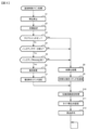
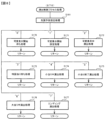
まず、主基板11における主要な動作を説明する。パチンコ遊技機1に対して電力供給が開始されると、遊技制御用マイクロコンピュータ100が起動し、CPU103によって遊技制御メイン処理が実行される。図3は、主基板11におけるCPU103が実行する遊技制御メイン処理を示すフローチャートである。
(Main operations of main board 11)
First, the main operations of the
図3に示す遊技制御メイン処理では、CPU103は、まず、割込禁止に設定する(ステップS1)。続いて、必要な初期設定を行う(ステップS2)。初期設定には、スタックポインタの設定、内蔵デバイス(CTC(カウンタ/タイマ回路)、パラレル入出力ポート等)のレジスタ設定、RAM102をアクセス可能状態にする設定等が含まれる。
In the game control main process shown in FIG. 3, the
次いで、クリアスイッチからの出力信号がオンであるか否かを判定する(ステップS3)。クリアスイッチは、例えば電源基板に搭載されている。クリアスイッチがオンの状態で電源が投入されると、出力信号(クリア信号)が入力ポートを介して遊技制御用マイクロコンピュータ100に入力される。クリアスイッチからの出力信号がオンである場合(ステップS3;Yes)、初期化処理(ステップS8)を実行する。初期化処理では、CPU103は、RAM102に記憶されるフラグ、カウンタ、バッファをクリアするRAMクリア処理を行い、作業領域に初期値を設定する。
Next, it is determined whether the output signal from the clear switch is on (step S3). The clear switch is mounted on, for example, a power supply board. When the power is turned on with the clear switch on, an output signal (clear signal) is input to the
また、CPU103は、初期化を指示する演出制御コマンドを演出制御基板12に送信する(ステップS9)。演出制御用CPU120は、当該演出制御コマンドを受信すると、例えば画像表示装置5において、遊技機の制御の初期化がなされたことを報知するための画面表示を行う。
Further, the
クリアスイッチからの出力信号がオンでない場合には(ステップS3;No)、RAM102(バックアップRAM)にバックアップデータが保存されているか否かを判定する(ステップS4)。不測の停電等(電断)によりパチンコ遊技機1への電力供給が停止したときには、CPU103は、当該電力供給の停止によって動作できなくなる直前に、電源供給停止時処理を実行する。この電源供給停止時処理では、RAM102にデータをバックアップすることを示すバックアップフラグをオンする処理、RAM102のデータ保護処理等が実行される。データ保護処理には、誤り検出符号(チェックサム、パリティビット等)の付加、各種データをバックアップする処理が含まれる。バックアップされるデータには、遊技を進行するための各種データ(各種フラグ、各種タイマの状態等を含む)の他、前記バックアップフラグの状態や誤り検出符号も含まれる。ステップS4では、バックアップフラグがオンであるか否かを判定する。バックアップフラグがオフでRAM102にバックアップデータが記憶されていない場合(ステップS4;No)、初期化処理(ステップS8)を実行する。
If the output signal from the clear switch is not on (step S3; No), it is determined whether backup data is stored in the RAM 102 (backup RAM) (step S4). When the power supply to the
RAM102にバックアップデータが記憶されている場合(ステップS4;Yes)、CPU103は、バックアップしたデータのデータチェックを行い(誤り検出符号を用いて行われる)、データが正常か否かを判定する(ステップS5)。ステップS5では、例えば、パリティビットやチェックサムにより、RAM102のデータが、電力供給停止時のデータと一致するか否かを判定する。これらが一致すると判定された場合、RAM102のデータが正常であると判定する。
If the backup data is stored in the RAM 102 (step S4; Yes), the
RAM102のデータが正常でないと判定された場合(ステップS5;No)、内部状態を電力供給停止時の状態に戻すことができないので、初期化処理(ステップS8)を実行する。
If it is determined that the data in the
RAM102のデータが正常であると判定された場合(ステップS5;Yes)、CPU103は、主基板11の内部状態を電力供給停止時の状態に戻すための復旧処理(ステップS6)を行う。復旧処理では、CPU103は、RAM102の記憶内容(バックアップしたデータの内容)に基づいて作業領域の設定を行う。これにより、電力供給停止時の遊技状態に復旧し、特別図柄の変動中であった場合には、後述の遊技制御用タイマ割込み処理の実行によって、復旧前の状態から特別図柄の変動が再開されることになる。
If it is determined that the data in the
そして、CPU103は、電断からの復旧を指示する演出制御コマンドを演出制御基板12に送信する(ステップS7)。これに合わせて、バックアップされている電断前の遊技状態を指定する演出制御コマンドや、特図ゲームの実行中であった場合には当該実行中の特図ゲームの表示結果を指定する演出制御コマンドを送信するようにしてもよい。これらコマンドは、後述の特別図柄プロセス処理で送信設定されるコマンドと同じコマンドを使用できる。演出制御用CPU120は、電断からの復旧時を特定する演出制御コマンドを受信すると、例えば画像表示装置5において、電断からの復旧がなされたこと又は電断からの復旧中であることを報知するための画面表示を行う。演出制御用CPU120は、前記演出制御コマンドに基づいて、適宜の画面表示を行うようにしてもよい。
Then, the
復旧処理または初期化処理を終了して演出制御基板12に演出制御コマンドを送信した後には、CPU103は、乱数回路104を初期設定する乱数回路設定処理を実行する(ステップS10)。そして、所定時間(例えば2ms)毎に定期的にタイマ割込がかかるように遊技制御用マイクロコンピュータ100に内蔵されているCTCのレジスタの設定を行い(ステップS11)、割込みを許可する(ステップS12)。その後、ループ処理に入る。以後、所定時間(例えば2ms)ごとにCTCから割込み要求信号がCPU103へ送出され、CPU103は定期的にタイマ割込み処理を実行することができる。
After completing the restoration process or initialization process and transmitting the production control command to the
こうした遊技制御メイン処理を実行したCPU103は、CTCからの割込み要求信号を受信して割込み要求を受け付けると、図4のフローチャートに示す遊技制御用タイマ割込み処理を実行する。図4に示す遊技制御用タイマ割込み処理を開始すると、CPU103は、まず、所定のスイッチ処理を実行することにより、スイッチ回路110を介してゲートスイッチ21、第1始動口スイッチ22A、第2始動口スイッチ22B、第1カウントスイッチ23、第2カウントスイッチ24といった各種スイッチからの検出信号の受信の有無を判定する(ステップS21)。続いて、所定のメイン側エラー処理を実行することにより、パチンコ遊技機1の異常診断を行い、その診断結果に応じて必要ならば警告を発生可能とする(ステップS22)。この後、所定の情報出力処理を実行することにより、例えばパチンコ遊技機1の外部に設置されたホール管理用コンピュータに供給される大当り情報(大当りの発生回数等を示す情報)、始動情報(始動入賞の回数等を示す情報)、確率変動情報(確変状態となった回数等を示す情報)などのデータを出力する(ステップS23)。
When the
情報出力処理に続いて、主基板11の側で用いられる遊技用乱数の少なくとも一部をソフトウェアにより更新するための遊技用乱数更新処理を実行する(ステップS24)。この後、CPU103は、第1特別図柄プロセス処理を実行する(ステップS25A)。CPU103がタイマ割込み毎に第1特別図柄プロセス処理を実行することにより、第1特図ゲームの実行及び保留の管理などが実現される(詳しくは後述)。また、CPU103は、第2特別図柄プロセス処理を実行する(ステップS25B)。CPU103がタイマ割込み毎に第2特別図柄プロセス処理を実行することにより、第2特図ゲームの実行及び保留の管理などが実現される。なお、このパチンコ遊技機1では、第1特別図柄の変動表示と第2特別図柄の変動表示とを同時に並行して実行することが可能である。
Following the information output process, a gaming random number updating process is executed to update at least a part of the gaming random numbers used on the
第1特別図柄プロセス処理および第2特別図柄プロセス処理に続いて、CPU103は、役物制御プロセス処理を実行する(ステップS25C)。CPU103がタイマ割込み毎に役物制御プロセス処理を実行することにより、大当り遊技状態や小当り遊技状態の制御、遊技状態の制御などが実現される(詳しくは後述)。
Following the first special symbol process and the second special symbol process, the
役物制御プロセス処理に続いて、普通図柄プロセス処理が実行される(ステップS26)。CPU103がタイマ割込み毎に普通図柄プロセス処理を実行することにより、ゲートスイッチ21からの検出信号に基づく(通過ゲート41に遊技球が通過したことに基づく)普図ゲームの実行及び保留の管理や、「普図当り」に基づく可変入賞球装置6Bの開放制御などを可能にする。普図ゲームの実行は、普通図柄表示器20を駆動することにより行われ、普図保留表示器25Cを点灯させることにより普図保留数を表示する。
Following the accessory control process, the normal symbol process is executed (step S26). The
普通図柄プロセス処理を実行した後、遊技制御用タイマ割込み処理の一部として、電断が発生したときの処理、賞球を払い出すための処理等などが行われてもよい。その後、CPU103は、コマンド制御処理を実行する(ステップS27)。CPU103は、上記各処理にて演出制御コマンドを送信設定することがある。ステップS27のコマンド制御処理では、送信設定された演出制御コマンドを演出制御基板12などのサブ側の制御基板に対して伝送させる処理が行われる。コマンド制御処理を実行した後には、割込みを許可してから、遊技制御用タイマ割込み処理を終了する。
After executing the normal symbol process processing, processing when a power outage occurs, processing for paying out prize balls, etc. may be performed as part of the game control timer interrupt processing. After that, the
また、図4では記載を省略しているが、遊技制御用タイマ割込み処理では、遊技機の制御状態を遊技機外部で確認できるようにするための試験信号を出力するための処理である試験端子処理も実行される。試験端子処理では、CPU103は、右打ち操作を行う期間であることを特定可能な試験信号(右打ち試験信号)も出力する制御を行う。具体的には、試験端子処理において、CPU103は、大当り遊技中や、第2特別図柄の変動表示にもとづく小当り遊技中、KT状態中に右打ち試験信号を出力する制御を行う。一方、試験端子処理において、CPU103は、第1特別図柄の変動表示にもとづく小当り遊技中には右打ち試験信号を出力する制御を行わない。
Although not shown in FIG. 4, in the game control timer interrupt process, a test terminal is used to output a test signal so that the control status of the game machine can be checked from outside the game machine. Processing is also executed. In the test terminal process, the
図5は、第1特別図柄プロセス処理として、図4に示すステップS25Aにて実行される処理の一例を示すフローチャートである。この第1特別図柄プロセス処理において、CPU103は、まず、第1始動入賞判定処理を実行する(ステップS101A)。
FIG. 5 is a flowchart showing an example of the process executed in step S25A shown in FIG. 4 as the first special symbol process process. In this first special symbol process, the
第1始動入賞判定処理では、第1始動入賞口への始動入賞の発生を検出し、RAM102の所定領域に保留情報を格納し第1保留記憶数を更新する処理が実行される。第1始動入賞口への始動入賞が発生すると、表示結果(大当り種別を含む)や変動パターンを決定するための乱数値が抽出され、保留情報としてRAM102に設けられた第1保留記憶バッファに記憶される。また、抽出した乱数値に基づいて、表示結果や変動パターンを先読み判定する処理が実行されてもよい。保留情報や第1保留記憶数を記憶した後には、演出制御基板12に始動入賞の発生、第1保留記憶数、先読み判定等の判定結果を指定するための演出制御コマンドを送信するための送信設定が行われる。こうして送信設定された始動入賞時の演出制御コマンドは、例えば第1特別図柄プロセス処理が終了した後、図4に示すステップS27のコマンド制御処理が実行されることなどにより、主基板11から演出制御基板12に対して伝送される。
In the first starting winning determination process, a process is executed to detect the occurrence of a starting winning in the first starting winning opening, store pending information in a predetermined area of the
S101にて第1始動入賞判定処理を実行した後、CPU103は、RAM102に設けられた第1特図プロセスフラグの値に応じて、ステップS110A~S113Aの処理のいずれかを選択して実行する。なお、第1特別図柄プロセス処理の各処理(ステップS110A~S113A)では、各処理に対応した演出制御コマンドを演出制御基板12に送信するための送信設定が行われる。
After executing the first starting winning determination process in S101, the
ステップS110Aの第1特別図柄通常処理は、第1特図プロセスフラグの値が“0”(初期値)のときに実行される。この第1特別図柄通常処理では、保留情報の有無などに基づいて、第1特図ゲームを開始するか否かの判定が行われる。また、第1特別図柄通常処理では、表示結果決定用の乱数値に基づき、第1特別図柄や飾り図柄の表示結果を「大当り」または「小当り」とするか否かや「大当り」とする場合の大当り種別を、その表示結果が導出表示される以前に決定(事前決定)する。さらに、第1特別図柄通常処理では、決定された表示結果に対応して、第1特図ゲームにおいて停止表示させる確定特別図柄(大当り図柄や小当り図柄、ハズレ図柄のいずれか)が設定される。その後、第1特図プロセスフラグの値が“1”に更新され、第1特別図柄通常処理は終了する。 The first special symbol normal process in step S110A is executed when the value of the first special symbol process flag is "0" (initial value). In this first special symbol normal processing, it is determined whether or not to start the first special symbol game based on the presence or absence of reservation information. In addition, in the first special symbol normal processing, based on the random number value for determining the display result, it is determined whether or not the display result of the first special symbol or decorative symbol is a "big hit" or "small win", or whether it is a "jackpot". The type of jackpot in the case is determined (predetermined) before the display result is derived and displayed. Furthermore, in the first special symbol normal processing, a confirmed special symbol (either a jackpot symbol, a small prize symbol, or a loss symbol) to be stopped and displayed in the first special symbol game is set in accordance with the determined display result. . After that, the value of the first special symbol process flag is updated to "1", and the first special symbol normal process ends.
乱数値に基づき各種の決定を行う場合には、ROM101に格納されている各種のテーブル(乱数値と比較される決定値が決定結果に割り当てられているテーブル)が参照される。主基板11における他の決定、演出制御基板12における各種の決定についても同じである。演出制御基板12においては、各種のテーブルがROM121に格納されている。
When making various decisions based on random numbers, various tables (tables in which decision values to be compared with random numbers are assigned to decision results) stored in the
ステップS111Aの第1変動パターン設定処理は、第1特図プロセスフラグの値が“1”のときに実行される。この第1変動パターン設定処理には、表示結果を「大当り」または「小当り」とするか否かの事前決定結果等に基づき、変動パターン決定用の乱数値を用いて変動パターンを複数種類のいずれかに決定する処理などが含まれている。第1変動パターン設定処理では、変動パターンを決定したときに、第1特図プロセスフラグの値が“2”に更新され、第1変動パターン設定処理は終了する。 The first variation pattern setting process in step S111A is executed when the value of the first special figure process flag is "1". In this first fluctuation pattern setting process, multiple types of fluctuation patterns are created using random values for determining the fluctuation pattern, based on the pre-determined result of whether the display result is a "big hit" or "small hit". It includes processing to decide either one. In the first variation pattern setting process, when the variation pattern is determined, the value of the first special figure process flag is updated to "2", and the first variation pattern setting process ends.
変動パターンは、特図ゲームの実行時間(特図変動時間)(飾り図柄の可変表示の実行時間でもある)や、飾り図柄の可変表示の態様(リーチの有無等)、飾り図柄の可変表示中の演出内容(リーチ演出の種類等)を指定するものであり、可変表示パターンとも呼ばれる。 The variation pattern includes the execution time of the special figure game (special figure variation time) (also the execution time of the variable display of decorative symbols), the variable display mode of the ornamental symbols (the presence or absence of reach, etc.), and the variable display period of the decorative symbols. It specifies the content of the performance (type of reach performance, etc.), and is also called a variable display pattern.
ステップS112Aの第1特別図柄変動処理は、第1特図プロセスフラグの値が“2”のときに実行される。この第1特別図柄変動処理には、第1特別図柄表示装置4Aにおいて第1特別図柄を変動させるための設定を行う処理や、その第1特別図柄が変動を開始してからの経過時間を計測する処理などが含まれている。また、計測された経過時間が変動パターンに対応する特図変動時間に達したか否かの判定も行われる。そして、第1特別図柄の変動を開始してからの経過時間が特図変動時間に達したときには、第1特図プロセスフラグの値が“3”に更新され、第1特別図柄変動処理は終了する。
The first special symbol variation process in step S112A is executed when the value of the first special symbol process flag is "2". This first special symbol variation process includes a process of making settings for varying the first special symbol in the first special
なお、本例では、第1特別図柄の変動表示と第2特別図柄の変動表示とは並行して実行可能であるので、例えば、第1特別図柄変動処理(ステップS112A)に移行して第1特別図柄の変動表示中であるときに、第2特別図柄の変動表示において小当りとなり小当り遊技に制御される場合がある。この場合、遊技制御用マイクロコンピュータ100(具体的には、CPU103)は、小当り遊技中であるか否かを判定し(具体的には、第2特図プロセスフラグの値が小当り開放前処理~小当り終了処理に相当する値であるか否かを判定し)、小当り遊技中であれば、第1特図プロセスフラグの値を第1特別図柄変動処理に相当する値から変更しないようにし、小当り遊技中でなければ、第1特図プロセスフラグの値を次の第1特別図柄停止処理に相当する値に更新可能としている。そのような制御を行うことにより、第2特別図柄の変動表示にもとづく小当り遊技中では第1特別図柄の変動表示を中断し、その小当り遊技の終了後に第1特別図柄の変動表示を再開するように制御している。なお、そのような制御にかぎらず、例えば、第2特別図柄の変動表示にもとづく小当り遊技中は、第1特別図柄が変動を開始してからの経過時間を計測する処理を中断(タイマの更新を中断)するように構成してもよい。 In addition, in this example, since the variable display of the first special symbol and the variable display of the second special symbol can be executed in parallel, for example, the process moves to the first special symbol variation process (step S112A) and the first While the special symbols are being displayed in a variable manner, a small win may occur in the variable display of the second special symbol and the game may be controlled to a small win game. In this case, the game control microcomputer 100 (specifically, the CPU 103) determines whether or not the small hit game is in progress (specifically, the value of the second special figure process flag is set before the small hit is released). Processing - Determine whether the value corresponds to the small winning end process), and if the small winning game is in progress, do not change the value of the first special symbol process flag from the value corresponding to the first special symbol variation processing. Thus, if the small winning game is not in progress, the value of the first special symbol process flag can be updated to a value corresponding to the next first special symbol stop process. By performing such control, the variable display of the first special symbol is interrupted during a small winning game based on the variable display of the second special symbol, and the variable display of the first special symbol is resumed after the small winning game is finished. controlled to do so. In addition to such control, for example, during a small winning game based on the fluctuating display of the second special symbol, the process of measuring the elapsed time after the first special symbol starts fluctuating may be interrupted (the timer may be The update may be suspended).
また、例えば、小当り終了処理期間としての小当りエンディング期間を遊技状態によって異ならせるように構成してもよい。例えば、通常状態において、第1特別図柄の変動表示を中断するように構成すると、第1特別図柄の変動表示の中断期間が長くなり、第1特別図柄の変動表示の実行期間と中断期間との差が大きくなると飾り図柄の揺れ停止などにより中断期間を吸収する必要があり、遊技者に違和感を与える演出になってしまう。そのため、通常状態では、小当りエンディング期間をKT状態(第1KT状態、第2KT状態)よりも短くすることが望ましい。この場合、例えば、通常状態では小当りエンディング期間が0.5秒であるのに対して、KT状態では小当りエンディング期間が3秒であるように構成してもよい。 Further, for example, the small winning ending period as the small winning ending processing period may be configured to vary depending on the gaming state. For example, if the variable display of the first special symbol is configured to be interrupted in the normal state, the interruption period of the variable display of the first special symbol becomes longer, and the execution period of the variable display of the first special symbol and the interruption period become longer. If the difference becomes large, it is necessary to absorb the interruption period by stopping the swinging of the decorative symbols, resulting in a performance that gives the player a sense of discomfort. Therefore, in the normal state, it is desirable to make the small winning ending period shorter than in the KT state (first KT state, second KT state). In this case, for example, the small winning ending period may be 0.5 seconds in the normal state, whereas the small winning ending period may be 3 seconds in the KT state.
また、上記のように構成する場合、例えば、第1KT状態では、小当り制御において実質的に遊技球が入賞困難であり特に演出を行わないので、第2KT状態に比べて小当りエンディング期間を短くするように構成してもよい。一方、第2KT状態では、小当り制御において遊技球が入賞容易であり小当り制御を強調する演出を実行するので、第1KT状態に比べて小当りエンディング期間を長くするように構成してもよい。この場合、例えば、第1KT状態では小当りエンディング期間が0.5秒であるのに対して、第2KT状態では小当りエンディング期間が3秒であるように構成してもよい。 In addition, in the case of the above configuration, for example, in the first KT state, it is practically difficult for the game ball to win in the small win control and no special effect is performed, so the small win ending period is shortened compared to the second KT state. It may be configured to do so. On the other hand, in the second KT state, since it is easy for the game ball to win a prize in the small win control and an effect that emphasizes the small win control is executed, the small win ending period may be configured to be longer than in the first KT state. . In this case, for example, the small winning ending period may be 0.5 seconds in the first KT state, while the small winning ending period may be 3 seconds in the second KT state.
さらに、小当り開放前処理期間としての小当りファンファーレ期間についても、上記の小当りエンディング期間と同様に、遊技状態によって期間の長さを異ならせてもよい。 Furthermore, the length of the small win fanfare period as the small win opening pre-processing period may be varied depending on the gaming state, similarly to the above small win ending period.
ステップS113Aの第1特別図柄停止処理は、第1特図プロセスフラグの値が“3”のときに実行される。この第1特別図柄停止処理には、第1特別図柄表示装置4Aにて第1特別図柄の変動を停止させ、第1特別図柄の表示結果となる確定特別図柄を停止表示(導出)させるための設定を行う処理が含まれている。そして、表示結果が「大当り」である場合には、大当り遊技を開始するための設定処理が行われる。その一方で、大当りフラグがオフであり、表示結果が「小当り」である場合には、小当り遊技を開始するための処理が行われる。そして、第1特図プロセスフラグの値が“0”に更新される。表示結果が「小当り」又は「ハズレ」である場合、確変状態やKT状態、高ベース状態に制御されているときであって、回数切りの終了成立する場合には、遊技状態も更新される。第1特図プロセスフラグの値が更新されると、第1特別図柄停止処理は終了する。
The first special symbol stop process in step S113A is executed when the value of the first special symbol process flag is "3". This first special symbol stopping process includes stopping the fluctuation of the first special symbol in the first special
なお、第2特別図柄プロセス処理(ステップS25B)において実行される処理は、第1特別図柄プロセス処理(ステップS25A)において実行される処理と同様である。すなわち、図5で説明した第1特別図柄プロセス処理において、「第1」を「第2」と読み替えれば、第2特別図柄プロセス処理が説明されることになる。また、第2特別図柄プロセス処理(ステップS25B)の第1始動入賞判定処理で抽出された各乱数値は、保留情報としてRAM102に設けられた第2保留記憶バッファに記憶される。
The process executed in the second special symbol process (step S25B) is the same as the process executed in the first special symbol process (step S25A). That is, in the first special symbol process described in FIG. 5, if "first" is replaced with "second", the second special symbol process will be explained. Further, each random number value extracted in the first starting winning determination process of the second special symbol process process (step S25B) is stored in the second pending storage buffer provided in the
なお、本例では、第1特別図柄の変動表示と第2特別図柄の変動表示とは並行して実行可能であるので、例えば、第2特別図柄変動処理に移行して第2特別図柄の変動表示中であるときに、第1特別図柄の変動表示において小当りとなり小当り遊技に制御される場合もある。この場合、遊技制御用マイクロコンピュータ100(具体的には、CPU103)は、小当り遊技中であるか否かを判定し(具体的には、第1特図プロセスフラグの値が小当り開放前処理~小当り終了処理に相当する値であるか否かを判定し)、小当り遊技中であれば、第2特図プロセスフラグの値を第2特別図柄変動処理に相当する値から変更しないようにし、小当り遊技中でなければ、第2特図プロセスフラグの値を次の第2特別図柄停止処理に相当する値に更新可能としている。そのような制御を行うことにより、第1特別図柄の変動表示にもとづく小当り遊技中では第2特別図柄の変動表示を中断し、その小当り遊技の終了後に第2特別図柄の変動表示を再開するように制御している。なお、そのような制御にかぎらず、例えば、第1特別図柄の変動表示にもとづく小当り遊技中は、第2特別図柄が変動を開始してからの経過時間を計測する処理を中断(タイマの更新を中断)するように構成してもよい。 In addition, in this example, since the fluctuation display of the first special symbol and the fluctuation display of the second special symbol can be executed in parallel, for example, the fluctuation display of the second special symbol can be executed by moving to the second special symbol fluctuation processing. While the first special symbol is being displayed, a small win may occur in the variable display of the first special symbol, and the game may be controlled as a small win game. In this case, the game control microcomputer 100 (specifically, the CPU 103) determines whether or not a small hit game is in progress (specifically, the value of the first special figure process flag is set before the small hit is released). Processing - Determine whether the value corresponds to the small hit end process), and if the small winning game is in progress, do not change the value of the second special symbol process flag from the value corresponding to the second special symbol variation process. Thus, if the small winning game is not in progress, the value of the second special symbol process flag can be updated to a value corresponding to the next second special symbol stop process. By performing such control, the variable display of the second special symbol is interrupted during a small winning game based on the variable display of the first special symbol, and the variable display of the second special symbol is resumed after the small winning game is finished. controlled to do so. In addition to such control, for example, during a small winning game based on the fluctuating display of the first special symbol, the process of measuring the elapsed time after the second special symbol starts fluctuating may be interrupted (the timer may be The update may be suspended).
なお、第2特別図柄の変動表示にもとづく小当り制御に関しても、遊技状態によって小当りファンファーレ期間や小当りエンディング期間の長さを異ならせるように構成してもよい。 Regarding the small win control based on the variable display of the second special symbol, the length of the small win fanfare period and the small win ending period may also be configured to vary depending on the gaming state.
図6は、役物制御プロセス処理として、図4に示すステップS25Cにて実行される処理の一例を示すフローチャートである。この役物制御プロセス処理において、CPU103は、RAM102に設けられた役物制御プロセスフラグの値に応じて、ステップS120~S128の処理のいずれかを選択して実行する。なお、役物制御プロセス処理の各処理(ステップS120~S128)では、各処理に対応した演出制御コマンドを演出制御基板12に送信するための送信設定が行われる。
FIG. 6 is a flowchart showing an example of the process executed in step S25C shown in FIG. 4 as the accessory control process process. In this accessory control process processing, the
ステップS120の役物制御通常処理は、役物制御プロセスフラグの値が“0”のときに実行される。この役物制御通常処理では、大当り遊技を開始するための設定が行われたか否かを監視し、大当り遊技を開始するための設定が行われれば、大当り遊技を開始するための処理が行われ、役物制御プロセスフラグの値が“1”に更新される。 The accessory control normal process in step S120 is executed when the value of the accessory control process flag is "0". In this accessory control normal processing, it is monitored whether or not the settings for starting the jackpot game have been made, and if the settings for starting the jackpot game have been made, the processing for starting the jackpot game is performed. , the value of the accessory control process flag is updated to "1".
ステップS121のゲート通過待ち処理は、役物制御プロセスフラグの値が“1”のときに実行される。このゲート通過待ち処理では、通過ゲート41への遊技球の通過を待機する制御を行う。通過ゲート41への遊技球の通過を検知したときには役物制御プロセスフラグの値が“2”に更新される。
The gate passage waiting process in step S121 is executed when the value of the accessory control process flag is "1". In this gate passage waiting process, control is performed to wait for the game ball to pass through the
ステップS122の大当り開放前処理は、役物制御プロセスフラグが“2”のときに実行される。この大当り開放前処理には、表示結果が「大当り」となったことなどに基づき、大当り遊技状態においてラウンドの実行を開始して大入賞口を開放状態とするための設定を行う処理などが含まれている。大入賞口を開放状態とするときには、大入賞口扉用のソレノイド82に対してソレノイド駆動信号を供給する処理が実行される。このときには、例えば大当り種別がいずれであるかに対応して、大入賞口を開放状態とする開放上限期間や、ラウンドの上限実行回数を設定する。これらの設定が終了すると、役物制御プロセスフラグの値が“3”に更新され、大当り開放前処理は終了する。
The jackpot release preprocessing in step S122 is executed when the accessory control process flag is "2". This jackpot opening pre-processing includes processing to start a round in the jackpot game state and set the jackpot opening state based on the display result being a "jackpot", etc. It is. When the big winning opening is opened, a process is executed to supply a solenoid drive signal to the
ステップS123の大当り開放中処理は、役物制御プロセスフラグの値が“3”のときに実行される。この大当り開放中処理には、大入賞口を開放状態としてからの経過時間を計測する処理や、その計測した経過時間や第1カウントスイッチ23によって検出された遊技球の個数などに基づいて、大入賞口を開放状態から閉鎖状態に戻すタイミングとなったか否かを判定する処理などが含まれている。そして、大入賞口を閉鎖状態に戻すときには、大入賞口扉用のソレノイド82に対するソレノイド駆動信号の供給を停止させる処理などを実行した後、役物制御プロセスフラグの値が“4”に更新し、大当り開放中処理を終了する。
The jackpot opening process in step S123 is executed when the value of the accessory control process flag is "3". This jackpot opening processing includes a process of measuring the elapsed time since the jackpot opening is opened, and a jackpot based on the measured elapsed time and the number of game balls detected by the
ステップS124の大当り開放後処理は、役物制御プロセスフラグの値が“4”のときに実行される。この大当り開放後処理には、大入賞口を開放状態とするラウンドの実行回数が設定された上限実行回数に達したか否かを判定する処理や、上限実行回数に達した場合に大当り遊技状態を終了させるための設定を行う処理などが含まれている。そして、ラウンドの実行回数が上限実行回数に達していないときには、役物制御プロセスフラグの値が“3”に更新される一方、ラウンドの実行回数が上限実行回数に達したときには、役物制御プロセスフラグの値が“5”に更新される。役物制御プロセスフラグの値が更新されると、大当り開放後処理は終了する。 The jackpot release post-processing in step S124 is executed when the value of the accessory control process flag is "4". This jackpot opening process includes a process to determine whether the number of rounds to open the jackpot has reached the set upper limit number of runs, and a process to enter the jackpot game state when the upper limit number of runs has been reached. This includes processing to make settings for terminating the process. When the number of executions of the round has not reached the upper limit number of executions, the value of the accessory control process flag is updated to "3", while when the number of executions of the round has reached the upper limit number of executions, the value of the accessory control process flag is updated to "3". The value of the flag is updated to "5". When the value of the accessory control process flag is updated, the jackpot release post-processing ends.
ステップS125の大当り終了処理は、役物制御プロセスフラグの値が“5”のときに実行される。この大当り終了処理には、大当り遊技状態の終了を報知する演出動作としてのエンディング演出が実行される期間に対応した待ち時間が経過するまで待機する処理や、大当り遊技状態の終了に対応して確変制御やKT制御、高ベース制御を開始するための各種の設定を行う処理などが含まれている。こうした設定が行われたときには、役物制御プロセスフラグの値が“0”に更新され、大当り終了処理は終了する。 The jackpot end process in step S125 is executed when the value of the accessory control process flag is "5". This jackpot ending process includes a process of waiting until the waiting time corresponding to the period in which the ending performance is executed as a performance operation to notify the end of the jackpot gaming state, and a process of waiting until the waiting time corresponding to the end of the jackpot gaming state has changed. It includes processing for making various settings for starting control, KT control, and high base control. When such settings are made, the value of the accessory control process flag is updated to "0", and the jackpot termination process ends.
ステップS126の小当り開放前処理は、役物制御プロセスフラグの値が“6”のときに実行される。この小当り開放前処理には、表示結果が「小当り」となったことに基づき、小当り遊技状態において特殊入賞口を開放状態とするための設定を行う処理などが含まれている。このときには、役物制御プロセスフラグの値が“7”に更新され、小当り開放前処理は終了する。 The small win release preprocessing in step S126 is executed when the value of the accessory control process flag is "6". This small win opening pre-processing includes processing for setting the special winning opening to be open in the small win game state based on the display result being "small win". At this time, the value of the accessory control process flag is updated to "7", and the small win release preprocessing ends.
ステップS127の小当り開放中処理は、役物制御プロセスフラグの値が“7”のときに実行される。この小当り開放中処理には、特殊入賞口を開放状態としてからの経過時間を計測する処理や、その計測した経過時間などに基づいて、特殊入賞口を開放状態から閉鎖状態に戻すタイミングとなったか否かを判定する処理などが含まれている。特殊入賞口を閉鎖状態に戻して小当り遊技状態の終了タイミングとなったときには、役物制御プロセスフラグの値が“8”に更新され、小当り開放中処理は終了する。 The small winning opening process in step S127 is executed when the value of the accessory control process flag is "7". This small hit opening process includes a process to measure the elapsed time since the special winning opening was opened, and a timing to return the special winning opening from the open state to the closed state based on the measured elapsed time. This includes processing to determine whether or not the When the special prize opening is returned to the closed state and the end timing of the small winning game state comes, the value of the accessory control process flag is updated to "8" and the small winning opening process ends.
ステップS128の小当り終了処理は、役物制御プロセスフラグの値が“8”のときに実行される。この小当り終了処理には、小当り遊技状態の終了を報知する演出動作が実行される期間に対応した待ち時間が経過するまで待機する処理などが含まれている。ここで、小当り遊技状態が終了するときには、小当り遊技状態となる以前のパチンコ遊技機1における遊技状態を継続させる。小当り遊技状態の終了時における待ち時間が経過したときには、役物制御プロセスフラグの値が“0”に更新され、小当り終了処理は終了する。
The small winning end process in step S128 is executed when the value of the accessory control process flag is "8". This small win ending process includes a process of waiting until a waiting time corresponding to a period in which a performance operation to notify the end of the small win game state has elapsed. Here, when the small winning gaming state ends, the gaming state in the
(演出制御基板12の主要な動作)
次に、演出制御基板12における主要な動作を説明する。演出制御基板12では、電源基板等から電源電圧の供給を受けると、演出制御用CPU120が起動して、図7のフローチャートに示すような演出制御メイン処理を実行する。図7に示す演出制御メイン処理を開始すると、演出制御用CPU120は、まず、所定の初期化処理を実行して(ステップS71)、RAM122のクリアや各種初期値の設定、また演出制御基板12に搭載されたCTC(カウンタ/タイマ回路)のレジスタ設定等を行う。また、初期動作制御処理を実行する(ステップS72)。初期動作制御処理では、可動体32を駆動して初期位置に戻す制御、所定の動作確認を行う制御といった可動体32の初期動作を行う制御が実行される。
(Main operations of the production control board 12)
Next, the main operations in the
その後、タイマ割込みフラグがオンとなっているか否かの判定を行う(ステップS73)。タイマ割込みフラグは、例えばCTCのレジスタ設定に基づき、所定時間(例えば2ミリ秒)が経過するごとにオン状態にセットされる。このとき、タイマ割込みフラグがオフであれば(ステップS73;No)、ステップS73の処理を繰り返し実行して待機する。 Thereafter, it is determined whether the timer interrupt flag is on (step S73). The timer interrupt flag is set to an on state every time a predetermined time (for example, 2 milliseconds) elapses, based on, for example, a register setting of the CTC. At this time, if the timer interrupt flag is off (step S73; No), the process of step S73 is repeatedly executed and the process waits.
また、演出制御基板12の側では、所定時間が経過するごとに発生するタイマ割込みとは別に、主基板11からの演出制御コマンドを受信するための割込みが発生する。この割込みは、例えば主基板11からの演出制御INT信号がオン状態となることにより発生する割込みである。演出制御INT信号がオン状態となることによる割込みが発生すると、演出制御用CPU120は、自動的に割込み禁止に設定するが、自動的に割込み禁止状態にならないCPUを用いている場合には、割込み禁止命令(DI命令)を発行することが望ましい。演出制御用CPU120は、演出制御INT信号がオン状態となることによる割込みに対応して、例えば所定のコマンド受信割込み処理を実行する。このコマンド受信割込み処理では、I/O125に含まれる入力ポートのうちで、中継基板15を介して主基板11から送信された制御信号を受信する所定の入力ポートより、演出制御コマンドを取り込む。このとき取り込まれた演出制御コマンドは、例えばRAM122に設けられた演出制御コマンド受信用バッファに格納する。その後、演出制御用CPU120は、割込み許可に設定してから、コマンド受信割込み処理を終了する。
Furthermore, on the side of the
ステップS73にてタイマ割込みフラグがオンである場合には(ステップS73;Yes)、タイマ割込みフラグをクリアしてオフ状態にするとともに(ステップS74)、コマンド解析処理を実行する(ステップS75)。コマンド解析処理では、例えば主基板11の遊技制御用マイクロコンピュータ100から送信されて演出制御コマンド受信用バッファに格納されている各種の演出制御コマンドを読み出した後に、その読み出された演出制御コマンドに対応した設定や制御などが行われる。例えば、どの演出制御コマンドを受信したかや演出制御コマンドが特定する内容等を演出制御プロセス処理等で確認できるように、読み出された演出制御コマンドをRAM122の所定領域に格納したり、RAM122に設けられた受信フラグをオンしたりする。また、演出制御コマンドが遊技状態を特定する場合、遊技状態に応じた背景の表示を表示制御部123に指示してもよい。
If the timer interrupt flag is on in step S73 (step S73; Yes), the timer interrupt flag is cleared and turned off (step S74), and command analysis processing is executed (step S75). In the command analysis process, for example, after reading various production control commands transmitted from the
ステップS75にてコマンド解析処理を実行した後には、演出制御プロセス処理を実行する(ステップS76)。演出制御プロセス処理では、例えば画像表示装置5の表示領域における演出画像の表示動作、スピーカ8L、8Rからの音声出力動作、枠LED9及び装飾用LEDといった装飾発光体における点灯動作、可動体32の駆動動作といった、各種の演出装置を動作させる制御が行われる。また、各種の演出装置を用いた演出動作の制御内容について、主基板11から送信された演出制御コマンド等に応じた判定や決定、設定などが行われる。
After executing the command analysis process in step S75, the production control process process is executed (step S76). In the effect control process processing, for example, the display operation of the effect image in the display area of the
ステップS76の演出制御プロセス処理に続いて、演出用乱数更新処理が実行され(ステップS77)、演出制御基板12の側で用いられる演出用乱数の少なくとも一部がソフトウェアにより更新される。その後、ステップS73の処理に戻る。ステップS73の処理に戻る前に、他の処理が実行されてもよい。
Following the performance control process processing in step S76, a performance random number update process is executed (step S77), and at least a portion of the performance random numbers used on the
図8は、演出制御プロセス処理として、図7のステップS76にて実行される処理の一例を示すフローチャートである。図8に示す演出制御プロセス処理において、演出制御用CPU120は、まず、先読予告設定処理を実行する(ステップS161)。先読予告設定処理では、例えば、主基板11から送信された始動入賞時の演出制御コマンドに基づいて、先読み予告演出を実行するための判定や決定、設定などが行われる。また、当該演出制御コマンドから特定される保留記憶数に基づき保留表示を表示するための処理が実行される。
FIG. 8 is a flowchart showing an example of the process executed in step S76 of FIG. 7 as the production control process process. In the performance control process shown in FIG. 8, the
ステップS161の処理を実行した後、演出制御用CPU120は、例えばRAM122に設けられた演出プロセスフラグの値に応じて、以下のようなステップS170~S177の処理のいずれかを選択して実行する。
After executing the process of step S161, the
ステップS170の可変表示開始待ち処理は、演出プロセスフラグの値が“0”(初期値)のときに実行される処理である。この可変表示開始待ち処理は、主基板11から可変表示の開始を指定するコマンドなどを受信したか否かに基づき、画像表示装置5における飾り図柄の可変表示を開始するか否かを判定する処理などを含んでいる。画像表示装置5における飾り図柄の可変表示を開始すると判定された場合、演出プロセスフラグの値を“1”に更新し、可変表示開始待ち処理を終了する。
The variable display start waiting process in step S170 is a process that is executed when the value of the production process flag is "0" (initial value). This variable display start waiting process is a process of determining whether or not to start variable display of decorative patterns on the
ステップS171の可変表示開始設定処理は、演出プロセスフラグの値が“1”のときに実行される処理である。この可変表示開始設定処理では、演出制御コマンドにより特定される表示結果や変動パターンに基づいて、飾り図柄の可変表示の表示結果(確定飾り図柄)、飾り図柄の可変表示の態様、リーチ演出や各種予告演出などの各種演出の実行の有無やその態様や実行開始タイミングなどを決定する。そして、その決定結果等を反映した演出制御パターン(表示制御部123に演出の実行を指示するための制御データの集まり)を設定する。その後、設定した演出制御パターンに基づいて、飾り図柄の可変表示の実行開始を表示制御部123に指示し、演出プロセスフラグの値を“2”に更新し、可変表示開始設定処理を終了する。表示制御部123は、飾り図柄の可変表示の実行開始の指示により、画像表示装置5において、飾り図柄の可変表示を開始させる。
The variable display start setting process in step S171 is a process that is executed when the value of the production process flag is "1". In this variable display start setting process, based on the display result and fluctuation pattern specified by the production control command, the display result of the variable display of the decorative pattern (determined decorative pattern), the mode of variable display of the decorative pattern, the reach effect, etc. It determines whether or not various performances such as preview performances are to be executed, their mode, execution start timing, and the like. Then, a performance control pattern (a collection of control data for instructing the
ステップS172の可変表示中演出処理は、演出プロセスフラグの値が“2”のときに実行される処理である。この可変表示中演出処理において、演出制御用CPU120は、表示制御部123を指示することで、ステップS171にて設定された演出制御パターンに基づく演出画像を画像表示装置5の表示画面に表示させることや、可動体32を駆動させること、音声制御基板13に対する指令(効果音信号)の出力によりスピーカ8L、8Rから音声や効果音を出力させること、LED制御基板14に対する指令(電飾信号)の出力により枠LED9や装飾用LEDを点灯/消灯/点滅させることといった、飾り図柄の可変表示中における各種の演出制御を実行する。こうした演出制御を行った後、例えば演出制御パターンから飾り図柄の可変表示終了を示す終了コードが読み出されたこと、あるいは、主基板11から確定飾り図柄を停止表示させることを指定するコマンドを受信したことなどに対応して、飾り図柄の表示結果となる確定飾り図柄を停止表示させる。確定飾り図柄を停止表示したときには、演出プロセスフラグの値が“3”に更新され、可変表示中演出処理は終了する。
The variable display effect processing in step S172 is a process that is executed when the value of the effect process flag is "2". In this variable display performance process, the
ステップS173の特図当り待ち処理は、演出プロセスフラグの値が“3”のときに実行される処理である。この特図当り待ち処理において、演出制御用CPU120は、主基板11から大当り遊技状態又は小当り遊技状態を開始することを指定する演出制御コマンドの受信があったか否かを判定する。そして、大当り遊技状態又は小当り遊技状態を開始することを指定する演出制御コマンドを受信したきに、そのコマンドが大当り遊技状態の開始を指定するものであれば、演出プロセスフラグの値を“6”に更新する。これに対して、そのコマンドが小当り遊技状態の開始を指定するものであれば、演出プロセスフラグの値を小当り中演出処理に対応した値である“4”に更新する。また、大当り遊技状態又は小当り遊技状態を開始することを指定するコマンドを受信せずに、当該コマンドの受信待ち時間が経過したときには、特図ゲームにおける表示結果が「ハズレ」であったと判定して、演出プロセスフラグの値を初期値である“0”に更新する。演出プロセスフラグの値を更新すると、特図当り待ち処理を終了する。
The special figure hit waiting process in step S173 is a process that is executed when the value of the production process flag is "3". In this special figure winning waiting process, the
ステップS174の小当り中演出処理は、演出制御プロセスフラグの値が“4”のときに実行される処理である。この小当り中演出処理において、演出制御用CPU120は、例えば小当り遊技状態における演出内容に対応した演出制御パターン等を設定し、その設定内容に基づく小当り遊技状態における各種の演出制御を実行する。また、小当り中演出処理では、例えば主基板11から小当り遊技状態を終了することを指定するコマンドを受信したことに対応して、演出プロセスフラグの値を小当り終了演出に対応した値である“5”に更新し、小当り中演出処理を終了する。
The small hit performance process in step S174 is a process that is executed when the value of the performance control process flag is "4". In this small win performance processing, the
ステップS175の小当り終了演出処理は、演出制御プロセスフラグの値が“5”のときに実行される処理である。この小当り終了演出処理において、演出制御用CPU120は、例えば小当り遊技状態の終了などに対応した演出制御パターン等を設定し、その設定内容に基づく小当り遊技状態の終了時における各種の演出制御を実行する。その後、演出プロセスフラグの値を初期値である“0”に更新し、小当り終了演出処理を終了する。
The small hit end production process in step S175 is a process that is executed when the value of the production control process flag is "5". In this small hit end performance process, the
ステップS176の大当り中演出処理は、演出プロセスフラグの値が“6”のときに実行される処理である。この大当り中演出処理において、演出制御用CPU120は、例えば大当り遊技状態における演出内容に対応した演出制御パターン等を設定し、その設定内容に基づく大当り遊技状態における各種の演出制御を実行する。また、大当り中演出処理では、例えば主基板11から大当り遊技状態を終了することを指定するコマンドを受信したことに対応して、演出制御プロセスフラグの値をエンディング演出処理に対応した値である“7”に更新し、大当り中演出処理を終了する。
The jackpot performance process in step S176 is a process that is executed when the value of the performance process flag is "6". In this jackpot performance process, the
ステップS177のエンディング演出処理は、演出プロセスフラグの値が“7”のときに実行される処理である。このエンディング演出処理において、演出制御用CPU120は、例えば大当り遊技状態の終了などに対応した演出制御パターン等を設定し、その設定内容に基づく大当り遊技状態の終了時におけるエンディング演出の各種の演出制御を実行する。その後、演出プロセスフラグの値を初期値である“0”に更新し、エンディング演出処理を終了する。
The ending effect processing in step S177 is a process that is executed when the value of the effect process flag is "7". In this ending performance processing, the
(基本説明の変形例)
この発明は、上記基本説明で説明したパチンコ遊技機1に限定されず、本発明の趣旨を逸脱しない範囲で、様々な変形及び応用が可能である。
(Variation of basic explanation)
This invention is not limited to the
上記基本説明のパチンコ遊技機1は、入賞の発生に基づいて所定数の遊技媒体を景品として払い出す払出式遊技機であったが、遊技媒体を封入し入賞の発生に基づいて得点を付与する封入式遊技機であってもよい。
The
特別図柄の可変表示中に表示されるものは1種類の図柄(例えば、「-」を示す記号)だけで、当該図柄の表示と消灯とを繰り返すことによって可変表示を行うようにしてもよい。さらに可変表示中に当該図柄が表示されるものも、可変表示の停止時には、当該図柄が表示されなくてもよい(表示結果としては「-」を示す記号が表示されなくてもよい)。 Only one type of symbol (for example, a symbol indicating "-") may be displayed during the variable display of the special symbol, and the variable display may be performed by repeatedly displaying and extinguishing the symbol. Further, even if the symbol is displayed during the variable display, the symbol does not need to be displayed when the variable display is stopped (the symbol indicating "-" does not need to be displayed as a display result).
上記基本説明では、遊技機としてパチンコ遊技機1を示したが、メダルが投入されて所定の賭け数が設定され、遊技者による操作レバーの操作に応じて複数種類の図柄を回転させ、遊技者によるストップボタンの操作に応じて図柄を停止させたときに停止図柄の組合せが特定の図柄の組み合わせになると、所定数のメダルが遊技者に払い出されるゲームを実行可能なスロット機(例えば、ビッグボーナス、レギュラーボーナス、RT、AT、ART、CZ(以下、ボーナス等)のうち1以上を搭載するスロット機)にも本発明を適用可能である。
In the above basic explanation, the
本発明を実現するためのプログラム及びデータは、パチンコ遊技機1に含まれるコンピュータ装置などに対して、着脱自在の記録媒体により配布・提供される形態に限定されるものではなく、予めコンピュータ装置などの有する記憶装置にインストールしておくことで配布される形態を採っても構わない。さらに、本発明を実現するためのプログラム及びデータは、通信処理部を設けておくことにより、通信回線等を介して接続されたネットワーク上の、他の機器からダウンロードすることによって配布する形態を採っても構わない。
The program and data for realizing the present invention are not limited to a form in which they are distributed and provided to a computer device included in the
そして、ゲームの実行形態も、着脱自在の記録媒体を装着することにより実行するものだけではなく、通信回線等を介してダウンロードしたプログラム及びデータを、内部メモリ等に一旦格納することにより実行可能とする形態、通信回線等を介して接続されたネットワーク上における、他の機器側のハードウェア資源を用いて直接実行する形態としてもよい。さらには、他のコンピュータ装置等とネットワークを介してデータの交換を行うことによりゲームを実行するような形態とすることもできる。 The game can be executed not only by attaching a removable recording medium, but also by temporarily storing the program and data downloaded via a communication line in internal memory, etc. It may also be executed directly using hardware resources of other devices on a network connected via a communication line or the like. Furthermore, the game may be executed by exchanging data with other computer devices via a network.
なお、本明細書において、演出の実行割合などの各種割合の比較の表現(「高い」、「低い」、「異ならせる」などの表現)は、一方が「0%」の割合であることを含んでもよい。例えば、一方が「0%」の割合で、他方が「100%」の割合又は「100%」未満の割合であることも含む。 In addition, in this specification, expressions that compare various proportions such as the execution rate of production (expressions such as "higher", "lower", "different", etc.) do not mean that one is a proportion of "0%". May include. For example, one of the ratios may be "0%" and the other ratio may be "100%" or a ratio less than "100%."
[特徴部21TMに関する説明]
次に、特徴部21TMに関して説明する。パチンコ遊技機1には、例えば図9-1に示すような主基板11、演出制御基板12、ターミナル基板(情報出力基板)21TM016といった、各種の制御基板が搭載されている。また、パチンコ遊技機1には、主基板11と演出制御基板12との間で伝送される各種の制御信号を中継するための中継基板15なども搭載されている。その他にも、パチンコ遊技機1における遊技盤2などの背面には、例えば払出制御基板、発射制御基板、インタフェース基板などといった、各種の基板が配置されている。
[Explanation regarding characteristic part 21TM]
Next, the characteristic portion 21TM will be explained. The
なお、前述した図2に示すように、主基板11には、第1始動口スイッチ22A及び第2始動口スイッチ22B、並びに、第1特別図柄表示装置4A及び第2特別図柄表示装置4B等の各種部品が接続されており、演出制御基板12には、スピーカ8L、8R、枠LED9等の各種演出装置が接続されているが、図9-1では、これらを省略している。
As shown in FIG. 2 described above, the
主基板11は、メイン側の制御基板であり、図9-3に示すように、基板ケース21TM201に収納された状態でパチンコ遊技機1の背面に搭載され、パチンコ遊技機1における遊技の進行を制御するための各種回路が搭載されている。主基板11は、主として、特図ゲームにおいて用いる乱数の設定機能、所定位置に配設されたスイッチ等からの信号の入力を行う機能、演出制御基板12などからなるサブ側の制御基板に宛てて、指令情報の一例となる制御コマンドを制御信号として出力して送信する機能、ホールの管理コンピュータに対して各種情報を出力する機能などを備えている。また、主基板11は、第1特別図柄表示装置4Aと第2特別図柄表示装置4Bを構成する各LED(例えばセグメントLED)などの点灯/消灯制御を行って第1特図や第2特図の変動表示を制御することや、普通図柄表示器20の点灯/消灯/発色制御などを行って普通図柄表示器20による普通図柄の変動表示を制御することといった、所定の表示図柄の変動表示を制御する機能も備えている。
The
また、主基板11には、図9-3に示すように、パチンコ遊技機1の背面側から視認可能な表示モニタ21TM029が設けられており、該表示モニタ21TM029に、入賞に関する各種の入賞情報を表示する機能も備えている。尚、表示モニタ21TM029の左側方には表示切替スイッチ21TM030が設けられており、該表示切替スイッチ21TM030の操作によって表示モニタ21TM029に表示されている情報を切り替えることが可能となっている。
Further, as shown in FIG. 9-3, the
主基板11には、例えば遊技制御用マイクロコンピュータ100や、遊技球検出用の各種スイッチからの検出信号の他、電源断信号、クリア信号、リセット信号等の各種信号を取り込んで遊技制御用マイクロコンピュータ100に伝送するスイッチ回路110、ターミナル基板21TM016からセキュリティ信号等の各種の信号の出力を行うための情報出力回路112が搭載されている。
The
また、図9-1に示す主基板11は、図9-3に示すように、透過性を有する合成樹脂材からなる基板ケース21TM201に封入されており、主基板11の中央には表示モニタ21TM029(例えば、7セグメント)が配置され、表示モニタ21TM029の右側には表示切替スイッチ21TM030が配置されている。表示モニタ21TM029及び表示切替スイッチ21TM030は、主基板11を視認する際の正面に配置されている。主基板11の背面中央下部には、後述する設定変更モードまたは設定確認モードに切り替えるための錠スイッチ21TM051(図9-1参照)が設けられている。主基板11は、遊技機用枠3を開放していない状態では視認できないので、主基板11を視認する際の正面とは、遊技機用枠3を開放した状態における遊技盤2の裏面側を視認する際の正面であり、パチンコ遊技機1の正面とは異なる。ただし、主基板11を視認する際の正面とパチンコ遊技機1の正面とが共通するようにしてもよい。
The
また、主基板11(遊技制御用マイクロコンピュータ100)は、各入賞口(大入賞口、第2始動入賞口、第1始動入賞口、第1~第4一般入賞口、以下、「進入領域」ともいう)への遊技球の進入数の集計を行い、該集計による連比、役比などの各種の入賞情報が表示モニタ21TM029に表示されるようになっており、これら入賞情報が表示されることで、遊技場に設置後における連比、役比などの各種の入賞情報を確認できる。つまり、パチンコ遊技機1のメーカ側においては、予め定められた頻度で一般入賞口に遊技球が進入するように(試験を通過するように)遊技盤面を設計することが通常である。また、試験を行う際には、あらかじめ定められた頻度で一般入賞口に遊技球が進入しているかが確認される。さらに、パチンコ遊技機1を設置した後においても、どのような調整が行われているか、その調整の結果、設計どおりの頻度で一般入賞口に遊技球が進入しているかが確認される。そこで、本実施例のパチンコ遊技機1では、当該パチンコ遊技機1において、設置後にどのような調整を加えられたかを認識できるようになっている。
In addition, the main board 11 (game control microcomputer 100) controls each winning opening (big winning opening, second starting winning opening, first starting winning opening, first to fourth general winning opening, hereinafter referred to as "entering area") The number of game balls entering the game ball is tallied, and various winning information such as consecutive ratios and hand ratios based on the tally is displayed on the display monitor 21TM029, and this winning information is displayed. By doing so, it is possible to check various winning information such as consecutive ratios and winning ratios after installation at the gaming hall. In other words, the manufacturer of the
また、電源基板は、透過性を有する合成樹脂材からなる基板ケースに封入されており、電源基板の背面右側下部には、後述する大当りの当選確率(出玉率)等の設定値を変更するための設定スイッチとして機能するクリアスイッチ(設定切替スイッチ)21TM052と、電源スイッチ21TM055が設けられている。遊技場の店員等が、パチンコ遊技機1に電源電圧が供給されていない状態で、電源スイッチ21TM055を操作することで、主基板11、演出制御基板12、払出制御基板21TM037等の各基板に所定の動作電圧が供給される。さらに、電源スイッチ21TM055が操作されるタイミングで、クリアスイッチ(設定切替スイッチ)21TM052が操作されていれば、遊技制御用マイクロコンピュータ100にクリア信号が入力され、後述する初期化処理(RAMクリア)が実行される。同じ電源基板上において、電源スイッチ21TM055とクリアスイッチ(設定切替スイッチ)21TM052を近くに配置することで、電源投入操作及び初期化操作を行い易いようにしている。
In addition, the power supply board is enclosed in a board case made of a transparent synthetic resin material, and on the lower right side of the back of the power supply board, settings such as jackpot winning probability (ball output rate), etc., which will be described later, can be changed. A clear switch (setting changeover switch) 21TM052 and a power switch 21TM055 are provided. By operating the power switch 21TM055 when the
尚、錠スイッチ21TM051及びクリアスイッチ(設定切替スイッチ)21TM052は、パチンコ遊技機1の背面側に設けられており、所定のキー操作により開放可能な遊技機用枠3を開放しない限り操作不可能とされており、所定のキーを所持する店員のみが操作可能となる。また、錠スイッチ21TM051はキー操作を要することから、遊技店の店員のなかでも、錠スイッチ21TM051の操作を行うキーを所持する店員のみ操作が可能とされている。また、錠スイッチ21TM051は、所定のキーによってONとOFFの切替操作を実行可能なスイッチであるが、該切替操作を実行可能であると共に該切替操作とは異なる操作(例えば、押込み操作)を実行可能なスイッチであっても良い。
Note that the lock switch 21TM051 and the clear switch (setting changeover switch) 21TM052 are provided on the back side of the
なお、錠スイッチ21TM051は、ON状態又はOFF状態を維持可能である。即ち、遊技場の店員等により力を加えられなくても、錠スイッチ21TM051は、ON状態又はOFF状態を維持可能である。また、錠スイッチ21TM051は、OFF状態でのみキーを挿抜可能な構成とする。このような構成によれば、遊技場の店員等は、キーを回収するために錠スイッチ21TM051をOFF状態としなければならないので、遊技場の店員等が錠スイッチ21TM051をON状態としたまま放置してしまうことを防ぐことができる。 Note that the lock switch 21TM051 can maintain an ON state or an OFF state. In other words, the lock switch 21TM051 can maintain the ON state or OFF state even if no force is applied by an employee of the game parlor or the like. Further, the lock switch 21TM051 is configured such that a key can be inserted and removed only in the OFF state. According to such a configuration, the clerk at the game parlor must turn off the lock switch 21TM051 in order to collect the key. You can prevent this from happening.
尚、図9-3に示すように、パチンコ遊技機1の背面側の下部には、各入賞口に入賞した遊技球やアウト口に進入した遊技球をパチンコ遊技機1外に排出するためのノズル(排出口)が設けられており、該ノズル内には、パチンコ遊技機1内から排出される遊技球を検出する(発射された遊技球を検出する)ための排出口スイッチ21TM070が設けられている。該排出口スイッチ21TM070は、スイッチ回路110に接続されている。
As shown in Figure 9-3, at the bottom of the back side of the
主基板11から演出制御基板12に向けて伝送される制御信号は、中継基板15によって中継される。中継基板15を介して主基板11から演出制御基板12に対して伝送される制御コマンドは、例えば電気信号として送受信される演出制御コマンドである。演出制御コマンドには、例えば画像表示装置5における画像表示動作を制御するために用いられる表示制御コマンドや、スピーカ8L、8Rからの音声出力を制御するために用いられる音声制御コマンド、枠LED9や装飾用LEDの点灯動作などを制御するために用いられるLED制御コマンドが含まれている。
Control signals transmitted from the
図9-2は、払出制御基板21TM037および球払出装置21TM097などの払出に関連する構成要素を示すブロック図である。図9-2に示すように、払出制御基板21TM037には、払出制御用CPU21TM371を含む払出制御用マイクロコンピュータ21TM370が搭載されている。この実施の形態では、払出制御用マイクロコンピュータ21TM370は、1チップマイクロコンピュータであり、少なくともRAMが内蔵されている。払出制御用マイクロコンピュータ21TM370、RAM(図示せず)、払出制御用プログラムを格納したROM(図示せず)およびI/Oポート等は、払出制御基板21TM037を構成する。すなわち、払出制御基板21TM037は、払出制御用CPU21TM371、RAMおよびROMを有する払出制御用マイクロコンピュータ21TM370と、I/Oポートとで実現される。また、I/Oポートは、払出制御用マイクロコンピュータ21TM370に内蔵されていてもよい。 FIG. 9-2 is a block diagram showing components related to payout, such as the payout control board 21TM037 and the ball payout device 21TM097. As shown in FIG. 9-2, the payout control board 21TM037 is equipped with a payout control microcomputer 21TM370 including a payout control CPU21TM371. In this embodiment, the payout control microcomputer 21TM370 is a one-chip microcomputer and includes at least a built-in RAM. The payout control microcomputer 21TM370, a RAM (not shown), a ROM (not shown) storing a payout control program, an I/O port, etc. constitute a payout control board 21TM037. That is, the payout control board 21TM037 is realized by a payout control microcomputer 21TM370 having a payout control CPU21TM371, a RAM and a ROM, and an I/O port. Further, the I/O port may be built in the payout control microcomputer 21TM370.
球切れスイッチ21TM187、満タンスイッチ21TM048および払出個数カウントスイッチ21TM301からの検出信号は、中継基板21TM072を介して払出制御基板21TM037のI/Oポート21TM372fに入力される。なお、この実施の形態では、払出個数カウントスイッチ21TM301からの検出信号は、払出制御用マイクロコンピュータ21TM370に入力されたあと、I/Oポート21TM372aおよび出力回路21TM373Bを介して主基板11に出力される。
Detection signals from the bulb out switch 21TM187, the full tank switch 21TM048, and the payout number counting switch 21TM301 are input to the I/O port 21TM372f of the payout control board 21TM037 via the relay board 21TM072. In this embodiment, the detection signal from the payout number counting switch 21TM301 is input to the payout control microcomputer 21TM370, and then output to the
また、払出制御基板21TM037には、図9-2に示すように、遊技盤2を支持固定する遊技機用枠3の開放を検知する遊技機枠開放センサと、遊技盤2の前面を開閉可能に覆うガラス扉枠3aの開放を検知する扉枠開放センサと、を備える遊技機枠・扉枠開放センサ21TM300が接続されており、これらのセンサから出力される検知信号に基づいて、各種の異常(エラー)の発生を判定する機能も備えている。なお、遊技機用枠3の開放が検知されたときの検知信号と、ガラス扉枠3aの開放が検知されたときの検出信号とは、異なる端子に入力されることにより、払出制御用マイクロコンピュータ21TM370は、遊技機用枠3の開放状態と、ガラス扉枠3aの開放状態とを、区別して認識可能となっている。
In addition, as shown in FIG. 9-2, the payout control board 21TM037 includes a gaming machine frame open sensor that detects the opening of the
また、払出モータ位置センサ21TM295からの検出信号は、中継基板21TM072を介して払出制御基板21TM037のI/Oポート21TM372eに入力される。払出モータ位置センサ21TM295は、払出モータ21TM289の回転位置を検出するための発光素子(LED)と受光素子とによるセンサであり、遊技球が詰まったこと、すなわちいわゆる球噛みを検出するために用いられる。払出制御基板21TM037に搭載されている払出制御用マイクロコンピュータ21TM370は、球切れスイッチ21TM187からの検出信号が球切れ状態を示していたり、満タンスイッチ21TM048からの検出信号が満タン状態を示していると、球払出処理を停止する。 Further, the detection signal from the payout motor position sensor 21TM295 is input to the I/O port 21TM372e of the payout control board 21TM037 via the relay board 21TM072. The payout motor position sensor 21TM295 is a sensor that includes a light emitting element (LED) and a light receiving element for detecting the rotational position of the payout motor 21TM289, and is used to detect that game balls are jammed, that is, so-called ball biting. . The payout control microcomputer 21TM370 mounted on the payout control board 21TM037 detects that the detection signal from the bulb out switch 21TM187 indicates the bulb is out, and the detection signal from the full tank switch 21TM048 indicates the full tank. , the ball payout process is stopped.
さらに、満タンスイッチ21TM048からの検出信号が満タン状態を示していると、払出制御用マイクロコンピュータ21TM370は、打球発射装置からの球発射を停止させるために、発射基板21TM090に対してローレベルの満タン信号を出力する。発射基板21TM090のAND回路21TM091が出力する発射モータ21TM094への発射モータ信号は、発射基板21TM090から発射モータ21TM094に伝えられる。払出制御用マイクロコンピュータ21TM370からの満タン信号は、発射基板21TM090に搭載されたAND回路21TM091の入力側の一方に入力され、駆動信号生成回路21TM092からの駆動信号(発射モータ21TM094を駆動するための信号であって、電源基板からの電源を供給する役割を果たす信号である。)は、AND回路21TM091の入力側の他方に入力される。そして、AND回路21TM091の発射モータ信号が発射モータ21TM094に入力される。すなわち、払出制御用マイクロコンピュータ21TM370が満タン信号を出力している間は、発射モータ21TM094への発射モータ信号の出力が停止される。 Further, when the detection signal from the full tank switch 21TM048 indicates a full tank state, the payout control microcomputer 21TM370 sets a low level to the firing board 21TM090 in order to stop the ball firing from the batted ball firing device. Outputs a full tank signal. A firing motor signal to the firing motor 21TM094 output from the AND circuit 21TM091 of the firing board 21TM090 is transmitted from the firing board 21TM090 to the firing motor 21TM094. The full tank signal from the dispensing control microcomputer 21TM370 is input to one input side of the AND circuit 21TM091 mounted on the ejection board 21TM090, and the drive signal from the drive signal generation circuit 21TM092 (for driving the ejection motor 21TM094) A signal that serves to supply power from the power supply board) is input to the other input side of the AND circuit 21TM091. Then, the firing motor signal of the AND circuit 21TM091 is input to the firing motor 21TM094. That is, while the dispensing control microcomputer 21TM370 is outputting the full tank signal, the output of the firing motor signal to the firing motor 21TM094 is stopped.
払出制御用マイクロコンピュータ21TM370には、遊技制御用マイクロコンピュータ100とシリアル通信で信号を入出力(送受信)するためのシリアル通信回路21TM380が内蔵されている。この実施の形態では、遊技制御用マイクロコンピュータ100と 払出制御用マイクロコンピュータ21TM370とは、シリアル通信回路21TM505,21TM380を介して、遊技制御用マイクロコンピュータ100と 払出制御用マイクロコンピュータ21TM370との間の接続確認を行うために、一定の間隔(例えば1秒)で信号(賞球要求信号、受信ACK信号)をやり取り(送受信)している。すなわち、遊技制御用マイクロコンピュータ100は、シリアル通信回路21TM505を介して、一定の間隔で接続確認を行うための信号(この実施の形態における賞球要求信号)を送信し、 払出制御用マイクロコンピュータ21TM370は、遊技制御用マイクロコンピュータ100からの賞球要求信号を受信した場合、その旨を通知する信号(受信ACK信号)を遊技制御用マイクロコンピュータ100に送信する。この実施の形態では、賞球要求信号や受信ACK信号に特定のデータを乗せることにより、賞球要求信号や受信ACK信号を送受信するタイミングにおいて、遊技制御用マイクロコンピュータ100と払出制御用マイクロコンピュータ21TM370との間で特定のデータをやり取りするように構成している。例えば、入賞が発生した場合には、遊技制御用マイクロコンピュータ100は、払い出すべき賞球個数を示すデータを、賞球要求信号の所定ビットを異ならせることにより設定し、当該設定がなされた賞球要求信号を 払出制御用マイクロコンピュータ21TM370に送信する。そして、 払出制御用マイクロコンピュータ21TM370は、賞球払出動作が終了すると、賞球終了を示すデータを、受信ACK信号の所定ビットを異ならせることにより設定し、当該設定がなされた受信ACK信号を遊技制御用マイクロコンピュータ100に送信する。また、所定のエラー(球貸し、満タン、球切れなどのエラー)が発生した場合には、エラーの内容を示すデータを、受信ACK信号の所定ビットを異ならせることにより設定し、当該設定がなされた受信ACK信号を遊技制御用マイクロコンピュータ100に送信する。
The payout control microcomputer 21TM370 has a built-in serial communication circuit 21TM380 for inputting and outputting (sending and receiving) signals with the
払出制御用マイクロコンピュータ21TM370は、出力ポート21TM372bを介して、賞球払出数を示す賞球情報信号および貸し球数を示す球貸し個数信号をターミナル基板(枠用外部端子基板と盤用外部端子基板とを含む)21TM160に出力する。なお、出力ポート21TM372bの外側に、ドライバ回路が設置されているが、図9-2では記載省略されている。 The payout control microcomputer 21TM370 sends a prize ball information signal indicating the number of prize balls paid out and a ball rental number signal indicating the number of rented balls to the terminal boards (an external terminal board for the frame and an external terminal board for the board) via the output port 21TM372b. )21TM160. Note that a driver circuit is installed outside the output port 21TM372b, but its illustration is omitted in FIG. 9-2.
また、 払出制御用マイクロコンピュータ21TM370は、出力ポート21TM372cを介して、7セグメントLEDによるエラー表示用LED21TM374にエラー信号を出力する。さらに、出力ポート21TM372bを介して、点灯/消灯を指示するための信号を賞球LED21TM053および球切れLED21TM054に出力する。なお、払出制御基板21TM037の入力ポート21TM372fには、エラー状態を解除するためのエラー解除スイッチ21TM375からの検出信号が入力される。エラー解除スイッチ21TM375は、ソフトウェアリセットによってエラー状態を解除するために用いられる。 Further, the payout control microcomputer 21TM370 outputs an error signal to the error display LED 21TM374 using a 7-segment LED via the output port 21TM372c. Furthermore, a signal for instructing lighting/extinguishment is output to the prize ball LED 21TM053 and the out of ball LED 21TM054 via the output port 21TM372b. Note that a detection signal from the error release switch 21TM375 for releasing the error state is input to the input port 21TM372f of the payout control board 21TM037. The error release switch 21TM375 is used to release the error state by software reset.
さらに、 払出制御用マイクロコンピュータ21TM370からの払出モータ21TM289への駆動信号は、出力ポート21TM372aおよび中継基板21TM072を介して球払出装置21TM097の払出機構部分における払出モータ21TM289に伝えられる。なお、出力ポート21TM372aの外側に、ドライバ回路(モータ駆動回路)が設置されているが、図9-3では記載省略されている。 Furthermore, the drive signal from the microcomputer 21TM370 for payout control to the payout motor 21TM289 is transmitted to the payout motor 21TM289 in the payout mechanism portion of the ball payout device 21TM097 via the output port 21TM372a and the relay board 21TM072. Note that a driver circuit (motor drive circuit) is installed outside the output port 21TM372a, but its illustration is omitted in FIG. 9-3.
遊技機に隣接して設置されているカードユニット21TM050には、カードユニット制御用マイクロコンピュータが搭載されている。また、カードユニット21TM050には、使用可表示ランプ、連結台方向表示器、カード投入表示ランプおよびカード挿入口が設けられている。インタフェース基板(中継基板)21TM066には、度数表示LED21TM060、球貸し可LED21TM061、球貸スイッチ21TM062および返却スイッチ21TM063が接続される。 A card unit 21TM050 installed adjacent to the gaming machine is equipped with a card unit control microcomputer. Further, the card unit 21TM050 is provided with a usable indicator lamp, a connection stand direction indicator, a card insertion indicator lamp, and a card insertion slot. A frequency display LED 21TM060, a ball rental LED 21TM061, a ball rental switch 21TM062, and a return switch 21TM063 are connected to the interface board (relay board) 21TM066.
インタフェース基板21TM066からカードユニット21TM050には、遊技者の操作に応じて、球貸スイッチ21TM062が操作されたことを示す球貸スイッチ信号および返却スイッチ21TM063が操作されたことを示す返却スイッチ信号が与えられる。また、カードユニット21TM050からインタフェース基板21TM066には、プリペイドカードの残高を示すカード残高表示信号および球貸し可表示信号が与えられる。カードユニット21TM050と払出制御基板21TM037の間では、接続信号(VL信号)、ユニット操作信号(BRDY信号)、球貸し要求信号(BRQ信号)、球貸し完了信号(EXS信号)およびパチンコ機動作信号(PRDY信号)が入力ポート21TM372fおよび出力ポート21TM372dを介して送受信される。カードユニット21TM050と払出制御基板21TM037の間には、インタフェース基板21TM066が介在している。よって、接続信号(VL信号)等の信号は、図9-2に示すように、インタフェース基板21TM066を介してカードユニット21TM050と払出制御基板21TM037の間で送受信されることになる。 A ball lending switch signal indicating that the ball lending switch 21TM062 has been operated and a return switch signal indicating that the return switch 21TM063 has been operated are provided from the interface board 21TM066 to the card unit 21TM050 in response to the player's operation. . Further, a card balance display signal indicating the balance of the prepaid card and a ball lending possible display signal are given from the card unit 21TM050 to the interface board 21TM066. Between the card unit 21TM050 and the payout control board 21TM037, a connection signal (VL signal), a unit operation signal (BRDY signal), a ball lending request signal (BRQ signal), a ball lending completion signal (EXS signal) and a pachinko machine operation signal ( PRDY signal) is transmitted and received via input port 21TM372f and output port 21TM372d. An interface board 21TM066 is interposed between the card unit 21TM050 and the payout control board 21TM037. Therefore, signals such as the connection signal (VL signal) are transmitted and received between the card unit 21TM050 and the payout control board 21TM037 via the interface board 21TM066, as shown in FIG. 9-2.
パチンコ遊技機1の電源が投入されると、払出制御基板21TM037に搭載されている 払出制御用マイクロコンピュータ21TM370は、カードユニット21TM050にPRDY信号を出力する。また、カードユニット制御用マイクロコンピュータは、電源が投入されると、VL信号を出力する。 払出制御用マイクロコンピュータ21TM370は、VL信号の入力状態によってカードユニット21TM050の接続状態/未接続状態を判定する。カードユニット21TM050においてカードが受け付けられ、球貸スイッチが操作され球貸スイッチ信号が入力されると、カードユニット制御用マイクロコンピュータは、払出制御基板21TM037にBRDY信号を出力する。この時点から所定の遅延時間が経過すると、カードユニット制御用マイクロコンピュータは、払出制御基板21TM037にBRQ信号を出力する。
When the power of the
そして、 払出制御用マイクロコンピュータ21TM370は、カードユニット21TM050に対するEXS信号を立ち上げ、カードユニット21TM050からのBRQ信号の立ち下がりを検出すると、払出モータ21TM289を駆動し、所定個の貸し球を遊技者に払い出す。そして、払出が完了したら、 払出制御用マイクロコンピュータ21TM370は、カードユニット21TM050に対するEXS信号を立ち下げる。その後、カードユニット21TM050からのBRDY信号がオン状態でないことを条件に、遊技制御用マイクロコンピュータ100から払出指令信号を受けると賞球払出制御を実行する。
Then, the payout control microcomputer 21TM370 raises the EXS signal to the card unit 21TM050, and when it detects the fall of the BRQ signal from the card unit 21TM050, drives the payout motor 21TM289 to send a predetermined number of rental balls to the player. Pay out. When the payout is completed, the payout control microcomputer 21TM370 lowers the EXS signal to the card unit 21TM050. Thereafter, on the condition that the BRDY signal from the card unit 21TM050 is not on, upon receiving a payout command signal from the
カードユニット21TM050で用いられる電源電圧AC24Vは払出制御基板21TM037から供給される。すなわち、カードユニット21TM050に対する電源基板からの電力供給は、払出制御基板21TM037およびインタフェース基板21TM066を介して行われる。この例では、インタフェース基板21TM066内に配されているカードユニット21TM050に対するAC24Vの電源供給ラインに、カードユニット21TM050を保護するためのヒューズが設けられ、カードユニット21TM050に所定電圧以上の電圧が供給されることが防止される。 The power supply voltage AC24V used in the card unit 21TM050 is supplied from the payout control board 21TM037. That is, power is supplied from the power supply board to the card unit 21TM050 via the payout control board 21TM037 and the interface board 21TM066. In this example, a fuse for protecting the card unit 21TM050 is provided on the AC 24V power supply line for the card unit 21TM050 arranged in the interface board 21TM066, and a voltage higher than a predetermined voltage is supplied to the card unit 21TM050. This will be prevented.
本実施例のパチンコ遊技機1は、設定値に応じて大当りの当選確率(出玉率)が変わる構成とされている。詳しくは、後述する特別図柄プロセス処理の特別図柄通常処理において、設定値に応じた表示結果判定テーブル(当選確率)を用いることにより、大当りの当選確率(出玉率)が変わるようになっている。設定値は1~6の6段階からなり、6が最も出玉率が高く、6,5,4,3,2,1の順に値が小さくなるほど出玉率が低くなる。すなわち、設定値として6が設定されている場合には遊技者にとって最も有利度が高く、5,4,3,2,1の順に値が小さくなるほど有利度が段階的に低くなる。
The
図9-4(A)~(F)は、各設定値に対応する表示結果判定テーブルを示す説明図である。表示結果判定テーブルとは、ROM101に記憶されているデータの集まりであって、MR1と比較される当り判定値が設定されているテーブルである。各表示結果判定テーブルは、変動特図指定バッファが1(第1)である、つまり、第1特別図柄が変動表示の対象とされている場合と、変動特図指定バッファが2(第2)である、つまり、第2特別図柄が変動表示の対象とされている場合のそれぞれについて、大当りとする判定値が設定されている。
FIGS. 9-4(A) to 9-4(F) are explanatory diagrams showing display result determination tables corresponding to each setting value. The display result determination table is a collection of data stored in the
図9-4(A)に示すように、設定値1に対応する表示結果判定テーブルを用いるときに、変動特図指定バッファが第1である場合、つまり、第1特別図柄が変動表示の対象とされている場合には、設定値が「2」、「3」、「4」、「5」、「6」である場合よりも低い確率(1/300)で大当りに当選するようになっている。また、変動特図指定バッファが第2である場合には、大当りに対応する判定値として、変動特図指定バッファが第1である場合と同様の判定値が設定されており、第2特別図柄が変動表示の対象とされている場合にも、第1特別図柄が変動表示の対象とされている場合と同じ確率(1/300)で大当りに当選するようになっている。
As shown in Figure 9-4 (A), when using the display result determination table corresponding to setting
また、図9-4(B)に示すように、設定値2に対応する表示結果判定テーブルを用いるときに、変動特図指定バッファが第1である場合には、設定値が「1」である場合よりも高い確率(1/280)で大当りに当選するようになっている。また、変動特図指定バッファが第2である場合には、大当りに対応する判定値として、変動特図指定バッファが第1である場合と同様の判定値が設定されており、第2特別図柄が変動表示の対象とされている場合にも、第1特別図柄が変動表示の対象とされている場合と同じ確率(1/280)で大当りに当選するようになっている。
In addition, as shown in Figure 9-4 (B), when using the display result determination table corresponding to setting
また、図9-4(C)に示すように、設定値3に対応する表示結果判定テーブルを用いるときに、変動特図指定バッファが第1である場合には、設定値が「1」、「2」である場合よりも高い確率(1/280)で大当りに当選するようになっている。また、変動特図指定バッファが第2である場合には、大当りに対応する判定値として、変動特図指定バッファが第1である場合と同様の判定値が設定されており、第2特別図柄が変動表示の対象とされている場合にも、第1特別図柄が変動表示の対象とされている場合と同じ確率(1/280)で大当りに当選するようになっている。
In addition, as shown in FIG. 9-4(C), when using the display result determination table corresponding to setting
また、図9-4(D)に示すように、設定値4に対応する表示結果判定テーブルを用いるときに、変動特図指定バッファが第1である場合には、設定値が「1」、「2」、「3」である場合よりも高い確率(1/250)で大当りに当選するようになっている。また、変動特図指定バッファが第2である場合には、大当りに対応する判定値として、変動特図指定バッファが第1である場合と同様の判定値が設定されており、第2特別図柄が変動表示の対象とされている場合にも、第1特別図柄が変動表示の対象とされている場合と同じ確率(1/250)で大当りに当選するようになっている。
In addition, as shown in FIG. 9-4(D), when using the display result determination table corresponding to setting
また、図9-4(E)に示すように、設定値5に対応する表示結果判定テーブルを用いるときに、変動特図指定バッファが第1である場合には、設定値が「1」、「2」、「3」、「4」である場合よりも高い確率(1/235)で大当りに当選するようになっている。また、変動特図指定バッファが第2である場合には、大当りに対応する判定値として、変動特図指定バッファが第1である場合と同様の判定値が設定されており、第2特別図柄が変動表示の対象とされている場合にも、第1特別図柄が変動表示の対象とされている場合と同じ確率(1/235)で大当りに当選するようになっている。
In addition, as shown in FIG. 9-4 (E), when using the display result determination table corresponding to the setting
また、図9-4(F)に示すように、設定値5に対応する表示結果判定テーブルを用いるときに、変動特図指定バッファが第1である場合には、設定値が「1」、「2」、「3」、「4」、「5」である場合よりも高い確率(1/220)で大当りに当選するようになっている。また、変動特図指定バッファが第2である場合には、大当りに対応する判定値として、変動特図指定バッファが第1である場合と同様の判定値が設定されており、第2特別図柄が変動表示の対象とされている場合にも、第1特別図柄が変動表示の対象とされている場合と同じ確率(1/220)で大当りに当選するようになっている。
In addition, as shown in FIG. 9-4 (F), when using the display result determination table corresponding to the setting
つまり、CPU103は、その時点で設定されている設定値に対応する表示結果判定テーブルを参照して、MR1の値が図9-4(A)~(F)に示す大当りに対応するいずれかの当り判定値に一致すると、特別図柄に関して大当り(大当りA~大当りF)とすることを決定する。すなわち、設定値に応じた確率で大当りの当選を決定する。尚、図9-4(A)~(F)に示す「確率」は、大当りになる確率(割合)を示す。また、大当りにするか否か決定するということは、大当り遊技状態に制御するか否か決定するということであるが、第1特別図柄表示装置4Aまたは第2特別図柄表示装置4Bにおける停止図柄を大当り図柄にするか否か決定するということでもある。
That is, the
また、本実施例では、CPU103は、図9-4(A)~(F)に示す表示結果判定テーブルを用いて大当りとするか否かを判定するようになっているが、大当り判定テーブルを別個に設け、大当りの判定は、変動特図指定バッファによらず第1特別図柄の変動表示である場合と第2特別図柄の変動表示である場合とで共通のテーブルを用いて行うようにしてもよい。
In addition, in this embodiment, the
尚、本実施例では、パチンコ遊技機1に設定可能な設定値として1~6の計6個の設定値を設けているが、本発明はこれに限定されるものではなく、パチンコ遊技機1に設定可能な設定値は、2個、3個、4個、5個、または7個以上であってもよい。
In this embodiment, a total of six
(設定示唆演出)
設定コマンドを受信した演出制御用CPU120は、設定コマンドが指定する設定値に応じた演出を実行することにより、設定値を示唆することが可能である。例えば、大当り遊技状態が終了したときに実行されるエンディング演出の態様を、指定された設定値に応じて異ならせることで、遊技者に設定値を示唆することが可能である。図9-5(1)、(2)、及び(3)は、設定示唆演出の例を示している。図9-5(1)は、大当り終了画面において「晴れ」態様のエンディング画像が選択された例、図9-5(2)は、大当り終了画面において「曇り」態様のエンディング画面が選択された例、図9-5(3)は、大当り終了画面において「雨」態様のエンディング画像が選択された例を示している。また、図9-5(4)は、設定示唆演出の態様を、設定コマンドが指定した設定値に基づいて決定するためのテーブルの具体例を示す説明図である。
(Setting suggestion effect)
The
CPU103は、設定値を指定する設定コマンドを演出制御用CPU120に送信している。また、CPU103は、大当り遊技状態が終了したときに、画像表示装置5においてエンディング演出を実行するための演出制御用コマンドを演出制御用CPU120に送信する。演出制御用CPU120は、受信した設定コマンドにより指定された設定値をRAM102に記憶することにより、記憶した設定値に基づいてエンディング演出の態様を決定可能である。例えば、大当り遊技状態が終了したときに送信される演出制御用コマンドに基づいて、画像表示装置5に、大当り遊技状態が終了したことを報知する文字(「BONUS終了」の文字)と共に、記憶している設定値に基づいて決定された態様(晴れの態様、曇りの態様、雨の態様)のエンディング画像を表示することが可能となる。
The
図9-5(4)に示すテーブルには、設定コマンドで指定された設定値が「1,2」である場合、「3,4」である場合、及び「5,6」である場合について、それぞれ、設定示唆演出の態様を、図9-5(1)に示す「晴れ」態様に決定する場合、図9-5(2)に示す「曇り」態様に決定する場合、及び図9-5(3)に示す「雨」態様に決定する場合、の判定値が割り振られている。 The table shown in Figure 9-5 (4) shows cases where the setting value specified by the setting command is "1, 2", "3, 4", and "5, 6". , respectively, when the mode of the setting suggestion effect is determined to be the "sunny" mode shown in FIG. 9-5 (1), when the mode is determined to be the "cloudy" mode shown in FIG. 9-5 (2), and when the mode of the setting suggestion effect is determined to be the "cloudy" mode shown in FIG. When determining the "rain" mode shown in 5(3), a determination value of is assigned.
演出制御用CPU120は、受信した設定コマンドで指定された設定値が「1」又は「2」である場合には、低い割合(例えば20%)で(1)に示す「晴れ」態様の設定示唆演出(エンディング演出)を実行することに決定し、中程度の割合(例えば40%)で(2)に示す「曇り」態様の設定示唆演出(エンディング演出)を実行することに決定し、中程度の割合(例えば40%)で(3)に示す「雨」態様の設定示唆演出(エンディング演出)を実行することに決定する。また、演出制御用CPU120は、受信した設定コマンドで指定された設定値が「3」又は「4」である場合には、低い割合(例えば20%)で(1)に示す「晴れ」態様の設定示唆演出(エンディング演出)を実行することに決定し、高い割合(例えば50%)で(2)に示す「曇り」態様の設定示唆演出(エンディング演出)を実行することに決定し、中程度の割合(例えば30%)で(3)に示す「雨」態様の設定示唆演出(エンディング演出)を実行することに決定する。また、演出制御用CPU120は、受信した設定コマンドで指定された設定値が「5」又は「6」である場合には、高い割合(例えば50%)で(1)に示す「晴れ」態様の設定示唆演出(エンディング演出)を実行することに決定し、低い割合(例えば20%)で(2)に示す「曇り」態様の設定示唆演出(エンディング演出)を実行することに決定し、中程度の割合(例えば30%)で(3)に示す「雨」態様の設定示唆演出(エンディング演出)を実行することに決定する。
When the setting value specified by the received setting command is "1" or "2", the
このように、設定値に応じて設定示唆演出の各態様の決定割合を異ならせることにより、遊技者は設定示唆演出がどのような態様で実行されるかに関心を抱くことになり、設定示唆演出の興趣を向上させることができる。本例では、遊技者は、大当り遊技状態が終了したときに実行されるエンディング演出がどのような態様で実行されるかに関心を抱くことになり、特に、「晴れ」態様でエンディング演出が実行されることに期待することになる。 In this way, by varying the determination ratio of each aspect of the setting suggestion performance depending on the setting value, the player becomes interested in the manner in which the setting suggestion performance is executed, and the setting suggestion It is possible to improve the interest of the performance. In this example, the player is interested in how the ending effect that is executed when the jackpot game state ends, and in particular, the ending effect is executed in the "sunny" mode. You will expect what will happen.
(電源投入時処理)
次に、電源投入時処理について説明する。
図9-6~図9-8は、パチンコ遊技機1の電源投入時に遊技制御用マイクロコンピュータ100において実行される処理の一例を示す図である。
(Processing at power-on)
Next, the power-on processing will be explained.
FIGS. 9-6 to 9-8 are diagrams showing an example of a process executed in the
図9-6に示すように、遊技制御用マイクロコンピュータ100のCPU103は、電源が投入された後に、バックアップRAM領域のデータチェックを行う(ステップS21TM4010)。この処理は、データチェックとしてパリティチェックを行う。
As shown in FIG. 9-6, the
チェック結果が正常であれば(ステップS21TM4010でYES)、CPU103は、RAM102の設定値格納領域に格納されている設定値が、正規の値、例えば、0~5の何れかに合致するか否かを確認する(ステップS21TM4020)。本例では設定値格納領域に格納されている設定値として、0、1、2、3、4、及び5の6つの数字を正規の値としており、大当り確率が異なる6段階の設定値を設けている。本例における設定値0は前述した図9-4等で示す設定値1に相当し、本例における設定値1は前述した図9-4等で示す設定値2に相当し、本例における設定値2は前述した図9-4等で示す設定値3に相当し、本例における設定値3は前述した図9-4等で示す設定値4に相当し、本例における設定値4は前述した図9-4等で示す設定値5に相当し、本例における設定値5は前述した図9-4等で示す設定値6に相当する。
If the check result is normal (YES in step S21TM4010), the
ここで、本例では、パチンコ遊技機1が遊技機メーカから出荷される際(遊技場に設置される前)には、設定値格納領域に、上記正規の値のうち最も大当り確率が低い値(本例では0)が記憶されているものとする。なお、設定値格納領域のデータが壊れている場合には、正規の値となっていない場合がある。設定値が正規の値であれば(ステップS21TM4020でYES)、設定変更中フラグがセットされているか否かを確認する(ステップS21TM4030)。設定変更中フラグは、後述する設定変更モードに移行したときにセットされ(ステップS21TM4580)、錠スイッチ21TM051がOFF状態に切り替えられたときにクリアされる(ステップS21TM4720)。
Here, in this example, when the
設定変更中フラグがセットされていなければ(ステップS21TM4030でNO)、CPU103は、クリアスイッチ(設定切替スイッチ)21TM052がON状態であるか否かを確認する(ステップS21TM4040)。
If the setting changing flag is not set (NO in step S21TM4030), the
クリアスイッチ(設定切替スイッチ)21TM052がON状態であれば(ステップS21TM4040でYES)、CPU103は、RAMクリアフラグを1に設定する(ステップS21TM4050)。RAMクリアフラグの値は、RAMクリア(遊技状態の初期化)が実行されることに決定されたか否かを示す値であり、値が1である場合にはRAMクリアが実行されることに決定されたことを示している。本例では、RAMクリアフラグが1にセットされた時点では実際にRAMクリアは実行されておらず、設定変更モードに制御される場合には、設定変更モードに関する処理が終了した後にRAMクリアが実行されることになる。
If the clear switch (setting changeover switch) 21TM052 is in the ON state (YES in step S21TM4040), the
RAMクリアフラグの値が格納される領域は、バックアップRAM領域には含まれない。そのため電源断が発生した場合にはRAMクリアフラグの値は保持されず、電源復旧時のRAMクリアフラグの値は0(初期値が非セット状態)となっている。なお、遊技状態が初期化されることの報知は、設定変更モード又は設定確認モードに制御される前に行われるようにしても良く、後述するように、設定変更モード又は設定確認モードの終了後に行われるようにしても良い。 The area where the value of the RAM clear flag is stored is not included in the backup RAM area. Therefore, when a power failure occurs, the value of the RAM clear flag is not held, and when the power is restored, the value of the RAM clear flag is 0 (initial value is not set). Note that the notification that the gaming state will be initialized may be made before being controlled to the setting change mode or setting confirmation mode, or may be notified after the setting change mode or setting confirmation mode ends, as will be described later. It is also possible to do so.
一方、クリアスイッチ(設定切替スイッチ)21TM052がOFF状態であれば(ステップS21TM4040でNO)、CPU103は、ステップS21TM4060に移行する。
On the other hand, if the clear switch (setting changeover switch) 21TM052 is in the OFF state (NO in step S21TM4040), the
次いで、CPU103は、遊技機用枠3又はガラス扉枠3aが開放状態となっているか否かを確認する(ステップS21TM4060)。ここで、前述したように、遊技機用枠3の開放状態、ガラス扉枠3aの開放状態は、遊技機枠・扉枠開放センサ21TM300により検出可能となっており、遊技機枠・扉枠開放センサ21TM300から払出制御用マイクロコンピュータ21TM370に、遊技機用枠3の開放状態が検出されたことを示す検出信号、ガラス扉枠3aの開放状態が検出されたことを示す検出信号が出力される。払出制御用マイクロコンピュータ21TM370が、遊技機用枠3の開放状態が検出されたことを認識すると、遊技制御用マイクロコンピュータ100に、遊技機用枠3の開放状態が検出された旨を通知し、ガラス扉枠3aの開放状態が検出されたことを認識すると、遊技制御用マイクロコンピュータ100に、ガラス扉枠3aの開放状態が検出された旨を通知することで、遊技制御用マイクロコンピュータ100側で、遊技機用枠3の開放状態と、ガラス扉枠3aの開放状態とを、個別に認識可能となっている。
Next, the
なお、遊技機枠・扉枠開放センサ21TM300から遊技制御用マイクロコンピュータ100に対して、遊技機用枠3の開放状態が検出されたことを示す検出信号、ガラス扉枠3aの開放状態が検出されたことを示す検出信号が出力される構成とした場合(即ち、遊技制御用マイクロコンピュータ100が遊技機枠・扉枠開放センサ21TM300を備える場合)には、遊技制御用マイクロコンピュータ100は、これらの検出信号の入力によって、遊技機用枠3の開放状態と、ガラス扉枠3aの開放状態とを、個別に認識可能となる。
Note that the game machine frame/door frame open sensor 21TM300 sends a detection signal to the
CPU103が、遊技機用枠3の開放状態又はガラス扉枠3aの開放状態を認識した場合には(ステップS21TM4060でYES)、錠スイッチ21TM051がON状態であるか否かを確認する(ステップS21TM4070)。そして、錠スイッチ21TM051がON状態であれば(ステップS21TM4070でYES)、図9-7に示す、設定変更モード又は設定確認モードに関連したステップS21TM4510以降の処理、に移行する。設定変更モードに移行した場合には設定値の確認及び変更が可能となり、設定確認モードに移行した場合には設定値の確認が可能となる。
When the
即ち、バックアップRAM領域のデータチェック結果が正常であり(ステップS21TM4010でYES)、設定値が正規の値であり(ステップS21TM4020でYES)、設定変更中に電源断が発生していない場合には(ステップS21TM4030でNO)、遊技機用枠3が開放状態であり(ステップS21TM4060でYES)、且つ、錠スイッチ21TM051がON状態である(ステップS21TM4070でYES)ことを条件として、設定値の変更及び/又は確認が可能となる。一方、遊技機用枠3が閉鎖状態であるか(ステップS21TM4060でNO)、又は、錠スイッチ21TM051がOFF状態である(ステップS21TM4070でNO)場合には、設定変更モード及び設定確認モードの何れのモードにも制御されることなく、後述するステップS21TM4760(設定コマンドの送信)に移行する。
That is, if the data check result of the backup RAM area is normal (YES in step S21TM4010), the setting value is a normal value (YES in step S21TM4020), and no power interruption has occurred during the setting change, ( The setting value can be changed and/or provided that the
本実施形態では、設定値の変更を許可しないものの設定値を確認することが可能な状態(設定確認モード)とするためには、(1)遊技機用枠3が開放状態であり、(2)錠スイッチ21TM051がON状態である、という2つの条件が必要となっている。CPU103は、ステップS21TM4060及びステップS21TM4070の判定処理によって、これら(1)及び(2)の条件が何れも成立していることを確認したときに、設定値を確認することが可能な状態(設定確認モード)に移行可能としている。また、これら(1)及び(2)の条件に加えて、さらに、(3)クリアスイッチ(設定切替スイッチ)21TM052がON状態である(YES)と判定されたことに基づいてRAMクリアフラグがセットされていることを条件として、後述するように、設定値を変更することが可能な状態(設定変更モード)に移行可能となっている。
In this embodiment, in order to create a state in which setting values are not allowed to be changed but can be confirmed (setting confirmation mode), (1) the
前述したように、設定値を確認又は変更するために操作しなければならない錠スイッチ21TM051は、遊技盤2の裏面側に設けられており、遊技機用枠3を開放状態としなければ操作することができない。仮に、遊技機用枠3が開放状態となっていないにもかかわらず、錠スイッチ21TM051が操作されたということは、遊技機枠・扉枠開放センサ21TM300に異常があるか、又は、何らかの不正な手段で設定値の確認又は変更が行われようとしている可能性がある。このような状態で、設定値の確認又は変更を許可することは不適切であるため、本実施形態では、遊技機用枠3が開放状態となっていないときには、パチンコ遊技機1を設定確認モード及び設定変更モードの何れにも制御させないようにしている。
As mentioned above, the lock switch 21TM051, which must be operated to check or change the setting value, is provided on the back side of the
なお、本実施形態では、(1)の条件として、遊技機用枠3又はガラス扉枠3aの何れか一方が開放状態となっているときには、パチンコ遊技機1を設定確認モード又は設定変更モードに制御可能としているが、このような形態に限らず、仮に、ガラス扉枠3aが開放状態となっていても、遊技機用枠3が開放状態となっていなければ、設定確認モード及び設定変更モードの何れにも制御させないようにしても良い。
In this embodiment, as the condition (1), when either the
一方、ステップS21TM4060で、遊技機用枠3の開放状態又はガラス扉枠3aの開放状態を認識しなかった場合(ステップS21TM4060でNO)、即ち、遊技機用枠3及びガラス扉枠3aが何れも閉鎖状態となっている場合には、設定変更モード及び設定確認モードの何れのモードにも制御されることなく、後述するステップS21TM4760(設定コマンドの送信)に移行する。また、ステップS21TM4070で、錠スイッチ21TM051がOFF状態であることが確認されると(ステップS21TM4070でNO)、設定変更モード及び設定確認モードの何れのモードにも制御されることなく、後述するステップS21TM4760(設定コマンドの送信)に移行する。
On the other hand, if the open state of the
バックアップRAM領域のデータチェックにおいて(ステップS21TM4010)、チェック結果が異常であれば(ステップS21TM4010でNO)、CPU103は、ステップS21TM4120に移行する。また、設定値格納領域に格納されている値のチェックにおいて(ステップS21TM4020)、設定値格納領域に正規の値(0~5)が格納されていない場合には(ステップS21TM4020でNO)、CPU103は、ステップS21TM4120に移行する。また、設定変更中フラグのチェックにおいて(ステップS21TM4030)、設定変更中フラグがセットされていることが確認された場合には(ステップS21TM4030でYES)、CPU103は、ステップS21TM4120に移行する。
In the data check of the backup RAM area (step S21TM4010), if the check result is abnormal (NO in step S21TM4010), the
ここで、仮に、設定値格納領域に正規の値(0~5)が格納されている場合であっても、バックアップRAM領域の一部が壊れている場合には、ステップS21TM4010でNOと判定されて、ステップS21TM4120に移行する。即ち、設定値格納領域に格納されている値が不適切である可能性がある場合には、設定変更モード移行条件(後述するステップS21TM4120~ステップS21TM4140)が成立していることに基づいて設定変更モードに制御されることになる。また、仮に、バックアップRAM領域のデータチェックにおいて(ステップS21TM4010)、チェック結果が正常であっても(ステップS21TM4010でYES)、設定値格納領域に正規の値(0~5)が格納されていない場合には(ステップS21TM4020でNO)、設定変更モード移行条件(後述するステップS21TM4120~ステップS21TM4140)が成立していることに基づいて設定変更モードに制御されることになる。また、前回の電源断発生時に設定変更モードに制御されていた場合には、設定変更モード移行条件(後述するステップS21TM4120~ステップS21TM4140)が成立していることに基づいて設定変更モードに制御されることになる。 Here, even if a regular value (0 to 5) is stored in the setting value storage area, if a part of the backup RAM area is damaged, the determination in step S21TM4010 is NO. Then, the process moves to step S21TM4120. That is, if there is a possibility that the value stored in the setting value storage area is inappropriate, the setting is changed based on the conditions for transitioning to setting change mode (steps S21TM4120 to S21TM4140 described later) being met. It will be controlled by the mode. Furthermore, even if the check result is normal in the data check of the backup RAM area (step S21TM4010) (YES in step S21TM4010), if the normal value (0 to 5) is not stored in the setting value storage area. (NO in step S21TM4020), the setting change mode is controlled based on the fact that conditions for transition to the setting change mode (steps S21TM4120 to S21TM4140, which will be described later) are satisfied. In addition, if the setting change mode was being controlled when the previous power-off occurred, the setting change mode is controlled based on the fact that the setting change mode transition conditions (steps S21TM4120 to S21TM4140 described later) are satisfied. It turns out.
ステップS21TM4120において、CPU103は、遊技機用枠3又はガラス扉枠3aが開放状態となっているか否かを確認する(ステップS21TM4120)。CPU103が、遊技機用枠3の開放状態又はガラス扉枠3aの開放状態を認識した場合には(ステップS21TM4120でYES)、錠スイッチ21TM051がON状態であるか否かを確認する(ステップS21TM4130)。
In step S21TM4120, the
錠スイッチ21TM051がON状態であれば(ステップS21TM4130でYES)、CPU103は、クリアスイッチ(設定切替スイッチ)21TM052がON状態であるか否かを確認する(ステップS21TM4140)。
If the lock switch 21TM051 is in the ON state (YES in step S21TM4130), the
クリアスイッチ(設定切替スイッチ)21TM052がON状態であれば(ステップS21TM4140でYES)、CPU103は、RAMクリアフラグを1に設定する(ステップS21TM4150)。そして、図9-7に示す、設定変更モードに関連したステップS21TM4510以降の処理が実行される。
If the clear switch (setting changeover switch) 21TM052 is in the ON state (YES in step S21TM4140), the
一方、ステップS21TM4120で、遊技機用枠3の開放状態又はガラス扉枠3aの開放状態を認識しなかった場合(ステップS21TM4120でNO)、即ち、遊技機用枠3及びガラス扉枠3aが何れも閉鎖状態となっている場合、ステップS21TM4130で、錠スイッチ21TM051がON状態となっていない場合(ステップS21TM4130でNO)、ステップS21TM4140において、クリアスイッチ(設定切替スイッチ)21TM052がON状態となっていない場合(ステップS21TM4140でNO)には、CPU103は、設定変更モードに関連したステップS21TM4510以降の処理を実行することなく、設定値格納領域に格納されている設定値が異常である可能性があることを示す設定値異常エラーコマンドを演出制御用CPU120に送信する。
On the other hand, if the open state of the
演出制御用CPU120は、設定値異常エラーコマンドを受信すると、画像表示装置5において、設定値が異常である可能性があることを報知する。例えば「設定値が異常である可能性があります」というメッセージを表示する。さらに、演出制御用CPU120は、画像表示装置5において、一旦は電源断の状態(電源スイッチ21TM055をOFF)にした後、電源再投入時(電源スイッチ21TM055をON時)に設定変更モードに移行させて設定値を変更するための操作を行う(設定値を確定させる)ように促す報知を行う。例えば「電源断後に電源を再投入して設定変更モードに移行させて下さい」というメッセージを表示する。なお、スピーカ8L、8Rからの音声出力により、同様の報知を行うようにしても良い。
When receiving the setting value abnormality error command, the
次いで、演出制御用CPU120は、電源断となるまで所定のループ処理(ステップS21TM4200~ステップS21TM4220の繰り返し)を実行する。
Next, the
このループ処理では、CPU103が、4msのウエイト(ステップS21TM4200)を行った後に、表示モニタ21TM029に「E」の文字を表示すること等により、「設定値が正規の値(0~5)ではない可能性があるにもかかわらず設定変更モードに制御するための移行条件(ステップS21TM4120~ステップS21TM4140で全てYESと判定されること)が成立しておらず設定変更モードに移行していないこと」を報知する(ステップS21TM4210)。そして、セキュリティ信号線の一端が接続されている出力端子(端子番号10)からセキュリティ信号を出力する(ステップS21TM4220)。セキュリティ信号はセキュリティ信号線の他端が接続されている外部装置(例えば、複数の遊技機の情報を管理するホールコンピュータ、当該遊技機に対応して設けられるカードユニット又は呼出ランプ装置等)に入力される。
In this loop process, after the
ループ処理の期間は、表示モニタ21TM029が備える7セグメント表示器に、4ms毎に「E」の文字が表示されることになる。4msのウエイトを設けることで7セグメント表示器に過度の熱が滞留して表示器にダメージを及ぼすことを防止するようにしている。また、ループ処理の期間はセキュリティ信号が継続して出力されている。セキュリティ信号を外部出力することで、ホールコンピュータ等の外部装置において、セキュリティ信号が入力されたことに基づいて当該パチンコ遊技機1で所定事象(本例では、設定値が正規の値(0~5)ではない可能性があるにもかかわらず設定変更モードに制御するための移行条件が成立しておらず設定変更モードに移行していないこと)が発生した可能性を特定可能となる。
During the loop processing period, the letter "E" is displayed every 4 ms on the 7-segment display included in the display monitor 21TM029. By providing a 4 ms wait, excessive heat is prevented from accumulating in the 7-segment display and damaging the display. Furthermore, the security signal is continuously output during the loop processing period. By outputting the security signal to the outside, an external device such as a hall computer can detect a predetermined event (in this example, the setting value is a normal value (0 to 5) in the
ステップS21TM4200~ステップS21TM4220のループ処理は、電力供給が停止するまで(電源スイッチ21TM055がOFFとされるまで)継続されることになる。 The loop process from step S21TM4200 to step S21TM4220 is continued until the power supply is stopped (until the power switch 21TM055 is turned off).
即ち、バックアップRAM領域のデータチェック結果が異常である場合(ステップS21TM4010でNO)、設定値が正規の値ではない場合(ステップS21TM4020でNO)、及び、設定変更中に電源断が発生した場合(即ち、電源投入時に設定変更中フラグがセットされていた場合であり、ステップS21TM4030でYESと判定される場合)、のいずれかに該当する場合には、この状態で遊技を行わせるべきではなく、通常遊技処理(例えば、賞球処理や特別図柄プロセス処理等を含む遊技制御用タイマ割込処理)に移行する前に、設定値格納領域の設定値を正規の値に確定させる必要がある。そのため、RAMクリアフラグをセットして設定変更モードに移行させるようにしている。 That is, if the data check result of the backup RAM area is abnormal (NO in step S21TM4010), if the set value is not a normal value (NO in step S21TM4020), and if a power outage occurs while changing the settings ( In other words, if the setting changing flag was set when the power was turned on and the determination is YES in step S21TM4030), the game should not be played in this state. Before proceeding to normal game processing (for example, game control timer interrupt processing including prize ball processing, special symbol process processing, etc.), it is necessary to confirm the set value in the set value storage area to a regular value. Therefore, the RAM clear flag is set to shift to setting change mode.
本実施形態では、設定値の変更が可能な状態(設定変更モード)とするためには、(1)遊技機用枠3が開放状態であり、(2)錠スイッチ21TM051がON状態であり、(3)クリアスイッチ(設定切替スイッチ)21TM052がON状態である、という3つの条件が必要となっている。CPU103は、ステップS21TM4120、ステップS21TM4130、及びステップS21TM4140の判定処理によって、これら(1)~(3)の条件が何れも成立していることを確認したときに、設定値の変更が可能な状態(設定変更モード)に移行可能としている。
In this embodiment, in order to enter a state in which setting values can be changed (setting change mode), (1) the
仮に、(1)~(3)の条件のうち何れかの条件が成立していなければ、設定値の変更が許可されないため、設定値格納領域の設定値を正規の値に確定させることができず、通常遊技処理に移行させることができない。そのため、ステップS21TM4120、ステップS21TM4130、及びステップS21TM4140の判定処理のうち、何れかでNOと判定された場合には、前述したループ処理(ステップS21TM4200~ステップS21TM4220)に移行する。 If any of the conditions (1) to (3) are not met, changes to the set value will not be permitted, and the set value in the set value storage area will not be fixed to the regular value. Therefore, it is not possible to proceed to normal game processing. Therefore, if a negative determination is made in any of the determination processes in steps S21TM4120, S21TM4130, and S21TM4140, the process moves to the loop process described above (steps S21TM4200 to S21TM4220).
ループ処理(ステップS21TM4200~ステップS21TM4220)に移行してしまうと通常遊技処理に移行することができなくなるため、遊技場の店員等は、一旦パチンコ遊技機1を電源断として再度電源を投入しなければならない。このように、設定変更モードに移行するための条件が成立していない場合には、一旦は電源断を行わせて、次の電源投入時に(1)~(3)の条件を全て成立させるようにして、設定変更モードに移行させ、設定値格納領域の設定値を正規の値に確定させるようにしている。
Once the loop processing (steps S21TM4200 to S21TM4220) has been entered, it will not be possible to proceed to the normal game processing, so the staff at the gaming parlor must first turn off the power to the
なお、CPU103は、(1)~(3)の条件のうち何れかの条件が成立していない場合には、第1特別図柄表示装置4Aや第2特別図柄表示装置4Bを、予め定められた電源断指示態様で発光させることにより、電源をOFF状態とするように促すようにしても良い。
Note that, if any of the conditions (1) to (3) is not satisfied, the
本実施形態では、設定変更中フラグがセットされていない場合(ステップS21TM4030でNO)、設定値の変更を許可しないものの、設定値を確認することが可能な状態(設定確認モード)とするために、(1)遊技機用枠3が開放状態であり(ステップS21TM4060でYES)、(2)錠スイッチ21TM051がON状態である(ステップS21TM4070でYES)、という2つの条件が必要となっている。
In this embodiment, if the setting changing flag is not set (NO in step S21TM4030), the setting value is not allowed to be changed, but the setting value can be confirmed (setting confirmation mode). Two conditions are required: (1) the
しかしながら、設定変更中フラグがセットされている場合には(ステップS21TM4030でYES)、(1)遊技機用枠3が開放状態であり(ステップS21TM4120でYES)、(2)錠スイッチ21TM051がON状態である(ステップS21TM4130でYES)、という2つの条件が成立している場合であっても、設定確認モードに制御されることはない。これら(1)及び(2)の条件が成立している場合であっても、(3)ステップS21TM4140でクリアスイッチ(設定切替スイッチ)21TM052がON状態でない(NO)と判定された場合には、設定変更モード及び設定確認モードの何れのモードにも制御されることなく遊技停止状態(ステップS21TM4200~ステップS21TM4220のループ処理)に制御されることになる。
However, if the setting changing flag is set (YES in step S21TM4030), (1) the
次に、設定変更モード及び設定確認モードに関連する処理について、図9-7及び図9-8を用いて説明する。図9-7の処理において、CPU103は、RAM102の設定値格納領域に格納されている設定値が、正規の値(本例では0~5の何れか)に合致するか否かを確認する(ステップS21TM4510)。設定値格納領域に正規の値(0~5)が格納されている場合には(ステップS21TM4510でYES)、ステップS21TM4530に移行する。設定値格納領域に正規の値(0~5)が格納されていない場合には(ステップS21TM4510でNO)、CPU103は、設定値格納領域に、正規の値として、最も大当り確率が低い「0」を格納する(ステップS21TM4520)。そして、ステップS21TM4530に移行する。
Next, processing related to the setting change mode and setting confirmation mode will be explained using FIGS. 9-7 and 9-8. In the process shown in FIG. 9-7, the
次いで、CPU103は、4msのウエイト(ステップS21TM4530)を行った後に、電源断用処理を実行する(ステップS21TM4540)。電源断用処理において、CPU103は、不測の停電等を含む電源断に基づく電源断信号が入力されているか否かを確認して、電源断信号が入力されている場合には、当該電力供給の停止によって動作できなくなる直前に、電源供給停止時処理を実行する。この電源供給停止時処理では、RAM102にデータをバックアップすることを示すバックアップフラグをオンする処理、RAM102のデータ保護処理等が実行される。データ保護処理には、誤り検出符号(チェックサム、パリティビット等)の付加、各種データをバックアップする処理が含まれる。バックアップされるデータには、遊技を進行するための各種データ(各種フラグ、各種タイマの状態等を含む)の他、前記バックアップフラグの状態や誤り検出符号も含まれる。即ち、電源断用処理では所定のバックアップ領域にチェックデータを格納する。
Next, the
これにより、設定変更モード又は設定確認モードに制御されているときに(ステップS21TM4530~ステップS21TM4620の繰返し処理、又は、ステップS21TM4530~ステップS21TM4570及びステップS21TM4650の繰返し処理が行われているときに)、電源断が発生した場合、電源復旧後のステップS21TM4010で適切にデータチェックが実行されることになる。 As a result, when the control is in the setting change mode or the setting confirmation mode (when the repeating process from step S21TM4530 to step S21TM4620 or the repeating process from step S21TM4530 to step S21TM4570 and step S21TM4650 is being performed), the power supply If a power outage occurs, a data check will be appropriately executed in step S21TM4010 after the power is restored.
次いで、CPU103は、設定値格納領域に格納されている設定値(本例では0~5)に対応した値を、表示モニタ21TM029に表示させる(ステップS21TM4550)。ここで、表示モニタ21TM029に表示される値は、設定値格納領域に格納されている値(0~5)に1を加算した値(1~6)である。遊技場の店員は通常、設定値の範囲を1~6と認識しているため、設定値格納領域に格納されている値をそのまま表示モニタ21TM029に表示させてしまうと、遊技場の店員が実際の設定値を誤って認識してしまうおそれがある。従って、本例では[設定値格納領域に格納されている値+1]を、設定値として表示モニタ21TM029に表示させるようにしている。次いで、CPU103は、セキュリティ信号を出力する(ステップS21TM4560)。
Next, the
次いで、CPU103は、RAMクリアフラグが0であるか否かを確認する(ステップS21TM4570)。RAMクリアフラグが0であれば(ステップS21TM4570でYES)、即ち、モード(ここでは設定確認モード)終了後にRAMクリアが実行されない場合には、CPU103は、設定確認モードに制御されたことを指定する設定確認モードコマンドを送信し(ステップS21TM4650)、ステップS21TM4680に移行する。演出制御用CPU120は、設定確認モードコマンドを受信したことに基づいて、遊技制御用マイクロコンピュータ100が設定確認モードに移行したことを特定可能である。従って、画像表示装置5やスピーカ8L、8Rにより、当該遊技機が設定確認モードに制御されていることを報知することが可能となる。
Next, the
一方、RAMクリアフラグが1であれば(ステップS21TM4570でNO)、即ち、モード(ここでは設定変更モード)終了後にRAMクリアが実行される場合には、CPU103は、設定値の変更が行われている可能性があることを示す設定変更中フラグをセットする(ステップS21TM4580)。設定変更中フラグの値が格納される領域は、バックアップRAM領域に含まれるため、電源断の状態となっても、設定変更中フラグの値は保持される。そのため設定変更モードに制御されているときに電源断が発生した場合には、次回の電源投入時に設定変更中フラグの値が1の状態(セット状態)となっている。
On the other hand, if the RAM clear flag is 1 (NO in step S21TM4570), that is, if RAM clear is executed after the mode (setting change mode here) ends, the
次いで、CPU103は、設定変更モードに制御されたことを指定する設定変更モードコマンドを送信する(ステップS21TM4590)。演出制御用CPU120は、設定変更モードコマンドを受信したことに基づいて、遊技制御用マイクロコンピュータ100が設定変更モードに移行したことを特定可能である。従って、画像表示装置5やスピーカ8L、8Rにより、当該遊技機が設定変更モードに制御されていることを報知することが可能となる。
Next, the
次いで、CPU103は、設定切替スイッチ(クリアスイッチ)21TM052が操作されたか否かを示す設定切替スイッチ情報を入力し(ステップS21TM4600)、設定切替スイッチ(クリアスイッチ)21TM052が操作されたか否かを確認する(ステップS21TM4610)。
Next, the
設定切替スイッチ(クリアスイッチ)21TM052が操作されていなければ(ステップS21TM4610でNO)、CPU103は、ステップS21TM4680に移行する。設定切替スイッチ(クリアスイッチ)21TM052が操作された場合には(ステップS21TM4610でYES)、CPU103は、RAM102の設定値格納領域に格納されている設定値を更新して(ステップS21TM4620)、ステップS21TM4680に移行する。更新された設定値は次回のステップS21TM4550で表示モニタ21TM029に表示される。
If the setting changeover switch (clear switch) 21TM052 is not operated (NO in step S21TM4610), the
遊技場の店員が、設定切替スイッチ(クリアスイッチ)21TM052を操作する(ステップS21TM4610でYES)毎に、設定値格納領域に格納されている設定値が更新される(ステップS21TM4620)。例えば、正規の設定値が0~5の範囲であり、設定変更モードに制御されたとき(電源投入時、前回の電源断発生時)に設定値格納領域に格納されていた設定値が3であったとすると、設定変更操作毎に、設定値格納領域に格納される設定値が、3→4→5→0→1→2→3の順序で更新され、これに応じて、表示モニタ21TM029に表示される情報が、4→5→6→1→2→3→4の順序で更新されることになる。 Every time the game parlor clerk operates the setting changeover switch (clear switch) 21TM052 (YES in step S21TM4610), the setting value stored in the setting value storage area is updated (step S21TM4620). For example, the normal setting value is in the range of 0 to 5, and the setting value stored in the setting value storage area when controlled to the setting change mode (when the power was turned on or when the previous power was turned off) was 3. If so, the setting values stored in the setting value storage area are updated in the order of 3 → 4 → 5 → 0 → 1 → 2 → 3 for each setting change operation, and accordingly, the setting values are updated on the display monitor 21TM029. The displayed information will be updated in the order of 4→5→6→1→2→3→4.
ここで、現在の設定値の表示(ステップS21TM4550)及びセキュリティ信号の出力(ステップS21TM4560)、並びに設定確認モードコマンドの送信(ステップS21TM4650)を実行可能であるが、設定変更モードコマンドの送信(ステップS21TM4590)及び設定値の更新(ステップS21TM4620)を実行できない状態は、設定値の確認は可能であるか設定値の変更はできない設定確認モードに相当する。設定確認モードに制御されている期間は、ステップS21TM4530~ステップS21TM4570及びステップS21TM4650の処理が繰り返し実行されることになる。 Here, it is possible to display the current setting value (step S21TM4550), output a security signal (step S21TM4560), and send a setting confirmation mode command (step S21TM4650), but send a setting change mode command (step S21TM4590). ) and the state in which the setting value update (step S21TM4620) cannot be executed corresponds to a setting confirmation mode in which the setting value can be confirmed or the setting value cannot be changed. During the period when the setting confirmation mode is controlled, the processes of steps S21TM4530 to S21TM4570 and step S21TM4650 are repeatedly executed.
設定確認モードには、錠スイッチ21TM051がON状態であり(ステップS21TM4070でYESと判定され)、クリアスイッチ(設定切替スイッチ)21TM052がOFF状態であること(ステップS21TM4040でNOと判定されてRAMクリアフラグが0のままであること)に基づいて制御される。 In the setting confirmation mode, the lock switch 21TM051 is in the ON state (determined as YES in step S21TM4070), and the clear switch (setting changeover switch) 21TM052 is in the OFF state (determined as NO in step S21TM4040, and the RAM clear flag is remains 0).
また、現在の設定値の表示(ステップS21TM4550)及びセキュリティ信号の出力(ステップS21TM4560)を実行可能であると共に、設定変更モードコマンドの送信(ステップS21TM4590)及び設定値の更新(ステップS21TM4620)を実行可能な状態は、設定値の確認及び変更が可能な設定変更モードに相当する。 In addition, it is possible to display the current setting value (step S21TM4550) and output a security signal (step S21TM4560), and also to send a setting change mode command (step S21TM4590) and update the setting value (step S21TM4620). This state corresponds to a setting change mode in which setting values can be checked and changed.
設定変更モードには、錠スイッチ21TM051がON状態であり(ステップS21TM4070又はステップS21TM4130でYESと判定され)、クリアスイッチ(設定切替スイッチ)21TM052がON状態であること(ステップS21TM4040又はステップS21TM4140でYESと判定されて、ステップS21TM4050又はステップS21TM4150でRAMクリアフラグが1に設定されていること)に基づいて制御される。 In the setting change mode, the lock switch 21TM051 is in the ON state (determined as YES in step S21TM4070 or step S21TM4130), and the clear switch (setting changeover switch) 21TM052 is in the ON state (determined as YES in step S21TM4040 or step S21TM4140). and the RAM clear flag is set to 1 in step S21TM4050 or step S21TM4150).
なお、設定確認モードコマンドに関しては、設定確認モード制御時に1回のみ送信されるコマンドである。そのため、CPU103は、設定確認モードコマンドを送信したときに、設定確認モードコマンドを送信したことを特定可能であり電源断時のバックアップ記憶が不要な設定確認モードコマンド送信フラグをセットするようにしておき、設定変更中フラグがクリアされたとき(ステップS21TM4720)に、設定確認モードコマンド送信フラグをクリアするようにしても良い。そして、設定確認モードコマンド送信フラグがセットされていない場合にのみ、設定確認モードコマンドを送信可能としても良い。同様に、設定変更モードコマンドに関しては、設定変更モード制御時に1回のみ送信されるコマンドである。そのため、CPU103は、設定変更モードコマンドを送信したときに、設定変更モードコマンドを送信したことを特定可能であり電源断時のバックアップ記憶が不要な設定変更モードコマンド送信フラグをセットするようにしておき、設定変更中フラグがクリアされたとき(ステップS21TM4720)に、設定変更モードコマンド送信フラグをクリアするようにしても良い。そして、設定変更モードコマンド送信フラグがセットされていない場合にのみ、設定変更モードコマンドを送信可能としても良い。
Note that the setting confirmation mode command is a command that is transmitted only once during setting confirmation mode control. Therefore, when the
CPU103は、ステップS21TM4680において、錠スイッチ21TM051がOFF状態であるか否かを確認する。そして、錠スイッチ21TM051がON状態であれば(ステップS21TM4680でNO)、再び4msのウエイト(ステップS21TM4530)を行った後にステップS21TM4540以降の処理を繰り返す。即ち、RAMクリアフラグの値が0であれば設定確認モードの制御を継続し、RAMクリアフラグの値が1であれば設定変更モードの制御を継続する。
In step S21TM4680, the
ステップS21TM4680において、錠スイッチ21TM051がOFF状態であれば(ステップS21TM4680でYES)、CPU103は、設定変更モード又は設定確認モードを終了させて、セキュリティ信号タイマの値として1000msを設定する(ステップS21TM4710)。セキュリティ信号タイマの値として所定時間が設定されることで、その後、通常遊技処理に移行した際の情報出力処理において、セキュリティ信号タイマの値が所定時間から0msになるまでセキュリティ信号が継続して出力されることになる。例えば、遊技制御用タイマ割込処理が2ms毎に実行される場合には、セキュリティ信号タイマの値が2msずつ減算され、0msになった時点でセキュリティ信号の出力が停止される。従って、ステップS21TM4710の時点では、設定変更モードが終了したのか、あるいは、設定確認モードが終了したのかにかかわらず、セキュリティ信号の残り出力期間が1000msに設定されていることになる。
In step S21TM4680, if the lock switch 21TM051 is in the OFF state (YES in step S21TM4680), the
即ち、図9-9(1)に示すように、設定変更モード及び設定確認モードの何れかの制御の開始に対応してセキュリティ信号の出力を開始し(ステップS21TM4560)、設定変更モード及び設定確認モードの何れかの制御の終了に対応して、設定変更モード及び設定確認モードの何れかの制御の終了から少なくとも1secが経過するまでセキュリティ信号を継続して出力するようにセキュリティ信号タイマの値をセットする(ステップS21TM4710)。 That is, as shown in FIG. 9-9 (1), the output of the security signal is started in response to the start of control in either the setting change mode or the setting confirmation mode (step S21TM4560), and the output of the security signal is started in response to the start of control in either the setting change mode or the setting confirmation mode. The value of the security signal timer is set so that in response to the end of control in any of the modes, the security signal is continuously output until at least 1 second has elapsed from the end of control in either the setting change mode or the setting confirmation mode. Set (step S21TM4710).
ここで、ステップS21TM4560でセキュリティ信号の出力を開始する処理は、設定変更モードに制御されるか、あるいは設定確認モードに制御されるかにかかわらず(何れのモードに制御されるかの判定を行うことなく)共通の処理として実行されている。また、ステップS21TM4710においてセキュリティ信号の残り出力期間をセットする処理も、設定変更モードに制御されたのか、あるいは設定確認モードに制御されたのかにかかわらず(何れのモードに制御されたかの判定を行うことなく)共通の処理として実行されている。このように、設定変更モードに制御される場合と、設定確認モードに制御される場合とで、セキュリティ信号の出力開始制御及び出力終了制御を共通化することにより、セキュリティ信号の出力制御を簡素化し、制御負担を軽減させることができる。 Here, the process of starting the output of the security signal in step S21TM4560 is performed regardless of whether the control is in the setting change mode or the setting confirmation mode (it is determined which mode is being controlled). ) is executed as a common process. Furthermore, the process of setting the remaining output period of the security signal in step S21TM4710 is performed regardless of whether the control is set to the setting change mode or the setting confirmation mode (it is not necessary to determine which mode is controlled). ) is executed as a common process. In this way, the security signal output control is simplified by making the security signal output start control and output end control common between the settings change mode and the settings confirmation mode. , the control burden can be reduced.
また、設定変更モード及び設定確認モードの何れかの制御の開始に対応してセキュリティ信号の出力を開始し、設定変更モード及び設定確認モードの何れかの制御の終了に対応してセキュリティ信号の出力を停止することにより、ホールコンピュータ等の外部装置に対して、当該遊技機が設定変更モード又は設定確認モードに制御された可能性があることを適切に通知することができる。 In addition, the output of a security signal is started in response to the start of control in either the setting change mode or the setting confirmation mode, and the output of the security signal is started in response to the end of control in either the setting change mode or the setting confirmation mode. By stopping the game, it is possible to appropriately notify an external device such as a hall computer that the gaming machine may have been controlled to the setting change mode or the setting confirmation mode.
ここで、設定変更モード又は設定確認モードの制御が終了した直後のステップS21TM4710では、設定変更モードに制御された場合と、設定確認モードに制御された場合とで共通の値(1000ms)をセキュリティ信号タイマにセットしている。しかしながら、設定変更モードに制御された場合と、設定変更モードに制御された場合とで、セキュリティ信号の出力開始制御及び出力終了制御を両方とも共通化してしまうと、外部装置側で何れのモードに制御されたのかを把握することが困難となってしまう。 Here, in step S21TM4710 immediately after the control in the setting change mode or setting confirmation mode ends, a common value (1000 ms) is sent to the security signal in the case where the control is in the setting change mode and in the case where the control is in the setting confirmation mode. It's set on a timer. However, if the output start control and output end control of the security signal are made common between when controlled to the setting change mode and when controlled to the setting change mode, it is difficult to select which mode the external device is in. This makes it difficult to determine whether or not the system is being controlled.
そこで、本実施形態では、図9-9(2)に示すように、設定変更モードに制御された場合、即ちRAMクリアフラグが1にセットされている場合には、一旦はステップS21TM4710でセキュリティ信号タイマの値として1000msをセットした後に、後述するステップS21TM4770でNOと判定されたことに基づいて、RAMクリア後のステップS21TM1465でセキュリティ信号タイマの値として30000msを再セットする(上書きする)ようにしている。即ち、セキュリティ信号の残り出力期間を一旦は1secにセットした後に、セキュリティ信号の残り出力期間を30secに再セットする(上書きする)ようにしている。 Therefore, in this embodiment, as shown in FIG. 9-9(2), when the setting change mode is controlled, that is, when the RAM clear flag is set to 1, the security signal is sent in step S21TM4710. After setting the timer value to 1000ms, based on the determination of NO in step S21TM4770, which will be described later, in step S21TM1465 after clearing the RAM, the security signal timer value is reset (overwritten) to 30000ms. There is. That is, after the remaining output period of the security signal is once set to 1 sec, the remaining output period of the security signal is reset (overwritten) to 30 sec.
以上に示した信号出力制御を行った場合、セキュリティ信号の最終的な出力停止タイミングは、図9-9(2)に示すように、設定確認モードに制御されていた場合には設定確認モード終了から1secが経過したタイミングとなり、設定変更モードに制御されていた場合には設定変更モード終了から30secが経過したタイミングとなる。 When the signal output control shown above is performed, the final output stop timing of the security signal is as shown in Figure 9-9 (2). If the control is in the setting confirmation mode, the setting confirmation mode ends. This is the timing when 1 sec has elapsed from the end of the setting change mode, and if the setting change mode has been controlled, the timing is the time when 30 seconds have elapsed from the end of the setting change mode.
具体的には、設定確認モードに制御されていた場合(RAMクリアが行われず、セキュリティ信号タイマの値が1秒から変更されなかった場合)には、割込許可後の遊技制御用タイマ割込処理(例えば、情報出力処理)において、セキュリティ信号タイマの値が1000msから0msになるまでセキュリティ信号の出力を継続し、設定変更モードに制御されていた場合(RAMクリアが行われた場合であり、セキュリティ信号タイマの値が1秒から30秒に変更された場合)には、割込許可後の遊技制御用タイマ割込処理(例えば、情報出力処理)において、セキュリティ信号タイマの値が30000msから0msになるまでセキュリティ信号の出力を継続することになる。なお、設定確認モードに制御されていた場合、設定変更モードに制御されていた場合に、遊技制御用タイマ割込処理に移行する前のタイミングで、セキュリティ信号タイマの値が所定時間(1000ms又は30000ms)から0msになるまでセキュリティ信号の出力を継続するようにして、セキュリティ信号の出力終了後に遊技制御用タイマ割込処理に移行するようにしても良い。 Specifically, if the control is in the setting confirmation mode (RAM is not cleared and the security signal timer value is not changed from 1 second), the game control timer interrupt after the interrupt is allowed. In processing (for example, information output processing), if the security signal continues to be output until the value of the security signal timer becomes 0 ms from 1000 ms, and the setting change mode is controlled (this is the case when RAM is cleared, (When the value of the security signal timer is changed from 1 second to 30 seconds), the value of the security signal timer is changed from 30000ms to 0ms in the game control timer interrupt processing (for example, information output processing) after the interrupt is permitted. The security signal will continue to be output until In addition, when the control is in the setting confirmation mode or the setting change mode, the value of the security signal timer changes for a predetermined period of time (1000ms or 30000ms) before proceeding to the gaming control timer interrupt process. ) to 0ms, and after the output of the security signal is finished, the game control timer interrupt processing may be started.
このように、設定確認モードの制御が終了した場合と、設定変更モードの制御が終了した場合とで、少なくとも1secはセキュリティ信号が継続して出力されることになり、設定変更モードに制御された場合には、設定変更モードの制御が終了してから30secが経過するまでセキュリティ信号が継続して出力されることになる。このような構成により、セキュリティ信号の出力制御を共通化しつつ、設定確認モードに制御された場合と、設定変更モードに制御された場合とで、セキュリティ信号の出力期間を異ならせることができる。 In this way, the security signal will continue to be output for at least 1 sec when the control in the setting confirmation mode is finished and when the control in the setting change mode is finished, and the control is changed to the setting change mode. In this case, the security signal will continue to be output until 30 seconds have passed after the control in the setting change mode ends. With such a configuration, it is possible to standardize the output control of the security signal and to make the output period of the security signal different between when the setting confirmation mode is controlled and when the setting change mode is controlled.
その結果、外部装置においては、初期化処理が実行されずに設定確認モードに制御されたのか、又は、初期化処理が実行されて設定変更モードに制御されたのかを把握することも可能となる。例えば、セキュリティ信号の出力期間が30秒未満であれば初期化処理が実行されることなく設定確認モードに制御されたことを特定可能であり、セキュリティ信号の出力期間が30秒以上であれば初期化処理が実行されて設定変更モードに制御された可能性があることを推定可能となる。 As a result, it is also possible to determine whether the external device is controlled to setting confirmation mode without executing initialization processing, or whether it is controlled to setting change mode after initialization processing is executed. . For example, if the output period of the security signal is less than 30 seconds, it is possible to identify that the setting confirmation mode has been entered without initialization processing being executed, and if the output period of the security signal is 30 seconds or more, it is possible to identify that the setting confirmation mode has been set. It is possible to estimate that the setting change mode may have been controlled by executing the conversion process.
なお、磁気異常等の遊技停止対象エラーが異常検出センサにより検出された場合にも、セキュリティ信号が出力されることになる。この場合のセキュリティ信号は、遊技機の電源がOFFとなるまで継続して出力される。また、CPU103は、異常検出センサにより異常が検出されたことに基づいてRAM102のバックアップ領域(ただし初期化処理によりクリアされる領域)に異常検出フラグをセットする。そして、電源復旧時に異常検出フラグがセットされていることに基づいて、セキュリティ信号を4分間出力するものとする。
Note that the security signal is also output when the abnormality detection sensor detects a game stoppage error such as a magnetic abnormality. In this case, the security signal is continuously output until the gaming machine is powered off. Further, the
ここで、電源復旧時に設定確認モードに制御された場合には、RAMクリアが実行されないため、信号出力処理において異常検出フラグの値が初期化されずにセットされたままの状態となっており、セキュリティ信号を電源ONから4分間継続して出力することが可能である。即ち、セキュリティ信号の出力期間を、設定確認モードの制御終了から1秒が経過するまでの期間に限定させないことが可能となる。一方で、電源復旧時に設定変更モードに制御された場合には、RAMクリアが実行されることになるため、その後の信号出力処理において異常検出フラグがクリアされた状態となっており(電源断発生時に異常が検出されていたか否かが不明な状態となっており)、結果として、セキュリティ信号の出力期間は、設定変更モードの終了から30秒が経過するまでの期間(RAMクリアの実行に応じた期間)となる。 Here, if the setting confirmation mode is controlled when the power is restored, RAM clearing is not executed, so the value of the abnormality detection flag is not initialized in the signal output process and remains set. It is possible to output the security signal continuously for 4 minutes after the power is turned on. That is, it is possible to not limit the output period of the security signal to the period from the end of the control in the setting confirmation mode until one second has elapsed. On the other hand, if the setting change mode is selected when the power is restored, the RAM will be cleared, so the abnormality detection flag will be cleared in the subsequent signal output processing (when the power is turned off). As a result, the output period of the security signal is the period from the end of the setting change mode until 30 seconds have elapsed (depending on the execution of RAM clear). period).
なお、図9-7のステップS21TM4710に示す例では、セキュリティ信号タイマの値として1秒を設定するようにしているが、このような形態に限らず、設定変更モード又は設定確認モードの終了後に最初に設定するセキュリティ信号タイマの値は、少なくともセキュリティ信号が出力されたことを外部装置側で認識可能な期間であれば良く、例えば50ms以上であれば良い。即ち、設定変更モードが終了した場合と設定確認モードが終了した場合とで、共通の50msをセキュリティ信号タイマの値として設定しても良い。 In the example shown in step S21TM4710 of FIG. 9-7, the value of the security signal timer is set to 1 second, but this is not the only option. The value of the security signal timer to be set may be at least a period that allows the external device to recognize that the security signal has been output, and may be, for example, 50 ms or more. That is, a common value of 50 ms may be set as the value of the security signal timer when the setting change mode ends and when the setting confirmation mode ends.
ステップS21TM4710の処理の後、CPU103は、設定変更中フラグをクリアする(ステップS21TM4720)。ここで、設定変更中フラグがクリアされたことにより、これ以降に電源断が発生した場合には、電源復旧時に設定変更中フラグがセットされていない(ステップS21TM4030でNO)と判定されることになる。
After the process in step S21TM4710, the
次いで、CPU103は、表示モニタ21TM029に表示している設定値を消去する(ステップS21TM4730)。そして、設定値格納領域に格納されている設定値(0~5の何れか)を設定コマンドにセットして、その設定コマンドを送信する(ステップS21TM4760)。なお、電源投入時に設定変更モード及び設定確認モードの何れのモードにも制御されない場合であっても、ステップS21TM4760の処理は実行されることになり、設定コマンドが送信される。
Next, the
ここで、遊技者は通常、設定値の範囲を1~6と認識しており、演出制御用CPU120側で、設定コマンドが指定する値(設定値格納領域に格納されている値)をそのまま画像表示装置5に表示してしまうと、遊技者が設定値を誤って理解してしまうおそれがある。そこで、本実施形態では、演出制御用CPU120側で、設定コマンドにより指定される値(0~5)に1を加算した値を設定値(1~6)として認識し、設定値1~6の範囲で、設定値を示唆する演出を実行するようにしている。
Here, the player usually recognizes that the range of setting values is 1 to 6, and the value specified by the setting command (the value stored in the setting value storage area) is directly transferred to the image on the
なお、このような形態に限らず、CPU103が、設定値格納領域に格納されている設定値(0~5)に1を加算した値(1~6)を設定コマンドにセットして、演出制御用CPU120に送信するようにしても良い。これにより、設定コマンドが指定する設定値の範囲は1~6となり、遊技者が通常認識している範囲と合致することになる。演出制御用CPU120側では、設定コマンドが指定する設定値(1~6)をそのまま画像表示装置5に表示したり、あるいは、設定コマンドが指定する設定値(1~6)を示唆する演出を実行することで、適切に設定値を報知又は示唆することができる。また、演出制御用CPU120側で、受信した設定コマンドが指定する設定値に対して加算処理を行うことも不要となり、演出制御用CPU120側の制御負担を軽減できる。
In addition, the
前述したように、演出制御用CPU120は、設定コマンドの受信により、設定確認モード又は設定変更モードが終了したことを特定可能である。また、設定コマンドが指定する設定値に応じた演出を実行することにより、設定値を示唆することが可能である。例えば、大当り遊技状態が終了したときに実行されるエンディング演出の態様を、指定された設定値に応じて異ならせることで、遊技者に設定値を示唆することが可能である。
As described above, the
次いで、CPU103は、RAMクリアフラグの値が0であるか否かを確認する(ステップS21TM4770)。
Next, the
ここで、RAMクリアフラグの値が0である(ステップS21TM4770でYES)ということは、バックアップRAM領域のデータチェック結果が正常であり(ステップS21TM4010でYES)、設定値が正規の値である(ステップS21TM4020でYES)、と判定され、且つ、設定変更中に電源断が発生しておらず(ステップS21TM4030でNO)、さらに、クリアスイッチ(設定切替スイッチ)21TM052がOFF状態である(ステップS21TM4040でNO)ということであるから、RAMクリアを伴わない電源断復旧時の処理を実行すれば良い。 Here, the value of the RAM clear flag is 0 (YES in step S21TM4770), which means that the data check result of the backup RAM area is normal (YES in step S21TM4010) and the set value is a normal value (YES in step S21TM4010). YES in S21TM4020), and there is no power outage during the setting change (NO in step S21TM4030), and furthermore, the clear switch (setting changeover switch) 21TM052 is in the OFF state (NO in step S21TM4040). ) Therefore, it is sufficient to perform processing at the time of power-off recovery that does not involve clearing the RAM.
CPU103は、RAMクリアフラグの値が0である場合、電源投入時にバックアップRAM領域のデータチェック結果が正常であった場合の処理を実行して、割込許可後に遊技制御用タイマ割込処理(特別図柄プロセス処理等を含む)に移行すれば良い。即ち、設定変更モード及び設定確認モードの何れにも制御されなかった場合、又は、設定確認モードの制御が終了した場合には、CPU103は、RAMクリアフラグの値が0であることに基づいてRAMクリアを実行することなく、電源断復旧時のコマンドとしてバックアップコマンドを送信して、通常遊技処理に移行することになる。
If the value of the RAM clear flag is 0, the
演出制御用CPU120では、このバックアップコマンド(復旧時のコマンド)を受信したことに基づいて、電力供給停止時のデータに基づいて電源断からの復旧が行われたこと(RAMクリアは行われてないこと)を認識する。演出制御用CPU120は、バックアップコマンドを受信すると、例えば画像表示装置5、スピーカ8L、8R、枠LED9等の演出装置において、電力供給停止時のデータに基づいて電源断からの復旧が行われたこと(RAMクリアは行われてないこと)を報知することが可能である。
Based on the reception of this backup command (command at the time of recovery), the
一方、RAMクリアフラグの値が1である(ステップS21TM4770でNO)ということは、ステップS21TM4050又はステップS21TM4150で、RAMクリアが1に設定されており、RAMクリアを実行することに決定されているということであるから、RAMクリアを伴う電源投入時の処理を実行すれば良い。 On the other hand, the value of the RAM clear flag is 1 (NO in step S21TM4770), which means that RAM clear was set to 1 in step S21TM4050 or step S21TM4150, and it was decided to execute RAM clear. Therefore, it is sufficient to perform power-on processing that involves clearing the RAM.
CPU103は、RAMクリアフラグの値が1である場合、セキュリティ信号タイマの値として30秒を設定する処理、及び電源投入時にバックアップRAM領域のデータチェック結果が異常であった場合の処理を実行して、割込許可後に遊技制御用タイマ割込処理(特別図柄プロセス処理等を含む)に移行すれば良い。
When the value of the RAM clear flag is 1, the
図9-8に示すように、CPU103は、RAMクリアフラグが1であることに基づいてRAMクリア処理を行う(ステップS21TM1410)。RAMクリア処理では、RAM102の遊技状態情報格納領域に格納されている電力供給停止前の遊技状態を示すデータ(特別図柄プロセスフラグ、確変フラグ、時短フラグ、保留記憶等)はクリアされて、初期値が設定されるが、RAM102の設定値格納領域に格納されている設定値はクリアされず、RAMクリア処理の前から変更されない。また、設定値毎に、連比、役比、及びベース等の各集計値(表示モニタ21TM029に表示可能な遊技情報)が記憶されている領域も、クリアされず、これら設定値毎の各集計値は、RAMクリア処理の前から変更されない。そして、表示モニタ21TM029に「C」の文字を表示すること等により、遊技状態が初期化されたことを報知する(ステップS21TM1420)。なお、RAMクリア処理によって、所定のデータ(例えば、普通図柄当り判定用乱数を生成するためのカウンタのカウント値のデータ)は0に初期化されるが、任意の値またはあらかじめ決められている値に初期化するようにしてもよい。また、RAM102の全領域を初期化せず、所定のデータ(例えば、普通図柄当り判定用乱数を生成するためのカウンタのカウント値のデータ)をそのままにしてもよい。
As shown in FIG. 9-8, the
このRAMクリア処理において設定値格納領域に格納されている設定値をクリアさせない理由は、(a)設定変更モードに制御されなかった場合には、電源投入時に設定値格納領域には正規の値が格納されていたことになり(ステップS21TM4020でYES)、(b)設定変更モードに制御された場合には、設定値格納領域の値が0に設定されたか(ステップS21TM4520)又は設定変更モード中の操作によって正規の値が格納されている(ステップS21TM4610及びステップS21TM4620)ためである。さらに、RAMクリア処理以降は、設定変更モードに制御することができず、設定値格納領域に格納されている値を変更する機会がないためである。 The reason why the setting values stored in the setting value storage area are not cleared in this RAM clearing process is as follows: (a) If the setting value storage area is not controlled by the setting change mode, the normal value will not be stored in the setting value storage area when the power is turned on. (YES in step S21TM4020), and (b) if the setting change mode is controlled, the value in the setting value storage area is set to 0 (step S21TM4520) or the value in the setting change mode is This is because a normal value is stored due to the operation (step S21TM4610 and step S21TM4620). Furthermore, after the RAM clearing process, the setting change mode cannot be controlled and there is no opportunity to change the values stored in the setting value storage area.
次いで、CPU103は、ROM101に格納されている初期化時設定テーブルの先頭アドレスをポインタに設定し(ステップS21TM1430)、初期化時設定テーブルの内容を順次作業領域に設定する(ステップS21TM1440)。ステップS21TM1430およびステップS21TM1440の処理によって、例えば、普通図柄当り判定用乱数カウンタ、特別図柄バッファ、総賞球数格納バッファ、特別図柄プロセスフラグなど制御状態に応じて選択的に処理を行うためのフラグに初期値が設定される。
Next, the
ステップS21TM1430、ステップS21TM1440の実行後、CPU103は、RAM102の設定値格納領域に格納されている設定値を読み出す(ステップS21TM1450)。後述する遊技制御用タイマ割込処理では、ここで読み出された設定値に基づいて特別図柄プロセス処理における大当り判定が実行される。次いで、CPU103は、電源投入時(あるいは設定変更モードの終了時)に初期化処理が行われたことを指定する初期化コマンドを送信する(ステップS21TM1460)。演出制御用CPU120では、この初期化コマンドを受信したことに基づいて、初期化処理が行われたこと(電力供給停止時のデータに基づいて電源断からの復旧が行われずに、RAMクリアが行われたこと)を認識する。演出制御用CPU120は、初期化コマンドを受信すると、例えば画像表示装置5、スピーカ8L、8R、枠LED9等の演出装置において、遊技状態等の初期化が行われたこと(電力供給停止時のデータに基づいて電源断からの復旧が行われずに、RAMクリアが行われたこと)を報知することが可能である。
After executing steps S21TM1430 and S21TM1440, the
次いで、CPU103は、セキュリティ信号タイマの値として30秒を設定する(ステップS21TM1465)。これにより、設定変更モード終了後のステップS21TM4710で設定されていたセキュリティ信号タイマの値(1秒)が、RAMクリアが実行されたことに対応した値(30秒)に変更(上書き)されることになる。また、設定変更モード及び設定確認モードの何れのモードにも制御されることなくRAMクリアが実行された場合には、ステップS21TM4710が実行されることなく(セキュリティ信号タイマの値として1秒が設定されることなく)、セキュリティ信号タイマの値が、RAMクリアが実行されたことに対応した30秒に設定される。一方、RAMクリアが実行されなかった場合(設定確認モードに制御された場合を含む)には、このステップS21TM1465の処理は実行されないので、セキュリティ信号タイマの値はステップS21TM4710で設定された1秒のままである。
Next, the
このステップS21TM1465又は前述したステップS21TM4710で、セキュリティ信号タイマの値が設定されたことにより、割込許可後の遊技制御用タイマ割込処理においてセキュリティ信号が出力されることになり(情報出力処理)、その後、割込許可により遊技制御用タイマ割込処理が実行される毎に、セキュリティ信号タイマの値が2msずつ減算され、セキュリティ信号タイマの値が0となったタイミングでセキュリティ信号の出力が停止されることになる。 Since the value of the security signal timer is set in step S21TM1465 or step S21TM4710 described above, a security signal will be output in the game control timer interrupt process after the interrupt is permitted (information output process), After that, each time the game control timer interrupt process is executed by interrupt permission, the value of the security signal timer is decremented by 2ms, and the output of the security signal is stopped when the value of the security signal timer becomes 0. That will happen.
そして、CPU103は、シリアル通信回路21TM505の設定処理を実行する(ステップS21TM1480)。この設定処理では、主基板11の出力回路21TM067から払出制御基板21TM037の入力回路21TM373Aに接続確認信号が出力される。また、遊技制御用マイクロコンピュータ100のシリアル通信回路21TM505と、払出制御用マイクロコンピュータ21TM370のシリアル通信回路21TM380との通信を実行可能な状態に設定する。
Then, the
次に、CPU103は、乱数回路104を初期設定する乱数回路設定処理を実行する(ステップS21TM1490)。CPU103は、例えば、乱数回路設定プログラムに従って処理を実行することによって、乱数回路104に特図表示結果判定用の乱数値MR1の値を更新させるための設定を行う。
Next, the
そして、ステップS21TM1500において、CPU103は、所定時間(例えば2ms)毎に定期的にタイマ割込がかかるように遊技制御用マイクロコンピュータ100に内蔵されているCTCのレジスタの設定を行う。すなわち、初期値として例えば2msに相当する値が所定のレジスタ(時間定数レジスタ)に設定される。この実施例では、2ms毎に定期的にタイマ割込がかかるとする。
Then, in step S21TM1500, the
次いで、CPU103は、表示用乱数更新処理(ステップS21TM1520)および初期値用乱数更新処理(ステップS21TM1530)を繰返し実行する。表示用乱数更新処理および初期値用乱数更新処理を実行するときには割込禁止状態に設定し(ステップS21TM1510)、表示用乱数更新処理および初期値用乱数更新処理の実行が終了すると割込許可状態に設定する(ステップS21TM1540)。これにより、遊技制御用タイマ割込み処理を実行可能な通常遊技処理に移行する。本実施例では、表示用乱数とは、大当りとしない場合の特別図柄の停止図柄を決定するための乱数や大当りとしない場合にリーチとするか否かを決定するための乱数であり、表示用乱数更新処理とは、表示用乱数を発生するためのカウンタのカウント値を更新する処理である。また、初期値用乱数更新処理とは、初期値用乱数を発生するためのカウンタのカウント値を更新する処理である。この実施例では、初期値用乱数とは、普通図柄に関して当りとするか否か決定するための乱数を発生するためのカウンタ(普通図柄当り判定用乱数発生カウンタ)のカウント値の初期値を決定するための乱数である。後述する遊技の進行を制御する遊技制御処理(遊技制御用マイクロコンピュータ100が、遊技機に設けられている演出表示装置、可変入賞球装置、球払出装置等の遊技用の装置を、自身で制御する処理、または他のマイクロコンピュータに制御させるために指令信号を送信する処理、遊技装置制御処理ともいう)において、普通図柄当り判定用乱数のカウント値が1周(普通図柄当り判定用乱数の取りうる値の最小値から最大値までの間の数値の個数分歩進したこと)すると、そのカウンタに初期値が設定される。
Next, the
なお、本例では、CPU103は、ステップS21TM4770でRAMクリアフラグが0である(YES)と判定された場合、遊技機用枠3及びガラス扉枠3aが何れも閉鎖状態となっているか否かを確認することなく(遊技機用枠3又はガラス扉枠3aの状態によらず)、電源断復旧時の処理に移行しているが、このような形態に限らず、ステップS21TM4770でRAMクリアフラグが0である(YES)と判定された場合、遊技機用枠3及びガラス扉枠3aが何れも閉鎖状態となっていることを条件として(遊技機用枠3又はガラス扉枠3aの状態に応じて)、電源断復旧時の処理に移行しても良い。
In this example, when it is determined in step S21TM4770 that the RAM clear flag is 0 (YES), the
また、本例では、CPU103は、ステップS21TM4770でRAMクリアフラグが1である(NO)と判定された場合、遊技機用枠3及びガラス扉枠3aが何れも閉鎖状態となっているか否かを確認することなく(遊技機用枠3又はガラス扉枠3aの状態によらず)、電源投入時の処理(ステップS21TM1410(RAMクリア)以降の処理)に移行しているが、このような形態に限らず、ステップS21TM4770でRAMクリアフラグが1である(NO)と判定された場合、遊技機用枠3及びガラス扉枠3aが何れも閉鎖状態となっていることを条件として(遊技機用枠3又はガラス扉枠3aの状態に応じて)、電源投入時の処理(ステップS21TM1410(RAMクリア)以降の処理)に移行しても良い。
Further, in this example, when it is determined that the RAM clear flag is 1 (NO) in step S21TM4770, the
以上に示したように、遊技場の店員等は、電源投入時に錠スイッチ21TM051をON状態とし、クリアスイッチ(設定切替スイッチ)21TM052をON状態とすることで、パチンコ遊技機1を設定変更モードに制御させることが可能であると共に、遊技状態等を初期化させること(RAMクリアを実行させること)ことが可能となる。また、電源投入時に錠スイッチ21TM051をON状態とし、クリアスイッチ(設定切替スイッチ)21TM052をOFF状態とすることで、パチンコ遊技機1を設定確認モードに制御させることが可能であると共に、遊技状態等を初期化させない(ステップS21TM4040又はステップS21TM4140でNOと判定させてRAMクリアフラグを1に設定させないこと)ことが可能となる。このように、遊技場の店員は、パチンコ遊技機1を設定変更モード及び設定確認モードの何れに制御させるのかを選択可能であると共に、遊技状態等を初期化させるか否かも選択可能となっている。
As shown above, the clerk of the game parlor, etc., turns on the lock switch 21TM051 and turns on the clear switch (setting changeover switch) 21TM052 when turning on the power, thereby putting the
前述したように、電源投入時に設定変更中フラグがセットされている場合には、電源断発生時に設定変更モードに制御されていたことになるため、設定値が不安定な状態となっており、遊技場側で確定させようとしている設定値が設定値格納領域に格納されていない可能性がある。図9-6~図9-8に示した例では、CPU103は、設定変更中フラグがセットされていること(ステップS21TM4030でYES)に基づいて、通常遊技処理に移行させず遊技停止状態(ステップS21TM4200~ステップS21TM4220のループ処理)に制御可能なようにしており、遊技停止状態への制御に対応してセキュリティ信号を出力するようにしている(ステップS21TM4220)。
As mentioned above, if the setting change flag is set when the power is turned on, it means that the setting change mode was set when the power was turned off, so the setting values are unstable. There is a possibility that the setting value that the game parlor is trying to confirm is not stored in the setting value storage area. In the examples shown in FIGS. 9-6 to 9-8, the
このような構成とすることにより、設定値が不安定な状態で遊技が開始される(遊技制御用タイマ割込処理が実行される)ことを防止するとともに、電源が投入されたときに、電源断発生時に設定変更モードに制御されていたことを外部装置に通知可能としている。 With this configuration, it is possible to prevent the game from starting with unstable set values (the timer interrupt processing for game control is executed), and also to prevent the power from being turned on when the power is turned on. When a power failure occurs, it is possible to notify an external device that the controller is in the setting change mode.
また、図9-6~図9-8に示した例では、CPU103は、設定変更中フラグがセットされていること(ステップS21TM4030でYES)に基づいて、設定変更モードに移行するための条件(ステップS21TM4120~ステップS21TM4140が全てYESであること)が成立していない場合に、設定値異常エラーコマンドを送信する(ステップS21TM4190)とともに、遊技停止状態(ステップS21TM4200~ステップS21TM4220のループ処理)において表示モニタ21TM029に「E」の文字を表示するエラー表示を行う(ステップS21TM4210)。
Furthermore, in the examples shown in FIGS. 9-6 to 9-8, the
図9-10に示す例では、表示モニタ21TM029を構成する各7セグメント表示器21TM029A~21TM029Dに、それぞれ「E」の文字を表示することで、遊技場の店員に異常の発生(設定変更モードに制御されていた状態で電源断が発生した可能性があること)を明確に報知するようにしている。また、設定値異常エラーコマンドを受信した演出制御用CPU120は、画像表示装置5に「電源断後に電源を再投入して設定変更モードに移行させて下さい」というメッセージを表示することにより、遊技場の店員等に、一旦は電源断の状態(電源スイッチ21TM055をOFF)にした後、電源再投入時(電源スイッチ21TM055をON時)に設定変更モードに移行させて設定値を変更するための操作を行う(設定値を確定させる)ように促す報知を行う。
In the example shown in FIG. 9-10, by displaying the letter "E" on each of the 7-segment displays 21TM029A to 21TM029D constituting the display monitor 21TM029, an abnormality has occurred to the clerk at the game hall (in the setting change mode). This clearly indicates that a power outage may have occurred while the system was under control. In addition, upon receiving the setting value abnormality error command, the
本例では、(a)電源投入時に設定変更中フラグがセットされていた場合において、設定変更モードに制御するための移行条件が成立している場合、即ち、(i)遊技機用枠3が開放状態であり(ステップS21TM4120でYES)、(ii)錠スイッチ21TM051がON状態であり(ステップS21TM4130でYES)、且つ、(iii)クリアスイッチ(設定切替スイッチ)21TM052がON状態である(ステップS21TM4140でYES)、と判定された場合には、設定変更モードに制御される。その結果、主基板11側でのエラー表示(ステップS21TM4210:表示モニタ21TM029における「E」の表示)は実行されず、演出制御基板12側でのメッセージ表示(「電源断後に電源を再投入して設定変更モードに移行させて下さい」)も行われないことになる。
In this example, (a) when the setting change flag is set when the power is turned on, and the transition conditions for controlling to the setting change mode are satisfied, that is, (i) when the
ここで、設定変更モードコマンド(ステップS21TM4590)を受信した演出制御用CPU120では、画像表示装置5に設定変更モードに制御されたこと、即ち、設定変更操作(設定切替スイッチ(クリアスイッチ)21TM052の操作)に応じて設定値の変更が可能であることを報知できる。例えば、「設定変更モード中です」というメッセージや、「設定変更操作を行って設定値を変更して下さい」というメッセージを画像表示装置5に表示させることができる。これにより、遊技場の店員等は、設定変更モードに制御されていることを把握可能であり、設定切替スイッチ(クリアスイッチ)21TM052を操作することで、設定値格納領域に格納されている設定値を、予定していた設定値に変更した後に、錠スイッチ21TM051をOFF状態に切り替えることで、設定値を確定させてパチンコ遊技機1を通常遊技処理に移行させることができる。
Here, the
一方で、(b)電源投入時に設定変更中フラグがセットされていた場合において、設定変更モードに制御するための移行条件が成立していない場合、即ち、上記(i)~(iii)のうちの何れかの条件が不成立の場合には、設定変更モードに制御されることなく、設定値異常エラーコマンド送信(ステップS21TM4190)後に遊技停止状態(ステップS21TM4200~ステップS21TM4220のループ処理)に制御される。その結果、主基板11側でのエラー表示(ステップS21TM4210:表示モニタ21TM029における「E」の表示)が実行されるとともに、演出制御基板12側でのメッセージ表示(「電源断後に電源を再投入して設定変更モードに移行させて下さい」)も行われることになる。
On the other hand, (b) if the setting change flag is set when the power is turned on, and the transition conditions for controlling to the setting change mode are not satisfied, that is, if any of the above (i) to (iii) If any of the conditions is not satisfied, the game is not controlled to the setting change mode, but is controlled to the gaming stop state (loop processing from step S21TM4200 to step S21TM4220) after sending the setting value abnormal error command (step S21TM4190). . As a result, an error display is executed on the
このように、主基板11側でのエラー表示(ステップS21TM4210:表示モニタ21TM029における「E」の表示)が実行されるとともに、演出制御基板12側でのメッセージ表示(「電源断後に電源を再投入して設定変更モードに移行させて下さい」)も行われる場合には、遊技機の状態として、設定変更モード中に電源断が発生したにもかかわらず電源復旧後に設定変更モードへの移行条件が成立していない状態であることが報知されることになる。この場合には、遊技場の店員等は、設定変更モードに制御されておらず、遊技停止状態となっていること(電源を再投入して設定変更モードに制御させる必要があること)を把握可能である。従って、一端電源をOFFにした後に、設定変更モードへの移行条件(i)~(iii)が全て成立するように操作して電源を再投入する。そして、設定変更モードにおいて、設定切替スイッチ(クリアスイッチ)21TM052を操作することで、設定値格納領域に格納されている設定値を、予定していた設定値に変更した後に、錠スイッチ21TM051をOFF状態に切り替えることで、設定値を確定させてパチンコ遊技機1を通常遊技処理に移行させることができる。
In this way, an error display is executed on the
このように、設定変更モードにおいて電源断が発生した場合には、電源復旧時に遊技機の状態を適切に報知することができる。 In this way, if a power failure occurs in the setting change mode, the state of the gaming machine can be appropriately notified when the power is restored.
ここで、電源復旧時に設定変更モードへの移行条件が成立している(a)の場合には、主基板11側でのエラー表示(ステップS21TM4210:表示モニタ21TM029における「E」の表示)が行われることなく自動的に設定変更モードに移行されることになり、不要なエラー表示を回避して適切に設定値の変更を促すことができる。
Here, in case (a) where the conditions for transitioning to the setting change mode are met when the power is restored, an error display on the
一方で、電源復旧時に設定変更モードへの移行条件が成立していない(b)の場合には、設定変更モード中に電源断が発生したにもかかわらず、電源復旧時に設定変更モードに移行できない状態となっているため、強制的に遊技停止状態(ステップS21TM4200~ステップS21TM4220のループ処理)に制御され、主基板11側でのエラー表示(ステップS21TM4210:表示モニタ21TM029における「E」の表示)が行われることになる。これにより、設定値が確定していない不安定な状態での遊技の進行を制限することができ、適切な遊技制御を実現できる。
On the other hand, in case (b) where the conditions for transitioning to the settings change mode are not met when the power is restored, the system cannot transition to the settings change mode when the power is restored even though a power outage occurred during the settings change mode. Therefore, the game is forcibly controlled to a stopped state (loop processing from step S21TM4200 to step S21TM4220), and the error display on the
なお、設定変更中フラグがセットされている場合に(ステップS21TM4030でYES)、設定変更モードに移行するための移行条件(i)~(iii)が全て成立している場合と、移行条件(i)~(iii)の何れかが成立していない場合とで、設定値が異常である可能性があることを示すコマンドとして異なるコマンドを送信するようにしても良い。 Note that if the settings change flag is set (YES in step S21TM4030), if all of the transition conditions (i) to (iii) for transitioning to the settings change mode are satisfied, and if the transition condition (i) ) to (iii) may not hold, a different command may be sent as a command indicating that the set value may be abnormal.
例えば、移行条件が成立している場合には、設定値が異常である可能性があることを示すコマンドであり且つ設定変更モードに移行されたこと(あるいは移行する条件が成立していること)を示すコマンドを送信し、このコマンドを受信した演出制御用CPU120では、「設定値が異常である可能性があります」というメッセージ及び「自動的に設定変更モードに制御されます」というメッセージを画像表示装置5に表示させるようにすると良い。一方、移行条件が成立していない場合には、前述したようにステップS21TM4190の設定値異常エラーコマンドを送信すると良い。
For example, if the transition conditions are met, the command indicates that the setting value may be abnormal, and the mode has been transitioned to setting change mode (or the conditions for transition are satisfied). When the
設定変更モード又は設定確認モードが終了して通常遊技処理へ移行した後は、遊技機用枠3及びガラス扉枠3aが何れも閉鎖状態となっているときに、(1)錠スイッチ21TM051が操作されたこと(OFF状態からON状態となったこと)に応じて、遊技制御用マイクロコンピュータ100から演出制御用CPU120に対して、錠スイッチ操作コマンドが送信され、(2)設定切替スイッチ(クリアスイッチ)21TM052が操作されたこと(OFF状態からON状態となったこと)に応じて、遊技制御用マイクロコンピュータ100から演出制御用CPU120に対して、設定切替スイッチ操作コマンドが送信されることになる。
After the setting change mode or setting confirmation mode ends and the transition to normal game processing occurs, when the
そして、演出制御基板12(演出制御用CPU120)は、錠スイッチ操作コマンド、及び/又は、設定切替スイッチ操作コマンドを受信したことに基づいて、設定変更モード及び設定確認モードの何れにも制御されていないにもかかわらず、設定値を変更させるための操作が行われたことを特定して、その旨を報知可能である。例えば、錠スイッチ操作コマンドを受信したことに基づいて、画像表示装置5において「錠スイッチの操作を検出しました。」の文字を表示する異常操作警告報知を実行する。また、設定切替スイッチ操作コマンドを受信したことに基づいて、「設定切替スイッチの操作を検出しました。」の文字を表示する異常操作警告報知を実行する。これにより、遊技場の店員等は、設定変更モード及び設定確認モードの何れにも制御されていないにもかかわらず設定値を変更させるための操作が行われたことを明確に把握して、不正が行われていないか等を確認することができる。
The production control board 12 (production control CPU 120) is controlled to either the setting change mode or the setting confirmation mode based on receiving the lock switch operation command and/or the setting changeover switch operation command. It is possible to specify that an operation to change the setting value has been performed even though the setting value has not been set, and to notify that fact. For example, on the basis of receiving a lock switch operation command, an abnormal operation warning notification is executed to display the words "Lock switch operation has been detected" on the
なお、このような形態に限らず、遊技制御用マイクロコンピュータ100は、設定変更モード又は設定確認モードが終了して通常遊技処理へ移行した後は、錠スイッチ21TM051が操作されたか否か、及び、設定切替スイッチ(クリアスイッチ)21TM052が操作されたか否か、を確認することなく、錠スイッチ操作コマンド及び設定切替スイッチ操作コマンドを送信しないようにしても良い。このように、通常遊技処理(遊技制御用タイマ割込処理)が実行されている期間は、設定値を変更するための操作及び設定値を確認するための操作の実行状況を確認しないようにすることで、遊技制御用マイクロコンピュータ100の制御負担を軽減することが可能になる。
In addition, the
(電源投入時処理の変形例)
図9-6に示した例では、電源投入時に設定変更中フラグがセットされていた場合には(ステップS21TM4030でYES)、(i)遊技機用枠3が開放状態であり(ステップS21TM4120でYES)、(ii)錠スイッチ21TM051がON状態であり(ステップS21TM4130でYES)、且つ、(iii)クリアスイッチ(設定切替スイッチ)21TM052がON状態である(ステップS21TM4140でYES)、という3条件が成立していることを確認した場合にのみ、RAMクリアフラグを1に設定して(ステップS21TM4150)、設定変更モードに移行した(ステップS21TM4570でNO)。
(Modified example of power-on processing)
In the example shown in FIG. 9-6, if the setting change flag is set when the power is turned on (YES in step S21TM4030), (i) the
このような形態に限らず、図9-11に示すように、電源投入時に設定変更中フラグがセットされていた場合には(ステップS21TM4030でYES)、(i)~(iii)の3条件が成立しているか否かを確認することなく、RAMクリアフラグを1に設定して(ステップS21TM4150)、設定変更モードに移行する(ステップS21TM4570でNO)ようにしても良い。 Not only in this form, but as shown in Figure 9-11, if the setting change flag is set when the power is turned on (YES in step S21TM4030), the three conditions (i) to (iii) are met. It is also possible to set the RAM clear flag to 1 (step S21TM4150) and shift to the setting change mode (NO in step S21TM4570) without checking whether this is true.
図9-11に示す処理では、バックアップRAM領域のデータチェック結果が異常である場合(ステップS21TM4010でNO)、設定値が正規の値ではない場合(ステップS21TM4020でNO)、設定変更中フラグがセットされている場合(ステップS21TM4030でYES)に、(i)~(iii)の条件が成立しているか否かを判定することなく、RAMクリアフラグを1に設定して(ステップS21TM4150)、設定変更モードに制御され(ステップS21TM4570でNO)、遊技停止状態(ステップS21TM4200~ステップS21TM4220のループ処理に相当する処理)には制御されない部分が、図9-6に示した処理と異なる。それ以外の部分は、図9-6~図9-8に示した処理と同様である。 In the process shown in FIG. 9-11, if the data check result of the backup RAM area is abnormal (NO in step S21TM4010) or if the setting value is not a normal value (NO in step S21TM4020), the setting change flag is set. (YES in step S21TM4030), the RAM clear flag is set to 1 (step S21TM4150) without determining whether conditions (i) to (iii) are satisfied, and the settings are changed. The process is different from the process shown in FIG. 9-6 in that it is controlled in the mode (NO in step S21TM4570) and is not controlled in the game stop state (processing corresponding to the loop process of steps S21TM4200 to S21TM4220). The other parts are the same as the processing shown in FIGS. 9-6 to 9-8.
このような形態とした場合であっても、電源投入時に設定変更中フラグがセットされていることに基づいて、RAMクリアフラグが1に設定されて設定変更モードに移行されることになり、設定変更中に電源断が発生した場合の遊技機の状態を適切に定めることができる。 Even in this case, the RAM clear flag is set to 1 and the setting change mode is entered based on the fact that the setting change flag is set when the power is turned on. It is possible to appropriately determine the state of a game machine when a power outage occurs during a change.
図9-11に示す例では、設定変更中フラグがセットされていない場合には(ステップS21TM4030でNO)、(i)遊技機用枠3が開放状態であり、(ii)錠スイッチ21TM051がON状態であり、且つ、(iii)クリアスイッチ(設定切替スイッチ)21TM052がON状態である、という3条件が成立していることに基づいて、設定変更モードに制御される(ステップS21TM4570でNOと判定されて、設定値格納領域の設定値を変更可能な状態となる)のに対して、設定変更中フラグがセットされている場合(ステップS21TM4030でYES)には、(i)~(iii)の3条件が成立しているか否かにかかわらず、強制的に設定変更モードに制御されることになる。
In the example shown in FIG. 9-11, if the setting changing flag is not set (NO in step S21TM4030), (i) the
このように、設定変更モードに制御されているときに電源断が発生した場合には、電源復旧時に設定変更中フラグが設定されていることに基づいて、(i)~(iii)の3条件が成立しているか否かにかかわらず自動的に設定変更モードに制御されることにより、設定値を確定させるための作業性を向上させることができる。 In this way, if a power outage occurs while the control is in the settings change mode, the three conditions (i) to (iii) are applied based on the fact that the setting change flag is set when the power is restored. By automatically being controlled to the setting change mode regardless of whether or not the setting value is established, it is possible to improve the work efficiency for determining the set value.
ここで、設定変更中フラグがセットされている場合(ステップS21TM4030でYES)には、(ii)錠スイッチ21TM051がON状態である(ステップS21TM4130でYES)という条件が成立していない場合でも、設定変更モードに制御されることになる。その結果、設定変更モードにおいては、錠スイッチ21TM051がOFF状態のままで、設定切替スイッチ(クリアスイッチ)21TM052を操作することで、設定値格納領域に格納されている設定値が変更されることになる(図9-7のステップS21TM4610~ステップS21TM4620)。 Here, if the setting changing flag is set (YES in step S21TM4030), the setting It will be controlled by the change mode. As a result, in the setting change mode, the setting value stored in the setting value storage area can be changed by operating the setting changeover switch (clear switch) 21TM052 while the lock switch 21TM051 remains in the OFF state. (Steps S21TM4610 to S21TM4620 in FIG. 9-7).
前述したように、設定変更モードを終了させる条件は、錠スイッチ21TM051をON状態からOFF状態に切り替えることである(ステップS21TM4680でYESと判定させることである)。そのため、設定値の変更操作を行った遊技場の店員は、設定値を確定して設定変更モードを終了させるために、錠スイッチ21TM051がOFF状態であれば、一旦、錠スイッチ21TM051をOFF状態からON状態に切り替えた後に、錠スイッチ21TM051をON状態からOFF状態に切り替える(ステップS21TM4680でYESと判定させる)ことになる。 As described above, the condition for terminating the setting change mode is to switch the lock switch 21TM051 from the ON state to the OFF state (YES in step S21TM4680). Therefore, if the lock switch 21TM051 is in the OFF state, the clerk at the game parlor who has performed the operation to change the setting value must first turn the lock switch 21TM051 from the OFF state in order to confirm the setting value and end the setting change mode. After switching to the ON state, the lock switch 21TM051 is switched from the ON state to the OFF state (YES is determined in step S21TM4680).
このように、設定変更中フラグがセットされていない場合と(ステップS21TM4030でNO)、設定変更中フラグがセットされている場合とで(ステップS21TM4030でYES)、設定変更モードの制御を開始させる条件を異ならせる一方で、設定変更モードの制御を終了させる条件(錠スイッチ21TM051をON状態からOFF状態に切り替える操作)は共通化することで、設定変更モードの制御を終了させる条件を明確にして、適切に通常遊技処理に移行させるようにしている。 In this way, the conditions for starting control in the setting change mode are determined depending on whether the setting change flag is not set (NO in step S21TM4030) or if the setting change flag is set (YES in step S21TM4030). While the conditions for terminating the control in the setting change mode are different, the conditions for terminating the control in the setting change mode (the operation of switching the lock switch 21TM051 from the ON state to the OFF state) are made common, thereby clarifying the conditions for terminating the control in the setting change mode. The game is appropriately transitioned to normal game processing.
ここで、設定変更中フラグがセットされている(ステップS21TM4030でYES)ことに基づいて設定変更モードに制御された場合に、錠スイッチ21TM051をON状態にするように促す報知を行うようにしても良い。例えば、CPU103は、設定変更中フラグがセットされている場合に(ステップS21TM4030でYES)、ステップS21TM4150でRAMクリアフラグを1に設定するとともに、設定値異常エラーコマンドを送信する(前述したステップS21TM4190に相当する処理を実行する)ようにしておき、設定値異常エラーコマンド(ステップS21TM4110)を受信した演出制御用CPU120が、「錠スイッチを一旦ONにして、設定値変更後にOFFに切り替えて下さい」というメッセージを画像表示装置5に表示するようにしても良い。
Here, when the setting change mode is controlled based on the setting change flag being set (YES in step S21TM4030), a notification prompting the lock switch 21TM051 to be turned on may be provided. good. For example, if the setting changing flag is set (YES in step S21TM4030), the
なお、図9-6~図9-8、並びに図9-11に示した処理においては、設定変更中フラグがセットされている状態では通常遊技処理に移行できないようになっている。そのため、遊技機メーカーが、パチンコ遊技機1を出荷する際(遊技場への設置前)に、予め設定変更中フラグをセットさせておくことで、その後、遊技場側では、設定変更モードを経て設定値を変更し、設定変更モードを終了させなければ、当該パチンコ遊技機1での遊技を行わせることができなくなる。これにより、遊技場でパチンコ遊技機1を設置する際に、確実に設定変更モードに制御させて設定変更操作を行わせ、設定値を確定させる措置をとるようにすることができる。
In addition, in the processes shown in FIGS. 9-6 to 9-8 and FIG. 9-11, it is not possible to proceed to the normal game process while the setting changing flag is set. Therefore, when the game machine manufacturer ships the pachinko game machine 1 (before it is installed in the game hall), it is possible to set the setting change flag in advance. Unless the setting value is changed and the setting change mode is ended, the
(設定値変更中に電源断が発生した場合の設定値記憶制御)
次に、設定値変更中に電源断が発生した場合の設定値記憶制御に関して、図9-12を用いて説明する。図9-7に示した例では、設定変更モードにおいて、設定切替スイッチ(クリアスイッチ)21TM052が操作されることで、設定値格納領域に格納されている設定値自体が変更されることになる。
(Set value memory control in case of power outage while changing set values)
Next, setting value storage control when a power failure occurs while changing a setting value will be explained using FIGS. 9-12. In the example shown in FIG. 9-7, when the setting changeover switch (clear switch) 21TM052 is operated in the setting change mode, the setting value itself stored in the setting value storage area is changed.
まず、設定変更モード中に設定値の変更操作が行われて、錠スイッチ21TM051がON状態からOFF状態に切り替えられる前(設定変更モード終了前)に電源断が発生した場合の制御に関して、図9-12(1)を用いて説明する。 First, FIG. 9 shows the control when the setting value is changed during the setting change mode and the power is cut off before the lock switch 21TM051 is switched from the ON state to the OFF state (before the end of the setting change mode). This will be explained using -12(1).
順番1に示すように、電源投入時に錠スイッチ21TM051をON状態として(クリアスイッチ21TM052もON状態として)設定変更モードに制御させるものとする。本例では、この電源投入時において、RAM102の設定値格納領域に設定値として「0」が格納されている。次いで、順番2に示すように、設定変更モードが開始されたことに伴い、RAM102の設定値格納領域に格納されている設定値「0」が読み出されて、読み出された設定値に1を加算した「1」が表示モニタ21TM029に表示されることになる。この時点で錠スイッチ21TM051はON状態のままである。
As shown in
次いで、順番3に示すように、設定変更モードにおいて、1回目の設定切替スイッチ(クリアスイッチ)21TM052の操作が行われたことに基づいて、設定値格納領域に格納される設定値が「0」から「1」に変更され、変更後の設定値に1を加算した「2」が表示モニタ21TM029に表示されることになる。この時点で錠スイッチ21TM051はON状態のままである。さらに、順番4に示すように、設定変更モードにおいて、2回目の設定切替スイッチ(クリアスイッチ)21TM052の操作が行われたことに基づいて、設定値格納領域に格納される設定値が「1」から「2」に変更され、変更後の設定値に1を加算した「3」が表示モニタ21TM029に表示されることになる。この時点で錠スイッチ21TM051はON状態のままである。
Next, as shown in
次いで、順番5に示すように、設定変更モードにおいて、錠スイッチ21TM051がON状態のままで、即ち、設定変更モードを終了させる操作が行われる前に、電源断が発生したものとする。このとき、設定値格納領域には、2回目の設定切替スイッチ(クリアスイッチ)21TM052の操作が行われた後の設定値「2」が格納された状態である。電源断の状態では、RAM102のバックアップ領域に形成された設定値格納領域に格納されている設定値「2」がそのまま保持されることになる。
Next, as shown in
次いで、順番6に示すように、電源投入時に錠スイッチ21TM051をON状態として(クリアスイッチ21TM052もON状態として)設定変更モードに制御させるものとする。この電源投入時において、RAM102の設定値格納領域に設定値として「2」が格納されている。この設定値「2」は、前回の設定変更モード中の電源断発生時に設定値格納領域に格納されていた値である。
Next, as shown in
次いで、順番7に示すように、設定変更モードが開始されたことに伴い、RAM102の設定値格納領域に格納されている設定値「2」が読み出されて、読み出された設定値に1を加算した「3」が表示モニタ21TM029に表示されることになる。この時点で錠スイッチ21TM051はON状態のままである。
Next, as shown in
なお、順番6の電源投入時には、設定変更中フラグがセットされた状態であるため、前述した図9-11に示した制御を適用する場合、錠スイッチ21TM051がOFF状態であっても(又はクリアスイッチ21TM052がOFF状態であっても)、自動的に設定変更モードに制御されることになる。そのため、順番6及び順番7における錠スイッチ21TM051の状態は、OFF状態である場合がある。
Note that when the power is turned on in
このように、設定変更モードにおいて設定値の変更が行われて、錠スイッチ21TM051がOFF状態とされることなく(設定変更モードを終了させることなく)電源断が発生した場合には、電源復旧時に、前回の設定変更モードにおける変更後の設定値が設定値格納領域に保持された状態となっている。従って、電源復旧時には、既に予定していた設定値が設定されている場合もあり、この場合には、遊技場の店員は改めて設定値を変更する操作を行わずとも、設定変更モードを終了させて遊技機を通常遊技処理に移行させれば良いため、作業性を向上させることができる。 In this way, if the setting value is changed in the setting change mode and the power is cut off without the lock switch 21TM051 being turned off (without terminating the setting change mode), when the power is restored, , the setting value after the change in the previous setting change mode is held in the setting value storage area. Therefore, when the power is restored, the planned setting values may have already been set, and in this case, the arcade staff can exit the setting change mode without having to perform an operation to change the setting values again. Since it is only necessary to shift the game machine to normal game processing by using the above command, work efficiency can be improved.
次に、設定変更モード中に設定値の変更操作が行われて、錠スイッチ21TM051がON状態からOFF状態に切り替えられた後(設定変更モード終了後)に電源断が発生した場合の制御に関して、図9-12(2)を用いて説明する。 Next, regarding the control when the power is cut off after the setting value change operation is performed during the setting change mode and the lock switch 21TM051 is switched from the ON state to the OFF state (after the setting change mode ends), This will be explained using FIG. 9-12 (2).
順番1~順番4に関しては、図9-12(1)に示した例と同様であり、説明を省略する。次いで、順番5に示すように、設定変更モードにおいて、錠スイッチ21TM051がON状態からOFF状態に切り替えられたことにより、設定変更モードが終了する。これにより、2回目の設定切替スイッチ(クリアスイッチ)21TM052の操作が行われた後の設定値「2」が、最終的な設定値として確定する。このとき設定値格納領域には設定値として「2」が格納されており、表示モニタ21TM029には、確定した設定値に1を加算した「3」が表示されている。
その後に、順番6に示すように、電源スイッチ21TM055をOFF状態とする操作が行われて、電力供給が停止された状態となったものとする。この電源断の状態では、RAM102のバックアップ領域に形成された設定値格納領域に格納されている設定値「2」がそのまま保持されることになる。
After that, as shown in
次いで、順番7に示すように、電源投入時に錠スイッチ21TM051をON状態として(クリアスイッチ21TM052もON状態として)設定変更モードに制御させるものとする。この電源投入時において、RAM102の設定値格納領域に設定値として「2」が格納されている。この設定値「2」は、前回の設定変更モード終了時に最終的に設定値格納領域に格納されていた値である。
Next, as shown in
次いで、順番8に示すように、設定変更モードが開始されたことに伴い、RAM102の設定値格納領域に格納されている設定値「2」が読み出されて、読み出された設定値に1を加算した「3」が表示モニタ21TM029に表示されることになる。この時点で錠スイッチ21TM051はON状態のままである。
Next, as shown in
図9-12(1)及び(2)に示すように、設定変更モードに制御されているときに電源断が発生した場合と、設定変更モードの制御が終了した後に電力供給が停止された場合とで、何れの場合にも、電源復旧時には、前回の設定変更モードにおける設定変更操作に応じて変更された後の設定値、即ち電源断直前に設定値格納領域に格納されていた設定値が、有効な設定値(電源復旧時に設定格納領域に格納されている設定値)となっている。 As shown in Figure 9-12 (1) and (2), when the power is cut off while being controlled in the settings change mode, and when the power supply is stopped after the settings change mode control ends. In either case, when the power is restored, the setting values that have been changed according to the setting change operation in the previous setting change mode, that is, the setting values that were stored in the setting value storage area immediately before the power was turned off, are restored. , is a valid setting value (the setting value stored in the setting storage area when the power is restored).
なお、図9-12に示した設定値の記憶制御に限られない。即ち、設定変更モードに制御されたときに設定値格納領域に格納されている設定値を設定情報一時記憶領域にコピーして、設定変更モードに制御されているときに設定切替スイッチ(クリアスイッチ)21TM052が操作された場合には、設定値格納領域の設定値を変更せずに設定情報一時記憶領域に記憶されている設定値を変更し、設定変更モードを終了させる操作(錠スイッチ21TM051をON状態からOFF状態に切り替える操作)が行われたことに基づいて、設定情報一時記憶領域に記憶されている設定値を設定値格納領域に格納して(上書きして)設定値を確定させるようにしても良い。なお、この場合に表示モニタ21TM029に表示させる設定値は、設定情報一時記憶領域に記憶されている設定値(0~5)に1を加算した値(1~6)となり、設定情報一時記憶領域に記憶されている設定値が変更されることに応じて、表示モニタ21TM029に表示される設定値も変化することになる。 Note that the storage control of setting values is not limited to that shown in FIGS. 9-12. That is, when the setting change mode is controlled, the setting values stored in the setting value storage area are copied to the setting information temporary storage area, and when the setting change mode is controlled, the setting changeover switch (clear switch) is activated. 21TM052 is operated, the setting value stored in the setting information temporary storage area is changed without changing the setting value in the setting value storage area, and the setting change mode is terminated (turning on the lock switch 21TM051). The setting value stored in the setting information temporary storage area is stored (overwritten) in the setting value storage area and the setting value is confirmed based on the fact that an operation for switching from the state to the OFF state has been performed. It's okay. In this case, the setting values to be displayed on the display monitor 21TM029 are the values (1 to 6) obtained by adding 1 to the setting values (0 to 5) stored in the setting information temporary storage area. According to the change in the setting value stored in the display monitor 21TM029, the setting value displayed on the display monitor 21TM029 will also change.
このような構成とすることで、電源投入に伴い設定変更モードに制御され、設定変更操作が行われた場合(表示モニタ21TM029に表示される設定値が変更された場合)であっても、設定変更モードを終了させる操作が完了することなく(錠スイッチ21TM051がOFF状態に切り替えられることなく)、電源断が発生した場合には、RAM102の設定値格納領域に格納されている設定値は、電源投入時(設定変更モードにおいて設定変更操作が行われる前)から変更されていないことになる。即ち、電力供給停止状態では、前回の電源投入時に設定値格納領域に格納されていた設定値が引き続き保持されていることになる。従って、電源復旧後に設定変更モード又は設定確認モードに制御されたときに表示モニタ21TM029(第1表示部21TM029A)に表示される設定値は、前回の電源投入時にRAM102の設定値格納領域に格納されていた設定値に応じた値となる。
With such a configuration, even if the power is turned on and the setting change mode is activated and a setting change operation is performed (the setting value displayed on the display monitor 21TM029 is changed), the settings will not be changed. If the power is cut off without completing the operation to end the change mode (without the lock switch 21TM051 being switched to the OFF state), the setting values stored in the setting value storage area of the
このように、設定変更モードに制御されているときに電源断が発生した場合の設定値を適切に定めることができる。また、設定変更モードが終了していない不安定な状態において電力供給が停止された場合に、設定値の変更を制限することができる。 In this way, it is possible to appropriately determine the set value in the event that power is cut off while the device is controlled in the setting change mode. Furthermore, when the power supply is stopped in an unstable state where the setting change mode has not ended, changes to the set value can be restricted.
上記の実施形態に示した設定変更モード及び設定確認モードに関連した制御は、複数の設定値(例えば0~5)が設けられており、設定値に応じて大当り確率が異なる遊技機に対して適用可能であるが、これに限らず、複数の設定値(例えば0~5)が設けられているものの、設定値によらず大当り確率は共通である(例えば、設定値0~5の全てに関して大当り確率が300分の1である)遊技機に対しても適用可能である。
The controls related to the setting change mode and setting confirmation mode shown in the above embodiments are provided for a gaming machine that has a plurality of setting values (for example, 0 to 5) and has different jackpot probabilities depending on the setting values. This is applicable, but is not limited to this.Although multiple setting values (for example, 0 to 5) are provided, the jackpot probability is the same regardless of the setting value (for example, for all setting
また、本特徴部21TMでは、以下に示す発明が開示されている。 Furthermore, the following invention is disclosed in this feature section 21TM.
特開2010-200902号公報(段落0007)に示すように、複数段階の設定値を外部からの設定変更操作に基づいて変更する設定変更手段を備える遊技機が提案されている。また、特開2014-200506号公報(段落0102)に示すように、主制御基板の外部出力端子から、「大当たり信号」等が出力される遊技機が提案されている。特開2010-200902号公報(段落0007)に記載されたような遊技機に関しては、設定値の変更等の際に、設定に関連する制御状態を外部装置側で把握することが必要となる場合があるが、特開2014-200506号公報(段落0102)に記載されている従来の遊技機の信号出力技術を適用しても、外部装置側でこれを把握することが困難であるという課題がある。手段O1~手段O4に係る発明は、上記の実状に鑑みてなされたものであり、設定に関連する制御状態を遊技機外部に適切に通知可能な遊技機を提供することにある。 As shown in Japanese Unexamined Patent Publication No. 2010-200902 (paragraph 0007), a gaming machine has been proposed that includes a setting change means for changing setting values in multiple stages based on a setting change operation from the outside. Furthermore, as shown in Japanese Patent Application Laid-open No. 2014-200506 (paragraph 0102), a gaming machine has been proposed in which a "jackpot signal" or the like is output from an external output terminal of a main control board. Regarding gaming machines such as those described in JP-A No. 2010-200902 (Paragraph 0007), when changing setting values, etc., it is necessary for the external device to understand the control state related to the settings. However, even if the conventional gaming machine signal output technology described in JP-A-2014-200506 (Paragraph 0102) is applied, there is a problem that it is difficult for the external device to understand this. be. The inventions related to means O1 to means O4 have been made in view of the above-mentioned actual situation, and an object thereof is to provide a gaming machine that can appropriately notify the outside of the gaming machine of the control state related to the settings.
手段O1の遊技機は、設定値(大当り判定用乱数の範囲が異なる設定値0~5の6段階)に応じた制御(特別図柄プロセス処理における大当り判定処理等)を実行可能な遊技機(パチンコ遊技機1)であって、設定値を変更可能な設定変更モードに制御可能な設定変更モード制御手段(ステップS21TM4530~ステップS21TM4620を実行可能な遊技制御用マイクロコンピュータ100)と、設定値を確認可能な設定確認モードに制御可能な設定確認モード制御手段(ステップS21TM4530~ステップS21TM4570及びステップS21TM4650を実行可能な遊技制御用マイクロコンピュータ100)と、前記設定変更モード及び前記設定確認モードの何れかの制御の開始に対応して特定信号(セキュリティ信号)を出力する特定信号出力手段(ステップS21TM4560でセキュリティ信号を出力する遊技制御用マイクロコンピュータ100)と、特定信号が出力される期間に関する値(セキュリティ信号タイマの値)を設定する設定手段(セキュリティ信号タイマの値をセットする遊技制御用マイクロコンピュータ100)と、を備え、前記設定手段は、前記設定変更モードに制御される場合と前記設定確認モードに制御される場合とで共通の所定値を設定可能であり(ステップS21TM4710でセキュリティ信号タイマの値として1秒を設定し)、前記特定信号出力手段は、前記設定変更モード及び前記設定確認モードの何れかの制御の終了に対応して、少なくとも前記所定値に対応した期間が経過するまで特定信号を出力する(設定確認モードの終了に伴い設定確認モードの終了から1秒が経過するまでセキュリティ信号を継続して出力し、設定変更モードの終了に伴い設定変更モードの終了から30秒が経過するまでセキュリティ信号を継続して出力する)ことを特徴とする。これによれば、設定に関連する遊技機の状態を外部装置に適切に通知できる。
The gaming machine of means O1 is a gaming machine (pachinko) that can execute control (jackpot judgment processing in special symbol process processing, etc.) according to set values (six levels of
手段O2の遊技機は、手段O1の遊技機であって、遊技状態を初期化する初期化手段(ステップS21TM4050、ステップS21TM4150でRAMクリアフラグがセットされていることに基づいてRAMクリア(ステップS21TM1410)を実行する遊技制御用マイクロコンピュータ100)を備え、前記初期化手段は前記設定変更モードの制御に伴い遊技状態を初期化し(設定変更モードに制御される場合には、設定変更モードに制御された後にRAMクリアが実行されており)、前記設定手段は、前記所定値を設定した後(ステップS21TM4710でセキュリティ信号タイマの値として1秒を設定した後)に、前記所定値に対応した期間よりも長い期間に対応した特定値を設定可能であり(RAMクリアが実行される場合にはステップS21TM1465でセキュリティ信号タイマの値として30秒を設定可能であり)、前記特定信号出力手段は、前記設定変更モードの制御の終了に対応して、前記特定値に対応した期間が経過するまで特定信号を出力する(設定変更モードの終了に伴い設定変更モードの終了から30秒が経過するまでセキュリティ信号を継続して出力する)ことを特徴とする。これによれば、設定変更モードの制御が終了した場合及び設定確認モードの制御が終了した場合の何れの場合にも少なくとも所定値に対応した期間は特定信号が出力されることになり、設定変更モードに制御された場合には所定値に対応した期間よりも長い期間、特定信号が出力されることになるため、設定手段による設定処理を共通化しつつ設定変更モードと設定確認モードとで異なる出力期間を設定することが可能となる。 The gaming machine of means O2 is the gaming machine of means O1, and initializes the gaming state (step S21TM4050, RAM clear based on the RAM clear flag being set in step S21TM4150 (step S21TM1410)) (100), the initializing means initializes the gaming state in accordance with the control of the setting change mode (when controlled to the setting change mode, After setting the predetermined value (after setting the value of the security signal timer to 1 second in step S21TM4710), the setting means sets the time period to be longer than the period corresponding to the predetermined value. A specific value corresponding to a long period can be set (30 seconds can be set as the value of the security signal timer in step S21TM1465 when RAM clearing is executed), and the specific signal output means is configured to change the setting. In response to the end of mode control, a specific signal is output until the period corresponding to the specific value has elapsed (as the setting change mode ends, the security signal continues until 30 seconds have passed from the end of the setting change mode) ). According to this, a specific signal is output for at least a period corresponding to a predetermined value in both cases when control in the setting change mode ends and when control in the setting confirmation mode ends, and when the setting change mode ends. When the mode is controlled, a specific signal is output for a period longer than the period corresponding to the predetermined value, so while the setting process by the setting means is standardized, different outputs are output in the setting change mode and setting confirmation mode. It becomes possible to set a period.
手段O3の遊技機は、手段O1又は手段O2の遊技機であって、前記設定変更モードにおいて、前記設定変更モードを終了させるための特定操作(ステップS21TM4680で錠スイッチ21TM051がOFFとされたことの検出)が行われることなく当該遊技機への電力供給が停止された場合に特定情報(設定変更中フラグ)を記憶する特定情報記憶手段(RAM102のバックアップ領域において、設定変更モードに移行したことに基づいてステップS21TM4580で設定変更中フラグをセットし、設定変更モードが終了したことに基づいてステップS21TM4720で設定変更中フラグをクリアする遊技制御用マイクロコンピュータ100)を備え、当該遊技機への電力供給が開始された場合に前記特定情報記憶手段に前記特定情報が記憶されているときに(電源復旧時のステップS21TM4030で設定変更中フラグがセットされていると判定された場合に)、遊技停止状態とするとともに特定信号を出力する(設定変更モードに移行するための条件が成立していないことに基づいてステップS21TM4200~ステップS21TM4220の処理を電源断まで繰り返し実行する)ことが可能であることを特徴とする。これによれば、設定変更モードの制御中に電力供給が停止された場合に、電力供給再開時に遊技機の状態を外部装置に適切に通知することができる。 The gaming machine of the means O3 is the gaming machine of the means O1 or the means O2, and in the setting change mode, a specific operation for ending the setting change mode (when the lock switch 21TM051 is turned OFF in step S21TM4680) is performed. If the power supply to the gaming machine is stopped without detection), the specific information storage means (in the backup area of the RAM 102) that stores specific information (setting change flag) is used to detect the transition to setting change mode. Based on this, the setting changing flag is set in step S21TM4580, and based on the completion of the setting changing mode, the setting changing flag is cleared in step S21TM4720. is started and the specific information is stored in the specific information storage means (when it is determined that the setting changing flag is set in step S21TM4030 when the power is restored), the game is stopped. and output a specific signal (based on the fact that the conditions for transitioning to the setting change mode are not met, the processes of steps S21TM4200 to S21TM4220 are repeatedly executed until the power is turned off). shall be. According to this, when the power supply is stopped during the control of the setting change mode, the state of the gaming machine can be appropriately notified to the external device when the power supply is restarted.
手段O4の遊技機は、手段O1~手段O3から選択される何れかの遊技機であって、遊技の進行を制御する遊技制御手段(遊技制御用タイマ割込処理を実行する遊技制御用マイクロコンピュータ100)と、演出の実行を制御する演出制御手段(演出制御用CPU120)と、を備え、前記遊技制御手段は、表示手段(表示モニタ21TM029)と、前記設定変更モード制御手段(ステップS21TM4530~ステップS21TM4620の処理を実行する遊技制御用マイクロコンピュータ100)と、前記設定変更モードにおいて、前記設定変更モードを終了させるための特定操作が行われることなく(ステップS21TM4680で錠スイッチ21TM051がOFFとされる操作が検出されることなく)当該遊技機への電力供給が停止された場合に特定情報を記憶する特定情報記憶手段(RAM102のバックアップ領域において、設定変更モードに移行したことに基づいてステップS21TM4580で設定変更中フラグをセットし、設定変更モードが終了したことに基づいてステップS21TM4720で設定変更中フラグをクリアする遊技制御用マイクロコンピュータ100)と、を有し、当該遊技機への電力供給が開始された場合に前記特定情報記憶手段に前記特定情報が記憶されているときに(電源復旧時のステップS21TM4030で設定変更中フラグがセットされていると判定された場合に)、前記表示手段においてエラー報知を実行するとともに前記演出制御手段にエラーコマンドを送信することが可能であり(ステップS21TM4190で設定値異常エラーコマンドを送信し、ステップS21TM4210のエラー表示において表示モニタ21TM029に「E」の文字を表示することが可能であり)、前記演出制御手段は、前記エラーコマンドを受信したことに応じて、設定値を変更するための操作を促す報知を行う(画像表示装置5に「電源断後に電源を再投入して設定変更モードに移行させて下さい」というメッセージを表示する)ことを特徴とする。これによれば、遊技場の店員に対して遊技機の状態を適切に報知できるとともに、設定値を変更するための操作を促すことができる。
The gaming machine of the means O4 is any gaming machine selected from the means O1 to O3, and includes a game control means (a game control microcomputer that executes a game control timer interrupt process) for controlling the progress of the game. 100), and a performance control means (performance control CPU 120) that controls the execution of the performance, and the game control means includes a display means (display monitor 21TM029) and the setting change mode control means (step S21TM4530 to step The
また、特開2010-200902号公報(段落0007)に示すように、複数段階の設定値を外部からの設定変更操作に基づいて変更する設定変更手段を備える遊技機が提案されている。特開2010-200902号公報(段落0007)に記載されたような遊技機では、設定値を変更する際に電力供給が停止された場合に、遊技機の状態を適切に報知する必要がある。手段P1~手段P4に係る発明は、上記の実状に鑑みてなされたものであり、設定値を変更する際に電力供給が停止された場合に、遊技機の状態を適切に報知する遊技機を提供することにある。 Further, as shown in Japanese Patent Application Laid-open No. 2010-200902 (paragraph 0007), a gaming machine has been proposed that includes a setting change means for changing setting values in multiple stages based on a setting change operation from the outside. In a gaming machine such as that described in JP-A No. 2010-200902 (paragraph 0007), it is necessary to appropriately notify the state of the gaming machine when power supply is stopped when changing a setting value. The inventions related to means P1 to means P4 have been made in view of the above-mentioned actual situation, and provide a gaming machine that appropriately notifies the state of the gaming machine when the power supply is stopped when changing the setting value. It is about providing.
手段P1の遊技機は、設定値(大当り判定用乱数の範囲が異なる設定値0~5の6段階)に応じた制御(特別図柄プロセス処理における大当り判定処理等)を実行可能な遊技機(パチンコ遊技機1)であって、設定値を変更可能な設定変更モードに制御可能な設定変更モード制御手段(ステップS21TM4530~ステップS21TM4620を実行可能な遊技制御用マイクロコンピュータ100)と、前記設定変更モードに制御されたことを特定可能な特定情報を記憶する特定情報記憶手段(設定変更モードに移行したことに基づいてステップS21TM4580で設定変更中フラグをセットし、設定変更モードが終了したことに基づいてステップS21TM4720で設定変更中フラグをクリアする遊技制御用マイクロコンピュータ100)と、を備え、前記特定情報記憶手段は、当該遊技機への電力供給が停止された後も前記特定情報を記憶可能であり(設定変更中フラグの値はRAM102のバックアップ領域に格納されており)、当該遊技機への電力供給が開始された場合に前記特定情報記憶手段に前記特定情報が記憶されているときに(電源復旧時のステップS21TM4030で設定変更中フラグがセットされていると判定された場合に)、エラー報知を実行可能なエラー報知手段(設定変更モードへの移行条件が成立していない場合にステップS21TM4210でエラー表示を行う遊技制御用マイクロコンピュータ100)をさらに備えることを特徴とする。これによれば、設定変更モードにおいて電力供給が停止された場合に遊技機の状態を適切に報知することができる。
The gaming machine of the means P1 is a gaming machine (pachinko) that can execute control (jackpot judgment processing in special symbol process processing, etc.) according to the setting value (six levels of setting
手段P2の遊技機は、手段P1の遊技機であって、前記設定変更モード制御手段は、設定変更条件が成立していること(電源投入時に、遊技機用枠3が開放状態となっており、錠スイッチ21TM051がON状態であり、且つ、クリアスイッチ(設定切替スイッチ)21TM052がON状態であること)に基づいて前記設定変更モードに制御可能であり、当該遊技機への電力供給が開始された場合に前記特定情報記憶手段に前記特定情報が記憶されているときに(電源復旧時のステップS21TM4030で設定変更中フラグがセットされていると判定された場合に)、前記設定変更条件が成立していることに基づいて、前記エラー報知を実行することなく前記設定変更モードに制御可能である(電源投入時に、ステップS21TM4120、ステップS21TM4130、ステップS21TM4140ですべてYESと判定されたことに基づいて、ステップS21TM4200~ステップS21TM4220のループ処理に移行することなく設定変更モードに移行する)ことを特徴とする。これによれば、設定変更モードに制御される条件が成立しているときにはエラー報知を実行することなく設定変更モードに制御されることになり、不要なエラー報知を回避して適切に設定値の変更を促すことができる。
The gaming machine of the means P2 is the gaming machine of the means P1, and the setting change mode control means determines that the setting change condition is satisfied (when the power is turned on, the
手段P3の遊技機は、手段P1又は手段P2の遊技機であって、当該遊技機への電力供給が開始された場合に前記特定情報記憶手段に前記特定情報が記憶されているときに(電源復旧時のステップS21TM4030で設定変更中フラグがセットされていると判定された場合に)、前記エラー報知を実行するとともに遊技停止状態とすることが可能である(電源投入時に、設定変更モードへの移行条件が成立していない場合には(ステップS21TM4120~ステップS21TM4140の何れかでNOと判定された場合には)、設定変更モードに移行することなくステップS21TM4200~ステップS21TM4220のループ処理に移行する)ことを特徴とする。これによれば、設定値が不安定な状態での遊技の進行を制限することができ、適切な遊技制御を実現できる。 The gaming machine of means P3 is the gaming machine of means P1 or means P2, and when power supply to the gaming machine is started and the specific information is stored in the specific information storage means (power supply If it is determined that the setting change flag is set in step S21TM4030 at the time of recovery), it is possible to execute the error notification and place the game in a stopped state (when the power is turned on, it is possible to enter the setting change mode). If the transition condition is not satisfied (if the determination is NO in any of steps S21TM4120 to S21TM4140), the process transitions to the loop process of steps S21TM4200 to S21TM4220 without transitioning to the setting change mode.) It is characterized by According to this, it is possible to restrict the progress of the game in a state where the set value is unstable, and it is possible to realize appropriate game control.
手段P4の遊技機は、手段P1~手段P3から選択される何れかの遊技機であって、遊技の進行を制御する遊技制御手段(遊技制御用タイマ割込処理を実行する遊技制御用マイクロコンピュータ100)と、演出の実行を制御する演出制御手段(演出制御用CPU120)と、を備え、前記遊技制御手段は、表示手段(表示モニタ21TM029)と、
前記設定変更モード制御手段(ステップS21TM4530~ステップS21TM4620の処理を実行する遊技制御用マイクロコンピュータ100)と、前記特定情報記憶手段と、を有し、当該遊技機への電力供給が開始された場合に前記特定情報記憶手段に前記特定情報が記憶されているときに(電源復旧時のステップS21TM4030で設定変更中フラグがセットされていると判定された場合に)、前記表示手段において前記エラー報知を実行するとともに前記演出制御手段にエラーコマンドを送信することが可能であり(ステップS21TM4190で設定値異常エラーコマンドを送信し、ステップS21TM4210のエラー表示において表示モニタ21TM029に「E」の文字を表示することが可能であり)、前記演出制御手段は、前記エラーコマンドを受信したことに応じて、設定値を変更するための操作を促す報知を行う(画像表示装置5に「電源断後に電源を再投入して設定変更モードに移行させて下さい」というメッセージを表示する)ことを特徴とする。これによれば、遊技場の店員に対して遊技機の状態を適切に報知できるとともに、設定値を変更するための操作を促すことができる。
The gaming machine of the means P4 is any gaming machine selected from the means P1 to P3, and includes a game control means (a game control microcomputer that executes a game control timer interrupt process) that controls the progress of the game. 100), and a performance control means (performance control CPU 120) that controls the execution of the performance, and the game control means includes a display means (display monitor 21TM029),
The game machine comprises the setting change mode control means (the
また、特開2010-200902号公報(段落0007)に示すように、複数段階の設定値を外部からの設定変更操作に基づいて変更する設定変更手段を備える遊技機が提案されている。特開2010-200902号公報(段落0007)に記載されたような遊技機では、設定値を変更する際に電力供給が停止された場合に、遊技機の状態を適切に定める必要がある。手段Q1~手段Q5に係る発明は、上記の実状に鑑みてなされたものであり、設定値を変更する際に電力供給が停止された場合に、遊技機の状態を適切に定める遊技機を提供することにある。 Further, as shown in Japanese Patent Application Laid-open No. 2010-200902 (paragraph 0007), a gaming machine has been proposed that includes a setting change means for changing setting values in multiple stages based on a setting change operation from the outside. In a gaming machine such as that described in JP-A-2010-200902 (paragraph 0007), it is necessary to appropriately determine the state of the gaming machine when power supply is stopped when changing a setting value. The inventions related to Means Q1 to Means Q5 have been made in view of the above-mentioned actual situation, and provide a gaming machine that appropriately determines the state of the gaming machine when the power supply is stopped when changing the setting value. It's about doing.
手段Q1の遊技機は、設定値(大当り判定用乱数の範囲が異なる設定値0~5の6段階)に応じた制御(特別図柄プロセス処理における大当り判定処理等)を実行可能な遊技機(パチンコ遊技機1)であって、設定値を変更可能な設定変更モードに制御可能な設定変更モード制御手段(ステップS21TM4530~ステップS21TM4620を実行可能な遊技制御用マイクロコンピュータ100)と、前記設定変更モードに制御されたことを特定可能な特定情報を記憶する特定情報記憶手段(設定変更モードに移行したことに基づいてステップS21TM4580で設定変更中フラグをセットし、設定変更モードが終了したことに基づいてステップS21TM4720で設定変更中フラグをクリアする遊技制御用マイクロコンピュータ100)と、を備え、前記特定情報記憶手段は、当該遊技機への電力供給が停止された後も前記特定情報を記憶可能であり(設定変更中フラグの値はRAM102のバックアップ領域に格納されており)、前記設定変更モード制御手段は、当該遊技機への電力供給が開始された場合に前記特定情報記憶手段に前記特定情報が記憶されているときに(電源復旧時のステップS21TM4030で設定変更中フラグがセットされていると判定された場合に)、前記設定変更モードに制御する(電源投入時に、遊技機用枠3が開放状態となっており、錠スイッチ21TM051がON状態であり、且つ、クリアスイッチ(設定切替スイッチ)21TM052がON状態である、という設定変更モードに移行するための条件が成立しているか否かにかかわらず、自動的に設定変更モードに制御する)ことを特徴とする。これによれば、遊技状態の初期化を伴う設定変更モードにおいて電力供給が停止された場合に遊技機の状態を適切に定めることができる。なお、手段Q1の遊技機が、前記設定変更モードの制御に対応して遊技状態を初期化する初期化手段(例えば、ステップS21TM4050、ステップS21TM4150でRAMクリアフラグがセットされていることに基づいてRAMクリア(ステップS21TM1410)を実行する遊技制御用マイクロコンピュータ100)を更に備えていても良い。
The gaming machine of the means Q1 is a gaming machine (pachinko) that can execute control (such as jackpot judgment processing in special symbol process processing) according to the setting value (six levels of setting
手段Q2の遊技機は、手段Q1の遊技機であって、前記設定変更モード制御手段は、当該遊技機への電力供給が開始された場合に、前記特定情報記憶手段に前記特定情報が記憶されていないときには設定変更条件が成立していることに基づいて前記設定変更モードに制御し(電源投入時に、設定変更中フラグがセットされていない場合には(ステップS21TM4030でNO)、遊技機用枠3が開放状態となっており、錠スイッチ21TM051がON状態であり、且つ、RAMクリアフラグが1である(クリアスイッチ(設定切替スイッチ)21TM052がON状態であったことにより設定変更モード終了後にRAMクリアが実行される)、という設定変更モードに移行するための条件が成立していることに基づいて設定変更モードに移行し)、前記特定情報記憶手段に前記特定情報が記憶されている場合には前記設定変更条件が成立しているか否かにかかわらず前記設定変更モードに制御する(電源投入時に、設定変更中フラグがセットされている場合には(ステップS21TM4030でYES)、設定変更モードに移行するための条件が成立しているか否かにかかわらず、自動的に設定変更モードに制御する)ことを特徴とする。これによれば、設定変更モード制御中に電源断が発生した場合には、電源復旧時に特定情報が記憶されていることに基づいて、設定変更条件が成立していないときにも設定変更モードに制御されることになるため、作業性を向上させることができる。 The gaming machine of means Q2 is the gaming machine of means Q1, and the setting change mode control means stores the specific information in the specific information storage means when power supply to the gaming machine is started. If not, the setting change mode is controlled based on the setting change condition being satisfied (if the setting change flag is not set when the power is turned on (NO in step S21TM4030), the gaming machine frame is 3 is in the open state, the lock switch 21TM051 is in the ON state, and the RAM clear flag is 1 (because the clear switch (setting changeover switch) 21TM052 is in the ON state, the RAM is When the specific information is stored in the specific information storage means, the specific information is stored in the specific information storage means. is controlled to the setting change mode regardless of whether or not the setting change condition is met (if the setting change flag is set when the power is turned on (YES in step S21TM4030), the setting change mode is set. (The setting change mode is automatically controlled regardless of whether the conditions for transition are met or not.) According to this, if a power outage occurs during setting change mode control, based on the fact that specific information is stored when the power is restored, the setting change mode will be activated even when the setting change conditions are not met. Since it is controlled, work efficiency can be improved.
手段Q3の遊技機は、手段Q1又は手段Q2の遊技機であって、前記設定変更モード制御手段は、当該遊技機への電力供給が開始された場合の移行操作(電源投入時に、設定変更中フラグがセットされていないときには(ステップS21TM4030でNO)、遊技機用枠3が開放状態となっており、錠スイッチ21TM051がON状態であり、且つ、RAMクリアフラグが1である(クリアスイッチ(設定切替スイッチ)21TM052がON状態であったことにより設定変更モード終了後にRAMクリアが実行される)、という設定変更モードに移行するための条件が成立していること)に基づいて前記設定変更モードに制御することが可能であり、前記設定変更モードに制御されているときの特定操作(ステップS21TM4680で錠スイッチ21TM051がOFFになったことが確認されたこと)に基づいて前記設定変更モードを終了させることが可能であり、前記特定情報記憶手段は、前記設定変更モードに制御されるときに前記特定情報を記憶し(設定変更モードの制御が開始されたステップS21TM4580のタイミングで設定変更中フラグをセットし)、前記特定操作に基づいて前記設定変更モードが終了するときに前記特定情報を消去し(設定変更モードの制御が終了したステップS21TM4720のタイミングで設定変更中フラグをクリアし)、前記設定変更モード制御手段は、当該遊技機への電力供給が開始された場合に、前記特定情報記憶手段に前記特定情報が記憶されているときには前記移行操作が行われたか否かにかかわらず前記設定変更モードに制御し(電源投入時に、設定変更中フラグがセットされている場合には(ステップS21TM4030でYES)、設定変更モードに移行するための条件が成立しているか否かにかかわらず、自動的に設定変更モードに制御し)、前記特定操作に基づいて前記設定変更モードを終了させる(ステップS21TM4680で錠スイッチ21TM051がOFFになったことが確認されたことに基づいて設定変更モードを終了させる)ことを特徴とする。これによれば設定変更モードの制御を終了させる条件を適切に定めることができる。
The gaming machine of the means Q3 is the gaming machine of the means Q1 or the means Q2, and the setting change mode control means performs a transition operation when power supply to the gaming machine is started (when the power is turned on, the setting is being changed). When the flag is not set (NO in step S21TM4030), the
手段Q4の遊技機は、手段Q1~手段Q3から選択される何れかの遊技機であって、設定値(大当り判定用乱数の範囲が異なる設定値0~5の6段階)を記憶する設定値記憶手段(設定値が格納されるRAM102の設定値格納領域)を備え、前記設定値記憶手段に記憶されている設定値に応じた制御(特別図柄プロセス処理における大当り判定処理等)を実行可能であり、前記設定変更モードに制御されているときの変更操作に基づいて前記設定値記憶手段に記憶されている設定値を変更し(ステップS21TM4610で設定切替スイッチ(クリアスイッチ)21TM052が操作された場合には設定値格納領域に格納されている設定値を変更し)、前記設定変更モード制御手段は、前記設定変更モードに制御されているときの特定操作に基づいて前記設定変更モードを終了させ(ステップS21TM4680で錠スイッチ21TM051がOFFになったことが確認されたことに基づいて設定変更モードを終了させ)、前記設定値記憶手段は、前記設定変更モードに制御されている場合に前記特定操作が行われることなく当該遊技機への電力供給が停止されたときに、前記設定変更モードにおいて前記変更操作により変更された後の設定値を継続して記憶する(設定値格納領域はRAM102のバックアップ領域に形成されており、設定変更モード中に設定切替スイッチ(クリアスイッチ)21TM052が操作されると設定値格納領域に格納されている設定値自体が変更されることになるため、設定変更モード中に電源断が発生した場合でも変更操作により変更された後の設定値が保持される)ことを特徴とする。これによれば、電力供給が再開されたときに、電源断発生前の設定変更モードにおいて変更操作により変更された後の設定値が設定値記憶手段に記憶されており、当該設定値に応じた制御が実行されることになるため作業性を向上できる。
The gaming machine of the means Q4 is any gaming machine selected from the means Q1 to Q3, and has a setting value that stores a setting value (6 levels of setting
手段Q5の遊技機は、手段Q1~手段Q3から選択される何れかの遊技機であって、設定値(大当り判定用乱数の範囲が異なる設定値0~5の6段階)を記憶する設定値記憶手段(設定値が格納されるRAM102の設定値格納領域)を備え、前記設定値記憶手段に記憶されている設定値に応じた制御(特別図柄プロセス処理における大当り判定処理等)を実行可能であり、前記設定変更モード制御手段は、前記設定変更モードに制御されているときの変更操作と(設定変更モードにおいて設定切替スイッチ(クリアスイッチ)21TM052が操作された場合には設定値格納領域に格納されている設定値ではなく設定情報一時記憶領域に記憶されている設定値のみを変更し)、該変更操作後の特定操作とに基づいて前記設定値記憶手段に記憶されている設定値を変更するとともに前記設定変更モードを終了させ(設定変更モードにおいて錠スイッチ21TM051がOFFになったことが確認されたことに基づいてそのとき設定情報一時記憶領域に記憶されている設定値を設定値格納領域に格納して有効な設定値として確定させるとともに設定変更モードを終了させ)、前記設定値記憶手段は、前記設定変更モードに制御されている場合に前記特定操作が行われることなく当該遊技機への電力供給が停止されたときに、前記設定変更モードにおいて前記変更操作が行われる前の設定値を記憶する(設定変更モード中に設定切替スイッチ(クリアスイッチ)21TM052が操作された場合でも錠スイッチ21TM051がOFFに切り替えられなければ設定値格納領域に格納されている設定値自体は変更されないため、設定変更モード中に電源断が発生した場合には設定変更モードに制御される前の設定値が保持される)ことを特徴とする。これによれば、設定変更モードが終了していない不安定な状態において電力供給が停止された場合に、設定値の変更を制限することができる。
The gaming machine of the means Q5 is any gaming machine selected from the means Q1 to Q3, and has a setting value that stores a setting value (six levels of setting
(特徴部052IWに関する説明)
次に、特徴部052IWについて説明する。まず、本特徴部052IWにおける遊技状態について説明する。まず、本特徴部052IWにおける遊技状態には、通常状態(低確率/非KT状態)と、通常状態よりも小当りになりやすいKT状態(いわゆる小当りタイム)とがある。さらに、KT状態には第1KT状態と第2KT状態との2種類があり、この特徴部052IWでは、遊技状態には、低確率状態且つ非KT状態(低確率/非KT状態:通常状態)に制御されている場合と、低確率且つ第1KT状態(低確率/第1KT状態)に制御されている場合と、高確率且つ第1KT状態(高確率/第1KT状態)に制御されている場合と、高確率且つ第2KT状態(高確率/第2KT状態)に制御されている場合とがある。
(Explanation regarding characteristic part 052IW)
Next, the characteristic part 052IW will be explained. First, the gaming state in this feature section 052IW will be explained. First, the gaming states in this feature section 052IW include a normal state (low probability/non-KT state) and a KT state (so-called small win time) where small wins are more likely to occur than in the normal state. Furthermore, there are two types of KT states, the first KT state and the second KT state, and in this characteristic part 052IW, the gaming state includes a low probability state and a non-KT state (low probability/non-KT state: normal state). There are two cases: controlled to a low probability and first KT state (low probability/first KT state), and controlled to a high probability and first KT state (high probability/first KT state). , and may be controlled to a high probability and second KT state (high probability/second KT state).
KT状態のうち第1KT状態は、後述するように、小当りが発生しやすく特殊可変入賞球装置17が開状態となりやすいものの、上流側の可変入賞球装置6Bの開放時間が極めて長く、小当りが発生しても下流側の特殊可変入賞球装置17に遊技球が入賞するケースは極めて少ない(例えば、100変動するごとに1球程度)。具体的には、第1KT状態では、小当りが発生しやすい状態に制御されるとともに高ベース状態に制御されて可変入賞球装置6Bの開放時間が長くなるように制御される。また、KT状態のうち第2KT状態は、後述するように、上流側の可変入賞球装置6Bの開放時間が短く、小当りが発生した場合に下流側の特殊可変入賞球装置17に遊技球が入賞しやすい。具体的には、第2KT状態では、小当りが発生しやすい状態に制御されるとともに低ベース状態に制御されて可変入賞球装置6Bの開放時間が短くなるように制御される。
Among the KT states, in the first KT state, as will be described later, a small hit is likely to occur and the special variable winning
また、KT状態は、通常状態(低確率/非KT状態)よりも小当りになりやすい遊技状態である。具体的には、この特徴部052IWでは、普図当りとなって可変入賞球装置6Bが開状態となる確率はKT状態の方が通常状態より高くなっている。そして、第1特別図柄の変動時には小当りと決定される割合が低いのに対して、第2特別図柄の変動時には小当りと決定される割合が高くなるよう構成されている(ただし、後述する強制はずれの場合を除く)ため、KT状態を、通常状態よりも小当りになりやすい遊技状態としている。これにより、KT状態では、主に第2特別図柄の変動を行わせることにより小当りを頻繁に発生させ、遊技者に有利な遊技状態となっている。
Further, the KT state is a gaming state in which small wins are more likely to occur than in the normal state (low probability/non-KT state). Specifically, in this characteristic part 052IW, the probability that the variable winning
なお、KT状態を、通常状態よりも小当りになりやすい遊技状態とするための構成としては、これに限るものではない。例えば、KT状態であっても普図当りとなって可変入賞球装置6Bが開状態となる確率は通常状態と同じ(例えば、10%または100%)であるが、第2特別図柄の変動時に選択する変動パターンの有する変動時間が、KT状態の方が通常状態よりも短く構成することにより、KT状態の方が通常状態よりも一定時間に対する変動回数の割合が高くなり、KT状態を通常状態よりも小当りになりやすい遊技状態とするものであってもよい。
Note that the configuration for making the KT state a gaming state in which small wins are more likely to occur than the normal state is not limited to this. For example, even in the KT state, the probability that the variable winning
また、本特徴部052IWでは、遊技球が通過ゲート41を通過してから可変入賞球装置6Bに到達するまでの所要時間が0.6秒以上になるよう構成されている。具体的には、通過ゲート41および可変入賞球装置6Bの設置位置や、遊技球の流下経路を形成する釘群により調整されている。詳しくは後述するが、本特徴部052IWでは遊技球が通過ゲート41を通過したことにもとづいて可変入賞球装置6Bが開放状態に制御され得る構成であり、後述する第1KT状態では遊技球が通過ゲート41を通過してから可変入賞球装置6Bが開放状態に制御されるまでの時間が0.5秒となっており、遊技球が通過ゲート41を通過してから可変入賞球装置6Bに到達するまでの所要時間である0.6秒よりも短いことから、第1KT状態において一の遊技球が通過ゲート41を通過した場合に可変入賞球装置6Bが開放状態に制御された場合、該一の遊技球がそのまま可変入賞球装置6Bに入賞可能となっている。
In addition, this feature section 052IW is configured such that the time required from when the game ball passes through the
(特別可変入賞球装置)
図10-1は、本特徴部052IWにおける特別可変入賞球装置7の構成例を示す説明図である。図10-1に示すように、特別可変入賞球装置7には、遊技球が流下する流路の底面として形成される板状の底面部材052IW108が設けられ、大当り遊技状態において、底面部材052IW108を前方に向けて前進移動させた閉状態から底面部材052IW108を後方に向けて後退移動させることにより、入賞領域となる大入賞口が開状態とされる。大入賞口内に入賞した遊技球は、第1カウントスイッチ23によって検出される。
(Special variable winning ball device)
FIG. 10-1 is an explanatory diagram showing a configuration example of the special variable winning
本特徴部052IWでは、図10-1に示すように、大入賞口内に入賞した遊技球は、さらに特別可変入賞球装置7の右方に設けられた誘導経路052IW100に導かれる。誘導経路052IW100は、さらに2つの経路052IW102,103に分岐しており、誘導経路052IW100に導かれた遊技球は、左側経路052IW102または右側経路052IW103に導かれる。左側経路052IW102に導かれた場合には、遊技球はV領域052IW104に進入し、V領域スイッチ052IW106によって検出される。右側経路052IW103に導かれた場合には、遊技球は排出領域052IW105に進入し、排出領域スイッチ052IW107によって検出される。
In this characteristic part 052IW, as shown in FIG. 10-1, the game ball that has won in the big winning hole is further guided to a guide path 052IW100 provided on the right side of the special variable winning
図10-1に示すように、左側経路052IW102の入口付近には、V領域開閉板052IW101が設けられており、V領域開閉板052IW101が開状態であるときに、誘導経路052IW100に導かれた遊技球が左側経路052IW102に進入し、V領域052IW104に進入可能である。また、V領域開閉板052IW101が閉状態であるときには、誘導経路052IW100に導かれた遊技球が右側経路052IW103に進入し、排出領域052IW105から遊技領域の裏側に排出される。 As shown in FIG. 10-1, a V area opening/closing plate 052IW101 is provided near the entrance of the left route 052IW102, and when the V area opening/closing plate 052IW101 is in the open state, the game guided to the guiding route 052IW100 The ball enters the left path 052IW102 and can enter the V area 052IW104. Further, when the V area opening/closing plate 052IW101 is in the closed state, the game ball guided to the guide path 052IW100 enters the right side path 052IW103 and is discharged from the discharge area 052IW105 to the back side of the game area.
なお、V領域開閉板052IW101は、遊技制御用マイクロコンピュータ100(具体的には、CPU103)によって、ソレノイド052IW109が駆動されることによって閉状態から開状態に制御される。 In addition, the V area opening/closing plate 052IW101 is controlled from the closed state to the open state by driving the solenoid 052IW109 by the game control microcomputer 100 (specifically, the CPU 103).
また、本特徴部052IWでは、大当り遊技に制御されると、その大当り遊技中に遊技球がV領域052IW104に進入し、V領域スイッチ052IW106によって検出されたことを条件として、その大当り遊技の終了後に確変状態に制御される。 In addition, in this characteristic part 052IW, when the jackpot game is controlled, the game ball enters the V area 052IW104 during the jackpot game and is detected by the V area switch 052IW106, and after the jackpot game ends. Controlled in a variable state.
なお、1ラウンド中にV領域スイッチ052IW106によって検出された遊技球数と排出領域スイッチ052IW107によって検出された遊技球数との合計数は、第1カウントスイッチ23によって検出された遊技球数と一致する筈である。そのため、1ラウンド中にV領域スイッチ052IW106によって検出された遊技球数と排出領域スイッチ052IW107によって検出された遊技球数との合計数が、第1カウントスイッチ23によって検出された遊技球数と一致しない場合には、大入賞口入排出不一致エラーと判定し、エラー報知するように構成してもよい。この場合、特別可変入賞球装置7が閉状態となる直前に入賞した遊技球がV領域052IW104や排出領域052IW105に到達するまでにはある程度時間がかかることから、特別可変入賞球装置7が閉状態となってから所定時間(例えば、30秒)が経過するまでに遊技球数が一致しなければ、大入賞口入排出不一致エラーと判定するように構成すればよい。
Note that the total number of game balls detected by the V area switch 052IW106 and the number of game balls detected by the discharge area switch 052IW107 during one round matches the number of game balls detected by the
(制御基板の構成)
図10-2は、本特徴部052IWにおける各種の制御基板などを示す構成図である。本特徴部052IWでは、図10-2に示すように、スイッチ回路110は、ゲートスイッチ21、始動口スイッチ(第1始動口スイッチ22Aおよび第2始動口スイッチ22B)、カウントスイッチ(第1カウントスイッチ23および第2カウントスイッチ24))からの検出信号に加えて、V領域スイッチ052IW106および排出領域スイッチ052IW107からの検出信号を取り込んで遊技制御用マイクロコンピュータ100に伝送する。
(Configuration of control board)
FIG. 10-2 is a configuration diagram showing various control boards and the like in this feature section 052IW. In this characteristic part 052IW, as shown in FIG. 23 and the second count switch 24)), the detection signals from the V area switch 052IW106 and the discharge area switch 052IW107 are taken in and transmitted to the
また、本特徴部052IWでは、図10-2に示すように、ソレノイド回路111は、遊技制御用マイクロコンピュータ100からのソレノイド駆動信号を、普通電動役物用のソレノイド81や大入賞口扉用のソレノイド82、特殊入賞口用のソレノイド83に加えて、V領域開閉板052IW101用のソレノイド052IW109に伝送する。
In addition, in this characteristic part 052IW, as shown in FIG. 10-2, the solenoid circuit 111 transmits the solenoid drive signal from the
(大当り確率、小当り確率)
図10-3および図10-4は、設定値ごとの大当り確率および小当り確率を説明するための説明図である。このうち、図10-3は、第1特別図柄の変動表示が実行される場合の大当り確率および小当り確率を示している。また、図10-4は、第2特別図柄の変動表示が実行される場合の大当り確率および小当り確率を示している。また、図10-3および図10-4に示すように、本例では、設定値「1」~「6」の6段階に設定変更可能に構成する場合が示されている。なお、6段階に設定変更可能である場合にかぎらず、例えば、2~5段階に設定変更可能に構成したり、7段階以上に設定変更可能に構成したりしてもよい。
(Jackpot probability, small hit probability)
FIGS. 10-3 and 10-4 are explanatory diagrams for explaining the jackpot probability and small win probability for each set value. Of these, FIG. 10-3 shows the jackpot probability and small win probability when the variable display of the first special symbol is executed. Further, FIG. 10-4 shows the jackpot probability and small win probability when the variable display of the second special symbol is executed. Furthermore, as shown in FIGS. 10-3 and 10-4, this example shows a configuration in which the settings can be changed in six steps from setting values "1" to "6". It should be noted that the configuration is not limited to the case where the settings can be changed in 6 stages, but may be configured so that the settings can be changed in 2 to 5 stages, or the settings can be changed in 7 stages or more, for example.
まず、図10-3を用いて、第1特別図柄の変動表示が実行される場合の大当り確率および小当り確率について説明する。図10-3(A)に示す例では、非確変状態(低確率状態)では、設定値「1」の場合が大当り確率「205/65536」と最も低く、遊技者にとって最も不利な設定となっている。そして、設定値「2」、設定値「3」、設定値「4」、設定値「5」の順に大当り確率が高くなり、設定値「6」の場合が大当り確率「247/65536」と最も高く、遊技者にとって最も有利な設定となっている。また、図10-3(B)に示す例では、確変状態(高確率状態)では、非確変状態(低確率状態)と比較して全体に大当りの当選確率が10倍となっており、設定値「1」の場合が大当り確率「2050/65536」と最も低く、遊技者にとって最も不利な設定となっている。そして、設定値「2」、設定値「3」、設定値「4」、設定値「5」の順に大当り確率が高くなり、設定値「6」の場合が大当り確率「2470/65536」と最も高く、遊技者にとって最も有利な設定となっている。 First, using FIG. 10-3, the jackpot probability and small win probability when the variable display of the first special symbol is executed will be explained. In the example shown in Figure 10-3 (A), in the non-probability variable state (low probability state), the setting value "1" has the lowest jackpot probability of "205/65536" and is the most disadvantageous setting for the player. ing. The jackpot probability increases in the order of setting value "2", setting value "3", setting value "4", and setting value "5", and for setting value "6", the jackpot probability is "247/65536", which is the highest. This is the most advantageous setting for players. In addition, in the example shown in Figure 10-3 (B), in the variable probability state (high probability state), the overall probability of winning the jackpot is 10 times higher than in the non-variable state (low probability state). When the value is "1", the jackpot probability is the lowest, "2050/65536", and is the most disadvantageous setting for the player. The jackpot probability increases in the order of setting value "2", setting value "3", setting value "4", and setting value "5", and for setting value "6", the jackpot probability is "2470/65536", which is the highest. This is the most advantageous setting for players.
一方で、小当りに関しては、図10-3(A),(B)に示すように、設定値「1」~「6」のいずれであるかに関係なく、また、非確変状態(低確率状態)と確変状態(高確率状態)とのいずれであるかに関係なく、小当り確率が「6298/65536」と一定である。すなわち、本例では、小当り判定用の判定値は、設定値によらず共通であり、かつ非確変状態と確変状態とで共通である。このように設定値に応じて大当り確率を異ならせる一方で小当り確率は一定となるように構成する場合であっても、図10-3(A),(B)に示すように、はずれ確率を設定値「1」~「6」で異ならせることによって、設定値ごとの判定値数が整合するように構成すればよい。 On the other hand, regarding the small hit, as shown in Figures 10-3 (A) and (B), regardless of the setting value "1" to "6", The small hit probability is constant at "6298/65536" regardless of whether the state is a variable state (state) or a variable probability state (high probability state). That is, in this example, the determination value for determining a small hit is common regardless of the setting value, and is common between the non-probability variable state and the probability variable state. Even if the configuration is such that the jackpot probability varies depending on the setting value while the small hit probability remains constant, the miss probability By varying the set values from "1" to "6", the number of determination values for each set value may be configured to match.
次に、図10-4を用いて、第2特別図柄の変動表示が実行される場合の大当り確率および小当り確率について説明する。図10-4(A)に示す例では、非確変状態(低確率状態)では、設定値「1」の場合が大当り確率「205/65536」と最も低く、遊技者にとって最も不利な設定となっている。そして、設定値「2」、設定値「3」、設定値「4」、設定値「5」の順に大当り確率が高くなり、設定値「6」の場合が大当り確率「247/65536」と最も高く、遊技者にとって最も有利な設定となっている。また、図10-4(B)に示す例では、確変状態(高確率状態)では、非確変状態(低確率状態)と比較して全体に大当りの当選確率が10倍となっており、設定値「1」の場合が大当り確率「2050/65536」と最も低く、遊技者にとって最も不利な設定となっている。そして、設定値「2」、設定値「3」、設定値「4」、設定値「5」の順に大当り確率が高くなり、設定値「6」の場合が大当り確率「2470/65536」と最も高く、遊技者にとって最も有利な設定となっている。 Next, using FIG. 10-4, the jackpot probability and small win probability when the variable display of the second special symbol is executed will be explained. In the example shown in Figure 10-4 (A), in the variable probability state (low probability state), the setting value "1" has the lowest jackpot probability of "205/65536" and is the most disadvantageous setting for the player. ing. The jackpot probability increases in the order of setting value "2", setting value "3", setting value "4", and setting value "5", and for setting value "6", the jackpot probability is "247/65536", which is the highest. This is the most advantageous setting for players. In addition, in the example shown in Figure 10-4 (B), in the variable probability state (high probability state), the overall probability of winning the jackpot is 10 times higher than in the non-variable state (low probability state), and the setting When the value is "1", the jackpot probability is the lowest, "2050/65536", and is the most disadvantageous setting for the player. The jackpot probability increases in the order of setting value "2", setting value "3", setting value "4", and setting value "5", and for setting value "6", the jackpot probability is "2470/65536", which is the highest. This is the most advantageous setting for players.
一方で、小当りに関しては、図10-4(A),(B)に示すように、設定値「1」~「6」のいずれであるかに関係なく、また、非確変状態(低確率状態)と確変状態(高確率状態)とのいずれであるかに関係なく、小当り確率が「62986/65536」と一定である。すなわち、本例では、小当り判定用の判定値は、設定値によらず共通であり、かつ非確変状態と確変状態とで共通である。ただし、本例では、第2特別図柄の変動表示の場合(図10-4参照)には、第1特別図柄の変動表示を実行する場合(図10-3参照)と比較すると、小当りの当選確率が約10倍になっている(すなわち、第2特別図柄の変動表示を実行する場合の小当り判定用の判定値の数は、第1特別図柄の変動表示を実行する場合の小当り判定用の判定値の数よりも多い)。このように設定値に応じて大当り確率を異ならせる一方で小当り確率は一定となるように構成する場合であっても、図10-4(A),(B)に示すように、はずれ確率を設定値「1」~「6」で異ならせることによって、設定値ごとの判定値数が整合するように構成すればよい。 On the other hand, regarding the small hit, as shown in Figures 10-4 (A) and (B), regardless of the setting value "1" to "6", The small hit probability is constant at "62986/65536" regardless of whether the state is a variable state (state) or a variable probability state (high probability state). That is, in this example, the determination value for determining a small hit is common regardless of the setting value, and is common between the non-probability variable state and the probability variable state. However, in this example, when the second special symbol is displayed in a variable manner (see Figure 10-4), the small hit is smaller than when the first special symbol is displayed in a variable manner (see Figure 10-3). The winning probability is approximately 10 times higher (that is, the number of judgment values for small hit determination when executing the variable display of the second special symbol is the same as the number of judgment values for small hit determination when executing the variable display of the first special symbol). (more than the number of judgment values for judgment). Even if the configuration is such that the jackpot probability varies depending on the setting value while the small hit probability remains constant, the miss probability will vary as shown in Figures 10-4 (A) and (B). By varying the set values from "1" to "6", the number of determination values for each set value may be configured to match.
なお、本例では、図10-3および図10-4に示すように、はずれに対応する判定値は、全ての設定値「1」~「6」に対応する判定値に含まれる(図10-3および図10-4に示すように、はずれ確率が0となる設定値はない)。そして、はずれに対応する判定値は、設定値に応じて異なっている(図10-3および図10-4に示すように、設定値「1」~「6」のいずれであるかに応じて、はずれ確率が異なっている)。 In addition, in this example, as shown in FIGS. 10-3 and 10-4, the judgment value corresponding to the deviation is included in the judgment values corresponding to all the setting values "1" to "6" (Fig. -3 and as shown in Figure 10-4, there is no set value for which the probability of failure is 0). The judgment value corresponding to the deviation differs depending on the setting value (as shown in Figures 10-3 and 10-4, depending on which of the setting values "1" to "6" , the probability of failure is different).
なお、本例で示した態様にかぎらず、例えば、はずれ確率が0となる場合(すなわち、はずれに対応する判定値が含まれない設定値)があるように構成してもよい。例えば、有利度が最も高い(大当り確率が最も高い)設定値「6」では、はずれ確率が0となり、はずれに対応する判定値が含まれないように構成してもよい。 Note that the configuration is not limited to the embodiment shown in this example, and may be configured such that, for example, there is a case where the probability of failure is 0 (that is, a set value that does not include a determination value corresponding to failure). For example, with the setting value "6" having the highest advantage (highest jackpot probability), the probability of losing is 0, and the configuration may be such that the determination value corresponding to the loss is not included.
また、本例で示した態様にかぎらず、例えば、小当り確率が0となる場合(すなわち、小当りに対応する判定値が含まれない判定値)があるように構成してもよい。例えば、第1特別図柄の変動表示を実行する場合(図10-3)には、一律に小当り確率が0となるようにして、小当りに対する判定値が含まれないように構成してもよい。 Furthermore, the configuration is not limited to the embodiment shown in this example, and may be configured such that, for example, there is a case where the small hit probability is 0 (that is, a judgment value that does not include a judgment value corresponding to a small win). For example, when performing a variable display of the first special symbol (Figure 10-3), the small hit probability may be uniformly set to 0, and the judgment value for the small hit may not be included. good.
なお、図10-3(A),(B)および図10-4(A),(B)では、確変状態(高確率状態)と非確変状態(低確率状態)とで小当り確率を一致させはずれ確率を異ならせているが、確変状態(高確率状態)では非確変状態(低確率状態)に対して大当り確率が上昇した分、非確変状態(低確率状態)よりも小当り確率を低下させ、はずれ確率を一致させてもよい。さらに、設定値が例えば「1」及び「2」で異なる値であっても、大当り確率及び小当り確率のそれぞれを一致させてもよい。これにより、実質的な設定可能段階数が6段階未満の遊技機又は設定変更機能による有利度の差がない遊技機において、6段階の設定変更機能を有する種別の遊技機とハードウェア・ソフトウェア構成の共通化を図ることができ、製造コストを低減できる。 In addition, in Figures 10-3 (A) and (B) and Figures 10-4 (A) and (B), the small hit probability is the same in the variable probability state (high probability state) and the variable probability state (low probability state). The probabilities of winning and losing are different, but the probability of a small hit is higher in a variable state (high probability state) than in a variable state (low probability state) because the probability of a jackpot is higher in a variable state (high probability state) than in a variable state (low probability state). It is also possible to lower the probability of failure and match the probability of failure. Furthermore, even if the set values are different, for example "1" and "2", the jackpot probability and the small win probability may be made to match each other. As a result, in gaming machines that have less than 6 actual settable stages or where there is no difference in advantage due to the setting change function, the hardware/software configuration of gaming machines with a 6-step setting change function and can be standardized, and manufacturing costs can be reduced.
(大当り種別判定テーブル)
図10-5(A),(B)は、ROM101に記憶されている大当り種別判定テーブルを示す説明図である。大当り種別判定テーブルは、可変表示結果を大当り図柄にする旨の判定がなされたときに、当り種別判定用の乱数にもとづいて、大当りの種別を「2R通常大当り」、「2R確変大当り」、「6R通常大当り」、「6R確変大当り」、または「10R確変大当り」のいずれかに決定するために参照されるテーブルである。
(Jackpot type determination table)
FIGS. 10-5 (A) and (B) are explanatory diagrams showing the jackpot type determination table stored in the
図10-5(A)に示すように、この特徴部052IWでは、設定値「1」~「6」のいずれであるかに関係なく、第1特別図柄の変動表示を実行する場合には、9%の確率で「10R確変大当り」と決定され、56%の確率で「6R確変大当り」と決定され、35%の確率で「6R通常大当り」と決定される。また、図10-5(B)に示すように、この特徴部052IWでは、設定値「1」~「6」のいずれであるかに関係なく、第2特別図柄の変動表示を実行する場合には、10%の確率で「10R確変大当り」と決定され、50%の確率で「6R確変大当り」と決定され、5%の確率で「2R確変大当り」と決定され、35%の確率で「2R通常大当り」と決定される。 As shown in FIG. 10-5(A), in this characteristic part 052IW, when performing a variable display of the first special symbol, regardless of the setting value "1" to "6", A ``10R probability variable jackpot'' is determined with a probability of 9%, a ``6R probability variable jackpot'' is determined with a 56% probability, and a ``6R regular jackpot'' is determined with a 35% probability. In addition, as shown in FIG. 10-5(B), in this characteristic part 052IW, when performing a variable display of the second special symbol, regardless of the setting value "1" to "6", has a 10% probability of determining a "10R probability variable jackpot", a 50% probability of determining a "6R probability variation jackpot", a 5% probability of determining a "2R probability variation jackpot", and a 35% probability of " 2R Normal Jackpot”.
「10R確変大当り」とは、10ラウンドの大当り遊技状態に制御し、その大当り遊技状態の終了後に高確率状態に移行させる大当りである。また、「6R確変大当り」とは、6ラウンドの大当り遊技状態に制御し、その大当り遊技状態の終了後に高確率状態に移行させる大当りである。また、「2R確変大当り」とは、2ラウンドの大当り遊技状態に制御し、その大当り遊技状態の終了後に高確率状態に移行させる大当りである。 "10R probability variable jackpot" is a jackpot that is controlled to a jackpot gaming state for 10 rounds and then shifts to a high probability state after the jackpot gaming state ends. Further, the "6R probability variable jackpot" is a jackpot that is controlled to a six-round jackpot gaming state and then shifts to a high probability state after the jackpot gaming state ends. Moreover, the "2R probability variable jackpot" is a jackpot that is controlled to a two-round jackpot gaming state and then shifts to a high probability state after the jackpot gaming state ends.
「6R通常大当り」とは、6ラウンドの大当り遊技状態に制御し、その大当り遊技状態の終了後に低確率状態に移行させる大当りである。また、「2R通常大当り」とは、2ラウンドの大当り遊技状態に制御し、その大当り遊技状態の終了後に低確率状態に制御される大当りである。 "6R normal jackpot" is a jackpot that controls the game to be in a jackpot gaming state for 6 rounds, and then shifts to a low probability state after the jackpot gaming state ends. In addition, "2R normal jackpot" is a jackpot that is controlled to a two-round jackpot gaming state and then controlled to a low probability state after the jackpot gaming state ends.
この特徴部052IWでは、「10R確変大当り」、「6R確変大当り」、および「6R通常大当り」となる場合には、その大当り遊技の各ラウンドにおいて所定期間(本例では、30秒間)が経過するか所定数(本例では、10個)の遊技球が入賞するまで大入賞口が開放状態に制御され、ラウンドごとに最大で10個の大入賞口への入賞が可能である。これに対して、「2R確変大当り」および「2R通常大当り」となる場合には、その大当り遊技の各ラウンドにおいて短い期間(本例では、1.8秒間)のみ大入賞口が開放状態に制御され、ラウンドごとに入賞可能な大入賞口への入賞数は2~3個程度である。 In this characteristic part 052IW, in the case of a "10R definite strange jackpot", "6R sure strange jackpot", and "6R normal jackpot", a predetermined period (in this example, 30 seconds) passes in each round of the jackpot game. The grand prize opening is controlled to be open until a fixed number (10 in this example) of game balls are won, and it is possible to enter a maximum of 10 winning holes in each round. On the other hand, in the case of "2R guaranteed strange jackpot" and "2R normal jackpot", the jackpot is controlled to be open only for a short period (1.8 seconds in this example) in each round of the jackpot game. The number of prizes that can be won in each round is about 2 to 3.
また、この特徴部052IWでは、大当り遊技を終了するときに、大当り遊技前の遊技状態および大当り種別に応じて第1KT状態、第2KT状態または非KT状態のいずれかに制御されるのであるが、大当り遊技後の遊技状態の遷移の仕方については後述する(図10-29参照)。 In addition, in this characteristic part 052IW, when ending the jackpot game, it is controlled to be in either the first KT state, the second KT state, or the non-KT state depending on the gaming state before the jackpot game and the jackpot type. The manner of transition of the gaming state after the jackpot game will be described later (see FIG. 10-29).
(小当り種別判定テーブル)
図10-6(A),(B)は、ROM101に記憶されている小当り種別判定テーブルを示す説明図である。小当り種別判定テーブルは、可変表示結果を小当り図柄にする旨の判定がなされたときに、当り種別判定用の乱数にもとづいて、小当りの種別を「小当りA」、「小当りB」、または「小当りC」のいずれかに決定するために参照されるテーブルである。
(Small hit type determination table)
FIGS. 10-6 (A) and (B) are explanatory diagrams showing the small hit type determination table stored in the
図10-6(A)に示すように、この特徴部052IWでは、設定値「1」~「6」のいずれであるかに関係なく、第1特別図柄の変動表示を実行する場合には、100%の確率で「小当りA」と決定される。また、図10-6(B)に示すように、この特徴部052IWでは、設定値「1」~「6」のいずれであるかに関係なく、第2特別図柄の変動表示を実行する場合には、70%の確率で「小当りB」と決定され、30%の確率で「小当りC」と決定される。 As shown in FIG. 10-6(A), in this characteristic part 052IW, when performing a variable display of the first special symbol, regardless of the setting value "1" to "6", "Small win A" is determined with 100% probability. In addition, as shown in FIG. 10-6(B), in this feature part 052IW, regardless of the setting value "1" to "6", when executing the variable display of the second special symbol, is determined to be "small win B" with a probability of 70%, and determined to be "small win C" with a probability of 30%.
本例では、後述するように、「小当りA」の場合には、その小当り遊技中に特殊入賞口が極めて短い0.2秒間しか開放されず(図10-12参照)、小当り遊技中に特殊入賞口への遊技球の入賞を殆ど期待できない。また、「小当りB」の場合には、その小当り遊技中に特殊入賞口が0.8秒間開放され(図10-13参照)、小当り遊技中に特殊入賞口への遊技球の入賞をある程度期待できる。また、「小当りC」の場合には、その小当り遊技中に特殊入賞口が1.8秒間開放され(図10-14参照)、小当り遊技中に特殊入賞口への遊技球の入賞を最も期待できる。 In this example, as will be described later, in the case of "small win A", the special winning opening is opened for only an extremely short 0.2 seconds during the small win game (see Figure 10-12), and the small win game There is almost no expectation that the game ball will enter the special prize opening. In addition, in the case of "small win B", the special winning hole is opened for 0.8 seconds during the small winning game (see Figure 10-13), and the game ball enters the special winning hole during the small winning game. can be expected to some extent. In addition, in the case of "small win C", the special winning hole is opened for 1.8 seconds during the small winning game (see Figure 10-14), and the game ball enters the special winning hole during the small winning game. can be most expected.
(変動パターンテーブル)
図10-7~図10-9は、この特徴部052IWで用いられる特別図柄および飾り図柄の変動パターン(変動時間)を示す説明図である。図10-7~図10-9に示すEXTとは、それぞれの変動パターンに対応した演出制御コマンド(2バイト構成)の2バイト目のデータである。
(Fluctuation pattern table)
FIGS. 10-7 to 10-9 are explanatory diagrams showing variation patterns (variation times) of special symbols and decorative symbols used in this characteristic portion 052IW. EXT shown in FIGS. 10-7 to 10-9 is the second byte data of the production control command (2-byte configuration) corresponding to each variation pattern.
図10-7~図10-9に示す例では、第1特別図柄および飾り図柄についての第1変動パターン#01~#09の9種類と、第2特別図柄および飾り図柄についての第2変動パターン#01~#34の34種類とが用いられる。以下、例えば変動パターン#n(n=01~09または01~34)というときには、第1変動パターン#nと第2変動パターン#nの双方を意味する。 In the examples shown in FIGS. 10-7 to 10-9, there are nine types of first variation patterns #01 to #09 for the first special symbol and the decorative symbol, and a second variation pattern for the second special symbol and the decorative symbol. Thirty-four types, #01 to #34, are used. Hereinafter, for example, when the variation pattern #n (n=01-09 or 01-34) is used, it means both the first variation pattern #n and the second variation pattern #n.
第1特別図柄の変動表示を実行する場合、非KT状態(低確率/非KT状態)である場合には、図10-7(A)に示す非KT時用の第1特別図柄用変動パターンテーブルが選択されて変動パターンが決定される。図10-7(A)に示すように、非KT状態において第1特別図柄の変動表示が実行される場合には、第1変動パターン#01~#06のいずれかに決定される。 When performing a variable display of the first special symbol, if it is in a non-KT state (low probability/non-KT state), the first special symbol variation pattern for non-KT times shown in Figure 10-7 (A) A table is selected and a variation pattern is determined. As shown in FIG. 10-7(A), when the variable display of the first special symbol is executed in the non-KT state, one of the first variable patterns #01 to #06 is determined.
第1特別図柄の変動表示を実行する場合、KT状態(低確率/第1KT状態、高確率/第1KT状態、高確率/第2KT状態)である場合には、図10-7(B)に示すKT時用の第1特別図柄用変動パターンテーブルが選択されて変動パターンが決定される。図10-7(B)に示すように、KT状態において第1特別図柄の変動表示が実行される場合には、第1変動パターン#07~#09のいずれかに決定される。 When performing a variable display of the first special symbol, if it is in the KT state (low probability/first KT state, high probability/first KT state, high probability/second KT state), the The first special symbol variation pattern table for the KT time shown in the table is selected and a variation pattern is determined. As shown in FIG. 10-7(B), when the variable display of the first special symbol is executed in the KT state, one of the first variable patterns #07 to #09 is determined.
第2特別図柄の変動表示を実行する場合、非KT状態(低確率/非KT状態)である場合には、図10-8(C)に示す非KT時用の第2特別図柄用変動パターンテーブルが選択されて変動パターンが決定される。図10-8(C)に示すように、非KT状態において第2特別図柄の変動表示が実行される場合には、第2変動パターン#01~#03のいずれかに決定される。具体的には、はずれと決定する場合には第2変動パターン#01が決定されて、15分間の長期間にわたって第2特別図柄の変動表示が実行される。また、小当りと決定する場合にも第2変動パターン#02が決定されて、15分間の長期間にわたって第2特別図柄の変動表示が実行される。また、大当りと決定する場合にも第2変動パターン#03が決定されて、5分間というある程度長期間にわたって第2特別図柄の変動表示が実行される。
When performing the variable display of the second special symbol, if it is in a non-KT state (low probability/non-KT state), the second special symbol variation pattern for non-KT times shown in Figure 10-8 (C) A table is selected and a variation pattern is determined. As shown in FIG. 10-8(C), when the variable display of the second special symbol is executed in the non-KT state, one of the second variable patterns #01 to #03 is determined. Specifically, when it is determined that the winning pattern is a loss, the second
この特徴部052IWでは、非KT状態中であっても第2特別図柄の変動表示が実行されて小当りとなると、特殊入賞口への遊技球の入賞によりある程度の賞球を期待できる状況が生じてしまう。そこで、この特徴部052IWでは、図10-8(C)に示すように、非KT状態中に第2特別図柄の変動表示が実行されても、変動時間を極端に長くし変動表示の実行頻度を低下させることによって却って小当りの発生頻度を低下させるようにし、非KT状態中であるにもかかわらず小当りによる賞球の獲得を狙われてしまう事態を防止している。なお、この特徴部052IWにおいて、「小当りの発生頻度」とは、例えば、単位時間(例えば、1分)あたりの小当りの発生割合であり、KT状態では、例えば、単位時間あたりの小当りの発生割合が通常状態よりも高い状態となっている。 In this feature part 052IW, even in the non-KT state, when the variable display of the second special symbol is executed and a small hit occurs, a situation arises in which a certain amount of prize balls can be expected by entering the game ball into the special winning hole. I end up. Therefore, in this characteristic part 052IW, as shown in FIG. 10-8(C), even if the variable display of the second special symbol is executed during the non-KT state, the variation time is extremely lengthened and the execution frequency of the variable display is By reducing this, the frequency of occurrence of small hits is reduced, thereby preventing a situation where players are targeted to obtain prize balls due to small hits even though they are in a non-KT state. In addition, in this characteristic part 052IW, the "occurrence frequency of small winnings" is, for example, the occurrence rate of small winnings per unit time (for example, 1 minute), and in the KT state, for example, the small winning frequency per unit time. The rate of occurrence is higher than normal.
なお、この特徴部052IWでは、図10-8(C)に示すように、非KT状態中に第2特別図柄の変動表示が実行される場合には、大当りとなる場合であっても変動時間を5分と比較的長くすることによって、非KT状態中に不当に特殊入賞口への入賞による賞球を狙う行為を防止するようにしている。ただし、大当りとなる場合には、小当りとなる場合と比較して第1保留記憶の消化を長くしなくてもよいので、小当りとなる場合よりも短い変動時間となるように構成している。 In addition, in this feature part 052IW, as shown in FIG. 10-8 (C), if the variable display of the second special symbol is executed during the non-KT state, the variable time will be changed even if it is a jackpot. By making the time period relatively long at 5 minutes, it is possible to prevent the player from illegally aiming for the prize ball by entering the special prize opening during the non-KT state. However, in the case of a jackpot, it is not necessary to take as long to digest the first retention memory as compared to the case of a small win, so the structure is configured so that the fluctuation time is shorter than in the case of a small win. There is.
第2特別図柄の変動表示を実行する場合、低確率/第1KT状態である場合には、その低確率/第1KT状態の契機となった6R通常大当りや2R通常大当りにもとづく大当り遊技を終了してからの変動回数に応じて、変動パターンテーブルを選択する。この場合、1変動目の変動表示を実行する場合であれば、図10-8(D)に示す低確率/第1KT時且つ1変動目用の第2特別図柄変動パターンテーブルが選択されて変動パターンが決定される。図10-8(D)に示すように、低確率/第1KT状態の1変動目として第2特別図柄の変動表示が実行される場合には、第2変動パターン#04~#06のいずれかに決定される。 When performing the variable display of the second special symbol, if it is in a low probability/first KT state, the jackpot game based on the 6R normal jackpot or 2R normal jackpot that triggered the low probability/first KT state will be terminated. A variation pattern table is selected according to the number of variations since then. In this case, if the first variation is to be displayed, the second special symbol variation pattern table for low probability/first KT time and first variation shown in Figure 10-8(D) is selected and the variation is changed. A pattern is determined. As shown in FIG. 10-8(D), when the second special symbol is displayed as the first variation in the low probability/first KT state, one of the second variation patterns #04 to #06 is executed. determined.
なお、図10-8(D)に示すように、低確率/第1KT状態の1変動目としてはずれと決定する場合には、変動時間が5秒と短い短縮変動の第2変動パターン#04に決定される。また、低確率/第1KT状態の1変動目として小当りと決定する場合には、小当りとしては比較的長めの7秒の変動時間である第2変動パターン#05(第2始動入賞口開放準備用の変動パターン)に決定される。この特徴部052IWでは、既に説明したように、第1KT状態に制御される場合には、小当りの頻度が高くなるものの可変入賞球装置6Bの開放時間を長くすることによって実際には特殊可変入賞球装置17内の特殊入賞口には滅多に入賞しないように設定されている。しかしながら、低確率/第1KT状態に移行した直後の状態では可変入賞球装置6Bや特殊可変入賞球装置17の底面部材上にある程度の遊技球が溜まっている可能性があり、直ちに特殊可変入賞球装置17を開状態に制御してしまったのでは、相当数の遊技球が特殊入賞口に入賞してしまう可能性がある。そこで、この特徴部052IWでは、第1KT状態の1変動目では、少なくとも7秒の変動時間を確保することによって、第1KT状態に移行する前から可変入賞球装置6Bや特殊可変入賞球装置17の底面部材上に溜まっている遊技球が全て落下するまでに十分な時間が経過してから特殊可変入賞球装置17を開状態に制御して特殊入賞口への入賞を可能とすることにより、第1KT状態において想定以上の賞球が得られるような事態が生じることを防止している。また、低確率/第1KT状態の1変動目として大当りと決定する場合には第2変動パターン#06が決定されて、2分間にわたって第2特別図柄の変動表示が実行される。
Furthermore, as shown in Figure 10-8 (D), when it is determined that the first variation in the low probability/first KT state is a failure, the second
また、低確率/第1KT状態の契機となった6R通常大当りや2R通常大当りにもとづく大当り遊技を終了してから2~49変動目の変動表示を実行する場合であれば、図10-8(E)に示す低確率/第1KT時且つ2~49変動目用の第2特別図柄変動パターンテーブルが選択されて変動パターンが決定される。図10-8(E)に示すように、低確率/第1KT状態の2~49変動目として第2特別図柄の変動表示が実行される場合には、第2変動パターン#07~#13のいずれかに決定される。また、図10-8(E)に示すように、低確率/第1KT状態の2~49変動目としてはずれと決定する場合には、変動時間が5秒と短い短縮変動の第2変動パターン#07や、変動時間が1秒とさらに短い短縮変動の第2変動パターン#08に決定される場合がある。一方で、低確率/第1KT状態の2~49変動目としてはずれと決定する場合には、リーチを伴う第2変動パターン#09に決定される場合がある。また、低確率/第1KT状態の2~49変動目として小当りと決定する場合には、変動時間が5秒と短い短縮変動の第2変動パターン#10や、変動時間が1秒とさらに短い短縮変動の第2変動パターン#11に決定される場合がある。一方で、低確率/第1KT状態の2~49変動目として小当りと決定する場合には、リーチを伴う第2変動パターン#12に決定される場合がある。第2変動パターン#07,#10は第2保留記憶が記憶されていないときのみ選択され得る変動パターンであり、第2変動パターン#08,#11は第2保留記憶が1個以上記憶されているときのみ選択され得る変動パターンである。これにより、保留記憶の消化を早め稼働率を高める構成としている。また、低確率/第1KT状態の2~49変動目として大当りと決定する場合には、リーチを伴う第2変動パターン#13に決定される。
Also, if you want to execute the 2nd to 49th variation display after finishing the jackpot game based on the 6R normal jackpot or 2R normal jackpot that triggered the low probability/1st KT state, then The second special symbol fluctuation pattern table for low probability/first KT time and 2nd to 49th fluctuations shown in E) is selected to determine the fluctuation pattern. As shown in FIG. 10-8(E), when the second special symbol is displayed as the second to 49th variations in the low probability/first KT state, the second variation patterns #07 to #13 are It will be decided either way. In addition, as shown in FIG. 10-8 (E), if it is determined that the 2nd to 49th fluctuations in the low probability/1st KT state are unsuccessful, the second fluctuation pattern # of shortened fluctuation with a short fluctuation time of 5 seconds is selected. 07, or the second
また、低確率/第1KT状態の契機となった6R通常大当りや2R通常大当りにもとづく大当り遊技を終了してから50変動目の変動表示(すなわち、低確率/第1KT状態における最終変動)を実行する場合であれば、図10-8(F)に示す低確率/第1KT時且つ50変動目用の第2特別図柄変動パターンテーブルが選択されて変動パターンが決定される。図10-8(F)に示すように、低確率/第1KT状態の50変動目として第2特別図柄の変動表示が実行される場合には、第2変動パターン#14~#16のいずれかに決定される。 In addition, after completing the jackpot game based on the 6R normal jackpot or 2R normal jackpot that triggered the low probability/1st KT state, the 50th variation display (i.e., the final variation in the low probability/1st KT state) is executed. If so, the second special symbol variation pattern table for low probability/1st KT time and 50th variation shown in FIG. 10-8(F) is selected and the variation pattern is determined. As shown in FIG. 10-8 (F), when the second special symbol is displayed as the 50th variation in the low probability/1st KT state, any of the second variation patterns #14 to #16 determined.
この特徴部052IWでは、低確率/第1KT状態に制御されている場合には、例えば、画像表示装置5において「チャンスタイム中」などの文字表示が表示される。図10-8(F)に示すように、低確率/第1KT状態の50変動目としてはずれや小当りと決定する場合には、画像表示装置5において「チャンスタイム終了!!」などの文字表示を行う終了表示を伴う第2変動パターン#14や第2変動パターン#15に決定される。また、図10-8(F)に示すように、低確率/第1KT状態の50変動目として大当りと決定する場合には、画像表示装置5において「チャンスタイム終了!!」などの文字表示を行う終了表示の後に所定の復活表示を伴う第2変動パターン#16に決定される。
In this feature section 052IW, when controlled to the low probability/first KT state, for example, text such as "Chance Time in progress" is displayed on the
なお、この特徴部052IWでは、図10-7に示すように、KT状態中に第1特別図柄の変動表示で大当りとなった場合には、変動時間が10秒の第1変動パターン#07を決定するように構成されている。これは、第2KT状態に移行した直後に第1特別図柄の変動表示で直ちに大当りが発生してしまったようなケースで、第1特別図柄の大当り変動の変動時間を長い変動時間としてしまうと、該第1特別図柄の大当り変動中に実行される第2特別図柄の変動は強制はずれとされる構成であるため、第2KT状態であるにもかかわらず強制はずれが頻発して遊技者が小当りによる利益を一切受けられないこととなる。そのため、この特徴部052IWでは、第1特別図柄の大当り変動の変動時間を短い変動時間とすることにより、強制はずれが頻発する前に第1特別図柄の変動にもとづく大当り遊技状態に移行するように構成されている。
In addition, in this feature part 052IW, as shown in Figure 10-7, if the first special symbol fluctuates and hits the jackpot during the KT state, the first fluctuating
なお、本特徴部052IWとは異なり、第1特別図柄の大当り変動中に第2特別図柄の変動を開始した場合にも、該第2特別図柄の変動を強制はずれとしない構成(例えば、第1特別図柄の大当り図柄停止時に第2特別図柄の変動中であるときは、第2特別図柄を強制はずれとする構成)の遊技機であれば、KT状態中の第1特別図柄の大当りの変動時間を長い変動時間(例えば、1分)としてもよい。これは、第2KT状態に移行した直後に第1特別図柄の変動表示で直ちに大当りが発生してしまったようなケースで、大当りの変動時間をはずれと同じ短い変動時間としてしまうと、遊技者が小当りによる利益を一切受けられなくなる。そのため、KT状態中の第1特別図柄の大当りの変動時間を長い変動時間(例えば、1分)とすれば、そのようなケースであっても、少なくとも複数回小当りが発生可能な十分な時間(例えば、1分)が確保されるように構成される。 In addition, unlike this feature part 052IW, even if the variation of the second special symbol is started during the jackpot variation of the first special symbol, the variation of the second special symbol is not forcibly missed (for example, the first If the machine has a configuration in which the second special symbol is forcibly missed when the second special symbol is changing when the special symbol jackpot symbol is stopped, the fluctuation time of the first special symbol's jackpot during the KT state. may be set to a long variable time (for example, 1 minute). This is a case where a jackpot occurs immediately after shifting to the second KT state due to the fluctuation display of the first special symbol, and if the fluctuation time of the jackpot is made the same short fluctuation time as the loss, the player You will not be able to receive any profits from small winnings. Therefore, if the fluctuation time of the jackpot of the first special symbol during the KT state is set to a long fluctuation time (for example, 1 minute), even in such a case, there will be enough time for the small hit to occur at least multiple times. (for example, 1 minute).
第2特別図柄の変動表示を実行する場合、高確率/第1KT状態である場合には、その高確率/第1KT状態の契機となった6R確変大当りにもとづく大当り遊技を終了してからの変動回数に応じて、変動パターンテーブルを選択する。この場合、1変動目の変動表示を実行する場合であれば、図10-9(G)に示す高確率/第1KT時且つ1変動目用の第2特別図柄変動パターンテーブルが選択されて変動パターンが決定される。図10-9(G)に示すように、高確率/第1KT状態の1変動目として第2特別図柄の変動表示が実行される場合には、第2変動パターン#17~#21のいずれかに決定される。 When performing the fluctuation display of the second special symbol, if it is in the high probability/first KT state, the fluctuation after the jackpot game based on the 6R probability variable jackpot that triggered the high probability/first KT state A variation pattern table is selected depending on the number of times. In this case, if the first variation is to be displayed, the second special symbol variation pattern table for high probability/first KT time and first variation shown in Figure 10-9(G) is selected and the variation is changed. A pattern is determined. As shown in FIG. 10-9 (G), when the second special symbol is displayed as the first variation in the high probability/first KT state, one of the second variation patterns #17 to #21 determined.
なお、低確率/第1KT状態の1変動目と同様に、図10-9(G)に示すように、高確率/第1KT状態の1変動目としてはずれと決定する場合にも、変動時間が5秒と短い短縮変動の第2変動パターン#17に決定される場合がある。一方で、高確率/第1KT状態の1変動目としてはずれと決定する場合にも、リーチを伴う第2変動パターン#18に決定される場合がある。また、高確率/第1KT状態の1変動目として小当りと決定する場合にも、第2始動入賞口開放準備用の変動パターン(第2変動パターン#19)に決定される場合がある。一方で、高確率/第1KT状態の1変動目として小当りと決定する場合にも、リーチを伴う第2変動パターン#20に決定される場合がある。また、図10-9(G)に示すように、高確率/第1KT状態の1変動目として大当りと決定する場合には、リーチを伴う第2変動パターン#21に決定される。
As with the first fluctuation of the low probability/first KT state, as shown in Figure 10-9 (G), the fluctuation time is also determined as the first fluctuation of the high probability/first KT state The second
また、高確率/第1KT状態の契機となった6R確変大当りにもとづく大当り遊技を終了してから2変動目以降の変動表示を実行する場合であれば、図10-9(H)に示す高確率/第1KT時且つ2変動目以降用の第2特別図柄変動パターンテーブルが選択されて変動パターンが決定される。図10-9(H)に示すように、高確率/第1KT状態の2変動目以降として第2特別図柄の変動表示が実行される場合には、第2変動パターン#22~#28のいずれかに決定される。 In addition, if you want to display the second and subsequent fluctuations after finishing the jackpot game based on the 6R probability variable jackpot that triggered the high probability/first KT state, the high probability shown in Figure 10-9 (H) The second special symbol fluctuation pattern table for probability/first KT and after the second fluctuation is selected and a fluctuation pattern is determined. As shown in FIG. 10-9 (H), when the second special symbol is displayed as the second variation or later in the high probability/first KT state, any of the second variation patterns #22 to #28 Determined by
なお、低確率/第1KT状態の2~49変動目と同様に、図10-9(H)に示すように、高確率/第1KT状態の2変動目以降としてはずれと決定する場合には、変動時間が5秒と短い短縮変動の第2変動パターン#22や、変動時間が1秒とさらに短い短縮変動の第2変動パターン#23に決定される場合がある。一方で、高確率/第1KT状態の2変動目以降としてはずれと決定する場合には、リーチを伴う第2変動パターン#24に決定される場合がある。また、高確率/第1KT状態の2変動目以降として小当りと決定する場合には、変動時間が5秒と短い短縮変動の第2変動パターン#25や、変動時間が1秒とさらに短い短縮変動の第2変動パターン#26に決定される場合がある。一方で、高確率/第1KT状態の2変動目以降として小当りと決定する場合には、リーチを伴う第2変動パターン#27に決定される場合がある。第2変動パターン#22,#25は第2保留記憶が記憶されていないときのみ選択され得る変動パターンであり、第2変動パターン#23,#26は第2保留記憶が1個以上記憶されているときのみ選択され得る変動パターンである。これにより、保留記憶の消化を早め稼働率を高める構成としている。また、高確率/第1KT状態の2変動目以降として大当りと決定する場合には、リーチを伴う第2変動パターン#28に決定される。
As with the 2nd to 49th fluctuations of the low probability/1st KT state, as shown in Figure 10-9 (H), when determining that it is a failure after the 2nd fluctuation of the high probability/1st KT state, The second
第2特別図柄の変動表示を実行する場合、高確率/第2KT状態である場合には、図10-9(I)に示す高確率/第2KT時用の第2特別図柄用変動パターンテーブルが選択されて変動パターンが決定される。図10-9(I)に示すように、高確率/第2KT状態において第2特別図柄の変動表示が実行される場合には、第2変動パターン#29~#34のいずれかに決定される。 When performing the variable display of the second special symbol, in the high probability/second KT state, the second special symbol variation pattern table for high probability/second KT shown in Figure 10-9(I) is are selected and a variation pattern is determined. As shown in FIG. 10-9 (I), when the variable display of the second special symbol is executed in the high probability/second KT state, one of the second variable patterns #29 to #34 is determined. .
なお、図10-9(I)に示すように、高確率/第2KT状態においてはずれと決定する場合には、変動時間が1.5秒と短い短縮変動の第2変動パターン#29に決定される場合や、変動時間が5秒の通常変動の第2変動パターン#30に決定される場合がある。一方で、高確率/第2KT状態においてはずれと決定する場合には、リーチを伴う第2変動パターン#31に決定される場合がある。また、高確率/第2KT状態において小当りと決定する場合には、変動時間が1.5秒と短い短縮変動の第2変動パターン#32に決定される場合や、変動時間が5秒の通常変動の第2変動パターン#33に決定される場合がある。また、高確率/第2KT状態において大当りと決定する場合には、リーチを伴う第2変動パターン#34に決定される。
Furthermore, as shown in Figure 10-9 (I), when it is determined to be a failure in the high probability/second KT state, the second
変動パターンを決定する場合には、より具体的には、第1特別図柄と第2特別図柄とのいずれの変動表示を実行する場合であるかや、現在の遊技状態、可変表示結果に応じた変動パターンテーブルを用いて、変動パターン判定用の乱数にもとづいて抽選処理を行い、いずれの変動パターンとするかが決定される。図10-10は、図10-9(I)に示す高確率/第2KT時用の第2特別図柄用変動パターンテーブルのうち、可変表示結果が小当りとなる場合の変動パターンを決定するための小当り用変動パターンテーブルの具体例を示す説明図である。 When determining the variable pattern, more specifically, it is determined whether the variable display of the first special symbol or the second special symbol is to be executed, the current gaming state, and the variable display result. Using the fluctuation pattern table, a lottery process is performed based on random numbers for determining the fluctuation pattern, and which fluctuation pattern to use is determined. Figure 10-10 is for determining the fluctuation pattern when the variable display result is a small hit in the second special symbol fluctuation pattern table for high probability/second KT shown in Figure 10-9 (I). It is an explanatory diagram showing a specific example of a small hit variation pattern table.
図10-10に示すように、この特徴部052IWでは、高確率/第2KT状態中に第2特別図柄の変動表示を実行する場合であって、小当りとなる変動表示を実行する場合には、設定値「1」~「6」のいずれであるかに関係なく、70%の確率で第2変動パターン#32と決定され、30%の確率で第2変動パターン#33と決定される。従って、本例では、第2KT状態の場合には、1.5秒の短縮変動の変動パターンが選択される確率が高い。
As shown in FIG. 10-10, in this feature part 052IW, when executing a variable display of the second special symbol during the high probability/second KT state, and when executing a variable display resulting in a small hit, , regardless of any of the set values "1" to "6", the second
なお、図10-10では、一例として、高確率/第2KT状態中に第2特別図柄の小当り変動を実行する場合の変動パターンテーブルを示したが、図10-7~図10-9に示した他の変動パターンテーブルも同様に構成され、設定値「1」~「6」のいずれであるかに関係なく、同じ確率で各変動パターンが決定される。 In addition, in FIG. 10-10, as an example, a fluctuation pattern table in the case where the small hit fluctuation of the second special symbol is executed during the high probability/second KT state is shown. The other fluctuation pattern tables shown are similarly configured, and each fluctuation pattern is determined with the same probability regardless of the set value "1" to "6".
なお、図10-8~図10-10に示す例では、第1KT状態の場合に5秒または1秒の短縮変動を実行し、第2KT状態の場合に1.5秒の短縮変動を高い確率で実行するように構成する場合を示しているが、そのような態様にかぎられない。例えば、低確率状態の場合に5秒または1秒の短縮変動を実行し、高確率状態の場合に1.5秒の短縮変動を実行するように構成してもよい。 In the examples shown in Figures 10-8 to 10-10, a shortening change of 5 seconds or 1 second is performed in the first KT state, and a shortening change of 1.5 seconds is performed with high probability in the second KT state. Although a case is shown in which the configuration is configured to be executed in For example, it may be configured to perform a shortening variation of 5 seconds or 1 second in the case of a low probability state, and to perform a shortening variation of 1.5 seconds in the case of a high probability state.
(特別可変入賞球装置7の開放パターン)
次に、特別可変入賞球装置7の開放パターンについて説明する。図10-11は、特別可変入賞球装置7の開放パターンを説明するための説明図である。まず、図10-11(1)を用いて、10R確変大当り、6R確変大当り、および2R確変大当り(以下、単に「確変大当り」ともいう)にもとづく大当り遊技に制御される場合の特別可変入賞球装置7の開放パターンについて説明する。図10-11(1)に示すように、大当り遊技の第1ラウンドが開始されると、大入賞口扉用のソレノイド82が駆動され、特別可変入賞球装置7(大入賞口)が開状態に制御される。そして、大入賞口の開放中に遊技球が入賞すると、第1カウントスイッチ23によって検出される。
(Opening pattern of special variable winning ball device 7)
Next, the opening pattern of the special variable winning
また、確変大当りにもとづく大当り遊技では、図10-11(1)に示すように、第1ラウンドにおいて大入賞口への2つ目の遊技球の入賞を検出すると、ソレノイド052IW109が駆動され、V領域開閉板052IW101が開状態に制御され、V領域052IW104に遊技球が進入可能となる。そして、第1ラウンドにおいて所定期間(例えば、29秒)を経過するか所定数(例えば、10個)の大入賞口への入賞を検出すると、図10-11(1)に示すように、特別可変入賞球装置7(大入賞口)が再び閉状態に制御され、大入賞口が閉状態に制御されると、V領域開閉板052IW101も閉状態に制御される。 In addition, in a jackpot game based on variable probability jackpots, as shown in Figure 10-11 (1), when the second game ball enters the jackpot in the first round, solenoid 052IW109 is driven and V The area opening/closing plate 052IW101 is controlled to be open, and the game ball can enter the V area 052IW104. Then, when a predetermined period of time (for example, 29 seconds) passes or a predetermined number of wins (for example, 10) are detected in the first round, a special prize will be awarded as shown in Figure 10-11 (1). When the variable winning ball device 7 (big winning hole) is controlled to be closed again, and the big winning hole is controlled to be closed, the V area opening/closing plate 052IW101 is also controlled to be closed.
V領域052IW104に遊技球が進入し、所定の検出有効期間内にV領域スイッチ052IW106によって検出されると、大当り遊技の終了後に遊技状態が確変状態に制御される。図10-11(1)に示すように、確変大当りにもとづく大当り遊技では、所定の検出有効期間は、V領域開閉板052IW101が開状態に制御されたタイミングで開始され、V領域開閉板052IW101が再び閉状態に制御された後、所定期間(本例では、500ms)を経過するまでの期間とされている。 When a game ball enters the V area 052IW104 and is detected by the V area switch 052IW106 within a predetermined detection effective period, the gaming state is controlled to a variable probability state after the end of the jackpot game. As shown in FIG. 10-11 (1), in the jackpot game based on the variable probability jackpot, the predetermined detection effective period starts at the timing when the V area opening/closing plate 052IW101 is controlled to the open state, and the V area opening/closing plate 052IW101 This is the period until a predetermined period (in this example, 500 ms) has elapsed after being controlled to the closed state again.
次に、図10-11(2)を用いて、6R通常大当りおよび2R通常大当り(以下、単に「通常大当り」ともいう)にもとづく大当り遊技に制御される場合の特別可変入賞球装置7の開放パターンについて説明する。図10-11(2)に示すように、大当り遊技の第1ラウンドが開始されると、大入賞口扉用のソレノイド82が駆動され、特別可変入賞球装置7(大入賞口)が開状態に制御される。そして、大入賞口の開放中に遊技球が入賞すると、第1カウントスイッチ23によって検出される。
Next, using FIG. 10-11 (2), release of the special variable winning
また、通常大当りにもとづく大当り遊技では、図10-11(2)に示すように、第1ラウンドにおいて大入賞口への1つ目の遊技球の入賞を検出すると、ソレノイド052IW109が駆動され、V領域開閉板052IW101が極めて短い期間(本例では、0.02秒間)開状態に制御される。そして、第1ラウンドにおいて所定期間(例えば、29秒)を経過するか所定数(例えば、10個)の大入賞口への入賞を検出すると、図10-11(2)に示すように、特別可変入賞球装置7(大入賞口)が再び閉状態に制御され、大入賞口が閉状態に制御される。 In addition, in a jackpot game based on a normal jackpot, as shown in Figure 10-11 (2), when the winning of the first game ball into the jackpot in the first round is detected, solenoid 052IW109 is driven, and V The area opening/closing plate 052IW101 is controlled to be open for a very short period (0.02 seconds in this example). Then, in the first round, when a predetermined period of time (for example, 29 seconds) passes or a predetermined number of wins (for example, 10) are detected in the big prize opening, a special prize is awarded as shown in Figure 10-11 (2). The variable winning ball device 7 (big winning hole) is controlled to be closed again, and the big winning hole is controlled to be closed.
図10-11(2)に示すように、通常大当りにもとづく大当り遊技では、所定の検出有効期間は、V領域開閉板052IW101の極めて短い開放期間(本例では、0.02秒間)の後、所定期間(本例では、500ms)を経過するまでの期間とされている。 As shown in FIG. 10-11 (2), in a jackpot game based on a normal jackpot, the predetermined detection effective period is after an extremely short opening period (in this example, 0.02 seconds) of the V area opening/closing plate 052IW101. The period is set as a period until a predetermined period (500 ms in this example) has elapsed.
図10-11(1)に示すように、確変大当りにもとづく大当り遊技では、V領域開閉板052IW101の開放期間が長い。そのため、所定の検出有効期間中にV領域052IW104に遊技球が進入しやすく、大当り遊技の終了後に確変状態に制御されやすい。一方、図10-11(2)に示すように、通常大当りにもとづく大当り遊技では、V領域開閉板052IW101の開放期間が極めて短い。そのため、実質的に所定の検出有効期間中にV領域052IW104に遊技球が進入することは困難であり、大当り遊技の終了後に確変状態に制御されることは極めて稀である。従って、本例では、確変大当りにもとづく大当り遊技では、通常大当りにもとづく大当り遊技と比較して、大当り遊技中に高い割合によりV領域052IW104に遊技球が進入する。 As shown in FIG. 10-11(1), in the jackpot game based on the variable probability jackpot, the opening period of the V area opening/closing board 052IW101 is long. Therefore, the game ball is likely to enter the V area 052IW104 during the predetermined detection effective period, and it is likely to be controlled to a variable probability state after the end of the jackpot game. On the other hand, as shown in FIG. 10-11(2), in a jackpot game based on a normal jackpot, the opening period of the V area opening/closing plate 052IW101 is extremely short. Therefore, it is substantially difficult for the game ball to enter the V area 052IW104 during the predetermined detection effective period, and it is extremely rare that the game ball is controlled to a variable probability state after the end of the jackpot game. Therefore, in this example, in the jackpot game based on variable probability jackpots, game balls enter the V area 052IW104 at a higher rate during the jackpot game than in the jackpot game based on normal jackpots.
次に、KT状態における可変入賞球装置6Bおよび特殊可変入賞球装置17の開放パターンについて説明する。図10-12~図10-14は、KT状態における可変入賞球装置6Bおよび特殊可変入賞球装置17の開放パターンを説明するための説明図である。このうち、図10-12は、小当りAとなる場合の可変入賞球装置6Bおよび特殊可変入賞球装置17の開放パターンを示している。また、図10-13は、小当りBとなる場合の可変入賞球装置6Bおよび特殊可変入賞球装置17の開放パターンを示している。また、図10-14は、小当りCとなる場合の可変入賞球装置6Bおよび特殊可変入賞球装置17の開放パターンを示している。また、図10-12(1)~図10-14(1)は、それぞれ、第1KT状態における可変入賞球装置6Bおよび特殊可変入賞球装置17の開放パターンを示し、図10-12(2)~図10-14(2)は、それぞれ、第2KT状態における可変入賞球装置6Bおよび特殊可変入賞球装置17の開放パターンを示している。
Next, the opening pattern of the variable winning
まず、図10-12(1)~図10-14(1)を用いて、第1KT状態における可変入賞球装置6Bおよび特殊可変入賞球装置17の開放パターンについて説明する。図10-12(1)~図10-14(1)に示すように、通過ゲート41を遊技球が通過してゲートスイッチ21にて遊技球が検出されると、普通図柄表示器20において普通図柄の変動表示が実行され、普図当りと決定された場合には普通図柄表示器20に当り図柄が導出表示され、はずれと決定された場合には普通図柄表示器20にはずれ図柄が導出表示される。この特徴部052IWでは、図10-12(1)~図10-14(1)に示すように、普通図柄の変動時間は0.2秒とされ、当り図柄やはずれ図柄を導出表示する図柄確定時間は0.2秒とされている。そして、当り図柄を導出表示した場合には、図10-12(1)~図10-14(1)に示すように、図柄確定時間0.2秒を経過した後、第2始動入賞口開放処理前時間0.1秒を経過してから、可変入賞球装置6Bが5.5秒間にわたって開状態とされ、第2始動入賞口に遊技球が入賞可能となる。
First, the opening pattern of the variable winning
可変入賞球装置6Bが開状態となっているときに第2始動入賞口に遊技球が入賞すると、第2特別図柄の変動表示が実行され、小当りとすることに決定された場合には、第2特別図柄表示装置4Bに小当り図柄が導出表示される。そして、小当り図柄を導出表示した場合には、小当りAである場合には、図10-12(1)に示すように、特殊可変入賞球装置17が0.2秒間にわたって開状態とされ、小当りBである場合には、図10-13(1)に示すように、特殊可変入賞球装置17が0.8秒間にわたって開状態とされ、小当りCである場合には、図10-14(1)に示すように、特殊可変入賞球装置17が1.8秒間にわたって開状態とされ、特殊入賞口に遊技球が入賞可能な状態となる(ただし、小当りAの場合には、特殊可変入賞球装置17が極めて短い0.2秒間しか開放しないので、殆ど入賞は期待できない)。しかしながら、第1KT状態では、図10-12(1)に示すように、下流側の特殊可変入賞球装置17の開放時間が0.2秒、0.8秒または1.8秒と短いのに対して、上流側の可変入賞球装置6Bの開放時間が5.5秒と長い。従って、第1KT状態では、小当りが発生しやすい状態ではあるものの、特殊入賞口に遊技球が入賞することは極めて稀である(例えば、100変動表示ごとに1球程度)。
When a game ball enters the second starting prize opening while the variable winning
なお、第1KT状態では、図10-12(1)~図10-14(1)に示すように、可変入賞球装置6Bの開放を終了した後、次の可変入賞球装置6Bの開放を行えるのは、次の普通図柄の変動時間0.2秒と図柄確定時間0.2秒と第2始動入賞口開放前処理時間0.1秒とを合計した少なくとも0.5秒を経過した後である。従って、この特徴部052IWでは、第1KT状態では、可変入賞球装置6Bの開放した後のインターバル期間として少なくとも0.5秒の閉鎖期間が設けられていることになる。
In addition, in the first KT state, as shown in FIGS. 10-12 (1) to 10-14 (1), after the opening of the variable winning
また、本特徴部052IWでは、第1KT状態では、普通図柄の変動が行われていない状態で遊技球が通過ゲート41を通過した後、可変入賞球装置6Bが開放状態に制御されるのは、普通図柄の変動時間0.2秒と図柄確定時間0.2秒と第2始動入賞口開放前処理時間0.1秒とを合計した0.5秒を経過した後であるとともに、遊技球が通過ゲート41を通過してから可変入賞球装置6Bに到達するまでの所要時間が約0.6秒であるよう構成されている。このように、第1KT状態では、普通図柄の変動が行われていない状態で遊技球が通過ゲート41を通過してから可変入賞球装置6Bが開放状態に制御されるまでの時間の方が、普通図柄の変動が行われていない状態で遊技球が通過ゲート41を通過してから該遊技球が可変入賞球装置6Bに到達するまでの時間よりも短いため、可変入賞球装置6Bが既に開放状態に制御されているときに遊技球が該可変入賞球装置6Bに到達することとなる。従って、第1KT状態では、普通図柄の変動が行われていない状態で通過ゲート41を通過した遊技球は、可変入賞球装置6Bに入賞しやすくなっている。
In addition, in this characteristic part 052IW, in the first KT state, after the game ball passes through the
次に、図10-12(2)~図10-14(2)を用いて、第2KT状態における可変入賞球装置6Bおよび特殊可変入賞球装置17の開放パターンについて説明する。図10-12(2)~図10-14(2)に示すように、通過ゲート41を遊技球が通過してゲートスイッチ21にて遊技球が検出されると、普通図柄表示器20において普通図柄の変動表示が実行され、普図当りと決定された場合には普通図柄表示器20に当り図柄が導出表示され、はずれと決定された場合には普通図柄表示器20にはずれ図柄が導出表示される。この特徴部052IWでは、図10-12(2)~図10-14(2)に示すように、普通図柄の変動時間は1.0秒とされ、当り図柄やはずれ図柄を導出表示する図柄確定時間は0.2秒とされている。そして、当り図柄を導出表示した場合には、図10-12(2)~図10-14(2)に示すように、図柄確定時間0.2秒を経過した後、第2始動入賞口開放処理前時間2.6秒を経過してから、可変入賞球装置6Bが0.2秒間にわたって開状態とされ、第2始動入賞口に遊技球が入賞可能となる。
Next, the opening pattern of the variable winning
可変入賞球装置6Bが開状態となっているときに第2始動入賞口に遊技球が入賞すると、第2特別図柄の変動表示が実行され、小当りとすることに決定された場合には、第2特別図柄表示装置4Bに小当り図柄が導出表示される。そして、小当り図柄を導出表示した場合には、小当りAである場合には、図10-12(2)に示すように、特殊可変入賞球装置17が0.2秒間にわたって開状態とされ、小当りBである場合には、図10-13(2)に示すように、特殊可変入賞球装置17が0.8秒間にわたって開状態とされ、小当りCである場合には、図10-14(2)に示すように、特殊可変入賞球装置17が1.8秒間にわたって開状態とされ、特殊入賞口に遊技球が入賞可能となる。
When a game ball enters the second starting prize opening while the variable winning
第2KT状態では、第1KT状態とは異なり可変入賞球装置6Bの開放時間が0.2秒と極めて短い。また、この特徴部052IWでは、第2KT状態では、可変入賞球装置6Bの開放した後のインターバル期間(閉鎖期間)として少なくとも3.8秒(普通図柄の変動時間1.0秒+図柄確定時間0.2秒+第2始動入賞口開放処理前時間2.6秒)という比較的長い期間が確保されている。従って、第2KT状態では、図10-12(2)~図10-14(2)に示すように、上流側の可変入賞球装置6Bの開放時間が短いとともにインターバル期間(閉鎖期間)が長いので、第1KT状態と比較して下流側の特殊可変入賞球装置17に遊技球が進入しやすく特殊入賞口に遊技球が入賞しやすい。ただし、小当りAの場合には、特殊可変入賞球装置17が極めて短い0.2秒間しか開放しないので、第2KT状態であっても、特殊入賞口への遊技球の入賞は殆ど期待できない。
In the second KT state, unlike the first KT state, the opening time of the variable winning
なお、第2KT状態では、特殊入賞口に遊技球が入賞しやすく賞球が得られやすいことから、本例では「小当りRUSH」ともいい、第2KT状態中である場合には「小当りRUSH」などの文字表示が表示される。 In addition, in the 2nd KT state, it is easy for the game ball to enter the special prize opening and it is easy to get a prize ball, so in this example, it is also called "small hit RUSH", and when in the 2nd KT state, it is called "small hit RUSH". ” will be displayed.
また、本例では、小当り種別が小当りA~Cのいずれであるかに応じて特殊可変入賞球装置17(特殊入賞口)の開放時間を異ならせる場合を示したが、そのような態様にかぎられない。例えば、小当り種別が小当りA~Cのいずれであるかに応じて特殊可変入賞球装置17の開放回数を異ならせるように構成してもよい。この場合、例えば、小当りAの場合には小当り遊技中に特殊可変入賞球装置17を1回のみ開放するのに対して、小当りBや小当りCの場合には小当り遊技中に特殊可変入賞球装置17を2回~11回開放するように構成してもよい。また、例えば、特殊可変入賞球装置17の開放時間はある程度短くても、0.4秒間の特殊可変入賞球装置17の開放を4回実行することにより、特殊可変入賞球装置17(特殊入賞口)にある程度遊技球が入賞可能な小当り種別を設けるように構成してもよく、様々な態様が考えられる。また、本例では、小当り種別が小当りA~Cの3種類である場合を示したが、そのような態様にかぎらず、例えば、4種類以上の小当り種別を設けるように構成してもよい。
In addition, in this example, a case is shown in which the opening time of the special variable winning ball device 17 (special winning opening) is varied depending on which of the small winning types is the small winning A to C. Not limited to. For example, the number of openings of the special variable winning
また、本特徴部052IWでは、第2KT状態では、普通図柄の変動が行われていない状態で遊技球が通過ゲート41を通過した後、可変入賞球装置6Bが開放状態に制御されるのは、普通図柄の変動時間1.0秒と図柄確定時間0.2秒と第2始動入賞口開放前処理時間2.6秒とを合計した3.8秒を経過した後であるとともに、遊技球が通過ゲート41を通過してから可変入賞球装置6Bに到達するまでの所要時間が約0.6秒であるよう構成されている。このように、第2KT状態では、普通図柄の変動が行われていない状態で遊技球が通過ゲート41を通過してから可変入賞球装置6Bが開放状態に制御されるまでの時間の方が、普通図柄の変動が行われていない状態で遊技球が通過ゲート41を通過してから該遊技球が可変入賞球装置6Bに到達するまでの時間よりも長いため、可変入賞球装置6Bが開放状態に制御される前に遊技球が該可変入賞球装置6Bに到達することとなる。従って、第2KT状態では、普通図柄の変動が行われていない状態で通過ゲート41を通過した遊技球は、可変入賞球装置6Bに入賞しにくくなっている。
In addition, in the present feature part 052IW, in the second KT state, after the game ball passes through the
なお、この特徴部052IWでは、普通図柄の変動表示を実行したり可変入賞球装置6Bを開放制御したりする処理は、遊技制御用マイクロコンピュータ100(具体的には、CPU103)によって普通図柄プロセス処理(ステップS26参照)が実行されることによって行われる。また、遊技制御用マイクロコンピュータ100は、ステップS26の普通図柄プロセス処理において、遊技状態が確変状態(高確率状態)であるか否かや、非KT状態、第1KT状態または第2KT状態のいずれであるか、大当り遊技状態であるか否かに関係なく、同じ確率(例えば、10%または100%)により普図当りとするか否かを決定する。
In addition, in this feature part 052IW, the process of executing the variable display of the normal symbols and controlling the opening of the variable winning
なお、この特徴部052IWでは、第1KT状態と第2KT状態とで普通図柄の変動時間と図柄確定時間とはそれぞれ0.2秒ずつで同じであり、第2始動入賞口開放処理前時間が第1KT状態では0.1秒と短く第2KT状態では2.6秒と長くすることによって、可変入賞球装置6Bの閉鎖期間(インターバル期間)を異ならせる場合を示したが、そのような態様にかぎられない。例えば、第1KT状態と第2KT状態とで変動時間や図柄確定時間を異ならせることによって、可変入賞球装置6Bの閉鎖期間(インターバル期間)を異ならせるように構成してもよい。また、例えば、可変入賞球装置6Bを閉鎖した後の第2始動入賞口開放処理後時間を制御可能に構成し、第1KT状態と第2KT状態とで第2始動入賞口開放処理後時間を異ならせることによって、可変入賞球装置6Bの閉鎖期間(インターバル期間)を異ならせるように構成してもよい。特に、上記のいずれかの方法により第1KT状態における可変入賞球装置6Bの閉鎖期間(インターバル期間)が短くなるように構成すれば、第1KT状態における特殊入賞口への入賞を抑制することができる。
In addition, in this characteristic part 052IW, the fluctuation time of the normal symbol and the symbol confirmation time are the same in the first KT state and the second KT state, each 0.2 seconds, and the time before the second starting prize opening opening process is the same in the first KT state and the second KT state. A case has been shown in which the closing period (interval period) of the variable winning
この特徴部052IWでは、後述するように、第1KT状態では、高ベース状態であることを示す高ベースフラグをセットすることによって高ベース状態に制御することによって、図10-12(1)~図10-14(1)に示すように、可変入賞球装置6Bの開放時間が長くなるように制御している。また、第2KT状態では、高ベースフラグをセットせず低ベース状態に制御することによって、図10-12(2)~図10-14(2)に示すように、可変入賞球装置6Bの開放時間が短くなるように制御している。
In this characteristic part 052IW, as will be described later, in the first KT state, the high base flag indicating that the high base state is set is set to control the high base state. As shown in 10-14(1), the variable winning
なお、例えば、可変入賞球装置6Bの開放時間を延長することを示す特殊フラグ(開放延長フラグ)を設けるようにし、その特殊フラグがセットされていれば図10-12(1)~図10-14(1)に示すような可変入賞球装置6Bを長時間開放する第1開放パターン(ロング開放)で制御し、特殊フラグがセットされていなければ図10-12(2)~図10-14(2)に示す可変入賞球装置6Bを短時間開放する第2開放パターン(ショート開放)で制御するように構成してもよい。つまり、第1KT状態でのみ特殊フラグをセットし、大当り遊技状態を含む他の状態では、特殊フラグをセットしないように制御するように構成してもよい。
For example, a special flag (opening extension flag) indicating that the opening time of the variable winning
また、第1KT状態であっても、低確率/第1KT状態中の最後の変動表示を実行する場合には、可変入賞球装置6Bの開放時間を短くしてもよい。例えば、低確率/第1KT状態の50回の特別図柄の短縮変動期間のうち、49回目の特別図柄の変動停止に応じて、前述の特殊フラグを消去するように構成してもよい。そのように構成すれば、低確率/第1KT状態の終了後に、左打ち報知を行うときに、可変入賞球装置6Bがロング開放していることに対して遊技者に違和感を与えることを抑制することができる。
Further, even in the first KT state, when performing the last variable display in the low probability/first KT state, the opening time of the variable winning
なお、上記のように、可変入賞球装置6Bの開放制御用のフラグ(特殊フラグ)を用いて可変入賞球装置6Bを構成する場合、さらに、特別図柄の変動表示の短縮変動用のフラグを用いて特別図柄の変動表示を制御するようにしてもよく、この場合、特殊フラグと短縮変動用のフラグとを別々に管理して制御を行うように構成してもよい。
In addition, as mentioned above, when configuring the variable winning
また、低確率/非KT状態中においては可変入賞球装置6Bをショート開放するように構成してもよい。そのように構成すれば、低確率/非KT状態(左打ち状態)である場合に可変入賞球装置6Bの開放確率が高くなるように構成する場合には、遊技球を数個発射操作しただけでは可変入賞球装置6Bに入賞しないようすることができ、低確率/非KT状態中に右打ち操作が行われてしまうことを防止することができる。
Further, the variable winning
なお、この特徴部052IWでは、図10-12~図10-14に示すように、普通図柄の変動時間が0.2秒と短い時間に設定されている。これは、例えば、第1KT状態において比較的変動時間が長い第2特別図柄の変動表示が実行される場合に、普通図柄が変動停止中であり且つ普通図柄の保留記憶がない状態では可変入賞球装置6Bが閉鎖状態となっており、第2特別図柄の変動停止タイミングを狙った攻略が可能となってしまうためである(小当りとなった場合に、普通図柄の変動時間が長いと通過ゲート41を通過した遊技球が可変入賞球装置6Bや特殊可変入賞球装置17に到達するまでに可変入賞球装置6Bが開放せず、特殊入賞口の入賞が可能となってしまう)。これに対して、この特徴部052IWでは、普通図柄の変動時間を短くすることにより、遊技球が通過ゲート41を通過してから可変入賞球装置6Bに到達する前に可変入賞球装置6Bの開放が開始されるように設定されているので、第1KT状態において第2特別図柄の変動表示にもとづく小当り発生タイミングを狙った発射操作による攻略要素を排除することができる。
In addition, in this feature part 052IW, as shown in FIGS. 10-12 to 10-14, the fluctuation time of the normal symbol is set to a short time of 0.2 seconds. For example, when the variable display of the second special symbol with a relatively long variation time is executed in the first KT state, the variable winning ball is This is because the
(演出制御コマンド)
図10-15および図10-16は、演出制御用CPU120に送出される演出制御コマンドの内容の一例を示す説明図である。図10-15に示す例において、コマンド8000(H)~8009(H),8011(H)~8032(H)は、特別図柄の可変表示に対応して画像表示装置5において可変表示される飾り図柄の変動パターンを指定する演出制御コマンド(変動パターンコマンド)である。なお、変動パターンを指定する演出制御コマンドは、変動開始を指定するためのコマンドでもある。従って、演出制御用CPU120は、コマンド8000(H)~8009(H),8011(H)~8032(H)のいずれかを受信すると、画像表示装置5において飾り図柄の可変表示を開始するように制御する。
(Production control command)
FIGS. 10-15 and 10-16 are explanatory diagrams showing an example of the content of the production control command sent to the
コマンド9001(H)は、変動パターンコマンドで指定する飾り図柄の可変表示の表示結果をはずれとすることを指定する演出制御コマンド(表示結果1指定コマンド)(はずれ指定コマンド))である。コマンド9002(H)は、変動パターンコマンドで指定する飾り図柄の可変表示の表示結果を10R確変大当りとすることを指定する演出制御コマンド(表示結果2指定コマンド(10R確変大当り指定コマンド))である。コマンド9003(H)は、変動パターンコマンドで指定する飾り図柄の可変表示の表示結果を6R確変大当りとすることを指定する演出制御コマンド(表示結果3指定コマンド(6R確変大当り指定コマンド))である。コマンド9004(H)は、変動パターンコマンドで指定する飾り図柄の可変表示の表示結果を6R通常大当りとすることを指定する演出制御コマンド(表示結果4指定コマンド(6R通常大当り指定コマンド))である。コマンド9005(H)は、変動パターンコマンドで指定する飾り図柄の可変表示の表示結果を2R確変大当りとすることを指定する演出制御コマンド(表示結果5指定コマンド(2R確変大当り指定コマンド))である。コマンド9006(H)は、変動パターンコマンドで指定する飾り図柄の可変表示の表示結果を2R通常大当りとすることを指定する演出制御コマンド(表示結果6指定コマンド(2R通常大当り指定コマンド))である。コマンド9007(H)は、変動パターンコマンドで指定する飾り図柄の可変表示の表示結果を小当りとすることを指定する演出制御コマンド(表示結果7指定コマンド(小当り指定コマンド))である。
Command 9001 (H) is a performance control command (
以下、表示結果1指定コマンド~表示結果7指定コマンドを、表示結果指定コマンドということがある。なお、この特徴部052IWでは、遊技制御用マイクロコンピュータ100は変動パターンコマンドの直前に表示結果指定コマンドを送信するので、演出制御用CPU120が第1変動パターンコマンドの直前に受信した表示結果指定コマンドは第1特別図柄についての表示結果指定コマンドであると判定でき、第2変動パターンコマンドの直前に受信した表示結果指定コマンドは第2特別図柄についての表示結果指定コマンドであると判定できるので、表示結果指定コマンドを第1特別図柄と第2特別図柄とについて兼用できるが、第1特別図柄についての表示結果指定コマンドと第2特別図柄についての表示結果指定コマンドとを別にしてもよい。
Hereinafter, the
また、遊技制御用マイクロコンピュータ100が表示結果指定コマンドを送信するのではなく、10R確変大当り/6R確変大当り/6R通常大当り/2R確変大当り/2R通常大当り/小当り/はずれのそれぞれに対応させて変動パターンコマンドを定め、演出制御用CPU120は、受信した変動パターンコマンドにもとづいて飾り図柄の停止図柄を決定するようにしてもよい。
In addition, the
コマンド9C00(H)は、右打ち表示器26の点灯を終了したことを指定する演出制御コマンド(右打ち点灯終了指定コマンド)である。コマンド9C01(H)は、右打ち表示器26の点灯を開始したことを指定する演出制御コマンド(右打ち点灯開始指定コマンド)である。
Command 9C00 (H) is a production control command (right-handed lighting end designation command) that specifies that lighting of the right-
コマンドA000(H)は、第1特別図柄の可変表示の停止を特定可能な演出制御コマンド(第1図柄確定指定コマンド)である。コマンドA001(H)は、第2特別図柄の可変表示の停止を特定可能な演出制御コマンド(第2図柄確定指定コマンド)である。 Command A000 (H) is a performance control command (first symbol confirmation designation command) that can specify the stop of the variable display of the first special symbol. Command A001 (H) is a production control command (second symbol confirmation designation command) that can specify the stop of the variable display of the second special symbol.
コマンドA002(H)は、第1特別図柄の可変表示を強制停止することを特定可能な演出制御コマンド(第1強制図柄確定指定コマンド)である。コマンドA003(H)は、第2特別図柄の可変表示を強制停止することを特定可能な演出制御コマンド(第2強制図柄確定指定コマンド)である。 Command A002 (H) is a performance control command (first forced symbol confirmation designation command) that can specify that the variable display of the first special symbol is forcibly stopped. Command A003 (H) is a production control command (second forced symbol confirmation designation command) that can specify to forcibly stop the variable display of the second special symbol.
コマンドBXXX(H)(X=任意の16進数)は、大当り遊技開始から大当り遊技終了までの間に送出される演出制御コマンドである。そのうち、B000(H)は、大当り遊技の開始を指定する演出制御コマンド(大当り開始指定コマンド:ファンファーレ指定コマンド)である。B001(H)は、大当り遊技の終了を指定する演出制御コマンド(大当り終了指定コマンド:エンディング指定コマンド)である。B004(H)は、小当り遊技の開始を指定する演出制御コマンド(小当り開始指定コマンド)である。B005(H)は、小当り遊技の終了を指定する演出制御コマンド(小当り終了指定コマンド)である。 Command BXXX(H) (X=any hexadecimal number) is an effect control command sent from the start of the jackpot game to the end of the jackpot game. Among them, B000(H) is a performance control command (jackpot start designation command: fanfare designation command) that designates the start of a jackpot game. B001(H) is a performance control command (jackpot end designation command: ending designation command) that designates the end of the jackpot game. B004(H) is a performance control command (small win start designation command) that specifies the start of a small win game. B005(H) is a performance control command (small win end designation command) that specifies the end of the small win game.
コマンドB1XX(H)は、大当り遊技中のラウンド中の表示を指定する演出制御コマンド(大入賞口開放中表示コマンド)である。なお、「XX」に表示するラウンド数が設定される。コマンドB2XX(H)は、大当り遊技中のラウンド後の表示(ラウンド間のインターバルの表示)を指定する演出制御コマンド(大入賞口開放後表示コマンド)である。 Command B1XX(H) is an effect control command (big winning opening display command) that specifies the display during a round during the jackpot game. Note that the number of rounds to be displayed is set in "XX". Command B2XX(H) is an effect control command (display command after opening of the jackpot opening) that specifies the display after the round (display of the interval between rounds) during the jackpot game.
コマンドB400(H)は、大入賞口に遊技球が入賞したことを指定する演出制御コマンド(大入賞口入賞指定コマンド)である。コマンドB401(H)は、特殊入賞口に遊技球が入賞したことを指定する演出制御コマンド(特殊入賞口入賞指定コマンド)である。 Command B400 (H) is a performance control command (big winning opening winning designation command) that specifies that a game ball has won in the big winning opening. Command B401 (H) is a performance control command (special winning opening designation command) that specifies that a game ball has won a prize in the special winning opening.
コマンドC000(H)は、第1保留記憶数が4に達していない状態で第1始動入賞口に遊技球が入賞したことを示す演出制御コマンド(第1有効始動入賞指定コマンド)である。コマンドC001(H)は、第2保留記憶数が4に達していない状態で第2始動入賞口に遊技球が入賞したことを示す演出制御コマンド(第2有効始動入賞指定コマンド)である。なお、第1有効始動入賞指定コマンドとして第1保留記憶数を示すコマンドを送信し、第2有効始動入賞指定コマンドとして第2保留記憶数を示すコマンドを送信してもよいが、この特徴部052IWでは、第1有効始動入賞指定コマンドおよび第2有効始動入賞指定コマンドは、始動入賞があったことを示すコマンドである。 Command C000 (H) is a production control command (first effective starting winning designation command) that indicates that a game ball has won in the first starting winning opening in a state where the first pending storage number has not reached 4. Command C001 (H) is an effect control command (second effective starting winning designation command) indicating that a game ball has won a prize in the second starting winning opening in a state where the second pending storage number has not reached 4. Note that a command indicating the first pending memory number may be transmitted as the first valid starting prize designation command, and a command indicating the second pending memory number as the second valid starting prize designating command, but this feature section 052IW Here, the first valid starting winning designation command and the second valid starting winning designation command are commands indicating that there is a starting winning.
コマンドC801(H)は、通過ゲート41を遊技球が通過したことを指定する演出制御コマンド(ゲート通過指定コマンド)である。
Command C801 (H) is a performance control command (gate passage designation command) that designates that the game ball has passed through the
コマンドD000(H)は、第1客待ち状態(第1特別図柄の変動が行われておらず、第1保留記憶が記憶されていない状態)であることを指定する演出制御コマンド(第1客待ちデモ表示指定コマンド)である。コマンドD001(H)は、第2客待ち状態(第2特別図柄の変動が行われておらず、第2保留記憶が記憶されていない状態)であることを指定する演出制御コマンド(第2客待ちデモ表示指定コマンド)である。なお、第1客待ちデモ表示指定コマンドは通常状態においてのみ送信され得るコマンドとしてもよい。また、第2客待ちデモ表示指定コマンドはKT状態においてのみ送信され得るコマンドとしてもよい。 Command D000 (H) is a production control command (first customer waiting state) that specifies the first customer waiting state (a state in which the first special symbol has not changed and the first pending memory has not been stored). (Waiting demo display specification command). Command D001 (H) is a performance control command (second customer waiting state) that specifies a second customer waiting state (a state in which the second special symbol is not changed and the second pending memory is not stored). (Waiting demo display specification command). Note that the first customer waiting demonstration display designation command may be a command that can be sent only in the normal state. Further, the second customer waiting demonstration display designation command may be a command that can be sent only in the KT state.
コマンドE000(H)は、遊技状態が低確率/非KT状態であるときの背景表示を指定する演出制御コマンド(低確/非KT背景指定コマンド)である。コマンドE001(H)は、遊技状態が低確率/第1KT状態であるときの背景表示を指定する演出制御コマンド(低確/第1KT背景指定コマンド)である。コマンドE002(H)は、遊技状態が高確率/第1KT状態であるときの背景表示を指定する演出制御コマンド(高確/第1KT背景指定コマンド)である。コマンドE003(H)は、遊技状態が高確率/第2KT状態であるときの背景表示を指定する演出制御コマンド(高確/第2KT背景指定コマンド)である。 Command E000(H) is an effect control command (low probability/non-KT background designation command) that specifies the background display when the gaming state is a low probability/non-KT state. Command E001 (H) is an effect control command (low probability/first KT background designation command) that specifies the background display when the gaming state is the low probability/first KT state. Command E002 (H) is an effect control command (high probability/first KT background designation command) that specifies the background display when the gaming state is the high probability/first KT state. Command E003 (H) is an effect control command (high probability/second KT background designation command) that specifies the background display when the gaming state is the high probability/second KT state.
コマンドE1XX(H)は、現在設定されている設定値を指定する演出制御コマンド(設定値コマンド)である。なお、「XX」に設定値が設定される。例えば、設定値「1」に設定されている場合には、設定値コマンドとしてコマンドE101(H)が送信される。また、例えば、設定値「6」に設定されている場合には、設定値コマンドとしてコマンドE106(H)が送信される。 Command E1XX (H) is a production control command (setting value command) that specifies the currently set setting value. Note that the setting value is set to "XX". For example, if the setting value is set to "1", command E101(H) is transmitted as the setting value command. Further, for example, if the setting value is set to "6", command E106(H) is transmitted as the setting value command.
演出制御基板12に搭載されている演出制御用CPU120(具体的には、演出制御用CPU120)は、主基板11に搭載されている遊技制御用マイクロコンピュータ100から上述した演出制御コマンドを受信すると図10-15および図10-16に示された内容に応じて画像表示装置5の表示状態を変更するとともに、ランプの表示状態を変更し、音声制御基板13に対して音番号データを出力する。なお、図10-15および図10-16に示された演出制御コマンド以外の演出制御コマンドも主基板11から演出制御基板12に送信される。例えば、大当り遊技に関するより詳細な演出制御コマンドや遊技状態を示す演出制御コマンド(例えば、初期化コマンドを示す演出制御コマンド)も主基板11から演出制御基板12に送信される。
When the production control CPU 120 (specifically, production control CPU 120) mounted on the
(第1特別図柄通常処理)
図10-17は、第1特別図柄プロセス処理における第1特別図柄通常処理(ステップS110A)を示すフローチャートである。第1特別図柄通常処理が実行される状態は、第1特図プロセスフラグの値がステップS110Aを示す値となっている場合である。なお、第1特図プロセスフラグの値がステップS110Aを示す値となっている場合とは、第1特別図柄表示装置4Aにおいて第1特別図柄の変動表示がなされていない状態である。
(1st special symbol normal processing)
FIG. 10-17 is a flowchart showing the first special symbol normal process (step S110A) in the first special symbol process. The state in which the first special symbol normal process is executed is when the value of the first special symbol process flag is a value indicating step S110A. Incidentally, when the value of the first special symbol process flag is a value indicating step S110A, it is a state where the first special symbol is not displayed in a variable manner on the first special
第1特別図柄通常処理において、遊技制御用マイクロコンピュータ100(具体的には、CPU103)は、まず、役物制御プロセスフラグの値が役物制御通常処理(ステップS120)を示す値となっているか否かを確認する(ステップ052IWS50A)。なお、役物制御プロセスフラグの値が役物制御通常処理(ステップS120)を示す値となっている場合とは、すなわち役物制御プロセスフラグの値がゲート通過待ち処理(ステップS121)~小当り終了処理(ステップS128)を示す値となっていない場合であり、大当り遊技(特別可変入賞球装置7を所定回開放)中でも小当り遊技中(特殊可変入賞球装置17を開放)中でもない場合である。 In the first special symbol normal process, the game control microcomputer 100 (specifically, the CPU 103) first checks whether the value of the accessory control process flag is a value indicating the accessory control normal process (step S120). It is confirmed whether or not (step 052IWS50A). In addition, when the value of the accessory control process flag is a value indicating the accessory control normal process (step S120), that is, the value of the accessory control process flag is the value indicating the gate passage waiting process (step S121) to the small hit. This is a case where the value indicating the end processing (step S128) is not reached, and the case is not during a jackpot game (opening the special variable winning ball device 7 a predetermined number of times) or during a small winning game (opening the special variable winning ball device 17). be.
役物制御プロセスフラグの値が役物制御通常処理(ステップS120)を示す値となっていれば、遊技制御用マイクロコンピュータ100は、第1保留記憶数の値を確認する(ステップ052IWS51A)。具体的には、第1保留記憶数カウンタのカウント値を確認する。第1保留記憶数が0であれば、第1客待ちデモ表示指定コマンドを演出制御用CPU120に送信する(ステップ052IWS52A)。
If the value of the accessory control process flag is a value indicating the accessory control normal process (step S120), the
第1保留記憶数が0でなければ、遊技制御用マイクロコンピュータ100は、RAM102の第1保留記憶数バッファにおける保留記憶数=1に対応する保存領域に格納されている各乱数値を読み出してRAM102の第1乱数バッファ領域に格納するとともに(ステップ052IWS53A)、第1保留記憶数の値を1減らし(第1保留記憶数カウンタのカウント値を1減算し)、かつ、各保存領域の内容をシフトする(ステップ052IWS54A)。すなわち、RAM102の第1保留記憶数バッファにおいて第1保留記憶数=n(n=2,3,4)に対応する保存領域に格納されている各乱数値を、第1保留記憶数=n-1に対応する保存領域に格納する。よって、各第1保留記憶数に対応するそれぞれの保存領域に格納されている各乱数値が抽出された順番は、常に、第1保留記憶数=1,2,3,4の順番と一致するようになっている。すなわち、この例では、可変表示の開始条件が成立する毎に、各保存領域の内容をシフトする構成としているので、各乱数値が抽出された順番を特定することができる。なお、本例では、第1保留記憶数に対応するそれぞれの保存領域に格納されている各乱数値と、第2保留記憶数に対応するそれぞれの保存領域に格納されている各乱数値とが抽出された順番についても特定可能に保存される。
If the first pending memory number is not 0, the
次いで、遊技制御用マイクロコンピュータ100は、RAM102に設定されている設定値を示す設定値コマンドを演出制御基板12に送信する制御を行う(ステップ052IWS55A)。なお、本例では、ステップ052IWS55Aの処理が実行されることによって、変動表示が開始されるごとに設定値コマンドが送信されるのであるが、電源投入時に設定変更処理(設定値を変更する処理)を実行したときにも設定値コマンドが送信される。
Next, the
なお、設定値コマンドを送信するタイミングは、本例で示したものにかぎらず、例えば、変動表示の終了ごとに設定値コマンドを送信するように構成したり、変動表示中に設定値コマンドを送信するように構成したりしてもよい。 Note that the timing at which the set value command is sent is not limited to that shown in this example; for example, the set value command may be configured to be sent every time the fluctuation display ends, or the set value command may be transmitted during the fluctuation display. It may also be configured to do so.
その後、遊技制御用マイクロコンピュータ100は、現在の遊技状態に応じた背景指定コマンドを演出制御用CPU120に送信する(ステップ052IWS56A)。具体的に、確変フラグおよび高ベースフラグがオフである場合には低確率/非KT状態であると判定して低確/非KT背景指定コマンドを、確変フラグがオフで高ベースフラグがオンである場合には低確率/第1KT状態であると判定して低確/第1KT背景指定コマンドを、確変フラグがオンおよび高ベースフラグがオンである場合には高確率/第1KT状態であると判定して高確/第1KT背景指定コマンドを、確変フラグがオンで高ベースフラグがオフである場合には高確率/第2KT状態であると判定して高確/第2KT背景指定コマンドを、送信する。
Thereafter, the
次いで、遊技制御用マイクロコンピュータ100は、第2特別図柄の大当り変動中であるか否かを判定する(ステップ052IWS57A)。具体的に、第2特別図柄の変動表示にもとづいて大当りとなることを示す第2大当りフラグがセットされている場合には第2特別図柄の大当り変動中であると判定する。第2特別図柄の大当り変動中であると判定した場合には、ステップ052IWS58A以降の処理を行うことなくステップ052IWS69Aへ移行する。これにより、第2特別図柄の大当り変動中に第1特別図柄の変動を開始する場合には、大当り判定値が記憶されているか否かにかかわらず強制的にはずれとする構成になっている。
Next, the
なお、強制的にはずれとする方法については、上述したものに限られない。例えば、ステップ052IWS57Aにて第2特別図柄の大当り変動中である場合に、当り判定用乱数としてはずれの乱数値(固定値)を設定する処理を行い、ステップ052IWS59Aへ移行することにより、始動入賞時にいずれの当り判定用乱数が取得されていたかにかかわらず強制的にはずれとするものであってもよい。 Note that the method of forcibly causing the disc to be removed is not limited to the method described above. For example, when the jackpot of the second special symbol is fluctuating in step 052IWS57A, a random number (fixed value) is set as the random number for determining the hit, and by moving to step 052IWS59A, when the starting prize is won, It may be possible to forcibly cause a win regardless of which random number for hit determination has been acquired.
また、例えば、ステップ052IWS57Aにて第2特別図柄の大当り変動中である場合に、ステップ052IWS58A~S63Aの処理を行わずに、当り判定用乱数としてはずれの乱数値(固定値)を設定して小当り判定を行うことにより、始動入賞時にいずれの当り判定用乱数が取得されていたかにかかわらず強制的にはずれとするものであってもよい。 Also, for example, when the second special symbol is fluctuating in the jackpot at step 052IWS57A, a random value (fixed value) of the loss may be set as the random number for hit determination without performing the processing at steps 052IWS58A to S63A. By performing the hit determination, it may be possible to forcibly cause a win regardless of which random number for hit determination was obtained at the time of starting winning.
第2特別図柄の大当り変動中でない場合には、遊技制御用マイクロコンピュータ100は、第1乱数格納バッファから当り判定用乱数を読み出し(ステップ052IWS58A)、大当り判定モジュールを実行する(ステップ052IWS59A)。大当り判定モジュールは、当り判定用乱数が、あらかじめ決められている大当り判定値と一致したら大当りとすることに決定するプログラムである。大当りとすることに決定した場合には(ステップ052IWS60A)、遊技制御用マイクロコンピュータ100は、第1特別図柄の変動表示にもとづいて大当りとなることを示す第1大当りフラグをセットする(ステップ052IWS61A)。そして、当り種別判定用乱数にもとづいて大当り種別が10R確変大当り、6R確変大当り、および6R通常大当りのいずれであるかを判定し(ステップ052IWS62A)、大当り種別を記憶し(ステップ052IWS63A)、ステップ052IWS69Aへ移行する。
When the jackpot of the second special symbol is not changing, the
また、ステップ052IWS60Aにおいて大当りとしない場合には、遊技制御用マイクロコンピュータ100は、小当り判定モジュールを実行する(ステップ052IWS64A)。小当り判定モジュールは、当り判定用乱数(小当り判定用の乱数でもよい)が、あらかじめ決められている小当り判定値と一致したら小当りとすることに決定するプログラムである。小当りとすることに決定した場合には(ステップ052IWS65A)、遊技制御用マイクロコンピュータ100は、第1特別図柄の変動表示にもとづいて小当りとなることを示す第1小当りフラグをセットする(ステップ052IWS66A)。また、遊技制御用マイクロコンピュータ100は、当り種別判定用乱数にもとづいて小当り種別を判定し(ステップ052IWS67A)、小当り種別を記憶する(ステップ052IWS68A)。なお、本例では、第1特別図柄の変動表示を実行する場合には、小当り種別として小当りAと決定される(図10-6(A)参照)。そして、ステップ052IWS69Aへ移行する。
Further, if the jackpot is not determined in step 052IWS60A, the
次いで、遊技制御用マイクロコンピュータ100は、高ベース状態の残余回数を示す高ベース回数カウンタの値が「0」であるか否かを判定し(ステップ052IWS69A)、「0」である場合、ステップ052IWS75Aへ移行する。高ベース回数カウンタの値が「0」でない場合、すなわち、低確率/第1KT状態である場合、遊技制御用マイクロコンピュータ100は、高ベース回数カウンタの値を「1」減算し(ステップ052IWS70A)、「0」になったか否かを判定する(ステップ052IWS71A)。高ベース回数カウンタの値が「0」にならない場合、ステップ052IWS75Aへ移行する。高ベース回数カウンタの値が「0」になった場合、遊技制御用マイクロコンピュータ100は、高ベース状態であることを示す高ベースフラグをリセットする(ステップ052IWS72A)とともに、特別図柄の変動表示の短縮制御中であることを示す特図時短フラグをリセットする(ステップ052IWS73A)。また、遊技制御用マイクロコンピュータ100は、右打ち表示器26の点灯を変動終了まで延長することを示す点灯延長フラグ(状態延長フラグ)をセットする(ステップ052IWS74A)。そして、ステップ052IWS75Aに移行する。
Next, the
この特徴部052IWでは、後述するように、高ベースフラグがセットされて高ベース状態における変動表示の実行回数が管理されるのは、6R通常大当りや2R通常大当りにもとづく大当り遊技の終了時に低確率/高ベース状態(低確率/第1KT状態)に制御され50回の変動表示が実行される場合である。低確率/高ベース状態(低確率/第1KT状態)である場合には、50回目の変動表示を開始するときに、ステップ052IWS71A,S71BでYと判定されてステップ052IWS72A,S72Bで高ベースフラグがリセットされるとともに、ステップ052IWS73A,S73Bで特図時短フラグもリセットされ、低確率/低ベース状態(通常状態(非KT状態))に移行することになる。 In this feature part 052IW, as will be described later, the high base flag is set and the number of executions of the fluctuation display in the high base state is managed when the high probability is low at the end of the jackpot game based on the 6R normal jackpot or 2R normal jackpot. /High base state (low probability/first KT state) is controlled and fluctuation display is executed 50 times. In the case of the low probability/high base state (low probability/1st KT state), when starting the 50th variation display, it is determined as Y in steps 052IWS71A and S71B, and the high base flag is set in steps 052IWS72A and S72B. At the same time as being reset, the special figure time saving flag is also reset in steps 052IWS73A and S73B, and a transition is made to a low probability/low base state (normal state (non-KT state)).
なお、点灯延長フラグ(状態延長フラグ)は、右打ち報知を継続して右打ち状態を継続するものであり、遊技状態としては高ベース状態が終了しているものの第1KT状態と共通の変動短縮状態としつつ、第1KT状態と共通の演出背景とするためのフラグである。 In addition, the lighting extension flag (state extension flag) continues the right-handed hitting notification and continues the right-handed hitting state, and although the high base state has ended as a gaming state, the same fluctuation reduction as the first KT state This flag is used to set the same performance background as the first KT state.
なお、本例では、ステップ052IWS74Aの処理や後述するステップ052IWS74Bの処理が実行されることによって、第1特別図柄の変動表示または第2特別図柄の変動表示のいずれか一方の変動開始により高ベース状態の最終変動(本例では、50回目の変動表示)が開始されるときに、点灯延長フラグ(状態延長フラグ)がセットされ変動短縮状態が延長される。この場合、点灯延長フラグ(状態延長フラグ)がセットされているときに、その第1特別図柄の変動表示または第2特別図柄の変動表示(本例では、50回目の変動表示)が終了するか、または他方の特別図柄の変動表示(本例では、51回目の変動表示)の開始に応じて、点灯延長フラグ(状態延長フラグ)がリセットされ、変動短縮状態の延長が終了するように構成することが望ましい。 In addition, in this example, by executing the process of step 052IWS74A and the process of step 052IWS74B, which will be described later, the high base state is established due to the start of variation of either the first special symbol variation display or the second special symbol variation display. When the final variation (in this example, the 50th variation display) is started, the lighting extension flag (state extension flag) is set and the variation shortening state is extended. In this case, when the lighting extension flag (state extension flag) is set, does the variable display of the first special symbol or the variable display of the second special symbol (in this example, the 50th variable display) end? , or the start of the variable display of the other special symbol (in this example, the 51st variable display), the lighting extension flag (state extension flag) is reset, and the extension of the variable shortening state is configured to end. This is desirable.
そして、ステップ052IWS75Aにおいて、第1特図プロセスフラグの値を第1変動パターン設定処理に対応した値に更新する(ステップ052IWS75A)。なお、図示は省略したが、ステップ052IWS75Aの直前において停止する図柄の確定をしている。 Then, in step 052IWS75A, the value of the first special figure process flag is updated to a value corresponding to the first variation pattern setting process (step 052IWS75A). Although not shown, the symbol to be stopped is determined immediately before step 052IWS75A.
なお、ステップ052IWS59Aでは、遊技状態を加味して、非確変時大当り判定テーブルおよび確変時大当り判定テーブルのいずれかを用いて大当りとするか否かの判定を行う。 In addition, in step 052IWS59A, it is determined whether or not to make a jackpot using either the non-probability variable jackpot determination table or the probability variable jackpot determination table, taking into consideration the gaming state.
(第1変動パターン設定処理)
図10-18は、第1特別図柄プロセス処理における第1変動パターン設定処理(ステップS111A)を示すフローチャートである。第1変動パターン設定処理において、遊技制御用マイクロコンピュータ100(具体的には、CPU103)は、まず、特別図柄の変動表示の短縮制御中であることを示す特図時短フラグがセットされているか否かを確認する(ステップ052IWS1700A)。なお、本例では、特図時短フラグがセットされ特別図柄の変動表示の短縮制御が行われることによって、第2特別図柄の変動表示を実行させた方が有利な状態になり(図10-7~図10-9参照)、小当りが発生しやすい状態となるので、KT状態に制御されている状態となる。特図時短フラグがセットされていなければ(すなわち、KT状態でなければ)、遊技制御用マイクロコンピュータ100は、変動パターンを決定するための変動パターンテーブルとして、図10-7(A)に示す非KT時用の第1特別図柄用変動パターンテーブルを選択する(ステップ052IWS1701A)。特図時短フラグがセットされていれば(すなわち、KT状態であれば)、遊技制御用マイクロコンピュータ100は、変動パターンを決定するための変動パターンテーブルとして、図10-7(B)に示すKT時用の第1特別図柄用変動パターンテーブルを選択する(ステップ052IWS1702A)。
(First fluctuation pattern setting process)
FIG. 10-18 is a flowchart showing the first variation pattern setting process (step S111A) in the first special symbol process process. In the first variation pattern setting process, the game control microcomputer 100 (specifically, the CPU 103) first checks whether the special symbol time-saving flag indicating that the variable display of the special symbol is under control for shortening is set. (Step 052 IWS1700A). In addition, in this example, by setting the special symbol time saving flag and performing shortening control of the variable display of the special symbol, it becomes more advantageous to execute the variable display of the second special symbol (Figure 10-7 (see FIG. 10-9), small hits are likely to occur, so the state is controlled to the KT state. If the special figure time saving flag is not set (that is, if it is not in the KT state), the
次に、遊技制御用マイクロコンピュータ100は、ステップ052IWS1701A,S1702Aにて使用することに決定した変動パターンテーブルと、第1特別図柄判定用バッファに格納されている変動パターン決定用乱数とにもとづいて、図10-7に示した変動パターンのいずれとするのかを決定する(ステップ052IWS1703A)。本例では、変動パターンを決定することによって、第1特別図柄の変動時間が決定される。また、変動時間を決定したあと、決定した変動時間が設定されている変動パターンを複数の変動パターンの中から選択するようにしてもよい。
Next, the
変動パターンを決定すると、遊技制御用マイクロコンピュータ100は、決定した変動パターンを示す変動パターンコマンドを演出制御用CPU120に送信する制御を行う(ステップ052IWS1704A)。
After determining the fluctuation pattern, the
また、ステップ052IWS1703Aにて第1特別図柄の変動時間(変動パターン)を決定すると、遊技制御用マイクロコンピュータ100は、決定した変動時間を示す変動時間データを第1変動時間タイマに設定して変動時間の計測を開始するとともに(ステップ052IWS1705A)、第1特別図柄表示装置4Aでの第1特別図柄の変動表示を開始する(ステップ052IWS1706A)。そして、遊技制御用マイクロコンピュータ100は、第1特図プロセスフラグの値を第1特別図柄変動処理に対応した値に更新する(ステップ052IWS1707A)。
Further, when the fluctuation time (fluctuation pattern) of the first special symbol is determined in step 052IWS1703A, the
(第1特別図柄変動処理)
図10-19は、第1特別図柄プロセス処理における第1特別図柄変動処理(ステップS112A)を示すフローチャートである。第1特別図柄変動処理において、CPU103は、まず、役物制御プロセスフラグの値が役物制御通常処理(ステップS120)を示す値となっているか否かを確認する(ステップ052IWS1120A)。なお、役物制御プロセスフラグの値が役物制御通常処理(ステップS120)を示す値となっている場合とは、すなわち役物制御プロセスフラグの値がゲート通過待ち処理(ステップS121)~小当り終了処理(ステップS128)を示す値となっていない場合であり、大当り遊技(特別可変入賞球装置7を所定回開放)中でも小当り遊技中(特殊可変入賞球装置17を開放)中でもない場合である。
(1st special symbol variation processing)
FIG. 10-19 is a flowchart showing the first special symbol variation process (step S112A) in the first special symbol process process. In the first special symbol variation process, the
役物制御プロセスフラグの値が役物制御通常処理(ステップS120)を示す値となっていれば、CPU103は、まだ送信していなければ、大当りとするか否かの決定結果、および大当り種別の決定結果にもとづいて、いずれかの表示結果指定コマンド(表示結果1指定コマンド、表示結果2指定コマンド、表示結果3指定コマンド、表示結果4指定コマンド、表示結果7指定コマンド)を演出制御用CPU120に対して送信する制御を行う(ステップ052IWS1121A)。
If the value of the accessory control process flag is a value indicating the accessory control normal process (step S120), the
次いで、CPU103は、第1変動時間タイマを1減算し(ステップ052IWS1122A)、第1変動時間タイマがタイムアウトしたら(ステップ052IWS1123A)、演出制御用CPU120に第1図柄確定指定コマンドを送信する制御を行う(ステップ052IWS1124A)。そして、CPU103は、第1特図プロセスフラグの値を第1特別図柄停止処理(ステップS113A)に対応した値に更新する(ステップ052IWS1130A)。
Next, the
第1変動時間タイマがタイムアウトしていない場合には、CPU103は、第2特別図柄表示装置4Bにて大当り図柄を導出表示しているか否かを確認する(ステップ052IWS1125A)。なお、第2特別図柄表示装置4Bにて大当り図柄を導出表示しているか否かは、例えば、第2特図プロセスフラグの値が第2特別図柄停止処理に対応した値となっているとともに、第2特別図柄の変動表示にもとづいて大当りとなることを示す第2大当りフラグがセットされているか否かを確認することにより判定できる。
If the first variable time timer has not timed out, the
第2特別図柄表示装置4Bにて大当り図柄を導出表示していなければ、CPU103は、第2特別図柄表示装置4Bにて小当り図柄を導出表示しているか否かを確認する(ステップ052IWS1126A)。なお、第2特別図柄表示装置4Bにて小当り図柄を導出表示しているか否かは、例えば、第2特図プロセスフラグの値が第2特別図柄停止処理に対応した値となっているとともに、第2特別図柄の変動表示にもとづいて小当りとなることを示す第2小当りフラグがセットされているか否かを確認することにより判定できる。第2特別図柄表示装置4Bにて小当り図柄を導出表示していなければ、そのまま処理を終了する。
If the jackpot symbol is not derived and displayed on the second special
第2特別図柄表示装置4Bにて小当り図柄を導出表示していれば、CPU103は、実行中の第1特別図柄の変動表示が大当りとなるものであるか否かを確認する(ステップ052IWS1127A)。なお、実行中の第1特別図柄の変動表示が大当りとなるものであるか否かは、例えば、第1大当りフラグがセットされているか否かを確認することにより判定できる。実行中の第1特別図柄の変動表示が大当りとなるものでなければ、そのまま処理を終了する。
If the small winning symbol is derived and displayed on the second special
実行中の第1特別図柄の変動表示が大当りとなるものであれば、CPU103は、その大当り種別が10R確変大当りまたは6R確変大当りであるか否かを確認する(ステップ052IWS1128A)。なお、10R確変大当りまたは6R確変大当りであるか否かは、例えば、ステップ052IWS63Aで記憶した大当り種別を確認することにより判定できる。10R確変大当りまたは6R確変大当りであれば、そのまま処理を終了する。
If the variable display of the first special symbol being executed is a jackpot, the
第2特別図柄表示装置4Bにて大当り図柄を導出表示した場合(ステップ052IWS1125AのY)、または小当り図柄を導出表示した場合(ステップ052IWS1126AのY)であって10R確変大当りおよび6R確変大当りのいずれともならない(すなわち、6R通常大当りとなる)第1特別図柄の変動表示の実行中である場合(ステップ052IWS1127AのY、ステップ052IWS1128AのN)には、CPU103は、演出制御用CPU120に第1強制図柄確定指定コマンドを送信する制御を行う(ステップ052IWS1129A)。なお、この場合、第1大当りフラグや第1小当りフラグがセットされていれば、CPU103は、それら第1大当りフラグや第1小当りフラグをリセットする。そして、CPU103は、第1特図プロセスフラグの値を第1特別図柄停止処理(ステップS113A)に対応した値に更新する(ステップ052IWS1130A)。
When a jackpot symbol is derived and displayed on the second special
ステップ052IWS1125A~S1129Aの処理が実行されることによって、この特徴部052IWでは、第1特別図柄の変動表示の実行中に第2特別図柄の変動表示が大当りとなった場合や、小当りとなった場合であって通常大当り(本例では、6R通常大当り)となる第1特別図柄の変動表示の実行中である場合に、第1特別図柄の変動表示は強制的に停止され、第1特別図柄と第2特別図柄とで同時に大当りや小当りが発生する事態が生じないようにしている。なお、この場合、演出制御用CPU120側では、第1特別図柄の変動表示が強制はずれとされた場合には、ステップ052IWS1129Aで送信された第2強制図柄確定指定コマンドにもとづいて、飾り図柄の変動表示結果として強制的にはずれ図柄を停止表示するように制御する。
By executing the processing of steps 052IWS1125A to S1129A, in this characteristic section 052IW, when the variable display of the second special symbol becomes a jackpot while the variable display of the first special symbol is being executed, or when the variable display of the second special symbol becomes a small hit, If the variable display of the first special symbol that results in a normal jackpot (6R normal jackpot in this example) is in progress, the variable display of the first special symbol is forcibly stopped, and the first special symbol is This prevents a situation in which a jackpot or small hit occurs at the same time with the second special symbol and the second special symbol. In this case, on the
なお、本例では、第1特別図柄の変動表示の実行中に第2特別図柄の変動表示が小当りとなった場合であって、確変大当り(本例では、10R確変大当りまたは6R確変大当り)となる第1特別図柄の変動表示の実行中である場合には、そのまま第1特別図柄変動処理を終了するのであるが(ステップ052IWS1128AのY参照)、この場合、第2特別図柄の変動表示が小当りとなったことにもとづいて、役物制御プロセスフラグの値が小当り開放前処理(ステップS126)に対応した値に更新されて、小当り遊技に移行する。そのため、次回のタイマ割込以降では、ステップ052IWS1120AでNと判定されてステップ052IWS1121A~S1130Aの処理はスキップされ、ステップ052IWS1122Aの第1変動時間タイマの更新も行われない。従って、第2特別図柄の変動表示が小当りとなった場合であって確変大当りとなる第1特別図柄の変動表示の実行中である場合には、小当り遊技中に、第1変動時間タイマの更新が中断され第1特別図柄の変動表示が継続して実行される状態となる。そして、小当り遊技を終了すると、再び役物制御プロセスフラグの値が役物制御通常処理(ステップS120)に対応した値に更新され、第1変動時間タイマの更新が再開される。 In addition, in this example, when the variable display of the second special symbol becomes a small hit while the variable display of the first special symbol is being executed, it is a probability variable jackpot (in this example, a 10R probability variable jackpot or a 6R probability variable jackpot). If the variable display of the first special symbol is in progress, the first special symbol variation process is immediately terminated (see Y in step 052IWS1128A), but in this case, the variable display of the second special symbol is Based on the small win, the value of the accessory control process flag is updated to a value corresponding to the small win release preprocessing (step S126), and the game shifts to the small win game. Therefore, after the next timer interrupt, the determination in step 052IWS1120A is N, the processing in steps 052IWS1121A to S1130A is skipped, and the first variable time timer in step 052IWS1122A is not updated. Therefore, when the variable display of the second special symbol becomes a small hit and the variable display of the first special symbol that results in a probability variable jackpot is being executed, the first variable time timer is activated during the small win game. The updating of is interrupted and the variable display of the first special symbol continues to be executed. Then, when the small winning game is finished, the value of the accessory control process flag is updated again to the value corresponding to the accessory control normal process (step S120), and the updating of the first variable time timer is restarted.
また、本例では、第1特別図柄の変動表示の実行中に第2特別図柄の変動表示が小当りとなった場合であって、はずれや小当りとなる第1特別図柄の変動表示中である場合にも、そのまま第1特別図柄変動処理を終了する(ステップ052IWS1127AのN参照)。従って、第2特別図柄の変動表示が小当りとなった場合であってはずれや小当りとなる第1特別図柄の変動表示の実行中である場合にも、小当り遊技中に、第1変動時間タイマの更新が中断され第1特別図柄の変動表示が継続して実行される状態となり、小当り遊技を終了すると、第1変動時間タイマの更新が再開される。 In addition, in this example, when the variable display of the second special symbol becomes a small hit while the variable display of the first special symbol is being executed, and the variable display of the first special symbol that becomes a miss or a small hit is executed, Even if there is, the first special symbol variation process is ended as is (see N in step 052IWS1127A). Therefore, even if the fluctuating display of the second special symbol is a small hit and the fluctuating display of the first special symbol is in progress, resulting in a loss or a small hit, the first fluctuation The update of the time timer is interrupted and the variable display of the first special symbol is continuously executed, and when the small winning game is finished, the update of the first variable time timer is restarted.
(第1特別図柄停止処理)
図10-20は、第1特別図柄停止処理を示すフローチャートである。第1特別図柄停止処理において、まず、CPU103は、点灯延長フラグがセットされているか否かを確認する(ステップ052IWS2010A)。点灯延長フラグがセットされていれば、CPU103は、セットされていた点灯延長フラグをリセットする(ステップ052IWS2011A)。また、CPU103は、右打ち表示器26の点灯を終了する制御を行う(ステップ052IWS2012A)とともに、演出制御用CPU120に対して右打ち点灯終了指定コマンドを送信する制御を行う(ステップ052IWS2013A)。
(1st special symbol stop processing)
FIG. 10-20 is a flowchart showing the first special symbol stop processing. In the first special symbol stop process, first, the
本例では、可変入賞球装置6B(第2始動入賞口)が遊技領域の右方に設けられているので、遊技状態がKT状態に制御されている場合には、右打ち操作を行った方が遊技者にとって有利であり、右打ち表示器26が点灯される。従って、本例では、低確率/第1KT状態中は右打ち表示器26が点灯されるのであるが、ステップ052IWS69A~S74A,S69B~S74Bの処理が実行されることによって、50回目の変動表示を開始するときに低確率/第1KT状態を終了して通常状態(非KT状態)に移行するとともに、ステップ052IWS2010A~S2013A,S2010B~S2013Bの処理が実行されることによって、50回目の変動表示を終了するときに右打ち表示器26が消灯される。
In this example, since the variable winning
次いで、CPU103は、第1特別図柄表示装置4Aにおいて第1特別図柄の停止図柄を導出表示させる(ステップ052IWS2014A)。なお、この場合、第1特別図柄変動処理のステップ052IWS1129Aで第1強制図柄確定指定コマンドを送信していた場合には、変動開始時の決定結果に関係なく、第1特別図柄の停止図柄として強制的にはずれ図柄を導出表示させる。
Next, the
次いで、CPU103は、第1大当りフラグがセットされているか否かを判定する(ステップ052IWS2015A)。第1大当りフラグがセットされている場合、CPU103は、大当りを開始することを示す大当り開始フラグをセットする(ステップ052IWS2016A)。また、CPU103は、第1大当りフラグをクリアする(ステップ052IWS2017A)。
Next, the
次いで、CPU103は、右打ち表示器26の点灯を開始する制御を行う(ステップ052IWS2018A)とともに、演出制御用CPU120に対して右打ち点灯開始指定コマンドを送信する制御を行う(ステップ052IWS2019A)。そして、ステップ052IWS2027Aに移行する。
Next, the
ステップ052IWS2018A,S2019Aの処理が実行されることによって、本例では、第1特別図柄の変動表示において大当りとなったときに右打ち表示器26の点灯が開始される。すなわち、本例では、本例では、特別可変入賞球装置7(大入賞口)が遊技領域の右方に設けられているので、大当り遊技中は右打ち操作を行った方が遊技者にとって有利であり、右打ち表示器26が点灯される。
By executing the processing of steps 052IWS2018A and S2019A, in this example, when a jackpot is achieved in the variable display of the first special symbol, the right hit
なお、本例では、大当り図柄が導出表示された後、さらに通過ゲート41を遊技球が通過したことにもとづいて大当り遊技が開始されるので、通過ゲート41を遊技球が通過したタイミングで右打ち表示器26の点灯を開始するように構成してもよい。
In addition, in this example, after the jackpot symbol is derived and displayed, the jackpot game starts based on the game ball passing through the passing
第1大当りフラグがセットされていない場合には(ステップ052IWS2015AのN)、CPU103は、第1小当りフラグがセットされているか否かを判定する(ステップ052IWS2020A)。第1小当りフラグがセットされている場合、演出制御用CPU120に対して小当り開始指定コマンドを送信する制御を行う(ステップ052IWS2021A)。また、CPU103は、第1小当りフラグをクリアする(ステップ052IWS2022A)。そして、CPU103は、役物制御プロセスフラグの値を小当り開放前処理に対応した値に設定する(ステップ052IWS2026A)。そして、ステップ052IWS2027Aに移行する。
If the first jackpot flag is not set (N in step 052IWS2015A), the
なお、本例では、特殊可変入賞球装置17(特殊入賞口)が遊技領域の右方に設けられているので、小当り遊技中は右打ち操作を行った方が遊技者にとって本来有利であるが、既に説明したように、第1特別図柄の変動表示において小当りとなる場合には小当り種別が小当りAとなる場合しかなく、特殊入賞口への遊技球の入賞を殆ど期待できない。そのため、本例では、第1特別図柄の変動表示において小当りとなる場合には、右打ち表示器26を点灯せず、右打ち点灯開始指定コマンドの送信も行わない。
In addition, in this example, since the special variable winning ball device 17 (special winning hole) is provided on the right side of the gaming area, it is inherently advantageous for the player to perform a right-handed operation during a small winning game. However, as already explained, when there is a small win in the variable display of the first special symbol, there is only a case where the small win type is small win A, and it is almost impossible to expect the game ball to enter the special winning hole. Therefore, in this example, when a small hit occurs in the variable display of the first special symbol, the right-
そして、CPU103は、第1特図プロセスフラグの値を第1特別図柄通常処理に対応した値に設定する(ステップ052IWS2027A)。
Then, the
なお、本例では、第1特別図柄で大当り図柄を停止表示したときに、遊技者に対して遊技領域の右方に遊技球を発射操作することを促す右打ち報知を実行可能に構成されている。また、第1特別図柄で大当り図柄を停止表示したときに、右打ち報知として、遊技者に対して通過ゲート41を狙って遊技球を発射操作することを促す発射促進報知を実行可能に構成されていてもよい。
In addition, in this example, when the jackpot symbol is stopped and displayed in the first special symbol, it is configured to be able to execute a right-hitting notification that prompts the player to operate the game ball to the right of the gaming area. There is. Further, when the jackpot symbol is stopped and displayed in the first special symbol, it is configured to be able to execute a firing promotion notification that urges the player to shoot the game ball aiming at the passing
また、第2特別図柄で大当り図柄を停止表示した状態では右打ち報知や発射促進報知を実行せず、その状態で第1始動入賞口に遊技球が入賞した場合に右打ち報知や発射促進報知を実行する(この場合、ゲート通過待ち状態であるので、第1始動入賞口に遊技球が入賞しても直ちには第1特別図柄の変動表示は開始されず、第1保留記憶となる)ように構成してもよい。 In addition, when the jackpot symbol is stopped and displayed in the second special symbol, the right hit notification and firing promotion notification will not be executed, and if the game ball enters the first starting prize opening in that state, the right hit notification and firing promotion notification will be issued. (In this case, since the game ball is waiting to pass through the gate, even if the game ball enters the first starting prize opening, the variable display of the first special symbol will not start immediately and will become the first pending memory.) It may be configured as follows.
また、逆に、通常状態(低確率/非KT状態)で通過ゲート41での遊技球の通過を検出した場合には、認識度合いが低い態様(例えば、小音量の音出力や小画面表示)により、遊技者に対して遊技領域の左方に遊技球を発射操作することを促す左打ち報知を行うように構成してもよい。一方で、通常状態(低確率/非KT状態)で第2始動入賞口や特殊入賞口への遊技球の入賞を検出した場合には、認識度合いが高い態様(例えば、大音量の音出力や大画面表示)により左打ち報知を行うように構成してもよい。そのように構成すれば、的確に発射報知を行うことができる。特に、上記の構成により、偶発的に遊技領域の右方に遊技球を発射操作した遊技者に対しては、遊技機の周囲への認識度合いが低い態様により軽度な左打ち報知を行う一方で、右打ち操作を意図的に行う遊技者に対しては、遊技機の周囲への認識度合いが高い態様により左打ち報知を行うように構成してもよい。そのように構成すれば、意図的に右打ち操作を行う遊技者に対して、遊技店の店員から左打ち操作に戻すように促すことができる。
Conversely, when the passing of a game ball at the passing
また、上記の場合に、通過ゲート41や第2始動入賞口、特殊入賞口での遊技球の検出数が一定数に達した場合に左打ち報知を行うように構成してもよい。また、通過ゲート41では所定期間内(例えば、1分間)に複数回(例えば、5回)遊技球を検知した場合に左打ち報知を行い、第2始動入賞口や特殊入賞口では所定数よりも少ない特定数(例えば、1個)以上遊技球を検出した場合に左打ち報知を行うように構成してもよい。
Further, in the above case, it may be configured such that a left-handed hit notification is performed when the number of game balls detected at the
なお、本特徴部052IWでは特定の条件が満たされたときにデモ表示を行うものであるが、通常状態においてデモ表示を行っているときに通過ゲート41、第2始動入賞口または特殊入賞口への遊技球の入賞を検出した場合には、実行していたデモ表示の実行を終了して左打ち報知を行うものであってもよい。
In addition, in this characteristic part 052IW, a demonstration display is performed when a specific condition is met, but when the demonstration display is performed in the normal state, the entry to the
(第2特別図柄通常処理)
図10-21は、第2特別図柄プロセス処理における第2特別図柄通常処理を示すフローチャートである。第2特別図柄通常処理が実行される状態は、第2特図プロセスフラグの値が第2特別図柄通常処理を示す値となっている場合である。なお、第2特図プロセスフラグの値が第2特別図柄通常処理を示す値となっている場合とは、第2特別図柄表示装置4Bにおいて第2特別図柄の変動表示がなされていない状態ある。
(2nd special symbol normal processing)
FIG. 10-21 is a flowchart showing the second special symbol normal process in the second special symbol process. The state in which the second special symbol normal process is executed is when the value of the second special symbol process flag is a value indicating the second special symbol normal process. In addition, when the value of the second special symbol process flag is a value indicating the second special symbol normal processing, there is a state where the second special symbol is not displayed in a variable manner on the second special
第2特別図柄通常処理において、遊技制御用マイクロコンピュータ100(具体的には、CPU103)は、まず、役物制御プロセスフラグの値が役物制御通常処理(ステップS120)を示す値となっているか否かを確認する(ステップ052IWS50B)。なお、役物制御プロセスフラグの値が役物制御通常処理(ステップS120)を示す値となっている場合とは、すなわち役物制御プロセスフラグの値がゲート通過待ち処理(ステップS121)~小当り終了処理(ステップS128)を示す値となっていない場合であり、大当り遊技(特別可変入賞球装置7を所定回開放)中でも小当り遊技中(特殊可変入賞球装置17を開放)中でもない場合である。 In the second special symbol normal process, the game control microcomputer 100 (specifically, the CPU 103) first checks whether the value of the accessory control process flag is a value indicating the accessory control normal process (step S120). It is confirmed whether or not (step 052IWS50B). In addition, when the value of the accessory control process flag is a value indicating the accessory control normal process (step S120), that is, the value of the accessory control process flag is the value indicating the gate passage waiting process (step S121) to the small hit. This is a case where the value indicating the end processing (step S128) is not reached, and the case is not during a jackpot game (opening the special variable winning ball device 7 a predetermined number of times) or during a small winning game (opening the special variable winning ball device 17). be.
役物制御プロセスフラグの値が役物制御通常処理(ステップS120)を示す値となっていれば、遊技制御用マイクロコンピュータ100は、第2保留記憶数の値を確認する(ステップ052IWS51B)。具体的には、第2保留記憶数カウンタのカウント値を確認する。第2保留記憶数が0であれば、第2客待ちデモ表示指定コマンドを演出制御用CPU120に送信する(ステップ052IWS52B)。
If the value of the accessory control process flag is a value indicating the accessory control normal process (step S120), the
第2保留記憶数が0でなければ、遊技制御用マイクロコンピュータ100は、RAM102の第2保留記憶数バッファにおける保留記憶数=1に対応する保存領域に格納されている各乱数値を読み出してRAM102の第2乱数バッファ領域に格納するとともに(ステップ052IWS53B)、第2保留記憶数の値を1減らし(第2保留記憶数カウンタのカウント値を1減算し)、かつ、各保存領域の内容をシフトする(ステップ052IWS54B)。すなわち、RAM102の第2保留記憶数バッファにおいて第2保留記憶数=n(n=2,3,4)に対応する保存領域に格納されている各乱数値を、第2保留記憶数=n-1に対応する保存領域に格納する。よって、各第2保留記憶数に対応するそれぞれの保存領域に格納されている各乱数値が抽出された順番は、常に、第2保留記憶数=1,2,3,4の順番と一致するようになっている。すなわち、この例では、可変表示の開始条件が成立する毎に、各保存領域の内容をシフトする構成としているので、各乱数値が抽出された順番を特定することができる。
If the second pending memory number is not 0, the
次いで、遊技制御用マイクロコンピュータ100は、RAM102に設定されている設定値を示す設定値コマンドを演出制御基板12に送信する制御を行う(ステップ052IWS55B)。なお、本例では、ステップ052IWS55Bの処理が実行されることによって、変動表示が開始されるごとに設定値コマンドが送信されるのであるが、電源投入時に設定変更処理(設定値を変更する処理)を実行したときにも設定値コマンドが送信される。
Next, the
その後、遊技制御用マイクロコンピュータ100は、現在の遊技状態に応じた背景指定コマンドを演出制御用CPU120に送信する(ステップ052IWS56B)。なお、具体的な背景指定コマンドの送信の仕方は、第1特別図柄通常処理のステップ052IWS56Aで示した処理と同様である。
Thereafter, the
次いで、遊技制御用マイクロコンピュータ100は、第1特別図柄の大当り変動中であるか否かを判定する(ステップ052IWS57B)。具体的に、第1特別図柄の変動表示にもとづいて大当りとなることを示す第1大当りフラグがセットされている場合には第1特別図柄の大当り変動中であると判定する。第1特別図柄の大当り変動中であると判定した場合には、ステップ052IWS58B以降の処理を行うことなくステップ052IWS69Bへ移行する。これにより、第1特別図柄の大当り変動中に第2特別図柄の変動を開始する場合には、大当り判定値が記憶されているか否かにかかわらず強制的にはずれとする構成になっている。
Next, the
なお、強制的にはずれとする方法については、上述したものに限られない。例えばステップ052IWS57Bにて第1特別図柄の大当り変動中である場合に、当り判定用乱数としてはずれの乱数値(固定値)を設定する処理を行い、ステップ052IWS59Bへ移行することにより、始動入賞時にいずれの当り判定用乱数が取得されていたかにかかわらず強制的にはずれとするものであってもよい。 Note that the method of forcibly causing the disc to be removed is not limited to the method described above. For example, if the jackpot of the first special symbol is fluctuating in step 052IWS57B, a random value (fixed value) of the loss is set as the random number for determining the hit, and by moving to step 052IWS59B, it is possible to It may be possible to forcibly cause a win regardless of whether a random number for determining a hit has been obtained.
また、例えば、ステップ052IWS57Bにて第1特別図柄の大当り変動中である場合に、ステップ052IWS58B~S63Bの処理を行わずに、当り判定用乱数としてはずれの乱数値(固定値)を設定して小当り判定を行うことにより、始動入賞時にいずれの当り判定用乱数が取得されていたかにかかわらず強制的にはずれとするものであってもよい。 For example, if the jackpot of the first special symbol is fluctuating in step 052IWS57B, a random value (fixed value) of the loss may be set as the random number for hit determination without performing the processing in steps 052IWS58B to S63B. By performing the hit determination, it may be possible to forcibly cause a win regardless of which random number for hit determination was obtained at the time of starting winning.
第1特別図柄の大当り変動中でない場合には、遊技制御用マイクロコンピュータ100は、第2乱数格納バッファから当り判定用乱数を読み出し(ステップ052IWS58B)、大当り判定モジュールを実行する(ステップ052IWS59B)。大当り判定モジュールは、当り判定用乱数が、あらかじめ決められている大当り判定値と一致したら大当りとすることに決定するプログラムである。大当りとすることに決定した場合には(ステップ052IWS60B)、遊技制御用マイクロコンピュータ100は、第2特別図柄の変動表示にもとづいて大当りとなることを示す第2大当りフラグをセットする(ステップ052IWS61B)。そして、当り種別判定用乱数にもとづいて大当り種別が10R確変大当り、6R確変大当り、2R確変大当り、および2R通常大当りのいずれであるかを判定し(ステップ052IWS62B)、大当り種別を記憶し(ステップ052IWS63B)、ステップ052IWS69Bへ移行する。
When the jackpot of the first special symbol is not changing, the
また、ステップ052IWS60Bにおいて大当りとしない場合には、遊技制御用マイクロコンピュータ100は、小当り判定モジュールを実行する(ステップ052IWS64B)。小当り判定モジュールは、当り判定用乱数(小当り判定用の乱数でもよい)が、あらかじめ決められている小当り判定値と一致したら小当りとすることに決定するプログラムである。小当りとすることに決定した場合には(ステップ052IWS65B)、遊技制御用マイクロコンピュータ100は、第2特別図柄の変動表示にもとづいて小当りとなることを示す第2小当りフラグをセットする(ステップ052IWS66B)。また、遊技制御用マイクロコンピュータ100は、当り種別判定用乱数にもとづいて小当り種別を判定し(ステップ052IWS67B)、小当り種別を記憶する(ステップ052IWS68B)。なお、本例では、第2特別図柄の変動表示を実行する場合には、小当り種別として小当りBまたは小当りCと決定される(図10-6(B)参照)。そして、ステップ052IWS69Bへ移行する。
Further, if the jackpot is not determined in step 052IWS60B, the
次いで、遊技制御用マイクロコンピュータ100は、高ベース回数カウンタの値が「0」であるか否かを判定し(ステップ052IWS69B)、「0」である場合、ステップ052IWS75Bへ移行する。高ベース回数カウンタの値が「0」でない場合、すなわち、低確率/第1KT状態である場合、遊技制御用マイクロコンピュータ100は、高ベース回数カウンタの値を「1」減算し(ステップ052IWS70B)、「0」になったか否かを判定する(ステップ052IWS71B)。高ベース回数カウンタの値が「0」にならない場合、ステップ052IWS75Bへ移行する。高ベース回数カウンタの値が「0」になった場合、遊技制御用マイクロコンピュータ100は、高ベース状態であることを示す高ベースフラグをリセットする(ステップ052IWS72B)とともに、特別図柄の変動表示の短縮制御中であることを示す特図時短フラグをリセットする(ステップ052IWS73B)。また、遊技制御用マイクロコンピュータ100は、点灯延長フラグ(状態延長フラグ)をセットする(ステップ052IWS74B)。そして、ステップ052IWS75Bに移行する。
Next, the
そして、ステップ052IWS75Bにおいて、第2特図プロセスフラグの値を第2変動パターン設定処理に対応した値に更新する(ステップ052IWS75B)。なお、図示は省略したが、ステップ052IWS75Bの直前において停止する図柄の確定をしている。 Then, in step 052IWS75B, the value of the second special figure process flag is updated to a value corresponding to the second fluctuation pattern setting process (step 052IWS75B). Although not shown, the symbol to be stopped is determined immediately before step 052IWS75B.
なお、ステップ052IWS59Bでは、遊技状態を加味して、非確変時大当り判定テーブルおよび確変時大当り判定テーブルのいずれかを用いて大当りとするか否かの判定を行う。 In addition, in step 052IWS59B, it is determined whether or not to make a jackpot using either the non-probability variable jackpot determination table or the probability variable jackpot determination table, taking into consideration the gaming state.
第2変動パターン設定処理は、図10-18に示した第1変動パターン設定処理(ステップS111A)と同様である。すなわち、図10-18に示す第1変動パターン設定処理において、「第1」を「第2」に読み替えれば、第2変動パターン処理が説明されたことになる。ただし、第2変動パターン設定処理では、CPU103は、まず、ステップ052IWS1700Aと同様の処理を行い、特図時短フラグがセットされているか否かを確認する。特図時短フラグがセットされていなければ(すなわち、KT状態でなければ)、遊技制御用マイクロコンピュータ100は、変動パターンを決定するための変動パターンテーブルとして、図10-8(C)に示す非KT時用の第2特別図柄用変動パターンテーブルを選択する。特図時短フラグがセットされていれば(すなわち、KT状態であれば)、遊技制御用マイクロコンピュータ100は、確変フラグおよび高ベースフラグがセットされているか否かや、変動回数に応じて、変動パターンを決定するための変動パターンテーブルとして、図10-8(D)~図10-9(I)に示すいずれかのKT時用の第2特別図柄用変動パターンテーブルを選択する。例えば、確変フラグがオフで高ベースフラグがオンであれば(低確率/第1KT状態であれば)、1変動目であれば図10-8(D)に示す第2特別図柄用変動パターンテーブルを選択し、2~49変動目であれば図10-8(E)に示す第2特別図柄用変動パターンテーブルを選択し、50変動目であれば図10-8(F)に示す第2特別図柄用変動パターンテーブルを選択する。また、例えば、確変フラグおよび高ベースフラグの両方がオンであれば(高確率/第1KT状態であれば)、1変動目であれば図10-9(G)に示す第2特別図柄用変動パターンテーブルを選択し、2変動目以降であれば図10-9(H)に示す第2特別図柄用変動パターンテーブルを選択する。また、例えば、確変フラグがオンで高ベースフラグがオフであれば(高確率/第2KT状態であれば)、図10-9(I)に示す第2特別図柄用変動パターンテーブルを選択する。
The second variation pattern setting process is similar to the first variation pattern setting process (step S111A) shown in FIG. 10-18. That is, in the first variation pattern setting process shown in FIGS. 10-18, if "first" is read as "second", the second variation pattern process has been explained. However, in the second fluctuation pattern setting process, the
(第2特別図柄変動処理)
図10-22は、第2特別図柄プロセス処理における第2特別図柄変動処理を示すフローチャートである。第2特別図柄変動処理において、CPU103は、まず、役物制御プロセスフラグの値が役物制御通常処理(ステップS120)を示す値となっているか否かを確認する(ステップ052IWS1120B)。なお、役物制御プロセスフラグの値が役物制御通常処理(ステップS120)を示す値となっている場合とは、すなわち役物制御プロセスフラグの値がゲート通過待ち処理(ステップS121)~小当り終了処理(ステップS128)を示す値となっていない場合であり、大当り遊技(特別可変入賞球装置7を所定回開放)中でも小当り遊技中(特殊可変入賞球装置17を開放)中でもない場合である。
(Second special symbol variation processing)
FIG. 10-22 is a flowchart showing the second special symbol variation process in the second special symbol process process. In the second special symbol variation process, the
役物制御プロセスフラグの値が役物制御通常処理(ステップS120)を示す値となっていれば、CPU103は、まだ送信していなければ、大当りとするか否かの決定結果、および大当り種別の決定結果にもとづいて、いずれかの表示結果指定コマンド(表示結果1指定コマンド、表示結果2指定コマンド、表示結果3指定コマンド、表示結果5指定コマンド、表示結果6指定コマンド、表示結果7指定コマンド)を演出制御用CPU120に対して送信する制御を行う(ステップ052IWS1121B)。
If the value of the accessory control process flag is a value indicating the accessory control normal process (step S120), the
次いで、CPU103は、第2変動時間タイマを1減算し(ステップ052IWS1122B)、第2変動時間タイマがタイムアウトしたら(ステップ052IWS1123B)、演出制御用CPU120に第2図柄確定指定コマンドを送信する制御を行う(ステップ052IWS1124B)。そして、CPU103は、第2特図プロセスフラグの値を第2特別図柄停止処理に対応した値に更新する(ステップ052IWS1130B)。
Next, the
第2変動時間タイマがタイムアウトしていない場合には、CPU103は、第1特別図柄表示装置4Aにて大当り図柄を導出表示しているか否かを確認する(ステップ052IWS1125B)。なお、第1特別図柄表示装置4Aにて大当り図柄を導出表示しているか否かは、例えば、第1特図プロセスフラグの値が第1特別図柄停止処理に対応した値となっているとともに、第1特別図柄の変動表示にもとづいて大当りとなることを示す第1大当りフラグがセットされているか否かを確認することにより判定できる。
If the second variable time timer has not timed out, the
第1特別図柄表示装置4Aにて大当り図柄を導出表示していなければ、CPU103は、第1特別図柄表示装置4Aにて小当り図柄を導出表示しているか否かを確認する(ステップ052IWS1126B)。なお、第1特別図柄表示装置4Aにて小当り図柄を導出表示しているか否かは、例えば、第1特図プロセスフラグの値が第1特別図柄停止処理に対応した値となっているとともに、第1特別図柄の変動表示にもとづいて小当りとなることを示す第1小当りフラグがセットされているか否かを確認することにより判定できる。第1特別図柄表示装置4Aにて小当り図柄を導出表示していなければ、そのまま処理を終了する。
If the jackpot symbol is not derived and displayed on the first special
第1特別図柄表示装置4Aにて小当り図柄を導出表示していれば、CPU103は、実行中の第2特別図柄の変動表示が大当りとなるものであるか否かを確認する(ステップ052IWS1127B)。なお、実行中の第2特別図柄の変動表示が大当りとなるものであるか否かは、例えば、第2大当りフラグがセットされているか否かを確認することにより判定できる。実行中の第2特別図柄の変動表示が大当りとなるものでなければ、そのまま処理を終了する。
If the small winning symbol is derived and displayed on the first special
実行中の第2特別図柄の変動表示が大当りとなるものであれば、CPU103は、その大当り種別が10R確変大当り、6R確変大当り、または2R確変大当りであるか否かを確認する(ステップ052IWS1128B)。なお、10R確変大当り、6R確変大当り、または2R確変大当りであるか否かは、例えば、ステップ052IWS63Bで記憶した大当り種別を確認することにより判定できる。10R確変大当り、6R確変大当り、または2R確変大当りであれば、そのまま処理を終了する。
If the variable display of the second special symbol being executed is a jackpot, the
第1特別図柄表示装置4Aにて大当り図柄を導出表示した場合(ステップ052IWS1125BのY)、または小当り図柄を導出表示した場合(ステップ052IWS1126BのY)であって10R確変大当り、6R確変大当り、および2R確変大当りのいずれともならない(すなわち、2R通常大当りとなる)第2特別図柄の変動表示の実行中である場合(ステップ052IWS1127BのY、ステップ052IWS1128BのN)には、CPU103は、演出制御用CPU120に第2強制図柄確定指定コマンドを送信する制御を行う(ステップ052IWS1129B)。なお、この場合、第2大当りフラグや第2小当りフラグがセットされていれば、CPU103は、それら第2大当りフラグや第2小当りフラグをリセットする。そして、CPU103は、第2特図プロセスフラグの値を第2特別図柄停止処理に対応した値に更新する(ステップ052IWS1130B)。
When a jackpot symbol is derived and displayed on the first special
ステップ052IWS1125B~S1129Bの処理が実行されることによって、この特徴部052IWでは、第2特別図柄の変動表示の実行中に第1特別図柄の変動表示が大当りとなった場合や、小当りとなった場合であって通常大当り(本例では、2R通常大当り)となる第2特別図柄の変動表示の実行中である場合に、第2特別図柄の変動表示は強制的に停止され、第1特別図柄と第2特別図柄とで同時に大当りや小当りが発生する事態が生じないようにしている。なお、この場合、演出制御用CPU120側では、第2特別図柄の変動表示が強制はずれとされた場合には、ステップ052IWS1129Bで送信された第2強制図柄確定指定コマンドにもとづいて、飾り図柄の変動表示結果として強制的にはずれ図柄を停止表示するように制御する。
By executing the processing of steps 052IWS1125B to S1129B, in this feature section 052IW, when the fluctuating display of the first special symbol becomes a jackpot while the fluctuating display of the second special symbol is being executed, or when it becomes a small hit. If the variable display of the second special symbol that results in a normal jackpot (in this example, 2R normal jackpot) is in progress, the variable display of the second special symbol is forcibly stopped and the first special symbol is This prevents a situation in which a jackpot or small hit occurs at the same time with the second special symbol and the second special symbol. In this case, on the
なお、本例では、第2特別図柄の変動表示の実行中に第1特別図柄の変動表示が小当りとなった場合であって、確変大当り(本例では、10R確変大当り、6R確変大当り、または2R確変大当り)となる第2特別図柄の変動表示の実行中である場合には、そのまま第2特別図柄変動処理を終了するのであるが(ステップ052IWS1128BのY参照)、この場合、第1特別図柄の変動表示が小当りとなったことにもとづいて、役物制御プロセスフラグの値が小当り開放前処理(ステップS126)に対応した値に更新されて、小当り遊技に移行する。そのため、次回のタイマ割込以降では、ステップ052IWS1120BでNと判定されてステップ052IWS1121B~S1130Bの処理はスキップされ、ステップ052IWS1122Bの第2変動時間タイマの更新も行われない。従って、第1特別図柄の変動表示が小当りとなった場合であって確変大当りとなる第2特別図柄の変動表示の実行中である場合には、小当り遊技中に、第2変動時間タイマの更新が中断され第2特別図柄の変動表示が継続して実行される状態となる。そして、小当り遊技を終了すると、再び役物制御プロセスフラグの値が役物制御通常処理(ステップS120)に対応した値に更新され、第2変動時間タイマの更新が再開される。
In addition, in this example, when the variable display of the first special symbol becomes a small hit while the variable display of the second special symbol is being executed, a probability variable jackpot (in this example, a 10R probability variable jackpot, a 6R probability variable jackpot, If the second special symbol variation display is in progress, resulting in a 2R guaranteed strange jackpot), the second special symbol variation process is ended (see Y in
また、本例では、第2特別図柄の変動表示の実行中に第1特別図柄の変動表示が小当りとなった場合であって、はずれや小当りとなる第2特別図柄の変動表示中である場合にも、そのまま第2特別図柄変動処理を終了する(ステップ052IWS1127BのN参照)。従って、第1特別図柄の変動表示が小当りとなった場合であってはずれや小当りとなる第2特別図柄の変動表示の実行中である場合にも、小当り遊技中に、第2変動時間タイマの更新が中断され第2特別図柄の変動表示が継続して実行される状態となり、小当り遊技を終了すると、第2変動時間タイマの更新が再開される。 In addition, in this example, when the variable display of the first special symbol becomes a small hit while the variable display of the second special symbol is being executed, and while the variable display of the second special symbol becomes a loss or a small hit, Even if there is, the second special symbol variation process is ended as is (see N in step 052IWS1127B). Therefore, even if the variable display of the first special symbol is a small hit and the variable display of the second special symbol is in progress, resulting in a loss or a small hit, the second variable The update of the time timer is interrupted and the variable display of the second special symbol is continuously executed, and when the small winning game is finished, the update of the second variable time timer is restarted.
上記のように構成することによって、第1KT状態終了後(時短状態終了後)の通常状態において、残りの第2保留記憶を消化することができ、遊技者不在の意図しないタイミングでの大当りの発生を抑制することができる。 By configuring as described above, the remaining second pending memory can be used in the normal state after the first KT state (after the time saving state has ended), and a jackpot can occur at an unintended timing when the player is not present. can be suppressed.
また、入賞球装置6A(第1始動入賞口)の下方に第1特別図柄用の可変入賞球装置を設けるように構成するとともに、遊技領域の右方に第2特別図柄用の入賞球装置(可変入賞球装置ではない始動入賞口)を設けるように構成し、第2KT状態(小当りRUSH)終了後に第1特別図柄の時短状態を経由して通常状態に移行するように構成した遊技機において、上記のように第2特別図柄の変動表示を強制はずれとする構成を適用してもよい。この場合、第1特別図柄の変動効率が高くなることにより第1特別図柄の変動表示にもとづく小当り発生の頻度も高くなるのであるが、それに伴って第2特別図柄の変動表示を強制はずれとする頻度も高めて、通常状態での第2保留記憶にもとづく第2特別図柄の変動表示の発生を抑制することができ、遊技者不在の意図しないタイミングでの大当りの発生をより一層抑制することができる。
In addition, a variable winning ball device for the first special symbol is provided below the winning
(第2特別図柄停止処理)
図10-23は、第2特別図柄停止処理を示すフローチャートである。第2特別図柄停止処理において、まず、CPU103は、点灯延長フラグがセットされているか否かを確認する(ステップ052IWS2010B)。点灯延長フラグがセットされていれば、CPU103は、セットされていた点灯延長フラグをリセットする(ステップ052IWS2011B)。また、CPU103は、右打ち表示器26の点灯を終了する制御を行う(ステップ052IWS2012B)とともに、演出制御用CPU120に対して右打ち点灯終了指定コマンドを送信する制御を行う(ステップ052IWS2013B)。
(Second special symbol stop processing)
FIG. 10-23 is a flowchart showing the second special symbol stop processing. In the second special symbol stop processing, first, the
次いで、CPU103は、第2特別図柄表示装置4Bにおいて第2特別図柄の停止図柄を導出表示させる(ステップ052IWS2014B)。なお、この場合、第2特別図柄変動処理のステップ052IWS1129Bで第2強制図柄確定指定コマンドを送信していた場合には、変動開始時の決定結果に関係なく、第2特別図柄の停止図柄として強制的にはずれ図柄を導出表示させる。
Next, the
次いで、CPU103は、第2大当りフラグがセットされているか否かを判定する(ステップ052IWS2015B)。第2大当りフラグがセットされている場合、CPU103は、大当り開始フラグをセットする(ステップ052IWS2016B)。また、CPU103は、第2大当りフラグをクリアする(ステップ052IWS2017B)。
Next, the
次いで、CPU103は、右打ち表示器26の点灯を開始する制御を行う(ステップ052IWS2018B)とともに、演出制御用CPU120に対して右打ち点灯開始指定コマンドを送信する制御を行う(ステップ052IWS2019B)。そして、ステップ052IWS2027Bに移行する。
Next, the
ステップ052IWS2018B,S2019Bの処理が実行されることによって、本例では、第2特別図柄の変動表示において大当りとなったときに右打ち表示器26の点灯が開始される。すなわち、本例では、本例では、特別可変入賞球装置7(大入賞口)が遊技領域の右方に設けられているので、大当り遊技中は右打ち操作を行った方が遊技者にとって有利であり、右打ち表示器26が点灯される。
By executing the processing of steps 052IWS2018B and S2019B, in this example, when a jackpot is achieved in the variable display of the second special symbol, the
第2大当りフラグがセットされていない場合には(ステップ052IWS2015BのN)、CPU103は、第2小当りフラグがセットされているか否かを判定する(ステップ052IWS2020B)。第2小当りフラグがセットされている場合、演出制御用CPU120に対して小当り開始指定コマンドを送信する制御を行う(ステップ052IWS2021B)。また、CPU103は、第2小当りフラグをクリアする(ステップ052IWS2022B)。
If the second jackpot flag is not set (N in step 052IWS2015B), the
次いで、CPU103は、特図時短フラグがセットされているか否かを確認する(ステップ052IWS2023B)。特図時短フラグがセットされていなければ(すなわち、KT状態でなければ)、CPU103は、右打ち表示器26の点灯を開始する制御を行う(ステップ052IWS2024B)とともに、演出制御用CPU120に対して右打ち点灯開始指定コマンドを送信する制御を行う(ステップ052IWS2025B)。
Next, the
そして、CPU103は、役物制御プロセスフラグの値を小当り開放前処理に対応した値に設定する(ステップ052IWS2026B)。そして、ステップ052IWS2027Bに移行する。
Then, the
ステップ052IWS2024B,S2025Bの処理が実行されることによって、本例では、第2特別図柄の変動表示において小当りとなったときに右打ち表示器26の点灯が開始される。すなわち、本例では、本例では、特殊可変入賞球装置17(特殊入賞口)が遊技領域の右方に設けられているので、小当り遊技中は右打ち操作を行った方が遊技者にとって有利であり、右打ち表示器26が点灯される。
By executing the processing of steps 052IWS2024B and S2025B, in this example, when a small hit occurs in the variable display of the second special symbol, lighting of the
ただし、本例では、第2特別図柄の変動表示において小当りとなる場合であっても、KT状態中である場合には既に右打ち表示器26の点灯中である筈である。従って、本例では、ステップ052IWS2023Bの判定処理を行うことによって、KT状態中に第2特別図柄の変動表示において小当りとなった場合には、重複して右打ち表示器26の点灯を開始したり右打ち点灯開始指定コマンドを送信したりする処理を行わないようにしている。
However, in this example, even if a small hit occurs in the variable display of the second special symbol, the
そして、CPU103は、第2特図プロセスフラグの値を第2特別図柄通常処理に対応した値に設定する(ステップ052IWS2027B)。
Then, the
(役物制御通常処理)
図10-24は、役物制御プロセス処理における役物制御通常処理(ステップS120)を示すフローチャートである。役物制御通常処理において、CPU103は、まず、大当り開始フラグがセットされているか否かを確認する(ステップ052IWS2101)。大当り開始フラグがセットされていなければ、そのまま処理を終了する。
(Accessories control normal processing)
FIG. 10-24 is a flowchart showing the accessory control normal processing (step S120) in the accessory control process. In the accessory control normal process, the
大当り開始フラグがセットされていれば、CPU103は、その大当り開始フラグをリセットする(ステップ052IWS2102)。次いで、CPU103は、大入賞口開放前タイマを設定し(ステップ052IWS2103)、大当り種別に応じたラウンド1用開放パターンデータをセットし(ステップ052IWS2104)、大当りのラウンド数を示すラウンド数カウンタに「1」をセットする(ステップ052IWS2105)。
If the jackpot start flag is set, the
そして、CPU103は、役物制御プロセスフラグの値をゲート通過待ち処理に対応した値に設定する(ステップ052IWS2106)。
Then, the
(ゲート通過待ち処理)
図10-25は、役物制御プロセス処理におけるゲート通過待ち処理(ステップS121)を示すフローチャートである。ゲート通過待ち処理において、CPU103は、ゲートスイッチ21からの検出信号を入力したか否かを確認する(ステップ052IWS2501)。ゲートスイッチ21からの検出信号を入力していなければ、そのまま処理を終了する。ゲートスイッチ21からの検出信号を入力していれば、CPU103は、セットされていれば、確変フラグや、高ベースフラグ、特図時短フラグをリセットし、高ベース回数カウンタの値を0クリアする(ステップ052IWS2502)。次いで、CPU103は、大当り開始指定コマンドを送信し(ステップ052IWS2503)、役物制御プロセスフラグの値を大当り開放前処理に対応した値に設定する(ステップ052IWS2504)。
(Gate passage waiting process)
FIG. 10-25 is a flowchart showing the gate passage waiting process (step S121) in the accessory control process. In the gate passage waiting process, the
この特徴部052IWでは、ゲート通過待ち処理が実行されることによって、第2特別図柄の変動表示結果として大当り図柄が導出表示されると直ちに大当り遊技が開始されるのではなく、通過ゲート41を遊技球が通過し、ゲートスイッチ21で検出されたことを条件として、大当り遊技に移行するように構成されている。
In this characteristic part 052IW, by executing the gate passing waiting process, the jackpot game is not started immediately when the jackpot symbol is derived and displayed as a result of the variable display of the second special symbol, but the
(大当り開放中処理)
図10-26は、役物制御プロセス処理における大当り開放中処理(ステップS123)を示すフローチャートである。大当り開放中処理において、CPU103は、第1カウントスイッチ23がオン状態となっているか否かを確認する(ステップ052IWS2401)。第1カウントスイッチ23がオン状態となっていれば、すなわち大入賞口に入賞した遊技球を検出していれば、CPU103は、大入賞口に入賞した遊技球の数をカウントするための入賞個数カウンタの値を1加算する(ステップ052IWS2402)。そして、CPU103は、大入賞口入賞指定コマンドを演出制御用CPU120に対して送信する制御を行う(ステップ052IWS2403)。
(Processing during jackpot opening)
FIG. 10-26 is a flowchart showing the jackpot opening process (step S123) in the accessory control process process. In the jackpot opening process, the
次いで、CPU103は、V領域スイッチ052IW106がオン状態となっているか否かを確認する(ステップ052IWS2404)。V領域スイッチ052IW106がオン状態となっていれば、すなわちV領域052IW104に進入した遊技球を検出していれば、CPU103は、V領域052IW104に遊技球が進入したことを示すV入賞フラグをセットする(ステップ052IWS2405)。
Next, the
次いで、CPU103は、入賞個数カウンタの値が10となっているか否かを確認する(ステップ052IWS2406)。入賞個数カウンタの値が10となっていれば、ステップ052IWS2409に移行する。入賞個数カウンタの値が10となっていなければ、CPU103は、大入賞口の開放時間を計測するための開放時間タイマの値を1減算し(ステップ052IWS2407)、減算後の開放時間タイマがタイムアウトしたか否かを確認する(ステップ052IWS2408)。開放時間タイマがタイムアウトしていなければ、そのまま処理を終了する。
Next, the
入賞個数カウンタの値が10となっている場合(ステップ052IWS2406のY)、または開放時間タイマがタイムアウトした場合(ステップ052IWS2408のY)には、CPU103は、大入賞口扉用のソレノイド82の駆動を停止して、大入賞口を閉鎖状態に制御する(ステップ052IWS2409)。また、CPU103は、大入賞口開放後表示コマンドを演出制御用CPU120に対して送信する制御を行う(ステップ052IWS2410)。また、CPU103は、ラウンド数カウンタの値を1減算する(ステップ052IWS2411)。
If the value of the prize winning counter is 10 (Y in step 052IWS2406) or if the open time timer times out (Y in step 052IWS2408), the
そして、CPU103は、役物制御プロセスフラグの値を大当り開放後処理に対応した値に設定する(ステップ052IWS2412)。
Then, the
(大当り終了処理)
図10-27は、役物制御プロセス処理における大当り終了処理(ステップS125)を示すフローチャートである。大当り終了処理において、CPU103は、大当り終了表示タイマが設定されているか否か確認し(ステップ052IWS2200)、大当り終了表示タイマが設定されている場合には、ステップ052IWS2202に移行する。大当り終了表示タイマが設定されていない場合には、CPU103は、大当り終了表示タイマに、画像表示装置5において大当り終了表示が行われている時間(大当り終了表示時間)に対応する表示時間に相当する値を設定し(ステップ052IWS2201)、処理を終了する。
(Jackpot end processing)
FIG. 10-27 is a flowchart showing the jackpot end process (step S125) in the accessory control process process. In the jackpot end processing, the
ステップ052IWS2202では、大当り終了表示タイマの値を1減算する(ステップ052IWS2202)。そして、CPU103は、大当り終了表示タイマの値が0になっているか否か、すなわち大当り終了表示時間が経過したか否か確認する(ステップ052IWS2203)。経過していなければ処理を終了する。
In step 052IWS2202, the value of the jackpot end display timer is subtracted by 1 (step 052IWS2202). Then, the
大当り終了表示時間を経過していれば(ステップ052IWS2203のY)、CPU103は、V入賞フラグがセットされているか否かを確認する(ステップ052IWS2204)。V入賞フラグがセットされていれば、CPU103は、そのV入賞フラグをクリアし(ステップ052IWS2205)、確変フラグをセットして確変状態(高確率状態)に移行する(ステップ052IWS2206)。
If the jackpot end display time has elapsed (Y in step 052IWS2203), the
次いで、CPU103は、今回終了した大当りの種別が10R確変大当りまたは2R確変大当りであるか否かを確認する(ステップ052IWS2207)。なお、10R確変大当りまたは2R確変大当りであるか否かは、例えば、第1特別図柄通常処理のステップ052IWS63Aや第2特別図柄通常処理のステップ052IWS63Bで記憶した大当り種別を確認することにより判定できる。10R確変大当りまたは2R確変大当りであれば、CPU103は、特図時短フラグをセットしてKT状態に移行する(ステップ052IWS2208)。そして、ステップ052IWS2215に移行する。なお、10R確変大当りまたは2R確変大当りであった場合には、高ベースフラグのセットは行われないので、大当り遊技中にV領域052IW104に遊技球が進入すれば、高確率/低ベース状態(高確率/第2KT状態)に制御されることになる。
Next, the
10R確変大当りおよび2R確変大当りのいずれでもなければ、CPU103は、今回終了した大当りの種別が6R確変大当りであるか否かを確認する(ステップ052IWS2209)。なお、6R確変大当りであるか否かは、例えば、第1特別図柄通常処理のステップ052IWS63Aや第2特別図柄通常処理のステップ052IWS63Bで記憶した大当り種別を確認することにより判定できる。6R確変大当りであれば、CPU103は、高ベースフラグをセットして高ベース状態に移行し(ステップ052IWS2210)、さらに特図時短フラグをセットしてKT状態に移行する(ステップ052IWS2211)。そして、ステップ052IWS2215に移行する。従って、6R確変大当りであった場合には、大当り遊技中にV領域052IW104に遊技球が進入すれば、高確率/高ベース状態(高確率/第1KT状態)に制御されることになる。
If it is neither a 10R probability variable jackpot nor a 2R probability variation jackpot, the
なお、6R確変大当りである場合には、高ベースフラグをセットするだけで高ベース回数カウンタのセットは行わない。この場合、高ベース回数カウンタは大当り遊技を開始するときに0にリセットされているので(ゲート通過待ち処理のステップ052IWS2502参照)、高ベース回数カウンタの値は0のままである。従って、6R確変大当りにもとづく大当り遊技の終了後は、高確率/高ベース状態(高確率/第1KT状態)に制御され、その後の変動表示において高ベース回数カウンタの値が0であることから、第1特別図柄通常処理のステップ052IWS69Aや第2特別図柄通常処理のステップ052IWS69BでYと判定されてステップ052IWS70Aやステップ052IWS70Bの高ベース回数カウンタの減算処理は行われない。そして、次回の大当りが発生するまで高確率/高ベース状態(高確率/第1KT状態)が維持されることになる。
In addition, in the case of a 6R probability variable jackpot, only the high base flag is set and the high base number counter is not set. In this case, since the high base number counter is reset to 0 when starting the jackpot game (see
6R確変大当りでもなければ(すなわち、6R通常大当りまたは2R通常大当りであれば)、CPU103は、高ベースフラグをセットして高ベース状態に移行する(ステップ052IWS2212)とともに、特図時短フラグをセットしてKT状態に移行する(ステップ052IWS2213)。また、CPU103は、高ベース回数カウンタに「50」をセットする(ステップ052IWS2214)。そして、ステップ052IWS2215に移行する。従って、6R通常大当りまたは2R通常大当りであった場合には、低確率/高ベース状態(低確率/第1KT状態)に制御されることになる。
If it is not a 6R definite strange jackpot (that is, if it is a 6R normal jackpot or a 2R normal jackpot), the
そして、CPU103は、役物制御プロセスフラグの値を役物制御通常処理に対応した値に更新する(ステップ052IWS2215)。
Then, the
(小当り終了処理)
図10-28は、役物制御プロセス処理における小当り終了処理(ステップS128)を示すフローチャートである。小当り終了処理において、CPU103は、小当り終了表示タイマが設定されているか否か確認し(ステップ052IWS2300)、小当り終了表示タイマが設定されている場合には、ステップ052IWS2302に移行する。小当り終了表示タイマが設定されていない場合には、CPU103は、小当り終了表示タイマに、画像表示装置5において小当り終了表示が行われている時間(小当り終了表示時間)に対応する表示時間に相当する値を設定し(ステップ052IWS2301)、処理を終了する。
(Small winning end processing)
FIG. 10-28 is a flowchart showing the small winning end process (step S128) in the accessory control process process. In the small hit end processing, the
ステップ052IWS2302では、小当り終了表示タイマの値を1減算する(ステップ052IWS2302)。そして、CPU103は、小当り終了表示タイマの値が0になっているか否か、すなわち小当り終了表示時間が経過したか否か確認する(ステップ052IWS2303)。経過していなければ処理を終了する。
In step 052IWS2302, the value of the small winning end display timer is subtracted by 1 (step 052IWS2302). Then, the
小当り終了表示時間を経過していれば(ステップ052IWS2303のY)、CPU103は、特図時短フラグがセットされているか否かを確認する(ステップ052IWS2304)。特図時短フラグがセットされていなければ(すなわち、KT状態でなければ)、CPU103は、右打ち表示器26の点灯中であるか否かを確認する(ステップ052IWS2305)。右打ち表示器26の点灯中であれば、CPU103は、右打ち表示器26の点灯を終了する制御を行う(ステップ052IWS2306)とともに、演出制御用CPU120に対して右打ち点灯終了指定コマンドを送信する制御を行う(ステップ052IWS2307)。
If the small hit end display time has elapsed (Y in step 052IWS2303), the
本例では、非KT状態中に第2特別図柄の変動表示が小当りとなった場合には小当り遊技の開始時に右打ち表示器26の点灯が開始されるのであるが(ステップ052IWS2023B~S2025B参照)、ステップ052IWS2304~S2307の処理が実行されることによって、その小当り遊技の終了時に右打ち表示器26の点灯が終了する。
In this example, if the variable display of the second special symbol becomes a small hit during the non-KT state, the right hit
そして、CPU103は、役物制御プロセスフラグの値を役物制御通常処理に対応した値に更新する(ステップ052IWS2308)。
Then, the
(遊技状態の遷移)
ここで、この特徴部052IWにおける遊技状態の遷移について説明する。図10-29は、この特徴部052IWにおける遊技状態の遷移の仕方を説明するための説明図である。まず、この特徴部052IWでは、低確率/低ベース状態(通常状態(非KT状態))では、遊技者は遊技領域の左方を狙って遊技球の発射操作(左打ち)を行う。そのため、通常状態では、主として第1始動入賞口への始動入賞が発生し、主として第1特別図柄の変動表示が実行される。また、主として第1特別図柄の変動表示が実行されることから、低確率/低ベース状態において大当りが発生した場合には、主として10R確変大当り、6R確変大当り、または6R通常大当りが発生する。
(Transition of gaming state)
Here, the transition of the gaming state in this feature section 052IW will be explained. FIG. 10-29 is an explanatory diagram for explaining how the gaming state changes in this feature section 052IW. First, in this feature part 052IW, in the low probability/low base state (normal state (non-KT state)), the player performs a firing operation (left-handed hit) of the game ball aiming at the left side of the gaming area. Therefore, in the normal state, starting winnings to the first starting winning hole mainly occur, and a variable display of the first special symbol is mainly executed. Furthermore, since the variable display of the first special symbol is mainly executed, when a jackpot occurs in a low probability/low base state, a 10R probability variable jackpot, a 6R probability variable jackpot, or a 6R normal jackpot mainly occurs.
図10-29に示すように、低確率/低ベース状態において10R確変大当りが発生した場合には、大当り遊技中にV領域052IW104に遊技球が進入すれば、その大当り遊技の終了後に高確率/低ベース状態(高確率/第2KT状態)に移行し、次の大当りが発生するまで高確率/低ベース状態が維持される(ステップ052IWS2204~S2208参照)。ただし、大当り遊技中にV領域052IW104に遊技球が進入しなければ、高確率状態には制御されない場合もある。また、低確率/低ベース状態において6R確変大当りが発生した場合には、大当り遊技中にV領域052IW104に遊技球が進入すれば、その大当り遊技の終了後に高確率/高ベース状態(高確率/第1KT状態)に移行し、次の大当りが発生するまで高確率/高ベース状態が維持される(ステップ052IWS2204~S2206,S2209~S2211参照)。ただし、大当り遊技中にV領域052IW104に遊技球が進入しなければ、高確率状態には制御されない場合もある。また、低確率/低ベース状態において6R通常大当りが発生した場合には、その大当り遊技の終了後に低確率/高ベース状態(低確率/第1KT状態)に移行し、次の大当りが発生するか50回の変動表示を終了するまで低確率/高ベース状態が維持される(ステップ052IWS2212~S2214参照)。
As shown in FIG. 10-29, when a 10R probability variable jackpot occurs in the low probability/low base state, if the game ball enters the V area 052IW104 during the jackpot game, the high probability/low probability/low probability jackpot after the jackpot game ends. The state shifts to a low base state (high probability/second KT state), and the high probability/low base state is maintained until the next jackpot occurs (see steps 052IWS2204 to S2208). However, if the game ball does not enter the V area 052IW104 during the jackpot game, the high probability state may not be controlled. In addition, if a 6R probability variable jackpot occurs in the low probability/low base state, if the game ball enters the V area 052IW104 during the jackpot game, the high probability/high base state (high probability/ The high probability/high base state is maintained until the next jackpot occurs (see
KT状態(高確率/高ベース状態、低確率/高ベース状態、高確率/低ベース状態)に移行した後である場合には、この特徴部052IWでは、遊技者は遊技領域の右方を狙って遊技球の発射操作(右打ち)を行う。そのため、KT状態では、主として第2始動入賞口への始動入賞が発生し、主として第2特別図柄の変動表示が実行される。また、主として第2特別図柄の変動表示が実行されることから、KT状態において大当りが発生した場合には、主として10R確変大当り、6R確変大当り、2R確変大当り、または2R通常大当りが発生する。 After transitioning to the KT state (high probability/high base state, low probability/high base state, high probability/low base state), this feature section 052IW allows the player to aim at the right side of the gaming area. to launch the game ball (hitting to the right). Therefore, in the KT state, starting winnings to the second starting winning hole mainly occur, and a variable display of the second special symbol is mainly executed. Furthermore, since the variable display of the second special symbol is mainly executed, when a jackpot occurs in the KT state, a 10R probability variable jackpot, a 6R probability variable jackpot, a 2R probability variable jackpot, or a 2R normal jackpot mainly occurs.
図10-29に示すように、高確率/高ベース状態(高確率/第1KT状態)において10R確変大当りまたは2R確変大当りが発生した場合には、大当り遊技中にV領域052IW104に遊技球が進入すれば、その大当り遊技の終了後に高確率/低ベース状態(高確率/第2KT状態)に移行し、次の大当りが発生するまで高確率/低ベース状態が維持される(ステップ052IWS2204~S2208参照)。ただし、大当り遊技中にV領域052IW104に遊技球が進入しなければ、高確率状態には制御されない場合もある。また、高確率/高ベース状態(高確率/第1KT状態)において6R確変大当りが発生した場合には、大当り遊技中にV領域052IW104に遊技球が進入すれば、その大当り遊技の終了後に高確率/高ベース状態(高確率/第1KT状態)に移行し、次の大当りが発生するまで高確率/高ベース状態が維持される(ステップ052IWS2204~S2206,S2209~S2211参照)。ただし、大当り遊技中にV領域052IW104に遊技球が進入しなければ、高確率状態には制御されない場合もある。なお、この特徴部052IWでは、第2特別図柄の変動表示が実行される場合には、6R確変大当りとなる確率が合計で50%であるので(図10-5参照)、一旦高確率/高ベース状態となると50%の割合で高確率/高ベース状態がループすることになる。また、高確率/高ベース状態(高確率/第1KT状態)において2R通常大当りが発生した場合には、その大当り遊技の終了後に低確率/高ベース状態(低確率/第1KT状態)に移行し、次の大当りが発生するか50回の変動表示を終了するまで低確率/高ベース状態が維持される(ステップ052IWS2212~S2214参照)。
As shown in Figure 10-29, when a 10R probability variable jackpot or 2R probability variable jackpot occurs in the high probability/high base state (high probability/1st KT state), the game ball enters the V area 052IW104 during the jackpot game. Then, after the jackpot game ends, the high probability/low base state (high probability/second KT state) is entered, and the high probability/low base state is maintained until the next jackpot occurs (see
図10-29に示すように、低確率/高ベース状態(低確率/第1KT状態)において10R確変大当りまたは2R確変大当りが発生した場合には、大当り遊技中にV領域052IW104に遊技球が進入すれば、その大当り遊技の終了後に高確率/低ベース状態(高確率/第2KT状態)に移行し、次の大当りが発生するまで高確率/低ベース状態が維持される(ステップ052IWS2204~S2208参照)。ただし、大当り遊技中にV領域052IW104に遊技球が進入しなければ、高確率状態には制御されない場合もある。また、低確率/高ベース状態(低確率/第1KT状態)において6R確変大当りが発生した場合には、大当り遊技中にV領域052IW104に遊技球が進入すれば、その大当り遊技の終了後に高確率/高ベース状態(高確率/第1KT状態)に移行し、次の大当りが発生するまで高確率/高ベース状態が維持される(ステップ052IWS2204~S2206,S2209~S2211参照)。ただし、大当り遊技中にV領域052IW104に遊技球が進入しなければ、高確率状態には制御されない場合もある。また、低確率/高ベース状態(低確率/第1KT状態)において2R通常大当りが発生した場合には、その大当り遊技の終了後に低確率/高ベース状態(低確率/第1KT状態)に移行し、次の大当りが発生するか50回の変動表示を終了するまで低確率/高ベース状態が維持される(ステップ052IWS2212~S2214参照)。なお、この特徴部052IWでは、第2特別図柄の変動表示が実行される場合には、2R通常大当りとなる確率が35%であるので(図10-5(D),(E)参照)、一旦低確率/高ベース状態となると35%の割合で低確率/高ベース状態がループすることになる。なお、6R通常大当りや2R通常大当りが発生して低確率/高ベース状態となった後、次の大当りが発生することなく、50回の変動表示が終了した場合には、図10-29に示すように、低確率/低ベース状態(通常状態(非KT状態))に移行する(ステップ052IWS69A~S73A,S69B~S73B参照)。
As shown in Figure 10-29, when a 10R probability variable jackpot or 2R probability variable jackpot occurs in the low probability/high base state (low probability/1st KT state), the game ball enters the V area 052IW104 during the jackpot game. Then, after the jackpot game ends, the high probability/low base state (high probability/second KT state) is entered, and the high probability/low base state is maintained until the next jackpot occurs (see
図10-29に示すように、高確率/低ベース状態(高確率/第2KT状態)において10R確変大当りまたは2R確変大当りが発生した場合には、大当り遊技中にV領域052IW104に遊技球が進入すれば、その大当り遊技の終了後に高確率/低ベース状態(高確率/第2KT状態)に移行し、次の大当りが発生するまで高確率/低ベース状態が維持される(ステップ052IWS2204~S2208参照)。ただし、大当り遊技中にV領域052IW104に遊技球が進入しなければ、高確率状態には制御されない場合もある。なお、この特徴部052IWでは、第2特別図柄の変動表示が実行される場合には、第2特別図柄の変動表示が実行される場合には、10R確変大当りまたは2R確変大当りとなる確率が15%であるので(図10-5(D),(E)参照)、一旦高確率/低ベース状態となると15%の割合で高確率/低ベース状態がループすることになる。また、高確率/低ベース状態(高確率/第2KT状態)において6R確変大当りが発生した場合には、大当り遊技中にV領域052IW104に遊技球が進入すれば、その大当り遊技の終了後に高確率/高ベース状態(高確率/第1KT状態)に移行し、次の大当りが発生するまで高確率/高ベース状態が維持される(ステップ052IWS2204~S2206,S2209~S2211参照)。ただし、大当り遊技中にV領域052IW104に遊技球が進入しなければ、高確率状態には制御されない場合もある。また、高確率/低ベース状態(高確率/第2KT状態)において2R通常大当りが発生した場合には、その大当り遊技の終了後に低確率/高ベース状態(低確率/第1KT状態)に移行し、次の大当りが発生するか50回の変動表示を終了するまで低確率/高ベース状態が維持される(ステップ052IWS2212~S2214参照)。
As shown in Figure 10-29, when a 10R probability variable jackpot or 2R probability variable jackpot occurs in the high probability/low base state (high probability/second KT state), the game ball enters the V area 052IW104 during the jackpot game. Then, after the jackpot game ends, the high probability/low base state (high probability/second KT state) is entered, and the high probability/low base state is maintained until the next jackpot occurs (see
なお、図10-29では、低確率/低ベース状態(通常状態(非KT状態))では第1特別図柄の変動表示が実行される場合について説明したが、低い割合で第2特別図柄の変動表示が実行される可能性もありうる。この場合、10R確変大当りまたは2R確変大当りが発生した場合には、大当り遊技中にV領域052IW104に遊技球が進入すれば、高確率/低ベース状態(高確率/第2KT状態)に移行することになる。また、6R確変大当りが発生した場合には、大当り遊技中にV領域052IW104に遊技球が進入すれば、高確率/高ベース状態(高確率/第1KT状態)に移行することになる。また、2R通常大当りが発生した場合には、低確率/高ベース状態(低確率/第1KT状態)に移行し、次の大当りが発生するか50回の変動表示を終了するまで低確率/高ベース状態が維持されることになる。 In addition, in FIG. 10-29, the case where the first special symbol is displayed fluctuating in the low probability/low base state (normal state (non-KT state)) is explained, but the second special symbol is fluctuating at a low rate. It is also possible that the display will be executed. In this case, if a 10R variable jackpot or a 2R variable jackpot occurs, if the game ball enters the V area 052IW104 during the jackpot game, it will shift to the high probability/low base state (high probability/second KT state). become. In addition, when a 6R probability variable jackpot occurs, if the game ball enters the V area 052IW104 during the jackpot game, the game will shift to a high probability/high base state (high probability/first KT state). In addition, if a 2R normal jackpot occurs, it will transition to the low probability/high base state (low probability/1st KT state), and the low probability/high probability will change until the next jackpot occurs or the fluctuating display ends 50 times. The base state will be maintained.
また、図10-29では、高確率/高ベース状態(高確率/第1KT状態)では第2特別図柄の変動表示が実行される場合について説明したが、低い割合で第1特別図柄の変動表示が実行される可能性もありうる。この場合、10R確変大当りが発生した場合には、大当り遊技中にV領域052IW104に遊技球が進入すれば、高確率/低ベース状態(高確率/第2KT状態)に移行することになる。また、6R確変大当りが発生した場合には、大当り遊技中にV領域052IW104に遊技球が進入すれば、高確率/高ベース状態(高確率/第1KT状態)に移行することになる。また、6R通常大当りが発生した場合には、低確率/高ベース状態(低確率/第1KT状態)に移行し、次の大当りが発生するか50回の変動表示を終了するまで低確率/高ベース状態が維持されることになる。 In addition, in FIG. 10-29, a case was explained in which the variable display of the second special symbol is executed in the high probability/high base state (high probability/1st KT state), but the variable display of the first special symbol is executed at a low rate. It is possible that this will be carried out. In this case, when a 10R variable jackpot occurs, if the game ball enters the V area 052IW104 during the jackpot game, the game will shift to a high probability/low base state (high probability/second KT state). In addition, when a 6R probability variable jackpot occurs, if the game ball enters the V area 052IW104 during the jackpot game, the game will shift to a high probability/high base state (high probability/first KT state). In addition, if a 6R normal jackpot occurs, it will transition to the low probability/high base state (low probability/1st KT state), and the low probability/high probability will change until the next jackpot occurs or the fluctuating display ends 50 times. The base state will be maintained.
また、図10-29では、低確率/高ベース状態(低確率/第1KT状態)では第2特別図柄の変動表示が実行される場合について説明したが、低い割合で第1特別図柄の変動表示が実行される可能性もありうる。この場合、10R確変大当りが発生した場合には、大当り遊技中にV領域052IW104に遊技球が進入すれば、高確率/低ベース状態(高確率/第2KT状態)に移行することになる。また、6R確変大当りが発生した場合には、大当り遊技中にV領域052IW104に遊技球が進入すれば、高確率/高ベース状態(高確率/第1KT状態)に移行することになる。また、6R通常大当りが発生した場合には、低確率/高ベース状態(低確率/第1KT状態)に移行し、次の大当りが発生するか50回の変動表示を終了するまで低確率/高ベース状態が維持されることになる。 In addition, in FIG. 10-29, a case was explained in which the second special symbol is displayed in a variable manner in the low probability/high base state (low probability/first KT state), but the first special symbol is displayed in a variable manner at a low rate. It is possible that this could be carried out. In this case, when a 10R variable jackpot occurs, if the game ball enters the V area 052IW104 during the jackpot game, the game will shift to a high probability/low base state (high probability/second KT state). In addition, when a 6R probability variable jackpot occurs, if the game ball enters the V area 052IW104 during the jackpot game, the game will shift to a high probability/high base state (high probability/first KT state). In addition, if a 6R normal jackpot occurs, it will transition to the low probability/high base state (low probability/1st KT state), and the low probability/high probability will change until the next jackpot occurs or the fluctuating display ends 50 times. The base state will be maintained.
また、図10-29では、高確率/低ベース状態(高確率/第2KT状態)では第2特別図柄の変動表示が実行される場合について説明したが、低い割合で第1特別図柄の変動表示が実行される可能性もありうる。この場合、10R確変大当りが発生した場合には、大当り遊技中にV領域052IW104に遊技球が進入すれば、高確率/低ベース状態(高確率/第2KT状態)に移行することになる。また、6R確変大当りが発生した場合には、大当り遊技中にV領域052IW104に遊技球が進入すれば、高確率/高ベース状態(高確率/第1KT状態)に移行することになる。また、6R通常大当りが発生した場合には、低確率/高ベース状態(低確率/第1KT状態)に移行し、次の大当りが発生するか50回の変動表示を終了するまで低確率/高ベース状態が維持されることになる。 In addition, in FIG. 10-29, a case was explained where the second special symbol is displayed in a variable manner in the high probability/low base state (high probability/second KT state), but the first special symbol is displayed in a variable manner at a low rate. It is possible that this will be carried out. In this case, when a 10R variable jackpot occurs, if the game ball enters the V area 052IW104 during the jackpot game, the game will shift to a high probability/low base state (high probability/second KT state). In addition, when a 6R probability variable jackpot occurs, if the game ball enters the V area 052IW104 during the jackpot game, the game will shift to a high probability/high base state (high probability/first KT state). In addition, if a 6R normal jackpot occurs, it will transition to the low probability/high base state (low probability/1st KT state), and the low probability/high probability will change until the next jackpot occurs or the fluctuating display ends 50 times. The base state will be maintained.
(普通図柄プロセス処理)
次に、遊技制御用マイクロコンピュータ100が実行する普通図柄プロセス処理(ステップS29)について説明する。図10-30は、普通図柄プロセス処理の一例を示すフローチャートである。普通図柄プロセス処理では、遊技制御用マイクロコンピュータ100(具体的には、CPU103)は、通過ゲート41を遊技球が通過してゲートスイッチ21がオン状態となったことを検出すると(ステップ052IWS5111)、ゲート通過指定コマンドを演出制御用CPU120に対して送信する制御を行う(ステップ052IWS5112)。そして、CPU103は、ゲートスイッチ通過処理(ステップ052IWS5113)を実行する。
(Normal pattern process processing)
Next, the normal symbol process processing (step S29) executed by the
この特徴部052IWでは、ステップ052IWS5111~S5113の処理が実行されることによって、通過ゲート41への遊技球の通過を検出した場合には、ゲート通過指定コマンドが送信される。なお、この特徴部052IWでは、通過ゲート41は兼用ゲートとして構成され作動領域の役割も担っているのであるが、大当り図柄を停止表示した後大当り遊技を開始する前のゲート通過待ち状態であるか否かには関係なく、ゲート通過指定コマンドが送信される。
In this feature section 052IW, when the passage of the game ball to the
そして、CPU103は、普通図柄プロセスフラグの値に応じてステップ052IWS5100~S5104に示された処理のうちのいずれかの処理を実行する。
Then, the
なお、この特徴部052IWでは、ゲート通過待ち状態であるか否かに関係なく、ステップ052IWS5111で通過ゲート41への遊技球の通過を検出した場合にはステップ052IWS5113のゲートスイッチ通過処理が実行されて普通図柄の変動表示が実行されるのであるが、そのような態様にかぎられない。例えば、ゲート通過待ち状態でないときに通過ゲート41を遊技球が通過した場合にのみ普通図柄の変動表示を実行するようにし、ゲート通過待ち状態では通過ゲート41を遊技球が通過しても普通図柄の変動表示を実行しないように構成してもよい。
In addition, in this characteristic part 052IW, regardless of whether or not the game is in the gate passage waiting state, if passage of the game ball to the
また、この特徴部052IWでは、通過ゲート41は普通始動領域と作動領域との兼用ゲートとして用いられているのであるが、タイマ割込処理内において特別図柄プロセス処理(ステップS25A,S25B参照)は普通図柄プロセス処理(ステップS26参照)よりも先に実行されるので、作動領域としての通過ゲート41の遊技球の通過の検出処理を行った後に普通始動領域としての通過ゲート41の遊技球の通過の検出処理が行われる。そのため、大当り遊技の開始のための処理を早く実行することができる。
In addition, in this characteristic part 052IW, the
ゲートスイッチ通過処理(ステップ052IWS5113):CPU103は、ゲート通過記憶カウンタ(通過ゲート41を通過した遊技球数をカウントするためのカウンタ)のカウント値(ゲート通過記憶数)が最大値(この例では「4」)に達しているか否か確認する。最大値に達していなければ、ゲート通過記憶カウンタのカウント値を+1する。なお、ゲート通過記憶カウンタの値に応じて普図保留表示器25CのLEDが点灯される。そして、CPU103は、普通図柄当り判定用乱数の値を抽出し、ゲート通過記憶数の値に対応した保存領域(普通図柄判定用バッファ)に格納する処理を行う。
Gate switch passage processing (
普通図柄通常処理(ステップ052IWS5100):CPU103は、普通図柄の変動を開始することができる状態(例えば普通図柄プロセスフラグの値がステップ052IWS5100を示す値となっている場合、具体的には、普通図柄表示器20において普通図柄の変動表示がなされておらず、かつ、普通図柄表示器20に当たり図柄が導出表示されたことにもとづく可変入賞球装置6Bの開閉動作中でもない場合)には、ゲート通過記憶数の値を確認する。具体的には、ゲート通過記憶数カウンタのカウント値を確認する。ゲート通過記憶数が0でなければ、当りとするか否か(普通図柄の停止図柄を当り図柄とするか否か)を決定する。そして、普通図柄プロセスタイマに普通図柄の変動時間をセットし、タイマをスタートさせる。そして、普通図柄プロセスフラグの値を普通図柄変動処理(ステップ052IWS5101)を示す値(具体的には「1」)に更新する。
Normal symbol normal processing (step 052IWS5100): The
普通図柄変動処理(ステップ052IWS5101):CPU103は、普通図柄プロセスタイマがタイムアウトしたか否か確認し、タイムアウトしていたら、普通図柄プロセスタイマに普通図柄停止図柄表示時間をセットし、タイマをスタートさせる。そして、普通図柄プロセスフラグの値を普通図柄停止処理(ステップ052IWS5102)を示す値(具体的には「2」)に更新する。
Normal symbol variation processing (
普通図柄停止処理(ステップ052IWS5102):CPU103は、普通図柄プロセスタイマがタイムアウトしたか否かを確認し、タイムアウトしていたら、普通図柄の停止図柄が当り図柄であるかどうかを確認する。当り図柄でなければ(はずれ図柄であれば)、普通図柄プロセスフラグの値を普通図柄通常処理(ステップ052IWS5100)を示す値(具体的には「0」)に更新する。一方、普通図柄の停止図柄が当り図柄であれば、普通図柄プロセスタイマに普通電動役物開放前時間をセットし、タイマをスタートさせる。そして、普通図柄プロセスフラグの値を普通電動役物開放前処理(ステップ052IWS5103)を示す値(具体的には「3」)に更新する。
Normal symbol stop processing (
普通電動役物開放前処理(ステップ052IWS5103):CPU103は、普通図柄プロセスタイマがタイムアウトしたか否かを確認し、タイムアウトしていたら、普通図柄プロセスタイマに普通電動役物作動時間をセットし、タイマをスタートさせ、可変入賞球装置6Bの開放を開始する。そして、普通図柄プロセスフラグの値を普通電動役物作動処理(ステップ052IWS5104)を示す値(具体的には「4」)に更新する。
Normal electric accessory opening pre-processing (step 052IWS5103): The
普通電動役物作動処理(ステップ052IWS5104):CPU103は、普通図柄プロセスタイマを計測し、普通図柄プロセスタイマがタイムアウトすると、可変入賞球装置6Bを閉鎖する。そして、普通図柄プロセスフラグの値を普通図柄通常処理(ステップ052IWS5100)を示す値(具体的には「0」)に更新する。
Normal electric accessory activation process (Step 052IWS5104): The
(普通図柄通常処理)
図10-31は、普通図柄通常処理(ステップ052IWS5100)を示すフローチャートである。普通図柄通常処理において、CPU103は、ゲート通過記憶数カウンタのカウント値を確認することにより、ゲート通過記憶数が0であるか否かを確認する(ステップ052IWS5121)。ゲート通過記憶数が0であれば(ステップ052IWS5121のY)、そのまま処理を終了する。ゲート通過記憶数が0でなければ(ステップ052IWS5121のN)、CPU103は、ゲート通過記憶数=1に対応する保存領域に格納されている普通図柄当り判定用乱数値を読み出す(ステップ052IWS5122)。そして、CPU103は、ゲート通過記憶数カウンタの値を1減らし、かつ、各保存領域の内容をシフトする(ステップ052IWS5123)。すなわち、ゲート通過記憶数=n(n=2,3,4)に対応する保存領域に格納されている普通図柄当り判定用乱数値を、ゲート通過記憶数=n-1に対応する保存領域に格納する。よって、各ゲート通過記憶数に対応するそれぞれの保存領域に格納されている普通図柄当り判定用乱数値が抽出された順番は、常に、ゲート通過記憶数=1,2,3,4の順番と一致するようになっている。
(Normal pattern normal processing)
FIG. 10-31 is a flowchart showing normal symbol normal processing (step 052IWS5100). In the normal symbol normal processing, the
次いで、CPU103は、普通図柄当りとするか否かを決定するための普通図柄判定テーブルを用いて、乱数(普通図柄当り判定用乱数値)にもとづく抽選処理を行い、普通図柄当りとするか否かを決定する(ステップ052IWS5127)。なお、この特徴部052IWでは、ステップ052IWS5127において、CPU103は、確変状態であるか否かや、KT状態であるか否か、高ベース状態であるか否かに関係なく、一律に99/100の確率で普通図柄当りとすることに決定する。
Next, the
ステップ052IWS5127において、読み出した普通図柄当り判定用乱数値が当りの範囲内である場合(当りである場合)、CPU103は、表示結果として当り図柄を設定し(ステップ052IWS5128)、ステップ052IWS5130へ移行する。また、ステップ052IWS5127において、読み出した普通図柄当り判定用乱数値が当りの範囲内でない場合(はずれである場合)、CPU103は表示結果としてはずれ図柄を設定し(ステップ052IWS5129)、ステップ052IWS5130へ移行する。
In step 052IWS5127, if the read random number value for normal symbol hit determination is within the winning range (if it is a hit), the
ステップ052IWS5130において、CPU103は、高ベースフラグがセットされていれば、普通図柄変動時間として0.2秒を普通図柄プロセスタイマにセットする(ステップ052IWS5130のY,S5131)。また、高ベースフラグがセットされていなければ、すなわち通常状態または第2KT状態であれば、普通図柄変動時間として1.0秒を普通図柄プロセスタイマにセットする(ステップ052IWS5130のN,S5132)。
In step 052IWS5130, if the high base flag is set, the
そして、遊技制御用マイクロコンピュータ100は、普通図柄プロセスフラグの値を普通図柄変動処理(ステップ052IWS5101)を示す値(具体的には「1」)に更新する(ステップ052IWS5133)。
Then, the
(普通図柄停止処理)
図10-32は、普通図柄停止処理(ステップ052IWS5102)を示すフローチャートである。普通図柄停止処理において、CPU103は、普通図柄プロセスタイマの値を-1する(ステップ052IWS3701)。そして、CPU103は、普通図柄プロセスタイマの値が0になったかどうか、すなわち、普通図柄プロセスタイマがタイムアウトしたかどうかを確認する(ステップ052IWS3702)。普通図柄プロセスタイマがタイムアウトしていなければ(ステップ052IWS3702のN)、そのまま処理を終了する。
(Normal pattern stop processing)
FIG. 10-32 is a flowchart showing the normal symbol stop processing (step 052IWS5102). In the normal symbol stop processing, the
普通図柄プロセスタイマがタイムアウトしたとき、すなわち、普通図柄停止図柄表示時間が経過したときは(ステップ052IWS3702のY)、CPU103は、普通図柄の停止図柄が当り図柄であるかどうか(ステップ052IWS5127にて当りと判定されたかどうか)を確認する(ステップ052IWS3703)。なお、普通図柄の停止図柄が当り図柄かどうかは、例えば、ステップ052IWS5127にて当りと判定されたときに普通図柄当り判定フラグをセットすることとして、そのフラグがセットされているかどうかによって確認することができる。
When the normal symbol process timer times out, that is, when the normal symbol stop symbol display time has elapsed (Y in step 052IWS3702), the
普通図柄の停止図柄が当り図柄でなく、はずれ図柄であると判定されたときは(ステップ052IWS3703のN)、CPU103は、普通図柄プロセスフラグの値を普通図柄通常処理(ステップ052IWS5100)を示す値(具体的には「0」)に更新する(ステップ052IWS3708)。
When it is determined that the stop symbol of the normal symbol is not a winning symbol but a miss symbol (N in step 052IWS3703), the
ステップ052IWS3703において、普通図柄の停止図柄が当り図柄であるときは(ステップ052IWS3703のY)、CPU103は、高ベースフラグがセットされているか否かを判定し(ステップ052IWS3704)、セットされている場合、すなわち、第1KT状態である場合には、普通電動役物開放前時間として0.1秒を普通図柄プロセスタイマにセットする(ステップ052IWS3706)。また、高ベースフラグがセットされていない場合、すなわち、通常状態または第2KT状態である場合には、普通電動役物開放前時間として2.6秒を普通図柄プロセスタイマにセットする(ステップ052IWS3705)。
In step 052IWS3703, when the stop symbol of the normal symbol is a winning symbol (Y in step 052IWS3703), the
次いで、CPU103は、特図プロセスフラグの値を、普通電動役物開放前処理(ステップ052IWS5103)に対応した値(具体的には「3」)に更新する(ステップ052IWS3707)。
Next, the
(普通電動役物開放前処理)
図10-33は、普通電動役物開放前処理(ステップ052IWS5103)を示すフローチャートである。普通電動役物開放前処理において、CPU103は、普通図柄プロセスタイマの値を-1する(ステップ052IWS3801)。そして、CPU103は、普通図柄プロセスタイマの値が0になったかどうか、すなわち、普通図柄プロセスタイマがタイムアウトしたかどうかを確認する(ステップ052IWS3802)。普通図柄プロセスタイマがタイムアウトしていなければ(ステップ052IWS3802のN)、そのまま処理を終了する。
(Normal electric accessory release pre-processing)
FIG. 10-33 is a flowchart showing the normal electric accessory release preprocessing (step 052IWS5103). In the normal electric accessory opening pre-processing, the
普通図柄プロセスタイマがタイムアウトしたとき、すなわち、普通電動役物開放前時間が経過したときは(ステップ052IWS3802のY)、CPU103は、高ベースフラグがセットされているか否かを判定し(ステップ052IWS3803)、セットされている場合、すなわち、第1KT状態である場合には、普通電動役物開放時間として5.5秒を普通図柄プロセスタイマにセットする(ステップ052IWS3805)。また、高ベースフラグがセットされていない場合、すなわち、通常状態または第2KT状態である場合には、普通電動役物開放時間として0.2秒を普通図柄プロセスタイマにセットする(ステップ052IWS3804)。
When the normal symbol process timer times out, that is, when the time before the normal electric accessory is released has elapsed (Y in step 052IWS3802), the
このように、本特徴部052IWでは、第1KT状態では普通電動役物開放時間として5.5秒をセットするとともに、通常状態または第2KT状態では普通電動役物開放時間として0.2秒をセットすることにより、第1KT状態は通常状態または第2KT状態よりも第2始動入賞口に始動入賞しやすい状態としている。したがって、第1KT状態は通常状態または第2KT状態よりも、可変入賞球装置6Bの下流に設けられている特殊可変入賞球装置17に遊技球が達しにくく構成されている。
In this way, in this characteristic part 052IW, 5.5 seconds is set as the normal electric accessory release time in the first KT state, and 0.2 seconds is set as the normal electric accessory release time in the normal state or the second KT state. By doing so, the first KT state is a state in which it is easier to win a starting prize in the second starting winning hole than in the normal state or the second KT state. Therefore, in the first KT state, the game ball is more difficult to reach the special variable winning
なお、遊技状態が第1KT状態である場合に第2始動入賞口に始動入賞しやすくなるようにする制御の仕方は、この特徴部052IWで示したものにかぎられない。例えば、第1KT状態である場合には、通常状態または第2KT状態である場合と比較して、可変入賞球装置6Bを多くの回数開放する(例えば、通常状態または第2KT状態では可変入賞球装置6Bの開放回数として1回をセットするのに対して、第1KT状態では可変入賞球装置6Bの開放回数として2回をセットする)ように制御してもよい。そのようにすれば、第1KT状態である場合には、可変入賞球装置6Bの開放回数を多くすることによって、第2始動入賞口に始動入賞しやすくすることができる。
In addition, when the gaming state is the first KT state, the control method for making it easier to win a starting prize in the second starting winning hole is not limited to the one shown in this characteristic part 052IW. For example, in the first KT state, the variable winning
また、例えば、第1KT状態である場合には、通常状態または第2KT状態である場合と比較して、上記に示した可変入賞球装置6Bの開放時間を長くする制御と、可変入賞球装置6Bの開放回数を多くする制御とを組み合わせて実行してもよい。
For example, in the case of the first KT state, compared to the normal state or the second KT state, the variable winning
次いで、CPU103は、可変入賞球装置6Bを開放状態に制御する(ステップ052IWS3806)。具体的には、ソレノイド81を駆動して可変入賞球装置6Bを開状態にする。
Next, the
そして、CPU103は、特図プロセスフラグの値を、普通電動役物作動処理(ステップ052IWS5104)に対応した値(具体的には「4」)に更新する(ステップ052IWS3807)。
Then, the
(コマンド解析処理)
次に、演出制御手段の動作について説明する。図10-34~図10-37は、コマンド解析処理(ステップS75)の具体例を示すフローチャートである。主基板11から受信された演出制御コマンドは受信コマンドバッファに格納されるが、コマンド解析処理では、演出制御用CPU120は、コマンド受信バッファに格納されているコマンドの内容を確認する。
(Command analysis processing)
Next, the operation of the production control means will be explained. FIGS. 10-34 to 10-37 are flowcharts showing specific examples of the command analysis process (step S75). The production control command received from the
コマンド解析処理において、演出制御用CPU120は、まず、コマンド受信バッファに受信コマンドが格納されているか否か確認する(ステップ052IWS611)。格納されているか否かは、コマンド受信個数カウンタの値と読出ポインタとを比較することによって判定される。両者が一致している場合が、受信コマンドが格納されていない場合である。コマンド受信バッファに受信コマンドが格納されている場合には、演出制御用CPU120は、コマンド受信バッファから受信コマンドを読み出す(ステップ052IWS612)。なお、読み出したら読出ポインタの値を+2しておく(ステップ052IWS613)。+2するのは2バイト(1コマンド)ずつ読み出すからである。
In the command analysis process, the
受信した演出制御コマンドが設定値コマンドであれば(ステップ052IWS614)、演出制御用CPU0120は、受信した設定値コマンドで示される設定値を、RAM122に形成されている設定値格納領域に格納する(ステップ052IWS615)。 If the received production control command is a setting value command (step 052IWS614), the production control CPU 0120 stores the setting value indicated by the received setting value command in the setting value storage area formed in the RAM 122 (step 052IWS615).
受信した演出制御コマンドが変動パターンコマンドであれば(ステップ052IWS616)、演出制御用CPU120は、受信した変動パターンコマンドを、RAM122に形成されている変動パターンコマンド格納領域に格納する(ステップ052IWS617)。そして、変動パターンコマンド受信フラグをセットする(ステップ052IWS618)。
If the received effect control command is a variable pattern command (step 052IWS616), the
受信した演出制御コマンドが表示結果指定コマンドであれば(ステップ052IWS619)、演出制御用CPU120は、受信した表示結果指定コマンドを、RAM122に形成されている表示結果指定コマンド格納領域に格納する(ステップ052IWS620)。
If the received production control command is a display result specification command (step 052IWS619), the
受信した演出制御コマンドがいずれかの図柄確定指定コマンド(第1図柄確定指定コマンド、第2図柄確定指定コマンド、第1強制図柄確定指定コマンド、第2強制図柄確定指定コマンド)であれば(ステップ052IWS621)、演出制御用CPU120は、受信した図柄確定指定コマンドに応じた確定コマンド受信フラグをセットする(ステップ052IWS622)。例えば、第1図柄確定指定コマンドを受信した場合には、第1確定コマンド受信フラグをセットする。また、例えば、第2図柄確定指定コマンドを受信した場合には、第2確定コマンド受信フラグをセットする。また、例えば、第1強制図柄確定指定コマンドを受信した場合には、第1強制確定コマンド受信フラグをセットする。また、例えば、第2強制図柄確定指定コマンドを受信した場合には、第2強制確定コマンド受信フラグをセットする。
If the received production control command is any of the symbol confirmation designation commands (first symbol confirmation designation command, second symbol confirmation designation command, first forced symbol confirmation designation command, second forced symbol confirmation designation command) (step 052 IWS621 ), the
受信した演出制御コマンドが大当り開始指定コマンドであれば(ステップ052IWS623)、演出制御用CPU120は、画像表示装置5の表示画面において右打ち表示の表示を開始する制御を行う(ステップ052IWS624)。また、演出制御用CPU120は、大当り開始指定コマンド受信フラグをセットする(ステップ052IWS625)。
If the received performance control command is a jackpot start designation command (step 052IWS623), the
受信した演出制御コマンドが大当り終了指定コマンドであれば(ステップ052IWS626)、演出制御用CPU120は、画像表示装置5の表示画面において右打ち表示の表示を終了する制御を行う(ステップ052IWS627)。また、演出制御用CPU120は、大当り終了指定コマンド受信フラグをセットする(ステップ052IWS628)。
If the received performance control command is a jackpot end designation command (step 052IWS626), the
なお、本例では、ステップ052IWS624,S627の処理が実行されることによって、大当り遊技中に画像表示装置5の表示画面において右打ち表示が表示される。
In addition, in this example, by executing the processing of steps 052IWS624 and S627, a right hit display is displayed on the display screen of the
なお、例えば、大当り遊技中に表示する右打ち表示の表示態様(例えば、表示色)を変化させることによって、現在の設定値を示唆する設定値示唆演出を実行するように構成してもよい。例えば、ステップ052IWS624で右打ち表示を開始するときに、通常は白色の表示色の右打ち表示を開始するのに対して、設定値示唆演出の実行を決定した場合には、設定値「1」である場合には比較的高い割合で青色の表示色の右打ち表示を開始したり、設定値「2」である場合には比較的高い割合で緑色の表示色の右打ち表示を開始したり、設定値「3」である場合には比較的高い割合で黄色の表示色の右打ち表示を開始したり、設定値「4」である場合には比較的高い割合で橙色の表示色の右打ち表示を開始したり、設定値「5」である場合には比較的高い割合で赤色の表示色の右打ち表示を開始したり、設定値「6」である場合には比較的高い割合で虹色の表示色の右打ち表示を開始したりしてもよい。
In addition, for example, by changing the display mode (for example, display color) of the right hit display displayed during the jackpot game, it may be configured to perform a setting value suggestion effect that suggests the current setting value. For example, when starting the right-handed display in
また、例えば、大当り遊技終了後のKT状態中も右打ち表示を継続して実行するように構成し、大当り遊技終了のタイミングで右打ち表示の表示態様(例えば、表示色)を変化させて設定値示唆演出を実行するように構成してもよい。 Also, for example, the right-handed display may be configured to continue to be displayed during the KT state after the end of the jackpot game, and the display mode (for example, display color) of the right-handed display may be changed and set at the timing of the end of the jackpot game. It may be configured to execute a value suggestion performance.
また、例えば、低確率/第1KT状態において50回の変動表示を終了して通常状態(低確率/低ベース状態)に移行するときに、左打ち表示を開始するように構成し、その左打ち表示の表示態様(例えば、表示色)を変化させて設定値示唆演出を実行するように構成してもよい。そのように何らかの形式で遊技状態の制御が切り替わるときに、設定値示唆演出を実行可能に構成すればよい。 Furthermore, for example, when transitioning to the normal state (low probability/low base state) after completing 50 fluctuation displays in the low probability/first KT state, the left-handed display may be started; The setting value suggestion performance may be performed by changing the display mode (for example, display color) of the display. It is only necessary to configure the setting value suggestion performance to be executable when the control of the gaming state is switched in some form in this way.
受信した演出制御コマンドが小当り開始指定コマンドであれば(ステップ052IWS629)、演出制御用CPU120は、小当り開始指定コマンド受信フラグをセットする(ステップ052IWS630)。
If the received production control command is a small hit start designation command (step 052IWS629), the
受信した演出制御コマンドが小当り終了指定コマンドであれば(ステップ052IWS631)、演出制御用CPU120は、小当り終了指定コマンド受信フラグをセットする(ステップ052IWS632)。
If the received performance control command is a small hit end designation command (step 052IWS631), the
受信した演出制御コマンドが大入賞口開放中表示コマンドであれば(ステップ052IWS633)、演出制御用CPU120は、大当り遊技のラウンド中に大入賞口に入賞した遊技球の数をカウントするための入賞数カウンタの値をリセット(0にクリア)する(ステップ052IWS634)。また、演出制御用CPU120は、大入賞口の開放中であること(大当り遊技中のラウンド期間であること)を指定する大入賞口開放中フラグをセットする(ステップ052IWS635)。
If the received performance control command is a big winning hole opening display command (step 052 IWS633), the
なお、本例では、ステップ052IWS634の処理が実行されることによって、大入賞口開放中表示コマンドを受信するタイミング(ラウンドを開始するタイミング)で入賞数カウンタの値が0にクリアされるので、極まれにラウンド期間終了後のインターバル期間にオーバー入賞を検出した場合にも、入賞数カウンタに値がカウントされる。 In addition, in this example, by executing the process of step 052IWS634, the value of the winning number counter is cleared to 0 at the timing of receiving the big winning opening opening display command (timing of starting a round), so it is extremely rare. Even if an over-win is detected during the interval period after the end of the round period, the value is counted in the number-of-wins counter.
受信した演出制御コマンドが大入賞口開放後表示コマンドであれば(ステップ052IWS636)、演出制御用CPU120は、大入賞口の開放後のインターバル期間であることを指定する大入賞口開放後フラグをセットする(ステップ052IWS637)。
If the received production control command is a display command after the opening of the grand prize opening (step 052IWS636), the
受信した演出制御コマンドが右打ち点灯開始指定コマンドであれば(ステップ052IWS638)、演出制御用CPU120は、右打ち報知用LED37の点灯を開始する制御を行う(ステップ052IWS639)。
If the received production control command is a right-handed lighting start designation command (step 052IWS638), the
受信した演出制御コマンドが右打ち点灯終了指定コマンドであれば(ステップ052IWS640)、演出制御用CPU120は、右打ち報知用LED37の点灯を終了する制御を行う(ステップ052IWS641)。
If the received production control command is a right-handed lighting end designation command (step 052IWS640), the
受信した演出制御コマンドが低確/非KT背景指定コマンドであれば(ステップ052IWS642)、演出制御用CPU120は、画像表示装置5における背景画像を低確率/非KT状態に応じた背景画像(例えば、青色の背景画像)で表示する制御を行う(ステップ052IWS643)。また、演出制御用CPU120は、セットされていれば、第1KT状態であることを示す第1KT状態フラグをリセットする(ステップ052IWS644)。また、演出制御用CPU120は、大当り遊技中および高確率/第2KT状態中に大入賞口および特殊入賞口に入賞したことにもとづいて払い出された賞球数の累積数をカウントするための賞球数カウンタがセットされていれば、その賞球数カウンタの値をリセット(0にクリア)する(ステップ052IWS645)。
If the received effect control command is a low probability/non-KT background designation command (step 052IWS642), the
本例では、大当り遊技中(ただし、2R確変大当りや2R通常大当りにもとづく大当り遊技中を除く)に大入賞口に遊技球が入賞したり、高確率/第2KT状態中に特殊入賞口に遊技球が入賞したりした場合に賞球数カウンタの値が累積的に更新されていくのであるが(ステップ052IWS660,S667参照)、ステップ052IWS645の処理が実行されることによって、遊技状態が低確率/高ベース状態(低確率/第1KT状態)となった後50回の変動表示を終了して低確率/低ベース状態となったときに、賞球数カウンタの値が0にクリアされる。 In this example, a game ball enters the jackpot during a jackpot game (excluding jackpot games based on 2R definite jackpot and 2R normal jackpot), or a game ball enters the special jackpot during the high probability/second KT state. When a ball wins a prize, the value of the prize ball counter is cumulatively updated (see steps 052IWS660, S667), but by executing the process of step 052IWS645, the game state changes to low probability/low probability/ After entering the high base state (low probability/first KT state), the value of the prize ball number counter is cleared to 0 when the 50 fluctuating displays are completed and the state becomes low probability/low base state.
受信した演出制御コマンドが低確/第1KT背景指定コマンドであれば(ステップ052IWS646)、演出制御用CPU120は、画像表示装置5における背景画像を低確率/第1KT状態に応じた背景画像(例えば、緑色の背景画像)で表示する制御を行う(ステップ052IWS647)。また、演出制御用CPU120は、第1KT状態フラグをセットする(ステップ052IWS648)とともに、セットされていれば、高確率状態であることを示す高確率状態フラグや、第2KT状態であることを示す第2KT状態フラグをリセットする(ステップ052IWS649)。
If the received effect control command is a low probability/first KT background specification command (step 052IWS646), the
受信した演出制御コマンドが高確/第1KT背景指定コマンドであれば(ステップ052IWS650)、演出制御用CPU120は、画像表示装置5における背景画像を高確率/第1KT状態に応じた背景画像(例えば、黄色の背景画像)で表示する制御を行う(ステップ052IWS651)。また、演出制御用CPU120は、高確率状態フラグおよび第1KT状態フラグをセットする(ステップ052IWS652)とともに、セットされていれば、第2KT状態フラグをリセットする(ステップ052IWS653)。
If the received effect control command is a high probability/first KT background designation command (step 052IWS650), the
受信した演出制御コマンドが高確/第2KT背景指定コマンドであれば(ステップ052IWS654)、演出制御用CPU120は、画像表示装置5における背景画像を高確率/第2KT状態に応じた背景画像(例えば、赤色の背景画像)で表示する制御を行う(ステップ052IWS655)。また、演出制御用CPU120は、高確率状態フラグおよび第2KT状態フラグをセットする(ステップ052IWS656)とともに、セットされていれば、第1KT状態フラグをリセットする(ステップ052IWS657)。
If the received effect control command is a high probability/second KT background designation command (step 052IWS654), the
受信した演出制御コマンドが大入賞口入賞指定コマンドであれば(ステップ052IWS658)、演出制御用CPU120は、10R確変大当り、6R確変大当り、または6R通常大当りにもとづく大当り遊技中であるか否かを確認する(ステップ052IWS659)。なお、10R確変大当り、6R確変大当り、または6R通常大当りにもとづく大当り遊技中であるか否かは、例えば、演出制御プロセスフラグの値が大当り中演出処理(ステップS176)~エンディング演出処理(ステップS177)を示す値となっているか否かを確認するとともに、表示結果指定コマンド格納領域に格納されている表示結果指定コマンドが表示結果2指定コマンド~表示結果4指定コマンドであるか否かを確認することにより判定できる。
If the received production control command is a big winning opening prize designation command (step 052 IWS658), the
10R確変大当り、6R確変大当り、または6R通常大当りにもとづく大当り遊技中であれば、演出制御用CPU120は、賞球数カウンタの値に15を加算する(ステップ052IWS660)。また、演出制御用CPU120は、加算後の賞球数カウンタの値にもとづいて、画像表示装置5に表示されている賞球数表示を更新する(ステップ052IWS661)。なお、賞球数表示は、大当り遊技中および高確率/第2KT状態中に大入賞口および特殊入賞口に入賞したことにもとづいて払い出された賞球数の累積数の表示である。
If a jackpot game based on the 10R probability variable jackpot, 6R probability variation jackpot, or 6R normal jackpot is in progress, the
ステップ052IWS658~S661の処理が実行されることによって、本例では、10R確変大当り、6R確変大当り、または6R通常大当りにもとづく大当り遊技中に大入賞口への入賞が発生したことにもとづいて賞球数カウンタの値および賞球数表示が更新される。一方で、大当り遊技中であっても、2R確変大当りまたは2R通常大当りにもとづく大当り遊技中に大入賞口への入賞が発生した場合には、賞球数カウンタの値は更新されず、賞球数表示も更新されない。 By executing the processing of steps 052IWS658 to S661, in this example, the prize ball is awarded based on the occurrence of a prize in the jackpot during the jackpot game based on the 10R probability variable jackpot, 6R probability variable jackpot, or 6R normal jackpot. The value of the number counter and the display of the number of prize balls are updated. On the other hand, even during a jackpot game, if a prize is entered into the jackpot during a jackpot game based on a 2R guaranteed variable jackpot or a 2R normal jackpot, the value of the prize ball counter will not be updated, and the prize ball number counter will not be updated. The number display is also not updated.
次いで、演出制御用CPU120は、オーバー入賞時示唆演出の決定および実行を行うためのオーバー入賞時示唆演出処理を実行する(ステップ052IWS662)。なお、「オーバー入賞時示唆演出」は、大入賞口へのオーバー入賞が発生したタイミングで実行され、現在設定されている設定値を示唆する演出である。
Next, the
次いで、演出制御用CPU120は、賞球数表示示唆演出の決定および実行を行うための賞球数表示示唆演出処理を実行する(ステップ052IWS663)。なお、「賞球数表示示唆演出」は、大当り遊技中や高確率/第2KT状態中に大入賞口や特殊入賞口に入賞したことにもとづいて払い出された賞球数の累積数が所定数(本例では、456個、555個、666個、2456個、2555個、2666個)に達したタイミングで実行され、現在設定されている設定値を示唆する演出である。
Next, the
次いで、演出制御用CPU120は、賞球数強調演出の決定および実行を行うための賞球数強調演出処理を実行する(ステップ052IWS664)。なお、「賞球数強調演出」は、大当り遊技中や高確率/第2KT状態中に大入賞口や特殊入賞口に入賞したことにもとづいて払い出された賞球数の累積数が所定数(本例では、1000個、2000個、3000個、4000個、5000個)に達したことを強調表示する演出である。
Next, the
受信した演出制御コマンドが特殊入賞口入賞指定コマンドであれば(ステップ052IWS665)、演出制御用CPU120は、第2KT状態フラグがセットされているか否かを確認する(ステップ052IWS666)。第2KT状態フラグがセットされていれば(すなわち、高確率/第2KT状態中であれば)、演出制御用CPU120は、賞球数カウンタの値に10を加算する(ステップ052IWS667)。また、演出制御用CPU120は、加算後の賞球数カウンタの値にもとづいて、画像表示装置5に表示されている賞球数表示を更新する(ステップ052IWS668)。
If the received performance control command is a special winning opening winning designation command (step 052IWS665), the
ステップ052IWS665~S668の処理が実行されることによって、本例では、高確率/第2KT状態中に小当りとなり特殊入賞口への入賞が発生したことにもとづいて賞球数カウンタの値および賞球数表示が更新される。一方で、KT状態中であっても、高確率/第1KT状態中や低確率/第1KT状態中に特殊入賞への入賞が発生した場合には、賞球数カウンタの値は更新されず、賞球数表示も更新されない(ただし、賞球数カウンタの値の更新が行われないだけで、賞球数カウンタの値のリセットまでは行われない)。 By executing the processing of steps 052IWS665 to S668, in this example, the value of the prize ball number counter and the prize ball are calculated based on the fact that a small hit occurred during the high probability/second KT state and a prize was entered into the special winning hole. The number display is updated. On the other hand, even if the ball is in the KT state, if a special winning occurs during the high probability/first KT state or the low probability/first KT state, the value of the prize ball number counter will not be updated. The prize ball number display is also not updated (however, the value of the prize ball number counter is not updated, and the value of the prize ball number counter is not reset).
次いで、演出制御用CPU120は、小当り入賞時示唆演出の決定および実行を行うための小当り入賞時示唆演出処理を実行する(ステップ052IWS669)。なお、「小当り入賞時示唆演出」は、高確率/第2KT状態中に小当りとなり特殊入賞口への入賞が発生したタイミングで実行され、現在設定されている設定値を示唆する演出である。
Next, the
次いで、演出制御用CPU120は、ステップ052IWS663に移行し、賞球数表示示唆演出処理を実行する(ステップ052IWS663)。次いで、演出制御用CPU120は、賞球数強調演出処理を実行する(ステップ052IWS664)。
Next, the
受信した演出制御コマンドがその他のコマンドであれば、演出制御用CPU120は、受信した演出制御コマンドを記憶したり、受信した演出制御コマンドに応じたフラグをセットしたりする処理を実行する(ステップ052IWS670)。そして、ステップ052IWS611に移行する。
If the received production control command is another command, the
(オーバー入賞時示唆演出処理)
図10-38は、オーバー入賞時示唆演出処理(ステップ052IWS662)を示すフローチャートである。オーバー入賞時示唆演出処理において、演出制御用CPU120は、まず、入賞数カウンタの値に1を加算する(ステップ052IWS301)。次いで、演出制御用CPU120は、加算後の入賞数カウンタの値が11以上となっているか否かを確認する(ステップ052IWS302)。入賞数カウンタの値が11以上となっていれば(すなわち、大入賞口へのオーバー入賞が発生していれば)、演出制御用CPU120は、オーバー入賞時示唆演出の有無および種類を決定するためのオーバー入賞時示唆演出決定テーブルを用いて、乱数にもとづく抽選処理を行い、オーバー入賞時示唆演出の有無および種類を決定する(ステップ052IWS303)。
(Suggestive effect processing when over winning)
FIG. 10-38 is a flowchart showing the over winning suggestion production process (step 052 IWS662). In the excessive winning suggestion performance process, the
図10-39は、オーバー入賞時示唆演出決定テーブルの具体例を示す説明図である。図10-39に示すように、オーバー入賞時示唆演出決定テーブルには、オーバー入賞時示唆演出なし、オーバー入賞時示唆演出A、オーバー入賞時示唆演出B、オーバー入賞時示唆演出C、オーバー入賞時示唆演出D、オーバー入賞時示唆演出E、およびオーバー入賞時示唆演出Fに対して、それぞれ判定値が割り振られている。 FIG. 10-39 is an explanatory diagram showing a specific example of the over-winning suggestion effect determination table. As shown in Figure 10-39, the over-winning suggestion performance determination table includes no over-winning suggestion performance, over-winning suggestion A, over-winning suggestion B, over-winning suggestion C, and over-winning suggestion performance C. Judgment values are assigned to each of the suggestion performance D, the over-winning suggestion performance E, and the over-winning suggestion performance F.
図10-39に示すように、本例では、大入賞口に遊技球が入賞したときには、画像表示装置5において通常の表示色(本例では、白色)で入賞表示(本例では、「+15」の文字表示)が表示されるとともに、スピーカ8L,8Rから通常音の入賞音が出力される。
As shown in FIG. 10-39, in this example, when a game ball wins in the big winning hole, the winning display (in this example, “+15 " character display) is displayed, and the winning sound of the normal sound is output from the
これに対して、図10-39に示すように、「オーバー入賞時示唆演出A」が実行される場合には、画像表示装置5において青色の表示色で入賞表示が表示されるとともに、スピーカ8L,8Rから通常音とは異なる音Aの入賞音が出力される。また、「オーバー入賞時示唆演出B」が実行される場合には、画像表示装置5において緑色の表示色で入賞表示が表示されるとともに、スピーカ8L,8Rから通常音とは異なる音Bの入賞音が出力される。また、「オーバー入賞時示唆演出C」が実行される場合には、画像表示装置5において黄色の表示色で入賞表示が表示されるとともに、スピーカ8L,8Rから通常音とは異なる音Cの入賞音が出力される。また、「オーバー入賞時示唆演出D」が実行される場合には、画像表示装置5において橙色の表示色で入賞表示が表示されるとともに、スピーカ8L,8Rから通常音とは異なる音Dの入賞音が出力される。また、「オーバー入賞時示唆演出E」が実行される場合には、画像表示装置5において赤色の表示色で入賞表示が表示されるとともに、スピーカ8L,8Rから通常音とは異なる音Eの入賞音が出力される。また、「オーバー入賞時示唆演出F」が実行される場合には、画像表示装置5において虹色の表示色で入賞表示が表示されるとともに、スピーカ8L,8Rから通常音とは異なる音Fの入賞音が出力される。
On the other hand, as shown in FIG. 10-39, when the "Over Winning Suggestion Effect A" is executed, the winning display is displayed in blue on the
図10-39に示すように、オーバー入賞時示唆演出決定テーブルには、現在の設定値が設定値「1」~「6」のいずれであるかに応じて異なる判定値が割り振られている。ステップ052IWS303では、演出制御用CPU120は、設定値格納領域(ステップ052IWS615参照)の記憶内容を確認し、現在の設定値を特定する。そして、特定した設定値に対応した判定値にもとづいてオーバー入賞時示唆演出の有無および種類を決定する。
As shown in FIG. 10-39, different determination values are assigned to the over winning suggestion effect determination table depending on which of the setting values "1" to "6" the current setting value is. In step 052IWS303, the
図10-39に示すように、本例では、設定値「1」である場合には、オーバー入賞時示唆演出Aの実行が決定される割合が比較的高い。また、本例では、設定値「2」である場合には、オーバー入賞時示唆演出Bの実行が決定される割合が比較的高い。また、本例では、設定値「3」である場合には、オーバー入賞時示唆演出Cの実行が決定される割合が比較的高い。また、本例では、設定値「4」である場合には、オーバー入賞時示唆演出Dの実行が決定される割合が比較的高い。また、本例では、設定値「5」である場合には、オーバー入賞時示唆演出Eの実行が決定される割合が比較的高い。また、本例では、設定値「6」である場合には、オーバー入賞時示唆演出Fの実行が決定される割合が比較的高い。 As shown in FIG. 10-39, in this example, when the set value is "1", the percentage of execution of the over winning suggestion performance A is relatively high. Further, in this example, when the setting value is "2", the proportion of execution of the over-winning suggestion effect B being determined is relatively high. Further, in this example, when the set value is "3", the percentage of execution of the over-winning suggestion effect C being determined is relatively high. Further, in this example, when the set value is "4", the percentage of execution of the over-winning suggestion effect D being determined is relatively high. Further, in this example, when the setting value is "5", the proportion of execution of the over-winning suggestion effect E is relatively high. Further, in this example, when the set value is "6", the proportion of execution of the over winning suggestion effect F is determined to be relatively high.
また、図10-39に示すように、本例では、設定値「1」である場合には、オーバー入賞時示唆演出A~Fを合計したオーバー入賞時示唆演出の実行を決定する割合は、10%+8%+7%+5%+5%+5%=40%であり、設定値「2」である場合には45%であり、設定値「3」である場合には50%であり、設定値「4」である場合には55%であり、設定値「5」である場合には60%であり、設定値「6」である場合には65%である。このように、本例では、オーバー入賞は比較的稀にしか発生しないことから、後述する小当り入賞時示唆演出と比較すると、オーバー入賞時示唆演出の実行を決定する割合が比較的高くなっている。 In addition, as shown in FIG. 10-39, in this example, when the setting value is "1", the ratio for determining the execution of the over winning suggestion effect, which is the sum of the over winning suggestion effects A to F, is: 10% + 8% + 7% + 5% + 5% + 5% = 40%, if the setting value is "2", it is 45%, if the setting value is "3", it is 50%, and the setting value When the setting value is "4", it is 55%, when the setting value is "5", it is 60%, and when the setting value is "6", it is 65%. In this way, in this example, since over-winning occurs relatively rarely, the proportion of decisions to execute the over-winning suggestion effect is relatively high compared to the small hit winning suggestion effect described later. There is.
次いで、演出制御用CPU120は、ステップ052IWS303でオーバー入賞時示唆演出の実行を決定したか否かを確認する(ステップ052IWS304)。オーバー入賞時示唆演出の実行を決定していれば、演出制御用CPU120は、画像表示装置5において、決定したオーバー入賞時示唆演出の種類に応じた入賞表示を表示する制御を行う(ステップ052IWS305)。例えば、オーバー入賞時示唆演出Aの実行を決定した場合であれば、画像表示装置5において青色の表示色で入賞表示を表示する制御を行う。また、演出制御用CPU120は、スピーカ8L,8Rから、決定したオーバー入賞時示唆演出の種類に応じた入賞音を出力する制御を行う(ステップ052IWS306)。例えば、オーバー入賞時示唆演出Aの実行を決定した場合であれば、スピーカ8L,8Rから音Aの入賞音を出力する制御を行う。
Next, the
一方、入賞数カウンタの値が10以下である場合(ステップ052IWS302のN)、またはオーバー入賞時示唆演出なしと決定した場合(ステップ052IWS304のN)には、演出制御用CPU120は、画像表示装置5において、通常の表示色(本例では、白色)で入賞表示を表示する制御を行う(ステップ052IWS307)。また、演出制御用CPU120は、スピーカ8L,8Rから、通常音の入賞音を出力する制御を行う(ステップ052IWS308)。
On the other hand, if the value of the winning number counter is 10 or less (N in
(小当り入賞時示唆演出処理)
図10-40は、小当り入賞時示唆演出処理(ステップ052IWS669)を示すフローチャートである。小当り入賞時示唆演出処理において、演出制御用CPU120は、まず、小当り入賞時示唆演出の有無および種類を決定するための小当り入賞時示唆演出決定テーブルを用いて、乱数にもとづく抽選処理を行い、小当り入賞時示唆演出の有無および種類を決定する(ステップ052IWS321)。
(Suggestive performance processing when winning a small hit)
FIG. 10-40 is a flowchart showing the small hit winning suggestion production process (step 052IWS669). In the small hit winning suggestion performance process, the
図10-41は、小当り入賞時示唆演出決定テーブルの具体例を示す説明図である。図10-41に示すように、小当り入賞時示唆演出決定テーブルには、小当り入賞時示唆演出なし、小当り入賞時示唆演出A、小当り入賞時示唆演出B、小当り入賞時示唆演出C、小当り入賞時示唆演出D、小当り入賞時示唆演出E、および小当り入賞時示唆演出Fに対して、それぞれ判定値が割り振られている。 FIG. 10-41 is an explanatory diagram showing a specific example of the small hit winning suggestion effect determination table. As shown in Figure 10-41, the small hit winning suggestion performance determination table includes: no small hit winning suggestion performance, small winning winning suggestion performance A, small winning winning suggestion performance B, and small winning winning suggestion performance. Judgment values are assigned to C, small hit winning suggestion performance D, small winning winning suggestion performance E, and small winning winning suggestion performance F, respectively.
図10-41に示すように、本例では、特殊入賞口に遊技球が入賞したときには、画像表示装置5において通常の表示色(本例では、白色)で入賞表示(本例では、「+10」の文字表示)が表示されるとともに、スピーカ8L,8Rから通常音の入賞音が出力される。
As shown in FIG. 10-41, in this example, when a game ball wins in the special winning hole, the winning display (in this example, "+10 " character display) is displayed, and the winning sound of the normal sound is output from the
これに対して、図10-41に示すように、「小当り入賞時示唆演出A」が実行される場合には、画像表示装置5において青色の表示色で入賞表示が表示されるとともに、スピーカ8L,8Rから通常音とは異なる音Aの入賞音が出力される。また、「小当り入賞時示唆演出B」が実行される場合には、画像表示装置5において緑色の表示色で入賞表示が表示されるとともに、スピーカ8L,8Rから通常音とは異なる音Bの入賞音が出力される。また、「小当り入賞時示唆演出C」が実行される場合には、画像表示装置5において黄色の表示色で入賞表示が表示されるとともに、スピーカ8L,8Rから通常音とは異なる音Cの入賞音が出力される。また、「小当り入賞時示唆演出D」が実行される場合には、画像表示装置5において橙色の表示色で入賞表示が表示されるとともに、スピーカ8L,8Rから通常音とは異なる音Dの入賞音が出力される。また、「小当り入賞時示唆演出E」が実行される場合には、画像表示装置5において赤色の表示色で入賞表示が表示されるとともに、スピーカ8L,8Rから通常音とは異なる音Eの入賞音が出力される。また、「小当り入賞時示唆演出F」が実行される場合には、画像表示装置5において虹色の表示色で入賞表示が表示されるとともに、スピーカ8L,8Rから通常音とは異なる音Fの入賞音が出力される。
On the other hand, as shown in FIG. 10-41, when the "Small hit winning suggestion effect A" is executed, the winning display is displayed in blue on the
図10-41に示すように、小当り入賞時示唆演出決定テーブルには、現在の設定値が設定値「1」~「6」のいずれであるかに応じて異なる判定値が割り振られている。ステップ052IWS321では、演出制御用CPU120は、設定値格納領域(ステップ052IWS615参照)の記憶内容を確認し、現在の設定値を特定する。そして、特定した設定値に対応した判定値にもとづいて小当り入賞時示唆演出の有無および種類を決定する。
As shown in Figure 10-41, different judgment values are assigned to the small hit winning suggestion effect determination table depending on whether the current setting value is from ``1'' to ``6''. . In step 052IWS321, the
図10-41に示すように、本例では、設定値「1」である場合には、小当り入賞時示唆演出Aの実行が決定される割合が比較的高い。また、本例では、設定値「2」である場合には、小当り入賞時示唆演出Bの実行が決定される割合が比較的高い。また、本例では、設定値「3」である場合には、小当り入賞時示唆演出Cの実行が決定される割合が比較的高い。また、本例では、設定値「4」である場合には、小当り入賞時示唆演出Dの実行が決定される割合が比較的高い。また、本例では、設定値「5」である場合には、小当り入賞時示唆演出Eの実行が決定される割合が比較的高い。また、本例では、設定値「6」である場合には、小当り入賞時示唆演出Fの実行が決定される割合が比較的高い。 As shown in FIG. 10-41, in this example, when the set value is "1", the percentage of execution of the small hit winning suggestion performance A is relatively high. Further, in this example, when the set value is "2", the proportion of execution of the small hit winning suggestion performance B is relatively high. Further, in this example, when the set value is "3", the proportion of execution of the small hit winning suggestion performance C is relatively high. Further, in this example, when the set value is "4", the percentage of execution of the small hit winning suggestion performance D being determined is relatively high. Further, in this example, when the set value is "5", the proportion of execution of the small hit winning suggestion performance E is relatively high. Further, in this example, when the set value is "6", the proportion of execution of the small hit winning suggestion performance F is relatively high.
また、図10-41に示すように、本例では、設定値「1」である場合には、小当り入賞時示唆演出A~Fを合計した小当り入賞時示唆演出の実行を決定する割合は、2%+1%+1%+1%=5%であり、設定値「2」である場合には6%であり、設定値「3」である場合には7%であり、設定値「4」である場合には8%であり、設定値「5」である場合には9%であり、設定値「6」である場合には10%である。このように、本例では、既に説明したオーバー入賞時示唆演出と比較すると、小当り入賞時示唆演出の実行を決定する割合が比較的低くなっている。 In addition, as shown in FIG. 10-41, in this example, if the setting value is "1", the ratio for determining the execution of the small hit winning suggestion performance, which is the sum of the small winning winning suggestion performances A to F. is 2% + 1% + 1% + 1% = 5%, when the setting value is "2", it is 6%, when the setting value is "3", it is 7%, and when the setting value is "4", it is 6%. ”, it is 8%, when the setting value is “5”, it is 9%, and when the setting value is “6”, it is 10%. In this way, in this example, the proportion of decisions to execute the small hit winning suggestion presentation is relatively low compared to the over winning suggestion presentation described above.
次いで、演出制御用CPU120は、ステップ052IWS321で小当り入賞時示唆演出の実行を決定したか否かを確認する(ステップ052IWS322)。小当り入賞時示唆演出の実行を決定していれば、演出制御用CPU120は、画像表示装置5において、決定した小当り入賞時示唆演出の種類に応じた入賞表示を表示する制御を行う(ステップ052IWS323)。例えば、小当り入賞時示唆演出Aの実行を決定した場合であれば、画像表示装置5において青色の表示色で入賞表示を表示する制御を行う。また、演出制御用CPU120は、スピーカ8L,8Rから、決定した小当り入賞時示唆演出の種類に応じた入賞音を出力する制御を行う(ステップ052IWS324)。例えば、小当り入賞時示唆演出Aの実行を決定した場合であれば、スピーカ8L,8Rから音Aの入賞音を出力する制御を行う。
Next, the
一方、小当り入賞時示唆演出なしと決定した場合(ステップ052IWS322のN)には、演出制御用CPU120は、画像表示装置5において、通常の表示色(本例では、白色)で入賞表示を表示する制御を行う(ステップ052IWS325)。また、演出制御用CPU120は、スピーカ8L,8Rから、通常音の入賞音を出力する制御を行う(ステップ052IWS326)。
On the other hand, if it is determined that there will be no suggestion presentation when winning a small hit (N in
なお、オーバー入賞時示唆演出を実行する場合と小当り入賞時示唆演出を実行する場合とで、設定値示唆の信頼度を異ならせてもよい。例えば、オーバー入賞時示唆演出Fは設定値「1」~「6」のいずれでも実行可能であるものの設定値「6」であるときに比較的高い割合で実行されるのに対して、小当り入賞時示唆演出Fが実行されれば設定値「6」であることが確定するように構成してもよい。また、逆に、例えば、小当り入賞時示唆演出Fは設定値「1」~「6」のいずれでも実行可能であるものの設定値「6」であるときに比較的高い割合で実行されるのに対して、オーバー入賞時示唆演出Fが実行されれば設定値「6」であることが確定するように構成してもよい。 In addition, the reliability of the set value suggestion may be made different depending on when the over-winning suggestion performance is executed and when the small winning suggestion presentation is executed. For example, although over-winning suggestion effect F can be executed with any setting value of ``1'' to ``6'', it is executed at a relatively high rate when the setting value is ``6''. It may be configured such that if the winning suggestion effect F is executed, the set value is determined to be "6". Conversely, for example, the small winning suggestion effect F can be executed at any setting value of "1" to "6", but it is executed at a relatively high rate when the setting value is "6". On the other hand, the setting value may be determined to be "6" if the over-winning suggestion effect F is executed.
また、本例では、オーバー入賞時示唆演出および小当り入賞時示唆演出は、入賞表示の表示態様(本例では、表示色)を通常とは異ならせるとともに、通常とは異なる入賞音を出力する態様により実行する場合を示したが、そのような態様にかぎられない。例えば、入賞表示の表示態様(本例では、表示色)と入賞音とのいずれか一方のみを通常とは異なる態様とすることにより、オーバー入賞時示唆演出や小当り入賞時示唆演出を実行するように構成してもよい。また、例えば、オーバー入賞の発生や特殊入賞口への入賞の発生のタイミングでエフェクト表示を表示したり、ランプやLEDの表示色を変化させたりする態様により、オーバー入賞時示唆演出や小当り入賞時示唆演出を実行するように構成してもよい。 In addition, in this example, for the over-winning suggestion effect and the small winning suggestion effect, the display format of the winning display (in this example, the display color) is different from normal, and a winning sound different from normal is output. Although the case where execution is carried out according to the mode has been shown, the present invention is not limited to such a mode. For example, by making either the display mode of the winning display (display color in this example) or the winning sound different from the usual mode, an over-winning suggestion effect or a small winning award suggestion effect can be executed. It may be configured as follows. In addition, for example, by displaying an effect display or changing the display color of lamps or LEDs at the timing of an over-winning or a winning in a special winning opening, it is possible to create a suggestion for over-winning or to win a small hit. It may be configured to execute a time-suggesting effect.
(賞球数表示示唆演出処理)
図10-42は、賞球数表示示唆演出処理(ステップ052IWS663)を示すフローチャートである。賞球数表示示唆演出処理において、演出制御用CPU120は、まず、賞球数カウンタの値が456に最初に到達したか否かを確認する(ステップ052IWS341)。本例では、大当り遊技中に大入賞口に遊技球が入賞すれば15個の賞球が得られ、賞球数カウンタの値が15ずつ加算されていくことから、ステップ052IWS341では、演出制御用CPU120は、賞球数カウンタの値が465となっていれば、賞球数カウンタの値が456に最初に到達したと判定する。
(Prize ball count display suggestion processing)
FIG. 10-42 is a flowchart showing the award ball count display suggestion production process (step 052IWS663). In the prize ball number display suggestion production process, the
賞球数カウンタの値が456に最初に到達していれば、演出制御用CPU120は、現在の設定値が設定値「4」以上であるか否かを確認する(ステップ052IWS342)。なお、現在の設定値が設定値「4」以上であるか否かは、具体的には、設定値格納領域(ステップ052IWS615参照)の記憶内容を確認することにより判定できる。現在の設定値が設定値「4」以上であれば、演出制御用CPU120は、賞球数表示示唆演出の有無を決定するための賞球数表示示唆演出決定テーブルを用いて、乱数にもとづく抽選処理を行い、賞球数表示示唆演出Aの有無を決定する(ステップ052IWS343)。そして、ステップ052IWS359に移行する。
If the value of the prize ball number counter reaches 456 for the first time, the
図10-43は、賞球数表示示唆演出決定テーブルの具体例を示す説明図である。図10-43に示すように、本例では、賞球数表示示唆演出Aが実行される場合には、画像表示装置5において「456 OVER」などの文字表示が表示され、現在の設定値が設定値「4」以上であることが示唆される。図10-43に示すように、本例では、3%の確率で賞球数表示示唆演出Aの実行が決定される。なお、本例では、賞球数表示示唆演出Aは設定値が設定値「4」以上であるときにしか実行されないので、賞球数表示示唆演出Aが実行されれば、少なくとも設定値「4」以上であることが確定することになる。
FIG. 10-43 is an explanatory diagram showing a specific example of the award ball count display suggestion effect determination table. As shown in FIG. 10-43, in this example, when prize pitch display suggestion effect A is executed, a character display such as "456 OVER" is displayed on the
賞球数カウンタの値が456に最初に到達した場合でなければ(ステップ052IWS341のN)、演出制御用CPU120は、賞球数カウンタの値が555に最初に到達したか否かを確認する(ステップ052IWS344)。本例では、大当り遊技中に大入賞口に遊技球が入賞すれば15個の賞球が得られ、賞球数カウンタの値が15ずつ加算されていくことから、ステップ052IWS344では、演出制御用CPU120は、賞球数カウンタの値が555となっていれば、賞球数カウンタの値が555に最初に到達したと判定する。
Unless the value of the prize ball number counter reaches 456 for the first time (N in
賞球数カウンタの値が555に最初に到達していれば、演出制御用CPU120は、現在の設定値が設定値「5」以上であるか否かを確認する(ステップ052IWS345)。なお、現在の設定値が設定値「5」以上であるか否かは、具体的には、設定値格納領域(ステップ052IWS615参照)の記憶内容を確認することにより判定できる。現在の設定値が設定値「5」以上であれば、演出制御用CPU120は、賞球数表示示唆演出決定テーブルを用いて、乱数にもとづく抽選処理を行い、賞球数表示示唆演出Bの有無を決定する(ステップ052IWS346)。そして、ステップ052IWS359に移行する。
If the value of the prize ball number counter reaches 555 for the first time, the
図10-43に示すように、本例では、賞球数表示示唆演出Bが実行される場合には、画像表示装置5において「555 OVER」などの文字表示が表示され、現在の設定値が設定値「5」以上であることが示唆される。図10-43に示すように、本例では、2%の確率で賞球数表示示唆演出Bの実行が決定される。なお、本例では、賞球数表示示唆演出Bは設定値が設定値「5」以上であるときにしか実行されないので、賞球数表示示唆演出Bが実行されれば、少なくとも設定値「5」以上であることが確定することになる。
As shown in FIG. 10-43, in this example, when award ball count display suggestion effect B is executed, characters such as "555 OVER" are displayed on the
賞球数カウンタの値が555に最初に到達した場合でなければ(ステップ052IWS344のN)、演出制御用CPU120は、賞球数カウンタの値が666に最初に到達したか否かを確認する(ステップ052IWS347)。本例では、大当り遊技中に大入賞口に遊技球が入賞すれば15個の賞球が得られ、賞球数カウンタの値が15ずつ加算されていくことから、ステップ052IWS347では、演出制御用CPU120は、賞球数カウンタの値が675となっていれば、賞球数カウンタの値が666に最初に到達したと判定する。
Unless the value of the prize ball number counter reaches 555 for the first time (N in
賞球数カウンタの値が666に最初に到達していれば、演出制御用CPU120は、現在の設定値が設定値「6」であるか否かを確認する(ステップ052IWS348)。なお、現在の設定値が設定値「6」であるか否かは、具体的には、設定値格納領域(ステップ052IWS615参照)の記憶内容を確認することにより判定できる。現在の設定値が設定値「6」であれば、演出制御用CPU120は、賞球数表示示唆演出決定テーブルを用いて、乱数にもとづく抽選処理を行い、賞球数表示示唆演出Cの有無を決定する(ステップ052IWS349)。そして、ステップ052IWS359に移行する。
If the value of the prize ball number counter reaches 666 for the first time, the
図10-43に示すように、本例では、賞球数表示示唆演出Cが実行される場合には、画像表示装置5において「666 OVER」などの文字表示が表示され、現在の設定値が設定値「6」であることが示唆される。図10-43に示すように、本例では、1%の確率で賞球数表示示唆演出Cの実行が決定される。なお、本例では、賞球数表示示唆演出Cは設定値が設定値「6」であるときにしか実行されないので、賞球数表示示唆演出Cが実行されれば、設定値「6」であることが確定することになる。
As shown in FIG. 10-43, in this example, when the prize ball number display suggestion effect C is executed, characters such as "666 OVER" are displayed on the
賞球数カウンタの値が666に最初に到達した場合でなければ(ステップ052IWS347のN)、演出制御用CPU120は、賞球数カウンタの値が2456に最初に到達したか否かを確認する(ステップ052IWS350)。本例では、大当り遊技中に大入賞口に遊技球が入賞すれば15個の賞球が得られ、高確率/第2KT状態中に特殊入賞口に遊技球が入賞すれば10個の賞球が得られ、賞球数カウンタの値が15または10ずつ加算されていくことから、ステップ052IWS350では、演出制御用CPU120は、賞球数カウンタの値が2460または2465となっていれば、賞球数カウンタの値が2456に最初に到達したと判定する。
Unless the value of the prize ball number counter reaches 666 for the first time (N in
賞球数カウンタの値が2456に最初に到達していれば、演出制御用CPU120は、現在の設定値が設定値「4」以上であるか否かを確認する(ステップ052IWS351)。なお、現在の設定値が設定値「4」以上であるか否かは、具体的には、設定値格納領域(ステップ052IWS615参照)の記憶内容を確認することにより判定できる。現在の設定値が設定値「4」以上であれば、演出制御用CPU120は、賞球数表示示唆演出決定テーブルを用いて、乱数にもとづく抽選処理を行い、賞球数表示示唆演出Dの有無を決定する(ステップ052IWS352)。そして、ステップ052IWS359に移行する。
If the value of the prize ball number counter reaches 2456 for the first time, the
図10-43に示すように、本例では、賞球数表示示唆演出Dが実行される場合には、画像表示装置5において「2456 OVER」などの文字表示が表示され、現在の設定値が設定値「4」以上であることが示唆される。図10-43に示すように、本例では、5%の確率で賞球数表示示唆演出Dの実行が決定される。なお、本例では、賞球数表示示唆演出Dは設定値が設定値「4」以上であるときにしか実行されないので、賞球数表示示唆演出Dが実行されれば、設定値「4」以上であることが確定することになる。
As shown in FIG. 10-43, in this example, when the prize pitch display suggestion effect D is executed, a character display such as "2456 OVER" is displayed on the
賞球数カウンタの値が2456に最初に到達した場合でなければ(ステップ052IWS350のN)、演出制御用CPU120は、賞球数カウンタの値が2555に最初に到達したか否かを確認する(ステップ052IWS353)。本例では、大当り遊技中に大入賞口に遊技球が入賞すれば15個の賞球が得られ、高確率/第2KT状態中に特殊入賞口に遊技球が入賞すれば10個の賞球が得られ、賞球数カウンタの値が15または10ずつ加算されていくことから、ステップ052IWS353では、演出制御用CPU120は、賞球数カウンタの値が2555または2560となっていれば、賞球数カウンタの値が2555に最初に到達したと判定する。
Unless the value of the prize ball number counter reaches 2456 for the first time (N in
賞球数カウンタの値が2555に最初に到達していれば、演出制御用CPU120は、現在の設定値が設定値「5」以上であるか否かを確認する(ステップ052IWS354)。なお、現在の設定値が設定値「5」以上であるか否かは、具体的には、設定値格納領域(ステップ052IWS615参照)の記憶内容を確認することにより判定できる。現在の設定値が設定値「5」以上であれば、演出制御用CPU120は、賞球数表示示唆演出決定テーブルを用いて、乱数にもとづく抽選処理を行い、賞球数表示示唆演出Eの有無を決定する(ステップ052IWS355)。そして、ステップ052IWS359に移行する。
If the value of the prize ball number counter reaches 2555 for the first time, the
図10-43に示すように、本例では、賞球数表示示唆演出Eが実行される場合には、画像表示装置5において「2555 OVER」などの文字表示が表示され、現在の設定値が設定値「5」以上であることが示唆される。図10-43に示すように、本例では、3%の確率で賞球数表示示唆演出Eの実行が決定される。なお、本例では、賞球数表示示唆演出Eは設定値が設定値「5」以上であるときにしか実行されないので、賞球数表示示唆演出Eが実行されれば、設定値「5」以上であることが確定することになる。
As shown in FIG. 10-43, in this example, when the award ball count display suggestion effect E is executed, a character display such as "2555 OVER" is displayed on the
賞球数カウンタの値が2555に最初に到達した場合でなければ(ステップ052IWS353のN)、演出制御用CPU120は、賞球数カウンタの値が2666に最初に到達したか否かを確認する(ステップ052IWS356)。本例では、大当り遊技中に大入賞口に遊技球が入賞すれば15個の賞球が得られ、高確率/第2KT状態中に特殊入賞口に遊技球が入賞すれば10個の賞球が得られ、賞球数カウンタの値が15または10ずつ加算されていくことから、ステップ052IWS356では、演出制御用CPU120は、賞球数カウンタの値が2670または2675となっていれば、賞球数カウンタの値が2666に最初に到達したと判定する。
Unless the value of the prize ball number counter reaches 2555 for the first time (N in
賞球数カウンタの値が2666に最初に到達していれば、演出制御用CPU120は、現在の設定値が設定値「6」であるか否かを確認する(ステップ052IWS357)。なお、現在の設定値が設定値「6」であるか否かは、具体的には、設定値格納領域(ステップ052IWS615参照)の記憶内容を確認することにより判定できる。現在の設定値が設定値「6」であれば、演出制御用CPU120は、賞球数表示示唆演出決定テーブルを用いて、乱数にもとづく抽選処理を行い、賞球数表示示唆演出Fの有無を決定する(ステップ052IWS358)。そして、ステップ052IWS359に移行する。
If the value of the prize ball number counter reaches 2666 for the first time, the
図10-43に示すように、本例では、賞球数表示示唆演出Fが実行される場合には、画像表示装置5において「2666 OVER」などの文字表示が表示され、現在の設定値が設定値「6」であることが示唆される。図10-43に示すように、本例では、2%の確率で賞球数表示示唆演出Fの実行が決定される。なお、本例では、賞球数表示示唆演出Fは設定値が設定値「6」であるときにしか実行されないので、賞球数表示示唆演出Fが実行されれば、設定値「6」であることが確定することになる。
As shown in FIG. 10-43, in this example, when the prize pitch display suggestion effect F is executed, characters such as "2666 OVER" are displayed on the
次いで、演出制御用CPU120は、ステップ052IWS343,S346,S349,S352,S355,S358で賞球数表示示唆演出の実行を決定したか否かを確認する(ステップ052IWS359)。賞球数表示示唆演出の実行を決定していれば、演出制御用CPU120は、画像表示装置5において、決定した種類の賞球数表示示唆演出を実行する制御を行う(ステップ052IWS360)。例えば、賞球数表示示唆演出Aの実行を決定した場合であれば、画像表示装置5において「456 OVER」などの文字表示を表示する制御を行う。
Next, the
なお、本例では、図10-43に示すように、大当り遊技中の期間に実行される賞球数表示示唆演出A~Cで見ると、大当り遊技中の期間が長くなり賞球数が増加するに従って、賞球数表示示唆演出の実行確率が3%、2%、および1%と低くなっていく一方で、設定値「4」以上確定、設定値「5」以上確定、および設定値「6」確定と設定値の示唆の精度が上昇している。また、本例では、図10-43に示すように、高確率/第2KT状態(小当りRUSH
)中の期間に実行される賞球数表示示唆演出D~Fで見ると、小当りRUSH中の期間が長くなり賞球数が増加するに従って、賞球数表示示唆演出の実行確率が5%、3%、および2%と低くなっていく一方で、設定値「4」以上確定、設定値「5」以上確定、および設定値「6」確定と設定値の示唆の精度が上昇している。
In addition, in this example, as shown in FIG. 10-43, looking at the prize ball number display suggestion effects A to C executed during the jackpot game, the period during the jackpot game becomes longer and the number of prize balls increases. As the game progresses, the execution probability of the prize pitch display suggestion effect becomes lower to 3%, 2%, and 1%. 6” The accuracy of confirmation and setting value suggestion has increased. In addition, in this example, as shown in Figure 10-43, high probability/second KT state (small hit RUSH
) Looking at the prize ball number display suggestion performances D to F that are executed during the period, as the period during the small hit RUSH becomes longer and the number of prize balls increases, the execution probability of the prize ball number display suggestion production increases to 5%. , 3%, and 2%, while the accuracy of confirming the set value "4" or more, confirming the set value "5" or more, confirming the set value "6" and suggesting the set value is increasing. .
なお、本例で示した態様にかぎらず、例えば、大当り遊技中の期間や小当りRUSH中の期間が長くなり賞球数が増加するに従って、賞球数表示示唆演出の実行確率が高くなっていくように構成してもよい。また、例えば、大当り遊技中の期間や小当りRUSH中の期間が長くなり賞球数が増加するに従って、設定値の示唆の精度が低くなっていくように構成してもよい。 Note that the mode is not limited to the mode shown in this example, but for example, as the period during the jackpot game or the period during the small win RUSH becomes longer and the number of prize balls increases, the execution probability of the prize ball number display suggestion effect increases. It may be configured as desired. Further, for example, as the period during the jackpot game or the period during the small win RUSH becomes longer and the number of prize balls increases, the accuracy of the setting value suggestion may be lowered.
また、本例では、図10-43に示すように、大当り遊技中の期間に実行される賞球数表示示唆演出A~Cと、小当りRUSH中の期間に実行される賞球数表示示唆演出D~Fとで、賞球数表示示唆演出の実行確率が異なる場合を示しているが、そのような態様にかぎらず、同じ実行確率で賞球数表示示唆演出を実行するように構成してもよい。 In addition, in this example, as shown in FIG. 10-43, there are prize ball number display suggestion effects A to C that are executed during the jackpot game, and prize ball number display suggestions that are executed during the small hit RUSH period. Productions D to F show a case where the execution probabilities of the award pitch display suggestion production are different, but the present invention is not limited to such a mode. It's okay.
(賞球数強調演出処理)
図10-44は、賞球数強調演出処理(ステップ052IWS664)を示すフローチャートである。賞球数強調演出処理において、演出制御用CPU120は、まず、賞球数カウンタの値が1000毎の閾値(本例では、1000、2000、3000、4000、5000)に最初に到達したか否かを確認する(ステップ052IWS371)。本例では、大当り遊技中に大入賞口に遊技球が入賞すれば15個の賞球が得られ、賞球数カウンタの値が15ずつ加算されていくことから、ステップ052IWS371では、演出制御用CPU120は、例えば、賞球数カウンタの値が1000または1005となっていれば、賞球数カウンタの値が1000に最初に到達したと判定する。また、例えば、賞球数カウンタの値が2000または2005となっていれば、賞球数カウンタの値が2000に最初に到達したと判定する。また、例えば、賞球数カウンタの値が3000または3005となっていれば、賞球数カウンタの値が3000に最初に到達したと判定する。また、例えば、賞球数カウンタの値が4000または4005となっていれば、賞球数カウンタの値が4000に最初に到達したと判定する。また、例えば、賞球数カウンタの値が5000または5005となっていれば、賞球数カウンタの値が5000に最初に到達したと判定する。
(Processing to emphasize the number of prize pitches)
FIG. 10-44 is a flowchart showing the prize pitch number emphasizing process (step 052IWS664). In the prize pitch number emphasizing production processing, the
賞球数カウンタの値が1000毎の閾値に最初に到達していれば、演出制御用CPU120は、賞球数強調演出の有無を決定するための賞球数強調演出決定テーブルを用いて、乱数にもとづく抽選処理を行い、賞球数強調演出の有無を決定する(ステップ052IWS372)。
If the value of the prize pitch number counter reaches the threshold of every 1000 for the first time, the
図10-45は、賞球数強調演出決定テーブルの具体例を示す説明図である。図10-45に示すように、本例では、賞球数カウンタの値が1000に到達している場合には、50%の確率で賞球数強調演出Aの実行が決定される。賞球数強調演出Aが実行される場合には、画像表示装置5において「1000 OVER」などの文字表示が表示される。また、本例では、賞球数カウンタの値が2000に到達している場合には、60%の確率で賞球数強調演出Bの実行が決定される。賞球数強調演出Bが実行される場合には、画像表示装置5において「2000 OVER」などの文字表示が表示される。また、本例では、賞球数カウンタの値が3000に到達している場合には、70%の確率で賞球数強調演出Cの実行が決定される。賞球数強調演出Cが実行される場合には、画像表示装置5において「3000 OVER」などの文字表示が表示される。また、本例では、賞球数カウンタの値が4000に到達している場合には、80%の確率で賞球数強調演出Dの実行が決定される。賞球数強調演出Dが実行される場合には、画像表示装置5において「4000 OVER」などの文字表示が表示される。また、本例では、賞球数カウンタの値が5000に到達している場合には、90%の確率で賞球数強調演出Eの実行が決定される。賞球数強調演出Eが実行される場合には、画像表示装置5において「5000 OVER」などの文字表示が表示される。
FIG. 10-45 is an explanatory diagram illustrating a specific example of a prize ball number emphasizing effect determination table. As shown in FIG. 10-45, in this example, if the value of the prize ball counter reaches 1000, execution of prize ball number emphasizing effect A is determined with a probability of 50%. When the prize ball number emphasizing effect A is executed, characters such as "1000 OVER" are displayed on the
次いで、演出制御用CPU120は、ステップ052IWS372で賞球数強調演出の実行を決定したか否かを確認する(ステップ052IWS373)。賞球数強調演出の実行を決定していれば、演出制御用CPU120は、画像表示装置5において、決定した種類の賞球数強調演出を実行する制御を行う(ステップ052IWS374)。例えば、賞球数強調演出Aの実行を決定した場合であれば、画像表示装置5において「1000 OVER」などの文字表示を表示する制御を行う。
Next, the
なお、本例では、賞球数が1000個、2000個、3000個、4000個、および5000個に到達したときに賞球数強調演出を実行可能に構成する場合を示したが、そのような態様にかぎられない。例えば、必ずしもこれら全ての場合に賞球数強調演出を実行可能とする場合にかぎらず、賞球数が1000個、2000個、および3000個に到達したときに賞球数強調演出を実行可能に構成してもよい。また、例えば、賞球数が6000個や7000個に到達したときにも賞球数強調演出を実行可能に構成したりしてもよく、様々な態様が考えられる。 In addition, in this example, a case is shown in which the number of prize balls emphasis effect can be executed when the number of prize balls reaches 1000, 2000, 3000, 4000, and 5000, but such It is not limited to the form. For example, it is not necessary to make it possible to perform the performance to emphasize the number of prize balls in all of these cases, but to make it possible to perform the performance to emphasize the number of prize balls when the number of prize balls reaches 1,000, 2,000, and 3,000. may be configured. Further, for example, the system may be configured to be able to perform a presentation that emphasizes the number of prize balls even when the number of prize balls reaches 6,000 or 7,000, and various embodiments are possible.
図10-44および図10-45に示すように、賞球数強調演出は、図10-42および図10-43に示した賞球数表示示唆演出とは異なり、現在の設定値とは無関係に決定され実行される演出である。なお、そのような態様にかぎらず、例えば、賞球数強調演出の表示態様を変化させることにより、現在の設定値を示唆する態様で賞球数強調演出を実行可能に構成してもよい。例えば、通常とは異なる表示色で「1000 OVER」や「2000 OVER」などの文字表示を表示させることにより、現在の設定値を示唆可能に構成してもよい。 As shown in Figures 10-44 and 10-45, the prize pitch count emphasizing performance is different from the prize pitch count display suggestion performance shown in Figures 10-42 and 10-43, and is unrelated to the current setting value. It is a performance that is decided and executed. Note that the present invention is not limited to such a mode, and may be configured to be able to execute the prize pitch number emphasizing performance in a manner that suggests the current setting value, for example, by changing the display mode of the prize pitch number emphasizing performance. For example, the present setting value may be suggested by displaying characters such as "1000 OVER" or "2000 OVER" in a different display color than usual.
(可変表示開始待ち処理)
図10-46は、可変表示開始待ち処理(ステップS170)を示すフローチャートである。可変表示開始待ち処理において、演出制御用CPU120は、変動パターンコマンドを受信しているか否か確認する(ステップ052IWS811)。なお、変動パターンコマンドを受信しているか否かは、例えば、コマンド解析処理(ステップS75)において、変動パターンコマンドを受信した場合に、変動パターンコマンドを受信したことを示す変動パターンコマンド受信フラグをセットするようにし、ステップ052IWS811では、その変動パターンコマンド受信フラグがセットされているか否かを確認するようにすればよい。
(variable display start waiting process)
FIG. 10-46 is a flowchart showing the variable display start waiting process (step S170). In the variable display start waiting process, the
変動パターンコマンドを受信していれば、演出制御用CPU120は、第1KT状態フラグまたは第2KT状態フラグがセットされているか否かを確認する(ステップ052IWS812)。第1KT状態フラグおよび第2KT状態フラグのいずれもセットされていなければ(すなわち、非KT状態であれば)、演出制御用CPU120は、第1特別図柄の変動表示を実行する場合であるか否かを確認する(ステップ052IWS813)。なお、第1特別図柄の変動表示を実行する場合であるか否かは、例えば、受信した変動パターンコマンドで示される変動パターンが第1変動パターン#01~#09を指定するものであるか否かを確認することにより判定できる。第1特別図柄の変動表示を実行する場合でなければ(すなわち、第2特別図柄の変動表示を実行する場合であれば)、そのまま処理を終了する。第1特別図柄の変動表示を実行する場合であれば、演出制御用CPU120は、演出制御プロセスフラグの値を可変表示開始設定処理(ステップS171)に対応した値に更新する(ステップ052IWS815)。
If the variation pattern command has been received, the
第1KT状態フラグまたは第2KT状態フラグがセットされていなければ(すなわち、KT状態であれば)、演出制御用CPU120は、第2特別図柄の変動表示を実行する場合であるか否かを確認する(ステップ052IWS814)。なお、第2特別図柄の変動表示を実行する場合であるか否かは、例えば、受信した変動パターンコマンドで示される変動パターンが第2変動パターン#01~#34を指定するものであるか否かを確認することにより判定できる。第2特別図柄の変動表示を実行する場合でなければ(すなわち、第1特別図柄の変動表示を実行する場合であれば)、そのまま処理を終了する。第2特別図柄の変動表示を実行する場合であれば、演出制御用CPU120は、演出制御プロセスフラグの値を可変表示開始設定処理(ステップS171)に対応した値に更新する(ステップ052IWS815)。
If the first KT state flag or the second KT state flag is not set (that is, if it is in the KT state), the
ステップ052IWS812~S815の処理が実行されることによって、この特徴部052IWでは、非KT状態である場合には、第1特別図柄の変動表示に対応して画像表示装置5において飾り図柄の変動表示が実行され、KT状態である場合には、第2特別図柄の変動表示に対応して画像表示装置5において飾り図柄の変動表示が実行される。言い換えれば、第1特別図柄の変動表示が実行される場合であってもKT状態である場合や、第2特別図柄の変動表示が実行される場合であっても非KT状態である場合には、飾り図柄の変動表示は実行されない。
By executing the processing of steps 052IWS812 to S815, in this characteristic part 052IW, in the case of the non-KT state, the variable display of the decorative symbol is displayed on the
(可変表示開始設定処理)
図10-47は、可変表示開始設定処理(ステップS171)を示すフローチャートである。可変表示開始設定処理において、演出制御用CPU120は、第1特別図柄の変動表示を実行する場合であるか否かを確認する(ステップ052IWS920)。なお、第1特別図柄の変動表示を実行する場合であるか否かは、例えば、変動パターンコマンド格納領域に格納されている変動パターンコマンドが第1変動パターン#01~#09を指定するものであるか否かを確認することにより判定できる。第1特別図柄の変動表示を実行する場合であれば、演出制御用CPU120は、今回の変動表示が小当りとなるものであるか否かを確認する(ステップ052IWS921)。なお、今回の変動表示が小当りとなるものであるか否かは、例えば、表示結果指定コマンド格納領域に格納されている表示結果指定コマンドが表示結果7指定コマンドであるか否かを確認することにより判定できる。小当り変動であれば、演出制御用CPU120は、飾り図柄の停止図柄として非リーチはずれ図柄を決定する(ステップ052IWS922)。
(Variable display start setting process)
FIG. 10-47 is a flowchart showing the variable display start setting process (step S171). In the variable display start setting process, the
既に説明したように、本例では、第1特別図柄の変動表示が実行されて小当りとなる場合には、小当りAとなる場合しかなく、小当り遊技中に特殊入賞口への遊技球の入賞を殆ど期待できない。そのため、ステップ052IWS920~S922の処理が実行されることによって、本例では、第1特別図柄の変動表示が実行されて小当りとなる場合には、強制的に非リーチはずれ図柄を停止表示することにより、遊技者に過度の期待を抱かせないようにしている。 As already explained, in this example, when the variable display of the first special symbol is executed and it becomes a small win, there is only a case where the small win is A. I can hardly expect to win any prizes. Therefore, in this example, by executing the processing of steps 052IWS920 to S922, if the variable display of the first special symbol is executed and a small hit occurs, the non-reach symbol is forcibly stopped and displayed. This prevents players from having excessive expectations.
第2特別図柄の変動表示を実行する場合(ステップ052IWS920のN)や、小当り変動でない場合(ステップ052IWS921のN)には、演出制御用CPU120は、変動表示結果に応じた飾り図柄の停止図柄を決定する(ステップ052IWS923)。ステップ052IWS923では、演出制御用CPU120は、表示結果1指定コマンドを受信した場合(はずれと決定されている場合)には、左中右の飾り図柄が全く不一致のはずれ図柄または左右の飾り図柄のみが一致したリーチはずれ図柄の組み合わせを決定する。また、表示結果2指定コマンドを受信した場合(10R確変大当りと決定されている場合)には、左中右の飾り図柄が奇数図柄のうち図柄「7」で揃った図柄の組み合わせを決定する。また、表示結果3指定コマンドを受信した場合(6R確変大当りと決定されている場合)には、左中右の飾り図柄が「7」以外の奇数図柄で揃った図柄の組み合わせを決定する。また、表示結果5指定コマンドを受信した場合(2R確変大当りと決定されている場合)には、中の飾り図柄が特殊図柄(本例では、図柄「R」)を含む図柄の組み合わせを決定する。また、表示結果4指定コマンドや表示結果6指定コマンドを受信した場合(6R通常大当りや2R通常大当りと決定されている場合)には、左中右の飾り図柄が偶数図柄で揃った図柄の組み合わせを決定する。また、表示結果7指定コマンドを受信した場合(小当りと決定されている場合)には、小当り図柄(例えば、「135」)の飾り図柄の組み合わせを決定する。
When performing a variable display of the second special symbol (N in step 052IWS920) or when there is no small hit variation (N in step 052IWS921), the
次いで、演出制御用CPU120は、今回の変動表示がはずれとなるものであるか否かを確認する(ステップ052IWS924)。なお、今回の変動表示がはずれとなるものであるか否かは、例えば、表示結果指定コマンド格納領域に格納されている表示結果指定コマンドが表示結果1指定コマンドであるか否かを確認することにより判定できる。はずれ変動でなければ、そのままステップ052IWS928に移行する。はずれ変動であれば(ステップ052IWS924のY)、演出制御用CPU120は、現在設定されている設定値を示唆する設定値示唆演出の有無および種類を決定するための設定値示唆演出設定処理を実行する(ステップ052IWS925)。
Next, the
ステップ052IWS925では、演出制御用CPU120は、設定値格納領域(ステップ052IWS615参照)に格納されている設定値を特定する。そして、演出制御用CPU120は、設定値示唆演出の有無および種類を決定するための設定値示唆演出決定テーブルとして、特定した設定値に対応するテーブルを用いて、乱数にもとづく抽選処理を行い、設定値示唆演出の有無および種類を決定する。
In step 052IWS925, the
図10-48は、設定値示唆演出決定テーブルの具体例を説明するための説明図である。図10-48に示すように、設定値示唆演出決定テーブルには、設定値示唆演出なし、設定値示唆演出A、設定値示唆演出B、設定値示唆演出C、設定値示唆演出D、設定値示唆演出E、および設定値示唆演出Fに対して、それぞれ判定値が割り振られている。 FIG. 10-48 is an explanatory diagram for explaining a specific example of the setting value suggestion effect determination table. As shown in Figure 10-48, the setting value suggestion effect determination table includes no setting value suggestion effect, setting value suggestion effect A, setting value suggestion effect B, setting value suggestion effect C, setting value suggestion effect D, and setting value. Judgment values are assigned to each of the suggestion effect E and the setting value suggestion effect F.
設定値示唆演出Aは、例えば、画像表示装置5において青色の表示色で所定のキャラクタ画像を表示する態様により実行される演出であり、図10-48に示すように、設定値「1」である場合に最も実行割合が高い。また、設定値示唆演出Bは、例えば、画像表示装置5において緑色の表示色で所定のキャラクタ画像を表示する態様により実行される演出であり、図10-48に示すように、設定値「2」である場合に最も実行割合が高い。また、設定値示唆演出Cは、例えば、画像表示装置5において黄色の表示色で所定のキャラクタ画像を表示する態様により実行される演出であり、図10-48に示すように、設定値「3」である場合に最も実行割合が高い。また、設定値示唆演出Dは、例えば、画像表示装置5において橙色の表示色で所定のキャラクタ画像を表示する態様により実行される演出であり、図10-48に示すように、設定値「4」である場合に最も実行割合が高い。また、設定値示唆演出Eは、例えば、画像表示装置5において赤色の表示色で所定のキャラクタ画像を表示する態様により実行される演出であり、図10-48に示すように、設定値「5」である場合に最も実行割合が高い。また、設定値示唆演出Fは、例えば、画像表示装置5において虹色の表示色で所定のキャラクタ画像を表示する態様により実行される演出であり、図10-48に示すように、設定値「6」である場合に最も実行割合が高い。
The setting value suggestion effect A is, for example, an effect executed by displaying a predetermined character image in a blue display color on the
次いで、演出制御用CPU120は、第2KT状態フラグがセットされているか否かを確認する(ステップ052IWS926)。第2KT状態フラグがセットされていなければ(すなわち、第2KT状態でなければ)、そのままステップ052IWS928に移行する。第2KT状態フラグがセットされていれば(ステップ052IWS926のY)、すなわち、第2KT状態であれば、演出制御用CPU120は、第2KT状態(小当りRUSH)が継続することを示唆する小当りRUSH継続示唆演出の有無および種類を決定するための小当りRUSH継続示唆演出設定処理を実行する(ステップ052IWS927)。
Next, the
図10-49は、小当りRUSH継続示唆演出決定テーブルの具体例を説明するための説明図である。図10-49に示すように、小当りRUSH継続示唆演出決定テーブルには、小当りRUSH継続示唆演出なし、小当りRUSH継続示唆演出A、および小当りRUSH継続示唆演出Bに対して、それぞれ判定値が割り振られている。小当りRUSH継続示唆演出Aは、例えば、画像表示装置5において青色の表示色で所定の演出画像を表示する態様により実行される演出である。また、小当りRUSH継続示唆演出Bは、例えば、画像表示装置5において赤色の表示色で所定の演出画像を表示する態様により実行される演出である。
FIG. 10-49 is an explanatory diagram for explaining a specific example of the small hit RUSH continuation suggestion production determination table. As shown in Figure 10-49, the small hit RUSH continuation suggestion performance determination table includes the judgments for no small hit RUSH continuation suggestion performance, small win RUSH continuation suggestion performance A, and small win RUSH continuation suggestion performance B. A value has been assigned. The small win RUSH continuation suggestion performance A is a performance executed by displaying a predetermined performance image in a blue display color on the
図10-49に示すように、本例では、設定値「1」である場合に小当りRUSH継続示唆演出の実行割合が最も高く、設定値「2」である場合に小当りRUSH継続示唆演出の実行割合が次に高く、設定値「3」である場合に小当りRUSH継続示唆演出の実行割合がさらに次に高く、設定値「4」である場合に小当りRUSH継続示唆演出の実行割合がさらに次に高く、設定値「5」である場合に小当りRUSH継続示唆演出の実行割合がさらに次に高く、設定値「6」である場合に小当りRUSH継続示唆演出の実行割合が最も低くなっている。 As shown in Figure 10-49, in this example, when the setting value is "1", the execution rate of the small hit RUSH continuation suggestion effect is highest, and when the setting value is "2", the small hit RUSH continuation suggestion effect is executed. If the execution rate is the next highest and the set value is "3", the execution rate of the small hit RUSH continuation suggestion effect is the next highest and the set value is "4", the execution rate of the small hit RUSH continuation suggestion effect. is the next highest, and when the setting value is ``5'', the execution rate of the small hit RUSH continuation suggestion effect is the next highest, and when the setting value is ``6'', the execution rate of the small hit RUSH continuation suggestion effect is the highest. It's getting lower.
また、図10-49に示すように、設定値「1」である場合に小当りRUSH継続示唆演出Aの実行割合が最も高く、設定値「6」である場合に小当りRUSH継続示唆演出Bの実行割合が最も高くなっている。 In addition, as shown in Figure 10-49, when the setting value is "1", the execution rate of small hit RUSH continuation suggestion performance A is highest, and when the setting value is "6", the execution rate of small hit RUSH continuation suggestion performance B has the highest execution rate.
本例では、設定値「1」の場合に大当り確率が最も低く設定値「6」の場合に大当り確率が最も高くなっているのであるが、第2KT状態中である場合には大当りの発生を契機として第2KT状態が終了する場合があるのであるから、設定値「1」である場合が最も第2KT状態が継続しやすい(継続期待度が高い)設定状態であり、設定値「6」である場合が最も第2KT状態が継続しにくい(継続期待度が低い)設定状態であるといえる。従って、本例では、設定値「1」である場合に小当りRUSH継続示唆演出の実行割合が最も高く、設定値「6」である場合に小当りRUSH継続示唆演出の実行割合が最も低くなっているのであるから、小当りRUSH継続示唆演出が実行されることによって、第2KT状態(小当りRUSH)が継続することに対する期待感を高めることができる。 In this example, the jackpot probability is the lowest when the set value is "1" and the highest when the set value is "6", but when the set value is in the second KT state, the jackpot probability does not occur. Since the second KT state may end as a trigger, a setting value of "1" is the setting state in which the second KT state is most likely to continue (high expectation of continuation), and a setting value of "6" It can be said that a certain case is a set state in which the second KT state is most difficult to continue (the degree of continuation expectation is low). Therefore, in this example, when the setting value is "1", the execution rate of the small hit RUSH continuation suggestion effect is the highest, and when the setting value is "6", the execution rate of the small hit RUSH continuation suggestion effect is the lowest. Therefore, by executing the small win RUSH continuation suggestion effect, expectations for the continuation of the second KT state (small win RUSH) can be increased.
なお、上記に説明したように、第2KT状態(小当りRUSH)の継続期待度とは、大当りが発生せずに第2KT状態への制御期間が長くなることに対する期待度である。 As explained above, the degree of expectation for continuation of the second KT state (small hit RUSH) is the degree of expectation that the control period to the second KT state will become longer without a jackpot occurring.
また、本例では、設定値「1」である場合に小当りRUSH継続示唆演出Aの実行割合が最も高くなっているのであるから、特に小当りRUSH継続示唆演出Aが実行されることによって、第2KT状態(小当りRUSH)が継続することに対する期待感をさらに高めることができる。 In addition, in this example, when the setting value is "1", the execution rate of the small hit RUSH continuation suggestion effect A is the highest, so especially when the small win RUSH continuation suggestion effect A is executed, Expectations for the continuation of the second KT state (small hit RUSH) can be further increased.
次いで、演出制御用CPU120は、受信した変動パターンコマンドで示される変動パターンにもとづいて、使用する飾り図柄の変動パターン、および設定値示唆演出や小当りRUSH継続示唆演出の実行を決定している場合には、設定値示唆演出や小当りRUSH継続示唆演出に応じたプロセステーブルを選択する(ステップ052IWS928)。
Next, based on the variation pattern indicated by the received variation pattern command, the
次いで、演出制御用CPU120は、ステップ052IWS928で選択したプロセステーブルにおけるプロセスデータ1のプロセスタイマ設定値をプロセスタイマに設定してプロセスタイマをスタートさせる(ステップ052IWS929)。次いで、演出制御用CPU120は、プロセスデータ1の内容(表示制御実行データ1、ランプ制御実行データ1、音番号データ1)に従って演出装置(画像表示装置5、各種ランプ、スピーカ8L,8R)の制御を実行する(ステップ052IWS930)。例えば、画像表示装置5において変動パターンに応じた画像を表示させるために、VDPに制御信号(表示制御実行データ)を出力する。また、各種ランプを点灯/消灯制御を行わせるために、LED制御基板14に対して制御信号(ランプ制御実行データ)を出力する。また、スピーカ8L,8Rからの音声出力を行わせるために、音声制御基板13に対して制御信号(音番号データ)を出力する。
Next, the
なお、設定値示唆演出の実行を決定した場合には、ステップ052IWS928で選択した設定値示唆演出を含むプロセステーブルに従ってステップ052IWS930おおよび可変表示中演出処理(ステップS172)が実行されることによって、飾り図柄の変動表示中(はずれ変動中)に設定値示唆演出が実行される。 Note that when it is decided to execute the setting value suggestion effect, step 052IWS930 and the variable display effect process (step S172) are executed according to the process table including the setting value suggestion effect selected in step 052IWS928, so that the decoration is The setting value suggestion effect is executed while the symbol is being displayed as a variation (while the symbol is being varied).
また、小当りRUSH継続示唆演出の実行を決定した場合には、ステップ052IWS928で選択した小当りRUSH継続示唆演出を含むプロセステーブルに従ってステップ052IWS930おおよび可変表示中演出処理(ステップS172)が実行されることによって、飾り図柄の変動表示中(第2KT状態中のはずれ変動中)に小当りRUSH継続示唆演出が実行される。 Further, when it is decided to execute the small win RUSH continuation suggestion effect, step 052IWS930 and variable display effect processing (step S172) are executed according to the process table including the small win RUSH continuation suggestion effect selected in step 052IWS928. As a result, the small hit RUSH continuation suggestion performance is executed during the fluctuating display of the decorative symbols (while the loss fluctuates during the second KT state).
次いで、演出制御用CPU120は、変動時間に応じた値を飾り図柄変動時間タイマに設定して飾り図柄変動時間タイマをスタートさせる(ステップ052IWS931)。そして、演出制御プロセスフラグを、可変表示中演出処理(ステップS172)に応じた値に更新する(ステップ052IWS932)。
Next, the
(可変表示中演出処理)
図10-50は、演出制御プロセス処理における可変表示中演出処理(ステップS172)を示すフローチャートである。可変表示中演出処理において、演出制御用CPU120は、まず、プロセスタイマの値を1減算するとともに(ステップ052IWS8101)、飾り図柄変動時間タイマの値を1減算する(ステップ052IWS8102)。プロセスタイマがタイムアウトしたら(ステップ052IWS8103)、プロセスデータの切替を行う。すなわち、プロセステーブルにおける次に設定されているプロセスタイマ設定値をプロセスタイマに設定する(ステップ052IWS8104)。また、その次に設定されている表示制御実行データ、ランプ制御実行データおよび音番号データにもとづいて演出装置に対する制御状態を変更する(ステップ052IWS8105)。
(Variable display processing)
FIG. 10-50 is a flowchart showing the variable display performance process (step S172) in the performance control process process. In the variable display performance process, the
次いで、演出制御用CPU120は、第1KT状態フラグまたは第2KT状態フラグがセットされているか否かを確認する(ステップ052IWS8106)。第1KT状態フラグおよび第2KT状態フラグのいずれもセットされていなければ(すなわち、非KT状態であれば)、演出制御用CPU120は、第1図柄確定指定コマンドを受信したか否か(例えば、第1確定コマンド受信フラグがセットされているか否か)を確認する(ステップ052IWS8107)。第1図柄確定指定コマンドを受信していれば、演出制御用CPU120は、演出制御プロセスフラグの値を特図当り待ち処理(ステップS173)に応じた値に更新する(ステップ052IWS8110)。
Next, the
第1図柄確定指定コマンドを受信していなければ、演出制御用CPU120は、第1強制図柄確定指定コマンドを受信したか否か(例えば、第1強制確定コマンド受信フラグがセットされているか否か)を確認する(ステップ052IWS8108)。第1強制図柄確定指定コマンドを受信していれば、演出制御用CPU120は、可変表示開始設定処理のステップ052IWS923で決定した飾り図柄の停止図柄を、はずれ図柄に差し替える処理を行う(ステップ052IWS8109)。そして、演出制御用CPU120は、演出制御プロセスフラグの値を特図当り待ち処理(ステップS173)に応じた値に更新する(ステップ052IWS8110)。
If the first symbol confirmation designation command has not been received, the
ステップ052IWS8106で第1KT状態フラグまたは第2KT状態フラグがセットされていれば(すなわち、KT状態であれば)、演出制御用CPU120は、第2図柄確定指定コマンドを受信したか否か(例えば、第2確定コマンド受信フラグがセットされているか否か)を確認する(ステップ052IWS8111)。第2図柄確定指定コマンドを受信していれば、演出制御用CPU120は、演出制御プロセスフラグの値を特図当り待ち処理(ステップS173)に応じた値に更新する(ステップ052IWS8114)。
If the first KT state flag or the second KT state flag is set in step 052IWS8106 (that is, if it is in the KT state), the
第2図柄確定指定コマンドを受信していなければ、演出制御用CPU120は、第2強制図柄確定指定コマンドを受信したか否か(例えば、第2強制確定コマンド受信フラグがセットされているか否か)を確認する(ステップ052IWS8112)。第2強制図柄確定指定コマンドを受信していれば、演出制御用CPU120は、可変表示開始設定処理のステップ052IWS923で決定した飾り図柄の停止図柄を、はずれ図柄に差し替える処理を行う(ステップ052IWS8113)。そして、演出制御用CPU120は、演出制御プロセスフラグの値を特図当り待ち処理(ステップS173)に応じた値に更新する(ステップ052IWS8114)。
If the second symbol confirmation designation command has not been received, the
ステップ052IWS8108で第1強制図柄確定指定コマンドも受信していなかった場合、またはステップ052IWS8112で第2強制図柄確定指定コマンドも受信していなかった場合には、演出制御用CPU120は、飾り図柄変動時間タイマがタイムアウトしたか否かを確認する(ステップ052IWS8115)。飾り図柄変動時間タイマがタイムアウトしていれば、演出制御用CPU120は、待機演出用のプロセスデータに切り替える(ステップ052IWS8116)。そして、演出制御用CPU120は、プロセスタイマを再スタートさせる(ステップ052IWS8117)。
If the first forced symbol confirmation designation command has not been received in step 052IWS8108, or if the second forced symbol confirmation designation command has not been received in step 052IWS8112, the
本例では、既に説明したように、第2特別図柄の変動表示が小当りとなった場合であって、はずれや小当り、確変大当りとなる第1特別図柄の変動表示の実行中である場合には、小当り遊技中に、第1変動時間タイマの更新が中断され第1特別図柄の変動表示が継続して実行される状態となる。また、第1特別図柄の変動表示が小当りとなった場合であって、はずれや小当り、確変大当りとなる第2特別図柄の変動表示の実行中である場合には、小当り遊技中に、第2変動時間タイマの更新が中断され第2特別図柄の変動表示が継続して実行される状態となる。いずれかの図柄確定指定コマンドを受信することなく、ステップ052IWS8115で飾り図柄変動時間タイマがタイムアウトしたということは、このように第1変動時間タイマまたは第2変動時間タイマの更新が中断され、第1特別図柄または第2特別図柄の変動表示が継続して実行されている場合である。この場合、本例では、ステップ052IWS8116,S8117の処理が実行されることによって、待機演出に切り替えられ、その後、第1変動時間タイマまたは第2変動時間タイマの更新が再開され、最終的に1特別図柄または第2特別図柄の変動表示が終了するまで、待機演出が継続される。なお、「待機演出」は、例えば、画像表示装置5において左中右の飾り図柄を揺れ変動または微変動させた状態で仮停止状態とする演出である。
In this example, as already explained, when the variable display of the second special symbol becomes a small hit, and the variable display of the first special symbol is in progress, resulting in a miss, small hit, or variable jackpot. In this case, during the small winning game, the updating of the first variable time timer is interrupted and the variable display of the first special symbol is continuously executed. In addition, if the first special symbol fluctuates and displays a small hit, and the second special symbol fluctuates and displays a miss, a small hit, or a probability-variable jackpot, during the small-win game. , the update of the second variable time timer is interrupted and the variable display of the second special symbol continues to be executed. The fact that the decorative symbol fluctuation time timer times out in step 052IWS8115 without receiving any symbol confirmation designation command means that the update of the first fluctuation time timer or the second fluctuation time timer is interrupted and the first This is a case where the variable display of the special symbol or the second special symbol is continuously executed. In this case, in this example, the process of steps 052IWS8116 and S8117 is executed to switch to the standby effect, and then the updating of the first variable time timer or the second variable time timer is restarted, and finally 1 special The standby performance is continued until the variable display of the symbol or the second special symbol is finished. Note that the "standby effect" is, for example, an effect in which the
なお、例えば、画像表示装置5において、例えば、システム小図柄や第4図柄などの変動表示も実行する場合には、第1変動時間タイマまたは第2変動時間タイマの更新が中断され、第1特別図柄または第2特別図柄の変動表示が継続して実行されている場合において、これらシステム小図柄や第4図柄の変動表示も継続して実行される。そして、第1変動時間タイマまたは第2変動時間タイマの更新が再開され、第1特別図柄または第2特別図柄の変動表示が最終的に停止表示されると、これらシステム小図柄や第4図柄の変動表示も停止表示される。
Note that, for example, in the case where the
(特図当り待ち処理)
図10-51および図10-52は、演出制御プロセス処理における特図当り待ち処理(ステップS173)を示すフローチャートである。特図当り待ち処理において、演出制御用CPU120は、まず、飾り図柄の停止図柄として大当り図柄を表示していることを示す停止図柄表示フラグ1がセットされているか否かを確認する(ステップ052IWS9701)。停止図柄表示フラグ1がセットされていれば、ステップ052IWS9706に移行する。この特徴部052IWでは、飾り図柄の停止図柄として大当り図柄を表示した場合には、ステップ052IWS9705で停止図柄表示フラグ1がセットされる。そして、大当り中演出を実行するときに停止図柄表示フラグ1がリセットされる。従って、停止図柄表示フラグ1がセットされているということは、大当り図柄を確定表示したが大当り中演出をまだ実行していない段階であるので、ステップ052IWS9703の飾り図柄の停止図柄を表示する処理を実行することなく、ステップ052IWS9706に移行する。
(Special drawing waiting process)
FIGS. 10-51 and 10-52 are flowcharts showing the special symbol per waiting process (step S173) in the production control process process. In the special symbol hit waiting process, the
停止図柄表示フラグ1がセットされていなければ、演出制御用CPU120は、飾り図柄の停止図柄として小当り図柄を表示していることを示す停止図柄表示フラグ2がセットされているか否かを確認する(ステップ052IWS9702)。停止図柄表示フラグ2がセットされていれば、ステップ052IWS9717に移行する。この特徴部052IWでは、飾り図柄の停止図柄として小当り図柄を表示した場合には、ステップ052IWS9716で停止図柄表示フラグ2がセットされる。そして、小当り中演出を実行するときに停止図柄表示フラグ2がリセットされる。従って、停止図柄表示フラグ2がセットされているということは、小当り図柄を確定表示したが小当り中演出をまだ実行していない段階であるので、ステップ052IWS9703の飾り図柄の停止図柄を表示する処理を実行することなく、ステップ052IWS9717に移行する。
If the stop
停止図柄表示フラグ1および停止図柄表示フラグ2のいずれもセットされていなければ、演出制御用CPU120は、画像表示装置5において停止表示中の左中右の飾り図柄の停止図柄(はずれ図柄、大当り図柄、小当り図柄)を確定表示させる制御を行う(ステップ052IWS9703)。なお、第1強制図柄確定指定コマンドや第2強制図柄確定指定コマンドを受信し、ステップ052IWS8109,S8113ではずれ図柄に差し替える処理を実行した場合には、ステップ052IWS9703において、演出制御用CPU120は、はずれ図柄を確定表示させる制御を行う。
If neither the stop
ステップ052IWS9703の処理で大当り図柄を確定表示した場合には(ステップ052IWS9704のY)、演出制御用CPU120は、停止図柄表示フラグ1をセットする(ステップ052IWS9705)。
When the jackpot symbol is confirmed and displayed in the process of step 052IWS9703 (Y of step 052IWS9704), the
次いで、演出制御用CPU120は、大当り開始指定コマンドを受信したか否かを確認する(ステップ052IWS9706)。大当り開始指定コマンドを受信している場合には、演出制御用CPU120は、停止図柄表示フラグ1をリセットする(ステップ052IWS9707)。
Next, the
次いで、演出制御用CPU120は、画像表示装置5において賞球数表示の表示中であるか否かを確認する(ステップ052IWS9708)。賞球数表示の表示中でなければ、演出制御用CPU120は、今回発生した大当りの大当り種別が10R確変大当り、6R確変大当り、または6R通常大当りであるか否かを確認する(ステップ052IWS9709)。なお、大当り種別が10R確変大当り、6R確変大当り、または6R通常大当りであるか否かは、例えば、受信した表示結果指定コマンドが表示結果2指定コマンド~表示結果4指定コマンドであるか否かを確認することにより判定できる。10R確変大当り、6R確変大当り、または6R通常大当りであれば、演出制御用CPU120は、画像表示装置5において賞球数表示の表示を開始する制御を行う(ステップ052IWS9710)。
Next, the
ステップ052IWS9708~S9710の処理が実行されることによって、本例では、10R確変大当り、6R確変大当り、または6R通常大当りにもとづく大当り遊技を開始するときに賞球数表示の表示が開始される。一方、大当りであっても2R確変大当りまたは2R通常大当りにもとづく大当り遊技を開始する場合には賞球数表示の表示は開始されない。 By executing the processing of steps 052IWS9708 to S9710, in this example, the display of the number of prize balls is started when a jackpot game based on a 10R probability variable jackpot, a 6R probability variable jackpot, or a 6R normal jackpot is started. On the other hand, even if there is a jackpot, when starting a jackpot game based on a 2R probability-variable jackpot or a 2R normal jackpot, the display of the number of prize balls is not started.
次いで、演出制御用CPU120は、大当り中演出に応じたプロセステーブルを選択する(ステップ052IWS9711)。次いで、演出制御用CPU120は、プロセスタイマ設定値をプロセスタイマに設定することによってプロセスタイマをスタートさせ(ステップ052IWS9712)、プロセスデータ1の内容(表示制御実行データ1、ランプ制御実行データ1、音番号データ1)に従って演出装置(演出用部品としての画像表示装置5、演出用部品としての各種ランプ、および演出用部品としてのスピーカ8L,8R)の制御を実行する(ステップ052IWS9713)。
Next, the
その後、演出制御用CPU120は、演出制御プロセスフラグの値を大当り中演出処理(ステップS176)に応じた値に更新する(ステップ052IWS9714)。
Thereafter, the
ステップ052IWS9703の処理で大当り図柄を確定表示していなければ(ステップ052IWS9704のN)、ステップ052IWS9703の処理で小当り図柄を確定表示した場合には(ステップ052IWS9715のY)、演出制御用CPU120は、停止図柄表示フラグ2をセットする(ステップ052IWS9716)。
If the jackpot symbol has not been confirmed and displayed in the process of step 052IWS9703 (N in step 052IWS9704), and if the small win symbol has been confirmed and displayed in the process in step 052IWS9703 (Y in step 052IWS9715), the
次いで、演出制御用CPU120は、小当り開始指定コマンドを受信したか否かを確認する(ステップ052IWS9717)。小当り開始指定コマンドを受信している場合には、演出制御用CPU120は、停止図柄表示フラグ2をリセットする(ステップ052IWS9718)。
Next, the
次いで、演出制御用CPU120は、小当り中演出に応じたプロセステーブルを選択する(ステップ052IWS9719)。次いで、演出制御用CPU120は、プロセスタイマ設定値をプロセスタイマに設定することによってプロセスタイマをスタートさせ(ステップ052IWS9720)、プロセスデータ1の内容(表示制御実行データ1、ランプ制御実行データ1、音番号データ1)に従って演出装置(演出用部品としての画像表示装置5、演出用部品としての各種ランプ、および演出用部品としてのスピーカ8L,8R)の制御を実行する(ステップ052IWS9721)。
Next, the
そして、演出制御用CPU120は、演出制御プロセスフラグの値を小当り中演出処理(ステップS174)に応じた値に更新する(ステップ052IWS9722)。
Then, the
ステップ052IWS9703の処理で大当り図柄や小当り図柄を表示しなかった場合(すなわち、はずれ図柄を表示した場合)には(ステップ052IWS9704のN、且つステップ052IWS9715のN)、演出制御用CPU120は、演出制御プロセスフラグの値を可変表示開始待ち処理(ステップS170)に応じた値に更新する(ステップ052IWS9723)。
If the jackpot symbol or the small prize symbol is not displayed in the process of step 052IWS9703 (that is, if a losing symbol is displayed) (N in step 052IWS9704 and N in step 052IWS9715), the
(エンディング演出処理)
図10-53は、図8に示された演出制御プロセス処理におけるエンディング演出処理(ステップS177)を示すフローチャートである。エンディング演出処理において、演出制御用CPU120は、まず、演出期間計測タイマの値を1減算する(ステップ052IWS951)。なお、演出期間計測タイマは、大当り中演出処理(ステップS176参照)において、大当り遊技の全てのラウンドを終了したことにもとづいてセットされる。次いで、演出制御用CPU120は、演出期間計測タイマがタイムアウトしたか否かを確認する(ステップ052IWS952)。
(Ending production processing)
FIG. 10-53 is a flowchart showing the ending effect processing (step S177) in the effect control process shown in FIG. In the ending performance process, the
演出期間計測タイマがタイムアウトしていないときは(ステップ052IWS952のN)、演出制御用CPU120は、プロセスタイマの値を1減算し(ステップ052IWS953)、プロセスデータnの内容に従って演出装置(画像表示装置5、遊技効果ランプ9、スピーカ8L,8R等)を制御する処理を実行する(ステップ052IWS954)。例えば、大当りが終了することを表示したり、所定のキャラクタを表示させたりする演出を実行する。
When the performance period measurement timer has not timed out (N in step 052IWS952), the
そして、演出制御用CPU120は、プロセスタイマがタイムアウトしていないかどうかを確認し(ステップ052IWS955)、プロセスタイマがタイムアウトしていれば、プロセスデータの切替を行う(ステップ052IWS956)。そして、次のプロセスデータにおけるプロセスタイマ設定値をプロセスタイマに設定してプロセスタイマをスタートさせる(ステップ052IWS957)。
Then, the
演出期間計測タイマがタイムアウトしていれば(ステップ052IWS952のY)、演出制御用CPU120は、今回終了する大当り遊技が6R確変大当りまたは6R通常大当りにもとづく大当り遊技であるか否かを確認する(ステップ052IWS958)。なお、6R確変大当りまたは6R通常大当りであるか否かは、例えば、表示結果指定コマンド格納領域に格納されている表示結果指定コマンドが表示結果3指定コマンドまたは表示結果4指定コマンドであるか否かを確認することにより判定できる。6R確変大当りまたは6R通常大当りであれば、演出制御用CPU120は、画像表示装置5において賞球数表示の表示を終了する制御を行う(ステップ052IWS959)。
If the performance period measurement timer has timed out (Y in
ステップ052IWS958~S959の処理が実行されることによって、本例では、6R確変大当りや6R通常大当りにもとづく大当り遊技を実行する場合には、その大当り遊技中に賞球数表示が表示され、その大当り遊技を終了するときに賞球数表示が消去されて、大当り遊技終了後の高確率/第1KT状態や低確率/第1KT状態中には賞球数表示は表示されない。 By executing the processing of steps 052IWS958 to S959, in this example, when a jackpot game based on a 6R probability variable jackpot or a 6R normal jackpot is executed, a prize ball number display is displayed during the jackpot game, and the jackpot is displayed. When the game ends, the prize ball number display is erased, and the prize ball number display is not displayed during the high probability/first KT state or the low probability/first KT state after the end of the jackpot game.
次いで、演出制御用CPU120は、今回終了する大当り遊技が2R確変大当りにもとづく大当り遊技であるか否かを確認する(ステップ052IWS960)。なお、2R確変大当りであるか否かは、例えば、表示結果指定コマンド格納領域に格納されている表示結果指定コマンドが表示結果5指定コマンドであるか否かを確認することにより判定できる。2R確変大当りであれば、演出制御用CPU120は、画像表示装置5において賞球数表示の表示中であるか否かを確認する(ステップ052IWS961)。賞球数表示の表示中でなければ、演出制御用CPU120は、画像表示装置5において賞球数表示の表示を開始する制御を行う(ステップ052IWS962)。
Next, the
ステップ052IWS960~S962の処理が実行されることによって、本例では、2R確変大当りにもとづく大当り遊技を実行する場合には、その大当り遊技中には賞球数表示が表示されないのであるが(ただし、本例では、2R確変大当りとなる前から賞球数表示が表示されていた場合には、賞球数表示は継続して表示されるが表示の更新はされない)、大当り遊技終了後の高確率/第2KT状態中には賞球数表示が表示される。 By executing the processing of steps 052IWS960 to S962, in this example, when a jackpot game based on the 2R probability variable jackpot is executed, the prize ball number display is not displayed during the jackpot game (however, In this example, if the prize ball number display has been displayed before the 2R probability variable jackpot, the prize ball number display will continue to be displayed, but the display will not be updated), and the high probability after the jackpot game ends. /The number of prize balls is displayed during the second KT state.
その後、演出制御用CPU120は、演出制御用CPU120は、演出制御プロセスフラグの値を可変表示開始待ち処理(ステップS170)に応じた値に更新する(ステップ052IWS963)。
Thereafter, the
(演出例)
次に、本特徴部052IWにおいて実行される演出の演出態様について説明する。まず、設定値示唆演出の演出態様について説明する。図10-54は、設定値示唆演出の演出態様を説明するための説明図である。本例では、はずれとなる飾り図柄の変動表示において設定値示唆演出を実行可能である。図10-54(A)に示すように、画像表示装置5において左中右の飾り図柄の変動表示を実行しているときに、設定値示唆演出の実行タイミングとなると、図10-54(B1)~(B3)に示すように、飾り図柄の変動表示中に設定値示唆演出が実行される。
(Example of production)
Next, the performance mode of the performance executed in this feature section 052IW will be explained. First, the presentation mode of the setting value suggestion presentation will be explained. FIG. 10-54 is an explanatory diagram for explaining the presentation mode of the setting value suggestion presentation. In this example, it is possible to perform the setting value suggestion effect in the variable display of the decorative pattern that is out of place. As shown in FIG. 10-54 (A), when the
本例では、図10-54(B1)~(B3)に示すように、画像表示装置5において所定のキャラクタ画像052IW001,052IW002,052IW003を表示する態様により設定値示唆演出が実行される。この場合、例えば、設定値示唆演出Aを実行する場合には、図10-54(B1)に示すように、画像表示装置5において青色の表示色で所定のキャラクタ画像052IW001を表示する態様により設定値示唆演出が実行される。また、例えば、設定値示唆演出Cを実行する場合には、図10-54(B2)に示すように、画像表示装置5において黄色の表示色で所定のキャラクタ画像052IW002を表示する態様により設定値示唆演出が実行される。また、例えば、設定値示唆演出Eを実行する場合には、図10-54(B3)に示すように、画像表示装置5において赤色の表示色で所定のキャラクタ画像052IW003を表示する態様により設定値示唆演出が実行される。
In this example, as shown in FIGS. 10-54 (B1) to (B3), the setting value suggestion effect is executed by displaying predetermined character images 052IW001, 052IW002, and 052IW003 on the
なお、図10-54に示す例では、設定値示唆演出Aや、設定値示唆演出C、設定値示唆演出Eを実行する場合を示したが、例えば、設定値示唆演出Bを実行する場合には緑色の表示色で所定のキャラクタ画像が表示され、設定値示唆演出Dを実行する場合には橙色の表示色で所定のキャラクタ画像が表示され、設定値示唆演出Fを実行する場合には虹色の表示色で所定のキャラクタ画像が表示される。 In addition, in the example shown in FIG. 10-54, the case where setting value suggestion effect A, setting value suggestion effect C, and setting value suggestion effect E are executed is shown, but for example, when executing setting value suggestion effect B, The predetermined character image is displayed in green, when setting value suggestion effect D is executed, the predetermined character image is displayed in orange display color, and when setting value suggestion effect F is executed, a rainbow is displayed. A predetermined character image is displayed in different display colors.
本例では、はずれとなる飾り図柄の変動表示中に異なる表示色のキャラクタ画像が表示されて設定値示唆演出が実行されるかによって、遊技者に対して現在いずれの設定値に設定されているかに対して期待感をもたせることができる。 In this example, depending on whether a character image of a different display color is displayed during the fluctuating display of a decorative pattern that is out of place and a setting value suggestion effect is executed, it is possible to tell the player which setting value is currently set. It can create a sense of expectation.
次に、小当りRUSH継続示唆演出の演出態様について説明する。図10-55は、小当りRUSH継続示唆演出の演出態様を説明するための説明図である。本例では、第2KT状態中(小当りRUSH中)のはずれとなる飾り図柄の変動表示において小当りRUSH継続示唆演出を実行可能である。 Next, the production mode of the small hit RUSH continuation suggestion production will be explained. FIG. 10-55 is an explanatory diagram for explaining the production mode of the small hit RUSH continuation suggestion production. In this example, it is possible to execute the small hit RUSH continuation suggestion performance in the fluctuating display of the decorative symbol that is out of the second KT state (during the small hit RUSH).
本例では、第2KT状態中である場合には、図10-55(A)に示すように、例えば、画像表示装置5において「小当りRUSH」などの文字表示052IW004が表示され、第2KT状態中であることが認識可能に表示される。そして、図10-55(A)に示すように、第2KT状態中に画像表示装置5において左中右の飾り図柄の変動表示を実行しているときに、小当りRUSH継続示唆演出の実行タイミングとなると、図10-55(B1)~(B3)に示すように、飾り図柄の変動表示中に小当りRUSH継続示唆演出が実行される。
In this example, when the second KT state is in progress, as shown in FIG. It is clearly displayed that it is inside. Then, as shown in FIG. 10-55 (A), when the
本例では、図10-55(B1),(B2)に示すように、画像表示装置5において所定の演出画像052IW005,052IW006を表示する態様により小当りRUSH継続示唆演出が実行される。なお、本例では、所定の演出画像052IW005,052IW006として、レーシングカーの画像が表示される場合が示されている。この場合、例えば、小当りRUSH継続示唆演出Aを実行する場合には、図10-55(B1)に示すように、画像表示装置5において青色の表示色で所定の演出画像052IW005を表示する態様により小当りRUSH継続示唆演出が実行される。また、例えば、小当りRUSH継続示唆演出Bを実行する場合には、図10-55(B2)に示すように、画像表示装置5において赤色の表示色で所定の演出画像052IW005を表示する態様により小当りRUSH継続示唆演出が実行される。
In this example, as shown in FIGS. 10-55 (B1) and (B2), the small hit RUSH continuation suggestion effect is executed by displaying predetermined effect images 052IW005, 052IW006 on the
本例では、第2KT状態中のはずれとなる飾り図柄の変動表示中に、小当りRUSH継続示唆演出が実行されることによって、あるいはいずれの表示色の演出画像が表示されて小当りRUSH継続示唆演出が実行されるかによって、遊技者に対して第2KT状態(小当りRUSH)が継続することに対して期待感をもたせることができる。 In this example, the small hit RUSH continuation suggestion effect is executed during the fluctuating display of the decorative pattern that is out of the second KT state, or the effect image of any display color is displayed to suggest the small hit RUSH continuation. Depending on whether the performance is executed or not, it is possible to give the player a sense of expectation that the second KT state (small win RUSH) will continue.
次に、右打ち報知の表示態様について説明する。図10-56は、右打ち報知の表示態様を説明するための説明図である。本例では、第1特別図柄の変動表示で大当りとなった場合であるか第2特別図柄の変動表示が実行されて大当りとなった場合であるかに関係なく、大当り遊技中である場合には、図10-56(1)に示すように、遊技制御用マイクロコンピュータ100(具体的には、CPU103)によって、右打ち表示器26が点灯される(ステップ052IWS2018A,S2018B参照)。また、右打ち点灯開始指定コマンドを受信したことにもとづいて、図10-56(1)に示すように、演出制御用CPU120によって、右打ち報知用LED37が点灯される(ステップ052IWS2019A,S2019B,S639参照)。さらに、図10-56(1)に示すように、演出制御用CPU120によって、画像表示装置5の表示画面において右打ち表示052IW007が表示される(ステップ052IWS624参照)。
Next, the display mode of the right-handed hit notification will be explained. FIG. 10-56 is an explanatory diagram for explaining the display mode of right-handed hit notification. In this example, regardless of whether the variable display of the first special symbol results in a jackpot or the variable display of the second special symbol executes and results in a jackpot, when a jackpot game is in progress, As shown in FIG. 10-56(1), the game control microcomputer 100 (specifically, the CPU 103) lights up the right-handed display 26 (see steps 052IWS2018A and S2018B). In addition, based on the reception of the right-handed lighting start designation command, as shown in FIG. 10-56 (1), the right-handed
また、本例では、第2特別図柄の変動表示で小当りとなった場合には、小当り遊技中に、図10-56(2)に示すように、遊技制御用マイクロコンピュータ100(具体的には、CPU103)によって、右打ち表示器26が点灯される(ステップ052IWS2024B参照)。また、右打ち点灯開始指定コマンドを受信したことにもとづいて、図10-56(2)に示すように、演出制御用CPU120によって、右打ち報知用LED37が点灯される(ステップ052IWS2025B,S639参照)。ただし、大当り遊技中とは異なり、図10-56(2)に示すように、画像表示装置5の表示画面における右打ち表示052IW007の表示は行われない。
In addition, in this example, when the variable display of the second special symbol results in a small hit, during the small hit game, the game control microcomputer 100 (specifically In this case, the CPU 103) lights up the right-hand hitting indicator 26 (see step 052IWS2024B). Furthermore, based on the reception of the right-handed lighting start designation command, the right-handed
一方、本例では、第1特別図柄の変動表示で小当りとなった場合には、図10-56(3)に示すように、小当り遊技中に、右打ち表示器26の点灯および右打ち報知用LED37の点灯は行われず、画像表示装置5の表示画面における右打ち表示052IW007の表示も行われない。
On the other hand, in this example, when a small hit occurs due to the fluctuating display of the first special symbol, as shown in FIG. The
次に、オーバー入賞時示唆演出、小当り入賞時示唆演出、および賞球数表示示唆演出の演出態様について説明する。図10-57および図10-58は、オーバー入賞時示唆演出、小当り入賞時示唆演出、および賞球数表示示唆演出の演出態様を説明するための説明図である。なお、図10-57および図10-58では、(A)(B)(C)・・・の順に表示画面が遷移する。また、図10-57および図10-58に示す例では、10R確変大当りとなったことにもとづいて大当り遊技状態に制御される場合が示されている。 Next, the presentation modes of the over-winning suggestion presentation, the small hit winning suggestion presentation, and the prize ball number display suggestion presentation will be explained. FIG. 10-57 and FIG. 10-58 are explanatory views for explaining the presentation modes of the over-winning suggestion presentation, the small hit winning suggestion presentation, and the prize ball number display suggestion presentation. Note that in FIGS. 10-57 and 10-58, the display screen changes in the order of (A), (B), (C), and so on. Furthermore, in the examples shown in FIGS. 10-57 and 10-58, a case is shown in which the game is controlled to a jackpot gaming state based on a 10R variable jackpot.
図10-57(A)に示すように、大当り遊技中においては、画像表示装置5において、「大当り中!」などの文字表示や、「ラウンド2」などのラウンド数表示が表示されるとともに、賞球数表示052IW008が表示される。また、大当り遊技中に大入賞口への通常の入賞(オーバー入賞でない入賞)が発生すると、図10-57(B)に示すように、通常の表示色(本例では、白色)で入賞表示052IW009(本例では、「+15」の文字表示)が表示されるとともに、スピーカ8L,8Rから通常音の入賞音が出力される(ステップ052IWS307,S308参照)。
As shown in FIG. 10-57(A), during the jackpot game, the
次いで、大当り遊技中にオーバー入賞が発生し、オーバー入賞が発生したことにもとづいてオーバー入賞時示唆演出の実行が決定されたものとする。この場合、図10-57(C)に示すように、決定したオーバー入賞時示唆演出の種類に応じた入賞表示052IW010(本例では、「+15」の文字表示)が表示されるとともに、スピーカ8L,8Rから、決定したオーバー入賞時示唆演出の種類に応じた入賞音が出力される(ステップ052IWS305,S306参照)。例えば、オーバー入賞時示唆演出Aを実行する場合には、画像表示装置5において青色の表示色で入賞表示が表示されるとともに、スピーカ8L,8Rから音Aの入賞音が出力される。
Next, it is assumed that an over-win occurs during the jackpot game, and based on the occurrence of the over-win, it is decided to execute the over-win suggestion performance. In this case, as shown in FIG. 10-57(C), the winning display 052IW010 (in this example, the characters "+15") is displayed according to the determined type of over-winning suggestion effect, and the
次いで、賞球数が456個に到達し、賞球数が456個に到達したことにもとづいて賞球数表示示唆演出Aの実行が決定されたものとする。この場合、図10-57(D)に示すように、画像表示装置5において「456 OVER」などの文字表示052IW011が表示され、賞球数表示示唆演出Aが実行される(ステップ052IWS360参照)。
Next, it is assumed that the number of prize balls reaches 456, and based on the fact that the number of prize balls reaches 456, it is decided to execute the prize ball number display suggestion effect A. In this case, as shown in FIG. 10-57(D), a character display 052IW011 such as "456 OVER" is displayed on the
なお、本例では、賞球数表示示唆演出Aを実行する場合が示されているが、例えば、賞球数表示示唆演出Bの実行が決定された場合には、画像表示装置5において「555 OVER」などの文字表示が表示され、賞球数表示示唆演出Bが実行される。また、例えば、賞球数表示示唆演出Cの実行が決定された場合には、画像表示装置5において「666
OVER」などの文字表示が表示され、賞球数表示示唆演出Cが実行される。
In this example, a case is shown in which the award pitch number display suggestion effect A is executed, but for example, if it is decided to execute the award pitch number display suggestion effect B, "555" is displayed on the
A character display such as "OVER" is displayed, and a prize ball number display suggestion effect C is executed.
次いで、図10-58(E)に示すように、大当り遊技を終了すると、大当り遊技終了後に遊技状態が高確率/第2KT状態に制御される。また、高確率/第2KT状態に制御されると、図10-58(F)に示すように、「小当りRUSH中!」などの文字表示が表示されるとともに、賞球数表示052IW008が継続して表示される。 Next, as shown in FIG. 10-58(E), when the jackpot game ends, the gaming state is controlled to the high probability/second KT state after the jackpot game ends. In addition, when controlled to the high probability/second KT state, as shown in Figure 10-58 (F), a text display such as "Small hit RUSH in progress!" is displayed, and the prize ball number display 052IW008 continues. will be displayed.
次いで、高確率/第2KT状態中に小当りとなって特殊入賞口への遊技球の入賞が発生したが、小当り入賞時示唆演出の実行を決定しなかった場合には、図10-58(F)に示すように、通常の表示色(本例では、白色)で入賞表示052IW012(本例では、「+10」の文字表示)が表示されるとともに、スピーカ8L,8Rから通常音の入賞音が出力される(ステップ052IWS325,S326参照)。
Next, in the high probability/second KT state, a small hit occurs and the game ball enters the special winning slot, but if it is not decided to execute the small hit winning suggestion effect, the process shown in Figure 10-58 As shown in (F), the winning display 052IW012 (in this example, the characters "+10") is displayed in the normal display color (white in this example), and the winning sound is played from the
次いで、高確率/第2KT状態中に小当りとなって特殊入賞口への遊技球の入賞が発生し、特殊入賞口への遊技球の入賞が発生したことにもとづいて小当り入賞時示唆演出の実行が決定されたものとする。この場合、図10-58(G)に示すように、決定した小当り入賞時示唆演出の種類に応じた入賞表示052IW013(本例では、「+10」の文字表示)が表示されるとともに、スピーカ8L,8Rから、決定した小当り入賞時示唆演出の種類に応じた入賞音が出力される(ステップ052IWS323,S324参照)。例えば、小当り入賞時示唆演出Aを実行する場合には、画像表示装置5において青色の表示色で入賞表示が表示されるとともに、スピーカ8L,8Rから音Aの入賞音が出力される。
Next, during the high probability/second KT state, a small hit occurs and the game ball enters the special winning opening, and based on the fact that the gaming ball enters the special winning opening, a small winning winning suggestion presentation is performed. Assume that it has been decided to execute. In this case, as shown in Figure 10-58 (G), the winning display 052IW013 (in this example, the character display of "+10") is displayed according to the determined type of small winning winning suggestion effect, and the speaker From 8L and 8R, a winning sound corresponding to the determined type of small hit winning suggestion effect is output (see steps 052IWS323 and S324). For example, when the small winning winning suggestion performance A is executed, the winning display is displayed in blue on the
次いで、高確率/第2KT状態中に賞球数が2666個に到達し、賞球数が2666個に到達したことにもとづいて賞球数表示示唆演出Fの実行が決定されたものとする。この場合、図10-58(H)に示すように、画像表示装置5において「2666 OVER」などの文字表示052IW014が表示され、賞球数表示示唆演出Fが実行される(ステップ052IWS360参照)。
Next, it is assumed that the number of prize balls reaches 2666 during the high probability/second KT state, and based on the fact that the number of prize balls reaches 2666, it is decided to execute the prize ball number display suggestion effect F. In this case, as shown in FIG. 10-58(H), a character display 052IW014 such as "2666 OVER" is displayed on the
なお、本例では、賞球数表示示唆演出Fを実行する場合が示されているが、例えば、賞球数表示示唆演出Dの実行が決定された場合には、画像表示装置5において「2456 OVER」などの文字表示が表示され、賞球数表示示唆演出Dが実行される。また、例えば、賞球数表示示唆演出Eの実行が決定された場合には、画像表示装置5において「2555 OVER」などの文字表示が表示され、賞球数表示示唆演出Eが実行される。
In this example, a case is shown in which the award ball number display suggestion effect F is executed, but for example, if it is decided to execute the award pitch number display suggestion effect D, the
また、図10-57および図10-58に示す例では、図示を省略しているが、例えば、賞球数が1000個に到達したことにもとづいて賞球数強調演出Aの実行が決定された場合には、画像表示装置5において、「1000 OVER」などの文字表示が表示され、賞球数強調演出Aが実行される。また、例えば、賞球数が2000個に到達したことにもとづいて賞球数強調演出Bの実行が決定された場合には、画像表示装置5において、「2000 OVER」などの文字表示が表示され、賞球数強調演出Bが実行される。また、例えば、賞球数が3000個に到達したことにもとづいて賞球数強調演出Cの実行が決定された場合には、画像表示装置5において、「3000 OVER」などの文字表示が表示され、賞球数強調演出Cが実行される。また、例えば、賞球数が4000個に到達したことにもとづいて賞球数強調演出Dの実行が決定された場合には、画像表示装置5において、「4000 OVER」などの文字表示が表示され、賞球数強調演出Dが実行される。また、例えば、賞球数が5000個に到達したことにもとづいて賞球数強調演出Eの実行が決定された場合には、画像表示装置5において、「5000 OVER」などの文字表示が表示され、賞球数強調演出Eが実行される。
Although not shown in the examples shown in FIGS. 10-57 and 10-58, for example, execution of the prize pitch number emphasizing effect A is determined based on the number of prize pitches reaching 1000. In this case, characters such as "1000 OVER" are displayed on the
なお、本例では、賞球数が456個、555個、666個、2456個、2555個、または2666個に到達したこと(言い換えれば、大当り遊技中や高確率/第2KT状態中の小当りにより付与された遊技価値の合計)に応じて、異なる選択割合で賞球数表示示唆演出A~Fを実行する場合を示しているが、そのような態様にかぎられない。例えば、高確率/第2KT状態中に発生した小当り回数や、高確率/第2KT状態中に実行された変動表示の実行回数に応じて、異なる選択割合で賞球数表示示唆演出A~Fを実行するように構成してもよく、様々な態様が考えられる。 In this example, the number of prize balls reaches 456, 555, 666, 2456, 2555, or 2666 (in other words, a small hit during a jackpot game or a high probability/second KT state). Although a case is shown in which the prize ball number display suggestion effects A to F are executed at different selection ratios depending on the total game value awarded by the player, the present invention is not limited to such an embodiment. For example, depending on the number of small hits that occurred during the high probability/second KT state or the number of times the variable display was executed during the high probability/second KT state, the prize ball number display suggestion effects A to F with different selection ratios. The system may be configured to perform the following, and various aspects are possible.
次に、一方の特別図柄の変動表示の実行中に他方の特別図柄の変動表示において小当りとなった場合の変動表示の制御について説明する。図10-59は、一方の特別図柄の変動表示の実行中に他方の特別図柄の変動表示において小当りとなった場合の変動表示の制御を説明するための説明図である。 Next, control of the variable display when a small hit occurs in the variable display of the other special symbol while the variable display of one special symbol is being executed will be explained. FIG. 10-59 is an explanatory diagram for explaining the control of the variable display when a small hit occurs in the variable display of the other special symbol while the variable display of one special symbol is being executed.
大当りとなる第1特別図柄の変動表示中に、第2特別図柄の変動表示において小当り図柄が停止表示された場合には、第1特別図柄の変動表示が確変大当り(本例では、10R確変大当りまたは6R確変大当り)となる大当り変動であった場合には、図10-59(A)に示すように、小当り図柄が停止表示されても第1特別図柄の変動表示が継続される。具体的には、小当り遊技中に、第1変動時間タイマの更新が中断され第1特別図柄の変動表示が継続して実行される状態となる。そして、小当り遊技を終了すると、再び役物制御プロセスフラグの値が役物制御通常処理(ステップS120)に対応した値に更新され、第1変動時間タイマの更新が再開される(ステップ052IWS1120A、ステップ052IWS1128AのY参照)。
If the small hit symbol is stopped and displayed in the variable display of the second special symbol during the variable display of the first special symbol that results in a jackpot, the variable display of the first special symbol becomes a probability variable jackpot (in this example, 10R probability variable In the case of a jackpot fluctuation resulting in a jackpot (or a 6R probability variable jackpot), as shown in FIG. 10-59(A), even if the small winning symbol is stopped and displayed, the fluctuation display of the first special symbol is continued. Specifically, during the small winning game, the update of the first variable time timer is interrupted and the variable display of the first special symbol is continuously executed. When the small winning game ends, the value of the accessory control process flag is updated again to the value corresponding to the accessory control normal process (step S120), and the updating of the first variable time timer is restarted (step 052IWS1120A, (See Y in
一方、第1特別図柄の変動表示が通常大当り(本例では、6R通常大当り)となる大当り変動であった場合には、図10-59(B)に示すように、小当り図柄が停止表示されたときに、第1特別図柄の変動表示もはずれ図柄で強制的に停止表示される(ステップ052IWS1128AのN、ステップ052IWS1129A参照)。 On the other hand, if the fluctuation display of the first special symbol is a jackpot fluctuation that results in a normal jackpot (in this example, a 6R normal jackpot), the small winning symbol is stopped and displayed as shown in Figure 10-59 (B). When this occurs, the variable display of the first special symbol is also forcibly stopped and displayed as a missed symbol (see N in step 052IWS1128A, step 052IWS1129A).
なお、はずれや小当りとなる第1特別図柄の変動表示中に、第2特別図柄の変動表示において小当り図柄が停止表示された場合には、図10-59(C)に示すように、小当り図柄が停止表示されても第1特別図柄の変動表示が継続される。具体的には、小当り遊技中に、第1変動時間タイマの更新が中断され第1特別図柄の変動表示が継続して実行される状態となる。そして、小当り遊技を終了すると、再び役物制御プロセスフラグの値が役物制御通常処理(ステップS120)に対応した値に更新され、第1変動時間タイマの更新が再開される(ステップ052IWS1120A、ステップ052IWS1127AのN参照)。
In addition, if the small hit symbol is stopped and displayed in the variable display of the second special symbol during the fluctuating display of the first special symbol that results in a loss or small hit, as shown in Figure 10-59 (C), Even if the small winning symbol is stopped and displayed, the variable display of the first special symbol is continued. Specifically, during the small winning game, the update of the first variable time timer is interrupted and the variable display of the first special symbol is continuously executed. When the small winning game ends, the value of the accessory control process flag is updated again to the value corresponding to the accessory control normal process (step S120), and the updating of the first variable time timer is restarted (step 052IWS1120A, (See
大当りとなる第2特別図柄の変動表示中に、第1特別図柄の変動表示において小当り図柄が停止表示された場合には、第2特別図柄の変動表示が確変大当り(本例では、10R確変大当り、6R確変大当り、または2R確変大当り)となる大当り変動であった場合には、図10-59(D)に示すように、小当り図柄が停止表示されても第2特別図柄の変動表示が継続される。具体的には、小当り遊技中に、第2変動時間タイマの更新が中断され第2特別図柄の変動表示が継続して実行される状態となる。そして、小当り遊技を終了すると、再び役物制御プロセスフラグの値が役物制御通常処理(ステップS120)に対応した値に更新され、第2変動時間タイマの更新が再開される(ステップ052IWS1120B、ステップ052IWS1128BのY参照)。
During the fluctuating display of the second special symbol that results in a jackpot, if the small hit symbol is stopped and displayed in the fluctuating display of the first special symbol, the fluctuating display of the second special symbol will be a probability variable jackpot (in this example, 10R probability variable). In the case of a jackpot fluctuation resulting in a jackpot, a 6R definite variable jackpot, or a 2R definite variable jackpot, the second special symbol is displayed as a variable even if the small winning symbol is stopped and displayed, as shown in Figure 10-59 (D). will continue. Specifically, during the small winning game, the update of the second variable time timer is interrupted and the variable display of the second special symbol is continuously executed. Then, when the small winning game ends, the value of the accessory control process flag is updated again to the value corresponding to the accessory control normal process (step S120), and the update of the second variable time timer is restarted (step 052IWS1120B, (See Y in
一方、第2特別図柄の変動表示が通常大当り(本例では、2R通常大当り)となる大当り変動であった場合には、図10-59(E)に示すように、小当り図柄が停止表示されたときに、第2特別図柄の変動表示もはずれ図柄で強制的に停止表示される(ステップ052IWS1128BのN、ステップ052IWS1129B参照)。 On the other hand, if the fluctuation display of the second special symbol is a jackpot fluctuation that results in a normal jackpot (in this example, 2R normal jackpot), the small hit symbol will be stopped and displayed as shown in Figure 10-59 (E). When this happens, the variable display of the second special symbol is also forcibly stopped and displayed as a missed symbol (N in step 052IWS1128B, see step 052IWS1129B).
なお、はずれや小当りとなる第2特別図柄の変動表示中に、第1特別図柄の変動表示において小当り図柄が停止表示された場合には、図10-59(F)に示すように、小当り図柄が停止表示されても第2特別図柄の変動表示が継続される。具体的には、小当り遊技中に、第2変動時間タイマの更新が中断され第2特別図柄の変動表示が継続して実行される状態となる。そして、小当り遊技を終了すると、再び役物制御プロセスフラグの値が役物制御通常処理(ステップS120)に対応した値に更新され、第2変動時間タイマの更新が再開される(ステップ052IWS1120B、ステップ052IWS1127BのN参照)。
In addition, if the small hit symbol is stopped and displayed in the variable display of the first special symbol during the fluctuating display of the second special symbol that results in a loss or small hit, as shown in Figure 10-59 (F), Even if the small winning symbol is stopped and displayed, the variable display of the second special symbol is continued. Specifically, during the small winning game, the update of the second variable time timer is interrupted and the variable display of the second special symbol is continuously executed. Then, when the small winning game ends, the value of the accessory control process flag is updated again to the value corresponding to the accessory control normal process (step S120), and the update of the second variable time timer is restarted (step 052IWS1120B, (See N in
一方の特別図柄の変動表示の実行中に他方の特別図柄の変動表示において小当りとなった場合の制御方法は、本例で示した態様にかぎられない。以下、一方の特別図柄の変動表示の実行中に他方の特別図柄の変動表示において小当りとなった場合の制御方法の変形例について説明する。 The control method when a small hit occurs in the variable display of the other special symbol while the variable display of one special symbol is being executed is not limited to the mode shown in this example. Hereinafter, a modification of the control method when a small hit occurs in the variable display of the other special symbol while the variable display of one special symbol is being executed will be described.
(変形例1)
図10-60は、変形例1における第1特別図柄変動処理(ステップS112A)を示すフローチャートである。図10-60において、ステップ052IWS1120A~S1127Aの処理は、図10-19に示したそれらの処理と同様であるが、変形例1では、図10-19に示したステップ052IWS1128Aの判定処理が存在しない。
(Modification 1)
FIG. 10-60 is a flowchart showing the first special symbol variation process (step S112A) in
変形例1では、実行中の第1特別図柄の変動表示が大当りとなるものであれば、CPU103は、そのままステップS1129Aの処理に移行し、演出制御用CPU120に第1強制図柄確定指定コマンドを送信する制御を行う(ステップ052IWS1129A)。なお、図10-60において、ステップ052IWS1130Aの処理は、図10-19に示した処理と同様である。
In modification example 1, if the variable display of the first special symbol being executed results in a jackpot, the
図10-61は、変形例1における第2特別図柄変動処理を示すフローチャートである。図10-61において、ステップ052IWS1120B~S1127Bの処理は、図10-22に示したそれらの処理と同様であるが、変形例1では、図10-22に示したステップ052IWS1128Bの判定処理が存在しない。
FIG. 10-61 is a flowchart showing the second special symbol variation process in
変形例1では、実行中の第2特別図柄の変動表示が大当りとなるものであれば、CPU103は、そのままステップS1129Bの処理に移行し、演出制御用CPU120に第2強制図柄確定指定コマンドを送信する制御を行う(ステップ052IWS1129B)。なお、図10-61において、ステップ052IWS1130Bの処理は、図10-22に示した処理と同様である。
In modification example 1, if the variable display of the second special symbol being executed results in a jackpot, the
図10-62は、変形例1における一方の特別図柄の変動表示の実行中に他方の特別図柄の変動表示において小当りとなった場合の変動表示の制御を説明するための説明図である。
FIG. 10-62 is an explanatory diagram for explaining the control of the variable display when a small hit occurs in the variable display of the other special symbol while the variable display of one special symbol is being executed in
大当りとなる第1特別図柄の変動表示中に、第2特別図柄の変動表示において小当り図柄が停止表示された場合には、第1特別図柄の変動表示が確変大当りとなる大当り変動であるか通常大当りとなる大当り変動であるかに関係なく、図10-62(A)に示すように、小当り図柄が停止表示されたときに、第1特別図柄の変動表示もはずれ図柄で強制的に停止表示される(ステップ052IWS1127AのN、ステップ052IWS1129A参照)。 If the small hit symbol is stopped and displayed in the variable display of the second special symbol while the first special symbol is fluctuating and displaying a jackpot, whether the fluctuating display of the first special symbol is a jackpot fluctuation that is a probability variable jackpot. Regardless of whether it is a jackpot fluctuation that normally results in a jackpot, as shown in Figure 10-62 (A), when the small winning symbol is stopped and displayed, the fluctuation display of the first special symbol is also forcibly displayed as a missed symbol. It is stopped and displayed (see N in step 052IWS1127A, step 052IWS1129A).
一方、はずれや小当りとなる第1特別図柄の変動表示中に、第2特別図柄の変動表示において小当り図柄が停止表示された場合には、図10-62(B)に示すように、小当り図柄が停止表示されても第1特別図柄の変動表示が継続される。具体的には、小当り遊技中に、第1変動時間タイマの更新が中断され第1特別図柄の変動表示が継続して実行される状態となる。そして、小当り遊技を終了すると、再び役物制御プロセスフラグの値が役物制御通常処理(ステップS120)に対応した値に更新され、第1変動時間タイマの更新が再開される(ステップ052IWS1120A、ステップ052IWS1127AのN参照)。
On the other hand, if the small hit symbol is stopped and displayed in the variable display of the second special symbol during the fluctuating display of the first special symbol that results in a loss or small hit, as shown in Figure 10-62 (B), Even if the small winning symbol is stopped and displayed, the variable display of the first special symbol is continued. Specifically, during the small winning game, the update of the first variable time timer is interrupted and the variable display of the first special symbol is continuously executed. When the small winning game ends, the value of the accessory control process flag is updated again to the value corresponding to the accessory control normal process (step S120), and the updating of the first variable time timer is restarted (step 052IWS1120A, (See
大当りとなる第2特別図柄の変動表示中に、第1特別図柄の変動表示において小当り図柄が停止表示された場合には、第2特別図柄の変動表示が確変大当りとなる大当り変動であるか通常大当りとなる大当り変動であるかに関係なく、図10-62(C)に示すように、小当り図柄が停止表示されたときに、第2特別図柄の変動表示もはずれ図柄で強制的に停止表示される(ステップ052IWS1127BのN、ステップ052IWS1129B参照)。 If the small winning symbol is stopped and displayed in the variable display of the first special symbol during the variable display of the second special symbol that results in a jackpot, whether the variable display of the second special symbol is a jackpot variation that results in a probability variable jackpot. Regardless of whether it is a jackpot fluctuation that normally results in a jackpot, as shown in Figure 10-62 (C), when the small winning symbol is stopped and displayed, the fluctuation display of the second special symbol is also forcibly displayed as a missed symbol. It is stopped and displayed (N in step 052IWS1127B, see step 052IWS1129B).
一方、はずれや小当りとなる第2特別図柄の変動表示中に、第1特別図柄の変動表示において小当り図柄が停止表示された場合には、図10-62(D)に示すように、小当り図柄が停止表示されても第2特別図柄の変動表示が継続される。具体的には、小当り遊技中に、第2変動時間タイマの更新が中断され第2特別図柄の変動表示が継続して実行される状態となる。そして、小当り遊技を終了すると、再び役物制御プロセスフラグの値が役物制御通常処理(ステップS120)に対応した値に更新され、第2変動時間タイマの更新が再開される(ステップ052IWS1120B、ステップ052IWS1127BのN参照)。
On the other hand, if the small hit symbol is stopped and displayed in the variable display of the first special symbol during the fluctuating display of the second special symbol that results in a loss or small hit, as shown in Figure 10-62 (D), Even if the small winning symbol is stopped and displayed, the variable display of the second special symbol is continued. Specifically, during the small winning game, the update of the second variable time timer is interrupted and the variable display of the second special symbol is continuously executed. Then, when the small winning game ends, the value of the accessory control process flag is updated again to the value corresponding to the accessory control normal process (step S120), and the update of the second variable time timer is restarted (step 052IWS1120B, (See N in
(変形例2)
図10-63は、変形例2における第1特別図柄変動処理(ステップS112A)を示すフローチャートである。図10-63において、ステップ052IWS1120A~S1126Aの処理は、図10-19に示したそれらの処理と同様であるが、変形例2では、図10-19に示したステップ052IWS1127A,S1128Aの判定処理に代えて、ステップ052IWS1127Cの処理を含む。
(Modification 2)
FIG. 10-63 is a flowchart showing the first special symbol variation process (step S112A) in
変形例2では、実行中の第1特別図柄の変動表示が大当りとなるものであれば、そのまま処理を終了する。一方、実行中の第1特別図柄の変動表示が大当りとなるものでなければ、CPU103は、演出制御用CPU120に第1強制図柄確定指定コマンドを送信する制御を行う(ステップ052IWS1129A)。なお、図10-63において、ステップ052IWS1130Aの処理は、図10-19に示した処理と同様である。
In the second modification, if the variable display of the first special symbol being executed results in a jackpot, the process is immediately terminated. On the other hand, if the variable display of the first special symbol being executed does not result in a jackpot, the
図10-64は、変形例2における第2特別図柄変動処理を示すフローチャートである。図10-64において、ステップ052IWS1120B~S1126Bの処理は、図10-22に示したそれらの処理と同様であるが、変形例2では、図10-22に示したステップ052IWS1127B,S1128Bの判定処理に代えて、ステップ052IWS1127Dの処理を含む。
FIG. 10-64 is a flowchart showing the second special symbol variation process in
変形例2では、実行中の第2特別図柄の変動表示が大当りとなるものであれば、そのまま処理を終了する。一方、実行中の第2特別図柄の変動表示が大当りとなるものでなければ、CPU103は、演出制御用CPU120に第2強制図柄確定指定コマンドを送信する制御を行う(ステップ052IWS1129B)。なお、図10-64において、ステップ052IWS1130Bの処理は、図10-22に示した処理と同様である。
In the second modification, if the variable display of the second special symbol being executed results in a jackpot, the process is ended as is. On the other hand, if the variable display of the second special symbol being executed does not result in a jackpot, the
図10-65は、変形例2における一方の特別図柄の変動表示の実行中に他方の特別図柄の変動表示において小当りとなった場合の変動表示の制御を説明するための説明図である。
FIG. 10-65 is an explanatory diagram for explaining the control of the variable display when a small hit occurs in the variable display of the other special symbol while the variable display of one special symbol is being executed in
大当りとなる第1特別図柄の変動表示中に、第2特別図柄の変動表示において小当り図柄が停止表示された場合には、第1特別図柄の変動表示が確変大当りとなる大当り変動であるか通常大当りとなる大当り変動であるかに関係なく、図10-65(A)に示すように、小当り図柄が停止表示されても第1特別図柄の変動表示が継続される。具体的には、小当り遊技中に、第1変動時間タイマの更新が中断され第1特別図柄の変動表示が継続して実行される状態となる。そして、小当り遊技を終了すると、再び役物制御プロセスフラグの値が役物制御通常処理(ステップS120)に対応した値に更新され、第1変動時間タイマの更新が再開される(ステップ052IWS1120A、ステップ052IWS1127CのY参照)。
If the small hit symbol is stopped and displayed in the variable display of the second special symbol while the first special symbol is fluctuating and displaying a jackpot, whether the fluctuating display of the first special symbol is a jackpot fluctuation that is a probability variable jackpot. Regardless of whether the jackpot fluctuation is a normal jackpot, as shown in FIG. 10-65(A), even if the small winning symbol is stopped and displayed, the fluctuation display of the first special symbol is continued. Specifically, during the small winning game, the update of the first variable time timer is interrupted and the variable display of the first special symbol is continuously executed. When the small winning game ends, the value of the accessory control process flag is updated again to the value corresponding to the accessory control normal process (step S120), and the updating of the first variable time timer is restarted (step 052IWS1120A, (See Y in
一方、はずれや小当りとなる第1特別図柄の変動表示中に、第2特別図柄の変動表示において小当り図柄が停止表示された場合には、図10-65(B)に示すように、小当り図柄が停止表示されたときに、第1特別図柄の変動表示もはずれ図柄で強制的に停止表示される(ステップ052IWS1127CのN、ステップ052IWS1129A参照)。 On the other hand, if the small hit symbol is stopped and displayed in the variable display of the second special symbol during the fluctuating display of the first special symbol that results in a loss or small hit, as shown in Figure 10-65 (B), When the small hit symbol is stopped and displayed, the variable display of the first special symbol is also forcibly stopped and displayed as a missed symbol (see N in step 052IWS1127C, step 052IWS1129A).
大当りとなる第2特別図柄の変動表示中に、第1特別図柄の変動表示において小当り図柄が停止表示された場合には、第2特別図柄の変動表示が確変大当りとなる大当り変動であるか通常大当りとなる大当り変動であるかに関係なく、図10-65(C)に示すように、小当り図柄が停止表示されても第2特別図柄の変動表示が継続される。具体的には、小当り遊技中に、第2変動時間タイマの更新が中断され第2特別図柄の変動表示が継続して実行される状態となる。そして、小当り遊技を終了すると、再び役物制御プロセスフラグの値が役物制御通常処理(ステップS120)に対応した値に更新され、第2変動時間タイマの更新が再開される(ステップ052IWS1120B、ステップ052IWS1127DのY参照)。
If the small winning symbol is stopped and displayed in the variable display of the first special symbol during the variable display of the second special symbol that results in a jackpot, whether the variable display of the second special symbol is a jackpot variation that results in a probability variable jackpot. Regardless of whether the jackpot fluctuation is a normal jackpot, as shown in FIG. 10-65(C), even if the small winning symbol is stopped and displayed, the fluctuation display of the second special symbol is continued. Specifically, during the small winning game, the update of the second variable time timer is interrupted and the variable display of the second special symbol is continuously executed. Then, when the small winning game ends, the value of the accessory control process flag is updated again to the value corresponding to the accessory control normal process (step S120), and the update of the second variable time timer is restarted (step 052IWS1120B, (See Y in
一方、はずれや小当りとなる第2特別図柄の変動表示中に、第1特別図柄の変動表示において小当り図柄が停止表示された場合には、図10-65(D)に示すように、小当り図柄が停止表示されたときに、第2特別図柄の変動表示もはずれ図柄で強制的に停止表示される(ステップ052IWS1127DのN、ステップ052IWS1129B参照)。 On the other hand, if the small hit symbol is stopped and displayed in the variable display of the first special symbol during the variable display of the second special symbol that results in a loss or small hit, as shown in Figure 10-65 (D), When the small hit symbol is stopped and displayed, the variable display of the second special symbol is also forcibly stopped and displayed as a missed symbol (see N in step 052IWS1127D, step 052IWS1129B).
また、一方の特別図柄の変動表示の実行中に他方の特別図柄の変動表示において小当りとなった場合の制御方法として、変形例1や変形例2で示したもの以外にも、例えば、はずれとなる第1特別図柄の変動表示中に第2特別図柄の変動表示において小当り図柄が停止表示された場合には強制はずれ停止する一方で、小当りとなる第1特別図柄の変動表示中に第2特別図柄の変動表示において小当り図柄が停止表示された場合には変動継続するように構成してもよい。
In addition, in addition to the methods shown in
また、例えば、10R確変大当りとなる第1特別図柄の変動表示中に第2特別図柄の変動表示において小当り図柄が停止表示された場合には強制はずれ停止する一方で、2R確変大当りとなる第1特別図柄の変動表示中に第2特別図柄の変動表示において小当り図柄が停止表示された場合には変動継続するように構成してもよい。 For example, if the small winning symbol is stopped and displayed in the variable display of the second special symbol during the variable display of the first special symbol that will result in a 10R probability variable jackpot, the second special symbol will be forced to miss and stop, while the second special symbol will become a 2R probability variable jackpot. If the small hit symbol is stopped and displayed during the variable display of the second special symbol during the variable display of the first special symbol, the variation may be continued.
また、例えば、通常状態(低確率/低ベース状態)中に、第1特別図柄の変動表示において小当り図柄が停止表示されたときに、実行中の第2特別図柄の変動表示がはずれ変動、小当り変動、または大当り変動のいずれであっても強制はずれ停止するように構成してもよい。そのように構成すれば、本例では、低確率/高ベース状態において50回の変動表示を終了すれば低確率/低ベース状態に移行するのであるが(図10-29参照)、50回の変動表示を終了して低確率/低ベース状態に移行したときに第2保留記憶が1~4個溜まっており、その中に大当りとなる第2保留記憶がある場合に、強制はずれ停止とすることによって、意図しないタイミングで大当りとなることを防止することができる。また、特に、本例のようにKT状態に制御可能に構成した遊技機では、通常状態(低確率/低ベース状態)において右打ち操作を行うことにより、始動入賞しやすい第2始動入賞口に始動入賞させて第2特別図柄の変動表示を行わせながら、第1始動入賞口に始動入賞させて第1特別図柄の変動表示を行わせるような攻略方法も可能であることころ、そのような攻略方法の防止対策として有効である。 Also, for example, during the normal state (low probability/low base state), when the small hit symbol is stopped and displayed in the fluctuating display of the first special symbol, the fluctuating display of the second special symbol that is being executed is off and fluctuates, It may be configured such that the game is forced to stop regardless of whether it is a small hit fluctuation or a jackpot fluctuation. With this configuration, in this example, after 50 fluctuation displays in the low probability/high base state, the transition to the low probability/low base state will occur (see Figure 10-29). When the fluctuating display ends and transitions to the low probability/low base state, 1 to 4 second pending memories are accumulated, and if there is a second pending memory that will be a jackpot, the game will be forced to stop. This can prevent you from hitting the jackpot at an unintended moment. In particular, in a gaming machine that is configured to be controllable to the KT state as in this example, by performing a right-handed operation in the normal state (low probability/low base state), the second starting prize opening where it is easy to win a starting prize is activated. It is also possible to have a winning strategy in which the first starting prize is won and the first special symbol is displayed in a variable manner while the second special symbol is displayed in a variable manner by the first winning opening. This method is effective as a preventive measure.
上記のように、一方の特別図柄の変動表示の実行中に他方の特別図柄の変動表示において小当りとなった場合の制御方法として様々な態様が考えられる。 As mentioned above, various aspects can be considered as a control method when a small hit occurs in the variable display of the other special symbol while the variable display of one special symbol is being executed.
(変形例3)
また、本特徴部052IWでは、第1特別図柄の変動表示を実行する場合と第2特別図柄の変動表示を実行する場合とで、同様の制御により強制的にはずれ図柄を停止表示させる制御を行う場合(図10-59参照)を示したが、異なる制御としてもよい。図10-66は、変形例3における第2特別図柄変動処理を示すフローチャートである。なお、変形例3において、第1特別図柄変動処理は、図10-19に示した処理と同様である。図10-66において、ステップ052IWS1120B~S1125Bの処理は、図10-22に示したそれらの処理と同様であるが、変形例3では、図10-22に示したステップ052IWS1126B~S1128Bの判定処理が存在しない。従って、変形例3では、第1特別図柄表示装置4Aにて大当り図柄を導出表示していなければ(ステップ052IWS1125BのN)、CPU103は、そのまま処理を終了する。
(Modification 3)
In addition, in this feature section 052IW, when executing the variable display of the first special symbol and when executing the variable display of the second special symbol, the same control is performed to forcibly stop and display the missed symbol. Although the case (see FIG. 10-59) is shown, different control may be used. FIG. 10-66 is a flowchart showing the second special symbol variation process in
図10-67は、変形例3における一方の特別図柄の変動表示の実行中に他方の特別図柄の変動表示において小当りとなった場合の変動表示の制御を説明するための説明図である。
FIG. 10-67 is an explanatory diagram for explaining the control of the variable display when a small hit occurs in the variable display of the other special symbol while the variable display of one special symbol is being executed in
図10-67(A),(C)に示すように、変形例3では、はずれや小当り、確変大当りとなる第1特別図柄の変動表示中に、第2特別図柄の変動表示において小当り図柄が停止表示された場合には、図10-59(A),(C)と同様に、小当り図柄が停止表示されても第1特別図柄の変動表示が継続される。また、図10-67(D),(F)に示すように、はずれや小当り、確変大当りとなる第2特別図柄の変動表示中に、第1特別図柄の変動表示において小当り図柄が停止表示された場合には、図10-59(D),(F)と同様に、小当り図柄が停止表示されても第2特別図柄の変動表示が継続される。
As shown in FIGS. 10-67 (A) and (C), in
また、図10-67(B)に示すように、変形例3では、通常大当りとなる第1特別図柄の変動表示中に、第2特別図柄の変動表示において小当り図柄が停止表示された場合には、図10-59(B)と同様に、小当り図柄が停止表示されたときに、第1特別図柄の変動表示もはずれ図柄で強制的に停止表示される。
Also, as shown in Figure 10-67(B), in
一方、図10-67(E)に示すように、変形例3では、通常大当りとなる第2特別図柄の変動表示中に、第1特別図柄の変動表示において小当り図柄が停止表示された場合には、図10-59(E)とは異なり、小当り図柄が停止表示されても第2特別図柄の変動表示が継続される。 On the other hand, as shown in FIG. 10-67(E), in modification example 3, when the small hit symbol is stopped and displayed in the variable display of the first special symbol during the variable display of the second special symbol, which normally results in a jackpot. Unlike FIG. 10-59(E), even if the small winning symbol is stopped and displayed, the variable display of the second special symbol is continued.
図10-67に示すように、変形例3では、第1特別図柄の変動表示を実行する場合と第2特別図柄の変動表示を実行する場合とで、特別図柄の変動表示をはずれ図柄で強制的に停止表示する制御が異なっている。 As shown in Figure 10-67, in Modification Example 3, when executing the variable display of the first special symbol and when executing the variable display of the second special symbol, the variable display of the special symbol is forced to be displayed with a missed symbol. The control to stop and display is different.
なお、変形例3では、通常大当りとなる第1特別図柄の変動表示の実行中に第2特別図柄の変動表示で小当り図柄が停止表示された場合には強制はずれ停止する一方で、通常大当りとなる第2特別図柄の変動表示の実行中に第1特別図柄の変動表示で小当り図柄が停止表示された場合には変動表示を継続する場合を示したが、そのような態様にかぎられない。例えば、逆に、通常大当りとなる第1特別図柄の変動表示の実行中に第2特別図柄の変動表示で小当り図柄が停止表示された場合には変動表示を継続する一方で、通常大当りとなる第2特別図柄の変動表示の実行中に第1特別図柄の変動表示で小当り図柄が停止表示された場合には強制はずれ停止するように構成してもよい。また、例えば、(確変大当りか通常大当りかは関係なく)大当りとなる第1特別図柄の変動表示の実行中に第2特別図柄の変動表示で小当り図柄が停止表示された場合には強制はずれ停止する一方で、(確変大当りか通常大当りかは関係なく)大当りとなる第2特別図柄の変動表示の実行中に第1特別図柄の変動表示で小当り図柄が停止表示された場合には変動表示を継続するように構成してもよい。そのように何らかの形式で、第1特別図柄の変動表示を実行する場合と第2特別図柄の変動表示を実行する場合とで、強制はずれ停止とする制御を異ならせてもよい。
In addition, in
(変形例4)
図10-68は、変形例4における第1特別図柄変動処理(ステップS112A)を示すフローチャートである。図10-68において、ステップ052IWS1120A~S1128Aの処理は、図10-19に示したそれらの処理と同様である。
(Modification 4)
FIG. 10-68 is a flowchart showing the first special symbol variation process (step S112A) in
変形例4では、ステップ052IWS1128Aで10R確変大当りおよび6R確変大当りのいずれともならない(すなわち、6R通常大当りとなる)第1特別図柄の変動表示の実行中である場合には、CPU103は、確変フラグがセットされているか否かを確認する(ステップ052IWS1131A)。確変フラグがセットされていなければ(すなわち、確変状態でなければ)、そのまま処理を終了する。確変フラグがセットされていれば(すなわち、確変状態であれば)、CPU103は、演出制御用CPU120に第1強制図柄確定指定コマンドを送信する制御を行う(ステップ052IWS1129A)。なお、ステップ052IWS1130Aの処理は、図10-19に示した処理と同様である。
In modification example 4, when the variable display of the first special symbol that does not result in either a 10R probability variable jackpot or a 6R probability variable jackpot (that is, a 6R normal jackpot) is being executed in step 052IWS1128A, the
変形例4では、ステップ052IWS1131Aの判定処理が実行されることによって、通常大当りとなる第1特別図柄の変動表示中に、第2特別図柄の変動表示において小当り図柄が停止表示された場合に、一律に第1特別図柄の変動表示がはずれ図柄で強制的に停止表示されるのではなく、確変状態中である場合に第1特別図柄の変動表示がはずれ図柄で強制的に停止表示される。一方、通常大当りとなる第1特別図柄の変動表示中であっても、確変状態中でなければ、小当り図柄が停止表示されても第2特別図柄の変動表示が継続される。
In
図10-69は、変形例4における第2特別図柄変動処理を示すフローチャートである。図10-69において、ステップ052IWS1120B~S1128Bの処理は、図10-22に示したそれらの処理と同様である。
FIG. 10-69 is a flowchart showing the second special symbol variation process in
変形例4では、ステップ052IWS1128Bで10R確変大当り、6R確変大当り、および2R確変大当りのいずれともならない(すなわち、2R通常大当りとなる)第1特別図柄の変動表示の実行中である場合には、CPU103は、確変フラグがセットされているか否かを確認する(ステップ052IWS1131B)。確変フラグがセットされていなければ(すなわち、確変状態でなければ)、そのまま処理を終了する。確変フラグがセットされていれば(すなわち、確変状態であれば)、CPU103は、演出制御用CPU120に第2強制図柄確定指定コマンドを送信する制御を行う(ステップ052IWS1129B)。なお、ステップ052IWS1130Bの処理は、図10-22に示した処理と同様である。
In modification example 4, in step 052IWS1128B, when the
変形例4では、ステップ052IWS1131Bの判定処理が実行されることによって、通常大当りとなる第2特別図柄の変動表示中に、第1特別図柄の変動表示において小当り図柄が停止表示された場合に、一律に第2特別図柄の変動表示がはずれ図柄で強制的に停止表示されるのではなく、確変状態中である場合に第2特別図柄の変動表示がはずれ図柄で強制的に停止表示される。一方、通常大当りとなる第2特別図柄の変動表示中であっても、確変状態中でなければ、小当り図柄が停止表示されても第1特別図柄の変動表示が継続される。 In modification example 4, by executing the determination process of step 052IWS1131B, when a small hit symbol is stopped and displayed in the variable display of the first special symbol during the variable display of the second special symbol that normally becomes a jackpot, The variable display of the second special symbol is not uniformly forcibly stopped and displayed at the missed symbol, but the variable display of the second special symbol is forcibly stopped and displayed at the missed symbol when the probability is in a variable state. On the other hand, even if the second special symbol that normally results in a jackpot is being displayed in a variable manner, if the probability is not in a variable state, the variable display of the first special symbol is continued even if the small winning symbol is stopped and displayed.
なお、変形例4では、確変フラグがセットされているか否か(確変状態であるか否か)によって強制的にはずれ図柄で停止表示させる制御を行う場合を示したが、そのような態様にかぎられない。例えば、特図時短フラグがセットされているか否かによって強制的にはずれ図柄で停止表示させる制御を行うように構成してもよい。また、例えば、高確率/低ベース状態(高確率フラグがオン、高ベースフラグがオフ)のときだけ、強制的にはずれ図柄で停止表示させる制御を行うように構成してもよい。そのように何らかの形式で、現在の遊技状態に応じて強制的にはずれ図柄で停止表示させる制御を行うように構成されたものであればよい。
In addition, in the
なお、上記のように高確率/低ベース状態のときだけ強制的にはずれ図柄で停止表示させる制御を行うように構成した場合、一方の識別情報の変動表示で通常大当りとなることを防止し、第2KT状態(小当りRUSH)が途切れることを防止することができる。 In addition, if the configuration is configured such that control is performed to forcibly stop and display a missed symbol only in the high probability/low base state as described above, it is possible to prevent the fluctuating display of one identification information from normally resulting in a jackpot, It is possible to prevent the second KT state (small win RUSH) from being interrupted.
以上に説明したように、本特徴部052IWによれば、遊技者にとって有利度が異なる複数の設定値(例えば、設定値「1」~「6」)のうちいずれかの設定値に設定可能である。また、遊技者にとって有利な有利状態(例えば、大当り遊技状態)に制御可能であり、有利状態とは異なる状態である特殊状態(例えば、小当り遊技状態)に制御可能であり、特殊状態により遊技価値が付与されやすい特別状態(例えば、KT状態)に制御可能である。そして、特定領域(例えば、特殊入賞口)を遊技媒体(例えば、遊技球)が通過したことに対応して、設定示唆演出(例えば、小当り入賞時示唆演出)を実行可能である。そのため、設定示唆演出の興趣を向上させることができる。 As explained above, according to the feature section 052IW, it is possible to set any one of a plurality of setting values (for example, setting values "1" to "6") that have different degrees of advantage for the player. be. In addition, it can be controlled to an advantageous state that is advantageous to the player (for example, a jackpot gaming state), and it can be controlled to a special state that is different from the advantageous state (for example, a small winning gaming state), and the special state allows the player to control the game. It is possible to control to a special state (for example, KT state) in which value is easily assigned. Then, in response to a game medium (eg, a game ball) passing through a specific area (eg, a special winning opening), a setting suggestion performance (eg, a small hit winning suggestion performance) can be executed. Therefore, it is possible to improve the interest of the setting suggestion performance.
具体的には、本例では、高確率/第2KT状態(小当りRUSH)中に特殊入賞口に遊技球が入賞したことにもとづいて小当り入賞時示唆演出を実行可能に構成しているのであるが、小当りRUSH中は特に特殊入賞口への入賞頻度が高いので、設定示唆演出(本例では、小当り入賞時示唆演出)に注目させることができ、設定示唆演出の興趣を向上させることができる。 Specifically, in this example, the system is configured to be able to execute the small hit winning suggestion effect based on the game ball winning in the special winning slot during the high probability/second KT state (small winning RUSH). However, during the small win RUSH, the frequency of winning is especially high in the special winning opening, so it is possible to draw attention to the setting suggestion performance (in this example, the suggestion performance when winning a small hit), and improve the interest of the setting suggestion performance. be able to.
なお、本例では、特定領域として特殊入賞口に遊技球が入賞したことにもとづいて設定示唆演出(本例では、小当り入賞時示唆演出)を実行する場合を示したが、そのような態様にかぎられない。例えば、特定領域として始動入賞口(入賞球装置6A、可変入賞球装置6B)や、一般入賞口10、大入賞口への遊技球の入賞にもとづいて設定示唆演出を実行可能に構成してもよい。また、特定領域としてアウト口への遊技球の進入にもとづいて設定示唆演出を実行可能に構成してもよい。また、例えば、特定領域として通過ゲート41などゲート類を遊技球が通過したことにもとづいて設定示唆演出を実行可能に構成してもよい。
In addition, in this example, a case is shown in which a setting suggestion performance (in this example, a small hit winning suggestion performance) is executed based on a game ball winning a prize in a special prize opening as a specific area, but such a mode is not applicable. Not limited to. For example, it may be configured to be able to execute a setting suggestion effect based on the winning of a game ball in the starting winning hole (winning
また、本特徴部052IWによれば、遊技者にとって有利度が異なる複数の設定値(例えば、設定値「1」~「6」)のうちいずれかの設定値に設定可能である。また、遊技者にとって有利な有利状態(例えば、大当り遊技状態)に制御可能であり、有利状態とは異なる状態である特殊状態(例えば、小当り遊技状態)に制御可能であり、特殊状態により遊技価値が付与されやすい特別状態(例えば、KT状態)に制御可能である。また、設定示唆演出(例えば、賞球数表示示唆演出)を実行可能であり、特別状態に制御される期間の長さによって、設定示唆演出の実行されやすさが異なる(例えば、図10-43に示すように、賞球数が456個に達したときには3%の確率で賞球数表示示唆演出Aを実行可能であり、賞球数が555個に達したときには2%の確率で賞球数表示示唆演出Bを実行可能であり、賞球数が666個に達したときには1%の確率で賞球数表示示唆演出Cを実行可能であり、賞球数が2456個に達したときには5%の確率で賞球数表示示唆演出Dを実行可能であり、賞球数が2555個に達したときには3%の確率で賞球数表示示唆演出Eを実行可能であり、賞球数が2666個に達したときには2%の確率で賞球数表示示唆演出Fを実行可能である)。そのため、設定示唆演出の興趣を向上させることができる。 Further, according to the feature section 052IW, it is possible to set the player to any one of a plurality of setting values (eg, setting values "1" to "6") that have different degrees of advantage for the player. In addition, it can be controlled to an advantageous state that is advantageous to the player (for example, a jackpot gaming state), and it can be controlled to a special state that is different from the advantageous state (for example, a small winning gaming state), and the special state allows the player to control the game. It is possible to control to a special state (for example, KT state) in which value is easily assigned. In addition, it is possible to execute a setting suggestion effect (for example, a prize pitch display suggestion effect), and the ease with which the setting suggestion effect is executed varies depending on the length of the period in which the special state is controlled (for example, in Figure 10-43 As shown in , when the number of prize balls reaches 456, there is a 3% probability that the prize ball number display suggestion effect A can be executed, and when the number of prize balls reaches 555, there is a 2% probability that the prize ball display will be executed. It is possible to execute the number display suggestion performance B, and when the number of prize balls reaches 666, it is possible to execute the number display suggestion performance C with a probability of 1%, and when the number of prize balls reaches 2456, it is possible to execute the number display suggestion performance C. It is possible to execute the award pitch number display suggestion performance D with a probability of %, and when the number of award pitches reaches 2555, it is possible to execute the award pitch number display suggestion production E with a 3% probability, and the number of award pitches is 2666. When the number of balls is reached, it is possible to execute the prize ball number display suggestion effect F with a probability of 2%). Therefore, it is possible to improve the interest of the setting suggestion performance.
なお、本例では、「特別状態に制御される期間の長さ」として、賞球数が456個や、555個、666個、2456個、2555個、2666個に到達したタイミング(言い換えれば、ある特定の遊技価値が付与されるまでの期間)で賞球数表示示唆演出を実行する場合を示しているが、そのような態様にかぎられない。例えば、「特別状態に制御される期間の長さ」は、有利状態(本例では、大当り遊技状態)に制御される期間の長さや、特殊状態(本例では、小当り遊技状態)に制御される期間の長さであってもよいし、これらの合計期間の長さであってもよい。 In this example, the "length of the period during which the special state is controlled" is determined by the timing when the number of prize balls reaches 456, 555, 666, 2456, 2555, or 2666 (in other words, Although a case is shown in which the prize ball number display suggestion performance is executed during the period until a certain specific game value is awarded, the present invention is not limited to such an embodiment. For example, "length of period controlled to special state" is the length of period controlled to advantageous state (in this example, jackpot gaming state), or controlled to special state (in this example, small winning gaming state). It may be the length of the period in which the period is set, or it may be the length of the total period.
また、「特別状態に制御される期間の長さ」として有利状態(例えば、大当り遊技状態)に制御される期間の長さを用いる場合、大当り遊技のファンファーレからエンディングまでの期間の長さを用いてもよいし、大当り遊技中のラウンド遊技のみの期間の長さを用いてもよい。この場合、例えば、大当り遊技のファンファーレからエンディングまでの期間が長い大当りほど、高い割合で賞球数表示示唆演出を実行するように構成してもよい。また、例えば、大当り遊技中のラウンド数が少ない大当りの場合には、ラウンド数が多い大当りと比較して、高い割合で賞球数表示示唆演出を実行するように構成してもよい。 In addition, when using the length of the period controlled to an advantageous state (for example, a jackpot game state) as the "length of the period controlled to a special state", the length of the period from the fanfare of the jackpot game to the ending is used. Alternatively, the length of only the round game during the jackpot game may be used. In this case, for example, it may be configured such that the longer the period from the fanfare of the jackpot game to the ending of the jackpot is, the higher the rate of the prize ball number display suggestion effect is executed. Further, for example, in the case of a jackpot with a small number of rounds during a jackpot game, the prize ball number display suggestion performance may be executed at a higher rate than in a jackpot with a large number of rounds.
また、例えば、「特別状態に制御される期間の長さ」として、高確率/第2KT状態中に発生した小当り回数や、高確率/第2KT状態中に実行された変動表示の実行回数に応じて、賞球数表示示唆演出を実行するように構成してもよい。この場合、例えば、小当り回数が多いほど高い割合で賞球数表示示唆演出を実行したり、変動表示の実行回数が多いほど高い割合で賞球数表示示唆演出を実行したりしてもよい。また、例えば、高確率/第2KT状態(小当りRUSH)が終了するタイミングで高い割合で賞球数表示示唆演出を実行してもよく、「特別状態に制御される期間の長さ」として様々な態様が考えられる。 For example, the "length of the period controlled by the special state" may be the number of small hits that occur during the high probability/second KT state, or the number of variable displays executed during the high probability/second KT state. Accordingly, it may be configured to perform a prize ball number display suggestion effect. In this case, for example, the larger the number of small hits, the higher the rate of the award ball number display suggestion effect, or the greater the number of variable displays, the higher the rate of the execution of the award ball number display suggestion effect. . Also, for example, the number of prize balls display suggestion effect may be executed at a high rate at the timing when the high probability/second KT state (small hit RUSH) ends, and the "length of the period controlled by the special state" may vary. There are many possible ways.
なお、一般に遊技機において、賞球数がある特定の数に達して「×××× OVER」などの表示を行う場合には、本例で示した賞球数強調演出の「1000 OVER」や「2000 OVER」などの表示のように賞球1000個単位で表示するなど、ある程度限がよい単位で表示される。これに対して、本例で示した賞球数表示示唆演出は、賞球数が456個や、555個、666個、2456個、2555個、2666個に到達したタイミングという通常とは異なるタイミングで実行されるので、賞球数表示示唆演出の発生タイミングに違和感を与えつつ、高設定を期待させることができ、遊技に対する興趣を向上させることができる。 Generally, when a game machine displays a message such as "XXXX OVER" when the number of prize balls reaches a certain number, it displays "1000 OVER" or the like shown in this example, which emphasizes the number of prize balls. The prize balls are displayed in units of a certain degree of limitation, such as in units of 1000 prize balls, such as a display such as "2000 OVER." On the other hand, the award ball number display suggestion performance shown in this example is performed at a different timing than usual, such as when the number of award balls reaches 456, 555, 666, 2456, 2555, or 2666. Since this is executed, it is possible to make the player expect a high setting while giving a sense of discomfort to the timing of occurrence of the prize ball number display suggestion performance, and it is possible to improve interest in the game.
また、本特徴部052IWによれば、可変表示の表示結果として特定表示結果(例えば、大当り図柄)が導出表示されたときに、有利状態(例えば、大当り遊技状態)に制御可能である。また、可変表示の表示結果として特定表示結果とは異なる特殊表示結果(例えば、小当り図柄)が導出表示されたときに、特殊状態(例えば、小当り遊技状態)に制御可能である。また、可変表示の表示結果を決定するための判定値(例えば、大当り判定用の判定値、小当り判定用の判定値)を用いて、可変表示の表示結果を決定する。また、判定値には、可変表示の表示結果として特定表示結果を導出表示することを決定するための特定判定値(例えば、大当り判定用の判定値)と、可変表示の表示結果として特殊表示結果を導出表示することを決定するための特殊判定値(例えば、小当り判定用の判定値)とが含まれる。また、特定判定値の数が異なる複数の設定値(例えば、設定値「1」~「6」)のうちのいずれかの設定値に設定可能である。また、特殊判定値の数は、設定値によらず共通である(図10-3および図10-4参照)。そのため、適切な遊技性を実現することができる。 Further, according to this feature section 052IW, when a specific display result (for example, a jackpot symbol) is derived and displayed as a display result of the variable display, it is possible to control to an advantageous state (for example, a jackpot game state). Further, when a special display result (for example, a small winning symbol) different from the specific display result is derived and displayed as a display result of the variable display, it can be controlled to a special state (for example, a small winning game state). Further, the display result of the variable display is determined using a determination value for determining the display result of the variable display (for example, a determination value for jackpot determination, a determination value for small hit determination). In addition, the judgment value includes a specific judgment value for deciding to derive and display a specific display result as a display result of a variable display (for example, a judgment value for jackpot judgment), and a special display result as a display result of a variable display. A special judgment value (for example, a judgment value for small hit judgment) is included for determining the derivation and display of . Furthermore, it is possible to set the specific judgment value to any one of a plurality of setting values (for example, setting values "1" to "6") having different numbers of specific judgment values. Further, the number of special judgment values is the same regardless of the set value (see FIGS. 10-3 and 10-4). Therefore, appropriate gameplay can be achieved.
また、本特徴部052IWによれば、特殊状態への制御に対応して、設定示唆演出を実行可能である(例えば、高確率/第2KT状態中に小当りとなり特殊入賞口に遊技球が入賞したことにもとづいて、小当り入賞時示唆演出や賞球数表示示唆演出を実行可能である)。そのため、特殊状態への制御に関連させて設定示唆演出の興趣を向上させることができる。 In addition, according to this feature section 052IW, it is possible to execute a setting suggestion performance in response to control to a special state (for example, a small hit occurs during the high probability/second KT state, and a game ball enters the special prize opening. (Based on this, it is possible to perform a small hit award suggestion performance and a prize pitch number display suggestion performance). Therefore, it is possible to improve the interest of the setting suggestion performance in relation to the control to the special state.
なお、本例では、特殊入賞口に遊技球が入賞したことにもとづいて設定示唆演出(本例では、小当り入賞時示唆演出、賞球数表示示唆演出)を実行する場合を示しているが、そのような態様にかぎられない。例えば、小当り変動中や、特殊可変入賞球装置17を開状態に制御したとき、小当り遊技の開始時に設定示唆演出を実行するように構成してもよい。また、例えば、小当りが発生したときの小当り報知態様を変化させることにより、設定示唆演出を実行するように構成してもよい。そのように何らかの形式で、小当りへの制御に対応して設定示唆演出を実行するものであればよい。
In addition, this example shows a case where a setting suggestion performance (in this example, a small hit winning suggestion performance and a prize ball number display suggestion performance) is executed based on a game ball winning a prize in the special winning opening. , but is not limited to such embodiments. For example, the configuration may be such that the setting suggestion effect is executed at the start of a small winning game during small winning fluctuations or when the special variable winning
また、本特徴部052IWによれば、有利状態に制御されているときおよび特殊状態に制御されているときに、可変手段(例えば、特別可変入賞球装置7、特殊可変入賞球装置17)を遊技媒体(例えば、遊技球)が進入容易な進入容易状態(例えば、開状態)と進入困難または不可能な進入非容易状態(例えば、閉状態)とに制御可能である。また、可変手段が進入容易状態に制御されたことに対応して、設定示唆演出を実行可能である(例えば、特別可変入賞球装置7や特殊可変入賞球装置17が開状態となって、大入賞口や特殊入賞口への遊技球の入賞が発生したことにもとづいて、小当り入賞時示唆演出や賞球数表示示唆演出を実行可能である)。そのため、可変手段の制御に関連させて設定示唆演出の興趣を向上させることができる。
Further, according to the present feature part 052IW, when controlled to be in an advantageous state and when controlled to be in a special state, the variable means (for example, the special variable winning
なお、本例では、大入賞口や、特殊入賞口に遊技球が入賞したことにもとづいて設定示唆演出(本例では、小当り入賞時示唆演出、賞球数表示示唆演出)を実行する場合を示しているが、そのような態様にかぎられない。例えば、特別可変入賞球装置7や特殊可変入賞球装置17が開状態に制御されたときに開放演出を実行する場合に、その開放演出の演出態様を変化させることにより、設定示唆演出を実行するように構成してもよい。そのように何らかの形式で、可変手段が進入容易状態に制御されたことに対応して、設定示唆演出を実行するものであればよい。
In addition, in this example, when executing a setting suggestion performance (in this example, a small hit winning suggestion performance and a prize ball number display suggestion performance) based on the game ball winning a prize in the big winning opening or the special winning opening. is shown, but is not limited to such an embodiment. For example, when performing an opening effect when the special variable winning
また、本特徴部052IWによれば、遊技状態の制御が切り替わるとき(例えば、大当り遊技の開始時や終了時、低確率/第1KT状態から通常状態(低確率/低ベース状態)に移行するとき)に、設定示唆演出を実行可能である(例えば、ステップ052IWS624で右打ち表示の表示態様(例えば、表示色)を変化させる)。そのため、遊技状態の制御の切り替わりに関連させて設定示唆演出の興趣を向上させることができる。
Furthermore, according to this feature section 052IW, when the control of the gaming state is switched (for example, at the start or end of a jackpot game, when transitioning from the low probability/first KT state to the normal state (low probability/low base state) ), it is possible to execute a setting suggestion effect (for example, in
なお、本例では、「遊技状態の制御が切り替わるとき」として、大当り遊技の開始時や終了時、低確率/第1KT状態から通常状態(低確率/低ベース状態)に移行するときに、設定示唆演出を実行可能に構成する場合を示しているが、そのような態様にかぎられない。例えば、高確率/第2KT状態(小当りRUSH)中に大当り遊技に移行するときの演出期間や、大当り遊技から高ベース状態(高確率/第1KT状態や低確率/第1KT状態)に移行するときの演出期間において、設定示唆演出を実行可能に構成してもよい。また、例えば、高ベース状態中に所定回数の変動表示を実行したり所定回数の小当りが発生したことにもとづいて高確率/第2KT状態(小当りRUSH)に移行するように構成した遊技機において、高ベース状態から高確率/第2KT状態(小当りRUSH)に移行するときの演出期間において、設定示唆演出を実行可能に構成してもよく、「遊技状態の制御が切り替わるとき」として様々な態様が考えられる。 In this example, "when the control of the gaming state changes" is when the setting is set at the start or end of a jackpot game, or when transitioning from the low probability/first KT state to the normal state (low probability/low base state). Although a case is shown in which the suggestive performance is configured to be executable, the present invention is not limited to such an embodiment. For example, the performance period when transitioning to a jackpot game during a high probability/second KT state (small win RUSH), or the transition from a jackpot game to a high base state (high probability/first KT state or low probability/first KT state) The setting suggestion performance may be configured to be executable during the current performance period. Furthermore, for example, a gaming machine configured to shift to a high probability/second KT state (small win RUSH) based on a predetermined number of fluctuating displays or a predetermined number of small wins occurring during the high base state. In the above, the setting suggestion performance may be configured to be executable during the performance period when transitioning from the high base state to the high probability/second KT state (small hit RUSH), and there are various times when the control of the gaming state is switched. There are many possible ways.
また、本例では、右打ち表示や左打ち表示の表示態様を変化させることによって、設定示唆演出を実行する場合を示しているが、そのような態様にかぎられない。例えば、大当り開始時のファンファーレ演出や、大当り終了時のエンディング演出の演出態様を変化させることにより、設定示唆演出を実行するように構成してもよく、様々な態様が考えられる。 Further, in this example, a case is shown in which the setting suggestion effect is executed by changing the display mode of right-handed hitting display or left-handed hitting display, but the present invention is not limited to such a mode. For example, the configuration may be such that the setting suggestion performance is executed by changing the performance mode of the fanfare performance at the start of the jackpot and the ending performance at the end of the jackpot, and various modes can be considered.
また、本特徴部052IWによれば、特別状態中における特殊状態への制御回数、特別状態中における特殊状態により付与された遊技価値の合計、または特別状態中における可変表示の実行回数に応じて、異なる選択割合により設定示唆演出を実行可能である(例えば、賞球数が456個、555個、666個、2456個、2555個、または2666個に到達したことに応じて、異なる選択割合で賞球数表示示唆演出A~Fを実行する。または、例えば、高確率/第2KT状態中に発生した小当り回数や、高確率/第2KT状態中に実行された変動表示の実行回数に応じて、異なる選択割合で賞球数表示示唆演出A~Fを実行するように構成してもよい。)。そのため、特殊状態への制御回数、遊技価値の合計、または可変表示の実行回数に関連させて設定示唆演出の興趣を向上させることができる。 Further, according to the present feature section 052IW, depending on the number of times the special state is controlled during the special state, the total gaming value given by the special state during the special state, or the number of times variable display is executed during the special state, It is possible to execute setting suggestion effects with different selection ratios (for example, depending on the number of prize balls reaching 456, 555, 666, 2456, 2555, or 2666, awards can be performed with different selection ratios). Execute pitch count display suggestion effects A to F. Or, for example, according to the number of small hits that occurred during the high probability/second KT state or the number of variable displays executed during the high probability/second KT state. , the number of prize pitches display suggestions effects A to F may be executed at different selection ratios.) Therefore, it is possible to improve the interest of the setting suggestion performance in relation to the number of times the special state is controlled, the total gaming value, or the number of times variable display is executed.
また、本特徴部052IWによれば、特別状態として、有利特別状態(例えば、第2KT状態)と、該有利特別状態と比較して遊技者にとって不利な不利特別状態(例えば、第1KT状態)とに制御可能である。また、有利特別状態中に特定領域を遊技媒体が通過したときと、不利特別状態中に特定領域を遊技媒体が通過したときとで、異なる選択割合により設定示唆演出を実行可能である(例えば、第2KT状態中に小当りとなって特殊入賞口に遊技球が入賞した場合のみ、小当り入賞時示唆演出や賞球数表示示唆演出を実行可能である)。そのため、特別状態の種類に関連させて設定示唆演出の興趣を向上させることができる。 Further, according to the feature section 052IW, the special states include an advantageous special state (for example, the second KT state) and a disadvantageous special state that is disadvantageous for the player compared to the advantageous special state (for example, the first KT state). can be controlled to Further, setting suggestion effects can be executed using different selection ratios depending on when the game medium passes through a specific area during an advantageous special state and when the game medium passes through a specific area during a disadvantageous special state (for example, Only when a small hit occurs and a game ball enters the special prize opening during the second KT state, it is possible to execute the small hit winning suggestion performance and the prize ball number display suggestion performance). Therefore, it is possible to improve the interest of the setting suggestion performance in relation to the type of special state.
なお、本例では、第2KT状態中に特殊入賞口に遊技球が入賞した場合のみ小当り入賞時示唆演出や賞球数表示示唆演出を実行可能に構成する場合を示しているが、そのような態様にかぎられない。例えば、第1KT状態中に特殊入賞口に遊技球が入賞した場合にも小当り入賞時示唆演出や賞球数表示示唆演出を実行可能に構成し、第2KT状態中に特殊入賞口に遊技球が入賞した場合であるか、第1KT状態中に特殊入賞口に遊技球が入賞した場合であるかに応じて、異なる割合で小当り入賞時示唆演出や賞球数表示示唆演出を実行可能に構成してもよい。また、例えば、非KT状態中に特殊入賞口へのイレギュラーな遊技球の入賞が発生した場合にも、小当り入賞時示唆演出や賞球数表示示唆演出を実行可能に構成してもよい。 In addition, this example shows a case where the small hit winning suggestion performance and the prize ball number display suggestion performance can be executed only when a game ball enters the special winning opening during the second KT state. It is not limited to this aspect. For example, even if a game ball enters the special winning slot during the first KT state, the system is configured to be able to perform a small hit winning suggestion performance or a display suggesting the number of prize balls, and a game ball enters the special winning slot during the second KT state. It is now possible to perform a small hit winning suggestion performance or a prize ball number display suggestion performance at different rates depending on whether the game ball wins or the game ball enters the special prize opening during the 1st KT state. may be configured. Further, for example, even if an irregular game ball enters a special winning slot during a non-KT state, the system may be configured to be able to perform a small hit winning suggestion performance or a prize ball number display suggestion performance. .
上記のように構成した場合、第1KT状態(高ベース状態)中の特殊入賞口への入賞やイレギュラー入賞が発生した場合には、第2KT状態中に特殊入賞口への入賞が発生した場合と比較して、高い割合で小当り入賞時示唆演出や賞球数表示示唆演出を実行するように構成してもよいし、低い割合で小当り入賞時示唆演出や賞球数表示示唆演出を実行するように構成してもよい。 In the case of the above configuration, if a winning or irregular winning occurs in the special winning opening during the 1st KT state (high base state), and if a winning occurs in the special winning opening during the 2nd KT state. In comparison, it may be configured to execute a small hit winning suggestion performance or a prize ball number display suggestion performance at a high rate, or a small hit winning suggestion performance or a prize ball number display suggestion performance at a low rate. It may be configured to run.
なお、本特徴部052IWでは、10R確変大当り、6R確変大当り、および6R通常大当りにもとづく大当り遊技中と高確率/第2KT状態(小当りRUSH)中に賞球数カウンタの値および賞球数表示を更新し、2R確変お当りおよび2R通常大当りにもとづく大当り遊技中と高ベース状態(高確率/第1KT状態、低確率/第1KT状態)中は賞球数カウンタの値を更新しない(ただし、賞球数カウンタのリセットまではしない)とともに、原則として賞球数表示を非表示とし、低確率/第1KT状態において50回の変動表示を終了して通常状態(低確率/低ベース状態)に移行したときに賞球数カウンタの値をリセットするように制御する場合を示したが、そのような態様にかぎられない。2R確変大当りや2R通常大当りにもとづく大当り遊技中も賞球数カウンタの値を更新するように構成してもよい。 In addition, in this feature part 052IW, the value of the prize ball number counter and the number of prize balls are displayed during jackpot games based on 10R definite variable jackpot, 6R definite variable jackpot, and 6R normal jackpot and during the high probability/second KT state (small hit RUSH). is updated, and the value of the prize ball counter is not updated during jackpot games based on 2R probability variable winnings and 2R normal jackpots and during high base states (high probability/1st KT state, low probability/1st KT state) (However, (Does not reset the prize pitch counter) In addition, in principle, the prize pitch number display is hidden, and after the 50 fluctuating displays are finished in the low probability/1st KT state, the system returns to the normal state (low probability/low base state). Although a case has been described in which the value of the prize ball counter is controlled to be reset when the transition occurs, the present invention is not limited to such an embodiment. The value of the prize ball counter may be updated even during a jackpot game based on a 2R probability variable jackpot or a 2R normal jackpot.
なお、本例では、上記のように構成されていることによって、例えば、高確率/第2KT状態(小当りRUSH)を終了して高ベース状態(高確率/第1KT状態、低確率/第1KT状態)に移行した後、その高ベース状態中に10R確変大当りや2R確変大当りが発生して再び高確率/第2KT状態(小当りRUSH)に移行した場合に、前回の小当りRUSH中の賞球数を引き継いだ状態で賞球数カウンタの値を更新するとともに賞球数表示を表示することができる。 In addition, in this example, by being configured as described above, for example, the high probability/second KT state (small hit RUSH) is finished and the high base state (high probability/first KT state, low probability/first KT state) is completed. After transitioning to the state), if a 10R probability variable jackpot or 2R probability variable jackpot occurs during that high base state and the state shifts again to the high probability/second KT state (small win RUSH), the prize during the previous small win RUSH While the number of pitches is inherited, the value of the prize pitch counter can be updated and a prize pitch number display can be displayed.
また、本例で示したような賞球数表示の態様にかぎらず、例えば、10R確変大当りとなって高確率/第2KT状態(小当りRUSH)に移行する場合に、高確率/第2KT状態(小当りRUSH)中とその直前の大当り遊技中とを一区間として、その区間中の賞球数を集計して集計値を表示するように構成してもよい。また、例えば、その集計値の表示態様(本例では、表示色)を変化させることによって、現在の設定値を示唆する設定示唆演出を実行するように構成してもよい。 In addition, it is not limited to the manner of displaying the number of prize balls as shown in this example, but for example, when a 10R probability variable jackpot occurs and the transition to the high probability/second KT state (small hit RUSH) occurs, the high probability/second KT state (Small win RUSH) and the immediately preceding jackpot game may be regarded as one section, and the number of prize balls in that section may be totaled and the total value may be displayed. Further, for example, a setting suggestion effect that suggests the current setting value may be executed by changing the display mode (in this example, display color) of the total value.
また、本特徴部052IWでは、「設定示唆演出」として、現在の設定値が設定値「1」~「6」のいずれかを示唆する態様で小当り入賞時示唆演出や賞球数表示示唆演出を実行する場合を示したが、そのような態様にかぎられない。例えば、現在の設定値を示唆するのではなく、遊技機への電源投入時に設定値を変更する設定変更が行われたか否かを示唆する態様により設定示唆演出を実行するように構成してもよい。そのように、「設定示唆演出」とは、何らかの形式で設定に関する示唆を行うものであればよい。 In addition, in this feature part 052IW, as a "setting suggestion production", a small hit winning suggestion production and a prize ball number display suggestion production in a manner that the current setting value suggests any of the setting values ``1'' to ``6''. Although a case in which the above is executed is shown, the present invention is not limited to such an embodiment. For example, instead of suggesting the current setting value, the setting suggestion effect may be executed in a manner that suggests whether or not a setting change has been made to change the setting value when the gaming machine is powered on. good. In this way, the "setting suggestion effect" may be anything that suggests settings in some form.
また、本特徴部052IWによれば、第1識別情報(例えば、第1特別図柄)の可変表示と第2識別情報(例えば、第2特別図柄)の可変表示とを並行して実行可能であり、可変表示の表示結果として特定表示結果(例えば、大当り図柄)が導出表示されたときに遊技者にとって有利な有利状態(例えば、大当り遊技状態)に制御可能であり、可変表示の表示結果として特殊表示結果(例えば、小当り図柄)が導出表示されたときに有利状態とは異なる特殊状態(例えば、小当り遊技状態)に制御可能である。また、特定表示結果には、第1特定表示結果(例えば、確変大当り図柄)と第2特定表示結果(例えば、通常大当り図柄)とがあり、第1特定表示結果が導出表示される方が、第2特定表示結果が導出表示されるよりも、遊技者にとっての有利度が高い(例えば、大当り遊技終了後に確変状態に制御される)。また、第1識別情報および第2識別情報のうちの一方の識別情報の可変表示であって第1特定表示結果に対応する可変表示の実行中に、他方の識別情報の可変表示において特殊表示結果を導出表示したことにもとづいて、該一方の識別情報の可変表示の表示結果を導出表示しない(例えば、第1変動時間タイマまたは第2変動時間タイマの更新が中断され、第1特別図柄または第2特別図柄の変動表示が継続して実行される)。また、第1識別情報および第2識別情報のうちの一方の識別情報の可変表示であって第2特定表示結果に対応する可変表示の実行中に、他方の識別情報の可変表示において特殊表示結果を導出表示したことにもとづいて、該一方の識別情報の可変表示を所定表示結果(例えば、はずれ図柄)で導出表示する(例えば、第1特別図柄または第2特別図柄の変動表示がはずれ図柄で強制的に停止表示される)。そのため、可変表示の表示結果の有利度合いを考慮した制御を実現できる。 Furthermore, according to the feature section 052IW, it is possible to perform variable display of the first identification information (for example, the first special symbol) and variable display of the second identification information (for example, the second special symbol) in parallel. , when a specific display result (for example, a jackpot symbol) is derived and displayed as a display result of the variable display, it can be controlled to an advantageous state (for example, a jackpot gaming state) that is advantageous for the player, and a special display result is displayed as a display result of the variable display. When a display result (for example, a small winning symbol) is derived and displayed, it can be controlled to a special state (for example, a small winning game state) different from an advantageous state. In addition, the specific display results include a first specific display result (for example, a probability variable jackpot symbol) and a second specific display result (for example, a normal jackpot symbol), and it is better to derive and display the first specific display result. It is more advantageous for the player than if the second specific display result is derived and displayed (for example, it is controlled to a variable probability state after the end of the jackpot game). In addition, during the execution of the variable display of one of the first identification information and the second identification information that corresponds to the first specific display result, the special display result is displayed in the variable display of the other identification information. Based on the derived and displayed display result of the variable display of the one identification information (for example, the update of the first variable time timer or the second variable time timer is interrupted, and the first special symbol or (2) The variable display of special symbols is continuously executed. In addition, during the execution of the variable display of one of the first identification information and the second identification information that corresponds to the second specific display result, the special display result is displayed in the variable display of the other identification information. Based on the derived and displayed, the variable display of one of the identification information is derived and displayed as a predetermined display result (for example, a missed symbol) (for example, when the variable display of the first special symbol or the second special symbol is a missed symbol) (Forcibly stopped and displayed). Therefore, it is possible to implement control that takes into account the degree of advantage of the display results of variable display.
具体的には、第2KT状態(小当りRUSH)または確変状態に移行したにもかかわらず、一方の識別情報の残り保留に対応する変動表示で通常大当り(非確変大当り)となる場合には、第2KT状態(小当りRUSH)または確変状態が直ぐに終了してしまうことになり、遊技に対する興趣が低下してしまうおそれがある。一方で、その一方の識別情報の残り保留に対応する変動表示で一律に強制的にはずれ図柄を停止表示(強制はずれ)させてしまうと、確変大当りとなる変動表示であっても強制はずれとすることになり、有利状態(大当り遊技状態)において遊技者に付与される遊技価値が減少してしまい好ましくない。そこで、本特徴部052IWでは、通常大当り(非確変大当り)となる変動表示を対象に強制はずれとする一方で、確変大当りとなる変動表示については変動延長(変動時間の計測を中断)することにより、遊技者に付与される遊技価値の減少を抑えつつ、遊技に対する興趣を向上できるようにしている。 Specifically, even though it has moved to the second KT state (small hit RUSH) or variable probability state, if it becomes a normal jackpot (non-probable variable jackpot) with a variable display corresponding to the remaining reservation of one of the identification information, The second KT state (small win RUSH) or variable probability state will end soon, and there is a possibility that interest in the game will decrease. On the other hand, if the fluctuation display corresponding to the remaining retention of one of the identification information is uniformly forced to stop and display the winning symbols (forced loss), even if the fluctuation display is a guaranteed variable jackpot, it will be a forced loss. As a result, the gaming value given to the player in an advantageous state (jackpot gaming state) decreases, which is undesirable. Therefore, in this feature part 052IW, while the fluctuation display that usually results in a jackpot (non-probable variable jackpot) is forced to miss, the fluctuation display that results in a probability variable jackpot is extended by extending the fluctuation (suspending the measurement of the fluctuation time). This makes it possible to improve the interest in the game while suppressing a decrease in the gaming value given to the player.
なお、本例では、「一方の識別情報の可変表示を停止しない」態様として、第1変動時間タイマまたは第2変動時間タイマの更新を中断し、第1特別図柄または第2特別図柄の変動表示を継続して実行する場合を示したが、そのような態様にかぎられない。例えば、第1特別図柄や第2特別図柄の変動表示を中断(一時停止)し、小当り遊技終了後に中断していた第1特別図柄や第2特別図柄の変動表示を再開するように構成してもよい。そのように何らかの形式で可変表示を完全には停止しないものであればよい。 In addition, in this example, the update of the first variable time timer or the second variable time timer is interrupted, and the variable display of the first special symbol or the second special symbol is Although the case is shown in which the process is executed continuously, the present invention is not limited to such an embodiment. For example, the variable display of the first special symbol and the second special symbol is interrupted (temporarily stopped), and the suspended variable display of the first special symbol and the second special symbol is resumed after the small winning game ends. It's okay. Any method that does not completely stop the variable display may be used.
また、本特徴部052IWによれば、特殊状態による遊技価値(例えば、賞球)が付与されやすい特別状態(例えば、第2KT状態)に制御可能である。そのため、特殊状態による遊技価値が付与されやすい状況を設けることにより、遊技に対する興趣を向上させることができる。 Further, according to the present feature section 052IW, it is possible to control the game to a special state (for example, the second KT state) in which a game value (for example, a prize ball) is easily awarded due to the special state. Therefore, by providing a situation in which a game value is easily awarded due to a special state, interest in the game can be improved.
また、本特徴部052IWによれば、有利状態とは異なる状態であって、非特定状態(例えば、低確率状態)と比較して有利状態に制御されやすい特定状態(例えば、高確率状態(確変状態))に制御可能である。また、第1特定表示結果が導出表示されたことにもとづいて特定状態に制御し(例えば、確変大当りにもとづく大当り遊技の終了後に確変状態に制御する)、第2特定表示結果が導出表示されたことにもとづいて非特定状態に制御する(例えば、通常大当りにもとづく大当り遊技の終了後に確変状態に制御しない)。そのため、特定状態に制御されるか否かを考慮した制御を実現できる。 Further, according to the present characteristic part 052IW, a specific state (for example, a high probability state (probability variable state) that is different from an advantageous state and that is easier to control into an advantageous state than a non-specific state (for example, a low probability state) state)). Further, the control is performed to a specific state based on the first specific display result being derived and displayed (for example, controlled to a variable probability state after the end of a jackpot game based on a variable probability jackpot), and the second specific display result is derived and displayed. Based on this, the game is controlled to a non-specific state (for example, it is not controlled to a variable probability state after the end of a jackpot game based on a normal jackpot). Therefore, it is possible to realize control that takes into account whether or not the control is to be controlled to a specific state.
また、本特徴部052IWによれば、有利状態とは異なる状態であって、非特定状態(例えば、低確率状態)と比較して有利状態に制御されやすい特定状態(例えば、高確率状態(確変状態))に制御可能である。また、有利状態に制御されているときに特定領域(例えば、V領域052IW104)を遊技媒体(例えば、遊技球)が通過したことにもとづいて、特定状態に制御可能である。そして、第1特定表示結果が導出表示された場合に、第2特定表示結果が導出表示された場合と比較して、有利状態に制御されているときに高い割合により特定領域を遊技媒体が通過する(図10-11参照)。そのため、特定領域を遊技媒体が通過しやすいか否かを考慮した制御を実現できる。 Further, according to the present characteristic part 052IW, a specific state (for example, a high probability state (probability variable state) that is different from an advantageous state and that is easier to control into an advantageous state than a non-specific state (for example, a low probability state) state)). Furthermore, it is possible to control to a specific state based on the fact that the game medium (for example, a game ball) has passed through a specific area (for example, V area 052IW104) while being controlled to be in an advantageous state. When the first specific display result is derived and displayed, the game medium passes through the specific area at a higher rate when the control is in an advantageous state compared to when the second specific display result is derived and displayed. (See Figure 10-11). Therefore, it is possible to implement control that takes into consideration whether or not it is easy for game media to pass through a specific area.
また、本特徴部052IWによれば、第1識別情報の可変表示を実行する場合と第2識別情報の可変表示を実行する場合のいずれであっても、特殊表示結果を導出表示可能である(図10-3、図10-4参照)。また、第1識別情報の可変表示であって第2特定表示結果に対応する可変表示の実行中に、第2識別情報の可変表示において特殊表示結果を導出表示したことにもとづいて、第1識別情報の可変表示を所定表示結果で導出表示する(図10-67(B)参照)。また、第2識別情報の可変表示であって第2特定表示結果に対応する可変表示の実行中に、第1識別情報の可変表示において特殊表示結果を導出表示した場合には、第2識別情報の可変表示を所定表示結果で導出表示する制御を行わない(図10-67(E)参照)。そのため、可変表示の表示結果の有利度合いに加えて、第1識別情報の可変表示であるか第2識別情報の可変表示であるかを考慮した制御を実現できる。 Furthermore, according to this feature section 052IW, it is possible to derive and display the special display result regardless of whether variable display of the first identification information or variable display of the second identification information is executed ( (See Figures 10-3 and 10-4). Further, based on the fact that the special display result is derived and displayed in the variable display of the second identification information during the execution of the variable display that corresponds to the second specific display result in the variable display of the first identification information, the first identification A variable display of information is derived and displayed based on a predetermined display result (see FIG. 10-67(B)). In addition, if a special display result is derived and displayed in the variable display of the first identification information while the variable display corresponding to the second specific display result is being performed, the second identification information Control is not performed to derive and display the variable display based on the predetermined display result (see FIG. 10-67(E)). Therefore, in addition to the degree of advantage of the display result of variable display, it is possible to implement control that takes into account whether the first identification information or the second identification information is variable display.
また、本特徴部052IWによれば、有利状態とは異なる状態であって、非特定状態(例えば、低確率状態)と比較して有利状態に制御されやすい特定状態(例えば、高確率状態(確変状態))に制御可能である。また、可変表示実行手段は、特定状態に制御されているときに、第1識別情報および第2識別情報のうちの一方の識別情報の可変表示であって第2特定表示結果に対応する可変表示の実行中に、他方の識別情報の可変表示において特殊表示結果を導出表示したことにもとづいて、該一方の識別情報の可変表示を所定表示結果で導出表示する(図10-68、図10-69参照)。また、非特定状態に制御されているときに、第1識別情報および第2識別情報のうちの一方の識別情報の可変表示であって第2特定表示結果に対応する可変表示の実行中に、他方の識別情報の可変表示において特殊表示結果を導出表示した場合には、該一方の識別情報の可変表示を所定表示結果で導出表示する制御を行わない(図10-68、図10-69参照)。そのため、可変表示の表示結果の有利度合いに加えて、特定状態に制御されているか否かを考慮した制御を実現できる。 Further, according to the present characteristic part 052IW, a specific state (for example, a high probability state (probability variable state) that is different from an advantageous state and that is easier to control into an advantageous state than a non-specific state (for example, a low probability state) state)). Further, the variable display execution means, when controlled to the specific state, variable display of one of the first identification information and the second identification information, the variable display corresponding to the second specific display result. During execution, based on the derivation and display of the special display result in the variable display of the other identification information, the variable display of one of the identification information is derived and displayed as a predetermined display result (Fig. 10-68, Fig. 10- 69). Further, when the control is in the non-specific state, during execution of the variable display of one of the first identification information and the second identification information, which corresponds to the second specific display result, When the special display result is derived and displayed in the variable display of the other identification information, the control to derive and display the variable display of the one identification information with the predetermined display result is not performed (see Figures 10-68 and 10-69). ). Therefore, in addition to the degree of advantage of the display result of the variable display, it is possible to implement control that takes into consideration whether or not a specific state is being controlled.
また、本特徴部052IWによれば、第1始動領域(例えば、第1始動入賞口)を遊技媒体(例えば、遊技球)が進入したことにもとづいて第1識別情報(例えば、第1特別図柄)の可変表示を実行可能であり、第2始動領域(例えば、第2始動入賞口)を遊技媒体が進入したことにもとづいて第2識別情報(例えば、第2特別図柄)の可変表示を実行可能である。また、遊技媒体が進入可能な第1状態(例えば、開状態)と遊技媒体が進入困難または進入不可能な第2状態(例えば、閉状態)とに変化可能な可変手段(例えば、特殊可変入賞球装置17)を備える。また、第1識別情報および第2識別情報のいずれかの可変表示が実行された後に、遊技者にとって有利な有利状態(例えば、大当り遊技状態)と該有利状態よりも有利度が低い特殊状態(例えば、小当り遊技状態)とのいずれかに制御可能であり、特殊状態に制御されているときに可変手段を第1状態に制御する。また、第1始動領域は、遊技媒体が移動可能な移動経路のうち所定経路(例えば、遊技領域の左方領域)を移動する遊技媒体が進入可能に設けられ、可変手段は、移動経路のうち特定経路(例えば、遊技領域の右方領域)を移動する遊技媒体が進入可能に設けられている。また、特定経路への遊技媒体の発射を促進するための特定報知(例えば、図10-56(1),(2)に示す右打ち報知)を実行可能であり、第1識別情報の可変表示が実行された後に特殊状態に制御されるときには、特定報知を実行しない(例えば、図10-56(3)参照)。そのため、遊技媒体の発射の促進について適切な報知を行うことができる。 Further, according to the present feature part 052IW, based on the fact that the game medium (for example, a game ball) enters the first start area (for example, the first start prize opening), the first identification information (for example, the first special symbol ), and the variable display of second identification information (e.g., second special symbol) can be executed based on the game medium entering the second starting area (e.g., second starting prize opening). It is possible. Further, the variable means (for example, a special variable prize winning state) that can change between a first state (for example, an open state) in which the game medium can enter and a second state (for example, a closed state) in which the game medium is difficult or impossible to enter. A ball device 17) is provided. In addition, after the variable display of either the first identification information or the second identification information is executed, an advantageous state (for example, a jackpot gaming state) that is advantageous to the player and a special state that is less advantageous than the advantageous state ( For example, the variable means can be controlled to the first state when the special state is controlled. Further, the first starting area is provided so that game media moving along a predetermined path (for example, the left area of the gaming area) among the movement paths in which the game medium can move can enter, and the variable means is configured to allow the game medium to enter the first starting area. A game medium that moves along a specific path (for example, the right area of the game area) is provided so that it can enter. In addition, it is possible to perform a specific notification (for example, the right-handed notification shown in FIGS. 10-56 (1) and (2)) to promote the firing of game media to a specific route, and it is possible to variably display the first identification information. When controlled to a special state after being executed, specific notification is not executed (for example, see FIG. 10-56 (3)). Therefore, it is possible to appropriately notify the promotion of firing of game media.
具体的には、本特徴部052IWに示したように、第1特別図柄の変動表示と第2特別図柄の変動表示とが並行して実行可能であり、第1特別図柄側の小当り種別の方が第2特別図柄側の小当り種別よりも特殊入賞口への入賞割合(有利度)が低くなるように構成され、第1特別図柄の変動表示において小当りとなったときに第2特別図柄の変動表示を強制的にはずれ停止させるように構成した場合に、入賞割合(有利度)が低い第1特別図柄側の小当りに対して右打ち報知を実行してしまうと、実質的に殆ど特殊入賞口への入賞が期待できないのに遊技者が遊技球を無駄打ちすることになり、却って不利な発射促進報知を行うことになってしまい好ましくない。そこで、本例では、第2特別図柄側の小当りに対しては右打ち報知を実行する一方で、第1特別図柄側の小当りに対しては右打ち報知を実行しないようにすることにより、遊技者の無駄打ちによる不利益の発生を抑制することができ、適切な報知を実現することができる。 Specifically, as shown in this feature part 052IW, the variable display of the first special symbol and the variable display of the second special symbol can be executed in parallel, and the small hit type of the first special symbol is This is configured so that the winning percentage (advantage) of the special winning opening is lower than that of the small winning type on the second special symbol side, and when a small winning occurs in the fluctuating display of the first special symbol, the second special symbol is In the case where the fluctuation display of the symbols is forcibly removed and stopped, if the right hit notification is executed for a small hit on the first special symbol side with a low winning percentage (advantage), it will effectively The player ends up hitting the game ball in vain even though it is almost impossible to expect to win a prize in the special winning hole, and it is not preferable that a disadvantageous firing promotion notification is performed. Therefore, in this example, right hit notification is executed for a small hit on the second special symbol side, while right hit notification is not executed for a small hit on the first special symbol side. , it is possible to suppress the occurrence of disadvantages due to wasteful play by the player, and it is possible to realize appropriate notification.
また、本特徴部052IWによれば、第1識別情報の可変表示に関する情報を、保留記憶として記憶可能な第1保留記憶手段(例えば、第1保留記憶バッファ)と、第2識別情報の可変表示に関する情報を、保留記憶として記憶可能な第2保留記憶手段(例えば、第2保留記憶バッファ)とを備える。また、第1識別情報の可変表示の表示結果または第2識別情報の可変表示の表示結果として特定表示結果(例えば、大当り図柄)が導出表示されたときに有利状態(例えば、大当り遊技状態)に制御可能であるとともに、第1識別情報の可変表示の表示結果または第2識別情報の可変表示の表示結果として特殊表示結果(例えば、小当り図柄)が導出表示されたときに特殊状態(例えば、小当り遊技状態)に制御可能である。また、第2識別情報の可変表示の表示結果が特殊表示結果となる頻度を高めた特別状態(例えば、KT状態)に制御可能である。また、第1識別情報の可変表示と第2識別情報の可変表示とを並行して実行しているときに、一方の可変表示の表示結果として特殊表示結果を導出表示させたことにもとづいて、他方の可変表示の表示結果として特定表示結果および特殊表示結果とは異なる所定表示結果(例えば、はずれ図柄)を導出表示させる。そのため、可変表示を強制的に終了させることができ、保留記憶を円滑に消化することができる。 Further, according to the present characteristic part 052IW, the first holding storage means (for example, a first holding storage buffer) capable of storing information regarding the variable display of the first identification information as a holding memory, and the variable display of the second identification information. and a second reservation storage means (for example, a second reservation storage buffer) capable of storing information related to the storage device as reservation storage. Furthermore, when a specific display result (for example, a jackpot symbol) is derived and displayed as a display result of the variable display of the first identification information or a display result of the variable display of the second identification information, an advantageous state (for example, a jackpot gaming state) is entered. In addition to being controllable, a special state (for example, It is possible to control the small winning game state). Further, it is possible to control the variable display of the second identification information to a special state (eg, KT state) in which the display result becomes a special display result more frequently. Further, based on the fact that when the variable display of the first identification information and the variable display of the second identification information are executed in parallel, a special display result is derived and displayed as the display result of one of the variable displays, As the display result of the other variable display, a predetermined display result (for example, a missed symbol) different from the specific display result and the special display result is derived and displayed. Therefore, the variable display can be forcibly terminated, and the suspended memory can be smoothly used.
また、本特徴部052IWによれば、特殊状態に制御されたときに所定価値を付与可能(例えば、特殊入賞口への遊技球の入賞にもとづき10個の賞球を払い出す)であるとともに、有利状態に制御されたときに所定価値よりも高い価値を付与可能(例えば、大入賞口への遊技球の入賞にもとづき15個の賞球を払い出す)である。また、特定報知として、第1特定報知(例えば、図10-56(1),(2)に示す右打ち表示器26および右打ち報知用LED37の点灯)と、該第1特定報知よりも視認性が高い第2特定報知(例えば、図10-56(1)に示す右打ち表示052IW007の表示)とを実行可能である。また、有利状態に制御されるときには、第1特定報知および第2特定報知を実行し(図10-56(1)参照)、第2識別情報の可変表示が実行された後に特殊状態に制御されるときには、第1特定報知を実行し、第2特定報知を実行しない(図10-56(2)参照)。そのため、付与可能な価値に対応した報知を実現することができる。
In addition, according to this feature section 052IW, when controlled to a special state, it is possible to give a predetermined value (for example,
また、本特徴部052IWによれば、複数種類の特殊状態(例えば、小当りA~C)に制御可能である。また、第1識別情報の可変表示が実行された後に特殊状態に制御されるときには、第2識別情報の可変表示が実行された後に特殊状態に制御されるときと比較して、高い割合により有利度が低い種類の特殊状態(例えば、小当りA)に制御する。また、第2識別情報の可変表示が実行された後に特殊状態に制御されるときに、特定報知を実行する(図10-56(2),(3)参照)。そのため、遊技者の有利度を考慮した適切な報知を実現することができる。 Further, according to this feature section 052IW, it is possible to control a plurality of types of special states (for example, small hits A to C). Furthermore, when the first identification information is variablely displayed and then controlled to a special state, it is more advantageous due to a higher ratio than when the second identification information is controlled to a special state after the variable display is executed. Control is performed to a special state of a low degree (for example, small win A). Further, when controlled to a special state after the variable display of the second identification information is executed, specific notification is executed (see (2) and (3) of FIG. 10-56). Therefore, it is possible to realize appropriate notification taking into consideration the player's advantage.
また、本特徴部052IWによれば、少なくとも第1識別情報の可変表示に対応して可変表示演出(例えば、飾り図柄の変動表示)を実行可能である。また、特殊状態に制御されるときと特殊状態に制御されないときとで共通態様の可変表示演出を実行可能である(例えば、第1特別図柄の変動表示が実行されて小当りとなる場合には、強制的に非リーチはずれ図柄を停止表示する)。そのため、第1識別情報の可変表示が実行された後に特殊状態に制御されることに対する遊技者への認識性を低下させることができる。また、その上で、第2保留記憶手段が記憶する保留記憶を円滑に消化することができる。 Further, according to the present feature section 052IW, it is possible to perform a variable display effect (for example, a variable display of a decorative pattern) corresponding to at least the variable display of the first identification information. In addition, it is possible to execute a common variable display performance when controlled by the special state and when not controlled by the special state (for example, when the variable display of the first special symbol is executed and a small hit occurs, , the non-reach pattern is forced to stop displaying). Therefore, it is possible to reduce the player's ability to recognize that the special state is controlled after the variable display of the first identification information is executed. In addition, the pending memory stored in the second pending storage means can be smoothly digested.
また、本特徴部052IWによれば、特定経路における可変手段の上流側に、遊技媒体の移動を遅延させるための遅延手段(例えば、可変入賞球装置6Bに設けられた規制片)を備える。そのため、通常時に第2識別情報の可変表示が実行された後の特殊状態への制御が実行されるタイミングに対して狙い打ちされることを防止することができる。従って、遊技機に対する攻略対策を強化することができる。
Further, according to this characteristic part 052IW, a delay means (for example, a regulating piece provided on the variable winning
なお、遅延手段は、本例で示した態様にかぎられない。例えば、遊技領域の右方に設けられた可変入賞球装置6Bや特殊可変入賞球装置17の上流側に、遅延手段として、遊技球が左右に蛇行するように移動させる通路部材を設けるように構成してもよい。
Note that the delay means is not limited to the embodiment shown in this example. For example, a passage member is provided as a delay means on the upstream side of the variable winning
また、本特徴部052IWによれば、遊技の進行を制御する遊技制御手段(例えば、遊技制御用マイクロコンピュータ100(具体的には、CPU103))と、遊技制御手段からの情報にもとづいて演出を制御する演出制御手段(例えば、演出制御用CPU120)とを備える。また、遊技制御手段は、所定の報知を行う報知手段(例えば、右打ち表示器26)による報知の実行を制御する。また、演出制御手段は、報知手段による報知に対応して特定報知(例えば、右打ち報知用LED37の点灯)を実行する。そのため、演出制御手段の処理負担を軽減しつつ、適切な報知を実現することができる。 In addition, according to the present feature section 052IW, the game control means (for example, the game control microcomputer 100 (specifically, the CPU 103)) that controls the progress of the game, and the performance based on information from the game control means. A production control means (for example, production control CPU 120) is provided. Moreover, the game control means controls the execution of notification by the notification means (for example, the right-handed display 26) that performs predetermined notification. Further, the production control means executes a specific notification (for example, lighting of the right-handed hitting notification LED 37) in response to the notification by the notification device. Therefore, appropriate notification can be realized while reducing the processing load on the performance control means.
なお、本例では、第1特別図柄の変動表示が実行された場合であるか第2特別図柄の変動表示が実行された場合であるかに関係なく、大当り遊技中に右打ち報知を実行する場合を示しているが、そのような態様にかぎられない。例えば、遊技領域の左方に特別可変入賞球装置(左大入賞口)が設けられているとともに遊技領域の右方にも特別可変入賞球装置(右大入賞口)が設けられ、第1特別図柄の変動表示で大当りとなった場合には大当り遊技中に左大入賞口を開放し、第2特別図柄の変動表示で大当りとなった場合には大当り遊技中に右大入賞口を開放するように構成された遊技機に適用する場合には、第2特別図柄の変動表示で大当りとなった場合には大当り遊技中に右打ち報知を実行する一方で、第1特別図柄の変動表示で大当りとなった場合には大当り遊技中に右打ち報知を実行しないように構成してもよい。また、このように構成した場合には、第1特別図柄の変動表示で大当りとなった場合には大当り遊技中に左打ち報知を実行するように構成してもよい。すなわち、特定報知実行手段は、可変手段(この例では、右大入賞口)を制御対象とした種別の有利状態に制御されるときに、特定報知を実行するように構成してもよい。そのように構成すれば、第1特別図柄の変動表示で大当りとなった場合には大当り遊技中に左打ち報知を実行することにより、遊技者が誤って右打ち操作を行うことを抑制することができ、遊技者の不利益の発生を抑えることができる。 In addition, in this example, the right hit notification is executed during the jackpot game, regardless of whether the variable display of the first special symbol is executed or the variable display of the second special symbol is executed. Although this example is illustrated, it is not limited to such an embodiment. For example, a special variable winning ball device (large left winning hole) is provided on the left side of the gaming area, a special variable winning ball device (large right winning hole) is also provided on the right side of the gaming area, and the first special If a jackpot is achieved with the fluctuating display of symbols, the left big prize opening is opened during the jackpot game, and when a jackpot is achieved with the fluctuating display of the second special symbol, the right big prize opening is opened during the jackpot game. When applied to a gaming machine configured as such, if a jackpot is achieved with the variable display of the second special symbol, a right hit notification is executed during the jackpot game, while with the variable display of the first special symbol. In the case of a jackpot, the right hit notification may not be executed during the jackpot game. Furthermore, in the case of such a configuration, if a jackpot is achieved in the variable display of the first special symbol, a left-handed hit notification may be executed during a jackpot game. That is, the specific notification execution means may be configured to execute the specific notification when the variable means (in this example, the right large winning hole) is controlled to be in an advantageous state of the type to be controlled. With such a configuration, when a jackpot is achieved with the fluctuating display of the first special symbol, a left-handed hit notification is executed during the jackpot game, thereby preventing the player from accidentally performing a right-handed operation. This makes it possible to suppress the occurrence of disadvantages to players.
また、本例では、可変入賞球装置6B(第2始動入賞口)が遊技領域の右方に設けられていることから、KT状態中も右打ち報知を実行する場合を示したが、そのような態様にかぎられない。例えば、第2始動入賞口が遊技領域の左方に設けられた遊技機に適用する場合には、KT状態中や高ベース状態中、時短状態中に右打ち報知を実行しないように構成してもよい。
In addition, in this example, since the variable winning
また、本例では、大当り遊技中のみ右打ち表示器26および右打ち報知用LED37の点灯の点灯に加えて画像表示装置5の表示画面において右打ち表示052IW007を表示することにより右打ち報知を実行する場合を示したが、そのような態様にかぎられない。例えば、第2KT状態中(小当りRUSH中)であっても、大当り遊技終了後の最初の変動表示を実行する場合には、右打ち表示器26および右打ち報知用LED37の点灯の点灯に加えて画像表示装置5の表示画面において右打ち表示052IW007を表示することにより右打ち報知を実行するように構成してもよい。または、この場合、例えば、大当り遊技終了時のエンディング期間において、右打ち表示器26および右打ち報知用LED37の点灯の点灯に加えて画像表示装置5の表示画面において右打ち表示052IW007を表示することにより右打ち報知を実行するように構成してもよい。
In addition, in this example, in addition to turning on the right-
また、本例では、画像表示装置5の表示画面において表示する右打ち表示は、本例で示した態様にかぎられない。例えば、図10-56(1)で示したような比較的大きなサイズの右打ち表示052IW007とは別に、画像表示装置5において右打ちを示す記号表示(例えば、右向きの三角形表示)を表示することにより、右打ち報知を実行可能に構成してもよい。
Furthermore, in this example, the right-handed display displayed on the display screen of the
また、小当り制御の仕方は、本例で示した態様にかぎられない。例えば、複数の特殊可変入賞球装置を備え、小当り種別に応じて開放対象となる特殊可変入賞球装置(特殊入賞口)が異なるように構成し、第1特別図柄の変動表示で小当りとなる場合と第2特別図柄の変動表示で小当りとなる場合とで小当り種別の選択割合が異なるように構成してもよい。この場合、第1特別図柄の変動表示を実行する場合には、賞球数が少ない特殊可変入賞球装置が開放する小当り種別(または入賞率が低い開放態様の小当り種別)が選択されやすく、第2特別図柄の変動表示を実行する場合には、賞球数が多い特殊可変入賞球装置が開放する小当り種別(または入賞率が高い開放態様の小当り種別)が選択されやすくなるように構成してもよい。 Moreover, the method of small hit control is not limited to the mode shown in this example. For example, a plurality of special variable winning ball devices are provided, and the special variable winning ball devices (special winning openings) to be opened are different depending on the type of small winning, and the variable display of the first special symbol is used to indicate the small winning. The selection ratio of the small winning type may be configured to be different depending on whether the small winning occurs due to the variable display of the second special symbol or the small winning. In this case, when performing the variable display of the first special symbol, the small winning type that is opened by the special variable winning ball device with a small number of winning balls (or the small winning type in the opening mode with a low winning rate) is likely to be selected. , When performing a variable display of the second special symbol, the small winning type opened by the special variable winning ball device with a large number of winning balls (or the small winning type in the opening mode with a high winning rate) is likely to be selected. It may be configured as follows.
また、本例では、第2特別図柄の変動表示において小当りが発生した場合には小当り遊技中に右打ち報知を行い(図10-56(2)参照)、第1特別図柄の変動表示において小当りが発生した場合には小当り遊技中に右打ち報知を行わない(図10-56(3)参照)場合を示したが、第2特別図柄の変動表示において小当りが発生した場合にも右打ち報知を行わない場合があるように構成してもよい。例えば、通常状態中であり左打ち操作を行うべき状況において第2特別図柄の変動表示が実行されて小当りが発生した場合には、その小当り遊技中に右打ち報知を行わないように構成してもよい。 In addition, in this example, if a small hit occurs in the variable display of the second special symbol, a right hit notification is performed during the small hit game (see Figure 10-56 (2)), and the variable display of the first special symbol is notified. In the case where a small hit occurs, the right hit notification is not performed during the small hit game (see Figure 10-56 (3)), but when a small hit occurs during the variable display of the second special symbol It may also be configured such that there are cases where the right-handed player is not notified. For example, if the variable display of the second special symbol is executed and a small hit occurs in a normal state where a left-handed operation should be performed, the configuration is such that the right-handed hit notification is not performed during the small hit game. You may.
また、本特徴部052IWによれば、可変表示の表示結果として特定表示結果(例えば、大当り図柄)が導出表示されたときに、遊技者にとって有利な有利状態(例えば、大当り遊技状態)に制御可能である。また、可変表示の表示結果として特定表示結果とは異なる特殊表示結果(例えば、小当り図柄)が導出表示されたときに、有利状態とは異なる特殊状態(例えば、小当り遊技状態)に制御可能である。また、可変表示の表示結果を決定するための判定値(例えば、大当り判定用の判定値、小当り判定用の判定値)を用いて、可変表示の表示結果を決定する。また、非特定状態(例えば、非確変状態)と該非特定状態よりも有利状態に制御されやすい特定状態(例えば、確変状態)とに制御可能である。また、判定値には、可変表示の表示結果として特定表示結果を導出表示することを決定するための特定判定値(例えば、大当り判定用の判定値)と、可変表示の表示結果として特殊表示結果を導出表示することを決定するための特殊判定値(例えば、小当り判定用の判定値)とが含まれる。また、特定判定値の数が異なる複数の設定値(例えば、設定値「1」~「6」)のうちのいずれかの設定値に設定可能である。また、特殊判定値の数は、設定値によらず共通であり、かつ非特定状態に制御されているときと特定状態に制御されているときとで共通である(図10-3および図10-4参照)。そのため、適切な遊技性を実現することができる。 Further, according to the feature section 052IW, when a specific display result (for example, a jackpot symbol) is derived and displayed as a display result of the variable display, it is possible to control the state to an advantageous state (for example, a jackpot gaming state) that is advantageous for the player. It is. In addition, when a special display result (for example, a small winning symbol) that is different from the specific display result is derived and displayed as a display result of the variable display, it can be controlled to a special state that is different from the advantageous state (for example, a small winning game state). It is. Further, the display result of the variable display is determined using a determination value for determining the display result of the variable display (for example, a determination value for jackpot determination, a determination value for small hit determination). Further, it is possible to control a non-specific state (for example, a variable probability state) and a specific state (for example, a variable probability state) that is more likely to be controlled to be advantageous than the non-specific state. In addition, the judgment value includes a specific judgment value for deciding to derive and display a specific display result as a display result of a variable display (for example, a judgment value for jackpot judgment), and a special display result as a display result of a variable display. A special judgment value (for example, a judgment value for small hit judgment) is included for determining the derivation and display of . Furthermore, it is possible to set the specific judgment value to any one of a plurality of setting values (for example, setting values "1" to "6") having different numbers of specific judgment values. Furthermore, the number of special judgment values is the same regardless of the set value, and is the same when the control is in a non-specific state and when the control is in a specific state (Figures 10-3 and 10-3). -4)). Therefore, appropriate gameplay can be achieved.
具体的には、設定値によって大当り当選確率以外の抽選確率や種別振り分けが変化すると、設定値によって有利度合いの差(出玉性能の差)が顕著になりすぎ、射幸性が過度に高くなるおそれがある。そこで、本特徴部052IWでは、特殊判定値の数を設定値によらず共通とする(小当り当選確率を共通とする)ことにより、設定値によって有利度合いの差が過度に大きくなることを防止し、射幸性が過度に高くなることを防止している。 Specifically, if the lottery probability and type distribution other than the jackpot winning probability change depending on the setting value, the difference in the degree of advantage (difference in ball payout performance) depending on the setting value may become too noticeable, and the gambling quality may become excessively high. There is. Therefore, in this feature section 052IW, by making the number of special judgment values the same regardless of the setting value (making the small winning probability the same), it is possible to prevent the difference in the degree of advantage depending on the setting value from becoming too large. This prevents gambling from becoming excessively high.
また、本特徴部052IWによれば、第1識別情報の可変表示と第2識別情報の可変表示とを並行して実行可能(例えば、第1特別図柄の変動表示と第2特別図柄の変動表示とを並行して実行可能である)である。また、第2識別情報の可変表示の表示結果が特殊表示結果(例えば、小当り図柄)となる頻度を高めた特別状態(例えば、KT状態)に制御可能である。そのため、特別状態に制御可能な遊技機において、適切な遊技性を実現することができる。 In addition, according to this characteristic part 052IW, variable display of the first identification information and variable display of the second identification information can be executed in parallel (for example, variable display of the first special symbol and variable display of the second special symbol). (can be executed in parallel). Further, it is possible to control the display result of the variable display of the second identification information to a special state (for example, KT state) in which the frequency at which the display result becomes a special display result (for example, a small winning symbol) is increased. Therefore, appropriate gaming performance can be realized in a gaming machine that can be controlled to a special state.
また、本特徴部052IWによれば、特別状態として、第1特別状態(例えば、第1KT状態)と該第1特別状態よりも有利度が高い第2特別状態(例えば、第2KT状態)とに制御可能である。そのため、第2特別状態に制御可能な遊技機において、適切な遊技性を実現することができる。 Further, according to this feature part 052IW, the special states include a first special state (for example, the first KT state) and a second special state (for example, the second KT state) that is more advantageous than the first special state. It is controllable. Therefore, in a gaming machine that can be controlled to the second special state, appropriate gaming performance can be achieved.
また、本特徴部052IWによれば、特別状態の有利度に対応した特別示唆演出(例えば、図10-55に示す小当りRUSH継続示唆演出)を実行可能である。そのため、特別状態の有利度が示唆されることにより、遊技に対する興趣を向上させることができる。 Further, according to this feature section 052IW, it is possible to execute a special suggestion performance (for example, the small hit RUSH continuation suggestion performance shown in FIG. 10-55) corresponding to the advantage of the special state. Therefore, by suggesting the advantage of the special state, the player's interest in the game can be improved.
また、本特徴部052IWによれば、可変表示の表示結果として特定表示結果(例えば、大当り図柄)および特殊表示結果(例えば、小当り図柄)とは異なる所定表示結果(例えば、はずれ図柄)が導出表示される可変表示が実行されるときに、設定値を示唆する設定値示唆演出(例えば、図10-54に示す設定値示唆演出)を実行可能である。そのため、設定値示唆演出を実行することにより、遊技に対する興趣を向上させることができる。 In addition, according to this feature section 052IW, a predetermined display result (for example, a losing symbol) that is different from a specific display result (for example, a jackpot symbol) and a special display result (for example, a small winning symbol) is derived as a display result of the variable display. When the displayed variable display is executed, a setting value suggestion effect that suggests a setting value (for example, a setting value suggestion effect shown in FIG. 10-54) can be executed. Therefore, by executing the setting value suggestion performance, the player's interest in the game can be improved.
なお、本例では、はずれとなる変動表示において小当りRUSH継続示唆演出や設定値示唆演出を実行する場合を示したが、そのような態様にかぎられない。例えば、大当り遊技中や小当り遊技中に小当りRUSH継続示唆演出や設定値示唆演出を実行するように構成してもよく、様々な態様が考えられる。 Although this example shows a case where the small hit RUSH continuation suggestion performance and the set value suggestion performance are executed in the fluctuating display that results in a loss, the present invention is not limited to such an embodiment. For example, it may be configured to execute a small win RUSH continuation suggestion performance or a set value suggestion performance during a jackpot game or a small win game, and various modes can be considered.
また、本特徴部052IWによれば、複数種類の特殊状態(例えば、小当りA~C)に制御可能である。また、特殊状態の種類を決定するための特殊種類判定値(例えば、小当り種別判定値)を用いて、特殊状態の種類を決定する。また、特殊種類判定値の数は、設定値によらず共通である(図10-6参照)。そのため、より適切な遊技性を実現することができる。 Further, according to this feature section 052IW, it is possible to control a plurality of types of special states (for example, small hits A to C). Further, the type of the special state is determined using a special type determination value (for example, a small hit type determination value) for determining the type of the special state. Furthermore, the number of special type determination values is the same regardless of the setting value (see Figure 10-6). Therefore, more appropriate gameplay can be realized.
具体的には、本特徴部052IWでは、特殊種類判定値の数を設定値によらず共通とする(小当り種別の振り分けを共通とする)ことにより、設定値によって有利度合いの差が過度に大きくなることを防止し、射幸性が過度に高くなることを防止している。 Specifically, in this feature part 052IW, by making the number of special type judgment values the same regardless of the setting value (making the distribution of the small hit type the same), the difference in the degree of advantage depending on the setting value is not excessive. This prevents it from becoming too large and prevents the gambling nature from becoming excessively high.
なお、本例では、図10-6に示すように、設定値「1」~「6」のいずれであるかに関係なく、小当り種別の割り振りが同じである場合を示したが、そのような態様にかぎられない。例えば、設定値「1」~「6」のいずれであるかに応じて小当り種別の決定割合を異ならせて、設定値によって有利度に差が出るように構成してもよい。 In addition, in this example, as shown in Figure 10-6, the allocation of the small hit type is the same regardless of the setting value "1" to "6". It is not limited to this aspect. For example, the determination ratio of the small winning type may be varied depending on the setting value "1" to "6", so that the degree of advantage may differ depending on the setting value.
また、本特徴部052IWによれば、複数種類の有利状態(例えば、10R確変大当り、6R確変大当り、6R通常大当り、2R確変大当り、2R通常大当り)に制御可能である。また、有利状態の種類を決定するための有利種類判定値(例えば、大当り種別判定値)を用いて、有利状態の種類を決定する。また、有利種類判定値の数は、設定値によらず共通である(図10-5参照)。そのため、より適切な遊技性を実現することができる。 Moreover, according to this characteristic part 052IW, it is possible to control a plurality of types of advantageous states (for example, 10R probability variable jackpot, 6R probability variation jackpot, 6R normal jackpot, 2R probability variation jackpot, and 2R normal jackpot). Further, the type of advantageous state is determined using an advantageous type determination value (for example, a jackpot type determination value) for determining the type of advantageous state. Furthermore, the number of advantageous type determination values is the same regardless of the setting value (see FIG. 10-5). Therefore, more appropriate gameplay can be achieved.
具体的には、本特徴部052IWでは、有利種類判定値の数を設定値によらず共通とする(大当り種別の振り分けを共通とする)ことにより、設定値によって有利度合いの差が過度に大きくなることを防止し、射幸性が過度に高くなることを防止している。 Specifically, in this feature section 052IW, by making the number of advantageous type judgment values the same regardless of the setting value (making the distribution of jackpot types the same), the difference in the degree of advantage depending on the setting value is excessively large. This prevents gambling from becoming excessively high.
なお、本例では、図10-5に示すように、設定値「1」~「6」のいずれであるかに関係なく、大当り種別の割り振りが同じである場合を示したが、そのような態様にかぎられない。例えば、設定値「1」~「6」のいずれであるかに応じて大当り種別の決定割合を異ならせて、設定値によって有利度に差が出るように構成してもよい。 In addition, in this example, as shown in Figure 10-5, the allocation of the jackpot type is the same regardless of the setting value "1" to "6", but such It is not limited to the form. For example, the determination ratio of the jackpot type may be varied depending on the setting value "1" to "6", so that the advantageous degree may differ depending on the setting value.
また、本特徴部052IWによれば、可変表示態様を決定するための可変表示態様判定値(例えば、変動パターン判定値)を用いて、可変表示態様を決定する。また、可変表示態様判定値の数は、設定値によらず共通である(図10-10参照)。そのため、より適切な遊技性を実現することができる。 Further, according to this feature section 052IW, the variable display mode is determined using the variable display mode determination value (for example, the variable pattern determination value) for determining the variable display mode. Further, the number of variable display mode determination values is the same regardless of the setting value (see FIG. 10-10). Therefore, more appropriate gameplay can be realized.
具体的には、本特徴部052IWでは、可変表示態様判定値の数を設定値によらず共通とする(変動パターンの振り分けを共通とする)ことにより、設定値によって有利度合いの差が過度に大きくなることを防止し、射幸性が過度に高くなることを防止している。 Specifically, in this feature part 052IW, by making the number of variable display mode judgment values the same regardless of the setting value (making the distribution of variation patterns the same), the difference in the degree of advantage depending on the setting value is not excessive. This prevents it from becoming too large and prevents the gambling nature from becoming excessively high.
特に、変動パターンの選択割合が設定値によって異なると、1の小当り制御から次の小当り制御までの期間が変化することになり、小当り当選確率を共通としても大当り抽選以外の要素で有利度合い(出玉性能の差)が大きく異なってしまい、好ましくないが、本特徴部052IWでは、設定値によらず変動パターンの選択割合を共通とすることにより、そのような問題が生じないようにしている。 In particular, if the selection rate of the variable pattern differs depending on the setting value, the period from one small win control to the next small win control will change, so even if the small win winning probability is the same, it is advantageous in factors other than the jackpot lottery. This is undesirable because the degree (difference in ball output performance) differs greatly, but this characteristic part 052IW prevents such problems from occurring by making the selection ratio of the fluctuation pattern the same regardless of the setting value. ing.
なお、本例では、図10-10に示すように、設定値「1」~「6」のいずれであるかに関係なく、変動パターンの割り振りが同じである場合を示したが、そのような態様にかぎられない。例えば、設定値「1」~「6」のいずれであるかに応じて変動パターンの決定割合を異ならせて、変動時間の差を設けることにより、設定値によって変動効率を異ならせるようにし、設定値によって有利度に差が出るように構成してもよい。 In this example, as shown in Figure 10-10, the allocation of the fluctuation pattern is the same regardless of the set value "1" to "6". It is not limited to the form. For example, by changing the determination ratio of the fluctuation pattern depending on the setting value "1" to "6" and providing a difference in the fluctuation time, the fluctuation efficiency can be made different depending on the setting value. It may also be configured such that the degree of advantage varies depending on the value.
また、本特徴部052IWによれば、可変表示の表示結果として特定表示結果(例えば、大当り図柄)が導出表示されたときに、遊技者にとって有利な有利状態(例えば、大当り遊技状態)に制御可能である。また、可変表示の表示結果として特定表示結果とは異なる特殊表示結果(例えば、小当り図柄)が導出表示されたときに、有利状態とは異なる特殊状態(例えば、小当り遊技状態)に制御可能である。また、可変表示の表示結果を決定するための判定値(例えば、大当り判定用の判定値、小当り判定用の判定値)を用いて、可変表示の表示結果を決定する。また、判定値には、可変表示の表示結果として特定表示結果を導出表示することを決定するための特定判定値(例えば、大当り判定用の判定値)と、可変表示の表示結果として特殊表示結果を導出表示することを決定するための特殊判定値(例えば、小当り判定用の判定値)と、可変表示の表示結果として特定表示結果および特殊表示結果とは異なる所定表示結果とすることを決定するための所定判定値(例えば、はずれ判定用の判定値)とが含まれる。また、特定判定値の数が異なる複数の設定値(例えば、設定値「1」~「6」)のうちのいずれかの設定値に設定可能である。また、特殊判定値の数は、設定値によらず共通である(図10-3および図10-4参照)。また、所定判定値は、全ての設定値に対応する判定値に含まれ、所定判定値の数は、設定値に応じて異なる(図10-3および図10-4参照)。そのため、設定値の推測の困難性を高めて、遊技に対する興趣を向上させることができる。 Further, according to the feature section 052IW, when a specific display result (for example, a jackpot symbol) is derived and displayed as a display result of the variable display, it is possible to control the state to an advantageous state (for example, a jackpot gaming state) that is advantageous for the player. It is. In addition, when a special display result (for example, a small winning symbol) that is different from the specific display result is derived and displayed as a display result of the variable display, it can be controlled to a special state that is different from the advantageous state (for example, a small winning game state). It is. Further, the display result of the variable display is determined using a determination value for determining the display result of the variable display (for example, a determination value for jackpot determination, a determination value for small hit determination). In addition, the judgment value includes a specific judgment value for deciding to derive and display a specific display result as a display result of a variable display (for example, a judgment value for jackpot judgment), and a special display result as a display result of a variable display. A special judgment value (for example, a judgment value for small hit judgment) for determining the derivation and display of the variable display result, and a predetermined display result different from the specific display result and the special display result as the display result of the variable display. A predetermined judgment value (for example, a judgment value for a deviation judgment) is included. Furthermore, it is possible to set the specific judgment value to any one of a plurality of setting values (for example, setting values "1" to "6") having different numbers of specific judgment values. Further, the number of special judgment values is the same regardless of the set value (see FIGS. 10-3 and 10-4). Further, the predetermined judgment value is included in the judgment values corresponding to all setting values, and the number of predetermined judgment values varies depending on the setting value (see FIGS. 10-3 and 10-4). Therefore, it is possible to increase the difficulty of estimating the set value and increase the interest in the game.
また、本特徴部052IWによれば、非特定状態(例えば、非確変状態)と該非特定状態よりも有利状態に制御されやすい特定状態(例えば、確変状態)とに制御可能である。また、所定判定値は、全ての設定値の特定状態に対応する判定値に含まれる(図10-3および図10-4参照)。そのため、特定状態中における設定値の推測の困難性を高めることができる。 Further, according to the feature section 052IW, it is possible to control a non-specific state (for example, a non-probability variable state) and a specific state (for example, a probability variable state) that is more likely to be controlled to be an advantageous state than the non-specific state. Further, the predetermined determination value is included in the determination values corresponding to the specific states of all setting values (see FIGS. 10-3 and 10-4). Therefore, it is possible to increase the difficulty of estimating the set value in a specific state.
また、本特徴部052IWによれば、第1識別情報の可変表示と第2識別情報の可変表示とを並行して実行可能である(例えば、第1特別図柄の変動表示と第2特別図柄の変動表示とを並行して実行可能である)。また、第2識別情報の可変表示に対応する特殊判定値の数は、第1識別情報の可変表示に対応する特殊判定値の数よりも多く、特定状態中の第2識別情報の可変表示に対応する判定値には、所定判定値が含まれる(図10-3および図10-4参照)。そのため、特定状態中の第2識別情報の可変表示の表示結果を用いた設定値の推測の困難性を高めることができる。 Further, according to the feature part 052IW, it is possible to perform variable display of the first identification information and variable display of the second identification information in parallel (for example, variable display of the first special symbol and variable display of the second special symbol). (can be executed in parallel with variable display). Further, the number of special judgment values corresponding to the variable display of the second identification information is greater than the number of special judgment values corresponding to the variable display of the first identification information, and the number of special judgment values corresponding to the variable display of the second identification information during the specific state is The corresponding determination value includes a predetermined determination value (see FIGS. 10-3 and 10-4). Therefore, it is possible to increase the difficulty of estimating the setting value using the display result of the variable display of the second identification information in the specific state.
また、本特徴部052IWによれば、第2識別情報の可変表示の表示結果が特殊表示結果となる頻度を高めた特別状態(例えば、KT状態)に制御可能である。また、特別状態に制御され、所定表示結果(例えば、はずれ図柄)が導出表示される可変表示が実行されるときに、設定値を示唆する設定値示唆演出(例えば、図10-54に示す設定値示唆演出)を実行可能である。そのため、設定値示唆演出を実行することにより、遊技に対する興趣を向上させることができる。 Further, according to the present feature section 052IW, it is possible to control the variable display of the second identification information to a special state (for example, KT state) in which the display result becomes a special display result more frequently. In addition, when a variable display is executed that is controlled to a special state and a predetermined display result (for example, a losing symbol) is derived and displayed, a setting value suggestion effect that suggests a setting value (for example, the setting shown in FIG. 10-54) is executed. Value suggestion performance) can be executed. Therefore, by executing the setting value suggestion performance, it is possible to improve interest in the game.
また、本特徴部052IWによれば、第1識別情報(例えば、第1特別図柄)の可変表示および第2識別情報(例えば、第2特別図柄)の可変表示を行うことが可能である。また、可変表示の表示結果として特定表示結果(例えば、大当り図柄)が導出表示されたときに、遊技者にとって有利な有利状態(例えば、大当り遊技状態)に制御可能である。また、可変表示の表示結果として特定表示結果とは異なる特殊表示結果(例えば、小当り図柄)が導出表示されたときに、有利状態とは異なる特殊状態(例えば、小当り遊技状態)に制御可能である。また、可変表示の表示結果を決定するための判定値(例えば、大当り判定用の判定値、小当り判定用の判定値)を用いて、可変表示の表示結果を決定する。また、判定値には、可変表示の表示結果として特定表示結果を導出表示することを決定するための特定判定値(例えば、大当り判定用の判定値)と、可変表示の表示結果として特殊表示結果を導出表示することを決定するための特殊判定値(例えば、小当り判定用の判定値)とが含まれる。また、特定判定値の数が異なる複数の設定値(例えば、設定値「1」~「6」)のうちのいずれかの設定値に設定可能である。また、第2識別情報の可変表示に対応する判定値のうち特殊判定値の数は、設定値によらず共通であり(図10-4参照)、第1識別情報の可変表示に対応する判定値と第2識別情報の可変表示に対応する判定値とで、特殊判定値の数が異なる(図10-3および図10-4参照)。そのため、適切な遊技性を実現しつつ、遊技の単調さを解消することができる。 Further, according to the present feature section 052IW, it is possible to variably display the first identification information (for example, the first special symbol) and to variably display the second identification information (for example, the second special symbol). Further, when a specific display result (for example, a jackpot symbol) is derived and displayed as a display result of the variable display, it can be controlled to an advantageous state (for example, a jackpot game state) that is advantageous for the player. In addition, when a special display result (for example, a small winning symbol) that is different from the specific display result is derived and displayed as a display result of the variable display, it can be controlled to a special state that is different from the advantageous state (for example, a small winning game state). It is. Further, the display result of the variable display is determined using a determination value for determining the display result of the variable display (for example, a determination value for jackpot determination, a determination value for small hit determination). In addition, the judgment value includes a specific judgment value for deciding to derive and display a specific display result as a display result of a variable display (for example, a judgment value for jackpot judgment), and a special display result as a display result of a variable display. A special judgment value (for example, a judgment value for small hit judgment) for deciding to derive and display is included. Furthermore, it is possible to set the specific judgment value to any one of a plurality of setting values (for example, setting values "1" to "6") having different numbers of specific judgment values. In addition, the number of special judgment values among the judgment values corresponding to the variable display of the second identification information is the same regardless of the set value (see Figure 10-4), and the number of special judgment values corresponding to the variable display of the first identification information is the same regardless of the setting value (see Figure 10-4). The number of special judgment values differs between the value and the judgment value corresponding to the variable display of the second identification information (see FIGS. 10-3 and 10-4). Therefore, it is possible to eliminate the monotony of the game while realizing appropriate gameplay.
なお、特許文献(特開2017-148127号公報)に記載された遊技機では、識別情報の可変表示を所定表示結果で導出表示(強制はずれ停止)する制御に関して、可変表示の表示結果の有利度合いを考慮した制御を実現できなかった。そこで、本特徴部052IWには、可変表示の表示結果の有利度合いを考慮した制御を実現できる遊技機を提供することを目的として、以下に示す(手段A1)~(手段A6)に示す遊技機の特徴的構成も開示されている。 In addition, in the gaming machine described in the patent document (Japanese Patent Application Laid-open No. 2017-148127), regarding the control for deriving and displaying the variable display of identification information with a predetermined display result (forced stoppage), the degree of advantage of the display result of the variable display is determined. It was not possible to realize control that took this into consideration. Therefore, the present feature section 052IW includes the following gaming machines (means A1) to (means A6) for the purpose of providing a gaming machine that can realize control that takes into account the advantageous degree of the display result of the variable display. Characteristic configurations of are also disclosed.
(手段A1)本発明による遊技機は、遊技を行うことが可能な遊技機であって、第1識別情報(例えば、第1特別図柄)の可変表示と第2識別情報(例えば、第2特別図柄)の可変表示とを並行して実行可能な可変表示実行手段(例えば、遊技制御用マイクロコンピュータ100(具体的には、CPU103)におけるステップS25A,S25Bを実行する部分)と、可変表示の表示結果として特定表示結果(例えば、大当り図柄)が導出表示されたときに遊技者にとって有利な有利状態(例えば、大当り遊技状態)に制御可能な有利状態制御手段(例えば、遊技制御用マイクロコンピュータ100(具体的には、CPU103)におけるステップS122~S125を実行する部分)と、可変表示の表示結果として特殊表示結果(例えば、小当り図柄)が導出表示されたときに有利状態とは異なる特殊状態(例えば、小当り遊技状態)に制御可能な特殊状態制御手段(例えば、遊技制御用マイクロコンピュータ100(具体的には、CPU103)におけるステップS126~S128を実行する部分)とを備え、可変表示実行手段は、第1識別情報および第2識別情報のうちの一方の識別情報の可変表示の実行中に、他方の識別情報の可変表示において特殊表示結果を導出表示したことにもとづいて、該一方の識別情報の可変表示の表示結果を導出表示しない第1制御(例えば、第1変動時間タイマまたは第2変動時間タイマの更新が中断され、第1特別図柄または第2特別図柄の変動表示が継続して実行される)と、該一方の識別情報の可変表示を所定表示結果(例えば、はずれ図柄)で導出表示する第2制御(例えば、はずれ図柄を表示して停止する(例えば、第1特別図柄または第2特別図柄の変動表示がはずれ図柄で強制的に停止表示される))とを実行可能であり、一方の識別情報の可変表示において導出表示される表示結果によって第1制御と第2制御とのいずれが実行されるかが異なる(例えば、遊技制御用マイクロコンピュータ100(具体的には、CPU103)は、ステップ052IWS1128A,S1128Bの判定結果によってステップ052IWS1129A,S1130A,S1129B,S1130Bを実行する。例えば、変形例1において、遊技制御用マイクロコンピュータ100(具体的には、CPU103)は、ステップ052IWS1127A,S1127Bの判定結果によってステップ052IWS1129A,S1130A,S1129B,S1130Bを実行する。例えば、変形例2において、遊技制御用マイクロコンピュータ100(具体的には、CPU103)は、ステップ052IWS1130C,S1130Dの判定結果によってステップ052IWS1129A,S1130A,S1129B,S1130Bを実行する。)ことを特徴とする。そのような構成によれば、可変表示の表示結果の有利度合いを考慮した制御を実現できる。
(Means A1) The gaming machine according to the present invention is a gaming machine that can play games, and includes a variable display of first identification information (for example, a first special symbol) and a variable display of second identification information (for example, a second special symbol). Variable display execution means (for example, a part that executes steps S25A and S25B in the game control microcomputer 100 (specifically, the CPU 103)) that can execute the variable display of the symbols) in parallel, and the display of the variable display As a result, when a specific display result (for example, a jackpot symbol) is derived and displayed, advantageous state control means (for example, the game control microcomputer 100 ( Specifically, when a special display result (for example, a small winning symbol) is derived and displayed as a display result of the variable display, a special state different from an advantageous state ( For example, a special state control means (for example, a part that executes steps S126 to S128 in the game control microcomputer 100 (specifically, the CPU 103)) that can control the small winning game state), and a variable display execution means is based on deriving and displaying a special display result in the variable display of the other identification information during the execution of the variable display of the identification information of one of the first identification information and the second identification information. The first control that does not derive and display the display result of the variable display of information (for example, the update of the first variable time timer or the second variable time timer is interrupted, and the variable display of the first special symbol or the second special symbol continues) execution), and a second control (for example, displaying a losing symbol and stopping (for example, displaying a losing symbol) to derive and display the variable display of one of the identification information with a predetermined display result (for example, a losing symbol) (for example, displaying a losing symbol and stopping (for example, the first special symbol or The variable display of the second special symbol is forcibly stopped and displayed when the symbol falls off. (For example, the game control microcomputer 100 (specifically, the CPU 103) executes steps 052IWS1129A, S1130A, S1129B, and S1130B depending on the determination results of steps 052IWS1128A and S1128B. For example, In
(手段A2)手段A1において、特殊状態による遊技価値(例えば、賞球)が付与されやすい特別状態(例えば、第2KT状態)に制御可能な特別状態制御手段(例えば、遊技制御用マイクロコンピュータ100(具体的には、CPU103)におけるステップ052IWS2208を実行する部分)を備えるように構成されていてもよい。そのような構成によれば、特殊状態による遊技価値が付与されやすい状況を設けることにより、遊技に対する興趣を向上させることができる。 (Means A2) In means A1, a special state control means (for example, a game control microcomputer 100) capable of controlling a special state (for example, a second KT state) in which a game value (for example, a prize ball) is easily given due to a special state; Specifically, the CPU 103) may be configured to include a portion that executes step 052IWS2208). According to such a configuration, interest in the game can be improved by providing a situation in which a game value is easily awarded due to the special state.
(手段A3)手段A1または手段A2において、特定表示結果には、第1特定表示結果(例えば、確変大当り図柄)と第2特定表示結果(例えば、通常大当り図柄)とがあり、有利状態とは異なる状態であって、非特定状態(例えば、低確率状態)と比較して有利状態に制御されやすい特定状態(例えば、高確率状態(確変状態))に制御可能な特定状態制御手段(例えば、遊技制御用マイクロコンピュータ100(具体的には、CPU103)におけるステップ052IWS2206を実行する部分)を備え、特定状態制御手段は、第1特定表示結果が導出表示されたことにもとづいて特定状態に制御し(例えば、確変大当りにもとづく大当り遊技の終了後に確変状態に制御する)、第2特定表示結果が導出表示されたことにもとづいて非特定状態に制御する(例えば、通常大当りにもとづく大当り遊技の終了後に確変状態に制御しない)ように構成されていてもよい。そのような構成によれば、特定状態に制御されるか否かを考慮した制御を実現できる。 (Means A3) In the means A1 or A2, the specific display results include a first specific display result (for example, a variable probability jackpot symbol) and a second specific display result (for example, a normal jackpot symbol), and the advantageous state is Specific state control means (for example, The game control microcomputer 100 (specifically, the part that executes step 052IWS2206 in the CPU 103) is provided, and the specific state control means controls the specific state based on the first specific display result being derived and displayed. (For example, control to a variable probability state after the end of a jackpot game based on a variable probability jackpot), control to a non-specific state based on the second specific display result being derived and displayed (For example, control to a non-specific state after the end of a jackpot game based on a normal jackpot) It may be configured such that the control is not later controlled to a variable state. According to such a configuration, it is possible to realize control that takes into consideration whether or not the control is to be performed in a specific state.
(手段A4)手段A1から手段A3のうちのいずれかにおいて、特定表示結果には、第1特定表示結果(例えば、確変大当り図柄)と第2特定表示結果(例えば、通常大当り図柄)とがあり、有利状態とは異なる状態であって、非特定状態(例えば、低確率状態)と比較して有利状態に制御されやすい特定状態(例えば、高確率状態(確変状態))に制御可能な特定状態制御手段(例えば、遊技制御用マイクロコンピュータ100(具体的には、CPU103)におけるステップ052IWS2206を実行する部分)を備え、特定状態制御手段は、有利状態に制御されているときに特定領域(例えば、V領域052IW104)を遊技媒体(例えば、遊技球)が通過したことにもとづいて、特定状態に制御可能であり(例えば、遊技制御用マイクロコンピュータ100(具体的には、CPU103)は、ステップ052IWS2404,S2405,S2204~S2206を実行する)、第1特定表示結果が導出表示された場合に、第2特定表示結果が導出表示された場合と比較して、有利状態に制御されているときに高い割合により特定領域を遊技媒体が通過する(図10-11(1)に示すように、確変大当りにもとづく大当り遊技では、V領域開閉板052IW101の開放期間が長い。一方、図10-11(2)に示すように、通常大当りにもとづく大当り遊技では、V領域開閉板052IW101の開放期間が極めて短い。)ように構成されていてもよい。そのような構成によれば、特定領域を遊技媒体が通過しやすいか否かを考慮した制御を実現できる。 (Means A4) In any of the means A1 to A3, the specific display results include a first specific display result (for example, a probability variable jackpot symbol) and a second specific display result (for example, a normal jackpot symbol). , a specific state that is different from an advantageous state and can be controlled into a specific state (e.g., a high probability state (variable probability state)) that is easier to control into an advantageous state than a non-specific state (e.g., a low probability state) The specific state control means includes a control means (e.g., a portion of the game control microcomputer 100 (specifically, the CPU 103) that executes step 052IWS2206), and the specific state control means controls the specific region (e.g., V area 052IWS104) can be controlled to a specific state based on the passing of the game medium (for example, a game ball) (for example, the game control microcomputer 100 (specifically, the CPU 103) S2405, S2204 to S2206), when the first specific display result is derived and displayed, compared to the case where the second specific display result is derived and displayed, the ratio is higher when the control is in an advantageous state. (As shown in FIG. 10-11 (1), in a jackpot game based on variable probability jackpots, the opening period of the V area opening/closing plate 052IW101 is long. On the other hand, as shown in FIG. 10-11 (2) As shown in , in a jackpot game based on a normal jackpot, the opening period of the V area opening/closing plate 052IW101 may be extremely short. According to such a configuration, it is possible to implement control that takes into consideration whether or not it is easy for game media to pass through a specific area.
(手段A5)手段A1から手段A4のうちのいずれかにおいて、特定表示結果には、第1特定表示結果(例えば、確変大当り図柄)と第2特定表示結果(例えば、通常大当り図柄)とがあり、第1特定表示結果が導出表示される方が、第2特定表示結果が導出表示されるよりも、遊技者にとっての有利度が高く(例えば、大当り遊技終了後に確変状態に制御される)、可変表示実行手段は、第1識別情報の可変表示を実行する場合と第2識別情報の可変表示を実行する場合のいずれであっても、特殊表示結果を導出表示可能であり(例えば、遊技制御用マイクロコンピュータ100(具体的には、CPU103)は、ステップ052IWS64A,S64Bを実行する。図10-3、図10-4参照。)、第1識別情報の可変表示であって第2特定表示結果に対応する可変表示の実行中に、第2識別情報の可変表示において特殊表示結果を導出表示したことにもとづいて、第1識別情報の可変表示を所定表示結果で導出表示し(例えば、変形例3において、遊技制御用マイクロコンピュータ100(具体的には、CPU103)は、ステップ052IWS1128AでNのときステップ052IWS1129A,S1130Aを実行する。図10-67(B)参照。)、第2識別情報の可変表示であって第2特定表示結果に対応する可変表示の実行中に、第1識別情報の可変表示において特殊表示結果を導出表示した場合には、第2識別情報の可変表示を所定表示結果で導出表示する制御を行わない(例えば、変形例3において、遊技制御用マイクロコンピュータ100(具体的には、CPU103)は、ステップ052IWS1126B~S1128Bの処理を行わない。図10-66、図10-67(E)参照。)ように構成されていてもよい。そのような構成によれば、可変表示の表示結果の有利度合いに加えて、第1識別情報の可変表示であるか第2識別情報の可変表示であるかを考慮した制御を実現できる。
(Means A5) In any of the means A1 to A4, the specific display results include a first specific display result (for example, a probability variable jackpot symbol) and a second specific display result (for example, a normal jackpot symbol). , it is more advantageous for the player to derive and display the first specific display result than to derive and display the second specific display result (for example, it is controlled to a variable probability state after the end of the jackpot game), The variable display execution means is capable of deriving and displaying a special display result (for example, when executing a variable display of the first identification information or when executing a variable display of the second identification information). The microcomputer 100 (specifically, the CPU 103) executes steps 052IWS64A and S64B (see FIGS. 10-3 and 10-4), a variable display of the first identification information and a second specific display result. During the execution of the variable display corresponding to , the variable display of the first identification information is derived and displayed as a predetermined display result based on the derivation and display of the special display result in the variable display of the second identification information (for example, in the modified example 3, the game control microcomputer 100 (specifically, the CPU 103) executes steps 052IWS1129A and S1130A when the result in step 052IWS1128A is N. (See FIG. 10-67(B).), Variable second identification information If a special display result is derived and displayed in the variable display of the first identification information during execution of a variable display corresponding to the second specific display result, the variable display of the second identification information is displayed as the predetermined display result. Control to derive and display is not performed (for example, in
(手段A6)手段A1から手段A5のうちのいずれかにおいて、特定表示結果には、第1特定表示結果(例えば、確変大当り図柄)と第2特定表示結果(例えば、通常大当り図柄)とがあり、第1特定表示結果が導出表示される方が、第2特定表示結果が導出表示されるよりも、遊技者にとっての有利度が高く(例えば、大当り遊技終了後に確変状態に制御される)、有利状態とは異なる状態であって、非特定状態(例えば、低確率状態)と比較して有利状態に制御されやすい特定状態(例えば、高確率状態(確変状態))に制御可能な特定状態制御手段(例えば、遊技制御用マイクロコンピュータ100(具体的には、CPU103)におけるステップ052IWS2206を実行する部分)を備え、可変表示実行手段は、特定状態に制御されているときに、第1識別情報および第2識別情報のうちの一方の識別情報の可変表示であって第2特定表示結果に対応する可変表示の実行中に、他方の識別情報の可変表示において特殊表示結果を導出表示したことにもとづいて、該一方の識別情報の可変表示を所定表示結果で導出表示し(例えば、変形例4において、遊技制御用マイクロコンピュータ100(具体的には、CPU103)は、ステップ052IWS1131A,S1131BでYのときステップ052IWS1129A,S1130Aを実行する。図10-68、図10-69参照。)、非特定状態に制御されているときに、第1識別情報および第2識別情報のうちの一方の識別情報の可変表示であって第2特定表示結果に対応する可変表示の実行中に、他方の識別情報の可変表示において特殊表示結果を導出表示した場合には、該一方の識別情報の可変表示を所定表示結果で導出表示する制御を行わない(例えば、変形例4において、遊技制御用マイクロコンピュータ100(具体的には、CPU103)は、ステップ052IWS1131A,S1131BでNのときステップ052IWS1129A,S1129Bに移行しない。図10-68、図10-69参照。)ように構成されていてもよい。そのような構成によれば、可変表示の表示結果の有利度合いに加えて、特定状態に制御されているか否かを考慮した制御を実現できる。
(Means A6) In any of the means A1 to A5, the specific display results include a first specific display result (for example, a probability variable jackpot symbol) and a second specific display result (for example, a normal jackpot symbol). , it is more advantageous for the player to derive and display the first specific display result than to derive and display the second specific display result (for example, it is controlled to a variable probability state after the end of the jackpot game), Specific state control that can be controlled to a specific state (for example, a high probability state (probability variable state)) that is different from an advantageous state and is more likely to be controlled to an advantageous state than a non-specific state (for example, a low probability state) The variable display execution means includes a means (for example, a portion of the game control microcomputer 100 (specifically, the CPU 103) that executes step 052IWS2206), and the variable display execution means displays the first identification information and the Based on the fact that during the execution of the variable display of one of the second identification information corresponding to the second specific display result, the special display result is derived and displayed in the variable display of the other identification information. Then, the variable display of one of the identification information is derived and displayed as a predetermined display result (for example, in
なお、特許文献(特開2017-148127号公報)に記載された遊技機では、識別情報の可変表示を所定表示結果で導出表示(強制はずれ停止)する制御に関して、可変表示の表示結果の有利度合いを考慮した制御を実現できなかった。そこで、本特徴部052IWには、可変表示の表示結果の有利度合いを考慮した制御を実現できる遊技機を提供することを目的として、以下に示す(手段B1)~(手段B6)に示す遊技機の特徴的構成も開示されている。 In addition, in the gaming machine described in the patent document (Japanese Unexamined Patent Publication No. 2017-148127), regarding the control for deriving and displaying the variable display of identification information with a predetermined display result (forced stoppage), the degree of advantage of the display result of the variable display is determined. It was not possible to realize control that took this into account. Therefore, the present feature section 052IW includes the following gaming machines (means B1) to (means B6) for the purpose of providing a gaming machine that can realize control that takes into account the advantageous degree of the display result of the variable display. Characteristic configurations of are also disclosed.
(手段B1)本発明による遊技機は、遊技を行うことが可能な遊技機であって、第1識別情報(例えば、第1特別図柄)の可変表示と第2識別情報(例えば、第2特別図柄)の可変表示とを並行して実行可能な可変表示実行手段(例えば、遊技制御用マイクロコンピュータ100(具体的には、CPU103)におけるステップS25A,S25Bを実行する部分)と、可変表示の表示結果として特定表示結果(例えば、大当り図柄)が導出表示されたときに遊技者にとって有利な有利状態(例えば、大当り遊技状態)に制御可能な有利状態制御手段(例えば、遊技制御用マイクロコンピュータ100(具体的には、CPU103)におけるステップS122~S125を実行する部分)と、可変表示の表示結果として特殊表示結果(例えば、小当り図柄)が導出表示されたときに有利状態とは異なる特殊状態(例えば、小当り遊技状態)に制御可能な特殊状態制御手段(例えば、遊技制御用マイクロコンピュータ100(具体的には、CPU103)におけるステップS126~S128を実行する部分)とを備え、可変表示実行手段は、第1識別情報の可変表示を実行する場合と第2識別情報の可変表示を実行する場合のいずれであっても、特殊表示結果を導出表示可能であり(例えば、遊技制御用マイクロコンピュータ100(具体的には、CPU103)は、ステップ052IWS64A,S64Bを実行する。図10-3、図10-4参照。)、第1識別情報および第2識別情報のうちの一方の識別情報の可変表示の実行中に、他方の識別情報の可変表示において特殊表示結果を導出表示したことにもとづいて、該一方の識別情報の可変表示の表示結果を導出表示しない第1制御(例えば、第1変動時間タイマまたは第2変動時間タイマの更新が中断され、第1特別図柄または第2特別図柄の変動表示が継続して実行される)と、該一方の識別情報の可変表示を所定表示結果(例えば、はずれ図柄)で導出表示する第2制御(例えば、はずれ図柄を表示して停止する(例えば、第1特別図柄または第2特別図柄の変動表示がはずれ図柄で強制的に停止表示される)とを実行可能であり、一方の識別情報の可変表示において導出表示される表示結果によって第1制御と第2制御とのいずれが実行されるかが異なる(例えば、遊技制御用マイクロコンピュータ100(具体的には、CPU103)は、ステップ052IWS1128A,S1128Bの判定結果によってステップ052IWS1129A,S1130A,S1129B,S1130Bを実行する。例えば、変形例1において、遊技制御用マイクロコンピュータ100(具体的には、CPU103)は、ステップ052IWS1127A,S1127Bの判定結果によってステップ052IWS1129A,S1130A,S1129B,S1130Bを実行する。例えば、変形例2において、遊技制御用マイクロコンピュータ100(具体的には、CPU103)は、ステップ052IWS1130C,S1130Dの判定結果によってステップ052IWS1129A,S1130A,S1129B,S1130Bを実行する。)ことを特徴とする。そのような構成によれば、可変表示の表示結果の有利度合いを考慮した制御を実現できる。
(Means B1) The gaming machine according to the present invention is a gaming machine that can play games, and includes a variable display of first identification information (for example, a first special symbol) and a variable display of second identification information (for example, a second special symbol). Variable display execution means (for example, a part that executes steps S25A and S25B in the game control microcomputer 100 (specifically, the CPU 103)) that can execute the variable display of the symbols) in parallel, and the display of the variable display As a result, when a specific display result (for example, a jackpot symbol) is derived and displayed, advantageous state control means (for example, the game control microcomputer 100 ( Specifically, when a special display result (for example, a small winning symbol) is derived and displayed as a display result of the variable display, a special state different from an advantageous state ( For example, a special state control means (for example, a part that executes steps S126 to S128 in the game control microcomputer 100 (specifically, the CPU 103)) that can control the small winning game state), and a variable display execution means is capable of deriving and displaying special display results, regardless of whether variable display of the first identification information is executed or variable display of the second identification information (for example, the
(手段B2)手段B1において、特殊状態による遊技価値(例えば、賞球)が付与されやすい特別状態(例えば、第2KT状態)に制御可能な特別状態制御手段(例えば、遊技制御用マイクロコンピュータ100(具体的には、CPU103)におけるステップ052IWS2208を実行する部分)を備えるように構成されていてもよい。そのような構成によれば、特殊状態による遊技価値が付与されやすい状況を設けることにより、遊技に対する興趣を向上させることができる。 (Means B2) In means B1, a special state control means (for example, a game control microcomputer 100) capable of controlling to a special state (for example, the second KT state) in which a game value (for example, a prize ball) is easily given due to a special state; Specifically, the CPU 103) may be configured to include a portion that executes step 052IWS2208). According to such a configuration, interest in the game can be improved by providing a situation in which a game value is easily awarded due to the special state.
(手段B3)手段B1または手段B2において、特定表示結果には、第1特定表示結果(例えば、確変大当り図柄)と第2特定表示結果(例えば、通常大当り図柄)とがあり、有利状態とは異なる状態であって、非特定状態(例えば、低確率状態)と比較して有利状態に制御されやすい特定状態(例えば、高確率状態(確変状態))に制御可能な特定状態制御手段(例えば、遊技制御用マイクロコンピュータ100(具体的には、CPU103)におけるステップ052IWS2206を実行する部分)を備え、特定状態制御手段は、第1特定表示結果が導出表示されたことにもとづいて特定状態に制御し(例えば、確変大当りにもとづく大当り遊技の終了後に確変状態に制御する)、第2特定表示結果が導出表示されたことにもとづいて非特定状態に制御する(例えば、通常大当りにもとづく大当り遊技の終了後に確変状態に制御しない)ように構成されていてもよい。そのような構成によれば、特定状態に制御されるか否かを考慮した制御を実現できる。 (Means B3) In means B1 or B2, the specific display results include a first specific display result (for example, a variable jackpot symbol) and a second specific display result (for example, a normal jackpot symbol), and the advantageous state is Specific state control means (for example, The game control microcomputer 100 (specifically, the part that executes step 052IWS2206 in the CPU 103) is provided, and the specific state control means controls the specific state based on the first specific display result being derived and displayed. (For example, control to a variable probability state after the end of a jackpot game based on a variable probability jackpot), control to a non-specific state based on the second specific display result being derived and displayed (For example, control to a non-specific state after the end of a jackpot game based on a normal jackpot) It may be configured such that the control is not later controlled to a variable state. According to such a configuration, it is possible to realize control that takes into account whether or not the control is to be performed in a specific state.
(手段B4)手段B1から手段B3のうちのいずれかにおいて、特定表示結果には、第1特定表示結果(例えば、確変大当り図柄)と第2特定表示結果(例えば、通常大当り図柄)とがあり、有利状態とは異なる状態であって、非特定状態(例えば、低確率状態)と比較して有利状態に制御されやすい特定状態(例えば、高確率状態(確変状態))に制御可能な特定状態制御手段(例えば、遊技制御用マイクロコンピュータ100(具体的には、CPU103)におけるステップ052IWS2206を実行する部分)を備え、特定状態制御手段は、有利状態に制御されているときに特定領域(例えば、V領域052IW104)を遊技媒体(例えば、遊技球)が通過したことにもとづいて、特定状態に制御可能であり(例えば、遊技制御用マイクロコンピュータ100(具体的には、CPU103)は、ステップ052IWS2404,S2405,S2204~S2206を実行する)、第1特定表示結果が導出表示された場合に、第2特定表示結果が導出表示された場合と比較して、有利状態に制御されているときに高い割合により特定領域を遊技媒体が通過する(図10-11(1)に示すように、確変大当りにもとづく大当り遊技では、V領域開閉板052IW101の開放期間が長い。一方、図10-11(2)に示すように、通常大当りにもとづく大当り遊技では、V領域開閉板052IW101の開放期間が極めて短い。)ように構成されていてもよい。そのような構成によれば、特定領域を遊技媒体が通過しやすいか否かを考慮した制御を実現できる。 (Means B4) In any of the means B1 to B3, the specific display results include a first specific display result (for example, a probability variable jackpot symbol) and a second specific display result (for example, a normal jackpot symbol). , a specific state that is different from an advantageous state and can be controlled to a specific state (e.g., a high probability state (probability variable state)) that is easier to be controlled to an advantageous state than a non-specific state (e.g., a low probability state) The specific state control means includes a control means (for example, a part of the game control microcomputer 100 (specifically, the CPU 103) that executes step 052IWS2206), and the specific state control means controls a specific area (for example, when controlled to be in an advantageous state). It is possible to control to a specific state (for example, the game control microcomputer 100 (specifically, the CPU 103) can control the game control microcomputer 100 (specifically, the CPU 103) in steps 052IWS2404, S2405, S2204 to S2206), when the first specific display result is derived and displayed, compared to the case where the second specific display result is derived and displayed, the ratio is higher when the control is in an advantageous state. (As shown in FIG. 10-11 (1), in a jackpot game based on variable probability jackpots, the opening period of the V area opening/closing plate 052IW101 is long. On the other hand, as shown in FIG. 10-11 (2) As shown in FIG. 1, in a jackpot game based on a normal jackpot, the opening period of the V area opening/closing plate 052IW101 may be extremely short.). According to such a configuration, it is possible to implement control that takes into consideration whether or not it is easy for game media to pass through a specific area.
(手段B5)手段B1から手段B4のうちのいずれかにおいて、特定表示結果には、第1特定表示結果(例えば、確変大当り図柄)と第2特定表示結果(例えば、通常大当り図柄)とがあり、第1特定表示結果が導出表示される方が、第2特定表示結果が導出表示されるよりも、遊技者にとっての有利度が高く(例えば、大当り遊技終了後に確変状態に制御される)、可変表示実行手段は、第1識別情報の可変表示であって第2特定表示結果に対応する可変表示の実行中に、第2識別情報の可変表示において特殊表示結果を導出表示したことにもとづいて、第1識別情報の可変表示を所定表示結果で導出表示し(例えば、変形例3において、遊技制御用マイクロコンピュータ100(具体的には、CPU103)は、ステップ052IWS1128AでNのときステップ052IWS1129A,S1130Aを実行する。図10-67(B)参照。)、第2識別情報の可変表示であって第2特定表示結果に対応する可変表示の実行中に、第1識別情報の可変表示において特殊表示結果を導出表示した場合には、第2識別情報の可変表示を所定表示結果で導出表示する制御を行わない(例えば、変形例3において、遊技制御用マイクロコンピュータ100(具体的には、CPU103)は、ステップ052IWS1126B~S1128Bの処理を行わない。図10-66、図10-67(E)参照。)ように構成されていてもよい。そのような構成によれば、可変表示の表示結果の有利度合いに加えて、第1識別情報の可変表示であるか第2識別情報の可変表示であるかを考慮した制御を実現できる。
(Means B5) In any of the means B1 to B4, the specific display results include a first specific display result (for example, a probability variable jackpot symbol) and a second specific display result (for example, a normal jackpot symbol). , it is more advantageous for the player to derive and display the first specific display result than to derive and display the second specific display result (for example, it is controlled to a variable probability state after the end of the jackpot game), The variable display execution means derives and displays the special display result in the variable display of the second identification information while executing the variable display of the first identification information that corresponds to the second specific display result. , the variable display of the first identification information is derived and displayed as a predetermined display result (for example, in
(手段B6)手段B1から手段B5のうちのいずれかにおいて、特定表示結果には、第1特定表示結果(例えば、確変大当り図柄)と第2特定表示結果(例えば、通常大当り図柄)とがあり、第1特定表示結果が導出表示される方が、第2特定表示結果が導出表示されるよりも、遊技者にとっての有利度が高く(例えば、大当り遊技終了後に確変状態に制御される)、有利状態とは異なる状態であって、非特定状態(例えば、低確率状態)と比較して有利状態に制御されやすい特定状態(例えば、高確率状態(確変状態))に制御可能な特定状態制御手段(例えば、遊技制御用マイクロコンピュータ100(具体的には、CPU103)におけるステップ052IWS2206を実行する部分)を備え、可変表示実行手段は、特定状態に制御されているときに、第1識別情報および第2識別情報のうちの一方の識別情報の可変表示であって第2特定表示結果に対応する可変表示の実行中に、他方の識別情報の可変表示において特殊表示結果を導出表示したことにもとづいて、該一方の識別情報の可変表示を所定表示結果で導出表示し(例えば、変形例4において、遊技制御用マイクロコンピュータ100(具体的には、CPU103)は、ステップ052IWS1131A,S1131BでYのときステップ052IWS1129A,S1130Aを実行する。図10-68、図10-69参照。)、非特定状態に制御されているときに、第1識別情報および第2識別情報のうちの一方の識別情報の可変表示であって第2特定表示結果に対応する可変表示の実行中に、他方の識別情報の可変表示において特殊表示結果を導出表示した場合には、該一方の識別情報の可変表示を所定表示結果で導出表示する制御を行わない(例えば、変形例4において、遊技制御用マイクロコンピュータ100(具体的には、CPU103)は、ステップ052IWS1131A,S1131BでNのときステップ052IWS1129A,S1129Bに移行しない。図10-68、図10-69参照。)ように構成されていてもよい。そのような構成によれば、可変表示の表示結果の有利度合いに加えて、特定状態に制御されているか否かを考慮した制御を実現できる。
(Means B6) In any of the means B1 to B5, the specific display results include a first specific display result (for example, a probability variable jackpot symbol) and a second specific display result (for example, a normal jackpot symbol). , it is more advantageous for the player to derive and display the first specific display result than to derive and display the second specific display result (for example, it is controlled to a variable probability state after the end of the jackpot game), Specific state control that can be controlled to a specific state (for example, a high probability state (probability variable state)) that is different from an advantageous state and is more likely to be controlled to an advantageous state than a non-specific state (for example, a low probability state) The variable display execution means includes a means (for example, a portion of the game control microcomputer 100 (specifically, the CPU 103) that executes step 052IWS2206), and the variable display execution means displays the first identification information and the Based on the fact that during the execution of the variable display of one of the second identification information corresponding to the second specific display result, the special display result is derived and displayed in the variable display of the other identification information. Then, the variable display of one of the identification information is derived and displayed as a predetermined display result (for example, in
なお、この特徴部052IWで示した構成は、特徴部21TMで示した構成と適宜組み合わせて遊技機を構成することが可能である。例えば、特徴部21TMで示した設定値を変更可能とする構成を本特徴部052IWに適用し、設定値示唆演出を実行可能に構成したり、小当りRUSH継続示唆演出を実行可能に構成したり、右打ち報知を実行可能に構成したり、オーバー入賞時示唆演出を実行可能に構成したり、小当り入賞時示唆演出を実行可能に構成したり、賞球数表示示唆演出を実行可能に構成したりしてもよい。また、例えば、特徴部21TMで示した設定値を変更可能とする構成を本特徴部052IWに適用し、一方の特別図柄の変動表示の実行中に他方の特別図柄の変動表示において小当りとなった場合に、その一方の特別図柄の変動表示をはずれ図柄で強制的に停止表示させたり変動表示を継続させたりするように構成してもよい。 Note that the configuration shown in the feature section 052IW can be appropriately combined with the structure shown in the feature section 21TM to configure a gaming machine. For example, a configuration that allows the setting value shown in the feature section 21TM to be changed can be applied to this feature section 052IW, so that a setting value suggestion effect can be executed, or a small hit RUSH continuation suggestion effect can be executed. , Configure right -handed notes, configure the over -priced suggestion production, configuration, and a prize -winning suggestions can be executed, and a prize ball display suggestive production can be executed. You may also do so. Also, for example, by applying a configuration that allows the setting value shown in the feature section 21TM to be changed to the present feature section 052IW, a small hit may occur in the variable display of one special symbol while the variable display of the other special symbol is being executed. In this case, the variable display of one of the special symbols may be forcibly stopped and displayed at the missed symbol, or the variable display may be continued.
また、特徴部021TMで示した構成を適用する場合、図9-5に示すように、エンディング演出の態様を異ならせることによって、設定値を示唆するように構成してもよい。この場合、例えば、エンディング演出において、小当りRUSHやチャンスモードなどを含むモード移行報知を実行したり、プリペイドカードなどのカード取り忘れ防止報知を実行したり、メーカーロゴ表示を表示したりするように構成し、それらのモード移行報知や、カード取り忘れ防止報知、メーカーロゴ表示の表示態様を変化させたり、同時に表示する画像の表示態様を変化させたりすることにより、設定値を示唆するように構成してもよい。 Furthermore, when applying the configuration shown in the feature section 021TM, the setting value may be suggested by changing the mode of the ending effect, as shown in FIG. 9-5. In this case, for example, in the ending effect, a mode transition notification including small win RUSH and chance mode, etc., a notification to prevent forgetting to take out a card such as a prepaid card, a manufacturer logo display, etc. It is configured to suggest setting values by changing the mode transition notification, notification to prevent forgetting to remove a card, the display form of the manufacturer logo display, and the display form of images displayed at the same time. You may.
なお、特許文献(特開2018-033787号公報)および特許文献(特開2010-200902号公報)に記載された遊技機を組み合わせれば、特別状態に制御可能に構成した遊技において設定示唆演出を実行可能に構成することができる。しかしながら、特別状態に制御可能に構成した遊技において設定示唆演出を実行するだけでは、遊技の興趣を十分に向上させることはできない。そこで、本特徴部052IWには、設定示唆演出の興趣を向上させることができる遊技機を提供することを目的として、以下に示す(手段C1)~(手段C7)に示す遊技機の特徴的構成も開示されている。 In addition, if you combine the gaming machines described in the patent document (Japanese Patent Application Laid-Open No. 2018-033787) and the patent document (Japanese Patent Application Laid-Open No. 2010-200902), it is possible to perform setting suggestion effects in a game configured to be able to control a special state. Can be configured to be executable. However, in a game configured to be controllable in a special state, simply executing the setting suggestion effect cannot sufficiently improve the interest of the game. Therefore, for the purpose of providing a gaming machine that can improve the interest of the setting suggestion performance, this characteristic section 052IW has the following characteristic configurations of the gaming machine (means C1) to (means C7). is also disclosed.
(手段C1)本発明による遊技機は、遊技を行うことが可能であり、遊技者にとって有利度が異なる複数の設定値(例えば、設定値「1」~「6」)のうちいずれかの設定値に設定可能な遊技機であって、遊技者にとって有利な有利状態(例えば、大当り遊技状態)に制御可能な有利状態制御手段(例えば、遊技制御用マイクロコンピュータ100におけるステップS122~S125を実行する部分)と、有利状態とは異なる状態である特殊状態(例えば、小当り遊技状態)に制御可能な特殊状態制御手段(例えば、遊技制御用マイクロコンピュータ100におけるステップS126~S128を実行する部分)と、特殊状態により遊技価値が付与されやすい特別状態(例えば、KT状態)に制御可能な特別状態制御手段(例えば、遊技制御用マイクロコンピュータ100におけるステップ052IWS2208,S2210,S2211,S2212,S2213を実行する部分)と、特定領域(例えば、特殊入賞口)を遊技媒体(例えば、遊技球)が通過したことに対応して、設定示唆演出(例えば、小当り入賞時示唆演出)を実行可能な設定示唆演出実行手段(例えば、演出制御用CPU120における052IWS323,S324を実行する部分)とを備えたことを特徴とする。そのような構成によれば、設定示唆演出の興趣を向上させることができる。
(Means C1) The gaming machine according to the present invention is capable of playing games, and is capable of setting any one of a plurality of setting values (for example, setting values "1" to "6") that have different degrees of advantage for the player. A gaming machine that can be set to a value, and is capable of controlling an advantageous state (for example, a jackpot gaming state) that is advantageous to the player (for example, an advantageous state control means (for example, executing steps S122 to S125 in the game control microcomputer 100) A special state control means (for example, a part that executes steps S126 to S128 in the game control microcomputer 100) that can control a special state (for example, a small winning game state) that is a state different from an advantageous state. , special state control means (for example, a part that executes steps 052IWS2208, S2210, S2211, S2212, and S2213 in the game control microcomputer 100 ), and a setting suggestion performance that can execute a setting suggestion performance (for example, a small winning prize suggestion performance) in response to a gaming medium (for example, a game ball) passing through a specific area (for example, a special winning opening). The present invention is characterized in that it includes an execution means (for example, a portion of the
(手段C2)手段C1において、有利状態制御手段は、可変表示の表示結果として特定表示結果(例えば、大当り図柄)が導出表示されたときに、有利状態(例えば、大当り遊技状態)に制御可能であり、特殊状態制御手段は、可変表示の表示結果として特定表示結果とは異なる特殊表示結果(例えば、小当り図柄)が導出表示されたときに、特殊状態(例えば、小当り遊技状態)に制御可能であり、可変表示の表示結果を決定するための判定値(例えば、大当り判定用の判定値、小当り判定用の判定値)を用いて、可変表示の表示結果を決定する表示結果決定手段(例えば、遊技制御用マイクロコンピュータ100におけるステップ026IWS59A,S64A,S59B,S64Bを実行する部分)を備え、判定値には、可変表示の表示結果として特定表示結果を導出表示することを決定するための特定判定値(例えば、大当り判定用の判定値)と、可変表示の表示結果として特殊表示結果を導出表示することを決定するための特殊判定値(例えば、小当り判定用の判定値)とが含まれ、特定判定値の数が異なる複数の設定値(例えば、設定値「1」~「6」)のうちのいずれかの設定値に設定可能な設定手段(例えば、遊技制御用マイクロコンピュータ100におけるステップS21TM4530~S21TM4620を実行する部分)を備え、特殊判定値の数は、設定値によらず共通である(図10-3および図10-4参照)ように構成されていてもよい。そのような構成によれば、適切な遊技性を実現することができる。 (Means C2) In the means C1, the advantageous state control means is capable of controlling to an advantageous state (for example, a jackpot gaming state) when a specific display result (for example, a jackpot symbol) is derived and displayed as a display result of the variable display. Yes, the special state control means controls the special state (e.g., small winning game state) when a special display result (e.g., small winning symbol) different from the specific display result is derived and displayed as a display result of the variable display. Display result determining means that determines the display result of the variable display using a determination value (for example, a determination value for jackpot determination, a determination value for small hit determination) for determining the display result of the variable display. (For example, a part that executes steps 026IWS59A, S64A, S59B, and S64B in the game control microcomputer 100), and the judgment value includes a value for determining to derive and display a specific display result as a display result of a variable display. A specific judgment value (for example, a judgment value for jackpot judgment) and a special judgment value (for example, a judgment value for small hit judgment) for deciding to derive and display a special display result as a display result of the variable display. A setting means (for example, the game control microcomputer 100 (a part that executes steps S21TM4530 to S21TM4620), and the number of special determination values may be the same regardless of the set value (see FIGS. 10-3 and 10-4). According to such a configuration, appropriate gameplay can be realized.
(手段C3)手段C1または手段C2において、設定示唆演出実行手段は、特殊状態への制御に対応して、設定示唆演出を実行可能である(例えば、高確率/第2KT状態中に小当りとなり特殊入賞口に遊技球が入賞したことにもとづいて、小当り入賞時示唆演出や賞球数表示示唆演出を実行可能である)ように構成されていてもよい。そのような構成によれば、特殊状態への制御に関連させて設定示唆演出の興趣を向上させることができる。 (Means C3) In the means C1 or C2, the setting suggestion performance execution means is capable of executing a setting suggestion performance in response to control to the special state (for example, a small hit occurs during the high probability/second KT state). Based on the fact that a game ball has won a prize in the special winning hole, it may be possible to perform a small hit winning suggestion presentation or a prize ball number display suggestion presentation. According to such a configuration, it is possible to improve the interest of the setting suggestion performance in relation to the control to the special state.
(手段C4)手段C1から手段C3のうちのいずれかにおいて、有利状態に制御されているときおよび特殊状態に制御されているときに、可変手段(例えば、特別可変入賞球装置7、特殊可変入賞球装置17)を遊技媒体(例えば、遊技球)が進入容易な進入容易状態(例えば、開状態)と進入困難または不可能な進入非容易状態(例えば、閉状態)とに制御可能な可変手段制御手段(例えば、遊技制御用マイクロコンピュータ100におけるステップS122~S124,S126,S127を実行する部分)を備え、設定示唆演出実行手段は、可変手段が進入容易状態に制御されたことに対応して、設定示唆演出を実行可能である(例えば、特別可変入賞球装置7や特殊可変入賞球装置17が開状態となって、大入賞口や特殊入賞口への遊技球の入賞が発生したことにもとづいて、小当り入賞時示唆演出や賞球数表示示唆演出を実行可能である)ように構成されていてもよい。そのような構成によれば、可変手段の制御に関連させて設定示唆演出の興趣を向上させることができる。
(Means C4) In any of the means C1 to C3, when controlled to an advantageous state or controlled to a special state, the variable means (for example, special variable winning
(手段C5)手段C1から手段C4のうちのいずれかにおいて、設定示唆演出実行手段は、遊技状態の制御が切り替わるとき(例えば、大当り遊技の開始時や終了時、低確率/第1KT状態から通常状態(低確率/低ベース状態)に移行するとき)に、設定示唆演出を実行可能である(例えば、ステップ052IWS624で右打ち表示の表示態様(例えば、表示色)を変化させる)ように構成されていてもよい。そのような構成によれば、遊技状態の制御の切り替わりに関連させて設定示唆演出の興趣を向上させることができる。
(Means C5) In any of the means C1 to C4, the setting suggestion performance execution means is configured to perform a setting suggestion performance execution means when the control of the game state is switched (for example, at the start or end of a jackpot game, from the low probability/first KT state to the normal state (low probability/low base state)), it is configured to be able to execute a setting suggestion effect (for example, change the display mode (for example, display color) of the right-handed display in
(手段C6)手段C1から手段C5のうちのいずれかにおいて、設定示唆演出実行手段は、特別状態中における特殊状態への制御回数、特別状態中における特殊状態により付与された遊技価値の合計、または特別状態中における可変表示の実行回数に応じて、異なる選択割合により設定示唆演出を実行可能である(例えば、賞球数が456個、555個、666個、2456個、2555個、または2666個に到達したことに応じて、異なる選択割合で賞球数表示示唆演出A~Fを実行する。または、例えば、高確率/第2KT状態中に発生した小当り回数や、高確率/第2KT状態中に実行された変動表示の実行回数に応じて、異なる選択割合で賞球数表示示唆演出A~Fを実行するように構成してもよい。)ように構成されていてもよい。そのような構成によれば、特殊状態への制御回数、遊技価値の合計、または可変表示の実行回数に関連させて設定示唆演出の興趣を向上させることができる。 (Means C6) In any of the means C1 to C5, the setting suggestion performance execution means calculates the number of times the special state is controlled during the special state, the total gaming value given by the special state during the special state, or Depending on the number of executions of the variable display during the special state, setting suggestion effects can be executed with different selection ratios (for example, if the number of prize balls is 456, 555, 666, 2456, 2555, or 2666) In response to reaching the number of prize balls, the number of prize balls display suggestions A to F are executed with different selection ratios.Alternatively, for example, the number of small hits that occurred during the high probability/second KT state, or the number of small hits that occurred during the high probability/second KT state It may be configured such that the prize ball number display suggestion effects A to F are executed at different selection ratios depending on the number of executions of the variable display executed during the execution. According to such a configuration, it is possible to improve the interest of the setting suggestion performance in relation to the number of times the special state is controlled, the total gaming value, or the number of times the variable display is executed.
(手段C7)手段C1から手段C6のうちのいずれかにおいて、特別状態制御手段は、特別状態として、有利特別状態(例えば、第2KT状態)と、該有利特別状態と比較して遊技者にとって不利な不利特別状態(例えば、第1KT状態)とに制御可能であり、設定示唆演出実行手段は、有利特別状態中に特定領域を遊技媒体が通過したときと、不利特別状態中に特定領域を遊技媒体が通過したときとで、異なる選択割合により設定示唆演出を実行可能である(例えば、第2KT状態中に小当りとなって特殊入賞口に遊技球が入賞した場合のみ、小当り入賞時示唆演出や賞球数表示示唆演出を実行可能である)ように構成されていてもよい。そのような構成によれば、特別状態の種類に関連させて設定示唆演出の興趣を向上させることができる。 (Means C7) In any of the means C1 to C6, the special state control means selects, as the special state, an advantageous special state (for example, the second KT state), which is disadvantageous to the player compared to the advantageous special state. The setting suggestion performance execution means can control the specific area when the game medium passes through the specific area during the advantageous special condition and when the game medium passes through the specific area during the disadvantageous special condition. It is possible to execute a setting suggestion performance with a different selection ratio depending on when the medium passes (for example, only when the game ball hits the special prize opening due to a small hit during the second KT state, the suggestion at the time of small hit winning can be executed) It may be configured such that it is possible to perform a presentation or a presentation suggesting the number of prize pitches. According to such a configuration, it is possible to improve the interest of the setting suggestion performance in relation to the type of special state.
(特徴部020SHに関する説明)
次に、特徴部020SHに係る遊技機について説明する。特徴部020SHに係る遊技機は、遊技を行うことが可能な遊技機である。この実施の形態では、遊技を行うことが可能なパチンコ遊技機1を例にとって説明する。
(Explanation regarding characteristic part 020SH)
Next, the gaming machine related to the feature section 020SH will be explained. The gaming machine according to the feature section 020SH is a gaming machine that can play games. In this embodiment, a
特徴部020SHに係る遊技機は、遊技状態制御手段と、可変表示実行手段と、開始前判定手段と、保留記憶手段と、設定手段と、演出実行手段と、を備える。遊技状態制御手段と、可変表示実行手段と、開始前判定手段と、保留記憶手段と、設定手段とは、例えば、主基板11のCPU103によって実現される。演出実行手段は、例えば、演出制御基板12の演出制御用CPU120によって実現される。
The gaming machine according to the feature section 020SH includes a gaming state control means, a variable display execution means, a pre-start determination means, a suspension storage means, a setting means, and an effect execution means. The game state control means, variable display execution means, pre-start determination means, suspension storage means, and setting means are realized by the
遊技状態制御手段は、遊技状態を制御する。遊技状態制御手段は、有利状態と、特殊状態と、特別状態と、非特別状態と、に制御可能である。有利状態は、遊技者にとって有利な有利状態であり、例えば、大当り遊技状態である。特殊状態は、有利状態とは異なる遊技状態であり、例えば、小当り遊技状態である。 The game state control means controls the game state. The game state control means is capable of controlling an advantageous state, a special state, a special state, and a non-special state. The advantageous state is an advantageous state that is advantageous to the player, and is, for example, a jackpot game state. The special state is a gaming state different from the advantageous state, and is, for example, a small winning gaming state.
特別状態は、特殊状態に制御されやすい状態であり、例えば、第2KT状態である。第2KT状態は、小当りが発生しやすい遊技状態であり、また、特殊入賞口に遊技球が入賞しやすい遊技状態である。非特別状態は、特別状態よりも特殊状態に制御されにくい遊技状態であり、例えば、第1KT状態である。第1KT状態は、小当りが発生しやすい遊技状態であるものの、特殊入賞口に遊技球が入賞しにくい遊技状態である。なお、第2KT状態と第1KT状態とを比較して、小当りが発生する頻度は同等であってもよいが、第2KT状態の方が、小当り遊技に制御される時間(例えば開放時間等)が長いため、小当り遊技に制御されやすい。 The special state is a state that is easily controlled into a special state, and is, for example, the second KT state. The second KT state is a gaming state where a small hit is likely to occur, and a gaming state where a game ball is likely to enter the special prize opening. The non-special state is a gaming state that is less likely to be controlled as a special state than the special state, and is, for example, the first KT state. The first KT state is a gaming state in which small wins are likely to occur, but it is difficult for game balls to enter the special prize opening. Note that when comparing the second KT state and the first KT state, the frequency at which small wins occur may be the same, but the second KT state has a longer time period controlled by the small win game (for example, opening time, etc.). ) is long, so it is easy to be controlled by small winning games.
特徴部020SHに係る遊技機において、有利状態および特殊状態は、可変表示(「変動表示」ともいう)が行われない状態である。可変表示が行われない状態とは、具体的には、有利状態を示す識別情報(大当り図柄)が導出表示されて、識別情報が停止表示している状態や、特殊状態を示す識別情報(小当り図柄)が導出表示されて、識別情報が停止表示している状態である。例えば、第1特別図柄の変動表示と第2特別図柄の変動表示とを同時に並行して実行する構成において、可変表示が行われない状態とは、一方の図柄(特別図柄)については大当り図柄または小当り図柄が導出表示された停止表示中であり、他方の図柄については可変表示の中断中である場合も含む。 In the gaming machine according to feature section 020SH, the advantageous state and special state are states in which variable display (also referred to as "variable display") is not performed. Specifically, a state where variable display is not performed is a state where identification information indicating an advantageous state (jackpot symbol) is derived and displayed and the identification information is stopped and displayed, or a state where identification information indicating a special state (small winning symbol) is displayed. The winning symbol) is derived and displayed, and the identification information is stopped and displayed. For example, in a configuration in which variable display of the first special symbol and variable display of the second special symbol are executed in parallel, a state in which variable display is not performed means that one symbol (special symbol) is a jackpot symbol or This also includes the case where the small winning symbol is being displayed in a stopped state and the variable display of the other symbol is being suspended.
また、特徴部020SHに係る遊技機において、演出実行手段は、特別状態(第2KT状態)において特殊状態(小当り遊技状態)に制御されるときには、特殊状態の制御に対応した特別演出を実行可能である。特別状態(第2KT状態)において特殊状態に制御された場合、特殊入賞口に遊技球が入賞しやすい。このため、演出実行手段は、例えば、小当り遊技を報知する特別演出を実行する。 In addition, in the gaming machine according to feature part 020SH, when the performance execution means is controlled to a special state (small hit game state) in the special state (second KT state), it is possible to execute a special performance corresponding to the control of the special state. It is. When the special state (second KT state) is controlled to the special state, it is easy for the game ball to enter the special winning hole. For this reason, the performance execution means executes, for example, a special performance that notifies the player of a small winning game.
一方で、演出実行手段は、非特別状態(第1KT状態)において特殊状態に制御されるときには、特別演出とは異なる演出であって遊技者にとって有利な内容を示唆する示唆演出を実行可能である。非特別状態(第1KT状態)において特殊状態に制御されたとしても、特殊入賞口に遊技球が入賞することはほとんどない。このため、非特別状態において、演出実行手段は、特別演出を実行しないこととする。 On the other hand, when the performance execution means is controlled to the special state in the non-special state (first KT state), it is possible to execute a suggestive performance that is different from the special performance and that suggests content advantageous to the player. . Even if the non-special state (first KT state) is controlled to a special state, a game ball hardly ever enters the special winning opening. Therefore, in the non-special state, the performance execution means does not execute the special performance.
示唆演出は、例えば、後述するように、先読み判定に基づく保留変化示唆演出、設定値示唆演出、確変報知演出などである。ただし、示唆演出は、これらに限らず、例えば、パチンコ遊技機1における本日の最大連荘回数、総可変表示回数、総賞球数などでもよいし、パチンコ遊技機1における演出内容の説明などであってもよい。また、示唆演出によって示唆される、遊技者にとって有利な内容とは、遊技者が遊技を行う上で知りたい情報であればよく、例えば、遊技者にとって不利な状態であることを示唆する内容(例えば、低設定値であることの示唆など)も含む。
Examples of the suggestion effects include, as will be described later, a pending change suggestion effect based on a look-ahead determination, a set value suggestion effect, a probability change notification effect, and the like. However, the suggestive presentation is not limited to these, and may be, for example, the maximum number of consecutive games today in the
また、特徴部020SHに係る遊技機において、演出実行手段は、識別情報の可変表示に対応して、装飾識別情報の可変表示を行うことが可能である。装飾識別情報は、例えば、飾り図柄である。また、演出実行手段は、特別状態において特殊状態に制御されるときには、装飾識別情報の表示結果として特殊表示結果を表示する。特殊表示結果は、例えば、小当りを示す飾り図柄の組み合わせ(例えば、「1,3,5」)である。なお、演出実行手段は、特別状態において特殊状態に制御されるときには、特殊状態に制御されることを示す特定のキャラクタを表示させてもよい。 Further, in the gaming machine according to the feature section 020SH, the performance execution means can perform variable display of decorative identification information in response to variable display of identification information. The decoration identification information is, for example, a decoration pattern. Moreover, when the effect execution means is controlled to the special state in the special state, the effect execution means displays the special display result as the display result of the decoration identification information. The special display result is, for example, a combination of decorative symbols indicating a small win (for example, "1, 3, 5"). Note that when the special state is controlled in the special state, the effect execution means may display a specific character indicating that the special state is controlled.
また、演出実行手段は、非特別状態において特殊状態に制御されるときには、装飾識別情報の表示結果として特殊表示結果とは異なる所定表示結果を表示する。所定表示結果は、例えば、ハズレを示す飾り図柄の組み合わせである。ハズレ図柄の組み合わせは、可変表示ごとにランダムに決定されればよい。 Furthermore, when the non-special state is controlled to the special state, the effect execution means displays a predetermined display result different from the special display result as a display result of the decoration identification information. The predetermined display result is, for example, a combination of decorative symbols indicating a loss. The combination of losing symbols may be randomly determined for each variable display.
また、特徴部020SHに係る遊技機において、開始前判定手段は、未だ開始されていない可変表示について、可変表示の表示結果が有利状態に制御されることを示す表示結果となるか否かを判定する。開始前判定手段が行う判定は、例えば、先読み判定であり、具体的には、可変表示を開始する際に行われる各種判定と同様の内容の判定であり、当該各種タイミング以前に行われる判定である。各種判定は、例えば、大当りの判定、大当り種別判定、変動パターン判定などを含む。 Further, in the gaming machine according to feature section 020SH, the pre-start determination means determines whether or not the display result of the variable display that has not yet been started is a display result indicating that the variable display is controlled to be in an advantageous state. do. The determination made by the pre-start determination means is, for example, a look-ahead determination, and specifically, the determination is similar to the various determinations made when starting the variable display, and is a determination made before the various timings. be. The various determinations include, for example, a jackpot determination, a jackpot type determination, a fluctuation pattern determination, and the like.
演出実行手段は、開始前判定手段に関する示唆を行う示唆演出を実行可能である。開始前判定手段に関する示唆は、例えば、先読み判定の判定結果に基づいて行われる演出の示唆である。 The effect execution means is capable of executing a suggestion effect that makes a suggestion regarding the pre-start determination means. The suggestion regarding the pre-start determination means is, for example, a suggestion of a performance to be performed based on the determination result of the pre-read determination.
また、特徴部020SHに係る遊技機において、保留記憶手段は、可変表示に関する情報を保留記憶情報として記憶する。保留記憶情報は、例えば、開始前判定手段による判定が行われた情報であるが、当該判定が行われていない情報を含んでもよい。演出実行手段は、保留記憶手段に記憶されている保留記憶情報を保留表示として表示する。例えば、演出実行手段は、保留記憶情報を、開始前判定手段による判定結果に応じた表示態様で保留表示する。保留表示の表示態様は、通常の表示態様と、通常の表示態様よりも高期待度の特殊表示態様とがある。 Further, in the gaming machine according to the feature section 020SH, the suspension storage means stores information regarding variable display as suspension storage information. The pending storage information is, for example, information that has been determined by the pre-start determining means, but may also include information that has not been determined. The performance execution means displays the suspension storage information stored in the suspension storage means as a suspension display. For example, the effect executing means suspends and displays the suspended storage information in a display mode according to the determination result by the pre-start determining means. The display mode of the hold display includes a normal display mode and a special display mode with higher expectations than the normal display mode.
また、演出実行手段は、示唆演出において、保留表示に作用する作用演出を実行可能である。具体的には、演出実行手段は、保留変化示唆演出として、保留表示の表示態様が変化する可能性があることを示唆する作用演出を実行可能である。例えば、作用演出は、変化する可能性がある対象の保留表示を明らかにして、対象の保留表示に対して何らかのアクションを行う演出である。作用演出は、具体的には、例えば、対象の保留表示に物体が当たる演出や、対象の保留表示に雷が落ちる演出などである。特徴部020SHに係る遊技機においては、保留表示の表示態様が変化するときと、保留表示の表示態様が変化しないときとがある。作用演出が行われて保留表示の表示態様が変化しない演出は、いわゆるガセ演出(以下「ガセ保留変化示唆演出」という場合がある)である。なお、開始前判定手段に関する示唆を行う示唆演出としては、保留変化示唆演出に限らない。例えば、大当りであると先読み判定された保留記憶情報が記憶されている場合や、ハズレとなるSP(スーパー)リーチの変動パターンであると先読み判定された保留記憶情報が記憶されている場合に、大当りの期待度が高い保留記憶情報が記憶されていることを示唆する背景画像やキャラクタ画像を表示させる演出としてもよい。 Further, the effect execution means can execute an action effect that acts on the pending display in the suggestion effect. Specifically, the performance execution means is capable of executing an action performance that suggests that the display mode of the reservation display may change as a performance that suggests a change in reservation. For example, the action performance is a performance that reveals a pending display of an object that may change and performs some action on the pending display of the target. Specifically, the action effect is, for example, an effect in which an object hits the target's pending display, or an effect in which lightning strikes the target's pending display, or the like. In the gaming machine according to the feature section 020SH, there are times when the display mode of the pending display changes and times when the display mode of the pending display does not change. A performance in which the display mode of the pending display does not change after the action performance is performed is a so-called fake performance (hereinafter sometimes referred to as "false pending change suggestion performance"). Note that the suggestion performance that makes a suggestion regarding the pre-start determination means is not limited to the pending change suggestion performance. For example, if pending storage information is stored that has been pre-read and determined to be a jackpot, or if pending storage information is stored that has been pre-read and determined to be a fluctuation pattern of SP (super) reach that will result in a loss, It may also be an effect that displays a background image or a character image that suggests that pending storage information with high expectations for a jackpot is stored.
また、特徴部020SHに係る遊技機において、設定手段は、遊技者にとって有利度が異なる複数の設定値のうちのいずれかの設定値に設定可能である。設定値は、大当りの当選確率に対応して設定される複数の値であり、例えば、「1」~「6」のうちのいずれかに設定される値である。演出実行手段は、設定手段に関する示唆を行う示唆演出(以下「設定値示唆演出」という)を実行可能である。設定値示唆演出は、背景画像やキャラクタ画像により、例えば、設定値を遊技者に推測させる演出である。なお、設定値示唆演出は、設定値そのものを示す演出であってもよい。特徴部020SHにおいて、設定値示唆演出は、設定値が低い場合よりも設定値が高い場合に、実行されやすい。 Further, in the gaming machine according to the feature section 020SH, the setting means can set the setting value to any one of a plurality of setting values that have different degrees of advantage for the player. The set value is a plurality of values set corresponding to the jackpot winning probability, and is, for example, a value set to one of "1" to "6". The effect execution means is capable of executing a suggestion effect (hereinafter referred to as "setting value suggestion effect") that makes a suggestion regarding the setting means. The setting value suggestion performance is a performance that allows the player to guess the setting value, for example, using a background image or a character image. Note that the setting value suggestion effect may be an effect indicating the setting value itself. In the feature section 020SH, the setting value suggestion effect is more likely to be executed when the setting value is high than when the setting value is low.
また、特徴部020SHに係る遊技機において、非特別状態には、第1非特別状態と、第1非特別状態よりも有利状態に制御されやすい第2非特別状態と、がある。第1非特別状態は、非確変状態(低確率状態)であり、例えば、低確率/第1KT状態である。第2非特別状態は、確変状態(高確率状態)であり、例えば、高確率/第1KT状態である。演出実行手段は、第1非特別状態に制御されているときと、第2非特別状態に制御されているときとで、共通演出を実行可能である。共通演出は、例えば、共通の演出モード(特徴部020SHに係る実施の形態では「チャンスタイムモード」)に制御される演出である。演出モードは、例えば、通常とは異なる特定の演出画像や特定のBGM等を一または複数の変動表示にわたって実行される演出である。ここでいう演出画像は、例えば、背景画像、キャラクタ画像、保留画像、アクティブ表示画像、インタフェース画像、表示態様の飾り図柄画像などである。 Furthermore, in the gaming machine according to feature section 020SH, the non-special state includes a first non-special state and a second non-special state that is more easily controlled to be advantageous than the first non-special state. The first non-special state is a non-probability variable state (low probability state), for example, a low probability/first KT state. The second non-special state is a variable probability state (high probability state), for example, a high probability/first KT state. The performance execution means can execute a common performance when controlled to the first non-special state and when controlled to the second non-special state. The common performance is, for example, a performance controlled by a common performance mode (“chance time mode” in the embodiment related to the feature section 020SH). The production mode is, for example, a production in which a specific production image different from normal, specific BGM, etc. is performed over one or more variable displays. The effect image here includes, for example, a background image, a character image, a reserved image, an active display image, an interface image, a decorative pattern image of a display mode, and the like.
また、示唆演出は、第2非特別状態に制御されていることを示唆する演出(以下「確変示唆演出」という場合がある)である。確変示唆演出は、例えば、第2非特別状態に制御されていることを示唆する画像(例えば、特定の背景画像、特定のキャラクタ画像、文字画像など)を表示する演出である。 Further, the suggestive performance is a performance that suggests that the second non-special state is controlled (hereinafter sometimes referred to as "probable variable suggestive performance"). The probability variation suggesting effect is, for example, an effect that displays an image (for example, a specific background image, a specific character image, a text image, etc.) that suggests that the second non-special state is being controlled.
また、特徴部020SHに係る遊技機において、演出実行手段は、示唆演出として、態様が異なる複数種類の示唆演出を実行可能である。複数種類の示唆演出は、上述したように、保留変化示唆演出、設定値示唆演出、確変示唆演出などである。また、複数種類の示唆演出は、示唆演出ごとに複数種類ある。例えば、保留変化示唆演出の場合、保留表示が変化する可能性が高い演出と、保留表示が変化する可能性が低い演出とがあってもよい。また、例えば、設定値示唆演出の場合、高設定である可能性が高いことを示唆する態様や、低設定である可能性が高いことを示唆する態様などがある。また、確変示唆演出の場合、確変状態に制御されている可能性が高いことを示唆する態様や、確変状態に制御されている可能性が低いことを示唆する態様などがある。 Further, in the gaming machine according to the feature section 020SH, the performance execution means is capable of executing a plurality of types of suggestive performances with different modes as the suggestive performances. As described above, the plurality of types of suggestion presentations include a pending change suggestion presentation, a set value suggestion presentation, a definite change suggestion presentation, and the like. Furthermore, there are multiple types of suggestion performances for each suggestion production. For example, in the case of a performance suggesting a pending change, there may be a performance that has a high possibility that the pending display will change and a performance that has a low possibility that the pending display will change. Further, for example, in the case of a setting value suggestion effect, there are modes that suggest that a high setting is likely to be set, and modes that suggest that a low setting is likely to be set. In addition, in the case of probability variable suggesting performance, there are modes that suggest that there is a high possibility of being controlled to a variable probability state, and modes that suggest that the possibility of being controlled to a variable probability state is low.
特徴部020SHにおいて、いずれの種類の示唆演出が実行されるかによって、遊技者にとって示唆される内容の有利度が異なる。例えば、設定値示唆演出において、高設定である可能性が高いことを示唆する設定値示唆演出が実行された場合には、低設定である可能性が高いことを示唆する設定値示唆演出が行われた場合に比べて、遊技者にとって有利度が高い。また、例えば、確変示唆演出において、確変状態に制御されている可能性が高いことを示唆する確変示唆演出が実行された場合には、確変状態に制御されている可能性が低いことを示唆する態様の確変示唆演出が実行された場合に比べて、遊技者にとって有利度が高い。 In the feature section 020SH, the degree of advantage of the content suggested to the player differs depending on which type of suggestion effect is executed. For example, in a setting value suggestion effect, if a setting value suggestion effect suggesting that a high setting is likely is performed, a setting value suggestion effect suggesting a high possibility of a low setting is executed. This is more advantageous for the player than if the In addition, for example, if a definite variable suggestion performance that suggests that there is a high possibility of being controlled in a definite variable state is performed, it also suggests that there is a low possibility of being controlled in a definite variable state. This is more advantageous for the player than when the mode probability change suggestion effect is executed.
また、特徴部020SHに係る遊技機において、可変表示実行手段は、第1識別情報の可変表示と、第2識別情報の可変表示とを、並行して実行可能である。特徴部020SHに係る遊技機は、第1可変入賞手段を備える。第1可変入賞手段は、例えば、第2始動入賞口を有する可変入賞球装置6B(図1参照)である。第1可変入賞手段は、遊技媒体が始動領域を通過しやすい第1状態(開状態)と、遊技媒体が始動領域を通過しにくい第2状態(閉状態)とに、変化可能である。
Further, in the gaming machine according to the feature section 020SH, the variable display execution means can execute variable display of the first identification information and variable display of the second identification information in parallel. The gaming machine according to feature section 020SH includes a first variable winning means. The first variable winning means is, for example, a variable winning
遊技状態制御手段は、第1可変入賞手段が第1状態に変化しやすい所定状態に制御可能である。所定状態は、例えば、非特別状態であり、具体的には、第1KT状態(遊技球がほぼ入賞しない小当り遊技が繰り返し実行される遊技状態)である。演出実行手段は、所定状態において特殊状態に制御されるときに示唆演出を実行可能である。 The game state control means is capable of controlling the first variable winning means to a predetermined state in which it is easy to change to the first state. The predetermined state is, for example, a non-special state, and specifically, a first KT state (a game state in which a small winning game in which almost no game ball wins is repeatedly executed). The performance execution means is capable of executing the suggested performance when controlled to a special state in a predetermined state.
また、特徴部020SHに係る遊技機は、第2可変入賞手段を備える。第2可変入賞手段は、例えば、小当り用の特殊入賞口を有する特殊可変入賞球装置17(図1参照)である。第2可変入賞手段は、遊技球が入賞容易な入賞容易状態(開放状態)と、遊技球が入賞困難な入賞困難状態(閉鎖状態)とに、変化可能である。第2可変入賞手段は、特殊状態(小当り遊技状態)において入賞容易状態に変化可能である。演出実行手段は、第2可変入賞手段が入賞容易状態に変化することに対応して示唆演出を実行する。具体的には、例えば、演出実行手段は、第2可変入賞手段の開放タイミングに合わせて、示唆演出を実行する。 Furthermore, the gaming machine according to the feature section 020SH includes a second variable winning means. The second variable winning means is, for example, a special variable winning ball device 17 (see FIG. 1) having a special winning opening for small wins. The second variable winning means can change between an easy winning state (open state) in which the game ball is easy to win, and a difficult winning state (closed state) in which it is difficult to win the game ball. The second variable winning means can change to an easy winning state in a special state (small winning game state). The effect execution means executes the suggested effect in response to the second variable winning means changing to the winning easy state. Specifically, for example, the performance execution means executes the suggested performance in accordance with the opening timing of the second variable winning means.
また、特徴部020SHに係る遊技機において、演出実行手段は、特別状態(例えば第2KT状態)において特殊状態(小当り)に制御されるときには、遊技媒体が特別領域を通過したことに基づいて、遊技媒体の特別領域の通過に対応した所定演出を実行可能である。特別領域は、具体的には、特殊可変入賞装置7に入賞した遊技球が通過する領域(例えば、V領域や排出領域)である。特別領域を通過した遊技球は、特殊入賞口内に設けられる第2カウントスイッチ24によって検出される。これにより、賞球の払い出しが行われる。所定演出は、例えば、特殊可変入賞装置7への入賞を示す演出や、当該入賞によって払い出される賞球数を加算する演出である。
In addition, in the gaming machine according to feature part 020SH, when the performance execution means is controlled to a special state (small win) in a special state (for example, the second KT state), based on the fact that the gaming medium has passed through the special area, It is possible to execute a predetermined effect corresponding to passage of the game medium through the special area. Specifically, the special area is an area (for example, the V area or the discharge area) through which the winning game ball passes through the special
また、演出実行手段は、非特別状態(例えば第1KT状態)において特殊状態に制御されるときには、遊技媒体が特別領域を通過したか否かにかかわらず、所定演出を実行しないこととする。具体的には、演出実行手段は、非特別状態において特殊状態に制御されるときには、所定演出を実行せずに、示唆演出を実行する。 Further, when the performance execution means is controlled to a special state in a non-special state (for example, the first KT state), the performance execution means does not execute the predetermined performance regardless of whether or not the game medium passes through the special area. Specifically, when the non-special state is controlled to the special state, the performance execution means executes the suggested performance without executing the predetermined performance.
(特徴部020SHにおける大当り遊技後の遊技状態および演出モードの遷移について)
次に、図11-1を用いて、特徴部020SHにおける大当り遊技後の遊技状態の遷移、および、遊技状態に応じた演出モードの遷移について説明する。図11-1は、特徴部020SHに係る大当り遊技後の遊技状態および演出モードの遷移の一例を示す説明図である。図11-1に示すように、特徴部020SHにおいて、通常状態(低確率/低ベース状態)では、通常モードに制御される。また、高確率/低ベース状態では、小当りRUSHモードに制御される。また、高確率/高ベース状態および低確率/高ベース状態では、チャンタイムモードに制御される。すなわち、高確率/高ベース状態および低確率/高ベース状態では、共通の演出が実行される。
(About the gaming state and production mode transition after the jackpot game in the feature section 020SH)
Next, using FIG. 11-1, the transition of the gaming state after the jackpot game in the feature section 020SH and the transition of the performance mode according to the gaming state will be explained. FIG. 11-1 is an explanatory diagram showing an example of the transition of the game state and production mode after the jackpot game related to the feature section 020SH. As shown in FIG. 11-1, the characteristic section 020SH is controlled to the normal mode in the normal state (low probability/low base state). In addition, in the high probability/low base state, the small win RUSH mode is controlled. Furthermore, in the high probability/high base state and the low probability/high base state, control is made to the chance time mode. That is, a common effect is executed in the high probability/high base state and the low probability/high base state.
また、大当り遊技中の演出についても、6R確変大当りに基づく大当り遊技が実行される場合と、6R通常大当りに基づく大当り遊技が実行される場合とで、共通の演出が実行されればよい。すなわち、6R確変大当りと6R通常大当りとで、共通の飾り図柄の組み合わせが停止表示され、また、各大当り遊技中も共通の大当り演出が実行されればよい。これにより、6R確変大当りに基づく大当り遊技が実行されたのか(高確率/高ベース状態に制御されているのか)、6R通常大当りに基づく大当り遊技が実行されたのか(低確率/高ベース状態に制御されているのか)を遊技者が判別できないようにすることができる。 Also, regarding the performance during the jackpot game, a common performance may be performed when the jackpot game based on the 6R probability variable jackpot is executed and when the jackpot game based on the 6R normal jackpot is executed. That is, a common combination of decorative symbols may be stopped and displayed for the 6R probability-variable jackpot and the 6R normal jackpot, and a common jackpot performance may be executed during each jackpot game. As a result, whether a jackpot game based on the 6R probability variable jackpot was executed (controlled to a high probability/high base state) or whether a jackpot game based on the 6R normal jackpot was executed (controlled to a low probability/high base state) It is possible to make it impossible for the player to determine whether the game is being controlled or not.
なお、特徴部020SHにおいては、KT状態(第1KT状態および第2KT状態)では、大当り種別判定において判定される通常大当りについては、原則、6R通常大当りとは判定されず、2R通常大当りと判定されるため、KT状態において、2Rの大当り遊技が実行された場合には、低確率/高ベース状態に遷移したこと、または、低確率/高ベース状態を継続したことが遊技者にわかってしまう。このため、KT状態において2R通常大当りに基づく大当り遊技が実行された場合には、低確率/高ベース状態を報知する演出(別途用意される大当り演出や演出モード)が実行されてもよい。 In addition, in the characteristic part 020SH, in the KT state (first KT state and second KT state), the normal jackpot determined in the jackpot type determination is not determined as a 6R normal jackpot, but is determined as a 2R normal jackpot. Therefore, when a 2R jackpot game is executed in the KT state, the player will know that the state has transitioned to the low probability/high base state or that the low probability/high base state has continued. Therefore, when a jackpot game based on the 2R normal jackpot is executed in the KT state, a performance (separately prepared jackpot performance or performance mode) that notifies the low probability/high base state may be performed.
また、KT状態において6R確変大当りに基づく大当り遊技が実行された場合には、高確率/高ベース状態に遷移したこと、または、高確率/高ベース状態を継続したことが遊技者にわかってしまう。このため、KT状態において6R確変大当りに基づく大当り遊技が実行された場合には、高確率/高ベース状態を報知する演出(別途用意される大当り演出や演出モード)が実行されてもよい。言い換えれば、チャンスタイムモードに制御されるのは、いわゆる初当りの場合に限ってもよく、すなわち、通常状態から、高確率/高ベース状態に遷移した場合や、低確率/高ベース状態に遷移した場合に限ってもよい。 Furthermore, if a jackpot game based on a 6R probability variable jackpot is executed in the KT state, the player will know that the state has transitioned to a high probability/high base state, or that the high probability/high base state has continued. . Therefore, when a jackpot game based on the 6R probability variable jackpot is executed in the KT state, a performance (separately prepared jackpot performance or performance mode) that notifies the high probability/high base state may be performed. In other words, the chance time mode may be controlled only in the so-called first hit, i.e., when there is a transition from the normal state to a high probability/high base state or a transition to a low probability/high base state. It may be limited to cases where
なお、大当り種別判定において、2R通常大当りと判定されることなく、6R通常大当りが判定されることとしてもよい。これにより、KT状態において、6R通常大当りに基づく大当り遊技が実行された場合と、6R確変大当りに基づく大当り遊技が実行された場合とで、共通の演出を行うことにより、いずれの種別の大当り遊技が実行されたのかを(高確率/高ベース状態に制御されているのか、低確率/高ベース状態に制御されているのかを)遊技者に判別できないようにすることができる。 In addition, in the jackpot type determination, a 6R normal jackpot may be determined without determining a 2R normal jackpot. As a result, in the KT state, by performing a common performance when a jackpot game based on 6R normal jackpot is executed and when a jackpot game based on 6R probability variable jackpot is executed, any type of jackpot game It is possible to make it impossible for the player to determine whether the game has been executed (whether it is controlled to a high probability/high base state or to a low probability/high base state).
(特徴部020SHに係る演出モード設定処理の一例)
次に、図11-2を用いて、特徴部020SHに係る演出モード設定処理の一例について説明する。図11-2は、特徴部020SHに係る演出モード設定処理の一例を示すフローチャートである。演出モード設定処理は、図8に示す演出制御プロセス処理におけるS173の特図当り待ち処理にて実行される処理である。
(Example of production mode setting process related to characteristic part 020SH)
Next, an example of the production mode setting process related to the feature section 020SH will be explained using FIG. 11-2. FIG. 11-2 is a flowchart showing an example of the production mode setting process related to the feature section 020SH. The production mode setting process is a process executed in the special figure waiting process of S173 in the production control process shown in FIG.
図11-2において、演出制御用CPU120は、大当り開始指定コマンドを受信しているか否かを判断する(ステップ020SHS11)。大当り開始指定コマンド(第1大当り開始指定コマンドまたは第2大当り開始指定コマンド)を受信している場合(ステップ020SHS11:YES)、すなわち、大当りが発生した場合には、演出制御用CPU120は、確変大当りであるか否かを判断する(ステップ020SHS12)。確変大当りではない場合(ステップ020SHS12:NO)、すなわち、2R通常大当り、または6R通常大当りである場合、演出制御用CPU120は、演出モードをチャンスタイムモードに制御することに決定し(ステップ020SHS14)、一連の処理を終了する。なお、2R通常大当りの場合に、演出制御用CPU120は、低確率/高ベース状態を報知する演出モード(別途用意される演出モード)を決定してもよい。
In FIG. 11-2, the
一方、ステップ020SHS12において、確変大当りである場合(ステップ020SHS12:NO)、演出制御用CPU120は、6R確変大当りであるか否かを判断する(ステップ020SHS13)。6R確変大当りである場合(ステップ020SHS13:YES)、演出制御用CPU120は、ステップ020SHS14に移行することにより、演出モードをチャンスタイムモードに制御することに決定する。すなわち、演出制御用CPU120は、通常大当りの場合と、6R確変大当りの場合とで、共通の演出(チャンスモード)を実行する。一方、6R確変大当りではない場合(ステップ020SHS13:NO)、演出制御用CPU120は、演出モードを小当りRUSHモードに制御することに決定し(ステップ020SHS15)、一連の処理を終了する。
On the other hand, in step 020SHS12, if it is a probability variable jackpot (step 020SHS12: NO), the
ステップ020SHS11において、大当り開始指定コマンドを受信していない場合(ステップ020SHS11:NO)、演出制御用CPU120は、小当り開始指定コマンドを受信しているか否かを判断する(ステップ020SHS16)。小当り開始指定コマンドを受信している場合(ステップ020SHS16:YES)、演出制御用CPU120は、一連の処理を終了する。一方、小当り開始指定コマンドを受信していない場合(ステップ020SHS16:NO)、演出制御用CPU120は、所定期間が経過したか否かを判断する(ステップ020SHS17)。ステップ020SHS17では、演出制御用CPU120は、大当り遊技状態または小当り遊技状態を開始することを指定するコマンドを受信せずに、当該コマンドの受信待ち時間(ステップ020SHS17における「所定期間」に相当)が経過したか否かを判断する。
In step 020SHS11, if the jackpot start designation command has not been received (step 020SHS11: NO), the
ステップ020SHS17において、所定期間が経過していない場合(ステップ020SHS17:NO)、演出制御用CPU120は、一連の処理を終了する。所定期間が経過した場合(ステップ020SHS17:YES)、すなわち、特図ゲームにおける表示結果が「ハズレ」であったと判断した場合、演出制御用CPU120は、演出用高ベース回数カウンタの値が「0」であるか否かを判断する(ステップ020SHS18)。演出用高ベース回数カウンタの値が「0」である場合(ステップ020SHS18:YES)、演出制御用CPU120は、一連の処理を終了する。演出用高ベース回数カウンタの値が「0」ではない場合(ステップ020SHS18:NO)、演出制御用CPU120は、演出用高ベース回数カウンタの値を「1」減算する(ステップ020SHS19)。
In step 020SHS17, if the predetermined period has not elapsed (step 020SHS17: NO), the
次いで、演出制御用CPU120は、演出用高ベース回数カウンタの値が「0」になったか否かを判断する(ステップ020SHS20)。演出用高ベース回数カウンタの値が「0」になっていない場合(ステップ020SHS20:NO)、演出制御用CPU120は、一連の処理を終了する。一方、演出用高ベース回数カウンタの値が「0」になった場合(ステップ020SHS20:YES)、演出制御用CPU120は、演出モードを通常モードに制御することに決定し(ステップ020SHS21)、一連の処理を終了する。
Next, the
図11-2に示す演出モード設定処理では、ステップ020SHS12~14の処理によって、大当り遊技が実行された後に、高確率/高ベース状態または低確率/高ベース状態に制御される際には、共通演出であるチャンスタイムモードに制御される。このため、高確率/高ベース状態に制御されているのか、または低確率/高ベース状態に制御されているのかを遊技者が判別できないようにすることができる。 In the performance mode setting process shown in FIG. 11-2, after the jackpot game is executed by the process of steps 020SHS12 to 14, when the high probability/high base state or the low probability/high base state is controlled, the common It is controlled by chance time mode, which is a production. Therefore, it is possible to prevent the player from being able to determine whether the state is being controlled to a high probability/high base state or to a low probability/high base state.
(特徴部020SHに係る可変表示対応表示制御処理の一例)
次に、図11-3を用いて、特徴部020SHに係る可変表示対応表示(保留表示およびアクティブ表示)制御処理の一例について説明する。図11-3は、特徴部020SHに係る可変表示対応表示制御処理の一例を示すフローチャートである。可変表示対応表示制御処理は、図8に示す演出制御プロセス処理におけるS161の先読み予告設定処理にて実行される処理である。
(Example of variable display compatible display control processing related to characteristic part 020SH)
Next, an example of the variable display compatible display (hold display and active display) control process related to the feature section 020SH will be described using FIG. 11-3. FIG. 11-3 is a flowchart illustrating an example of variable display compatible display control processing related to the feature section 020SH. The variable display compatible display control process is a process executed in the advance notice setting process of S161 in the production control process process shown in FIG.
図11-3において、演出制御用CPU120は、始動入賞指定コマンドを受信しているか否かを判断する(ステップ020SHS31)。始動入賞指定コマンド(第1有効始動入賞指定コマンドまたは第2有効始動入賞指定コマンド)を受信していない場合(ステップ020SHS31:NO)、演出制御用CPU120は、一連の処理を終了する。始動入賞指定コマンドを受信している場合(ステップ020SHS31:YES)、保留表示の開始する際の表示態様である初期色を決定するとともに(ステップ020SHS32)、可変表示対応表示(保留表示およびアクティブ表示)の最終的な表示態様である最終色を決定する(ステップ020SHS33)。初期色の決定および最終色の決定では、以下に説明する初期色決定テーブルおよび最終色決定テーブルが用いられる。
In FIG. 11-3, the
(可変表示対応表示の初期色決定テーブルおよび最終色決定テーブル)
図11-4は、可変表示対応表示の初期色決定テーブルおよび最終色決定テーブルの一例を示す説明図である。図11-4において、(A)は初期色決定テーブルを示し、(B)は最終色決定テーブルを示す。(A)において、表示態様は、可変表示対応表示(保留表示)を開始する際の表示態様を示す。また、(B)において、表示態様は、最終的に表示する可変表示対応表示(アクティブ表示)の表示態様を示す。
(Initial color determination table and final color determination table for display compatible with variable display)
FIG. 11-4 is an explanatory diagram showing an example of an initial color determination table and a final color determination table for variable display compatible display. In FIG. 11-4, (A) shows the initial color determination table, and (B) shows the final color determination table. In (A), the display mode indicates the display mode when starting variable display compatible display (pending display). Furthermore, in (B), the display mode indicates the display mode of the variable display compatible display (active display) to be finally displayed.
特徴部020SHにおいて、可変表示対応表示の表示態様は、可変表示の実行中や、可変表示が開始されるとき(いわゆる保留シフト時)や、チャンスタイムモード中においては小当り遊技の実行中などといった変化タイミングにおいて変化可能である。(A)および(B)において、表示態様は、「赤」、「緑」、「青」、「灰」の4種類を示す。「灰」の表示態様は、通常の表示態様である。また、「赤」、「緑」および「青」の表示態様は、通常の表示態様とは異なる特殊表示態様である。 In the feature section 020SH, the display mode of the variable display compatible display is during the execution of the variable display, when the variable display is started (so-called hold shift), during the execution of a small winning game in the chance time mode, etc. It is possible to change at the change timing. In (A) and (B), four types of display modes are shown: "red", "green", "blue", and "gray". The "gray" display mode is a normal display mode. Moreover, the display modes of "red", "green", and "blue" are special display modes different from the normal display modes.
また、(A)および(B)において、変動パターンは、「大当り」、「SP(スーパー)リーチハズレ」、「その他のハズレ」のいずれかを示す。ここで、特徴部020SHにおいては、主にチャンスタイムモード中(高確率/高ベース状態または低確率/高ベース状態)における演出を対象として説明するため、図11-4では、高確率/高ベース状態または低確率/高ベース状態において用いられる変動パターン(図10-8(E)および図10-9(H)に示した変動パターン)を例に挙げて説明する。 Furthermore, in (A) and (B), the variation pattern indicates any of "jackpot", "SP (super) reach loss", and "other loss". Here, in the feature section 020SH, since the description will mainly focus on the performance during chance time mode (high probability/high base state or low probability/high base state), in FIG. 11-4, high probability/high base A variation pattern used in a state or a low probability/high base state (the variation patterns shown in FIGS. 10-8(E) and 10-9(H)) will be explained as an example.
「大当り」の変動パターンは、例えば、変動時間が2分の、第2変動パターン#13,#28である。第2変動パターン#13,#28では、SPリーチ後に大当りを示す飾り図柄が停止表示される。「SPリーチハズレ」の変動パターンは、例えば、変動時間が2分の、第2変動パターン#09,#12,#24,#27である。第2変動パターン#09,#12,#24,#27では、SPリーチ後にハズレを示す飾り図柄が停止表示される。「その他のハズレ」の変動パターンは、例えば、変動時間が1秒または5秒の、第2変動パターン#07,#08,#22,#23である。
The "jackpot" variation patterns are, for example, second
また、「その他のハズレ」変動パターンのは、変動時間が1秒または5秒であって、小当りと決定された場合に選択される、第2変動パターン#10,#11,#25,#26を含む。変動時間が1秒または5秒の、第2変動パターン#07,#08,#22,#23や、第2変動パターン#10,#11,#25,#26では、飾り図柄の可変表示の態様がSPリーチの態様とならずに、ハズレの組合せの確定飾り図柄が停止表示される。なお、変動時間が1秒または5秒の、第2変動パターン#07,#08,#22,#23や、第2変動パターン#10,#11,#25,#26では、ノーマルリーチの演出が行われて、リーチ態様のハズレの組合せの確定飾り図柄が停止表示されもよい。
In addition, the "other losses" variation patterns have a variation time of 1 second or 5 seconds, and are selected when a small hit is determined as second
(B)に示すように、「大当り」の変動パターンの場合、最終色の表示態様は、「赤」が最も選択されやすく、次いで「緑」が選択されやすく、次いで「青」が選択されやすく、「灰」が最も選択されにくくなっている。また、(B)に示すように、「SPリーチハズレ」の変動パターンの場合、最終色の表示態様は、「緑」が最も選択されやすく、次いで「赤」が選択されやすく、次いで「青」が選択されやすく、「灰」が最も選択されにくくなっている。また、(B)に示すように、「その他のハズレ」の変動パターンの場合、最終色の表示態様は、「灰」が最も選択されやすく、次いで「青」が選択されやすく、次いで「緑」が選択されやすく、「赤」が最も選択されにくくなっている。このため、表示態様の大当り期待度を不等号で表すと、「赤」>「緑」>「青」>「灰」となる。 As shown in (B), in the case of the "Jackpot" variation pattern, the final color display mode is "Red" most likely to be selected, followed by "Green", and then "Blue". , "ash" is the least likely to be selected. In addition, as shown in (B), in the case of the variation pattern of "SP reach loss", the final color display mode is "green" most likely to be selected, followed by "red", and then "blue". It is easy to select, and "ash" is the least likely to be selected. In addition, as shown in (B), in the case of the variation pattern of "Other losses", the final color display mode is "gray" most likely to be selected, followed by "blue", followed by "green". is the most likely to be selected, and "red" is the least likely to be selected. Therefore, if the jackpot expectation degree of the display mode is expressed by an inequality sign, it becomes "red">"green">"blue">"gray".
一方で、(A)に示すように、いずれの変動パターンの場合でも、初期色の表示態様は、「灰」が最も選択されやすく、次いで「青」が選択されやすく、次いで「緑」が選択されやすく、「赤」が最も選択されにくくなっている。これにより、表示態様の変化タイミングにおいて、期待度の低い表示態様から、期待度の高い表示態様に段階的に変化させることが可能になっている。また、「その他のハズレ」の変動パターンについて、(A)および(B)を比較すると、(B)の方が、期待度の高い表示態様(「青」および「緑」)が選択されやすくなっている。これにより、「その他のハズレ」の変動パターンの場合でも、期待度の低い表示態様から、期待度の高い表示態様に段階的に変化させることが可能になっている。また、特徴部020SHにおいて、表示態様が期待度の低い表示態様に変化する、いわゆる演出の成り下がりが生じないようにしている。 On the other hand, as shown in (A), in the case of any variation pattern, as for the initial color display mode, "gray" is most likely to be selected, followed by "blue", and then "green". "Red" is the least likely to be selected. This makes it possible to change the display mode in stages from a display mode with low expectations to a display mode with high expectations. In addition, when comparing (A) and (B) regarding the variation pattern of "other losses", in (B), the display formats with higher expectations ("blue" and "green") are more likely to be selected. ing. Thereby, even in the case of the variation pattern of "other losses", it is possible to change the display mode from a low expectation level to a display mode with a high expectation level in stages. Furthermore, in the feature section 020SH, so-called decline in performance, in which the display mode changes to a display mode with a low level of expectation, is prevented from occurring.
図11-3に戻り、演出制御用CPU120は、初期色および最終色を決定すると、決定した初期色および最終色の表示態様の期待度を比較し、初期色の表示態様の期待度よりも最終色の表示態様の期待度が高いか否かを判断する(ステップ020SHS34)。初期色の表示態様が示す期待度よりも最終色の表示態様が示す期待度の方が低い場合(ステップ020SHS34:NO)、演出制御用CPU120は、初期色の表示態様による可変表示対応表示を開始する(ステップ020SHS37)。なお、初期色の表示態様が示す期待度よりも最終色の表示態様が示す期待度の方が低い場合、仮に、可変表示対応表示の表示態様を変化させる変化演出を行ったとすると、演出の成り下がりが生じるため、ステップ020SHS37に移行させることにより、変化演出を行わないようにしている。
Returning to FIG. 11-3, once the initial color and the final color are determined, the
一方、ステップ020SHS34において、初期色の表示態様が示す期待度よりも最終色の表示態様が示す期待度の方が高い場合(ステップ020SHS34:YES)、演出制御用CPU120は、最終色の表示態様を、RAM122に設けられた所定の記憶領域に記憶する(ステップ020SHS35)。
On the other hand, in step 020SHS34, if the expectation level indicated by the final color display mode is higher than the expectation level indicated by the initial color display mode (step 020SHS34: YES), the
そして、演出制御用CPU120は、可変表示対応表示の表示態様を変化させる変化演出を行うことを示す変化フラグをセットする(ステップ020SHS36)。次いで、演出制御用CPU120は、初期色の表示態様による可変表示対応表示(保留表示)を開始し(ステップ020SHS37)、一連の処理を終了する。
Then, the
(小当たり遊技状態に制御されている場合に演出制御用CPU120が行う示唆演出実行処理の一例)
次に、図11-5および図11-6を用いて、小当たり遊技状態に制御されている場合に演出制御用CPU120が行う示唆演出実行処理の一例について説明する。図11-5および図11-6は、小当たり遊技状態に制御されている場合に演出制御用CPU120が行う示唆演出実行処理の一例を示すフローチャートである。図11-5および図11-6に示す示唆演出実行処理は、図8に示す演出制御プロセス処理におけるS173の特図当り待ち処理にて実行される処理である。
(An example of the suggested production execution process performed by the
Next, with reference to FIGS. 11-5 and 11-6, an example of the suggestion performance execution process performed by the
図11-5において、演出制御用CPU120は、小当り開始指定コマンドを受信しているか否かを判断する(ステップ020SHS51)。小当り開始指定コマンドを受信していない場合(ステップ020SHS51:NO)、演出制御用CPU120は、一連の処理を終了する。小当り開始指定コマンドを受信している場合(ステップ020SHS51:YES)、演出モードがチャンスタイムモード(第1KT状態)に制御されているか否かを判断する(ステップ020SHS52)。演出モードがチャンスタイムモードに制御されている場合(ステップ020SHS52:YES)、演出制御用CPU120は、演出モードが小当りRUSHモードに制御されているか否かを判断する(ステップ020SHS53)。
In FIG. 11-5, the
演出モードが小当りRUSHモードに制御されている場合(ステップ020SHS53:YES)、演出制御用CPU120は、小当りRUSHモードに応じた演出(小当りを報知する演出)を実行するための設定を行い(ステップ020SHS54)、一連の処理を終了する。一方、演出モードが小当りRUSHモードに制御されていない場合(ステップ020SHS53:NO)、すなわち、演出モードが通常モードに制御されている場合、演出制御用CPU120は、通常モードに応じた演出(ハズレ演出:ハズレの組み合わせで停止表示した飾り図柄を継続して表示する)を実行するための設定を行い(ステップ020SHS55)、一連の処理を終了する。
When the performance mode is controlled to the small hit RUSH mode (step 020SHS53: YES), the
ステップ020SHS52において、演出モードがチャンスタイムモードに制御されている場合(ステップ020SHS52:YES)、演出制御用CPU120は、可変表示対応表示の表示態様を変化させる変化演出を行うことを示す変化フラグがセットされているか否かを判断する(ステップ020SHS56)。変化フラグがセットされていない場合(ステップ020SHS56:NO)、演出制御用CPU120は、ステップ020SHS63へ移行する。一方、変化フラグがセットされている場合(ステップ020SHS56:YES)、演出制御用CPU120は、現時点での保留表示の表示態様は最終色であるか否かを判断する(ステップ020SHS57)。
In step 020SHS52, if the production mode is controlled to chance time mode (step 020SHS52: YES), the
現時点での保留表示の表示態様は最終色である場合(ステップ020SHS57:YES)、演出制御用CPU120は、ステップ020SHS63へ移行する。一方、現時点での保留表示の表示態様は最終色ではない場合(ステップ020SHS57:NO)、演出制御用CPU120は、保留変化示唆演出の有無を決定する(ステップ020SHS58)。保留変化示唆演出の有無の決定では、以下に説明する保留変化示唆演出決定テーブルが用いられる。
When the display mode of the pending display at the present time is the final color (step 020SHS57: YES), the
図11-7は、各種示唆演出の決定テーブルの一例を示す説明図である。図11-7(A)は、保留変化示唆演出決定テーブルを示す。保留変化示唆演出決定テーブルは、「保留変化示唆演出あり」と、「保留変化示唆演出なし」とのうちのいずれか一方を決定するためのテーブルである。「保留変化示唆演出あり」は、保留変化示唆演出を行った後に(例えば、次の可変表示の開始時に)、保留表示の表示態様が変化する一連の変化演出を行うことを示す。「保留変化示唆演出なし」は、保留変化示唆演出を行わず、また、保留表示の表示態様が変化しないこと(変化演出を行わないこと)を示す。 FIG. 11-7 is an explanatory diagram showing an example of a determination table for various suggestion effects. FIG. 11-7(A) shows a pending change suggestion effect determination table. The pending change suggestion performance determination table is a table for determining either "with pending change suggestion performance" or "without pending change suggestion performance." “Holding change suggesting performance is present” indicates that after performing the holding change suggesting performance (for example, at the start of the next variable display), a series of change performances in which the display mode of the hold display changes is performed. "No hold change suggestion effect" indicates that hold change suggestion effect is not performed and the display mode of the hold display does not change (change effect is not performed).
図11-7(A)において、「保留変化示唆演出あり」の決定割合は、「保留変化示唆演出なし」の決定割合よりも高い割合となっている。このため、小当り遊技状態において、保留表示が最終色の表示態様に変化していない場合には、保留変化示唆演出が行われやすくなっている。なお、保留変化示唆演出が行われることにより、保留表示の表示態様は、表示中の保留表示の表示態様が1段階高い期待度を示す表示態様に変化させることとする。具体的には、例えば、現時点での保留表示の表示態様が「灰」であれば「青」に変化し、現時点での保留表示の表示態様が「青」であれば「緑」に変化することとする。 In FIG. 11-7(A), the determination ratio of "with pending change suggestion effect" is higher than the determination ratio of "no pending change suggestion effect". Therefore, in the small winning game state, when the pending display has not changed to the display mode of the final color, the pending change suggestion performance is likely to be performed. Note that by performing the suspension change suggestion effect, the display mode of the pending display is changed to a display mode in which the display mode of the currently displayed pending display shows an expectation level that is one step higher. Specifically, for example, if the current status of the pending display is "gray", it changes to "blue", and if the current status of the pending display is "blue", it changes to "green". That's it.
なお、変化後の保留表示の表示態様は、期待度が1段階高くなる表示態様に限らず、期待度が2段階高くなる表示態様としてもよいし、期待度が3段階高くなる表示態様としてもよい。具体的には、保留表示の表示態様を変化させる表示態様は、最終色が示す期待度以下の表示態様であればよく、例えば、最終色の表示態様に至るまでに複数の表示態様がある場合には(例えば、初期色が「灰」、最終色が「赤」の場合には)、複数の表示態様(「青」、「緑」、「赤」)の中からいずれか一つを決定するようにしてもよい。 Note that the display mode of the pending display after the change is not limited to a display mode in which the expectation level increases by one level, but may also be a display mode in which the expectation level increases by two levels, or a display mode in which the expectation level increases by three levels. good. Specifically, the display mode that changes the display mode of the pending display may be any display mode that is less than or equal to the expected level indicated by the final color, for example, if there are multiple display modes before reaching the final color display mode. (for example, if the initial color is "gray" and the final color is "red"), one of the multiple display modes ("blue", "green", "red") is determined. You may also do so.
また、特徴部020SHに係る実施の形態では、可変表示対応表示の表示態様を変化させる変化演出を行うか否かについては、例えば、可変表示や小当り遊技を実行する際に、その都度、決定することとしたが、これに限らない。例えば、最終色に至るまでの変化演出を行うタイミングを示すシナリオ(ストーリ)を予め決定しておき、当該シナリオを参照することにより、変化演出を行うか否かを決定してもよい。また、当該シナリオに、表示態様の変遷を含ませることにより、当該シナリオを参照することにより、変化演出を行うか否か、および、変化後の色を決定してもよい。 In addition, in the embodiment related to the feature section 020SH, whether or not to perform a change effect that changes the display mode of the variable display compatible display is determined each time, for example, when executing a variable display or a small winning game. However, it is not limited to this. For example, a scenario (story) indicating the timing for performing a change effect up to the final color may be determined in advance, and by referring to the scenario, it may be determined whether or not to perform a change effect. Further, by including the transition of the display mode in the scenario, by referring to the scenario, it is possible to decide whether or not to perform a change effect and the color after the change.
図11-5に戻り、演出制御用CPU120は、保留変化示唆演出を行うか否かを判断する(ステップ020SHS59)。保留変化示唆演出を行わない場合(ステップ020SHS59:NO)、演出制御用CPU120は、ステップ020SHS63に移行する。一方、保留変化示唆演出を行う場合(ステップ020SHS59:YES)、演出制御用CPU120は、保留表示の変化後の表示態様が最終色であるか否かを判断する(ステップ020SHS60)。具体的には、ステップ020SHS60では、演出制御用CPU120は、RAM122の所定の記憶領域に記憶されている最終色の表示態様を参照し、変化後の保留表示の表示態様が最終色であるか否かを判断する。
Returning to FIG. 11-5, the
変化後の保留表示の表示態様が最終色ではない場合(ステップ020SHS60:NO)、演出制御用CPU120は、ステップ020SHS62へ移行する。一方、変化後の保留表示の表示態様が最終色である場合(ステップ020SHS60:YES)、演出制御用CPU120は、変化フラグをリセットする(ステップ020SHS61)。そして、演出制御用CPU120は、保留変化示唆演出を実行するための設定を行い(ステップ020SHS62)、一連の処理を終了する。なお、保留変化示唆演出は、一例については、図11-10を用いて後述するが、第1煽り演出、第2煽り演出および作用演出を含む一連の演出である。
When the display mode of the pending display after the change is not the final color (step 020SHS60: NO), the
図11-6において、ステップ020SHS64では、演出制御用CPU120は、設定値示唆演出の有無を決定する(ステップ020SHS63)。設定値示唆演出の有無の決定では、以下に説明する設定値示唆演出決定テーブルが用いられる。
In FIG. 11-6, in step 020SHS64, the
図11-7(B)は、設定値示唆演出決定テーブルを示す。設定値示唆演出決定テーブルは、設定値ごとに、設定値示唆演出の有無および設定値示唆演出の種類を決定するためのテーブルである。図11-7(B)において、「設定値」は、「1」~「6」のいずれかを示す。 FIG. 11-7(B) shows a setting value suggestion effect determination table. The setting value suggestion performance determination table is a table for determining the presence or absence of setting value suggestion performance and the type of setting value suggestion performance for each setting value. In FIG. 11-7(B), the "setting value" indicates any one of "1" to "6".
また、設定値示唆演出の「種類」は、設定値が奇数設定であることを示唆する「奇数設定示唆」と、設定値が偶数設定であることを示唆する「偶数設定示唆」と、設定値が「4」以上であることを示唆する「設定値4以上示唆」と、の3種類を示す。「奇数設定示唆」の演出は、設定値が奇数(「1」、「3」、「5」のいずれか)の場合に決定可能な演出である。「偶数設定示唆」の演出は、設定値が偶数(「2」、「4」、「6」のいずれか)の場合に決定可能な演出である。「設定値4以上示唆」の演出は、設定値が4以上(「4」、「5」、「6」のいずれか)の場合に決定可能な演出である。
In addition, the "types" of setting value suggestion effects are "odd number setting suggestion" which suggests that the setting value is an odd number setting, "even number setting suggestion" which suggests that the setting value is an even number setting, and "even number setting suggestion" which suggests that the setting value is an even number setting. There are three types: "suggestion of setting value of 4 or more", which indicates that the value is "4" or more. The effect of "odd number setting suggestion" is a effect that can be determined when the setting value is an odd number (any of "1", "3", and "5"). The effect of "even number setting suggestion" is a effect that can be determined when the setting value is an even number (any of "2", "4", and "6"). The effect "suggestion of setting
また、設定値示唆演出は、種類ごとに演出態様が異なっており、例えば、背景画像が異なる。背景画像は、例えば、「奇数設定示唆」の演出の場合、朝を示す画像であり、「偶数設定示唆」の演出の場合、昼を示す画像であり、「設定値4以上示唆」の演出の場合、夜を示す画像である。
In addition, the setting value suggestion effect has a different effect depending on the type, for example, a background image is different. For example, the background image is an image indicating morning in the case of an "odd number setting suggestion" production, an image indicating noon in the case of an "even number setting suggestion" production, and an image indicating daytime in the production of "setting
設定値示唆演出決定テーブルに示すように、「設定値」が「1」~「6」のいずれであっても、「設定値示唆演出なし」が最も高い割合で決定される。これにより、設定値示唆演出が頻繁に行われないようにすることができ、遊技者が容易に設定値を推測できないようにすることができる。 As shown in the setting value suggestion effect determination table, regardless of whether the ``setting value'' is from ``1'' to ``6'', ``no setting value suggestion effect'' is determined at the highest rate. Thereby, it is possible to prevent the setting value suggestion performance from being performed frequently, and it is possible to prevent the player from easily guessing the setting value.
また、「奇数設定示唆」の演出は、「設定値」が「1」、「3」、「5」と高くなるにしたがって、高い割合で決定される。このため、「奇数設定示唆」の演出が行われることにより、設定値が「5」である可能性が高いことを示唆することができる。同様に、「偶数設定示唆」の演出は、「設定値」が「2」、「4」、「6」と高くなるにしたがって、高い割合で決定される。このため、「偶数設定示唆」の演出が行われることにより、設定値が「6」である可能性が高いことを示唆することができる。また、「設定値4以上示唆」の演出は、「設定値」が「4」、「5」、「6」と高くなるにしたがって、高い割合で決定される。このため、「設定値4以上示唆」の演出が行われることにより、設定値が「6」である可能性が高いことを示唆することができる。
Further, the effect of "odd number setting suggestion" is determined at a higher rate as the "setting value" increases from "1" to "3" to "5". Therefore, by performing the "odd number setting suggestion" effect, it is possible to suggest that the setting value is likely to be "5". Similarly, the effect of "even number setting suggestion" is determined at a higher rate as the "setting value" increases from "2" to "4" to "6". Therefore, by performing the "even number setting suggestion" effect, it is possible to suggest that the setting value is likely to be "6". Furthermore, the effect of "suggestion of
図11-6に戻り、演出制御用CPU120は、ステップ020SHS63において設定値示唆演出の有無を決定した結果、設定値示唆演出を行うか否かを判断する(ステップ020SHS64)。設定値示唆演出を行う場合(ステップ020SHS64:YES)、演出制御用CPU120は、設定値示唆演出を実行するための設定を行い(ステップ020SHS65)、一連の処理を終了する。なお、設定値示唆演出は、一例については、図11-12を用いて後述するが、第1煽り演出および第2煽り演出を含む一連の演出である。一方、設定値示唆演出を行わない場合(ステップ020SHS64:NO)、演出制御用CPU120は、確変唆演出の有無を決定する(ステップ020SHS66)。確変唆演出の有無の決定では、以下に説明する確変唆演出決定テーブルが用いられる。
Returning to FIG. 11-6, the
図11-7(C)は、確変示唆演出決定テーブルを示す。確変示唆演出決定テーブルは、高確率状態および低確率状態ごとに、確変示唆演出の有無および確変示唆演出の種類を決定するためのテーブルである。図11-7(C)において、「確率状態」は、確変状態(高確率/高ベース状態)である「高確率」と、非確変状態(低確率/高ベース状態)である「低確率」のいずれかを示す。また、確変示唆演出の種類は、高確率状態である可能性が高いことを示唆する「可能性大を示唆」と、高確率状態である可能性が「可能性大を示唆」よりも低いことを示唆する「可能性中を示唆」と、高確率状態である可能性が「可能性中を示唆」よりも低いことを示唆する「可能性小を示唆」とのの3種類を示す。 FIG. 11-7(C) shows a probability change suggestion effect determination table. The probability variable suggestion performance determination table is a table for determining the presence or absence of probability variation suggestion performance and the type of probability variation suggestion performance for each high probability state and low probability state. In Figure 11-7(C), the "probability states" are "high probability", which is a definite variable state (high probability/high base state), and "low probability", which is an indeterminate variable state (low probability/high base state). Indicates one of the following. In addition, the types of definite variable suggestion effects are ``suggesting a high possibility'' which suggests that there is a high possibility of being in a high probability state, and ``suggesting a high probability'' indicating that the possibility of being in a high probability state is lower than ``suggesting a high possibility.'' There are three types: ``Suggests a medium probability'' which suggests that the probability is high, and ``Suggests a low possibility'' which indicates that the probability of being in a high probability state is lower than ``Suggests a medium possibility.''
確変示唆演出決定テーブルに示すように、「確率状態」が「高確率」および「低確率」のいずれであっても、「確変示唆演出なし」が最も高い割合で決定される。これにより、確変示唆演出が頻繁に行われないようにすることができ、遊技者が、高確率状態に制御されているのか、低確率状態に制御されているのかを容易に推測できないようにすることができる。 As shown in the probability variation suggestion performance determination table, regardless of whether the "probability state" is "high probability" or "low probability", "no probability variation suggestion production" is determined at the highest rate. As a result, it is possible to prevent probability-variable suggestive effects from being performed frequently, and to prevent players from easily guessing whether they are being controlled to a high-probability state or a low-probability state. be able to.
また、確変示唆演出決定テーブルに示すように、「確率状態」が「高確率」の場合には、「低確率」の場合に比べて、「確変示唆演出なし」が決定される割合が低く、すなわち、いずれかの種類の確変示唆演出が決定される割合が高い。これにより、確変示唆演出が行われること自体で、高確率状態に制御されている可能性が高いことを示唆することができる。 In addition, as shown in the definite variable suggestion performance determination table, when the "probability state" is "high probability", the percentage of "no definite variable suggestion performance" being determined is lower than when the "probability state" is "low probability". In other words, there is a high probability that one of the types of probability-variable suggestive effects will be determined. As a result, the very fact that the probability change suggestion performance is performed can suggest that there is a high possibility that the state is being controlled to a high probability state.
また、「確率状態」が「高確率」の場合、「可能性大を示唆」の演出が最も決定されやすく、次いで「可能性中を示唆」の演出が決定されやすく、「可能性小を示唆」の演出が最も決定されにくい。また、「確率状態」が「低確率」の場合、「可能性小を示唆」の演出が最も決定されやすく、次いで「可能性中を示唆」の演出が決定されやすく、「可能性大を示唆」の演出が最も決定されにくい。これにより、「可能性大を示唆」の演出が行われた場合に、高確率状態に制御されている可能性が高いことを示唆することができる。また、「可能性中を示唆」の演出が行われた場合には、高確率状態に制御されているのか、低確率状態に制御されているのかを遊技者に判別しにくくすることができる。また、「可能性小を示唆」の演出が行われた場合に、低確率状態に制御されている可能性が高いことを示唆することができる。 In addition, when the "probability state" is "high probability", the performance that "suggests a high probability" is most likely to be decided, followed by the performance that "suggests a medium possibility", and the production that "suggests a small probability" is the most likely to be decided. ” is the most difficult to decide. In addition, when the "probability state" is "low probability", the performance that "suggests a small probability" is most likely to be decided, followed by the performance that "suggests a medium possibility", and the production that "suggests a high possibility" is the most likely to be decided. ” is the most difficult to decide. As a result, when the effect of "suggesting a high possibility" is performed, it is possible to suggest that there is a high possibility that the state is being controlled to a high probability state. Furthermore, when the effect of "suggesting possibility" is performed, it is possible to make it difficult for the player to distinguish whether the state is being controlled to a high probability state or a low probability state. Furthermore, when an effect of "suggesting low probability" is performed, it is possible to suggest that there is a high possibility that the state is being controlled to a low probability state.
図11-6に戻り、演出制御用CPU120は、ステップ020SHS66において確変示唆演出の有無を決定した結果、確変示唆演出を行うか否かを判断する(ステップ020SHS67)。確変示唆演出を行う場合(ステップ020SHS68:YES)、演出制御用CPU120は、確変示唆演出を実行するための設定を行い(ステップ020SHS69)、一連の処理を終了する。なお、確変示唆演出は、詳細については図11-13を用いて後述するが、第1煽り演出および第2煽り演出を含む一連の演出である。一方、確変示唆演出を行わない場合(ステップ020SHS68:NO)、演出制御用CPU120は、保留表示中の保留記憶の最終色は全て灰色に決定されているか否かを判断する(ステップ020SHS69)。具体的には、ステップ020SHS69では、演出制御用CPU120は、RAM122の所定の記憶領域に記憶されている各保留記憶の最終色の表示態様を参照することにより、表示中の保留記憶の最終色が全て灰色に決定されているか否かを判断する。
Returning to FIG. 11-6, the
保留表示中の保留記憶の最終色が全て灰色に決定されていない場合(ステップ020SHS69:NO)、すなわち、保留表示中の保留記憶のうち、少なくとも一の保留記憶が特殊表示態様である決定されている場合、演出制御用CPU120は、第1煽り演出(図11-10の(C)参照)を実行するための設定を行い(ステップ020SHS73)、一連の処理を終了する。一方、保留表示中の保留記憶の最終色が全て灰色に決定されている場合(ステップ020SHS69:YES)、演出制御用CPU120は、ガセ保留変化示唆演出の有無を決定する(ステップ020SHS70)。ガセ保留変化示唆演出は、保留表示の表示態様が変化しないにもかかわらず、実行される保留変化示唆演出であり、結果的に保留変化示唆演出がガセ演出となる一連の演出である。ガセ保留変化示唆演出の有無の決定では、以下に説明するガセ保留変化示唆演出決定テーブルが用いられる。
If the final color of all the pending memories being displayed pending is not determined to be gray (step 020SHS69: NO), that is, at least one of the pending memories being displayed pending is determined to have a special display mode. If so, the
図11-7(D)は、ガセ保留変化示唆演出決定テーブルを示す。ガセ保留変化示唆演出決定テーブルは、「ガセ保留変化示唆演出あり」と、「ガセ保留変化示唆演出なし」とのうちのいずれか一方を決定するためのテーブルである。「ガセ保留変化示唆演出あり」は、保留変化示唆演出を行った後に(例えば、次の可変表示の開始時に)、保留表示の表示態様が変化しなことを示す。「ガセ保留変化示唆演出なし」は、保留変化示唆演出を行わず、また、保留表示の表示態様が変化しないこと(変化演出を行わないこと)を示す。 FIG. 11-7(D) shows a false hold change suggestion effect determination table. The false pending change suggestion performance determination table is a table for determining either "with false pending change suggestion performance" or "without false pending change suggestion performance". "Gauze pending change suggestion effect" indicates that the display mode of the pending display does not change after the pending change suggestion effect is performed (for example, at the start of the next variable display). "No false hold change suggestion effect" indicates that hold change suggestion effect is not performed and the display mode of the hold display does not change (change effect is not performed).
「ガセ保留変化示唆演出あり」の決定割合は、「ガセ保留変化示唆演出なし」の決定割合よりも高い割合となっている。このため、小当り遊技状態において、ガセ保留変化示唆演出により演出を賑やかにすることができる。 The determination ratio of ``there is a performance suggesting a change with false reservations'' is higher than the determination ratio of ``no performance suggesting a change with false reservation''. Therefore, in the small winning game state, the performance can be made lively by the false hold change suggestion performance.
なお、特徴部020SHにおいて、ガセ演出としては、ガセ保留変化示唆演出を実行することとするが、設定値示唆演出を行うと見せかけて行わないガセ設定値示唆演出を実行可能としてもよいし、確変示唆演出を行うと見せかけて行わないガセ確変示唆演出を実行可能としてもよい。 In addition, in the feature section 020SH, as a false effect, a false pending change suggestion effect is executed, but if a setting value suggestion effect is performed, a false setting value suggestion effect that is not performed may be executed, or a certain change may be performed. It may also be possible to perform a false probability-variable suggestion performance that is not performed in a fake manner when the suggestion performance is performed.
図11-6に戻り、演出制御用CPU120は、ステップ020SHS70においてガセ保留変化示唆演出の有無を決定した結果、ガセ保留変化示唆演出を行うか否かを判断する(ステップ020SHS71)。ガセ保留変化示唆演出を行う場合(ステップ020SHS71:YES)、演出制御用CPU120は、ガセ保留変化示唆演出を実行するための設定を行い(ステップ020SHS72)、一連の処理を終了する。なお、ガセ保留変化示唆演出は、詳細については図11-11を用いて後述するが、第1煽り演出、第2煽り演出および作用演出を含む一連の演出である。一方、ガセ保留変化示唆演出を行わない場合(ステップ020SHS71:NO)、演出制御用CPU120は、ステップ020SHS74に移行する。
Returning to FIG. 11-6, the
上述した処理により、チャンスタイムモード中(高確率/高ベース状態または低確率/高ベース状態)における小当り遊技状態において、保留変化示唆演出、設定値示唆演出、および確変示唆演出のうちのいずれかの示唆演出を実行することが可能になる。 Through the above-described processing, in the small winning game state during the chance time mode (high probability/high base state or low probability/high base state), any one of the pending change suggestion performance, the set value suggestion performance, and the probability change suggestion performance It becomes possible to execute the suggested performance.
(可変表示中に演出制御用CPU120が行う可変表示対応表示の変化演出実行処理の一例)
次に、図11-8を用いて、可変表示中に演出制御用CPU120が行う可変表示対応表示の変化演出実行処理の一例について説明する。図11-8は、可変表示中に演出制御用CPU120が行う可変表示対応表示の変化演出実行処理の一例を示すフローチャートである。図11-8に示す可変表示対応表示の変化演出実行処理は、図8に示す演出制御プロセス処理におけるS171の可変表示開始待ち処理にて実行される処理である。
(Example of change performance execution processing of variable display compatible display performed by
Next, with reference to FIG. 11-8, an example of a change effect execution process of a variable display compatible display performed by the
図11-8において、演出制御用CPU120は、可変表示対応表示の表示態様を変化させる変化演出を行うことを示す変化フラグがセットされているか否かを判断する(ステップ020SHS101)。変化フラグがセットされていない場合(ステップ020SHS101:NO)、演出制御用CPU120は、一連の処理を終了する。一方、変化フラグがセットされている場合(ステップ020SHS101:YES)、演出制御用CPU120は、現時点での可変表示対応表示の表示態様が最終色であるか否かを判断する(ステップ020SHS102)。
In FIG. 11-8, the
現時点での可変表示対応表示の表示態様は最終色である場合(ステップ020SHS102:YES)、演出制御用CPU120は、一連の処理を終了する。一方、現時点での可変表示対応表示の表示態様が最終色ではない場合(ステップ020SHS102:NO)、演出制御用CPU120は、対象の可変表示対応表示がアクティブ表示であるか否かを判断する(ステップ020SHS103)。対象の可変表示対応表示がアクティブ表示である場合(ステップ020SHS103:YES)、演出制御用CPU120は、アクティブ表示に対して、強制的に最終色の表示態様を実行するための設定を行う(ステップ020SHS107)。
If the current display mode of the variable display compatible display is the final color (step 020SHS102: YES), the
ここで、ステップ020SHS107において、アクティブ表示の表示態様は、現在の表示態様から最終色の表示態様に変化することとなるため、期待度が1段階高くなる表示態様に変化する場合もあるし、期待度が2段階以上高くなる表示態様に変化する場合もある。一方、対象の可変表示対応表示がアクティブ表示ではない場合(ステップ020SHS103:NO)、保留表示の表示態様を変化させるか否かを決定する(ステップ020SHS104)。なお、保留表示の表示態様を変化させると決定する割合は、例えば、小当り遊技中の保留変化示唆演出を伴って保留表示を変化させる決定割合(図11-7(A)に示す保留変化示唆演出の決定割合:70/100)と同様の割合とするが、異なる割合であってもよい。 Here, in step 020SHS107, the display mode of the active display changes from the current display mode to the display mode of the final color. In some cases, the display mode may change to increase the degree by two or more levels. On the other hand, if the target variable display compatible display is not an active display (step 020SHS103: NO), it is determined whether or not to change the display mode of the pending display (step 020SHS104). The rate at which it is decided to change the display mode of the hold display is, for example, the rate at which the hold display is changed with the hold change suggestion effect during a small winning game (the hold change suggestion shown in Figure 11-7 (A)). The ratio is the same as the ratio for determining the performance (70/100), but it may be a different ratio.
そして、演出制御用CPU120は、ステップ020SHS104の決定の結果、保留表示の表示態様を変化させない場合(ステップ020SHS105:NO)、演出制御用CPU120は、一連の処理を終了する。一方、保留表示の表示態様を変化させる場合(ステップ020SHS105:YES)、演出制御用CPU120は、保留表示の変化後の表示態様が最終色であるか否かを判断する(ステップ020SHS106)。具体的には、ステップ020SHS106では、演出制御用CPU120は、RAM122の所定の記憶領域に記憶されている最終色の表示態様を参照し、変化後の保留表示の表示態様が最終色であるか否かを判断する。
When the
変化後の保留表示の表示態様が最終色である場合(ステップ020SHS106:YES)、保留表示に対して、最終色の表示態様に変化させる変化演出を実行するための設定を行う(ステップ020SHS107)。そして、演出制御用CPU120は、変化フラグをリセットし(ステップ020SHS108)、一連の処理を終了する。ステップ020SHS106において、変化後の保留表示の表示態様が最終色ではない場合(ステップ020SHS106:NO)、演出制御用CPU120は、保留表示の表示態様を1段階高い期待度の表示態様に変化させる変化演出を実行するための設定を行い(ステップ020SHS109)、一連の処理を終了する。
When the display mode of the pending display after the change is the final color (step 020SHS106: YES), settings are made to execute a change effect for changing the display mode of the pending display to the display mode of the final color (step 020SHS107). Then, the
なお、可変表示中に保留表示の表示態様を変化させる変化演出と、小当り遊技中の保留変化示唆演出を伴って保留表示の表示態様を変化させる演出とは、異なる演出である。具体的には、可変表示中に保留表示の表示態様を変化させる演出では、保留変化示唆演出が行われない。 It should be noted that a change performance that changes the display mode of the hold display during variable display and a performance that changes the display mode of the hold display accompanied by a hold change suggestion performance during a small winning game are different effects. Specifically, in the performance that changes the display mode of the hold display during the variable display, the hold change suggestion performance is not performed.
(小当りRUSHモード中における演出画面の遷移の一例)
次に、図11-9を用いて、小当りRUSHモード中における演出画面の遷移の一例について説明する。なお、図11-9においては、小当りRUSHモード中(高確率/第2KT状態中)に小当り遊技が実行された際の演出画面の遷移を示す。図11-9は、小当りRUSHモード中における演出画面の遷移の一例を示す説明図である。
(Example of transition of production screen during small hit RUSH mode)
Next, an example of transition of the effect screen during the small win RUSH mode will be explained using FIG. 11-9. Note that FIG. 11-9 shows the transition of the production screen when a small win game is executed during the small win RUSH mode (high probability/second KT state). FIG. 11-9 is an explanatory diagram showing an example of the transition of the performance screen during the small hit RUSH mode.
図11-9の(A)は、小当りRUSHモード中における可変表示を示す。具体的には、画像表示装置5には、飾り図柄020SH200および小図柄020SH201が可変表示されている。なお、小当りRUSHモード中では、飾り図柄020SH200を表示させずに、小図柄020SH201のみを表示させてもよい。(A)に示す画面を表示するにあたり、演出制御用CPU120は、主基板11から受信した演出制御コマンドにより特定される、表示結果や変動パターン(例えば、図10-9の第2変動パターン#32)や遊技状態に基づいて、飾り図柄の可変表示の表示結果(確定飾り図柄)、飾り図柄の可変表示の態様、リーチ演出や各種予告演出、遊技状態の応じた演出モードなどの各種演出の実行の有無やその態様や実行開始タイミングなどを決定し、その決定結果に基づいて、飾り図柄の可変表示を実行させる。
FIG. 11-9 (A) shows a variable display during the small win RUSH mode. Specifically, on the
また、(A)には、総賞球数表示020SH204が表示されている。総賞球数表示020SH204は、小当りRUSHモードを含む連チャン中の総賞球数を示す。また、(A)では、画像表示装置5の表示領域の右上には、右打ち報知に対応する報知画像として「右打ち」の文字を含む報知画像が表示されている。なお、この報知画像には、右打ちを促すために、右向きの矢印を示す画像が含まれていてもよい。また、図11-9においては、保留表示およびアクティブ表示は、表示されていないが、こられは表示されていもよい。(A)に示す画面において、可変表示の停止タイミングになると、(B)の画面に遷移する。
Further, in (A), a total prize pitch number display 020SH204 is displayed. The total number of prize balls display 020SH204 shows the total number of prize balls during the consecutive games including the small hit RUSH mode. In addition, in (A), a notification image including the characters "right-handed hit" is displayed at the upper right of the display area of the
図11-9の(B)は、小当りRUSHモード中に小当りであると判定された場合の変動停止時の画面を示す。具体的には、画像表示装置5には、小当りを示す小当り報知画像020SH202が表示され、また、小図柄020SH201が小当り遊技を示す組合せとなる確定図柄「1,3,5」で停止表示されている。(B)に示す画面を表示するにあたり、演出制御用CPU120は、例えば、演出制御パターンから飾り図柄020SH200(および小図柄020SH201)の可変表示終了を示す終了コードが読み出されたこと、または、主基板11から確定飾り図柄020SH200を停止表示させることを指定するコマンドを受信したことなどに対応して、飾り図柄020SH200の表示結果となる確定飾り図柄020SH200を停止表示させる。(B)において、図柄確定期間が経過すると、(C)に示す画面に遷移する。
FIG. 11-9 (B) shows the screen when the fluctuation is stopped when it is determined that there is a small hit during the small hit RUSH mode. Specifically, the
図11-9の(C)は、小当りRUSHモード中の小当り判定において小当り遊技中の画面を示す。具体的には、小当り遊技状態において、特殊入賞口への入賞があると、画像表示装置5には、賞球数(たとえば10球)を示す入賞エフェクト画像020SH203が表示される。また、総賞球数表示020SH204は、図11-9の(B)と比較して、10球分加算された数字を示す。
(C) of FIG. 11-9 shows a screen during a small winning game in small winning determination in the small winning RUSH mode. Specifically, in the small winning game state, when a prize is won in the special prize opening, the
図11-9の(D)は、小当り遊技中における2球目の特殊入賞口への入賞時の画面を示す。小当り遊技状態において、2球目の特殊入賞口への入賞があると、画像表示装置5には、さらに、賞球数(たとえば10球)を示す入賞エフェクト画像020SH203(合計2つの画像)が表示される。また、総賞球数表示020SH204は、図11-9の(C)と比較して、10球分加算された数字を示す。なお、3球目以降も同様であり、特殊入賞口への入賞があると、画像表示装置5には、さらに、入賞エフェクト画像020SH203が加えて表示される。
FIG. 11-9 (D) shows the screen when the second ball enters the special winning hole during the small winning game. In the small winning game state, when the second ball wins in the special winning hole, the
(C)および(D)に示す画面を表示するにあたり、演出制御用CPU120は、特殊入賞口入賞指定コマンド(演出制御コマンド)を受信した際に、第2KT状態フラグがセットされていれば(すなわち、高確率/第2KT状態中であれば)、賞球数カウンタの値に10を加算するとともに、画像表示装置5に入賞エフェクト画像020SH203を表示させる。小当り遊技が終了すると、(E)に示す画面に遷移し、次の可変表示が開始される。
In displaying the screens shown in (C) and (D), when the
図11-9に示したように、小当りRUSHモードにおける小当り判定において小当り遊技を実行すると判定された場合には、小当りを示す小当り報知画像020SH202および小図柄020SH201が停止表示され、小当り遊技中には、特殊入賞口への入賞に応じて入賞エフェクト画像020SH203が表示される。すなわち、高確率/第2KT状態において、小当り遊技状態に制御されるときには、小当り遊技状態の制御に対応した小当り報知画像020SH202、小図柄020SH201、および入賞エフェクト画像020SH203が表示される。したがって、小当りRUSHモードにおける小当り遊技の興趣を向上させることができる。 As shown in FIG. 11-9, when it is determined to execute the small win game in the small win determination in the small win RUSH mode, the small win notification image 020SH202 and the small symbol 020SH201 indicating the small win are stopped and displayed, During the small winning game, a winning effect image 020SH203 is displayed in response to a winning in the special winning opening. That is, in the high probability/second KT state, when the small win gaming state is controlled, the small winning notification image 020SH202, the small symbol 020SH201, and the winning effect image 020SH203 corresponding to the control of the small winning gaming state are displayed. Therefore, it is possible to improve the interest of the small winning game in the small winning RUSH mode.
(チャンスタイムモード中における示唆演出の遷移の一例)
次に、図11-10~図11-13を用いて、チャンスタイムモード中における示唆演出の一例について説明する。なお、図11-10~図11-13においては、チャンスタイムモード中(高確率/第1KT状態中または低確率/第1KT状態中)に小当り遊技が実行された際の演出画面の遷移を示す。なお、図11-10~図11-13の説明において、図11-9で説明した内容と同様の内容については、同様の符号を付すとともに、説明を省略する。
(Example of transition of suggestion effect during chance time mode)
Next, an example of the suggestion effect during the chance time mode will be explained using FIGS. 11-10 to 11-13. In addition, in Figures 11-10 to 11-13, the transition of the effect screen when a small winning game is executed during the chance time mode (during high probability/1st KT state or low probability/1st KT state) is shown. show. Note that in the explanation of FIGS. 11-10 to 11-13, the same content as that explained in FIG. 11-9 will be given the same reference numeral and the explanation will be omitted.
(チャンスタイムモード中に保留表示の表示態様を変化させる演出の遷移の一例)
図11-10は、チャンスタイムモード中に保留表示の表示態様を変化させる演出の遷移の一例を示す説明図である。図11-11は、チャンスタイムモード中に保留表示の表示態様を変化させる演出のガセ演出の遷移の一例を示す説明図である。なお、図11-10および図11-11の(A)~(E)は、同様の画面を示す。
(An example of the transition of the effect that changes the display mode of the pending display during chance time mode)
FIG. 11-10 is an explanatory diagram illustrating an example of the transition of the effect that changes the display mode of the hold display during the chance time mode. FIG. 11-11 is an explanatory diagram illustrating an example of a transition of a fake effect that changes the display mode of the pending display during the chance time mode. Note that (A) to (E) in FIGS. 11-10 and 11-11 show similar screens.
図11-10および図11-11の(A)は、チャンスタイムモード中における可変表示を示す。具体的には、画像表示装置5には、飾り図柄020SH200および小図柄020SH201が可変表示されている。また、画像表示装置5には、可変表示対応表示として、アクティブ表示020SH205および保留表示020SH206が表示されている。なお、チャンスタイムモード中では、飾り図柄020SH200を表示させずに、小図柄020SH201のみを表示させてもよい。(A)において、可変表示対応表示は、いずれも、通常の表示態様(例えば「灰」)を示す。
FIGS. 11-10 and 11-11(A) show variable displays during chance time mode. Specifically, on the
(A)に示す画面を表示するにあたり、演出制御用CPU120は、主基板11から受信した演出制御コマンドにより特定される、表示結果や変動パターン(例えば、図10-8の第2変動パターン#11、または、図10-9の第2変動パターン#26)や遊技状態に基づいて、飾り図柄の可変表示を実行させる。また、可変表示対応表示を表示するにあたり、演出制御用CPU120は、例えば、先読み予告演出の判定結果に基づいて可変表示対応表示の表示態様を決定し、当該決定の結果に応じた表示態様で可変表示対応表示を表示させる。(A)に示す画面において、可変表示の停止タイミングになると、(B)の画面に遷移する。
In displaying the screen shown in (A), the
図11-10および図11-11の(B)は、チャンスタイムモード中の小当り判定において小当りであると判定された場合の変動停止時の画面を示す。具体的には、画像表示装置5には、小当りであると判定されたものの、賞球を期待することができないため、飾り図柄020SH200および小当り報知画像020SH202がいずれもハズレの組み合わせを示す図柄で停止表示されており、小当り報知画像020SH202(図11-10の(B)参照)が表示されていない。(B)において、図柄確定期間が経過すると、(C)に示す画面に遷移する。
FIG. 11-10 and FIG. 11-11 (B) show the screen when the fluctuation is stopped when it is determined that there is a small hit in the small hit determination during the chance time mode. Specifically, the
図11-10および図11-11の(C)は、チャンスタイムモードにおける小当り遊技中の画面(煽り演出1:ステップ1)を示す。具体的には、チャンスタイムモード中における小当り遊技状態では、示唆演出(保留変化示唆演出、設定値示唆演出および確変示唆演出)が行われる可能性があることを示唆する第1煽り演出画像020SH211が表示される。第1煽り演出画像020SH211は、例えば、キャラクタが登場することを示す画像である。また、飾り図柄020SH200は消去され、小当り報知画像020SH202がハズレの組み合わせを示す図柄でそのまま停止表示されている。なお、チャンスタイムモード中の小当り遊技状態では、特殊入賞口へ入賞することはほとんどない。また、仮に、チャンスタイムモード中の小当り遊技状態において特殊入賞口へ入賞したとしても、図11-9(C)に示した入賞エフェクト画像020SH203は表示されない。 FIGS. 11-10 and 11-11 (C) show the screen (inciting performance 1: step 1) during a small winning game in the chance time mode. Specifically, in the small winning game state in the chance time mode, the first provocation effect image 020SH211 suggests that there is a possibility that a suggestive effect (a pending change suggestive effect, a set value suggestive effect, and a probability change suggestive effect) is performed. is displayed. The first inciting effect image 020SH211 is, for example, an image indicating that a character appears. Further, the decorative pattern 020SH200 is erased, and the small hit notification image 020SH202 is stopped and displayed as it is as a pattern indicating a losing combination. In addition, in the small winning game state in the chance time mode, there is almost no chance of winning a prize in the special prize opening. Furthermore, even if a prize is won in the special winning opening in the small winning game state in the chance time mode, the winning effect image 020SH203 shown in FIG. 11-9(C) is not displayed.
図11-10および図11-11の(D)は、チャンスタイムモードにおける小当り遊技中の画面(煽り演出2:ステップ2)を示す。具体的には、画像表示装置5には、(C)の煽り演出1よりも、示唆演出(保留変化示唆演出、設定値示唆演出および確変示唆演出のうちのいずれかの演出)が行われる可能性があることを示唆する第2煽り演出画像020SH212が表示されている。第2煽り演出画像020SH212は、第1煽り演出画像020SH211が発展した画像であり、例えば、キャラクタが動作する画像(キャラクタが剣を振りかざす画像)である。
FIG. 11-10 and FIG. 11-11 (D) show the screen (inciting performance 2: step 2) during the small winning game in the chance time mode. Specifically, the
図11-10および図11-11の(E)は、保留変化示唆演出を示し、具体的には、チャンスタイムモードにおける小当り遊技中の画面(作用演出:ステップ3)を示す。具体的には、画像表示装置5には、作用演出画像020SH213が表示されている。作用演出画像020SH213は、第2煽り演出画像020SH212が発展した画像であり、例えば、キャラクタが保留表示020SH206に作用する(剣が保留表示020SH206に接触する)画像である。
FIG. 11-10 and FIG. 11-11 (E) show a pending change suggestion performance, and specifically show a screen (effect performance: step 3) during a small winning game in the chance time mode. Specifically, the
図11-10の(F)は、チャンスタイムモードにおける保留表示の変化(ステップ4)を示す。具体的には、画像表示装置5には、飾り図柄020SH200の可変表示が開始される保留シフト020SH214のタイミングで、保留表示020SH206の表示態様が高期待度の表示態様に変化(例えば「灰」から「青」に変化)したが表示される。すなわち、(E)に示したように小当り遊技状態において作用演出画像020SH213が保留表示020SH206に作用したことによって、図11-10の(F)において、保留表示020SH206の表示態様が変化する、一連の変化演出が行われる。なお、図11-10においては、小当たり遊技が終了した後の次の可変表示が開始された際に保留表示020SH206の表示態様を変化させることとしたが、これに限らず、例えば、小当り遊技中(次の可変表示の開始前)に、保留表示020SH206の表示態様を変化させてもよい。
(F) of FIG. 11-10 shows a change in the hold display in the chance time mode (step 4). Specifically, on the
一方、図11-11の(F)は、チャンスタイムモードにおける保留表示の表示態様が変化しないガセ演出(ガセ保留変化示唆演出)を示す。具体的には、飾り図柄020SH200の可変表示が開始される保留シフト020SH214のタイミングになっても、保留表示020SH206の表示態様が高期待度の表示態様に変化しない場合を示す。すなわち、(E)に示したように小当り遊技状態において作用演出画像020SH213(弓矢を示す画像)が保留表示020SH206に作用したものの、図11-11の(F)において、保留表示020SH206の表示態様が変化しないこととなる(演出が発展しない)。 On the other hand, (F) in FIG. 11-11 shows a fake effect (a false hold change suggestion effect) in which the display mode of the hold display in the chance time mode does not change. Specifically, a case is shown in which the display mode of the pending display 020SH206 does not change to a display mode with high expectations even at the timing of the pending shift 020SH214 when the variable display of the decorative pattern 020SH200 is started. In other words, although the action effect image 020SH213 (image showing a bow and arrow) acts on the pending display 020SH206 in the small winning game state as shown in (E), in (F) of FIG. 11-11, the display mode of the pending display 020SH206 will not change (the performance will not develop).
図11-10および図11-11に示したように、特徴部020SHでは、チャンスタイムモードにおける小当り判定において小当り遊技を実行すると判定された場合には、飾り図柄020SH200および小当り報知画像020SH202がいずれもハズレの組み合わせを示す図柄で停止表示され、小当り遊技中に、遊技者にとって有利な内容を示唆する保留変化示唆演出(作用演出画像020SH213の表示)を実行可能である。また、図11-10および図11-11に示した保留変化示唆演出またはガセ保留変化示唆演出により、保留表示の表示態様の変化を期待させることができ、チャンスタイムモード中の小当り遊技状態に制御される期間を有効活用することができる。したがって、興趣を向上させることができる。 As shown in FIGS. 11-10 and 11-11, in the characteristic part 020SH, when it is determined to execute a small hit game in the small hit determination in the chance time mode, the decorative pattern 020SH200 and the small hit notification image 020SH202 are all stopped and displayed with symbols indicating losing combinations, and during the small winning game, it is possible to perform a pending change suggestion performance (display of action performance image 020SH213) that suggests content advantageous to the player. In addition, by using the hold change suggestion effect or the false hold change suggestion effect shown in Figures 11-10 and 11-11, it is possible to make people expect a change in the display mode of the hold display, and the small winning game state during the chance time mode. The controlled period can be effectively utilized. Therefore, interest can be improved.
なお、図11-11の(C)において、第1煽り演出画像020SH211を表示したものの、(D)に示す第2煽り演出画像020SH212や、(E)に示す作用演出画像020SH213を表示させないガセ演出を行う場合もある。また、(D)において、第2煽り演出画像020SH212を表示させたものの、作用演出画像020SH213を表示させないガセ演出を行う場合もある。また、(E)において、作用演出画像020SH213が保留表示020SH206に作用しないガセ演出(例えば、画像表示装置5の左上にキャラクタが飛んでいく画像を表示させる演出)を行う場合もある。 In addition, in (C) of FIG. 11-11, although the first inciting effect image 020SH211 is displayed, the second inciting effect image 020SH212 shown in (D) and the effect effect image 020SH213 shown in (E) are not displayed. In some cases, Further, in (D), although the second inciting effect image 020SH212 is displayed, a false effect may be performed in which the effect effect image 020SH213 is not displayed. In addition, in (E), the action effect image 020SH213 may perform a fake effect that does not affect the pending display 020SH206 (for example, an effect that displays an image of a character flying in the upper left corner of the image display device 5).
また、第1煽り演出画像020SH211と、第2煽り演出画像020SH212と、作用演出画像020SH213との、各画像(または少なくともいずれか1つの画像)については、複数の表示態様を用意しておき、これらの表示態様に応じて、保留表示020SH206の表示態様の変化のしやすさが異なっていてもよい。具体的には、各画像について、保留表示020SH206の表示態様の変化する場合に決定されやすい表示態様と、保留表示020SH206の表示態様が変化しない場合に決定されやすい表示態様と、を用意しておけばよい。また、作用演出画像020SH213を表示させずに、すなわち、保留変化示唆演出を行わずに、保留表示020SH206の表示態様の変化する場合があってもよい。 In addition, a plurality of display modes are prepared for each image (or at least one of the images) of the first inciting effect image 020SH211, the second inciting effect image 020SH212, and the effect effect image 020SH213. The ease with which the display mode of the pending display 020SH206 can be changed may vary depending on the display mode. Specifically, for each image, prepare a display mode that is likely to be determined when the display mode of the pending display 020SH206 changes, and a display mode that is likely to be determined when the display mode of the pending display 020SH206 does not change. Bye. Furthermore, the display mode of the hold display 020SH206 may change without displaying the action effect image 020SH213, that is, without performing the hold change suggestion effect.
(チャンスタイムモード中における設定値示唆演出の遷移の一例)
図11-12は、チャンスタイムモード中における設定値示唆演出の一例を示す説明図である。なお、図11-12の(A)~(D)は、図11-10およb図11-10の(A)~(D)と同様であるため、説明を省略する。
(Example of transition of setting value suggestion effect during chance time mode)
FIGS. 11-12 are explanatory diagrams showing an example of a setting value suggestion effect during the chance time mode. Note that (A) to (D) in FIGS. 11-12 are the same as (A) to (D) in FIGS. 11-10 and 11-10, and therefore the description thereof will be omitted.
図11-12の(E)は、チャンスタイムモードにおける小当り遊技中の画面(設定値示唆演出)を示す。具体的には、画像表示装置5には、背景画像が夜を示す設定値示唆画像020SH220が表示されている。設定値示唆画像020SH220における夜の背景画像は、設定値が4以上であることを示唆する画像である(図11-7の(B)参照)。
(E) of FIG. 11-12 shows a screen (setting value suggestion performance) during a small winning game in the chance time mode. Specifically, the
図11-12の(F)は、小当り遊技が終了し、次の可変表示が行われていることを示す。なお、図11-12に示した設定値示唆演出においては、小当たり遊技状態に制御されている期間内で設定値示唆画像020SH220を表示させることとしたが、これに限らず、例えば、次の可変表示の開始後も、設定値示唆画像020SH220を継続して表示させてもよい。 (F) in FIG. 11-12 shows that the small winning game has ended and the next variable display is being performed. In addition, in the setting value suggestion effect shown in FIG. 11-12, the setting value suggestion image 020SH220 is displayed within the period when the small winning game state is controlled, but the present invention is not limited to this, and for example, the following Even after the variable display starts, the setting value suggestion image 020SH220 may be continuously displayed.
図11-12に示したように、特徴部020SHでは、チャンスタイムモードにおける小当り判定において小当り遊技を実行すると判定された場合には、飾り図柄020SH200および小当り報知画像020SH202がいずれもハズレの組み合わせを示す図柄で停止表示され、小当り遊技中に設定値示唆画像020SH220を表示させるようにした。すなわち、特徴部020SHでは、高確率/第1KT状態、または低確率/第1KT状態において、小当り遊技状態に制御されるときには、遊技者にとって有利な内容を示唆する設定値示唆演出(設定値示唆画像020SH220の表示)を実行可能である。図11-12に示した設定値示唆演出により、チャンスタイムモード中の小当り遊技状態に制御される期間を有効活用することができ、興趣を向上させることができる。 As shown in FIG. 11-12, in the feature section 020SH, when it is determined to execute a small hit game in the small hit determination in the chance time mode, the decorative pattern 020SH200 and the small hit notification image 020SH202 are both displayed to indicate a loss. A symbol indicating a combination is displayed in a stopped state, and a setting value suggestion image 020SH220 is displayed during a small winning game. That is, in the characteristic part 020SH, when the small winning game state is controlled in the high probability/first KT state or the low probability/first KT state, a setting value suggestion effect (setting value suggestion) that suggests contents advantageous to the player is provided. display of image 020SH220). By the setting value suggestion performance shown in FIGS. 11-12, it is possible to effectively utilize the period during which the game is controlled to a small winning game state in the chance time mode, and the interest can be improved.
なお、設定値示唆演出においても、保留変化示唆演出と同様にガセ演出を行う場合もある。具体的には、図11-12の(C)において、第1煽り演出画像020SH211を表示したものの、(D)に示す第2煽り演出画像020SH212を表示させないガセ演出を行う場合もある。また、(D)において、第2煽り演出画像020SH212を表示させたものの、設定値示唆画像020SH220を表示させないガセ演出を行う場合もある。 Note that in the setting value suggestion performance, a fake performance may be performed similarly to the pending change suggestion performance. Specifically, although the first inciting effect image 020SH211 is displayed in (C) of FIG. 11-12, a false effect may be performed in which the second inciting effect image 020SH212 shown in (D) is not displayed. Further, in (D), although the second inciting effect image 020SH212 is displayed, a false effect may be performed in which the setting value suggestion image 020SH220 is not displayed.
また、第1煽り演出画像020SH211と、第2煽り演出画像020SH212と、作用演出画像020SH213との、各画像(または少なくともいずれか1つの画像)については、複数の表示態様を用意しておき、これらの表示態様に応じて、設定値示唆演出が実行されやすさが異なっていてもよい。具体的には、各画像について、設定値示唆演出が実行される場合に決定されやすい表示態様と、設定値示唆演出が実行されない場合に決定されやすい表示態様と、を用意しておけばよい。 In addition, a plurality of display modes are prepared for each image (or at least one of the images) of the first inciting effect image 020SH211, the second inciting effect image 020SH212, and the effect effect image 020SH213. The ease with which the setting value suggestion effect is performed may vary depending on the display mode. Specifically, for each image, a display mode that is likely to be determined when the setting value suggestion effect is executed and a display mode that is likely to be determined when the setting value suggestion effect is not executed may be prepared.
(チャンスタイムモード中における確変示唆演出の遷移の一例)
図11-13は、チャンスタイムモード中における確変示唆演出の一例を示す説明図である。なお、図11-13の(A)~(D)は、図11-10およb図11-10の(A)~(D)と同様であるため、説明を省略する。図11-13の(E)は、チャンスタイムモードにおける小当り遊技中の画面(確変示唆演出)を示す。具体的には、画像表示装置5には、3人のキャラクタを出現させた確変示唆画像020SH230が表示されている。3人のキャラクタを出現させた確変示唆画像020SH230は、高確率状態に制御されている可能性が高いことを示す画像である(図11-7の(C)参照)。
(Example of transition of probability change suggestion performance during chance time mode)
FIGS. 11-13 are explanatory diagrams showing an example of probability change suggestion performance during the chance time mode. Note that (A) to (D) in FIGS. 11-13 are the same as (A) to (D) in FIGS. 11-10 and 11-10, and therefore the description thereof will be omitted. (E) of FIG. 11-13 shows a screen (probability change suggestion performance) during a small winning game in chance time mode. Specifically, the
図11-13の(F)は、小当り遊技が終了し、次の可変表示が行われていることを示す。なお、図11-13に示した確変示唆演出においては、小当たり遊技状態に制御されている期間内で確変示唆画像020SH230を表示させることとしたが、これに限らず、例えば、次の可変表示の開始後も、確変示唆画像020SH230を継続して表示させてもよい。 (F) in FIG. 11-13 shows that the small winning game has ended and the next variable display is being performed. In addition, in the probability change suggestion effect shown in FIG. 11-13, the probability change suggestion image 020SH230 is displayed within the period when the small winning game state is controlled, but the present invention is not limited to this, and for example, the following variable display Even after the start of the process, the probability change suggestion image 020SH230 may be continuously displayed.
図11-13に示したように、特徴部020SHでは、チャンスタイムモードにおける小当り判定において小当り遊技を実行すると判定された場合には、飾り図柄020SH200および小当り報知画像020SH202がいずれもハズレの組み合わせを示す図柄で停止表示され、小当り遊技中に確変示唆画像020SH230を表示させるようにした。すなわち、特徴部020SHでは、高確率/第1KT状態、または低確率/第1KT状態において、小当り遊技状態に制御されるときには、遊技者にとって有利な内容を示唆する確変唆演出(確変示唆画像020SH230の表示)を実行可能である。図11-13に示した確変示唆演出により、チャンスタイムモード中の小当り遊技状態に制御される期間を有効活用することができ、興趣を向上させることができる。 As shown in FIG. 11-13, in the feature section 020SH, when it is determined that a small win game is to be executed in the small win determination in the chance time mode, the decorative pattern 020SH200 and the small win notification image 020SH202 are both displayed to indicate a loss. A pattern indicating a combination is displayed in a stopped state, and a probability change suggestion image 020SH230 is displayed during a small winning game. That is, in the characteristic section 020SH, when controlled to a small winning gaming state in the high probability/first KT state or the low probability/first KT state, a probability change effect (probability change suggestion image 020SH230 display) can be executed. The probability change suggestion effect shown in FIGS. 11-13 makes it possible to effectively utilize the period in which the small winning game state is controlled during the chance time mode, thereby increasing the interest.
なお、確変示唆演出においても、保留変化示唆演出と同様にガセ演出を行う場合もある。具体的には、図11-13の(C)において、第1煽り演出画像020SH211を表示したものの、(D)に示す第2煽り演出画像020SH212を表示させないガセ演出を行う場合もある。また、(D)において、第2煽り演出画像020SH212を表示させたものの、確変示唆画像020SH230を表示させないガセ演出を行う場合もある。 It should be noted that in the definite change suggestion performance, a fake performance may be performed in the same way as the pending change suggestion performance. Specifically, although the first inciting effect image 020SH211 is displayed in (C) of FIG. 11-13, a false effect may be performed in which the second inciting effect image 020SH212 shown in (D) is not displayed. Further, in (D), although the second inciting effect image 020SH212 is displayed, a false effect may be performed in which the probability change suggestion image 020SH230 is not displayed.
また、第1煽り演出画像020SH211と、第2煽り演出画像020SH212と、作用演出画像020SH213との、各画像(または少なくともいずれか1つの画像)については、複数の表示態様を用意しておき、これらの表示態様に応じて、確変唆演出が実行されやすさが異なっていてもよい。具体的には、各画像について、確変示唆演出が実行される場合に決定されやすい表示態様と、確変示唆演出が実行されない場合に決定されやすい表示態様と、を用意しておけばよい。 In addition, a plurality of display modes are prepared for each image (or at least one of the images) of the first inciting effect image 020SH211, the second inciting effect image 020SH212, and the effect effect image 020SH213. Depending on the display mode, the ease with which the probability-changing effect is performed may vary. Specifically, for each image, a display mode that is likely to be determined when the probability variable suggestion effect is executed and a display mode that is likely to be determined when the probability variation suggestion effect is not executed may be prepared.
図11-10~図11-13に示した各示唆演出により、チャンスタイムモード中の小当り遊技状態における興趣を向上させることができる。具体的には、主に1.5秒の可変表示が連続して実行されるチャンスタイムモードにおいて、1.8秒を超える小当り遊技が実行されたとしても、小当り遊技が実行されていることを遊技者に認識させにくくすることができるとともに、円滑に遊技が進行しているように見せることができる。これにより、第1KT状態における小当り遊技中に遊技が停止しているのではないかと、遊技者が違和感を抱いてしまうことを抑えることができ、第1KT状態において、軽快な遊技(テンポのよく、気持ちのよい遊技)を実現することができる。 Each of the suggestive performances shown in FIGS. 11-10 to 11-13 can improve the interest in the small winning game state in the chance time mode. Specifically, in the chance time mode where a variable display of 1.5 seconds is executed continuously, even if a small winning game is executed for more than 1.8 seconds, the small winning game is executed. This can be made difficult for the player to recognize, and the game can be made to appear to be progressing smoothly. As a result, it is possible to prevent the player from feeling uncomfortable that the game may have stopped during the small winning game in the first KT state, , a pleasant game).
(小当り開放タイミングと、各種示唆演出の実行タイミングとについて)
次に、図11-14を用いて、小当り遊技における特殊可変入賞球装置17の開放タイミングと、各種示唆演出の実行タイミングとについて説明する。図11-14は、小当り開放タイミングと、各種示唆演出の実行タイミングとの一例を示す説明図である。図11-14では、小当り判定において小当りと判定された特別図柄(第2特別図柄)の可変表示と、その後に実行される小当り遊技(特殊可変入賞球装置17の開放)とを示す。
(About the small hit release timing and the execution timing of various suggestion effects)
Next, with reference to FIGS. 11-14, the opening timing of the special variable winning
まず、特別図柄の可変表示と、小当り遊技とについて説明する。図11-14に示すように、第1KT状態においては、主に第2特別図柄の可変表示が実行される。第1KT状態における第2特別図柄の可変表示時間(変動時間)は、第2保留記憶数が「1以上」であれば1秒(図10-8の第2変動パターン#11、または、図10-9の第2変動パターン#26参照)であり、第2保留記憶数が「0」であれば5秒(図10-8の第2変動パターン#10、または、図10-9の第2変動パターン#25参照)である。第2特別図柄の可変表示が停止すると、0.5秒間の図柄確定期間(図柄確定期間ともいう)が経過するまで、第2特別図柄(例えば、小当り図柄)を確定表示させる。
First, the variable display of special symbols and the small winning game will be explained. As shown in FIGS. 11-14, in the first KT state, variable display of the second special symbol is mainly performed. The variable display time (fluctuation time) of the second special symbol in the first KT state is 1 second if the number of second reserved memories is "1 or more" (second
そして、図柄確定期間が経過すると、小当り遊技状態に制御される。小当り遊技状態は、0.1秒のファンファーレ期間と、所定の開放期間と、小当りエンディング期間とを含む。具体的には、小当り遊技状態では、0.1秒の小当りファンファーレ期間の経過後に、特殊可変入賞球装置17が開放し、所定の開放期間(例えば1.8秒)が経過すると、特殊可変入賞球装置17が閉鎖して小当りエンディング期間に移行する。小当りエンディング期間が経過すると、次の第2特別図柄の可変表示が実行される。
Then, when the symbol confirmation period has elapsed, the small winning game state is controlled. The small winning game state includes a fanfare period of 0.1 seconds, a predetermined opening period, and a small winning ending period. Specifically, in the small winning game state, the special variable winning
次に、保留変化示唆演出(ガセ保留変化示唆演出を含む)の実行タイミングについて説明する。図11-14に示すように、小当りファンファーレ期間が経過し、特殊可変入賞球装置17の開放タイミングなると、第1煽り演出(図11-10の第1煽り演出画像020SH211の表示)、第2煽り演出(第2煽り演出画像020SH212の表示)、および作用演出(作用演出画像020SH213が保留表示020SH206に接触する画像の表示)が行われる。そして、保留表示を変化させる場合(保留変化示唆演出の場合)、次の第2特別図柄の可変表示が実行されるタイミング(保留シフトのタイミング)で保留表示が変化する。一方、ガセ保留変化示唆演出の場合、次の第2特別図柄の可変表示が実行されるタイミング(保留シフトのタイミング)で保留表示が変化せず、現在の保留表示の表示態様を保持する。
Next, the execution timing of the pending change suggestion performance (including the fake pending change suggestion performance) will be explained. As shown in FIG. 11-14, when the small win fanfare period has passed and the special variable winning
このように、特徴部020SHにおいては、小当り遊技と、可変表示と、にわたって保留表示の表示態様を変化させる演出を行うようにした。これにより、小当り遊技状態から、可変表示が実行される状態への移行を遊技者に判別させにくくすることができる。したがって、円滑に遊技が進行しているように見せることができ、遊技の進行に対して遊技者が違和感を抱くことを抑えることができる。 In this way, in the feature section 020SH, an effect is performed in which the display mode of the pending display is changed between the small winning game and the variable display. This makes it difficult for the player to discern the transition from the small winning game state to the state where the variable display is executed. Therefore, it is possible to make it appear that the game is progressing smoothly, and it is possible to prevent the player from feeling uncomfortable with the progress of the game.
次に、設定値示唆演出および確変示唆演出について説明する。なお、図11-14の説明において、設定値示唆演出および確変示唆演出を「設定値示唆演出等」という。図11-14に示すように、小当りファンファーレ期間が経過し、特殊可変入賞球装置17の開放タイミングなると、第1煽り演出(例えば、図11-12の第1煽り演出画像020SH211の表示)、第2煽り演出(第2煽り演出画像020SH212の表示)、および設定値示唆演出等(設定値示唆画像020SH220の表示等)が行われる。設定値示唆演出等は、例えば、特殊可変入賞球装置17の閉鎖タイミングまで実行される。
Next, the setting value suggestion performance and the probability change suggestion performance will be explained. In the description of FIGS. 11-14, the setting value suggestion performance and the probability change suggestion performance are referred to as "setting value suggestion performance etc." As shown in FIG. 11-14, when the small hit fanfare period has passed and the special variable winning
このように、特徴部020SHにおいては、特殊可変入賞球装置17の開放タイミングに対応して設定値示唆演出等を行うようにした。このため、特殊可変入賞球装置17の開放を注目させにくくし、設定値示唆演出等に注目させることができる。したがって、遊技球がほぼ入賞しない小当り遊技を遊技者に気付かせにくくすることができ、円滑に遊技が進行しているように見せることができる。また、小当り遊技状態に制御される期間を、設定値示唆演出等によって有効活用することができ、小当り遊技中の興趣を向上させることができる。
In this way, in the characteristic section 020SH, the setting value suggestion performance and the like are performed in response to the opening timing of the special variable winning
また、特徴部020SHにおいては、各示唆演出を、特殊可変入賞球装置17の開放開始のタイミングに合わせて演出を開始させるようにした。したがって、小当り遊技状態に移行後に、すぐに各示唆演出を開始することができるため、小当り遊技が実行されていることを遊技者に認識させにくくすることができ、遊技の進行に対して遊技者が違和感を抱くことを抑えることができる。
Furthermore, in the feature section 020SH, each suggestion effect is started in synchronization with the timing of the start of opening of the special variable winning
なお、各示唆演出が実行されるタイミングは、特殊可変入賞球装置17の開放タイミングに応じたタイミングであればよく、具体的には、特殊可変入賞球装置17の開放中を含むタイミングであればよい。例えば、各示唆演出の開始タイミングは、特殊可変入賞球装置17の開放開始のタイミングに限らず、小当りファンファーレ期間中のタイミングとしてもよい。これにより、小当り遊技状態に移行後に最も早いタイミングでこれらの演出を開始することができるため、小当り遊技が実行されていることを遊技者に、より認識させにくくすることができる。
Note that the timing at which each suggestion effect is executed may be any timing that corresponds to the opening timing of the special variable winning
また、各示唆演出の開始タイミングは、図柄確定期間中のタイミングとしてもよいし、第2特別図柄の可変表示中のタイミングとしてもよい。これにより、可変表示が実行される状態から小当り遊技状態への移行を遊技者に判別させにくくすることができる。したがって、円滑に遊技が進行しているように見せることができ、遊技の進行に対して遊技者が違和感を抱くことを抑えることができる。 Further, the start timing of each suggestion performance may be the timing during the symbol confirmation period, or may be the timing during the variable display of the second special symbol. Thereby, it is possible to make it difficult for the player to distinguish the transition from the state where the variable display is executed to the small winning game state. Therefore, it is possible to make it appear that the game is progressing smoothly, and it is possible to prevent the player from feeling uncomfortable with the progress of the game.
また、設定値示唆演出等の終了タイミングは、特殊可変入賞球装置17の閉鎖タイミングに限らず、小当りエンディング期間中のタイミングとしてもよい。これにより、小当り遊技状態の終了までこれらの演出を実行することができるため、小当り遊技状態に制御される期間を、より有効活用することができる。
Further, the end timing of the setting value suggestion performance etc. is not limited to the closing timing of the special variable winning
また、各示唆演出の終了タイミングは、次の第2特別図柄の可変表示中のタイミングとしてもよい。これにより、小当り遊技状態から可変表示が行われる状態への移行を遊技者に判別させにくくすることができる。したがって、円滑に遊技が進行しているように見せることができ、遊技の進行に対して遊技者が違和感を抱くことを抑えることができる。 Moreover, the end timing of each suggestion performance may be the timing during the variable display of the next second special symbol. This makes it difficult for the player to discern the transition from the small winning game state to the state where variable display is performed. Therefore, it is possible to make it appear that the game is progressing smoothly, and it is possible to prevent the player from feeling uncomfortable with the progress of the game.
以上説明したように、上述した実施の形態では、遊技の興趣を向上させることができる。ここで、興趣の向上について具体的に補足する。第1KT状態では、例えば、短縮変動(1秒変動)と、小当り遊技(飾り図柄はハズレ図柄で停止)とが、繰り返し実行される。小当り遊技状態において、特段演出が行われないとすると、小当り遊技状態では遊技の進行が停止しているかのように見える。このため、第1KT状態(高ベース状態)において迅速且つ軽快に遊技が進行するように見えず、遊技者が違和感を抱くおそれがある。また、第1KT状態において小当り遊技状態に制御される時間が遊技者にとって無駄な時間となるおそれがある。 As explained above, in the embodiment described above, it is possible to improve the interest of the game. Here, I would like to add some specifics about improving interest. In the first KT state, for example, shortening variations (1 second variations) and small winning games (decorative symbols stop when losing symbols) are repeatedly executed. If no special performance is performed in the small win game state, the progress of the game appears to be stopped in the small win game state. For this reason, the game does not appear to proceed quickly and easily in the first KT state (high base state), and the player may feel uncomfortable. Further, there is a possibility that the time during which the game is controlled to a small winning gaming state in the first KT state becomes wasted time for the player.
以上説明したように、特徴部020SHに係る実施の形態では、第1KT状態(高確率/第1KT状態または低確率/第1KT状態)において小当り遊技状態に制御されるときには、遊技者にとって有利な内容を示唆する示唆演出(例えば、保留変化示唆演出、設定値示唆演出、および確変示唆演出のうちのいずれかの演出)を実行可能とした。したがって、遊技球がほぼ入賞しない第1KT状態において小当り遊技が繰り返し実行されたとしても、遊技が円滑に進行している印象を遊技者に与えることができ、すなわち、第1KT状態における小当り遊技によって遊技の進行に対して遊技者が違和感を抱くことを抑えることができる。また、第1KT状態において小当り遊技が実行される期間を有効活用することができるため、当該期間が遊技者にとって無駄な時間となることを抑えることができる。 As explained above, in the embodiment related to the feature part 020SH, when the small winning gaming state is controlled in the first KT state (high probability/first KT state or low probability/first KT state), it is advantageous for the player. It is possible to execute a suggestive performance that suggests the content (for example, any one of the pending change suggestive performance, the set value suggestive performance, and the probability change suggestive performance). Therefore, even if the small winning game is repeatedly executed in the first KT state in which almost no game ball wins, it is possible to give the player the impression that the game is progressing smoothly. This can prevent the player from feeling uncomfortable with the progress of the game. Further, since the period during which the small winning game is executed in the first KT state can be effectively utilized, it is possible to prevent the period from being wasted time for the player.
また、第2KT状態において小当り遊技状態に制御されるときには、小当り遊技状態の制御に対応した演出(例えば、図11-9に示した小当り報知画像020SH202や入賞エフェクト画像020SH203の表示)を実行可能とした。したがって、本実施形態によれば、第1KT状態および第2KT状態における小当り遊技中の興趣を向上させることができる。 In addition, when the small winning game state is controlled in the second KT state, the effect corresponding to the control of the small winning gaming state (for example, the display of the small winning notification image 020SH202 and the winning effect image 020SH203 shown in FIG. 11-9) is displayed. Made it executable. Therefore, according to the present embodiment, it is possible to improve the interest during the small winning game in the first KT state and the second KT state.
(特徴部020SHの変形例1)
次に、特徴部020SHの変形例1について説明する。上述した、特徴部020SHに係る実施の形態では、いわゆる一種タイプのパチンコ遊技機1に特徴部020SHを適用した構成について説明した。このような構成に代えて、いわゆる一種二種混合タイプのパチンコ遊技機に特徴部020SHを適用することも可能である。以下に、一種二種混合タイプのパチンコ遊技機の一仕様例について説明する。
(Modification example 1 of characteristic part 020SH)
Next, a first modification of the characteristic portion 020SH will be described. In the above-described embodiment related to the feature section 020SH, a configuration in which the feature section 020SH is applied to a so-called one-type
一種二種混合タイプのパチンコ遊技機では、通常状態(非特別状態:低ベース状態)において、左打ちにより、主に第1特別図柄の可変表示(第1特図ゲーム)が実行される。第1特別図柄の可変表示において大当り図柄が導出表示されると、大当り遊技が実行される。 In a pachinko game machine of one type and two types, in a normal state (non-special state: low base state), a variable display of the first special symbol (first special symbol game) is mainly executed by left-handed hitting. When the jackpot symbol is derived and displayed in the variable display of the first special symbol, a jackpot game is executed.
第1始動入賞口への入賞に基づく判定において、小当り確率は、設定値にかかわらず一定であり、例えば、6298/65536(約1/100)である。なお、詳細については後述するが、第1始動入賞口への入賞に基づいて小当り遊技が実行されたとしても、遊技球が特殊可変入賞球装置17内の特定領域(V領域)を通過することは、ほとんど期待できないようになっている。
In the determination based on winning in the first starting winning hole, the small winning probability is constant regardless of the setting value, and is, for example, 6298/65536 (about 1/100). Although the details will be described later, even if a small winning game is executed based on winning in the first starting winning hole, the game ball passes through a specific area (V area) in the special variable winning
また、第1始動入賞口への入賞に基づく判定において、大当り確率は、設定値によって異なる。ここで、第1始動入賞口への入賞に基づく、設定値ごとの大当り確率の一例を以下に示す。 In addition, in the determination based on the winning in the first starting winning opening, the jackpot probability differs depending on the set value. Here, an example of the jackpot probability for each set value based on winnings in the first starting winning hole is shown below.
設定値が「1」の場合、329/65536(約1/199)。
設定値が「2」の場合、346/65536(約1/189)。
設定値が「3」の場合、366/65536(約1/179)。
設定値が「4」の場合、387/65536(約1/169)。
設定値が「5」の場合、412/65536(約1/159)。
設定値が「6」の場合、439/65536(約1/149)。
If the setting value is "1", 329/65536 (approximately 1/199).
When the setting value is "2", 346/65536 (approximately 1/189).
If the setting value is "3", 366/65536 (approximately 1/179).
If the setting value is "4", 387/65536 (approximately 1/169).
When the setting value is "5", 412/65536 (approximately 1/159).
If the setting value is "6", 439/65536 (approximately 1/149).
第1始動入賞口への入賞に基づく判定において、小当り確率は一定であることから、ハズレ確率を設定値「1」~「6」に応じて異ならせることによって、設定値「1」~「6」に応じた大当り確率を設定することができる。 In the judgment based on the winning in the first starting prize opening, the small winning probability is constant, so by varying the probability of losing according to the set value "1" to "6", the set value "1" to " You can set the jackpot probability according to "6".
例えば、第1特図ゲームにおいて、大当り遊技を実行すると判定されると、大当り種別に応じて(所定の確率で)、大当り遊技が実行された後に、特別状態(例えば、時短状態)に移行する。なお、大当り遊技が実行されると、大当り種別によっては、特別状態に移行せずに、例えば、通常状態に戻る場合もある。 For example, in the first special game, when it is determined that a jackpot game is to be executed, the system shifts to a special state (for example, a time-saving state) after the jackpot game is executed according to the jackpot type (with a predetermined probability). . Note that when a jackpot game is executed, depending on the type of jackpot, the game may return to the normal state, for example, without shifting to the special state.
特別状態では、例えば、遊技領域の右側に配置されるゲートおよび第2始動入賞口を狙って発射操作を行う右打ちによって遊技(主に第2特図ゲーム)が行われる。特別状態は、高ベース状態であり、具体的には、以下の(1)~(4)の制御が行われる。
(1)普図当りの確率を通常状態よりも高くする制御が行われる。
(2)普通電動役物の開放時間を通常状態よりも長時間にする制御が行われる。
(3)普図ゲームの変動時間を通常状態よりも短縮させる制御が行われる。
(4)特別図柄の変動時間を通常状態よりも短縮させる制御が行われる。
これにより、第2始動入賞口に遊技球が進入しやすくなり、第2特図ゲームが実行される頻度が高くなる。特別状態は、例えば、所定回数の可変表示が実行されるまで制御される。
In the special state, for example, the game (mainly the second special figure game) is played by right-handed firing operation aiming at the gate and the second starting prize opening located on the right side of the game area. The special state is a high base state, and specifically, the following controls (1) to (4) are performed.
(1) Control is performed to make the probability of winning a normal figure higher than in the normal state.
(2) Control is performed to make the opening time of the normal electric accessory longer than in the normal state.
(3) Control is performed to shorten the fluctuation time of the Fuzu game compared to the normal state.
(4) Control is performed to shorten the variation time of the special symbol compared to the normal state.
This makes it easier for the game ball to enter the second starting prize opening, increasing the frequency with which the second special figure game is executed. The special state is controlled, for example, until variable display is performed a predetermined number of times.
一方で、通常状態では、上記(1)~(4)の制御が行われない。仮に、通常状態において遊技者が右打ちをしたとしても、普図当りとなる確率が低く、普通電動役物の開放時間が短く、普図ゲームの変動時間も長いことから、第2始動入賞口へ入賞させることは、ほとんど期待できない。 On the other hand, in the normal state, the above controls (1) to (4) are not performed. Even if the player hits right in the normal state, the probability of hitting a normal figure is low, the opening time of the normal electric accessory is short, and the fluctuation time of the normal figure game is long, so the second starting winning hole There is almost no hope of winning the prize.
また、第2始動入賞口への入賞に基づく判定において、小当り確率は、設定値にかかわらず一定であり、例えば、62986/65536(約96/100)である。なお、第2始動入賞口への入賞に基づく判定における小当り確率と、第1始動入賞口への入賞に基づく判定における小当り確率とは、異なっている。 In addition, in the determination based on winning in the second starting winning opening, the small winning probability is constant regardless of the set value, and is, for example, 62986/65536 (approximately 96/100). In addition, the small winning probability in the determination based on winning in the second starting winning hole and the small winning probability in determining based on winning in the first starting winning opening are different.
また、第2始動入賞口への入賞に基づく判定において、大当り確率は、設定値によって異なる。ここで、第2始動入賞口への入賞に基づく、設定値ごとの大当り確率の一例を以下に示す。 In addition, in the determination based on the winning in the second starting winning opening, the jackpot probability differs depending on the set value. Here, an example of the jackpot probability for each set value based on the winning in the second starting winning opening is shown below.
設定値が「1」の場合、329/65536(約1/199)。
設定値が「2」の場合、346/65536(約1/189)。
設定値が「3」の場合、366/65536(約1/179)。
設定値が「4」の場合、387/65536(約1/169)。
設定値が「5」の場合、412/65536(約1/159)。
設定値が「6」の場合、439/65536(約1/149)。
If the setting value is "1", 329/65536 (approximately 1/199).
When the setting value is "2", 346/65536 (approximately 1/189).
If the setting value is "3", 366/65536 (approximately 1/179).
If the setting value is "4", 387/65536 (approximately 1/169).
When the setting value is "5", 412/65536 (approximately 1/159).
If the setting value is "6", 439/65536 (approximately 1/149).
第2始動入賞口への入賞に基づく判定において、小当り確率は一定であることから、ハズレ確率を設定値「1」~「6」に応じて異ならせることによって、設定値「1」~「6」に応じた大当り確率を設定することができる。 In the judgment based on winnings in the second starting prize opening, the small winning probability is constant, so by varying the probability of losing according to the set values "1" to "6", the set values "1" to " You can set the jackpot probability according to "6".
上述したように、第2始動入賞口への入賞に基づく判定において、小当り確率は96/100であるため、特別状態における可変表示(主に第2特図ゲーム)では、小当り図柄が導出表示されやすい。小当り遊技状態では、遊技領域の右側に配置される特殊可変入賞球装置17が開放し、遊技球が特殊可変入賞球装置17(小当りアタッカ)内に入賞し、特殊可変入賞球装置17に設けられている特定領域(いわゆるV領域)を通過すると、大当り遊技が実行される。なお、特別状態における小当り遊技状態では、通常状態に比べて、特殊可変入賞球装置17の開放時間が長いため、特殊可変入賞球装置17内に入賞しやすく、また、V領域を通過しやすくなっている。
As mentioned above, in the judgment based on the winning in the second starting prize opening, the small hit probability is 96/100, so in the variable display in the special state (mainly the second special pattern game), the small winning symbol is derived. Easy to display. In the small winning game state, the special variable winning
特別状態(主に第2特図ゲーム)において、所定回数の可変表示が実行されるまでの間に、小当り遊技状態に制御されて遊技球がV領域を通過すると、特別状態を終了し、大当り遊技が実行される。また、特別状態において、所定回数の可変表示が実行されるまでの間に、大当り遊技を実行すると判定された場合も(大当り図柄が導出表示された場合も)、同様に、特別状態を終了し、大当り遊技が実行される。そして、大当り遊技が実行されると、大当り種別に応じて(所定の確率で)、再び特別状態に制御される。このように、特別状態において大当り遊技が実行されることにより(連荘により)、遊技者は多くの賞球を期待することができる。 In the special state (mainly the second special figure game), if the game ball passes through the V area under control of the small winning game state until the variable display is executed a predetermined number of times, the special state ends, A jackpot game is executed. Also, in the special state, if it is determined that a jackpot game will be executed before the variable display is executed a predetermined number of times (even if the jackpot symbol is derived and displayed), the special state will be terminated in the same way. , a jackpot game is executed. Then, when the jackpot game is executed, the special state is controlled again depending on the jackpot type (with a predetermined probability). In this way, by executing the jackpot game in the special state (by winning consecutive games), the player can expect many prize balls.
一方で、特別状態において、所定回数の可変表示が実行されるまでの間に、大当り遊技を実行された場合でも、大当り種別によっては、特別状態に制御されずに、例えば、通常状態に移行する場合もある。また、特別状態において、所定回数の可変表示が実行された場合も、通常状態に移行する。具体的には、特別状態において、所定回数の可変表示が実行されるまでの間に、大当り遊技が実行されない場合には(例えば、小当り遊技状態に制御されたものの、遊技球が特殊可変入賞球装置17内に入賞しなかったり、V領域を通過しなかったりした場合や、大当り図柄が導出表示されない場合には)、通常状態に移行する。これにより、特別状態の制御が終了し、連荘が終了する。なお、一種二種混合タイプのパチンコ遊技機においても、大当り遊技状態および小当り遊技状態では、例えば、特別図柄の可変表示は行われない。
On the other hand, in the special state, even if a jackpot game is executed before the predetermined number of variable displays are executed, depending on the type of jackpot, the game may not be controlled to the special state and may, for example, shift to the normal state. In some cases. Further, when variable display is executed a predetermined number of times in the special state, the state also shifts to the normal state. Specifically, in the special state, if the jackpot game is not executed before the variable display is executed a predetermined number of times (for example, although the game ball is controlled to the small win game state, the game ball does not win the special variable prize If the ball does not enter the
このような、一種二種混合タイプのパチンコ遊技機において、特別状態において小当り遊技状態に制御されるときには、小当り遊技状態(特殊状態)の制御に対応した特別演出(例えば、「小当りアタッカ(特殊可変入賞球装置17)を狙え!」の画像を表示)を実行可能である。これにより、特別状態における小当り遊技において、遊技者に大当りを期待させることができる。
In such a pachinko game machine of one type and two types, when the special state is controlled to the small winning game state, the special effect (for example, "small winning attacker") corresponding to the control of the small winning gaming state (special state) is (Display the image "Aim for the special variable winning
また、通常状態(非特別状態:低ベース状態)における第1特図ゲームの可変表示において、小当り図柄が導出表示されることがある(小当り確率:約1/100)。通常状態における小当り遊技では左打ちによって遊技が行われており、また、特殊可変入賞球装置17が右側領域に配置されていることから、特殊可変入賞球装置17内に入賞しにくくなっている。仮に、右打ちを行ったとしても、特殊可変入賞球装置17の開放時間が短いため、特殊可変入賞球装置17内に入賞しにくく、また、特殊可変入賞球装置17内に入賞したとしてもV領域を通過しにくい構成となっているため、遊技球がV領域を通過することは、ほとんど期待できない。
Further, in the variable display of the first special symbol game in the normal state (non-special state: low base state), small winning symbols may be derived and displayed (small winning probability: approximately 1/100). In the small winning game in the normal state, the game is played by hitting to the left, and since the special variable winning
変形例1では、このような一種二種混合タイプのパチンコ遊技機において、通常状態(非特別状態)において小当り遊技状態(特殊状態)に制御されるときに、特徴部020SHに係る示唆演出を実行可能としてもよい。示唆演出は、遊技者にとって有利な内容を示唆する演出であり、例えば、先読み判定の判定結果に基づく示唆演出や、設定値示唆演出などである。なお、先読み判定の判定結果に基づく示唆演出は、例えば、保留変化示唆演出であるが、これに限らず、大当りの期待度が高い保留記憶情報が記憶されていることを示唆する演出(例えば、高期待度の背景画像やキャラクタ画像等の表示)であってもよい。 In modification example 1, in such a one-two type pachinko game machine, when the normal state (non-special state) is controlled to the small winning game state (special state), the suggestion effect related to the characteristic part 020SH is performed. It may be executable. The suggestion performance is a performance that suggests content that is advantageous to the player, and is, for example, a suggestion performance based on the determination result of a pre-reading determination, a setting value suggestion performance, or the like. Note that the suggestion performance based on the judgment result of the look-ahead judgment is, for example, a reservation change suggestion performance, but is not limited to this, but is also a production that suggests that reservation memory information with a high expectation of a jackpot is stored (for example, (Display of highly anticipated background images, character images, etc.) may also be acceptable.
なお、特別状態においても、第1保留記憶が記憶されている場合には、第1特図ゲームの可変表示において、小当り図柄が導出表示されることも起こり得る。この場合に、小当り遊技でV領域を通過しにくい構成としている場合には、当該小当り遊技に制御されるときに、特徴部020SHに係る示唆演出を実行可能としてもよい。 Note that even in the special state, if the first pending memory is stored, small winning symbols may be derived and displayed in the variable display of the first special symbol game. In this case, if the configuration is such that it is difficult to pass through the V area in a small winning game, it may be possible to execute the suggestion performance related to the feature section 020SH when controlled by the small winning game.
変形例1によれば、遊技球がほぼ入賞しない通常状態における小当り遊技が実行されたとしても、円滑に遊技が進行している印象を遊技者に与えることができ、すなわち、通常状態における小当り遊技によって遊技の進行に対して遊技者が違和感を抱くことを抑えることができる。したがって、変形例1によれば、一種二種混合タイプのパチンコ遊技機において、通常状態における小当り遊技中の興趣を向上させることができる。なお、一種二種混合タイプのパチンコ遊技機は、上述した仕様に限らず、遊技球がほぼ入賞しない通常状態における小当り遊技が実行されるものであれば、他の仕様であってもよい。 According to modification example 1, even if a small winning game is executed in the normal state in which almost no game ball wins, it is possible to give the player the impression that the game is progressing smoothly. It is possible to suppress the player from feeling uncomfortable with the progress of the game due to the winning game. Therefore, according to the first modification, it is possible to improve the interest during the small winning game in the normal state in the Pachinko game machine of the one type and two types mixed type. It should be noted that the pachinko game machine of one type and two types is not limited to the above-mentioned specifications, but may have other specifications as long as a small winning game is executed in a normal state in which game balls hardly win.
なお、特徴部020SHの変形例1に係るパチンコ遊技機は、以下のように表現することができる。遊技を行うことが可能な遊技機(一種二種混合タイプのパチンコ遊技機)であって、遊技状態を制御する遊技状態制御手段と、識別情報(例えば、特別図柄)の可変表示を行い、表示結果を導出表示する可変表示実行手段と、演出実行手段と、を備え、前記遊技状態制御手段は、遊技者にとって有利な有利状態(例えば、大当り遊技状態)と、前記有利状態とは異なる特殊状態(例えば、小当り遊技状態)と、非特別状態(例えば、通常状態)と、前記非特別状態よりも前記特殊状態に制御されやすい特別状態(特徴部020SHの変形例1にかかる特別状態:例えば、時短状態)と、に制御可能であり、前記有利状態および前記特殊状態は、前記可変表示が行われない状態であり、前記演出実行手段は、前記特別状態において前記特殊状態に制御されるときには、前記特殊状態の制御に対応した特別演出(例えば、「小当りアタッカ(特殊可変入賞球装置17)を狙え!」の画像を表示)を実行可能であり、前記非特別状態において前記特殊状態に制御されるときには、前記特別演出とは異なる演出であって遊技者にとって有利な内容を示唆する示唆演出(例えば、先読み判定の判定結果に基づく示唆演出や、設定値示唆演出など)を実行可能である。 Note that the pachinko gaming machine according to the first modification of the characteristic part 020SH can be expressed as follows. A gaming machine capable of playing games (one type and two types of pachinko gaming machines), which includes a gaming state control means for controlling the gaming state, and a variable display of identification information (for example, special symbols). The game state control means includes a variable display execution means for deriving and displaying a result, and an effect execution means, and the game state control means controls an advantageous state that is advantageous to the player (for example, a jackpot game state) and a special state different from the advantageous state. (for example, a small winning game state), a non-special state (for example, a normal state), and a special state that is more easily controlled by the special state than the non-special state (a special state according to the first modification of the characteristic part 020SH: for example , time saving state), the advantageous state and the special state are states in which the variable display is not performed, and the effect execution means is controlled to , it is possible to execute a special effect corresponding to the control of the special state (for example, displaying an image of "Aim for the small hit attacker (special variable winning ball device 17)!"), and when the special state is controlled in the non-special state. When controlled, it is possible to execute a suggestive performance that is different from the special performance and that suggests content that is advantageous to the player (for example, a suggestive performance based on the judgment result of the pre-reading judgment, a setting value suggestion presentation, etc.). be.
(特徴部020SHの変形例2)
次に、特徴部020SHの変形例2について説明する。上述した、特徴部020SHに係る実施の形態では、小当り時に特殊可変入賞球装置17を1回開放する構成について説明した。変形例2では、このような構成に代えて、またはこのような構成に加えて、小当り種別に応じて、特殊可変入賞球装置17を複数回開放させてもよい。
(Modification example 2 of characteristic part 020SH)
Next, a second modification of the characteristic portion 020SH will be described. In the above-described embodiment related to the characteristic part 020SH, the configuration is explained in which the special variable winning
具体的には、特殊可変入賞球装置17の開放パターンは、開放時間が最も長い小当りCの場合に1.8秒×1回としたが(図10-14参照)、これに限らない。開放パターンは、例えば、開放時間を最も長くした場合において、トータルの開放時間が1.8秒以内であればよく、0.9秒×2回、0.2秒×9回としてもよい。また、開放パターンに応じた内容の示唆演出を実行可能としてもよい。具体的には、例えば、0.9秒×2回の開放に対応した示唆演出を実行してもよい。このように、複数回開放する開放パターンとしたとしても、開放パターンに応じた示唆演出を行うことにより、特殊可変入賞球装置17の開放に注目させにくくし、各示唆演出に注目させることができる。
Specifically, the opening pattern of the special variable winning
(特徴部020SHの変形例3)
次に、特徴部020SHの変形例3について説明する。上述した、特徴部020SHに係る実施の形態では、第1KT状態において示唆演出を実行可能とした構成について説明した。変形例3では、このような構成に代えて、またはこのような構成に加えて、通常状態(低確率/低ベース状態)において示唆演出を実行可能としてもよい。
(Modification example 3 of characteristic part 020SH)
Next, a third modification of the characteristic portion 020SH will be described. In the embodiment related to the feature section 020SH described above, a configuration has been described in which the suggestive effect can be executed in the first KT state. In
例えば、通常状態(低確率/低ベース状態)では、主に第1始動入賞口への入賞により第1特別図柄の可変表示が実行されるが、この場合の小当り判定における小当り確率は、図10-3に示したように「6298/65536」(約10%)である。なお、第1始動入賞口への入賞による小当り種別は、小当りA(開放時間:0.2秒)である。また、第1特別図柄の変動表示が実行されて小当り(小当りA)となる場合には、強制的に非リーチハズレ図柄を停止表示することにより、遊技者に過度の期待を抱かせないようにしている。 For example, in the normal state (low probability/low base state), the variable display of the first special symbol is executed mainly by winning the first starting prize opening, but the small winning probability in the small winning determination in this case is As shown in FIG. 10-3, it is "6298/65536" (approximately 10%). In addition, the small win type due to winning in the first starting winning hole is small win A (opening time: 0.2 seconds). In addition, when the first special symbol is displayed in a variable manner and results in a small hit (small win A), the non-reach losing symbol is forcibly stopped and displayed so that the player does not have excessive expectations. I have to.
そこで、変形例3では、通常状態において小当り遊技状態に制御されているときに、示唆演出を実行可能としてもよい。なお、示唆演出を実行する時間を確保するために、小当りファンファーレ期間や小当りエンディング期間を長く設定してもよい。これにより、通常状態における小当り遊技における演出を、遊技者にとって有益な演出とすることができる。したがって、通常状態において小当り遊技に制御される期間を有効活用することができ、通常状態における小当り遊技の興趣を向上させることができる。 Therefore, in the third modification, when the small winning game state is controlled in the normal state, the suggestion performance may be made executable. In addition, in order to secure time to perform the suggestion performance, the small win fanfare period and the small win ending period may be set long. Thereby, the performance in the small winning game in the normal state can be made into a performance that is beneficial to the player. Therefore, the period controlled by the small winning game in the normal state can be effectively utilized, and the interest of the small winning game in the normal state can be improved.
なお、低確率/高ベース状態から通常状態に移行した後に、第2保留記憶に基づく可変表示が実行される場合がある。具体的には、低確率/高ベース状態から通常状態に移行した直後では、移行前の低確率/高ベース状態において記憶された第2保留記憶に基づく可変表示が実行されることがある。本実施の形態に係るパチンコ遊技機1は、第1特別図柄と第2特別図柄とが同時に可変表示可能であることから、通常状態における第2保留記憶に基づく可変表示において小当り図柄が導出表示されて、小当り遊技が実行される際に、第1特別図柄の可変表示が実行されていることある。この場合、小当り遊技状態に制御されている期間は第1特別図柄の可変表示が中断され、小当り遊技の終了後に第1特別図柄の可変表示が再開されることとなる。すなわち、小当り遊技状態に制御されている期間分、第1特別図柄の可変表示が伸びることとなる。変形例3においては、この第1特別図柄の可変表示が伸びた期間に、示唆演出を行うことも可能である。すなわち、通常状態(低確率/低ベース状態)において示唆演出を実行することが可能である。これにより、第1特別図柄の可変表示が伸びた期間を有効活用することができ、興趣を向上させることができる。
Note that after transitioning from the low probability/high base state to the normal state, variable display based on the second pending memory may be executed. Specifically, immediately after transitioning from the low probability/high base state to the normal state, variable display may be performed based on the second reserved memory stored in the low probability/high base state before transition. Since the
(特徴部020SHの変形例4)
次に、特徴部020SHの変形例4について説明する。上述した、特徴部020SHに係る実施の形態では、先読み判定の判定結果に基づく示唆演出として、大当りの期待度を示唆する保留変化示唆演出を実行する構成について説明した。変形例4では、このような構成に代えて、またはこのような構成に加えて、先読み判定の判定結果に基づく示唆演出として、大当りであると先読み判定された場合に大当り種別を示唆する示唆演出を実行可能としてもよい。
(Modification example 4 of characteristic part 020SH)
Next, a fourth modification of the characteristic portion 020SH will be described. In the above-described embodiment related to the feature section 020SH, a configuration has been described in which a pending change suggestion performance that suggests the expectation level of a jackpot is executed as a suggestion performance based on the determination result of the pre-reading determination. In
例えば、高確率/第1KT状態における小当り遊技中に、2R通常大当りであると先読み判定された保留記憶が記憶されている場合、すなわち、高確率/第1KT状態から低確率/第1KT状態へ移行することが判明している場合、小当り遊技中に、遊技者にとって残念な演出(残念演出)を実行可能としてもよい。具体的には、例えば、2R通常大当りであると先読み判定された保留記憶に基づく可変表示が開始される前の小当り遊技において、背景画像を暗い表示としたり、背景画像にドクロマークの画像やエフェクト画像を表示したりする演出を行ってもよい。また、この場合、対象の保留記憶に対して、例えば、保留表示を、ドクロマークの画像を付した保留表示に変化させる保留変化示唆演出を行ってもよい。 For example, during a small hit game in the high probability/first KT state, if a pending memory that has been pre-read and determined to be a 2R normal jackpot is stored, that is, from the high probability/first KT state to the low probability/first KT state If it is known that there will be a transition, it may be possible to perform a performance that is disappointing for the player (disappointment performance) during the small winning game. Specifically, for example, in a small winning game before the start of the variable display based on the reserved memory that has been determined to be a 2R normal jackpot, the background image may be displayed darkly, or the background image may be a skull or crossbones image. You may perform an effect such as displaying an effect image. Further, in this case, for example, a hold change suggesting performance may be performed for the target hold memory, such as changing the hold display to a hold display with an image of a skull mark attached.
一方、高確率/第1KT状態または低確率/第1KT状態における小当り遊技中に、10R確変大当りまたは2R確変大当りであると先読み判定された保留記憶が記憶されている場合、すなわち、高確率/第1KT状態または低確率/第1KT状態から、第2KT状態へ移行することが判明している場合、小当り遊技中に、遊技者にとって嬉しい演出(高期待度演出)を実行可能としてもよい。具体的には、例えば、10R確変大当りまたは2R確変大当りであると先読み判定された保留記憶に基づく可変表示が開始される前の小当り遊技において、背景画像を明るい(虹色の)表示としたり、背景画像に天使のマークの画像やエフェクト画像を表示したりする演出を行ってもよい。また、この場合、対象の保留記憶に対して、例えば、保留表示を、天使のマークの画像を付した保留表示に変化させる保留変化示唆演出を行ってもよい。 On the other hand, during a small winning game in the high probability/first KT state or the low probability/first KT state, if a pending memory is stored that has been pre-read and determined to be a 10R probability variable jackpot or a 2R probability variable jackpot, that is, a high probability/ If it is known that the first KT state or the low probability/first KT state will shift to the second KT state, a performance that is pleasing to the player (high expectation performance) may be made possible during the small winning game. Specifically, for example, in a small winning game before the start of the variable display based on the reserved memory that has been determined to be a 10R definite strange jackpot or a 2R definite strange jackpot, the background image may be displayed brightly (in rainbow color). , an image of an angel mark or an effect image may be displayed on the background image. Further, in this case, for example, a hold change suggestion effect may be performed for the target hold memory, such as changing the hold display to a hold display with an image of an angel mark attached.
また、先読み判定された対象の保留記憶に対応する可変表示が実行されるまでに、複数回の小当り遊技が実行される場合には、複数回の小当り遊技において、同様の示唆演出(残念演出または高期待度演出)を行ってもよく、すなわち、示唆演出を複数回行ってもよい。また、対象の保留記憶に対応する可変表示が実行されるまでに、複数回の可変表示が実行される場合には、小当り遊技状態のほかに、複数回の可変表示においても、同様の示唆演出を行ってもよい。すなわち、このような示唆演出を、先読み判定された対象の保留記憶に基づく可変表示が開始されるまで、継続して実行されてもよい。 In addition, if multiple small winning games are executed before the variable display corresponding to the pending memory of the target that has been determined to be read ahead is executed, similar suggestive effects (unfortunate A presentation or a high expectation presentation) may be performed, that is, a suggestion presentation may be performed multiple times. In addition, if multiple variable displays are executed before the variable display corresponding to the target pending memory is executed, in addition to the small winning game state, similar suggestions will be made in the multiple variable displays. You may also perform a performance. That is, such a suggestive effect may be continuously executed until variable display based on the pending memory of the target determined in advance is started.
(特徴部020SHの変形例5)
次に、特徴部020SHの変形例5について説明する。上述した、特徴部020SHに係る実施の形態では、図11-8における可変表示中に保留表示の表示態様を変化させると決定する割合(変形例5の説明において「可変表示中の変化決定割合」という)については、小当り遊技中の保留変化示唆演出を伴って保留表示を変化させる決定割合(保留変化示唆演出の決定割合)と同様の割合として説明した。変形例5は、可変表示中の変化決定割合と、保留変化示唆演出の決定割合とを、異なる割合としてもよい。
(Modification example 5 of characteristic part 020SH)
Next, a fifth modification of the characteristic portion 020SH will be described. In the embodiment related to the feature section 020SH described above, the rate at which it is decided to change the display mode of the pending display during the variable display in FIG. ) has been explained as the same ratio as the determination ratio of changing the reservation display together with the reservation change suggestion performance during the small winning game (the determination ratio of the reservation change suggestion performance). In
例えば、可変表示中の変化決定割合よりも、保留変化示唆演出の決定割合の方が、高い割合となるようにしてもよい。これにより、可変表示中の保留表示の変化よりも、保留変化示唆演出を伴う保留表示の変化を行いやすくし、小当り遊技状態に制御される期間を有効活用することができる。 For example, the determination ratio of the pending change suggestion performance may be higher than the change determination ratio during variable display. This makes it easier to change the hold display accompanied by hold change suggestion performance than to change the hold display during variable display, and it is possible to effectively utilize the period in which the small winning game state is controlled.
また、対象の保留記憶情報に対する先読み判定(大当りの判定)結果に応じて、可変表示中の変化決定割合と、保留変化示唆演出の決定割合とを、異なる割合としてもよい。例えば、先読み判定により大当りを実行すると判定された場合に、可変表示中の変化決定割合よりも、保留変化示唆演出の決定割合が高い割合となるようにし、一方で、先読み判定によりハズレと判定された場合に、可変表示中の変化決定割合よりも、保留変化示唆演出の決定割合が低い割合となるようにしてもよい。これにより、可変表示中の保留表示の表示態様の変化よりも、保留変化示唆演出を伴う保留表示の変化を、期待度の高い演出とすることができる。したがって、小当り遊技中における保留変化示唆演出の興趣を向上させることができる。 Further, the change determination ratio during the variable display and the determination ratio of the reservation change suggestion performance may be set to different ratios depending on the result of pre-reading judgment (judgment of jackpot) for the target pending storage information. For example, when it is determined that a jackpot will be executed by the look-ahead judgment, the decision ratio of the pending change suggestion performance is set to be higher than the change decision ratio during the variable display. In this case, the determination ratio of the pending change suggestion performance may be set to be lower than the change determination ratio during variable display. As a result, a change in the hold display accompanied by a hold change suggestion effect can be made to be a highly anticipated effect than a change in the display mode of the hold display during variable display. Therefore, it is possible to improve the interest of the reservation change suggestion performance during the small winning game.
なお、第1KT状態(高確率/第1KT状態または低確率/第1KT状態)では、他の遊技状態(通常状態や第2KT状態)に比べて、保留表示が変化されやすくてもよい。すなわち、チャンスタイムモードを保留表示の表示態様が最も変化しやすいモードとしてもよい。また、この場合に、可変表示中の変化決定割合よりも、保留変化示唆演出の決定割合の方が高い割合となるようにしてもよい。すなわち、保留表示の表示態様を変化させる演出のうち、小当り遊技中において保留変化示唆演出を伴って保留表示の表示態様を変化させる演出を最も実行されやすいものとしてもよい。これにより、チャンスタイムモード中の小当り遊技状態に制御される期間を有効活用することができる。 Note that in the first KT state (high probability/first KT state or low probability/first KT state), the pending display may be changed more easily than in other gaming states (normal state or second KT state). That is, the chance time mode may be set as a mode in which the display mode of the hold display is most likely to change. Further, in this case, the determination ratio of the pending change suggestion performance may be higher than the change determination ratio during variable display. That is, among the performances that change the display mode of the hold display, the performance that changes the display mode of the hold display together with the hold change suggestion performance during the small winning game may be the one that is most likely to be executed. Thereby, it is possible to effectively utilize the period during the chance time mode in which the small winning game state is controlled.
(特徴部020SHの変形例6)
次に、特徴部020SHの変形例6について説明する。上述した、特徴部020SHに係る実施の形態では、小当り遊技中におけるガセ保留変化示唆演出は、保留表示中の保留記憶の最終色が全て灰色の場合に実行される構成(図11-6の020SHS70:YES参照)について説明した。変形例6は、このような構成に代えて、またはこのような構成に加えて、小当り遊技中におけるガセ保留変化示唆演出は、保留表示中の保留記憶に、最終色が灰色以外の特殊表示態様と決定された保留記憶が記憶されている場合にも実行可能としてもよい。
(Variation example 6 of characteristic part 020SH)
Next, a sixth modification of the characteristic portion 020SH will be described. In the above-mentioned embodiment related to the feature section 020SH, the false hold change suggestion performance during the small winning game is executed when all the final colors of the hold memory during hold display are gray (see FIG. 11-6). 020SHS70:YES) was explained. In
この場合、特殊表示態様と決定された保留記憶よりも、最終色が灰色の表示態様と決定された保留記憶の方が、ガセ保留変化示唆演出を行いやすくしてもよい。これにより、特殊表示態様と決定された保留記憶が記憶されている場合でも、最終色が灰色の表示態様と決定された保留記憶に対して、ガセ保留変化示唆演出を行うことができるため、小当り遊技中に演出を盛り上げることができる。 In this case, it may be easier to perform a fake pending change suggestion performance for a pending memory whose final color is determined to be a gray display mode, rather than a pending memory that is determined to be a special display mode. As a result, even if a suspended memory determined to have a special display mode is stored, a false suspended change suggestion effect can be performed for a suspended memory determined to have a display mode whose final color is gray. It is possible to liven up the performance during the winning game.
また、逆に、特殊表示態様と決定された保留記憶に対しては、最終色が灰色の表示態様と決定された保留記憶よりも、ガセ保留変化示唆演出を行いやすくしてもよい。例えば、最終色が特殊表示態様と決定された保留記憶に対して、ガセ保留変化示唆演出を強制的に実行することとし、保留変化示唆演出を実行しないようにしてもよい。この場合、アクティブ表示において、表示態様を最終色に変化させることとなる。これにより、保留表示の段階では敢えて遊技者の期待感を下げ、その分、アクティブ表示の段階で表示態様が変化した際の期待感をより高めることができる。したがって、保留変化示唆演出の興趣を向上させることができる。 In addition, conversely, for a suspended memory determined to have a special display mode, it may be easier to perform a fake pending change suggestion effect than for a suspended memory determined to have a display mode whose final color is gray. For example, for a pending memory whose final color is determined to be a special display mode, a false pending change suggestion performance may be forcibly executed, and the pending change suggestion performance may not be executed. In this case, in active display, the display mode is changed to the final color. As a result, it is possible to purposely lower the player's expectations at the stage of pending display, and correspondingly increase the sense of expectation when the display mode changes at the stage of active display. Therefore, it is possible to improve the interest of the pending change suggestion performance.
(特徴部020SHの変形例7)
次に、特徴部020SHの変形例7について説明する。上述した、特徴部020SHに係る実施の形態では、示唆演出として、保留変化示唆演出、設定値示唆演出、および確変示唆演出を行う構成について説明した。変形例7では、このような構成に代えて、またはこのような構成に加えて、示唆演出として、遊技の進行に関する説明示唆演出を実行可能としてもよい。
(Modification example 7 of characteristic part 020SH)
Next, a seventh modification of the characteristic portion 020SH will be described. In the above-described embodiment related to the feature section 020SH, a configuration has been described in which the pending change suggestion presentation, the set value suggestion presentation, and the probability change suggestion presentation are performed as the suggestion presentation. In
説明示唆演出は、例えば、チャンスタイムモードにおける遊技の進行に関する文字画像による演出であり、具体的には、「50回のゲームで通常モードに移行するかも?」といった説明示唆演出や、「小当りRUSHモードまでもうすぐ!」といった説明示唆演出や、初当り時のチャンスモードにおける高確率状態に制御されている可能性(62%=「56/56+35」%:図11-1参照)を示唆する「確変の確率は60%強?」といった説明示唆演出である。 For example, the explanation-suggestive performance is a text-image-based performance regarding the progress of the game in the chance time mode. Specifically, it is an explanation-suggestive performance such as "Maybe you can move to the normal mode after 50 games?" or "Small win". ``RUSH mode is almost here!'' and the possibility of being controlled to a high probability state in chance mode at the time of the first hit (62% = ``56/56 + 35''%: see Figure 11-1). Is the probability of a definite change over 60%?'' This is an explanatory and suggestive performance.
ここで、特徴部020SHにおいては、遊技状態として、通常状態、高確率/第1KT状態、低確率/第1KT状態、および第2KT状態といった複数の遊技状態のうちいずれかの遊技状態に制御され、また、遊技状態が遷移するため、遊技者にとって遊技の内容を把握しにくいことがある。このため、変形例7の説明示唆演出を実行可能とすることにより、チャンスモード後に移行可能な遊技状態等を遊技者に容易に把握させることができ、遊技の興趣を向上させることができる。
Here, in the characteristic part 020SH, the gaming state is controlled to be one of a plurality of gaming states such as a normal state, a high probability/first KT state, a low probability/first KT state, and a second KT state, Furthermore, since the game state changes, it may be difficult for the player to understand the content of the game. Therefore, by making the explanatory and suggestive performance of
(特徴部020SHの変形例8)
次に、特徴部020SHの変形例8について説明する。上述した、特徴部020SHに係る実施の形態では、確変大当りに基づく大当り遊技が実行された場合に次回の大当りまで高確率状態に制御されるパチンコ遊技機1に特徴部020SHを適用した構成について説明した。このような構成に代えて、規定回数が経過するまで高確率状態に制御される遊技機(例えば、いわゆるST機)に特徴部020SHを適用することも可能である。ここで、ST機のパチンコ遊技機の一仕様例について説明する。
(Modification example 8 of characteristic part 020SH)
Next,
例えば、ST機では、確変大当りが実行された場合、規定回数(ST回数)の可変表示が実行されるまでの間、高確率状態に制御され、規定回数の可変表示が実行されると、高確率状態から低確率状態に移行する。 For example, in an ST machine, when a variable probability jackpot is executed, the machine is controlled to a high probability state until the variable display of the specified number of times (ST number) is executed, and once the variable display of the specified number of times is executed, the high probability state is maintained. Transition from a probability state to a low probability state.
また、確変大当りが実行されると、確変大当り遊技後に高ベース状態(高確率/第1KT状態)に制御される。高確率/第1KT状態に制御される期間(可変表示回数)は、確変大当り図柄に応じた期間(移行変動回数)である。高確率/第1KT状態に制御されてから、移行変動回数が実行されると、高ベース状態(高確率/第1KT状態)から低ベース状態(第2KT状態)へ移行する。移行変動回数は、例えば、ST回数よりも少ない回数である。 Furthermore, when a variable probability jackpot is executed, the game is controlled to a high base state (high probability/first KT state) after the variable probability jackpot game. The period (variable display number) controlled to the high probability/first KT state is a period (transition fluctuation number) according to the probability variable jackpot symbol. After being controlled to the high probability/first KT state, when the number of transition fluctuations is executed, the state shifts from the high base state (high probability/first KT state) to the low base state (second KT state). The number of transition fluctuations is, for example, less than the number of times ST.
これにより、移行変動回数が経過してから、ST回数が経過するまでの間、第2KT状態で制御可能になり、すなわち、入賞が期待できる小当り遊技が実行される。なお、第2KT状態においてST回数の可変表示が実行されるまでに1度も大当りに当選しなければ、ST回数の可変表示が実行されることにより通常状態に戻る。ここで、第2KT状態において小当り遊技状態に制御されるときには、小当り遊技状態の制御に対応した演出(例えば、図11-9に示した小当り報知画像020SH202や入賞エフェクト画像020SH203の表示)を実行可能とする。 As a result, it becomes possible to control the second KT state after the number of transition fluctuations has elapsed until the number of ST has elapsed, that is, a small winning game in which winning can be expected is performed. Note that if the jackpot is not won even once before the variable display of the number of STs is executed in the second KT state, the state returns to the normal state by the variable display of the number of STs. Here, when the small win game state is controlled in the second KT state, the effect corresponding to the control of the small win game state (for example, the display of the small win notification image 020SH202 and the winning effect image 020SH203 shown in FIG. 11-9) be executable.
また、ST機では、通常大当り図柄が実行されると、通常大当り遊技後に高ベース状態(低確率/第1KT状態)に制御される。低確率/第1KT状態に制御される期間(可変表示回数)は、通常大当り図柄に応じた期間(移行変動回数)である。低確率/第1KT状態に制御されてから、移行変動回数が実行されると、高ベース状態(低確率/第1KT状態)から低ベース状態(通常状態)へ移行する。 Further, in the ST machine, when a normal jackpot symbol is executed, the game is controlled to a high base state (low probability/first KT state) after the normal jackpot game. The period (variable display number) controlled to the low probability/first KT state is usually a period (transition fluctuation number) according to the jackpot symbol. After being controlled to the low probability/first KT state, when the number of transition fluctuations is executed, the high base state (low probability/first KT state) shifts to the low base state (normal state).
高確率/第1KT状態と、低確率/第1KT状態とでは、共通の演出(例えば、チャンタイムモード)を実行可能としてもよい。なお、第1KT状態では、小当りが発生しやすいものの、特殊可変入賞球装置17に遊技球が入賞しにくく、すなわち、賞球を期待することができない。
A common effect (for example, chance time mode) may be executable in the high probability/first KT state and the low probability/first KT state. In the first KT state, although a small hit is likely to occur, it is difficult for a game ball to enter the special variable winning
変形例8においては、ST機における第1KT状態(高確率/第1KT状態または低確率/第1KT状態)において、小当り遊技状態に制御されるときには、遊技者にとって有利な内容を示唆する示唆演出(例えば、保留変化示唆演出、設定値示唆演出、および確変示唆演出のうちのいずれかの演出)を実行可能とすればよい。
In
変形例8によれば、ST機において、遊技球がほぼ入賞しない第1KT状態における小当り遊技が繰り返し実行されたとしても、示唆演出を実行することによって、円滑に遊技が進行している印象を遊技者に与えることができる。これにより、第1KT状態における小当り遊技によって遊技の進行に対して遊技者が違和感を抱くことを抑えることができる。特に、ST機のパチンコ遊技機において、第1KT状態における小当り遊技中の興趣を向上させることができる。なお、ST機のパチンコ遊技機は、上述した仕様に限らず、遊技球がほぼ入賞しない小当り遊技が実行されるものであれば、他の仕様であってもよい。 According to modification example 8, even if the small winning game in the first KT state in which almost no game ball wins is repeatedly executed in the ST machine, the impression that the game is progressing smoothly is created by executing the suggestion effect. can be given to the player. Thereby, it is possible to prevent the player from feeling uncomfortable with the progress of the game due to the small winning game in the first KT state. Particularly, in the ST pachinko game machine, it is possible to improve the interest during the small winning game in the first KT state. Note that the pachinko game machine of the ST machine is not limited to the above-mentioned specifications, but may have other specifications as long as a small winning game in which the game balls hardly win a prize is executed.
(特徴部020SHに係る手段の説明)
上述した特徴部020SHに関連して、第1特別図柄と第2特別図柄とが同時に可変表示可能であり、確変遊技状態において小当りを高頻度で発生させるパチンコ遊技機が知られている(例えば、特開2018-033787号公報参照。)。しかしながら、遊技球がほぼ入賞しない小当り遊技が実行されると、この期間は可変表示が行われない期間となることから、円滑に遊技が進行していない印象を遊技者に与えてしまうおそれがある。具体的には、例えば、遊技球がほぼ入賞しない小当り遊技が繰り返し実行されたとすると、小当り遊技状態においては、その都度、特別図柄が停止表示されることになり、円滑に遊技が進行していない印象を遊技者に与えてしまいうおそれがある。このため、遊技者が違和感を抱いてしまい、遊技の興趣が低下するおそれがある。
(Description of means related to characteristic part 020SH)
In relation to the above-mentioned feature section 020SH, a pachinko gaming machine is known in which a first special symbol and a second special symbol can be variably displayed at the same time, and small hits occur frequently in variable probability gaming states (for example, , see Japanese Patent Application Publication No. 2018-033787.). However, when a small winning game is executed in which few game balls win prizes, the variable display is not performed during this period, which may give the player the impression that the game is not progressing smoothly. be. Specifically, for example, if a small winning game in which almost no game ball wins is repeatedly executed, the special symbol will be stopped and displayed each time in the small winning game state, and the game will proceed smoothly. There is a risk that players may be given the impression that the For this reason, the player may feel uncomfortable and may lose interest in the game.
(手段D1)
そこで、特徴部020SHに係る手段D1の遊技機は、遊技を行うことが可能な遊技機(例えば、遊技を行うことが可能なパチンコ遊技機1)であって、遊技状態を制御する遊技状態制御手段(例えば、図6に示す、遊技制御用マイクロコンピュータ100(具体的には、CPU103)におけるステップS120~S128を実行する部分)と、識別情報(例えば、特別図柄)の可変表示を行い、表示結果を導出表示する可変表示実行手段(例えば、図4に示す、遊技制御用マイクロコンピュータ100(具体的には、CPU103)におけるステップS25A,S25Bを実行する部分)と、演出実行手段(例えば、演出制御用CPU120)と、を備え、前記遊技状態制御手段は、遊技者にとって有利な有利状態(例えば、大当り遊技状態)と、前記有利状態とは異なる特殊状態(例えば、小当り遊技状態)と、非特別状態(第1KT状態)と、前記非特別状態よりも前記特殊状態に制御されやすい特別状態(例えば、第2KT状態)とに制御可能であり、前記有利状態および前記特殊状態は、前記可変表示が行われない状態であり、前記演出実行手段は、前記特別状態において前記特殊状態に制御されるときには、前記特殊状態の制御に対応した特別演出(例えば、図10-9に示す、小当り報知画像020SH202、小図柄020SH201、および入賞エフェクト画像020SH203)を実行可能であり、前記非特別状態において前記特殊状態に制御されるときには、前記特別演出とは異なる演出であって遊技者にとって有利な内容を示唆する示唆演出(例えば、図11-11の(E)に示す保留変化示唆演出)を実行可能である。
(Means D1)
Therefore, the gaming machine of the means D1 according to the characteristic part 020SH is a gaming machine that can play games (for example, a
このような構成によれば、非特別状態(例えば、第1KT状態)において小当り遊技が繰り返し実行されたとしても、円滑に遊技が進行している印象を遊技者に与えることができ、すなわち、非特別状態における小当り遊技によって遊技の進行に対して遊技者が違和感を抱くことを抑えることができる。特に、このような構成によれば、示唆演出によって、非特別状態における小当り遊技中の興趣を向上させることができる。 According to such a configuration, even if the small winning game is repeatedly executed in a non-special state (for example, the first KT state), it is possible to give the player the impression that the game is progressing smoothly, that is, A small winning game in a non-special state can prevent a player from feeling uncomfortable with the progress of the game. Particularly, according to such a configuration, it is possible to improve the interest during the small winning game in the non-special state by the suggestive performance.
(手段D2)
また、特徴部020SHに係る手段D2の遊技機として、手段D1に記載の遊技機において、前記演出実行手段は、前記識別情報の可変表示に対応して、装飾識別情報(例えば、飾り図柄)の可変表示を行うことが可能であり、前記特別状態において前記特殊状態に制御されるときには、前記装飾識別情報の表示結果として特殊表示結果(例えば、小当り遊技を示す組合せとなる確定図柄「1,3,5」)を表示し、前記非特別状態において前記特殊状態に制御されるときには、前記装飾識別情報の表示結果として前記特殊表示結果とは異なる所定表示結果(ハズレを示す飾り図柄の組み合わせ)を表示する。
(Means D2)
Further, in the gaming machine of the means D2 according to the characteristic part 020SH, in the gaming machine described in the means D1, the performance execution means displays decorative identification information (for example, a decorative pattern) in response to the variable display of the identification information. It is possible to perform a variable display, and when controlled to the special state in the special state, the display result of the decoration identification information is a special display result (for example, a fixed symbol "1," which is a combination indicating a small winning game). 3, 5"), and when the non-special state is controlled to the special state, the display result of the decoration identification information is a predetermined display result different from the special display result (a combination of decorative patterns indicating a loss). Display.
このような構成によれば、非特別状態においては、小当り遊技中に特殊入賞口への遊技球の入賞を殆ど期待できないため、強制的に所定表示結果(例えば、ハズレ図柄)を停止表示することにより、遊技者を過度に期待させないようにすることができる。 According to such a configuration, in a non-special state, it is almost impossible to expect a game ball to enter the special winning hole during a small winning game, so a predetermined display result (for example, a losing pattern) is forcibly stopped and displayed. By doing so, it is possible to prevent players from having excessive expectations.
(手段D3)
また、特徴部020SHに係る手段D3の遊技機として、手段D1または手段D2に記載の遊技機において、未だ開始されていない可変表示について、可変表示の表示結果が前記有利状態に制御されることを示す表示結果となるか否かを判定(例えば、先読み判定)する開始前判定手段と、を備え、前記演出実行手段は、前記開始前判定手段に関する示唆を行う前記示唆演出(例えば、図11-10の(E)に示す保留変化示唆演出)を実行可能である。
(Means D3)
Further, in the gaming machine of the means D3 according to the characteristic part 020SH, in the gaming machine described in the means D1 or the means D2, regarding the variable display that has not yet started, the display result of the variable display is controlled to the advantageous state. a pre-start determination means for determining whether or not the display result shown in FIG. 10(E)) can be executed.
このような構成によれば、先読み判定の判定結果に基づく示唆演出を行うことができるため、保留記憶に対する期待感を高めることができる。したがって、非特別状態における小当り遊技中の興趣を向上させることができる。 According to such a configuration, since it is possible to perform a suggestive effect based on the determination result of the prefetch determination, it is possible to increase expectations for pending storage. Therefore, it is possible to improve the interest during the small winning game in the non-special state.
(手段D4)
また、特徴部020SHに係る手段D4の遊技機として、手段1Dから手段D3のいずれかに記載の遊技機において、可変表示に関する情報を保留記憶情報として記憶する保留記憶手段を備え、前記演出実行手段は、前記保留記憶手段に記憶されている前記保留記憶情報を保留表示(例えば、図11-10の(A)に示す保留表示020SH206)として表示し、前記示唆演出において、前記保留表示に作用する作用演出(例えば、図11-10の(E)に示す作用演出画像020SH213)を実行可能であり、前記保留表示の表示態様が変化するときと、前記保留表示の表示態様が変化しないときと、がある。
(Means D4)
Further, as the gaming machine of the means D4 according to the characteristic part 020SH, the gaming machine according to any one of the
このような構成によれば、作用演出と、保留表示の表示態様を変化させる演出とを含む一連の演出を行うことができるため、保留表示に注目させ、保留記憶に対する期待感を高めることができる。したがって、非特別状態における小当り遊技中の興趣を向上させることができる。 According to such a configuration, it is possible to perform a series of effects including action effects and effects that change the display mode of the pending display, thereby drawing attention to the pending display and increasing expectations for the pending memory. . Therefore, it is possible to improve the interest during the small winning game in the non-special state.
(手段D5)
また、特徴部020SHに係る手段D5の遊技機として、手段D1から手段D4のいずれかに記載の遊技機において、遊技者にとって有利度が異なる複数の設定値のうちのいずれかの設定値に設定可能な設定手段を備え、前記演出実行手段は、前記設定手段に関する示唆を行う前記示唆演出(例えば、図11-12の(E)に示す設定値示唆画像020SH220)を実行可能である。
(Means D5)
Further, as the gaming machine of the means D5 according to the characteristic part 020SH, in the gaming machine described in any one of the means D1 to the means D4, the setting value is set to one of a plurality of setting values that have different degrees of advantage for the player. The effect execution means is capable of executing the suggestion effect (for example, the setting value suggestion image 020SH220 shown in (E) of FIG. 11-12) that makes a suggestion regarding the setting means.
このような構成によれば、非特別状態(例えば、第1KT状態)における小当り遊技において、遊技者に設定値を推測させることができる。したがって、非特別状態における小当り遊技中の興趣を向上させることができる。 According to such a configuration, in a small winning game in a non-special state (for example, the first KT state), the player can be allowed to guess the set value. Therefore, it is possible to improve the interest during the small winning game in the non-special state.
(手段D6)
また、特徴部020SHに係る手段D6の遊技機として、手段D1から手段D5のいずれかに記載の遊技機において、前記非特別状態には、第1非特別状態(例えば、非確変状態:低確率/第1KT状態)と、前記第1非特別状態よりも前記有利状態に制御されやすい第2非特別状態(例えば、確変状態:高確率/第1KT状態)と、があり、前記演出実行手段は、前記第1非特別状態に制御されているときと、前記第2非特別状態に制御されているときとで、共通演出(チャンスタイムモード)を実行可能であり、前記示唆演出は、前記第2非特別状態に制御されていることを示唆する(例えば、図11-13の(E)に示す確変示唆画像020SH230)。
(Means D6)
Further, in the gaming machine of the means D6 according to the characteristic part 020SH, in the gaming machine according to any one of the means D1 to the means D5, the non-special state includes a first non-special state (for example, a non-probability variable state: low probability state). /first KT state) and a second non-special state (for example, variable probability state: high probability/first KT state) that is more easily controlled to the advantageous state than the first non-special state, and the effect execution means , a common effect (chance time mode) can be executed when controlled to the first non-special state and when controlled to the second non-special state, and the suggested effect is 2 suggests that it is controlled to a non-special state (for example, the probability change suggestion image 020SH230 shown in (E) of FIG. 11-13).
このような構成によれば、高確率/第1KT状態および低確率/第1KT状態のいずれかに制御されているときに共通演出を実行し、チャンタイムモード中の小当り遊技において確変示唆演出を実行可能であるため、高確率/第1KT状態および低確率/第1KT状態における小当り遊技において、遊技者に確変状態であるか否かを推測させることができる。したがって、非特別状態における小当り遊技中の興趣を向上させることができる。 According to such a configuration, the common performance is executed when the control is in either the high probability/first KT state or the low probability/first KT state, and the probability change suggestion performance is performed in the small winning game during the chance time mode. Since it is executable, it is possible to have the player guess whether or not the probability variable state is in the small winning game in the high probability/first KT state and the low probability/first KT state. Therefore, it is possible to improve the interest during the small winning game in the non-special state.
(手段D7)
また、特徴部020SHに係る手段D7の遊技機として、手段D1から手段D6のいずれかに記載の遊技機において、前記演出実行手段は、前記示唆演出として、態様が異なる複数種類の示唆演出(例えば、図11-7の(B)に示した、奇数設定示唆、偶数設定示唆、および設定値4以上示唆)を実行可能であり、いずれの種類の前記示唆演出が実行されるかによって、遊技者にとって示唆される内容の有利度が異なる。
(Means D7)
Further, in the gaming machine of the means D7 according to the characteristic part 020SH, in the gaming machine according to any one of the means D1 to the means D6, the effect execution means may perform a plurality of types of suggestion effects having different modes as the suggestion effect (for example, , the odd number setting suggestion, the even number setting suggestion, and the setting
このような構成によれば、複数種類の示唆演出を実行可能とすることにより、示唆演出のバリエーションを増やすことができるため、示唆演出が単調な演出となることを抑えることができる。また、示唆演出によって有利度が異なるため、実行される示唆演出によって遊技者の注目度合いを異ならせることができる。したがって、非特別状態における小当り遊技中の興趣をより向上させることができる。 According to such a configuration, by making it possible to execute a plurality of types of suggestion performances, it is possible to increase the variation of suggestion performances, so that it is possible to prevent the suggestion performances from becoming monotonous performances. Further, since the degree of advantage varies depending on the suggestion performance, the degree of attention of the player can be varied depending on the suggestion performance executed. Therefore, it is possible to further improve the interest during the small winning game in the non-special state.
(手段D8)
また、特徴部020SHに係る手段D8の遊技機として、手段D1から手段D7のいずれかに記載の遊技機において、前記可変表示実行手段は、第1識別情報(例えば、第1特別図柄)の可変表示と、第2識別情報(例えば、第2特別図柄)の可変表示とを、並行して実行可能であり、遊技媒体が始動領域(例えば、第2始動入賞口)を通過しやすい第1状態と、遊技媒体が始動領域を通過しにくい第2状態とに、変化可能な第1可変入賞手段(例えば、図1に示す可変入賞球装置6B)を備え、前記遊技状態制御手段は、前記第1可変入賞手段が前記第1状態に変化しやすい所定状態(例えば、第1KT状態)に制御可能であり、前記演出実行手段は、前記所定状態において前記特殊状態(例えば、小当り遊技状態)に制御されるときに前記示唆演出を実行可能である。
(Means D8)
Further, in the gaming machine of the means D8 according to the characteristic part 020SH, in the gaming machine described in any one of the means D1 to the means D7, the variable display execution means is configured to change the first identification information (for example, the first special symbol). A first state in which the display and the variable display of the second identification information (for example, the second special symbol) can be executed in parallel, and the game medium easily passes through the starting area (for example, the second starting prize opening). and a second state in which the game medium is difficult to pass through the starting area. 1. The variable prize winning means can be controlled to a predetermined state (for example, the first KT state) that is easy to change to the first state, and the production execution means can be controlled to change to the special state (for example, small winning game state) in the predetermined state. The suggestion effect can be executed when controlled.
このような構成によれば、遊技球がほぼ入賞しない第1KT状態における小当り遊技が繰り返し実行されたとしても、円滑に遊技が進行している印象を遊技者に与えることができ、すなわち、第1KT状態における小当り遊技によって遊技の進行に対して遊技者が違和感を抱くことを抑えることができる。特に、このような構成によれば、第1KT状態における小当り遊技中の興趣を向上させることができる。 According to such a configuration, even if the small winning game in the first KT state in which almost no game ball wins is repeatedly executed, it is possible to give the player the impression that the game is progressing smoothly. The small winning game in the 1KT state can prevent the player from feeling uncomfortable with the progress of the game. In particular, with such a configuration, it is possible to improve the interest during the small winning game in the first KT state.
(手段D9)
また、特徴部020SHに係る手段D9の遊技機として、手段D1から手段D8のいずれかに記載の遊技機において、遊技球が入賞容易な入賞容易状態(開放状態)と、遊技球が入賞困難な入賞困難状態(閉鎖状態)とに、変化可能な第2可変入賞手段(例えば、図1に示した特殊可変入賞球装置17)を備え、前記第2可変入賞手段は、前記特殊状態において前記入賞容易状態に変化可能であり、前記演出実行手段は、前記第2可変入賞手段が前記入賞容易状態に変化すること(例えば、特殊可変入賞球装置17開放タイミング)に対応して前記示唆演出を実行する。
(Means D9)
Further, as the gaming machine of the means D9 according to the characteristic part 020SH, in the gaming machine according to any one of the means D1 to the means D8, there is a winning easy state (open state) in which the game ball can easily win a prize, and a winning state (open state) in which the game ball can easily win a prize. A second variable winning means (for example, the special variable winning
このような構成によれば、特殊可変入賞球装置17の開放に注目させにくくし、示唆演出に注目させることができる。したがって、遊技球がほぼ入賞しない小当り遊技を遊技者に気付かせにくくすることができ、当該小当り遊技によって遊技の興趣が低下することを抑えることができる。
According to such a configuration, it is possible to make it difficult to draw attention to the opening of the special variable winning
(手段D10)
また、特徴部020SHに係る手段D10の遊技機として、手段D1から手段D9のいずれかに記載の遊技機において、前記遊技状態制御手段は、前記特殊状態において、遊技媒体が特定領域(例えば、特殊可変入賞球装置17内に特定領域:いわゆるV領域)を通過したことに基づいて前記有利状態に制御可能である。
(Means D10)
Further, in the gaming machine of the means D10 according to the characteristic part 020SH, in the gaming machine according to any one of the means D1 to the means D9, the gaming state control means controls the gaming medium in a specific area (for example, a special area) in the special state. The advantageous state can be controlled based on the fact that the variable winning
このような構成によれば、特徴部020SHを一種二種混合タイプのパチンコ遊技機において、遊技球がほぼ入賞しない通常状態(非特別状態)における小当り遊技が実行されたとしても、円滑に遊技が進行している印象を遊技者に与えることができ、すなわち、通常状態における小当り遊技によって遊技の進行に対して遊技者が違和感を抱くことを抑えることができる。特に、通常状態における小当り遊技中の興趣を向上させることができる。 According to such a configuration, even if a small winning game is executed in a normal state (non-special state) in which most game balls do not win in a pachinko game machine in which the characteristic part 020SH is a combination of one type and two types, the game can be smoothly played. It is possible to give the player the impression that the game is progressing, and in other words, it is possible to prevent the player from feeling uncomfortable with the progress of the game due to the small winning game in the normal state. In particular, it is possible to improve the interest during the small winning game in the normal state.
(手段D11)
また、特徴部020SHに係る手段D11の遊技機として、手段D1から手段D10のいずれかに記載の遊技機において、前記演出実行手段は、前記特別状態において前記特殊状態に制御されるときには、遊技媒体が特別領域(例えば、排出領域)を通過したこと(例えば、特殊入賞口内に設けられる第2カウントスイッチ24によって遊技球が検出されたこと)に基づいて、遊技媒体の前記特別領域の通過に対応した所定演出(例えば、図11-11の(C)に示す入賞エフェクト画像020SH203)を実行可能であり、前記非特別状態において前記特殊状態に制御されるときには、遊技媒体が前記特別領域を通過したか否かにかかわらず、前記所定演出を実行しない。
(Means D11)
Further, in the gaming machine of the means D11 according to the characteristic part 020SH, in the gaming machine according to any one of the means D1 to the means D10, the performance execution means is configured to provide a game medium when controlled to the special state in the special state. Based on the fact that the game ball has passed through the special area (for example, the discharge area) (for example, that the game ball has been detected by the
このような構成によれば、第2KT状態においては、特殊可変入賞口への入賞を遊技者に促し、第2KT状態における興趣を向上させることができる。一方で、第1KT状態における小当り遊技では、遊技球が稀に特殊可変入賞口に入賞することがあるものの、所定演出を実行しなようにするため、第1KT状態における小当り時の入賞を遊技者に期待させないようにすることができる。 According to such a configuration, in the second KT state, it is possible to encourage the player to win a prize in the special variable winning hole, thereby increasing the interest in the second KT state. On the other hand, in the small hit game in the 1st KT state, although the game ball may occasionally enter the special variable winning slot, in order to avoid executing the prescribed effect, the winning in the small win in the 1st KT state is It is possible to prevent players from having expectations.
(特徴部022SHに関する説明)
次に、特徴部022SHに係る遊技機について説明する。特徴部022SHに係る遊技機は、遊技を行うことが可能な遊技機である。この実施の形態では、遊技を行うことが可能なパチンコ遊技機1を例にとって説明する。
(Explanation regarding characteristic part 022SH)
Next, the gaming machine related to the feature section 022SH will be explained. The gaming machine according to the feature section 022SH is a gaming machine that can play games. In this embodiment, a
特徴部022SHに係る遊技機は、遊技状態制御手段と、可変表示実行手段と、開始前判定手段と、演出実行手段と、を備える。遊技状態制御手段と、可変表示実行手段と、開始前判定手段とは、例えば、主基板11のCPU103によって実現される。演出実行手段は、例えば、演出制御基板12の演出制御用CPU120によって実現される。
The gaming machine according to the feature section 022SH includes a gaming state control means, a variable display execution means, a pre-start determination means, and an effect execution means. The game state control means, the variable display execution means, and the pre-start determination means are realized by the
遊技状態制御手段は、遊技状態を制御する。遊技状態制御手段は、有利状態と、特殊状態と、特別状態と、に制御可能である。有利状態は、遊技者にとって有利な有利状態であり、例えば、大当り遊技状態である。特殊状態は、有利状態とは異なる遊技状態であり、例えば、小当り遊技状態である。 The gaming state control means controls the gaming state. The game state control means is capable of controlling an advantageous state, a special state, and a special state. The advantageous state is an advantageous state that is advantageous to the player, and is, for example, a jackpot game state. The special state is a gaming state different from the advantageous state, and is, for example, a small winning gaming state.
特別状態は、特殊状態により遊技価値が付与されやすい状態であり、例えば、第2KT状態(高確率/低ベース状態)である。第2KT状態は、小当りが発生しやすい遊技状態であり、また、特殊入賞口に遊技球が入賞しやすい遊技状態である。なお、第1KT状態(高確率/高ベース状態または低確率/高ベース状態)は、小当りが発生しやすい遊技状態であるものの、また、特殊入賞口に遊技球が入賞しにくい遊技状態である。すなわち、第1KT状態は、特殊状態によって遊技価値がほぼ付与されることのない状態である。 The special state is a state in which gaming value is likely to be given due to the special state, and is, for example, the second KT state (high probability/low base state). The second KT state is a gaming state where a small hit is likely to occur, and a gaming state where a game ball is likely to enter the special prize opening. Note that the first KT state (high probability/high base state or low probability/high base state) is a gaming state in which small wins are likely to occur, but it is also a gaming state in which it is difficult for game balls to enter the special prize opening. . That is, the first KT state is a state in which almost no gaming value is awarded due to the special state.
特徴部022SHに係る遊技機において、有利状態に制御された後に特別状態に制御可能であり、特別状態に制御された後に有利状態に制御可能である。ここで言う有利遊技は、大当り遊技状態の終了後に第2KT状態に移行させる大当りである。遊技状態制御手段は、大当り遊技状態に制御した後に、第2KT状態に制御可能であり、第2KT状態に制御した後に、再び大当り遊技状態に制御可能である。 In the gaming machine according to characteristic part 022SH, it is possible to control to a special state after being controlled to an advantageous state, and it is possible to control to an advantageous state after being controlled to a special state. The advantageous game mentioned here is a jackpot that causes the player to move to the second KT state after the jackpot game state ends. The gaming state control means can control to the second KT state after controlling to the jackpot gaming state, and can control to the jackpot gaming state again after controlling to the second KT state.
演出実行手段は、第2KT状態において、小当りRUSHモードの演出モードに制御する。第2KT状態では、小当りRUSHモードに制御され、それ以外の演出モードに制御されることはない。また、小当りRUSHモードについても、第2KT状態においてのみ制御される演出モードである。つまり、小当りRUSHモードに制御されているときは、必ず第2KT状態に制御されていることとなる。 The performance execution means controls the performance mode to be the small hit RUSH mode in the second KT state. In the second KT state, the small hit RUSH mode is controlled, and no other performance mode is controlled. Further, the small hit RUSH mode is also an effect mode that is controlled only in the second KT state. In other words, when the small hit RUSH mode is controlled, the second KT state is always controlled.
演出実行手段は、有利状態に制御される際に、有利状態に制御された後の状態として遊技価値が付与され得る状態が複数存在することに対応した特定表示を表示可能である。有利状態に制御される際とは、今回の大当り遊技に制御される際である。遊技価値が付与され得る状態は、第2KT状態と、次回の大当り遊技状態とである。特定表示は、第2KT状態と、次回の大当り遊技状態とが以降に存在(発生)することに対応した表示である。 When the effect execution means is controlled to be in an advantageous state, it is possible to display a specific display corresponding to the fact that there are a plurality of states in which a gaming value can be awarded as a state after being controlled to be in an advantageous state. The time when the game is controlled in an advantageous state is the time when the game is controlled by the current jackpot game. The states in which gaming value can be awarded are the second KT state and the next jackpot game state. The specific display is a display corresponding to the subsequent existence (occurrence) of the second KT state and the next jackpot game state.
例えば、特定表示は、第2KT状態(小当りRUSHモード)と、次回の大当り遊技状態とに対応した画像(以下、「ボーナス・ラッシュアイコン」と称する。)である。具体的には、特定表示は、今回の大当り対応するアイコン画像と、以降の第2KT状態に対応するアイコン画像と、第2KT状態において当選する次回の大当りに対応するアイコン画像と、を含む複数のアイコン画像からなる。 For example, the specific display is an image (hereinafter referred to as a "bonus rush icon") corresponding to the second KT state (small win RUSH mode) and the next jackpot game state. Specifically, the specific display includes a plurality of icon images corresponding to the current jackpot, icon images corresponding to the subsequent second KT state, and icon images corresponding to the next jackpot won in the second KT state. Consists of icon images.
ボーナス・ラッシュアイコンの表示態様は、丸、四角、三角など、いずれの形状の表示態様であってもよいし、文字や記号が付された表示態様であってもよい。ボーナス・ラッシュアイコンの各アイコン画像は、対応する状態(遊技)が完了していない場合には空欄を示す画像であり、対応する状態が完了すると所定の色が付された画像に変化する。ボーナス・ラッシュアイコンを構成する、今回の大当りに対応する空欄のアイコン画像と、第2KT状態に対応する空欄のアイコン画像と、次回の大当りに対応する空欄のアイコン画像とは、いずれも同じ表示態様で表示される。 The bonus rush icon may be displayed in any shape such as a circle, square, or triangle, or may have letters or symbols attached. Each icon image of the bonus rush icon is an image indicating a blank space when the corresponding state (game) is not completed, and changes to an image with a predetermined color when the corresponding state is completed. The blank icon image corresponding to the current jackpot, the blank icon image corresponding to the second KT state, and the blank icon image corresponding to the next jackpot, which constitute the bonus rush icon, are all displayed in the same manner. is displayed.
また、特徴部022SHにおいて、演出実行手段は、有利状態と、遊技価値が付与され得る複数の状態と、を含む状態のうち、制御された状態に対応して、特定表示の表示態様を変化可能である。例えば、今回の大当りが終了すると、演出実行手段は、今回の大当りに対応する空欄のアイコン画像を所定の表示態様を変化させる。具体的には、演出実行手段は、空欄のボーナス・ラッシュアイコンに赤色を付し、空欄が埋まった状態を示す表示態様に変化させる。なお、表示態様の変化は、色を付して空欄を埋めることに限らず、例えば、対応するアイコンに「済」などの文字を付したり、対応するアイコンの形状を変えたりしてもよい。 In addition, in the feature section 022SH, the performance execution means can change the display mode of the specific display according to a controlled state among states including an advantageous state and a plurality of states in which gaming value can be given. It is. For example, when the current jackpot ends, the performance execution means changes the display mode of the blank icon image corresponding to the current jackpot in a predetermined manner. Specifically, the performance execution means adds red to the blank bonus rush icon and changes the display mode to show a state in which the blank is filled. Note that changing the display mode is not limited to adding color and filling in the blanks; for example, it is also possible to add text such as "done" to the corresponding icon, or change the shape of the corresponding icon. .
ここで、ボーナス・ラッシュアイコンの表示態様を変化させるタイミングについて説明する。例えば、大当りに対応するボーナス・ラッシュアイコンの場合、大当りのエンディング期間に表示態様を変化させる。ただし、大当りに対応するボーナス・ラッシュアイコンの表示態様を変化させるタイミングは、これらに限らず、ラウンド遊技中(例えば、最終ラウンド)であってもよい。また、第2KT状態に対応するボーナス・ラッシュアイコンの場合、例えば、大当りのファンファーレ期間に表示態様を変化させる。ただし、第2KT状態に対応するボーナス・ラッシュアイコンの表示態様を変化させるタイミングは、これらに限らず、ラウンド遊技中(例えば、1ラウンド目)であってもよい。 Here, the timing of changing the display mode of the bonus rush icon will be explained. For example, in the case of a bonus rush icon corresponding to a jackpot, the display mode is changed during the ending period of the jackpot. However, the timing at which the display mode of the bonus rush icon corresponding to a jackpot is changed is not limited to these, and may be during a round game (for example, the final round). Further, in the case of the bonus rush icon corresponding to the second KT state, the display mode is changed during the fanfare period of the jackpot, for example. However, the timing at which the display mode of the bonus rush icon corresponding to the second KT state is changed is not limited to these, and may be during a round game (for example, during the first round).
また、特徴部022SHにおいて、特定表示には、異なる複数種類の表示態様がある。演出実行手段は、有利状態と、遊技価値が付与され得る複数の状態と、を含む状態のうち、制御された状態に対応した表示態様の特定表示を表示可能である。具体的には、演出実行手段は、大当りが終了した場合、当該大当りに対応するボーナス・ラッシュアイコンのアイコン画像を、大当りに対応した表示態様(例えば、赤色)に変化させる。 Furthermore, in the characteristic section 022SH, there are a plurality of different display modes for specific display. The performance execution means is capable of displaying a specific display in a display mode corresponding to a controlled state among states including an advantageous state and a plurality of states in which a gaming value can be awarded. Specifically, when the jackpot ends, the performance execution means changes the icon image of the bonus rush icon corresponding to the jackpot to a display mode (for example, red) corresponding to the jackpot.
また、演出実行手段は、第2KT状態が終了した場合、第2KT状態に対応するボーナス・ラッシュアイコンのアイコン画像を、第2KT状態(小当りRUSHモード)に制御されたことを示す表示態様(例えば、黄色)に変化させる。 Further, when the second KT state ends, the effect execution means changes the icon image of the bonus rush icon corresponding to the second KT state to a display mode (for example, , yellow).
また、特徴部022SHにおいて、演出実行手段は、制御された有利状態に対応した特定態様の特定表示と、遊技価値が付与され得る状態が複数存在することに対応した所定態様の特定表示と、を表示可能である。特定態様の特定表示は、例えば、赤色や黄色を埋めた状態のアイコン画像である。所定態様の特定表示は、例えば、空欄のアイコン画像である。演出実行手段は、赤色を埋めた状態のアイコン画像と、空欄のアイコン画像とを、含むボーナス・ラッシュアイコンを表示可能である。 Further, in the feature section 022SH, the performance execution means performs a specific display in a specific mode corresponding to the controlled advantageous state, and a specific display in a predetermined mode corresponding to the existence of a plurality of states in which gaming value can be awarded. Can be displayed. The specific display of the specific mode is, for example, an icon image filled with red or yellow. The specific display of the predetermined mode is, for example, a blank icon image. The effect execution means is capable of displaying a bonus rush icon including an icon image filled in red and an icon image with a blank space.
また、特徴部022SHにおいて、演出実行手段は、有利状態と、遊技価値が付与され得る複数の状態と、を含む状態のうち、複数の状態に亘って、特定表示を表示可能である。具体的には、演出実行手段は、今回の大当り遊技状態と、今回の大当り後の第2KT状態と、次回の大当り遊技状態と、に亘って、すなわち、複数の遊技状態を跨いで、特定表示を表示可能である。また、演出実行手段は、可変表示中、図柄の停止表示中、可変表示の待機中、小当り遊技中、大当り遊技中など、常に、特定表示を表示可能である。 Further, in the feature section 022SH, the performance execution means can display a specific display over a plurality of states including an advantageous state and a plurality of states in which a gaming value can be awarded. Specifically, the production execution means performs a specific display across the current jackpot gaming state, the second KT state after the current jackpot, and the next jackpot gaming state, that is, across multiple gaming states. can be displayed. Further, the performance execution means can always display a specific display, such as during variable display, stop display of symbols, standby for variable display, small win game, jackpot game, etc.
また、特徴部022SHにおいて、演出実行手段は、有利状態において付与された遊技価値と、特別状態において付与された遊技価値とを、有利状態と特別状態とに亘って表示可能である。遊技価値は、例えば、賞球である。演出実行手段は、具体的には、今回の大当り遊技状態と、今回の大当り後の第2KT状態と、次回の大当り遊技状態と、に亘って、すなわち、複数の遊技状態を跨いで、総賞球数を表示可能である。 Further, in the feature section 022SH, the performance execution means can display the gaming value given in the advantageous state and the gaming value given in the special state, both in the advantageous state and the special state. The game value is, for example, a prize ball. Specifically, the production execution means executes the total prize over the current jackpot gaming state, the second KT state after the current jackpot, and the next jackpot gaming state, that is, across multiple gaming states. It is possible to display the number of pitches.
また、特徴部022SHにおいて、演出実行手段は、特別状態に制御された後の有利状態に制御される際に、当該後の有利状態に制御された後に特別状態に制御されることを示唆する示唆演出を実行する。具体的には、演出実行手段は、次回の大当り遊技において、該次回の大当り遊技後に、再度第2KT状態に制御されることを示唆する示唆演出を実行する。示唆演出は、例えば、成功および失敗のうちのいずれかの結果を示す成否演出であり、具体的には、バトル演出や、段階的に発展する演出などである。 In addition, in the feature part 022SH, when the production execution means is controlled to an advantageous state after being controlled to a special state, the effect execution means suggests that it is controlled to the special state after being controlled to the subsequent advantageous state. Execute the performance. Specifically, in the next jackpot game, the performance execution means executes a suggestive performance that suggests that the control will be returned to the second KT state after the next jackpot game. The suggestive performance is, for example, a success/failure performance that indicates either success or failure, and specifically includes a battle performance, a staged performance, and the like.
また、演出実行手段は、示唆演出の演出結果に対応して、後の有利状態に制御された後の状態として遊技価値が付与され得る状態が複数存在することに対応した所定態様の特定表示を表示可能である。例えば、演出実行手段は、示唆演出の演出結果が成功を示す演出結果である場合、該次回の大当り遊技において、ボーナス・ラッシュアイコンに空欄のアイコン画像を追加して表示する。一方、演出実行手段は、示唆演出の演出結果が失敗を示す演出結果である場合、該次回の大当り遊技において、空欄のアイコン画像を追加しない。 Further, the performance execution means, in response to the performance result of the suggested performance, displays a specific display in a predetermined manner corresponding to the existence of a plurality of states in which gaming value can be given as a state after being controlled to a later advantageous state. Can be displayed. For example, when the performance result of the suggested performance is a performance result indicating success, the performance execution means adds and displays a blank icon image to the bonus rush icon in the next jackpot game. On the other hand, when the performance result of the suggested performance is a performance result indicating failure, the performance execution means does not add a blank icon image in the next jackpot game.
例えば、演出実行手段は、同一ラウンド内で(例えば5ラウンド目に)、示唆演出を実行し、空欄のアイコン画像を追加して表示可能である。ただし、演出実行手段は、複数のラウンドに亘って、示唆演出を実行し、空欄のアイコン画像を追加させてもよい。例えば、5ラウンド目に示唆演出を実行し、6ラウンド目にアイコン画像を追加させてもよい。また、演出実行手段は、示唆演出を複数のラウンドに亘って実行してもよい。 For example, the effect execution means can execute a suggestive effect within the same round (for example, in the fifth round) and add and display a blank icon image. However, the effect executing means may execute the suggestive effect over a plurality of rounds to add a blank icon image. For example, a suggestive effect may be performed in the fifth round, and an icon image may be added in the sixth round. Further, the performance execution means may execute the suggested performance over a plurality of rounds.
また、特徴部022SHにおいて、特別状態に制御される前の有利状態と、特別状態に制御された後の有利状態と、において、共通の回数のラウンド遊技が実行される。すなわち、今回の大当りと、次回の大当りとでは、同じ回数のラウンド遊技が実行される。演出実行手段は、今回の有利状態に制御されるときと、後の有利状態に制御されるときとで、共通の表示態様の特定表示を表示可能である。具体的には、演出実行手段は、今回の大当りと、次回の大当りとのいずれの大当りが完了した場合でも、それぞれに対応するアイコン画像を、赤色を付した共通の表示態様で表示させる。 Further, in the feature section 022SH, a common number of round games are executed in the advantageous state before being controlled to the special state and the advantageous state after being controlled to the special state. That is, the same number of round games are executed for the current jackpot and the next jackpot. The performance execution means is capable of displaying a specific display in a common display mode when being controlled to the current advantageous state and when being controlled to the later advantageous state. Specifically, the performance execution means displays the icon images corresponding to the respective jackpots in a common display mode with red color, regardless of whether the current jackpot or the next jackpot is completed.
また、特徴部022SHにおいて、可変表示実行手段は、第1識別情報の可変表示と、第2識別情報の可変表示とを、並行して実行可能である。具体的には、可変表示実行手段は、第1特別図柄の変動表示と第2特別図柄の変動表示とを並行して実行可能である。遊技状態制御手段は、可変表示の表示結果として特定表示結果が導出表示されたときに有利状態に制御可能である。特定表示結果は、例えば、大当りを示す表示結果(大当り図柄)である。このため、遊技状態制御手段は、可変表示の表示結果として大当りを示す表示結果が導出表示されたときに、大当り遊技状態に制御する。 Further, in the characteristic section 022SH, the variable display execution means can execute variable display of the first identification information and variable display of the second identification information in parallel. Specifically, the variable display execution means can execute the variable display of the first special symbol and the variable display of the second special symbol in parallel. The game state control means can control the game to an advantageous state when a specific display result is derived and displayed as a display result of the variable display. The specific display result is, for example, a display result (jackpot symbol) indicating a jackpot. For this reason, the gaming state control means controls to the jackpot gaming state when a display result indicating a jackpot is derived and displayed as a display result of the variable display.
また、特徴部022SHにおいて、第2識別情報の可変表示の方が第1識別情報の可変表示よりも、遊技者にとっての有利度が高い。例えば、特徴部022SHにおいて、第1特別図柄の変動表示に基づく大当りより、第2特別図柄の変動表示に基づく大当りの方が、大当り遊技状態の終了後に第2KT状態に移行させる大当りや、ラウンド数の多い大当りが実行されやすい。 Furthermore, in the feature section 022SH, the variable display of the second identification information is more advantageous to the player than the variable display of the first identification information. For example, in the feature section 022SH, a jackpot based on the variable display of the second special symbol is better than a jackpot based on the variable display of the first special symbol. A jackpot with many is likely to be executed.
演出実行手段は、第1識別情報の可変表示の表示結果として特定表示結果が導出表示されたことに基づいて有利状態に制御される際に、特定表示を表示している場合には、特定表示を消去する。特定表示を表示するのは、主に第2識別情報の可変表示が実行される第2KT状態であるため、特定表示の表示中に第1識別情報の可変表示に基づいて大当り遊技状態に制御されるのは、イレギュラーなことである。 The effect executing means is configured to display the specific display when the specific display is displayed when the specific display result is derived and displayed as a display result of the variable display of the first identification information. Erase. Since the specific display is displayed mainly in the second KT state where the variable display of the second identification information is executed, the jackpot gaming state is controlled based on the variable display of the first identification information while the specific display is displayed. It is an irregular thing to do.
ここで、第1識別情報の可変表示の表示結果として、大当り遊技状態の終了後に第2KT状態に移行させる大当りが導出表示された場合には、特定表示を消去させないこととする。言い換えれば、演出実行手段は、第1識別情報の可変表示の表示結果として、大当り遊技状態の終了後に第2KT状態に移行させる大当りを除く大当りが導出表示された場合に限って、特定表示を消去することとする。 Here, as a display result of the variable display of the first identification information, when a jackpot that causes the transition to the second KT state after the end of the jackpot gaming state is derived and displayed, the specific display is not erased. In other words, the performance execution means erases the specific display only when a jackpot is derived and displayed as a result of the variable display of the first identification information, excluding a jackpot that causes the transition to the second KT state after the end of the jackpot gaming state. I decided to.
ここで、特定表示を消去するタイミングは、例えば、大当りのファンファーレ期間である。例えば、第1識別情報の可変表示に基づく大当り遊技が行われる場合でも、この大当りによって第2KT状態の制御が完了(小当りRUSHモードの完了)していることから、ファンファーレ期間に、アイコン画像を、第2KT状態に制御されたことを示す表示態様(例えば黄色)に変化させ、その後に(ファンファーレ期間中に)、ボーナス・ラッシュアイコンを消去してもよい。また、第1識別情報の可変表示に基づく大当り遊技に限らず、特定表示を消去するタイミングは、ラウンド遊技中としてもよいし、エンディング期間としてもよい。ラウンド遊技中に特定表示を消去する場合は、例えば、示唆演出を行い、示唆演出の演出結果として失敗を示す演出結果を表示させて、その後に特定表示を消去するようにしてもよい。 Here, the timing for erasing the specific display is, for example, the fanfare period of the jackpot. For example, even when a jackpot game is played based on the variable display of the first identification information, since the control of the second KT state is completed (the small win RUSH mode is completed) by this jackpot, the icon image is displayed during the fanfare period. , the display mode may be changed to indicate that the second KT state is controlled (for example, yellow), and then (during the fanfare period), the bonus rush icon may be deleted. Further, the timing for erasing the specific display is not limited to the jackpot game based on the variable display of the first identification information, and may be during the round game or during the ending period. When erasing the specific display during a round game, for example, a suggestion performance may be performed, a performance result indicating failure is displayed as a performance result of the suggestion performance, and then the specific display may be erased.
また、特徴部022SHにおいて、演出実行手段は、可変表示の表示結果として特定表示結果が導出表示される前に、特定表示を表示可能である。例えば、演出実行手段は、今回の可変表示が大当りとなる場合には、可変表示中に、第2KT状態に対応するボーナス・ラッシュアイコンのアイコン画像を、第2KT状態に制御されることを示す表示態様(例えば、黄色)に変化させることが可能である。 Furthermore, in the characteristic section 022SH, the effect execution means can display a specific display before the specific display result is derived and displayed as the display result of the variable display. For example, if the current variable display is a jackpot, the production execution means may display an icon image of the bonus rush icon corresponding to the second KT state during the variable display to indicate that the control is to be performed in the second KT state. It is possible to change the appearance (for example, yellow).
また、特徴部022SHにおいて、開始前判定手段は、未だ開始されていない可変表示について、可変表示の表示結果が有利状態に制御されることを示す表示結果となるか否かを判定する。開始前判定手段が行う判定は、例えば、先読み判定であり、具体的には、開可変表示を開始する際に行われる各種判定(大当りの判定、大当り種別判定、変動パターン判定など)と同様の内容の判定である。開始前判定手段が行う判定タイミングは、当該各種判定を行うタイミング以前のタイミングである。 Further, in the feature section 022SH, the pre-start determining means determines whether or not the display result of the variable display that has not yet been started is a display result indicating that the variable display is controlled to be in an advantageous state. The judgment performed by the pre-start judgment means is, for example, a look-ahead judgment, and specifically, it is similar to the various judgments (jackpot judgment, jackpot type judgment, fluctuation pattern judgment, etc.) made when starting the open variable display. This is a content judgment. The determination timing performed by the pre-start determination means is a timing before the timing for performing the various determinations.
演出実行手段は、開始前判定手段の判定結果に基づいて、特定表示を表示可能である。例えば、演出実行手段は、先読み判定により大当りであると判定された保留記憶がある場合には、この保留記憶の可変表示が開始される前に、第2KT状態に対応するボーナス・ラッシュアイコンのアイコン画像を、第2KT状態に制御されることを示す表示態様(例えば、黄色)に変化させることが可能である。 The performance execution means can display a specific display based on the determination result of the pre-start determination means. For example, if there is a pending memory that has been determined to be a jackpot based on the pre-read judgment, the performance execution means may display an icon of a bonus rush icon corresponding to the second KT state before variable display of this pending memory is started. It is possible to change the display mode (for example, yellow) to indicate that the image is controlled to the second KT state.
(特徴部022SHにおける大当り遊技後の遊技状態および演出モードの遷移について)
図12-1は、特徴部022SHにおける大当り遊技後の遊技状態および演出モードの遷移の一例を示す説明図である。図12-1は、図11-1に示した、特徴部020SHにおける大当り遊技後の遊技状態および演出モードの遷移と比較して、大当りの種別が異なる。図12-1の説明では、図11-1と異なる点について説明する。
(About the transition of the gaming state and production mode after the jackpot game in the feature part 022SH)
FIG. 12-1 is an explanatory diagram showing an example of the transition of the game state and production mode after the jackpot game in the feature section 022SH. In FIG. 12-1, the type of jackpot is different from the transition of the game state and production mode after the jackpot game in the characteristic section 020SH shown in FIG. 11-1. In the explanation of FIG. 12-1, points different from FIG. 11-1 will be explained.
図12-1に示すように、特徴部022SHにおいて、大当りの種別には、10R確変大当りAと、10R確変大当りBと、6R確変大当りと、10R通常大当りと、6R通常大当りとの、5種別がある。10R確変大当りAは、大当り遊技後に、高確率/第2KT状態に移行させる大当りである。10R確変大当りBおよび6R確変大当りは、大当り遊技後に、高確率/第1KT状態に移行させる大当りである。10R通常大当りおよび6R通常大当りは、大当り遊技後に、低確率/第1KT状態に移行させる大当りである。10Rの大当りの場合、いずれの大当りでも、同等の賞球が得られる。特徴部022SHに係るパチンコ遊技機1は、上述した特徴部020SHと比較して、より多くの賞球を得やすいスペックとなっている。
As shown in FIG. 12-1, in the feature section 022SH, there are five types of jackpots: 10R probability variable jackpot A, 10R probability variation jackpot B, 6R probability variation jackpot, 10R normal jackpot, and 6R normal jackpot. There is. 10R probability variable jackpot A is a jackpot that causes the player to move to the high probability/second KT state after the jackpot game. The 10R probability variable jackpot B and the 6R probability variation jackpot are jackpots that cause the player to shift to the high probability/first KT state after the jackpot game. The 10R normal jackpot and the 6R normal jackpot are jackpots that cause the player to enter the low probability/first KT state after the jackpot game. In the case of a 10R jackpot, the same prize ball can be obtained for any jackpot. The
次に、各遊技状態において各大当りの種別が決定される割合について説明する。例えば、通常遊技状態では、主に、第1始動入賞口への始動入賞が発生し、第1特別図柄の可変表示が行われる。第1始動入賞口への始動入賞に基づく大当り種別判定では(すなわち、通常遊技状態では)、6R通常大当りが35%、6R確変大当りが30%、10R確変大当りAが35%、の割合でそれぞれ決定される。 Next, the ratio at which each type of jackpot is determined in each gaming state will be explained. For example, in the normal game state, a starting prize is mainly generated in the first starting winning hole, and a first special symbol is variably displayed. In the jackpot type determination based on the starting prize entered into the first starting winning hole (that is, in the normal gaming state), the ratio of 6R normal jackpot is 35%, 6R probability variable jackpot is 30%, and 10R probability variable jackpot A is 35%, respectively. It is determined.
一方、低確率/第1KT状態、高確率/第1KT状態、および低確率/第2KT状態では、主に、第2始動入賞口への始動入賞が発生し、第2特別図柄の可変表示が行われる。第2始動入賞口への始動入賞に基づく大当り種別判定では(すなわち、低確率/第1KT状態、高確率/第1KT状態、および低確率/第2KT状態では)、10R通常大当りが35%、10R確変大当りBが15%、10R確変大当りAが50%、の割合でそれぞれ決定される。このように、特徴部022SHに係るパチンコ遊技機1は、上述した特徴部020SHと比較して、10R確変大当りAに決定される割合が高いため、より多くの賞球を得やすいスペックとなっている。
On the other hand, in the low probability/1st KT state, the high probability/1st KT state, and the low probability/2nd KT state, a starting prize mainly occurs in the second starting winning hole, and a variable display of the second special symbol is performed. be exposed. In the jackpot type determination based on the starting prize in the second starting winning hole (that is, in the low probability/1st KT state, high probability/1st KT state, and low probability/2nd KT state), 10R normal jackpot is 35%, 10R The probability variable jackpot B is determined at a rate of 15%, and the 10R probability variable jackpot A is determined at a rate of 50%. In this way, the
また、10R確変大当りBに基づく大当り遊技が実行される場合と、10R通常大当りに基づく大当り遊技が実行される場合とで、大当り遊技中には、共通の演出が実行される。具体的には、10R確変大当りBと、10R通常大当りとで、共通の飾り図柄の組み合わせが導出表示され、また、各大当り遊技中も共通の大当り演出が実行される。そして、大当り遊技後には、共通のチャンタイムモードに制御される。 In addition, a common performance is performed during the jackpot game when the jackpot game is executed based on the 10R probability variable jackpot B and when the jackpot game is executed based on the 10R normal jackpot. Specifically, a common combination of decorative symbols is derived and displayed for the 10R probability variable jackpot B and the 10R normal jackpot, and a common jackpot performance is also executed during each jackpot game. After the jackpot game, the game is controlled to a common chance time mode.
これにより、10R確変大当りBと、10R通常大当りとで、実行された大当りの種別を遊技者が判別できず、また、大当り遊技に制御される遊技状態(高確率/高ベース状態および低確率/高ベース状態のいずれか)についても遊技者が判別できないようにすることができる。このため、特徴部022SHでは、通常モードからチャンタイムモードに遷移する、いわゆる初当りの場合に限らず、いずれのモードからチャンタイムモードが開始された場合でも、制御されている遊技状態を遊技者が判別できないようにすることができる。 As a result, the player cannot distinguish the type of jackpot executed between 10R probability variable jackpot B and 10R normal jackpot, and the gaming states controlled by the jackpot game (high probability/high base state and low probability/ It is also possible to make it impossible for the player to determine whether the player is in a high base state (any of the high base states). Therefore, in the feature section 022SH, the controlled gaming state can be controlled by the player, not only in the so-called first win when changing from the normal mode to the chance time mode, but also when the chance time mode is started from any mode. can be made undetectable.
(特徴部022SHの大当り種別判定テーブルについて)
図12-2は、特徴部022SHの大当り種別判定テーブルの一例を示す説明図である。図12-2の(A)は、第1特別図柄の変動表示を実行する場合の大当り種別判定テーブルである。図12-2の(B)は、第2特別図柄の変動表示を実行する場合の大当り種別判定テーブルである。
(About the jackpot type determination table of feature part 022SH)
FIG. 12-2 is an explanatory diagram showing an example of the jackpot type determination table of the feature section 022SH. FIG. 12-2 (A) is a jackpot type determination table when performing a variable display of the first special symbol. FIG. 12-2 (B) is a jackpot type determination table when performing a variable display of the second special symbol.
図12-2の(A)に示すように、第1特別図柄の変動表示を実行する場合の大当り種別には、10R確変大当りAと、6R確変大当りと、6R通常大当りと、の3種類の大当りのうち、いずれかが決定される。また、図12-2の(B)に示すように、第2特別図柄の変動表示を実行する場合の大当り種別には、10R確変大当りAと、10R確変大当りBと、10R通常大当りと、の3種類の大当りのうち、いずれかが決定される。図12-2の(A)、(B)のいずれにおいても、設定値にかかわらず、それぞれの大当り種別が決定される割合は一定である。また、図12-2の(A)、(B)のいずれにおいても、確変大当りに決定される割合が65%であり、通常大当りに決定される割合が35%となっている。 As shown in (A) of Figure 12-2, there are three types of jackpots when performing the variable display of the first special symbol: 10R probability variable jackpot A, 6R probability variation jackpot, and 6R normal jackpot. One of the jackpots is determined. In addition, as shown in FIG. 12-2 (B), the jackpot types when executing the variable display of the second special symbol include 10R probability variable jackpot A, 10R probability variable jackpot B, and 10R normal jackpot. One of three types of jackpots is determined. In both (A) and (B) of FIG. 12-2, the rate at which each jackpot type is determined is constant regardless of the setting value. Furthermore, in both (A) and (B) of FIG. 12-2, the percentage determined to be a variable jackpot is 65%, and the percentage determined to be a normal jackpot is 35%.
以下、図12-2の(A)と(B)とを比較して説明する。10R確変大当りAは、(A)よりも(B)の方が決定されやすい。具体的には、10R確変大当りAは、(A)では35%であり、(B)では50%である。また、(A)では、6R確変大当りが選択可能であり、10R確変大当りBが選択不可能であるが、(B)では、10R確変大当りBが選択可能であり、6R確変大当りが選択不可能である。また、通常大当りについては、(A)では、6R通常大当りが選択可能(10R通常大当りが選択不可能)であり、(B)では、10R通常大当りが選択可能(6R通常大当りが選択不可能)である。このため、(A)よりも(B)を用いた大当り種別判定の方が、遊技者にとって有利な大当りに決定されやすくなっている。すなわち、第2特別図柄の可変表示の方が第1特別図柄の可変表示よりも、遊技者にとっての有利度が高い可変表示となっている。 Below, (A) and (B) of FIG. 12-2 will be compared and explained. 10R probability variable jackpot A is easier to determine in (B) than in (A). Specifically, the 10R probability variable jackpot A is 35% in (A) and 50% in (B). In addition, in (A), 6R probability variable jackpot can be selected, and 10R probability variation jackpot B cannot be selected, but in (B), 10R probability variation jackpot B can be selected, and 6R probability variation jackpot cannot be selected. It is. Regarding normal jackpots, in (A), 6R normal jackpot can be selected (10R normal jackpot cannot be selected), and in (B), 10R normal jackpot can be selected (6R normal jackpot cannot be selected). It is. For this reason, the jackpot type determination using (B) is more likely to determine a jackpot that is advantageous to the player than (A). That is, the variable display of the second special symbol is a variable display that is more advantageous to the player than the variable display of the first special symbol.
(大当り開始時のボーナス・ラッシュアイコン制御処理)
次に、図12-3を用いて、大当り開始時にボーナス・ラッシュアイコンを表示させる場合、または、ボーナス・ラッシュアイコンの表示態様を変化させる場合の処理について説明する。図12-3は、大当り開始時のボーナス・ラッシュアイコン制御処理の一例を示すフローチャートである。大当り開始時のボーナス・ラッシュアイコン制御処理は、図8に示す演出制御プロセス処理におけるS173の特図当り待ち処理において実行される処理である。
(Bonus/rush icon control process at the start of jackpot)
Next, with reference to FIG. 12-3, a description will be given of the processing when displaying the bonus rush icon at the start of a jackpot or when changing the display mode of the bonus rush icon. FIG. 12-3 is a flowchart showing an example of bonus/rush icon control processing at the start of a jackpot. The bonus rush icon control process at the start of the jackpot is a process executed in the special figure hit waiting process of S173 in the performance control process shown in FIG.
図12-3において、演出制御用CPU120は、大当り開始指定コマンド(第1大当り開始指定コマンドまたは第2大当り開始指定コマンド)を受信しているか否かを判断する(ステップ022SHS11)。大当り開始指定コマンドを受信していない場合(ステップ022SHS11:NO)、演出制御用CPU120は、そのまま一連の処理を終了する。
In FIG. 12-3, the
一方、大当り開始指定コマンドを受信している場合(ステップ022SHS11:YES)、すなわち、大当りが発生した場合には、演出制御用CPU120は、10R確変大当りAであるか否かを判断する(ステップ022SHS12)。10R確変大当りAである場合(ステップ022SHS12:YES)、演出制御用CPU120は、ステップ022SHS14へ移行する。10R確変大当りAではない場合(ステップ022SHS12:NO)、演出制御用CPU120は、第1特別図柄の変動表示に基づく大当りであるか否かを判断する(ステップ022SHS13)。
On the other hand, if the jackpot start designation command is received (step 022SHS11: YES), that is, if a jackpot occurs, the
第1特別図柄の変動表示に基づく大当りではない場合(ステップ022SHS13:NO)、すなわち、第2特別図柄の変動表示に基づく大当りである場合、演出制御用CPU120は、ボーナス・ラッシュアイコンの表示中であるか否を判断する(ステップ022SHS14)。ボーナス・ラッシュアイコンの表示中ではない場合(ステップ022SHS14:NO)、演出制御用CPU120は、ボーナス・ラッシュアイコンの表示を開始し(ステップ022SHS15)、一連の処理を終了する。
If it is not a jackpot based on the fluctuating display of the first special symbol (step 022SHS13: NO), that is, if it is a jackpot based on the fluctuating display of the second special symbol, the
一方、ボーナス・ラッシュアイコンの表示中である場合(ステップ022SHS14:YES)、ボーナス・ラッシュアイコンのうち、第2KT状態(小当りRUSHモード)に対応するアイコン画像を、小当りRUSHモードに制御されたことを示す表示態様(黄色)に変化させる表示変化演出を実行設定し(ステップ022SHS16)、一連の処理を終了する。 On the other hand, if the bonus rush icon is being displayed (step 022SHS14: YES), the icon image corresponding to the second KT state (small win RUSH mode) of the bonus rush icon is changed to the small win RUSH mode. A display change effect is set to be executed to change the display mode (yellow) to indicate this (step 022SHS16), and the series of processing ends.
ステップ022SHS13において、第1特別図柄の変動表示に基づく大当りである場合(ステップ022SHS13:YES)、演出制御用CPU120は、ボーナス・ラッシュアイコンを表示中であるか否を判断する(ステップ022SHS17)。ボーナス・ラッシュアイコンの表示中ではない場合(ステップ022SHS17:NO)、演出制御用CPU120は、一連の処理を終了する。
In step 022SHS13, if it is a jackpot based on the variable display of the first special symbol (step 022SHS13: YES), the
一方、ボーナス・ラッシュアイコンの表示中である場合(ステップ022SHS17:YES)、すなわち、例えば、第2KT状態(小当りRUSHモード)において、第1特別図柄の変動表示に基づくイレギュラーな大当り遊技に制御される場合、演出制御用CPU120は、ボーナス・ラッシュアイコンを消去し(ステップ022SHS18)、一連の処理を終了する。
On the other hand, if the bonus rush icon is being displayed (step 022SHS17: YES), that is, for example, in the second KT state (small hit RUSH mode), the control is controlled to an irregular jackpot game based on the variable display of the first special symbol. If so, the
上述した処理により、10R確変大当りAの大当り遊技を実行する場合、当該大当りのファンファーレ期間に、ボーナス・ラッシュアイコンを表示させることができる。また、小当りRUSHモードにおいて第2特別図柄の変動表示に基づく大当り遊技が実行される場合、ラウンド遊技中に、ボーナス・ラッシュアイコンを、小当りRUSHモードに制御されたことを示す表示態様(例えば、黄色)に変化させることができる。また、小当りRUSHモードにおいて第1特別図柄の変動表示に基づくイレギュラーな大当りが実行される場合には、ファンファーレ期間にボーナス・ラッシュアイコンを消去することができる。 By the above-described process, when a jackpot game of 10R probability variable jackpot A is executed, a bonus rush icon can be displayed during the fanfare period of the jackpot. In addition, when a jackpot game based on the variable display of the second special symbol is executed in the small win RUSH mode, during the round game, the bonus rush icon is displayed in a display mode indicating that the small win RUSH mode is controlled (e.g. , yellow). Furthermore, when an irregular jackpot is executed based on the variable display of the first special symbol in the small win RUSH mode, the bonus rush icon can be erased during the fanfare period.
(ラウンド遊技中のボーナス・ラッシュアイコン制御処理)
次に、図12-4を用いて、ラウンド遊技中にボーナス・ラッシュアイコンの空欄を追加する場合の処理について説明する。図12-4は、ラウンド遊技中のボーナス・ラッシュアイコン制御処理の一例を示すフローチャートである。ラウンド遊技中のボーナス・ラッシュアイコン制御処理は、図8に示す演出制御プロセス処理におけるS176の大当り中演出処理において実行される処理である。
(Bonus/rush icon control process during round play)
Next, with reference to FIG. 12-4, a process for adding a blank space for the bonus rush icon during a round game will be described. FIG. 12-4 is a flowchart showing an example of bonus rush icon control processing during a round game. The bonus rush icon control process during the round game is a process executed in the jackpot performance process of S176 in the performance control process process shown in FIG.
図12-4において、演出制御用CPU120は、大入賞口開放中表示コマンドを受信しているか否かを判断する(ステップ022SHS31)。大入賞口開放中表示コマンドを受信していない場合(ステップ022SHS31:NO)、演出制御用CPU120は、そのまま一連の処理を終了する。大入賞口開放中表示コマンドを受信している場合(ステップ022SHS31:YES)、演出制御用CPU120は、今回の大当りが小当りRUSHモードに制御されているときの大当りであるか否かを判断する(ステップ022SHS32)。
In FIG. 12-4, the
今回の大当りが小当りRUSHモードに制御されているときの大当りではない場合(ステップ022SHS32:NO)、演出制御用CPU120は、一連の処理を終了する。一方、今回の大当りが小当りRUSHモードに制御されているときの大当りである場合(ステップ022SHS32:YES)、ラウンド遊技が5ラウンド目であるか否かを判断する(ステップ022SHS33)。なお、演出制御用CPU120は、CPU103によってカウントされる、大当りのラウンド数を示すラウンド数カウンタの値に基づいて、5ラウンド目であるか否かを判断してもよいし、大入賞口開放中表示コマンドを受信した回数をカウントすることにより、5ラウンド目であるか否かを判断してもよい。
If the current jackpot is not the jackpot when controlled by the small hit RUSH mode (step 022 SHS32: NO), the
ラウンド遊技が5ラウンド目ではない場合(ステップ022SHS33:NO)、演出制御用CPU120は、一連の処理を終了する。一方、ラウンド遊技が5ラウンド目である場合(ステップ022SHS33:YES)、演出制御用CPU120は、ボーナス・ラッシュアイコンの表示中であるか否かを判断する(ステップ022SHS34)。ボーナス・ラッシュアイコンの表示中ではない場合(ステップ022SHS34:NO)、演出制御用CPU120は、一連の処理を終了する。
If the round game is not the fifth round (step 022SHS33: NO), the
一方、ボーナス・ラッシュアイコンの表示中である場合(ステップ022SHS34:YES)、演出制御用CPU120は、今回の大当りが10R確変大当りAであるか否かを判断する(ステップ022SHS35)。10R確変大当りAである場合(ステップ022SHS35:YES)、演出制御用CPU120は、示唆演出として成功演出を実行設定することにより、ボーナス・ラッシュアイコンを追加して表示し(ステップ022SHS36)、一連の処理を終了する。一方、10R確変大当りAではない場合(ステップ022SHS35:NO)、演出制御用CPU120は、示唆演出として失敗演出を実行設定し(ステップ022SHS37)、一連の処理を終了する。
On the other hand, when the bonus rush icon is being displayed (step 022SHS34: YES), the
上述した処理により、小当りRUSHモードにおける大当り遊技において、今回の大当りが10R確変大当りAであれば、示唆演出として成功演出を実行することができ、一方で、今回の大当りが10R確変大当りBや10R通常大当りであれば、示唆演出として失敗演出を実行することができる。 By the above-mentioned process, in the jackpot game in the small hit RUSH mode, if the current jackpot is a 10R probability variable jackpot A, a successful performance can be executed as a suggestion performance, while on the other hand, if the current jackpot is a 10R probability variable jackpot B or If it is a 10R normal jackpot, a failure performance can be executed as a suggestion performance.
(エンディング期間のボーナス・ラッシュアイコン制御処理)
次に、図12-5を用いて、エンディング期間にボーナス・ラッシュアイコンの表示態様を変化させる場合の処理のボーナス・ラッシュアイコン制御処理について説明する。図12-5は、エンディング期間のボーナス・ラッシュアイコン制御処理の一例を示すフローチャートである。エンディング期間のボーナス・ラッシュアイコン制御処理は、図8に示す演出制御プロセス処理におけるS177のエンディング演出処理において実行される処理である。
(Bonus rush icon control process during ending period)
Next, with reference to FIG. 12-5, a bonus rush icon control process for changing the display mode of the bonus rush icon during the ending period will be described. FIG. 12-5 is a flowchart showing an example of bonus rush icon control processing during the ending period. The bonus rush icon control process for the ending period is a process executed in the ending effect process of S177 in the effect control process process shown in FIG.
図12-5において、演出制御用CPU120は、ボーナス・ラッシュアイコンの表示中であるか否かを判断する(ステップ022SHS51)。ボーナス・ラッシュアイコンの表示中ではない場合(ステップ022SHS51:NO)、演出制御用CPU120は、そのまま一連の処理を終了する。ボーナス・ラッシュアイコンの表示中である場合(ステップ022SHS51:YES)、演出制御用CPU120は、ボーナス・ラッシュアイコンのうち、今回の大当りに対応するアイコン画像を、大当り完了を示す表示態様(例えば赤色)に変化させる表示変化演出を実行設定する(ステップ022SHS52)。
In FIG. 12-5, the
そして、演出制御用CPU120は、今回の大当りが10R確変大当りAであるか否かを判断する(ステップ022SHS53)。今回の大当りが10R確変大当りAである場合(ステップ022SHS53:YES)、演出制御用CPU120は、小当りRUSHモードへの移行を示すエンディング演出を実行設定し(ステップ022SHS54)、一連の処理を終了する。一方、今回の大当りが10R確変大当りAではない場合(ステップ022SHS53:NO)、すなわち、今回の大当りが10R確変大当りBまたは10R通常大当りである場合、演出制御用CPU120は、チャンタイムモードへの移行を示すエンディング演出を実行設定し(ステップ022SHS55)、一連の処理を終了する。なお、チャンタイムモードにおいて、ボーナス・ラッシュアイコンは表示されない。
Then, the
上述した処理により、大当り遊技のエンディング期間に、ボーナス・ラッシュアイコンを、大当りの完了を示す表示態様(例えば、赤色)に変化させることができる。また、10R確変大当りAの場合、小当りRUSHモードにおいても、ボーナス・ラッシュアイコンを継続して表示することができる。また、10R確変大当りBや通常大当りの場合、チャンタイムモードにおいて、ボーナス・ラッシュアイコンを表示しないようにすることができる。 Through the above-described processing, the bonus rush icon can be changed to a display mode (for example, red) indicating completion of the jackpot during the ending period of the jackpot game. Further, in the case of 10R probability variable jackpot A, the bonus rush icon can be continuously displayed even in the small win RUSH mode. Further, in the case of 10R probability variable jackpot B or normal jackpot, the bonus rush icon can be made not to be displayed in the chance time mode.
(演出モードおよび大当りの演出画面の遷移の一例)
次に、図12-6~図12-8を用いて、演出モードおよび大当りの演出画面の遷移の一例について説明する。図12-6は、通常モード→小当りRUSHモードの演出画面の遷移の一例を示す説明図である。図12-7は、小当りRUSHモード→チャンタイムモードの演出画面の遷移の一例を示す説明図である。図12-8は、小当りRUSHモードが継続する場合の演出画面の遷移の一例を示す説明図である。
(Example of transition between production mode and jackpot production screen)
Next, an example of the transition of the performance mode and the jackpot performance screen will be explained using FIGS. 12-6 to 12-8. FIG. 12-6 is an explanatory diagram showing an example of the transition of the performance screen from normal mode to small hit RUSH mode. FIG. 12-7 is an explanatory diagram showing an example of the transition of the performance screen from the small hit RUSH mode to the chance time mode. FIG. 12-8 is an explanatory diagram showing an example of transition of the performance screen when the small hit RUSH mode continues.
図12-6の(A)は、通常モード中における可変表示を示す。具体的には、画像表示装置5には、第1特別図柄の可変表示に対応して、飾り図柄022SH100および第1小図柄022SH101が可変表示されている。(A)に示す画面を表示するにあたり、演出制御用CPU120は、主基板11から受信した演出制御コマンドにより特定される、表示結果や変動パターンや遊技状態に基づいて、飾り図柄の可変表示の表示結果(確定飾り図柄)、飾り図柄の可変表示の態様、リーチ演出や各種予告演出、遊技状態の応じた演出モードなどの各種演出の実行の有無やその態様や実行開始タイミングなどを決定し、その決定結果に基づいて、飾り図柄の可変表示を実行させる。また、(A)において、画像表示装置5の下側の中央領域には、アクティブ表示022SH110が表示されている。(A)において、可変表示期間が経過すると、(B)に示す画面に遷移する。
FIG. 12-6 (A) shows variable display during normal mode. Specifically, on the
図12-6の(B)は、通常モードにおいて、10R確変大当りAを示す飾り図柄022SH100が導出表示された際の画面を示す。具体的には、画像表示装置5には、飾り図柄022SH100および第1小図柄022SH101が10R確変大当りAを示す組合せとなる確定図柄「7,7,7」で停止表示されている。(B)に示す画面を表示するにあたり、演出制御用CPU120は、例えば、演出制御パターンから飾り図柄022SH100(および第1小図柄022SH101)の可変表示終了を示す終了コードが読み出されたこと、または、主基板11から確定飾り図柄022SH100を停止表示させることを指定するコマンドを受信したことなどに対応して、飾り図柄022SH100の表示結果となる確定飾り図柄022SH100を停止表示させる。(B)において、図柄確定期間が経過すると、(C)に示す画面に遷移する。
FIG. 12-6 (B) shows the screen when the decorative pattern 022SH100 indicating 10R probability variable jackpot A is derived and displayed in the normal mode. Specifically, on the
図12-6の(C)は、10R確変大当りAの大当り遊技におけるファンファーレ期間の画面を示す。具体的には、画像表示装置5には、10R確変大当りAを示す大当り報知画像022SH105や、ボーナス・ラッシュアイコン022SH120が表示されている。ボーナス・ラッシュアイコン022SH120は、空欄を示す3つのアイコン画像022SH120a~120cからなる。3つのアイコン画像022SH120a~120cは、今回の大当りと、今回の大当りの終了後の小当りRUSHモードと、次回の大当りとの、3回分の遊技価値が付与される状態が存在することを示す。(C)に示す画面を表示するにあたり、演出制御用CPU120は、例えば、主基板11から大当り開始指定コマンドを受信したことなどに対応して、大当り報知画像022SH105や、ボーナス・ラッシュアイコン022SH120を表示させる。
FIG. 12-6 (C) shows a screen during the fanfare period in the jackpot game of 10R probability variable jackpot A. Specifically, the
図12-6の(D)は、10R確変大当りAの5ラウンド目のラウンド遊技中の画面を示す。具体的には、画像表示装置5には、10R確変大当りAの5ラウンド目であることを報知するラウンド報知画像022SH106が表示されている。また、(D)には、総賞球数表示022SH130が表示されている。総賞球数表示022SH130は、小当りRUSHモードを含む連チャン中の総賞球数を示す。なお、総賞球数表示022SH130は、図12-6の(C)に示すファンファーレ期間が表示してもよい。また、(D)では、画像表示装置5の表示領域の右上には、右打ち報知に対応する報知画像として「右打ち」の文字を含む報知画像が表示されている。(D)に示す画面を表示するにあたり、演出制御用CPU120は、例えば、主基板11から大入賞口開放中表示コマンドを受信したことなどに対応して、ラウンド報知画像022SH106を表示させる。
FIG. 12-6 (D) shows the screen during the 5th round of 10R probability variable jackpot A. Specifically, the
図12-6の(E)は、10R確変大当りAの大当り遊技におけるエンディング期間の画面を示す。具体的には、画像表示装置5には、小当りRUSHモードに制御されることを示す小当りRUSH移行報知画像022SH107や、ボーナス・ラッシュアイコン022SH120のアイコン画像022SH120a(下から1つ目)に色が付された画像が表示されている。アイコン画像022SH120aに付された色は、大当りが完了したことを示す色(例えば赤色)である。(E)に示す画面を表示するにあたり、演出制御用CPU120は、例えば、主基板11から大当り終了指定コマンドを受信したことなどに対応して、小当りRUSH移行報知画像022SH107や、アイコン画像022SH120aに色が付された画像を表示させる。
(E) of FIG. 12-6 shows the screen of the ending period in the jackpot game of 10R probability variable jackpot A. Specifically, the
このように、ボーナス・ラッシュアイコン022SH120は、遊技の進行に応じて表示態様が変化する。また、ボーナス・ラッシュアイコン022SH120は、大当り遊技状態に対応した表示態様(例えば、赤)で表示される。 In this way, the display mode of the bonus rush icon 022SH120 changes according to the progress of the game. Further, the bonus rush icon 022SH120 is displayed in a display mode (for example, red) corresponding to the jackpot gaming state.
図12-6の(F)は、小当りRUSHモード中における可変表示を示す。具体的には、画像表示装置5には、第2特別図柄の可変表示に対応して、飾り図柄022SH100および第2小図柄022SH102が可変表示されている。ボーナス・ラッシュアイコン022SH120は、大当り遊技状態と、第2KT状態(小当りRUSHモード)との複数の遊技状態に亘って表示されている。また、(F)において、画像表示装置5のアクティブ表示022SH110に右側領域には、第2保留記憶を示す保留表示022SH111が表示されている。
(F) of FIG. 12-6 shows a variable display during the small win RUSH mode. Specifically, on the
図12-6の(G)は、小当りRUSHモード中に小当り図柄が導出表示された画面を示す。具体的には、画像表示装置5には、飾り図柄022SH100および第2小図柄022SH102が小当り遊技を示す組合せとなる確定図柄「1,3,5」で停止表示されている。
FIG. 12-6 (G) shows a screen on which small winning symbols are derived and displayed during the small winning RUSH mode. Specifically, on the
図12-6の(H)は、小当りRUSHモード中の小当り遊技中の画面を示す。具体的には、小当り遊技状態において、特殊入賞口への入賞があると、画像表示装置5には、賞球数(たとえば10球)を示す入賞エフェクト画像022SH131が表示される。(H)では、例えば、特殊入賞口への2球入賞し、2回分の賞球(計20球の払出し)が行われたことを示す。また、総賞球数表示022SH130は、大当りにおける賞球と、小当りRUSHモードにおける賞球との、総数を示し、大当り遊技状態と、小当りRUSHモード(第2KT状態)とに亘って表示可能である。総賞球数表示022SH130は、図12-6の(G)と比較して、20球分加算された数字を示す。この後、図12-7の(I)および図12-8の(I)のいずれかの画面に遷移する。
(H) of FIG. 12-6 shows a screen during a small winning game in the small winning RUSH mode. Specifically, in the small winning game state, when a prize is won in the special winning hole, a winning effect image 022SH131 indicating the number of prize balls (for example, 10 balls) is displayed on the
図12-7の(I)は、小当りRUSHモード中における可変表示を示す。 (I) of FIG. 12-7 shows a variable display during the small win RUSH mode.
図12-7の(J)は、小当りRUSHモードにおいて、確変大当り(10R確変大当りA、10R確変大当りB)および通常大当り(10R通常大当り)のうちのいずれかを示す飾り図柄022SH100が導出表示された際の画面を示す。具体的には、画像表示装置5には、飾り図柄022SH100および第2小図柄022SH102が確変大当りおよび通常大当りのうちのいずれの可能性もあることを示す組合せとなる確定図柄「2,2,2」で停止表示されている。(J)において、図柄確定期間が経過すると、(K)に示す画面に遷移する。
(J) in Figure 12-7 shows that in the small hit RUSH mode, a decorative pattern 022SH100 indicating either a probability variable jackpot (10R probability variable jackpot A, 10R probability variable jackpot B) or a normal jackpot (10R normal jackpot) is derived and displayed. The screen shown is shown below. Specifically, the
図12-7の(K)は、小当りRUSHモードにおいて制御される大当り遊技のファンファーレ期間の画面を示す。具体的には、画像表示装置5には、確変大当りおよび通常大当りのうちのいずれの可能性もあることを示す大当り報知画像022SH115や、ボーナス・ラッシュアイコン022SH120のアイコン画像022SH120b(下から2つ目)に色が付された画像が表示されている。アイコン画像022SH120bに付された色は、小当りRUSHモードに制御されたことを示す色(例えば黄色)である。また、ボーナス・ラッシュアイコン022SH120は、第2KT状態(小当りRUSHモード)から大当り遊技状態に移行後も継続して表示されている。また、大当り報知画像022SH115は、キャラクタが弓矢を持っており、大当り遊技において、該大当り遊技後に小当りRUSHモードに制御される可能性があることを示唆する、弓矢を用いた示唆演出が行われることを示す。
(K) of FIG. 12-7 shows a screen during the fanfare period of the jackpot game controlled in the small win RUSH mode. Specifically, the
このように、ボーナス・ラッシュアイコン022SH120は、前回の大当り遊技状態と、第2KT状態(小当りRUSHモード)と、今回の大当り遊技状態との、複数の遊技状態に亘って表示される。また、ボーナス・ラッシュアイコン022SH120は、遊技の進行に応じて表示態様が変化する。また、ボーナス・ラッシュアイコン022SH120(アイコン画像022SH120b)は、小当りRUSHモード(第2KT状態)に制御されたことを示す表示態様(例えば、黄色)で表示される。 In this way, the bonus rush icon 022SH120 is displayed across a plurality of gaming states, including the previous jackpot gaming state, the second KT state (small winning RUSH mode), and the current jackpot gaming state. Further, the display mode of the bonus rush icon 022SH120 changes according to the progress of the game. Further, the bonus rush icon 022SH120 (icon image 022SH120b) is displayed in a display mode (for example, yellow) indicating that the small win RUSH mode (second KT state) is controlled.
図12-7の(L)は、5ラウンド目のラウンド遊技中の画面を示す。具体的には、画像表示装置5には、今回の大当りの後に小当りRUSHモードに制御される可能性があることを示唆する示唆演出画像022SH116が表示されている。例えば、示唆演出は、表示されているキャラクタが弓矢によって的を命中させる成功演出と、的を命中させることのできない失敗演出と、がある。
FIG. 12-7 (L) shows the screen during the fifth round of the game. Specifically, the
図12-7の(M)は、示唆演出における演出結果として、失敗を示す画面を示す。具体的には、画像表示装置5には、表示されているキャラクタが弓矢によって的を命中することができなかった失敗演出画像022SH117が表示されている。失敗演出画像022SH117が表示されることにより、今回の大当り遊技後に小当りRUSHモードに制御されないことを遊技者に示唆する。
(M) in FIG. 12-7 shows a screen indicating failure as a performance result in the suggestive performance. Specifically, the
なお、5ラウンド目において、失敗演出画像022SH117を表示させておき、その後のラウンドやエンディング期間などに、成功を示す画像を表示させる復活演出(今回の大当り遊技後に小当りRUSHモードに制御されることを示す演出)を実行可能としてもよい。また、示唆演出として、空欄のアイコン画像が、追加される可能性の高い演出や、追加されない可能性の高い演出を用意しておき、判定によって選択したいずれかの演出を実行するようによしてもい。 In addition, in the 5th round, the failure effect image 022SH117 is displayed, and in subsequent rounds and ending periods, an image indicating success is displayed. It is also possible to make it possible to perform a performance that shows In addition, as a suggestion effect, a blank icon image prepares effects that are likely to be added or effects that are unlikely to be added, and then executes one of the effects selected based on the judgment. Yes.
図12-7の(N)は、大当り遊技におけるエンディング期間の画面を示す。具体的には、画像表示装置5には、チャンタイムモードに制御されることを示すチャンタイムモード移行報知画像022SH118や、ボーナス・ラッシュアイコン022SH120の空欄(下から3つ目)が埋まった画像が表示されている。ボーナス・ラッシュアイコン022SH120のアイコン画像022SH120c(下から3つ目)に色が付された画像が表示されている。アイコン画像022SH120cに付された色は、大当りが完了したことを示す色(例えば赤色)である。このように、ボーナス・ラッシュアイコン022SH120は、遊技の進行に応じて表示態様が変化する。
(N) in FIG. 12-7 shows a screen during the ending period in the jackpot game. Specifically, the
なお、特徴部022SHでは、小当りRUSHモードにおいて当選可能な大当りは、ラウンド数が共通する10ラウンドの大当りである。このため、小当りRUSHモードにおける大当り遊技によって遊技者に付与される遊技価値は共通である。このことから、特徴部022SHでは、ボーナス・ラッシュアイコン022SHのアイコン画像を、大当りの完了を示す表示態様とする際には、大当り種別に関係なく、一律に「赤色」の表示態様としている。 In addition, in the characteristic part 022SH, the jackpot that can be won in the small win RUSH mode is a jackpot of 10 rounds having the same number of rounds. Therefore, the gaming value given to the players by the jackpot games in the small jackpot RUSH mode is the same. For this reason, in the feature section 022SH, when the icon image of the bonus rush icon 022SH is displayed in a display mode indicating the completion of a jackpot, the icon image is uniformly displayed in "red" regardless of the jackpot type.
また、ボーナス・ラッシュアイコン022SH120のアイコン画像022SH120a~120cのうち、一番下のアイコン画像022SH120aおよび一番上のアイコン画像022SH120cには赤色が付され、真ん中のアイコン画像022SH120bには黄色が付されることとなる。このため、アイコン画像022SH120a~120cを表示する際には(例えば、図12-6の(C)参照)、一番下のアイコン画像022SH120aおよび一番上のアイコン画像022SH120cと、真ん中のアイコン画像022SH120bとは、当初から(空欄の状態から)異なる表示態様で表示してもよい。例えば、真ん中のアイコン画像022SH120bを、他のアイコン画像022SH120a,120cに比べて、表示領域の大きい表示態様としてもよい。これにより、各アイコン画像022SH120a~120cが空欄の状態であっても、空欄の表示態様によって、大当りに対応するアイコン画像であるのか、小当りRUSHモードに対応するアイコン画像であるのかを遊技者に示唆することができる。 Also, among the icon images 022SH120a to 120c of the bonus rush icon 022SH120, the bottom icon image 022SH120a and the top icon image 022SH120c are colored red, and the middle icon image 022SH120b is colored yellow. That will happen. Therefore, when displaying the icon images 022SH120a to 120c (for example, see (C) in FIG. 12-6), the bottom icon image 022SH120a, the top icon image 022SH120c, and the middle icon image 022SH120b are displayed. may be displayed in a different display mode from the beginning (from the blank state). For example, the middle icon image 022SH120b may have a larger display area than the other icon images 022SH120a and 120c. As a result, even if each icon image 022SH120a to 120c is blank, the player can tell whether the icon image corresponds to a jackpot or a small win RUSH mode depending on the display mode of the blank. can be suggested.
図12-7の(O)は、チャンタイムモード中における可変表示を示す。具体的には、画像表示装置5には、第2特別図柄の可変表示に対応して、飾り図柄022SH100および第2小図柄022SH102が可変表示されている。なお、チャンタイムモードは、第1KT状態(高確率/高ベース状態または低確率/高ベース状態)である場合に制御される。チャンタイムモードにおいて、ボーナス・ラッシュアイコン022SH120は、消去されている。
(O) in FIG. 12-7 shows variable display during the chance time mode. Specifically, on the
次に、図12-8について説明する。図12-8の(I)~(L)は、図12-7の(I)~(L)に示す画面と同様の画面である。このため、図12-8の(I)~(L)についての説明は省略する。 Next, FIG. 12-8 will be explained. (I) to (L) in FIG. 12-8 are screens similar to the screens shown in (I) to (L) in FIG. 12-7. Therefore, descriptions of (I) to (L) in FIG. 12-8 will be omitted.
図12-8の(M)は、示唆演出における演出結果として、成功を示す画面を示す。具体的には、画像表示装置5には、表示されているキャラクタが弓矢によって的を命中することができた成功演出画像022SH127が表示されている。また、ボーナス・ラッシュアイコン022SH120には、空欄を示す2つのアイコン画像022SH120d,120eが追加して表示されている。この2つのアイコン画像022SH120d,120eは、大当り終了後(2回目の大当り終了後)の小当りRUSHモードと、次回の大当り(3回目の大当り)との、以降に2回分の遊技価値が付与され得る状態が新たに追加されたことを示す。このように、ボーナス・ラッシュアイコン022SH120において、完了した遊技に対応した表示態様(赤色や黄色)のアイコン画像022SH120a,120bと、以降に遊技価値が付与され得る状態が複数存在することに対応した空欄の表示態様のアイコン画像022SH120c~120eとは、同時に表示可能である。
(M) in FIG. 12-8 shows a screen indicating success as a result of the suggestion performance. Specifically, the
図12-8の(N)は、大当り遊技におけるエンディング期間の画面を示す。具体的には、画像表示装置5には、小当りRUSHモードが継続して制御されることを示す小当りRUSH継続報知画像022SH128や、ボーナス・ラッシュアイコン022SH120のアイコン画像022SH120c(下から3つ目)に色が付された画像が表示されている。アイコン画像022SH120cに付された色は、大当りが完了したことを示す色(例えば赤色)である。
(N) in FIG. 12-8 shows the screen during the ending period in the jackpot game. Specifically, the
図12-8の(O)は、小当りRUSHモード中における可変表示を示す。 (O) of FIG. 12-8 shows a variable display during the small win RUSH mode.
この後、図12-8の(P)に示すように、小当りRUSHモードにおいて、10R確変大当りAが実行されると、そのたびに、ボーナス・ラッシュアイコン022SH120には、空欄を示す2つのアイコン画像022SH120f,120gが追加して表示されていく。 After this, as shown in FIG. 12-8 (P), when the 10R probability variable jackpot A is executed in the small hit RUSH mode, each time the bonus rush icon 022SH120 has two icons indicating a blank field. Images 022SH120f and 120g are additionally displayed.
なお、図12-8の説明では、示唆演出の結果を表示するまで、10R確変大当りAであることを明示しないようにしたが、可変表示結果を導出表示する際に、10R確変大当りAであることを明示してもよい。すなわち、図12-8の説明では、10R確変大当りAと判定された可変表示において、飾り図柄022SH100を、確変大当りおよび通常大当りのうちのいずれの可能性もあることを示す組合せ「2,2,2」で停止表示させ、大当り遊技中に、示唆演出により成功演出画像022SH127を表示させるようにしたが、これに限らず、例えば、10R確変大当りAと判定された可変表示において、飾り図柄022SH100を、10R確変大当りAを示す組合せ「7,7,7」で停止表示させてもよい。 In addition, in the explanation of FIG. 12-8, it was not made clear that it was a 10R probability variable jackpot A until the result of the suggestion effect was displayed, but when the variable display result was derived and displayed, it was confirmed that it was a 10R probability variation jackpot A. You may also specify that. That is, in the explanation of FIG. 12-8, in the variable display determined to be 10R probability variable jackpot A, the decorative pattern 022SH100 is displayed as a combination "2, 2, 2", and during the jackpot game, the success effect image 022SH127 is displayed by the suggestion effect. However, the present invention is not limited to this. For example, in the variable display that is determined to be a 10R probability variable jackpot A, the decorative pattern 022SH100 may be displayed. , the combination "7, 7, 7" indicating 10R probability variable jackpot A may be displayed in a stopped state.
なお、この場合、ボーナス・ラッシュアイコン022SH120に2つのアイコン画像120d,120eを追加させるタイミングは、例えば、ファンファーレ期間としてもよいし、ラウンド遊技中としてもよいし、エンディング期間としてもよい。また、この場合、10R確変大当りAを示す飾り図柄022SH100の組合せ「7,7,7」が停止表示されているものの、ボーナス・ラッシュアイコン022SH120に2つのアイコン画像120d,120eを追加させる前に、示唆演出を行ってもよい。この場合、示唆演出における結果演出として成功を示す演出が行われることが明らかであるため、遊技者は、安心して示唆演出を眺めて遊技することができる。一方で、既に、10R確変大当りAを示す組合せ「7,7,7」が停止表示されていることから、示唆演出を行わずに、ボーナス・ラッシュアイコン022SH120に2つのアイコン画像120d,120eを追加させてもよい。 In this case, the timing at which the two icon images 120d and 120e are added to the bonus rush icon 022SH120 may be, for example, during the fanfare period, during the round game, or during the ending period. In addition, in this case, although the combination "7, 7, 7" of the decorative pattern 022SH100 indicating 10R probability variable jackpot A is stopped and displayed, before adding the two icon images 120d and 120e to the bonus rush icon 022SH120, Suggestive performances may also be performed. In this case, since it is clear that a performance indicating success will be performed as a result performance in the suggestion performance, the player can watch the suggestion performance and play the game with peace of mind. On the other hand, since the combination "7, 7, 7" indicating 10R probability variable jackpot A has already been stopped and displayed, two icon images 120d and 120e are added to the bonus rush icon 022SH120 without performing any suggestive effect. You may let them.
また、10R確変大当りAと判定された場合に、10R確変大当りAであることを、明示する演出を行うか、明示しない演出を行うかの判定を行い、判定によって決定した、いずれかの演出を行うようにしてもよい。 In addition, when it is determined that it is a 10R guaranteed variable jackpot A, it is determined whether to perform a production that clearly indicates that it is a 10R probability variable jackpot A, or to perform a production that does not clearly indicate that it is a 10R probability variable jackpot A, and either of the productions determined by the judgment is performed. You may also do so.
(可変表示におけるボーナス・ラッシュアイコン制御処理)
次に、図12-9を用いて、可変表示においてボーナス・ラッシュアイコンの表示態様を変化させる場合の処理について説明する。図12-9は、可変表示におけるボーナス・ラッシュアイコン制御処理の一例を示すフローチャートである。可変表示におけるボーナス・ラッシュアイコン制御処理は、図8に示す演出制御プロセス処理におけるS171の可変表示開始設定処理において実行される処理である。
(Bonus rush icon control processing in variable display)
Next, a process for changing the display mode of the bonus rush icon in variable display will be explained using FIG. 12-9. FIG. 12-9 is a flowchart showing an example of bonus rush icon control processing in variable display. The bonus rush icon control process in the variable display is a process executed in the variable display start setting process of S171 in the production control process shown in FIG.
図12-9において、演出制御用CPU120は、小当りRUSHモード中であるか否かを判断する(ステップ022SHS71)。小当りRUSHモード中ではない場合(ステップ022SHS71:NO)、演出制御用CPU120は、そのまま一連の処理を終了する。小当りRUSHモード中である場合(ステップ022SHS71:YES)、演出制御用CPU120は、先読み判定により大当りであると判定された保留記憶があるか否かを判断する(ステップ022SHS72)。
In FIG. 12-9, the
大当りであると先読み判定された保留記憶がある場合(ステップ022SHS72:YES)、演出制御用CPU120は、ボーナス・ラッシュアイコンの表示変化の有無を決定する(ステップ022SHS73)。ステップ022SHS73の決定では、図12-10の(A)に示すボーナス・ラッシュアイコン表示変化決定テーブルが用いられる。
If there is a pending memory that has been pre-read and determined to be a jackpot (step 022SHS72: YES), the
(ボーナス・ラッシュアイコン表示変化決定テーブルについて)
ここで、図12-10を用いて、ボーナス・ラッシュアイコン表示変化決定テーブルについて説明する。図12-10は、ボーナス・ラッシュアイコン表示変化決定テーブルの一例を示す説明図である。図12-10の(A)は、保留記憶に対応するボーナス・ラッシュアイコンの表示変化の有無を決定する際に用いられるテーブルである。
(About bonus/rush icon display change determination table)
Here, the bonus/rush icon display change determination table will be explained using FIG. 12-10. FIG. 12-10 is an explanatory diagram showing an example of a bonus/rush icon display change determination table. FIG. 12-10 (A) is a table used to determine whether or not to change the display of the bonus rush icon corresponding to pending storage.
具体的には、図12-10の(A)は、先読み判定によって大当りであると判定された場合に用いられる、大当り種別ごとの、ボーナス・ラッシュアイコン表示変化の実行割合を示したテーブルである。より具体的には、図12-10の(A)のテーブルにおいて、「先読み判定結果」は、先読み判定による大当り種別を示す。また、「ボーナス・ラッシュアイコン表示変化実行割合」は、表示変化を行う「あり」と、表示変化を行わない「なし」とを示す。 Specifically, (A) in FIG. 12-10 is a table showing the execution rate of bonus/rush icon display changes for each type of jackpot, which is used when a jackpot is determined by the look-ahead judgment. . More specifically, in the table of FIG. 12-10 (A), "pre-reading determination result" indicates the jackpot type based on the pre-reading determination. Further, the "bonus rush icon display change execution rate" indicates "yes" where the display change is performed and "no" where the display change is not performed.
例えば、10R確変大当りAの場合、ボーナス・ラッシュアイコンの表示変化が行われる割合は、「25/100」である。また、10R確変大当りBおよび10R通常大当りの場合、ボーナス・ラッシュアイコンの表示変化が行われる割合は、「10/100」である。このため、大当りの保留記憶が記憶されているときには、10R確変大当りAの方が、すなわち、大当り遊技後に小当りRUSHモードが継続する場合の方が、大当り遊技後に小当りRUSHモードが継続しない場合よりも、ボーナス・ラッシュアイコンの表示変化が行われやすくなっている。 For example, in the case of 10R probability variable jackpot A, the display change rate of the bonus rush icon is "25/100". Further, in the case of 10R probability variable jackpot B and 10R normal jackpot, the ratio of display changes of the bonus rush icon is "10/100". Therefore, when the pending memory of the jackpot is stored, 10R probability variable jackpot A is better, that is, when the small win RUSH mode continues after the jackpot game, it is better when the small win RUSH mode does not continue after the jackpot game. It is now easier to change the display of the bonus rush icon.
図12-9に戻り、演出制御用CPU120は、ステップ022SHS73における決定の結果、ボーナス・ラッシュアイコンの表示変化を行うか否かを判断する(ステップ022SHS74)。ボーナス・ラッシュアイコンの表示変化を行わない場合(ステップ022SHS74:NO)、演出制御用CPU120は、一連の処理を終了する。
Returning to FIG. 12-9, the
ボーナス・ラッシュアイコンの表示変化を行う場合(ステップ022SHS74:YES)、演出制御用CPU120は、対応するアイコン画像の表示態様を、小当りRUSHモードに制御されたことを示す表示態様(例えば、黄色)に変化させる表示変化演出を実行設定し(ステップ022SHS75)、一連の処理を終了する。
When changing the display of the bonus rush icon (step 022SHS74: YES), the
ステップ022SHS72において、大当りであると先読み判定された保留記憶がない場合(ステップ022SHS72:NO)、演出制御用CPU120は、今回の可変表示において大当りの表示結果が導出表示されるか否かを判断する(ステップ022SHS76)。今回の可変表示において大当りの表示結果が導出表示されない場合(ステップ022SHS76:NO)、演出制御用CPU120は、一連の処理を終了する。
In step 022SHS72, if there is no pending memory pre-read and determined to be a jackpot (step 022SHS72: NO), the
一方、今回の可変表示において大当りの表示結果が導出表示される場合(ステップ022SHS76:YES)、今回の可変表示が開始される前の保留記憶の段階でボーナス・ラッシュアイコンが表示変化済みであるか否かを判断する(ステップ022SHS77)。保留記憶の段階でボーナス・ラッシュアイコンが表示変化済みである場合(ステップ022SHS77:YES)、演出制御用CPU120は、一連の処理を終了する。保留記憶の段階でボーナス・ラッシュアイコンが表示変化済みではない場合(ステップ022SHS77:NO)、ボーナス・ラッシュアイコンの表示変化の有無を決定し(ステップ022SHS78)、ステップ022SHS74に移行する。ステップ022SHS78の決定では、図12-10の(B)に示すボーナス・ラッシュアイコン表示変化決定テーブルが用いられる。
On the other hand, if the display result of the jackpot is derived and displayed in the current variable display (step 022 SHS76: YES), the display of the bonus rush icon has already been changed at the stage of pending storage before the current variable display starts. It is determined whether or not (step 022SHS77). If the bonus rush icon has already changed its display at the stage of pending storage (step 022SHS77: YES), the
ここで、図12-10の(B)は、可変表示に対応するボーナス・ラッシュアイコンの表示変化の有無を決定する際に用いられるテーブルである。具体的には、図12-10の(B)は、可変表示に対応する大当り判定によって大当りであると判定された場合に用いられる、大当り種別ごとの、ボーナス・ラッシュアイコン表示変化の実行割合を示したテーブルである。より具体的には、図12-10の(B)のテーブルにおいて、「大当り判定結果」は、今回の可変表示が大当りとなる場合の大当り種別を示す。また、「ボーナス・ラッシュアイコン表示変化実行割合」は、表示変化を行う「あり」と、表示変化を行わない「なし」とを示す。 Here, (B) of FIG. 12-10 is a table used when determining whether or not to change the display of the bonus rush icon corresponding to the variable display. Specifically, (B) in FIG. 12-10 shows the execution rate of the bonus/rush icon display change for each jackpot type, which is used when it is determined to be a jackpot by the jackpot judgment corresponding to the variable display. This is the table shown. More specifically, in the table of FIG. 12-10 (B), "Jackpot determination result" indicates the jackpot type when the current variable display is a jackpot. Further, the "bonus rush icon display change execution rate" indicates "yes" where the display change is performed and "no" where the display change is not performed.
例えば、10R確変大当りAの場合、ボーナス・ラッシュアイコンの表示変化が行われる割合は、「10/100」である。また、10R確変大当りBおよび10R通常大当りの場合、ボーナス・ラッシュアイコンの表示変化が行われる割合は、「25/100」である。このため、大当りの表示結果が導出される可変表示中には、10R確変大当りBや10R通常大当りの方が(大当り遊技後に小当りRUSHモードが終了する場合の方が)、10R確変大当りAよりも(大当り遊技後に小当りRUSHモードが継続する場合よりも)、ボーナス・ラッシュアイコンの表示変化が行われやすくなっている。 For example, in the case of 10R probability variable jackpot A, the display change rate of the bonus rush icon is "10/100". Further, in the case of 10R probability variable jackpot B and 10R normal jackpot, the ratio of display changes of the bonus rush icon is "25/100". Therefore, during the variable display where the display result of the jackpot is derived, 10R probability variable jackpot B and 10R normal jackpot (when the small win RUSH mode ends after the jackpot game) is better than 10R probability variable jackpot A. Also (than when the small win RUSH mode continues after the jackpot game), the display change of the bonus rush icon is more likely to occur.
図12-10の(A)、(B)に示したテーブルを用いることにより、ボーナス・ラッシュアイコンが表示変化するタイミングによって、小当りRUSHモードの継続または終了を示唆することができる。具体的には、保留記憶されている際にボーナス・ラッシュアイコンの表示態様が変化した場合には、小当りRUSHモードが継続する可能性が高く、可変表示中にボーナス・ラッシュアイコンの表示態様が変化した場合には、小当りRUSHモードが終了する可能性が高いことを示唆することができる。 By using the tables shown in FIGS. 12-10 (A) and (B), it is possible to suggest the continuation or termination of the small win RUSH mode, depending on the timing at which the bonus rush icon changes in display. Specifically, if the display mode of the bonus rush icon changes while it is stored on hold, there is a high possibility that the small hit RUSH mode will continue, and the display mode of the bonus rush icon will change during variable display. If it changes, it can suggest that there is a high possibility that the small win RUSH mode will end.
なお、上述した説明では、対象の可変表示に関する情報について、保留記憶中か可変表示中かに応じて、小当りRUSHモードが継続する可能性を示唆することとしたが、これに限らない。例えば、対象の可変表示に関する情報について、可変表示結果(大当り図柄)の導出表示前(保留記憶中か可変表示中)か、導出表示後(大当り遊技中)かによって、小当りRUSHモードが継続する可能性を示唆してもよい。具体的には、可変表示結果(大当り図柄)の導出表示前であれば、小当りRUSHモードが継続する可能性が高く、一方で、可変表示結果の導出表示後であれば、小当りRUSHモードが終了する可能性が高いことを示唆するようにしてもよい。 In addition, in the above description, it was suggested that the small hit RUSH mode may continue depending on whether the information regarding the variable display of the target is being stored on hold or being displayed variablely, but the information is not limited to this. For example, regarding the information regarding the variable display of the target, the small hit RUSH mode continues depending on whether the variable display result (jackpot symbol) is displayed before the derivation is displayed (during storage or variable display) or after the derivation is displayed (during a jackpot game). You can also suggest possibilities. Specifically, before the variable display result (jackpot symbol) is derived and displayed, there is a high possibility that the small hit RUSH mode will continue; on the other hand, after the variable display result is derived and displayed, the small hit RUSH mode will continue. It may be possible to suggest that there is a high possibility that the process will be terminated.
(可変表示中にボーナス・ラッシュアイコンの表示態様を変化させる場合の画面遷移)
次に、図12-11を用いて、可変表示中にボーナス・ラッシュアイコンの表示態様を変化させる場合の演出画面の遷移について説明する。図12-11は、可変表示中にボーナス・ラッシュアイコンの表示態様を変化させる場合の演出画面の遷移の一例を示す説明図である。
(Screen transition when changing the display mode of the bonus rush icon during variable display)
Next, the transition of the performance screen when changing the display mode of the bonus rush icon during variable display will be explained using FIGS. 12-11. FIG. 12-11 is an explanatory diagram showing an example of transition of the performance screen when changing the display mode of the bonus rush icon during variable display.
図12-11の(A)は、小当りRUSHモード中において、アクティブ表示022SH110に対応する可変表示が開始された際の画面を示す。また、(A)には、第2保留記憶を示す保留表示022SH111が表示されている。(A)に示す保留表示022SH111は、通常の表示態様とは異なる表示態様であり、具体的には、大当りの期待度が高い表示態様である。保留表示022SH111に対応する保留記憶は、例えば、先読み判定によって大当りであると判定されている保留記憶である。 (A) of FIG. 12-11 shows the screen when the variable display corresponding to the active display 022SH110 is started in the small winning RUSH mode. Further, in (A), a pending display 022SH111 indicating second pending storage is displayed. The pending display 022SH111 shown in (A) is a display mode different from the normal display mode, and specifically, it is a display mode with a high expectation of a jackpot. The pending memory corresponding to the pending display 022SH111 is, for example, a pending memory that has been determined to be a jackpot by the pre-read determination.
図12-11の(B)は、(A)と同様のアクティブ表示022SH110に対応する可変表示中の画面を示す。(B)には、ボーナス・ラッシュアイコン022SH120のアイコン画像022SH120b(下から2つ目)に黄色が付された画像が表示されている。これにより、大当り遊技が行われること(小当りRUSHモードが終了または中断すること)を遊技者に示唆することができる。なお、アイコン画像022SH120bに付された色は、例えば、小当りRUSHモードに制御されたことを示す色(例えば黄色)である。 (B) of FIG. 12-11 shows a screen during variable display corresponding to the active display 022SH110 similar to (A). In (B), an image in which the icon image 022SH120b (second from the bottom) of the bonus rush icon 022SH120 is colored yellow is displayed. Thereby, it is possible to suggest to the player that a jackpot game will be played (that the small jackpot RUSH mode will end or be interrupted). In addition, the color attached to the icon image 022SH120b is, for example, a color (for example, yellow) indicating that the small winning RUSH mode is controlled.
図12-11の(C)は、小当りRUSHモード中に小当り図柄が導出表示された画面を示す。具体的には、画像表示装置5には、飾り図柄022SH100および第2小図柄022SH102が小当り遊技を示す組合せとなる確定図柄「1,3,5」で停止表示されている。(C)の後、小当り遊技状態に制御され、小当り遊技が終了すると、(D)に示す画面に遷移する。
FIG. 12-11 (C) shows a screen on which small winning symbols are derived and displayed during the small winning RUSH mode. Specifically, on the
図12-11の(D)は、小当りRUSHモード中において、アクティブ表示022SH113に対応する可変表示が開始された際の画面を示す。具体的には、(D)は、高期待度の保留表示022SH111がアクティブ表示022SH113に移動し、可変表示が開始された際の画面を示す。 (D) of FIG. 12-11 shows the screen when the variable display corresponding to the active display 022SH113 is started during the small winning RUSH mode. Specifically, (D) shows the screen when the highly anticipated pending display 022SH111 moves to the active display 022SH113 and variable display is started.
図12-11の(E)は、小当りRUSHモードにおいて、確変大当り(10R確変大当りA、10R確変大当りB)または通常大当り(10R通常大当り)のうちのいずれかを示す飾り図柄022SH100が導出表示された際の画面を示す。(E)において、図柄確定期間が経過すると、(F)に示す画面に遷移する。 In (E) of FIG. 12-11, in the small hit RUSH mode, a decorative pattern 022SH100 indicating either a variable probability jackpot (10R probability variable jackpot A, 10R probability variable jackpot B) or a normal jackpot (10R normal jackpot) is displayed. The screen shown is shown below. In (E), when the symbol confirmation period has elapsed, the screen changes to the screen shown in (F).
図12-11の(F)は、大当り遊技におけるファンファーレ期間の画面を示す。具体的には、画像表示装置5には、確変大当りおよび通常大当りのうちのいずれの可能性もあることを示す大当り報知画像022SH115が表示されている。
(F) of FIG. 12-11 shows a screen during the fanfare period in the jackpot game. Specifically, the
図12-11の(G)は、5ラウンド目に行われる示唆演出における演出結果として、成功を示す画面を示す。具体的には、実行されている大当りの種別が10R確変大当りAの場合には、(G)に示すように成功演出画像127が表示される。なお、実行されている大当りの種別が10R確変大当りBや10R通常大当りの場合には、(G)において、図12-7の(M)に示すように失敗演出画像022SH117が表示される。また、(G)では、ボーナス・ラッシュアイコン022SH120には、空欄を示す2つのアイコン画像022SH120d,120eが追加して表示されている。 (G) in FIG. 12-11 shows a screen showing success as a performance result in the suggestion performance performed in the fifth round. Specifically, when the type of jackpot being executed is 10R probability variable jackpot A, a success effect image 127 is displayed as shown in (G). Note that if the type of jackpot being executed is 10R probability variable jackpot B or 10R normal jackpot, a failure performance image 022SH117 is displayed in (G) as shown in (M) of FIG. 12-7. Furthermore, in (G), two icon images 022SH120d and 120e indicating blank spaces are additionally displayed on the bonus rush icon 022SH120.
図12-11の(H)は、大当り遊技におけるエンディング期間の画面を示す。具体的には、画像表示装置5には、小当りRUSHモードが継続して制御されることを示す小当りRUSH継続報知画像022SH128や、ボーナス・ラッシュアイコン022SH120のアイコン画像022SH120c(下から3つ目)に色が付された画像が表示されている。アイコン画像022SH120cに付された色は、大当り(2回目の大当り)が完了したことを示す色(例えば赤色)である。
(H) in FIG. 12-11 shows a screen during the ending period in the jackpot game. Specifically, the
なお、図12-11の(A)~(C)の変動表示における図柄変動時間は、例えば1秒である。すなわち、(A)~(C)の画面遷移は、短時間に行われる。このため、(B)に示すアイコン画像022SH120bに色を付す演出を行うタイミングは、変動表示の開始とほぼ同時としてもよく、すなわち、(A)に示す画面が表示されるタイミングとしてもよい。 Note that the symbol fluctuation time in the fluctuation display of (A) to (C) in FIGS. 12-11 is, for example, 1 second. That is, the screen transitions (A) to (C) are performed in a short time. Therefore, the timing for coloring the icon image 022SH120b shown in (B) may be approximately the same as the start of the variable display, that is, the timing at which the screen shown in (A) is displayed.
また、アイコン画像022SH120bに色(黄色)を付す演出を行うタイミングは、例えば、保留表示022SH111に対応する保留記憶を記憶したタイミングとしてもよいし、保留表示022SH111がアクティブ表示022SH113にシフトして、このアクティブ表示022SH113対応する可変表示が開始された以降のタイミングとしてもよい。 Further, the timing for adding color (yellow) to the icon image 022SH120b may be, for example, the timing when the pending memory corresponding to the pending display 022SH111 is stored, or the timing when the pending display 022SH111 is shifted to the active display 022SH113 and The timing may be after the start of the variable display corresponding to the active display 022SH113.
また、アイコン画像022SH120bに色を付す演出を行う前に、煽り演出を行ってもよい。例えば、煽り演出は、アイコン画像022SH120bに作用する作用演出を含む。この作用演出の後に、アイコン画像022SH120bに色を付す演出が行われてもよい。なお、煽り演出の後に、アイコン画像022SH120bに色を付さない、いわゆるガセ演出が行われてもよい。 Moreover, before performing the effect of adding color to the icon image 022SH120b, an exciting effect may be performed. For example, the inciting effect includes an action effect that acts on the icon image 022SH120b. After this action rendering, a rendering of adding color to the icon image 022SH120b may be performed. Note that after the exciting effect, a so-called fake effect may be performed in which the icon image 022SH120b is not colored.
以上説明したように、上述した実施の形態では、ボーナス・ラッシュアイコン022SH120によって、大当り遊技において該大当り遊技後の状態として遊技価値が付与され得る状態(第2KT状態や、次の大当り遊技)が複数存在することを示唆することができる。例えば、今回の大当り遊技において、今回の大当り遊技後に、第2KT状態と、次回の大当り遊技とを含む、少なくとも遊技者に有利な状態が2つ以上あること(本実施の形態では、今回の大当り遊技と、第2KT状態と、次回の大当り遊技との3つの状態が存在すること)を示唆することができる。したがって、今回の大当り遊技において、以降に遊技者に有利な状態が起こり得ることを明確にすることができるため、大当り遊技中に遊技者を一層高揚させることができる。したがって、大当り中における遊技の興趣を向上させることができる。 As explained above, in the embodiment described above, the bonus rush icon 022SH120 allows a plurality of states (the second KT state and the next jackpot game) in which gaming value can be given as a state after the jackpot game in the jackpot game. It can be suggested that it exists. For example, in the current jackpot game, after the current jackpot game, there are at least two or more states that are advantageous to the player, including the second KT state and the next jackpot game (in this embodiment, after the current jackpot game) It can be suggested that there are three states: a game, a second KT state, and the next jackpot game. Therefore, in the current jackpot game, it can be made clear that a situation advantageous to the player may occur thereafter, so that the player can be further excited during the jackpot game. Therefore, it is possible to improve the interest of the game during the jackpot.
(特徴部022SHの変形例1)
次に、特徴部022SHの変形例1について説明する。上述した、特徴部022SHに係る実施の形態では、ボーナス・ラッシュアイコン022SH120に、2つの空欄を示すアイコン画像022SH120d,120eを追加するタイミングを、10R確変大当りAにおけるラウンド遊技中とした。このような構成に代えて、または、このような構成に加えて、変形例1では、ボーナス・ラッシュアイコン022SH120に、2つの空欄を示すアイコン画像022SH120d,120eを追加するタイミングを、可変表示の表示結果(大当り図柄)が導出表示される前とした場合について説明する。
(Modification example 1 of characteristic part 022SH)
Next, a first modification of the characteristic portion 022SH will be described. In the embodiment related to the feature section 022SH described above, the timing for adding the icon images 022SH120d and 120e indicating two blank fields to the bonus rush icon 022SH120 is during the round game in 10R probability variable jackpot A. Instead of or in addition to such a configuration, in
具体的に説明すると、特徴部022SHに係る演出実行手段は、先読み判定により大当りであると判定され、且つこの保留記憶が大当り後に第2KT状態に移行させる大当りであると判定された場合には、この保留記憶の可変表示が開始される前に、ボーナス・ラッシュアイコンに空欄のアイコン画像を追加させる。なお、演出実行手段は、今回の可変表示が大当りとなり且つ大当り後に第2KT状態に移行させる大当りである場合には、可変表示中に、ボーナス・ラッシュアイコンに空欄のアイコン画像を追加させてもよい。 To be more specific, when it is determined that it is a jackpot by the pre-reading judgment, and this pending memory is determined to be a jackpot that causes a transition to the second KT state after the jackpot, the performance execution means related to the feature part 022SH, Before the variable display of the reserved memory is started, a blank icon image is added to the bonus rush icon. In addition, the performance execution means may add a blank icon image to the bonus rush icon during the variable display, if the current variable display is a jackpot and is a jackpot that moves to the second KT state after the jackpot. .
次に、変形例1に係る演出画面の遷移について説明する。図12-12は、ボーナス・ラッシュアイコンの表示態様を変化させる場合の、変形例1に係る演出画面の遷移の一例を示す説明図である。図12-12の(A)は、小当りRUSHモード中において、アクティブ表示022SH110に対応する可変表示が開始された際の画面を示す。また、(A)には、第2保留記憶を示す保留表示022SH111が表示されている。(A)に示す保留表示022SH111は、大当りの期待度が高い表示態様である。保留表示022SH111に対応する保留記憶は、先読み判定によって10R確変大当りAであると判定されている保留記憶である。
Next, the transition of the effect screen according to
図12-12の(B)は、(A)と同様のアクティブ表示022SH110に対応する可変表示中の画面を示す。(B)において、ボーナス・ラッシュアイコン022SH120には、空欄を示す2つのアイコン画像022SH120d,120eが追加して表示されている。これにより、以降に、10R確変大当りAの大当り遊技に制御されることや、小当りRUSHモードが継続することを遊技者に示唆することができる。 (B) of FIG. 12-12 shows a screen during variable display corresponding to the active display 022SH110 similar to (A). In (B), two icon images 022SH120d and 120e indicating blank spaces are additionally displayed on the bonus rush icon 022SH120. Thereby, it is possible to suggest to the player that the game will be controlled to a jackpot game of 10R probability variable jackpot A and that the small win RUSH mode will continue.
図12-12の(C)は、小当りRUSHモード中に小当り図柄が導出表示された画面を示す。 (C) of FIG. 12-12 shows a screen on which small winning symbols are derived and displayed during the small winning RUSH mode.
図12-12の(D)は、高期待度の保留表示022SH111がアクティブ表示022SH113に移動し、可変表示が開始された際の画面を示す。(D)において、可変表示期間が経過すると、(E)に示す画面に遷移する。 (D) of FIG. 12-12 shows the screen when the highly anticipated pending display 022SH111 moves to the active display 022SH113 and variable display is started. In (D), when the variable display period has elapsed, the screen changes to the screen shown in (E).
図12-12の(E)は、小当りRUSHモードにおいて、10R確変大当りAを示す飾り図柄022SH100が導出表示された際の画面を示す。(E)において、図柄確定期間が経過すると、(F)に示す画面に遷移する。 (E) of FIG. 12-12 shows the screen when the decorative pattern 022SH100 indicating 10R probability variable jackpot A is derived and displayed in the small hit RUSH mode. In (E), when the symbol confirmation period has elapsed, the screen changes to the screen shown in (F).
図12-12の(F)は、10R確変大当りAの大当り遊技におけるファンファーレ期間の画面を示す。具体的には、画像表示装置5には、10R確変大当りAを示す大当り報知画像022SH105や、ボーナス・ラッシュアイコン022SH120のアイコン画像022SH120b(下から2つ目)に色が付された画像が表示されている。アイコン画像022SH120bに付された色は、小当りRUSHモードに制御されたことを示す色(例えば黄色)である。
(F) of FIG. 12-12 shows a screen during the fanfare period in the jackpot game of 10R probability variable jackpot A. Specifically, the
図12-12の(G)は、10R確変大当りAの5ラウンド目のラウンド遊技中の画面を示す。具体的には、画像表示装置5には、10R確変大当りAの5ラウンド目であることを報知するラウンド報知画像022SH106が表示されている。
FIG. 12-12 (G) shows the screen during the 5th round of 10R probability variable jackpot A. Specifically, the
図12-12の(H)は、10R確変大当りAの大当り遊技におけるエンディング期間の画面を示す。具体的には、画像表示装置5には、小当りRUSHモードが継続して制御されることを示す小当りRUSH継続報知画像022SH128や、ボーナス・ラッシュアイコン022SH120のアイコン画像022SH120c(下から3つ目)に色が付された画像が表示されている。アイコン画像022SH120cに付された色は、大当りが完了したことを示す色(例えば赤色)である。
(H) of FIG. 12-12 shows the screen of the ending period in the jackpot game of 10R probability variable jackpot A. Specifically, the
なお、図12-12の(A)~(C)の変動表示における図柄変動時間は、例えば1秒である。すなわち、(A)~(C)の画面遷移は、短時間に行われる。このため、(B)に示す、2つのアイコン画像022SH120d,120eを追加する演出を行うタイミングは、変動表示の開始とほぼ同時としてもよく、すなわち、(A)に示す画面が表示されるタイミングとしてもよい。 The symbol fluctuation time in the fluctuation display of (A) to (C) in FIGS. 12-12 is, for example, 1 second. That is, the screen transitions (A) to (C) are performed in a short time. Therefore, the timing for adding the two icon images 022SH120d and 120e shown in (B) may be approximately the same as the start of the variable display, that is, the timing for displaying the screen shown in (A) may be approximately the same as the start of the variable display. Good too.
また、2つのアイコン画像022SH120d,120eを追加する演出を行うタイミングは、例えば、保留表示022SH111に対応する保留記憶を記憶したタイミングとしてもよいし、保留表示022SH111がアクティブ表示022SH113にシフトして、このアクティブ表示022SH113対応する可変表示が開始された以降のタイミングとしてもよい。 Further, the timing for adding the two icon images 022SH120d and 120e may be, for example, the timing at which the pending memory corresponding to the pending display 022SH111 is stored, or the timing when the pending display 022SH111 is shifted to the active display 022SH113 and The timing may be after the start of the variable display corresponding to the active display 022SH113.
また、2つのアイコン画像022SH120d,120eを追加する演出を行う前に、煽り演出を行ってもよい。例えば、煽り演出は、ボーナス・ラッシュアイコン022SH120に作用する作用演出を含む。この作用演出の後に、2つのアイコン画像022SH120d,120eを追加する演出が行われてもよい。なお、煽り演出の後に、2つのアイコン画像022SH120d,120eを追加されない、いわゆるガセ演出が行われてもよい。 Moreover, before performing the effect of adding the two icon images 022SH120d and 120e, an inciting effect may be performed. For example, the inciting effect includes an action effect that acts on the bonus rush icon 022SH120. After this action rendering, a rendering of adding two icon images 022SH120d and 120e may be performed. Note that after the inciting effect, a so-called fake effect may be performed in which the two icon images 022SH120d and 120e are not added.
(特徴部022SHの変形例2)
次に、特徴部022SHの変形例2について説明する。上述した、特徴部022SHに係る実施の形態では、いわゆる一種タイプのパチンコ遊技機1に特徴部022を適用した構成について説明した。このような構成に代えて、いわゆる一種二種混合タイプのパチンコ遊技機に特徴部022SHを適用することも可能である。なお、一種二種混合タイプのパチンコ遊技機については、上述した特徴部020SHの変形例1に示したため、詳細な説明を省略し、必要な点についてのみする。
(Modification example 2 of characteristic part 022SH)
Next, a second modification of the characteristic portion 022SH will be described. In the embodiment related to the feature section 022SH described above, a configuration in which the feature section 022 is applied to the so-called one-type
一種二種混合タイプの遊技機は、第1始動入賞口への入賞に基づく判定において、小当り確率は、例えば、約1/100である。また、第1始動入賞口への入賞に基づいて小当り遊技が実行されたとしても、遊技球が特殊可変入賞球装置17内に入賞することはほとんどなく、また、仮に入賞したとしても、特定領域(V領域)を通過することはほとんどない。すなわち、第1始動入賞口への入賞に基づく小当り遊技によって遊技価値が付与されることは、ほぼ期待できない。
In a game machine of one type and two types, the probability of a small win is, for example, about 1/100 in the judgment based on winnings in the first starting winning hole. In addition, even if a small winning game is executed based on a winning in the first starting winning opening, the game ball almost never wins in the special variable winning
一方で、第2始動入賞口への入賞に基づく判定において、小当り確率は、例えば、約1/7(≒14/100)である。また、第2始動入賞口への入賞に基づいて小当り遊技が実行された場合、遊技球は、ほぼ特殊可変入賞球装置17内に入賞し、また、ほぼ特定領域(V領域)を通過する。このため、第2始動入賞口への入賞に基づく小当り遊技が行われることにより、ほぼ大当り遊技状態に制御されることとなる。
On the other hand, in the determination based on winning in the second starting winning opening, the small winning probability is, for example, about 1/7 (≈14/100). In addition, when a small winning game is executed based on a winning in the second starting winning opening, the game ball almost enters the special variable winning
また、一種二種混合タイプのパチンコ遊技機では、大当り種別に応じて(所定の確率で)、大当り遊技後に、所定回数の可変表示が実行されるまでの間に特別状態(例えば時短状態:主に第2特図ゲームの可変表示が行われる状態)に制御される。変形例2では、例えば、大当り遊技に7回の可変表示が実行されるまでの間、時短状態に制御される。そして、特別状態における第2特図ゲームにおいて、小当り遊技が行われることにより、再び、大当り遊技状態に制御される。大当り遊技状態において、小当りと先読み判定された第2保留記憶が記憶されている場合には、以降に、小当りと先読み判定された第2保留記憶数に応じた数の大当り遊技が行われることになる。 In addition, in pachinko gaming machines that mix one type and two types, depending on the type of jackpot (with a predetermined probability), a special state (for example, time saving state: main (a state in which variable display of the second special figure game is performed) is controlled. In the second modification, for example, the time saving state is controlled until the variable display is performed seven times in the jackpot game. Then, in the second special figure game in the special state, a small winning game is performed, thereby controlling to a jackpot gaming state again. In the jackpot game state, if the second pending memory that has been pre-read and determined to be a small hit is stored, then a number of jackpot games will be played according to the number of second pending memories that have been pre-read and determined to be a small hit. It turns out.
ここで、一種二種混合タイプの遊技においても、小当り確率は、設定値にかかわらず、一定である(第1始動口:約1/100、第2始動口:約1/7)。一方で、大当り確率については、設定値によって異なる。ここで、第1始動入賞口および第2始動入賞口への入賞に基づく、設定値ごとの大当り確率の一例を以下に示す。 Here, even in the game of one type and two types mixed type, the small winning probability is constant regardless of the setting value (first starting opening: about 1/100, second starting opening: about 1/7). On the other hand, the jackpot probability differs depending on the setting value. Here, an example of the jackpot probability for each setting value based on winnings in the first starting winning hole and the second starting winning hole is shown below.
設定値が「1」の場合、約1/100。
設定値が「2」の場合、約1/95。
設定値が「3」の場合、約1/90。
設定値が「4」の場合、約1/85。
設定値が「5」の場合、約1/80。
設定値が「6」の場合、約1/75。
When the setting value is "1", it is approximately 1/100.
When the setting value is "2", it is approximately 1/95.
When the setting value is "3", it is approximately 1/90.
When the setting value is "4", it is approximately 1/85.
When the setting value is "5", it is approximately 1/80.
When the setting value is "6", it is approximately 1/75.
このため、いわゆる初当り(通常遊技状態における大当り:第1特別図柄の可変表示に基づく大当り)については、設定値に応じた差異を大きくすることができる。一方で、連荘の大当り(時短遊技中の大当り:第2特別図柄の可変表示に基づく小当り遊技を経由した大当り)については、設定値に応じた差異を小さくすることができる。すなわち、時短遊技中では、設定値による継続率の差異を小さくすることができる。 Therefore, with regard to the so-called first hit (jackpot in the normal gaming state: jackpot based on the variable display of the first special symbol), the difference according to the set value can be increased. On the other hand, for consecutive jackpots (jackpots during time-saving games: jackpots via small winning games based on the variable display of the second special symbol), the difference according to the set value can be reduced. That is, during a time-saving game, the difference in continuation rate depending on the set value can be reduced.
変形例2では、大当り遊技状態において、大当り遊技状態に制御された後の状態として大当り遊技状態が複数存在することに対応した特定表示を表示可能である。ここで言う特定表示は、以降に大当り遊技が行われることを示す特定表示(「ボーナスアイコン」と称する。)である。例えば、大当り遊技の開始時に、小当りと先読み判定された第2保留記憶数が「2」であれば、今回の大当りと、小当りと先読み判定された第2保留記憶数「2」に応じた2回の大当りとを、加算した3回の大当りが行われることになる。このため、3回の大当りが行われることを示す、3つのアイコン画像から成るボーナスアイコンが表示される。ボーナスアイコンを表示するタイミングは、例えば、大当り遊技のファンファーレ期間とすればよい。 In the second modification, in the jackpot gaming state, a specific display corresponding to the existence of a plurality of jackpot gaming states can be displayed as a state after being controlled to the jackpot gaming state. The specific display referred to here is a specific display (referred to as a "bonus icon") indicating that a jackpot game will be played thereafter. For example, at the start of a jackpot game, if the second pending memory count that is determined to be a small hit is "2", then the current jackpot and the second pending memory count that is determined to be a small hit and read ahead are "2". There will be three jackpots, including the two jackpots. Therefore, a bonus icon consisting of three icon images indicating that three jackpots will be won is displayed. The timing for displaying the bonus icon may be, for example, the fanfare period of the jackpot game.
1回目の大当り遊技が終了する際に、ボーナスアイコンのうちの1つ目の空欄を示すアイコン画像に、今回の大当りが完了したことを示す色(例えば赤色)を付せばよい。また、2回目の大当り遊技が終了する際に、ボーナスアイコンのうちの2つ目の空欄を示すアイコン画像に、2回目の大当りが完了したことを示す色(例えば赤色)を付せばよい。なお、2回目の大当り遊技の開始時に、小当りと先読み判定された第2保留記憶数が新たに記憶されていれば、その分の空欄を示すボーナスアイコンを追加すればよい。 When the first jackpot game ends, a color (for example, red) indicating that the current jackpot has been completed may be added to the icon image indicating the first blank among the bonus icons. Further, when the second jackpot game ends, a color (for example, red) indicating that the second jackpot has been completed may be added to the icon image indicating the second blank among the bonus icons. Incidentally, if the second pending storage number that is pre-read and determined to be a small win is newly stored at the start of the second jackpot game, a bonus icon indicating a blank space corresponding to that number may be added.
このように、一種二種混合タイプの遊技機においても、大当り遊技状態において、以降に、大当りが複数存在することに対応したボーナスアイコン(特定表示)を表示可能である。 In this way, even in the game machine of the one type and two types combination type, in the jackpot game state, a bonus icon (specific display) corresponding to the existence of a plurality of jackpots can be displayed thereafter.
なお、変形例2では、小当りと先読み判定された第2保留記憶数に応じて、ボーナスアイコンの空欄を表示させる場合について説明したが、これに限らない。例えば、特別状態(時短状態)に制御される可変表示回数に基づいて、大当りの発生する回数が見込める場合には、大当りの発生する回数に応じた数のボーナスアイコンの空欄を表示させるようにしてもよい。例えば、第2特別図柄の可変表示に基づく小当り確率を100%に近い確率とした場合には、特別状態(時短状態)に制御される可変表示回数と、発生が見込める大当りの回数とがほぼ等しいため、特別状態に制御される可変表示回数分(大当りの発生する回数分)のボーナスアイコンの空欄を表示させるようにしてもよい。具体的には、大当り遊技後に3変動だけ特別状態に制御されるものとした場合、大当り遊技の開始時に、今回の大当りと、特別状態における3回の可変表示に応じた3回の大当りとを加算した、4回の大当りが行われることを示す4つの空欄を示すボーナスアイコンを表示すればよい。そして、今回の大当りのエンディング期間に、今回の大当りに対応する空欄に、今回の大当りが完了したことを示す色を付せばよい。 In the second modification, a case has been described in which a blank space for the bonus icon is displayed in accordance with the second pending storage number that is determined to be a small hit, but the present invention is not limited to this. For example, if the number of times the jackpot is expected to occur based on the variable display number controlled by the special state (time saving state), the number of blank spaces for the bonus icons corresponding to the number of times the jackpot will occur is displayed. Good too. For example, if the small hit probability based on the variable display of the second special symbol is close to 100%, the number of variable displays controlled by the special state (time saving state) and the number of jackpots that can be expected to occur are approximately the same. Since they are equal, blank spaces for bonus icons may be displayed for the number of variable displays controlled by the special state (the number of times a jackpot occurs). Specifically, if the special state is controlled by 3 variations after the jackpot game, at the start of the jackpot game, the current jackpot and the 3 jackpots corresponding to the 3 variable displays in the special state are It is sufficient to display a bonus icon showing four blank fields indicating that the added four jackpots will be made. Then, during the ending period of the current jackpot, the blank space corresponding to the current jackpot may be colored to indicate that the current jackpot has been completed.
なお、特徴部022SHの変形例2に係るパチンコ遊技機は、以下のように表現することができる。遊技を行うことが可能な遊技機(一種二種混合タイプのパチンコ遊技機)であって、遊技状態を制御する遊技状態制御手段と、演出実行手段と、を備え、前記遊技状態制御手段は、遊技者にとって有利な有利状態(例えば、大当り遊技状態)と、前記有利状態とは異なる特殊状態(例えば、小当り遊技状態)と、前記特殊状態により遊技価値が付与されやすい特別状態(例えば、時短状態)と、に制御可能であり、前記有利状態に制御された後に前記特別状態に制御可能であり、前記特別状態に制御された後に前記有利状態に制御可能であり、前記演出実行手段は、前記有利状態に制御される際に、前記有利状態に制御された後の状態として遊技価値が付与され得る状態(例えば、大当り遊技状態)が複数存在することに対応した特定表示(例えば、ボーナスアイコン)を表示可能である。 Note that the pachinko gaming machine according to the second modification of the characteristic part 022SH can be expressed as follows. A gaming machine capable of playing games (a pachinko gaming machine of one kind and two types mixed type), comprising a gaming state control means for controlling a gaming state and a production execution means, the gaming state control means comprising: An advantageous state that is advantageous for the player (for example, a jackpot gaming state), a special state that is different from the advantageous state (for example, a small win gaming state), and a special state in which gaming value is more likely to be awarded due to the special state (for example, a time-saving state), is controllable to the special state after being controlled to the advantageous state, and is controllable to the advantageous state after being controlled to the special state, and the effect execution means: When controlled to the advantageous state, a specific display (e.g., bonus icon ) can be displayed.
変形例2によれば、大当り遊技中に、該大当り遊技中の後の状態として遊技価値が付与され得る状態が複数存在することに対応したボーナスアイコンを表示することとした。これにより、例えば、最初の大当り遊技において、該大当り遊技後に、今回の大当りと、次回の大当り遊技とを含む、少なくとも遊技者に有利な状態が2つ以上あることを示唆することができる。したがって、最初の大当り遊技において、以降に大当りが起こり得ることを遊技者に明示することができるため、大当り遊技中に遊技者を一層高揚させることができる。したがって、一種二種混合タイプの遊技機における大当り中の遊技の興趣を向上させることができる。 According to the second modification, during a jackpot game, a bonus icon is displayed corresponding to the fact that there are a plurality of states in which a gaming value can be awarded as a subsequent state during the jackpot game. Thereby, for example, in the first jackpot game, it can be suggested that there are at least two or more conditions advantageous to the player after the jackpot game, including the current jackpot and the next jackpot game. Therefore, in the first jackpot game, it is possible to make it clear to the player that a jackpot may occur thereafter, so that the player can be further excited during the jackpot game. Therefore, it is possible to improve the interest of the game during the jackpot in the one-two type gaming machine.
(特徴部022SHの変形例3)
次に、特徴部022SHの変形例3について説明する。上述した、特徴部022SHに係る実施の形態では、特定表示(ボーナス・ラッシュアイコン)を画像表示装置5に表示させる構成についてい説明した。このような構成に代えて、または、このような構成に加えて、変形例3では、特定表示を画像表示装置5以外の領域に表示させる構成について説明する。
(Modification example 3 of characteristic part 022SH)
Next, a third modification of the characteristic portion 022SH will be described. In the embodiment related to the feature section 022SH described above, the configuration for displaying a specific display (bonus rush icon) on the
例えば、特定表示を、装飾用LEDや、画像表示装置5とは異なる他の表示装置(サブ液晶)などに表示させることも可能である。まず、特定表示を、装飾用LEDによってあらわす場合について説明する。
For example, it is also possible to display the specific display on a decorative LED or another display device (sub-liquid crystal) different from the
特定表示を装飾用LEDによって表す場合、例えば、所定個数の装飾用LEDを遊技盤2に配置しておく。具体的には、例えば、遊技盤2に、10個のLEDを縦方向に並べて配置しておく。そして、10R確変大当りAの大当り遊技に制御される際に、当該大当り遊技において、下から3つの装飾用LEDを、白色に点灯させる。3つの装飾用LEDの白色の点灯は、今回の大当りと、今回の大当りの終了後の小当りRUSHモードと、次回の大当りとの、3回分の遊技価値が付与される状態が存在することを示す。
When the specific display is represented by decorative LEDs, for example, a predetermined number of decorative LEDs are arranged on the
そして、1回目の大当りのエンディング期間に、白色に点灯させた3つのLEDのうちの一番下のLEDを赤色に点灯させる。これにより、1回目の大当りが完了したことを報知することができる。また、小当りRUSHモードにおいて大当り遊技状態(2回目の大当り)に制御される際には、当該大当りのファンファーレ期間に、下から2つ目のLEDを黄色に点灯させる。これにより、小当りRUSHモードに制御されたことを報知することができる。 Then, during the ending period of the first jackpot, the bottom LED of the three LEDs lit in white is lit in red. Thereby, it is possible to notify that the first jackpot has been completed. Further, when controlled to a jackpot game state (second jackpot) in the small win RUSH mode, the second LED from the bottom is lit in yellow during the fanfare period of the jackpot. Thereby, it is possible to notify that the small hit RUSH mode has been controlled.
さらに、2回目の大当りのエンディング期間に、下から3つ目のLEDを赤色に点灯させる。これにより、2回目の大当りが完了したことを報知することができる。また、2回目の大当りが10R確変大当りAの場合には、大当り遊技状態(例えば、5ラウンド目)において、さらに、下から4つ目と5つ目の2つのLEDを白色に点灯させればよい。この2つのLEDの白色点灯により、2回目の大当り終了後の小当りRUSHモードと、3回目の大当りとの、以降に2回分の遊技価値が付与される状態が新たに追加された報知することができる。 Furthermore, during the ending period of the second jackpot, the third LED from the bottom is lit in red. Thereby, it is possible to notify that the second jackpot has been completed. In addition, if the second jackpot is 10R variable jackpot A, in the jackpot game state (for example, 5th round), if you further light up the 4th and 5th two LEDs from the bottom in white, good. By lighting these two LEDs in white, a new state has been added in which the game value is given for two times, the small win RUSH mode after the second jackpot and the third jackpot. I can do it.
なお、連荘が継続すると、10個の装飾用LEDが全て点灯することがある。この場合、一巡目の点灯が終了したものとして、二巡目の点灯を開始させる。具体的には、一番下のLEDの表示態様を変えて点灯させればよい。例えば、一番下のLEDを、2巡目の点灯を示す色(例えば紫色)に点灯させてもよい。さらに、2巡目の点灯を行ってから、大当りや小当りRUSHモードが完了した場合も、それぞれ対応するLEDを、1巡目とは異なる表示態様で点灯させればよい。 Note that if the series continues, all 10 decorative LEDs may light up. In this case, it is assumed that the first round of lighting has ended, and the second round of lighting is started. Specifically, the display mode of the bottom LED may be changed and turned on. For example, the bottom LED may be lit in a color (for example, purple) that indicates the second round of lighting. Furthermore, even if the jackpot or small win RUSH mode is completed after the second round of lighting, the corresponding LEDs may be lit in a display mode different from that of the first round.
このように、特定表示を装飾用LEDによって表すことにより、装飾用LEDに注目させることができるとともに、画像表示装置5の表示領域を有効活用することができる。
In this way, by representing the specific display with the decorative LED, it is possible to attract attention to the decorative LED, and the display area of the
次に、サブ液晶にボーナス・ラッシュアイコンを表示可能にする構成について説明する。上述した特徴部022SHに係るボーナス・ラッシュアイコンは、全てサブ液晶に表示されてもよい。また、ボーナス・ラッシュアイコンは、遊技状態に応じて、異なる表示領域に表示されてもよい。例えば、ボーナス・ラッシュアイコンは、大当り遊技状態では画像表示装置5に表示され、小当りRUSHモードではサブ液晶に表示されてもよい。これにより、小当りRUSHモードでは、画像表示装置5において、小当り遊技における賞球や、連チャン中の賞球の累積数に注目させることができ、また、大当り遊技状態では、ボーナス・ラッシュアイコンに注目させることができる。これにより、画像表示装置5やサブ液晶を有効活用することができる。
Next, a configuration that allows the bonus rush icon to be displayed on the sub-liquid crystal will be described. All of the bonus rush icons related to the feature section 022SH described above may be displayed on the sub-liquid crystal. Further, the bonus rush icon may be displayed in different display areas depending on the gaming state. For example, the bonus rush icon may be displayed on the
(特徴部022SHの変形例4)
次に、特徴部022SHの変形例4について説明する。上述した、特徴部022SHに係る実施の形態では、小当りRUSHモードに制御されたことを示すボーナス・ラッシュアイコンの表示態様は、一の表示態様(例えば、黄色)とした。変形例4では、小当りRUSHモードに制御されたことを示すボーナス・ラッシュアイコンの表示態様として、複数の表示態様を取り得る場合について説明する。
(Modification example 4 of characteristic part 022SH)
Next, a fourth modification of the characteristic portion 022SH will be described. In the embodiment related to the feature section 022SH described above, the display mode of the bonus rush icon indicating that the small win RUSH mode is controlled is set to one display mode (for example, yellow). In
具体的に説明すると、特徴部022SHに係る演出実行手段は、ボーナス・ラッシュアイコンの表示態様を、第2KT状態(小当りRUSHモード)の継続回数に応じた表示態様で表示してもよい。例えば、演出実行手段は、小当りRUSHモードにおいて、50変動以上の可変表示が実行されて、大当り遊技状態に制御される場合には(小当りRUSHモードにおける利益度合いが高い場合には)、ボーナス・ラッシュアイコンの表示態様を黄色の表示態様とする。 To be more specific, the performance execution means related to the feature section 022SH may display the bonus rush icon in a display manner according to the number of times the second KT state (small win RUSH mode) continues. For example, in the small win RUSH mode, when a variable display of 50 fluctuations or more is executed and the control is made into a jackpot game state (when the degree of profit in the small win RUSH mode is high), the performance execution means - Change the display mode of the rush icon to yellow.
また、演出実行手段は、小当りRUSHモードにおいて、50変動未満の可変表示が実行されて、大当り遊技状態に制御される場合には(小当りRUSHモードにおける利益度合いが低い場合には)、ボーナス・ラッシュアイコンの表示態様を青色の表示態様とする。これにより、小当りRUSHモードごとの継続回数を、ボーナス・ラッシュアイコンの表示態様によって遊技者に示唆することができる。したがって、ボーナス・ラッシュアイコンに青色よりも黄色の表示態様が多く表示された場合には、遊技者は優越感や満足感を得ることができるため、遊技の興趣を向上させることができる。 Furthermore, in the small hit RUSH mode, when a variable display of less than 50 fluctuations is executed and the jackpot game state is controlled (when the degree of profit in the small hit RUSH mode is low), the performance execution means provides a bonus - Change the display mode of the rush icon to blue. Thereby, the number of continuations for each small win RUSH mode can be suggested to the player by the display mode of the bonus rush icon. Therefore, when the bonus rush icon is displayed in more yellow than in blue, the player can feel a sense of superiority and satisfaction, thereby increasing the interest in the game.
(特徴部022SHの変形例5)
次に、特徴部022SHの変形例5について説明する。上述した、特徴部022SHに係る実施の形態では、大当り遊技が完了した際のボーナス・ラッシュアイコンの表示態様は、一の表示態様(例えば、赤色)とした。変形例5では、大当り遊技が完了した際のボーナス・ラッシュアイコンの表示態様として、複数の表示態様を取り得る場合について説明する。
(Modification example 5 of characteristic part 022SH)
Next, a fifth modification of the characteristic portion 022SH will be described. In the embodiment related to the feature section 022SH described above, the display mode of the bonus rush icon when the jackpot game is completed is one display mode (for example, red). In
具体的に説明すると、特徴部022SHに係る演出実行手段は、ボーナス・ラッシュアイコンのアイコン画像の表示態様を、大当りの種別に応じた表示態様で表示してもよい。例えば、演出実行手段は、10R確変大当りAの大当り遊技が行われた場合には、ボーナス・ラッシュアイコンの表示態様を赤色の表示態様とする。これにより、ボーナス・ラッシュアイコンが赤色の表示態様で表示されることによって、小当りRUSHモードの継続(連荘の継続)を示唆することができる。また、演出実行手段は、10R確変大当りBの大当り遊技や、10R通常大当りの大当り遊技が行われた場合には、ボーナス・ラッシュアイコンを緑色の表示態様とする。これにより、ボーナス・ラッシュアイコンが緑色の表示態様で表示されることによって、小当りRUSHモードの終了(連荘の終了)を示唆することができる。 To be more specific, the performance execution means related to the feature section 022SH may display the icon image of the bonus rush icon in a display manner depending on the type of jackpot. For example, when a jackpot game of 10R variable jackpot A is played, the performance execution means changes the display mode of the bonus rush icon to red. Thereby, by displaying the bonus rush icon in a red display mode, it is possible to suggest continuation of the small win RUSH mode (continuation of consecutive wins). Further, the performance execution means displays the bonus rush icon in green when a jackpot game of 10R probability variable jackpot B or a jackpot game of 10R normal jackpot is performed. As a result, the bonus rush icon is displayed in green, thereby indicating the end of the small win RUSH mode (end of consecutive wins).
また、特徴部022SHに係る実施の形態では、小当りRUSHモードを継続させることが可能な大当りの大当り種別は、10R確変大当りAの一種類であるが、複数種類としてもよい。例えば、小当りRUSHモードを継続させることが可能な大当りの大当り種別は、10R確変大当りAのほかに、5R確変大当りを取り得るようにしてもよい。この場合、演出実行手段は、10R確変大当りAの大当り遊技が行われた場合には、ボーナス・ラッシュアイコンの表示態様を赤色の表示態様とする。また、演出実行手段は、5R確変大当りの大当り遊技が行われた場合には、ボーナス・ラッシュアイコンを橙色の表示態様とする。これにより、ボーナス・ラッシュアイコンの表示態様によって、付与された遊技価値を示唆することができる。したがって、ボーナス・ラッシュアイコンに橙色よりも赤色の表示態様が多く表示された場合には、遊技者は優越感や満足感を得ることができるため、遊技の興趣を向上させることができる。 Further, in the embodiment related to the feature part 022SH, the jackpot type of the jackpot that can continue the small hit RUSH mode is one type of 10R probability variable jackpot A, but it may be multiple types. For example, the jackpot type of the jackpot that allows the small hit RUSH mode to continue may be a 5R probability variable jackpot in addition to the 10R probability variable jackpot A. In this case, when the jackpot game of 10R probability variable jackpot A is played, the performance execution means changes the display mode of the bonus rush icon to red. In addition, when a jackpot game of 5R probability-variable jackpot is performed, the performance execution means displays the bonus rush icon in orange. As a result, the awarded gaming value can be indicated by the display mode of the bonus rush icon. Therefore, when the bonus rush icon is displayed more in red than orange, the player can feel a sense of superiority and satisfaction, which can improve the interest of the game.
(特徴部022SHの変形例6)
次に、特徴部022SHの変形例6について説明する。上述した、特徴部022SHに係る実施の形態では、図12-11に示したように、大当り遊技の開始前に(可変表示の表示結果が導出表示される前に)表示態様を変化させる対象のアイコン画像を、下から2つ目のアイコン画像022SH120bとした。このような構成に代えて、またはこのような構成に加えて、変形例6では、大当り遊技の開始前に(可変表示の表示結果が導出表示される前に)表示態様を変化させる対象のアイコン画像を、下から3つめのアイコン画像022SH120c(図12-11参照)としてもよい。
(Variation example 6 of characteristic part 022SH)
Next, a sixth modification of the characteristic portion 022SH will be described. In the embodiment related to the feature section 022SH described above, as shown in FIG. The icon image is the second icon image 022SH120b from the bottom. Instead of or in addition to such a configuration, in
具体的には、上述した、特徴部022SHに係る実施の形態では、大当り遊技の開始前に、ボーナス・ラッシュアイコンの下から2つめのアイコン画像022SH120bを、小当りRUSHモードに制御されたことを示す色(黄色)を付した表示態様とする場合について説明した。変形例6では、大当り遊技の開始前に(可変表示の表示結果が導出表示される前に)、ボーナス・ラッシュアイコンにおける下から3つめのアイコン画像022SH120c(図12-11参照)を、大当りが実行されることを示す色を付した表示態様としてもよい。
Specifically, in the embodiment related to the feature section 022SH described above, before the start of the jackpot game, the second icon image 022SH120b from the bottom of the bonus rush icon is displayed to indicate that the small winning RUSH mode has been controlled. A case has been described in which the display mode is given a color (yellow). In
具体的には、先読み判定によって大当りであると判定された保留記憶がある場合に、下から3つの目のアイコン画像022SH120cに赤色を付す演出を行ってもよい。このような構成としたとしても、大当りが開始される前に、次回の大当りが実行されることを示唆することができる。 Specifically, if there is a pending memory that has been determined to be a jackpot by the pre-read determination, an effect may be performed in which the three eye icon images 022SH120c from the bottom are colored red. Even with such a configuration, it is possible to suggest that the next jackpot will be executed before the jackpot starts.
また、下から3つの目のアイコン画像022SH120cの変化後の表示態様は、赤色を付した表示態様に限らず、大当り種別に応じた表示態様としてもよい。具体的には、例えば、保留表示022SH111に対応する保留記憶に対する先読み判定によって得られた大当り種別が、10R確変大当りAの場合には、下から3つの目のアイコン画像022SH120cを赤色の表示態様とし、また、10R確変大当りBや通常大当りの場合には、桃色の表示態様としてもよい。これにより、下から3つの目のアイコン画像022SH120cの表示態様(色)によって、実行される大当り種別を示唆することができる。 Further, the display mode after the change of the three eye icon images 022SH120c from the bottom is not limited to the display mode in which red is added, but may be a display mode according to the jackpot type. Specifically, for example, if the jackpot type obtained by the look-ahead determination for the pending memory corresponding to the pending display 022SH111 is 10R probability variable jackpot A, the icon image 022SH120c of the three eyes from the bottom is displayed in red. , In addition, in the case of 10R probability variable jackpot B or normal jackpot, the display mode may be pink. Thereby, the type of jackpot to be executed can be suggested by the display mode (color) of the three eye icon images 022SH120c from the bottom.
また、このほかにも、例えば、保留表示022SH111に対応する保留記憶に対する先読み判定によって得られた大当り種別が、10R確変大当りAの場合には、下から3つの目のアイコン画像022SH120cを点滅速度の速い点滅態様になりやすくしてもよい。また、10R確変大当りBや通常大当りの場合には、下から3つの目のアイコン画像022SH120cを点滅速度の遅い点灯態様になりやすいこととしてもよい。これにより、下から3つの目のアイコン画像022SH120cの表示態様(点滅態様)によって、実行される可能性が高い大当り種別を示唆することができる。 In addition to this, for example, if the jackpot type obtained by look-ahead judgment for the pending memory corresponding to the pending display 022SH111 is 10R probability variable jackpot A, the icon image 022SH120c of the three eyes from the bottom is changed to the flashing speed. It may be possible to make it easier to blink quickly. Further, in the case of 10R probability variable jackpot B or normal jackpot, the icon images 022SH120c of the three eyes from the bottom may be set to a lighting mode with a slow blinking speed. Thereby, the type of jackpot that is likely to be executed can be suggested by the display mode (flashing mode) of the three eye icon images 022SH120c from the bottom.
(特徴部022SHの変形例7)
次に、特徴部022SHの変形例7について説明する。上述した、特徴部022SHに係る実施の形態では、小当りRUSHモードの開始の契機となる大当りが開始されてから、小当りRUSHモードを終了させる大当りが終了するまで、ボーナス・ラッシュアイコンを表示可能とした。このような構成に代えて、またはこのような構成に加えて、変形例7では、小当りRUSHモードが終了して、チャンタイムモード(第1KT状態)に移行(転落)した場合でも、ボーナス・ラッシュアイコンを継続して表示可能とする場合について説明する。
(Modification example 7 of characteristic part 022SH)
Next, a seventh modification of the characteristic portion 022SH will be described. In the embodiment related to the feature section 022SH described above, the bonus rush icon can be displayed from the start of the jackpot that triggers the start of the small win RUSH mode until the end of the jackpot that ends the small win RUSH mode. And so. In place of or in addition to such a configuration, in Modification Example 7, even if the small winning RUSH mode ends and the transition to the chance time mode (first KT state) occurs (falls), the bonus A case where the rush icon can be continuously displayed will be explained.
小当りRUSHモードにおいて、10R確変大当りBや10R通常大当りの大当り遊技が実行されると、チャンスタイムモード(第1KT状態:高確率/高ベース状態または低確率/高ベース状態)に制御される。ここで、チャンスタイムモード中においても、大当りが発生することは十分起こり得る。このため、変形例7では、チャンスタイムモード中にも、ボーナス・ラッシュアイコンを継続して表示可能とする。 In the small hit RUSH mode, when a jackpot game of 10R probability variable jackpot B or 10R normal jackpot is executed, the game is controlled to chance time mode (first KT state: high probability/high base state or low probability/high base state). Here, it is quite possible that a jackpot will occur even during the chance time mode. Therefore, in the seventh modification, the bonus rush icon can be continuously displayed even during the chance time mode.
例えば、チャンタイムモードにおいては、ボーナス・ラッシュアイコンのアイコン画像は、全て色が付された状態で表示される。また、ボーナス・ラッシュアイコンを消去するタイミングは、チャンタイムモードから通常モードに移行する際とすればよい。また、チャンタイムモードにおいて10R確変大当りAの大当り遊技が行われた場合には、すなわち、小当りRUSHモードに移行させる大当り遊技が行われた場合には、表示中のボーナス・ラッシュアイコンに、空欄のアイコン画像を追加して表示すればよい。 For example, in the chance time mode, all icon images of bonus rush icons are displayed in a colored state. Further, the timing for erasing the bonus rush icon may be at the time of transition from the chance time mode to the normal mode. In addition, if a jackpot game of 10R probability variable jackpot A is played in the chance time mode, that is, if a jackpot game that moves to the small hit RUSH mode is played, a blank space will be displayed in the bonus rush icon being displayed. All you have to do is add and display the icon image.
また、高確率/高ベース状態のチャンタイムモードに限って、ボーナス・ラッシュアイコンを継続して表示してもよい。高確率/高ベース状態に制御された場合、少なくとも、もう1回大当りが行われることが確定している。このため、小当りRUSHモードからチャンタイムモードに移行(転落)させる大当り遊技(10R確変大当りB)の実行中に、ボーナス・ラッシュアイコンに空欄のアイコン画像を1つ追加する演出を行うようにしてもよい。これにより、チャンタイムモードに転落した場合でも、少なくとも、もう1回発生が確定している大当りが10R確変大当りAとなることを(小当りRUSHモードへの移行)を遊技者は願って遊技することができる。したがって、チャンタイムモード中における興趣を向上させることができる。 Further, the bonus rush icon may be continuously displayed only in the chance time mode in the high probability/high base state. When controlled to a high probability/high base state, it is certain that at least one more jackpot will occur. For this reason, during the execution of the jackpot game (10R guaranteed variable jackpot B) that transitions (falls) from the small win RUSH mode to the chance time mode, an effect is performed in which one blank icon image is added to the bonus rush icon. Good too. As a result, even if the player falls into the chance time mode, the player plays the game with the hope that at least one more jackpot that is guaranteed to occur will become the 10R probability variable jackpot A (transition to the small hit RUSH mode). be able to. Therefore, it is possible to improve the interest during the game time mode.
なお、チャンタイムモードは、高確率/高ベース状態で制御されているのか、低確率/高ベース状態で制御されているのかを、遊技者に判別させないようにした演出モードである。ここで、チャンタイムモードにおいて、空欄のアイコン画像が1つ追加されたボーナス・ラッシュアイコンが表示されたとすると、高確率/高ベース状態で制御されていることを遊技者が判別することが可能となる。このため、高確率/高ベース状態で制御されているときにボーナス・ラッシュアイコンを表示させる際には、チャンタイムモードに制御せずに、高確率/高ベース状態であることを報知する別の演出モードに制御するようにしてもよい。 The chance time mode is an effect mode in which the player is not required to distinguish whether the control is in a high probability/high base state or in a low probability/high base state. Here, in the chance time mode, if a bonus rush icon with one blank icon image added is displayed, it would be possible for the player to determine that it is being controlled in a high probability/high base state. Become. For this reason, when displaying the bonus rush icon while being controlled in a high probability/high base state, instead of controlling the chance time mode, a separate It may also be controlled to be in production mode.
また、高確率/高ベース状態に制御される際には、ボーナス・ラッシュアイコンを継続して表示するか否かの演出判定を行い、当該演出判定の結果に応じて、ボーナス・ラッシュアイコンを継続して表示してもよい。具体的には、当該演出判定によって肯定の判定結果が得られた場合に、高確率/高ベース状態において、空欄のアイコン画像が1つ追加されたボーナス・ラッシュアイコンを表示してもよい。これにより、ボーナス・ラッシュアイコンが表示されない場合でも、高確率/高ベース状態で制御されている可能性があることから、遊技者は高確率/高ベース状態に制御されていることを願って遊技することができる。 Also, when controlled to a high probability/high base state, a performance judgment is made as to whether or not to continue displaying the bonus rush icon, and depending on the result of the performance judgment, the bonus rush icon continues to be displayed. It may also be displayed. Specifically, if a positive determination result is obtained by the performance determination, a bonus rush icon to which one blank icon image is added may be displayed in the high probability/high base state. As a result, even if the bonus rush icon is not displayed, there is a possibility that it is being controlled in a high probability/high base state, so the player can play in the hope that it is being controlled in a high probability/high base state. can do.
なお、変形例7においても、空欄のアイコン画像を追加させる際には、示唆演出(例えば、図12-8(L)、(M)参照)を行うようにしてもよい。また、示唆演出として、空欄のアイコン画像が、2つ追加される可能性の高い演出や、1つ追加される可能性の高い演出や、追加されない可能性の高い演出を用意しておき、判定によって選択したいずれかの演出を実行するようによしてもい。これにより、示唆演出の興趣を向上させることができる。
Note that in
(特徴部022SHに係る手段の説明)
上述した特徴部022SHに関連して、通常状態に比べて小当り遊技状態に制御される頻度が高い特殊状態に制御するパチンコ遊技機が知られている(例えば、特開2015-156952号公報)。また、大当り遊技状態におけるラウンド遊技中に、大当り終了後の遊技状態が高確率状態且つ高ベース状態となることに対応する予告画像を表示するパチンコ遊技機が知られている(例えば、特開2016-135166号公報)。しかしながら、大当り終了後の遊技状態を遊技者に報知するだけでは、遊技者はその後に遊技価値が付与され得る状態を明確に把握することができず、興趣が不十分である。
(Description of means related to characteristic part 022SH)
In relation to the above-mentioned characteristic part 022SH, a pachinko gaming machine is known that is controlled to a special state in which the small winning gaming state is controlled more frequently than the normal state (for example, Japanese Patent Application Laid-Open No. 2015-156952). . Furthermore, pachinko gaming machines are known that display a preview image corresponding to the fact that the gaming state after the jackpot will be a high probability state and a high base state during a round game in a jackpot gaming state (for example, Japanese Patent Laid-Open No. 2011 -135166). However, simply notifying the player of the gaming status after the end of the jackpot does not provide the player with a clear understanding of the status in which gaming value can be awarded afterward, resulting in insufficient interest.
(手段E1)
そこで、特徴部022SHに係る手段E1の遊技機は、遊技を行うことが可能な遊技機(例えば、遊技を行うことが可能なパチンコ遊技機1)であって、遊技状態を制御する遊技状態制御手段(例えば、図6に示す、遊技制御用マイクロコンピュータ100(具体的には、CPU103)におけるステップS120~S128を実行する部分)と、演出実行手段(例えば、演出制御用CPU120)と、を備え、前記遊技状態制御手段は、遊技者にとって有利な有利状態(例えば、大当り遊技状態)と、前記有利状態とは異なる特殊状態(例えば、小当り遊技状態)と、前記特殊状態により遊技価値が付与されやすい特別状態(例えば、第2KT状態)と、に制御可能であり、前記有利状態(例えば、今回の大当り遊技状態:10R確変大当りA)に制御された後に前記特別状態に制御可能であり、前記特別状態に制御された後に前記有利状態(例えば、図12-2の第2特別図柄用の大当り種別判定テーブルを用いた次回の大当り遊技状態:10R確変大当りA、10R確変大当りBおよび10R通常大当りのうちいずれか)に制御可能であり、前記演出実行手段は、前記有利状態(例えば、今回の大当り遊技状態:10R確変大当りA)に制御される際に、前記有利状態に制御された後の状態として遊技価値が付与され得る状態(例えば、第2KT状態と、次回の大当り遊技状態)が複数存在することに対応した特定表示(図12-6(C)のボーナス・ラッシュアイコン022SH120)を表示可能である(例えば、図12-3のステップ022SHS15に示す、演出制御用CPU120が行う処理)。
(Means E1)
Therefore, the gaming machine of the means E1 according to the characteristic part 022SH is a gaming machine that can play games (for example, a
このような構成によれば、特定表示によって、有利状態において、該有利状態後の状態として遊技価値が付与され得る状態が複数存在することを示唆することができる。これにより、有利状態によって以降に遊技価値が付与され得る状態を明確にすることができる。このため、例えば、有利状態における遊技者の満足感を高めることができる。したがって、有利状態における遊技の興趣を向上させることができる。 According to such a configuration, the specific display can suggest that, in an advantageous state, there are a plurality of states in which gaming value can be awarded as states after the advantageous state. Thereby, it is possible to clarify the state in which a gaming value can be given later depending on the advantageous state. Therefore, for example, it is possible to increase the player's sense of satisfaction in an advantageous situation. Therefore, it is possible to improve the interest of the game in an advantageous state.
(手段E2)
また、特徴部022SHに係る手段E2の遊技機として、手段E1に記載の遊技機において、前記演出実行手段は、前記有利状態(例えば、今回の大当り遊技状態:10R確変大当りA)と、前記遊技価値が付与され得る複数の状態(例えば、第2KT状態と、次回の大当り遊技状態)と、を含む状態のうち、制御された状態(例えば、今回の大当り遊技状態:10R確変大当りA)に対応して、前記特定表示の表示態様を変化可能である(図12-5のステップ022SHS52や図12-6(E)に示す、大当りが完了したことを示す赤色の表示態様にボーナス・ラッシュアイコン022SH120の表示態様を変化可能である)。
(Means E2)
Further, in the gaming machine of the means E2 according to the characteristic part 022SH, in the gaming machine described in the means E1, the performance execution means is configured to control the advantageous state (for example, the current jackpot game state: 10R probability variable jackpot A) and the game machine according to the means E1. Corresponds to a controlled state (for example, current jackpot gaming state: 10R probability variable jackpot A) among states that include a plurality of states that can be given value (for example, the second KT state and the next jackpot gaming state) The display mode of the specific display can be changed by changing the display mode of the specific display (a bonus rush icon 022SH120 is added to the red display mode indicating that the jackpot has been completed, as shown in step 022SHS52 of FIG. 12-5 and FIG. 12-6 (E)). (The display mode can be changed.)
このような構成によれば、遊技の進行に応じて、特定表示の表示態様を変化させることができる。これにより、既に遊技価値が付与された状態を明確にすることができる。このため、遊技者は、特定表示の表示態様によって、遊技価値が付与された状態についての遊技の進行状況を容易に把握することができる。これにより、遊技者は、既に遊技価値が付与されたことによる満足感を得ることができる。したがって、有利状態における遊技の興趣を向上させることができる。 According to such a configuration, the display mode of the specific display can be changed according to the progress of the game. This makes it possible to clarify the state in which gaming value has already been awarded. Therefore, the player can easily grasp the progress status of the game with respect to the state in which the game value is given, depending on the display mode of the specific display. This allows the player to feel satisfied because the game value has already been awarded. Therefore, it is possible to improve the interest of the game in an advantageous state.
(手段E3)
また、特徴部022SHに係る手段E3の遊技機として、手段E1または手段E2に記載の遊技機において、前記特定表示には、異なる複数種類の表示態様(例えば、赤色の表示態様と黄色の表示態様)があり、前記演出実行手段は、前記有利状態(例えば、今回の大当り遊技状態:10R確変大当りA)と、前記遊技価値が付与され得る複数の状態(例えば、第2KT状態と、次回の大当り遊技状態)と、を含む状態のうち、制御された状態に対応した表示態様(例えば、図12-5のステップ022SHS52や図12-6(E)に示す、大当り遊技の完了に対応した赤色の表示態様と、図12-3のステップ022SHS16や図12-6(E)に示す、第2KT状態に制御されたことを示す黄色の表示態様)の特定表示を表示可能である。
(Means E3)
Further, in the gaming machine of the means E3 according to the characteristic part 022SH, in the gaming machine described in the means E1 or the means E2, the specific display may include a plurality of different display modes (for example, a red display mode and a yellow display mode). ), and the performance execution means is configured to control the advantageous state (for example, the current jackpot game state: 10R probability variable jackpot A) and the plurality of states in which the gaming value can be awarded (for example, the second KT state and the next jackpot Among the states including (gaming state), the display mode corresponding to the controlled state (for example, the red color corresponding to the completion of the jackpot game shown in step 022SHS52 of FIG. 12-5 and FIG. 12-6 (E)) It is possible to display a specific display such as the display mode and the yellow display mode shown in step 022SHS16 of FIG. 12-3 and FIG. 12-6(E) indicating that the control is in the second KT state.
このような構成によれば、特定表示の表示態様によって、既に遊技価値が付与された状態の種類を明確にすることができる。これにより、遊技者は、遊技価値が付与された状態の種類を容易に把握することができる。このため、遊技者は、既に遊技価値が付与された状態の種類に応じた満足感を得ることができる。したがって、遊技の興趣を向上させることができる。 According to such a configuration, the type of state in which gaming value has already been given can be clarified by the display mode of the specific display. Thereby, the player can easily understand the type of state in which gaming value is given. Therefore, the player can obtain a feeling of satisfaction that corresponds to the type of state in which the game value has already been awarded. Therefore, it is possible to improve the interest of the game.
(手段E4)
また、特徴部022SHに係る手段E4の遊技機として、手段E1~手段E3のいずれかに記載の遊技機において、前記演出実行手段は、制御された前記有利状態に対応した特定態様(例えば、図12-6(E)に示す、大当り遊技の完了に対応した赤色の表示態様)の特定表示と、前記遊技価値が付与され得る状態が複数存在することに対応した所定態様の特定表示(例えば、図12-8(M)のボーナス・ラッシュアイコン022SH120に示す空欄のアイコン画像022SH120d,120e)と、を表示可能である。
(Means E4)
Further, in the gaming machine of the means E4 according to the characteristic part 022SH, in the gaming machine according to any one of the means E1 to the means E3, the performance execution means may perform a specific mode corresponding to the controlled advantageous state (for example, as shown in FIG. 12-6(E), a red display mode corresponding to the completion of the jackpot game) and a specific display mode of a predetermined mode corresponding to the existence of a plurality of states in which the gaming value can be awarded (for example, Blank icon images 022SH120d, 120e) shown in the bonus rush icon 022SH120 in FIG. 12-8(M) can be displayed.
このような構成によれば、特定表示の表示態様によって、既に遊技価値が付与された状態と、以降に遊技価値が付与され得る状態とを明確にすることができる。これにより、遊技者は、遊技価値が付与された状態と、以降に遊技価値が付与され得る状態とを、容易に把握することができる。このため、遊技者は、既に遊技価値が付与されたことによる満足感と、以降に遊技価値が付与され得る状態があることに対する期待感とを、得ることができる。したがって、遊技の興趣を向上させることができる。 According to such a configuration, depending on the display mode of the specific display, it is possible to clarify a state in which a gaming value has already been provided and a state in which a gaming value may be provided thereafter. Thereby, the player can easily grasp the state in which a gaming value has been awarded and the state in which a gaming value can be awarded in the future. Therefore, the player can feel a sense of satisfaction because the game value has already been awarded, and a sense of expectation that there will be a situation in which the game value can be awarded later. Therefore, it is possible to improve the interest of the game.
(手段E5)
また、特徴部022SHに係る手段E5の遊技機として、手段E1~手段E4のいずれかに記載の遊技機において、前記演出実行手段は、前記有利状態(例えば、今回の大当り遊技状態)と、前記遊技価値が付与され得る複数の状態(例えば、第2KT状態と、次回の大当り遊技状態)と、を含む状態のうち、複数の状態に亘って、前記特定表示を表示可能(例えば、図12-6(E)、(F)に示すように、大当り遊技状態から第2KT状態に亘って、ボーナス・ラッシュアイコン022SH120を表示可能)である。
(Means E5)
Further, in the gaming machine of the means E5 according to the characteristic part 022SH, in the gaming machine described in any one of the means E1 to the means E4, the performance execution means is configured to control the advantageous state (for example, the current jackpot game state) and the The specific display can be displayed across a plurality of states (e.g., FIG. 12- As shown in 6(E) and 6(F), the bonus rush icon 022SH120 can be displayed from the jackpot gaming state to the second KT state.
このような構成によれば、有利状態から遊技価値が付与され得る状態へ、状態が変わっても、遊技価値が付与され得る状態を遊技者に継続して示すことができる。これにより、遊技者は、状態が変わっても、継続して、既に遊技価値が付与されたことによる満足感と、以降に遊技価値が付与され得る状態があることに対する期待感とを、得ることができる。したがって、遊技の興趣を保持することができる。 According to such a configuration, even if the state changes from an advantageous state to a state where gaming value can be awarded, it is possible to continuously show the player the state where gaming value can be awarded. As a result, even if the state changes, the player can continue to feel satisfied that the game value has already been awarded and a sense of expectation that there will be a state in which the game value can be awarded afterward. I can do it. Therefore, it is possible to maintain the interest in the game.
(手段E6)
また、特徴部022SHに係る手段E6の遊技機として、手段E1から手段E5のいずれか一つに記載の遊技機において、前記演出実行手段は、前記有利状態(例えば、今回の大当り遊技状態:10R確変大当りAの大当り)において付与された遊技価値(例えば、図12-6(E)の総賞球数表示022SH130)と、前記特別状態(例えば、第2KT状態)において付与された遊技価値(例えば、図12-6(H)の総賞球数表示022SH130)とを、前記有利状態(例えば、初回の大当り遊技状態)と前記特別状態とに亘って表示可能である。
(Means E6)
Further, in the gaming machine of the means E6 according to the characteristic part 022SH, in the gaming machine described in any one of the means E1 to the means E5, the performance execution means is in the advantageous state (for example, the current jackpot game state: 10R The gaming value awarded in the special state (for example, the second KT state) (for example, the total prize ball number display 022SH130 in FIG. 12-6(E)) , the total prize ball count display 022SH130 in FIG. 12-6(H)) can be displayed across the advantageous state (for example, the first jackpot game state) and the special state.
このような構成によれば、状態が変わっても、有利状態と特別状態とにおいて付与された遊技価値を明確に示すことができる。これにより、遊技者は、状態が変わっても、継続して、付与された遊技価値を把握することができる。したがって、例えば、付与された遊技価値が多い場合には遊技者は満足感を得ることができ、また、付与された遊技価値が遊技者の予想に反して少ない場合には、遊技者の遊技意欲を掻き立てることができる。このため、遊技の興趣を向上させることができる。 According to such a configuration, even if the state changes, the gaming value given in the advantageous state and the special state can be clearly shown. Thereby, the player can continue to grasp the awarded gaming value even if the situation changes. Therefore, for example, if the awarded gaming value is large, the player will feel satisfied, and if the awarded gaming value is less than the player expected, the player's motivation to play will increase. can stir up. Therefore, it is possible to improve the interest of the game.
(手段E7)
また、特徴部022SHに係る手段E7の遊技機として、手段E1から手段E6のいずれか一つに記載の遊技機において、前記演出実行手段は、前記特別状態に制御された後の有利状態(例えば、次回の大当り遊技状態)に制御される際に、前記後の有利状態に制御された後に特別状態に制御されることを示唆する示唆演出(例えば、図12-8(L)の示唆演出画像022SH116)を実行し、前記示唆演出の演出結果(例えば、図12-8(M)の成功演出画像022SH127)に対応して、前記後の有利状態に制御された後の状態として遊技価値が付与され得る状態が複数存在することに対応した所定態様(例えば、図12-4のステップ022SHS36や、図12-8(M)のボーナス・ラッシュアイコン022SH120に示す空欄の表示態様)の特定表示を表示可能である。
(Means E7)
Further, in the gaming machine of the means E7 according to the characteristic part 022SH, in the gaming machine described in any one of the means E1 to the means E6, the performance execution means is in an advantageous state after being controlled to the special state (for example, , the next jackpot game state), a suggestive effect (for example, the suggestive effect image in FIG. 12-8(L)) that suggests that the special state will be controlled after the latter advantageous state is controlled 022SH116), and a game value is given as a state after being controlled to the later advantageous state, corresponding to the effect of the suggested effect (for example, the successful effect image 022SH127 in FIG. 12-8(M)). Display a specific display in a predetermined manner corresponding to the existence of multiple possible states (for example, step 022SHS36 in FIG. 12-4 or the blank display manner shown in the bonus rush icon 022SH120 in FIG. 12-8(M)). It is possible.
このような構成によれば、後の有利状態において、以降に遊技価値が付与され得る状態が複数存在するか否か(具体的には、連荘が継続するか否か)を煽ることができる。したがって、後の有利状態においても、先の有利状態と同様に、有利状態における興趣を向上させることができる。 According to such a configuration, in a later advantageous state, it is possible to determine whether there are multiple states in which gaming value can be given afterward (specifically, whether or not consecutive games will continue). . Therefore, even in the later advantageous state, the interest in the advantageous state can be improved in the same way as in the previous advantageous state.
(手段E8)
また、特徴部022SHに係る手段E8の遊技機として、手段E1から手段E7のいずれか一つに記載の遊技機において、前記特別状態に制御される前の有利状態(例えば、今回の大当り遊技状態:10R確変大当りA)と、前記特別状態に制御された後の有利状態(例えば、次回の大当り遊技状態)と、において、共通の回数(例えば、10ラウンド)のラウンド遊技が実行され、前記演出実行手段は、前記先の有利状態に制御されるときと、前記後の有利状態に制御されるときとで、共通の表示態様(例えば、図12-6(E)に示す一番下のアイコン画像022SH120aの表示態様と、図12-7(N)に示す一番上のアイコン画像022SH120cの表示態様とが、共通の表示態様)の特定表示を表示可能である。
(Means E8)
Further, as the gaming machine of the means E8 according to the characteristic part 022SH, in the gaming machine described in any one of the means E1 to the means E7, an advantageous state before being controlled to the special state (for example, the current jackpot game state) : In the 10R probability variable jackpot A) and the advantageous state after being controlled to the special state (for example, the next jackpot game state), a common number of round games (for example, 10 rounds) are executed, and the above-mentioned production The execution means displays a common display mode (for example, the bottom icon shown in FIG. 12-6(E)) when being controlled to the earlier advantageous state and when being controlled to the later advantageous state. The display mode of the image 022SH120a and the display mode of the topmost icon image 022SH120c shown in FIG. 12-7(N) are a common display mode).
このような構成によれば、各有利状態において付与される遊技価値を同等にすることができるため、有利状態に対応した特定表示を共通の表示態様とすることができる。具体的には、付与され得る有利状態に対応した特定表示の表示態様(例えば、空欄)を、先の有利状態と、後の有利状態とで、共通の表示態様(例えば、同じ形状の空欄)とすることができる。また、制御された有利状態に対応する特定表示の表示態様(例えば、赤色)についても、先の有利状態と、後の有利状態とで、共通の表示態様とすることができる。したがって、例えば、遊技者は、特定表示の個数により、付与され得る遊技価値の概算や、付与された遊技価値の概算を容易に把握することができる。したがって、特定表示の興趣を向上させることができる。 According to such a configuration, the gaming value given in each advantageous state can be made equal, so that the specific display corresponding to the advantageous state can be made into a common display mode. Specifically, the display mode (for example, a blank field) of a specific display corresponding to an advantageous state that can be given is set to be a common display mode (for example, a blank field with the same shape) for the earlier advantageous state and the later advantageous state. It can be done. Further, the display mode (for example, red) of the specific display corresponding to the controlled advantageous state can also be made the same display mode for the previous advantageous state and the subsequent advantageous state. Therefore, for example, the player can easily grasp the estimated gaming value that can be awarded or the estimated gaming value that has been awarded, based on the number of specific displays. Therefore, the interest of specific display can be improved.
(手段E9)
また、特徴部022SHに係る手段E9の遊技機として、手段E1から手段E8のいずれか一つに記載の遊技機において、第1識別情報(例えば、第1特別図柄)の可変表示と、第2識別情報(例えば、第2特別図柄)の可変表示とを、並行して実行可能な可変表示実行手段(例えば、図10-17および図10-21に示す、CPU103が実行する処理)をさらに備え、前記遊技状態制御手段は、可変表示の表示結果として特定表示結果(例えば、大当り図柄)が導出表示されたときに前記有利状態に制御可能であり、第2識別情報の可変表示の方が第1識別情報の可変表示よりも、遊技者にとっての有利度が高く(例えば、図12-2(A)、(B)の大当り種別判定テーブルに示すように、第2特別図柄用の大当り種別判定テーブルの方が、10R確変大当りAであると判定される割合が高く、また、ラウンド数の多い大当りが選択される)、前記演出実行手段は、前記第1識別情報の可変表示の表示結果として前記特定表示結果が導出表示されたことに基づいて前記有利状態に制御される際に、前記特定表示を消去する(例えば、図12-3のステップ022SHS13:YES→ステップ022SHS17:YES→ステップ022SHS18に示す、演出制御用CPU120が行う処理)。
(Means E9)
Further, as the gaming machine of the means E9 according to the characteristic part 022SH, in the gaming machine described in any one of the means E1 to the means E8, a variable display of the first identification information (for example, a first special symbol) and a second The apparatus further includes variable display execution means (for example, the process executed by the
具体的に補足すると、特徴部022SHに係るパチンコ遊技機1は、第1識別情報の変動表示と第2識別情報の可変表示とを同時に並行して実行可能であり、第2識別情報の可変表示に基づいて有利状態に制御される際に、特定表示を表示可能とした。また、特徴部022SHに係るパチンコ遊技機1は、第1識別情報の可変表示では第2識別情報の可変表示よりも遊技者にとっての有利度が低いため、第1識別情報の可変表示において特定表示結果が導出表示されることにより、遊技価値が付与され得る状態が消滅することがある。ここで、遊技価値が付与され得る状態が消滅したにも関わらず、特定表示が表示されると、遊技の興趣が低下してしまう。このため、手段E9の遊技機は、第1識別情報の可変表示に基づいて有利状態に制御される際に、特定表示を消去することとした。このような構成によれば、第1識別情報の可変表示に基づいて有利状態に制御されることによって、遊技の興趣が低下することを抑えることができる。
To be more specific, the
(手段E10)
また、特徴部022SHに係る手段E10の遊技機として、手段E1から手段E9のいずれか一つに記載の遊技機において、前記遊技状態制御手段は、可変表示の表示結果として特定表示結果(例えば、大当り図柄)が導出表示されたときに前記有利状態に制御可能であり、前記演出実行手段は、可変表示の表示結果として前記特定表示結果が導出表示される前に(例えば、可変表示の実行中に)、前記特定表示を表示可能(例えば、図12-12(B)の空欄のアイコン画像022SH120d,120eを追加可能)である。
(Means E10)
Further, in the gaming machine of the means E10 according to the characteristic part 022SH, in the gaming machine described in any one of the means E1 to the means E9, the gaming state control means may control a specific display result (for example, The effect execution means can be controlled to the advantageous state when a jackpot symbol (a jackpot symbol) is derived and displayed, and the effect execution means is configured to perform control before the specific display result is derived and displayed as a display result of the variable display (for example, during execution of the variable display). ), the specific display can be displayed (for example, the blank icon images 022SH120d and 120e in FIG. 12-12(B) can be added).
このような構成によれば、特定表示を表示するタイミングや、特定表示の表示態様を変化させるタイミングのバリエーションを増やすことができる。したがって、特別状態における興趣のみならず、可変表示中の遊技の興趣も向上させることができる。 According to such a configuration, it is possible to increase variations in the timing of displaying the specific display and the timing of changing the display mode of the specific display. Therefore, it is possible to improve not only the interest in the special state but also the interest in the game during the variable display.
(手段E11)
また、特徴部022SHに係る手段E11の遊技機として、手段E10に記載の遊技機において、未だ開始されていない可変表示について、可変表示の表示結果が前記有利状態に制御されることを示す表示結果となるか否かを判定(例えば、先読み判定)する開始前判定手段を備え、前記演出実行手段は、前記開始前判定手段の判定結果に基づいて、前記特定表示を表示可能(例えば、図12-11(B)に示すように、アイコン画像022SH120bの表示態様を、第2KT状態に制御されることを示す黄色の表示態様に変化可能)である。
(Means E11)
Further, in the gaming machine of the means E11 according to the characteristic part 022SH, in the gaming machine described in the means E10, regarding the variable display that has not yet started, a display result indicating that the display result of the variable display is controlled to the advantageous state. The performance execution means can display the specific display based on the determination result of the pre-start determination means (for example, in FIG. 12). As shown in -11(B), the display mode of the icon image 022SH120b can be changed to a yellow display mode indicating that the icon image 022SH120b is controlled to the second KT state).
このような構成によれば、特定表示を表示するタイミングや、特定表示の表示態様を変化させるタイミングのバリエーションを増やすことができる。したがって、特別状態における興趣のみならず、可変表示前の保留記憶中における遊技の興趣を向上させることができる。 According to such a configuration, it is possible to increase variations in the timing of displaying the specific display and the timing of changing the display mode of the specific display. Therefore, it is possible to improve not only the interest in the special state but also the interest in the game during the hold storage before the variable display.
(特徴部026SHに関する説明)
次に、特徴部026SHに係る遊技機について説明する。特徴部026SHに係る遊技機は、遊技を行うことが可能な遊技機である。この実施の形態では、遊技を行うことが可能なパチンコ遊技機1を例にとって説明する。
(Explanation regarding characteristic part 026SH)
Next, the gaming machine related to the feature section 026SH will be explained. The gaming machine related to the feature section 026SH is a gaming machine that can play games. In this embodiment, a
特徴部026SHに係る遊技機は、遊技状態制御手段(状態制御手段)と、演出実行手段と、を備える。遊技状態制御手段は、例えば、主基板11のCPU103によって実現される。演出実行手段は、例えば、演出制御基板12の演出制御用CPU120によって実現される。また、特徴部026SHに係る遊技機は、上記に加えて、例えば、可変表示実行手段と、開始前判定手段と、保留記憶手段と、設定手段と、を備える。可変表示実行手段と、開始前判定手段と、保留記憶手段と、設定手段とは、例えば、主基板11のCPU103によって実現される。
The gaming machine according to the feature section 026SH includes a gaming state control means (state control means) and a performance execution means. The game state control means is realized, for example, by the
遊技状態制御手段は、遊技状態を制御する。遊技状態制御手段は、有利状態と、特殊状態と、特別状態と、非特別状態と、に制御可能である。有利状態は、遊技者にとって有利な有利状態であり、例えば、大当り遊技状態である。特殊状態は、有利状態とは異なる遊技状態であり、例えば、小当り遊技状態である。 The gaming state control means controls the gaming state. The game state control means is capable of controlling an advantageous state, a special state, a special state, and a non-special state. The advantageous state is an advantageous state that is advantageous to the player, and is, for example, a jackpot game state. The special state is a gaming state different from the advantageous state, and is, for example, a small winning gaming state.
特別状態は、特殊状態により遊技価値が付与されやすい状態であり、例えば、第2KT状態(高確率/低ベース状態)である。第2KT状態は、小当りが発生しやすい遊技状態であり、また、特殊入賞口に遊技球が入賞しやすい遊技状態である。なお、第1KT状態(高確率/高ベース状態または低確率/高ベース状態)は、小当りが発生しやすい遊技状態であるものの、また、特殊入賞口に遊技球が入賞しにくい遊技状態である。すなわち、第1KT状態は、特殊状態によって遊技価値がほぼ付与されることのない状態である。 The special state is a state in which gaming value is likely to be given due to the special state, and is, for example, the second KT state (high probability/low base state). The second KT state is a gaming state where a small hit is likely to occur, and a gaming state where a game ball is likely to enter the special prize opening. Note that the first KT state (high probability/high base state or low probability/high base state) is a gaming state in which small wins are likely to occur, but it is also a gaming state in which it is difficult for game balls to enter the special prize opening. . That is, the first KT state is a state in which almost no gaming value is awarded due to the special state.
特徴部026SHに係る遊技機において、有利状態に制御された後に特別状態に制御可能であり、特別状態に制御された後に有利状態に制御可能である。ここで言う有利遊技は、大当り遊技状態の終了後に第2KT状態に移行させる大当りである。遊技状態制御手段は、大当り遊技状態に制御した後に、第2KT状態に制御可能であり、第2KT状態に制御した後に、再び大当り遊技状態に制御可能である。 In the gaming machine according to characteristic part 026SH, it is possible to control to a special state after being controlled to an advantageous state, and it is possible to control to an advantageous state after being controlled to a special state. The advantageous game mentioned here is a jackpot that causes the player to move to the second KT state after the jackpot game state ends. The gaming state control means can control to the second KT state after controlling to the jackpot gaming state, and can control to the jackpot gaming state again after controlling to the second KT state.
演出実行手段は、状況に応じて種々の演出を実行する。例えば、メーター演出や役物演出を実行する。詳細は後述する。 The performance execution means executes various performances depending on the situation. For example, a meter performance or a character performance is performed. Details will be described later.
(特徴部026SHに係る遊技機の可動体について)
図13-1は、特徴部026SHに係る遊技機の遊技盤2の一部分(画像表示装置5の付近)の構成を説明する説明図である。特徴部026SHに係る遊技機は、例えば、図13-1(A)に示すように、画像表示装置5の近傍に役物である可動体026SH32を備える。可動体026SH32は、演出制御基板12の制御に従って、図13-1(B)(C)に示すように、第1状態(初期状態)と第2状態(傾斜状態)との間において動作する。例えば、可動体026SH32は、第1状態→第2状態→第1状態と動作したり、第1状態→第2状態→第1状態→第2状態→第1状態と動作したり、第1状態→第1状態と第2状態との間の状態(一旦停止)→第2状態→第1状態と動作したり、第1状態→第1状態と第2状態との間の状態(一旦停止)→第1状態と動作したりしてもよい。
(Regarding the movable body of the gaming machine related to characteristic part 026SH)
FIG. 13-1 is an explanatory diagram illustrating the configuration of a portion of the game board 2 (near the image display device 5) of the game machine related to the feature section 026SH. The gaming machine related to the characteristic part 026SH includes, for example, a movable body 026SH32 as an accessory near the
(特徴部026SHに係る遊技機のメーター演出について)
図13-2は、特徴部026SHに係る遊技機において実行されるメーター演出を説明する説明図である。特徴部026SHに係る遊技機は、可変表示中において、図13-2に示すような、メーター演出を実行する。図13-2(A)~(D)は、演出制御基板12の制御に従ってメーター演出が実行されている各場面を示している。
(Regarding the meter display of gaming machines related to feature section 026SH)
FIG. 13-2 is an explanatory diagram illustrating the meter performance executed in the gaming machine related to the feature section 026SH. The gaming machine according to the feature section 026SH executes a meter effect as shown in FIG. 13-2 during variable display. FIGS. 13-2 (A) to (D) show each scene where the meter performance is executed according to the control of the
図13-2(A)において、左側のメーターゲージ部026SHMTGは、メーター値が4段階(「1」~「4」)のうちのいずれであるかを報知するものである。図13-2(A)では、メーターゲージ部026SHMTGによってメーター値が第1段階目(初期段階)である「1」である旨が報知されている。図13-2(A)において、メーターゲージ部026SHMTGの上部のレベル表示026SHLVは、メーターゲージ部026SHMTGによって報知されるメーター値に対応するレベルを報知するものである。図13-2(A)では、レベル表示026SHLVによってレベルが第1段階目(初期段階)である「LEVEL1」である旨が報知されている。つまり、図13-2(A)は、メーターゲージ部026SHMTG、及び、レベル表示026SHLVによって、メーター値が第1段階目(初期段階)である「1」であり、レベルが第1段階目(初期段階)である「LEVEL1」である旨が報知されている場面である。なお、左下には、飾り図柄に対応した第1小図柄026SH101が表示されている。なお、以下の説明において、メーター値をメーター数と称する場合がある。
In FIG. 13-2(A), the meter gauge section 026SHMTG on the left side notifies which of four levels ("1" to "4") the meter value is. In FIG. 13-2(A), the meter gauge unit 026SHMTG reports that the meter value is "1", which is the first stage (initial stage). In FIG. 13-2(A), the level display 026SHLV above the meter gauge section 026SHMTG reports the level corresponding to the meter value reported by the meter gauge section 026SHMTG. In FIG. 13-2(A), the level display 026SHLV notifies that the level is "LEVEL1" which is the first stage (initial stage). In other words, in FIG. 13-2(A), the meter value is "1", which is the first stage (initial stage), and the level is "1", which is the first stage (initial stage), according to the meter gauge section 026SHMTG and the level display 026SHLV. This is a scene where it is announced that the current level is "
図13-2(B)は、メーターゲージ部026SHMTG、及び、レベル表示026SHLVによって、メーター値が第2段階目である「2」であり、レベルが第2段階目である「LEVEL2」である旨が報知されている場面である。図13-2(C)は、メーターゲージ部026SHMTG、及び、レベル表示026SHLVによって、メーター値が第3段階目である「3」であり、レベルが第3段階目である「LEVEL3」である旨が報知されている場面である。図13-2(D)は、メーターゲージ部026SHMTG、及び、レベル表示026SHLVによって、メーター値が第4段階目(最終段階)である「4」であり、レベルが第4段階目(最終段階)である「LEVEL4」である旨が報知されている場面である。
FIG. 13-2 (B) shows that the meter value is "2", which is the second stage, and the level is "
特徴部026SHに係る遊技機では、メーター演出においてメーター値が最終段階である「4」になるときには、可動体026SH32が動作する場合(役物演出が実行される場合)がある(図13-6(D)参照)。また、特徴部026SHに係る遊技機では、メーター演出においてメーター値が最終段階である「4」になるときには、スーパーリーチ(SP)となるようにしている(図13-5(A)等参照)。 In the gaming machine related to the characteristic part 026SH, when the meter value reaches the final stage of "4" in the meter performance, the movable body 026SH32 may operate (when the accessory performance is executed) (Figure 13-6 (See (D)). In addition, in the gaming machine related to the feature part 026SH, when the meter value reaches the final stage of "4" in the meter performance, it becomes a super reach (SP) (see Figure 13-5 (A) etc.) .
図13-3は、各種のタイミングを説明する説明図である。具体的には、図13-3(A)は、非KT状態(通常状態)における、メーター演出、役物演出(可動体026SH32を動作させる演出)の実行タイミングを説明する説明図である。図13-3(B)は、第2KT状態(小当りRUSH中)における、役物演出の実行タイミングを説明する説明図である。なお、図13-3(B)については後述する。 FIG. 13-3 is an explanatory diagram illustrating various timings. Specifically, FIG. 13-3(A) is an explanatory diagram illustrating the execution timing of the meter effect and the accessory effect (the effect of moving the movable body 026SH32) in the non-KT state (normal state). FIG. 13-3(B) is an explanatory diagram illustrating the execution timing of the accessory production in the second KT state (during small hit RUSH). Note that FIG. 13-3(B) will be described later.
図13-3(A)は、具体的には、スーパーリーチとなる可変表示において、メーター演出と、役物演出とが実行される場合において、メーター演出、及び、役物演出の実行タイミング等の一例を示したものである。図13-3(A)において、Ta0~Ta10は可変表示中の期間である。Ta10~Ta11は停止表示中の期間である。Ta0~Ta1は、リーチ前の期間である。Ta1~Ta9は、ノーマルリーチの期間である。Ta9~Ta10は、スーパーリーチの期間である。 Specifically, Fig. 13-3 (A) shows the execution timing of the meter performance and the accessory performance when the meter performance and the accessory performance are executed in a variable display that becomes super reach. This is an example. In FIG. 13-3(A), Ta0 to Ta10 are periods during variable display. Ta10 to Ta11 are periods during which the display is stopped. Ta0 to Ta1 is the period before reach. Ta1 to Ta9 are normal reach periods. Ta9 to Ta10 is the super reach period.
図13-3(A)において、Ta2~Ta8は、メーター演出の実行期間である。Ta2~Ta8のうち、Ta2~Ta3は、図13-2(A)の如くメーター値が「1」であること報知している場面である。Ta3~Ta4は、図13-2(B)の如くメーター値が「2」であることを報知している場面である。Ta4~Ta7は、図13-2(C)の如くメーター値が「3」であることを報知している場面である。Ta7~Ta8は、図13-D(C)の如くメーター値が「4」であることを報知している場面である。換言すれば、Ta3は、メーター演出においてメーター値が「1」から「2」に更新(加算)されるタイミングである。Ta4は、メーター演出においてメーター値が「2」から「3」に更新(加算)されるタイミングである。Ta7は、メーター演出においてメーター値が「3」から「4」に更新(加算)されるタイミングである。 In FIG. 13-3(A), Ta2 to Ta8 are the execution periods of the meter effect. Among Ta2 to Ta8, Ta2 to Ta3 are scenes where the meter value is notifying that it is "1" as shown in FIG. 13-2(A). Ta3 to Ta4 are scenes where the meter value is notifying that it is "2" as shown in FIG. 13-2(B). Ta4 to Ta7 are scenes where the meter value is notifying that it is "3" as shown in FIG. 13-2(C). Ta7 to Ta8 are scenes where the meter value is notifying that it is "4" as shown in FIG. 13-D(C). In other words, Ta3 is the timing at which the meter value is updated (added) from "1" to "2" in the meter performance. Ta4 is the timing at which the meter value is updated (added) from "2" to "3" in the meter performance. Ta7 is the timing at which the meter value is updated (added) from "3" to "4" in the meter performance.
メーター演出の実行態様(メーター演出パターン)は、複数種類があるが(図13-5(A)参照)、図13-3(A)は、一の実行態様(具体的には、メーター演出パターン「MEP5」)によるメーター演出の例を示している。 There are multiple types of meter production execution modes (meter production patterns) (see Figure 13-5 (A)), but Figure 13-3 (A) shows one execution mode (specifically, meter production patterns). An example of a meter effect using "MEP5" is shown.
図13-3(A)において、Ta5~Ta6は、役物演出の実行期間である。Ta5は、可動体026SH32が最初に初期位置から動き出すタイミングである。Ta6は、可動体026SH32が最後に初期位置で停止するタイミングである。例えば、可動体026SH32が第1状態→第2状態→第1状態と動作する場合には、第1状態(Ta5)→第2状態→第1状態(Ta6)である。また例えば、可動体026SH32が第1状態→第2状態→第1状態→第2状態→第1状態と動作する場合には、第1状態(Ta5)→第2状態→第1状態→第2状態→第1状態(Ta6)である。 In FIG. 13-3(A), Ta5 to Ta6 are the execution period of the accessory performance. Ta5 is the timing when the movable body 026SH32 first starts moving from the initial position. Ta6 is the timing at which the movable body 026SH32 finally stops at the initial position. For example, when the movable body 026SH32 moves from the first state to the second state to the first state, the state is the first state (Ta5), the second state, and the first state (Ta6). Further, for example, when the movable body 026SH32 operates in the order of first state → second state → first state → second state → first state, first state (Ta5) → second state → first state → second state The state is the first state (Ta6).
図13-4は、特徴部026SHに係る遊技機における、特別図柄および飾り図柄の変動パターン(変動時間)を示す説明図である。具体的には、図13-4は、非KT時用の第1特別図柄用変動パターンテーブルの一例である。特徴部026SHに係る遊技機では、非KT状態(低確率/非KT状態)である場合には、図10-7(A)に示す非KT時用の第1特別図柄用変動パターンテーブルに代えて、図13-4に示す非KT時用の第1特別図柄用変動パターンテーブルが選択されて変動パターンが決定される。すなわち、特徴部026SHに係る遊技機では、非KT状態において第1特別図柄の変動表示が実行される場合には、図13-4に示した第1変動パターン#101~#109のいずれかの変動パターンが決定される。 FIG. 13-4 is an explanatory diagram showing a variation pattern (variation time) of special symbols and decorative symbols in the gaming machine according to the feature section 026SH. Specifically, FIG. 13-4 is an example of the first special symbol variation pattern table for non-KT. In the gaming machine related to the feature part 026SH, when the non-KT state (low probability/non-KT state), the first special symbol variation pattern table for non-KT times shown in FIG. 10-7(A) is used. Then, the first special symbol variation pattern table for non-KT time shown in FIG. 13-4 is selected and a variation pattern is determined. That is, in the gaming machine according to the feature part 026SH, when the first special symbol is displayed in a variable manner in the non-KT state, any one of the first variable patterns #101 to #109 shown in FIG. 13-4 is executed. A variation pattern is determined.
なお、第1変動パターン#104は、スーパーリーチはずれの変動パターンであり、ノーマルリーチからスーパーリーチAに発展し最終的にはずれとなる変動パターンである。第1変動パターン#105は、スーパーリーチはずれの変動パターンであり、ノーマルリーチからスーパーリーチBに発展し最終的にはずれとなる変動パターンである。第1変動パターン#108は、スーパーリーチ大当りの変動パターンであり、ノーマルリーチからスーパーリーチAに発展し最終的に大当りとなる変動パターンである。第1変動パターン#109は、スーパーリーチ大当りの変動パターンであり、ノーマルリーチからスーパーリーチBに発展し最終的に大当りとなる変動パターンである。大当りの信頼度は、スーパーリーチB>スーパーリーチAである。 Note that the first variation pattern #104 is a variation pattern in which the super reach is off, and is a variation pattern that develops from the normal reach to the super reach A and finally becomes out of reach. The first variation pattern #105 is a variation pattern in which the super reach is out of reach, and is a variation pattern that develops from the normal reach to super reach B and ultimately becomes out of reach. The first variation pattern #108 is a variation pattern of a super reach jackpot, and is a variation pattern that develops from a normal reach to a super reach A and finally becomes a jackpot. The first variation pattern #109 is a variation pattern of a super reach jackpot, and is a variation pattern that develops from a normal reach to a super reach B and finally becomes a jackpot. The reliability of the jackpot is super reach B > super reach A.
図13-5及び図13-6は、メーター演出等について説明する説明図である。具体的には、図13-5(A)は、メーター演出パターンの内容(メーター値の増加の態様等)を示している。図13-5(B)は、メーター演出の実行有無の決定割合の一例である。図13-6(A)は、設定値が「1」「2」の場合におけるメーター演出パターンの決定割合の一例である。図13-6(B)は、設定値が「3」「4」の場合におけるメーター演出パターンの決定割合の一例である。図13-6(C)は、設定値が「5」「6」の場合におけるメーター演出パターンの決定割合の一例である。図13-6(D)は、メーター値が「4」となるときの役物演出(可動体026SH32を動作させる演出)の実行有無の決定割合の一例である。 FIGS. 13-5 and 13-6 are explanatory diagrams for explaining meter effects and the like. Specifically, FIG. 13-5(A) shows the contents of the meter effect pattern (mode of increase in meter value, etc.). FIG. 13-5(B) is an example of the determination ratio of whether or not to perform the meter effect. FIG. 13-6(A) is an example of the determination ratio of the meter effect pattern when the set value is "1" or "2". FIG. 13-6(B) is an example of the determination ratio of the meter performance pattern when the set value is "3" and "4". FIG. 13-6(C) is an example of the determination ratio of the meter performance pattern when the set value is "5" or "6". FIG. 13-6(D) is an example of the determination ratio of whether or not to execute the accessory effect (the effect of moving the movable body 026SH32) when the meter value is "4".
図13-5(A)に示すように、メーター演出パターン「MEP1」は、メーター値が増加する回数が0回であるメーター演出のパターンである。つまり、メーター演出パターン「MEP1」によるメーター演出では、メーター値が、図13-2(A)に示した「1(初期段階)」から増加しない。メーター演出パターン「MEP2」は、メーター値が増加する回数が1回であり、メーター値が「2」に到達(「2」迄到達)する(すなわち「3」や「4」にはならない)メーター演出のパターンである。つまり、メーター演出パターン「MEP2」によるメーター演出では、メーター値が、図13-2(A)に示した「1(初期段階)」から図13-2(B)に示した「2(第2段階)」に増加する。メーター演出パターン「MEP3」は、メーター値が増加する回数が2回であり、メーター値が「3」に到達(「3」迄到達)する(すなわち「4」にはならない)メーター演出のパターンである。つまり、メーター演出パターン「MEP3」によるメーター演出では、メーター値が、図13-2(A)に示した「1(初期段階)」から図13-2(B)に示した「2(第2段階)」に増加し、更に、図13-2(C)に示した「3(第3段階)」に増加する。メーター演出パターン「MEP4」は、メーター値が増加する回数が1回であり、メーター値が「3」に到達する(すなわち「4」にはならない)メーター演出のパターンである。つまり、メーター演出パターン「MEP4」によるメーター演出では、メーター値が、図13-2(A)に示した「1(初期段階)」から、図13-2(B)に示した「2(第2段階)」を経ずに、図13-2(C)に示した「3(第3段階)」に増加する。メーター演出パターン「MEP5」は、メーター値が増加する回数が3回であり、メーター値が「4」に到達(「4」迄到達)するメーター演出のパターンである。つまり、メーター演出パターン「MEP5」によるメーター演出では、メーター値が、図13-2(A)に示した「1(初期段階)」から図13-2(B)に示した「2(第2段階)」に増加し、更に、図13-2(C)に示した「3(第3段階)」に増加し、更に、図13-2(D)に示した「4(最終段階)」に増加する。 As shown in FIG. 13-5(A), the meter effect pattern "MEP1" is a meter effect pattern in which the meter value increases 0 times. That is, in the meter performance using the meter performance pattern "MEP1", the meter value does not increase from "1 (initial stage)" shown in FIG. 13-2(A). The meter production pattern "MEP2" is a meter in which the meter value increases once, and the meter value reaches "2" (reaches up to "2") (that is, it does not reach "3" or "4"). This is a pattern of performance. In other words, in the meter performance using the meter performance pattern "MEP2", the meter value changes from "1 (initial stage)" shown in Figure 13-2 (A) to "2 (second stage)" shown in Figure 13-2 (B). stage). The meter performance pattern "MEP3" is a meter performance pattern in which the meter value increases twice, and the meter value reaches "3" (reaches "3") (that is, does not reach "4"). be. In other words, in the meter performance using the meter performance pattern "MEP3", the meter value changes from "1 (initial stage)" shown in Figure 13-2 (A) to "2 (second stage)" shown in Figure 13-2 (B). stage)" and further increases to "3 (third stage)" shown in FIG. 13-2(C). The meter performance pattern "MEP4" is a meter performance pattern in which the meter value increases once, and the meter value reaches "3" (that is, does not reach "4"). In other words, in the meter performance using the meter performance pattern "MEP4", the meter value changes from "1 (initial stage)" shown in Figure 13-2 (A) to "2 (initial stage)" shown in Figure 13-2 (B). 2 (stage 2)", the stage increases to "3 (third stage)" shown in FIG. 13-2(C). The meter effect pattern "MEP5" is a meter effect pattern in which the meter value increases three times and the meter value reaches "4" (reaches up to "4"). In other words, in the meter performance using the meter performance pattern "MEP5", the meter value changes from "1 (initial stage)" shown in Figure 13-2 (A) to "2 (second stage)" shown in Figure 13-2 (B). stage)", further increased to "3 (third stage)" shown in Figure 13-2 (C), and further increased to "4 (final stage)" shown in Figure 13-2 (D). increases to
メーター演出パターン「MEP6」及び「MEP7」は、メーター値が増加する回数が2回であり、メーター値が「4」に到達するメーター演出のパターンである。具体的には、メーター演出パターン「MEP6」によるメーター演出では、メーター値が、図13-2(A)に示した「1(初期段階)」から図13-2(B)に示した「2(第2段階)」に増加し、更に、図13-2(C)に示した「3(第3段階)」を経ずに、図13-2(D)に示した「4(最終段階)」に増加する。また、メーター演出パターン「MEP7」によるメーター演出では、メーター値が、図13-2(A)に示した「1(初期段階)」から、図13-2(B)に示した「2(第2段階)」を経ずに、図13-2(C)に示した「3(第3段階)」に増加し、更に、図13-2(D)に示した「4(最終段階)」に増加する。メーター演出パターン「MEP8」は、メーター値が増加する回数が1回であり、メーター値が「4」に到達するメーター演出のパターンである。つまり、メーター演出パターン「MEP8」によるメーター演出では、メーター値が、図13-2(A)に示した「1(初期段階)」から、図13-2(B)に示した「2(第2段階)」や図13-2(C)に示した「3(第3段階)」を経ずに、図13-2(D)に示した「4(最終段階)」に増加する。 The meter effect patterns "MEP6" and "MEP7" are meter effect patterns in which the meter value increases twice, and the meter value reaches "4". Specifically, in the meter performance using the meter performance pattern "MEP6", the meter value changes from "1 (initial stage)" shown in Figure 13-2 (A) to "2" shown in Figure 13-2 (B). (2nd stage)", and furthermore, without going through "3 (third stage)" shown in Figure 13-2 (C), it increases to "4 (final stage)" shown in Figure 13-2 (D). )”. In addition, in the meter performance using the meter performance pattern "MEP7", the meter value changes from "1 (initial stage)" shown in Figure 13-2 (A) to "2 (second stage)" shown in Figure 13-2 (B). 2 (stage 2)", it increases to "3 (third stage)" shown in Figure 13-2 (C), and further increases to "4 (final stage)" shown in Figure 13-2 (D). increases to The meter effect pattern "MEP8" is a meter effect pattern in which the meter value increases once and the meter value reaches "4". In other words, in the meter performance using the meter performance pattern "MEP8", the meter value changes from "1 (initial stage)" shown in Figure 13-2 (A) to "2 (initial stage)" shown in Figure 13-2 (B). The process increases to "4 (final stage)" shown in FIG. 13-2 (D) without passing through "2 stage)" or "3 (third stage)" shown in FIG. 13-2 (C).
特徴部026SHに係る遊技機では、図13-5(B)に示したように、設定値と変動パターンとに基づいてメーター演出の実行有無が決定される。図13-5(B)に示した例によれば、設定値が「1」又は「2」では、非リーチはずれ(図13-4の第1変動パターン#101,#102)となる場合には実行有の決定割合は0%であり、ノーマルリーチはずれ(図13-4の第1変動パターン#103)となる場合には実行有の決定割合は8%であり、スーパーリーチはずれ(図13-4の第1変動パターン#104,#105)となる場合には実行有の決定割合は24%であり、小当り(図13-4の変動パターン#106)となる場合には実行有の決定割合は0%であり、ノーマルリーチ大当り(図13-4の第1変動パターン#107)となる場合には実行有の決定割合は16%であり、スーパーリーチ大当り(図13-4の第1変動パターン#108,#109)となる場合には実行有の決定割合は40%である。 In the gaming machine according to the feature section 026SH, as shown in FIG. 13-5(B), whether or not to perform the meter performance is determined based on the set value and the fluctuation pattern. According to the example shown in Figure 13-5 (B), if the setting value is "1" or "2", the unreachable result will occur (first fluctuation pattern #101, #102 in Figure 13-4). The decision ratio of execution is 0%, and when the normal reach is off (first fluctuation pattern #103 in Figure 13-4), the decision ratio of execution is 8%, and the super reach is off (Figure 13-4). In the case of the first fluctuation pattern #104, #105 of Figure 13-4), the decision ratio of execution is 24%, and in the case of a small hit (variation pattern #106 of Figure 13-4), the determination of execution is 24%. The percentage is 0%, and in the case of a normal reach jackpot (first variation pattern #107 in Figure 13-4), the decision ratio of execution is 16%, and a super reach jackpot (first variation pattern #107 in Figure 13-4). In the case of patterns #108 and #109), the determination ratio of execution is 40%.
また、設定値が「3」又は「4」では、非リーチはずれとなる場合には実行有の決定割合は0%であり、ノーマルリーチはずれとなる場合には実行有の決定割合は10%であり、スーパーリーチはずれとなる場合には実行有の決定割合は30%であり、小当りとなる場合には実行有の決定割合は0%であり、ノーマルリーチ大当りとなる場合には実行有の決定割合は20%であり、スーパーリーチ大当りとなる場合には実行有の決定割合は50%である。また、設定値が「5」又は「6」では、非リーチはずれとなる場合には実行有の決定割合は0%であり、ノーマルリーチはずれとなる場合には実行有の決定割合は12%であり、スーパーリーチはずれとなる場合には実行有の決定割合は36%であり、小当りとなる場合には実行有の決定割合は0%であり、ノーマルリーチ大当りとなる場合には実行有の決定割合は24%であり、スーパーリーチ大当りとなる場合には実行有の決定割合は60%である。 In addition, when the setting value is "3" or "4", the decision ratio of execution is 0% when the non-reach is off, and the decision ratio of execution is 10% when the normal reach is off. , if the super reach is a miss, the decision percentage of execution is 30%, if it is a small hit, the decision percentage of execution is 0%, and if it is a normal reach jackpot, the decision percentage of execution is 30%. is 20%, and in the case of a super reach jackpot, the decision ratio of execution is 50%. In addition, when the setting value is "5" or "6", the decision ratio of execution is 0% when the non-reach is off, and the decision ratio of execution is 12% when the normal reach is off. , if the super reach is a miss, the decision percentage of execution is 36%, if it is a small hit, the decision percentage of execution is 0%, and if it is a normal reach jackpot, the decision percentage of execution is 36%. is 24%, and in the case of a super reach jackpot, the decision ratio of execution is 60%.
図13-5(B)に示した例では、非リーチはずれとなる場合や小当りとなる場合には、設定値によらず(設定値が「1」~「6」のいずれであっても)、メーター演出は実行されない。また、ノーマルリーチはずれとなる場合やスーパーリーチはずれとなる場合やノーマルリーチ大当りとなる場合やスーパーリーチ大当りとなる場合には、メーター演出の実行割合は設定値に依存し、設定値が「5」又は「6」であるときが最も実行されやすく、設定値が「1」又は「2」であるときが最も実行されにくい。 In the example shown in Figure 13-5 (B), when the out-of-reach result or the small hit occurs, it does not depend on the setting value (even if the setting value is between "1" and "6"). ), no meter display is performed. In addition, when the normal reach is off, when the super reach is off, when the normal reach is a jackpot, or when the super reach is a jackpot, the execution rate of the meter effect depends on the setting value, and the setting value is "5" or " It is most likely to be executed when the setting value is ``6'', and the least likely to be executed when the setting value is ``1'' or ``2''.
特徴部026SHに係る遊技機では、図13-6(A)~図13-6(C)に示したように、設定値と変動パターンとに基づいてメーター演出パターンが決定される。一例として、設定値が「1」であり、ノーマルリーチはずれとなる場合には、図13-6(A)に示したように、メーター演出パターン「MEP1」の決定割合は50%であり、メーター演出パターン「MEP2」の決定割合は40%であり、メーター演出パターン「MEP3」の決定割合は8%であり、メーター演出パターン「MEP4」の決定割合は2%であり、メーター演出パターン「MEP5」~「MEP8」の夫々の決定割合は0%である。他の例として、設定値が「3」であり、スーパーリーチはずれとなる場合には、図13-6(B)に示したように、メーター演出パターン「MEP1」の決定割合は0%であり、メーター演出パターン「MEP2」の決定割合は0%であり、メーター演出パターン「MEP3」の決定割合は20%であり、メーター演出パターン「MEP4」の決定割合は20%であり、メーター演出パターン「MEP5」の決定割合は45%であり、メーター演出パターン「MEP6」の決定割合は10%であり、メーター演出パターン「MEP7」の決定割合は5%であり、メーター演出パターン「MEP8」の決定割合は0%である In the gaming machine according to the feature section 026SH, the meter performance pattern is determined based on the set value and the fluctuation pattern, as shown in FIGS. 13-6(A) to 13-6(C). As an example, if the set value is "1" and the normal reach is off, the determination ratio of the meter effect pattern "MEP1" is 50%, as shown in Figure 13-6 (A), and the meter effect pattern is 50%. The determination ratio of the pattern "MEP2" is 40%, the determination ratio of the meter production pattern "MEP3" is 8%, the determination ratio of the meter production pattern "MEP4" is 2%, and the determination ratio of the meter production pattern "MEP5" ~ The determination ratio of each "MEP8" is 0%. As another example, if the setting value is "3" and the super reach is off, the determination ratio of the meter effect pattern "MEP1" is 0%, as shown in Figure 13-6 (B). , the determination ratio of the meter production pattern "MEP2" is 0%, the determination ratio of the meter production pattern "MEP3" is 20%, the determination ratio of the meter production pattern "MEP4" is 20%, and the determination ratio of the meter production pattern "MEP4" is 20%. The determination ratio of "MEP5" is 45%, the determination ratio of meter production pattern "MEP6" is 10%, the determination ratio of meter production pattern "MEP7" is 5%, and the determination ratio of meter production pattern "MEP8". is 0%
図13-6(A)~図13-6(C)に示した例では、設定値によらず(設定値が「1」~「6」のいずれであっても)、ノーマルリーチの場合にはメーター値が「3」に到達しないメーター演出パターン(「MEP1」又は「MEP2」)を決定し得るが、スーパーリーチの場合にはメーター値が「3」に到達しないメーター演出パターン(「MEP1」又は「MEP2」)を決定しない。つまり、特徴部026SHに係る遊技機では、設定値によらず、メーター演出においてメーター値が「3」に到達しない場合にはスーパーリーチに発展することはない。 In the examples shown in Figures 13-6 (A) to 13-6 (C), regardless of the setting value (regardless of whether the setting value is "1" to "6"), in the case of normal reach, A meter performance pattern ("MEP1" or "MEP2") in which the meter value does not reach "3" can be determined, but in the case of super reach, a meter performance pattern ("MEP1" or "MEP2") in which the meter value does not reach "3" can be determined. "MEP2") is not determined. That is, in the gaming machine according to the feature part 026SH, regardless of the setting value, if the meter value does not reach "3" in the meter performance, the super reach will not develop.
また、図13-6(A)~図13-6(C)に示した例では、設定値によらず(設定値が「1」~「6」のいずれであっても)、スーパーリーチの場合にはメーター値が「4」に到達するメーター演出パターン(「MEP5」~「MEP8」)を決定し得るが、ノーマルリーチの場合にはメーター値が「4」に到達するメーター演出パターン(「MEP5」~「MEP8」)を決定しない。つまり、特徴部026SHに係る遊技機では、設定値によらず、メーター演出においてメーター値が「4」に到達した場合には常にスーパーリーチに発展する。 In addition, in the examples shown in Figures 13-6 (A) to 13-6 (C), regardless of the setting value (regardless of whether the setting value is "1" to "6"), the super reach In the case of normal reach, the meter performance pattern ("MEP5" to "MEP8") in which the meter value reaches "4" can be determined, but in the case of normal reach, the meter performance pattern ("MEP5") in which the meter value reaches "4" can be determined. ” to “MEP8”) are not determined. That is, in the gaming machine according to the feature part 026SH, regardless of the setting value, when the meter value reaches "4" in the meter performance, the game always develops into a super reach.
また、図13-6(A)~図13-6(C)に示した例では、設定値が「1」又は「2」であるときと、設定値が「3」又は「4」であるときと、設定値が、「5」又は「6」であるときとで、スーパーリーチはずれとなる場合のメーター演出パターン(具体的には「MEP3」~「MEP7」)の決定割合を異ならせている。具体的には、設定値が「1」又は「2」では、メーター値が「3」止まりのメーター演出パターン(「MEP3」又は「MEP4」)が46%(23%+23%)の決定割合で決定されるのに対し、メーター値が「4」に到達するメーター演出パターン(「MEP5」~「MEP8」)が54%(42%+8%+4%)の決定割合で決定される。設定値が「3」又は「4」では、メーター値が「3」止まりのメーター演出パターンが40%(20%+20%)の決定割合で決定されるのに対し、メーター値が「4」に到達するメーター演出パターンが60%(45%+10%+5%)の決定割合で決定される。設定値が「5」又は「6」では、メーター値が「3」止まりのメーター演出パターンが34%(17%+17%)の決定割合で決定されるのに対し、メーター値が「4」に到達するメーター演出パターンが66%(48%+12%+6%)の決定割合で決定される。 In addition, in the examples shown in Figures 13-6(A) to 13-6(C), the set value is "1" or "2", and the set value is "3" or "4". The determination ratio of the meter production pattern (specifically, "MEP3" to "MEP7") when the super reach is off is made different depending on when the set value is "5" or "6". There is. Specifically, when the setting value is "1" or "2", the meter performance pattern where the meter value stops at "3" ("MEP3" or "MEP4") has a determination rate of 46% (23% + 23%). On the other hand, meter performance patterns ("MEP5" to "MEP8") in which the meter value reaches "4" are determined at a determination rate of 54% (42%+8%+4%). If the setting value is "3" or "4", the meter production pattern where the meter value stops at "3" is determined at a determination ratio of 40% (20% + 20%), but when the meter value stops at "4". The meter performance pattern to be reached is determined at a determination rate of 60% (45% + 10% + 5%). When the setting value is "5" or "6", the meter production pattern where the meter value stops at "3" is determined at a determination rate of 34% (17% + 17%), but when the meter value stops at "4". The meter performance pattern to be reached is determined at a determination rate of 66% (48% + 12% + 6%).
また、図13-6(A)~図13-6(C)に示した例では、設定値によらず(設定値が「1」~「6」のいずれであっても)、スーパーリーチ大当りの場合にはメーター演出パターン「MEP8」を決定し得るが、他の場合にはメーター演出パターン「MEP8」を決定しない。つまり、特徴部026SHに係る遊技機では、設定値によらず、メーター演出パターン「MEP8」は、大当り(スーパーリーチ大当り)が確定するメーター演出パターンである。なお、特徴部026SHに係る遊技機では、設定値によらず、スーパーリーチ大当りとなるときのメーター演出パターン「MEP8」の決定割合を一定(5%)にしている。 In addition, in the examples shown in Figures 13-6 (A) to 13-6 (C), the super reach jackpot is achieved regardless of the setting value (regardless of whether the setting value is "1" to "6"). In this case, the meter effect pattern "MEP8" can be determined, but in other cases, the meter effect pattern "MEP8" is not determined. That is, in the gaming machine according to the feature section 026SH, the meter performance pattern "MEP8" is a meter performance pattern that ensures a jackpot (super reach jackpot) regardless of the set value. In addition, in the gaming machine according to the characteristic part 026SH, the determination ratio of the meter effect pattern "MEP8" when a super reach jackpot occurs is set to be constant (5%) regardless of the setting value.
特徴部026SHに係る遊技機では、メーター演出においてメーター値が「4」となるときには、役物演出(可動体026SH32を動作させる演出)を実行する場合がある。特徴部026SHに係る遊技機では、図13-6(D)に示したようにメーター演出パターンに基づいてメーター値が「4」となるときの役物演出の実行有無が決定される。図13-6(D)に示した例によれば、メーター演出パターンが「MEP5」であるときには実行有の決定割合は50%であり、メーター演出パターンが「MEP6」であるときには実行有の決定割合は70%であり、メーター演出パターンが「MEP7」であるときには実行有の決定割合は80%であり、メーター演出パターンが「MEP8」であるときには実行有の決定割合は100%である。 In the gaming machine related to the feature section 026SH, when the meter value becomes "4" in the meter performance, an accessory performance (a performance in which the movable body 026SH32 is operated) may be executed. In the gaming machine according to the feature section 026SH, whether or not to perform the accessory performance when the meter value becomes "4" is determined based on the meter performance pattern as shown in FIG. 13-6(D). According to the example shown in FIG. 13-6 (D), when the meter effect pattern is "MEP5", the determination ratio of execution is 50%, and when the meter effect pattern is "MEP6", the determination of execution is 50%. The ratio is 70%, and when the meter performance pattern is "MEP7", the determination ratio of execution is 80%, and when the meter performance pattern is "MEP8", the determination ratio of execution is 100%.
つまり、メーター演出パターンが「MEP5」であるときには、図13-5(A)に示したように、メーター値が「1」→「2」→「3」→「4」と変化(増加)するが、メーター値が「3」→「4」となるときには50%の割合で役物演出が実行される。メーター演出パターンが「MEP6」であるときには、メーター値が「1」→「2」→「4」と変化(増加)するが、メーター値が「2」→「4」となるときには70%の割合で役物演出が実行される。メーター演出パターンが「MEP7」であるときには、メーター値が「1」→「3」→「4」と変化(増加)するが、メーター値が「3」→「4」となるときには80%の割合で役物演出が実行される。メーター演出パターンが「MEP8」であるときには、メーター値が「1」→「4」と変化(増加)するが、メーター値が「1」→「4」となるときには100%の割合で役物演出が実行される。 In other words, when the meter production pattern is "MEP5", the meter value changes (increases) from "1" → "2" → "3" → "4" as shown in Figure 13-5 (A). However, when the meter value changes from "3" to "4", the accessory effect is executed at a rate of 50%. When the meter production pattern is "MEP6", the meter value changes (increases) from "1" to "2" to "4", but when the meter value changes from "2" to "4", the rate is 70%. A role performance is performed. When the meter production pattern is "MEP7", the meter value changes (increases) from "1" to "3" to "4", but when the meter value changes from "3" to "4", the rate is 80%. A role performance is performed. When the meter production pattern is "MEP8", the meter value changes (increases) from "1" to "4", but when the meter value changes from "1" to "4", the role performance is performed at a rate of 100%. is executed.
なお、特徴部026SHに係る遊技機では、メーター演出においてメーター値が「4」とならないときには、役物演出を実行しない(実行有の決定割合は0%である)。メーター演出においてメーター値が「4」とならないときとは、メーター値が「4」に到達しないメーター演出パターン(「MEP1」~「MEP4」)であるときや、メーター値が「4」に到達するメーター演出パターン(「MEP5」~「MEP7」)ではあるが、メーター値が「4」になるときでないとき(「MEP5」においてメーター値が「1」→「2」となるときや「2」→「3」となるとき、「MEP6」においてメーター値が「1」→「2」となるとき、「MEP7」においてメーター値が「1」→「3」となるとき)である。 In addition, in the gaming machine according to the characteristic part 026SH, when the meter value does not become "4" in the meter performance, the accessory performance is not executed (the determination ratio of execution is 0%). When the meter value does not reach "4" in the meter performance, there are times when the meter value does not reach "4" in the meter performance pattern ("MEP1" to "MEP4"), or when the meter value reaches "4". Although it is a meter production pattern ("MEP5" to "MEP7"), when the meter value does not become "4" (when the meter value changes from "1" to "2" in "MEP5" or when the meter value changes from "2" to When the meter value changes from “1” to “2” in “MEP6” and when the meter value changes from “1” to “3” in “MEP7”).
図13-7は、図8に示す演出制御プロセス処理におけるS171の可変表示開始設定処理において実行される演出決定処理(メーター演出、役物演出等を決定する演出決定処理)の一例を示すフローチャートである。なお、図13-7のフローチャートの開始時において、遊技状態は、通常状態(主に第1特別図柄が変動する非KT状態)であるものとする。 FIG. 13-7 is a flowchart showing an example of the performance determination process (performance determination process for determining meter performance, character performance, etc.) executed in the variable display start setting process of S171 in the performance control process shown in FIG. be. It is assumed that at the start of the flowchart of FIG. 13-7, the gaming state is a normal state (mainly a non-KT state in which the first special symbol changes).
図13-7に示す演出決定処理において、演出制御用CPU120は、設定値と変動パターンとに基づいてメーター演出の実行有無を決定する(ステップ026SHS100)。例えば、演出制御用CPU120は、設定値が「1」であって変動パターンがノーマルリーチはずれ(第1変動パターン#103)であるときには実行有を8%の決定割合で決定し、設定値が「4」であって変動パターンがスーパーリーチ大当り(第1変動パターン#108,#109)であるときには実行有を50%の決定割合で決定する(図13-5(B)参照)。
In the effect determination process shown in FIG. 13-7, the
ステップ026SHS100に続いて、演出制御用CPU120は、メーター演出について実行有と決定したか否かを判定する(ステップ026SHS101)。メーター演出について実行有と決定しなかった場合(ステップ026SHS101;NO)、演出決定処理を終了する。
Following step 026SHS100, the
一方、メーター演出について実行有と決定した場合(ステップ026SHS101;YES)、演出制御用CPU120は、設定値と変動パターンとに基づいてメーター演出パターンを決定する(ステップ026SHS102)。例えば、設定値が「1」であって変動パターンがノーマルリーチはずれ(第1変動パターン#103)であるときには、「MEP1」を50%、「MEP2」を40%、「MEP3」を8%、「MEP4」を2%、「MEP5」を0%、「MEP6」を0%、「MEP7」を0%、「MEP8」を0%の割合で決定する(図13-6(A)参照)。また、設定値が「4」であって変動パターンがスーパーリーチ大当り(第1変動パターン#108,#109)であるときには、「MEP1」を0%、「MEP2」を0%、「MEP3」を5%、「MEP4」を15%、「MEP5」を45%、「MEP6」を15%、「MEP7」を15%、「MEP8」を5%の割合で決定する(図13-6(B)参照)。
On the other hand, when it is determined that the meter performance is to be executed (step 026SHS101; YES), the
ステップ026SHS102に続いて、演出制御用CPU120は、ステップ026SHS102にて決定したメーター演出パターンを設定する(ステップ026SHS103)。
Following step 026SHS102, the
ステップ026SHS103に続いて、演出制御用CPU120は、メーター値が「4」迄到達するメーター演出パターンを決定(設定)したか否かを判定する(ステップ026SHS104)。つまり、演出制御用CPU120は、「MEP5」~「MEP8」のいずれかを決定(設定)したか否かを判定する。メーター値が「4」迄到達するメーター演出パターンを決定(設定)しなかった場合(ステップ026SHS104;NO)、演出決定処理を終了する。つまり、「MEP1」~「MEP4」のいずれかを決定(設定)した場合には演出決定処理を終了する。
Following step 026SHS103, the
一方、メーター値が「4」迄到達するメーター演出パターンを決定(設定)した場合(ステップ026SHS104;YES)、演出制御用CPU120は、メーター演出パターンに基づいてメーター値が「4」となるときの役物演出の実行有無を決定する(ステップ026SHS105)。具体的には、演出制御用CPU120は、メーター演出パターンが「MEP5」であるときには実行有を50%の決定割合で決定し、メーター演出パターンが「MEP6」であるときには実行有を70%の決定割合で決定し、メーター演出パターンが「MEP7」であるときには実行有を80%の決定割合で決定し、メーター演出パターンが「MEP6」であるときには実行有を100%の決定割合で決定する(図13-6(D)参照)。
On the other hand, when the meter effect pattern in which the meter value reaches "4" is determined (set) (step 026 SHS104; YES), the
ステップ026SHS105に続いて、演出制御用CPU120は、役物演出について実行有と決定したか否かを判定する(ステップ026SHS106)。役物演出について実行有と決定しなかった場合(ステップ026SHS106;NO)、演出決定処理を終了する。
Following step 026SHS105, the
一方、役物演出について実行有と決定した場合(ステップ026SHS106;YES)、演出制御用CPU120は、役物演出実行有(具体的には役物演出を実行する旨を示すフラグや役物演出の実行を制御する情報等)を設定し(ステップ026SHS107)、演出決定処理を終了する。
On the other hand, when it is determined that the accessory performance is to be performed (step 026SHS106; YES), the
図13-8は、特徴部026SHに係る演出動作例を示す図である。具体的には、図13-8は、非KT状態(通常状態)における、メーター演出(メーター演出パターンは「MEP5」)及び役物演出の演出動作例を示す図である。図13-8において、画像表示装置5の画面上の表示は、図13-8(A)→図13-8(B)→図13-8(C)→図13-8(D)の順に遷移する。
FIG. 13-8 is a diagram showing an example of the effect operation related to the feature section 026SH. Specifically, FIG. 13-8 is a diagram showing an example of the performance operation of the meter performance (the meter performance pattern is "MEP5") and the accessory performance in the non-KT state (normal state). In FIG. 13-8, the display on the screen of the
図13-8(A)は、メーター演出においてメーター値が「3」となっている場面(具体的には、図13-3(A)のTa4とTa5の間の場面)である。図13-8(A)では、メーターゲージ部026SHMTG、及び、レベル表示026SHLVは、メーター値「3」、及び、レベル「LEVEL3」を報知している。なお、図13-8(A)は、役物演出の実行前の場面であるため、可動体026SH32は、第1状態(初期状態)となっている。 FIG. 13-8(A) shows a scene where the meter value is "3" in the meter performance (specifically, a scene between Ta4 and Ta5 in FIG. 13-3(A)). In FIG. 13-8(A), the meter gauge section 026SHMTG and the level display 026SHLV notify the meter value "3" and the level "LEVEL3". Note that since FIG. 13-8(A) is a scene before the performance of the accessory, the movable body 026SH32 is in the first state (initial state).
図13-8(B)は、役物演出として可動体026SH32が動作し、第2状態(傾斜状態)となっている場面(具体的には、図13-3(A)のTa5とTa6の間の場面)である。図13-8(B)では、役物演出のエフェクトとして小判画像026SH32EF01が表示されている。 Figure 13-8 (B) shows a scene in which the movable body 026SH32 moves as a performance effect and is in the second state (tilted state) (specifically, Ta5 and Ta6 in Figure 13-3 (A) (The scene in between) In FIG. 13-8(B), an oval image 026SH32EF01 is displayed as an effect of the accessory production.
図13-8(C)は、メーター演出においてメーター値が「3」から「4」に変化した場面(具体的には、図13-3(A)のTa7とTa8の間の場面)である。図13-8(C)では、メーターゲージ部026SHMTG、及び、レベル表示026SHLVは、メーター値「4」、及び、レベル「LEVEL4」を報知している。図13-8(C)では、メーター値がMAXとなったことのエフェクトとして星画像026SHMTMAXEFが表示されている。なお、メーター演出の一部として星画像026SHMTMAXEFを表示してもよいし、メーター演出に関連する他の演出として星画像026SHMTMAXEFを表示してもよい。なお、図13-8(C)は、役物演出の実行後の場面であるため、可動体026SH32は、第1状態(初期状態)となっている。 Figure 13-8 (C) is a scene where the meter value changes from "3" to "4" in the meter performance (specifically, the scene between Ta7 and Ta8 in Figure 13-3 (A)). . In FIG. 13-8(C), the meter gauge section 026SHMTG and the level display 026SHLV notify the meter value "4" and the level "LEVEL4". In FIG. 13-8(C), star image 026SHMTMAXEF is displayed as an effect of the meter value reaching MAX. Note that the star image 026SHMTMAXEF may be displayed as part of the meter effect, or the star image 026SHMTMAXEF may be displayed as another effect related to the meter effect. Note that since FIG. 13-8(C) is a scene after the execution of the accessory performance, the movable body 026SH32 is in the first state (initial state).
図13-8(D)は、スーパーリーチに発展する場面(具体的には、図13-3(A)のTa8とTa9の間の場面、又は、Ta9の場面、又は、Ta9の少し後の場面)である。図13-8(D)では、発展先のスーパーリーチの種類(図13-8(D)の例ではスーパーリーチA)と信頼度とを報知するSP発展報知画像026SHSPが表示されている。 Figure 13-8 (D) shows the scene that develops into super reach (specifically, the scene between Ta8 and Ta9 in Figure 13-3 (A), the scene at Ta9, or the scene slightly after Ta9). scene). In FIG. 13-8(D), an SP development notification image 026SHSP is displayed that notifies the type of super reach to be developed (super reach A in the example of FIG. 13-8(D)) and reliability.
なお、メーター値がMAXとなった場合に発展先(スーパーリーチA、スーパーリーチB)や発展先の信頼度を示唆又は報知するようにしてもよい。図13-8(C)(D)に示す例では、図13-8(C)の星画像026SHMTMAXEFの態様(図13-8(C)の例では星の数が3つ)が、発展先のスーパーリーチAの信頼度(図13-8(D)の例では星の数が3つ)を示唆している。 Note that when the meter value reaches MAX, the development destinations (super reach A, super reach B) and the reliability of the development destination may be suggested or notified. In the examples shown in Figures 13-8(C) and (D), the aspect of the star image 026SHMTMAXEF in Figure 13-8(C) (the number of stars is three in the example in Figure 13-8(C)) is indicates the reliability of Super Reach A (in the example of Figure 13-8 (D), the number of stars is 3).
(特徴部026SHに係る遊技機の第2KT状態における役物演出について)
特徴部026SHに係る遊技機は、第2KT状態(小当りRUSH中)であるときにも、役物演出(可動体026SH32を動作させる演出)を実行可能である。図13-3(B)は、上述したように、第2KT状態(小当りRUSH中)における、役物演出の実行タイミングを説明する説明図である。
(About the accessory performance in the second KT state of the gaming machine related to the characteristic part 026SH)
The gaming machine related to the feature section 026SH can perform the accessory performance (the performance of operating the movable body 026SH32) even when in the second KT state (during small hit RUSH). FIG. 13-3(B) is an explanatory diagram illustrating the execution timing of the accessory production in the second KT state (during small hit RUSH), as described above.
図13-3(B)において、Tb0~Tb1は可変表示中の期間である。Tb1~Tb2は停止表示中(小当りに対応する小当り図柄が停止表示している)の期間である。Tb3~Tb8は、小当りとなったことに対応して開放される特殊可変入賞球装置17の開放期間(小当り遊技状態による開放期間)である。Tb4は小当り入賞のタイミング(特殊可変入賞球装置17の特殊入賞口に遊技球が通過(進入)したタイミング)である。Tb5~Tb6は、役物演出の実行期間である。Tb5は、可動体026SH32が最初に初期位置から動き出すタイミングである。Tb6は、可動体026SH32が最後に初期位置で停止するタイミングである。Tb7は、総賞球数を更新するタイミングである。
In FIG. 13-3(B), Tb0 to Tb1 are periods during variable display. Tb1 to Tb2 is a period in which the small winning symbols corresponding to the small winnings are stopped and displayed. Tb3 to Tb8 are opening periods of the special variable winning
図13-9は、特徴部026SHに係る演出動作例を示す図である。具体的には、図13-9は、第2KT状態(小当りRUSH中)における役物演出の演出動作例や大当り遊技状態となる場合の演出動作例を示す図である。図13-9において、画像表示装置5の画面上の表示は、図13-9(A)→図13-9(B)→図13-9(C)→図13-9(D)→図13-9(E)→図13-9(F)→図13-9(G)→図13-9(H)の順に遷移する。
FIG. 13-9 is a diagram showing an example of the effect operation related to the feature section 026SH. Specifically, FIG. 13-9 is a diagram showing an example of the performance operation of the accessory performance in the second KT state (during small win RUSH) and an example of the performance operation when the jackpot game state is reached. In Figure 13-9, the display on the screen of the
図13-9(A)は、小当り図柄(例えば、「135」)が停止表示している場面(例えば、図13-3(B)のTb1とTb2の間の場面)である。図13-9(A)では、左上に「小当りラッシュモード」の文字を含むモード表示026SHMDが表示され、右上に「右打ち」の文字を含む右打ち報知画像026SHMGと、総賞球数を報知する総賞球数表示026SH130とが表示され、右下に飾り図柄に対応した第2小図柄026SH102が表示されている。なお、図13-9(A)は、役物演出の実行前の場面であるため、可動体026SH32は、第1状態(初期状態)となっている。 FIG. 13-9(A) shows a scene (eg, the scene between Tb1 and Tb2 in FIG. 13-3(B)) where the small winning symbol (for example, "135") is stopped and displayed. In FIG. 13-9(A), a mode display 026SHMD including the words "Small hit rush mode" is displayed in the upper left, and a right-handed hit notification image 026SHMG including the words "Right-handed hit" and the total number of prize balls are displayed in the upper right. A total prize ball number display 026SH130 to be notified is displayed, and a second small pattern 026SH102 corresponding to the decorative pattern is displayed at the lower right. Note that since FIG. 13-9(A) is a scene before the performance of the accessory, the movable body 026SH32 is in the first state (initial state).
図13-9(B)は、役物演出として可動体026SH32が動作し、第2状態(傾斜状態)となっている場面(具体的には、図13-3(B)のTb5とTb6の間の場面)である。図13-9(B)では、小当り入賞(図13-9(B)では遊技球が2つ入賞)、又は、小当り入賞による獲得球数を報知する小当り入賞報知画像026SHKNが表示されている。なお、小当り入賞と小当り入賞報知画像026SHKNと役物演出との関係について整理すると、小当り入賞に対応する演出として、小当り入賞報知画像026SHKNが表示され、かつ役物演出が実行されると解釈してもよい。また、小当り入賞に対応する演出として、役物演出が実行され、役物演出の実行に対応して(例えば、役物演出のエフェクトとして)、入賞報知画像026SHKNを表示すると解釈してもよい。なお、役物演出の実行に対応して表示する場合には、入賞報知画像026SHKNの名称は、相応する名称(例えば、星画像026SHMTMAXEF2等)としてもよい。 Figure 13-9 (B) shows a scene where the movable body 026SH32 operates as a performance effect and is in the second state (tilted state) (specifically, Tb5 and Tb6 in Figure 13-3 (B) (The scene in between) In FIG. 13-9(B), a small hit notification image 026SHKN is displayed that notifies you of a small hit (two game balls were won in FIG. 13-9(B)) or the number of balls acquired by a small hit. ing. In addition, if we summarize the relationship between the small hit prize, the small hit prize notification image 026SHKN, and the accessory performance, the small hit prize notification image 026SHKN is displayed as the performance corresponding to the small hit prize win, and the accessory performance is executed. It can also be interpreted as Furthermore, it may be interpreted that a role-playing effect is executed as the effect corresponding to winning a small hit, and the winning notification image 026SHKN is displayed in response to the execution of the role-playing effect (for example, as an effect of the role-playing effect). . In addition, when displaying in response to the execution of the accessory performance, the name of the winning notification image 026SHKN may be a corresponding name (for example, star image 026SHMTMAXEF2, etc.).
図13-9(C)は、小当り入賞報知画像026SHKNが消去され、総賞球数表示026SH130が更新(小当り入賞報知画像026SHKNによって報知されていた獲得球数分が加算)される場面(例えば、図13-3(B)のTb7の場面)である。図13-9(C)では、総賞球数更新画像026SHKSEFによる総賞球数更新演出が実行されている。なお、総賞球数更新画像026SHKSEFは、総賞球数表示026SH130に作用する総賞球数更新演出の一部であるが、総賞球数更新画像026SHKSEFを役物演出のエフェクトとして捉えることもできる。 FIG. 13-9(C) shows a scene where the small hit prize notification image 026SHKN is deleted and the total prize ball number display 026SH130 is updated (the number of acquired balls reported by the small hit prize notification image 026SHKN is added) ( For example, scene Tb7 in FIG. 13-3(B)). In FIG. 13-9(C), the total prize pitch number update effect is executed using the total prize pitch number update image 026SHKSEF. Note that the total award pitch number update image 026SHKSEF is a part of the total award pitch number update effect that acts on the total award pitch number display 026SH130, but the total award pitch number update image 026SHKSEF can also be taken as an effect of the accessory production. can.
図13-9(D)は、次の保留に対応し、可変表示している場面(例えば、図13-3(B)のTb8の直後の場面)である。図13-9(E)は、大当り図柄(例えば、「777」)が停止表示している場面である。図13-9(F)は、第2KT状態の終了に際し、現時点の総賞球数と、当該総賞球数のうちの小当り入賞による獲得球数とを、比較的大きな態様で報知する総賞球数表示026SH130Dを表示している場面である。図13-9(G)は、ファンファーレ演出が実行されている場面である。図13-9(H)は、1ラウンド目のある場面である。 FIG. 13-9 (D) corresponds to the next hold and is a scene that is variably displayed (for example, the scene immediately after Tb8 in FIG. 13-3 (B)). FIG. 13-9(E) shows a scene where the jackpot symbol (for example, "777") is stopped and displayed. Figure 13-9 (F) shows the total number of balls that are announced at the end of the second KT state in a relatively large manner, the current total number of prize balls and the number of balls won by winning small hits out of the total number of prize balls. This is a scene where the prize ball number display 026SH130D is displayed. FIG. 13-9 (G) shows a scene where a fanfare performance is being performed. Figure 13-9 (H) shows a scene in the first round.
図13-9(G)では、左上に今回の賞球数を報知する今回賞球数表示026SH140と、大当り図柄を報知する026SHOAZとが表示され、右上に「右打ち」の文字を含む右打ち報知画像026SHMGと、総賞球数を報知する総賞球数表示026SH130とが表示され、右下に現在のラウンドが何ラウンド目かを報知するラウンド数表示026SH106が表示されている。 In Figure 13-9 (G), the current prize ball number display 026SH140 that informs the current prize ball number and 026SHOAZ that informs the jackpot symbol are displayed in the upper left, and the right-handed ball display including the words "Right-handed" is displayed in the upper right. A notification image 026SHMG and a total prize ball number display 026SH130 that reports the total number of prize balls are displayed, and a round number display 026SH106 that reports what round the current round is is displayed at the lower right.
(特徴部026SHに係る遊技機の背景演出について)
特徴部026SHに係る遊技機は、背景画像を変化させる背景演出を実行可能である。また、特徴部026SHに係る遊技機は、背景演出とともに、役物演出(可動体026SH32を動作させる演出)を実行可能である。
(Regarding the background effect of gaming machines related to feature section 026SH)
The gaming machine according to the feature section 026SH can execute a background effect that changes the background image. Furthermore, the gaming machine related to the feature section 026SH is capable of performing an accessory performance (a performance in which the movable body 026SH32 is operated) as well as a background performance.
図13-10は、各種のタイミングを説明する説明図である。具体的には、図13-10(A)は、背景演出、役物演出の実行タイミングを説明する説明図である。図13-10(B)は、アクティブ表示によるアクティブ表示演出、役物演出の実行タイミングを説明する説明図である。なお、図13-10(B)については後述する。 FIG. 13-10 is an explanatory diagram illustrating various timings. Specifically, FIG. 13-10(A) is an explanatory diagram illustrating the execution timing of background effects and accessory effects. FIG. 13-10(B) is an explanatory diagram illustrating the execution timing of active display effects and accessory effects based on active display. Note that FIG. 13-10(B) will be described later.
図13-10(A)において、Tc0~Tc10は可変表示中の期間である。Tc10~Tc11は停止表示中の期間である。Tc0~Tc1は、リーチ前の期間である。Tc1~Tc2は、ノーマルリーチの期間である。Tc2~Tc10は、スーパーリーチの期間である。 In FIG. 13-10(A), Tc0 to Tc10 are periods during variable display. Tc10 to Tc11 are periods during stop display. Tc0 to Tc1 is the period before reach. Tc1 to Tc2 are normal reach periods. Tc2 to Tc10 are the super reach periods.
図13-10(A)において、Tc3~Tc10は、背景演出の実行期間である。Tc3~Tc10のうち、Tc3~Tc6は、背景画像が通常態様(例えば、青色)とは異なる第1特別態様(例えば、黄色)となっている場面である。Tc6~Tc9は、背景画像が通常態様とは異なる第2特別態様(例えば、緑色)となっている場面である。Tc9~Tc10は、背景画像が通常態様とは異なる第3特別態様(例えば、赤色)となっている場面である。換言すれば、Tc3は、背景演出が開始され、背景画像が通常態様(青色)から第1特別態様(黄色)に変化するタイミングである。Tc6は、背景演出において、背景画像が第1特別態様(黄色)から第2特別態様(緑色)に変化するタイミングである。Tc9は、背景演出において、背景画像が第2特別態様(緑色)から第3特別態様(赤色)に変化するタイミングである。 In FIG. 13-10(A), Tc3 to Tc10 are the execution periods of the background effect. Among Tc3 to Tc10, Tc3 to Tc6 are scenes in which the background image is in a first special mode (for example, yellow) that is different from the normal mode (for example, blue). Tc6 to Tc9 are scenes in which the background image is in a second special mode (for example, green) that is different from the normal mode. Tc9 to Tc10 are scenes in which the background image is in a third special mode (for example, red) that is different from the normal mode. In other words, Tc3 is the timing when the background effect is started and the background image changes from the normal mode (blue) to the first special mode (yellow). Tc6 is the timing at which the background image changes from the first special mode (yellow) to the second special mode (green) in the background effect. Tc9 is the timing at which the background image changes from the second special mode (green) to the third special mode (red) in the background effect.
背景演出の実行態様(背景演出パターン)は、複数種類があるが(図13-11(A)参照)、図13-10(A)は、一の実行態様(具体的には、背景演出パターン「MEP3」)による背景演出の例を示している。 There are multiple types of execution modes (background effect patterns) for background effects (see Figure 13-11 (A)), but Figure 13-10 (A) shows one execution mode (specifically, background effect patterns). An example of a background effect using "MEP3" is shown.
図13-10(A)において、Tc4~Tc5は、役物演出の実行期間である。Tc4は、可動体026SH32が最初に初期位置から動き出すタイミングである。Tc5は、可動体026SH32が最後に初期位置で停止するタイミングである。Tc7~Tc8は、役物演出の実行期間である。Tc7は、可動体026SH32が最初に初期位置から動き出すタイミングである。Tc8は、可動体026SH32が最後に初期位置で停止するタイミングである。 In FIG. 13-10(A), Tc4 to Tc5 are the execution period of the accessory performance. Tc4 is the timing when the movable body 026SH32 first starts moving from the initial position. Tc5 is the timing at which the movable body 026SH32 finally stops at the initial position. Tc7 to Tc8 are the execution period of the accessory performance. Tc7 is the timing when the movable body 026SH32 first starts moving from the initial position. Tc8 is the timing at which the movable body 026SH32 finally stops at the initial position.
図13-11は、背景演出等について説明する説明図である。具体的には、図13-11(A)は、背景演出パターンの内容(背景画像の変化の態様等)を示している。図13-11(B)は、背景演出の実行有無の決定割合の一例である。図13-11(C)は、背景演出パターンの決定割合の一例である。図13-11(D)は、背景画像が第2特別態様(緑色)となるときの役物演出の実行有無の決定割合の一例である。図13-11(E)は、背景画像が第3特別態様(赤色)となるときの役物演出の実行有無の決定割合の一例である。 FIG. 13-11 is an explanatory diagram illustrating background effects and the like. Specifically, FIG. 13-11(A) shows the contents of the background effect pattern (the mode of change of the background image, etc.). FIG. 13-11(B) is an example of the determination ratio of whether or not to perform background effects. FIG. 13-11(C) is an example of the determination ratio of the background effect pattern. FIG. 13-11(D) is an example of the determination ratio of whether or not to execute the accessory effect when the background image is in the second special mode (green). FIG. 13-11(E) is an example of the determination ratio of whether or not to execute the accessory effect when the background image is in the third special mode (red).
図13-11(A)に示すように、背景演出パターン「HEP1」は、背景画像が変化する回数が1回であり、背景画像が第1特別態様(黄色)に到達(「黄色」迄到達)する(すなわち「緑色」や「赤色」にはならない)背景演出のパターンである。つまり、背景演出パターン「HEP1」による背景演出では、背景画像が、通常態様(青色)から第1特別態様(黄色)に変化する。背景演出パターン「HEP2」は、背景画像が変化する回数が2回であり、背景画像が第2特別態様(緑色)に到達(「緑色」迄到達)する背景演出のパターンである。つまり、景演出パターン「HEP2」による背景演出では、背景画像が、通常態様(青色)から第1特別態様(黄色)に変化し、更に、第1特別態様(黄色)から第2特別態様(緑色)に変化する。背景演出パターン「HEP3」は、背景画像が変化する回数が3回であり背景画像が第3特別態様(赤色)に到達(「赤色」迄到達)する背景演出のパターンである。つまり、景演出パターン「HEP3」による背景演出では、背景画像が、通常態様(青色)から第1特別態様(黄色)に変化し、更に、第1特別態様(黄色)から第2特別態様(緑色)に変化し、更に、第2特別態様(緑色)から第3特別態様(赤色)に変化する。背景演出パターン「HEP4」は、背景画像が変化する回数が2回であり背景画像が第3特別態様(赤色)に到達(「赤色」迄到達)する背景演出のパターンである。具体的には、景演出パターン「HEP4」による背景演出では、背景画像が、通常態様(青色)から第1特別態様(黄色)に変化し、更に、第2特別態様(緑色)を経ずに、第1特別態様(黄色)から第3特別態様(赤色)に変化する。 As shown in Figure 13-11(A), in the background effect pattern "HEP1", the number of times the background image changes is one, and the background image reaches the first special mode (yellow) (reaches "yellow"). ) (that is, it does not turn "green" or "red"). That is, in the background effect using the background effect pattern "HEP1," the background image changes from the normal mode (blue) to the first special mode (yellow). The background effect pattern "HEP2" is a background effect pattern in which the background image changes twice, and the background image reaches the second special mode (green) (reaches "green"). In other words, in the background effect using the scenic effect pattern "HEP2," the background image changes from the normal mode (blue) to the first special mode (yellow), and further changes from the first special mode (yellow) to the second special mode (green). ). The background effect pattern "HEP3" is a background effect pattern in which the background image changes three times and the background image reaches the third special mode (red) (reaches "red"). In other words, in the background effect using the scenic effect pattern "HEP3," the background image changes from the normal mode (blue) to the first special mode (yellow), and further changes from the first special mode (yellow) to the second special mode (green). ), and further changes from the second special mode (green) to the third special mode (red). The background effect pattern "HEP4" is a background effect pattern in which the background image changes twice and the background image reaches the third special mode (red) (reaches "red"). Specifically, in the background effect using the scenic effect pattern "HEP4," the background image changes from the normal mode (blue) to the first special mode (yellow), and then changes without passing through the second special mode (green). , changes from the first special mode (yellow) to the third special mode (red).
特徴部026SHに係る遊技機では、図13-11(B)に示したように、変動パターンに基づいて背景演出の実行有無が決定される。図13-5(B)に示した例によれば、スーパーリーチはずれ(図13-4の第1変動パターン#104,#105)となる場合には実行有の決定割合は25%である。スーパーリーチ大当り(図13-4の第1変動パターン#108,#109)となる場合には実行有の決定割合は50%である。一方、非リーチはずれ(図13-4の第1変動パターン#101,#102)となる場合や、ノーマルリーチはずれ(図13-4の第1変動パターン#103)となる場合や、小当り(図13-4の変動パターン#106)となる場合や、ノーマルリーチ大当り(図13-4の第1変動パターン#107)となる場合には実行有の決定割合には、実行有の決定割合は0%である。つまり、特徴部026SHに係る遊技機では、スーパーリーチに発展しない場合には背景演出は実行されない。 In the gaming machine related to the feature section 026SH, as shown in FIG. 13-11(B), whether or not to perform the background effect is determined based on the variation pattern. According to the example shown in FIG. 13-5(B), when the super reach is off (first variation patterns #104 and #105 in FIG. 13-4), the determination ratio of execution is 25%. In the case of a super reach jackpot (first variation pattern #108, #109 in FIG. 13-4), the determination ratio of execution is 50%. On the other hand, there are cases where the non-reach is off (first variation patterns #101 and #102 in Figure 13-4), cases where the normal reach is off (first variation pattern #103 in Figure 13-4), and cases where there is a small hit (the first variation pattern #103 in Figure 13-4). 13-4 fluctuation pattern #106) or a normal reach jackpot (first fluctuation pattern #107 in Figure 13-4), the determination ratio of execution is 0%. It is. In other words, in the gaming machine according to the characteristic part 026SH, the background effect is not executed when the game does not develop into a super reach.
特徴部026SHに係る遊技機では、図13-11(C)に示したように、変動パターンに基づいて背景演出パターンが決定される。図13-11(C)に示した例によれば、スーパーリーチはずれ(図13-4の第1変動パターン#104,#105)となる場合には、背景画像が「第1特別態様(黄色)」止まりの背景演出パターン(「HEP1」)が70%の決定割合で決定され、背景画像が「第2特別態様(緑色)」止まりの背景演出パターン(「HEP2」)が20%の決定割合で決定され、背景画像が「第3特別態様(赤色)」に到達する背景演出パターン(「HEP3」又は「HEP4」)が10%(8%+2%)の決定割合で決定される。また、スーパーリーチ大当り(図13-4の第1変動パターン#108,#109)となる場合には、背景画像が「第1特別態様(黄色)」止まりの背景演出パターン(「HEP1」)が10%の決定割合で決定され、背景画像が「第2特別態様(緑色)」止まりの背景演出パターン(「HEP2」)が20%の決定割合で決定され、背景画像が「第3特別態様(赤色)」に到達する背景演出パターン(「HEP3」又は「HEP4」)が70%(50%+20%)の決定割合で決定される。 In the gaming machine according to the feature section 026SH, the background effect pattern is determined based on the variation pattern, as shown in FIG. 13-11(C). According to the example shown in FIG. 13-11(C), when the super reach is off (first variation patterns #104 and #105 in FIG. 13-4), the background image is "first special mode (yellow color)". )" stop background effect pattern ("HEP1") is determined at a 70% determination rate, and the background image is "second special mode (green)" stop background effect pattern ("HEP2") is determined at a 20% determination rate. The background effect pattern (“HEP3” or “HEP4”) in which the background image reaches the “third special mode (red)” is determined at a determination rate of 10% (8%+2%). In addition, in the case of a super reach jackpot (first variation pattern #108, #109 in Figure 13-4), the background effect pattern ("HEP1") where the background image stops at "first special mode (yellow)" The background effect pattern ("HEP2") in which the background image stops at the "second special mode (green)" is determined at a decision rate of 20%, and the background image stops at the "third special mode (green)". The background effect pattern (“HEP3” or “HEP4”) that reaches “Red)” is determined at a determination rate of 70% (50%+20%).
特徴部026SHに係る遊技機では、背景画像が「第2特別態様(緑色)」となるときには、役物演出(可動体026SH32を動作させる演出)を実行する場合がある。特徴部026SHに係る遊技機では、図13-11(D)に示したように背景演出パターンに基づいて背景画像が「第2特別態様(緑色)」となるときの役物演出の実行有無が決定される。図13-11(D)に示した例によれば、背景演出パターンが「HEP2」であるときには実行有の決定割合は40%であり、背景演出パターンが「HEP3」であるときには実行有の決定割合は60%である。 In the gaming machine related to the feature section 026SH, when the background image becomes the "second special mode (green)", a role effect effect (effect that moves the movable body 026SH32) may be executed. In the gaming machine related to the feature part 026SH, as shown in FIG. 13-11(D), it is determined whether or not to execute the accessory effect when the background image becomes the "second special mode (green)" based on the background effect pattern. It is determined. According to the example shown in FIG. 13-11(D), when the background effect pattern is "HEP2", the determination ratio of execution is 40%, and when the background effect pattern is "HEP3", the determination rate of execution is 40%. The percentage is 60%.
また、特徴部026SHに係る遊技機では、背景画像が「第3特別態様(赤色)」となるときにも、役物演出(可動体026SH32を動作させる演出)を実行する場合がある。特徴部026SHに係る遊技機では、図13-11(E)に示したように背景演出パターンに基づいて背景画像が「第3特別態様(赤色)」となるときの役物演出の実行有無が決定される。図13-11(E)に示した例によれば、背景演出パターンが「HEP3」であるときには実行有の決定割合は80%であり、背景演出パターンが「HEP4」であるときには実行有の決定割合は100%である。 Further, in the gaming machine related to the feature section 026SH, even when the background image is in the "third special mode (red)", the accessory effect (the effect of moving the movable body 026SH32) may be performed. In the gaming machine related to the characteristic part 026SH, as shown in FIG. 13-11(E), it is determined whether or not to execute the accessory effect when the background image becomes the "third special mode (red)" based on the background effect pattern. It is determined. According to the example shown in FIG. 13-11(E), when the background effect pattern is "HEP3", the determination rate of execution is 80%, and when the background effect pattern is "HEP4", the determination rate of execution is 80%. The percentage is 100%.
つまり、背景演出パターンが「HEP2」であるときには、図13-11(A)に示したように、背景画像が「通常態様(青色)」→「第1特別態様(黄色)」→「第2特別態様(緑色)」と変化するが、「第1特別態様(黄色)」→「第2特別態様(緑色)」と変化するときには40%の割合で役物演出が実行される(図13-11(D)参照)。背景演出パターンが「HEP3」であるときには、図13-11(A)に示したように、背景画像が「通常態様(青色)」→「第1特別態様(黄色)」→「第2特別態様(緑色)」→「第3特別態様(赤色)」と変化するが、「第1特別態様(黄色)」→「第2特別態様(緑色)」と変化するときには60%の割合で役物演出が実行され(図13-11(D)参照)、「第2特別態様(緑色)」→「第3特別態様(赤色)」と変化するときには80%の割合で役物演出が実行される(図13-11(E)参照)。背景演出パターンが「HEP4」であるときには、図13-11(A)に示したように、背景画像が「通常態様(青色)」→「第1特別態様(黄色)」→「第3特別態様(赤色)」と変化するが、「第1特別態様(黄色)」→「第3特別態様(赤色)」と変化するときには100%の割合で役物演出が実行される(図13-11(E)参照)。 In other words, when the background effect pattern is "HEP2", the background image changes from "normal mode (blue)" to "first special mode (yellow)" to "second mode" as shown in Figure 13-11(A). However, when changing from "first special mode (yellow)" to "second special mode (green)", the role effect is executed at a rate of 40% (Figure 13- 11(D)). When the background effect pattern is "HEP3", the background image changes from "normal mode (blue)" to "first special mode (yellow)" to "second special mode" as shown in Figure 13-11(A). (green)"→"Third special mode (red)", but when changing from "First special mode (yellow)" to "Second special mode (green)", the role effect is performed at a rate of 60%. is executed (see Figure 13-11 (D)), and when changing from "second special mode (green)" to "third special mode (red)", the role performance is executed at a rate of 80% ( (See Figure 13-11(E)). When the background effect pattern is "HEP4", as shown in Figure 13-11(A), the background image changes from "normal mode (blue)" to "first special mode (yellow)" to "third special mode" (red)", but when changing from "first special mode (yellow)" to "third special mode (red)", the role performance is executed at a rate of 100% (Figure 13-11) (See E).
(特徴部026SHに係る遊技機のアクティブ表示演出について)
特徴部026SHに係る遊技機は、アクティブ表示によるアクティブ表示演出を実行可能である。また、特徴部026SHに係る遊技機は、アクティブ表示演出とともに、役物演出(可動体026SH32を動作させる演出)を実行可能である。
(Regarding the active display effect of gaming machines related to feature section 026SH)
The gaming machine according to the feature section 026SH is capable of performing an active display effect using active display. Furthermore, the gaming machine related to the feature section 026SH is capable of executing an active display effect as well as an accessory effect (a effect that causes the movable body 026SH32 to operate).
図13-10(B)において、Td0~Td9は可変表示中の期間である。Td9~Td10は停止表示中の期間である。Td0~Td1は、リーチ前の期間である。Td1~Td5は、ノーマルリーチの期間である。Td5~Td9は、スーパーリーチの期間である。 In FIG. 13-10(B), Td0 to Td9 are periods during variable display. Td9 to Td10 is a period during stop display. Td0 to Td1 is the period before reach. Td1 to Td5 are normal reach periods. Td5 to Td9 is the super reach period.
図13-10(B)において、Td0~Td10は、アクティブ表示演出の実行期間(つまり、当該変動に対応するものとしてアクティブ表示を表示する期間)である。Td0~Td10のうち、Td0~Td4は、アクティブ表示が通常態様(例えば、灰色)となっている場面である。Td4~Td8は、アクティブ表示が通常態様とは異なる第1特別態様(例えば、緑色)となっている場面である。Td8~Td9は、アクティブ表示が通常態様とは異なる第2特別態様(例えば、赤色)となっている場面である。換言すれば、Td4は、アクティブ表示演出において、アクティブ表示が通常態様(灰色)から第1特別態様(緑色)に変化するタイミングである。Td8は、アクティブ表示演出において、アクティブ表示が第1特別態様(緑色)から第2特別態様(赤色)に変化するタイミングである。 In FIG. 13-10(B), Td0 to Td10 are the execution period of the active display effect (that is, the period in which the active display is displayed in response to the fluctuation). Among Td0 to Td10, Td0 to Td4 are scenes where the active display is in a normal mode (for example, gray). Td4 to Td8 are scenes in which the active display is in a first special mode (for example, green) that is different from the normal mode. Td8 to Td9 are scenes in which the active display is in a second special mode (for example, red) different from the normal mode. In other words, Td4 is the timing at which the active display changes from the normal mode (gray) to the first special mode (green) in the active display effect. Td8 is the timing at which the active display changes from the first special mode (green) to the second special mode (red) in the active display effect.
アクティブ表示演出の実行態様(アクティブ表示演出パターン)は、複数種類があるが(図13-12(A)参照)、図13-10(B)は、一の実行態様(具体的には、アクティブ表示演出パターン「AEP3」)によるアクティブ表示演出の例を示している。 Although there are multiple types of execution modes (active display effect patterns) for active display effects (see Figure 13-12 (A)), one execution mode (specifically, active display effect patterns) is shown in Figure 13-10 (B). An example of an active display effect using the display effect pattern "AEP3" is shown.
図13-10(B)において、Td2~Td3は、役物演出の実行期間である。Td2は、可動体026SH32が最初に初期位置から動き出すタイミングである。Td3は、可動体026SH32が最後に初期位置で停止するタイミングである。Td6~Td7は、役物演出の実行期間である。Td6は、可動体026SH32が最初に初期位置から動き出すタイミングである。Td7は、可動体026SH32が最後に初期位置で停止するタイミングである。 In FIG. 13-10(B), Td2 to Td3 are the execution period of the accessory performance. Td2 is the timing when the movable body 026SH32 first starts moving from the initial position. Td3 is the timing at which the movable body 026SH32 finally stops at the initial position. Td6 to Td7 is an execution period of the accessory performance. Td6 is the timing when the movable body 026SH32 first starts moving from the initial position. Td7 is the timing at which the movable body 026SH32 finally stops at the initial position.
図13-12は、アクティブ表示演出等について説明する説明図である。具体的には、図13-12(A)は、アクティブ表示演出パターンの内容(アクティブ表示の変化の有無、変化の態様等)を示している。図13-12(B)は、アクティブ表示演出パターンの決定割合の一例である。図13-12(C)は、第1動作期間(図13-10(B)のTd2~Td3)における役物演出の実行有無の決定割合の一例である。図13-12(D)は、第2動作期間(図13-10(B)のTd6~Td7)における役物演出の実行有無の決定割合の一例である。 FIG. 13-12 is an explanatory diagram illustrating active display effects and the like. Specifically, FIG. 13-12(A) shows the contents of the active display effect pattern (presence or absence of change in active display, mode of change, etc.). FIG. 13-12(B) is an example of the determination ratio of the active display effect pattern. FIG. 13-12(C) is an example of the determination ratio of whether or not to execute the accessory performance during the first operation period (Td2 to Td3 in FIG. 13-10(B)). FIG. 13-12(D) is an example of the determination ratio of whether or not to execute the accessory production during the second operation period (Td6 to Td7 in FIG. 13-10(B)).
図13-12(A)に示すように、アクティブ表示演出パターン「AEP1」は、アクティブ表示が変化する回数が0回であるアクティブ表示演出のパターンである。つまり、アクティブ表示が、第1変化タイミング(図13-10(B)のTd4)においても第2変化タイミング(図13-10(B)のTd8)においても通常態様(灰色)のまま変化しないアクティブ表示演出のパターンである。アクティブ表示演出パターン「AEP2」は、アクティブ表示が変化する回数が1回であり、アクティブ表示が第1特別態様(緑色)に到達(「緑色」迄到達)する(すなわち「赤色」にはならない)アクティブ表示演出のパターンである。具体的には、アクティブ表示が、第1変化タイミングにおいて通常態様(灰色)から第1特別態様(緑色)に変化し、第2変化タイミングにおいては第1特別態様(緑色)のまま変化しないアクティブ表示演出のパターンである。アクティブ表示演出パターン「AEP3」は、アクティブ表示が変化する回数が2回であり、アクティブ表示が第2特別態様(赤色)に到達(「赤色」迄到達)するアクティブ表示演出のパターンである。具体的には、アクティブ表示が、第1変化タイミングにおいて通常態様(灰色)から第1特別態様(緑色)に変化し、第2変化タイミングにおいて第1特別態様(緑色)から第2特別態様(赤色)に変化するアクティブ表示演出のパターンである。アクティブ表示演出パターン「AEP4」は、アクティブ表示が変化する回数が1回であり、アクティブ表示が第2特別態様(赤色)に到達(「赤色」迄到達)するアクティブ表示演出のパターンである。具体的には、アクティブ表示が、第1変化タイミングにおいては通常態様(灰色)のまま変化せず、第2変化タイミングにおいて通常態様(灰色)から第1特別態様(緑色)を経ずに第2特別態様(赤色)に変化するアクティブ表示演出のパターンである。 As shown in FIG. 13-12(A), the active display effect pattern "AEP1" is an active display effect pattern in which the number of active display changes is 0 times. In other words, the active display remains in its normal state (gray) at both the first change timing (Td4 in Figure 13-10 (B)) and the second change timing (Td8 in Figure 13-10 (B)). This is a pattern of display effects. In the active display performance pattern "AEP2", the number of times the active display changes is once, and the active display reaches the first special mode (green) (reaches "green") (that is, does not become "red"). This is a pattern of active display performance. Specifically, the active display changes from the normal mode (gray) to the first special mode (green) at the first change timing, and remains unchanged in the first special mode (green) at the second change timing. This is a pattern of performance. The active display effect pattern "AEP3" is an active display effect pattern in which the active display changes twice, and the active display reaches the second special mode (red) (reaches "red"). Specifically, the active display changes from the normal mode (gray) to the first special mode (green) at the first change timing, and changes from the first special mode (green) to the second special mode (red) at the second change timing. ) is the pattern of active display effect that changes. The active display performance pattern "AEP4" is an active display performance pattern in which the number of times the active display changes is one, and the active display reaches the second special mode (red) (reaches "red"). Specifically, the active display does not change in the normal mode (gray) at the first change timing, and changes from the normal mode (gray) to the second special mode (green) without passing through the first special mode (green) at the second change timing. This is an active display effect pattern that changes to a special mode (red).
特徴部026SHに係る遊技機では、図13-12(B)に示したように、変動パターンに基づいてアクティブ表示演出が決定される。図13-12(B)に示した例によれば、非リーチはずれ(図13-4の第1変動パターン#101,#102)となる場合にはアクティブ表示演出パターン(「AEP1」)が100%の決定割合で決定される。つまり、特徴部026SHに係る遊技機では、非リーチの場合にはアクティブ表示は通常態様(灰色)のまま変化しない。 In the gaming machine related to the feature section 026SH, as shown in FIG. 13-12(B), the active display effect is determined based on the variation pattern. According to the example shown in FIG. 13-12(B), when the non-reach is out of reach (first fluctuation patterns #101 and #102 in FIG. 13-4), the active display performance pattern ("AEP1") is set to 100. Determined by percentage. That is, in the gaming machine according to the characteristic part 026SH, the active display remains in the normal mode (gray) and does not change in the case of non-reach.
また、図13-12(B)に示した例によれば、非リーチはずれ(図13-4の第1変動パターン#101,#102)となる場合や、ノーマルリーチはずれ(図13-4の第1変動パターン#103)となる場合や、小当り(図13-4の変動パターン#106)となる場合や、ノーマルリーチ大当り(図13-4の第1変動パターン#107)となる場合には、アクティブ表示が「第2特別態様(赤色)」に到達するアクティブ表示演出パターン(「HEP3」又は「HEP4」)が決定されない。つまり、特徴部026SHに係る遊技機では、リーチになってもスーパーリーチに発展しない場合にはアクティブ表示は「第2特別態様(赤色)」にはならない。 Also, according to the example shown in Figure 13-12(B), there are cases where the non-reach is off (first fluctuation patterns #101 and #102 in Figure 13-4), and there are cases where the normal reach is off (the first variation pattern in Figure 13-4). 1 variation pattern #103), a small hit (variation pattern #106 in Figure 13-4), or a normal reach jackpot (first variation pattern #107 in Figure 13-4), The active display performance pattern ("HEP3" or "HEP4") in which the active display reaches the "second special mode (red)" is not determined. In other words, in the gaming machine according to the characteristic part 026SH, if the game becomes a reach but does not develop into a super reach, the active display does not change to the "second special mode (red)".
特徴部026SHに係る遊技機では、第1動作期間(図13-10(B)のTd2~Td3)において、役物演出(可動体026SH32を動作させる演出)を実行する場合がある。特徴部026SHに係る遊技機では、図13-12(C)に示したようにアクティブ表示演出パターンに基づいて第1動作期間における役物演出の実行有無が決定される。図13-12(C)に示した例によれば、アクティブ表示演出パターンが「AEP1」であるときには実行有の決定割合は10%であり、アクティブ表示演出パターンが「AEP2」であるときには実行有の決定割合は30%であり、アクティブ表示演出パターンが「AEP3」であるときには実行有の決定割合は80%であり、アクティブ表示演出パターンが「AEP4」であるときには実行有の決定割合は10%である。 In the gaming machine related to the feature section 026SH, a role effect (effect that moves the movable body 026SH32) may be executed during the first operation period (Td2 to Td3 in FIG. 13-10(B)). In the gaming machine according to the feature section 026SH, as shown in FIG. 13-12(C), it is determined whether or not to perform the accessory presentation in the first operation period based on the active display presentation pattern. According to the example shown in FIG. 13-12(C), when the active display performance pattern is "AEP1", the determination ratio of execution is 10%, and when the active display performance pattern is "AEP2", the determination ratio of execution is 10%. The determination ratio of execution is 30%, when the active display performance pattern is "AEP3", the determination ratio of execution is 80%, and when the active display performance pattern is "AEP4", the determination ratio of execution is 10%. It is.
なお、アクティブ表示演出パターンが「AEP1」であるときには、第1動作期間(Td2~Td3)では10%の実行割合で役物演出が実行されるが、続く、第1変化タイミング(Td4)ではアクティブ表示は通常態様(灰色)のまま変化しない。つまり、当該10%は、役物演出が行われればアクティブ表示が変化するといった展開に対するガセの展開(役物演出が行われたたアクティブ表示が変化しないといった展開)における、ガセの役物演出(後にアクティブ表示が変化しない役物演出)の実行割合でもある。アクティブ表示演出パターンが「AEP4」であるときも同様である。 Note that when the active display performance pattern is "AEP1", the accessory performance is executed at an execution rate of 10% during the first operation period (Td2 to Td3), but at the subsequent first change timing (Td4), the accessory performance is executed at an execution rate of 10%. The display remains in the normal mode (gray) and does not change. In other words, the 10% is based on the fake performance of the character (in a development where the active display does not change after the performance of the character), which is a false development (development where the active display does not change after the performance of the character). It is also the execution rate of the role-playing effect (in which the active display does not change afterward). The same applies when the active display effect pattern is "AEP4".
特徴部026SHに係る遊技機では、第2動作期間(図13-10(B)のTd6~Td7)において、役物演出を実行する場合がある。特徴部026SHに係る遊技機では、図13-12(D)に示したようにアクティブ表示演出パターンに基づいて第2動作期間における役物演出の実行有無が決定される。図13-12(D)に示した例によれば、アクティブ表示演出パターンが「AEP1」であるときには実行有の決定割合は0%であり、アクティブ表示演出パターンが「AEP2」であるときには実行有の決定割合は10%であり、アクティブ表示演出パターンが「AEP3」であるときには実行有の決定割合は80%であり、アクティブ表示演出パターンが「AEP4」であるときには実行有の決定割合は100%である。 In the gaming machine according to the characteristic part 026SH, a role model effect may be executed in the second operation period (Td6 to Td7 in FIG. 13-10(B)). In the gaming machine according to the feature section 026SH, as shown in FIG. 13-12(D), it is determined whether or not to perform the accessory presentation in the second operation period based on the active display presentation pattern. According to the example shown in FIG. 13-12 (D), when the active display performance pattern is "AEP1", the determination ratio of execution is 0%, and when the active display performance pattern is "AEP2", the determination ratio of execution is 0%. The determination ratio of execution is 10%, when the active display performance pattern is "AEP3", the determination ratio of execution is 80%, and when the active display performance pattern is "AEP4", the determination ratio of execution is 100%. It is.
なお、アクティブ表示演出パターンが「AEP2」であるときには、第2動作期間(Td6~Td7)では10%の実行割合で役物演出が実行されるが、続く、第2変化タイミング(Td8)ではアクティブ表示は第1特別態様(緑色のまま変化しない。つまり、当該10%は、ガセの役物演出(後にアクティブ表示が変化しない役物演出)の実行割合でもある。 In addition, when the active display performance pattern is "AEP2", the accessory performance is executed at a 10% execution rate during the second operation period (Td6 to Td7), but at the subsequent second change timing (Td8), the accessory performance is executed at an execution rate of 10%. The display is in the first special mode (green and does not change. In other words, the 10% is also the execution rate of the false accessory effect (the accessory effect in which the active display does not change later).
図13-13(A)は、図8に示す演出制御プロセス処理におけるS171の可変表示開始設定処理において実行される演出決定処理(背景演出、役物演出等を決定する演出決定処理)の一例を示すフローチャートである。なお、図13-13(A)のフローチャートの開始時において、遊技状態は、通常状態(主に第1特別図柄が変動する非KT状態)であるものとする。 FIG. 13-13(A) shows an example of the production determination process (production determination process for determining background production, character production, etc.) executed in the variable display start setting process of S171 in the production control process shown in FIG. FIG. It is assumed that at the start of the flowchart of FIG. 13-13(A), the gaming state is a normal state (mainly a non-KT state in which the first special symbol changes).
図13-13(A)に示す演出決定処理において、演出制御用CPU120は、変動パターンに基づいて背景演出の実行有無を決定する(ステップ026SHS200)。例えば、演出制御用CPU120は、変動パターンがノーマルリーチはずれ(第1変動パターン#103)であるときには実行有を0%の決定割合で決定する(図13-11(B)参照)。また、演出制御用CPU120は、変動パターンがスーパーリーチはずれ(第1変動パターン#104,#105)であるときには実行有を25%の決定割合で決定し、変動パターンがスーパーリーチ大当り(第1変動パターン#108,#109)であるときには実行有を50%の決定割合で決定する(図13-11(B)参照)。
In the effect determination process shown in FIG. 13-13(A), the
ステップ026SHS200に続いて、演出制御用CPU120は、背景演出について実行有と決定したか否かを判定する(ステップ026SHS201)。背景演出について実行有と決定しなかった場合(ステップ026SHS201;NO)、演出決定処理を終了する。
Following step 026SHS200, the
一方、背景演出について実行有と決定した場合(ステップ026SHS201;YES)、演出制御用CPU120は、変動パターンに基づいて背景演出パターンを決定する(ステップ026SHS202)。具体的には、演出制御用CPU120は、変動パターンがスーパーリーチはずれ(第1変動パターン#104,#105)であるときには、「HEP1」を70%、「HEP2」を20%、「HEP3」を8%、「MEP4」を2%の割合で決定する(図13-11(C)参照)。また、演出制御用CPU120は、変動パターンがスーパーリーチ大当り(第1変動パターン#108,#109)であるときには、「HEP1」を10%、「HEP2」を20%、「HEP3」を50%、「MEP4」を20%の割合で決定する(図13-11(C)参照)。
On the other hand, when it is determined that the background effect is to be executed (step 026SHS201; YES), the
ステップ026SHS202に続いて、演出制御用CPU120は、ステップ026SHS202にて決定した背景演出パターンを設定する(ステップ026SHS203)。
Following step 026SHS202, the
ステップ026SHS203に続いて、演出制御用CPU120は、背景演出パターンに基づいて役物演出の実行有無を決定する(ステップ026SHS205)。具体的には、演出制御用CPU120は、背景演出パターンが「HEP2」であるときには背景画像が「第2特別態様(緑色)」となるときの役物演出について実行有を40%の決定割合で決定する(図13-11(D)参照)。また、演出制御用CPU120は、背景演出パターンが「HEP3」であるときには背景画像が「第2特別態様(緑色)」となるときの役物演出について実行有を60%の決定割合で決定し(図13-11(D)参照)、背景画像が「第3特別態様(赤色)」となるときの役物演出について実行有を80%の決定割合で決定する(図13-11(E)参照)。また、演出制御用CPU120は、背景演出パターンが「HEP4」であるときには背景画像が「第3特別態様(赤色)」となるときの役物演出について実行有を100%の決定割合で決定する(図13-11(E)参照)。
Following step 026SHS203, the
ステップ026SHS205に続いて、演出制御用CPU120は、役物演出実行有無(具体的には役物演出の実行有無を示すフラグや役物演出の実行を制御する情報等)を設定し(ステップ026SHS207)、演出決定処理を終了する。
Following step 026SHS205, the
図13-13(B)は、図8に示す演出制御プロセス処理におけるS171の可変表示開始設定処理において実行される演出決定処理(アクティブ表示演出、役物演出等を決定する演出決定処理)の一例を示すフローチャートである。なお、図13-13(B)のフローチャートの開始時において、遊技状態は、通常状態(主に第1特別図柄が変動する非KT状態)であるものとする。 FIG. 13-13(B) is an example of the performance determination process (performance determination process that determines active display performance, character performance, etc.) executed in the variable display start setting process of S171 in the performance control process shown in FIG. It is a flowchart which shows. It is assumed that at the start of the flowchart of FIG. 13-13(B), the gaming state is a normal state (mainly a non-KT state in which the first special symbol changes).
図13-13(B)に示す演出決定処理において、演出制御用CPU120は、変動パターンに基づいてアクティブ表示演出パターンを決定する(ステップ026SHS302)。例えば、演出制御用CPU120は、変動パターンがスーパーリーチはずれ(第1変動パターン#104,#105)であるときには、「AEP1」を10%、「AEP2」を80%、「AEP3」を8%、「AEP4」を2%の割合で決定する(図13-12(B)参照)。また、演出制御用CPU120は、変動パターンがスーパーリーチ大当り(第1変動パターン#108,#109)であるときには、「AEP1」を10%、「AEP2」を30%、「AEP3」を30%、「AEP4」を30%の割合で決定する(図13-12(B)参照)。
In the performance determination process shown in FIG. 13-13(B), the
ステップ026SHS202に続いて、演出制御用CPU120は、ステップ026SHS202にて決定したアクティブ表示演出パターンを設定する(ステップ026SHS303)。
Following step 026SHS202, the
ステップ026SHS303に続いて、演出制御用CPU120は、アクティブ表示演出パターンに基づいて役物演出の実行有無を決定する(ステップ026SHS305)。具体的には、演出制御用CPU120は、アクティブ表示演出パターンが「AEP1」であるときには第1動作期間における役物演出について実行有を10%の決定割合で決定し(図13-12(C)参照)、第2動作期間における役物演出について実行有を0%の決定割合で決定する(図13-12(D)参照)。また、演出制御用CPU120は、アクティブ表示演出パターンが「AEP2」であるときには第1動作期間における役物演出について実行有を30%の決定割合で決定し(図13-12(C)参照)、第2動作期間における役物演出について実行有を10%の決定割合で決定する(図13-12(D)参照)。また、演出制御用CPU120は、アクティブ表示演出パターンが「AEP3」であるときには第1動作期間における役物演出について実行有を80%の決定割合で決定し(図13-12(C)参照)、第2動作期間における役物演出について実行有を80%の決定割合で決定する(図13-12(D)参照)。また、演出制御用CPU120は、アクティブ表示演出パターンが「AEP4」であるときには第1動作期間における役物演出について実行有を10%の決定割合で決定し(図13-12(C)参照)、第2動作期間における役物演出について実行有を100%の決定割合で決定する(図13-12(D)参照)。
Following step 026SHS303, the
ステップ026SHS305に続いて、演出制御用CPU120は、役物演出実行有無(具体的には役物演出の実行有無を示すフラグや役物演出の実行を制御する情報等)を設定し(ステップ026SHS307)、演出決定処理を終了する。
Following step 026SHS305, the
図13-14は、特徴部026SHに係る演出動作例を示す図である。具体的には、図13-14の左側((A1)→(B1)→(C1)の遷移)は、非KT状態(通常状態)における、背景演出(背景演出パターンは「HEP3」)及び役物演出の演出動作例を示す図である。また、図13-14の右側((A2)→(B2)→(C2)→(D2)の遷移)は、非KT状態(通常状態)における、アクティブ表示演出(アクティブ表示演出パターンは「AEP3」)及び役物演出の演出動作例を示す図である。 FIGS. 13-14 are diagrams showing an example of the effect operation related to the feature section 026SH. Specifically, the left side of Figure 13-14 ((A1) → (B1) → (C1) transition) shows the background effect (the background effect pattern is "HEP3") and the role in the non-KT state (normal state). It is a diagram showing an example of a production operation of a product production. In addition, the right side of Figure 13-14 ((A2) → (B2) → (C2) → (D2) transition) shows the active display performance (the active display performance pattern is "AEP3") in the non-KT state (normal state). ) and a diagram illustrating an example of the performance operation of the role performance.
図13-14の左側において、図13-14(A1)は、背景演出において背景画像が「第1特別態様(黄色)」になっている場面(具体的には、図13-10(A)のTc3とTc4の間の場面)である。なお、図13-14(A1)において、符号026SHHK-Yは、第1特別態様(黄色)の背景画像を示している。また、スーパーリーチの演出としてはバトルが開始される場面でもある。 On the left side of Figure 13-14, Figure 13-14 (A1) is a scene where the background image is in the "first special mode (yellow)" in the background effect (specifically, Figure 13-10 (A) This is the scene between Tc3 and Tc4). Note that in FIG. 13-14 (A1), the code 026SHHK-Y indicates the background image of the first special mode (yellow). It is also the scene where the battle begins as part of the Super Reach production.
図13-14の左側において、図13-14(B1)は、役物演出として可動体026SH32が動作し、第2状態(傾斜状態)となっている場面(具体的には、図13-10(A)のTc4とTc5の間の場面)である。また、スーパーリーチの演出としてはバトルが行われている場面でもある。 On the left side of FIG. 13-14, FIG. 13-14 (B1) is a scene in which the movable body 026SH32 moves as a role performance and is in the second state (tilted state) (specifically, as shown in FIG. This is the scene between Tc4 and Tc5 in (A). It is also a scene where a battle is taking place as part of Super Reach's production.
図13-14の左側において、図13-14(C1)は、背景演出において背景画像が「第1特別態様(黄色)」から「第2特別態様(緑色)」に変化した場面(具体的には、図13-10(A)のTc6とTc7の間の場面)である。なお、図13-14(C1)において、符号026SHHK-Gは、第2特別態様(緑色)の背景画像を示している。また、スーパーリーチの演出としてはバトル(2回目)が開始される場面でもある。 On the left side of Figure 13-14, Figure 13-14 (C1) shows a scene (specifically is the scene between Tc6 and Tc7 in FIG. 13-10(A)). Note that in FIG. 13-14 (C1), the code 026SHHK-G indicates the background image of the second special mode (green). It is also the scene where the battle (second time) begins as part of the Super Reach performance.
図13-14の右側において、図13-14(A2)は、アクティブ表示演出においてアクティブ表示026SH110が「通常態様(灰色)」で表示されている場面(具体的には、図13-10(B)のTd1とTd2の間の場面)である。図13-14(A2)において、アクティブ表示026SH110の白丸は、通常態様(灰色)のアクティブ表示026SH110を示している。なお、図13-14(A2)の例では、アクティブ表示026SH110の表示態様は、第1保留記憶を示す保留表示(同図の符号A)と同様である。 On the right side of FIG. 13-14, FIG. 13-14 (A2) shows a scene where the active display 026SH110 is displayed in the "normal mode (gray)" in the active display effect (specifically, FIG. 13-10 (B ) is the scene between Td1 and Td2 of ). In FIG. 13-14 (A2), the white circle of the active display 026SH110 indicates the active display 026SH110 in the normal mode (gray). In the example of FIG. 13-14 (A2), the display mode of the active display 026SH110 is the same as the pending display (symbol A in the figure) indicating the first pending storage.
図13-14の右側において、図13-14(B2)は、役物演出として可動体026SH32が動作し、第2状態(傾斜状態)となっている場面(具体的には、図13-10(B)のTd2とTd3の間の場面)である。 On the right side of FIG. 13-14, FIG. 13-14 (B2) shows a scene in which the movable body 026SH32 moves as a role performance and is in the second state (tilted state) (specifically, as shown in FIG. This is the scene between Td2 and Td3 in (B).
図13-14の右側において、図13-14(C2)は、アクティブ表示026SH110に対する作用演出(キャラクタ画像026SHSYによる演出)が行われている場面(具体的には、図13-10(B)のTd4の直前の場面)である。 On the right side of FIG. 13-14, FIG. 13-14 (C2) shows a scene in which an action effect (effect by the character image 026SHSY) on the active display 026SH110 is being performed (specifically, the scene shown in FIG. 13-10 (B) This is the scene immediately before Td4).
図13-14の右側において、図13-14(D2)は、アクティブ表示演出においてアクティブ表示が通常態様(灰色)から「第1特別態様(緑色)」に変化した場面(具体的には、図13-10(B)のTd4とTd5の間の場面)である。図13-14(D2)において、アクティブ表示026SH110の斜線で塗りつぶした丸は、第1特別態様(緑色)のアクティブ表示026SH110を示している。 On the right side of Figure 13-14, Figure 13-14 (D2) shows a scene where the active display changes from the normal mode (gray) to the "first special mode (green)" in the active display effect (specifically, the 13-10 (B) between Td4 and Td5). In FIG. 13-14 (D2), the circle filled with diagonal lines in the active display 026SH110 indicates the active display 026SH110 in the first special mode (green).
(特徴部026SHに係る遊技機のインターバル期間における役物演出について)
特徴部026SHに係る遊技機は、インターバル期間において、役物演出(可動体026SH32を動作させる演出)を実行可能である。
(Regarding the performance of accessories during the interval period of gaming machines related to feature part 026SH)
The gaming machine related to the feature section 026SH can perform a role-playing performance (a performance that moves the movable body 026SH32) during the interval period.
図13-15は、各種のタイミングを説明する説明図である。具体的には、図13-15(A)は、大当り遊技状態のインターバル期間における、役物演出の実行タイミングを説明する説明図である。図13-15(B)は、大当り(突確)となる前における、役物演出の実行タイミングを説明する説明図である。なお、図13-15(B)については後述する。 FIGS. 13-15 are explanatory diagrams explaining various timings. Specifically, FIG. 13-15(A) is an explanatory diagram illustrating the execution timing of the accessory performance during the interval period of the jackpot game state. FIG. 13-15(B) is an explanatory diagram illustrating the execution timing of the accessory performance before the jackpot (suddenly certain). Note that FIG. 13-15(B) will be described later.
図13-15(A)において、Te1~Te5は大当り遊技状態のインターバル期間である。Te1~Te5のうち、Te2~Te3は、役物演出の実行期間である。Te2は、可動体026SH32が最初に初期位置から動き出すタイミングである。Te3は、可動体026SH32が最後に初期位置で停止するタイミングである。Te4は、ラウンド数表示026SH106を更新(当該インターバル期間の終了後に行われるのラウンド遊技に対応する数にラウンド数表示026SH106を更新)するタイミングである。 In FIG. 13-15(A), Te1 to Te5 are the interval periods of the jackpot gaming state. Among Te1 to Te5, Te2 to Te3 are the execution periods of the accessory production. Te2 is the timing when the movable body 026SH32 first starts moving from the initial position. Te3 is the timing at which the movable body 026SH32 finally stops at the initial position. Te4 is the timing to update the round number display 026SH106 (update the round number display 026SH106 to the number corresponding to the round game to be played after the end of the interval period).
(特徴部026SHに係る遊技機において突確大当りとなるときの役物演出について)
特徴部026SHに係る遊技機は、「2R確変大当り(突確大当り)」となるときに、役物演出(可動体026SH32を動作させる演出)を実行可能である。なお、図10-5(A)に示した例では、変動図柄が第1特別図柄の場合には2R確変大当りとはならないが、特徴部026SHに係る遊技機に係る以下の説明においては、変動図柄が第1特別図柄の場合であっても2R確変大当りとなるものとする。
(About the performance when a sudden jackpot occurs in a gaming machine related to feature part 026SH)
The gaming machine according to the feature part 026SH can perform a role performance (a performance that moves the movable body 026SH32) when a "2R definite jackpot (sudden definite jackpot)" occurs. In addition, in the example shown in FIG. 10-5(A), if the variable symbol is the first special symbol, it will not be a 2R probability variable jackpot, but in the following explanation regarding the gaming machine related to feature section 026SH, the variable symbol Even if the symbol is the first special symbol, it will be a 2R probability-variable jackpot.
図13-15(B)において、Tf0~Tf3は可変表示中の期間である。Tf3~Tf4は停止表示中(例えば、突確大当りに対応する特殊図柄が停止表示している)の期間である。Tf1~Tf2は、役物演出の実行期間である。Tf1は、可動体026SH32が最初に初期位置から動き出すタイミングである。Tf2は、可動体026SH32が最後に初期位置で停止するタイミングである。Tf5は、特別可変入賞球装置7が開放し始めるタイミングである。
In FIG. 13-15(B), Tf0 to Tf3 are periods during variable display. Tf3 to Tf4 is a period in which the display is stopped (for example, a special symbol corresponding to a sudden jackpot is displayed in a stopped state). Tf1 to Tf2 are the execution period of the accessory performance. Tf1 is the timing when the movable body 026SH32 first starts moving from the initial position. Tf2 is the timing at which the movable body 026SH32 finally stops at the initial position. Tf5 is the timing when the special variable winning
図13-16は、特徴部026SHに係る演出動作例を示す図である。具体的には、図13-16の左側((A3)→(B3)→(C3)→(D3)の遷移)は、大当り遊技状態における役物演出の演出動作例を示す図である。また、図13-16の右側((A4)→(B4)→(C4)→(D4)の遷移)は、非KT状態(通常状態)における役物演出の演出動作例を示す図である。 FIGS. 13-16 are diagrams showing an example of the effect operation related to the feature section 026SH. Specifically, the left side of FIG. 13-16 ((A3)→(B3)→(C3)→(D3) transition) is a diagram showing an example of performance operation of the accessory performance in the jackpot game state. Further, the right side of FIG. 13-16 (transition from (A4) to (B4) to (C4) to (D4)) is a diagram showing an example of the performance operation of the accessory performance in a non-KT state (normal state).
図13-16の左側において、図13-16(A3)は、ラウンド遊技として5ラウンド目が行われている場面(例えば、図13-15(A)のインターバル期間が5ラウンド目と6ラウンド目の間のインターバル期間を示しているものとした場合、図13-15(A)のTe1の少し前の場面)である。図13-16(A3)には、左上に今回の賞球数を報知する今回賞球数表示026SH140と、大当り図柄を報知する026SHOAZとが表示され、右上に「右打ち」の文字を含む右打ち報知画像026SHMGと、総賞球数を報知する総賞球数表示026SH130とが表示され、右下に現在のラウンドが何ラウンド目かを報知するラウンド数表示026SH106が表示されている。 On the left side of FIG. 13-16, FIG. 13-16 (A3) shows a scene where the 5th round is being played as a round game (for example, the interval period in FIG. 13-15 (A) is the 5th round and the 6th round). 13-15(A)). In Figure 13-16 (A3), the current prize ball number display 026SH140, which informs the current prize ball number, and 026SHOAZ, which informs the jackpot symbol, are displayed in the upper left, and the right button, which includes the words "Right hit" in the upper right, is displayed. A hit notification image 026SHMG and a total prize pitch number display 026SH130 that reports the total number of prize pitches are displayed, and a round number display 026SH106 that reports what round the current round is is displayed at the lower right.
図13-16の左側において、図13-16(B3)は、インターバル期間において、役物演出として可動体026SH32が動作し、第2状態(傾斜状態)となっている場面(例えば、図13-15(A)のインターバル期間が5ラウンド目と6ラウンド目の間のインターバル期間を示しているものとした場合、図13-15(A)のTe2とTe3の間の場面)である。図13-16(B3)では、星画像026SH32EF02によるラウンド数表示更新演出が実行されている。なお、星画像026SH32EF02は、ラウンド数表示026SH106に作用するラウンド数表示更新演出の一部であるが、星画像026SH32EF02を役物演出のエフェクトとして捉えることもできる。 On the left side of FIG. 13-16, FIG. 13-16 (B3) shows a scene (for example, FIG. If the interval period of 15(A) indicates the interval period between the 5th round and the 6th round, the scene is the scene between Te2 and Te3 in FIG. 13-15(A). In FIG. 13-16 (B3), a round number display update effect using the star image 026SH32EF02 is being executed. Note that the star image 026SH32EF02 is part of the round number display update effect that acts on the round number display 026SH106, but the star image 026SH32EF02 can also be regarded as an effect of the accessory effect.
図13-16の左側において、図13-16(C3)は、インターバル期間における、ラウンド数表示026SH106の更新後の場面(例えば、図13-15(A)のインターバル期間が5ラウンド目と6ラウンド目の間のインターバル期間を示しているものとした場合、図13-15(A)のTe4とTe5の間の場面)である。 On the left side of FIG. 13-16, FIG. 13-16 (C3) shows a scene after the round number display 026SH106 has been updated during the interval period (for example, the interval period in FIG. 13-15 (A) is the 5th round and the 6th round). If the interval period between eyes is shown, this is the scene between Te4 and Te5 in FIG. 13-15(A).
図13-16の左側において、図13-16(D3)は、ラウンド遊技として6ラウンド目が行われている場面(例えば、図13-15(A)のインターバル期間が5ラウンド目と6ラウンド目の間のインターバル期間を示しているものとした場合、図13-15(A)のTe5の少し後の場面)である。 On the left side of FIG. 13-16, FIG. 13-16 (D3) shows a scene where the 6th round is being played as a round game (for example, the interval period in FIG. 13-15 (A) is the 5th round and the 6th round). 13-15 (A), this is the scene a little after Te5 in FIG. 13-15(A)).
図13-16の右側において、図13-16(A4)は、突確(2ラウンド確変大当り)となる可変表示が行われている場面(具体的には、図13-15(B)のTf0とTf1の間の場面)である。また、図13-16(B4)は、特殊図柄(例えば、「123」)が仮停止表示している場面(具体的には、図13-15(B)のTf1の少し前の場面)である。 On the right side of FIG. 13-16, FIG. 13-16 (A4) shows a scene where a variable display with sudden certainty (2 round probability variable jackpot) is performed (specifically, Tf0 and Tf0 in FIG. 13-15 (B)). This is the scene during Tf1). Also, Figure 13-16 (B4) is a scene where a special symbol (for example, "123") is temporarily stopped (specifically, a scene slightly before Tf1 in Figure 13-15 (B)). be.
図13-16の右側において、図13-16(C4)は、役物演出として可動体026SH32が動作し、第2状態(傾斜状態)となっている場面(例えば、図13-15(B)のTf1とTf2の間の場面)である。図13-16(C4)では、役物演出のエフェクトとして小判画像026SH32EF03が表示されている。 On the right side of FIG. 13-16, FIG. 13-16 (C4) is a scene in which the movable body 026SH32 moves as a role performance and is in the second state (tilted state) (for example, FIG. 13-15 (B) (scene between Tf1 and Tf2). In FIG. 13-16 (C4), an oval image 026SH32EF03 is displayed as an effect of the accessory production.
図13-16の右側において、図13-16(D4)は、突確(2ラウンド確変大当り)となったことに基づいて大当り(2ラウンドの遊技状態)の終了後には戦闘モード(高確モード)に突入(移行)する旨を報知するモード移行画像026SHMDIKが表示されている画面である。なお、図示は省略しているが、図13-16(C4)と図13-16(D4)との間においては、特殊図柄(例えば、「123」)の仮停止表示が解かれ、当該特殊図柄の停止が確定(停止表示)した旨が報知される。 On the right side of Fig. 13-16, Fig. 13-16 (D4) shows that after the jackpot (playing state of 2 rounds) ends, the battle mode (high probability mode) is activated based on the sudden probability (2 round probability variable jackpot). This is a screen on which a mode transition image 026SHMDIK is displayed to notify that the mode will enter (transition) to. Although not shown, between Figure 13-16 (C4) and Figure 13-16 (D4), the temporary stop display of the special symbol (for example, "123") is released, and the special It is notified that the stoppage of the symbol has been confirmed (stopped display).
(特徴部026SHに係る遊技機に関する変形例について)
続いて、図13-1~図13-16における変形例について説明する。
(Regarding the modification regarding the gaming machine related to the characteristic part 026SH)
Next, modifications in FIGS. 13-1 to 13-16 will be described.
(特徴部026SHの変形例1)
上記説明では、設定値「1」又は「2」と、設定値「3」又は「4」と、設定値「5」又は「6」と、でメーター演出の実行有無の決定割合を異ならせているが、メーター演出の実行有無の決定割合に影響を与える設定値の分け方は、上記の分け方(設定値「1」又は「2」、設定値「3」又は「4」、設定値「5」又は「6」)に限定されない。例えば、設定値「1」、設定値「2」、設定値「3」、設定値「4」、設定値「5」、設定値「6」の夫々で、メーター演出の実行有無の決定割合を異ならせてもよいし、設定値「1」、「2」又は「3」と、設定値「4」、「5」又は「6」と、でメーター演出の実行有無の決定割合を異ならせてもよいし、設定値「1」、「3」又は「5」と、設定値「2」、「4」又は「6」と、でメーター演出の実行有無の決定割合を異ならせてもよい。メーター演出パターンの決定割合についても同様である。
(Modification example 1 of characteristic part 026SH)
In the above explanation, the determination ratio of whether or not to execute the meter effect is different depending on the setting value "1" or "2", the setting value "3" or "4", and the setting value "5" or "6". However, the setting values that affect the rate of determining whether or not to execute the meter effect are divided as described above (setting value "1" or "2", setting value "3" or "4", setting value "5" or "6"). For example, setting value ``1'', setting value ``2'', setting value ``3'', setting value ``4'', setting value ``5'', and setting value ``6'' each determine the percentage of whether or not to execute the meter effect. Alternatively, the ratio of determining whether or not to perform the meter production may be set differently depending on the setting value "1", "2", or "3" and the setting value "4", "5", or "6". Alternatively, the determination ratio of whether or not to perform the meter effect may be made different depending on the set value "1", "3", or "5" and the set value "2", "4", or "6". The same applies to the determination ratio of meter performance patterns.
(特徴部026SHの変形例2)
上記説明では、メーター演出の実行有無の決定割合を設定値に応じて異ならせているが、背景演出の実行有無の決定割合やアクティブ表示演出の実行有無の決定割合と同様、設定値共通としてもよい。
(Modification example 2 of characteristic part 026SH)
In the above explanation, the rate of determining whether to execute the meter effect is different depending on the setting value, but similar to the rate of determining whether to execute the background effect and the rate of determining whether to execute the active display effect, the setting value may be common. good.
(特徴部026SHの変形例3)
上記説明では、メーター演出においてメーター値が「4(MAX)」となるときの役物演出の実行割合はメーター演出パターン毎に異ならせているが(図13-8(D))、メーター演出パターンによらず共通であってもよい。
(Modification example 3 of characteristic part 026SH)
In the above explanation, the execution rate of the role performance when the meter value reaches "4 (MAX)" in the meter performance is different for each meter performance pattern (Figure 13-8 (D)). It may be common regardless of the situation.
(特徴部026SHの変形例4)
上記説明では、メーター演出においてメーター値が「4(MAX)」となるときの役物演出の実行割合は設定値共通であるが、設定値に応じて異ならせてもよい。例えば、メーター演出パターンと、設定値と、に基づいて、メーター演出においてメーター値が「4(MAX)」となるときの役物演出の実行割合を異ならせてもよいし、単に設定値に基づいて、メーター演出においてメーター値が「4(MAX)」となるときの役物演出の実行割合を異ならせてもよい。
(Modification example 4 of characteristic part 026SH)
In the above description, the execution rate of the accessory performance when the meter value becomes "4 (MAX)" in the meter performance is the same as the set value, but it may be changed depending on the set value. For example, based on the meter performance pattern and the setting value, the execution rate of the role performance when the meter value reaches "4 (MAX)" in the meter performance may be different, or simply based on the setting value. In addition, in the meter performance, the execution rate of the accessory performance when the meter value reaches “4 (MAX)” may be varied.
(特徴部026SHの変形例5)
上記説明では、メーター値が「4(MAX)」になる場合であっても、役物演出が行われない場合があったが(図13-8(D))、メーター演出においてメーター値が「4(MAX)」になる場合には、常に役物演出が行われるようにしてもよい。
(Modification example 5 of characteristic part 026SH)
In the above explanation, even if the meter value was "4 (MAX)", there were cases where the role performance was not performed (Figure 13-8 (D)), but in the meter performance, the meter value was "4 (MAX)". 4 (MAX)'', the accessory performance may be always performed.
(特徴部026SHの変形例6)
上記説明では、メーター演出において役物演出が実行され得るのは、メーター値が「4(MAX)」になる場合であったが(図13-8(D))、メーター値が「4(MAX)」になる場合に代えて又は加えて、メーター値が「2」になる場合やメーター値が「3」になる場合に、役物演出が実行され得るようにしてもよい。
(Variation example 6 of characteristic part 026SH)
In the above explanation, the role performance can be executed in the meter performance when the meter value is "4 (MAX)" (Figure 13-8 (D)); )'', the accessory effect may be performed when the meter value becomes ``2'' or when the meter value becomes ``3''.
(特徴部026SHの変形例7)
上記説明では、役物演出が行われた場合にはメーター演出においてメーター値が必ず変化(更新)するが(図13-8(D))、役物演出が行われた場合であってもアクティブ表示演出においてアクティブ表示が変化しない場合があるのと同様(図13-12(C)、図13-12(D))、役物演出が行われた場合であってもメーター演出においてメーター値が変化しない場合があるようにしてもよい。
(Modification example 7 of characteristic part 026SH)
In the above explanation, the meter value always changes (updates) in the meter performance when the role performance is performed (Figure 13-8 (D)), but even when the role performance is performed, the meter value is always changed (updated). In the same way that the active display may not change in the display performance (Figure 13-12 (C), Figure 13-12 (D)), the meter value may not change in the meter performance even when the role performance is performed. It may be arranged so that there is a case where it does not change.
(特徴部026SHの変形例8)
上記説明では、背景演出の実行有無の決定割合は、設定値共通であるが(図13-11(B))、メーター演出の実行有無の決定割合(図13-5(B))と同様、設定値に応じて異ならせてもよい。背景演出パターンの決定割合についても同様である。
(Modification example 8 of characteristic part 026SH)
In the above explanation, the ratio for determining whether to execute the background effect is the same as the setting value (Figure 13-11 (B)), but like the ratio for determining whether to execute the meter effect (Figure 13-5 (B)), It may be changed depending on the set value. The same applies to the determination ratio of the background effect pattern.
(特徴部026SHの変形例9)
上記説明では、背景画像が第2特別態様(緑色)になるときの役物演出の実行割合は設定値共通であるが(図13-11(D))、設定値に応じて異ならせてもよい。同様に、背景画像が第3特別態様(赤色)になるときの役物演出の実行割合は設定値共通であるが(図13-11(E))、設定値に応じて異ならせてもよい。例えば、背景演出パターンと、設定値と、に基づいて、役物演出の実行割合を異ならせてもよいし、単に設定値に基づいて、役物演出の実行割合を異ならせてもよい。
(Modification example 9 of characteristic part 026SH)
In the above explanation, the execution rate of the accessory effect when the background image becomes the second special mode (green) is the same set value (Figure 13-11 (D)), but it can also be changed depending on the set value. good. Similarly, the execution rate of the accessory effect when the background image becomes the third special mode (red) is the same as the setting value (Figure 13-11 (E)), but may be changed depending on the setting value. . For example, the execution rate of the accessory effect may be varied based on the background effect pattern and the set value, or the execution rate of the accessory effect may be varied simply based on the set value.
(特徴部026SHの変形例10)
上記説明では、背景演出において役物演出が実行され得るのは、背景画像が第2特別態様(緑色)になる場合と、背景画像が第3特別態様(赤色)になる場合であったが(図13-11(D)、図13-11(E))、上記に代えて又は加えて、背景画像が第1特別態様(黄色)になる場合にも役物演出が実行され得るようにしてもよい。
(Modification example 10 of characteristic part 026SH)
In the above explanation, the role effects can be executed in the background effect when the background image becomes the second special mode (green) and when the background image becomes the third special mode (red). 13-11(D), FIG. 13-11(E)), instead of or in addition to the above, the accessory effect can be executed even when the background image becomes the first special mode (yellow). Good too.
(特徴部026SHの変形例11)
上記説明では、背景演出において背景画像が第2特別態様(緑色)になる場合であっても役物演出が行われない場合があったが(図13-11(D))、背景演出において背景画像が第2特別態様(緑色)になる場合には常に役物演出が行われるようにしてもよい。また、上記説明では、背景演出において背景画像が第3特別態様(赤色)になる場合であっても役物演出が行われない場合があったが(図13-11(E))、背景演出において背景画像が第3特別態様(赤色)になる場合には常に役物演出が行われるようにしてもよい。
(Modification example 11 of characteristic part 026SH)
In the above explanation, even if the background image becomes the second special mode (green) in the background effect, there are cases where the role effect is not performed (Figure 13-11 (D)). The accessory effect may always be performed when the image is in the second special mode (green). In addition, in the above explanation, even if the background image becomes the third special mode (red) in the background effect, there are cases where the role effect is not performed (Figure 13-11 (E)). In the case where the background image is in the third special mode (red), the accessory effect may always be performed.
(特徴部026SHの変形例12)
上記説明では、役物演出が行われた場合には背景演出において背景画像が必ず変化するが(図13-11(D)、図13-11(E))、役物演出が行われた場合であってもアクティブ表示演出においてアクティブ表示が変化しない場合があるのと同様(図13-12(C)、図13-12(D))、役物演出が行われた場合であっても背景演出において背景画像が変化しない場合があるようにしてもよい。
(Modification example 12 of characteristic part 026SH)
In the above explanation, the background image always changes in the background effect when the role effect is performed (Figure 13-11 (D), Figure 13-11 (E)); In the same way that the active display may not change even if the active display effect is performed (Figure 13-12 (C), Figure 13-12 (D)), even when the accessory effect is performed, the background The background image may not change during the presentation.
(特徴部026SHの変形例13)
上記説明では、アクティブ表示演出パターンの決定割合は、設定値共通であるが(図13-12(B))、メーター演出パターンの決定割合(図13-6(A)、図13-6(B)、図13-6(C))と同様、設定値に応じて異ならせてもよい。
(Modification example 13 of characteristic part 026SH)
In the above explanation, the determination ratio of the active display performance pattern is the same as the set value (Figure 13-12 (B)), but the determination ratio of the meter performance pattern (Figure 13-6 (A), Figure 13-6 (B) ) and FIG. 13-6(C)), it may be changed depending on the setting value.
(特徴部026SHの変形例14)
上記説明では、第1動作期間における役物演出の実行割合は設定値共通であるが(図13-12(C))、設定値に応じて異ならせてもよい。同様に、第2動作期間における役物演出の実行割合は設定値共通であるが(図13-12(D))、設定値に応じて異ならせてもよい。例えば、アクティブ表示演出パターンと、設定値と、に基づいて、役物演出の実行割合を異ならせてもよいし、単に設定値に基づいて、役物演出の実行割合を異ならせてもよい。
(Modification example 14 of characteristic part 026SH)
In the above description, the execution rate of the accessory production in the first operation period is the same set value (FIG. 13-12(C)), but it may be changed depending on the set value. Similarly, although the execution rate of the accessory production during the second operation period is the same as the set value (FIG. 13-12(D)), it may be varied depending on the set value. For example, the execution rate of the accessory effect may be varied based on the active display effect pattern and the set value, or the execution rate of the accessory effect may be varied simply based on the set value.
(特徴部026SHの変形例15)
上記では、役物演出が実行されアクティブ表示が変化する例を説明したが(図13-10(B)、図13-12、図13-13(B))、役物演出が実行されアクティブ表示が変化することに代えて又は加えて、役物演出が実行され保留表示が変化するようにしてもよい。
(Modification example 15 of characteristic part 026SH)
Above, we have explained an example in which the accessory effect is executed and the active display changes (Figure 13-10 (B), Figure 13-12, Figure 13-13 (B)). In place of or in addition to the change, an accessory effect may be performed and the pending display may be changed.
(特徴部026SHの変形例16)
上記では、役物演出とメーター演出との関係(実行タイミング)に関して、役物演出開始(可動体026SH32が最初に初期位置から動き出すタイミング)→役物演出終了(可動体026SH32が最後に初期位置で停止するタイミング)→メーター値更新(変化)、と説明したが(図13-3(A))、実行タイミングはこれに限定されない。例えば、役物演出開始→メーター値更新(メーター値が「2」「3」「4」のいずれかになるとき)→役物演出終了、としてもよい。また、メーター値更新(例えばメーター値が「4」になるとき)→役物演出開始→役物演出終了、としてもよい。
(Modification example 16 of characteristic part 026SH)
In the above, regarding the relationship (execution timing) between the character performance and the meter performance, the character performance starts (the timing when the movable body 026SH32 first moves from the initial position) → the character performance ends (the movable body 026SH32 finally moves from the initial position) Although the explanation has been made as follows (stop timing) → meter value update (change) (FIG. 13-3 (A)), the execution timing is not limited to this. For example, the sequence may be as follows: start of accessory performance → meter value update (when the meter value becomes one of "2", "3", or "4") → end of accessory performance. Further, it is also possible to update the meter value (for example, when the meter value becomes "4") → start the performance of the accessory → end the performance of the accessory.
(特徴部026SHの変形例17)
上記では、役物演出と小当りRUSH中の演出との関係(実行タイミング)に関して、役物演出開始→役物演出終了→小当りRUSH中の小当り入賞による総賞球数更新、と説明したが(図13-3(B))、実行タイミングはこれに限定されない。例えば、役物演出開始→小当りRUSH中の小当り入賞による総賞球数更新→役物演出終了、としてもよい。また、小当りRUSH中の小当り入賞による総賞球数更新(例えば、総賞球数が所定数に達したとき)→役物演出開始→役物演出終了、としてもよい。
(Modification example 17 of characteristic part 026SH)
In the above, regarding the relationship (execution timing) between the role performance and the performance during the small hit RUSH, it was explained that the role play starts → the end of the role play → the total number of prize balls is updated by winning the small hit during the small win RUSH. However, the execution timing is not limited to this (FIG. 13-3(B)). For example, the sequence may be as follows: start of the accessory performance → update of the total number of prize balls due to small winnings during the small winning RUSH → end of the accessory performance. Alternatively, the total number of prize balls may be updated by winning a small prize during the small winning RUSH (for example, when the total number of prize balls reaches a predetermined number) → the start of the accessory performance → the end of the accessory performance.
(特徴部026SHの変形例18)
上記では、役物演出と背景演出との関係(実行タイミング)に関して、役物演出開始→役物演出終了→背景画像更新(変化)、と説明したが(図13-10(A))、実行タイミングはこれに限定されない。例えば、役物演出開始→背景画像更新(背景画像が第1特別態様(黄色)、第2特別態様(緑色)、第3特別態様(赤色)のいずれかになるとき)→役物演出終了、としてもよい。また、背景画像更新(例えば、背景画像が第3特別態様(赤色)になるとき)→役物演出開始→役物演出終了、としてもよい。
(Modification example 18 of characteristic part 026SH)
In the above, the relationship (execution timing) between the role production and the background production was explained as follows: start of role production → end of role production → background image update (change) (Figure 13-10 (A)). The timing is not limited to this. For example, start of role play → background image update (when the background image becomes one of the first special mode (yellow), second special mode (green), or third special mode (red)) → end of role play, You can also use it as Alternatively, the background image may be updated (for example, when the background image becomes the third special mode (red)) → the start of the accessory performance → the end of the accessory performance.
(特徴部026SHの変形例19)
上記では、役物演出とアクティブ表示演出との関係(実行タイミング)に関して、役物演出開始→役物演出終了→アクティブ表示更新(変化)、と説明したが(図13-10(B))、実行タイミングはこれに限定されない。例えば、役物演出開始→アクティブ表示更新(例えば、アクティブ表示が第2特別態様(赤色)になるとき)→役物演出終了、としてもよい。また、アクティブ表示更新(例えば、アクティブ表示が第2特別態様(赤色)になるとき)→役物演出開始→役物演出終了、としてもよい。
(Modification example 19 of characteristic part 026SH)
In the above, the relationship (execution timing) between the role play and the active display display was explained as follows: start of role play → end of role play → active display update (change) (Figure 13-10 (B)). The execution timing is not limited to this. For example, the sequence may be as follows: start of accessory production → update of active display (for example, when active display changes to the second special mode (red)) → end of accessory production. Alternatively, the active display may be updated (for example, when the active display changes to the second special mode (red)) → the start of the accessory performance → the end of the accessory performance.
(特徴部026SHの変形例20)
上記では、役物演出とインターバル期間中の演出との関係(実行タイミング)に関して、役物演出開始→役物演出終了→インターバル期間中のラウンド数更新、と説明したが(図13-15(A))、実行タイミングはこれに限定されない。例えば、役物演出開始→インターバル期間中のラウンド数更新(例えば、実際は10ラウンドの大当りであるが見かけ上は6ラウンドの大当りが報知されていたような場合において7ラウンド目へになるとき。つまりラウンド昇格となるとき)→役物演出終了、としてもよい。また、インターバル期間中のラウンド数更新→役物演出開始→役物演出終了、としてもよい。
(Modification example 20 of characteristic part 026SH)
In the above, regarding the relationship (execution timing) between the role performance and the performance during the interval period, it was explained that the role performance starts → the end of the role play → the number of rounds during the interval is updated (Figure 13-15 (A )), the execution timing is not limited to this. For example, when the role performance starts → the number of rounds is updated during the interval period (for example, when the actual jackpot is 10 rounds, but it appears to be a 6 round jackpot, and the 7th round is reached. (When the round is promoted) → The role performance may end. Alternatively, the number of rounds during the interval period may be updated → Accessory performance start → Accessory performance end.
(特徴部026SHの変形例21)
上記では、役物演出と突確大当りとなるときの関係(実行タイミング)に関して、役物演出開始→役物演出終了→特殊図柄仮停止、と説明したが(図13-15(B))、実行タイミングはこれに限定されない。例えば、役物演出開始→特殊図柄仮停止→役物演出終了、としてもよい。また、特殊図柄仮停止→役物演出開始→役物演出終了、としてもよい。
(Modification example 21 of characteristic part 026SH)
In the above, regarding the relationship (execution timing) between the role play and the sudden jackpot, it was explained that the role play starts → the role play ends → special symbol temporary stop (Figure 13-15 (B)), but the execution The timing is not limited to this. For example, the sequence may be as follows: start of role play → special symbol temporary stop → end of role play. Alternatively, the sequence may be as follows: temporary stop of special symbol → start of accessory performance → end of accessory performance.
(特徴部026SHの変形例22)
上記では、役物演出における可動体026SH32の動作として、第1状態(初期状態)と第2状態(傾斜状態)との間において動作すると説明したが、役物演出とは異なる役物煽り演出(役物演出と類似する他の演出、役物演出と一部が共通する他の演出等)として、可動体026SH32を動作させるようにしてもよい。役物煽り演出の一例は、可動体026SH32が第1状態から第2状態の方向に少しだけ動いて第1状態に戻る演出、可動体026SH32が第1状態において振動し始めて第2状態の方向に動くと見せかけて実際には第2状態の方向に移動せずに振動が終わる演出などである。なお、役物煽り演出について、役物演出とは異なる演出ではなく、役物演出の一態様であるとしてもよい。
(Modification example 22 of characteristic part 026SH)
In the above, it has been explained that the movable body 026SH32 operates between the first state (initial state) and the second state (tilted state) in the role performance, but the role excitement production (which is different from the role play) The movable body 026SH32 may be operated as another performance similar to the accessory performance, another performance partially common to the accessory performance, etc.). An example of a role-enhancing performance is a performance in which the movable body 026SH32 moves a little from the first state to the second state and returns to the first state, or a performance in which the movable body 026SH32 begins to vibrate in the first state and moves in the direction of the second state. This is a performance that pretends to move, but actually ends the vibration without moving in the direction of the second state. Note that the role-playing inciting performance may not be a different performance from the role-playing performance, but may be a mode of the role-playing performance.
(特徴部026SHの変形例23)
上記説明における役物演出における役物は、図13-1に示した可動体026SH32であったが、役物演出における役物は可動体026SH32に限定されない。可動体026SH32に代えて又は加えて、他の1以上の役物を用いて役物演出を実行してもよい。
(Modification example 23 of characteristic part 026SH)
Although the accessory in the accessory performance in the above explanation was the movable body 026SH32 shown in FIG. 13-1, the accessory in the accessory performance is not limited to the movable body 026SH32. Instead of or in addition to the movable body 026SH32, one or more other accessories may be used to perform the accessory effect.
(特徴部026SHの変形例24)
例えば、図13-8では、役物演出の実行により2つの対象(メーターゲージ部026SHMTGのメーター値、レベル表示026SHLV)が更新される例を示し、図13-9では、役物演出の実行により1つの対象(総賞球数表示026SH130)が更新される例を示したが、役物演出の実行により更新される対象は3以上であってもよい。
(Modification example 24 of characteristic part 026SH)
For example, FIG. 13-8 shows an example in which two objects (the meter value of the meter gauge section 026SHMTG, the level display 026SHLV) are updated by the execution of the accessory effect, and in FIG. 13-9, the execution of the accessory effect Although an example has been shown in which one target (total award ball count display 026SH130) is updated, three or more targets may be updated by executing the accessory production.
(特徴部026SHの変形例25)
図13-8では、役物演出の実行により複数の対象(メーターゲージ部026SHMTGのメーター値、レベル表示026SHLV)の全部が更新される例を示したが、役物演出の実行により複数の対象のうちの一部が更新される場合があるようにしてもよい。例えば、メーター演出におけるメーター値を10段階(「1」~「10」)とし、メーター値「1」~「3」の範囲をLEVEL1、メーター値「4」~「6」の範囲をLEVEL2、メーター値「7」及び「8」の範囲をLEVEL3、メーター値「9」及び「10」の範囲をLEVEL4としてもよい。この例では、例えば、メーター値が「7」→「8」となるときに役物演出を実行した場合にはメーター値は「7」→「8」に更新されるがレベルは「LEVEL3」のまま更新されず、メーター値が「7」→「9」となるときに役物演出を実行した場合にはメーター値は「7」→「9」と更新され、かつ、レベルも「LEVEL3」→「LEVEL4」と更新されるようになる。
(Modification example 25 of characteristic part 026SH)
Figure 13-8 shows an example in which all of the multiple objects (the meter value of the meter gauge section 026SHMTG, the level display 026SHLV) are updated by the execution of the accessory effect. It may be arranged so that some of them may be updated. For example, if the meter value in a meter performance is set to 10 levels ("1" to "10"), the range of meter values "1" to "3" is LEVEL1, the range of meter values "4" to "6" is LEVEL2, and the meter value range of "4" to "6" is LEVEL2. The range of values "7" and "8" may be set as
(特徴部026SHの変形例26)
上記では、役物演出とメーター演出の関係では、役物演出の実行に対応する更新として値(具体的にはメーター値)が増加する例を示したが、役物演出に対応して更新として値が減少してもよい。例えば、カウントダウン演出が実行可能であり、役物演出の実行に対応してカウントダウン演出において残数が減少してもよい。例えば、カウント「3」→カウント「2」→カウント「1」→役物演出開始→役物演出終了→カウント「0」、としてもよい。また、バトル演出(例えば、敵キャラの体力値が「0」になると味方キャラが勝利し、確変大当りなどが報知される演出等)などにおいて、敵キャラの体力値を減少させてもよい。例えば、敵キャラの体力値「100」→敵キャラの体力値「1」→役物演出開始→役物演出終了→敵キャラの体力値「0」、としてもよい。
(Modification example 26 of characteristic part 026SH)
In the above example, in the relationship between role production and meter production, the value (specifically, the meter value) increases as an update corresponding to the execution of the role production. The value may decrease. For example, a countdown performance may be performed, and the remaining number may decrease in the countdown performance in response to the execution of the accessory performance. For example, it may be as follows: count "3" → count "2" → count "1" → start of accessory performance → end of accessory performance → count "0". Furthermore, in a battle performance (for example, a performance in which an ally character wins when the enemy character's physical strength value reaches "0" and is notified of a guaranteed jackpot, etc.), the physical strength value of the enemy character may be reduced. For example, the physical strength value of the enemy character may be "100" → the physical strength value of the enemy character "1" → the start of the performance of the accessory → the end of the performance of the accessory → the physical strength value of the enemy character may be "0".
(特徴部026SHの変形例27)
上記では、場面(状況)に応じて役物演出のエフェクト(エフェクトの種類、演出態様)が異なる例を説明したが(例えば、図13-8(B)の小判画像026SH32EF01、図13-9(C)の総賞球数更新画像026SHKSEF、図13-16(B3)の星画像026SH32EF02)、場面(状況)によらず役物演出のエフェクトは共通であってもよい。例えば、図13-9(C)において、総賞球数更新画像026SHKSEFに代えて、図13-8(B)の小判画像026SH32EF01を表示してもよい。なお、例えば、図13-8(B)の小判画像026SH32EF01と、図13-16(C4)の小判画像026SH32EF03とは、エフェクトが共通している。
(Modification example 27 of characteristic part 026SH)
In the above, an example was explained in which the effect (type of effect, production mode) of the role production differs depending on the scene (situation) (for example, the oval image 026SH32EF01 in Figure 13-8(B), C) total prize ball count update image 026SHKSEF, star image 026SH32EF02 in FIG. 13-16 (B3)), the effect of the role production may be the same regardless of the scene (situation). For example, in FIG. 13-9(C), the oval image 026SH32EF01 of FIG. 13-8(B) may be displayed instead of the total prize pitch count update image 026SHKSEF. Note that, for example, the oval image 026SH32EF01 in FIG. 13-8(B) and the oval image 026SH32EF03 in FIG. 13-16(C4) have a common effect.
(特徴部026SHの変形例28)
役物による役物演出に代えて又は加えて、画像(暗転等表示しない場合も含む)、音、光、振動、導光板、風(送風)による演出などを行ってもよい。すなわち、上記では、役物演出と、種々の更新(例えば、メーター値、レベル、背景画像、アクティブ表示、ラウンド数表示等の更新)とが対応する例を説明したが、例えば、画像、音、光、振動、導光板、風(送風)等のうちの1つ以上による演出と、種々の更新とが対応するようにしてもよい。
(Modification example 28 of characteristic part 026SH)
In place of or in addition to the performance using a role model, effects using images (including cases where the display is not displayed, such as blackout), sound, light, vibration, a light guide plate, wind (blowing), etc. may be performed. That is, in the above example, the role performance and various updates (for example, update of meter value, level, background image, active display, round number display, etc.) were explained, but for example, images, sounds, Effects using one or more of light, vibration, a light guide plate, wind (air blowing), etc. may correspond to various updates.
(他の機器への適用)
なお、上記では、パチンコ遊技機に適用する例を説明したが、パチスロ機にも適用可能である。例えば、ある状態(例えば、通常ゲーム中)ではメーター演出を実行し、他の状態(例えば、ART、ATへの期待度が通常ゲーム中よりも高いチャンスゾーン等)には背景演出を実行し、メーター演出や背景演出において、例えば当該パチスロ機の液晶部の周辺に設けられた可動体による役物演出を実行し、役物演出の実行に対応して、メーター演出におけるメーター値を更新したり、背景演出における背景画像を更新したりしてもよい。あるいは、例えばART中の上乗せゲーム中に、役物演出を実行し、残ゲームや残セット数等を更新してもよい。なお、可動体による役物演出に代えて又は加えて、画像、音、光、振動、導光板、風(送風)等のうちの1つ以上による演出や、リールによる演出(いわゆるリールロック演出)を実行するようにしてもよい。
(Application to other devices)
In addition, although the example applied to a pachinko game machine was described above, it is also applicable to a pachi-slot machine. For example, a meter effect is executed in a certain state (for example, during a normal game), a background effect is executed in another state (for example, a chance zone where expectations for ART and AT are higher than during a normal game, etc.), In the meter performance and background performance, for example, a character performance is performed using a movable body provided around the liquid crystal display of the pachislot machine, and a meter value in the meter performance is updated in accordance with the execution of the character performance. The background image in the background effect may be updated. Alternatively, for example, during the add-on game during ART, an accessory effect may be executed to update the remaining games, the number of remaining sets, etc. Furthermore, instead of or in addition to the performance using movable bodies, there may be a performance using one or more of images, sound, light, vibration, light guide plates, wind (air blower), etc., or a performance using reels (so-called reel lock performance). may also be executed.
(特徴部026SHに係る手段の説明)
(手段F1)
遊技を行うことが可能な遊技機(例えば、パチンコ遊技機1、スロット機等)であって、演出を実行可能な演出実行手段(例えば、演出制御用CPU120等)を備え、前記演出実行手段は、第1の状況(例えば、リーチ変動中等)において所定表示(例えば、メーターゲージ部026SHMTGのメーター値、背景画像、アクティブ表示等)の表示態様を変化させる変化演出(例えば、図13-8等に示したメーター演出、図13-14(左側)に示した背景演出、図13-14(右側)に示したアクティブ表示演出等)と、前記所定表示の表示態様が特定態様(例えば、メーター値が「4(MAX)」、背景画像が赤色に変化、アクティブ表示が赤色に変化等)となったことに対応して遊技者にとって有利な第1の内容(例えば、スーパーリーチに発展等)を報知する特別演出と、前記第1の状況とは異なる第2の状況(例えば、小当りRUSH中の小当り入賞、大当り遊技状態のインターバル期間等)において前記所定表示とは異なる特定表示(例えば、総賞球数表示026SH130、ラウンド数表示026SH106等)の表示態様を変化(例えば、当該小当り入賞による賞球数を加算、ラウンド数を1加算等)させて前記第1の内容とは異なる遊技者にとって有利な第2の内容(例えば、総賞球数(又は総賞球数の増加)、次ラウンドへの進行等)を報知する所定演出(例えば、図13-9等に示した総賞球数更新画像026SHKSEFによる総賞球数更新演出、図13-16等に示した026SH32EF02によるラウンド数表示更新演出等)と、を実行可能であり、前記変化演出(例えば、メーター演出等)が実行されるときと、前記所定演出(例えば、総賞球数更新演出等)が実行されるときとで、少なくとも一部の演出態様が共通する特定演出(例えば、図13-8(B)、図13-9(B)に示した、可動体026SH32を動作させる役物演出等)が実行されることを特徴とする遊技機。
(Description of means related to characteristic part 026SH)
(Means F1)
A gaming machine (for example, a
上記遊技機によれば、異なる状況において、少なくとも一部の演出態様が共通する特定演出が実行されて、遊技者にとって有利な内容が報知されるため、興趣を向上させることができる。 According to the gaming machine described above, in different situations, a specific performance having at least a part of the performance mode in common is executed, and contents advantageous to the player are notified, so that the player's interest can be improved.
(手段F2)
手段F1の遊技機は、遊技者にとって有利な有利状態(例えば、大当り遊技状態等)と、前記有利状態とは異なる特殊状態(例えば、小当り遊技状態等)と、前記特殊状態に制御されやすい特別状態(例えば、第2KT状態等)とに、遊技状態を制御可能な状態制御手段(例えば、遊技制御用マイクロコンピュータ100(具体的には、CPU103))を備え、前記第2の状況は、前記特別状態において前記特殊状態に制御されたことに対応して遊技媒体が所定領域を通過したことであり(例えば、小当りRUSH中の小当り入賞等)、前記演出実行手段は、前記所定演出として、前記特別状態において前記特殊状態に制御されたことに対応して遊技媒体が所定領域を通過したことに対応して前記特定表示(例えば、総賞球数表示026SH130等)の表示態様を変化(例えば、当該小当り入賞による賞球数を加算等)させて前記第2の内容(例えば、総賞球数)を報知するものであってもよい。
(Means F2)
The gaming machine of the means F1 is easily controlled into an advantageous state that is advantageous to the player (for example, a jackpot gaming state, etc.), a special state different from the advantageous state (for example, a small winning gaming state, etc.), and the special state. The special state (for example, the second KT state, etc.) is provided with a state control means (for example, the game control microcomputer 100 (specifically, the CPU 103)) capable of controlling the game state, and the second situation is The game medium passes through a predetermined area in response to being controlled to the special state in the special state (for example, winning a small hit during a small win RUSH, etc.), and the performance execution means executes the predetermined performance. In response to being controlled to the special state in the special state, the display mode of the specific display (for example, total prize ball number display 026SH130, etc.) is changed in response to the game medium passing through a predetermined area. The second content (for example, the total number of prize balls) may be notified by adding the number of prize balls resulting from the small hit.
上記遊技機によれば、遊技者にとって有利な有利状態と、有利状態とは異なる特殊状態と、特殊状態に制御されやすい特別状態とに制御可能な遊技機において、興趣を向上させることができる。 According to the gaming machine described above, it is possible to improve interest in a gaming machine that can control an advantageous state that is advantageous to the player, a special state different from the advantageous state, and a special state that is easily controlled by the special state.
(手段F3)
手段F1又は手段F2の遊技機において、前記特定演出は、演出用の可動体(例えば、可動体026SH32等)を動作させる演出であってもよい。
(Means F3)
In the gaming machine of means F1 or means F2, the specific performance may be a performance that operates a movable body for performance (for example, movable body 026SH32, etc.).
上記遊技機によれば、演出用の可動体を用いて、興趣を向上させることができる。 According to the gaming machine described above, interest can be improved by using the movable body for presentation.
(手段F4)
手段F1~手段F3の遊技機において、前記演出実行手段は、前記特定演出の実行に対応して該特定演出の演出効果を高める効果演出を実行可能であり、前記第1の状況における前記特定演出の実行に対応して実行される前記効果演出と、前記第2の状況における前記特定演出の実行に対応して実行される前記効果演出と、は演出態様が共通するものであってもよい。上述したように、例えば、図13-9(C)において、総賞球数更新画像026SHKSEFに代えて、図13-8(B)の小判画像026SH32EF01を表示してもよい。
(Means F4)
In the gaming machines of means F1 to F3, the performance execution means is capable of executing an effect performance that enhances the performance effect of the specific performance in response to the execution of the specific performance, and is capable of executing an effect performance that enhances the performance effect of the specific performance, and The effect production that is executed in response to the execution of , and the effect production that is executed in response to the execution of the specific production in the second situation may have a common production mode. As described above, for example, in FIG. 13-9(C), the oval image 026SH32EF01 of FIG. 13-8(B) may be displayed instead of the total award ball count update image 026SHKSEF.
上記遊技機によれば、演出態様が異なることによって混乱することがないため、興趣の低下を防止することができる。 According to the gaming machine described above, there is no confusion due to different performance modes, so it is possible to prevent a decrease in interest.
(手段F5)
手段F1~手段F3の遊技機において、前記演出実行手段は、前記特定演出の実行に対応して該特定演出の演出効果を高める効果演出を実行可能であり、前記第1の状況における前記特定演出の実行に対応して実行される前記効果演出と、前記第2の状況における前記特定演出の実行に対応して実行される前記効果演出と、は演出態様の少なくとも一部が異なるものであってもよい。例えば、図13-8(B)の小判画像026SH32EF01と、図13-9(C)の総賞球数更新画像026SHKSEFとは、演出態様の少なくとも一部が異なる。
(Means F5)
In the gaming machines of means F1 to F3, the performance execution means is capable of executing an effect performance that enhances the performance effect of the specific performance in response to the execution of the specific performance, and is capable of executing an effect performance that enhances the performance effect of the specific performance, and The effect production that is executed in response to the execution of the specific production and the effect production that is executed in response to the execution of the specific production in the second situation are different in at least a part of the production mode. Good too. For example, the oval image 026SH32EF01 in FIG. 13-8(B) and the total prize ball number update image 026SHKSEF in FIG. 13-9(C) differ in at least a part of the presentation mode.
上記遊技機によれば、様々な演出態様があるため、興趣を向上させることができる。 According to the gaming machine described above, since there are various performance modes, it is possible to improve the interest.
(手段F6)
遊技を行うことが可能な遊技機(例えば、パチンコ遊技機1、スロット機等)であって、演出を実行可能な演出実行手段(例えば、演出制御用CPU120等)を備え、前記演出実行手段は、所定表示の表示態様(例えば、メーターゲージ部026SHMTGのメーター値、背景画像、アクティブ表示等)を変化させる変化演出(例えば、図13-8等に示したメーター演出、図13-14(左側)に示した背景演出、図13-14(右側)に示したアクティブ表示演出等)と、前記所定表示の表示態様が特定態様(例えば、メーター値が「4(MAX)」、背景画像が赤色に変化、アクティブ表示が赤色に変化等)となったことに対応して遊技者にとって有利な第1の内容(例えば、スーパーリーチに発展等)を報知する特別演出と、前記所定表示とは異なる特定表示(例えば、総賞球数表示026SH130、ラウンド数表示026SH106等)の表示態様を変化(例えば、当該小当り入賞による賞球数を加算、ラウンド数を1加算等)させて前記第1の内容とは異なる遊技者にとって有利な第2の内容(例えば、小当りRUSH中の小当り入賞、大当り遊技状態のインターバル期間等)を報知する所定演出(例えば、図13-9等に示した総賞球数更新画像026SHKSEFによる総賞球数更新演出、図13-16等に示した026SH32EF02によるラウンド数表示更新演出等)と、を実行可能であり、前記変化演出(例えば、メーター演出等)が実行されるときと、前記所定演出(例えば、総賞球数更新演出等)が実行されるときとで、少なくとも一部の演出態様が共通する特定演出(例えば、図13-8(B)、図13-9(B)に示した、可動体026SH32を動作させる役物演出等)が実行されることを特徴とする遊技機。
(Means F6)
A gaming machine (for example, a
上記遊技機によれば、特定演出が実行されて、遊技者にとって有利な内容が報知されるため、興趣を向上させることができる。 According to the gaming machine described above, since a specific performance is executed and content advantageous to the player is notified, it is possible to improve the player's interest.
(手段F7)
遊技を行うことが可能な遊技機であって、特定演出の実行に対応して変化演出を実行可能な演出実行手段(例えば、演出制御用CPU120等)を備え、前記変化演出は、所定表示(例えば、メーターゲージ部026SHMTGのメーター値、背景画像、アクティブ表示等)の表示態様を変化させる第1変化演出(例えば、図13-8等に示したメーター演出、図13-14(左側)に示した背景演出、図13-14(右側)に示したアクティブ表示演出等)と、前記所定表示とは異なる特定表示(例えば、総賞球数表示026SH130、ラウンド数表示026SH106等)の表示態様を変化させる第2変化演出(例えば、図13-9等に示した総賞球数更新画像026SHKSEFによる総賞球数更新演出、図13-16等に示した026SH32EF02によるラウンド数表示更新演出等)とを含み、前記演出実行手段は、前記第1変化演出を実行することにより前記所定表示の表示態様が特定態様(例えば、メーター値が「4(MAX)」、背景画像が赤色に変化、アクティブ表示が赤色に変化等)となったことに対応して遊技者にとって有利な第1の内容(例えば、スーパーリーチに発展等)を報知する特別演出を実行し、前記第2変化演出を実行することにより前記特定表示の表示態様を変化させて前記第1の内容とは異なる遊技者にとって有利な第2の内容(例えば、総賞球数(又は総賞球数の増加)、次ラウンドへの進行等)を報知することを特徴とする遊技機。
(Means F7)
It is a gaming machine capable of playing games, and is equipped with performance execution means (for example,
上記遊技機によれば、特定演出が実行されて、遊技者にとって有利な内容が報知されるため、興趣を向上させることができる。 According to the gaming machine described above, since a specific performance is executed and content advantageous to the player is notified, it is possible to improve the player's interest.
以上、特徴部026SHに係る遊技機の実施形態について図面等を用いて説明したが、発明の趣旨を逸脱しない範囲で、様々な変形及び応用が可能である。また、実施形態として説明した部分についても、必ずしも全てが必須の構成というわけではなく、適宜省略可能である。 Although the embodiment of the gaming machine related to the characteristic part 026SH has been described above using drawings and the like, various modifications and applications are possible without departing from the spirit of the invention. Also, all of the parts described as the embodiments are not necessarily essential configurations, and can be omitted as appropriate.
本発明は、以上に説明したものに限られるものではない。また、その具体的な構成は上述の実施形態や後述の他の形態例に加えて、本発明の要旨を逸脱しない範囲における変更や追加があっても本発明に含まれる。 The present invention is not limited to what has been described above. In addition, the specific configuration is included in the present invention, in addition to the above-described embodiments and other embodiments described below, even if there are changes or additions within the scope of the present invention.
また、上述した実施の形態及び各変形例に示した構成、後述の形態例及び各変形例に示した構成のうち、全部または一部の構成を任意に組み合わせることとしてもよい。 Further, all or some of the configurations shown in the embodiment and each modification example described above, and the configurations shown in the embodiment example and each modification example described below may be combined arbitrarily.
なお、今回開示された上述の実施形態及び後述の形態はすべての点で例示であって制限的なものではないと考えられるべきである。本発明の範囲は上述の説明及び後述の説明ではなく特許請求の範囲によって示され、特許請求の範囲と均等の意味および範囲内での全ての変更が含まれることが意図される。 It should be noted that the above-described embodiments and the later-described embodiments disclosed this time are illustrative in all respects and should not be considered restrictive. The scope of the present invention is indicated by the claims rather than the above description and the following description, and it is intended that all changes within the meaning and scope equivalent to the claims are included.
本発明の遊技機としては、他にも、遊技を行い、遊技者にとって有利な有利状態(例えば、大当り遊技状態)に制御可能な遊技機であって、演出を実行可能な演出実行手段(例えば、演出制御用CPU120等)を備え、前記演出実行手段は、第1の状況(例えば、リーチ変動中等)において所定表示(例えば、メーターゲージ部026SHMTGのメーター値、背景画像、アクティブ表示等)の表示態様を変化させる変化演出(例えば、図13-8等に示したメーター演出、図13-14(左側)に示した背景演出、図13-14(右側)に示したアクティブ表示演出等)と、前記所定表示の表示態様が特定態様(例えば、メーター値が「4(MAX)」、背景画像が赤色に変化、アクティブ表示が赤色に変化等)となったことに対応して遊技者にとって有利な第1の内容(例えば、スーパーリーチに発展等)を報知する特別演出と、前記第1の状況とは異なる第2の状況(例えば、小当りRUSH中の小当り入賞、大当り遊技状態のインターバル期間等)において前記所定表示とは異なる特定表示(例えば、総賞球数表示026SH130、ラウンド数表示026SH106等)の表示態様を変化(例えば、当該小当り入賞による賞球数を加算、ラウンド数を1加算等)させて前記第1の内容とは異なる遊技者にとって有利な第2の内容(例えば、総賞球数(又は総賞球数の増加)、次ラウンドへの進行等)を報知する所定演出(例えば、図13-9等に示した総賞球数更新画像026SHKSEFによる総賞球数更新演出、図13-16等に示した026SH32EF02によるラウンド数表示更新演出等)と、を実行可能であり、前記変化演出(例えば、メーター演出等)が実行されるときと、前記所定演出(例えば、総賞球数更新演出等)が実行されるときとで、少なくとも一部の演出態様が共通する特殊演出(例えば、図13-8(B)、図13-9(B)に示した、可動体026SH32を動作させる役物演出等)が実行され、
前記特定演出の実行に対応して該特定演出の演出効果を高める効果演出を実行可能であり、
さらに、
有利状態に制御されるか否かを示唆する特定演出(例えば、スーパーリーチA~C)を実行可能な特定演出実行手段(例えば、演出制御用CPU120におけるステップ097IWS104でスーパーリーチA~Cを含むプロセステーブルを選択してステップ097IWS106,S305を実行する部分)と、特定演出の実行中に特定画像(例えば、チャンスアップ画像)と該特定画像とは異なる所定画像(例えば、キャラクタ画像097IW11、キャラクタ画像097IW21)とを表示可能な画像表示手段(例えば、演出制御用CPU120におけるステップ097IWS104でスーパーリーチA~Cおよびチャンスアップ演出を含むプロセステーブルを選択してステップ097IWS106,S305を実行する部分)とを備え、特定演出実行手段は、少なくとも第1特定演出(例えば、スーパーリーチA)および第2特定演出(例えば、スーパーリーチB)を含む複数種類の特定演出(例えば、スーパーリーチA~C)を実行可能であり、画像表示手段は、特定画像として、少なくとも、第1特定演出の実行中に第1特定画像(例えば、画像A1、画像A2、画像A3、画像A4)を表示可能であるとともに第2特定演出の実行中に第2特定画像(例えば、画像B1、画像B2、画像B3)を表示可能であり、通常態様(例えば、白色)による特定画像と、該通常態様よりも有利状態に制御される期待度が高いことを示唆する特別態様(例えば、青色、緑色、赤色、虹色)による特定画像とを表示可能であり、所定画像は、有利状態に制御される期待度に関連しない表示態様であり(例えば、図18-9~図18-16に示すように、キャラクタ画像097IW11およびキャラクタ画像097IW21の表示態様は変化しない)、画像表示手段は、特別態様による特定画像を表示する場合に第1特殊演出要素(例えば、青色、緑色、赤色、虹色の表示色のエフェクト画像)を付加して特定画像を表示可能であり、通常態様による特定画像を表示する場合に第1特殊演出要素とは異なる第2特殊演出要素(例えば、白色の表示色のエフェクト画像)を付加して特定画像を表示可能である(図18-9~図18-16参照)遊技機が挙げられる。
The gaming machine of the present invention is also a gaming machine that can play a game and be controlled to an advantageous state (for example, a jackpot game state) that is advantageous to the player, and that has performance execution means that can execute a performance (for example, ,
In response to the execution of the specific production, it is possible to execute an effect production that enhances the production effect of the specific production,
moreover,
A specific performance execution means (for example, a process including super reach A to C at step 097IWS104 in the performance control CPU 120) that can execute a specific performance (for example, super reach A to C) that indicates whether or not the control will be controlled in an advantageous state A part in which a table is selected and steps 097IWS106 and S305 are executed), a specific image (for example, a chance-up image), and a predetermined image different from the specific image (for example, character image 097IW11, character image 097IW21) during execution of a specific effect. ) and an image display means capable of displaying (for example, a part of the
このような構成によれば、興趣を向上させることができる。さらに、特定画像が予告画像であることを遊技者に認識させることができ、特定画像に遊技者を注目させることができる。 According to such a configuration, interest can be improved. Furthermore, it is possible to make the player recognize that the specific image is a preview image, and it is possible to draw the player's attention to the specific image.
なお、変化演出や所定演出についても、当該演出において画像表示を行う際に有利状態に制御される期待度に応じた態様の特殊演出要素(例えば期待度に応じた表示色のエフェクト画像)を付加して表示するようにしてもよい、そのようにすれば、変化演出や所定演出が予告演出であることや当該演出の期待度を遊技者に認識させることができ、変化演出や所定演出にも遊技者を注目させることができる。 Furthermore, for the change production and predetermined production, special production elements (for example, an effect image with a display color according to the expectation level) are added in a manner that is controlled to be advantageous when displaying images in the production according to the expectation level. In this way, it is possible to make the player aware that the change performance or predetermined performance is a preview performance and the level of expectation for the performance. This can attract the attention of players.
また、変化演出と特定演出とを関連付けてもよい。例えば、変化演出と特定演出との両方が実行された場合は、いずれかのみが実行された場合よりも大当たりに制御される割合が高くてもよい。そうすることで、遊技者は変化演出と特定演出により注目し興趣が向上する。 Further, the change performance and the specific performance may be associated with each other. For example, when both the change performance and the specific performance are performed, the ratio of being controlled to a jackpot may be higher than when only one of them is performed. By doing so, the player pays attention to the changing performance and the specific performance, and the interest is increased.
また、変化演出と特定演出とを関連付ける場合、付加される演出要素を変化させるようにしてもよい。例えば、第1特殊演出要素が付加されると見せかけてから第2特殊演出要素が付加されるようにしてもよい。そうすることで、変化演出や付加される演出要素に注目し興趣が向上する。 Further, when associating a changing performance with a specific performance, the added performance element may be changed. For example, the second special effect element may be added after pretending that the first special effect element is added. By doing so, attention will be paid to changes in production and added production elements, and interest will be increased.
さらに、興趣を向上させることが可能な遊技機の他の一例として、遊技を行い、遊技者にとって有利な有利状態(例えば、大当り遊技状態)に制御可能な遊技機であって、有利状態に制御されるか否かを示唆する特定演出(例えば、スーパーリーチA~C)を実行可能な特定演出実行手段(例えば、演出制御用CPU120におけるステップ097IWS104でスーパーリーチA~Cを含むプロセステーブルを選択してステップ097IWS106,S305を実行する部分)と、特定演出の実行中に特定画像(例えば、チャンスアップ画像)と該特定画像とは異なる所定画像(例えば、キャラクタ画像097IW11、キャラクタ画像097IW21)とを表示可能な画像表示手段(例えば、演出制御用CPU120におけるステップ097IWS104でスーパーリーチA~Cおよびチャンスアップ演出を含むプロセステーブルを選択してステップ097IWS106,S305を実行する部分)とを備え、特定演出実行手段は、少なくとも第1特定演出(例えば、スーパーリーチA)および第2特定演出(例えば、スーパーリーチB)を含む複数種類の特定演出(例えば、スーパーリーチA~C)を実行可能であり、画像表示手段は、特定画像として、少なくとも、第1特定演出の実行中に第1特定画像(例えば、画像A1、画像A2、画像A3、画像A4)を表示可能であるとともに第2特定演出の実行中に第2特定画像(例えば、画像B1、画像B2、画像B3)を表示可能であり、通常態様(例えば、白色)による特定画像と、該通常態様よりも有利状態に制御される期待度が高いことを示唆する特別態様(例えば、青色、緑色、赤色、虹色)による特定画像とを表示可能であり、所定画像は、有利状態に制御される期待度に関連しない表示態様であり(例えば、図18-9~図18-16に示すように、キャラクタ画像097IW11およびキャラクタ画像097IW21の表示態様は変化しない)、画像表示手段は、特別態様による特定画像を表示する場合に第1特殊演出要素(例えば、青色、緑色、赤色、虹色の表示色のエフェクト画像)を付加して特定画像を表示可能であり、通常態様による特定画像を表示する場合に第1特殊演出要素とは異なる第2特殊演出要素(例えば、白色の表示色のエフェクト画像)を付加して特定画像を表示可能である(図18-9~図18-16参照)遊技機が挙げられる。以下にこの遊技機の形態例を他の形態例として説明する。
Furthermore, another example of a gaming machine that can improve interest is a gaming machine that can be controlled to an advantageous state (for example, a jackpot gaming state) that is advantageous to the player when playing a game. A specific performance execution means that can execute a specific performance (for example, super reach A to C) that indicates whether or not the performance will be carried out (for example, by selecting a process table including super reach A to C in step 097IWS104 in the performance control CPU 120) 097IWS106, S305), a specific image (for example, a chance-up image) and a predetermined image different from the specific image (for example, a character image 097IW11, a character image 097IW21) are displayed during execution of a specific effect. possible image display means (for example, a part that selects a process table including super reach A to C and chance up effects in step 097IWS104 in the
(他の形態例) (Other form examples)
まず、図14~図16を用いて、後述するパチンコ遊技機1の基本的な構成及び制御のうち、前述した図2、図4、図5と相違する点について説明する。これら相違点以外については、基本的な構成及び制御は、図1~図7を用いて説明した前述のパチンコ遊技機1の構成及び制御と基本的に同様である。
First, with reference to FIGS. 14 to 16, points different from those of FIGS. 2, 4, and 5 described above among the basic configuration and control of the
可変入賞球装置6B(普通電動役物)は、ソレノイド81(図14参照)によって閉鎖状態と開放状態とに変化する第2始動入賞口を形成する。可変入賞球装置6Bは、例えば、一対の可動翼片を有する電動チューリップ型役物を備え、ソレノイド81がオフ状態であるときに可動翼片が垂直位置となることにより、当該可動翼片の先端が入賞球装置6Aに近接し、第2始動入賞口に遊技球が進入しない閉鎖状態になる(第2始動入賞口が閉鎖状態になるともいう。)。その一方で、可変入賞球装置6Bは、ソレノイド81がオン状態であるときに可動翼片が傾動位置となることにより、第2始動入賞口に遊技球が進入できる開放状態になる(第2始動入賞口が開放状態になるともいう。)。第2始動入賞口に遊技球が進入したときには、所定個(例えば3個)の賞球が払い出されるとともに、第2特図ゲームが開始され得る。なお、可変入賞球装置6Bは、閉鎖状態と開放状態とに変化するものであればよく、電動チューリップ型役物を備えるものに限定されない。
The variable prize winning
遊技盤2の所定位置(図1に示す例では、遊技領域の左右下方4箇所)には、所定の玉受部材によって常に一定の開放状態に保たれる一般入賞口10が設けられる。この場合には、一般入賞口10のいずれかに進入したときには、所定個数(例えば10個)の遊技球が賞球として払い出される。
At predetermined positions on the game board 2 (in the example shown in FIG. 1, four locations on the left and right lower sides of the game area), general winning
入賞球装置6Aと可変入賞球装置6Bの下方には、大入賞口を有する特別可変入賞球装置7が設けられている。特別可変入賞球装置7は、ソレノイド82(図14参照)によって開閉駆動される大入賞口扉を備え、その大入賞口扉によって開放状態と閉鎖状態とに変化する特定領域としての大入賞口を形成する。
A special variable winning
一例として、特別可変入賞球装置7では、大入賞口扉用(特別電動役物用)のソレノイド82がオフ状態であるときに大入賞口扉が大入賞口を閉鎖状態として、遊技球が大入賞口に進入(通過)できなくなる。その一方で、特別可変入賞球装置7では、大入賞口扉用のソレノイド82がオン状態であるときに大入賞口扉が大入賞口を開放状態として、遊技球が大入賞口に進入しやすくなる。
As an example, in the special variable winning
大入賞口に遊技球が進入したときには、所定個数(例えば14個)の遊技球が賞球として払い出される。大入賞口に遊技球が進入したときには、例えば第1始動入賞口や第2始動入賞口及び一般入賞口10に遊技球が進入したときよりも多くの賞球が払い出される。
When game balls enter the grand prize opening, a predetermined number (for example, 14) of game balls are paid out as prize balls. When the game ball enters the big winning hole, more prize balls are paid out than when the game ball enters the first starting winning hole, the second starting winning hole, and the general winning
一般入賞口10を含む各入賞口に遊技球が進入することを「入賞」ともいう。特に、始動口(第1始動入賞口、第2始動入賞口始動口)への入賞を始動入賞ともいう。
Entering the game ball into each winning hole including the general winning
遊技盤2の所定位置(図1に示す例では、遊技領域の左側方)には、普通図柄表示器20が設けられている。一例として、普通図柄表示器20は、7セグメントのLEDなどからなり、特別図柄とは異なる複数種類の普通識別情報としての普通図柄の可変表示を行う。普通図柄は、「0」~「9」を示す数字や「-」などの点灯パターンなどにより表される。普通図柄には、LEDを全て消灯したパターンが含まれてもよい。このような普通図柄の可変表示は、普図ゲームともいう。
A
画像表示装置5の左方には、遊技球が通過可能な通過ゲート41が設けられている。遊技球が通過ゲート41を通過したことに基づき、普図ゲームが実行される。
A
普通図柄表示器20の上方には、普図保留表示器25Cが設けられている。普図保留表示器25Cは、例えば4個のLEDを含んで構成され、実行が保留されている普図ゲームの数である普図保留記憶数をLEDの点灯個数により表示する。
A normal symbol holding display 25C is provided above the
遊技盤2の表面には、上記の構成以外にも、遊技球の流下方向や速度を変化させる風車及び多数の障害釘が設けられている。遊技領域の最下方には、いずれの入賞口にも進入しなかった遊技球が取り込まれるアウト口が設けられている。
In addition to the above structure, the surface of the
遊技機用枠3の左右上部位置には、効果音等を再生出力するためのスピーカ8L、8Rが設けられており、さらに遊技領域周辺部には、遊技効果用の遊技効果ランプ909が設けられている。遊技効果ランプ909は、LEDを含んで構成されている。
遊技盤2の所定位置(図1では図示略)には、演出に応じて動作する可動体32が設けられている。
A
遊技機用枠3の右下部位置には、遊技球を打球発射装置により遊技領域に向けて発射するために遊技者等によって操作される打球操作ハンドル(操作ノブ)30が設けられている。
At the lower right position of the
遊技領域の下方における遊技機用枠3の所定位置には、賞球として払い出された遊技球や所定の球貸機により貸し出された遊技球を、打球発射装置へと供給可能に保持(貯留)する打球供給皿(上皿)が設けられている。上皿の下方には、上皿満タン時に賞球が払い出される打球供給皿(下皿)が設けられている。
At a predetermined position of the
遊技領域の下方における遊技機用枠3の所定位置には、遊技者が把持して傾倒操作が可能なスティックコントローラ31Aが取り付けられている。スティックコントローラ31Aには、遊技者が押下操作可能なトリガボタンが設けられている。スティックコントローラ31Aに対する操作は、コントローラセンサユニット35A(図14参照)により検出される。
A
遊技領域の下方における遊技機用枠3の所定位置には、遊技者が押下操作などにより所定の指示操作を可能なプッシュボタン31Bが設けられている。プッシュボタン31Bに対する操作は、プッシュセンサ35B(図14参照)により検出される。
At a predetermined position of the
パチンコ遊技機1では、遊技者の動作(操作等)を検出する検出手段として、スティックコントローラ31Aやプッシュボタン31Bが設けられるが、これら以外の検出手段が設けられていてもよい。
In the
(遊技の進行の概略)
パチンコ遊技機1が備える打球操作ハンドル30への遊技者による回転操作により、遊技球が遊技領域に向けて発射される。遊技球が通過ゲート41を通過すると、普通図柄表示器20による普図ゲームが開始される。なお、前回の普図ゲームの実行中の期間等に遊技球が通過ゲート41を通過した場合(遊技球が通過ゲート41を通過したが当該通過に基づく普図ゲームを直ちに実行できない場合)には、当該通過に基づく普図ゲームは所定の上限数(例えば4)まで保留される。
(Outline of game progress)
When a player rotates a ball-hitting operation handle 30 provided in the
この普図ゲームでは、特定の普通図柄(普図当り図柄)が停止表示されれば、普通図柄の表示結果が「普図当り」となる。その一方、確定普通図柄として、普図当り図柄以外の普通図柄(普図ハズレ図柄)が停止表示されれば、普通図柄の表示結果が「普図ハズレ」となる。「普図当り」となると、可変入賞球装置6Bを所定期間開放状態とする開放制御が行われる(第2始動入賞口が開放状態になる)。
In this general pattern game, if a specific normal pattern (a pattern per normal pattern) is stopped and displayed, the display result of the normal pattern becomes ``a common pattern hit''. On the other hand, if a normal symbol other than the regular symbol (ordinary symbol losing symbol) is stopped and displayed as a confirmed ordinary symbol, the display result of the ordinary symbol becomes "ordinary symbol losing". When it becomes a "normal map hit", opening control is performed to keep the variable winning
入賞球装置6Aに形成された第1始動入賞口に遊技球が進入すると、第1特別図柄表示装置4Aによる第1特図ゲームが開始される。
When the game ball enters the first starting winning hole formed in the winning
可変入賞球装置6Bに形成された第2始動入賞口に遊技球が進入すると、第2特別図柄表示装置4Bによる第2特図ゲームが開始される。
When a game ball enters the second starting winning hole formed in the variable winning
なお、特図ゲームの実行中の期間や、後述する大当り遊技状態や小当り遊技状態に制御されている期間に、遊技球が始動入賞口へ進入(入賞)した場合(始動入賞が発生したが当該始動入賞に基づく特図ゲームを直ちに実行できない場合)には、当該進入に基づく特図ゲームは所定の上限数(例えば4)までその実行が保留される。 In addition, if the game ball enters the starting prize opening (wins) during the period when the special drawing game is being executed or during the period when it is controlled in the jackpot game state or small winning game state (described later) (the starting prize has occurred) If the special pattern game based on the starting prize cannot be executed immediately), the execution of the special pattern game based on the entry is suspended until a predetermined upper limit number (for example, 4).
特図ゲームにおいて、確定特別図柄として特定の特別図柄(大当り図柄、例えば「7」、後述の大当り種別に応じて実際の図柄は異なる。)が停止表示されれば、「大当り」となり、大当り図柄とは異なる所定の特別図柄(小当り図柄、例えば「2」)が停止表示されれば、「小当り」となる。また、大当り図柄や小当り図柄とは異なる特別図柄(ハズレ図柄、例えば「-」)が停止表示されれば「ハズレ」となる。 In the special pattern game, if a specific special pattern (a jackpot pattern, e.g. "7", the actual pattern differs depending on the jackpot type described later) is stopped and displayed as a confirmed special pattern, it becomes a "jackpot" and the jackpot pattern If a predetermined special symbol (a small winning symbol, for example "2") different from the above is stopped and displayed, it becomes a "small winning". Further, if a special symbol (a losing symbol, for example "-") different from the jackpot symbol or the small winning symbol is stopped and displayed, it becomes a "loser".
特図ゲームでの表示結果が「大当り」になった後には、遊技者にとって有利な有利状態として大当り遊技状態に制御される。特図ゲームでの表示結果が「小当り」になった後には、小当り遊技状態に制御される。 After the display result in the special figure game becomes a "jackpot", the game is controlled to be in a jackpot game state as an advantageous state for the player. After the display result in the special figure game becomes a "small win", the game is controlled to a small win game state.
大当り遊技状態では、特別可変入賞球装置7により形成される大入賞口が所定の態様で開放状態となる。当該開放状態は、所定期間(例えば29秒間や1.8秒間)の経過タイミングと、大入賞口に進入した遊技球の数が所定個数(例えば9個)に達するまでのタイミングと、のうちのいずれか早いタイミングまで継続される。前記所定期間は、1ラウンドにおいて大入賞口を開放することができる上限期間であり、以下、開放上限期間ともいう。このように大入賞口が開放状態となる1のサイクルをラウンド(ラウンド遊技)という。大当り遊技状態では、当該ラウンドが所定の上限回数(15回や2回)に達するまで繰り返し実行可能となっている。
In the jackpot game state, the jackpot formed by the special variable winning
大当り遊技状態においては、遊技者は、遊技球を大入賞口に進入させることで、賞球を得ることができる。従って、大当り遊技状態は、遊技者にとって有利な状態である。大当り遊技状態におけるラウンド数が多い程、また、開放上限期間が長い程遊技者にとって有利となる。 In the jackpot game state, the player can receive a prize ball by entering the game ball into the jackpot opening. Therefore, the jackpot gaming state is an advantageous state for the player. The greater the number of rounds in the jackpot gaming state and the longer the open upper limit period, the more advantageous it is for the player.
なお、「大当り」には、大当り種別が設定されている。例えば、大入賞口の開放態様(ラウンド数や開放上限期間)や、大当り遊技状態後の遊技状態(後述の、通常状態、時短状態、確変状態など)を複数種類用意し、これらに応じて大当り種別が設定されている。大当り種別として、多くの賞球を得ることができる大当り種別や、賞球の少ない又はほとんど賞球を得ることができない大当り種別が設けられていてもよい。 In addition, the jackpot type is set in "Jackpot". For example, we prepare multiple types of opening modes for the jackpot (number of rounds and upper limit opening period) and gaming states after the jackpot gaming state (normal state, time-saving state, variable probability state, etc., described later), and the jackpot can be adjusted accordingly. The type is set. As the jackpot type, there may be provided a jackpot type in which a large number of prize balls can be obtained, and a jackpot type in which a small number of prize balls or hardly any prize balls can be obtained.
小当り遊技状態では、特別可変入賞球装置7により形成される大入賞口が所定の開放態様で開放状態となる。例えば、小当り遊技状態では、一部の大当り種別のときの大当り遊技状態と同様の開放態様(大入賞口の開放回数が上記ラウンド数と同じであり、かつ、大入賞口の閉鎖タイミングも同じ等)で大入賞口が開放状態となる。なお、大当り種別と同様に、「小当り」にも小当り種別を設けてもよい。
In the small winning game state, the big winning opening formed by the special variable winning
大当り遊技状態が終了した後は、上記大当り種別に応じて、時短状態や確変状態に制御されることがある。 After the jackpot gaming state ends, depending on the above-mentioned jackpot type, it may be controlled to a time saving state or a variable probability state.
時短状態では、平均的な特図変動時間(特図を変動させる期間)を通常状態よりも短縮させる制御(時短制御)が実行される。時短状態では、平均的な普図変動時間(普図を変動させる期間)を通常状態よりも短縮させたり、普図ゲームで「普図当り」となる確率を通常状態よりも向上させる等により、第2始動入賞口に遊技球が進入しやすくなる制御(高開放制御、高ベース制御)も実行される。時短状態は、特別図柄(特に第2特別図柄)の変動効率が向上する状態であるので、遊技者にとって有利な状態である。 In the time-saving state, control (time-saving control) is executed to shorten the average special symbol variation time (period for varying the special symbol) compared to the normal state. In the short time state, by shortening the average fluctuation time (period for changing the general pattern) than in the normal state, and by increasing the probability of hitting the normal pattern in the general drawing game compared to the normal state, etc. Control (high opening control, high base control) that makes it easier for game balls to enter the second starting prize opening is also executed. The time saving state is a state in which the variation efficiency of the special symbols (especially the second special symbol) is improved, so it is an advantageous state for the player.
確変状態(確率変動状態)では、時短制御に加えて、表示結果が「大当り」となる確率が通常状態よりも高くなる確変制御が実行される。確変状態は、特別図柄の変動効率が向上することに加えて「大当り」となりやすい状態であるので、遊技者にとってさらに有利な状態である。 In the variable probability state (probability variable state), in addition to the time saving control, variable probability control is executed in which the probability that the displayed result is a "jackpot" is higher than in the normal state. The variable probability state is a state that is more advantageous to the player because it improves the efficiency of changing the special symbols and is also a state where it is easy to hit the jackpot.
時短状態や確変状態は、所定回数の特図ゲームが実行されたことと、次回の大当り遊技状態が開始されたこと等といった、いずれか1つの終了条件が先に成立するまで継続する。所定回数の特図ゲームが実行されたことが終了条件となるものを、回数切り(回数切り時短、回数切り確変等)ともいう。 The time saving state and the variable probability state continue until any one of the end conditions is met first, such as the execution of the special figure game a predetermined number of times and the start of the next jackpot game state. A condition where the termination condition is that the special figure game has been executed a predetermined number of times is also called number-cutting (number-cutting time reduction, number-cutting probability variable, etc.).
通常状態とは、遊技者にとって有利な大当り遊技状態等の有利状態、時短状態、確変状態等の特別状態以外の遊技状態のことであり、普図ゲームにおける表示結果が「普図当り」となる確率及び特図ゲームにおける表示結果が「大当り」となる確率などのパチンコ遊技機1が、パチンコ遊技機1の初期設定状態(例えばシステムリセットが行われた場合のように、電源投入後に所定の復帰処理を実行しなかったとき)と同一に制御される状態である。
A normal state is a gaming state other than a special state such as an advantageous state such as a jackpot game state that is advantageous to the player, a time saving state, or a variable probability state, and the display result in the Fuzu game is "Fuzu hit". The
確変制御が実行されている状態を高確状態、確変制御が実行されていない状態を低確状態ともいう。時短制御が実行されている状態を高ベース状態、時短制御が実行されていない状態を低ベース状態ともいう。これらを組み合わせて、時短状態は低確高ベース状態、確変状態は高確高ベース状態、通常状態は低確低ベース状態などともいわれる。高確状態かつ低ベース状態は高確低ベース状態ともいう。 A state in which variable probability control is being executed is also referred to as a high probability state, and a state in which variable probability control is not executed is also referred to as a low probability state. A state in which time saving control is being executed is also referred to as a high base state, and a state in which time saving control is not being executed is also referred to as a low base state. Combining these, the time-saving state is also called a low-probability high-base state, the variable-probability state is a high-probability high-base state, and the normal state is called a low-probability low-base state. The high certainty state and low base state is also referred to as the high certainty low base state.
小当り遊技状態が終了した後は、遊技状態の変更が行われず、特図ゲームの表示結果が「小当り」となる以前の遊技状態に継続して制御される(但し、「小当り」発生時の特図ゲームが、上記回数切りにおける上記所定回数目の特図ゲームである場合には、当然遊技状態が変更される)。なお、特図ゲームの表示結果として「小当り」がなくてもよい。 After the small hit game state ends, the game state is not changed, and the display result of the special figure game continues to be controlled to the previous game state when it became a "small win" (However, if a "small win" occurs) If the special figure game of the hour is the special figure game of the predetermined number of times in the above-mentioned number cut, the game state is naturally changed). It should be noted that the display result of the special figure game does not need to be a "small win".
なお、遊技状態は、大当り遊技状態中に遊技球が特定領域(例えば、大入賞口内の特定領域)を通過したことに基づいて、変化してもよい。例えば、遊技球が特定領域を通過したとき、その大当り遊技状態後に確変状態に制御してもよい。 Note that the gaming state may change based on the game ball passing through a specific area (for example, a specific area within the big winning opening) during the jackpot gaming state. For example, when the game ball passes through a specific area, the control may be changed to a variable probability state after the jackpot game state.
(演出の進行など)
パチンコ遊技機1では、遊技の進行に応じて種々の演出(遊技の進行状況を報知したり、遊技を盛り上げたりする演出)が実行される。当該演出について以下説明する。なお、当該演出は、画像表示装置5に各種の演出画像を表示することによって行われるが、当該表示に加えて又は代えて、スピーカ8L、8Rからの音声出力、及び/又は、遊技効果ランプ909の点等/消灯、可動体32の動作等により行われてもよい。
(Progress of production, etc.)
In the
遊技の進行に応じて実行される演出として、画像表示装置5に設けられた「左」、「中」、「右」の飾り図柄表示エリア5L、5C、5Rでは、第1特図ゲーム又は第2特図ゲームが開始されることに対応して、飾り図柄の可変表示が開始される。第1特図ゲームや第2特図ゲームにおいて表示結果(確定特別図柄ともいう。)が停止表示されるタイミングでは、飾り図柄の可変表示の表示結果となる確定飾り図柄(3つの飾り図柄の組合せ)も停止表示(導出)される。
As a performance executed according to the progress of the game, the "left", "middle", "right" decorative
飾り図柄の可変表示が開始されてから終了するまでの期間では、飾り図柄の可変表示の態様が所定のリーチ態様となる(リーチが成立する)ことがある。ここで、リーチ態様とは、画像表示装置5の画面上にて停止表示された飾り図柄が後述の大当り組合せの一部を構成しているときに未だ停止表示されていない飾り図柄については可変表示が継続している態様などのことである。
During the period from when the variable display of the decorative symbols starts until it ends, the mode of the variable display of the decorative symbols may become a predetermined reach mode (reach is established). Here, the reach mode refers to the variable display of decorative symbols that are not yet displayed while the decorative symbols that are stopped and displayed on the screen of the
また、飾り図柄の可変表示中に上記リーチ態様となったことに対応してリーチ演出が実行される。パチンコ遊技機1では、演出態様に応じて表示結果(特図ゲームの表示結果や飾り図柄の可変表示の表示結果)が「大当り」となる割合(大当り信頼度、大当り期待度とも呼ばれる。)が異なる複数種類のリーチ演出が実行される。リーチ演出には、例えば、ノーマルリーチと、ノーマルリーチよりも大当り信頼度の高いスーパーリーチと、がある。
Furthermore, a ready-to-win effect is executed in response to the above-mentioned ready-to-win mode being set during the variable display of the decorative symbols. In the
特図ゲームの表示結果が「大当り」となるときには、画像表示装置5の画面上において、飾り図柄の可変表示の表示結果として、予め定められた大当り組合せとなる確定飾り図柄が導出される(飾り図柄の可変表示の表示結果が「大当り」となる)。一例として、「左」、「中」、「右」の飾り図柄表示エリア5L、5C、5Rにおける所定の有効ライン上に同一の飾り図柄(例えば、「7」等)が揃って停止表示される。
When the display result of the special figure game becomes a "jackpot", a fixed decorative pattern that becomes a predetermined jackpot combination is derived as a display result of the variable display of decorative patterns on the screen of the image display device 5 (decorative pattern). The display result of the variable display of symbols is a "jackpot"). As an example, the same decorative symbols (for example, "7", etc.) are all stopped and displayed on predetermined valid lines in the "left", "middle", and "right" decorative
大当り遊技状態の終了後に確変状態に制御される「確変大当り」である場合には、奇数の飾り図柄(例えば、「7」等)が揃って停止表示され、大当り遊技状態の終了後に確変状態に制御されない「非確変大当り(通常大当り)」である場合には、偶数の飾り図柄(例えば、「6」等)が揃って停止表示されるようにしてもよい。この場合、奇数の飾り図柄を確変図柄、偶数の飾り図柄を非確変図柄(通常図柄)ともいう。非確変図柄でリーチ態様となった後に、最終的に「確変大当り」となる昇格演出を実行するようにしてもよい。 In the case of a "probable variable jackpot" that is controlled to a variable probability state after the end of the jackpot gaming state, odd-numbered decorative symbols (for example, "7", etc.) are stopped and displayed, and the variable probability state is changed after the jackpot gaming state ends. In the case of an uncontrolled "uncertain variable jackpot (normal jackpot)", even-numbered decorative symbols (for example, "6", etc.) may be stopped and displayed all together. In this case, the odd-numbered decorative patterns are also referred to as variable probability patterns, and the even-numbered decorative patterns are also referred to as non-probable variable patterns (normal patterns). After reaching the reach mode with non-probability variable symbols, a promotion performance that ultimately becomes a "probability variable jackpot" may be executed.
特図ゲームの表示結果が「小当り」となるときには、画像表示装置5の画面上において、飾り図柄の可変表示の表示結果として、予め定められた小当り組合せとなる確定飾り図柄(例えば、「1 3 5」等)が導出される(飾り図柄の可変表示の表示結果が「小当り」となる)。一例として、「左」、「中」、「右」の飾り図柄表示エリア5L、5C、5Rにおける所定の有効ライン上にチャンス目を構成する飾り図柄が停止表示される。なお、特図ゲームの表示結果が、一部の大当り種別(小当り遊技状態と同様の態様の大当り遊技状態の大当り種別)の「大当り」となるときと、「小当り」となるときとで、共通の確定飾り図柄が導出表示されてもよい。
When the display result of the special figure game becomes a "small win", on the screen of the
特図ゲームの表示結果が「ハズレ」となる場合には、飾り図柄の可変表示の態様がリーチ態様とならずに、飾り図柄の可変表示の表示結果として、非リーチ組合せの確定飾り図柄(「非リーチハズレ」ともいう。)が停止表示される(飾り図柄の可変表示の表示結果が「非リーチハズレ」となる)ことがある。また、表示結果が「ハズレ」となる場合には、飾り図柄の可変表示の態様がリーチ態様となった後に、飾り図柄の可変表示の表示結果として、大当り組合せでない所定のリーチ組合せ(「リーチハズレ」ともいう)の確定飾り図柄が停止表示される(飾り図柄の可変表示の表示結果が「リーチハズレ」となる)こともある。 If the display result of the special pattern game is a "lose", the mode of variable display of the decorative pattern does not become the reach mode, and the display result of the variable display of the decorative pattern is the fixed decorative pattern of the non-reach combination (" ) may be stopped and displayed (the display result of the variable display of decorative symbols may be "non-reach loss"). In addition, if the display result is a "lose", after the variable display mode of the decorative design becomes the reach mode, a predetermined reach combination that is not a jackpot combination ("reach loss") is displayed as the display result of the variable display of the decorative symbol. The fixed decorative pattern (also referred to as "decorative pattern") may be stopped and displayed (the display result of the variable display of the decorative pattern may be "reach loss").
パチンコ遊技機1が実行可能な演出には、上記の可変表示対応表示(保留表示やアクティブ表示)を表示することも含まれる。また、他の演出として、例えば、大当り信頼度を予告する予告演出等が飾り図柄の可変表示中に実行される。予告演出には、実行中の可変表示における大当り信頼度を予告する予告演出や、実行前の可変表示(実行が保留されている可変表示)における大当り信頼度を予告する先読み予告演出がある。先読み予告演出として、可変表示対応表示(保留表示やアクティブ表示)の表示態様を通常とは異なる態様に変化させる演出が実行されるようにしてもよい。
The performances that can be performed by the
また、画像表示装置5において、飾り図柄の可変表示中に飾り図柄を一旦仮停止させた後に可変表示を再開させることで、1回の可変表示を擬似的に複数回の可変表示のように見せる擬似連演出を実行するようにしてもよい。
In addition, in the
大当り遊技状態中にも、大当り遊技状態を報知する大当り中演出が実行される。大当り中演出としては、ラウンド数を報知する演出や、大当り遊技状態の価値が向上することを示す昇格演出が実行されてもよい。また、小当り遊技状態中にも、小当り遊技状態を報知する小当り中演出が実行される。なお、小当り遊技状態中と、一部の大当り種別(小当り遊技状態と同様の態様の大当り遊技状態の大当り種別で、例えばその後の遊技状態を高確状態とする大当り種別)での大当り遊技状態とで、共通の演出を実行することで、現在が小当り遊技状態中であるか、大当り遊技状態中であるかを遊技者に分からないようにしてもよい。そのような場合であれば、小当り遊技状態の終了後と大当り遊技状態の終了後とで共通の演出を実行することで、高確状態であるか低確状態であるかを識別できないようにしてもよい。 Even during the jackpot game state, a jackpot performance for notifying the jackpot game state is executed. As the jackpot performance, a performance that notifies the number of rounds or a promotion performance that indicates that the value of the jackpot game state is improved may be executed. Further, even during the small winning game state, a small winning performance for notifying the small winning gaming state is executed. In addition, the jackpot game during the small win game state and some jackpot types (jackpot type of the jackpot game state in the same manner as the small win game state, for example, the jackpot type that makes the subsequent gaming state a high probability state). By performing a common performance depending on the state, the player may not be able to tell whether the player is currently in a small win game state or a jackpot game state. In such a case, by executing a common performance after the end of the small win gaming state and after the end of the jackpot gaming state, it is possible to make it impossible to distinguish between a high probability state and a low probability state. It's okay.
また、例えば特図ゲーム等が実行されていないときには、画像表示装置5にデモ(デモンストレーション)画像が表示される(客待ちデモ演出が実行される)。 Further, for example, when a special figure game or the like is not being executed, a demonstration image is displayed on the image display device 5 (a customer waiting demonstration effect is executed).
(基板構成)
パチンコ遊技機1には、例えば図14に示すような主基板11、演出制御基板12、音声制御基板13、ランプ制御基板14、中継基板15などが搭載されている。その他にも、パチンコ遊技機1の背面には、例えば払出制御基板、情報端子基板、発射制御基板、電源基板などといった、各種の基板が配置されている。
(Substrate configuration)
The
主基板11は、メイン側の制御基板であり、パチンコ遊技機1における上記遊技の進行(特図ゲームの実行(保留の管理を含む)、普図ゲームの実行(保留の管理を含む)、大当り遊技状態、小当り遊技状態、遊技状態など)を制御する機能を有する。主基板11は、遊技制御用マイクロコンピュータ100、スイッチ回路110、ソレノイド回路111などを有する。
The
主基板11に搭載された遊技制御用マイクロコンピュータ100は、例えば1チップのマイクロコンピュータであり、ROM(Read Only Memory)101と、RAM(Random Access Memory)102と、CPU(Central Processing Unit)103と、乱数回路104と、I/O(Input/Output port)105とを備える。
The
CPU103は、ROM101に記憶されたプログラムを実行することにより、遊技の進行を制御する処理(主基板11の機能を実現する処理)を行う。このとき、ROM101が記憶する各種データ(後述の変動パターン、後述の演出制御コマンド、後述の各種決定を行う際に参照される各種テーブルなどのデータ)が用いられ、RAM102がメインメモリとして使用される。RAM102は、その一部または全部がパチンコ遊技機1に対する電力供給が停止しても、所定期間記憶内容が保存されるバックアップRAMとなっている。なお、ROM101に記憶されたプログラムの全部又は一部をRAM102に展開して、RAM102上で実行するようにしてもよい。
The
乱数回路104は、遊技の進行を制御するときに使用される各種の乱数値(遊技用乱数)を示す数値データを更新可能にカウントする。遊技用乱数は、CPU103が所定のコンピュータプログラムを実行することで更新されるもの(ソフトウェアで更新されるもの)であってもよい。
The
I/O105は、例えば各種信号(後述の検出信号)が入力される入力ポートと、各種信号(第1特別図柄表示装置4A、第2特別図柄表示装置4B、普通図柄表示器20、第1保留表示器25A、第2保留表示器25B、普図保留表示器25Cなどを制御(駆動)する信号、ソレノイド駆動信号)を伝送するための出力ポートとを含んで構成される。
The I/
スイッチ回路110は、遊技球検出用の各種スイッチ(ゲートスイッチ21、始動口スイッチ(第1始動口スイッチ22Aおよび第2始動口スイッチ22B)、カウントスイッチ23)からの検出信号(遊技球が通過又は進入してスイッチがオンになったことを示す検出信号など)を取り込んで遊技制御用マイクロコンピュータ100に伝送する。検出信号の伝送により、遊技球の通過又は進入が検出されたことになる。
The
ソレノイド回路111は、遊技制御用マイクロコンピュータ100からのソレノイド駆動信号(例えば、ソレノイド81やソレノイド82をオンする信号など)を、普通電動役物用のソレノイド81や大入賞口扉用のソレノイド82に伝送する。
The solenoid circuit 111 sends a solenoid drive signal (for example, a signal to turn on the
主基板11(遊技制御用マイクロコンピュータ100)は、遊技の進行の制御の一部として、遊技の進行に応じて演出制御コマンド(遊技の進行状況等を指定(通知)するコマンド)を演出制御基板12に供給する。主基板11から出力された演出制御コマンドは、中継基板15により中継され、演出制御基板12に供給される。当該演出制御コマンドには、例えば主基板11における各種の決定結果(例えば、特図ゲームの表示結果(大当り種別を含む。)、特図ゲームを実行する際に使用される変動パターン(詳しくは後述))、遊技の状況(例えば、可変表示の開始や終了、大入賞口の開放状況、入賞の発生、保留記憶数、遊技状態)、エラーの発生等を指定するコマンド等が含まれる。
The main board 11 (game control microcomputer 100) is a production control board that sends production control commands (commands that specify (notify) the progress of the game, etc.) according to the progress of the game as part of the control of the progress of the game. Supply to 12. The production control command output from the
演出制御基板12は、主基板11とは独立したサブ側の制御基板であり、演出制御コマンドを受信し、受信した演出制御コマンドに基づいて演出(遊技の進行に応じた種々の演出であり、可動体32の駆動、エラー報知、電断復旧の報知等の各種報知を含む)を実行する機能を有する。
The
演出制御基板12には、演出制御用CPU120と、ROM121と、RAM122と、表示制御部123と、乱数回路124と、I/O125とが搭載されている。
The
演出制御用CPU120は、ROM121に記憶されたプログラムを実行することにより、表示制御部123とともに演出を実行するための処理(演出制御基板12の上記機能を実現するための処理であり、実行する演出の決定等を含む)を行う。このとき、ROM121が記憶する各種データ(各種テーブルなどのデータ)が用いられ、RAM122がメインメモリとして使用される。
The
演出制御用CPU120は、コントローラセンサユニット35Aやプッシュセンサ35Bからの検出信号(遊技者による操作を検出したときに出力される信号であり、操作内容を適宜示す信号)に基づいて演出の実行を表示制御部123に指示することもある。
The
表示制御部123は、VDP(Video Display Processor)、CGROM(Character Generator ROM)、VRAM(Video RAM)などを備え、演出制御用CPU120からの演出の実行指示に基づき、演出を実行する。
The
表示制御部123は、演出制御用CPU120からの演出の実行指示に基づき、実行する演出に応じた映像信号を画像表示装置5に供給することで、演出画像を画像表示装置5に表示させる。表示制御部123は、さらに、演出画像の表示に同期した音声出力や、遊技効果ランプ909の点灯/消灯を行うため、音指定信号(出力する音声を指定する信号)を音声制御基板13に供給したり、ランプ信号(ランプの点灯/消灯態様を指定する信号)をランプ制御基板14に供給したりする。また、表示制御部123は、可動体32を動作させる信号を当該可動体32又は当該可動体32を駆動する駆動回路に供給する。
The
音声制御基板13は、スピーカ8L、8Rを駆動する各種回路を搭載しており、当該音指定信号に基づきスピーカ8L、8Rを駆動し、当該音指定信号が指定する音声をスピーカ8L、8Rから出力させる。
The
ランプ制御基板9014は、遊技効果ランプ909を駆動する各種回路を搭載しており、当該ランプ信号に基づき遊技効果ランプ9を駆動し、当該ランプ信号が指定する態様で遊技効果ランプ909を点灯/消灯する。このようにして、表示制御部123は、音声出力、ランプの点灯/消灯を制御する。
The lamp control board 9014 is equipped with various circuits that drive the game effect lamp 909, drives the
なお、音声出力、ランプの点灯/消灯の制御(音指定信号やランプ信号の供給等)、可動体32の制御(可動体32を動作させる信号の供給等)は、演出制御用CPU120が実行するようにしてもよい。
Note that the
乱数回路124は、各種演出を実行するために使用される各種の乱数値(演出用乱数)を示す数値データを更新可能にカウントする。演出用乱数は、演出制御用CPU120が所定のコンピュータプログラムを実行することで更新されるもの(ソフトウェアで更新されるもの)であってもよい。
The
演出制御基板12に搭載されたI/O125は、例えば主基板11などから伝送された演出制御コマンドを取り込むための入力ポートと、各種信号(映像信号、音指定信号、ランプ信号)を伝送するための出力ポートとを含んで構成される。
The I/
演出制御基板12、音声制御基板13、ランプ制御基板14といった、主基板11以外の基板をサブ基板ともいう。パチンコ遊技機1のようにサブ基板が機能別に複数設けられていてもよいし、1のサブ基板が複数の機能を有するように構成してもよい。
Boards other than the
こうした遊技制御メイン処理を実行したCPU103は、CTCからの割込み要求信号を受信して割込み要求を受け付けると、図15のフローチャートに示す遊技制御用タイマ割込み処理を実行する。図15に示す遊技制御用タイマ割込み処理を開始すると、CPU103は、まず、所定のスイッチ処理を実行することにより、スイッチ回路110を介してゲートスイッチ21、第1始動口スイッチ22A、第2始動口スイッチ22B、カウントスイッチ23といった各種スイッチからの検出信号の受信の有無を判定する(ステップS9021)。続いて、所定のメイン側エラー処理を実行することにより、パチンコ遊技機1の異常診断を行い、その診断結果に応じて必要ならば警告を発生可能とする(ステップS9022)。この後、所定の情報出力処理を実行することにより、例えばパチンコ遊技機1の外部に設置されたホール管理用コンピュータに供給される大当り情報(大当りの発生回数等を示す情報)、始動情報(始動入賞の回数等を示す情報)、確率変動情報(確変状態となった回数等を示す情報)などのデータを出力する(ステップS9023)。
When the
情報出力処理に続いて、主基板11の側で用いられる遊技用乱数の少なくとも一部をソフトウェアにより更新するための遊技用乱数更新処理を実行する(ステップS9024)。この後、CPU103は、特別図柄プロセス処理を実行する(ステップS9025)。CPU103がタイマ割込み毎に特別図柄プロセス処理を実行することにより、特図ゲームの実行及び保留の管理や、大当り遊技状態や小当り遊技状態の制御、遊技状態の制御などが実現される(詳しくは後述)。
Following the information output process, a gaming random number update process is executed to update at least a part of the gaming random numbers used on the
特別図柄プロセス処理に続いて、普通図柄プロセス処理が実行される(ステップS9026)。CPU103がタイマ割込み毎に普通図柄プロセス処理を実行することにより、ゲートスイッチ21からの検出信号に基づく(通過ゲート41に遊技球が通過したことに基づく)普図ゲームの実行及び保留の管理や、「普図当り」に基づく可変入賞球装置6Bの開放制御などを可能にする。普図ゲームの実行は、普通図柄表示器20を駆動することにより行われ、普図保留表示器25Cを点灯させることにより普図保留数を表示する。
Following the special symbol process, the normal symbol process is executed (step S9026). The
普通図柄プロセス処理を実行した後、遊技制御用タイマ割込み処理の一部として、電断が発生したときの処理、賞球を払い出すための処理等などが行われてもよい。その後、CPU103は、コマンド制御処理を実行する(ステップS9027)。CPU103は、上記各処理にて演出制御コマンドを送信設定することがある。ステップS27のコマンド制御処理では、送信設定された演出制御コマンドを演出制御基板12などのサブ側の制御基板に対して伝送させる処理が行われる。コマンド制御処理を実行した後には、割込みを許可してから、遊技制御用タイマ割込み処理を終了する。
After executing the normal symbol process processing, processing when a power outage occurs, processing for paying out prize balls, etc. may be performed as part of the game control timer interrupt processing. After that, the
図16は、特別図柄プロセス処理として、図15に示すステップS25にて実行される処理の一例を示すフローチャートである。この特別図柄プロセス処理において、CPU103は、まず、始動入賞判定処理を実行する(ステップS101)。
FIG. 16 is a flowchart showing an example of the process executed in step S25 shown in FIG. 15 as the special symbol process process. In this special symbol process, the
始動入賞判定処理では、始動入賞の発生を検出し、RAM102の所定領域に保留情報を格納し保留記憶数を更新する処理が実行される。始動入賞が発生すると、表示結果(大当り種別を含む)や変動パターンを決定するための乱数値が抽出され、保留情報として記憶される。また、抽出した乱数値に基づいて、表示結果や変動パターンを先読み判定する処理が実行されてもよい。保留情報や保留記憶数を記憶した後には、演出制御基板12に始動入賞の発生、保留記憶数、先読み判定等の判定結果を指定するための演出制御コマンドを送信するための送信設定が行われる。こうして送信設定された始動入賞時の演出制御コマンドは、例えば特別図柄プロセス処理が終了した後、図15に示すステップS27のコマンド制御処理が実行されることなどにより、主基板11から演出制御基板12に対して伝送される。
In the starting winning determination process, a process is executed to detect the occurrence of a starting winning, store pending information in a predetermined area of the
S90101にて始動入賞判定処理を実行した後、CPU103は、RAM102に設けられた特図プロセスフラグの値に応じて、ステップS90110~S90120の処理のいずれかを選択して実行する。なお、特別図柄プロセス処理の各処理(ステップS90110~S90120)では、各処理に対応した演出制御コマンドを演出制御基板12に送信するための送信設定が行われる。
After executing the starting winning determination process in S90101, the
ステップS90110の特別図柄通常処理は、特図プロセスフラグの値が“0”(初期値)のときに実行される。この特別図柄通常処理では、保留情報の有無などに基づいて、第1特図ゲーム又は第2特図ゲームを開始するか否かの判定が行われる。また、特別図柄通常処理では、表示結果決定用の乱数値に基づき、特別図柄や飾り図柄の表示結果を「大当り」または「小当り」とするか否かや「大当り」とする場合の大当り種別を、その表示結果が導出表示される以前に決定(事前決定)する。さらに、特別図柄通常処理では、決定された表示結果に対応して、特図ゲームにおいて停止表示させる確定特別図柄(大当り図柄や小当り図柄、ハズレ図柄のいずれか)が設定される。その後、特図プロセスフラグの値が“1”に更新され、特別図柄通常処理は終了する。なお、第2特図を用いた特図ゲームが第1特図を用いた特図ゲームよりも優先して実行されるようにしてもよい(特図14優先消化ともいう)。また、第1始動入賞口及び第2始動入賞口への遊技球の入賞順序を記憶し、入賞順に特図ゲームの開始条件を成立させるようにしてもよい(入賞順消化ともいう)。 The special symbol normal process in step S90110 is executed when the value of the special symbol process flag is "0" (initial value). In this special symbol normal processing, it is determined whether or not to start the first special symbol game or the second special symbol game based on the presence or absence of reservation information. In addition, in the special symbol normal processing, based on the random value for determining the display result, it is determined whether the display result of the special symbol or decorative symbol is a "big hit" or "small win" and the type of jackpot when it is determined to be a "jackpot". is determined (pre-determined) before the display result is derived and displayed. Furthermore, in the special symbol normal processing, a confirmed special symbol (any of a jackpot symbol, a small prize symbol, or a losing symbol) to be stopped and displayed in the special symbol game is set in accordance with the determined display result. After that, the value of the special symbol process flag is updated to "1", and the special symbol normal processing ends. Note that the special figure game using the second special figure may be executed with priority over the special figure game using the first special figure (also referred to as special figure 14 priority consumption). Further, the winning order of the game balls in the first starting winning hole and the second starting winning hole may be stored, and the starting conditions for the special figure game may be established in the winning order (also referred to as winning order completion).
乱数値に基づき各種の決定を行う場合には、ROM101に格納されている各種のテーブル(乱数値と比較される決定値が決定結果に割り当てられているテーブル)が参照される。主基板11における他の決定、演出制御基板12における各種の決定についても同じである。演出制御基板12においては、各種のテーブルがROM121に格納されている。
When making various decisions based on random numbers, various tables (tables in which decision values to be compared with random numbers are assigned to decision results) stored in the
ステップS90111の変動パターン設定処理は、特図プロセスフラグの値が“1”のときに実行される。この変動パターン設定処理には、表示結果を「大当り」または「小当り」とするか否かの事前決定結果等に基づき、変動パターン決定用の乱数値を用いて変動パターンを複数種類のいずれかに決定する処理などが含まれている。変動パターン設定処理では、変動パターンを決定したときに、特図プロセスフラグの値が“2”に更新され、変動パターン設定処理は終了する。 The fluctuation pattern setting process in step S90111 is executed when the value of the special figure process flag is "1". In this fluctuation pattern setting process, based on the pre-determined result of whether the display result will be a "big hit" or "small hit", a random value for determining the fluctuation pattern is used to select one of multiple types of fluctuation patterns. It includes the process of determining the In the variation pattern setting process, when the variation pattern is determined, the value of the special figure process flag is updated to "2", and the variation pattern setting process ends.
変動パターンは、特図ゲームの実行時間(特図変動時間)(飾り図柄の可変表示の実行時間でもある)や、飾り図柄の可変表示の態様(リーチの有無等)、飾り図柄の可変表示中の演出内容(リーチ演出の種類等)を指定するものであり、可変表示パターンとも呼ばれる。 The variation pattern includes the execution time of the special figure game (special figure variation time) (also the execution time of the variable display of decorative symbols), the variable display mode of the ornamental symbols (the presence or absence of reach, etc.), and the variable display period of the decorative symbols. It specifies the content of the performance (type of reach performance, etc.), and is also called a variable display pattern.
ステップS90112の特別図柄変動処理は、特図プロセスフラグの値が“2”のときに実行される。この特別図柄変動処理には、第1特別図柄表示装置4Aや第2特別図柄表示装置4Bにおいて特別図柄を変動させるための設定を行う処理や、その特別図柄が変動を開始してからの経過時間を計測する処理などが含まれている。また、計測された経過時間が変動パターンに対応する特図変動時間に達したか否かの判定も行われる。そして、特別図柄の変動を開始してからの経過時間が特図変動時間に達したときには、特図プロセスフラグの値が“3”に更新され、特別図柄変動処理は終了する。
The special symbol variation process in step S90112 is executed when the value of the special symbol process flag is "2". This special symbol variation process includes a process of making settings for varying the special symbol in the first special
ステップS90113の特別図柄停止処理は、特図プロセスフラグの値が“3”のときに実行される。この特別図柄停止処理には、第1特別図柄表示装置4Aや第2特別図柄表示装置4Bにて特別図柄の変動を停止させ、特別図柄の表示結果となる確定特別図柄を停止表示(導出)させるための設定を行う処理が含まれている。そして、表示結果が「大当り」である場合には特図プロセスフラグの値が“4”に更新される。その一方で、大当りフラグがオフであり、表示結果が「小当り」である場合には、特図プロセスフラグの値が“8”に更新される。また、表示結果が「ハズレ」である場合には、特図プロセスフラグの値が“0”に更新される。表示結果が「小当り」又は「ハズレ」である場合、時短状態や確変状態に制御されているときであって、回数切りの終了成立する場合には、遊技状態も更新される。特図プロセスフラグの値が更新されると、特別図柄停止処理は終了する。
The special symbol stop process in step S90113 is executed when the value of the special symbol process flag is "3". In this special symbol stopping process, the fluctuation of the special symbol is stopped in the first special
ステップS90114の大当り開放前処理は、特図プロセスフラグの値が“4”のときに実行される。この大当り開放前処理には、表示結果が「大当り」となったことなどに基づき、大当り遊技状態においてラウンドの実行を開始して大入賞口を開放状態とするための設定を行う処理などが含まれている。大入賞口を開放状態とするときには、大入賞口扉用のソレノイド82に対してソレノイド駆動信号を供給する処理が実行される。このときには、例えば大当り種別がいずれであるかに対応して、大入賞口を開放状態とする開放上限期間や、ラウンドの上限実行回数を設定する。これらの設定が終了すると、特図プロセスフラグの値が“5”に更新され、大当り開放前処理は終了する。
The jackpot release preprocessing in step S90114 is executed when the value of the special figure process flag is "4". This jackpot opening pre-processing includes processing to start a round in the jackpot game state and set the jackpot opening state based on the display result being a "jackpot", etc. It is. When the big winning opening is opened, a process is executed to supply a solenoid drive signal to the
ステップS90115の大当り開放中処理は、特図プロセスフラグの値が“5”のときに実行される。この大当り開放中処理には、大入賞口を開放状態としてからの経過時間を計測する処理や、その計測した経過時間やカウントスイッチ23によって検出された遊技球の個数などに基づいて、大入賞口を開放状態から閉鎖状態に戻すタイミングとなったか否かを判定する処理などが含まれている。そして、大入賞口を閉鎖状態に戻すときには、大入賞口扉用のソレノイド82に対するソレノイド駆動信号の供給を停止させる処理などを実行した後、特図プロセスフラグの値が“6”に更新し、大当り開放中処理を終了する。
The jackpot opening process in step S90115 is executed when the value of the special figure process flag is "5". This jackpot opening process includes a process of measuring the elapsed time since the jackpot opening is opened, and a process of measuring the elapsed time from when the jackpot opening is opened, and based on the measured elapsed time and the number of game balls detected by the
ステップS90116の大当り開放後処理は、特図プロセスフラグの値が“6”のときに実行される。この大当り開放後処理には、大入賞口を開放状態とするラウンドの実行回数が設定された上限実行回数に達したか否かを判定する処理や、上限実行回数に達した場合に大当り遊技状態を終了させるための設定を行う処理などが含まれている。そして、ラウンドの実行回数が上限実行回数に達していないときには、特図プロセスフラグの値が“5”に更新される一方、ラウンドの実行回数が上限実行回数に達したときには、特図プロセスフラグの値が“7”に更新される。特図プロセスフラグの値が更新されると、大当り解放後処理は終了する。 The jackpot release post-processing in step S90116 is executed when the value of the special figure process flag is "6". This jackpot opening process includes a process to determine whether the number of rounds to open the jackpot has reached the set upper limit number of runs, and a process to enter the jackpot game state when the upper limit number of runs has been reached. This includes processing to make settings for terminating the process. When the number of executions of the round has not reached the upper limit number of executions, the value of the special figure process flag is updated to "5", while when the number of executions of the round has reached the upper limit number of executions, the value of the special figure process flag is updated to "5". The value is updated to "7". When the value of the special figure process flag is updated, the jackpot release post-processing ends.
ステップS90117の大当り終了処理は、特図プロセスフラグの値が“7”のときに実行される。この大当り終了処理には、大当り遊技状態の終了を報知する演出動作としてのエンディング演出が実行される期間に対応した待ち時間が経過するまで待機する処理や、大当り遊技状態の終了に対応して確変制御や時短制御を開始するための各種の設定を行う処理などが含まれている。こうした設定が行われたときには、特図プロセスフラグの値が“0”に更新され、大当り終了処理は終了する。 The jackpot end process in step S90117 is executed when the value of the special figure process flag is "7". This jackpot ending process includes a process of waiting until the waiting time corresponding to the period in which the ending performance is executed as a performance operation to notify the end of the jackpot gaming state, and a process of waiting until the waiting time corresponding to the end of the jackpot gaming state has changed. It includes processing to perform various settings for starting control and time-saving control. When such settings are made, the value of the special figure process flag is updated to "0", and the jackpot ending process ends.
ステップS90118の小当り開放前処理は、特図プロセスフラグの値が“8”のときに実行される。この小当り開放前処理には、表示結果が「小当り」となったことに基づき、小当り遊技状態において大入賞口を開放状態とするための設定を行う処理などが含まれている。このときには、特図プロセスフラグの値が“9”に更新され、小当り開放前処理は終了する。 The small hit opening preprocessing in step S90118 is executed when the value of the special figure process flag is "8". This small win opening pre-processing includes processing for setting the large winning opening to be open in the small winning gaming state based on the display result being "small winning". At this time, the value of the special figure process flag is updated to "9", and the small hit release preprocessing ends.
ステップS90119の小当り開放中処理は、特図プロセスフラグの値が“9”のときに実行される。この小当り開放中処理には、大入賞口を開放状態としてからの経過時間を計測する処理や、その計測した経過時間などに基づいて、大入賞口を開放状態から閉鎖状態に戻すタイミングとなったか否かを判定する処理などが含まれている。大入賞口を閉鎖状態に戻して小当り遊技状態の終了タイミングとなったときには、特図プロセスフラグの値が“10”に更新され、小当り開放中処理は終了する。 The small hit opening process in step S90119 is executed when the value of the special figure process flag is "9". This small win opening process includes a process that measures the elapsed time since the big winning opening was opened, and a timing that returns the big winning opening from the open state to the closed state based on the measured elapsed time. This includes processing to determine whether or not the When the big winning opening is returned to the closed state and the timing for ending the small winning game state is reached, the value of the special figure process flag is updated to "10" and the small winning opening process ends.
ステップS90120の小当り終了処理は、特図プロセスフラグの値が“10”のときに実行される。この小当り終了処理には、小当り遊技状態の終了を報知する演出動作が実行される期間に対応した待ち時間が経過するまで待機する処理などが含まれている。ここで、小当り遊技状態が終了するときには、小当り遊技状態となる以前のパチンコ遊技機1における遊技状態を継続させる。小当り遊技状態の終了時における待ち時間が経過したときには、特図プロセスフラグの値が“0”に更新され、小当り終了処理は終了する。
The small hit end process of step S90120 is executed when the value of the special figure process flag is "10". This small win ending process includes a process of waiting until a waiting time corresponding to a period in which a performance operation to notify the end of the small win game state has elapsed. Here, when the small winning gaming state ends, the gaming state in the
(演出制御基板12の主要な動作)
次に、演出制御基板12における主要な動作を説明する。演出制御基板12では、電源基板等から電源電圧の供給を受けると、演出制御用CPU120が起動して、図6のフローチャートに示すような演出制御メイン処理を実行する。図6に示す演出制御メイン処理を開始すると、演出制御用CPU120は、まず、所定の初期化処理を実行して(ステップS71)、RAM122のクリアや各種初期値の設定、また演出制御基板12に搭載されたCTC(カウンタ/タイマ回路)のレジスタ設定等を行う。また、初期動作制御処理を実行する(ステップS72)。初期動作制御処理では、可動体32を駆動して初期位置に戻す制御、所定の動作確認を行う制御といった可動体32の初期動作を行う制御が実行される。
(Main operations of the production control board 12)
Next, the main operations in the
その後、タイマ割込みフラグがオンとなっているか否かの判定を行う(ステップS73)。タイマ割込みフラグは、例えばCTCのレジスタ設定に基づき、所定時間(例えば2ミリ秒)が経過するごとにオン状態にセットされる。このとき、タイマ割込みフラグがオフであれば(ステップS73;No)、ステップS73の処理を繰り返し実行して待機する。 Thereafter, it is determined whether the timer interrupt flag is on (step S73). The timer interrupt flag is set to an on state every time a predetermined time (for example, 2 milliseconds) elapses, based on, for example, a register setting of the CTC. At this time, if the timer interrupt flag is off (step S73; No), the process of step S73 is repeatedly executed and the process waits.
また、演出制御基板12の側では、所定時間が経過するごとに発生するタイマ割込みとは別に、主基板11からの演出制御コマンドを受信するための割込みが発生する。この割込みは、例えば主基板11からの演出制御INT信号がオン状態となることにより発生する割込みである。演出制御INT信号がオン状態となることによる割込みが発生すると、演出制御用CPU120は、自動的に割込み禁止に設定するが、自動的に割込み禁止状態にならないCPUを用いている場合には、割込み禁止命令(DI命令)を発行することが望ましい。演出制御用CPU120は、演出制御INT信号がオン状態となることによる割込みに対応して、例えば所定のコマンド受信割込み処理を実行する。このコマンド受信割込み処理では、I/O125に含まれる入力ポートのうちで、中継基板15を介して主基板11から送信された制御信号を受信する所定の入力ポートより、演出制御コマンドを取り込む。このとき取り込まれた演出制御コマンドは、例えばRAM122に設けられた演出制御コマンド受信用バッファに格納する。その後、演出制御用CPU120は、割込み許可に設定してから、コマンド受信割込み処理を終了する。
Furthermore, on the side of the
ステップS73にてタイマ割込みフラグがオンである場合には(ステップS73;Yes)、タイマ割込みフラグをクリアしてオフ状態にするとともに(ステップS74)、コマンド解析処理を実行する(ステップS75)。コマンド解析処理では、例えば主基板11の遊技制御用マイクロコンピュータ100から送信されて演出制御コマンド受信用バッファに格納されている各種の演出制御コマンドを読み出した後に、その読み出された演出制御コマンドに対応した設定や制御などが行われる。例えば、どの演出制御コマンドを受信したかや演出制御コマンドが特定する内容等を演出制御プロセス処理等で確認できるように、読み出された演出制御コマンドをRAM122の所定領域に格納したり、RAM122に設けられた受信フラグをオンしたりする。また、演出制御コマンドが遊技状態を特定する場合、遊技状態に応じた背景の表示を表示制御部123に指示してもよい。
If the timer interrupt flag is on in step S73 (step S73; Yes), the timer interrupt flag is cleared and turned off (step S74), and command analysis processing is executed (step S75). In the command analysis process, for example, after reading various production control commands transmitted from the
ステップS75にてコマンド解析処理を実行した後には、演出制御プロセス処理を実行する(ステップS76)。演出制御プロセス処理では、例えば画像表示装置5の表示領域における演出画像の表示動作、スピーカ8L、8Rからの音声出力動作、遊技効果ランプ9及び装飾用LEDといった装飾発光体における点灯動作、可動体32の駆動動作といった、各種の演出装置を動作させる制御が行われる。また、各種の演出装置を用いた演出動作の制御内容について、主基板11から送信された演出制御コマンド等に応じた判定や決定、設定などが行われる。
After executing the command analysis process in step S75, the production control process process is executed (step S76). In the performance control process processing, for example, the display operation of the performance image in the display area of the
ステップS76の演出制御プロセス処理に続いて、演出用乱数更新処理が実行され(ステップS77)、演出制御基板12の側で用いられる演出用乱数の少なくとも一部がソフトウェアにより更新される。その後、ステップS73の処理に戻る。ステップS73の処理に戻る前に、他の処理が実行されてもよい。
Following the performance control process processing in step S76, a performance random number update process is executed (step S77), and at least a portion of the performance random numbers used on the
次に、この実施の形態の特徴部103SGにおける実施例1に係る遊技機につき、図17-1~図17-19を参照して説明する。 Next, a gaming machine according to Example 1 in the feature section 103SG of this embodiment will be described with reference to FIGS. 17-1 to 17-19.
まず、図17-1は、この実施の形態の特徴部103SGにおけるパチンコ遊技機1の正面図であり、主要部材の配置レイアウトを示す。図17-1及び図17-3に示すように、パチンコ遊技機(遊技機)1は、大別して、縦長の方形枠状に形成された外枠103SG001aと、遊技盤面を構成する遊技盤(ゲージ盤)2と、遊技盤2を支持固定する遊技機用枠(台枠)103SG003とから構成されている。遊技盤2には、遊技領域が形成され、この遊技領域には、遊技媒体としての遊技球が所定の打球発射装置から発射されて打ち込まれる。また、遊技機用枠103SG003には、ガラス窓を有するガラス扉枠103SG003aが左側辺を中心として遊技機用枠103SG003の前面を開放する扉開放位置と該前面を閉鎖する扉閉鎖位置との間で回動可能に設けられ、該ガラス扉枠103SG003aにより遊技領域を開閉できるようになっており、ガラス扉枠103SG003aを閉鎖したときにガラス窓を通して遊技領域を透視できるようになっている。
First, FIG. 17-1 is a front view of the
また、遊技機用枠103SG003は、遊技場の店員等が所有する扉キーを図示しない錠前に挿入して解錠することで開放可能となり、店員以外の遊技者等は遊技機用枠103SG003及びガラス扉枠103SG003aを開放することはできないようになっている。 In addition, the gaming machine frame 103SG003 can be opened by inserting a door key owned by a clerk at the gaming parlor into a lock (not shown) and unlocking it. The door frame 103SG003a cannot be opened.
左遊技領域103SG002Lは、打球操作ハンドル30の操作によって比較的弱く打ち出された(左打ち)遊技球が流下する遊技領域であり、右遊技領域103SG002Rは、打球操作ハンドル30の操作によって左遊技領域103SG002Lを流下する遊技球よりも強く打ち出された(右打ち)遊技球が、画像表示装置5の上方経路103SG002Cを通過して流下する遊技領域である。
The left game area 103SG002L is a game area in which a game ball that is hit relatively weakly (hit left) by operating the ball-hitting operation handle 30 flows down, and the right game area 103SG002R is a game area where the game ball is launched by operating the ball-hitting
また、左遊技領域103SG002Lには、一般入賞口10が配置されており、右遊技領域103SG002Rには、該右遊技領域103SG002Rの上流方から下流側にかけて、通過ゲート41、可変入賞球装置6B、一般入賞口10、特別可変入賞球装置7が配置されている。つまり、左遊技領域103SG002Lを流下する遊技球は、一般入賞口10と入賞球装置6Aが形成する第1始動入賞口に入賞可能となっており、右遊技領域103SG002Rを流下する遊技球は、可変入賞球装置6Bが形成する第2始動入賞口、一般入賞口10及び特別可変入賞球装置7が形成する大入賞口に入賞可能となっているとともに、通過ゲート41を通過可能となっている。
In addition, the general winning
図17-1に示すように、入賞球装置6Aと可変入賞球装置6B及び特別可変入賞球装置7の間には、複数の障害釘103SGK1が配設されている。このため、左遊技領域103SG002Lを流下する遊技球は、第2始動入賞口や大入賞口に入賞不能であるとともに、右遊技領域103SG002Rを流下する遊技球は、第1始動入賞口に入賞不能となっている。
As shown in FIG. 17-1, a plurality of obstacle nails 103SGK1 are arranged between the winning
図17-2及び図17-3に示すように、この実施の形態の特徴部103SGにおける主基板11は、第1部材と第2部材とにより開放可能に構成された基板ケース103SG201に収納された状態でパチンコ遊技機1の背面に搭載されている。また、主基板11には、パチンコ遊技機1の設定値を変更可能な設定値変更状態に切り替えるための錠スイッチ103SG051と、設定値変更状態において後述する大当りの当選確率(出玉率)等の設定値を変更するための設定スイッチとして機能する設定切替スイッチ103SG052と、遊技機用枠103SG003の開放を検知する開放センサ103SG090と、が設けられている。尚、詳細は後述するが、この実施の形態の特徴部103SGにおける設定値変更状態は、遊技場の店員等がパチンコ遊技機1に設定されている設定値を確認可能な状態(設定値確認状態)でもある。
As shown in FIGS. 17-2 and 17-3, the
これら錠スイッチ103SG051及び設定切替スイッチ103SG052といった遊技者が操作可能な操作部が設けられた設定切替本体部は、主基板11とともに基板ケース103SG201内に収容されており、錠スイッチ103SG051及び設定切替スイッチ103SG052は、基板ケース103SG201を開放しなくても操作可能となるように基板ケース103SG201の背面に形成された開口を介して背面側に露出している。
The setting switching main body section provided with operation parts that can be operated by the player, such as the lock switch 103SG051 and the setting changeover switch 103SG052, is housed in the board case 103SG201 together with the
錠スイッチ103SG051及び設定切替スイッチ103SG052を有する基板ケース103SG201は、パチンコ遊技機1の背面に設けられているため、遊技機用枠103SG003を閉鎖した状態では操作が極めて困難であり、所定の扉キーを用いて遊技機用枠103SG003を開放することで操作が可能となる。また、錠スイッチ103SG051は、遊技場の店員等が所有する設定キーの操作を要することから、設定キーを所持する店員のみ操作が可能とされている。また、錠スイッチ103SG051は、設定キーによって、後述するONとOFFの切替操作を実行可能なスイッチでもある。尚、この実施の形態の特徴部103SGでは、扉キーと設定キーとが別個のキーである形態を例示しているが、これらは1のキーにて兼用されていてもよい。
Since the board case 103SG201 having the lock switch 103SG051 and the setting changeover switch 103SG052 is provided on the back of the
また、基板ケース103SG201には、設定値や後述するベース値を表示可能な表示モニタ103SG029が配置されている。該表示モニタ103SG029は、主基板11に接続されているとともに、基板ケース103SG201の上部に配置されている。つまり、表示モニタ103SG029は、基板ケース103SG201における主基板11を視認する際の正面に配置されている。主基板11は、遊技機用枠103SG003を開放していない状態では視認できないので、主基板11を視認する際の正面とは、遊技機用枠103SG003を開放した状態における遊技盤2の裏面側を視認する際の正面であり、パチンコ遊技機1の正面とは異なる。ただし、主基板11を視認する際の正面とパチンコ遊技機1の正面とが共通するようにしてもよい。
Further, a display monitor 103SG029 that can display set values and a base value to be described later is arranged in the board case 103SG201. The display monitor 103SG029 is connected to the
また、図17-1及び図17-2に示すように、この実施の形態の特徴部103SGにおけるパチンコ遊技機1の遊技盤2の所定位置(例えば、遊技領域の左下方位置)には、第1特図の可変表示を実行可能な第1特別図柄表示装置103SG004A、第2特図の可変表示を実行可能な第2特別図柄表示装置103SG004B、第1保留記憶数を表示可能な第1保留表示器103SG025A、第2保留記憶数を表示可能な第2保留表示器103SG025B、普通図柄の可変表示を実行可能な普通図柄表示器103SG020、普図保留記憶数を表示可能な普図保留表示器103SG025C、大当り遊技中に当該大当り遊技のラウンド数(大当り種別)を表示可能なラウンド表示器103SG131、高ベース状態(時短状態)や大当り遊技状態等の遊技球を右遊技領域103SG002Rに向けて打ち出す遊技状態において点灯する右打ちランプ103SG132、確変状態であるとき点灯する確変ランプ103SG133、高ベース状態(時短状態)において点灯する時短ランプ103SG134が纏めて配置されている遊技情報表示部103SG200が設けられている。 In addition, as shown in FIGS. 17-1 and 17-2, in the characteristic section 103SG of this embodiment, there is a A first special symbol display device 103SG004A capable of variable display of one special symbol, a second special symbol display device 103SG004B capable of variable display of a second special symbol, and a first reservation display capable of displaying the number of first reservation memories. device 103SG025A, a second reservation display 103SG025B that can display the second reservation memory number, a normal symbol display 103SG020 that can perform variable display of ordinary symbols, a regular symbol reservation display 103SG025C that can display the number of ordinary symbols reservations, A round display 103SG131 that can display the number of rounds (jacket type) of the jackpot game during a jackpot game, in a game state where the game ball is launched towards the right game area 103SG002R, such as a high base state (time saving state) or a jackpot game state. A game information display section 103SG200 is provided in which a right-handed lamp 103SG132 that lights up, a variable probability lamp 103SG133 that lights up when in a variable probability state, and a time saving lamp 103SG134 that lights up in a high base state (time saving state) are all arranged.
第1特別図柄表示装置103SG004Aと第2特別図柄表示装置103SG004Bとは、それぞれ8セグメントのLEDから構成されている。また、第1特別図柄表示装置103SG004Aと第2特別図柄表示装置103SG004Bとでは、特別図柄の可変表示結果がはずれや小当りである場合は、共通の組合せで該可変表示結果を導出表示可能となっている。 The first special symbol display device 103SG004A and the second special symbol display device 103SG004B each include an 8-segment LED. In addition, in the first special symbol display device 103SG004A and the second special symbol display device 103SG004B, if the variable display result of the special symbol is a miss or a small hit, the variable display result can be derived and displayed using a common combination. ing.
第1特別図柄の可変表示において該可変表示結果が大当りとなる場合について、第1特別図柄表示装置103SG004Aは、大当り種別毎に2種類の大当り図柄(点灯するLEDの組合せ)にて可変表示結果と導出表示可能となっている。また、第2特別図柄の可変表示において該可変表示結果が大当りとなる場合について、第2特別図柄表示装置103SG004Bは、大当り種別毎に2種類の大当り図柄(点灯するLEDの組合せ)にて可変表示結果と導出表示可能となっている。 In the case where the variable display result becomes a jackpot in the variable display of the first special symbol, the first special symbol display device 103SG004A displays the variable display result with two types of jackpot symbols (combinations of lit LEDs) for each jackpot type. Derivation and display are possible. In addition, in the case where the variable display result becomes a jackpot in the variable display of the second special symbol, the second special symbol display device 103SG004B variably displays two types of jackpot symbols (combinations of lit LEDs) for each jackpot type. Results and derivations can be displayed.
尚、この実施の形態の特徴部103SGにおいては、第1特別図柄表示装置103SG004Aと第2特別図柄表示装置103SG004Bとで導出表示可能な大当り図柄は全て異なっているが、第1特別図柄表示装置103SG004Aで導出表示可能な大当り図柄と第2特別図柄表示装置103SG004Bで導出表示可能な大当り図柄は少なくとも一部が重複していてもよい。 In addition, in the feature section 103SG of this embodiment, the jackpot symbols that can be derived and displayed on the first special symbol display device 103SG004A and the second special symbol display device 103SG004B are all different, but the first special symbol display device 103SG004A The jackpot symbols that can be derived and displayed by the second special symbol display device 103SG004B may overlap at least in part.
第1保留表示器103SG025Aと第2保留表示器103SG025Bとは、それぞれ4セグメントのLEDが左右方向に並列して配置されている。これら第1保留表示器103SG025Aと第2保留表示器103SG025Bとでは、保留記憶数が1個であれば左端部のLEDのみが点灯し、保留記憶数が増加していく毎に左から2番目、左から3番目、左から4番目のLEDが順次点灯する。そして、可変表示が実行される毎に、保留記憶が減少する(消費される)ことに応じて、該可変表示に対応する保留表示器でのLEDが所定のシフト方向(この実施の形態の特徴部103SGでは左方向)に向けて消灯していく。 The first hold indicator 103SG025A and the second hold indicator 103SG025B each have four segments of LEDs arranged in parallel in the left-right direction. In these first hold display 103SG025A and second hold display 103SG025B, if the number of hold memories is one, only the leftmost LED lights up, and as the number of hold memories increases, the LED on the second from the left, The third LED from the left and the fourth LED from the left light up sequentially. Then, each time a variable display is executed, the LED on the hold display corresponding to the variable display is shifted in a predetermined shift direction (characteristic of this embodiment In the case of section 103SG, the light goes out toward the left.
尚、この実施の形態の特徴部103SGでは、第1特図保留記憶と第2特図保留記憶とが両方存在する場合は、第2特図保留記憶にもとづく可変表示が優先して実行される様になっている。このため例えば第1特図保留記憶が1個存在するとともに第2特図保留記憶が2個存在する場合(第1保留表示器103SG025Aの左端部のLEDのみが点灯しているとともに、第2保留表示器103SG25Bの左2個のLEDが点灯している場合)は、第2特図保留記憶にもとづく可変表示の実行によって第2特図保留記憶が0個となった後に、第1特図保留記憶にもとづく可変表示が実行される。 In addition, in the feature section 103SG of this embodiment, when both the first special figure holding memory and the second special figure holding memory exist, the variable display based on the second special figure holding memory is executed with priority. It looks like this. For this reason, for example, if there is one first special figure holding memory and two second special figure holding memories (only the LED at the left end of the first holding display 103SG025A is lit, and the second holding memory is When the left two LEDs of the display 103SG25B are lit), after the second special figure reservation memory becomes 0 by executing the variable display based on the second special figure reservation memory, the first special figure reservation A variable display based on memory is performed.
また、ラウンド表示器103SG131は5個のセグメント(LED)から構成されている。尚、この実施の形態の特徴部103SGにおける大当り種別としては、5ラウンド大当りである大当りA、10ラウンド大当りである大当りB、15ラウンド大当りである大当りCの計3個の大当り種別が設けられており、これら大当り種別に応じてラウンド表示器103SG131を構成するセグメントのうちいずれのセグメントが点灯するかが異なっている。 Further, the round indicator 103SG131 is composed of five segments (LEDs). In addition, as the jackpot types in the feature section 103SG of this embodiment, a total of three jackpot types are provided: jackpot A which is a 5-round jackpot, jackpot B which is a 10-round jackpot, and jackpot C which is a 15-round jackpot. Therefore, which segment lights up among the segments forming the round display 103SG131 differs depending on these jackpot types.
主基板11から演出制御基板12に向けて伝送される制御信号は、中継基板15によって中継される。中継基板15を介して主基板11から演出制御基板12に対して伝送される制御コマンドは、例えば電気信号として送受信される演出制御コマンドである。演出制御コマンドには、例えば画像表示装置5における画像表示動作を制御するために用いられる表示制御コマンドや、スピーカ8L、8Rからの音声出力を制御するために用いられる音声制御コマンド、遊技効果ランプ9や装飾用LEDの点灯動作などを制御するために用いられるLED制御コマンドが含まれている。
Control signals transmitted from the
尚、この実施の形態の特徴部103SGにおける演出制御基板12には、可変表示中等にそれぞれの原点位置と演出位置との間で動作可能な第1可動体103SG321及び第2可動体103SG322と、第1可動体103SG321が該第1可動体103SG321の原点位置に位置していることを検出可能な原点検出センサ103SG331と、第2可動体103SG322が該第2可動体103SG322の原点位置に位置していることを検出可能な原点検出センサ103SG332と、が接続されている。
In addition, the
図17-4(A)は、この実施の形態における特徴部103SGで用いられる演出制御コマンドの内容の一例を示す説明図である。演出制御コマンドは、例えば2バイト構成であり、1バイト目はMODE(コマンドの分類)を示し、2バイト目はEXT(コマンドの種類)を表す。MODEデータの先頭ビット(ビット7)は必ず「1」とされ、EXTデータの先頭ビットは「0」とされる。尚、図17-4(A)に示されたコマンド形態は一例であって、他のコマンド形態を用いてもよい。また、この例では、制御コマンドが2つの制御信号で構成されることになるが、制御コマンドを構成する制御信号数は、1であってもよいし、3以上の複数であってもよい。 FIG. 17-4(A) is an explanatory diagram showing an example of the content of the production control command used in the feature section 103SG in this embodiment. The production control command has, for example, a 2-byte configuration, with the first byte indicating MODE (command classification) and the second byte indicating EXT (command type). The first bit (bit 7) of MODE data is always set to "1", and the first bit of EXT data is set to "0". Note that the command format shown in FIG. 17-4(A) is an example, and other command formats may be used. Further, in this example, the control command is made up of two control signals, but the number of control signals making up the control command may be one, or may be three or more.
図17-4(A)に示す例において、コマンド8001Hは、第1特別図柄表示装置103SG004Aにおける第1特図を用いた特図ゲームにおける可変表示の開始を指定する第1可変表示開始コマンドである。コマンド8002Hは、第2特別図柄表示装置103SG004Bにおける第2特図を用いた特図ゲームにおける可変表示の開始を指定する第2可変表示開始コマンドである。コマンド81XXHは、特図ゲームにおける特別図柄の可変表示に対応して画像表示装置5における「左」、「中」、「右」の各飾り図柄表示エリア5L,5C,5Rで可変表示される飾り図柄などの変動パターン(変動時間)を指定する変動パターン指定コマンドである。ここで、XXHは不特定の16進数であることを示し、演出制御コマンドによる指示内容に応じて任意に設定される値であればよい。尚、変動パターン指定コマンドでは、指定する変動パターンなどに応じて、異なるEXTデータが設定される。
In the example shown in FIG. 17-4(A), command 8001H is a first variable display start command that specifies the start of variable display in a special pattern game using the first special pattern in the first special pattern display device 103SG004A. . Command 8002H is a second variable display start command that specifies the start of variable display in the special pattern game using the second special pattern on the second special pattern display device 103SG004B. The command 81XXH is a decoration that is variably displayed in the "left", "middle", and "right" decorative
コマンド8CXXHは、可変表示結果通知コマンドであり、特別図柄や飾り図柄などの可変表示結果を指定する演出制御コマンドである。可変表示結果通知コマンドでは、例えば図17-4(B)に示すように、可変表示結果が「はずれ」であるか「大当り」であるか「小当り」であるかの決定結果(事前決定結果)や、可変表示結果が「大当り」となる場合の大当り種別を複数種類のいずれとするかの決定結果(大当り種別決定結果)に応じて、異なるEXTデータが設定される。 Command 8CXXH is a variable display result notification command, and is an effect control command that specifies variable display results such as special symbols and decorative symbols. In the variable display result notification command, for example, as shown in Figure 17-4 (B), the result of determining whether the variable display result is a "miss", "big hit", or "small hit" (predetermined result) ) and the result of determining which of a plurality of types of jackpot is to be selected when the variable display result is "jackpot" (jackpot type determination result), different EXT data is set.
可変表示結果通知コマンドでは、例えば図17-4(B)に示すように、コマンド8C00Hは、可変表示結果が「はずれ」となる旨の事前決定結果を示す第1可変表示結果指定コマンドである。コマンド8C01Hは、可変表示結果が「大当り」で大当り種別が「大当りA」となる旨の事前決定結果及び大当り種別決定結果を通知する第2可変表示結果指定コマンドである。コマンド8C02Hは、可変表示結果が「大当り」で大当り種別が「大当りB」となる旨の事前決定結果及び大当り種別決定結果を通知する第3可変表示結果指定コマンドである。コマンド8C03Hは、可変表示結果が「大当り」で大当り種別が「大当りC」となる旨の事前決定結果及び大当り種別決定結果を通知する第4可変表示結果指定コマンドである。コマンド8C04Hは、可変表示結果が「小当り」となる旨の事前決定結果を通知する第5可変表示結果指定コマンドである。 In the variable display result notification command, for example, as shown in FIG. 17-4(B), command 8C00H is a first variable display result designation command that indicates a predetermined result that the variable display result is "miss". Command 8C01H is a second variable display result designation command that notifies the pre-determined result that the variable display result is "jackpot" and the jackpot type is "jackpot A" and the jackpot type determination result. Command 8C02H is a third variable display result designation command that notifies the pre-determined result that the variable display result is "jackpot" and the jackpot type is "jackpot B" and the jackpot type determination result. Command 8C03H is a fourth variable display result designation command that notifies the pre-determined result that the variable display result is "jackpot" and the jackpot type is "jackpot C" and the jackpot type determination result. Command 8C04H is a fifth variable display result designation command that notifies a predetermined result that the variable display result is a "small win."
コマンド8F00Hは、画像表示装置5における「左」、「中」、「右」の各飾り図柄表示エリア5L,5C,5Rで飾り図柄の変動停止(確定)を指定する図柄確定コマンドである。コマンド95XXHは、パチンコ遊技機1における現在の遊技状態を指定する遊技状態指定コマンドである。遊技状態指定コマンドでは、例えばパチンコ遊技機1における現在の遊技状態に応じて、異なるEXTデータが設定される。具体的な一例として、コマンド9500Hを時短制御が行われない遊技状態(低ベース状態、通常状態)に対応した第1遊技状態指定コマンドとし、コマンド9501Hを時短制御が行われる遊技状態(高ベース状態、時短状態)に対応した第2遊技状態指定コマンドとする。
Command 8F00H is a symbol confirmation command that specifies stopping (determination) of variation of decorative symbols in each of the "left", "middle", and "right" decorative
コマンド96XXHは、パチンコ遊技機1においてエラー(異常)の発生および発生したエラー(異常)の種別を指定するエラー(異常)指定コマンドである。エラー(異常)指定コマンドでは、例えば、各エラー(異常)に対応するEXTデータが設定されることにより、演出制御基板12側において、いずれのエラー(異常)の発生が判定されたのかを特定することができ、特定したエラー(異常)の発生が、後述するエラー報知処理によって報知される。
The command 96XXH is an error (abnormality) designation command that specifies the occurrence of an error (abnormality) in the
コマンドA0XXHは、大当り遊技状態または小当り遊技状態の開始を示す演出画像の表示を指定する当り開始指定コマンド(「ファンファーレコマンド」ともいう)である。コマンドA1XXHは、大当り遊技状態または小当り遊技状態において、大入賞口が開放状態となっている期間であることを通知する大入賞口開放中通知コマンドである。コマンドA2XXHは、大当り遊技状態または小当り遊技状態において、大入賞口が開放状態から閉鎖状態に変化した期間であることを通知する大入賞口開放後通知コマンドである。コマンドA3XXHは、大当り遊技状態または小当り遊技状態の終了時における演出画像の表示を指定する当り終了指定コマンドである。 The command A0XXH is a winning start designation command (also referred to as a "fanfare command") that designates the display of an effect image indicating the start of a jackpot gaming state or a small winning gaming state. Command A1XXH is a big winning opening notification command that notifies that the big winning opening is in an open state in the jackpot gaming state or the small winning gaming state. The command A2XXH is a post-opening notification command of the big winning opening which notifies that the big winning opening has changed from the open state to the closed state in the jackpot gaming state or the small winning gaming state. Command A3XXH is a winning end designation command that designates the display of the effect image at the end of the jackpot gaming state or the small winning gaming state.
当り開始指定コマンドや当り終了指定コマンドでは、例えば可変表示結果通知コマンドと同様のEXTデータが設定されることなどにより、事前決定結果や大当り種別決定結果に応じて異なるEXTデータが設定されてもよい。あるいは、当り開始指定コマンドや当り終了指定コマンドでは、事前決定結果及び大当り種別決定結果と設定されるEXTデータとの対応関係を、可変表示結果通知コマンドにおける対応関係とは異ならせるようにしてもよい。大入賞口開放中通知コマンドや大入賞口開放後通知コマンドでは、大当り遊技状態または小当り遊技状態におけるラウンドの実行回数(例えば「1」~「15」)に対応して、異なるEXTデータが設定される。 In the winning start designation command and the winning end designation command, different EXT data may be set depending on the predetermined result or the jackpot type determination result, for example, by setting the same EXT data as the variable display result notification command. . Alternatively, in the winning start designation command and the winning end designation command, the correspondence relationship between the predetermined result and the jackpot type determination result and the set EXT data may be made different from the correspondence relationship in the variable display result notification command. . In the notification command while the big winning opening is open and the notification command after the opening of the big winning opening, different EXT data is set corresponding to the number of rounds to be executed (for example, "1" to "15") in the jackpot gaming state or the small winning gaming state. be done.
コマンドB100Hは、入賞球装置6Aが形成する第1始動入賞口を通過(進入)した遊技球が第1始動口スイッチ22Aにより検出されて始動入賞(第1始動入賞)が発生したことに基づき、第1特別図柄表示装置103SG004Aにおける第1特図を用いた特図ゲームを実行するための第1始動条件が成立したことを通知する第1始動口入賞指定コマンドである。コマンドB200Hは、可変入賞球装置6Bが形成する第2始動入賞口を通過(進入)した遊技球が第2始動口スイッチ22Bにより検出されて始動入賞(第2始動入賞)が発生したことに基づき、第2特別図柄表示装置103SG004Bにおける第2特図を用いた特図ゲームを実行するための第2始動条件が成立したことを通知する第2始動口入賞指定コマンドである。
The command B100H is based on the fact that the game ball that passed through (entered) the first starting prize opening formed by the winning
コマンドC1XXHは、画像表示装置5などにて特図保留記憶数を特定可能に表示するために、第1特図保留記憶数を通知する第1保留記憶数通知コマンドである。コマンドC2XXHは、画像表示装置5などにて特図保留記憶数を特定可能に表示するために、第2特図保留記憶数を通知する第2保留記憶数通知コマンドである。第1保留記憶数通知コマンドは、例えば第1始動入賞口を遊技球が通過(進入)して第1始動条件が成立したことに基づいて、第1始動口入賞指定コマンドが送信されるときに、主基板11から演出制御基板12に対して送信される。第2保留記憶数通知コマンドは、例えば第2始動入賞口を遊技球が通過(進入)して第2始動条件が成立したことに基づいて、第2始動口入賞指定コマンドが送信されるときに、主基板11から演出制御基板12に対して送信される。また、第1保留記憶数通知コマンドや第2保留記憶数通知コマンドは、第1開始条件と第2開始条件のいずれかが成立したとき(保留記憶数が減少したとき)に、特図ゲームの実行が開始されることなどに対応して送信されるようにしてもよい。
The command C1XXH is a first pending memory number notification command that notifies the first special symbol pending memory number in order to display the special symbol pending memory number in a specifiable manner on the
第1保留記憶数通知コマンドや第2保留記憶数通知コマンドに代えて、合計保留記憶数を通知する合計保留記憶数通知コマンドを送信するようにしてもよい。すなわち、合計保留記憶数の増加(または減少)を通知するための合計保留記憶数通知コマンドが用いられてもよい。 Instead of the first pending memory number notification command and the second pending memory number notification command, a total pending memory number notification command that notifies the total number of pending memories may be transmitted. That is, a total number of pending memories notification command may be used to notify an increase (or decrease) in the total number of pending memories.
コマンドD0XXHは、新たに設定された設定値を主基板11から演出制御基板12(演出制御用CPU120)に指定するための設定値指定コマンドである。コマンドE101Hは、パチンコ遊技機1がRAM102の内容をクリアせずに起動したこと(電断復旧したこと、ホットスタートとも言う)を通知するホットスタート通知コマンドである。コマンドE102Hは、パチンコ遊技機1がRAM102の内容をクリアして起動したこと(コールドスタート)を通知するコールドスタート通知コマンドである。
Command D0XXH is a setting value designation command for specifying a newly set setting value from the
主基板11に搭載された遊技制御用マイクロコンピュータ100は、例えば1チップのマイクロコンピュータであり、遊技制御用のプログラムや固定データ等を記憶するROM(Read Only Memory)101と、遊技制御用のワークエリアを提供するRAM(Random Access Memory)102と、遊技制御用のプログラムを実行して制御動作を行うCPU(Central Processing Unit)103と、CPU103とは独立して乱数値を示す数値データの更新を行う乱数回路104と、I/O(Input/Output port)105と、時刻情報を出力可能なリアルタイムクロック(RTC)106とを備えて構成される。
The
一例として、遊技制御用マイクロコンピュータ100では、CPU103がROM101から読み出したプログラムを実行することにより、パチンコ遊技機1における遊技の進行を制御するための処理が実行される。このときには、CPU103がROM101から固定データを読み出す固定データ読出動作や、CPU103がRAM102に各種の変動データを書き込んで一時記憶させる変動データ書込動作、CPU103がRAM102に一時記憶されている各種の変動データを読み出す変動データ読出動作、CPU103がI/O105を介して遊技制御用マイクロコンピュータ100の外部から各種信号の入力を受け付ける受信動作、CPU103がI/O105を介して遊技制御用マイクロコンピュータ100の外部へと各種信号を出力する送信動作なども行われる。
As an example, in the
図17-5は、主基板11の側においてカウントされる乱数値を例示する説明図である。図17-5に示すように、この実施の形態の特徴部103SGでは、主基板11の側において、特図表示結果判定用の乱数値MR1の他、大当り種別判定用の乱数値MR2、変動パターン判定用の乱数値MR3、普図表示結果判定用の乱数値MR4、MR4の初期値決定用の乱数値MR5のそれぞれを示す数値データが、カウント可能に制御される。尚、遊技効果を高めるために、これら以外の乱数値が用いられてもよい。これらの乱数値MR1~MR5は、CPU103にて、異なるランダムカウンタを用いて、ソフトウェアによる更新によってカウントするようにしてもよいし、乱数回路104によって更新されてもよい。乱数回路104は、遊技制御用マイクロコンピュータ100に内蔵されるものであってもよいし、遊技制御用マイクロコンピュータ100とは異なる乱数回路チップとして構成されるものであってもよい。こうした遊技の進行を制御するために用いられる乱数は、遊技用乱数ともいう。
FIG. 17-5 is an explanatory diagram illustrating random numbers counted on the
尚、この実施の形態では各乱数値MR1~MR5をそれぞれ図17-5に示す範囲の値として用いる形態を例示しているが、この発明はこれに限定されるものではなく、これら各乱数値MR1~MR5の範囲は、パチンコ遊技機1に設定されている設定値に応じて異ならせてもよい。
Although this embodiment exemplifies a mode in which each of the random numbers MR1 to MR5 is used as a value in the range shown in FIG. 17-5, the present invention is not limited to this. The range of MR1 to MR5 may be varied depending on the setting values set in the
図17-6は、この実施の形態における変動パターンを示している。この実施の形態では、可変表示結果が「はずれ」となる場合のうち、飾り図柄の可変表示態様が「非リーチ」である場合と「リーチ」である場合のそれぞれに対応して、また、可変表示結果が「大当り」となる場合などに対応して、複数の変動パターンが予め用意されている。また、可変表示結果が「小当り」となる場合などに対応して、1の変動パターンが予め用意されている。尚、可変表示結果が「はずれ」で飾り図柄の可変表示態様が「非リーチ」である場合に対応した変動パターンは、非リーチ変動パターン(「非リーチはずれ変動パターン」ともいう)と称され、可変表示結果が「はずれ」で飾り図柄の可変表示態様が「リーチ」である場合に対応した変動パターンは、リーチ変動パターン(「リーチはずれ変動パターン」ともいう)と称される。また、非リーチ変動パターンとリーチ変動パターンは、可変表示結果が「はずれ」となる場合に対応したはずれ変動パターンに含まれる。可変表示結果が「大当り」である場合に対応した変動パターンは、大当り変動パターンと称される。可変表示結果が「小当り」である場合に対応した変動パターンは、小当り変動パターンと称される。 FIG. 17-6 shows the variation pattern in this embodiment. In this embodiment, among the cases where the variable display result is "miss", the variable display mode of the decorative pattern is "non-reach" and "reach", respectively. A plurality of fluctuation patterns are prepared in advance in response to cases where the display result is a "jackpot". In addition, one variation pattern is prepared in advance in response to a case where the variable display result is a "small win". In addition, the variation pattern corresponding to the case where the variable display result is "miss" and the variable display mode of the decorative symbol is "non-reach" is called a non-reach variation pattern (also referred to as "non-reach variation pattern"), A variation pattern corresponding to a case where the variable display result is "miss" and the variable display mode of the decorative symbol is "reach" is referred to as a reach variation pattern (also referred to as "reach variation pattern"). Further, the non-reach variation pattern and the reach variation pattern are included in the off-reach variation pattern corresponding to the case where the variable display result is "off". A variation pattern corresponding to a case where the variable display result is a "jackpot" is referred to as a jackpot variation pattern. A variation pattern corresponding to a case where the variable display result is a "small win" is referred to as a small win variation pattern.
大当り変動パターンやリーチ変動パターンには、ノーマルリーチのリーチ演出が実行されるノーマルリーチ変動パターンと、スーパーリーチα、スーパーリーチβといったスーパーリーチのリーチ演出が実行されるスーパーリーチ変動パターンとがある。尚、この実施の形態では、ノーマルリーチ変動パターンを1種類のみしか設けていないが、この発明はこれに限定されるものではなく、スーパーリーチと同様に、ノーマルリーチα、ノーマルリーチβ、…のように、複数のノーマルリーチ変動パターンを設けてもよい。また、スーパーリーチ変動パターンでも、スーパーリーチαやスーパーリーチβに加えてスーパーリーチγ…といった3以上のスーパーリーチ変動パターンを設けてもよい。 The jackpot fluctuation pattern and the reach fluctuation pattern include a normal reach fluctuation pattern in which a normal reach reach performance is performed, and a super reach fluctuation pattern in which a super reach reach performance such as super reach α and super reach β is performed. In addition, in this embodiment, only one type of normal reach variation pattern is provided, but the present invention is not limited to this, and like the super reach, normal reach α, normal reach β, etc. A plurality of normal reach variation patterns may be provided. Further, as for the super reach variation patterns, three or more super reach variation patterns such as super reach α, super reach β, super reach γ, etc. may be provided.
図17-6に示すように、この実施の形態の特徴部103SGにおけるノーマルリーチのリーチ演出が実行されるノーマルリーチ変動パターンの特図変動時間については、スーパーリーチ変動パターンであるスーパーリーチα、スーパーリーチβよりも短く設定されている。また、この実施の形態におけるスーパーリーチα、スーパーリーチβといったスーパーリーチのリーチ演出が実行されるスーパーリーチ変動パターンの特図変動時間については、スーパーリーチβのスーパーリーチ演出が実行される変動パターンの方が、スーパーリーチαのスーパーリーチ演出が実行される変動パターンよりも特図変動時間が長く設定されている。 As shown in FIG. 17-6, regarding the special figure variation time of the normal reach variation pattern in which the reach effect of normal reach is executed in the feature section 103SG of this embodiment, the super reach variation pattern super reach α, super reach β is set shorter than. In addition, regarding the special figure fluctuation time of the super reach variation pattern in which the super reach effect such as super reach α and super reach β in this embodiment is executed, the special figure variation time of the variation pattern in which the super reach effect of super reach β is executed. In this case, the special figure fluctuation time is set longer than the fluctuation pattern in which the super reach effect of super reach α is executed.
尚、この実施の形態では、前述したようにスーパーリーチβ、スーパーリーチα、ノーマルリーチの順に可変表示結果が「大当り」となる大当り期待度が高くなるように設定されているため、ノーマルリーチ変動パターン及びスーパーリーチ変動パターンにおいては変動時間が長いほど大当り期待度が高くなっている。 In addition, in this embodiment, as mentioned above, since the variable display result is set to be a "jackpot" and the jackpot expectation level increases in the order of super reach β, super reach α, and normal reach, the normal reach variation pattern and In the super reach fluctuation pattern, the longer the fluctuation time, the higher the expectation of a jackpot.
尚、この実施の形態の特徴部103SGにおいては、後述するように、これら変動パターンを、例えば、非リーチの種別や、ノーマルリーチの種別や、スーパーリーチの種別等のように、変動パターンの種別を先に決定してから、該決定した種別に属する変動パターンに属する変動パターンから実行する変動パターンを決定するのではなく、これらの種別を決定することなしに変動パターン判定用の乱数値MR3のみを用いて決定するようにしているが、この発明はこれに限定されるものではなく、たとえば、変動パターン判定用の乱数値MR3に加えて、変動パターン種別判定用の乱数値を設けて、これら変動パターン種別判定用の乱数値から変動パターンの種別を先に決定してから、該決定した種別に属する変動パターンに属する変動パターンから実行する変動パターンを決定するようにしてもよい。 In addition, in the characteristic section 103SG of this embodiment, as described later, these fluctuation patterns are classified into different types of fluctuation patterns, such as non-reach type, normal reach type, super reach type, etc. Instead of first determining the fluctuation pattern to be executed from among the fluctuation patterns belonging to the determined type, only the random number MR3 for determining the fluctuation pattern is used without determining these types. However, the present invention is not limited to this. For example, in addition to the random number MR3 for determining the variation pattern, a random number for determining the type of variation pattern may be provided to determine the type of variation. It is also possible to first determine the type of a variation pattern from a random number value for pattern type determination, and then determine the variation pattern to be executed from among the variation patterns belonging to the determined type.
また、この実施の形態の特徴部103SGでは、図17-6に示すように、変動パターン毎に変動内容(演出内容)が予め決定されている形態を例示しているが、この発明はこれに限定されるものではなく、設定されている設定値に応じて同じ変動パターンであっても変動内容(演出内容)が異なるようにしてもよい。例えば、ノーマルリーチはずれの変動パターンPA2-1の場合は、設定されている設定値が1の場合は、ノーマルリーチはずれとなる変動パターンとし、設定されている設定値が2の場合は、擬似連演出を2回実行して非リーチはずれとなる変動パターンとして、設定されている設定値が3の場合は、擬似連演出を3回実行してスーパーリーチはずれとなる変動パターン…等とすればよい。 Further, in the characteristic section 103SG of this embodiment, as shown in FIG. 17-6, the variation content (performance content) is predetermined for each variation pattern. The present invention is not limited to this, and even if the variation pattern is the same, the variation content (performance content) may be different depending on the set value that has been set. For example, in the case of the variation pattern PA2-1 in which the normal reach is off, if the set value is 1, it will be the variation pattern in which the normal reach is out, and if the set value is 2, the pseudo continuous effect will be used. If the set value is 3 as a variation pattern in which a non-reach result is performed twice and a non-reach result, a variation pattern in which a pseudo-continuous performance is performed three times and a super reach result is used, etc.
遊技制御用マイクロコンピュータ100では、CPU103がROM101から読み出したプログラムを実行し、RAM102をワークエリアとして用いることで、パチンコ遊技機1における遊技の進行を制御するための各種の処理が実行される。また、CPU103は、乱数生成プログラムを実行することで、主基板11の側において用いられる各種の乱数の全てを生成可能とされている。
In the
遊技制御用マイクロコンピュータ100が備えるROM101には、ゲーム制御用のプログラムの他にも、遊技の進行を制御するために用いられる各種のテーブルデータなどが記憶されている。例えば、ROM101には、CPU103が各種の判定や決定を行うために用意された、図17-7~図17-11などに示す複数の判定テーブルを構成するテーブルデータが記憶されている。また、ROM101には、CPU103が主基板11から各種の制御信号を出力させるために用いられる複数の制御パターンテーブルを構成するテーブルデータや、特別図柄や普通図柄などの可変表示における各図柄の変動態様となる変動パターンを複数種類格納する変動パターンテーブルなどが記憶されている。
The
ROM101が記憶する判定テーブルには、例えば図17-7(A)に示す第1特図用表示結果判定テーブル、図17-7(B)に示す第2特図用表示結果判定テーブル、図17-8(A)に示す大当り種別判定テーブル(第1特別図柄用)、図17-8(B)に示す大当り種別判定テーブル(第2特別図柄用)の他、大当り変動パターン判定テーブル、小当り変動パターン判定テーブル、はずれ変動パターン判定テーブル、普図表示結果判定テーブル(図示略)、普図変動パターン決定テーブル(図示略)などが含まれている。
The determination tables stored in the
この実施の形態の特徴部103SGのパチンコ遊技機1は、設定値に応じて大当りの当選確率(出玉率)が変わる構成とされている。詳しくは、後述する特別図柄プロセス処理の特別図柄通常処理において、設定値に応じた表示結果判定テーブル(当選確率)を用いることにより、大当りの当選確率(出玉率)が変わるようになっている。設定値は1~6の6段階からなり、6が最も出玉率が高く、6、5、4、3、2、1の順に値が小さくなるほど出玉率が低くなる。すなわち、設定値として6が設定されている場合には遊技者にとって最も有利度が高く、5、4、3、2、1の順に値が小さくなるほど有利度が段階的に低くなる。換言すれば、設定値とは、最も大きい値である6が最も遊技場側にとって不利な値であり、5、4、3、2、1の順に値が小さくなるほど遊技場側にとって有利な値となる。
The
図17-7(A)及び図17-7(B)は、表示結果判定テーブルを示す説明図である。表示結果判定テーブルとは、ROM101に記憶されているデータの集まりであって、MR1と比較される当り判定値が設定値毎に設定されているテーブルである。この実施の形態の特徴部103SGでは、表示結果判定テーブルとして、第1特図と第2特図とで個別の表示結果判定テーブルを用いているが、この発明はこれに限定されるものではなく、第1特図と第2特図とで共通の表示結果判定テーブルを用いるようにしても良い。
FIGS. 17-7(A) and 17-7(B) are explanatory diagrams showing display result determination tables. The display result determination table is a collection of data stored in the
図17-7(A)に示すように、設定値が1であり変動特図が第1特図である場合においては、遊技状態が通常状態または時短状態である場合は、0~65535の範囲で値を取り得る数値であり、特図表示結果判定用の乱数値MR1と比較される当り判定値のうち、1020~1237までが「大当り」に割り当てられており、32767~33094までが「小当り」に割り当てられており、その他の数値範囲が「はずれ」に割り当てられている。また、遊技状態が確変状態である場合は、前述の当り判定値のうち、1020~1346までが「大当り」に割り当てられており、32767~33094までが「小当り」に割り当てられており、その他の数値範囲が「はずれ」に割り当てられている。 As shown in Figure 17-7 (A), when the set value is 1 and the variable special symbol is the first special symbol, if the gaming state is the normal state or the time saving state, the range is 0 to 65535. It is a numerical value that can take a value, and among the hit judgment values that are compared with the random value MR1 for judging the special figure display result, 1020 to 1237 are assigned to "big hit", and 32767 to 33094 are assigned to "small hit". The other numerical ranges are assigned to "hit" and other numerical ranges are assigned to "miss". In addition, when the gaming state is a variable probability state, among the hit judgment values mentioned above, 1020 to 1346 are assigned to "big hit", 32767 to 33094 are assigned to "small hit", and others numeric range is assigned to "outliers".
図17-7(B)に示すように、設定値が1であり変動特図が第2特図である場合においては、遊技状態が通常状態または時短状態である場合は、0~65535の範囲で値を取り得る数値であり、特図表示結果判定用の乱数値MR1と比較される当り判定値のうち、1020~1237までが「大当り」に割り当てられており、32767~33421までが「小当り」に割り当てられており、その他の数値範囲が「はずれ」に割り当てられている。また、遊技状態が確変状態である場合は、前述の当り判定値のうち、1020~1346までが「大当り」に割り当てられており、32767~33421までが「小当り」に割り当てられており、その他の数値範囲が「はずれ」に割り当てられている。 As shown in Figure 17-7 (B), when the set value is 1 and the variable special figure is the second special figure, if the gaming state is the normal state or the time saving state, the range is 0 to 65535. Among the hit judgment values that are compared with the random number MR1 for judging the special figure display result, 1020 to 1237 are assigned to "big hit", and 32767 to 33421 are assigned to "small hit". The other numerical ranges are assigned to "hit" and other numerical ranges are assigned to "miss". In addition, when the gaming state is a variable probability state, among the hit judgment values mentioned above, 1020 to 1346 are assigned to "big hit", 32767 to 33421 are assigned to "small hit", and others numeric range is assigned to "outliers".
図17-7(A)に示すように、設定値が2であり変動特図が第1特図である場合においては、遊技状態が通常状態または時短状態である場合は、0~65535の範囲で値を取り得る数値であり、特図表示結果判定用の乱数値MR1と比較される当り判定値のうち、1020~1253までが「大当り」に割り当てられており、32767~33094までが「小当り」に割り当てられており、その他の数値範囲が「はずれ」に割り当てられている。また、遊技状態が確変状態である場合は、前述の当り判定値のうち、1020~1383までが「大当り」に割り当てられており、32767~33094までが「小当り」に割り当てられており、その他の数値範囲が「はずれ」に割り当てられている。 As shown in Figure 17-7 (A), when the setting value is 2 and the variable special figure is the first special figure, if the gaming state is the normal state or the time saving state, the range is 0 to 65535. It is a numerical value that can take a value, and among the hit judgment values that are compared with the random number MR1 for judging the special figure display result, 1020 to 1253 are assigned to "big hit", and 32767 to 33094 are assigned to "small hit". The other numerical ranges are assigned to "hit" and other numerical ranges are assigned to "miss". In addition, when the gaming state is a variable probability state, among the hit judgment values mentioned above, 1020 to 1383 are assigned to "big hit", 32767 to 33094 are assigned to "small hit", and others numeric range is assigned to "outliers".
図17-7(B)に示すように、設定値が2であり変動特図が第2特図である場合においては、遊技状態が通常状態または時短状態である場合は、0~65535の範囲で値を取り得る数値であり、特図表示結果判定用の乱数値MR1と比較される当り判定値のうち、1020~1253までが「大当り」に割り当てられており、32767~33421までが「小当り」に割り当てられており、その他の数値範囲が「はずれ」に割り当てられている。また、遊技状態が確変状態である場合は、前述の当り判定値のうち、1020~1383までが「大当り」に割り当てられており、32767~33421までが「小当り」に割り当てられており、その他の数値範囲が「はずれ」に割り当てられている。 As shown in Figure 17-7 (B), when the set value is 2 and the variable special figure is the second special figure, if the gaming state is the normal state or the time saving state, the range is 0 to 65535. It is a numerical value that can take a value, and among the hit judgment values that are compared with the random value MR1 for judging the special figure display result, 1020 to 1253 are assigned to "big hit", and 32767 to 33421 are assigned to "small hit". The other numerical ranges are assigned to "hit" and other numerical ranges are assigned to "miss". In addition, when the gaming state is a variable probability state, among the hit judgment values mentioned above, 1020 to 1383 are assigned to "big hit", 32767 to 33421 are assigned to "small hit", and others numeric range is assigned to "outliers".
図17-7(A)に示すように、設定値が3であり変動特図が第1特図である場合においては、遊技状態が通常状態または時短状態である場合は、0~65535の範囲で値を取り得る数値であり、特図表示結果判定用の乱数値MR1と比較される当り判定値のうち、1020~1272までが「大当り」に割り当てられており、32767~33094までが「小当り」に割り当てられており、その他の数値範囲が「はずれ」に割り当てられている。また、遊技状態が確変状態である場合は、前述の当り判定値のうち、1020~1429までが「大当り」に割り当てられており、32767~33094までが「小当り」に割り当てられており、その他の数値範囲が「はずれ」に割り当てられている。 As shown in Figure 17-7 (A), when the set value is 3 and the variable special symbol is the first special symbol, if the gaming state is the normal state or the time saving state, the range is 0 to 65535. It is a numerical value that can take a value, and among the hit judgment values that are compared with the random number MR1 for judging the special figure display result, 1020 to 1272 are assigned to "big hit", and 32767 to 33094 are assigned to "small hit". The other numerical ranges are assigned to "hit" and other numerical ranges are assigned to "miss". In addition, when the gaming state is a variable probability state, among the hit judgment values mentioned above, 1020 to 1429 are assigned to "big hit", 32767 to 33094 are assigned to "small hit", and others numeric range is assigned to "outliers".
図17-7(B)に示すように、設定値が3であり変動特図が第2特図である場合においては、遊技状態が通常状態または時短状態である場合は、0~65535の範囲で値を取り得る数値であり、特図表示結果判定用の乱数値MR1と比較される当り判定値のうち、1020~1272までが「大当り」に割り当てられており、32767~33421までが「小当り」に割り当てられており、その他の数値範囲が「はずれ」に割り当てられている。また、遊技状態が確変状態である場合は、前述の当り判定値のうち、1020~1429までが「大当り」に割り当てられており、32767~33421までが「小当り」に割り当てられており、その他の数値範囲が「はずれ」に割り当てられている。 As shown in Figure 17-7 (B), when the set value is 3 and the variable special figure is the second special figure, if the gaming state is the normal state or the time saving state, the range is 0 to 65535. It is a numerical value that can take a value, and among the hit judgment values that are compared with the random value MR1 for judging the special figure display result, 1020 to 1272 are assigned to "big hit", and 32767 to 33421 are assigned to "small hit". The other numerical ranges are assigned to "hit" and other numerical ranges are assigned to "miss". In addition, when the gaming state is a variable probability state, among the hit judgment values mentioned above, 1020 to 1429 are assigned to "big hit", 32767 to 33421 are assigned to "small hit", and others numeric range is assigned to "outliers".
図17-7(A)に示すように、設定値が4であり変動特図が第1特図である場合においては、遊技状態が通常状態または時短状態である場合は、0~65535の範囲で値を取り得る数値であり、特図表示結果判定用の乱数値MR1と比較される当り判定値のうち、1020~1292までが「大当り」に割り当てられており、32767~33094までが「小当り」に割り当てられており、その他の数値範囲が「はずれ」に割り当てられている。また、遊技状態が確変状態である場合は、前述の当り判定値のうち、1020~1487までが「大当り」に割り当てられており、32767~33094までが「小当り」に割り当てられており、その他の数値範囲が「はずれ」に割り当てられている。 As shown in Figure 17-7 (A), when the set value is 4 and the variable special symbol is the first special symbol, if the gaming state is the normal state or the time saving state, the range is 0 to 65535. It is a numerical value that can take a value, and among the hit judgment values that are compared with the random value MR1 for judging the special figure display result, 1020 to 1292 are assigned to "big hit", and 32767 to 33094 are assigned to "small hit". The other numerical ranges are assigned to "hit" and other numerical ranges are assigned to "miss". In addition, when the gaming state is a variable probability state, among the hit judgment values mentioned above, 1020 to 1487 are assigned to "big hit", 32767 to 33094 are assigned to "small hit", and others numeric range is assigned to "outliers".
図17-7(B)に示すように、設定値が4であり変動特図が第2特図である場合においては、遊技状態が通常状態または時短状態である場合は、0~65535の範囲で値を取り得る数値であり、特図表示結果判定用の乱数値MR1と比較される当り判定値のうち、1020~1292までが「大当り」に割り当てられており、32767~33421までが「小当り」に割り当てられており、その他の数値範囲が「はずれ」に割り当てられている。また、遊技状態が確変状態である場合は、前述の当り判定値のうち、1020~1487までが「大当り」に割り当てられており、32767~33421までが「小当り」に割り当てられており、その他の数値範囲が「はずれ」に割り当てられている。 As shown in Figure 17-7 (B), when the set value is 4 and the variable special figure is the second special figure, if the gaming state is the normal state or the time saving state, the range is 0 to 65535. It is a numerical value that can take a value, and among the hit judgment values that are compared with the random value MR1 for judging the special figure display result, 1020 to 1292 are assigned to "big hit", and 32767 to 33421 are assigned to "small hit". The other numerical ranges are assigned to "hit" and other numerical ranges are assigned to "miss". In addition, when the gaming state is a variable probability state, among the hit judgment values mentioned above, 1020 to 1487 are assigned to "big hit", 32767 to 33421 are assigned to "small hit", and others numeric range is assigned to "outliers".
図17-7(A)に示すように、設定値が5であり変動特図が第1特図である場合においては、遊技状態が通常状態または時短状態である場合は、0~65535の範囲で値を取り得る数値であり、特図表示結果判定用の乱数値MR1と比較される当り判定値のうち、1020~1317までが「大当り」に割り当てられており、32767~33094までが「小当り」に割り当てられており、その他の数値範囲が「はずれ」に割り当てられている。また、遊技状態が確変状態である場合は、前述の当り判定値のうち、1020~1556までが「大当り」に割り当てられており、32767~33094までが「小当り」に割り当てられており、その他の数値範囲が「はずれ」に割り当てられている。 As shown in Figure 17-7 (A), when the set value is 5 and the variable special figure is the first special figure, if the gaming state is the normal state or the time saving state, the range is 0 to 65535. It is a numerical value that can take a value, and among the hit judgment values that are compared with the random number MR1 for judging the special figure display result, 1020 to 1317 are assigned to "big hit", and 32767 to 33094 are assigned to "small hit". The other numerical ranges are assigned to "hit" and other numerical ranges are assigned to "miss". In addition, when the gaming state is a variable probability state, among the hit judgment values mentioned above, 1020 to 1556 are assigned to "big hit", 32767 to 33094 are assigned to "small hit", and others numeric range is assigned to "outliers".
図17-7(B)に示すように、設定値が5であり変動特図が第2特図である場合においては、遊技状態が通常状態または時短状態である場合は、0~65535の範囲で値を取り得る数値であり、特図表示結果判定用の乱数値MR1と比較される当り判定値のうち、1020~1317までが「大当り」に割り当てられており、32767~33421までが「小当り」に割り当てられており、その他の数値範囲が「はずれ」に割り当てられている。また、遊技状態が確変状態である場合は、前述の当り判定値のうち、1020~1556までが「大当り」に割り当てられており、32767~33421までが「小当り」に割り当てられており、その他の数値範囲が「はずれ」に割り当てられている。 As shown in Figure 17-7 (B), when the set value is 5 and the variable special symbol is the second special symbol, if the gaming state is the normal state or the time saving state, the range is from 0 to 65535. Among the hit judgment values that are compared with the random number MR1 for judging the special figure display result, 1020 to 1317 are assigned to "big hit", and 32767 to 33421 are assigned to "small hit". The other numerical ranges are assigned to "hit" and other numerical ranges are assigned to "miss". In addition, when the gaming state is a variable probability state, among the hit judgment values mentioned above, 1020 to 1556 are assigned to "big hit", 32767 to 33421 are assigned to "small hit", and others numeric range is assigned to "outliers".
図17-7(A)に示すように、設定値が6であり変動特図が第1特図である場合においては、遊技状態が通常状態または時短状態である場合は、0~65535の範囲で値を取り得る数値であり、特図表示結果判定用の乱数値MR1と比較される当り判定値のうち、1020~1346までが「大当り」に割り当てられており、32767~33094までが「小当り」に割り当てられており、その他の数値範囲が「はずれ」に割り当てられている。また、遊技状態が確変状態である場合は、前述の当り判定値のうち、1020~1674までが「大当り」に割り当てられており、32767~33094までが「小当り」に割り当てられており、その他の数値範囲が「はずれ」に割り当てられている。 As shown in Figure 17-7(A), when the set value is 6 and the variable special symbol is the first special symbol, if the gaming state is the normal state or the time saving state, the range is 0 to 65535. It is a numerical value that can take a value, and among the hit judgment values that are compared with the random value MR1 for judging the special figure display result, 1020 to 1346 are assigned to "big hit", and 32767 to 33094 are assigned to "small hit". The other numerical ranges are assigned to "hit" and other numerical ranges are assigned to "miss". In addition, when the gaming state is a variable probability state, among the hit judgment values mentioned above, 1020 to 1674 are assigned to "big hit", 32767 to 33094 are assigned to "small hit", and others numeric range is assigned to "outliers".
図17-7(B)に示すように、設定値が6であり変動特図が第2特図である場合においては、遊技状態が通常状態または時短状態である場合は、0~65535の範囲で値を取り得る数値であり、特図表示結果判定用の乱数値MR1と比較される当り判定値のうち、1020~1346までが「大当り」に割り当てられており、32767~33421までが「小当り」に割り当てられており、その他の数値範囲が「はずれ」に割り当てられている。また、遊技状態が確変状態である場合は、前述の当り判定値のうち、1020~1674までが「大当り」に割り当てられており、32767~33421までが「小当り」に割り当てられており、その他の数値範囲が「はずれ」に割り当てられている。 As shown in Figure 17-7 (B), when the set value is 6 and the variable special figure is the second special figure, if the gaming state is the normal state or the time saving state, the range is 0 to 65535. Among the hit judgment values that are compared with the random number MR1 for judging the special figure display result, 1020 to 1346 are assigned to "big hit", and 32767 to 33421 are assigned to "small hit". The other numerical ranges are assigned to "hit" and other numerical ranges are assigned to "miss". In addition, when the gaming state is a variable probability state, among the hit judgment values mentioned above, 1020 to 1674 are assigned to "big hit", 32767 to 33421 are assigned to "small hit", and others numeric range is assigned to "outliers".
以上のように、各表示結果判定テーブルにおいては、遊技状態が確変状態(高確状態)であるときに、通常状態または時短状態(低確状態)であるときよりも多くの判定値が、「大当り」の特図表示結果に割り当てられている。これにより、パチンコ遊技機1において確変制御が行われる確変状態(高確状態)では、通常状態または時短状態(低確状態)であるときに特図表示結果を「大当り」として大当り遊技状態に制御すると決定される確率(この実施の形態の特徴部103SGでは、設定値が1の場合は1/300、設定値が2の場合は1/280、設定値が3の場合は1/260、設定値が4の場合は1/240、設定値が5の場合は1/220、設定値が6の場合は1/200)に比べて、特図表示結果を「大当り」として大当り遊技状態に制御すると決定される確率が高くなる(この実施の形態の特徴部103SGでは、設定値が1の場合は1/200、設定値が2の場合は1/180、設定値が3の場合は1/160、設定値が4の場合は1/140、設定値が5の場合は1/120、設定値が6の場合は1/100)。即ち、各表示結果判定テーブルでは、パチンコ遊技機1における遊技状態が確変状態(高確状態)であるときに、通常状態や時短状態であるときに比べて大当り遊技状態に制御すると決定される確率が高くなるように、判定値が大当り遊技状態に制御するか否かの決定結果に割り当てられている。
As described above, in each display result determination table, when the gaming state is in a variable probability state (high probability state), more judgment values are displayed as " It is assigned to the special figure display result of "Jackpot". As a result, in a variable probability state (high probability state) in which probability variable control is performed in the
尚、この実施の形態の特徴部103SGでは、図17-7に示すように、各設定値に応じて通常状態や時短状態における大当り確率に対する確変状態における大当り確率の倍率がそれぞれ異なる(例えば、設定値1であれば通常状態や時短状態における大当り確率に対する確変状態における大当り確率の倍率は1.5倍であり、設定値2であれば通常状態や時短状態における大当り確率に対する確変状態における大当り確率の倍率は約1.56倍であり、設定値3であれば通常状態や時短状態における大当り確率に対する確変状態における大当り確率の倍率は1.625倍である)ように設定されている形態を例示しているが、この発明はこれに限定されるものではなく、各設定値での通常状態や時短状態における大当り確率に対する確変状態における大当り確率の倍率は全て一定(例えば、5倍)に設定してもよい。 In addition, in the characteristic section 103SG of this embodiment, as shown in FIG. If the value is 1, the jackpot probability in the variable probability state is multiplied by 1.5 times compared to the jackpot probability in the normal state or time saving state, and if the setting value is 2, the jackpot probability in the variable probability state is multiplied by the jackpot probability in the normal state or time saving state. The magnification is approximately 1.56 times, and if the setting value is 3, the magnification of the jackpot probability in the probability variable state is 1.625 times compared to the jackpot probability in the normal state or time saving state. However, the present invention is not limited to this, and the multiplier of the jackpot probability in the variable probability state with respect to the jackpot probability in the normal state and time saving state at each setting value is all set to be constant (for example, 5 times). Good too.
また、各第1特図用表示結果判定テーブルにおいては、遊技状態や設定値にかかわらず、特図表示結果を「小当り」として小当り遊技状態に制御すると決定される確率が同一値となるように判定値が割り当てられている。具体的には、図17-7(A)に示すように、第1特図用表示結果判定テーブルにおいては、遊技状態や設定値にかかわらず、特図表示結果を「小当り」として小当り遊技状態に制御すると決定される確率が1/200に設定されている。 In addition, in each of the first special figure display result determination tables, the probability that the special figure display result is determined to be a "small hit" and controlled to the small hit game state is the same regardless of the gaming state or setting value. Judgment values are assigned as follows. Specifically, as shown in Figure 17-7 (A), in the first special figure display result determination table, the special figure display result is regarded as a "small hit" and a small hit is determined regardless of the gaming state or setting value. The probability of determining that the game state is controlled is set to 1/200.
一方で、各第2特図用表示結果判定テーブルにおいては、遊技状態や設定値にかかわらず、特図表示結果を「小当り」として小当り遊技状態に制御すると決定される確率が第1特図用表示結果判定テーブルとは異なる同一値となるように判定値が割り当てられている。具体的には、図17-7(B)に示すように、第2特図用表示結果判定テーブルにおいては、遊技状態や設定値にかかわらず、特図表示結果を「小当り」として小当り遊技状態に制御すると決定される確率が1/100に設定されている。 On the other hand, in each second special figure display result determination table, the probability that the special figure display result will be determined as a "small win" and controlled to a small win gaming state is determined by the first feature, regardless of the gaming state or setting value. Judgment values are assigned so as to be the same value, different from those in the graphical display result judgment table. Specifically, as shown in Figure 17-7 (B), in the second special figure display result determination table, the special figure display result is regarded as a "small hit" and a small hit is determined regardless of the gaming state or setting value. The probability of determining that the game state is controlled is set to 1/100.
尚、この実施の形態の特徴部103SGでは、設定値にかかわらず特図表示結果を「小当り」として小当り遊技状態に制御すると決定される確率が同一確率である形態を例示しているが、この発明はこれに限定されるものではなく、設定値に応じて特図表示結果を「小当り」として小当り遊技状態に制御すると決定される確率を異ならせてもよい。更に、この実施の形態の特徴部103SGでは、変動特図に応じて特図表示結果を「小当り」として小当り遊技状態に制御すると決定される確率が異なる形態を例示しているが、この発明はこれに限定されるものではなく、変動特図にかかわらず特図表示結果を「小当り」として小当り遊技状態に制御すると決定される確率を同一確率としてもよい。 Note that the feature section 103SG of this embodiment exemplifies a mode in which the probability of determining that the special figure display result is a "small win" and controlling the small win game state is the same regardless of the setting value. However, the present invention is not limited to this, and the probability that the special figure display result is determined to be a "small win" and controlled to a small win game state may be varied depending on the set value. Furthermore, the feature section 103SG of this embodiment exemplifies a form in which the probability of determining that the special figure display result is a "small win" and is controlled to a small win gaming state according to the variable special figure is different. The invention is not limited to this, and the probability of determining that the special figure display result is a "small win" and is controlled to a small win game state may be set to be the same probability regardless of the variable special figure.
ここで、各表示結果判定テーブルにおいて「大当り」や「小当り」に割り当てられている当り判定値の数値範囲に着目すると、遊技状態が通常状態または時短状態の場合における第1特図用表示結果判定テーブルにおいては、当り判定値のうち1020~1237までの範囲が、設定値にかかわらず大当りを判定するための大当り判定値の共通数値範囲に設定されている。 Here, if we focus on the numerical range of the hit judgment value assigned to "big hit" and "small win" in each display result judgment table, we can see the display result for the first special figure when the gaming state is normal state or time saving state. In the determination table, the range from 1020 to 1237 of the hit determination values is set as a common numerical range of jackpot determination values for determining a jackpot regardless of the set value.
尚、設定値が1の場合は、大当りを判定するための大当り判定値の共通数値範囲のみが設定されている(1020~1237までが「大当り」に割り当てられている)一方で、設定値2~設定値6の場合は、該大当り判定値の共通数値範囲から連続するように、1238から各設定値に応じた数値範囲が大当り判定値の非共通数値範囲に設定されている。この大当り判定値の非共通数値範囲は、設定値2では1238~1253の範囲、設定値3では1238~1272の範囲、設定値4では1238~1292の範囲、設定値5では1238~1317の範囲、設定値6では1238~1346の範囲にそれぞれ設定されている。
In addition, when the setting value is 1, only the common numerical range of jackpot determination values for determining jackpots is set (1020 to 1237 are assigned to "jackpot"), while setting
つまり、この実施の形態の特徴部103SGでは、遊技状態が通常状態または時短状態である場合における第1特図用表示結果判定テーブルにおいては、設定値が1の場合は0~65535の範囲で値を取り得る当り判定値のうち、共通数値範囲(1020~1237)内の数値のみが「大当り」に割り当てられている一方で、設定値が2以上である場合は、大当り判定値のうち、共通数値範囲に非共通数値範囲を加えた範囲内の数値が「大当り」に割り当てられている。更に、非共通数値範囲は、設定値の値が大きくなるに連れて1238を基準として増加していく。 That is, in the characteristic section 103SG of this embodiment, in the first special figure display result determination table when the gaming state is the normal state or the time saving state, when the set value is 1, the value is set in the range of 0 to 65535. Among the possible hit judgment values, only the numbers within the common numerical range (1020 to 1237) are assigned to the "jackpot", while if the set value is 2 or more, the common jackpot judgment values Numerical values within the numerical range plus the non-common numerical range are assigned to the "jackpot". Furthermore, the non-common numerical value range increases from 1238 as the set value increases.
このため、大当り確率は、1020を大当り判定値の基準値(大当り基準値)として、設定値が大きくなるに連れて共通数値範囲に連続する非共通数値範囲が増加していくことによって高くなっていく。 For this reason, the jackpot probability is set at 1020 as the standard value for the jackpot determination value (jackpot standard value), and as the set value increases, the non-common numerical range that is continuous with the common numerical range increases, so the jackpot probability increases. go.
尚、遊技状態が通常状態または時短状態である場合における第1特図用表示結果判定テーブルにおいては、当り判定値のうち32767~33094までの範囲が、設定値にかかわらず小当りを判定するための小当り判定値の共通数値範囲に設定されている。ここで設定値が6の場合に注目すると、該設定値が6の場合は、前述したように当り判定値のうち1020~1346までが大当り判定値の数値範囲に設定されている一方で、小当り判定値は、前記設定値6の場合の大当り判定値の範囲(1020~1346)とは異なる数値範囲において、32767を小当り判定値の基準値(小当り基準値)として、32767~33094の範囲に設定されているので、小当り判定値の数値範囲が各設定値に応じて変化する大当り判定値の範囲に重複することが防止されている。
In addition, in the display result determination table for the first special figure when the gaming state is the normal state or the time saving state, the range from 32767 to 33094 of the hit determination values is used to determine a small hit regardless of the set value. It is set in the common numerical range of the small hit judgment value. If we pay attention to the case where the setting value is 6, as mentioned above, 1020 to 1346 of the hit judgment values are set in the numerical range of the jackpot judgment value, while the small The hit judgment value is in a numerical range different from the jackpot judgment value range (1020 to 1346) in the case of the setting
次に、遊技状態が確変状態の場合における第1特図用表示結果判定テーブルにおいては、当り判定値のうち1020~1346までの範囲が、設定値にかかわらず大当りを判定するための大当り判定値の共通数値範囲に設定されている。 Next, in the first special figure display result determination table when the gaming state is variable probability state, the range from 1020 to 1346 among the hit determination values is the jackpot determination value for determining a jackpot regardless of the set value. is set to a common numerical range.
尚、設定値が1の場合は、大当りを判定するための大当り判定値の共通数値範囲のみが設定されている(1020~1346までが「大当り」に割り当てられている)一方で、設定値2~設定値6の場合は、該大当り判定値の共通数値範囲から連続するように、1347から各設定値に応じた数値範囲が大当り判定値の非共通数値範囲に設定されている。この大当り判定値の非共通数値範囲は、設定値2では1347~1383の範囲、設定値3では1347~1429の範囲、設定値4では1347~1487の範囲、設定値5では1347~1556の範囲、設定値6では1347~1674の範囲にそれぞれ設定されている。
In addition, when the setting value is 1, only the common numerical range of the jackpot judgment value for determining the jackpot is set (1020 to 1346 is assigned to "jackpot"), while the setting
つまり、この実施の形態の特徴部103SGでは、遊技状態が確変状態である場合における第1特図用表示結果判定テーブルにおいては、設定値が1の場合は0~65535の範囲で値を取り得る当り判定値のうち、共通数値範囲(1020~1346)内の数値のみが「大当り」に割り当てられている一方で、設定値が2以上である場合は、大当り判定値のうち、共通数値範囲に非共通数値範囲を加えた範囲内の数値が「大当り」に割り当てられている。更に、非共通数値範囲は、設定値の値が大きくなるに連れて1347を基準として増加していく。 That is, in the characteristic section 103SG of this embodiment, when the setting value is 1 in the first special symbol display result determination table when the gaming state is the variable probability state, it can take a value in the range of 0 to 65535. Among the hit judgment values, only the numbers within the common numerical range (1020 to 1346) are assigned to the "jackpot", while if the set value is 2 or more, the common numerical range of the jackpot judgment values is assigned to the "jackpot". Numerical values within the range plus the non-common numerical value range are assigned to the "jackpot". Furthermore, the non-common numerical value range increases from 1347 as the set value increases.
このため、大当り確率は、1020を大当り判定値の基準値(大当り基準値)として、設定値が大きくなるに連れて共通数値範囲に連続する非共通数値範囲が増加していくことによって高くなっていく。 For this reason, the jackpot probability is set at 1020 as the standard value for the jackpot determination value (jackpot standard value), and as the set value increases, the non-common numerical range that is continuous with the common numerical range increases, so the jackpot probability increases. go.
尚、遊技状態が確変状態である場合における第1特図用表示結果判定テーブルにおいては、遊技状態が通常状態または時短状態である場合における第1特図用表示結果判定テーブルと同じく、当り判定値のうち32767~33094までの範囲が、設定値にかかわらず小当りを判定するための小当り判定値の共通数値範囲に設定されている。ここで設定値が6の場合に注目すると、該設定値が6の場合は、前述したように当り判定値のうち1020~1674までが大当り判定値の数値範囲に設定されている一方で、小当り判定値は、前記設定値6の場合の大当り判定値の範囲(1020~1674)とは異なる数値範囲において、32767を小当り判定値の基準値(小当り基準値)として、32767~33094の範囲に設定されているので、小当り判定値の数値範囲が各設定値に応じて変化する大当り判定値の範囲に重複することが防止されている。
In addition, in the display result determination table for the first special figure when the gaming state is the variable probability state, the hit determination value is the same as the display result determination table for the first special symbol when the gaming state is the normal state or the time saving state. Of these, the range from 32767 to 33094 is set as a common numerical range of small hit determination values for determining small hits regardless of the set value. If we pay attention to the case where the setting value is 6, as mentioned above, 1020 to 1674 of the hit judgment values are set in the numerical range of the jackpot judgment value, while the small The hit judgment value is in a numerical range different from the jackpot judgment value range (1020 to 1674) in the case of the setting
遊技状態が通常状態または時短状態の場合における第2特図用表示結果判定テーブルにおいては、当り判定値のうち1020~1237までの範囲が、設定値にかかわらず大当りを判定するための大当り判定値の共通数値範囲に設定されている。 In the second special figure display result determination table when the gaming state is the normal state or the time saving state, the range from 1020 to 1237 among the hit determination values is the jackpot determination value for determining a jackpot regardless of the set value. is set to a common numerical range.
尚、設定値が1の場合は、大当りを判定するための大当り判定値の共通数値範囲のみが設定されている(1020~1237までが「大当り」に割り当てられている)一方で、設定値2~設定値6の場合は、該大当り判定値の共通数値範囲から連続するように、1238から各設定値に応じた数値範囲が大当り判定値の非共通数値範囲に設定されている。この大当り判定値の非共通数値範囲は、設定値2では1238~1253の範囲、設定値3では1238~1272の範囲、設定値4では1238~1292の範囲、設定値5では1238~1317の範囲、設定値6では1238~1346の範囲にそれぞれ設定されている。
In addition, when the setting value is 1, only the common numerical range of jackpot determination values for determining jackpots is set (1020 to 1237 are assigned to "jackpot"), while setting
つまり、この実施の形態の特徴部103SGでは、遊技状態が通常状態または時短状態である場合における第2特図用表示結果判定テーブルにおいては、設定値が1の場合は0~65535の範囲で値を取り得る当り判定値のうち、共通数値範囲(1020~1237)内の数値のみが「大当り」に割り当てられている一方で、設定値が2以上である場合は、大当り判定値のうち、共通数値範囲に非共通数値範囲を加えた範囲内の数値が「大当り」に割り当てられている。更に、非共通数値範囲は、設定値の値が大きくなるに連れて1238を基準として増加していく。 In other words, in the characteristic section 103SG of this embodiment, in the second special figure display result determination table when the gaming state is the normal state or the time saving state, when the set value is 1, the value is set in the range of 0 to 65535. Among the possible hit judgment values, only the numbers within the common numerical range (1020 to 1237) are assigned to the "jackpot", while if the set value is 2 or more, the common jackpot judgment values Numerical values within the numerical range plus the non-common numerical range are assigned to the "jackpot". Furthermore, the non-common numerical value range increases from 1238 as the set value increases.
このため、大当り確率は、1020を大当り判定値の基準値(大当り基準値)として、設定値が大きくなるに連れて共通数値範囲に連続する非共通数値範囲が増加していくことによって高くなっていく。 For this reason, the jackpot probability is set at 1020 as the standard value for the jackpot determination value (jackpot standard value), and as the setting value increases, the non-common numerical range that is continuous with the common numerical range increases, so the jackpot probability increases. go.
尚、遊技状態が通常状態または時短状態である場合における第2特図用表示結果判定テーブルにおいては、当り判定値のうち32767~33421までの範囲が、設定値にかかわらず小当りを判定するための小当り判定値の共通数値範囲に設定されている。ここで設定値が6の場合に注目すると、該設定値が6の場合は、前述したように当り判定値のうち1020~1346までが大当り判定値の数値範囲に設定されている一方で、小当り判定値は、前記設定値6の場合の大当り判定値の範囲(1020~1346)とは異なる数値範囲において、32767を小当り判定値の基準値(小当り基準値)として、32767~33421の範囲に設定されているので、小当り判定値の数値範囲が各設定値に応じて変化する大当り判定値の範囲に重複することが防止されている。
In addition, in the second special figure display result determination table when the gaming state is normal state or time saving state, the range from 32767 to 33421 of the hit determination values is used to determine a small hit regardless of the set value. It is set in the common numerical range of the small hit judgment value. If we pay attention to the case where the setting value is 6, as mentioned above, 1020 to 1346 of the hit judgment values are set in the numerical range of the jackpot judgment value, while the small The hit judgment value is in a numerical range different from the jackpot judgment value range (1020 to 1346) in the case of the setting
次に、遊技状態が確変状態の場合における第2特図用表示結果判定テーブルにおいては、当り判定値のうち1020~1346までの範囲が、設定値にかかわらず大当りを判定するための大当り判定値の共通数値範囲に設定されている。 Next, in the second special figure display result determination table when the gaming state is variable probability state, the range from 1020 to 1346 among the hit determination values is the jackpot determination value for determining a jackpot regardless of the set value. is set to a common numerical range.
尚、設定値が1の場合は、大当りを判定するための大当り判定値の共通数値範囲のみが設定されている(1020~1346までが「大当り」に割り当てられている)一方で、設定値2~設定値6の場合は、該大当り判定値の共通数値範囲から連続するように、1347から各設定値に応じた数値範囲が大当り判定値の非共通数値範囲に設定されている。この大当り判定値の非共通数値範囲は、設定値2では1347~1383の範囲、設定値3では1347~1429の範囲、設定値4では1347~1487の範囲、設定値5では1347~1556の範囲、設定値6では1347~1674の範囲にそれぞれ設定されている。
In addition, when the setting value is 1, only the common numerical range of the jackpot judgment value for determining the jackpot is set (1020 to 1346 is assigned to "jackpot"), while the setting
つまり、この実施の形態の特徴部103SGでは、遊技状態が確変状態である場合における第2図用表示結果判定テーブルにおいては、設定値が1の場合は0~65535の範囲で値を取り得る当り判定値のうち、共通数値範囲(1020~1346)内の数値のみが「大当り」に割り当てられている一方で、設定値が2以上である場合は、大当り判定値のうち、共通数値範囲に非共通数値範囲を加えた範囲内の数値が「大当り」に割り当てられている。更に、非共通数値範囲は、設定値の値が大きくなるに連れて1347を基準として増加していく。 In other words, in the characteristic section 103SG of this embodiment, in the display result determination table for FIG. Of the judgment values, only the numbers within the common numerical range (1020 to 1346) are assigned to the "jackpot", while if the set value is 2 or more, the jackpot judgment values that do not fall within the common numerical range are assigned to the "jackpot". Numerical values within the range plus the common numerical range are assigned to the "jackpot." Furthermore, the non-common numerical value range increases from 1347 as the set value increases.
このため、大当り確率は、1020を大当り判定値の基準値(大当り基準値)として、設定値が大きくなるに連れて共通数値範囲に連続する非共通数値範囲が増加していくことによって高くなっていく。 For this reason, the jackpot probability is set at 1020 as the standard value for the jackpot determination value (jackpot standard value), and as the set value increases, the non-common numerical range that is continuous with the common numerical range increases, so the jackpot probability increases. go.
尚、遊技状態が確変状態である場合における第2特図用表示結果判定テーブルにおいては、遊技状態が通常状態または時短状態である場合における第2特図用表示結果判定テーブルと同じく、当り判定値のうち32767~33421までの範囲が、設定値にかかわらず小当りを判定するための小当り判定値の共通数値範囲に設定されている。ここで設定値が6の場合に注目すると、該設定値が6の場合は、前述したように当り判定値のうち1020~1674までが大当り判定値の数値範囲に設定されている一方で、小当り判定値は、前記設定値6の場合の大当り判定値の範囲(1020~1674)とは異なる数値範囲において、32767を小当り判定値の基準値(小当り基準値)として、32767~33421の範囲に設定されているので、小当り判定値の数値範囲が各設定値に応じて変化する大当り判定値の範囲に重複することが防止されている。
In addition, in the display result determination table for the second special figure when the gaming state is the variable probability state, the hit determination value is the same as the display result determination table for the second special symbol when the gaming state is the normal state or the time saving state. Of these, the range from 32767 to 33421 is set as a common numerical range of small hit determination values for determining small hits regardless of the set value. If we pay attention to the case where the setting value is 6, as mentioned above, 1020 to 1674 of the hit judgment values are set in the numerical range of the jackpot judgment value, while the small The hit judgment value is in a numerical range different from the jackpot judgment value range (1020 to 1674) in the case of the setting
以上、この実施の形態の特徴部103SGにおいては、各表示結果判定テーブルにおいて、遊技状態及び設定値にかかわらず、当り判定値の1020を基準として共通数値範囲または共通数値範囲と非共通数値範囲とからなる連続した1の数値範囲内に含まれる判定値を大当り判定値の数値範囲とするとともに、遊技状態及び設定値にかかわらず、当り判定値の32767を基準として連続した1の数値範囲(共通数値範囲)内に含まれる判定値を小当り判定値の数値範囲として可変表示結果を判定するようになっている。 As described above, in the characteristic section 103SG of this embodiment, in each display result determination table, the common numerical value range or the common numerical value range and the non-common numerical value range are determined based on the winning determination value of 1020, regardless of the gaming state and setting value. The judgment value included in the numerical range of consecutive 1 consisting of The variable display result is determined using the determination value included in the numerical value range) as the numerical range of the small hit determination value.
更に、これら各表示結果判定テーブルにおいては、変動特図が同一である場合は、遊技状態にかかわらず小当り判定値の数値範囲は同一(小当り判定値の数値範囲に含まれる判定値数が同一)である。また、変動特図が第1特図であるか第2特図であるかに応じて小当り判定値の数値範囲に含まれる判定値数が異なる(第1特図用表示結果判定テーブルにおける小当り判定値の数値範囲に含まれる判定値数は328個であるのに対して、第2特図用表示結果判定テーブルにおける小当り判定値の数値範囲に含まれる判定値数は655個と約2倍である)一方で、小当り判定値の数値範囲自体は、32767を基準値(小当り基準値)として設定されている。 Furthermore, in each of these display result judgment tables, if the variable special figure is the same, the numerical range of the small hit judgment value is the same regardless of the gaming state (the number of judgment values included in the numerical range of the small hit judgment value is same). In addition, the number of judgment values included in the numerical range of the small hit judgment value differs depending on whether the variable special figure is the first special figure or the second special figure (the small hit judgment value in the display result judgment table for the first special figure The number of judgment values included in the numerical range of the hit judgment value is 328, while the number of judgment values included in the numerical range of the small hit judgment value in the second special figure display result judgment table is approximately 655. On the other hand, the numerical range of the small hit determination value itself is set with 32767 as the reference value (small hit reference value).
更に、前述したように、各遊技状態においては、パチンコ遊技機1に設定されている設定値が1の場合が最も特図表示結果を「大当り」として大当り遊技状態に制御すると決定される確率が低く、設定値の値が大きくなるほど特図表示結果を「大当り」として大当り遊技状態に制御すると決定される確率が高くなるように判定値が割り当てられている(大当り確率:設定値6>設定値5>設定値4>設定値3>設定値2>設定値1)。
Furthermore, as described above, in each gaming state, when the setting value set in the
つまり、CPU103は、その時点で設定されている設定値に対応する表示結果判定テーブルを参照して、MR1の値が大当りに対応するいずれかの当り判定値に一致すると、特別図柄に関して大当り(大当りA~大当りC)とすることを決定する。また、MR1が小当りに対応するいずれかの当り判定値に一致すると、特別図柄に関して小当りとすることを決定する。すなわち、設定値に応じた確率で大当り及び小当りの当選を決定する。尚、図17-7に示す「確率」は、大当りになる確率(割合)並びに小当りになる確率(割合)を示す。また、大当りにするか否か決定するということは、大当り遊技状態に制御するか否か決定するということであるが、第1特別図柄表示装置103SG004Aまたは第2特別図柄表示装置103SG004Bにおける停止図柄を大当り図柄にするか否か決定するということでもある。また、小当りにするか否か決定するということは、小当り遊技状態に制御するか否か決定するということであるが、第1特別図柄表示装置103SG004Aまたは第2特別図柄表示装置103SG004Bにおける停止図柄を小当り図柄にするか否か決定するということでもある。
That is, the
尚、この実施の形態では、パチンコ遊技機1に設定可能な設定値として1~6の計6個の設定値を設けているが、この発明はこれに限定されるものではなく、パチンコ遊技機1に設定可能な設定値は、5個以下や7個以上であってもよい。
In this embodiment, a total of six
図17-8(A)及び図17-8(B)は、ROM101に記憶されている大当り種別判定テーブル(第1特別図柄用)、大当り種別判定テーブル(第2特別図柄用)を示す説明図である。このうち、図17-8(A)は、遊技球が第1始動入賞口に入賞したことに基づく保留記憶を用いて(すなわち、第1特別図柄の可変表示が行われるとき)大当り種別を決定する場合のテーブルである。また、図17-8(B)は、遊技球が第2始動入賞口に入賞したことに基づく保留記憶を用いて(すなわち、第2特別図柄の可変表示が行われるとき)大当り種別を決定する場合のテーブルである。
FIGS. 17-8(A) and 17-8(B) are explanatory diagrams showing the jackpot type determination table (for the first special symbol) and the jackpot type determination table (for the second special symbol) stored in the
大当り種別判定テーブルは、可変表示結果を大当り図柄にする旨の判定がなされたときに、当り種別判定用の乱数(MR2)に基づいて、大当りの種別を大当りA~大当りCのうちのいずれかに決定するために参照されるテーブルである。 The jackpot type determination table determines whether the jackpot type is one of jackpot A to jackpot C based on the random number (MR2) for determining the jackpot when it is determined that the variable display result is to be used as a jackpot symbol. This is the table that is referenced to determine the
ここで、この実施の形態の特徴部103SGにおける大当り種別について、図17-9を用いて説明する。この実施の形態の特徴部103SGでは、大当り種別として、大当り遊技状態の終了後において時短制御のみが実行されて低確高ベース状態に移行する大当りA(非確変大当りともいう)と、大当り遊技の終了後において高確制御と時短制御とが実行されて高確高ベース状態に移行する大当りBや大当りC(確変大当りともいう)が設定されている。 Here, the jackpot type in the feature section 103SG of this embodiment will be explained using FIG. 17-9. In the feature section 103SG of this embodiment, the jackpot types include jackpot A (also referred to as non-probability variable jackpot) in which only time-saving control is executed after the jackpot game state ends and the transition to a low-probability-high base state occurs; A jackpot B and a jackpot C (also referred to as probability-variable jackpots) are set in which the high-accuracy control and time-saving control are executed after the game ends and the game shifts to a high-accuracy/high base state.
「大当りA」による大当り遊技状態は、特別可変入賞球装置7を遊技者にとって有利な第1状態に変化させるラウンドが5回(いわゆる5ラウンド)、繰返し実行される通常開放大当りであり、「大当りB」による大当り遊技状態は、特別可変入賞球装置7を遊技者にとって有利な第1状態に変化させるラウンドが10回(いわゆる10ラウンド)、繰返し実行される通常開放大当りである。更に、「大当りC」による大当り遊技状態は、特別可変入賞球装置7を遊技者にとって有利な第1状態に変化させるラウンドが15回(いわゆる15ラウンド)、繰返し実行される通常開放大当りである。
The jackpot game state due to "Jackpot A" is a normal open jackpot in which rounds in which the special variable winning
「大当りA」による大当り遊技状態の終了後において実行される時短制御は、所定回数(この実施の形態の特徴部103SGでは100回)の特図ゲームが実行されること、或いは該所定回数の特図ゲームが実行される前に大当り遊技状態となることにより終了する。 The time saving control that is executed after the end of the jackpot game state due to "Jackpot A" requires that the special figure game be executed a predetermined number of times (100 times in the feature section 103SG of this embodiment), or that the special figure game be executed the predetermined number of times. The game ends by entering a jackpot game state before the figure game is executed.
一方、大当りBや大当りCの大当り遊技状態の終了後において実行される高確制御と時短制御は、該大当り遊技状態の終了後において再度大当りが発生するまで継続して実行される。よって、再度発生した大当りが大当りBや大当りCである場合には、大当り遊技状態の終了後に再度、高確制御と時短制御が実行されるので、大当り遊技状態が通常状態を介することなく連続的に発生する、いわゆる連荘状態となる。 On the other hand, the high accuracy control and time saving control that are executed after the end of the jackpot game state of jackpot B and jackpot C are continuously executed until the jackpot occurs again after the end of the jackpot game state. Therefore, if the jackpot that occurs again is jackpot B or jackpot C, the high accuracy control and time saving control are executed again after the jackpot gaming state ends, so the jackpot gaming state is continuous without going through the normal state. This is a so-called multi-family situation.
尚、この実施の形態の特徴部103SGにおいては、大当り種別として大当りA~大当りCの3種類を設ける形態を例示しているが、この発明はこれに限定されるものではなく、大当り種別は2種類以下、または4種類以上設けてもよい。 In addition, in the feature section 103SG of this embodiment, a configuration is illustrated in which three types of jackpots, jackpot A to jackpot C, are provided, but the present invention is not limited to this, and there are two jackpot types. Less than or equal to four types, or four or more types may be provided.
また、図17-8(A)に示すように、大当り種別判定テーブル(第1特別図柄用)においては、設定値が「1」である場合は、MR2の判定値の範囲0~299のうち、0~99までが大当りAに割り当てられており、100~249までが大当りBに割り当てられており、250~299までが大当りCに割り当てられている。また、設定値が「2」である場合は、MR2の判定値の範囲0~299のうち、0~99までが大当りAに割り当てられており、100~229までが大当りBに割り当てられており、200~299までが大当りCに割り当てられている。また、設定値が「3」である場合は、MR2の判定値の範囲0~299のうち、0~99までが大当りAに割り当てられており、100~209までが大当りBに割り当てられており、150~299までが大当りCに割り当てられている。また、設定値が「4」である場合は、MR2の判定値の範囲0~299のうち、0~99までが大当りAに割り当てられており、100~189までが大当りBに割り当てられており、190~299までが大当りCに割り当てられている。また、設定値が「5」である場合は、MR2の判定値の範囲0~299のうち、0~99までが大当りAに割り当てられており、100~169までが大当りBに割り当てられており、170~299までが大当りCに割り当てられている。また、設定値が「6」である場合は、MR2の判定値の範囲0~299のうち、0~99までが大当りAに割り当てられており、100~149までが大当りBに割り当てられており、150~299までが大当りCに割り当てられている。 In addition, as shown in Figure 17-8 (A), in the jackpot type determination table (for the first special symbol), if the set value is "1", it is within the range of 0 to 299 of the determination value of MR2. , 0 to 99 are assigned to jackpot A, 100 to 249 are assigned to jackpot B, and 250 to 299 are assigned to jackpot C. Also, if the setting value is "2", of the MR2 judgment value range 0 to 299, 0 to 99 is assigned to jackpot A, and 100 to 229 is assigned to jackpot B. , 200 to 299 are assigned to jackpot C. Also, when the setting value is "3", out of the range of 0 to 299 of the judgment value of MR2, 0 to 99 is assigned to jackpot A, and 100 to 209 is assigned to jackpot B. , 150 to 299 are assigned to jackpot C. Also, if the setting value is "4", of the MR2 judgment value range 0 to 299, 0 to 99 is assigned to jackpot A, and 100 to 189 is assigned to jackpot B. , 190 to 299 are assigned to jackpot C. Also, if the setting value is "5", out of the range of 0 to 299 of the judgment value of MR2, 0 to 99 is assigned to jackpot A, and 100 to 169 is assigned to jackpot B. , 170 to 299 are assigned to jackpot C. Also, if the setting value is "6", out of the range of 0 to 299 of the judgment value of MR2, 0 to 99 is assigned to jackpot A, and 100 to 149 is assigned to jackpot B. , 150 to 299 are assigned to jackpot C.
このように、第1特別図柄の特図ゲームにおいて大当りが発生した場合は、大当り遊技終了後に時短制御のみが実行される大当りAを決定する割合が同一である一方で、大当り遊技終了後に時短制御と確変制御の両方が実行される大当りBと大当りCのうち、大当りCを決定する割合が設定値6、5、4、3、2、1の順に低くなる。つまり、変動特図が第1特別図柄である場合は、パチンコ遊技機1に設定されている設定値が6である場合が最も出玉率が高く、設定値が5、4,3、2、1の順に小さくなるほど出玉率が低くなっている。
In this way, when a jackpot occurs in the special symbol game with the first special symbol, while the ratio for determining jackpot A is the same, in which only the time-saving control is executed after the jackpot game ends, the time-saving control is executed after the jackpot game ends. Among jackpot B and jackpot C in which both the and probability variable control are executed, the ratio for determining jackpot C becomes lower in the order of setting
一方で、図17-8(B)に示すように、大当り種別判定テーブル(第2特別図柄用)においては、設定値が「1」である場合は、MR2の判定値の範囲0~299のうち、0~99までが大当りAに割り当てられており、100~199までが大当りBに割り当てられており、200~299までが大当りCに割り当てられている。また、設定値が「2」である場合は、MR2の判定値の範囲0~299のうち、0~99までが大当りAに割り当てられており、100~179までが大当りBに割り当てられており、180~299までが大当りCに割り当てられている。また、設定値が「3」である場合は、MR2の判定値の範囲0~299のうち、0~99までが大当りAに割り当てられており、100~159までが大当りBに割り当てられており、160~299までが大当りCに割り当てられている。また、設定値が「4」である場合は、MR2の判定値の範囲0~299のうち、0~99までが大当りAに割り当てられており、100~139までが大当りBに割り当てられており、140~299までが大当りCに割り当てられている。また、設定値が「5」である場合は、MR2の判定値の範囲0~299のうち、0~99までが大当りAに割り当てられており、100~119までが大当りBに割り当てられており、120~299までが大当りCに割り当てられている。また、設定値が「6」である場合は、MR2の判定値の範囲0~299のうち、0~99までが大当りAに割り当てられており、100~299までが大当りCに割り当てられている(大当りBには判定値が割り当てられていない)。 On the other hand, as shown in Figure 17-8 (B), in the jackpot type determination table (for the second special symbol), if the setting value is "1", the determination value range of 0 to 299 for MR2 is determined. Of these, 0 to 99 are assigned to jackpot A, 100 to 199 are assigned to jackpot B, and 200 to 299 are assigned to jackpot C. Also, if the setting value is "2", of the MR2 judgment value range 0 to 299, 0 to 99 is assigned to jackpot A, and 100 to 179 is assigned to jackpot B. , 180 to 299 are assigned to jackpot C. Also, if the setting value is "3", of the MR2 judgment value range 0 to 299, 0 to 99 is assigned to jackpot A, and 100 to 159 is assigned to jackpot B. , 160 to 299 are assigned to jackpot C. Also, if the setting value is "4", out of the range of 0 to 299 of the judgment value of MR2, 0 to 99 is assigned to jackpot A, and 100 to 139 is assigned to jackpot B. , 140 to 299 are assigned to jackpot C. Also, if the setting value is "5", out of the range of 0 to 299 of the judgment value of MR2, 0 to 99 is assigned to jackpot A, and 100 to 119 is assigned to jackpot B. , 120 to 299 are assigned to jackpot C. Also, when the setting value is "6", out of the range of MR2 judgment values 0 to 299, 0 to 99 are assigned to jackpot A, and 100 to 299 are assigned to jackpot C. (No judgment value is assigned to jackpot B).
このように、第2特別図柄の特図ゲームにおいて大当りが発生した場合は、大当り遊技終了後に時短制御のみが実行される大当りAを決定する割合が同一である一方で、大当り遊技終了後に時短制御と確変制御の両方が実行される大当りBと大当りCのうち、大当りCを決定する割合が設定値6、5、4、3、2、1の順に低くなる。つまり、変動特図が第2特別図柄である場合は、パチンコ遊技機1に設定されている設定値が6である場合が最も出玉率が高く、設定値が5、4,3、2、1の順に小さくなるほど出玉率が低くなっている。
In this way, when a jackpot occurs in the special symbol game with the second special symbol, while the ratio for determining jackpot A is the same, in which only the time-saving control is executed after the jackpot game ends, the time-saving control is executed after the jackpot game ends. Among jackpot B and jackpot C in which both the and probability variable control are executed, the ratio for determining jackpot C becomes lower in the order of setting
尚、この実施の形態の特徴部103SGでは、変動特図が第2特図であり、且つパチンコ遊技機1に設定されている設定値が6である場合には、大当り種別を大当りBに決定しない形態を例示している、つまり、設定されている設定値に応じて大当り種別の決定割合が異なることには、いずれかの大当り種別を決定しないこと(決定割合が0%である)ことを含んでいるが、変動特図が第2特図であり、且つパチンコ遊技機1に設定されている設定値が6である場合においても、大当り種別を大当りBに決定する場合を設けてもよい。
In addition, in the characteristic section 103SG of this embodiment, when the variable special figure is the second special figure and the setting value set in the
このように、この実施の形態の特徴部103SGでは、設定されている設定値に応じて可変表示結果が大当りとなった場合の大当り種別の決定割合が異なっているので、遊技興趣を向上できるようになっている。 In this way, in the feature section 103SG of this embodiment, the percentage of determining the jackpot type when the variable display result becomes a jackpot is different depending on the set value, so that it is possible to improve the interest in the game. It has become.
尚、この実施の形態の特徴部103SGでは、大当り種別を大当り種別判定用の乱数値であるMR2を用いて決定しているが、この発明はこれに限定されるものではなく、大当り種別は、特図表示結果判定用の乱数値であるMR1を用いて決定してもよい。 In addition, in the feature section 103SG of this embodiment, the jackpot type is determined using MR2, which is a random number value for jackpot type determination, but the present invention is not limited to this, and the jackpot type is It may be determined using MR1, which is a random number value for determining the special figure display result.
また、この実施の形態の特徴部103SGでは、パチンコ遊技機1に設定される設定値が大きいほど遊技者にとって有利となる(大当り確率が高まることや、大当り種別としての大当りCが決定されやすくなること等)形態を例示しているが、この発明はこれに限定されるものではなく、パチンコ遊技機1に設定される設定値が小さいほど遊技者にとって有利となるようにしてもよい。
In addition, in the feature section 103SG of this embodiment, the larger the setting value set in the
また、この実施の形態の特徴部103SGでは、パチンコ遊技機1に設定される設定値に応じて大当り確率が変化する一方で、遊技性自体は変化しない形態を例示しているが、この発明はこれに限定されるものではなく、パチンコ遊技機1に設定される設定値に応じて遊技性が変化するようにしてもよい。
Further, in the feature section 103SG of this embodiment, while the jackpot probability changes according to the setting value set in the
例えば、パチンコ遊技機1に設定される設定値が1である場合は、通常状態での大当り確率が1/320、確変状態が65%の割合でループする遊技性(所謂確変ループタイプ)とし、パチンコ遊技機1に設定されている設定値が2である場合は、通常状態での大当り確率が1/200、大当り遊技中に遊技球が、特別可変入賞球装置7内に設けられた所定スイッチを通過することに基づいて大当り遊技終了後の遊技状態を確変状態に制御する一方で、変動特図に応じて大当り遊技中に遊技球が該所定スイッチを通過する割合が異なる遊技性(所謂V確変タイプ)とし、パチンコ遊技機1に設定されている設定値が3である場合は、大当り確率が1/320且つ小当り確率が1/50であり、高ベース中(時短制御中)に遊技球が特別可変入賞球装置7内に設けられた所定スイッチを通過することに基づいて大当り遊技状態に制御する遊技性(所謂1種2種混合タイプ)としてもよい。更に、パチンコ遊技機1に設定されている設定値が1~3のいずれかである場合は遊技性が同一であるが、これら設定値が1~3のいずれかである場合よりも大当り確率や小当り確率が高い一方で大当り遊技中に獲得可能な賞球数が少ない設定(例えば、パチンコ遊技機1に設定されている設定値が4~6のいずれかである場合)を設けてもよい。
For example, if the setting value set in the
更に、このように、設定値に応じて遊技性を変化させる場合は、共通のスイッチを異なる用途に使用してもよい。具体的には、上述の例であれば、設定値が1~3の場合は、特別可変入賞球装置7内に設けられた所定スイッチを演出用スイッチ(遊技球が所定領域を通過する毎に所定の演出を実行するためのスイッチ)として使用し、設定値が4~6の場合は、該所定スイッチを遊技用スイッチ(遊技球が所定スイッチを通過したことに基づいて遊技状態を確変状態や大当り遊技状態に制御するためのスイッチ)として使用してもよい。
Furthermore, when changing the gameplay according to the set value in this way, a common switch may be used for different purposes. Specifically, in the above example, when the set value is 1 to 3, the predetermined switch provided in the special variable winning
また、ROM101には、変動パターン判定用の乱数値MR3に基づいて変動パターンを決定するための変動パターン判定テーブルも記憶されており、変動パターンを、事前決定結果に応じて前述した複数種類のうちのいずれかの変動パターンに決定する。
The
具体的には、変動パターン判定テーブルとしては、可変表示結果を「大当り」にすることが事前決定されたときに使用される大当り用変動パターン判定テーブルと、可変表示結果を「小当り」にすることが事前決定されたときに使用される大当り用変動パターン判定テーブルと、可変表示結果を「はずれ」にすることが事前決定されたときに使用されるはずれ用変動パターン判定テーブルとが予め用意されている。 Specifically, the fluctuation pattern determination table includes a fluctuation pattern determination table for jackpot, which is used when it is predetermined to make a variable display result a "jackpot", and a fluctuation pattern determination table for making a variable display result a "small hit". A fluctuation pattern determination table for a jackpot, which is used when the variable display result is predetermined, and a fluctuation pattern determination table for a loss, which is used when it is predetermined that the variable display result will be a "loss" are prepared in advance. ing.
大当り用変動パターン判定テーブルにおいては、ノーマルリーチ大当りの変動パターン(PB1-1)、スーパーリーチα大当りの変動パターン(PB1-2)、スーパーリーチβ大当りの変動パターン(PB1-3)の各変動パターンに対して、変動パターン判定用の乱数値MR3がとりうる範囲のうち所定の乱数値が判定値として割り当てられている。 In the jackpot variation pattern determination table, each variation pattern of normal reach jackpot variation pattern (PB1-1), super reach α jackpot variation pattern (PB1-2), and super reach β jackpot variation pattern (PB1-3) On the other hand, a predetermined random number value within the possible range of the random number value MR3 for determining the fluctuation pattern is assigned as the determination value.
図17-10(A)及び図17-10(B)に示すように、大当り用変動パターン判定テーブルとしては、大当り種別が大当りAである場合に使用される大当り用変動パターン判定テーブル(大当りA用)と、大当り種別が大当りB、大当りC用である場合に使用される大当り用変動パターン判定テーブル(大当りB、大当りC用)が予め用意されており、これら大当り用変動パターン判定テーブル(大当りA用)と大当り用変動パターン判定テーブル(大当りB、大当りC用)には、ノーマルリーチ大当りの変動パターン(PB1-1)、スーパーリーチα大当りの変動パターン(PB1-2)、スーパーリーチβ大当りの変動パターン(PB1-3)の各変動パターンに対して、変動パターン判定用の乱数値MR3がとりうる範囲のうち所定の乱数値が判定値として割り当てられている。 As shown in FIGS. 17-10(A) and 17-10(B), the jackpot variation pattern judgment table (Jackpot A ) and the jackpot variation pattern judgment table (for jackpot B, jackpot C) used when the jackpot type is jackpot B or jackpot C are prepared in advance, and these jackpot variation pattern judgment tables (for jackpot A) and the fluctuation pattern judgment table for jackpots (for jackpot B, jackpot C) include the fluctuation pattern of normal reach jackpot (PB1-1), the fluctuation pattern of super reach α jackpot (PB1-2), and the fluctuation pattern of super reach β jackpot. For each of the variation patterns (PB1-3), a predetermined random number value within the possible range of the random number value MR3 for variation pattern determination is assigned as a determination value.
図17-10(A)に示すように、大当り用変動パターン判定テーブル(大当りA用)においては、設定値が「1」である場合は、MR3の判定値の範囲1~997のうち、1~400までがノーマルリーチ大当りの変動パターン(PB1-1)に割り当てられており、401~850までがスーパーリーチα大当りの変動パターン(PB1-2)に割り当てられており、851~997までがスーパーリーチβ大当りの変動パターン(PB1-3)に割り当てられている。また、設定値が「2」である場合は、MR3の判定値の範囲1~997のうち、1~380までがノーマルリーチ大当りの変動パターン(PB1-1)に割り当てられており、381~835までがスーパーリーチα大当りの変動パターン(PB1-2)に割り当てられており、836~997までがスーパーリーチβ大当りの変動パターン(PB1-3)に割り当てられている。また、設定値が「3」である場合は、MR3の判定値の範囲1~997のうち、1~360までがノーマルリーチ大当りの変動パターン(PB1-1)に割り当てられており、361~820までがスーパーリーチα大当りの変動パターン(PB1-2)に割り当てられており、821~997までがスーパーリーチβ大当りの変動パターン(PB1-3)に割り当てられている。また、設定値が「4」である場合は、MR3の判定値の範囲1~997のうち、1~340までがノーマルリーチ大当りの変動パターン(PB1-1)に割り当てられており、341~805までがスーパーリーチα大当りの変動パターン(PB1-2)に割り当てられており、806~997までがスーパーリーチβ大当りの変動パターン(PB1-3)に割り当てられている。また、設定値が「5」である場合は、MR3の判定値の範囲1~997のうち、1~320までがノーマルリーチ大当りの変動パターン(PB1-1)に割り当てられており、321~790までがスーパーリーチα大当りの変動パターン(PB1-2)に割り当てられており、791~997までがスーパーリーチβ大当りの変動パターン(PB1-3)に割り当てられている。また、設定値が「6」である場合は、MR3の判定値の範囲1~997のうち、1~300までがノーマルリーチ大当りの変動パターン(PB1-1)に割り当てられており、301~775までがスーパーリーチα大当りの変動パターン(PB1-2)に割り当てられており、776~997までがスーパーリーチβ大当りの変動パターン(PB1-3)に割り当てられている。 As shown in Figure 17-10(A), in the jackpot variation pattern judgment table (for jackpot A), if the setting value is "1", 1 out of the range of 1 to 997 of the judgment value of MR3. ~400 is assigned to the normal reach jackpot variation pattern (PB1-1), 401 to 850 is assigned to the super reach α jackpot variation pattern (PB1-2), and 851 to 997 is super reach It is assigned to the β jackpot fluctuation pattern (PB1-3). In addition, when the setting value is "2", out of the range of 1 to 997 of the judgment value of MR3, 1 to 380 is assigned to the normal reach jackpot variation pattern (PB1-1), and 381 to 835 is assigned to the normal reach jackpot variation pattern (PB1-1). is assigned to the Super Reach α jackpot variation pattern (PB1-2), and 836 to 997 are assigned to the Super Reach β jackpot variation pattern (PB1-3). In addition, when the setting value is "3", out of the range of 1 to 997 of the judgment value of MR3, 1 to 360 is assigned to the normal reach jackpot variation pattern (PB1-1), and 361 to 820 is assigned to the normal reach jackpot variation pattern (PB1-1). is assigned to the Super Reach α jackpot variation pattern (PB1-2), and 821 to 997 are assigned to the Super Reach β jackpot variation pattern (PB1-3). Also, if the setting value is "4", of the range of 1 to 997 of the judgment value of MR3, 1 to 340 is assigned to the normal reach jackpot variation pattern (PB1-1), and 341 to 805 is assigned to the normal reach jackpot variation pattern (PB1-1). is assigned to the Super Reach α jackpot variation pattern (PB1-2), and 806 to 997 are assigned to the Super Reach β jackpot variation pattern (PB1-3). Also, if the setting value is "5", out of the range of 1 to 997 of the judgment value of MR3, 1 to 320 is assigned to the normal reach jackpot variation pattern (PB1-1), and 321 to 790 is assigned to the normal reach jackpot variation pattern (PB1-1). is assigned to the Super Reach α jackpot variation pattern (PB1-2), and 791 to 997 are assigned to the Super Reach β jackpot variation pattern (PB1-3). Also, if the setting value is "6", out of the range of 1 to 997 of the judgment value of MR3, 1 to 300 is assigned to the normal reach jackpot variation pattern (PB1-1), and 301 to 775. is assigned to the Super Reach α jackpot variation pattern (PB1-2), and 776 to 997 are assigned to the Super Reach β jackpot variation pattern (PB1-3).
図17-10(B)に示すように、大当り用変動パターン判定テーブル(大当りB、大当りC用)においては、設定値が「1」である場合、MR3の判定値の範囲1~997のうち、1~200までがノーマルリーチ大当りの変動パターン(PB1-1)に割り当てられており、201~550までがスーパーリーチα大当りの変動パターン(PB1-2)に割り当てられており、551~997までがスーパーリーチβ大当りの変動パターン(PB1-3)に割り当てられている。また、設定値が「2」である場合、MR3の判定値の範囲1~997のうち、1~180までがノーマルリーチ大当りの変動パターン(PB1-1)に割り当てられており、181~510までがスーパーリーチα大当りの変動パターン(PB1-2)に割り当てられており、511~997までがスーパーリーチβ大当りの変動パターン(PB1-3)に割り当てられている。また、設定値が「3」である場合、MR3の判定値の範囲1~997のうち、1~160までがノーマルリーチ大当りの変動パターン(PB1-1)に割り当てられており、161~470までがスーパーリーチα大当りの変動パターン(PB1-2)に割り当てられており、471~997までがスーパーリーチβ大当りの変動パターン(PB1-3)に割り当てられている。また、設定値が「4」である場合、MR3の判定値の範囲1~997のうち、1~140までがノーマルリーチ大当りの変動パターン(PB1-1)に割り当てられており、141~430までがスーパーリーチα大当りの変動パターン(PB1-2)に割り当てられており、431~997までがスーパーリーチβ大当りの変動パターン(PB1-3)に割り当てられている。また、設定値が「5」である場合、MR3の判定値の範囲1~997のうち、1~120までがノーマルリーチ大当りの変動パターン(PB1-1)に割り当てられており、121~390までがスーパーリーチα大当りの変動パターン(PB1-2)に割り当てられており、391~997までがスーパーリーチβ大当りの変動パターン(PB1-3)に割り当てられている。また、設定値が「6」である場合、MR3の判定値の範囲1~997のうち、1~100までがノーマルリーチ大当りの変動パターン(PB1-1)に割り当てられており、101~350までがスーパーリーチα大当りの変動パターン(PB1-2)に割り当てられており、351~997までがスーパーリーチβ大当りの変動パターン(PB1-3)に割り当てられている。
As shown in Figure 17-10 (B), in the jackpot variation pattern judgment table (for jackpot B, jackpot C), if the setting value is "1", the judgment value of MR3 is within the
このように、特図ゲームにおいて大当りAが当選した場合に、スーパーリーチα大当りの変動パターン(PB1-2)を決定する割合が、スーパーリーチβ大当りの変動パターン(PB1-3)を決定する割合よりも高く、かつ、設定値6、5、4、3、2、1の順に低くなるようになっている。また、特図ゲームにおいて大当りBまたは大当りCが当選した場合に、スーパーリーチβ大当りの変動パターン(PB1-3)を決定する割合が、スーパーリーチα大当りの変動パターン(PB1-2)を決定する割合よりも高く、かつ、設定値6、5、4、3、2、1の順に低くなるようになっている。
In this way, when jackpot A is won in the special map game, the ratio that determines the fluctuation pattern of super reach α jackpot (PB1-2) is the ratio that determines the fluctuation pattern of super reach β jackpot (PB1-3). , and decreases in the order of setting
つまり、この実施の形態では、これらの判定値が、大当りの種別が「大当りB」または「大当りC」である場合にはスーパーリーチβが決定され易く、大当りの種別が「大当りA」である場合には、スーパーリーチαが決定され易いように割り当てられていることで、スーパーリーチβの変動パターンが実行されたときには、「大当りB」または「大当りC」となるのではないかという遊技者の期待感を高めることできる。 That is, in this embodiment, if these judgment values indicate that the type of jackpot is "Jackpot B" or "Jackpot C", the super reach β is likely to be determined, and if the type of jackpot is "Jackpot A" In this case, a player who thinks that because the super reach α is assigned in a way that makes it easy to determine, the result will be “jackpot B” or “jackpot C” when the fluctuation pattern of super reach β is executed. can increase expectations.
また、小当り用変動パターン判定テーブルにおいては、小当りの変動パターン(PC1-1)の変動パターンに対して、変動パターン判定用の乱数値MR3がとりうる範囲のうち所定の乱数値が判定値として割り当てられている。具体的には、図17-10(C)に示すように、小当り用変動パターン判定テーブルにおいては、設定値が1~6のいずれである場合でも、MR3の判定値の範囲0~997のうち、0~997までが小当りの変動パターン(PC1-1)に割り当てられている。尚、本実施における小当りの変動パターンとしてはPC1-1のみが設けられているが、この発明はこれに限定されるものではなく、小当りの変動パターンとしては2以上の変動パターンを設け、設定値1~6で小当りの変動パターンを複数の変動パターンから異なる割合で決定してもよい。
In addition, in the small hit fluctuation pattern determination table, for the fluctuation pattern of the small hit fluctuation pattern (PC1-1), a predetermined random number value out of the range that the random number value MR3 for fluctuation pattern determination can take is the determination value. is assigned as. Specifically, as shown in Figure 17-10 (C), in the small hit variation pattern judgment table, even if the set value is between 1 and 6, the judgment value range of MR3 is 0 to 997. Of these, 0 to 997 are assigned to the small winning variation pattern (PC1-1). In addition, although only PC1-1 is provided as the small winning variation pattern in this implementation, the present invention is not limited to this, and two or more variation patterns are provided as the small winning variation pattern, With
また、はずれ用変動パターン判定テーブルには、遊技状態が時短制御の実施されていない低ベース状態において保留記憶数が1個以下である場合に使用されるはずれ用変動パターン判定テーブルAと、低ベース状態において合計保留記憶数が2~4個である場合に使用されるはずれ用変動パターン判定テーブルBと、低ベース状態において合計保留記憶数が5~8個である場合に使用されるはずれ用変動パターン判定テーブルCと、遊技状態が時短制御の実施されている高ベース状態である場合に使用されるはずれ用変動パターン判定テーブルDとが予め用意されている。 In addition, the fluctuation pattern determination table for loss includes a fluctuation pattern determination table A for loss, which is used when the number of pending memories is one or less in a low base gaming state where time saving control is not implemented, and a low base A variation pattern determination table B for failure that is used when the total number of pending memories is 2 to 4 in the state, and a variation pattern for failure that is used when the total number of pending memories is 5 to 8 in the low base state. A pattern determination table C and a loss variation pattern determination table D used when the gaming state is a high base state in which time saving control is implemented are prepared in advance.
はずれ用変動パターン判定テーブルAにおいては、短縮なしの非リーチはずれの変動パターン(PA1-1)、ノーマルリーチはずれの変動パターン(PA2-1)、スーパーリーチαはずれの変動パターン(PA2-2)、スーパーリーチβはずれの変動パターン(PA2-3)に対して変動パターン判定用の乱数値MR3がとりうる範囲のうち所定の乱数値が判定値として割り当てられている。 In the variation pattern determination table A for misses, there are variation patterns for non-reach misses without shortening (PA1-1), variation patterns for normal reach misses (PA2-1), variation patterns for super reach α misses (PA2-2), and super reach α miss variation patterns (PA2-2). A predetermined random number value is assigned as a determination value for the fluctuation pattern (PA2-3) with the reach β out of range within the possible range of the random number value MR3 for determining the fluctuation pattern.
図17-11(A)に示すように、はずれ用変動パターン判定テーブルA(低ベース中合算保留記憶数1個以下用)においては、設定値が「1」である場合、MR3の判定値の範囲1~997のうち、1~450までが非リーチはずれの変動パターン(PA1-1)に割り当てられており、451~700までがノーマルリーチはずれの変動パターン(PA2-1)に割り当てられており、701~900までがスーパーリーチαはずれの変動パターン(PA2-2)に割り当てられ、901~997までがスーパーリーチβはずれの変動パターン(PA2-3)に割り当てられている。また、設定値が「2」である場合、MR3の判定値の範囲1~997のうち、1~430までが非リーチはずれの変動パターン(PA1-1)に割り当てられており、431~700までがノーマルリーチはずれの変動パターン(PA2-1)に割り当てられており、701~900までがスーパーリーチαはずれの変動パターン(PA2-2)に割り当てられ、901~997までがスーパーリーチβはずれの変動パターン(PA2-3)に割り当てられている。また、設定値が「3」である場合、MR3の判定値の範囲1~997のうち、1~410までが非リーチはずれの変動パターン(PA1-1)に割り当てられており、411~700までがノーマルリーチはずれの変動パターン(PA2-1)に割り当てられており、701~900までがスーパーリーチαはずれの変動パターン(PA2-2)に割り当てられ、901~997までがスーパーリーチβはずれの変動パターン(PA2-3)に割り当てられている。また、設定値が「4」である場合、MR3の判定値の範囲1~997のうち、1~390までが非リーチはずれの変動パターン(PA1-1)に割り当てられており、391~700までがノーマルリーチはずれの変動パターン(PA2-1)に割り当てられており、701~900までがスーパーリーチαはずれの変動パターン(PA2-2)に割り当てられ、901~997までがスーパーリーチβはずれの変動パターン(PA2-3)に割り当てられている。また、設定値が「5」である場合、MR3の判定値の範囲1~997のうち、1~370までが非リーチはずれの変動パターン(PA1-1)に割り当てられており、371~700までがノーマルリーチはずれの変動パターン(PA2-1)に割り当てられており、701~900までがスーパーリーチαはずれの変動パターン(PA2-2)に割り当てられ、901~997までがスーパーリーチβはずれの変動パターン(PA2-3)に割り当てられている。また、設定値が「6」である場合、MR3の判定値の範囲1~997のうち、1~350までが非リーチはずれの変動パターン(PA1-1)に割り当てられており、351~700までがノーマルリーチはずれの変動パターン(PA2-1)に割り当てられており、701~900までがスーパーリーチαはずれの変動パターン(PA2-2)に割り当てられ、901~997までがスーパーリーチβはずれの変動パターン(PA2-3)に割り当てられている。
As shown in Figure 17-11 (A), in the fluctuation pattern determination table A for failure (for low base medium total pending storage number of 1 or less), when the set value is "1", the determination value of MR3 is Of the
また、はずれ用変動パターン判定テーブルBにおいては、合計保留記憶数が2~4個に対応する短縮の非リーチはずれの変動パターン(PA1-2)、ノーマルリーチはずれの変動パターン(PA2-1)、スーパーリーチαはずれの変動パターン(PA2-2)、スーパーリーチβはずれの変動パターン(PA2-3)に対して変動パターン判定用の乱数値MR3がとりうる範囲のうち所定の乱数値が判定値として割り当てられている。 In addition, in the variation pattern determination table B for failure, there is a shortened non-reach failure variation pattern (PA1-2) corresponding to a total number of pending memories of 2 to 4, a normal reach failure variation pattern (PA2-1), a super A predetermined random number value is assigned as a judgment value from the range that the random number value MR3 for variation pattern judgment can take for the variation pattern (PA2-2) where reach α is off and the variation pattern where super reach β is off (PA2-3). It is being
図17-11(B)に示すように、はずれ用変動パターン判定テーブルB(低ベース中合算保留記憶数2~4個用)においては、設定値が「1」である場合、MR3の判定値の範囲1~997のうち、1~500までが非リーチはずれの変動パターン(PA1-2)に割り当てられており、501~700までがノーマルリーチはずれの変動パターン(PA2-1)に割り当てられており、701~900までがスーパーリーチαはずれの変動パターン(PA2-2)に割り当てられ、901~997までがスーパーリーチβはずれの変動パターン(PA2-3)に割り当てられている。また、設定値が「2」である場合、MR3の判定値の範囲1~997のうち、1~480までが非リーチはずれの変動パターン(PA1-2)に割り当てられており、481~700までがノーマルリーチはずれの変動パターン(PA2-1)に割り当てられており、701~900までがスーパーリーチαはずれの変動パターン(PA2-2)に割り当てられ、901~997までがスーパーリーチβはずれの変動パターン(PA2-3)に割り当てられている。また、設定値が「3」である場合、MR3の判定値の範囲0~997のうち、1~460までが非リーチはずれの変動パターン(PA1-2)に割り当てられており、461~700までがノーマルリーチはずれの変動パターン(PA2-1)に割り当てられており、701~900までがスーパーリーチαはずれの変動パターン(PA2-2)に割り当てられ、901~997までがスーパーリーチβはずれの変動パターン(PA2-3)に割り当てられている。また、設定値が「4」である場合、MR3の判定値の範囲1~997のうち、1~440までが非リーチはずれの変動パターン(PA1-2)に割り当てられており、441~700までがノーマルリーチはずれの変動パターン(PA2-1)に割り当てられており、701~900までがスーパーリーチαはずれの変動パターン(PA2-2)に割り当てられ、901~997までがスーパーリーチβはずれの変動パターン(PA2-3)に割り当てられている。また、設定値が「5」である場合、MR3の判定値の範囲1~997のうち、1~420までが非リーチはずれの変動パターン(PA1-2)に割り当てられており、421~700までがノーマルリーチはずれの変動パターン(PA2-1)に割り当てられており、701~900までがスーパーリーチαはずれの変動パターン(PA2-2)に割り当てられ、901~997までがスーパーリーチβはずれの変動パターン(PA2-3)に割り当てられている。また、設定値が「6」である場合、MR3の判定値の範囲1~997のうち、1~400までが非リーチはずれの変動パターン(PA1-2)に割り当てられており、401~700までがノーマルリーチはずれの変動パターン(PA2-1)に割り当てられており、701~900までがスーパーリーチαはずれの変動パターン(PA2-2)に割り当てられ、901~997までがスーパーリーチβはずれの変動パターン(PA2-3)に割り当てられている。
As shown in FIG. 17-11 (B), in the variation pattern judgment table B for failure (for low base medium total
また、はずれ用変動パターン判定テーブルCにおいては、合計保留記憶数が5~8個に対応する短縮の非リーチはずれの変動パターン(PA1-3)、ノーマルリーチはずれの変動パターン(PA2-1)、スーパーリーチαはずれの変動パターン(PA2-2)、スーパーリーチβはずれの変動パターン(PA2-3)に対して変動パターン判定用の乱数値MR3がとりうる範囲のうち所定の乱数値が判定値として割り当てられている。 In addition, in the variation pattern determination table C for failure, there is a shortened non-reach failure variation pattern (PA1-3) corresponding to a total number of pending memories of 5 to 8, a normal reach failure variation pattern (PA2-1), a super A predetermined random number value is assigned as a judgment value from the range that the random number value MR3 for variation pattern judgment can take for the variation pattern (PA2-2) where reach α is off and the variation pattern where super reach β is off (PA2-3). It is being
図17-11(C)に示すように、はずれ用変動パターン判定テーブルC(低ベース中合算保留記憶数5個以上用)においては、設定値が「1」である場合、MR3の判定値の範囲1~997のうち、1~550までが非リーチはずれの変動パターン(PA1-3)に割り当てられており、551~700までがノーマルリーチはずれの変動パターン(PA2-1)に割り当てられており、701~900までがスーパーリーチαはずれの変動パターン(PA2-2)に割り当てられ、901~997までがスーパーリーチβはずれの変動パターン(PA2-3)に割り当てられている。また、設定値が「2」である場合、MR3の判定値の範囲1~997のうち、1~530までが非リーチはずれの変動パターン(PA1-3)に割り当てられており、531~700までがノーマルリーチはずれの変動パターン(PA2-1)に割り当てられており、701~900までがスーパーリーチαはずれの変動パターン(PA2-2)に割り当てられ、901~997までがスーパーリーチβはずれの変動パターン(PA2-3)に割り当てられている。また、設定値が「3」である場合、MR3の判定値の範囲1~997のうち、1~510までが非リーチはずれの変動パターン(PA1-3)に割り当てられており、511~700までがノーマルリーチはずれの変動パターン(PA2-1)に割り当てられており、701~900までがスーパーリーチαはずれの変動パターン(PA2-2)に割り当てられ、901~997までがスーパーリーチβはずれの変動パターン(PA2-3)に割り当てられている。また、設定値が「4」である場合、MR3の判定値の範囲1~997のうち、1~490までが非リーチはずれの変動パターン(PA1-3)に割り当てられており、491~700までがノーマルリーチはずれの変動パターン(PA2-1)に割り当てられており、701~900までがスーパーリーチαはずれの変動パターン(PA2-2)に割り当てられ、901~997までがスーパーリーチβはずれの変動パターン(PA2-3)に割り当てられている。また、設定値が「5」である場合、MR3の判定値の範囲1~997のうち、1~470までが非リーチはずれの変動パターン(PA1-3)に割り当てられており、471~700までがノーマルリーチはずれの変動パターン(PA2-1)に割り当てられており、701~900までがスーパーリーチαはずれの変動パターン(PA2-2)に割り当てられ、901~997までがスーパーリーチβはずれの変動パターン(PA2-3)に割り当てられている。また、設定値が「6」である場合、MR3の判定値の範囲1~997のうち、1~450までが非リーチはずれの変動パターン(PA1-3)に割り当てられており、451~700までがノーマルリーチはずれの変動パターン(PA2-1)に割り当てられており、701~900までがスーパーリーチαはずれの変動パターン(PA2-2)に割り当てられ、901~997までがスーパーリーチβはずれの変動パターン(PA2-3)に割り当てられている。
As shown in Figure 17-11(C), in the fluctuation pattern judgment table C for failure (for the total pending memory number of 5 or more during low base), when the set value is "1", the judgment value of MR3 is Of the
また、はずれ用変動パターン判定テーブルDにおいては、時短制御中に対応する短縮の非リーチはずれの変動パターン(PA1-4)、ノーマルリーチはずれの変動パターン(PA2-1)、スーパーリーチαはずれの変動パターン(PA2-2)、スーパーリーチβはずれの変動パターン(PA2-3)に対して変動パターン判定用の乱数値MR3がとりうる範囲のうち所定の乱数値が判定値として割り当てられている。 In addition, in the deviation pattern determination table D, there is a shortened non-reach deviation pattern (PA1-4), a normal reach deviation pattern (PA2-1), and a super reach α deviation pattern that corresponds to the time saving control. (PA2-2) and a variation pattern (PA2-3) in which the super reach β is off, a predetermined random number value is assigned as a determination value within the range that the random number value MR3 for determining the variation pattern can take.
図17-11(D)に示すように、はずれ用変動パターン判定テーブルD(高ベース中用)においては、設定値が「1」である場合、MR3の判定値の範囲1~997のうち、1~550までが非リーチはずれの変動パターン(PA1-4)に割り当てられており、551~700までがノーマルリーチはずれの変動パターン(PA2-1)に割り当てられており、701~900までがスーパーリーチαはずれの変動パターン(PA2-2)に割り当てられ、901~997までがスーパーリーチβはずれの変動パターン(PA2-3)に割り当てられている。また、設定値が「2」である場合、MR3の判定値の範囲1~997のうち、1~530までが非リーチはずれの変動パターン(PA1-4)に割り当てられており、531~700までがノーマルリーチはずれの変動パターン(PA2-1)に割り当てられており、701~900までがスーパーリーチαはずれの変動パターン(PA2-2)に割り当てられ、901~997までがスーパーリーチβはずれの変動パターン(PA2-3)に割り当てられている。また、設定値が「3」である場合、MR3の判定値の範囲1~997のうち、1~510までが非リーチはずれの変動パターン(PA1-4)に割り当てられており、511~700までがノーマルリーチはずれの変動パターン(PA2-1)に割り当てられており、701~900までがスーパーリーチαはずれの変動パターン(PA2-2)に割り当てられ、901~997までがスーパーリーチβはずれの変動パターン(PA2-3)に割り当てられている。また、設定値が「4」である場合、MR3の判定値の範囲1~997のうち、1~490までが非リーチはずれの変動パターン(PA1-4)に割り当てられており、491~700までがノーマルリーチはずれの変動パターン(PA2-1)に割り当てられており、701~900までがスーパーリーチαはずれの変動パターン(PA2-2)に割り当てられ、901~997までがスーパーリーチβはずれの変動パターン(PA2-3)に割り当てられている。また、設定値が「5」である場合、MR3の判定値の範囲1~997のうち、1~470までが非リーチはずれの変動パターン(PA1-4)に割り当てられており、471~700までがノーマルリーチはずれの変動パターン(PA2-1)に割り当てられており、701~900までがスーパーリーチαはずれの変動パターン(PA2-2)に割り当てられ、901~997までがスーパーリーチβはずれの変動パターン(PA2-3)に割り当てられている。また、設定値が「6」である場合、MR3の判定値の範囲1~997のうち、1~450までが非リーチはずれの変動パターン(PA1-4)に割り当てられており、451~700までがノーマルリーチはずれの変動パターン(PA2-1)に割り当てられており、701~900までがスーパーリーチαはずれの変動パターン(PA2-2)に割り当てられ、901~997までがスーパーリーチβはずれの変動パターン(PA2-3)に割り当てられている。 As shown in FIG. 17-11(D), in the variation pattern determination table D for failure (high base medium), when the set value is "1", out of the range of 1 to 997 of the determination value of MR3, 1 to 550 are assigned to the non-reach variation pattern (PA1-4), 551 to 700 are assigned to the normal reach variation pattern (PA2-1), and 701 to 900 are super reach. α is assigned to the deviation pattern (PA2-2), and 901 to 997 are assigned to the super reach β deviation pattern (PA2-3). In addition, when the setting value is "2", out of the range of 1 to 997 of the judgment value of MR3, 1 to 530 are assigned to the non-reaching variation pattern (PA1-4), and 531 to 700 is assigned to the normal reach deviation variation pattern (PA2-1), 701 to 900 is assigned to the super reach α deviation variation pattern (PA2-2), and 901 to 997 is the super reach β deviation variation pattern. (PA2-3). In addition, when the setting value is "3", out of the range of MR3 judgment values 1 to 997, 1 to 510 are assigned to the non-reach variation pattern (PA1-4), and 511 to 700 is assigned to the normal reach deviation variation pattern (PA2-1), 701 to 900 is assigned to the super reach α deviation variation pattern (PA2-2), and 901 to 997 is the super reach β deviation variation pattern. (PA2-3). In addition, when the setting value is "4", of the range of MR3 judgment values 1 to 997, 1 to 490 are assigned to the non-reach variation pattern (PA1-4), and 491 to 700 is assigned to the normal reach deviation variation pattern (PA2-1), 701 to 900 is assigned to the super reach α deviation variation pattern (PA2-2), and 901 to 997 is the super reach β deviation variation pattern. (PA2-3). In addition, when the setting value is "5", out of the range of 1 to 997 of the judgment value of MR3, 1 to 470 is assigned to the non-reaching variation pattern (PA1-4), and 471 to 700 is assigned to the normal reach deviation variation pattern (PA2-1), 701 to 900 is assigned to the super reach α deviation variation pattern (PA2-2), and 901 to 997 is the super reach β deviation variation pattern. (PA2-3). In addition, when the setting value is "6", out of the range of 1 to 997 of the judgment value of MR3, 1 to 450 is assigned to the non-reach variation pattern (PA1-4), and 451 to 700 is assigned to the normal reach deviation variation pattern (PA2-1), 701 to 900 is assigned to the super reach α deviation variation pattern (PA2-2), and 901 to 997 is the super reach β deviation variation pattern. (PA2-3).
このように、はずれ用変動パターン判定テーブルA~Dを用いる場合、非リーチ変動パターンやノーマルリーチ変動パターンを決定する割合は、スーパーリーチ変動パターンを決定する割合よりも高く、ノーマルリーチ変動パターンを決定する割合は、設定値6、5、4、3、2、1の順に低くなるように設定されている。また、はずれ用変動パターン判定テーブルA~Dを用いる場合は、変動パターン判定テーブルにかかわらず判定値のうち701~900までがスーパーリーチαはずれの変動パターン、901~997までがスーパーリーチβはずれの変動パターンにそれぞれ割り当てられている、つまり、可変表示結果がはずれである場合は、設定されている設定値にかかわらずスーパーリーチの変動パターンを共通の決定割合で決定するので、スーパーリーチの変動パターンによる可変表示が実行されないことにより演出効果が低下してしまうことを防ぐことができる。 In this way, when using the fluctuation pattern determination tables A to D for misses, the ratio of determining non-reach fluctuation patterns and normal reach fluctuation patterns is higher than the ratio of determining super reach fluctuation patterns, and the ratio of determining normal reach fluctuation patterns. The setting values are set to decrease in the order of 6, 5, 4, 3, 2, and 1. In addition, when using fluctuation pattern determination tables A to D for failure, regardless of the fluctuation pattern determination table, 701 to 900 of the determination values is a fluctuation pattern of failure of super reach α, and 901 to 997 is a fluctuation pattern of failure of super reach β. In other words, if the variable display result assigned to each variation pattern is a failure, the super reach variation pattern is determined by a common determination ratio regardless of the set value, so the super reach variation pattern It is possible to prevent the presentation effect from being degraded due to the variable display not being executed.
尚、この実施の形態の特徴部103SGにおいては、はずれ用変動パターンとしてスーパーリーチαはずれの変動パターンの決定割合とスーパーリーチβはずれの変動パターンの決定割合とが各設定値間にて完全に同一の形態を例示しているが、この発明はこれに限定されるものではなく、これらスーパーリーチαはずれの変動パターンの決定割合とスーパーリーチβはずれの変動パターンの決定割合とは、各設定値間において僅差(例えば、1%程度)で異なっていてもよい。 In the feature section 103SG of this embodiment, the determination ratio of the variation pattern for losing super reach α and the determination ratio for the variation pattern for super reach β are completely the same between each set value. Although the present invention is not limited to this, the determination ratio of the variation pattern in which super reach α deviates and the determination ratio of the variation pattern in which super reach β deviates are determined by the difference between each setting value. may differ by a small difference (for example, about 1%).
尚、この実施の形態の特徴部103SGでは、可変表示結果がはずれである場合は、設定されている設定値にかかわらずスーパーリーチの変動パターンの決定割合が同一である形態を例示しているが、この発明はこれに限定されるものではなく、可変表示結果がはずれである場合は、設定されている設定値にかかわらず非リーチ、ノーマルリーチ、スーパーリーチの全ての変動パターンの決定割合が同一であってもよいし、また、非リーチとノーマルリーチとのいずれかの変動パターンの決定割合のみが同一であってもよい。 Note that the feature section 103SG of this embodiment exemplifies a mode in which when the variable display result is a failure, the determination ratio of the super reach variation pattern is the same regardless of the set value. However, this invention is not limited to this, but if the variable display result is a failure, the determination ratio of all fluctuation patterns of non-reach, normal reach, and super reach is the same regardless of the set value. Alternatively, only the determination ratio of the variation pattern of non-reach and normal reach may be the same.
また、この実施の形態の特徴部103SGでは、可変表示結果がはずれである場合は、設定されている設定値にかかわらずスーパーリーチαはずれの変動パターンの決定割合とスーパーリーチβはずれの変動パターンの決定割合の両方が設定されている設定値にかかわらず同一である形態を例示しているが、この発明はこれに限定されるものではなく、可変表示結果がはずれである場合は、スーパーリーチαはずれの変動パターンの決定割合とスーパーリーチβはずれの変動パターンの決定割合のどちらか一方のみの決定割合が設定されている設定値にかかわらず同一であってもよい。 In addition, in the feature section 103SG of this embodiment, when the variable display result is an error, the determination ratio of the variation pattern of the error in super reach α and the variation pattern of the error in super reach β, regardless of the set value, are determined. Although a form in which both the determination ratios are the same regardless of the setting values set is illustrated, the present invention is not limited to this, and if the variable display result is a failure, the super reach α The determination ratio of only one of the determination ratio of the fluctuation pattern that is out of reach and the determination ratio of the fluctuation pattern that is out of super reach β may be the same regardless of the set value.
また、この実施の形態の特徴部103SGでは、可変表示結果がはずれである場合は、設定されている設定値にかかわらずスーパーリーチαはずれの変動パターンの決定割合とスーパーリーチβはずれの変動パターンの決定割合の両方が設定されている設定値にかかわらず同一である形態を例示しているが、この発明はこれに限定されるものではなく、可変表示結果が大当りである場合においても、設定されている設定値にかかわらずスーパーリーチ大当りの変動パターンの決定割合が設定されている設定値にかかわらず同一であってもよい。 In addition, in the feature section 103SG of this embodiment, when the variable display result is off, the determination ratio of the variation pattern where super reach α is off and the variation pattern where super reach β is off, regardless of the set value. Although the embodiment is exemplified in which both determination ratios are the same regardless of the set value, the present invention is not limited to this, and even when the variable display result is a jackpot, the set value may be the same. Regardless of the setting value set, the determination ratio of the variation pattern of the super reach jackpot may be the same regardless of the setting value set.
尚、この実施の形態の特徴部103SGでは、可変表示結果がはずれである場合は、設定されている設定値に応じて非リーチやノーマルリーチの変動パターンの決定割合が異なる形態を例示しているが、設定されている設定値によっては、非リーチの変動パターンとノーマルリーチの変動パターンのうち、決定されない変動パターンが1つまたは複数あってもよい。つまり、設定されている設定値に応じて変動パターンの決定割合が異なることには、いずれかの変動パターンを決定しないこと(決定割合が0%であること)や、特定の変動パターンを100%の割合で決定することも含まれている。 Note that, in the feature section 103SG of this embodiment, when the variable display result is a failure, the determination ratio of the non-reach and normal reach variation patterns is exemplified depending on the set value. Depending on the setting values that have been set, there may be one or more variation patterns that are not determined among the non-reach variation patterns and the normal reach variation patterns. In other words, the determination ratio of fluctuation patterns differs depending on the set value, such as not determining one of the fluctuation patterns (determination ratio is 0%), or determining a particular fluctuation pattern at 100%. It also includes determining the percentage of
尚、短縮なしの非リーチはずれの変動パターン(PA1-1)よりも非リーチはずれの変動パターン(PA1-2)の方が変動時間は短く、さらに、変動パターン(PA1-2)よりも非リーチはずれの変動パターン(PA1-3)の方が変動時間は短い(図17-6参照)。よって、保留記憶数が増加した場合には、変動時間が短い非リーチはずれの変動パターンが決定されることにより、保留記憶が消化されやすくなって、保留記憶数が上限数である4に達しているときに始動入賞することで、保留記憶がなされない無駄な始動入賞が発生し難くなるようになるとともに、保留記憶数が減少した場合には、変動時間が長い短縮なしの非リーチはずれの変動パターン(PA1-1)が決定されることによって、可変表示の時間が長くなることにより、可変表示が実行されないことによる遊技の興趣低下を防ぐことができるようになる。 In addition, the fluctuation time of the non-reach deviation pattern (PA1-2) is shorter than the non-reach deviation pattern (PA1-1) without shortening, and furthermore, the non-reach deviation pattern (PA1-2) is shorter than the non-reach deviation pattern (PA1-1) without shortening. The fluctuation time of the deviation pattern (PA1-3) is shorter (see Figure 17-6). Therefore, when the number of retained memories increases, by determining a non-reach variation pattern with a short fluctuation time, the retained memories are more easily digested, and the number of retained memories reaches the upper limit of 4. By making a starting win when you are in a position, you will be less likely to receive a wasteful starting winning that is not stored in your memory, and if the number of held memories decreases, the fluctuation time will be long. By determining the pattern (PA1-1), the variable display time becomes longer, thereby making it possible to prevent the game from becoming less interesting due to the variable display not being executed.
また、この実施の形態の特徴部103SGでは、図17-11(A)~図17-11(C)に示すように、合算保留記憶数に応じて異なるはずれ用変動パターン判定テーブルを用いて変動パターンを決定する形態を例示しているが、この発明はこれに限定されるものではなく、変動対象の特別図柄における保留記憶数(例えば、第1特別図柄の可変表示を実行する場合は第1特別図柄の保留記憶数、第2特別図柄の可変表示を実行する場合は第2特別図柄の保留記憶数)に応じて異なるはずれ用変動パターン判定テーブルを用いて変動パターンを決定してもよい。 In addition, in the characteristic unit 103SG of this embodiment, as shown in FIGS. 17-11(A) to 17-11(C), fluctuation pattern determination tables for failure that differ depending on the total number of pending memories are used to Although the form of determining the pattern is illustrated, the present invention is not limited to this. The variation pattern may be determined using a different variation pattern determination table for loss depending on the number of reserved memories of the special symbol, and the number of reserved memories of the second special symbol when variable display of the second special symbol is executed.
また、この実施の形態の特徴部103SGの各はずれ用変動パターン判定テーブルにおいては、パチンコ遊技機1に設定されている設定値が1~6のいずれの数値であっても、スーパーリーチはずれの変動パターン(PA2-2及びPA2-3)に割り当てられている乱数値の範囲が同一となっている。しかしながら、大当り確率及びはずれ確率は、パチンコ遊技機1に設定されている設定値に応じて異なっているので、実際に可変表示がスーパーリーチはずれの変動パターンにて実行される割合(スーパーリーチはずれの変動パターンの出現率)は、パチンコ遊技機1に設定されている設定値に応じて異なっている。尚、この実施の形態の特徴部103SGでは、パチンコ遊技機1に設定されている設定値に応じて可変表示がスーパーリーチはずれの変動パターンにて実行される割合が異なる形態を例示しているが、この発明はこれに限定されるものではなく、設定値毎の大当り確率及びはずれ確率を考慮し、パチンコ遊技機1に設定されている設定値にかかわらず同一の割合で可変表示がスーパーリーチはずれの変動パターンにて実行されるようにしてもよい。
In addition, in each variation pattern determination table for losing in the characteristic section 103SG of this embodiment, regardless of the setting value set in the
また、この実施の形態の特徴部103SGでは、図17-10及び図17-11に示すように、パチンコ遊技機1に設定されている設定値毎に異なる割合にて変動パターンを決定する形態を例示しているが、この発明はこれに限定されるものではなく、変動パターンは、パチンコ遊技機1に設定されている設定値にかかわらず同一割合にて決定してもよい。
Furthermore, the feature section 103SG of this embodiment has a configuration in which a variation pattern is determined at a different rate for each setting value set in the
また、この実施の形態の特徴部103SGでは、決定した変動パターン毎にリーチ演出を実行するか否かといずれのリーチ演出を実行するかが1対1で対応付いている形態を例示しているが、この発明はこれに限定されるものではなく、演出制御用CPU120が、変動パターンの特図変動時間や可変表示結果等にもとづいてリーチ演出を実行するか否かや、いずれのリーチ演出を実行するかを抽選して決定してもよい。
In addition, the feature section 103SG of this embodiment exemplifies a form in which there is a one-to-one correspondence between whether or not to perform a reach effect for each determined variation pattern and which reach effect to perform. , the present invention is not limited to this, and the
図17-1に示す遊技制御用マイクロコンピュータ100が備えるRAM102は、その一部または全部が所定の電源基板において作成されるバックアップ電源によってバックアップされているバックアップRAMであればよい。すなわち、パチンコ遊技機1に対する電力供給が停止しても、所定期間(バックアップ電源としてのコンデンサが放電してバックアップ電源が電力供給不能になるまで)は、RAM102の一部または全部の内容は保存される。特に、少なくとも、遊技状態すなわち遊技制御手段の制御状態に応じたデータ(特図プロセスフラグなど)と未払出賞球数を示すデータとは、バックアップRAMに保存されるようにすればよい。遊技制御手段の制御状態に応じたデータとは、停電等が生じた後に復旧した場合に、そのデータにもとづいて、制御状態を停電等の発生前に復旧させるために必要なデータである。また、制御状態に応じたデータと未払出賞球数を示すデータとを遊技の進行状態を示すデータと定義する。
The
次に、この実施の形態の特徴部103SGにおける表示モニタ103SG029の表示について説明する。 Next, the display on the display monitor 103SG029 in the characteristic section 103SG of this embodiment will be explained.
図17-12(A)に示すように、表示モニタ103SG029は、第1表示部103SG029A、第2表示部103SG029B、第3表示部103SG029C、第4表示部103SG029Dを備えている。第1表示部103SG029A~第5表示部103SG29Eは、いずれも「8」の字を描く7つのセグメントによって構成される7セグメントと、7セグメントの右側方下部に配置されたドットによって構成されている。これらの第1表示部103SG029A~第5表示部103SG29Eは、それぞれ種々の色、例えば赤色、青色、緑色、黄色、白色等で点灯、点滅可能とされている。また、これらの色を極短周期で変化させながら異なる色やいわゆるレインボーで表示させることも可能である。 As shown in FIG. 17-12(A), the display monitor 103SG029 includes a first display section 103SG029A, a second display section 103SG029B, a third display section 103SG029C, and a fourth display section 103SG029D. The first display section 103SG029A to the fifth display section 103SG29E are each composed of 7 segments formed by 7 segments that form a figure 8, and dots arranged at the lower right side of the 7 segments. These first display section 103SG029A to fifth display section 103SG29E can be lit or blinked in various colors, for example, red, blue, green, yellow, white, etc. It is also possible to display different colors or a so-called rainbow while changing these colors in extremely short cycles.
尚、この実施の形態の特徴部103SGにおける表示モニタ103SG029の表示制御は、パチンコ遊技機1の試験時においてROM101やRAM102の全領域における試験対象外の領域を用いて実行されるようになっている。
Note that the display control of the display monitor 103SG029 in the characteristic section 103SG of this embodiment is executed using the area outside the test target in the entire area of the
表示モニタ103SG029には、図17-12(B)及び図17-12(C)に示すように、全遊技状態のアウト6000球毎の通常状態(低確低ベース状態)で算出されたベース値(計測中のリアルタイム値)であるベースLと、全遊技状態における1回目のアウト6000球毎の通常状態(低確低ベース状態)で算出されたベース値であるベース1と、全遊技状態における2回目のアウト6000球毎の通常状態(低確低ベース状態)で算出されたベース値であるベース2と、全遊技状態における3回目のアウト6000球毎の通常状態(低確低ベース状態)で算出されたベース値であるベース3と、を表示可能となっている。ベースL、ベース1、ベース2、ベース3は、百分率にて表示モニタ103SG029に表示される。
The display monitor 103SG029 displays the base value calculated in the normal state (low probability low base state) for every 6000 balls out in all game states, as shown in Figures 17-12(B) and 17-12(C). Base L, which is the real-time value during measurement;
実際に表示モニタ103SG029にてベースLを表示する場合は、該ベースLの略記である「bL.」を表示するために第1表示部103SG029Aに「b」、第2表示部103SG029Bに「L.」が表示されるとともに、算出した値の上位2桁(「00」~「99」の値)が第3表示部103SG029Cと第4表示部103SG029Dとにおいて表示される。また、表示モニタ103SG029にてベース1を表示する場合は、該ベースの略記である「b1.」を表示するために第1表示部103SG029Aに「b」、第2表示部103SG029Bに「1.」が表示されるとともに、算出した値の上位2桁(「00」~「99」の値)が第3表示部103SG029Cと第4表示部103SG029Dとにおいて表示される。また、表示モニタ103SG029にてベース2を表示する場合は、該ベースの略記である「b2.」を表示するために第1表示部103SG029Aに「b」、第2表示部103SG029Bに「2.」が表示されるとともに、算出した値の上位2桁(「00」~「99」の値)が第3表示部103SG029Cと第4表示部103SG029Dとにおいて表示される。また、表示モニタ103SG029にてベース3を表示する場合は、該ベースの略記である「b3.」を表示するために第1表示部103SG029Aに「b」、第2表示部103SG029Bに「3.」が表示されるとともに、算出した値の上位2桁(「00」~「99」の値)が第3表示部103SG029Cと第4表示部103SG029Dとにおいて表示される。
When actually displaying the base L on the display monitor 103SG029, in order to display the abbreviation "bL." for the base L, "b" is displayed on the first display section 103SG029A, and "L." is displayed on the second display section 103SG029B. " is displayed, and the upper two digits of the calculated value (values from "00" to "99") are displayed on the third display section 103SG029C and the fourth display section 103SG029D. When displaying
この実施の形態の表示モニタ103SG029では、主基板11(CPU103)の制御によってこれらベースL、ベース1、ベース2、ベース3を順次表示する制御を実行するようになっている。例えば、主基板11は、ベースL→ベース1→ベース2→ベース3の順番で表示モニタ103SG029の表示を5秒間隔で切り替える制御を実行する。尚、これら表示モニタ103SG029における各ベース値の表示は、パチンコ遊技機1に設定されている設定値に応じて表示色が異なるようになっている。具体的には、パチンコ遊技機1に設定されている設定値が「1」である場合は表示モニタ103SG029における各ベース値を白色にて表示し、パチンコ遊技機1に設定されている設定値が「2」である場合は表示モニタ103SG029における各ベース値を青色にて表示し、パチンコ遊技機1に設定されている設定値が「3」である場合は表示モニタ103SG029における各ベース値を黄色にて表示し、パチンコ遊技機1に設定されている設定値が「4」である場合は表示モニタ103SG029における各ベース値を緑色にて表示し、パチンコ遊技機1に設定されている設定値が「5」である場合は表示モニタ103SG029における各ベース値を赤色にて表示し、パチンコ遊技機1に設定されている設定値が「6」である場合は表示モニタ103SG029における各ベース値を紫色にて表示する。このため遊技場の店員等は、CPU103が後述する設定値変更処理を実行せずとも、表示モニタ103SG029の表示色を確認するのみでパチンコ遊技機1に設定されている設定値を特定可能となっている。
In the display monitor 103SG029 of this embodiment, the main board 11 (CPU 103) controls to sequentially display the base L,
次に、この実施の形態の特徴部103SGにおける遊技制御メイン処理について説明する。図17-13は、CPU103が実行する遊技制御メイン処理を示すフローチャートである。遊技制御メイン処理では、CPU103は、先ず、割込禁止に設定する(103SGSa001)。続いて、必要な初期設定を行う(103SGSa002)。初期設定には、スタックポインタの設定、内蔵デバイス(CTC(カウンタ/タイマ回路)、パラレル入出力ポート等)のレジスタ設定、RAM102をアクセス可能状態にする設定等が含まれる。
Next, the game control main processing in the feature section 103SG of this embodiment will be explained. FIG. 17-13 is a flowchart showing the game control main processing executed by the
次いで、CPU103は、RAM102にバックアップデータが記憶されているか否か(107SGSa003)や、RAM102(バックアップRAM)が正常であるか否か(107SGSa004)を判定する。バックアップデータが記憶されていない場合(103SGSa003;N)やRAM102が正常でない場合(103SGSa004;N)は、103SGSa017に進み、バックアップデータが記憶されており、且つRAM102が正常である場合(103SGSa003;Y、103SGSa004;Y)は、更にRAM102に格納されている設定値が1~6のいずれかであるか、つまり、RAM102に正常な値の設定値が格納されているか否かを判定する(103SGSa005)。
Next, the
RAM102に格納されている設定値が1~6のいずれかではない場合(103SGSa005;N)は、103SGSa017に進み、RAM102に格納されている設定値が1~6のいずれかである場合(103SGSa005;Y)は、電断前に後述する設定値変更処理の実行中であったこと(設定値変更処理の実行中に電断が発生したこと)を示す設定値変更中フラグがセットされているか否かを判定する(103SGSa006)。設定値変更中フラグがセットされている場合(103SGSa006;Y)は、103SGSa017に進み、設定値変更中フラグがセットされていない場合は、後述するRAMクリア処理を実行したことを示すRAMクリアフラグがセットされていれば該RAMクリアフラグをクリアし(103SGSa007)、クリアスイッチがONであるか否か、つまり、クリアスイッチが操作されている状態でパチンコ遊技機1が起動したか否かを判定する(103SGSa008)。
If the setting value stored in the
クリアスイッチがONである場合(103SGSa008;Y)は、RAMクリアフラグをセットして103SGSa011に進み(103SGSa010)、クリアスイッチがOFFである場合(103SGSa008;N)は、103SGSa010を実行せずに103SGSa011に進む。 If the clear switch is ON (103SGSa008; Y), set the RAM clear flag and proceed to 103SGSa011 (103SGSa010); if the clear switch is OFF (103SGSa008; N), proceed to 103SGSa011 without executing 103SGSa010. move on.
103SGSa011においてCPU103は、錠スイッチ103SG051がONであるか否かを判定する(103SGSa011)。錠スイッチ103SG051がONである場合(103SGSa011;Y)は、更に開放センサ103SG090がONであるか否かを判定する(103SGSa012)。開放センサ103SG090がONである場合、つまり、錠スイッチ103SG051がON且つ遊技機用枠103SG003が開放されている状態でパチンコ遊技機1が起動した場合(103SGSa012;Y)は、RAMクリアフラグがセットされているか否かを判定する(103SGSa013a)。
At 103SGSa011, the
RAMクリアフラグがセットされている場合(103SGSa013a;Y)は、パチンコ遊技機1に設定されている設定値を変更するための設定値変更処理(103SGSa013b)を実行して103SGSa013dに進み、RAMクリアフラグがセットされていない場合(103SGSa013a;N)は、パチンコ遊技機1に設定されている設定値を確認するための設定値確認処理(103SGSa013c)を実行して103SGSa013dに進む。
If the RAM clear flag is set (103SGSa013a; Y), execute setting value change processing (103SGSa013b) to change the setting values set in the
尚、設定値変更処理(103SGSa013b)では、CPU103は、先ず、表示モニタ103SG029において現在設定されている設定値の表示を行う。次いで、設定切替スイッチ103SG052が操作される毎に表示モニタ103SG029における設定値の更新表示を行う。そして、錠スイッチ103SG051がOFFとなったことにもとづいて表示モニタ103SG029に表示されている設定値をRAM102に更新記憶するとともに、該新たにRAM102に更新記憶された設定値を特定可能な設定値指定コマンドを演出制御用CPU120に対して出力する。
In the setting value change process (103SGSa013b), the
また、設定値確認処理(103SGSa013c)では、CPU103は、表示モニタ103SG029において現在設定されている設定値の表示を行う。そして、錠スイッチ103SG051がOFFとなったことにもとづいて表示モニタ103SG029における設定値の表示を終了すればよい。
Furthermore, in the setting value confirmation process (103SGSa013c), the
尚、103SGSa011において錠スイッチ103SG051がOFFである場合(103SGSa011;N)や開放センサがOFFである場合(103SGSa012;N)は、103SGSa013a~103SGSa013cの処理を実行せずに103SGSa013dに進む。 Note that in 103SGSa011, if the lock switch 103SG051 is OFF (103SGSa011; N) or if the open sensor is OFF (103SGSa012; N), the process proceeds to 103SGSa013d without executing the processes 103SGSa013a to 103SGSa013c.
103SGSa013dにおいてCPU103は、RAMクリアフラグがセットされているか否か、つまり、今回のパチンコ遊技機1の起動に際してRAM102をクリアするか(RAMクリア処理(103SGSa009)を実行するか)否かを判定する(103SGSa013d)。RAMクリアフラグがセットされている場合(103SGSa013d;Y)はRAMクリア処理(103SGSa013e)を実行した後に103SGSa014に進み、RAMクリアフラグがセットされていない場合(103SGSa013d;N)はRAMクリア処理(103SGSa013e)を実行せずに103SGSa014に進む。
In 103SGSa013d, the
尚、RAMクリア処理(103SGSa013e)では、CPU103は、設定値が格納されているアドレスとRAMクリアフラグが格納(セット)されているアドレスを除く全てのアドレスに「00H」をセットする処理を実行する。つまり、この実施の形態の特徴部103SGでは、103SGSa001~103SGSa013e及び後述する103SGSa017~103SGSa021に示すように、RAM102に異常がない場合は、設定値が格納されているアドレスとRAMクリアフラグが格納されているドレスを除く全てのアドレスの内容をクリアするようになっている。
In the RAM clearing process (103SGSa013e), the
103SGSa014においてCPU103は、再度RAMクリアフラグがセットされているか否か判定する(103SGSa014)。RAMクリアフラグがセットされている場合(103SGSa014;Y)は103SGSa022に進み、RAMクリアフラグがセットされていない場合(103SGSa014;N)は、主基板11の内部状態を電力供給停止(電断)時の状態に戻すための復旧処理を行う(103SGSa015)。
At 103SGSa014, the
復旧処理では、CPU103は、RAM102の記憶内容(バックアップしたデータの内容)に基づいて作業領域の設定を行う。これにより、電力供給停止時の遊技状態に復旧し、特別図柄の変動中であった場合には、後述の遊技制御用タイマ割込み処理の実行によって、復旧前の状態から特別図柄の変動が再開されることになる。そして、CPU103は、パチンコ遊技機1が電断前の状態で復旧(ホットスタートで起動)したとして、演出制御基板12に対してホットスタート通知コマンドを含む復旧時のコマンドを送信し、103SGSa028に進む(103SGSa016)。
In the recovery process, the
また、103SGSa017においてCPU103は、クリアスイッチがONであるか否か、つまり、クリアスイッチが操作されている状態でパチンコ遊技機1が起動したか否かを判定する(103SGSa017)。クリアスイッチがONである場合(103SGSa017;Y)は、更に錠スイッチ103SG051がONであるか否か(103SGSa018)や、開放センサ103SG090がONであるか否かを判定する(103SGSa019)。
Further, in 103SGSa017, the
錠スイッチ103SG051がONであり(103SGSa018;Y)、且つ開放センサ103SG090がONである場合、つまり、RAM102にバックアップデータが存在しない、RAM102が正常ではない、または、正常な設定値が設定されていないが、遊技場の従業員等の操作により正式な手順によりパチンコ遊技機1を起動した場合(遊技機用枠103SG003を開放し、錠スイッチ103SG051をONとした状態でクリアスイッチを操作しつつパチンコ遊技機1を起動した場合)は、RAM102に記憶されている設定値をクリアするとともに(103SGSa020)、設定値変更中フラグがセットされていれば該設定値変更中フラグをクリアする(103SGSa021)。そして、前述した103SGSa009~103SGSa016の処理を実行する。
If lock switch 103SG051 is ON (103SGSa018; Y) and open sensor 103SG090 is ON, that is, there is no backup data in
尚、クリアスイッチがOFFである場合(103SGSa017;N)、錠スイッチ103SG051がOFFである場合(103SGSa018;N)、開放センサ103SG090がOFFである場合(103SGSa019;N)は、103SGSa031に進む。 Note that if the clear switch is OFF (103SGSa017; N), if the lock switch 103SG051 is OFF (103SGSa018; N), or if the open sensor 103SG090 is OFF (103SGSa019; N), the process advances to 103SGSa031.
また、2078SGSa022においてCPU103は、パチンコ遊技機1がコールドスタートにて起動したとして、演出制御基板12に対してコールドスタート通知コマンドを含む復旧時のコマンドを送信する(103SGSa022)。そして、パチンコ遊技機1のコールドスタートを報知するための期間に応じたコールドスタート報知タイマをセットし(103SGSa023)、表示モニタ103SG029を構成する全セグメントの点滅を開始することによってコールドスタートの報知を開始する(103SGSa024)。
Further, in 2078SGSa022, the
103SGSa024の実行後、CPU103は、コールドスタート報知タイマの値を-1し(103SGSa025)、該コールドスタート報知タイマがタイマアウトしたか否かを判定する(103SGSa026)。コールドスタート報知タイマがタイマアウトしていない場合(103SGSa026;N)は、103SGSa025と103SGSa026の処理を繰返し実行し、コールドスタート報知タイマがタイマアウトした場合(103SGSa026;Y)は、表示モニタ103SG029における全セグメントの点滅を終了し(103SGSa027)、103SGSa028に進む。
After executing 103SGSa024, the
尚、この実施の形態の特徴部103SGでは、パチンコ遊技機1のコールとスタート時にコールドスタート報知タイマの期間(例えば、5秒間)に亘って表示モニタ103SG029を構成する全セグメントを点滅させる形態を例示しているが、この発明はこれに限定されるものではなく、パチンコ遊技機1のコールとスタート時には、表示モニタ103SG029を構成する全セグメントのうち一部のセグメントのみを点滅させるようにしてもよいし、また、表示モニタ103SG029を構成する全セグメントのうち少なくとも一部のセグメントを点灯させるようにしてもよい。
Note that the feature section 103SG of this embodiment exemplifies a mode in which all segments constituting the display monitor 103SG029 blink for a period of a cold start notification timer (for example, 5 seconds) at the time of a call and start of the
そして、103SGSa028においてCPU103は、乱数回路104を初期設定する乱数回路設定処理(103SGSa028)を実行し、所定時間(例えば2ms)毎に定期的にタイマ割込がかかるように遊技制御用マイクロコンピュータ100に内蔵されているCTCのレジスタの設定を行い(103SGSa029)、割込みを許可する(103SGSa030)。その後、ループ処理に入る。以後、所定時間(例えば2ms)ごとにCTCから割込み要求信号がCPU103へ送出され、CPU103は定期的にタイマ割込み処理を実行することができる。
Then, in 103SGSa028, the
また、103SGSa031においてCPU103は、RAM102に異常な設定値が記憶されていること(設定値異常エラー)や、後述する設定変更中の電断から復帰したこと等にもとづいて、演出制御基板12に対して設定値の異常に応じたエラー指定コマンドを送信する(103SGSa031)。更に、エラー報知実行待ちタイマをセットする(103SGSa032)。そして、CPU103は、エラー報知実行待ちタイマの値を-1し(103SGSa033)、該エラー報知実行待ちタイマがタイマアウトしたか否かを判定する(103SGSa034)。エラー報知実行待ちタイマがタイマアウトしていない場合(103SGSa034;N)は、103SGSa033と103SGSa034の処理を繰返し実行し、エラー報知実行待ちタイマがタイマアウトした場合(103SGSa034;Y)は、設定値異常エラーの発生や設定変更中の電断から復帰しことの報知(エラー報知)として、表示モニタ103SG029を構成する第1表示部103SG029A、第2表示部103SG029B、第3表示部103SG029C、第4表示部103SG029Dのそれぞれにおいて「E.」を表示する(103SGSa035)。
In addition, in 103SGSa031, the
また、CPU103は、第1特別図柄表示装置103SG004A及び第2特別図柄表示装置103SG004Bを構成する全てのLEDを点滅させるとともに(103SGSa036)、パチンコ遊技機1に設けられた図示しないターミナル基板を介して遊技場の管理コンピュータ等の管理装置に対してセキュリティ信号を出力し103SGSa032に進む(103SGSa037)。以降、CPU103は、パチンコ遊技機1の電断発生まで(遊技場の店員等の操作によってパチンコ遊技機1の電源がOFFになるまで)103SGSa032~103SGSa037の処理を繰返し実行することで、表示モニタ103SG029、第1特別図柄表示装置103SG004A、第2特別図柄表示装置103SG004Bによるエラーの発生報知を実行する。
In addition, the
このように、この実施の形態の特徴部103SGにおけるパチンコ遊技機1は、異常な設定値が設定されていることや設定値の変更中の電断から復帰した場合に、表示モニタ103SG029、第1特別図柄表示装置103SG004A、第2特別図柄表示装置103SG004Bによるエラーの発生報知を実行するので、遊技場の店員等は、パチンコ遊技機1の正面側と背面側の両面からエラーの発生や設定値の変更中の電断から復帰したことを認識することが可能となっている。加えて、パチンコ遊技機1のエラーの発生や設定値の変更中の電断からの復帰は遊技場の管理装置においても認識することができるので、パチンコ遊技機1のセキュリティ性を向上できるようになっている。
In this way, the
尚、この実施の形態の特徴部103SGの遊技制御メイン処理では、図17-13に示すように、103SGSa008においてクリアスイッチがONであると判定した場合(103SGSa008;Y)や103SGSa021において設定値変更中フラグをクリアした後にRAMクリア処理(103SGSa009)を実行する形態を例示しているが、この発明はこれに限定されるものではなく、この発明はこれに限定されるものではなく、該RAMクリア処理は、103SGSa008においてクリアスイッチがONであると判定した場合(103SGSa008;Y)や103SGSa021において設定値変更中フラグをクリアした後ではなく、103SGSa014においてRAMクリアフラグがセットされていると判定した場合(103SGSa014;Y)に実行してもよい。 In addition, in the game control main processing of the feature section 103SG of this embodiment, as shown in FIG. Although the embodiment is exemplified in which the RAM clearing process (103SGSa009) is executed after clearing the flag, the present invention is not limited to this; is not after determining that the clear switch is ON in 103SGSa008 (103SGSa008; Y) or clearing the setting value changing flag in 103SGSa021, but when determining that the RAM clear flag is set in 103SGSa014 (103SGSa014 ;Y).
図17-14は、図7に示された演出制御プロセス処理における可変表示開始設定処理(S171)を示すフローチャートである。可変表示開始設定処理において、演出制御用CPU120は、まず、第1変動開始コマンド受信フラグがセットされているか否かを判定する(103SGS271)。第1変動開始コマンド受信フラグがセットされている場合は(103SGS271;Y)、始動入賞時受信コマンドバッファ103SG194Aにおける第1特図保留記憶のバッファ番号「1-0」~「1-4」に対応付けて格納されている各種コマンドデータと各種フラグを、バッファ番号1個分ずつ上位にシフトする(103SGS272)。尚、バッファ番号「1-0」の内容については、シフトする先が存在しないためにシフトすることはできないので消去される。
FIG. 17-14 is a flowchart showing the variable display start setting process (S171) in the production control process shown in FIG. In the variable display start setting process, the
具体的には、第1特図保留記憶のバッファ番号「1-1」に対応付けて格納されている各種コマンドデータと各種フラグをバッファ番号「1-0」に対応付けて格納するようにシフトし、第1特図保留記憶のバッファ番号「1-2」に対応付けて格納されている各種コマンドデータと各種フラグをバッファ番号「1-1」に対応付けて格納するようにシフトし、第1特図保留記憶のバッファ番号「1-3」に対応付けて格納されている各種コマンドデータと各種フラグをバッファ番号「1-2」に対応付けて格納するようにシフトし、第1特図保留記憶のバッファ番号「1-4」に対応付けて格納されている各種コマンドデータと各種フラグをバッファ番号「1-3」に対応付けて格納するようにシフトする。 Specifically, various command data and various flags stored in correspondence with buffer number "1-1" in the first special figure reservation memory are shifted to be stored in correspondence with buffer number "1-0". Then, the various command data and various flags stored in correspondence with the buffer number "1-2" of the first special figure reservation memory are shifted so as to be stored in correspondence with the buffer number "1-1", and the The various command data and various flags stored in correspondence with the buffer number "1-3" of the 1st special figure pending memory are shifted so as to be stored in correspondence with the buffer number "1-2", and the 1st special figure Various command data and various flags stored in association with buffer numbers "1-4" in the pending storage are shifted so as to be stored in association with buffer numbers "1-3".
また、103SGS271において第1変動開始コマンド受信フラグがセットされていない場合は(103SGS271;N)、第2変動開始コマンド受信フラグがセットされているか否かを判定する(103SGS273)。第2変動開始コマンド受信フラグがセットされていない場合は(103SGS273;N)、可変表示開始設定処理を終了し、第2変動開始コマンド受信フラグがセットされている場合は(103SGS273;Y)、始動入賞時受信コマンドバッファ(図示略)における第2特図保留記憶のバッファ番号「2-0」~「2-4」に対応付けて格納されている各種コマンドデータと各種フラグを、バッファ番号1個分ずつ上位にシフトする(103SGS274)。尚、バッファ番号「2-0」の内容については、シフトする先が存在しないためにシフトすることはできないので消去される。 Further, if the first fluctuation start command reception flag is not set in 103SGS271 (103SGS271;N), it is determined whether the second fluctuation start command reception flag is set (103SGS273). If the second fluctuation start command reception flag is not set (103SGS273; N), the variable display start setting process is ended, and if the second fluctuation start command reception flag is set (103SGS273; Y), the start Various command data and various flags stored in association with buffer numbers "2-0" to "2-4" of the second special figure pending memory in the winning command reception command buffer (not shown) are stored in one buffer number. Shift upward by minutes (103SGS274). Note that the contents of buffer number "2-0" cannot be shifted because there is no destination to shift them to, so they are erased.
具体的には、第2特図保留記憶のバッファ番号「2-1」に対応付けて格納されている各種コマンドデータと各種フラグをバッファ番号「2-0」に対応付けて格納するようにシフトし、第2特図保留記憶のバッファ番号「2-2」に対応付けて格納されている各種コマンドデータと各種フラグをバッファ番号「2-1」に対応付けて格納するようにシフトし、第2特図保留記憶のバッファ番号「2-3」に対応付けて格納されている各種コマンドデータと各種フラグをバッファ番号「2-2」に対応付けて格納するようにシフトし、第2特図保留記憶のバッファ番号「2-4」に対応付けて格納されている各種コマンドデータと各種フラグをバッファ番号「2-3」に対応付けて格納するようにシフトする。 Specifically, various command data and various flags stored in association with buffer number "2-1" in the second special figure reservation memory are shifted to be stored in association with buffer number "2-0". Then, the various command data and various flags stored in correspondence with the buffer number "2-2" in the second special figure reservation memory are shifted so as to be stored in correspondence with the buffer number "2-1", and the The various command data and various flags stored in correspondence with the buffer number "2-3" of the 2nd special figure pending memory are shifted so as to be stored in correspondence with the buffer number "2-2", and the 2nd special figure Various command data and various flags stored in association with the buffer number "2-4" in the pending storage are shifted so as to be stored in association with the buffer number "2-3".
103SGS272または103SGS274の実行後、演出制御用CPU120は、変動パターン指定コマンド格納領域から変動パターン指定コマンドを読み出す(103SGS275)。
After executing 103SGS272 or 103SGS274, the
次いで、表示結果指定コマンド格納領域に格納されているデータ(即ち、受信した表示結果指定コマンド)に応じて飾り図柄の表示結果(停止図柄)を決定する(103SGS276)。この場合、演出制御用CPU120は、表示結果指定コマンドで指定される表示結果に応じた飾り図柄の停止図柄を決定し、決定した飾り図柄の停止図柄を示すデータを飾り図柄表示結果格納領域に格納する。
Next, the display result (stop symbol) of the decorative symbol is determined according to the data stored in the display result designation command storage area (that is, the received display result designation command) (103SGS276). In this case, the
尚、本特徴部103SGでは、受信した可変表示結果指定コマンドが非確変大当りAに該当する第2可変表示結果指定コマンドである場合において、演出制御用CPU120は、例えば、停止図柄として3図柄が偶数図柄で揃った飾り図柄の組合せ(大当り図柄)を決定する。また、受信した可変表示結果指定コマンドが確変大当りBに該当する第3可変表示結果指定コマンドである場合においては、停止図柄として、「7」以外の奇数図柄の複数の組合せ(例えば「111」、「333」、「555」、「999」などの飾り図柄の組合せ)の中から決定する。また、受信した可変表示結果指定コマンドが確変大当りCに該当する第4可変表示結果指定コマンドである場合においては、停止図柄として3図柄が「7」で揃った飾り図柄の組合せ(大当り図柄)を決定する。また、受信した可変表示結果指定コマンドが確変大当りCに該当する第5可変表示結果指定コマンドである場合においては、停止図柄として、小当りと同一のチャンス目となる「334」、「778」の中から決定する。また、受信した可変表示結果指定コマンドが小当りに該当する第5可変表示結果指定コマンドである場合においては、停止図柄として、確変大当りCと同一のチャンス目となる「334」、「778」の中から決定する。また、受信した可変表示結果指定コマンドが、はずれに該当する第1可変表示結果指定コマンドである場合には、停止図柄として3図柄が不揃いとなる飾り図柄であって、上記したチャンス目以外の組合せ(はずれ図柄)を決定する。
In addition, in this feature section 103SG, when the received variable display result designation command is the second variable display result designation command corresponding to non-probable variable jackpot A, the
これら停止図柄の決定においては、演出制御用CPU120は、例えば、停止図柄を決定するための乱数を抽出し、飾り図柄の組合せを示すデータと数値とが対応付けられている停止図柄判定テーブルを用いて、飾り図柄の停止図柄を決定すればよい。即ち、抽出した乱数に一致する数値に対応する飾り図柄の組合せを示すデータを選択することによって停止図柄を決定すればよい。
In determining these stop symbols, the
次いで、演出制御用CPU120は、図17-15に示す可変表示中演出決定処理を実施して、当該可変表示において可変表示中演出を実行するか否かを決定する(103SGS277)。
Next, the
(可変表示中演出)
可変表示中演出は、演出結果として、大当り遊技状態に制御されることに関する示唆となる有利状態示唆結果と、CPU103が設定値変更処理にて行う設定値の設定に関する示唆となる設定示唆結果と、のいずれかとなることが可能な演出(所定演出)である。本特徴部103SGでは、演出制御用CPU120は、演出結果が有利状態示唆結果となる演出として、可変表示態様がリーチとなって大当りとなる可能性を示唆するリーチ予告(予告演出)を実行可能である。また、演出結果が設定示唆結果となる演出として、設定値が設定値1~6のいずれであるかを示唆する設定示唆を実行可能である。また、演出制御用CPU120は、演出結果が有利状態示唆結果と設定示唆結果のいずれにもなることが可能であるとき、つまり、リーチ予告と設定示唆のいずれも実行可能な可変表示中演出を実行可能であるときには、演出結果が有利状態示唆結果となるリーチ予告を、演出結果が設定示唆結果となる設定示唆よりも優先して実行可能である。
(Variable display performance)
The variable display performance includes, as a performance result, an advantageous state suggestion result that suggests that the jackpot gaming state is controlled, and a setting suggestion result that indicates the setting of the setting value performed by the
図17-16に示すように、可変表示中演出は、パターンPT-1~PT-9の複数種類の演出パターン(演出態様)を有しており、演出制御用CPU120は、可変表示中演出の実行を決定した場合には、パターンPT-1~PT-9のうちいずれの演出パターンに基づいて可変表示中演出を実行するか、つまり、パターンPT-1~PT-9のうちいずれの演出態様に基づく可変表示中演出を実行するかを抽選により決定する。
As shown in FIG. 17-16, the variable display performance has multiple types of performance patterns (performance modes) of patterns PT-1 to PT-9, and the
図17-18(A)~(C)に示すように、図柄の可変表示が開始されてから所定期間が経過したタイミング(可変表示態様がリーチとなる前のタイミング)で可変表示中演出が開始されると、搭乗者が乗ったパラグライダーを示す複数(例えば、8体)の画像Z1が、画像表示装置5の表示領域の左側からフェードインして表示領域の右側に向けて移動していき、表示領域の右側へフェードアウトすることで可変表示中演出が終了する。また、複数の画像Z1が右側に向けて移動している途中にて所定個数のグライダーが破壊して落下することを示す画像Z2を表示することがあり、この落下したパラグライダーの個数により、設定値またはリーチが示唆される。
As shown in Figures 17-18 (A) to (C), the variable display effect starts when a predetermined period of time has passed after the start of variable display of symbols (timing before the variable display mode becomes reach). Then, a plurality of (for example, eight) images Z1 showing paragliders on which passengers are riding fade in from the left side of the display area of the
具体的には、パターンPT-1の場合は1体が破壊して落下し、パターンPT-2の場合は2体が破壊して落下し、パターンPT-3の場合は3体が破壊して落下し、パターンPT-4の場合は4体が破壊して落下し、パターンPT-5の場合は5体が破壊して落下し、パターンPT-6の場合は6体が破壊して落下し、パターンPT-7の場合は7体が破壊して落下し、パターンPT-8及びパターンPT-9の場合は8体が破壊して落下する。 Specifically, in the case of pattern PT-1, one body breaks and falls, in the case of pattern PT-2, two bodies break and fall, and in the case of pattern PT-3, three bodies break and fall. In the case of pattern PT-4, 4 bodies are destroyed and fall, in the case of pattern PT-5, 5 bodies are destroyed and fall, and in the case of pattern PT-6, 6 bodies are destroyed and fall. In the case of pattern PT-7, seven bodies break and fall, and in the case of pattern PT-8 and pattern PT-9, eight bodies break and fall.
また、図17-18(B)や図17-19(A)に示すように、パターンPT-1~PT-8は、パラグライダーが破壊されるタイミングは全て同じであり、各パターンPT-1~PT-8に応じた個数のパラグライダーが一斉(または所定個数ずつでもよい)に破壊される。一方、図17-19(B)に示すように、パターンPT-9は、パターンPT-8と同様に計8体のパラグライダーが落下するパターンであるが、パラグライダーが破壊される態様がパターンPT-8とは異なっている。詳しくは、7体のパラグライダーについてはパターンPT-7と同じタイミングで破壊されるが、残りの1体は他の7体が破壊される第1タイミングよりも後の第2タイミングにて破壊される。 In addition, as shown in Figures 17-18 (B) and 17-19 (A), the timing at which the paraglider is destroyed is the same for patterns PT-1 to PT-8, and each pattern PT-1 to PT-8 is destroyed at the same timing. A number of paragliders corresponding to PT-8 are destroyed all at once (or a predetermined number at a time). On the other hand, as shown in Figure 17-19 (B), pattern PT-9 is a pattern in which a total of eight paragliders fall, similar to pattern PT-8, but the manner in which the paragliders are destroyed is different from pattern PT-9. It is different from 8. Specifically, seven paragliders are destroyed at the same timing as pattern PT-7, but the remaining one is destroyed at the second timing after the first timing when the other seven are destroyed. .
このような可変表示中演出の演出期間は、パターンPT-1~PT-9のいずれに基づいて実行されるか、つまり、演出結果が有利状態示唆結果となるリーチ予告または演出結果が設定示唆結果となる設定示唆のいずれとなるかにかかわらず、共通態様の演出(例えば、画像Z1が画像表示装置5の表示領域の左側からフェードインして表示領域の右側に向けて移動する態様の演出)が実行される共通演出期間と、演出結果が有利状態示唆結果と設定示唆結果のいずれであるかを特定可能な非共通態様の演出(例えば、演出パターンに応じた個数の画像Z2が画像表示装置5の表示領域の下方に移動していく態様の演出)が実行される非共通演出期間とで構成されている。
The performance period of such a variable display performance is executed based on which of patterns PT-1 to PT-9. In other words, the performance result is a reach notice that will be an advantageous state suggestion result, or the performance result will be a setting suggestion result. Regardless of which of the setting suggestions is, a common mode of production (for example, a mode of production in which the image Z1 fades in from the left side of the display area of the
尚、こられ可変表示中演出として画像Z1、Z2が表示されている背景では、飾り図柄表示エリア5L、5C、5Rにおいて飾り図柄が可変表示されているが、飾り図柄を通常よりも縮小表示した小図柄を所定箇所にて可変表示してもよい。また、可変表示中演出の実行期間において、該可変表示中演出とは異なる他の予告演出等が実行されていてもよい。
In addition, in the background where images Z1 and Z2 are displayed as a variable display effect, decorative patterns are variably displayed in the decorative
また、図17-16に示すように、パターンPT-1~PT-9のうち、パラグライダーが破壊される数が1~7体であるパターンPT-1~PT-7については、設定値が1~6のうちのいずれに設定されるかを示唆する設定示唆に対応する特定パターン(特定態様)とされ、パラグライダーが破壊される数が8体であるパターンPT-8及びPT-9については、リーチになる可能性を示唆するリーチ予告に対応する特別パターン(特別態様)とされている。つまり、可変表示中演出は、共通演出期間における演出態様は同じであるが、非共通演出期間での演出態様の違い(破壊されるパラグライダーの個数)によって示唆対象が異なり、パラグライダーが1~7体破壊された場合は設定示唆、8体破壊された場合はリーチ予告となる。 Furthermore, as shown in Figure 17-16, among patterns PT-1 to PT-9, for patterns PT-1 to PT-7 in which the number of paragliders destroyed is 1 to 7, the setting value is 1. Regarding patterns PT-8 and PT-9, in which the number of paragliders destroyed is 8, which is a specific pattern (specific mode) corresponding to a setting suggestion that suggests which of 6 to 6 is to be set, It is said to be a special pattern (special aspect) that corresponds to a reach notice that indicates the possibility of becoming a reach. In other words, for the variable display performance, the performance mode during the common performance period is the same, but the suggested target differs depending on the difference in the production mode (number of paragliders destroyed) during the non-common performance period, and there are 1 to 7 paragliders. If it is destroyed, it will be a setting suggestion, and if 8 units are destroyed, it will be a reach notice.
具体的には、パターンPT-1、PT-3は、設定値が奇数(例えば、1,3,5)である可能性を示唆し、パターンPT-2、PT-4は、設定値が偶数(例えば、2,4,6)である可能性を示唆し、パターンPT-5は、設定値が奇数寄りの中間設定以上(例えば、3または5)である可能性を示唆し、パターンPT-6は、設定値が偶数寄りの中間設定以上(例えば、4または6)である可能性を示唆し、パターンPT-7は、設定値が最高設定(例えば、6)である可能性を示唆する。 Specifically, patterns PT-1 and PT-3 suggest the possibility that the set value is an odd number (for example, 1, 3, 5), and patterns PT-2 and PT-4 suggest that the set value is an even number. (for example, 2, 4, 6), and the pattern PT-5 suggests the possibility that the set value is an odd intermediate setting or higher (for example, 3 or 5). 6 suggests that the setting value may be an even middle setting or higher (e.g., 4 or 6), and pattern PT-7 suggests that the setting value may be the highest setting (e.g., 6). .
そして、パターンPT-1~PT-4については、設定値が1~4(低設定)のいずれかである場合に高い割合で決定されることで、設定値5,6(高設定)のいずれかであることの期待度が低い第1特定パターン{設定示唆(低)、第1特定態様}とされ、パターンPT-5~PT-6については、設定値が5,6のいずれかである場合に高い割合で決定されることで、設定値5,6であることの期待度が高い第2特定パターン{設定示唆(高)、第2特定態様}とされている。 Patterns PT-1 to PT-4 are determined at a high rate when the setting value is one of 1 to 4 (low setting). The first specific pattern {setting suggestion (low), first specific mode} has a low expectation that it will be the same, and for patterns PT-5 to PT-6, the setting value is either 5 or 6. The second specific pattern {setting suggestion (high), second specific mode} has a high expectation that the setting value is 5 or 6.
尚、本特徴部103SGでは、設定値1~4を低設定、設定値5,6を高設定として説明するが、設定値1~3を低設定、設定値4~6を高設定としてもよいし、設定値1,2を低設定、設定値3,4を中間設定、設定値5,6を高設定として演出パターンの実行割合を設定するようにしてもよい。
In addition, in this feature section 103SG, setting
一方、パターンPT-8は、図柄の可変表示がリーチ以上(例えば、ノーマルリーチまたはスーパーリーチ)となる可能性ことを示唆し、パターンPT-9は、図柄の可変表示がスーパーリーチとなる可能性を示唆する。 On the other hand, pattern PT-8 suggests the possibility that the variable display of the symbol will be greater than reach (for example, normal reach or super reach), and pattern PT-9 suggests the possibility that the variable display of the symbol will be super reach. suggest.
パターンPT-8については、図柄の可変表示態様がノーマルリーチとなる場合に高い割合で決定されることで、スーパーリーチとなることの期待度が低い第1特別パターン{リーチ予告(低)、第1特定態様}とされ、パターンPT-9については、図柄の可変表示態様がスーパーリーチとなる場合に高い割合で決定されることで、スーパーリーチとなることの期待度が高い第2特別パターン{リーチ予告(高)、第2特別態様}とされている。 Regarding pattern PT-8, the first special pattern {reach notice (low), first For pattern PT-9, it is determined at a high rate when the variable display mode of the symbol becomes super reach, so it is a second special pattern {reach that is highly expected to become super reach. Advance notice (high), second special aspect}.
このように、演出制御用CPU120は、大当り遊技状態に制御されることの示唆となる特別態様(例えば、パターンPT-8及びPT-9)及び設定に関する示唆となる特定態様(例えば、パターンPT-1~PT-7)を含む複数種類の演出態様のうちいずれかに基づく可変表示中演出を実行可能であり、パターンPT-8またはパターンPT-9に基づくリーチ予告(特別態様の所定演出)とパターンPT-1~PT-7のいずれかに基づく設定示唆(特定態様の所定演出)とのいずれも実行可能な場合には、リーチ予告を設定示唆よりも優先して実行可能である。
In this way, the
尚、本実施例1では、パターンPT-8やパターンPT-9は、可変表示結果が大当りとなるか否かにかかわらず、変動パターンがノーマルリーチまたはスーパーリーチとなる場合に決定されるが、ノーマルリーチ変動パターンは、可変表示結果がはずれとなるときに、大当りとなるときよりも高い割合で決定されるものであるため、パターンPT-8は、スーパーリーチとなること、つまり、大当り期待度がパターンPT-9よりも低いパターンである一方で、スーパーリーチ変動パターンは、可変表示結果が大当りとなるときに、はずれとなるときよりも高い割合で決定されるものであるため、パターンPT-9は、スーパーリーチとなること、つまり、大当り期待度がパターンPT-8よりも高いパターンである。 In the first embodiment, pattern PT-8 and pattern PT-9 are determined when the variable pattern becomes normal reach or super reach, regardless of whether the variable display result becomes a jackpot. Since the fluctuation pattern is determined at a higher rate when the variable display result is a miss than when it is a jackpot, pattern PT-8 has a super reach, that is, the jackpot expectation is higher than the pattern. While it is a lower pattern than PT-9, the super reach variation pattern is determined at a higher rate when the variable display result becomes a jackpot than when it becomes a loss. , it is a pattern with a super reach, that is, a higher jackpot expectation than pattern PT-8.
また、本実施例1では、可変表示中演出において、パラグライダーが破壊された個数により、大当りの可能性または何れの設定値に設定されているかを示唆する形態を例示したが、この発明はこれに限定されるものではなく、パラグライダーが破壊されずに所定個数(例えば、8体)以上のパラグライダーが出現することで大当りや高設定であることが示唆されるようにしてもよい。さらに、大当りの可能性の示唆と、何れの設定値に設定されているかの示唆とが可能であれば、演出態様は種々に変更可能であり、例えば、キャラクタの出現数や出現するキャラクタ種別等によって大当りや設定値を示唆できるもの等でもよい。 In addition, in the first embodiment, in the variable display performance, the number of destroyed paragliders indicates the possibility of a jackpot or which setting value is set. The present invention is not limited to this, and the appearance of a predetermined number (for example, 8) or more of paragliders without being destroyed may indicate a jackpot or a high setting. Furthermore, if it is possible to suggest the possibility of a jackpot and to suggest which setting value is set, the production mode can be changed in various ways, such as the number of characters appearing, the type of characters appearing, etc. It may also be something that can suggest a jackpot or a set value.
また、パターンPT-5~PT-7のいずれかに基づく設定示唆(高)やパターンPT-9に基づくリーチ予告(高)においては、各パターンに対応する個数のうち最後のパラグライダーが破壊されて落下する際に、特定音を出力したり遊技効果ランプ9等を発光させることで、大当りまたは高設定の期待度が高いパターンであることを報知可能としてもよい。
In addition, in setting suggestion (high) based on any of patterns PT-5 to PT-7 and reach notice (high) based on pattern PT-9, the last paraglider out of the number corresponding to each pattern is destroyed. When falling, it may be possible to notify that the pattern has a high expectation of a jackpot or a high setting by outputting a specific sound or emitting light from a
図17-15に示すように、可変表示中演出決定処理において、演出制御用CPU120は、まず、可変表示結果と変動パターンとを特定する(103SGS291)。可変表示結果は、可変表示の開始時において主基板11から送信される可変表示結果(はずれ、非確変大当りA、確変大当りB、確変大当りC、小当り)を指定するための可変表示結果指定コマンドを格納するための可変表示結果指定コマンド格納領域に記憶されている可変表示結果指定コマンドにより特定することができる。また、変動パターンは、前述したように、変動パターン指定コマンド格納領域に記憶されている変動パターン指定コマンドにて特定できる。
As shown in FIG. 17-15, in the variable display performance determination process, the
そして、リーチ予告種別決定用乱数を抽出するとともに、図17-17(A)に示す演出(リーチ予告)種別決定用テーブルAを用いて、可変表示中演出におけるリーチ予告の実行の有無と、実行する場合のリーチ予告の種別とを決定するための抽選を行う(103SGS292)。 Then, a random number for determining the type of reach notice is extracted, and table A for determining the type of effect (reach notice) shown in FIG. A lottery is held to determine the type of reach notice if the
図17-17(A)に示す演出(リーチ予告)種別決定用テーブルAでは、変動パターンがスーパーリーチである場合には、非実行に20個の判定値が割り当てられ、パターンPT-8に20個の判定値が割り当てられ、パターンPT-9に60個の判定値が割り当てられている。つまり、変動パターンがスーパーリーチである場合は、変動パターンがスーパーリーチ以外である場合よりも高い割合でPT-9に当選するようになっている。 In the effect (reach notice) type determination table A shown in FIG. 17-17(A), when the variation pattern is super reach, 20 judgment values are assigned to non-execution, and 60 determination values are assigned to pattern PT-9. In other words, when the fluctuation pattern is Super Reach, you will win PT-9 at a higher rate than when the fluctuation pattern is other than Super Reach.
変動パターンがノーマルリーチである場合には、非実行に20個の判定値が割り当てられ、パターンPT-8に60個の判定値が割り当てられ、パターンPT-9に20個の判定値が割り当てられている。つまり、変動パターンがノーマルリーチである場合は、変動パターンがノーマルリーチ以外である場合よりも高い割合でPT-8に当選するようになっている。 When the variation pattern is normal reach, 20 judgment values are assigned to non-execution, 60 judgment values are assigned to pattern PT-8, and 20 judgment values are assigned to pattern PT-9. There is. In other words, when the fluctuation pattern is normal reach, the probability of winning PT-8 is higher than when the fluctuation pattern is other than normal reach.
また、変動パターンが非リーチまたは小当り変動パターンである場合には、非実行に100個の判定値が割り当てられ、パターンPT-8及びPT-9には判定値が割り当てられていない。つまり、変動パターンが非リーチまたは小当り変動パターンである場合は、リーチ予告に当選しないようになっている。 Further, when the variation pattern is a non-reach or small hit variation pattern, 100 determination values are assigned to non-execution, and no determination value is assigned to patterns PT-8 and PT-9. In other words, if the fluctuation pattern is a non-reach or small hit fluctuation pattern, you will not win the reach notice.
このように判定値が設定されていることにより、変動パターンがノーマルリーチの場合は、ノーマルリーチ変動パターン以外の場合よりも高い割合でパターンPT-8が当選しやすく、変動パターンがスーパーリーチの場合は、スーパーリーチ変動パターン以外の場合よりも高い割合でパターンPT-9が当選しやすくなっている。 By setting the determination value in this way, if the fluctuation pattern is normal reach, pattern PT-8 is likely to win at a higher rate than in cases other than normal reach fluctuation patterns, and if the fluctuation pattern is super reach, Pattern PT-9 is easier to win at a higher rate than patterns other than super reach variation patterns.
よって、パターンPT-8に基づく演出が出現した場合は、スーパーリーチ変動パターンよりもノーマルリーチ変動パターンとなる可能性が高く、パターンPT-9に基づく演出が出現した場合は、ノーマルリーチ変動パターンよりもスーパーリーチ変動パターンである可能性が高い。つまり、パターンPT-8は、リーチ変動パターンとなることは確定するがノーマルリーチとなる可能性が高いため、大当り期待度が低いリーチ予告(低)とされ、パターンPT-9は、スーパーリーチ変動パターンとなる可能性が高いため、大当り期待度が高いリーチ予告(高)のパターンとされる。 Therefore, if an effect based on pattern PT-8 appears, it is more likely to become a normal reach variation pattern than a super reach variation pattern, and if an effect based on pattern PT-9 appears, it is more likely to become a super reach variation pattern than a normal reach variation pattern. There is a high possibility that this is a reach fluctuation pattern. In other words, pattern PT-8 is determined to be a reach variation pattern, but it is likely to be a normal reach, so it is considered a reach forecast (low) with low jackpot expectation, and pattern PT-9 is a super reach variation pattern. Since there is a high possibility that this will happen, it is considered a pattern with a high reach forecast (high) that has a high expectation of a jackpot.
図17-15に戻って、演出制御用CPU120は、103SGS292においてリーチ予告の実行の有無と種別の抽選を行った結果、パターンPT-9{リーチ予告(高)}が当選したか否かを判定する(103SGS293)。パターンPT-9が当選したと判定した場合、パターンPT-9に基づくリーチ予告の実行を、パターンPT-1~PT-7のいずれかに基づく設定示唆よりも優先して決定し(103SGS294)、103SGS304に進む。
Returning to FIG. 17-15, the
103SGS292においてパターンPT-9が当選していないと判定した場合、つまり、リーチ予告の非実行またはパターンPT-8が当選した場合は、リーチ予告の非実行またはパターンPT-8{リーチ予告(低)}が当選したことに基づいて、RAM102に記憶されている設定値を読み出して、パチンコ遊技機1に設定されている現在の設定値を特定する(103SGS295)。次いで、設定示唆種別決定用乱数を抽出するとともに、103SGS295にて特定した設定値に対応する演出(設定示唆)種別決定用テーブルBを用いて、可変表示中演出における設定示唆の実行の有無と、実行する場合の設定示唆の種別とを決定するための抽選を行う(103SGS296)。
If it is determined in 103SGS292 that pattern PT-9 has not won, that is, if reach notice is not executed or pattern PT-8 is won, reach notice is not executed or pattern PT-8 {reach notice (low) } is won, the setting values stored in the
図17-17(B)に示す演出(設定示唆)種別決定用テーブルBでは、設定値が1である場合には、非実行に30個の判定値が割り当てられ、パターンPT-1に25個の判定値が割り当てられ、パターンPT-2に10個の判定値が割り当てられ、パターンPT-3に25個の判定値が割り当てられ、パターンPT-4に5個の判定値が割り当てられ、パターンPT-5に4個の判定値が割り当てられ、パターンPT-6に1個の判定値が割り当てられ、パターンPT-7に1個の判定値が割り当てられていない。設定値が2である場合には、非実行に30個の判定値が割り当てられ、パターンPT-1に10個の判定値が割り当てられ、パターンPT-2に25個の判定値が割り当てられ、パターンPT-3に5個の判定値が割り当てられ、パターンPT-4に25個の判定値が割り当てられ、パターンPT-5に1個の判定値が割り当てられ、パターンPT-6に4個の判定値が割り当てられ、パターンPT-7に1個の判定値が割り当てられていない。設定値が3である場合には、非実行に30個の判定値が割り当てられ、パターンPT-1に20個の判定値が割り当てられ、パターンPT-2に5個の判定値が割り当てられ、パターンPT-3に20個の判定値が割り当てられ、パターンPT-4に5個の判定値が割り当てられ、パターンPT-5に15個の判定値が割り当てられ、パターンPT-6に5個の判定値が割り当てられ、パターンPT-7に1個の判定値が割り当てられていない。設定値が4である場合には、非実行に30個の判定値が割り当てられ、パターンPT-1に5個の判定値が割り当てられ、パターンPT-2に20個の判定値が割り当てられ、パターンPT-3に5個の判定値が割り当てられ、パターンPT-4に20個の判定値が割り当てられ、パターンPT-5に5個の判定値が割り当てられ、パターンPT-6に15個の判定値が割り当てられ、パターンPT-7に1個の判定値が割り当てられていない。設定値が5である場合には、非実行に30個の判定値が割り当てられ、パターンPT-1に5個の判定値が割り当てられ、パターンPT-2に10個の判定値が割り当てられ、パターンPT-3に5個の判定値が割り当てられ、パターンPT-4に10個の判定値が割り当てられ、パターンPT-5に25個の判定値が割り当てられ、パターンPT-6に15個の判定値が割り当てられ、パターンPT-7に1個の判定値が割り当てられていない。設定値が6である場合には、非実行に30個の判定値が割り当てられ、パターンPT-1に10個の判定値が割り当てられ、パターンPT-2に5個の判定値が割り当てられ、パターンPT-3に10個の判定値が割り当てられ、パターンPT-4に5個の判定値が割り当てられ、パターンPT-5に10個の判定値が割り当てられ、パターンPT-6に25個の判定値が割り当てられ、パターンPT-7に5個の判定値が割り当てられている。 In table B for effect (setting suggestion) type determination shown in FIG. pattern PT-2 is assigned 10 decision values, pattern PT-3 is assigned 25 decision values, pattern PT-4 is assigned 5 decision values, and pattern PT-2 is assigned 10 decision values, pattern PT-3 is assigned 25 decision values, pattern PT-4 is assigned 5 decision values, Four decision values are assigned to PT-5, one decision value is assigned to pattern PT-6, and one decision value is not assigned to pattern PT-7. When the set value is 2, 30 determination values are assigned to non-execution, 10 determination values are assigned to pattern PT-1, 25 determination values are assigned to pattern PT-2, Five judgment values are assigned to pattern PT-3, 25 judgment values are assigned to pattern PT-4, one judgment value is assigned to pattern PT-5, and four judgment values are assigned to pattern PT-6. A judgment value is assigned, and one judgment value is not assigned to pattern PT-7. When the set value is 3, 30 determination values are assigned to non-execution, 20 determination values are assigned to pattern PT-1, 5 determination values are assigned to pattern PT-2, Pattern PT-3 is assigned 20 decision values, pattern PT-4 is assigned 5 decision values, pattern PT-5 is assigned 15 decision values, and pattern PT-6 is assigned 5 decision values. A judgment value is assigned, and one judgment value is not assigned to pattern PT-7. When the set value is 4, 30 determination values are assigned to non-execution, 5 determination values are assigned to pattern PT-1, 20 determination values are assigned to pattern PT-2, Pattern PT-3 is assigned 5 decision values, pattern PT-4 is assigned 20 decision values, pattern PT-5 is assigned 5 decision values, and pattern PT-6 is assigned 15 decision values. A judgment value is assigned, and one judgment value is not assigned to pattern PT-7. When the set value is 5, 30 determination values are assigned to non-execution, 5 determination values are assigned to pattern PT-1, 10 determination values are assigned to pattern PT-2, Pattern PT-3 is assigned 5 decision values, pattern PT-4 is assigned 10 decision values, pattern PT-5 is assigned 25 decision values, and pattern PT-6 is assigned 15 decision values. A judgment value is assigned, and one judgment value is not assigned to pattern PT-7. When the set value is 6, 30 determination values are assigned to non-execution, 10 determination values are assigned to pattern PT-1, 5 determination values are assigned to pattern PT-2, Pattern PT-3 is assigned 10 decision values, pattern PT-4 is assigned 5 decision values, pattern PT-5 is assigned 10 decision values, and pattern PT-6 is assigned 25 decision values. Determination values are assigned, and five determination values are assigned to pattern PT-7.
このように判定値が設定されていることにより、設定値が奇数である1または3の場合は、設定値が1または3以外の場合よりも高い割合でパターンPT-1、PT-3が当選しやすく、設定値が偶数である2または4の場合は、設定値が2または4以外の場合よりも高い割合でパターンPT-2、PT-4が当選しやすく、設定値が5である場合は、設定値が5以外の場合よりも高い割合でパターンPT-5が当選しやすく、設定値が6である場合は、設定値が6以外の場合よりも高い割合でパターンPT-6が当選しやすくなっている。また、設定値が6である場合にのみ、パターンPT-7が当選することがあるため、パターンPT-7に基づく設定示唆が出現した場合は設定値6であることが確定する。 By setting the judgment value in this way, if the setting value is an odd number of 1 or 3, patterns PT-1 and PT-3 will be won at a higher rate than when the setting value is other than 1 or 3. If the setting value is an even number, 2 or 4, patterns PT-2 and PT-4 are likely to win at a higher rate than when the setting value is other than 2 or 4, and if the setting value is 5. , pattern PT-5 is likely to win at a higher rate than when the setting value is other than 5, and when the setting value is 6, pattern PT-6 is likely to be won at a higher rate than when the setting value is other than 6. It's easier to do. Further, since pattern PT-7 may win only when the setting value is 6, if a setting suggestion based on pattern PT-7 appears, it is confirmed that the setting value is 6.
よって、パラグライダーが破壊される数が4体以下のパターンPT-1~PT-4に基づく演出が出現しやすい場合は、設定値が1~4のいずれかである可能性が高く、パラグライダーが破壊される数が5体以上のパターンPT-5~PT-7に基づく演出が出現しやすい場合は、設定値が5,6のいずれかである可能性が高い。つまり、パターンPT-1~PT-4は高設定(設定値5または6)である可能性が低い設定示唆(低)とされ、パターンPT-5~PT-7は高設定(設定値5または6)である可能性が高い設定示唆(高)とされている。
Therefore, if effects based on patterns PT-1 to PT-4 in which the number of paragliders destroyed is 4 or less tend to appear, there is a high possibility that the setting value is one of 1 to 4, and the paragliders are destroyed. If effects based on patterns PT-5 to PT-7 in which the number of objects displayed is 5 or more are likely to appear, the setting value is likely to be either 5 or 6. In other words, patterns PT-1 to PT-4 are considered setting suggestions (low) that are unlikely to be high settings (setting
尚、本実施例1では、リーチ予告種別決定用乱数や設定示唆種別決定用乱数は、1~100の範囲の乱数とされていて1~100の範囲のいずれかの値が抽出される。つまり、各決定用乱数の判定値数の1~100の範囲の100個とされているが、この発明はこれに限定されるものではなく、これら各決定用乱数の範囲等は適宜に決定すればよい。また、これら各決定用乱数を生成するための各決定用乱数カウンタがRAM122に設定されており、各決定用乱数カウンタが乱数更新処理にてタイマ割込毎に更新される。
In the first embodiment, the random number for determining the reach notice type and the random number for determining the setting suggestion type are random numbers in the range of 1 to 100, and any value in the range of 1 to 100 is extracted. In other words, the number of judgment values for each random number for determination is 100 in the range of 1 to 100, but the present invention is not limited to this, and the range of each random number for determination may be determined as appropriate. Bye. Moreover, each random number counter for determination for generating each of these random numbers for determination is set in the
図17-15に戻って、演出制御用CPU120は、103SGS296において設定示唆の実行の有無と種別の抽選を行った結果、パターンPT-5~PT-7{設定示唆(高)}のいずれかが当選したか否かを判定する(103SGS297)。パターンPT-5~PT-7のいずれかが当選したと判定した場合は、103SGS293においてリーチ予告の非実行が当選しているときには、当選しているパターンPT-5~PT-7のいずれかに基づく設定示唆(高)の実行を一義的に決定し、103SGS293においてパターンPT-8{リーチ予告(低)}が当選しているときには、当選しているパターンPT-5~PT-7のいずれかに基づく設定示唆(高)の実行を、パターンPT-8に基づくリーチ予告(低)よりも優先して決定し(103SGS298)、103SGS304に進む。
Returning to FIG. 17-15, the
103SGS297においてパターンPT-5~PT-7{設定示唆(高)}のいずれかが当選しなかった、つまり、設定示唆の非実行またはパターンPT-1~PT-4のいずれかが当選した場合は、103SGS297において設定示唆の非実行またはパターンPT-1~PT-4のいずれかが当選したことに基づいて、103SGS293においてパターンPT-8{リーチ予告(低)}が当選しているか否かを判定する(103SGS300)。 In 103SGS297, if any of the patterns PT-5 to PT-7 {setting suggestion (high)} was not won, that is, if the setting suggestion was not executed or any of the patterns PT-1 to PT-4 was won. , Determine whether or not pattern PT-8 {Reach Notice (Low)} has been won in 103SGS293, based on non-execution of setting suggestion or winning of any of patterns PT-1 to PT-4 in 103SGS297. (103SGS300).
103SGS300においてパターンPT-8{リーチ予告(低)}が当選していたと判定した場合は、103SGS297において設定示唆の非実行が当選しているときには、パターンPT-8に基づくリーチ予告(低)の実行を一義的に決定し、103SGS297においてパターンPT-1~PT-4{設定示唆(低)}のいずれかが当選していれば、当選しているパターンPT-8に基づくリーチ予告(低)の実行を、パターンPT-1~PT-4に基づく設定示唆(低)よりも優先して決定し(103SGS301)、103SGS304に進む。 If it is determined in 103SGS300 that pattern PT-8 {Reach Notice (Low)} has been won, if 103SGS297 has won the non-execution of setting suggestion, execution of Reach Notice (Low) based on Pattern PT-8. is determined uniquely, and if any of the patterns PT-1 to PT-4 {setting suggestion (low)} is won in 103SGS297, the reach notice (low) based on the winning pattern PT-8. Execution is determined with priority over the setting suggestions (low) based on patterns PT-1 to PT-4 (103SGS301), and the process proceeds to 103SGS304.
103SGS300においてパターンPT-8{リーチ予告(低)}が当選していないと判定した場合は、パターンPT-1~PT-4{設定示唆(低)}のいずれかが当選しているか否かを判定し(103SGS302)、パターンPT-1~PT-4のいずれかが当選していれば、パターンPT-1~PT-4に基づく設定示唆(低)の実行を決定し、103SGS304に進む。また、パターンPT-1~PT-4のいずれも当選していない、つまり、リーチ予告及び設定示唆双方の非実行が当選した場合は、可変表示中演出の実行を決定することなく、可変表示中演出決定処理を終了する。 103SGS300, if it is determined that pattern PT-8 {Reach notice (low)} has not won, check whether any of patterns PT-1 to PT-4 {setting suggestion (low)} has won. It is determined (103SGS302), and if any of the patterns PT-1 to PT-4 has been won, it is decided to execute the setting suggestion (low) based on the patterns PT-1 to PT-4, and the process proceeds to 103SGS304. In addition, if none of the patterns PT-1 to PT-4 are won, that is, if the non-execution of both reach notice and setting suggestion is won, the execution of the variable display effect will not be decided and the variable display will continue. The performance determination process ends.
103SGS304においては、103SGS294、103SGS298、103SGS301、103SGS303のいずれかにおいて決定した演出種別(パターンPT-1~PT-9のいずれか)をRAM122の所定領域に記憶し(103SGS304)、可変表示中演出の実行が決定されたことを示す可変表示中演出実行決定フラグをセットして(103SGS305)、可変表示中演出決定処理を終了する。 In 103SGS304, the production type (any of patterns PT-1 to PT-9) determined in any one of 103SGS294, 103SGS298, 103SGS301, and 103SGS303 is stored in a predetermined area of RAM 122 (103SGS304), and the production during variable display is executed. A variable display performance execution determination flag indicating that has been determined is set (103SGS305), and the variable display performance determination process is ended.
図17-14に戻り、103SGS277の可変表示中演出決定処理の後に、103SGS278において演出制御用CPU120は、可変表示中演出実行決定フラグがセットされているか否か、つまり、103SGS277の可変表示中演出決定処理においてパターンPT-1~PT-9のいずれかの可変表示中演出の実行が決定されたか否かを判定する。
Returning to FIG. 17-14, after the variable display performance determination process of 103SGS277, the
可変表示中演出実行決定フラグがセットされている場合には、103SGS279に進んで、可変表示中演出開始待ちタイマに、可変表示中演出開始までの期間を設定し(103SGS279)、可変表示中演出実行決定フラグをクリアして(103SGS280)、103SGS281に進む。一方、可変表示中演出実行決定フラグがセットされていない場合には、103SGS279と103SGS280とを経由することなく103SGS281に進む。 If the variable display performance execution determination flag is set, proceed to 103SGS279, set the period until the start of the variable display performance in the variable display performance start wait timer (103SGS279), and execute the variable display performance execution. Clear the determination flag (103SGS280) and proceed to 103SGS281. On the other hand, if the variable display performance execution determination flag is not set, the process proceeds to 103SGS281 without passing through 103SGS279 and 103SGS280.
可変表示中演出開始までの期間としては、本特徴部103SGでは、パラグライダーが登場するタイミングが可変表示中演出の開始タイミングとされ、可変表示中演出の開始から実行される可変表示中演出のプロセステーブルに基づいて特定されて可変表示中演出が開始されるようになっているため、可変表示中演出の開始タイミングまでの期間を可変表示中演出開始待ちタイマに設定している形態を例示したが、この発明はこれに限定されるものではなく、例えば、可変表示中演出が開始されるタイミングの前に前兆を示す演出(図示略)が実施され、該前兆を開始するタイミングを可変表示中演出の開始タイミングとする場合は、可変表示中演出を開始するまでの期間よりも短い期間を可変表示中演出開始待ちタイマに設定してもよい。 As for the period until the start of the variable display performance, in this feature section 103SG, the timing when the paraglider appears is the start timing of the variable display performance, and the process table of the variable display performance that is executed from the start of the variable display performance. Since the variable display performance is started based on the variable display performance, we have exemplified a form in which the period until the start timing of the variable display performance is set as the variable display performance start wait timer. The present invention is not limited to this, and for example, an effect (not shown) indicating a precursor may be performed before the start of the variable display effect, and the timing to start the omen may be set as the variable display effect. When the start timing is set, a period shorter than the period until the start of the variable display performance may be set as the variable display performance start wait timer.
103SGS281において演出制御用CPU120は、変動パターン指定コマンドに応じた演出制御パターン(プロセステーブル)を選択する。そして、選択したプロセステーブルのプロセスデータ1におけるプロセスタイマをスタートさせる(103SGS282)。
In 103SGS281, the
尚、プロセステーブルには、画像表示装置5の表示を制御するための表示制御実行データ、各LEDの点灯を制御するためのランプ制御実行データ、スピーカ8L,8Rから出力する音の制御するための音制御実行データや、プッシュボタン31Bやスティックコントローラ31Aの操作を制御するための操作部制御実行データ等が、各プロセスデータn(1~N番まで)に対応付けて時系列に順番配列されている。
The process table includes display control execution data for controlling the display of the
次いで、演出制御用CPU120は、プロセスデータ1の内容(表示制御実行データ1、ランプ制御実行データ1、音制御実行データ1、操作部制御実行データ1)に従って演出装置(演出用部品としての画像表示装置5、演出用部品としての各種ランプ及び演出用部品としてのスピーカ8L,8R、操作部(プッシュボタン31B、スティックコントローラ31A等))の制御を実行する(103SGS283)。例えば、画像表示装置5において変動パターンに応じた画像を表示させるために、表示制御部123に指令を出力する。また、各種ランプを点灯/消灯制御を行わせるために、ランプ制御基板14に対して制御信号(ランプ制御実行データ)を出力する。また、スピーカ8L,8Rからの音声出力を行わせるために、音声制御基板13に対して制御信号(音番号データ)を出力する。
Next, the
尚、本実施例1では、演出制御用CPU120は、変動パターン指定コマンドに1対1に対応する変動パターンによる飾り図柄の可変表示が行われるように制御するが、演出制御用CPU120は、変動パターン指定コマンドに対応する複数種類の変動パターンから、使用する変動パターンを選択するようにしてもよい。
In the first embodiment, the
そして、可変表示時間タイマに、変動パターン指定コマンドで特定される可変表示時間に相当する値を設定する(103SGS284)。また、可変表示制御タイマに所定時間を設定する(103SGS285)。尚、所定時間は例えば30msであり、演出制御用CPU120は、所定時間が経過する毎に左中右の飾り図柄の表示状態を示す画像データをVRAMに書き込み、表示制御部123がVRAMに書き込まれた画像データに応じた信号を画像表示装置5に出力し、画像表示装置5が信号に応じた画像を表示することによって飾り図柄の可変表示(変動)が実現される。次いで、演出制御プロセスフラグの値を可変表示中演出処理(S172)に対応した値にする(103SGS286)。
Then, a value corresponding to the variable display time specified by the variable pattern designation command is set in the variable display time timer (103SGS284). Also, a predetermined time is set in the variable display control timer (103SGS285). Note that the predetermined time is, for example, 30 ms, and the
このように、本実施例1において、演出制御用CPU120は、リーチ変動パターンに基づく図柄の可変表示を実行する際に、可変表示を開始してから可変表示態様がリーチ態様となる前の所定の演出タイミングにて、可変表示中演出としてリーチ予告と設定示唆とのいずれかを実行可能であり、可変表示中演出の実行の有無を決定するときに、演出結果が有利状態示唆結果となるリーチ予告(特別態様の演出)を、演出結果が設定示唆結果となる設定示唆(特定態様の演出)よりも優先して実行することが可能である。
As described above, in the first embodiment, when executing the variable display of symbols based on the reach variation pattern, the
具体的には、図17-15の可変表示中演出決定処理にて示すように、演出制御用CPU120は、リーチ予告の実行の有無及び種別の抽選を、設定示唆の実行の有無及び種別の抽選よりも優先して行う。
Specifically, as shown in the variable display performance determination process in FIG. 17-15, the
すなわち、演出制御用CPU120は、リーチ予告の抽選において、変動パターンがスーパーリーチの場合は、パターンPT-9に基づくリーチ予告(高)の実行を60%の割合で決定するため(103SGS294)、リーチ予告(高)を設定示唆よりも高い割合で(優先して)実行することになる。一方、変動パターンがノーマルリーチの場合は、パターンPT-9に基づくリーチ予告(高)の実行は20%の割合でしか決定しないが、パターンPT-8に基づくリーチ予告(低)が60%の割合で当選(仮決定)するため、リーチ予告(低)の当選に基づき、103SGS296にて設定示唆の抽選が実行されたとしても、103SGS297にてパターンPT-5~PT-7に基づく設定示唆(高)が当選しなければ、103SGS301にてパターンPT-8に基づくリーチ予告(低)の実行を決定することになるため、リーチ予告を設定示唆よりも高い割合で(優先して)実行することになる。
That is, in the lottery for reach notice, when the variation pattern is super reach, the
また、リーチ予告は、リーチ予告(低)と、該リーチ予告(低)よりも大当りに制御される割合が高いことを示唆するリーチ予告(高)とを含み、演出制御用CPU120は、パターンPT-9に基づくリーチ予告(高)とパターンPT-1~PT-7のいずれかに基づく設定示唆のいずれも実行可能であるときには、パターンPT-9に基づくリーチ予告(高)を、パターンPT-1~PT-7のいずれかに基づく設定示唆よりも優先して実行する(103SGS294)。一方、パターンPT-8に基づくリーチ予告(低)とパターンPT-1~PT-7のいずれかに基づく設定示唆のいずれも実行可能であるときには、パターンPT-5~PT-7のいずれかに基づく設定示唆(高)を、パターンPT-8に基づくリーチ予告(低)よりも優先して実行することが可能である(103SGS298)。このようにすることで、過度にリーチ予告が優先され設定示唆の実行が制限されることによって、可変表示中演出による興趣が低下してしまうことを防ぐことができる。
In addition, the reach notice includes a reach notice (low) and a reach notice (high) that suggests that the ratio of being controlled to a jackpot is higher than the reach notice (low), and the
また、設定示唆は、設定示唆(低)と、該設定示唆(低)よりも高設定である可能性が高いことを示唆する設定示唆(高)とを含み、演出制御用CPU120は、パターンPT-5~PT-7のいずれかに基づく設定示唆(高)とパターンPT-8~PT-9のいずれかに基づくリーチ予告のいずれも実行可能であるときには、パターンPT-5~PT-7に基づく設定示唆(高)を、パターンPT-8に基づくリーチ予告(低)よりも優先して実行する(103SGS298)。一方、パターンPT-1~PT-4のいずれかに基づく設定示唆(低)とパターンPT-8~PT-9のいずれかに基づくリーチ予告のいずれも実行可能であるときには、パターンPT-8に基づくリーチ予告(低)を、パターンPT-1~PT-4のいずれかに基づく設定示唆(低)よりも優先して実行することが可能である(103SGS301)。よって、過度に設定示唆が優先されリーチ予告の実行が制限されることによって、可変表示中演出による興趣が低下してしまうことを防ぐことができる。 Further, the setting suggestion includes a setting suggestion (low) and a setting suggestion (high) which suggests that the setting is more likely to be higher than the setting suggestion (low), and the production control CPU 120 -5 to PT-7 when both the setting suggestion (high) and the reach notice based on any of the patterns PT-8 to PT-9 are executable, the pattern PT-5 to PT-7 is set. The setting suggestion (high) based on the pattern PT-8 is executed with priority over the reach notice (low) based on the pattern PT-8 (103SGS298). On the other hand, when both the setting suggestion (low) based on any of patterns PT-1 to PT-4 and the reach notice based on any of patterns PT-8 to PT-9 are executable, pattern PT-8 is used. It is possible to execute the reach notice (low) based on this pattern with priority over the setting suggestion (low) based on any of the patterns PT-1 to PT-4 (103SGS301). Therefore, it is possible to prevent the interest of the variable display performance from decreasing due to excessive priority being given to setting suggestions and execution of the reach notice being restricted.
このように演出制御用CPU120は、リーチ予告を設定示唆よりも優先して実行する。詳しくは、リーチ予告(高)を設定示唆(高)よりも優先して実行し、設定示唆(高)をリーチ予告(低)よりも優先して実行し、リーチ予告(低)を設定示唆(低)よりも優先して実行する。すなわち、各々の演出パターンの実行の優先度が「リーチ予告(高)>設定示唆(高)>リーチ予告(低)>設定示唆(低)」の関係となるように設定されている。
In this way, the
本特徴部103SGでは、リーチ予告の実行割合が設定示唆の実行割合よりも高くなるように設定されていればよい。すなわち、可変表示中演出は、図柄の可変表示期間中に実行される演出であって、リーチ予告は当該可変表示結果が大当りとなる可能性を示唆するものであるのに対し、設定示唆は少なくとも営業期間中において変更されるものではない設定値が何れであるかを示唆するものである。また、遊技場にとって、設定示唆が頻出して設定値が何れであるかを遊技者が容易に推測できることは好ましくない。よって、スーパーリーチ変動パターンで、かつ、設定値が高設定であるときに可変表示中演出を実行する場合、遊技者にとってはいずれが示唆されても好ましいが、設定値については別のタイミングでも示唆できるものであるのに対し、大当りの示唆は当該可変表示中にしかできないため、リーチ予告が設定示唆よりも高い割合で出現する方が遊技者にとって好ましい。 In this feature section 103SG, it is sufficient that the execution rate of the reach notice is set to be higher than the execution rate of the setting suggestion. In other words, the variable display effect is an effect that is executed during the variable display period of the symbol, and while the reach notice suggests the possibility that the variable display result will be a jackpot, the setting suggestion is at least This indicates which setting value is not changed during the business period. Furthermore, it is not desirable for a gaming parlor that setting suggestions are frequently made and players can easily guess which setting value is. Therefore, when performing a variable display effect when the super reach variation pattern is used and the setting value is set to high, it is preferable for the player to suggest either one, but the setting value may be suggested at a different timing. However, since jackpot suggestions can only be made during the variable display, it is preferable for the player that reach notices appear at a higher rate than setting suggestions.
また、可変表示中演出は、非リーチ変動パターンよりも大当り期待度が高いスーパーリーチ変動パターンまたはノーマルリーチ変動パターンに基づく図柄の可変表示期間においてのみ実行される演出であるため、可変表示態様がリーチとなる場合、リーチとならない場合よりも遊技者の大当りに対する期待感が高まるものである。よって、特に大当りリーチ変動パターンである場合に設定示唆がリーチ予告よりも優先して実行されると、遊技者の大当りに対する期待感が低下してしまい、演出が不適切となってしまうため、リーチ予告が設定示唆よりも優先して実行されるようにすることで、演出が不適切となってしまうことを抑制できる。 In addition, the variable display performance is a performance that is executed only during the variable display period of symbols based on the super reach variation pattern or normal reach variation pattern, which has a higher jackpot expectation than the non-reach variation pattern, so the variable display mode is different from reach. If this happens, the player's expectations for the jackpot will be higher than if it is not a reach. Therefore, if the setting suggestion is given priority over the reach notice especially when the jackpot reach fluctuates pattern, the player's expectations for the jackpot will be lowered, and the performance will be inappropriate, resulting in an increase in reach. By allowing the preview to be executed with priority over the setting suggestion, it is possible to prevent the presentation from becoming inappropriate.
また、本実施例1においては、可変表示中演出の傾向として、リーチ予告が設定示唆よりも優先して実行されるようになっていれば、例えば、非リーチやノーマルリーチ変動パターンで、かつ、高設定である場合などの一部の状況において、設定示唆がリーチ予告よりも優先して実行されるように実行割合を設定してもよい。 In addition, in Example 1, if the tendency of the variable display performance is that the reach notice is executed with priority over the setting suggestion, for example, if the reach notice is executed with priority over the setting suggestion, In some situations such as settings, the execution ratio may be set so that the setting suggestion is executed with priority over the reach notice.
また、本実施例1においては、リーチ予告の抽選と設定示唆の抽選とが別個に実行され、かつ、リーチ予告の抽選が設定示唆の抽選よりも優先して(先に)実行される形態を例示したが、この発明はこれに限定されるものではなく、リーチ予告の実行割合が設定示唆の実行割合よりも高くなれば、設定示唆の抽選がリーチ予告の抽選より先に行われてもよく、順序は任意である。また、演出種別決定用テーブルA,Bにおける判定値数は、リーチ予告の実行割合が設定示唆の実行割合よりも高くなるように設定されていれば、図17-17(A)(B)に記載のものに限定されるものではない。 In addition, in this first embodiment, the reach preview lottery and the setting suggestion lottery are executed separately, and the reach preview lottery is executed with priority (before) the setting suggestion lottery. Although the example has been given, the present invention is not limited to this, and if the execution rate of the reach notice is higher than the execution rate of the setting suggestion, the lottery for the setting suggestion may be held before the lottery for the reach notice. , the order is arbitrary. In addition, the number of judgment values in tables A and B for determining the production type will be as shown in Figures 17-17 (A) and (B) if the execution rate of reach notice is set higher than the execution rate of setting suggestions. It is not limited to what is described.
尚、本実施例1においては、可変表示中演出の演出種別(演出パターン)として、パチンコ遊技機1に設定されている設定値を示唆する設定示唆を実行可能な形態を例示したが、この発明はこれに限定されるものではなく、設定示唆としては、前回パチンコ遊技機1が起動したときから該パチンコ遊技機1に設定されている設定値が変化したか否かを示唆してもよい。
In the first embodiment, as the performance type (performance pattern) of the variable display performance, a configuration is exemplified in which a setting suggestion that suggests setting values set in the
(第1発明)
以上説明したように、この実施の形態には、以下に示す第1発明が含まれている。つまり、従来、遊技者にとって有利な有利状態に制御可能な遊技機において、例えば、特開2010-200902号公報等に記載されたもののように、設定値を変更することによって可変表示結果が大当りとなる確率(有利状態に制御される確率)を変更可能なもの等があった。上記特許公報に記載の遊技機では、表示される動物の種類によって設定値を示唆する設定示唆演出を実行可能であるが、例えば、有利状態である大当り状態となることを示唆する予告演出と前記設定示唆演出とのいずれの実行も可能であるときに、どちらの演出を優先するかについて何ら考慮されておらず、有利状態に制御される場合に設定値にする設定示唆演出が実行されるなどして演出が不適切となってしまうという問題があった。そこで、演出が不適切となってしまうことを防ぐことのできる遊技機を提供することを目的として、
第1発明の手段1の遊技機は、
遊技者にとって有利な有利状態(例えば、大当り遊技状態)に制御可能であるとともに、遊技者にとって有利度が異なる複数の設定値(例えば、設定値1~6)のうちいずれかの設定値に設定可能な遊技機(例えば、パチンコ遊技機1)であって、
複数種類の演出態様のうちいずれかの演出態様により所定演出を実行可能な所定演出実行手段(例えば、演出制御用CPU120が、可変表示中演出として、パターンPT-1~PT-7のいずれかに基づく設定示唆、またはパターンPT-8やPT-9に基づくリーチ予告を実行可能な部分)を備え、
前記所定演出の演出態様は、前記有利状態に制御されることの示唆を行う特別態様(例えば、特別パターンであるパターンPT-8またはパターンPT-9に基づくリーチ予告)と、設定に関する示唆を行う特定態様(例えば、特定パターンであるパターンPT-1~PT-7のいずれかに基づく設定示唆)とを含み、
前記所定演出実行手段は、前記特別態様の所定演出と前記特定態様の所定演出とのいずれも実行可能な場合(例えば、図柄の可変表示が開始されてから所定期間が経過したタイミング(可変表示態様がリーチとなる前のタイミング))には、前記特別態様の所定演出を前記特定態様の所定演出よりも優先して実行可能である(例えば、演出制御用CPU120が、実施例1の図17-15に示す可変表示中演出決定処理において、リーチ予告の抽選においてパターンPT-9が当選した場合、103SGS294においてパターンPT-9に基づくリーチ予告(高)の実行を設定示唆よりも優先して決定する部分や、103SGS296にて設定示唆の抽選が実行されたとしてもパターンPT-5~PT-7に基づく設定示唆(高)が当選しなければ、103SGS301にてパターンPT-8に基づくリーチ予告(低)の実行をパターンPT-1~PT-4のいずれかに基づく設定示唆(低)よりも優先して決定する部分など。/演出制御用CPU120が、リーチ予告(高)>設定示唆(高)>リーチ予告(低)>設定示唆(低)の関係となる割合でパターンPT1~PT-9のいずれかに基づく演出の実行を決定する部分など(変形例1の図17-20参照))
ことを特徴としている。
この特徴によれば、有利状態に制御される場合に、特定態様の所定演出が実行されてしまい、演出が不適切となってしまうことを防ぐことができる。
詳しくは、可変表示結果が大当りになる可変表示が実行されている場合にもかかわらず、当該可変表示以外のタイミングでも示唆することが可能な設定示唆がリーチ予告より優先して実行されることで、大当りに対する遊技者の期待感を好適に高めることができなくなり、演出が不適切となることを防ぐことができる。
(First invention)
As explained above, this embodiment includes the first invention described below. In other words, in conventional gaming machines that can be controlled to an advantageous state that is advantageous to the player, the variable display result can be changed to a jackpot by changing the setting value, for example, as described in Japanese Patent Laid-Open No. 2010-200902. There were some that allowed you to change the probability of being controlled (probability of being controlled to an advantageous state). In the gaming machine described in the above patent publication, it is possible to execute a setting suggestion effect that suggests a setting value depending on the type of animal displayed. For example, when it is possible to execute both the setting suggestion effect, no consideration is given to which effect should be given priority, and the setting suggestion effect is executed to set the setting value when controlled to be in an advantageous state. There was a problem that the direction would be inappropriate. Therefore, our aim is to provide a gaming machine that can prevent inappropriate performances.
The gaming machine of
It can be controlled to an advantageous state that is advantageous to the player (for example, a jackpot gaming state), and is set to one of a plurality of setting values (for example, setting
A predetermined performance execution means (for example, the
The production mode of the predetermined production includes a special mode that suggests that the game will be controlled to the advantageous state (for example, a reach notice based on the special pattern PT-8 or PT-9) and a suggestion regarding settings. A specific aspect (for example, a setting suggestion based on any of patterns PT-1 to PT-7 that are specific patterns),
The predetermined effect execution means executes the predetermined effect when both the predetermined effect of the special mode and the predetermined effect of the specific mode are executable (for example, when a predetermined period of time has elapsed after the start of variable display of symbols (variable display mode (timing before reaching reach)), the predetermined effect of the special mode can be executed with priority over the predetermined effect of the specific mode (for example, the
It is characterized by
According to this feature, when controlled to be in an advantageous state, it is possible to prevent a predetermined performance of a specific aspect from being executed and the performance from becoming inappropriate.
Specifically, even if a variable display is executed where the variable display result is a jackpot, setting suggestions that can be suggested at times other than the variable display will be executed with priority over the reach notice. Therefore, it is possible to prevent the player's expectation of winning the jackpot from becoming inappropriate and the performance from becoming inappropriate.
第1発明の手段2の遊技機は、手段1に記載の遊技機であって、
前記特別態様は、第1特別態様(例えば、リーチ予告(低))と、該第1特別態様よりも前記有利状態に制御される割合が高いことを示唆する第2特別態様(例えば、リーチ予告(高))とを含み、
前記所定演出実行手段は、
前記第2特別態様の所定演出と前記特定態様の所定演出とのいずれも実行可能な場合には、前記第2特別態様の所定演出を前記特定態様の所定演出よりも優先して実行し(例えば、演出制御用CPU120が、実施例1の図17-15に示す可変表示中演出決定処理において、リーチ予告の抽選においてパターンPT-9が当選した場合、103SGS294においてパターンPT-9に基づくリーチ予告(高)の実行を、パターンPT-1~パターンPT-7のいずれかに基づく設定示唆よりも優先して決定する部分)、
前記第1特別態様の所定演出と前記特定態様の所定演出とのいずれも実行可能な場合には、前記特定態様の所定演出を前記第1特別態様の所定演出よりも優先して実行可能である(例えば、演出制御用CPU120が、実施例1の図17-15に示す可変表示中演出決定処理において、設定示唆の抽選においてパターンPT-5~PT-7のいずれかが当選した場合、103SGS298においてパターンPT-5~PT-7のいずれかに基づく設定示唆(高)の実行をパターンPT-8に基づくリーチ予告(低)よりも優先して決定する部分)
ことを特徴としている。
この特徴によれば、過度に特定態様の所定演出の実行が制限されることによって、所定演出による興趣が低下してしまうことを防ぐことができる。
The gaming machine according to means 2 of the first invention is the gaming machine according to
The special aspect includes a first special aspect (e.g., reach notification (low)) and a second special aspect (e.g., reach notification (high))
The predetermined performance execution means is
If both the predetermined presentation of the second special mode and the specific presentation are executable, the predetermined presentation of the second special mode is executed with priority over the predetermined presentation of the specific mode (for example, In the variable display performance determination process shown in FIG. 17-15 of
If both the predetermined presentation of the first special mode and the specific presentation are executable, the predetermined presentation of the specific mode can be executed with priority over the predetermined presentation of the first special mode. (For example, if the
It is characterized by
According to this feature, it is possible to prevent the predetermined effect from becoming less interesting due to excessively restricting execution of the predetermined effect in a specific mode.
第1発明の手段3の遊技機は、手段1または2に記載の遊技機であって、
前記特定態様は、第1特定態様(例えば、設定示唆(低))と、該第1特定態様よりも有利度が高い設定値の設定に関する示唆を行う第2特定態様(例えば、設定示唆(高))とを含み、
前記所定演出実行手段は、
前記第2特定態様の所定演出と前記特別態様の所定演出とのいずれも実行可能な場合には、前記第2特定態様の所定演出を前記特別態様の所定演出よりも優先して実行し(例えば、演出制御用CPU120が、実施例1の図17-15に示す可変表示中演出決定処理において、設定示唆の抽選においてパターンPT-5~PT-7のいずれかが当選した場合、103SGS298においてパターンPT-5~PT-7のいずれかに基づく設定示唆(高)の実行をパターンPT-8に基づくリーチ予告(低)よりも優先して決定する部分)、
前記第1特定態様の所定演出と前記特別態様の所定演出とのいずれも実行可能な場合には、前記特別態様の所定演出を前記第1特定態様の所定演出よりも優先して実行可能である(例えば、演出制御用CPU120が、実施例1の図17-15に示す可変表示中演出決定処理において、リーチ予告の抽選においてパターンPT-8が当選している場合、103SGS301においてパターンPT-8に基づくリーチ予告(低)の実行をパターンPT-1~パターンPT-4のいずれかに基づく設定示唆(低)よりも優先して決定する部分)
ことを特徴としている。
この特徴によれば、過度に特別態様の所定演出の実行が制限されることによって、所定演出による興趣が低下してしまうことを防ぐことができる。
The gaming machine according to
The specific mode includes a first specific mode (for example, setting suggestion (low)) and a second specific mode (for example, setting suggestion (high)) that makes a suggestion regarding setting a setting value that is more advantageous than the first specific mode. )),
The predetermined performance execution means is
If both the predetermined effect of the second specific mode and the predetermined effect of the special mode are executable, the predetermined effect of the second specific mode is executed with priority over the predetermined effect of the special mode (for example, In the variable display performance determination process shown in FIG. 17-15 of the first embodiment, if any of patterns PT-5 to PT-7 is won in the setting suggestion lottery, the
If both the predetermined presentation of the first specific mode and the predetermined presentation of the special mode are executable, the predetermined presentation of the special mode can be executed with priority over the predetermined presentation of the first specific mode. (For example, in the variable display performance determination process shown in FIG. 17-15 of the first embodiment, if the pattern PT-8 is won in the lottery for the reach preview, the
It is characterized by
According to this feature, it is possible to prevent the predetermined effect from becoming less interesting due to the execution of the predetermined effect in the special mode being excessively restricted.
第1発明の手段4の遊技機は、手段1~3のいずれかに記載の遊技機であって、
遊技者による動作の実行を促す動作促報知を実行可能な動作促報知手段(例えば、演出制御用CPU120が、プッシュボタン31Bの操作有効期間において遊技者によるプッシュボタン31Bの操作を促す操作促進演出を実行可能な部分。)と、
前記動作促報知手段による動作促進報知が実行されているか否かに係わらず、遊技者による特定動作(例えば、プッシュボタン31Bを操作する動作)を検出可能な動作検出手段(例えば、プッシュセンサ35B)と、
を備え、
前記所定演出実行手段は、前記動作検出手段によって特定動作が検出されたことにもとづいて所定演出を実行可能である(例えば、演出制御用CPU120が、プッシュボタン31Bの操作有効期間においてプッシュボタン31Bを操作する特定動作がプッシュセンサ35Bにて検出された場合、遊技者によるプッシュボタン31Bの操作を促す操作促進画像を表示しているか否かにかかわらず、プッシュボタン31Bの操作に応じて画像Z1を画像Z2に変化させる(パラグライダーを破壊して落下させる)演出を実行可能な部分。変形例)
ことを特徴としている。
この特徴によれば、特定動作を知っている遊技者は、特定動作を行うことにより所望のタイミングにて所定演出を実行させることができるので、遊技興趣を向上できる。
The gaming machine according to
A motion prompting notification means capable of issuing a motion prompting notice that prompts the player to perform a motion (for example, the
Operation detection means (for example,
Equipped with
The predetermined performance execution means is capable of executing a predetermined performance based on the detection of a specific motion by the motion detection means (for example, the
It is characterized by
According to this feature, a player who knows the specific motion can execute a predetermined performance at a desired timing by performing the specific motion, thereby improving the interest in the game.
第1発明の手段5の遊技機は、手段1~4のいずれかに記載の遊技機であって、
前記所定演出は、前記特別態様の所定演出と前記特定態様の所定演出とのいずれが実行されるかにかかわらず共通の演出が実行される共通演出期間(例えば、リーチ予告または設定示唆のいずれであるかにかかわらず、画像Z1が画像表示装置5の表示領域の左側からフェードインして表示領域の右側に向けて移動する態様の演出が実行される共通演出期間)と、前記特別態様の所定演出と前記特定態様の所定演出とのいずれであるかを特定可能な非共通演出期間(例えば、リーチ予告と設定示唆のいずれであるかを特定可能、つまり、演出パターンに応じた個数の画像Z2が画像表示装置5の表示領域の下方に移動していく態様の演出が実行される非共通演出期間)とで構成されている(図17-18参照)
ことを特徴としている。
この特徴によれば、共通演出期間を有することで、特別態様の所定演出と特定態様の所定演出とのいずれが実行されるかに対する遊技者の期待感を効果的に高めることができるので、遊技興趣を向上できる。
The gaming machine according to
The predetermined performance is a common performance period during which a common performance is performed regardless of whether the predetermined performance of the special mode or the predetermined performance of the specific mode is performed (for example, whether it is a reach notice or a setting suggestion). Regardless of whether there is a common presentation period (common presentation period) in which a presentation is performed in which the image Z1 fades in from the left side of the display area of the
It is characterized by
According to this feature, by having a common performance period, it is possible to effectively increase the player's expectations as to whether the predetermined performance in the special mode or the predetermined performance in the specific mode will be executed. You can improve your interest.
第1発明の手段6の遊技機は、手段1~5のいずれかに記載の遊技機であって、
前記所定演出実行手段は、前記有利状態に制御されることの示唆となるとともに設定に関する示唆ともなる特殊態様の所定演出を実行可能である(例えば、リーチ予告と設定示唆のいずれも実行可能であるときに、大当り及び最高設定(設定値6)の双方を示唆する特定画像(例えば、パラグライダーの画像Z1を表示しているときに、キャラクタが登場しているパラグライダーが移動する画像など)を表示する部分など。)
ことを特徴としている。
この特徴によれば、特別態様や特定態様とは異なる特殊態様の所定演出が実行されることに対する遊技者の期待感を効果的に高めることができるので、遊技興趣を向上できる。
The gaming machine according to the
The predetermined effect execution means is capable of executing a predetermined effect in a special manner that not only indicates that the game will be controlled to the advantageous state but also indicates settings (for example, it is possible to execute both a reach notice and a setting suggestion). Sometimes, a specific image that suggests both a jackpot and the highest setting (setting value 6) is displayed (for example, when displaying the image Z1 of a paraglider, an image in which a paraglider in which a character appears is moving) is displayed. parts, etc.)
It is characterized by
According to this feature, it is possible to effectively increase the player's expectations for the execution of a predetermined performance in a special mode different from the special mode or the specific mode, so that the interest in the game can be improved.
尚、本実施例1において、リーチ予告(特別態様の所定演出)と設定示唆(特定態様の所定演出)とのいずれも実行可能な場合とは、例えば、一の可変表示の表示結果についての示唆が可能なタイミングであって、かつ、パチンコ遊技機1に設定されている設定値の示唆が可能なタイミングであれば、種々のタイミングであってもよい。詳しくは、リーチ予告にて当該可変表示の表示結果についての示唆をするのであれば、当該可変表示の実行期間における任意のタイミングでリーチ予告を実行可能であり、また、保留記憶に対応する可変表示の表示結果についての示唆をするのであれば、保留記憶に対応する可変表示が実行されるまでの複数の可変表示にわたる期間及び該可変表示の実行期間における任意のタイミングでリーチ予告を実行可能である。また、設定示唆については、営業期間中において変更されることはないので、一の営業期間中における任意のタイミングで設定示唆を実行可能である。
In the first embodiment, the case where both the reach notice (predetermined effect of a special mode) and the setting suggestion (predetermined effect of a specific mode) are executable means, for example, a suggestion regarding the display result of one variable display. Various timings may be used as long as the timing is such that the setting values set in the
また、リーチ予告(特別態様の所定演出)と設定示唆(特定態様の所定演出)とのいずれも実行可能な場合にリーチ予告を設定示唆よりも優先して実行可能であるとは、リーチ予告の抽選を設定示唆の抽選よりも優先して実行すること、パターンPT-8やPT-9に基づくリーチ予告の実行をパターンPT-1~PT-7のいずれかに基づく設定示唆の実行よりも先に決定すること、パターンPT-8やPT-9に基づくリーチ予告をパターンPT-1~PT-7のいずれかに基づく設定示唆よりも高い割合で実行することを含む。尚、リーチ予告を設定示唆よりも高い割合で実行するとは、リーチ予告を100%の割合で実行し、設定示唆を実行しない、つまり、リーチ予告の実行割合が100%の場合を含む。 In addition, if both the reach notice (predetermined effect of a special mode) and the setting suggestion (prescribed effect of a specific mode) are executable, the reach notice can be executed with priority over the setting suggestion. Execute the lottery with priority over the setting suggestion lottery, and execute the reach notice based on pattern PT-8 or PT-9 before the execution of the setting suggestion based on any of patterns PT-1 to PT-7. and executing the reach notification based on patterns PT-8 and PT-9 at a higher rate than the setting suggestions based on any of patterns PT-1 to PT-7. Note that executing the reach notice at a higher rate than the setting suggestion includes a case where the reach notice is executed at a rate of 100% and the setting suggestion is not executed, that is, the execution rate of the reach notice is 100%.
また、前記実施例1においては、破壊されたパラグライダーの個数によって大当りまたは設定値の可能性が示唆される、つまり、リーチ予告と設定示唆のいずれも実行可能な場合に実行される可変表示中演出として、演出結果が有利状態示唆結果または設定示唆結果のいずれかとなる形態を例示したが、この発明はこれに限定されるものではなく、リーチ予告と設定示唆のいずれも実行可能な場合に実行される可変表示中演出として、演出結果として有利状態示唆結果及び設定示唆結果の双方を含むようにしてもよい。 In addition, in the first embodiment, the possibility of a jackpot or a set value is suggested depending on the number of destroyed paragliders, that is, a variable display effect that is executed when both the reach notice and the setting suggestion are executable. Although the present invention is not limited to this example, the present invention is not limited to this, and both the reach notice and the setting suggestion can be executed when it is practicable. The variable display performance may include both an advantageous state suggestion result and a setting suggestion result as a production result.
すなわち、前記実施例1では、可変表示中演出は、リーチ予告と設定示唆とで共通の共通演出期間を有していたが、リーチ予告と設定示唆とを演出態様が異なる(前記共通演出期間に対応する期間を有しない)別個の演出としてもよい(具体的には、リーチ予告はキャラクタを用いた示唆、設定示唆はパラグライダーによる示唆とするなど)。そして、これら演出態様が異なるリーチ予告と設定示唆とを同一期間(同一タイミング)において一緒に実行する場合でも、リーチ予告が設定示唆よりも優先して実行されるようにしてもよい。 That is, in the first embodiment, the variable display performance has a common performance period common to the reach notice and setting suggestion, but the reach notice and setting suggestion have different presentation modes (the common performance period is different from that of the reach notice and setting suggestion). It is also possible to use a separate effect (without a corresponding period) (specifically, the reach preview is suggested by a character, the setting suggestion is suggested by a paraglider, etc.). Even when a ready-to-reach notice and a setting suggestion with different performance modes are executed together in the same period (same timing), the ready-to-reach notice may be executed with priority over the setting suggestion.
(変形例1)
次に、本特徴部103SGの実施例1における変形例1について、図17-20に基づいて説明する。図17-20は、(A)は変形例1としての可変表示中演出決定処理を示すフローチャート、(B)はリーチ予告と設定示唆の実行割合を示す図である。
(Modification 1)
Next, a first modification of the first embodiment of the feature section 103SG will be described based on FIGS. 17-20. In FIGS. 17-20, (A) is a flowchart showing the variable display performance determination process as
前記実施例1では、リーチ予告の実行の有無及び種別の抽選を、設定示唆の実行の有無及び種別の抽選よりも優先して行うことで、リーチ予告を設定示唆よりも優先して実行する形態を例示したが、この発明はこれに限定されるものではなく、リーチ予告と設定示唆の抽選を一の演出種別判定テーブルC(図示略)を用いて行うようにしてもよい。 In the first embodiment, the reach notice is executed with priority over the setting suggestion by giving priority to the lottery for whether or not to execute the reach notice and the type of the reach notice over the lottery for the execution or not and the type of the setting suggestion. is illustrated, but the present invention is not limited to this, and the lottery for the reach notice and the setting suggestion may be performed using one performance type determination table C (not shown).
具体的には、図17-20(A)に示すように、可変表示中演出決定処理において、演出制御用CPU120は、まず、可変表示結果と変動パターンとを特定する(103SGS311)。次いで、演出種別決定用乱数を抽出するとともに、演出(リーチ予告・設定示唆)種別決定用テーブルC(図示略)を用いて、可変表示中演出(リーチ予告・設定示唆)の実行の有無と、実行する場合のリーチ予告または設定示唆の種別とを決定するための抽選を行う(103SGS312)。
Specifically, as shown in FIG. 17-20(A), in the variable display performance determination process, the
演出(リーチ予告・設定示唆)種別決定用テーブルC(図示略)は、特に図示しないが、変動パターンの種別及び設定値数に応じて演出パターンPT-1~PT-9の決定割合が設定されている。つまり、変動パターンの種別及び設定値1~6に応じて演出パターンPT-1~PT-9の決定割合は各々異なるが、図17-20(B)に示すリーチ予告と設定示唆の実行割合の傾向図に示すように、全体としては、リーチ予告が設定示唆よりも高い割合で(優先して)決定される、つまり、リーチ予告、設定示唆、非実行の順に決定割合が高くなるように設定されていることが好ましい(例えば、リーチ予告を50%、設定示唆を40%、非実行を10%の割合で決定する)。
Although not particularly shown in the table C (not shown) for determining the effect (reach notice/setting suggestion) type, the determination ratio of the effect patterns PT-1 to PT-9 is set according to the type of variation pattern and the number of set values. ing. In other words, although the decision ratios of production patterns PT-1 to PT-9 differ depending on the type of fluctuation pattern and setting
また、例えば、変動パターンがスーパーリーチである場合は、リーチ予告(高)をリーチ予告(低)よりも高い割合(例えば、リーチ予告(高)を40%、リーチ予告(低)を10%)で決定することが好ましい。また、設定値が高設定値5,6である場合は、設定示唆(高)を設定示唆(低)よりも高い割合(例えば、設定示唆(高)を35%、設定示唆(低)を5%)で決定することが好ましい。つまり、演出制御用CPU120は、リーチ予告(高)>設定示唆(高)>リーチ予告(低)>設定示唆(低)の関係となる割合でパターンPT1~PT-9のいずれかに基づく演出の実行を決定すればよい。
For example, if the fluctuation pattern is super reach, the ratio of reach notification (high) is higher than reach notification (low) (for example, reach notification (high) is 40%, reach notification (low) is 10%). It is preferable to decide by Also, if the setting value is
また、前記実施例1及び変形例1では、リーチ予告と設定示唆の実行割合を、変動パターン及び設定値に基づいて決定する形態を例示したが、この発明はこれに限定されるものではなく、変動パターンと設定値及び可変表示結果に応じてリーチ予告と設定示唆の実行割合が異なるようにしてもよい。詳しくは、変動パターンがスーパーリーチとノーマルリーチ変動パターンのいずれであっても、大当りになるときは、はずれとなるときよりも高い割合でリーチ予告を設定示唆よりも優先して実行するようにすることが好ましい。 Further, in the first embodiment and the first modification, the execution ratio of the reach notice and the setting suggestion is determined based on the fluctuation pattern and the setting value, but the present invention is not limited to this. The execution ratio of the reach notice and the setting suggestion may be made different depending on the fluctuation pattern, the setting value, and the variable display result. In detail, regardless of whether the fluctuation pattern is super reach or normal reach fluctuation pattern, when it becomes a jackpot, the reach notice should be given priority over the setting suggestion at a higher rate than when it is a loss. is preferred.
また、前記実施例1及び変形例1では、演出結果として有利状態示唆結果と設定示唆結果のいずれも実行可能であるときに、可変表示中演出としてリーチ予告と設定示唆とのいずれか一方を実行可能な形態を例示したが、この発明はこれに限定されるものではなく、演出結果として有利状態示唆結果と設定示唆結果のいずれも実行可能であるときに、可変表示中演出の演出結果が、有利状態示唆結果となるとともに設定示唆結果ともなる特定結果となる特定演出を実行可能としてもよい。 Further, in the first embodiment and the first modification, when both the advantageous state suggestion result and the setting suggestion result are executable as the production result, either the reach notice or the setting suggestion is executed as the variable display production. Although possible forms have been illustrated, the present invention is not limited thereto, and when both the advantageous state suggestion result and setting suggestion result are executable as the production result, the production result of the variable display production is It may be possible to execute a specific performance that results in a specific result that is an advantageous state suggestion result and also a setting suggestion result.
尚、特定演出としては、例えば、大当り及び最高設定(設定値6)の双方を示唆する特定画像(例えば、図17-18に示すように、パラグライダーの画像Z1を表示しているときに、キャラクタが登場しているパラグライダーが移動する画像を表示するなど)を表示したり、パラグライダーの表示態様(例えば、色、大きさ、移動速度、軌道など)を通常態様とは異なる態様とした画像等を表示したり、背景色を異ならせたり、エフェクト画像を表示したりするものであってもよい。あるいは、パラグライダーの画像表示に合わせて特殊効果音を出力したり、特殊な発光態様で発光体を発光させたりするものでもよい。 In addition, as a specific effect, for example, a specific image that suggests both a jackpot and the highest setting (setting value 6) (for example, as shown in Figures 17-18, when the image Z1 of a paraglider is displayed, a character (e.g. displaying an image of a paraglider moving), or displaying an image in which the paraglider's display mode (e.g., color, size, speed of movement, trajectory, etc.) is different from the normal mode. It may also be possible to display a different background color, or display an effect image. Alternatively, a special sound effect may be output in accordance with the image display of the paraglider, or a light emitting body may be caused to emit light in a special light emission mode.
また、前記実施例1及び変形例1では、演出結果として有利状態示唆結果と設定示唆結果のいずれにもなるとき、つまり、可変表示中演出としてリーチ予告と設定示唆とのいずれか一方を実行可能な形態を例示したが、この発明はこれに限定されるものではなく、可変表示中演出においてリーチ予告と設定示唆とのいずれかを実行可能とする一方で、リーチ予告と設定示唆とを、可変表示中演出とは異なる演出タイミングにて各々単独で実行可能としてもよい。 In addition, in the first embodiment and the first modification, when the performance result is either an advantageous state suggestion result or a setting suggestion result, in other words, either the reach notice or the setting suggestion can be executed as the variable display performance. However, the present invention is not limited to this, and while it is possible to execute either the reach notice or the setting suggestion in the variable display performance, the reach notice and the setting suggestion can be made variable. Each of these may be independently executable at a different presentation timing from the on-display presentation.
具体的には、例えば、図17-18にて示したリーチ予告とは異なる態様のリーチ予告(例えば、キャラクタが登場するキャラクタ予告など)を、可変表示中演出とは異なる演出タイミングで実行可能とする一方で、図17-18にて示した設定示唆とは異なる態様の設定示唆(例えば、大当りのエンディング画像など)を、可変表示中演出とは異なるタイミング(例えば、大当りの終了後など)で実行可能としてもよい。 Specifically, for example, it is possible to execute a reach notice in a manner different from the reach notice shown in FIGS. 17-18 (for example, a character notice in which a character appears) at a different timing from the variable display effect. On the other hand, setting suggestions in a manner different from the setting suggestions shown in Figures 17-18 (for example, the ending image of a jackpot) may be given at a timing different from the variable display performance (for example, after the jackpot ends). It may be executable.
前記実施の形態の特徴部103SGの実施例1では、一の可変表示中に可変表示中演出を1回のみ実行可能な形態を例示したが、この発明はこれに限定されるものではなく、一の可変表示中に可変表示中演出を複数回実行可能としてもよい。 In the first embodiment of the feature section 103SG of the embodiment, a mode in which the variable display effect can be executed only once during one variable display is illustrated, but the present invention is not limited to this. The variable display effect may be executed multiple times during the variable display.
例えば、実施例2として図17-21(A)に示すように、ノーマルリーチとスーパーリーチの変動パターンを対象として、可変表示の開始タイミングからノーマルリーチのリーチ演出の開始タイミングまでの間である第1期間と該第1期間よりも後の第2期間とで可変表示中演出を実行可能とする。 For example, as shown in FIG. 17-21 (A) as Example 2, the first period is from the start timing of the variable display to the start timing of the normal reach reach effect, targeting the fluctuation patterns of normal reach and super reach. A variable display performance can be executed during a second period after the first period.
尚、非リーチや小当りの変動パターンは可変表示中演出を2回以上実行するには可変表示時間が短いので、本実施例2では可変表示中演出の実行対象をノーマルリーチとスーパーリーチの変動パターンに限定しているが、可変表示中演出の実行対象として非リーチや小当りの変動パターンを含むようにしてもよい。 In addition, since the variable display time is too short for non-reach and small hit fluctuation patterns to execute the variable display performance more than once, in this second embodiment, the variable display performance is executed using the normal reach and super reach fluctuation patterns. Although it is limited to , non-reach and small hit fluctuation patterns may be included as targets for execution of the variable display performance.
また、本実施例2では、前述した可変表示中演出決定処理において、図17-21(B)に示す可変表示中演出実行決定テーブルを用いて可変表示中演出の実行の有無を変動パターンに応じた異なる割合にて決定する。具体的には、図17-21(B)に示すように、変動パターンがノーマルリーチである場合、可変表示中演出実行決定テーブルには、100個の可変表示中演出実行決定用乱数のうち40個が可変表示中演出の実行に割り当てられており、60個が可変表示中演出の非実行に割り当てられている。また、変動パターンがスーパーリーチである場合、可変表示中演出実行決定テーブルには、100個の可変表示中演出実行決定用乱数のうち60個が可変表示中演出の実行に割り当てられており、40個が可変表示中演出の非実行に割り当てられている。 In addition, in the second embodiment, in the variable display performance determination process described above, the variable display performance execution determination table shown in FIG. determined by different ratios. Specifically, as shown in FIG. 17-21 (B), when the fluctuation pattern is normal reach, the variable display performance execution determination table contains 40 random numbers out of 100 variable display performance execution determination tables. are assigned to the execution of the variable display performance, and 60 are assigned to non-execution of the variable display performance. In addition, when the variation pattern is super reach, in the variable display performance execution determination table, 60 of the 100 variable display performance execution determination random numbers are allocated to the execution of the variable display performance, and 40 are assigned to non-execution of variable display effects.
尚、本実施例2において可変表示中演出の実行が決定された場合は、図17-21(A)に示す第1期間と第2期間の両方で可変表示中演出を実行する。 In the second embodiment, when it is decided to execute the variable display effect, the variable display effect is executed in both the first period and the second period shown in FIG. 17-21(A).
変動パターンがノーマルリーチやスーパーリーチである場合に可変表示中演出の実行が決定された場合は、図17-22(A)及び図17-22(B)に示すように、第1期間にて実行する可変表示中演出と第2期間にて実行する可変表示中演出とで、それぞれ異なる割合で設定示唆とリーチ予告との実行を決定する。尚、同一期間においては、パチンコ遊技機1に設定されている設定値にかかわらず設定示唆とリーチ予告との実行割合は同一に設定されている。
If the variable pattern is normal reach or super reach and it is decided to execute the variable display effect, it will be executed in the first period as shown in Figures 17-22 (A) and 17-22 (B). The execution of setting suggestion and reach notice is determined at different rates for the variable display performance to be performed and the variable display performance to be executed in the second period. Incidentally, during the same period, the execution ratio of setting suggestion and reach notice is set to be the same regardless of the setting value set in the
具体的には、図17-23に示すように、変動パターンがノーマルリーチであるときに可変表示中演出の実行が決定された場合は、第1期間に実行する可変表示中演出の演出種別(演出パターン)を、パチンコ遊技機1に設定されている設定値にかかわらず60%の割合でパターンPT-1~PT-7(設定示唆(低)または設定示唆(高))のいずれかに決定し、40%の割合でパターンPT-8またはパターンPT-9(期待度(低)または期待度(高))に決定する。また、図17-24に示すように、第2期間に実行する可変表示中演出の演出種別(演出パターン)を、パチンコ遊技機1に設定されている設定値にかかわらず40%の割合でパターンPT-1~PT-7(設定示唆(低)または設定示唆(高))のいずれかに決定し、60%の割合でパターンPT-8またはパターンPT-9(期待度(低)または期待度(高))に決定する。
Specifically, as shown in Figure 17-23, if it is decided to execute the variable display effect when the fluctuation pattern is normal reach, the effect type (effect pattern) is determined to be one of patterns PT-1 to PT-7 (setting suggestion (low) or setting suggestion (high)) at a rate of 60% regardless of the setting value set in
ここで、図17-23及び図17-24に示すように、変動パターンがノーマルリーチである場合について注目すると、パチンコ遊技機1に設定されている設定値が1である場合は、第1期間に実行する可変表示中演出の演出種別(演出パターン)を、59%の割合でパターンPT-1~PT-4のいずれか{設定示唆(低)}に決定し、1%の割合でパターンPT-5~PT-7のいずれか{設定示唆(高)}に決定し、35%の割合でパターンPT-8{リーチ予告(低)}に決定し、5%の割合でパターンPT-9{リーチ予告(高)}に決定する。また、第2期間に実行する可変表示中演出の演出種別(演出パターン)を、38%の割合でパターンPT-1~PT-4のいずれか{設定示唆(低)}に決定し、2%の割合でパターンPT-5~PT-7のいずれか{設定示唆(高)}に決定し、55%の割合でパターンPT-8{リーチ予告(低)}に決定し、5%の割合でパターンPT-9{リーチ予告(高)}に決定する。
Here, as shown in Figures 17-23 and 17-24, if we pay attention to the case where the fluctuation pattern is normal reach, if the setting value set in
パチンコ遊技機1に設定されている設定値が2である場合は、第1期間に実行する可変表示中演出の演出種別(演出パターン)を、58.8%の割合でパターンPT-1~PT-4のいずれか{設定示唆(低)}に決定し、1.2%の割合でパターンPT-5~PT-7のいずれか{設定示唆(高)}に決定し、35%の割合でパターンPT-8{リーチ予告(低)}に決定し、5%の割合でパターンPT-9{リーチ予告(高)}に決定する。また、第2期間に実行する可変表示中演出の演出種別(演出パターン)を、37.8%の割合でパターンPT-1~PT-4のいずれか{設定示唆(低)}に決定し、2.2%の割合でパターンPT-5~PT-7のいずれか{設定示唆(高)}に決定し、55%の割合でパターンPT-8{リーチ予告(低)}に決定し、5%の割合でパターンPT-9{リーチ予告(高)}に決定する。
If the setting value set in the
パチンコ遊技機1に設定されている設定値が3である場合は、第1期間に実行する可変表示中演出の演出種別(演出パターン)を、58.5%の割合でパターンPT-1~PT-4のいずれか{設定示唆(低)}に決定し、1.5%の割合でパターンPT-5~PT-7のいずれか{設定示唆(高)}に決定し、35%の割合でパターンPT-8{リーチ予告(低)}に決定し、5%の割合でパターンPT-9{リーチ予告(高)}に決定する。また、第2期間に実行する可変表示中演出の演出種別(演出パターン)を、37.5%の割合でパターンPT-1~PT-4のいずれか{設定示唆(低)}に決定し、2.5%の割合でパターンPT-5~PT-7のいずれか{設定示唆(高)}に決定し、55%の割合でパターンPT-8{リーチ予告(低)}に決定し、5%の割合でパターンPT-9{リーチ予告(高)}に決定する。
If the setting value set in the
パチンコ遊技機1に設定されている設定値が4である場合は、第1期間に実行する可変表示中演出の演出種別(演出パターン)を、58%の割合でパターンPT-1~PT-4のいずれか{設定示唆(低)}に決定し、2%の割合でパターンPT-5~PT-7のいずれか{設定示唆(高)}に決定し、35%の割合でパターンPT-8{リーチ予告(低)}に決定し、5%の割合でパターンPT-9{リーチ予告(高)}に決定する。また、第2期間に実行する可変表示中演出の演出種別(演出パターン)を、37%の割合でパターンPT-1~PT-4のいずれか{設定示唆(低)}に決定し、3%の割合でパターンPT-5~PT-7のいずれか{設定示唆(高)}に決定し、55%の割合でパターンPT-8{リーチ予告(低)}に決定し、5%の割合でパターンPT-9{リーチ予告(高)}に決定する。
If the setting value set in the
パチンコ遊技機1に設定されている設定値が5である場合は、第1期間に実行する可変表示中演出の演出種別(演出パターン)を、56.5%の割合でパターンPT-1~PT-4のいずれか{設定示唆(低)}に決定し、3.5%の割合でパターンPT-5~PT-7のいずれか{設定示唆(高)}に決定し、35%の割合でパターンPT-8{リーチ予告(低)}に決定し、5%の割合でパターンPT-9{リーチ予告(高)}に決定する。また、第2期間に実行する可変表示中演出の演出種別(演出パターン)を、35.5%の割合でパターンPT-1~PT-4のいずれか{設定示唆(低)}に決定し、4.5%の割合でパターンPT-5~PT-7のいずれか{設定示唆(高)}に決定し、55%の割合でパターンPT-8{リーチ予告(低)}に決定し、5%の割合でパターンPT-9{リーチ予告(高)}に決定する。
If the setting value set in the
パチンコ遊技機1に設定されている設定値が6である場合は、第1期間に実行する可変表示中演出の演出種別(演出パターン)を、55%の割合でパターンPT-1~PT-4のいずれか{設定示唆(低)}に決定し、5%の割合でパターンPT-5~PT-7のいずれか{設定示唆(高)}に決定し、35%の割合でパターンPT-8{リーチ予告(低)}に決定し、5%の割合でパターンPT-9{リーチ予告(高)}に決定する。また、第2期間に実行する可変表示中演出の演出種別(演出パターン)を、34%の割合でパターンPT-1~PT-4のいずれか{設定示唆(低)}に決定し、6%の割合でパターンPT-5~PT-7のいずれか{設定示唆(高)}に決定し、55%の割合でパターンPT-8{リーチ予告(低)}に決定し、5%の割合でパターンPT-9{リーチ予告(高)}に決定する。
If the setting value set in the
また、図17-25及び図17-26に示すように、変動パターンがスーパーリーチの場合に注目すると、パチンコ遊技機1に設定されている設定値が1である場合は、第1期間に実行する可変表示中演出の演出種別(演出パターン)を、59%の割合でパターンPT-1~PT-4のいずれか{設定示唆(低)}に決定し、1%の割合でパターンPT-5~PT-7のいずれか{設定示唆(高)}に決定し、15%の割合でパターンPT-8{リーチ予告(低)}に決定し、25%の割合でパターンPT-9{リーチ予告(高)}に決定する。また、第2期間に実行する可変表示中演出の演出種別(演出パターン)を、38%の割合でパターンPT-1~PT-4のいずれか{設定示唆(低)}に決定し、2%の割合でパターンPT-5~PT-7のいずれか{設定示唆(高)}に決定し、5%の割合でパターンPT-8{リーチ予告(低)}に決定し、55%の割合でパターンPT-9{リーチ予告(高)}に決定する。
Also, as shown in Figures 17-25 and 17-26, if we pay attention to the case where the fluctuation pattern is Super Reach, if the setting value set in
パチンコ遊技機1に設定されている設定値が2である場合は、第1期間に実行する可変表示中演出の演出種別(演出パターン)を、58.8%の割合でパターンPT-1~PT-4のいずれか{設定示唆(低)}に決定し、1.2%の割合でパターンPT-5~PT-7のいずれか{設定示唆(高)}に決定し、15%の割合でパターンPT-8{リーチ予告(低)}に決定し、25%の割合でパターンPT-9{リーチ予告(高)}に決定する。また、第2期間に実行する可変表示中演出の演出種別(演出パターン)を、37.8%の割合でパターンPT-1~PT-4のいずれか{設定示唆(低)}に決定し、2.2%の割合でパターンPT-5~PT-7のいずれか{設定示唆(高)}に決定し、5%の割合でパターンPT-8{リーチ予告(低)}に決定し、55%の割合でパターンPT-9{リーチ予告(高)}に決定する。
If the setting value set in the
パチンコ遊技機1に設定されている設定値が3である場合は、第1期間に実行する可変表示中演出の演出種別(演出パターン)を、58.5%の割合でパターンPT-1~PT-4のいずれか{設定示唆(低)}に決定し、1.5%の割合でパターンPT-5~PT-7のいずれか{設定示唆(高)}に決定し、15%の割合でパターンPT-8{リーチ予告(低)}に決定し、25%の割合でパターンPT-9{リーチ予告(高)}に決定する。また、第2期間に実行する可変表示中演出の演出種別(演出パターン)を、37.5%の割合でパターンPT-1~PT-4のいずれか{設定示唆(低)}に決定し、2.5%の割合でパターンPT-5~PT-7のいずれか{設定示唆(高)}に決定し、5%の割合でパターンPT-8{リーチ予告(低)}に決定し、55%の割合でパターンPT-9{リーチ予告(高)}に決定する。
If the setting value set in the
パチンコ遊技機1に設定されている設定値が4である場合は、第1期間に実行する可変表示中演出の演出種別(演出パターン)を、58%の割合でパターンPT-1~PT-4のいずれか{設定示唆(低)}に決定し、2%の割合でパターンPT-5~PT-7のいずれか{設定示唆(高)}に決定し、15%の割合でパターンPT-8{リーチ予告(低)}に決定し、25%の割合でパターンPT-9{リーチ予告(高)}に決定する。また、第2期間に実行する可変表示中演出の演出種別(演出パターン)を、37%の割合でパターンPT-1~PT-4のいずれか{設定示唆(低)}に決定し、3%の割合でパターンPT-5~PT-7のいずれか{設定示唆(高)}に決定し、5%の割合でパターンPT-8{リーチ予告(低)}に決定し、55%の割合でパターンPT-9{リーチ予告(高)}に決定する。
If the setting value set in the
パチンコ遊技機1に設定されている設定値が5である場合は、第1期間に実行する可変表示中演出の演出種別(演出パターン)を、56.5%の割合でパターンPT-1~PT-4のいずれか{設定示唆(低)}に決定し、3.5%の割合でパターンPT-5~PT-7のいずれか{設定示唆(高)}に決定し、15%の割合でパターンPT-8{リーチ予告(低)}に決定し、25%の割合でパターンPT-9{リーチ予告(高)}に決定する。また、第2期間に実行する可変表示中演出の演出種別(演出パターン)を、35.5%の割合でパターンPT-1~PT-4のいずれか{設定示唆(低)}に決定し、4.5%の割合でパターンPT-5~PT-7のいずれか{設定示唆(高)}に決定し、5%の割合でパターンPT-8{リーチ予告(低)}に決定し、55%の割合でパターンPT-9{リーチ予告(高)}に決定する。
If the setting value set in the
パチンコ遊技機1に設定されている設定値が6である場合は、第1期間に実行する可変表示中演出の演出種別(演出パターン)を、55%の割合でパターンPT-1~PT-4のいずれか{設定示唆(低)}に決定し、5%の割合でパターンPT-5~PT-7のいずれか{設定示唆(高)}に決定し、15%の割合でパターンPT-8{リーチ予告(低)}に決定し、25%の割合でパターンPT-9{リーチ予告(高)}に決定する。また、第2期間に実行する可変表示中演出の演出種別(演出パターン)を、34%の割合でパターンPT-1~PT-4のいずれか{設定示唆(低)}に決定し、6%の割合でパターンPT-5~PT-7のいずれか{設定示唆(高)}に決定し、5%の割合でパターンPT-8{リーチ予告(低)}に決定し、55%の割合でパターンPT-9{リーチ予告(高)}に決定する。
If the setting value set in the
以上のように、本実施例2では、可変表示中演出の実行が決定された場合は、第2期間に実行される可変表示中演出の演出種別としてパターンPT-8やパターンPT-9{リーチ予告(低)またはリーチ予告(高)}の実行が決定される割合(60%)が、第1期間に実行される可変表示中演出の演出種別としてパターンPT-8やパターンPT-9{リーチ予告(低)またはリーチ予告(高)}の実行が決定される割合(40%)よりも高く設定されている。 As described above, in the second embodiment, when it is decided to execute the variable display performance, pattern PT-8 and pattern PT-9 {reach Notice (low) or reach notice (high)} is decided to be executed at a higher rate (60%) than pattern PT-8 or pattern PT-9 {reach This is set higher than the percentage (40%) at which the execution of "Advance Notice (Low)" or "Reach Notice (High)" is decided.
よって、可変表示中演出が繰返し実行されるにつれて有利状態示唆結果となるリーチ予告が実行され易くなるため、一の遊技結果、つまり、当該可変表示の可変表示結果が導出されるタイミングに近いタイミングで大当りに対する期待感を高めることができる。 Therefore, as the variable display effect is repeatedly executed, the reach notice that indicates an advantageous state becomes more likely to be executed. It is possible to increase expectations for winning the jackpot.
特に、図17-23~図17-26に示すように、第1期間に実行される可変表示中演出の演出種別については、パターンPT-1~PT-7のいずれか{設定示唆(低)または設定示唆(高)}が決定される割合がパターンPT-8やパターンPT-9{リーチ予告(低)またはリーチ予告(高)}の実行が決定される割合よりも高く設定されている一方で、第2期間に実行される可変表示中演出の演出種別については、パターンPT-8やパターンPT-9{リーチ予告(低)またはリーチ予告(高)}の実行が決定される割合がパターンPT-1~PT-7のいずれか{設定示唆(低)または設定示唆(高)}が決定される割合よりも高く設定されている。 In particular, as shown in Figures 17-23 to 17-26, for the effect type of the variable display effect executed in the first period, one of the patterns PT-1 to PT-7 {setting suggestion (low) or setting suggestion (high)} is set higher than the rate at which execution of pattern PT-8 or pattern PT-9 {reach notice (low) or reach notice (high)} is decided. Regarding the performance type of the variable display performance executed in the second period, the rate at which pattern PT-8 or pattern PT-9 {reach notice (low) or reach notice (high)} is decided to be executed is determined by the pattern. Any one of PT-1 to PT-7 {setting suggestion (low) or setting suggestion (high)} is set higher than the determined rate.
つまり、リーチ予告に対応するパターンPT-8やパターンPT-9は、第2期間において第1期間よりも高い割合で決定され、設定示唆に対応するパターンPT-1~PT-7は、第2期間において第1期間よりも低い割合で決定されることで、第1期間では設定示唆がリーチ予告よりも高い割合で実行され、第2期間ではリーチ予告が設定示唆よりも高い割合で実行される。 In other words, patterns PT-8 and PT-9 corresponding to reach notice are determined at a higher rate in the second period than in the first period, and patterns PT-1 to PT-7 corresponding to setting suggestions are determined in the second period. By determining the ratio in the period to be lower than the first period, setting suggestions are executed at a higher rate than reach notifications in the first period, and reach notifications are executed at a higher rate than setting suggestions in the second period. .
このため、例えば、第1期間の可変表示中演出としてリーチ予告(高)が実行された後に、第2期間の可変表示中演出としてリーチ予告(低)が実行されること、つまり、可変表示中演出が繰返し実行されるにつれてリーチ予告の期待度が低下するようにリーチ予告が実行されてしまうこと(所謂成り下がり)や、第1回目においてリーチ予告(高)が実行されることにより、当該可変表示がスーパーリーチになる可能性が高いことを遊技者がリーチ予告が2回実行される前に予測できてしまうことによって、当該可変表示がスーパーリーチであることに対する遊技者の期待感を低下させてしまうことを抑制できるようになっている。 For this reason, for example, after the reach notice (high) is executed as a variable display effect in the first period, the reach notice (low) is executed as a variable display effect in the second period, that is, during the variable display. The variable display may be caused by the reach notice being executed in such a way that the expectation level of the reach notice decreases as the production is repeated (so-called decline), or by the reach notice (high) being executed for the first time. By allowing the player to predict that there is a high possibility that the variable display will be a super reach before the reach notice is executed twice, the player's expectations regarding the variable display being a super reach may be lowered. It is now possible to prevent it from being put away.
また、本実施例2では、図17-23~図17-26に示すように、第1期間にて実行される可変表示中演出よりも第2期間にて実行される可変表示中演出の方が、演出種別としてパターンPT-5~パターンPT-8のいずれか{設定示唆(高)}が決定される割合が高く設定されている。つまり、可変表示中演出が実行されるにつれて可変表示中演出がパターンPT-9にて実行され易くなるので、可変表示中演出がパターンPT-5~パターンPT-8にて実行されることに対する遊技者の期待感を持続させることができる。 In addition, in the second embodiment, as shown in FIGS. 17-23 to 17-26, the variable display effect executed in the second period is better than the variable display effect executed in the first period. However, the rate at which one of patterns PT-5 to PT-8 {setting suggestion (high)} is determined as the effect type is set high. In other words, as the variable display effect is executed, it becomes easier to execute the variable display effect in pattern PT-9, so the game for the variable display effect to be executed in patterns PT-5 to pattern PT-8. It is possible to maintain people's expectations.
尚、本実施例2では、可変表示中演出の実行を決定した場合は該可変表示中演出を第1期間と第2期間とで2回実行する形態を例示しているが、この発明はこれに限定されるものではなく、可変表示中演出の実行を決定した場合に、該可変表示中演出を3回以上実行してもよい。尚、このように可変表示中演出を3回以上実行する場合については、可変表示中演出を実行する毎にパターンPT-9が決定され易くなるように演出種別の決定割合を設定することで、より長期間に亘って技者の期待感を持続させることができるようにしてもよい。 In the second embodiment, when it is decided to execute the variable display effect, the variable display effect is executed twice in the first period and the second period. The present invention is not limited to this, and when it is decided to perform the variable display performance, the variable display performance may be performed three or more times. In addition, when performing the variable display performance three or more times in this way, by setting the determination ratio of the performance type so that pattern PT-9 is easily determined each time the variable display performance is executed, It may also be possible to maintain the technician's sense of expectation for a longer period of time.
また、図17-23~図17-26に示すように、第1期間にて実行される可変表示中演出と第2期間にて実行される可変表示中演出とでは、演出種別としてパターンPT-1~PT-7{設定示唆(低)または設定示唆(高)}が決定される割合が異なっているため、第1期間にて実行される可変表示中演出と第2期間にて実行される可変表示中演出とで設定示唆が連続して実行され難くなっている。つまり、これら2回の可変表示中演出においてどちらも設定示唆が実行されることにより可変表示中演出が単調となってしまうことにより遊技興趣が低下してしまうことを抑制できるようになっている。 In addition, as shown in FIGS. 17-23 to 17-26, the variable display effect executed in the first period and the variable display effect executed in the second period have a pattern PT- 1 to PT-7 Since the ratio at which {setting suggestion (low) or setting suggestion (high)} is determined is different, the variable display effect executed in the first period and the variable display effect executed in the second period The setting suggestions are difficult to be executed continuously due to the variable display effect. In other words, since the setting suggestion is executed in both of these two variable display performances, it is possible to prevent the variable display performance from becoming monotonous and thereby reducing the game's interest.
更に、図17-23~図17-26に示すように、第1期間にて実行される可変表示中演出と第2期間にて実行される可変表示中演出とでは、演出種別としてパターンPT-8やPT-9{リーチ予告(低)またはリーチ予告(高)}が決定される割合が異なっているため、第1期間にて実行される可変表示中演出と第2期間にて実行される可変表示中演出とでリーチ予告が連続して実行され難くなっている。つまり、これら2回の可変表示中演出においてどちらもリーチ予告が実行されることにより可変表示中演出が単調となってしまうことにより遊技興趣が低下してしまうことを抑制できるようになっている。 Furthermore, as shown in FIGS. 17-23 to 17-26, the variable display effect executed in the first period and the variable display effect executed in the second period have pattern PT- as the effect type. 8 and PT-9 {reach notice (low) or reach notice (high)} are determined at different rates, so the variable display performance is executed in the first period and the variable display effect is executed in the second period. Variable display effects make it difficult for reach notices to be executed continuously. In other words, it is possible to suppress the decrease in game interest due to the variable display performance becoming monotonous due to the reach notice being executed in both of these two variable display performances.
また、本実施例2では、図17-23~図17-26に示すように、演出制御用CPU120が第1期間にて可変表示中演出を実行する場合と第2期間にて可変表示中演出を実行する場合とでは、これら可変表示中演出としてリーチ予告が実行される割合が異なる形態を例示したが、この発明はこれに限定されるものではなく、演出制御用CPU120が第1期間にて可変表示中演出を実行する場合と第2期間にて可変表示中演出を実行する場合とでは、これら可変表示中演出としてリーチ予告が実行される割合を同一としてもよい。このようにすることで、第1期間と第2期間とで可変表示中演出が実行される場合、これら可変表示中演出としてリーチ予告が実行されることに対して第1期間と第2期間とで同じように遊技者を期待させることができる。
In addition, in the second embodiment, as shown in FIGS. 17-23 to 17-26, the
尚、本実施例2では、図17-23~図17-26に示すように、同一期間に実行される可変表示中予告演出であればパチンコ遊技機1に設定されている設定値にかかわらず可変表示中演出としてリーチ予告の実行が決定される割合が同一である形態を例示しているが、この発明はこれに限定されるものではなく、同一期間に実行される可変表示中予告演出において、可変表示中演出としてリーチ予告の実行が決定される割合がパチンコ遊技機1に設定されている設定値に応じて異なっていてもよい。このようにすることで、パチンコ遊技機1に設定されている設定値に応じて、第1期間や第2期間にて可変表示中演出としてリーチ予告が実行される割合が変化するので、可変表示中演出が単調となってしまうことを防ぐことができる。
In the second embodiment, as shown in FIGS. 17-23 to 17-26, if the variable display notice performance is executed during the same period, regardless of the setting value set in the
更に、本実施例2では、図17-22~図17-26に示すように、第1期間に実行する可変表示中演出について着目すると、設定示唆の実行を決定する割合(パターンPT-1~パターンPT-7のいずれかの実行を決定する割合)がパチンコ遊技機1に設定されている設定値にかかわらず同一割合である60%に設定されているとともに、リーチ予告を決定する割合(パターンPT-8またはパターンPT9の実行を決定する割合)がパチンコ遊技機に設定されている設定値にかかわらず同一割合である40%に設定されている。同様に第2期間に実行する可変表示中演出について着目すると、設定示唆の実行を決定する割合(パターンPT-1~パターンPT-7のいずれかの実行を決定する割合)がパチンコ遊技機1に設定されている設定値にかかわらず同一割合である40%に設定されているとともに、リーチ予告を決定する割合(パターンPT-8またはパターンPT9の実行を決定する割合)がパチンコ遊技機に設定されている設定値にかかわらず同一割合である60%に設定されている。
Furthermore, in the second embodiment, as shown in FIGS. 17-22 to 17-26, when focusing on the variable display effects executed in the first period, the ratio of determining the execution of setting suggestions (patterns PT-1 to PT-1) The ratio that determines the execution of one of the patterns PT-7) is set to 60%, which is the same ratio regardless of the setting value set in the
このため、パチンコ遊技機1に設定されている設定値が1~6のいずれかである場合であっても、第1期間に実行する可変表示中演出(1回目の可変表示中演出)では必ず60%の割合で設定示唆が実行されるとともに40%の割合でリーチ予告が実行され、第2期間に実行する可変表示中演出(2回目の可変表示中演出)では必ず40%の割合で設定示唆が実行されるとともに60%の割合でリーチ予告が実行されるため、遊技者に対して設定示唆が実行されることに対して同じように期待させることができる。
Therefore, even if the setting value set in the
また、本実施例2では、一の可変表示において可変表示中演出を複数回実行可能であることで、一の可変表示においてリーチ予告や設定示唆が提供される機会が増えるため、興趣が向上する。 In addition, in this second embodiment, by being able to perform the variable display effect multiple times in one variable display, the chances of providing reach previews and setting suggestions in one variable display increase, which improves interest. .
より詳しくは、一の可変表示の表示結果に関連してリーチ予告のみを単独で実行可能とする場合、設定示唆については、可変表示中以外のタイミング(例えば、大当り遊技状態のエンディングや可変表示を実行していないとき)にて単独で実行することが可能であるが、遊技者が遊技を行っているときに最も注目するのは可変表示の実行期間中である。よって、リーチ予告と設定示唆のいずれも実行可能な可変表示中演出では、遊技者が最も注目する可変表示の実行期間において設定示唆を実行することが可能となるだけでなく、本実施例2のように、一の可変表示において可変表示中演出を複数回実行可能とすることで、より設定示唆を実行する機会を増加させることができるだけでなく、上記したように第1期間にて第2期間よりも高い割合で実行すれば、大当りの変動パターンにおいてもリーチ予告の実行を阻害することなく、設定示唆とリーチ予告とをバランスよく実行することが可能となる。 More specifically, if only the reach notice can be executed independently in relation to the display result of the first variable display, the setting suggestion should be made at a timing other than during the variable display (for example, at the ending of the jackpot game state or when the variable display is Although the variable display can be executed independently during the period when the variable display is not being executed, it is during the execution period of the variable display that the player pays the most attention while playing the game. Therefore, in the variable display performance in which both the reach notice and the setting suggestion can be executed, it is not only possible to execute the setting suggestion during the execution period of the variable display that attracts the most attention of the player, but also allows By making it possible to execute the variable display effect multiple times in one variable display, it is possible to not only increase the chances of executing setting suggestions, but also to increase the number of times during the second period in the first period as described above. If executed at a higher rate than , it is possible to execute setting suggestions and reach notices in a well-balanced manner without hindering the execution of reach notices even in fluctuating patterns of jackpots.
また、本実施例2では、可変表示中演出の実行を決定した場合、第1期間と第2期間のいずれにおいても、リーチ予告と設定示唆のいずれかが実行される形態を例示したが、この発明はこれに限定されるものではなく、第1期間と第2期間のうち少なくとも一方において、リーチ予告と設定示唆のいずれも実行しない非実行を決定するようにしてもよい。 In addition, in the second embodiment, when it is decided to execute the variable display effect, either the reach notice or the setting suggestion is executed in both the first period and the second period. The invention is not limited to this, and non-execution may be determined in which neither the reach notice nor the setting suggestion is executed in at least one of the first period and the second period.
このように非実行を決定可能とした場合、設定示唆の実行割合を第1期間と第2期間とで同一に設定しても、リーチ予告の実行割合を第1期間と第2期間とで異ならせることができる。また、リーチ予告の実行割合を第1期間と第2期間とで同一に設定しても、設定示唆の実行割合を第1期間と第2期間とで異ならせることができる。 If non-execution can be determined in this way, even if the execution rate of setting suggestions is set to be the same in the first and second periods, the execution rate of reach notices will be different between the first and second periods. can be set. Further, even if the execution rate of the reach notice is set to be the same in the first period and the second period, the execution rate of the setting suggestion can be made different between the first period and the second period.
(第2発明)
以上説明したように、この実施の形態には、以下に示す第2発明が含まれている。つまり、従来、遊技者にとって有利な有利状態に制御可能な遊技機において、例えば、特開2010-200902号公報等に記載されたもののように、設定値を変更することによって可変表示結果が大当りとなる確率(有利状態に制御される確率)を変更可能なもの等があった。上記特許公報に記載の遊技機では、表示される動物の種類によって設定値を示唆する設定示唆演出を実行可能であるが、例えば、有利状態である大当り状態となることを示唆する予告演出と前記設定示唆演出とのいずれの実行も可能であるときに、どちらの演出を優先するかについて何ら考慮されておらず、有利状態に制御される場合に設定値にする設定示唆演出が実行されるなどして演出が不適切となってしまうという問題があった。そこで、演出が不適切となってしまうことを防ぐことのできる遊技機を提供することを目的として、
第2発明の手段1の遊技機は、
遊技者にとって有利な有利状態(例えば、大当り遊技状態)に制御可能であるとともに、遊技者にとって有利度が異なる複数の設定値(例えば、設定値1~6)のうちいずれかの設定値に設定可能な遊技機(例えば、パチンコ遊技機1)であって、
複数種類の演出態様のうちいずれかの演出態様により所定演出を実行可能である所定演出実行手段(例えば、演出制御用CPU120が、可変表示中演出として、パターンPT-1~PT-7のいずれかに基づく設定示唆、またはパターンPT-8やPT-9に基づくリーチ予告を実行可能な部分)を備え、
前記所定演出の演出態様は、前記有利状態に制御されることの示唆を行う特別態様(例えば、特別パターンであるパターンPT-8またはパターンPT-9に基づくリーチ予告)と、設定に関する示唆を行う特定態様(例えば、特定パターンであるパターンPT-1~PT-7のいずれかに基づく設定示唆)とを含み、
前記所定演出実行手段は、前記所定演出を複数回実行するときに前記特別態様の所定演出と前記特定態様の所定演出とのいずれも実行可能な場合(例えば、実施例2として図17-21に示すように、ノーマルリーチやスーパーリーチの可変表示中)には、複数回のうち第1回数において前記所定演出を実行するときよりも、複数回のうち前記第1回数よりも後の第2回数において前記所定演出を実行するときの方が高い割合で前記特別態様の所定演出を実行可能である(例えば、実施例2として図17-22に示すように、演出制御用CPU120が、第1期間にて可変表示中演出を実行する場合よりも該第1期間の後の第2期間にて可変表示中演出を実行する場合の方が特別パターンであるパターンPT-8またはパターンPT-9に基づくリーチ予告を高い割合で実行する部分)
ことを特徴としている。
この特徴によれば、所定演出が繰返し実行されるにつれて特別態様の所定演出が実行され易くなるため、一の遊技結果に近いタイミングで有利状態に対する期待感を高めることができる。
詳しくは、図17-22に示すように、第2期間に実行される可変表示中演出では、第1期間に実行される可変表示中演出よりもリーチ予告が実行され易くなっているため、第1期間よりも可変表示が終了するタイミングに近い第2期間中に大当り遊技状態に制御されることに対する期待感を高めることができる。
(Second invention)
As explained above, this embodiment includes the second invention described below. In other words, in conventional gaming machines that can be controlled to an advantageous state that is advantageous to the player, the variable display result can be changed to a jackpot by changing the setting value, for example, as described in Japanese Patent Laid-Open No. 2010-200902. There were some that allowed you to change the probability of being controlled (probability of being controlled to an advantageous state). In the gaming machine described in the above patent publication, it is possible to execute a setting suggestion effect that suggests a setting value depending on the type of animal displayed. For example, when it is possible to execute both the setting suggestion effect, no consideration is given to which effect should be given priority, and the setting suggestion effect is executed to set the setting value when controlled to be in an advantageous state. There was a problem that the direction would be inappropriate. Therefore, our aim is to provide a gaming machine that can prevent inappropriate performances.
The gaming machine of
It can be controlled to an advantageous state that is advantageous to the player (for example, a jackpot gaming state), and is set to one of a plurality of setting values (for example, setting
A predetermined performance execution means (for example, the
The production mode of the predetermined production includes a special mode that suggests that the game will be controlled to the advantageous state (for example, a reach notice based on the special pattern PT-8 or PT-9) and a suggestion regarding settings. A specific aspect (for example, a setting suggestion based on any of patterns PT-1 to PT-7 that are specific patterns),
The predetermined performance execution means may execute the predetermined performance in a case where both the predetermined performance in the special mode and the predetermined performance in the specific mode are executable when executing the predetermined performance a plurality of times (for example, as shown in FIG. 17-21 as Example 2). As shown, during the variable display of normal reach and super reach), the predetermined effect is performed during the second time after the first time among the plurality of times than when the predetermined effect is executed during the first time among the plurality of times. When executing the predetermined effect, the predetermined effect of the special mode can be executed at a higher rate (for example, as shown in FIG. 17-22 as a second embodiment, the
It is characterized by
According to this feature, as the predetermined performance is repeatedly executed, the predetermined performance in the special mode becomes more likely to be executed, so that expectations for an advantageous state can be heightened at a timing close to the first game result.
Specifically, as shown in Figure 17-22, in the variable display performance executed in the second period, the reach notice is more likely to be executed than in the variable display performance executed in the first period. It is possible to increase expectations for being controlled to a jackpot gaming state during the second period, which is closer to the timing at which the variable display ends than the first period.
第2発明の手段2の遊技機は、手段1に記載の遊技機であって、
前記所定演出実行手段は、前記第2回数において所定演出を実行するときは、前記第1回数において前記特定態様の所定演出を実行する割合よりも低い割合で前記特定態様の所定演出を実行可能である(例えば、実施例2として図17-22に示すように、演出制御用CPU120が、第1期間にて可変表示中演出を実行する場合よりも該第1期間の後の第2期間にて可変表示中演出を実行する場合の方が特定パターンであるパターンPT-1~PT-7のいずれかに基づく設定示唆を低い割合で実行する部分)
ことを特徴としている。
この特徴によれば、一の遊技結果に近いタイミングで特定態様の所定演出が実行され易くなることで有利状態に対する期待感が低下することを抑制できる。
詳しくは、可変表示演出として非実行を決定可能としなくても、第1期間よりも第2期間の方がリーチ予告を高い割合で決定することが可能となる。
The gaming machine according to means 2 of the second invention is the gaming machine according to
The predetermined effect execution means is capable of executing the predetermined effect in the specific mode at a lower rate than the rate at which the predetermined effect in the specific mode is executed in the first number of times when executing the predetermined effect in the second number of times. (For example, as shown in FIG. 17-22 as Example 2, the
It is characterized by
According to this feature, a predetermined effect of a specific mode is more likely to be executed at a timing close to one game result, so that expectations for an advantageous state can be suppressed from decreasing.
Specifically, even if it is not possible to determine non-execution as a variable display effect, it is possible to determine a reach notice at a higher rate in the second period than in the first period.
第2発明の手段3の遊技機は、手段1または2に記載の遊技機であって、
前記所定演出実行手段は、
前記第1回数において所定演出を実行するときは、前記特定態様の所定演出を前記特別態様の所定演出よりも高い割合にて実行可能であり(例えば、実施例2として図17-22に示すように、演出制御用CPU120が、第1期間にて可変表示中演出を実行するときは、特定パターンであるパターンPT-1~PT-7のいずれかに基づく設定示唆を特別パターンであるパターンPT-8またはパターンPT-9に基づくリーチ予告よりも高い割合で実行する部分)、
前記第2回数において所定演出を実行するときは、前記特別態様の所定演出を前記特定態様の所定演出よりも高い割合にて実行可能である(例えば、実施例2として図17-22に示すように、演出制御用CPU120が、第2期間にて可変表示中演出を実行するときは、特別パターンであるパターンPT-8またはパターンPT-9に基づくリーチ予告を特定パターンであるパターンPT-1~PT-7のいずれかに基づく設定示唆よりも高い割合で実行する部分)
ことを特徴としている。
この特徴によれば、所定演出が繰返し実行されるにつれて特別態様の所定演出が実行され易くなる一方で、特定態様の所定演出が実行され難くなるため、一の遊技結果に近いタイミングで有利状態に対する期待感を好適に高めることができる。
The gaming machine according to the
The predetermined performance execution means is
When executing the predetermined effect in the first number of times, the predetermined effect in the specific mode can be executed at a higher rate than the predetermined effect in the special mode (for example, as shown in FIG. 17-22 as Example 2). When the
When executing the predetermined effect in the second number of times, the predetermined effect in the special mode can be executed at a higher rate than the predetermined effect in the specific mode (for example, as shown in FIG. 17-22 as Example 2). When the
It is characterized by
According to this feature, as the predetermined effect is repeatedly executed, the predetermined effect of the special mode becomes easier to execute, while the predetermined effect of the specific mode becomes difficult to execute, so that the advantageous state can be controlled at a timing close to the first game result. Expectations can be suitably increased.
第2発明の手段4の遊技機は、手段1~3のいずれかに記載の遊技機であって、
前記遊技機は、可変表示が可能であり(例えば、図16に示すようにCPU103が特別図柄変動処理を実行することで特別図柄の可変表示を実行する部分や、図7に示すように演出制御用CPU120が可変表示中演出処理を実行することで飾り図柄の可変表示を実行する部分)、
前記所定演出実行手段は、一の可変表示において前記所定演出を複数回実行可能である(例えば、実施例2として図17-21に示すように、演出制御用CPU120が、ノーマルリーチ演出の開始よりも前の期間である第1期間と第2期間とで可変表示中演出を実行可能な部分)
ことを特徴としている。
この特徴によれば、一の可変表示において特別態様や特定態様の所定演出が提供される機会が増えるため、興趣が向上する。
The gaming machine according to means 4 of the second invention is the gaming machine according to any one of
The gaming machine is capable of variable display (for example, as shown in FIG. 16, the
The predetermined effect execution means can execute the predetermined effect multiple times in one variable display (for example, as shown in FIG. 17-21 as a second embodiment, the
It is characterized by
According to this feature, there are more opportunities to provide a predetermined effect in a special mode or a specific mode in one variable display, thereby improving interest.
尚、前記実施例2では、図17-21に示すように、リーチ演出の開始前である第1期間と第2期間とで可変表示中演出を実行可能な形態を例示したが、この発明はこれに限定されるものではなく、リーチ演出の実行中においても可変表示中演出を実行可能としてもよい。 In the second embodiment, as shown in FIG. 17-21, a mode in which the variable display effect can be executed in the first period and the second period before the start of the reach effect has been exemplified. The present invention is not limited to this, and the variable display performance may be executed even while the reach performance is being executed.
第2発明の手段5の遊技機は、手段1~4のいずれかに記載の遊技機であって、
前記遊技機は、可変表示が可能であり(例えば、図16に示すようにCPU103が特別図柄変動処理を実行することで特別図柄の可変表示を実行する部分や、図7に示すように演出制御用CPU120が可変表示中演出処理を実行することで飾り図柄の可変表示を実行する部分)、
前記所定演出実行手段は、複数回の可変表示にわたり前記所定演出を複数回実行可能である(例えば、演出制御用CPU120が、先読み予告の対象となった保留記憶に基づく可変表示(ターゲット変動)が開始されるまでの複数回の可変表示にわたり、ターゲット変動に対する先読み予告としてのリーチ予告または設定示唆を実行する部分)
ことを特徴としている。
この特徴によれば、一の遊技結果となる可変表示が開始される前から特別態様の所定演出や設特定態様の所定演出を実行できるため、興趣が向上する。
The gaming machine according to means 5 of the second invention is the gaming machine according to any one of
The gaming machine is capable of variable display (for example, as shown in FIG. 16, the
The predetermined effect execution means is capable of executing the predetermined effect multiple times over a plurality of variable displays (for example, the
It is characterized by
According to this feature, since the predetermined effect of the special mode or the predetermined effect of the set specific mode can be executed before the variable display that becomes one game result is started, the interest is improved.
第2発明の手段6の遊技機は、手段1~5のいずれかに記載の遊技機であって、
前記所定演出実行手段は、前記有利状態に制御されることの示唆となるとともに設定に関する示唆ともなる特殊態様の所定演出を実行可能である(例えば、演出制御用CPU120が、リーチ予告と設定示唆のいずれも実行可能であるときに、大当り及び最高設定(設定値6)の双方を示唆する特定画像(例えば、パラグライダーの画像Z1を表示しているときに、キャラクタが登場しているパラグライダーが移動する画像など)を表示する部分など)
ことを特徴としている。
この特徴によれば、特別態様や特定態様とは異なる特殊態様の所定演出が実行されることに対する遊技者の期待感を効果的に高めることができるので、遊技興趣を向上できる。
The gaming machine according to means 6 of the second invention is the gaming machine according to any one of
The predetermined effect execution means is capable of executing a predetermined effect in a special mode that indicates that the control will be in the advantageous state and also provides a suggestion regarding the setting (for example, the
It is characterized by
According to this feature, it is possible to effectively increase the player's expectations for the execution of a predetermined performance in a special mode different from the special mode or the specific mode, so that the interest in the game can be improved.
(第3発明)
以上説明したように、この実施の形態には、以下に示す第3発明が含まれている。つまり、従来、遊技者にとって有利な有利状態に制御可能な遊技機において、例えば、特開2010-200902号公報等に記載されたもののように、設定値を変更することによって可変表示結果が大当りとなる確率(有利状態に制御される確率)を変更可能なもの等があった。上記特許公報に記載の遊技機では、表示される動物の種類によって設定値を示唆する設定示唆演出を実行可能であるが、例えば、このような設定示唆演出を複数回繰返し実行可能とした場合に、複数回のうちの第1回数と第2回数とで設定示唆演出をどのように実行するかについて何ら考慮されていないため、演出が不適切となってしまう可能性があるという問題があった。そこで、演出が不適切となってしまうことを防ぐことのできる遊技機を提供することを目的として、
第3発明の手段1の遊技機は、
遊技者にとって有利な有利状態(例えば、大当り遊技状態)に制御可能であるとともに、遊技者にとって有利度が異なる複数の設定値(例えば、設定値1~6)のうちいずれかの設定値に設定可能な遊技機(例えば、パチンコ遊技機1)であって、
複数種類の演出態様のうちいずれかの演出態様により所定演出を実行可能である所定演出実行手段(例えば、演出制御用CPU120が、可変表示中演出を実行可能な部分)を備え、
前記所定演出の演出態様は、設定に関する示唆を行う第1示唆態様(例えば、パターンPT-1~パターンPT-4に基づく設定示唆(低))と、該第1示唆態様で示唆する設定と種別の異なる設定に関する示唆を行う第2示唆態様(例えば、パターンPT-5~パターンPT-7に基づく設定示唆(高))とを含み、
前記所定演出実行手段は、前記所定演出を複数回実行するときに前記第1示唆態様の所定演出と前記第2示唆態様の所定演出とのいずれも実行可能な場合(例えば、実施例2として図17-21に示すように、ノーマルリーチやスーパーリーチの可変表示中)には、複数回のうち第1回数において前記所定演出を実行するときよりも、複数回のうち前記第1回数よりも後の第2回数において前記所定演出を実行するときの方が高い割合で前記第2示唆態様の所定演出を実行可能である(例えば、図17-23~図17-26や図17-28~図17-31に示すように、演出制御用CPU120が、実施例2や実施例3としてノーマルリーチやスーパーリーチの可変表示中に第1期間と第2期間とで可変表示中演出を実行可能な場合は、第1期間にて可変表示中演出を実行するときよりも第2期間にて可変表示中演出を実行するときの方が設定示唆(強)を高い割合で実行する部分)
ことを特徴としている。
この特徴によれば、所定演出が繰返し実行されるにつれて第2示唆態様の所定演出が実行され易くなるため、第2示唆態様の所定演出が実行されることに対する遊技者の期待感を持続させることができる。
詳しくは、図17-23~図17-26に示すように、第2期間中に実行される可変表示中演出では、第1期間中に実行される可変表示中演出よりも設定示唆(強)が実行されやすくなっているため、パチンコ遊技機1に設定されている設定値が4~6等の高設定値であることに対する遊技者の期待感を持続させることができる。
(Third invention)
As explained above, this embodiment includes the third invention described below. In other words, in conventional gaming machines that can be controlled to an advantageous state that is advantageous to the player, the variable display result can be changed to a jackpot by changing the setting value, for example, as described in Japanese Patent Laid-Open No. 2010-200902. There were some that allowed you to change the probability of being controlled (probability of being controlled to an advantageous state). In the gaming machine described in the above patent publication, it is possible to execute a setting suggestion effect that suggests a setting value depending on the type of animal displayed. , there was a problem that there was a possibility that the presentation would be inappropriate because no consideration was given to how to execute the setting suggestion presentation for the first and second times of the multiple times. . Therefore, our aim is to provide a gaming machine that can prevent inappropriate performances.
The gaming machine of
It can be controlled to an advantageous state that is advantageous to the player (for example, a jackpot gaming state), and is set to one of a plurality of setting values (for example, setting
A predetermined performance execution means (for example, a portion where the
The production mode of the predetermined production includes a first suggestion mode for suggesting settings (for example, setting suggestion (low) based on patterns PT-1 to PT-4), and settings and types suggested in the first suggestion mode. a second suggestion mode (for example, setting suggestion (high) based on patterns PT-5 to PT-7) that makes suggestions regarding different settings of
The predetermined effect execution means may execute the predetermined effect in the case where both the predetermined effect of the first suggestion mode and the predetermined effect of the second suggestion mode are executable when executing the predetermined effect a plurality of times (for example, as shown in the example 2). As shown in 17-21, during the variable display of normal reach and super reach), when the predetermined effect is executed the first time among the plurality of times, the predetermined effect after the first time among the plurality When the predetermined effect is executed the second time, the predetermined effect of the second suggestion mode can be executed at a higher rate (for example, FIGS. 17-23 to 17-26 and FIGS. 17-28 to 17 As shown in -31, if the
It is characterized by
According to this feature, as the predetermined effect is repeatedly executed, the predetermined effect of the second suggestion mode becomes more likely to be executed, so that the player's sense of expectation for the predetermined effect of the second suggestion mode to be executed is maintained. I can do it.
In detail, as shown in Figures 17-23 to 17-26, the variable display effect executed during the second period has a stronger setting suggestion than the variable display effect executed during the first period. Since it is easier to execute, it is possible to maintain the player's expectation that the setting value set in the
尚、本実施例2では、設定に関する示唆を行う第1示唆態様であるパターンPT-1~PT-4のいずれかに基づく設定示唆(低)は奇数設定または偶数設定を示唆し、第1示唆態様で示唆する設定と種別の異なる設定に関する示唆を行う第2示唆態様であるパターンPT-5~PT-7のいずれかに基づく設定示唆(高)は中間設定以上または最高設定を示唆する形態を例示したが、この発明はこれに限定されるものではなく、第2示唆態様は、第1示唆態様で示唆する設定と種別の異なる設定に関する示唆を行うものであればよく、例えば、第1示唆態様で示唆する設定値と第2示唆態様で示唆する設定値とが全て別の設定値であってもよいし(例えば、第1示唆態様が設定値1を示唆し、第2示唆態様が設定値6を示唆する場合や、第1示唆態様が奇数設定値1、3、5を示唆し、第2示唆態様が偶数設定2、4、6を示唆する場合など)、第1示唆態様で示唆する設定値と第2示唆態様で示唆する設定値の双方に共通な設定値が含まれていてもよいし(例えば、第1示唆態様が設定値1~4を示唆し、第2示唆態様が中間以上の設定値3~6を示唆する場合など)、第1示唆態様と第2示唆態様とのうちいずれか一方が設定変更に関する示唆、他方が設定されている設定値に関する示唆であってもよい。つまり、第1示唆態様と第2示唆態様とが示唆する設定値が異なるものだけでなく、第1示唆態様と第2示唆態様とが示唆する設定値が複数の場合は示唆の対象となる設定値の数や範囲等が異なるもの、あるいは示唆内容が異なるもの等を含む。
In the second embodiment, the setting suggestion (low) based on any of the patterns PT-1 to PT-4, which is the first suggestion mode for suggesting settings, suggests an odd number setting or an even number setting, and the first suggestion The setting suggestion (high) based on any of patterns PT-5 to PT-7, which is the second suggestion mode that suggests a setting different from the setting suggested by the mode, is a form that suggests an intermediate setting or higher or the highest setting. Although the present invention is not limited to this example, the second suggestion mode may be one that makes a suggestion regarding a setting different in type from the setting suggested in the first suggestion mode. The setting value suggested by the mode and the setting value suggested by the second suggestion mode may all be different setting values (for example, the first suggestion mode suggests setting
第3発明の手段2の遊技機は、手段1に記載の遊技機であって、
前記所定演出実行手段は、前記第1回数において前記所定演出を実行するときと、前記第2回数において前記所定演出を実行するときとで、前記第1示唆態様及び前記第2示唆態様を含む特定態様の所定演出を同一の割合で実行可能である(例えば、実施例3として図17-27に示すように、演出制御用CPU120が、第1期間にて可変表示中演出を実行する場合と該第1期間よりも後の第2期間にて可変表示中演出を実行する場合とで、パターンPT-1~PT-7のいずれかに基づく設定示唆を同一の割合で実行する部分)
ことを特徴としている。
この特徴によれば、特定態様の所定演出が第1回数と第2回数のいずれで実行された場合でも、特定態様の所定演出の実行に対して同じように期待することができる。
詳しくは、第1期間と第2期間とで設定示唆全体の実行割合を同一(または第1期間よりも第2期間の方が低い割合)とした上で、第1期間にて可変表示中演出を実行するときよりも第2期間にて可変表示中演出を実行するときの方が設定示唆(強)を高い割合で実行するようにすることで、過度に設定示唆が実行されることを回避しつつ、高設定値であることに対する遊技者の期待感を高めることができる。
The gaming machine according to means 2 of the third invention is the gaming machine according to
The predetermined effect execution means is configured to perform a specific effect including the first suggestion mode and the second suggestion mode when executing the predetermined effect in the first number of times and when executing the predetermined effect in the second number of times. It is possible to execute the predetermined effect of the mode at the same rate (for example, as shown in FIG. 17-27 as Example 3, when the
It is characterized by
According to this feature, whether the predetermined effect of the specific mode is executed the first time or the second time, the same expectation can be given to the execution of the predetermined effect of the specific mode.
In detail, the execution rate of the entire setting suggestion is the same in the first period and the second period (or a lower rate in the second period than in the first period), and the variable display effect is set in the first period. Setting suggestions (strong) are executed at a higher rate when executing the variable display effect in the second period than when executing, to avoid excessive execution of setting suggestions. At the same time, it is possible to increase the player's expectations regarding the high setting value.
第3発明の手段3の遊技機は、手段1または2に記載の遊技機であって、
前記所定演出実行手段は、
前記有利状態に制御されることの示唆を行う特別態様(例えば、特別パターンであるパターンPT-8またはパターンPT-9に基づくリーチ予告)の所定演出を実行可能であり、
前記第2回数において所定演出を実行する場合は、前記第1回数において前記特別態様の所定演出を実行する割合よりも高い割合で前記特別態様の所定演出を実行可能である(例えば、実施例2として図17-22に示すように、演出制御用CPU120が、第1期間にて可変表示中演出を実行する場合よりも該第1期間の後の第2期間にて可変表示中演出を実行する場合の方が特別パターンであるパターンPT-8またはパターンPT-9に基づくリーチ予告を高い割合で実行する部分)
ことを特徴としている。
この特徴によれば、所定演出が繰返し実行されるにつれて特別態様の所定演出が実行される割合が高くなるため、一の遊技結果に近いタイミングで有利状態に対する期待感を高めることができる。
尚、実施例2では、第1期間と第2期間とで設定示唆全体の実行割合を同一とすれば、第1期間よりも第2期間の方が設定示唆(強)を高い割合で実行可能としつつ、第1期間よりも第2期間の方がリーチ予告を高い割合で実行可能とすることができる。
The gaming machine according to means 3 of the third invention is the gaming machine according to means 1 or 2,
The predetermined performance execution means is
It is possible to execute a predetermined effect of a special mode (for example, a reach notice based on the special pattern PT-8 or PT-9) that suggests that the control will be in the advantageous state;
When executing the predetermined effect in the second number of times, it is possible to execute the predetermined effect in the special aspect at a higher rate than the rate in which the predetermined effect in the special aspect is executed in the first number of times (for example, in Example 2 As shown in FIG. 17-22, the
It is characterized by
According to this feature, as the predetermined performance is repeatedly executed, the rate of execution of the predetermined performance in the special mode increases, so that expectations for an advantageous state can be increased at a timing close to the first game result.
In addition, in Example 2, if the execution rate of the entire setting suggestion is the same in the first period and the second period, the setting suggestion (strong) can be executed at a higher rate in the second period than in the first period. However, it is possible to execute the reach notice at a higher rate in the second period than in the first period.
第3発明の手段4の遊技機は、手段1~3のいずれかに記載の遊技機であって、
前記遊技機は、可変表示が可能であり(例えば、図16に示すようにCPU103が特別図柄変動処理を実行することで特別図柄の可変表示を実行する部分や、図7に示すように演出制御用CPU120が可変表示中演出処理を実行することで飾り図柄の可変表示を実行する部分)、
前記所定演出実行手段は、一の可変表示において前記所定演出を複数回実行可能である(例えば、実施例2として図17-21に示すように、演出制御用CPU120が、ノーマルリーチ演出の開始よりも前の期間である第1期間と第2期間とで可変表示中演出を実行可能な部分)
ことを特徴としている。
この特徴によれば、一の可変表示において特別態様や特定態様の所定演出が提供される機会が増えるため、興趣が向上する。
The gaming machine according to means 4 of the third invention is the gaming machine according to any one of
The gaming machine is capable of variable display (for example, as shown in FIG. 16, the
The predetermined effect execution means is capable of executing the predetermined effect multiple times in one variable display (for example, as shown in FIG. 17-21 as a second embodiment, the
It is characterized by
According to this feature, there are more opportunities to provide a predetermined effect of a special mode or a specific mode in one variable display, thereby improving interest.
第3発明の手段5の遊技機は、手段1~4のいずれかに記載の遊技機であって、
前記遊技機は、可変表示が可能であり(例えば、図16に示すようにCPU103が特別図柄変動処理を実行することで特別図柄の可変表示を実行する部分や、図7に示すように演出制御用CPU120が可変表示中演出処理を実行することで飾り図柄の可変表示を実行する部分)、
前記所定演出実行手段は、複数回の可変表示にわたり前記所定演出を複数回実行可能である(例えば、演出制御用CPU120が、先読み予告の対象となった保留記憶に基づく可変表示(ターゲット変動)が開始されるまでの複数回の可変表示にわたり、ターゲット変動に対する先読み予告としてのリーチ予告または設定示唆を実行する部分)
ことを特徴としている。
この特徴によれば、一の遊技結果となる可変表示が開始される前から特別態様の所定演出や設特定態様の所定演出を実行できるため、興趣が向上する。
The gaming machine according to means 5 of the third invention is the gaming machine according to any one of
The gaming machine is capable of variable display (for example, as shown in FIG. 16, the
The predetermined effect execution means is capable of executing the predetermined effect multiple times over a plurality of variable displays (for example, the
It is characterized by
According to this feature, since the predetermined effect of the special mode or the predetermined effect of the set specific mode can be executed before the variable display that becomes one game result is started, the interest is improved.
第3発明の手段6の遊技機は、手段1~5のいずれかに記載の遊技機であって、
前記所定演出実行手段は、前記有利状態に制御されることの示唆となるとともに設定に関する示唆ともなる特殊態様の所定演出を実行可能である(例えば、演出制御用CPU120が、リーチ予告と設定示唆のいずれも実行可能であるときに、大当り及び最高設定(設定値6)の双方を示唆する特定画像(例えば、パラグライダーの画像Z1を表示しているときに、キャラクタが登場しているパラグライダーが移動する画像など)を表示する部分など)
ことを特徴としている。
この特徴によれば、特別態様や特定態様とは異なる特殊態様の所定演出が実行されることに対する遊技者の期待感を効果的に高めることができるので、遊技興趣を向上できる。
The gaming machine according to means 6 of the third invention is the gaming machine according to any one of
The predetermined effect execution means is capable of executing a predetermined effect in a special mode that indicates that the control is to be controlled to the advantageous state and also provides a suggestion regarding the setting (for example, the
It is characterized by
According to this feature, it is possible to effectively increase the player's expectations for the execution of a predetermined performance in a special mode different from the special mode or the specific mode, so that the interest in the game can be improved.
(第4発明)
以上説明したように、この実施の形態には、以下に示す第4発明が含まれている。つまり、従来、遊技者にとって有利な有利状態に制御可能な遊技機において、例えば、特開2010-200902号公報等に記載されたもののように、設定値を変更することによって可変表示結果が大当りとなる確率(有利状態に制御される確率)を変更可能なもの等があった。上記特許公報に記載の遊技機では、表示される動物の種類によって設定値を示唆する設定示唆演出を実行可能であるが、例えば、このような設定示唆演出を複数回繰返し実行可能とした場合に、複数回のうちの第1回数と第2回数とで設定示唆演出をどのように実行するかについて何ら考慮されていないため、演出が不適切となってしまう可能性があるという問題があった。そこで、演出が不適切となってしまうことを防ぐことのできる遊技機を提供することを目的として、
第4発明の手段1の遊技機は、
遊技者にとって有利な有利状態(例えば、大当り遊技状態)に制御可能であるとともに、遊技者にとって有利度が異なる複数の設定値(例えば、設定値1~6)のうちいずれかの設定値に設定可能な遊技機(例えば、パチンコ遊技機1)であって、
複数種類の演出態様のうちいずれかの演出態様により所定演出を実行可能な所定演出実行手段(例えば、演出制御用CPU120が、可変表示中演出として、パターンPT-1~PT-7のいずれかに基づく設定示唆、またはパターンPT-8やPT-9に基づくリーチ予告を実行可能な部分)を備え、
前記所定演出の演出態様は、前記有利状態に制御されることの示唆を行う特別態様(例えば、特別パターンであるパターンPT-8またはパターンPT-9に基づくリーチ予告)と、設定に関する示唆を行う特定態様(例えば、特定パターンであるパターンPT-1~PT-7のいずれかに基づく設定示唆)とを含み、
前記所定演出実行手段は、
前記所定演出を複数回実行可能であり(例えば、実施例2として図17-21に示すように、リーチ演出を開始する前の第1期間と第2期間とで可変表示中演出を実行可能な部分)、
複数回のうち第1回数において前記所定演出を実行するときと、複数回のうち前記第1回数よりも後の第2回数において前記所定演出を実行するときとで、前記特定態様の所定演出を異なる割合で実行可能である(例えば、実施例2として図17-22に示すように、演出制御用CPU120が、第1期間にて可変表示中演出を実行する場合と該第1期間よりも後の第2期間にて可変表示中演出を実行する場合とでパターンPT-1~PT-7のいずれかに基づく設定示唆を実行する割合が異なる部分)
ことを特徴としている。
この特徴によれば、第1回数と第2回数とで特定態様の所定演出の出現しやすさが異なるため、所定演出が単調になることを抑制できる。
詳しくは、図17-22に示すように、演出制御用CPU120は、第1期間において、可変表示中演出として設定示唆の実行をリーチ予告の実行よりも高い割合で決定する一方で、第2期間において、可変表示中演出として設定示唆の実行をリーチ予告の実行よりも低い割合で決定することで、可変表示結果に近いタイミングである第2期間において、設定示唆が実行され難くなるだけでなく、リーチ予告が実行されやすくなるので、大当りに対する遊技者の期待感を高めることができる。尚、第1期間において、設定示唆の実行をリーチ予告の実行よりも低い割合で決定する一方で、第2期間において、設定示唆の実行をリーチ予告の実行よりも高い割合で決定してもよい。
(Fourth invention)
As explained above, this embodiment includes the fourth invention described below. In other words, in conventional gaming machines that can be controlled to an advantageous state that is advantageous to the player, the variable display result can be changed to a jackpot by changing the setting value, for example, as described in Japanese Patent Laid-Open No. 2010-200902. There were some that allowed you to change the probability of being controlled (probability of being controlled to an advantageous state). In the gaming machine described in the above patent publication, it is possible to execute a setting suggestion effect that suggests a setting value depending on the type of animal displayed. , there was a problem that there was a possibility that the presentation would be inappropriate because no consideration was given to how to execute the setting suggestion presentation for the first and second times of the multiple times. . Therefore, our aim is to provide a gaming machine that can prevent inappropriate performances.
The gaming machine of
It can be controlled to an advantageous state that is advantageous to the player (for example, a jackpot gaming state), and is set to one of a plurality of setting values (for example, setting
A predetermined performance execution means (for example, the
The production mode of the predetermined production includes a special mode that suggests that the game will be controlled to the advantageous state (for example, a reach notice based on the special pattern PT-8 or PT-9) and a suggestion regarding settings. A specific aspect (for example, a setting suggestion based on any of patterns PT-1 to PT-7 that are specific patterns),
The predetermined performance execution means is
The predetermined effect can be executed multiple times (for example, as shown in FIG. 17-21 as a second embodiment, a variable display effect can be executed in a first period and a second period before starting the reach effect). part),
The predetermined effect in the specific mode is executed when the predetermined effect is executed in a first number of times among the plurality of times, and when the predetermined effect is executed in a second time after the first number of times among the plurality of times. It can be executed at different rates (for example, as shown in FIG. 17-22 as Example 2, when the
It is characterized by
According to this feature, since the likelihood of appearance of the predetermined effect in a specific mode differs between the first and second times, it is possible to suppress the predetermined effect from becoming monotonous.
Specifically, as shown in FIG. 17-22, the
第4発明の手段2の遊技機は、手段1に記載の遊技機であって、
前記所定演出実行手段は、前記第1回数において所定演出を実行するときと、前記第2回数において所定演出を実行するときとで、前記特別態様の所定演出を同一の割合で実行可能である(例えば、演出制御用CPU120が、第1期間にて可変表示中演出を実行する場合と該第1期間よりも後の第2期間にて可変表示中演出を実行する場合とで、パターンPT-8またはパターンPT-9に基づくリーチ予告を同一の割合で実行する部分)
ことを特徴としている。
この特徴によれば、特別態様の所定演出が第1回数と第2回数のいずれで実行された場合でも、特別態様の所定演出の実行に対して同じように期待することができる。
尚、実施例2では、非実行を決定可能とすれば、第1期間と第2期間とで設定示唆の実行割合を異ならせつつ、リーチ予告の実行割合を同一とすることができる。
The gaming machine according to means 2 of the fourth invention is the gaming machine according to
The predetermined effect execution means is capable of executing the predetermined effect of the special mode at the same rate when executing the predetermined effect in the first number of times and when executing the predetermined effect in the second number of times ( For example, when the
It is characterized by
According to this feature, whether the predetermined effect of the special mode is executed the first time or the second time, the same expectations can be given to the execution of the predetermined effect of the special mode.
In the second embodiment, if non-execution can be determined, it is possible to make the execution rate of the ready-to-reach notice the same while making the execution rate of the setting suggestion different between the first period and the second period.
第4発明の手段3の遊技機は、手段1に記載の遊技機であって、
前記所定演出実行手段は、前記第1回数において所定演出を実行するときと、前記第2回数において所定演出を実行するときとで、前記特別態様の所定演出を異なる割合で実行可能である(例えば、実施例2として図17-22に示すように、演出制御用CPU120が、第1期間にて可変表示中演出を実行する場合と該第1期間よりも後の第2期間にて可変表示中演出を実行する場合とで、パターンPT-8またはパターンPT-9に基づくリーチ予告を同一の割合で実行する部分)
ことを特徴としている。
この特徴によれば、第1回数と第2回数とで特別態様の所定演出の出現状況が変わるので、所定演出が単調となることを抑制できる。
詳しくは、第1期間において、設定示唆の実行をリーチ予告の実行よりも高い割合で決定する一方で、第2期間において、設定示唆の実行をリーチ予告の実行よりも低い割合で決定することで、可変表示結果に近いタイミングである第2期間において、設定示唆が実行され難くなるだけでなく、リーチ予告が実行されやすくなるので、大当りに対する遊技者の期待感を高めることができる。
The gaming machine according to means 3 of the fourth invention is the gaming machine according to
The predetermined effect execution means is capable of executing the predetermined effect of the special mode at different rates when executing the predetermined effect in the first number of times and when executing the predetermined effect in the second number of times (for example, , as shown in FIG. 17-22 as Example 2, when the
It is characterized by
According to this feature, since the appearance of the predetermined effect of the special mode changes between the first and second times, it is possible to prevent the predetermined effect from becoming monotonous.
Specifically, in the first period, the execution of setting suggestions is determined at a higher rate than the execution of reach notices, while in the second period, the execution of setting suggestions is decided at a lower rate than the execution of reach notices. In the second period, which is a timing close to the variable display result, not only is it difficult to execute the setting suggestion, but also the reach notice is more likely to be executed, so that the player's expectation for a jackpot can be increased.
第4発明の手段4の遊技機は、手段1~3のいずれかに記載の遊技機であって、
前記所定演出実行手段は、複数回のうち所定回数目において所定演出を実行するときには、前記複数の設定値のうち第1設定値が設定されているときと、該第1設定値とは異なる第2設定値が設定されているときとで、前記特別態様の所定演出を同一の割合で実行可能である(例えば、実施例2として図17-22に示すように、演出制御用CPU120が第1期間にて可変表示中演出を実行する場合に、設定されている設定値にかかわらずパターンPT-8またはパターンPT-9に基づくリーチ予告を同一の割合で実行する部分と、演出制御用CPU120が第2期間にて可変表示中演出を実行する場合に、設定されている設定値にかかわらずパターンPT-8またはパターンPT-9に基づくリーチ予告を同一の割合で実行する部分)
ことを特徴としている。
この特徴によれば、所定回数目における特別態様の所定演出の出現状況が設定値によらず変わらないため、特別態様の所定演出の実行に対して同じように期待することができる。
The gaming machine according to means 4 of the fourth invention is the gaming machine according to any one of
When executing the predetermined effect a predetermined number of times out of the plurality of times, the predetermined effect execution means is configured to perform a predetermined effect when a first setting value is set among the plurality of setting values, and a first setting value different from the first setting value. 2 set value is set, the predetermined effect of the special mode can be executed at the same rate (for example, as shown in FIG. 17-22 as Example 2, the
It is characterized by
According to this feature, since the appearance status of the predetermined effect of the special mode in the predetermined number of times does not change regardless of the setting value, it is possible to have the same expectations regarding the execution of the predetermined effect of the special mode.
第4発明の手段5の遊技機は、手段1~3のいずれかに記載の遊技機であって、
前記所定演出実行手段は、複数回のうち所定回数目において所定演出を実行するときには、前記複数の設定値のうち第1設定値が設定されているときと該第1設定値とは異なる第2設定値が設定されているときとで、前記特別態様の所定演出を異なる割合で実行可能である(例えば、演出制御用CPU120が第1期間にて可変表示中演出を実行する場合に、設定されている設定値に応じてパターンPT-8またはパターンPT-9に基づくリーチ予告を異なる割合で実行する部分と、演出制御用CPU120が第2期間にて可変表示中演出を実行する場合に、設定されている設定値に応じてパターンPT-8またはパターンPT-9に基づくリーチ予告を異なる割合で実行する部分)
ことを特徴としている。
この特徴によれば、所定回数目における特別態様の所定演出の出現状況が設定値に応じて変わるため、所定演出が単調となることを抑制できる。
The gaming machine according to means 5 of the fourth invention is the gaming machine according to any one of
When executing the predetermined effect a predetermined number of times out of the plurality of times, the predetermined effect execution means sets a second set value that is different from the first set value among the plurality of set values when the first set value is set. It is possible to execute the predetermined effect of the special mode at a different rate depending on when the set value is set (for example, when the
It is characterized by
According to this feature, since the appearance status of the predetermined effect of the special mode at the predetermined number of times changes according to the set value, it is possible to suppress the predetermined effect from becoming monotonous.
(第5発明)
以上説明したように、この実施の形態には、以下に示す第5発明が含まれている。つまり、従来、遊技者にとって有利な有利状態に制御可能な遊技機において、例えば、特開2010-200902号公報等に記載されたもののように、設定値を変更することによって可変表示結果が大当りとなる確率(有利状態に制御される確率)を変更可能なもの等があった。上記特許公報に記載の遊技機では、表示される動物の種類によって設定値を示唆する設定示唆演出を実行可能であるが、例えば、このような設定示唆演出を複数回繰返し実行可能とした場合に、複数回のうちの第1回数と第2回数とで設定示唆演出をどのように実行するかについて何ら考慮されていないため、演出が不適切となってしまう可能性があるという問題があった。そこで、演出が不適切となってしまうことを防ぐことのできる遊技機を提供することを目的として、
第5発明の手段1の遊技機は、
遊技者にとって有利な有利状態(例えば、大当り遊技状態)に制御可能であるとともに、遊技者にとって有利度が異なる複数の設定値(例えば、設定値1~6)のうちいずれかの設定値に設定可能な遊技機(例えば、パチンコ遊技機1)であって、
複数種類の演出態様のうちいずれかの演出態様により所定演出を実行可能な所定演出実行手段(例えば、演出制御用CPU120が、可変表示中演出として、パターンPT-1~PT-7のいずれかに基づく設定示唆、またはパターンPT-8やPT-9に基づくリーチ予告を実行可能な部分)を備え、
前記所定演出の演出態様は、前記有利状態に制御されることの示唆を行う特別態様(例えば、特別パターンであるパターンPT-8またはパターンPT-9に基づくリーチ予告)と、設定に関する示唆を行う特定態様(例えば、特定パターンであるパターンPT-1~PT-7のいずれかに基づく設定示唆)とを含み、
前記所定演出実行手段は、
前記所定演出を複数回実行可能であり(例えば、実施例2として図17-21に示すように、リーチ演出を開始する前の第1期間と第2期間とで可変表示中演出を実行可能な部分)、
前記複数の設定値のうち第1設定値に設定されているときと、前記複数の設定値のうち前記第1設定値とは異なる第2設定値に設定されているときとで、複数回のうち所定回数目において同一の割合で前記特定態様の所定演出を実行可能である(例えば、実施例2として図17-22に示すように、第1期間に実行する可変表示中演出についてはパチンコ遊技機1に設定されている設定値にかかわらず設定示唆を60%の割合で実行し、第2期間に実行する可変表示中演出についてはパチンコ遊技機1に設定されている設定値にかかわらず設定示唆を40%の割合で実行する部分)
ことを特徴としている。
この特徴によれば、第1設定値と第2設定値のいずれに設定されている場合でも、所定回数目における特定態様の所定演出の出現状況は変わらないため、特定態様の所定演出の実行に対して同じように期待することができる。
詳しくは、図17-22~図17-26に示すように、パチンコ遊技機1に設定値として1~6のいずれの値が設定されている場合であっても、第1期間に実行される可変表示中演出として設定示唆が実行される割合(出現状況)と第2期間に実行される可変表示中演出として設定示唆が実行される割合(出現状況)とが変わらない、つまり、設定値が低設定値と高設定値のいずれが設定されている場合でも設定示唆の出現状況は同じであるため、設定示唆の出現状況によって設定値を予測され難くすることができる。
(Fifth invention)
As explained above, this embodiment includes the fifth invention described below. In other words, in conventional gaming machines that can be controlled to an advantageous state that is advantageous to the player, the variable display result can be changed to a jackpot by changing the setting value, for example, as described in Japanese Patent Laid-Open No. 2010-200902. There were some that allowed you to change the probability of being controlled (probability of being controlled to an advantageous state). In the gaming machine described in the above patent publication, it is possible to execute a setting suggestion effect that suggests a setting value depending on the type of animal displayed. , there was a problem that there was a possibility that the presentation would be inappropriate because no consideration was given to how to execute the setting suggestion presentation for the first and second times of the multiple times. . Therefore, our aim is to provide a gaming machine that can prevent inappropriate performances.
The gaming machine of
It can be controlled to an advantageous state that is advantageous to the player (for example, a jackpot gaming state), and is set to one of a plurality of setting values (for example, setting
A predetermined performance execution means (for example, the
The production mode of the predetermined production includes a special mode that suggests that the game will be controlled to the advantageous state (for example, a reach notice based on the special pattern PT-8 or PT-9) and a suggestion regarding settings. A specific aspect (for example, a setting suggestion based on any of patterns PT-1 to PT-7 that are specific patterns),
The predetermined performance execution means is
The predetermined effect can be executed multiple times (for example, as shown in FIG. 17-21 as a second embodiment, a variable display effect can be executed in a first period and a second period before starting the reach effect). part),
When it is set to the first setting value among the plurality of setting values and when it is set to the second setting value different from the first setting value among the plurality of setting values, The predetermined effect of the specific mode can be executed at the same rate in a predetermined number of times (for example, as shown in FIG. The setting suggestion is executed at a rate of 60% regardless of the setting value set in
It is characterized by
According to this feature, regardless of whether the first setting value or the second setting value is set, the appearance status of the predetermined effect of the specific mode in the predetermined number of times does not change, so that the execution of the predetermined effect of the specific mode is You can expect the same.
Specifically, as shown in FIGS. 17-22 to 17-26, regardless of which value from 1 to 6 is set in the
尚、前記実施例2では、パチンコ遊技機1に設定値として1~6のいずれの値が設定されている場合であっても、第1期間に実行される可変表示中演出として設定示唆が実行される割合(出現状況)と第2期間に実行される可変表示中演出として設定示唆が実行される割合(出現状況)とが変わらない形態を例示したが、この発明はこれに限定されるものではなく、複数の設定値1~6のうち少なくとも2つの設定値(例えば、1と2など)について第1期間に実行される可変表示中演出として設定示唆が実行される割合(出現状況)と第2期間に実行される可変表示中演出として設定示唆が実行される割合(出現状況)が同一となっていれば、前記2つの設定値以外の設定値(例えば、3~6)については第1期間と第2期間とで設定示唆が実行される割合(出現状況)が同一となっていなくてもよい。
In the second embodiment, even if any value from 1 to 6 is set as a setting value in the
更には、第1期間に実行される可変表示中演出と第2期間に実行される可変表示中演出のうちいずれか一方の可変表示中演出においてのみ、パチンコ遊技機1に設定値として1~6のいずれの値が設定されている場合であっても、第1期間に実行される可変表示中演出として設定示唆が実行される割合(出現状況)と第2期間に実行される可変表示中演出として設定示唆が実行される割合(出現状況)とが変わらないようにしてもよい。
Furthermore, the
第5発明の手段2の遊技機は、手段1に記載の遊技機であって、
前記所定演出実行手段は、複数回のうち第1回数において所定演出を実行するときと、複数回のうち前記第1回数よりも後の第2回数において所定演出を実行するときとで、前記特別態様の所定演出を同一の割合で実行可能である(例えば、演出制御用CPU120が、第1期間にて可変表示中演出を実行する場合と第2期間にて可変表示中演出を実行する場合とで、パターンPT-8やPT-9に基づくリーチ予告を同一の割合で実行する部)
ことを特徴としている。
この特徴によれば、特別態様の所定演出が第1回数と第2回数のいずれで実行された場合でも、特別態様の所定演出の実行に対して同じように期待することができる。
The gaming machine according to means 2 of the fifth invention is the gaming machine according to
The predetermined effect execution means executes the special effect when executing the predetermined effect a first time among the plurality of times and when executing the predetermined effect a second time after the first time among the plurality of times. It is possible to execute the predetermined effect of the mode at the same rate (for example, when the
It is characterized by
According to this feature, whether the predetermined effect of the special mode is executed the first time or the second time, the same expectations can be given to the execution of the predetermined effect of the special mode.
第5発明の手段3の遊技機は、手段1に記載の遊技機であって、
前記所定演出実行手段は、複数回のうち第1回数において所定演出を実行するときと、複数回のうち前記第1回数よりも後の第2回数において所定演出を実行するときとで、前記特別態様の所定演出を異なる割合で実行可能である(例えば、実施例2として図17-22に示すように、演出制御用CPU120が、第1期間にて可変表示中演出を実行する場合と該第1期間よりも後の第2期間にて可変表示中演出を実行する場合とで、パターンPT-8やPT-9に基づくリーチ予告を異なる割合で実行する部分)
ことを特徴としている。
この特徴によれば、第1回数と第2回数とで特別態様の所定演出の出現状況が変わるので、所定演出が単調となることを抑制できる。
The gaming machine according to means 3 of the fifth invention is the gaming machine according to
The predetermined effect execution means executes the special effect when executing the predetermined effect a first time among the plurality of times and when executing the predetermined effect a second time after the first time among the plurality of times. It is possible to execute predetermined effects of different modes at different rates (for example, as shown in FIG. (The part where the reach notice based on patterns PT-8 and PT-9 is executed at different rates depending on when the variable display effect is executed in the second period after the first period)
It is characterized by
According to this feature, since the appearance of the predetermined effect of the special mode changes between the first and second times, it is possible to prevent the predetermined effect from becoming monotonous.
第5発明の手段4の遊技機は、手段1~3のいずれかに記載の遊技機であって、
前記所定演出実行手段は、複数回のうち所定回数目において所定演出を実行するときには、前記複数の設定値のうち第1設定値が設定されているときと、該第1設定値とは異なる第2設定値が設定されているときとで、前記特別態様の所定演出を同一の割合で実行可能である(例えば、実施例2として図17-22に示すように、第1期間に実行する可変表示中演出についてはパチンコ遊技機1に設定されている設定値にかかわらずリーチ予告を40%の割合で実行し、第2期間に実行する可変表示中演出についてはパチンコ遊技機1に設定されている設定値にかかわらずリーチ予告を60%の割合で実行する部分)
ことを特徴としている。
この特徴によれば、所定回数目における特別態様の所定演出の出現状況が設定値によらず変わらないため、特別態様の所定演出の実行に対して同じように期待することができる。
詳しくは、設定値が1~6のいずれが設定されている場合でもリーチ予告の出現状況は同じであるため、リーチ予告の出現状況によって設定値を予測され難くすることができる。
The gaming machine according to means 4 of the fifth invention is the gaming machine according to any one of
When executing the predetermined effect a predetermined number of times out of the plurality of times, the predetermined effect execution means is configured to perform a predetermined effect when a first setting value is set among the plurality of setting values, and a first setting value different from the first setting value. The predetermined effect of the special mode can be executed at the same rate depending on when the two set values are set (for example, as shown in FIG. Regarding the display performance, the reach notice is executed at a rate of 40% regardless of the setting value set in the
It is characterized by
According to this feature, since the appearance status of the predetermined effect of the special mode in the predetermined number of times does not change regardless of the setting value, the user can have the same expectations regarding the execution of the predetermined effect of the special mode.
Specifically, since the appearance situation of the ready-to-reach notice is the same no matter which of the setting values 1 to 6 is set, the setting value can be made difficult to predict based on the appearance situation of the ready-to-reach notice.
第5発明の手段5の遊技機は、手段1~3のいずれかに記載の遊技機であって、
前記所定演出実行手段は、複数回のうち所定回数目において所定演出を実行するときには、前記複数の設定値のうち第1設定値が設定されているときと該第1設定値とは異なる第2設定値が設定されているときとで、前記特別態様の所定演出を異なる割合で実行可能である(例えば、演出制御用CPU120が第1期間にて可変表示中演出を実行する場合では、設定されている設定値に応じてパターンPT-8やPT-9に基づくリーチ予告を異なる割合で実行する部分と、演出制御用CPU120が第2期間にて可変表示中演出を実行する場合では、設定されている設定値に応じてパターンPT-8やPT-9に基づくリーチ予告を異なる割合で実行する部分)
ことを特徴としている。
この特徴によれば、所定回数目における特別態様の所定演出の出現状況が設定値に応じて変わるため、所定演出が単調となることを抑制できる。
The gaming machine according to means 5 of the fifth invention is the gaming machine according to any one of
When executing the predetermined effect a predetermined number of times out of the plurality of times, the predetermined effect execution means sets a second set value that is different from the first set value among the plurality of set values when the first set value is set. The predetermined effect of the special mode can be executed at a different rate depending on when the set value is set (for example, when the
It is characterized by
According to this feature, since the appearance status of the predetermined effect of the special mode at the predetermined number of times changes according to the set value, it is possible to suppress the predetermined effect from becoming monotonous.
また、実施例2では、第1期間及び第2期間は、可変表示の開始タイミングからノーマルリーチのリーチ演出の開始タイミングまでの間に設定されている形態を例示したが、この発明はこれに限定されるものではなく、可変表示の開始から終了して可変表示結果を表示するまでの期間であれば、上記以外の期間にも設定することが可能である。例えば、第1期間をノーマルリーチの開始から終了までの間、第2期間をスーパーリーチの開始から終了までの間としたり、第1期間をノーマルリーチやスーパーリーチの開始までの間、第2期間をノーマルリーチやスーパーリーチが終了するまでの間としたり、変動パターンが、飾り図柄の可変表示中に飾り図柄を一旦仮停止させた後に可変表示を再開させることで1回の可変表示を擬似的に複数回の可変表示のように見せる擬似連演出を伴う擬似連変動パターンである場合、第1期間を1回目の再可変表示の開始タイミング、第2期間を2回目の再可変表示の開始タイミングとするなど、再可変表示期間に対応させてもよい。 Further, in the second embodiment, the first period and the second period are set between the start timing of the variable display and the start timing of the normal reach reach effect, but the present invention is not limited to this. However, it is possible to set a period other than the above as long as it is a period from the start of the variable display to the end of the variable display and display of the variable display result. For example, the first period may be from the start to the end of normal reach, the second period may be from the start to the end of super reach, or the first period may be from the start of normal reach or super reach, and the second period may be from the start of normal reach. or until the end of the super reach, or when the variable pattern is temporarily stopping the decorative pattern during the variable display of the decorative pattern and then restarting the variable display, one variable display can be simulated multiple times. In the case of a pseudo continuous variation pattern with a pseudo continuous effect that looks like a variable display, the first period is the start timing of the first re-variable display, the second period is the start timing of the second re-variable display, etc. , it may be made to correspond to a re-variable display period.
前記実施例2では、一の可変表示中に可変表示中演出を2回実行可能とするとともに、同一回数の可変表示中演出であればパチンコ遊技機1に設定されている設定値にかかわらずリーチ予告の実行と設定示唆の実行とを同一割合にて決定する形態を例示した。しかしながら、この発明はこれに限定されるものではなく、実施例3として図17-27(A)及び図17-27(B)に示すように、一の可変表示中に可変表示中演出を2回実行可能とする場合については、同一回数の可変表示中演出であってもリーチ予告の実行と設定示唆の実行とをパチンコ遊技機1に設定されている設定値に応じた異なる割合にて決定してもよい。
In the second embodiment, the variable display performance can be executed twice during one variable display, and if the variable display performance is performed the same number of times, the reach is achieved regardless of the setting value set in the
尚、可変表示中演出の実行が決定された場合は、図17-27(A)及び図17-27(B)に示すように、第1期間にて実行する可変表示中演出と第2期間にて実行する可変表示中演出とで、それぞれ同一の割合で設定示唆とリーチ予告との実行を決定する。 In addition, if it is decided to execute the variable display effect, as shown in Figure 17-27 (A) and Figure 17-27 (B), the variable display effect to be executed in the first period and the second period The execution of setting suggestions and reach notices is determined at the same rate in the variable display performance executed in .
ここで、図17-28及び図17-29に示すように、変動パターンがノーマルリーチである場合に注目すると、パチンコ遊技機1に設定されている設定値が1である場合は、第1期間に実行する可変表示中演出の演出種別(演出パターン)を、64%の割合でパターンPT-1~パターンPT-4{設定示唆(低)}に決定し、1%の割合でパターンPT5~パターンPT-8{設定示唆(高)}に決定し、30%の割合でパターンPT-8{リーチ予告(低)}に決定し、5%の割合でパターンPT-9{リーチ予告(高)}に決定する。また、第2期間に実行する可変表示中演出の演出種別(演出パターン)を、63%の割合でパターンPT-1~パターンPT-4{設定示唆(低)}に決定し、2%の割合でパターンPT5~パターンPT-8{設定示唆(高)}に決定し、30%の割合でパターンPT-8{リーチ予告(低)}に決定し、5%の割合でパターンPT-9{リーチ予告(高)}に決定する。
Here, as shown in FIGS. 17-28 and 17-29, if we pay attention to the case where the fluctuation pattern is normal reach, if the setting value set in
パチンコ遊技機1に設定されている設定値が2である場合は、第1期間に実行する可変表示中演出の演出種別(演出パターン)を、58.8%の割合でパターンPT-1~パターンPT-4{設定示唆(低)}に決定し、1.2%の割合でパターンPT5~パターンPT-8{設定示唆(高)}に決定し、35%の割合でパターンPT-8{リーチ予告(低)}に決定し、5%の割合でパターンPT-9{リーチ予告(高)}に決定する。また、第2期間に実行する可変表示中演出の演出種別(演出パターン)を、57.8%の割合でパターンPT-1~パターンPT-4{設定示唆(低)}に決定し、2.2%の割合でパターンPT5~パターンPT-8{設定示唆(高)}に決定し、35%の割合でパターンPT-8{リーチ予告(低)}に決定し、5%の割合でパターンPT-9{リーチ予告(高)}に決定する。
If the setting value set in the
パチンコ遊技機1に設定されている設定値が3である場合は、第1期間に実行する可変表示中演出の演出種別(演出パターン)を、53.5%の割合でパターンPT-1~パターンPT-4{設定示唆(低)}に決定し、1.5%の割合でパターンPT5~パターンPT-8{設定示唆(高)}に決定し、40%の割合でパターンPT-8{リーチ予告(低)}に決定し、5%の割合でパターンPT-9{リーチ予告(高)}に決定する。また、第2期間に実行する可変表示中演出の演出種別(演出パターン)を、52.5%の割合でパターンPT-1~パターンPT-4{設定示唆(低)}に決定し、2.5%の割合でパターンPT5~パターンPT-8{設定示唆(高)}に決定し、40%の割合でパターンPT-8{リーチ予告(低)}に決定し、5%の割合でパターンPT-9{リーチ予告(高)}に決定する。
If the setting value set in the
パチンコ遊技機1に設定されている設定値が4である場合は、第1期間に実行する可変表示中演出の演出種別(演出パターン)を、48%の割合でパターンPT-1~パターンPT-4{設定示唆(低)}に決定し、2%の割合でパターンPT5~パターンPT-8{設定示唆(高)}に決定し、45%の割合でパターンPT-8{リーチ予告(低)}に決定し、5%の割合でパターンPT-9{リーチ予告(高)}に決定する。また、第2期間に実行する可変表示中演出の演出種別(演出パターン)を、47%の割合でパターンPT-1~パターンPT-4{設定示唆(低)}に決定し、3%の割合でパターンPT5~パターンPT-8{設定示唆(高)}に決定し、45%の割合でパターンPT-8{リーチ予告(低)}に決定し、5%の割合でパターンPT-9{リーチ予告(高)}に決定する。
If the setting value set in the
パチンコ遊技機1に設定されている設定値が5である場合は、第1期間に実行する可変表示中演出の演出種別(演出パターン)を、41.5%の割合でパターンPT-1~パターンPT-4{設定示唆(低)}に決定し、3.5%の割合でパターンPT5~パターンPT-8{設定示唆(高)}に決定し、50%の割合でパターンPT-8{リーチ予告(低)}に決定し、5%の割合でパターンPT-9{リーチ予告(高)}に決定する。また、第2期間に実行する可変表示中演出の演出種別(演出パターン)を、41.5%の割合でパターンPT-1~パターンPT-4{設定示唆(低)}に決定し、4.5%の割合でパターンPT5~パターンPT-8{設定示唆(高)}に決定し、50%の割合でパターンPT-8{リーチ予告(低)}に決定し、5%の割合でパターンPT-9{リーチ予告(高)}に決定する。
If the setting value set in the
パチンコ遊技機1に設定されている設定値が6である場合は、第1期間に実行する可変表示中演出の演出種別(演出パターン)を、35%の割合でパターンPT-1~パターンPT-4{設定示唆(低)}に決定し、5%の割合でパターンPT5~パターンPT-8{設定示唆(高)}に決定し、55%の割合でパターンPT-8{リーチ予告(低)}に決定し、5%の割合でパターンPT-9{リーチ予告(高)}に決定する。また、第2期間に実行する可変表示中演出の演出種別(演出パターン)を、34%の割合でパターンPT-1~パターンPT-4{設定示唆(低)}に決定し、6%の割合でパターンPT5~パターンPT-8{設定示唆(高)}に決定し、55%の割合でパターンPT-8{リーチ予告(低)}に決定し、5%の割合でパターンPT-9{リーチ予告(高)}に決定する。
If the setting value set in the
また、図17-30及び図17-31に示すように、変動パターンがスーパーリーチである場合について注目すると、パチンコ遊技機1に設定されている設定値が1である場合は、第1期間に実行する可変表示中演出の演出種別(演出パターン)を、64%の割合でパターンPT-1~パターンPT-4{設定示唆(低)}のいずれかに決定し、1%の割合でパターンPT5~パターンPT-8{設定示唆(高)}のいずれかに決定し、17.5%の割合でパターンPT-8{リーチ予告(低)}に決定し、17.5%の割合でパターンPT-9{リーチ予告(高)}に決定する。また、第2期間に実行する可変表示中演出の演出種別(演出パターン)を、63%の割合でパターンPT-1~パターンPT-4{設定示唆(低)}のいずれかに決定し、2%の割合でパターンPT5~パターンPT-8{設定示唆(高)}のいずれかに決定し、5%の割合でパターンPT-8{リーチ予告(低)}に決定し、30%の割合でパターンPT-9{リーチ予告(高)}に決定する。
Also, as shown in Figures 17-30 and 17-31, if we pay attention to the case where the fluctuation pattern is super reach, if the setting value set in
パチンコ遊技機1に設定されている設定値が2である場合は、第1期間に実行する可変表示中演出の演出種別(演出パターン)を、58.8%の割合でパターンPT-1~パターンPT-4{設定示唆(低)}のいずれかに決定し、1.2%の割合でパターンPT5~パターンPT-8{設定示唆(高)}のいずれかに決定し、20%の割合でパターンPT-8{リーチ予告(低)}に決定し、20%の割合でパターンPT-9{リーチ予告(高)}に決定する。また、第2期間に実行する可変表示中演出の演出種別(演出パターン)を、57.8%の割合でパターンPT-1~パターンPT-4{設定示唆(低)}のいずれかに決定し、2.2%の割合でパターンPT5~パターンPT-8{設定示唆(高)}のいずれかに決定し、5%の割合でパターンPT-8{リーチ予告(低)}に決定し、35%の割合でパターンPT-9{リーチ予告(高)}に決定する。
If the setting value set in the
パチンコ遊技機1に設定されている設定値が3である場合は、第1期間に実行する可変表示中演出の演出種別(演出パターン)を、53.5%の割合でパターンPT-1~パターンPT-4{設定示唆(低)}のいずれかに決定し、1.5%の割合でパターンPT5~パターンPT-8{設定示唆(高)}のいずれかに決定し、22.5%の割合でパターンPT-8{リーチ予告(低)}に決定し、22.5%の割合でパターンPT-9{リーチ予告(高)}に決定する。また、第2期間に実行する可変表示中演出の演出種別(演出パターン)を、52.5%の割合でパターンPT-1~パターンPT-4{設定示唆(低)}のいずれかに決定し、2.5%の割合でパターンPT5~パターンPT-8{設定示唆(高)}のいずれかに決定し、5%の割合でパターンPT-8{リーチ予告(低)}に決定し、40%の割合でパターンPT-9{リーチ予告(高)}に決定する。
If the setting value set in the
パチンコ遊技機1に設定されている設定値が4である場合は、第1期間に実行する可変表示中演出の演出種別(演出パターン)を、48%の割合でパターンPT-1~パターンPT-4{設定示唆(低)}のいずれかに決定し、2%の割合でパターンPT5~パターンPT-8{設定示唆(高)}のいずれかに決定し、25%の割合でパターンPT-8{リーチ予告(低)}に決定し、25%の割合でパターンPT-9{リーチ予告(高)}に決定する。また、第2期間に実行する可変表示中演出の演出種別(演出パターン)を、47%の割合でパターンPT-1~パターンPT-4{設定示唆(低)}のいずれかに決定し、3%の割合でパターンPT5~パターンPT-8{設定示唆(高)}のいずれかに決定し、5%の割合でパターンPT-8{リーチ予告(低)}に決定し、45%の割合でパターンPT-9{リーチ予告(高)}に決定する。
If the setting value set in the
パチンコ遊技機1に設定されている設定値が5である場合は、第1期間に実行する可変表示中演出の演出種別(演出パターン)を、41.5%の割合でパターンPT-1~パターンPT-4{設定示唆(低)}のいずれかに決定し、3.5%の割合でパターンPT5~パターンPT-8{設定示唆(高)}のいずれかに決定し、27.5%の割合でパターンPT-8{リーチ予告(低)}に決定し、27.5%の割合でパターンPT-9{リーチ予告(高)}に決定する。また、第2期間に実行する可変表示中演出の演出種別(演出パターン)を、40.5%の割合でパターンPT-1~パターンPT-4{設定示唆(低)}のいずれかに決定し、4.5%の割合でパターンPT5~パターンPT-8{設定示唆(高)}のいずれかに決定し、5%の割合でパターンPT-8{リーチ予告(低)}に決定し、50%の割合でパターンPT-9{リーチ予告(高)}に決定する。
If the setting value set in the
パチンコ遊技機1に設定されている設定値が6である場合は、第1期間に実行する可変表示中演出の演出種別(演出パターン)を、35%の割合でパターンPT-1~パターンPT-4{設定示唆(低)}のいずれかに決定し、5%の割合でパターンPT5~パターンPT-8{設定示唆(高)}のいずれかに決定し、30%の割合でパターンPT-8{リーチ予告(低)}に決定し、30%の割合でパターンPT-9{リーチ予告(高)}に決定する。また、第2期間に実行する可変表示中演出の演出種別(演出パターン)を、34%の割合でパターンPT-1~パターンPT-4{設定示唆(低)}のいずれかに決定し、6%の割合でパターンPT5~パターンPT-8{設定示唆(高)}のいずれかに決定し、5%の割合でパターンPT-8{リーチ予告(低)}に決定し、55%の割合でパターンPT-9{リーチ予告(高)}に決定する。
If the setting value set in the
以上のように、本実施例3では、可変表示中演出の実行が決定された場合は、パチンコ遊技機1に設定されている設定値が1~6のいずれであっても、第1期間にて実行される可変表示中演出の演出種別としてパターンPT-1~PT-7{設定値示唆(低)または設定示唆(高)}が決定される割合と第2期間にて実行される可変表示中演出の演出種別としてパターンPT-1~PT-7{設定値示唆(低)または設定示唆(高)}が決定される割合とが同一に設定されている。よって、設定示唆が第1期間と第2期間のいずれで実行された場合でも、遊技者は設定示唆結果に対して同じように期待することができる。
As described above, in the third embodiment, when it is decided to execute the variable display performance, regardless of the setting value set in the
更に、第1期間にて実行される可変表示中演出の演出種別としてパターンPT-8やパターンPT-9{リーチ予告(低)やリーチ予告(高)}が決定される割合と第2期間にて実行される可変表示中演出の演出種別としてパターンPT-8やパターンPT-9{リーチ予告(低)やリーチ予告(高)}が決定される割合とが同一に設定されている。よって、リーチ予告が第1期間と第2期間のいずれで実行された場合でも、遊技者は有利状態示唆結果に対して同じように期待することができる。 Furthermore, the rate at which Pattern PT-8 and Pattern PT-9 {Reach Notice (Low) and Reach Notice (High)} are determined as the performance type of the variable display performance executed in the first period and in the second period The rate at which pattern PT-8 and pattern PT-9 (reach notice (low) and reach notice (high)) are determined as the performance type of the variable display performance that is executed is set to be the same. Therefore, regardless of whether the reach notice is executed in the first period or the second period, the player can have the same expectations for the advantageous state suggestion result.
一方で、第1期間または第2期間で可変表示中演出を実行する場合において、パチンコ遊技機1に設定されている設定値が第1設定値(例えば、設定値1)であるときと第2設定値(例えば、設定値6)であるときとで、演出種別としてパターンPT-1~PT-7{設定値示唆(低)または設定値示唆(高)}が決定される割合が異なることで、第1設定値と第2設定値のいずれに設定されているかによって、第1期間または第2期間における設定示唆の出現状況が変わるため、可変表示中演出が単調となることを抑制できる。
On the other hand, when executing the variable display effect in the first period or the second period, when the setting value set in the
また、第1期間にて実行される可変表示中演出と第2期間にて実行される可変表示中演出とでは、パチンコ遊技機1に設定されている設定値が大きくなる毎に演出種別としてパターンPT-1~PT-7{設定値示唆(低)または設定値示唆(高)}が決定される割合が減少し、パターンPT-8やパターンPT-9{リーチ予告(低)やリーチ予告(高)}が決定される割合が増加する。このため、パチンコ遊技機1に高設定値(例えば、5,6)が設定されている場合は、パチンコ遊技機1に低設定値(例えば1~4)が設定されている場合よりも設定示唆が実行され難くなるので、可変表示中演出を認識する遊技者によってパチンコ遊技機1に設定されている設定値が特定され難くなっている。
In addition, for the variable display performance executed in the first period and the variable display performance executed in the second period, each time the setting value set in the
また、実施例2と同じく、実施例3においても第1期間にて実行される可変表示中演出よりも第2期間にて実行される可変表示中演出の方が、演出種別としてパターンPT-9{設定示唆(高)}が決定される割合が高く設定されている。つまり、可変表示中演出が繰返し実行されるにつれてパターンPT-9に基づくリーチ予告が実行され易くなるので、可変表示中演出がパターンPT-9にて実行されることに対する遊技者の期待感を持続させることができる。 In addition, as in the second embodiment, in the third embodiment, the variable display performance executed in the second period is better than the variable display performance executed in the first period with pattern PT-9 as the performance type. The rate at which {setting suggestion (high)} is determined is set high. In other words, as the variable display effect is repeatedly executed, the reach notice based on pattern PT-9 becomes more likely to be executed, thereby maintaining the player's expectation that the variable display effect will be executed in pattern PT-9. can be done.
尚、本実施例3では、図17-27に示すように、パチンコ遊技機1に設定されている設定値が1~6のいずれである場合でも、第1期間にて実行される可変表示中演出と第2期間にて実行される可変表示中演出とでパターンPT-1~PT-7{設定値示唆(低)または設定値示唆(高)}が決定される割合が同一であるとともに、パターンPT-8やパターンPT-9{リーチ予告(低)やリーチ予告(高)}が決定される割合が同一である形態を例示しているが、この発明はこれに限定されるものではなく、パチンコ遊技機1に設定されている設定値が同一であっても、第1期間にて実行される可変表示中演出と第2期間にて実行される可変表示中演出とでパターンPT-1~PT-7{設定値示唆(低)または設定値示唆(高)}が決定される割合が異なっていてもよいし、パターンPT-8やパターンPT-9{リーチ予告(低)やリーチ予告(高)}が決定される割合が異なっていてもよい。
In addition, in this third embodiment, as shown in FIG. 17-27, even if the setting value set in the
尚、本実施例3では、演出制御用CPU120が第1期間にて可変表示中演出を実行する場合と第2期間にて可変表示中演出を実行する場合とで、これら可変表示中演出として同一割合にて設定示唆を実行する形態を例示したが、この発明はこれに限定されるものではなく、演出制御用CPU120が第1期間にて可変表示中演出を実行する場合と第2期間にて可変表示中演出を実行する場合とで、これら可変表示中演出として異なる割合にて設定示唆を実行してもよい。このようにすることで、第1期間にて可変表示中演出を実行する場合と第2期間にて可変表示中演出を実行する場合とで設定示唆が実行される割合(出現率)が変化するので、可変表示中演出が単調となってしまうことを抑制できる。
In addition, in this third embodiment, when the
また、本実施例3では、図17-27に示すように、演出制御用CPU120が第1期間に実行する可変表示中演出(1回目の可変表示中演出)や第2期間に実行する可変表示中演出(2回目の可変表示中演出)としてリーチ予告を実行する場合は、同一回数において、パチンコ遊技機1に設定されている設定値に応じて異なる割合にてリーチ予告を実行する形態を例示したが、この発明はこれに限定されるものではなく、演出制御用CPU120が第1期間に実行する可変表示中演出(1回目の可変表示中演出)や第2期間に実行する可変表示中演出(2回目の可変表示中演出)としてリーチ予告を実行する場合は、同一回数の可変表示中演出であれば、パチンコ遊技機1に設定されている設定値にかかわらず同一割合にてリーチ予告を実行してもよい。このようにすることで、同一回数の可変表示中演出であれば、リーチ予告が実行される割合(出現状況)がパチンコ遊技機1に設定されている設定値に応じて変化することがないので、第1期間で実行される可変表示中演出と第2期間で実行される可変表示中演出とでリーチ予告が実行されることに対して遊技者を変わらず期待させることができる。
In addition, in the third embodiment, as shown in FIG. 17-27, the
(第6発明)
以上説明したように、この実施の形態には、以下に示す第6発明が含まれている。つまり、従来、遊技者にとって有利な有利状態に制御可能な遊技機において、例えば、特開2010-200902号公報等に記載されたもののように、設定値を変更することによって可変表示結果が大当りとなる確率(有利状態に制御される確率)を変更可能なもの等があった。上記特許公報に記載の遊技機では、表示される動物の種類によって設定値を示唆する設定示唆演出を実行可能であるが、例えば、このような設定示唆演出を複数回繰返し実行可能とした場合に、複数回のうちの第1回数と第2回数とで設定示唆演出をどのように実行するかについて何ら考慮されていないため、演出が不適切となってしまう可能性があるという問題があった。そこで、演出が不適切となってしまうことを防ぐことのできる遊技機を提供することを目的として、
第6発明の手段1の遊技機は、
遊技者にとって有利な有利状態(例えば、大当り遊技状態)に制御可能であるとともに、遊技者にとって有利度が異なる複数の設定値(例えば、設定値1~6)のうちいずれかの設定値に設定可能な遊技機(例えば、パチンコ遊技機1)であって、
複数種類の演出態様のうちいずれかの演出態様により所定演出を実行可能な所定演出実行手段(例えば、演出制御用CPU120が、可変表示中演出として、パターンPT-1~PT-7のいずれかに基づく設定示唆、またはパターンPT-8やPT-9に基づくリーチ予告を実行可能な部分)を備え、
前記所定演出の演出態様は、前記有利状態に制御されることの示唆を行う特別態様(例えば、特別パターンであるパターンPT-8またはパターンPT-9に基づくリーチ予告)と、設定に関する示唆を行う特定態様(例えば、特定パターンであるパターンPT-1~PT-7のいずれかに基づく設定示唆)とを含み、
前記所定演出実行手段は、
前記所定演出を複数回実行可能であり(例えば、実施例3に示すように、リーチ演出を開始する前の第1期間と第2期間とで可変表示中演出を実行可能な部分)、
複数回のうち第1回数において前記所定演出を実行するときと、複数回のうち前記第1回数よりも後の第2回数において前記所定演出を実行するときとで、前記特定態様の所定演出を同一の割合で実行可能である(例えば、実施例3として図17-27に示すように、演出制御用CPU120が、第1期間にて可変表示中演出を実行する場合と該第1期間よりも後の第2期間にて可変表示中演出を実行する場合とで、設定示唆を同一の割合で実行する部分)
ことを特徴としている。
この特徴によれば、特定態様の所定演出が第1回数と第2回数のいずれで実行された場合でも、特定態様の所定演出の実行に対して同じように期待することができる。
詳しくは、図17-27に示すように、演出制御用CPU120が第1期間にて可変表示中演出を実行する場合と第2期間にて可変表示中演出を実行する場合とで、これら可変表示中演出として同一割合(図17-27に示す例では65%)にて設定示唆を実行するので、第1期間に実行する可変表示中演出と第2期間に実行する可変表示中演出とで設定示唆が実行されることに対して同じように遊技者を期待させることができる。
(Sixth invention)
As explained above, this embodiment includes the sixth invention described below. In other words, in conventional gaming machines that can be controlled to an advantageous state that is advantageous to the player, the variable display result can be changed to a jackpot by changing the setting value, for example, as described in Japanese Patent Laid-Open No. 2010-200902. There were some that allowed you to change the probability of being controlled (probability of being controlled to an advantageous state). In the gaming machine described in the above patent publication, it is possible to execute a setting suggestion effect that suggests a setting value depending on the type of animal displayed. , there was a problem that there was a possibility that the presentation would be inappropriate because no consideration was given to how to execute the setting suggestion presentation for the first and second times of the multiple times. . Therefore, our aim is to provide a gaming machine that can prevent inappropriate performances.
The gaming machine of
It can be controlled to an advantageous state that is advantageous to the player (for example, a jackpot gaming state), and is set to one of a plurality of setting values (for example, setting
A predetermined performance execution means (for example, the
The production mode of the predetermined production includes a special mode that suggests that the game will be controlled to the advantageous state (for example, a reach notice based on the special pattern PT-8 or PT-9) and a suggestion regarding settings. A specific aspect (for example, a setting suggestion based on any of patterns PT-1 to PT-7 that are specific patterns),
The predetermined performance execution means is
The predetermined effect can be executed multiple times (for example, as shown in the third embodiment, a variable display effect can be executed in a first period and a second period before starting the reach effect),
The predetermined effect in the specific mode is executed when the predetermined effect is executed in a first number of times among the plurality of times, and when the predetermined effect is executed in a second time after the first number of times among the plurality of times. It can be executed at the same rate (for example, as shown in FIG. 17-27 as Example 3, when the
It is characterized by
According to this feature, whether the predetermined effect of the specific mode is executed the first time or the second time, the same expectation can be given to the execution of the predetermined effect of the specific mode.
Specifically, as shown in FIG. 17-27, when the
第6発明の手段2の遊技機は、手段1に記載の遊技機であって、
前記所定演出実行手段は、前記第1回数において所定演出を実行するときと、前記第2回数において所定演出を実行するときとで、前記特別態様の所定演出を同一の割合で実行可能である(例えば、実施例3として図17-27に示すように、演出制御用CPU120が、第1期間にて可変表示中演出を実行する場合と該第1期間よりも後の第2期間にて可変表示中演出を実行する場合とで、パターンPT-8またはパターンPT-9に基づくリーチ予告を同一の割合で実行する部分)
ことを特徴としている。
この特徴によれば、特別態様の所定演出が第1回数と第2回数のいずれで実行された場合でも、特別態様の所定演出の実行に対して同じように期待することができる。
The gaming machine according to means 2 of the sixth invention is the gaming machine according to
The predetermined effect execution means is capable of executing the predetermined effect of the special mode at the same rate when executing the predetermined effect in the first number of times and when executing the predetermined effect in the second number of times ( For example, as shown in FIG. 17-27 as
It is characterized by
According to this feature, whether the predetermined effect of the special mode is executed the first time or the second time, the same expectation can be given to the execution of the predetermined effect of the special mode.
第6発明の手段3の遊技機は、手段1に記載の遊技機であって、
前記所定演出実行手段は、前記第1回数において所定演出を実行するときと、前記第2回数において所定演出を実行するときとで、前記特別態様の所定演出を異なる割合で実行可能である(例えば、演出制御用CPU120が、第1期間にて可変表示中演出を実行する場合よりも該第1期間の後の第2期間にて可変表示中演出を実行する場合の方が特別パターンであるパターンPT-8またはパターンPT-9に基づくリーチ予告を高い割合で実行する部分)
ことを特徴としている。
この特徴によれば、第1回数と第2回数とで特別態様の所定演出の出現状況が変わるので、所定演出が単調となることを抑制できる。
尚、実施例3では、非実行を決定可能とすれば、第1期間と第2期間とで設定示唆の実行割合を同一としつつ、リーチ予告の実行割合を異ならせることができる。
The gaming machine according to means 3 of the sixth invention is the gaming machine according to
The predetermined effect execution means is capable of executing the predetermined effect of the special mode at different rates when executing the predetermined effect in the first number of times and when executing the predetermined effect in the second number of times (e.g. , a pattern in which the case where the
It is characterized by
According to this feature, since the appearance situation of the predetermined effect of the special mode changes between the first and second times, it is possible to suppress the predetermined effect from becoming monotonous.
In the third embodiment, if it is possible to determine non-execution, it is possible to make the execution rate of the setting suggestion the same in the first period and the second period, and to make the execution rate of the reach notice different between the first period and the second period.
第6発明の手段4の遊技機は、手段1~3のいずれかに記載の遊技機であって、
前記所定演出実行手段は、複数回のうち所定回数目において所定演出を実行するときには、前記複数の設定値のうち第1設定値が設定されているときと、該第1設定値とは異なる第2設定値が設定されているときとで、前記特別態様の所定演出を同一の割合で実行可能である(例えば、演出制御用CPU120が第1期間にて可変表示中演出を実行する場合に、設定されている設定値にかかわらずパターンPT-8またはパターンPT-9に基づくリーチ予告を同一の割合で実行する部分と、演出制御用CPU120が第2期間にて可変表示中演出を実行する場合に、設定されている設定値にかかわらずパターンPT-8またはパターンPT-9に基づくリーチ予告を同一の割合で実行する部分)
ことを特徴としている。
この特徴によれば、所定回数目における特別態様の所定演出の出現状況が設定値によらず変わらないため、特別態様の所定演出の実行に対して同じように期待することができる。
詳しくは、設定値が1~6のいずれが設定されている場合でもリーチ予告の出現状況は同じであるため、リーチ予告の出現状況によって設定値を予測され難くすることができる。
The gaming machine according to means 4 of the sixth invention is the gaming machine according to any one of
When executing the predetermined effect a predetermined number of times out of the plurality of times, the predetermined effect execution means is configured to perform a predetermined effect when a first setting value is set among the plurality of setting values, and a first setting value different from the first setting value. 2 setting value is set, the predetermined effect of the special mode can be executed at the same rate (for example, when the
It is characterized by
According to this feature, since the appearance status of the predetermined effect of the special mode in the predetermined number of times does not change regardless of the setting value, it is possible to have the same expectations regarding the execution of the predetermined effect of the special mode.
Specifically, since the appearance situation of the ready-to-reach notice is the same no matter which setting value is set from 1 to 6, the setting value can be made difficult to predict based on the appearance situation of the ready-to-reach notice.
第6発明の手段5の遊技機は、手段1~3のいずれかに記載の遊技機であって、
前記所定演出実行手段は、複数回のうち所定回数目において所定演出を実行するときには、前記複数の設定値のうち第1設定値が設定されているときと該第1設定値とは異なる第2設定値が設定されているときとで、前記特別態様の所定演出を異なる割合で実行可能である(例えば、実施例3として図17-27に示すように、演出制御用CPU120が第1期間にて可変表示中演出を実行する場合に、設定されている設定値に応じてパターンPT-8またはパターンPT-9に基づくリーチ予告を異なる割合で実行する部分と、演出制御用CPU120が第2期間にて可変表示中演出を実行する場合に、設定されている設定値に応じてパターンPT-8またはパターンPT-9に基づくリーチ予告を異なる割合で実行する部分)
ことを特徴としている。
この特徴によれば、所定回数目における特別態様の所定演出の出現状況が設定値に応じて変わるため、所定演出が単調となることを抑制できる。
The gaming machine according to means 5 of the sixth invention is the gaming machine according to any one of
When executing the predetermined effect a predetermined number of times out of the plurality of times, the predetermined effect execution means sets a second set value that is different from the first set value among the plurality of set values when the first set value is set. The predetermined performance of the special mode can be executed at different rates depending on the set value (for example, as shown in FIG. 17-27 as the third embodiment, the
It is characterized by
According to this feature, since the appearance status of the predetermined effect of the special mode at the predetermined number of times changes according to the set value, it is possible to suppress the predetermined effect from becoming monotonous.
(第7発明)
以上説明したように、この実施の形態には、以下に示す第7発明が含まれている。つまり、従来、遊技者にとって有利な有利状態に制御可能な遊技機において、例えば、特開2010-200902号公報等に記載されたもののように、設定値を変更することによって可変表示結果が大当りとなる確率(有利状態に制御される確率)を変更可能なもの等があった。上記特許公報に記載の遊技機では、表示される動物の種類によって設定値を示唆する設定示唆演出を実行可能であるが、例えば、このような設定示唆演出を複数回繰返し実行可能とした場合に、複数回のうちの第1回数と第2回数とで設定示唆演出をどのように実行するかについて何ら考慮されていないため、演出が不適切となってしまう可能性があるという問題があった。そこで、演出が不適切となってしまうことを防ぐことのできる遊技機を提供することを目的として、
第7発明の手段1の遊技機は、
遊技者にとって有利な有利状態(例えば、大当り遊技状態)に制御可能であるとともに、遊技者にとって有利度が異なる複数の設定値のうちいずれかの設定値(例えば、設定値1~6)に設定可能な遊技機(例えば、パチンコ遊技機1)であって、
複数種類の演出態様のうちいずれかの演出態様により所定演出を実行可能な所定演出実行手段(例えば、演出制御用CPU120が、可変表示中演出として、パターンPT-1~PT-7のいずれかに基づく設定示唆、またはパターンPT-8やPT-9に基づくリーチ予告を実行可能な部分)を備え、
前記所定演出の演出態様は、前記有利状態に制御されることの示唆を行う特別態様(例えば、特別パターンであるパターンPT-8またはパターンPT-9に基づくリーチ予告)と、設定に関する示唆を行う特定態様(例えば、特定パターンであるパターンPT-1~PT-7のいずれかに基づく設定示唆)とを含み、
前記所定演出実行手段は、
前記所定演出を複数回実行可能であり(例えば、リーチ演出を開始する前の第1期間と第2期間とで可変表示中演出を実行可能な部分)、
前記複数の設定値のうち第1設定値に設定されているときと、前記複数の設定値のうち前記第1設定値とは異なる第2設定値に設定されているときとで、複数回のうち所定回数目において異なる割合で前記特定態様の所定演出を実行可能である(例えば、実施例3として図17-27に示すように、演出制御用CPU120が第1期間にて可変表示中演出を実行する場合は、設定されている設定値に応じて異なる割合にてパターンPT-1~PT-7のいずれかに基づく設定示唆を実行可能な部分)
ことを特徴としている。
この特徴によれば、第1設定値と第2設定値のいずれに設定されているかによって、所定回数目における特定態様の所定演出の出現状況が変わるため、所定演出が単調となることを抑制できる。
詳しくは、図17-27~図17-31に示すように、パチンコ遊技機1に設定されている値が1~6のいずれであるかによって、演出制御用CPU120が第1期間にて可変表示中演出を実行する場合と第2期間にて可変表示中演出を実行する場合とで設定示唆の実行割合(出現状況)が変わるため、遊技者は、設定示唆の結果だけでなく、所定回数目における設定示唆の出現状況によって設定値を予測することが可能となる。
(Seventh invention)
As explained above, this embodiment includes the seventh invention described below. In other words, in conventional gaming machines that can be controlled to an advantageous state that is advantageous to the player, the variable display result can be changed to a jackpot by changing the setting value, for example, as described in Japanese Patent Laid-Open No. 2010-200902. There were some that allowed you to change the probability of being controlled (probability of being controlled to an advantageous state). In the gaming machine described in the above patent publication, it is possible to execute a setting suggestion effect that suggests a setting value depending on the type of animal displayed. , there was a problem that there was a possibility that the presentation would be inappropriate because no consideration was given to how to execute the setting suggestion presentation for the first and second times of the multiple times. . Therefore, our aim is to provide a gaming machine that can prevent inappropriate performances.
The gaming machine of
It can be controlled to an advantageous state that is advantageous to the player (for example, a jackpot gaming state), and is set to one of a plurality of setting values (for example, setting
A predetermined performance execution means (for example, the
The production mode of the predetermined production includes a special mode that suggests that the game will be controlled to the advantageous state (for example, a reach notice based on the special pattern PT-8 or PT-9) and a suggestion regarding settings. A specific aspect (for example, a setting suggestion based on any of patterns PT-1 to PT-7 that are specific patterns),
The predetermined performance execution means is
The predetermined performance can be performed multiple times (for example, a part where a variable display performance can be performed in a first period and a second period before starting the reach performance),
When it is set to the first setting value among the plurality of setting values and when it is set to the second setting value different from the first setting value among the plurality of setting values, It is possible to execute the predetermined effects of the specific mode at different rates in a predetermined number of times (for example, as shown in FIG. When executing, the part where setting suggestions based on any of patterns PT-1 to PT-7 can be executed at different rates depending on the set setting values)
It is characterized by
According to this feature, the appearance status of the predetermined effect of the specific aspect in the predetermined number of times changes depending on whether the first setting value or the second setting value is set, so it is possible to suppress the predetermined effect from becoming monotonous. .
Specifically, as shown in FIGS. 17-27 to 17-31, the
第7発明の手段2の遊技機は、手段1に記載の遊技機であって、
前記所定演出実行手段は、複数回のうち第1回数において所定演出を実行するときと、複数回のうち前記第1回数よりも後の第2回数において所定演出を実行するときとで、前記特別態様の所定演出を同一の割合で実行可能である(例えば、実施例3として図17-27に示すように、演出制御用CPU120が第1期間にて可変表示中演出を実行する場合と第2期間にて可変表示中演出を実行する場合とでは、同一の割合にてパターンPT-8やPT-9に基づくリーチ予告を実行可能な部分)
ことを特徴としている。
この特徴によれば、特別態様の所定演出が第1回数と第2回数のいずれで実行された場合でも、特別態様の所定演出の実行に対して同じように期待することができる。
The gaming machine according to means 2 of the seventh invention is the gaming machine according to
The predetermined effect execution means executes the special effect when executing the predetermined effect a first time among the plurality of times and when executing the predetermined effect a second time after the first time among the plurality of times. It is possible to execute the predetermined effect of the mode at the same rate (for example, as shown in FIG. 17-27 as Example 3, when the
It is characterized by
According to this feature, whether the predetermined effect of the special mode is executed the first time or the second time, the same expectations can be given to the execution of the predetermined effect of the special mode.
第7発明の手段3の遊技機は、手段1に記載の遊技機であって、
前記所定演出実行手段は、複数回のうち第1回数において所定演出を実行するときと、複数回のうち前記第1回数よりも後の第2回数において所定演出を実行するときとで、前記特別態様の所定演出を異なる割合で実行可能である(例えば、演出制御用CPU120が第1期間にて可変表示中演出を実行する場合と第2期間にて可変表示中演出を実行する場合とで、異なる割合にてパターンPT-8やPT-9に基づくリーチ予告を実行可能な部分)
ことを特徴としている。
この特徴によれば、第1回数と第2回数とで特別態様の所定演出の出現状況が変わるので、所定演出が単調となることを抑制できる。
The gaming machine according to means 3 of the seventh invention is the gaming machine according to
The predetermined effect execution means executes the special effect when executing the predetermined effect a first time among the plurality of times and when executing the predetermined effect a second time after the first time among the plurality of times. It is possible to execute the predetermined effects of the mode at different rates (for example, when the
It is characterized by
According to this feature, since the appearance of the predetermined effect of the special mode changes between the first and second times, it is possible to prevent the predetermined effect from becoming monotonous.
第7発明の手段4の遊技機は、手段1~3のいずれかに記載の遊技機であって、
前記所定演出実行手段は、複数回のうち所定回数目において所定演出を実行するときには、前記複数の設定値のうち第1設定値が設定されているときと、該第1設定値とは異なる第2設定値が設定されているときとで、前記特別態様の所定演出を同一の割合で実行可能である(例えば、演出制御用CPU120が第1期間にて可変表示中演出を実行する場合に、設定されている設定値にかかわらずパターンPT-8またはパターンPT-9に基づくリーチ予告を同一の割合で実行する部分と、演出制御用CPU120が第2期間にて可変表示中演出を実行する場合に、設定されている設定値にかかわらずパターンPT-8またはパターンPT-9に基づくリーチ予告を同一の割合で実行する部分)
ことを特徴としている。
この特徴によれば、所定回数目における特別態様の所定演出の出現状況が設定値によらず変わらないため、特別態様の所定演出の実行に対して同じように期待することができる。
詳しくは、設定値が1~6のいずれが設定されている場合でもリーチ予告の出現状況は同じであるため、リーチ予告の出現状況によって設定値を予測され難くすることができる。
The gaming machine according to means 4 of the seventh invention is the gaming machine according to any one of
When executing the predetermined effect a predetermined number of times out of the plurality of times, the predetermined effect execution means is configured to perform a predetermined effect when a first setting value is set among the plurality of setting values, and a first setting value different from the first setting value. 2 setting value is set, the predetermined effect of the special mode can be executed at the same rate (for example, when the
It is characterized by
According to this feature, since the appearance status of the predetermined effect of the special mode in the predetermined number of times does not change regardless of the setting value, it is possible to have the same expectations regarding the execution of the predetermined effect of the special mode.
Specifically, since the appearance situation of the ready-to-reach notice is the same no matter which setting value is set from 1 to 6, the setting value can be made difficult to predict based on the appearance situation of the ready-to-reach notice.
第7発明の手段5の遊技機は、手段1~3のいずれかに記載の遊技機であって、
前記所定演出実行手段は、複数回のうち所定回数目において所定演出を実行するときには、前記複数の設定値のうち第1設定値が設定されているときと該第1設定値とは異なる第2設定値が設定されているときとで、前記特別態様の所定演出を異なる割合で実行可能である(例えば、実施例3として図17-27に示すように、演出制御用CPU120が第1期間にて可変表示中演出を実行する場合に、設定されている設定値に応じてパターンPT-8またはパターンPT-9に基づくリーチ予告を異なる割合で実行する部分と、演出制御用CPU120が第2期間にて可変表示中演出を実行する場合に、設定されている設定値に応じてパターンPT-8またはパターンPT-9に基づくリーチ予告を異なる割合で実行する部分)
ことを特徴としている。
この特徴によれば、所定回数目における特別態様の所定演出の出現状況が設定値に応じて変わるため、所定演出が単調となることを抑制できる。
The gaming machine according to means 5 of the seventh invention is the gaming machine according to any one of
When executing the predetermined effect a predetermined number of times out of the plurality of times, the predetermined effect execution means sets a second set value that is different from the first set value among the plurality of set values when the first set value is set. The predetermined performance of the special mode can be executed at different rates depending on the set value (for example, as shown in FIG. 17-27 as the third embodiment, the
It is characterized by
According to this feature, since the appearance status of the predetermined effect of the special mode at the predetermined number of times changes according to the set value, it is possible to suppress the predetermined effect from becoming monotonous.
前記実施の形態の特徴部103SGの実施例2及び実施例3では、一の可変表示中に可変表示中演出を2回実行可能であり、可変表示中演出の実行を決定した場合、第1期間と第2期間各々において変動パターン及び設定値に基づいてリーチ予告と設定示唆のいずれを実行するかを決定する形態を例示したが、この発明はこれに限定されるものではなく、第1期間については、変動パターンにかかわらず設定値に基づいてリーチ予告と設定示唆のいずれを実行するかを決定する一方で、第2期間については、変動パターンと設定値とに基づいてリーチ予告と設定示唆のいずれを実行するかを決定する、つまり、第1期間と第2期間のいずれで実行する演出を各々異なる判断基準で実行するかを決定するようにしてもよい。 In the second and third embodiments of the feature section 103SG of the embodiment, the variable display effect can be executed twice during one variable display, and when it is decided to execute the variable display effect, the first period Although the present invention is not limited to this, the present invention is not limited to this, and the present invention is not limited to this, but the present invention is not limited to this, and the present invention is not limited to this. determines whether to perform a reach notice or setting suggestion based on the setting value regardless of the fluctuation pattern, while determining whether to perform the reach notice or setting suggestion based on the fluctuation pattern and the setting value for the second period. It may be determined which one to perform, that is, which one to perform in the first period or the second period, based on different criteria.
例えば、実施例4として図17-32に示すように、ノーマルリーチとスーパーリーチの変動パターンを対象として、可変表示の開始タイミングからノーマルリーチのリーチ演出の開始タイミングまでの間である第1期間と該第1期間よりも後の第2期間とで可変表示中演出を実行可能とする。尚、非リーチや小当りの変動パターンは可変表示中演出を2回以上実行するには可変表示時間が短いので、本実施例4では可変表示中演出の実行対象をノーマルリーチとスーパーリーチの変動パターンに限定している。
For example, as shown in FIG. 17-32 as Example 4, for the fluctuation patterns of normal reach and super reach, the first period is between the start timing of the variable display and the start timing of the normal reach reach effect, and A variable display performance can be executed in a second period after the first period. In addition, since the variable display time is too short for the non-reach and small hit variation patterns to execute the variable display effect more than once, in this
また、本実施例4では、前述した可変表示中演出決定処理において、変動パターンがノーマルリーチまたはスーパーリーチである場合は、第1期間については設定値に基づいて可変表示中演出の種別を決定し、第2期間については変動パターンに基づいて可変表示中演出の種別を決定する処理を実行する。以下においては、本実施例4における可変表示中演出決定処理について、図17-33に基づいて説明する。 In addition, in the fourth embodiment, in the variable display performance determination process described above, if the variation pattern is normal reach or super reach, the type of variable display performance is determined based on the set value for the first period, For the second period, processing is executed to determine the type of variable display performance based on the fluctuation pattern. Below, the variable display effect determination process in the fourth embodiment will be explained based on FIG. 17-33.
図17-33に示すように、可変表示中演出決定処理において、演出制御用CPU120は、まず、変動パターンを特定する(103SGS311)。変動パターンは、前述したように、変動パターン指定コマンド格納領域に記憶されている変動パターン指定コマンドにて特定できる。次いで、特定した変動パターンがノーマルリーチまたはスーパーリーチであるかを判定し(103SGS312)、ノーマルリーチまたはスーパーリーチの場合は103SG313に進み、ノーマルリーチまたはスーパーリーチ以外の場合、つまり、非リーチまたは小当り変動パターンの場合は、可変表示中演出の対象外なので可変表示中演出決定処理を終了する。
As shown in FIG. 17-33, in the variable display performance determination process, the
103SGS312において変動パターンがノーマルリーチまたはスーパーリーチの場合、RAM102に記憶されている設定値を読み出して、パチンコ遊技機1に設定されている現在の設定値を特定する(103SGS313)。次いで、103SGS313にて特定した設定値に基づいて、第1期間における可変表示中演出の実行の有無と、実行する場合の演出種別(演出パターン)とを、図示しない可変表示中演出実行決定テーブル(ノーマルリーチ・スーパーリーチ共通)を用いて決定する(103SGS314)。
When the variation pattern is normal reach or super reach in 103SGS312, the setting values stored in the
図17-34(A)に示すように、103SGS314において、演出制御用CPU120は、変動パターンがノーマルリーチまたはスーパーリーチで共通の可変表示中演出実行決定テーブルを用いて、リーチ予告、設定示唆、非実行のいずれかに決定する。具体的には、演出制御用CPU120は、設定値1の場合、リーチ予告(低)の実行を40%の割合で決定し、設定示唆を40%の割合で決定し、非実行を10%の割合で決定する。また、設定値6の場合、リーチ予告(低)の実行を40%の割合で決定し、設定示唆を55%の割合で決定し、非実行を5%の割合で決定する。尚、ここでは設定値2~5に対応する実行割合については省略するが、設定値が1~6のいずれであってもリーチ予告は共通の実行割合にて決定し、設定示唆については、設定値が大きくなるほど設定示唆の実行割合及び設定示唆(高)の実行割合が高くなるように設定されている。
As shown in FIG. 17-34(A), in the 103SGS314, the
具体的には、図17-35に示すように、第1期間における可変表示中演出種別決定割合に注目すると、パチンコ遊技機1に設定されている設定値が1である場合は、第1期間に実行する可変表示中演出の演出種別(演出パターン)を、20%の割合で非実行を決定し、39%の割合でパターンPT-1~パターンPT-4{設定示唆(低)}に決定し、1%の割合でパターンPT5~パターンPT-8{設定示唆(高)}に決定し、40%の割合でパターンPT-8{リーチ予告(低)}に決定する。
Specifically, as shown in FIG. 17-35, if we pay attention to the variable display performance type determination ratio in the first period, if the setting value set in the
パチンコ遊技機1に設定されている設定値が2である場合は、第1期間に実行する可変表示中演出の演出種別(演出パターン)を、18%の割合で非実行を決定し、40.8%の割合でパターンPT-1~パターンPT-4{設定示唆(低)}に決定し、1.2%の割合でパターンPT5~パターンPT-8{設定示唆(高)}に決定し、40%の割合でパターンPT-8{リーチ予告(低)}に決定する。
If the setting value set in the
パチンコ遊技機1に設定されている設定値が3である場合は、第1期間に実行する可変表示中演出の演出種別(演出パターン)を、15%の割合で非実行を決定し、43.5%の割合でパターンPT-1~パターンPT-4{設定示唆(低)}に決定し、1.5%の割合でパターンPT5~パターンPT-8{設定示唆(高)}に決定し、40%の割合でパターンPT-8{リーチ予告(低)}に決定する。
If the setting value set in the
パチンコ遊技機1に設定されている設定値が4である場合は、第1期間に実行する可変表示中演出の演出種別(演出パターン)を、12.5%の割合で非実行を決定し、45.5%の割合でパターンPT-1~パターンPT-4{設定示唆(低)}に決定し、2%の割合でパターンPT5~パターンPT-8{設定示唆(高)}に決定し、40%の割合でパターンPT-8{リーチ予告(低)}に決定する。
If the setting value set in the
パチンコ遊技機1に設定されている設定値が5である場合は、第1期間に実行する可変表示中演出の演出種別(演出パターン)を、10%の割合で非実行を決定し、46.5%の割合でパターンPT-1~パターンPT-4{設定示唆(低)}に決定し、3.5%の割合でパターンPT5~パターンPT-8{設定示唆(高)}に決定し、40%の割合でパターンPT-8{リーチ予告(低)}に決定する。
If the setting value set in the
パチンコ遊技機1に設定されている設定値が6である場合は、第1期間に実行する可変表示中演出の演出種別(演出パターン)を、5%の割合で非実行を決定し、50%の割合でパターンPT-1~パターンPT-4{設定示唆(低)}に決定し、5%の割合でパターンPT5~パターンPT-8{設定示唆(高)}に決定し、40%の割合でパターンPT-8{リーチ予告(低)}に決定する。
If the setting value set in the
図17-33に戻って、103SGS314において第1期間における可変表示中演出の実行が決定されたか否かを判定し(103SGS315)、実行を決定した場合は決定した演出種別(パターンPT-1~PT-9のいずれか)をRAM122の所定領域に記憶し(103SGS316)、第1期間における可変表示中演出の実行が決定されたことを示す可変表示中演出実行決定フラグをセットして(103SGS317)、103SGS318に進む。103SGS315において実行を決定しなかった場合、つまり、非実行を決定した場合は103SGS318に進む。 Returning to FIG. 17-33, it is determined in 103SGS314 whether execution of the variable display effect in the first period has been decided (103SGS315), and if execution has been decided, the determined effect type (pattern PT-1 to PT -9) in a predetermined area of the RAM 122 (103SGS316), and sets a variable display performance execution determination flag indicating that execution of the variable display performance in the first period has been decided (103SGS317); Proceed to 103SGS318. If execution is not determined in 103SGS315, that is, if non-execution is determined, the process advances to 103SGS318.
次いで、103SGS318において、演出制御用CPU120は、変動パターンがノーマルリーチであるか否かを判定し(103SGS318)、ノーマルリーチであると判定した場合は、特定した変動パターンと設定値とに基づいて、第2期間における可変表示中演出の実行の有無と、実行する場合の演出種別(演出パターン)とを、図示しない可変表示中演出実行決定テーブル(ノーマルリーチ用)を用いて決定する(103SGS319)。
Next, in 103SGS318, the
図17-34(B)に示すように、103SGS319において、演出制御用CPU120は、ノーマルリーチ用の可変表示中演出実行決定テーブルを用いて、リーチ予告、設定示唆、非実行のいずれかに決定する。具体的には、演出制御用CPU120は、設定値1の場合、リーチ予告(低)の実行を60%の割合で決定し、設定示唆を35%の割合で決定し、非実行を5%の割合で決定する。また、設定値6の場合、リーチ予告(低)の実行を60%の割合で決定し、設定示唆を35%の割合で決定し、非実行を5%の割合で決定する。尚、ここでは設定値2~5に対応する実行割合については省略するが、設定値が1~6のいずれであってもリーチ予告及び設定示唆は共通の実行割合にて決定し、設定示唆(高)については、設定値が大きくなるほど実行割合が高くなるように設定されている。
As shown in FIG. 17-34(B), in 103SGS319, the
具体的には、図17-36に示すように、第2期間における可変表示中予告演出種別決定割合についてノーマルリーチの場合に注目すると、パチンコ遊技機1に設定されている設定値が1である場合は、第1期間に実行する可変表示中演出の演出種別(演出パターン)を、5%の割合で非実行を決定し、33%の割合でパターンPT-1~パターンPT-4{設定示唆(低)}に決定し、2%の割合でパターンPT5~パターンPT-8{設定示唆(高)}に決定し、55%の割合でパターンPT-8{リーチ予告(低)}に決定し、5%の割合でパターンPT-9{リーチ予告(高)}に決定する。
Specifically, as shown in FIG. 17-36, if we focus on the case of normal reach regarding the variable display notice performance type determination ratio during the second period, if the setting value set in
パチンコ遊技機1に設定されている設定値が2である場合は、第1期間に実行する可変表示中演出の演出種別(演出パターン)を、5%の割合で非実行を決定し、32.8%の割合でパターンPT-1~パターンPT-4{設定示唆(低)}に決定し、2.2%の割合でパターンPT5~パターンPT-8{設定示唆(高)}に決定し、55%の割合でパターンPT-8{リーチ予告(低)}に決定し、5%の割合でパターンPT-9{リーチ予告(高)}に決定する。
If the setting value set in the
パチンコ遊技機1に設定されている設定値が3である場合は、第1期間に実行する可変表示中演出の演出種別(演出パターン)を、5%の割合で非実行を決定し、32.5%の割合でパターンPT-1~パターンPT-4{設定示唆(低)}に決定し、2.5%の割合でパターンPT5~パターンPT-8{設定示唆(高)}に決定し、55%の割合でパターンPT-8{リーチ予告(低)}に決定し、5%の割合でパターンPT-9{リーチ予告(高)}に決定する。
If the setting value set in the
パチンコ遊技機1に設定されている設定値が4である場合は、第1期間に実行する可変表示中演出の演出種別(演出パターン)を、5%の割合で非実行を決定し、32%の割合でパターンPT-1~パターンPT-4{設定示唆(低)}に決定し、3%の割合でパターンPT5~パターンPT-8{設定示唆(高)}に決定し、55%の割合でパターンPT-8{リーチ予告(低)}に決定し、5%の割合でパターンPT-9{リーチ予告(高)}に決定する。
If the setting value set in the
パチンコ遊技機1に設定されている設定値が5である場合は、第1期間に実行する可変表示中演出の演出種別(演出パターン)を、5%の割合で非実行を決定し、30.5%の割合でパターンPT-1~パターンPT-4{設定示唆(低)}に決定し、4.5%の割合でパターンPT5~パターンPT-8{設定示唆(高)}に決定し、55%の割合でパターンPT-8{リーチ予告(低)}に決定し、5%の割合でパターンPT-9{リーチ予告(高)}に決定する。
If the setting value set in the
パチンコ遊技機1に設定されている設定値が6である場合は、第1期間に実行する可変表示中演出の演出種別(演出パターン)を、5%の割合で非実行を決定し、29%の割合でパターンPT-1~パターンPT-4{設定示唆(低)}に決定し、6%の割合でパターンPT5~パターンPT-8{設定示唆(高)}に決定し、55%の割合でパターンPT-8{リーチ予告(低)}に決定し、5%の割合でパターンPT-9{リーチ予告(高)}に決定する。
If the setting value set in the
また、103SGS318において変動パターンがノーマルリーチではない、つまり、スーパーリーチであると判定した場合は、特定した変動パターンと設定値とに基づいて、第2期間における可変表示中演出の実行の有無と、実行する場合の演出種別(演出パターン)とを、図示しない可変表示中演出実行決定テーブル(スーパーリーチ用)を用いて決定する(103SGS320)。 In addition, if it is determined in 103SGS318 that the fluctuation pattern is not normal reach, that is, it is super reach, then based on the specified fluctuation pattern and setting value, whether or not to execute the variable display effect in the second period, and the execution The performance type (performance pattern) to be used is determined using a variable display performance execution determination table (for super reach, not shown) (103SGS320).
図17-34(C)に示すように、103SGS320において、演出制御用CPU120は、スーパーリーチ用の可変表示中演出実行決定テーブルを用いて、リーチ予告、設定示唆、非実行のいずれかに決定する。具体的には、演出制御用CPU120は、設定値1及び設定値6の場合、リーチ予告(低)の実行を60%の割合で決定し、設定示唆を40%の割合で決定し、非実行を決定しない。尚、ここでは設定値2~5に対応する実行割合については省略するが、設定値が1~6のいずれであってもリーチ予告及び設定示唆は共通の実行割合にて決定し、設定示唆(高)については、設定値が大きくなるほど実行割合が高くなるように設定されている。
As shown in FIG. 17-34(C), in the 103SGS320, the
具体的には、図17-36に示すように、第2期間における可変表示中予告演出種別決定割合についてスーパーリーチの場合に注目すると、パチンコ遊技機1に設定されている設定値が1である場合は、第1期間に実行する可変表示中演出の演出種別(演出パターン)を、36%の割合でパターンPT-1~パターンPT-4{設定示唆(低)}に決定し、4%の割合でパターンPT5~パターンPT-8{設定示唆(高)}に決定し、5%の割合でパターンPT-8{リーチ予告(低)}に決定し、55%の割合でパターンPT-9{リーチ予告(高)}に決定する。
Specifically, as shown in FIG. 17-36, if we pay attention to the super reach case regarding the variable display notice performance type determination ratio during the second period, the setting value set in the
パチンコ遊技機1に設定されている設定値が2である場合は、第1期間に実行する可変表示中演出の演出種別(演出パターン)を、35.8%の割合でパターンPT-1~パターンPT-4{設定示唆(低)}に決定し、4.2%の割合でパターンPT5~パターンPT-8{設定示唆(高)}に決定し、5%の割合でパターンPT-8{リーチ予告(低)}に決定し、55%の割合でパターンPT-9{リーチ予告(高)}に決定する。
If the setting value set in the
パチンコ遊技機1に設定されている設定値が3である場合は、第1期間に実行する可変表示中演出の演出種別(演出パターン)を、35.5%の割合でパターンPT-1~パターンPT-4{設定示唆(低)}に決定し、4.5%の割合でパターンPT5~パターンPT-8{設定示唆(高)}に決定し、5%の割合でパターンPT-8{リーチ予告(低)}に決定し、55%の割合でパターンPT-9{リーチ予告(高)}に決定する。
If the setting value set in the
パチンコ遊技機1に設定されている設定値が4である場合は、第1期間に実行する可変表示中演出の演出種別(演出パターン)を、35%の割合でパターンPT-1~パターンPT-4{設定示唆(低)}に決定し、5%の割合でパターンPT5~パターンPT-8{設定示唆(高)}に決定し、5%の割合でパターンPT-8{リーチ予告(低)}に決定し、55%の割合でパターンPT-9{リーチ予告(高)}に決定する。
If the setting value set in the
パチンコ遊技機1に設定されている設定値が5である場合は、第1期間に実行する可変表示中演出の演出種別(演出パターン)を、33.5%の割合でパターンPT-1~パターンPT-4{設定示唆(低)}に決定し、6.5%の割合でパターンPT5~パターンPT-8{設定示唆(高)}に決定し、5%の割合でパターンPT-8{リーチ予告(低)}に決定し、55%の割合でパターンPT-9{リーチ予告(高)}に決定する。
If the setting value set in the
パチンコ遊技機1に設定されている設定値が6である場合は、第1期間に実行する可変表示中演出の演出種別(演出パターン)を、32%の割合でパターンPT-1~パターンPT-4{設定示唆(低)}に決定し、8%の割合でパターンPT5~パターンPT-8{設定示唆(高)}に決定し、5%の割合でパターンPT-8{リーチ予告(低)}に決定し、55%の割合でパターンPT-9{リーチ予告(高)}に決定する。
If the setting value set in the
図17-33に戻って、103SGS319または103SGS320において第2期間における可変表示中演出の実行が決定されたか否かを判定し(103SGS321)、実行を決定した場合は決定した演出種別(パターンPT-1~PT-9のいずれか)をRAM122の所定領域に記憶し(103SGS322)、第2期間における可変表示中演出の実行が決定されたことを示す可変表示中演出実行決定フラグをセットして(103SGS323)、可変表示中演出を終了する。103SGS321において実行を決定しなかった場合、つまり、非実行を決定した場合は可変表示中演出を終了する。 Returning to FIG. 17-33, it is determined in 103SGS319 or 103SGS320 whether execution of the variable display effect in the second period has been decided (103SGS321), and if execution has been decided, the determined effect type (pattern PT-1 ~PT-9) in a predetermined area of the RAM 122 (103SGS322), and sets a variable display performance execution determination flag indicating that execution of the variable display performance in the second period has been decided (103SGS323). ), ends the variable display performance. If execution is not determined in 103SGS321, that is, if non-execution is determined, the variable display performance ends.
以上のように、本実施例4では、複数回のうちの第1期間において可変表示中演出を実行するときは、変動パターンがノーマルリーチであるかスーパーリーチであるかによらず設置値が1~6のいずれであるかに基づいて設定示唆を実行するか否かを決定し、第2期間において可変表示中演出を実行するときは、変動パターンがノーマルリーチであるときとスーパーリーチであるときとで別個の判定テーブルに基づいてリーチ予告または設定示唆を決定する。つまり、第1期間と第2期間とでリーチ予告と設定示唆のいずれを実行するかについての判断基準が異なるため、可変表示中演出が単調になることを抑制できる。 As described above, in the fourth embodiment, when executing the variable display effect in the first period of multiple times, the setting value is 1 to 1 regardless of whether the fluctuation pattern is normal reach or super reach. 6, and when executing the variable display effect in the second period, the variable pattern is normal reach and super reach. Determine the reach preview or setting suggestion based on a separate decision table. In other words, since the criteria for determining whether to perform a reach notice or a setting suggestion are different between the first period and the second period, it is possible to prevent the performance during variable display from becoming monotonous.
また、第1期間における設定示唆の実行割合は、第2期間における設定示唆の実行割合よりも高くなっているので、第1期間では設定示唆は実行されやすいのに対し、第2期間ではリーチ予告の方が実行されやすくなっているので、第2期間においてノーマルリーチまたはスーパーリーチになるにもかかわらず、第1期間と第2期間の双方で設定示唆が実行されやすくなってしまうことがなく、また、第1期間でリーチ予告が実行され、第2期間で設定示唆が実行されやすくなってしまうこともないので、設定示唆とリーチ予告とがバランスよく実行させることが可能となる。 In addition, the execution rate of setting suggestions in the first period is higher than the execution rate of setting suggestions in the second period, so while setting suggestions are more likely to be executed in the first period, in the second period Since it is easier to execute, the setting suggestion will not be executed more easily in both the first period and the second period even if it becomes normal reach or super reach in the second period, and Since the reach notice is executed in the first period and the setting suggestion is not likely to be executed in the second period, it is possible to execute the setting suggestion and the reach notice in a well-balanced manner.
また、第2期間におけるリーチ予告の実行割合は、第1期間におけるリーチ予告の実行割合よりも高くなっているので、第1期間と第2期間の双方でリーチ予告が実行されることにより可変表示中演出が単調となることを抑制できる。しかしながら、図17-35~図17-37に示すように、各設定値について注目すると、第1期間において可変表示中演出を実行するときは、パチンコ遊技機1に設定されている設定値にかかわらずリーチ予告の実行を同一割合(40%)にて決定し、第2期間において可変表示中演出を実行するときは、パチンコ遊技機1に設定されている設定値にかかわらずリーチ予告の実行を同一割合(60%)にて決定するようになっている。このため、第1期間に実行する可変表示中演出と第2期間に実行する可変表示中演出とでは、それぞれパチンコ遊技機1に設定されている設定値にかかわらず、リーチ予告の実行に対して同じように遊技者を注目させることができる。
In addition, the execution rate of reach notices in the second period is higher than the execution rate of reach notices in the first period, so the display can be changed by executing reach notices in both the first and second periods. It is possible to suppress the monotony of the middle production. However, as shown in FIGS. 17-35 to 17-37, when paying attention to each setting value, when executing the variable display effect in the first period, regardless of the setting value set in the
また、設定値が高設定(例えば、設定値5,6など)であっても、ノーマルリーチやスーパーリーチの場合、第2期間においてはリーチ予告が設定示唆よりも実行されやすいばかりか、スーパーリーチの場合はリーチ予告(高)が実行されやすいので、遊技者の大当りに対する期待感を低下させることを抑制できる。
In addition, even if the setting value is set high (for example, setting
さらに、第2期間において設定示唆の実行が決定された場合でも、第1期間において設定示唆の実行が決定された場合に比べて設定示唆(高)が実行されやすいため、スーパーリーチにて設定示唆が実行された場合でも、高設定に対する遊技者の期待感を高めることができる。 Furthermore, even if it is decided to execute the setting suggestion in the second period, the setting suggestion (high) is more likely to be executed compared to the case where the execution of the setting suggestion is decided in the first period, so the setting suggestion is made in super reach. Even if this is executed, it is possible to increase the player's expectations for the high setting.
また、第1期間では、設定値1である場合はリーチ予告と設定示唆の実行を同一の割合で決定しているのに対し、設定値6である場合、つまり、設定値が1,2,3,4,5,6の順に高くなるほど設定示唆の実行をリーチ予告よりも高い割合で決定していることで、高設定であるほど設定示唆が出現しやすくなるので、遊技者が設定値を予測しやすくなる。 In addition, in the first period, when the setting value is 1, execution of reach notice and setting suggestion are determined at the same rate, whereas when the setting value is 6, that is, when the setting value is 1, 2, As the settings increase in the order of 3, 4, 5, and 6, the execution of setting suggestions is determined at a higher rate than the reach notice, so the higher the setting, the more likely setting suggestions will appear, so it is easier for players to set the setting value. It becomes easier to predict.
尚、本実施例4では、図17-34に示すように、演出制御用CPU120が第1期間にて可変表示中演出(1回目の可変表示中演出)を実行する場合と第2期間にて可変表示中演出(2回目の可変表示中演出)を実行する場合とで、リーチ予告の実行を異なる割合にて決定する形態を例示しているが、この発明はこれに限定されるものではなく、演出制御用CPU120が第1期間にて可変表示中演出を実行する場合と第2期間にて可変表示中演出を実行する場合とで、リーチ予告の実行を同一割合にて決定してもよい。このようにすることで、1回目の可変表示中演出と2回目の可変表示中演出とでリーチ予告の実行に対して遊技者を同じように期待させることができる。
In the fourth embodiment, as shown in FIG. 17-34, when the
また、本実施例4では、図17-34に示すように、同一回数の可変表示中演出であればパチンコ遊技機1に設定されている設定値にかかわらずリーチ予告の実行を同一割合にて決定する形態を例示しているが、この発明はこれに限定されるものではなく、同一回数の可変表示中演出においては、パチンコ遊技機1に設定されている設定値に応じてリーチ予告の実行を異なる割合にて決定してもよい。このようにすることで、1回目の可変表示中演出と2回目の可変表示中演出とで同一の演出種別の実行が決定されてしまうことを抑えることができるので、可変表示中演出が単調となることを抑制できる。
In addition, in this
(第8発明)
以上説明したように、この実施の形態には、以下に示す第8発明が含まれている。つまり、従来、遊技者にとって有利な有利状態に制御可能な遊技機において、例えば、特開2010-200902号公報等に記載されたもののように、設定値を変更することによって可変表示結果が大当りとなる確率(有利状態に制御される確率)を変更可能なもの等があった。上記特許公報に記載の遊技機では、表示される動物の種類によって設定値を示唆する設定示唆演出を実行可能であるが、例えば、このような設定示唆演出を複数回繰返し実行可能とした場合に、複数回のうちの第1回数と第2回数とで設定示唆演出をどのように実行するかについて何ら考慮されていないため、演出が不適切となってしまう可能性があるという問題があった。そこで、演出が不適切となってしまうことを防ぐことのできる遊技機を提供することを目的として、
第8発明の手段1の遊技機は、
遊技者にとって有利な有利状態(例えば、大当り遊技状態)に制御可能であるとともに、遊技者にとって有利度が異なる複数の設定値(例えば、設定値1~6)のうちいずれかの設定値に設定可能な遊技機(例えば、パチンコ遊技機1)であって、
複数の可変表示パターンのうちから一の可変表示パターンを決定可能な可変表示パターン決定手段(例えば、CPU103が、S111の変動パターン設定処理において、表示結果を「大当り」または「小当り」とするか否かの事前決定結果等に基づき、変動パターン決定用の乱数値を用いて変動パターンを複数種類のいずれかに決定する部分)と、
決定された可変表示パターンにより可変表示を実行可能な可変表示手段(例えば、演出制御用CPU120が、可変表示中演出処理において、演出制御コマンドにより特定される表示結果や変動パターンに基づいて飾り図柄の可変表示を実行する部分)と、
所定演出の演出態様を複数種類のうちからいずれかに決定する所定演出決定手段(例えば、可変表示中演出決定処理において、可変表示中演出の演出パターンとして、パターンPT-1~PT-9のうちからいずれかを決定する部分)と、
前記所定演出決定手段の決定結果にもとづいて前記所定演出を実行可能な所定演出実行手段(例えば、演出制御用CPU120が、可変表示中演出として、パターンPT-1~PT-7のいずれかに基づく設定示唆、またはパターンPT-8やPT-9に基づくリーチ予告を実行可能な部分)と、
を備え、
前記所定演出の演出態様は、前記有利状態に制御されることの示唆を行う特別態様(例えば、特別パターンであるパターンPT-8またはパターンPT-9に基づくリーチ予告)と、設定に関する示唆を行う特定態様(例えば、特定パターンであるパターンPT-1~PT-7のいずれかに基づく設定示唆)とを含み、
前記所定演出実行手段は、
前記所定演出を複数回実行可能であり(例えば、実施例4として図17-32示すように、リーチ演出を開始する前の第1期間と第2期間とで可変表示中演出を実行可能な部分)、
少なくとも設定されている前記設定値にもとづいて、複数回のうち第1回数において実行される前記所定演出の演出態様を決定し(例えば、実施例4として図17-33に示すように、演出制御用CPU120が、第1期間における可変表示中演出において、設定されている設定値にもとづいて可変表示中演出の演出種別を決定する部分)、
少なくとも前記可変表示パターン決定手段により決定された可変表示パターンにもとづいて、複数回のうち前記第1回数より後の第2回数において実行される前記所定演出の演出態様を決定する(例えば、実施例4として図17-33に示すように、演出制御用CPU120が、第2期間における可変表示中演出において設定されている設定値と変動パターンとにもとづいて可変表示中演出の演出種別を決定する部分)
ことを特徴としている。
この特徴によれば、第1回数と第2回数とで所定演出の演出態様を決定する際の判断基準が異なるため、所定演出が単調になることを抑制できる。
詳しくは、図17-33に示すように、第1期間における可変表示中演出(1回目の可変表示中演出)の演出種別を決定する場合は、当該可変表示の変動パターンに基づいて可変表示中演出の演出種別を決定する※設定値でない?(103SGS314参照)一方で、第2期間における可変表示中演出(2回目の可変表示中演出)の演出種別を決定する場合は、当該可変表示の変動パターンとパチンコ遊技機1に設定されている設定値にもとづいて可変表示中演出の演出種別を決定する(103SGS319、103SGS320参照)。つまり、1回目の可変表示中演出と2回目の可変表示中演出とで演出種別を決定する際の判断基準が異なっているため、1回目の可変表示中演出と2回目の可変表示中演出とで同一の演出種別の実行が決定されてしまうことが抑えられており、可変表示中演出が単調となることを抑制できる。
(Eighth invention)
As explained above, this embodiment includes the eighth invention described below. In other words, in conventional gaming machines that can be controlled to an advantageous state that is advantageous to the player, the variable display result can be changed to a jackpot by changing the setting value, for example, as described in Japanese Patent Laid-Open No. 2010-200902. There were some that allowed you to change the probability of being controlled (probability of being controlled to an advantageous state). In the gaming machine described in the above patent publication, it is possible to execute a setting suggestion effect that suggests a setting value depending on the type of animal displayed. , there was a problem that there was a possibility that the presentation would be inappropriate because no consideration was given to how to execute the setting suggestion presentation for the first and second times of the multiple times. . Therefore, our aim is to provide a gaming machine that can prevent inappropriate performances.
The gaming machine of
It can be controlled to an advantageous state that is advantageous to the player (for example, a jackpot gaming state), and is set to one of a plurality of setting values (for example, setting
Variable display pattern determining means capable of determining one variable display pattern from among a plurality of variable display patterns (for example, whether the
A variable display means (for example, the
A predetermined performance determining means that determines the performance mode of the predetermined performance to be one of a plurality of types (for example, in the variable display performance determination process, one of patterns PT-1 to PT-9 is selected as the performance pattern of the variable display performance. ), and
A predetermined effect execution means that can execute the predetermined effect based on the determination result of the predetermined effect determination means (for example, the
Equipped with
The production mode of the predetermined production includes a special mode that suggests that the game will be controlled to the advantageous state (for example, a reach notice based on the special pattern PT-8 or PT-9) and a suggestion regarding settings. A specific aspect (for example, a setting suggestion based on any of patterns PT-1 to PT-7 that are specific patterns),
The predetermined performance execution means is
The predetermined effect can be executed multiple times (for example, as shown in FIG. 17-32 as Example 4, there is a part where the variable display effect can be executed in the first period and the second period before starting the reach effect) ),
Based on at least the setting value that has been set, the performance mode of the predetermined performance to be executed at the first time among the plurality of times is determined (for example, as shown in FIG. 17-33 as Example 4, the performance control (a part in which the
Based on at least the variable display pattern determined by the variable display pattern determining means, the performance mode of the predetermined performance to be executed in a second number of times after the first number of times among the plurality of times is determined (for example, in the
It is characterized by
According to this feature, since the criteria for determining the presentation mode of the predetermined presentation are different between the first and second times, it is possible to prevent the predetermined presentation from becoming monotonous.
In detail, as shown in Figure 17-33, when determining the performance type of the variable display performance in the first period (the first variable display performance), the variable display performance is determined based on the fluctuation pattern of the variable display. Determine the production type of production *Is it not a setting value? (Refer to 103SGS314) On the other hand, when determining the performance type of the variable display performance in the second period (the second variable display performance), the fluctuation pattern of the variable display and the settings set in the
第8発明の手段2の遊技機は、手段1に記載の遊技機であって、
前記所定演出実行手段は、前記第1回数において所定演出を実行するときと、前記第2回数において所定演出を実行するときとで、前記特別態様の所定演出を同一の割合で実行可能である(例えば、演出制御用CPU120が、第1期間において可変表示中演出を実行する場合と第2期間において可変表示中演出を実行する場合とで、パターンPT-8またはパターンPT-9に基づくリーチ予告を同一の割合で実行する部分)
ことを特徴としている。
この特徴によれば、特別態様の所定演出が第1回数と第2回数のいずれで実行された場合でも、特別態様の所定演出の実行に対して同じように期待することができる。
The gaming machine according to means 2 of the eighth invention is the gaming machine according to
The predetermined effect execution means is capable of executing the predetermined effect of the special mode at the same rate when executing the predetermined effect in the first number of times and when executing the predetermined effect in the second number of times ( For example, the
It is characterized by
According to this feature, whether the predetermined effect of the special mode is executed the first time or the second time, the same expectations can be given to the execution of the predetermined effect of the special mode.
第8発明の手段3の遊技機は、手段1に記載の遊技機であって、
前記所定演出実行手段は、前記第1回数において所定演出を実行するときと、前記第2回数において所定演出を実行するときとで、前記特別態様の所定演出を異なる割合で実行可能である(例えば、実施例4として図17-34に示すように、演出制御用CPU120が、第1期間において可変表示中演出を実行する場合と第2期間において可変表示中演出を実行する場合とで、パターンPT-8またはパターンPT-9に基づくリーチ予告を異なる割合で実行する部分)
ことを特徴としている。
この特徴によれば、第1回数と第2回数とで特別態様の所定演出の出現状況が変わるので、所定演出が単調となることを抑制できる。
The gaming machine according to means 3 of the eighth invention is the gaming machine according to
The predetermined effect execution means is capable of executing the predetermined effect of the special mode at different rates when executing the predetermined effect in the first number of times and when executing the predetermined effect in the second number of times (e.g. As shown in FIG. 17-34 as a fourth embodiment, the
It is characterized by
According to this feature, since the appearance situation of the predetermined effect of the special mode changes between the first and second times, it is possible to suppress the predetermined effect from becoming monotonous.
第8発明の手段4の遊技機は、手段1~3のいずれかに記載の遊技機であって、
前記所定演出実行手段は、複数回のうち所定回数目において所定演出を実行するときには、前記複数の設定値のうち第1設定値が設定されているときと、該第1設定値とは異なる第2設定値が設定されているときとで、前記特別態様の所定演出を同一の割合で実行可能である(例えば、実施例4として図17-34に示すように、演出制御用CPU120が第1期間において可変表示中演出を実行する場合に、設定されている設定値にかかわらずパターンPT-8またはパターンPT-9に基づくリーチ予告を同一の割合で実行する部分と、演出制御用CPU120が第2期間において可変表示中演出を実行する場合に、設定されている設定値にかかわらずパターンPT-8またはパターンPT-9に基づくリーチ予告を同一の割合で実行する部分)
ことを特徴としている。
この特徴によれば、所定回数目における特別態様の所定演出の出現状況が設定値によらず変わらないため、特別態様の所定演出の実行に対して同じように期待することができる。
The gaming machine according to means 4 of the eighth invention is the gaming machine according to any one of
When executing the predetermined effect a predetermined number of times out of the plurality of times, the predetermined effect execution means is configured to perform a predetermined effect when a first setting value is set among the plurality of setting values, and a first setting value different from the first setting value. 2 setting values are set, the predetermined effect of the special mode can be executed at the same rate (for example, as shown in FIG. 17-34 as Example 4, the
It is characterized by
According to this feature, since the appearance status of the predetermined effect of the special mode in the predetermined number of times does not change regardless of the setting value, the user can have the same expectations regarding the execution of the predetermined effect of the special mode.
第8発明の手段5の遊技機は、手段1~3のいずれかに記載の遊技機であって、
前記所定演出実行手段は、複数回のうち所定回数目において所定演出を実行するときには、前記複数の設定値のうち第1設定値が設定されているときと該第1設定値とは異なる第2設定値が設定されているときとで、前記特別態様の所定演出を異なる割合で実行可能である(例えば、演出制御用CPU120が第1期間において可変表示中演出を実行する場合に、設定されている設定値に応じてパターンPT-8またはパターンPT-9に基づくリーチ予告を異なる割合で実行する部分と、演出制御用CPU120が第2期間において可変表示中演出を実行する場合に、設定されている設定値に応じてパターンPT-8またはパターンPT-9に基づくリーチ予告を異なる割合で実行する部分)
ことを特徴としている。
この特徴によれば、所定回数目における特別態様の所定演出の出現状況が設定値に応じて変わるため、所定演出が単調となることを抑制できる。
The gaming machine according to means 5 of the eighth invention is the gaming machine according to any one of
When executing the predetermined effect a predetermined number of times out of the plurality of times, the predetermined effect execution means sets a second set value that is different from the first set value among the plurality of set values when the first set value is set. The predetermined effect of the special mode can be executed at a different rate depending on when the setting value is set (for example, when the
It is characterized by
According to this feature, since the appearance status of the predetermined effect of the special mode at the predetermined number of times changes according to the set value, it is possible to suppress the predetermined effect from becoming monotonous.
尚、本実施例4では、第1期間では、変動パターンがノーマルリーチまたはスーパーリーチであるかによらず、設定値に応じて設定示唆とリーチ予告のいずれを実行するかを決定する形態を例示したが、この発明はこれに限定されるものではなく、第1期間では、変動パターンがいずれであっても、設定値のみに応じて設定示唆とリーチ予告のいずれを実行するかを決定するようにしてもよい。 In addition, in the present Example 4, in the first period, regardless of whether the fluctuation pattern is normal reach or super reach, a mode is exemplified in which it is determined whether to perform setting suggestion or reach notice according to the setting value. However, the present invention is not limited to this, and in the first period, regardless of the variation pattern, it is determined whether to perform setting suggestion or reach notice only according to the setting value. It's okay.
また、第2期間では、変動パターンがノーマルリーチまたはスーパーリーチであることに応じてリーチ予告の実行を設定示唆よりも優先して決定する形態を例示したが、この発明はこれに限定されるものではなく、第2期間では、変動パターンがノーマルリーチまたはスーパーリーチであることに応じてリーチ予告と設定示唆とを同一の割合で決定するようにしてもよい。 Furthermore, in the second period, a mode was exemplified in which the execution of the reach notice is given priority over the setting suggestion in response to the fluctuation pattern being normal reach or super reach, but the present invention is not limited to this. Instead, in the second period, the reach notice and the setting suggestion may be determined at the same rate depending on whether the variation pattern is normal reach or super reach.
また、本実施例4では、第2期間では、変動パターンがノーマルリーチまたはスーパーリーチであることに応じてリーチ予告と設定示唆とのいずれを実行するかを決定する形態を例示したが、この発明はこれに限定されるものではなく、第2期間では、変動パターンがノーマルリーチやスーパーリーチである場合だけでなく、非リーチや小当りである場合においても、リーチ予告と設定示唆とのいずれを実行するかを決定するようにしてもよい。 Furthermore, in the fourth embodiment, in the second period, it is determined whether to perform a reach notice or a setting suggestion depending on whether the fluctuation pattern is normal reach or super reach. Not limited to this, in the second period, either reach notification or setting suggestion is executed not only when the fluctuation pattern is normal reach or super reach, but also when it is non-reach or small hit. It may also be possible to decide whether
(変形例2)
前記実施の形態の特徴部103SGの実施例2~4では、一の可変表示中に可変表示中演出を2回実行可能であるとともに、ノーマルリーチとスーパーリーチの変動パターンを対象として、可変表示の開始タイミングからノーマルリーチのリーチ演出の開始タイミングまでの間である第1期間と該第1期間よりも後の第2期間とで可変表示中演出を実行可能とした形態を例示したが、この発明はこれに限定されるものではなく、一の可変表示中に可変表示中演出を3回以上実行可能としてもよい。また、これら複数回の可変表示中演出を、飾り図柄の可変表示中に飾り図柄を一旦仮停止させた後に可変表示を再開させることで、1回の可変表示を擬似的に複数回の可変表示のように見せる擬似連演出を伴う変動パターンにおける飾り図柄の再変動に応じたタイミングで実行するようにしてもよい。
(Modification 2)
In Examples 2 to 4 of the feature section 103SG of the embodiment, the variable display effect can be executed twice during one variable display, and the start of the variable display can be executed for the variation patterns of normal reach and super reach. Although the embodiment has been exemplified in which the variable display performance can be executed in the first period between the timing and the start timing of the normal reach reach performance and the second period after the first period, this invention The present invention is not limited to this, and the variable display performance may be executed three or more times during one variable display. In addition, by temporarily stopping the decorative pattern during the variable display of the decorative pattern and then restarting the variable display, one variable display can be simulated as a variable display multiple times. It may also be executed at a timing corresponding to the re-fluctuation of the decorative symbols in the fluctuating pattern accompanied by a pseudo-continuous effect that looks like this.
例えば、変形例2として図17-38に示すように、非リーチ・小当り、ノーマルリーチ及びスーパーリーチの変動パターン全てを対象として、可変表示の開始タイミングからノーマルリーチのリーチ演出の開始タイミングまでの間であって、1回目の飾り図柄の仮停止前の第1期間と、該第1期間よりも後であって1回目の飾り図柄の仮停止後における再可変表示期間に該当する第2期間と、該第2期間よりも後であって3回目の飾り図柄の仮停止後における再可変表示期間に該当する第3期間とで可変表示中演出を実行可能とする。 For example, as shown in Figure 17-38 as Modification Example 2, all fluctuation patterns of non-reach/small hit, normal reach, and super reach are targeted, and from the start timing of the variable display to the start timing of the normal reach reach effect. There is a first period before the first temporary stop of the decorative pattern, and a second period that is after the first period and corresponds to the re-variable display period after the first temporary stop of the decorative pattern. The performance during variable display can be executed in a third period which is after the second period and corresponds to a re-variable display period after the third temporary stop of the decorative pattern.
尚、本変形例2では、第1期間は1回目の飾り図柄の仮停止前に実行される形態を例示したが、この発明はこれに限定されるものではなく、第1期間を1回目の飾り図柄の仮停止における再可変表示に応じて実行し、第2期間を2回目の飾り図柄の仮停止における再可変表示に応じて実行し、第3期間を3回目の飾り図柄の仮停止における再可変表示に応じて実行するようにしてもよい。
In addition, in this
本変形例2では、前述した可変表示中演出決定処理において、第1期間については、変動パターンがいずれであるかにかかわらず、パチンコ遊技機1に設定されている設定値1~6のうちいずれに設定されているかに応じて可変表示中演出の演出種別を決定し、第2期間及び第3期間については、変動パターンがノーマルリーチまたはスーパーリーチである場合にのみ、設定値に基づいて可変表示中演出の種別を決定する処理を実行する。
In this modification example 2, in the variable display performance determination process described above, for the first period, regardless of which variation pattern is selected, any of the setting values 1 to 6 set in the
具体的には、演出制御用CPU120は、第1期間においては、変動パターンによらず設定示唆の実行を100%の割合で決定する(リーチ予告の実行を決定しない)。尚、設定値が1、2、3、4、5、6の順に大きくなるほど設定示唆(高)の実行割合が高くなるように設定する。第2期間においては、変動パターンがノーマルリーチまたはスーパーリーチである場合にのみ、リーチ予告の実行を40%の割合で決定し、設定示唆の実行を60%の割合で決定する。尚、設定値が1、2、3、4、5、6の順に大きくなるほど設定示唆(高)の実行割合が高くなるように設定する。第3期間においては、変動パターンがノーマルリーチまたはスーパーリーチである場合にのみ、リーチ予告の実行を100%の割合で決定し、設定示唆の実行を決定しない。尚、設定値が1、2、3、4、5、6の順に大きくなるほど設定示唆(高)の実行割合が高くなるように設定する。
Specifically, in the first period, the
また、第1期間において設定示唆を決定する割合よりも第2期間や第3期間において設定示唆を決定する割合の方が低くなるように設定される一方で、第1期間においてリーチ予告を決定する割合よりも第2期間や第3期間においてリーチ予告を決定する割合の方が高くなるように設定されることで、可変表示中演出が繰返し実行されるにつれて設定示唆よりもリーチ予告が実行されやすくなる。 In addition, while the proportion of setting suggestions determined in the second and third periods is set to be lower than the proportion of setting suggestions determined in the first period, reach notices are determined in the first period. By setting the ratio that determines the reach notice in the second and third periods to be higher than the ratio, as the variable display effect is repeatedly executed, the reach notice is more likely to be executed than the setting suggestion. Become.
以上のように本変形例2では、第1期間において可変表示中演出を実行するときは、設定示唆に対応する演出パターンPT-1~PT-7のいずれかを決定し、第2期間や第3期間において可変表示中演出を実行するときは、少なくとも変動パターンに基づいて演出パターンPT-1~PT-9のいずれかを決定する。つまり、第1期間と第2期間や第3期間とで、演出制御用CPU120が所定演出の演出態様を決定する際の判断基準が異なるため、可変表示中演出が単調になることを抑制できる。
As described above, in this modified example 2, when executing the variable display effect in the first period, one of the effect patterns PT-1 to PT-7 corresponding to the setting suggestion is determined, and When executing the variable display effect during the three periods, one of the effect patterns PT-1 to PT-9 is determined based on at least the variable pattern. That is, since the criteria used by the
詳しくは、擬似連演出を伴う変動パターンは、再可変表示の回数が1、2、3・・の順に多くなるほど大当り期待度が高くなる変動パターンとされている。よって、第1回目の再可変表示に対応する第1期間においては、変動パターンがスーパーリーチではない可能性も高いため、設定示唆をリーチ予告よりも優先して実行し、第2回目の再可変表示に対応する第2期間においては、変動パターンが非リーチではない可能性が高くなるがノーマルリーチの可能性もあるため、設定示唆をリーチ予告よりも優先して実行し、第3回目の再可変表示に対応する第3期間においては、変動パターンがスーパーリーチの可能性が高くなるため、リーチ予告を設定示唆よりも優先して実行している。 Specifically, the variation pattern accompanied by the pseudo-continuous performance is such that the expectation of a jackpot increases as the number of re-variable displays increases in the order of 1, 2, 3, and so on. Therefore, in the first period corresponding to the first re-variable display, there is a high possibility that the fluctuation pattern is not super reach, so the setting suggestion is given priority over the reach notice, and the second re-variable display is In the second period corresponding to the display, there is a high possibility that the fluctuation pattern is not non-reach, but there is also a possibility of normal reach, so the setting suggestion is given priority over the reach notice, and the third re-variation is performed. In the third period corresponding to the display, there is a high possibility that the fluctuation pattern will be a super reach, so the reach notice is executed with priority over the setting suggestion.
このようにすることで、1回や2回の擬似連演出を伴う変動パターンの場合にリーチ予告が頻発してリーチ予告の信頼度が低下してしまうことを抑制しつつ、設定示唆を行うことができる一方で、3回の擬似連演出を伴う変動パターンの場合に設定示唆が頻発して大当りに対する遊技者の期待感が低下してしまうことを抑制することができる。 By doing this, setting suggestions can be made while suppressing the possibility that reach notices occur frequently and the reliability of reach notices decreases in the case of a fluctuating pattern that involves one or two pseudo-continuous performances. On the other hand, in the case of a variable pattern involving three pseudo-continuous performances, it is possible to prevent setting suggestions from occurring frequently and lowering the player's expectations for a jackpot.
また、本変形例2では、大当り信頼度が最も低い第1期間では、変動パターンによらず、設定値に応じて設定示唆の実行をリーチ予告よりも優先して決定するため、設定示唆を好適に行うことができる一方で、大当り信頼度が第1期間よりも高くなる第2期間及び第3期間では、変動パターンがノーマルリーチまたはスーパーリーチであることに応じてリーチ予告の実行を設定示唆よりも優先して決定するため、大当りに対する遊技者の期待感を好適に高めることができる。
In addition, in this
尚、本変形例2では、第1期間では設定示唆の実行を100%の割合で決定する形態を例示したが、第1期間では設定示唆の実行をリーチ予告よりも高い割合で決定するものであれば、設定示唆の実行を100%の割合で決定するものでなくてもよい。また、第2期間では設定示唆の実行をリーチ予告よりも高い割合で決定する形態を例示したが、リーチ予告の実行を設定示唆よりも高い割合で決定するようにしてもよい。また、第3期間ではリーチ予告の実行を100%の割合で決定する形態を例示したが、第3期間ではリーチ予告の実行を設定示唆よりも高い割合で決定するものであれば、リーチ予告の実行を100%の割合で決定するものでなくてもよい。 In addition, in this modification example 2, the execution of the setting suggestion is determined at a rate of 100% in the first period, but in the first period, the execution of the setting suggestion is determined at a higher rate than the reach notice. If there is, the execution of the setting suggestion need not be determined 100% of the time. Further, in the second period, although the execution of the setting suggestion is determined at a higher rate than the ready-to-reach notice, the execution of the ready-to-reach notice may be decided at a higher rate than the setting suggestion. In addition, in the third period, we exemplified a form in which the execution of the reach notice is determined at a rate of 100%, but in the third period, if the execution of the reach notice is determined at a higher rate than the setting suggestion, It is not necessary to determine execution at a 100% rate.
また、本変形例2では、第1期間では、変動パターンによらず、設定値に応じて設定示唆の実行をリーチ予告よりも優先して決定し、第2期間及び第3期間では、変動パターンがノーマルリーチまたはスーパーリーチであることに応じてリーチ予告の実行を設定示唆よりも優先して決定する形態を例示したが、この発明はこれに限定されるものではなく、第1期間及び第2期間では、変動パターンによらず、設定値に応じて設定示唆の実行をリーチ予告よりも優先して決定し、第3期間では、変動パターンがノーマルリーチまたはスーパーリーチであることに応じてリーチ予告の実行を設定示唆よりも優先して決定するようにしてもよい。
In addition, in this
また、本変形例2では、第1期間では設定値に応じて設定示唆の実行をリーチ予告よりも優先して決定する形態を例示したが、この発明はこれに限定されるものではなく、複数回のうち第1回数(例えば、第1期間や第2期間)では、少なくとも設定値に応じて設定示唆またはリーチ予告を決定するものであれば、設定値と変動パターンとに応じて設定示唆またはリーチ予告を決定するようにしてもよい。 Furthermore, in the second modification example, the execution of the setting suggestion is given priority over the reach notice in the first period according to the setting value, but the present invention is not limited to this, and there are multiple In the first number of times (for example, the first period or the second period), if the setting suggestion or reach notice is determined at least according to the setting value, the setting suggestion or reach notice is determined according to the setting value and the fluctuation pattern. A reach notice may also be determined.
また、本変形例2では、第2期間及び第3期間では、設定値及び変動パターンに応じてリーチ予告の実行を設定示唆よりも優先して決定する形態を例示したが、この発明はこれに限定されるものではなく、複数回のうち第1回数よりも後の第2回数(例えば、第2期間や第3期間)では、少なくとも変動パターンに応じて設定示唆またはリーチ予告を決定するものであれば、設定値と変動パターンとに応じて設定示唆またはリーチ予告を決定するようにしてもよい。 Furthermore, in the second modification example, in the second period and the third period, execution of the reach notice is given priority over the setting suggestion according to the setting value and the fluctuation pattern. The present invention is not limited to this, and in the second number of times (for example, the second period or the third period) after the first number of times among the plurality of times, the setting suggestion or reach notice is determined at least according to the fluctuation pattern. If so, the setting suggestion or reach notice may be determined according to the setting value and the fluctuation pattern.
また、実施例2~実施例4では、第1期間にて実行する可変表示中演出として、設定示唆の実行が決定される割合をリーチ予告が決定される割合よりも高くすることによって設定示唆の実行を優先して決定する形態を例示しているが、この発明はこれに限定されるものではなく、実施例1として図17-15に示すように、第1期間にて実行する可変表示中演出としては、演出種別を決定する処理の順番によって設定示唆の実行を優先して決定してもよい。 In addition, in Examples 2 to 4, as a variable display effect executed in the first period, the rate at which setting suggestions are determined to be executed is set higher than the rate at which reach notices are determined. Although the embodiment is exemplified in which the execution is determined with priority, the present invention is not limited to this, and as shown in FIGS. The performance may be determined by giving priority to the execution of setting suggestions depending on the order of processing for determining the type of performance.
また、実施例2~実施例4では、第2期間にて実行する可変表示中演出として、リーチ予告の実行が決定される割合を設定示唆が決定される割合よりも高くすることによってリーチ予告の実行を優先して決定する形態を例示しているが、この発明はこれに限定されるものではなく、実施例1として図17-15に示すように、第2期間にて実行する可変表示中演出としては、演出種別を決定する処理の順番によってリーチ予告の実行を優先して決定してもよい。 In addition, in Examples 2 to 4, as a variable display effect executed in the second period, the rate at which the execution of the reach notice is determined is higher than the rate at which setting suggestions are determined, so that the reach notice is determined. Although a mode in which execution is given priority is illustrated, the present invention is not limited to this, and as shown in FIGS. 17-15 as a first embodiment, during variable display executed in the second period As for the performance, the execution of the ready-to-reach notice may be given priority depending on the order of processing for determining the performance type.
以上、この発明の実施の形態を図面により説明してきたが、具体的な構成はこれら実施の形態に限られるものではなく、この発明の要旨を逸脱しない範囲における変更や追加があってもこの発明に含まれる。 Although the embodiments of this invention have been described above with reference to the drawings, the specific configuration is not limited to these embodiments, and the present invention may be modified or added without departing from the gist of this invention. include.
例えば、前記実施の形態では、一の可変表示において可変表示中演出を複数回実行可能とした形態を例示したが、この発明はこれに限定されるものではなく、リーチ予告や設定示唆を複数の可変表示にわたり実行可能としてもよい(第2発明の手段5参照)。 For example, in the embodiment described above, the variable display effect can be executed multiple times in one variable display, but the present invention is not limited to this, and the reach notice and setting suggestion can be executed multiple times. It may be possible to execute the process over variable display (see means 5 of the second invention).
具体的には、CPU103は、始動入賞が発生したときに実行が保留された可変表示に関する情報(例えば、表示結果(大当り種別を含む)や変動パターンを決定するための乱数値など)を保留記憶として記憶可能とし、抽出した乱数値に基づいて表示結果や変動パターンを先読み判定し、該判定結果を始動入賞時の演出制御コマンドとして演出制御基板12に送信することで、演出制御用CPU120が、実行前の可変表示(実行が保留されている可変表示)における大当り信頼度を予告する先読み予告演出を実行可能とした場合、先読み予告の対象となった保留記憶に基づく可変表示(ターゲット変動)が開始されるまでの複数回の可変表示にわたり、ターゲット変動に対する先読み予告としてのリーチ予告または設定示唆を実行するようにしてもよい。
Specifically, the
また、前記実施の形態では、演出制御用CPU120は、可変表示中演出において画像表示装置5の表示領域に表示したパラグライダーを示す複数の画像Z1を、予め定められたタイミングにて、103SG277の可変表示中演出決定処理にて決定した演出パターンPT-1~PT-9に対応する個数の画像Z1を破壊して落下することを示す画像Z2に変化させる処理を実行する形態を例示したが、この発明はこれに限定されるものではなく、遊技者によるプッシュボタン31B(またはスティックコントローラ31Aでもよい)の操作がプッシュセンサ35Bにて検出された場合には、該操作に応じたタイミングで画像Z2に変化させるようにしてもよい。
Further, in the embodiment, the
また、演出制御用CPU120は、可変表示中演出において上記のように遊技者による操作に応じたタイミングで画像Z2に変化させる場合、プッシュボタン31Bの操作有効期間において遊技者によるプッシュボタン31Bの操作を促す操作促進演出として、操作促進画像(例えば、「連打!」なる文字画像やボタン画像など)を画像表示装置5の表示領域に表示するようにしてもよい。
In addition, when changing to image Z2 at a timing corresponding to the operation by the player as described above in the variable display performance, the
また、演出制御用CPU120は、プッシュボタン31Bの操作有効期間においてプッシュボタン31Bを操作する特定動作がプッシュセンサ35Bにて検出された場合、遊技者によるプッシュボタン31Bの操作を促す操作促進画像を表示しているか否かにかかわらず、プッシュボタン31Bの操作に応じて画像Z1を画像Z2に変化させる(パラグライダーを破壊して落下させる)演出を実行可能とし、プッシュボタン31Bの操作が検出されなかった場合にはパラグライダーを破壊させずにフェードアウトさせる、つまり、リーチ予告や設定示唆を行わずに可変表示中演出を終了するようにしてもよい。
In addition, when the
このようにすることで、特定動作を知っている遊技者は、特定動作を行うことにより所望のタイミングにて画像Z1を画像Z2に変化させる演出を実行させることができるので、遊技興趣を向上できる。 By doing this, a player who knows the specific action can execute an effect that changes the image Z1 to the image Z2 at a desired timing by performing the specific action, thereby increasing the interest in the game. .
尚、プッシュボタン31Bの操作有効期間において遊技者によるプッシュボタン31Bの操作を促す操作促進演出として、画像表示装置5の表示領域に遊技者によるプッシュボタン31Bの操作を促す操作促進画像を表示する形態を例示したが、この発明はこれに限定されるものではなく、可変表示中演出が実行される画像表示装置5の表示領域に操作促進画像を表示せずに、例えば、可変表示中演出が実行され遊技者が注目する画像表示装置5の表示領域とは異なる位置に設けられたプッシュボタン31Bに内蔵またはその周囲に設けられた発光部などを発光させること等により操作促進演出を実行してもよい。このようにすることで、特定動作を知っている遊技者や発光に気が付いた遊技者のみがリーチ予告や設定示唆を見ることができるため、遊技の興趣が向上する。
In addition, as an operation promotion effect that encourages the player to operate the
また、前記実施の形態では、演出結果が有利状態示唆結果となる所定演出として、リーチになる可能性を示唆するリーチ予告を適用した形態を例示したが、この発明はこれに限定されるものではなく、有利状態示唆結果となる所定演出は、可変表示中の図柄が何れの図柄で停止するかを示唆する停止図柄予告や、キャラクタが登場するキャラクタ予告や、予告画像が段階的に変化するステップアップ予告や、所定のキャラクタの一群が表示領域を横切る群予告等、大当りの可能性を示唆する示唆演出であれば種々の予告演出を適用することができる。 Further, in the above embodiment, as a predetermined performance in which the performance result suggests an advantageous state, a reach notice indicating the possibility of becoming a reach is applied as an example, but the present invention is not limited to this. Instead, the predetermined effects that result in an advantageous state suggestion include a stop symbol preview that suggests at which symbol the variable display symbol will stop, a character preview where a character appears, and a step in which the preview image changes step by step. Various preview performances can be applied as long as they are suggestive performances that suggest the possibility of a jackpot, such as a close-up preview or a group preview in which a group of predetermined characters cross the display area.
また前記実施の形態では、可変表示中演出は、リーチ予告と設定示唆とで共通の共通演出期間を有していたが、リーチ予告と設定示唆とを演出態様が異なる(前記共通演出期間に対応する期間を有しない)別個の演出としてもよい(具体的には、リーチ予告はキャラクタを用いた示唆、設定示唆はパラグライダーによる示唆とするなど)。そして、これら演出態様が異なるリーチ予告と設定示唆とを同一期間(同一タイミング)において一緒に実行する場合でも、リーチ予告が設定示唆よりも優先して実行されるようにしてもよい。 In addition, in the above embodiment, the variable display performance has a common performance period common to the reach notice and setting suggestion, but the reach notice and setting suggestion have different presentation modes (corresponding to the common performance period). (Specifically, the reach preview may be a suggestion using a character, the setting suggestion may be a suggestion using a paraglider, etc.). Even when a ready-to-reach notice and a setting suggestion with different performance modes are executed together in the same period (same timing), the ready-to-reach notice may be executed with priority over the setting suggestion.
例えば、リーチ予告に対応する第1演出画像と該第1演出画像とは異なり設定示唆に対応する第2演出画像とを、画像表示装置5の表示領域に同一期間(同タイミング)において一緒に表示する場合に、例えば、第1演出画像の表示領域を第2演出画像の表示領域よりも大きくしたり、発光色、輝度、コントラストなどの表示態様を異ならせることによって、第1演出画像の視認性を第2演出画像の視認性よりも高くしたりすることで、リーチ予告を設定示唆よりも優先して実行することも可能である。
For example, a first effect image corresponding to a reach notice and a second effect image different from the first effect image and corresponding to a setting suggestion are displayed together in the display area of the
また、演出制御用CPU120が、複数の描画レイヤーにて画像を描画可能な場合、例えば、リーチ予告に対応する第1演出画像を複数の描画レイヤーのうち第1描画レイヤーにて描画するとともに、設定示唆に対応する第2演出画像を、第1描画レイヤーよりも下位の第2描画レイヤーにて描画する場合は、画像表示装置5において第1描画レイヤーに描画された画像と第2描画レイヤーに描画された画像とを合成して重複表示すると、第1演出画像が第2演出画像に重複して表示されることによって、第1演出画像の視認性が第2演出画像の視認性よりも高くなることで、リーチ予告を設定示唆よりも優先して実行することも可能である。さらに、第2演出画像を上位の第1描画レイヤーに描画し、第1演出画像を下位の第2描画レイヤーに描画する場合、第2演出画像の不透明度を第1演出画像の不透明度よりも低くする(第2演出画像の透過率を第1演出画像の透過率よりも高くする)ことで、リーチ予告を設定示唆よりも優先して実行することも可能である。
In addition, if the
また、スピーカ8L,8Rから出力される効果音の音量や音質といった音態様をリーチ予告と設定示唆とで異ならせることで、リーチ予告に対応する効果音の可聴性が設定示唆に対応する効果音の可聴性よりも高くなる、つまり、リーチ予告に対応する効果音が設定示唆に対応する効果音よりも聞こえやすくなるようにしてもよい。リーチ予告に対応する効果音の可聴性を高める方法としては、例えば、効果音の音量を大きくするだけでなく、BGM等の他の音の音量を小さくすること等により可聴性を高めるようにしてもよい。尚、リーチ予告に対応する効果音は出力するが設定示唆に対応する効果音は出力しないものも含む。
In addition, by making the sound aspects such as the volume and sound quality of the sound effects output from
さらに、演出制御用CPU120が、複数の再生チャンネル(例えば、再生チャンネル0~31)を有し、いずれかの再生チャンネルを使用してスピーカ8L,8Rから演出音を出力する制御を実行可能な場合において、例えば、リーチ予告に対応する第1演出音を第1再生チャンネルにて再生可能とし、設定示唆に対応する第2演出音を第1再生チャンネルとは異なる第2再生チャンネルにて再生可能とするとともに、第1演出音と第2演出音とを異なる再生チャンネル(第1再生チャンネルと第2再生チャンネル)から同タイミングで再生する場合、第1再生チャンネルにて再生される第1演出音の音量や音質を第2再生チャンネルにて再生される第2演出音の音量や音質と異ならせる(向上させる)ことによって第1演出音の可聴性を第2演出音の可聴性よりも高くし、リーチ予告を設定示唆よりも優先して実行することも可能である。
Furthermore, if the
また、遊技効果ランプ9の発光色や点灯態様や輝度といった発光態様をリーチ予告と設定示唆とで異ならせることで、リーチ予告に対応する発光態様の視認性が設定示唆に対応する効果音の視認性よりも高くなる、つまり、リーチ予告に対応する発光態様が設定示唆に対応する発光態様よりも視認しやすくなるようにしてもよい。尚、リーチ予告に対応して光は点灯するが設定示唆に対応して光を点灯せずに消灯するものも含む。
In addition, by making the light emission color, lighting mode, and brightness of the
つまり、リーチ予告を設定示唆よりも優先して実行するとは、前記実施例1~4や変形例1、2で説明したように、演出結果が有利状態示唆結果と設定示唆結果のうちいずれかとなる場合においてリーチ予告の実行割合を高めることだけでなく、演出結果が有利状態示唆結果及び設定示唆結果双方となる場合において、リーチ予告の表示、音、光といった演出態様が設定示唆の演出態様よりも優先されること等を含む。更に、リーチ予告を設定示唆よりも優先して実行するとは、リーチ予告が遊技者に対して与える演出効果が設定示唆が遊技者に対して与える演出効果より高まるように、実行割合、表示、音、光、可動体の動作といった演出態様を異ならせて実行することも含む。
In other words, executing the reach notice with priority over the setting suggestion means that, as explained in Examples 1 to 4 and
また、前記実施の形態では、設定示唆では、CPU103における設定に関する示唆として、設定されている設定値が1~6のいずれであるかを示唆する形態を例示したが、この発明はこれに限定されるものではなく、CPU103における設定に関する示唆として、例えば、設定値が変更された可能性または設定値が変更されていない(据え置き)可能性を示唆するものであってもよい。
Further, in the above embodiment, the setting suggestion suggests which of the set values 1 to 6 is set as a suggestion regarding the setting in the
また、前記実施の形態では、遊技者にとって有利な有利状態の一例として大当り遊技状態を適用した形態を例示したが、この発明はこれに限定されるものではなく、通常状態よりも賞球払出の条件が成立しやすくなる高ベース状態(時短状態)や、大当り遊技状態となる確率が高い高確率遊技状態(高確率状態)や、高確低ベース状態(潜伏確変状態)、特別リーチ状態(例えば、スーパーリーチ等)、当該変動パターンが大当り変動パターンに基づく変動パターンである状態等を含む。 Further, in the above embodiment, a jackpot game state is applied as an example of an advantageous state advantageous to the player, but the present invention is not limited to this, and the payout of prize balls is higher than in the normal state. A high base state (time saving state) where conditions are more likely to be met, a high probability game state (high probability state) where the probability of becoming a jackpot game state is high, a high probability low base state (latent probability variable state), a special reach state (e.g. , super reach, etc.), and a state where the fluctuation pattern is a fluctuation pattern based on a jackpot fluctuation pattern.
また、前記実施の形態では、遊技機の一例としてパチンコ遊技機1を例示しているが、この発明はこれに限定されるものではなく、例えば、予め定められた球数の遊技球が遊技機内部に循環可能に内封され、遊技者による貸出要求に応じて貸し出された貸出球や、入賞に応じて付与された賞球数が加算される一方、遊技に使用された遊技球数が減算されて記憶される、所謂、封入式遊技機にもこの発明を適用可能である。尚、これら封入式遊技機においては遊技球ではなく得点やポイントが遊技者に付与されるので、これら付与される得点やポイントが遊技価値に該当する。
Further, in the embodiment, the
また、前記実施の形態では、遊技媒体の一例として、球状の遊技球(パチンコ球)が適用されていたが、球状の遊技媒体に限定されるものではなく、例えば、メダル等の非球状の遊技媒体であってもよい。 Furthermore, in the above embodiment, a spherical game ball (pachinko ball) is used as an example of the game medium, but the game medium is not limited to a spherical game medium, and for example, non-spherical game balls such as medals, It may be a medium.
また、前記実施の形態では、遊技機の一例としてパチンコ遊技機が適用されていたが、例えば遊技用価値を用いて1ゲームに対して所定数の賭数を設定することによりゲームが開始可能となるとともに、各々が識別可能な複数種類の図柄を変動表示可能な変動表示装置に変動表示結果が導出されることにより1ゲームが終了し、該変動表示装置に導出された変動表示結果に応じて入賞が発生可能とされたスロットマシンにも適用可能である。 Furthermore, in the embodiment described above, a pachinko game machine is applied as an example of a game machine, but a game can be started by setting a predetermined number of bets for one game using, for example, a game value. At the same time, one game ends when a variable display result is derived to a variable display device capable of variably displaying a plurality of types of symbols, each of which can be identified. It is also applicable to slot machines that allow winnings to occur.
また、スロットマシンにおいて遊技者にとって有利な状態とは、小役の当選確率が高まるビッグボーナスボーナスやレギュラーボーナスや、遊技者にとって有利な操作態様が報知される状態(例えば、AT(アシストタイム)状態)や、遊技者にとって有利な操作態様が報知され、かつ、リプレイ役の当選確率が高まる状態(例えば、ART(アシストリプレイタイム)状態)等を含む。 In addition, in a slot machine, a state that is advantageous for a player is a state in which a big bonus bonus or regular bonus that increases the probability of winning a small prize, or a state in which an operation mode that is advantageous to the player is notified (for example, an AT (assist time) state) ), a state in which an operation mode advantageous to the player is notified and the probability of winning a replay combination increases (for example, an ART (assisted replay time) state), and the like.
また、スロットマシンにおいてこの発明の所定演出を実行可能とする場合、ビッグボーナスボーナスやレギュラーボーナス等の特別役が内部当選したが図柄の組合せが揃わずに持ち越されている状態等において、特別役に対応する図柄の組合せが導出表示される可能性を示唆する示唆演出やスロットマシンに設定されている設定値を示唆する設定示唆を複数ゲーム(複数回の可変表示)にわたり実行可能としたり、AT状態やART状態に当選し該AT状態やART状態が開始されるまでの間における複数ゲーム(複数回の可変表示)にわたり実行することが可能である。 In addition, when the predetermined performance of the present invention is made possible to be executed in a slot machine, when a special prize such as a big bonus bonus or a regular bonus is internally won, but the combination of symbols is not completed and is carried over, the special prize Suggestions that suggest the possibility that the corresponding combination of symbols will be derived and displayed and setting suggestions that suggest the setting values set in the slot machine can be executed over multiple games (multiple variable displays), and AT status It is possible to execute a plurality of games (multiple variable displays) between winning the AT state or the ART state and starting the AT state or the ART state.
(特徴部097IWに関する説明)
次に、特徴部097IWについて説明する。
(Explanation regarding characteristic part 097IW)
Next, the characteristic part 097IW will be explained.
(変動パターンテーブル)
図18-1は、特徴部097IWにおける変動パターンテーブルの具体例を示す説明図である。このうち、図18-1(A)は、はずれ用の変動パターンテーブルの具体例を示している。また、図18-1(B)は、大当り用の変動パターンテーブルの具体例を示している。図18-1(A)に示すように、本例では、はずれとなる場合には、変動パターンとして、変動パターンPA1~PA5のいずれかに決定される。また、図18-1(B)に示すように、本例では、大当りとなる場合には、変動パターンとして、変動パターンPB2~PB5のいずれかに決定される。
(Fluctuation pattern table)
FIG. 18-1 is an explanatory diagram showing a specific example of a variation pattern table in the feature section 097IW. Of these, FIG. 18-1(A) shows a specific example of a variation pattern table for failure. Further, FIG. 18-1(B) shows a specific example of a fluctuation pattern table for jackpot. As shown in FIG. 18-1(A), in this example, in the case of a deviation, one of the fluctuation patterns PA1 to PA5 is determined as the fluctuation pattern. Further, as shown in FIG. 18-1(B), in this example, in the case of a jackpot, one of the variation patterns PB2 to PB5 is determined as the variation pattern.
本例では、変動パターンPA1は、通常変動を指定する変動パターンである。また、変動パターンPA2,PB2は、飾り図柄の変動表示中にノーマルリーチを実行することを指定する変動パターンである。また、変動パターンPA3,PB3は、飾り図柄の変動表示中にスーパーリーチAを実行することを指定する変動パターンである。また、変動パターンPA4,PB4は、飾り図柄の変動表示中にスーパーリーチBを実行することを指定する変動パターンである。また、変動パターンPA5,PB5は、飾り図柄の変動表示中にスーパーリーチCを実行することを指定する変動パターンである。 In this example, the variation pattern PA1 is a variation pattern that specifies normal variation. Moreover, the variation patterns PA2 and PB2 are variation patterns that designate execution of normal reach during the variation display of decorative symbols. Further, the variation patterns PA3 and PB3 are variation patterns that specify execution of the super reach A during the variation display of the decorative symbols. Furthermore, the variation patterns PA4 and PB4 are variation patterns that designate execution of the super reach B during the variation display of decorative symbols. Further, the variation patterns PA5 and PB5 are variation patterns that specify execution of the super reach C while the decorative symbols are displayed in a variable manner.
本例では、図18-1に示すように、スーパーリーチ(スーパーリーチA、スーパーリーチB、スーパーリーチC)が実行される場合には、ノーマルリーチが実行される場合と比較して、大当りに対する期待度(信頼度)が高くなっている。また、3種類のスーパーリーチのうちスーパーリーチCが実行される場合が最も大当りに対する期待度(信頼度)が高く、スーパーリーチBが実行される場合が次に大当りに対する期待度(信頼度)が高く、スーパーリーチAが実行される場合が最も大当りに対する期待度(信頼度)が低くなっている。従って、本例では、ノーマルリーチやスーパーリーチ(スーパーリーチA、スーパーリーチB、スーパーリーチC)は、大当りとなるか否かを示唆する演出となっており、いずれの種類のリーチが実行されるかに応じて大当りに対する期待度(信頼度)が異なっている。 In this example, as shown in Figure 18-1, when a super reach (super reach A, super reach B, super reach C) is executed, the expectation for the jackpot is higher than when a normal reach is executed. The degree of reliability (reliability) is high. Also, among the three types of super reach, when super reach C is executed, the expectation (confidence) for a jackpot is the highest, and when super reach B is executed, the expectation (confidence) for a jackpot is the next highest. The expectation level (confidence level) for a jackpot is lowest when Super Reach A is executed. Therefore, in this example, normal reach and super reach (super reach A, super reach B, super reach C) are effects that suggest whether or not there will be a jackpot, and which type of reach will be executed. The level of expectation (confidence) for a jackpot differs depending on the situation.
次に、演出制御手段(演出制御用CPU120)の動作について説明する。 Next, the operation of the performance control means (performance control CPU 120) will be explained.
(可変表示開始設定処理)
図18-2は、図7に示された演出制御プロセス処理における可変表示開始設定処理(ステップS171)を示すフローチャートである。可変表示開始設定処理において、演出制御用CPU120は、まず、変動パターンコマンド格納領域から変動パターンコマンドを読み出す(ステップ097IWS101)。次いで、演出制御用CPU120は、ステップ097IWS101で読み出した変動パターンコマンド(変動パターンを指定する演出制御コマンド)、および表示結果指定コマンド格納領域に格納されているデータ(すなわち、受信した表示結果指定コマンド(大当りとするか否かや、小当りとするか否か、大当り種別を指定する演出制御コマンド))に応じて飾り図柄の表示結果(停止図柄)を決定する(ステップ097IWS102)。すなわち、演出制御用CPU120によってステップ097IWS102の処理が実行されることによって、可変表示パターン決定手段が決定した可変表示パターン(変動パターン)に応じて、識別情報の可変表示の表示結果(飾り図柄の停止図柄)を決定する表示結果決定手段が実現される。なお、演出制御用CPU120は、決定した飾り図柄の停止図柄を示すデータを飾り図柄表示結果格納領域に格納する。なお、ステップ097IWS102において、演出制御用CPU120は、受信した変動パターンコマンドにもとづいて大当りであるか否かを判定し、変動パターンコマンドのみにもとづいて飾り図柄の停止図柄を決定するようにしてもよい。
(Variable display start setting process)
FIG. 18-2 is a flowchart showing the variable display start setting process (step S171) in the production control process shown in FIG. In the variable display start setting process, the
ステップ097IWS102では、例えば、受信した表示結果指定コマンドが確変大当りを示している場合には、演出制御用CPU120は、停止図柄として3図柄が同じ確変図柄(例えば、奇数図柄)で揃った飾り図柄の組み合わせを決定する。また、例えば、受信した表示結果指定コマンドが通常大当りを示している場合には、演出制御用CPU120は、停止図柄として3図柄が同じ非確変図柄(例えば、偶数図柄)で揃った飾り図柄の組み合わせを決定する。また、例えば、受信した表示結果指定コマンドが小当りを示している場合には、停止図柄として小当り図柄(例えば、「135」の図柄の組み合わせ)を決定する。また、受信した表示結果指定コマンドがはずれを示している場合には、上記以外の飾り図柄の組み合わせを決定する。ただし、リーチ演出を伴う場合には、左右の2図柄が揃った飾り図柄の組み合わせを決定する。
In step 097IWS102, for example, if the received display result designation command indicates a variable probability jackpot, the
演出制御用CPU120は、例えば、停止図柄を決定するための乱数を抽出し、飾り図柄の組み合わせを示すデータと数値とが対応付けられている停止図柄決定テーブルを用いて、飾り図柄の停止図柄を決定する。すなわち、抽出した乱数に一致する数値に対応する飾り図柄の組み合わせを示すデータを選択することによって停止図柄を決定する。
For example, the
次いで、演出制御用CPU120は、スーパーリーチ中におけるチャンスアップ演出の有無および種類を設定するためのチャンスアップ演出設定処理を実行する(ステップ097IWS103)。なお、本例において、「チャンスアップ演出」とは、スーパーリーチの実行中に大当りに対する期待感がさらに高まる(チャンスアップする)ような態様で実行される演出である。
Next, the
次いで、演出制御用CPU120は、変動パターン、およびチャンスアップ演出の実行が決定されている場合であれば、チャンスアップ演出に応じたプロセステーブルを選択する(ステップ097IWS104)。そして、演出制御用CPU120は、選択したプロセステーブルのプロセスデータ1におけるプロセスタイマをスタートさせる(ステップ097IWS105)。
Next, the
プロセステーブルとは、演出制御用CPU120が演出装置の制御を実行する際に参照するプロセスデータが設定されたテーブルである。すなわち、演出制御用CPU120は、プロセステーブルに設定されているプロセスデータに従って画像表示装置5等の演出装置(演出用部品)の制御を行う。プロセステーブルは、プロセスタイマ設定値と表示制御実行データ、ランプ制御実行データおよび音番号データの組み合わせが複数集まったデータで構成されている。表示制御実行データには、飾り図柄の可変表示の可変表示時間(変動時間)中の変動態様を構成する各変動の態様を示すデータ等が記載されている。具体的には、画像表示装置5の表示画面の変更に関わるデータが記載されている。また、プロセスタイマ設定値には、その変動の態様での変動時間が設定されている。演出制御用CPU120は、プロセステーブルを参照し、プロセスタイマ設定値に設定されている時間だけ表示制御実行データに設定されている変動の態様で飾り図柄を表示させる制御を行う。また、プロセステーブルは、演出制御基板12におけるROM121に格納されている。また、プロセステーブルは、各変動パターンに応じて用意されている。
The process table is a table in which process data referred to by the
なお、リーチ演出を伴う変動パターンについて演出制御を実行する場合に用いられるプロセステーブルには、変動開始から所定時間が経過したときに左図柄を停止表示させ、さらに所定時間が経過すると右図柄を停止表示させることを示すプロセスデータが設定されている。 In addition, the process table used when executing performance control for a fluctuation pattern that involves a reach performance has a function that stops displaying the left symbol when a predetermined time has elapsed from the start of the fluctuation, and stops displaying the right symbol when a further predetermined time has elapsed. Process data indicating display is set.
また、特に、スーパーリーチA~Cを伴う変動パターン(変動パターンPA3~PA5,PB3~PB5)である場合には、ステップ097IWS104でスーパーリーチA~Cを含むプロセステーブルが選択され、その選択されたプロセステーブルに従ってステップ097IWS106および可変表示中演出処理(ステップS172)のステップ097IWS305の処理が実行されることによって、飾り図柄の変動表示中にスーパーリーチA~Cが実行される。 In addition, especially in the case of a variation pattern involving super reaches A to C (variation patterns PA3 to PA5, PB3 to PB5), a process table including super reaches A to C is selected in step 097IWS104, and the selected By executing step 097IWS106 and the process of step 097IWS305 of the variable display processing (step S172) according to the process table, super reach A to C are executed during the variable display of decorative symbols.
また、スーパーリーチA~Cを実行する場合に、さらにステップ097IWS103のチャンスアップ演出設定処理でチャンスアップ演出の実行が決定された場合には、ステップ097IWS104でチャンスアップ演出を含むプロセステーブルが選択され、その選択されたプロセステーブルに従ってステップ097IWS106および可変表示中演出処理(ステップS172)のステップ097IWS305の処理が実行されることによって、飾り図柄の変動表示中にスーパーリーチA~Cが実行されるとともにチャンスアップ演出が実行される。 Furthermore, when executing Super Reach A to C, if execution of the chance up effect is further determined in the chance up effect setting process in step 097IWS103, a process table including the chance up effect is selected in step 097IWS104, By executing step 097IWS106 and the process of step 097IWS305 of the variable display processing (step S172) according to the selected process table, super reach A to C are executed while the decorative symbols are being displayed in a variable manner, and the chances are increased. The performance is executed.
また、演出制御用CPU120は、プロセスデータ1の内容(表示制御実行データ1、ランプ制御実行データ1、音番号データ1)に従って演出装置(演出用部品としての画像表示装置5、演出用部品としての各種ランプおよび演出用部品としてのスピーカ8L,8R)の制御を実行する(ステップ097IWS106)。
In addition, the
なお、この特徴部097IWでは、演出制御用CPU120は、変動パターンコマンドに1対1に対応する変動パターンによる飾り図柄の可変表示が行われるように制御するが、演出制御用CPU120は、変動パターンコマンドに対応する複数種類の変動パターンから、使用する変動パターンを選択するようにしてもよい。
In addition, in this feature part 097IW, the
次いで、演出制御用CPU120は、変動時間タイマに、変動パターンコマンドで特定される変動時間に相当する値を設定する(ステップ097IWS107)。そして、演出制御用CPU120は、演出プロセスフラグの値を“2”に更新し(ステップ097IWS108)、可変表示開始設定処理を終了する。
Next, the
(チャンスアップ演出設定処理)
図18-3は、チャンスアップ演出設定処理(ステップ097IWS103)を示すフローチャートである。チャンスアップ演出設定処理では、演出制御用CPU120は、まず、変動パターンコマンドで指定される変動パターンがスーパーリーチAを含む変動パターン(変動パターンPA3,PB3)であるか否かを確認する(ステップ097IWS201)。スーパーリーチAを含む変動パターンであれば、演出制御用CPU120は、チャンスアップ演出の有無および種類を決定するためのテーブルとして、チャンスアップ演出決定テーブルAを選択する(ステップ097IWS202)。そして、ステップ097IWS207に移行する。
(Chance up effect setting process)
FIG. 18-3 is a flowchart showing the chance-up effect setting process (step 097IWS103). In the chance up effect setting process, the
スーパーリーチAを含む変動パターンでなければ、演出制御用CPU120は、変動パターンコマンドで指定される変動パターンがスーパーリーチBを含む変動パターン(変動パターンPA4,PB4)であるか否かを確認する(ステップ097IWS203)。スーパーリーチBを含む変動パターンであれば、演出制御用CPU120は、チャンスアップ演出の有無および種類を決定するためのテーブルとして、チャンスアップ演出決定テーブルBを選択する(ステップ097IWS204)。そして、ステップ097IWS207に移行する。
If the variation pattern does not include super reach A, the
スーパーリーチBを含む変動パターンでなければ、演出制御用CPU120は、変動パターンコマンドで指定される変動パターンがスーパーリーチCを含む変動パターン(変動パターンPA5,PB5)であるか否かを確認する(ステップ097IWS205)。スーパーリーチCを含む変動パターンであれば、演出制御用CPU120は、チャンスアップ演出の有無および種類を決定するためのテーブルとして、チャンスアップ演出決定テーブルCを選択する(ステップ097IWS206)。そして、ステップ097IWS207に移行する。
If the variation pattern does not include super reach B, the
なお、スーパーリーチCを含む変動パターンでもなかった場合には(ステップ097IWS205のN)、すなわち非リーチはずれやノーマルリーチを含む変動パターンであれば、そのままチャンスアップ演出設定処理を終了する。 If the variable pattern does not include super reach C (N in step 097IWS205), that is, if the variable pattern includes non-reach or normal reach, the chance-up performance setting process is immediately terminated.
次いで、演出制御用CPU120は、ステップ097IWS202,S204,S206で選択したチャンスアップ演出決定テーブルを用いて、乱数にもとづく抽選処理を行い、チャンスアップ演出の有無および種類を決定する(ステップ097IWS207)。
Next, the
図18-4~図18-6は、チャンスアップ演出決定テーブルの具体例を示す説明図である。このうち、図18-4は、ステップ097IWS202で選択されるチャンスアップ演出決定テーブルAの具体例を示している。また、図18-5は、ステップ097IWS204で選択されるチャンスアップ演出決定テーブルBの具体例を示している。また、図18-6は、ステップ097IWS206で選択されるチャンスアップ演出決定テーブルCの具体例を示している。 FIGS. 18-4 to 18-6 are explanatory diagrams showing specific examples of the chance-up effect determination table. Of these, FIG. 18-4 shows a specific example of the chance-up effect determination table A selected in step 097IWS202. Further, FIG. 18-5 shows a specific example of the chance-up effect determination table B selected in step 097IWS204. Further, FIG. 18-6 shows a specific example of the chance-up effect determination table C selected in step 097IWS206.
まず、図18-4を用いて、チャンスアップ演出決定テーブルA(スーパーリーチA用のチャンスアップ演出決定テーブル)について説明する。図18-4に示すように、チャンスアップ演出決定テーブルAには、チャンスアップ演出なし、およびチャンスアップ演出A1~A7に対して、それぞれ判定値が割り振られている。 First, the chance-up performance determination table A (chance-up performance determination table for super reach A) will be explained using FIG. 18-4. As shown in FIG. 18-4, in the chance-up effect determination table A, determination values are assigned to no chance-up effect and to chance-up effects A1 to A7, respectively.
図18-4に示すように、本例では、スーパーリーチAが実行される場合には、原則としてそのスーパーリーチAの実行中に画像A1、画像A2、画像A3および画像A4の4つの画像が順に表示される。また、図18-4に示すように、これらの画像A1、画像A2、画像A3および画像A4は、原則として白色、青色、緑色または赤色のいずれかの表示色で表示される。これらの表示色のうち白色は通常態様に相当し、これらの画像A1、画像A2、画像A3、および画像A4が白色の表示色で表示された場合には、チャンスアップ演出なしに相当する。また、これらの表示色のうち青色、緑色および赤色は特別態様に相当し、これらの画像A1や、画像A2、画像A3、画像A4が青色や緑色、赤色で表示された場合には、チャンスアップ演出が実行されている状態に相当する。従って、本例では、スーパーリーチA中に画像A1や、画像A2、画像A3、画像A4が青色や緑色、赤色で表示された場合には、大当りに対する期待感がさらに高まる(チャンスアップする)。 As shown in Figure 18-4, in this example, when super reach A is executed, four images, image A1, image A2, image A3, and image A4, are created during the execution of super reach A. displayed in order. Further, as shown in FIG. 18-4, these images A1, A2, A3, and A4 are displayed in one of white, blue, green, or red in principle. Among these display colors, white corresponds to the normal mode, and when these images A1, A2, A3, and A4 are displayed in white, it corresponds to no chance-up effect. In addition, among these display colors, blue, green, and red correspond to special modes, and if these images A1, A2, A3, and A4 are displayed in blue, green, or red, your chances will increase. This corresponds to a state in which a performance is being executed. Therefore, in this example, when image A1, image A2, image A3, and image A4 are displayed in blue, green, or red during super reach A, expectations for a jackpot are further increased (chances are increased).
なお、本例では、スーパーリーチA中に表示される画像A1や、画像A2、画像A3、画像A4、後述するスーパーリーチB中に表示される画像B1や、画像B2、画像B3、後述するスーパーリーチC中に表示される画像C1や、画像C2をチャンスアップ画像ともいう。 In addition, in this example, image A1, image A2, image A3, image A4 displayed during super reach A, image B1 displayed during super reach B described later, image B2, image B3, and super Image C1 and image C2 displayed during reach C are also referred to as chance-up images.
図18-4に示すように、本例では、スーパーリーチA中に実行されるチャンスアップ演出には、チャンスアップ演出A1~A7の7種類がある。「チャンスアップ演出A1」は、画像A1、画像A2、画像A3および画像A4が青色の表示色で表示されるチャンスアップ演出である。また、「チャンスアップ演出A2」は、画像A1、画像A2、画像A3および画像A4が緑色の表示色で表示されるチャンスアップ演出である。また、「チャンスアップ演出A3」は、画像A1、画像A2、画像A3および画像A4が赤色の表示色で表示されるチャンスアップ演出である。 As shown in FIG. 18-4, in this example, there are seven types of chance-up effects A1 to A7 as chance-up effects executed during super reach A. "Chance-up effect A1" is a chance-up effect in which image A1, image A2, image A3, and image A4 are displayed in a blue display color. Further, "chance-up effect A2" is a chance-up effect in which image A1, image A2, image A3, and image A4 are displayed in green display color. Further, "chance-up effect A3" is a chance-up effect in which image A1, image A2, image A3, and image A4 are displayed in a red display color.
図18-4に示すように、本例では、チャンスアップ演出A2が実行される場合、チャンスアップ演出A1が実行される場合よりも、大当りに対する期待度(信頼度)が高くなっている。また、本例では、チャンスアップ演出A3が実行される場合、チャンスアップ演出A2が実行される場合よりも、大当りに対する期待度(信頼度)がさらに高くなっている。従って、本例では、チャンスアップ演出が実行される場合、各チャンスアップ画像が赤色で表示された場合が最も大当りに対する期待度(信頼度)が高く、各チャンスアップ画像が緑色で表示された場合が次に大当りに対する期待度(信頼度)が高く、各チャンスアップ画像が青色で表示された場合が最も大当りに対する期待度(信頼度)が低くなっている(ただし、各チャンスアップ画像が白色で表示された場合よりは大当りに対する期待度(信頼度)が高い)。 As shown in FIG. 18-4, in this example, when the chance-up effect A2 is executed, the expectation level (reliability) for a jackpot is higher than when the chance-up effect A1 is executed. Furthermore, in this example, when the chance-up effect A3 is executed, the expectation level (reliability) for a jackpot is higher than when the chance-up effect A2 is executed. Therefore, in this example, when the chance-up effect is executed, the expectation level (confidence level) for a jackpot is highest when each chance-up image is displayed in red, and when each chance-up image is displayed in green has the second highest expectation (confidence) for a jackpot, and the lowest expectation (confidence) for a jackpot is when each chance-up image is displayed in blue (however, when each chance-up image is displayed in white) (The level of expectation (confidence) for winning the jackpot is higher than when it is displayed.)
また、図18-4に示すように、本例では、チャンスアップ画像が青色で表示されても、その後に表示されるチャンスアップ画像が緑色や赤色で表示される場合がある。「チャンスアップ演出A4」は、画像A1および画像A2が青色の表示色で表示された後、画像A3および画像A4が緑色の表示色で表示されるチャンスアップ演出である。また、「チャンスアップ演出A5」は、画像A1および画像A2が青色の表示色で表示された後、画像A3が緑色の表示色で表示され、さらに画像A4が赤色の表示色で表示されるチャンスアップ演出である。本例では、チャンスアップ画像が青色で表示されてチャンスアップ演出が開始されても、その後に表示されるチャンスアップ画像が緑色や赤色で表示される場合があるので、大当りに対する期待度(信頼度)が低い表示色によりチャンスアップ画像が表示された場合であっても、その後に表示されるチャンスアップ画像に対して期待感をもつことができる。 Further, as shown in FIG. 18-4, in this example, even if the chance-up image is displayed in blue, the chance-up image displayed after that may be displayed in green or red. "Chance-up effect A4" is a chance-up effect in which image A1 and image A2 are displayed in blue display color, and then image A3 and image A4 are displayed in green display color. In addition, "chance up effect A5" is a chance that after image A1 and image A2 are displayed in blue display color, image A3 is displayed in green display color, and image A4 is further displayed in red display color. This is a close-up performance. In this example, even if the chance-up image is displayed in blue and the chance-up effect starts, the chance-up image that is displayed afterwards may be displayed in green or red, so the expectation level (reliability) for the jackpot ) Even if the chance-up image is displayed in a display color with a low value, the user can have a sense of anticipation for the chance-up image that will be displayed afterwards.
また、図18-4に示すように、本例では、チャンスアップ画像の表示色が変化する場合であっても、大当りに対する期待度(信頼度)が高い表示色から低い表示色に変化する場合がないように構成している(例えば、チャンスアップ画像が赤色で表示された後、その後に表示されるチャンスアップ画像が青色や緑色で表示される場合がないように構成している)。そのように構成することによって、本例では、大当りに対する期待感が高まった後に遊技者が落胆してしまう事態を防止することができる。 In addition, as shown in Figure 18-4, in this example, even if the display color of the chance-up image changes, the display color changes from a display color with high expectations (confidence) for a jackpot to a low display color. (For example, after a chance-up image is displayed in red, a chance-up image that is displayed after that is configured so that it will not be displayed in blue or green.) With such a configuration, in this example, it is possible to prevent a situation in which the player becomes disappointed after having high expectations for a jackpot.
また、本例では、原則としてスーパーリーチA~Cのいずれであるかに応じて異なるチャンスアップ画像が表示されるのであるが、スーパーリーチAとスーパーリーチBとで共通のチャンスアップ画像が表示される場合がある。「チャンスアップ演出A6」は、画像A1に代えて、スーパーリーチBと共通に表示可能な画像Xを表示し、その後、画像A2、画像A3および画像A4を順に表示するチャンスアップ演出である。本例では、共通の画像Xが表示される場合には、各チャンスアップ画像(画像X、画像A2、画像A3、画像A4)は、虹色の表示色で表示される。そのように青色や緑色、赤色とは異なる虹色の表示色で表示することによって、チャンスアップ画像として共通態様の画像が表示されたことを遊技者に認識させることができる。 Additionally, in this example, different chance-up images are displayed depending on which of Super Reach A to C is in principle, but a common chance-up image is displayed for Super Reach A and Super Reach B. There may be cases where "Chance-up effect A6" is a chance-up effect that displays image X that can be displayed in common with super reach B instead of image A1, and then displays image A2, image A3, and image A4 in order. In this example, when the common image X is displayed, each chance-up image (image X, image A2, image A3, image A4) is displayed in a rainbow display color. By displaying in a rainbow color different from blue, green, and red in this way, it is possible to make the player recognize that an image of a common mode is displayed as a chance-up image.
なお、本例では、チャンスアップ画像が虹色で表示された場合にも、大当りに対する期待感がさらに高まる(チャンスアップする)ので、虹色の表示色も特別態様に相当する。 Note that in this example, even when the chance-up image is displayed in rainbow colors, the expectation for a jackpot is further increased (the chances are increased), so the rainbow display color also corresponds to a special mode.
また、本例では、図18-4に示すように、チャンスアップ画像が白色(通常態様)で表示されても、その後に表示されるチャンスアップ画像が赤色で表示される場合がある。「チャンスアップ演出A7」は、画像A1、画像A2および画像A3が白色の表示色で表示された後、画像A4が赤色の表示色で表示されるチャンスアップ演出である。また、図18-4に示すように、本例では、チャンスアップ演出A7が実行される場合(チャンスアップ画像の表示色が白色から赤色に変化する場合)には、大当りとなる場合にしか判定値の割り振りがなく、大当りが確定するようになっている。そのように構成することによって、本例では、チャンスアップ画像が白色(通常態様)で表示された場合であっても、期待感を持続させることができる。 Further, in this example, as shown in FIG. 18-4, even if the chance-up image is displayed in white (normal mode), the chance-up image displayed after that may be displayed in red. "Chance-up effect A7" is a chance-up effect in which image A1, image A2, and image A3 are displayed in white display color, and then image A4 is displayed in red display color. Furthermore, as shown in FIG. 18-4, in this example, when chance-up effect A7 is executed (when the display color of the chance-up image changes from white to red), it is determined only when there is a jackpot. There is no value assigned, and the jackpot is guaranteed. With such a configuration, in this example, even if the chance-up image is displayed in white (normal mode), a sense of anticipation can be maintained.
次に、図18-5を用いて、チャンスアップ演出決定テーブルB(スーパーリーチB用のチャンスアップ演出決定テーブル)について説明する。図18-5に示すように、チャンスアップ演出決定テーブルBには、チャンスアップ演出なし、およびチャンスアップ演出B1~B7に対して、それぞれ判定値が割り振られている。 Next, the chance-up performance determination table B (chance-up performance determination table for super reach B) will be explained using FIG. 18-5. As shown in FIG. 18-5, in the chance-up performance determination table B, determination values are assigned to no chance-up performance and to chance-up performances B1 to B7, respectively.
図18-5に示すように、本例では、スーパーリーチBが実行される場合には、原則としてそのスーパーリーチBの実行中に画像B1、画像B2および画像B3の3つの画像が順に表示される。また、図18-5に示すように、これらの画像B1、画像B2および画像B3は、原則として白色、青色、緑色または赤色のいずれかの表示色で表示される。これらの表示色のうち白色は通常態様に相当し、これらの画像B1、画像B2および画像B3が白色の表示色で表示された場合には、チャンスアップ演出なしに相当する。また、これらの表示色のうち青色、緑色および赤色は特別態様に相当し、これらの画像B1や、画像B2、画像B3が青色や緑色、赤色で表示された場合には、チャンスアップ演出が実行されている状態に相当する。従って、本例では、スーパーリーチB中に画像B1や、画像B2、画像B3が青色や緑色、赤色で表示された場合には、大当りに対する期待感がさらに高まる(チャンスアップする)。 As shown in FIG. 18-5, in this example, when super reach B is executed, three images, image B1, image B2, and image B3, are displayed in sequence during the execution of super reach B. Ru. Furthermore, as shown in FIG. 18-5, these images B1, B2, and B3 are displayed in one of white, blue, green, or red in principle. Among these display colors, white corresponds to the normal mode, and when these images B1, B2, and B3 are displayed in white, it corresponds to no chance-up effect. In addition, among these display colors, blue, green, and red correspond to special modes, and when these images B1, B2, and B3 are displayed in blue, green, or red, a chance-up effect is executed. corresponds to the state in which Therefore, in this example, when image B1, image B2, and image B3 are displayed in blue, green, or red during super reach B, expectations for a jackpot are further increased (chances are increased).
図18-5に示すように、本例では、スーパーリーチB中に実行されるチャンスアップ演出には、チャンスアップ演出B1~B7の7種類がある。「チャンスアップ演出B1」は、画像B1、画像B2および画像B3が青色の表示色で表示されるチャンスアップ演出である。また、「チャンスアップ演出B2」は、画像B1、画像B2および画像B3が緑色の表示色で表示されるチャンスアップ演出である。また、「チャンスアップ演出B3」は、画像B1、画像B2および画像B3が赤色の表示色で表示されるチャンスアップ演出である。 As shown in FIG. 18-5, in this example, there are seven types of chance-up effects B1 to B7 as chance-up effects executed during super reach B. "Chance-up effect B1" is a chance-up effect in which image B1, image B2, and image B3 are displayed in a blue display color. Further, "chance-up effect B2" is a chance-up effect in which image B1, image B2, and image B3 are displayed in a green display color. Further, "chance-up effect B3" is a chance-up effect in which image B1, image B2, and image B3 are displayed in a red display color.
図18-5に示すように、本例では、チャンスアップ演出B2が実行される場合、チャンスアップ演出B1が実行される場合よりも、大当りに対する期待度(信頼度)が高くなっている。また、本例では、チャンスアップ演出B3が実行される場合、チャンスアップ演出B2が実行される場合よりも、大当りに対する期待度(信頼度)がさらに高くなっている。従って、本例では、チャンスアップ演出が実行される場合、各チャンスアップ画像が赤色で表示された場合が最も大当りに対する期待度(信頼度)が高く、各チャンスアップ画像が緑色で表示された場合が次に大当りに対する期待度(信頼度)が高く、各チャンスアップ画像が青色で表示された場合が最も大当りに対する期待度(信頼度)が低くなっている(ただし、各チャンスアップ画像が白色で表示された場合よりは大当りに対する期待度(信頼度)が高い)。 As shown in FIG. 18-5, in this example, when the chance-up effect B2 is executed, the expectation level (reliability) for a jackpot is higher than when the chance-up effect B1 is executed. Furthermore, in this example, when the chance-up effect B3 is executed, the expectation level (reliability) for the jackpot is higher than when the chance-up effect B2 is executed. Therefore, in this example, when the chance-up effect is executed, the expectation level (confidence level) for a jackpot is highest when each chance-up image is displayed in red, and when each chance-up image is displayed in green has the second highest expectation (confidence) for a jackpot, and the lowest expectation (confidence) for a jackpot is when each chance-up image is displayed in blue (however, when each chance-up image is displayed in white) (The level of expectation (confidence) for winning the jackpot is higher than when it is displayed.)
また、図18-5に示すように、本例では、チャンスアップ画像が青色で表示されても、その後に表示されるチャンスアップ画像が緑色や赤色で表示される場合がある。「チャンスアップ演出B4」は、画像B1が青色の表示色で表示された後、画像B2および画像B3が緑色の表示色で表示されるチャンスアップ演出である。また、「チャンスアップ演出B5」は、画像B1が青色の表示色で表示された後、画像B2が緑色の表示色で表示され、さらに画像B3が赤色の表示色で表示されるチャンスアップ演出である。本例では、チャンスアップ画像が青色で表示されてチャンスアップ演出が開始されても、その後に表示されるチャンスアップ画像が緑色や赤色で表示される場合があるので、大当りに対する期待度(信頼度)が低い表示色によりチャンスアップ画像が表示された場合であっても、その後に表示されるチャンスアップ画像に対して期待感をもつことができる。 Further, as shown in FIG. 18-5, in this example, even if the chance-up image is displayed in blue, the chance-up image displayed after that may be displayed in green or red. "Chance-up effect B4" is a chance-up effect in which image B1 is displayed in blue display color, and then image B2 and image B3 are displayed in green display color. "Chance-up effect B5" is a chance-up effect in which image B1 is displayed in blue display color, image B2 is displayed in green display color, and image B3 is further displayed in red display color. be. In this example, even if the chance-up image is displayed in blue and the chance-up effect starts, the chance-up image that is displayed afterwards may be displayed in green or red, so the expectation level (reliability) for the jackpot ) Even if the chance-up image is displayed in a display color with a low value, the user can have a sense of anticipation for the chance-up image that will be displayed afterwards.
また、図18-5に示すように、本例では、チャンスアップ画像の表示色が変化する場合であっても、大当りに対する期待度(信頼度)が高い表示色から低い表示色に変化する場合がないように構成している(例えば、チャンスアップ画像が赤色で表示された後、その後に表示されるチャンスアップ画像が青色や緑色で表示される場合がないように構成している)。そのように構成することによって、本例では、大当りに対する期待感が高まった後に遊技者が落胆してしまう事態を防止することができる。 Furthermore, as shown in Figure 18-5, in this example, even if the display color of the chance-up image changes, the display color changes from a high expectation (confidence) for a jackpot to a low display color. (For example, after a chance-up image is displayed in red, a chance-up image that is displayed after that is configured so that it will not be displayed in blue or green.) With such a configuration, in this example, it is possible to prevent a situation in which the player becomes disappointed after having high expectations for a jackpot.
また、本例では、原則としてスーパーリーチA~Cのいずれであるかに応じて異なるチャンスアップ画像が表示されるのであるが、スーパーリーチAとスーパーリーチBとで共通のチャンスアップ画像が表示される場合がある。「チャンスアップ演出B6」は、画像B1に代えて、スーパーリーチAと共通に表示可能な画像Xを表示し、その後、画像B2および画像B3を順に表示するチャンスアップ演出である。本例では、共通の画像Xが表示される場合には、各チャンスアップ画像(画像X、画像B2、画像B3)は、虹色の表示色で表示される。そのように青色や緑色、赤色とは異なる虹色の表示色で表示することによって、チャンスアップ画像として共通態様の画像が表示されたことを遊技者に認識させることができる。 Additionally, in this example, different chance-up images are displayed depending on which of Super Reach A to C is in principle, but a common chance-up image is displayed for Super Reach A and Super Reach B. There may be cases where "Chance-up effect B6" is a chance-up effect that displays image X that can be displayed in common with super reach A instead of image B1, and then displays image B2 and image B3 in order. In this example, when the common image X is displayed, each chance-up image (image X, image B2, image B3) is displayed in a rainbow display color. By displaying in a rainbow color different from blue, green, and red in this way, it is possible to make the player recognize that an image of a common mode is displayed as a chance-up image.
また、本例では、図18-5に示すように、チャンスアップ画像が白色(通常態様)で表示されても、その後に表示されるチャンスアップ画像が赤色で表示される場合がある。「チャンスアップ演出B7」は、画像B1および画像B2が白色の表示色で表示された後、画像B3が赤色の表示色で表示されるチャンスアップ演出である。また、図18-5に示すように、本例では、チャンスアップ演出B7が実行される場合(チャンスアップ画像の表示色が白色から赤色に変化する場合)には、大当りとなる場合にしか判定値の割り振りがなく、大当りが確定するようになっている。そのように構成することによって、本例では、チャンスアップ画像が白色(通常態様)で表示された場合であっても、期待感を持続させることができる。 Further, in this example, as shown in FIG. 18-5, even if the chance-up image is displayed in white (normal mode), the chance-up image displayed after that may be displayed in red. "Chance-up effect B7" is a chance-up effect in which image B1 and image B2 are displayed in white display color, and then image B3 is displayed in red display color. In addition, as shown in FIG. 18-5, in this example, when the chance-up effect B7 is executed (the display color of the chance-up image changes from white to red), it is determined only when a jackpot occurs. There is no value assigned, and the jackpot is guaranteed. With such a configuration, in this example, even if the chance-up image is displayed in white (normal mode), a sense of anticipation can be maintained.
次に、図18-6を用いて、チャンスアップ演出決定テーブルC(スーパーリーチC用のチャンスアップ演出決定テーブル)について説明する。図18-6に示すように、チャンスアップ演出決定テーブルCには、チャンスアップ演出なし、およびチャンスアップ演出C1~C5に対して、それぞれ判定値が割り振られている。 Next, the chance-up performance determination table C (chance-up performance determination table for super reach C) will be explained using FIG. 18-6. As shown in FIG. 18-6, in the chance-up effect determination table C, determination values are assigned to no chance-up effect and to chance-up effects C1 to C5, respectively.
図18-6に示すように、本例では、スーパーリーチCが実行される場合には、原則としてそのスーパーリーチCの実行中に画像C1および画像C2の2つの画像が順に表示される。また、図18-6に示すように、これらの画像C1および画像C2は、原則として白色、青色、緑色または赤色のいずれかの表示色で表示される。これらの表示色のうち白色は通常態様に相当し、これらの画像C1および画像C2が白色の表示色で表示された場合には、チャンスアップ演出なしに相当する。また、これらの表示色のうち青色、緑色および赤色は特別態様に相当し、これらの画像C1や、画像C2が青色や緑色、赤色で表示された場合には、チャンスアップ演出が実行されている状態に相当する。従って、本例では、スーパーリーチC中に画像C1や、画像C2が青色や緑色、赤色で表示された場合には、大当りに対する期待感がさらに高まる(チャンスアップする)。 As shown in FIG. 18-6, in this example, when super reach C is executed, two images, image C1 and image C2, are sequentially displayed in principle during execution of super reach C. Furthermore, as shown in FIG. 18-6, these images C1 and C2 are displayed in one of white, blue, green, or red in principle. Among these display colors, white corresponds to the normal mode, and when these images C1 and C2 are displayed in white display color, it corresponds to no chance-up effect. Furthermore, among these display colors, blue, green, and red correspond to special modes, and when these images C1 and C2 are displayed in blue, green, or red, a chance-up effect is being executed. Corresponds to the state. Therefore, in this example, when the image C1 and the image C2 are displayed in blue, green, or red during the super reach C, the expectation for a jackpot is further increased (the chances are increased).
図18-6に示すように、本例では、スーパーリーチC中に実行されるチャンスアップ演出には、チャンスアップ演出C1~C5の5種類がある。「チャンスアップ演出C1」は、画像C1および画像C2が青色の表示色で表示されるチャンスアップ演出である。また、「チャンスアップ演出C2」は、画像C1および画像C2が緑色の表示色で表示されるチャンスアップ演出である。また、「チャンスアップ演出C3」は、画像C1および画像C2が赤色の表示色で表示されるチャンスアップ演出である。 As shown in FIG. 18-6, in this example, there are five types of chance-up effects C1 to C5 as chance-up effects executed during super reach C. "Chance-up effect C1" is a chance-up effect in which image C1 and image C2 are displayed in a blue display color. Furthermore, the "chance-up effect C2" is a chance-up effect in which the image C1 and the image C2 are displayed in a green display color. Furthermore, the "chance-up effect C3" is a chance-up effect in which the image C1 and the image C2 are displayed in a red display color.
図18-6に示すように、本例では、チャンスアップ演出C2が実行される場合、チャンスアップ演出C1が実行される場合よりも、大当りに対する期待度(信頼度)が高くなっている。また、本例では、チャンスアップ演出C3が実行される場合、チャンスアップ演出C2が実行される場合よりも、大当りに対する期待度(信頼度)がさらに高くなっている。従って、本例では、チャンスアップ演出が実行される場合、各チャンスアップ画像が赤色で表示された場合が最も大当りに対する期待度(信頼度)が高く、各チャンスアップ画像が緑色で表示された場合が次に大当りに対する期待度(信頼度)が高く、各チャンスアップ画像が青色で表示された場合が最も大当りに対する期待度(信頼度)が低くなっている(ただし、各チャンスアップ画像が白色で表示された場合よりは大当りに対する期待度(信頼度)が高い)。 As shown in FIG. 18-6, in this example, when the chance-up effect C2 is executed, the expectation level (reliability) for a jackpot is higher than when the chance-up effect C1 is executed. Furthermore, in this example, when the chance-up effect C3 is executed, the expectation level (reliability) for a jackpot is higher than when the chance-up effect C2 is executed. Therefore, in this example, when the chance-up effect is executed, the expectation level (confidence level) for a jackpot is highest when each chance-up image is displayed in red, and when each chance-up image is displayed in green has the second highest expectation (confidence) for a jackpot, and the lowest expectation (confidence) for a jackpot is when each chance-up image is displayed in blue (however, when each chance-up image is displayed in white) (The level of expectation (confidence) for winning the jackpot is higher than when it is displayed.)
また、図18-6に示すように、本例では、チャンスアップ画像が緑色で表示されても、その後に表示されるチャンスアップ画像が赤色で表示される場合がある。「チャンスアップ演出C4」は、画像C1が緑色の表示色で表示された後、画像C2が赤色の表示色で表示されるチャンスアップ演出である。本例では、チャンスアップ画像が緑色で表示されてチャンスアップ演出が開始されても、その後に表示されるチャンスアップ画像が赤色で表示される場合があるので、大当りに対する期待度(信頼度)が低い表示色によりチャンスアップ画像が表示された場合であっても、その後に表示されるチャンスアップ画像に対して期待感をもつことができる。 Further, as shown in FIG. 18-6, in this example, even if the chance-up image is displayed in green, the chance-up image displayed after that may be displayed in red. The "chance-up effect C4" is a chance-up effect in which the image C1 is displayed in a green display color, and then the image C2 is displayed in a red display color. In this example, even if the chance-up image is displayed in green and the chance-up effect has started, the chance-up image that is displayed afterwards may be displayed in red, so the expectation level (reliability) for the jackpot is Even if the chance-up image is displayed in a low display color, the user can have a sense of anticipation for the chance-up image that will be displayed afterwards.
また、図18-6に示すように、本例では、チャンスアップ画像の表示色が変化する場合であっても、大当りに対する期待度(信頼度)が高い表示色から低い表示色に変化する場合がないように構成している(例えば、チャンスアップ画像が赤色で表示された後、その後に表示されるチャンスアップ画像が青色や緑色で表示される場合がないように構成している)。そのように構成することによって、本例では、大当りに対する期待感が高まった後に遊技者が落胆してしまう事態を防止することができる。 In addition, as shown in Figure 18-6, in this example, even if the display color of the chance-up image changes, the display color changes from a display color with high expectations (confidence) for a jackpot to a low display color. (For example, after a chance-up image is displayed in red, a chance-up image that is displayed after that is configured so that it will not be displayed in blue or green.) With such a configuration, in this example, it is possible to prevent a situation in which the player becomes disappointed after having high expectations for a jackpot.
また、本例では、図18-6に示すように、チャンスアップ画像が白色(通常態様)で表示されても、その後に表示されるチャンスアップ画像が赤色で表示される場合がある。「チャンスアップ演出C5」は、画像C1が白色の表示色で表示された後、画像C2が赤色の表示色で表示されるチャンスアップ演出である。また、図18-6に示すように、本例では、チャンスアップ演出C5が実行される場合(チャンスアップ画像の表示色が白色から赤色に変化する場合)には、大当りとなる場合にしか判定値の割り振りがなく、大当りが確定するようになっている。そのように構成することによって、本例では、チャンスアップ画像が白色(通常態様)で表示された場合であっても、期待感を持続させることができる。 Furthermore, in this example, as shown in FIG. 18-6, even if the chance-up image is displayed in white (normal mode), the chance-up image displayed after that may be displayed in red. The "chance-up effect C5" is a chance-up effect in which the image C1 is displayed in a white display color, and then the image C2 is displayed in a red display color. In addition, as shown in Figure 18-6, in this example, when the chance-up effect C5 is executed (the display color of the chance-up image changes from white to red), it is determined only when a jackpot occurs. There is no value assigned, and the jackpot is guaranteed. With such a configuration, in this example, even if the chance-up image is displayed in white (normal mode), a sense of anticipation can be maintained.
なお、本例では、図18-4~図18-6に示すチャンスアップ演出決定テーブルA~Cを用いて、チャンスアップ演出の有無および各チャンスアップ画像の表示色を1回の抽選処理で一括して決定する場合を示したが、そのような態様にかぎられない。例えば、スーパーリーチAを実行する場合に、一の抽選処理でチャンスアップ演出を実行することに決定した場合、各チャンスアップ画像(画像A1、画像A2、画像A3、画像A4)の表示色を個別の抽選処理でそれぞれ決定するように構成してもよい。 In this example, the presence or absence of a chance-up effect and the display color of each chance-up image are determined in one lottery process using the chance-up effect determination tables A to C shown in Figures 18-4 to 18-6. Although the case where the determination is made is shown above, it is not limited to such an embodiment. For example, when executing Super Reach A, if it is decided to perform a chance-up effect in one lottery process, the display color of each chance-up image (image A1, image A2, image A3, image A4) can be changed individually. It may be configured such that each is determined by a lottery process.
また、本例では、チャンスアップ画像の表示色が変化する場合、大当りに対する期待度(信頼度)が高い表示色から低い表示色に変化する場合がない(成り下がる場合がない)ように予め設定したパターン(チャンスアップ演出A4,A5,B4,B5,C4)を決定するように構成する場合を示したが、そのような決定方法にかぎられない。例えば、各チャンスアップ画像の表示色を個別の抽選処理で決定するように構成した場合、先に表示されるチャンスアップ画像よりも後に表示されるチャンスアップ画像の方が成り下がらないように禁則処理を行うように構成してもよい。この場合、例えば、先に表示されるチャンスアップ画像の表示色を決定すると、後に表示されるチャンスアップ画像の表示色を決定する場合には、その表示色よりも高い期待度または同じ期待度の表示色のみを含む決定テーブルを用いて抽選処理を行うことにより、後に表示されるチャンスアップ画像の表示色を決定するように構成してもよい。また、例えば、先に表示されるチャンスアップ画像よりも期待度が低い表示色を決定した場合には、その決定結果を破棄し、その表示色よりも高い期待度または同じ期待度の表示色が決定されるまで、後に表示されるチャンスアップ画像の表示色の決定処理を繰り返し実行するように構成してもよい。 In addition, in this example, when the display color of the chance-up image changes, it is set in advance so that the expectation level (confidence level) for the jackpot does not change from a high display color to a low display color (there is no case of decline). Although a case has been shown in which the pattern (chance up effects A4, A5, B4, B5, C4) is determined, the method is not limited to such a determination method. For example, if the display color of each chance-up image is determined by an individual lottery process, the chance-up image that is displayed later is processed by prohibition so that the chance-up image that is displayed later is not inferior to the chance-up image that is displayed first. It may be configured to perform the following. In this case, for example, if you decide the display color of the chance-up image that will be displayed first, then when you decide the display color of the chance-up image that will be displayed later, it will be The display color of the chance-up image to be displayed later may be determined by performing a lottery process using a determination table that includes only display colors. Also, for example, if a display color with a lower expectation level than the chance-up image that is displayed first is determined, that decision result is discarded and a display color with a higher expectation level or the same expectation level as that display color is selected. The process of determining the display color of the chance-up image to be displayed later may be repeatedly executed until the color is determined.
また、チャンスアップ演出の種類は、図18-4~図18-6に示したものにかぎられない。例えば、本例では、チャンスアップ画像の表示色が変化する場合(チャンスアップ演出A4,A5,B4,B5,C4)に、青色、緑色および赤色の順に段階的に表示色が変化する場合を示しているが、例えば、緑色を飛ばして青色から赤色に変化するパターンがあるように構成してもよい。 Furthermore, the types of chance-up effects are not limited to those shown in FIGS. 18-4 to 18-6. For example, in this example, when the display color of the chance-up image changes (chance-up effect A4, A5, B4, B5, C4), the display color changes stepwise in the order of blue, green, and red. However, for example, it may be configured so that there is a pattern that skips green and changes from blue to red.
また、例えば、本例では、チャンスアップ画像の表示色が変化する場合(チャンスアップ演出A4,A5,B4,B5,C4)に、先にある表示色でチャンスアップ画像が表示された後、後に表示されるチャンスアップ画像が先とは異なる表示色で表示される(一度表示されたチャンスアップ画像の表示色自体が途中で変化する場合はない)ように構成する場合を示したが、そのような態様にかぎられない。例えば、スーパーリーチAを実行する場合に、チャンスアップ画像として画像A1を青色で表示した後、その画像A1自体の表示色がその後に緑色や赤色に変化するパターンがあるように構成してもよい。 For example, in this example, when the display color of the chance-up image changes (chance-up effect A4, A5, B4, B5, C4), the chance-up image is displayed in a certain display color first, and then We have shown a case in which the displayed chance-up image is displayed in a different display color from the previous one (the display color of the chance-up image itself does not change halfway through once displayed). It is not limited to this aspect. For example, when executing Super Reach A, the image A1 may be displayed in blue as a chance-up image, and then the display color of the image A1 itself may be configured so that there is a pattern in which the display color changes to green or red. .
また、本例では、スーパーリーチA,Bが実行される場合に、1つ目に表示されるチャンスアップ画像として共通の画像Xを表示する場合(チャンスアップ演出A6,B6)があるように構成する場合を示したが、そのような態様にかぎられない。例えば、スーパーリーチA,B中に表示される全てのチャンスアップ画像を共通の画像Xで表示するように構成してもよいし、2つまたは3つのチャンスアップ画像を共通の画像Xで表示するように構成してもよい。 In addition, in this example, when super reach A and B are executed, a common image X is displayed as the first chance-up image (chance-up effect A6, B6). However, the present invention is not limited to such an embodiment. For example, all chance-up images displayed during Super Reach A and B may be displayed as a common image X, or two or three chance-up images may be displayed as a common image X. It may be configured as follows.
また、本例では、スーパーリーチA,Bが実行される場合のみ共通の画像Xが表示される場合があるように構成しているが、スーパーリーチCが実行される場合にも共通の画像Xが表示されるパターンがあるように構成してもよい。 In addition, in this example, the configuration is such that the common image X may be displayed only when super reach A and B are executed, but the common image It may be configured so that there is a pattern in which is displayed.
また、本例では、チャンスアップ画像が白色(通常態様)で表示された後、チャンスアップ画像が赤色(特別態様)で表示される場合(チャンスアップ演出A7,B7,C5)、大当りが確定するように判定値を割り振る場合を示したが、そのような態様にかぎられない。例えば、チャンスアップ画像が白色(通常態様)から赤色(特別態様)に変化する場合であっても、低い確率ではずれとなる場合があるように構成してもよい。 In addition, in this example, if the chance-up image is displayed in white (normal mode) and then the chance-up image is displayed in red (special mode) (chance-up effects A7, B7, C5), the jackpot is confirmed. Although the case where the judgment values are allocated in this manner is shown, the present invention is not limited to such an embodiment. For example, even if the chance-up image changes from white (normal mode) to red (special mode), it may be configured such that there is a low probability that the image will be missed.
また、例えば、チャンスアップ画像が白色(通常態様)から特別態様として青色や緑色、虹色に変化するパターンがあるように構成してもよい。 Further, for example, the chance-up image may be configured to have a pattern in which it changes from white (normal mode) to blue, green, or rainbow color as a special mode.
また、例えば、チャンスアップ演出A4,A5,B4,B5,C4のようにチャンスアップ画像が青色から緑色や赤色に変化したり、緑色から赤色に変化したりする場合であっても、大当りが確定する場合があるように判定値を割り振るように構成してもよい。 Also, for example, even if the chance-up image changes from blue to green or red, or from green to red, as in chance-up effects A4, A5, B4, B5, and C4, the jackpot is confirmed. The configuration may be such that the determination value is allocated in such a way that the
また、本例では、スーパーリーチA~Cの3種類のスーパーリーチを実行可能に構成する場合を示したが、そのような態様にかぎらず、例えば、4種類以上のスーパーリーチを実行可能に構成してもよく、2種類のスーパーリーチのみを実行可能に構成してもよい。また、チャンスアップ画像を表示せずチャンスアップ演出を実行しない種類のスーパーリーチを設けるように構成してもよい。 In addition, in this example, a case is shown in which three types of super reaches A to C are configured to be executable, but the configuration is not limited to such a mode. Alternatively, only two types of super reach may be executed. Alternatively, a type of super reach that does not display a chance-up image and perform no chance-up effect may be provided.
また、本例では、スーパーリーチ中に最大でチャンスアップ画像を4回表示可能である場合を示したが、そのような態様にかぎらず、チャンスアップ画像を5回以上表示可能に構成してもよい。 In addition, although this example shows a case where the chance-up image can be displayed up to four times during the super reach, it is not limited to such a mode, and it is also possible to configure the chance-up image so that it can be displayed five or more times. good.
上記のように、チャンスアップ演出の態様として様々な態様が考えられる。 As mentioned above, various modes can be considered as modes of chance-up production.
(可変表示中演出処理)
図18-7は、演出制御プロセス処理における可変表示中演出処理(ステップS172)を示すフローチャートである。可変表示中演出処理において、演出制御用CPU120は、まず、プロセスタイマの値を1減算するとともに(ステップ097IWS301)、変動時間タイマの値を1減算する(ステップ097IWS302)。プロセスタイマがタイムアウトしたら(ステップ097IWS303)、プロセスデータの切替を行う。すなわち、プロセステーブルにおける次に設定されているプロセスタイマ設定値をプロセスタイマに設定する(ステップ097IWS304)。また、その次に設定されている表示制御実行データ、ランプ制御実行データおよび音番号データにもとづいて演出装置に対する制御状態を変更する(ステップ097IWS305)。
(Variable display processing)
FIG. 18-7 is a flowchart showing the variable display performance process (step S172) in the performance control process process. In the variable display performance process, the
次いで、演出制御用CPU120は、スーパーリーチA~Cのいずれかを実行中であるか否かを確認する(ステップ097IWS306)。スーパーリーチA~Cのいずれも実行中でなければ、ステップ097IWS316に移行する。スーパーリーチA~Cのいずれかを実行中であれば、演出制御用CPU120は、いずれかのチャンスアップ画像の表示タイミングとなっているか否かを確認する(ステップ097IWS307)。チャンスアップ画像の表示タイミングとなっていれば、演出制御用CPU120は、画像表示装置5において、表示対象のチャンスアップ画像をチャンスアップ演出設定処理で決定した表示色(白色、青色、緑色、赤色、虹色)で表示する制御を行う(ステップ097IWS308)。また、演出制御用CPU120は、画像表示装置5において、表示したチャンスアップ画像と同じ表示色(白色、青色、緑色、赤色、虹色)で、チャンスアップ画像の周囲にエフェクト表示を表示する制御を行う(ステップ097IWS309)。
Next, the
次いで、演出制御用CPU120は、表示したチャンスアップ画像やエフェクト画像の表示色が白色(通常態様)であるか否かを確認する(ステップ097IWS310)。表示色が白色(通常態様)であれば、ステップ097IWS316に移行する。表示色が白色(通常態様)でなければ(すなわち、特別態様であれば)、演出制御用CPU120は、スピーカ8L,8Rから所定の報知音を出力する制御を行う(ステップ097IWS311)。そして、ステップ097IWS316に移行する。
Next, the
ステップ097IWS310,S311の処理が実行されることによって、本例では、チャンスアップ画像が特別態様で表示される場合のみ報知音が出力されるので、大当りに対する期待度が高い場合にのみ遊技者に意識させることができる。 By executing the processing in steps 097IWS310 and S311, in this example, the notification sound is output only when the chance-up image is displayed in a special mode, so the player is alerted only when the expectation level for a jackpot is high. can be done.
チャンスアップ画像の表示タイミングでなければ(ステップ097IWS307のN)、演出制御用CPU120は、プッシュボタン31Bの操作有効期間内であるか否かを確認する(ステップ097IWS312)。本例では、各スーパーリーチA~Cの演出期間の後半に操作有効期間が設けられ、操作有効期間内にプッシュボタン31Bの押下操作がなされると、またはプッシュボタン31Bの操作が行われることなく操作有効期間が経過すると、画像表示装置5において、大当りとなるか否かを報知する当否結果報知を表示する制御が行われる。なお、本例では、各チャンスアップ画像の表示タイミングは、各スーパーリーチA~Cの演出期間の前半の期間(操作有効期間より前の期間)に設けられており、各チャンスアップ画像を表示可能な期間と、操作有効期間および当否結果報知を表示可能な期間とは重ならないように構成されている。
If it is not the display timing of the chance up image (N in step 097IWS307), the
操作有効期間内でなければ、ステップ097IWS316に移行する。操作有効期間内であれば、演出制御用CPU120は、プッシュボタン31がオンとなったか否か(具体的には、プッシュセンサ35Bからの検出信号を入力したか否か)を確認する(ステップ097IWS313)。プッシュボタン31がオンとなっていれば、ステップ097IWS315に移行する。
If it is not within the operation validity period, the process moves to step 097IWS316. If it is within the operation validity period, the
プッシュボタン31がオンとなっていなければ、演出制御用CPU120は、操作有効期間の終了タイミングとなっているか否かを確認する(ステップ097IWS314)。操作有効期間の終了タイミングとなっていなければ、ステップ097IWS316に移行する。プッシュボタン31がオンとなっていれば(ステップ097IWS313のY)、または操作有効期間の終了タイミングとなっていれば(ステップ097IWS314のY)、演出制御用CPU120は、画像表示装置5において、当否結果報知を表示する制御を行う(ステップ097IWS315)。
If the
ステップ097IWS315では、演出制御用CPU120は、例えば、表示結果指定コマンドで示される表示結果を確認し、大当りとなる場合であれば、当否結果報知として「大当り」などの文字表示を表示する制御を行う。また、はずれとなる場合であれば、当否結果報知として「はずれ」などの文字表示を表示する制御を行う。
In step 097IWS315, the
次いで、演出制御用CPU120は、変動時間タイマがタイムアウトしたか否かを確認する(ステップ097IWS316)。変動時間タイマがタイムアウトしていれば、演出制御用CPU120は、演出プロセスフラグの値を“3”に更新し(ステップ097IWS317)、可変表示中演出処理を終了する。
Next, the
(演出実行タイミング)
次に、スーパーリーチの実行中のチャンスアップ画像や当否結果報知の表示タイミングについて説明する。図18-8は、スーパーリーチの実行中のチャンスアップ画像や当否結果報知の表示タイミングを説明するためのタイミングチャートである。なお、図18-8に示す例では、一例として、スーパーリーチAを実行する場合にチャンスアップ演出A3を実行する場合が示されている。
(Production execution timing)
Next, the display timing of the chance-up image and the success/failure result notification during the execution of Super Reach will be explained. FIG. 18-8 is a timing chart for explaining the display timing of the chance up image and the success/failure result notification during the execution of Super Reach. In addition, in the example shown in FIG. 18-8, a case is shown in which the chance up effect A3 is executed when the super reach A is executed.
図18-8に示す例では、タイミングT1において画像表示装置5において左中右の飾り図柄の変動表示が開始され、その後、タイミングT2においてリーチ成立タイミングとなりノーマルリーチが開始される。そして、その後、タイミングT3においてスーパーリーチへの発展タイミングとなると、スーパーリーチAが開始される。
In the example shown in FIG. 18-8, at timing T1, the
また、図18-8に示すように、スーパーリーチAの実行中は、チャンスアップ画像として画像A1、画像A2、画像A3および画像A4を表示可能である。図18-8に示すように、本例では、操作有効期間となる前のスーパーリーチAの演出期間の前半のT3~T4の期間において画像A1、画像A2、画像A3および画像A4を表示することが可能である。また、図18-8に示すように、本例では、チャンスアップ画像(画像A1、画像A2、画像A3、画像A4)が表示されると、同時にエフェクト画像も表示される。また、エフェクト画像は、チャンスアップ画像と同じ表示色で表示される。図18-8に示す例では、各チャンスアップ画像が赤色で表示されることに応じて、それぞれエフェクト画像が赤色で表示される場合が示されている。 Further, as shown in FIG. 18-8, while super reach A is being executed, image A1, image A2, image A3, and image A4 can be displayed as chance-up images. As shown in FIG. 18-8, in this example, image A1, image A2, image A3, and image A4 are displayed in the period T3 to T4 in the first half of the production period of super reach A before the operation valid period. is possible. Further, as shown in FIG. 18-8, in this example, when the chance-up images (image A1, image A2, image A3, image A4) are displayed, the effect image is also displayed at the same time. Furthermore, the effect image is displayed in the same display color as the chance-up image. The example shown in FIG. 18-8 shows a case where each effect image is displayed in red in response to each chance-up image being displayed in red.
なお、図18-8は一例であり、各チャンスアンプ画像が緑色で表示される場合にはエフェクト画像もそれぞれ緑色で表示され、各チャンスアンプ画像が青色で表示される場合にはエフェクト画像もそれぞれ青色で表示され、各チャンスアンプ画像が虹色で表示される場合にはエフェクト画像もそれぞれ虹色で表示され、各チャンスアンプ画像が白色(通常態様)で表示される場合にはエフェクト画像もそれぞれ白色(通常態様)で表示される。 Note that Figure 18-8 is an example; when each chance amplifier image is displayed in green, each effect image is also displayed in green, and when each chance amplifier image is displayed in blue, each effect image is also displayed in green. If each chance amplifier image is displayed in blue, each effect image will also be displayed in rainbow color, and if each chance amplifier image is displayed in white (normal mode), each effect image will also be displayed in rainbow color. Displayed in white (normal mode).
また、図18-8に示すように、スーパーリーチAの演出期間の後半の期間では、例えば、タイミングT4から操作有効期間が開始され、操作有効期間内にプッシュボタン31の押圧操作を検出すると、プッシュボタン31の押圧操作を検出したタイミング(タイミングT5)から当否結果報知の表示が開始される。なお、操作有効期間内にプッシュボタン31Bの操作が行われなかった場合には、操作有効期間の終了時に当否結果報知の表示が開始される。そして、変動時間を終了すると(タイミングT6)、飾り図柄の変動表示を終了し、画像表示装置5において飾り図柄の停止図柄が停止表示される。
Further, as shown in FIG. 18-8, in the second half of the performance period of Super Reach A, for example, the valid operation period starts from timing T4, and if a pressing operation of the
なお、本例では、操作が行われなかった場合に操作有効期間の終了時に当否結果報知の表示が開始される場合を示したが、そのような態様にかぎらず、操作が行われなかった場合には当否結果報知の表示を行わないように構成してもよい。 Note that this example shows a case where the display of the success/failure result notification starts at the end of the operation validity period if no operation is performed, but this is not the only case; if no operation is performed The configuration may also be such that the display of the success/failure result notification is not performed.
図18-8に示すように、本例では、スーパーリーチの実行期間の前半の期間の演出でチャンスアップ画像やエフェクト画像を表示可能であり、後半の期間の演出では当否結果報知を表示可能である。また、後半の期間の演出ではチャンスアップ画像やエフェクト画像を表示しないように制限されている。そのため、当否結果報知に対して、遊技者の意識を集中させることができる。 As shown in Figure 18-8, in this example, chance-up images and effect images can be displayed in the first half of the Super Reach execution period, and success/failure results can be displayed in the second half. be. Additionally, during the second half of the performance, chance-up images and effect images are restricted from being displayed. Therefore, it is possible to concentrate the player's attention on the notification of the success or failure result.
なお、本例では、図18-8に示すように、スーパーリーチの実行期間の前半の期間の演出でのみチャンスアップ画像やエフェクト画像が表示可能に構成され、後半の期間の演出で当否結果報知を表示可能に予め設計されている場合を示しているが、そのような態様にかぎられない。例えば、スーパーリーチの実行期間中のいずれのタイミングであるかに関係なく、チャンスアップ画像やエフェクト画像を表示可能に構成し、チャンスアップ画像やエフェクト画像の表示タイミングとなったときに、操作有効期間中や当否結果報知の表示中であれば、チャンスアップ画像やエフェクト画像を表示しないように禁則処理を行うように構成してもよい。 In this example, as shown in Figure 18-8, the chance-up image and effect image are configured to be displayed only during the first half of the Super Reach execution period, and the success/failure results are announced during the second half. Although the case is shown in which the screen is designed in advance to be able to display, the present invention is not limited to such a mode. For example, a configuration can be configured so that a chance-up image or an effect image can be displayed regardless of the timing during the execution period of Super Reach, and when the chance-up image or effect image is displayed, the effective operation period It may be configured such that prohibition processing is performed so as not to display the chance-up image or the effect image while the display is in progress or the result notification is being displayed.
また、例えば、操作有効期間中や当否結果報知の表示中は全くチャンスアップ画像やエフェクト画像を表示しないのではなく、極低い割合でチャンスアップ画像やエフェクト画像を表示するように構成してもよい。また、例えば、操作有効期間中や当否結果報知の表示中である場合には、表示サイズを小さくするなど目立ちにくい表示態様でチャンスアップ画像やエフェクト画像を表示するように構成してもよい。そのように何らかの形式でチャンスアップ画像やエフェクト画像の表示が制限されているものであればよい。 Furthermore, for example, instead of not displaying the chance-up image or effect image at all during the operation validity period or while displaying the success/fail result notification, the configuration may be such that the chance-up image or effect image is displayed at a very low rate. . Further, for example, during the operation validity period or when the success/failure result notification is being displayed, the chance-up image or the effect image may be displayed in a display mode that is less noticeable, such as by reducing the display size. It is sufficient if the display of the chance-up image or the effect image is restricted in some way.
(スーパーリーチの演出例)
次に、スーパーリーチの演出態様について説明する。図18-9~図18-16は、スーパーリーチの演出態様の具体例を説明するための説明図である。このうち、図18-9および図18-10は、チャンスアップ演出を伴うスーパーリーチAの演出態様の具体例を示している。また、図18-11および図18-12は、チャンスアップ演出を伴うスーパーリーチBの演出態様の具体例を示している。また、図18-13および図18-14は、チャンスアップ演出を伴わないスーパーリーチAの演出態様の具体例を示している。また、図18-15および図18-16は、チャンスアップ演出を伴わないスーパーリーチBの演出態様の具体例を示している。なお、図18-9~図18-16において、(A)(B)(C)・・・の順に表示画面が遷移する。
(Super reach production example)
Next, the presentation mode of Super Reach will be explained. FIGS. 18-9 to 18-16 are explanatory diagrams for explaining specific examples of super reach performance modes. Of these, FIGS. 18-9 and 18-10 show specific examples of the performance mode of super reach A with chance-up performance. Furthermore, FIGS. 18-11 and 18-12 show a specific example of a performance mode of super reach B with a chance-up performance. Further, FIGS. 18-13 and 18-14 show a specific example of the performance mode of super reach A without the chance-up performance. Further, FIGS. 18-15 and 18-16 show specific examples of the performance mode of super reach B without the chance-up performance. Note that in FIGS. 18-9 to 18-16, the display screen changes in the order of (A), (B), (C), and so on.
まず、図18-9および図18-10を用いて、チャンスアップ演出を伴うスーパーリーチAの演出態様について説明する。なお、図18-9および図18-10に示す例では、一例として、チャンスアップ演出A3の実行を決定した場合について説明する。図18-9(A)に示すように、画像表示装置5において左中右の飾り図柄の変動表示が実行され、図18-9(B)に示すように、左および右の飾り図柄が同じ図柄(本例では、図柄「7」)で停止表示されてリーチ状態となる。次いで、スーパーリーチAへの発展タイミングとなり、図18-9(C)に示すように、画像表示装置5において所定のキャラクタ画像097IW11が表示され、キャラクタのセリフとして「スーパーリーチA突入」などの文字表示が表示されて、スーパーリーチAが開始される。なお、本例では、図18-9(C)に示すように、スーパーリーチAが開始されると、画像表示装置5の表示画面の左上端部に飾り図柄の変動表示が縮小表示される場合が示されている。
First, the production mode of Super Reach A with chance-up production will be explained using FIGS. 18-9 and 18-10. In addition, in the example shown in FIGS. 18-9 and 18-10, a case will be described as an example in which it is decided to execute the chance-up effect A3. As shown in FIG. 18-9(A), the
次いで、画像A1の表示タイミングとなると、図18-9(D)に示すように、画像表示装置5において、画像A1として鳥を模した画像097IW12が表示される。また、チャンスアップ演出A3の実行が決定されていることから、図18-9(D)に示すように、画像097IW12において鳥の翼の部分が赤色の表示色で表示される(ステップ097IWS308参照)。また、図18-9(D)に示すように、画像097IW12の周囲に赤色の表示色でエフェクト画像097IW13が表示される(ステップ097IWS309参照)。さらに、チャンスアップ画像およびエフェクト画像が特別態様で表示されることから、スピーカ8L,8Rから報知音が出力される(ステップ097IWS311参照)。
Next, when the timing for displaying the image A1 comes, the image 097IW12 imitating a bird is displayed as the image A1 on the
次いで、画像A2の表示タイミングとなると、図18-10(E)に示すように、画像表示装置5において、画像A2として、画像A1とは異なる鳥を模した画像097IW14が表示される。また、チャンスアップ演出A3の実行が決定されていることから、図18-10(E)に示すように、画像097IW14において鳥の翼の部分が赤色の表示色で表示される(ステップ097IWS308参照)。また、図18-10(E)に示すように、画像097IW14の周囲に赤色の表示色でエフェクト画像097IW15が表示される(ステップ097IWS309参照)。さらに、チャンスアップ画像およびエフェクト画像が特別態様で表示されることから、スピーカ8L,8Rから報知音が出力される(ステップ097IWS311参照)。
Next, when the timing for displaying the image A2 comes, as shown in FIG. 18-10(E), the
次いで、画像A3の表示タイミングとなると、図18-10(F)に示すように、画像表示装置5において、画像A3として、画像A1および画像A2とは異なる鳥を模した画像097IW16が表示される。また、チャンスアップ演出A3の実行が決定されていることから、図18-10(F)に示すように、画像097IW16において鳥の翼の部分が赤色の表示色で表示される(ステップ097IWS308参照)。また、図18-10(F)に示すように、画像097IW16の周囲に赤色の表示色でエフェクト画像097IW17が表示される(ステップ097IWS309参照)。さらに、チャンスアップ画像およびエフェクト画像が特別態様で表示されることから、スピーカ8L,8Rから報知音が出力される(ステップ097IWS311参照)。
Next, when the timing for displaying image A3 comes, as shown in FIG. 18-10(F), image 097IW16 imitating a bird, which is different from images A1 and A2, is displayed as image A3 on
次いで、画像A4の表示タイミングとなると、図18-10(G)に示すように、画像表示装置5において、画像A4として、画像A1、画像A2および画像A3とは異なる鳥を模した画像097IW18が表示される。また、チャンスアップ演出A3の実行が決定されていることから、図18-10(G)に示すように、画像097IW18において鳥の翼の部分が赤色の表示色で表示される(ステップ097IWS308参照)。また、図18-10(G)に示すように、画像097IW18の周囲に赤色の表示色でエフェクト画像097IW19が表示される(ステップ097IWS309参照)。さらに、チャンスアップ画像およびエフェクト画像が特別態様で表示されることから、スピーカ8L,8Rから報知音が出力される(ステップ097IWS311参照)。
Next, when the timing for displaying image A4 comes, as shown in FIG. 18-10(G),
次に、図18-11および図18-12を用いて、チャンスアップ演出を伴うスーパーリーチBの演出態様について説明する。なお、図18-11および図18-12に示す例では、一例として、チャンスアップ演出B3の実行を決定した場合について説明する。図18-11(A)に示すように、画像表示装置5において左中右の飾り図柄の変動表示が実行され、図18-11(B)に示すように、左および右の飾り図柄が同じ図柄(本例では、図柄「7」)で停止表示されてリーチ状態となる。次いで、スーパーリーチBへの発展タイミングとなり、図18-11(C)に示すように、画像表示装置5において所定のキャラクタ画像097IW21が表示され、キャラクタのセリフとして「スーパーリーチB突入」などの文字表示が表示されて、スーパーリーチBが開始される。なお、本例では、図18-11(C)に示すように、スーパーリーチBが開始されると、画像表示装置5の表示画面の左上端部に飾り図柄の変動表示が縮小表示される場合が示されている。
Next, the production mode of super reach B with chance-up production will be explained using FIGS. 18-11 and 18-12. In addition, in the example shown in FIGS. 18-11 and 18-12, a case will be described as an example in which it is decided to execute the chance-up effect B3. As shown in FIG. 18-11(A), a variable display of the left-center right decorative pattern is performed on the
次いで、画像B1の表示タイミングとなると、図18-11(D)に示すように、画像表示装置5において、画像B1として月を模した画像097IW22が表示される。また、チャンスアップ演出B3の実行が決定されていることから、図18-11(D)に示すように、画像097IW22において月が赤色の表示色で表示される(ステップ097IWS308参照)。また、図18-11(D)に示すように、画像097IW22の周囲に赤色の表示色でエフェクト画像097IW23が表示される(ステップ097IWS309参照)。さらに、チャンスアップ画像およびエフェクト画像が特別態様で表示されることから、スピーカ8L,8Rから報知音が出力される(ステップ097IWS311参照)。
Next, when the timing for displaying image B1 comes, as shown in FIG. 18-11(D), image 097IW22 imitating the moon is displayed on
次いで、画像B2の表示タイミングとなると、図18-12(E)に示すように、画像表示装置5において、画像B2として木星を模した画像097IW24が表示される。また、チャンスアップ演出B3の実行が決定されていることから、図18-12(E)に示すように、画像097IW24において木星が赤色の表示色で表示される(ステップ097IWS308参照)。また、図18-12(E)に示すように、画像097IW24の周囲に赤色の表示色でエフェクト画像097IW25が表示される(ステップ097IWS309参照)。さらに、チャンスアップ画像およびエフェクト画像が特別態様で表示されることから、スピーカ8L,8Rから報知音が出力される(ステップ097IWS311参照)。
Next, when the timing for displaying image B2 comes, as shown in FIG. 18-12(E), image 097IW24 imitating Jupiter is displayed on
次いで、画像B3の表示タイミングとなると、図18-12(F)に示すように、画像表示装置5において、画像B3として土星を模した画像097IW26が表示される。また、チャンスアップ演出B3の実行が決定されていることから、図18-12(F)に示すように、画像097IW26において土星が赤色の表示色で表示される(ステップ097IWS308参照)。また、図18-12(F)に示すように、画像097IW26の周囲に赤色の表示色でエフェクト画像097IW27が表示される(ステップ097IWS309参照)。さらに、チャンスアップ画像およびエフェクト画像が特別態様で表示されることから、スピーカ8L,8Rから報知音が出力される(ステップ097IWS311参照)。
Next, when the timing for displaying image B3 comes, as shown in FIG. 18-12(F), image 097IW26 imitating Saturn is displayed on
次に、図18-13および図18-14を用いて、チャンスアップ演出を伴わないスーパーリーチAの演出態様について説明する。従って、図18-13および図18-14に示す例では、チャンスアップ演出を実行しないことに決定したものとする。図18-13(A)に示すように、画像表示装置5において左中右の飾り図柄の変動表示が実行され、図18-13(B)に示すように、左および右の飾り図柄が同じ図柄(本例では、図柄「7」)で停止表示されてリーチ状態となる。次いで、スーパーリーチAへの発展タイミングとなり、図18-13(C)に示すように、画像表示装置5において所定のキャラクタ画像097IW11が表示され、キャラクタのセリフとして「スーパーリーチA突入」などの文字表示が表示されて、スーパーリーチAが開始される。なお、本例では、図18-13(C)に示すように、スーパーリーチAが開始されると、画像表示装置5の表示画面の左上端部に飾り図柄の変動表示が縮小表示される場合が示されている。
Next, using FIGS. 18-13 and 18-14, an explanation will be given of the production mode of super reach A without the chance-up production. Therefore, in the examples shown in FIGS. 18-13 and 18-14, it is assumed that it is decided not to perform the chance-up effect. As shown in FIG. 18-13 (A), the
次いで、画像A1の表示タイミングとなると、図18-13(D)に示すように、画像表示装置5において、画像A1として鳥を模した画像097IW32が表示される。また、チャンスアップ演出を実行しないことに決定されていることから、図18-13(D)に示すように、画像097IW32において鳥が白色の表示色で表示される(ステップ097IWS308参照)。また、図18-13(D)に示すように、画像097IW32の周囲に白色の表示色でエフェクト画像097IW33が表示される(ステップ097IWS309参照)。なお、チャンスアップ画像およびエフェクト画像が通常態様で表示されることから、報知音の出力は行われない。
Next, when the timing for displaying the image A1 comes, as shown in FIG. 18-13(D), the
次いで、画像A2の表示タイミングとなると、図18-14(E)に示すように、画像表示装置5において、画像A2として、画像A1とは異なる鳥を模した画像097IW34が表示される。また、チャンスアップ演出を実行しないことに決定されていることから、図18-14(E)に示すように、画像097IW34において鳥が白色の表示色で表示される(ステップ097IWS308参照)。また、図18-14(E)に示すように、画像097IW34の周囲に白色の表示色でエフェクト画像097IW35が表示される(ステップ097IWS309参照)。なお、チャンスアップ画像およびエフェクト画像が通常態様で表示されることから、報知音の出力は行われない。
Next, when the timing for displaying the image A2 comes, as shown in FIG. 18-14(E), the
次いで、画像A3の表示タイミングとなると、図18-14(F)に示すように、画像表示装置5において、画像A3として、画像A1および画像A2とは異なる鳥を模した画像097IW36が表示される。また、チャンスアップ演出を実行しないことに決定されていることから、図18-14(F)に示すように、画像097IW36において鳥が白色の表示色で表示される(ステップ097IWS308参照)。また、図18-14(F)に示すように、画像097IW36の周囲に白色の表示色でエフェクト画像097IW37が表示される(ステップ097IWS309参照)。なお、チャンスアップ画像およびエフェクト画像が通常態様で表示されることから、報知音の出力は行われない。
Next, when the timing for displaying image A3 comes, as shown in FIG. 18-14(F), image 097IW36 imitating a bird, which is different from images A1 and A2, is displayed as image A3 on the
次いで、画像A4の表示タイミングとなると、図18-14(G)に示すように、画像表示装置5において、画像A4として、画像A1、画像A2および画像A3とは異なる鳥を模した画像097IW38が表示される。また、チャンスアップ演出を実行しないことに決定されていることから、図18-14(G)に示すように、画像097IW38において鳥が白色の表示色で表示される(ステップ097IWS308参照)。また、図18-14(G)に示すように、画像097IW38の周囲に白色の表示色でエフェクト画像097IW39が表示される(ステップ097IWS309参照)。なお、チャンスアップ画像およびエフェクト画像が通常態様で表示されることから、報知音の出力は行われない。
Next, when the timing for displaying image A4 comes, as shown in FIG. 18-14(G),
次に、図18-15および図18-16を用いて、チャンスアップ演出を伴わないスーパーリーチBの演出態様について説明する。従って、図18-15および図18-16に示す例では、チャンスアップ演出を実行しないことに決定したものとする。図18-15(A)に示すように、画像表示装置5において左中右の飾り図柄の変動表示が実行され、図18-15(B)に示すように、左および右の飾り図柄が同じ図柄(本例では、図柄「7」)で停止表示されてリーチ状態となる。次いで、スーパーリーチBへの発展タイミングとなり、図18-15(C)に示すように、画像表示装置5において所定のキャラクタ画像097IW21が表示され、キャラクタのセリフとして「スーパーリーチB突入」などの文字表示が表示されて、スーパーリーチBが開始される。なお、本例では、図18-15(C)に示すように、スーパーリーチBが開始されると、画像表示装置5の表示画面の左上端部に飾り図柄の変動表示が縮小表示される場合が示されている。
Next, using FIGS. 18-15 and 18-16, an explanation will be given of the production mode of super reach B that does not involve chance-up production. Therefore, in the examples shown in FIGS. 18-15 and 18-16, it is assumed that it is decided not to perform the chance-up effect. As shown in FIG. 18-15(A), the
次いで、画像B1の表示タイミングとなると、図18-15(D)に示すように、画像表示装置5において、画像B1として月を模した画像097IW42が表示される。また、チャンスアップ演出を実行しないことに決定されていることから、図18-15(D)に示すように、画像097IW42において月が白色の表示色で表示される(ステップ097IWS308参照)。また、図18-15(D)に示すように、画像097IW42の周囲に白色の表示色でエフェクト画像097IW43が表示される(ステップ097IWS309参照)。なお、チャンスアップ画像およびエフェクト画像が通常態様で表示されることから、報知音の出力は行われない。
Next, when the timing for displaying image B1 comes, as shown in FIG. 18-15(D), image 097IW42 imitating the moon is displayed on
次いで、画像B2の表示タイミングとなると、図18-16(E)に示すように、画像表示装置5において、画像B2として木星を模した画像097IW44が表示される。また、チャンスアップ演出を実行しないことに決定されていることから、図18-16(E)に示すように、画像097IW44において木星が白色の表示色で表示される(ステップ097IWS308参照)。また、図18-16(E)に示すように、画像097IW44の周囲に白色の表示色でエフェクト画像097IW45が表示される(ステップ097IWS309参照)。なお、チャンスアップ画像およびエフェクト画像が通常態様で表示されることから、報知音の出力は行われない。
Next, when the timing for displaying image B2 comes, as shown in FIG. 18-16(E), image 097IW44 imitating Jupiter is displayed on
次いで、画像B3の表示タイミングとなると、図18-16(F)に示すように、画像表示装置5において、画像B3として土星を模した画像097IW46が表示される。また、チャンスアップ演出を実行しないことに決定されていることから、図18-16(F)に示すように、画像097IW46において土星が白色の表示色で表示される(ステップ097IWS308参照)。また、図18-16(F)に示すように、画像097IW46の周囲に白色の表示色でエフェクト画像097IW47が表示される(ステップ097IWS309参照)。なお、チャンスアップ画像およびエフェクト画像が通常態様で表示されることから、報知音の出力は行われない。
Next, when the timing for displaying image B3 comes, as shown in FIG. 18-16(F), image 097IW46 imitating Saturn is displayed on
なお、図18-9~図18-16に示すように、キャラクタ画像097IW11やキャラクタ画像097IW21は、チャンスアップ画像とは異なり、はずれ変動であるか大当り変動であるかによって特に表示態様は変化せず、大当りに対する期待度に関連しない表示態様で表示される画像である。 Furthermore, as shown in Figures 18-9 to 18-16, character image 097IW11 and character image 097IW21 differ from the chance-up image in that the display mode does not change depending on whether it is a loss fluctuation or a jackpot fluctuation. , is an image displayed in a display mode that is not related to the level of expectation for a jackpot.
また、図18-9~図18-16では、一例として、スーパーリーチAとスーパーリーチBについて示したが、スーパーリーチCを実行する場合も類似の演出態様で実行される。例えば、図18-9~図18-16では、チャンスアップ画像として鳥を模した画像や天体の画像を表示する場合を示したが、スーパーリーチCを実行する場合には、チャンスアップ画像として他の画像(例えば、自動車や飛行機など乗り物を模した画像)が表示され、図18-9~図18-16と同様の態様により、これらのチャンスアップ画像が特別態様(青色、緑色、赤色)または通常態様(白色)で表示されたり、エフェクト画像が特別態様(青色、緑色、赤色)または通常態様(白色)で表示されたりする。 Further, in FIGS. 18-9 to 18-16, super reach A and super reach B are shown as an example, but when super reach C is executed, it is executed in a similar manner. For example, in Figures 18-9 to 18-16, an image imitating a bird or an image of a celestial body is displayed as a chance-up image, but when executing Super Reach C, other images can be used as chance-up images. images (for example, images imitating vehicles such as cars and airplanes) are displayed, and these chance-up images are displayed in special modes (blue, green, red) or in the same manner as in Figures 18-9 to 18-16. The effect image may be displayed in a normal mode (white), or the effect image may be displayed in a special mode (blue, green, red) or a normal mode (white).
また、例えば、チャンスアップ演出A6やチャンスアップ演出B6が実行される場合には、画像A1や画像B1に代えて、画像Xとして共通の画像(例えば、共通のキャラクタ画像や共通のアイテム画像)が表示され、その共通の画像Xおよびエフェクト画像が虹色で表示されるとともに、その後に表示されるチャンスアップ画像やエフェクト画像も虹色で表示される。 For example, when chance-up effect A6 or chance-up effect B6 is executed, a common image (for example, a common character image or a common item image) is used as image X instead of image A1 or image B1. The common image X and the effect image are displayed in rainbow colors, and the chance-up image and effect image that will be displayed thereafter are also displayed in rainbow colors.
なお、本例では、図18-13~図18-16に示すように、スーパーリーチAの実行中にチャンスアップ画像(画像A1、画像A2、画像A3、画像A4)を表示する場合と、スーパーリーチBの実行中にチャンスアップ画像(画像B1、画像B2、画像B3)を表示する場合とで、共通の白色の表示色のエフェクト画像を付加してチャンスアップ画像を表示しているが、付加される共通のエフェクト画像の態様は、そのような態様にかぎられない。例えば、全く同じ形状および全く同じ表示色の画像(例えば、エフェクト画像)を付加してチャンスアップ画像を表示してもよく、形状は異なるが同じ表示色の画像を付加するなど一部の態様が共通する画像を付加してチャンスアップ画像を表示するように構成してもよい。そのように通常態様のチャンスアップ画像を表示する場合に、全く同じ画像などの演出要素を付加する場合にかぎらず、類似する画像などの演出要素を付加するものであってもよく、何らかの形式で共通の演出要素を付加してチャンスアップ画像を表示するように構成されたものであればよい。 In addition, in this example, as shown in Figures 18-13 to 18-16, there are cases where chance-up images (Image A1, Image A2, Image A3, Image A4) are displayed while Super Reach A is being executed, and when Super Reach A is displayed. When displaying chance-up images (Image B1, Image B2, Image B3) during Reach B, an effect image with a common white display color is added and the chance-up image is displayed. The aspect of the common effect image that is displayed is not limited to such an aspect. For example, a chance-up image may be displayed by adding an image with the exact same shape and the same display color (for example, an effect image), and some aspects such as adding an image with a different shape but the same display color may be used. It is also possible to display a chance-up image by adding a common image. When displaying a chance-up image in the normal mode in this way, it is not limited to adding a production element such as the exact same image, but it is also possible to add a production element such as a similar image, or in some form. Any configuration may be used as long as it is configured to add a common effect element and display a chance-up image.
以上に説明したように、本特徴部097IWによれば、有利状態(例えば、大当り遊技状態)に制御されるか否かを示唆する特定演出(例えば、スーパーリーチA~C)を実行可能であり、特定演出の実行中に特定画像(例えば、チャンスアップ画像)と該特定画像とは異なる所定画像(例えば、キャラクタ画像097IW11、キャラクタ画像097IW21)とを表示可能である。また、少なくとも第1特定演出(例えば、スーパーリーチA)および第2特定演出(例えば、スーパーリーチB)を含む複数種類の特定演出(例えば、スーパーリーチA~C)を実行可能であり、特定画像として、少なくとも、第1特定演出の実行中に第1特定画像(例えば、画像A1、画像A2、画像A3、画像A4)を表示可能であるとともに第2特定演出の実行中に第2特定画像(例えば、画像B1、画像B2、画像B3)を表示可能である。また、通常態様(例えば、白色)による特定画像と、該通常態様よりも有利状態に制御される期待度が高いことを示唆する特別態様(例えば、青色、緑色、赤色、虹色)による特定画像とを表示可能であり、所定画像は、有利状態に制御される期待度に関連しない表示態様である(例えば、図18-9~図18-16に示すように、キャラクタ画像097IW11およびキャラクタ画像097IW21の表示態様は変化しない)。また、特別態様による特定画像を表示する場合に第1特殊演出要素(例えば、青色、緑色、赤色、虹色の表示色のエフェクト画像)を付加して特定画像を表示可能であり、通常態様による特定画像を表示する場合に第1特殊演出要素とは異なる第2特殊演出要素(例えば、白色の表示色のエフェクト画像)を付加して特定画像を表示可能である。そのため、特定画像が予告画像であることを遊技者に認識させることができ、特定画像に遊技者を注目させることができる。 As explained above, according to this feature section 097IW, it is possible to execute a specific performance (for example, super reach A to C) that indicates whether or not the control will be controlled to an advantageous state (for example, jackpot gaming state). , it is possible to display a specific image (eg, a chance-up image) and a predetermined image different from the specific image (eg, character image 097IW11, character image 097IW21) during execution of a specific effect. Furthermore, it is possible to execute a plurality of types of specific effects (for example, super reach A to C) including at least a first specific effect (for example, super reach A) and a second specific effect (for example, super reach B), and At least, the first specific image (for example, image A1, image A2, image A3, image A4) can be displayed during execution of the first specific effect, and the second specific image (for example, image A1, image A2, image A3, image A4) can be displayed during execution of the second specific effect. For example, image B1, image B2, image B3) can be displayed. In addition, a specific image in a normal mode (for example, white) and a specific image in a special mode (for example, blue, green, red, rainbow color) that suggests that there is a higher expectation that the control will be controlled in a more advantageous state than in the normal mode. The predetermined image is a display mode that is not related to the expectation level controlled to be advantageous (for example, as shown in FIGS. 18-9 to 18-16, character image 097IW11 and character image 097IW21 (The display mode does not change.) In addition, when displaying a specific image in a special mode, it is possible to add a first special effect element (for example, an effect image with a display color of blue, green, red, or rainbow color) and display the specific image, and the specific image can be displayed in a normal mode. When displaying a specific image, it is possible to add a second special effect element different from the first special effect element (for example, an effect image with a white display color) to display the specific image. Therefore, it is possible to make the player recognize that the specific image is a preview image, and it is possible to draw the player's attention to the specific image.
具体的には、特別態様(例えば、青色、緑色、赤色、虹色)でチャンスアップ画像を表示する場合に特別態様のエフェクト画像を表示するだけで、通常態様(例えば、白色)でチャンスアップ画像を表示する場合には何らエフェクト画像を表示しないように構成した場合には、そのチャンスアップ画像が予告画像となっていることを遊技者に認識させることができない。そこで、本例では、通常態様でチャンスアップ画像を表示する場合であっても通常態様のエフェクト画像を表示するように構成されているので、チャンスアップ画像が予告画像となっていることを遊技者に認識させることができ、チャンスアップ画像に遊技者を注目させることができる。 Specifically, when displaying a chance-up image in a special mode (for example, blue, green, red, rainbow color), simply displaying the effect image of the special mode, the chance-up image in a normal mode (for example, white) is displayed. If the system is configured so that no effect image is displayed when the game is displayed, the player cannot be made aware that the chance-up image is a preview image. Therefore, in this example, even when the chance-up image is displayed in the normal mode, the effect image in the normal mode is displayed, so that the player does not know that the chance-up image is a preview image. This allows the player to pay attention to the chance-up image.
また、本例では、通常態様でチャンスアップ画像やエフェクト画像を表示する場合(チャンスアップしない場合)には、比較的目立たない表示色(本例では、白色)でチャンスアップ画像やエフェクト画像を表示するので、チャンスアップしない場合に無駄に目立つ表示となることを防止し、逆に特別態様でチャンスアップ画像およびエフェクト画像が表示される場合の認識度合いを高めることができる。 Additionally, in this example, when displaying the chance-up image or effect image in the normal mode (when the chance-up does not occur), the chance-up image or effect image is displayed in a relatively inconspicuous display color (in this example, white). Therefore, it is possible to prevent the display from becoming unnecessarily conspicuous when the chance does not increase, and conversely, it is possible to increase the degree of recognition when the chance up image and the effect image are displayed in a special mode.
なお、第1特殊演出要素や第2特殊演出要素を付加するとは、例えば、チャンスアップ画像にエフェクト画像を付加した画像を生成して表示するように構成してもよいし、チャンスアップ画像とエフェクト画像とを合成する処理までは実行しないが、チャンスアップ画像とエフェクト画像とを近傍に表示したり重畳表示したりして、チャンスアップ画像にエフェクト画像が付加されているように見せるものであってもよい。 Note that adding the first special effect element and the second special effect element may mean, for example, generating and displaying an image in which an effect image is added to a chance-up image, or a configuration in which an image in which an effect image is added to a chance-up image is generated and displayed, or an image in which an effect image is added to a chance-up image may be generated and displayed. Although it does not perform the process of compositing the images, it displays the chance-up image and the effect image close to each other or displays them superimposed on each other to make it appear as if the effect image has been added to the chance-up image. Good too.
また、第1特殊演出要素や第2特殊演出要素は、エフェクト画像である場合にかぎらず、何らかの形式でチャンスアップ画像に付加されるように表示される他の画像(例えば、キャラクタ画像やアイテム画像)であってもよい。また、例えば、第1特殊演出要素や第2特殊演出要素として、チャンスアップ画像の表示領域近傍のランプやLEDを表示させたり、チャンスアップ画像と関連付ける態様で所定の演出音を出力したりするものであってもよく、何らかの形式で演出要素を付加するものであればよい。 In addition, the first special effect element and the second special effect element are not limited to effect images, but also other images (for example, character images or item images) that are displayed in some form to be added to the chance-up image. ). Further, for example, as a first special effect element or a second special effect element, a lamp or LED near the display area of the chance-up image may be displayed, or a predetermined effect sound may be output in a manner associated with the chance-up image. It may be any other method as long as it adds a presentation element in some form.
また、本例では、「所定画像」の具体例としてキャラクタ画像097IW11やキャラクタ画像097IW21を示したが、そのような態様にかぎられない。例えば、スーパーリーチの実行中に、期待度に関連なく変化しない態様で背景画像やアイテム画像を所定画像として表示するように構成してもよい。 Further, in this example, the character image 097IW11 and the character image 097IW21 are shown as specific examples of the "predetermined image", but the present invention is not limited to such an embodiment. For example, the background image and the item image may be displayed as predetermined images in a manner that does not change regardless of the degree of expectation during execution of the super reach.
また、本例では、「特定演出」の具体例としてスーパーリーチA~Cを実行する場合を示したが、そのような態様にかぎられない。例えば、特定演出として予告演出や擬似連を実行可能に構成し、それら予告演出や擬似連の実行中にチャンスアップ画像を特別態様や通常態様で表示するとともにエフェクト画像を特別態様や通常態様で表示するように構成してもよい。また、例えば、大当り遊技中に確変大当りに昇格するか否かを示唆する昇格演出を特定演出として実行可能に構成してもよく、その昇格演出の実行中にチャンスアップ画像を特別態様や通常態様で表示するとともにエフェクト画像を特別態様や通常態様で表示するように構成してもよい。そのように特定演出として様々な態様が考えられる。 Furthermore, in this example, a case where super reach A to C are executed is shown as a specific example of the "specific effect," but the present invention is not limited to such an aspect. For example, a preview performance or a pseudo sequence can be executed as a specific performance, and a chance-up image is displayed in a special mode or a normal mode while the preview effect or pseudo sequence is executed, and an effect image is displayed in a special mode or a normal mode. It may be configured to do so. Further, for example, a promotion effect that suggests whether or not to be promoted to a probability-variable jackpot during a jackpot game may be configured to be executable as a specific effect, and during the execution of the promotion effect, a chance-up image may be displayed in a special mode or a normal mode. In addition, the effect image may be displayed in a special mode or a normal mode. In this way, various aspects can be considered as the specific performance.
また、本例では、「所定画像は、有利状態に制御される期待度に関連しない表示態様である」について、具体的には、チャンスアップ画像以外のキャラクタ画像097IW11やキャラクタ画像097IW21の表示態様を示したが、「関連しない」とは、チャンスアップ画像のような大当りに対する期待感がチャンスアップする要素ではないことを意味している。従って、これらのチャンスアップ画像以外の画像を表示する場合であっても、それらの画像が表示されるスーパーリーチ自体の種類に応じて大当りに対する期待度(信頼度)が異なるものは含まれる。 Furthermore, in this example, regarding "the predetermined image is a display mode that is not related to the degree of expectation that is controlled to be advantageous", specifically, the display mode of character image 097IW11 and character image 097IW21 other than the chance-up image is However, "not related" means that the feeling of anticipation for a jackpot like the chance-up image is not a factor that increases the chance. Therefore, even when images other than these chance-up images are displayed, there are images whose expectations (reliability) for a jackpot differ depending on the type of super reach itself in which those images are displayed.
また、本特徴部097IWによれば、第1特定演出の実行中に、有利状態に制御される期待度に応じて異なる態様(例えば、青色、緑色、赤色、虹色)により第1特定画像を表示可能であり、第1特定画像の態様に対応した表示態様の第1特殊演出要素(例えば、青色、緑色、赤色、虹色の表示色のエフェクト画像)を付加して第1特定画像を表示可能である。そのため、付加された第1特殊演出要素の表示態様によって特定画像の態様の違いを強調することができる。 Further, according to the present feature section 097IW, during the execution of the first specific effect, the first specific image is displayed in a different manner (for example, blue, green, red, rainbow color) depending on the degree of expectation to be controlled to an advantageous state. Displaying the first specific image with the addition of a first special effect element (for example, an effect image with display colors of blue, green, red, and rainbow colors) that can be displayed and has a display mode corresponding to the mode of the first specific image. It is possible. Therefore, the difference in the aspect of the specific image can be emphasized depending on the display aspect of the added first special effect element.
また、本特徴部097IWによれば、第1特定画像および第2特定画像として共通態様の画像(例えば、画像X)を表示することが可能であり、共通態様の画像を表示する場合に、共通の第1特殊演出要素(例えば、虹色の表示色のエフェクト画像)を付加して第1特定画像および第2特定画像を表示可能である。そのため、特定画像として共通態様の画像が表示されたことを遊技者に認識させることができる。 Further, according to this characteristic part 097IW, it is possible to display an image in a common aspect (for example, image X) as the first specific image and the second specific image, and when displaying images in a common aspect, it is possible to The first specific image and the second specific image can be displayed by adding a first special effect element (for example, an effect image with a rainbow display color). Therefore, it is possible to make the player recognize that an image of the common mode is displayed as the specific image.
また、本特徴部097IWによれば、第1特殊演出要素を付加して特定画像が表示される場合に報知演出(例えば、報知音の出力)を実行可能である。また、第2特殊演出要素を付加して特定画像が表示される場合には報知演出を実行しない。そのため、有利状態に制御される期待度が高い場合にのみ遊技者に意識させることができる。 Further, according to this feature section 097IW, when a specific image is displayed with the addition of the first special effect element, it is possible to perform a notification effect (for example, outputting a notification sound). Furthermore, when the specific image is displayed with the second special effect element added, the notification effect is not executed. Therefore, it is possible to make the player conscious only when the degree of expectation of being controlled to be in an advantageous state is high.
なお、本例では、チャンスアップ画像やエフェクト画像が青色、緑色、赤色および虹色のいずれの表示色で表示された場合であっても、共通の報知音を出力する場合を示しているが、そのような態様にかぎられない。例えば、チャンスアップ画像として共通の画像Xが表示され、チャンスアップ画像やエフェクト画像が虹色で表示される場合には、青色や緑色、赤色の場合とは異なる専用の報知音を出力するように構成してもよい。また、チャンスアップ画像やエフェクト画像を青色や緑色、赤色で表示する場合であっても、青色、緑色または赤色のいずれであるかに応じて異なる報知音を出力するように構成してもよい。 Note that this example shows a case where a common notification sound is output regardless of whether the chance-up image or the effect image is displayed in blue, green, red, or rainbow color. It is not limited to such an embodiment. For example, if a common image may be configured. Furthermore, even when displaying the chance-up image or the effect image in blue, green, or red, it may be configured to output different notification sounds depending on whether the color is blue, green, or red.
また、本特徴部097IWによれば、第2特殊演出要素を付加した特定画像を第1特殊演出要素を付加した特定画像に変化させる演出(例えば、チャンスアップ演出A7,B7,C5)を実行可能である。そのため、第2特殊演出要素を付加して特定画像を表示した場合であっても期待感を持続させることができる。 Furthermore, according to this feature section 097IW, it is possible to execute a performance (for example, chance-up effects A7, B7, C5) that changes a specific image to which the second special performance element is added to a specific image to which the first special performance element is added. It is. Therefore, even when a specific image is displayed with the addition of the second special effect element, a feeling of anticipation can be maintained.
また、本特徴部097IWによれば、第1期間の演出(例えば、スーパーリーチA~Cの演出期間の前半の期間の演出)と、該第1期間の後に有利状態に制御されるか否かを報知する演出(例えば、当否結果報知)を含む第2期間の演出(例えば、スーパーリーチA~Cの演出期間の後半の期間の演出)とを含む特定演出を実行可能である。また、第1期間中に特定画像を表示可能であり、第2期間中に特定画像を表示することを制限する(図18-8参照)。そのため、有利状態に制御されるか否かに対して、遊技者の意識を集中させることができる。 Furthermore, according to this feature section 097IW, the effect of the first period (for example, the effect of the first half of the effect period of Super Reach A to C) and whether or not it will be controlled to an advantageous state after the first period. It is possible to execute a specific performance including a second period performance (for example, a performance in the latter half of the Super Reach A to C performance period) including a performance that notifies the player (for example, notification of success/failure results). Further, a specific image can be displayed during the first period, and display of the specific image during the second period is restricted (see FIG. 18-8). Therefore, it is possible for the player to concentrate on whether or not the game will be controlled to an advantageous state.
なお、本例では、スーパーリーチの後半の操作有効期間や当否結果報知を表示する期間にチャンスアップ画像やエフェクト画像の表示を制限する場合を示したが、そのような態様にかぎられない。例えば、スーパーリーチの実行中に期待度が低い弱リーチから期待度が高い強リーチに発展する演出を実行する場合に、弱リーチの期間中はチャンスアップ画像やエフェクト画像の表示頻度が高く、強リーチの期間中はチャンスアップ画像やエフェクト画像を表示しないか制限するように構成してもよい。 In this example, a case is shown in which the display of the chance-up image and the effect image is restricted during the operational validity period of the latter half of the super reach and the period during which the success/failure result notification is displayed, but the present invention is not limited to such a mode. For example, when executing a super reach that progresses from a weak reach with low expectations to a strong reach with high expectations, chance-up images and effect images will be displayed more frequently during the weak reach period, and During the reach period, the display of chance-up images and effect images may be restricted or not displayed.
また、本特徴部097IWによれば、有利状態(例えば、大当り遊技状態)に制御されるか否かを示唆する特定演出(例えば、スーパーリーチA~C)を実行可能であり、特定演出の実行中に特定画像(例えば、チャンスアップ画像)と該特定画像とは異なる所定画像(例えば、キャラクタ画像097IW11、キャラクタ画像097IW21)とを表示可能である。また、少なくとも第1特定演出(例えば、スーパーリーチA)および第2特定演出(例えば、スーパーリーチB)を含む複数種類の特定演出(例えば、スーパーリーチA~C)を実行可能である。また、通常態様(例えば、白色)による特定画像と、該通常態様よりも有利状態に制御される期待度が高いことを示唆する特別態様(例えば、青色、緑色、赤色、虹色)による特定画像とを表示可能であり、所定画像は、有利状態に制御される期待度に関連しない表示態様である(例えば、図18-9~図18-16に示すように、キャラクタ画像097IW11およびキャラクタ画像097IW21の表示態様は変化しない)。また、特別態様による特定画像を表示する場合に第1特殊演出要素(例えば、青色、緑色、赤色、虹色の表示色のエフェクト画像)を付加して特定画像を表示可能であり、通常態様による特定画像を表示する場合に第1特殊演出要素とは異なる第2特殊演出要素(例えば、白色の表示色のエフェクト画像)を付加して特定画像を表示可能である。そして、第1特定演出が実行される場合と第2特定演出が実行される場合とで特定画像を異なる回数表示可能である(例えば、図18-4および図18-5に示すように、スーパーリーチAではチャンスアップ画像を4回(画像A1、画像A2、画像A3、画像A4)表示可能であり、スーパーリーチBではチャンスアップ画像を3回(画像B1、画像B2、画像B3)表示可能である)。そのため、特定画像が予告画像であることを遊技者に認識させることができ、特定画像に遊技者を注目させることができる。 In addition, according to this feature section 097IW, it is possible to execute a specific performance (for example, super reach A to C) that indicates whether or not the control will be controlled to an advantageous state (for example, a jackpot gaming state), and it is possible to execute a specific performance. A specific image (eg, a chance-up image) and a predetermined image different from the specific image (eg, character image 097IW11, character image 097IW21) can be displayed inside. Further, it is possible to execute a plurality of types of specific effects (for example, super reach AC) including at least a first specific effect (for example, super reach A) and a second specific effect (for example, super reach B). In addition, a specific image in a normal mode (for example, white) and a specific image in a special mode (for example, blue, green, red, rainbow color) that suggests that there is a higher expectation that the control will be controlled in a more advantageous state than in the normal mode. The predetermined image is a display mode that is not related to the expectation level controlled to be advantageous (for example, as shown in FIGS. 18-9 to 18-16, character image 097IW11 and character image 097IW21 (The display mode does not change.) In addition, when displaying a specific image in a special mode, it is possible to add a first special effect element (for example, an effect image with a display color of blue, green, red, or rainbow color) and display the specific image, and the specific image can be displayed in a normal mode. When displaying a specific image, it is possible to add a second special effect element different from the first special effect element (for example, an effect image with a white display color) to display the specific image. The specific image can be displayed different times depending on whether the first specific effect is executed or the second specific effect (for example, as shown in FIGS. 18-4 and 18-5, In Reach A, chance-up images can be displayed four times (Image A1, Image A2, Image A3, Image A4), and in Super Reach B, chance-up images can be displayed three times (Image B1, Image B2, Image B3). be). Therefore, it is possible to make the player recognize that the specific image is a preview image, and it is possible to draw the player's attention to the specific image.
また、本特徴部097IWによれば、特定画像を複数回数表示する場合、第1回数目に特定画像を表示した後第2回数目に特定画像を表示するときに、高い割合で第1回数目よりも有利状態に制御される期待度が高い態様により特定画像を表示可能である(例えば、図18-4~図18-6に示すように、チャンスアップ演出A4,A5,B4,B5,C4を実行可能である)。そのため、第1回数目に期待度が低い態様により特定画像が表示された場合であっても、第2回数目に表示される特定画像に対して期待感をもつことができる。 Further, according to this characteristic part 097IW, when displaying a specific image multiple times, when displaying the specific image a second time after displaying the specific image the first time, a high percentage of the specific image is displayed for the first time. It is possible to display a specific image in a manner in which the degree of expectation is high and is controlled to be more advantageous than the previous image (for example, as shown in FIG. 18-4 to FIG. ). Therefore, even if the specific image is displayed in a manner with low expectations the first time, the user can have a sense of anticipation for the specific image displayed the second time.
なお、本例では、スーパーリーチA~Cのうち大当りに対する期待度が最も高いスーパーリーチCを実行する場合にチャンスアップ画像を表示する回数が2回と最も少なく、大当りに対する期待度が次に高いスーパーリーチBを実行する場合にチャンスアップ画像を表示する回数が3回であり、大当りに対する期待度が最も低いスーパーリーチAを実行する場合にチャンスアップ画像を表示する回数が4回と最も多くなっている。そのように、本例では、大当りに対する期待度が高いリーチ程、チャンスアップ画像の表示回数を少なくすることにより、元々期待度が高いにもかかわらず、チャンスアップ画像が頻繁に表示されて却って演出が煩わしくなることを防止している。また、逆に、大当りに対する期待度が低いリーチの場合には、チャンスアップ画像が表示される回数を多くすることにより、リーチの期待度が低くても遊技者の期待感を持続させることができる。 In addition, in this example, when executing Super Reach C, which has the highest expectation for a jackpot among Super Reach A to C, the number of times the chance-up image is displayed is the least, 2 times, and the expectation for a jackpot is the second highest. When executing Super Reach B, the number of times the chance-up image is displayed is 3, and when executing Super Reach A, which has the lowest expectation for a jackpot, the number of times the chance-up image is displayed is the highest, 4 times. ing. In this way, in this example, the higher the expectation for a jackpot, the fewer the number of times the chance-up image is displayed, so that even though the expectation is high, the chance-up image is displayed frequently and becomes more dramatic. This prevents it from becoming a nuisance. Conversely, in the case of a reach where the level of expectation for a jackpot is low, by increasing the number of times the chance-up image is displayed, it is possible to maintain the player's sense of expectation even if the level of expectation for a jackpot is low. .
なお、本特徴部097IWで示した構成は、特徴部103SGに示した構成と適宜組み合わせて構成することが可能である。例えば、特徴部103SGに示した設定値の設定を行う構成や、設定に関する示唆を行う特定態様の所定演出を実行する構成を、本特徴部097IWで示したチャンスアップ演出を実行する構成と適宜組み合わせて構成することが可能である。 Note that the configuration shown in the feature section 097IW can be configured in appropriate combination with the configuration shown in the feature section 103SG. For example, the configuration for setting the setting value shown in the feature section 103SG or the configuration for executing a predetermined effect of a specific mode that gives suggestions regarding settings may be combined as appropriate with the configuration for executing the chance-up effect shown in the feature section 097IW. It is possible to configure
1 … パチンコ遊技機
2 … 遊技盤
3 … 遊技機用枠
4A、4B … 特別図柄表示装置
5 … 画像表示装置
6A … 入賞球装置
6B … 可変入賞球装置
7 … 特別可変入賞球装置
8L、8R … スピーカ
9 … 遊技効果ランプ
10 … 一般入賞口
11 … 主基板
12 … 演出制御基板
13 … 音声制御基板
14 … ランプ制御基板
15 … 中継基板
20 … 普通図柄表示器
21 … ゲートスイッチ
22A、22B … 始動口スイッチ
23 … カウントスイッチ
30 … 打球操作ハンドル
31A … スティックコントローラ
31B … プッシュボタン
32 … 可動体
100 … 遊技制御用マイクロコンピュータ
101、121 … ROM
102、122 … RAM
103 … CPU
104、124 … 乱数回路
105、125 … I/O
120 … 演出制御用CPU
123 … 表示制御部
1...
102, 122...RAM
103...CPU
104, 124...
120... CPU for production control
123...Display control section
Claims (1)
予告演出を実行可能であるとともに、前記予告演出に対応して変化演出を実行可能な演出実行手段と、
動作可能に設けられた可動体と、
前記有利状態に制御されるか否かを示唆する特定演出を実行可能な特定演出実行手段と、
前記特定演出の実行中に特定画像と該特定画像とは異なる所定画像とを表示可能な画像表示手段と、を備え、
前記変化演出は、所定表示の表示態様を変化させる第1変化演出と、前記所定表示とは異なる特定表示の表示態様を変化させる第2変化演出とを含み、
前記第1変化演出は、可変表示中に実行される演出であり、前記第2変化演出は、前記有利状態中に実行される演出であり、
前記所定表示の表示態様は、互いに異なる第1所定態様と、第2所定態様と、特定態様と、を含み、
前記演出実行手段は、
前記第1変化演出を実行することにより前記所定表示の表示態様が前記特定態様となったことに対応して遊技者にとって有利な第1の内容を報知する特別演出と、
前記第2変化演出を実行することにより前記特定表示の表示態様を変化させて前記第1の内容とは異なる遊技者にとって有利な第2の内容を報知する所定演出と、
前記第1変化演出が実行されるときと、前記第2変化演出が実行されるときとで、少なくとも一部の演出態様が共通する前記可動体を用いた可動体演出と、
前記可動体演出の実行に対応して該可動体演出の演出効果を高める効果演出と、を実行可能であり、
前記所定表示の表示態様が前記第1所定態様から前記第2所定態様に変化する場合、前記可動体演出を伴わず、
前記所定表示の表示態様が前記第1所定態様または前記第2所定態様から前記特定態様に変化する場合、前記可動体演出を伴い、
前記第1変化演出により前記所定表示の表示態様が前記第1所定態様から前記第2所定態様に変化することなく前記特定態様となったことに対応して前記特別演出が実行されるときと、前記第1変化演出により前記所定表示の表示態様が前記第2所定態様から前記特定態様となったことに対応して前記特別演出が実行されるときと、前記第1変化演出により前記所定表示の表示態様が前記第1所定態様から前記第2所定態様に変化し、前記第2所定態様から前記特定態様となったことに対応して前記特別演出が実行されるときと、で前記特別演出により報知される前記第1の内容の有利度が異なり、
前記特定演出実行手段は、少なくとも第1特定演出および第2特定演出を含む複数種類の前記特定演出を実行可能であり、
前記画像表示手段は、
前記特定画像として、少なくとも、前記第1特定演出の実行中に第1特定画像を表示可能であるとともに前記第2特定演出の実行中に第2特定画像を表示可能であり、
通常態様による前記特定画像と、該通常態様よりも前記有利状態に制御される期待度が高いことを示唆する特別態様による前記特定画像とを表示可能であり、
前記所定画像は、前記有利状態に制御される期待度に関連しない表示態様であり、
前記画像表示手段は、前記特別態様による前記特定画像を表示する場合に第1特殊演出要素を付加して前記特定画像を表示可能である、
ことを特徴とする遊技機。 A gaming machine that executes a variable display and can be controlled to an advantageous state advantageous to a player,
A performance execution means capable of executing a preview performance and a changing performance in response to the preview performance;
a movable body that is operable;
A specific performance execution means capable of executing a specific performance that indicates whether or not the control is to be controlled to the advantageous state;
image display means capable of displaying a specific image and a predetermined image different from the specific image during execution of the specific effect;
The change effect includes a first change effect that changes the display mode of a predetermined display, and a second change effect that changes the display mode of a specific display different from the predetermined display,
The first change performance is a performance executed during variable display, the second change performance is a performance executed during the advantageous state,
The display mode of the predetermined display includes a first predetermined mode, a second predetermined mode, and a specific mode that are different from each other,
The performance execution means is
a special performance that notifies a first content advantageous to the player in response to the display mode of the predetermined display changing to the specific mode by executing the first change production;
a predetermined effect that changes the display mode of the specific display by executing the second change effect to notify a second content that is advantageous to the player and is different from the first content;
a movable body performance using the movable body in which at least some performance aspects are common when the first change performance is executed and when the second change performance is executed;
In response to the execution of the movable body performance, it is possible to perform an effect performance that enhances the performance effect of the movable body performance,
When the display mode of the predetermined display changes from the first predetermined mode to the second predetermined mode, without the movable body effect,
When the display mode of the predetermined display changes from the first predetermined mode or the second predetermined mode to the specific mode, accompanied by the movable object effect,
When the special effect is executed in response to the first change effect causing the display mode of the predetermined display to change to the specific mode without changing from the first predetermined mode to the second predetermined mode ; When the special effect is executed in response to the display mode of the predetermined display changing from the second predetermined mode to the specific mode due to the first change effect; when the special effect is executed in response to the display mode changing from the first predetermined mode to the second predetermined mode and changing from the second predetermined mode to the specific mode; The advantageousness of the first content to be notified is different,
The specific performance execution means is capable of executing a plurality of types of specific performances including at least a first specific performance and a second specific performance,
The image display means includes:
As the specific image, at least a first specific image can be displayed while the first specific effect is being executed, and a second specific image can be displayed while the second specific effect is being executed;
It is possible to display the specific image in a normal mode and the specific image in a special mode that suggests that there is a higher expectation of being controlled to the advantageous state than in the normal mode;
The predetermined image is a display mode that is not related to the expectation level controlled to the advantageous state,
The image display means is capable of displaying the specific image by adding a first special effect element when displaying the specific image according to the special mode;
A gaming machine characterized by:
Priority Applications (1)
| Application Number | Priority Date | Filing Date | Title |
|---|---|---|---|
| JP2019169040A JP7358140B2 (en) | 2019-09-18 | 2019-09-18 | gaming machine |
Applications Claiming Priority (1)
| Application Number | Priority Date | Filing Date | Title |
|---|---|---|---|
| JP2019169040A JP7358140B2 (en) | 2019-09-18 | 2019-09-18 | gaming machine |
Publications (3)
| Publication Number | Publication Date |
|---|---|
| JP2021045304A JP2021045304A (en) | 2021-03-25 |
| JP2021045304A5 JP2021045304A5 (en) | 2022-12-02 |
| JP7358140B2 true JP7358140B2 (en) | 2023-10-10 |
Family
ID=74876863
Family Applications (1)
| Application Number | Title | Priority Date | Filing Date |
|---|---|---|---|
| JP2019169040A Active JP7358140B2 (en) | 2019-09-18 | 2019-09-18 | gaming machine |
Country Status (1)
| Country | Link |
|---|---|
| JP (1) | JP7358140B2 (en) |
Citations (8)
| Publication number | Priority date | Publication date | Assignee | Title |
|---|---|---|---|---|
| JP2011189021A (en) | 2010-03-15 | 2011-09-29 | Sankyo Co Ltd | Game machine |
| JP2014023851A (en) | 2012-07-30 | 2014-02-06 | Newgin Co Ltd | Game machine |
| JP2014200303A (en) | 2013-04-01 | 2014-10-27 | 株式会社ソフイア | Game machine |
| JP2014226193A (en) | 2013-05-20 | 2014-12-08 | 株式会社ソフイア | Game machine |
| JP2015198727A (en) | 2014-04-07 | 2015-11-12 | 株式会社三共 | Game machine |
| JP2018164619A (en) | 2017-03-28 | 2018-10-25 | 京楽産業.株式会社 | Game machine |
| JP7080835B2 (en) | 2019-02-04 | 2022-06-06 | 株式会社三共 | Pachinko machine |
| JP7103931B2 (en) | 2018-12-26 | 2022-07-20 | 株式会社三共 | Pachinko machine |
-
2019
- 2019-09-18 JP JP2019169040A patent/JP7358140B2/en active Active
Patent Citations (8)
| Publication number | Priority date | Publication date | Assignee | Title |
|---|---|---|---|---|
| JP2011189021A (en) | 2010-03-15 | 2011-09-29 | Sankyo Co Ltd | Game machine |
| JP2014023851A (en) | 2012-07-30 | 2014-02-06 | Newgin Co Ltd | Game machine |
| JP2014200303A (en) | 2013-04-01 | 2014-10-27 | 株式会社ソフイア | Game machine |
| JP2014226193A (en) | 2013-05-20 | 2014-12-08 | 株式会社ソフイア | Game machine |
| JP2015198727A (en) | 2014-04-07 | 2015-11-12 | 株式会社三共 | Game machine |
| JP2018164619A (en) | 2017-03-28 | 2018-10-25 | 京楽産業.株式会社 | Game machine |
| JP7103931B2 (en) | 2018-12-26 | 2022-07-20 | 株式会社三共 | Pachinko machine |
| JP7080835B2 (en) | 2019-02-04 | 2022-06-06 | 株式会社三共 | Pachinko machine |
Also Published As
| Publication number | Publication date |
|---|---|
| JP2021045304A (en) | 2021-03-25 |
Similar Documents
| Publication | Publication Date | Title |
|---|---|---|
| JP2020058531A (en) | Game machine | |
| JP7309537B2 (en) | game machine | |
| JP2020141970A (en) | Game machine | |
| JP7103931B2 (en) | Pachinko machine | |
| JP7225140B2 (en) | game machine | |
| JP2021115195A (en) | Game machine | |
| JP2020044083A (en) | Game machine | |
| JP7358140B2 (en) | gaming machine | |
| JP7358138B2 (en) | gaming machine | |
| JP7358139B2 (en) | gaming machine | |
| JP7351686B2 (en) | gaming machine | |
| JP7225141B2 (en) | game machine | |
| JP7277025B2 (en) | game machine | |
| JP2021129862A (en) | Game machine | |
| JP2021115202A (en) | Game machine | |
| JP2021129783A (en) | Game machine | |
| JP7309538B2 (en) | game machine | |
| JP7309539B2 (en) | game machine | |
| JP7346035B2 (en) | gaming machine | |
| JP7313981B2 (en) | game machine | |
| JP7313980B2 (en) | game machine | |
| JP7313979B2 (en) | game machine | |
| JP7358077B2 (en) | gaming machine | |
| JP7358076B2 (en) | gaming machine | |
| JP2020014542A (en) | Game machine |
Legal Events
| Date | Code | Title | Description |
|---|---|---|---|
| A621 | Written request for application examination |
Free format text: JAPANESE INTERMEDIATE CODE: A621 Effective date: 20220728 |
|
| A521 | Request for written amendment filed |
Free format text: JAPANESE INTERMEDIATE CODE: A523 Effective date: 20221124 |
|
| A977 | Report on retrieval |
Free format text: JAPANESE INTERMEDIATE CODE: A971007 Effective date: 20230428 |
|
| A131 | Notification of reasons for refusal |
Free format text: JAPANESE INTERMEDIATE CODE: A131 Effective date: 20230502 |
|
| A521 | Request for written amendment filed |
Free format text: JAPANESE INTERMEDIATE CODE: A523 Effective date: 20230628 |
|
| TRDD | Decision of grant or rejection written | ||
| A01 | Written decision to grant a patent or to grant a registration (utility model) |
Free format text: JAPANESE INTERMEDIATE CODE: A01 Effective date: 20230926 |
|
| A61 | First payment of annual fees (during grant procedure) |
Free format text: JAPANESE INTERMEDIATE CODE: A61 Effective date: 20230927 |
|
| R150 | Certificate of patent or registration of utility model |
Ref document number: 7358140 Country of ref document: JP Free format text: JAPANESE INTERMEDIATE CODE: R150 |