JP7344207B2 - Heat resistant laser probe assembly - Google Patents
Heat resistant laser probe assembly Download PDFInfo
- Publication number
- JP7344207B2 JP7344207B2 JP2020531766A JP2020531766A JP7344207B2 JP 7344207 B2 JP7344207 B2 JP 7344207B2 JP 2020531766 A JP2020531766 A JP 2020531766A JP 2020531766 A JP2020531766 A JP 2020531766A JP 7344207 B2 JP7344207 B2 JP 7344207B2
- Authority
- JP
- Japan
- Prior art keywords
- cannula
- probe assembly
- proximal end
- protective window
- cylindrical protective
- Prior art date
- Legal status (The legal status is an assumption and is not a legal conclusion. Google has not performed a legal analysis and makes no representation as to the accuracy of the status listed.)
- Active
Links
- 239000000523 sample Substances 0.000 title claims description 41
- 230000001681 protective effect Effects 0.000 claims description 90
- 239000013307 optical fiber Substances 0.000 claims description 33
- 239000000463 material Substances 0.000 claims description 8
- 230000003287 optical effect Effects 0.000 claims description 8
- 239000012780 transparent material Substances 0.000 claims description 7
- VYPSYNLAJGMNEJ-UHFFFAOYSA-N Silicium dioxide Chemical compound O=[Si]=O VYPSYNLAJGMNEJ-UHFFFAOYSA-N 0.000 claims description 4
- 239000005350 fused silica glass Substances 0.000 claims description 4
- 239000011521 glass Substances 0.000 claims description 4
- 239000010980 sapphire Substances 0.000 claims description 4
- 229910052594 sapphire Inorganic materials 0.000 claims description 4
- 239000000919 ceramic Substances 0.000 claims 3
- 239000008280 blood Substances 0.000 description 6
- 210000004369 blood Anatomy 0.000 description 6
- 238000001356 surgical procedure Methods 0.000 description 6
- 230000000712 assembly Effects 0.000 description 5
- 238000000429 assembly Methods 0.000 description 5
- 239000000835 fiber Substances 0.000 description 5
- 230000000644 propagated effect Effects 0.000 description 5
- HLXZNVUGXRDIFK-UHFFFAOYSA-N nickel titanium Chemical compound [Ti].[Ti].[Ti].[Ti].[Ti].[Ti].[Ti].[Ti].[Ti].[Ti].[Ti].[Ni].[Ni].[Ni].[Ni].[Ni].[Ni].[Ni].[Ni].[Ni].[Ni].[Ni].[Ni].[Ni].[Ni] HLXZNVUGXRDIFK-UHFFFAOYSA-N 0.000 description 3
- 229910001000 nickel titanium Inorganic materials 0.000 description 3
- 238000013021 overheating Methods 0.000 description 3
- 230000002207 retinal effect Effects 0.000 description 3
- 239000010935 stainless steel Substances 0.000 description 3
- 229910001220 stainless steel Inorganic materials 0.000 description 3
- 230000004075 alteration Effects 0.000 description 2
- 239000012530 fluid Substances 0.000 description 2
- 238000002844 melting Methods 0.000 description 2
- 230000008018 melting Effects 0.000 description 2
- 238000000034 method Methods 0.000 description 2
- 230000000649 photocoagulation Effects 0.000 description 2
- 210000001525 retina Anatomy 0.000 description 2
- 230000007704 transition Effects 0.000 description 2
- 229910000566 Platinum-iridium alloy Inorganic materials 0.000 description 1
- 208000002367 Retinal Perforations Diseases 0.000 description 1
- 238000010521 absorption reaction Methods 0.000 description 1
- 238000004026 adhesive bonding Methods 0.000 description 1
- 229910010293 ceramic material Inorganic materials 0.000 description 1
- 230000007812 deficiency Effects 0.000 description 1
- 238000002430 laser surgery Methods 0.000 description 1
- 230000007257 malfunction Effects 0.000 description 1
- 238000012986 modification Methods 0.000 description 1
- 230000004048 modification Effects 0.000 description 1
- HWLDNSXPUQTBOD-UHFFFAOYSA-N platinum-iridium alloy Chemical class [Ir].[Pt] HWLDNSXPUQTBOD-UHFFFAOYSA-N 0.000 description 1
Images


Classifications
-
- A—HUMAN NECESSITIES
- A61—MEDICAL OR VETERINARY SCIENCE; HYGIENE
- A61F—FILTERS IMPLANTABLE INTO BLOOD VESSELS; PROSTHESES; DEVICES PROVIDING PATENCY TO, OR PREVENTING COLLAPSING OF, TUBULAR STRUCTURES OF THE BODY, e.g. STENTS; ORTHOPAEDIC, NURSING OR CONTRACEPTIVE DEVICES; FOMENTATION; TREATMENT OR PROTECTION OF EYES OR EARS; BANDAGES, DRESSINGS OR ABSORBENT PADS; FIRST-AID KITS
- A61F9/00—Methods or devices for treatment of the eyes; Devices for putting-in contact lenses; Devices to correct squinting; Apparatus to guide the blind; Protective devices for the eyes, carried on the body or in the hand
- A61F9/007—Methods or devices for eye surgery
- A61F9/008—Methods or devices for eye surgery using laser
- A61F9/00821—Methods or devices for eye surgery using laser for coagulation
-
- A—HUMAN NECESSITIES
- A61—MEDICAL OR VETERINARY SCIENCE; HYGIENE
- A61B—DIAGNOSIS; SURGERY; IDENTIFICATION
- A61B18/00—Surgical instruments, devices or methods for transferring non-mechanical forms of energy to or from the body
- A61B18/18—Surgical instruments, devices or methods for transferring non-mechanical forms of energy to or from the body by applying electromagnetic radiation, e.g. microwaves
- A61B18/20—Surgical instruments, devices or methods for transferring non-mechanical forms of energy to or from the body by applying electromagnetic radiation, e.g. microwaves using laser
- A61B18/22—Surgical instruments, devices or methods for transferring non-mechanical forms of energy to or from the body by applying electromagnetic radiation, e.g. microwaves using laser the beam being directed along or through a flexible conduit, e.g. an optical fibre; Couplings or hand-pieces therefor
- A61B18/24—Surgical instruments, devices or methods for transferring non-mechanical forms of energy to or from the body by applying electromagnetic radiation, e.g. microwaves using laser the beam being directed along or through a flexible conduit, e.g. an optical fibre; Couplings or hand-pieces therefor with a catheter
-
- A—HUMAN NECESSITIES
- A61—MEDICAL OR VETERINARY SCIENCE; HYGIENE
- A61B—DIAGNOSIS; SURGERY; IDENTIFICATION
- A61B90/00—Instruments, implements or accessories specially adapted for surgery or diagnosis and not covered by any of the groups A61B1/00 - A61B50/00, e.g. for luxation treatment or for protecting wound edges
- A61B90/30—Devices for illuminating a surgical field, the devices having an interrelation with other surgical devices or with a surgical procedure
-
- A—HUMAN NECESSITIES
- A61—MEDICAL OR VETERINARY SCIENCE; HYGIENE
- A61F—FILTERS IMPLANTABLE INTO BLOOD VESSELS; PROSTHESES; DEVICES PROVIDING PATENCY TO, OR PREVENTING COLLAPSING OF, TUBULAR STRUCTURES OF THE BODY, e.g. STENTS; ORTHOPAEDIC, NURSING OR CONTRACEPTIVE DEVICES; FOMENTATION; TREATMENT OR PROTECTION OF EYES OR EARS; BANDAGES, DRESSINGS OR ABSORBENT PADS; FIRST-AID KITS
- A61F9/00—Methods or devices for treatment of the eyes; Devices for putting-in contact lenses; Devices to correct squinting; Apparatus to guide the blind; Protective devices for the eyes, carried on the body or in the hand
- A61F9/007—Methods or devices for eye surgery
- A61F9/008—Methods or devices for eye surgery using laser
- A61F9/00821—Methods or devices for eye surgery using laser for coagulation
- A61F9/00823—Laser features or special beam parameters therefor
-
- B—PERFORMING OPERATIONS; TRANSPORTING
- B05—SPRAYING OR ATOMISING IN GENERAL; APPLYING FLUENT MATERIALS TO SURFACES, IN GENERAL
- B05C—APPARATUS FOR APPLYING FLUENT MATERIALS TO SURFACES, IN GENERAL
- B05C1/00—Apparatus in which liquid or other fluent material is applied to the surface of the work by contact with a member carrying the liquid or other fluent material, e.g. a porous member loaded with a liquid to be applied as a coating
- B05C1/02—Apparatus in which liquid or other fluent material is applied to the surface of the work by contact with a member carrying the liquid or other fluent material, e.g. a porous member loaded with a liquid to be applied as a coating for applying liquid or other fluent material to separate articles
- B05C1/022—Apparatus in which liquid or other fluent material is applied to the surface of the work by contact with a member carrying the liquid or other fluent material, e.g. a porous member loaded with a liquid to be applied as a coating for applying liquid or other fluent material to separate articles to the outer surface of hollow articles
-
- B—PERFORMING OPERATIONS; TRANSPORTING
- B05—SPRAYING OR ATOMISING IN GENERAL; APPLYING FLUENT MATERIALS TO SURFACES, IN GENERAL
- B05C—APPARATUS FOR APPLYING FLUENT MATERIALS TO SURFACES, IN GENERAL
- B05C1/00—Apparatus in which liquid or other fluent material is applied to the surface of the work by contact with a member carrying the liquid or other fluent material, e.g. a porous member loaded with a liquid to be applied as a coating
- B05C1/02—Apparatus in which liquid or other fluent material is applied to the surface of the work by contact with a member carrying the liquid or other fluent material, e.g. a porous member loaded with a liquid to be applied as a coating for applying liquid or other fluent material to separate articles
- B05C1/027—Apparatus in which liquid or other fluent material is applied to the surface of the work by contact with a member carrying the liquid or other fluent material, e.g. a porous member loaded with a liquid to be applied as a coating for applying liquid or other fluent material to separate articles only at particular parts of the articles
-
- G—PHYSICS
- G02—OPTICS
- G02B—OPTICAL ELEMENTS, SYSTEMS OR APPARATUS
- G02B27/00—Optical systems or apparatus not provided for by any of the groups G02B1/00 - G02B26/00, G02B30/00
- G02B27/10—Beam splitting or combining systems
- G02B27/1086—Beam splitting or combining systems operating by diffraction only
-
- G—PHYSICS
- G02—OPTICS
- G02B—OPTICAL ELEMENTS, SYSTEMS OR APPARATUS
- G02B6/00—Light guides; Structural details of arrangements comprising light guides and other optical elements, e.g. couplings
- G02B6/02—Optical fibres with cladding with or without a coating
- G02B6/02033—Core or cladding made from organic material, e.g. polymeric material
-
- G—PHYSICS
- G02—OPTICS
- G02B—OPTICAL ELEMENTS, SYSTEMS OR APPARATUS
- G02B6/00—Light guides; Structural details of arrangements comprising light guides and other optical elements, e.g. couplings
- G02B6/24—Coupling light guides
- G02B6/36—Mechanical coupling means
- G02B6/38—Mechanical coupling means having fibre to fibre mating means
- G02B6/3807—Dismountable connectors, i.e. comprising plugs
- G02B6/3833—Details of mounting fibres in ferrules; Assembly methods; Manufacture
- G02B6/3834—Means for centering or aligning the light guide within the ferrule
- G02B6/3843—Means for centering or aligning the light guide within the ferrule with auxiliary facilities for movably aligning or adjusting the fibre within its ferrule, e.g. measuring position or eccentricity
-
- G—PHYSICS
- G02—OPTICS
- G02B—OPTICAL ELEMENTS, SYSTEMS OR APPARATUS
- G02B6/00—Light guides; Structural details of arrangements comprising light guides and other optical elements, e.g. couplings
- G02B6/24—Coupling light guides
- G02B6/36—Mechanical coupling means
- G02B6/38—Mechanical coupling means having fibre to fibre mating means
- G02B6/3807—Dismountable connectors, i.e. comprising plugs
- G02B6/3833—Details of mounting fibres in ferrules; Assembly methods; Manufacture
- G02B6/3851—Ferrules having keying or coding means
-
- G—PHYSICS
- G02—OPTICS
- G02B—OPTICAL ELEMENTS, SYSTEMS OR APPARATUS
- G02B6/00—Light guides; Structural details of arrangements comprising light guides and other optical elements, e.g. couplings
- G02B6/24—Coupling light guides
- G02B6/36—Mechanical coupling means
- G02B6/38—Mechanical coupling means having fibre to fibre mating means
- G02B6/3807—Dismountable connectors, i.e. comprising plugs
- G02B6/3873—Connectors using guide surfaces for aligning ferrule ends, e.g. tubes, sleeves, V-grooves, rods, pins, balls
- G02B6/3885—Multicore or multichannel optical connectors, i.e. one single ferrule containing more than one fibre, e.g. ribbon type
-
- G—PHYSICS
- G02—OPTICS
- G02B—OPTICAL ELEMENTS, SYSTEMS OR APPARATUS
- G02B6/00—Light guides; Structural details of arrangements comprising light guides and other optical elements, e.g. couplings
- G02B6/24—Coupling light guides
- G02B6/42—Coupling light guides with opto-electronic elements
- G02B6/4201—Packages, e.g. shape, construction, internal or external details
- G02B6/4204—Packages, e.g. shape, construction, internal or external details the coupling comprising intermediate optical elements, e.g. lenses, holograms
-
- G—PHYSICS
- G02—OPTICS
- G02B—OPTICAL ELEMENTS, SYSTEMS OR APPARATUS
- G02B6/00—Light guides; Structural details of arrangements comprising light guides and other optical elements, e.g. couplings
- G02B6/24—Coupling light guides
- G02B6/42—Coupling light guides with opto-electronic elements
- G02B6/4296—Coupling light guides with opto-electronic elements coupling with sources of high radiant energy, e.g. high power lasers, high temperature light sources
-
- A—HUMAN NECESSITIES
- A61—MEDICAL OR VETERINARY SCIENCE; HYGIENE
- A61B—DIAGNOSIS; SURGERY; IDENTIFICATION
- A61B18/00—Surgical instruments, devices or methods for transferring non-mechanical forms of energy to or from the body
- A61B2018/00571—Surgical instruments, devices or methods for transferring non-mechanical forms of energy to or from the body for achieving a particular surgical effect
- A61B2018/00589—Coagulation
-
- A—HUMAN NECESSITIES
- A61—MEDICAL OR VETERINARY SCIENCE; HYGIENE
- A61B—DIAGNOSIS; SURGERY; IDENTIFICATION
- A61B18/00—Surgical instruments, devices or methods for transferring non-mechanical forms of energy to or from the body
- A61B2018/00636—Sensing and controlling the application of energy
- A61B2018/00773—Sensed parameters
- A61B2018/00779—Power or energy
-
- A—HUMAN NECESSITIES
- A61—MEDICAL OR VETERINARY SCIENCE; HYGIENE
- A61B—DIAGNOSIS; SURGERY; IDENTIFICATION
- A61B18/00—Surgical instruments, devices or methods for transferring non-mechanical forms of energy to or from the body
- A61B18/18—Surgical instruments, devices or methods for transferring non-mechanical forms of energy to or from the body by applying electromagnetic radiation, e.g. microwaves
- A61B18/20—Surgical instruments, devices or methods for transferring non-mechanical forms of energy to or from the body by applying electromagnetic radiation, e.g. microwaves using laser
- A61B2018/2015—Miscellaneous features
- A61B2018/2025—Miscellaneous features with a pilot laser
-
- A—HUMAN NECESSITIES
- A61—MEDICAL OR VETERINARY SCIENCE; HYGIENE
- A61B—DIAGNOSIS; SURGERY; IDENTIFICATION
- A61B18/00—Surgical instruments, devices or methods for transferring non-mechanical forms of energy to or from the body
- A61B18/18—Surgical instruments, devices or methods for transferring non-mechanical forms of energy to or from the body by applying electromagnetic radiation, e.g. microwaves
- A61B18/20—Surgical instruments, devices or methods for transferring non-mechanical forms of energy to or from the body by applying electromagnetic radiation, e.g. microwaves using laser
- A61B2018/2065—Multiwave; Wavelength mixing, e.g. using four or more wavelengths
-
- A—HUMAN NECESSITIES
- A61—MEDICAL OR VETERINARY SCIENCE; HYGIENE
- A61B—DIAGNOSIS; SURGERY; IDENTIFICATION
- A61B18/00—Surgical instruments, devices or methods for transferring non-mechanical forms of energy to or from the body
- A61B18/18—Surgical instruments, devices or methods for transferring non-mechanical forms of energy to or from the body by applying electromagnetic radiation, e.g. microwaves
- A61B18/20—Surgical instruments, devices or methods for transferring non-mechanical forms of energy to or from the body by applying electromagnetic radiation, e.g. microwaves using laser
- A61B2018/208—Surgical instruments, devices or methods for transferring non-mechanical forms of energy to or from the body by applying electromagnetic radiation, e.g. microwaves using laser with multiple treatment beams not sharing a common path, e.g. non-axial or parallel
-
- A—HUMAN NECESSITIES
- A61—MEDICAL OR VETERINARY SCIENCE; HYGIENE
- A61B—DIAGNOSIS; SURGERY; IDENTIFICATION
- A61B18/00—Surgical instruments, devices or methods for transferring non-mechanical forms of energy to or from the body
- A61B18/18—Surgical instruments, devices or methods for transferring non-mechanical forms of energy to or from the body by applying electromagnetic radiation, e.g. microwaves
- A61B18/20—Surgical instruments, devices or methods for transferring non-mechanical forms of energy to or from the body by applying electromagnetic radiation, e.g. microwaves using laser
- A61B18/22—Surgical instruments, devices or methods for transferring non-mechanical forms of energy to or from the body by applying electromagnetic radiation, e.g. microwaves using laser the beam being directed along or through a flexible conduit, e.g. an optical fibre; Couplings or hand-pieces therefor
- A61B2018/2205—Characteristics of fibres
- A61B2018/2211—Plurality of fibres
-
- A—HUMAN NECESSITIES
- A61—MEDICAL OR VETERINARY SCIENCE; HYGIENE
- A61B—DIAGNOSIS; SURGERY; IDENTIFICATION
- A61B18/00—Surgical instruments, devices or methods for transferring non-mechanical forms of energy to or from the body
- A61B18/18—Surgical instruments, devices or methods for transferring non-mechanical forms of energy to or from the body by applying electromagnetic radiation, e.g. microwaves
- A61B18/20—Surgical instruments, devices or methods for transferring non-mechanical forms of energy to or from the body by applying electromagnetic radiation, e.g. microwaves using laser
- A61B18/22—Surgical instruments, devices or methods for transferring non-mechanical forms of energy to or from the body by applying electromagnetic radiation, e.g. microwaves using laser the beam being directed along or through a flexible conduit, e.g. an optical fibre; Couplings or hand-pieces therefor
- A61B2018/2255—Optical elements at the distal end of probe tips
- A61B2018/2266—Optical elements at the distal end of probe tips with a lens, e.g. ball tipped
-
- A—HUMAN NECESSITIES
- A61—MEDICAL OR VETERINARY SCIENCE; HYGIENE
- A61B—DIAGNOSIS; SURGERY; IDENTIFICATION
- A61B18/00—Surgical instruments, devices or methods for transferring non-mechanical forms of energy to or from the body
- A61B18/18—Surgical instruments, devices or methods for transferring non-mechanical forms of energy to or from the body by applying electromagnetic radiation, e.g. microwaves
- A61B18/20—Surgical instruments, devices or methods for transferring non-mechanical forms of energy to or from the body by applying electromagnetic radiation, e.g. microwaves using laser
- A61B18/22—Surgical instruments, devices or methods for transferring non-mechanical forms of energy to or from the body by applying electromagnetic radiation, e.g. microwaves using laser the beam being directed along or through a flexible conduit, e.g. an optical fibre; Couplings or hand-pieces therefor
- A61B2018/2255—Optical elements at the distal end of probe tips
- A61B2018/2294—Optical elements at the distal end of probe tips with a diffraction grating
-
- A—HUMAN NECESSITIES
- A61—MEDICAL OR VETERINARY SCIENCE; HYGIENE
- A61B—DIAGNOSIS; SURGERY; IDENTIFICATION
- A61B90/00—Instruments, implements or accessories specially adapted for surgery or diagnosis and not covered by any of the groups A61B1/00 - A61B50/00, e.g. for luxation treatment or for protecting wound edges
- A61B90/30—Devices for illuminating a surgical field, the devices having an interrelation with other surgical devices or with a surgical procedure
- A61B2090/306—Devices for illuminating a surgical field, the devices having an interrelation with other surgical devices or with a surgical procedure using optical fibres
-
- A—HUMAN NECESSITIES
- A61—MEDICAL OR VETERINARY SCIENCE; HYGIENE
- A61F—FILTERS IMPLANTABLE INTO BLOOD VESSELS; PROSTHESES; DEVICES PROVIDING PATENCY TO, OR PREVENTING COLLAPSING OF, TUBULAR STRUCTURES OF THE BODY, e.g. STENTS; ORTHOPAEDIC, NURSING OR CONTRACEPTIVE DEVICES; FOMENTATION; TREATMENT OR PROTECTION OF EYES OR EARS; BANDAGES, DRESSINGS OR ABSORBENT PADS; FIRST-AID KITS
- A61F9/00—Methods or devices for treatment of the eyes; Devices for putting-in contact lenses; Devices to correct squinting; Apparatus to guide the blind; Protective devices for the eyes, carried on the body or in the hand
- A61F9/007—Methods or devices for eye surgery
- A61F9/008—Methods or devices for eye surgery using laser
- A61F2009/00861—Methods or devices for eye surgery using laser adapted for treatment at a particular location
- A61F2009/00863—Retina
-
- G—PHYSICS
- G02—OPTICS
- G02B—OPTICAL ELEMENTS, SYSTEMS OR APPARATUS
- G02B6/00—Light guides; Structural details of arrangements comprising light guides and other optical elements, e.g. couplings
- G02B6/02—Optical fibres with cladding with or without a coating
- G02B6/02042—Multicore optical fibres
-
- G—PHYSICS
- G02—OPTICS
- G02B—OPTICAL ELEMENTS, SYSTEMS OR APPARATUS
- G02B6/00—Light guides; Structural details of arrangements comprising light guides and other optical elements, e.g. couplings
- G02B6/24—Coupling light guides
- G02B6/42—Coupling light guides with opto-electronic elements
- G02B6/4201—Packages, e.g. shape, construction, internal or external details
- G02B6/4204—Packages, e.g. shape, construction, internal or external details the coupling comprising intermediate optical elements, e.g. lenses, holograms
- G02B6/4206—Optical features
Description
本開示は概してレーザプローブアセンブリに関し、より具体的には、手術(例えば、眼科手術)等で使用されるそのようなシステムに関する。 TECHNICAL FIELD This disclosure relates generally to laser probe assemblies, and more particularly to such systems used in surgery, such as in ophthalmic surgery.
レーザプローブアセンブリは、多くの異なる手技及び手術中に使用され得る。一例として、レーザプローブアセンブリは、とりわけ、網膜裂傷を封止するために網膜レーザ手術中に使用され得る。レーザ光は通常、レーザ光源から光ファイバケーブルを介して伝送される。光ファイバケーブルは、レーザ光源に接続するレーザコネクタで近位で終端し、外科医によって操作されるプローブアセンブリで遠位で終端する。なお、本明細書では、構成要素の遠位端とは、患者の身体に近い方の端部、言い換えるとレーザ光がレーザプローブから放出される端部を指す。一方、構成要素の近位端とは、患者の身体から離れる方を向く端部、言い換えると、例えば、レーザ光源の近くの端部を指す。 Laser probe assemblies may be used during many different procedures and surgeries. As an example, the laser probe assembly may be used during retinal laser surgery to seal retinal tears, among other things. Laser light is typically transmitted from a laser light source via a fiber optic cable. The fiber optic cable terminates proximally at a laser connector that connects to a laser light source and distally at a probe assembly operated by the surgeon. Note that in this specification, the distal end of a component refers to the end closer to the patient's body, in other words, the end from which laser light is emitted from the laser probe. On the other hand, the proximal end of a component refers to the end facing away from the patient's body, in other words, for example, the end near the laser light source.
プローブアセンブリは、患者の目に部分的に挿入されるカニューレに結合されたハンドピースを含む。光ファイバケーブルは、レーザ光を患者の網膜に伝送するためにハンドピースとカニューレを通って延びる光ファイバを収容する。特定の場合、レンズを使用して、光ファイバによって伝播されたレーザビームを拡大し、患者の網膜に投影して、パフォーマンスを向上させる。レンズは光ファイバの前に置かれ、カニューレに取り付けられる。 The probe assembly includes a handpiece coupled to a cannula that is partially inserted into a patient's eye. A fiber optic cable houses an optical fiber that extends through the handpiece and cannula to transmit laser light to the patient's retina. In certain cases, lenses are used to expand the laser beam propagated by the optical fiber and project it onto the patient's retina to improve performance. A lens is placed in front of the optical fiber and attached to the cannula.
特定の場合、光ファイバケーブルは複数の光ファイバを収容し、レーザプローブアセンブリが複数の光凝固ビームを同時に送達することを可能にする。例えば、特定の場合、光ファイバケーブルは4本の光ファイバ又はマルチコア光ファイバを収容し得る。このような場合、密閉された空間(例えばカニューレ内)での高出力スループットのため、血液又は他の暗色物質がカニューレの先端又はレンズの前にあるか、それらを少なくとも部分的に塞いだりそれらに触れたりすると、カニューレ及びレンズは過度の熱を経験する可能性がある。いくつかの場合、光ファイバによって伝播されたレーザビームは、血液又は暗色物質によって反射して、レンズ、カニューレ、及び/又はレンズとカニューレの間を接合する接着剤に戻るため、過度の熱が発生する。この過熱と熱の暴走により、カニューレとレンズが溶融し、またカニューレからのレンズの離脱が引き起こされる。 In certain cases, the fiber optic cable accommodates multiple optical fibers, allowing the laser probe assembly to deliver multiple photocoagulation beams simultaneously. For example, in certain cases, a fiber optic cable may accommodate four optical fibers or a multi-core optical fiber. In such cases, due to the high power throughput in a confined space (e.g. within a cannula), blood or other dark-colored material may be in front of the cannula tip or lens, or at least partially occlude or interfere with them. If touched, the cannula and lens can experience excessive heat. In some cases, the laser beam propagated by the optical fiber reflects off blood or dark matter and returns to the lens, cannula, and/or adhesive bonding between the lens and cannula, creating excessive heat. do. This overheating and runaway heat can cause the cannula and lens to melt and also cause the lens to detach from the cannula.
本開示は、レーザプローブアセンブリに関し、より詳細には、手術(例えば、眼科手術)等で使用されるそのようなシステムに関する。 TECHNICAL FIELD This disclosure relates to laser probe assemblies and, more particularly, to such systems used in surgery, such as in ophthalmic surgery.
特定の実施形態は、カニューレを含むプローブアセンブリを提供し、ここで1つ又は複数の光ファイバが、少なくとも部分的にカニューレを通って延在し、レーザ光源から標的位置にレーザ光を伝送する。プローブアセンブリは、カニューレに収容されたレンズと、カニューレの遠位端に圧入された保護構成要素とをさらに含み、ここでレンズは1つ又は複数の光ファイバと保護構成要素との間に配置される。 Certain embodiments provide a probe assembly that includes a cannula, where one or more optical fibers extend at least partially through the cannula to transmit laser light from a laser light source to a target location. The probe assembly further includes a lens housed in the cannula and a protective component press-fit into the distal end of the cannula, where the lens is disposed between the one or more optical fibers and the protective component. Ru.
また、特定の実施形態は、レーザ光源と、1つ又は複数の光ファイバを介してレーザ光源に接続されたプローブアセンブリとを含む手術システムを提供する。レーザプローブアセンブリは、カニューレに接続されたハンドピースを備え、カニューレは遠位端を含み、ここで1つ又は複数の光ファイバは、ハンドピースを通って、及び少なくとも部分的にカニューレを通って延在し、レーザ光をレーザ光源から標的位置に伝送する。レーザプローブアセンブリはまた、カニューレに収容されたレンズと、カニューレの遠位端に圧入された保護構成要素とを含み、ここでレンズは1つ又は複数の光ファイバと保護構成要素との間に配置される。 Certain embodiments also provide a surgical system that includes a laser light source and a probe assembly connected to the laser light source via one or more optical fibers. The laser probe assembly includes a handpiece connected to a cannula, the cannula including a distal end, wherein one or more optical fibers extend through the handpiece and at least partially through the cannula. and transmits laser light from the laser light source to the target location. The laser probe assembly also includes a lens housed in the cannula and a protective component press-fit into the distal end of the cannula, where the lens is disposed between the one or more optical fibers and the protective component. be done.
以下の記載及び関連する図面は、1つ又は複数の実施形態の特定の例示的な特徴を詳細に記載している。 The following description and associated drawings set forth in detail certain illustrative features of one or more embodiments.
添付の図は、1つ又は複数の実施形態の特定の態様を示しており、したがって、本開示の範囲を限定するものと見なされるべきではない。 The accompanying figures depict certain aspects of one or more embodiments and therefore should not be considered as limiting the scope of the disclosure.
理解を容易にするために、可能な場合、図面に共通の同一の要素を示すために同一の参照番号が使用されている。一実施形態の要素及び特徴は、さらに言及することなく、他の実施形態に有利に組み込むことができると考えられる。 To facilitate understanding, where possible, the same reference numerals have been used to refer to identical elements common to the drawings. It is contemplated that elements and features of one embodiment may be advantageously incorporated into other embodiments without further reference.
本開示の態様は、保護構成要素を有するプローブアセンブリを提供する。 Aspects of the present disclosure provide probe assemblies with protective components.
上述のように、高出力スループットのプローブアセンブリは、血液がレンズを汚染するか、又はレーザビームを遮断するときに過熱を経験し得、その結果、カニューレ内のレンズが溶融し得る。また、溶融レンズはカニューレから離脱し、プローブアセンブリが誤動作する可能性がある。本開示に記載される特定の実施形態は、カニューレの遠位端に保護構成要素を圧入することによってこれらの欠陥を克服し得、ここでレンズは1つ又は複数の光ファイバと保護構成要素との間に配置される。 As mentioned above, high power throughput probe assemblies can experience overheating when blood contaminates the lens or blocks the laser beam, which can result in melting of the lens within the cannula. Additionally, the fused lens may become dislodged from the cannula, potentially causing the probe assembly to malfunction. Certain embodiments described in this disclosure may overcome these deficiencies by press-fitting a protective component into the distal end of the cannula, where the lens combines one or more optical fibers with the protective component. placed between.
図1Aは、ハンドピース102とカニューレ104とを備えるプローブアセンブリ100の例を示す。外科医は、ハンドピース102を使用して、カニューレ104(例えば、円筒形状の中空管)を患者の身体の一部に導く。身体の一部は患者の眼であり得る。示されるように、プローブアセンブリ100は、複数の光凝固ビーム106を同時に提供して、複数のレーザスポットをもたらす。各レーザスポットの出力は250~500ミリワット(mW)であり得、その結果、複数のレーザスポットを提供することにより、カニューレ104を通過する最小出力は1ワット(W)であり得る。上述のように、カニューレを通って延びる光ファイバの前にレンズを配置して、例えば、患者の眼の網膜表面にレーザビームを投射することができる。上述のように、光ファイバの近位端は、手術システムに結合されるか、又はその一部であるレーザ光源に接続する。
FIG. 1A shows an example of a
図1Bは、カニューレ104の先端の断面図を示し、レンズ110は、カニューレ104を通って延びる複数の光ファイバ108によって伝搬されるビーム106を投影するために配置される。光ファイバ108は、特定の態様では、光ファイバアレイ又はマルチコア光ファイバを表す。カニューレ104がトロカールカニューレ(図示せず)などを介して患者の身体の一部の中に配置されると、血液又は他の暗色物質がカニューレ104の先端の前に存在する場合、又はレンズ110を部分的に塞ぐ若しくはそれに触れる場合など、ビーム106は反射してカニューレ104内に戻される。カニューレ104内へ戻るレーザビームの反射、及びカニューレ104のそのようなビームの吸収は、カニューレ104内で既に生成されている熱の量を増加させる。上記のように、この過熱は、カニューレ104とレンズ110を溶融し、レンズ110をカニューレ104から外す可能性がある。
FIG. 1B shows a cross-sectional view of the tip of
したがって、本明細書に記載される態様は、プローブアセンブリのカニューレの遠位端に圧入される保護構成要素に関する。保護構成要素(例えば、保護窓)は、それ自体が1つ又は複数の光ファイバの前に配置されるレンズの遠位端の前に配置される。圧入された保護構成要素は、カニューレに沿ったレンズの動きを制限することによって、及び/又はレンズがカニューレから離脱しないようにすることによって、レンズを保護する。保護構成要素はカニューレの遠位端に圧入されているので、手術中にカニューレ内に(例えば、患者の身体の一部から)漏れる可能性のある液体(例えば、血液)の量を阻止する、最小限に押される、又は少なくとも低減する。 Accordingly, aspects described herein relate to a protective component that is press-fit into the distal end of a cannula of a probe assembly. A protective component (eg, a protective window) is placed in front of the distal end of the lens, which is itself placed in front of one or more optical fibers. The press-fit protective component protects the lens by restricting movement of the lens along the cannula and/or by preventing the lens from dislodging from the cannula. The protective component is press-fit into the distal end of the cannula to prevent the amount of fluid (e.g., blood) that may leak into the cannula (e.g., from a part of the patient's body) during surgery; Pressed to a minimum, or at least reduced.
図2Aは、カニューレ104の先端に配置された例示的な保護構成要素212の断面図を示す。図示のように、保護構成要素212は、カニューレ104の遠位端205に配置され、カニューレ104の近位端207は、ハンドピース(例えば、図1Aに示されるハンドピース102)に接続される。上記のように、カニューレ104の遠位端205は、患者の身体の一部に挿入される端部である、言い換えるとレーザ光がプローブアセンブリ100から放出されるように構成されている端部である。また、示されるように、レンズ210は、近位端209及び遠位端211を備える。さらに、保護構成要素212は、近位端215及び遠位端213を備える。
FIG. 2A shows a cross-sectional view of an exemplary
特定の態様では、保護構成要素212は、光学的にクリア又は透明な材料を含む。特定の態様では、透明な材料は光パワーを有し、特定の他の態様では、透明な材料は光パワーを有さない。光パワー(屈折度数、屈折力、集束力、又は収束力とも呼ばれる)は、レンズ、ミラー、又は他の光学システムが光を収束又は発散させる度合いである。特定の態様では、保護構成要素212は、溶融することなく高温に耐えることができる材料を含み得る。例えば、保護構成要素212は、800℃~2000℃の範囲の転移温度を有し得る。透明な材料の例には、サファイア、溶融シリカ、又は高い転移温度を有する他のガラス又はセラミック材料が含まれる。
In certain aspects,
特定の態様では、保護構成要素212は、構成要素212をカニューレ104に圧入することによってカニューレ104に取り付けられる。締まり嵌め又は摩擦嵌めとしても知られる圧入は、保護構成要素212をカニューレ104に固定する技術であり、保護構成要素212がカニューレ104に押し込まれた後、保護構成要素212とカニューレ104の間の摩擦によって固定が達成される。特定の態様では、カニューレ104は、ステンレス鋼、ニチノール(NiTi)、又はプラチナ-イリジウム合金(Pt-lr)などの材料を含む。特定の態様では、保護構成要素212は、十分な堅牢性又は剛性(例えば、硬度又は靭性)を有する材料を含み、その結果、特にカニューレ104もまた剛性材料(例えば、ステンレス鋼)から作られている場合に、保護構成要素212をカニューレ104に圧入することにより、保護構成要素212が破砕されないようにする。特定の態様において、カニューレ104は、保護構成要素212の直径よりも小さい内径を有し得る。
In certain aspects,
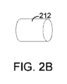
図2Bは、保護構成要素212の3次元図を示す。示されるように、特定の態様では、保護構成要素212は、カニューレ104の円筒形開口部に圧入され得る円筒形構成要素である。特定の態様では、保護構成要素212の直径は350μm±5μm、360μm±5μm、又は370μm±5μmであり得る。特定の態様では、保護構成要素212の長さは、355μm±25μmの長さであり得る。
FIG. 2B shows a three-dimensional view of the
図2Cは、保護構成要素212を収容するカニューレ104の先端の正面図を示す。
FIG. 2C shows a front view of the tip of
図2Dは、カニューレ104の先端の3次元図を示す。示されるように、保護構成要素212は、カニューレ104の外側に部分的に延びる。ただし、特定の態様では、保護構成要素212は、カニューレ104の外側に延びない。例えば、保護構成要素212は、カニューレ104の外側と面一であるか、又はカニューレ104の外側まで延びない場合もある。
FIG. 2D shows a three-dimensional view of the tip of
図2A~2Dに示されるように、特定の態様では、保護構成要素(例えば、保護構成要素212)は、両方とも平坦である遠位端及び近位端を有する円筒形状を有し得る。しかしながら、特定の態様では、保護構成要素の近位端は平坦である必要はない。例えば、保護構成要素の近位端は、球形又は非球形であり得る。球形又は非球形の近位端は圧入中にカニューレの先端を通してより容易に案内又は挿入できるため、球形又は非球形の近位端を備えた保護構成要素は有利な場合がある。 As shown in FIGS. 2A-2D, in certain aspects, a protective component (eg, protective component 212) can have a cylindrical shape with distal and proximal ends that are both flat. However, in certain embodiments, the proximal end of the protective component need not be flat. For example, the proximal end of the protective component can be spherical or non-spherical. A protective component with a spherical or non-spherical proximal end may be advantageous because the spherical or non-spherical proximal end can be more easily guided or inserted through the tip of the cannula during press fit.
同じく、図2Aに示すように、特定の態様では、カニューレ104内に配置されたレンズ(例えば、レンズ210)は、両方とも平坦である遠位端及び近位端を有する円筒形状を有する。そのようなレンズの例は、屈折率分布型(GRIN)レンズである。しかしながら、特定の他の態様では、球面又は非球面レンズを代わりに使用することができ、これは対応するプローブアセンブリの性能及び/又は熱的信頼性を向上し得る。したがって、特定の態様では、レンズの近位端又は遠位端の少なくとも一方は平坦ではない。例えば、レンズの近位端、遠位端、又は両端は、球面又は非球面であり得る。なお、本明細書に記載されるレンズの異なる形状はいずれも、本明細書に記載される保護構成要素の異なる形状のいずれと併せて使用することもできることに留意されたい。
Also, as shown in FIG. 2A, in certain embodiments, a lens (eg, lens 210) disposed within
図3A~3Eは、カニューレ104内の異なる形状のレンズ及び保護構成要素のいくつかの例示的な構成の断面図を示す。
3A-3E illustrate cross-sectional views of several exemplary configurations of differently shaped lenses and protective components within
図3Aは、光ファイバ108が部分的に延びるカニューレ104を示す。示されるように、光ファイバ108の遠位端にはレンズ320があり、その近位端は球形であり、遠位端は平坦である。保護構成要素330は、カニューレ104に圧入されて、レンズ320の遠位端に配置され、それによりレンズ320のカニューレ104に沿った移動及びカニューレ104からの離脱を制限する。レンズ320の球面近位端は、光ファイバ108によって伝播されるレーザビームを、保護構成要素330の近位端の中央に向かって操作する。
FIG. 3A shows
図3Bは、平坦な近位端及び遠位端を有するレンズ322を保護する保護構成要素330を示す。特定の態様では、レンズ322は、GRINレンズである。
FIG. 3B shows a
図3Cは、近位端が平坦であり、遠位端が球面であるレンズ324を保護する保護構成要素330を示す。特定の態様では、レンズ324の球面遠位端と保護構成要素330の球形近位端との間で光パワーが分割され、その結果、球面収差が少なくなる(例えば、忠実度が高くなる)。球面収差を低減すると、プローブアセンブリが患者の体の一部(例えば、網膜表面)により鋭いレーザスポットを投影又は伝播し、これによりプローブアセンブリの性能と精度が向上する可能性がある。
FIG. 3C shows a
図3Dは、球面の近位端及び遠位端を有するレンズ326を保護する保護構成要素330を示す。特定の態様では、レンズ326(例えば、球面レンズと呼ばれる)は、GRINレンズよりも高い温度性能を有する。保護構成要素330によって提供される保護は、レンズ326などの球面レンズの使用を可能にする。特定の態様では、球面レンズ326は、光ファイバ108によって伝播されるレーザビームを、保護構成要素330の近位端の中央に向かって集束させることができる。図3Dの例では、保護構成要素330の球形端部は、レンズ326の2つの球面端部と組み合わされて、レーザビームの操作及び集束をさらに助ける。さらに、高軟化点球面レンズは、より高い表面温度に耐えることができる可能性があり、これにより、プローブアセンブリの熱的信頼性が向上する可能性がある。
FIG. 3D shows a
図3Eは、平坦な近位端及び遠位端を有するレンズ322を保護する保護構成要素332を示す。保護構成要素332は、非球形である近位端と平坦である遠位端とを有する。特定の態様では、保護構成要素332の非球形端部を成形することができる。特定の態様では、非球形の近位端を有する保護構成要素は、球形の近位端よりもカニューレ104の先端を通してより容易に案内又は挿入することができる。
FIG. 3E shows a
上述のように、特定の態様では、保護構成要素330~332のうちの1つ又は複数は光パワーを有し得るが、他の態様では、保護構成要素は光パワーを有し得ない。また、特定の態様では、3A~3E構成のそれぞれにおいて、光ファイバの遠位端は、レンズの近位端に接触又は近接する一方で、レンズの遠位端は、保護構成要素の近位端に接触又は近接する。このような態様では、レンズの動きは、一方の側(例えば、近位側)から光ファイバによって、もう一方の側(例えば、遠位側)から保護構成要素によって制限される。 As mentioned above, in certain aspects one or more of the protection components 330-332 may have optical power, while in other aspects the protection components may not have optical power. Also, in certain aspects, in each of the 3A-3E configurations, the distal end of the optical fiber contacts or proximal the proximal end of the lens, while the distal end of the lens contacts or proximal the proximal end of the protective component. come into contact with or be close to. In such embodiments, lens movement is limited by the optical fiber from one side (eg, the proximal side) and by the protective component from the other side (eg, the distal side).
図4Aは保護構成要素の別の例示的な形状の断面図を示す。示されるように、保護構成要素430の近位端は、面取りされた縁432及び平坦な表面434を備える。例えば、保護構成要素430は、円筒形構成要素の近位端の縁を面取りすることによって製造され得る。図4Bは、保護構成要素430の3次元図を示す。保護構成要素430の面取りされた近位端は、カニューレの先端を通してより容易に案内又は挿入できるため、保護構成要素430は有利である。
FIG. 4A shows a cross-sectional view of another exemplary shape of a protective component. As shown, the proximal end of the
図4Cは保護構成要素のさらに別の例示的な形状の断面図を示す。示されるように、保護構成要素440の近位端は、面取りされた縁442及び球面444を備える。図4Dは、保護構成要素440の3次元図を示す。
FIG. 4C shows a cross-sectional view of yet another exemplary shape of a protective component. As shown, the proximal end of the
保護構成要素430又は440などの保護構成要素は、保護構成要素の面取りされた形状の近位端がカニューレの先端を通してより容易に案内又は挿入され得るため、有利であり得る。保護構成要素430又は440は、図3A~3Eに示されるレンズ構成320~326のいずれと組み合わせて使用することもできる。
A protective component such as
特定の態様では、カニューレ(例えば、カニューレ104)は、可撓性材料(例えば、ステンレス鋼、NiTi、Pt-lr、その他)から作製され得、その結果、カニューレの直径は、より大きな直径のレンズ及び/又は保護構成要素がカニューレに挿入されると、拡張し得る。 In certain aspects, the cannula (e.g., cannula 104) may be made from a flexible material (e.g., stainless steel, NiTi, Pt-lr, etc.) such that the diameter of the cannula is smaller than that of the larger diameter lens. and/or may expand when the protective component is inserted into the cannula.
図4Eは、カニューレ(例えば、カニューレ404)に挿入されている図4Aの保護構成要素430を示す。示されるように、カニューレの先端の直径は拡張し、保護構成要素430の面取りされた端部の形状をとっている。特定の態様では、通常の状態のカニューレの直径よりも大きい直径の保護構成要素を使用することは有利である。これは、そのような態様では、保護構成要素をカニューレに圧入することにより、保護構成要素の外面とカニューレの内面との間の充填されていない空間又は開口部が排除、最小化、又は少なくとも減少されるからである。結果として、血液などの流体が、そのような充填されていない空間又は開口部を通ってカニューレ内に漏れる可能性も低減され得る。
FIG. 4E shows the
前述の記載は、当業者が本明細書に記載されている様々な実施形態を実施することを可能にするために提供されている。これらの実施形態に対する様々な修正は、当業者には容易に明らかであり、本明細書で定義される一般的な原理は、他の実施形態に適用されてもよい。したがって、特許請求の範囲は、本明細書に示される実施形態に限定されることを意図するものではなく、特許請求の範囲の文言と一致する全範囲を与えられるべきである。 The previous description is provided to enable any person skilled in the art to practice the various embodiments described herein. Various modifications to these embodiments will be readily apparent to those skilled in the art, and the general principles defined herein may be applied to other embodiments. Therefore, the claims are not intended to be limited to the embodiments set forth herein, but are to be accorded the full scope consistent with the language of the claims.
Claims (15)
カニューレであって、前記マルチコア光ファイバが、レーザ光をレーザ光源から標的位置に伝送するために、少なくとも部分的に前記カニューレを通って延在する、カニューレと、
前記カニューレに収容された屈折率分布型(GRIN)レンズであって、前記マルチコア光ファイバは、前記GRINレンズの近位端に接触する、GRINレンズと、
前記カニューレの遠位端に圧入された円筒形保護窓と
を備え、
前記GRINレンズの遠位端は、前記カニューレ内部の前記円筒形保護窓の近位端に接触し、
前記円筒形保護窓の遠位端は、前記カニューレの外側で延在し、
前記GRINレンズは前記マルチコア光ファイバと前記円筒形保護窓との間に配置される、プローブアセンブリ。 multi-core optical fiber,
a cannula, the multi-core optical fiber extending at least partially through the cannula for transmitting laser light from a laser light source to a target location;
a graded refractive index (GRIN) lens housed in the cannula, the multicore optical fiber contacting a proximal end of the GRIN lens ;
a cylindrical protective window press-fitted into the distal end of the cannula;
a distal end of the GRIN lens contacts a proximal end of the cylindrical protective window inside the cannula;
a distal end of the cylindrical protective window extends outside the cannula;
The probe assembly, wherein the GRIN lens is disposed between the multi-core optical fiber and the cylindrical protection window .
前記円筒形保護窓の近位端が凸面を備える、
請求項1に記載のプローブアセンブリ。 the cylindrical protective window has a distal end and a proximal end;
the proximal end of the cylindrical protective window comprises a convex surface;
A probe assembly according to claim 1.
前記円筒形保護窓の近位端が球面セグメントを備える、
請求項1に記載のプローブアセンブリ。 the cylindrical protective window has a distal end and a proximal end;
the proximal end of the cylindrical protective window comprises a spherical segment;
A probe assembly according to claim 1.
前記円筒形保護窓の近位端が、成形された非球面セグメントを備える、
請求項1に記載のプローブアセンブリ。 the cylindrical protective window has a distal end and a proximal end;
a proximal end of the cylindrical protective window comprises a shaped aspherical segment;
A probe assembly according to claim 1.
請求項1に記載のプローブアセンブリ。 the proximal end of the GRIN lens is curved;
A probe assembly according to claim 1.
請求項1に記載のプローブアセンブリ。 the distal end of the GRIN lens is curved;
A probe assembly according to claim 1.
レーザ光源と、
マルチコア光ファイバと、
1つ又は複数の光ファイバを介して前記レーザ光源に接続された前記プローブアセンブリとを含む手術システムであって、前記プローブアセンブリが、
カニューレに接続されたハンドピースであって、前記カニューレは遠位端を備え、前記マルチコア光ファイバは、レーザ光を前記レーザ光源から標的位置に伝送するために、前記ハンドピースを通って、及び少なくとも部分的に前記カニューレを通って延在する、ハンドピースと、
をさらに備える、手術システム。 A probe assembly according to claim 1;
a laser light source;
multi-core optical fiber,
the probe assembly connected to the laser light source via one or more optical fibers, the probe assembly comprising:
a handpiece connected to a cannula, the cannula having a distal end, the multi -core optical fiber passing through the handpiece for transmitting laser light from the laser light source to a target location; a handpiece extending partially through the cannula;
A surgical system further equipped with.
Applications Claiming Priority (9)
| Application Number | Priority Date | Filing Date | Title |
|---|---|---|---|
| US201762597550P | 2017-12-12 | 2017-12-12 | |
| US62/597,550 | 2017-12-12 | ||
| US201762598653P | 2017-12-14 | 2017-12-14 | |
| US62/598,653 | 2017-12-14 | ||
| US201862622299P | 2018-01-26 | 2018-01-26 | |
| US62/622,299 | 2018-01-26 | ||
| US201862630865P | 2018-02-15 | 2018-02-15 | |
| US62/630,865 | 2018-02-15 | ||
| PCT/IB2018/059981 WO2019116287A1 (en) | 2017-12-12 | 2018-12-12 | Thermally robust laser probe assembly |
Publications (2)
| Publication Number | Publication Date |
|---|---|
| JP2021505311A JP2021505311A (en) | 2021-02-18 |
| JP7344207B2 true JP7344207B2 (en) | 2023-09-13 |
Family
ID=65041807
Family Applications (7)
| Application Number | Title | Priority Date | Filing Date |
|---|---|---|---|
| JP2020531726A Pending JP2021505302A (en) | 2017-12-12 | 2018-12-12 | Thermally robust laser probe assembly |
| JP2020531766A Active JP7344207B2 (en) | 2017-12-12 | 2018-12-12 | Heat resistant laser probe assembly |
| JP2020531780A Active JP7324204B2 (en) | 2017-12-12 | 2018-12-12 | Multi-core fiber in multi-spot laser probe |
| JP2020531706A Active JP7324202B2 (en) | 2017-12-12 | 2018-12-12 | Multi-core fiber in multi-spot laser probe |
| JP2020531700A Active JP7312175B2 (en) | 2017-12-12 | 2018-12-12 | Multi-input coupled illuminated multi-spot laser probe |
| JP2023112385A Pending JP2023118974A (en) | 2017-12-12 | 2023-07-07 | Multiple-input-coupled illuminated multi-spot laser probe |
| JP2023146060A Pending JP2023168359A (en) | 2017-12-12 | 2023-09-08 | Thermally robust laser probe assembly |
Family Applications Before (1)
| Application Number | Title | Priority Date | Filing Date |
|---|---|---|---|
| JP2020531726A Pending JP2021505302A (en) | 2017-12-12 | 2018-12-12 | Thermally robust laser probe assembly |
Family Applications After (5)
| Application Number | Title | Priority Date | Filing Date |
|---|---|---|---|
| JP2020531780A Active JP7324204B2 (en) | 2017-12-12 | 2018-12-12 | Multi-core fiber in multi-spot laser probe |
| JP2020531706A Active JP7324202B2 (en) | 2017-12-12 | 2018-12-12 | Multi-core fiber in multi-spot laser probe |
| JP2020531700A Active JP7312175B2 (en) | 2017-12-12 | 2018-12-12 | Multi-input coupled illuminated multi-spot laser probe |
| JP2023112385A Pending JP2023118974A (en) | 2017-12-12 | 2023-07-07 | Multiple-input-coupled illuminated multi-spot laser probe |
| JP2023146060A Pending JP2023168359A (en) | 2017-12-12 | 2023-09-08 | Thermally robust laser probe assembly |
Country Status (11)
| Country | Link |
|---|---|
| US (9) | US11771597B2 (en) |
| EP (6) | EP4299028A3 (en) |
| JP (7) | JP2021505302A (en) |
| KR (2) | KR20200098570A (en) |
| CN (7) | CN111511305B (en) |
| AU (5) | AU2018385652A1 (en) |
| BR (2) | BR112020011628A2 (en) |
| CA (5) | CA3084311A1 (en) |
| ES (1) | ES2946276T3 (en) |
| RU (2) | RU2770121C2 (en) |
| WO (5) | WO2019116286A2 (en) |
Families Citing this family (27)
| Publication number | Priority date | Publication date | Assignee | Title |
|---|---|---|---|---|
| US10918522B2 (en) | 2017-06-08 | 2021-02-16 | Alcon Inc. | Photodisruption-based vitrectomy system |
| US11109938B2 (en) | 2017-11-14 | 2021-09-07 | Alcon Inc. | Multi-spot laser probe with illumination features |
| US11779427B2 (en) | 2017-12-12 | 2023-10-10 | Alcon Inc. | Multiple-input-coupled illuminated multi-spot laser probe |
| US11213426B2 (en) | 2017-12-12 | 2022-01-04 | Alcon Inc. | Thermally robust multi-spot laser probe |
| WO2019116283A1 (en) | 2017-12-12 | 2019-06-20 | Novartis Ag | Surgical probe with shape-memory material |
| CA3084311A1 (en) | 2017-12-12 | 2019-06-20 | Alcon Inc. | Multiple-input-coupled illuminated multi-spot laser probe |
| US10758415B2 (en) * | 2018-01-17 | 2020-09-01 | Topcon Medical Systems, Inc. | Method and apparatus for using multi-clad fiber for spot size selection |
| US11471698B2 (en) * | 2018-02-23 | 2022-10-18 | Lumitex, Inc. | Tunable light source |
| US11389241B2 (en) | 2019-01-15 | 2022-07-19 | Boston Scientific Scimed, Inc. | Alignment method and tools |
| JP2022535240A (en) | 2019-06-03 | 2022-08-05 | アルコン インコーポレイティド | Alignment of multiwavelength laser beams to cores of multicore fibers |
| US11931297B2 (en) | 2019-06-14 | 2024-03-19 | Alcon Inc. | Glare reduction endoilluminators |
| WO2020256898A1 (en) | 2019-06-19 | 2020-12-24 | Boston Scientific Scimed, Inc. | Balloon surface photoacoustic pressure wave generation to disrupt vascular lesions |
| US11717139B2 (en) | 2019-06-19 | 2023-08-08 | Bolt Medical, Inc. | Plasma creation via nonaqueous optical breakdown of laser pulse energy for breakup of vascular calcium |
| US11660427B2 (en) | 2019-06-24 | 2023-05-30 | Boston Scientific Scimed, Inc. | Superheating system for inertial impulse generation to disrupt vascular lesions |
| US11517713B2 (en) | 2019-06-26 | 2022-12-06 | Boston Scientific Scimed, Inc. | Light guide protection structures for plasma system to disrupt vascular lesions |
| CA3159654A1 (en) | 2019-12-04 | 2021-06-10 | Alireza Mirsepassi | Multi-core optical fiber with reduced bubble formation |
| EP4106696A1 (en) | 2020-02-18 | 2022-12-28 | Alcon Inc. | Multi-spot laser probe with multiple single-core fibers |
| US11672599B2 (en) | 2020-03-09 | 2023-06-13 | Bolt Medical, Inc. | Acoustic performance monitoring system and method within intravascular lithotripsy device |
| US20210290286A1 (en) | 2020-03-18 | 2021-09-23 | Bolt Medical, Inc. | Optical analyzer assembly and method for intravascular lithotripsy device |
| US11707323B2 (en) | 2020-04-03 | 2023-07-25 | Bolt Medical, Inc. | Electrical analyzer assembly for intravascular lithotripsy device |
| US20210353359A1 (en) * | 2020-05-12 | 2021-11-18 | Bolt Medical, Inc. | Active alignment system and method for optimizing optical coupling of multiplexer for laser-driven intravascular lithotripsy device |
| US20220009036A1 (en) * | 2020-07-07 | 2022-01-13 | Panasonic Intellectual Property Management Co. Ltd | Laser systems and techniques for workpiece processing utilizing optical fibers and multiple beams |
| US11672585B2 (en) | 2021-01-12 | 2023-06-13 | Bolt Medical, Inc. | Balloon assembly for valvuloplasty catheter system |
| US11648057B2 (en) | 2021-05-10 | 2023-05-16 | Bolt Medical, Inc. | Optical analyzer assembly with safety shutdown system for intravascular lithotripsy device |
| US11806075B2 (en) | 2021-06-07 | 2023-11-07 | Bolt Medical, Inc. | Active alignment system and method for laser optical coupling |
| US11877956B2 (en) | 2021-08-06 | 2024-01-23 | Alcon Inc. | Vitreoretinal instruments for illumination, fluid aspiration, and photocoagulation |
| US11839391B2 (en) | 2021-12-14 | 2023-12-12 | Bolt Medical, Inc. | Optical emitter housing assembly for intravascular lithotripsy device |
Citations (1)
| Publication number | Priority date | Publication date | Assignee | Title |
|---|---|---|---|---|
| JP2003518395A (en) | 1999-07-14 | 2003-06-10 | カーディオフォーカス・インコーポレイテッド | Light stripping system |
Family Cites Families (156)
| Publication number | Priority date | Publication date | Assignee | Title |
|---|---|---|---|---|
| US4632505A (en) * | 1983-10-11 | 1986-12-30 | The Deustsch Company Electronic Components Division | Optical fiber connector |
| US5104392A (en) | 1985-03-22 | 1992-04-14 | Massachusetts Institute Of Technology | Laser spectro-optic imaging for diagnosis and treatment of diseased tissue |
| US5199431A (en) | 1985-03-22 | 1993-04-06 | Massachusetts Institute Of Technology | Optical needle for spectroscopic diagnosis |
| US5693043A (en) | 1985-03-22 | 1997-12-02 | Massachusetts Institute Of Technology | Catheter for laser angiosurgery |
| CA1279901C (en) * | 1985-03-22 | 1991-02-05 | Carter Kittrell | Catheter for laser angiosurgery |
| US20020045811A1 (en) * | 1985-03-22 | 2002-04-18 | Carter Kittrell | Laser ablation process and apparatus |
| JPH0667389B2 (en) * | 1987-04-30 | 1994-08-31 | 松下電器産業株式会社 | Laser mess probe |
| JPH01256948A (en) * | 1988-04-06 | 1989-10-13 | Matsushita Electric Ind Co Ltd | Optical fiber probe |
| EP0355996A3 (en) * | 1988-07-21 | 1990-05-02 | Advanced Interventional Systems, Inc. | Guidance and delivery system for high-energy pulsed laser light and endoscope |
| CN1044228A (en) * | 1989-01-20 | 1990-08-01 | 苏联科学院阿·勃·明茨无线电工程科学研究所 | Optically-derived device used for optical therapeutics |
| JPH02297355A (en) | 1989-05-12 | 1990-12-07 | Topcon Corp | Laser device for therapy |
| JP2933945B2 (en) * | 1989-05-29 | 1999-08-16 | 株式会社トプコン | Laser therapy equipment |
| JPH0798050B2 (en) * | 1989-08-09 | 1995-10-25 | 株式会社トプコン | Ophthalmic laser treatment device |
| DE4014956A1 (en) * | 1990-05-10 | 1991-11-14 | Schott Glaswerke | DISTAL PROTECTIVE CAP FOR A LASER-FIBER CATHETER |
| WO1992008427A2 (en) | 1990-11-07 | 1992-05-29 | Premier Laser Systems, Inc. | Laser surgical probe |
| JPH0614936A (en) | 1992-03-10 | 1994-01-25 | Trimedyne Inc | Laser probe and handpiece and manual apparatus and device having the same |
| JPH06105863A (en) * | 1992-09-18 | 1994-04-19 | Topcon Corp | Intraocular operation apparatus |
| JPH06242331A (en) * | 1993-02-18 | 1994-09-02 | Furukawa Electric Co Ltd:The | Quartz group optical fiber with lens and its production |
| US5625638A (en) | 1993-05-28 | 1997-04-29 | Coherent, Inc. | Sealed crystalline windows for hollow laser fibers |
| JPH07155659A (en) * | 1993-11-30 | 1995-06-20 | Sony Corp | Method to apply liquid linearly and apparatus for method thereof |
| CN2188253Y (en) * | 1994-05-24 | 1995-01-25 | 方础股份有限公司 | Semiconductor laser arrangement |
| US5815626A (en) * | 1994-10-14 | 1998-09-29 | Mitsubishi Denki Kabushiki Kaisha | Optical transmission device, solid state laser device, and laser beam processing device |
| FR2730317A1 (en) * | 1995-02-03 | 1996-08-09 | Alcatel Cable Interface | OPTICAL FIBER CONNECTING MULTIFERACE, CONNECTOR USING THE SAME, AND METHOD FOR MANUFACTURING THE SAME |
| US5664037A (en) * | 1995-09-28 | 1997-09-02 | Corning Incorporated | Multi-neckdown fiber optic coupler |
| US5921981A (en) | 1995-11-09 | 1999-07-13 | Alcon Laboratories, Inc. | Multi-spot laser surgery |
| US5953477A (en) * | 1995-11-20 | 1999-09-14 | Visionex, Inc. | Method and apparatus for improved fiber optic light management |
| WO1998039265A1 (en) * | 1997-03-04 | 1998-09-11 | Andromis S.A. | Method and device for assembling optical components or an optical component and a substrate |
| US6043895A (en) * | 1998-11-10 | 2000-03-28 | Uop Llc | Radiation probe with flexible sleeve |
| JP2001008945A (en) * | 1999-06-28 | 2001-01-16 | Topcon Corp | Laser surgical instrument |
| IL133073A (en) * | 1999-11-22 | 2003-06-24 | Yaakov Amitai | Method and system for treating a target plane with a laser beam |
| US6929603B2 (en) | 2000-08-30 | 2005-08-16 | Durell & Gitelis, Inc. | Variable view arthroscope |
| JP3881508B2 (en) * | 2000-12-04 | 2007-02-14 | 株式会社ニデック | Laser therapy device |
| DE10212366A1 (en) * | 2001-03-23 | 2002-12-05 | Surgical Laser Tech | Light emitting probe for hyperthermic treatment of carcinogenic tissue, has light dispersing material of different dispersive power, filled in each segmented section of tube coupled to optical fiber |
| US20020193781A1 (en) * | 2001-06-14 | 2002-12-19 | Loeb Marvin P. | Devices for interstitial delivery of thermal energy into tissue and methods of use thereof |
| US6682771B2 (en) * | 2001-07-02 | 2004-01-27 | Scimed Life Systems, Inc. | Coating dispensing system and method using a solenoid head for coating medical devices |
| WO2003032039A1 (en) * | 2001-10-09 | 2003-04-17 | Crystal Fibre A/S | Hermetically sealed optical fibre with voids or holes, method of its production, and its use |
| US7762965B2 (en) * | 2001-12-10 | 2010-07-27 | Candela Corporation | Method and apparatus for vacuum-assisted light-based treatments of the skin |
| US6845193B2 (en) * | 2002-05-21 | 2005-01-18 | Trimedyne, Inc. | Laser channeling devices |
| US6953458B2 (en) * | 2002-12-20 | 2005-10-11 | Trimedyne, Inc. | Device and method for delivery of long wavelength laser energy to a tissue site |
| US20130178789A1 (en) * | 2003-01-29 | 2013-07-11 | Novartis Ag | Monitoring Thermal Conditions To Vary Operation of an Ultrasonic Needle Tip of a Surgical Instrument |
| US7448995B2 (en) | 2003-06-23 | 2008-11-11 | Microvision, Inc. | Scanning endoscope |
| PT1653896E (en) | 2003-07-28 | 2013-05-07 | Synergetics Inc | Coaxial illuminated laser endoscopic probe |
| JP2005202047A (en) * | 2004-01-14 | 2005-07-28 | Hitachi Cable Ltd | Boot for protecting optical fiber |
| US6997868B1 (en) * | 2004-07-27 | 2006-02-14 | Martin Uram | Autoclavable endoscope |
| ES2362619T3 (en) | 2005-02-15 | 2011-07-08 | Alcon, Inc. | HIGH PERFORMANCE ENDOILUMINATOR PROBE. |
| US7618177B2 (en) * | 2005-04-29 | 2009-11-17 | Alcon, Inc. | Multi-fiber variable intensity wide-angle illuminator |
| CN2824861Y (en) * | 2005-10-28 | 2006-10-11 | 北京光电技术研究所 | Side-emitting laser fiber structure |
| JP4963375B2 (en) * | 2005-11-02 | 2012-06-27 | 富士フイルム株式会社 | Optical device, optical member and light guide |
| US7450806B2 (en) * | 2005-11-08 | 2008-11-11 | Corning Incorporated | Microstructured optical fibers and methods |
| US10098781B2 (en) * | 2006-03-24 | 2018-10-16 | Topcon Medical Laser Systems Inc. | Multi-spot optical fiber endophotocoagulation probe |
| US20070282312A1 (en) * | 2006-05-31 | 2007-12-06 | Sie Ag Surgical Instrument Engineering | Ophthalmologic apparatus |
| JP2008036536A (en) * | 2006-08-07 | 2008-02-21 | Nippon Densan Corp | Method of applying oil repellent agent solution for coating |
| US20080051770A1 (en) | 2006-08-22 | 2008-02-28 | Synergetics, Inc. | Multiple Target Laser Probe |
| WO2008024848A2 (en) | 2006-08-22 | 2008-02-28 | Synergetics, Inc. | Multiple target laser probe |
| US8556807B2 (en) | 2006-12-21 | 2013-10-15 | Intuitive Surgical Operations, Inc. | Hermetically sealed distal sensor endoscope |
| CA2675617C (en) * | 2007-01-19 | 2016-11-01 | Sunnybrook Health Sciences Centre | Imaging probe with combined ultrasound and optical means of imaging |
| US20080177257A1 (en) | 2007-01-23 | 2008-07-24 | Smith Ronald T | Thermally robust illumination probe tip |
| US7526166B2 (en) * | 2007-01-31 | 2009-04-28 | Corning Incorporated | High numerical aperture fiber |
| FR2913192B1 (en) | 2007-03-02 | 2010-02-26 | Optical System & Res For Ind & Science Osyris | CANNULA / FIBER OPTIC ASSEMBLY AND LASER INSTRUMENT COMPRISING SAID ASSEMBLY. |
| JP5028124B2 (en) | 2007-03-29 | 2012-09-19 | 株式会社ニデック | Ophthalmic laser treatment device |
| US20090270850A1 (en) | 2007-06-20 | 2009-10-29 | Tea Time Partners, L.P., Organized In Texas | Devices and methods for the ablation of tissue in the lateral direction |
| US7566173B2 (en) | 2007-07-09 | 2009-07-28 | Alcon, Inc. | Multi-spot ophthalmic laser probe |
| US9402643B2 (en) | 2008-01-15 | 2016-08-02 | Novartis Ag | Targeted illumination for surgical instrument |
| CN201179110Y (en) * | 2008-04-09 | 2009-01-14 | 天津市天坤光电技术有限公司 | Beam convergence type laser side-irradiation optical fiber knife head for surgical purposes |
| WO2009135213A2 (en) | 2008-05-02 | 2009-11-05 | Zelickson Brian D | Laser energy devices and methods for soft tissue removal |
| US8657812B2 (en) | 2008-05-19 | 2014-02-25 | Boston Scientific Scimed, Inc. | Side-firing laser fiber with internal bent fiber and related methods |
| JP5325485B2 (en) * | 2008-07-10 | 2013-10-23 | 株式会社トプコン | Laser surgical device |
| US10718909B2 (en) | 2008-07-29 | 2020-07-21 | Glenair, Inc. | Expanded beam fiber optic connection system |
| US8542962B2 (en) | 2008-08-13 | 2013-09-24 | Alcon Research, Ltd. | Preconditioned illuminator system and method |
| JP2010042182A (en) * | 2008-08-18 | 2010-02-25 | Fujifilm Corp | Laser treatment device |
| JP5372527B2 (en) | 2009-01-07 | 2013-12-18 | 株式会社ニデック | Ophthalmic laser treatment device |
| WO2010104752A2 (en) | 2009-03-08 | 2010-09-16 | Oprobe, Llc | Multi-function optical probe system for medical and veterinary applications |
| JP5441465B2 (en) * | 2009-03-24 | 2014-03-12 | 富士フイルム株式会社 | Capsule endoscope |
| JP5184700B2 (en) | 2009-06-09 | 2013-04-17 | 株式会社フジクラ | Optical apparatus, laser irradiation apparatus, and laser treatment apparatus |
| US9814392B2 (en) | 2009-10-30 | 2017-11-14 | The Johns Hopkins University | Visual tracking and annotaton of clinically important anatomical landmarks for surgical interventions |
| JP5902623B2 (en) | 2009-11-24 | 2016-04-13 | アルコン リサーチ, リミテッド | Single fiber multi-spot laser probe for intraocular illumination |
| CA2781677C (en) | 2009-12-10 | 2017-07-11 | Alcon Research Ltd. | Multi-spot laser surgical probe using faceted optical elements |
| ES2588393T3 (en) | 2009-12-15 | 2016-11-02 | Alcon Research, Ltd | Multipoint laser probe |
| EP2519177A4 (en) * | 2009-12-31 | 2013-07-03 | Laser Abrasive Technologies Llc | Dental surgical laser with feedback mechanisms |
| EP2521520B1 (en) | 2010-01-08 | 2017-08-16 | Optimedica Corporation | System for modifying eye tissue and intraocular lenses |
| WO2011091326A1 (en) * | 2010-01-22 | 2011-07-28 | Optimedica Corporation | Apparatus for automated placement of scanned laser capsulorhexis incisions |
| BR112012020778A2 (en) * | 2010-02-17 | 2016-05-03 | Alcon Res Ltd | probe |
| JP5267481B2 (en) * | 2010-02-18 | 2013-08-21 | 住友電気工業株式会社 | Multi-core optical fiber |
| WO2011112846A1 (en) * | 2010-03-10 | 2011-09-15 | Ofs Fitel Llc. A Delaware Limited Liability Company | Multicore fibers and associated structures and techniques |
| IL205022A (en) * | 2010-04-12 | 2013-10-31 | Cleanoscope Inc | Lens protector for endoscopic devices |
| JP6018060B2 (en) | 2010-08-09 | 2016-11-02 | アルコン リサーチ, リミテッド | Illuminated surgical instrument |
| EP2603151B1 (en) | 2010-08-13 | 2014-12-24 | Alcon Research, Ltd. | Dual-mode illumination for surgical instrument |
| US20120099112A1 (en) * | 2010-10-25 | 2012-04-26 | Gerard Argant Alphonse | Multi-core low reflection lateral output fiber probe |
| AU2011338290B2 (en) | 2010-12-09 | 2015-09-17 | Alcon Inc. | Optical coherence tomography and illumination using common light source |
| US8488930B2 (en) | 2010-12-09 | 2013-07-16 | Alcon Research, Ltd. | Wavelength converting illumination probe |
| TWI554243B (en) | 2011-01-21 | 2016-10-21 | 愛爾康研究有限公司 | Combined surgical endoprobe for optical coherence tomography, illumination or photocoagulation |
| US20120203075A1 (en) | 2011-02-08 | 2012-08-09 | Christopher Horvath | White coherent laser light launched into nano fibers for surgical illumination |
| US20120330102A1 (en) * | 2011-05-24 | 2012-12-27 | Oprobe, Llc | Scanning Endoscopic Imaging Probes and Related Methods |
| WO2012172968A1 (en) * | 2011-06-17 | 2012-12-20 | 住友電気工業株式会社 | Optical device |
| AU2012290158B2 (en) * | 2011-08-03 | 2016-07-07 | Alcon Inc. | Articulating ophthalmic surgical probe |
| CN103732124B (en) | 2011-08-09 | 2016-04-06 | 爱尔康研究有限公司 | Use many light spot lasers surgical probe of point face optical element |
| JP5861329B2 (en) | 2011-08-31 | 2016-02-16 | 株式会社ニデック | Ophthalmic laser treatment device |
| WO2013031836A1 (en) * | 2011-09-01 | 2013-03-07 | コニカミノルタアドバンストレイヤー株式会社 | Coupling optical system and coupling method |
| EP2765944B1 (en) * | 2011-10-14 | 2018-09-05 | RA Medical Systems | Small flexible liquid core catheter for laser ablation in body lumens |
| US8561280B2 (en) | 2011-10-20 | 2013-10-22 | Alcon Research, Ltd. | Assembling a multi-fiber multi-spot laser probe |
| US8571364B2 (en) * | 2011-11-09 | 2013-10-29 | Alcon Research, Ltd. | Multi-spot laser probe with faceted optical element |
| US8939964B2 (en) | 2011-12-01 | 2015-01-27 | Alcon Research, Ltd. | Electrically switchable multi-spot laser probe |
| ES2569257T3 (en) | 2011-12-09 | 2016-05-09 | Alcon Research, Ltd. | Devices and procedures for reconfigurable multi-point scanning |
| JP5867076B2 (en) * | 2011-12-28 | 2016-02-24 | 住友電気工業株式会社 | Multi-core optical fiber |
| US9211214B2 (en) | 2012-03-21 | 2015-12-15 | Valeant Pharmaceuticals International, Inc | Photodynamic therapy laser |
| JPWO2013141112A1 (en) * | 2012-03-23 | 2015-08-03 | 住友電気工業株式会社 | Interference measurement device |
| CN202886643U (en) * | 2012-08-17 | 2013-04-17 | 北京凯普林光电科技有限公司 | Optical-fiber abutting joint apparatus and medical appliance comprising the same |
| JP5956883B2 (en) * | 2012-09-13 | 2016-07-27 | 株式会社トプコン | Laser therapy device |
| US10245181B2 (en) * | 2012-12-21 | 2019-04-02 | Alcon Research, Ltd. | Grin fiber multi-spot laser probe |
| US9308128B2 (en) * | 2013-01-08 | 2016-04-12 | Novartis Ag | Multi-spot laser probe with micro-structured faceted proximal surface |
| US20140200566A1 (en) | 2013-01-15 | 2014-07-17 | Alcon Research, Ltd. | Multi-spot laser probe with micro-structured distal surface |
| US20170238807A9 (en) * | 2013-03-15 | 2017-08-24 | LX Medical, Inc. | Tissue imaging and image guidance in luminal anatomic structures and body cavities |
| WO2014145465A2 (en) | 2013-03-15 | 2014-09-18 | Liolios Thomas | Eye safe laser illumination in ophthalmic surgeries |
| US9844318B2 (en) * | 2013-03-26 | 2017-12-19 | Novartis Ag | Devices, systems, and methods for calibrating an OCT imaging system in a laser surgical system |
| JP6500774B2 (en) * | 2013-03-29 | 2019-04-17 | ソニー株式会社 | Laser scanning endoscope apparatus |
| GB2513123B (en) * | 2013-04-15 | 2015-12-02 | Lumenis Ltd | Adaptor |
| US20140363125A1 (en) * | 2013-06-06 | 2014-12-11 | Prima Electro North America, LLC | Cladding mode stripper |
| US10838155B2 (en) * | 2013-06-14 | 2020-11-17 | Chiral Photonics, Inc. | Multichannel optical coupler |
| US20150025369A1 (en) * | 2013-07-17 | 2015-01-22 | Corning Incorporated | Housing for the oct probe, oct probe assembly, and a method of making such assembly |
| JP6196838B2 (en) * | 2013-08-23 | 2017-09-13 | 株式会社フジクラ | Optical fiber cable and intermediate post-branching method of optical fiber cable |
| JP6287179B2 (en) * | 2013-12-25 | 2018-03-07 | 住友電気工業株式会社 | Multi-core optical fiber and method for manufacturing multi-core optical fiber connector |
| US9690085B2 (en) * | 2014-01-30 | 2017-06-27 | Olympus Corporation | Microscope illumination apparatus, microscope, and microscope illumination method |
| CN203953807U (en) * | 2014-02-08 | 2014-11-26 | 张艳春 | A kind of semiconductor laser therapeutic instrument |
| US9629749B2 (en) * | 2014-02-27 | 2017-04-25 | Iridex Corporation | Illuminated treatment probe for delivering laser energy |
| CN104901148A (en) * | 2014-03-03 | 2015-09-09 | 无锡源清创业投资有限公司 | Optical fiber cladding light filtering method based on surface crystallization |
| US20150351629A1 (en) | 2014-06-06 | 2015-12-10 | Novartis Ag | Back reflection minimization for oct probes |
| US9681793B2 (en) * | 2014-06-19 | 2017-06-20 | Novartis Ag | Surgical probe with interlocking attachment |
| US10016302B2 (en) | 2014-06-19 | 2018-07-10 | Visumedics, Inc. | Diagnostic and surgical laser device utilizing a visible laser diode |
| US10533837B2 (en) * | 2014-12-14 | 2020-01-14 | Cylite Pty Ltd | Multichannel optical receivers |
| US10111778B2 (en) | 2014-12-19 | 2018-10-30 | Novartis Ag | BSS-only multi-sport laser probe |
| US9488782B2 (en) | 2014-12-22 | 2016-11-08 | InnovaQuartz LLC | Redirecting electromagnetic radiation |
| WO2016157639A1 (en) * | 2015-03-30 | 2016-10-06 | 住友電気工業株式会社 | Optical fiber leakage loss measurement method |
| US10695128B2 (en) * | 2015-04-16 | 2020-06-30 | Boston Scientific Scimed, Inc. | Methods and devices for targeted ablation of tissue |
| US20160357007A1 (en) * | 2015-05-05 | 2016-12-08 | Eric Swanson | Fixed distal optics endoscope employing multicore fiber |
| CN105372759B (en) * | 2015-11-30 | 2018-08-31 | 武汉锐科光纤激光技术股份有限公司 | Optical fiber wet etching method for cladding light stripper |
| US10441157B2 (en) * | 2015-12-02 | 2019-10-15 | Novartis Ag | Optical fiber having proximal taper for ophthalmic surgical illumination |
| WO2017108061A1 (en) * | 2015-12-23 | 2017-06-29 | Nkt Photonics A/S | Hollow core optical fiber and a laser system |
| WO2018011737A1 (en) | 2016-07-13 | 2018-01-18 | Novartis Ag | Improved optical fiber coupling reliability |
| IT201600087226A1 (en) * | 2016-08-25 | 2018-02-25 | Strand S R L | OPTICAL MULTIPLATION COMMUNICATION SYSTEM WITH FASHION DIVISION |
| CA3028632A1 (en) | 2016-08-25 | 2018-03-01 | Novartis Ag | Planar illuminator for ophthalmic surgery |
| JP6954294B2 (en) * | 2016-09-09 | 2021-10-27 | 住友電気工業株式会社 | Optical amplifier and multi-core optical fiber |
| CN107029941B (en) * | 2016-11-01 | 2023-02-21 | 广州市景泰科技有限公司 | Line printing type micro dispensing device and method |
| EP3558088A4 (en) | 2016-12-20 | 2020-10-28 | 3dintegrated ApS | A medical probe assembly |
| JP7136471B2 (en) | 2017-02-09 | 2022-09-13 | ノルレーズ アーペーエス | photothermal ophthalmic treatment device |
| JP2020511201A (en) | 2017-02-28 | 2020-04-16 | アルコン インコーポレイティド | Multi-fiber multi-spot laser probe with simple tip structure |
| JP2020508750A (en) | 2017-02-28 | 2020-03-26 | アルコン インコーポレイティド | Multi-fiber, multi-spot laser probe with articulated beam separation |
| AU2018268192A1 (en) | 2017-05-16 | 2019-10-24 | Alcon Inc. | Laser probe with lensed fibers for panretinal photocoagulation |
| WO2018220488A1 (en) | 2017-05-30 | 2018-12-06 | Novartis Ag | Multi-fiber multi-spot laser probe with articulating beam separation |
| US11109938B2 (en) | 2017-11-14 | 2021-09-07 | Alcon Inc. | Multi-spot laser probe with illumination features |
| CA3084311A1 (en) | 2017-12-12 | 2019-06-20 | Alcon Inc. | Multiple-input-coupled illuminated multi-spot laser probe |
| US11213426B2 (en) | 2017-12-12 | 2022-01-04 | Alcon Inc. | Thermally robust multi-spot laser probe |
| US11779427B2 (en) | 2017-12-12 | 2023-10-10 | Alcon Inc. | Multiple-input-coupled illuminated multi-spot laser probe |
| WO2019116283A1 (en) | 2017-12-12 | 2019-06-20 | Novartis Ag | Surgical probe with shape-memory material |
| EP3703601A1 (en) | 2018-01-05 | 2020-09-09 | Alcon Inc. | Multiple illumination transmission through optical fiber |
| US20190307527A1 (en) | 2018-04-09 | 2019-10-10 | Alcon Inc. | Fiber Tip Protection Integration For Cannula |
| AU2019353187A1 (en) | 2018-10-05 | 2021-03-18 | Alcon Inc. | Occlusion sensing in ophthalmic laser probes |
-
2018
- 2018-12-12 CA CA3084311A patent/CA3084311A1/en active Pending
- 2018-12-12 CA CA3084738A patent/CA3084738A1/en active Pending
- 2018-12-12 EP EP23210414.1A patent/EP4299028A3/en active Pending
- 2018-12-12 AU AU2018385652A patent/AU2018385652A1/en active Pending
- 2018-12-12 CN CN201880080456.XA patent/CN111511305B/en active Active
- 2018-12-12 CN CN202310508994.7A patent/CN116270010A/en active Pending
- 2018-12-12 JP JP2020531726A patent/JP2021505302A/en active Pending
- 2018-12-12 AU AU2018383136A patent/AU2018383136A1/en active Pending
- 2018-12-12 WO PCT/IB2018/059980 patent/WO2019116286A2/en unknown
- 2018-12-12 AU AU2018385649A patent/AU2018385649A1/en active Pending
- 2018-12-12 ES ES18836650T patent/ES2946276T3/en active Active
- 2018-12-12 EP EP18836645.4A patent/EP3723680B1/en active Active
- 2018-12-12 JP JP2020531766A patent/JP7344207B2/en active Active
- 2018-12-12 US US16/217,383 patent/US11771597B2/en active Active
- 2018-12-12 JP JP2020531780A patent/JP7324204B2/en active Active
- 2018-12-12 US US16/218,365 patent/US11160686B2/en active Active
- 2018-12-12 WO PCT/IB2018/059978 patent/WO2019116284A1/en unknown
- 2018-12-12 EP EP18836650.4A patent/EP3706683B1/en active Active
- 2018-12-12 US US16/218,333 patent/US11135092B2/en active Active
- 2018-12-12 US US16/218,243 patent/US20190175408A1/en not_active Abandoned
- 2018-12-12 EP EP18836651.2A patent/EP3706684B1/en active Active
- 2018-12-12 WO PCT/IB2018/059975 patent/WO2019116281A1/en unknown
- 2018-12-12 JP JP2020531706A patent/JP7324202B2/en active Active
- 2018-12-12 BR BR112020011628-9A patent/BR112020011628A2/en unknown
- 2018-12-12 KR KR1020207019351A patent/KR20200098570A/en not_active Application Discontinuation
- 2018-12-12 WO PCT/IB2018/059981 patent/WO2019116287A1/en unknown
- 2018-12-12 KR KR1020207018478A patent/KR20200098549A/en not_active Application Discontinuation
- 2018-12-12 JP JP2020531700A patent/JP7312175B2/en active Active
- 2018-12-12 EP EP18836648.8A patent/EP3706682A1/en active Pending
- 2018-12-12 CN CN201880080561.3A patent/CN111479535B/en active Active
- 2018-12-12 AU AU2018385653A patent/AU2018385653A1/en active Pending
- 2018-12-12 RU RU2020122402A patent/RU2770121C2/en active
- 2018-12-12 CN CN202310226338.8A patent/CN116211584A/en active Pending
- 2018-12-12 CN CN201880080453.6A patent/CN111491594B/en active Active
- 2018-12-12 CA CA3084305A patent/CA3084305A1/en active Pending
- 2018-12-12 AU AU2018383137A patent/AU2018383137A1/en active Pending
- 2018-12-12 RU RU2020122397A patent/RU2770265C2/en active
- 2018-12-12 CA CA3084739A patent/CA3084739A1/en active Pending
- 2018-12-12 WO PCT/IB2018/059979 patent/WO2019116285A1/en unknown
- 2018-12-12 BR BR112020011655-6A patent/BR112020011655A2/en unknown
- 2018-12-12 US US16/218,382 patent/US11344449B2/en active Active
- 2018-12-12 CA CA3084730A patent/CA3084730A1/en active Pending
- 2018-12-12 CN CN201880080457.4A patent/CN111479533B/en active Active
- 2018-12-12 EP EP18836649.6A patent/EP3706654A1/en active Pending
- 2018-12-12 CN CN201880080560.9A patent/CN111479534B/en active Active
-
2021
- 2021-03-05 US US17/193,364 patent/US20210186758A1/en active Pending
- 2021-08-25 US US17/411,563 patent/US20210386588A1/en active Pending
-
2022
- 2022-04-29 US US17/661,336 patent/US11844726B2/en active Active
-
2023
- 2023-07-07 JP JP2023112385A patent/JP2023118974A/en active Pending
- 2023-08-16 US US18/451,033 patent/US20230390114A1/en active Pending
- 2023-09-08 JP JP2023146060A patent/JP2023168359A/en active Pending
Patent Citations (1)
| Publication number | Priority date | Publication date | Assignee | Title |
|---|---|---|---|---|
| JP2003518395A (en) | 1999-07-14 | 2003-06-10 | カーディオフォーカス・インコーポレイテッド | Light stripping system |
Also Published As
Similar Documents
| Publication | Publication Date | Title |
|---|---|---|
| JP7344207B2 (en) | Heat resistant laser probe assembly | |
| ES2645647T3 (en) | GRIN fiber multipoint laser probe | |
| EP2162085B1 (en) | Multi-spot ophthalmic laser probe | |
| JP6018060B2 (en) | Illuminated surgical instrument | |
| JP5809163B2 (en) | Multi-spot laser probe | |
| US10111778B2 (en) | BSS-only multi-sport laser probe | |
| US11213426B2 (en) | Thermally robust multi-spot laser probe | |
| JP7297752B2 (en) | laser probe |
Legal Events
| Date | Code | Title | Description |
|---|---|---|---|
| A621 | Written request for application examination |
Free format text: JAPANESE INTERMEDIATE CODE: A621 Effective date: 20211125 |
|
| A977 | Report on retrieval |
Free format text: JAPANESE INTERMEDIATE CODE: A971007 Effective date: 20221223 |
|
| A131 | Notification of reasons for refusal |
Free format text: JAPANESE INTERMEDIATE CODE: A131 Effective date: 20230110 |
|
| A521 | Request for written amendment filed |
Free format text: JAPANESE INTERMEDIATE CODE: A523 Effective date: 20230406 |
|
| A131 | Notification of reasons for refusal |
Free format text: JAPANESE INTERMEDIATE CODE: A131 Effective date: 20230509 |
|
| A521 | Request for written amendment filed |
Free format text: JAPANESE INTERMEDIATE CODE: A523 Effective date: 20230804 |
|
| TRDD | Decision of grant or rejection written | ||
| A01 | Written decision to grant a patent or to grant a registration (utility model) |
Free format text: JAPANESE INTERMEDIATE CODE: A01 Effective date: 20230822 |
|
| A61 | First payment of annual fees (during grant procedure) |
Free format text: JAPANESE INTERMEDIATE CODE: A61 Effective date: 20230901 |
|
| R150 | Certificate of patent or registration of utility model |
Ref document number: 7344207 Country of ref document: JP Free format text: JAPANESE INTERMEDIATE CODE: R150 |