EP3723680B1 - Multiple-input-coupled illuminated multi-spot laser probe - Google Patents
Multiple-input-coupled illuminated multi-spot laser probe Download PDFInfo
- Publication number
- EP3723680B1 EP3723680B1 EP18836645.4A EP18836645A EP3723680B1 EP 3723680 B1 EP3723680 B1 EP 3723680B1 EP 18836645 A EP18836645 A EP 18836645A EP 3723680 B1 EP3723680 B1 EP 3723680B1
- Authority
- EP
- European Patent Office
- Prior art keywords
- laser
- core
- treatment
- spot
- illumination
- Prior art date
- Legal status (The legal status is an assumption and is not a legal conclusion. Google has not performed a legal analysis and makes no representation as to the accuracy of the status listed.)
- Active
Links
- 239000000523 sample Substances 0.000 title claims description 44
- 238000005286 illumination Methods 0.000 claims description 129
- 239000013307 optical fiber Substances 0.000 claims description 83
- 238000011282 treatment Methods 0.000 claims description 68
- 238000005253 cladding Methods 0.000 claims description 32
- 230000001225 therapeutic effect Effects 0.000 claims description 27
- 230000003287 optical effect Effects 0.000 claims description 20
- 230000008878 coupling Effects 0.000 claims description 9
- 238000010168 coupling process Methods 0.000 claims description 9
- 238000005859 coupling reaction Methods 0.000 claims description 9
- 239000000835 fiber Substances 0.000 description 46
- 238000000034 method Methods 0.000 description 31
- VYPSYNLAJGMNEJ-UHFFFAOYSA-N Silicium dioxide Chemical compound O=[Si]=O VYPSYNLAJGMNEJ-UHFFFAOYSA-N 0.000 description 15
- 238000013532 laser treatment Methods 0.000 description 15
- 238000001228 spectrum Methods 0.000 description 15
- 210000003484 anatomy Anatomy 0.000 description 12
- 230000010287 polarization Effects 0.000 description 12
- 238000005516 engineering process Methods 0.000 description 10
- 239000005350 fused silica glass Substances 0.000 description 9
- 239000000463 material Substances 0.000 description 8
- 230000002207 retinal effect Effects 0.000 description 8
- 230000008901 benefit Effects 0.000 description 5
- 230000000644 propagated effect Effects 0.000 description 5
- 210000001525 retina Anatomy 0.000 description 5
- 238000001356 surgical procedure Methods 0.000 description 5
- 229920000840 ethylene tetrafluoroethylene copolymer Polymers 0.000 description 4
- 230000000649 photocoagulation Effects 0.000 description 4
- 229920000642 polymer Polymers 0.000 description 4
- 239000013078 crystal Substances 0.000 description 3
- 239000000377 silicon dioxide Substances 0.000 description 3
- 230000001131 transforming effect Effects 0.000 description 3
- 239000011248 coating agent Substances 0.000 description 2
- 238000000576 coating method Methods 0.000 description 2
- QHSJIZLJUFMIFP-UHFFFAOYSA-N ethene;1,1,2,2-tetrafluoroethene Chemical group C=C.FC(F)=C(F)F QHSJIZLJUFMIFP-UHFFFAOYSA-N 0.000 description 2
- 239000002121 nanofiber Substances 0.000 description 2
- 230000001902 propagating effect Effects 0.000 description 2
- OAICVXFJPJFONN-UHFFFAOYSA-N Phosphorus Chemical compound [P] OAICVXFJPJFONN-UHFFFAOYSA-N 0.000 description 1
- 239000000853 adhesive Substances 0.000 description 1
- 230000001070 adhesive effect Effects 0.000 description 1
- 230000009286 beneficial effect Effects 0.000 description 1
- 238000010276 construction Methods 0.000 description 1
- 230000001419 dependent effect Effects 0.000 description 1
- 238000002845 discoloration Methods 0.000 description 1
- 239000011521 glass Substances 0.000 description 1
- 238000012986 modification Methods 0.000 description 1
- 230000004048 modification Effects 0.000 description 1
- 230000002093 peripheral effect Effects 0.000 description 1
- 239000004065 semiconductor Substances 0.000 description 1
- 229910001220 stainless steel Inorganic materials 0.000 description 1
- 239000010935 stainless steel Substances 0.000 description 1
- 229910052724 xenon Inorganic materials 0.000 description 1
- FHNFHKCVQCLJFQ-UHFFFAOYSA-N xenon atom Chemical compound [Xe] FHNFHKCVQCLJFQ-UHFFFAOYSA-N 0.000 description 1
Images


Classifications
-
- G—PHYSICS
- G02—OPTICS
- G02B—OPTICAL ELEMENTS, SYSTEMS OR APPARATUS
- G02B6/00—Light guides; Structural details of arrangements comprising light guides and other optical elements, e.g. couplings
- G02B6/02—Optical fibres with cladding with or without a coating
- G02B6/02042—Multicore optical fibres
-
- A—HUMAN NECESSITIES
- A61—MEDICAL OR VETERINARY SCIENCE; HYGIENE
- A61F—FILTERS IMPLANTABLE INTO BLOOD VESSELS; PROSTHESES; DEVICES PROVIDING PATENCY TO, OR PREVENTING COLLAPSING OF, TUBULAR STRUCTURES OF THE BODY, e.g. STENTS; ORTHOPAEDIC, NURSING OR CONTRACEPTIVE DEVICES; FOMENTATION; TREATMENT OR PROTECTION OF EYES OR EARS; BANDAGES, DRESSINGS OR ABSORBENT PADS; FIRST-AID KITS
- A61F9/00—Methods or devices for treatment of the eyes; Devices for putting-in contact lenses; Devices to correct squinting; Apparatus to guide the blind; Protective devices for the eyes, carried on the body or in the hand
- A61F9/007—Methods or devices for eye surgery
- A61F9/008—Methods or devices for eye surgery using laser
- A61F9/00821—Methods or devices for eye surgery using laser for coagulation
-
- A—HUMAN NECESSITIES
- A61—MEDICAL OR VETERINARY SCIENCE; HYGIENE
- A61B—DIAGNOSIS; SURGERY; IDENTIFICATION
- A61B18/00—Surgical instruments, devices or methods for transferring non-mechanical forms of energy to or from the body
- A61B18/18—Surgical instruments, devices or methods for transferring non-mechanical forms of energy to or from the body by applying electromagnetic radiation, e.g. microwaves
- A61B18/20—Surgical instruments, devices or methods for transferring non-mechanical forms of energy to or from the body by applying electromagnetic radiation, e.g. microwaves using laser
- A61B18/22—Surgical instruments, devices or methods for transferring non-mechanical forms of energy to or from the body by applying electromagnetic radiation, e.g. microwaves using laser the beam being directed along or through a flexible conduit, e.g. an optical fibre; Couplings or hand-pieces therefor
- A61B18/24—Surgical instruments, devices or methods for transferring non-mechanical forms of energy to or from the body by applying electromagnetic radiation, e.g. microwaves using laser the beam being directed along or through a flexible conduit, e.g. an optical fibre; Couplings or hand-pieces therefor with a catheter
-
- A—HUMAN NECESSITIES
- A61—MEDICAL OR VETERINARY SCIENCE; HYGIENE
- A61B—DIAGNOSIS; SURGERY; IDENTIFICATION
- A61B90/00—Instruments, implements or accessories specially adapted for surgery or diagnosis and not covered by any of the groups A61B1/00 - A61B50/00, e.g. for luxation treatment or for protecting wound edges
- A61B90/30—Devices for illuminating a surgical field, the devices having an interrelation with other surgical devices or with a surgical procedure
-
- A—HUMAN NECESSITIES
- A61—MEDICAL OR VETERINARY SCIENCE; HYGIENE
- A61F—FILTERS IMPLANTABLE INTO BLOOD VESSELS; PROSTHESES; DEVICES PROVIDING PATENCY TO, OR PREVENTING COLLAPSING OF, TUBULAR STRUCTURES OF THE BODY, e.g. STENTS; ORTHOPAEDIC, NURSING OR CONTRACEPTIVE DEVICES; FOMENTATION; TREATMENT OR PROTECTION OF EYES OR EARS; BANDAGES, DRESSINGS OR ABSORBENT PADS; FIRST-AID KITS
- A61F9/00—Methods or devices for treatment of the eyes; Devices for putting-in contact lenses; Devices to correct squinting; Apparatus to guide the blind; Protective devices for the eyes, carried on the body or in the hand
- A61F9/007—Methods or devices for eye surgery
- A61F9/008—Methods or devices for eye surgery using laser
- A61F9/00821—Methods or devices for eye surgery using laser for coagulation
- A61F9/00823—Laser features or special beam parameters therefor
-
- B—PERFORMING OPERATIONS; TRANSPORTING
- B05—SPRAYING OR ATOMISING IN GENERAL; APPLYING FLUENT MATERIALS TO SURFACES, IN GENERAL
- B05C—APPARATUS FOR APPLYING FLUENT MATERIALS TO SURFACES, IN GENERAL
- B05C1/00—Apparatus in which liquid or other fluent material is applied to the surface of the work by contact with a member carrying the liquid or other fluent material, e.g. a porous member loaded with a liquid to be applied as a coating
- B05C1/02—Apparatus in which liquid or other fluent material is applied to the surface of the work by contact with a member carrying the liquid or other fluent material, e.g. a porous member loaded with a liquid to be applied as a coating for applying liquid or other fluent material to separate articles
- B05C1/022—Apparatus in which liquid or other fluent material is applied to the surface of the work by contact with a member carrying the liquid or other fluent material, e.g. a porous member loaded with a liquid to be applied as a coating for applying liquid or other fluent material to separate articles to the outer surface of hollow articles
-
- B—PERFORMING OPERATIONS; TRANSPORTING
- B05—SPRAYING OR ATOMISING IN GENERAL; APPLYING FLUENT MATERIALS TO SURFACES, IN GENERAL
- B05C—APPARATUS FOR APPLYING FLUENT MATERIALS TO SURFACES, IN GENERAL
- B05C1/00—Apparatus in which liquid or other fluent material is applied to the surface of the work by contact with a member carrying the liquid or other fluent material, e.g. a porous member loaded with a liquid to be applied as a coating
- B05C1/02—Apparatus in which liquid or other fluent material is applied to the surface of the work by contact with a member carrying the liquid or other fluent material, e.g. a porous member loaded with a liquid to be applied as a coating for applying liquid or other fluent material to separate articles
- B05C1/027—Apparatus in which liquid or other fluent material is applied to the surface of the work by contact with a member carrying the liquid or other fluent material, e.g. a porous member loaded with a liquid to be applied as a coating for applying liquid or other fluent material to separate articles only at particular parts of the articles
-
- G—PHYSICS
- G02—OPTICS
- G02B—OPTICAL ELEMENTS, SYSTEMS OR APPARATUS
- G02B27/00—Optical systems or apparatus not provided for by any of the groups G02B1/00 - G02B26/00, G02B30/00
- G02B27/10—Beam splitting or combining systems
- G02B27/1086—Beam splitting or combining systems operating by diffraction only
-
- G—PHYSICS
- G02—OPTICS
- G02B—OPTICAL ELEMENTS, SYSTEMS OR APPARATUS
- G02B6/00—Light guides; Structural details of arrangements comprising light guides and other optical elements, e.g. couplings
- G02B6/02—Optical fibres with cladding with or without a coating
- G02B6/02033—Core or cladding made from organic material, e.g. polymeric material
-
- G—PHYSICS
- G02—OPTICS
- G02B—OPTICAL ELEMENTS, SYSTEMS OR APPARATUS
- G02B6/00—Light guides; Structural details of arrangements comprising light guides and other optical elements, e.g. couplings
- G02B6/24—Coupling light guides
- G02B6/36—Mechanical coupling means
- G02B6/38—Mechanical coupling means having fibre to fibre mating means
- G02B6/3807—Dismountable connectors, i.e. comprising plugs
- G02B6/3833—Details of mounting fibres in ferrules; Assembly methods; Manufacture
- G02B6/3834—Means for centering or aligning the light guide within the ferrule
- G02B6/3843—Means for centering or aligning the light guide within the ferrule with auxiliary facilities for movably aligning or adjusting the fibre within its ferrule, e.g. measuring position or eccentricity
-
- G—PHYSICS
- G02—OPTICS
- G02B—OPTICAL ELEMENTS, SYSTEMS OR APPARATUS
- G02B6/00—Light guides; Structural details of arrangements comprising light guides and other optical elements, e.g. couplings
- G02B6/24—Coupling light guides
- G02B6/36—Mechanical coupling means
- G02B6/38—Mechanical coupling means having fibre to fibre mating means
- G02B6/3807—Dismountable connectors, i.e. comprising plugs
- G02B6/3833—Details of mounting fibres in ferrules; Assembly methods; Manufacture
- G02B6/3851—Ferrules having keying or coding means
-
- G—PHYSICS
- G02—OPTICS
- G02B—OPTICAL ELEMENTS, SYSTEMS OR APPARATUS
- G02B6/00—Light guides; Structural details of arrangements comprising light guides and other optical elements, e.g. couplings
- G02B6/24—Coupling light guides
- G02B6/36—Mechanical coupling means
- G02B6/38—Mechanical coupling means having fibre to fibre mating means
- G02B6/3807—Dismountable connectors, i.e. comprising plugs
- G02B6/3873—Connectors using guide surfaces for aligning ferrule ends, e.g. tubes, sleeves, V-grooves, rods, pins, balls
- G02B6/3885—Multicore or multichannel optical connectors, i.e. one single ferrule containing more than one fibre, e.g. ribbon type
-
- G—PHYSICS
- G02—OPTICS
- G02B—OPTICAL ELEMENTS, SYSTEMS OR APPARATUS
- G02B6/00—Light guides; Structural details of arrangements comprising light guides and other optical elements, e.g. couplings
- G02B6/24—Coupling light guides
- G02B6/42—Coupling light guides with opto-electronic elements
- G02B6/4201—Packages, e.g. shape, construction, internal or external details
- G02B6/4204—Packages, e.g. shape, construction, internal or external details the coupling comprising intermediate optical elements, e.g. lenses, holograms
- G02B6/4206—Optical features
-
- G—PHYSICS
- G02—OPTICS
- G02B—OPTICAL ELEMENTS, SYSTEMS OR APPARATUS
- G02B6/00—Light guides; Structural details of arrangements comprising light guides and other optical elements, e.g. couplings
- G02B6/24—Coupling light guides
- G02B6/42—Coupling light guides with opto-electronic elements
- G02B6/4296—Coupling light guides with opto-electronic elements coupling with sources of high radiant energy, e.g. high power lasers, high temperature light sources
-
- A—HUMAN NECESSITIES
- A61—MEDICAL OR VETERINARY SCIENCE; HYGIENE
- A61B—DIAGNOSIS; SURGERY; IDENTIFICATION
- A61B18/00—Surgical instruments, devices or methods for transferring non-mechanical forms of energy to or from the body
- A61B2018/00571—Surgical instruments, devices or methods for transferring non-mechanical forms of energy to or from the body for achieving a particular surgical effect
- A61B2018/00589—Coagulation
-
- A—HUMAN NECESSITIES
- A61—MEDICAL OR VETERINARY SCIENCE; HYGIENE
- A61B—DIAGNOSIS; SURGERY; IDENTIFICATION
- A61B18/00—Surgical instruments, devices or methods for transferring non-mechanical forms of energy to or from the body
- A61B2018/00636—Sensing and controlling the application of energy
- A61B2018/00773—Sensed parameters
- A61B2018/00779—Power or energy
-
- A—HUMAN NECESSITIES
- A61—MEDICAL OR VETERINARY SCIENCE; HYGIENE
- A61B—DIAGNOSIS; SURGERY; IDENTIFICATION
- A61B18/00—Surgical instruments, devices or methods for transferring non-mechanical forms of energy to or from the body
- A61B18/18—Surgical instruments, devices or methods for transferring non-mechanical forms of energy to or from the body by applying electromagnetic radiation, e.g. microwaves
- A61B18/20—Surgical instruments, devices or methods for transferring non-mechanical forms of energy to or from the body by applying electromagnetic radiation, e.g. microwaves using laser
- A61B2018/2015—Miscellaneous features
- A61B2018/2025—Miscellaneous features with a pilot laser
-
- A—HUMAN NECESSITIES
- A61—MEDICAL OR VETERINARY SCIENCE; HYGIENE
- A61B—DIAGNOSIS; SURGERY; IDENTIFICATION
- A61B18/00—Surgical instruments, devices or methods for transferring non-mechanical forms of energy to or from the body
- A61B18/18—Surgical instruments, devices or methods for transferring non-mechanical forms of energy to or from the body by applying electromagnetic radiation, e.g. microwaves
- A61B18/20—Surgical instruments, devices or methods for transferring non-mechanical forms of energy to or from the body by applying electromagnetic radiation, e.g. microwaves using laser
- A61B2018/2065—Multiwave; Wavelength mixing, e.g. using four or more wavelengths
-
- A—HUMAN NECESSITIES
- A61—MEDICAL OR VETERINARY SCIENCE; HYGIENE
- A61B—DIAGNOSIS; SURGERY; IDENTIFICATION
- A61B18/00—Surgical instruments, devices or methods for transferring non-mechanical forms of energy to or from the body
- A61B18/18—Surgical instruments, devices or methods for transferring non-mechanical forms of energy to or from the body by applying electromagnetic radiation, e.g. microwaves
- A61B18/20—Surgical instruments, devices or methods for transferring non-mechanical forms of energy to or from the body by applying electromagnetic radiation, e.g. microwaves using laser
- A61B2018/208—Surgical instruments, devices or methods for transferring non-mechanical forms of energy to or from the body by applying electromagnetic radiation, e.g. microwaves using laser with multiple treatment beams not sharing a common path, e.g. non-axial or parallel
-
- A—HUMAN NECESSITIES
- A61—MEDICAL OR VETERINARY SCIENCE; HYGIENE
- A61B—DIAGNOSIS; SURGERY; IDENTIFICATION
- A61B18/00—Surgical instruments, devices or methods for transferring non-mechanical forms of energy to or from the body
- A61B18/18—Surgical instruments, devices or methods for transferring non-mechanical forms of energy to or from the body by applying electromagnetic radiation, e.g. microwaves
- A61B18/20—Surgical instruments, devices or methods for transferring non-mechanical forms of energy to or from the body by applying electromagnetic radiation, e.g. microwaves using laser
- A61B18/22—Surgical instruments, devices or methods for transferring non-mechanical forms of energy to or from the body by applying electromagnetic radiation, e.g. microwaves using laser the beam being directed along or through a flexible conduit, e.g. an optical fibre; Couplings or hand-pieces therefor
- A61B2018/2205—Characteristics of fibres
- A61B2018/2211—Plurality of fibres
-
- A—HUMAN NECESSITIES
- A61—MEDICAL OR VETERINARY SCIENCE; HYGIENE
- A61B—DIAGNOSIS; SURGERY; IDENTIFICATION
- A61B18/00—Surgical instruments, devices or methods for transferring non-mechanical forms of energy to or from the body
- A61B18/18—Surgical instruments, devices or methods for transferring non-mechanical forms of energy to or from the body by applying electromagnetic radiation, e.g. microwaves
- A61B18/20—Surgical instruments, devices or methods for transferring non-mechanical forms of energy to or from the body by applying electromagnetic radiation, e.g. microwaves using laser
- A61B18/22—Surgical instruments, devices or methods for transferring non-mechanical forms of energy to or from the body by applying electromagnetic radiation, e.g. microwaves using laser the beam being directed along or through a flexible conduit, e.g. an optical fibre; Couplings or hand-pieces therefor
- A61B2018/2255—Optical elements at the distal end of probe tips
- A61B2018/2266—Optical elements at the distal end of probe tips with a lens, e.g. ball tipped
-
- A—HUMAN NECESSITIES
- A61—MEDICAL OR VETERINARY SCIENCE; HYGIENE
- A61B—DIAGNOSIS; SURGERY; IDENTIFICATION
- A61B18/00—Surgical instruments, devices or methods for transferring non-mechanical forms of energy to or from the body
- A61B18/18—Surgical instruments, devices or methods for transferring non-mechanical forms of energy to or from the body by applying electromagnetic radiation, e.g. microwaves
- A61B18/20—Surgical instruments, devices or methods for transferring non-mechanical forms of energy to or from the body by applying electromagnetic radiation, e.g. microwaves using laser
- A61B18/22—Surgical instruments, devices or methods for transferring non-mechanical forms of energy to or from the body by applying electromagnetic radiation, e.g. microwaves using laser the beam being directed along or through a flexible conduit, e.g. an optical fibre; Couplings or hand-pieces therefor
- A61B2018/2255—Optical elements at the distal end of probe tips
- A61B2018/2294—Optical elements at the distal end of probe tips with a diffraction grating
-
- A—HUMAN NECESSITIES
- A61—MEDICAL OR VETERINARY SCIENCE; HYGIENE
- A61B—DIAGNOSIS; SURGERY; IDENTIFICATION
- A61B90/00—Instruments, implements or accessories specially adapted for surgery or diagnosis and not covered by any of the groups A61B1/00 - A61B50/00, e.g. for luxation treatment or for protecting wound edges
- A61B90/30—Devices for illuminating a surgical field, the devices having an interrelation with other surgical devices or with a surgical procedure
- A61B2090/306—Devices for illuminating a surgical field, the devices having an interrelation with other surgical devices or with a surgical procedure using optical fibres
-
- A—HUMAN NECESSITIES
- A61—MEDICAL OR VETERINARY SCIENCE; HYGIENE
- A61F—FILTERS IMPLANTABLE INTO BLOOD VESSELS; PROSTHESES; DEVICES PROVIDING PATENCY TO, OR PREVENTING COLLAPSING OF, TUBULAR STRUCTURES OF THE BODY, e.g. STENTS; ORTHOPAEDIC, NURSING OR CONTRACEPTIVE DEVICES; FOMENTATION; TREATMENT OR PROTECTION OF EYES OR EARS; BANDAGES, DRESSINGS OR ABSORBENT PADS; FIRST-AID KITS
- A61F9/00—Methods or devices for treatment of the eyes; Devices for putting-in contact lenses; Devices to correct squinting; Apparatus to guide the blind; Protective devices for the eyes, carried on the body or in the hand
- A61F9/007—Methods or devices for eye surgery
- A61F9/008—Methods or devices for eye surgery using laser
- A61F2009/00861—Methods or devices for eye surgery using laser adapted for treatment at a particular location
- A61F2009/00863—Retina
Definitions
- the present disclosure relates to a multiple-input-coupled illuminated multi-spot laser system, and more specifically to systems for creating multi-spot laser light beams, multiplexing an illumination light and the multi-spot laser light beams, and delivering the multiplexed light to a surgical handpiece via a multi-core optical fiber cable.
- a surgeon In many ophthalmic procedures a surgeon is required to use a variety of instruments in the patient's eye. For example, during a vitreoretinal surgery, a surgeon oftentimes manipulates a first handpiece for directing an illumination light beam onto the retinal surface in order to view patient anatomy and also manipulates an additional laser probe handpiece for delivering a laser treatment beam for treating the patient anatomy.
- a multiple-input-coupled illuminated multi-spot laser system Reference is made to documents JP2013048864 and US 2008243108 which have been cited as relating to the background state of the art.
- the disclosed embodiments of the present technology relate to multiple-input-coupled illuminated multi-spot laser probes and systems for multiplexing an illumination light and multi-spot laser light.
- the technology involves a laser system with a therapeutic laser source, an aiming laser source, a diffractive optical element (DOE) that creates a multi-spot pattern of laser beams, an illumination system, and a multiplexing assembly that multiplexes the multi-spot pattern of laser beams with light from the illumination system.
- DOE diffractive optical element
- the disclosed technology also involves a condensing lens for focusing the multiplex light onto an interface with a multi-core optical fiber cable, selecting the materials used in a multi-core optical fiber cable, designing the condensing lens to ensure that the illumination beam and the laser aiming/treatment beams are propagated down an entire length of the multi-core optical fiber cable, and providing the ability of a surgical probe to simultaneously deliver illumination light and a multi-spot pattern of laser light beams to patient anatomy.
- a laser system includes therapeutic laser source that produces a treatment laser beam having a wavelength substantially equal to 532nm and directs the treatment laser beam to the DOE.
- the laser system also includes an aiming laser source that produces a laser aiming beam having a wavelength substantially equal to 635nm and directs the laser aiming beam to a beamsplitter for directing the laser aiming beam to the DOE.
- the laser system can also include a shutter arranged between the therapeutic laser source and the DOE that alternatively blocks and transmits the treatment laser beam from reaching the DOE.
- the DOE creates a multi-spot laser pattern from the aiming laser beam and the treatment laser beam when the shutter transmits the treatment laser beam.
- the laser system also includes an illumination system that emits substantially white light and a collimating lens that collimates the substantially white light received from the illumination system into an illumination beam.
- the laser system also includes a multiplexing beam splitter arranged to receive the illumination beam and the multi-spot laser pattern from the DOE, reflect the multi-spot laser pattern towards a condensing lens, and transmit the illumination beam from the collimating lens towards the condensing lens, thereby multiplexing the multi-spot laser pattern and the illumination beam.
- the condensing lens focuses a multiplexed beam of the illumination beam and the multi-spot pattern onto an interface with a port.
- the laser system includes beam compressor arranged between the therapeutic laser source and the DOE that collimates the treatment beam to a diameter selected based on the attributes of the DOE and a desired multi-spot pattern.
- the laser system can include an optical element configured to transform a horizontally polarized treatment beam from the therapeutic laser source into a vertically polarized treatment beam.
- the optical element can be a half-wave plate, a quartz-crystal polarization rotator, or a metamaterial polarization rotator.
- the laser system can also include a laser probe assembly having a multi-core optical fiber cable with a plurality of inner cores contained within an outer core.
- the plurality of inner cores contained within the outer core can match the multi-spot pattern created by the DOE.
- the multi-core optical fiber cable has a proximal end which, when coupled with the port, substantially abuts the interface in the port such that the focused, multiplexed multi-spot pattern and the illumination beam are focused on a proximal end of the multi-core optical fiber cable.
- the condensing lens and the materials for the multi-core optical fiber cable can be selected to ensure that the illumination beam and the laser aiming/treatment beams are propagated down an entire length of the multi-core optical fiber cable.
- a refractive index of the outer core is greater than a refractive index of the outer-core cladding
- a refractive index of each of the inner cores in the plurality of inner cores is greater than a refractive index of the inner-core cladding
- a refractive index of each or the inner cores in the plurality of inner cores is larger than the refractive index of the outer-core cladding.
- the laser probe assembly can also include a surgical handpiece at the distal end of the multi-core optical fiber cable.
- the surgical handpiece can have a probe tip with a lens that translates a geometry of the multiplexed multi-spot laser pattern and illumination beam from the distal end of the multi-core optical fiber cable onto a target surface.
- the methods can involve directing a laser light beams to an optical element for collimating the laser light beam and directing the collimated laser light beam to a diffractive optical element (DOE) to create a multi-spot laser pattern of laser light beams.
- DOE diffractive optical element
- the methods can involve directing the multi-spot pattern of laser light beams and an illumination light beam to a beamsplitter.
- methods can involve the beamsplitter reflecting the multi-spot pattern of laser light beams towards a condensing lens and transmitting the illumination light beam to the condensing lens, thereby multiplexing the multi-spot pattern of laser light beams and a transmitted illumination beam.
- the methods can also involve the condensing lens focusing the multiplexed multi-spot pattern of laser light beams and transmitted illumination beam onto an interface with a multi-core optical fiber cable.
- the methods can involve directing the multiplexed multi-spot pattern of laser light beams and transmitted illumination beam through the multi-core optical fiber cable and onto a lens in a probe tip.
- the methods can also involve the lens translating the geometry of the multiplexed multi-spot laser pattern of laser light beams and illumination beam from the distal end of the multi-core optical fiber cable onto a target surface.
- the disclosed technology can also involve creating an image of a multiplexed beam of multi-spot pattern of laser light beams and illumination light on patient anatomy by selecting materials for a multi-core optical fiber cable to ensure confinement of the beams within the various core regions as they propagate down the lengths fiber cable.
- the methods can involve determining a numerical aperture of laser light beams from a laser source and a numerical aperture of an illumination light beam from an illumination light source and selecting a condensing lens to focus the multiplexed multi-spot pattern of laser light beams and illumination beam onto an interface plane of the multi-core optical fiber cable to ensure confinement of the beams within the various core regions as they propagate down the lengths fiber cable.
- the disclosed technology also includes a dual-port laser system with a first port for providing laser treatment beams and aiming laser beams to a laser probe and with an additional port for providing a multiplexed beam of illumination light and a multi-spot pattern of laser light beams to a multi-core optical fiber cable coupled with an illuminated multi-spot laser probe.
- the dual-port laser system includes a port selector for selectively directing the therapeutic laser beam to a first beam splitter and an additional beam splitter.
- the dual-port laser system also includes one or more aiming laser sources for directing an aiming laser beam to the first beam splitter and/ or the second beam splitter.
- the first beam splitter directs the treatment laser beam and the aiming laser beam to the first port and the additional beam splitter directs portions of the treatment laser beam and the aiming laser beam to a diffractive optical element (DOE).
- DOE creates a multi-spot laser pattern from the treatment laser beam and the aiming laser beam.
- the dual-port laser system also includes a multiplexing beam splitter arranged to receive an illumination light beam from an illumination source and the multi-spot laser pattern from the DOE.
- the multiplexing beam splitter reflects the multi-spot laser pattern towards a condensing lens and to transmit an illumination beam from a collimating lens towards the condensing lens, thereby multiplexing the multi-spot laser pattern and the illumination beam.
- the condensing lens focuses a multiplexed beam of the illumination beam and the multi-spot pattern onto an interface in the additional port.
- the dual-port laser system can include one or more beam detectors, power monitors, beam dumps, etc. Also the dual-port laser system can include an optical element for transforming a horizontally polarized treatment beam from the therapeutic laser source into a vertically polarized treatment beam.
- the optical element can be a half-wave plate, a quartz-crystal polarization rotator, or a metamaterial polarization rotator.
- the dual-port laser system can also include a shutter that selectively blocks and transmits the treatment laser beam from reaching the port selector.
- Vitreoretinal procedures commonly involve a laser probe that is capable of alternately emitting an aiming laser beam to select target spots on retinal tissue and emitting a treatment laser beam to perform the photocoagulation at the targeted spots.
- the laser probe utilizes light in a red band of the electromagnetic spectrum for the aiming beam and light in a green band of the electromagnetic spectrum for the treatment beam.
- a surgeon selects thousands of spots on retinal tissue to apply the treatment laser beam to, resulting in a very long and tedious procedure. Therefore, a laser probe capable of producing a multi-spot pattern of laser light is desirable.
- Vitreoretinal procedures also benefit from illumination light being directed into the eye and onto retinal tissue. Vitreoretinal surgeons oftentimes use a laser probe handpiece for delivering the laser aiming beams and laser treatment beams and also use an additional handpiece for directing an illumination light beam onto the retinal surface in order to view patient anatomy.
- the technology described herein involves multiple-input-coupled illuminated multi-spot laser probes, adaptors and other systems for multiplexing an illumination light and multi-spot laser light, and methods for multiplexing an illumination light and multi-spot laser light and delivering the multiplexed light onto patient anatomy.
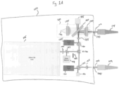
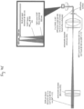
- Fig. 1A illustrates a dual-port laser system 100 for providing aiming beams and treatment beams of laser light through a first port 105 and providing a multiplexed beam of illumination light and a multi-spot pattern of laser aiming beams and treatment beams through a second port 110 in accordance with a particular embodiment of the present disclosure.
- the dual-port surgical laser system 100 includes a therapeutic laser source 115 for generating laser treatment beams used during an ophthalmic procedure.
- the therapeutic laser source 115 can generate a surgical treatment beam with a wavelength of around 532 nanometers (nm).
- the dual-port surgical laser system 100 also includes two aiming laser sources 120, 125 which produce aiming laser beams.
- the dual-port surgical laser system 100 also includes a port selector 130 that selectively directs the therapeutic laser beam to a first beam splitter 135 and the second beam splitter 140. Also, the two aiming laser sources 120, 125 respectively direct the aiming laser beams to the first beam splitter 135 and the second beam splitter 140.
- the dual-port surgical laser system 100 also includes a shutter 145 arranged between the therapeutic laser source 115 and the port selector 130.
- the shutter 145 alternatively blocks and transmits the treatment laser beam from reaching the port selector 130.
- a surgeon or surgical staff member can control the shutter 145 (e.g. via a foot switch, voice commands, etc.) to emit the laser aiming beam and fire the treatment laser beam (i.e. open the shutter 145 ) to treat patient anatomy, e.g. photocoagulation.
- the first beam splitter 135 and the second beam splitter 140 direct the laser beams towards the first port 105 and the second port 110, respectively.
- the first beam splitter 135 When the port selector 130 is in a first position, the first beam splitter 135 reflects portions of the treatment laser beam and transmits portions of the laser aiming beam towards the first port 105. The reflected portion of the laser aiming beam and the transmitted portion of the treatment laser beam can be directed towards a beam detector 150, a beam dump, a power monitor, etc. Also, a focusing lens 155 can be arranged between the first beam splitter 135 and the first port 105. The focusing lens 155 receives the treatment laser beam and the aiming laser beam from the first beam splitter 135 and focuses the treatment laser beam and the aiming laser beam onto an interface with an optical fiber 107 of a laser probe assembly 109 in the first port 105.
- the second beam splitter 140 When the port selector 130 is in a second position, the second beam splitter 140 reflects a portion of the laser aiming beam from the aiming laser source 125 towards a diffractive optical element (DOE) 165. The second beam splitter 140 also transmits substantially all of the treatment laser beam through to the DOE 165. In some embodiments, the laser aiming beam and the treatment laser beam are collimated or substantially collimated when they fall incident on the DOE 165.
- DOE diffractive optical element
- the DOE 165 receives the laser aiming beam and the treatment laser beam and creates a multi-spot laser pattern of laser light beams.
- the DOE 165 can be selected to diffract incident laser light into a multi-spot pattern that will align with an intended target geometry.
- the DOE 165 can be selected to create a 2X2 array pattern of laser light beams that substantially matches a 2X2 array of inner cores of a multi-core optical fiber cable that delivers the multiplexed light to the surgical probe, as explained in greater detail below.
- the DOE 165 is a moveable DOE 165 having a plurality of different diffraction regions selected for creating and transmitting various multi-spot patterns of laser light.
- the DOE 165 can be a movable linear stage with three diffraction regions for creating and transmitting multi-spot patterns of one, two, or four beams to the multi-core optical fiber cable.
- the multi-spot laser pattern of laser light beams travels towards a multiplexing assembly 160 before reaching the second port 110.
- the multiplexing assembly 160 of the dual-port surgical laser system 100 multiplexes the multi-spot pattern of laser light beams with an illumination light from an illumination light source 170.
- the illumination light source 170 can include one or more of a xenon illuminator, an RGB light-emitting diode (LED) illuminator, a white light LED illuminator, a laser-pumped phosphor illuminator, a supercontinuum white laser illuminator, etc.
- the multiplexing assembly 160 contains a collimating lens 175 for collimating or substantially collimating the illumination light from the illumination light source 170. Also, the multiplexing assembly 160 contains a beam splitter 180 that reflects a portion of the light spectrum and transmits a remaining portion of the light spectrum. More specifically, the beam splitter 180 can both: a) reflect the multi-spot pattern of laser aiming beams and treatment laser beams from the DOE 165 toward the second port 110 and b) transmit the illumination light (minus narrow bands of the spectrum corresponding with the laser aiming beam and the treatment laser beam) from the illumination light source 170 toward the second port 110. The beam splitter 180 reflects the narrow bands of the spectrum corresponding with the laser aiming beam and the treatment laser beam from the illumination light source 170 toward a beam detector 185 , a beam dump, a power monitor, etc.
- the beam splitter 180 can be configured to highly reflect light in a narrow band of the red spectrum and a narrow band of the green spectrum and configured to transmit the remaining electromagnetic spectrum.
- the beam splitter 180 reflects light in a first narrow band around 532 nanometers (nm) and in a second narrow band around 635 nm and transmits the remaining spectrum.
- the beam splitter 180 can be a dichroic beam splitter cube, a beamsplitter plate, etc.
- the multiplexing assembly 160 also contains a condensing lens 190 arranged between the beam splitter 180 and the second port 110.
- the multiplexed light including the Illumination light transmitted through the beam splitter 180 and the multi-spot pattern of laser light reflected by the beam splitter 180, falls incident on the condensing lens 190 before reaching the second port 110.
- the condensing lens 190 is selected to precisely focus the multiplexed light onto an interface with a proximal end of a multi-core optical fiber cable 112 (as explained below) coupled with an illuminated multi-spot laser probe 114.
- the dual-port surgical laser system 100 can also include an optical element 195 for transforming the polarization of the laser light emitted by the therapeutic laser source 115. It can be beneficial to have the linearly polarized treatment laser beam polarization and linearly polarized aiming laser beam polarization be oriented vertically because that will ensure the beamsplitter can be designed to most efficiently reflect the multi-spot pattern of laser beams while minimizing the transmitted white light discoloration and maximizing its throughput.
- the aiming laser sources 120, 125 originate from cylindrical laser diodes that can be axially rotated to achieve vertical polarization.
- the therapeutic laser source 115 can be a diode-pumped solid-state (DPSS) laser.
- DPSS diode-pumped solid-state
- the therapeutic laser source 115 can be a semiconductor laser that naturally emits horizontally polarized light in a conventional mounting configuration. Therefore, to transform the horizontally polarized beam to a vertically polarized beam, the optical element 195 can rotate the polarization of the treatment laser beam.
- optical element 195 can be a half-wave plate, a quartz-crystal polarization rotator, or a metamaterial polarization rotator.
- the dual-port surgical laser system 100 can also include a mirror 197 for directing a small portion of the treatment laser beam from the therapeutic laser source 115 to a power monitor 199.
- Fig. 1B illustrates another surgical laser system 100'for providing a multiplexed beam of illumination light and a multi-spot pattern of laser aiming beams and treatment beams in accordance with a particular embodiment of the present disclosure.
- the surgical laser system 100' includes a therapeutic laser source 115' for generating laser treatment beams used during an ophthalmic procedure and an aiming laser source 125' that produces an aiming laser beam.
- the therapeutic laser source 115' and the aiming laser source 125' can both direct their emitted beams to a beam splitter 140' that reflects ' the laser aiming beam and transmits the laser treatment beam towards a diffractive optical element (DOE) 165'.
- DOE diffractive optical element
- the DOE 165' receives the laser aiming beam and the treatment laser beam and creates a multi-spot laser pattern of laser light beams.
- a DOE 165' can be selected to create a 2X2 array pattern of laser light beams that substantially matches a 2X2 array of inner cores of a multi-core optical fiber cable that delivers the multiplexed light to the surgical probe, as explained in greater detail below.
- the multi-spot laser pattern of laser light beams travels towards a multiplexing assembly 160' before reaching a port 110'.
- the multiplexing assembly 160' of the surgical laser system 100' multiplexes the multi-spot pattern of laser light beams with an illumination light from an illumination light source 170'.
- the multiplexing assembly 160' contains a collimating lens 175' for collimating or substantially collimating the illumination light from the illumination light source 170.
- the multiplexing assembly 160' contains a beam splitter 180' that both: a) reflects the multi-spot pattern of laser aiming beams and treatment laser beams from the DOE 165' toward the port 110' and b) transmits the illumination light (minus narrow bands of the spectrum corresponding with the laser aiming beam and the treatment laser beam) from the illumination light source 170' toward the port 110'.
- the beam splitter 180' reflects the narrow bands of the spectrum corresponding with the laser aiming beam and the treatment laser beam from the illumination light source 170' toward a beam detector 185', a beam dump, a power monitor, etc.
- the multiplexing assembly 160' further contains a condensing lens 190' arranged between the beam splitter 180' and the port 110'.
- the condensing lens 190' can be selected to precisely focus the multiplexed light onto an interface with a proximal end of a multi-core optical fiber cable 112' (as explained below) coupled with an illuminated multi-spot laser probe 114'.
- the surgical laser system 100' can also include one or more of a shutter 145' arranged between the therapeutic laser source 115' and the DOE 165', an optical element 195' for transforming the polarization of the laser light emitted by the therapeutic laser source 115', and a mirror 197' for directing a portion of the treatment laser beam from the therapeutic laser source 115' to a power monitor 199'.
- a shutter 145' arranged between the therapeutic laser source 115' and the DOE 165'
- an optical element 195' for transforming the polarization of the laser light emitted by the therapeutic laser source 115'
- a mirror 197' for directing a portion of the treatment laser beam from the therapeutic laser source 115' to a power monitor 199'.
- Fig. 2 illustrates a method 200 for multiplexing a multi-spot pattern of laser light beams and illumination light in accordance with a particular embodiment of the present disclosure.
- the method 200 involves creating a multi-spot pattern of laser light beams by directing the collimated laser light beam onto a diffractive optical element (DOE) at step 205, and directing the multi-spot pattern of laser light beams to a beamsplitter at step 210.
- DOE diffractive optical element
- the method 200 also involves collimating an illumination beam using a collimating lens at step 215 and directing the collimated illumination beam to a beamsplitter at step 220.
- the method 200 involves multiplexing, using the beamsplitter, the multi-spot pattern of laser light with the collimated illumination beam at step 225. More specifically, in some cases, multiplexing the multi-spot pattern of laser light with the collimated illumination beam can involve the beamsplitter reflecting laser aiming and treatment beams from the surgical laser system toward a condensing lens and transmitting the illumination light from the illumination light source towards the condensing lens.
- the method 200 also involves focusing, with a condensing lens, the multiplexed beam of multi-spot pattern of laser light and illumination light onto an interface with a multi-core optical fiber cable of a surgical handpiece at step 230 and, subsequently, directing the multiplexed beam of multi-spot pattern of laser light beams and illumination light through a lens in the surgical handpiece at step 235 , as described in more detail below.
- the intensities of the white illumination and the laser aiming beams can be adjusted (e.g. at the illumination light source and surgical laser system, respectively) to provide the right amount of laser aiming beam contrast against the white while providing enough white illumination to easily see the retina.
- a condensing lens can be selected to precisely focus the multiplexed light onto an interface of the terminal end of the multi-core optical fiber cable such that an illumination beam and laser aiming/treatment beams are propagated down an entire length of the multi-core optical fiber cable and into a surgical hand probe. More specifically, the condensing lens can be selected such that resulting light cones of light from the illumination beam and laser aiming/treatment beams have an acceptance angle and a numerical aperture (NA) to interface with the various fiber core and cladding materials used in the multi-core optical fiber cable such that the illumination beam and the laser aiming/treatment beams are propagated down the appropriate core fibers the entire length of the multi-core optical fiber cable.
- NA numerical aperture
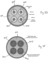
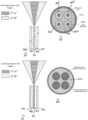
- Fig. 3A illustrates the top view of a proximal end of a multi-core optical fiber cable 330 according to some embodiments of the present disclosure.
- the multi-core fiber cable 330 can include four inner core fibers 305 with a relatively small-diameter and a relatively small NA inside of an outer core fiber 310 having a relatively large diameter and a relatively large NA.
- the outer core fiber 310 can be contained within an outer-core cladding 315 with refractive index ( n clad1 ) and the inner core fibers 305 can be contained within an inner-core cladding 320 with refractive index ( n clad2 ).
- the outer core 310 has a core diameter (d core2 ) and the inner cores 305 can have a core diameter (d core1 ).
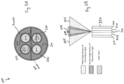
- Fig. 3B illustrates a side view of the interface of a plurality of light cones 335 , 340 , 345 onto a terminal end of a multi-core optical fiber cable 330 according to some embodiments of the present disclosure.
- the multi-core optical fiber cable 330 in Fig. 3B shows the outer core fiber 310 and two of the inner core fibers 305.
- the outer-core cladding 315 and the inner-core cladding 320 is not depicted in Fig. 3B .
- Also represented are a wide-angle portion of the illumination light cone 335, a narrow angle portion of the illumination light cone 340, and the laser light cone 345.
- the selection of the condensing lens is related to the half-angle of each of the light cones. Therefore, selecting a condensing lens can involve selecting a condensing lens based on the NA of the light, the acceptance angle of the light cones, and the refractive indices of the materials of the outer core fiber 310, the outer-core cladding 315, the inner core fibers 305, and the inner-core cladding 320.
- the condensing lens is designed to focus laser light down onto the multi-core fiber interface with the desired beam NA.
- the refractive indices of the inner core fibers 305 and inner cladding-core claddings 320 are selected according to an NA calculation (shown below) so that the NA of the inner cores is equal to or greater than the beam NA, thereby ensuring confinement of the beams within the inner core regions as they propagate down the lengths of the inner core fibers 305.
- a refractive index ( n core2 ) of the outer core fiber 310 is greater than a refractive index ( n clad2 ) of the outer-core cladding 315 .
- a refractive index ( n core1 ) of each of the inner cores fibers 305 is greater than a refractive index ( n clad1 ) of the inner-core cladding 320 .
- the refractive index (n core1 ) of each or the inner cores fibers 305 is larger than the refractive index ( n clad1 ) of the outer-core cladding 315 .
- NA 1 n core 1 2 ⁇ n clad 1 2
- the materials for the outer core fiber 310 , the outer-core cladding 315 , the inner core fibers 305 , and the inner-core cladding 320 are selected such that NA 2 is much larger than NA 1 .
- the outer core can be an undoped fused silica with an index of substantially 1.46.
- the red aiming laser beam has an NA of about 0.044 and the green treatment laser beam has an NA of about 0.0657. Therefore, as long as the numerical aperture (NA 1 ) for the inner core fiber 305 is larger than 0.0657, the red and green laser beams will remain confined within the inner cores 305 as they propagate down the probe. So, a silica fiber with an NA of 0.22 used for the outer core 310 may confine the laser beams.
- the illumination beam etendue When the illumination beam etendue is greater than outer core 310 etendue, then coupling efficiency into outer core 310 is less than one hundred percent regardless of condenser lens focal length choice. However, if the illumination beam etendue (which is the product of the illumination beam angular width and spot width) is less than the outer core 310 etendue, then one hundred percent coupling efficiency (neglecting Fresnel reflection losses) can occur if the condensing lens focus is designed correctly. If the condensing lens has too short of a focus, the converging beam may have an NA greater than core 310 NA, and coupling efficiency may be degraded.
- the condensing lens has too long of a focal length, then the focused beam diameter may be larger than the 310 diameter, and coupling efficiency may be degraded. However if the condensing lens focal length is adjusted so that beam NA is less than or equal to the fiber NA, and the beam diameter is less than or equal to the fiber core diameter, then one hundred percent or near one hundred percent coupling efficiency can occur.
- the illumination beam may both spatially and angularly underfill the outer core 310, which will permit spatial and angular misalignments without a loss of coupling efficiency. Also, since the illumination beam NA is >> NA1, off-axis rays can frequently pass in and out of the inner cores 305 and inner core cladding 320 as the rays propagate down the length of the multi-core optical fiber cable 330.
- Fig. 3C illustrates the cut-away view of a multi-core optical fiber cable 350 according to some embodiments of the present disclosure.
- the multi-core fiber cable 350 includes four fused silica inner core fibers 305 with a 75 micrometer diameter and a numerical aperture (NA) of 0.22 inside of a non-doped fused silica outer core fiber 310 having a 300 micrometer diameter and an NA of 0.47.
- the outer core fiber 310 can be contained within low-index polymer cladding 315 having a 25 micrometer thickness and the inner core fibers 305 can be contained within fluorine-doped fused silica inner-core cladding 320 having a 15 micrometer thickness.
- the multi-core optical fiber cable 350 can be further contained in an Ethylene Tetrafluoroethylene (ETFE) coating 375.
- Ethylene Tetrafluoroethylene (ETFE) coating 375 Ethylene Tetrafluoroethylene
- the four fused silica inner core fibers 305 have a refractive index of 1.46 at 532 nanometers.
- the non-doped fused silica outer core fiber 310 have a refractive index of 1.46 at 532 nanometers.
- the fluorine-doped fused silica inner-core cladding 320 can have a refractive index of 1.4433 at 532 nanometers.
- the low-index polymer cladding 315 can have a refractive index of 1.38228 at 532 nanometers.
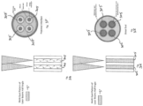
- Fig. 3D illustrates a proximal, interface end of the multi-core optical fiber cable with a red laser aiming beam spot and a green laser treatment beam spot lining up with the inner cores 305 and the illumination light beam spot lining up with the outer core 310.
- Fig. 3E illustrates the distal end of the multi-core optical fiber cable with all three beams spread out to totally spatially fill their respective cores.
- Figs. 3F-3L illustrate the propagation of the multiplexed light through the multi-core optical fiber cable.
- Fig. 3F illustrates a proximal, interface end of the multi-core optical fiber cable with a red laser aiming beam spot and a green laser treatment beam spot lining up with the inner cores 305.
- Fig. 3G illustrates two light cones from the multi-spot pattern of laser light (with the multiplexed illumination light emitted for image clarity) propagating down the lengths of a multi-core optical fiber cable.
- Fig. 3H illustrates the laser beams spread out to totally spatially fill the inner cores 305 .
- Fig. 3I illustrates the distal end of the multi-core optical fiber cable with the laser beams spread out to totally spatially fill the inner cores 305.
- Fig. 3J illustrates a proximal, interface end of the multi-core optical fiber cable with the illumination light spot lining up with the outer core 310.
- Fig. 3K illustrates a light cone of the illumination light (with the multiplexed multi-spot pattern of laser light beams emitted for image clarity), with the light cone including a narrow half-angle portion of the light cone and a wide half-angle portion.
- the narrow half-angle portion of the light cone propagates the lengths of the outer cores 310, but is excluded from the inner cores 305.
- the wide half-angle portion of the illumination light cone fills the length of the outer core 310 and the inner cores 305.
- Fig. 3L illustrates the illumination beam spread out to totally spatially fill the outer core 310.
- Fig. 3M illustrates the distal end of the multi-core optical fiber cable with the illumination beam spread across the outer cores 310 and the inner cores 305.
- Fig. 3N illustrates the cut-away view of another multi-core optical fiber cable 380 according to some embodiments of the present disclosure.
- the multi-core fiber cable 380 includes four germanium-doped silica inner core fibers 385 with a 75 micrometer diameter and a numerical aperture (NA) of 0.22 inside of a non-doped fused silica outer core fiber 390 having a 300 micrometer diameter and an NA of 0.47.
- the outer core fiber 390 can be contained within low-index polymer cladding 395 having a 25 micrometer thickness.
- the multi-core optical fiber cable 380 can be further contained in an Ethylene Tetrafluoroethylene (ETFE) coating 376.
- Ethylene Tetrafluoroethylene (ETFE) coating 376 Ethylene Tetrafluoroethylene
- the four germanium-doped silica inner core fibers 385 have a refractive index of substantially 1.47648 at 532 nanometers.
- the non-doped fused silica outer core fiber 390 have a refractive index of 1.46 at 532 nanometers.
- the low-index polymer cladding 395 can have a refractive index of 1.38228 at 532 nanometers.
- the white illumination spot at the distal end of the multi-core optical fiber is somewhat larger than the 2X2 array of laser spots.
- this geometry is desired, because it provides illumination into both the retinal treatment target area as well as some surrounding retina and because the illumination spot small enough to keep the white light fairly concentrated.
- the geometry enables adequate white irradiance at the retina with a relatively small core diameter fiber.
- the intensities of the white illumination and the laser aiming beams can be adjusted (e.g., at the Illumination Light Source and Surgical Laser System, respectively) to provide the right amount of laser aiming beam contrast against the white while providing enough white illumination to easily see the retina.
- Fig. 4 illustrates a method 400 of creating an image of a multiplexed beam of multi-spot pattern of laser light beams and illumination light.
- the method involves selecting materials for a multi-core optical fiber cable to ensure confinement of the beams within the various core regions as they propagate down the lengths fiber cable, as explained above, at step 405.
- the method 400 also involves determining a numerical aperture of laser light beams from a laser source and a numerical aperture of an illumination light beam from an illumination light source at step 410 and selecting a condensing lens to focus the multiplexed multi-spot pattern of laser light beams and illumination beam onto an interface plane of the multi-core optical fiber cable at step 415.
- the method 400 involves multiplexing a multi-spot pattern of laser light beams with the illumination light beam at step 420, focusing the multiplexed multi-spot pattern of laser light beams and illumination beam onto an interface plane of the multi-core optical fiber cable at step 425, and directing the multiplexed beam of multi-spot pattern of laser light beams and illumination light through a lens in the surgical handpiece at step 430.
- an incoherent white light illumination light source can be replaced with a white laser system (e.g. a supercontinuum laser system).
- a white laser system e.g. a supercontinuum laser system
- the etendue of the white laser beam may be small enough that it is less than the nanofiber etendue and can be efficiently coupled into the nanofiber, such that a multi-core optical fiber cable as described above can be used to deliver multiplexed laser aiming and treatment beams and white laser illumination.
- the distal end of the multi-core optical fiber cable terminates within a tip of a surgical hand probe that is inserted into a patient's eye.
- the tip of the surgical hand probe can also include a lens to image the multiplexed beams onto patient anatomy, e.g. the retina.
- Fig. 5A illustrates an open side view of a tip 505 of a surgical hand probe according to some embodiments of the present disclosure.
- the probe tip 505 can comprise a cannula 535 (e.g., a stainless steel cannula) with a cannula distal end 530 and the probe tip containing the multi-core optical fiber 510 and a lens 515.
- the lens 515 can be a graded-index (GRIN) lens and an air gap 525 can be left open between the GRIN lens 515 and the distal end of the multi-core optical fiber 510.
- the air gap 525 can be sized such that the light emitted from the multi-core optical fiber 510 experiences an amount of spread before falling incident on the GRIN lens 515 and such that the GRIN lens 515 images the light onto the patient anatomy.
- the multi-core optical fiber 510 and lens 515 are substantially butted up against one other with positive pressure to avoid air-gap tolerance concerns, allowing less chance for peripheral off-axis rays to travel far enough off axis to reflect off of the cylindrical side wall of the GRIN lens.
- using a conventional lens instead of the GRIN lens involves an air gap between the multi-core optical fiber 510 and lens 515 to focus the light properly.
- the lens 515 is secured within the probe tip 505 with an optical adhesive 520.
- an optical adhesive 520 As shown in Fig. 5A , a multi-spot pattern of green, 532 nm laser light is projected retinal tissue located 4 millimeters from the cannula distal end 530.
- Fig. 5B illustrates an open side view of another tip 540 of a surgical hand probe according to some embodiments of the present disclosure.
- the probe tip 540 can comprise a cannula 545 with a cannula distal end 550 and the probe tip containing the multi-core optical fiber 555 and a lens 560.
- the lens 560 illustrated in Fig. 5B is a Plano-convex glass lens. Also, the Plano-convex lens 560 is secured in the cannula 545 by a retaining feature 565.
- an air gap 570 can be sized such that the light emitted from the multi-core optical fiber 555 experiences an amount of spread before falling incident on the Plano-convex lens 560 and such that the Plano-convex lens 560 images the light onto the patient anatomy.
- a surgical laser system e.g., surgical laser systems 100, 100'
- a surgical laser system can alternatively generate a surgical treatment beam with a wavelength of around 532 nanometers (nm) (i.e., green) and a laser aiming beam with a wavelength of around 635 nm (i.e., red).
- red and green incident laser light diffract off a DOE with different diffraction angles.
- the DOE can have a fixed requirement for the collimated laser beam diameter. Therefore some embodiments of the disclosed technology involve collimating the multiple beams with a selected beam diameter for the DOE.
- Fig. 6 illustrates a laser light multiplexing assembly 600 with a two-lens beam compressor 605 for achieving correct collimated laser beam diameter for a diffraction optical element (DOE) 665.
- the two-lens beam compressor 605 can include two achromatic doublets 607 , 609 for focusing and then re-collimating the laser beams and for directing the collimated beams to the DOE 665 with an appropriate beam diameter.
- Fig. 6 includes precise dimensions for a specific embodiment; however, those with ordinary skill in the art having the benefit of the present disclosure will readily appreciate that other lens, dimensions, etc. can be used to achieve collimated laser beams having the appropriate lens diameter for other DOEs.
- the laser light multiplexing assembly 600 also includes a collimating lens 675 for collimating or substantially collimating the illumination light from an illumination light source 670 and a beam splitter 680 that both: a) reflects the multi-spot pattern of laser aiming beams and treatment laser beams from the DOE 665 and b) transmits the illumination light (minus narrow bands of the spectrum corresponding with the laser aiming beam and the treatment laser beam) from the illumination light source 670.
- the laser light multiplexing assembly 600 further contains a condensing lens 690 arranged between the beam splitter 680 and a port 610 for coupling with a multi-core optical fiber cable 612 of an illuminated multi-spot laser probe assembly.
- the condensing lens 690 can be selected to precisely focus the multiplexed light onto an interface with a proximal end of the multi-core optical fiber cable 612.
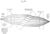
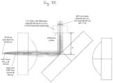
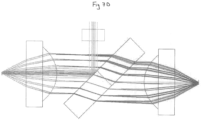
- Figs. 7A-7G illustrate examples of ray trace models of a multiplexing assembly according to some embodiments of the disclosed technology.
- Figs. 7A -&B illustrates examples of a ray trace for white illumination light through a multiplexing assembly.
- Fig. 7C illustrates an example of a ray trace for laser treatment beams reflected from a beam splitter in a multiplexing assembly.
- Fig. 7D illustrates an example of a ray trace of white illumination light and laser treatment beams in a multiplexing assembly.
- Fig. 7E illustrates an example of a ray trace for laser treatment beams directed through a two-lens compressor, reflected from a beam splitter, and focused by a condensing lens.
- Fig. 7F-7G illustrate examples a ray trace for white illumination light through a multiplexing assembly.
Description
- The present disclosure relates to a multiple-input-coupled illuminated multi-spot laser system, and more specifically to systems for creating multi-spot laser light beams, multiplexing an illumination light and the multi-spot laser light beams, and delivering the multiplexed light to a surgical handpiece via a multi-core optical fiber cable.
- In many ophthalmic procedures a surgeon is required to use a variety of instruments in the patient's eye. For example, during a vitreoretinal surgery, a surgeon oftentimes manipulates a first handpiece for directing an illumination light beam onto the retinal surface in order to view patient anatomy and also manipulates an additional laser probe handpiece for delivering a laser treatment beam for treating the patient anatomy. However, there is a need for a multiple-input-coupled illuminated multi-spot laser system. Reference is made to documents
JP2013048864 US 2008243108 which have been cited as relating to the background state of the art. - It will be appreciated that the scope is in accordance with the claims. Accordingly, there is provided a laser system as defined in
claim 1. Further features are provided in the dependent claims. The specification may include arrangements outside the scope of the claims provided as background and to assist in understanding the invention. - The disclosed embodiments of the present technology relate to multiple-input-coupled illuminated multi-spot laser probes and systems for multiplexing an illumination light and multi-spot laser light.
- The technology involves a laser system with a therapeutic laser source, an aiming laser source, a diffractive optical element (DOE) that creates a multi-spot pattern of laser beams, an illumination system, and a multiplexing assembly that multiplexes the multi-spot pattern of laser beams with light from the illumination system. The disclosed technology also involves a condensing lens for focusing the multiplex light onto an interface with a multi-core optical fiber cable, selecting the materials used in a multi-core optical fiber cable, designing the condensing lens to ensure that the illumination beam and the laser aiming/treatment beams are propagated down an entire length of the multi-core optical fiber cable, and providing the ability of a surgical probe to simultaneously deliver illumination light and a multi-spot pattern of laser light beams to patient anatomy.
- A laser system includes therapeutic laser source that produces a treatment laser beam having a wavelength substantially equal to 532nm and directs the treatment laser beam to the DOE. The laser system also includes an aiming laser source that produces a laser aiming beam having a wavelength substantially equal to 635nm and directs the laser aiming beam to a beamsplitter for directing the laser aiming beam to the DOE. The laser system can also include a shutter arranged between the therapeutic laser source and the DOE that alternatively blocks and transmits the treatment laser beam from reaching the DOE. The DOE creates a multi-spot laser pattern from the aiming laser beam and the treatment laser beam when the shutter transmits the treatment laser beam.
- The laser system also includes an illumination system that emits substantially white light and a collimating lens that collimates the substantially white light received from the illumination system into an illumination beam. The laser system also includes a multiplexing beam splitter arranged to receive the illumination beam and the multi-spot laser pattern from the DOE, reflect the multi-spot laser pattern towards a condensing lens, and transmit the illumination beam from the collimating lens towards the condensing lens, thereby multiplexing the multi-spot laser pattern and the illumination beam. The condensing lens focuses a multiplexed beam of the illumination beam and the multi-spot pattern onto an interface with a port.
- In some cases, the laser system includes beam compressor arranged between the therapeutic laser source and the DOE that collimates the treatment beam to a diameter selected based on the attributes of the DOE and a desired multi-spot pattern. Also, the laser system can include an optical element configured to transform a horizontally polarized treatment beam from the therapeutic laser source into a vertically polarized treatment beam. The optical element can be a half-wave plate, a quartz-crystal polarization rotator, or a metamaterial polarization rotator.
- The laser system can also include a laser probe assembly having a multi-core optical fiber cable with a plurality of inner cores contained within an outer core. The plurality of inner cores contained within the outer core can match the multi-spot pattern created by the DOE.
- In some cases, the multi-core optical fiber cable has a proximal end which, when coupled with the port, substantially abuts the interface in the port such that the focused, multiplexed multi-spot pattern and the illumination beam are focused on a proximal end of the multi-core optical fiber cable. The condensing lens and the materials for the multi-core optical fiber cable can be selected to ensure that the illumination beam and the laser aiming/treatment beams are propagated down an entire length of the multi-core optical fiber cable. Some cases involve the outer core surrounded by an outer-core cladding and a plurality of inner cores contained within the outer core, each inner core in the plurality of inner cores surrounded by an inner-core cladding. In these cases, a refractive index of the outer core is greater than a refractive index of the outer-core cladding, a refractive index of each of the inner cores in the plurality of inner cores is greater than a refractive index of the inner-core cladding, and a refractive index of each or the inner cores in the plurality of inner cores is larger than the refractive index of the outer-core cladding.
- The laser probe assembly can also include a surgical handpiece at the distal end of the multi-core optical fiber cable. The surgical handpiece can have a probe tip with a lens that translates a geometry of the multiplexed multi-spot laser pattern and illumination beam from the distal end of the multi-core optical fiber cable onto a target surface.
- For explanatory purpose methods of multiplexing a multi-spot pattern of laser light beams with an illumination light beam are described, which are explicitly not part of the claimed invention. The methods can involve directing a laser light beams to an optical element for collimating the laser light beam and directing the collimated laser light beam to a diffractive optical element (DOE) to create a multi-spot laser pattern of laser light beams. Likewise, the methods can involve directing the multi-spot pattern of laser light beams and an illumination light beam to a beamsplitter. Next, methods can involve the beamsplitter reflecting the multi-spot pattern of laser light beams towards a condensing lens and transmitting the illumination light beam to the condensing lens, thereby multiplexing the multi-spot pattern of laser light beams and a transmitted illumination beam. The methods can also involve the condensing lens focusing the multiplexed multi-spot pattern of laser light beams and transmitted illumination beam onto an interface with a multi-core optical fiber cable. Also, the methods can involve directing the multiplexed multi-spot pattern of laser light beams and transmitted illumination beam through the multi-core optical fiber cable and onto a lens in a probe tip. The methods can also involve the lens translating the geometry of the multiplexed multi-spot laser pattern of laser light beams and illumination beam from the distal end of the multi-core optical fiber cable onto a target surface.
- The disclosed technology can also involve creating an image of a multiplexed beam of multi-spot pattern of laser light beams and illumination light on patient anatomy by selecting materials for a multi-core optical fiber cable to ensure confinement of the beams within the various core regions as they propagate down the lengths fiber cable. The methods can involve determining a numerical aperture of laser light beams from a laser source and a numerical aperture of an illumination light beam from an illumination light source and selecting a condensing lens to focus the multiplexed multi-spot pattern of laser light beams and illumination beam onto an interface plane of the multi-core optical fiber cable to ensure confinement of the beams within the various core regions as they propagate down the lengths fiber cable.
- The disclosed technology also includes a dual-port laser system with a first port for providing laser treatment beams and aiming laser beams to a laser probe and with an additional port for providing a multiplexed beam of illumination light and a multi-spot pattern of laser light beams to a multi-core optical fiber cable coupled with an illuminated multi-spot laser probe. The dual-port laser system includes a port selector for selectively directing the therapeutic laser beam to a first beam splitter and an additional beam splitter. The dual-port laser system also includes one or more aiming laser sources for directing an aiming laser beam to the first beam splitter and/ or the second beam splitter. The first beam splitter directs the treatment laser beam and the aiming laser beam to the first port and the additional beam splitter directs portions of the treatment laser beam and the aiming laser beam to a diffractive optical element (DOE). The DOE creates a multi-spot laser pattern from the treatment laser beam and the aiming laser beam.
- The dual-port laser system also includes a multiplexing beam splitter arranged to receive an illumination light beam from an illumination source and the multi-spot laser pattern from the DOE. The multiplexing beam splitter reflects the multi-spot laser pattern towards a condensing lens and to transmit an illumination beam from a collimating lens towards the condensing lens, thereby multiplexing the multi-spot laser pattern and the illumination beam. Also, the condensing lens focuses a multiplexed beam of the illumination beam and the multi-spot pattern onto an interface in the additional port.
- The dual-port laser system can include one or more beam detectors, power monitors, beam dumps, etc. Also the dual-port laser system can include an optical element for transforming a horizontally polarized treatment beam from the therapeutic laser source into a vertically polarized treatment beam. The optical element can be a half-wave plate, a quartz-crystal polarization rotator, or a metamaterial polarization rotator. The dual-port laser system can also include a shutter that selectively blocks and transmits the treatment laser beam from reaching the port selector.
- For a more complete understanding of the present technology, its features, and its advantages, reference is made to the following description, taken in conjunction with the accompanying drawings, in which:
-
Fig. 1A illustrates a dual-port laser system in accordance with a particular embodiment of the present disclosure; -
Fig. 1B illustrates a surgical laser system for providing a multiplexed beam of illumination light and a multi-spot pattern of laser aiming beams and treatment beams in accordance with a particular embodiment of the present disclosure; -
Fig. 2 illustrates a method for multiplexing a multi-spot pattern of laser light beams and illumination light; -
Fig. 3A illustrates the top view of a proximal end of a multi-core optical fiber cable in accordance with a particular embodiment of the present disclosure; -
Fig. 3B illustrates a side view of the interface of a plurality of light cones onto a terminal end of a multi-core optical fiber cable in accordance with a particular embodiment of the present disclosure; -
Fig. 3C illustrates the cut-away view of a multi-core optical fiber cable in accordance with a particular embodiment of the present disclosure; -
Fig. 3D illustrates a proximal, interface end of the multi-core optical fiber cable in accordance with a particular embodiment of the present disclosure with a red laser aiming beam spot and a green laser treatment beam spot lining up with the inner cores and the illumination light beam spot lining up with the outer core; -
Fig. 3E illustrates the distal end of the multi-core optical fiber cable in accordance with a particular embodiment of the present disclosure with all three beams spread out to totally spatially fill their respective cores; -
Fig. 3F illustrates a proximal, interface end of the multi-core optical fiber cable in accordance with a particular embodiment of the present disclosure with a red laser aiming beam spot and a green laser treatment beam spot lining up with the inner cores; -
Fig. 3G illustrates two light cones from the multi-spot pattern of laser light propagating down the lengths of a multi-core optical fiber cable in accordance with a particular embodiment of the present disclosure; -
Fig. 3H illustrates the laser beams spread out to totally spatially fill the inner cores in accordance with a particular embodiment of the present disclosure; -
Fig. 3I illustrates the distal end of the multi-core optical fiber cable with the laser beams spread out to totally spatially fill the inner cores in accordance with a particular embodiment of the present disclosure; -
Fig. 3J illustrates a proximal, interface end of the multi-core optical fiber cable in accordance with a particular embodiment of the present disclosure with the illumination light spot lining up with the outer core; -
Fig. 3K illustrates a light cone of the illumination light in accordance with a particular embodiment of the present disclosure with the light cone including a narrow half-angle portion of the light cone and a wide half-angle portion; -
Fig. 3L illustrates the illumination beam spread out to totally spatially fill the outer core in accordance with a particular embodiment of the present disclosure; -
Fig. 3M illustrates the distal end of the multi-core optical fiber cable in accordance with a particular embodiment of the present disclosure with the illumination beam spread across the outer cores and the inner cores; -
Fig. 3N illustrates the cut-away view of another multi-core optical fiber cable in accordance with a particular embodiment of the present disclosure; -
Fig. 4 illustrates a method of creating an image of a multiplexed beam of multi-spot pattern of laser light beams and illumination light; -
Fig. 5A illustrates an open side view of a tip of a surgical hand probe in accordance with a particular embodiment of the present disclosure; -
Fig. 5B illustrates an open side view of another tip of a surgical hand probe in accordance with a particular embodiment of the present disclosure; -
Fig. 6 illustrates a laser light multiplexing assembly in accordance with a particular embodiment of the present disclosure with a two-lens beam compressor for achieving correct collimated laser beam diameter for a diffraction optical element; and -
Figs. 7A-7G illustrate examples of ray trace models of a multiplexing assembly in accordance with a particular embodiment of the present disclosure. - In a wide variety of medical procedures, laser light is used to assist the procedure and treat patient anatomy. For example, a vitreoretinal surgery oftentimes involves using a laser treatment beam for photocoagulation of retinal tissue. Vitreoretinal procedures commonly involve a laser probe that is capable of alternately emitting an aiming laser beam to select target spots on retinal tissue and emitting a treatment laser beam to perform the photocoagulation at the targeted spots. Frequently, the laser probe utilizes light in a red band of the electromagnetic spectrum for the aiming beam and light in a green band of the electromagnetic spectrum for the treatment beam. Also, during a panretinal laser photocoagulation procedure, a surgeon selects thousands of spots on retinal tissue to apply the treatment laser beam to, resulting in a very long and tedious procedure. Therefore, a laser probe capable of producing a multi-spot pattern of laser light is desirable.
- Vitreoretinal procedures also benefit from illumination light being directed into the eye and onto retinal tissue. Vitreoretinal surgeons oftentimes use a laser probe handpiece for delivering the laser aiming beams and laser treatment beams and also use an additional handpiece for directing an illumination light beam onto the retinal surface in order to view patient anatomy.
- The field of vitreoretinal surgery, as well as other medical laser procedures, would benefit from multiplexing an illumination light and multi-spot laser light. Accordingly, the technology described herein involves multiple-input-coupled illuminated multi-spot laser probes, adaptors and other systems for multiplexing an illumination light and multi-spot laser light, and methods for multiplexing an illumination light and multi-spot laser light and delivering the multiplexed light onto patient anatomy.
-
Fig. 1A illustrates a dual-port laser system 100 for providing aiming beams and treatment beams of laser light through a first port 105 and providing a multiplexed beam of illumination light and a multi-spot pattern of laser aiming beams and treatment beams through a second port 110 in accordance with a particular embodiment of the present disclosure. - The dual-port
surgical laser system 100 includes a therapeutic laser source 115 for generating laser treatment beams used during an ophthalmic procedure. For example, the therapeutic laser source 115 can generate a surgical treatment beam with a wavelength of around 532 nanometers (nm). The dual-portsurgical laser system 100 also includes two aiminglaser sources 120, 125 which produce aiming laser beams. - The dual-port
surgical laser system 100 also includes a port selector 130 that selectively directs the therapeutic laser beam to a first beam splitter 135 and the second beam splitter 140. Also, the two aiminglaser sources 120, 125 respectively direct the aiming laser beams to the first beam splitter 135 and the second beam splitter 140. - The dual-port
surgical laser system 100 also includes a shutter 145 arranged between the therapeutic laser source 115 and the port selector 130. The shutter 145 alternatively blocks and transmits the treatment laser beam from reaching the port selector 130. A surgeon or surgical staff member can control the shutter 145 (e.g. via a foot switch, voice commands, etc.) to emit the laser aiming beam and fire the treatment laser beam (i.e. open the shutter 145) to treat patient anatomy, e.g. photocoagulation. In each case, the first beam splitter 135 and the second beam splitter 140 direct the laser beams towards the first port 105 and the second port 110, respectively. - When the port selector 130 is in a first position, the first beam splitter 135 reflects portions of the treatment laser beam and transmits portions of the laser aiming beam towards the first port 105. The reflected portion of the laser aiming beam and the transmitted portion of the treatment laser beam can be directed towards a beam detector 150, a beam dump, a power monitor, etc. Also, a focusing lens 155 can be arranged between the first beam splitter 135 and the first port 105. The focusing lens 155 receives the treatment laser beam and the aiming laser beam from the first beam splitter 135 and focuses the treatment laser beam and the aiming laser beam onto an interface with an optical fiber 107 of a
laser probe assembly 109 in the first port 105. - When the port selector 130 is in a second position, the second beam splitter 140 reflects a portion of the laser aiming beam from the aiming
laser source 125 towards a diffractive optical element (DOE) 165. The second beam splitter 140 also transmits substantially all of the treatment laser beam through to theDOE 165. In some embodiments, the laser aiming beam and the treatment laser beam are collimated or substantially collimated when they fall incident on theDOE 165. - The
DOE 165 receives the laser aiming beam and the treatment laser beam and creates a multi-spot laser pattern of laser light beams. TheDOE 165 can be selected to diffract incident laser light into a multi-spot pattern that will align with an intended target geometry. For example, theDOE 165 can be selected to create a 2X2 array pattern of laser light beams that substantially matches a 2X2 array of inner cores of a multi-core optical fiber cable that delivers the multiplexed light to the surgical probe, as explained in greater detail below. - In some cases the
DOE 165 is amoveable DOE 165 having a plurality of different diffraction regions selected for creating and transmitting various multi-spot patterns of laser light. For example, theDOE 165 can be a movable linear stage with three diffraction regions for creating and transmitting multi-spot patterns of one, two, or four beams to the multi-core optical fiber cable. - From the
DOE 165, the multi-spot laser pattern of laser light beams travels towards a multiplexingassembly 160 before reaching the second port 110. The multiplexingassembly 160 of the dual-portsurgical laser system 100 multiplexes the multi-spot pattern of laser light beams with an illumination light from an illumination light source 170. In some cases, the illumination light source 170 can include one or more of a xenon illuminator, an RGB light-emitting diode (LED) illuminator, a white light LED illuminator, a laser-pumped phosphor illuminator, a supercontinuum white laser illuminator, etc. - The multiplexing
assembly 160 contains acollimating lens 175 for collimating or substantially collimating the illumination light from the illumination light source 170. Also, the multiplexingassembly 160 contains abeam splitter 180 that reflects a portion of the light spectrum and transmits a remaining portion of the light spectrum. More specifically, thebeam splitter 180 can both: a) reflect the multi-spot pattern of laser aiming beams and treatment laser beams from theDOE 165 toward the second port 110 and b) transmit the illumination light (minus narrow bands of the spectrum corresponding with the laser aiming beam and the treatment laser beam) from the illumination light source 170 toward the second port 110. Thebeam splitter 180 reflects the narrow bands of the spectrum corresponding with the laser aiming beam and the treatment laser beam from the illumination light source 170 toward abeam detector 185, a beam dump, a power monitor, etc. - As explained above, vitreoretinal procedures frequently utilize light in a red band of the electromagnetic spectrum for a laser aiming beam and light in a green band of the electromagnetic spectrum for a laser treatment beam. Accordingly, the
beam splitter 180 can be configured to highly reflect light in a narrow band of the red spectrum and a narrow band of the green spectrum and configured to transmit the remaining electromagnetic spectrum. In some embodiments, thebeam splitter 180 reflects light in a first narrow band around 532 nanometers (nm) and in a second narrow band around 635 nm and transmits the remaining spectrum. Thebeam splitter 180 can be a dichroic beam splitter cube, a beamsplitter plate, etc. - The multiplexing
assembly 160 also contains a condensinglens 190 arranged between thebeam splitter 180 and the second port 110. The multiplexed light, including the Illumination light transmitted through thebeam splitter 180 and the multi-spot pattern of laser light reflected by thebeam splitter 180, falls incident on the condensinglens 190 before reaching the second port 110. Also, the condensinglens 190 is selected to precisely focus the multiplexed light onto an interface with a proximal end of a multi-core optical fiber cable 112 (as explained below) coupled with an illuminatedmulti-spot laser probe 114. As described below, selecting the materials used in a multi-core optical fiber cable and carefully focusing the multiplexed light using the condensinglens 190 can ensure that the illumination beam and the laser aiming/treatment beams are propagated down an entire length of the multi-core optical fiber cable, providing the ability of a surgical probe to simultaneously deliver illumination light and a multi-spot pattern of laser light beams to patient anatomy. - The dual-port
surgical laser system 100 can also include an optical element 195 for transforming the polarization of the laser light emitted by the therapeutic laser source 115. It can be beneficial to have the linearly polarized treatment laser beam polarization and linearly polarized aiming laser beam polarization be oriented vertically because that will ensure the beamsplitter can be designed to most efficiently reflect the multi-spot pattern of laser beams while minimizing the transmitted white light discoloration and maximizing its throughput. In some cases, the aiminglaser sources 120, 125 originate from cylindrical laser diodes that can be axially rotated to achieve vertical polarization. In some cases, the therapeutic laser source 115 can be a diode-pumped solid-state (DPSS) laser. In some cases, the therapeutic laser source 115 can be a semiconductor laser that naturally emits horizontally polarized light in a conventional mounting configuration. Therefore, to transform the horizontally polarized beam to a vertically polarized beam, the optical element 195 can rotate the polarization of the treatment laser beam. For example, optical element 195 can be a half-wave plate, a quartz-crystal polarization rotator, or a metamaterial polarization rotator. - In some cases, the dual-port
surgical laser system 100 can also include amirror 197 for directing a small portion of the treatment laser beam from the therapeutic laser source 115 to a power monitor 199. -
Fig. 1B illustrates another surgical laser system 100'for providing a multiplexed beam of illumination light and a multi-spot pattern of laser aiming beams and treatment beams in accordance with a particular embodiment of the present disclosure. The surgical laser system 100' includes a therapeutic laser source 115' for generating laser treatment beams used during an ophthalmic procedure and an aiming laser source 125' that produces an aiming laser beam. The therapeutic laser source 115' and the aiming laser source 125' can both direct their emitted beams to a beam splitter 140' that reflects ' the laser aiming beam and transmits the laser treatment beam towards a diffractive optical element (DOE) 165'. - The DOE 165' receives the laser aiming beam and the treatment laser beam and creates a multi-spot laser pattern of laser light beams. For example, a DOE 165' can be selected to create a 2X2 array pattern of laser light beams that substantially matches a 2X2 array of inner cores of a multi-core optical fiber cable that delivers the multiplexed light to the surgical probe, as explained in greater detail below. From the DOE 165', the multi-spot laser pattern of laser light beams travels towards a multiplexing assembly 160' before reaching a port 110'.
- The multiplexing assembly 160' of the surgical laser system 100' multiplexes the multi-spot pattern of laser light beams with an illumination light from an illumination light source 170'. The multiplexing assembly 160' contains a collimating lens 175' for collimating or substantially collimating the illumination light from the illumination light source 170. Also, the multiplexing assembly 160' contains a beam splitter 180' that both: a) reflects the multi-spot pattern of laser aiming beams and treatment laser beams from the DOE 165' toward the port 110' and b) transmits the illumination light (minus narrow bands of the spectrum corresponding with the laser aiming beam and the treatment laser beam) from the illumination light source 170' toward the port 110'. The beam splitter 180' reflects the narrow bands of the spectrum corresponding with the laser aiming beam and the treatment laser beam from the illumination light source 170' toward a beam detector 185', a beam dump, a power monitor, etc.
- The multiplexing assembly 160' further contains a condensing lens 190' arranged between the beam splitter 180' and the port 110'. The condensing lens 190' can be selected to precisely focus the multiplexed light onto an interface with a proximal end of a multi-core optical fiber cable 112' (as explained below) coupled with an illuminated multi-spot laser probe 114'.
- The surgical laser system 100' can also include one or more of a shutter 145' arranged between the therapeutic laser source 115' and the DOE 165', an optical element 195' for transforming the polarization of the laser light emitted by the therapeutic laser source 115', and a mirror 197' for directing a portion of the treatment laser beam from the therapeutic laser source 115' to a power monitor 199'.
-
Fig. 2 illustrates a method 200 for multiplexing a multi-spot pattern of laser light beams and illumination light in accordance with a particular embodiment of the present disclosure. The method 200 involves creating a multi-spot pattern of laser light beams by directing the collimated laser light beam onto a diffractive optical element (DOE) atstep 205, and directing the multi-spot pattern of laser light beams to a beamsplitter at step 210. - The method 200 also involves collimating an illumination beam using a collimating lens at
step 215 and directing the collimated illumination beam to a beamsplitter atstep 220. Next, the method 200 involves multiplexing, using the beamsplitter, the multi-spot pattern of laser light with the collimated illumination beam atstep 225. More specifically, in some cases, multiplexing the multi-spot pattern of laser light with the collimated illumination beam can involve the beamsplitter reflecting laser aiming and treatment beams from the surgical laser system toward a condensing lens and transmitting the illumination light from the illumination light source towards the condensing lens. - The method 200 also involves focusing, with a condensing lens, the multiplexed beam of multi-spot pattern of laser light and illumination light onto an interface with a multi-core optical fiber cable of a surgical handpiece at
step 230 and, subsequently, directing the multiplexed beam of multi-spot pattern of laser light beams and illumination light through a lens in the surgical handpiece atstep 235, as described in more detail below. - In some cases, the intensities of the white illumination and the laser aiming beams can be adjusted (e.g. at the illumination light source and surgical laser system, respectively) to provide the right amount of laser aiming beam contrast against the white while providing enough white illumination to easily see the retina.
- As mentioned above, a condensing lens can be selected to precisely focus the multiplexed light onto an interface of the terminal end of the multi-core optical fiber cable such that an illumination beam and laser aiming/treatment beams are propagated down an entire length of the multi-core optical fiber cable and into a surgical hand probe. More specifically, the condensing lens can be selected such that resulting light cones of light from the illumination beam and laser aiming/treatment beams have an acceptance angle and a numerical aperture (NA) to interface with the various fiber core and cladding materials used in the multi-core optical fiber cable such that the illumination beam and the laser aiming/treatment beams are propagated down the appropriate core fibers the entire length of the multi-core optical fiber cable.
-
Fig. 3A illustrates the top view of a proximal end of a multi-coreoptical fiber cable 330 according to some embodiments of the present disclosure. Themulti-core fiber cable 330 can include fourinner core fibers 305 with a relatively small-diameter and a relatively small NA inside of anouter core fiber 310 having a relatively large diameter and a relatively large NA. Theouter core fiber 310 can be contained within an outer-core cladding 315 with refractive index (nclad1 ) and theinner core fibers 305 can be contained within an inner-core cladding 320 with refractive index (nclad2 ). Also, theouter core 310 has a core diameter (dcore2) and theinner cores 305 can have a core diameter (dcore1). -
Fig. 3B illustrates a side view of the interface of a plurality oflight cones optical fiber cable 330 according to some embodiments of the present disclosure. The multi-coreoptical fiber cable 330 inFig. 3B shows theouter core fiber 310 and two of theinner core fibers 305. For the sake of image clarity, the outer-core cladding 315 and the inner-core cladding 320 is not depicted inFig. 3B . Also represented are a wide-angle portion of the illuminationlight cone 335, a narrow angle portion of the illumination light cone 340, and thelaser light cone 345. The selection of the condensing lens is related to the half-angle of each of the light cones. Therefore, selecting a condensing lens can involve selecting a condensing lens based on the NA of the light, the acceptance angle of the light cones, and the refractive indices of the materials of theouter core fiber 310, the outer-core cladding 315, theinner core fibers 305, and the inner-core cladding 320. - The condensing lens is designed to focus laser light down onto the multi-core fiber interface with the desired beam NA. The refractive indices of the
inner core fibers 305 and inner cladding-core claddings 320 are selected according to an NA calculation (shown below) so that the NA of the inner cores is equal to or greater than the beam NA, thereby ensuring confinement of the beams within the inner core regions as they propagate down the lengths of theinner core fibers 305. - Referring again to
Fig. 3A , a refractive index (ncore2 ) of theouter core fiber 310 is greater than a refractive index (nclad2 ) of the outer-core cladding 315. Also, a refractive index (ncore1 ) of each of theinner cores fibers 305 is greater than a refractive index (nclad1 ) of the inner-core cladding 320. Further, the refractive index (ncore1) of each or theinner cores fibers 305 is larger than the refractive index (nclad1 ) of the outer-core cladding 315. - The numerical aperture (NA2) for the
outer core fiber 310 and the outer-core cladding 315 can be calculated as:
- Likewise, the numerical aperture (NA1) for the
inner core fibers 305 and the inner-core cladding 320 can be calculated as:
- In some embodiments of the present technology, the materials for the
outer core fiber 310, the outer-core cladding 315, theinner core fibers 305, and the inner-core cladding 320 are selected such that NA2 is much larger than NA1. In a specific embodiment, the outer core can be an undoped fused silica with an index of substantially 1.46. - Also, in some embodiments, the red aiming laser beam has an NA of about 0.044 and the green treatment laser beam has an NA of about 0.0657. Therefore, as long as the numerical aperture (NA1) for the
inner core fiber 305 is larger than 0.0657, the red and green laser beams will remain confined within theinner cores 305 as they propagate down the probe. So, a silica fiber with an NA of 0.22 used for theouter core 310 may confine the laser beams. - Also, the illumination light can have an NA of around 0.63 and the core diameter can be configured to under-fill or match dcore2. The numerical aperture (NA2) for the
outer core fiber 310 and the outer-core cladding 315 can be designed to have a fiber NA ≥ 0.63, e.g. a borosilicate fiber construction. - When the illumination beam etendue is greater than
outer core 310 etendue, then coupling efficiency intoouter core 310 is less than one hundred percent regardless of condenser lens focal length choice. However, if the illumination beam etendue (which is the product of the illumination beam angular width and spot width) is less than theouter core 310 etendue, then one hundred percent coupling efficiency (neglecting Fresnel reflection losses) can occur if the condensing lens focus is designed correctly. If the condensing lens has too short of a focus, the converging beam may have an NA greater thancore 310 NA, and coupling efficiency may be degraded. If the condensing lens has too long of a focal length, then the focused beam diameter may be larger than the 310 diameter, and coupling efficiency may be degraded. However if the condensing lens focal length is adjusted so that beam NA is less than or equal to the fiber NA, and the beam diameter is less than or equal to the fiber core diameter, then one hundred percent or near one hundred percent coupling efficiency can occur. - Therefore, the illumination beam may both spatially and angularly underfill the
outer core 310, which will permit spatial and angular misalignments without a loss of coupling efficiency. Also, since the illumination beam NA is >> NA1, off-axis rays can frequently pass in and out of theinner cores 305 andinner core cladding 320 as the rays propagate down the length of the multi-coreoptical fiber cable 330. -
Fig. 3C illustrates the cut-away view of a multi-coreoptical fiber cable 350 according to some embodiments of the present disclosure. Themulti-core fiber cable 350 includes four fused silicainner core fibers 305 with a 75 micrometer diameter and a numerical aperture (NA) of 0.22 inside of a non-doped fused silicaouter core fiber 310 having a 300 micrometer diameter and an NA of 0.47. Theouter core fiber 310 can be contained within low-index polymer cladding 315 having a 25 micrometer thickness and theinner core fibers 305 can be contained within fluorine-doped fused silica inner-core cladding 320 having a 15 micrometer thickness. The multi-coreoptical fiber cable 350 can be further contained in an Ethylene Tetrafluoroethylene (ETFE) coating 375. - The four fused silica
inner core fibers 305 have a refractive index of 1.46 at 532 nanometers. The non-doped fused silicaouter core fiber 310 have a refractive index of 1.46 at 532 nanometers. The fluorine-doped fused silica inner-core cladding 320 can have a refractive index of 1.4433 at 532 nanometers. The low-index polymer cladding 315 can have a refractive index of 1.38228 at 532 nanometers. -
Fig. 3D illustrates a proximal, interface end of the multi-core optical fiber cable with a red laser aiming beam spot and a green laser treatment beam spot lining up with theinner cores 305 and the illumination light beam spot lining up with theouter core 310.Fig. 3E illustrates the distal end of the multi-core optical fiber cable with all three beams spread out to totally spatially fill their respective cores.Figs. 3F-3L illustrate the propagation of the multiplexed light through the multi-core optical fiber cable. -
Fig. 3F illustrates a proximal, interface end of the multi-core optical fiber cable with a red laser aiming beam spot and a green laser treatment beam spot lining up with theinner cores 305.Fig. 3G illustrates two light cones from the multi-spot pattern of laser light (with the multiplexed illumination light emitted for image clarity) propagating down the lengths of a multi-core optical fiber cable.Fig. 3H illustrates the laser beams spread out to totally spatially fill theinner cores 305. Similarly,Fig. 3I illustrates the distal end of the multi-core optical fiber cable with the laser beams spread out to totally spatially fill theinner cores 305. -
Fig. 3J illustrates a proximal, interface end of the multi-core optical fiber cable with the illumination light spot lining up with theouter core 310.Fig. 3K illustrates a light cone of the illumination light (with the multiplexed multi-spot pattern of laser light beams emitted for image clarity), with the light cone including a narrow half-angle portion of the light cone and a wide half-angle portion. The narrow half-angle portion of the light cone propagates the lengths of theouter cores 310, but is excluded from theinner cores 305. The wide half-angle portion of the illumination light cone fills the length of theouter core 310 and theinner cores 305. -
Fig. 3L illustrates the illumination beam spread out to totally spatially fill theouter core 310. Similarly,Fig. 3M illustrates the distal end of the multi-core optical fiber cable with the illumination beam spread across theouter cores 310 and theinner cores 305. -
Fig. 3N illustrates the cut-away view of another multi-coreoptical fiber cable 380 according to some embodiments of the present disclosure. Themulti-core fiber cable 380 includes four germanium-doped silicainner core fibers 385 with a 75 micrometer diameter and a numerical aperture (NA) of 0.22 inside of a non-doped fused silicaouter core fiber 390 having a 300 micrometer diameter and an NA of 0.47. Theouter core fiber 390 can be contained within low-index polymer cladding 395 having a 25 micrometer thickness. The multi-coreoptical fiber cable 380 can be further contained in an Ethylene Tetrafluoroethylene (ETFE)coating 376. - The four germanium-doped silica
inner core fibers 385 have a refractive index of substantially 1.47648 at 532 nanometers. The non-doped fused silicaouter core fiber 390 have a refractive index of 1.46 at 532 nanometers. The low-index polymer cladding 395 can have a refractive index of 1.38228 at 532 nanometers. - While specific geometries of the multi-core optical fiber cable are shown explicitly herein, those with ordinary skill in the art having the benefit of the present disclosure will readily appreciate that a wide variety of configurations for the multi-core optical fiber cable are possible. In the configuration shown in
Figs. 3A-3N , the white illumination spot at the distal end of the multi-core optical fiber is somewhat larger than the 2X2 array of laser spots. In some cases, this geometry is desired, because it provides illumination into both the retinal treatment target area as well as some surrounding retina and because the illumination spot small enough to keep the white light fairly concentrated. Also, the geometry enables adequate white irradiance at the retina with a relatively small core diameter fiber. Furthermore, as explained above, the intensities of the white illumination and the laser aiming beams can be adjusted (e.g., at the Illumination Light Source and Surgical Laser System, respectively) to provide the right amount of laser aiming beam contrast against the white while providing enough white illumination to easily see the retina. -
Fig. 4 illustrates amethod 400 of creating an image of a multiplexed beam of multi-spot pattern of laser light beams and illumination light. The method involves selecting materials for a multi-core optical fiber cable to ensure confinement of the beams within the various core regions as they propagate down the lengths fiber cable, as explained above, atstep 405. Themethod 400 also involves determining a numerical aperture of laser light beams from a laser source and a numerical aperture of an illumination light beam from an illumination light source atstep 410 and selecting a condensing lens to focus the multiplexed multi-spot pattern of laser light beams and illumination beam onto an interface plane of the multi-core optical fiber cable atstep 415. - Next, the
method 400 involves multiplexing a multi-spot pattern of laser light beams with the illumination light beam atstep 420, focusing the multiplexed multi-spot pattern of laser light beams and illumination beam onto an interface plane of the multi-core optical fiber cable at step 425, and directing the multiplexed beam of multi-spot pattern of laser light beams and illumination light through a lens in the surgical handpiece atstep 430. - As explained above, a wide variety of configurations for the multi-core optical fiber cable are possible. For example, an incoherent white light illumination light source can be replaced with a white laser system (e.g. a supercontinuum laser system). In this case, the etendue of the white laser beam may be small enough that it is less than the nanofiber etendue and can be efficiently coupled into the nanofiber, such that a multi-core optical fiber cable as described above can be used to deliver multiplexed laser aiming and treatment beams and white laser illumination.
- In some embodiments of the present disclosure, the distal end of the multi-core optical fiber cable terminates within a tip of a surgical hand probe that is inserted into a patient's eye. The tip of the surgical hand probe can also include a lens to image the multiplexed beams onto patient anatomy, e.g. the retina.
-
Fig. 5A illustrates an open side view of a tip 505 of a surgical hand probe according to some embodiments of the present disclosure. The probe tip 505 can comprise a cannula 535 (e.g., a stainless steel cannula) with a cannula distal end 530 and the probe tip containing the multi-core optical fiber 510 and a lens 515. The lens 515 can be a graded-index (GRIN) lens and an air gap 525 can be left open between the GRIN lens 515 and the distal end of the multi-core optical fiber 510. The air gap 525 can be sized such that the light emitted from the multi-core optical fiber 510 experiences an amount of spread before falling incident on the GRIN lens 515 and such that the GRIN lens 515 images the light onto the patient anatomy. - In some cases, no air gap is allowed between the distal end of the multi-core optical fiber 510 and the proximal end of the lens 515. Here, the multi-core optical fiber 510 and lens 515 are substantially butted up against one other with positive pressure to avoid air-gap tolerance concerns, allowing less chance for peripheral off-axis rays to travel far enough off axis to reflect off of the cylindrical side wall of the GRIN lens. However, using a conventional lens instead of the GRIN lens involves an air gap between the multi-core optical fiber 510 and lens 515 to focus the light properly.
- In some cases, the lens 515 is secured within the probe tip 505 with an optical adhesive 520. As shown in
Fig. 5A , a multi-spot pattern of green, 532 nm laser light is projected retinal tissue located 4 millimeters from the cannula distal end 530. -
Fig. 5B illustrates an open side view of another tip 540 of a surgical hand probe according to some embodiments of the present disclosure. Again, the probe tip 540 can comprise a cannula 545 with a cannula distal end 550 and the probe tip containing the multi-core optical fiber 555 and a lens 560. The lens 560 illustrated inFig. 5B is a Plano-convex glass lens. Also, the Plano-convex lens 560 is secured in the cannula 545 by a retaining feature 565. Again, an air gap 570 can be sized such that the light emitted from the multi-core optical fiber 555 experiences an amount of spread before falling incident on the Plano-convex lens 560 and such that the Plano-convex lens 560 images the light onto the patient anatomy. - As explained above, a surgical laser system (e.g.,
surgical laser systems 100, 100') can alternatively generate a surgical treatment beam with a wavelength of around 532 nanometers (nm) (i.e., green) and a laser aiming beam with a wavelength of around 635 nm (i.e., red). However, red and green incident laser light diffract off a DOE with different diffraction angles. When the laser beams are not collimated then their focus is also affected, i.e. red and green will focus at different axial locations. This greatly complicates trying to focus both green and red laser beams into the same inner-core regions of the multi-core fiber, as explained above. Also, the DOE can have a fixed requirement for the collimated laser beam diameter. Therefore some embodiments of the disclosed technology involve collimating the multiple beams with a selected beam diameter for the DOE. -
Fig. 6 illustrates a laserlight multiplexing assembly 600 with a two-lens beam compressor 605 for achieving correct collimated laser beam diameter for a diffraction optical element (DOE) 665. The two-lens beam compressor 605 can include twoachromatic doublets Fig. 6 includes precise dimensions for a specific embodiment; however, those with ordinary skill in the art having the benefit of the present disclosure will readily appreciate that other lens, dimensions, etc. can be used to achieve collimated laser beams having the appropriate lens diameter for other DOEs. - The laser
light multiplexing assembly 600 also includes acollimating lens 675 for collimating or substantially collimating the illumination light from anillumination light source 670 and abeam splitter 680 that both: a) reflects the multi-spot pattern of laser aiming beams and treatment laser beams from the DOE 665 and b) transmits the illumination light (minus narrow bands of the spectrum corresponding with the laser aiming beam and the treatment laser beam) from theillumination light source 670. The laserlight multiplexing assembly 600 further contains a condensing lens 690 arranged between thebeam splitter 680 and a port 610 for coupling with a multi-coreoptical fiber cable 612 of an illuminated multi-spot laser probe assembly. The condensing lens 690 can be selected to precisely focus the multiplexed light onto an interface with a proximal end of the multi-coreoptical fiber cable 612. -
Figs. 7A-7G illustrate examples of ray trace models of a multiplexing assembly according to some embodiments of the disclosed technology.Figs. 7A -&B illustrates examples of a ray trace for white illumination light through a multiplexing assembly.Fig. 7C illustrates an example of a ray trace for laser treatment beams reflected from a beam splitter in a multiplexing assembly.Fig. 7D illustrates an example of a ray trace of white illumination light and laser treatment beams in a multiplexing assembly.Fig. 7E illustrates an example of a ray trace for laser treatment beams directed through a two-lens compressor, reflected from a beam splitter, and focused by a condensing lens.Fig. 7F-7G illustrate examples a ray trace for white illumination light through a multiplexing assembly. - The above-disclosed subject matter is to be considered illustrative, and not restrictive, and the appended claims are intended to cover all such modifications, enhancements, and other embodiments which fall within the scope of the present disclosure. Thus, to the maximum extent allowed by law, the scope of the present disclosure is to be determined by the broadest permissible interpretation of the following claims and shall not be restricted or limited by the foregoing detailed description.
Claims (12)
- A laser system (100) comprising:a first port (105) for coupling with a first laser probe assembly;an additional port (110) for coupling with an additional laser probe assembly;a port selector (130);a therapeutic laser source (115) configured to direct a treatment laser beam to the port selector, the port selector configured to selectively direct the therapeutic laser beam to a first beam splitter (135) and a second beam splitter (140);at least one aiming laser source (120,125) for directing an aiming laser beam to the first beam splitter and the second beam splitter;a diffractive optical element (DOE) (165) configured to receive the treatment laser beam and the aiming laser beam and to create a multi-spot laser pattern from the treatment laser beam and the aiming laser beam;an illumination system (170) that emits substantially white light;a collimating lens (175) that collimates the substantially white light received from the illumination system (170) into an illumination beam;a condensing lens (190); anda multiplexing beam splitter (180) arranged to receive the illumination beam and the multi-spot laser pattern from the DOE (165), the multiplexing beam splitter configured to reflect the multi-spot laser pattern towards the condensing lens and to transmit an illumination beam from the collimating lens (175) towards the condensing lens (190), thereby multiplexing the multi-spot laser pattern and the illumination beam,wherein the first beam splitter (135) directs a portion of the treatment laser beam and the aiming laser beam to the first port,wherein the second beam splitter (140) directs portions of the treatment laser beam and the aiming laser beam to the DOE (165), andwherein the condensing lens (190) focuses a multiplexed beam of the illumination beam and the multi-spot pattern onto an interface in the additional port (110).
- The laser system of claim 1, further comprising:
a focusing lens arranged to receive the treatment laser beam and the aiming laser beam from the first beam splitter (135) and focus the treatment laser beam and the aiming laser beam to the first port and onto an interface with an optical fiber of the first laser probe assembly. - The laser system of claim 1, further comprising:
a first beam detector (150), wherein the first beam splitter (135) directs another portion of the treatment laser beam and the aiming laser beam to the first beam detector. - The laser system of claim 3, further comprising:
an additional beam detector (185), wherein the multiplexing beam splitter (180) reflects a portion of the illumination beam to the additional beam detector. - The laser system of claim 1, further comprising:a power monitor; anda beamsplitter arranged to receive the treatment laser from the therapeutic laser source and direct a portion of the treatment laser to the power monitor.
- The laser system of claim 1, further comprising:
an optical element (195') configured to transform a horizontally polarized treatment beam from the therapeutic laser source into a vertically polarized treatment beam. - The laser system of claim 1, further comprising:
a shutter (145') arranged between the therapeutic laser source and the port selector, the shutter configured to alternatively block and transmit the treatment laser beam from reaching the port selector. - The laser system of claim 1, wherein the DOE (165) contains a plurality of different diffraction regions selected for creating and transmitting various multi-spot patterns of laser light.
- The laser system of claim 1, wherein the DOE (165) comprises a movable linear stage with a plurality of diffraction regions for creating and transmitting multi-spot patterns of laser light.
- The laser system of claim 1, wherein the additional laser probe assembly is comprised in the system and the additional laser probe system comprises:a multi-core optical fiber cable (112, 330) with a proximal end which, when coupled with the additional port (110), substantially abuts the interface in the additional port such that the focused, multiplexed multi-spot pattern and the illumination beam are focused on a proximal end of the multi-core optical fiber cable, wherein the multi-core optical fiber cable further comprises a first outer core (310) surrounded by an outer-core cladding (315) and a plurality of inner cores (305) contained within the outer core, each inner core in the plurality of inner cores surrounded by an inner-core cladding (320), wherein a refractive index of the outer core is greater than a refractive index of the outer-core cladding, wherein a refractive index of each of the inner cores (305) in the plurality of inner cores is greater than a refractive index of the inner-core cladding (320), anda handpiece with a probe tip (505) coupled with a distal end of the multi-core optical fiber cable, the probe tip having a lens (515) located substantially at a distal end of the probe tip, wherein the distal end of the multi-core optical fiber cable (510) terminates in an interface with the lens, and wherein the lens translates a geometry of the multiplexed multi-spot laser pattern and illumination beam from the distal end of the multi-core optical fiber cable onto a target surface.
- The laser probe assembly of claim 1, further comprising:
a beam compressor (605) arranged between the therapeutic laser source and the DOE (665), the beam compressor configured to collimate the treatment beam to a diameter selected based on the attributes of the DOE and a desired multi-spot pattern. - The laser system of claim 1, further comprising:
a shutter (145') arranged between the therapeutic laser source (115') and the DOE (165'), the shutter configured to alternatively block and transmit the treatment laser beam from reaching the DOE.
Priority Applications (1)
| Application Number | Priority Date | Filing Date | Title |
|---|---|---|---|
| EP23210414.1A EP4299028A3 (en) | 2017-12-12 | 2018-12-12 | Multiple-input-coupled illuminated multi-spot laser probe |
Applications Claiming Priority (5)
| Application Number | Priority Date | Filing Date | Title |
|---|---|---|---|
| US201762597550P | 2017-12-12 | 2017-12-12 | |
| US201762598653P | 2017-12-14 | 2017-12-14 | |
| US201862622299P | 2018-01-26 | 2018-01-26 | |
| US201862630865P | 2018-02-15 | 2018-02-15 | |
| PCT/IB2018/059975 WO2019116281A1 (en) | 2017-12-12 | 2018-12-12 | Multiple-input-coupled illuminated multi-spot laser probe |
Related Child Applications (2)
| Application Number | Title | Priority Date | Filing Date |
|---|---|---|---|
| EP23210414.1A Division-Into EP4299028A3 (en) | 2017-12-12 | 2018-12-12 | Multiple-input-coupled illuminated multi-spot laser probe |
| EP23210414.1A Division EP4299028A3 (en) | 2017-12-12 | 2018-12-12 | Multiple-input-coupled illuminated multi-spot laser probe |
Publications (2)
| Publication Number | Publication Date |
|---|---|
| EP3723680A1 EP3723680A1 (en) | 2020-10-21 |
| EP3723680B1 true EP3723680B1 (en) | 2024-01-10 |
Family
ID=65041807
Family Applications (6)
| Application Number | Title | Priority Date | Filing Date |
|---|---|---|---|
| EP18836650.4A Active EP3706683B1 (en) | 2017-12-12 | 2018-12-12 | Multi-core fiber for a multi-spot laser probe |
| EP23210414.1A Pending EP4299028A3 (en) | 2017-12-12 | 2018-12-12 | Multiple-input-coupled illuminated multi-spot laser probe |
| EP18836649.6A Pending EP3706654A1 (en) | 2017-12-12 | 2018-12-12 | Multi-core fiber for a multi-spot laser probe |
| EP18836645.4A Active EP3723680B1 (en) | 2017-12-12 | 2018-12-12 | Multiple-input-coupled illuminated multi-spot laser probe |
| EP18836651.2A Active EP3706684B1 (en) | 2017-12-12 | 2018-12-12 | Thermally robust laser probe assembly |
| EP18836648.8A Pending EP3706682A1 (en) | 2017-12-12 | 2018-12-12 | Thermally robust laser probe assembly |
Family Applications Before (3)
| Application Number | Title | Priority Date | Filing Date |
|---|---|---|---|
| EP18836650.4A Active EP3706683B1 (en) | 2017-12-12 | 2018-12-12 | Multi-core fiber for a multi-spot laser probe |
| EP23210414.1A Pending EP4299028A3 (en) | 2017-12-12 | 2018-12-12 | Multiple-input-coupled illuminated multi-spot laser probe |
| EP18836649.6A Pending EP3706654A1 (en) | 2017-12-12 | 2018-12-12 | Multi-core fiber for a multi-spot laser probe |
Family Applications After (2)
| Application Number | Title | Priority Date | Filing Date |
|---|---|---|---|
| EP18836651.2A Active EP3706684B1 (en) | 2017-12-12 | 2018-12-12 | Thermally robust laser probe assembly |
| EP18836648.8A Pending EP3706682A1 (en) | 2017-12-12 | 2018-12-12 | Thermally robust laser probe assembly |
Country Status (11)
| Country | Link |
|---|---|
| US (9) | US20190175408A1 (en) |
| EP (6) | EP3706683B1 (en) |
| JP (7) | JP7324204B2 (en) |
| KR (2) | KR20200098570A (en) |
| CN (7) | CN116211584A (en) |
| AU (5) | AU2018383137A1 (en) |
| BR (2) | BR112020011655A2 (en) |
| CA (5) | CA3084311A1 (en) |
| ES (1) | ES2946276T3 (en) |
| RU (2) | RU2770265C2 (en) |
| WO (5) | WO2019116287A1 (en) |
Families Citing this family (27)
| Publication number | Priority date | Publication date | Assignee | Title |
|---|---|---|---|---|
| US10918522B2 (en) | 2017-06-08 | 2021-02-16 | Alcon Inc. | Photodisruption-based vitrectomy system |
| EP3678617A1 (en) | 2017-11-14 | 2020-07-15 | Alcon Inc. | Multi-spot laser probe with illumination features |
| US11213426B2 (en) | 2017-12-12 | 2022-01-04 | Alcon Inc. | Thermally robust multi-spot laser probe |
| WO2019116282A1 (en) | 2017-12-12 | 2019-06-20 | Novartis Ag | Multiple-input-coupled illuminated multi-spot laser probe |
| CA3084311A1 (en) | 2017-12-12 | 2019-06-20 | Alcon Inc. | Multiple-input-coupled illuminated multi-spot laser probe |
| US11291470B2 (en) | 2017-12-12 | 2022-04-05 | Alcon Inc. | Surgical probe with shape-memory material |
| US10758415B2 (en) * | 2018-01-17 | 2020-09-01 | Topcon Medical Systems, Inc. | Method and apparatus for using multi-clad fiber for spot size selection |
| US11471698B2 (en) * | 2018-02-23 | 2022-10-18 | Lumitex, Inc. | Tunable light source |
| US11819229B2 (en) | 2019-06-19 | 2023-11-21 | Boston Scientific Scimed, Inc. | Balloon surface photoacoustic pressure wave generation to disrupt vascular lesions |
| US11389241B2 (en) | 2019-01-15 | 2022-07-19 | Boston Scientific Scimed, Inc. | Alignment method and tools |
| US11432963B2 (en) | 2019-06-03 | 2022-09-06 | Alcon Inc. | Aligning multi-wavelength laser beams with cores of a multi-core fiber |
| US11931297B2 (en) | 2019-06-14 | 2024-03-19 | Alcon Inc. | Glare reduction endoilluminators |
| US11717139B2 (en) | 2019-06-19 | 2023-08-08 | Bolt Medical, Inc. | Plasma creation via nonaqueous optical breakdown of laser pulse energy for breakup of vascular calcium |
| US11660427B2 (en) | 2019-06-24 | 2023-05-30 | Boston Scientific Scimed, Inc. | Superheating system for inertial impulse generation to disrupt vascular lesions |
| US20200406010A1 (en) | 2019-06-26 | 2020-12-31 | Boston Scientific Scimed, Inc. | Side light direction plasma system to disrupt vascular lesions |
| JP2023505475A (en) | 2019-12-04 | 2023-02-09 | アルコン インコーポレイティド | Multi-core optical fiber with reduced bubble formation |
| US11493692B2 (en) | 2020-02-18 | 2022-11-08 | Alcon Inc. | Multi-spot laser probe with multiple single-core fibers |
| US11672599B2 (en) | 2020-03-09 | 2023-06-13 | Bolt Medical, Inc. | Acoustic performance monitoring system and method within intravascular lithotripsy device |
| US20210290286A1 (en) | 2020-03-18 | 2021-09-23 | Bolt Medical, Inc. | Optical analyzer assembly and method for intravascular lithotripsy device |
| US11707323B2 (en) | 2020-04-03 | 2023-07-25 | Bolt Medical, Inc. | Electrical analyzer assembly for intravascular lithotripsy device |
| US20210353359A1 (en) * | 2020-05-12 | 2021-11-18 | Bolt Medical, Inc. | Active alignment system and method for optimizing optical coupling of multiplexer for laser-driven intravascular lithotripsy device |
| WO2022010701A1 (en) * | 2020-07-07 | 2022-01-13 | Panasonic intellectual property Management co., Ltd | Step-core fiber structures and methods for altering beam shape and intensity |
| US11672585B2 (en) | 2021-01-12 | 2023-06-13 | Bolt Medical, Inc. | Balloon assembly for valvuloplasty catheter system |
| US11648057B2 (en) | 2021-05-10 | 2023-05-16 | Bolt Medical, Inc. | Optical analyzer assembly with safety shutdown system for intravascular lithotripsy device |
| US11806075B2 (en) | 2021-06-07 | 2023-11-07 | Bolt Medical, Inc. | Active alignment system and method for laser optical coupling |
| WO2023012531A1 (en) | 2021-08-06 | 2023-02-09 | Alcon Inc. | Vitreoretinal instruments for illumination, fluid aspiration, and photocoagulation |
| US11839391B2 (en) | 2021-12-14 | 2023-12-12 | Bolt Medical, Inc. | Optical emitter housing assembly for intravascular lithotripsy device |
Family Cites Families (157)
| Publication number | Priority date | Publication date | Assignee | Title |
|---|---|---|---|---|
| US4632505A (en) * | 1983-10-11 | 1986-12-30 | The Deustsch Company Electronic Components Division | Optical fiber connector |
| US5199431A (en) | 1985-03-22 | 1993-04-06 | Massachusetts Institute Of Technology | Optical needle for spectroscopic diagnosis |
| US5693043A (en) | 1985-03-22 | 1997-12-02 | Massachusetts Institute Of Technology | Catheter for laser angiosurgery |
| US5104392A (en) | 1985-03-22 | 1992-04-14 | Massachusetts Institute Of Technology | Laser spectro-optic imaging for diagnosis and treatment of diseased tissue |
| CA1279901C (en) * | 1985-03-22 | 1991-02-05 | Carter Kittrell | Catheter for laser angiosurgery |
| US20020045811A1 (en) * | 1985-03-22 | 2002-04-18 | Carter Kittrell | Laser ablation process and apparatus |
| JPH0667389B2 (en) * | 1987-04-30 | 1994-08-31 | 松下電器産業株式会社 | Laser mess probe |
| JPH01256948A (en) * | 1988-04-06 | 1989-10-13 | Matsushita Electric Ind Co Ltd | Optical fiber probe |
| EP0355996A3 (en) * | 1988-07-21 | 1990-05-02 | Advanced Interventional Systems, Inc. | Guidance and delivery system for high-energy pulsed laser light and endoscope |
| CN1044228A (en) * | 1989-01-20 | 1990-08-01 | 苏联科学院阿·勃·明茨无线电工程科学研究所 | Optically-derived device used for optical therapeutics |
| JPH02297355A (en) | 1989-05-12 | 1990-12-07 | Topcon Corp | Laser device for therapy |
| JP2933945B2 (en) * | 1989-05-29 | 1999-08-16 | 株式会社トプコン | Laser therapy equipment |
| JPH0798050B2 (en) * | 1989-08-09 | 1995-10-25 | 株式会社トプコン | Ophthalmic laser treatment device |
| DE4014956A1 (en) * | 1990-05-10 | 1991-11-14 | Schott Glaswerke | DISTAL PROTECTIVE CAP FOR A LASER-FIBER CATHETER |
| AU9083491A (en) | 1990-11-07 | 1992-06-11 | Premier Laser Systems, Inc. | Laser surgical probe |
| JPH0614936A (en) | 1992-03-10 | 1994-01-25 | Trimedyne Inc | Laser probe and handpiece and manual apparatus and device having the same |
| JPH06105863A (en) * | 1992-09-18 | 1994-04-19 | Topcon Corp | Intraocular operation apparatus |
| JPH06242331A (en) * | 1993-02-18 | 1994-09-02 | Furukawa Electric Co Ltd:The | Quartz group optical fiber with lens and its production |
| US5625638A (en) | 1993-05-28 | 1997-04-29 | Coherent, Inc. | Sealed crystalline windows for hollow laser fibers |
| JPH07155659A (en) * | 1993-11-30 | 1995-06-20 | Sony Corp | Method to apply liquid linearly and apparatus for method thereof |
| CN2188253Y (en) * | 1994-05-24 | 1995-01-25 | 方础股份有限公司 | Semiconductor laser arrangement |
| US6572609B1 (en) * | 1999-07-14 | 2003-06-03 | Cardiofocus, Inc. | Phototherapeutic waveguide apparatus |
| US5815626A (en) * | 1994-10-14 | 1998-09-29 | Mitsubishi Denki Kabushiki Kaisha | Optical transmission device, solid state laser device, and laser beam processing device |
| FR2730317A1 (en) * | 1995-02-03 | 1996-08-09 | Alcatel Cable Interface | OPTICAL FIBER CONNECTING MULTIFERACE, CONNECTOR USING THE SAME, AND METHOD FOR MANUFACTURING THE SAME |
| US5664037A (en) * | 1995-09-28 | 1997-09-02 | Corning Incorporated | Multi-neckdown fiber optic coupler |
| US5921981A (en) | 1995-11-09 | 1999-07-13 | Alcon Laboratories, Inc. | Multi-spot laser surgery |
| US5953477A (en) * | 1995-11-20 | 1999-09-14 | Visionex, Inc. | Method and apparatus for improved fiber optic light management |
| WO1998039265A1 (en) * | 1997-03-04 | 1998-09-11 | Andromis S.A. | Method and device for assembling optical components or an optical component and a substrate |
| US6043895A (en) * | 1998-11-10 | 2000-03-28 | Uop Llc | Radiation probe with flexible sleeve |
| JP2001008945A (en) * | 1999-06-28 | 2001-01-16 | Topcon Corp | Laser surgical instrument |
| IL133073A (en) * | 1999-11-22 | 2003-06-24 | Yaakov Amitai | Method and system for treating a target plane with a laser beam |
| US6929603B2 (en) | 2000-08-30 | 2005-08-16 | Durell & Gitelis, Inc. | Variable view arthroscope |
| JP3881508B2 (en) * | 2000-12-04 | 2007-02-14 | 株式会社ニデック | Laser therapy device |
| DE10212366A1 (en) | 2001-03-23 | 2002-12-05 | Surgical Laser Tech | Light emitting probe for hyperthermic treatment of carcinogenic tissue, has light dispersing material of different dispersive power, filled in each segmented section of tube coupled to optical fiber |
| US20020193781A1 (en) * | 2001-06-14 | 2002-12-19 | Loeb Marvin P. | Devices for interstitial delivery of thermal energy into tissue and methods of use thereof |
| US6682771B2 (en) * | 2001-07-02 | 2004-01-27 | Scimed Life Systems, Inc. | Coating dispensing system and method using a solenoid head for coating medical devices |
| CA2445487A1 (en) * | 2001-10-09 | 2003-04-17 | Crystal Fibre A/S | Hermetically sealed optical fibre with voids or holes, method of its production, and its use |
| US7762965B2 (en) * | 2001-12-10 | 2010-07-27 | Candela Corporation | Method and apparatus for vacuum-assisted light-based treatments of the skin |
| US6845193B2 (en) * | 2002-05-21 | 2005-01-18 | Trimedyne, Inc. | Laser channeling devices |
| US6953458B2 (en) * | 2002-12-20 | 2005-10-11 | Trimedyne, Inc. | Device and method for delivery of long wavelength laser energy to a tissue site |
| US20130178789A1 (en) * | 2003-01-29 | 2013-07-11 | Novartis Ag | Monitoring Thermal Conditions To Vary Operation of an Ultrasonic Needle Tip of a Surgical Instrument |
| US7448995B2 (en) | 2003-06-23 | 2008-11-11 | Microvision, Inc. | Scanning endoscope |
| PT2293127E (en) | 2003-07-28 | 2014-10-30 | Synergetics Inc | Ferrule connector for use with an illumination or laser source |
| JP2005202047A (en) * | 2004-01-14 | 2005-07-28 | Hitachi Cable Ltd | Boot for protecting optical fiber |
| US6997868B1 (en) * | 2004-07-27 | 2006-02-14 | Martin Uram | Autoclavable endoscope |
| JP5313507B2 (en) | 2005-02-15 | 2013-10-09 | アルコン,インコーポレイティド | High-throughput end illuminator probe |
| US7618177B2 (en) * | 2005-04-29 | 2009-11-17 | Alcon, Inc. | Multi-fiber variable intensity wide-angle illuminator |
| CN2824861Y (en) * | 2005-10-28 | 2006-10-11 | 北京光电技术研究所 | Side-emitting laser fiber structure |
| JP4963375B2 (en) * | 2005-11-02 | 2012-06-27 | 富士フイルム株式会社 | Optical device, optical member and light guide |
| US7450806B2 (en) * | 2005-11-08 | 2008-11-11 | Corning Incorporated | Microstructured optical fibers and methods |
| US10098781B2 (en) * | 2006-03-24 | 2018-10-16 | Topcon Medical Laser Systems Inc. | Multi-spot optical fiber endophotocoagulation probe |
| US20070282312A1 (en) * | 2006-05-31 | 2007-12-06 | Sie Ag Surgical Instrument Engineering | Ophthalmologic apparatus |
| JP2008036536A (en) * | 2006-08-07 | 2008-02-21 | Nippon Densan Corp | Method of applying oil repellent agent solution for coating |
| WO2008024848A2 (en) | 2006-08-22 | 2008-02-28 | Synergetics, Inc. | Multiple target laser probe |
| US20080051770A1 (en) | 2006-08-22 | 2008-02-28 | Synergetics, Inc. | Multiple Target Laser Probe |
| US8556807B2 (en) | 2006-12-21 | 2013-10-15 | Intuitive Surgical Operations, Inc. | Hermetically sealed distal sensor endoscope |
| WO2008086614A1 (en) * | 2007-01-19 | 2008-07-24 | University Health Network | Electrostatically driven imaging probe |
| US20080177257A1 (en) | 2007-01-23 | 2008-07-24 | Smith Ronald T | Thermally robust illumination probe tip |
| US7526166B2 (en) * | 2007-01-31 | 2009-04-28 | Corning Incorporated | High numerical aperture fiber |
| FR2913192B1 (en) | 2007-03-02 | 2010-02-26 | Optical System & Res For Ind & Science Osyris | CANNULA / FIBER OPTIC ASSEMBLY AND LASER INSTRUMENT COMPRISING SAID ASSEMBLY. |
| JP5028124B2 (en) | 2007-03-29 | 2012-09-19 | 株式会社ニデック | Ophthalmic laser treatment device |
| US20090270850A1 (en) | 2007-06-20 | 2009-10-29 | Tea Time Partners, L.P., Organized In Texas | Devices and methods for the ablation of tissue in the lateral direction |
| US7566173B2 (en) * | 2007-07-09 | 2009-07-28 | Alcon, Inc. | Multi-spot ophthalmic laser probe |
| US9402643B2 (en) | 2008-01-15 | 2016-08-02 | Novartis Ag | Targeted illumination for surgical instrument |
| CN201179110Y (en) * | 2008-04-09 | 2009-01-14 | 天津市天坤光电技术有限公司 | Beam convergence type laser side-irradiation optical fiber knife head for surgical purposes |
| US20090275932A1 (en) | 2008-05-02 | 2009-11-05 | Zelickson Brian D | Laser energy devices and methods for soft tissue removal |
| US8657812B2 (en) | 2008-05-19 | 2014-02-25 | Boston Scientific Scimed, Inc. | Side-firing laser fiber with internal bent fiber and related methods |
| JP5325485B2 (en) * | 2008-07-10 | 2013-10-23 | 株式会社トプコン | Laser surgical device |
| US10718909B2 (en) | 2008-07-29 | 2020-07-21 | Glenair, Inc. | Expanded beam fiber optic connection system |
| US8542962B2 (en) | 2008-08-13 | 2013-09-24 | Alcon Research, Ltd. | Preconditioned illuminator system and method |
| JP2010042182A (en) * | 2008-08-18 | 2010-02-25 | Fujifilm Corp | Laser treatment device |
| JP5372527B2 (en) | 2009-01-07 | 2013-12-18 | 株式会社ニデック | Ophthalmic laser treatment device |
| US20100228132A1 (en) | 2009-03-08 | 2010-09-09 | Jeffrey Brennan | Systems for controlling optical probe functions during medical and veterinary procedures |
| JP5441465B2 (en) * | 2009-03-24 | 2014-03-12 | 富士フイルム株式会社 | Capsule endoscope |
| EP2374427A4 (en) | 2009-06-09 | 2014-07-09 | Fujikura Ltd | Optical device, laser irradiation device and laser therapy device |
| EP2493387A4 (en) | 2009-10-30 | 2017-07-19 | The Johns Hopkins University | Visual tracking and annotation of clinically important anatomical landmarks for surgical interventions |
| US8398240B2 (en) | 2009-11-24 | 2013-03-19 | Alcon Research, Ltd. | Single-fiber multi-spot laser probe for ophthalmic endoillumination |
| BR112012013750A2 (en) | 2009-12-10 | 2016-03-15 | Alcon Res Ltd | optical surgical probe, and method for manufacturing a multipoint optical surgical probe |
| ES2588393T3 (en) | 2009-12-15 | 2016-11-02 | Alcon Research, Ltd | Multipoint laser probe |
| EA027884B1 (en) * | 2009-12-31 | 2017-09-29 | Лазер Абразив Технолоджис, Ллс | Dental surgical laser with feedback mechanisms |
| JP5722345B2 (en) | 2010-01-08 | 2015-05-20 | オプティメディカ・コーポレイション | Eye tissue and artificial lens modification system |
| EP3138475B1 (en) * | 2010-01-22 | 2023-10-25 | AMO Development, LLC | Apparatus for automated placement of scanned laser capsulorhexis incisions |
| MX2012009035A (en) * | 2010-02-17 | 2012-09-07 | Alcon Res Ltd | Multi-fiber flexible surgical probe. |
| JP5267481B2 (en) * | 2010-02-18 | 2013-08-21 | 住友電気工業株式会社 | Multi-core optical fiber |
| WO2011112846A1 (en) * | 2010-03-10 | 2011-09-15 | Ofs Fitel Llc. A Delaware Limited Liability Company | Multicore fibers and associated structures and techniques |
| IL205022A (en) * | 2010-04-12 | 2013-10-31 | Cleanoscope Inc | Lens protector for endoscopic devices |
| EP2603184A1 (en) | 2010-08-09 | 2013-06-19 | Alcon Research, Ltd. | Illuminated surgical instrument |
| ES2527667T3 (en) | 2010-08-13 | 2015-01-28 | Alcon Research, Ltd. | Dual mode lighting for surgical instrument |
| US20120099112A1 (en) * | 2010-10-25 | 2012-04-26 | Gerard Argant Alphonse | Multi-core low reflection lateral output fiber probe |
| US8488930B2 (en) | 2010-12-09 | 2013-07-16 | Alcon Research, Ltd. | Wavelength converting illumination probe |
| CN103260540B (en) | 2010-12-09 | 2016-08-10 | 爱尔康研究有限公司 | Use Optical Coherence Tomography and the illumination of common light source |
| TWI554243B (en) | 2011-01-21 | 2016-10-21 | 愛爾康研究有限公司 | Combined surgical endoprobe for optical coherence tomography, illumination or photocoagulation |
| US20120203075A1 (en) | 2011-02-08 | 2012-08-09 | Christopher Horvath | White coherent laser light launched into nano fibers for surgical illumination |
| EP2713847A2 (en) * | 2011-05-24 | 2014-04-09 | Jeffrey Brennan | Scanning endoscopic imaging probes and related methods |
| WO2012172968A1 (en) * | 2011-06-17 | 2012-12-20 | 住友電気工業株式会社 | Optical device |
| US9795505B2 (en) * | 2011-08-03 | 2017-10-24 | Alcon Research, Ltd. | Articulating ophthalmic surgical probe |
| EP2720602B1 (en) * | 2011-08-09 | 2016-03-23 | Alcon Research, Ltd. | Multi-spot laser surgical probe using faceted optical elements |
| JP5861329B2 (en) | 2011-08-31 | 2016-02-16 | 株式会社ニデック | Ophthalmic laser treatment device |
| JP5831403B2 (en) * | 2011-09-01 | 2015-12-09 | コニカミノルタ株式会社 | Coupling optical system and coupling method |
| CN103997981B (en) * | 2011-10-14 | 2017-07-07 | 放射医疗系统公司 | Small flexible liquid core conduit and application method for carrying out laser ablation in body lumen |
| US8561280B2 (en) | 2011-10-20 | 2013-10-22 | Alcon Research, Ltd. | Assembling a multi-fiber multi-spot laser probe |
| US8571364B2 (en) | 2011-11-09 | 2013-10-29 | Alcon Research, Ltd. | Multi-spot laser probe with faceted optical element |
| US8939964B2 (en) | 2011-12-01 | 2015-01-27 | Alcon Research, Ltd. | Electrically switchable multi-spot laser probe |
| EP2768416B1 (en) | 2011-12-09 | 2016-03-16 | Alcon Research, Ltd. | Devices and methods for reconfigurable multispot scanning |
| JP5867076B2 (en) * | 2011-12-28 | 2016-02-24 | 住友電気工業株式会社 | Multi-core optical fiber |
| US9211214B2 (en) | 2012-03-21 | 2015-12-15 | Valeant Pharmaceuticals International, Inc | Photodynamic therapy laser |
| WO2013141112A1 (en) * | 2012-03-23 | 2013-09-26 | 住友電気工業株式会社 | Interference measuring apparatus |
| CN202886643U (en) * | 2012-08-17 | 2013-04-17 | 北京凯普林光电科技有限公司 | Optical-fiber abutting joint apparatus and medical appliance comprising the same |
| JP5956883B2 (en) * | 2012-09-13 | 2016-07-27 | 株式会社トプコン | Laser therapy device |
| US10245181B2 (en) * | 2012-12-21 | 2019-04-02 | Alcon Research, Ltd. | Grin fiber multi-spot laser probe |
| US9308128B2 (en) * | 2013-01-08 | 2016-04-12 | Novartis Ag | Multi-spot laser probe with micro-structured faceted proximal surface |
| US20140200566A1 (en) | 2013-01-15 | 2014-07-17 | Alcon Research, Ltd. | Multi-spot laser probe with micro-structured distal surface |
| EP2968973B1 (en) | 2013-03-15 | 2019-12-11 | Liolios, Thomas | Eye safe laser illumination in ophthalmic surgeries |
| US20170238807A9 (en) * | 2013-03-15 | 2017-08-24 | LX Medical, Inc. | Tissue imaging and image guidance in luminal anatomic structures and body cavities |
| US9844318B2 (en) * | 2013-03-26 | 2017-12-19 | Novartis Ag | Devices, systems, and methods for calibrating an OCT imaging system in a laser surgical system |
| WO2014157645A1 (en) * | 2013-03-29 | 2014-10-02 | ソニー株式会社 | Laser scanning observation device and laser scanning method |
| GB2513123B (en) * | 2013-04-15 | 2015-12-02 | Lumenis Ltd | Adaptor |
| US20140363125A1 (en) * | 2013-06-06 | 2014-12-11 | Prima Electro North America, LLC | Cladding mode stripper |
| US10838155B2 (en) * | 2013-06-14 | 2020-11-17 | Chiral Photonics, Inc. | Multichannel optical coupler |
| US20150025369A1 (en) * | 2013-07-17 | 2015-01-22 | Corning Incorporated | Housing for the oct probe, oct probe assembly, and a method of making such assembly |
| JP6196838B2 (en) * | 2013-08-23 | 2017-09-13 | 株式会社フジクラ | Optical fiber cable and intermediate post-branching method of optical fiber cable |
| JP6287179B2 (en) * | 2013-12-25 | 2018-03-07 | 住友電気工業株式会社 | Multi-core optical fiber and method for manufacturing multi-core optical fiber connector |
| US9690085B2 (en) * | 2014-01-30 | 2017-06-27 | Olympus Corporation | Microscope illumination apparatus, microscope, and microscope illumination method |
| CN203953807U (en) * | 2014-02-08 | 2014-11-26 | 张艳春 | A kind of semiconductor laser therapeutic instrument |
| US9629749B2 (en) * | 2014-02-27 | 2017-04-25 | Iridex Corporation | Illuminated treatment probe for delivering laser energy |
| CN104901148A (en) * | 2014-03-03 | 2015-09-09 | 无锡源清创业投资有限公司 | Optical fiber cladding light filtering method based on surface crystallization |
| US20150351629A1 (en) | 2014-06-06 | 2015-12-10 | Novartis Ag | Back reflection minimization for oct probes |
| KR20170020759A (en) | 2014-06-19 | 2017-02-24 | 비주메딕스, 인크. | Diagnostic and Surgical Laser Device Utilizing a Visible Laser Diode |
| US9681793B2 (en) | 2014-06-19 | 2017-06-20 | Novartis Ag | Surgical probe with interlocking attachment |
| AU2015367283B2 (en) * | 2014-12-14 | 2021-05-20 | Cylite Pty Ltd | Multichannel optical receivers |
| US10111778B2 (en) | 2014-12-19 | 2018-10-30 | Novartis Ag | BSS-only multi-sport laser probe |
| US9488782B2 (en) | 2014-12-22 | 2016-11-08 | InnovaQuartz LLC | Redirecting electromagnetic radiation |
| JP6597773B2 (en) * | 2015-03-30 | 2019-10-30 | 住友電気工業株式会社 | Optical fiber leakage loss measurement method |
| US10695128B2 (en) * | 2015-04-16 | 2020-06-30 | Boston Scientific Scimed, Inc. | Methods and devices for targeted ablation of tissue |
| US20160357007A1 (en) * | 2015-05-05 | 2016-12-08 | Eric Swanson | Fixed distal optics endoscope employing multicore fiber |
| CN105372759B (en) * | 2015-11-30 | 2018-08-31 | 武汉锐科光纤激光技术股份有限公司 | Optical fiber wet etching method for cladding light stripper |
| US10441157B2 (en) | 2015-12-02 | 2019-10-15 | Novartis Ag | Optical fiber having proximal taper for ophthalmic surgical illumination |
| CN108474905B (en) * | 2015-12-23 | 2021-09-03 | Nkt光子学有限公司 | Hollow core optical fiber and laser system |
| EP3451984A1 (en) | 2016-07-13 | 2019-03-13 | Novartis AG | Improved optical fiber coupling reliability |
| IT201600087226A1 (en) * | 2016-08-25 | 2018-02-25 | Strand S R L | OPTICAL MULTIPLATION COMMUNICATION SYSTEM WITH FASHION DIVISION |
| ES2801574T3 (en) | 2016-08-25 | 2021-01-11 | Alcon Inc | Flat illuminator for ophthalmic surgery |
| EP3525300B1 (en) * | 2016-09-09 | 2024-03-06 | Sumitomo Electric Industries, Ltd. | Optical amplifier and multi-core optical fiber |
| CN107029941B (en) * | 2016-11-01 | 2023-02-21 | 广州市景泰科技有限公司 | Line printing type micro dispensing device and method |
| EP3558088A4 (en) | 2016-12-20 | 2020-10-28 | 3dintegrated ApS | A medical probe assembly |
| JP7136471B2 (en) | 2017-02-09 | 2022-09-13 | ノルレーズ アーペーエス | photothermal ophthalmic treatment device |
| EP3589226A1 (en) | 2017-02-28 | 2020-01-08 | Novartis AG | Multi-fiber multi-spot laser probe with articulating beam separation |
| CA3048969A1 (en) | 2017-02-28 | 2018-09-07 | Novartis Ag | Multi-fiber multi-spot laser probe with simplified tip construction |
| EP3592310A1 (en) | 2017-05-16 | 2020-01-15 | Alcon Inc. | Laser probe with lensed fibers for panretinal photocoagulation |
| WO2018220488A1 (en) | 2017-05-30 | 2018-12-06 | Novartis Ag | Multi-fiber multi-spot laser probe with articulating beam separation |
| EP3678617A1 (en) | 2017-11-14 | 2020-07-15 | Alcon Inc. | Multi-spot laser probe with illumination features |
| CA3084311A1 (en) | 2017-12-12 | 2019-06-20 | Alcon Inc. | Multiple-input-coupled illuminated multi-spot laser probe |
| US11213426B2 (en) | 2017-12-12 | 2022-01-04 | Alcon Inc. | Thermally robust multi-spot laser probe |
| WO2019116282A1 (en) | 2017-12-12 | 2019-06-20 | Novartis Ag | Multiple-input-coupled illuminated multi-spot laser probe |
| US11291470B2 (en) | 2017-12-12 | 2022-04-05 | Alcon Inc. | Surgical probe with shape-memory material |
| US11331219B2 (en) | 2018-01-05 | 2022-05-17 | Alcon Inc. | Multiple illumination transmission through optical fiber |
| US20190307527A1 (en) | 2018-04-09 | 2019-10-10 | Alcon Inc. | Fiber Tip Protection Integration For Cannula |
| CN112789014B (en) | 2018-10-05 | 2023-08-29 | 爱尔康公司 | Occlusion Sensing in Ophthalmic Laser Probes |
-
2018
- 2018-12-12 CA CA3084311A patent/CA3084311A1/en active Pending
- 2018-12-12 JP JP2020531780A patent/JP7324204B2/en active Active
- 2018-12-12 CN CN202310226338.8A patent/CN116211584A/en active Pending
- 2018-12-12 US US16/218,243 patent/US20190175408A1/en not_active Abandoned
- 2018-12-12 EP EP18836650.4A patent/EP3706683B1/en active Active
- 2018-12-12 CN CN201880080560.9A patent/CN111479534B/en active Active
- 2018-12-12 RU RU2020122397A patent/RU2770265C2/en active
- 2018-12-12 CA CA3084739A patent/CA3084739A1/en active Pending
- 2018-12-12 KR KR1020207019351A patent/KR20200098570A/en not_active Application Discontinuation
- 2018-12-12 AU AU2018383137A patent/AU2018383137A1/en active Pending
- 2018-12-12 CA CA3084730A patent/CA3084730A1/en active Pending
- 2018-12-12 CN CN201880080453.6A patent/CN111491594B/en active Active
- 2018-12-12 KR KR1020207018478A patent/KR20200098549A/en not_active Application Discontinuation
- 2018-12-12 US US16/218,333 patent/US11135092B2/en active Active
- 2018-12-12 CA CA3084738A patent/CA3084738A1/en active Pending
- 2018-12-12 WO PCT/IB2018/059981 patent/WO2019116287A1/en unknown
- 2018-12-12 CN CN202310508994.7A patent/CN116270010A/en active Pending
- 2018-12-12 CA CA3084305A patent/CA3084305A1/en active Pending
- 2018-12-12 WO PCT/IB2018/059975 patent/WO2019116281A1/en unknown
- 2018-12-12 WO PCT/IB2018/059978 patent/WO2019116284A1/en unknown
- 2018-12-12 US US16/217,383 patent/US11771597B2/en active Active
- 2018-12-12 AU AU2018383136A patent/AU2018383136A1/en active Pending
- 2018-12-12 US US16/218,382 patent/US11344449B2/en active Active
- 2018-12-12 BR BR112020011655-6A patent/BR112020011655A2/en unknown
- 2018-12-12 AU AU2018385652A patent/AU2018385652A1/en active Pending
- 2018-12-12 BR BR112020011628-9A patent/BR112020011628A2/en unknown
- 2018-12-12 EP EP23210414.1A patent/EP4299028A3/en active Pending
- 2018-12-12 EP EP18836649.6A patent/EP3706654A1/en active Pending
- 2018-12-12 EP EP18836645.4A patent/EP3723680B1/en active Active
- 2018-12-12 JP JP2020531700A patent/JP7312175B2/en active Active
- 2018-12-12 CN CN201880080457.4A patent/CN111479533B/en active Active
- 2018-12-12 CN CN201880080561.3A patent/CN111479535B/en active Active
- 2018-12-12 JP JP2020531766A patent/JP7344207B2/en active Active
- 2018-12-12 AU AU2018385649A patent/AU2018385649A1/en active Pending
- 2018-12-12 RU RU2020122402A patent/RU2770121C2/en active
- 2018-12-12 ES ES18836650T patent/ES2946276T3/en active Active
- 2018-12-12 CN CN201880080456.XA patent/CN111511305B/en active Active
- 2018-12-12 WO PCT/IB2018/059979 patent/WO2019116285A1/en unknown
- 2018-12-12 EP EP18836651.2A patent/EP3706684B1/en active Active
- 2018-12-12 AU AU2018385653A patent/AU2018385653A1/en active Pending
- 2018-12-12 JP JP2020531706A patent/JP7324202B2/en active Active
- 2018-12-12 WO PCT/IB2018/059980 patent/WO2019116286A2/en unknown
- 2018-12-12 US US16/218,365 patent/US11160686B2/en active Active
- 2018-12-12 JP JP2020531726A patent/JP2021505302A/en active Pending
- 2018-12-12 EP EP18836648.8A patent/EP3706682A1/en active Pending
-
2021
- 2021-03-05 US US17/193,364 patent/US20210186758A1/en active Pending
- 2021-08-25 US US17/411,563 patent/US20210386588A1/en active Pending
-
2022
- 2022-04-29 US US17/661,336 patent/US11844726B2/en active Active
-
2023
- 2023-07-07 JP JP2023112385A patent/JP2023118974A/en active Pending
- 2023-08-16 US US18/451,033 patent/US20230390114A1/en active Pending
- 2023-09-08 JP JP2023146060A patent/JP2023168359A/en active Pending
Also Published As
Similar Documents
| Publication | Publication Date | Title |
|---|---|---|
| EP3723680B1 (en) | Multiple-input-coupled illuminated multi-spot laser probe | |
| US11779427B2 (en) | Multiple-input-coupled illuminated multi-spot laser probe | |
| JP2021505300A5 (en) | ||
| US6908461B2 (en) | Laser device for medical treatment system | |
| CN110337284A (en) | The multi fiber multipoint mode laser microprobe constructed with simplified end | |
| US20130150839A1 (en) | Devices and Methods for Reconfigurable Multispot Scanning | |
| JP2018537250A (en) | Pattern laser | |
| JP5666207B2 (en) | Ophthalmic laser treatment device | |
| US11432963B2 (en) | Aligning multi-wavelength laser beams with cores of a multi-core fiber | |
| US20210173143A1 (en) | Optical fiber for transmitting both an illumination light and a laser light beam | |
| US10507074B2 (en) | Ophthalmic illumination systems, devices, and methods | |
| US20230157876A1 (en) | Vitreoretinal visualization for ophthalmic procedures | |
| JP2023082619A (en) | Light diffusion device and medical equipment using the same | |
| JP2017029477A (en) | Ophthalmic laser treatment apparatus |
Legal Events
| Date | Code | Title | Description |
|---|---|---|---|
| STAA | Information on the status of an ep patent application or granted ep patent |
Free format text: STATUS: UNKNOWN |
|
| STAA | Information on the status of an ep patent application or granted ep patent |
Free format text: STATUS: THE INTERNATIONAL PUBLICATION HAS BEEN MADE |
|
| PUAI | Public reference made under article 153(3) epc to a published international application that has entered the european phase |
Free format text: ORIGINAL CODE: 0009012 |
|
| STAA | Information on the status of an ep patent application or granted ep patent |
Free format text: STATUS: REQUEST FOR EXAMINATION WAS MADE |
|
| 17P | Request for examination filed |
Effective date: 20200609 |
|
| AK | Designated contracting states |
Kind code of ref document: A1 Designated state(s): AL AT BE BG CH CY CZ DE DK EE ES FI FR GB GR HR HU IE IS IT LI LT LU LV MC MK MT NL NO PL PT RO RS SE SI SK SM TR |
|
| AX | Request for extension of the european patent |
Extension state: BA ME |
|
| DAV | Request for validation of the european patent (deleted) | ||
| DAX | Request for extension of the european patent (deleted) | ||
| GRAP | Despatch of communication of intention to grant a patent |
Free format text: ORIGINAL CODE: EPIDOSNIGR1 |
|
| STAA | Information on the status of an ep patent application or granted ep patent |
Free format text: STATUS: GRANT OF PATENT IS INTENDED |
|
| RIC1 | Information provided on ipc code assigned before grant |
Ipc: A61B 18/22 20060101ALI20230303BHEP Ipc: A61B 18/20 20060101ALI20230303BHEP Ipc: A61F 9/008 20060101AFI20230303BHEP |
|
| INTG | Intention to grant announced |
Effective date: 20230320 |
|
| P01 | Opt-out of the competence of the unified patent court (upc) registered |
Effective date: 20230507 |
|
| GRAJ | Information related to disapproval of communication of intention to grant by the applicant or resumption of examination proceedings by the epo deleted |
Free format text: ORIGINAL CODE: EPIDOSDIGR1 |
|
| STAA | Information on the status of an ep patent application or granted ep patent |
Free format text: STATUS: REQUEST FOR EXAMINATION WAS MADE |
|
| GRAP | Despatch of communication of intention to grant a patent |
Free format text: ORIGINAL CODE: EPIDOSNIGR1 |
|
| STAA | Information on the status of an ep patent application or granted ep patent |
Free format text: STATUS: GRANT OF PATENT IS INTENDED |
|
| INTC | Intention to grant announced (deleted) | ||
| INTG | Intention to grant announced |
Effective date: 20230808 |
|
| GRAS | Grant fee paid |
Free format text: ORIGINAL CODE: EPIDOSNIGR3 |
|
| GRAA | (expected) grant |
Free format text: ORIGINAL CODE: 0009210 |
|
| STAA | Information on the status of an ep patent application or granted ep patent |
Free format text: STATUS: THE PATENT HAS BEEN GRANTED |
|
| AK | Designated contracting states |
Kind code of ref document: B1 Designated state(s): AL AT BE BG CH CY CZ DE DK EE ES FI FR GB GR HR HU IE IS IT LI LT LU LV MC MK MT NL NO PL PT RO RS SE SI SK SM TR |
|
| REG | Reference to a national code |
Ref country code: GB Ref legal event code: FG4D |
|
| REG | Reference to a national code |
Ref country code: CH Ref legal event code: EP |
|
| REG | Reference to a national code |
Ref country code: DE Ref legal event code: R096 Ref document number: 602018064067 Country of ref document: DE |
|
| REG | Reference to a national code |
Ref country code: IE Ref legal event code: FG4D |
|
| REG | Reference to a national code |
Ref country code: NL Ref legal event code: FP |