JP7317543B2 - Recording device and transport device - Google Patents
Recording device and transport device Download PDFInfo
- Publication number
- JP7317543B2 JP7317543B2 JP2019065975A JP2019065975A JP7317543B2 JP 7317543 B2 JP7317543 B2 JP 7317543B2 JP 2019065975 A JP2019065975 A JP 2019065975A JP 2019065975 A JP2019065975 A JP 2019065975A JP 7317543 B2 JP7317543 B2 JP 7317543B2
- Authority
- JP
- Japan
- Prior art keywords
- slitter
- recording medium
- recording
- roll paper
- cutting
- Prior art date
- Legal status (The legal status is an assumption and is not a legal conclusion. Google has not performed a legal analysis and makes no representation as to the accuracy of the status listed.)
- Active
Links
Images
Classifications
-
- B—PERFORMING OPERATIONS; TRANSPORTING
- B41—PRINTING; LINING MACHINES; TYPEWRITERS; STAMPS
- B41J—TYPEWRITERS; SELECTIVE PRINTING MECHANISMS, i.e. MECHANISMS PRINTING OTHERWISE THAN FROM A FORME; CORRECTION OF TYPOGRAPHICAL ERRORS
- B41J11/00—Devices or arrangements of selective printing mechanisms, e.g. ink-jet printers or thermal printers, for supporting or handling copy material in sheet or web form
- B41J11/66—Applications of cutting devices
- B41J11/70—Applications of cutting devices cutting perpendicular to the direction of paper feed
-
- B—PERFORMING OPERATIONS; TRANSPORTING
- B41—PRINTING; LINING MACHINES; TYPEWRITERS; STAMPS
- B41J—TYPEWRITERS; SELECTIVE PRINTING MECHANISMS, i.e. MECHANISMS PRINTING OTHERWISE THAN FROM A FORME; CORRECTION OF TYPOGRAPHICAL ERRORS
- B41J11/00—Devices or arrangements of selective printing mechanisms, e.g. ink-jet printers or thermal printers, for supporting or handling copy material in sheet or web form
- B41J11/66—Applications of cutting devices
- B41J11/68—Applications of cutting devices cutting parallel to the direction of paper feed
-
- B—PERFORMING OPERATIONS; TRANSPORTING
- B41—PRINTING; LINING MACHINES; TYPEWRITERS; STAMPS
- B41J—TYPEWRITERS; SELECTIVE PRINTING MECHANISMS, i.e. MECHANISMS PRINTING OTHERWISE THAN FROM A FORME; CORRECTION OF TYPOGRAPHICAL ERRORS
- B41J2/00—Typewriters or selective printing mechanisms characterised by the printing or marking process for which they are designed
- B41J2/005—Typewriters or selective printing mechanisms characterised by the printing or marking process for which they are designed characterised by bringing liquid or particles selectively into contact with a printing material
- B41J2/01—Ink jet
-
- B—PERFORMING OPERATIONS; TRANSPORTING
- B26—HAND CUTTING TOOLS; CUTTING; SEVERING
- B26D—CUTTING; DETAILS COMMON TO MACHINES FOR PERFORATING, PUNCHING, CUTTING-OUT, STAMPING-OUT OR SEVERING
- B26D1/00—Cutting through work characterised by the nature or movement of the cutting member or particular materials not otherwise provided for; Apparatus or machines therefor; Cutting members therefor
- B26D1/01—Cutting through work characterised by the nature or movement of the cutting member or particular materials not otherwise provided for; Apparatus or machines therefor; Cutting members therefor involving a cutting member which does not travel with the work
- B26D1/12—Cutting through work characterised by the nature or movement of the cutting member or particular materials not otherwise provided for; Apparatus or machines therefor; Cutting members therefor involving a cutting member which does not travel with the work having a cutting member moving about an axis
- B26D1/14—Cutting through work characterised by the nature or movement of the cutting member or particular materials not otherwise provided for; Apparatus or machines therefor; Cutting members therefor involving a cutting member which does not travel with the work having a cutting member moving about an axis with a circular cutting member, e.g. disc cutter
- B26D1/24—Cutting through work characterised by the nature or movement of the cutting member or particular materials not otherwise provided for; Apparatus or machines therefor; Cutting members therefor involving a cutting member which does not travel with the work having a cutting member moving about an axis with a circular cutting member, e.g. disc cutter coacting with another disc cutter
- B26D1/245—Cutting through work characterised by the nature or movement of the cutting member or particular materials not otherwise provided for; Apparatus or machines therefor; Cutting members therefor involving a cutting member which does not travel with the work having a cutting member moving about an axis with a circular cutting member, e.g. disc cutter coacting with another disc cutter for thin material, e.g. for sheets, strips or the like
-
- B—PERFORMING OPERATIONS; TRANSPORTING
- B26—HAND CUTTING TOOLS; CUTTING; SEVERING
- B26D—CUTTING; DETAILS COMMON TO MACHINES FOR PERFORATING, PUNCHING, CUTTING-OUT, STAMPING-OUT OR SEVERING
- B26D11/00—Combinations of several similar cutting apparatus
-
- B—PERFORMING OPERATIONS; TRANSPORTING
- B41—PRINTING; LINING MACHINES; TYPEWRITERS; STAMPS
- B41J—TYPEWRITERS; SELECTIVE PRINTING MECHANISMS, i.e. MECHANISMS PRINTING OTHERWISE THAN FROM A FORME; CORRECTION OF TYPOGRAPHICAL ERRORS
- B41J11/00—Devices or arrangements of selective printing mechanisms, e.g. ink-jet printers or thermal printers, for supporting or handling copy material in sheet or web form
- B41J11/36—Blanking or long feeds; Feeding to a particular line, e.g. by rotation of platen or feed roller
-
- B—PERFORMING OPERATIONS; TRANSPORTING
- B41—PRINTING; LINING MACHINES; TYPEWRITERS; STAMPS
- B41J—TYPEWRITERS; SELECTIVE PRINTING MECHANISMS, i.e. MECHANISMS PRINTING OTHERWISE THAN FROM A FORME; CORRECTION OF TYPOGRAPHICAL ERRORS
- B41J11/00—Devices or arrangements of selective printing mechanisms, e.g. ink-jet printers or thermal printers, for supporting or handling copy material in sheet or web form
- B41J11/66—Applications of cutting devices
- B41J11/70—Applications of cutting devices cutting perpendicular to the direction of paper feed
- B41J11/706—Applications of cutting devices cutting perpendicular to the direction of paper feed using a cutting tool mounted on a reciprocating carrier
Landscapes
- Life Sciences & Earth Sciences (AREA)
- Forests & Forestry (AREA)
- Engineering & Computer Science (AREA)
- Mechanical Engineering (AREA)
- Handling Of Sheets (AREA)
Description
本発明は、搬送されるシート状の記録媒体を切断可能な記録装置および搬送装置に関する。 The present invention relates to a recording apparatus and a conveying apparatus capable of cutting a conveyed sheet-like recording medium.
特許文献1には、記録後の記録媒体を、記録媒体の搬送方向に沿って切断するスリッターを備えた搬送装置に関する技術が開示されている。具体的には、特許文献1では、搬送される記録媒体は、その先端部からカッターに挿入され、記録媒体の搬送に伴って搬送方向に沿って切断する。
Japanese Unexamined Patent Application Publication No. 2002-100001 discloses a technique related to a conveying device having a slitter that cuts a printed recording medium along the conveying direction of the recording medium. Specifically, in
しかしながら、インク付与により記録媒体が波打つコックリングなどによって、記録媒体の先端部に浮きが生じる虞がある。このため、特許文献1の技術では、記録媒体を切断する際に先端部に浮きが生じることで、先端部のスリッターにより切断される位置が、搬送方向と直交する方向でずれてしまう虞があった。 However, there is a possibility that the leading edge of the recording medium may float due to cockling or the like in which the recording medium undulates due to the application of ink. For this reason, in the technique disclosed in Japanese Patent Laid-Open No. 2002-100001, the leading end portion of the recording medium is lifted when the recording medium is cut, so that the cutting position of the leading end slitter may shift in the direction orthogonal to the conveying direction. rice field.
本発明は、上記課題に鑑みてなされたものであり、スリッターにより切断される位置のずれを抑制することが可能な記録装置および搬送装置を提供することを目的とする。 SUMMARY OF THE INVENTION It is an object of the present invention to provide a recording apparatus and a conveying apparatus capable of suppressing displacement of cutting positions by a slitter.
上記目的を達成するために、本発明は、記録媒体を搬送する搬送手段と、記録媒体に対して画像を記録する記録手段と、前記搬送手段が搬送する記録媒体を搬送方向に沿って切断する切断部を有するスリッターと、を備えた記録装置であって、前記スリッターは、前記記録媒体の幅方向において、前記切断部が前記記録媒体を切断する位置よりも内側の位置で前記記録媒体と当接する当接部を有し、前記切断部と前記当接部とを備えたスリッターユニットを少なくとも1つ備え、前記スリッターユニットを前記幅方向に移動する移動部をさらに有することを特徴とする。 In order to achieve the above object, the present invention provides transport means for transporting a recording medium, recording means for recording an image on the recording medium, and cutting the recording medium transported by the transport means along the transport direction. a slitter having a cutting section, wherein the slitter contacts the recording medium at a position inside a position where the cutting section cuts the recording medium in the width direction of the recording medium. At least one slitter unit having an abutment portion in contact with the cutting portion and the abutment portion is provided, and the slitter unit is further provided with a moving portion for moving the slitter unit in the width direction.
本発明によれば、スリッターにより切断される位置のずれを抑制することが可能となる。 ADVANTAGE OF THE INVENTION According to this invention, it becomes possible to suppress the shift|offset|difference of the position cut|disconnected by a slitter.
以下、本発明の実施形態について、図面を参照して説明する。なお、以下の実施形態は本発明を限定するものではなく、また、本実施形態で説明されている特徴の組み合わせの全てが本発明の解決手段に必須のものとは限らない。なお、同一の構成については、同じ符号を付して説明する。また、実施形態に記載されている構成要素の相対配置、形状などは、あくまで例示であり、この発明の範囲をそれらのみに限定する趣旨のものではない。 BEST MODE FOR CARRYING OUT THE INVENTION Hereinafter, embodiments of the present invention will be described with reference to the drawings. It should be noted that the following embodiments do not limit the present invention, and not all combinations of features described in the embodiments are essential for the solution of the present invention. In addition, the same configuration will be described by attaching the same reference numerals. In addition, the relative arrangement, shape, etc. of the constituent elements described in the embodiments are merely examples, and are not intended to limit the scope of the present invention only to them.
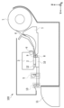
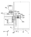
図1は、本実施形態に係るインクジェット記録装置の一例を示す断面図である。インクジェット記録装置(以下、単に「記録装置」と適宜に称する。)100は、長尺のシート状の記録媒体に記録を行うものである。本実施形態において記録媒体はロール紙1である。記録装置100に保持されたロール紙1は、上ガイド6および下ガイド7から形成される搬送路を通り、下流へと送られる。ロール紙1は、搬送ローラ8とピンチローラ9とによって挟持され、画像記録部に搬送される。画像記録部は、記録ヘッド2と、記録ヘッド2を搭載するキャリッジ3と、記録ヘッド2に対向する位置に配置されたプラテン10とを含む構成である。ロール紙1は、搬送ローラ8によってプラテン10上へと搬送される。画像記録部に搬送されたロール紙1に対して、記録ヘッド2によりインクが吐出され、画像が記録される。
FIG. 1 is a cross-sectional view showing an example of an inkjet recording apparatus according to this embodiment. An inkjet recording apparatus (hereinafter simply referred to as a "recording apparatus" as appropriate) 100 performs recording on a long sheet-like recording medium. In this embodiment, the recording medium is
キャリッジ3は、記録装置100に平行に配置されたガイドシャフト4と不図示のガイドレールとに沿って摺動可能に支持されている。キャリッジ3は、プラテン10の方向に向いている反射型の検出センサ12を有しており、スポット位置の反射率を検出できる。即ち、プラテン10が黒色、ロール紙1が白色の場合、両者の反射率は大きく異なるので、スポット位置にプラテン10があるのかロール紙1があるのかを検出センサ12を用いて判定することができる。搬送ローラ8でロール紙1を搬送中にロール紙1の搬送方向先端部が検出センサ12のスポット位置を通過すると反射率が大きくなることを利用して、ロール紙1の先端部を検出することができる。
The
キャリッジ3は、記録ヘッド2を保持したままガイドシャフト4に沿ってX方向に走査し、走査しながら記録ヘッド2からインクを吐出することによってロール紙1に対して記録を行う。キャリッジ3が走査しロール紙1に記録を行った後、搬送ローラ8はロール紙1を所定量搬送し、再びキャリッジ3がロール紙1上を走査し記録を行う。このように、記録と搬送とを繰り返すことで全記録が完成する。また、検出センサ12は、キャリッジ3に搭載されているので、キャリッジ3の往復動作によって、ロール紙1の幅方向(X方向)の紙端の位置も検出することができる。
The
ロール紙1の搬送方向におけるキャリッジ3の下流には、搬送方向と交差する方向にロール紙1を切断するためのカッター5が設けられ、さらにその下流にロール紙1を搬送方向に沿って切断するためのスリッター13が設けられている。スリッター13より下流には、切断されたロール紙1を排出する排紙ガイド11が設けられている。
A
カッター5は、ロール紙1を切断する切断手段としてのカッターユニット300と、カッターユニット300をX方向に沿って移動させるためのユニットとから構成される。また、スリッター13は、ロール紙1を切断するための切断手段としてのスリッターユニット303と、スリッターユニット303をX方向に沿って移動させるためのユニットとから構成される。
The
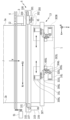
図2は、カッター5、および、スリッターユニット303L、303Rを有するスリッター13について説明する上面図である。なお、本明細書において符号の末尾の「L」と「R」とは、図面上の左側(つまり、+X側)の部材と右側(つまり、-X側)の部材とをそれぞれ示すものである。本明細書では、左右の部材で共通する事項については、符号の末尾を省略する場合がある。
FIG. 2 is a top view illustrating the
ガイドレール101は、ロール紙1の搬送方向と交差する方向にカッターキャリッジ200を案内するように構成されている。カッターキャリッジ200は、カッターユニット300およびベルト102を一体に結合している。また、ベルト102は、ガイドレール101の左右に設けられたモータプーリ107と、テンショナプーリ108との間に橋渡しされており、モータプーリ107に接続されたカッターモータ103により可動するように構成されている。カッターモータ103は、カッターエンコーダ104を備えている。カッターエンコーダ104は、カッターモータ103の駆動に応じたパルス数をカウントする。カッターキャリッジ200の原点位置とカッターエンコーダ104で得られるパルス数とに基づいて、カッターユニット300のX1およびX2方向の移動位置を制御することが可能である。
The
カッターユニット300は、上可動刃301と下可動刃302とを有し、それらの接触点においてX1方向に移動中にロール紙1が切断される。また、上可動刃301および下可動刃302は、カッターモータ103からベルト102およびカッターキャリッジ200を介して連結されており、回転駆動可能な構成である。ロール紙1の切断時には、下可動刃302および下可動刃302に接触する上可動刃301が共に回転しながら、ロール紙1を切断する。図2の例では、ロール紙第一端部1aからロール紙第二端部1bに向かってカッターユニット300による切断が行われる。ロール紙第一端部1aは、カッターユニット300の待機位置P1側の端部である。ロール紙1の切断後は、カッターキャリッジ200は、所定の反転位置で反転して、次の切断動作のために待機位置P1となる位置まで移動し、待機する。なお、本実施形態では、カッターユニット300は、カッターキャリッジ200に搭載されている例を示しているが、例えば、記録ヘッド2などを移動するキャリッジ3にカッターユニット300が搭載されるようにしてもよい。
The
スリッター13は、ロール紙1の搬送方向においてカッター5の下流側に配されている。スリッター13のスリッターユニット303は、X1およびX2方向の任意の位置に移動可能でロール紙1を搬送方向(+Y方向)と平行な方向に沿って切断可能である。本実施形態では、スリッターユニット303を2個搭載した構成を説明する。即ち、スリッターユニット303L、303Rが搭載されている例を説明する。なお、スリッターユニット303L、303Rは、X1およびX2方向において左右対称で同じ部品構成となっており、図2では簡略化のため、主にスリッターユニット303Lの部品に符号を付している。
The
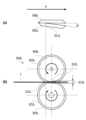
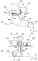
図3乃至図5は、スリッターユニット303Lの詳細を説明する図である。図3(a)は、スリッターユニット303Lのスリッター上可動刃304Lとスリッター下可動刃305Lとの概略平面図である。図3(b)は、スリッターユニット303Lにおけるスリッター上可動刃304L、スリッター下可動刃305L、スリッター上搬送ローラ320L、およびスリッター下搬送ローラ321Lの概略側面図である。図4(a)は、スリッターユニット303Lの背面斜視図、図4(b)は、スリッターユニット303Lの正面図である。図5は、規制部600Lによる規制位置を説明する図である。
3 to 5 are diagrams illustrating the details of the
スリッターユニット303Lは、スリッター上可動刃304Lと、スリッター下可動刃305Lとを有する。スリッター上可動刃304Lとスリッター下可動刃305Lとは、上下方向に丸刃オーバーラップ量313Lと、切断方向となる搬送方向Yに対して所定量の角度(交差角)θとを設けるように配されている。スリッター上可動刃304Lとスリッター下可動刃305Lとの接触点311Lにおいて、ロール紙1が切断される。即ち、本実施形態では、スリッターユニット303において、スリッター上可動刃304とスリッター下可動刃305とが、記録媒体を切断する切断部として機能している。スリッター上可動刃304Lは、ギアを介してスリッター駆動モータ16Lに接続されている。
The
スリッター駆動モータ16Lの駆動によって、スリッター上可動刃304Lを回転させる際に、スリッター上可動刃304Lと同軸上に接続されたスリッター上搬送ローラ320Lも回転する。スリッター上搬送ローラ320Lの外周面は、スリッター下可動刃305Lの同軸上に接続されたスリッター下搬送ローラ321Lの外周面とローラ挟持点312Lで接触している。このため、摩擦伝達により駆動することで、スリッター上搬送ローラ320Lおよびスリッター下搬送ローラ321Lによってロール紙1を搬送しつつ、上下の刃が共に回転しながらロール紙1を搬送方向に切断する。即ち、本実施形態では、スリッターユニット303において、スリッター上搬送ローラ320とスリッター下搬送ローラ321とが、記録媒体を搬送する搬送部として機能している。
When the slitter upper
スリッター上搬送ローラ320Lおよびスリッター下搬送ローラ321Lはそれぞれ、X方向において、スリッター上可動刃304Lとスリッター下可動刃305Lとの接触点311Lよりも、ロール紙1の外側に位置している(図5参照)。なお、ロール紙1の外側とは、ロール紙第二端部1b側であり、成果物として残す画像が記録されていない領域側(図5中ではnPS側)である。
The slitter
スリッター駆動モータ16Lは、スリッター駆動エンコーダ310Lを有しているので、所定量の回転速度および所定量の回転量での制御が可能である。スリッター駆動モータ16Lは、搬送ローラ8による搬送量と同期した搬送量に対応する駆動量(具体的には、回転速度、回転量)に制御される。
Since the
スリッターユニット303Lは、スリッター移動モータ14Lを有し、ギアを介してスリッター移動ローラ306Lに駆動力が伝達される構成となっている。スリッター移動ローラ306Lは、X方向に延在するスリッターガイドレール307に当接している。そして、スリッター移動ローラ306Lの外周面とスリッターガイドレール307との摩擦によって、スリッターユニット303LがX1およびX2方向に移動可能に構成されている。なお、スリッター移動モータ14Lは、スリッター移動エンコーダ309Lを有しており、待機位置P1からのスリッターユニット303Lの移動位置を制御することが可能である。
The
スリッターユニット303Lでは、後述する規制部600Lを含む各構成は、保持部材608に保持されている。これにより、スリッター上可動刃304L、スリッター下可動刃305L、スリッター上搬送ローラ320L、スリッター下搬送ローラ321L、および規制部600Lは、スリッターガイドレール307に沿って一体的に移動可能になっている。本実施形態では、スリッター移動ローラ306Lは摩擦駆動であるが、スリッター移動ローラをピニオン、スリッターガイドレールをラックとしたラック&ピニオンの構成としてもよい。即ち、本実施形態では、スリッター移動モータ14L、スリッター移動ローラ306Lおよびスリッターガイドレール307などが、スリッターユニット303をX方向で移動するための移動部として機能している。
In the
スリッターユニット303Lには、記録後のロール紙1の切断時の平面性を確保するために、図4(a)(b)のように、ロール紙1の浮き上がりを規制する規制部600Lが配されている。規制部600Lは、X方向において、接触点311Lよりもロール紙1の内側に位置している。なお、ロール紙1の内側とは、ロール紙第一端部1a側であり、成果物として残す画像が記録された領域側(図5中ではPS側)である。
The
規制部600Lは、ロール紙1の記録面側に当接して、ロール紙1に生じた浮きを規制する拍車601Lと、ロール紙1に当接することなく拍車601Lを保持する保持部602Lとを備えている。規制部600Lでは、記録面に当接してロール紙1に生じた浮きを規制する部材を拍車601Lとすることで、記録面に記録された画像の転写を抑制する。また、拍車601Lは、例えば、バネなどの弾性部材606L(図5参照)を介して保持部602Lに保持されており、弾性的にロール紙1に作用する構成となっている。即ち、本実施形態では、規制部600が記録媒体に当接する当接部として機能している。
The regulating
拍車601Lによりロール紙1に当接してロール紙1に生じた浮きを規制する規制位置は、搬送方向および幅方向に直交するZ方向において接触点311L(図3(b)参照)と一致する。これにより、Z方向において、接触点311Lと略一致する位置に位置するようにロール紙1の浮きを規制することができる。なお、規制位置と接触点311LとがZ方向で一致するとは、完全に一致する場合に限定されるものではなく、所定範囲を持たせるようにしてもよい。また、規制位置は、Y方向において、図5のように、接触点311Lより長さL1だけ搬送方向上流側(-Y方向側)に位置している。さらに、規制位置は、X方向において、図5のように、接触点311Lより長さL2(例えば、10mm)だけロール紙1の内側に位置している。長さL1、L2については、搬送されるロール紙1の先端部が接触点311Lに到達する際に、接触点311L近傍におけるロール紙1の平面性を確保できる値を、例えば、実験的に求めて設定される。上記所定範囲を設ける場合にも、同様にして実験的に求められる。
The regulation position where the
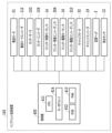
図6は、記録装置100の制御構成を示す概略ブロック図である。記録装置100は制御部400を備えている。また、制御部400は、CPU411、ROM412、RAM413、およびモータドライバ414を備えている。制御部400は、搬送モータ51、カッターモータ103、スリッター移動モータ14、スリッター駆動モータ16、キャリッジモータ52、および記録ヘッド2の制御を実現する。制御部400は、搬送ローラエンコーダ112、カッターエンコーダ104、スリッター移動エンコーダ309、スリッター駆動エンコーダ310、キャリッジエンコーダ19、および検出センサ12からの信号を取得する。そして、制御部400は、これらの信号に基づいて、各種モータおよび記録ヘッド2の制御を行う。
FIG. 6 is a schematic block diagram showing the control configuration of the
上記したように、記録装置100は、記録後のロール紙1の幅方向(X方向)における所定領域をスリッター13により切断可能な構成となっている。このため、記録装置100においては、例えば、幅方向において、成果物として残す画像に隣接する領域を、スリッター13により切断することで、スリッター13を備えていない記録装置により左右縁なし記録を行った場合と同様の記録物を取得することができる。この場合、ロール紙1からはみ出すようにインクを付与する必要がないため、プラテン10へのインクの付着を大幅に抑制することができる。以下、記録装置100によりロール紙1に対して、左右、つまり、X方向における縁なし記録を行う場合について説明する。
As described above, the
ユーザーによって、ロール紙1に対する左右縁なし記録の開始が指示されると、まず、スリッター移動モータ14L、14Rを駆動して、スリッターユニット303L、303Rをそれぞれ切断位置に移動させる。切断位置としては、スリッター上可動刃304およびスリッター下可動刃305によって、成果物として残す画像が記録された領域PSの、例えば、X方向の端部位置である。
When the user instructs the start of left and right marginless recording on the
次に、搬送ローラ8による搬送速度と、スリッター上搬送ローラ320による搬送速度とが等速となるように、搬送モータ51およびスリッター駆動モータ16を駆動して、搬送ローラ8によりロール紙1を搬送する。その後、センサ(不図示)の検知結果に基づいてロール紙1の先端部が記録開始位置まで搬送されたことを検知すると、記録データに基づいてロール紙1に対する記録を行う。
Next, the
記録の進行によって、ロール紙1の先端部がスリッターユニット303の接触点311に到達すると、ロール紙1は、回転している左右のスリッター上可動刃304およびスリッター下可動刃305によって切断される。
When the leading edge of the
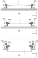
ここで、図7(a)は、スリッターユニット303に規制部600が配されていない場合のロール紙1を示す正面図である。図7(b)は、スリッターユニット303に規制部600が配されている場合のロール紙1を示す正面図である。図7(c)は、規制部600が配されたスリッターユニット303によるロール紙1の切断を説明する平面図である。
Here, FIG. 7A is a front view showing the
図7(a)のように、単に、ロール紙1のX方向における2箇所を保持して、ロール紙1を搬送する場合には、インク付与によりロール紙1にコックリングが生じると、保持した2箇所の間でロール紙1が浮き上がる。この状態で、接触点311Lにロール紙1の先端部が到達すると、先端部近傍においてカットずれが生じる。
As shown in FIG. 7A, when the
本実施形態では、図7(b)のように、スリッターユニット303においてロール紙1の浮きを規制する規制部600を設けた。これにより、ロール紙1の先端部が接触点311に到達する際のロール紙1の接触点311近傍の平面性を確保する構成とした。このため、規制部600を備えていないときと比較して、規制部600を備えた場合には、接触点311に到達する際のロール紙1の先端部の姿勢が安定する。
In this embodiment, as shown in FIG. 7B, the slitter unit 303 is provided with a restricting portion 600 that restricts floating of the
その後、ロール紙1は、スリッター上可動刃304およびスリッター下可動刃305により切断され、ロール紙1の切断された側の切断片がスリッター上搬送ローラ320とスリッター下搬送ローラ321と挟持されて搬送される。このように、接触点311では、規制部600によって、ロール紙1の姿勢が安定する。このため、スリッターユニット303により切断されたロール紙1は、その先端部において、カットずれの発生が抑制されて切断精度が安定する(図7(c)参照)。
Thereafter, the
記録が終了すると、所定位置までスリッターユニット303によるカットを行う。その後、スリッターユニット303L、303Rをそれぞれの待機位置まで移動するとともに、ロール紙1をカッターユニット300により切断可能な位置まで搬送する。そして、ロール紙1をカッターユニット300により切断する。これにより、ロール紙1において成果物として残す画像が記録された記録物および当該記録が記録されていない切断片が排紙ガイド11を介して排出される。
When the recording is finished, the slitter unit 303 cuts to a predetermined position. After that, the
以上において説明したように、記録装置100では、規制部600を、接触点311に対して、X方向において内側、Y方向において搬送方向の上流側、かつ、Z方向において一致する位置でロール紙1に当接して、ロール紙1に生じた浮きを規制するようにした。このため、コックリングによりロール紙1に浮きが生じても、接触点311に到達するときのロール紙1の平面性を確保することができるようになる。これにより、ロール紙1の先端部のスリッター13により切断される位置の、幅方向でのずれが生じ難くなる。
As described above, in the
(他の実施形態)
なお、上記実施形態は、以下の(1)乃至(5)に示すように変形してもよい。
(Other embodiments)
The above embodiment may be modified as shown in (1) to (5) below.
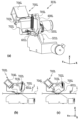
(1)上記実施形態では特に記載しなかったが、拍車601により当接してロール紙1の浮きを規制する規制姿勢と、ロール紙1に当接しない退避姿勢とを選択的に変更可能な構成の規制部700によりロール紙1の浮きを規制するようにしてもよい。以下、図8を参照しながら、規制部700について詳細に説明する。上記したように、スリッターユニット303、L303Rは互いに左右対称に構成されるため、以下の説明では、スリッターユニット303Lに設けられる規制部700Lについて説明し、スリッターユニット303Rについての説明は省略する。
(1) Although not specifically described in the above embodiment, a configuration in which the spur 601 abuts to restrict the floating of the
図8(a)は、規制部700Lを備えたスリッターユニット303Lの概略構成図である。図8(b)は、規制部700Lが規制姿勢にあるスリッターユニット303Lの側面図である。図8(c)は、規制部700Lが退避姿勢にあるスリッターユニット303Lの側面図である。なお、以下の説明においては、上記実施形態のスリッターユニット303Lと同一または相当する構成については、同一の符号を用いることによりその詳細な説明は適宜に省略する。
FIG. 8(a) is a schematic configuration diagram of a
規制部700Lは、保持部材608Lに対して、拍車601Lを保持する保持部702Lが、矢印I方向および矢印II方向に回動可能に軸703Lに固定されている。規制部700Lが規制姿勢(第1姿勢)にあるときに、保持部702Lを矢印I方向に回動して退避姿勢に変更させるバネ705Lを備えている。また、規制部700Lが退避姿勢(第2姿勢)にあるときに、保持部702Lを矢印II方向に回動して規制姿勢に変更させる回動制御部704Lを備えている。回動制御部704Lは、例えば、ソレノイドにより構成され、通電することによりバネ705Lの付勢力に抗して保持部702Lを矢印II方向に回動させる。
In the restricting
こうした構成において、左右縁なし記録を行う場合には、例えば、ユーザーにより入力された記録媒体の種類に関する情報に基づいて、規制部700Lを退避姿勢または規制姿勢に変更する。具体的には、例えば、剛性が高く、コックリングなどが生じ難い記録媒体を用いる場合には、回動制御部704Lへの通電を解除して、バネ705Lの付勢力によって規制部700Lを退避姿勢とする。なお、剛性が高く、コックリングなどが生じ難い記録媒体としては、例えば、光沢紙、アート紙がある。また、剛性が低く、コックリングなどが生じ易い記録媒体を用いる場合には、回動制御部704Lへ通電して、バネ705Lの付勢力に抗して規制部700Lを規制姿勢とする。
In such a configuration, when performing left and right borderless printing, for example, the
このように、規制部700Lにより記録媒体に生じる浮きを規制すること、当該規制の必要のない記録媒体では、成果物としての画像に拍車601が当接しなくなり、画像転写を確実に抑制することができる。
In this way, the regulating
(2)上記実施形態では、記録媒体をX方向に移動し、記録媒体をY方向に移動する、所謂、シリアルスキャンタイプの記録装置を例として説明したが、記録媒体の幅方向に亘ってインクを吐出する、所謂、フルラインタイプの記録装置を用いるようにしてもよい。また、上記実施形態では特に記載しなかったが、スリッターユニット303における記録媒体を切断する構成、X方向へ移動する構成については、種々の公知の技術を用いるようにしてもよい。 (2) In the above embodiment, a so-called serial scan type printing apparatus, in which the printing medium is moved in the X direction and the printing medium is moved in the Y direction, was described as an example. A so-called full-line type printing apparatus may be used. Although not specifically described in the above embodiment, various known techniques may be used for the configuration for cutting the recording medium in the slitter unit 303 and the configuration for moving in the X direction.
(3)上記実施形態では、スリッター13では、スリッターユニット303を2個設けるようにしたが、スリッターユニット303は、1個だけ設けるようにしてもよいし、3個以上の複数設けるようにしてもよい。また、上記実施形態では、記録装置100においてインクジェット方式により記録するようにしたが、記録装置100の記録方式は、公知の種々の記録方式であってもよい。
(3) In the above embodiment, two slitter units 303 are provided in the
(4)上記実施形態では特に記載しなかったが、保持部材608に対して規制部600をXYZ方向においてその位置を調整可能な構成とし、記録媒体の種類やインク付与量などに応じて規制位置を調整するようにしてもよい。この場合、ユーザーが手動あるいは記録装置100に設けられた操作パネルなどを介して規制部600による規制位置を調整してもよいし、制御部400により規制部600による規制位置を調整してもよい。また、上記実施形態では、スリッター13は、制御部400の制御によりロール紙1の幅方向にスリッターユニット303が移動するようにしたが、これに限定されるものではない。即ち、スリッターユニット303は固定的に配置されるようにしてもよいし、ユーザーにより移動可能な構成としてもよい。
(4) Although not specifically described in the above embodiment, the regulating portion 600 is configured so that its position can be adjusted in the XYZ directions with respect to the holding member 608, and the regulating position can be adjusted according to the type of printing medium, the amount of ink applied, and the like. may be adjusted. In this case, the user may adjust the regulating position of the regulating portion 600 manually or via an operation panel provided in the
(5)上記実施形態および上記した(1)乃至(4)に示す各種の形態は、適宜に組み合わせるようにしてもよい。 (5) The above embodiments and the various forms shown in (1) to (4) above may be combined as appropriate.
100 記録装置
13 スリッター
600 規制部
100
Claims (14)
記録媒体に対して画像を記録する記録手段と、
前記搬送手段が搬送する記録媒体を搬送方向に沿って切断する切断部を有するスリッターと、を備えた記録装置であって、
前記スリッターは、
前記記録媒体の幅方向において、前記切断部が前記記録媒体を切断する位置よりも内側の位置で前記記録媒体と当接する当接部を有し、
前記切断部と前記当接部とを備えたスリッターユニットを少なくとも1つ備え、
前記スリッターユニットを前記幅方向に移動する移動部をさらに有することを特徴とする記録装置。 a conveying means for conveying a recording medium;
a recording means for recording an image on a recording medium;
A recording apparatus comprising a slitter having a cutting section that cuts the recording medium conveyed by the conveying means along the conveying direction,
The slitter is
a contact portion that contacts the recording medium at a position inside a position where the cutting portion cuts the recording medium in the width direction of the recording medium ;
At least one slitter unit including the cutting portion and the contact portion,
A recording apparatus, further comprising a moving section that moves the slitter unit in the width direction .
前記切断する位置は、前記2つの丸刃が接触する接触点である
ことを特徴とする請求項1から10のいずれか1項に記載の記録装置。 The cutting unit is configured to cut the recording medium by bringing two circular blades into contact,
The recording apparatus according to any one of claims 1 to 10 , wherein the cutting position is a contact point where the two round blades contact.
前記記録媒体を搬送方向に沿って切断する切断部を備えたスリッターと、を備えた搬送装置であって、
前記スリッターは、
前記記録媒体の幅方向において、前記切断部が前記記録媒体を切断する位置よりも内側の位置で前記記録媒体と当接する当接部を有し、
前記切断部と前記当接部とを備えたスリッターユニットを少なくとも1つ備え、
前記スリッターユニットを前記幅方向に移動する移動部をさらに有することを特徴とする搬送装置。 a conveying means for conveying a recording medium on which an image is recorded;
A conveying device comprising a slitter having a cutting section that cuts the recording medium along the conveying direction,
The slitter is
a contact portion that contacts the recording medium at a position inside a position where the cutting portion cuts the recording medium in the width direction of the recording medium ;
At least one slitter unit including the cutting portion and the contact portion,
A conveying device, further comprising a moving section that moves the slitter unit in the width direction .
Priority Applications (4)
| Application Number | Priority Date | Filing Date | Title |
|---|---|---|---|
| JP2019065975A JP7317543B2 (en) | 2019-03-29 | 2019-03-29 | Recording device and transport device |
| CN202010226959.2A CN111746112B (en) | 2019-03-29 | 2020-03-27 | Printing apparatus and conveying apparatus |
| US16/831,888 US11173732B2 (en) | 2019-03-29 | 2020-03-27 | Printing apparatus and conveyance apparatus |
| KR1020200037227A KR102624589B1 (en) | 2019-03-29 | 2020-03-27 | Printing apparatus and conveyance apparatus |
Applications Claiming Priority (1)
| Application Number | Priority Date | Filing Date | Title |
|---|---|---|---|
| JP2019065975A JP7317543B2 (en) | 2019-03-29 | 2019-03-29 | Recording device and transport device |
Publications (2)
| Publication Number | Publication Date |
|---|---|
| JP2020163679A JP2020163679A (en) | 2020-10-08 |
| JP7317543B2 true JP7317543B2 (en) | 2023-07-31 |
Family
ID=72603914
Family Applications (1)
| Application Number | Title | Priority Date | Filing Date |
|---|---|---|---|
| JP2019065975A Active JP7317543B2 (en) | 2019-03-29 | 2019-03-29 | Recording device and transport device |
Country Status (4)
| Country | Link |
|---|---|
| US (1) | US11173732B2 (en) |
| JP (1) | JP7317543B2 (en) |
| KR (1) | KR102624589B1 (en) |
| CN (1) | CN111746112B (en) |
Families Citing this family (6)
| Publication number | Priority date | Publication date | Assignee | Title |
|---|---|---|---|---|
| JP2020163680A (en) | 2019-03-29 | 2020-10-08 | キヤノン株式会社 | Recording device and transport device |
| JP2020163692A (en) * | 2019-03-29 | 2020-10-08 | キヤノン株式会社 | Inkjet recording device and its control method and program |
| CN111844177B (en) * | 2020-06-05 | 2022-04-12 | 广州广电运通金融电子股份有限公司 | A kind of sheet medium cutting and conveying device and self-service equipment |
| JP7441510B2 (en) * | 2020-08-26 | 2024-03-01 | デュプロ精工株式会社 | sheet processing equipment |
| JP7764723B2 (en) * | 2021-10-13 | 2025-11-06 | セイコーエプソン株式会社 | Printing device and method for controlling printing device |
| JP7602497B2 (en) * | 2022-01-20 | 2024-12-18 | 株式会社ミマキエンジニアリング | Printing device |
Citations (5)
| Publication number | Priority date | Publication date | Assignee | Title |
|---|---|---|---|---|
| JP2001328303A (en) | 2000-05-24 | 2001-11-27 | Fuji Photo Film Co Ltd | Printer |
| US20100258017A1 (en) | 2009-04-10 | 2010-10-14 | Kersey Kevin T | Print Media Slitter |
| JP2012236310A (en) | 2011-05-11 | 2012-12-06 | Canon Inc | Recording medium cutting device and recording apparatus |
| JP2015145080A (en) | 2014-02-03 | 2015-08-13 | 三菱電機株式会社 | thermal transfer printer |
| JP2016203308A (en) | 2015-04-22 | 2016-12-08 | コニカミノルタ株式会社 | Image forming device and image forming system |
Family Cites Families (23)
| Publication number | Priority date | Publication date | Assignee | Title |
|---|---|---|---|---|
| US5007318A (en) * | 1989-12-20 | 1991-04-16 | National Steel Corporation | Metal strip edge trimming apparatus |
| JP2743290B2 (en) | 1989-12-21 | 1998-04-22 | キヤノン株式会社 | Control device for recording device |
| US5790168A (en) * | 1994-07-22 | 1998-08-04 | Hitachi Koki Company, Ltd. | Printing apparatus with movable slitter for printed paper sheet |
| US6408750B1 (en) * | 1999-06-23 | 2002-06-25 | Fuji Photo Film Co., Ltd. | Printer capable of cutting margins |
| JP4144850B2 (en) | 2001-07-19 | 2008-09-03 | キヤノン株式会社 | Liquid applicator applicable to ink recorded medium and image forming apparatus having the same |
| US20040037960A1 (en) | 2002-06-27 | 2004-02-26 | Canon Kabushiki Kaisha | Liquid transfer device, liquid transfer method and liquid remaining amount monitoring method of liquid transfer device |
| JP3897007B2 (en) * | 2003-07-31 | 2007-03-22 | ブラザー工業株式会社 | Inkjet printer |
| JP4227489B2 (en) | 2003-09-03 | 2009-02-18 | キヤノン株式会社 | Recording apparatus and recording method |
| JP4262165B2 (en) | 2003-09-03 | 2009-05-13 | キヤノン株式会社 | Recording apparatus and data processing method |
| JP4497877B2 (en) | 2003-09-24 | 2010-07-07 | キヤノン株式会社 | Recording device |
| JP2007021927A (en) * | 2005-07-19 | 2007-02-01 | Fujifilm Corp | Image recording device |
| JP5424624B2 (en) | 2008-12-02 | 2014-02-26 | キヤノン株式会社 | Recording device |
| JP5582753B2 (en) * | 2009-10-05 | 2014-09-03 | キヤノン株式会社 | Printer and printing method |
| JP5634114B2 (en) | 2010-04-30 | 2014-12-03 | キヤノン株式会社 | Recording device |
| US8312798B2 (en) * | 2010-05-18 | 2012-11-20 | Eastman Kodak Company | Slitter with translating cutting devices |
| JP5921138B2 (en) | 2011-10-21 | 2016-05-24 | キヤノン株式会社 | Printing apparatus and sheet drying apparatus |
| JP6039172B2 (en) * | 2011-10-21 | 2016-12-07 | キヤノン株式会社 | Sheet cutting device and printer |
| JP5966544B2 (en) * | 2012-04-11 | 2016-08-10 | セイコーエプソン株式会社 | Image forming apparatus |
| JP6024172B2 (en) * | 2012-04-16 | 2016-11-09 | セイコーエプソン株式会社 | Cutting device and recording device |
| JP6376775B2 (en) * | 2014-02-28 | 2018-08-22 | キヤノン株式会社 | Sheet conveying apparatus, sheet cutting apparatus, and image forming apparatus |
| JP5967383B2 (en) * | 2014-03-18 | 2016-08-10 | コニカミノルタ株式会社 | Post-processing apparatus and image forming system |
| JP2017013438A (en) | 2015-07-03 | 2017-01-19 | 株式会社ユウコス | Printed object feeding device, printing object discharging device, and printing system |
| ITUA20163797A1 (en) * | 2016-05-25 | 2017-11-25 | Fotoba Int S R L | METHOD AND AUTOMATIC DEVICE FOR CUTTING SUBSTRATES WITH PRINTED IMAGES |
-
2019
- 2019-03-29 JP JP2019065975A patent/JP7317543B2/en active Active
-
2020
- 2020-03-27 CN CN202010226959.2A patent/CN111746112B/en active Active
- 2020-03-27 US US16/831,888 patent/US11173732B2/en active Active
- 2020-03-27 KR KR1020200037227A patent/KR102624589B1/en active Active
Patent Citations (5)
| Publication number | Priority date | Publication date | Assignee | Title |
|---|---|---|---|---|
| JP2001328303A (en) | 2000-05-24 | 2001-11-27 | Fuji Photo Film Co Ltd | Printer |
| US20100258017A1 (en) | 2009-04-10 | 2010-10-14 | Kersey Kevin T | Print Media Slitter |
| JP2012236310A (en) | 2011-05-11 | 2012-12-06 | Canon Inc | Recording medium cutting device and recording apparatus |
| JP2015145080A (en) | 2014-02-03 | 2015-08-13 | 三菱電機株式会社 | thermal transfer printer |
| JP2016203308A (en) | 2015-04-22 | 2016-12-08 | コニカミノルタ株式会社 | Image forming device and image forming system |
Also Published As
| Publication number | Publication date |
|---|---|
| JP2020163679A (en) | 2020-10-08 |
| KR102624589B1 (en) | 2024-01-15 |
| KR20200115332A (en) | 2020-10-07 |
| CN111746112B (en) | 2022-06-14 |
| US20200307272A1 (en) | 2020-10-01 |
| US11173732B2 (en) | 2021-11-16 |
| CN111746112A (en) | 2020-10-09 |
Similar Documents
| Publication | Publication Date | Title |
|---|---|---|
| JP7317543B2 (en) | Recording device and transport device | |
| JP2012001332A (en) | Image recording apparatus | |
| EP1790486B1 (en) | Recording medium conveying mechanism and image recording device including the same | |
| US7681974B2 (en) | Recording apparatus and method | |
| JP7225000B2 (en) | RECORDING DEVICE, RECORDING DEVICE CONTROL METHOD, AND PROGRAM | |
| KR102655992B1 (en) | Printing apparatus, printing method, and storage medium | |
| JP7521071B2 (en) | Recording device, control method for recording device, and program | |
| US11766881B2 (en) | Printing apparatus and conveyance apparatus | |
| JP6987665B2 (en) | Transport and recording equipment | |
| JP4324017B2 (en) | Recording device | |
| JP2020163692A (en) | Inkjet recording device and its control method and program | |
| JP2020163726A (en) | Recording device, control method of recording device, and program | |
| JP2009083351A (en) | Inkjet recording device | |
| JP7310390B2 (en) | Cutter device and printing device | |
| JPH11115274A (en) | Sheet-transferring apparatus and image-recording apparatus | |
| JP2006193303A (en) | Inkjet recording device | |
| JP2007007967A (en) | Cutting device and image forming apparatus having the same | |
| JP2022017973A (en) | Cutting device and recording device | |
| JP2020163773A (en) | Recording device | |
| JP2010047366A (en) | Recording device | |
| JP2009234687A (en) | Automatic feeder and electronic device having the same | |
| JP2009196195A (en) | Recording medium conveying device and recording device | |
| JP2002002057A (en) | Ink jet type image forming apparatus | |
| JP2006341384A (en) | Image recorder | |
| JP2005028500A (en) | Sheet cutter device |
Legal Events
| Date | Code | Title | Description |
|---|---|---|---|
| A621 | Written request for application examination |
Free format text: JAPANESE INTERMEDIATE CODE: A621 Effective date: 20220124 |
|
| A977 | Report on retrieval |
Free format text: JAPANESE INTERMEDIATE CODE: A971007 Effective date: 20230228 |
|
| A131 | Notification of reasons for refusal |
Free format text: JAPANESE INTERMEDIATE CODE: A131 Effective date: 20230404 |
|
| A521 | Request for written amendment filed |
Free format text: JAPANESE INTERMEDIATE CODE: A523 Effective date: 20230518 |
|
| TRDD | Decision of grant or rejection written | ||
| A01 | Written decision to grant a patent or to grant a registration (utility model) |
Free format text: JAPANESE INTERMEDIATE CODE: A01 Effective date: 20230620 |
|
| A61 | First payment of annual fees (during grant procedure) |
Free format text: JAPANESE INTERMEDIATE CODE: A61 Effective date: 20230719 |
|
| R151 | Written notification of patent or utility model registration |
Ref document number: 7317543 Country of ref document: JP Free format text: JAPANESE INTERMEDIATE CODE: R151 |