JP7316290B2 - drive system - Google Patents
drive system Download PDFInfo
- Publication number
- JP7316290B2 JP7316290B2 JP2020547047A JP2020547047A JP7316290B2 JP 7316290 B2 JP7316290 B2 JP 7316290B2 JP 2020547047 A JP2020547047 A JP 2020547047A JP 2020547047 A JP2020547047 A JP 2020547047A JP 7316290 B2 JP7316290 B2 JP 7316290B2
- Authority
- JP
- Japan
- Prior art keywords
- shaft
- drive system
- bearing
- train
- gear stage
- Prior art date
- Legal status (The legal status is an assumption and is not a legal conclusion. Google has not performed a legal analysis and makes no representation as to the accuracy of the status listed.)
- Active
Links
Images


Classifications
-
- B—PERFORMING OPERATIONS; TRANSPORTING
- B62—LAND VEHICLES FOR TRAVELLING OTHERWISE THAN ON RAILS
- B62M—RIDER PROPULSION OF WHEELED VEHICLES OR SLEDGES; POWERED PROPULSION OF SLEDGES OR SINGLE-TRACK CYCLES; TRANSMISSIONS SPECIALLY ADAPTED FOR SUCH VEHICLES
- B62M6/00—Rider propulsion of wheeled vehicles with additional source of power, e.g. combustion engine or electric motor
- B62M6/40—Rider propelled cycles with auxiliary electric motor
- B62M6/55—Rider propelled cycles with auxiliary electric motor power-driven at crank shafts parts
-
- F—MECHANICAL ENGINEERING; LIGHTING; HEATING; WEAPONS; BLASTING
- F16—ENGINEERING ELEMENTS AND UNITS; GENERAL MEASURES FOR PRODUCING AND MAINTAINING EFFECTIVE FUNCTIONING OF MACHINES OR INSTALLATIONS; THERMAL INSULATION IN GENERAL
- F16H—GEARING
- F16H3/00—Toothed gearings for conveying rotary motion with variable gear ratio or for reversing rotary motion
- F16H3/44—Toothed gearings for conveying rotary motion with variable gear ratio or for reversing rotary motion using gears having orbital motion
- F16H3/72—Toothed gearings for conveying rotary motion with variable gear ratio or for reversing rotary motion using gears having orbital motion with a secondary drive, e.g. regulating motor, in order to vary speed continuously
- F16H3/724—Toothed gearings for conveying rotary motion with variable gear ratio or for reversing rotary motion using gears having orbital motion with a secondary drive, e.g. regulating motor, in order to vary speed continuously using external powered electric machines
-
- B—PERFORMING OPERATIONS; TRANSPORTING
- B62—LAND VEHICLES FOR TRAVELLING OTHERWISE THAN ON RAILS
- B62M—RIDER PROPULSION OF WHEELED VEHICLES OR SLEDGES; POWERED PROPULSION OF SLEDGES OR SINGLE-TRACK CYCLES; TRANSMISSIONS SPECIALLY ADAPTED FOR SUCH VEHICLES
- B62M11/00—Transmissions characterised by the use of interengaging toothed wheels or frictionally-engaging wheels
- B62M11/04—Transmissions characterised by the use of interengaging toothed wheels or frictionally-engaging wheels of changeable ratio
- B62M11/14—Transmissions characterised by the use of interengaging toothed wheels or frictionally-engaging wheels of changeable ratio with planetary gears
- B62M11/145—Transmissions characterised by the use of interengaging toothed wheels or frictionally-engaging wheels of changeable ratio with planetary gears built in, or adjacent to, the bottom bracket
-
- B—PERFORMING OPERATIONS; TRANSPORTING
- B62—LAND VEHICLES FOR TRAVELLING OTHERWISE THAN ON RAILS
- B62M—RIDER PROPULSION OF WHEELED VEHICLES OR SLEDGES; POWERED PROPULSION OF SLEDGES OR SINGLE-TRACK CYCLES; TRANSMISSIONS SPECIALLY ADAPTED FOR SUCH VEHICLES
- B62M6/00—Rider propulsion of wheeled vehicles with additional source of power, e.g. combustion engine or electric motor
- B62M6/40—Rider propelled cycles with auxiliary electric motor
- B62M6/45—Control or actuating devices therefor
- B62M6/50—Control or actuating devices therefor characterised by detectors or sensors, or arrangement thereof
-
- B—PERFORMING OPERATIONS; TRANSPORTING
- B60—VEHICLES IN GENERAL
- B60L—PROPULSION OF ELECTRICALLY-PROPELLED VEHICLES; SUPPLYING ELECTRIC POWER FOR AUXILIARY EQUIPMENT OF ELECTRICALLY-PROPELLED VEHICLES; ELECTRODYNAMIC BRAKE SYSTEMS FOR VEHICLES IN GENERAL; MAGNETIC SUSPENSION OR LEVITATION FOR VEHICLES; MONITORING OPERATING VARIABLES OF ELECTRICALLY-PROPELLED VEHICLES; ELECTRIC SAFETY DEVICES FOR ELECTRICALLY-PROPELLED VEHICLES
- B60L2240/00—Control parameters of input or output; Target parameters
- B60L2240/40—Drive Train control parameters
- B60L2240/42—Drive Train control parameters related to electric machines
- B60L2240/421—Speed
-
- B—PERFORMING OPERATIONS; TRANSPORTING
- B60—VEHICLES IN GENERAL
- B60Y—INDEXING SCHEME RELATING TO ASPECTS CROSS-CUTTING VEHICLE TECHNOLOGY
- B60Y2200/00—Type of vehicle
- B60Y2200/10—Road Vehicles
- B60Y2200/13—Bicycles; Tricycles
-
- B—PERFORMING OPERATIONS; TRANSPORTING
- B62—LAND VEHICLES FOR TRAVELLING OTHERWISE THAN ON RAILS
- B62M—RIDER PROPULSION OF WHEELED VEHICLES OR SLEDGES; POWERED PROPULSION OF SLEDGES OR SINGLE-TRACK CYCLES; TRANSMISSIONS SPECIALLY ADAPTED FOR SUCH VEHICLES
- B62M6/00—Rider propulsion of wheeled vehicles with additional source of power, e.g. combustion engine or electric motor
- B62M6/40—Rider propelled cycles with auxiliary electric motor
- B62M6/45—Control or actuating devices therefor
Description
提案の解決手段は、変速機ハウジング内の入力軸と出力軸との間の駆動システムであって、当該入力軸および当該出力軸は、多段合成変速機(mehrstufiges Ueberlagerungsgetriebe)を介して、第1の電気モータ又は圧力モータの第1のロータ軸および第2の電気モータ又は圧力モータの第2のロータ軸に接続されており、2つの当該モータ同士は、無段作動機構(Stellgetriebe)を形成するように出力制御装置(Leistungssteuerung)によって接続されていて且つエネルギー蓄積装置としてのバッテリ又は圧力蓄積装置に接続されており、上記多段合成変速機が、サンギア、リングギア、および複数のプラネットギアを具備したプラネットキャリアを有する少なくとも1つの三軸遊星歯車段を含む、駆動システムに関する。 The proposed solution is a drive system between an input shaft and an output shaft in the transmission housing, which input shaft and output shaft are connected via a multi-stage compound transmission to the first It is connected to a first rotor shaft of an electric or pressure motor and to a second rotor shaft of a second electric or pressure motor, the two motors forming a stepless actuation mechanism. and connected to a battery or a pressure accumulator as an energy accumulator, the multi-stage composite transmission having a sun gear, a ring gear and a planet gear with a plurality of planet gears. A drive system comprising at least one three-axis planetary gear stage with a carrier.
ここで、DE 199 25 229 A1(特許文献1)から、請求項1の前提部に記載の駆動システムが知られている。同文献の図1では、入力軸127と出力軸114とが、サンギア121、リングギア122、および複数のプラネットギア123を具備したプラネタリキャリア124を有する三軸遊星歯車段120を含む多段合成変速機を介して接続されている。出力軸114は、一定の変速比を有する多段副変速機を介してリングギア122に接続されている。入力軸127は、プラネタリキャリア124に接続されている。第1のモータ(ここでは、電気モータ)の第1のロータ軸132は、サンギア121に接続されている。第2のモータ(ここでは、同じく電気モータ)の第2のロータ軸は、出力軸114と同様にリングギア122に接続されている。これらの2つのモータ同士は、連続可変作動機構を形成するように出力制御装置によって接続されていて且つここではエネルギー蓄積装置としてのバッテリに接続されている。上記作動機構の変速比を連続的に変化させると、出力回転速度に対する入力回転速度の比も連続的に変化する。このような駆動システムを上手く設計することで、低効率の上記作動機構には駆動動力の一部しか流れなくなり、駆動システムの全体効率が上がる。
A drive system according to the preamble of
従来技術では、電気モータ又は圧力モータが出力軸に接続されたこの種の駆動システムが、さらに、出力側動力分岐式の接続機構として説明されている。また、電気モータ又は圧力モータが入力軸に接続されたこの種の駆動システムは、さらに、それとは対照的な入力側動力分岐式の接続機構としても説明されている。 In the prior art, drive systems of this type, in which an electric motor or a pressure motor is connected to the output shaft, are also described as output-side power branch couplings. A drive system of this type, in which an electric or pressure motor is connected to the input shaft, is also described as a connection mechanism of the input side power split type, in contrast thereto.
DE 31 47 447 A1(特許文献2)には、入力側動力分岐式の駆動システムが記載されている。同文献の図1では、入力軸1および出力軸2が、多段合成変速機を介して、第1の圧力モータaの第1のロータ軸および第2の圧力モータbの第2のロータ軸に接続されている。これら2つの圧力モータa,b同士は、無段作動機構を形成するように出力制御装置(この図1には描かれていないが、従来技術からは知られている)によって接続されている。従来技術に従い、この無段作動機構も、エネルギー蓄積装置としての圧力蓄積装置に取り付けられ得る。同文献でも、上記多段合成変速機は、サンギア1’、リングギア2’、および複数のプラネットギアp’を具備したプラネットキャリアsを有する遊星歯車段Iを含んでいる。これらのプラネットキャリアsは、複数の切替可能な変速段を介して出力軸2に接続され得る。上記多段合成変速機は、さらに、サンギア1’’、リングギア2’’、および複数のプラネットギアp’’を具備したプラネットキャリアs’を有するさらなる遊星歯車段IIを含んでいる。リングギア2’’も、さらなる切替可能な変速段を介して出力軸2に同じく接続され得る。入力軸1は、変速段を介して、第1の圧力モータaならびにリングギア2’およびプラネットキャリアs’に接続されている。同文献に記載の駆動システムは、建設機械の駆動部や農業用トラクタの駆動部に使用される。
DE 31 47 447 A1 describes a drive system with a power split on the input side. In FIG. 1 of the document, an
特許文献2に記載の駆動システムは、特許文献1に記載の駆動システムよりも遥かに複雑である。その理由は、ギアの数が増えるほど無段作動機構を流れる動力の割合が小さくなるという設計が、切替可能なギアを多くすることで可能になるからである。これにより、このような駆動システムは、作動機構内のモータが小型であっても極めて大きな入出力トルクを管理できる。 The drive system described in WO 2005/020000 is much more complex than the drive system described in WO 2005/020001. The reason for this is that a design in which the greater the number of gears, the smaller the percentage of power flowing through the stepless actuation mechanism becomes possible by increasing the number of gears that can be switched. This allows such a drive system to manage very large input and output torques even though the motor in the actuation mechanism is small.
US 5,151,321 A(特許文献3)からは、上記前提部に記載の駆動システムを電気モータで構成したものが、「電磁変速機構」として既に知られている。同文献の図1では、当該駆動システムが、ハウジング84内に配置されており、かつ、入力フランジ11に接続された入力軸10と出力軸12との間に位置している。入力軸10および出力軸12は、多段合成変速機を介して、第1の電気モータ20の第1のロータ軸47および第2の電気モータ25の第2のロータ軸44に接続されている。第1のロータ軸47が入力軸10に固定的に接続されているため、ここでは駆動側動力分岐式が使われていることになる。
From US Pat. No. 5,151,321 A, the drive system described in the above preamble is already known as an "electromagnetic gearbox" in the form of an electric motor. In FIG. 1 of that document, the drive system is located in a housing 84 and between an
この多段合成変速機は、サンギア、リングギアおよびプラネットキャリアを各々有する2つの接続された遊星歯車段からなる。これらのプラネットキャリア同士は、互いに固定的に接続されており、かつ、一部のプラネットギア同士は、いわゆる段付きプラネットを形成するように連結されている。入力軸10は、第1の遊星歯車段のサンギア53に接続されている。出力軸12は、この遊星歯車段のリングギアに接続されている。第2の電気モータ25は、第2の遊星歯車段のサンギア62を介して上記共通のプラネットキャリアに働きかける。
This multi-stage compound transmission consists of two connected planetary gear stages each having a sun gear, a ring gear and a planet carrier. These planet carriers are fixedly connected to each other and some of the planet gears are connected to form so-called stepped planets. The
US 3,623,568 A(特許文献4)にも、上記前提部に記載の駆動システムを2つの電気モータで構成したものが記載されている。同文献の図1では、入力軸10が、重ね合わせシステムの遊星歯車段のプラネットキャリア20に接続されており、第1の電気モータ15が、リングギア22に接続されており、第2の電気モータ12が、サンギア21とリングギア22との間に働きかける。出力軸11も、リングギア22に接続されている。この駆動システムは、さらに、2つの回転速度センサを備える。第1の回転速度センサ30は、プラネットキャリア20の回転速度と等しい、入力軸10の回転速度を測定する。第2の回転速度センサ31は、リングギア22の回転速度に等しい、出力軸11の回転速度を測定する。三軸遊星歯車段同士の運動学的な基本関係により、上記サンギアの回転速度もそれによって固定される。従来技術では、それらのような回転速度センサが、一回転当たりの少なくとも1つの参照角度も検出する。これらの参照角度、および統合された回転速度信号同士が、上記駆動システム内の残りの軸の正確な角度方向位置を与える。これは、2つの上記電気モータの相電流の正確な制御に重要である。そして、上記回転速度信号の時間微分が、外部トルクに対する応答として上記システム内の回転加速度を駆動する。
US Pat. No. 3,623,568 A also describes the drive system described in the above preamble with two electric motors. In FIG. 1 of the same document the
自転車の駆動システムは、入力軸と出力軸との間に、一般的に機械式である多段変速機を備える。電動補助自転車の駆動システムは、これに加えて、必要に応じて主駆動部として運転者を補助する電気モータを備える。ハイブリッド駆動部(例えば、特許文献1に記載の駆動システムを用いたもの)が市場で成功して以来、自転車の動力分岐式の電動無段駆動システムが検討されてきた。このような改良品は、市場での電動補助自転車の成功によってなおいっそう強く提案されるようになった。 A bicycle drive system comprises a multi-speed transmission, typically mechanical, between an input shaft and an output shaft. The drive system of the battery-assisted bicycle additionally comprises an electric motor as the main drive to assist the driver if necessary. Since the commercial success of hybrid drives (for example, using the drive system described in US Pat. No. 6,200,000), power split type electric stepless drive systems for bicycles have been considered. Such improvements have been made even more strongly suggested by the success of electrically assisted bicycles on the market.
US 9,254,890 B2(特許文献5)には、上記前提部に記載の駆動システムを2つの電気モータで構成した、自転車用途の駆動システムが記載されている。この駆動システムの構成要素の極めて詳細な配置構成は、同文献の図19から明らかである。この駆動システムは、変速機ハウジング内で、入力軸111と当該入力軸111に対して同軸に配置された出力軸123との間に設置されている。自転車用途では通例であるが、入力軸111は、両端に駆動クランクを取り付けることが可能であるように上記駆動システムを軸方向に貫通している。この多段合成変速機は、サンギア113、リングギア112’、および複数のプラネットギア115を具備したプラネットキャリア114を有する遊星歯車段を含んでいる。ここでも、プラネットギア115は段付きプラネットとして構成されており、大径側の段はサンギア113に合わさって小径側の段はリングギア112’に合わさっている。入力軸111は、変速段を介して、第1の電気モータ104およびリングギア112に接続されている。サンギア113は、第2の電気モータ105に直接、当該第2の電気モータ105と同軸に接続されている。出力軸123は、上記プラネットキャリアに接続されている。したがって、この配置構成は、入力側動力分岐式に関するものである。 US 9,254,890 B2 describes a drive system for bicycle applications in which the drive system described in the above preamble consists of two electric motors. A very detailed layout of the components of this drive system is evident from FIG. 19 of the same document. The drive system is located within the transmission housing between the input shaft 111 and an output shaft 123 arranged coaxially to the input shaft 111 . As is customary in bicycle applications, the input shaft 111 passes axially through the drive system so that drive cranks can be attached to both ends. This multi-stage compound transmission includes a planetary gear stage having a sun gear 113 , a ring gear 112 ′ and a planet carrier 114 with a plurality of planet gears 115 . Again, the planet gears 115 are configured as stepped planets, the larger step being mated with the sun gear 113 and the smaller step being mated with the ring gear 112'. The input shaft 111 is connected to the first electric motor 104 and the ring gear 112 via gear stages. The sun gear 113 is directly and coaxially connected to the second electric motor 105 . The output shaft 123 is connected to the planet carrier. Therefore, this arrangement relates to an input side power split type.
この駆動システムが利用できる軸方向長さは短いので、上記サンギアのトルクを高くするには、第2の電気モータ105の空隙直径を大きくする必要がある。そのため、このモータは、アウタロータ型モータとして設計される。第2の電気モータ105の径方向外方では、第1の電気モータ104が上記入力軸と平行な軸に設置されている。このモータは、一般的にアウタステータ型で設計される。当該モータは、最大トルクが小さいので、上記遊星歯車段のリングギアに対する変速比を大きくする必要がある。このとき、この変速比は、限られた軸方向設置空間に鑑みて単一の変速段のみで構成しているため、ギア112が極めて大型になる。自転車用途では、これにより、路面及び後輪から変速機ケースまでの距離が不利なことに短くなってしまう。この駆動システムでは、上記軸方向設置空間の多くが、上記遊星歯車段の上記段付きプラネットに使われてしまう。しかし、ここで比較的大きいサンギアとリングギアとの間の固定変速比を十分大きくするには、これらの段付きプラネットが必須である。この構成では、上記入力軸と上記出力軸の両方を上記サンギアに貫通させているため、当該サンギアを大きくする必要がある。しかも、段付きプラネットは、多くの軸方向設置空間を必要とするだけでなく製造および組付けが高価であり、特には、小径側の段での取付けが困難である。 Due to the short axial length available for this drive system, the air gap diameter of the second electric motor 105 needs to be increased in order to increase the torque of the sun gear. This motor is therefore designed as an outer rotor type motor. Radially outward of the second electric motor 105, the first electric motor 104 is mounted on an axis parallel to the input axis. This motor is generally designed as an outer stator type. Since the motor has a small maximum torque, it is necessary to increase the gear ratio of the planetary gear stage to the ring gear. At this time, since this transmission gear ratio is configured with only a single transmission stage in view of the limited installation space in the axial direction, the gear 112 becomes extremely large. In bicycle applications, this disadvantageously shortens the distance of the transmission case from the road surface and rear wheels. In this drive system, much of the axial installation space is taken up by the stepped planets of the planetary gear stages. However, these stepped planets are essential for a sufficiently large fixed transmission ratio between the relatively large sun gear and ring gear here. In this configuration, since both the input shaft and the output shaft are passed through the sun gear, it is necessary to increase the size of the sun gear. Moreover, stepped planets not only require a lot of axial installation space, but are also expensive to manufacture and assemble, and are particularly difficult to mount at the step on the smaller diameter side.
最後に、EP 2 218 634 B1(特許文献6)にも、上記前提部に記載の駆動システムを2つの電気モータで構成した、自転車用途のさらなる駆動システムが記載されている。同文献唯一の図には、この駆動システムの重要な特徴が描かれている。この駆動システムも、入力軸2と当該入力軸2に対して同軸に配置された出力軸32との間に設置されている。入力軸2も、この駆動システムを軸方向に貫通している。この重ね合わせシステムも、サンギア軸18上のサンギア、リングギア軸20上のリングギア、および複数の簡素なプラネットギア16を具備したプラネットキャリア20を有する三軸遊星歯車段を含んでいる。プラネットキャリア12は、入力軸2に共回りで接続されている。サンギア軸18は、第1の変速段を介して、第1の電気モータ22のロータ軸26に接続されている。リングギア軸20は、第2の変速段を介して、第2の電気モータ24のロータ軸28および上記出力軸に接続されている。したがって、ここも出力側動力分岐式に関するものである。2つの電気モータ22,24は、出力制御装置30を介して互いに、かつ、バッテリ31に接続されている。
Finally,
ここでは、2つの電気モータ22,24の最大トルクが小さいので、ロータ軸26,28と対応する接続軸18,20との間に、上記遊星歯車段に対する変速比を大きくした変速段が必要となる。このため、ここでも、上記入力軸に対して同軸である歯車が不利なことに大型となり、それによって上記入力軸周りの径方向設置空間が大きくなる。
Since the maximum torque of the two
従来技術を背景に、改良された駆動システム、特には自転車での使用に構成かつ設けられた駆動システムの需要が引き続き存在する。 Background of the Invention In the background of the prior art, there continues to be a need for improved drive systems, particularly drive systems constructed and arranged for use on bicycles.
ここでは、改良された駆動システムが、請求項1の駆動システムにより提供される。
An improved drive system is now provided by the drive system of
提案の解決手段によれば:前記入力軸、前記出力軸、および第2のロータ軸を有する前記第2のモータが、第1の軸トレーン(Wellenstrang)にて同軸に配置されており;前記多段合成変速機が、当該第1の軸トレーンと平行に位置した第2の軸トレーンに配置され、前記サンギア、前記リングギアおよび前記プラネットキャリアを含む三軸遊星歯車段のみを含んでいる。さらに、第1のロータ軸を有する前記第1のモータが、前記第1の軸トレーンおよび前記第2の軸トレーンと平行に位置した第3の軸トレーンにて配置されている。 According to the proposed solution: the second motor with the input shaft, the output shaft and the second rotor shaft are coaxially arranged in a first shaft train; A compound transmission is arranged on a second axle train positioned parallel to the first axle train and includes only a three-axis planetary gear stage including the sun gear, the ring gear and the planet carrier. Furthermore, said first motor having a first rotor shaft is arranged in a third axial train positioned parallel to said first axial train and said second axial train.
このとき、提案の駆動システムは、これまでに知られている解決手段と比べて設置空間、重量、電力潮流(Leistungsfluessen)および効率に関して、特には自転車への用途で向上をもたらすことが可能であり、かつ、ここでは、例えば下記のような様々な要件を考慮に入れている:
-前記遊星歯車段は、固定変速比が大きくなければならないものの、構造上軸方向および径方向に小さい(したがって、高価な段付きプラネットを含まない)ものであるように意図されている;
-使用する変速段は、径方向寸法が大きい大型の歯車を必要とする変速比の大きいものであるようには意図されていない;
-前記駆動システムの全構成要素は、可能な限り互いの内部に収まって軸方向および径方向の全長が最小限となるよう配置されるように意図されている;
-前記駆動システムのハウジングと路面との間の地上高が、最大限に大きくなるように意図されている;
-前記入力軸は、前記駆動システムを可能な限り貫通し且つ前記出力軸と同軸に位置しているのが望ましい。
The proposed drive system is then able to provide improvements in terms of installation space, weight, power flow and efficiency compared to hitherto known solutions, especially in bicycle applications. , and here we take into account different requirements, for example:
- said planetary gear stage is intended to be axially and radially small in construction (thus not including expensive stepped planets), although the fixed transmission ratio must be large;
- the gears used are not intended to be high gear ratios requiring large gears with large radial dimensions;
- all components of said drive system are intended to be arranged so as to be as close together as possible to minimize the overall axial and radial length;
- the ground clearance between the housing of the drive system and the road surface is intended to be maximized;
- The input shaft preferably extends as far as possible through the drive system and is coaxial with the output shaft.
自転車への用途では、提案の駆動システムの前記構成により、径方向範囲(特には、前記第1の軸トレーンでの径方向範囲)が最大限に短くなって、当該駆動システムの設計が極めてコンパクトなものになる。入力部と出力部とを同軸に有した前記第1の軸トレーンと平行な第2の軸トレーンに前記遊星歯車段を配置することにより、サンギアの直径を小さくすることができる。前記三軸遊星歯車段の固定変速比を有利なことに大きな負の固定変速比としているにもかかわらず、高価な段付きプラネットを使わずとも、前記リングギアの直径が小さく維持される。 For bicycle applications, the configuration of the proposed drive system results in a maximally short radial extent (especially at the first axial train) and a very compact design of the drive system. become something. By arranging the planetary gear stage on a second shaft train parallel to the first shaft train with coaxial inputs and outputs, the diameter of the sun gear can be reduced. Despite the advantageously large negative fixed ratio of the three-axis planetary gear stage, the diameter of the ring gear remains small without the use of expensive stepped planets.
提案の駆動システムの例示的な一実施形態では、例えば、|-4|超の大きな固定変速比が得られる。具体的に述べると、例示的なこのような実施形態において、前記駆動システムは、(第1の)変速段によって前記入力軸の回転速度が、前記遊星歯車段を介して前記第2の接続軸に接続された前記第1の接続軸の、約3倍の絶対回転速度増加するように、かつ/あるいは、(第2の)変速段によって前記第2の接続軸の回転速度が、前記出力軸の、約30%低い回転速度へと変換されるように構成及び設計され得る。 An exemplary embodiment of the proposed drive system provides a large fixed transmission ratio, for example greater than |-4|. Specifically, in such an exemplary embodiment, the drive system is such that a (first) gear stage allows the rotational speed of the input shaft to be transferred to the second connecting shaft via the planetary gear stage. and/or the rotational speed of the second connecting shaft is increased by a (second) gear stage to increase the absolute rotational speed of the first connecting shaft connected to the output shaft , can be constructed and designed to be converted to approximately 30% lower rotational speeds.
前記第1の軸トレーンと前記第2の軸トレーンとの間の軸方向オフセットを利用することにより、自転車用途において、極めて低速で動く前記入力軸と前記遊星歯車段との間で回転速度を増加させることができる。これにより、最大トルク荷重(したがって、前記遊星歯車段の全体サイズ)がなおいっそう減少する。また、これにより、中程度の速度で回転する前記遊星歯車段と前記無段作動機構において高速で回転する小型ロータとの間で必要となる変速比が低下する。 Utilizing the axial offset between the first and second axle trains to increase rotational speed between the very slow moving input shaft and the planetary gear stage in bicycle applications. can be made This reduces the maximum torque load (and thus the overall size of the planetary gear stage) even further. This also reduces the transmission ratio required between the planetary gear stage rotating at moderate speeds and the small rotor rotating at high speed in the stepless actuation mechanism.
提案の解決手段のさらなる実施形態において:a)前記第1の軸トレーンにおける前記入力軸は、第1の平歯車段を介して、前記第2の軸トレーンにおける第1の接続軸に接続されており;b)前記第1の軸トレーンにおける前記出力軸は、第2の平歯車段を介して、前記第2の軸トレーンにおける第2の接続軸に接続されており;c)前記第1の軸トレーンにおける前記第2のモータの前記第2のロータ軸は、第3の平歯車段を介して、前記第2の軸トレーンにおける第3の接続軸に接続されていて、当該接続軸は、前記サンギアに連結しており;d)前記第3の軸トレーンにおける前記第1のモータの前記第1のロータ軸は、第4の平歯車段を介して、前記第2の軸トレーンにおける前記リングギアに接続されている。 In a further embodiment of the proposed solution: a) the input shaft in the first shaft train is connected via a first spur gear stage to a first connecting shaft in the second shaft train cage; b) said output shaft in said first shaft train is connected via a second spur gear stage to a second connecting shaft in said second shaft train; the second rotor shaft of the second motor in the shaft train is connected via a third spur gear stage to a third connecting shaft in the second shaft train, the connecting shaft comprising: d) said first rotor shaft of said first motor in said third shaft-train is connected to said ring in said second shaft-train via a fourth spur gear stage; connected to gear.
一実施例において、前記第1の平歯車段は、前記入力軸の回転速度を、前記遊星歯車段を介して第2の接続軸に接続された前記第1の接続軸の、約3倍の絶対回転速度に増加させる。前記第2の接続軸の回転速度は、前記第2の平歯車段の変速比により、前記出力軸の回転速度へと変換される。ここでは、前記第1の軸トレーンにおける歯車の回転速度に対する第2の軸トレーンにおける歯車の回転速度の比として各々定義される前記第1の平歯車段の変速比と前記第2の平歯車段の変速比との比率が、前記第1の接続軸と前記第2の接続軸との間での作動接続最大変速比を定める。前記第1の接続軸および前記第2の接続軸は、提案の駆動システムの実施例に応じて前記遊星歯車段の別の構成要素に接続される。 In one embodiment, the first spur gear stage increases the rotational speed of the input shaft about three times that of the first connecting shaft connected to the second connecting shaft via the planetary gear stage. Increase the absolute rotational speed. The rotational speed of the second connecting shaft is converted into the rotational speed of the output shaft by the gear ratio of the second spur gear stage. wherein the transmission ratio of said first spur gear stage and said second spur gear stage respectively defined as the ratio of the rotational speed of the gears in the second axial train to the rotational speed of the gears in the first axial train defines a working connection maximum transmission ratio between said first connecting shaft and said second connecting shaft. Said first connecting shaft and said second connecting shaft are connected to further components of said planetary gear stage according to the embodiment of the proposed drive system.
第1の実施例では、前記第2の軸トレーンにて、前記第1の接続軸が前記プラネットキャリアに連結していて且つ前記第2の接続軸が前記遊星歯車段の前記リングギアに連結している。変形例では、前記第2の軸トレーンにて、前記第1の接続軸が前記リングギアに連結していて且つ前記第2の接続軸が前記プラネットキャリアに連結している。前述した第1の実施例では前記第1のモータの前記第1のロータ軸が前記リングギアに常時接続されているので、当該第1の実施例は出力側動力分岐式となる。対照的に、前述した第2の実施例は入力側動力分岐式となる。 In a first embodiment, in said second axle train, said first connecting shaft is connected to said planet carrier and said second connecting shaft is connected to said ring gear of said planetary gear stage. ing. In a variant, in the second axle train, the first connecting shaft is connected to the ring gear and the second connecting shaft is connected to the planet carrier. In the first embodiment described above, the first rotor shaft of the first motor is always connected to the ring gear, so the first embodiment is of the output side power branch type. In contrast, the second embodiment described above is of the input side power split type.
例示的な一実施形態では、2つの前記モータの前記ロータ軸間の前記遊星歯車段のこのような径方向配置構成が、前記変速段同士の軸方向配置構成と組み合わさることにより、全体的に極めてコンパクトな配置構成が形成される。この目的のために、5つの配置平面が規定されている。例えば、前記第2の平歯車段が第1の配置平面に位置しており、前記遊星歯車段および前記第4の平歯車段が、前記出力軸のうちの前記変速機ハウジングから突出した出力部から内側へと向いた軸方向に前記第1の配置平面と平行にずれて位置した、第2の配置平面に位置している。前記第1の平歯車段は、前記第2の配置平面に対して同じく前記軸方向にずれて(versetzt liegen)位置した第3の配置平面に位置しており、前記第3の平歯車段が、前記第3の配置平面に対して同じく前記軸方向にずれて位置した第4の配置平面に位置している。そして、前記2つのモータが、前記第4の配置平面に対して同じく前記軸方向にずれて位置した第5の配置平面に位置している。 In an exemplary embodiment, this radial arrangement of the planetary gear stages between the rotor shafts of the two motors combined with the axial arrangement of the gear stages results in an overall A very compact arrangement is formed. For this purpose, five placement planes are defined. For example, the second spur gear stage is located in a first plane of placement and the planetary gear stage and the fourth spur gear stage are output portions of the output shaft projecting from the transmission housing. is located in a second alignment plane offset parallel to the first alignment plane in an axial direction pointing inward from the . The first spur gear stage lies in a third arranging plane which is also axially offset with respect to the second arranging plane, and the third spur gear stage , in a fourth arrangement plane which is also offset in the axial direction with respect to the third arrangement plane. The two motors are positioned on a fifth layout plane that is also shifted in the axial direction with respect to the fourth layout plane.
これ以上配置平面が必要とならないようにして軸方向全長を短くする目的で、前記第4の平歯車段のうちの前記第2の軸トレーンにおける歯車は、前記三軸遊星歯車段の前記リングギアよりも大きいピッチ円半径を有するものとされ得る。結果として、前記リングギアは、前記第2の配置平面の前記第4の平歯車段のその歯車内に配置される。 For the purpose of reducing the overall axial length so that no more locating planes are required, the gears in the second axial train of the fourth spur gear stage are replaced by the ring gear of the triaxial planetary gear stage. may have a pitch radius greater than . As a result, the ring gear is arranged in its gear of the fourth spur gear stage in the second plane of arrangement.
簡単な組付け及び取付をさらに支援するために、前記第1の平歯車段のうちの前記第1の接続軸上の歯車は、前記第3の接続軸上の前記サンギアよりも大きいピッチ円半径を有するものとされ得る。結果として、前記駆動システムの組付け時に前記サンギアを前記第1の接続軸のその歯車内に差し込むことが可能となる。 To further aid in easy assembly and installation, the gear on the first connecting axis of the first spur gear stage has a larger pitch radius than the sun gear on the third connecting axis. can be assumed to have As a result, it is possible to plug the sun gear into its gear on the first connecting shaft during assembly of the drive system.
前記変速機ハウジングへの前記駆動システムの残りの構成要素の組付け及び取付を簡単にするために、当該変速機ハウジングは、複数部位の設計で例えば4つの基本的ハウジング部位を有するものとされ得る。このようにして、前記変速機ハウジングは、中央ウェブを具備したメインハウジング(場合によっては、当該中央ウェブが当該メインハウジングに切離し可能に連結している)、当該メインハウジングに連結したモータ・カバリング、および当該メインハウジングに連結した変速機カバリングを有するものとされ得る。前述した配置平面を基準とすると、例えば、前記モータ・カバリングが、前記変速機ハウジングのうちの前記第5の配置平面側に設けられ得て、前記変速機カバリングが、前記変速機ハウジングのうちの前記出力軸が当該変速機ハウジングから突出する前記第1の配置平面側に設けられ得る。 To simplify the assembly and mounting of the remaining components of the drive system to the transmission housing, the transmission housing may be of a multi-part design, having, for example, four basic housing parts. . Thus, the transmission housing comprises a main housing with a central web (in some cases the central web is detachably connected to the main housing), a motor covering connected to the main housing, and a transmission cover connected to the main housing. Taking the aforementioned arrangement planes as references, for example, the motor covering can be provided on the fifth arrangement plane side of the transmission housing, and the transmission cover can be arranged on the fifth arrangement plane side of the transmission housing. The output shaft may be provided on the first arrangement plane side protruding from the transmission housing.
駆動システム内の全ての軸の低ノイズ及び低損失の動作のために、有利なことに、可能な限り小型であり且つ十分に広い軸受間隔を有する軸受による、前記変速機ハウジング又は他の軸への当該全ての軸の静定構造型(statisch bestimmte)の軸受配置構造が設けられている。 For low-noise and low-loss operation of all shafts in the drive system, to said transmission housing or other shafts, advantageously with bearings that are as small as possible and have sufficiently wide bearing spacing. are provided with a static determinant bearing arrangement for all such axes.
前記入力軸は、第1の軸受で前記出力軸に、第2の軸受で前記モータ・カバリングに支持され得る。そして、前記出力軸は、第3の軸受で前記変速機カバリングに、第4の軸受で前記入力軸に支持され得る。原則として、前記入力軸は、前記変速機ハウジングの両側から突出するものとされ得る。 The input shaft may be supported on the output shaft with a first bearing and on the motor covering with a second bearing. The output shaft may then be supported on the transmission cover with a third bearing and on the input shaft with a fourth bearing. In principle, the input shaft could project from both sides of the transmission housing.
例示的な一実施形態において、前記第1のロータ軸は、第5の軸受で前記変速機カバリングに、第6の軸受で前記中央ウェブ又は前記モータ・カバリングに支持されている。
前記軸受配置構造のさらなる実施形態では、前記第2のロータ軸が、第7の軸受で前記入力軸又は前記中央ウェブに、第8の軸受で前記入力軸又は前記モータ・カバリングに取り付けられ得る。
In an exemplary embodiment, the first rotor shaft is supported with a fifth bearing on the transmission covering and a sixth bearing on the central web or the motor covering.
In a further embodiment of the bearing arrangement, the second rotor shaft may be attached to the input shaft or the central web at a seventh bearing and to the input shaft or the motor covering at an eighth bearing.
前記第2の軸トレーンにおける前記接続軸の前記軸受配置構造に関して述べると、例えば:a)前記第2の軸トレーンにおける前記第2の接続軸は、第9の軸受で前記変速機カバリングに、第10の軸受で前記中央ウェブ又は前記モータ・カバリングに取り付けられており;b)前記第3の接続軸は、第11の軸受で前記第2の接続軸に、第12の軸受で前記中央ウェブに支持されており;c)前記第1の接続軸は、第13の軸受で前記第3の接続軸に、第14の軸受で前記第2の接続軸に支持されており;d)第15の軸受が、前記第3の接続軸と前記中央ウェブとの間で軸方向力を伝達し;e)第16の軸受が、前記第1の接続軸と前記第3の接続軸との間で軸方向力を伝達する。 Regarding the bearing arrangement of the connecting shaft in the second shaft-train, for example: a) the second connecting shaft in the second shaft-train is mounted on the transmission cover at a ninth bearing; attached to said central web or to said motor covering with ten bearings; b) said third connecting shaft is attached to said second connecting shaft with an eleventh bearing and to said central web with a twelfth bearing; c) the first connecting shaft is supported by a thirteenth bearing to the third connecting shaft and by a fourteenth bearing to the second connecting shaft; d) a fifteenth a bearing for transmitting axial forces between said third connecting shaft and said central web; e) a sixteenth bearing axially between said first connecting shaft and said third connecting shaft; Transmits directional force.
前記駆動システム内の前記入力軸の回転速度と前記出力軸の回転速度との間の最大の変速比においても純粋な機械式での基本機能が可能であるように、前記第1の軸受と前記第4の軸受との間には、前記入力軸が前記出力軸よりも速く回転しないように防ぐ当該入力軸-当該出力軸間のフリーホイールが設置され得る。これにより、本発明にかかる駆動システムを自転車に適用した場合に電気系統や制御部が完全に故障しても、運転者は、困難な地形についても低速かつ最大の変速比で引き続き走行することが可能となる。 The first bearing and the Between the fourth bearing may be an input-to-output shaft freewheel that prevents the input shaft from rotating faster than the output shaft. As a result, if the drive system according to the invention is applied to a bicycle and the electrical system or the control unit fails completely, the rider can continue to travel over difficult terrain at low speed and maximum transmission ratio. It becomes possible.
前記駆動システムを高い走行快適度で正確かつ確実に制御するため、前記制御装置は、正確な信号を短いクロック時間で要求する。この目的のために、例示的な一実施形態では、例えば:角度方向位置及び回転速度を(正確に)測定するセンサ及びエンコーダホイールを含む第1のレゾルバが前記第1のロータ軸に設置されており;かつ/あるいは、角度方向位置及び回転速度を(正確に)測定するセンサ及びエンコーダホイールを含む第2のレゾルバが前記第2のロータ軸に設置されており;かつ/あるいは、回転速度測定システムが前記入力軸に設置されており;かつ/あるいは、加速度センサ及び/又は傾斜センサが前記変速機ハウジングに設置されている。 In order to control the drive system precisely and reliably with high driving comfort, the control device requires precise signals with short clock times. To this end, in an exemplary embodiment, for example: a first resolver comprising a sensor and an encoder wheel for (accurately) measuring angular position and rotational speed is mounted on said first rotor shaft cage; and/or a second resolver comprising a sensor and encoder wheel for (accurately) measuring angular position and rotational speed is mounted on said second rotor shaft; and/or a rotational speed measurement system is mounted on the input shaft; and/or an acceleration sensor and/or a tilt sensor is mounted on the transmission housing.
高精度レゾルバにより、例えば、前記駆動システムの動作モードに応じて前記2つのモータの回転速度制御および/またはトルク制御を正確なものに出来る。追加の(任意で設けられる)回転速度測定システムにより、前記入力軸についてのシステム信頼性を向上させる一定の冗長性が可能となり得る。少なくとも1つのセンサの加速度信号及び傾斜度信号が、伝達される動力についての知識と組み合わされることにより、システムの重量や入力トルクのダイナミクスについて結論を下すことが可能になる。この情報は、前記出力制御装置で、制御をより高速且つより快適なものにするのに用いられ得る。 A high precision resolver allows, for example, accurate rotational speed and/or torque control of the two motors depending on the operating mode of the drive system. An additional (optionally provided) rotational speed measurement system may allow a certain redundancy for the input shaft, which improves system reliability. The acceleration and tilt signals of at least one sensor, combined with knowledge of the power transmitted, allows conclusions to be drawn about the weight and input torque dynamics of the system. This information can be used in the power controller to make control faster and more comfortable.
原則として、提案の解決手段は、先に述べた詳細や後で述べる詳細に限定されることなく例えば下記のような等価的な解決手段にも拡げられる;
-平歯車変速段は、歯付きベルト変速段に置き換えられてもよく;かつ/あるいは、
-径方向力と軸方向力とを併せて支持する球軸受は、純粋なラジアル軸受とアキシアル軸受との組合せに置き換えられてもよく;かつ/あるいは、
-転がり軸受は、滑り軸受に置き換えられてもよい。
In principle, the proposed solutions are not restricted to the details mentioned above or to the details mentioned later, but also extend to equivalent solutions, e.g.
- the spur gear stage may be replaced by a toothed belt gear; and/or
- ball bearings that support both radial and axial forces may be replaced by a combination of purely radial and axial bearings; and/or
- Rolling bearings may be replaced by sliding bearings.
例示として、添付の図面には、提案の解決手段の考えられ得る実施例が描かれている。 By way of illustration, the accompanying drawings depict possible implementations of the proposed solution.
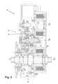
図1及び図2に、電動補助自転車用の、本発明にかかる駆動システム10の第1の実施例の、変速機ハウジング25内の入力軸1と出力軸2との間の変速機構造および2次元構造設計を示す。入力軸1は、変速機ハウジング25を貫通しており、かつ、運転者が駆動システム10を駆動するためのクランクに両側で連結する。出力軸2は、変速機ハウジング25の片側からしか突出しておらず、かつ、そこから自転車の後輪を駆動するようにチェーンホイール又は歯付きベルトプーリに接続されている。
1 and 2 show the transmission structure and 2 between the
駆動システム10は、第1のロータ軸3を有する第1のモータ11を備える。当該モータは、本用途では電気モータとして構成されている。駆動システム10は、さらに、第2のロータ軸4を有する第2のモータ12を備える。当該第2のモータも、本用途では電気モータとして構成されている。これら2つの電気モータ11,12同士は、出力制御装置8で接続されることによって電動無段作動機構(stufenloses elektrisches Stellgetriebe)を形成している。出力制御装置8は、さらに、バッテリの形態のエネルギー蓄積装置9に接続されている。これにより、出力軸2は、第1の電気モータ11によって純粋に電動で駆動されることも可能である。そして、エネルギー蓄積装置9は、制動力が出力軸2で駆動システム10へと流れた際にはブレーキエネルギー蓄積装置としても利用され得る。
The
入力軸1、出力軸2、および2つのロータ軸3,4は、多段合成変速機(Ueberlagerungsgetriebe)15で接続されている。多段合成変速機15は、1自由度の複数の変速段および2自由度の少なくとも1つの遊星歯車段16を含んでいる。ここでは、当該変速段が、平歯車段として構成されている。しかしながら、歯付きベルト変速段も想定され得る。三軸遊星歯車段16は、サンギア17、リングギア18、およびプラネットギアボルトで取り付けられた複数のプラネットギア20を具備しているプラネットキャリア19を有する。
The
駆動システム10の構成要素同士は、変速機ハウジング25のうちの利用可能な設置空間内でいずれも互いに平行に設けられた3つの軸トレーン(Wellenstraengen)21,22,23で分散するように位置している。
The components of the
第1の軸トレーン21に、入力軸1、出力軸2、および第2の電気モータ12の第2のロータ軸4が同軸に配置されている。第2の軸トレーン22に、前記多段合成変速機の三軸遊星歯車段16が配置されている。第3の軸トレーン23に、第1の電気モータ11の第1のロータ軸3が配置されている。
The
第1の軸トレーン21では、外側の出力軸2が変速機ハウジング25のうちの一方の側にて内側の入力軸1を取り囲んでおり、第2のロータ軸4が変速機ハウジング25のうちの他方の側にて入力軸1を取り囲んでいる。
In the
前記第2の軸トレーンに三軸遊星歯車段16を配置することにより、直径の小さいサンギア17を使用することができる。そして、これにより、許容範囲内の大きさに留めたリングギア18に対する固定変速比として|-4|超の大きな固定変速比が可能となる。このような大きさの負の固定変速比とすることで、簡素な(つまり、幅狭の)プラネットギア20のサイズを、そこに十分に大きな幅狭の球軸受をプラネットギア軸受として設置できるようなサイズにすることができる。まとめると、これにより、遊星歯車段16が有利なことに軸方向に極めて短寸の設計となる。
By arranging the three-axis
3つの軸トレーン21,22,23間で分散した、駆動システム10の構成要素同士を運動学的に結合するために、平歯車段として構成された4つの変速段が使用される。第1の軸トレーン21の入力軸1は、第1の平歯車段31を介して、第2の軸トレーン22の第1の接続軸5に接続されている。第1の軸トレーン21の出力軸2は、第2の平歯車段32を介して、第2の軸トレーン22の第2の接続軸6に接続されている。第1の軸トレーン21の第2の電気モータ12の第2のロータ軸4は、第3の平歯車段33を介して、第2の軸トレーン22の第3の接続軸7に接続されている。この第3の接続軸は、サンギア17も保持している。第3の軸トレーン23の第1の電気モータ11の第1のロータ軸3は、第4の平歯車段を介して、第2の軸トレーン22の遊星歯車段16のリングギア18に接続されている。
For the kinematic coupling of the components of the
第1の平歯車段31は、入力軸1の回転速度を、遊星歯車段16を介して第2の接続軸6に接続された第1の接続軸5の、約3倍の絶対回転速度へと増加させる。第2の接続軸6の回転速度は、第2の平歯車段32の変速比により、出力軸2の、約30%低い回転速度へと変換される。
The first
第1の軸トレーン21における歯車の回転速度に対する第2の軸トレーン22における歯車の回転速度の比として各々定義される第1の平歯車段31の変速比と第2の平歯車段32の変速比との比率が、第1の接続軸5と第2の接続軸6との間での作動接続最大変速比を定める。作動域の当該作動接続変速比に亘って高効率のプロファイルを得るには、作動接続最大変速比と作動接続最小変速比とがおおよそ逆数であるのが有利である。これは、上記のような設計で簡単に実現することができる。
The transmission ratio of the first
第2の軸トレーン22では、第1の接続軸5がプラネットキャリア19に連結しており、かつ、第2の接続軸6がリングギア18に連結しており、かつ、前記第3の接続軸が遊星歯車段16のサンギア17に連結している。第1のモータ11の第1のロータ軸3がリングギア18(したがって、出力軸2)に接続されているので、第1の実施例は出力側動力分岐式となる。
In the
図1には、5つの配置平面35,36,37,38,39(数字は軸方向30で増える)が標記されている。軸方向30は、出力軸2が変速機ハウジング25を出る側から当該変速機ハウジング25内へと向いている。そして、図1では、第2の平歯車段32が第1の配置平面35に位置しており、かつ、遊星歯車段16および第4の平歯車段34が第1の配置平面35と平行に軸方向30にずれて位置した第2の配置平面36に位置しており、かつ、第1の平歯車段31が第2の配置平面36に対して軸方向30に同じくずれて位置した第3の配置平面37に位置しており、かつ、第3の平歯車段33が第3の配置平面37に対して軸方向30に同じくずれて位置した第4の配置平面38に位置しており、かつ、2つのモータ11,12が第4の配置平面38に対して軸方向30に同じくずれて位置した第5の配置平面39に位置していることが明らかである。
Five placement planes 35, 36, 37, 38, 39 (numbers increase in axial direction 30) are labeled in FIG. The
第4の平歯車段34のうちの第2の軸トレーン22における歯車は、三軸遊星歯車段16のリングギア18よりも大きいピッチ円半径を有しているので、遊星歯車段16と第4の平歯車段34は、同じ第2の配置平面36に位置させることができる。結果として、リングギア18は、第2の配置平面36上で第4の平歯車段34のその歯車内に配される。
Since the gears in the
第2の軸トレーン22の遊星歯車段16の周囲に平歯車段31,32,33,34をこのように軸方向に配置すると共に、本発明に従って駆動構成要素同士を3つの軸平面21,22,23間で分けることにより、多段合成変速機15は極めてコンパクトなものになる。これは、駆動システム10を競争力に優れた軽量かつ小型なものにするための決定的な前提条件である。
With this axial arrangement of the spur gear stages 31, 32, 33, 34 around the
図1および図2では、さらに、第1の平歯車段31のうちの第1の接続軸5上の歯車が第3の接続軸7上のサンギア17よりも大きいピッチ円半径を有していることは明らかである。結果として、駆動システム10の組付け時にサンギア17を、第1の接続軸5のその歯車に差し込むことが可能となる。
1 and 2, the gearwheel on the first connecting
変速機ハウジング25への駆動システム10の残りの構成要素の組付け及び取付を簡単にするために、当該変速機ハウジング25は、4つの基本的ハウジング部位を有するものとされる。変速機ハウジング25は、中央ウェブ27を具備したメインハウジング26(当該中央ウェブ27は当該メインハウジング26に連結可能であるか又は連結している)、第5の配置平面39側で当該メインハウジング26に連結可能であるか又は連結しているモータ・カバリング28、および出力軸2が変速機ハウジング25から突出する第1の配置平面35側で当該メインハウジング26に連結可能であるか又は連結している変速機覆い部29で構成されている。
To simplify assembly and attachment of the remaining components of
図2に示す構造設計には、変速機ハウジング25又は他の軸への、駆動システム10の全ての軸の、考えられ得る軸受配置構造が描かれている。ここで、その目的は、広い軸受間隔および小さい軸受寸法で静定構造型の軸受配置構造を実現することである。これらは、全ての軸を低ノイズ及び低損失で動作させる優れた前提条件である。
The structural design shown in FIG. 2 depicts possible bearing arrangements of all shafts of
第1の軸トレーン21では、入力軸1が、第1の軸受41で出力軸2に、第2の軸受42でモータ・カバリング28に支持されている。入力軸1は、変速機ハウジング25の両側から突出しており、駆動部から高いラジアル荷重に曝される。軸受41,42は、入力軸1の最適な取付のために最大限の間隔を有している。出力軸2は、第3の軸受43で変速機カバリング29に、第4の軸受44で前記入力軸に支持されている。軸受41,43は、軸受41の径方向軸受荷重が直接軸受43で変速機ハウジング25に支持されるように互いの略径方向周囲に位置している。
In the
第1のロータ軸3は、第1の軸受45で変速機カバリング29に、第6の軸受46でモータ・カバリング28に支持されている。しかしながら、軸受46は、同じく良好な機能で中央ウェブ27とロータ軸3との間に配置されることも可能である。
The
第2のロータ軸4は、第7の軸受47および第8の軸受48で入力軸1に取り付けられている。しかし、軸受47は、ロータ軸4と中央ウェブ27との間に設置されることも可能であるが、そのときは直径が大きくなる。また、軸受48は、ロータ軸4とモータ・カバリング28との間に設置されることも可能であるが、より多くの軸方向及び径方向設置空間がさらに必要となる。
The second rotor shaft 4 is attached to the
第2の軸トレーン22では、複数の軸が互いの内側に(但し、最終的には変速機ハウジング25内に)取り付けられている。第2の接続軸6は、第2の軸トレーン22で最も高い荷重を受ける軸なので、第9の軸受49で変速機カバリング29に且つ第10の軸受50で中央ウェブ27に取り付けられた、最も内側の軸として構成されている。これにより、軸受空間が有利なことに大きくなる。変形例では、軸受50がモータ・カバリング28に設置されることも可能であり、実際に軸受間隔がなおいっそう広くなるものの、第2の接続軸6の曲げ剛性が犠牲となる。
In the
第3の接続軸7は、第11の軸受51で第2の接続軸6に、第12の軸受52で中央ウェブ27に支持されている。第1の接続軸5は、第13の軸受53で第3の接続軸7に、第14の軸受54で第2の接続軸6に支持されている。さらには、第15の軸受55が第3の接続軸7と中央ウェブ27との間で軸方向力を伝達し、第16の軸受56が第1の接続軸5と第3の接続軸7との間で軸方向力を伝達する。
The third connecting shaft 7 is supported with an
第2の平歯車段32を含む第1の配置平面35には、入力軸1-出力軸2間のフリーホイール40が位置している。これは、締結体型フリーホイール(Klemmkoerperfreilauf)であるのが好ましい。というのも、この設計のフリーホイールは、高いトルク容量を有し、かつ、接続される軸同士の硬化円筒面を同時活用できるからである。ただし、図2の構造形態では、当該フリーホイールが専用の内輪および専用の外輪を有している。
A
当然ながら、自転車用途では、強い力の運転者がクランクで入力軸に高い荷重を散発的に印加することがあり得る。このようなことは、特には、強い加速時や急峻な上り坂走行時に、すなわち、大きいギア比の路面条件で発生する。そのため、これらの走行状況では、フリーホイール40が最大のギア比で入力軸1を出力軸2へ直接連結することで前記駆動システムを保護する。
Of course, in bicycle applications, a strong rider can sporadically apply a high load to the input shaft with the crank. This happens in particular when accelerating strongly or when driving steeply uphill, ie in road conditions with large gear ratios. Therefore, in these driving situations, the
出力制御装置8の制御により第2のモータ12の最大トルクが制限された場合、当該第2のモータ12で支え切れなくなった過剰入力トルクが入力軸1を加速させると、フリーホイール40が入力軸1を出力軸2へ摩擦係合(Kraftschluessig)で自動的に連結する。これにより、フリーホイール40は、前記駆動システムの過負荷保護装置として機能すると同時に、例えば電圧降下時などの電気系統の問題時や例えばセンサの故障時等といったコントローラ/レギュレータの問題時に駆動部の機械的基本機能を保証する。
When the maximum torque of the
前記駆動システムを高い走行快適度で正確かつ確実に制御するため、前記制御装置は、正確な信号を短いクロック時間で要求する。この目的のために、角度方向位置及び回転速度を正確に測定するセンサ及びエンコーダホイールを含む第1のレゾルバ57が第1のロータ軸3に設置されている。第2のレゾルバ58が、第2のロータ軸4に設置されている。さらに、シンプルな回転速度測定システム59が、入力軸1の回転速度を測定する。高精度のレゾルバ57,58は、2つのモータ11,12の回転速度および/またはトルク制御を正確なものにするための前提条件である。追加の、前記入力軸に任意で設けられる前記回転速度測定システム58により、システム信頼性を向上させる一定の冗長性が可能となる。当該回転速度測定システム58は、例えば、前記レゾルバの信号の妥当性を確認するように機能し得て、かつ、レゾルバが故障した場合には、機能を縮小した緊急時機能を可能にする。
In order to control the drive system precisely and reliably with high driving comfort, the control device requires precise signals with short clock times. For this purpose, a
図2では、さらに、例えば多くのスマートフォンで今日採用されているような加速度・傾斜センサ24が、変速機ハウジング25に設置されている。それらの加速度信号及び傾斜度信号が、伝達される動力についての知識と組み合わされることにより、システムの重量や入力トルクのダイナミクスについて結論を下すことが可能になる。この情報は、前記出力制御装置で、制御をより高速且つより快適なものにするのに用いられ得る。
In FIG. 2, furthermore, an acceleration and
図3及び図4に、電動補助自転車用途の、本発明にかかる駆動システム10の第2の実施例の、変速機ハウジング25内の入力軸1と出力軸2との間の変速機構造および2次元構造設計を示す。
3 and 4 show the transmission structure and 2 between the
第1の実施例では、第1の接続軸5がプラネットキャリア9に連結しており、かつ、第2の接続軸6が遊星歯車段20のリングギア18に連結している。第2の実施例では、第1の接続軸5がリングギア18に連結しており、かつ、第2の接続軸6が遊星歯車段20の前記プラネットキャリアに連結している。2つの実施例間では、これらが唯一の構造的相違点である。
In a first embodiment, the first connecting
いずれの実施例においても第1のモータ11の第1のロータ3が第4の平歯車段34(変速比=|-8|の範囲内)を介してリングギア18に接続されていることから、第1の実施例における出力軸2の回転速度と第1のロータ軸3の回転速度は比例する。第2の実施例では、入力軸1の回転速度と第1のロータ軸3の回転速度が比例する。いずれの例も技術的に好都合である。電動補助自転車の駆動においては、電動補助が大きくなるほど第1の実施例のほうが有利になる。というのも、電動補助の動力が、エネルギー蓄積装置9から主に第1のモータ11を介してより直接的な経路で従動輪に作用するからである。
In any embodiment, the
このように、3つの接続軸同士を互いの内側に取り付けるという観点からみると、構造上の構成では僅かな違いしかない。これは、軸受51,54の構成に主に関係したものである。
以下、本発明に含まれる態様を記す。
〔態様1〕-変速機ハウジング(25)と、
-入力軸(1)と、
-出力軸(2)と、
-前記入力軸(1)および前記出力軸(2)を第1のモータ(11)の第1のロータ軸(3)および第2のモータ(12)の第2のロータ軸(4)に接続する、多段合成変速機(15)と、
-2つの前記モータ(11,12)が、連続可変作動機構を形成するように接続されている、出力制御装置(8)と、
-前記2つのモータ(11,12)が接続されたエネルギー蓄積装置(9)と、
を備え、前記多段合成変速機(15)が、サンギア(17)、リングギア(18)、および複数のプラネットギア(20)を具備したプラネットキャリア(19)を有する遊星歯車段(16)を含む、駆動システム(10)において、
-前記入力軸(1)、前記出力軸(2)、および第2のロータ軸(4)を有する前記第2のモータ(12)が、第1の軸トレーン(21)にて同軸に配置されており、
-前記サンギア(17)、前記リングギア(18)および前記プラネットキャリア(19)を含む前記多段合成変速機(15)が、前記第1の軸トレーン(21)と平行に設けられた第2の軸トレーン(22)にて配置された三軸遊星歯車段のみとして構成されており、
-第1のロータ軸(3)を有する前記第1のモータ(11)が、前記第1の軸トレーン(21)および前記第2の軸とレーン(22)と平行に位置した第3の軸トレーン(23)に配置されている、ことを特徴とする、駆動システム(10)。
〔態様2〕態様1に記載の駆動システム(10)において、
-前記第1の軸トレーン(21)における前記入力軸(1)が、第1の平歯車段(31)を介して、前記第2の軸トレーン(22)における第1の接続軸(5)に接続されており、
-前記第1の軸トレーン(21)における前記出力軸(2)が、第2の平歯車段(32)を介して、前記第2の軸トレーン(22)における第2の接続軸(6)に接続されており、
-前記第1の軸トレーン(21)における前記第2のモータ(12)の前記第2のロータ軸(4)が、第3の平歯車段(33)を介して、前記第2の軸トレーン(22)における第3の接続軸(7)に接続されていて、当該第3の接続軸(7)が、前記サンギア(17)に連結しており、
-前記第3の軸トレーン(23)における前記第1のモータ(11)の前記第1のロータ軸(3)が、第4の平歯車段(34)を介して、前記第2の軸トレーン(22)における前記リングギア(18)に接続されている、
ことを特徴とする、駆動システム(10)。
〔態様3〕態様1または2に記載の駆動システム(10)において、前記第2の軸トレーン(22)にて、前記第1の接続軸(5)が前記プラネットキャリア(19)に連結していて且つ前記第2の接続軸(6)が前記遊星歯車段(16)の前記リングギア(18)に連結していることを特徴とする、駆動システム(10)。
〔態様4〕態様1または2に記載の駆動システム(10)において、前記第2の軸トレーン(22)にて、前記第1の接続軸(5)が前記リングギア(18)に連結していて且つ前記第2の接続軸(6)が前記遊星歯車段(16)の前記プラネットキャリア(19)に連結していることを特徴とする、駆動システム(10)。
〔態様5〕態様1から4のいずれか一態様に記載の駆動システム(10)において、
-前記第2の平歯車段(32)が、第1の配置平面(35)に位置しており、
-前記遊星歯車段(16)および前記第4の平歯車段(34)が、前記出力軸(2)のうちの前記変速機ハウジング(25)から突出した出力部から当該変速機ハウジング(25)内へと向いた軸方向(30)にずれて前記第1の配置平面(35)と平行に位置した、第2の配置平面(36)に位置しており、
-前記第1の平歯車段(31)が、前記第2の配置平面(36)に対して同じく前記軸方向(30)にずれて位置した第3の配置平面(37)に位置しており、
-前記第3の平歯車段(33)が、前記第3の配置平面(37)に対して同じく前記軸方向(30)にずれて位置した第4の配置平面(38)に位置しており、
-前記2つのモータ(11,12)が、前記第4の配置平面(38)に対して同じく前記軸方向(30)にずれて位置した第5の配置平面(39)に位置している、
ことを特徴とする、駆動システム(10)。
〔態様6〕態様1から5のいずれか一態様に記載の駆動システム(10)において、前記第4の平歯車段(34)のうちの前記第2の軸トレーン(22)における歯車が、前記三軸遊星歯車段(16)の前記リングギア(18)よりも大きいピッチ円半径を有することを特徴とする、駆動システム(10)。
〔態様7〕態様1から6のいずれか一態様に記載の駆動システム(10)において、前記第1の平歯車段(31)のうちの前記第1の接続軸(5)上の歯車が、前記第3の接続軸(7)の前記サンギア(17)よりも大きいピッチ円半径を有することを特徴とする、駆動システム(10)。
〔態様8〕態様1から7のいずれか一態様に記載の駆動システム(10)において、前記変速機ハウジング(25)が、中央ウェブ(27)を具備したメインハウジング(26)、当該メインハウジング(26)に連結したモータ・カバリング(28)、および当該メインハウジング(26)に連結した変速機カバリング(29)を有することを特徴とする、駆動システム(10)。
〔態様9〕態様5に従属するときの態様8に記載の駆動システム(10)において、前記モータ・カバリング(28)が、前記変速機ハウジング(25)のうちの前記第5の配置平面(39)側に設けられており、前記変速機カバリング(29)が、前記変速機ハウジング(25)のうちの前記出力軸(2)が当該変速機ハウジング(25)から突出する前記第1の配置平面(35)側に設けられていることを特徴とする、駆動システム(10)。
〔態様10〕態様8または9に記載の駆動システム(10)において、
-前記入力軸(1)が、第1の軸受(41)で前記出力軸(2)に、第2の軸受(42)で前記モータ・カバリング(28)に支持されており、
-前記入力軸(1)が、前記変速機ハウジング(25)の両側から突出しており、
-前記出力軸(2)が、第3の軸受(43)で前記変速機カバリング(29)に、第4の軸受(44)で前記入力軸(1)に支持されている、
ことを特徴とする、駆動システム(10)。
〔態様11〕態様8から10のいずれか一態様に記載の駆動システム(10)において、前記第1のロータ軸(3)が、第5の軸受(45)で前記変速機カバリング(29)に、第6の軸受(46)で前記中央ウェブ又は前記モータ・カバリング(28)に支持されていることを特徴とする、駆動システム(10)。
〔態様12〕態様8から11のいずれか一態様に記載の駆動システム(10)において、前記第2のロータ軸(4)が、第7の軸受(47)で前記駆動軸(1)又は前記中央ウェブ(27)に、第8の軸受(48)で前記入力軸(1)又は前記モータ・カバリング(28)に取り付けられていることを特徴とする、駆動システム(10)。
〔態様13〕態様2に記載され、かつ、態様8から12のいずれか一態様に記載の駆動システム(10)において、
-前記第2の軸トレーン(22)における前記第2の接続軸(6)が、第9の軸受(49)で前記変速機カバリング(29)に、第10の軸受(50)で前記中央ウェブ(27)又は前記モータ・カバリング(28)に取り付けられており、
-前記第3の接続軸(7)が、第11の軸受(51)で前記第2の接続軸(6)に、第12の軸受(52)で前記中央ウェブ(27)に支持されており、
-前記第1の接続軸(5)が、第13の軸受(53)で前記第3の接続軸(7)に、第14の軸受(54)で前記第2の接続軸(6)に支持されており、
-第15の軸受(55)が、前記第3の接続軸(7)と前記中央ウェブ(27)との間で軸方向力を伝達し、
-第16の軸受(56)が、前記第1の接続軸(5)と前記第3の接続軸(7)との間で軸方向力を伝達する、
ことを特徴とする、駆動システム(10)。
〔態様14〕態様9または態様9に従属したときの態様10から13のいずれか一態様に記載の駆動システム(10)において、前記第1の軸受(41)と前記第2の軸受(44)との間には、前記入力軸(1)が前記出力軸(2)よりも速く回転しないように防ぐフリーホイール(40)が当該入力軸(1)-当該出力軸(2)間で配置されていることを特徴とする、駆動システム(10)。
〔態様15〕態様1から14のいずれか一態様に記載の駆動システム(10)において、角度方向位置及び回転速度を測定するセンサ及びエンコーダホイールを含む第1のレゾルバ(57)が前記第1のロータ軸(3)に設置されており、かつ/あるいは、角度方向位置及び回転速度を測定するセンサ及びエンコーダホイールを含む第2のレゾルバ(58)が前記第2のロータ軸(4)に設置されており、かつ/あるいは、回転速度センサ(59)が前記入力軸に設置されており、かつ/あるいは、加速度センサ及び/又は傾斜センサ(24)が前記変速機ハウジング(25)に設置されていることを特徴とする、駆動システム(10)。
〔態様16〕態様1から15のいずれか一態様に記載の駆動システムを備える電動補助自転車。
Thus, from the point of view of mounting the three connecting shafts inside each other, there are only minor structural differences. This is primarily related to the construction of the
Embodiments included in the present invention are described below.
- an input shaft (1);
- an output shaft (2);
- connecting said input shaft (1) and said output shaft (2) to a first rotor shaft (3) of a first motor (11) and a second rotor shaft (4) of a second motor (12); a multi-stage compound transmission (15);
- a power controller (8), wherein the two motors (11, 12) are connected to form a continuously variable actuation mechanism;
- an energy storage device (9) to which said two motors (11, 12) are connected;
wherein said multi-stage compound transmission (15) comprises a planetary gear stage (16) having a sun gear (17), a ring gear (18) and a planet carrier (19) comprising a plurality of planet gears (20) , in the drive system (10),
- said second motor (12) having said input shaft (1), said output shaft (2) and a second rotor shaft (4) coaxially arranged in a first axial train (21); and
- a second, wherein said multi-stage compound transmission (15) comprising said sun gear (17), said ring gear (18) and said planet carrier (19) is arranged parallel to said first axial train (21); configured as only three-axis planetary gear stages arranged in an axle train (22),
- said first motor (11) with a first rotor axis (3) has a third axis located parallel to said first axial train (21) and said second axis and lane (22); A drive system (10), characterized in that it is arranged in a train (23).
[Aspect 2] In the drive system (10) according to
- said input shaft (1) in said first shaft train (21) is connected via a first spur gear stage (31) to a first connecting shaft (5) in said second shaft train (22); is connected to
- said output shaft (2) in said first shaft train (21) is connected via a second spur gear stage (32) to a second connecting shaft (6) in said second shaft train (22); is connected to
- said second rotor shaft (4) of said second motor (12) in said first shaft train (21) is connected to said second shaft train via a third spur gear stage (33); (22) is connected to a third connecting shaft (7), the third connecting shaft (7) is connected to the sun gear (17),
- said first rotor shaft (3) of said first motor (11) in said third shaft train (23) is connected to said second shaft train via a fourth spur gear stage (34); connected to said ring gear (18) at (22);
A drive system (10), characterized in that:
[Aspect 3] In the drive system (10) according to
[Aspect 4] In the drive system (10) according to
[Aspect 5] In the drive system (10) according to any one of
- said second spur gear stage (32) lies in a first plane of placement (35),
- said planetary gear stage (16) and said fourth spur gear stage (34) are located from the output of said output shaft (2) projecting from said transmission housing (25); located in a second alignment plane (36) parallel to said first alignment plane (35) offset in an inwardly directed axial direction (30);
- said first spur gear stage (31) lies in a third locating plane (37) which is also offset in said axial direction (30) with respect to said second locating plane (36); ,
- said third spur gear stage (33) lies in a fourth locating plane (38) which is also offset in said axial direction (30) with respect to said third locating plane (37); ,
- the two motors (11, 12) are situated in a fifth orientation plane (39) which is also offset in the axial direction (30) with respect to the fourth orientation plane (38),
A drive system (10), characterized in that:
[Aspect 7] The drive system (10) according to any one of
[Aspect 8] A drive system (10) according to any one of
[Aspect 9] A drive system (10) according to
[Aspect 10] In the drive system (10) according to
- said input shaft (1) is supported by a first bearing (41) on said output shaft (2) and by a second bearing (42) on said motor covering (28),
- said input shaft (1) protrudes from both sides of said transmission housing (25),
- said output shaft (2) is supported on said transmission cover (29) with a third bearing (43) and on said input shaft (1) with a fourth bearing (44);
A drive system (10), characterized in that:
[Aspect 11] In the drive system (10) according to any one of
[Aspect 12] In the drive system (10) according to any one of
[Aspect 13] In the drive system (10) according to
- said second connecting shaft (6) in said second axle train (22) is connected to said transmission covering (29) at a ninth bearing (49) and to said central web at a tenth bearing (50); (27) or attached to the motor covering (28),
- said third connecting shaft (7) is supported on said second connecting shaft (6) with an eleventh bearing (51) and on said central web (27) with a twelfth bearing (52); ,
- said first connecting shaft (5) is supported by a thirteenth bearing (53) on said third connecting shaft (7) and by a fourteenth bearing (54) on said second connecting shaft (6); has been
- a fifteenth bearing (55) transmits axial forces between said third connecting shaft (7) and said central web (27),
- a sixteenth bearing (56) transmits axial forces between said first connecting shaft (5) and said third connecting shaft (7);
A drive system (10), characterized in that:
[Aspect 14] A drive system (10) according to
[Aspect 15] A drive system (10) according to any one of
[Aspect 16] A battery-assisted bicycle comprising the drive system according to any one of
1 入力軸
2 出力軸
3 第1のロータ軸
4 第2のロータ軸
5 第1の接続軸
6 第2の接続軸
7 第3の接続軸
8 出力制御装置
9 エネルギー蓄積装置(バッテリまたは圧力蓄積装置)
10 駆動システム
11 第1の(電気または圧力)モータ
12 第2の(電気または圧力)モータ
13 第1のステータ
14 第2のステータ
15 多段合成変速機
16 三軸遊星歯車段PG
17 サンギア
18 リングギア
19 プラネットキャリア
20 プラネットギア
21 第1の軸トレーン
22 第2の軸トレーン
23 第3の軸トレーン
24 加速度・傾斜センサ
25 変速機ハウジング
26 メインハウジング
27 中央ウェブ
28 モータ・カバリング
29 変速機カバリング
30 軸方向
31 第1の平歯車段
32 第2の平歯車段
33 第3の平歯車段
34 第4の平歯車段
35 第1の配置平面
36 第2の配置平面
37 第3の配置平面
38 第4の配置平面
39 第5の配置平面
40 フリーホイール
41 第1の軸受
42 第2の軸受
43 第3の軸受
44 第4の軸受
45 第5の軸受
46 第6の軸受
47 第7の軸受
48 第8の軸受
49 第9の軸受
50 第10の軸受
51 第11の軸受
52 第12の軸受
53 第13の軸受
54 第14の軸受
55 第15の軸受
56 第16の軸受
57 センサ及びエンコーダホイールを含む第1のレゾルバ
58 センサ及びエンコーダホイールを含む第2のレゾルバ
59 回転速度測定システム
1
10
17
Claims (16)
-入力軸(1)と、
-出力軸(2)と、
-前記入力軸(1)および前記出力軸(2)を第1のモータ(11)の第1のロータ軸(3)および第2のモータ(12)の第2のロータ軸(4)に接続する、多段合成変速機(15)と、
-2つの前記モータ(11,12)が、連続可変作動機構を形成するように接続されている、出力制御装置(8)と、
-前記2つのモータ(11,12)が接続されたエネルギー蓄積装置(9)と、
を備え、前記多段合成変速機(15)が、サンギア(17)、リングギア(18)、および複数のプラネットギア(20)を具備したプラネットキャリア(19)を有する遊星歯車段(16)を含む、駆動システム(10)において、
-前記入力軸(1)、前記出力軸(2)、および第2のロータ軸(4)を有する前記第2のモータ(12)が、第1の軸トレーン(21)にて同軸に配置されており、
-前記サンギア(17)、前記リングギア(18)および前記プラネットキャリア(19)を含む前記多段合成変速機(15)が、前記第1の軸トレーン(21)と平行に設けられた第2の軸トレーン(22)にて配置された三軸遊星歯車段(16)のみとして構成されており、
-第1のロータ軸(3)を有する前記第1のモータ(11)が、前記第1の軸トレーン(21)および前記第2の軸トレーン(22)と平行に位置した第3の軸トレーン(23)に配置されている、ことを特徴とする、駆動システム(10)。 - the transmission housing (25);
- an input shaft (1);
- an output shaft (2);
- connecting said input shaft (1) and said output shaft (2) to a first rotor shaft (3) of a first motor (11) and a second rotor shaft (4) of a second motor (12); a multi-stage compound transmission (15);
- a power controller (8), wherein the two motors (11, 12) are connected to form a continuously variable actuation mechanism;
- an energy storage device (9) to which said two motors (11, 12) are connected;
wherein said multi-stage compound transmission (15) comprises a planetary gear stage (16) having a sun gear (17), a ring gear (18) and a planet carrier (19) comprising a plurality of planet gears (20) , in the drive system (10),
- said second motor (12) having said input shaft (1), said output shaft (2) and a second rotor shaft (4) coaxially arranged in a first axial train (21); and
- a second, wherein said multi-stage compound transmission (15) comprising said sun gear (17), said ring gear (18) and said planet carrier (19) is arranged parallel to said first axial train (21); configured as only a three-axis planetary gear stage (16) arranged in an axial train (22),
- said first motor (11) having a first rotor axis (3) with a third axis positioned parallel to said first axial train (21) and said second axial train (22); A drive system (10), characterized in that it is arranged in a train (23).
-前記第1の軸トレーン(21)における前記入力軸(1)が、第1の平歯車段(31)を介して、前記第2の軸トレーン(22)における第1の接続軸(5)に接続されており、
-前記第1の軸トレーン(21)における前記出力軸(2)が、第2の平歯車段(32)を介して、前記第2の軸トレーン(22)における第2の接続軸(6)に接続されており、
-前記第1の軸トレーン(21)における前記第2のモータ(12)の前記第2のロータ軸(4)が、第3の平歯車段(33)を介して、前記第2の軸トレーン(22)における第3の接続軸(7)に接続されていて、当該第3の接続軸(7)が、前記サンギア(17)に連結しており、
-前記第3の軸トレーン(23)における前記第1のモータ(11)の前記第1のロータ軸(3)が、第4の平歯車段(34)を介して、前記第2の軸トレーン(22)における前記リングギア(18)に接続されている、
ことを特徴とする、駆動システム(10)。 A drive system (10) according to claim 1, wherein
- said input shaft (1) in said first shaft train (21) is connected via a first spur gear stage (31) to a first connecting shaft (5) in said second shaft train (22); is connected to
- said output shaft (2) in said first shaft train (21) is connected via a second spur gear stage (32) to a second connecting shaft (6) in said second shaft train (22); is connected to
- said second rotor shaft (4) of said second motor (12) in said first shaft train (21) is connected to said second shaft train via a third spur gear stage (33); (22) is connected to a third connecting shaft (7), the third connecting shaft (7) is connected to the sun gear (17),
- said first rotor shaft (3) of said first motor (11) in said third shaft train (23) is connected to said second shaft train via a fourth spur gear stage (34); connected to said ring gear (18) at (22);
A drive system (10), characterized in that:
-前記第2の平歯車段(32)が、第1の配置平面(35)に位置しており、
-前記遊星歯車段(16)および前記第4の平歯車段(34)が、前記出力軸(2)のうちの変速機ハウジング(25)から突出した出力部から当該変速機ハウジング(25)内へと向いた軸方向(30)にずれて前記第1の配置平面(35)と平行に位置した、第2の配置平面(36)に位置しており、
-前記第1の平歯車段(31)が、前記第2の配置平面(36)に対して同じく前記軸方向(30)にずれて位置した第3の配置平面(37)に位置しており、
-前記第3の平歯車段(33)が、前記第3の配置平面(37)に対して同じく前記軸方向(30)にずれて位置した第4の配置平面(38)に位置しており、
-前記2つのモータ(11,12)が、前記第4の配置平面(38)に対して同じく前記軸方向(30)にずれて位置した第5の配置平面(39)に位置している、
ことを特徴とする、駆動システム(10)。 A drive system (10) according to any one of claims 2 to 4, wherein
- said second spur gear stage (32) lies in a first plane of placement (35),
- the planetary gear stage (16) and the fourth spur gear stage (34) are located from the output of the output shaft (2) projecting from the transmission housing (25); located in a second alignment plane (36) parallel to said first alignment plane (35) offset in an inwardly directed axial direction (30);
- said first spur gear stage (31) lies in a third locating plane (37) which is also offset in said axial direction (30) with respect to said second locating plane (36); ,
- said third spur gear stage (33) lies in a fourth locating plane (38) which is also offset in said axial direction (30) with respect to said third locating plane (37); ,
- the two motors (11, 12) are situated in a fifth orientation plane (39) which is also offset in the axial direction (30) with respect to the fourth orientation plane (38),
A drive system (10), characterized in that:
-前記入力軸(1)が、第1の軸受(41)で前記出力軸(2)に、第2の軸受(42)で前記モータ・カバリング(28)に支持されており、
-前記入力軸(1)が、前記変速機ハウジング(25)の両側から突出しており、
-前記出力軸(2)が、第3の軸受(43)で前記変速機カバリング(29)に、第4の軸受(44)で前記入力軸(1)に支持されている、
ことを特徴とする、駆動システム(10)。 A drive system (10) according to claim 8 or 9, wherein
- said input shaft (1) is supported by a first bearing (41) on said output shaft (2) and by a second bearing (42) on said motor covering (28),
- said input shaft (1) protrudes from both sides of said transmission housing (25),
- said output shaft (2) is supported on said transmission cover (29) with a third bearing (43) and on said input shaft (1) with a fourth bearing (44);
A drive system (10), characterized in that:
ロータ軸(4)が、第7の軸受(47)で前記入力軸(1)又は前記中央ウェブ(27)に、第8の軸受(48)で前記入力軸(1)又は前記モータ・カバリング(28)に取り付けられていることを特徴とする、駆動システム(10)。 A drive system (10) according to any one of claims 8 to 11, wherein said second rotor shaft (4) is coupled to said input shaft (1) or said central web (1) at a seventh bearing (47). 27), mounted on said input shaft (1) or said motor covering (28) with an eighth bearing (48).
-前記第2の軸トレーン(22)における前記第2の接続軸(6)が、第9の軸受(49)で前記変速機カバリング(29)に、第10の軸受(50)で前記中央ウェブ(27)又は前記モータ・カバリング(28)に取り付けられており、
-前記第3の接続軸(7)が、第11の軸受(51)で前記第2の接続軸(6)に、第12の軸受(52)で前記中央ウェブ(27)に支持されており、
-前記第1の接続軸(5)が、第13の軸受(53)で前記第3の接続軸(7)に、第14の軸受(54)で前記第2の接続軸(6)に支持されており、
-第15の軸受(55)が、前記第3の接続軸(7)と前記中央ウェブ(27)との間で軸方向力を伝達し、
-第16の軸受(56)が、前記第1の接続軸(5)と前記第3の接続軸(7)との間で軸方向力を伝達する、
ことを特徴とする、駆動システム(10)。 In a drive system (10) according to claim 2 and according to any one of claims 8 to 12,
- said second connecting shaft (6) in said second axle train (22) is connected to said transmission covering (29) at a ninth bearing (49) and to said central web at a tenth bearing (50); (27) or attached to the motor covering (28),
- said third connecting shaft (7) is supported on said second connecting shaft (6) with an eleventh bearing (51) and on said central web (27) with a twelfth bearing (52); ,
- said first connecting shaft (5) is supported by a thirteenth bearing (53) on said third connecting shaft (7) and by a fourteenth bearing (54) on said second connecting shaft (6); has been
- a fifteenth bearing (55) transmits axial forces between said third connecting shaft (7) and said central web (27),
- a sixteenth bearing (56) transmits axial forces between said first connecting shaft (5) and said third connecting shaft (7);
A drive system (10), characterized in that:
A battery-assisted bicycle comprising the drive system according to any one of claims 1 to 15.
Applications Claiming Priority (2)
| Application Number | Priority Date | Filing Date | Title |
|---|---|---|---|
| DE102018001795.9A DE102018001795B4 (en) | 2018-03-06 | 2018-03-06 | Drive system |
| PCT/EP2019/055734 WO2019175022A1 (en) | 2018-03-06 | 2019-03-07 | Drive system |
Publications (3)
| Publication Number | Publication Date |
|---|---|
| JP2021517533A JP2021517533A (en) | 2021-07-26 |
| JPWO2019175022A5 JPWO2019175022A5 (en) | 2022-03-09 |
| JP7316290B2 true JP7316290B2 (en) | 2023-07-27 |
Family
ID=65812269
Family Applications (1)
| Application Number | Title | Priority Date | Filing Date |
|---|---|---|---|
| JP2020547047A Active JP7316290B2 (en) | 2018-03-06 | 2019-03-07 | drive system |
Country Status (6)
| Country | Link |
|---|---|
| US (1) | US11453460B2 (en) |
| EP (1) | EP3790789B1 (en) |
| JP (1) | JP7316290B2 (en) |
| CN (1) | CN111918816A (en) |
| DE (1) | DE102018001795B4 (en) |
| WO (1) | WO2019175022A1 (en) |
Families Citing this family (9)
| Publication number | Priority date | Publication date | Assignee | Title |
|---|---|---|---|---|
| KR102075980B1 (en) | 2018-04-13 | 2020-02-12 | 주식회사 세진아이지비 | Difference transmission |
| DE102018217883B4 (en) * | 2018-09-25 | 2020-06-04 | Zf Friedrichshafen Ag | Drive arrangement for a bicycle or pedelec |
| DE102018216340A1 (en) | 2018-09-25 | 2020-03-26 | Brose Antriebstechnik GmbH & Co. Kommanditgesellschaft, Berlin | Drive device for an electric bicycle with electronic anti-theft device and control method |
| DE102021000585B4 (en) | 2021-02-05 | 2024-04-18 | EGS Entwicklungsgesellschaft für Getriebesysteme mbH | Modular drive system |
| DE102021207255A1 (en) | 2021-07-08 | 2023-01-12 | Brose Antriebstechnik GmbH & Co. Kommanditgesellschaft, Berlin | Drive system for an electric bicycle with limp home mode and control method |
| DE102021208412A1 (en) | 2021-08-03 | 2023-02-09 | Brose Antriebstechnik GmbH & Co. Kommanditgesellschaft, Berlin | Drive system for an electric bicycle with at least one freewheel and exactly one electric motor |
| DE102021211219A1 (en) | 2021-10-05 | 2023-04-06 | Brose Antriebstechnik GmbH & Co. Kommanditgesellschaft, Berlin | Drive system for an electric bicycle with a training mode |
| DE102022102070A1 (en) | 2022-01-28 | 2023-08-03 | Brose Antriebstechnik GmbH & Co. Kommanditgesellschaft, Berlin | Drive system for an electric bicycle with calculation of a torque at the bottom bracket shaft for controlling the power assist |
| DE102022210892A1 (en) | 2022-10-14 | 2024-04-25 | Zf Friedrichshafen Ag | Drive device for a muscle-powered vehicle and vehicle with this drive device |
Citations (5)
| Publication number | Priority date | Publication date | Assignee | Title |
|---|---|---|---|---|
| JP2005041352A (en) | 2003-07-23 | 2005-02-17 | Moric Co Ltd | Torque controlling method for power-assisted bicycle |
| US20140051548A1 (en) | 2012-08-17 | 2014-02-20 | Shimano Inc. | Bicycle drive unit |
| JP3194818U (en) | 2014-09-29 | 2014-12-11 | 株式会社シマノ | Bicycle drive unit |
| JP2017100486A (en) | 2015-11-30 | 2017-06-08 | 株式会社シマノ | Drive unit for bicycle |
| JP2017190100A (en) | 2016-04-15 | 2017-10-19 | 株式会社シマノ | Bicycle control device |
Family Cites Families (20)
| Publication number | Priority date | Publication date | Assignee | Title |
|---|---|---|---|---|
| US1515321A (en) * | 1920-11-30 | 1924-11-11 | William A Neracher | Electromagnetic transmission mechanism |
| US3623568A (en) | 1968-05-31 | 1971-11-30 | Nissan Motor | Electromechanical power train system for an automotive vehicle |
| DE3147447C2 (en) | 1981-12-01 | 1984-06-14 | Jarchow, Friedrich, Prof. Dr.-Ing., 4300 Essen | Hydrostatic-mechanical actuating coupling gear with input-side power split |
| US5151321A (en) | 1984-08-29 | 1992-09-29 | Kimberly-Clark Corporation | Method of making conductive, water and/or alcohol repellent nonwoven fabric and resulting product |
| JPH09226667A (en) * | 1996-02-29 | 1997-09-02 | Suzuki Motor Corp | Control device for electric motor-driven bicycle |
| JP3412525B2 (en) | 1998-07-13 | 2003-06-03 | トヨタ自動車株式会社 | Power output device, control method therefor, and hybrid vehicle |
| GB0902356D0 (en) * | 2009-02-12 | 2009-04-01 | Nexxtdrive Ltd | Bicycle transmission systems |
| DE102012103355A1 (en) | 2012-04-17 | 2013-10-17 | Brose Fahrzeugteile Gmbh & Co. Kommanditgesellschaft, Coburg | Drive device for an electric bike |
| BE1020653A4 (en) | 2012-04-27 | 2014-02-04 | Deleval Arthur | POWERTRAIN. |
| KR101489933B1 (en) | 2013-08-12 | 2015-02-04 | 주식회사 하이코어 | Gear system for combining inputs |
| BE1022240B1 (en) | 2014-09-02 | 2016-03-04 | E2 Drives Sa | POWER UNIT FOR A PEDAL VEHICLE |
| JP6325430B2 (en) * | 2014-12-17 | 2018-05-16 | 株式会社シマノ | Bicycle drive unit |
| JP2017088093A (en) * | 2015-11-16 | 2017-05-25 | 株式会社シマノ | Drive unit for bicycle |
| JP6567983B2 (en) | 2016-01-29 | 2019-08-28 | 株式会社シマノ | Bicycle control device and bicycle transmission system |
| JP2017132440A (en) | 2016-01-29 | 2017-08-03 | 株式会社シマノ | Bicycle drive device |
| DE102016014410B3 (en) * | 2016-11-14 | 2018-01-25 | Oechsler Ag | Electromotive auxiliary drive for a bicycle |
| US10919599B2 (en) | 2017-05-23 | 2021-02-16 | Mahle International Gmbh | Bicycle having electric drive or auxiliary drive |
| BE1025518B1 (en) * | 2017-08-30 | 2019-04-03 | E2 Drives Sa | Powertrain |
| BE1026017B1 (en) * | 2018-02-16 | 2019-09-16 | E2 Drives Sa | Powertrain |
| DE102018216340A1 (en) | 2018-09-25 | 2020-03-26 | Brose Antriebstechnik GmbH & Co. Kommanditgesellschaft, Berlin | Drive device for an electric bicycle with electronic anti-theft device and control method |
-
2018
- 2018-03-06 DE DE102018001795.9A patent/DE102018001795B4/en active Active
-
2019
- 2019-03-07 JP JP2020547047A patent/JP7316290B2/en active Active
- 2019-03-07 US US16/978,207 patent/US11453460B2/en active Active
- 2019-03-07 EP EP19711521.5A patent/EP3790789B1/en active Active
- 2019-03-07 WO PCT/EP2019/055734 patent/WO2019175022A1/en unknown
- 2019-03-07 CN CN201980017359.0A patent/CN111918816A/en active Pending
Patent Citations (5)
| Publication number | Priority date | Publication date | Assignee | Title |
|---|---|---|---|---|
| JP2005041352A (en) | 2003-07-23 | 2005-02-17 | Moric Co Ltd | Torque controlling method for power-assisted bicycle |
| US20140051548A1 (en) | 2012-08-17 | 2014-02-20 | Shimano Inc. | Bicycle drive unit |
| JP3194818U (en) | 2014-09-29 | 2014-12-11 | 株式会社シマノ | Bicycle drive unit |
| JP2017100486A (en) | 2015-11-30 | 2017-06-08 | 株式会社シマノ | Drive unit for bicycle |
| JP2017190100A (en) | 2016-04-15 | 2017-10-19 | 株式会社シマノ | Bicycle control device |
Also Published As
| Publication number | Publication date |
|---|---|
| US20210039746A1 (en) | 2021-02-11 |
| CN111918816A (en) | 2020-11-10 |
| WO2019175022A8 (en) | 2019-12-05 |
| EP3790789B1 (en) | 2021-10-06 |
| JP2021517533A (en) | 2021-07-26 |
| EP3790789A1 (en) | 2021-03-17 |
| US11453460B2 (en) | 2022-09-27 |
| DE102018001795B4 (en) | 2024-02-01 |
| WO2019175022A1 (en) | 2019-09-19 |
| DE102018001795A1 (en) | 2019-09-12 |
Similar Documents
| Publication | Publication Date | Title |
|---|---|---|
| JP7316290B2 (en) | drive system | |
| US5419406A (en) | Drive system for electric car | |
| US11884146B2 (en) | Transmission and vehicle with transmission | |
| US8123645B2 (en) | Vehicle transmission | |
| US9638302B2 (en) | Electric axle with a two gear transmission | |
| US7410017B2 (en) | Electric drive axle | |
| US20180345949A1 (en) | Electric vehicle drive using combined differential and reduction gearing | |
| KR100717306B1 (en) | A transmission for hybrid vehicles | |
| EP3546320B1 (en) | Drive configurations for skid steered vehicles | |
| CN103775573B (en) | In-line gears system | |
| JP2011102639A (en) | Reduction gear for electric motor | |
| WO2005120877A1 (en) | Epicyclic differential transmission | |
| CN108082274A (en) | Utilize the transfer for steering of lead system | |
| CN102811878A (en) | Wheel hub drive for motor vehicles | |
| JP2021191673A (en) | Bicycle including electric driving device with multiple unit system | |
| EP2894055B1 (en) | Motor drive unit | |
| CN104210536B (en) | Electric power-assisted steering apparatus for vehicle | |
| KR20170065445A (en) | Steering system with low-bulk mechanical differential | |
| EP2373538B1 (en) | Transmission unit for a bicycle | |
| JPWO2019175022A5 (en) | ||
| CN115704462A (en) | Transmission for a vehicle and drive train having such a transmission | |
| JP2017141929A (en) | Transmission device | |
| JPS58191350A (en) | Drive unit for automobile | |
| SE439969B (en) | Gearbox, designed to be installed between a main gearbox and a transmission lead to the driving-wheel in a motor vehicle | |
| JPH0692154A (en) | Drive unit for electric automobile |
Legal Events
| Date | Code | Title | Description |
|---|---|---|---|
| A521 | Request for written amendment filed |
Free format text: JAPANESE INTERMEDIATE CODE: A523 Effective date: 20210524 |
|
| A521 | Request for written amendment filed |
Free format text: JAPANESE INTERMEDIATE CODE: A523 Effective date: 20220228 |
|
| A621 | Written request for application examination |
Free format text: JAPANESE INTERMEDIATE CODE: A621 Effective date: 20220228 |
|
| A977 | Report on retrieval |
Free format text: JAPANESE INTERMEDIATE CODE: A971007 Effective date: 20220930 |
|
| A131 | Notification of reasons for refusal |
Free format text: JAPANESE INTERMEDIATE CODE: A131 Effective date: 20221018 |
|
| A601 | Written request for extension of time |
Free format text: JAPANESE INTERMEDIATE CODE: A601 Effective date: 20230118 |
|
| A601 | Written request for extension of time |
Free format text: JAPANESE INTERMEDIATE CODE: A601 Effective date: 20230316 |
|
| A521 | Request for written amendment filed |
Free format text: JAPANESE INTERMEDIATE CODE: A523 Effective date: 20230322 |
|
| TRDD | Decision of grant or rejection written | ||
| A01 | Written decision to grant a patent or to grant a registration (utility model) |
Free format text: JAPANESE INTERMEDIATE CODE: A01 Effective date: 20230620 |
|
| A61 | First payment of annual fees (during grant procedure) |
Free format text: JAPANESE INTERMEDIATE CODE: A61 Effective date: 20230714 |
|
| R150 | Certificate of patent or registration of utility model |
Ref document number: 7316290 Country of ref document: JP Free format text: JAPANESE INTERMEDIATE CODE: R150 |