JP2017190100A - Bicycle control device - Google Patents
Bicycle control device Download PDFInfo
- Publication number
- JP2017190100A JP2017190100A JP2016082093A JP2016082093A JP2017190100A JP 2017190100 A JP2017190100 A JP 2017190100A JP 2016082093 A JP2016082093 A JP 2016082093A JP 2016082093 A JP2016082093 A JP 2016082093A JP 2017190100 A JP2017190100 A JP 2017190100A
- Authority
- JP
- Japan
- Prior art keywords
- phase
- bicycle
- control
- control state
- control unit
- Prior art date
- Legal status (The legal status is an assumption and is not a legal conclusion. Google has not performed a legal analysis and makes no representation as to the accuracy of the status listed.)
- Granted
Links
Images

Classifications
-
- B—PERFORMING OPERATIONS; TRANSPORTING
- B62—LAND VEHICLES FOR TRAVELLING OTHERWISE THAN ON RAILS
- B62M—RIDER PROPULSION OF WHEELED VEHICLES OR SLEDGES; POWERED PROPULSION OF SLEDGES OR SINGLE-TRACK CYCLES; TRANSMISSIONS SPECIALLY ADAPTED FOR SUCH VEHICLES
- B62M6/00—Rider propulsion of wheeled vehicles with additional source of power, e.g. combustion engine or electric motor
- B62M6/40—Rider propelled cycles with auxiliary electric motor
- B62M6/55—Rider propelled cycles with auxiliary electric motor power-driven at crank shafts parts
-
- B—PERFORMING OPERATIONS; TRANSPORTING
- B62—LAND VEHICLES FOR TRAVELLING OTHERWISE THAN ON RAILS
- B62M—RIDER PROPULSION OF WHEELED VEHICLES OR SLEDGES; POWERED PROPULSION OF SLEDGES OR SINGLE-TRACK CYCLES; TRANSMISSIONS SPECIALLY ADAPTED FOR SUCH VEHICLES
- B62M6/00—Rider propulsion of wheeled vehicles with additional source of power, e.g. combustion engine or electric motor
- B62M6/40—Rider propelled cycles with auxiliary electric motor
- B62M6/45—Control or actuating devices therefor
- B62M6/50—Control or actuating devices therefor characterised by detectors or sensors, or arrangement thereof
-
- B—PERFORMING OPERATIONS; TRANSPORTING
- B60—VEHICLES IN GENERAL
- B60W—CONJOINT CONTROL OF VEHICLE SUB-UNITS OF DIFFERENT TYPE OR DIFFERENT FUNCTION; CONTROL SYSTEMS SPECIALLY ADAPTED FOR HYBRID VEHICLES; ROAD VEHICLE DRIVE CONTROL SYSTEMS FOR PURPOSES NOT RELATED TO THE CONTROL OF A PARTICULAR SUB-UNIT
- B60W10/00—Conjoint control of vehicle sub-units of different type or different function
- B60W10/04—Conjoint control of vehicle sub-units of different type or different function including control of propulsion units
- B60W10/08—Conjoint control of vehicle sub-units of different type or different function including control of propulsion units including control of electric propulsion units, e.g. motors or generators
-
- B—PERFORMING OPERATIONS; TRANSPORTING
- B60—VEHICLES IN GENERAL
- B60W—CONJOINT CONTROL OF VEHICLE SUB-UNITS OF DIFFERENT TYPE OR DIFFERENT FUNCTION; CONTROL SYSTEMS SPECIALLY ADAPTED FOR HYBRID VEHICLES; ROAD VEHICLE DRIVE CONTROL SYSTEMS FOR PURPOSES NOT RELATED TO THE CONTROL OF A PARTICULAR SUB-UNIT
- B60W10/00—Conjoint control of vehicle sub-units of different type or different function
- B60W10/10—Conjoint control of vehicle sub-units of different type or different function including control of change-speed gearings
- B60W10/11—Stepped gearings
-
- B—PERFORMING OPERATIONS; TRANSPORTING
- B60—VEHICLES IN GENERAL
- B60W—CONJOINT CONTROL OF VEHICLE SUB-UNITS OF DIFFERENT TYPE OR DIFFERENT FUNCTION; CONTROL SYSTEMS SPECIALLY ADAPTED FOR HYBRID VEHICLES; ROAD VEHICLE DRIVE CONTROL SYSTEMS FOR PURPOSES NOT RELATED TO THE CONTROL OF A PARTICULAR SUB-UNIT
- B60W30/00—Purposes of road vehicle drive control systems not related to the control of a particular sub-unit, e.g. of systems using conjoint control of vehicle sub-units
- B60W30/18—Propelling the vehicle
- B60W30/182—Selecting between different operative modes, e.g. comfort and performance modes
-
- B—PERFORMING OPERATIONS; TRANSPORTING
- B60—VEHICLES IN GENERAL
- B60W—CONJOINT CONTROL OF VEHICLE SUB-UNITS OF DIFFERENT TYPE OR DIFFERENT FUNCTION; CONTROL SYSTEMS SPECIALLY ADAPTED FOR HYBRID VEHICLES; ROAD VEHICLE DRIVE CONTROL SYSTEMS FOR PURPOSES NOT RELATED TO THE CONTROL OF A PARTICULAR SUB-UNIT
- B60W30/00—Purposes of road vehicle drive control systems not related to the control of a particular sub-unit, e.g. of systems using conjoint control of vehicle sub-units
- B60W30/18—Propelling the vehicle
- B60W30/188—Controlling power parameters of the driveline, e.g. determining the required power
-
- B—PERFORMING OPERATIONS; TRANSPORTING
- B60—VEHICLES IN GENERAL
- B60W—CONJOINT CONTROL OF VEHICLE SUB-UNITS OF DIFFERENT TYPE OR DIFFERENT FUNCTION; CONTROL SYSTEMS SPECIALLY ADAPTED FOR HYBRID VEHICLES; ROAD VEHICLE DRIVE CONTROL SYSTEMS FOR PURPOSES NOT RELATED TO THE CONTROL OF A PARTICULAR SUB-UNIT
- B60W30/00—Purposes of road vehicle drive control systems not related to the control of a particular sub-unit, e.g. of systems using conjoint control of vehicle sub-units
- B60W30/18—Propelling the vehicle
- B60W30/19—Improvement of gear change, e.g. by synchronisation or smoothing gear shift
-
- B—PERFORMING OPERATIONS; TRANSPORTING
- B62—LAND VEHICLES FOR TRAVELLING OTHERWISE THAN ON RAILS
- B62M—RIDER PROPULSION OF WHEELED VEHICLES OR SLEDGES; POWERED PROPULSION OF SLEDGES OR SINGLE-TRACK CYCLES; TRANSMISSIONS SPECIALLY ADAPTED FOR SUCH VEHICLES
- B62M25/00—Actuators for gearing speed-change mechanisms specially adapted for cycles
- B62M25/08—Actuators for gearing speed-change mechanisms specially adapted for cycles with electrical or fluid transmitting systems
-
- B—PERFORMING OPERATIONS; TRANSPORTING
- B62—LAND VEHICLES FOR TRAVELLING OTHERWISE THAN ON RAILS
- B62M—RIDER PROPULSION OF WHEELED VEHICLES OR SLEDGES; POWERED PROPULSION OF SLEDGES OR SINGLE-TRACK CYCLES; TRANSMISSIONS SPECIALLY ADAPTED FOR SUCH VEHICLES
- B62M6/00—Rider propulsion of wheeled vehicles with additional source of power, e.g. combustion engine or electric motor
- B62M6/40—Rider propelled cycles with auxiliary electric motor
- B62M6/45—Control or actuating devices therefor
-
- B—PERFORMING OPERATIONS; TRANSPORTING
- B60—VEHICLES IN GENERAL
- B60W—CONJOINT CONTROL OF VEHICLE SUB-UNITS OF DIFFERENT TYPE OR DIFFERENT FUNCTION; CONTROL SYSTEMS SPECIALLY ADAPTED FOR HYBRID VEHICLES; ROAD VEHICLE DRIVE CONTROL SYSTEMS FOR PURPOSES NOT RELATED TO THE CONTROL OF A PARTICULAR SUB-UNIT
- B60W2300/00—Indexing codes relating to the type of vehicle
- B60W2300/36—Cycles; Motorcycles; Scooters
-
- B—PERFORMING OPERATIONS; TRANSPORTING
- B60—VEHICLES IN GENERAL
- B60W—CONJOINT CONTROL OF VEHICLE SUB-UNITS OF DIFFERENT TYPE OR DIFFERENT FUNCTION; CONTROL SYSTEMS SPECIALLY ADAPTED FOR HYBRID VEHICLES; ROAD VEHICLE DRIVE CONTROL SYSTEMS FOR PURPOSES NOT RELATED TO THE CONTROL OF A PARTICULAR SUB-UNIT
- B60W2510/00—Input parameters relating to a particular sub-units
- B60W2510/09—Other types of propulsion units, e.g. fluid motors, or type not specified
-
- B—PERFORMING OPERATIONS; TRANSPORTING
- B60—VEHICLES IN GENERAL
- B60W—CONJOINT CONTROL OF VEHICLE SUB-UNITS OF DIFFERENT TYPE OR DIFFERENT FUNCTION; CONTROL SYSTEMS SPECIALLY ADAPTED FOR HYBRID VEHICLES; ROAD VEHICLE DRIVE CONTROL SYSTEMS FOR PURPOSES NOT RELATED TO THE CONTROL OF A PARTICULAR SUB-UNIT
- B60W2510/00—Input parameters relating to a particular sub-units
- B60W2510/10—Change speed gearings
- B60W2510/1005—Transmission ratio engaged
-
- B—PERFORMING OPERATIONS; TRANSPORTING
- B60—VEHICLES IN GENERAL
- B60W—CONJOINT CONTROL OF VEHICLE SUB-UNITS OF DIFFERENT TYPE OR DIFFERENT FUNCTION; CONTROL SYSTEMS SPECIALLY ADAPTED FOR HYBRID VEHICLES; ROAD VEHICLE DRIVE CONTROL SYSTEMS FOR PURPOSES NOT RELATED TO THE CONTROL OF A PARTICULAR SUB-UNIT
- B60W2520/00—Input parameters relating to overall vehicle dynamics
- B60W2520/16—Pitch
-
- B—PERFORMING OPERATIONS; TRANSPORTING
- B60—VEHICLES IN GENERAL
- B60W—CONJOINT CONTROL OF VEHICLE SUB-UNITS OF DIFFERENT TYPE OR DIFFERENT FUNCTION; CONTROL SYSTEMS SPECIALLY ADAPTED FOR HYBRID VEHICLES; ROAD VEHICLE DRIVE CONTROL SYSTEMS FOR PURPOSES NOT RELATED TO THE CONTROL OF A PARTICULAR SUB-UNIT
- B60W2552/00—Input parameters relating to infrastructure
- B60W2552/15—Road slope, i.e. the inclination of a road segment in the longitudinal direction
-
- B—PERFORMING OPERATIONS; TRANSPORTING
- B60—VEHICLES IN GENERAL
- B60W—CONJOINT CONTROL OF VEHICLE SUB-UNITS OF DIFFERENT TYPE OR DIFFERENT FUNCTION; CONTROL SYSTEMS SPECIALLY ADAPTED FOR HYBRID VEHICLES; ROAD VEHICLE DRIVE CONTROL SYSTEMS FOR PURPOSES NOT RELATED TO THE CONTROL OF A PARTICULAR SUB-UNIT
- B60W2710/00—Output or target parameters relating to a particular sub-units
- B60W2710/08—Electric propulsion units
-
- B—PERFORMING OPERATIONS; TRANSPORTING
- B60—VEHICLES IN GENERAL
- B60W—CONJOINT CONTROL OF VEHICLE SUB-UNITS OF DIFFERENT TYPE OR DIFFERENT FUNCTION; CONTROL SYSTEMS SPECIALLY ADAPTED FOR HYBRID VEHICLES; ROAD VEHICLE DRIVE CONTROL SYSTEMS FOR PURPOSES NOT RELATED TO THE CONTROL OF A PARTICULAR SUB-UNIT
- B60W2710/00—Output or target parameters relating to a particular sub-units
- B60W2710/10—Change speed gearings
- B60W2710/1005—Transmission ratio engaged
-
- B—PERFORMING OPERATIONS; TRANSPORTING
- B62—LAND VEHICLES FOR TRAVELLING OTHERWISE THAN ON RAILS
- B62K—CYCLES; CYCLE FRAMES; CYCLE STEERING DEVICES; RIDER-OPERATED TERMINAL CONTROLS SPECIALLY ADAPTED FOR CYCLES; CYCLE AXLE SUSPENSIONS; CYCLE SIDE-CARS, FORECARS, OR THE LIKE
- B62K23/00—Rider-operated controls specially adapted for cycles, i.e. means for initiating control operations, e.g. levers, grips
- B62K23/02—Rider-operated controls specially adapted for cycles, i.e. means for initiating control operations, e.g. levers, grips hand actuated
Landscapes
- Engineering & Computer Science (AREA)
- Chemical & Material Sciences (AREA)
- Combustion & Propulsion (AREA)
- Transportation (AREA)
- Mechanical Engineering (AREA)
- Automation & Control Theory (AREA)
- Electric Propulsion And Braking For Vehicles (AREA)
Abstract
【課題】自転車の走行状況に応じた制御を行うことのできる自転車用制御装置を提供する。【解決手段】自転車用制御装置は、自転車に入力される人力駆動力をアシストするモータを制御する制御部を備え、前記制御部は、前記自転車の変速比を変更する変速機が動作するときに前記自転車のクランクの回転位相に基づいて前記モータの制御状態を第1の制御状態から第2の制御状態に切り替えるとともに、前記自転車の前後方向の傾斜角度に基づいて前記モータの制御状態を第1の制御状態から第2の制御状態に切り替えるタイミングを変更する。【選択図】図2A bicycle control device capable of performing control in accordance with a traveling state of the bicycle. A control device for a bicycle includes a control unit that controls a motor that assists a manual driving force input to the bicycle, and the control unit operates when a transmission that changes a speed ratio of the bicycle operates. The control state of the motor is switched from the first control state to the second control state based on the rotation phase of the crank of the bicycle, and the control state of the motor is changed to the first based on the tilt angle in the front-rear direction of the bicycle. The timing for switching from the control state to the second control state is changed. [Selection] Figure 2
Description
本発明は、自転車用制御装置に関する。 The present invention relates to a bicycle control device.
特許文献1の自転車用制御装置は、クランクの上死点および下死点を中心とする所定の回転位相の範囲においてモータのトルクが所定値よりも小さくならないようにモータのトルクを所定値にする制御を実行する。他方、自転車の変速機を動作させる変速要求がある場合、変速機にかかるトルクが最も小さくなるときに変速機を動作させることが好ましい。このため、自転車用制御装置は、変速要求があるときには変速機にかかるトルクが小さくなる所定の回転位相の範囲においてモータのトルクを所定値にする制御を実行しない。
The bicycle control device disclosed in
自転車の走行状況に応じて変速機にかかるトルクとクランクの回転角度との関係は変化する。上記の自転車用制御装置は走行状況を考慮せず、クランクの回転位相に基づいて変速要求に対する制御を実行しているため、改良の余地がある。 The relationship between the torque applied to the transmission and the rotation angle of the crank changes according to the traveling state of the bicycle. The above-described bicycle control device has room for improvement because it does not take the traveling situation into consideration and executes control for the shift request based on the rotational phase of the crank.
本発明の目的は、自転車の走行状況に応じた制御を行うことのできる自転車用制御装置を提供する。 An object of the present invention is to provide a bicycle control device capable of performing control in accordance with the traveling state of the bicycle.
(1)本発明に従う自転車用制御装置の一形態は、自転車に入力される人力駆動力をアシストするモータを制御する制御部を備え、前記制御部は、前記自転車の変速比を変更する変速機が動作するときに前記自転車のクランクの回転位相に基づいて前記モータの制御状態を第1の制御状態から第2の制御状態に切り替えるとともに、前記自転車の前後方向の傾斜角度に基づいて前記モータの制御状態を第1の制御状態から第2の制御状態に切り替えるタイミングを変更する。 (1) One aspect of the bicycle control device according to the present invention includes a control unit that controls a motor that assists a human-powered driving force input to the bicycle, and the control unit changes a transmission ratio of the bicycle. When the motor operates, the control state of the motor is switched from the first control state to the second control state based on the rotational phase of the crank of the bicycle, and the motor is controlled based on the tilt angle in the front-rear direction of the bicycle. The timing for switching the control state from the first control state to the second control state is changed.
(2)前記自転車用制御装置の一例では、前記制御部は、前記自転車のクランクの回転位相が第1の位相のときに前記モータの制御状態を第1の制御状態から第2の制御状態に切り替える。 (2) In one example of the bicycle control device, the control unit changes the control state of the motor from the first control state to the second control state when the rotation phase of the crank of the bicycle is the first phase. Switch.
(3)前記自転車用制御装置の一例では、前記制御部は、前記傾斜角度が「0」よりも大きい、上り勾配であるとき、前記傾斜角度が「0」のときよりも前記第1の位相を遅角する。 (3) In one example of the bicycle control device, the control unit has the first phase when the tilt angle is larger than “0” and when the tilt angle is “0” when the tilt angle is “0”. Retard.
(4)前記自転車用制御装置の一例では、前記制御部は、前記傾斜角度が「0」よりも小さい、下り勾配であるとき、前記傾斜角度が「0」のときよりも前記第1の位相を進角する。 (4) In one example of the bicycle control device, the control unit has the first phase when the inclination angle is smaller than “0” and when the inclination angle is “0” than when the inclination angle is “0”. Advance.
(5)前記自転車用制御装置の一例では、前記制御部は、前記傾斜角度が大きいほど前記第1の位相を遅角する。
(6)前記自転車用制御装置の一例では、前記制御部は、前記モータの制御状態が前記第2の制御状態のときに前記クランクの回転位相が第3の位相になったとき、前記モータの制御状態を前記第2の制御状態から前記第1の制御状態に切り替える。
(5) In an example of the bicycle control device, the control unit retards the first phase as the tilt angle increases.
(6) In one example of the bicycle control device, the control unit is configured to control the motor when the rotation phase of the crank is the third phase when the control state of the motor is the second control state. The control state is switched from the second control state to the first control state.
(7)前記自転車用制御装置の一例では、前記制御部は、前記モータの制御状態を前記第1の制御状態から前記第2の制御状態に切り替えてから所定の時間が経過したとき、前記モータの制御状態を前記第2の制御状態から前記第1の制御状態に切り替える。 (7) In an example of the bicycle control device, the control unit may be configured such that when a predetermined time elapses after the control state of the motor is switched from the first control state to the second control state, the motor The control state is switched from the second control state to the first control state.
(8)前記自転車用制御装置の一例では、前記制御部は、前記モータの制御状態が前記第2の制御状態のときに前記変速機の動作が完了したとき、前記モータの制御状態を前記第2の制御状態から前記第1の制御状態に切り替える。 (8) In one example of the bicycle control device, the control unit changes the control state of the motor when the operation of the transmission is completed when the control state of the motor is the second control state. The control state is switched from the second control state to the first control state.
(9)前記自転車用制御装置の一例では、前記制御部は、前記モータの制御状態が前記第2の制御状態のときの前記人力駆動力に対する前記モータの出力を、前記モータの制御状態が前記第1の制御状態のときの前記人力駆動力に対する前記モータの出力よりも小さくする。 (9) In one example of the bicycle control device, the control unit outputs the output of the motor with respect to the human driving force when the control state of the motor is the second control state, and the control state of the motor is the The output of the motor with respect to the human driving force in the first control state is made smaller.
(10)前記自転車用制御装置の一例では、前記制御部は、前記モータの制御状態が前記第1の制御状態のときに前記人力駆動力が減少するとき、前記第1の制御状態において前記人力駆動力が増大するときよりも前記人力駆動力に対する前記モータの出力を大きくする。 (10) In one example of the bicycle control device, the control unit is configured to perform the human power operation in the first control state when the human driving force decreases when the control state of the motor is the first control state. The output of the motor with respect to the human power driving force is made larger than when the driving force increases.
(11)前記自転車用制御装置の一例では、前記制御部は、操作部から変速信号が入力されたとき、前記クランクの回転位相が第2の位相のときに前記変速機を動作させる。
(12)前記自転車用制御装置の一例では、前記制御部は、前記傾斜角度に基づいて前記第2の位相を変更する。
(11) In one example of the bicycle control device, when the shift signal is input from the operation unit, the control unit operates the transmission when the rotation phase of the crank is the second phase.
(12) In one example of the bicycle control device, the control unit changes the second phase based on the tilt angle.
(13)前記自転車用制御装置の一例では、操作部から入力される変速信号に基づいて自転車の変速比を変更する変速機の動作を制御する制御部を備え、前記制御部は、クランクの回転位相が第2の位相のときに前記変速機を動作させるとともに、前記自転車の前後方向の傾斜角度に基づいて前記第2の位相を変更する。 (13) The example of the bicycle control device includes a control unit that controls an operation of the transmission that changes a gear ratio of the bicycle based on a shift signal input from the operation unit, and the control unit rotates the crank. The transmission is operated when the phase is the second phase, and the second phase is changed based on the inclination angle of the bicycle in the front-rear direction.
(14)前記自転車用制御装置の一例では、前記傾斜角度が「0」のときの前記第2の位相は、前記クランクが上死点または下死点にあるときの前記クランクの回転位相と実質的に等しい。 (14) In one example of the bicycle control device, the second phase when the tilt angle is “0” is substantially the same as the rotational phase of the crank when the crank is at top dead center or bottom dead center. Are equal.
(15)前記自転車用制御装置の一例では、前記制御部は、前記傾斜角度が「0」よりも大きい、上り勾配であるとき、前記傾斜角度が「0」のときよりも前記第2の位相を遅角する。 (15) In one example of the bicycle control device, the control unit is configured to increase the second phase when the tilt angle is greater than “0” and when the tilt angle is “0” when the tilt angle is “0”. Retard.
(16)前記自転車用制御装置の一例では、前記制御部は、前記傾斜角度が「0」よりも小さい、下り勾配であるとき、前記傾斜角度が「0」のときよりも前記第2の位相を進角する。 (16) In one example of the bicycle control device, the control unit is configured to reduce the second phase when the tilt angle is smaller than “0” and when the tilt angle is “0” when the tilt angle is “0”. Advance.
(17)前記自転車用制御装置の一例では、前記制御部は、前記傾斜角度が大きいほど前記第2の位相を遅角する。
(18)前記自転車用制御装置の一例では、前記第2の位相は、前記第1の位相と実質的に等しい、または、前記第1の位相よりも所定の位相だけ遅角されている。
(17) In one example of the bicycle control device, the control unit retards the second phase as the tilt angle increases.
(18) In one example of the bicycle control device, the second phase is substantially equal to the first phase, or is delayed by a predetermined phase from the first phase.
(19)前記自転車用制御装置の一例では、前記制御部は、前記傾斜角度を検出する傾斜センサの出力に基づいて前記傾斜角度を演算する。
(20)前記自転車用制御装置の一例では、前記制御部は、前記クランクの回転位相を検出するセンサの出力に基づいて前記クランクの回転位相を演算する。
(19) In one example of the bicycle control device, the control unit calculates the tilt angle based on an output of a tilt sensor that detects the tilt angle.
(20) In one example of the bicycle control device, the control unit calculates a rotation phase of the crank based on an output of a sensor that detects a rotation phase of the crank.
本発明の自転車用制御装置は自転車の走行状況に応じた制御を行うことができる。 The bicycle control device of the present invention can perform control according to the traveling state of the bicycle.
図1〜図9を参照して、第1の実施形態の自転車用制御装置を搭載する自転車について説明する。
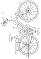
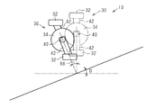
図1に示されるとおり、自転車10は、前輪12、後輪14、自転車本体16、駆動機構18、操作部20、ドライブユニット22、および、自転車用制御装置70を備える。自転車本体16は、フレーム24、フレーム24に接続されるフロントフォーク26、および、フロントフォーク26にステム28Aを介して着脱可能に接続されるハンドルバー28を備える。フロントフォーク26は、フレーム24に支持されて、前輪12の車軸12Aに接続される。
A bicycle equipped with the bicycle control device of the first embodiment will be described with reference to FIGS.
As shown in FIG. 1, the
自転車10は、人力駆動力が駆動機構18を介して後輪14に伝達されることによって走行する。駆動機構18は、クランク30、一対のペダル32、フロントスプロケット34、リアスプロケット36、および、チェーン38を含む。
The
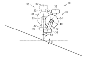
クランク30は、クランク軸40、および、一対のクランクアーム42を含む。クランク軸40は、フレーム24に連結されるドライブユニット22のハウジング22Aに回転可能に支持される。一対のクランクアーム42は、クランク軸40に取り付けられる。一対のペダル32は、ペダル本体32Aおよびペダル軸32Bを含む。ペダル軸32Bは、クランクアーム42のそれぞれに連結される。ペダル本体32Aは、ペダル軸32Bに対する回転が可能な状態でペダル軸32Bのそれぞれに支持される。
The
フロントスプロケット34は、ドライブユニット22を介してクランク軸40に連結されている。フロントスプロケット34は、クランク軸40と同軸に設けられる。リアスプロケット36は、後輪14の車軸14Aまわりに回転可能に後輪14に取り付けられている。リアスプロケット36は、後輪14に連結される。後輪14は、ハブ(図示略)を含む。チェーン38は、フロントスプロケット34とリアスプロケット36とに巻き掛けられている。ペダル32に加えられる人力駆動力によってクランク30が一方向に回転するとき、フロントスプロケット34、チェーン38、および、リアスプロケット36によって、後輪14も一方向に回転する。
The
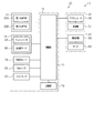
操作部20は、ハンドルバー28に取り付けられる。操作部20は、自転車用制御装置70の制御部72(図2参照)と有線または無線によって通信可能に接続されている。図2に示されるとおり、操作部20は、第1の操作部20Aおよび第2の操作部20Bを含む。操作者によって第1の操作部20Aが操作されるとき、操作部20は自転車10の変速比rが大きくなる方向への変速信号(以下、「シフトアップ信号」)を制御部72に送信する。操作者によって第2の操作部20Bが操作されるとき、操作部20は自転車10の変速比rが小さくなる方向への変速信号(以下、「シフトダウン信号」)を制御部72に送信する。
The
図1に示すバッテリユニット44は、バッテリ46、および、バッテリ46をフレーム24に着脱可能に取り付けるためのバッテリホルダ48を備えている。バッテリ46は、1または複数のバッテリセルを含む。バッテリ46は、充電池によって構成される。バッテリ46は、ドライブユニット22のモータ60に電気的に接続されて、モータ60に電力を供給する。
The
ドライブユニット22は、ハウジング22A、変速装置50(図2参照)、および、アシスト装置52を含む。ハウジング22Aは、フレーム24に設けられる。変速装置50(図2参照)およびアシスト装置52は、ハウジング22Aに収容される。
The
図2に示されるとおり、変速装置50は、変速機54およびアクチュエータ56を含む。変速機54は、クランク軸40(図1参照)に入力された回転を変速してフロントスプロケット34(図1参照)に伝達する。変速装置50は、自転車10の変速比rを変更する。変速機54は、遊星歯車機構を備えている。変速装置50は、アクチュエータ56の駆動によって変速機54の遊星歯車機構を構成する歯車の連結状態が変更されることにより、自転車10の変速比rを段階的に変更する。
As shown in FIG. 2, the
アシスト装置52は、駆動回路58およびモータ60を含む。駆動回路58は、バッテリ46からモータ60に供給される電力を制御する。モータ60は、自転車10に入力される人力駆動力をアシストする。モータ60は、電気モータによって構成される。モータ60は、クランク軸40または変速機54に結合される。モータ60とクランク軸40または変速機54との間の動力伝達経路には、クランク30を前転させたときにクランク軸40の回転力によってモータ60を回転しないようにワンウェイクラッチ(図示略)が設けられるのが好ましい。
The
自転車用制御装置70は、制御部72を含む。一例では、自転車用制御装置70は、記憶部74、傾斜センサ76、回転角センサ78、車速センサ80、および、トルクセンサ82を含むことが好ましい。
The
制御部72は、予め定められる制御プログラムを実行する演算処理装置を含む。演算処理装置は、例えばCPU(Central Processing Unit)またはMPU(Micro Processing Unit)を含む。記憶部74には、各種の制御プログラムおよび各種の制御処理に用いられる情報が記憶される。
傾斜センサ76は、傾斜角度を検出する。傾斜センサ76は、フレーム24(図1参照)またはドライブユニット22に設けられる。傾斜センサ76は、有線または無線によって制御部72と通信可能に接続されている。傾斜センサ76は、3軸のジャイロセンサ84および3軸の加速度センサ86を含む。傾斜センサ76の出力は、3軸のそれぞれの姿勢角度、および、3軸のそれぞれの加速度の情報を含む。なお、3軸の姿勢角度は、ピッチ角度DA、ロール角度DB、および、ヨー角度DCである。ジャイロセンサ84の3軸と、加速度センサ86の3軸とは一致することが好ましい。傾斜センサ76は、図1の自転車本体16の左右方向とピッチ角度DAの軸の延びる方向とが略一致するようにフレーム24またはドライブユニット22に取り付けられることが好ましい。
The
回転角センサ78は、クランク軸40の回転速度およびクランクの回転位相を検出する。回転角センサ78は、フレーム24(図1参照)に取り付けられる。回転角センサ78は、第1の磁石(図示略)の磁界を検出する第1の素子(図示略)と、第2の磁石(図示略)との位置関係に応じた信号を出力する第2の素子(図示略)とを含む。第1の磁石は、図1に示すクランク軸40またはクランクアーム42に設けられ、クランク軸40に同軸に配置される。第1の磁石は、環状の磁石であって、周方向に複数の磁極が交互に並んで配置されている。第1の素子は、フレーム24またはハウジング22Aに対するクランク30の回転位相を検出する。第1の素子は、クランク30が1回転するとき、360°を同極の磁極の数で割った角度を1周期とした信号を出力する。回転角センサ78が検出可能なクランク30の回転位相RAの最小値は、180°以下であり、好ましくは15度であり、さらに好ましくは、6度である。第2の磁石は、クランク軸40またはクランクアーム42に設けられ、クランク軸40に同軸に配置される。第2の素子は、フレーム24またはハウジング22Aに対するクランク30の基準位相(例えば、クランク30の上死点または下死点)を検出する。第2の素子は、クランク軸の1回転を1周期とした信号を出力する。なお、クランク30の上死点は、クランクアーム42が、路面と直交する方向に延び、かつ、一方のペダル32が路面から最も遠い位置にある状態を示す。クランク30の下死点は、クランクアーム42が、路面と直交する方向に延び、かつ、他方のペダル32が路面から最も遠い位置にある状態を示す。上死点および下死点の位相差は180°であることが好ましい。
The
図2に示す車速センサ80は、有線または無線によって制御部72と電気的に接続されている。車速センサ80は、図1に示すフロントフォーク26に取り付けられる。車速センサ80は、前輪12のスポーク12Bに取り付けられる磁石88との相対位置の変化に応じた値を制御部72に出力する。車速センサ80は、リードスイッチを構成する磁性体リード、または、ホール素子を含むことが好ましい。
The
図2に示すトルクセンサ82は、人力駆動力に応じた信号を出力する。トルクセンサ82は、クランク30(図1参照)に与えられる人力駆動力を検出する。トルクセンサ82は、図1に示すクランク軸40からフロントスプロケット34までの間に設けられてもよく、クランク軸40またはフロントスプロケット34に設けられてもよく、クランクアーム42またはペダル32に設けられてもよい。トルクセンサ82は、例えば、歪センサ、磁歪センサ、光学センサおよび圧力センサなどを用いて実現することができ、クランクアーム42またはペダル32に加えられる人力駆動力に応じた信号を出力するセンサであれば、いずれのセンサを採用することもできる。
The
制御部72は、傾斜センサ76および車速センサ80の出力に基づいて自転車10の傾斜角度Dを演算する。傾斜角度Dは、自転車本体16(図1参照)の左右方向に延びる軸まわりの自転車10の前後方向の傾斜角度である。すなわち、傾斜角度Dは、自転車10のピッチ角度DAである。傾斜角度Dは、自転車本体16が水平な場所に設置されるときに「0」度になるように設定されている。このため、傾斜角度Dは、自転車10の走行路面の勾配と相関する。
The
制御部72は、ジャイロセンサ84の出力からピッチ角度DA、ロール角度DB、および、ヨー角度DCを演算する。制御部72は、加速度センサ86から自転車本体16(図1参照)の前後方向についての第1加速度ベクトルを演算する。制御部72は、車速センサ80の出力から第2加速度ベクトルを演算する。制御部72は、第1加速度ベクトルおよび第2加速度ベクトルに基づいて、ピッチ角度DA、ロール角度DB、および、ヨー角度DCを補正し、ピッチ角度DA、ロール角度DB、および、ヨー角度DCに含まれる誤差を低減する。具体的には、制御部72は、第1加速度ベクトルと第2加速度ベクトルとの差分に基づいてピッチ角度DA、ロール角度DB、および、ヨー角度DCのそれぞれの補正角度を演算する。制御部72は、補正角度をピッチ角度DA、ロール角度DB、および、ヨー角度DCに加算する。制御部72は、補正されたピッチ角度DA、ロール角度DB、ヨー角度DC、および、自転車10の傾斜角度の初期値に基づいて傾斜角度Dを演算する。なお、傾斜センサ76が自転車本体16(図1参照)の左右方向とピッチ角度DAの軸の延びる方向とが略一致するように自転車10に取り付けられているとき、ピッチ角度DA、ロール角度DB、および、自転車10の傾斜角度の初期値に基づいて傾斜角度Dを演算することができる。また、傾斜センサ76が自転車本体16(図1参照)の左右方向とピッチ角度DAの軸の延びる方向とが略一致し、かつ、自転車本体16(図1参照)の前後方向とロール角度DBの軸とが略一致するように自転車10に取り付けられているとき、ピッチ角度DAおよび自転車10の傾斜角度の初期値に基づいて傾斜角度Dを演算することができる。
The
制御部72は、回転角センサ78の出力に基づいてクランク30の回転位相(以下、クランクの回転位相RA)を演算する。制御部72は、クランク30の上死点または下死点を「0」°としてクランクの回転位相RAを演算する。クランク30の回転位相RAは0°以上360°未満となる。
The
制御部72は、回転角センサ78の出力に基づいて、クランク軸40の回転速度(以下、「クランクの回転速度CA」)を演算する。制御部72は、車速センサ80の出力と、予め記憶部74に記憶されている前輪12(図1参照)の周長に基づいて単位時間あたりの走行距離(以下、「車速V」)を演算する。制御部72は、トルクセンサ82の出力に基づいて単位時間あたりの人力駆動力(以下、「人力駆動力T」)を演算する。
The
制御部72は、操作部20からのシフトアップ信号およびシフトダウン信号に基づいて変速機54を制御する変速制御を実行する。制御部72は、シフトアップ信号が入力されたとき、変速比rが大きくなるように変速機54を動作させる。制御部72はシフトダウン信号が入力されたとき、変速比rが小さくなるように変速機54を動作させる。
The
制御部72は、モータ60を制御する。制御部72は、人力駆動力Tおよび車速Vに基づいてモータ60を制御するアシスト制御を実行する。制御部72は、モータ60の制御状態を第1の制御状態と第2の制御状態との間で切り替える。制御部72は、車速Vが予め設定される所定の車速V以上のとき、モータ60の駆動を停止する。所定の車速Vは、例えば時速25kmである。制御部72は、モータ60の出力TAが予め定められている所定の出力TA以下となるようにモータ60を制御する。
The
制御部72は、モータ60の制御状態が第1の制御状態のときに人力駆動力Tが増加するとき、人力駆動力Tに所定の係数を乗算した値をモータ60に出力させる。所定の係数は、複数設定されることが好ましい。所定の係数は、例えば操作部20を介した操作によってユーザが変更可能である。所定の係数は、「0」以上「3」以下であることが好ましい。制御部72は、モータ60の制御状態が第1の制御状態のときに人力駆動力Tが減少するとき、第1の制御状態において人力駆動力Tが増大するときよりも人力駆動力Tに対するモータ60の出力TAを大きくする。
The
制御部72は、モータ60の制御状態が第2の制御状態のときの人力駆動力Tに対するモータ60の出力を、モータ60の制御状態が第1の制御状態のときの人力駆動力Tに対するモータ60の出力TAよりも小さくする。一例では、制御部72は、モータ60の制御状態が第2の制御状態のときに人力駆動力Tが低下するときの人力駆動力Tに対するモータ60の出力TAを、第1の制御状態のときに人力駆動力Tが増加するときの人力駆動力Tに対するモータ60の出力TAと等しくする。
The
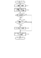
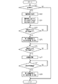
図3を参照して、アシスト制御について説明する。
制御部72は、ステップS11において人力駆動力Tを取得し、ステップS12において人力駆動力Tに基づいてモータの出力TAを演算してステップS13に移る。例えば、制御部72は、人力駆動力Tに設定されている所定の係数を乗算した値をモータの出力TAとする。
The assist control will be described with reference to FIG.
In step S11, the
制御部72は、ステップS13においてモータ60の制御状態が第1の制御状態か否かを判定する。モータ60の制御状態が第1の制御状態のとき、制御部72は、ステップS14において人力駆動力Tが低下しているか否かを判定する。例えば、制御部72は、トルクセンサ82から入力された信号を離散信号に変換する。制御部72は、離散信号に基づき、人力駆動力Tが一つ前の時刻において検出された人力駆動力Tよりも小さいと判断すると、人力駆動力Tが低下したと判断する。
In step S13, the
制御部72は、第1の制御状態において人力駆動力Tが低下しているとき、ステップS15に移り、ステップS12において演算したモータ60の出力TAを補正し、ステップS16に移る。具体的には、制御部72は、人力駆動力Tが減少するとき、人力駆動力Tの減少に対してモータ60の出力TAの低下が遅れるように、モータ60の出力TAを補正する。補正後のモータ60の出力TAは、補正前のモータ60の出力TA以上となる。例えば、制御部72は、一次ローパスフィルタを用いてモータ60の出力TAを補正する。制御部72が一次ローパスフィルタを用いてモータ60の出力TAを補正することによって、モータ60の出力TAの低下は人力駆動力の低下に対して遅れる。なお、一次ローパスフィルタに用いられる時定数は、クランク30の回転速度に応じて変更してもよい。また、クランク30の回転速度に応じた複数の時定数マップを記憶部74に記憶し、所定の条件に応じてマップを選択的に切り替えてもよい。
When the human driving force T is decreasing in the first control state, the
制御部72は、ステップS13においてモータ60の制御状態が第1の制御状態ではないとき、すなわち、モータ60の制御状態が第2の制御状態であるとき、モータ60の出力TAの補正を行わずにステップS16に進む。また、制御部72は、ステップS14において人力駆動力Tが低下していないと判定したとき、モータ60の出力TAの補正を行わずにステップS16に進む。制御部72は、ステップS16においてモータ60の出力TAに基づいてモータ60を制御し、所定周期後に再びステップS11からの処理を実行する。
When the control state of the
制御部72は、自転車10の変速比rを変更する変速機54が動作するときに自転車10のクランクの回転位相に基づいてモータ60の制御状態を第1の制御状態から第2の制御状態に切り替えるとともに、自転車10の前後方向の傾斜角度Dに基づいてモータ60の制御状態を第1の制御状態から第2の制御状態に切り替えるタイミングを変更する。一例では、制御部72は、自転車10のクランクの回転位相RAが第1の位相R1のときにモータ60の制御状態を第1の制御状態から第2の制御状態に切り替える。制御部72は、操作部20から変速信号が入力されたとき、クランクの回転位相RAが第2の位相R2のときに変速機54を動作させる。制御部72は、モータ60の制御状態が第2の制御状態のときにクランクの回転位相RAが第3の位相R3になったとき、モータ60の制御状態を第2の制御状態から第1の制御状態に切り替える。
The
第1の位相R1、第2の位相R2、および、第3の位相R3は、それぞれ基準の位相が予め記憶部74に記憶される。基準の第2の位相R2は、クランクが上死点または下死点にあるときのクランクの回転位相RAと実質的に等しい。第2の位相R2は、第1の位相R1よりも所定の位相RB(図5参照)だけ遅角されている。所定の位相RBは、モータ60の出力TAを下降させるために充分なクランクの回転位相RAに相当する。第3の位相R3は、第1の位相R1よりも所定の位相RC(図5参照)だけ進角されている。所定の位相RCは、変速機54(図2参照)が変速動作を完了するために充分なクランクの回転位相RAに相当する。なお、「遅角する」は、クランクの回転位相RAを大きくする、すなわちタイミングを遅くすることを示す。また、「進角する」は、クランクの回転位相RAを小さくする、すなわちタイミングを早くすることを示す。第1の位相R1、第2の位相R2、および、第3の位相R3は、それぞれクランクの1周期において180°異なる2つのタイミングが設定されることが好ましい。
For the first phase R1, the second phase R2, and the third phase R3, reference phases are stored in the
制御部72は、傾斜角度Dに基づいて第1の位相R1を変更する。制御部72は、傾斜角度Dが「0」よりも大きい、上り勾配であるとき、傾斜角度Dが「0」のときよりも第1の位相R1を遅角する。制御部72は、傾斜角度Dが「0」よりも小さい、下り勾配であるとき、傾斜角度Dが「0」のときよりも第1の位相R1を進角する。制御部72は、傾斜角度Dが大きいほど第1の位相R1を遅角する。制御部72は、傾斜角度Dが「0」のとき、予め記憶部74に記憶されている基準の第1の位相R1を補正しない。
The
制御部72は、傾斜角度Dに基づいて第2の位相R2を変更する。制御部72は、傾斜角度Dが「0」よりも大きい、上り勾配であるとき、傾斜角度Dが「0」のときよりも第2の位相R2を遅角する。制御部72は、傾斜角度Dが「0」よりも小さい、下り勾配であるとき、傾斜角度Dが「0」のときよりも第2の位相R2を進角する。制御部72は、傾斜角度Dが大きいほど第2の位相R2を遅角する。制御部72は、傾斜角度Dが「0」のとき、予め記憶部74に記憶されている基準の第2の位相R2を補正しない。このため、傾斜角度Dが「0」のときの第2の位相R2は、クランク30が上死点または下死点にあるときのクランクの回転位相RAと実質的に等しい。
The
制御部72は、傾斜角度Dに基づいて第3の位相R3を変更する。制御部72は、傾斜角度Dが「0」よりも大きい、上り勾配であるとき、傾斜角度Dが「0」のときよりも第3の位相R3を遅角する。制御部72は、傾斜角度Dが「0」よりも小さい、下り勾配であるとき、傾斜角度Dが「0」のときよりも第3の位相R3を進角する。制御部72は、傾斜角度Dが大きいほど第3の位相R3を遅角する。制御部72は、傾斜角度Dが「0」のとき、予め記憶部74に記憶されている基準の第3の位相R3を補正しない。
The
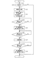
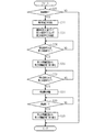
図4および図5を参照して、変速制御について説明する。
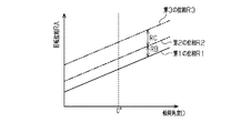
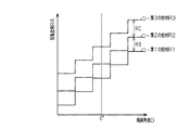
制御部72は、ステップS21において変速要求があるか否かを判定する。すなわち、制御部72は、シフトアップ信号またはシフトダウン信号が入力されたか否かを判定する。制御部72は、変速要求がある旨判定したとき、ステップS22において傾斜角度Dを取得し、ステップS23に移行する。制御部72は、ステップS23において傾斜角度Dに基づいて第1の位相R1、第2の位相R2、および、第3の位相R3を補正する。例えば、制御部72は、図5に示すように傾斜角度Dが大きくなるほど第1の位相R1、第2の位相R2、および、第3の位相R3を遅角または進角する。第1の位相R1は、いずれの傾斜角度Dにおいても第2の位相R2よりも早くなるように設定される。第3の位相R3は、いずれの傾斜角度Dにおいても第2の位相R2よりも遅くなるように設定される。傾斜角度Dが「0」のときは、制御部72は予め記憶部74に記憶される基準の第1の位相R1、基準の第2の位相R2、および、基準の第3の位相R3が用いられる。なお、基準の第1の位相R1、基準の第2の位相R2、および、基準の第3の位相R3を用いずに、傾斜角度Dとの関係を規定したマップまたは演算式を用いて第1の位相R1、第2の位相R2、および、第3の位相R3を設定することもできる。
Shift control will be described with reference to FIGS. 4 and 5.
The
制御部72は、ステップS24において、回転位相RAが第1の位相R1になったか否かを判定する。回転位相RAが第1の位相R1ではないとき、制御部72は所定周期後に再びステップS24の処理を実行する。制御部72は、回転位相RAが第1の位相R1になるまでステップS24の処理を繰り返す。制御部72は、回転位相RAが第1の位相R1になったとき、ステップS25に移行し、モータ60の制御状態を第1の制御状態から第2の制御状態に切り替え、ステップS26に移行する。
In step S24, the
制御部72は、ステップS26において、回転位相RAが第2の位相R2になったか否かを判定する。回転位相RAが第2の位相R2ではないとき、制御部72は所定周期後に再びステップS26の処理を実行する。制御部72は、回転位相RAが第2の位相R2になるまでステップS26の処理を繰り返す。制御部72は、回転位相RAが第2の位相R2になったとき、ステップS27に移行し、変速信号に基づいて変速機54を動作させ、ステップS28に移行する。
In step S26, the
制御部72は、ステップS28において、回転位相RAが第3の位相R3になったか否かを判定する。回転位相RAが第3の位相R3ではないとき、制御部72は所定周期後に再びステップS28の処理を実行する。制御部72は、回転位相RAが第3の位相R3になるまでステップS28の処理を繰り返す。制御部72は、回転位相RAが第3の位相R3になったとき、ステップS29に移行し、モータ60の制御状態を第2の制御状態から第1の制御状態に切り替え、本処理を終了する。
In step S28, the
図6〜図9を参照して自転車用制御装置70の作用について説明する。
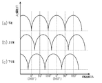
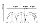
図6に示されるとおり、傾斜角度Dが「0」の平道を自転車10が走行しているとき、人力駆動力Tは、上死点および下死点(クランクの回転位相RAが0°および180°)において最小となり、上死点と下死点との中央部分(クランクの回転位相RAが90°および270°)において最大となる。
The operation of the
As shown in FIG. 6, when the
図6および図7に示されるとおり、傾斜角度Dが「0」よりも大きい上り坂を自転車10が走行しているとき、人力駆動力Tは上死点および下死点よりも遅いタイミング(クランクの回転位相RAが0°+|RX|°および180°+|RX|°)で最小となる。なお、RXは、上死点または下死点と、人力駆動力Tが最小となる回転位相RAとの位相差である。位相差RXは、傾斜角度Dと実質的に等しい。傾斜角度Dが「0」よりも大きいときの位相差RXは正の値である。具体的には、図7の二点鎖線に示すようにクランクアーム42が路面と直交する方向に延びる状態のとき、人力駆動力Tは最小となる。
As shown in FIG. 6 and FIG. 7, when the
図6および図8に示されるとおり、傾斜角度Dが「0」よりも小さい下り坂を自転車10が走行しているとき、人力駆動力Tは上死点および下死点よりも早いタイミング(クランクの回転位相RAが0°−|RX|°および180°−|RX|°)で最小となる。傾斜角度Dが「0」よりも小さいときの位相差RXは負の値である。具体的には、図7の二点鎖線に示すようにクランクアーム42が路面と直交する方向に延びる状態のとき、人力駆動力Tは最小となる。
As shown in FIGS. 6 and 8, when the
図9の実線L1は、図3に示すアシスト制御が行われているときのモータ60の出力TAの一例を示し、二点鎖線L2は図3に示すアシスト制御のステップS14の処理が行われない仮想のモータ60の出力の一例を示し、一点鎖線L3はアシスト制御が行われているときの人力駆動力Tの経時的な変化の一例を示す。
A solid line L1 in FIG. 9 shows an example of the output TA of the
時刻t10は、運転者によってクランク30の回転が開始された時刻を示す。
時刻t11は、モータ60の制御状態が第1の制御状態にあるときに人力駆動力Tが最大となる時刻を示す。
Time t10 indicates the time when rotation of the
Time t11 indicates a time at which the manpower driving force T becomes maximum when the control state of the
時刻t12は、制御部72がモータ60の制御状態が第1の制御状態にあるときに人力駆動力Tが減少したと判定した時刻を示す。このとき、制御部72は、時刻t11のときよりも人力駆動力Tに対するモータ60の出力TAが大きくなるようにモータ60の出力TAを補正する(図3のステップS15)。
Time t12 indicates the time when the
時刻t13は、制御部72がモータ60の制御状態が第1の制御状態にあるときに人力駆動力Tが増加したと判定した時刻を示す。このとき、制御部72は、時刻t12〜t13のときよりも人力駆動力Tに対するモータ60の出力TAが小さくなるようにモータ60の出力TAの補正を終了する。
Time t13 indicates the time when the
時刻t14は、再び制御部72がモータ60の制御状態が第1の制御状態にあるときに人力駆動力Tが減少したと判定した時刻を示す。このとき、制御部72は、時刻t11のときよりも人力駆動力Tに対するモータ60の出力TAが大きくなるようにモータ60の出力TAを補正する(図3のステップS15)。
Time t14 indicates the time when the
時刻t15は、制御部72に操作部20からシフトアップ信号またはシフトダウン信号が入力された時刻を示す。
時刻t16は、クランクの回転位相RAが第1の位相R1になった時刻を示す。このとき、制御部72は、モータ60の制御状態を第1の制御状態から第2の制御状態に切り替える。このため、モータ60の出力TAが低下し、二点鎖線L2と等しくなる。
The time t15 indicates the time when the upshift signal or the downshift signal is input from the
Time t16 indicates the time at which the crank rotation phase RA becomes the first phase R1. At this time, the
時刻t17は、クランクの回転位相RAが第2の位相R2になった時刻を示す。このとき、制御部72は、時刻t15に入力されたシフトアップ信号またはシフトダウン信号に基づいて変速機54を動作させる。
Time t17 indicates the time when the rotational phase RA of the crank becomes the second phase R2. At this time, the
時刻t18は、クランクの回転位相RAが第3の位相R3になった時刻を示す。このとき、制御部72は、モータ60の制御状態を第2の制御状態から第1の制御状態に切り替える。
Time t18 indicates the time when the crank rotation phase RA becomes the third phase R3. At this time, the
自転車用制御装置70によれば、以下の作用および効果を得られる。
傾斜角度Dが「0」のとき、時刻t17のクランクの回転位相RAは上死点または下死点と等しい。他方、傾斜角度Dが「0」よりも大きいとき、時刻t17のクランクの回転位相RAは上死点または下死点よりも遅くなる。傾斜角度Dが「0」よりも小さいとき、時刻t17のクランクの回転位相RAは上死点または下死点よりも早くなる。制御部72は、傾斜角度Dに応じてモータ60の制御状態を第1の制御状態から第2の制御状態に変更するための第1の位相R1を変更する。このため、変速機54にかかるトルクが最小となる直前のタイミングにモータ60の出力を低下させることができるため、自転車10の走行状況に応じた制御を行うことができる。
According to the
When the tilt angle D is “0”, the rotational phase RA of the crank at time t17 is equal to the top dead center or the bottom dead center. On the other hand, when the tilt angle D is larger than “0”, the rotational phase RA of the crank at time t17 becomes slower than the top dead center or the bottom dead center. When the inclination angle D is smaller than “0”, the rotational phase RA of the crank at time t17 becomes earlier than the top dead center or the bottom dead center. The
制御部72は、傾斜角度Dに応じて変速機54の変速動作を行うための第2の位相R2を変更する。このため、変速機54にかかるトルクが最小となるタイミングに変速機54の変速動作を行うことができるため、変速性能が向上する。このため、自転車10の走行状況に応じた制御を行うことができる。また、自転車用制御装置70では、傾斜角度Dが「0」のときと傾斜角度Dが「0」以外のときの両方において、変速機54にかかるトルクが最小となるタイミングに変速機54の変速動作が行われるため、運転者が違和感を覚えるおそれが低減される。
The
(変形例)
上記各実施の形態に関する説明は、本発明に従う自転車用制御装置が取り得る形態の例示であり、その形態を制限することを意図していない。本発明に従う自転車用制御装置は、例えば以下に示される上記各実施形態の変形例、および、相互に矛盾しない少なくとも2つの変形例が組み合わせられた形態を取り得る。
(Modification)
The description regarding each of the above embodiments is an example of a form that can be taken by the bicycle control device according to the present invention, and is not intended to limit the form. The bicycle control device according to the present invention can take a form in which, for example, the following modifications of the above-described embodiments and at least two modifications not contradicting each other are combined.
・図4の変速制御のステップS23において図10に示すように第1の位相R1、第2の位相R2、および、第3の位相R3の少なくとも1つを傾斜角度Dに応じて段階的に変更することもできる。この場合も傾斜角度Dごとに、第1の位相R1と第2の位相R2との位相差は所定の位相RB以上であることが好ましい。傾斜角度Dごとに、第2の位相R2と第3の位相R3との位相差は所定の位相RC以上であることが好ましい。 In step S23 of the shift control in FIG. 4, at least one of the first phase R1, the second phase R2, and the third phase R3 is changed stepwise according to the inclination angle D as shown in FIG. You can also Also in this case, for each inclination angle D, the phase difference between the first phase R1 and the second phase R2 is preferably equal to or greater than the predetermined phase RB. For each inclination angle D, the phase difference between the second phase R2 and the third phase R3 is preferably equal to or greater than a predetermined phase RC.
・図4の変速制御を図11の変速制御に変更することもできる。図11の変速制御では、制御部72は、モータ60の制御状態を第1の制御状態から第2の制御状態に切り替えてから所定の時間が経過したとき、モータ60の制御状態を第2の制御状態から第1の制御状態に切り替える。具体的には、制御部72は、図4のステップS23の処理に代えて図11のステップS31の処理を実行し、図4のステップS28の処理に代えて図11のステップS32の処理を実行する。制御部72は、ステップS31において傾斜角度Dに基づいて第1の位相R1および第2の位相R2を補正する。制御部72は、ステップS32において、所定の時間が経過したと判定したとき、ステップS29に移行し、所定の時間が経過するまでステップS32の処理を繰り返し実行する。所定の時間は、予め記憶部74に記憶されている。所定の時間は、変速機54が変速動作を完了するために充分な時間である。また、制御部72は、ステップS32の処理をステップS27において変速機54の変速動作を開始させてから所定時間が経過したとき、モータ60の制御状態を第2の制御状態から第1の制御状態に切り替える処理に変更してもよい。
The shift control in FIG. 4 can be changed to the shift control in FIG. In the shift control of FIG. 11, the
・図11の変速制御を、図12の変速制御に変更することもできる。図12の変速制御では、制御部72はモータ60の制御状態が第2の制御状態のときに変速機54の動作が完了したとき、モータ60の制御状態を第2の制御状態から第1の制御状態に切り替える。具体的には、制御部72は、図11のステップS32の処理に代えて図12のステップS33の処理を実行する。制御部72は、ステップS33において、変速完了したと判定したとき、ステップS29に移行し、変速完了するまでステップS33の処理を繰り返し実行する。変速完了は、例えば自転車用制御装置70に変速状態検出センサを設け、変速状態検出センサの出力によって判定される。変速状態検出センサは、変速機54の歯車の連結状態を検出可能である。
The shift control in FIG. 11 can be changed to the shift control in FIG. In the shift control of FIG. 12, the
・図4の変速制御を図13の変速制御に変更することもできる。図13の変速制御では、制御部72はクランクの回転位相RAが第2の位相R2のときに変速機54を動作させるとともに、自転車10の前後方向の傾斜角度Dに基づいて第2の位相R2を変更する。具体的には、制御部72は、ステップS51において変速要求があるか否かを判定する。すなわち、制御部72は、シフトアップ信号またはシフトダウン信号が入力されたか否かを判定する。制御部72は、変速要求がある旨判定したとき、ステップS52において傾斜角度Dを取得し、ステップS53に移行する。制御部72は、ステップS53において傾斜角度Dに基づいて第2の位相R2を設定する。制御部72は、ステップS54において、回転位相RAが第2の位相R2になったか否かを判定する。回転位相RAが第2の位相R2ではないとき、制御部72は所定周期後に再びステップS54の処理を実行する。制御部72は、回転位相RAが第2の位相R2になるまでステップS54の処理を繰り返す。制御部72は、回転位相RAが第2の位相R2になったとき、ステップS55に移行し、変速信号に基づいて変速機54を動作させ、本処理を終了する。なお、この変形例では、自転車10からアシスト装置52を省略することもできる。
The shift control in FIG. 4 can be changed to the shift control in FIG. In the shift control of FIG. 13, the
・第2の位相R2を、第1の位相R1と実質的に等しくすることもできる。この場合、第1の制御状態から第2の制御状態に切り替えることによるモータ60の出力TAの低下と、変速機54の変速動作とが同時に開始される。
The second phase R2 can be substantially equal to the first phase R1. In this case, a decrease in the output TA of the
・制御部72は、変速制御において人力駆動力Tに基づいて変速機54を動作させることもできる。具体的には、図4の変速制御のステップS26の処理において、人力駆動力Tが所定の人力駆動力T以下になったか否かを判定する。所定の人力駆動力Tは、変速機54の変速動作が適切に実行される人力駆動力Tである。
The
・変速装置50からアクチュエータ56を省略することもできる。この場合、自転車10は変速機54と機械的に接続される操作部を有し、操作部の操作量が所定量以上になることによって変速機54の変速動作が行われる。自転車用制御装置70は、操作部の操作量が所定量未満のときに制御部72に検出信号を出力可能な検出部を有する。制御部72は、図4の変速制御のステップS21において検出部の出力に基づいて操作部の操作が開始されたことを取得し、変速要求の有無を判定してもよい。また、この場合、図4の変速制御のステップS26が省略され、ステップS27の代わりに操作部の操作量が所定量以上になることによって変速機54が機械的に変速制御される。この場合、変速装置50は、変速機54の変速動作を規制する規制機構を設けることもできる。規制機構は、回転位相RAが所定の位相(例えば、第2の回転位相R2)以外のときに変速機54の変速動作を規制し、回転位相RAが所定の位相のときに変速機54の変速動作を許容する。または、規制機構は、人力駆動力Tが所定の人力駆動力Tよりも大きいときに変速機54の変速動作を規制し、人力駆動力Tが所定の人力駆動力T以下のときに変速機54の変速動作を許容する。規制機構は操作部の操作量が所定量以上にならないようにすることによって変速機54の変速動作を規制する構成であってもよい。
The
・制御部72は、図4の変速制御のステップS21において操作部20からの変速信号が入力されたときに変速要求がある旨判定したが、走行状況に応じて制御部72が変速要求を設定することもできる。この場合、例えば、制御部72は、クランクの回転速度CAに基づいて変速比rを変更する変速要求を設定する。制御部72は、クランクの回転速度CAが第1の所定の回転速度CAよりも大きいとき、変速比rが小さくなるように変速機54を変更する。制御部72は、クランクの回転速度CAが第2の所定の回転速度CAよりも小さいとき、変速比rが大きくなるように変速機54を変更する。
The
・制御部72は、図3のアシスト制御のステップS14およびステップS15に代えて、モータ60の出力TAを一定値に補正する処理を実行することもできる。
・制御部72は、図3のアシスト制御のステップS13においてモータ60の制御状態が第2の制御状態であるとき、モータ60の出力TAの補正を行わずにステップS16に進むとしたが、モータ60の出力TAの補正を行ってステップS16に進んでもよい。この場合、モータ60の出力TAを、ステップS12において演算したモータ60の出力TAよりも小さくする。
-The
The
・制御部72は、傾斜角度DをGPS(Global Positioning System)によって取得することもできる。GPSによる傾斜角度Dの情報は、例えばサイクルコンピュータまたはスマートフォン等を介して制御部72に入力される。また、制御部72は、傾斜角度Dを操作者の入力を介して取得することもできる。
-The
・制御部72は、クランクの回転位相RAを、クランクの回転速度CAを用いて推定することもできる。例えば、クランク30が基準の位相(上死点または下死点)を通過したときからの時間とクランクの回転速度CAとを乗算することによってクランクの回転位相RAを推定する。
The
・制御部72は、車速Vを用いてクランクの回転速度CAを推定することもできる。例えば、制御部72は、タイヤ径と変速比rとを用いてクランクの回転速度CAを推定する。この場合、制御部72は、車速Vを用いて演算されたクランクの回転速度CAに基づいてクランクの回転位相RAを演算することもできる。制御部72は、推定されたクランクの回転速度CAを用いてクランク30が基準の位相(上死点または下死点)を通過したタイミングを推定する。そして、制御部72は、クランク30が基準の位相(上死点または下死点)を通過したタイミングからの時間と車速Vとを乗算することによってクランクの回転位相RAを推定する。
The
・変速装置50を、後輪14のハブに設けられる内装変速機に変更することもできる。
・変速装置50を、外装変速機およびアクチュエータを含む変速装置に変更することもできる。外装変速機はフロントディレーラまたはリアディレーラである。アクチュエータは例えば電気モータである。制御部72はアクチュエータを駆動することによって外装変速機を動作させる。外装変速機は、複数のフロントスプロケット34または複数のリアスプロケット36がそれぞれ含む複数のスプロケット間でチェーン38を掛け替えることによって、自転車10のクランク30の回転数に対する後輪14の回転数(変速比r)を変更する。
The
The
10…自転車、20…操作部、54…変速機、60…モータ、70…自転車用制御装置
72…制御部、76…傾斜センサ、78…回転角センサ。
DESCRIPTION OF
Claims (20)
前記制御部は、前記自転車の変速比を変更する変速機が動作するときに前記自転車のクランクの回転位相に基づいて前記モータの制御状態を第1の制御状態から第2の制御状態に切り替えるとともに、前記自転車の前後方向の傾斜角度に基づいて前記モータの制御状態を第1の制御状態から第2の制御状態に切り替えるタイミングを変更する、自転車用制御装置。 A control unit that controls a motor that assists the human-powered driving force input to the bicycle is provided.
The control unit switches the control state of the motor from the first control state to the second control state based on the rotation phase of the crank of the bicycle when a transmission that changes the speed ratio of the bicycle operates. A bicycle control device that changes the timing for switching the control state of the motor from the first control state to the second control state based on an inclination angle of the bicycle in the front-rear direction.
前記制御部は、クランクの回転位相が第2の位相のときに前記変速機を動作させるとともに、前記自転車の前後方向の傾斜角度に基づいて前記第2の位相を変更する、自転車用制御装置。 A control unit for controlling the operation of the transmission for changing the speed ratio of the bicycle based on a shift signal input from the operation unit;
The control unit is a bicycle control device that operates the transmission when a rotation phase of a crank is a second phase and changes the second phase based on an inclination angle of the bicycle in the front-rear direction.
Priority Applications (5)
| Application Number | Priority Date | Filing Date | Title |
|---|---|---|---|
| JP2016082093A JP6796393B2 (en) | 2016-04-15 | 2016-04-15 | Bicycle control device |
| US15/419,662 US10889351B2 (en) | 2016-04-15 | 2017-01-30 | Bicycle controller for bicycle equipped with assist device and gear change device |
| TW106104821A TWI722111B (en) | 2016-04-15 | 2017-02-15 | Control device for bicycle |
| CN201710081355.1A CN107298151B (en) | 2016-04-15 | 2017-02-15 | bicycle control device |
| DE102017205675.4A DE102017205675A1 (en) | 2016-04-15 | 2017-04-04 | bicycle control |
Applications Claiming Priority (1)
| Application Number | Priority Date | Filing Date | Title |
|---|---|---|---|
| JP2016082093A JP6796393B2 (en) | 2016-04-15 | 2016-04-15 | Bicycle control device |
Publications (3)
| Publication Number | Publication Date |
|---|---|
| JP2017190100A true JP2017190100A (en) | 2017-10-19 |
| JP2017190100A5 JP2017190100A5 (en) | 2018-06-21 |
| JP6796393B2 JP6796393B2 (en) | 2020-12-09 |
Family
ID=59980918
Family Applications (1)
| Application Number | Title | Priority Date | Filing Date |
|---|---|---|---|
| JP2016082093A Active JP6796393B2 (en) | 2016-04-15 | 2016-04-15 | Bicycle control device |
Country Status (5)
| Country | Link |
|---|---|
| US (1) | US10889351B2 (en) |
| JP (1) | JP6796393B2 (en) |
| CN (1) | CN107298151B (en) |
| DE (1) | DE102017205675A1 (en) |
| TW (1) | TWI722111B (en) |
Cited By (5)
| Publication number | Priority date | Publication date | Assignee | Title |
|---|---|---|---|---|
| JP2019089517A (en) * | 2017-11-16 | 2019-06-13 | 株式会社シマノ | Control device for man-power drive vehicle |
| JP2019182176A (en) * | 2018-04-09 | 2019-10-24 | 株式会社シマノ | Control device for man-power driven vehicle |
| WO2020217664A1 (en) * | 2019-04-25 | 2020-10-29 | 本田技研工業株式会社 | Power assist device for bicycle, and bicycle |
| JP2021517533A (en) * | 2018-03-06 | 2021-07-26 | ブローゼ・アントリープシュテヒニク・ゲーエムベーハー・ウント・シーオー.コマンディートゲゼルシャフト,ベルリンBROSE ANTRIEBSTECHNIK GmbH & CO.KOMMANDITGESELLSCHAFT,BERLIN | Drive system |
| JPWO2021162079A1 (en) * | 2020-02-14 | 2021-08-19 |
Families Citing this family (21)
| Publication number | Priority date | Publication date | Assignee | Title |
|---|---|---|---|---|
| WO2016009535A1 (en) * | 2014-07-17 | 2016-01-21 | パイオニア株式会社 | Rotation angle detection device |
| US20190100275A1 (en) * | 2017-10-03 | 2019-04-04 | PalTorc, Inc. | Smart crank control for e-bike |
| JP7146385B2 (en) * | 2017-11-15 | 2022-10-04 | 株式会社シマノ | Control device for human-powered vehicle |
| JP6993272B2 (en) * | 2018-03-22 | 2022-01-13 | 株式会社シマノ | Control device for human-powered vehicles |
| US11014630B2 (en) | 2018-03-29 | 2021-05-25 | Shimano Inc. | Human-powered vehicle control device |
| US11518470B2 (en) | 2018-04-30 | 2022-12-06 | Accelerated Systems Inc. | Method and apparatus for controlling a vehicle |
| US11008063B2 (en) * | 2018-06-25 | 2021-05-18 | GM Global Technology Operations LLC | Adaptive pedal assist systems and control logic with input torque filters for intelligent e-bikes |
| JP7156908B2 (en) * | 2018-10-31 | 2022-10-19 | 株式会社シマノ | Controller and detector |
| DE102020200677B4 (en) | 2020-01-22 | 2025-10-02 | Zf Friedrichshafen Ag | Drive device for a human-powered bicycle with an electric auxiliary drive and method for controlling the drive device |
| JP7626617B2 (en) | 2020-12-28 | 2025-02-04 | 株式会社シマノ | Control device for human-powered vehicles |
| JP7680846B2 (en) * | 2021-01-29 | 2025-05-21 | ヤマハ発動機株式会社 | Electrically assisted bicycle and motor control device |
| TWI790579B (en) * | 2021-03-25 | 2023-01-21 | 宏碁股份有限公司 | Driving device and driving method for electric assisted bicycle |
| DE102022106233A1 (en) * | 2021-03-31 | 2022-10-06 | Shimano Inc. | CONTROL DEVICE FOR MUSCLE-POWERED VEHICLE |
| TWI813977B (en) | 2021-04-16 | 2023-09-01 | 國立中興大學 | Electric Vehicles with Moisture Replenishment Reminder |
| US12103639B2 (en) * | 2021-06-03 | 2024-10-01 | Sram, Llc | Bicycle control system |
| US12103640B2 (en) | 2021-06-03 | 2024-10-01 | Sram, Llc | Bicycle control system |
| TWI782578B (en) * | 2021-06-16 | 2022-11-01 | 信邦電子股份有限公司 | Bicycle electronic control system and user identity authentication method |
| US11704949B2 (en) | 2021-07-21 | 2023-07-18 | Sinbon Electronics Company Ltd. | User verifying bicycle control system and user verification method thereof |
| WO2024067971A1 (en) * | 2022-09-29 | 2024-04-04 | Zf Friedrichshafen Ag | Method for controlling a drive device for a bicycle, and control device for carrying out the method |
| US12441427B2 (en) * | 2023-04-24 | 2025-10-14 | Shimano Inc. | Electrical device and rotational device for human-powered vehicle |
| DE102023211771B3 (en) * | 2023-11-27 | 2025-05-15 | Zf Friedrichshafen Ag | Method for filtering a first measured variable, method for determining a control parameter as a function of a first measured variable filtered in this way, computer device for carrying out the method and vehicle with computer device |
Citations (9)
| Publication number | Priority date | Publication date | Assignee | Title |
|---|---|---|---|---|
| JPH1134966A (en) * | 1997-07-22 | 1999-02-09 | Honda Motor Co Ltd | Auxiliary power control device for electric assist bicycle |
| JP2004268854A (en) * | 2003-03-11 | 2004-09-30 | Shimano Inc | Transmission control device for motorcycle |
| US20130054102A1 (en) * | 2011-08-24 | 2013-02-28 | Chi-Chang Cheng | Automatic gear-shifting bicycle with optimal shift timing |
| JP2013047082A (en) * | 2011-08-29 | 2013-03-07 | Shimano Inc | Control device for bicycle |
| JP2013047083A (en) * | 2011-08-29 | 2013-03-07 | Shimano Inc | Bicycle control apparatus |
| US20130090819A1 (en) * | 2011-10-11 | 2013-04-11 | Chi-Chang Cheng | Power-assisted bicycle with a gear shift smoothening function |
| JP2013216176A (en) * | 2012-04-06 | 2013-10-24 | Shimano Inc | Bicycle control device |
| EP2724925A1 (en) * | 2012-10-25 | 2014-04-30 | J.D Components Co., Ltd. | Gear shifting system for lowering motor rotational speed during gear shifting of pedal-assisted bicycle |
| DE102014208479A1 (en) * | 2014-05-07 | 2015-11-12 | Schaeffler Technologies AG & Co. KG | Gear shift for a bicycle and bicycle with such a gearshift |
Family Cites Families (16)
| Publication number | Priority date | Publication date | Assignee | Title |
|---|---|---|---|---|
| US2724925A (en) * | 1951-11-20 | 1955-11-29 | Fisher Price Toys Inc | Toy vehicle with movable figure |
| US5370200A (en) * | 1992-05-11 | 1994-12-06 | Yamaha Hatsudoki Kabushiki Kaisha | Bicycle with electric motor |
| WO1997014608A1 (en) * | 1995-10-17 | 1997-04-24 | Seiko Epson Corporation | Sensor device, driving force supplementing device using the device and zero point adjusting device for a torque sensor for the driving force supplementing device |
| TW409105B (en) * | 1997-07-22 | 2000-10-21 | Honda Motor Co Ltd | Auxiliary power control unit for auxiliary electromotive bicycle |
| JP4744283B2 (en) * | 2005-12-19 | 2011-08-10 | パナソニック株式会社 | Vehicle with auxiliary power |
| JP2008143330A (en) * | 2006-12-08 | 2008-06-26 | Bridgestone Corp | Driving force control device for electrically assisted bicycle and electrically assisted bicycle |
| JP5296784B2 (en) * | 2008-05-19 | 2013-09-25 | サンスター技研株式会社 | Electric assist bicycle |
| CN102092385A (en) * | 2011-01-11 | 2011-06-15 | 上海中科深江电动车辆有限公司 | Automatic gear shifting strategy for electric vehicles |
| CN102849168B (en) * | 2011-07-01 | 2014-08-06 | 久鼎金属实业股份有限公司 | A power-assisted bicycle that adjusts the riding state by detecting the current of the power-assisted motor |
| JP5496158B2 (en) * | 2011-08-29 | 2014-05-21 | 株式会社シマノ | Bicycle control device |
| US9243692B2 (en) * | 2013-02-19 | 2016-01-26 | Sram, Llc | Electric bicycle transmission |
| EP2862788B1 (en) | 2013-10-16 | 2018-12-12 | Conti Temic microelectronic GmbH | Control unit for use in a means of locomotion which can be driven by a driver |
| EP2862789B1 (en) | 2013-10-16 | 2018-06-20 | Conti Temic microelectronic GmbH | Control unit for use in a means of locomotion which can be driven by a driver |
| JP5575968B1 (en) * | 2013-10-29 | 2014-08-20 | 株式会社シマノ | Bicycle control device |
| JP5774748B1 (en) * | 2014-04-28 | 2015-09-09 | 株式会社シマノ | Shift control device |
| ITUB20155621A1 (en) * | 2015-11-16 | 2017-05-16 | Piaggio & C Spa | Method of managing the energy autonomy of an electric pedal assisted bicycle |
-
2016
- 2016-04-15 JP JP2016082093A patent/JP6796393B2/en active Active
-
2017
- 2017-01-30 US US15/419,662 patent/US10889351B2/en active Active
- 2017-02-15 TW TW106104821A patent/TWI722111B/en active
- 2017-02-15 CN CN201710081355.1A patent/CN107298151B/en active Active
- 2017-04-04 DE DE102017205675.4A patent/DE102017205675A1/en active Pending
Patent Citations (9)
| Publication number | Priority date | Publication date | Assignee | Title |
|---|---|---|---|---|
| JPH1134966A (en) * | 1997-07-22 | 1999-02-09 | Honda Motor Co Ltd | Auxiliary power control device for electric assist bicycle |
| JP2004268854A (en) * | 2003-03-11 | 2004-09-30 | Shimano Inc | Transmission control device for motorcycle |
| US20130054102A1 (en) * | 2011-08-24 | 2013-02-28 | Chi-Chang Cheng | Automatic gear-shifting bicycle with optimal shift timing |
| JP2013047082A (en) * | 2011-08-29 | 2013-03-07 | Shimano Inc | Control device for bicycle |
| JP2013047083A (en) * | 2011-08-29 | 2013-03-07 | Shimano Inc | Bicycle control apparatus |
| US20130090819A1 (en) * | 2011-10-11 | 2013-04-11 | Chi-Chang Cheng | Power-assisted bicycle with a gear shift smoothening function |
| JP2013216176A (en) * | 2012-04-06 | 2013-10-24 | Shimano Inc | Bicycle control device |
| EP2724925A1 (en) * | 2012-10-25 | 2014-04-30 | J.D Components Co., Ltd. | Gear shifting system for lowering motor rotational speed during gear shifting of pedal-assisted bicycle |
| DE102014208479A1 (en) * | 2014-05-07 | 2015-11-12 | Schaeffler Technologies AG & Co. KG | Gear shift for a bicycle and bicycle with such a gearshift |
Cited By (12)
| Publication number | Priority date | Publication date | Assignee | Title |
|---|---|---|---|---|
| JP2019089517A (en) * | 2017-11-16 | 2019-06-13 | 株式会社シマノ | Control device for man-power drive vehicle |
| US11077855B2 (en) | 2017-11-16 | 2021-08-03 | Shimano Inc. | Human-powered vehicle control device |
| TWI776992B (en) * | 2017-11-16 | 2022-09-11 | 日商島野股份有限公司 | Control device for human powered vehicle |
| JP2021517533A (en) * | 2018-03-06 | 2021-07-26 | ブローゼ・アントリープシュテヒニク・ゲーエムベーハー・ウント・シーオー.コマンディートゲゼルシャフト,ベルリンBROSE ANTRIEBSTECHNIK GmbH & CO.KOMMANDITGESELLSCHAFT,BERLIN | Drive system |
| JP7316290B2 (en) | 2018-03-06 | 2023-07-27 | ブローゼ・アントリープシュテヒニク・ゲーエムベーハー・ウント・シーオー.コマンディートゲゼルシャフト,ベルリン | drive system |
| JP2019182176A (en) * | 2018-04-09 | 2019-10-24 | 株式会社シマノ | Control device for man-power driven vehicle |
| WO2020217664A1 (en) * | 2019-04-25 | 2020-10-29 | 本田技研工業株式会社 | Power assist device for bicycle, and bicycle |
| JPWO2020217664A1 (en) * | 2019-04-25 | 2021-11-11 | 本田技研工業株式会社 | Bicycle electric assist device and bicycle |
| JP7147058B2 (en) | 2019-04-25 | 2022-10-04 | 本田技研工業株式会社 | Bicycle electric assist device and bicycle |
| US12172731B2 (en) | 2019-04-25 | 2024-12-24 | Honda Motor Co., Ltd. | Electric power assist device for bicycles and bicycle |
| JPWO2021162079A1 (en) * | 2020-02-14 | 2021-08-19 | ||
| WO2021162079A1 (en) * | 2020-02-14 | 2021-08-19 | 本田技研工業株式会社 | Electric assistance device, and bicycle |
Also Published As
| Publication number | Publication date |
|---|---|
| CN107298151B (en) | 2021-04-16 |
| US10889351B2 (en) | 2021-01-12 |
| DE102017205675A1 (en) | 2017-10-19 |
| TW201738141A (en) | 2017-11-01 |
| CN107298151A (en) | 2017-10-27 |
| US20170297651A1 (en) | 2017-10-19 |
| TWI722111B (en) | 2021-03-21 |
| JP6796393B2 (en) | 2020-12-09 |
Similar Documents
| Publication | Publication Date | Title |
|---|---|---|
| JP6796393B2 (en) | Bicycle control device | |
| JP7254851B2 (en) | Control device for human-powered vehicle | |
| US11072390B2 (en) | Bicycle control apparatus with operating device | |
| TWI823965B (en) | Variable speed control system for human-driven vehicles | |
| JP6499028B2 (en) | Bicycle shift control device for controlling transmission and bicycle shift control system including transmission | |
| US8777804B2 (en) | Bicycle control apparatus | |
| US10793224B2 (en) | Bicycle control device and bicycle driving device including bicycle control device | |
| US10167056B2 (en) | Bicycle transmission control apparatus | |
| JP6916047B2 (en) | Bicycle control device | |
| TWI889176B (en) | Shifting system for human-powered vehicle | |
| JP6585564B2 (en) | Bicycle control device and bicycle drive device | |
| JP6325427B2 (en) | Bicycle detection device, bicycle component operation device including the detection device, and bicycle control system including the operation device | |
| JP2021187303A (en) | Control device and transmission system | |
| JP7566623B2 (en) | Control device for human-powered vehicle |
Legal Events
| Date | Code | Title | Description |
|---|---|---|---|
| A521 | Request for written amendment filed |
Free format text: JAPANESE INTERMEDIATE CODE: A523 Effective date: 20180509 |
|
| A621 | Written request for application examination |
Free format text: JAPANESE INTERMEDIATE CODE: A621 Effective date: 20180509 |
|
| A977 | Report on retrieval |
Free format text: JAPANESE INTERMEDIATE CODE: A971007 Effective date: 20190306 |
|
| A131 | Notification of reasons for refusal |
Free format text: JAPANESE INTERMEDIATE CODE: A131 Effective date: 20190312 |
|
| A521 | Request for written amendment filed |
Free format text: JAPANESE INTERMEDIATE CODE: A523 Effective date: 20190510 |
|
| A131 | Notification of reasons for refusal |
Free format text: JAPANESE INTERMEDIATE CODE: A131 Effective date: 20191015 |
|
| A521 | Request for written amendment filed |
Free format text: JAPANESE INTERMEDIATE CODE: A523 Effective date: 20191211 |
|
| A02 | Decision of refusal |
Free format text: JAPANESE INTERMEDIATE CODE: A02 Effective date: 20200519 |
|
| A521 | Request for written amendment filed |
Free format text: JAPANESE INTERMEDIATE CODE: A523 Effective date: 20200807 |
|
| C60 | Trial request (containing other claim documents, opposition documents) |
Free format text: JAPANESE INTERMEDIATE CODE: C60 Effective date: 20200807 |
|
| A911 | Transfer to examiner for re-examination before appeal (zenchi) |
Free format text: JAPANESE INTERMEDIATE CODE: A911 Effective date: 20200818 |
|
| C21 | Notice of transfer of a case for reconsideration by examiners before appeal proceedings |
Free format text: JAPANESE INTERMEDIATE CODE: C21 Effective date: 20200825 |
|
| TRDD | Decision of grant or rejection written | ||
| A01 | Written decision to grant a patent or to grant a registration (utility model) |
Free format text: JAPANESE INTERMEDIATE CODE: A01 Effective date: 20201027 |
|
| A61 | First payment of annual fees (during grant procedure) |
Free format text: JAPANESE INTERMEDIATE CODE: A61 Effective date: 20201116 |
|
| R150 | Certificate of patent or registration of utility model |
Ref document number: 6796393 Country of ref document: JP Free format text: JAPANESE INTERMEDIATE CODE: R150 |
|
| R250 | Receipt of annual fees |
Free format text: JAPANESE INTERMEDIATE CODE: R250 |
|
| R250 | Receipt of annual fees |
Free format text: JAPANESE INTERMEDIATE CODE: R250 |
|
| R250 | Receipt of annual fees |
Free format text: JAPANESE INTERMEDIATE CODE: R250 |