JP7309713B2 - Comparator and imager - Google Patents
Comparator and imager Download PDFInfo
- Publication number
- JP7309713B2 JP7309713B2 JP2020530078A JP2020530078A JP7309713B2 JP 7309713 B2 JP7309713 B2 JP 7309713B2 JP 2020530078 A JP2020530078 A JP 2020530078A JP 2020530078 A JP2020530078 A JP 2020530078A JP 7309713 B2 JP7309713 B2 JP 7309713B2
- Authority
- JP
- Japan
- Prior art keywords
- signal
- comparator
- fet
- voltage
- vsl
- Prior art date
- Legal status (The legal status is an assumption and is not a legal conclusion. Google has not performed a legal analysis and makes no representation as to the accuracy of the status listed.)
- Active
Links
Images


Classifications
-
- H—ELECTRICITY
- H03—ELECTRONIC CIRCUITRY
- H03K—PULSE TECHNIQUE
- H03K5/00—Manipulating of pulses not covered by one of the other main groups of this subclass
- H03K5/22—Circuits having more than one input and one output for comparing pulses or pulse trains with each other according to input signal characteristics, e.g. slope, integral
- H03K5/24—Circuits having more than one input and one output for comparing pulses or pulse trains with each other according to input signal characteristics, e.g. slope, integral the characteristic being amplitude
- H03K5/2472—Circuits having more than one input and one output for comparing pulses or pulse trains with each other according to input signal characteristics, e.g. slope, integral the characteristic being amplitude using field effect transistors
- H03K5/2481—Circuits having more than one input and one output for comparing pulses or pulse trains with each other according to input signal characteristics, e.g. slope, integral the characteristic being amplitude using field effect transistors with at least one differential stage
-
- H—ELECTRICITY
- H04—ELECTRIC COMMUNICATION TECHNIQUE
- H04N—PICTORIAL COMMUNICATION, e.g. TELEVISION
- H04N25/00—Circuitry of solid-state image sensors [SSIS]; Control thereof
- H04N25/70—SSIS architectures; Circuits associated therewith
- H04N25/709—Circuitry for control of the power supply
-
- H—ELECTRICITY
- H03—ELECTRONIC CIRCUITRY
- H03K—PULSE TECHNIQUE
- H03K5/00—Manipulating of pulses not covered by one of the other main groups of this subclass
- H03K5/01—Shaping pulses
- H03K5/08—Shaping pulses by limiting; by thresholding; by slicing, i.e. combined limiting and thresholding
-
- H—ELECTRICITY
- H03—ELECTRONIC CIRCUITRY
- H03F—AMPLIFIERS
- H03F3/00—Amplifiers with only discharge tubes or only semiconductor devices as amplifying elements
- H03F3/04—Amplifiers with only discharge tubes or only semiconductor devices as amplifying elements with semiconductor devices only
- H03F3/08—Amplifiers with only discharge tubes or only semiconductor devices as amplifying elements with semiconductor devices only controlled by light
- H03F3/082—Amplifiers with only discharge tubes or only semiconductor devices as amplifying elements with semiconductor devices only controlled by light with FET's
-
- H—ELECTRICITY
- H03—ELECTRONIC CIRCUITRY
- H03F—AMPLIFIERS
- H03F3/00—Amplifiers with only discharge tubes or only semiconductor devices as amplifying elements
- H03F3/45—Differential amplifiers
- H03F3/45071—Differential amplifiers with semiconductor devices only
- H03F3/45076—Differential amplifiers with semiconductor devices only characterised by the way of implementation of the active amplifying circuit in the differential amplifier
- H03F3/45179—Differential amplifiers with semiconductor devices only characterised by the way of implementation of the active amplifying circuit in the differential amplifier using MOSFET transistors as the active amplifying circuit
- H03F3/45183—Long tailed pairs
-
- H—ELECTRICITY
- H03—ELECTRONIC CIRCUITRY
- H03F—AMPLIFIERS
- H03F3/00—Amplifiers with only discharge tubes or only semiconductor devices as amplifying elements
- H03F3/45—Differential amplifiers
- H03F3/45071—Differential amplifiers with semiconductor devices only
- H03F3/45076—Differential amplifiers with semiconductor devices only characterised by the way of implementation of the active amplifying circuit in the differential amplifier
- H03F3/45475—Differential amplifiers with semiconductor devices only characterised by the way of implementation of the active amplifying circuit in the differential amplifier using IC blocks as the active amplifying circuit
-
- H—ELECTRICITY
- H03—ELECTRONIC CIRCUITRY
- H03M—CODING; DECODING; CODE CONVERSION IN GENERAL
- H03M1/00—Analogue/digital conversion; Digital/analogue conversion
- H03M1/12—Analogue/digital converters
- H03M1/50—Analogue/digital converters with intermediate conversion to time interval
- H03M1/56—Input signal compared with linear ramp
-
- H—ELECTRICITY
- H04—ELECTRIC COMMUNICATION TECHNIQUE
- H04N—PICTORIAL COMMUNICATION, e.g. TELEVISION
- H04N25/00—Circuitry of solid-state image sensors [SSIS]; Control thereof
- H04N25/70—SSIS architectures; Circuits associated therewith
- H04N25/76—Addressed sensors, e.g. MOS or CMOS sensors
- H04N25/77—Pixel circuitry, e.g. memories, A/D converters, pixel amplifiers, shared circuits or shared components
- H04N25/772—Pixel circuitry, e.g. memories, A/D converters, pixel amplifiers, shared circuits or shared components comprising A/D, V/T, V/F, I/T or I/F converters
-
- H—ELECTRICITY
- H03—ELECTRONIC CIRCUITRY
- H03F—AMPLIFIERS
- H03F2203/00—Indexing scheme relating to amplifiers with only discharge tubes or only semiconductor devices as amplifying elements covered by H03F3/00
- H03F2203/45—Indexing scheme relating to differential amplifiers
- H03F2203/45396—Indexing scheme relating to differential amplifiers the AAC comprising one or more switches
-
- H—ELECTRICITY
- H03—ELECTRONIC CIRCUITRY
- H03F—AMPLIFIERS
- H03F2203/00—Indexing scheme relating to amplifiers with only discharge tubes or only semiconductor devices as amplifying elements covered by H03F3/00
- H03F2203/45—Indexing scheme relating to differential amplifiers
- H03F2203/45674—Indexing scheme relating to differential amplifiers the LC comprising one current mirror
-
- H—ELECTRICITY
- H03—ELECTRONIC CIRCUITRY
- H03M—CODING; DECODING; CODE CONVERSION IN GENERAL
- H03M1/00—Analogue/digital conversion; Digital/analogue conversion
- H03M1/12—Analogue/digital converters
- H03M1/1205—Multiplexed conversion systems
- H03M1/123—Simultaneous, i.e. using one converter per channel but with common control or reference circuits for multiple converters
-
- H—ELECTRICITY
- H03—ELECTRONIC CIRCUITRY
- H03M—CODING; DECODING; CODE CONVERSION IN GENERAL
- H03M1/00—Analogue/digital conversion; Digital/analogue conversion
- H03M1/12—Analogue/digital converters
- H03M1/124—Sampling or signal conditioning arrangements specially adapted for A/D converters
- H03M1/129—Means for adapting the input signal to the range the converter can handle, e.g. limiting, pre-scaling ; Out-of-range indication
- H03M1/1295—Clamping, i.e. adjusting the DC level of the input signal to a predetermined value
-
- H—ELECTRICITY
- H04—ELECTRIC COMMUNICATION TECHNIQUE
- H04N—PICTORIAL COMMUNICATION, e.g. TELEVISION
- H04N25/00—Circuitry of solid-state image sensors [SSIS]; Control thereof
- H04N25/70—SSIS architectures; Circuits associated therewith
- H04N25/71—Charge-coupled device [CCD] sensors; Charge-transfer registers specially adapted for CCD sensors
- H04N25/75—Circuitry for providing, modifying or processing image signals from the pixel array
Description
本技術は、コンパレータ及び撮像装置に関し、特に、例えば、コンパレータの動作点電位を容易に変更することができるようにするコンパレータ及び撮像装置に関する。 TECHNICAL FIELD The present technology relates to a comparator and an imaging device, and more particularly to a comparator and an imaging device that can easily change the operating point potential of the comparator, for example.
例えば、CMOS(Complementary Metal Oxide Semiconductor)イメージセンサは、光電変換を行うPD(Photo diode)等の光電変換素子を有する画素が出力するアナログの画素信号をAD(Analog to Digital)変換するADC(AD Converter)を、例えば、画素の列等ごとに有する。 For example, a CMOS (Complementary Metal Oxide Semiconductor) image sensor is an ADC (AD converter) that converts analog pixel signals output by pixels that have photoelectric conversion elements such as PDs (Photo diodes) that perform photoelectric conversion to AD (Analog to Digital). ), for example, for each column of pixels.
CMOSイメージセンサのADCとしては、例えば、コンパレータとカウンタとを有し、所定の参照信号と画素が出力する画素信号とを比較することにより、画素信号のAD変換を行う、シングルスロープ型と呼ばれるADCがある。 As an ADC of a CMOS image sensor, for example, an ADC called a single slope type that has a comparator and a counter and performs AD conversion of the pixel signal by comparing a predetermined reference signal with the pixel signal output by the pixel. There is
シングルスロープ型のADCでは、コンパレータにおいて、ランプ(RAMP)信号等の一定の傾きで電圧が変化する参照信号と画素が出力する画素信号とが比較され、カウンタにおいて、参照信号と画素信号とのレベルが一致するまでの、参照信号の電圧の変化に要する時間がカウントされることにより、画素が出力する画素信号がAD変換される。 In a single-slope ADC, a comparator compares a reference signal whose voltage changes with a constant slope, such as a ramp (RAMP) signal, with the pixel signal output by the pixel. The pixel signal output from the pixel is AD-converted by counting the time required for the voltage of the reference signal to change.
CMOSイメージセンサでは、画素をリセットした直後の画素信号であるリセットレベルのAD変換結果と、リセット後に、画素のPDに蓄積される電荷を含む電荷に対応する画素信号である信号レベルのAD変換結果との差分を求めるCDS(Correlated Double Sampling)が行われ、そのCDSの結果得られる差分が、画素値として出力される。 In a CMOS image sensor, the AD conversion result of the reset level, which is the pixel signal immediately after resetting the pixel, and the AD conversion result of the signal level, which is the pixel signal corresponding to the charge including the charge accumulated in the PD of the pixel after resetting. CDS (Correlated Double Sampling) is performed to find the difference between the two, and the difference obtained as a result of the CDS is output as a pixel value.
ところで、シングルスロープ型のADCを採用するCMOSイメージセンサでは、AD変換の前に、コンパレータの動作点電位を決定するオートゼロ動作が行われる。オートゼロ動作では、コンパレータ(を構成する差動対)に入力される画素信号と参照信号とがオートゼロ電位と呼ばれる同一の電位になるように、コンパレータが設定される。 By the way, in a CMOS image sensor that employs a single-slope ADC, an auto-zero operation that determines the operating point potential of the comparator is performed before AD conversion. In the auto-zero operation, the comparator is set so that the pixel signal and the reference signal input to the comparator (the differential pair constituting the comparator) are at the same potential called auto-zero potential.
特許文献1には、コンパレータの外部に設けられた外部印加電圧生成回路において、外部印加電圧を生成し、その外部印加電圧をコンパレータに供給することにより、オートゼロ電位を変更する技術が記載されている。
近年、オートゼロ動作のオートゼロ電位、すなわち、コンパレータの動作点電位を、容易に変更することができる技術の提案が要請されている。 In recent years, there has been a demand for a proposal of a technique that can easily change the auto-zero potential of the auto-zero operation, that is, the operating point potential of the comparator.
本技術は、このような状況に鑑みてなされたものであり、コンパレータの動作点電位を容易に変更することができるようにするものである。 The present technology has been made in view of such circumstances, and enables the operating point potential of a comparator to be easily changed.
本技術のコンパレータは、画素から出力される画素信号、及び、電圧が変化する参照信号が入力される差動対と、前記差動対に接続されたカレントミラーと、前記差動対を構成するトランジスタと、前記カレントミラーを構成するトランジスタとの間に接続された、所定の電圧降下を生じさせる電圧降下機構と、前記電圧降下機構に並列に接続され、前記参照信号における電圧の変化方向に応じてオン又はオフが制御されるスイッチとを備えるコンパレータである。 A comparator of the present technology includes a differential pair to which a pixel signal output from a pixel and a reference signal whose voltage changes are input, a current mirror connected to the differential pair, and the differential pair. a voltage drop mechanism for generating a predetermined voltage drop, connected between a transistor and a transistor forming the current mirror; and a switch whose ON or OFF is controlled by the comparator.
本技術の撮像装置は、光電変換を行い、画素信号を出力する画素と、前記画素信号と、電圧が変化する参照信号とを比較するコンパレータと、前記コンパレータの、前記画素信号と前記参照信号との比較結果に基づいて、前記画素信号と前記参照信号とが一致するまでの、前記参照信号の変化に要する時間をカウントすることにより得られるカウント値を、前記画素信号のAD(Analog Digital)変換結果として求めるカウンタとを備え、前記コンパレータは、画素信号、及び、前記参照信号が入力される差動対と、前記差動対に接続されたカレントミラーと、前記差動対を構成するトランジスタと、前記カレントミラーを構成するトランジスタとの間に接続された、所定の電圧降下を生じさせる電圧降下機構と、前記電圧降下機構に並列に接続され、前記参照信号における電圧の変化方向に応じてオン又はオフが制御されるスイッチとを有する撮像装置である。 An imaging device according to the present technology includes: a pixel that performs photoelectric conversion and outputs a pixel signal; a comparator that compares the pixel signal with a reference signal whose voltage changes; A count value obtained by counting the time required for the reference signal to change until the pixel signal and the reference signal match based on the comparison result of AD (Analog Digital) conversion of the pixel signal a resulting counter, the comparator comprising a differential pair to which the pixel signal and the reference signal are input, a current mirror connected to the differential pair, and transistors forming the differential pair. , a voltage drop mechanism for generating a predetermined voltage drop connected between the current mirror and the transistor forming the current mirror; Alternatively, it is an imaging device having a switch whose off is controlled .
本技術のコンパレータ及び撮像装置においては、画素から出力される画素信号、及び、電圧が変化する参照信号が入力される差動対を構成するトランジスタと、前記差動対に接続されたカレントミラーを構成するトランジスタとの間に、所定の電圧降下を生じさせる電圧降下機構が接続され、前記電圧降下機構には、前記参照信号における電圧の変化方向に応じてオン又はオフが制御されるスイッチが、並列に接続されている。 In the comparator and imaging device according to the present technology, transistors that form a differential pair to which a pixel signal output from a pixel and a reference signal whose voltage changes are input, and a current mirror connected to the differential pair are provided. A voltage drop mechanism that causes a predetermined voltage drop is connected between the constituent transistors, and the voltage drop mechanism includes a switch that is controlled to be turned on or off according to the direction of voltage change in the reference signal , connected in parallel.
コンパレータや撮像装置は、独立した装置(チップやモジュールを含む)であっても良いし、1つの装置を構成している内部ブロックであっても良い。 The comparator and imaging device may be independent devices (including chips and modules), or may be internal blocks forming one device.
本技術によれば、コンパレータの動作点電位を容易に変更することができる。 According to the present technology, it is possible to easily change the operating point potential of the comparator.
なお、ここに記載された効果は必ずしも限定されるものではなく、本開示中に記載されたいずれかの効果であってもよい。 Note that the effects described here are not necessarily limited, and may be any of the effects described in the present disclosure.
<本技術を適用したディジタルカメラの一実施の形態> <Embodiment of digital camera to which this technology is applied>
図1は、本技術を適用したディジタルカメラの一実施の形態の構成例を示すブロック図である。 FIG. 1 is a block diagram showing a configuration example of an embodiment of a digital camera to which the present technology is applied.
なお、ディジタルカメラは、静止画、及び、動画のいずれも撮像することができる。 A digital camera can capture both still images and moving images.
図1において、ディジタルカメラは、光学系1、イメージセンサ2、メモリ3、信号処理部4、出力部5、及び、制御部6を有する。
In FIG. 1, the digital camera has an
光学系1は、例えば、図示せぬズームレンズや、フォーカスレンズ、絞り等を有し、外部からの光を、イメージセンサ2に入射させる。
The
イメージセンサ2は、例えば、CMOS(Complementary Metal Oxide Semiconductor)イメージセンサ等の撮像装置であり、光学系1からの入射光を受光し、光電変換を行って、光学系1からの入射光に対応する画像データを出力する。
The
メモリ3は、イメージセンサ2が出力する画像データを一時記憶する。
The memory 3 temporarily stores image data output by the
信号処理部4は、メモリ3に記憶された画像データを用いた信号処理としての、例えば、ノイズの除去や、ホワイトバランスの調整等の処理を行い、出力部5に供給する。 The signal processing unit 4 performs signal processing such as noise removal and white balance adjustment using the image data stored in the memory 3 , and supplies the processed data to the output unit 5 .
出力部5は、信号処理部4からの画像データを出力する。 The output unit 5 outputs image data from the signal processing unit 4 .
すなわち、出力部5は、例えば、液晶等で構成されるディスプレイ(図示せず)を有し、信号処理部4からの画像データに対応する画像を、いわゆるスルー画として表示する。 That is, the output unit 5 has a display (not shown) composed of, for example, a liquid crystal or the like, and displays an image corresponding to the image data from the signal processing unit 4 as a so-called through image.
また、出力部5は、例えば、半導体メモリや、磁気ディスク、光ディスク等の記録媒体を駆動するドライバ(図示せず)を有し、信号処理部4からの画像データを記録媒体に記録する。 The output unit 5 also has a driver (not shown) for driving a recording medium such as a semiconductor memory, a magnetic disk, an optical disk, etc., and records the image data from the signal processing unit 4 on the recording medium.
制御部6は、ユーザの操作等に従い、ディジタルカメラを構成する各ブロックを制御する。
The
以上のように構成されるディジタルカメラでは、イメージセンサ2が、光学系1からの入射光を受光し、その入射光に応じて、画像データを出力する。
In the digital camera configured as described above, the
イメージセンサ2が出力する画像データは、メモリ3に供給されて記憶される。メモリ3に記憶された画像データについては、信号処理部4による信号処理が施され、その結果得られる画像データは、出力部5に供給されて出力される。
Image data output from the
<イメージセンサ2の構成例>
<Configuration example of
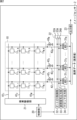
図2は、図1のイメージセンサ2の構成例を示すブロック図である。
FIG. 2 is a block diagram showing a configuration example of the
図2において、イメージセンサ2は、画素アレイ10、制御部20、画素駆動部21、列並列AD変換部22、及び、出力部23を有する。
2, the
画素アレイ10は、光電変換を行うM×N個(M及びNは、1以上の整数)の画素111,1,111,2,・・・,111,N,112,1,112,2,・・・,112,N,・・・,11M,1,11M,2,・・・,11M,Nを有し、画像を撮像する撮像部(撮像素子)として機能する。The
M×N個の画素111,1ないし11M,Nは、2次元平面上に、M行N列の行列(格子)状に配置されている。The M×
画素アレイ10の、(上から)m行目(m=1,2,・・・,M)の行方向(横方向)に並ぶN個の画素11m,1ないし11m,Nには、行方向に延びる画素制御線41mが接続されている。
また、(左から)n列目(n=1,2,・・・,N)の列方向(縦方向)に並ぶM個の画素111,nないし11M,nには、列方向に延びるVSL(Vertical Signal Line)42nが接続されている。In addition, in the column direction (vertical direction) of
画素11m,nは、そこに入射する光(入射光)の光電変換を行う。さらに、画素11m,nは、光電変換によって得られる電荷に対応する電圧としての画素信号を、画素駆動部21からの、画素制御線41mを介しての制御に従い、電流源43nが接続されたVSL42n上に出力する。The
なお、画素11m,nは、例えば、ベイヤ配列等の色フィルタ(図示せず)を介して入射する所定の色の光の光電変換を行うことができる。Note that the
制御部20は、画素駆動部21や、列並列AD変換部22(を構成するオートゼロ制御部32や、参照信号出力部33等)、その他の必要なブロックを、所定のロジック等に従って制御する。
The
画素駆動部21は、制御部20の制御に従い、画素制御線41mを介して、その画素制御線41mに接続されている画素11m,1ないし11m,Nを制御(駆動)する。The
列並列AD変換部22は、一行に並ぶ画素11m,1ないし11m,Nそれぞれと、VSL421ないし42Nを介して接続されており、したがって、画素11m,nがVSL42n上に出力する画素信号(電圧)(以下、VSL信号ともいう)は、列並列AD変換部22に供給される。The column-parallel
列並列AD変換部22は、一行に並ぶ画素11m,1ないし11m,Nそれぞれから、VSL421ないし42Nを介して供給されるVSL信号のAD変換を、並列で行う処理装置であり、AD変換の結果得られるディジタルデータを、画素11m,1ないし11m,Nの画素値(画素データ)として、出力部23に供給する。The column-parallel
ここで、列並列AD変換部22は、一行に並ぶN個の画素11m,1ないし11m,Nすべての画素信号のAD変換を、並列で行う他、そのN個の画素11m,1ないし11m,Nのうちの、N個未満の1個以上の画素の画素信号のAD変換を、並列で行うことができる。Here, the column-parallel
但し、以下では、説明を簡単にするため、列並列AD変換部22は、一行に並ぶN個の画素11m,1ないし11m,NすべてのVSL信号のAD変換を、並列で行うこととする。However, in the following description, for the sake of simplicity, the column-parallel
列並列AD変換部22は、一行に並ぶN個の画素11m,1ないし11m,NすべてのVSL信号のAD変換を、並列で行うために、N個のADC(Analog to Digital Converter)311ないし31Nを有する。The column-parallel
さらに、列並列AD変換部22は、オートゼロ制御部32、参照信号出力部33、及び、クロック出力部34を有する。
Furthermore, the column-parallel
オートゼロ制御部32は、ADC31nが有する、後述するコンパレータ61nのオートゼロ動作を制御するための信号であるオートゼロパルス(オートゼロ信号)を、オートゼロ信号線32Aを介して、ADC311ないし31Nに供給(出力)する。The auto-zero control unit 32 supplies an auto-zero pulse (auto-zero signal), which is a signal for controlling the auto-zero operation of a comparator 61- n , which the ADC 31- n has, to the ADCs 31-1 to 31- N via an auto-zero
参照信号出力部33は、例えば、DAC(Digital to Analog Converter)で構成され、ランプ(RAMP)信号のような一定の傾きで、所定の初期値から所定の最終値まで電圧が変化する期間を有する参照信号を、参照信号線33Aを介して、ADC311ないし31Nに供給(出力)する。The reference
クロック出力部34は、所定の周波数のクロックを、クロック信号線34Aを介して、ADC311ないし31Nに供給(出力)する。The
ADC31nは、VSL41nに接続されており、したがって、ADC31nには、画素11m,nがVSL41n上に出力するVSL信号(画素信号)が供給される。The ADC 31_n is connected to the VSL 41_n and is therefore supplied with the VSL signal (pixel signal) that the pixel 11_m,n outputs on the VSL 41_n.
ADC31nは、画素11m,nが出力するVSL信号のAD変換を、参照信号出力部33からの参照信号、及び、クロック出力部34からのクロックを用いて行い、さらに、CDS(Correlated Double Sampling)を行って、画素値としてのディジタルデータを求める。The ADC 31 n performs AD conversion of the VSL signals output by the
ここで、ADC31nは、画素11m,nのVSL信号と、参照信号出力部33からの参照信号とを比較し、画素11m,nのVSL信号と参照信号との電圧が一致するまでの(VSL信号と参照信号との大小関係が逆転するまでの)、参照信号の電圧の変化に要する時間をカウントすることにより、画素11m,nのVSL信号のAD変換を行う。Here, the ADC 31n compares the VSL signal of the
ADC31nにおいて、画素11m,nのVSL信号と参照信号との電圧が一致するまでの、参照信号の電圧の変化に要する時間のカウントは、クロック出力部34からのクロックをカウントすることにより行われる。In the ADC 31 n , the clock from the
また、N個のADC311ないし31Nには、画素アレイ10の第1行ないし第M行の各行のN個の画素11m,1ないし11m,NのVSL信号が、例えば、第1行から順次供給され、そのVSL信号のAD変換、及び、CDSが、行単位で行われる。Further, the N ADCs 31 1 to 31 N receive the VSL signals of the
出力部23は、画素値を読み出す列nを選択し、その列nのADC31nから、そのADC31nで求められた画素11m,nのAD変換(及びCDS)の結果を、画素値として読み出し、外部(本実施の形態では、メモリ3(図1))に出力する。The
なお、ここでは、ADC31nにおいて、AD変換の他、CDSを行うこととしたが、ADC31nでは、AD変換のみを行い、CDSは、出力部23で行うことが可能である。In this case, the ADC 31 n performs CDS in addition to AD conversion.
また、以下では、CDSについては、適宜、説明を省略する。 Also, hereinafter, description of the CDS will be omitted as appropriate.
<画素11m,nの構成例><Configuration example of
図3は、図2の画素11m,nの構成例を示す回路図である。FIG. 3 is a circuit diagram showing a configuration example of the
図3において、画素11m,nは、PD51、並びに、4個のNMOS(negative channel MOS)のFET(Field Effect Transistor)52,54,55、及び、56を有する。In FIG. 3, the
また、画素11m,nにおいては、FET52のドレイン、FET54のソース、及び、FET55のゲートが接続されており、その接続点には、電荷を電圧に変換するためのFD(Floating Diffusion)(容量)53が形成されている。Further, in the
PD51は、光電変換を行う光電変換素子の一例であり、入射光を受光して、その入射光に対応する電荷をチャージすることにより、光電変換を行う。
The
PD51のアノードはグランド(ground)に接続され(接地され)、PD51のカソードは、FET52のソースに接続されている。 The anode of PD51 is connected to the ground (grounded), and the cathode of PD51 is connected to the source of FET52.
FET52は、PD51にチャージされた電荷を、PD51からFD53に転送するためのFETであり、以下、転送Tr52ともいう。
The
転送Tr52のソースは、PD51のカソードに接続され、転送Tr52のドレインは、FD53を介して、FET54のソースに接続されている。 The source of transfer Tr52 is connected to the cathode of PD51, and the drain of transfer Tr52 is connected to the source of FET54 via FD53.
また、転送Tr52のゲートは、画素制御線41mに接続されており、転送Tr52のゲートには、画素制御線41mを介して、転送パルスTRGが供給される。A gate of the transfer Tr52 is connected to the pixel control line 41m , and a transfer pulse TRG is supplied to the gate of the transfer Tr52 through the pixel control line 41m .
ここで、画素駆動部21(図2)が、画素制御線41mを介して、画素11m,nを駆動(制御)するために、画素制御線41mに供給する制御信号(電圧)には、転送パルスTRGの他、後述するリセットパルスRST、及び、選択パルスSELがある。Here, the control signal (voltage) supplied to the pixel control line 41m by the pixel drive unit 21 (FIG. 2) to drive (control) the
FD53は、転送Tr52のドレイン、FET54のソース、及び、FET55のゲートの接続点に形成された、コンデンサの如く電荷を電圧に変換する領域である。 The FD53 is a region formed at the connection point of the drain of the transfer Tr52, the source of the FET54, and the gate of the FET55 and converts charge into voltage like a capacitor.
FET54は、FD53にチャージされた電荷(電圧(電位))をリセットするためのFETであり、以下、リセットTr54ともいう。
The
リセットTr54のドレインは、電源Vddに接続されている。 A drain of the reset Tr54 is connected to the power supply Vdd.
また、リセットTr54のゲートは、画素制御線41mに接続されており、リセットTr54のゲートには、画素制御線41mを介して、リセットパルスRSTが供給される。A gate of the reset Tr54 is connected to the pixel control line 41m , and a reset pulse RST is supplied to the gate of the reset Tr54 through the pixel control line 41m .
FET55は、FD53の電圧をバッファするためのFETであり、以下、増幅Tr55ともいう。
The
増幅Tr55のゲートは、FD53に接続され、増幅Tr55のドレインは、電源Vddに接続されている。また、増幅Tr55のソースは、FET56のドレインに接続されている。 A gate of the amplification Tr55 is connected to the FD53, and a drain of the amplification Tr55 is connected to the power supply Vdd. Also, the source of the amplification Tr55 is connected to the drain of the FET56.
FET56は、VSL42nへの画素信号(VSL信号)の出力を選択するためのFETであり、以下、選択Tr56ともいう。The FET 56 is a FET for selecting the output of the pixel signal (VSL signal) to the VSL 42 n , and is hereinafter also referred to as a selection Tr 56 .
選択Tr56のソースは、VSL42nに接続されている。The source of select Tr 56 is connected to VSL 42n .
また、選択Tr56のゲートは、画素制御線41mに接続されており、選択Tr56のゲートには、画素制御線41mを介して、選択パルスSELが供給される。The gate of the selection Tr56 is connected to the pixel control line 41m , and the selection pulse SEL is supplied to the gate of the selection Tr56 via the pixel control line 41m .
ここで、増幅Tr55のソースが、選択Tr56、及び、VSL42nを介して電流源43nに接続されることで、増幅Tr55及び電流源43nによって、SF(Source Follower)(の回路)が構成されており、したがって、FD53の電圧は、SFを介して、VSL42n上のVSL信号となる。Here, the source of the amplification Tr55 is connected to the current source 43n through the selection Tr56 and the VSL42n , so that the amplification Tr55 and the current source 43n form an SF (Source Follower) (circuit). Therefore, the voltage of FD53 becomes the VSL signal on VSL42n through SF.
なお、画素11m,nは、選択Tr56なしで構成することができる。Note that the
また、画素11m,nの構成としては、FD53ないし選択Tr56を、複数のPD51及び転送Tr52で共有する共有画素の構成を採用することができる。Further, as the configuration of the
以上のように構成される画素11m,nでは、PD51は、そこに入射する光を受光し、光電変換を行うことにより、受光した入射光の光量に応じた電荷のチャージを開始する。なお、ここでは、説明を簡単にするために、選択パルスSELはHレベルになっており、選択Tr56はオン状態であることとする。In the
PD51での電荷のチャージが開始されてから、所定の時間(露光時間)が経過すると、画素駆動部21(図2)は、転送パルスTRGを、一時的に、(L(Low)レベルから)H(High)レベルにする。
When a predetermined time (exposure time) elapses after the
転送パルスTRGが一時的にHレベルになることにより、転送Tr52は、一時的に、オン状態になる。 The transfer Tr52 is temporarily turned on by the transfer pulse TRG temporarily becoming H level.
転送Tr52がオン状態になると、PD51にチャージされた電荷は、転送Tr52を介して、FD53に転送されてチャージされる。 When the transfer Tr52 is turned on, the charges charged in the PD51 are transferred to the FD53 via the transfer Tr52 and charged.
画素駆動部21は、転送パルスTRGを一時的にHレベルにする前に、リセットパルスRSTを、一時的に、Hレベルにし、これにより、リセットTr54を、一時的に、オン状態にする。
The
リセットTr54がオン状態になることにより、FD53は、リセットTr54を介して、電源Vddに接続され、FD53にある電荷は、リセットTr54を介して、電源Vddに掃き出されてリセットされる。 When the reset Tr54 is turned on, the FD53 is connected to the power supply Vdd through the reset Tr54, and the charge in the FD53 is discharged to the power supply Vdd through the reset Tr54 and reset.
ここで、以上のように、FD53が、電源Vddに接続され、FD53にある電荷がリセットされることが、画素11m,nのリセットである。Here, as described above, connecting the
FD53の電荷のリセット後、画素駆動部21は、上述のように、転送パルスTRGを、一時的に、Hレベルにし、これにより、転送Tr52は、一時的に、オン状態になる。
After the charge of the
転送Tr52がオン状態になることにより、PD51にチャージされた電荷は、転送Tr52を介して、リセット後のFD53に転送されてチャージされる。 By turning on the transfer Tr52, the charge charged in the PD51 is transferred to the FD53 after reset via the transfer Tr52 and charged.
FD53にチャージされた電荷に対応する電圧(電位)は、増幅Tr55及び選択Tr56を介して、VSL信号として、VSL42n上に出力される。A voltage (potential) corresponding to the charges charged in the
VSL42nに接続されているADC31n(図2)では、画素11m,nのリセットが行われた直後のVSL信号であるリセットレベルがAD変換される。The ADC 31 n (FIG. 2) connected to the VSL 42 n AD-converts the reset level, which is the VSL signal immediately after the
さらに、ADC31nでは、転送Tr52が一時的にオン状態になった後のVSL信号(PD51にチャージされ、FD53に転送された電荷に対応する電圧)である信号レベル(リセットレベルと、画素値となるレベルとを含む)がAD変換される。Furthermore, in the ADC 31 n , the signal level (reset level, pixel value and ) are AD-converted.
そして、ADC31nでは、リセットレベルのAD変換結果(以下、リセットレベルAD値ともいう)と、信号レベルのAD変換結果(以下、信号レベルAD値ともいう)との差分を、画素値として求めるCDSが行われる。Then, in the ADC 31 n , the difference between the reset level AD conversion result (hereinafter also referred to as reset level AD value) and the signal level AD conversion result (hereinafter also referred to as signal level AD value) is obtained as a pixel value CDS is done.
<ADC31nの構成例><Configuration example of ADC31n >
図4は、図2のADC31nの構成例を示すブロック図である。FIG. 4 is a block diagram showing a configuration example of ADC 31n in FIG.
ADC31nは、コンパレータ61n、及び、カウンタ62nを有し、シングルスロープ型のAD変換、及び、CDSを行う。The ADC 31n has a comparator 61n and a counter 62n , and performs single-slope AD conversion and CDS.
コンパレータ61nは、反転入力端子(-)、及び、非反転入力端子(+)の2つの入力端子を有する。The comparator 61n has two input terminals, an inverting input terminal (-) and a non-inverting input terminal (+).
コンパレータ61nの2つの入力端子のうちの一方の入力端子である反転入力端子(-)には、参照信号出力部33からの参照信号、及び、画素11m,nのVSL信号(リセットレベル、信号レベル)のうちの一方である、例えば、参照信号が供給される。コンパレータ61nの2つの入力端子のうちの他方の入力端子である非反転入力端子(+)には、参照信号出力部33からの参照信号、及び、画素11m,nのVSL信号のうちの他方である、例えば、VSL信号が供給される。The reference signal from the reference
コンパレータ61nは、反転入力端子に供給される参照信号と、非反転入力端子に供給されるVSL信号とを比較し、その比較結果を出力する。The comparator 61n compares the reference signal supplied to the inverting input terminal and the VSL signal supplied to the non-inverting input terminal, and outputs the comparison result.
すなわち、コンパレータ61nは、反転入力端子に供給される参照信号が、非反転入力端子に供給されるVSL信号よりも大である場合、H及びLレベルのうちの一方である、例えば、Lレベルを出力する。That is, the comparator 61n is at one of H and L levels, e.g., L level, when the reference signal supplied to its inverting input terminal is greater than the VSL signal supplied to its non-inverting input terminal. to output
また、コンパレータ61nは、非反転入力端子に供給されるVSL信号が、反転入力端子に供給される参照信号の電圧よりも大である場合、H及びLレベルのうちの他方であるHレベルを出力する。Further, the comparator 61n outputs the H level, which is the other of the H and L levels, when the VSL signal supplied to the non-inverting input terminal is higher than the voltage of the reference signal supplied to the inverting input terminal. Output.
なお、コンパレータ61nには、オートゼロ制御部32から、オートゼロ信号線32Aを介して、オートゼロパルスが供給される。コンパレータ61nでは、オートゼロ制御部32からのオートゼロパルスに従って、コンパレータ61nの動作点電位であるオートゼロ電位を決定するオートゼロ動作が行われる。An auto-zero pulse is supplied from the auto-zero control unit 32 to the comparator 61n via the auto-zero
ここで、オートゼロ動作では、コンパレータ61nに入力(供給)される画素信号と参照信号とが同一のオートゼロ電位になるように、コンパレータが設定される。したがって、オートゼロ動作では、コンパレータ61nにおいて、そのコンパレータ61nに現に与えられている2つの入力信号、すなわち、コンパレータ61nの反転入力端子に現に供給されている信号と、非反転入力端子に現に供給されている信号とが一致している旨の比較結果が得られるように、コンパレータ61nが設定される。Here, in the auto-zero operation, the comparator is set so that the pixel signal and the reference signal input (supplied) to the comparator 61n have the same auto-zero potential. Thus, in autozero operation, at comparator 61- n , the two input signals currently applied to that comparator 61- n , namely the signal currently applied to the inverting input terminal of comparator 61- n and the signal currently applied to the non-inverting input terminal of comparator 61-n. The comparator 61n is set so as to obtain a comparison result indicating that it matches the supplied signal.
カウンタ62nには、コンパレータ61nの出力と、クロック出力部34からのクロックとが供給される。The output of the comparator 61- n and the clock from the
カウンタ62nは、例えば、参照信号出力部33からコンパレータ61nに供給される参照信号(の電圧)が変化を開始するタイミングで、クロック出力部34からのクロックのカウントを開始し、コンパレータ61nの出力が、例えば、LレベルからHレベルになると(、又は、HレベルからLレベルになると)、すなわち、コンパレータ61nの反転入力端子に供給される参照信号と、非反転入力端子に供給されるVSL信号との電圧が等しくなると(参照信号とVSL信号との大小関係が逆転すると)、クロック出力部34からのクロックのカウントを終了する。For example, the counter 62n starts counting the clock from the
そして、カウンタ62nは、クロックのカウント値を、コンパレータ61nの非反転入力端子に供給されるVSL信号のAD変換結果として出力する。Then, the counter 62- n outputs the clock count value as the AD conversion result of the VSL signal supplied to the non-inverting input terminal of the comparator 61- n .
ここで、参照信号出力部33は、参照信号として、例えば、所定の初期値から所定の最終値まで、一定の割合で電圧が小さく又は大きくなっていくスロープ(スロープ状の波形)を有するRAMP信号を出力する。
Here, the reference
カウンタ62nでは、スロープの開始から、参照信号が、コンパレータ61nの非反転入力端子に供給されるVSL信号に一致する電圧に変化するまでの時間がカウントされ、そのカウントにより得られるカウント値が、コンパレータ61nの非反転入力端子に供給されるVSL信号のAD変換結果とされる。The counter 62n counts the time from the start of the slope until the reference signal changes to a voltage that matches the VSL signal supplied to the non-inverting input terminal of the comparator 61n . , is the AD conversion result of the VSL signal supplied to the non-inverting input terminal of the comparator 61- n .
ADC31nは、画素11m,nからコンパレータ61nの非反転入力端子に供給されるVSL信号としてのリセットレベル、及び、信号レベルのAD変換結果を得る。そして、ADC31nは、信号レベルのAD変換結果(信号レベルAD値)と、リセットレベルのAD変換結果(リセットレベルAD値)との差分を求めるCDSを行い、そのCDSにより得られる差分を、画素11m,nの画素値として出力する。The ADC 31n obtains the reset level as the VSL signal supplied from the
なお、ADC31nにおいて、CDSは、信号レベルAD値とリセットレベルAD値との差分を求める演算を実際に実行することにより行う他、例えば、カウンタ62nでのクロックのカウントを制御することにより行うことができる。In the ADC 31 n , the CDS is performed by actually executing an operation to find the difference between the signal level AD value and the reset level AD value, and for example, by controlling the clock count in the counter 62 n . be able to.
すなわち、カウンタ62nにおいて、リセットレベルについては、例えば、カウント値を、1ずつデクリメントしながら、クロックをカウントし、信号レベルについては、リセットレベルについてのクロックのカウント値を初期値として、カウント値を、リセットレベルの場合とは逆に、1ずつインクリメントしながら、クロックをカウントすることにより、リセットレベル、及び、信号レベルのAD変換を行いつつ、信号レベル(のAD変換結果)とリセットレベル(のAD変換結果)との差分を求めるCDSを行うことができる。That is, in the counter 62n , for the reset level, for example, clocks are counted while the count value is decremented by one, and for the signal level, the count value is counted with the clock count value for the reset level as the initial value. , in contrast to the case of the reset level, by counting the clock while incrementing by 1, AD conversion of the reset level and the signal level is performed, and the signal level (AD conversion result) and the reset level (of CDS can be performed to find the difference between AD conversion results).
<コンパレータ61nの第1の構成例><First Configuration Example of Comparator 61n >
図5は、図4のコンパレータ61nの第1の構成例を示す回路図である。FIG. 5 is a circuit diagram showing a first configuration example of the comparator 61- n in FIG.
コンパレータ61nは、NMOSのFET101及びFET102、PMOS(positive channel MOS)のFET103及びFET104、NMOSのFET105及びFET106、スイッチ107及びスイッチ108、PMOSのFET109、NMOSのFET110、並びに、コンデンサC0, C1, C2, C3を有する。The comparator 61n includes
FET101及びFET102は、いわゆる差動対を構成しており、それぞれのソースどうしが接続されている。さらに、FET101及びFET102のソースどうしの接続点は、FET105のドレインに接続されている。 FET101 and FET102 comprise what is called a differential pair, and each source is connected. Furthermore, the connection point between the sources of the FET101 and the FET102 is connected to the drain of the FET105.
FET101のゲートは、コンデンサC1を介して、コンパレータ61nの反転入力端子に接続されており、FET101のゲートには、コンデンサC1を介して、参照信号としてのRAMP信号が供給される。FET102のゲートは、コンデンサC2を介して、コンパレータ61nの非反転入力端子に接続されており、FET102のゲートには、コンデンサC2を介して、画素11m,nが出力するVSL信号(画素信号)が供給される。The gate of the
コンパレータ61nは、以上のように、FET101、及び、FET102で構成される差動対を入力段に有し、その差動対の入力段としてのFET101及び102のゲートには、コンデンサC1及びC2がそれぞれ設けられている。As described above, the comparator 61n has a differential pair composed of the
FET103及びFET104は、カレントミラーを構成しており、FET101及び102で構成される差動対のアクティブロードとして機能する。FET103及びFET104において、ゲートどうしは接続され、ソースは、電源(電圧)VDD(>0)に接続されている、FET103及びFET104のゲートどうしの接続点は、FET103のドレインに接続されている。
The
カレントミラーを構成するFET103及びFET104のうちの、FET103のドレインは、FET101のドレインに接続され、FET104のドレインは、FET102のドレインに接続されている。
Of the
そして、FET102及びFET104のドレインどうしの接続点は、FET109のゲートに接続されており、したがって、FET102及びFET104のドレインどうしの接続点の信号は、FET109に対して、そのFET109の入力信号として与えられる。
A connection point between the drains of the
スイッチ107及びスイッチ108は、例えば、FET等で構成されるスイッチであり、オートゼロ制御部32から供給されるオートゼロパルスに応じて、オン又はオフする。
The
すなわち、スイッチ107は、オートゼロパルスに応じて、FET101のゲートとドレインとの間を接続又は切断するようにオン又はオフする。スイッチ108は、オートゼロパルスに応じて、FET102のゲートとドレインとの間を接続又は切断するようにオン又はオフする。
That is, the
ここで、スイッチ107及びスイッチ108は、オートゼロ動作において、オンになる。スイッチ107及びスイッチ108がオンになると、FET101及びFET102それぞれのゲート電圧及びドレイン電圧が等しくなるように、コンデンサC1及びC2がチャージされる。したがって、オートゼロ動作によれば、コンデンサC1を介してFET101のゲートに供給されるRAMP信号であるDIFF_DAC信号と、コンデンサC2を介してFET102のゲートに供給されるVSL信号であるDIFF_VSL信号との電圧が、同一になる。
Here, switches 107 and 108 are turned on in autozero operation. When switches 107 and 108 are turned on, capacitors C1 and C2 are charged so that the gate and drain voltages of FET101 and FET102, respectively, are equal. Therefore, according to the autozero operation, the voltages of the DIFF_DAC signal, which is the RAMP signal supplied to the gate of
この、オートゼロ動作によって等しくなるDIFF_DAC信号及びDIFF_VSL信号の電圧が、コンパレータ61nの動作点電位であるオートゼロ電位である。The voltages of the DIFF_DAC signal and the DIFF_VSL signal, which are equalized by this auto-zero operation, are the auto-zero potential, which is the operating point potential of the comparator 61n .
FET105のドレインは、上述したように、差動対を構成するFET101及びFET102のソースどうしの接続点に接続されている。そして、FET105のソースは、FET106のドレインに接続され、FET105のゲートには、図示せぬ回路から制御信号としてのBIASCUT信号が供給される。
The drain of the
FET106のゲート及びソースは、コンデンサC0の一端及び他端とそれぞれ接続されている。FET106のゲートとコンデンサC0の一端との接続点には、図示せぬ回路から制御信号としてのVGCM信号が供給され、FET106のソースとコンデンサC0の他端との接続点は、電源(電圧)VSS(<VDD)に接続されている。FET105及び106、並びに、コンデンサC0は、電流源を構成する。
The gate and source of
FET109のソースは、電源VDDに接続され、ドレインは、FET110のドレインに接続されている。
The
FET110のゲート及びソースは、コンデンサC3の一端及び他端とそれぞれ接続されている。FET110のゲートとコンデンサC3の一端との接続点には、図示せぬ回路から制御信号としてのVBIAS信号が供給され、FET110のソースとコンデンサC3の他端との接続点は、電源VSSに接続されている。FET110及びコンデンサC3は、電流源を構成する。
The gate and source of
以上のように構成されるコンパレータ61nでは、FET101(のドレインからソース)には、FET101のゲート電圧としてのDIFF_DAC信号に対応する電流i1が流れ、FET102(のドレインからソース)には、FET102のゲート電圧としてのDIFF_VSLに対応する電流i2が流れる。In the comparator 61 n configured as above, a current i 1 corresponding to the DIFF_DAC signal as the gate voltage of the
また、カレントミラーを構成するFET103及びFET104(のソースからドレイン)には、FET101に流れる電流i1と同一の電流が流れる。In addition, the same current as the current i1 flowing through the
FET101のゲート電圧としてのDIFF_DAC信号が、FET102のゲート電圧としてのDIFF_VSL信号よりも大である場合には、FET101に流れる電流i1が、FET102に流れる電流i2よりも大になる。When the DIFF_DAC signal as the gate voltage of FET101 is greater than the DIFF_VSL signal as the gate voltage of FET102, the current i1 flowing through FET101 becomes greater than the current i2 flowing through FET102.
この場合、FET101に接続されているFET103をミラー元としてカレントミラーを構成するFET104には、FET101に流れる電流i1と同一の電流が流れるが、FET104と接続しているFET102に流れる電流i2は、電流i1よりも小さい電流であるため、FET102では、電流i2を増大させようとして、ドレインソース間電圧が大になる。In this case, the same current as the current i1 flowing through the
その結果、FET102とFET104の接続点の電圧は、Hレベルになる。
As a result, the voltage at the connection point between
一方、FET102のゲート電圧としてのDIFF_VSL信号が、FET101のゲート電圧としてのDIFF_DAC信号よりも大である場合には、FET102に流れる電流i2が、FET101に流れる電流i1よりも大になる。On the other hand, when the DIFF_VSL signal as the gate voltage of the
この場合、FET101に接続されているFET103をミラー元としてカレントミラーを構成するFET104には、FET101に流れる電流i1と同一の電流が流れるが、FET104と接続しているFET102に流れる電流i2は、電流i1よりも大きい電流であるため、FET102では、電流i2を減少させようとして、ドレインソース間電圧が小になる。In this case, the same current as the current i1 flowing through the
その結果、FET102とFET104との接続点の電圧は、Lレベルになる。
As a result, the voltage at the connection point between
FET102とFET104との接続点の電圧は、差動対とカレントミラーとで構成される差動アンプの出力である差動出力として、コンパレータ61nの出力信号であるOUT信号を出力する出力アンプを構成するFET109のゲートに供給される。The voltage at the connection point between the
FET110は、そのゲートに供給される差動出力に応じて、コンパレータ61nの出力信号であるOUT信号を出力する。The
すなわち、差動出力がHレベルである場合には、FET109はオフになって、LレベルのOUT信号を出力する。また、差動出力がLレベルである場合には、FET109はオンになって、HレベルのOUT信号を出力する。
That is, when the differential output is at H level, the
以上から、参照信号としてのRAMP信号(の電圧)が、VSL信号(の電圧)よりも高い場合には、コンパレータ61nの出力信号であるOUT信号は、Lレベルになる。一方、VSL信号が、RAMP信号よりも高い場合には、コンパレータ61nの出力信号であるOUT信号は、Hレベルになる。From the above, when the (voltage of) the RAMP signal as the reference signal is higher than (the voltage of) the VSL signal, the OUT signal, which is the output signal of the comparator 61n , becomes L level. On the other hand, when the VSL signal is higher than the RAMP signal, the OUT signal, which is the output signal of the comparator 61n , becomes H level.
以上のように構成されるコンパレータ61nでは、オートゼロ動作と比較動作とが行われる。The comparator 61n configured as described above performs an auto-zero operation and a comparison operation.
オートゼロ動作では、スイッチ107及びスイッチ108がオンになる。 In autozero operation, switches 107 and 108 are turned on.
スイッチ107及びスイッチ108がオンになると、FET101のゲートとドレインとが接続されるとともに、FET102のゲートとドレインとが接続され、FET101及びFET102のゲート電圧は、同一になる。
When the
FET101のゲート電圧は、コンデンサC1を介して供給されるRAMP信号であるDIFF_DAC信号であり、FET102のゲート電圧は、コンデンサC2を介して供給されるVSL信号であるDIFF_VSL信号である。オートゼロ動作では、これらのDIFF_DAC信号とDIFF_VSL信号とが一致するように、コンデンサC1及びC2には、電荷がチャージされる。
The gate voltage of
その後、コンパレータ61nでは、スイッチ107及びスイッチ108がオフになり、コンパレータ61nに供給されるRAMP信号とVSL信号とを比較する比較動作が開始される。スイッチ107及びスイッチ108がオフになることにより、コンデンサC1及びC2では、スイッチ107及びスイッチ108がオンになっているときにチャージされた電荷が維持される。After that, in the comparator 61n , the
その結果、コンパレータ61nは、スイッチ107及びスイッチ108がオンになっているときにコンパレータ61nに与えられていたDIFF_DAC信号としてのRAMP信号とDIFF_VSL信号としてのVSL信号とが一致するように設定される。As a result, the comparator 61n is set so that the RAMP signal as the DIFF_DAC signal and the VSL signal as the DIFF_VSL signal, which have been given to the
以上のようなコンパレータ61nの設定が行われる動作が、オートゼロ動作である。The operation in which the comparator 61n is set as described above is the auto-zero operation.
オートゼロ動作が行われることにより、その後の比較動作では、コンパレータ61nにおいて、オートゼロ動作時に、コンパレータ61nに与えられていたRAMP信号(電圧)と、VSL信号(電圧)とが一致しているということを基準として、RAMP信号とVSL信号との大小関係を判定することができる。By performing the auto-zero operation, in the subsequent comparison operation, the RAMP signal (voltage) supplied to the comparator 61n during the auto-zero operation matches the VSL signal (voltage). Using this as a reference, it is possible to determine the magnitude relationship between the RAMP signal and the VSL signal.
図6は、図5のコンパレータ61nの第1の構成例の動作の例を説明するタイミングチャートである。FIG. 6 is a timing chart illustrating an operation example of the first configuration example of the comparator 61- n in FIG.
図6には、スイッチ107及びスイッチ108のオン/オフ、コンパレータ61nの動作、並びに、RAMP信号及びVSL信号が示されている。FIG. 6 shows the on/off of
ここで、VSL信号のAD変換では、図3等で説明したように、リセットレベルのVSL信号のAD変換と、信号レベルのVSL信号のAD変換とが行われる。 Here, in the AD conversion of the VSL signal, AD conversion of the reset level VSL signal and AD conversion of the signal level VSL signal are performed as described with reference to FIG. 3 and the like.
VSL信号のAD変換では、図4で説明したように、一定の割合で電圧が小さく又は大きくなっていくスロープを有するRAMP信号のスロープの開始から、RAMP信号が、VSL信号に一致する電圧に変化するまでの時間がカウントされ、そのカウントにより得られるカウント値が、VSL信号のAD変換結果とされる。 In the AD conversion of the VSL signal, as explained in FIG. 4, the RAMP signal changes to a voltage that matches the VSL signal from the start of the slope of the RAMP signal, which has a slope in which the voltage decreases or increases at a constant rate. The time until this is done is counted, and the count value obtained by the count is used as the AD conversion result of the VSL signal.
リセットレベルのVSL信号のAD変換が行われるRAMP信号のスロープの期間はP(Preset)相と呼ばれ、信号レベルのVSL信号のAD変換が行われるRAMP信号のスロープの期間はD(Data)相と呼ばれる。ここでは、P相及びD相の順で、AD変換を行うこととする。但し、AD変換は、D相及びP相の順で行うことも可能である。 The period of the ramp signal slope during AD conversion of the reset level VSL signal is called the P (Preset) phase, and the period of the RAMP signal slope during which the signal level VSL signal is AD converted is the D (Data) phase. called. Here, AD conversion is performed in the order of P phase and D phase. However, AD conversion can also be performed in the order of D phase and P phase.
コンパレータ61nでは、例えば、画素11m,nに入射する光が明るいほど(光の強度が強いほど)、その画素11m,nが出力するVSL信号(電圧)が低下することを前提として、P相及びD相で電圧が低下するRAMP信号が用いられる。In the comparator 61n , for example, on the premise that the brighter the light incident on the
ここで、図6では(後述する図でも同様)、画素11m,nに入射する光が明るい場合のVSL信号を実線で、暗い場合のVSL信号を点線で、それぞれ示してある。Here, in FIG. 6 (similarly to the figures described later), the VSL signal when the light incident on the
コンパレータ61nでは、オートゼロ動作(AZ動作)において、スイッチ107及びスイッチ108がオンにされる。これにより、RAMP信号としてのDIFF_DAC信号と、VSL信号としてのDIFF_VSL信号とは、いずれもオートゼロ電位(AZ電位)VNとなる。In the comparator 61n , the
オートゼロ電位VNは、スイッチ107(スイッチ108)がオンになっているときのFET101(FET102)のゲート電圧であるから、FET101(FET102)のドレイン電圧に等しい。したがって、オートゼロ電位VNは、電源電圧VDDから、FET103(FET104)のゲートソース間電圧Vgsp2を減算した電圧VDD-Vgsp2である。 Since the auto-zero potential VN is the gate voltage of the FET101 (FET102) when the switch 107 (switch 108) is on, it is equal to the drain voltage of the FET101 (FET102). Therefore, the auto-zero potential VN is the voltage VDD-Vgsp2 obtained by subtracting the gate-source voltage Vgsp2 of the FET 103 (FET 104) from the power supply voltage VDD.
コンパレータ61nでは、オートゼロ動作後、スイッチ107及びスイッチ108がオフになり、比較動作が開始される。In the comparator 61n , after the auto-zero operation, the
比較動作では、VSL信号のAD変換、すなわち、リセットレベルのVSL信号のAD変換と、信号レベルのVSL信号のAD変換とが行われる。 In the comparison operation, AD conversion of the VSL signal, that is, AD conversion of the reset level VSL signal and AD conversion of the signal level VSL signal are performed.
比較動作では、P相の開始前に、RAMP信号(としてのDIFF_DAC信号)が、所定の電圧だけ上昇するようにオフセットされ、その後、P相において、一定の割合で下降される。そして、P相の開始から、RAMP信号(としてのDIFF_DAC信号)と、リセットレベルのVSL信号(としてのDIFF_VSL信号)との大小関係が逆転するまでの時間がカウントされ、そのカウントにより得られるカウント値が、リセットレベルのVSL信号のAD変換結果となる。 In the compare operation, the RAMP signal (as the DIFF_DAC signal) is offset up by a predetermined voltage before the start of the P phase, and then ramped down during the P phase. Then, the time from the start of the P-phase until the magnitude relationship between the RAMP signal (as the DIFF_DAC signal) and the reset level VSL signal (as the DIFF_VSL signal) is reversed is counted. is the AD conversion result of the reset level VSL signal.
P相の終了後、RAMP信号は、P相の開始時の電圧まで上昇するようにオフセットされ、その後、D相において、一定の割合で下降される。そして、D相の開始から、RAMP信号と、信号レベルのVSL信号との大小関係が逆転するまでの時間がカウントされ、そのカウントにより得られるカウント値が、信号レベルのVSL信号のAD変換結果となる。 After the P-phase ends, the RAMP signal is offset to rise to the voltage at the start of the P-phase, and then ramped down during the D-phase. Then, the time from the start of the D phase until the magnitude relationship between the RAMP signal and the signal level of the VSL signal is reversed is counted. Become.
ここでは、上述したように、画素11m,nに入射する光が明るいほど、その画素11m,nが出力するVSL信号が低下することを前提としているので、D相において、画素11m,nに入射する光が明るい場合には、図6に実線で示すように、信号レベルのVSL信号は大きく低下し、画素11m,nに入射する光が暗い場合には、図6に点線で示すように、信号レベルのVSL信号はあまり低下しない。Here, as described above, it is assumed that the brighter the light incident on the
以上のように、画素11m,nに入射する光が明るいほど、その画素11m,nが出力するVSL信号が低下することを前提として、RAMP信号としては、P相及びD相において時間の経過とともに低下(下降)する信号が用いられる。As described above, on the premise that the brighter the light incident on the
ここで、上述のような、画素11m,nに入射する光が明るいほど低下するVSL信号の変化、及び、P相及びD相において時間の経過とともに低下(下降)するRAMP信号の変化を、通常変化ともいう。Here, as described above, the change in the VSL signal that decreases as the light incident on the
図5の第1の構成例のコンパレータ61nは、VSL信号やRAMP信号が通常変化することを前提として設計されている。The comparator 61n of the first configuration example of FIG. 5 is designed on the premise that the VSL signal and the RAMP signal normally change.
すなわち、電源電圧VDDより、FET103及びFET104が飽和領域で動作するのに必要なFET103及びFET104のドレインソース間電圧Vdsだけ低い電圧を、電圧VHとする。また、電源電圧VSSより、FET105及びFET106が飽和領域で動作するのに必要なFET105のドレインソース間電圧VdsとFET106のドレインソース間電圧Vdsとの加算値だけ高い電圧を、電圧VL(>VH)とする。That is, the voltage VH is lower than the power supply voltage VDD by the drain-source voltage Vds of the
コンパレータ61nは、電圧VL以上電圧VH以下の範囲を、コンパレータ61nの動作範囲として、通常変化するRAMP信号(としてのDIFF_DAC信号)及びVSL信号(としてのDIFF_VSL信号)が、コンパレータ61nの動作範囲に収まるように設計される。The comparator 61n defines the operating range of the comparator 61n as the range between voltage VL and voltage VH. Designed to fit the range.
ところで、通常変化とは反対に、入射する光が明るいほど、VSL信号(画素信号)が上昇する新規の画素が開発された場合、かかる新規の画素については、RAMP信号としては、通常変化とは反対に、P相及びD相において時間の経過とともに上昇するRAMP信号が適切な場合があり得る。 By the way, when a new pixel is developed in which the VSL signal (pixel signal) increases as the incident light becomes brighter, contrary to the normal change, the RAMP signal for such a new pixel is different from the normal change. Conversely, a RAMP signal that rises over time in the P and D phases may be appropriate.
また、新規の画素については、通常変化するRAMP信号が適切であるか、又は、通常変化とは反対に、P相及びD相において時間の経過とともに上昇するRAMP信号が適切であるかは、実際に試して評価してみないと分からないことがあり得る。 Also, for new pixels, it is practically impossible to determine whether a normally varying RAMP signal is appropriate, or a RAMP signal that rises over time in the P and D phases, as opposed to normally varying. There may be things you don't know until you try and evaluate.
ここで、VSL信号及びRAMP信号の通常変化とは反対の変化、すなわち、画素11m,nに入射する光が明るいほど上昇するVSL信号の変化、及び、P相及びD相において時間の経過とともに上昇するRAMP信号の変化を、反転変化ともいう。Here, the opposite change to the normal change of the VSL and RAMP signals, i.e., the change in the VSL signal that rises as the light incident on the
図7は、RAMP信号及びVSL信号が反転変化する場合のコンパレータ61nの第1の構成例の動作の例を説明するタイミングチャートである。FIG. 7 is a timing chart illustrating an operation example of the first configuration example of the comparator 61n when the RAMP signal and the VSL signal are inverted.
図7には、図6と同様に、スイッチ107及びスイッチ108のオン/オフ、コンパレータ61nの動作、並びに、RAMP信号及びVSL信号が示されている。Similar to FIG. 6, FIG. 7 shows the ON/OFF states of the
図7では、RAMP信号及びVSL信号が通常変化するのではなく、反転変化している点が、図6の場合と異なっている。 FIG. 7 differs from the case of FIG. 6 in that the RAMP signal and VSL signal do not change normally, but are reversed.
コンパレータ61nでは、オートゼロ動作(AZ動作)において、スイッチ107及びスイッチ108がオンにされる。これにより、RAMP信号としてのDIFF_DAC信号と、VSL信号としてのDIFF_VSL信号とは、いずれもオートゼロ電位(AZ電位)VNとなる。In the comparator 61n , the
オートゼロ電位VNは、図6で説明したように、電源電圧VDDから、FET103のゲートソース間電圧Vgsp2を減算した電圧VDD-Vgsp2である。
The auto-zero potential VN is the voltage VDD-Vgsp2 obtained by subtracting the gate-to-source voltage Vgsp2 of the
コンパレータ61nでは、オートゼロ動作後、スイッチ107及びスイッチ108がオフになり、比較動作が開始される。In the comparator 61n , after the auto-zero operation, the
比較動作では、VSL信号のAD変換、すなわち、リセットレベルのVSL信号のAD変換と、信号レベルのVSL信号のAD変換とが行われる。 In the comparison operation, AD conversion of the VSL signal, that is, AD conversion of the reset level VSL signal and AD conversion of the signal level VSL signal are performed.
反転変化するRAMP信号が用いられる場合、比較動作では、P相の開始前に、RAMP信号が、所定の電圧だけ下降するようにオフセットされ、その後、P相において、一定の割合で上昇される。そして、P相の開始から、RAMP信号と、リセットレベルのVSL信号との大小関係が逆転するまでの時間がカウントされ、そのカウントにより得られるカウント値が、リセットレベルのVSL信号のAD変換結果となる。 When a ramping RAMP signal is used, the comparison operation offsets the RAMP signal down by a predetermined voltage before the start of the P phase and then ramps it up during the P phase. Then, the time from the start of the P phase until the magnitude relationship between the RAMP signal and the reset level VSL signal is reversed is counted, and the count value obtained by that count is the AD conversion result of the reset level VSL signal. Become.
P相の終了後、RAMP信号は、P相の開始時の電圧まで下降するようにオフセットされ、その後、D相において、一定の割合で上昇される。そして、D相の開始から、RAMP信号と、信号レベルのVSL信号との大小関係が逆転するまでの時間がカウントされ、そのカウントにより得られるカウント値が、信号レベルのVSL信号のAD変換結果となる。 After the end of P-phase, the RAMP signal is offset down to the voltage at the start of P-phase, and then ramped up in D-phase. Then, the time from the start of the D phase until the magnitude relationship between the RAMP signal and the signal level of the VSL signal is reversed is counted. Become.
図7では、VSL信号が反転変化するので、D相において、画素11m,nに入射する光が明るい場合には、図7に実線で示すように、信号レベルのVSL信号は大きく上昇し、画素11m,nに入射する光が暗い場合には、図7に点線で示すように、信号レベルのVSL信号はあまり上昇しない。In FIG. 7, since the VSL signal is inverted and changed, in the D phase, when the light incident on the
コンパレータ61nの第1の構成例では、RAMP信号及びVSL信号が通常変化する場合でも、反転変化する場合でも、オートゼロ電位は電圧(電位)VNのままで変化しない。オートゼロ電位が電圧VNである場合、RAMP信号及びVSL信号が通常変化するときには、図6に示したように、RAMP信号及びVSL信号は、コンパレータ61nの動作範囲である電圧VL以上電圧VH以下の範囲に収まる。しかしながら、オートゼロ電位が電圧VNである場合、RAMP信号及びVSL信号が反転変化するときには、図7に示したように、RAMP信号及びVSL信号が、コンパレータ61nの動作範囲である電圧VL以上電圧VH以下の範囲に収まらず、電圧VHを超えた電圧になることがあり得る。In the first configuration example of the comparator 61n , the auto-zero potential remains the voltage (potential) VN and does not change regardless of whether the RAMP signal and the VSL signal change normally or reversely change. When the auto-zero potential is the voltage VN, when the RAMP signal and the VSL signal change normally , as shown in FIG. fit in the range. However, when the auto-zero potential is the voltage VN, when the RAMP signal and the VSL signal are reversed, as shown in FIG . The voltage may exceed the voltage VH without being within the following range.
このように、RAMP信号やVSL信号が、電圧VHを超えた電圧になると、FET103及びFET104が飽和領域で動作することができず、AD変換のリニアリティが損なわれる。
As described above, when the RAMP signal and the VSL signal exceed the voltage VH, the
そこで、特許文献1には、コンパレータの外部に設けられた外部印加電圧生成回路において、外部印加電圧を生成し、その外部印加電圧をコンパレータに供給することにより、オートゼロ電位を変更する技術が記載されている。
Therefore,
しかしながら、コンパレータの外部の外部印加電圧生成回路において、外部印加電圧を生成し、コンパレータに供給する場合には、コンパレータの外部に、外部印加電圧生成回路を設ける必要がある。さらに、例えば、外部印加電圧生成回路を、CMOSイメージセンサとしてのチップの外部に設ける場合には、外部印加電圧生成回路に加えて、チップに、外部印加電圧生成回路が生成する外部印加電圧をコンパレータに供給するための外部入力端子が必要となる。 However, when an externally applied voltage generation circuit outside the comparator generates an externally applied voltage and supplies it to the comparator, it is necessary to provide the externally applied voltage generation circuit outside the comparator. Furthermore, for example, when the externally applied voltage generation circuit is provided outside the chip as a CMOS image sensor, in addition to the externally applied voltage generation circuit, the chip is provided with a comparator for the externally applied voltage generated by the externally applied voltage generation circuit. An external input terminal is required to supply the
そこで、以下では、コンパレータのオートゼロ電位を容易に変更することができるコンパレータ、すなわち、例えば、外部印加電圧生成回路を設けることなく、簡単な構成で、オートゼロ電位を容易に変更することができるコンパレータを説明する。 Therefore, a comparator that can easily change the auto-zero potential of the comparator, that is, a comparator that can easily change the auto-zero potential with a simple configuration without providing an externally applied voltage generation circuit, for example, will be described below. explain.
<コンパレータ61nの第2の構成例><Second Configuration Example of Comparator 61n >
図8は、図4のコンパレータ61nの第2の構成例を示す回路図である。FIG. 8 is a circuit diagram showing a second configuration example of the comparator 61- n in FIG.
なお、図8において、図5の場合と対応する部分については、同一の符号を付してあり、以下では、その説明は、適宜省略する。 In FIG. 8, parts corresponding to those in FIG. 5 are denoted by the same reference numerals, and description thereof will be omitted as appropriate.
図8において、コンパレータ61nは、FET101ないしFET110、コンデンサC0ないし C3、PMOSのFET121、及び、スイッチ122を有する。In FIG. 8, the comparator 61n has
したがって、図8のコンパレータ61nは、FET101ないしFET110、及び、コンデンサC0ないしC3を有する点で、図5の場合と共通する。但し、図8のコンパレータ61nは、FET121、及び、スイッチ122が新たに設けられている点で、図5の場合と相違する。Therefore, the comparator 61n of FIG. 8 is common to the case of FIG. 5 in that it has FET101 to FET110 and capacitors C0 to C3. However, the comparator 61n of FIG. 8 differs from the case of FIG. 5 in that an
FET121は、差動対を構成するFET102と、カレントミラーを構成するFET104との間に接続されている。すなわち、FET121のドレインは、FET102のドレインと接続され、FET121のソースは、FET104のドレインと接続されている。そして、FET121のゲートは、FET121のドレインと接続されている。したがって、FET121は、ダイオード接続されており、FET102とFET104との間で、所定の電圧降下を生じさせる電圧降下機構として機能する。
The
なお、本実施の形態では、所定の電圧降下を生じさせる電圧降下機構として、ダイオード接続されたFET等のトランジスタを採用するが、電圧降下機構としては、例えば、ダイオードや抵抗等の、所定の電圧降下を生じさせる任意の機構を採用することができる。 In this embodiment, a transistor such as a diode-connected FET is used as a voltage drop mechanism that causes a predetermined voltage drop. Any mechanism that causes the descent can be employed.
スイッチ122は、例えば、FET等で構成され、電圧降下機構としてのダイオード接続されたFET121に並列に接続されている。すなわち、スイッチ122は、差動対を構成するFET102と、カレントミラーを構成するFET104との間に、FET121をバイパスするように接続されている。
The
なお、図8では、図6の場合と同様に、FET102とFET104との接続点の電圧である差動出力が、コンパレータ61nの出力信号であるOUT信号を出力する出力アンプを構成するFET109のゲートに供給される。In FIG. 8, as in the case of FIG. 6, the differential output, which is the voltage at the connection point between the
したがって、コンパレータ61nでは、VSL信号が入力されるFET102(のドレイン)が、出力アンプを構成するFET109(のゲート)に接続されている。Therefore, in the comparator 61n , (the drain of) the
ここで、出力アンプを構成するFET109には、差動対を構成するFET101及びFET102のうちの、FET102ではなく、FET101(のドレイン)を接続することができる。
Here, the
但し、FET101のゲートには、RAMP信号を入力するための参照信号線33A(図4)が接続され、参照信号線33Aは、1行の画素11m,1ないし画素11m,Nに接続されている。FET109に、FET101を接続する場合には、ある画素11m,nのVSL信号(画素信号)を処理するコンパレータ61nのFET109の影響が、参照信号線33Aを介して、画素11m,nの隣の画素11m,n-1や画素11m,n+1に伝播することがある。そのため、FET109に、参照信号線33Aが接続されたFET101を接続することは、ストリーキングの原因となる。ストリーキングとは、例えば、光源等を撮像したときに、その光源の光が左右に帯状に広がって映るような現象である。However, a
そこで、FET109には、図8に示したように、差動対を構成するFET101及びFET102のうちの、参照信号線33Aが接続されていないFET102を接続することができる。
Therefore, as shown in FIG. 8, the
FET109にFET102を接続することにより、ストリーキングを抑制することができる。
Streaking can be suppressed by connecting the
なお、FET109にFET102を接続することにより、VSL信号やRAMP信号が通常変化する場合、及び、反転変化する場合のいずれの場合も、FET109を、飽和領域の、なるべく線形領域から離れた位置から動作を開始させることができる。これにより、コンパレータ61nの動作の安定性に資することができる。By connecting the
また、図8では、FET121及びスイッチ122が、差動対を構成するFET101及びFET102のうちの、VSL信号が入力されるFET102と、カレントミラーを構成するFET103及びFET104のうちの、ミラー先のFET104との間に接続されている。但し、FET121及びスイッチ122は、FET102とFET104との間ではなく、差動対を構成するFET101及びFET102のうちの、RAMP信号が入力されるFET101と、カレントミラーを構成するFET103及びFET104のうちの、ミラー元のFET103との間に接続することができる。
In FIG. 8, the
以上のように構成されるコンパレータ61nにおいて、VSL信号やRAMP信号が通常変化する場合、オートゼロ動作時には、図8に示したように、スイッチ107及びスイッチ108、並びに、スイッチ122は、オンになる。スイッチ122がオンである場合、FET102とFET104とは、ダイオード接続のFET121をバイパスして、いわば直接接続される。In the comparator 61n configured as described above, when the VSL signal and the RAMP signal change normally, the
図9は、図8のコンパレータ61nの第2の構成例において、VSL信号やRAMP信号が通常変化する場合の比較動作時のスイッチ107及びスイッチ108、並びに、スイッチ122の状態を示す図である。FIG. 9 is a diagram showing states of the
図8のコンパレータ61nの第2の構成例において、VSL信号やRAMP信号が通常変化する場合、比較動作時には、図9に示したように、スイッチ107及びスイッチ108は、オフになり、スイッチ122は、オンになる。したがって、VSL信号やRAMP信号が通常変化する場合、スイッチ122は、常時オンになる。In the second configuration example of the comparator 61n in FIG. 8, when the VSL signal and the RAMP signal change normally, the
図10は、RAMP信号及びVSL信号が通常変化する場合のコンパレータ61nの第2の構成例の動作の例を説明するタイミングチャートである。FIG. 10 is a timing chart illustrating an operation example of the second configuration example of the comparator 61n when the RAMP signal and the VSL signal change normally.
図10には、図6と同様に、スイッチ107及びスイッチ108のオン/オフ、コンパレータ61nの動作、並びに、RAMP信号及びVSL信号が示されている。さらに、図10には、スイッチ122のオン/オフが示されている。Similar to FIG. 6, FIG. 10 shows the ON/OFF states of the
RAMP信号及びVSL信号が通常変化する場合、スイッチ122は、常時オンになる。したがって、図8のコンパレータ61nの第2の構成例において、FET102とFET104とは、スイッチ122を介して接続される。すなわち、説明を簡単にするため、スイッチ122での電圧降下がないと考えれば、FET102とFET104とは、図5のコンパレータ61nの第1の構成例と同様に、直接接続されていると考えることができる。When the RAMP and VSL signals change normally,
したがって、図8のコンパレータ61nの第2の構成例は、図5のコンパレータ61nの第1の構成例と同様に動作する。Therefore, the second configuration example of the comparator 61- n in FIG. 8 operates similarly to the first configuration example of the comparator 61- n in FIG.
すなわち、コンパレータ61nでは、オートゼロ動作(AZ動作)において、スイッチ107及びスイッチ108がオンにされる。これにより、RAMP信号としてのDIFF_DAC信号と、VSL信号としてのDIFF_VSL信号とは、いずれもオートゼロ電位(AZ電位)VNとなる。That is, in the comparator 61n , the
オートゼロ電位VNは、図5の場合と同様に、電源電圧VDDから、FET103のゲートソース間電圧Vgsp2を減算した電圧VDD-Vgsp2である。
The auto-zero potential VN is the voltage VDD-Vgsp2 obtained by subtracting the gate-source voltage Vgsp2 of the
コンパレータ61nでは、オートゼロ動作後、スイッチ107及びスイッチ108がオフになり、比較動作が開始される。In the comparator 61n , after the auto-zero operation, the
比較動作では、VSL信号のAD変換、すなわち、リセットレベルのVSL信号のAD変換と、信号レベルのVSL信号のAD変換とが行われる。 In the comparison operation, AD conversion of the VSL signal, that is, AD conversion of the reset level VSL signal and AD conversion of the signal level VSL signal are performed.
通常変化するRAMP信号が用いられる場合、比較動作では、P相の開始前に、RAMP信号が、所定の電圧だけ上昇するようにオフセットされ、その後、P相において、一定の割合で下降される。そして、P相の開始から、RAMP信号と、リセットレベルのVSL信号との大小関係が逆転するまでの時間がカウントされ、そのカウントにより得られるカウント値が、リセットレベルのVSL信号のAD変換結果となる。 If a normally varying RAMP signal is used, the compare operation offsets the RAMP signal to rise by a predetermined voltage before the start of the P phase and then ramps it down during the P phase. Then, the time from the start of the P phase until the magnitude relationship between the RAMP signal and the reset level VSL signal is reversed is counted, and the count value obtained by that count is the AD conversion result of the reset level VSL signal. Become.
P相の終了後、RAMP信号は、P相の開始時の電圧まで上昇するようにオフセットされ、その後、D相において、一定の割合で下降される。そして、D相の開始から、RAMP信号と、信号レベルのVSL信号との大小関係が逆転するまでの時間がカウントされ、そのカウントにより得られるカウント値が、信号レベルのVSL信号のAD変換結果となる。 After the P-phase ends, the RAMP signal is offset to rise to the voltage at the start of the P-phase, and then ramped down during the D-phase. Then, the time from the start of the D phase until the magnitude relationship between the RAMP signal and the signal level of the VSL signal is reversed is counted. Become.
なお、図10では、図6と同様に、実線のVSL信号は、画素11m,nに入射する光が明るい場合のVSL信号を示しており、点線のVSL信号は、画素11m,nに入射する光が暗い場合のVSL信号を示している。In FIG. 10, as in FIG. 6, the solid-line VSL signal indicates the VSL signal when the light incident on the
図10において、VSL信号及びRAMP信号は、図6の場合と同様に、オートゼロ電位である電圧VN=VDD-Vgsp2を基準として通常変化するので、その通常変化するRAMP信号及びVSL信号は、コンパレータ61nの動作範囲に収まる。10, the VSL signal and the RAMP signal normally change with reference to the voltage VN=VDD-Vgsp2, which is the auto-zero potential, as in the case of FIG. It fits within the operating range of n .
図11は、図8のコンパレータ61nの第2の構成例において、VSL信号やRAMP信号が反転変化する場合のオートゼロ動作時のスイッチ107及びスイッチ108、並びに、スイッチ122の状態を示す図である。FIG. 11 is a diagram showing states of the
図8のコンパレータ61nの第2の構成例において、VSL信号やRAMP信号が反転変化する場合、オートゼロ動作時には、図11に示したように、スイッチ107及びスイッチ108は、オンになり、スイッチ122は、オフになる。In the second configuration example of the comparator 61n in FIG. 8, when the VSL signal and the RAMP signal are inverted, the
スイッチ122がオフになることにより、FET102とFET104とは、ダイオード接続のFET121を介して接続される。その結果、FET102とFET104との間では、ダイオード接続のFET121において、FET121のゲートソース間電圧Vgsp3だけの電圧降下が生じる。
When the
したがって、VSL信号やRAMP信号が反転変化する場合のオートゼロ電位は、VSL信号やRAMP信号が通常変化する場合のオートゼロ電位である電圧VNよりも、FET121のゲートソース間電圧Vgsp3だけ低い電圧VN-Vgsp3=VDD-Vgsp2-Vgsp3となる。
Therefore, the auto-zero potential when the VSL signal and the RAMP signal change inversion is a voltage VN-Vgsp3 lower than the voltage VN, which is the auto-zero potential when the VSL signal and the RAMP signal change normally, by the gate-source voltage Vgsp3 of the
図8のコンパレータ61nの第2の構成例では、オートゼロ動作後、図9に示したように、スイッチ107及びスイッチ108がオフになり、さらに、スイッチ122がオンになって、比較動作が開始される。In the second configuration example of the comparator 61n in FIG. 8, after the auto-zero operation, the
図12は、RAMP信号及びVSL信号が反転変化する場合のコンパレータ61nの第2の構成例の動作の例を説明するタイミングチャートである。FIG. 12 is a timing chart illustrating an operation example of the second configuration example of the comparator 61n when the RAMP signal and the VSL signal are inverted.
図12には、図6と同様に、スイッチ107及びスイッチ108のオン/オフ、コンパレータ61nの動作、並びに、RAMP信号及びVSL信号が示されている。さらに、図12には、スイッチ122のオン/オフが示されている。Similar to FIG. 6, FIG. 12 shows the ON/OFF states of the
図12では、RAMP信号及びVSL信号が通常変化するのではなく、反転変化している点が、図10の場合と異なっている。さらに、図12では、オートゼロ動作時に、スイッチ122がオフになる点、及び、オートゼロ電位が、RAMP信号及びVSL信号が通常変化する場合のオートゼロ電位VNから、ダイオード接続されたFET121のゲートソース間電圧Vgsp3だけ低い電圧VRになっている点が、図10の場合と異なっている。
FIG. 12 differs from the case of FIG. 10 in that the RAMP signal and VSL signal do not change normally, but are reversed. Furthermore, in FIG. 12, the point at which the
コンパレータ61nでは、オートゼロ動作(AZ動作)において、スイッチ107及びスイッチ108がオンにされるとともに、スイッチ122がオフにされる。これにより、RAMP信号としてのDIFF_DAC信号と、VSL信号としてのDIFF_VSL信号とは、いずれもオートゼロ電位(AZ電位)VRとなる。In the auto-zero operation (AZ operation) of the comparator 61n , the
図11で説明したように、RAMP信号及びVSL信号が反転変化する場合、スイッチ122がオフになることにより、FET102とFET104との間では、ダイオード接続のFET121において、FET121のゲートソース間電圧Vgsp3だけの電圧降下が生じる。その結果、RAMP信号及びVSL信号が反転変化する場合のオートゼロ電位VRは、VSL信号やRAMP信号が通常変化する場合のオートゼロ電位である電圧VNよりも、FET121のゲートソース間電圧Vgsp3だけ低い電圧VN-Vgsp3=VDD-Vgsp2-Vgsp3となる。
As described in FIG. 11, when the RAMP signal and the VSL signal are reversed, the
コンパレータ61nでは、オートゼロ動作後、スイッチ107及びスイッチ108がオフになり、さらに、スイッチ122がオンになって、比較動作が開始される。In the comparator 61n , after the auto-zero operation, the
比較動作では、VSL信号のAD変換、すなわち、リセットレベルのVSL信号のAD変換と、信号レベルのVSL信号のAD変換とが行われる。 In the comparison operation, AD conversion of the VSL signal, that is, AD conversion of the reset level VSL signal and AD conversion of the signal level VSL signal are performed.
反転変化するRAMP信号が用いられる場合、比較動作では、P相の開始前に、RAMP信号が、所定の電圧だけ下降するようにオフセットされ、その後、P相において、一定の割合で上昇される。そして、P相の開始から、RAMP信号と、リセットレベルのVSL信号との大小関係が逆転するまでの時間がカウントされ、そのカウントにより得られるカウント値が、リセットレベルのVSL信号のAD変換結果となる。 When a ramping RAMP signal is used, the comparison operation offsets the RAMP signal down by a predetermined voltage before the start of the P phase and then ramps it up during the P phase. Then, the time from the start of the P phase until the magnitude relationship between the RAMP signal and the reset level VSL signal is reversed is counted, and the count value obtained by that count is the AD conversion result of the reset level VSL signal. Become.
P相の終了後、RAMP信号は、P相の開始時の電圧まで下降するようにオフセットされ、その後、D相において、一定の割合で上昇される。そして、D相の開始から、RAMP信号と、信号レベルのVSL信号との大小関係が逆転するまでの時間がカウントされ、そのカウントにより得られるカウント値が、信号レベルのVSL信号のAD変換結果となる。 After the end of P-phase, the RAMP signal is offset down to the voltage at the start of P-phase, and then ramped up in D-phase. Then, the time from the start of the D phase until the magnitude relationship between the RAMP signal and the signal level of the VSL signal is reversed is counted. Become.
なお、図12では、図7と同様に、実線のVSL信号は、画素11m,nに入射する光が明るい場合のVSL信号を示しており、点線のVSL信号は、画素11m,nに入射する光が暗い場合のVSL信号を示している。In FIG. 12, as in FIG. 7, the solid line VSL signal indicates the VSL signal when the light incident on the
図12において、VSL信号及びRAMP信号は、図6や図7の場合のオートゼロ電位VNよりも、FET121のゲートソース間電圧Vgsp3だけ低い電圧VR=VN-Vgsp3を基準として反転変化するので、その反転変化するRAMP信号及びVSL信号を、コンパレータ61nの動作範囲に収めることができる。In FIG. 12, the VSL signal and the RAMP signal are inverted based on the voltage VR=VN-Vgsp3, which is lower than the auto-zero potential VN in FIGS. 6 and 7 by the gate-to-source voltage Vgsp3 of the
したがって、RAMP信号やVSL信号が反転変化する場合に、図7に示したように、RAMP信号やVSL信号が、コンパレータ61nの動作範囲である電圧VL以上電圧VH以下の範囲に収まらず、電圧VHを超えた電圧になって、AD変換のリニアリティが損なわれることを防止することができる。Therefore, when the RAMP signal and the VSL signal are inverted , as shown in FIG. It is possible to prevent the linearity of AD conversion from being impaired due to the voltage exceeding VH.
以上のように、図8のコンパレータ61nの第2の構成例によれば、電圧降下機構としてのダイオード接続されたFET121及びスイッチ122を追加した簡単な構成により、オートゼロ電位を、スイッチ122のオン/オフだけで容易に変更することができる。As described above, according to the second configuration example of the comparator 61 n in FIG. / can be easily changed only by turning off.
これにより、RAMP信号やVSL信号が通常変化する場合、及び、反転変化する場合のいずれの場合にも、リニアリティを維持したAD変換を行うことができる。 As a result, AD conversion that maintains linearity can be performed regardless of whether the RAMP signal or VSL signal changes normally or reverses.
また、図8のコンパレータ61nの第2の構成例では、オートゼロ電位を変更するために、特許文献1に記載の技術のように、外部印加電圧生成回路や、外部印加電圧生成回路が生成する外部印加電圧をコンパレータに供給するための外部入力端子を設ける必要がない。したがって、オートゼロ電位を変更するために、イメージセンサ2としてのチップが大型化することを抑制することができる。Further, in the second configuration example of the comparator 61n in FIG. 8, in order to change the auto-zero potential, like the technique described in
さらに、図8のコンパレータ61nの第2の構成例では、RAMP信号やVSL信号が通常変化する場合、及び、反転変化する場合のいずれの場合にも、差動対を構成するFET101及びFET102のうちの、参照信号線33Aが接続される(RAMP信号が入力される)方ではないFET102が、出力アンプを構成するFET109に接続された状態になっているので、FET109の影響が、参照信号線33Aを介して伝播することに起因するストリーキングを抑制することができる。Furthermore, in the second configuration example of the comparator 61n in FIG. 8, the
<コンパレータ61nの第3の構成例><Third Configuration Example of Comparator 61n >
図13は、図4のコンパレータ61nの第3の構成例を示す回路図である。FIG. 13 is a circuit diagram showing a third configuration example of the comparator 61- n in FIG.
なお、図13において、図8の場合と対応する部分については、同一の符号を付してあり、以下では、その説明は、適宜省略する。 In FIG. 13, parts corresponding to those in FIG. 8 are denoted by the same reference numerals, and description thereof will be omitted as appropriate.
図13において、コンパレータ61nは、FET101ないしFET110、コンデンサC0ないしC3、FET121、スイッチ122、PMOSのFET131、及び、スイッチ132を有する。13, the comparator 61n has FET101 to FET110, capacitors C0 to C3, FET121,
したがって、図13のコンパレータ61nは、FET101ないしFET110、コンデンサC0ないしC3、FET121、及び、スイッチ122を有する点で、図8の場合と共通する。但し、図13のコンパレータ61nは、FET131、及び、スイッチ132が新たに設けられている点で、図8の場合と相違する。Therefore, the comparator 61n of FIG. 13 has FET101 to FET110, capacitors C0 to C3, FET121, and switch 122 in common with the case of FIG. However, the comparator 61n of FIG. 13 differs from the case of FIG. 8 in that an
ここで、図8のコンパレータ61nの第2の構成例では、差動対を構成するFET101及びFET102のうちの一方であるFET102と、カレントミラーを構成するFET103及びFET104のうちの一方であるFET104との間に、FET121及びスイッチ122が設けられている。但し、差動対を構成するFET101及びFET102のうちの他方であるFET101と、カレントミラーを構成するFET103及びFET104のうちの他方であるFET103との間には、FET121及びスイッチ122に相当する回路は、設けられていない。したがって、図8のコンパレータ61nの第2の構成例において、差動対とカレントミラーとで構成される差動アンプは、いわば左右対称に構成されていない。Here, in the second configuration example of the comparator 61 n of FIG.
このように差動アンプが左右対称に構成されていない場合には、例えば、RAMP信号やVSL信号が通常変化する場合と反転変化する場合とで、コンパレータ61nの動作にずれが生じることが懸念される。If the differential amplifier is not configured symmetrically in this way, there is a concern that the operation of the comparator 61n may deviate between, for example, when the RAMP signal and VSL signal change normally and when they change inversely. be done.
そこで、図13のコンパレータ61nの第3の構成例では、図8のコンパレータ61nの第2の構成例のFET101とFET103との間に、FET121及びスイッチ122に相当する回路であるFET131及びスイッチ132を設けることで、差動対とカレントミラーとで構成される差動アンプが左右対称の構成になっている。Therefore , in the third configuration example of the comparator 61n in FIG. 13, between the FET101 and the FET103 of the second configuration example of the
すなわち、図13において、FET131は、差動対を構成するFET101と、カレントミラーを構成するFET103との間に接続されている。具体的には、FET131のドレインは、FET101のドレインと接続され、FET131のソースは、FET103のドレインと接続されている。そして、FET131のゲートは、FET131のドレインと接続されている。したがって、FET131は、FET121と同様に、ダイオード接続されており、FET101とFET103との間で、所定の電圧降下を生じさせる電圧降下機構として機能する。
That is, in FIG. 13, the
スイッチ132は、例えば、FET等で構成され、電圧降下機構としてのダイオード接続されたFET131に並列に接続されている。すなわち、スイッチ132は、差動対を構成するFET101と、カレントミラーを構成するFET103との間に、FET131をバイパスするように接続されている。
The
なお、図13でも、図8の場合と同様に、FET109には、FET102が接続されることにより、ストリーキングの抑制等が担保されるようになっている。
In FIG. 13 as well, similarly to the case of FIG. 8, the
以上のように構成されるコンパレータ61nにおいて、VSL信号やRAMP信号が通常変化する場合、オートゼロ動作時には、図13に示したように、スイッチ107及びスイッチ108、並びに、スイッチ122及びスイッチ132は、オンになる。スイッチ122及びスイッチ132がオンである場合、FET102とFET104とが、ダイオード接続のFET121をバイパスして直接接続されるとともに、FET101とFET103とが、ダイオード接続のFET131をバイパスして直接接続される。In the comparator 61n configured as described above, when the VSL signal and the RAMP signal normally change, during the auto-zero operation, the
図14は、図13のコンパレータ61nの第3の構成例において、VSL信号やRAMP信号が通常変化する場合の比較動作時のスイッチ107及びスイッチ108、並びに、スイッチ122及びスイッチ132の状態を示す図である。FIG. 14 shows the states of the
図13のコンパレータ61nの第3の構成例において、VSL信号やRAMP信号が通常変化する場合、比較動作時には、図14に示したように、スイッチ107及びスイッチ108は、オフになり、スイッチ122及びスイッチ132は、オンになる。したがって、VSL信号やRAMP信号が通常変化する場合、スイッチ122及びスイッチ132は、常時オンになる。In the third configuration example of the comparator 61n in FIG. 13, when the VSL signal and the RAMP signal change normally, the
図15は、RAMP信号及びVSL信号が通常変化する場合のコンパレータ61nの第3の構成例の動作の例を説明するタイミングチャートである。FIG. 15 is a timing chart illustrating an operation example of the third configuration example of the comparator 61n when the RAMP signal and the VSL signal change normally.
図15には、図10と同様に、スイッチ107及びスイッチ108のオン/オフ、コンパレータ61nの動作、RAMP信号及びVSL信号、並びに、スイッチ122のオン/オフが示されている。さらに、図15には、スイッチ132のオン/オフが示されている。Similar to FIG. 10, FIG. 15 shows on/off of the
RAMP信号及びVSL信号が通常変化する場合、スイッチ122及びスイッチ132は、常時オンになる。したがって、図13のコンパレータ61nの第3の構成例において、FET102とFET104とは、スイッチ122を介して接続されるとともに、FET101とFET103とは、スイッチ132を介して接続される。すなわち、説明を簡単にするため、スイッチ122及びスイッチ132での電圧降下がないと考えれば、図5のコンパレータ61nの第1の構成例と同様に、FET102とFET104とが直接接続され、FET101とFET103とが直接接続されていると考えることができる。When the RAMP and VSL signals change normally, switches 122 and 132 are always on. Therefore, in the third configuration example of the comparator 61n of FIG. That is, in order to simplify the explanation , assuming that there is no voltage drop at the
したがって、図13のコンパレータ61nの第3の構成例は、図5のコンパレータ61nの第1の構成例と同様に動作する。Therefore, the third configuration example of the comparator 61- n in FIG. 13 operates similarly to the first configuration example of the comparator 61- n in FIG.
すなわち、コンパレータ61nでは、オートゼロ動作(AZ動作)において、スイッチ107及びスイッチ108がオンにされる。これにより、RAMP信号としてのDIFF_DAC信号と、VSL信号としてのDIFF_VSL信号とは、いずれもオートゼロ電位(AZ電位)VNとなる。That is, in the comparator 61n , the
オートゼロ電位VNは、電源電圧VDDから、FET103のゲートソース間電圧Vgsp2を減算した電圧VDD-Vgsp2である。電源電圧VDDから、FET103のゲートソース間電圧Vgsp2を減算した電圧VDD-Vgsp2は、電源電圧VDDから、FET101のゲートソース間電圧を減算した電圧でもある。
The auto-zero potential VN is a voltage VDD-Vgsp2 obtained by subtracting the gate-source voltage Vgsp2 of the
コンパレータ61nでは、オートゼロ動作後、スイッチ107及びスイッチ108がオフになり、比較動作が開始される。In the comparator 61n , after the auto-zero operation, the
比較動作では、VSL信号のAD変換が、図6や図10の場合と同様に行われる。 In the comparison operation, AD conversion of the VSL signal is performed in the same manner as in FIGS.
すなわち、通常変化するRAMP信号が用いられる場合、比較動作では、P相の開始前に、RAMP信号が、所定の電圧だけ上昇するようにオフセットされ、その後、P相において、一定の割合で下降される。そして、P相の開始から、RAMP信号と、リセットレベルのVSL信号との大小関係が逆転するまでの時間がカウントされ、そのカウントにより得られるカウント値が、リセットレベルのVSL信号のAD変換結果となる。 That is, if a normally varying RAMP signal is used, the comparison operation offsets the RAMP signal to rise by a predetermined voltage before the start of the P phase and then ramps it down during the P phase. be. Then, the time from the start of the P phase until the magnitude relationship between the RAMP signal and the reset level VSL signal is reversed is counted, and the count value obtained by that count is the AD conversion result of the reset level VSL signal. Become.
P相の終了後、RAMP信号は、P相の開始時の電圧まで上昇するようにオフセットされ、その後、D相において、一定の割合で下降される。そして、D相の開始から、RAMP信号と、信号レベルのVSL信号との大小関係が逆転するまでの時間がカウントされ、そのカウントにより得られるカウント値が、信号レベルのVSL信号のAD変換結果となる。 After the P-phase ends, the RAMP signal is offset to rise to the voltage at the start of the P-phase, and then ramped down during the D-phase. Then, the time from the start of the D phase until the magnitude relationship between the RAMP signal and the signal level of the VSL signal is reversed is counted. Become.
図15において、VSL信号及びRAMP信号は、図6や図10の場合と同様に、オートゼロ電位である電圧VN=VDD-Vgsp2を基準として通常変化するので、その通常変化するRAMP信号及びVSL信号は、コンパレータ61nの動作範囲に収まる。In FIG. 15, the VSL signal and the RAMP signal normally change based on the voltage VN=VDD-Vgsp2, which is the auto-zero potential, as in the case of FIGS. , within the operating range of the comparator 61- n .
図16は、図13のコンパレータ61nの第3の構成例において、VSL信号やRAMP信号が反転変化する場合のオートゼロ動作時のスイッチ107及びスイッチ108、並びに、スイッチ122及びスイッチ132の状態を示す図である。FIG. 16 shows the states of the
図13のコンパレータ61nの第3の構成例において、VSL信号やRAMP信号が反転変化する場合、オートゼロ動作時には、図16に示したように、スイッチ107及びスイッチ108は、オンになり、スイッチ122及びスイッチ132は、オフになる。In the third configuration example of the comparator 61n in FIG. 13, when the VSL signal and the RAMP signal are reversed, the
スイッチ122及びスイッチ132がオフになることにより、FET102とFET104とは、ダイオード接続のFET121を介して接続され、FET101とFET103とは、ダイオード接続のFET131を介して接続される。その結果、FET102とFET104との間では、ダイオード接続のFET121において、FET121のゲートソース間電圧Vgsp3だけの電圧降下が生じる。さらに、FET101とFET103との間では、ダイオード接続のFET131において、FET131のゲートソース間電圧だけの電圧降下が生じる。
When the
したがって、VSL信号やRAMP信号が反転変化する場合のオートゼロ電位は、VSL信号やRAMP信号が通常変化する場合のオートゼロ電位である電圧VNよりも、FET121のゲートソース間電圧Vgsp3だけ低い電圧VN-Vgsp3=VDD-Vgsp2-Vgsp3となる。
Therefore, the auto-zero potential when the VSL signal and the RAMP signal change inversion is a voltage VN-Vgsp3 lower than the voltage VN, which is the auto-zero potential when the VSL signal and the RAMP signal change normally, by the gate-source voltage Vgsp3 of the
なお、FET103及びFET104は、同一の特性を有し、FET121及びFET131は、同一の特性を有することとする。VSL信号やRAMP信号が通常変化する場合のオートゼロ電位VNは、電源電圧VDDから、FET103のゲートソース間電圧Vgsp2を減算した電圧VDD-Vgsp2であり、この電圧VDD-Vgsp2は、電源電圧VDDから、FET104のゲートソース間電圧を減算した電圧に等しい。そして、VSL信号やRAMP信号が反転変化する場合のオートゼロ電位VRは、VSL信号やRAMP信号が通常変化する場合のオートゼロ電位である電圧VNよりも、FET121のゲートソース間電圧Vgsp3だけ低い電圧VN-Vgsp3=VDD-Vgsp2-Vgsp3であり、この電圧VN-Vgsp3は、電圧VNより、FET131のゲートソース間電圧だけ低い電圧に等しい。
Note that the
図13のコンパレータ61nの第3の構成例では、オートゼロ動作後、図14に示したように、スイッチ107及びスイッチ108がオフになり、さらに、スイッチ122及びスイッチ132がオンになって、比較動作が開始される。In the third configuration example of the comparator 61n in FIG. 13, after the auto-zero operation, the
図17は、RAMP信号及びVSL信号が反転変化する場合のコンパレータ61nの第3の構成例の動作の例を説明するタイミングチャートである。FIG. 17 is a timing chart illustrating an operation example of the third configuration example of the comparator 61n when the RAMP signal and the VSL signal are inverted.
図17には、図12と同様に、スイッチ107及びスイッチ108のオン/オフ、コンパレータ61nの動作、RAMP信号及びVSL信号、並びに、スイッチ122のオン/オフが示されている。さらに、図17には、スイッチ132のオン/オフが示されている。Similar to FIG. 12, FIG. 17 shows on/off of the
図17では、RAMP信号及びVSL信号が通常変化するのではなく、反転変化している点が、図15の場合と異なっている。さらに、図17では、オートゼロ動作時に、スイッチ122がオフになる点、及び、オートゼロ電位が、RAMP信号及びVSL信号が通常変化する場合のオートゼロ電位VNから、ダイオード接続されたFET121(又はFET131)のゲートソース間電圧Vgsp3だけ低い電圧VRになっている点が、図15の場合と異なっている。 FIG. 17 differs from the case of FIG. 15 in that the RAMP signal and VSL signal do not change normally, but are reversed. Furthermore, in FIG. 17, during autozero operation, the point at which switch 122 is turned off, and the autozero potential varies from the autozero potential VN when the RAMP and VSL signals normally vary to the diode-connected FET 121 (or FET 131). The difference from the case of FIG. 15 is that the voltage VR is lower by the gate-source voltage Vgsp3.
コンパレータ61nでは、オートゼロ動作(AZ動作)において、スイッチ107及びスイッチ108がオンにされるとともに、スイッチ122及びスイッチ132がオフにされる。これにより、RAMP信号としてのDIFF_DAC信号と、VSL信号としてのDIFF_VSL信号とは、いずれもオートゼロ電位(AZ電位)となる。In the auto-zero operation (AZ operation) of the comparator 61n , the
図16で説明したように、RAMP信号及びVSL信号が反転変化する場合、スイッチ122及びスイッチ132がオフになることにより、FET102とFET104との間では、ダイオード接続のFET121において、FET121のゲートソース間電圧Vgsp3だけの電圧降下が生じる。同様に、FET101とFET103との間では、ダイオード接続のFET131において、FET131のゲートソース間電圧だけの電圧降下が生じる。その結果、RAMP信号及びVSL信号が反転変化する場合のオートゼロ電位VRは、VSL信号やRAMP信号が通常変化する場合のオートゼロ電位である電圧VNよりも、FET121のゲートソース間電圧Vgsp3だけ低い電圧VN-Vgsp3=VDD-Vgsp2-Vgsp3となる。図16で説明したように、電圧VN-Vgsp3は、電圧VNより、FET131のゲートソース間電圧だけ低い電圧に等しい。
As described with reference to FIG. 16, when the RAMP signal and the VSL signal are reversed, the
コンパレータ61nでは、オートゼロ動作後、スイッチ107及びスイッチ108がオフになり、さらに、スイッチ122及びスイッチ132がオンになって、比較動作が開始される。In the comparator 61n , after the auto-zero operation, the
比較動作では、VSL信号のAD変換が、図12の場合と同様に行われる。 In the comparison operation, AD conversion of the VSL signal is performed in the same manner as in FIG.
すなわち、反転変化するRAMP信号が用いられる場合、比較動作では、P相の開始前に、RAMP信号が、所定の電圧だけ下降するようにオフセットされ、その後、P相において、一定の割合で上昇される。そして、P相の開始から、RAMP信号と、リセットレベルのVSL信号との大小関係が逆転するまでの時間がカウントされ、そのカウントにより得られるカウント値が、リセットレベルのVSL信号のAD変換結果となる。 That is, if an inverting RAMP signal is used, the comparison operation offsets the RAMP signal down by a predetermined voltage before the start of the P phase and then ramps it up during the P phase. be. Then, the time from the start of the P phase until the magnitude relationship between the RAMP signal and the reset level VSL signal is reversed is counted, and the count value obtained by that count is the AD conversion result of the reset level VSL signal. Become.
P相の終了後、RAMP信号は、P相の開始時の電圧まで下降するようにオフセットされ、その後、D相において、一定の割合で上昇される。そして、D相の開始から、RAMP信号と、信号レベルのVSL信号との大小関係が逆転するまでの時間がカウントされ、そのカウントにより得られるカウント値が、信号レベルのVSL信号のAD変換結果となる。 After the end of P-phase, the RAMP signal is offset down to the voltage at the start of P-phase, and then ramped up in D-phase. Then, the time from the start of the D phase until the magnitude relationship between the RAMP signal and the signal level of the VSL signal is reversed is counted. Become.
図17において、VSL信号及びRAMP信号は、図15の場合のオートゼロ電位VNよりも、FET121のゲートソース間電圧Vgsp3だけ低い電圧VR=VN-Vgsp3を基準として反転変化するので、その反転変化するRAMP信号及びVSL信号を、コンパレータ61nの動作範囲に収めることができる。In FIG. 17, the VSL signal and the RAMP signal are inverted based on the voltage VR=VN-Vgsp3, which is lower than the auto-zero potential VN in FIG. 15 by the gate-to-source voltage Vgsp3 of the
したがって、RAMP信号やVSL信号が反転変化する場合に、図7に示したように、RAMP信号やVSL信号が、コンパレータ61nの動作範囲である電圧VL以上電圧VH以下の範囲に収まらず、電圧VHを超えた電圧になって、AD変換のリニアリティが損なわれることを防止することができる。また、図17のコンパレータ61nの第3の構成例によれば、その他、図8のコンパレータ61nの第2の構成例と同様の効果を奏することができる。Therefore, when the RAMP signal and the VSL signal are inverted , as shown in FIG. It is possible to prevent the linearity of AD conversion from being impaired due to the voltage exceeding VH. In addition, according to the third configuration example of the comparator 61- n in FIG. 17, the same effects as those of the second configuration example of the comparator 61- n in FIG. 8 can be obtained.
さらに、図17のコンパレータ61nの第3の構成例では、差動対とカレントミラーとで構成される差動アンプが左右対称に構成されているので、いわば、差動アンプの左右のバランスが等しくなる。その結果、例えば、RAMP信号やVSL信号が通常変化する場合と反転変化する場合とで、コンパレータ61nの動作にずれが生じることを抑制することができる。Furthermore, in the third configuration example of the comparator 61n in FIG. 17, the differential amplifier composed of the differential pair and the current mirror is configured symmetrically, so that the left and right balance of the differential amplifier is balanced. be equal. As a result, for example, it is possible to suppress the occurrence of a deviation in the operation of the comparator 61n between when the RAMP signal and the VSL signal change normally and when they change inversely.
<コンパレータ61nの第4の構成例><Fourth Configuration Example of Comparator 61n >
図18は、図4のコンパレータ61nの第4の構成例を示す回路図である。FIG. 18 is a circuit diagram showing a fourth configuration example of the comparator 61- n in FIG.
ここで、図8のコンパレータ61nの第2の構成例は、いわゆるN-top型のコンパレータであるが、コンパレータ61nは、P-top型のコンパレータに構成することができる。図18のコンパレータ61nの第4の構成例は、図8のコンパレータ61nの第2の構成例に対応するP-top型のコンパレータになっている。Here, the second configuration example of the comparator 61- n in FIG. 8 is a so-called N-top type comparator, but the comparator 61- n can be configured as a P-top type comparator. A fourth configuration example of the comparator 61- n in FIG. 18 is a P-top type comparator corresponding to the second configuration example of the comparator 61- n in FIG.
図18において、コンパレータ61nは、PMOSのFET201及びFET202、NMOSのFET203及びFET204、PMOSのFET205及びFET206、スイッチ207及びスイッチ208、NMOSのFET209、PMOSのFET210、コンデンサC10, C11, C12, C13、NMOSのFET221、並びに、スイッチ222を有する。18, the comparator 61n includes
FET201ないしFET210、コンデンサC10ないしC13、FET221、及び、スイッチ222は、図8のFET101ないしFET110、コンデンサC0ないしC3、FET121、及び、スイッチ122に、それぞれ相当する。 FET201 to FET210, capacitors C10 to C13, FET221, and switch 222 correspond to FET101 to FET110, capacitors C0 to C3, FET121, and switch 122 in FIG. 8, respectively.
そして、図18のコンパレータ61nの第4の構成例は、図8の場合と極性が反対になっていること、すなわち、図8において電源電圧VDDに接続されている側が、図18では、電源電圧VSSに接続され、図8において電源電圧VSSに接続されている側が、図18では、電源電圧VDDに接続されていることを除き、図8の場合と同様に構成されるため、説明は省略する。In the fourth configuration example of the comparator 61n in FIG. 18, the polarity is opposite to that in FIG. 8 except that the side connected to the voltage VSS, which in FIG. 8 is connected to the power supply voltage VSS, is connected to the power supply voltage VDD in FIG. do.
図18のコンパレータ61nの第4の構成例によれば、図8のコンパレータ61nの第2の構成例の場合と同様の効果を奏することができる。According to the fourth configuration example of the comparator 61- n in FIG. 18, the same effects as in the case of the second configuration example of the comparator 61- n in FIG. 8 can be obtained.
<コンパレータ61nの第5の構成例><Fifth Configuration Example of Comparator 61n >
図19は、図4のコンパレータ61nの第5の構成例を示す回路図である。FIG. 19 is a circuit diagram showing a fifth configuration example of the comparator 61- n in FIG.
ここで、図13のコンパレータ61nの第3の構成例は、図8の場合と同様に、N-top型のコンパレータである。図19のコンパレータ61nの第5の構成例は、図13のN-top型のコンパレータ61nの第3の構成例に対応するP-top型のコンパレータになっている。Here, a third configuration example of the comparator 61n in FIG. 13 is an N-top type comparator as in the case of FIG. A fifth configuration example of the comparator 61n in FIG. 19 is a P-top type comparator corresponding to the third configuration example of the N-top type comparator 61n in FIG.
図19において、コンパレータ61nは、PMOSのFET201及びFET202、NMOSのFET203及びFET204、PMOSのFET205及びFET206、スイッチ207及びスイッチ208、NMOSのFET209、PMOSのFET210、コンデンサC10, C11, C12, C13、NMOSのFET221、スイッチ222、NMOSのFET231、及び、スイッチ232を有する。In FIG. 19, the comparator 61n includes
FET201ないしFET210、コンデンサC10ないしC13、FET221、スイッチ222、FET231、及び、スイッチ232は、図13のFET101ないしFET110、コンデンサC0ないしC3、FET121、スイッチ122、FET131、及び、スイッチ132に、それぞれ相当する。
FET201 to FET210, capacitors C10 to C13, FET221,
そして、図19のコンパレータ61nの第5の構成例は、図13の場合と極性が反対になっていること、すなわち、図13において電源電圧VDDに接続されている側が、図19では、電源電圧VSSに接続され、図13において電源電圧VSSに接続されている側が、図19では、電源電圧VDDに接続されていることを除き、図13の場合と同様に構成されるため、説明は省略する。In the fifth configuration example of the comparator 61n in FIG. 19, the polarity is opposite to that in FIG. 13 except that the side connected to the voltage VSS, which in FIG. 13 is connected to the power supply voltage VSS, is connected to the power supply voltage VDD in FIG. do.
図19のコンパレータ61nの第5の構成例によれば、図13のコンパレータ61nの第3の構成例の場合と同様の効果を奏することができる。According to the fifth configuration example of the comparator 61- n in FIG. 19, the same effects as in the case of the third configuration example of the comparator 61- n in FIG. 13 can be obtained.
なお、コンパレータ61nは、FET以外のトランジスタ、すなわち、例えば、バイポーラトランジスタ等で構成することができる。Note that the comparator 61n can be configured with a transistor other than the FET, that is, a bipolar transistor, for example.
また、FET121及びスイッチ122のセット(FET131及び132や、FET221及びスイッチ222、FET231及びスイッチ232についても同様)を、直列的に複数セット設けることにより、オン/オフするスイッチ122(の数)によって、オートゼロ電位を、3段階以上の値に変更することができる。
Also, by providing a plurality of sets of
<イメージセンサの使用例> <Usage example of image sensor>
図20は、図1のイメージセンサ2を使用する使用例を示す図である。
FIG. 20 is a diagram showing a usage example using the
イメージセンサ2は、例えば、以下のように、可視光や、赤外光、紫外光、X線等の光をセンシングする様々な電子機器に使用することができる。
The
・ディジタルカメラや、カメラ機能付きの携帯機器等の、鑑賞の用に供される画像を撮影する電子機器
・自動停止等の安全運転や、運転者の状態の認識等のために、自動車の前方や後方、周囲、車内等を撮影する車載用センサ、走行車両や道路を監視する監視カメラ、車両間等の測距を行う測距センサ等の、交通の用に供される電子機器
・ユーザのジェスチャを撮影して、そのジェスチャに従った機器操作を行うために、TVや、冷蔵庫、エアーコンディショナ等の家電に供される電子機器
・内視鏡や、電子顕微鏡、赤外光の受光による血管撮影を行う装置等の、医療やヘルスケアの用に供される電子機器
・防犯用途の監視カメラや、人物認証用途のカメラ等の、セキュリティの用に供される電子機器
・肌を撮影する肌測定器や、頭皮を撮影するマイクロスコープ等の、美容の用に供される電子機器
・スポーツ用途等向けのアクションカメラやウェアラブルカメラ等の、スポーツの用に供される電子機器
・畑や作物の状態を監視するためのカメラ等の、農業の用に供される電子機器・Electronic devices that capture images for viewing purposes, such as digital cameras and mobile devices with camera functions. Electronic devices used for transportation, such as in-vehicle sensors that take pictures of the rear, surroundings, and inside the car, surveillance cameras that monitor running vehicles and roads, and ranging sensors that measure the distance between vehicles. Electronic devices used in household appliances such as TVs, refrigerators, air conditioners, etc. to capture gestures and operate devices according to the gestures ・Endoscopes, electron microscopes, infrared light reception Electronic equipment used for medical and healthcare purposes, such as angiography equipment ・Electronic equipment used for security purposes, such as surveillance cameras for crime prevention and cameras for personal authentication ・Photography of the skin Electronic devices used for beauty, such as skin measuring instruments and microscopes that photograph the scalp ・Electronic devices used for sports, such as action cameras and wearable cameras for sports ・Fields and crops electronic equipment for agricultural use, such as cameras for monitoring the condition of
<移動体への応用例>
本開示に係る技術(本技術)は、様々な製品へ応用することができる。例えば、本開示に係る技術は、自動車、電気自動車、ハイブリッド電気自動車、自動二輪車、自転車、パーソナルモビリティ、飛行機、ドローン、船舶、ロボット等のいずれかの種類の移動体に搭載される装置として実現されてもよい。<Example of application to a moving object>
The technology (the present technology) according to the present disclosure can be applied to various products. For example, the technology according to the present disclosure can be realized as a device mounted on any type of moving body such as automobiles, electric vehicles, hybrid electric vehicles, motorcycles, bicycles, personal mobility, airplanes, drones, ships, and robots. may
図21は、本開示に係る技術が適用され得る移動体制御システムの一例である車両制御システムの概略的な構成例を示すブロック図である。 FIG. 21 is a block diagram showing a schematic configuration example of a vehicle control system, which is an example of a mobile control system to which the technology according to the present disclosure can be applied.
車両制御システム12000は、通信ネットワーク12001を介して接続された複数の電子制御ユニットを備える。図21に示した例では、車両制御システム12000は、駆動系制御ユニット12010、ボディ系制御ユニット12020、車外情報検出ユニット12030、車内情報検出ユニット12040、及び統合制御ユニット12050を備える。また、統合制御ユニット12050の機能構成として、マイクロコンピュータ12051、音声画像出力部12052、及び車載ネットワークI/F(interface)12053が図示されている。
駆動系制御ユニット12010は、各種プログラムにしたがって車両の駆動系に関連する装置の動作を制御する。例えば、駆動系制御ユニット12010は、内燃機関又は駆動用モータ等の車両の駆動力を発生させるための駆動力発生装置、駆動力を車輪に伝達するための駆動力伝達機構、車両の舵角を調節するステアリング機構、及び、車両の制動力を発生させる制動装置等の制御装置として機能する。
Drive
ボディ系制御ユニット12020は、各種プログラムにしたがって車体に装備された各種装置の動作を制御する。例えば、ボディ系制御ユニット12020は、キーレスエントリシステム、スマートキーシステム、パワーウィンドウ装置、あるいは、ヘッドランプ、バックランプ、ブレーキランプ、ウィンカー又はフォグランプ等の各種ランプの制御装置として機能する。この場合、ボディ系制御ユニット12020には、鍵を代替する携帯機から発信される電波又は各種スイッチの信号が入力され得る。ボディ系制御ユニット12020は、これらの電波又は信号の入力を受け付け、車両のドアロック装置、パワーウィンドウ装置、ランプ等を制御する。
Body
車外情報検出ユニット12030は、車両制御システム12000を搭載した車両の外部の情報を検出する。例えば、車外情報検出ユニット12030には、撮像部12031が接続される。車外情報検出ユニット12030は、撮像部12031に車外の画像を撮像させるとともに、撮像された画像を受信する。車外情報検出ユニット12030は、受信した画像に基づいて、人、車、障害物、標識又は路面上の文字等の物体検出処理又は距離検出処理を行ってもよい。
External
撮像部12031は、光を受光し、その光の受光量に応じた電気信号を出力する光センサである。撮像部12031は、電気信号を画像として出力することもできるし、測距の情報として出力することもできる。また、撮像部12031が受光する光は、可視光であっても良いし、赤外線等の非可視光であっても良い。
The
車内情報検出ユニット12040は、車内の情報を検出する。車内情報検出ユニット12040には、例えば、運転者の状態を検出する運転者状態検出部12041が接続される。運転者状態検出部12041は、例えば運転者を撮像するカメラを含み、車内情報検出ユニット12040は、運転者状態検出部12041から入力される検出情報に基づいて、運転者の疲労度合い又は集中度合いを算出してもよいし、運転者が居眠りをしていないかを判別してもよい。
The vehicle interior
マイクロコンピュータ12051は、車外情報検出ユニット12030又は車内情報検出ユニット12040で取得される車内外の情報に基づいて、駆動力発生装置、ステアリング機構又は制動装置の制御目標値を演算し、駆動系制御ユニット12010に対して制御指令を出力することができる。例えば、マイクロコンピュータ12051は、車両の衝突回避あるいは衝撃緩和、車間距離に基づく追従走行、車速維持走行、車両の衝突警告、又は車両のレーン逸脱警告等を含むADAS(Advanced Driver Assistance System)の機能実現を目的とした協調制御を行うことができる。
The
また、マイクロコンピュータ12051は、車外情報検出ユニット12030又は車内情報検出ユニット12040で取得される車両の周囲の情報に基づいて駆動力発生装置、ステアリング機構又は制動装置等を制御することにより、運転者の操作に拠らずに自律的に走行する自動運転等を目的とした協調制御を行うことができる。
In addition, the
また、マイクロコンピュータ12051は、車外情報検出ユニット12030で取得される車外の情報に基づいて、ボディ系制御ユニット12020に対して制御指令を出力することができる。例えば、マイクロコンピュータ12051は、車外情報検出ユニット12030で検知した先行車又は対向車の位置に応じてヘッドランプを制御し、ハイビームをロービームに切り替える等の防眩を図ることを目的とした協調制御を行うことができる。
Further, the
音声画像出力部12052は、車両の搭乗者又は車外に対して、視覚的又は聴覚的に情報を通知することが可能な出力装置へ音声及び画像のうちの少なくとも一方の出力信号を送信する。図21の例では、出力装置として、オーディオスピーカ12061、表示部12062及びインストルメントパネル12063が例示されている。表示部12062は、例えば、オンボードディスプレイ及びヘッドアップディスプレイの少なくとも一つを含んでいてもよい。
The audio/
図22は、撮像部12031の設置位置の例を示す図である。
FIG. 22 is a diagram showing an example of the installation position of the
図22では、車両12100は、撮像部12031として、撮像部12101,12102,12103,12104,12105を有する。
In FIG. 22 ,
撮像部12101,12102,12103,12104,12105は、例えば、車両12100のフロントノーズ、サイドミラー、リアバンパ、バックドア及び車室内のフロントガラスの上部等の位置に設けられる。フロントノーズに備えられる撮像部12101及び車室内のフロントガラスの上部に備えられる撮像部12105は、主として車両12100の前方の画像を取得する。サイドミラーに備えられる撮像部12102,12103は、主として車両12100の側方の画像を取得する。リアバンパ又はバックドアに備えられる撮像部12104は、主として車両12100の後方の画像を取得する。撮像部12101及び12105で取得される前方の画像は、主として先行車両又は、歩行者、障害物、信号機、交通標識又は車線等の検出に用いられる。
The
なお、図22には、撮像部12101ないし12104の撮影範囲の一例が示されている。撮像範囲12111は、フロントノーズに設けられた撮像部12101の撮像範囲を示し、撮像範囲12112,12113は、それぞれサイドミラーに設けられた撮像部12102,12103の撮像範囲を示し、撮像範囲12114は、リアバンパ又はバックドアに設けられた撮像部12104の撮像範囲を示す。例えば、撮像部12101ないし12104で撮像された画像データが重ね合わせられることにより、車両12100を上方から見た俯瞰画像が得られる。
Note that FIG. 22 shows an example of the imaging range of the
撮像部12101ないし12104の少なくとも1つは、距離情報を取得する機能を有していてもよい。例えば、撮像部12101ないし12104の少なくとも1つは、複数の撮像素子からなるステレオカメラであってもよいし、位相差検出用の画素を有する撮像素子であってもよい。
At least one of the
例えば、マイクロコンピュータ12051は、撮像部12101ないし12104から得られた距離情報を基に、撮像範囲12111ないし12114内における各立体物までの距離と、この距離の時間的変化(車両12100に対する相対速度)を求めることにより、特に車両12100の進行路上にある最も近い立体物で、車両12100と略同じ方向に所定の速度(例えば、0km/h以上)で走行する立体物を先行車として抽出することができる。さらに、マイクロコンピュータ12051は、先行車の手前に予め確保すべき車間距離を設定し、自動ブレーキ制御(追従停止制御も含む)や自動加速制御(追従発進制御も含む)等を行うことができる。このように運転者の操作に拠らずに自律的に走行する自動運転等を目的とした協調制御を行うことができる。
For example, based on the distance information obtained from the
例えば、マイクロコンピュータ12051は、撮像部12101ないし12104から得られた距離情報を元に、立体物に関する立体物データを、2輪車、普通車両、大型車両、歩行者、電柱等その他の立体物に分類して抽出し、障害物の自動回避に用いることができる。例えば、マイクロコンピュータ12051は、車両12100の周辺の障害物を、車両12100のドライバが視認可能な障害物と視認困難な障害物とに識別する。そして、マイクロコンピュータ12051は、各障害物との衝突の危険度を示す衝突リスクを判断し、衝突リスクが設定値以上で衝突可能性がある状況であるときには、オーディオスピーカ12061や表示部12062を介してドライバに警報を出力することや、駆動系制御ユニット12010を介して強制減速や回避操舵を行うことで、衝突回避のための運転支援を行うことができる。
For example, based on the distance information obtained from the
撮像部12101ないし12104の少なくとも1つは、赤外線を検出する赤外線カメラであってもよい。例えば、マイクロコンピュータ12051は、撮像部12101ないし12104の撮像画像中に歩行者が存在するか否かを判定することで歩行者を認識することができる。かかる歩行者の認識は、例えば赤外線カメラとしての撮像部12101ないし12104の撮像画像における特徴点を抽出する手順と、物体の輪郭を示す一連の特徴点にパターンマッチング処理を行って歩行者か否かを判別する手順によって行われる。マイクロコンピュータ12051が、撮像部12101ないし12104の撮像画像中に歩行者が存在すると判定し、歩行者を認識すると、音声画像出力部12052は、当該認識された歩行者に強調のための方形輪郭線を重畳表示するように、表示部12062を制御する。また、音声画像出力部12052は、歩行者を示すアイコン等を所望の位置に表示するように表示部12062を制御してもよい。
At least one of the
以上、本開示に係る技術が適用され得る車両制御システムの一例について説明した。本開示に係る技術は、以上説明した構成のうち、例えば、撮像部12031に適用され得る。具体的には、例えば、図5や、図8、図13、図18、図19のコンパレータ61nを有する図2のイメージセンサ2は、撮像部12031に適用することができる。撮像部12031に本開示に係る技術を適用することにより、RAMP信号やVSL信号が通常変化する場合及び反転変化する場合の両方に対応する撮像部12031を安価に構成することができ、その結果、車両12100が高コスト化することを抑制することができる。An example of a vehicle control system to which the technology according to the present disclosure can be applied has been described above. The technology according to the present disclosure can be applied to, for example, the
なお、本技術の実施の形態は、上述した実施の形態に限定されるものではなく、本技術の要旨を逸脱しない範囲において種々の変更が可能である。 The embodiments of the present technology are not limited to the above-described embodiments, and various modifications are possible without departing from the gist of the present technology.
また、本明細書に記載された効果はあくまで例示であって限定されるものではなく、他の効果があってもよい。 Moreover, the effects described in this specification are merely examples and are not limited, and other effects may be provided.
なお、本技術は、以下のような構成をとることができる。 In addition, this technique can take the following structures.
<1>
画素から出力される画素信号、及び、電圧が変化する参照信号が入力される差動対と、
前記差動対に接続されたカレントミラーと、
前記差動対を構成するトランジスタと、前記カレントミラーを構成するトランジスタとの間に接続された、所定の電圧降下を生じさせる電圧降下機構と、
前記電圧降下機構に並列に接続されたスイッチと
を備えるコンパレータ。
<2>
前記電圧降下機構は、ダイオード接続されたトランジスタである
<1>に記載のコンパレータ。
<3>
前記参照信号の変化として、電圧が下降する通常変化が行われる場合、前記スイッチは、前記コンパレータの動作点電位を決定するオートゼロ動作時、及び、前記画素信号と前記参照信号とを比較する比較動作時のいずれもオンにされ、
前記参照信号の変化として、電圧が上昇する反転変化が行われる場合、前記スイッチは、前記オートゼロ動作時にオフにされ、前記比較動作時にオンにされる
ように構成された<1>又は<2>に記載のコンパレータ。
<4>
前記差動対を構成する一対のトランジスタのうちの一方のトランジスタと、前記カレントミラーを構成する一対のトランジスタうちの一方のトランジスタとの間に接続された第1の電圧降下機構と、
前記第1の電圧降下機構に並列に接続された第1のスイッチと
を、前記電圧降下機構及び前記スイッチとして備える
<1>ないし<3>のいずれかに記載のコンパレータ。
<5>
前記差動対を構成する一対のトランジスタのうちの他方のトランジスタと、前記カレントミラーを構成する一対のトランジスタうちの他方のトランジスタとの間に接続された第2の電圧降下機構と、
前記第2の電圧降下機構に並列に接続された第2のスイッチと
を、前記電圧降下機構及び前記スイッチとしてさらに備える
<4>に記載のコンパレータ。
<6>
前記差動対を構成する一対のトランジスタのうちの、前記画素信号が入力されるトランジスタが、前記コンパレータの出力信号を出力するアンプに接続された
<1>ないし<5>のいずれかに記載のコンパレータ。
<7>
光電変換を行い、画素信号を出力する画素と、
前記画素信号と、電圧が変化する参照信号とを比較するコンパレータと、
前記コンパレータの、前記画素信号と前記参照信号との比較結果に基づいて、前記画素信号と前記参照信号とが一致するまでの、前記参照信号の変化に要する時間をカウントすることにより得られるカウント値を、前記画素信号のAD(Analog Digital)変換結果として求めるカウンタと
を備え、
前記コンパレータは、
前記画素信号、及び、前記参照信号が入力される差動対と、
前記差動対に接続されたカレントミラーと、
前記差動対を構成するトランジスタと、前記カレントミラーを構成するトランジスタとの間に接続された、所定の電圧降下を生じさせる電圧降下機構と、
前記電圧降下機構に並列に接続されたスイッチと
を有する
撮像装置。<1>
a differential pair to which a pixel signal output from a pixel and a reference signal whose voltage changes are input;
a current mirror connected to the differential pair;
a voltage drop mechanism that causes a predetermined voltage drop, connected between the transistors that form the differential pair and the transistors that form the current mirror;
and a switch connected in parallel with the voltage drop mechanism.
<2>
The comparator according to <1>, wherein the voltage drop mechanism is a diode-connected transistor.
<3>
When the change of the reference signal is a normal change in which the voltage drops, the switch performs an auto-zero operation for determining the operating point potential of the comparator and a comparison operation for comparing the pixel signal and the reference signal. None of the times is turned on,
<1> or <2>, wherein the switch is turned off during the auto-zero operation and turned on during the comparison operation when an inversion change in which the voltage rises occurs as the change in the reference signal. The comparator described in .
<4>
a first voltage drop mechanism connected between one of the pair of transistors forming the differential pair and one of the pair of transistors forming the current mirror;
The comparator according to any one of <1> to <3>, further comprising: a first switch connected in parallel to the first voltage drop mechanism as the voltage drop mechanism and the switch.
<5>
a second voltage drop mechanism connected between the other transistor of the pair of transistors forming the differential pair and the other transistor of the pair of transistors forming the current mirror;
The comparator according to <4>, further comprising: a second switch connected in parallel to the second voltage drop mechanism as the voltage drop mechanism and the switch.
<6>
<5> according to any one of <1> to <5>, wherein, of the pair of transistors forming the differential pair, the transistor to which the pixel signal is input is connected to an amplifier that outputs the output signal of the comparator. comparator.
<7>
a pixel that performs photoelectric conversion and outputs a pixel signal;
a comparator that compares the pixel signal with a reference signal whose voltage changes;
A count value obtained by counting the time required for the reference signal to change until the pixel signal and the reference signal match, based on the result of comparison between the pixel signal and the reference signal by the comparator. as an AD (Analog Digital) conversion result of the pixel signal, and
The comparator is
a differential pair to which the pixel signal and the reference signal are input;
a current mirror connected to the differential pair;
a voltage drop mechanism that causes a predetermined voltage drop, connected between the transistors that form the differential pair and the transistors that form the current mirror;
and a switch connected in parallel to the voltage drop mechanism.
1 光学系, 2 イメージセンサ, 3 メモリ, 4 信号処理部, 5 出力部, 6 制御部, 10 画素アレイ, 111,1ないし11M,N 画素, 20 制御部, 21 画素駆動部, 22 列並列AD変換部, 311ないし31N ADC, 32 オートゼロ制御部, 32A オートゼロ信号線, 33 参照信号出力部, 33A 参照信号線, 34 クロック出力部, 34A クロック信号線, 411ないし41M 画素制御線, 421ないし42N VSL, 431ないし43N 電流源, 51 PD, 52 転送Tr, 53 FD, 54 リセットTr, 55 増幅Tr, 56 選択Tr, 611ないし61N コンパレータ, 621ないし62N カウンタ, 101ないし106 FET, 107,108 スイッチ, 109,110,121 FET, 122 スイッチ, 131 FET, 132 スイッチ, 201ないし206 FET, 207,208 スイッチ, 209,210,221 FET, 222 スイッチ, 231 FET, 232 スイッチ1 optical system, 2 image sensor, 3 memory, 4 signal processing unit, 5 output unit, 6 control unit, 10 pixel array, 11 1, 1 to 11 M, N pixels, 20 control unit, 21 pixel driving unit, 22 columns Parallel AD conversion unit 31 1 to 31 N ADC 32 auto zero
Claims (7)
前記差動対に接続されたカレントミラーと、
前記差動対を構成するトランジスタと、前記カレントミラーを構成するトランジスタとの間に接続された、所定の電圧降下を生じさせる電圧降下機構と、
前記電圧降下機構に並列に接続され、前記参照信号における電圧の変化方向に応じてオン又はオフが制御されるスイッチと
を備えるコンパレータ。 a differential pair to which a pixel signal output from a pixel and a reference signal whose voltage changes are input;
a current mirror connected to the differential pair;
a voltage drop mechanism that causes a predetermined voltage drop, connected between the transistors that form the differential pair and the transistors that form the current mirror;
a switch that is connected in parallel to the voltage drop mechanism and whose ON or OFF is controlled according to the direction of voltage change in the reference signal .
請求項1に記載のコンパレータ。 2. The comparator of claim 1, wherein the voltage drop mechanism is a diode-connected transistor.
前記参照信号の変化として、電圧が上昇する反転変化が行われる場合、前記スイッチは、前記オートゼロ動作時にオフにされ、前記比較動作時にオンにされる
ように構成された請求項1または2に記載のコンパレータ。 When the change of the reference signal is a normal change in which the voltage drops, the switch performs an auto-zero operation for determining the operating point potential of the comparator and a comparison operation for comparing the pixel signal and the reference signal. None of the times is turned on,
3. The switch according to claim 1 , wherein the switch is turned off during the auto-zero operation and turned on during the comparison operation when the change in the reference signal is an inversion change in which the voltage rises. comparator.
前記第1の電圧降下機構に並列に接続された第1のスイッチと
を、前記電圧降下機構及び前記スイッチとして備える
請求項1ないし3のいずれかに記載のコンパレータ。 a first voltage drop mechanism connected between one of the pair of transistors forming the differential pair and one of the pair of transistors forming the current mirror;
4. The comparator according to claim 1, further comprising a first switch connected in parallel with said first voltage drop mechanism as said voltage drop mechanism and said switch.
前記第2の電圧降下機構に並列に接続された第2のスイッチと
を、前記電圧降下機構及び前記スイッチとしてさらに備える
請求項4に記載のコンパレータ。 a second voltage drop mechanism connected between the other transistor of the pair of transistors forming the differential pair and the other transistor of the pair of transistors forming the current mirror;
5. The comparator according to claim 4, further comprising a second switch connected in parallel with said second voltage drop mechanism as said voltage drop mechanism and said switch.
請求項1ないし5のいずれかに記載のコンパレータ。 6. The comparator according to any one of claims 1 to 5, wherein, of a pair of transistors forming said differential pair, a transistor to which said pixel signal is input is connected to an amplifier for outputting an output signal of said comparator.
前記画素信号と、電圧が変化する参照信号とを比較するコンパレータと、
前記コンパレータの、前記画素信号と前記参照信号との比較結果に基づいて、前記画素信号と前記参照信号とが一致するまでの、前記参照信号の変化に要する時間をカウントすることにより得られるカウント値を、前記画素信号のAD(Analog Digital)変換結果として求めるカウンタと
を備え、
前記コンパレータは、
前記画素信号、及び、前記参照信号が入力される差動対と、
前記差動対に接続されたカレントミラーと、
前記差動対を構成するトランジスタと、前記カレントミラーを構成するトランジスタとの間に接続された、所定の電圧降下を生じさせる電圧降下機構と、
前記電圧降下機構に並列に接続され、前記参照信号における電圧の変化方向に応じてオン又はオフが制御されるスイッチと
を有する
撮像装置。 a pixel that performs photoelectric conversion and outputs a pixel signal;
a comparator that compares the pixel signal with a reference signal whose voltage changes;
A count value obtained by counting the time required for the reference signal to change until the pixel signal and the reference signal match, based on the result of comparison between the pixel signal and the reference signal by the comparator. as an AD (Analog Digital) conversion result of the pixel signal, and
The comparator is
a differential pair to which the pixel signal and the reference signal are input;
a current mirror connected to the differential pair;
a voltage drop mechanism that causes a predetermined voltage drop, connected between the transistors that form the differential pair and the transistors that form the current mirror;
and a switch that is connected in parallel to the voltage drop mechanism and whose on or off is controlled according to the direction of voltage change in the reference signal .
Applications Claiming Priority (3)
| Application Number | Priority Date | Filing Date | Title |
|---|---|---|---|
| JP2018129693 | 2018-07-09 | ||
| JP2018129693 | 2018-07-09 | ||
| PCT/JP2019/025040 WO2020012943A1 (en) | 2018-07-09 | 2019-06-25 | Comparator and imaging device |
Publications (2)
| Publication Number | Publication Date |
|---|---|
| JPWO2020012943A1 JPWO2020012943A1 (en) | 2021-08-02 |
| JP7309713B2 true JP7309713B2 (en) | 2023-07-18 |
Family
ID=69141963
Family Applications (1)
| Application Number | Title | Priority Date | Filing Date |
|---|---|---|---|
| JP2020530078A Active JP7309713B2 (en) | 2018-07-09 | 2019-06-25 | Comparator and imager |
Country Status (7)
| Country | Link |
|---|---|
| US (3) | US11438538B2 (en) |
| EP (1) | EP3823165A4 (en) |
| JP (1) | JP7309713B2 (en) |
| KR (1) | KR20210025529A (en) |
| CN (2) | CN115767297B (en) |
| TW (1) | TWI826459B (en) |
| WO (1) | WO2020012943A1 (en) |
Families Citing this family (1)
| Publication number | Priority date | Publication date | Assignee | Title |
|---|---|---|---|---|
| CN114625207A (en) * | 2022-03-21 | 2022-06-14 | 四川创安微电子有限公司 | DAC circuit and gain adjustment method thereof |
Citations (4)
| Publication number | Priority date | Publication date | Assignee | Title |
|---|---|---|---|---|
| JP2003188662A (en) | 2001-12-19 | 2003-07-04 | Nec Kansai Ltd | Differential amplifying circuit |
| JP2014075705A (en) | 2012-10-04 | 2014-04-24 | Asahi Kasei Electronics Co Ltd | Differential amplification circuit |
| JP2015097304A (en) | 2013-11-15 | 2015-05-21 | キヤノン株式会社 | Comparison circuit, imaging device using the same, and comparison circuit control method |
| WO2016163228A1 (en) | 2015-04-06 | 2016-10-13 | ソニー株式会社 | Solid-state image capturing device, electronic instrument, and ad converting device |
Family Cites Families (18)
| Publication number | Priority date | Publication date | Assignee | Title |
|---|---|---|---|---|
| JPH05102755A (en) * | 1991-10-08 | 1993-04-23 | Nec Corp | Differential amplifier |
| JP3368474B2 (en) * | 1992-06-20 | 2003-01-20 | 福山ゴム工業株式会社 | Connecting link type rubber track |
| US6836157B2 (en) * | 2003-05-09 | 2004-12-28 | Semtech Corporation | Method and apparatus for driving LEDs |
| GB2404798A (en) * | 2003-08-04 | 2005-02-09 | Seiko Epson Corp | A two-phase current comparator using a current memory, for a thin-film active matrix image array suitable for fingerprint sensing |
| KR100748426B1 (en) * | 2005-11-07 | 2007-08-10 | 플래닛팔이 주식회사 | Image sensor with high frame |
| US8743258B2 (en) * | 2010-11-29 | 2014-06-03 | Samsung Electronics Co., Ltd. | Correlated double sampling circuit, method thereof and devices having the same |
| CN102595030A (en) * | 2011-01-12 | 2012-07-18 | 英属开曼群岛商恒景科技股份有限公司 | Digital camera device capable of sensing environment light |
| CA2875842A1 (en) | 2012-05-11 | 2013-11-14 | The University Of Utah Research Foundation | Compounds with trpv4 activity, compositions and associated methods thereof |
| JP2014165845A (en) * | 2013-02-27 | 2014-09-08 | Sony Corp | Electronic apparatus, control method and image sensor |
| JP5880478B2 (en) | 2013-03-29 | 2016-03-09 | ソニー株式会社 | Comparator, solid-state imaging device, electronic device, and driving method |
| JP5870954B2 (en) * | 2013-03-29 | 2016-03-01 | ソニー株式会社 | Comparator, solid-state imaging device, electronic device, and driving method |
| JP6180318B2 (en) * | 2013-12-27 | 2017-08-16 | ソニーセミコンダクタソリューションズ株式会社 | Comparator circuit |
| JP2015233184A (en) * | 2014-06-09 | 2015-12-24 | ソニー株式会社 | Image sensor, electronic apparatus, comparator, and driving method |
| CN104469192B (en) * | 2014-12-11 | 2017-11-17 | 昆山锐芯微电子有限公司 | Compensation circuit and imaging sensor |
| DE102015105172B4 (en) * | 2015-04-02 | 2023-05-04 | Langenstein & Schemann Gmbh | blacksmith hammer |
| JP2016201649A (en) * | 2015-04-09 | 2016-12-01 | キヤノン株式会社 | Imaging apparatus, imaging system, and driving method for imaging apparatus |
| CN108605106B (en) * | 2016-02-15 | 2021-01-12 | 松下半导体解决方案株式会社 | Solid-state imaging device and imaging device |
| US10079990B2 (en) * | 2016-09-27 | 2018-09-18 | Omnivision Technologies, Inc. | Comparator for double ramp analog to digital converter |
-
2019
- 2019-06-05 TW TW108119436A patent/TWI826459B/en active
- 2019-06-25 CN CN202211464222.XA patent/CN115767297B/en active Active
- 2019-06-25 CN CN201980044152.2A patent/CN112352384A/en active Pending
- 2019-06-25 JP JP2020530078A patent/JP7309713B2/en active Active
- 2019-06-25 US US17/257,410 patent/US11438538B2/en active Active
- 2019-06-25 EP EP19834529.0A patent/EP3823165A4/en active Pending
- 2019-06-25 KR KR1020207037368A patent/KR20210025529A/en active IP Right Grant
- 2019-06-25 WO PCT/JP2019/025040 patent/WO2020012943A1/en unknown
-
2022
- 2022-08-02 US US17/879,481 patent/US11606522B2/en active Active
-
2023
- 2023-02-22 US US18/112,773 patent/US11889212B2/en active Active
Patent Citations (4)
| Publication number | Priority date | Publication date | Assignee | Title |
|---|---|---|---|---|
| JP2003188662A (en) | 2001-12-19 | 2003-07-04 | Nec Kansai Ltd | Differential amplifying circuit |
| JP2014075705A (en) | 2012-10-04 | 2014-04-24 | Asahi Kasei Electronics Co Ltd | Differential amplification circuit |
| JP2015097304A (en) | 2013-11-15 | 2015-05-21 | キヤノン株式会社 | Comparison circuit, imaging device using the same, and comparison circuit control method |
| WO2016163228A1 (en) | 2015-04-06 | 2016-10-13 | ソニー株式会社 | Solid-state image capturing device, electronic instrument, and ad converting device |
Also Published As
| Publication number | Publication date |
|---|---|
| EP3823165A4 (en) | 2021-09-01 |
| CN112352384A (en) | 2021-02-09 |
| US20220368843A1 (en) | 2022-11-17 |
| EP3823165A1 (en) | 2021-05-19 |
| US20210274117A1 (en) | 2021-09-02 |
| US11889212B2 (en) | 2024-01-30 |
| JPWO2020012943A1 (en) | 2021-08-02 |
| US11438538B2 (en) | 2022-09-06 |
| CN115767297B (en) | 2023-09-15 |
| US20230209222A1 (en) | 2023-06-29 |
| CN115767297A (en) | 2023-03-07 |
| TWI826459B (en) | 2023-12-21 |
| US11606522B2 (en) | 2023-03-14 |
| TW202017312A (en) | 2020-05-01 |
| KR20210025529A (en) | 2021-03-09 |
| WO2020012943A1 (en) | 2020-01-16 |
Similar Documents
| Publication | Publication Date | Title |
|---|---|---|
| US11509840B2 (en) | Solid-state imaging device, signal processing chip, and electronic apparatus | |
| WO2017163890A1 (en) | Solid state imaging apparatus, method for driving solid state imaging apparatus, and electronic device | |
| CN115398885A (en) | Solid-state image pickup element | |
| US11381764B2 (en) | Sensor element and electronic device | |
| WO2019193801A1 (en) | Solid-state imaging element, electronic apparatus, and method for controlling solid-state imaging element | |
| US11889212B2 (en) | Comparator and imaging device | |
| JP2021170691A (en) | Imaging element, method for control, and electronic apparatus | |
| WO2020090459A1 (en) | Solid-state imaging device and electronic equipment | |
| WO2023067961A1 (en) | Solid-state imaging element, imaging device, and method for controlling solid-state imaging element | |
| WO2023166848A1 (en) | Imaging device, image processing device, and imaging device control method | |
| WO2024004377A1 (en) | Solid-state imaging element, imaging device, and method for controlling solid-state imaging element | |
| WO2022118630A1 (en) | Imaging device and electronic apparatus | |
| WO2023276199A1 (en) | Solid-state imaging element, electronic device, and method for controlling solid-state imaging element | |
| WO2023062935A1 (en) | Solid-state imaging element, imaging device, and method for controlling solid-state imaging element | |
| WO2024024261A1 (en) | Solid-state imaging element, imaging system, and method for controlling solid-state imaging element | |
| WO2023218774A1 (en) | Image capturing element and electronic device | |
| WO2024042864A1 (en) | Imaging device | |
| WO2023157489A1 (en) | Solid-state imaging element, imaging device, and method for controlling solid-state imaging element | |
| JP2022168704A (en) | Image capturing device | |
| CN117795977A (en) | Image pickup apparatus and electronic device including the same | |
| KR20210023838A (en) | Solid-state imaging devices and electronic devices |
Legal Events
| Date | Code | Title | Description |
|---|---|---|---|
| A621 | Written request for application examination |
Free format text: JAPANESE INTERMEDIATE CODE: A621 Effective date: 20220428 |
|
| A131 | Notification of reasons for refusal |
Free format text: JAPANESE INTERMEDIATE CODE: A131 Effective date: 20230221 |
|
| A521 | Request for written amendment filed |
Free format text: JAPANESE INTERMEDIATE CODE: A523 Effective date: 20230414 |
|
| TRDD | Decision of grant or rejection written | ||
| A01 | Written decision to grant a patent or to grant a registration (utility model) |
Free format text: JAPANESE INTERMEDIATE CODE: A01 Effective date: 20230606 |
|
| A61 | First payment of annual fees (during grant procedure) |
Free format text: JAPANESE INTERMEDIATE CODE: A61 Effective date: 20230705 |
|
| R150 | Certificate of patent or registration of utility model |
Ref document number: 7309713 Country of ref document: JP Free format text: JAPANESE INTERMEDIATE CODE: R150 |