JP7307582B2 - Substrate holding member - Google Patents
Substrate holding member Download PDFInfo
- Publication number
- JP7307582B2 JP7307582B2 JP2019077303A JP2019077303A JP7307582B2 JP 7307582 B2 JP7307582 B2 JP 7307582B2 JP 2019077303 A JP2019077303 A JP 2019077303A JP 2019077303 A JP2019077303 A JP 2019077303A JP 7307582 B2 JP7307582 B2 JP 7307582B2
- Authority
- JP
- Japan
- Prior art keywords
- convex
- base
- main surface
- substrate
- protrusions
- Prior art date
- Legal status (The legal status is an assumption and is not a legal conclusion. Google has not performed a legal analysis and makes no representation as to the accuracy of the status listed.)
- Active
Links
Images


Description
本発明は、半導体ウエハなどの基板を真空吸着保持するために用いられる基板保持部材に関する。 The present invention relates to a substrate holding member used to hold a substrate such as a semiconductor wafer by vacuum suction.
半導体製造プロセスなどにおいて、基板を保持するために基体の表面に多数の凸部(ピン)を有し、基板の裏面と基体の表面の空間を真空排気することにより基板を保持する基板保持部材が知られている。
基体表面に形成された凸部は基板と直接的に接触する部分であり、凸部と基板との間にパーティクルが介在してしまうと、基板に局所的な盛り上がりが生じ、基板の面精度の悪化およびデフォーカスエラーの発生を招来する。近年、半導体の微細化及び高密度化が進んでおり、基板の面精度の悪化は歩留まりの低下に直接的に影響するため基板の面精度に対して高い精度が要求されている。
そこで、基体と基板との接触を原因とするパーティクル発生を極力少なくするための対策として、凸部の数の減少または先細り形状の凸部の設計などにより凸部と基板との接触面積を低減することが知られている(例えば、特許文献1参照)。
In a semiconductor manufacturing process, etc., there is a substrate holding member that has a large number of protrusions (pins) on the surface of a substrate to hold the substrate, and holds the substrate by evacuating the space between the back surface of the substrate and the surface of the substrate. Are known.
The projections formed on the surface of the substrate are the portions that come into direct contact with the substrate, and if particles are interposed between the projections and the substrate, the substrate locally swells, degrading the surface accuracy of the substrate. This leads to deterioration and occurrence of defocus errors. 2. Description of the Related Art In recent years, miniaturization and high density of semiconductors have progressed, and the deterioration of surface accuracy of substrates directly affects the decrease in yield.
Therefore, as a measure to minimize the generation of particles caused by the contact between the base and the substrate, the contact area between the protrusions and the substrate is reduced by reducing the number of protrusions or designing the protrusions in a tapered shape. is known (see, for example, Patent Document 1).
しかし、凸部の過度の細径化は、凸部の強度が低下するため、凸部の先端部の損傷によるパーティクル発生を誘発する可能性がある。さらに、凸部の数の減少および凸部の細径化の分だけ、基板保持部材とこれに載置された基板とにより画定された空間の体積が増大する。このため、当該空間における負圧状態の発現が遅延し、当該空間の真空発現状態に異常が生じたと判断されて真空吸引装置の動作が停止される場合もある。 However, excessive reduction in the diameter of the protrusions reduces the strength of the protrusions, and may induce particle generation due to damage to the tips of the protrusions. Furthermore, the volume of the space defined by the substrate holding member and the substrate placed thereon increases by the amount corresponding to the reduction in the number of projections and the reduction in the diameter of the projections. Therefore, the development of the negative pressure state in the space may be delayed, and it may be determined that an abnormality has occurred in the vacuum development state of the space, and the operation of the vacuum suction device may be stopped.
そこで、本発明は、複数の凸部と基板との接触面積の低減およびパーティクルの発生の抑制を図りながら、基板の真空吸引時における真空発現状態の誤認識を回避することができる基板保持部材を提供することを目的とする。 Accordingly, the present invention provides a substrate holding member capable of avoiding erroneous recognition of the state of vacuum development during vacuum suction of the substrate while reducing the contact area between the plurality of projections and the substrate and suppressing the generation of particles. intended to provide
本発明の第1態様の基板保持部材は、
基体と、
前記基体の主面から突出する複数の凸部と、
前記基体の内部を通り、前記基体の主面に開口部を有する少なくとも1つの通気経路と、 前記基体の主面から突出し、前記複数の凸部および前記通気経路の開口部を取り囲む環状凸部と、を備える基板保持部材であって、
前記複数の凸部のそれぞれが、前記基体の主面から突出している第1凸要素と、前記第1凸要素の端面から突出している、当該第1凸要素の端面より小面積の端面を有する円柱状の第2凸要素と、を備え、
前記複数の凸部のうち一部の凸部が、その他の凸部と比較して前記第1凸要素の体積が大きい拡大凸部として形成されている。
The substrate holding member of the first aspect of the present invention comprises
a substrate;
a plurality of protrusions protruding from the main surface of the base;
at least one ventilation path passing through the base and having an opening on a main surface of the base; and an annular protrusion projecting from the main surface of the base and surrounding the plurality of protrusions and the opening of the ventilation path. A substrate holding member comprising
Each of the plurality of convex portions has a first convex element protruding from the main surface of the base, and an end face protruding from an end face of the first convex element and having a smaller area than the end face of the first convex element. a cylindrical second convex element;
Some of the plurality of convex portions are formed as enlarged convex portions having a larger volume of the first convex element than other convex portions .
当該構成の基板保持部材によれば、基板が基板保持部材の主面側に載置され、基体の主面と基板の裏面とにより画定される空間が通気経路を通じて真空吸引されて負圧領域が形成されることにより、基板の裏面が複数の凸部のそれぞれの端面に接触した状態で基板が基板保持部材により保持される。各凸部が、基体の主面から突出している第1凸要素と、第1凸要素の端面から突出し、第1凸要素の端面よりも小面積の端面を有している第2凸要素と、により構成されている。このため、基板と各凸部との接触面積の低減を図りながら、各凸部の強度の向上が図られている。 According to the substrate holding member having this configuration, the substrate is placed on the main surface side of the substrate holding member, and the space defined by the main surface of the substrate and the back surface of the substrate is vacuum-sucked through the ventilation path to form a negative pressure region. As a result, the substrate is held by the substrate holding member while the rear surface of the substrate is in contact with the end surfaces of the plurality of protrusions. A first convex element in which each convex portion protrudes from the main surface of the base, and a second convex element which protrudes from an end face of the first convex element and has an end face having a smaller area than the end face of the first convex element. , is composed of Therefore, the strength of each projection is improved while reducing the contact area between the substrate and each projection.
複数の凸部のうち一部の凸部が選択的に拡大凸部、すなわち他の凸部と比較して第1凸要素の体積が大きい凸部として形成されている。このため、凸部と基板との接触面積のさらなる低減のために複数の凸部の数の減少を図りながらも、基体の主面と基板の裏面とにより画定される空間の体積の増大が抑制または回避され、当該空間の真空発現状態に異常が生じたと誤認識される事態が回避される。 Some of the plurality of convex portions are selectively formed as enlarged convex portions, that is, convex portions having a larger volume of the first convex element than other convex portions. Therefore, while reducing the number of the plurality of protrusions in order to further reduce the contact area between the protrusions and the substrate, an increase in the volume of the space defined by the main surface of the base and the back surface of the substrate is suppressed. Alternatively, it is avoided, and a situation in which it is erroneously recognized that an abnormality has occurred in the vacuum development state of the space is avoided.
本発明の第2態様の基板保持部材は、
基体と、
前記基体の主面から突出する複数の凸部と、
前記基体の内部を通り、前記基体の主面に開口部を有する少なくとも1つの通気経路と、 前記基体の主面から突出し、前記複数の凸部および前記通気経路の開口部を取り囲む環状凸部と、を備える基板保持部材であって、
前記複数の凸部のそれぞれが、前記基体の主面から突出している第1凸要素と、前記第1凸要素の端面から突出している、当該第1凸要素の端面より小面積の端面を有する円柱状の第2凸要素と、を備え、
前記複数の凸部のうち一部の凸部が、その他の凸部と比較して前記第1凸要素の体積が大きい拡大凸部として形成され、
前記基体の主面において、一または複数の前記拡大凸部が、前記通気経路の開口部の周辺に形成され、
前記基体の主面において、前記複数の拡大凸部が、前記通気経路の開口部を取り囲むように形成されている。ここで、通気経路の開口部の周辺とは、例えば、開口部の開口縁から4mm以内の領域を意味する。
The substrate holding member according to the second aspect of the present invention includes
a substrate;
a plurality of protrusions protruding from the main surface of the base;
at least one ventilation path passing through the base and having an opening on a main surface of the base; and an annular protrusion projecting from the main surface of the base and surrounding the plurality of protrusions and the opening of the ventilation path. A substrate holding member comprising
Each of the plurality of convex portions has a first convex element protruding from the main surface of the base, and an end face protruding from an end face of the first convex element and having a smaller area than the end face of the first convex element. a cylindrical second convex element;
Some of the plurality of convex portions are formed as enlarged convex portions having a larger volume of the first convex element than the other convex portions,
one or more of the enlarged protrusions are formed around the opening of the ventilation path on the main surface of the base,
The plurality of enlarged projections are formed on the main surface of the base so as to surround the opening of the ventilation path . Here, the periphery of the opening of the ventilation path means, for example, a region within 4 mm from the edge of the opening.
当該構成の基板保持部材によれば、通気経路の開口部の周辺に配置された複数の拡大凸部、特に当該拡大凸部を構成する第1凸要素によって、基体の主面と基板の裏面とにより画定される空間のうち、通気経路の開口部の周囲の少なくとも一の方位範囲の流体抵抗の増大が図られる。このため、当該空間の真空吸引時、特に初期段階において、当該空間の流体抵抗が過小であることに由来して真空発現状態に異常が生じたと誤認識される事態が回避される。 According to the substrate holding member having this configuration, the main surface of the base and the rear surface of the substrate are separated by the plurality of enlarged convex portions arranged around the opening of the ventilation path, particularly the first convex elements constituting the enlarged convex portions. Increased fluid resistance is achieved in at least one azimuthal range around the opening of the ventilation path in the space defined by. Therefore, at the time of vacuum suction of the space, especially in the initial stage, it is possible to avoid a situation in which it is erroneously recognized that an abnormality has occurred in the vacuum development state due to excessively low fluid resistance in the space.
当該構成の基板保持部材によれば、通気経路の開口部を取り囲むように配置された複数の拡大凸部、特に当該拡大凸部を構成する第1凸要素によって、基体の主面と基板の裏面とにより画定される空間のうち、通気経路の開口部の周囲の複数の方位範囲の流体抵抗の増大が図られる。このため、当該空間の真空吸引時、特に初期段階において、当該空間の流体抵抗が過小であることに由来して真空発現状態に異常が生じたと誤認識される事態がより確実に回避される。 According to the substrate holding member having this configuration, the main surface of the base and the back surface of the substrate are separated from each other by the plurality of enlarged projections arranged so as to surround the opening of the ventilation path, particularly the first projection elements constituting the enlarged projections. The fluid resistance is increased in a plurality of azimuth ranges around the opening of the ventilation path in the space defined by and. Therefore, at the time of vacuum suction of the space, especially in the initial stage, it is possible to more reliably avoid a situation in which it is erroneously recognized that an abnormality has occurred in the vacuum development state due to excessively low fluid resistance in the space.
本発明の第3態様の基板保持部材は、
基体と、
前記基体の主面から突出する複数の凸部と、
前記基体の内部を通り、前記基体の主面に開口部を有する少なくとも1つの通気経路と、 前記複数の凸部および前記通気経路の開口部を取り囲むように延在し、前記基体の主面から突出する外側環状凸部と、を備える基板保持部材であって、
前記複数の凸部のそれぞれが、前記基体の主面から突出している第1凸要素と、前記第1凸要素の端面から突出している、当該第1凸要素の端面より小面積の端面を有する第2凸要素と、を備え、
前記複数の凸部のうち一部の凸部が、その他の凸部と比較して前記第1凸要素の体積が大きい拡大凸部として形成され、
前記基体の主面において、前記拡大凸部は、前記基体の主面から突出し、前記外側環状凸部の内側で前記通気経路の開口部を取り囲む内側環状凸部としての前記第1凸要素と前記第1凸要素の端面から突出している複数の円柱状の第2凸要素とを有している。
A substrate holding member according to a third aspect of the present invention comprises:
a substrate;
a plurality of protrusions protruding from the main surface of the base;
at least one ventilation path passing through the interior of the base body and having an opening on the main surface of the base body; A substrate holding member comprising: a projecting outer annular projection;
Each of the plurality of convex portions has a first convex element protruding from the main surface of the base, and an end face protruding from an end face of the first convex element and having a smaller area than the end face of the first convex element. a second convex element;
Some of the plurality of convex portions are formed as enlarged convex portions having a larger volume of the first convex element than the other convex portions,
In the main surface of the base, the enlarged convex portion protrudes from the main surface of the base and surrounds the opening of the ventilation path inside the outer annular convex portion. and a plurality of cylindrical second convex elements protruding from the end faces of the first convex elements .
当該構成の基板保持部材によれば、通気経路の開口部の周辺に配置された複数の拡大凸部、特に複数の拡大凸部に共有の第1凸要素としての内側環状凸部によって、基体の主面と基板の裏面とにより画定される空間のうち、通気経路の開口部の周囲の全方位範囲の流体抵抗の増大が図られる。このため、当該空間の真空吸引時、特に初期段階において、当該空間の流体抵抗が過小であることに由来して真空発現状態に異常が生じたと誤認識される事態がさらに確実に回避される。 According to the substrate holding member having this configuration, the plurality of enlarged projections arranged around the opening of the ventilation path, particularly the inner annular projection serving as the first projection element shared by the plurality of enlarged projections, allows the substrate to be held. In the space defined by the main surface and the back surface of the substrate, the fluid resistance is increased in all directions around the opening of the ventilation path. Therefore, when vacuuming the space, especially in the initial stage, it is possible to more reliably avoid a situation in which it is erroneously recognized that an abnormality has occurred in the vacuum development state due to excessively low fluid resistance in the space.
(第1実施形態) (First embodiment)
(構成)
図1および図2に示されている本発明の一実施形態としての基板保持部材は、基体1と、基体1の第1主面101から突出する複数の凸部10と、基体1の内部を通り、基体1の第1主面に開口部20を有する通気経路2と、基体1の第1主面101から突出する複数の凸部10および通気経路2の開口部20を取り囲む外側環状凸部14と、を備えている。
(composition)
The substrate holding member as one embodiment of the present invention shown in FIGS. , a
基体1は、略円板形状のSiC、AlNまたはAl2O3等のセラミックス焼結体からなる。複数の凸部10、外側環状凸部14および通気経路2のそれぞれは、研削加工、ブラスト加工、ミリング加工もしくはレーザー加工またはこれらの組み合わせにより形成される。基体1の第1主面101および第2主面102のそれぞれは略平面状に形成されている。
The
複数の凸部10のそれぞれは、大径の円柱の上に小径の円柱が同心に重なったような形状である。複数の凸部10は、基体1の第1主面101において三角格子もしくは正方格子等の格子の格子点を構成するように配置されるほか、複数の同心円のそれぞれに沿って配置され、あるいは、中心から延在する複数の放射線のそれぞれに沿って規則的に配置される等、規則的に配置されてもよく、不規則的に配置されていてもよい。複数の凸部10のうち、一の凸部群を構成する凸部10(例えば、通気経路2の開口部20の周囲に近接して配置された複数の凸部10)の配置態様または規則性と、当該一の群とは異なる他の凸部群(例えば、通気経路2の開口部20の周囲から離間して配置された複数の凸部10)を構成する凸部10の配置態様または規則性と、が相違していてもよい。
Each of the plurality of
複数の凸部10のそれぞれは、第1凸部11および第2凸部12に区分されて形成されている(図3参照)。第1凸部11は、基体1の第1主面101から突出している略円柱状の第1凸要素111と、第1凸要素111の端面1110から突出し、当該第1凸要素111の端面1110より小面積の端面1120を有する略円柱状の第2凸要素112と、を備えている。第2凸部12は、基体1の第1主面101から突出している略円柱状の第1凸要素121と、第1凸要素121の端面1210から突出し、当該第1凸要素121の端面1210より小面積の端面1220を有する略円柱状の第2凸要素122と、を備えている。
Each of the plurality of projecting
第1凸部11の第1凸要素111の高さH111および第2凸要素112の高さH112のそれぞれと、第2凸部12の第1凸要素121の高さH121および第2凸要素122の高さH122のそれぞれと、は等しい。すなわち、第1凸部11の高さH11(第1主面101からの突出量)と、第2凸部12の高さH12と、は等しい。
The height H111 of the first
第1凸部11の第2凸要素112の径W112と、第2凸部12の第2凸要素122の径W122と、は等しい。その一方、第1凸部11の第1凸要素111の径W111は、第2凸部12の第1凸要素121の径W121よりも小さい。これにより、拡大凸部としての第2凸部12の第1凸要素121の体積(=π(W121)2×(H121))は、その他の凸部としての第1凸部11の第1凸要素111の体積(=π(W111)2×(H111))よりも大きい。
The diameter W112 of the second
「W111<W121かつH111=H121」という関係のほか、「W111=W121かつH111<H121」、「W111<W121かつH111<H121」、「W111<W121かつH111>H121」または「W111>W121かつH111<H121」という関係にしたがって、第2凸部12の第1凸要素121の体積が第1凸部11の第1凸要素111の体積よりも大きくされてもよい。
In addition to the relationship "W111<W121 and H111=H121", "W111=W121 and H111<H121", "W111<W121 and H111<H121", "W111<W121 and H111>H121", or "W111>W121 and H111 <H121”, the volume of the first
第1凸部11および第2凸部12のそれぞれは、大径の円柱(第1凸要素111、121)の上に小径の円柱(第2凸要素112、122)が同心に重ねられたような形状のほか、円柱、角柱、円錐台および角錐台が任意に組み合わせられて重ねられたようなその他の形状など様々な形状であってもよい。第1凸部11の第1凸要素111の上端面と、略錐台状の第2凸要素112の下端面とが同一であって、第1凸要素111および第2凸要素112の連続箇所において、第1凸部11が段差を有していなくてもよい。第2凸部12の第1凸要素121の上端面と、略錐台状の第2凸要素122の下端面とが同一であって、第1凸要素121および第2凸要素122の連続箇所において、第2凸部12が段差を有していなくてもよい。
Each of the first
図4に示されているように、基体1の第1主面101において、通気経路2の開口部20を基準として広がる略円形の第1領域S1に含まれている複数(例えば6個)の凸部10のうち少なくとも1つが第2凸部12として形成されている。基体1の第1主面101において、通気経路2の開口部20を基準として広がる第1領域S1よりも大径の略円形の第2領域S2に含まれている複数(18個)の凸部10のうち少なくとも1つが第2凸部12として形成されていてもよい。
As shown in FIG. 4, on the first
基板保持部材の縦断面図において外側環状凸部14の形状が略矩形状のほか、略台形状、半楕円形状、半円形状、または、矩形と当該矩形の一辺を直径とする半円形とが組み合わせられた形状など、様々な形状であってもよい。なお、外側環状凸部14が省略されてもよい。基体1の第1主面101を基準とした外側環状凸部14の上端面140の高さ位置(第1主面101からの突出量)が、第1凸部11の上端面1120および第2凸部12の上端面1220の高さ位置よりも低くまたは同一に設計されている。
In the vertical cross-sectional view of the substrate holding member, the shape of the outer
基体1には、中心に配置された1つの通気経路2の開口部20と、その外側で中心を基準とした6回対称性を有するように配置されている6つの通気経路2の開口部20と、が形成されている。通気経路20は、基体1の第1主面101から第2主面102に達するまで、基体1を貫通する略円柱状の孔により構成されている。通気経路2の個数および配置態様ならびに延在態様は任意に設計変更されてもよい。例えば、通気経路2が、基体1の第1主面101に垂直な平面を基準とした鏡像対称性を有するように配置されてもよく、回転対称性または鏡像対称性を有しないように非対称的に配置されてもよい。
In the
なお、図面では基板保持部材が概略的に表されており、当該基板保持部材の構成要素のアスペクト比、間隔、個数などは、原則的に実際の設計値とは異なっている。これは、すべての実施形態において同様である。 Note that the substrate holding member is schematically shown in the drawings, and the aspect ratio, spacing, number, etc. of the constituent elements of the substrate holding member are basically different from the actual design values. This is the same for all embodiments.
(機能)
本発明の一実施形態としての基板保持部材によれば、基板Wが基板保持部材の第1主面101の側に載置され、基体1の第1主面101と基板Wの裏面とにより画定される空間が通気経路2を通じて真空吸引されて負圧領域が形成されることにより、基板Wの裏面が複数の凸部10のそれぞれの端面に接触した状態で基板Wが基板保持部材により保持される(図1および図2参照)。第1凸部11が、基体1の第1主面101から突出している第1凸要素111と、第1凸要素111の端面1110から突出し、第1凸要素111の端面1110よりも小面積の端面1120を有している第2凸要素112と、により構成されている(図3参照)。第2凸部12が、基体1の第1主面101から突出している第1凸要素121と、第1凸要素121の端面1210から突出し、第1凸要素121の端面1210よりも小面積の端面1220を有している第2凸要素122と、により構成されている(図3参照)。このため、基板Wと各凸部11、12との接触面積の低減を図りながら、各凸部11、12の強度の向上が図られている。凸部10の上端面に基板Wを均一に当接させることができ、基板保持部材に吸着保持されている際の基板Wの平面度の向上が図られる。そして、基板Wの表面(上面)において、所望のパターンの回路形成のための露光処理など、所定の処理が実施されうる。
(function)
According to the substrate holding member as one embodiment of the present invention, the substrate W is placed on the side of the first
複数の凸部10のうち一部の凸部である第2凸部12(拡大凸部)の第1凸要素121の体積が、他の凸部である第1凸部11の第1凸要素111の体積よりも大きい。このため、凸部10と基板Wとの接触面積のさらなる低減のために複数の凸部10の数の減少を図りながらも、基体1の第1主面101と基板Wの裏面とにより画定される空間の体積の増大が抑制または回避され、当該空間の真空発現状態に異常が生じたと誤認識される事態が回避される。特に、通気経路2の開口部20の周辺に配置された複数の第2凸部12(図4参照)、特に当該第2凸部12を構成する第1凸要素121によって、基体1の第1主面101と基板Wの裏面とにより画定される空間のうち、通気経路2の開口部20の周囲の一または複数の方位範囲の流体抵抗の増大が図られる。このため、当該空間の真空吸引時、特に初期段階において、当該空間の流体抵抗が過小であることに由来して真空発現状態に異常が生じたと誤認識される事態が回避される。
The volume of the first
(実施例) (Example)
(実施例1)
基体1として、径φ300mm、厚さ5mmの略円盤状の炭化珪素焼結体からなる基体が準備された。基体1の第1主面101には、基体1の第1主面101の全体にわたり均一の密度となるように、間隔2.0mmの三角格子状に19900個の凸部10が配置された。第1凸部11は、径φ0.5mm、高さ0.25mmの略円柱状の第1凸要素111の上に、径φ0.2mm、高さ0.05mmの略円柱状の第2凸要素112が同心に重ねられたような段差付き円柱状に形成された。第2凸部12は、径φ1.0mm、高さ0.25mmの略円柱状の第1凸要素121の上に、径φ0.2mm、高さ0.05mmの略円柱状の第2凸要素122が同心に重ねられたような段差付き円柱状に形成された。
(Example 1)
As the
基体1の第1主面101において、複数の凸部10を取り囲む内径φ299mm、幅0.5mm、高さ0.3mmの外側環状凸部14が形成された。基体1の第1主面101において、中心からの距離が異なる3つの円環状のそれぞれに沿って中心を基準として6回対称性を有するように配置された18個の径φ1.0mmの通気経路2の開口部20が形成された。ここで、各通気経路2の開口部20を基準とする略円形状の第1領域S1(図4 参照)に含まれ、当該開口部20を取り囲むように同心円上に配置されている6個(合計 108個)の凸部10のみが第2凸部12として形成された。
これにより、実施例1の基板保持装置が作製された。この場合、径φ300mmの円盤状の基板Wの裏面の面積に対する、複数の凸部10の上端面の面積の比率である接触面積比率は0.90%であった。真空ポンプを作動させ、基板保持部材の第1主面101と基板Wとの間の空間が真空吸引されることにより、複数の凸部10の先端部が損傷することなく当該基板Wが高い平面度で基板保持部材により吸着保持された。真空ポンプの作動開始から0.3秒経過しても圧力が-50kPaよりも大きいときに真空発現状態に異常が発生したと検知されるが、実施例1では真空吸引の際に異常が検知されることはなかった。
On the first
Thus, the substrate holding device of Example 1 was produced. In this case, the contact area ratio, which is the ratio of the area of the upper end surfaces of the plurality of
(実施例2)
各通気経路2の開口部20を基準とする略円形状の第2領域S2(図4参照)に含まれ、当該開口部20を取り囲むように、中心からの距離が異なる3つの同心円上に6個ずつ配置されている18個(合計324個)の凸部10のみが第2凸部12として形成された。各吸引経路2の開口部20を取り囲むように配置されている18個の第2凸部12のうち、開口部20に最も近い(第1領域S1に含まれる)円上に配置されている6個の第2凸部12は、径φ1.0mm、高さ0.25mmの略円柱状の第1凸要素121の上に、径φ0.2mm、高さ0.05mmの略円柱状の第2凸要素122が同心に重ねられたような段差付き円柱状に形成された。開口部20に2番目に近い円上に配置されている6個の第2凸部12は、径φ0.9mm、高さ0.25mmの略円柱状の第1凸要素121の上に、径φ0.2mm、高さ0.05mmの略円柱状の第2凸要素122が同心に重ねられたような段差付き円柱状に形成された。開口部20から最も遠い円上に配置されている6個の第2凸部12は、径φ0.8mm、高さ0.25mmの略円柱状の第1凸要素121の上に、径φ0.2mm、高さ0.05mmの略円柱状の第2凸要素122が同心に重ねられたような段差付き円柱状に形成された。
(Example 2)
6 on three concentric circles with different distances from the center so as to be included in a substantially circular second region S2 (see FIG. 4) based on the
そのほかは実施例1と同様の条件で実施例2の基板保持部材2が作製された。実施例1と同様に、真空ポンプを作動させ、基板保持部材の第1主面101と基板Wとの間の空間が真空吸引されることにより、複数の凸部10の先端部が損傷することなく当該基板Wが高い平面度で基板保持部材により吸着保持された。また、実施例2では真空吸引の際に異 常が検知されることはなかった。
A
(比較例)
第1凸部11および第2凸部12の区別なく、すべての凸部10が、径φ0.5mm、高さ0.25mmの略円柱状の第1凸要素111の上に、径φ0.2mm、高さ0.05mmの略円柱状の第2凸要素112が同心に重ねられたような段差付き円柱状に形成された。そのほかは実施例1と同様の条件で比較例1の基板保持部材2が作製された。真空ポンプを作動させ、基板保持部材の第1主面101と基板Wとの間の空間が真空吸引された際、負圧形成の遅延に由来すると推察される異常が検知され、真空ポンプの作動が停止された。
(Comparative example)
Regardless of whether the first
(本発明の他の実施形態)
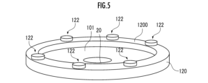
図5に示されているように、基体1の第1主面101から突出し、基体1の第1主面101において、外側環状凸部14の内側で通気経路2の開口部20を取り囲むように延在する内側環状凸部120が形成され、拡大凸部が、当該内側環状凸部120である第1凸要素と、当該内側環状凸部120(第1凸要素)の端面から突出している複数の第2凸要素122と、を有していてもよい。
(Another embodiment of the present invention)
As shown in FIG. 5, it protrudes from the first
当該構成の基板保持部材によれば、通気経路2の開口部20の周辺に配置された内側環状凸部120によって、基体1の第1主面101と基板Wの裏面とにより画定される空間のうち、通気経路2の開口部20の周囲の全方位範囲の流体抵抗の増大が図られる。このため、当該空間の真空吸引時、特に初期段階において、当該空間の流体抵抗が過小であることに由来して真空発現状態に異常が生じたと誤認識される事態がさらに確実に回避される。
According to the substrate holding member having this configuration, the space defined by the first
1‥基体、2‥通気経路、10‥凸部、11‥第1凸部、12‥第2凸部(拡大凸部)、14‥外側環状凸部、20‥通気経路の開口部、101‥第1主面(上面)、102‥第2主面(下面)、111‥第1凸部の第1凸要素、112‥第1凸部の第2凸要素、120‥内側環状凸部、121‥第2凸部の第1凸要素、122‥第2凸部の第2凸要素、1200‥内側環状凸部の端面、1110‥第1凸部の第1凸要素の端面、1120‥第1凸部の第2凸要素の端面、1210‥第2凸部の第1凸要素の端面、1220‥第2凸部の第2凸要素の端面、W‥基板(ウエハ)。
Claims (3)
前記基体の主面から突出する複数の凸部と、
前記基体の内部を通り、前記基体の主面に開口部を有する少なくとも1つの通気経路と、 前記基体の主面から突出し、前記複数の凸部および前記通気経路の開口部を取り囲む環状凸部と、を備える基板保持部材であって、
前記複数の凸部のそれぞれが、前記基体の主面から突出している第1凸要素と、前記第1凸要素の端面から突出している、当該第1凸要素の端面より小面積の端面を有する円柱状の第2凸要素と、を備え、
前記複数の凸部のうち一部の凸部が、その他の凸部と比較して前記第1凸要素の体積が大きい拡大凸部として形成されていることを特徴とする基板保持部材。 a substrate;
a plurality of protrusions protruding from the main surface of the base;
at least one ventilation path passing through the base and having an opening on a main surface of the base; and an annular protrusion projecting from the main surface of the base and surrounding the plurality of protrusions and the opening of the ventilation path. A substrate holding member comprising
Each of the plurality of convex portions has a first convex element protruding from the main surface of the base, and an end face protruding from an end face of the first convex element and having a smaller area than the end face of the first convex element. a cylindrical second convex element;
A substrate holding member, wherein some of the plurality of protrusions are formed as enlarged protrusions in which the volume of the first protrusion element is larger than that of other protrusions.
前記基体の主面から突出する複数の凸部と、
前記基体の内部を通り、前記基体の主面に開口部を有する少なくとも1つの通気経路と、 前記基体の主面から突出し、前記複数の凸部および前記通気経路の開口部を取り囲む環状凸部と、を備える基板保持部材であって、
前記複数の凸部のそれぞれが、前記基体の主面から突出している第1凸要素と、前記第1凸要素の端面から突出している、当該第1凸要素の端面より小面積の端面を有する円柱状の第2凸要素と、を備え、
前記複数の凸部のうち一部の凸部が、その他の凸部と比較して前記第1凸要素の体積が大きい拡大凸部として形成され、
前記基体の主面において、一または複数の前記拡大凸部が、前記通気経路の開口部の周辺に形成され、
前記基体の主面において、前記複数の拡大凸部が、前記通気経路の開口部を取り囲むように形成されていることを特徴とする基板保持部材。 a substrate;
a plurality of protrusions protruding from the main surface of the base;
at least one ventilation path passing through the base and having an opening on a main surface of the base; and an annular protrusion projecting from the main surface of the base and surrounding the plurality of protrusions and the opening of the ventilation path. A substrate holding member comprising
Each of the plurality of convex portions has a first convex element protruding from the main surface of the base, and an end face protruding from an end face of the first convex element and having a smaller area than the end face of the first convex element. a cylindrical second convex element;
Some of the plurality of convex portions are formed as enlarged convex portions having a larger volume of the first convex element than the other convex portions,
one or more of the enlarged protrusions are formed around the opening of the ventilation path on the main surface of the base,
The substrate holding member, wherein the plurality of enlarged projections are formed on the main surface of the base so as to surround the opening of the ventilation path .
前記基体の主面から突出する複数の凸部と、
前記基体の内部を通り、前記基体の主面に開口部を有する少なくとも1つの通気経路と、 前記複数の凸部および前記通気経路の開口部を取り囲むように延在し、前記基体の主面から突出する外側環状凸部と、を備える基板保持部材であって、
前記複数の凸部のそれぞれが、前記基体の主面から突出している第1凸要素と、前記第1凸要素の端面から突出している、当該第1凸要素の端面より小面積の端面を有する第2凸要素と、を備え、
前記複数の凸部のうち一部の凸部が、その他の凸部と比較して前記第1凸要素の体積が大きい拡大凸部として形成され、
前記基体の主面において、前記拡大凸部は、前記基体の主面から突出し、前記外側環状凸部の内側で前記通気経路の開口部を取り囲む内側環状凸部としての前記第1凸要素と前記第1凸要素の端面から突出している複数の円柱状の第2凸要素とを有していることを特徴とする基板保持部材。 a substrate;
a plurality of protrusions protruding from the main surface of the base;
at least one ventilation path passing through the interior of the base body and having an opening on the main surface of the base body; A substrate holding member comprising: a projecting outer annular projection;
Each of the plurality of convex portions has a first convex element protruding from the main surface of the base, and an end face protruding from an end face of the first convex element and having a smaller area than the end face of the first convex element. a second convex element;
Some of the plurality of convex portions are formed as enlarged convex portions having a larger volume of the first convex element than the other convex portions,
In the main surface of the base, the enlarged convex portion protrudes from the main surface of the base and surrounds the opening of the ventilation path inside the outer annular convex portion. A substrate holding member comprising a plurality of cylindrical second convex elements protruding from an end surface of the first convex element .
Priority Applications (1)
| Application Number | Priority Date | Filing Date | Title |
|---|---|---|---|
| JP2019077303A JP7307582B2 (en) | 2019-04-15 | 2019-04-15 | Substrate holding member |
Applications Claiming Priority (1)
| Application Number | Priority Date | Filing Date | Title |
|---|---|---|---|
| JP2019077303A JP7307582B2 (en) | 2019-04-15 | 2019-04-15 | Substrate holding member |
Publications (2)
| Publication Number | Publication Date |
|---|---|
| JP2020177952A JP2020177952A (en) | 2020-10-29 |
| JP7307582B2 true JP7307582B2 (en) | 2023-07-12 |
Family
ID=72935900
Family Applications (1)
| Application Number | Title | Priority Date | Filing Date |
|---|---|---|---|
| JP2019077303A Active JP7307582B2 (en) | 2019-04-15 | 2019-04-15 | Substrate holding member |
Country Status (1)
| Country | Link |
|---|---|
| JP (1) | JP7307582B2 (en) |
Families Citing this family (1)
| Publication number | Priority date | Publication date | Assignee | Title |
|---|---|---|---|---|
| US9358417B2 (en) * | 2011-06-06 | 2016-06-07 | Trudell Medical International | Oscillating positive expiratory pressure device |
Citations (3)
| Publication number | Priority date | Publication date | Assignee | Title |
|---|---|---|---|---|
| JP2014241357A (en) | 2013-06-12 | 2014-12-25 | レーザーテック株式会社 | Substrate holding device, optical device, and substrate holding method |
| JP2017212374A (en) | 2016-05-26 | 2017-11-30 | 日本特殊陶業株式会社 | Substrate holding device and manufacturing method of the same |
| JP2018110148A (en) | 2016-12-28 | 2018-07-12 | 日本特殊陶業株式会社 | Vacuum suction member |
Family Cites Families (1)
| Publication number | Priority date | Publication date | Assignee | Title |
|---|---|---|---|---|
| JPH10242255A (en) * | 1997-02-28 | 1998-09-11 | Kyocera Corp | Vacuum chuck device |
-
2019
- 2019-04-15 JP JP2019077303A patent/JP7307582B2/en active Active
Patent Citations (3)
| Publication number | Priority date | Publication date | Assignee | Title |
|---|---|---|---|---|
| JP2014241357A (en) | 2013-06-12 | 2014-12-25 | レーザーテック株式会社 | Substrate holding device, optical device, and substrate holding method |
| JP2017212374A (en) | 2016-05-26 | 2017-11-30 | 日本特殊陶業株式会社 | Substrate holding device and manufacturing method of the same |
| JP2018110148A (en) | 2016-12-28 | 2018-07-12 | 日本特殊陶業株式会社 | Vacuum suction member |
Also Published As
| Publication number | Publication date |
|---|---|
| JP2020177952A (en) | 2020-10-29 |
Similar Documents
| Publication | Publication Date | Title |
|---|---|---|
| JP6650345B2 (en) | Substrate holding device and method of manufacturing the same | |
| JP6108803B2 (en) | Substrate holding member | |
| WO2017086333A1 (en) | Vacuum chuck | |
| TWI690017B (en) | Substrate holding device | |
| JP7307582B2 (en) | Substrate holding member | |
| JP6838963B2 (en) | Vacuum suction member | |
| US20170084477A1 (en) | Substrate support unit and substrate treatment apparatus comprising the same | |
| JP6496255B2 (en) | Substrate holding device | |
| KR20120069391A (en) | A porous chuck of improved vacuum suction power | |
| JP4611292B2 (en) | Semiconductor manufacturing equipment | |
| JP2022111715A (en) | Substrate holding member | |
| JP2023045060A (en) | Substrate holding member | |
| JP7125326B2 (en) | Substrate holding member | |
| KR101739795B1 (en) | Edge ring and manufacturing method thereof | |
| JP4447497B2 (en) | Board holder | |
| JP6975601B2 (en) | Board holding member and board holding method | |
| JP2021197373A (en) | Substrate holding device | |
| JP2005032977A (en) | Vacuum chuck | |
| JP6581495B2 (en) | Substrate holding device | |
| WO2019163214A1 (en) | Wafer holding stage | |
| JP7178831B2 (en) | Substrate holding member | |
| JP7011459B2 (en) | Vacuum suction member | |
| US8969870B2 (en) | Pattern for ultra-high voltage semiconductor device manufacturing and process monitoring | |
| TW201909332A (en) | Substrate support apparatus | |
| JP6236256B2 (en) | Vacuum adsorption apparatus and vacuum adsorption method |
Legal Events
| Date | Code | Title | Description |
|---|---|---|---|
| A621 | Written request for application examination |
Free format text: JAPANESE INTERMEDIATE CODE: A621 Effective date: 20220131 |
|
| A131 | Notification of reasons for refusal |
Free format text: JAPANESE INTERMEDIATE CODE: A131 Effective date: 20230124 |
|
| A977 | Report on retrieval |
Free format text: JAPANESE INTERMEDIATE CODE: A971007 Effective date: 20230125 |
|
| A521 | Request for written amendment filed |
Free format text: JAPANESE INTERMEDIATE CODE: A523 Effective date: 20230317 |
|
| TRDD | Decision of grant or rejection written | ||
| A01 | Written decision to grant a patent or to grant a registration (utility model) |
Free format text: JAPANESE INTERMEDIATE CODE: A01 Effective date: 20230620 |
|
| A61 | First payment of annual fees (during grant procedure) |
Free format text: JAPANESE INTERMEDIATE CODE: A61 Effective date: 20230630 |
|
| R150 | Certificate of patent or registration of utility model |
Ref document number: 7307582 Country of ref document: JP Free format text: JAPANESE INTERMEDIATE CODE: R150 |