JP7305305B2 - game machine - Google Patents
game machine Download PDFInfo
- Publication number
- JP7305305B2 JP7305305B2 JP2018057408A JP2018057408A JP7305305B2 JP 7305305 B2 JP7305305 B2 JP 7305305B2 JP 2018057408 A JP2018057408 A JP 2018057408A JP 2018057408 A JP2018057408 A JP 2018057408A JP 7305305 B2 JP7305305 B2 JP 7305305B2
- Authority
- JP
- Japan
- Prior art keywords
- game
- display
- effect
- state
- special
- Prior art date
- Legal status (The legal status is an assumption and is not a legal conclusion. Google has not performed a legal analysis and makes no representation as to the accuracy of the status listed.)
- Active
Links
Images


Classifications
-
- Y—GENERAL TAGGING OF NEW TECHNOLOGICAL DEVELOPMENTS; GENERAL TAGGING OF CROSS-SECTIONAL TECHNOLOGIES SPANNING OVER SEVERAL SECTIONS OF THE IPC; TECHNICAL SUBJECTS COVERED BY FORMER USPC CROSS-REFERENCE ART COLLECTIONS [XRACs] AND DIGESTS
- Y02—TECHNOLOGIES OR APPLICATIONS FOR MITIGATION OR ADAPTATION AGAINST CLIMATE CHANGE
- Y02E—REDUCTION OF GREENHOUSE GAS [GHG] EMISSIONS, RELATED TO ENERGY GENERATION, TRANSMISSION OR DISTRIBUTION
- Y02E60/00—Enabling technologies; Technologies with a potential or indirect contribution to GHG emissions mitigation
- Y02E60/10—Energy storage using batteries
Landscapes
- Display Devices Of Pinball Game Machines (AREA)
Description
本発明は、遊技媒体を用いた遊技が可能であり、遊技者にとって有利な有利状態に制御可能な遊技機に関する。 TECHNICAL FIELD The present invention relates to a gaming machine that can play games using game media and can be controlled to an advantageous state for a player.
従来、設定値変更機能付きパチンコ遊技機がある(例えば、特許文献1参照)。また、付与される遊技価値に関する所定情報を表示可能な情報表示手段を備えるパチンコ遊技機がある(例えば、特許文献2参照)。
Conventionally , there is a pachinko game machine with a setting value changing function (see
しかしながら、特許文献1に記載されているパチンコ遊技機に特許文献2に記載されている情報表示手段を適用する場合、設定値を確認するための表示部と情報表示手段とを個別に設けると遊技機のコストを低減できないという問題がある。
However, when applying the information display means described in
本発明は、このような問題点に着目してなされたもので、コストを低減できる遊技機を提供することを目的とする。 SUMMARY OF THE INVENTION It is an object of the present invention to provide a gaming machine capable of reducing costs .
前記課題を解決するために、手段Aに記載の遊技機は、
可変表示を行い、遊技媒体を用いた遊技が可能であり、遊技者にとって有利な有利状態に制御可能な遊技機であって、
前記有利状態に制御される確率に関する設定値を設定可能な設定手段と、
前記設定手段によって設定された設定値にもとづいて前記有利状態に関する制御を実行可能な遊技制御手段と、
遊技媒体が流下する遊技領域内に設けられた所定領域に進入することにもとづいて遊技価値を付与する遊技価値付与手段と、
複数の表示部を有し、前記遊技価値付与手段によって付与される遊技価値に関する所定情報を表示可能な情報表示手段と、
前記遊技制御手段が遊技の進行を制御するための遊技情報を少なくとも記憶可能な遊技情報記憶手段と、
電源投入時の遊技機の状態を検出可能な検出手段と、
前記検出手段により検出された電源投入時の遊技機の状態を特定可能な状態情報を記憶可能な状態情報記憶手段と、
を備え、
前記遊技制御手段は、可変表示に関する情報を保留記憶として記憶可能な保留記憶手段を含み、
前記遊技制御手段により制御され、少なくとも可変表示を行うことが可能な可変表示部を含む情報表示部を有し、
前記情報表示手段は、
遊技機の前面側から遊技者が視認不能となるように遊技機の背面側に設けられており、
所定条件が成立したときに移行する設定確認状態において前記設定手段により設定されている設定値を特定可能な設定値情報を表示可能であって、
前記所定情報が表示される場合と前記設定値情報が表示される場合とで、使用される前記表示部の数が異なり、
前記検出手段により検出される電源投入時の遊技機の状態が特殊状態であることを含む特定条件が成立したときに前記設定手段による設定値の設定を行うことが可能な設定許可状態に移行し、
前記設定許可状態であるときに、該設定許可状態であることを認識可能な特殊表示を前記可変表示部において行うことが可能であり、
前記特殊表示は、遊技中において前記可変表示部に表示される表示とは異なる表示であり、
前記可変表示部に前記特殊表示が表示されているときに、該可変表示部に可変表示に係わる表示は表示されず、
前記設定許可状態に移行する場合は、前記保留記憶手段に記憶されている保留記憶は消去されるが、前記設定確認状態に移行する場合は、前記保留記憶手段に記憶されている保留記憶は消去されず、
前記遊技制御手段は、
前記検出手段により検出される電源投入時の遊技機の状態が特殊状態であることを含む特殊条件が成立しているときに、前記遊技情報の消去を伴う前記遊技情報記憶手段の初期化を行うための初期化処理を実行可能であり、
前記特定条件が成立しているときに、前記特殊条件が成立した場合に実行する前記初期化処理と共通の初期化処理を、前記状態情報記憶手段に記憶されている状態情報にもとづいて実行可能であり、
前記特殊条件と前記特定条件のいずれが成立した場合であっても、前記状態情報を消去せず、
タイマ割込み処理が許可されるまでの間に実行される遊技制御メイン処理において、前記特定条件は成立したが所定のエラーが発生した場合に、前記可変表示部において、該所定のエラーが発生したことを特定可能な表示が行われる、
ことを特徴としている。
さらに、他の態様に係る手段1に記載の遊技機は、
遊技者にとって有利な有利状態(例えば、大当り遊技状態)に制御可能な遊技機(例えば、パチンコ遊技機1)であって、
前記有利状態に制御されることを示唆する示唆演出(例えば、リーチ演出)を実行可能な示唆演出実行手段(例えば演出制御用CPU120)と、
前記示唆演出に対応したタイトルを報知可能なタイトル報知手段(例えば演出制御用CPU120)と、を備え、
前記タイトル報知手段は、前記示唆演出の開始から所定期間経過したときに当該示唆演出に対応したタイトルを報知可能であり(例えば図8-2(D)や図8-2(F)に示すようにリーチ演出のタイトルを表示する部分)、
前記示唆演出実行手段は、前記示唆演出として少なくとも第1示唆演出(例えばスーパーリーチAやスーパーリーチBのリーチ演出)と第2示唆演出(例えばスーパーリーチDやスーパーリーチEのリーチ演出)とを実行可能であり、
前記タイトル報知手段は、前記第2示唆演出では、当該第2示唆演出の開始時から当該第2示唆演出に対応したタイトルを報知する(例えば、8-2(H)に示すように、スーパーリーチDのリーチ演出の開始から該スーパーリーチDのリーチ演出に対応したタイトル31AK007を表示する部分)
ことを特徴としている。
この特徴によれば、示唆演出に応じたタイトルの報知を実行できるので演出効果が向上する。
In order to solve the above problems, the gaming machine described in means A
A game machine that performs variable display, enables a game using game media, and is controllable to an advantageous state for a player,
setting means capable of setting a set value related to the probability of being controlled to the advantageous state;
game control means capable of executing control relating to the advantageous state based on the setting value set by the setting means;
a game value imparting means for imparting a game value based on entry into a predetermined area provided within a game area in which a game medium flows;
information display means having a plurality of display units and capable of displaying predetermined information regarding the game value imparted by the game value imparting means;
a game information storage means capable of storing at least game information for the game control means to control the progress of the game;
a detecting means capable of detecting the state of the gaming machine when the power is turned on;
a state information storage means capable of storing state information capable of specifying the state of the gaming machine detected by the detection means when the power is turned on;
with
The game control means includes a pending storage means capable of storing information on variable display as a pending storage,
Having an information display unit controlled by the game control means and including a variable display unit capable of performing at least variable display,
The information display means is
It is provided on the back side of the gaming machine so that the player cannot be seen from the front side of the gaming machine,
setting value information capable of specifying the setting value set by the setting means can be displayed in a setting confirmation state to which a transition is made when a predetermined condition is satisfied,
The number of the display units used differs between when the predetermined information is displayed and when the set value information is displayed,
When a specific condition including that the state of the game machine at the time of power-on detected by the detection means is a special state is established, the setting means shifts to a setting permission state in which setting values can be set by the setting means. ,
When the setting permission state is set, a special display that enables recognition of the setting permission state can be performed on the variable display unit,
The special display is a display different from the display displayed on the variable display portion during the game,
When the special display is displayed on the variable display section, the display related to the variable display is not displayed on the variable display section,
When shifting to the setting permission state, the pending storage stored in the pending storage means is erased, but when shifting to the setting confirmation state, the pending storage stored in the pending storage means is erased. not,
The game control means is
When a special condition including that the state of the gaming machine at the time of power-on detected by the detecting means is a special state is established, the game information storage means is initialized along with erasure of the game information. It is possible to execute initialization processing for
When the specific condition is satisfied, an initialization process common to the initialization process executed when the special condition is satisfied can be executed based on the state information stored in the state information storage means. and
not erasing the state information regardless of whether the special condition or the specific condition is satisfied;
In the game control main processing executed until the timer interrupt processing is permitted, when the specific condition is established but a predetermined error occurs, the predetermined error occurs in the variable display section. identifiable display is made,
It is characterized by
Furthermore, the gaming machine according to
A game machine (for example, a pachinko game machine 1) that can be controlled to an advantageous state (for example, a jackpot game state) that is advantageous to a player,
Suggestive effect execution means (for example, effect control CPU 120) capable of executing a suggestive effect (for example, ready-to-win effect) that suggests being controlled to the advantageous state;
A title notification means (for example, the effect control CPU 120) that can notify the title corresponding to the suggested effect,
The title notification means can notify the title corresponding to the suggestive effect when a predetermined period of time has passed since the start of the suggestive effect (for example, as shown in FIG. 8-2(D) or FIG. 8-2(F)). The part that displays the title of the reach effect in),
The suggestive effect executing means executes at least a first suggestive effect (for example, reach effects of super reach A and super reach B) and a second suggestive effect (for example, reach effects of super reach D and super reach E) as the suggestive effects. is possible and
The title notifying means, in the second suggestive effect, notifies the title corresponding to the second suggestive effect from the start of the second suggestive effect (for example, as shown in 8-2 (H), Super Reach The part that displays the title 31AK007 corresponding to the reach effect of the super reach D from the start of the reach effect of D)
It is characterized by
According to this feature, it is possible to execute the notification of the title according to the suggestive effect, thereby improving the effect of the effect.
尚、本発明は、本発明の請求項に記載された発明特定事項のみを有するものであって良いし、本発明の請求項に記載された発明特定事項とともに該発明特定事項以外の構成を有するものであっても良い。 The present invention may include only the matters specifying the invention described in the claims of the present invention, or may include the matters specifying the invention described in the claims of the present invention as well as the matters specifying the invention other than the matters specifying the invention. It can be anything.
(基本説明)
まず、パチンコ遊技機1の基本的な構成及び制御(一般的なパチンコ遊技機の構成及び制御でもある。)について説明する。
(Basic explanation)
First, the basic configuration and control of the pachinko game machine 1 (also the configuration and control of a general pachinko game machine) will be described.
(パチンコ遊技機1の構成等)
図1は、パチンコ遊技機1の正面図であり、主要部材の配置レイアウトを示す。パチンコ遊技機(遊技機)1は、大別して、遊技盤面を構成する遊技盤(ゲージ盤)2と、遊技盤2を支持固定する遊技機用枠(台枠)3とから構成されている。遊技盤2には、遊技領域が形成され、この遊技領域には、遊技媒体としての遊技球が、所定の打球発射装置から発射されて打ち込まれる。
(Structure of
FIG. 1 is a front view of the
遊技盤2の所定位置(図1に示す例では、遊技領域の右側方)には、複数種類の特別識別情報としての特別図柄(特図ともいう)の可変表示(特図ゲームともいう)を行う第1特別図柄表示装置4A及び第2特別図柄表示装置4Bが設けられている。これらは、それぞれ、7セグメントのLEDなどからなる。特別図柄は、「0」~「9」を示す数字や「-」などの点灯パターンなどにより表される。特別図柄には、LEDを全て消灯したパターンが含まれてもよい。
At a predetermined position of the game board 2 (in the example shown in FIG. 1, on the right side of the game area), a variable display (also called a special game) of special symbols (also called special symbols) as a plurality of types of special identification information is displayed. A first special
なお、特別図柄の「可変表示」とは、例えば、複数種類の特別図柄を変動可能に表示することである(後述の他の図柄についても同じ)。変動としては、複数の図柄の更新表示、複数の図柄のスクロール表示、1以上の図柄の変形、1以上の図柄の拡大/縮小などがある。特別図柄や後述の普通図柄の変動では、複数種類の特別図柄又は普通図柄が更新表示される。後述の飾り図柄の変動では、複数種類の飾り図柄がスクロール表示又は更新表示されたり、1以上の飾り図柄が変形や拡大/縮小されたりする。なお、変動には、ある図柄を点滅表示する態様も含まれる。可変表示の最後には、表示結果として所定の特別図柄が停止表示(導出又は導出表示などともいう)される(後述の他の図柄の可変表示についても同じ)。なお、可変表示を変動表示、変動と表現する場合がある。 In addition, the "variable display" of the special symbols means, for example, that a plurality of types of special symbols are displayed in a variable manner (the same applies to other symbols described later). Variations include updating display of a plurality of patterns, scrolling display of a plurality of patterns, deformation of one or more patterns, enlargement/reduction of one or more patterns, and the like. In the variation of special symbols and normal symbols, which will be described later, a plurality of types of special symbols or normal symbols are updated and displayed. In the variation of decorative patterns, which will be described later, a plurality of types of decorative patterns are scrolled or updated, and one or more decorative patterns are deformed or enlarged/reduced. Note that the variation also includes a mode in which a certain symbol is displayed blinking. At the end of the variable display, a predetermined special symbol is stopped and displayed (also referred to as derivation or derivation display) as a display result (the same applies to variable display of other symbols to be described later). Variable display may be expressed as variable display or variation.
なお、第1特別図柄表示装置4Aにおいて可変表示される特別図柄を「第1特図」ともいい、第2特別図柄表示装置4Bにおいて可変表示される特別図柄を「第2特図」ともいう。また、第1特図を用いた特図ゲームを「第1特図ゲーム」といい、第2特図を用いた特図ゲームを「第2特図ゲーム」ともいう。なお、特別図柄の可変表示を行う特別図柄表示装置は1種類であってもよい。
The special symbols variably displayed on the first special
遊技盤2における遊技領域の中央付近には画像表示装置5が設けられている。画像表示装置5は、例えばLCD(液晶表示装置)や有機EL(Electro Luminescence)等から構成され、各種の演出画像を表示する。画像表示装置5は、プロジェクタ及びスクリーンから構成されていてもよい。画像表示装置5には、各種の演出画像が表示される。
An
例えば、画像表示装置5の画面上では、第1特図ゲームや第2特図ゲームと同期して、特別図柄とは異なる複数種類の装飾識別情報としての飾り図柄(数字などを示す図柄など)の可変表示が行われる。ここでは、第1特図ゲーム又は第2特図ゲームに同期して、「左」、「中」、「右」の各飾り図柄表示エリア5L、5C、5Rにおいて飾り図柄が可変表示(例えば上下方向のスクロール表示や更新表示)される。なお、同期して実行される特図ゲーム及び飾り図柄の可変表示を総称して単に可変表示ともいう。
For example, on the screen of the
画像表示装置5の画面上には、実行が保留されている可変表示に対応する保留表示や、実行中の可変表示に対応するアクティブ表示を表示するための表示エリアが設けられていてもよい。保留表示及びアクティブ表示を総称して可変表示に対応する可変表示対応表示ともいう。
A display area may be provided on the screen of the
保留されている可変表示の数は保留記憶数ともいう。第1特図ゲームに対応する保留記憶数を第1保留記憶数、第2特図ゲームに対応する保留記憶数を第2保留記憶数ともいう。また、第1保留記憶数と第2保留記憶数との合計を合計保留記憶数ともいう。 The number of variable representations that are reserved is also referred to as the number of reserved memories. The reserved memory number corresponding to the first special game is also referred to as the first reserved memory number, and the reserved memory number corresponding to the second special game is also referred to as the second reserved memory number. The sum of the first reserved memory count and the second reserved memory count is also referred to as the total reserved memory count.
また、遊技盤2の所定位置には、複数のLEDを含んで構成された第1保留表示器25Aと第2保留表示器25Bとが設けられ、第1保留表示器25Aは、LEDの点灯個数によって、第1保留記憶数を表示し、第2保留表示器25Bは、LEDの点灯個数によって、第2保留記憶数を表示する。
At a predetermined position of the
画像表示装置5の下方には、入賞球装置6Aと、可変入賞球装置6Bとが設けられている。
Below the
入賞球装置6Aは、例えば所定の玉受部材によって常に遊技球が進入可能な一定の開放状態に保たれる第1始動入賞口を形成する。第1始動入賞口に遊技球が進入したときには、所定個(例えば3個)の賞球が払い出されるとともに、第1特図ゲームが開始され得る。
Winning
可変入賞球装置6B(普通電動役物)は、ソレノイド81(図2参照)によって閉鎖状態と開放状態とに変化する第2始動入賞口を形成する。可変入賞球装置6Bは、例えば、一対の可動翼片を有する電動チューリップ型役物を備え、ソレノイド81がオフ状態であるときに可動翼片が垂直位置となることにより、当該可動翼片の先端が入賞球装置6Aに近接し、第2始動入賞口に遊技球が進入しない閉鎖状態になる(第2始動入賞口が閉鎖状態になるともいう。)。その一方で、可変入賞球装置6Bは、ソレノイド81がオン状態であるときに可動翼片が傾動位置となることにより、第2始動入賞口に遊技球が進入できる開放状態になる(第2始動入賞口が開放状態になるともいう。)。第2始動入賞口に遊技球が進入したときには、所定個(例えば3個)の賞球が払い出されるとともに、第2特図ゲームが開始され得る。なお、可変入賞球装置6Bは、閉鎖状態と開放状態とに変化するものであればよく、電動チューリップ型役物を備えるものに限定されない。
The variable winning
遊技盤2の所定位置(図1に示す例では、遊技領域の左右下方4箇所)には、所定の玉受部材によって常に一定の開放状態に保たれる一般入賞口10が設けられる。この場合には、一般入賞口10のいずれかに進入したときには、所定個数(例えば10個)の遊技球が賞球として払い出される。
At predetermined positions of the game board 2 (in the example shown in FIG. 1, four positions on the left and right sides of the game area), there are provided general winning holes 10 which are always kept open by predetermined ball receiving members. In this case, when the player enters one of the general winning
入賞球装置6Aと可変入賞球装置6Bの下方には、大入賞口を有する特別可変入賞球装置7が設けられている。特別可変入賞球装置7は、ソレノイド82(図2参照)によって開閉駆動される大入賞口扉を備え、その大入賞口扉によって開放状態と閉鎖状態とに変化する特定領域としての大入賞口を形成する。
Below the winning
一例として、特別可変入賞球装置7では、大入賞口扉用(特別電動役物用)のソレノイド82がオフ状態であるときに大入賞口扉が大入賞口を閉鎖状態として、遊技球が大入賞口に進入(通過)できなくなる。その一方で、特別可変入賞球装置7では、大入賞口扉用のソレノイド82がオン状態であるときに大入賞口扉が大入賞口を開放状態として、遊技球が大入賞口に進入しやすくなる。
As an example, in the special variable winning
大入賞口に遊技球が進入したときには、所定個数(例えば14個)の遊技球が賞球として払い出される。大入賞口に遊技球が進入したときには、例えば第1始動入賞口や第2始動入賞口及び一般入賞口10に遊技球が進入したときよりも多くの賞球が払い出される。
When game balls enter the big winning hole, a predetermined number (for example, 14) of game balls are paid out as prize balls. When the game balls enter the big winning hole, more prize balls are paid out than when the game balls enter the first starting winning hole, the second starting winning hole and the general winning
一般入賞口10を含む各入賞口に遊技球が進入することを「入賞」ともいう。特に、始動口(第1始動入賞口、第2始動入賞口始動口)への入賞を始動入賞ともいう。
Entering a game ball into each winning hole including the general winning
遊技盤2の所定位置(図1に示す例では、遊技領域の左側方)には、普通図柄表示器20が設けられている。一例として、普通図柄表示器20は、7セグメントのLEDなどからなり、特別図柄とは異なる複数種類の普通識別情報としての普通図柄の可変表示を行う。普通図柄は、「0」~「9」を示す数字や「-」などの点灯パターンなどにより表される。普通図柄には、LEDを全て消灯したパターンが含まれてもよい。このような普通図柄の可変表示は、普図ゲームともいう。
A
画像表示装置5の左方には、遊技球が通過可能な通過ゲート41が設けられている。遊技球が通過ゲート41を通過したことに基づき、普図ゲームが実行される。
A
普通図柄表示器20の上方には、普図保留表示器25Cが設けられている。普図保留表示器25Cは、例えば4個のLEDを含んで構成され、実行が保留されている普図ゲームの数である普図保留記憶数をLEDの点灯個数により表示する。
Above the
遊技盤2の表面には、上記の構成以外にも、遊技球の流下方向や速度を変化させる風車及び多数の障害釘が設けられている。遊技領域の最下方には、いずれの入賞口にも進入しなかった遊技球が取り込まれるアウト口が設けられている。
The surface of the
遊技機用枠3の左右上部位置には、効果音等を再生出力するためのスピーカ8L、8Rが設けられており、さらに遊技領域周辺部には、遊技効果用の遊技効果ランプ9が設けられている。遊技効果ランプ9は、LEDを含んで構成されている。
遊技盤2の所定位置(図1では図示略)には、演出に応じて動作する可動体32が設けられている。
At a predetermined position (not shown in FIG. 1) of the
遊技機用枠3の右下部位置には、遊技球を打球発射装置により遊技領域に向けて発射するために遊技者等によって操作される打球操作ハンドル(操作ノブ)30が設けられている。
A ball hitting operation handle (operation knob) 30 operated by a player or the like to shoot a game ball toward the game area by the ball shooting device is provided at the lower right portion of the
遊技領域の下方における遊技機用枠3の所定位置には、賞球として払い出された遊技球や所定の球貸機により貸し出された遊技球を、打球発射装置へと供給可能に保持(貯留)する打球供給皿(上皿)が設けられている。上皿の下方には、上皿満タン時に賞球が払い出される打球供給皿(下皿)が設けられている。
At a predetermined position of the
遊技領域の下方における遊技機用枠3の所定位置には、遊技者が把持して傾倒操作が可能なスティックコントローラ31Aが取り付けられている。スティックコントローラ31Aには、遊技者が押下操作可能なトリガボタンが設けられている。スティックコントローラ31Aに対する操作は、コントローラセンサユニット35A(図2参照)により検出される。
A
遊技領域の下方における遊技機用枠3の所定位置には、遊技者が押下操作などにより所定の指示操作を可能なプッシュボタン31Bが設けられている。プッシュボタン31Bに対する操作は、プッシュセンサ35B(図2参照)により検出される。
At a predetermined position of the
パチンコ遊技機1では、遊技者の動作(操作等)を検出する検出手段として、スティックコントローラ31Aやプッシュボタン31Bが設けられるが、これら以外の検出手段が設けられていてもよい。
The
(遊技の進行の概略)
パチンコ遊技機1が備える打球操作ハンドル30への遊技者による回転操作により、遊技球が遊技領域に向けて発射される。遊技球が通過ゲート41を通過すると、普通図柄表示器20による普図ゲームが開始される。なお、前回の普図ゲームの実行中の期間等に遊技球が通過ゲート41を通過した場合(遊技球が通過ゲート41を通過したが当該通過に基づく普図ゲームを直ちに実行できない場合)には、当該通過に基づく普図ゲームは所定の上限数(例えば4)まで保留される。
(Overview of Game Progress)
A game ball is shot toward a game area by a player's rotation operation of a ball hitting operation handle 30 provided in the
この普図ゲームでは、特定の普通図柄(普図当り図柄)が停止表示されれば、普通図柄の表示結果が「普図当り」となる。その一方、確定普通図柄として、普図当り図柄以外の普通図柄(普図ハズレ図柄)が停止表示されれば、普通図柄の表示結果が「普図ハズレ」となる。「普図当り」となると、可変入賞球装置6Bを所定期間開放状態とする開放制御が行われる(第2始動入賞口が開放状態になる)。
In this general pattern game, if a specific normal pattern (normal pattern winning pattern) is stopped and displayed, the display result of the normal pattern becomes "normal pattern winning". On the other hand, if a normal pattern (normal pattern losing pattern) other than the normal pattern per pattern is stop-displayed as the determined normal pattern, the display result of the normal pattern becomes "normal pattern losing". When it comes to "normal game", the variable winning
入賞球装置6Aに形成された第1始動入賞口に遊技球が進入すると、第1特別図柄表示装置4Aによる第1特図ゲームが開始される。
When a game ball enters the first starting winning hole formed in the winning
可変入賞球装置6Bに形成された第2始動入賞口に遊技球が進入すると、第2特別図柄表示装置4Bによる第2特図ゲームが開始される。
When the game ball enters the second starting winning hole formed in the variable winning
なお、特図ゲームの実行中の期間や、後述する大当り遊技状態や小当り遊技状態に制御されている期間に、遊技球が始動入賞口へ進入(入賞)した場合(始動入賞が発生したが当該始動入賞に基づく特図ゲームを直ちに実行できない場合)には、当該進入に基づく特図ゲームは所定の上限数(例えば4)までその実行が保留される。 In addition, when the game ball enters (wins) the start winning opening during the period during which the special game is running, or during the period when it is controlled to the big win game state or the small win game state described later (although the start win has occurred If the special game based on the starting prize cannot be executed immediately), the execution of the special game based on the entry is suspended up to a predetermined upper limit number (for example, 4).
特図ゲームにおいて、確定特別図柄として特定の特別図柄(大当り図柄、例えば「7」、後述の大当り種別に応じて実際の図柄は異なる。)が停止表示されれば、「大当り」となり、大当り図柄とは異なる所定の特別図柄(小当り図柄、例えば「2」)が停止表示されれば、「小当り」となる。また、大当り図柄や小当り図柄とは異なる特別図柄(ハズレ図柄、例えば「-」)が停止表示されれば「ハズレ」となる。 In the special symbol game, when a specific special symbol (a big hit symbol, for example, "7", the actual symbol varies depending on the type of the big hit to be described later) is stopped and displayed as a fixed special symbol, it becomes a "big hit" and a big winning symbol. If a predetermined special symbol (a small winning symbol, for example, "2") different from the symbol is stop-displayed, it becomes a "small winning". Also, if a special symbol (losing symbol, for example, "-") different from the big-hit symbol or the small-hit symbol is stop-displayed, it becomes "losing".
特図ゲームでの表示結果が「大当り」になった後には、遊技者にとって有利な有利状態として大当り遊技状態に制御される。特図ゲームでの表示結果が「小当り」になった後には、小当り遊技状態に制御される。 After the display result in the special game becomes "big win", the game is controlled to a big win game state as an advantageous state for the player. After the display result in the special game becomes "small hit", it is controlled to the small win game state.
大当り遊技状態においては、遊技者は、遊技球を大入賞口に進入させることで、賞球を得ることができる。従って、大当り遊技状態は、遊技者にとって有利な状態である。大当り遊技状態におけるラウンド数が多い程、また、開放上限期間が長い程遊技者にとって有利となる。 In the jackpot game state, the player can get a prize ball by entering the game ball into the big winning hole. Therefore, the jackpot gaming state is an advantageous state for the player. The larger the number of rounds in the jackpot game state and the longer the upper limit period of opening, the more advantageous the player is.
なお、「大当り」には、大当り種別が設定されている。例えば、大入賞口の開放態様(ラウンド数や開放上限期間)や、大当り遊技状態後の遊技状態(後述の、通常状態、時短状態、確変状態など)を複数種類用意し、これらに応じて大当り種別が設定されている。大当り種別として、多くの賞球を得ることができる大当り種別や、賞球の少ない又はほとんど賞球を得ることができない大当り種別が設けられていてもよい。 In addition, a jackpot type is set in the "jackpot". For example, a plurality of types of opening modes (number of rounds and upper limit period of opening) of the big winning opening and game states after the jackpot game state (normal state, time saving state, variable probability state, etc. described later) are prepared, and the jackpot is obtained according to these. type is set. As the jackpot type, there may be provided a jackpot type in which a large number of prize balls can be obtained, and a jackpot type in which a small number of prize balls or almost no prize balls can be obtained.
小当り遊技状態では、特別可変入賞球装置7により形成される大入賞口が所定の開放態様で開放状態となる。例えば、小当り遊技状態では、一部の大当り種別のときの大当り遊技状態と同様の開放態様(大入賞口の開放回数が上記ラウンド数と同じであり、かつ、大入賞口の閉鎖タイミングも同じ等)で大入賞口が開放状態となる。なお、大当り種別と同様に、「小当り」にも小当り種別を設けてもよい。
In the small winning game state, the big winning opening formed by the special variable winning
大当り遊技状態が終了した後は、上記大当り種別に応じて、時短状態や確変状態に制御されることがある。 After the jackpot game state is finished, depending on the jackpot type, it may be controlled to a time-saving state or a variable probability state.
時短状態では、平均的な特図変動時間(特図を変動させる期間)を通常状態よりも短縮させる制御(時短制御)が実行される。時短状態では、平均的な普図変動時間(普図を変動させる期間)を通常状態よりも短縮させたり、普図ゲームで「普図当り」となる確率を通常状態よりも向上させる等により、第2始動入賞口に遊技球が進入しやすくなる制御(高開放制御、高ベース制御)も実行される。時短状態は、特別図柄(特に第2特別図柄)の変動効率が向上する状態であるので、遊技者にとって有利な状態である。 In the time saving state, the control (time saving control) that shortens the average special figure fluctuation time (period of varying the special figure) than the normal state is executed. In the time-saving state, by shortening the average normal figure fluctuation time (the period during which the normal figure is changed) than in the normal state, and by improving the probability of becoming a "normal figure hit" in the general figure game than in the normal state, etc. Control (high opening control, high base control) that makes it easier for game balls to enter the second start winning opening is also executed. Since the time-saving state is a state in which the variation efficiency of the special symbols (especially the second special symbols) is improved, it is an advantageous state for the player.
確変状態(確率変動状態)では、時短制御に加えて、表示結果が「大当り」となる確率が通常状態よりも高くなる確変制御が実行される。確変状態は、特別図柄の変動効率が向上することに加えて「大当り」となりやすい状態であるので、遊技者にとってさらに有利な状態である。 In the variable probability state (probability variable state), in addition to time saving control, variable probability control is executed in which the probability that the display result will be a "jackpot" is higher than in the normal state. The variable probability state is a state in which a "big hit" is likely to occur in addition to the improvement of the variation efficiency of the special symbols, so it is a further advantageous state for the player.
時短状態や確変状態は、所定回数の特図ゲームが実行されたことと、次回の大当り遊技状態が開始されたこと等といった、いずれか1つの終了条件が先に成立するまで継続する。所定回数の特図ゲームが実行されたことが終了条件となるものを、回数切り(回数切り時短、回数切り確変等)ともいう。 The time saving state and the variable probability state are continued until one of the end conditions such as execution of the special game for a predetermined number of times and start of the next big win game state is established first. The end condition that the special figure game of a predetermined number of times has been executed is also referred to as a number cut (number cut time reduction, number cut probability variable, etc.).
通常状態とは、遊技者にとって有利な大当り遊技状態等の有利状態、時短状態、確変状態等の特別状態以外の遊技状態のことであり、普図ゲームにおける表示結果が「普図当り」となる確率及び特図ゲームにおける表示結果が「大当り」となる確率などのパチンコ遊技機1が、パチンコ遊技機1の初期設定状態(例えばシステムリセットが行われた場合のように、電源投入後に所定の復帰処理を実行しなかったとき)と同一に制御される状態である。
The normal state means a game state other than a special state such as an advantageous state such as a jackpot game state that is advantageous to the player, a time saving state, a variable probability state, etc., and the display result in the normal game is "normal game". The
確変制御が実行されている状態を高確状態、確変制御が実行されていない状態を低確状態ともいう。時短制御が実行されている状態を高ベース状態、時短制御が実行されていない状態を低ベース状態ともいう。これらを組み合わせて、時短状態は低確高ベース状態、確変状態は高確高ベース状態、通常状態は低確低ベース状態などともいわれる。高確状態かつ低ベース状態は高確低ベース状態ともいう。 The state in which probability variable control is executed is also called a high probability state, and the state in which probability variable control is not executed is also called a low probability state. A state in which time-saving control is performed is also referred to as a high-based state, and a state in which time-saving control is not performed is also referred to as a low-based state. Combining these, the short-time state is also called a low-probability-high base state, the probability-variable state is a high-probability-high base state, and the normal state is a low-probability-low base state. The high probability state and the low base state are also referred to as the high probability low base state.
小当り遊技状態が終了した後は、遊技状態の変更が行われず、特図ゲームの表示結果が「小当り」となる以前の遊技状態に継続して制御される(但し、「小当り」発生時の特図ゲームが、上記回数切りにおける上記所定回数目の特図ゲームである場合には、当然遊技状態が変更される)。なお、特図ゲームの表示結果として「小当り」がなくてもよい。 After the small win game state is over, the game state is not changed, and the game state before the display result of the special figure game becomes "small win" is continuously controlled (however, "small win" occurs If the special game at the time is the special game for the predetermined number of times in the above cut, the game state is naturally changed). In addition, there may not be a "small hit" as a display result of a special figure game.
なお、遊技状態は、大当り遊技状態中に遊技球が特定領域(例えば、大入賞口内の特定領域)を通過したことに基づいて、変化してもよい。例えば、遊技球が特定領域を通過したとき、その大当り遊技状態後に確変状態に制御してもよい。 In addition, the game state may change based on the fact that the game ball has passed through a specific area (for example, a specific area within the big winning opening) during the jackpot game state. For example, when the game ball passes through the specific area, it may be controlled to the probability variable state after the big hit game state.
(演出の進行など)
パチンコ遊技機1では、遊技の進行に応じて種々の演出(遊技の進行状況を報知したり、遊技を盛り上げたりする演出)が実行される。当該演出について以下説明する。なお、当該演出は、画像表示装置5に各種の演出画像を表示することによって行われるが、当該表示に加えて又は代えて、スピーカ8L、8Rからの音声出力、及び/又は、遊技効果ランプ9の点等/消灯、可動体32の動作等により行われてもよい。
(Progress of production, etc.)
In the
遊技の進行に応じて実行される演出として、画像表示装置5に設けられた「左」、「中」、「右」の飾り図柄表示エリア5L、5C、5Rでは、第1特図ゲーム又は第2特図ゲームが開始されることに対応して、飾り図柄の可変表示が開始される。第1特図ゲームや第2特図ゲームにおいて表示結果(確定特別図柄ともいう。)が停止表示されるタイミングでは、飾り図柄の可変表示の表示結果となる確定飾り図柄(3つの飾り図柄の組合せ)も停止表示(導出)される。 As an effect executed according to the progress of the game, the first special game or the second In response to the start of the 2 special figure game, the variable display of the decoration pattern is started. At the timing when the display result (also called fixed special pattern) is stopped and displayed in the first special game or the second special game, a fixed decorative pattern (combination of three decorative patterns) which is the display result of variable display of decorative patterns ) is also stopped (derived).
飾り図柄の可変表示が開始されてから終了するまでの期間では、飾り図柄の可変表示の態様が所定のリーチ態様となる(リーチが成立する)ことがある。ここで、リーチ態様とは、画像表示装置5の画面上にて停止表示された飾り図柄が後述の大当り組合せの一部を構成しているときに未だ停止表示されていない飾り図柄については可変表示が継続している態様などのことである。
During the period from the start of the variable display of the decorative design to the end of the variable display, the variable display of the decorative design may be in a predetermined ready-to-win state (ready-to-win state is established). Here, the ready-to-win mode means that when the decorative symbols stopped and displayed on the screen of the
また、飾り図柄の可変表示中に上記リーチ態様となったことに対応してリーチ演出が実行される。パチンコ遊技機1では、演出態様に応じて表示結果(特図ゲームの表示結果や飾り図柄の可変表示の表示結果)が「大当り」となる割合(大当り信頼度、大当り期待度とも呼ばれる。)が異なる複数種類のリーチ演出が実行される。リーチ演出には、例えば、ノーマルリーチと、ノーマルリーチよりも大当り信頼度の高いスーパーリーチと、がある。
Further, a ready-to-win effect is executed in response to the above-described ready-to-win mode during the variable display of decorative symbols. In the
特図ゲームの表示結果が「大当り」となるときには、画像表示装置5の画面上において、飾り図柄の可変表示の表示結果として、予め定められた大当り組合せとなる確定飾り図柄が導出される(飾り図柄の可変表示の表示結果が「大当り」となる)。一例として、「左」、「中」、「右」の飾り図柄表示エリア5L、5C、5Rにおける所定の有効ライン上に同一の飾り図柄(例えば、「7」等)が揃って停止表示される。
When the display result of the special game is a "big hit", a fixed decorative pattern that is a predetermined big hit combination is derived as a display result of the variable display of decorative patterns on the screen of the image display device 5 (decoration The display result of the variable display of the pattern becomes a "jackpot"). As an example, the same decoration patterns (for example, "7" etc.) are stop-displayed together on predetermined effective lines in the "left", "middle" and "right" decoration
大当り遊技状態の終了後に確変状態に制御される「確変大当り」である場合には、奇数の飾り図柄(例えば、「7」等)が揃って停止表示され、大当り遊技状態の終了後に確変状態に制御されない「非確変大当り(通常大当り)」である場合には、偶数の飾り図柄(例えば、「6」等)が揃って停止表示されるようにしてもよい。この場合、奇数の飾り図柄を確変図柄、偶数の飾り図柄を非確変図柄(通常図柄)ともいう。非確変図柄でリーチ態様となった後に、最終的に「確変大当り」となる昇格演出を実行するようにしてもよい。 In the case of the ``variable probability big hit'' controlled to the variable probability state after the end of the big win game state, odd decorative patterns (for example, "7" etc.) are stopped and displayed, and the variable probability state is entered after the end of the big win game state. In the case of an uncontrolled "non-probability variable jackpot (normal jackpot)", even-numbered decorative symbols (for example, "6") may be stopped and displayed together. In this case, odd-numbered decorative patterns are also called probability variable patterns and even-numbered decorative patterns are also called non-probable variable patterns (normal patterns). After becoming a ready-to-win mode with non-probability variation symbols, a promotion performance may be executed to finally become a "probability variation big hit".
特図ゲームの表示結果が「小当り」となるときには、画像表示装置5の画面上において、飾り図柄の可変表示の表示結果として、予め定められた小当り組合せとなる確定飾り図柄(例えば、「1 3 5」等)が導出される(飾り図柄の可変表示の表示結果が「小当り」となる)。一例として、「左」、「中」、「右」の飾り図柄表示エリア5L、5C、5Rにおける所定の有効ライン上にチャンス目を構成する飾り図柄が停止表示される。なお、特図ゲームの表示結果が、一部の大当り種別(小当り遊技状態と同様の態様の大当り遊技状態の大当り種別)の「大当り」となるときと、「小当り」となるときとで、共通の確定飾り図柄が導出表示されてもよい。
When the display result of the special figure game is "small hit", on the screen of the
特図ゲームの表示結果が「ハズレ」となる場合には、飾り図柄の可変表示の態様がリーチ態様とならずに、飾り図柄の可変表示の表示結果として、非リーチ組合せの確定飾り図柄(「非リーチハズレ」ともいう。)が停止表示される(飾り図柄の可変表示の表示結果が「非リーチハズレ」となる)ことがある。また、表示結果が「ハズレ」となる場合には、飾り図柄の可変表示の態様がリーチ態様となった後に、飾り図柄の可変表示の表示結果として、大当り組合せでない所定のリーチ組合せ(「リーチハズレ」ともいう)の確定飾り図柄が停止表示される(飾り図柄の可変表示の表示結果が「リーチハズレ」となる)こともある。 When the display result of the special game is "Loss", the variable display mode of the decorative pattern does not become the ready-to-win mode, and the display result of the variable display of the decorative pattern is the fixed decorative pattern of the non-reach combination (" Also referred to as "non-reach loss".) may be stopped (the display result of the variable display of the decorative pattern becomes "non-reach loss"). In addition, when the display result is "losing", after the mode of variable display of the decorative pattern becomes the ready-to-win mode, the display result of the variable display of the decorative pattern is a predetermined ready-to-win combination ("reach losing") that is not a big hit combination. (Also called) fixed decorative pattern is displayed stop (the display result of the variable display of the decorative pattern is "reach lost").
パチンコ遊技機1が実行可能な演出には、上記の可変表示対応表示(保留表示やアクティブ表示)を表示することも含まれる。また、他の演出として、例えば、大当り信頼度を予告する予告演出等が飾り図柄の可変表示中に実行される。予告演出には、実行中の可変表示における大当り信頼度を予告する予告演出や、実行前の可変表示(実行が保留されている可変表示)における大当り信頼度を予告する先読み予告演出がある。先読み予告演出として、可変表示対応表示(保留表示やアクティブ表示)の表示態様を通常とは異なる態様に変化させる演出が実行されるようにしてもよい。
The effects that can be executed by the
また、画像表示装置5において、飾り図柄の可変表示中に飾り図柄を一旦仮停止させた後に可変表示を再開させることで、1回の可変表示を擬似的に複数回の可変表示のように見せる擬似連演出を実行するようにしてもよい。
Also, in the
大当り遊技状態中にも、大当り遊技状態を報知する大当り中演出が実行される。大当り中演出としては、ラウンド数を報知する演出や、大当り遊技状態の価値が向上することを示す昇格演出が実行されてもよい。また、小当り遊技状態中にも、小当り遊技状態を報知する小当り中演出が実行される。なお、小当り遊技状態中と、一部の大当り種別(小当り遊技状態と同様の態様の大当り遊技状態の大当り種別で、例えばその後の遊技状態を高確状態とする大当り種別)での大当り遊技状態とで、共通の演出を実行することで、現在が小当り遊技状態中であるか、大当り遊技状態中であるかを遊技者に分からないようにしてもよい。そのような場合であれば、小当り遊技状態の終了後と大当り遊技状態の終了後とで共通の演出を実行することで、高確状態であるか低確状態であるかを識別できないようにしてもよい。 During the big winning game state, the performance during the big winning is executed to report the big winning game state. As the effect during the big win, the effect of notifying the number of rounds or the promotion effect indicating that the value of the big win game state is improved may be executed. Also, during the small-hit game state, an effect during the small-hit game for notifying the small-hit game state is executed. In addition, during the small-hit game state, some of the big-hit types (in the big-hit type of the big-hit game state in the same manner as the small-hit game state, for example, the jackpot type in which the subsequent game state is a high probability state) By executing a common performance in both states, the player may not know whether the current state is a small win game state or a big win game state. In such a case, by executing a common performance after the end of the small winning game state and after the end of the big winning game state, it is made impossible to distinguish whether the state is a high probability state or a low probability state. may
また、例えば特図ゲーム等が実行されていないときには、画像表示装置5にデモ(デモンストレーション)画像が表示される(客待ちデモ演出が実行される)。 Further, for example, when a special game or the like is not being executed, a demonstration (demonstration) image is displayed on the image display device 5 (customer waiting demonstration effect is executed).
(基板構成)
パチンコ遊技機1には、例えば図2に示すような主基板11、演出制御基板12、音声制御基板13、ランプ制御基板14、中継基板15などが搭載されている。その他にも、パチンコ遊技機1の背面には、例えば払出制御基板、情報端子基板、発射制御基板、電源基板などといった、各種の基板が配置されている。
(Substrate configuration)
The
主基板11は、メイン側の制御基板であり、パチンコ遊技機1における上記遊技の進行(特図ゲームの実行(保留の管理を含む)、普図ゲームの実行(保留の管理を含む)、大当り遊技状態、小当り遊技状態、遊技状態など)を制御する機能を有する。主基板11は、遊技制御用マイクロコンピュータ100、スイッチ回路110、ソレノイド回路111などを有する。
The
主基板11に搭載された遊技制御用マイクロコンピュータ100は、例えば1チップのマイクロコンピュータであり、ROM(Read Only Memory)101と、RAM(Random Access Memory)102と、CPU(Central Processing Unit)103と、乱数回路104と、I/O(Input/Output port)105とを備える。
The
CPU103は、ROM101に記憶されたプログラムを実行することにより、遊技の進行を制御する処理(主基板11の機能を実現する処理)を行う。このとき、ROM101が記憶する各種データ(後述の変動パターン、後述の演出制御コマンド、後述の各種決定を行う際に参照される各種テーブルなどのデータ)が用いられ、RAM102がメインメモリとして使用される。RAM102は、その一部または全部がパチンコ遊技機1に対する電力供給が停止しても、所定期間記憶内容が保存されるバックアップRAMとなっている。なお、ROM101に記憶されたプログラムの全部又は一部をRAM102に展開して、RAM102上で実行するようにしてもよい。
The
乱数回路104は、遊技の進行を制御するときに使用される各種の乱数値(遊技用乱数)を示す数値データを更新可能にカウントする。遊技用乱数は、CPU103が所定のコンピュータプログラムを実行することで更新されるもの(ソフトウェアで更新されるもの)であってもよい。
The
I/O105は、例えば各種信号(後述の検出信号)が入力される入力ポートと、各種信号(第1特別図柄表示装置4A、第2特別図柄表示装置4B、普通図柄表示器20、第1保留表示器25A、第2保留表示器25B、普図保留表示器25Cなどを制御(駆動)する信号、ソレノイド駆動信号)を伝送するための出力ポートとを含んで構成される。
The I/
スイッチ回路110は、遊技球検出用の各種スイッチ(ゲートスイッチ21、始動口スイッチ(第1始動口スイッチ22Aおよび第2始動口スイッチ22B)、カウントスイッチ23)からの検出信号(遊技球が通過又は進入してスイッチがオンになったことを示す検出信号など)を取り込んで遊技制御用マイクロコンピュータ100に伝送する。検出信号の伝送により、遊技球の通過又は進入が検出されたことになる。
The
ソレノイド回路111は、遊技制御用マイクロコンピュータ100からのソレノイド駆動信号(例えば、ソレノイド81やソレノイド82をオンする信号など)を、普通電動役物用のソレノイド81や大入賞口扉用のソレノイド82に伝送する。
主基板11(遊技制御用マイクロコンピュータ100)は、遊技の進行の制御の一部として、遊技の進行に応じて演出制御コマンド(遊技の進行状況等を指定(通知)するコマンド)を演出制御基板12に供給する。主基板11から出力された演出制御コマンドは、中継基板15により中継され、演出制御基板12に供給される。当該演出制御コマンドには、例えば主基板11における各種の決定結果(例えば、特図ゲームの表示結果(大当り種別を含む。)、特図ゲームを実行する際に使用される変動パターン(詳しくは後述))、遊技の状況(例えば、可変表示の開始や終了、大入賞口の開放状況、入賞の発生、保留記憶数、遊技状態)、エラーの発生等を指定するコマンド等が含まれる。
The main board 11 (game control microcomputer 100), as part of the control of the progress of the game, produces a production control command (a command to specify (notify) the progress of the game, etc.) according to the progress of the game. 12. The effect control command output from the
演出制御基板12は、主基板11とは独立したサブ側の制御基板であり、演出制御コマンドを受信し、受信した演出制御コマンドに基づいて演出(遊技の進行に応じた種々の演出であり、可動体32の駆動、エラー報知、電断復旧の報知等の各種報知を含む)を実行する機能を有する。
The
演出制御基板12には、演出制御用CPU120と、ROM121と、RAM122と、表示制御部123と、乱数回路124と、I/O125とが搭載されている。
The
演出制御用CPU120は、ROM121に記憶されたプログラムを実行することにより、表示制御部123とともに演出を実行するための処理(演出制御基板12の上記機能を実現するための処理であり、実行する演出の決定等を含む)を行う。このとき、ROM121が記憶する各種データ(各種テーブルなどのデータ)が用いられ、RAM122がメインメモリとして使用される。
The
演出制御用CPU120は、コントローラセンサユニット35Aやプッシュセンサ35Bからの検出信号(遊技者による操作を検出したときに出力される信号であり、操作内容を適宜示す信号)に基づいて演出の実行を表示制御部123に指示することもある。
The
表示制御部123は、VDP(Video Display Processor)、CGROM(Character Generator ROM)、VRAM(Video RAM)などを備え、演出制御用CPU120からの演出の実行指示に基づき、演出を実行する。
The
表示制御部123は、演出制御用CPU120からの演出の実行指示に基づき、実行する演出に応じた映像信号を画像表示装置5に供給することで、演出画像を画像表示装置5に表示させる。表示制御部123は、さらに、演出画像の表示に同期した音声出力や、遊技効果ランプ9の点灯/消灯を行うため、音指定信号(出力する音声を指定する信号)を音声制御基板13に供給したり、ランプ信号(ランプの点灯/消灯態様を指定する信号)をランプ制御基板14に供給したりする。また、表示制御部123は、可動体32を動作させる信号を当該可動体32又は当該可動体32を駆動する駆動回路に供給する。
The
音声制御基板13は、スピーカ8L、8Rを駆動する各種回路を搭載しており、当該音指定信号に基づきスピーカ8L、8Rを駆動し、当該音指定信号が指定する音声をスピーカ8L、8Rから出力させる。
The
ランプ制御基板14は、遊技効果ランプ9を駆動する各種回路を搭載しており、当該ランプ信号に基づき遊技効果ランプ9を駆動し、当該ランプ信号が指定する態様で遊技効果ランプ9を点灯/消灯する。このようにして、表示制御部123は、音声出力、ランプの点灯/消灯を制御する。
The
なお、音声出力、ランプの点灯/消灯の制御(音指定信号やランプ信号の供給等)、可動体32の制御(可動体32を動作させる信号の供給等)は、演出制御用CPU120が実行するようにしてもよい。
The
乱数回路124は、各種演出を実行するために使用される各種の乱数値(演出用乱数)を示す数値データを更新可能にカウントする。演出用乱数は、演出制御用CPU120が所定のコンピュータプログラムを実行することで更新されるもの(ソフトウェアで更新されるもの)であってもよい。
The
演出制御基板12に搭載されたI/O125は、例えば主基板11などから伝送された演出制御コマンドを取り込むための入力ポートと、各種信号(映像信号、音指定信号、ランプ信号)を伝送するための出力ポートとを含んで構成される。
I /
演出制御基板12、音声制御基板13、ランプ制御基板14といった、主基板11以外の基板をサブ基板ともいう。パチンコ遊技機1のようにサブ基板が機能別に複数設けられていてもよいし、1のサブ基板が複数の機能を有するように構成してもよい。
Boards other than the
(動作)
次に、パチンコ遊技機1の動作(作用)を説明する。
(motion)
Next, the operation (action) of the
(主基板11の主要な動作)
まず、主基板11における主要な動作を説明する。パチンコ遊技機1に対して電力供給が開始されると、遊技制御用マイクロコンピュータ100が起動し、CPU103によって遊技制御メイン処理が実行される。図3は、主基板11におけるCPU103が実行する遊技制御メイン処理を示すフローチャートである。
(Major operations of the main substrate 11)
First, main operations in the
図3に示す遊技制御メイン処理では、CPU103は、まず、割込禁止に設定する(ステップS1)。続いて、必要な初期設定を行う(ステップS2)。初期設定には、スタックポインタの設定、内蔵デバイス(CTC(カウンタ/タイマ回路)、パラレル入出力ポート等)のレジスタ設定、RAM102をアクセス可能状態にする設定等が含まれる。
In the game control main process shown in FIG. 3, the
次いで、クリアスイッチからの出力信号がオンであるか否かを判定する(ステップS3)。クリアスイッチは、例えば電源基板に搭載されている。クリアスイッチがオンの状態で電源が投入されると、出力信号(クリア信号)が入力ポートを介して遊技制御用マイクロコンピュータ100に入力される。クリアスイッチからの出力信号がオンである場合(ステップS3;Yes)、初期化処理(ステップS8)を実行する。初期化処理では、CPU103は、RAM102に記憶されるフラグ、カウンタ、バッファをクリアするRAMクリア処理を行い、作業領域に初期値を設定する。
Next, it is determined whether or not the output signal from the clear switch is ON (step S3). The clear switch is mounted, for example, on the power board. When the clear switch is turned on and the power is turned on, an output signal (clear signal) is input to the
また、CPU103は、初期化を指示する演出制御コマンドを演出制御基板12に送信する(ステップS9)。演出制御用CPU120は、当該演出制御コマンドを受信すると、例えば画像表示装置5において、遊技機の制御の初期化がなされたことを報知するための画面表示を行う。
Moreover, CPU103 transmits the production|presentation control command which instruct|indicates initialization to the production|presentation control board 12 (step S9). When the
クリアスイッチからの出力信号がオンでない場合には(ステップS3;No)、RAM102(バックアップRAM)にバックアップデータが保存されているか否かを判定する(ステップS4)。不測の停電等(電断)によりパチンコ遊技機1への電力供給が停止したときには、CPU103は、当該電力供給の停止によって動作できなくなる直前に、電源供給停止時処理を実行する。この電源供給停止時処理では、RAM102にデータをバックアップすることを示すバックアップフラグをオンする処理、RAM102のデータ保護処理等が実行される。データ保護処理には、誤り検出符号(チェックサム、パリティビット等)の付加、各種データをバックアップする処理が含まれる。バックアップされるデータには、遊技を進行するための各種データ(各種フラグ、各種タイマの状態等を含む)の他、前記バックアップフラグの状態や誤り検出符号も含まれる。ステップS4では、バックアップフラグがオンであるか否かを判定する。バックアップフラグがオフでRAM102にバックアップデータが記憶されていない場合(ステップS4;No)、初期化処理(ステップS8)を実行する。
If the output signal from the clear switch is not ON (step S3; No), it is determined whether backup data is stored in the RAM 102 (backup RAM) (step S4). When the power supply to the
RAM102にバックアップデータが記憶されている場合(ステップS4;Yes)、CPU103は、バックアップしたデータのデータチェックを行い(誤り検出符号を用いて行われる)、データが正常か否かを判定する(ステップS5)。ステップS5では、例えば、パリティビットやチェックサムにより、RAM102のデータが、電力供給停止時のデータと一致するか否かを判定する。これらが一致すると判定された場合、RAM102のデータが正常であると判定する。
If backup data is stored in the RAM 102 (step S4; Yes), the
RAM102のデータが正常でないと判定された場合(ステップS5;No)、内部状態を電力供給停止時の状態に戻すことができないので、初期化処理(ステップS8)を実行する。
If it is determined that the data in the
RAM102のデータが正常であると判定された場合(ステップS5;Yes)、CPU103は、主基板11の内部状態を電力供給停止時の状態に戻すための復旧処理(ステップS6)を行う。復旧処理では、CPU103は、RAM102の記憶内容(バックアップしたデータの内容)に基づいて作業領域の設定を行う。これにより、電力供給停止時の遊技状態に復旧し、特別図柄の変動中であった場合には、後述の遊技制御用タイマ割込み処理の実行によって、復旧前の状態から特別図柄の変動が再開されることになる。
If it is determined that the data in the
そして、CPU103は、電断からの復旧を指示する演出制御コマンドを演出制御基板12に送信する(ステップS7)。これに合わせて、バックアップされている電断前の遊技状態を指定する演出制御コマンドや、特図ゲームの実行中であった場合には当該実行中の特図ゲームの表示結果を指定する演出制御コマンドを送信するようにしてもよい。これらコマンドは、後述の特別図柄プロセス処理で送信設定されるコマンドと同じコマンドを使用できる。演出制御用CPU120は、電断からの復旧時を特定する演出制御コマンドを受信すると、例えば画像表示装置5において、電断からの復旧がなされたこと又は電断からの復旧中であることを報知するための画面表示を行う。演出制御用CPU120は、前記演出制御コマンドに基づいて、適宜の画面表示を行うようにしてもよい。
And CPU103 transmits the production|presentation control command which instruct|indicates restoration from a power failure to the production|presentation control board 12 (step S7). In accordance with this, an effect control command that designates the game state before the power cut that is backed up, and if the special game is being executed, the effect control that designates the display result of the special game that is being executed You may make it transmit a command. These commands can use the same commands as the commands set for transmission in the special symbol process described later. When the
復旧処理または初期化処理を終了して演出制御基板12に演出制御コマンドを送信した後には、CPU103は、乱数回路104を初期設定する乱数回路設定処理を実行する(ステップS10)。そして、所定時間(例えば2ms)毎に定期的にタイマ割込がかかるように遊技制御用マイクロコンピュータ100に内蔵されているCTCのレジスタの設定を行い(ステップS11)、割込みを許可する(ステップS12)。その後、ループ処理に入る。以後、所定時間(例えば2ms)ごとにCTCから割込み要求信号がCPU103へ送出され、CPU103は定期的にタイマ割込み処理を実行することができる。
After completing the recovery process or the initialization process and transmitting the effect control command to the
こうした遊技制御メイン処理を実行したCPU103は、CTCからの割込み要求信号を受信して割込み要求を受け付けると、図4のフローチャートに示す遊技制御用タイマ割込み処理を実行する。図4に示す遊技制御用タイマ割込み処理を開始すると、CPU103は、まず、所定のスイッチ処理を実行することにより、スイッチ回路110を介してゲートスイッチ21、第1始動口スイッチ22A、第2始動口スイッチ22B、カウントスイッチ23といった各種スイッチからの検出信号の受信の有無を判定する(ステップS21)。続いて、所定のメイン側エラー処理を実行することにより、パチンコ遊技機1の異常診断を行い、その診断結果に応じて必要ならば警告を発生可能とする(ステップS22)。この後、所定の情報出力処理を実行することにより、例えばパチンコ遊技機1の外部に設置されたホール管理用コンピュータに供給される大当り情報(大当りの発生回数等を示す情報)、始動情報(始動入賞の回数等を示す情報)、確率変動情報(確変状態となった回数等を示す情報)などのデータを出力する(ステップS23)。
When the
情報出力処理に続いて、主基板11の側で用いられる遊技用乱数の少なくとも一部をソフトウェアにより更新するための遊技用乱数更新処理を実行する(ステップS24)。この後、CPU103は、特別図柄プロセス処理を実行する(ステップS25)。CPU103がタイマ割込み毎に特別図柄プロセス処理を実行することにより、特図ゲームの実行及び保留の管理や、大当り遊技状態や小当り遊技状態の制御、遊技状態の制御などが実現される(詳しくは後述)。
Following the information output process, a game random number update process for updating at least part of the game random numbers used on the
特別図柄プロセス処理に続いて、普通図柄プロセス処理が実行される(ステップS26)。CPU103がタイマ割込み毎に普通図柄プロセス処理を実行することにより、ゲートスイッチ21からの検出信号に基づく(通過ゲート41に遊技球が通過したことに基づく)普図ゲームの実行及び保留の管理や、「普図当り」に基づく可変入賞球装置6Bの開放制御などを可能にする。普図ゲームの実行は、普通図柄表示器20を駆動することにより行われ、普図保留表示器25Cを点灯させることにより普図保留数を表示する。
Following the special symbol process, the normal symbol process is executed (step S26). By the
普通図柄プロセス処理を実行した後、遊技制御用タイマ割込み処理の一部として、電断が発生したときの処理、賞球を払い出すための処理等などが行われてもよい。その後、CPU103は、コマンド制御処理を実行する(ステップS27)。CPU103は、上記各処理にて演出制御コマンドを送信設定することがある。ステップS27のコマンド制御処理では、送信設定された演出制御コマンドを演出制御基板12などのサブ側の制御基板に対して伝送させる処理が行われる。コマンド制御処理を実行した後には、割込みを許可してから、遊技制御用タイマ割込み処理を終了する。
After executing the normal symbol process processing, as part of the game control timer interrupt processing, processing when power failure occurs, processing for paying out prize balls, and the like may be performed. After that, the
図5は、特別図柄プロセス処理として、図4に示すステップS25にて実行される処理の一例を示すフローチャートである。この特別図柄プロセス処理において、CPU103は、まず、始動入賞判定処理を実行する(ステップS101)。
FIG. 5 is a flow chart showing an example of the process executed in step S25 shown in FIG. 4 as the special symbol process process. In this special symbol process process, the
始動入賞判定処理では、始動入賞の発生を検出し、RAM102の所定領域に保留情報を格納し保留記憶数を更新する処理が実行される。始動入賞が発生すると、表示結果(大当り種別を含む)や変動パターンを決定するための乱数値が抽出され、保留情報として記憶される。また、抽出した乱数値に基づいて、表示結果や変動パターンを先読み判定する処理が実行されてもよい。保留情報や保留記憶数を記憶した後には、演出制御基板12に始動入賞の発生、保留記憶数、先読み判定等の判定結果を指定するための演出制御コマンドを送信するための送信設定が行われる。こうして送信設定された始動入賞時の演出制御コマンドは、例えば特別図柄プロセス処理が終了した後、図4に示すステップS27のコマンド制御処理が実行されることなどにより、主基板11から演出制御基板12に対して伝送される。
In the starting prize determination process, the process of detecting the occurrence of the starting prize, storing pending information in a predetermined area of the
S101にて始動入賞判定処理を実行した後、CPU103は、RAM102に設けられた特図プロセスフラグの値に応じて、ステップS110~S120の処理のいずれかを選択して実行する。なお、特別図柄プロセス処理の各処理(ステップS110~S120)では、各処理に対応した演出制御コマンドを演出制御基板12に送信するための送信設定が行われる。
After executing the starting prize determination process in S101, the
ステップS110の特別図柄通常処理は、特図プロセスフラグの値が“0”(初期値)のときに実行される。この特別図柄通常処理では、保留情報の有無などに基づいて、第1特図ゲーム又は第2特図ゲームを開始するか否かの判定が行われる。また、特別図柄通常処理では、表示結果決定用の乱数値に基づき、特別図柄や飾り図柄の表示結果を「大当り」または「小当り」とするか否かや「大当り」とする場合の大当り種別を、その表示結果が導出表示される以前に決定(事前決定)する。さらに、特別図柄通常処理では、決定された表示結果に対応して、特図ゲームにおいて停止表示させる確定特別図柄(大当り図柄や小当り図柄、ハズレ図柄のいずれか)が設定される。その後、特図プロセスフラグの値が“1”に更新され、特別図柄通常処理は終了する。なお、第2特図を用いた特図ゲームが第1特図を用いた特図ゲームよりも優先して実行されるようにしてもよい(特図2優先消化ともいう)。また、第1始動入賞口及び第2始動入賞口への遊技球の入賞順序を記憶し、入賞順に特図ゲームの開始条件を成立させるようにしてもよい(入賞順消化ともいう)。 The special symbol normal process of step S110 is executed when the value of the special symbol process flag is "0" (initial value). In this special symbol normal process, it is determined whether or not to start the first special symbol game or the second special symbol game based on the presence or absence of pending information. In addition, in the special symbol normal processing, based on the random number value for determining the display result, whether or not the display result of the special symbol or the decorative symbol is a "big hit" or "small hit", and the type of the big hit in the case of "big hit". is determined (predetermined) before the display result is derived and displayed. Furthermore, in the special symbol normal process, a fixed special symbol (any one of a big hit symbol, a small winning symbol, or a losing symbol) to be stopped and displayed in the special symbol game is set according to the determined display result. After that, the value of the special figure process flag is updated to "1", and the special symbol normal process ends. In addition, the special figure game using the second special figure may be executed with priority over the special figure game using the first special figure (also called special figure 2 priority digestion). Also, the winning order of the game balls to the first start winning opening and the second starting winning opening may be stored, and the condition for starting the special game may be established in the order of winning (also called winning order).
乱数値に基づき各種の決定を行う場合には、ROM101に格納されている各種のテーブル(乱数値と比較される決定値が決定結果に割り当てられているテーブル)が参照される。主基板11における他の決定、演出制御基板12における各種の決定についても同じである。演出制御基板12においては、各種のテーブルがROM121に格納されている。
When making various decisions based on random numbers, various tables stored in the ROM 101 (tables in which decision values to be compared with random numbers are assigned to decision results) are referred to. Other decisions on the
ステップS111の変動パターン設定処理は、特図プロセスフラグの値が“1”のときに実行される。この変動パターン設定処理には、表示結果を「大当り」または「小当り」とするか否かの事前決定結果等に基づき、変動パターン決定用の乱数値を用いて変動パターンを複数種類のいずれかに決定する処理などが含まれている。変動パターン設定処理では、変動パターンを決定したときに、特図プロセスフラグの値が“2”に更新され、変動パターン設定処理は終了する。 The variation pattern setting process of step S111 is executed when the value of the special figure process flag is "1". In this variation pattern setting process, one of a plurality of variation patterns is selected using random numbers for determining the variation pattern based on the result of pre-determination as to whether the display result is a "big hit" or a "small hit." including the process of determining In the variation pattern setting process, when the variation pattern is determined, the value of the special figure process flag is updated to "2", and the variation pattern setting process ends.
変動パターンは、特図ゲームの実行時間(特図変動時間)(飾り図柄の可変表示の実行時間でもある)や、飾り図柄の可変表示の態様(リーチの有無等)、飾り図柄の可変表示中の演出内容(リーチ演出の種類等)を指定するものであり、可変表示パターンとも呼ばれる。 The variation pattern is the execution time of the special game (special figure fluctuation time) (also the execution time of variable display of decorative patterns), the form of variable display of decorative patterns (whether or not there is a reach, etc.), and the variable display of decorative patterns. It specifies the content of the production (type of reach production, etc.), and is also called a variable display pattern.
ステップS112の特別図柄変動処理は、特図プロセスフラグの値が“2”のときに実行される。この特別図柄変動処理には、第1特別図柄表示装置4Aや第2特別図柄表示装置4Bにおいて特別図柄を変動させるための設定を行う処理や、その特別図柄が変動を開始してからの経過時間を計測する処理などが含まれている。また、計測された経過時間が変動パターンに対応する特図変動時間に達したか否かの判定も行われる。そして、特別図柄の変動を開始してからの経過時間が特図変動時間に達したときには、特図プロセスフラグの値が“3”に更新され、特別図柄変動処理は終了する。
The special symbol variation process of step S112 is executed when the value of the special symbol process flag is "2". This special symbol variation processing includes a process of setting for varying the special symbols in the first special
ステップS113の特別図柄停止処理は、特図プロセスフラグの値が“3”のときに実行される。この特別図柄停止処理には、第1特別図柄表示装置4Aや第2特別図柄表示装置4Bにて特別図柄の変動を停止させ、特別図柄の表示結果となる確定特別図柄を停止表示(導出)させるための設定を行う処理が含まれている。そして、表示結果が「大当り」である場合には特図プロセスフラグの値が“4”に更新される。その一方で、大当りフラグがオフであり、表示結果が「小当り」である場合には、特図プロセスフラグの値が“8”に更新される。また、表示結果が「ハズレ」である場合には、特図プロセスフラグの値が“0”に更新される。表示結果が「小当り」又は「ハズレ」である場合、時短状態や確変状態に制御されているときであって、回数切りの終了成立する場合には、遊技状態も更新される。特図プロセスフラグの値が更新されると、特別図柄停止処理は終了する。
The special symbol stop processing of step S113 is executed when the value of the special symbol process flag is "3". In this special symbol stop processing, the first special
ステップS114の大当り開放前処理は、特図プロセスフラグの値が“4”のときに実行される。この大当り開放前処理には、表示結果が「大当り」となったことなどに基づき、大当り遊技状態においてラウンドの実行を開始して大入賞口を開放状態とするための設定を行う処理などが含まれている。大入賞口を開放状態とするときには、大入賞口扉用のソレノイド82に対してソレノイド駆動信号を供給する処理が実行される。このときには、例えば大当り種別がいずれであるかに対応して、大入賞口を開放状態とする開放上限期間や、ラウンドの上限実行回数を設定する。これらの設定が終了すると、特図プロセスフラグの値が“5”に更新され、大当り開放前処理は終了する。
The jackpot opening preprocessing of step S114 is executed when the value of the special figure process flag is "4". This jackpot opening pre-processing includes processing for making settings for starting a round in the jackpot game state and opening the jackpot, based on the fact that the display result is a "jackpot". is When opening the big winning opening, a process of supplying a solenoid drive signal to the
ステップS115の大当り開放中処理は、特図プロセスフラグの値が“5”のときに実行される。この大当り開放中処理には、大入賞口を開放状態としてからの経過時間を計測する処理や、その計測した経過時間やカウントスイッチ23によって検出された遊技球の個数などに基づいて、大入賞口を開放状態から閉鎖状態に戻すタイミングとなったか否かを判定する処理などが含まれている。そして、大入賞口を閉鎖状態に戻すときには、大入賞口扉用のソレノイド82に対するソレノイド駆動信号の供給を停止させる処理などを実行した後、特図プロセスフラグの値が“6”に更新し、大当り開放中処理を終了する。
The process during jackpot opening of step S115 is performed when the value of a special figure process flag is "5". In this process during the opening of the big win, there is a process of measuring the elapsed time from opening the big winning hole, and based on the measured elapsed time and the number of game balls detected by the
ステップS116の大当り開放後処理は、特図プロセスフラグの値が“6”のときに実行される。この大当り開放後処理には、大入賞口を開放状態とするラウンドの実行回数が設定された上限実行回数に達したか否かを判定する処理や、上限実行回数に達した場合に大当り遊技状態を終了させるための設定を行う処理などが含まれている。そして、ラウンドの実行回数が上限実行回数に達していないときには、特図プロセスフラグの値が“5”に更新される一方、ラウンドの実行回数が上限実行回数に達したときには、特図プロセスフラグの値が“7”に更新される。特図プロセスフラグの値が更新されると、大当り解放後処理は終了する。 The jackpot opening post-processing of step S116 is executed when the value of the special figure process flag is "6". This jackpot opening post-processing includes processing for determining whether or not the number of executions of rounds in which the jackpot is opened has reached a set upper limit execution count, and a jackpot gaming state when the upper limit execution count is reached. It includes processing to make settings for terminating . Then, when the number of executions of the round has not reached the upper limit number of executions, the value of the special process flag is updated to "5", while when the number of executions of the round reaches the upper limit number of executions, the special process flag The value is updated to "7". When the value of the special figure process flag is updated, the jackpot release post-processing ends.
ステップS117の大当り終了処理は、特図プロセスフラグの値が“7”のときに実行される。この大当り終了処理には、大当り遊技状態の終了を報知する演出動作としてのエンディング演出が実行される期間に対応した待ち時間が経過するまで待機する処理や、大当り遊技状態の終了に対応して確変制御や時短制御を開始するための各種の設定を行う処理などが含まれている。こうした設定が行われたときには、特図プロセスフラグの値が“0”に更新され、大当り終了処理は終了する。 The jackpot end processing of step S117 is executed when the value of the special figure process flag is "7". This jackpot end processing includes a process of waiting until a waiting time corresponding to a period in which an ending production is executed as a production operation for notifying the end of the jackpot game state, and a probability change corresponding to the end of the jackpot game state. It includes processing for performing various settings for starting control and time saving control. When such setting is performed, the value of the special figure process flag is updated to "0", and the jackpot ending process ends.
ステップS118の小当り開放前処理は、特図プロセスフラグの値が“8”のときに実行される。この小当り開放前処理には、表示結果が「小当り」となったことに基づき、小当り遊技状態において大入賞口を開放状態とするための設定を行う処理などが含まれている。このときには、特図プロセスフラグの値が“9”に更新され、小当り開放前処理は終了する。 Small hit opening pretreatment of step S118 is executed when the value of the special figure process flag is "8". This small hit opening pre-processing includes a process of setting to open the big winning opening in the small win game state based on the display result being "small win". At this time, the value of the special figure process flag is updated to "9", and the small hit opening preprocessing ends.
ステップS119の小当り開放中処理は、特図プロセスフラグの値が“9”のときに実行される。この小当り開放中処理には、大入賞口を開放状態としてからの経過時間を計測する処理や、その計測した経過時間などに基づいて、大入賞口を開放状態から閉鎖状態に戻すタイミングとなったか否かを判定する処理などが含まれている。大入賞口を閉鎖状態に戻して小当り遊技状態の終了タイミングとなったときには、特図プロセスフラグの値が“10”に更新され、小当り開放中処理は終了する。 Small hit during opening processing of step S119 is executed when the value of the special figure process flag is "9". In this process during opening of the small prize, there is a process of measuring the elapsed time from opening the big winning opening, and the timing of returning the big winning opening from the open state to the closed state based on the measured elapsed time. It includes processing for determining whether or not When the big winning opening is returned to the closed state and the end timing of the small winning game state comes, the value of the special figure process flag is updated to "10", and the small winning open processing is ended.
ステップS120の小当り終了処理は、特図プロセスフラグの値が“10”のときに実行される。この小当り終了処理には、小当り遊技状態の終了を報知する演出動作が実行される期間に対応した待ち時間が経過するまで待機する処理などが含まれている。ここで、小当り遊技状態が終了するときには、小当り遊技状態となる以前のパチンコ遊技機1における遊技状態を継続させる。小当り遊技状態の終了時における待ち時間が経過したときには、特図プロセスフラグの値が“0”に更新され、小当り終了処理は終了する。
Small hit end processing of step S120 is executed when the value of the special figure process flag is "10". This small-hit end processing includes processing of waiting until a waiting time corresponding to the period in which the performance operation for informing the end of the small-hit game state is executed elapses. Here, when the small winning game state ends, the game state in the
(演出制御基板12の主要な動作)
次に、演出制御基板12における主要な動作を説明する。演出制御基板12では、電源基板等から電源電圧の供給を受けると、演出制御用CPU120が起動して、図6のフローチャートに示すような演出制御メイン処理を実行する。図6に示す演出制御メイン処理を開始すると、演出制御用CPU120は、まず、所定の初期化処理を実行して(ステップS71)、RAM122のクリアや各種初期値の設定、また演出制御基板12に搭載されたCTC(カウンタ/タイマ回路)のレジスタ設定等を行う。また、初期動作制御処理を実行する(ステップS72)。初期動作制御処理では、可動体32を駆動して初期位置に戻す制御、所定の動作確認を行う制御といった可動体32の初期動作を行う制御が実行される。
(Major operations of production control board 12)
Next, main operations in the
その後、タイマ割込みフラグがオンとなっているか否かの判定を行う(ステップS73)。タイマ割込みフラグは、例えばCTCのレジスタ設定に基づき、所定時間(例えば2ミリ秒)が経過するごとにオン状態にセットされる。このとき、タイマ割込みフラグがオフであれば(ステップS73;No)、ステップS73の処理を繰り返し実行して待機する。 After that, it is determined whether or not the timer interrupt flag is turned on (step S73). The timer interrupt flag is set to ON every time a predetermined time (for example, 2 milliseconds) elapses based on, for example, the CTC register setting. At this time, if the timer interrupt flag is off (step S73; No), the process of step S73 is repeated and waits.
また、演出制御基板12の側では、所定時間が経過するごとに発生するタイマ割込みとは別に、主基板11からの演出制御コマンドを受信するための割込みが発生する。この割込みは、例えば主基板11からの演出制御INT信号がオン状態となることにより発生する割込みである。演出制御INT信号がオン状態となることによる割込みが発生すると、演出制御用CPU120は、自動的に割込み禁止に設定するが、自動的に割込み禁止状態にならないCPUを用いている場合には、割込み禁止命令(DI命令)を発行することが望ましい。演出制御用CPU120は、演出制御INT信号がオン状態となることによる割込みに対応して、例えば所定のコマンド受信割込み処理を実行する。このコマンド受信割込み処理では、I/O125に含まれる入力ポートのうちで、中継基板15を介して主基板11から送信された制御信号を受信する所定の入力ポートより、演出制御コマンドを取り込む。このとき取り込まれた演出制御コマンドは、例えばRAM122に設けられた演出制御コマンド受信用バッファに格納する。その後、演出制御用CPU120は、割込み許可に設定してから、コマンド受信割込み処理を終了する。
Also, on the side of the
ステップS73にてタイマ割込みフラグがオンである場合には(ステップS73;Yes)、タイマ割込みフラグをクリアしてオフ状態にするとともに(ステップS74)、コマンド解析処理を実行する(ステップS75)。コマンド解析処理では、例えば主基板11の遊技制御用マイクロコンピュータ100から送信されて演出制御コマンド受信用バッファに格納されている各種の演出制御コマンドを読み出した後に、その読み出された演出制御コマンドに対応した設定や制御などが行われる。例えば、どの演出制御コマンドを受信したかや演出制御コマンドが特定する内容等を演出制御プロセス処理等で確認できるように、読み出された演出制御コマンドをRAM122の所定領域に格納したり、RAM122に設けられた受信フラグをオンしたりする。また、演出制御コマンドが遊技状態を特定する場合、遊技状態に応じた背景の表示を表示制御部123に指示してもよい。
If the timer interrupt flag is ON at step S73 (step S73; Yes), the timer interrupt flag is cleared to be turned off (step S74), and command analysis processing is executed (step S75). In the command analysis process, for example, after reading various effect control commands that are transmitted from the
ステップS75にてコマンド解析処理を実行した後には、演出制御プロセス処理を実行する(ステップS76)。演出制御プロセス処理では、例えば画像表示装置5の表示領域における演出画像の表示動作、スピーカ8L、8Rからの音声出力動作、遊技効果ランプ9及び装飾用LEDといった装飾発光体における点灯動作、可動体32の駆動動作といった、各種の演出装置を動作させる制御が行われる。また、各種の演出装置を用いた演出動作の制御内容について、主基板11から送信された演出制御コマンド等に応じた判定や決定、設定などが行われる。
After executing the command analysis process in step S75, the effect control process process is executed (step S76). In the effect control process processing, for example, the display operation of the effect image in the display area of the
ステップS76の演出制御プロセス処理に続いて、演出用乱数更新処理が実行され(ステップS77)、演出制御基板12の側で用いられる演出用乱数の少なくとも一部がソフトウェアにより更新される。その後、ステップS73の処理に戻る。ステップS73の処理に戻る前に、他の処理が実行されてもよい。
Random number update processing for production|presentation is performed following the production|presentation control process processing of step S76 (step S77), and at least one part of the random number for production|presentation used by the production|
図7は、演出制御プロセス処理として、図6のステップS76にて実行される処理の一例を示すフローチャートである。図7に示す演出制御プロセス処理において、演出制御用CPU120は、まず、先読予告設定処理を実行する(ステップS161)。先読予告設定処理では、例えば、主基板11から送信された始動入賞時の演出制御コマンドに基づいて、先読み予告演出を実行するための判定や決定、設定などが行われる。また、当該演出制御コマンドから特定される保留記憶数に基づき保留表示を表示するための処理が実行される。
FIG. 7 is a flow chart showing an example of processing executed in step S76 of FIG. 6 as the effect control process processing. In the effect control process shown in FIG. 7, the
ステップS161の処理を実行した後、演出制御用CPU120は、例えばRAM122に設けられた演出プロセスフラグの値に応じて、以下のようなステップS170~S177の処理のいずれかを選択して実行する。
After executing the process of step S161, the
ステップS170の可変表示開始待ち処理は、演出プロセスフラグの値が“0”(初期値)のときに実行される処理である。この可変表示開始待ち処理は、主基板11から可変表示の開始を指定するコマンドなどを受信したか否かに基づき、画像表示装置5における飾り図柄の可変表示を開始するか否かを判定する処理などを含んでいる。画像表示装置5における飾り図柄の可変表示を開始すると判定された場合、演出プロセスフラグの値を“1”に更新し、可変表示開始待ち処理を終了する。
The variable display start waiting process in step S170 is a process executed when the value of the effect process flag is "0" (initial value). This variable display start waiting process is a process of determining whether or not to start variable display of decorative patterns on the
ステップS171の可変表示開始設定処理は、演出プロセスフラグの値が“1”のときに実行される処理である。この可変表示開始設定処理では、演出制御コマンドにより特定される表示結果や変動パターンに基づいて、飾り図柄の可変表示の表示結果(確定飾り図柄)、飾り図柄の可変表示の態様、リーチ演出や各種予告演出などの各種演出の実行の有無やその態様や実行開始タイミングなどを決定する。そして、その決定結果等を反映した演出制御パターン(表示制御部123に演出の実行を指示するための制御データの集まり)を設定する。その後、設定した演出制御パターンに基づいて、飾り図柄の可変表示の実行開始を表示制御部123に指示し、演出プロセスフラグの値を“2”に更新し、可変表示開始設定処理を終了する。表示制御部123は、飾り図柄の可変表示の実行開始の指示により、画像表示装置5において、飾り図柄の可変表示を開始させる。
The variable display start setting process in step S171 is a process executed when the value of the effect process flag is "1". In this variable display start setting process, based on the display result and the variation pattern specified by the effect control command, the display result of the variable display of the decorative pattern (determined decorative pattern), the form of the variable display of the decorative pattern, the ready-to-win effect, and various other Whether or not to execute various effects such as advance notice effects, its mode, execution start timing, etc. are determined. Then, an effect control pattern (collection of control data for instructing the
ステップS172の可変表示中演出処理は、演出プロセスフラグの値が“2”のときに実行される処理である。この可変表示中演出処理において、演出制御用CPU120は、表示制御部123を指示することで、ステップS171にて設定された演出制御パターンに基づく演出画像を画像表示装置5の表示画面に表示させることや、可動体32を駆動させること、音声制御基板13に対する指令(効果音信号)の出力によりスピーカ8L、8Rから音声や効果音を出力させること、ランプ制御基板14に対する指令(電飾信号)の出力により遊技効果ランプ9や装飾用LEDを点灯/消灯/点滅させることといった、飾り図柄の可変表示中における各種の演出制御を実行する。こうした演出制御を行った後、例えば演出制御パターンから飾り図柄の可変表示終了を示す終了コードが読み出されたこと、あるいは、主基板11から確定飾り図柄を停止表示させることを指定するコマンドを受信したことなどに対応して、飾り図柄の表示結果となる確定飾り図柄を停止表示させる。確定飾り図柄を停止表示したときには、演出プロセスフラグの値が“3”に更新され、可変表示中演出処理は終了する。
The effect process during variable display in step S172 is a process executed when the value of the effect process flag is "2". In this variable display effect processing, the
ステップS173の特図当り待ち処理は、演出プロセスフラグの値が“3”のときに実行される処理である。この特図当り待ち処理において、演出制御用CPU120は、主基板11から大当り遊技状態又は小当り遊技状態を開始することを指定する演出制御コマンドの受信があったか否かを判定する。そして、大当り遊技状態又は小当り遊技状態を開始することを指定する演出制御コマンドを受信したきに、そのコマンドが大当り遊技状態の開始を指定するものであれば、演出プロセスフラグの値を“6”に更新する。これに対して、そのコマンドが小当り遊技状態の開始を指定するものであれば、演出プロセスフラグの値を小当り中演出処理に対応した値である“4”に更新する。また、大当り遊技状態又は小当り遊技状態を開始することを指定するコマンドを受信せずに、当該コマンドの受信待ち時間が経過したときには、特図ゲームにおける表示結果が「ハズレ」であったと判定して、演出プロセスフラグの値を初期値である“0”に更新する。演出プロセスフラグの値を更新すると、特図当り待ち処理を終了する。
The special figure per waiting process of step S173 is a process executed when the value of the production process flag is "3". In this special figure hit waiting process, the
ステップS174の小当り中演出処理は、演出制御プロセスフラグの値が“4”のときに実行される処理である。この小当り中演出処理において、演出制御用CPU120は、例えば小当り遊技状態における演出内容に対応した演出制御パターン等を設定し、その設定内容に基づく小当り遊技状態における各種の演出制御を実行する。また、小当り中演出処理では、例えば主基板11から小当り遊技状態を終了することを指定するコマンドを受信したことに対応して、演出プロセスフラグの値を小当り終了演出に対応した値である“5”に更新し、小当り中演出処理を終了する。
The production process during the small hit of step S174 is a process executed when the value of the production control process flag is "4". In this small-hit mid-performance process, the
ステップS175の小当り終了演出処理は、演出制御プロセスフラグの値が“5”のときに実行される処理である。この小当り終了演出処理において、演出制御用CPU120は、例えば小当り遊技状態の終了などに対応した演出制御パターン等を設定し、その設定内容に基づく小当り遊技状態の終了時における各種の演出制御を実行する。その後、演出プロセスフラグの値を初期値である“0”に更新し、小当り終了演出処理を終了する。
The small hit end production process of step S175 is a process executed when the value of the production control process flag is "5". In this small hit end effect processing, the
ステップS176の大当り中演出処理は、演出プロセスフラグの値が“6”のときに実行される処理である。この大当り中演出処理において、演出制御用CPU120は、例えば大当り遊技状態における演出内容に対応した演出制御パターン等を設定し、その設定内容に基づく大当り遊技状態における各種の演出制御を実行する。また、大当り中演出処理では、例えば主基板11から大当り遊技状態を終了することを指定するコマンドを受信したことに対応して、演出制御プロセスフラグの値をエンディング演出処理に対応した値である“7”に更新し、大当り中演出処理を終了する。
The effect process during the big hit in step S176 is a process executed when the value of the effect process flag is "6". In this big-hit production process, the
ステップS177のエンディング演出処理は、演出プロセスフラグの値が“7”のときに実行される処理である。このエンディング演出処理において、演出制御用CPU120は、例えば大当り遊技状態の終了などに対応した演出制御パターン等を設定し、その設定内容に基づく大当り遊技状態の終了時におけるエンディング演出の各種の演出制御を実行する。その後、演出プロセスフラグの値を初期値である“0”に更新し、エンディング演出処理を終了する。
The ending effect process of step S177 is a process executed when the value of the effect process flag is "7". In this ending effect processing, the
(基本説明の変形例)
この発明は、上記基本説明で説明したパチンコ遊技機1に限定されず、本発明の趣旨を逸脱しない範囲で、様々な変形及び応用が可能である。
(Modified example of basic explanation)
The present invention is not limited to the
上記基本説明のパチンコ遊技機1は、入賞の発生に基づいて所定数の遊技媒体を景品として払い出す払出式遊技機であったが、遊技媒体を封入し入賞の発生に基づいて得点を付与する封入式遊技機であってもよい。
The
特別図柄の可変表示中に表示されるものは1種類の図柄(例えば、「-」を示す記号)だけで、当該図柄の表示と消灯とを繰り返すことによって可変表示を行うようにしてもよい。さらに可変表示中に当該図柄が表示されるものも、可変表示の停止時には、当該図柄が表示されなくてもよい(表示結果としては「-」を示す記号が表示されなくてもよい)。 Only one type of pattern (for example, a symbol indicating "-") is displayed during the variable display of the special pattern, and the variable display may be performed by repeating display and extinguishing of the pattern. Further, even if the pattern is displayed during the variable display, the pattern may not be displayed when the variable display is stopped (the symbol indicating "-" may not be displayed as a display result).
上記基本説明では、遊技機としてパチンコ遊技機1を示したが、メダルが投入されて所定の賭け数が設定され、遊技者による操作レバーの操作に応じて複数種類の図柄を回転させ、遊技者によるストップボタンの操作に応じて図柄を停止させたときに停止図柄の組合せが特定の図柄の組み合わせになると、所定数のメダルが遊技者に払い出されるゲームを実行可能なスロット機(例えば、ビッグボーナス、レギュラーボーナス、RT、AT、ART、CZ(以下、ボーナス等)のうち1以上を搭載するスロット機)にも本発明を適用可能である。
In the above basic explanation, the
本発明を実現するためのプログラム及びデータは、パチンコ遊技機1に含まれるコンピュータ装置などに対して、着脱自在の記録媒体により配布・提供される形態に限定されるものではなく、予めコンピュータ装置などの有する記憶装置にインストールしておくことで配布される形態を採っても構わない。さらに、本発明を実現するためのプログラム及びデータは、通信処理部を設けておくことにより、通信回線等を介して接続されたネットワーク上の、他の機器からダウンロードすることによって配布する形態を採っても構わない。
The program and data for realizing the present invention are not limited to being distributed/provided on a detachable recording medium to a computer device or the like included in the
そして、ゲームの実行形態も、着脱自在の記録媒体を装着することにより実行するものだけではなく、通信回線等を介してダウンロードしたプログラム及びデータを、内部メモリ等に一旦格納することにより実行可能とする形態、通信回線等を介して接続されたネットワーク上における、他の機器側のハードウェア資源を用いて直接実行する形態としてもよい。さらには、他のコンピュータ装置等とネットワークを介してデータの交換を行うことによりゲームを実行するような形態とすることもできる。 The game can be executed not only by inserting a detachable recording medium, but also by temporarily storing programs and data downloaded via a communication line or the like in an internal memory or the like. Alternatively, it may be directly executed using hardware resources of other devices on a network connected via a communication line or the like. Furthermore, the game may be executed by exchanging data with another computer device or the like via a network.
なお、本明細書において、演出の実行割合などの各種割合の比較の表現(「高い」、「低い」、「異ならせる」などの表現)は、一方が「0%」の割合であることを含んでもよい。例えば、一方が「0%」の割合で、他方が「100%」の割合又は「100%」未満の割合であることも含む。 In this specification, expressions for comparing various ratios such as the execution ratio of effects (expressions such as “high”, “low”, “different”) indicate that one is a ratio of “0%”. may contain. For example, the ratio of one is "0%" and the other is "100%" or less than "100%".
(特徴部31AKに関する説明)
次に、本実施の形態の特徴部31AKについて説明する。図8-1は、本実施の形態のパチンコ遊技機1における変動パターンやリーチの種類を説明するための図である。図8-1(A)に示すように、本実施の形態では、飾り図柄の可変表示の態様がリーチ態様とならずに表示結果が「ハズレ」となる非リーチハズレの変動パターンPA1-1、PA1-2、飾り図柄の可変表示の態様がリーチ態様となって表示結果が「ハズレ」となるリーチハズレの変動パターンPA2-1~PA2-6、PA3-1~PA3-4等、表示結果が「大当り」となる変動パターンPB2-1~PB2-6、PB3-1~PB3-4等が用意されている。
(Description of Characteristic Portion 31AK)
Next, the characteristic portion 31AK of this embodiment will be described. FIG. 8-1 is a diagram for explaining variation patterns and types of reach in the
また、図8-1(B)に示すように、本実施の形態では、ノーマルリーチ、スーパーリーチA~Eといったリーチ演出が実行されるようになっている。この実施の形態では、リーチ演出は、大当り状態に制御されることを示唆する示唆演出とも称される。各リーチが実行されたときの信頼度(大当り信頼度)は、図8-1(B)の黒色の星の数で表すように、ノーマルリーチ<スーパーリーチE<スーパーリーチD<スーパーリーチC<スーパーリーチB<スーパーリーチAの順番に高くなっている。なお、大当りとなることが確定するリーチを設けてもよい。 Further, as shown in FIG. 8-1(B), in the present embodiment, ready-to-win effects such as normal reach and super-to-reach A to E are executed. In this embodiment, the ready-to-win effect is also referred to as a suggestive effect suggesting that the jackpot state is controlled. The reliability (jackpot reliability) when each reach is executed is normal reach < super reach E < super reach D < super reach C < super, as represented by the number of black stars in FIG. 8-1 (B) The reach B is higher than the super reach A. In addition, you may provide the reach which confirms that it will become a big hit.
この実施の形態では、スーパーリーチはノーマルリーチを経由して実行されるようになっている。また、スーパーリーチのリーチ演出中に、より信頼度の高いリーチに発展(昇格)する発展演出が実行される場合がある。図8-1(A)に示す変動パターンPA3-1~PA3-4等、変動パターンPB3-1~PB3-4等が、発展演出が実行されることに対応した変動パターンとなっている。なお、図8-1(A)では、信頼度が一段階上のスーパーリーチに発展する変動パターンが示されているが、信頼度が二段階以上発展する変動パターンも設けられる。また、発展演出が複数回実行される変動パターンを設けてもよい。 In this embodiment, super reach is performed via normal reach. Further, during the ready-to-win effect of the super reach, there is a case where a developing effect to develop (promote) to a more reliable reach is executed. Variation patterns PA3-1 to PA3-4, etc. and variation patterns PB3-1 to PB3-4, etc. shown in FIG. 8-1(A) are variation patterns corresponding to execution of the development effect. Note that FIG. 8-1(A) shows a variation pattern in which the reliability level develops to super reach, which is one level higher, but a variation pattern in which the reliability level develops by two levels or more is also provided. Also, a variation pattern in which the development effect is executed multiple times may be provided.
この実施の形態では、信頼度が最も低いノーマルリーチ以外では、リーチ成立後の所定タイミングにおいて、そのリーチのタイトルが報知されるようになっている。図8-1(B)に示すように、リーチの種類によってタイトルの報知態様が異なっている。具体的には、スーパーリーチの中で最も信頼度の低いスーパーリーチEは、表示のみでリーチのタイトルが報知され、それ以外のスーパーリーチは、表示及び音声によりタイトルが報知される。このように、信頼度の高いリーチの方が信頼度の低いリーチより多くの演出装置によりタイトルの報知が実行されるようになっている。これにより、遊技者の期待感を効果的に煽ることができ演出効果が向上する。なお、タイトルの報知態様は、信頼度によってまたは信頼度によらず任意に変更してもよい。また、同じリーチ演出においても、実際の表示結果等に応じて報知態様を異ならせてもよい。また、リーチの種類によってタイトル文字のフォント(ゴシック体、明朝体等)や書体(行書、楷書等)を異ならせてもよい。 In this embodiment, except for the normal reach which has the lowest reliability, the title of the reach is announced at a predetermined timing after establishment of the reach. As shown in FIG. 8-1(B), the notification mode of the title differs depending on the type of reach. Specifically, for the super reach E, which has the lowest reliability among the super reach, the title of the reach is notified only by display, and for the other super reach, the title is notified by display and sound. In this way, the title notification is executed by more production devices for reach with a high degree of reliability than for reach with a low degree of reliability. As a result, it is possible to effectively arouse the player's sense of anticipation, thereby improving the performance effect. Note that the notification mode of the title may be arbitrarily changed depending on the reliability or not depending on the reliability. Also, even in the same ready-to-win effect, the notification mode may be changed according to the actual display result or the like. Also, the font (Gothic, Mincho, etc.) and typeface (line script, square script, etc.) of title characters may be changed according to the type of reach.
リーチのタイトルの報知(タイトル報知)とは、リーチの名称といったタイトルそのものを示すものに限定されず、リーチ演出で登場するキャラクタの名称、リーチ演出の演出内容等を示すものであってもよい。 The notification of the title of the reach (title notification) is not limited to indicating the title itself such as the name of the reach, but may indicate the name of the character appearing in the reach effect, the content of the reach effect, and the like.
(特徴部31AKの演出動作例)
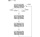
続いて、本実施の形態における演出動作例について説明する。以下の演出動作は、主基板11から送信される演出制御コマンドに基づいて、演出制御用CPU120が演出制御プロセス処理を実行することで実行される。図8-2、図8-3は、本実施の形態におけるスーパーリーチの演出動作例を示す図である。図8-2(A)は、画像表示装置5の「左」、「中」、「右」の各飾り図柄表示エリア5L、5C、5Rにおいて飾り図柄の可変表示が実行されていることを示している。その後、例えば、図8-2(B)に示すように、「左」及び「右」に7の数字を示す飾り図柄が停止してリーチ態様となる。その後はリーチの種類に応じて演出が分岐する。
(Example of production operation of characteristic portion 31AK)
Next, an example of an effect operation in this embodiment will be described. The following production operations are executed by the
(スーパーリーチA)
スーパーリーチAとなる場合には、図8-2(C)に示すように、画像表示装置5に味方キャラであるキャラクタ31AK001が表示されてリーチ演出が開始される。ここでは、例えばキャラクタ31AK001を使用したアニメーション等が表示される。スーパーリーチのリーチ演出(スーパーリーチ演出ともいう)の導入部分が終了する等、スーパーリーチ演出が開始されてから所定期間経過すると、図8-2(D)に示すように、画像表示装置5の画面全体にスーパーリーチAのタイトル31AK002(ここでは「SPリーチA」の文字)が表示されるとともに、スピーカ8からリーチのタイトル名に対応する音声(ここでは「スーパーリーチA」)が出力されることで、スーパーリーチAのタイトルが報知される。その後、スーパーリーチAのタイトル31AK002が消去され、図8-2(E)に示すように、敵キャラであるキャラクタ31AK003が表示され、キャラクタ31AK001のセリフ31AK004が表示されたり、キャラクタ31AK001とキャラクタ31AK003とが対決するスーパーリーチAのリーチ演出の後続部分が実行される。キャラクタ同士が対決する演出をバトル演出ともいい、バトル演出において味方キャラが勝利すると大当りとなり、味方キャラが敗北するとハズレとなる。
(Super Reach A)
In the case of super reach A, as shown in FIG. 8-2(C), the character 31AK001, which is a friendly character, is displayed on the
なお、スーパーリーチ演出中に画像表示装置5にセリフを表示するときに、スピーカ8からセリフに対応する音声が出力されるようにしてもよい。また、セリフは図8-2(E)に示すように吹き出しに表示することに限定されず、画像表示装置5の下部等に字幕で表示するようにしてもよい。
It should be noted that when the lines are displayed on the
(スーパーリーチB)
スーパーリーチBとなる場合には、図8-2(C)に示すように、画像表示装置5にキャラクタ31AK001が表示されてリーチ演出が開始される。ここでは、例えばキャラクタ31AK001を使用したアニメーション等が表示される。スーパーリーチ演出の導入部分が終了する等、スーパーリーチ演出が開始されてから所定期間経過すると、図8-2(F)に示すように、画像表示装置5の画面全体にスーパーリーチBのタイトル31AK005(ここでは「SPリーチB」の文字)が表示されるとともに、スピーカ8からリーチのタイトル名に対応する音声(ここでは「スーパーリーチB」)が出力されることで、スーパーリーチBのタイトルが報知される。その後、スーパーリーチBのタイトル31AK005が消去され、図8-2(G)に示すように、敵キャラであるキャラクタ31AK006が表示され、キャラクタ31AK001のセリフ31AK004が表示されたり、キャラクタ31AK001とキャラクタ31AK006とが対決するスーパーリーチBのリーチ演出の後続部分が実行される。
(Super Reach B)
In the case of super reach B, as shown in FIG. 8-2(C), the character 31AK001 is displayed on the
このように、スーパーリーチAとスーパーリーチBとでは、スーパーリーチ演出が開始されてから所定期間経過したときにリーチのタイトルが報知されるようになっている。このようにすることで、スーパーリーチ演出の導入部分等を遊技者に見せた後にタイトルを報知できるので、タイトル報知の演出効果を高めることができる。 In this way, in super ready-to-win A and super ready-to-win B, the title of ready-to-win is reported when a predetermined period has passed since the start of the super ready-to-win effect. By doing so, the title can be notified after the introduction part of the super ready-to-win effect is shown to the player, so that the effect of the title notification can be enhanced.
また、スーパーリーチA(図8-2(C)→(D)→(E)・・・)とスーパーリーチB(図8-2(C)→(F)→(G)・・・)とでは、タイトルが報知されるまでの導入部分においては、共通の演出態様でスーパーリーチ演出が実行されるようになっている(図8-2(C))。このようにすることで、スーパーリーチ演出が開始されてからいずれのスーパーリーチとなるか、いずれのタイトルが報知されるかに遊技者を注目させることができる。スーパーリーチAとスーパーリーチBとにおいて、タイトルが報知されるまでの演出態様を完全に共通にすることに限定されず、演出を注視すればいずれのスーパーリーチとなるかを判別できる等、少なくとも一部を共通の演出態様にするようにしてもよい。例えば、スーパーリーチAとスーパーリーチBとの導入部分において、その後に報知されるタイトルに関連する態様でスーパーリーチ演出(例えば敵キャラを表示したり敵キャラを示唆するような演出)を実行するようにしてもよい。このようにすることで、演出効果が向上し、遊技者が演出に注目するようになる。このように、いずれのスーパーリーチとなるかを特定可能にしてからタイトル報知を実行するようにしてもよい。 In addition, Super Reach A (Fig. 8-2 (C) → (D) → (E) ...) and Super Reach B (Fig. 8-2 (C) → (F) → (G) ...) Then, in the introductory part until the title is announced, the super ready-to-win effect is executed in a common effect mode (FIG. 8-2(C)). By doing so, it is possible to make the player pay attention to which super reach will be achieved after the start of the super reach effect and which title will be announced. In super reach A and super reach B, it is not limited to making the production mode until the title is announced completely common, but at least one You may make it make the part into a common production mode. For example, in the introductory portion of Super Reach A and Super Reach B, a Super Reach production (for example, a production that displays an enemy character or suggests an enemy character) is executed in a manner related to the title notified after that. can be By doing so, the performance effect is improved, and the player pays attention to the performance. In this way, the title notification may be executed after making it possible to specify which super reach is to be achieved.
(スーパーリーチD)
スーパーリーチDとなる場合には、図8-2(H)に示すように、画像表示装置5の中央の一部にスーパーリーチDのタイトル31AK007(ここでは「SPリーチD」の文字)が表示されるとともに、スピーカ8からリーチのタイトル名に対応する音声(ここでは「敵を倒せ」)が出力されることで、スーパーリーチDのタイトルが報知される。このように、スーパーリーチDでは、スーパーリーチ演出の開始時にタイトルが報知されるようになっている。また、タイトル31AK007の下には、当該リーチの期待度を示唆する期待度示唆表示31AK008が表示される。期待度は、図8-2(H)に示すように、黒い星の数で表される。ここで、期待度とは大当りとなる期待度であるが、リーチの大当り信頼度と完全に一致していなくてもよい。
(Super Reach D)
In the case of super reach D, as shown in FIG. 8-2 (H), the title 31AK007 of super reach D (here, "SP reach D" characters) is displayed in a part of the center of the
なお、スーパーリーチDの音声による報知は、タイトル名をそのまま報知するのではなく、リーチの内容を報知するようになっている。このように、この実施の形態では、リーチの種類によって音声によるタイトル報知の報知態様を異ならせている。これにより、タイトル報知の報知態様が多彩になり、興趣が向上する。 It should be noted that the notification by voice of Super Reach D is not to notify the title name as it is, but to notify the content of Reach. As described above, in this embodiment, the notification mode of title notification by sound is varied depending on the type of reach. As a result, the notification mode of the title notification is diversified, and the interest is improved.
スーパーリーチDにおいてタイトルが報知された後には、図8-2(I)に示すように、画像表示装置5にキャラクタ31AK001が表示される。このとき、タイトル31AK007及び期待度示唆表示31AK008は、画像表示装置5の右上部分等に縮小して表示され続ける。このようにすることで、リーチ演出中にも遊技者がリーチの期待度を把握することができる。なお、図8-2(I)では、図8-2(C)(スーパーリーチA、スーパーリーチB)と共通の演出内容が示されているが、スーパーリーチD専用のスーパーリーチ演出が実行されてもよい。
After the title is notified in Super Reach D, the character 31AK001 is displayed on the
その後、図8-2(J)に示すように、敵キャラであるキャラクタ31AK009が表示され、キャラクタ31AK001のセリフ31AK004が表示されたり、キャラクタ31AK001とキャラクタ31AK009とが対決するスーパーリーチDのリーチ演出が実行される。 After that, as shown in FIG. 8-2(J), character 31AK009, which is an enemy character, is displayed, dialogue 31AK004 of character 31AK001 is displayed, and reach effect of super reach D in which character 31AK001 and character 31AK009 confront each other is performed. executed.
(スーパーリーチE)
スーパーリーチEとなる場合には、図8-3(A)に示すように、画像表示装置5の左上の一部にスーパーリーチEのタイトル31AK010(ここでは「SPリーチE」の文字)が表示されることで、スーパーリーチEのタイトルが報知される。なお、スーパーリーチEでは、音声によるタイトルの報知が行われない。また、タイトル31AK010の表示と合わせて、キャラクタ31AK001と敵キャラであるキャラクタ31AK011とが表示され、キャラクタ31AK001のセリフ31AK004が表示されたり、キャラクタ31AK001とキャラクタ31AK011とが対決するスーパーリーチEのリーチ演出が実行される。このように、スーパーリーチEでは、リーチ演出の進行と合わせてタイトルが報知されるようになっている。スーパーリーチEでは、リーチ演出中にタイトル31AK010が表示され続ける。
(Super Reach E)
In the case of super reach E, as shown in FIG. 8-3 (A), the title 31AK010 of super reach E (here, the characters "SP reach E") are displayed in the upper left part of the
大当り信頼度の低いスーパーリーチEのリーチ演出では、リーチ演出の進行を止めずにタイトル報知を行うことで、遊技者に過度な期待感を与えることを防止できる。これに対して、スーパーリーチA、スーパーリーチB、スーパーリーチDのリーチ演出では、リーチ演出の進行を停止してタイトル報知を行うようになっている(図8-2(D)、(F)、(H))。このようにすることで、スーパーリーチ演出に応じたタイトル報知を実行でき演出効果が向上する。なお、スーパーリーチA、スーパーリーチB、スーパーリーチDといったスーパーリーチ演出においてもリーチの進行を停止せずにタイトル報知を行うようにしてもよい。また、この実施の形態とは逆に、大当り信頼度の高いスーパーリーチのリーチ演出では、リーチ演出の進行を止めずにタイトル報知を行うようにしてもよい。大当り信頼度の低いスーパーリーチのリーチ演出では、リーチ演出の進行を停止してタイトル報知を行うようにしてもよい。 In the ready-to-win performance of super ready-to-win E with low reliability of big hit, the title is notified without stopping the progress of the ready-to-win performance, thereby preventing the player from having excessive expectations. On the other hand, in the reach effects of super reach A, super reach B, and super reach D, the progress of the reach effect is stopped and the title is announced (Fig. 8-2 (D), (F) , (H)). By doing so, the title notification can be executed in accordance with the super ready-to-win effect, and the effect of the effect is improved. It should be noted that the title notification may be performed without stopping the progress of the reach even in the super reach performance such as the super reach A, the super reach B, and the super reach D. Contrary to this embodiment, in the ready-to-win effect of super ready-to-win with high reliability of big win, the title may be notified without stopping the progress of the ready-to-win effect. In the ready-to-win performance of super ready-to-win with low reliability of big win, the progress of the ready-to-win performance may be stopped and the title may be announced.
(タイトルの報知タイミング)
以上のように、この実施の形態では、スーパーリーチA及びスーパーリーチBにおいては、スーパーリーチ演出開始後所定期間経過してからタイトルが報知され、スーパーリーチD及びスーパーリーチEにおいては、スーパーリーチ演出開始時にタイトルが報知されるようになっている。このようにすることで、リーチ演出に応じたタイトル報知を実行でき演出効果が向上する。なお、この実施の形態では、大当り信頼度の高いスーパーリーチA及びスーパーリーチBにおいては、スーパーリーチ演出開始後所定期間経過してからタイトルが報知され、大当り信頼度の低いスーパーリーチD及びスーパーリーチEにおいては、スーパーリーチ演出開始時にタイトルが報知されるようになっていたが、大当り信頼度の高いリーチの場合にスーパーリーチ演出開始時にタイトルが報知され、大当り信頼度の低いリーチの場合にスーパーリーチ演出後所定期間経過してからタイトルが報知されるようにしてもよい。
(Title notification timing)
As described above, in this embodiment, in super ready-to-reach A and super ready-to-reach B, the title is notified after a predetermined period of time has passed after the start of the super ready-to-win effect, and in super ready-to-win D and super ready-to-e E, the super ready-to-win effect is announced. The title is announced at the start. By doing so, the title notification can be executed according to the ready-to-win effect, and the effect of the effect is improved. In this embodiment, in super reach A and super reach B with high reliability of big hit, the title is notified after a predetermined period has passed after the start of super reach performance, and super reach D and super reach D with low reliability of big hit are announced. In E, the title is notified at the start of super reach production, but in the case of reach with high reliability of big hit, the title is notified at the start of super reach production, and in the case of reach with low reliability of big hit, super. The title may be announced after a predetermined period of time has elapsed after the ready-to-win effect.
(タイトルの表示領域)
また、この実施の形態では、スーパーリーチA及びスーパーリーチBにおいては、画像表示装置5の画面全体(第1領域)においてタイトルが報知され、スーパーリーチD及びスーパーリーチEにおいては、画像表示装置5の画面の一部(第2領域)においてタイトルが報知される。このようにすることで、リーチ演出に応じたタイトル報知を実行でき演出効果が向上する。特に、大当り信頼度の高いリーチである場合には、信頼度の低いリーチである場合よりも広い表示領域でタイトル報知が実行されるので効果的なタイトル報知が可能になる。なお、画像表示装置5の画面全体におけるタイトル報知とは、画面いっぱいに収まるサイズでタイトルが表示されるものであってもよいし、背景全体をタイトル報知用の背景としてそこにタイトルが表示されるもの(画面全体を使用したタイトル報知)等であってもよい。また、スーパーリーチAとスーパーリーチBとでタイトル報知を行う表示領域を異ならせてもよいし、スーパーリーチDとスーパーリーチEとでタイトル報知を行う表示領域を異ならせてもよい。
(title display area)
In addition, in this embodiment, in super reach A and super reach B, the title is announced on the entire screen (first area) of the
リーチ演出に応じてタイトル報知を行う表示領域を異ならせる方法は、この実施の形態の例に限定されず、リーチ演出に応じてタイトル報知を行う表示領域を任意に異ならせてもよい。例えば、大当り信頼度の高いリーチである場合には、信頼度の低いリーチである場合よりも狭い表示領域でタイトル報知が実行されてもよい。また、リーチ演出に応じてタイトル報知を行う表示領域を異ならせる場合において、この実施の形態のように表示面積を異ならせてもよいし、表示させる場所を異ならせてもよい。 The method of differentiating the display area for title notification according to the ready-to-win effect is not limited to the example of this embodiment, and the display area for title notification may be arbitrarily changed according to the ready-to-win effect. For example, when the hit reliability is high, the title notification may be performed in a narrower display area than when the reliability is low. Further, when the display area for title notification is changed according to the ready-to-win effect, the display area may be changed as in this embodiment, or the display location may be changed.
(期待度示唆表示)
この実施の形態では、大当り信頼度の高いスーパーリーチA及びスーパーリーチBにおけるタイトル報知では、期待度示唆表示を表示せずに、スーパーリーチA及びスーパーリーチBよりも大当り信頼度の低いスーパーリーチDにおけるタイトル報知では、期待度示唆表示を表示するようにしていた。このようにすることで、演出がくどくなることを防止できる。また、スーパーリーチDよりも大当り信頼度の低いスーパーリーチEにおけるタイトル報知では、期待度示唆表示を表示しないようになっていた。このようにすることで、信頼度の低いリーチにおいて信頼度が低いことを示す期待度示唆表示が表示されることで遊技者が期待感を失うことを防止できる。なお、スーパーリーチA、スーパーリーチB、スーパーリーチEの少なくとも一部において期待度示唆表示を表示するようにしてもよい。
(Expectation indication)
In this embodiment, in the title announcement in super reach A and super reach B with high reliability of big hit, super reach D with lower reliability of big hit than super reach A and super reach B is displayed without displaying expectation indication. In the title notification in , the expectation level suggestion display was displayed. By doing so, it is possible to prevent the production from becoming repetitive. In addition, in the title announcement in the super reach E, which has a lower hit reliability than the super reach D, the expectation suggestive display is not displayed. By doing so, it is possible to prevent the player from losing his sense of expectation due to the display of the expectation suggesting display indicating that the reliability is low in the reach with the low reliability. At least a part of the super reach A, the super reach B, and the super reach E may display the expectation level suggestion display.
なお期待度示唆表示は、図8-2(H)等に示すように、黒い星の数によって示すものに限定されず、メーターやゲージにより期待度を示唆するようにしてもよいし、期待度に対応した数値を表示するようにしてもよい。また、図8-2(H)等に示すように、黒い星の数によって示す場合において、半個相当(半分)の黒い星を表示可能ようにして、期待度の段階数を増やしてもよい。 The indication of the level of expectation is not limited to the number of black stars as shown in Fig. 8-2 (H). You may make it display the numerical value corresponding to . In addition, as shown in FIG. 8-2 (H), etc., in the case of indicating by the number of black stars, the number of levels of expectations may be increased by enabling display of black stars equivalent to half (half). .
(タイトルの表示終了タイミング)
また、この実施の形態では、スーパーリーチA及びスーパーリーチBにおいては、タイトルが表示された後、タイトルが消去されてスーパーリーチ演出が実行される。これにより、スーパーリーチA及びスーパーリーチBにおいては、リーチ演出に注目させることができる。また、スーパーリーチD及びスーパーリーチEにおいては、タイトルが表示された後、後述の決め演出が実行されるまでタイトルが表示され続ける。これにより、スーパーリーチD及びスーパーリーチEにおいては、スーパーリーチ演出中もリーチの種類を把握することができる。また、以上のようにすることで、リーチ演出に応じたタイトル報知を実行でき演出効果が向上する。なお、タイトルの表示終了タイミングは、いずれであっても演出効果の向上を図れるため、任意に変更してもよい。
(Title display end timing)
In addition, in this embodiment, in super reach A and super reach B, after the title is displayed, the title is erased and the super reach effect is executed. As a result, in the super reach A and the super reach B, attention can be paid to the reach effect. Also, in super reach D and super reach E, after the title is displayed, the title continues to be displayed until a final effect, which will be described later, is executed. As a result, in super reach D and super reach E, the type of reach can be grasped even during the super reach performance. Further, by doing so, the title notification can be executed according to the ready-to-win effect, and the effect of the effect is improved. Note that the display end timing of the title can be changed arbitrarily because the effect can be improved at any time.
なお、ここではスーパーリーチCのリーチ演出の演出動作については省略するが、例えば大当り信頼度に応じたタイトル報知や期待度示唆表示が実行されればよい。 In addition, here, the effect operation of the reach effect of the super reach C is omitted, but for example, the title notification and the expectation suggestive display according to the reliability of the big hit may be executed.
(決め演出)
各リーチ演出が実行されてから、表示結果を導出するタイミング(可変表示の終盤)になると、表示結果が「大当り」となるか否かを報知するための決め演出が実行される。決め演出には、表示結果が「大当り」となることを示す決め演出と、表示結果が「ハズレ」となることを示す決め演出と、が含まれる。この実施の形態では、図8-3(B)に示すように、画像表示装置5に画像31AK012が表示される決め演出が実行される。その後、表示結果が「大当り」であれば、図8-3(C)に示すように、味方キャラが勝利したことを示す画像31AK013が表示され、図8-3(D)に示すように、大当り組合せとなる確定飾り図柄が導出される。なお、表示結果が「ハズレ」であれば、味方キャラが敗北したことを示す画像が表示され、リーチハズレ組合せとなる確定飾り図柄が導出される。
(Decision production)
After each ready-to-win performance is executed, at the timing of deriving the display result (end stage of variable display), a decision performance for informing whether or not the display result will be a ``jackpot'' is executed. The fixed effects include a fixed effect indicating that the display result is a "big hit" and a fixed effect indicating that the display result is a "loss". In this embodiment, as shown in FIG. 8-3(B), an effect of displaying an image 31AK012 on the
この実施の形態では、リーチ演出中も継続してタイトルを報知する場合でも、決め演出が実行される前にタイトルの報知を終了するようになっている。これにより、決め演出に注目させることができ、また、メリハリのあるタイトル報知を実行できる。 In this embodiment, even if the title is continuously notified during the ready-to-win effect, the title notification is finished before the final effect is executed. As a result, it is possible to make the player pay attention to the decided effect, and to perform a well-balanced title notification.
図8-2、図8-3に示した演出動作例では、スーパーリーチのリーチ演出中は画像表示装置5の右下部分で飾り図柄を縮小して可変表示を実行するようになっていたが、リーチ演出中の飾り図柄の表示のさせ方は任意でよい。例えば、リーチ演出中は飾り図柄が表示されなくてもよいし、リーチ演出の種類によって表示態様(大きさ、位置、濃淡、数等)を異ならせてもよい。
In the production operation examples shown in FIGS. 8-2 and 8-3, during the ready-to-win production of super-ready-to-win, the decoration pattern is reduced in the lower right portion of the
なお、画像表示装置5に保留表示、アクティブ表示、可変表示中に常駐表示されるキャラクタ、携帯連動関連の表示を表示する場合、スーパーリーチのリーチ演出中はリーチ演出に注目させるために適宜非表示としてもよい。その際に、スーパーリーチEといった低信頼度のリーチ演出中には、これらの表示を表示したままにするようにしてもよい。このようにすることで、低信頼度のリーチ演出により遊技者を過度に期待させてしまうことを防止できるとともに、高信頼度のリーチ演出ではリーチ演出に注目させることができる。
It should be noted that, when displaying characters permanently displayed during the pending display, active display, and variable display, and display related to cellphone interlocking on the
(発展演出)
続いて、発展演出が実行される場合の演出動作例について説明する。図8-4(A)に示すように、スーパーリーチDのリーチ演出が実行されている(スーパーリーチDのタイトル報知が実行されている)ときに発展演出が実行される場合、図8-4(B)に示すように、リーチ演出が中断して画面が裂けるような演出が実行される。その後、スーパーリーチAに発展する場合には、図8-4(C)に示すように、スーパーリーチAのタイトルが報知され、スーパーリーチAのリーチ演出が実行される。スーパーリーチBに発展する場合には、図8-4(D)に示すように、スーパーリーチBのタイトルが報知され、スーパーリーチのリーチ演出が実行される。このように、発展演出が実行された場合には、発展元のリーチのタイトル報知から発展先のリーチのタイトル報知に切り替えられるで、いずれのリーチに発展したかがわかりやすくなる。図8-4に示すように、発展先のリーチが表示及び音声によりタイトル報知を行うリーチである場合には、表示及び音声によるタイトル報知が改めて実行される。
(development production)
Next, a description will be given of an example of an effect operation when the development effect is executed. As shown in FIG. 8-4 (A), when the development effect is executed while the ready-to-reach effect of super reach D is being executed (title notification of super reach D is being executed), FIG. As shown in (B), the ready-to-win effect is interrupted and an effect is executed in which the screen is torn. After that, when it develops to super reach A, as shown in FIG. 8-4(C), the title of super reach A is reported, and the reach performance of super reach A is executed. In the case of developing into super reach B, as shown in FIG. 8-4(D), the title of super reach B is announced, and the reach effect of super reach is executed. In this way, when the development effect is executed, the title notification of the development source reach is switched to the title notification of the development destination reach, so that it becomes easy to understand which reach has developed. As shown in FIG. 8-4, when the destination reach is a reach in which title notification is performed by display and sound, the title notification is performed again by display and sound.
なお、発展演出は図8-4(B)に示すような例に限定されず、画面に徐々にヒビが入って割れるような演出であってもよいし、砂嵐(故障したような表示)を表示するようにしてもよい。このような演出とすることで、意外性のある演出を実行できる。なお、画面に徐々にヒビが入るがリーチが発展しない演出といった、ガセの発展演出があってもよい。 The development effect is not limited to the example shown in FIG. 8-4(B). You may make it display. By setting it as such production|presentation, an unexpected production|presentation can be performed. It should be noted that there may be a fake development production such as a production in which the screen gradually cracks but the reach does not develop.
(期待度示唆演出)
図8-2(H)に示す演出動作例では、期待度示唆表示31AK008が期待度を示す黒い星が最初から表示されるようになっていたが、最初に5つの白い星を表示し、段階的に黒い星となることで期待度示唆する期待度示唆演出を実行するようにしてもよい。
(Expectation suggestion performance)
In the production operation example shown in FIG. 8-2 (H), the expectation suggestive display 31AK008 was designed to display black stars indicating the degree of expectation from the beginning. It is also possible to execute an expectation level suggesting effect in which an expectation level is suggested by becoming a black star.
例えば、図8-5(A)に示すように、スーパーリーチDのタイトルを報知する際に、最初に5つの白い星の期待度示唆表示31AK021が表示される。そして、図8-5(B)に示すように、期待度示唆表示31AK021の星より大きな黒い星31AK022が表示され、図8-5(C)に示すように、黒い星31AK022が移動して期待度示唆表示31AK021の白い星の一つに収まるような演出が実行される。このとき、スピーカ8から期待度を示す黒い星が増加したことを示す「ピン」という音声が出力される。図8-5(D)、(E)に示すように、リーチの期待度に対応した回数同じ演出が繰り返される。このときに、繰り返される毎(星の数毎)にスピーカ8から出力される音声(音量、音階、音質等)を段階的に変化させるようにしてもよい。期待度示唆表示31AK021に期待度に対応した数の黒い星が収まった段階で、図8-5(F)に示すように、その黒い星が光るといったように強調表示される。このようにすることで、期待度示唆演出が終了したことがわかりやすくなる。
For example, as shown in FIG. 8-5(A), when announcing the title of Super Reach D, an expectation suggestive display 31AK021 of five white stars is displayed first. Then, as shown in FIG. 8-5(B), a black star 31AK022 larger than the star of the expectation indication indication 31AK021 is displayed, and as shown in FIG. An effect is executed to fit in one of the white stars of the degree suggestive display 31AK021. At this time, the
図8-5(A)~(F)に示す例では、黒い星が1つずつ表示されて期待度示唆表示により示される期待度が1段階ずつ上がるようになっていたが、黒い星が2つ以上表示されて期待度が2段階以上上がるようにしてもよい。また、半分の黒い星が表示されて期待度が半段階上がるようにしてもよい。この場合において、表示される星の数(上昇する期待度の段階数)に応じて、異なる音声を出力するようにしてもよいし、同じ音声を出力するようにしてもよい。例えば、半分の黒い星が表示されるときと1つの黒い星が表示されるときとで同じ音声を出力するようにしてもよい。2つ半の黒い星が表示されるときと3つの黒い星が表示されるときとで同じ音声を出力するようにしてもよい。また、音声を出力しない場合があってもよい。このようにすることで、期待度示唆演出が多彩になり、演出効果が向上する。なお、一度に増加する期待度の段階数によらず、同じ黒い星の画像が表示されて、期待度示唆表示の白い星に収まって、増加する期待度の段階数に応じた黒い星が増加するような演出を実行するようにしてもよい。 In the example shown in FIGS. 8-5 (A) to (F), black stars are displayed one by one and the expectation level indicated by the expectation level suggestion display is raised one step at a time, but two black stars are displayed. One or more may be displayed so that the degree of expectation is raised by two or more stages. Alternatively, a half black star may be displayed to raise the expectation level by half. In this case, different sounds or the same sound may be output according to the number of stars displayed (the number of levels of rising expectations). For example, the same sound may be output when half black stars are displayed and when one black star is displayed. The same sound may be output when two and a half black stars are displayed and when three black stars are displayed. Moreover, there may be a case where the sound is not output. By doing so, the expectation degree suggesting effects are diversified, and the effects of the effects are improved. In addition, the same black star image will be displayed regardless of the number of stages of expectations that increase at once, and the black stars will increase according to the number of stages of expectations that will increase. You may make it perform the production|presentation which does.
(演出モード)
画像表示装置5、スピーカ8、遊技効果ランプ9といった演出装置における演出モードが複数あってもよい。異なる演出モードでは、主基板11から同じコマンド(例えば変動パターンを指定するコマンド)が送信された場合でも、当該コマンドに基づく演出が異なる演出態様で実行される。各演出モードでは、画像表示装置5に表示される背景、キャラクタ、モチーフ、スピーカ8から出力される音声等が異なっていればよい。演出モードは、可変表示の回数や遊技状態に応じて自動的に変更されるようにしてもよいし、遊技者の操作により変更可能にしてもよい。
(Direction mode)
There may be a plurality of effect modes in the effect device such as the
図8-5(G)~(L)は、演出モードとして通常モード及び特別モードが設けられる場合において、特別モードとなっている場合のタイトル報知及び期待度示唆演出の演出動作例である。通常モードでは、図8-5(A)~(F)に示すようタイトル報知及び期待度示唆演出が実行される。特別モードでは、スーパーリーチDの変動パターンに基づくリーチ演出は、スーパーリーチDのリーチ演出とは演出態様の異なるスーパーリーチD2のリーチ演出となる。従って、スーパーリーチDの変動パターンが指定された場合、図8-5(G)に示すように、スーパーリーチD2のタイトル31AK023が表示される。このとき、スピーカ8からリーチのタイトル名に対応する音声が出力されるが、通常モードとは異なる音声(例えば声色が異なる音声)が出力される。また、スーパーリーチD2における期待度示唆表示31AK024は、星型ではなく菱形となっている。
FIGS. 8-5(G) to (L) show an example of the effect operation of the title notification and the expectation suggesting effect in the special mode when the normal mode and the special mode are provided as the effect modes. In the normal mode, the title notification and expectation suggesting effects are executed as shown in FIGS. 8-5(A) to (F). In the special mode, the ready-to-reach performance based on the variation pattern of super ready-to-reach D is the ready-to-reach performance of super ready-to-reach D2 that is different from the ready-to-reach performance of super ready-to-win D. Therefore, when the fluctuation pattern of super reach D is specified, the title 31AK023 of super reach D2 is displayed as shown in FIG. 8-5(G). At this time, a sound corresponding to the title name of READY is output from the
その後、図8-5(H)に示すように、期待度示唆表示31AK024の星より大きな黒い菱形31AK025が表示され、図8-5(I)に示すように、黒い菱形31AK025が移動して期待度示唆表示31AK024の白い菱形の一つに収まるような演出が実行される。このとき、スピーカ8から期待度を示す黒い菱形が増加したことを示す「ポン」という音声が出力される。図8-5(J)、(K)に示すように、リーチの期待度に対応した回数同じ演出が繰り返される。期待度示唆表示31AK024に期待度に対応した数の黒菱形が収まった段階で、図8-5(L)に示すように、その黒い菱形が光るといったように強調表示される。このように、遊技者の選択や遊技状態等に応じて決定される演出モード(リーチ演出が実行されるときの状態)によって、タイトルの報知態様を異ならせることで演出が多彩になり演出効果が向上する。
After that, as shown in FIG. 8-5(H), a black rhombus 31AK025 larger than the star of the expectation indication display 31AK024 is displayed, and as shown in FIG. An effect is executed to fit in one of the white rhombuses of the degree suggestion display 31AK024. At this time, a sound "pong" is output from the
図8-5では、スーパーリーチDの変動パターンが指定された場合の演出動作例を示したが、演出モード(リーチ演出が実行されるときの状態)によって他のリーチ演出(タイトル報知、期待度示唆演出を含む)の演出態様を異ならせるようにしてもよい。演出モード(リーチ演出が実行されるときの状態)によって、リーチのタイトルを報知するか否かやタイトル報知の実行割合を異ならせてもよい。例えば、所定の演出モードが選択された場合には、リーチのタイトルが報知されないようにしてもよい。このようにすることで、遊技者の好みに応じた演出を実行でき演出効果が向上する。 FIG. 8-5 shows an example of the effect operation when the variation pattern of Super Reach D is specified, but other reach effects (title notification, expectation degree) depending on the effect mode (state when the reach effect is executed) (including suggestive effects) may be made different. Depending on the effect mode (the state when the ready-to-win effect is executed), whether or not to report the title of ready-to-win, and the execution ratio of the title to be reported may be varied. For example, when a predetermined effect mode is selected, the title of ready-to-win may not be announced. By doing so, it is possible to execute an effect according to the taste of the player, thereby improving the effect of the effect.
なお、この実施の形態では、期待度示唆表示における黒い星の数によって期待度を示唆し、黒い星の数を段階的に増加させる期待度示唆演出を実行するようになっていたが、期待度を示唆する表示の数を段階的に減少させる期待度示唆演出を実行するようにしてもよい。そのような期待度示唆演出をこの実施の形態の期待度示唆演出に加えて実行するようにしてもよいし、代えて実行するようにしてもよい。 In this embodiment, the expectation level is suggested by the number of black stars in the expectation level indication display, and the expectation level suggestion effect is executed to gradually increase the number of black stars. It is also possible to execute an expectation level suggesting effect in which the number of displays suggesting is gradually reduced. Such an expectation level suggesting effect may be executed in addition to the expectation level suggesting effect of this embodiment, or may be executed instead.
(発展演出の他の例)
期待度示唆表示の期待度を示す表示を段階的に増加させる期待度示唆演出を実行する場合において、期待度を示す表示を増加させた後に発展演出を実行するようにしてもよい。この場合において、発展演出後に期待度を示す表示を増加させる場合、増加させる表示については段階的ではなく一度に表示するようにしてもよい。例えば図8-6(A)に示すように、スーパーリーチDのタイトルが報知され、黒い星を段階的に増加させる演出が完了した後に、図8-6(B)に示すように、画像表示装置5にボタン画像31AK031が表示される発展演出が実行される。ここで、プッシュボタン31Bへの操作が検出されると、図8-6(C)に示すように、スーパーリーチCのタイトル31AK032(ここでは「SPリーチC」の文字)が表示されることで、スーパーリーチCのタイトルが報知される。このように、発展演出が実行された場合には、発展元のリーチのタイトル報知から発展先のリーチのタイトル報知に切り替えられるで、いずれのリーチに発展したかがわかりやすくなる。また、タイトル31AK032の下には、黒い星の数が3個である期待度示唆表示31AK033が強調表示される。なお、黒い星の数が2個以上増加する場合でも一度に表示される。なお、可動体32が動作した後に、タイトルや期待度示唆表示が変化する発展演出を実行するようにしてもよい。
(Another example of development production)
In the case of executing the expectation degree suggesting effect in which the display indicating the degree of expectation of the expectation degree suggesting display is increased step by step, the development effect may be executed after increasing the display indicating the degree of expectation. In this case, when the display indicating the degree of expectation is increased after the development effect, the display to be increased may be displayed all at once instead of step by step. For example, as shown in FIG. 8-6 (A), the title of Super Reach D is notified, and after completing the effect of gradually increasing black stars, as shown in FIG. 8-6 (B), the image display A development effect is executed in which the button image 31AK031 is displayed on the
(予告演出)
この実施の形態では、予告演出として、タイトルの報知態様(例えばタイトルの表示色等)によって、大当り信頼度を予告するタイトル予告を実行するようになっている。例えば図8-7(A)に示すように、スーパーリーチAのタイトル31AK036が黒色で表示されるとともに、スピーカ8からリーチのタイトル名に対応する音声が出力されることで、スーパーリーチAのタイトルが報知された後、図8-7(B)に示すようにタイトル31AK036の表示色が赤色に変化するタイトル予告を実行するようになっている。このように、タイトル予告が実行されない場合はタイトルが黒色で表示され、タイトル予告が実行される場合はタイトルが黒色以外の色で表示される。図8-7に示すタイトル予告では、音声によりリーチのタイトルが報知された後に、タイトルの表示態様(表示色)が変化する場合がある。このようにすることで、予告演出の演出効果を高めることができる。なお、タイトルが黒色以外で表示されるタイミングはこれに限定されず、タイトルの表示開始時から黒色以外で表示されるようにしてもよい。
(Notice production)
In this embodiment, as the advance notice effect, a title advance notice for giving notice of the degree of reliability of a big hit is executed according to the title notification mode (for example, the display color of the title, etc.). For example, as shown in FIG. 8-7 (A), the title 31AK036 of Super Reach A is displayed in black, and the sound corresponding to the title name of Reach A is output from the
また、タイトルの表示態様(表示色)が変化するタイトル予告が実行された場合には、タイトルの表示態様が変化した後に、変化後の表示態様に応じた音声を出力するようにしてもよい。このようにすることで、予告演出の演出効果を高めることができる。また、音声によるタイトル報知は、タイトルの表示態様(表示色)が変化した後に実行されるようにしてもよい。この場合、変化後のタイトルの表示態様(表示色)に応じた音声が出力するようにしてもよい。 Further, when a title announcement is executed in which the display mode (display color) of the title is changed, after the display mode of the title is changed, a sound corresponding to the display mode after the change may be output. By doing so, it is possible to enhance the effect of the advance notice effect. Also, the title notification by voice may be executed after the display mode (display color) of the title is changed. In this case, the sound may be output according to the display mode (display color) of the changed title.
(タイトル報知の実行タイミング)
リーチ中のタイトルの報知は、予告演出や発展演出といった、大当り有利状態に制御される期待度が向上する演出(特定演出)の実行タイミング以外で実行することが好ましい。このようにすることで、一旦タイトルが報知された場合、期待度が向上する演出が実行され得るので、遊技者の期待感を維持することができる。
(Execution timing of title notification)
It is preferable that the notification of the title in reach is executed at a timing other than the execution timing of the effect (specific effect) such as the advance effect and the development effect, which increases the expectation of being controlled to the big hit advantage state. By doing so, once the title is announced, an effect that raises the degree of expectation can be executed, so that the player's sense of expectation can be maintained.
図8-8は、予告演出の実行の有無や演出態様を決定するための予告演出決定処理の一例を示すフローチャートである。予告演出決定処理は、演出制御用CPU120が図7のステップS171の可変表示開始設定処理内で実行する。予告演出決定処理では、演出制御用CPU120は、先ず、主基板11から送信されるコマンドから特定される変動パターンがスーパーリーチの変動パターンであるか否かを判定する(ステップ31AKS001)。
FIG. 8-8 is a flow chart showing an example of the announcement effect determination process for determining whether or not the announcement effect is to be executed and the mode of effect. The advance notice effect determination process is executed by the
スーパーリーチの変動パターンである場合には(ステップ31AKS001;Yes)、スーパーリーチのタイトルの表示色(タイトル予告の実行の有無)を決定する(ステップ31AKS002)。 If it is a super reach variation pattern (step 31AKS001; Yes), the display color of the super reach title (whether or not to execute a title announcement) is determined (step 31AKS002).
ステップ31AKS002では、表示結果が「大当り」となるか「ハズレ」となるかに応じて、例えば図8-9(A)に示す決定割合で、スーパーリーチのタイトルの表示色を決定する。スーパーリーチのタイトルの表示色は、図8-9(A)に示すように、「黒」、「赤」、「黒」から「赤」に変化するもの、「黒」から「フルーツ柄」に変化するもの、「赤」から「フルーツ柄」に変化するものが設けられており、この順番(昇順)で大当り信頼度が高くなっている。即ち、タイトルの表示色の変化タイミングに応じて大当り信頼度が異なっている。このようにすることで、遊技者がタイトルの表示色の変化タイミングに注目するようになり、演出効果が向上する。 In step 31AKS002, the display color of the super ready-to-win title is determined according to whether the display result is a "big hit" or a "losing", for example, at the determination ratio shown in FIG. 8-9(A). As shown in Figure 8-9 (A), the display colors of the Super Reach titles are "black", "red", "black" to "red", and "black" to "fruit pattern". Those that change, those that change from "red" to "fruit pattern" are provided, and the reliability of the big hit increases in this order (ascending order). That is, the reliability of the big win differs depending on the timing of changing the display color of the title. By doing so, the player will pay attention to the change timing of the display color of the title, and the performance effect will be improved.
なお、「フルーツ柄」は、タイトルの文字が太字で表示され文字そのものが「フルーツ柄」であってもよいし、タイトルの表示領域の背景部分が「フルーツ柄」となるものであってもよい。最初から「フルーツ柄」で表示されるパターンがあってもよい。表示色が変化するものについては、図8-7に示したように、タイトル報知が実行された後に表示色が変化すればよい。表示色が変化するものについて、表示色が変化するタイミングが複数あってもよい。そして、表示色が変化するタイミングに応じて大当り信頼度を異ならせてもよい。また、スーパーリーチの種類によって、タイトルの表示期間が異なるため、スーパーリーチの種類によって表示色が変化するタイミングが異なるようにしてもよい。タイトルの表示期間が長いスーパーリーチ(例えばスーパーリーチDやスーパーリーチE)の場合には、変化するタイミングを複数設けて、変化タイミングをいずれかに決定するようにしてもよい。そして、タイトルの表示期間が短いスーパーリーチ(例えばスーパーリーチAやスーパーリーチB)の場合には、変化するタイミングの数を1つ又はタイトルの表示期間が長いスーパーリーチよりも少数にしてもよい。 In addition, the "fruit pattern" may be displayed in bold and the characters themselves may be "fruit pattern", or the background portion of the title display area may be "fruit pattern". . There may be a pattern displayed as a “fruit pattern” from the beginning. As for the display color that changes, it is sufficient that the display color changes after the title notification is executed, as shown in FIG. 8-7. For the object whose display color changes, there may be a plurality of timings at which the display color changes. Then, the big win reliability may be varied according to the timing at which the display color changes. Also, since the title display period differs depending on the type of super reach, the timing at which the display color changes may differ depending on the type of super reach. In the case of a super reach that has a long title display period (for example, super reach D or super reach E), a plurality of change timings may be provided and one of the change timings may be determined. In the case of super reach with a short title display period (for example, super reach A or super reach B), the number of changing timings may be one or less than that of super reach with a long title display period.
演出モードとして、通常モードと特別モードとがある場合、通常モードでは図8-9(A)に示す決定割合でタイトルの表示色を決定し、特別モードでは図8-9(B)に示すような通常モードと異なる割合でタイトルの表示色を決定する。なお、特別モードでは、表示色のパターンや信頼度の順位が通常モードと異なるようにしてもよい。このように、演出モードによってタイトル予告の実行態様(表示色や表示色の変化タイミング)を異ならせることで、演出が多彩になり演出効果が向上する。 If there are a normal mode and a special mode as production modes, the display color of the title is determined by the determination ratio shown in FIG. 8-9 (A) in the normal mode, and as shown in FIG. Determines the display color of the title at a rate different from that in the normal mode. In the special mode, the pattern of display colors and the order of reliability may be different from those in the normal mode. In this way, by varying the manner of execution of the title announcement (display color and display color change timing) depending on the presentation mode, the presentation is diversified and the presentation effect is improved.
この実施の形態では、予告演出として、スーパーリーチのリーチ演出におけるキャラクタのセリフの表示態様(例えばセリフの表示色等)によって、大当り信頼度を予告するセリフ予告を実行するようになっている。 In this embodiment, as the advance notice production, a speech advance notice for notifying the reliability of the big hit is executed according to the display mode of the character's speech in the ready-to-win production of the super reach (for example, the display color of the speech).
スーパーリーチのタイトルの表示色を決定した後には、スーパーリーチのリーチ演出におけるキャラクタのセリフの表示色(セリフ予告の実行の有無)を決定する(ステップ31AKS003)。 After determining the display color of the title of super ready-to-win, the display color of the character's words in the ready-to-win effect of super ready-to-win (whether or not to execute advance notice of the words) is decided (step 31AKS003).
ステップ31AKS003では、表示結果が「大当り」となるか「ハズレ」となるかに応じて、例えば図8-9(C)に示す決定割合で、リーチ演出におけるセリフの表示色を決定する。リーチ演出におけるセリフの表示色は、図8-9(C)に示すように、「白」、「赤」、「白」から「赤」に変化するものが設けられており、この順番(昇順)で大当り信頼度が高くなっている。即ち、セリフの表示色の変化タイミングに応じて大当り信頼度が異なっている。このようにすることで、遊技者がセリフの表示色の変化タイミングに注目するようになり、演出効果が向上する。なお、表示色が変化するものについては、セリフが表示された後に表示色が変化すればよい。表示色が変化するものについて、表示色が変化するタイミングが複数あってもよい。そして、表示色が変化するタイミングに応じて大当り信頼度を異ならせてもよい。 In step 31AKS003, depending on whether the display result is "big win" or "losing", the display color of the lines in the ready-to-win effect is determined, for example, by the determination ratio shown in FIG. 8-9(C). As shown in FIG. 8-9(C), the display colors of the lines in the ready-to-win effect are "white", "red", and those that change from "white" to "red". ), the reliability of the big win is high. In other words, the reliability of the big win differs depending on the change timing of the display color of the words. By doing so, the player will pay attention to the change timing of the display color of the words, and the production effect will be improved. As for the display color changing, the display color may be changed after the words are displayed. For the object whose display color changes, there may be a plurality of timings at which the display color changes. Then, the big win reliability may be varied according to the timing at which the display color changes.
また、タイトル予告とセリフ予告との演出態様の組み合わせで、大当り信頼度が異なるようにしてもよい。例えば、タイトル予告とセリフ予告とで同じ演出態様(表示色)が含まれる場合、同じ演出態様となった場合には大当り信頼度が高くなるようにしてもよい。また、タイトル予告とセリフ予告との演出態様の変化タイミングの組み合わせで、大当り信頼度が異なるようにしてもよい。例えば、変化タイミングが同じ場合に変化タイミングが異なる場合より大当り信頼度が高くなるようにしたり、いずれの変化が先かで大当り信頼度を異ならせてもよい。このようにすることで、タイトル予告とセリフ予告とのそれぞれの変化タイミングに注目させることができる。 Also, the reliability of the big win may be different depending on the combination of the effect modes of the title notice and the dialogue notice. For example, when the same effect mode (display color) is included in the title notice and the dialogue notice, the reliability of the big win may be increased when the same effect mode is used. Also, the reliability of the big win may differ depending on the combination of the change timings of the presentation modes of the title notice and the dialogue notice. For example, when the change timing is the same, the big win reliability may be higher than when the change timing is different, or the big win reliability may be different depending on which change comes first. By doing so, it is possible to draw attention to the respective change timings of the title notice and the dialogue notice.
演出モードとして、通常モードと特別モードとがある場合、特別モードでは通常モードと異なる割合でセリフの表示色を決定するようにしてもよい。なお、特別モードでは、表示色のパターンや信頼度の順位が通常モードと異なるようにしてもよい。 If there are a normal mode and a special mode as production modes, the special mode may determine the display color of the words at a rate different from that in the normal mode. In the special mode, the pattern of display colors and the order of reliability may be different from those in the normal mode.
なお、セリフ予告に代えてリーチ演出の演出態様の変化によって大当り信頼度を予告する予告演出を実行するようにしてもよい。その場合、その予告演出において、演出態様の変化タイミングを複数設けて、変化タイミングに応じて大当り信頼度が異なるようにすればよい。 It should be noted that, in place of the speech notice, a notice effect for notifying the reliability of the big hit may be executed by a change in the effect mode of the ready-to-win effect. In that case, in the advance notice effect, a plurality of change timings of the effect mode may be provided so that the reliability of the big win differs according to the change timing.
リーチ演出におけるセリフの表示色を決定した後や、スーパーリーチの変動パターンでないと判定された場合(ステップAK31S001;No)、その他の予告演出に実行有無や演出態様を決定する(ステップAK31S004)。その後、31AKS002~31AKS004における決定結果をRAM122の所定領域に保存し(ステップAK31S005)、予告演出決定処理を終了する。 After determining the display color of the lines in the ready-to-win effect, or when it is determined that the change pattern is not super-ready-to-win (step AK31S001; No), the presence or absence of other advance notice effects and the effect mode are determined (step AK31S004). After that, the decision results in 31AKS002 to 31AKS004 are stored in a predetermined area of RAM 122 (step AK31S005), and the advance notice effect decision processing is terminated.
なお、この実施の形態では、スーパーリーチである場合に、タイトル予告及びセリフ予告を実行可能となっているが、特定のスーパーリーチ(例えば信頼度の低いスーパーリーチ以外)である場合に、タイトル予告及びセリフ予告のうち少なくとも一方を実行可能にしてもよい。また、タイトル予告及びセリフ予告については、図8-9に示す決定割合で決定されるものとして説明したが、決定割合は任意であり、例えばスーパーリーチの種類に応じて決定割合を異ならせてもよい。このようにすることで、リーチの種類に応じた予告演出を実行でき、演出効果が向上する。 In this embodiment, it is possible to execute the title notice and the dialogue notice in the case of super reach. and at least one of the speech announcement may be made executable. Also, the title notice and dialogue notice are explained as being determined by the decision ratio shown in FIG. 8-9, but the decision ratio is arbitrary. good. By doing so, it is possible to execute the notice effect according to the type of ready-to-win, and the effect of the effect is improved.
この実施の形態では、タイトル予告とセリフ予告とでは、実行可能な演出態様の数(表示可能な表示色の数)が異なっている。このようにすることで、演出が多彩になり演出効果が高まる。タイトル予告とセリフ予告とにおいて、実行可能な演出態様の数は任意に変更してもよく、実行可能な演出態様の数や種類が同じであってもよい。このようにすることで、統一感ある予告演出が実行でき、遊技者は大当り信頼度を把握しやすくなる。 In this embodiment, the title notice and the dialogue notice differ in the number of executable rendering modes (the number of display colors that can be displayed). By doing so, the presentation becomes diverse and the presentation effect is enhanced. In the title announcement and the dialogue announcement, the number of executable effects may be changed arbitrarily, and the number and types of executable effects may be the same. By doing so, it is possible to execute a notice effect with a sense of unity, and the player can easily grasp the reliability of the big win.
(作用演出)
このタイトル予告とセリフ予告との演出態様が変化するときに、演出態様が変化することを示す演出を実行するようにしてもよい。例えば、画像表示装置5に作用演出画像を表示し、その画像がタイトル及びセリフのうち少なくとも1つに作用する作用演出を実行するようにしてもよい。そして、作用演出が実行された後に、タイトルやセリフの演出態様(表示色)が変化するようにしてもよい。作用演出の演出態様(作用演出画像等)はタイトル及びセリフにいずれに作用する場合でも共通としてもよい。なお、作用演出が実行されたにも関わらず、タイトルやセリフの演出態様が変化しない場合があってもよい。作用演出を実行する場合には、タイトル予告とセリフ予告に係る決定結果に基づいて、作用演出の実行の有無や実行タイミング、演出態様を決定するようにすればよい。そのような決定はステップAK31S004の処理で実行されればよい。例えば、作用演出の演出態様に応じて、タイトル予告とセリフ予告との少なくとも一方の演出態様が変化する割合(作用演出により演出態様が変化する割合)が異なるようにしてもよいし、タイトル予告とセリフ予告といずれの演出態様が変化するかの割合(いずれに作用するかの割合)が異なるようにしてもよいし、何色に(何段階)変化するかの割合が異なるようにしてもよい。このような作用演出を実行することで、遊技者はいずれ作用演出画像が表示されたときに、タイトルとセリフのいずれに作用するかに注目するようになり演出効果が向上する。なお、複数の演出モードがある場合、演出モードに応じて異なる割合で作用演出の実行有無や演出態様を決定するようにしてもよい。このようにすることで、演出モードに応じた作用演出を実行でき、演出効果が向上する。
(Effect production)
When the effect mode between the title notice and the dialogue notice changes, an effect indicating that the effect mode will change may be executed. For example, an action effect image may be displayed on the
このような作用演出の他の例として、リーチ演出の演出内容(例えばキャラクタの動作やバトル演出における演出内容等)に応じて、タイトル及びセリフのいずれかのうち少なくとも1つの演出態様(表示色)が変化するようにしてもよい。このようにすることで、遊技者はリーチ演出の演出内容に注目するようになる。 As another example of such an action effect, at least one effect mode (display color) of either the title or the dialogue is selected according to the effect content of the ready-to-win effect (for example, the action of the character, the effect content in the battle effect, etc.). may change. By doing so, the player will pay attention to the contents of the ready-to-win effect.
この発明は、上記特徴部31AKで説明したパチンコ遊技機1に限定されず、本発明の趣旨を逸脱しない範囲で、様々な変形及び応用が可能である。例えば、上記実施の形態で説明した特徴部分は、全てが必須構成ではなく、適宜省略可能である。
The present invention is not limited to the
(サブ液晶)
画像表示装置5とは異なるサブ表示装置として、遊技盤2または遊技機用枠3にサブ液晶が設けられていてもよい。ここではサブ液晶と表現するが、サブ表示装置は、有機ELやドットマトリクスのLEDにより構成されてもよい。サブ液晶装置は、例えば画像表示装置5の近傍等に固定されるものであってもよいし、可動式または収納式であってもよい。サブ液晶においては、予告演出や保留表示の表示といった各種演出を実行する。例えば、サブ液晶においてタイトル報知を実行するようにしてもよい。上記実施の形態のスーパーリーチD及びスーパーリーチEのように、タイトル報知後にも継続してタイトルを表示する場合に、サブ液晶においてタイトルや期待度示唆表示を表示するようにしてもよい。この場合、画像表示装置5においてタイトルを報知した後に、サブ液晶においてタイトルや期待度示唆表示を表示するようにしてもよい。このようにすることで、画像表示装置5におけるスーパーリーチ演出を阻害することなくタイトルや期待度示唆表示を表示することができる、タイトルや期待度示唆表示もわかりやすくなる。
(Sub LCD)
As a sub display device different from the
上記実施の形態では、示唆演出としてのリーチ演出のタイトルの報知について、本発明を適用した例を説明したが、他の演出に関するタイトル報知(主に文字を表示する報知)に本発明を適用してもよい。例えば、予告演出(例えば先読み予告演出)として、画像表示装置5における背景画像や演出態様がそれぞれ異なる複数のゾーン(ステージ、演出モード等)に移行させる先読みゾーン演出を実行する場合において、移行したゾーンのタイトル報知に本発明を適用してもよい。ミッション(「7でリーチをかけろ」、「スティックコントローラを使って敵を全滅させろ」等)を提示し、当該ミッションを達成したときに遊技者に有利な状態となるミッション演出を実行する場合に、ミッションのタイトル報知に本発明を適用してもよい。
In the above-described embodiment, an example in which the present invention is applied to notification of the title of the ready-to-win effect as a suggestive effect has been described. may For example, as a preview effect (for example, a pre-read preview effect), when executing a pre-read zone effect that shifts to a plurality of zones (stages, effect modes, etc.) with different background images and effect modes on the
(特徴部31AKの変形例31AK-1)
上記実施の形態では、表示結果を導出するタイミングになると、表示結果が「大当り」となるか否かを報知するための決め演出が実行され、その後、表示結果が示されるようになっていた(図8-3(B)~(D))。このような決め演出に代えて、表示結果を導出する前の所定タイミングになると、スティックコントローラ31Aやプッシュボタン31Bの操作を促す操作演出が実行され、操作有効期間に所定の操作が検出されるとバトル演出の勝敗が表示されたり、表示結果が仮停止される等により、表示結果が示されるようにしてもよい。このようにすることで、遊技者の操作に応じて表示結果が示されるため、遊技者の遊技参加意欲を高めることができ、興趣が向上する。
(Modified example 31AK-1 of characteristic portion 31AK)
In the above embodiment, when the timing for deriving the display result comes, a decided effect is executed to notify whether or not the display result will be a "big hit", and then the display result is shown ( Figure 8-3 (B) to (D)). Instead of such a determined effect, at a predetermined timing before deriving the display result, an operation effect that prompts the operation of the
図8-10、図8-11は、操作演出が実行され、その操作に応じて表示結果が示される変形例31AK-1におけるスーパーリーチの演出動作例を示す図である。図8-10(A)に示すように、画像表示装置5においてリーチ態様となった後、例えば図8-10(B)に示すように、味方キャラであるのキャラクタ31AK041と敵キャラであるキャラクタ31AK042とが表示され、図8-10(C)~(F)、図8-11(G)~(I)に示すように、キャラクタ31AK041とキャラクタ31AK042とが対決するリーチ演出が実行される。
FIGS. 8-10 and 8-11 are diagrams showing an example of a super ready-to-win effect operation in modification 31AK-1 in which an operation effect is executed and a display result is displayed according to the operation. As shown in FIG. 8-10(A), after the
リーチ演出に伴い、図8-10(C)に示すように、画像表示装置5の右下に小ボタン画像31AK043と小ボタン画像31AK043に重畳する規制線31AK044とが表示される。これにより、プッシュボタン31Bを使用する操作演出が実行されるが、現状は操作の受付が規制されていることが示唆される。
As shown in FIG. 8-10(C), a small button image 31AK043 and a regulation line 31AK044 superimposed on the small button image 31AK043 are displayed at the lower right of the
この変形例31AK-1では、操作演出が実行されることを示す操作演出画像が複数種類用意されている。そして、いずれの操作演出画像が表示されて操作演出が実行されるかによって大当り信頼度が異なるようになっている。また、リーチ演出中に操作演出が実行されることを示す画像がより信頼度の高い態様に変化する場合があるようになっている。 In this modified example 31AK-1, a plurality of types of operation effect images are prepared to indicate that an operation effect is to be executed. The reliability of the big win differs depending on which operation effect image is displayed and the operation effect is executed. In addition, the image indicating that the operation effect will be executed during the ready-to-win effect may change to a more reliable mode.
例えば、図8-10(D)に示すように、祈るキャラクタ31AK045が表示され、図8-10(E)に示すように、祈るキャラクタ31AK045が喜ぶキャラクタ31AK046に変化するとともに、小ボタン画像31AK043が大ボタン画像31AK047に変化する。 For example, as shown in FIG. 8-10(D), a praying character 31AK045 is displayed, and as shown in FIG. It changes to the large button image 31AK047.
その後、図8-11(H)に示すように、大砲31AK048が表示され、図8-11(I)に示すように、大砲31AK048から弾が発射されるエフェクト31AK049が表示され、大ボタン画像31AK047に弾が命中するエフェクト31AK050が表示される。そして、大ボタン画像31AK047がスティック画像31AK051に変化する。 After that, as shown in FIG. 8-11(H), a cannon 31AK048 is displayed, and as shown in FIG. Effect 31AK050 that the bullet hits is displayed. Then, the large button image 31AK047 changes to the stick image 31AK051.
このように、この変形例31AK-1では、操作演出画像が変化する場合には操作演出画像が変化することを示す作用演出が実行される。なお、作用演出を伴わずに操作演出画像が変化する場合があってもよい。また、作用演出が実行されたにも関わらず操作演出画像が変化しない場合があってもよい。作用演出の種類によって、操作演出画像が変化する割合が異なっていてもよい。 As described above, in the modification 31AK-1, when the operation effect image changes, an action effect indicating that the operation effect image changes is executed. It should be noted that the operation effect image may change without accompanying the effect effect. Further, there may be a case where the operation effect image does not change even though the effect effect is executed. The rate at which the operation effect image changes may differ depending on the type of action effect.
その後、表示結果が導出される所定時間前に、図8-11(J)に示すように、規制線31AK044が消去され、図8-11(K)に示すように、スティック画像31AK051が中央部に拡大表示され、スティックコントローラ31Aを引く操作を促す表示がされる。また、このときスティックコントローラ31Aへの操作が有効な操作有効期間となる。
8-11(J), the restriction line 31AK044 is erased, and the stick image 31AK051 is displayed at the center portion as shown in FIG. 8-11(K). , and a display prompting an operation to pull the
ここで、スティックコントローラ31Aを引く操作が検出されると、図8-11(L)に示すように、味方キャラが勝利したことを示す画像31AK052が表示される。その後、変動時間の終了するタイミングで、図8-11(M)に示すように、大当り組合せとなる確定飾り図柄が導出される。なお、予め定められた操作有効期間内に操作が検出されなかった場合には、自動的に図8-11(L)に示す画像が表示される。
Here, when an operation of pulling the
この変形例31AK-1では、操作演出画像として、小ボタン画像、大ボタン画像、スティック画像とがあり、小ボタン画像<大ボタン画像<スティック画像の順でこれらの画像を用いた操作演出が実行された場合の大当り信頼度が高くなっている。信頼度の低い操作演出画像が表示された場合であっても、リーチ演出中に信頼度の高い操作演出画像に変化する場合があるので、演出効果が向上し、また、遊技者の期待感を維持することができる。 In this modified example 31AK-1, there are a small button image, a large button image, and a stick image as operation effect images, and operation effects using these images are executed in the order of small button image<large button image<stick image. The reliability of the jackpot is high when it is done. Even when an operation performance image with low reliability is displayed, it may change to an operation performance image with high reliability during ready-to-win performance, so that the performance effect is improved and the expectation of the player is increased. can be maintained.
なお、図8-10、図8-11に示した演出動作例では、リーチのタイトル報知や、期待度示唆表示は省略しているが、図8-10、図8-11に示したリーチ演出や操作演出と並行して適宜実行されるようにしてもよい。操作演出や操作演出画像に係る決定(操作演出の有無、表示する操作演出画像、作用演出の有無等)は、図8-8のステップ31AKS004にて実行されればよい。 In addition, in the production operation examples shown in FIGS. 8-10 and 8-11, the reach title notification and the expectation level suggestion display are omitted, but the reach production shown in FIGS. 8-10 and 8-11 or in parallel with the operation effect. Decisions related to operation effects and operation effect images (whether there is an operation effect, whether to display an operation effect image, whether there is an effect effect, etc.) may be executed in step 31AKS004 in FIG. 8-8.
(特徴部31AKの変形例31AK-2)
大当り遊技状態等の有利状態への制御の期待度を示唆する示唆表示を行なうようにしてもよい。例えば、第1示唆表示を行うシャッター演出と、第2示唆表示を行うリーチタイトル演出と、実行するようにしてもよい。シャッター演出では、可変表示開始後に画面上をシャッター表示で覆う演出が実行される。また、リーチタイトル演出では、リーチ後にリーチ演出の発展先を示すリーチタイトル表示をする演出が実行される。シャッター表示およびリーチタイトル表示のいずれを表示するときにも特定画像が含まれて表示される場合がある。リーチタイトル演出は、上記実施の形態のタイトル予告と同じであってもよいし、別の処理で決定される別の演出であってもよい。
(Modified example 31AK-2 of characteristic portion 31AK)
A suggestive display that suggests the degree of expectation of control to an advantageous state such as a jackpot game state may be performed. For example, a shutter effect for performing the first suggestive display and a reach title effect for performing the second suggestive display may be executed. In the shutter effect, the effect of covering the screen with the shutter display is executed after the start of the variable display. In addition, in the ready-to-win effect, after the ready-to-win effect, an effect to display a ready-to-win title indicating the development destination of the ready-to-win effect is executed. A specific image may be included and displayed when either the shutter display or the reach title display is displayed. The ready-to-win title effect may be the same as the title announcement in the above embodiment, or may be another effect determined by another process.
特定画像とは、画像内に複数種類の要素を含んで表示される大当り信頼度の高い画像のことである。複数種類の要素としては、要素E1のバナナ画像、要素E2のメロン画像、要素E3のリンゴ画像、要素E4のスイカ画像、要素E5のイチゴ画像が含まれる。これら要素E1~E5を含んで構成されたフルーツ柄画像が特定画像である。シャッター表示およびリーチタイトル表示のいずれにおいても、要素E1~E5の全てが視認可能となるように表示される。また、特定画像を構成する要素E1~E5の表示サイズは、シャッター表示とリーチタイトル表示との表示サイズの違いに応じて変更して表示される。また、要素E1~E5のすべてがシャッター表示およびリーチタイトル表示のそれぞれに収まるように表示される。 A specific image is an image with a high degree of reliability of a big hit that is displayed including a plurality of types of elements in the image. The multiple types of elements include a banana image as element E1, a melon image as element E2, an apple image as element E3, a watermelon image as element E4, and a strawberry image as element E5. A fruit pattern image composed of these elements E1 to E5 is the specific image. In both the shutter display and the reach title display, all of the elements E1 to E5 are displayed so as to be visible. Also, the display sizes of the elements E1 to E5 forming the specific image are changed and displayed according to the difference in display size between the shutter display and the reach title display. Also, all of the elements E1 to E5 are displayed so as to fit within the shutter display and the reach title display.
可変表示開始後にシャッター演出が実行された場合に、フルーツ柄画像が表示されるときには、フルーツ柄画像が表示されないときよりも大当り信頼度が高い。また、リーチ演出実行中に、リーチタイトル表示をする際に、フルーツ柄画像で表示がされるときには、フルーツ柄画像で表示がされないときよりも大当り信頼度が高い。フルーツ柄が表示されないときには、たとえば、各要素E1~E5を含まない無地の画像が表示される。なお、シャッター演出およびリーチタイトル演出が実行されたときの大当り信頼度を示す画像として、フルーツ柄画像以外の画像のパターンが用意されていてもよい。たとえば、大当り信頼度の順に白画像<青画像<赤画像<フルーツ柄画像が用意されていてもよい(たとえば、赤色のシャッターや赤文字のリーチタイトル等)。そして、可変表示の表示結果が大当りとなるか否かにより、所定の乱数抽選でいずれか1つの画像パターンが選択されるようにしてもよい。 When the shutter performance is executed after the start of the variable display, when the fruit pattern image is displayed, the reliability of the big win is higher than when the fruit pattern image is not displayed. In addition, when the ready-to-win title is displayed during execution of the ready-to-win effect, when the fruit pattern image is displayed, the reliability of the big win is higher than when the fruit pattern image is not displayed. When the fruit pattern is not displayed, for example, a plain image that does not contain the elements E1 to E5 is displayed. It should be noted that an image pattern other than the fruit pattern image may be prepared as the image indicating the jackpot reliability when the shutter effect and the ready-to-win title effect are executed. For example, white image<blue image<red image<fruit pattern image may be prepared in order of the degree of reliability of the big hit (for example, a red shutter or a reach title with red characters). Then, one of the image patterns may be selected by a predetermined random number lottery depending on whether or not the display result of the variable display results in a big win.
シャッター表示およびリーチタイトル表示を行なう際に、フルーツ柄が表示される際においても、スピーカ8による共通音(メロディ)を出力する報知を行なうとともに遊技効果ランプ9の発光による報知を行なう。共通音および遊技効果ランプ9の発光制御により、フルーツ柄が特別な画像であることが遊技者に示される。このような、シャッター表示およびリーチタイトル表示を行なう際には、フルーツ柄に対する共通報知が実行される。また、リーチタイトル表示では、共通報知の後に、特定音(ボイス)がさらに出力される。なお、共通音と特定音とは、出力期間が一部重なるようにしてもよい。
When performing the shutter display and the ready-to-win title display, even when the fruit pattern is displayed, the
図8-12は、シャッター演出およびリーチタイトル演出が実行されるときの表示画面図である。図8-12(a)に示すように、シャッター演出が実行される場合、画像表示装置5において可変表示の開始時にシャッター画像31AK061が表示される。シャッター画像31AK061には、要素E1~E5全てを含むフルーツ柄の画像が表示される。また、シャッター演出実行時には、スピーカ8による共通音(メロディ)を出力する報知が実行されるとともに遊技効果ランプ9の発光による報知が実行される。閉じていたシャッターが開くと、図8-12(b)に示すように、飾り図柄の可変表示が開始される。下向きの矢印が左、中、右図柄の可変表示を示している。左図柄および右図柄の可変表示が仮停止すると、図8-12(c)に示すように、リーチ状態となる。
FIG. 8-12 is a display screen diagram when the shutter effect and the reach title effect are executed. As shown in FIG. 8-12(a), when the shutter effect is executed, the shutter image 31AK061 is displayed on the
次いで、図8-12(d)に示すように、スーパーリーチ演出が開始される。可変表示は例えば画面右上に小さく表示され、画面左側にキャラクタが表示される。画面右下には、リーチタイトル画像31AK062が表示され、これから実行されるスーパーリーチの内容がリーチタイトル表示として示される。リーチタイトル画像31AK062には、要素E1~E5全てを含むフルーツ柄の画像が表示される。また、リーチタイトル画像31AK062には、バトル演出を伴うリーチ演出が実行されることを示す「バトルリーチ」の文字が表示される。 Then, as shown in FIG. 8-12(d), the super ready-to-win effect is started. For example, the variable display is displayed in a small size on the upper right side of the screen, and the character is displayed on the left side of the screen. A reach title image 31AK062 is displayed at the lower right of the screen, and the content of the super reach to be executed is shown as a reach title display. The ready-to-win title image 31AK062 displays a fruit pattern image including all of the elements E1 to E5. Also, in the ready-to-win title image 31AK062, characters of "battle ready-to-win" are displayed to indicate that a ready-to-win effect accompanied by a battle effect is to be executed.
また、リーチタイトル演出実行時には、スピーカ8による共通音(メロディ)を出力する報知が実行されるとともに遊技効果ランプ9の発光による報知が実行される。さらに、共通音を出力後に、キャラクタが「アツイアツイ」のような大当り信頼度が高いことを示す特定音(ボイス)を発する演出が実行される。ここで、リーチタイトル演出ではシャッター演出に比べ表示する示唆表示のサイズが小さい。しかし、このように、リーチタイトル演出においては、特定音を出力することで、フルーツ柄画像が表示されたことを遊技者により認識させやすくすることができる。なお、共通音と特定音とは、出力期間が完全に分かれている場合を説明したが、出力期間が一部重なるようにしてもよい。
Further, when the ready-to-win title effect is executed, the
その後、図8-12(e)に示すような、バトルリーチ演出が実行される。画面左には敵キャラクタが表示され、画面右には味方キャラクタが表示される。味方キャラクタが敵キャラクタとのバトルに勝利すると、画面左上には「バトル勝利!」の文字が表示される。バトルに勝利したことで大当りが確定したことが報知される。バトル演出が終了すると元の数字図柄による可変表示画面に戻る。図8-12(f)に示すように、全ての図柄が停止し、「777」の大当り図柄が表示される。 After that, a battle ready-to-win effect is executed as shown in FIG. 8-12(e). An enemy character is displayed on the left side of the screen, and an ally character is displayed on the right side of the screen. When the ally character wins the battle with the enemy character, the characters "Battle Victory!" are displayed on the upper left of the screen. It is reported that the jackpot has been confirmed by winning the battle. When the battle production ends, the screen returns to the variable display screen with the original number patterns. As shown in FIG. 8-12(f), all the symbols are stopped and the jackpot symbol of "777" is displayed.
図8-12(a)、(d)に示すように、シャッター画像31AK061およびリーチタイトル画像31AK062のいずれにもフルーツ柄画像を構成する全ての要素E1~E5を含んで表示される。このようにすれば、表示サイズの異なるシャッター画像31AK061とリーチタイトル画像31AK062とのいずれにおいても、フルーツ柄画像を好適に表示することができる。これにより、大当り信頼度の高いフルーツ柄画像が表示されたことを正確に伝えることができる。 As shown in FIGS. 8-12(a) and (d), both the shutter image 31AK061 and the reach title image 31AK062 are displayed including all the elements E1 to E5 forming the fruit pattern image. In this way, the fruit pattern image can be preferably displayed in both the shutter image 31AK061 and the ready-to-win title image 31AK062 having different display sizes. As a result, it is possible to accurately convey that a fruit pattern image with a high degree of reliability for big wins has been displayed.
また、図8-12(a)に示すシャッター画像31AK061の表示サイズは、図8-12(d)に示すリーチタイトル画像31AK062の表示サイズよりも大きく表示される。よって、シャッター画像31AK061の表示サイズとリーチタイトル画像31AK062の表示サイズとの違いに注目させることができる。 The display size of the shutter image 31AK061 shown in FIG. 8-12(a) is displayed larger than the display size of the reach title image 31AK062 shown in FIG. 8-12(d). Therefore, attention can be paid to the difference between the display size of the shutter image 31AK061 and the display size of the reach title image 31AK062.
また、図8-12(a)に示すシャッター画像31AK061と図8-12(d)に示すリーチタイトル画像31AK062とは異なるタイミングで表示される。このようにすれば、実行タイミングが重なることにより特定画像であるフルーツ柄画像が見えづらくなってしまうことを防止することができる。 Also, the shutter image 31AK061 shown in FIG. 8-12(a) and the reach title image 31AK062 shown in FIG. 8-12(d) are displayed at different timings. By doing so, it is possible to prevent the fruit pattern image, which is the specific image, from becoming difficult to see due to overlapping execution timings.
シャッター演出に係る決定(シャッター演出の有無や演出態様)は、図8-8のステップ31AKS004にて実行されればよい。その際には、図8-8のステップ31AKS002におけるタイトルの表示色の決定結果に基づいてシャッター演出に係る決定を行うようにしてもよい。例えば、タイトルの表示色がフルーツ柄になるものが決定されている場合は、フルーツ柄のシャッター演出が実行されやすくしてもよい。また、リーチタイトル演出の係る決定もシャッター演出に係る決定と合わせて図8-8のステップ31AKS004にて実行されるようにしてもよい。 The determination of the shutter effect (whether or not to use the shutter effect and the mode of effect) may be executed in step 31AKS004 in FIG. 8-8. In that case, the shutter performance may be determined based on the determination result of the title display color in step 31AKS002 of FIG. 8-8. For example, when the display color of the title is determined to be a fruit pattern, the fruit pattern shutter effect may be executed more easily. Further, the determination relating to the ready-to-win title effect may also be executed in step 31AKS004 of FIG. 8-8 together with the determination relating to the shutter effect.
(本実施形態の特徴部207SGに関する説明)
次に、本実施の形態の特徴部207SGについて説明する。図9-1は、本実施の形態の特徴部207SGにおけるパチンコ遊技機1の正面図であり、主要部材の配置レイアウトを示す。図9-1及び図9-7に示すように、パチンコ遊技機(遊技機)1は、大別して、縦長の方形枠状に形成された外枠207SG001aと、遊技盤面を構成する遊技盤(ゲージ盤)2と、遊技盤2を支持固定する遊技機用枠(台枠)207SG003とから構成されている。遊技盤2には、遊技領域が形成され、この遊技領域には、遊技媒体としての遊技球が所定の打球発射装置から発射されて打ち込まれる。また、遊技機用枠207SG003には、ガラス窓を有するガラス扉枠207SG003aが左側辺を中心として遊技機用枠207SG003の前面を開放する扉開放位置と該前面を閉鎖する扉閉鎖位置との間で回動可能に設けられ、該ガラス扉枠207SG003aにより遊技領域を開閉できるようになっており、ガラス扉枠207SG003aを閉鎖したときにガラス窓を通して遊技領域を透視できるようになっている。
(Description of Characteristic Portion 207SG of this Embodiment)
Next, the characteristic portion 207SG of this embodiment will be described. FIG. 9-1 is a front view of the
また、遊技機用枠207SG003は、遊技場の店員等が所有する扉キーを図示しない錠前に挿入して解錠することで開放可能となり、店員以外の遊技者等は遊技機用枠207SG003及びガラス扉枠207SG003aを開放することはできないようになっている。 In addition, the game machine frame 207SG003 can be opened by inserting a door key owned by a store clerk or the like into a lock (not shown) to unlock it. The door frame 207SG003a cannot be opened.
また、図9-1に示すように、パチンコ遊技機(遊技機)1の遊技盤2における画像表示装置5の左側は、遊技球が流下可能な左遊技領域207SG002Lに形成されており、遊技盤2における画像表示装置5の右側は、遊技球が流下可能な右遊技領域207SG002Rに形成されている。
Further, as shown in FIG. 9-1, the left side of the
左遊技領域207SG002Lは、打球操作ハンドル30の操作によって比較的弱く打ち出された(左打ち)遊技球が流下する遊技領域であり、右遊技領域207SG002Rは、打球操作ハンドル30の操作によって左遊技領域207SG002Lを流下する遊技球よりも強く打ち出された(右打ち)遊技球が、画像表示装置5の上方経路207SG002Cを通過して流下する遊技領域である。
The left game area 207SG002L is a game area in which a game ball hit relatively weakly (left-handed) by operating the
また、左遊技領域207SG002Lには、一般入賞口10が配置されており、右遊技領域207SG002Rには、該右遊技領域207SG002Rの上流方から下流側にかけて、通過ゲート41、可変入賞球装置6B、一般入賞口10、特別可変入賞球装置7が配置されている。つまり、左遊技領域207SG002Lを流下する遊技球は、一般入賞口10と入賞球装置6Aが形成する第1始動入賞口に入賞可能となっており、右遊技領域207SG002Rを流下する遊技球は、可変入賞球装置6Bが形成する第2始動入賞口、一般入賞口10及び特別可変入賞球装置7が形成する大入賞口に入賞可能となっているとともに、通過ゲート41を通過可能となっている。
In addition, the left game area 207SG002L is provided with a general
図9-1に示すように、入賞球装置6Aと可変入賞球装置6B及び特別可変入賞球装置7の間には、複数の障害釘207SGK1が配設されている。このため、左遊技領域207SG002Lを流下する遊技球は、第2始動入賞口や大入賞口に入賞不能であるとともに、右遊技領域207SG002Rを流下する遊技球は、第1始動入賞口に入賞不能となっている。
As shown in FIG. 9-1, between the winning
図9-2及び図9-7に示すように、本実施の形態の特徴部207SGにおける主基板11は、第1部材と第2部材とにより開放可能に構成された基板ケース207SG201に収納された状態でパチンコ遊技機1の背面に搭載されている。また、主基板11には、パチンコ遊技機1の設定値を変更可能な設定値変更状態に切り替えるための錠スイッチ207SG051と、設定値変更状態において後述する大当りの当選確率(出玉率)等の設定値を変更するための設定スイッチとして機能する設定切替スイッチ207SG052と、遊技機用枠207SG003の開放を検知する開放センサ207SG090と、が設けられている。尚、詳細は後述するが、本実施の形態の特徴部207SGにおける設定値変更状態は、遊技場の店員等がパチンコ遊技機1に設定されている設定値を確認可能な状態(設定値確認状態)でもある。
As shown in FIGS. 9-2 and 9-7, the
これら錠スイッチ207SG051及び設定切替スイッチ207SG052といった遊技者が操作可能な操作部が設けられた設定切替本体部は、主基板11とともに基板ケース207SG201内に収容されており、錠スイッチ207SG051及び設定切替スイッチ207SG052は、基板ケース207SG201を開放しなくても操作可能となるように基板ケース207SG201の背面に形成された開口を介して背面側に露出している。
A setting-switching main body portion provided with operation portions that can be operated by a player, such as the lock switch 207SG051 and the setting-switching switch 207SG052, is housed in the substrate case 207SG201 together with the
錠スイッチ207SG051及び設定切替スイッチ207SG052を有する基板ケース207SG201は、パチンコ遊技機1の背面に設けられているため、遊技機用枠207SG003を閉鎖した状態では操作が極めて困難であり、所定の扉キーを用いて遊技機用枠207SG003を開放することで操作が可能となる。また、錠スイッチ207SG051は、遊技場の店員等が所有する設定キーの操作を要することから、設定キーを所持する店員のみ操作が可能とされている。また、錠スイッチ207SG051は、設定キーによって、後述するONとOFFの切替操作を実行可能なスイッチでもある。尚、本実施の形態の特徴部207SGでは、扉キーと設定キーとが別個のキーである形態を例示しているが、これらは1のキーにて兼用されていてもよい。
Since the substrate case 207SG201 having the lock switch 207SG051 and the setting changeover switch 207SG052 is provided on the back of the
また、基板ケース207SG201には、設定値や後述するベース値を表示可能な表示モニタ207SG029が配置されている。該表示モニタ207SG029は、主基板11に接続されているとともに、基板ケース207SG201の上部に配置されている。つまり、表示モニタ207SG029は、基板ケース207SG201における主基板11を視認する際の正面に配置されている。主基板11は、遊技機用枠207SG003を開放していない状態では視認できないので、主基板11を視認する際の正面とは、遊技機用枠207SG003を開放した状態における遊技盤2の裏面側を視認する際の正面であり、パチンコ遊技機1の正面とは異なる。ただし、主基板11を視認する際の正面とパチンコ遊技機1の正面とが共通するようにしてもよい。
A display monitor 207SG029 capable of displaying set values and base values, which will be described later, is arranged on the board case 207SG201. The display monitor 207SG029 is connected to the
また、図9-1及び図9-2に示すように、本実施の形態の特徴部207SGにおけるパチンコ遊技機1の遊技盤2の所定位置(例えば、遊技領域の左下方位置)には、第1特図の変動表示を実行可能な第1特別図柄表示装置207SG004A、第2特図の変動表示を実行可能な第2特別図柄表示装置207SG004B、第1保留記憶数を表示可能な第1保留表示器207SG025A、第2保留記憶数を表示可能な第2保留表示器207SG025B、普通図柄の変動表示を実行可能な普通図柄表示器207SG020、普図保留記憶数を表示可能な普図保留表示器207SG025C、大当り遊技中に当該大当り遊技のラウンド数(大当り種別)を表示可能なラウンド表示器207SG131、高ベース状態(時短状態)や大当り遊技状態等の遊技球を右遊技領域207SG002Rに向けて打ち出す遊技状態において点灯する右打ちランプ207SG132、確変状態であるとき点灯する確変ランプ207SG133、高ベース状態(時短状態)において点灯する時短ランプ207SG134が纏めて配置されている遊技情報表示部207SG200が設けられている。
Further, as shown in FIGS. 9-1 and 9-2, at a predetermined position (for example, the lower left position of the game area) of the
図9-3及び図9-4に示すように、第1特別図柄表示装置207SG004Aと第2特別図柄表示装置207SG004Bとは、それぞれ8セグメントのLEDから構成されている。また、第1特別図柄表示装置207SG004Aと第2特別図柄表示装置207SG004Bとでは、特別図柄の変動表示結果がハズレや小当りである場合は、共通の組合せで該変動表示結果を導出表示可能となっている。 As shown in FIGS. 9-3 and 9-4, the first special symbol display device 207SG004A and the second special symbol display device 207SG004B are each composed of 8-segment LEDs. In addition, in the first special symbol display device 207SG004A and the second special symbol display device 207SG004B, when the variation display result of the special symbol is a loss or a small hit, the variation display result can be derived and displayed by a common combination. ing.
第1特別図柄の変動表示において該変動表示結果が大当りとなる場合について、第1特別図柄表示装置207SG004Aは、大当り種別毎に2種類の大当り図柄(点灯するLEDの組合せ)にて変動表示結果と導出表示可能となっている。また、第2特別図柄の変動表示において該変動表示結果が大当りとなる場合について、第2特別図柄表示装置207SG004Bは、大当り種別毎に2種類の大当り図柄(点灯するLEDの組合せ)にて変動表示結果と導出表示可能となっている。 When the variation display result is a big hit in the variation display of the first special symbol, the first special symbol display device 207SG004A displays the variation display result with two types of jackpot symbols (combination of LEDs that light up) for each jackpot type. Derivation display is possible. In addition, when the variation display result is a big hit in the variation display of the second special symbol, the second special symbol display device 207SG004B performs variation display with two kinds of jackpot symbols (a combination of lit LEDs) for each jackpot type. Results and derivations can be displayed.
尚、本実施の形態の特徴部207SGにおいては、第1特別図柄表示装置207SG004Aと第2特別図柄表示装置207SG004Bとで導出表示可能な大当り図柄は全て異なっているが、第1特別図柄表示装置207SG004Aで導出表示可能な大当り図柄と第2特別図柄表示装置207SG004Bで導出表示可能な大当り図柄は少なくとも一部が重複していてもよい。 In addition, in the characteristic part 207SG of the present embodiment, the jackpot symbols that can be derived and displayed are all different between the first special symbol display device 207SG004A and the second special symbol display device 207SG004B, but the first special symbol display device 207SG004A At least a part of the jackpot symbols that can be derived and displayed in the second special symbol display device 207SG004B may overlap.
図9-5に示すように、第1保留表示器207SG025Aと第2保留表示器207SG025Bとは、それぞれ4セグメントのLEDが左右方向に並列して配置されている。これら第1保留表示器207SG025Aと第2保留表示器207SG025Bとでは、保留記憶数が1個であれば左端部のLEDのみが点灯し、保留記憶数が増加していく毎に左から2番目、左から3番目、左から4番目のLEDが順次点灯する。そして、変動表示が実行される毎に、保留記憶が減少する(消費される)ことに応じて、該変動表示に対応する保留表示器でのLEDが所定のシフト方向(本実施の形態の特徴部207SGでは左方向)に向けて消灯していく。 As shown in FIG. 9-5, each of the first suspension display 207SG025A and the second suspension display 207SG025B has four segments of LEDs arranged side by side in the horizontal direction. With these first pending display 207SG025A and second pending display 207SG025B, if the number of pending memories is 1, only the LED at the left end lights up. The third LED from the left and the fourth LED from the left light up in sequence. Each time the variable display is executed, the reserve memory is reduced (consumed), so that the LED in the reserve display device corresponding to the variable display is shifted in a predetermined shift direction (characteristic of the present embodiment). In the part 207SG, the lights are extinguished toward the left direction).
尚、本実施の形態の特徴部207SGでは、第1特図保留記憶と第2特図保留記憶とが両方存在する場合は、第2特図保留記憶にもとづく変動表示が優先して実行される様になっている。このため、図9-6に示すように、例えば第1特図保留記憶が1個存在するとともに第2特図保留記憶が2個存在する場合(第1保留表示器207SG025Aの左端部のLEDのみが点灯しているとともに、第2保留表示器207SG25Bの左2個のLEDが点灯している場合)は、第2特図保留記憶にもとづく変動表示の実行によって第2特図保留記憶が0個となった後に、第1特図保留記憶にもとづく変動表示が実行される。 In addition, in the characteristic part 207SG of the present embodiment, when both the first special figure pending memory and the second special figure pending memory exist, the variable display based on the second special figure pending memory is preferentially executed. It looks like Therefore, as shown in FIG. 9-6, for example, when there is one first special figure pending memory and two second special figure pending memories exist (only the LED at the left end of the first pending indicator 207SG025A is lit and the left two LEDs of the second suspension indicator 207SG25B are lit), the second special figure suspension memory is 0 by the execution of the variable display based on the second special figure suspension memory After that, the variable display based on the first special figure reservation storage is executed.
また、図9-6に示すように、ラウンド表示器207SG131は5個のセグメント(LED)から構成されている。尚、本実施の形態の特徴部207SGにおける大当り種別としては、5ラウンド大当りである大当りA、10ラウンド大当りである大当りB、15ラウンド大当りである大当りCの計3個の大当り種別が設けられており、これら大当り種別に応じてラウンド表示器207SG131を構成するセグメントのうちいずれのセグメントが点灯するかが異なっている。 Also, as shown in FIG. 9-6, the round indicator 207SG131 consists of five segments (LEDs). In addition, as the jackpot types in the characterizing part 207SG of the present embodiment, a total of three jackpot types are provided: a jackpot A that is a 5-round jackpot, a jackpot B that is a 10-round jackpot, and a jackpot C that is a 15-round jackpot. Which of the segments constituting the round indicator 207SG131 lights up differs depending on the types of these jackpots.
主基板11から演出制御基板12に向けて伝送される制御信号は、中継基板15によって中継される。中継基板15を介して主基板11から演出制御基板12に対して伝送される制御コマンドは、例えば電気信号として送受信される演出制御コマンドである。演出制御コマンドには、例えば画像表示装置5における画像表示動作を制御するために用いられる表示制御コマンドや、スピーカ8L、8Rからの音声出力を制御するために用いられる音声制御コマンド、遊技効果ランプ9や装飾用LEDの点灯動作などを制御するために用いられるLED制御コマンドが含まれている。
A control signal transmitted from the
尚、本実施の形態の特徴部207SGにおける演出制御基板12には、変動表示中等にそれぞれの原点位置と演出位置との間で動作可能な第1可動体207SG321及び第2可動体207SG322と、第1可動体207SG321が該第1可動体207SG321の原点位置に位置していることを検出可能な原点検出センサ207SG331と、第2可動体207SG322が該第2可動体207SG322の原点位置に位置していることを検出可能な原点検出センサ207SG332と、が接続されている。
Note that the
図9-8(A)は、本実施の形態における特徴部207SGで用いられる演出制御コマンドの内容の一例を示す説明図である。演出制御コマンドは、例えば2バイト構成であり、1バイト目はMODE(コマンドの分類)を示し、2バイト目はEXT(コマンドの種類)を表す。MODEデータの先頭ビット(ビット7)は必ず「1」とされ、EXTデータの先頭ビットは「0」とされる。尚、図9-8(A)に示されたコマンド形態は一例であって、他のコマンド形態を用いてもよい。また、この例では、制御コマンドが2つの制御信号で構成されることになるが、制御コマンドを構成する制御信号数は、1であってもよいし、3以上の複数であってもよい。 FIG. 9-8(A) is an explanatory diagram showing an example of the content of the effect control command used in the characteristic portion 207SG in this embodiment. The effect control command has, for example, a 2-byte configuration, where the first byte indicates MODE (class of command) and the second byte indicates EXT (type of command). The leading bit (bit 7) of MODE data is always set to "1", and the leading bit of EXT data is set to "0". The command form shown in FIG. 9-8(A) is an example, and other command forms may be used. Also, in this example, the control command is made up of two control signals, but the number of control signals that make up the control command may be one, or three or more.
図9-8(A)に示す例において、コマンド8001Hは、第1特別図柄表示装置207SG004Aにおける第1特図を用いた特図ゲームにおける変動開始を指定する第1変動開始コマンドである。コマンド8002Hは、第2特別図柄表示装置207SG004Bにおける第2特図を用いた特図ゲームにおける変動開始を指定する第2変動開始コマンドである。コマンド81XXHは、特図ゲームにおける特別図柄の変動表示に対応して画像表示装置5における「左」、「中」、「右」の各飾り図柄表示エリア5L,5C,5Rで変動表示される飾り図柄などの変動パターン(変動時間)を指定する変動パターン指定コマンドである。ここで、XXHは不特定の16進数であることを示し、演出制御コマンドによる指示内容に応じて任意に設定される値であればよい。尚、変動パターン指定コマンドでは、指定する変動パターンなどに応じて、異なるEXTデータが設定される。
In the example shown in FIG. 9-8 (A), the command 8001H is the first variation start command that designates the start of variation in the special symbol game using the first special symbol in the first special symbol display device 207SG004A. Command 8002H is a second variation start command that designates the start of variation in the special symbol game using the second special symbol in the second special symbol display device 207SG004B. The command 81XXH is a decoration that is variably displayed in each of the "left", "middle" and "right" decoration
コマンド8CXXHは、変動表示結果通知コマンドであり、特別図柄や飾り図柄などの変動表示結果を指定する演出制御コマンドである。変動表示結果通知コマンドでは、例えば図9-8(B)に示すように、変動表示結果が「ハズレ」であるか「大当り」であるか「小当り」であるかの決定結果(事前決定結果)や、変動表示結果が「大当り」となる場合の大当り種別を複数種類のいずれとするかの決定結果(大当り種別決定結果)に応じて、異なるEXTデータが設定される。 Command 8CXXH is a variable display result notification command, and is an effect control command that designates variable display results such as special symbols and decorative symbols. In the variable display result notification command, for example, as shown in FIG. 9-8(B), the determination result (predetermined result ), and different EXT data are set according to the determination result (jackpot type determination result) as to which of a plurality of types the jackpot type should be when the variable display result is "big hit".
変動表示結果通知コマンドでは、例えば図9-8(B)に示すように、コマンド8C00Hは、変動表示結果が「ハズレ」となる旨の事前決定結果を示す第1変動表示結果指定コマンドである。コマンド8C01Hは、変動表示結果が「大当り」で大当り種別が「大当りA」となる旨の事前決定結果及び大当り種別決定結果を通知する第2変動表示結果指定コマンドである。コマンド8C02Hは、変動表示結果が「大当り」で大当り種別が「大当りB」となる旨の事前決定結果及び大当り種別決定結果を通知する第3変動表示結果指定コマンドである。コマンド8C03Hは、変動表示結果が「大当り」で大当り種別が「大当りC」となる旨の事前決定結果及び大当り種別決定結果を通知する第4変動表示結果指定コマンドである。コマンド8C04Hは、変動表示結果が「小当り」となる旨の事前決定結果を通知する第5変動表示結果指定コマンドである。 In the variable display result notification command, for example, as shown in FIG. 9-8(B), command 8C00H is a first variable display result specifying command indicating a predetermined result that the variable display result is "loss". The command 8C01H is a second variation display result specifying command for notifying the pre-determination result and the jackpot type determination result that the variation display result is "big win" and the jackpot type is "jackpot A". The command 8C02H is a third variation display result specifying command for notifying the pre-determination result and the jackpot type determination result that the variation display result is "jackpot" and the jackpot type is "jackpot B". The command 8C03H is a fourth variation display result specification command for notifying the pre-determined result that the variation display result is "jackpot" and the jackpot type is "jackpot C" and the jackpot type determination result. The command 8C04H is a fifth variable display result designation command for notifying the pre-determined result that the variable display result will be a "minor win".
コマンド8F00Hは、画像表示装置5における「左」、「中」、「右」の各飾り図柄表示エリア5L,5C,5Rで飾り図柄の変動停止(確定)を指定する図柄確定コマンドである。コマンド95XXHは、パチンコ遊技機1における現在の遊技状態を指定する遊技状態指定コマンドである。遊技状態指定コマンドでは、例えばパチンコ遊技機1における現在の遊技状態に応じて、異なるEXTデータが設定される。具体的な一例として、コマンド9500Hを時短制御が行われない遊技状態(低ベース状態、通常状態)に対応した第1遊技状態指定コマンドとし、コマンド9501Hを時短制御が行われる遊技状態(高ベース状態、時短状態)に対応した第2遊技状態指定コマンドとする。
The command 8F00H is a pattern confirmation command that designates stoppage (confirmation) of the decorative patterns in the “left”, “middle” and “right” decorative
コマンド96XXHは、パチンコ遊技機1においてエラー(異常)の発生および発生したエラー(異常)の種別を指定するエラー(異常)指定コマンドである。エラー(異常)指定コマンドでは、例えば、各エラー(異常)に対応するEXTデータが設定されることにより、演出制御基板12側において、いずれのエラー(異常)の発生が判定されたのかを特定することができ、特定したエラー(異常)の発生が、後述するエラー報知処理によって報知される。
The command 96XXH is an error (abnormality) designation command that designates the type of error (abnormality) that has occurred and the type of error (abnormality) that has occurred in the
コマンドA0XXHは、大当り遊技状態または小当り遊技状態の開始を示す演出画像の表示を指定する当り開始指定コマンド(「ファンファーレコマンド」ともいう)である。コマンドA1XXHは、大当り遊技状態または小当り遊技状態において、大入賞口が開放状態となっている期間であることを通知する大入賞口開放中通知コマンドである。コマンドA2XXHは、大当り遊技状態または小当り遊技状態において、大入賞口が開放状態から閉鎖状態に変化した期間であることを通知する大入賞口開放後通知コマンドである。コマンドA3XXHは、大当り遊技状態または小当り遊技状態の終了時における演出画像の表示を指定する当り終了指定コマンドである。 The command A0XXH is a win start designation command (also referred to as "fanfare command") for designating the display of an effect image indicating the start of the big win game state or the small win game state. The command A1XXH is a large winning opening open notification command for notifying that the large winning opening is open in the big winning game state or the small winning game state. The command A2XXH is a post-opening notification command for a large winning opening that notifies that the large winning opening changes from the open state to the closed state in the big winning game state or the small winning game state. The command A3XXH is a winning end designation command for designating the display of the performance image at the end of the big winning game state or the small winning game state.
当り開始指定コマンドや当り終了指定コマンドでは、例えば変動表示結果通知コマンドと同様のEXTデータが設定されることなどにより、事前決定結果や大当り種別決定結果に応じて異なるEXTデータが設定されてもよい。あるいは、当り開始指定コマンドや当り終了指定コマンドでは、事前決定結果及び大当り種別決定結果と設定されるEXTデータとの対応関係を、変動表示結果通知コマンドにおける対応関係とは異ならせるようにしてもよい。大入賞口開放中通知コマンドや大入賞口開放後通知コマンドでは、大当り遊技状態または小当り遊技状態におけるラウンドの実行回数(例えば「1」~「15」)に対応して、異なるEXTデータが設定される。 In the hit start designation command and the hit end designation command, for example, by setting the same EXT data as the variable display result notification command, different EXT data may be set according to the pre-determined result or the jackpot type determination result. . Alternatively, in the winning start designation command and the winning end designation command, the correspondence relationship between the pre-determined result and the jackpot type determination result and the set EXT data may be different from the correspondence relationship in the variable display result notification command. . In the notification command during the opening of the big winning mouth and the notification command after opening the big winning mouth, different EXT data is set according to the number of rounds executed in the big win game state or the small win game state (for example, "1" to "15"). be done.
コマンドB100Hは、入賞球装置6Aが形成する第1始動入賞口を通過(進入)した遊技球が第1始動口スイッチ22Aにより検出されて始動入賞(第1始動入賞)が発生したことに基づき、第1特別図柄表示装置207SG004Aにおける第1特図を用いた特図ゲームを実行するための第1始動条件が成立したことを通知する第1始動口入賞指定コマンドである。コマンドB200Hは、可変入賞球装置6Bが形成する第2始動入賞口を通過(進入)した遊技球が第2始動口スイッチ22Bにより検出されて始動入賞(第2始動入賞)が発生したことに基づき、第2特別図柄表示装置207SG004Bにおける第2特図を用いた特図ゲームを実行するための第2始動条件が成立したことを通知する第2始動口入賞指定コマンドである。
The command B100H is based on the fact that a game ball that has passed through (entered) the first starting winning opening formed by the winning
コマンドC1XXHは、画像表示装置5などにて特図保留記憶数を特定可能に表示するために、第1特図保留記憶数を通知する第1保留記憶数通知コマンドである。コマンドC2XXHは、画像表示装置5などにて特図保留記憶数を特定可能に表示するために、第2特図保留記憶数を通知する第2保留記憶数通知コマンドである。第1保留記憶数通知コマンドは、例えば第1始動入賞口を遊技球が通過(進入)して第1始動条件が成立したことに基づいて、第1始動口入賞指定コマンドが送信されるときに、主基板11から演出制御基板12に対して送信される。第2保留記憶数通知コマンドは、例えば第2始動入賞口を遊技球が通過(進入)して第2始動条件が成立したことに基づいて、第2始動口入賞指定コマンドが送信されるときに、主基板11から演出制御基板12に対して送信される。また、第1保留記憶数通知コマンドや第2保留記憶数通知コマンドは、第1開始条件と第2開始条件のいずれかが成立したとき(保留記憶数が減少したとき)に、特図ゲームの実行が開始されることなどに対応して送信されるようにしてもよい。
Command C1XXH is a first reserved storage number notification command for notifying the first special figure reserved storage number, in order to display the number of special figure reserved storage so that it can be specified on the
第1保留記憶数通知コマンドや第2保留記憶数通知コマンドに代えて、合計保留記憶数を通知する合計保留記憶数通知コマンドを送信するようにしてもよい。すなわち、合計保留記憶数の増加(または減少)を通知するための合計保留記憶数通知コマンドが用いられてもよい。 Instead of the first reserved storage number notification command and the second reserved storage number notification command, a total reserved storage number notification command for notifying the total reserved storage number may be transmitted. That is, a total pending storage number notification command may be used to report an increase (or decrease) in the total pending storage number.
コマンドD0XXHは、新たに設定された設定値を主基板11から演出制御基板12(演出制御用CPU120)に指定するための設定値指定コマンドである。コマンドE101Hは、パチンコ遊技機1がRAM102の内容をクリアせずに起動したこと(電断復旧したこと、ホットスタートとも言う)を通知するホットスタート通知コマンドである。コマンドE102Hは、パチンコ遊技機1がRAM102の内容をクリアして起動したこと(コールドスタート)を通知するコールドスタート通知コマンドである。コマンドE103Hは、パチンコ遊技機1において設定値の変更操作が開始されたこと(パチンコ遊技機1が設定値変更状態で起動したこと)を通知する設定値変更開始通知コマンドである。コマンドE104Hは、パチンコ遊技機1において設定値の変更操作が終了したことを通知する設定値変更終了通知コマンドである。コマンドE105Hは、パチンコ遊技機1において設定値の確認操作が開始されたこと(パチンコ遊技機1が設定値確認状態で起動したこと)を通知する設定値確認開始通知コマンドである。コマンドE106Hは、パチンコ遊技機1の設定値の確認操作が終了したことを通知する設定値変更終了通知コマンドである。
The command D0XXH is a set value designation command for designating a newly set set value from the
主基板11に搭載された遊技制御用マイクロコンピュータ100は、例えば1チップのマイクロコンピュータであり、遊技制御用のプログラムや固定データ等を記憶するROM(Read Only Memory)101と、遊技制御用のワークエリアを提供するRAM(Random Access Memory)102と、遊技制御用のプログラムを実行して制御動作を行うCPU(Central Processing Unit)103と、CPU103とは独立して乱数値を示す数値データの更新を行う乱数回路104と、I/O(Input/Output port)105と、時刻情報を出力可能なリアルタイムクロック(RTC)106とを備えて構成される。
The
一例として、遊技制御用マイクロコンピュータ100では、CPU103がROM101から読み出したプログラムを実行することにより、パチンコ遊技機1における遊技の進行を制御するための処理が実行される。このときには、CPU103がROM101から固定データを読み出す固定データ読出動作や、CPU103がRAM102に各種の変動データを書き込んで一時記憶させる変動データ書込動作、CPU103がRAM102に一時記憶されている各種の変動データを読み出す変動データ読出動作、CPU103がI/O105を介して遊技制御用マイクロコンピュータ100の外部から各種信号の入力を受付ける受信動作、CPU103がI/O105を介して遊技制御用マイクロコンピュータ100の外部へと各種信号を出力する送信動作なども行われる。
As an example, in the
図9-9は、主基板11の側においてカウントされる乱数値を例示する説明図である。図9-9に示すように、この実施の形態の特徴部207SGでは、主基板11の側において、特図表示結果判定用の乱数値MR1の他、大当り種別判定用の乱数値MR2、変動パターン判定用の乱数値MR3、普図表示結果判定用の乱数値MR4、MR4の初期値決定用の乱数値MR5のそれぞれを示す数値データが、カウント可能に制御される。尚、遊技効果を高めるために、これら以外の乱数値が用いられてもよい。これらの乱数値MR1~MR5は、CPU103にて、異なるランダムカウンタを用いて、ソフトウェアによる更新によってカウントするようにしてもよいし、乱数回路104によって更新されてもよい。乱数回路104は、遊技制御用マイクロコンピュータ100に内蔵されるものであってもよいし、遊技制御用マイクロコンピュータ100とは異なる乱数回路チップとして構成されるものであってもよい。こうした遊技の進行を制御するために用いられる乱数は、遊技用乱数ともいう。
FIG. 9-9 is an explanatory diagram illustrating random numbers counted on the
尚、本実施の形態では各乱数値MR1~MR5をそれぞれ図9-9に示す範囲の値として用いる形態を例示しているが、本発明はこれに限定されるものではなく、これら各乱数値MR1~MR5の範囲は、パチンコ遊技機1に設定されている設定値に応じて異ならせてもよい。
In this embodiment, the random numbers MR1 to MR5 are used as values within the ranges shown in FIGS. 9-9, respectively. The range of MR1 to MR5 may be varied according to the setting values set in the
図9-10は、本実施の形態における変動パターンを示している。本実施の形態では、変動表示結果が「ハズレ」となる場合のうち、飾り図柄の変動表示態様が「非リーチ」である場合と「リーチ」である場合のそれぞれに対応して、また、変動表示結果が「大当り」となる場合などに対応して、複数の変動パターンが予め用意されている。また、変動表示結果が「小当り」となる場合などに対応して、1の変動パターンが予め用意されている。尚、変動表示結果が「ハズレ」で飾り図柄の変動表示態様が「非リーチ」である場合に対応した変動パターンは、非リーチ変動パターン(「非リーチハズレ変動パターン」ともいう)と称され、変動表示結果が「ハズレ」で飾り図柄の変動表示態様が「リーチ」である場合に対応した変動パターンは、リーチ変動パターン(「リーチハズレ変動パターン」ともいう)と称される。また、非リーチ変動パターンとリーチ変動パターンは、変動表示結果が「ハズレ」となる場合に対応したハズレ変動パターンに含まれる。変動表示結果が「大当り」である場合に対応した変動パターンは、大当り変動パターンと称される。変動表示結果が「小当り」である場合に対応した変動パターンは、小当り変動パターンと称される。 9-10 show variation patterns in this embodiment. In the present embodiment, among the cases where the variable display result is "losing", the variable A plurality of variation patterns are prepared in advance for cases such as when the display result is a "big hit". In addition, one variation pattern is prepared in advance in response to a case where the variation display result is a "minor hit". In addition, the variation pattern corresponding to the case where the variation display result is "losing" and the variation display mode of the decorative pattern is "non-reach" is referred to as a non-reach variation pattern (also referred to as "non-reach loss variation pattern"), and variation A variation pattern corresponding to the case where the display result is "losing" and the variation display mode of the decoration pattern is "reach" is called a reach variation pattern (also referred to as a "reach loss variation pattern"). Further, the non-reach fluctuation pattern and the reach fluctuation pattern are included in the loss fluctuation pattern corresponding to the case where the fluctuation display result is "loss". A variation pattern corresponding to the case where the variation display result is "big hit" is called a "big hit variation pattern". A variation pattern corresponding to the case where the variation display result is "small hit" is called a small hit variation pattern.
大当り変動パターンやリーチ変動パターンには、ノーマルリーチのリーチ演出が実行されるノーマルリーチ変動パターンと、スーパーリーチα、スーパーリーチβといったスーパーリーチのリーチ演出が実行されるスーパーリーチ変動パターンとがある。尚、本実施の形態では、ノーマルリーチ変動パターンを1種類のみしか設けていないが、本発明はこれに限定されるものではなく、スーパーリーチと同様に、ノーマルリーチα、ノーマルリーチβ、…のように、複数のノーマルリーチ変動パターンを設けてもよい。また、スーパーリーチ変動パターンでも、スーパーリーチαやスーパーリーチβに加えてスーパーリーチγ…といった3以上のスーパーリーチ変動パターンを設けてもよい。 The jackpot variation pattern and the reach variation pattern include a normal reach variation pattern in which a normal reach reach performance is executed, and a super reach variation pattern in which a super reach performance such as super reach α and super reach β is executed. In the present embodiment, only one type of normal reach variation pattern is provided, but the present invention is not limited to this, and similar to super reach, normal reach α, normal reach β, . A plurality of normal reach fluctuation patterns may be provided. Also, as for the super reach variation patterns, three or more super reach variation patterns such as super reach α, super reach β, and super reach γ may be provided.
図9-10に示すように、本実施の形態の特徴部207SGにおけるノーマルリーチのリーチ演出が実行されるノーマルリーチ変動パターンの特図変動時間については、スーパーリーチ変動パターンであるスーパーリーチα、スーパーリーチβよりも短く設定されている。また、本実施の形態におけるスーパーリーチα、スーパーリーチβといったスーパーリーチのリーチ演出が実行されるスーパーリーチ変動パターンの特図変動時間については、スーパーリーチβのスーパーリーチ演出が実行される変動パターンの方が、スーパーリーチαのスーパーリーチ演出が実行される変動パターンよりも特図変動時間が長く設定されている。 As shown in FIGS. 9-10, for the special figure fluctuation time of the normal reach fluctuation pattern in which the reach effect of the normal reach in the characteristic part 207SG of the present embodiment is executed, the super reach fluctuation pattern super reach α, super reach β is set shorter than Also, for the special figure fluctuation time of the super reach variation pattern in which the reach production of super reach such as super reach α and super reach β in the present embodiment is executed, the variation pattern in which the super reach production of super reach β is executed Toku-zu fluctuation time is set longer than the fluctuation pattern in which the super reach production of super reach α is executed.
尚、本実施の形態では、前述したようにスーパーリーチβ、スーパーリーチα、ノーマルリーチの順に変動表示結果が「大当り」となる大当り期待度が高くなるように設定されているため、ノーマルリーチ変動パターン及びスーパーリーチ変動パターンにおいては変動時間が長いほど大当り期待度が高くなっている。 In addition, in the present embodiment, as described above, super reach β, super reach α, since it is set so that the degree of expectation of the big hit becomes higher in the order of the variation display result "big hit", the normal reach variation pattern and In the super reach fluctuation pattern, the longer the fluctuation time, the higher the expectation of a big hit.
尚、本実施の形態の特徴部207SGにおいては、後述するように、これら変動パターンを、例えば、非リーチの種別や、ノーマルリーチの種別や、スーパーリーチの種別等のように、変動パターンの種別を先に決定してから、該決定した種別に属する変動パターンに属する変動パターンから実行する変動パターンを決定するのではなく、これらの種別を決定することなしに変動パターン判定用の乱数値MR3のみを用いて決定するようにしているが、本発明はこれに限定されるものではなく、たとえば、変動パターン判定用の乱数値MR3に加えて、変動パターン種別判定用の乱数値を設けて、これら変動パターン種別判定用の乱数値から変動パターンの種別を先に決定してから、該決定した種別に属する変動パターンに属する変動パターンから実行する変動パターンを決定するようにしてもよい。 In addition, in the characteristic unit 207SG of the present embodiment, as described later, these fluctuation patterns are classified into types of fluctuation patterns, such as non-reach type, normal reach type, super reach type, etc. Instead of first determining and then determining the variation pattern to be executed from the variation patterns belonging to the determined type, only the random number MR3 for determining the variation pattern is determined without determining these types. However, the present invention is not limited to this. For example, in addition to the random number MR3 for determining the variation pattern, a random number for determining the type of variation pattern is provided, and these variations After the type of the variation pattern is first determined from the random number value for pattern type determination, the variation pattern to be executed may be determined from the variation patterns belonging to the determined type.
また、本実施の形態の特徴部207SGでは、図9-10に示すように、変動パターン毎に変動内容(演出内容)が予め決定されている形態を例示しているが、本発明はこれに限定されるものではなく、設定されている設定値に応じて同じ変動パターンであっても変動内容(演出内容)が異なるようにしてもよい。例えば、ノーマルリーチハズレの変動パターンPA2-1の場合は、設定されている設定値が1の場合は、ノーマルリーチハズレとなる変動パターンとし、設定されている設定値が2の場合は、擬似連演出を2回実行して非リーチハズレとなる変動パターンとして、設定されている設定値が3の場合は、擬似連演出を3回実行してスーパーリーチハズレとなる変動パターン…等とすればよい。 Further, in the characterizing part 207SG of the present embodiment, as shown in FIGS. 9-10, the form in which the contents of variation (contents of presentation) are determined in advance for each variation pattern is exemplified. This is not a limitation, and even if the variation pattern is the same, the content of variation (content of presentation) may differ according to the set value. For example, in the case of normal reach loss variation pattern PA2-1, if the set value is 1, the variation pattern will be normal reach loss, and if the set value is 2, a pseudo continuous effect will be performed. If the set value is 3 as a variation pattern that results in non-ready-to-lose after being executed twice, a variation pattern that results in super-ready-to-lose by performing pseudo-continuous effect three times, and so on.
遊技制御用マイクロコンピュータ100では、CPU103がROM101から読み出したプログラムを実行し、RAM102をワークエリアとして用いることで、パチンコ遊技機1における遊技の進行を制御するための各種の処理が実行される。また、CPU103は、乱数生成プログラムを実行することで、主基板11の側において用いられる各種の乱数の全てを生成可能とされている。
In the
遊技制御用マイクロコンピュータ100が備えるROM101には、ゲーム制御用のプログラムの他にも、遊技の進行を制御するために用いられる各種のテーブルデータなどが記憶されている。例えば、ROM101には、CPU103が各種の判定や決定を行うために用意された、図9-11~図9-13などに示す複数の判定テーブルを構成するテーブルデータが記憶されている。また、ROM101には、CPU103が主基板11から各種の制御信号を出力させるために用いられる複数の制御パターンテーブルを構成するテーブルデータや、特別図柄や普通図柄などの変動表示における各図柄の変動態様となる変動パターンを複数種類格納する変動パターンテーブルなどが記憶されている。
The
ROM101が記憶する判定テーブルには、例えば図9-11(A)に示す表示結果判定テーブル(設定値1)、図9-11(B)に示す表示結果判定テーブル(設定値2)、図9-11(C)に示す表示結果判定テーブル(設定値3)、図9-12(A)に示す表示結果判定テーブル(設定値4)、図9-12(B)に示す表示結果判定テーブル(設定値5)、図9-12(C)に示す表示結果判定テーブル(設定値6)、図9-13(A)に示す大当り種別判定テーブル(第1特別図柄用)、図9-13(B)に示す大当り種別判定テーブル(第2特別図柄用)の他、大当り変動パターン判定テーブル、小当り変動パターン判定テーブル、ハズレ変動パターン判定テーブル、普図表示結果判定テーブル(図示略)、普図変動パターン決定テーブル(図示略)などが含まれている。
The determination table stored in the
本実施の形態の特徴部207SGのパチンコ遊技機1は、設定値に応じて大当りの当選確率(出玉率)が変わる構成とされている。詳しくは、後述する特別図柄プロセス処理の特別図柄通常処理において、設定値に応じた表示結果判定テーブル(当選確率)を用いることにより、大当りの当選確率(出玉率)が変わるようになっている。設定値は1~6の6段階からなり、6が最も出玉率が高く、6、5、4、3、2、1の順に値が小さくなるほど出玉率が低くなる。すなわち、設定値として6が設定されている場合には遊技者にとって最も有利度が高く、5、4、3、2、1の順に値が小さくなるほど有利度が段階的に低くなる。換言すれば、設定値とは、最も大きい値である6が最も遊技場側にとって不利な値であり、5、4、3、2、1の順に値が小さくなるほど遊技場側にとって有利な値となる。
The
図9-11(A)~図9-11(C)及び図9-12(A)~図9-12(C)は、各設定値に対応する表示結果判定テーブルを示す説明図である。表示結果判定テーブルとは、ROM101に記憶されているデータの集まりであって、MR1と比較される当り判定値が設定されているテーブルである。本実施の形態の特徴部207SGでは、表示結果判定テーブルとして、第1特図と第2特図とで共通の表示結果判定テーブルを用いているが、本発明はこれに限定されるものではなく、第1特図と第2特図とで個別の表示結果判定テーブルを用いるようにしても良い。
FIGS. 9-11(A) to 9-11(C) and FIGS. 9-12(A) to 9-12(C) are explanatory diagrams showing the display result determination table corresponding to each set value. The display result determination table is a collection of data stored in the
図9-11(A)~図9-11(C)及び図9-12(A)~図9-12(C)に示すように、各表示結果判定テーブルにおいては、遊技状態が確変状態(高確状態)であるときに、通常状態または時短状態(低確状態)であるときよりも多くの判定値が、「大当り」の特図表示結果に割り当てられている。これにより、パチンコ遊技機1において確変制御が行われる確変状態(高確状態)では、通常状態または時短状態(低確状態)であるときに特図表示結果を「大当り」として大当り遊技状態に制御すると決定される確率(本実施の形態の特徴部207SGでは、設定値が1の場合は1/300、設定値が2の場合は1/280、設定値が3の場合は1/260、設定値が4の場合は1/240、設定値が5の場合は1/220、設定値が6の場合は1/200)に比べて、特図表示結果を「大当り」として大当り遊技状態に制御すると決定される確率が高くなる(本実施の形態の特徴部207SGでは、設定値が1の場合は1/200、設定値が2の場合は1/180、設定値が3の場合は1/160、設定値が4の場合は1/140、設定値が5の場合は1/120、設定値が6の場合は1/100)。即ち、各表示結果判定テーブルでは、パチンコ遊技機1における遊技状態が確変状態(高確状態)であるときに、通常状態や時短状態であるときに比べて大当り遊技状態に制御すると決定される確率が高くなるように、判定値が大当り遊技状態に制御するか否かの決定結果に割り当てられている。
As shown in FIGS. 9-11 (A) to 9-11 (C) and FIGS. 9-12 (A) to 9-12 (C), in each display result determination table, the game state is a probability variable state ( When it is a high probability state), more judgment values than when it is a normal state or a time saving state (low probability state) are assigned to the special figure display result of "big hit". As a result, in the variable probability state (high probability state) in which the variable probability control is performed in the
また、各表示結果判定テーブルにおいては、遊技状態や設定値にかかわらず、特図表示結果を「小当り」として小当り遊技状態に制御すると決定される確率が同一となるように判定値が割り当てられている。具体的には、図9-11(A)~図9-11(C)及び図9-12(A)~図9-12(C)に示すように、遊技状態や設定値にかかわらず、特図表示結果を「小当り」として小当り遊技状態に制御すると決定される確率が1/200に設定されている。尚、本実施の形態の特徴部207SGでは、設定値にかかわらず特図表示結果を「小当り」として小当り遊技状態に制御すると決定される確率が同一確率である形態を例示しているが、本発明はこれに限定されるものではなく、設定値に応じて特図表示結果を「小当り」として小当り遊技状態に制御すると決定される確率を異ならせてもよい。 In addition, in each display result determination table, regardless of the game state or set value, the determination value is assigned so that the probability that the special figure display result will be controlled to the small hit game state as "small hit" will be the same. It is Specifically, as shown in FIGS. 9-11 (A) to 9-11 (C) and FIGS. 9-12 (A) to 9-12 (C), regardless of the game state or setting value, The probability of being determined to control the special figure display result as "small win" to the small win game state is set to 1/200. In addition, in the characteristic portion 207SG of the present embodiment, the probability that the special figure display result is controlled to the small hit game state as the "small hit" regardless of the setting value is the same probability. , The present invention is not limited to this, and the probability of determining that the special figure display result is controlled to a small hit game state as a "small hit" may be varied according to the set value.
更に、前述したように、各遊技状態においては、パチンコ遊技機1に設定されている設定値が1の場合が最も特図表示結果を「大当り」として大当り遊技状態に制御すると決定される確率が低く、設定値の値が大きくなるほど特図表示結果を「大当り」として大当り遊技状態に制御すると決定される確率が高くなるように判定値が割り当てられている(大当り確率:設定値6>設定値5>設定値4>設定値3>設定値2>設定値1)。
Furthermore, as described above, in each game state, when the setting value set in the
つまり、CPU103は、その時点で設定されている設定値に対応する表示結果判定テーブルを参照して、MR1の値が図9-11(A)~図9-11(C)及び図9-12(A)~図9-12(C)に示す大当りに対応するいずれかの当り判定値に一致すると、特別図柄に関して大当り(大当りA~大当りC)とすることを決定する。また、MR1が図9-11(A)~図9-11(C)及び図9-12(A)~図9-12(C)に示す小当りに対応するいずれかの当り判定値に一致すると、特別図柄に関して小当りとすることを決定する。すなわち、設定値に応じた確率で大当り及び小当りの当選を決定する。尚、図9-11(A)~図9-11(C)及び図9-12(A)~図9-12(C)に示す「確率」は、大当りになる確率(割合)並びに小当りになる確率(割合)を示す。また、大当りにするか否か決定するということは、大当り遊技状態に制御するか否か決定するということであるが、第1特別図柄表示装置207SG004Aまたは第2特別図柄表示装置207SG004Bにおける停止図柄を大当り図柄にするか否か決定するということでもある。また、小当りにするか否か決定するということは、小当り遊技状態に制御するか否か決定するということであるが、第1特別図柄表示装置207SG004Aまたは第2特別図柄表示装置207SG004Bにおける停止図柄を小当り図柄にするか否か決定するということでもある。
That is, the
また、本実施の形態の特徴部207SGでは、CPU103は、図9-11(A)~図9-11(C)及び図9-12(A)~図9-12(C)に示す表示結果判定テーブルを用いて大当りまたは小当りとするか否かを判定するようになっているが、設定値毎に大当り判定テーブルと小当り判定テーブルとを別個に設け、変動表示結果を大当りとするか否か、小当りとするか否かを個別に判定してもよい。
Further, in the characteristic part 207SG of the present embodiment, the
尚、本実施の形態では、パチンコ遊技機1に設定可能な設定値として1~6の計6個の設定値を設けているが、本発明はこれに限定されるものではなく、パチンコ遊技機1に設定可能な設定値は、5個以下や7個以上であってもよい。
In the present embodiment, a total of six set values, 1 to 6, are provided as set values that can be set in the
図9-13(A)及び図9-13(B)は、ROM101に記憶されている大当り種別判定テーブル(第1特別図柄用)、大当り種別判定テーブル(第2特別図柄用)を示す説明図である。このうち、図9-13(A)は、遊技球が第1始動入賞口に入賞したことに基づく保留記憶を用いて(すなわち、第1特別図柄の変動表示が行われるとき)大当り種別を決定する場合のテーブルである。また、図9-13(B)は、遊技球が第2始動入賞口に入賞したことに基づく保留記憶を用いて(すなわち、第2特別図柄の変動表示が行われるとき)大当り種別を決定する場合のテーブルである。
9-13 (A) and 9-13 (B) are explanatory diagrams showing a jackpot type determination table (for the first special symbol) and a jackpot type determination table (for the second special symbol) stored in the
大当り種別判定テーブルは、変動表示結果を大当り図柄にする旨の判定がなされたときに、当り種別判定用の乱数(MR2)に基づいて、大当りの種別を大当りA~大当りCのうちのいずれかに決定するために参照されるテーブルである。 The jackpot type determination table selects a jackpot type from jackpot A to jackpot C based on the hit type determination random number (MR2) when it is determined that the variation display result is a jackpot pattern. This table is referenced to determine
ここで、本実施の形態の特徴部207SGにおける大当り種別について、図9-14を用いて説明する。本実施の形態の特徴部207SGでは、大当り種別として、大当り遊技状態の終了後において時短制御のみが実行されて低確高ベース状態に移行する大当りA(非確変大当りともいう)と、大当り遊技の終了後において高確制御と時短制御とが実行されて高確高ベース状態に移行する大当りBや大当りC(確変大当りともいう)が設定されている。 Here, the jackpot type in the characterizing portion 207SG of the present embodiment will be described with reference to FIGS. 9-14. In the characteristic part 207SG of the present embodiment, as the jackpot type, only the time saving control is executed after the end of the jackpot game state and the jackpot A (also called non-probability variable jackpot) that shifts to the low-probability base state and the jackpot game A big hit B or a big hit C (also referred to as a variable probability big hit) are set in which the high-probability control and the time-saving control are executed after the end and shifts to a high-probability high base state.
「大当りA」による大当り遊技状態は、特別可変入賞球装置7を遊技者にとって有利な第1状態に変化させるラウンドが5回(いわゆる5ラウンド)、繰返し実行される通常開放大当りであり、「大当りB」による大当り遊技状態は、特別可変入賞球装置7を遊技者にとって有利な第1状態に変化させるラウンドが10回(いわゆる10ラウンド)、繰返し実行される通常開放大当りである。更に、「大当りC」による大当り遊技状態は、特別可変入賞球装置7を遊技者にとって有利な第1状態に変化させるラウンドが15回(いわゆる15ラウンド)、繰返し実行される通常開放大当りである。
The jackpot game state by the "jackpot A" is a normal open jackpot in which five rounds (so-called five rounds) are repeated to change the special variable winning
「大当りA」による大当り遊技状態の終了後において実行される時短制御は、所定回数(本実施の形態の特徴部207SGでは100回)の特図ゲームが実行されること、或いは該所定回数の特図ゲームが実行される前に大当り遊技状態となることにより終了する。 The time-saving control executed after the end of the jackpot gaming state by "jackpot A" is that the special figure game is executed a predetermined number of times (100 times in the characteristic part 207SG of the present embodiment), or the special figure game of the predetermined number of times is executed. Before the game is executed, the game ends by entering a jackpot game state.
一方、大当りBや大当りCの大当り遊技状態の終了後において実行される高確制御と時短制御は、該大当り遊技状態の終了後において再度大当りが発生するまで継続して実行される。よって、再度発生した大当りが大当りBや大当りCである場合には、大当り遊技状態の終了後に再度、高確制御と時短制御が実行されるので、大当り遊技状態が通常状態を介することなく連続的に発生する、いわゆる連荘状態となる。 On the other hand, the high-precision control and time-saving control executed after the end of the big win game state of the big win B or the big win C are continuously executed until the big win occurs again after the big win game state ends. Therefore, when the reoccurring big win is the big win B or the big win C, the high accuracy control and the short-time control are executed again after the big win game state ends, so that the big win game state is continuous without going through the normal state. This is the so-called continuous state that occurs in
尚、本実施の形態の特徴部207SGにおいては、大当り種別として大当りA~大当りCの3種類を設ける形態を例示しているが、本発明はこれに限定されるものではなく、大当り種別は2種類以下、または4種類以上設けてもよい。 In addition, in the characterizing portion 207SG of the present embodiment, three types of jackpot A to jackpot C are provided as jackpot types, but the present invention is not limited to this, and there are two jackpot types. You may provide less than a kind or four kinds or more.
また、図9-13(A)に示すように、大当り種別判定テーブル(第1特別図柄用)においては、設定値が「1」である場合は、MR2の判定値の範囲0~299のうち、0~99までが大当りAに割り当てられており、100~249までが大当りBに割り当てられており、250~299までが大当りCに割り当てられている。また、設定値が「2」である場合は、MR2の判定値の範囲0~299のうち、0~99までが大当りAに割り当てられており、100~229までが大当りBに割り当てられており、200~299までが大当りCに割り当てられている。また、設定値が「3」である場合は、MR2の判定値の範囲0~299のうち、0~99までが大当りAに割り当てられており、100~209までが大当りBに割り当てられており、150~299までが大当りCに割り当てられている。また、設定値が「4」である場合は、MR2の判定値の範囲0~299のうち、0~99までが大当りAに割り当てられており、100~189までが大当りBに割り当てられており、190~299までが大当りCに割り当てられている。また、設定値が「5」である場合は、MR2の判定値の範囲0~299のうち、0~99までが大当りAに割り当てられており、100~169までが大当りBに割り当てられており、170~299までが大当りCに割り当てられている。また、設定値が「6」である場合は、MR2の判定値の範囲0~299のうち、0~99までが大当りAに割り当てられており、100~149までが大当りBに割り当てられており、150~299までが大当りCに割り当てられている。 Also, as shown in FIG. 9-13 (A), in the big hit type determination table (for the first special symbol), when the setting value is "1", , 0 to 99 are assigned to the jackpot A, 100 to 249 are assigned to the jackpot B, and 250 to 299 are assigned to the jackpot C. Further, when the set value is "2", 0 to 99 in the range of 0 to 299 of the judgment value of MR2 are assigned to the jackpot A, and 100 to 229 are assigned to the jackpot B. , 200 to 299 are assigned to the jackpot C. Further, when the set value is "3", 0 to 99 are assigned to the jackpot A, and 100 to 209 are assigned to the jackpot B in the range of 0 to 299 of the judgment value of MR2. , 150 to 299 are assigned to the jackpot C. Further, when the set value is "4", 0 to 99 in the range of 0 to 299 of the judgment value of MR2 are assigned to the jackpot A, and 100 to 189 are assigned to the jackpot B. , 190 to 299 are assigned to the jackpot C. Further, when the set value is "5", 0 to 99 are assigned to the jackpot A, and 100 to 169 are assigned to the jackpot B in the range of 0 to 299 of the judgment value of MR2. , 170 to 299 are assigned to the jackpot C. Further, when the set value is "6", 0 to 99 are assigned to the jackpot A, and 100 to 149 are assigned to the jackpot B in the range of 0 to 299 of the judgment value of MR2. , 150 to 299 are assigned to the jackpot C.
このように、第1特別図柄の特図ゲームにおいて大当りが発生した場合は、大当り遊技終了後に時短制御のみが実行される大当りAを決定する割合が同一である一方で、大当り遊技終了後に時短制御と確変制御の両方が実行される大当りBと大当りCのうち、大当りCを決定する割合が設定値6、5、4、3、2、1の順に低くなる。つまり、変動特図が第1特別図柄である場合は、パチンコ遊技機1に設定されている設定値が6である場合が最も出玉率が高く、設定値が5、4,3、2、1の順に小さくなるほど出玉率が低くなっている。
In this way, when a big hit occurs in the special game of the first special symbol, only time-saving control is executed after the big-hit game ends. and variable probability control are executed, the ratio of determining the big win C becomes lower in the order of
一方で、図9-13(B)に示すように、大当り種別判定テーブル(第2特別図柄用)においては、設定値が「1」である場合は、MR2の判定値の範囲0~299のうち、0~99までが大当りAに割り当てられており、100~199までが大当りBに割り当てられており、200~299までが大当りCに割り当てられている。また、設定値が「2」である場合は、MR2の判定値の範囲0~299のうち、0~99までが大当りAに割り当てられており、100~179までが大当りBに割り当てられており、180~299までが大当りCに割り当てられている。また、設定値が「3」である場合は、MR2の判定値の範囲0~299のうち、0~99までが大当りAに割り当てられており、100~159までが大当りBに割り当てられており、160~299までが大当りCに割り当てられている。また、設定値が「4」である場合は、MR2の判定値の範囲0~299のうち、0~99までが大当りAに割り当てられており、100~139までが大当りBに割り当てられており、140~299までが大当りCに割り当てられている。また、設定値が「5」である場合は、MR2の判定値の範囲0~299のうち、0~99までが大当りAに割り当てられており、100~119までが大当りBに割り当てられており、120~299までが大当りCに割り当てられている。また、設定値が「6」である場合は、MR2の判定値の範囲0~299のうち、0~99までが大当りAに割り当てられており、100~299までが大当りCに割り当てられている(大当りBには判定値が割り当てられていない)。 On the other hand, as shown in FIG. 9-13 (B), in the big hit type determination table (for the second special symbol), when the setting value is "1", the range of the determination value of MR2 0 to 299 Among them, 0 to 99 are assigned to the jackpot A, 100 to 199 are assigned to the jackpot B, and 200 to 299 are assigned to the jackpot C. Further, when the set value is "2", 0 to 99 are assigned to the jackpot A, and 100 to 179 are assigned to the jackpot B in the range of 0 to 299 of the judgment value of MR2. , 180 to 299 are assigned to the jackpot C. Further, when the set value is "3", 0 to 99 are assigned to the jackpot A, and 100 to 159 are assigned to the jackpot B in the range of 0 to 299 of the judgment value of MR2. , 160 to 299 are assigned to the jackpot C. Further, when the set value is "4", 0 to 99 in the range of 0 to 299 of the judgment value of MR2 are assigned to the jackpot A, and 100 to 139 are assigned to the jackpot B. , 140 to 299 are assigned to the jackpot C. Further, when the set value is "5", 0 to 99 are assigned to the jackpot A, and 100 to 119 are assigned to the jackpot B in the range of 0 to 299 of the judgment value of MR2. , 120 to 299 are assigned to the jackpot C. Further, when the set value is "6", 0 to 99 are assigned to the jackpot A, and 100 to 299 are assigned to the jackpot C in the range of 0 to 299 of the judgment value of MR2. (No decision value is assigned to jackpot B).
このように、第2特別図柄の特図ゲームにおいて大当りが発生した場合は、大当り遊技終了後に時短制御のみが実行される大当りAを決定する割合が同一である一方で、大当り遊技終了後に時短制御と確変制御の両方が実行される大当りBと大当りCのうち、大当りCを決定する割合が設定値6、5、4、3、2、1の順に低くなる。つまり、変動特図が第2特別図柄である場合は、パチンコ遊技機1に設定されている設定値が6である場合が最も出玉率が高く、設定値が5、4,3、2、1の順に小さくなるほど出玉率が低くなっている。
In this way, when a big hit occurs in the special game of the second special symbol, only time-saving control is executed after the big-hit game ends. and variable probability control are executed, the ratio of determining the big win C becomes lower in the order of
尚、本実施の形態の特徴部207SGでは、変動特図が第2特図であり、且つパチンコ遊技機1に設定されている設定値が6である場合には、大当り種別を大当りBに決定しない形態を例示している、つまり、設定されている設定値に応じて大当り種別の決定割合が異なることには、いずれかの大当り種別を決定しないこと(決定割合が0%である)ことを含んでいるが、変動特図が第2特図であり、且つパチンコ遊技機1に設定されている設定値が6である場合においても、大当り種別を大当りBに決定する場合を設けてもよい。
In addition, in the characteristic part 207SG of the present embodiment, when the variable special figure is the second special figure and the set value set in the
このように、本実施の形態の特徴部207SGでは、設定されている設定値に応じて変動表示結果が大当りとなった場合の大当り種別の決定割合が異なっているので、遊技興趣を向上できるようになっている。 As described above, in the characterizing part 207SG of the present embodiment, the determination ratio of the jackpot type when the variation display result is a jackpot differs depending on the set value. It has become.
尚、本実施の形態の特徴部207SGでは、大当り種別を大当り種別判定用の乱数値であるMR2を用いて決定しているが、本発明はこれに限定されるものではなく、大当り種別は、特図表示結果判定用の乱数値であるMR1を用いて決定してもよい。 In addition, in the characteristic part 207SG of the present embodiment, the jackpot type is determined using MR2, which is a random number for judging the jackpot type, but the present invention is not limited to this, and the jackpot type is You may determine using MR1 which is a random number value for special figure display result determination.
また、本実施の形態の特徴部207SGでは、パチンコ遊技機1に設定される設定値が大きいほど遊技者にとって有利となる(大当り確率が高まることや、大当り種別としての大当りCが決定されやすくなること等)形態を例示しているが、本発明はこれに限定されるものではなく、パチンコ遊技機1に設定される設定値が小さいほど遊技者にとって有利となるようにしてもよい。
Further, in the characteristic part 207SG of the present embodiment, the larger the set value set in the
また、本実施の形態の特徴部207SGでは、パチンコ遊技機1に設定される設定値に応じて大当り確率が変化する一方で、遊技性自体は変化しない形態を例示しているが、本発明はこれに限定されるものではなく、パチンコ遊技機1に設定される設定値に応じて遊技性が変化するようにしてもよい。
Further, in the characterizing part 207SG of the present embodiment, while the jackpot probability changes according to the setting value set in the
例えば、パチンコ遊技機1に設定される設定値が1である場合は、通常状態での大当り確率が1/320、確変状態が65%の割合でループする遊技性(所謂確変ループタイプ)とし、パチンコ遊技機1に設定されている設定値が2である場合は、通常状態での大当り確率が1/200、大当り遊技中に遊技球が、特別可変入賞球装置7内に設けられた所定スイッチを通過することに基づいて大当り遊技終了後の遊技状態を確変状態に制御する一方で、変動特図に応じて大当り遊技中に遊技球が該所定スイッチを通過する割合が異なる遊技性(所謂V確変タイプ)とし、パチンコ遊技機1に設定されている設定値が3である場合は、大当り確率が1/320且つ小当り確率が1/50であり、高ベース中(時短制御中)に遊技球が特別可変入賞球装置7内に設けられた所定スイッチを通過することに基づいて大当り遊技状態に制御する遊技性(所謂1種2種混合タイプ)としてもよい。更に、パチンコ遊技機1に設定されている設定値が1~3のいずれかである場合は遊技性が同一であるが、これら設定値が1~3のいずれかである場合よりも大当り確率や小当り確率が高い一方で大当り遊技中に獲得可能な賞球数が少ない設定(例えば、パチンコ遊技機1に設定されている設定値が4~6のいずれかである場合)を設けてもよい。
For example, when the setting value set in the
更に、このように、設定値に応じて遊技性を変化させる場合は、共通のスイッチを異なる用途に使用してもよい。具体的には、上述の例であれば、設定値が1~3の場合は、特別可変入賞球装置7内に設けられた所定スイッチを演出用スイッチ(遊技球が所定領域を通過する毎に所定の演出を実行するためのスイッチ)として使用し、設定値が4~6の場合は、該所定スイッチを遊技用スイッチ(遊技球が所定スイッチを通過したことに基づいて遊技状態を確変状態や大当り遊技状態に制御するためのスイッチ)として使用してもよい。
Furthermore, in such a case where the game characteristics are changed according to the set value, the common switch may be used for different purposes. Specifically, in the above example, when the set value is 1 to 3, the predetermined switch provided in the special variable winning
また、ROM101には、変動パターン判定用の乱数値MR3に基づいて変動パターンを決定するための変動パターン判定テーブルも記憶されており、変動パターンを、事前決定結果に応じて前述した複数種類のうちのいずれかの変動パターンに決定する。
In addition, the
具体的には、変動パターン判定テーブルとしては、変動表示結果を「大当り」にすることが事前決定されたときに使用される大当り用変動パターン判定テーブルと、変動表示結果を「小当り」にすることが事前決定されたときに使用される大当り用変動パターン判定テーブルと、変動表示結果を「ハズレ」にすることが事前決定されたときに使用されるハズレ用変動パターン判定テーブルとが予め用意されている。 Specifically, the variation pattern determination table includes a big hit variation pattern determination table used when it is determined in advance that the variation display result will be a "big hit", and a variation display result that will be a "small hit". A big hit variation pattern determination table used when it is determined in advance, and a variation pattern determination table for loss used when it is determined in advance that the variation display result is "losing" are prepared in advance. ing.
大当り用変動パターン判定テーブルにおいては、ノーマルリーチ大当りの変動パターン(PB1-1)、スーパーリーチα大当りの変動パターン(PB1-2)、スーパーリーチβ大当りの変動パターン(PB1-3)の各変動パターンに対して、変動パターン判定用の乱数値MR3がとりうる範囲のうち所定の乱数値が判定値として割り当てられている。 In the jackpot variation pattern determination table, each variation pattern of the normal reach jackpot variation pattern (PB1-1), the super reach α jackpot variation pattern (PB1-2), and the super reach β jackpot variation pattern (PB1-3) On the other hand, a predetermined random number within the range that the random number MR3 for determining the variation pattern can take is assigned as the determination value.
図9-15(A)及び図9-15(B)に示すように、大当り用変動パターン判定テーブルとしては、大当り種別が大当りAである場合に使用される大当り用変動パターン判定テーブル(大当りA用)と、大当り種別が大当りB、大当りC用である場合に使用される大当り用変動パターン判定テーブル(大当りB、大当りC用)が予め用意されており、これら大当り用変動パターン判定テーブル(大当りA用)と大当り用変動パターン判定テーブル(大当りB、大当りC用)には、ノーマルリーチ大当りの変動パターン(PB1-1)、スーパーリーチα大当りの変動パターン(PB1-2)、スーパーリーチβ大当りの変動パターン(PB1-3)の各変動パターンに対して、変動パターン判定用の乱数値MR3がとりうる範囲のうち所定の乱数値が判定値として割り当てられている。 As shown in FIGS. 9-15 (A) and 9-15 (B), as the jackpot variation pattern determination table, the jackpot variation pattern determination table (jackpot A ) and a big-hit variation pattern judgment table (for big-hit B, big-hit C) used when the big-hit types are for big-hit B and big-hit C are prepared in advance. A) and the jackpot variation pattern determination table (for jackpot B, jackpot C) include the variation pattern for the normal reach jackpot (PB1-1), the variation pattern for the super reach α jackpot (PB1-2), and the super reach β jackpot. A predetermined random number within the possible range of the random number MR3 for determining the variation pattern is assigned as a determination value to each variation pattern of the variation patterns (PB1-3).
図9-15(A)に示すように、大当り用変動パターン判定テーブル(大当りA用)においては、設定値が「1」である場合は、MR3の判定値の範囲1~997のうち、1~400までがノーマルリーチ大当りの変動パターン(PB1-1)に割り当てられており、401~850までがスーパーリーチα大当りの変動パターン(PB1-2)に割り当てられており、851~997までがスーパーリーチβ大当りの変動パターン(PB1-3)に割り当てられている。また、設定値が「2」である場合は、MR3の判定値の範囲1~997のうち、1~380までがノーマルリーチ大当りの変動パターン(PB1-1)に割り当てられており、381~835までがスーパーリーチα大当りの変動パターン(PB1-2)に割り当てられており、836~997までがスーパーリーチβ大当りの変動パターン(PB1-3)に割り当てられている。また、設定値が「3」である場合は、MR3の判定値の範囲1~997のうち、1~360までがノーマルリーチ大当りの変動パターン(PB1-1)に割り当てられており、361~820までがスーパーリーチα大当りの変動パターン(PB1-2)に割り当てられており、821~997までがスーパーリーチβ大当りの変動パターン(PB1-3)に割り当てられている。また、設定値が「4」である場合は、MR3の判定値の範囲1~997のうち、1~340までがノーマルリーチ大当りの変動パターン(PB1-1)に割り当てられており、341~805までがスーパーリーチα大当りの変動パターン(PB1-2)に割り当てられており、806~997までがスーパーリーチβ大当りの変動パターン(PB1-3)に割り当てられている。また、設定値が「5」である場合は、MR3の判定値の範囲1~997のうち、1~320までがノーマルリーチ大当りの変動パターン(PB1-1)に割り当てられており、321~790までがスーパーリーチα大当りの変動パターン(PB1-2)に割り当てられており、791~997までがスーパーリーチβ大当りの変動パターン(PB1-3)に割り当てられている。また、設定値が「6」である場合は、MR3の判定値の範囲1~997のうち、1~300までがノーマルリーチ大当りの変動パターン(PB1-1)に割り当てられており、301~775までがスーパーリーチα大当りの変動パターン(PB1-2)に割り当てられており、776~997までがスーパーリーチβ大当りの変動パターン(PB1-3)に割り当てられている。
As shown in FIG. 9-15 (A), in the big hit variation pattern determination table (for big win A), if the set value is "1", 1 out of the
図9-15(B)に示すように、大当り用変動パターン判定テーブル(大当りB、大当りC用)においては、設定値が「1」である場合、MR3の判定値の範囲1~997のうち、1~200までがノーマルリーチ大当りの変動パターン(PB1-1)に割り当てられており、201~550までがスーパーリーチα大当りの変動パターン(PB1-2)に割り当てられており、551~997までがスーパーリーチβ大当りの変動パターン(PB1-3)に割り当てられている。また、設定値が「2」である場合、MR3の判定値の範囲1~997のうち、1~180までがノーマルリーチ大当りの変動パターン(PB1-1)に割り当てられており、181~510までがスーパーリーチα大当りの変動パターン(PB1-2)に割り当てられており、511~997までがスーパーリーチβ大当りの変動パターン(PB1-3)に割り当てられている。また、設定値が「3」である場合、MR3の判定値の範囲1~997のうち、1~160までがノーマルリーチ大当りの変動パターン(PB1-1)に割り当てられており、161~470までがスーパーリーチα大当りの変動パターン(PB1-2)に割り当てられており、471~997までがスーパーリーチβ大当りの変動パターン(PB1-3)に割り当てられている。また、設定値が「4」である場合、MR3の判定値の範囲1~997のうち、1~140までがノーマルリーチ大当りの変動パターン(PB1-1)に割り当てられており、141~430までがスーパーリーチα大当りの変動パターン(PB1-2)に割り当てられており、431~997までがスーパーリーチβ大当りの変動パターン(PB1-3)に割り当てられている。また、設定値が「5」である場合、MR3の判定値の範囲1~997のうち、1~120までがノーマルリーチ大当りの変動パターン(PB1-1)に割り当てられており、121~390までがスーパーリーチα大当りの変動パターン(PB1-2)に割り当てられており、391~997までがスーパーリーチβ大当りの変動パターン(PB1-3)に割り当てられている。また、設定値が「6」である場合、MR3の判定値の範囲1~997のうち、1~100までがノーマルリーチ大当りの変動パターン(PB1-1)に割り当てられており、101~350までがスーパーリーチα大当りの変動パターン(PB1-2)に割り当てられており、351~997までがスーパーリーチβ大当りの変動パターン(PB1-3)に割り当てられている。
As shown in FIG. 9-15 (B), in the jackpot variation pattern determination table (for jackpot B and jackpot C), when the set value is "1", , 1 to 200 are assigned to the normal reach jackpot variation pattern (PB1-1), 201 to 550 are assigned to the super reach α jackpot variation pattern (PB1-2), and 551 to 997 It is assigned to the fluctuation pattern (PB1-3) of super reach β jackpot. Also, if the set value is "2", 1 to 180 out of the
このように、特図ゲームにおいて大当りAが当選した場合に、スーパーリーチα大当りの変動パターン(PB1-2)を決定する割合が、スーパーリーチβ大当りの変動パターン(PB1-3)を決定する割合よりも高く、かつ、設定値6、5、4、3、2、1の順に低くなるようになっている。また、特図ゲームにおいて大当りBまたは大当りCが当選した場合に、スーパーリーチβ大当りの変動パターン(PB1-3)を決定する割合が、スーパーリーチα大当りの変動パターン(PB1-2)を決定する割合よりも高く、かつ、設定値6、5、4、3、2、1の順に低くなるようになっている。
In this way, when the jackpot A is won in the special game, the ratio of determining the super reach α jackpot variation pattern (PB1-2) is the ratio of determining the super reach β jackpot variation pattern (PB1-3). and lower in the order of
つまり、本実施の形態では、これらの判定値が、大当りの種別が「大当りB」または「大当りC」である場合にはスーパーリーチβが決定され易く、大当りの種別が「大当りA」である場合には、スーパーリーチαが決定され易いように割り当てられていることで、スーパーリーチβの変動パターンが実行されたときには、「大当りB」または「大当りC」となるのではないかという遊技者の期待感を高めることできる。 That is, in the present embodiment, super reach β is likely to be determined when the type of the jackpot is "jackpot B" or "jackpot C", and the type of jackpot is "jackpot A". In some cases, the super reach α is assigned so that it can be easily determined, so that when the variation pattern of the super reach β is executed, a "jackpot B" or a "jackpot C" may occur. can raise the expectations of
また、小当り用変動パターン判定テーブルにおいては、小当りの変動パターン(PC1-1)の変動パターンに対して、変動パターン判定用の乱数値MR3がとりうる範囲のうち所定の乱数値が判定値として割り当てられている。具体的には、図9-15(C)に示すように、小当り用変動パターン判定テーブルにおいては、設定値が1~6のいずれである場合でも、MR3の判定値の範囲0~997のうち、0~997までが小当りの変動パターン(PC1-1)に割り当てられている。尚、本実施における小当りの変動パターンとしてはPC1-1のみが設けられているが、本発明はこれに限定されるものではなく、小当りの変動パターンとしては2以上の変動パターンを設け、設定値1~6で小当りの変動パターンを複数の変動パターンから異なる割合で決定してもよい。
In addition, in the small hit variation pattern determination table, a predetermined random value out of the range that the random number MR3 for variation pattern determination can take for the variation pattern of the small hit variation pattern (PC1-1) is the determination value. assigned as. Specifically, as shown in FIG. 9-15 (C), in the small hit variation pattern determination table, even if the set value is any of 1 to 6, the range of the determination value of
また、ハズレ用変動パターン判定テーブルには、遊技状態が時短制御の実施されていない低ベース状態において保留記憶数が1個以下である場合に使用されるハズレ用変動パターン判定テーブルAと、低ベース状態において合計保留記憶数が2~4個である場合に使用されるハズレ用変動パターン判定テーブルBと、低ベース状態において合計保留記憶数が5~8個である場合に使用されるハズレ用変動パターン判定テーブルCと、遊技状態が時短制御の実施されている高ベース状態である場合に使用されるハズレ用変動パターン判定テーブルDとが予め用意されている。 In addition, the variation pattern determination table for loss includes a variation pattern determination table for loss A that is used when the number of pending memories is 1 or less in the low base state where the time saving control is not performed, and a low base Loss variation pattern determination table B used when the total number of reserved memories is 2 to 4 in the state, and variation for loss used when the total number of reserved memories is 5 to 8 in the low base state A pattern determination table C and a losing variation pattern determination table D used when the game state is a high base state in which time reduction control is performed are prepared in advance.
ハズレ用変動パターン判定テーブルAにおいては、短縮なしの非リーチハズレの変動パターン(PA1-1)、ノーマルリーチハズレの変動パターン(PA2-1)、スーパーリーチαハズレの変動パターン(PA2-2)、スーパーリーチβハズレの変動パターン(PA2-3)に対して変動パターン判定用の乱数値MR3がとりうる範囲のうち所定の乱数値が判定値として割り当てられている。 In the loss variation pattern determination table A, non-shortening non-reach loss variation pattern (PA1-1), normal reach loss variation pattern (PA2-1), super reach α loss variation pattern (PA2-2), super reach A predetermined random number within the range that the random number MR3 for determining the variation pattern can take is assigned as a determination value to the variation pattern (PA2-3) of β-loss.
図9-16(A)に示すように、ハズレ用変動パターン判定テーブルA(低ベース中合算保留記憶数1個以下用)においては、設定値が「1」である場合、MR3の判定値の範囲1~997のうち、1~450までが非リーチハズレの変動パターン(PA1-1)に割り当てられており、451~700までがノーマルリーチハズレの変動パターン(PA2-1)に割り当てられており、701~900までがスーパーリーチαハズレの変動パターン(PA2-2)に割り当てられ、901~997までがスーパーリーチβハズレの変動パターン(PA2-3)に割り当てられている。また、設定値が「2」である場合、MR3の判定値の範囲1~997のうち、1~430までが非リーチハズレの変動パターン(PA1-1)に割り当てられており、431~700までがノーマルリーチハズレの変動パターン(PA2-1)に割り当てられており、701~900までがスーパーリーチαハズレの変動パターン(PA2-2)に割り当てられ、901~997までがスーパーリーチβハズレの変動パターン(PA2-3)に割り当てられている。また、設定値が「3」である場合、MR3の判定値の範囲1~997のうち、1~410までが非リーチハズレの変動パターン(PA1-1)に割り当てられており、411~700までがノーマルリーチハズレの変動パターン(PA2-1)に割り当てられており、701~900までがスーパーリーチαハズレの変動パターン(PA2-2)に割り当てられ、901~997までがスーパーリーチβハズレの変動パターン(PA2-3)に割り当てられている。また、設定値が「4」である場合、MR3の判定値の範囲1~997のうち、1~390までが非リーチハズレの変動パターン(PA1-1)に割り当てられており、391~700までがノーマルリーチハズレの変動パターン(PA2-1)に割り当てられており、701~900までがスーパーリーチαハズレの変動パターン(PA2-2)に割り当てられ、901~997までがスーパーリーチβハズレの変動パターン(PA2-3)に割り当てられている。また、設定値が「5」である場合、MR3の判定値の範囲1~997のうち、1~370までが非リーチハズレの変動パターン(PA1-1)に割り当てられており、371~700までがノーマルリーチハズレの変動パターン(PA2-1)に割り当てられており、701~900までがスーパーリーチαハズレの変動パターン(PA2-2)に割り当てられ、901~997までがスーパーリーチβハズレの変動パターン(PA2-3)に割り当てられている。また、設定値が「6」である場合、MR3の判定値の範囲1~997のうち、1~350までが非リーチハズレの変動パターン(PA1-1)に割り当てられており、351~700までがノーマルリーチハズレの変動パターン(PA2-1)に割り当てられており、701~900までがスーパーリーチαハズレの変動パターン(PA2-2)に割り当てられ、901~997までがスーパーリーチβハズレの変動パターン(PA2-3)に割り当てられている。
As shown in FIG. 9-16 (A), in the change pattern determination table A for losing (for 1 or less total pending storage in low base), if the setting value is "1", the determination value of MR3 Of the
また、ハズレ用変動パターン判定テーブルBにおいては、合計保留記憶数が2~4個に対応する短縮の非リーチハズレの変動パターン(PA1-2)、ノーマルリーチハズレの変動パターン(PA2-1)、スーパーリーチαハズレの変動パターン(PA2-2)、スーパーリーチβハズレの変動パターン(PA2-3)に対して変動パターン判定用の乱数値MR3がとりうる範囲のうち所定の乱数値が判定値として割り当てられている。 In addition, in the change pattern determination table for loss B, the variation pattern of shortened non-reach loss corresponding to the total number of retained memories of 2 to 4 (PA1-2), the change pattern of normal reach loss (PA2-1), super reach A predetermined random value is assigned as a judgment value from the range that the random number MR3 for fluctuation pattern judgment can take for the fluctuation pattern of α loss (PA2-2) and the fluctuation pattern of super reach β loss (PA2-3). ing.
図9-16(B)に示すように、ハズレ用変動パターン判定テーブルB(低ベース中合算保留記憶数2~4個用)においては、設定値が「1」である場合、MR3の判定値の範囲1~997のうち、1~500までが非リーチハズレの変動パターン(PA1-2)に割り当てられており、501~700までがノーマルリーチハズレの変動パターン(PA2-1)に割り当てられており、701~900までがスーパーリーチαハズレの変動パターン(PA2-2)に割り当てられ、901~997までがスーパーリーチβハズレの変動パターン(PA2-3)に割り当てられている。また、設定値が「2」である場合、MR3の判定値の範囲1~997のうち、1~480までが非リーチハズレの変動パターン(PA1-2)に割り当てられており、481~700までがノーマルリーチハズレの変動パターン(PA2-1)に割り当てられており、701~900までがスーパーリーチαハズレの変動パターン(PA2-2)に割り当てられ、901~997までがスーパーリーチβハズレの変動パターン(PA2-3)に割り当てられている。また、設定値が「3」である場合、MR3の判定値の範囲0~997のうち、1~460までが非リーチハズレの変動パターン(PA1-2)に割り当てられており、461~700までがノーマルリーチハズレの変動パターン(PA2-1)に割り当てられており、701~900までがスーパーリーチαハズレの変動パターン(PA2-2)に割り当てられ、901~997までがスーパーリーチβハズレの変動パターン(PA2-3)に割り当てられている。また、設定値が「4」である場合、MR3の判定値の範囲1~997のうち、1~440までが非リーチハズレの変動パターン(PA1-2)に割り当てられており、441~700までがノーマルリーチハズレの変動パターン(PA2-1)に割り当てられており、701~900までがスーパーリーチαハズレの変動パターン(PA2-2)に割り当てられ、901~997までがスーパーリーチβハズレの変動パターン(PA2-3)に割り当てられている。また、設定値が「5」である場合、MR3の判定値の範囲1~997のうち、1~420までが非リーチハズレの変動パターン(PA1-2)に割り当てられており、421~700までがノーマルリーチハズレの変動パターン(PA2-1)に割り当てられており、701~900までがスーパーリーチαハズレの変動パターン(PA2-2)に割り当てられ、901~997までがスーパーリーチβハズレの変動パターン(PA2-3)に割り当てられている。また、設定値が「6」である場合、MR3の判定値の範囲1~997のうち、1~400までが非リーチハズレの変動パターン(PA1-2)に割り当てられており、401~700までがノーマルリーチハズレの変動パターン(PA2-1)に割り当てられており、701~900までがスーパーリーチαハズレの変動パターン(PA2-2)に割り当てられ、901~997までがスーパーリーチβハズレの変動パターン(PA2-3)に割り当てられている。
As shown in FIG. 9-16 (B), in the change pattern determination table B for losing (for 2 to 4 total pending memories in low base), when the setting value is "1", the determination value of MR3 Of the
また、ハズレ用変動パターン判定テーブルCにおいては、合計保留記憶数が5~8個に対応する短縮の非リーチハズレの変動パターン(PA1-3)、ノーマルリーチハズレの変動パターン(PA2-1)、スーパーリーチαハズレの変動パターン(PA2-2)、スーパーリーチβハズレの変動パターン(PA2-3)に対して変動パターン判定用の乱数値MR3がとりうる範囲のうち所定の乱数値が判定値として割り当てられている。 In addition, in the fluctuation pattern determination table for loss C, the fluctuation pattern of shortened non-reach loss corresponding to the total number of retained memories of 5 to 8 (PA1-3), the fluctuation pattern of normal reach loss (PA2-1), super reach A predetermined random value is assigned as a judgment value from the range that the random number MR3 for fluctuation pattern judgment can take for the fluctuation pattern of α loss (PA2-2) and the fluctuation pattern of super reach β loss (PA2-3). ing.
図9-16(C)に示すように、ハズレ用変動パターン判定テーブルC(低ベース中合算保留記憶数5個以上用)においては、設定値が「1」である場合、MR3の判定値の範囲1~997のうち、1~550までが非リーチハズレの変動パターン(PA1-3)に割り当てられており、551~700までがノーマルリーチハズレの変動パターン(PA2-1)に割り当てられており、701~900までがスーパーリーチαハズレの変動パターン(PA2-2)に割り当てられ、901~997までがスーパーリーチβハズレの変動パターン(PA2-3)に割り当てられている。また、設定値が「2」である場合、MR3の判定値の範囲1~997のうち、1~530までが非リーチハズレの変動パターン(PA1-3)に割り当てられており、531~700までがノーマルリーチハズレの変動パターン(PA2-1)に割り当てられており、701~900までがスーパーリーチαハズレの変動パターン(PA2-2)に割り当てられ、901~997までがスーパーリーチβハズレの変動パターン(PA2-3)に割り当てられている。また、設定値が「3」である場合、MR3の判定値の範囲1~997のうち、1~510までが非リーチハズレの変動パターン(PA1-3)に割り当てられており、511~700までがノーマルリーチハズレの変動パターン(PA2-1)に割り当てられており、701~900までがスーパーリーチαハズレの変動パターン(PA2-2)に割り当てられ、901~997までがスーパーリーチβハズレの変動パターン(PA2-3)に割り当てられている。また、設定値が「4」である場合、MR3の判定値の範囲1~997のうち、1~490までが非リーチハズレの変動パターン(PA1-3)に割り当てられており、491~700までがノーマルリーチハズレの変動パターン(PA2-1)に割り当てられており、701~900までがスーパーリーチαハズレの変動パターン(PA2-2)に割り当てられ、901~997までがスーパーリーチβハズレの変動パターン(PA2-3)に割り当てられている。また、設定値が「5」である場合、MR3の判定値の範囲1~997のうち、1~470までが非リーチハズレの変動パターン(PA1-3)に割り当てられており、471~700までがノーマルリーチハズレの変動パターン(PA2-1)に割り当てられており、701~900までがスーパーリーチαハズレの変動パターン(PA2-2)に割り当てられ、901~997までがスーパーリーチβハズレの変動パターン(PA2-3)に割り当てられている。また、設定値が「6」である場合、MR3の判定値の範囲1~997のうち、1~450までが非リーチハズレの変動パターン(PA1-3)に割り当てられており、451~700までがノーマルリーチハズレの変動パターン(PA2-1)に割り当てられており、701~900までがスーパーリーチαハズレの変動パターン(PA2-2)に割り当てられ、901~997までがスーパーリーチβハズレの変動パターン(PA2-3)に割り当てられている。
As shown in FIG. 9-16 (C), in the change pattern determination table C for loss (for 5 or more total pending memories in the low base), when the setting value is "1", the determination value of MR3 Of the
また、ハズレ用変動パターン判定テーブルDにおいては、時短制御中に対応する短縮の非リーチハズレの変動パターン(PA1-4)、ノーマルリーチハズレの変動パターン(PA2-1)、スーパーリーチαハズレの変動パターン(PA2-2)、スーパーリーチβハズレの変動パターン(PA2-3)に対して変動パターン判定用の乱数値MR3がとりうる範囲のうち所定の乱数値が判定値として割り当てられている。 In addition, in the loss variation pattern determination table D, the variation pattern of the shortened non-reach loss corresponding to the time saving control (PA1-4), the variation pattern of the normal reach loss (PA2-1), the variation pattern of the super reach α loss ( PA2-2), a predetermined random number within the possible range of the random number MR3 for determining the variation pattern is assigned as a determination value to the super reach β loss variation pattern (PA2-3).
図9-10(D)に示すように、ハズレ用変動パターン判定テーブルD(高ベース中用)においては、設定値が「1」である場合、MR3の判定値の範囲1~997のうち、1~550までが非リーチハズレの変動パターン(PA1-4)に割り当てられており、551~700までがノーマルリーチハズレの変動パターン(PA2-1)に割り当てられており、701~900までがスーパーリーチαハズレの変動パターン(PA2-2)に割り当てられ、901~997までがスーパーリーチβハズレの変動パターン(PA2-3)に割り当てられている。また、設定値が「2」である場合、MR3の判定値の範囲1~997のうち、1~530までが非リーチハズレの変動パターン(PA1-4)に割り当てられており、531~700までがノーマルリーチハズレの変動パターン(PA2-1)に割り当てられており、701~900までがスーパーリーチαハズレの変動パターン(PA2-2)に割り当てられ、901~997までがスーパーリーチβハズレの変動パターン(PA2-3)に割り当てられている。また、設定値が「3」である場合、MR3の判定値の範囲1~997のうち、1~510までが非リーチハズレの変動パターン(PA1-4)に割り当てられており、511~700までがノーマルリーチハズレの変動パターン(PA2-1)に割り当てられており、701~900までがスーパーリーチαハズレの変動パターン(PA2-2)に割り当てられ、901~997までがスーパーリーチβハズレの変動パターン(PA2-3)に割り当てられている。
また、設定値が「4」である場合、MR3の判定値の範囲1~997のうち、1~490までが非リーチハズレの変動パターン(PA1-4)に割り当てられており、491~700までがノーマルリーチハズレの変動パターン(PA2-1)に割り当てられており、701~900までがスーパーリーチαハズレの変動パターン(PA2-2)に割り当てられ、901~997までがスーパーリーチβハズレの変動パターン(PA2-3)に割り当てられている。また、設定値が「5」である場合、MR3の判定値の範囲1~997のうち、1~470までが非リーチハズレの変動パターン(PA1-4)に割り当てられており、471~700までがノーマルリーチハズレの変動パターン(PA2-1)に割り当てられており、701~900までがスーパーリーチαハズレの変動パターン(PA2-2)に割り当てられ、901~997までがスーパーリーチβハズレの変動パターン(PA2-3)に割り当てられている。また、設定値が「6」である場合、MR3の判定値の範囲1~997のうち、1~450までが非リーチハズレの変動パターン(PA1-4)に割り当てられており、451~700までがノーマルリーチハズレの変動パターン(PA2-1)に割り当てられており、701~900までがスーパーリーチαハズレの変動パターン(PA2-2)に割り当てられ、901~997までがスーパーリーチβハズレの変動パターン(PA2-3)に割り当てられている。
As shown in FIG. 9-10 (D), in the losing variation pattern determination table D (for high base medium), when the set value is "1", out of the
Also, if the set value is "4", 1 to 490 out of the
このように、ハズレ用変動パターン判定テーブルA~Dを用いる場合、非リーチ変動パターンやノーマルリーチ変動パターンを決定する割合は、スーパーリーチ変動パターンを決定する割合よりも高く、ノーマルリーチ変動パターンを決定する割合は、設定値6、5、4、3、2、1の順に低くなるように設定されている。また、ハズレ用変動パターン判定テーブルA~Dを用いる場合は、変動パターン判定テーブルにかかわらず判定値のうち701~900までがスーパーリーチαハズレの変動パターン、901~997までがスーパーリーチβハズレの変動パターンにそれぞれ割り当てられている、つまり、変動表示結果がハズレである場合は、設定されている設定値にかかわらずスーパーリーチの変動パターンを共通の決定割合で決定するので、スーパーリーチの変動パターンによる変動表示が実行されないことにより演出効果が低下してしまうことを防ぐことができる。
Thus, when using the fluctuation pattern determination tables A to D for losing, the ratio of determining the non-reach fluctuation pattern and the normal reach fluctuation pattern is higher than the ratio of deciding the super reach fluctuation pattern, and the ratio of deciding the normal reach fluctuation pattern are set to decrease in the order of
尚、本実施の形態の特徴部207SGにおいては、ハズレ用変動パターンとしてスーパーリーチαハズレの変動パターンの決定割合とスーパーリーチβハズレの変動パターンの決定割合とが各設定値間にて完全に同一の形態を例示しているが、本発明はこれに限定されるものではなく、これらスーパーリーチαハズレの変動パターンの決定割合とスーパーリーチβハズレの変動パターンの決定割合とは、各設定値間において僅差(例えば、1%程度)で異なっていてもよい。 In addition, in the characteristic part 207SG of the present embodiment, the determination ratio of the variation pattern of super reach α loss and the determination ratio of the variation pattern of super reach β loss as the variation pattern for loss are completely the same between each set value However, the present invention is not limited to this. may be slightly different (for example, about 1%).
尚、本実施の形態の特徴部207SGでは、変動表示結果がハズレである場合は、設定されている設定値にかかわらずスーパーリーチの変動パターンの決定割合が同一である形態を例示しているが、本発明はこれに限定されるものではなく、変動表示結果がハズレである場合は、設定されている設定値にかかわらず非リーチ、ノーマルリーチ、スーパーリーチの全ての変動パターンの決定割合が同一であってもよいし、また、非リーチとノーマルリーチとのいずれかの変動パターンの決定割合のみが同一であってもよい。 In addition, in the characterizing portion 207SG of the present embodiment, when the result of the fluctuation display is a loss, regardless of the setting value that has been set, the determination ratio of the super reach fluctuation pattern is the same. , The present invention is not limited to this, and if the result of the variable display is a loss, regardless of the set value that has been set, the determination ratio of all the variable patterns of non-reach, normal reach, and super reach is the same. Alternatively, only the determination ratio of the fluctuation pattern between non-reach and normal reach may be the same.
また、本実施の形態の特徴部207SGでは、変動表示結果がハズレである場合は、設定されている設定値にかかわらずスーパーリーチαハズレの変動パターンの決定割合とスーパーリーチβハズレの変動パターンの決定割合の両方が設定されている設定値にかかわらず同一である形態を例示しているが、本発明はこれに限定されるものではなく、変動表示結果がハズレである場合は、スーパーリーチαハズレの変動パターンの決定割合とスーパーリーチβハズレの変動パターンの決定割合のどちらか一方のみの決定割合が設定されている設定値にかかわらず同一であってもよい。 Further, in the characteristic unit 207SG of the present embodiment, when the variation display result is a loss, regardless of the set value that is set, the determination ratio of the variation pattern of super reach α loss and the variation pattern of super reach β loss Although both determination ratios are exemplified in a form that is the same regardless of the set value, the present invention is not limited to this, and if the variable display result is a loss, super reach α It may be the same regardless of the set value in which only one of the determination ratio of the losing variation pattern and the determination percentage of the super reach β losing variation pattern is set.
また、本実施の形態の特徴部207SGでは、変動表示結果がハズレである場合は、設定されている設定値にかかわらずスーパーリーチαハズレの変動パターンの決定割合とスーパーリーチβハズレの変動パターンの決定割合の両方が設定されている設定値にかかわらず同一である形態を例示しているが、本発明はこれに限定されるものではなく、変動表示結果が大当りである場合においても、設定されている設定値にかかわらずスーパーリーチ大当りの変動パターンの決定割合が設定されている設定値にかかわらず同一であってもよい。 Further, in the characteristic unit 207SG of the present embodiment, when the variation display result is a loss, regardless of the set value that is set, the determination ratio of the variation pattern of super reach α loss and the variation pattern of super reach β loss Although both determination ratios are the same regardless of the set values, the present invention is not limited to this, and even if the variable display result is a big hit, the set value is the same. Regardless of the set value, the determination ratio of the variation pattern of the super reach jackpot may be the same regardless of the set value.
尚、本実施の形態の特徴部207SGでは、変動表示結果がハズレである場合は、設定されている設定値に応じて非リーチやノーマルリーチの変動パターンの決定割合が異なる形態を例示しているが、設定されている設定値によっては、非リーチの変動パターンとノーマルリーチの変動パターンのうち、決定されない変動パターンが1つまたは複数あってもよい。つまり、設定されている設定値に応じて変動パターンの決定割合が異なることには、いずれかの変動パターンを決定しないこと(決定割合が0%であること)や、特定の変動パターンを100%の割合で決定することも含まれている。 In addition, in the characterizing part 207SG of the present embodiment, when the result of the variation display is a loss, a configuration is exemplified in which the determination ratio of the variation pattern of non-reach and normal reach is different according to the set value. , Depending on the set value, there may be one or more undetermined variation patterns among the non-reach variation pattern and the normal reach variation pattern. In other words, if the determination ratio of the variation pattern differs according to the set value, it is possible to not determine any variation pattern (the determination ratio is 0%) or to set a specific variation pattern to 100% It also includes determining the ratio of
尚、短縮なしの非リーチハズレの変動パターン(PA1-1)よりも非リーチハズレの変動パターン(PA1-2)の方が変動時間は短く、さらに、変動パターン(PA1-2)よりも非リーチハズレの変動パターン(PA1-3)の方が変動時間は短い(図9-10参照)。よって、保留記憶数が増加した場合には、変動時間が短い非リーチハズレの変動パターンが決定されることにより、保留記憶が消化されやすくなって、保留記憶数が上限数である4に達しているときに始動入賞することで、保留記憶がなされない無駄な始動入賞が発生し難くなるようになるとともに、保留記憶数が減少した場合には、変動時間が長い短縮なしの非リーチハズレの変動パターン(PA1-1)が決定されることによって、変動表示の時間が長くなることにより、変動表示が実行されないことによる遊技の興趣低下を防ぐことができるようになる。 In addition, the non-reach loss variation pattern (PA1-2) has a shorter variation time than the non-reach loss variation pattern (PA1-1) without shortening, and the non-reach loss variation than the variation pattern (PA1-2). The pattern (PA1-3) has a shorter fluctuation time (see FIGS. 9-10). Therefore, when the number of retained memories increases, a non-reach-losing variation pattern with a short variation time is determined, making it easier to digest the retained memories, and the number of retained memories reaches the upper limit of 4. Occasionally winning a starting prize makes it difficult to generate useless starting winnings that are not stored in pending memory, and when the number of pending memories is reduced, a non-reach-losing fluctuation pattern with a long fluctuation time and no reduction ( By determining PA1-1), the time for the variable display is lengthened, and thus it is possible to prevent the loss of interest in the game due to the non-execution of the variable display.
また、本実施の形態の特徴部207SGでは、図9-16(A)~図9-16(C)に示すように、合算保留記憶数に応じて異なるハズレ用変動パターン判定テーブルを用いて変動パターンを決定する形態を例示しているが、本発明はこれに限定されるものではなく、変動対象の特別図柄における保留記憶数(例えば、第1特別図柄の変動表示を実行する場合は第1特別図柄の保留記憶数、第2特別図柄の変動表示を実行する場合は第2特別図柄の保留記憶数)に応じて異なるハズレ用変動パターン判定テーブルを用いて変動パターンを決定してもよい。 Further, in the characteristic unit 207SG of the present embodiment, as shown in FIGS. 9-16 (A) to 9-16 (C), it varies using a different change pattern determination table for loss depending on the total pending storage number Although the mode for determining the pattern is exemplified, the present invention is not limited to this, and the number of reserved memories in the special symbol to be changed (for example, when performing the variable display of the first special symbol, the first A variation pattern may be determined using a different variation pattern determination table for losing according to the number of reserved memories of special symbols, or the number of reserved memories of second special symbols when performing variable display of second special symbols.
また、本実施の形態の特徴部207SGの各ハズレ用変動パターン判定テーブルにおいては、パチンコ遊技機1に設定されている設定値が1~6のいずれの数値であっても、スーパーリーチハズレの変動パターン(PA2-2及びPA2-3)に割り当てられている乱数値の範囲が同一となっている。しかしながら、大当り確率及びハズレ確率は、パチンコ遊技機1に設定されている設定値に応じて異なっているので、実際に変動表示がスーパーリーチハズレの変動パターンにて実行される割合(スーパーリーチハズレの変動パターンの出現率)は、パチンコ遊技機1に設定されている設定値に応じて異なっている。尚、本実施の形態の特徴部207SGでは、パチンコ遊技機1に設定されている設定値に応じて変動表示がスーパーリーチハズレの変動パターンにて実行される割合が異なる形態を例示しているが、本発明はこれに限定されるものではなく、設定値毎の大当り確率及びハズレ確率を考慮し、パチンコ遊技機1に設定されている設定値にかかわらず同一の割合で変動表示がスーパーリーチハズレの変動パターンにて実行されるようにしてもよい。
In addition, in each losing variation pattern determination table of the characteristic part 207SG of the present embodiment, even if the setting value set in the
図9-1に示す遊技制御用マイクロコンピュータ100が備えるRAM102は、その一部または全部が所定の電源基板において作成されるバックアップ電源によってバックアップされているバックアップRAMであればよい。すなわち、パチンコ遊技機1に対する電力供給が停止しても、所定期間(バックアップ電源としてのコンデンサが放電してバックアップ電源が電力供給不能になるまで)は、RAM102の一部または全部の内容は保存される。特に、少なくとも、遊技状態すなわち遊技制御手段の制御状態に応じたデータ(特図プロセスフラグなど)と未払出賞球数を示すデータとは、バックアップRAMに保存されるようにすればよい。遊技制御手段の制御状態に応じたデータとは、停電等が生じた後に復旧した場合に、そのデータにもとづいて、制御状態を停電等の発生前に復旧させるために必要なデータである。また、制御状態に応じたデータと未払出賞球数を示すデータとを遊技の進行状態を示すデータと定義する。
The
このようなRAM102には、パチンコ遊技機1における遊技の進行などを制御するために用いられる各種のデータを保持する領域として、図示しない遊技制御用データ保持エリアが設けられている。遊技制御用データ保持エリアは、第1特図保留記憶部と、第2特図保留記憶部と、普図保留記憶部と、遊技制御フラグ設定部と、遊技制御タイマ設定部と、遊技制御カウンタ設定部と、遊技制御バッファ設定部とを備えている。
The
第1特図保留記憶部は、入賞球装置6Aが形成する第1始動入賞口を遊技球が通過(進入)して始動入賞(第1始動入賞)が発生したものの未だ開始されていない特図ゲーム(第1特別図柄表示装置207SG004Aにおける第1特図を用いた特図ゲーム)の保留データを記憶する。一例として、第1特図保留記憶部は、第1始動入賞口への入賞順(遊技球の検出順)に保留番号と関連付けて、その遊技球の通過(進入)における第1始動条件の成立に基づいてCPU103により乱数回路104等から抽出された変動表示結果判定用の乱数値MR1や大当り種別判定用の乱数値MR2、変動パターン判定用の乱数値MR3を示す数値データなどを保留データとして、その記憶数が所定の上限値(例えば「4」)に達するまで記憶する。こうして第1特図保留記憶部に記憶された保留データは、第1特図を用いた特図ゲームの実行が保留されていることを示し、この特図ゲームにおける変動表示結果(特図表示結果)に基づき大当りとなるか否かなどを判定可能にする保留情報となる。
In the first special figure reservation storage unit, the game ball passes (enters) the first start prize opening formed by the
第2特図保留記憶部は、可変入賞球装置6Bが形成する第2始動入賞口を遊技球が通過(進入)して始動入賞(第2始動入賞)が発生したものの未だ開始されていない特図ゲーム(第2特別図柄表示装置207SG004Bにおける第2特図を用いた特図ゲーム)の保留データを記憶する。一例として、第2特図保留記憶部は、第2始動入賞口への入賞順(遊技球の検出順)に保留番号と関連付けて、その遊技球の通過(進入)における第2始動条件の成立に基づいてCPU103により乱数回路104等から抽出された変動表示結果判定用の乱数値MR1や大当り種別判定用の乱数値MR2、変動パターン判定用の乱数値MR3を示す数値データなどを保留データとして、その数が所定の上限値(例えば「4」)に達するまで記憶する。こうして第2特図保留記憶部に記憶された保留データは、第2特図を用いた特図ゲームの実行が保留されていることを示し、この特図ゲームにおける変動表示結果(特図表示結果)に基づき大当りとなるか否かなどを判定可能にする保留情報となる。
The second special figure reservation storage unit is a special feature that has not yet started although the game ball has passed (entered) the second start prize opening formed by the variable
尚、第1始動入賞口を遊技球が通過(進入)したことによる第1始動条件の成立に基づく保留情報(第1保留情報)と、第2始動入賞口を遊技球が通過(進入)したことによる第2始動入賞の成立に基づく保留情報(第2保留情報)とを、共通の保留記憶部にて保留番号と対応付けて記憶するようにしてもよい。この場合には、第1始動入賞口と第2始動入賞口のいずれを遊技球が通過(進入)したかを示す始動口データを保留情報に含め、保留番号と対応付けて記憶させればよい。 In addition, hold information (first hold information) based on the establishment of the first start condition due to the game ball passing (entering) the first start winning hole, and the game ball passing (entering) the second start winning hole The suspension information (second suspension information) based on the establishment of the second starting prize by chance may be stored in association with the suspension number in the common suspension storage unit. In this case, starting opening data indicating which of the first starting winning opening and the second starting winning opening the game ball passed through (entered) should be included in the holding information and stored in association with the holding number. .
普図保留記憶部は、通過ゲートを通過した遊技球がゲートスイッチ21によって検出されたにもかかわらず、未だ普通図柄表示器20により開始されていない普図ゲームの保留情報を記憶する。例えば、普図保留記憶部は、遊技球が通過ゲートを通過した順に保留番号と対応付けて、その遊技球の通過に基づいてCPU103により乱数回路104等から抽出された普図表示結果判定用の乱数値MR4を示す数値データなどを保留データとして、その数が所定の上限値(例えば「4」)に達するまで記憶する。
The normal pattern reservation storage part stores the reservation information of the normal pattern game which is not yet started by the normal
遊技制御フラグ設定部には、パチンコ遊技機1における遊技の進行状況などに応じて状態を更新可能な複数種類のフラグが設けられている。例えば、遊技制御フラグ設定部には、複数種類のフラグそれぞれについて、フラグの値を示すデータや、オン状態あるいはオフ状態を示すデータが記憶される。
The game control flag setting unit is provided with a plurality of types of flags whose states can be updated according to the progress of the game in the
遊技制御タイマ設定部には、パチンコ遊技機1における遊技の進行を制御するために用いられる各種のタイマが設けられている。例えば、遊技制御タイマ設定部には、複数種類のタイマそれぞれにおけるタイマ値を示すデータが記憶される。
Various timers used to control the progress of the game in the
遊技制御カウンタ設定部には、パチンコ遊技機1における遊技の進行を制御するために用いられるカウント値を計数するための複数種類のカウンタが設けられている。例えば、遊技制御カウンタ設定部には、複数種類のカウンタそれぞれにおけるカウント値を示すデータが記憶される。ここで、遊技制御カウンタ設定部には、遊技用乱数の一部または全部をCPU103がソフトウェアにより更新可能にカウントするためのランダムカウンタが設けられてもよい。
The game control counter setting unit is provided with a plurality of types of counters for counting count values used to control the progress of the game in the
遊技制御カウンタ設定部のランダムカウンタには、乱数回路104で生成されない乱数値、例えば、乱数値MR1~MR4を示す数値データが、ランダムカウント値として記憶され、CPU103によるソフトウェアの実行に応じて、定期的あるいは不定期に、各乱数値を示す数値データが更新される。CPU103がランダムカウント値を更新するために実行するソフトウェアは、ランダムカウント値を乱数回路104における数値データの更新動作とは別個に更新するためのものであってもよいし、乱数回路104から抽出された数値データの全部又は一部にスクランブル処理や演算処理といった所定の処理を施すことによりランダムカウント値を更新するためのものであってもよい。
In the random counter of the game control counter setting unit, a random number that is not generated by the
遊技制御バッファ設定部には、パチンコ遊技機1における遊技の進行を制御するために用いられるデータを一時的に記憶する各種のバッファが設けられている。例えば、遊技制御バッファ設定部には、複数種類のバッファそれぞれにおけるバッファ値を示すデータが記憶される。
The game control buffer setting section is provided with various buffers for temporarily storing data used to control the progress of the game in the
次に、本実施の形態の特徴部207SGにおける表示モニタ207SG029の表示について説明する。 Next, the display of the display monitor 207SG029 in the characteristic portion 207SG of this embodiment will be described.
図9-17(A)に示すように、表示モニタ207SG029は、第1表示部207SG029A、第2表示部207SG029B、第3表示部207SG029C、第4表示部207SG029Dを備えている。第1表示部207SG029A~第5表示部207SG29Eは、いずれも「8」の字を描く7つのセグメントによって構成される7セグメントと、7セグメントの右側方下部に配置されたドットによって構成されている。これらの第1表示部207SG029A~第5表示部207SG29Eは、それぞれ種々の色、例えば赤色、青色、緑色、黄色、白色等で点灯、点滅可能とされている。また、これらの色を極短周期で変化させながら異なる色やいわゆるレインボーで表示させることも可能である。 As shown in FIG. 9-17(A), the display monitor 207SG029 has a first display section 207SG029A, a second display section 207SG029B, a third display section 207SG029C, and a fourth display section 207SG029D. Each of the first display portion 207SG029A to the fifth display portion 207SG29E is composed of 7 segments composed of 7 segments that draw the figure "8" and dots arranged on the lower right side of the 7 segments. These first display section 207SG029A to fifth display section 207SG29E are capable of lighting and blinking in various colors such as red, blue, green, yellow, and white. It is also possible to display different colors or a so-called rainbow while changing these colors in an extremely short period.
尚、本実施の形態の特徴部207SGにおける表示モニタ207SG029の表示制御は、パチンコ遊技機1の試験時においてROM101やRAM102の全領域における試験対象外の領域を用いて実行されるようになっている。
In addition, the display control of the display monitor 207SG029 in the characterizing part 207SG of the present embodiment is executed using the area outside the test object in the entire area of the
表示モニタ207SG029には、図9-17(B)及び図9-17(C)に示すように、全遊技状態のアウト6000球毎の通常状態(低確低ベース状態)で算出されたベース値(計測中のリアルタイム値)であるベースLと、全遊技状態における1回目のアウト6000球毎の通常状態(低確低ベース状態)で算出されたベース値であるベース1と、全遊技状態における2回目のアウト6000球毎の通常状態(低確低ベース状態)で算出されたベース値であるベース2と、全遊技状態における3回目のアウト6000球毎の通常状態(低確低ベース状態)で算出されたベース値であるベース3と、を表示可能となっている。ベースL、ベース1、ベース2、ベース3は、百分率にて表示モニタ207SG029に表示される。
On the display monitor 207SG029, as shown in FIGS. 9-17 (B) and 9-17 (C), the base value calculated in the normal state (low probability low base state) for each out 6000 balls in all game states Base L which is (real time value during measurement),
実際に表示モニタ207SG029にてベースLを表示する場合は、該ベースLの略記である「bL.」を表示するために第1表示部207SG029Aに「b」、第2表示部207SG029Bに「L.」が表示されるとともに、算出した値の上位2桁(「00」~「99」の値)が第3表示部207SG029Cと第4表示部207SG029Dとにおいて表示される。また、表示モニタ207SG029にてベース1を表示する場合は、該ベースの略記である「b1.」を表示するために第1表示部207SG029Aに「b」、第2表示部207SG029Bに「1.」が表示されるとともに、算出した値の上位2桁(「00」~「99」の値)が第3表示部207SG029Cと第4表示部207SG029Dとにおいて表示される。また、表示モニタ207SG029にてベース2を表示する場合は、該ベースの略記である「b2.」を表示するために第1表示部207SG029Aに「b」、第2表示部207SG029Bに「2.」が表示されるとともに、算出した値の上位2桁(「00」~「99」の値)が第3表示部207SG029Cと第4表示部207SG029Dとにおいて表示される。また、表示モニタ207SG029にてベース3を表示する場合は、該ベースの略記である「b3.」を表示するために第1表示部207SG029Aに「b」、第2表示部207SG029Bに「3.」が表示されるとともに、算出した値の上位2桁(「00」~「99」の値)が第3表示部207SG029Cと第4表示部207SG029Dとにおいて表示される。
When actually displaying the base L on the display monitor 207SG029, "b" is displayed on the first display unit 207SG029A and "L. ” is displayed, and the upper two digits of the calculated value (values from “00” to “99”) are displayed in the third display section 207SG029C and the fourth display section 207SG029D. When displaying the
本実施の形態の表示モニタ207SG029では、主基板11(CPU103)の制御によってこれらベースL、ベース1、ベース2、ベース3を順次表示する制御を実行するようになっている。例えば、図9-19に示すように、主基板11は、ベースL→ベース1→ベース2→ベース3の順番で表示モニタ207SG029の表示を5秒間隔で切り替える制御を実行する。尚、これら表示モニタ207SG029における各ベース値の表示は、パチンコ遊技機1に設定されている設定値に応じて表示色が異なるようになっている。具体的には、図9-18に示すように、パチンコ遊技機1に設定されている設定値が「1」である場合は表示モニタ207SG029における各ベース値を白色にて表示し、パチンコ遊技機1に設定されている設定値が「2」である場合は表示モニタ207SG029における各ベース値を青色にて表示し、パチンコ遊技機1に設定されている設定値が「3」である場合は表示モニタ207SG029における各ベース値を黄色にて表示し、パチンコ遊技機1に設定されている設定値が「4」である場合は表示モニタ207SG029における各ベース値を緑色にて表示し、パチンコ遊技機1に設定されている設定値が「5」である場合は表示モニタ207SG029における各ベース値を赤色にて表示し、パチンコ遊技機1に設定されている設定値が「6」である場合は表示モニタ207SG029における各ベース値を紫色にて表示する。このため遊技場の店員等は、CPU103が後述する設定値変更処理を実行せずとも、表示モニタ207SG029の表示色を確認するのみでパチンコ遊技機1に設定されている設定値を特定可能となっている。
In the display monitor 207SG029 of the present embodiment, control for sequentially displaying these base L,
次に、本実施の形態の特徴部207SGにおける遊技制御メイン処理について説明する。図9-20は、CPU103が実行する遊技制御メイン処理を示すフローチャートである。遊技制御メイン処理では、CPU103は、先ず、割込禁止に設定する(207SGSa001)。続いて、必要な初期設定を行う(207SGSa002)。初期設定には、スタックポインタの設定、内蔵デバイス(CTC(カウンタ/タイマ回路)、パラレル入出力ポート等)のレジスタ設定、RAM102をアクセス可能状態にする設定等が含まれる。
Next, the game control main processing in the characterizing portion 207SG of the present embodiment will be described. 9-20 is a flow chart showing the game control main process executed by the
次いで、CPU103は、RAM102にバックアップデータが記憶されているか否か(107SGSa003)や、RAM102(バックアップRAM)が正常であるか否か(107SGSa004)を判定する。バックアップデータが記憶されていない場合(207SGSa003;N)やRAM102が正常でない場合(207SGSa004;N)は、207SGSa017に進み、バックアップデータが記憶されており、且つRAM102が正常である場合(207SGSa003;Y、207SGSa004;Y)は、更にRAM102に格納されている設定値が1~6のいずれかであるか、つまり、RAM102に正常な値の設定値が格納されているか否かを判定する(207SGSa005)。
Next, the
RAM102に格納されている設定値が1~6のいずれかではない場合(207SGSa005;N)は、207SGSa017に進み、RAM102に格納されている設定値が1~6のいずれかである場合(207SGSa005;Y)は、電断前に後述する設定値変更処理の実行中であったこと(設定値変更処理の実行中に電断が発生したこと)を示す設定値変更中フラグがセットされているか否かを判定する(207SGSa006)。設定値変更中フラグがセットされている場合(207SGSa006;Y)は、207SGSa017に進み、設定値変更中フラグがセットされていない場合は、後述するRAMクリア処理を実行したことを示すRAMクリアフラグがセットされていれば該RAMクリアフラグをクリアし(207SGSa007)、クリアスイッチがONであるか否か、つまり、クリアスイッチが操作されている状態でパチンコ遊技機1が起動したか否かを判定する(207SGSa008)。
If the setting value stored in
クリアスイッチがONである場合(207SGSa008;Y)は、RAM102をクリアするRAMクリア処理を実行し(207SGSa009)、RAMクリアフラグを改めてセットして207SGSa011に進む(207SGSa010)。尚、クリアスイッチがOFFである場合(207SGSa008;N)は、207SGSa009及び207SGSa010を実行せずに207SGSa011に進む。
If the clear switch is ON (207SGSa008; Y), the RAM clear processing for clearing the
207SGSa011においてCPU103は、錠スイッチ207SG051がONであるか否かを判定する(207SGSa011)。錠スイッチ207SG051がONである場合(207SGSa011;Y)は、更に開放センサ207SG090がONであるか否かを判定する(207SGSa012)。開放センサ207SG090がONである場合、つまり、錠スイッチ207SG051がON且つ遊技機用枠207SG003が開放されている状態でパチンコ遊技機1が起動した場合(207SGSa012;Y)は、RAMクリアフラグがセットされているか否かを判定する(207SGSa013a)。
At 207SGSa011, the
RAMクリアフラグがセットされている場合(207SGSa013a;Y)は、パチンコ遊技機1に設定されている設定値を変更するための設定値変更処理(207SGSa013b)を実行して207SGSa014に進み、RAMクリアフラグがセットされていない場合(207SGSa013a;N)は、パチンコ遊技機1に設定されている設定値を確認するための設定値確認処理(207SGSa013c)を実行して207SGSa014に進む。
If the RAM clear flag is set (207SGSa013a; Y), set value change processing (207SGSa013b) for changing the set value set in the
尚、錠スイッチ207SG051がOFFである場合(207SGSa011;N)や開放センサがOFFである場合(207SGSa012;N)は、207SGSa013a~207SGSa013cの処理を実行せずに207SGSa014に進む。 If the lock switch 207SG051 is OFF (207SGSa011; N) or if the open sensor is OFF (207SGSa012; N), the process proceeds to 207SGSa014 without executing the processes of 207SGSa013a to 207SGSa013c.
207SGSa014においてCPU103は、RAMクリアフラグがセットされているか否か、つまり、今回のパチンコ遊技機1の起動に際してRAM102をクリアしたか(RAMクリア処理(207SGSa009)を実行したか)否かを判定する(207SGSa014)。RAMクリアフラグがセットされている場合(207SGSa014;Y)は207SGSa022に進み、RAMクリアフラグがセットされていない場合(207SGSa014;N)は、主基板11の内部状態を電力供給停止(電断)時の状態に戻すための復旧処理を行う(207SGSa015)。
At 207SGSa014, the
復旧処理では、CPU103は、RAM102の記憶内容(バックアップしたデータの内容)に基づいて作業領域の設定を行う。これにより、電力供給停止時の遊技状態に復旧し、特別図柄の変動中であった場合には、後述の遊技制御用タイマ割込み処理の実行によって、復旧前の状態から特別図柄の変動が再開されることになる。そして、CPU103は、パチンコ遊技機1が電断前の状態で復旧(ホットスタートで起動)したとして、演出制御基板12に対してホットスタート通知コマンドを含む復旧時のコマンドを送信し、207SGSa028に進む(207SGSa016)。
In the recovery process, the
また、207SGSa017においてCPU103は、クリアスイッチがONであるか否か、つまり、クリアスイッチが操作されている状態でパチンコ遊技機1が起動したか否かを判定する(207SGSa017)。クリアスイッチがONである場合(207SGSa017;Y)は、更に錠スイッチ207SG051がONであるか否か(207SGSa018)や、開放センサ207SG090がONであるか否かを判定する(207SGSa019)。
In addition, at 207SGSa017, the
錠スイッチ207SG051がONであり(207SGSa018;Y)、且つ開放センサ207SG090がONである場合、つまり、RAM102にバックアップデータが存在しない、RAM102が正常ではない、または、正常な設定値が設定されていないが、遊技場の従業員等の操作により正式な手順によりパチンコ遊技機1を起動した場合(遊技機用枠207SG003を開放し、錠スイッチ207SG051をONとした状態でクリアスイッチを操作しつつパチンコ遊技機1を起動した場合)は、RAM102に記憶されている設定値をクリアするとともに(207SGSa020)、設定値変更中フラグがセットされていれば該設定値変更中フラグをクリアする(207SGSa021)。そして、前述した207SGSa009~207SGSa016の処理を実行する。
When the lock switch 207SG051 is ON (207SGSa018; Y) and the open sensor 207SG090 is ON, that is, there is no backup data in the
尚、クリアスイッチがOFFである場合(207SGSa017;N)、錠スイッチ207SG051がOFFである場合(207SGSa018;N)、開放センサ207SG090がOFFである場合(207SGSa019;N)は、207SGSa031に進む。 When the clear switch is OFF (207SGSa017; N), when the lock switch 207SG051 is OFF (207SGSa018; N), and when the open sensor 207SG090 is OFF (207SGSa019; N), the process proceeds to 207SGSa031.
また、2078SGSa022においてCPU103は、パチンコ遊技機1がコールドスタートにて起動したとして、演出制御基板12に対してコールドスタート通知コマンドを含む復旧時のコマンドを送信する(207SGSa022)。そして、パチンコ遊技機1のコールドスタートを報知するための期間に応じたコールドスタート報知タイマをセットし(207SGSa023)、図9-26(A)に示すように、表示モニタ207SG029を構成する全セグメントの点滅を開始することによってコールドスタートの報知を開始する(207SGSa024)。
In addition, at 2078SGSa022, the
207SGSa024の実行後、CPU103は、コールドスタート報知タイマの値を-1し(207SGSa025)、該コールドスタート報知タイマがタイマアウトしたか否かを判定する(207SGSa026)。コールドスタート報知タイマがタイマアウトしていない場合(207SGSa026;N)は、207SGSa025と207SGSa026の処理を繰り返し実行し、コールドスタート報知タイマがタイマアウトした場合(207SGSa026;Y)は、表示モニタ207SG029における全セグメントの点滅を終了し(207SGSa027)、207SGSa028に進む。
After executing 207SGSa024, the
尚、本実施の形態の特徴部207SGでは、パチンコ遊技機1のコールとスタート時にコールドスタート報知タイマの期間(例えば、5秒間)に亘って表示モニタ207SG029を構成する全セグメントを点滅させる形態を例示しているが、本発明はこれに限定されるものではなく、パチンコ遊技機1のコールとスタート時には、表示モニタ207SG029を構成する全セグメントのうち一部のセグメントのみを点滅させるようにしてもよいし、また、表示モニタ207SG029を構成する全セグメントのうち少なくとも一部のセグメントを点灯させるようにしてもよい。
In addition, in the characterizing part 207SG of the present embodiment, an example is shown in which all segments constituting the display monitor 207SG029 are blinked over the period of the cold start notification timer (for example, 5 seconds) when the
そして、207SGSa028においてCPU103は、乱数回路104を初期設定する乱数回路設定処理(207SGSa028)を実行し、所定時間(例えば2ms)毎に定期的にタイマ割込がかかるように遊技制御用マイクロコンピュータ100に内蔵されているCTCのレジスタの設定を行い(207SGSa029)、割込みを許可する(207SGSa030)。その後、ループ処理に入る。以後、所定時間(例えば2ms)ごとにCTCから割込み要求信号がCPU103へ送出され、CPU103は定期的にタイマ割込み処理を実行することができる。
Then, in 207SGSa028, the
また、207SGSa031においてCPU103は、RAM102に異常な設定値が記憶されていること(設定値異常エラー)や、後述する設定変更中の電断から復帰したこと等にもとづいて、演出制御基板12に対して設定値の異常に応じたエラー指定コマンドを送信する(207SGSa031)。更に、エラー報知実行待ちタイマをセットする(207SGSa032)。そして、CPU103は、エラー報知実行待ちタイマの値を-1し(207SGSa033)、該エラー報知実行待ちタイマがタイマアウトしたか否かを判定する(207SGSa034)。エラー報知実行待ちタイマがタイマアウトしていない場合(207SGSa034;N)は、207SGSa033と207SGSa034の処理を繰り返し実行し、エラー報知実行待ちタイマがタイマアウトした場合(207SGSa034;Y)は、図9-26(B)に示すように、設定値異常エラーの発生や設定変更中の電断から復帰しことの報知(エラー報知)として、表示モニタ207SG029を構成する第1表示部207SG029A、第2表示部207SG029B、第3表示部207SG029C、第4表示部207SG029Dのそれぞれにおいて「E.」を表示する(207SGSa035)。
In addition, in 207SGSa031, the
また、CPU103は、図9-27(B)に示すように、第1特別図柄表示装置207SG004A及び第2特別図柄表示装置207SG004Bを構成する全てのLEDを点滅させるとともに(207SGSa036)、パチンコ遊技機1に設けられた図示しないターミナル基板を介して遊技場の管理コンピュータ等の管理装置に対してセキュリティ信号を出力し207SGSa032に進む(207SGSa037)。以降、CPU103は、パチンコ遊技機1の電断発生まで(遊技場の店員等の操作によってパチンコ遊技機1の電源がOFFになるまで)207SGSa032~207SGSa037の処理を繰り返し実行することで、表示モニタ207SG029、第1特別図柄表示装置207SG004A、第2特別図柄表示装置207SG004Bによるエラーの発生報知を実行する。
In addition, as shown in FIG. 9-27 (B), the
このように、本実施の形態の特徴部207SGにおけるパチンコ遊技機1は、異常な設定値が設定されていることや設定値の変更中の電断から復帰した場合に、表示モニタ207SG029、第1特別図柄表示装置207SG004A、第2特別図柄表示装置207SG004Bによるエラーの発生報知を実行するので、遊技場の店員等は、パチンコ遊技機1の正面側と背面側の両面からエラーの発生や設定値の変更中の電断から復帰したことを認識することが可能となっている。加えて、パチンコ遊技機1のエラーの発生や設定値の変更中の電断からの復帰は遊技場の管理装置においても認識することができるので、パチンコ遊技機1のセキュリティ性を向上できるようになっている。
In this way, the
尚、本実施の形態の特徴部207SGの遊技制御メイン処理では、図9-20に示すように、207SGSa008においてクリアスイッチがONであると判定した場合(207SGSa008;Y)や207SGSa021において設定値変更中フラグをクリアした後にRAMクリア処理(207SGSa009)を実行する形態を例示しているが、本発明はこれに限定されるものではなく、本発明はこれに限定されるものではなく、該RAMクリア処理は、207SGSa008においてクリアスイッチがONであると判定した場合(207SGSa008;Y)や207SGSa021において設定値変更中フラグをクリアした後ではなく、207SGSa014においてRAMクリアフラグがセットされていると判定した場合(207SGSa014;Y)に実行してもよい。 In addition, in the game control main processing of the characterizing portion 207SG of the present embodiment, as shown in FIG. Although the form of executing the RAM clear processing (207SGSa009) after clearing the flag is exemplified, the present invention is not limited to this, and the present invention is not limited to this, and the RAM clear processing , when it is determined that the clear switch is ON in 207SGSa008 (207SGSa008; Y), or when it is determined that the RAM clear flag is set in 207SGSa014 (207SGSa014 ;Y).
図9-21(A)は、CPU103が遊技制御面処理において実行するRAMクリア処理(207SGSa009)を示すフローチャートである。RAMクリア処理では、CPU103は、先ず、RAM102における先頭から2番目のアドレスを指定する(207SGSa041)。次いで、指定したアドレスに「00H」をセット(格納)する(207SGSa042)。そして、指定されたアドレスがRAM102の最後のアドレス(後述するFXXX)であるか否かを判定する(207SGSa043)。指定されたアドレスがRAM102の最後のアドレスでない場合(207SGSa043;N)は、RAM102における次のアドレスを指定し(207SGSa044)、該指定したアドレスがRAMクリアフラグを格納しているアドレス(F002)であるか否かを判定する(207SGSa45)。
FIG. 9-21(A) is a flow chart showing RAM clear processing (207SGSa009) executed by the
指定したアドレスがRAMクリアフラグを格納しているアドレスでない場合(207SGSa045;N)は207SGSa042に進み、指定したアドレスがRAMクリアフラグを格納しているアドレスである場合(207SGSa045;N)は、更に次のアドレスを指定して207SGSa042に進む(207SGSa046)。尚、指定されたアドレスがRAM102の最後のアドレスである場合(207SGSa043;Y)は、RAMクリア処理を終了する。 If the specified address does not store the RAM clear flag (207SGSa045; N), proceed to 207SGSa042. , and proceed to 207SGSa042 (207SGSa046). If the designated address is the last address of the RAM 102 (207SGSa043; Y), the RAM clear processing is terminated.
尚、本実施の形態の特徴部207SGにおけるRAM102は、図9-21(B)に示すように、格納領域毎にアドレス(F000~FXXX)が割り当てられている。これら格納領域のうち、RAM102の先頭のアドレス(F000)には、パチンコ遊技機1に設定されている設定値が格納されており、RAM102の先頭から2番目のアドレス(F001)には、後述する仮設定値が格納されている。更に、3番目のアドレス(F002)には、RAMクリアフラグが格納されている。その他のアドレス(F003以降)には、特図保留記憶や普図保留記憶、各種カウンタの値、各種タイマ、各種フラグ、パチンコ遊技機1にて発生したエラー情報を含む遊技情報が格納されている。尚、バックアップデータ(バックアップフラグを含む)は、その他の情報が記憶される領域のうち、特定のバックアップデータ記憶領域に記憶される。また、工場出荷時におけるRAM102の先頭のアドレス(F000)には、工場出荷状態を示す値(例えば、設定値「0」)がセットされている。尚、RAM102の先頭のアドレス(F000)に工場出荷状態を示す値がセットされている状態においてパチンコ遊技機1を起動した場合は、必ず設定変更処理が実行されるようにしてもよいし、画像表示装置5での表示等によって設定変更処理を実行するためのパチンコ遊技機1を再起動するように促してもよい。
In the
つまり、本実施の形態の特徴部207SGにおけるRAMクリア処理とは、設定値を除くアドレスに「00H」を格納することによって設定値とRAMクリアフラグ以外のデータをクリアする処理である。 In other words, the RAM clearing process in the characterizing part 207SG of the present embodiment is a process of clearing data other than the set value and the RAM clear flag by storing "00H" in addresses other than the set value.
尚、本実施の形態における特徴部207SGでは、RAMクリア処理において設定値以外のデータをクリアする形態を例示しているが、本発明はこれに限定されるものではなく、パチンコ遊技機1がコールドスタートで起動した場合は、RAM102の所定のアドレス(本実施の形態の特徴部207SGではアドレスF003以降)に格納されている遊技情報のみをクリアするようにしてもよい。
In addition, in the characteristic part 207SG in the present embodiment, the form of clearing data other than the set value in the RAM clearing process is illustrated, but the present invention is not limited to this, and the
また、本実施の形態における特徴部207SGでは、RAM102にRAMクリアフラグを記憶する形態を例示しているが、本発明はこれに限定されるものではなく、RAMクリアフラグを、遊技制御用マイクロコンピュータ100のレジスタ(例えば、演算の中心となるアキュームレータ、アキュームレータの状態を記憶するフラグレジスタ、汎用レジスタのいずれか)に記憶することで、RAM102にRAMクリアフレアグを記憶したり読み出したりする処理を省略し、CPU103の処理負荷を軽減できるようにしてもよい。尚、RAM102にRAMクリアフラグを記憶する場合は、RAMクリアフラグを遊技制御用マイクロコンピュータ100のレジスタに記憶する場合よりも該レジスタの自由度を向上できるので、RAMクリアフラグがCPU103の処理によって他の情報(データ)に上書きされてしまうことを防ぐことができる。
Further, in the characterizing portion 207SG in the present embodiment, the form of storing the RAM clear flag in the
図9-22は、CPU103が遊技制御メイン処理で実行する設定値変更処理(207SGSa013b)を示すフローチャートである。設定値変更処理においてCPU103は、先ず、第1特別図柄表示装置207SG004A及び第2特別図柄表示装置207SG004Bを構成する全セグメントの点灯を開始するとともに(207SGSa051)、右打ちランプ207SG132及び第1保留表示器207SG025A、第2保留表示器207SG025Bの点滅を開始する(207SGSa052、図9-27(A)参照)。更にCPU103は、設定値変更処理に応じた態様(図9-6に示す大当りA、大当りB、大当りCのいずれでもない態様)として、ラウンド表示器207SG131を構成するセグメントのうち、1のセグメントのみの点灯を開始する(207SGSa052a)。
FIG. 9-22 is a flow chart showing set value change processing (207SGSa013b) executed by the
また、CPU103は、演出制御基板12に対して設定値変更開始通知コマンドを送信し(207SGSa053)、RAM102のアドレスF000に設定値として1~6のいずれかの値が記憶されているか否かを判定する(207SGSa053a)。RAM102に設定値として1~6以外の値が記憶されている場合や、RAM102に設定値が記憶されていない場合(207SGSa020において設定値がクリアされている場合)は、RAM102におけるアドレスF000に設定値として「1」をセット(設定値を「1」にリセット)して207SGSa054に進む(207SGSa053b)。尚、RAM102に設定値として1^&のいずれかの値が記憶されている場合(207SGSa053a;Y)は、207SGSa053bの処理を実行せずに207SGSa054に進む。
Further, the
207SGSa054においてCPU103は、電源断検出処理を実行するまで待機するための電源断検出処理実行開始待ちタイマをセットする。そして、該電源断検出処理実行開始待ちタイマの値を-1し(207SGSa055)、電源断検出処理実行開始待ちタイマがタイマアウトしたか否かを判定する(207SGSa056)。電源断検出処理実行開始待ちタイマがタイマアウトしていない場合(207SGSa056;N)は、207SGSa055と207SGSa056の処理を繰り返し実行し、電源断検出処理実行開始待ちタイマがタイマアウトした場合(207SGSa056;Y)は、電源断検出処理を実行する(207SGSa057)。
In 207SGSa054, the
電源断検出処理の実行後、CPU103は、RAM102におけるアドレスF000に格納されている設定値の表示を表示モニタ207SG029において開始し(207SGSa058)、パチンコ遊技機1に設けられた図示しないターミナル基板を介して遊技場の管理コンピュータ等の管理装置に対してセキュリティ信号を出力する(207SGSa059)。
After executing the power-off detection process, the
そしてCPU103は、設定値変更中フラグをセットし(207SGSa061)、設定切替スイッチ207SG052の操作が有りか否かを判定する(207SGSa062)。設定切替スイッチ207SG052の操作が無い場合(207SGSa062;N)は207SGSa065に進み、設定切替スイッチ207SG052の操作が有る場合(207SGSa062;Y)は、該設定切替スイッチ207SG052の操作にもとづいてRAM102におけるアドレスF001の内容を更新する(207SGSa063)。
Then, the
具体的には、表示モニタ207SG029に表示されている設定値が「1」である場合は、該「1」よりも遊技者にとって1段階有利な設定値である「2」を仮の設定値としてRAM102のアドレスF001に格納し、表示モニタ207SG029に表示されている設定値が「2」である場合は、該「2」よりも遊技者にとって1段階有利な設定値である「3」を仮の設定値としてRAM102のアドレスF001に格納する等、表示モニタ207SG029に表示されている設定値よりも1大きい数値を借りの設定としてRAM102のアドレスF001に格納する。尚、表示モニタ207SG029に表示されている設定値が「6」である場合は、「1」を仮の設定値としてRAM102のアドレスF001に格納すればよい。
Specifically, when the set value displayed on the display monitor 207SG029 is "1", the set value "2", which is one step more advantageous for the player than "1", is set as the provisional set value. When the set value stored in the address F001 of the
そして、CPU103は、RAM102におけるアドレスF001格納されている設定値(仮の設定値)を表示モニタ207SG029に表示し(207SGSa064)、錠スイッチ207SG051がONであるか否かを判定する(207SGSa065)。
Then, the
錠スイッチ207SG051がONである場合(207SGSa065;Y)、CPU103は、207SGSa062~207SGSa065の処理を繰り返し実行することによってRAM102のアドレスF001に新たな仮の設定値を格納する処理や、アドレスF001に格納されている設定値を表示モニタ207SG029に表示する処理を実行する。
When the lock switch 207SG051 is ON (207SGSa065; Y), the
また、207SGSa065において錠スイッチ207SG051がOFFである場合(207SGSa065;N)は、CPU103は、設定値変更中フラグをクリアする(207SGSa066)とともに、表示モニタ207SG029における設定値(または仮の設定値)の表示を終了し(207SGSa067)、第1特別図柄表示装置207SG004A及び第2特別図柄表示装置207SG004Bを構成する全セグメントを消灯する(207SGSa067a)。更に、CPU103は、右打ちランプ207SG132、第1保留表示器207SG025A及び第2保留表示器207SG025Bの点滅と、ラウンド表示器207SG131を構成するセグメントの点灯を終了する(207SGSa068、207SGSa068a)。
Further, when the lock switch 207SG051 is OFF at 207SGSa065 (207SGSa065; N), the
そしてCPU103は、RAM102におけるアドレスF001に仮の設定値が格納されているか否かを判定する(207SGSa069)。RAM102におけるアドレスF001に仮の設定値が格納されていない場合(207SGSa069;N)は207SGSa072に進み、RAM102におけるアドレスF001に仮の設定値が格納されている場合(207SGSa069;Y)は、更にRAM102におけるアドレスF000に格納されている設定値の値とアドレスF001に格納されている仮の設定値の値とが異なっているか否かを判定する(207SGSa070)。
Then, the
RAM102におけるアドレスF000に格納されている設定値の値とアドレスF001に格納されている仮の設定値の値とが同一である場合(207SGSa070;N)は207SGSa072に進み、RAM102におけるアドレスF000に格納されている設定値の値とアドレスF001に格納されている仮の設定値の値とが異なっている場合(207SGSa070;Y)は、RAM102におけるアドレスF001に格納されている仮の設定値をアドレスF000に格納し(207SGSa071)、207SGSa072に進む。つまり、207SGSa071の処理では、仮の設定値を実際の設定値としてRAM102に更新記憶する。
If the setting value stored at address F000 in
また、CPU103は、演出制御基板12に対して設定値変更終了通知コマンドを送信し(207SGSa073)、設定値変更処理を終了する。
Further, the
図9-23は、CPU103が遊技制御メイン処理で実行する設定値確認処理(207SGSa013c)を示すフローチャートである。設定値確認処理においてCPU103は、先ず、第1特別図柄表示装置207SG004A及び第2特別図柄表示装置207SG004Bを構成する全セグメントの点灯を開始するとともに(207SGSa101)、右打ちランプ207SG132及び第1保留表示器207SG025A、第2保留表示器207SG025Bの点滅を開始する(207SGSa102、図9-27(A)参照)。更にCPU103は、設定値確認処理に応じた態様(図9-6に示す大当りA、大当りB、大当りCのいずれでもない態様)として、ラウンド表示器207SG131を構成するセグメントのうち、1のセグメントのみの点灯を開始する(207SGSa103)。
FIG. 9-23 is a flow chart showing set value confirmation processing (207SGSa013c) executed by the
また、CPU103は、演出制御基板12に対して設定値確認開始通知コマンドを送信し(207SGSa104)、電源断検出処理を実行するまで待機するための電源断検出処理実行開始待ちタイマをセットする(207SGSa105)。そして、該電源断検出処理実行開始待ちタイマの値を-1し(207SGSa106)、電源断検出処理実行開始待ちタイマがタイマアウトしたか否かを判定する(207SGSa107)。電源断検出処理実行開始待ちタイマがタイマアウトしていない場合(207SGSa107;N)は、207SGSa106と207SGSa107の処理を繰り返し実行し、電源断検出処理実行開始待ちタイマがタイマアウトした場合(207SGSa107;Y)は、電源断検出処理を実行する(207SGSa108)。尚、本電源断検出処理(207SGSa108)は、前述した設定値変更処理の電源断検出処理(207SGSa057)と同一の処理である。
In addition, the
電源断検出処理の実行後、CPU103は、RAM102におけるアドレスF000に格納されている設定値の表示を表示モニタ207SG029において開始し(207SGSa109)、パチンコ遊技機1に設けられた図示しないターミナル基板を介して遊技場の管理コンピュータ等の管理装置に対してセキュリティ信号を出力する(207SGSa110)。
After executing the power-off detection process, the
そしてCPU103は、錠スイッチ207SG051がONであるか否かを判定する(207SGSa111)。錠スイッチ207SG051がONである場合(207SGSa111;Y)、CPU103は、207SGSa111の処理を繰り返し実行することによって錠スイッチ207SG051がOFFとなるまで待機する。また、207SGSa111において錠スイッチ207SG051がOFFである場合(207SGSa111;N)は、表示モニタ207SG029における設定値の表示を終了するとともに(207SGSa112)、第1特別図柄表示装置207SG004A及び第2特別図柄表示装置207SG004Bを構成する全セグメントを消灯する(207SGSa112a)。更に、CPU103は、右打ちランプ207SG132、第1保留表示器207SG025A及び第2保留表示器207SG025Bの点滅と、ラウンド表示器207SG131を構成するセグメントの点灯を終了する(207SGSa113、207SGSa114)。
Then, the
そしてCPU103は、演出制御基板12に対して設定値確認終了通知コマンドを送信し(207SGSa115)、設定値確認処理を終了する。
Then, the
このように、設定値変更処理や設定値確認処理の開始時から第1特別図柄表示装置207SG004A、第2特別図柄表示装置207Sg004B及びラウンド表示器207SG131の点灯と、第1保留表示器207SG025A、第2保留表示器207Sg025B及び右打ちランプ207SG232の点滅とを開始することによって、遊技者や遊技場の店員等は、パチンコ遊技機1の正面側から該パチンコ遊技機1が設定値の変更中または設定値の確認中であることを認識可能となっている。
Thus, the first special symbol display device 207SG004A, the second special symbol display device 207Sg004B and the lighting of the round indicator 207SG131 from the start of the set value change process and the set value confirmation process, the first hold indicator 207SG025A, the second By starting the blinking of the hold indicator 207Sg025B and the right strike lamp 207SG232, a player or a store clerk of the game hall can see from the front side of the
尚、本実施の形態の特徴部207SGでは、設定値変更処理や設定値確認処理の開始時に、設定値変更処理や設定値確認処理に応じた態様として、ラウンド表示器207SG131を構成するセグメントのうち1のLEDのみを点灯する形態を例示しているが、本発明はこれに限定されるものではなく、ラウンド表示器207SG131を構成するセグメントの点灯パターンは、図9-6に示す大当りA、大当りB、大当りCのいずれにも該当しない態様であれば特にその点灯態様は問わない。 In addition, in the characterizing part 207SG of the present embodiment, at the start of the set value change process or the set value confirmation process, as a mode corresponding to the set value change process or the set value confirmation process, Although a form in which only one LED is lit is exemplified, the present invention is not limited to this, and the lighting pattern of the segments that constitute the round indicator 207SG131 is the jackpot A, jackpot shown in FIG. 9-6. The lighting mode is not particularly limited as long as it is a mode that does not correspond to either B or big hit C.
また、本実施の形態の特徴部207SGでは、図9-27(A)に示すように、設定値変更処理や設定値確認処理の開始時に、設定値変更処理や設定値確認処理に応じた態様として、ラウンド表示器207SG131を構成するセグメントが同一態様にて点灯する形態を例示しているが、本発明はこれに限定されるものではなく、ラウンド表示器207SG131を構成するセグメントは、設定値変更処理の開始時と設定値確認処理の開始時とで異なる態様にて点灯してもよい。 Further, in the characteristic unit 207SG of the present embodiment, as shown in FIG. , the segments that make up the round indicator 207SG131 are lit in the same manner, but the present invention is not limited to this. The lights may be lit in different modes at the start of the process and at the start of the set value confirmation process.
以上のように本実施の形態の特徴部207SGでは、パチンコ遊技機1の電源を一旦OFF(電断)した後に再起動する際に、遊技機用枠207SG003が開放されている状態で錠スイッチ207SG051とクリアスイッチとをONとすることで設定値変更処理を実行するようになっている。
As described above, in the characterizing part 207SG of the present embodiment, when the
このとき、表示モニタ207SG029では、図9-25(A)~図9-25(E)に示すように、パチンコ遊技機1の電源をOFFとすることによって第1表示部207SG029A、第2表示部207SG029B、第3表示部207SG029C、第4表示部207SG029Dを用いた表示(図9-17に示すベース値の表示)が終了する。つまり、本実施の形態における表示モニタ207SG029は、起動時に設定値変更処理を実行する場合と、起動が終了した後にベース値を表示する場合とでは、使用する表示部数が異なっている。
At this time, on the display monitor 207SG029, as shown in FIGS. 9-25(A) to 9-25(E), by turning off the power of the
次に、パチンコ遊技機1の再起動によってCPU103が設定値変更処理を開始すると、第4表示部207SG029Dにおいてパチンコ遊技機1に設定されている設定値の表示が開始される。そして、このように第4表示部207SG029Dにおいて設定値が表示されている状態で設定切替スイッチ207SG052が操作されると、第4表示部207SG029Dでの表示が更新されていくようになっている。尚、この状態にて錠スイッチ207SG051がOFFとなった場合は、第4表示部207SG29Dに表示されている数値が新たな設定値として設定される。
Next, when the
また、本実施の形態の特徴部207SGでは、パチンコ遊技機1の電源を一旦OFF(電断)した後に再起動する際に、遊技機用枠207SG003が開放されている状態で錠スイッチ207SG051をON(クリアスイッチはOFF)とすることで設定値確認処理を実行するようになっている。
Further, in the characterizing portion 207SG of the present embodiment, when the
このとき、表示モニタ207SG029では、図9-25(A)、図9-25(B)及び図9-25(E)に示すように、パチンコ遊技機1の電源をOFFとすることによって第1表示部207SG029A、第2表示部207SG029B、第3表示部207SG029C、第4表示部207SG029Dを用いた表示(図9-17に示すベース値の表示)が終了する。つまり、本実施の形態における表示モニタ207SG029は、起動時に設定値確認処理を実行する場合と、起動が終了した後にベース値を表示する場合とでは、使用する表示部数が異なっている。
At this time, on the display monitor 207SG029, as shown in FIGS. 9-25 (A), 9-25 (B), and 9-25 (E), by turning off the power of the
次に、パチンコ遊技機1の再起動によってCPU103が設定値確認処理を開始すると、第4表示部207SG029Dにおいてパチンコ遊技機1に設定されている設定値の表示が開始される。尚、該第4表示部207SG029Dにける設定値の表示は、錠スイッチ207SG051がOFFとなることによって終了し、パチンコ遊技機1が遊技可能な状態となる。
Next, when the
図9-24は、CPU103が設定値変更処理や設定値確認処理で実行する電断検出処理(207SGSa013c)を示すフローチャートである。設定値確認処理においてCPU103は、先ず、先ず、電源基板(図示略)からの電源電圧が所定値以下に低下したことを示す電源断信号の入力が有るか否かを判定する(207SGS081)。電源断信号の入力が無い場合は(207SGS081;N)、処理を終了し、電源断信号の入力が有る場合は(207SGS081;Y)、RAM122に記憶されている設定値情報を含むバックアップデータを特定し(207SGS082)、該特定したバックアップデータをRAM122に設けられたバックアップデータ記憶領域に格納する(207SGS083)。そして、バックアップデータを復旧させるときに用いるチェックデータを作成し、バックアップデータ記憶領域に格納した後(207SGS084)、パチンコ遊技機1が電断するまでいずれの処理も実行しないループ処理に移行する。
FIG. 9-24 is a flow chart showing power interruption detection processing (207SGSa013c) executed by the
尚、本実施の形態の特徴部207SGにおける遊技制御用タイマ割込処理では、図9-28に示すように、CPU103は、前述した207SGSa057及び207SGSa108と同一の電源断検出処理(207SGS200)を実行した後にS21~S27(図4参照)を実行するようになっている。 In addition, in the game control timer interrupt processing in the characterizing portion 207SG of the present embodiment, as shown in FIG. S21 to S27 (see FIG. 4) are executed later.
次に、演出制御用CPU120が実行する処理について説明する。
Next, processing executed by the
図9-29は、演出制御用CPU120が実行する演出制御メイン処理を示すフローチャートである。演出制御メイン処理において演出制御用CPU120は、先ず、所定の初期化処理を実行して(207SGS401)、RAM122のクリアや各種初期値の設定、また演出制御基板12に搭載されたCTC(カウンタ/タイマ回路)のレジスタ設定等を行う。
FIG. 9-29 is a flow chart showing the effect control main process executed by the
また、演出制御用CPU120は、主基板11から送信されるコマンドの受信待ち期間に応じたコマンド受信待ちタイマをセットする(207SGS403)。そして、コマンド受信待ちタイマの値を-1し(207SGS404)、該コマンド受信待ちタイマがタイマアウトしたか否かを判定する(207SGS405)。コマンド受信待ちタイマがタイマアウトした場合(207SGS405;N)は、207SGS404及び207SGS405の処理を繰り返し実行し、コマンド受信待ちタイマがタイマアウトするまで待機する。
In addition, the
そして、コマンド受信待ちタイマがタイマアウトした場合(207SGS405;Y)、演出制御用CPU120は、ホットスタート通知コマンドの受信が有るか否かを判定する(207SGS406)。ホットスタート通知コマンドの受信が有る場合(207SGS406;Y)、即ち、パチンコ遊技機1が電断復旧した場合は、RAM122に記憶されている遊技者情報(後述する遊技者情報入力処理において該遊技者情報の入力を受け付けてからRAM122に記憶される変動回数、大当り回数、スーパーリーチ回数等を含む情報)をクリアし(207SGS407)、207SGS427に進む。
When the command reception wait timer times out (207SGS405; Y), the
ホットスタート通知コマンドの受信が無い場合(207SGS406;N)、演出制御用CPU120は、コールド通知コマンドの受信が有るか否かを判定する(207SGS408)。コールド通知コマンドの受信が有る場合(207SGS408;Y)は、RAM122に記憶されている遊技者情報と演出用情報(前回のパチンコ遊技機1の起動時からRAM122に記憶される変動回数、大当り回数、スーパーリーチ回数等を含む情報)をクリアするとともに(207SGS409)、RAM102に記憶されていた情報がクリアされたことや、RAM122に記憶されていた遊技者情報と演出用情報がクリアされたことを報知(RAMクリア報知を実行)するためのRAMクリア報知処理を実行する(207SGS410)。尚、RAMクリア報知処理では、画像表示装置5における画像(例えば、図9-236(A)に示すように、画像表示装置5においてRAM122に記憶されていた遊技者情報と演出用情報がクリアされたことを報知する報知画像207SG005M1)の表示、遊技効果ランプ9の発光、スピーカ8L,8Rからの音出力等を所定期間(例えば、10秒間)し、パチンコ遊技機1を起動した遊技場の店員等にRAM122に記憶されていた遊技者情報と演出用情報とがクリアされたことを報知できればよい。そして、RAMクリア報知処理の実行後は、207SGS427に進む。
When there is no reception of the hot start notification command (207SGS406; N), the
また、コールドスタート通知コマンドの受信が無い場合(207SGS408;N)、演出制御用CPU120は、設定値変更開始通知コマンドまたは設定値確認開始通知コマンドの受信が有るか否かを判定する(207SGS411)。設定値変更開始通知コマンドまたは設定値確認開始通知コマンドの受信が有る場合(207SGS411;Y)、即ち、パチンコ遊技機1が設定値変更状態や設定値確認状態で起動した場合は、設定値の変更操作中であることの報知(設定値変更中報知)や設定値の確認中であることの報知(設定値確認中報知)を実行するための設定値関連報知処理を実行する(207SGS412)。
Moreover, when there is no reception of the cold start notification command (207SGS408; N), the
尚、本実施の形態の特徴部207SGでは、設定値変更中報知や設定値確認中報知として、図9-36(B)及び図9-36(C)に示すように、画像表示装置5において、設定変値の更中であることを示す報知画像207SG005M2や設定値の確認中であることを示す報知画像207SG005M3を表示するが、パチンコ遊技機1が設定値変更状態や設定値確認状態で起動している状態とは、一般的に遊技機用枠207SG003が開放されており、且つ設定値の変更や確認を行う遊技場の店員等は、主基板11に搭載されている表示モニタ207SG029を視認している状態である。つまり、設定値変更状態や設定値確認状態とは、設定値の変更や確認を行う遊技場の店員等からは画像表示装置5において表示されている画像を視認することができない状態であるため、該遊技場の店員は画像表示装置5の表示からはパチンコ遊技機1が設定値変更状態や設定値確認状態であるか否かを判断することができないと考えられる。そこで、設定値変更中報知や設定値確認中報知としては、スピーカ8L,8Rからの音出力や、遊技効果ランプ9の発光によって、設定値の変更や確認を行う遊技場の店員にパチンコ遊技機1が設定値変更状態や設定値確認状態で起動していることを報知してもよい。
In addition, in the characteristic part 207SG of the present embodiment, as shown in FIGS. , the notification image 207SG005M2 indicating that the setting value is being changed and the notification image 207SG005M3 indicating that the setting value is being confirmed are displayed, but the
また、演出制御用CPU120は、第1可動体207SG321の動作チェックを行うための第1可動体初期化処理(207SGS413)と、第2可動体207SG322の動作チェックを行うための第2可動体初期化処理(207SGS414)を実行する。尚、本実施の形態の特徴部207SGにおける第1可動体初期化処理と第2可動体初期化処理とでは、第1可動体207SG321の動作チェックが終了した後に第2可動体207SG322の動作チェックを実行するようになっている(図9-35参照)。
In addition, the
ここで、第1可動体初期化処理と第2可動体初期化処理について図9-33及び図9-34を用いて説明する。図9-33は、演出制御用CPU120が行う非検出時動作制御と実動作確認用動作制御の動作態様を示す概略説明図である。図9-34は、(A)は実動作確認用動作制御における制御速度を示す説明図、(B)は非検出時動作制御における制御速度を示す説明図である。
Here, the first movable body initialization process and the second movable body initialization process will be described with reference to FIGS. 9-33 and 9-34. FIG. 9-33 is a schematic explanatory diagram showing the operation modes of the non-detection time operation control and the actual operation confirmation operation control performed by the
第1可動体207SG321と第2可動体207SG322は、それぞれの原点位置(第1位置)と演出位置(第2位置)との間で往復動作可能に設けられており、原点位置から演出位置(第2位置)への往動作や演出位置から原点位置への復動作は、変動表示中等における第1可動体207SG321と第2可動体207SG322の実際の動作態様である。 The first movable body 207SG321 and the second movable body 207SG322 are provided so as to be able to reciprocate between their origin position (first position) and effect position (second position). 2 position) and the return movement from the performance position to the origin position are the actual movement modes of the first movable body 207SG321 and the second movable body 207SG322 during variable display.
演出制御用CPU120は、第1可動体初期化処理や第2可動体初期化処理を実行したときに可動体207SG321,207SG322の被検出部が原点検出センサ207SG331,207SG332により検出されない場合、つまり、可動体207SG321,207SG322が何らかの理由(例えば、搬送や遊技島への設置時に原点位置から動いてしまっている場合、前回の動作時に原点復帰できなかった場合(例えば、演出の実行時において、モータの脱調、故障、引っ掛かりなどにより可動体207SG321,207SG322の原点復帰が確認できなかったり動作できなくなるといった可動体エラー(動作異常)が発生した場合など)、遊技機の振動により原点位置から動いてしまった場合など)により原点位置以外の位置(例えば、図9-22における非検出時動作制御に対応する黒丸で示す位置など、原点位置と合体位置との間の所定位置)にある場合、原点復帰させるための非検出時動作制御を実行する。この非検出時動作制御を実行する場合、可動体207SG321,207SG322は原点位置から離れた位置にあるため、動作としては可動体207SG321,207SG322を原点位置方向に移動させる動作のみとされている。
The
また、演出制御用CPU120は、第1可動体初期化処理や第2可動体初期化処理において非検出時動作制御を実行した場合、または、可動体207SG321,207SG322が原点検出センサ207SG331,207SG332により検出された場合、実動作確認動作制御を実行する。実動作確認用動作制御は、可動体207SG321,207SG322を用いた演出(例えば、変動表示中に実行な可動体演出等)において実際に行われる実動作と同一の動作とされている。
In addition, the
次に、演出制御用CPU120が非検出時動作制御と実動作確認動作制御を実行する際に設定する制御速度について比較する。尚、図9-34(A)及び図9-34(B)にて示す速度は、演出制御用CPU120が各可動体207SG321,207SG322を動作させるために設定する制御速度であって、可動体207SG321,207SG322の実際の動作速度とは異なる。つまり、例えば、所定の可動体207SG321,207SG322を動作させる場合において、原点位置と演出位置との間における一の移動区間と他の移動区間に同一の制御速度を設定した場合でも、一の移動区間と他の移動区間とで態様が異なる場合(例えば、バネがある区間とない区間、直線区間と曲線区間)や、同一の移動区間でも上昇する場合と下降する場合においては、可動体207SG321,207SG322を実際に動作させた場合の動作速度は制御速度とは異なることがある。また、可動体207SG321,207SG322に対し同一の制御速度を設定しても、各可動体207SG321,207SG322の大きさ、重量、動作態様、動作距離、駆動機構等の違いがある場合、各可動体207SG321,207SG322の実際の動作速度は必ずしも同一にはならない。複数の可動体207SG321,207SG322を同一性能のステッピングモータにて動作させる場合において、各可動体207SG321,207SG322に対し同一の制御速度を設定しても、各可動体207SG321,207SG322の大きさ、重量、動作態様、動作距離、駆動機構等の違いがある場合、各可動体207SG321,207SG322の実際の動作速度は必ずしも同一にはならない。
Next, the control speed set when the
図9-34(A)に示すように、演出制御用CPU120は、実動作確認用動作制御を実行する場合、セットした実動作確認用プロセスデータにおいて実動作確認用プロセスタイマのタイマカウント値に対応して設定されている制御速度に基づいて可動体207SG321,207SG322を動作させる。具体的には、原点位置から加速した後に減速して演出位置に停止させるとともに、演出位置から加速した後に減速して原点位置に停止させる制御を行う。すなわち、各可動体207SG321,207SG322が正常に動作可能であることを確認するための実動作確認用動作制御では、原点位置と演出位置との間において、可動体207SG321,207SG322の制御速度を低速→高速→低速の順に変化させる。つまり、演出制御用CPU120は、各可動体207SG321,207SG322を用いた演出を実行する場合、第1速度である最低速度(低速)と該最低速度よりも速い第2速度としての最高速度(高速)との範囲内の速度で各可動体207SG321,207SG322が動作するように制御するため、実動作確認用動作制御を実行する場合においても、第1速度である最低速度(低速)と該最低速度よりも速い第2速度としての最高速度(高速)との範囲内の速度で各可動体207SG321,207SG322が動作するように制御する。
As shown in FIG. 9-34 (A), when executing the actual operation confirmation operation control, the
すなわち、上記第1速度としての最低速度や第2速度としての最高速度は、可動体207SG321,207SG322の実際の動作速度であって、該動作速度としての最低速度や最高速度となるように制御速度が設定されることになる。尚、以下においては、最低制御速度に基づいて可動体207SG321,207SG322を動作させた場合は最低速度にて動作し、最高制御速度に基づいて可動体207SG321,207SG322を動作させた場合は最高速度にて動作するものとして説明する。 That is, the minimum speed as the first speed and the maximum speed as the second speed are the actual operating speeds of the movable bodies 207SG321 and 207SG322, and the control speed is set so as to be the minimum speed and the maximum speed as the operating speeds. will be set. In the following, when the movable bodies 207SG321 and 207SG322 are operated based on the lowest control speed, they are operated at the lowest speed, and when the movable bodies 207SG321 and 207SG322 are operated based on the maximum control speed, they are operated at the maximum speed. It will be explained assuming that
ここで、可動体207SG321,207SG322の加速時及び減速時における動作速度が、実動作確認用動作制御における最低速度となるように制御速度が設定されている。また、演出位置に移動した後に原点位置に復帰させる際においては、演出位置に停止させるときよりも長い時間にわたり実動作確認用動作制御における最低速度となるように制御することで、可動体207SG321,207SG322を確実に減速させてから原点検出センサ207SG331,207SG332により被検出部が検出されるようにしている。 Here, the control speed is set so that the motion speed during acceleration and deceleration of the movable bodies 207SG321 and 207SG322 is the lowest speed in the motion control for actual motion confirmation. Further, when returning to the origin position after moving to the effect position, the movable body 207SG321, SG321, 207SG321, 207SG321, 207SG321, 207SG321, 207SG321, 207SG321, 207SG321, 207SG321, 207SG321, 207SG321, 207SG321, 207SG321, 207SG321, . 207SG322 is reliably decelerated, and then the origin detection sensors 207SG331 and 207SG332 detect the detected portions.
また、図9-34(B)に示すように、演出制御用CPU120は、非検出時動作制御を実行する場合、原点位置と演出位置との間の任意の位置から原点位置まで移動させる期間において、常に実動作確認用動作制御における最低速度(第1速度)にて動作するように制御する。つまり、演出制御用CPU120は、第1動作制御としての非検出時動作制御における最高速度(最大動作速度)が、第2動作制御としての実動作確認用動作制御における最低速度以下の速度(本実施の形態の特徴部207SGでは、実動作確認用動作制御における最低速度と同じ速度)となるように、常に実動作確認用動作制御において設定されている制御速度のうち最も低い最低制御速度に基づいて可動体207SG321,207SG322を動作させる制御を行う。
In addition, as shown in FIG. 9-34 (B), the
この場合、可動体207SG321,207SG322は原点位置からどの程度離れた位置にあるかが不明であるため、可動体207SG321,207SG322が原点位置の近傍に位置していた場合、実動作確認用動作制御において加速したときの制御速度、つまり高速で動作させると、可動体207SG321,207SG322が原点位置に復帰したときに原点検出センサ207SG331,207SG332にて被検出部を確実に検出できなかったり、近距離から可動体207SG321,207SG322が原点位置に復帰して移動規制されたときの衝撃により可動体207SG321,207SG322等が破損したりする虞があるため、実動作確認用動作制御における最低速度にて動作するように制御する。 In this case, it is unknown how far away the movable bodies 207SG321 and 207SG322 are from the origin position. When the movable bodies 207SG321 and 207SG322 return to the origin position, the origin detection sensors 207SG331 and 207SG332 cannot reliably detect the detected parts, or the movable bodies cannot be reliably detected from a short distance. Since there is a risk that the movable bodies 207SG321, 207SG322, etc. may be damaged due to the impact when the bodies 207SG321, 207SG322 return to the origin position and the movement is restricted, the movable bodies 207SG321, 207SG322 and the like may be damaged. Control.
図9-29に戻り、第1可動体初期化処理(207SGS413)と第2可動体初期化処理(207SGS413)の実行後、演出制御用CPU120は、第1可動体207SG321の動作チェック中に設定値の変更または設定値の確認が終了したことを示す設定値早期変更終了フラグがセットされているか否かを判定する(207SGS415)。設定値早期変更終了フラグがセットされていない場合(207SGS415;N)は、更に設定値変更終了通知コマンドまたは設定値確認終了通知コマンドの受信があるか否かを判定する(207SGS416)。設定値変更終了通知コマンドまたは設定値確認終了通知コマンドの受信がある場合(207SGS416;N)207SGS412に進み、設定値変更終了通知コマンド及び設定値確認終了通知コマンドの受信が無い場合(207SGS416;Y)は207SGS417に進む。尚、設定値早期変更終了フラグがセットされている場合(207SGS415;Y)は、207SGS416の処理を実行せずに207SGS417に進む。
Returning to FIG. 9-29, after executing the first movable body initialization process (207SGS413) and the second movable body initialization process (207SGS413), the
207SGS417において演出制御用CPU120は、第1可動体207SG321の初期化(動作チェック)が終了したか否かを判定する(207SGS417)。第1可動体207SG321の初期化が終了していない場合(207SGS417;N)は、設定値早期変更終了フラグをセットして207SG412に進み(207SGS418)、第1可動体207SG321の初期化が終了している場合(207SGS417;Y)は、第2可動体207SG322の初期化(動作チェック)が終了しているか否かを判定する(207SGS419)。第2可動体207SG322の初期化が終了していない場合(207SGS419;N)は207SGS412に進み、第2可動体207SG322の初期化が終了している場合(207SGS419;Y)は、設定値早期変更終了フラグがセットされているか否かを判定する(207SGS420)。
At 207SGS417, the
207SGS420において、設定値早期変更終了フラグガセットされている場合(207SGS420;Y)は、設定値早期変更終了フラグをクリアし(207SGS421)、207SGS413と同一処理である第1可動体初期化処理(207SGS422)と、207SGS414と同一処理である第2可動体初期化処理(207SGS423)を実行し、これら第1可動体初期化処理(207SGS422)と207SGS414と第2可動体初期化処理(207SGS423)において第1可動体207SG321と第2可動体207SG322の初期化(動作チェック)が終了したか否かを判定する(207SGS424)。第1可動体207SG321と第2可動体207SG322の初期化が終了していない場合(207SGS424;N)は207SGS422に進み、第1可動体207SG321と第2可動体207SG322の初期化が終了している場合(207SGS424;Y)は、207SGS427に進む。 In 207SGS420, if the set value early change end flag is set (207SGS420; Y), the set value early change end flag is cleared (207SGS421), and the first movable body initialization process (207SGS422) is the same process as 207SGS413. Then, the second movable body initialization process (207SGS423), which is the same process as 207SGS414, is executed. It is determined whether the initialization (operation check) of the body 207SG321 and the second movable body 207SG322 is completed (207SGS424). If the initialization of the first movable body 207SG321 and the second movable body 207SG322 has not been completed (207SGS424; N), proceed to 207SGS422. (207SGS424; Y) goes to 207SGS427.
以上のようにこれら207SG412~207SG424の処理については、図9-35(A)に示すように、演出制御用CPU120は、設定値変更開始通知コマンドや設定値確認開始通知コマンドを受信した時点(パチンコ遊技機1が設定値変更状態や設定値確認状態に制御された時点)から設定値変更報知や設定値確認中報知を開始するとともに、第1可動体初期化処理と第2可動体初期化処理を実行する。尚、前述したように、本実施の形態の特徴部207SGでは、第2可動体初期化処理は、第1可動体初期化処理が終了してから実行される、つまり、第1可動体207SG321の動作チェック終了後に第2可動体207SG322の動作チェックが実行されるようになっている。
As described above, for the processing of these 207SG412 to 207SG424, as shown in FIG. When the
このとき、図9-35(A)に示すように、第1可動体初期化処理と第2可動体初期化処理に演出制御用CPU120が設定値変更終了通知コマンドや設定値確認終了通知コマンドを受信した場合、つまり、第1可動体207SG321と第2可動体207SG322の動作チェックが終了した後に設定値の変更や設定値の確認が終了した場合は、再度第1可動体初期化処理と第2可動体初期化処理が実行されるようになっている。
At this time, as shown in FIG. 9-35(A), the
一方で、図9-35(B)に示すように、第1可動体初期化処理と第2可動体初期化処理のうち、第1可動体初期化処理のみが終了しているタイミングで演出制御用CPU120が設定値変更終了通知コマンドや設定値確認終了通知コマンドを受信した場合、つまり、第1可動体207SG321の動作チェックは終了しているが未だ第2可動体207SG322の動作チェックが終了していない状態で設定値の変更や設定値の確認が終了した場合は、第2可動体初期化処理が終了した後、再度第1可動体初期化処理と第2可動体初期化処理が実行されるようになっている。
On the other hand, as shown in FIG. 9-35 (B), of the first movable body initialization process and the second movable body initialization process, the effect control is performed at the timing when only the first movable body initialization process is completed. When the
更に、図9-35(C)に示すように、第1可動体初期化処理が未だ終了していないタイミングで演出制御用CPU120が設定値変更終了通知コマンドや設定値確認終了通知コマンドを受信した場合、つまり、第1可動体207SG321の動作チェックが終了していない状態で設定値の変更や設定値の確認が終了した場合は、実行中の第1可動体初期化処理と第2可動体初期化処理のみを実行し、再度第1可動体初期化処理と第2可動体初期化処理とが実行されないようになっている。
Furthermore, as shown in FIG. 9-35(C), the
尚、207SGS411において設定値変更開始通知コマンド及び設定値確認開始通知コマンドの受信が無い場合(207SGS411;N)、演出制御用CPU120は、エラー指定コマンドの受信が有るか否かを判定する(207SGS425)。エラー指定コマンドの受信が有る場合(207SGS425;Y)は、エラー指定コマンドが示すエラー報知を行うためのエラー報知処理(207SGS426)を実行し、エラー指定コマンドの受信が無い場合(207SGS425;N)は、207SGS403に進む。
In addition, when there is no reception of the setting value change start notification command and the setting value confirmation start notification command at 207SGS411 (207SGS411; N), the
尚、本実施の形態の特徴部207SGにおけるエラー報知としては、図9-36(D)に示すように、画像表示装置5においてエラー指定コマンドから特定したエラーに応じた報知画像207SG005M4を表示すればよい。 As the error notification in the characterizing part 207SG of the present embodiment, as shown in FIG. good.
このように、本実施の形態の特徴部207SGにおける演出制御メイン処理では、図9-30に示すように、パチンコ遊技機1をホットスタートで起動した場合には、遊技者情報(該遊技者情報の入力を受け付けてからの変動回数、大当り回数、スーパーリーチ回数等)をRAM122からクリアする一方で、演出用情報(パチンコ遊技機1の前回起動時からの変動回数、大当り回数、スーパーリーチ回数等)と設定値情報(パチンコ遊技機1に設定されている設定値に対応する「1」~「6」のいずれかの数値)についてはRAM122からクリアしないようになっている。また、パチンコ遊技機1をコールドスタートで起動した場合には、遊技者情報と演出用情報をRAM122からクリアする一方で、設定値情報についてはRAM122からクリアしないようになっている。更に、パチンコ遊技機1を設定値変更状態や設定確認状態にて起動した場合には、遊技者情報と演出用情報とをRAM122からクリアしない一方で、設定値情報についてはRAM122に既に記憶されている設定値情報に上書き(更新記憶)するようになっている。
Thus, in the effect control main process in the characterizing part 207SG of the present embodiment, as shown in FIG. While clearing the number of fluctuations, the number of big hits, the number of super reach, etc. after receiving the input of , from the
つまり、本実施の形態の特徴部207SGにおいては、パチンコ遊技機1がホットスタート、コールドスタート、設定値確認状態、設定値変更状態のいずれで起動するかに応じてRAM122からクリアする情報が異なっている。
That is, in the characterizing portion 207SG of the present embodiment, the information to be cleared from the
そして、207SGS427において演出制御用CPU120は、ホットスタート通知コマンド、コールドスタート通知コマンド、設定値変更終了通知コマンド、設定値確認終了通知コマンドのいずれを受信したかを特定し、画像表示装置5において該受信したコマンドに応じた初期図柄の表示を開始する。具体的には、図9-31に示すように、受信したコマンドがホットスタート通知コマンドや設定値確認終了通知コマンド、コールドスタート通知コマンドである場合、つまり、パチンコ遊技機1に新たな設定値が設定されていない場合には、画像表示装置5に初期図柄として左から「1」、「2」、「3」の組み合わせで飾り図柄の表示を開始する。また、受信したコマンドが設定値変更終了通知コマンドである場合、つまり、パチンコ遊技機1に新たな設定値が設定された可能性のある場合には、画像表示装置5に初期図柄として左から「4」、「5」、「6」の組み合わせで飾り図柄の表示を開始する。
Then, at 207SGS427, the
尚、本実施の形態における特徴部207SGにおいては、パチンコ遊技機1に新たな設定値が設定された可能性のある場合には、画像表示装置5に初期図柄として左から「4」、「5」、「6」の組み合わせで飾り図柄の表示を開始する形態を例示しているが、本発明はこれに限定されるものではなく、遊技者にとって有利な設定値(例えば、「6」)が設定された場合は、遊技者にとって不利な設定値が(例えば「1」)が設定された場合よりも高い割合で初期図柄として飾り図柄を「4」、「5」、「6」の組み合わせで表示してもよい。このようにすることで、パチンコ遊技機1に遊技者にとって有利な設定値が設定されていることを示唆することでき、遊技興趣を向上できる。
In addition, in the characterizing part 207SG in the present embodiment, when there is a possibility that a new set value is set in the
尚、本実施の形態における特徴部207SGにおいては、パチンコ遊技機1に新たな設定値が設定された可能性のある場合には、画像表示装置5に初期図柄として左から「4」、「5」、「6」の組み合わせで飾り図柄の表示を開始する形態を例示しているが、本発明はこれに限定されるものではなく、遊技者にとって有利な設定値(例えば、「6」)が設定された場合と、遊技者にとって不利な設定値が(例えば「1」)が設定された場合とで、画像表示装置5に表示する初期図柄を異ならせてもよい。また、遊技者にとって有利な設定値(例えば、「6」)が設定された場合と、遊技者にとって不利な設定値が(例えば「1」)が設定された場合とで、スピーカ8L,8Rから出力される音の音量や、遊技効果ランプ9の光量等を異ならせるようにしてもよい。
In addition, in the characterizing part 207SG in the present embodiment, when there is a possibility that a new set value is set in the
そして、図9-29に戻り演出制御用CPU120は、最初の4変動において先読予告演出の実行を規制するために、先読規制カウンタに「4」をセットする(207SGS428)。その後、演出制御用CPU120は、タイマ割込フラグの監視(207SGS429)を行うループ処理に移行する。タイマ割込が発生すると、演出制御用CPU120は、タイマ割込処理においてタイマ割込フラグをセットする。タイマ割込フラグがセット(オン)されていたら、演出制御用CPU120は、そのフラグをクリアし(207SGS430)、以下の処理を実行する。
Then, returning to FIG. 9-29, the
演出制御用CPU120は、まず、パチンコ遊技機1が起動したことを報知するための起動報知処理を実行する(207SGS431)。起動報知処理においては、例えば、該割込がパチンコ遊技機1の起動から最初の割込であるか否かを判定する。パチンコ遊技機1の起動から最初の割込である場合は、ホットスタート通知コマンド、コールドスタート通知コマンド、設定値変更終了通知コマンド、設定値確認終了通知コマンドのいずれを受信したかを特定し、該受信したコマンドに対応する起動報知用プロセステーブルを選択するとともに、該受信したコマンドに対応する起動報知用プロセスタイマをスタートさせる。そして、起動報知用プロセスタイマをスタートさせた後は、次回以降の割込において起動報知処理を実行することによって起動報知用プロセスタイマの値と起動報知用プロセステーブルにもとづいてパチンコ遊技機1の起動報知を実行すればよい。
The
尚、本実施の形態における特徴部207SGでは、パチンコ遊技機1の起動時に受信したコマンドがホットスタート通知コマンド、コールドスタート通知コマンド、設定値変更終了通知コマンド、設定値確認終了通知コマンドのいずれかであるかに応じて、パチンコ遊技機1の起動報知の態様が異なっている。
In addition, in the characteristic part 207SG in the present embodiment, the command received at the start of the
具体的には、図9-32に示すように、パチンコ遊技機1を起動する際にホットスタート通知コマンドや設定値確認終了通知コマンドを受信している場合、つまり、パチンコ遊技機1に新たな設定値が設定されていない場合には、遊技効果ランプ9の60秒間の発光とスピーカ8L,8Rから30秒間の出力音Aの出力を実行する。尚、これら遊技効果ランプ9の60秒間の発光開始タイミングとスピーカ8L,8Rから30秒間の出力音Aの出力開始タイミングとは同であるが、これら遊技効果ランプ9の60秒間の発光開始タイミングとスピーカ8L,8Rから30秒間の出力音Aの出力開始タイミングとは異なっていてもよい。
Specifically, as shown in FIG. 9-32, when a hot start notification command or a setting value confirmation end notification command is received when the
また、パチンコ遊技機1を起動する際にコールドスタート通知コマンドを受信している場合、つまり、パチンコ遊技機1に新たな設定値が設定されておらず、且つRAM102におけるデータがクリアされている場合には、遊技効果ランプ9の60秒間の発光とスピーカ8L,8Rから30秒間の出力音Bの出力を実行する。尚、これら遊技効果ランプ9の60秒間の発光開始タイミングとスピーカ8L,8Rから30秒間の出力音Bの出力開始タイミングとは同一であるが、これら遊技効果ランプ9の60秒間の発光開始タイミングとスピーカ8L,8Rから30秒間の出力音Bの出力開始タイミングは異なっていてもよい。
Also, when the cold start notification command is received when the
つまり、本発明における特定制御とは、パチンコ遊技機1がホットスタートや設定確認状態で起動した場合に、演出制御用CPU120が、遊技効果ランプ9の60秒間の発光とスピーカ8L,8Rから30秒間の出力音Aの出力を実行することと、パチンコ遊技機1がコールドスタートで起動した場合に、演出制御用CPU120が遊技効果ランプ9の60秒間の発光とスピーカ8L,8Rから30秒間の出力音Bの出力を実行することの両方を含んでいる。
That is, the specific control in the present invention means that when the
また、パチンコ遊技機1を起動する際に設定値変更終了通知コマンドまたは設定値変更終了通知コマンドを受信している場合には、遊技効果ランプ9の40秒間の発光とスピーカ8L,8Rから20秒間の出力音Cの出力、そして画像表示装置5において40秒間のメッセージ画像(例えば、設定値の変更が終了した旨のメッセージ画像)の表示を実行する。尚、これら遊技効果ランプ9の40秒間の発光開始タイミングとスピーカ8L,8Rからの20秒間の出力音Cの出力開始タイミング、画像表示装置5でのメッセージ画像の表示開始タイミングは同一であるが、これら遊技効果ランプ9の40秒間の発光開始タイミングとスピーカ8L,8Rからの20秒間の出力音Cの出力開始タイミング、画像表示装置5でのメッセージ画像の表示開始タイミングは異なっていてもよい。
Further, when the
特に、パチンコ遊技機1を起動する際に設定値変更終了通知コマンドを受信している場合は、パチンコ遊技機1を起動する際にホットスタート通知コマンドやコールドスタート通知コマンドを受信している場合とは異なり、画像表示装置5においてメッセージ画像の表示を行うため、パチンコ遊技機1の設定値が変更されたことが認識され易いようになっている。
In particular, when the
尚、本実施の形態の特徴部207SGでは、パチンコ遊技機1が起動した際の起動報知を遊技効果ランプ9、スピーカ8L,8R、画像表示装置5を用いて実行する形態を例示しているが、本発明はこれに限定されるものではなく、パチンコ遊技機1に遊技場の管理コンピュータや各台計数機等の管理装置に信号を出力可能な外部出力端子を設け、パチンコ遊技機1が起動した際の起動報知として、該外部出力端子から管理装置にパチンコ遊技機1が起動したことを特定可能な信号を出力するようにしてもよい。
In addition, in the characterizing part 207SG of the present embodiment, a mode is illustrated in which the activation notification when the
また、本実施例の特徴部207SGでは、パチンコ遊技機1がホットスタート、コールドスタート、設定変更状態、設定確認状態のいずれで起動した場合であっても起動報知を実行する装置が一部共通である(いずれにおいても遊技効果ランプ9の発光とスピーカ8L,8Rからの音出力を実行する)形態を例示しているが、本発明はこれに限定されるものではなく、パチンコ遊技機1がホットスタート、コールドスタート、設定変更状態、設定確認状態のいずれで起動したかに応じて起動報知を実行する装置が異なる(例えば、パチンコ遊技機1がコールドスタートで起動した場合には、画像表示装置5にてメッセージ画像を表示し、パチンコ遊技機1が設定変更状態で起動した場合には、前述した外部出力端子から管理装置に信号を出力する等)ようにしてもよい。
In addition, in the characterizing part 207SG of the present embodiment, the device for executing the activation notification is partly common even when the
また、パチンコ遊技機1がホットスタート、コールドスタート、設定変更状態、設定確認状態のいずれで起動したかに応じて起動報知を実行する各装置での報知態様を異ならせてもよい。具体的には、パチンコ遊技機1がコールドスタートで起動した場合は、パチンコ遊技機1に設けられている全ての遊技効果ランプ9を発光させる一方で、パチンコ遊技機1が設定変更状態で起動した場合には、パチンコ遊技機1に設けられている遊技効果ランプ9のうち一部のみを発光させてもよい。
In addition, depending on whether the
更に、パチンコ遊技機1が設定変更状態で起動した場合は、遊技機用枠207SG003が開放されている状態であるので、スピーカ8L,8Rのうち一方のみから音出力を行い(パチンコ遊技機1に3個以上のスピーカが設けられている場合は、一部のスピーカからのみ音出力を行う)、パチンコ遊技機1がコールドスタートで起動した場合は、遊技機用枠207SG003が閉鎖されている状態であることが多いので、全てのスピーカ8L,8Rからの音出力を行うようにしてもよい。更に、パチンコ遊技機1が設定変更状態で起動した場合は、画像表示装置5において「設定変更中」等の設定変更中である旨を示すメッセージ画像を表示する一方で、パチンコ遊技機1がコールドスタートで起動した場合は、画像表示装置5において「RAMがクリアされました」等のRAM102やRAM122がクリアされた旨を示すメッセージ画像を表示してもよい。
Furthermore, when the
更に、パチンコ遊技機1に前述した外部出力端子を複数設ける場合は、各報知に応じて管理装置に信号を出力する端子を異ならせてもよい。例えば、パチンコ遊技機1が設定変更状態で起動した場合は、設定値変更中報知として、設定値の変更が終了するまでの期間(設定値変更終了通知コマンドや設定値指定コマンドを受信するまでの期間)にわたって設定変更に対応する端子から管理装置に信号を出力し、設定値の変更が終了した後は、RAMクリア報知として、エラーやRAMクリアに対応する端子から管理装置に信号を出力する。尚、パチンコ遊技機1がコールドスタートで起動した場合は、RAMクリア報知として、エラーやRAMクリアに対応する端子から管理装置に信号を出力するのみでよい。
Furthermore, when the
尚、外部出力端子を各報知において共通して用いる場合には、各報知に応じて管理装置に対して信号を出力するタイミングを異ならせるようにしてもよい。 When the external output terminal is commonly used for each notification, the timing of outputting the signal to the management device may be varied according to each notification.
以上のように起動報知処理では、受信したコマンドに応じてパチンコ遊技機1の起動報知態様が異なる形態を例示しているが、本発明はこれに限定されるものではなく、これらパチンコ遊技機1の起動報知は、受信したコマンドにかかわらず1の報知態様にて実行してもよい。また、パチンコ遊技機1の起動報知は、ホットスタート通知コマンド、コールドスタート通知コマンド、設定値確認終了通知コマンド、設定値変更終了通知コマンドのいずれを受信した場合でも実行する形態を例示しているが、本発明はこれに限定されるものではなく、これらホットスタート通知コマンド、コールドスタート通知コマンド、設定値確認終了通知コマンド、設定値変更終了通知コマンドのうちで、受信してもパチンコ遊技機1の起動報知を実行しないコマンドを設けてもよい。
As described above, in the start-up notification process, a form in which the start-up notification mode of the
また、本実施の形態における特徴部207SGにおいては、本発明における初期化演出として、パチンコ遊技機1を起動した際に受信したコマンドに応じて異なる態様の起動報知を実行したり、パチンコ遊技機1を起動した際に受信したコマンドに応じて異なる組み合わせの飾り図柄を画像表示装置5に表示する形態を例示しているが、本発明はこれに限定されるものではなく、これら初期化演出としての起動報知の態様や飾り図柄の組み合わせは、パチンコ遊技機1を起動した際に受信したコマンドに応じて全て異なっていてもよいし、一部のみが同一であってもよい。
Further, in the characterizing portion 207SG in the present embodiment, as the initialization effect in the present invention, different modes of activation notification are executed according to the command received when the
また、本実施の形態における特徴部207SGにおいては、パチンコ遊技機1がホットスタートで起動した場合、コールドスタートで起動した場合、設定変更状態で起動した場合、設定確認状態で起動した場合のいずれにおいても起動報知を実行する形態を例示しているが、本発明はこれに限定されるものではなく、パチンコ遊技機1がホットスタートで起動した場合や設定確認状態で起動した場合は、これら起動報知を実行しないようにしてもよい。
Further, in the characterizing part 207SG in the present embodiment, when the
図9-29に戻り、次に演出制御用CPU120は、電源断検出処理を実行する(207SGS432)。電源断検出処理では、図9-37に示すように、演出制御用CPU120は、先ず、電源基板(図示略)からの電源電圧が所定値以下に低下したことを示す電源断信号の入力が有るか否かを判定する(207SGS441)。電源断信号の入力が無い場合は(207SGS441;N)、処理を終了し、電源断信号の入力が有る場合は(207SGS441;Y)、RAM122に記憶されている設定値情報や遊技者情報等を含むバックアップデータを特定し(207SGS442)、該特定したバックアップデータをRAM122に設けられたバックアップデータ記憶領域に格納する(207SGS443)。そして、バックアップデータを復旧させるときに用いるチェックデータを作成し、バックアップデータ記憶領域に格納した後(207SGS444)、パチンコ遊技機1が電断するまでいずれの処理も実行しないループ処理に移行する。
Returning to FIG. 9-29, the
図9-29に戻り、次に演出制御用CPU120は、受信した演出制御コマンドを解析し、受信した演出制御コマンドに応じたフラグをセットする処理等を行う(コマンド解析処理:207SGS433)。このコマンド解析処理において演出制御用CPU120は、受信コマンドバッファに格納されている主基板11から送信されてきたコマンドの内容を確認する。尚、遊技制御用マイクロコンピュータ100から送信された演出制御コマンドは、演出制御INT信号にもとづく割込処理で受信され、RAM122に形成されているバッファ領域に保存されている。コマンド解析処理では、バッファ領域に保存されている演出制御コマンドがどのコマンド(図9-8参照)であるのか解析する。
Returning to FIG. 9-29, the
次いで、演出制御用CPU120は、演出制御プロセス処理を行う(207SGS434)。演出制御プロセス処理では、制御状態に応じた各プロセスのうち、現在の制御状態(演出制御プロセスフラグ)に対応した処理を選択して画像表示装置5の表示制御を実行する。
Next, the
次いで、大当り図柄判定用乱数などの演出用乱数を生成するためのカウンタのカウント値を更新する演出用乱数更新処理(207SGS435)、遊技者情報の入力を受け付ける遊技者情報入力処理(207SGS436)、遊技者情報を出力する遊技者情報出力処理(207SGS437)、演出用情報を集計する演出用情報集計処理(207SGS438)を実行する。その後、S52に移行する。 Next, production random number update processing (207SGS435) for updating the count value of the counter for generating production random numbers such as jackpot symbol determination random numbers (207SGS435), player information input processing (207SGS436) for accepting input of player information, game A player information output process (207SGS437) for outputting player information and an effect information totaling process (207SGS438) for totalizing effect information are executed. After that, the process proceeds to S52.
尚、遊技者情報入力処理では、演出制御用CPU120は、遊技者のスティックコントローラ31Aやプッシュボタン31Bの操作によってパスワード(予め遊技者の遊技情報が記憶されている外部のサーバにて生成されたパスワード。遊技者は、スマートフォン等の通信端末を使用することで該サーバにアクセスし、生成されたパスワードを受信可能)の入力を受け付け、該パスワードから特定した遊技者情報をRAM122に記憶する。更に、演出制御用CPU120は、変動表示、大当り遊技、スーパーリーチが実行される毎に記憶している遊技者情報としての変動回数、大当り回数、スーパーリーチ回数等を更新記憶する。
In the player information input process, the
遊技者情報出力処理では、演出制御用CPU120は、遊技者のスティックコントローラ31Aやプッシュボタン31Bの操作によって、RAM122に記憶されている遊技者情報にもとづいて2次元コードを生成し、該2次元コードを画像表示装置5に表示する。そして、該2次元コードの表示終了後は、RAM122に記憶される遊技者情報をクリアする。尚、遊技者は、画像表示装置5に表示された2次元コードをスマートフォン等の携帯端末にて読み込むことによって今回の遊技にて集計した遊技者情報を外部サーバに送信することによって、パチンコ遊技機1における累計の遊技者情報を該サーバに記憶させておくことができる。
In the player information output process, the
演出用情報集計処理では、演出制御用CPU120は、変動表示、大当り遊技、スーパーリーチが実行される毎に演出用情報としてRAM122に記憶されている変動回数、大当り回数、スーパーリーチ回数等を更新記憶する。
In the performance information aggregation process, the
次に、本実施の形態の特徴部207SGにおける演出制御プロセス処理について説明する。図9-38に示すように、演出制御プロセス処理において演出制御用CPU120は、先ず、先読規制カウンタの値が「0」であるか否かを判定する(207SGS451)。先読規制カウンタの値が「0」である場合(207SGS451;Y)は、先読予告設定処理(S161)を実行した後、演出制御プロセスフラグに応じてS170~S177(図7参照)のいずれかの処理を実行する。
Next, the effect control process processing in the characterizing portion 207SG of the present embodiment will be described. As shown in FIG. 9-38, in the effect control process processing, the
また、先読規制カウンタの値が「1」~「4」のいずれかである場合(207SGS451;N)は、更に演出制御プロセスフラグの値が「1」であるか否かを判定する(207SGS452)。演出制御プロセスフラグの値が「0」、「2」~「7」のいずれかである場合(207SGS452;N)は、演出制御プロセスフラグに応じてS170~S177(図7参照)のいずれかの処理を実行し、演出制御プロセスフラグの値が「1」のである場合(207SGS452;Y)は、先読規制カウンタの値を-1し(207SGS453)、演出制御プロセスフラグに応じてS170~S177(図7参照)のいずれかの処理を実行する。以上のように207SGS451~207SGS453の処理を実行することで、起動直後のパチンコ遊技機1においては、変動表示が4回実行されるまで先読予告演出の実行が規制されるようになっている。
In addition, when the value of the prefetch regulation counter is one of "1" to "4" (207SGS451; N), it is further determined whether the value of the effect control process flag is "1" (207SGS452 ). If the value of the effect control process flag is one of "0", "2" to "7" (207SGS452; N), one of S170 to S177 (see FIG. 7) according to the effect control process flag When the process is executed and the value of the production control process flag is "1" (207SGS452; Y), the value of the prefetch regulation counter is decremented by 1 (207SGS453), and S170 to S177 ( 7) is executed. By executing the processing of 207SGS451 to 207SGS453 as described above, in the
尚、本実施の形態における特徴部207SGにおいては、パチンコ遊技機1が起動したことにもとづいて、演出制御用CPU120が演出制御メイン処理及び演出制御プロセス処理を実行することで、4回の変動表示にわたって先読予告演出の実行を規制する形態を例示しているが、本発明はこれに限定されるものではなく、パチンコ遊技機1が起動したことにもとづいて、CPU103が始動入賞判定処理(図5参照)を実行しないことで、4回の変動表示にわたって先読予告演出の実行を規制するようにしてもよい。
In addition, in the characteristic portion 207SG in the present embodiment, the
以上のように本実施の形態の特徴部207SGでは、パチンコ遊技機1において遊技が可能な状態となったことにもとづいて、4回の変動表示に亘って先読予告演出の実行を規制する形態を例示しているが、本発明はこれに限定されるものではなく、遊技が可能となったことにもとづいて、遊技進行に関わる設定として、スピーカ8L,8Rから出力される音の音量、遊技効果ランプ9の光量、RTCに応じた演出の設定等を工場出荷時の状態としてもよい。
As described above, in the characterizing part 207SG of the present embodiment, based on the
以上、本実施の形態におけるパチンコ遊技機1においては、図8-2(H)に示すように、演出制御用CPU120は、第1示唆演出としてのスーパーリーチAやスーパーリーチBのリーチ演出と、第2示唆演出としてのスーパーリーチCやスーパーリーチDのリーチ演出と、を実行可能であるとともに、スーパーリーチCやスーパーリーチDのリーチ演出を実行する際には、該スーパーリーチCやスーパーリーチDのリーチ演出の開始時から該スーパーリーチCやスーパーリーチDのリーチ演出に対応したタイトル31AK007を報知するので、リーチ演出に応じたタイトル31AK007の報知を実行することができ、演出効果を向上できる。
As described above, in the
また、本実施の形態には、以下に示す発明207SGも含まれている。つまり、従来、設定値変更機能付きパチンコ遊技機として、例えば、特開2010-200902号公報に記載されているものがある。しかしながら、特開2010-200902号公報に記載されている遊技機にあっては、設定状態であることが液晶画面でのみ報知されるため、設定状態であることの報知を好適に行うことができないという問題があった。そのため、該問題点に着目した場合に、該問題を解決する発明207SGの手段1に記載の遊技機として、
可変表示を行い、遊技者にとって有利な有利状態(例えば、大当り遊技状態)に制御可能な遊技機(例えば、パチンコ遊技機1)であって、
複数の設定値(例えば、設定値としての1~6)のうちのいずれかの設定値を設定可能な設定手段(例えば、CPU103が図9-22に示す設定値変更処理を実行する部分)と、
前記設定手段によって設定された設定値にもとづいて前記有利状態に関する制御を実行可能な遊技制御手段(例えば、CPU103が特別図柄プロセス処理を実行する部分)と、
を備え、
前記遊技制御手段により制御され、少なくとも可変表示を行うことが可能な可変表示部(例えば、第1特別図柄表示装置207SG004Aと第2特別図柄表示装置207SG004B)を含む情報表示部(例えば、遊技情報表示部207SG200)を有し、
特定条件が成立したとき(例えば、図9-20に示すように、パチンコ遊技機1の起動時にクリアスイッチ、錠スイッチ207SG051、開放センサ207SG090がそれぞれONであるとき)に前記設定手段による設定値の設定を行うことが可能な設定状態(例えば、CPU103が図9-22に示す設定値変更処理を実行中である状態)に移行し、
前記設定状態であるときに、該設定状態であることを認識可能な表示を前記情報表示部において行う(例えば、図9-27(A)に示すように、CPU103が設定値変更処理の実行中である場合は第1特別図柄表示装置207SG004Aと第2特別図柄表示装置207SG004Bとを構成する全セグメントを点灯させる部分)
ことを特徴とする遊技機が記載されており、この特徴によれば、遊技機において重要な表示となる可変表示が実行される情報表示部において設定状態であることが報知されるので、好適な報知を行うことができる。
In addition, the present embodiment also includes invention 207SG described below. That is, conventionally, there is a pachinko game machine with a setting value changing function, for example, disclosed in Japanese Unexamined Patent Application Publication No. 2010-200902. However, in the gaming machine described in Japanese Patent Application Laid-Open No. 2010-200902, since the setting state is notified only on the liquid crystal screen, it is not possible to appropriately notify the setting state. There was a problem. Therefore, when focusing on the problem, as the game machine according to the
A gaming machine (for example, a pachinko gaming machine 1) that performs variable display and is controllable to an advantageous state (for example, a jackpot game state) that is advantageous to a player,
A setting means (for example, a portion where the
A game control means (for example, a part in which the
with
Information display unit (for example, game information display) including a variable display unit (for example, first special symbol display device 207SG004A and second special symbol display device 207SG004B) that is controlled by the game control means and can perform at least variable display part 207SG200),
When a specific condition is satisfied (for example, as shown in FIG. 9-20, when the clear switch, the lock switch 207SG051, and the open sensor 207SG090 are ON when the
When it is in the setting state, the information display section displays a display that enables recognition of the setting state (for example, as shown in FIG. 9-27A, the
According to this feature, it is notified that the information display unit is in the setting state in which variable display, which is an important display in the game machine, is performed. Notification can be made.
更には、発明207SGの手段2に記載の遊技機として、
可変表示を行い、遊技者にとって有利な有利状態(例えば、大当り遊技状態)に制御可能な遊技機(例えば、パチンコ遊技機1)であって、
複数の設定値(例えば、設定値としての1~6)のうちのいずれかの設定値を設定可能な設定手段(例えば、CPU103が図9-22に示す設定値変更処理を実行する部分)と、
前記設定手段によって設定された設定値にもとづいて前記有利状態に関する制御を実行可能な遊技制御手段(例えば、CPU103が特別図柄プロセス処理を実行する部分)と、
を備え、
前記遊技制御手段により制御され、少なくとも可変表示を行うことが可能な可変表示部(例えば、第1特別図柄表示装置207SG004Aと第2特別図柄表示装置207SG004B)を含む情報表示部(例えば、遊技情報表示部207SG200)を有し、
確認条件が成立したとき(例えば、図9-20に示すように、パチンコ遊技機1の起動時にクリアスイッチがOFF、錠スイッチ207SG051と開放センサ207SG090とがONであるとき)に前記設定手段により設定されている設定値の確認を行うことが可能な確認状態(例えば、CPU103が図9-23に示す設定値確認処理を実行中である状態)に移行し、
前記確認状態であるときに、該確認状態であることを認識可能な表示を前記情報表示部において行う(例えば、図9-27(A)に示すように、CPU103が設定値確認処理の実行中である場合は第1特別図柄表示装置207SG004Aと第2特別図柄表示装置207SG004Bとを構成する全セグメントを点灯させる部分)
ことを特徴とする遊技機が記載されており、この特徴によれば、遊技機において重要な表示となる可変表示が実行される情報表示部において確認状態であることが報知されるので、好適な報知を行うことができる。
Furthermore, as the game machine according to the
A gaming machine (for example, a pachinko gaming machine 1) that performs variable display and is controllable to an advantageous state (for example, a jackpot game state) that is advantageous to a player,
A setting means (for example, a portion where the
A game control means (for example, a part in which the
with
Information display unit (for example, game information display) including a variable display unit (for example, first special symbol display device 207SG004A and second special symbol display device 207SG004B) that is controlled by the game control means and can perform at least variable display part 207SG200),
When the confirmation condition is established (for example, as shown in FIG. 9-20, when the clear switch is OFF and the lock switch 207SG051 and the open sensor 207SG090 are ON when the
When it is in the confirmation state, the information display section displays a display that enables recognition of the confirmation state (for example, as shown in FIG. If it is, the part that lights up all the segments that constitute the first special symbol display device 207SG004A and the second special symbol display device 207SG004B)
According to this feature, the information display section that executes the variable display, which is an important display in the game machine, notifies that the confirmation state is in effect. Notification can be made.
更には、発明207SGの手段3に記載の遊技機として、
前記設定状態または前記確認状態であることを認識可能な表示は、遊技中において前記情報表示部に表示される表示とは異なる表示である(例えば、図9-4及び図9-27に示すように、第1特別図柄表示装置207SG004Aと第2特別図柄表示装置207SG004Bとが変動表示結果を導出表示する場合の表示態様と、設定値変更状態や設定値確認状態である場合の表示態様と、が異なる部分)
ことを特徴とする遊技機が記載されており、この特徴によれば、設定状態または確認状態であることを的確に認識できる。
Furthermore, as the game machine according to the
The display that allows recognition of the setting state or the confirmation state is a display different from the display displayed on the information display unit during the game (for example, as shown in FIGS. 9-4 and 9-27). In addition, the display mode when the first special symbol display device 207SG004A and the second special symbol display device 207SG004B derive and display the variable display result, and the display mode when it is in the setting value change state or the setting value confirmation state. different parts)
According to this feature, it is possible to accurately recognize the setting state or the confirmation state.
更には、発明207SGの手段4に記載の遊技機として、
前記設定状態または前記確認状態であるときに、前記設定状態または前記確認状態であることを認識可能な表示を前記可変表示部において行う(例えば、第1特別図柄表示装置207SG004Aや第2特別図柄表示装置207SG004Bを構成する全セグメントを点灯させる部分)
ことを特徴とする遊技機が記載されており、この特徴によれば、可変表示部において好適な報知を行うことができる。
Furthermore, as the gaming machine according to means 4 of invention 207SG,
When it is in the setting state or the confirmation state, a display that can be recognized as the setting state or the confirmation state is performed in the variable display unit (for example, the first special symbol display device 207SG004A or the second special symbol display The part that lights up all the segments that make up the device 207SG004B)
According to this feature, a suitable notification can be made in the variable display section.
更には、発明207SGの手段5に記載の遊技機として、
前記可変表示部は、独立して点灯可能な複数の小表示部にて構成され(例えば、第1特別図柄表示装置207SG004Aや第2特別図柄表示装置207SG004Bがそれぞれ8個のセグメントにて構成されている部分)、
前記設定状態または前記確認状態であることを認識可能な表示として、前記小表示部の全てを点灯状態とした表示を行う(例えば、第1特別図柄表示装置207SG004Aや第2特別図柄表示装置207SG004Bを構成する全セグメントを点灯させる部分)
ことを特徴とする遊技機が記載されており、この特徴によれば、前記設定状態または前記確認状態であることを認識し易くできる。
Furthermore, as the game machine according to the
The variable display unit is composed of a plurality of small display units that can be lit independently (for example, the first special symbol display device 207SG004A and the second special symbol display device 207SG004B are each composed of eight segments. part),
As a display that can be recognized that it is the setting state or the confirmation state, all of the small display units are displayed in a lighting state (for example, the first special symbol display device 207SG004A and the second special symbol display device 207SG004B The part that lights up all segments that make up the segment)
According to this feature, it is possible to easily recognize the setting state or the confirmation state.
更には、発明207SGの手段6に記載の遊技機として、
遊技媒体を遊技領域(例えば、左遊技領域207SG002Lと右遊技領域207SG002R)に発射して遊技を行う遊技機(例えば、パチンコ遊技機1)であって、
前記情報表示部は、前記遊技領域において遊技媒体の発射方向を報知する発射方向報知部(例えば、右打ちランプ207SG132)を含み、
前記設定状態または前記確認状態であるときに、前記設定状態または前記確認状態であることを認識可能な表示を前記発射方向報知部において行う(例えば、図9-27(A)に示すように、設定値変更状態や設定値確認状態において右打ちランプ207SG132を点滅させる部分)
ことを特徴とする遊技機が記載されており、この特徴によれば、発射方向報知部において好適な報知を行うことができる。
Furthermore, as the game machine according to the
A gaming machine (e.g., pachinko gaming machine 1) that performs a game by shooting game media into game areas (e.g., left game area 207SG002L and right game area 207SG002R),
The information display unit includes a shooting direction reporting unit (for example, a right-handed lamp 207SG132) that reports the shooting direction of the game medium in the game area,
When it is in the setting state or the confirmation state, the firing direction notification unit displays a display that enables recognition of the setting state or the confirmation state (for example, as shown in FIG. 9-27(A), The part that blinks the right-handed lamp 207SG132 in the setting value change state or the setting value confirmation state)
According to this feature, a suitable notification can be made in the shooting direction notification unit.
更には、発明207SGの手段7に記載の遊技機として、
可変表示に関する情報を保留情報として記憶可能な保留記憶手段(例えば、CPU103が図5に示す始動入賞判定処理を実行する部分)を備え、
前記情報表示部は、前記保留記憶手段に記憶されている保留記憶に対応した保留表示を表示可能な保留表示部(例えば、第1保留表示器207SG025Aと第2保留表示器207SG025B)を含み、
前記設定状態または前記確認状態であるときに、前記設定状態または前記確認状態であることを認識可能な表示を前記保留表示部において行う(例えば、図9-27(A)に示すように、設定値変更状態や設定値確認状態において第1保留表示器207SG025Aと第2保留表示器207SG025Bとを構成する全セグメントを点滅させる部分)
ことを特徴とする遊技機が記載されており、この特徴によれば、保留表示部において好適な報知を行うことができる。
Furthermore, as the game machine according to means 7 of invention 207SG,
Equipped with a pending storage means (for example, a portion where the
The information display unit includes a hold display unit (for example, a first hold display 207SG025A and a second hold display 207SG025B) capable of displaying a hold display corresponding to the hold storage stored in the hold storage means,
When it is in the setting state or the confirmation state, a display that enables recognition of the setting state or the confirmation state is performed in the holding display unit (for example, as shown in FIG. 9-27 (A), the setting A portion that blinks all the segments that constitute the first suspension display 207SG025A and the second suspension display 207SG025B in the value change state or the setting value confirmation state)
According to this feature, a suitable notification can be made in the hold display section.
更には、発明207SGの手段8に記載の遊技機として、
前記有利状態において、遊技媒体が進入可能な第1状態と該第1状態よりも遊技媒体が進入し難い第2状態とに変化可能な特別可変装置(特別可変入賞球装置7)を備え、
前記情報表示部は、前記特別可変装置が前記有利状態において前記第1状態となる回数を報知する回数報知部(例えば、ラウンド表示器207SG131)を備え、
前記設定状態または前記確認状態であるときに、前記設定状態または前記確認状態であることを認識可能な表示を前記回数報知部において行う(例えば、図9-27(A)に示すように、設定値変更状態や設定値確認状態においてラウンド表示器207SG131を構成するセグメントのうち、1のセグメントのみを点灯する部分)
ことを特徴とする遊技機が記載されており、この特徴によれば、回数報知部において好適な報知を行うことができる。
Furthermore, as the gaming machine according to means 8 of invention 207SG,
a special variable device (special variable winning ball device 7) capable of changing between a first state in which game media can enter and a second state in which game media are less likely to enter than the first state in the advantageous state;
The information display unit includes a number of times notification unit (for example, a round indicator 207SG131) that notifies the number of times the special variable device becomes the first state in the advantageous state,
When it is in the setting state or the confirmation state, the number-of-times notification unit displays a display that enables recognition of the setting state or the confirmation state (for example, as shown in FIG. 9-27 (A), the setting A part where only one segment among the segments constituting the round indicator 207SG131 is lit in the value change state or the set value confirmation state)
According to the game machine characterized by the following, according to this characteristic, it is possible to perform suitable notification in the number of times notification unit.
更には、発明207SGの手段8に記載の遊技機として、
前記遊技制御手段が遊技の進行を制御するための遊技情報を少なくとも記憶可能な遊技情報記憶手段(例えば、RAM102)と、
電源投入時の遊技機の状態を検出可能な検出手段(例えば、クリアスイッチ)と、
前記検出手段により検出された電源投入時の遊技機の状態を特定可能な状態情報(例えば、RAMクリアフラグ)を記憶可能な状態情報記憶手段(例えば、RAM102のアドレスF002の領域)と、
を備え、
前記遊技制御手段は、
前記検出手段により検出される電源投入時の遊技機の状態が特殊状態(例えば、クリアスイッチがONである状態)であることを含む第1条件(例えば、クリアスイッチがONである状態)が成立しているときには、前記遊技情報の消去を伴う前記遊技情報記憶手段の初期化を行うための初期化処理(例えば、CPU103が図9-21(A)に示すRAMクリア処理を実行する部分)を実行可能であり、
前記検出手段により検出される電源投入時の遊技機の状態が特殊状態(例えば、クリアスイッチがONである状態)であることを含む第2条件(例えば、クリアスイッチがONであり、且つ錠スイッチ207SG051と開放センサ207SG090とがONである状態)が成立しているときには、前記設定値を変更するための設定変更処理を実行可能であるとともに、前記第1条件が成立した場合に実行する前記初期化処理と共通の初期化処理を、前記状態情報記憶手段に記憶されている状態情報にもとづいて実行可能であり(例えば、RAMクリア処理と設定値変更処理を実行可能な部分)、
前記第1条件と前記第2条件のいずれが成立した場合であっても、前記状態情報を消去しない(例えば、図9-21(A)に示すように、RAMクリア処理においてRAMクリアフラグをクリアしない部分)
ことを特徴とする遊技機が記載されており、この特徴によれば、第1条件の成立時と第2条件の成立時とで初期化処理の共通化することができるので、初期化処理の処理プログラムの記憶容量が増大してしまうことを防ぎつつ、状態情報にもとづいた初期化処理を的確に実行できる。
Furthermore, as the gaming machine according to means 8 of invention 207SG,
game information storage means (for example, RAM 102) capable of storing at least game information for the game control means to control the progress of the game;
A detection means (for example, a clear switch) capable of detecting the state of the gaming machine when the power is turned on;
State information storage means (for example, the area of address F002 of RAM 102) capable of storing state information (for example, a RAM clear flag) capable of specifying the state of the gaming machine detected by the detection means when the power is turned on;
with
The game control means is
A first condition (for example, a state in which the clear switch is ON) including that the state of the gaming machine at the time of power-on detected by the detection means is a special state (for example, a state in which the clear switch is ON) is established. When the game information is being erased, an initialization process (for example, the portion where the
A second condition (for example, the clear switch is ON and the lock switch is 207SG051 and the open sensor 207SG090 are ON), the setting change process for changing the set value can be executed, and the initial state executed when the first condition is satisfied. initialization processing and common initialization processing can be executed based on the state information stored in the state information storage means (for example, a portion capable of executing RAM clear processing and set value change processing),
The state information is not erased regardless of whether the first condition or the second condition is satisfied (for example, as shown in FIG. 9-21(A), the RAM clear flag is cleared in the RAM clear process) part that does not)
According to this feature, the initialization process can be shared between when the first condition is satisfied and when the second condition is satisfied. The initialization processing based on the state information can be accurately executed while preventing the storage capacity of the processing program from increasing.
また、本実施の形態には、以下に示す発明208SGも含まれている。つまり、従来、設定値変更機能付きパチンコ遊技機として、例えば、特開2010-200902号公報に記載されているものがある。しかしながら、特開2010-200902号公報に記載されている遊技機にあっては、設定状態において所定のエラーが発生したことを好適に放置することができないという問題があった。そのため、該問題点に着目した場合に、該問題を解決する発明208SGの手段1に記載の遊技機として、
可変表示を行い、遊技者にとって有利な有利状態(例えば、大当り遊技状態)に制御可能な遊技機(例えば、パチンコ遊技機1)であって、
複数の設定値(例えば、設定値としての1~6)のうちのいずれかの設定値を設定可能な設定手段(例えば、CPU103が図9-22に示す設定値変更処理を実行する部分)と、
前記設定手段によって設定された設定値にもとづいて前記有利状態に関する制御を実行可能な遊技制御手段(例えば、CPU103が特別図柄プロセス処理を実行する部分)と、
を備え、
前記遊技制御手段により制御され、少なくとも可変表示を行うことが可能な可変表示部(例えば、第1特別図柄表示装置207SG004Aと第2特別図柄表示装置207SG004B)を含む情報表示部(例えば、遊技情報表示部207SG200)を有し、
特定条件が成立したとき(例えば、図9-20に示すように、パチンコ遊技機1の起動時にクリアスイッチ、錠スイッチ207SG051、開放センサ207SG090がそれぞれONであるとき)に前記設定手段による設定値の設定を行うことが可能な設定状態(例えば、CPU103が図9-22に示す設定値変更処理を実行中である状態)に移行し、
前記特定条件が成立したが所定のエラーが発生した場合には、該所定のエラーが発生したことを特定可能な表示を前記可変表示領域において行う(例えば、図9-27(B)に示すように、設定値以上エラーが発生した場合は、第1特別図柄表示装置207SG004Aと第2特別図柄表示装置207SG004Bとを構成する全セグメントを点滅させる部分)
ことを特徴とする遊技機が記載されており、この特徴によれば、遊技機において重要な表示となる可変表示が実行される可変表示領域において、特定条件が成立しても所定のエラーが発生したことが表示により報知されるので、特定条件が成立したが所定のエラーが発生したことの報知を好適に行うことができる。
In addition, the present embodiment also includes invention 208SG described below. That is, conventionally, there is a pachinko game machine with a setting value changing function, for example, disclosed in Japanese Unexamined Patent Application Publication No. 2010-200902. However, in the gaming machine described in Japanese Patent Application Laid-Open No. 2010-200902, there is a problem that the occurrence of a predetermined error in the setting state cannot be appropriately ignored. Therefore, when focusing on the problem, as the game machine according to the
A gaming machine (for example, a pachinko gaming machine 1) that performs variable display and is controllable to an advantageous state (for example, a jackpot game state) that is advantageous to a player,
A setting means (for example, a portion where the
A game control means (for example, a part in which the
with
Information display unit (for example, game information display) including a variable display unit (for example, first special symbol display device 207SG004A and second special symbol display device 207SG004B) that is controlled by the game control means and can perform at least variable display part 207SG200),
When a specific condition is satisfied (for example, as shown in FIG. 9-20, when the clear switch, the lock switch 207SG051, and the open sensor 207SG090 are ON when the
When the specific condition is satisfied but a predetermined error occurs, a display that can specify that the predetermined error has occurred is displayed in the variable display area (for example, as shown in FIG. 9-27B). , If an error occurs more than the set value, all the segments that make up the first special symbol display device 207SG004A and the second special symbol display device 207SG004B blink)
According to this feature, a predetermined error occurs even if a specific condition is satisfied in the variable display area where the variable display, which is an important display in the game machine, is executed. Since the fact that the operation has been performed is notified by the display, it is possible to appropriately notify that a predetermined error has occurred although the specific condition has been met.
更には、発明208SGの手段2に記載の遊技機として、
前記所定のエラーは、少なくとも前記設定値が記憶されている記憶領域に関するエラー(例えば、設定値以上エラー)である
ことを特徴とする遊技機が記載されており、この特徴によれば、設定値が記憶されている記憶領域に関するエラーが発生し、設定値の再設定が必要であることの報知を好適に行うことができる。
Furthermore, as the game machine according to the
The game machine is characterized in that the predetermined error is an error related to a storage area in which at least the set value is stored (for example, an error greater than or equal to the set value). It is possible to suitably notify that an error has occurred in the storage area in which is stored and that the set value needs to be reset.
更には、発明208SGの手段3に記載の遊技機として、
前記設定状態において変更された新たな設定値が確定する前に電断が発生した場合には、該電断からの復旧時において、前記設定値が記憶されている記憶領域に関するエラーが発生していなくても、エラーが発生したことを特定可能な表示を前記可変表示領域において行う(例えば、図287(B)に示すように設定変更中の電断から復帰した場合においても、第1特別図柄表示装置207SG004Aと第2特別図柄表示装置207SG004Bとを構成する全セグメントを点滅させる部分)
ことを特徴とする遊技機が記載されており、この特徴によれば、新たにエラーを設けることなしに、設定値が確定する前に電断が発生したことにより、設定値の再設定が必要であることの報知を好適に行うことができる。
Furthermore, as the game machine according to the
If a power failure occurs before the new set values changed in the setting state are determined, an error related to the storage area storing the set values will not occur at the time of recovery from the power failure. Even if there is not, a display that can specify that an error has occurred is performed in the variable display area (for example, even when the power is restored during the setting change as shown in FIG. 287 (B), the first special symbol A part that blinks all the segments that constitute the display device 207SG004A and the second special symbol display device 207SG004B)
According to this feature, the setting value needs to be reset due to the power failure occurring before the setting value is determined without providing a new error. It is possible to preferably notify that it is.
また、本実施の形態には、以下に示す発明209SGも含まれている。つまり、従来、設定値変更機能付きパチンコ遊技機として、例えば、特開2010-200902号公報に記載されているものがある。また、付与される遊技価値に関する所定情報を表示可能な情報表示手段を備えるパチンコ遊技機として、例えば、特許第6209653号公報に記載されているものがある。しかしながら、特開2010-200902号公報に記載されているパチンコ遊技機に特許第6209653号公報に記載されている情報表示手段を適用する場合、設定値を確認するための表示部と情報表示手段とを個別に設けると遊技機のコストを低減できないという問題があった。そのため、該問題点に着目した場合に、該問題を解決する発明209SGの手段1に記載の遊技機として、
遊技媒体を用いた遊技が可能であり、遊技者にとって有利な有利状態に制御可能な遊技機であって、
複数の設定値(例えば、設定値としての1~6)のうちのいずれかの設定値を設定可能な設定手段(例えば、CPU103が図9-22に示す設定値変更処理を実行する部分)と、
前記設定手段によって設定された設定値にもとづいて前記有利状態に関する制御を実行可能な遊技制御手段(例えば、CPU103が特別図柄プロセス処理を実行する部分)と、
遊技媒体が所定領域に進入することにもとづいて遊技価値を付与する遊技価値付与手段(例えば、遊技球が第1始動入賞口、第2始動入賞口、一般入賞口10、大入賞口等に入賞することによって賞球が払い出される部分)と、
複数の表示部(例えば、第1表示部207SG029A~第4表示部207SG029D)を有し、前記遊技価値付与手段によって付与される遊技価値に関する所定情報(例えば、図9-17(C)に示すベース値)を表示可能な情報表示手段(例えば、表示モニタ207SG029)と、
を備え、
前記情報表示手段は、所定条件が成立したときに前記設定手段により設定されている設定値を特定可能な設定値情報を表示可能であって(例えば、図9-25に示すように、パチンコ遊技機1を起動した際に錠スイッチ207SG051と開放センサ207SG090がON且つクリアスイッチがOFFである場合、設定値確認状態において設定値を表示可能な部分)、
前記所定情報が表示される場合と前記設定値情報が表示される場合とで、使用される前記表示部の数が異なる(例えば、図9-25に示すように、表示モニタ207SG029においてベース値が表示される場合は、第1表示部207SG029A、第2表示部207SG029B、第3表示部207SG029C、第4表示部207SG029Dが使用され、表示モニタ207SG029において設定値が表示される場合は、第4表示部207SG029Dのみが使用される部分)
ことを特徴とする遊技機が記載されており、この特徴によれば、遊技価値に関する所定情報を表示可能な情報表示手段に設定値情報も表示されるため、設定値情報を表示する表示手段を個別に設ける必要がなく、遊技機のコストを低減できる。
In addition, the present embodiment also includes invention 209SG described below. That is, conventionally, there is a pachinko game machine with a setting value changing function, for example, disclosed in Japanese Unexamined Patent Application Publication No. 2010-200902. Japanese Patent No. 6209653, for example, discloses a pachinko game machine having information display means capable of displaying predetermined information relating to the game value to be awarded. However, when applying the information display means described in Japanese Patent No. 6209653 to the pachinko game machine described in Japanese Patent Application Laid-Open No. 2010-200902, the display unit for confirming the set value and the information display means There was a problem that the cost of the gaming machine could not be reduced if each was provided separately. Therefore, when focusing on the problem, as the game machine according to the
A game machine capable of playing games using game media and being controllable to an advantageous state advantageous to a player,
A setting means (for example, a portion where the
A game control means (for example, a part in which the
Game value imparting means for imparting a game value based on the entry of a game medium into a predetermined area (e.g., a game ball wins a first starting winning opening, a second starting winning opening, a general winning
It has a plurality of display units (for example, the first display unit 207SG029A to the fourth display unit 207SG029D), and has predetermined information (for example, the base shown in FIG. information display means (for example, display monitor 207SG029) capable of displaying
with
The information display means can display setting value information that can specify the setting value set by the setting means when a predetermined condition is established (for example, as shown in FIG. 9-25, a pachinko game If the lock switch 207SG051 and the open sensor 207SG090 are ON and the clear switch is OFF when the
The number of display units used differs depending on whether the predetermined information is displayed or the set value information is displayed (for example, as shown in FIG. 9-25, the display monitor 207SG029 has a base value When displayed, the first display section 207SG029A, the second display section 207SG029B, the third display section 207SG029C, and the fourth display section 207SG029D are used, and when the set values are displayed on the display monitor 207SG029, the fourth display section Part where only 207SG029D is used)
According to this feature, the set value information is also displayed on the information display means capable of displaying the predetermined information regarding the game value. Since there is no need to provide them individually, the cost of the game machine can be reduced.
更には、発明209SGの手段2に記載の遊技機として、
前記情報表示手段は、少なくとも前記設定値が記憶されている記憶領域に関するエラーが発生したことを特定可能なエラー情報を表示可能であって(例えば、図9-26(B)に示すように、設定値異常エラーが発生した場合は、第1表示部207SG029A、第2表示部207SG029B、第3表示部207SG029C、第4表示部207SG029Dにおいて「E.」が表示される部分)、
前記所定情報が表示される場合と前記エラー情報が表示される場合とで、使用される前記表示部の数が同じである(例えば、図9-25(A)及び図9-26(B)に示すように、表示モニタ207SG029においてベース値を表示する場合と異常エラーの発生を表示する場合とで、どちらも第1表示部207SG029A、第2表示部207SG029B、第3表示部207SG029C、第4表示部207SG029Dを使用する部分)
ことを特徴とする遊技機が記載されており、この特徴によれば、設定値が記憶されている記憶領域に関するエラーが発生したことを報知できるとともに、設定値情報とは異なるエラー情報であることを認識し易くできる。
Furthermore, as the gaming machine according to the
The information display means can display error information that can specify that an error has occurred in at least the storage area storing the set value (for example, as shown in FIG. 9-26(B), When an abnormal set value error occurs, the portion where "E."
When the predetermined information is displayed and when the error information is displayed, the number of the display units used is the same (for example, FIGS. 9-25 (A) and 9-26 (B) , the display monitor 207SG029 displays the base value and the occurrence of an abnormal error on the first display section 207SG029A, the second display section 207SG029B, the third display section 207SG029C, and the fourth display. Part using part 207SG029D)
According to this feature, it is possible to notify that an error has occurred in the storage area in which the setting value is stored, and that the error information is different from the setting value information. can be easily recognized.
更には、発明209SGの手段3に記載の遊技機として、
前記表示部は、独立して点灯可能な複数の小表示部から構成されており(例えば、第1表示部207SG029A、第2表示部207SG029B、第3表示部207SG029C、第4表示部207SG029Dがそれぞれ8個のセグメントから構成されている部分)、
電源投入時の遊技機の状態を検出可能な検出手段(例えば、クリアスイッチ)を備え、
前記情報表示手段は、前記検出手段により検出された電源投入時の遊技機の状態が初期化条件(例えば、クリアスイッチがONであること)を満たす場合には、各表示部を構成する前記小表示部の全てを点灯した全点灯表示状態となる(例えば、図9-26(A)に示すように、第1表示部207SG029A、第2表示部207SG029B、第3表示部207SG029C、第4表示部207SG029Dを構成する全セグメントの全点灯と全消灯を繰り返す(点滅させる)部分)
ことを特徴とする遊技機が記載されており、この特徴によれば、小表示部の全てが正常であるか否かを確認できる。
Furthermore, as the gaming machine according to the
The display section is composed of a plurality of small display sections that can be lit independently (for example, the first display section 207SG029A, the second display section 207SG029B, the third display section 207SG029C, and the fourth display section 207SG029D each have eight display sections). segments),
Equipped with detection means (for example, a clear switch) capable of detecting the state of the gaming machine when the power is turned on,
When the state of the gaming machine detected by the detection means at the time of power-on satisfies an initialization condition (for example, that the clear switch is ON), the information display means displays the information displayed on the small screen constituting each display unit. All of the display portions are turned on (for example, as shown in FIG. 9-26(A), the first display portion 207SG029A, the second display portion 207SG029B, the third display portion 207SG029C, the fourth display portion 207SG029D repeats all lighting and all lights out of all segments (flashing))
According to this feature, it is possible to confirm whether or not all of the small display portions are normal.
更には、発明209SGの手段4に記載の遊技機として、
電源投入時の遊技機の状態を検出可能な検出手段(例えば、クリアスイッチ)を備え、
前記情報表示手段は、前記検出手段により検出された電源投入時の遊技機の状態が前記所定条件を満たす場合には、前記全点灯表示状態とならずに前記設定値情報を表示する(例えば、図9-22に示すように、CPU103が設定値確認処理を実行する場合は、207SGSa015と207SGSa016との実行後、207SGSa28~207SGSa030が実行されて表示モニタ207SG029にベース値が表示される部分)
ことを特徴とする遊技機が記載されており、この特徴によれば、設定値の確認を迅速に行うことができる。
Furthermore, as the gaming machine according to means 4 of invention 209SG,
Equipped with detection means (for example, a clear switch) capable of detecting the state of the gaming machine when the power is turned on,
The information display means displays the set value information without entering the all lighting display state (for example, when the state of the gaming machine at the time of power-on detected by the detection means satisfies the predetermined condition). As shown in FIG. 9-22, when the
According to this feature, the set value can be confirmed quickly.
また、本実施の形態の形態には、以下に示す発明210SGも含まれている。つまり、従来、設定値の変更操作にもとづいて可動体の確認動作を実行するパチンコ遊技機として、例えば、特開2017-189349号公報に記載されているものがある。しかしながら、特開2017-189349号公報に記載されているパチンコ遊技機にあっては、設定値の変更中に可動体の確認動作を実行すると、作業者が該確認動作を見逃すことが考えられる。そこで、設定値の変更操作の終了後に再度確認動作を実行することが考えられるが、この場合は、1回目の可動体の確認動作中に設定値の変更操作が終了すると、該変更操が終了したタイミングから新たな可動体の確認動作が開始されることとなり、意図しない動作を可動体が行ってしまう虞があるという問題があった。そのため、該問題点に着目した場合に、該問題を解決する発明210SGの手段1に記載の遊技機として、
遊技者にとって有利な有利状態(例えば、大当り遊技状態)に制御可能な遊技機(例えば、パチンコ遊技機1)であって、
動作可能に設けられた可動体(例えば、第1可動体207SG321と第2可動体207SG322)と、
前記可動体の動作を制御する制御手段(例えば、演出制御用CPU120が第1可動体初期化処理や第2可動体初期化処理を実行する部分)と、
複数の設定値(例えば、設定値としての1~6)のうちのいずれかの設定値を設定可能な設定手段(例えば、CPU103が図9-22に示す設定値変更処理を実行する部分)と、
前記設定手段によって設定された設定値にもとづいて前記有利状態に関する制御を実行可能な遊技制御手段(例えば、CPU103が特別図柄プロセス処理を実行する部分)と、
を備え、
特定条件が成立したときに前記設定手段による設定値の設定を行うことが可能な設定状態に移行し(例えば、図9-20に示すように、パチンコ遊技機1の起動時にクリアスイッチ、錠スイッチ207SG051、開放センサ207SG090がそれぞれONである場合に、CPU103が設定値変更処理を実行する部分)、
前記制御手段は、
前記可動体が正常に動作可能であることを確認するための確認動作を前記可動体に行わせるための確認動作制御(例えば、実動作確認動作制御)を、前記設定状態に移行したときと前記設定状態が終了したときとに実行可能であり(例えば、図9-35に示すように、演出制御用CPU120が、設定値変更開始通知コマンドや設定値確認開始通知コマンドを受信したタイミングから、実動作確認動作制御を含む第1可動体初期化処理と第2可動体初期化処理とを順番に実行する部分と、設定値変更終了通知コマンドや設定値確認終了通知コマンドを受信したタイミングから実動作確認動作制御を含む第1可動体初期化処理と第2可動体初期化処理とを順番に実行する部分)、
前記設定状態に移行したときの確認動作制御により前記可動体が確認動作を行っているときに前記設定状態が終了した場合には、該設定状態が終了したことによる確認動作制御は実行しない(例えば、図9-35(C)に示すように、演出制御用CPU120が設定値変更開始通知コマンドや設定値確認開始通知コマンドを受信したことにもとづいて実行中の第2可動体初期化処理中に演出制御用CPU120が設定値変更終了通知コマンドや設定値確認終了通知コマンドを受信した場合には、演出制御用CPU120が設定値変更終了通知コマンドや設定値確認終了通知コマンドを受信したことにもとづく第1可動体初期化処理と第2可動体初期化処理とを実行しない部分)
ことを特徴とする遊技機が記載されており、この特徴によれば、意図しない動作を可動体が行ってしまうことを防ぐことができる。
The present embodiment also includes invention 210SG described below. That is, conventionally, as a pachinko game machine that executes a movable body confirmation operation based on a setting value change operation, for example, there is one described in Japanese Patent Application Laid-Open No. 2017-189349. However, in the pachinko game machine described in Japanese Unexamined Patent Publication No. 2017-189349, if the confirming operation of the movable body is executed while the set value is being changed, the operator may miss the confirming operation. Therefore, it is conceivable that the confirmation operation is executed again after the operation for changing the set value is completed. At this timing, a new operation for confirming the movable body is started, and there is a problem that the movable body may perform an unintended movement. Therefore, when focusing on the problem, as the game machine according to the
A game machine (for example, a pachinko game machine 1) that can be controlled to an advantageous state (for example, a jackpot game state) that is advantageous to a player,
operably provided movable bodies (for example, the first movable body 207SG321 and the second movable body 207SG322);
Control means for controlling the motion of the movable body (for example, a portion where the
A setting means (for example, a portion where the
A game control means (for example, a part in which the
with
When a specific condition is established, the setting means shifts to a setting state in which setting values can be set (for example, as shown in FIG. 207SG051 and open sensor 207SG090 are ON, the
The control means is
confirmation operation control (for example, actual operation confirmation operation control) for causing the movable body to perform a confirmation operation for confirming that the movable body can operate normally; It can be executed when the setting state ends (for example, as shown in FIG. 9-35, the
If the setting state ends while the movable body is performing a checking operation by the checking operation control when shifting to the setting state, the checking operation control due to the completion of the setting state is not executed (for example, , As shown in FIG. 9-35(C), during the second movable body initialization process being executed based on the
According to this feature, it is possible to prevent the movable body from performing an unintended action.
更には、発明210SGの手段2に記載の遊技機として、
遊技者にとって有利な有利状態(例えば、大当り遊技状態)に制御可能な遊技機(例えば、パチンコ遊技機1)であって、
動作可能に設けられた可動体(例えば、第1可動体207SG321と第2可動体207SG322)と、
前記可動体の動作を制御する制御手段(例えば、演出制御用CPU120が第1可動体初期化処理や第2可動体初期化処理を実行する部分)と、
複数の設定値(例えば、設定値としての1~6)のうちのいずれかの設定値を設定可能な設定手段(例えば、CPU103が図9-22に示す設定値変更処理を実行する部分)と、
前記設定手段によって設定された設定値にもとづいて前記有利状態に関する制御を実行可能な遊技制御手段(例えば、CPU103が特別図柄プロセス処理を実行する部分)と、
を備え、
確認条件が成立したときに前記設定手段により設定されている設定値の確認を行うことが可能な確認状態に移行し(例えば、図9-20に示すように、パチンコ遊技機1の起動時にクリアスイッチがOFF、錠スイッチ207SG051と開放センサ207SG090とがONの場合にCPU103が設定値確認処理を実行する部分)、
前記制御手段は、
前記可動体が正常に動作可能であることを確認するための確認動作を前記可動体に行わせるための確認動作制御(例えば、第1可動体初期化処理と第2可動体初期化処理)を、前記確認状態に移行したときと前記確認状態が終了したときとに実行可能であり(例えば、図9-35に示すように、演出制御用CPU120が、設定値変更開始通知コマンドや設定値確認開始通知コマンドを受信したタイミングから、実動作確認動作制御を含む第1可動体初期化処理と第2可動体初期化処理とを順番に実行する部分と、設定値変更終了通知コマンドや設定値確認終了通知コマンドを受信したタイミングから、実動作確認動作制御を含む第1可動体初期化処理と第2可動体初期化処理とを順番に実行する部分)、
前記確認状態に移行したときの確認動作制御により前記可動体が確認動作を行っているときに前記確認状態が終了した場合には、該確認状態が終了したことによる確認動作制御は実行しない(例えば、図9-35(C)に示すように、演出制御用CPU120が設定値変更開始通知コマンドや設定値確認開始通知コマンドを受信したことにもとづいて実行中の第2可動体初期化処理中に演出制御用CPU120が設定値変更終了通知コマンドや設定値確認終了通知コマンドを受信した場合には、演出制御用CPU120が設定値変更終了通知コマンドや設定値確認終了通知コマンドを受信したことにもとづく第1可動体初期化処理と第2可動体初期化処理とを実行しない部分)
ことを特徴とする遊技機が記載されており、この特徴によれば、意図しない動作を可動体が行ってしまうことを防ぐことができる。
Furthermore, as the gaming machine according to the
A game machine (for example, a pachinko game machine 1) that can be controlled to an advantageous state (for example, a jackpot game state) that is advantageous to a player,
operably provided movable bodies (for example, the first movable body 207SG321 and the second movable body 207SG322);
Control means for controlling the motion of the movable body (for example, a portion where the
A setting means (for example, a portion where the
A game control means (for example, a part in which the
with
When the confirmation condition is established, the setting value set by the setting means can be confirmed (for example, as shown in FIG. 9-20, when the
The control means is
Confirmation operation control (for example, first movable body initialization processing and second movable body initialization processing) for causing the movable body to perform a confirmation operation for confirming that the movable body can operate normally , and can be executed when the confirmation state is entered and when the confirmation state ends (for example, as shown in FIG. From the timing when the start notification command is received, the first movable body initialization processing including the actual operation confirmation operation control and the second movable body initialization processing are sequentially executed, and the setting value change end notification command and setting value confirmation A part that sequentially executes the first movable body initialization process and the second movable body initialization process including the actual operation confirmation operation control from the timing when the end notification command is received),
If the confirming state ends while the movable body is performing a confirming operation by the confirming operation control when shifting to the confirming state, the confirming operation control due to the completion of the confirming state is not executed (for example, , As shown in FIG. 9-35(C), during the second movable body initialization process being executed based on the
According to this feature, it is possible to prevent the movable body from performing an unintended action.
更には、発明210SGの手段3に記載の遊技機として、
前記制御手段は、
前記可動体が所定の原点位置に位置していないときには、前記可動体を前記原点位置に位置させるための復帰動作をさせるための復帰動作制御(例えば、非検出時動作制御)を、前記確認動作制御を実行する前に実行可能であって、
前記復帰動作中において前記設定状態または前記確認状態が終了した場合には、該復帰動作の終了後に前記確認動作制御を実行する(例えば、第1可動体初期化処理や第2可動体初期化処理において、非検出自動作制御を終了した後に実動作確認動作制御を実行する部分)
ことを特徴とする遊技機が記載されており、この特徴によれば、意図しない動作を可動体が行ってしまうことを防ぐことができる。
Furthermore, as the game machine according to the
The control means is
When the movable body is not positioned at the predetermined origin position, a return operation control (for example, non-detection operation control) for performing a return operation for positioning the movable body at the origin position is performed in the confirmation operation. executable before executing the control, and
When the setting state or the confirmation state ends during the return operation, the confirmation operation control is executed after the return operation ends (for example, the first movable body initialization process or the second movable body initialization process , the part that executes the actual operation confirmation operation control after finishing the non-detection automatic operation control)
According to this feature, it is possible to prevent the movable body from performing an unintended action.
更には、発明210SGの手段4に記載の遊技機として、
前記制御手段は、
前記可動体が確認動作を行っているときに前記設定状態または前記確認状態が終了した場合には、該確認動作の動作状況が所定条件を満たす場合には該設定状態または該確認状態が終了したことによる確認動作制御は実行しない(例えば、図9-35(C)に示すように、演出制御用CPU120が設定値変更開始通知コマンドや設定値確認開始通知コマンドを受信したことにもとづく第1可動体初期化処理の実行中に設定値変更終了通知コマンドや設定値確認終了通知コマンドを受信した場合は、第2可動体初期化処理の実行後に新たに第1可動体初期化処理や第2可動体初期化処理を実行しない部分)一方、該確認動作の動作状況が所定条件を満たさない場合には該設定状態または該確認状態が終了したことによる確認動作制御を実行する(例えば、図9-35(B)に示すように、演出制御用CPU120が設定値変更開始通知コマンドや設定値確認開始通知コマンドを受信したことにもとづく第1可動体初期化処理が終了し、第2可動体初期化処理の実行中に設定値変更通知コマンドや設定値確認通知コマンドを受信した場合は、該第2可動体初期化処理の終了後に新たに第1可動体初期化処理と第2可動体初期化処理とを順番に実行する部分)
ことを特徴とする遊技機が記載されており、この特徴によれば、設定状態または確認状態が終了した場合に、確認動作の動作状況に応じて確認動作を再度実行させることができる。
Furthermore, as the game machine according to the
The control means is
When the setting state or the confirmation state ends while the movable body is performing the confirmation operation, the setting state or the confirmation state ends when the operation status of the confirmation operation satisfies a predetermined condition. (For example, as shown in FIG. 9-35 (C), the
According to this feature, when the setting state or the confirmation state ends, the confirmation operation can be executed again according to the operation status of the confirmation operation.
更には、発明210SGの手段5に記載の遊技機として、
複数の前記可動体を備え、
前記制御手段は、
前記可動体の各々について前記確認動作制御を順次実行可能であって(例えば、演出制御用CPU120が第1顔伝い初期化処理と第2可動体初期化処理とを順番に実行する部分)、
前記可動体の全てについて前記確認動作が終了していないときに前記設定状態または前記確認状態が終了した場合には、前記確認動作が終了した前記可動体の数が所定条件を満たす場合には該設定状態または該確認状態が終了したことによる確認動作制御は実行しない(例えば、図9-35(C)に示すように、演出制御用CPU120が設定値変更開始通知コマンドや設定値確認開始通知コマンドを受信したことにもとづく第1可動体初期化処理の実行中に設定値変更終了通知コマンドや設定値確認終了通知コマンドを受信した場合は、第2可動体初期化処理の実行後に新たに第1可動体初期化処理や第2可動体初期化処理を実行しない部分)一方、前記確認動作が終了した前記可動体の数が所定条件を満たさない場合には該設定状態または該確認状態が終了したことによる確認動作制御を前記可動体の各々について実行する(例えば、図9-35(B)に示すように、演出制御用CPU120が設定値変更開始通知コマンドや設定値確認開始通知コマンドを受信したことにもとづく第1可動体初期化処理が終了し、第2可動体初期化処理の実行中に設定値変更通知コマンドや設定値確認通知コマンドを受信した場合は、該第2可動体初期化処理の終了後に新たに第1可動体初期化処理と第2可動体初期化処理とを順番に実行する部分)
ことを特徴とする遊技機が記載されており、この特徴によれば、設定状態または確認状態が終了した場合に、確認動作の動作状況に応じて確認動作を再度実行させることができる。
Furthermore, as the gaming machine according to the fifth aspect of invention 210SG,
comprising a plurality of said movable bodies,
The control means is
The confirmation operation control can be sequentially executed for each of the movable bodies (for example, the part where the
If the setting state or the confirmation state ends when the confirmation operation has not been completed for all the movable bodies, the number of the movable bodies for which the confirmation operation has been completed satisfies a predetermined condition. Confirmation operation control due to the end of the setting state or the confirmation state is not executed (for example, as shown in FIG. If a setting value change end notification command or a setting value confirmation end notification command is received during the execution of the first movable body initialization processing based on the reception of the Part where the movable body initialization processing and the second movable body initialization processing are not executed) On the other hand, if the number of the movable bodies for which the confirmation operation is completed does not satisfy a predetermined condition, the setting state or the confirmation state is completed. Confirmation operation control is executed for each of the movable bodies (for example, as shown in FIG. When the first movable body initialization process is completed and a set value change notification command or a set value confirmation notification command is received during execution of the second movable body initialization process, the second movable body initialization process is executed. After the end of the part where the first movable body initialization processing and the second movable body initialization processing are newly executed in order)
According to this feature, when the setting state or the confirmation state ends, the confirmation operation can be executed again according to the operation status of the confirmation operation.
以上、本実施の形態における特徴部207SGを図面により説明してきたが、具体的な構成はこれら実施例に限られるものではなく、本発明の要旨を逸脱しない範囲における変更や追加があっても本発明に含まれる。 The characteristic portion 207SG in the present embodiment has been described above with reference to the drawings, but the specific configuration is not limited to these examples, and the present invention may be modified or added without departing from the gist of the present invention. Included in the invention.
例えば、前記実施の形態の特徴部207SGでは、遊技情報表示部207SG200を、第1特別図柄表示装置207SG004A、第2特別図柄表示装置207SG004B、第1保留表示器207SG025A、第2保留表示器207SG025B、普通図柄表示器207SG020、普図保留表示器207SG025C、ラウンド表示器207SG131、右打ちランプ207SG132、確変ランプ207SG133、時短ランプ207SG134から構成する形態を例示したが、本発明はこれに限定されるものではなく、遊技情報表示部207SG200は、第1特別図柄表示装置207SG004Aと第2特別図柄表示装置207SG004Bとを含まなくとも含んでいればよい。 For example, in the characterizing portion 207SG of the above embodiment, the game information display portion 207SG200 is replaced with the first special symbol display device 207SG004A, the second special symbol display device 207SG004B, the first suspension display device 207SG025A, the second suspension display device 207SG025B, the normal A pattern display 207SG020, a normal pattern reservation display 207SG025C, a round display 207SG131, a right-handed lamp 207SG132, a variable probability lamp 207SG133, and a time-saving lamp 207SG134 were exemplified, but the present invention is not limited to this, The game information display unit 207SG200 may or may not include the first special symbol display device 207SG004A and the second special symbol display device 207SG004B.
また、前記実施の形態の特徴部207SGでは、CPU103が設定値変更処理を実行中(設定値変更状態)である場合と設定値確認処理を実行中(設定値確認状態)である場合とで第1特別図柄表示装置207SG004Aと第2特別図柄表示装置207SG004Bとを同一態様にて点灯させる形態を例示したが、本発明はこれに限定されるものではなく、CPU103が設定値変更処理を実行中である場合と設定値確認処理を実行中である場合とで、第1特別図柄表示装置207SG004Aと第2特別図柄表示装置207SG004Bとを異なる態様で点灯または点滅させるようにしてもよい。このようにすることで、第1特別図柄表示装置207SG004Aと第2特別図柄表示装置207SG004Bとの点灯態様または点滅態様によりパチンコ遊技機1が設定値変更状態と設定値確認状態とのどちらの状態であるのかを分かり易く報知できる。
In addition, in the characterizing portion 207SG of the above-described embodiment, the
また、前記実施の形態の特徴部207SGでは、設定値変更状態や設定値確認状態では、第1特別図柄表示装置207SG004Aや第2特別図柄表示装置207SG004Bを構成する全セグメントを点灯させることによって、第1特別図柄表示装置207SG004Aや第2特別図柄表示装置207SG004Bの表示態様(点灯態様)を第1特別図柄表示装置207SG004Aや第2特別図柄表示装置207SG004Bが変動表示結果を導出表示する場合の表示態様と異ならせる形態を例示したが、本発明はこれに限定されるものではなく、設定値変更状態や設定値確認状態における第1特別図柄表示装置207SG004Aや第2特別図柄表示装置207SG004Bの表示態様(点灯態様)は、第1特別図柄表示装置207SG004Aや第2特別図柄表示装置207SG004Bが変動表示結果を導出表示する場合の表示態様と異なっていれば、これら第1特別図柄表示装置207SG004Aや第2特別図柄表示装置207SG004Bを構成する全セグメントのうち一部のセグメントを点灯させなくともよい。 Further, in the characterizing portion 207SG of the embodiment, in the setting value change state or the setting value confirmation state, by lighting all segments constituting the first special symbol display device 207SG004A and the second special symbol display device 207SG004B, the second The display mode (lighting mode) of the 1 special symbol display device 207SG004A and the second special symbol display device 207SG004B is the display mode when the first special symbol display device 207SG004A and the second special symbol display device 207SG004B derive and display the fluctuation display result. Although the form to be made different was exemplified, the present invention is not limited to this, and the display mode (lighting mode) is different from the display mode when the first special symbol display device 207SG004A and the second special symbol display device 207SG004B derive and display the variable display result, these first special symbol display device 207SG004A and the second special symbol It is not necessary to turn on some of all the segments forming the display device 207SG004B.
また、前記実施の形態の特徴部207SGにおいて、設定値変更状態や設定値確認状態では、第1特別図柄表示装置207SG004Aと第2特別図柄表示装置207SG004Bと構成する全セグメント及びラウンド表示器207SG131を構成する1のセグメントの点灯、右打ちランプ207SG132及び第1保留表示器207SG025Aと第2保留表示器207SG025Bとを構成する全セグメントの点滅を行う形態を例示したが、本発明はこれに限定されるものではなく、設定値変更状態や設定値確認状態では、ラウンド表示器207SG131を構成する1のセグメントの点灯、右打ちランプ207SG132の点滅、第1保留表示器207SG025Aと第2保留表示器207SG025Bとを構成する全セグメントの点滅については、実行しない、もしくは一部のみ実行してもよい。 In addition, in the characterizing portion 207SG of the embodiment, in the setting value change state or the setting value confirmation state, all the segments and the round indicator 207SG131 which are configured with the first special symbol display device 207SG004A and the second special symbol display device 207SG004B are configured. 1 segment lighting, right-handed lamp 207SG132, first suspension indicator 207SG025A and second suspension indicator 207SG025B All segments are blinking. Instead, in the setting value change state or the setting value confirmation state, lighting of one segment constituting the round indicator 207SG131, blinking of the right-handed lamp 207SG132, and configuration of the first suspension indicator 207SG025A and the second suspension indicator 207SG025B Blinking of all segments to be performed may not be performed, or may be performed only partially.
また、前記実施の形態の特徴部207SGにおいて、設定値変更状態や設定値確認状態では、ラウンド表示器207SG131を構成するセグメントのうち1のセグメントのみを点灯する形態を例示しているが、本発明はこれに限定されるものではなく、図9-6に示す大当り種別に該当する組合せでなければ、設定値変更状態や設定値確認状態におけるラウンド表示器207SG131を構成するセグメントの点灯数は複数であってもよい。 In addition, in the characteristic portion 207SG of the above embodiment, in the setting value change state and the setting value confirmation state, only one segment among the segments constituting the round indicator 207SG131 is lit. is not limited to this, and unless the combination corresponds to the jackpot type shown in FIG. There may be.
また、前記実施の形態の特徴部207SGでは、第1特別図柄表示装置207SG004Aと第2特別図柄表示装置207SG004Bを用いて設定値異常エラーの報知を実行する形態を例示したが、本発明はこれに限定されるものではなく、例えば、パチンコ遊技機1にエラー報知用のLEDを個別に設け、該LEDを点灯または点滅させることによって設定値異常エラーが発生したことを報知してもよい。
In addition, in the characterizing portion 207SG of the above-described embodiment, the form of executing the notification of the set value abnormal error using the first special symbol display device 207SG004A and the second special symbol display device 207SG004B was exemplified, but the present invention For example, the
また、前記実施の形態の特徴部207SGにおいては、パチンコ遊技機1にベース値を表示するための表示モニタ207SG029を備える形態を例示したが、本発明はこれに限定されるものではなく、パチンコ遊技機1には表示モニタ207SG029を備えないようにしてもよい。尚、このようにパチンコ遊技機1に表示モニタ207SG029を備えない場合は、設定値変更状態や設定値確認状態において設定値(または仮の設定値)を表示する表示手段を新たに備えればよい。
Further, in the characterizing part 207SG of the above-described embodiment, an example is provided of the display monitor 207SG029 for displaying the base value on the
また、前記実施の形態の特徴部207SGでは、第1可動体初期化処理や第2可動体初期化処理の実行中に設定値の変更や設定値の確認が終了した場合は、第1可動体初期化処理の実行中であるか否か、つまり、第1可動体207SG321の確認動作が既に終了したか否かに応じて新たな第1可動体初期化処理や第2可動体初期化処理を実行するか否かを決定する形態を例示したが、本発明はこれに限定されるものではなく、新たな第1可動体初期化処理や第2可動体初期化処理を実行するか否は、各可動体の動作距離や各可動体の確認動作に要する残り期間等に応じて決定してもよい。 Further, in the characterizing part 207SG of the above-described embodiment, when the change of the setting value or the confirmation of the setting value is completed during execution of the first movable body initialization process or the second movable body initialization process, the first movable body Depending on whether or not the initialization process is being executed, that is, whether or not the confirmation operation of the first movable body 207SG321 has already been completed, a new first movable body initialization process or second movable body initialization process is executed. Although the form of determining whether or not to execute has been exemplified, the present invention is not limited to this, and whether or not to execute new first movable body initialization processing and second movable body initialization processing It may be determined according to the operation distance of each movable body, the remaining period required for the confirmation operation of each movable body, and the like.
また、前記実施の形態の特徴部207SGでは、遊技情報表示部207SG200を構成する第1特別図柄表示装置207SG004A、第2特別図柄表示装置207SG004B、第1保留表示器207SG025A、第2保留表示器207SG025B、ラウンド表示器207SG0131、右打ちランプ207SG132等を、遊技中とは異なる態様とすることによってパチンコ遊技機1が設定値変更状態や設定値確認状態であることを報知する形態を例示したが、本発明はこれに限定されるものではなく、遊技情報表示部207SG200を構成する第1特別図柄表示装置207SG004A、第2特別図柄表示装置207SG004B、第1保留表示器207SG025A、第2保留表示器207SG025B、ラウンド表示器207SG0131、右打ちランプ207SG132等は、パチンコ遊技機1が設定値変更状態や設定値確認状態であることを報知可能であれば遊技中において表示(点灯または点滅)される態様であってもよい。
Further, in the characterizing portion 207SG of the embodiment, the first special symbol display device 207SG004A, the second special symbol display device 207SG004B, the first suspension display device 207SG025A, the second suspension display device 207SG025B, which constitute the game information display unit 207SG200, A mode for notifying that the
また、前記実施の形態の特徴部207SGでは、遊技情報表示部207SG200を構成する第1特別図柄表示装置207SG004A、第2特別図柄表示装置207SG004B、第1保留表示器207SG025A、第2保留表示器207SG025B、ラウンド表示器207SG0131、右打ちランプ207SG132等を、遊技中とは異なる態様とすることによってパチンコ遊技機1が設定値変更状態や設定値確認状態であることを報知する形態を例示したが、本発明はこれに限定されるものではなく、『遊技中とは異なる態様』には、点滅周期が異なることや輝度、各セグメントの発光色が異なること等を含んでいてもよい。
Further, in the characterizing portion 207SG of the embodiment, the first special symbol display device 207SG004A, the second special symbol display device 207SG004B, the first suspension display device 207SG025A, the second suspension display device 207SG025B, which constitute the game information display unit 207SG200, A mode for notifying that the
また、前記実施の形態の特徴部207SGでは、演出制御用CPU120が設定値変更開始通知コマンドや設定値確認開始通知コマンドを受信した時点から、第1可動体初期化処理や第2可動体初期化処理として、各可動体の非検出時動作制御と実動作確認動作制御とを実行する形態を例示したが、本発明はこれに限定されるものではなく、演出制御用CPU120が設定値変更開始通知コマンドや設定値確認開始通知コマンドを受信した時点から、各可動体の非検出時動作制御を実行し、演出制御用CPU120が設定値変更終了通知コマンドや設定値確認終了通知コマンドを受信した時点から、各可動体の実動作確認動作制御を実行してもよい。
Further, in the characterizing portion 207SG of the above-described embodiment, the first movable body initialization process and the second movable body initialization process are started from the time when the
また、前記実施の形態の特徴部207SGでは、遊技情報表示部207SG200を構成する第1特別図柄表示装置207SG004A、第2特別図柄表示装置207SG004B、第1保留表示器207SG025A、第2保留表示器207SG025B、ラウンド表示器207SG131、右打ちランプ207SG132を点灯または点滅させることによってパチンコ遊技機1が設定値変更状態または設定値確認状態であることを報知する形態を例示したが、本発明はこれに限定されるものではなく、パチンコ遊技機1が設定値変更状態や設定値確認状態であるときに第1特別図柄表示装置207SG004A、第2特別図柄表示装置207SG004B、第1保留表示器207SG025A、第2保留表示器207SG025B、ラウンド表示器207SG131、右打ちランプ207SG132の点灯や点滅が実行されることの説明書きをパチンコ遊技機1の所定箇所(例えば、遊技情報表示部207SG200の近傍位置)に設けてもよい。このようにすることで、当該パチンコ遊技機1について熟知していない遊技場の店員等が、第1特別図柄表示装置207SG004A、第2特別図柄表示装置207SG004B、第1保留表示器207SG025A、第2保留表示器207SG025B、ラウンド表示器207SG131、右打ちランプ207SG132の点灯や点滅をパチンコ遊技機1の故障等と誤認してしまうことを防ぐことができる。
Further, in the characterizing portion 207SG of the embodiment, the first special symbol display device 207SG004A, the second special symbol display device 207SG004B, the first suspension display device 207SG025A, the second suspension display device 207SG025B, which constitute the game information display unit 207SG200, The form in which the
尚、本実施の形態の特徴部207SGの遊技制御メイン処理では、図9-20に示すように、207SGSa008においてクリアスイッチがONであると判定した場合(207SGSa008;Y)や207SGSa021において設定値変更中フラグをクリアした後にRAMクリア処理(207SGSa009)を実行する形態を例示しているが、本発明はこれに限定されるものではなく、本発明はこれに限定されるものではなく、該RAMクリア処理は、207SGSa008においてクリアスイッチがONであると判定した場合(207SGSa008;Y)や207SGSa021において設定値変更中フラグをクリアした後ではなく、207SGSa014においてRAMクリアフラグがセットされていると判定した場合(207SGSa014;Y)に実行してもよい。 In addition, in the game control main processing of the characterizing portion 207SG of the present embodiment, as shown in FIG. Although the form of executing the RAM clear processing (207SGSa009) after clearing the flag is exemplified, the present invention is not limited to this, and the present invention is not limited to this, and the RAM clear processing , when it is determined that the clear switch is ON in 207SGSa008 (207SGSa008; Y), or when it is determined that the RAM clear flag is set in 207SGSa014 (207SGSa014 ;Y).
1 パチンコ遊技機
4A 第1特別図柄表示器
4B 第2特別図柄表示器
5 演出表示装置
100 遊技制御用マイクロコンピュータ
120 演出制御用CPU
1
Claims (1)
前記有利状態に制御される確率に関する設定値を設定可能な設定手段と、
前記設定手段によって設定された設定値にもとづいて前記有利状態に関する制御を実行可能な遊技制御手段と、
遊技媒体が流下する遊技領域内に設けられた所定領域に進入することにもとづいて遊技価値を付与する遊技価値付与手段と、
複数の表示部を有し、前記遊技価値付与手段によって付与される遊技価値に関する所定情報を表示可能な情報表示手段と、
前記遊技制御手段が遊技の進行を制御するための遊技情報を少なくとも記憶可能な遊技情報記憶手段と、
電源投入時の遊技機の状態を検出可能な検出手段と、
前記検出手段により検出された電源投入時の遊技機の状態を特定可能な状態情報を記憶可能な状態情報記憶手段と、
を備え、
前記遊技制御手段は、可変表示に関する情報を保留記憶として記憶可能な保留記憶手段を含み、
前記遊技制御手段により制御され、少なくとも可変表示を行うことが可能な可変表示部を含む情報表示部を有し、
前記情報表示手段は、
遊技機の前面側から遊技者が視認不能となるように遊技機の背面側に設けられており、
所定条件が成立したときに移行する設定確認状態において前記設定手段により設定されている設定値を特定可能な設定値情報を表示可能であって、
前記所定情報が表示される場合と前記設定値情報が表示される場合とで、使用される前記表示部の数が異なり、
前記検出手段により検出される電源投入時の遊技機の状態が特殊状態であることを含む特定条件が成立したときに前記設定手段による設定値の設定を行うことが可能な設定許可状態に移行し、
前記設定許可状態であるときに、該設定許可状態であることを認識可能な特殊表示を前記可変表示部において行うことが可能であり、
前記特殊表示は、遊技中において前記可変表示部に表示される表示とは異なる表示であり、
前記可変表示部に前記特殊表示が表示されているときに、該可変表示部に可変表示に係わる表示は表示されず、
前記設定許可状態に移行する場合は、前記保留記憶手段に記憶されている保留記憶は消去されるが、前記設定確認状態に移行する場合は、前記保留記憶手段に記憶されている保留記憶は消去されず、
前記遊技制御手段は、
前記検出手段により検出される電源投入時の遊技機の状態が特殊状態であることを含む特殊条件が成立しているときに、前記遊技情報の消去を伴う前記遊技情報記憶手段の初期化を行うための初期化処理を実行可能であり、
前記特定条件が成立しているときに、前記特殊条件が成立した場合に実行する前記初期化処理と共通の初期化処理を、前記状態情報記憶手段に記憶されている状態情報にもとづいて実行可能であり、
前記特殊条件と前記特定条件のいずれが成立した場合であっても、前記状態情報を消去せず、
タイマ割込み処理が許可されるまでの間に実行される遊技制御メイン処理において、前記特定条件は成立したが所定のエラーが発生した場合に、前記可変表示部において、該所定のエラーが発生したことを特定可能な表示が行われる、
ことを特徴とする遊技機。 A game machine that performs variable display, enables a game using game media, and is controllable to an advantageous state for a player,
setting means capable of setting a set value related to the probability of being controlled to the advantageous state;
game control means capable of executing control relating to the advantageous state based on the setting value set by the setting means;
a game value imparting means for imparting a game value based on entry into a predetermined area provided within a game area in which a game medium flows;
information display means having a plurality of display units and capable of displaying predetermined information regarding the game value imparted by the game value imparting means;
a game information storage means capable of storing at least game information for the game control means to control the progress of the game;
a detecting means capable of detecting the state of the gaming machine when the power is turned on;
a state information storage means capable of storing state information capable of specifying the state of the gaming machine detected by the detection means when the power is turned on;
with
The game control means includes a pending storage means capable of storing information on variable display as a pending storage,
Having an information display unit controlled by the game control means and including a variable display unit capable of performing at least variable display,
The information display means is
It is provided on the back side of the gaming machine so that the player cannot be seen from the front side of the gaming machine,
setting value information capable of specifying the setting value set by the setting means can be displayed in a setting confirmation state to which a transition is made when a predetermined condition is satisfied,
The number of the display units used differs between when the predetermined information is displayed and when the set value information is displayed,
When a specific condition including that the state of the game machine at the time of power-on detected by the detection means is a special state is established, the setting means shifts to a setting permission state in which setting values can be set by the setting means. ,
When the setting permission state is set, a special display that enables recognition of the setting permission state can be performed on the variable display unit,
The special display is a display different from the display displayed on the variable display portion during the game,
When the special display is displayed on the variable display section, the display related to the variable display is not displayed on the variable display section,
When shifting to the setting permission state, the pending storage stored in the pending storage means is erased, but when shifting to the setting confirmation state, the pending storage stored in the pending storage means is erased. not,
The game control means is
When a special condition including that the state of the gaming machine at the time of power-on detected by the detecting means is a special state is established, the game information storage means is initialized along with erasure of the game information. It is possible to execute initialization processing for
When the specific condition is satisfied, an initialization process common to the initialization process executed when the special condition is satisfied can be executed based on the state information stored in the state information storage means. and
not erasing the state information regardless of whether the special condition or the specific condition is satisfied;
In the game control main processing executed until the timer interrupt processing is permitted, when the specific condition is established but a predetermined error occurs, the predetermined error occurs in the variable display section. identifiable display is made,
A gaming machine characterized by:
Priority Applications (1)
| Application Number | Priority Date | Filing Date | Title |
|---|---|---|---|
| JP2018057408A JP7305305B2 (en) | 2018-03-26 | 2018-03-26 | game machine |
Applications Claiming Priority (1)
| Application Number | Priority Date | Filing Date | Title |
|---|---|---|---|
| JP2018057408A JP7305305B2 (en) | 2018-03-26 | 2018-03-26 | game machine |
Publications (3)
| Publication Number | Publication Date |
|---|---|
| JP2019166175A JP2019166175A (en) | 2019-10-03 |
| JP2019166175A5 JP2019166175A5 (en) | 2021-08-05 |
| JP7305305B2 true JP7305305B2 (en) | 2023-07-10 |
Family
ID=68105730
Family Applications (1)
| Application Number | Title | Priority Date | Filing Date |
|---|---|---|---|
| JP2018057408A Active JP7305305B2 (en) | 2018-03-26 | 2018-03-26 | game machine |
Country Status (1)
| Country | Link |
|---|---|
| JP (1) | JP7305305B2 (en) |
Families Citing this family (1)
| Publication number | Priority date | Publication date | Assignee | Title |
|---|---|---|---|---|
| JP7015572B2 (en) * | 2020-03-18 | 2022-02-03 | 株式会社ニューギン | Pachinko machine |
Citations (2)
| Publication number | Priority date | Publication date | Assignee | Title |
|---|---|---|---|---|
| JP2007252596A (en) | 2006-03-23 | 2007-10-04 | Daiman:Kk | Pachinko game machine |
| JP2017143914A (en) | 2016-02-15 | 2017-08-24 | 株式会社平和 | Game machine |
Family Cites Families (8)
| Publication number | Priority date | Publication date | Assignee | Title |
|---|---|---|---|---|
| JP2989869B2 (en) * | 1990-08-24 | 1999-12-13 | 株式会社三共 | Ball game machine |
| JP2004222875A (en) * | 2003-01-21 | 2004-08-12 | Sankyo Kk | Game machine |
| JP2009039579A (en) * | 2008-11-27 | 2009-02-26 | Toyomaru Industry Co Ltd | Game machine |
| JP6623336B2 (en) * | 2015-11-30 | 2019-12-25 | 株式会社高尾 | Gaming machine |
| JP2018011731A (en) * | 2016-07-20 | 2018-01-25 | 株式会社三共 | Information display device and system for game |
| JP6151414B1 (en) * | 2016-07-29 | 2017-06-21 | 山佐株式会社 | Game machine |
| JP7011808B2 (en) * | 2017-11-29 | 2022-01-27 | 株式会社ソフイア | Pachinko machine |
| JP6748627B2 (en) * | 2017-11-30 | 2020-09-02 | 株式会社ソフイア | Amusement machine |
-
2018
- 2018-03-26 JP JP2018057408A patent/JP7305305B2/en active Active
Patent Citations (2)
| Publication number | Priority date | Publication date | Assignee | Title |
|---|---|---|---|---|
| JP2007252596A (en) | 2006-03-23 | 2007-10-04 | Daiman:Kk | Pachinko game machine |
| JP2017143914A (en) | 2016-02-15 | 2017-08-24 | 株式会社平和 | Game machine |
Also Published As
| Publication number | Publication date |
|---|---|
| JP2019166175A (en) | 2019-10-03 |
Similar Documents
| Publication | Publication Date | Title |
|---|---|---|
| JP6754789B2 (en) | Game machine | |
| JP6978331B2 (en) | Pachinko machine | |
| JP6856573B2 (en) | Game machine | |
| JP6974284B2 (en) | Pachinko machine | |
| JP6912405B2 (en) | Pachinko machine | |
| JP7128627B2 (en) | game machine | |
| JP7237898B2 (en) | game machine | |
| JP6787963B2 (en) | Game machine | |
| JP7358033B2 (en) | gaming machine | |
| JP7305305B2 (en) | game machine | |
| JP7204332B2 (en) | game machine | |
| JP7191993B2 (en) | game machine | |
| JP7150795B2 (en) | game machine | |
| JP7135046B2 (en) | game machine | |
| JP7128865B2 (en) | game machine | |
| JP7271273B2 (en) | game machine | |
| JP6787964B2 (en) | Game machine | |
| JP7128626B2 (en) | game machine | |
| JP6630756B2 (en) | Gaming machine | |
| JP7191994B2 (en) | game machine | |
| JP7106704B2 (en) | game machine | |
| JP7032464B2 (en) | Pachinko machine | |
| JP7032465B2 (en) | Pachinko machine | |
| JP7032463B2 (en) | Pachinko machine | |
| JP7189244B2 (en) | game machine |
Legal Events
| Date | Code | Title | Description |
|---|---|---|---|
| A621 | Written request for application examination |
Free format text: JAPANESE INTERMEDIATE CODE: A621 Effective date: 20210205 |
|
| A521 | Request for written amendment filed |
Free format text: JAPANESE INTERMEDIATE CODE: A523 Effective date: 20210625 |
|
| A977 | Report on retrieval |
Free format text: JAPANESE INTERMEDIATE CODE: A971007 Effective date: 20211224 |
|
| A131 | Notification of reasons for refusal |
Free format text: JAPANESE INTERMEDIATE CODE: A131 Effective date: 20220105 |
|
| A521 | Request for written amendment filed |
Free format text: JAPANESE INTERMEDIATE CODE: A523 Effective date: 20220304 |
|
| A02 | Decision of refusal |
Free format text: JAPANESE INTERMEDIATE CODE: A02 Effective date: 20220517 |
|
| A521 | Request for written amendment filed |
Free format text: JAPANESE INTERMEDIATE CODE: A523 Effective date: 20220804 |
|
| C60 | Trial request (containing other claim documents, opposition documents) |
Free format text: JAPANESE INTERMEDIATE CODE: C60 Effective date: 20220804 |
|
| A911 | Transfer to examiner for re-examination before appeal (zenchi) |
Free format text: JAPANESE INTERMEDIATE CODE: A911 Effective date: 20220815 |
|
| C21 | Notice of transfer of a case for reconsideration by examiners before appeal proceedings |
Free format text: JAPANESE INTERMEDIATE CODE: C21 Effective date: 20220818 |
|
| A912 | Re-examination (zenchi) completed and case transferred to appeal board |
Free format text: JAPANESE INTERMEDIATE CODE: A912 Effective date: 20220909 |
|
| C211 | Notice of termination of reconsideration by examiners before appeal proceedings |
Free format text: JAPANESE INTERMEDIATE CODE: C211 Effective date: 20220913 |
|
| C22 | Notice of designation (change) of administrative judge |
Free format text: JAPANESE INTERMEDIATE CODE: C22 Effective date: 20221206 |
|
| C13 | Notice of reasons for refusal |
Free format text: JAPANESE INTERMEDIATE CODE: C13 Effective date: 20230124 |
|
| A521 | Request for written amendment filed |
Free format text: JAPANESE INTERMEDIATE CODE: A523 Effective date: 20230323 |
|
| C22 | Notice of designation (change) of administrative judge |
Free format text: JAPANESE INTERMEDIATE CODE: C22 Effective date: 20230411 |
|
| A61 | First payment of annual fees (during grant procedure) |
Free format text: JAPANESE INTERMEDIATE CODE: A61 Effective date: 20230628 |
|
| R150 | Certificate of patent or registration of utility model |
Ref document number: 7305305 Country of ref document: JP Free format text: JAPANESE INTERMEDIATE CODE: R150 |