JP7301647B2 - box - Google Patents

box Download PDF

Info

Publication number
JP7301647B2
JP7301647B2 JP2019129401A JP2019129401A JP7301647B2 JP 7301647 B2 JP7301647 B2 JP 7301647B2 JP 2019129401 A JP2019129401 A JP 2019129401A JP 2019129401 A JP2019129401 A JP 2019129401A JP 7301647 B2 JP7301647 B2 JP 7301647B2
Authority
JP
Japan
Prior art keywords
side wall
folded
box
sides
open
Prior art date
Legal status (The legal status is an assumption and is not a legal conclusion. Google has not performed a legal analysis and makes no representation as to the accuracy of the status listed.)
Active
Application number
JP2019129401A
Other languages
Japanese (ja)
Other versions
JP2021014282A5 (en
JP2021014282A (en
Inventor
知也 畠山
真也 大根田
Current Assignee (The listed assignees may be inaccurate. Google has not performed a legal analysis and makes no representation or warranty as to the accuracy of the list.)
Nippon Paper Industries Co Ltd
Original Assignee
Nippon Paper Industries Co Ltd
Priority date (The priority date is an assumption and is not a legal conclusion. Google has not performed a legal analysis and makes no representation as to the accuracy of the date listed.)
Filing date
Publication date
Application filed by Nippon Paper Industries Co Ltd filed Critical Nippon Paper Industries Co Ltd
Priority to JP2019129401A priority Critical patent/JP7301647B2/en
Publication of JP2021014282A publication Critical patent/JP2021014282A/en
Publication of JP2021014282A5 publication Critical patent/JP2021014282A5/ja
Application granted granted Critical
Publication of JP7301647B2 publication Critical patent/JP7301647B2/en
Active legal-status Critical Current
Anticipated expiration legal-status Critical

Links

Images

Classifications

    • YGENERAL TAGGING OF NEW TECHNOLOGICAL DEVELOPMENTS; GENERAL TAGGING OF CROSS-SECTIONAL TECHNOLOGIES SPANNING OVER SEVERAL SECTIONS OF THE IPC; TECHNICAL SUBJECTS COVERED BY FORMER USPC CROSS-REFERENCE ART COLLECTIONS [XRACs] AND DIGESTS
    • Y02TECHNOLOGIES OR APPLICATIONS FOR MITIGATION OR ADAPTATION AGAINST CLIMATE CHANGE
    • Y02WCLIMATE CHANGE MITIGATION TECHNOLOGIES RELATED TO WASTEWATER TREATMENT OR WASTE MANAGEMENT
    • Y02W30/00Technologies for solid waste management
    • Y02W30/50Reuse, recycling or recovery technologies
    • Y02W30/80Packaging reuse or recycling, e.g. of multilayer packaging

Landscapes

  • Cartons (AREA)

Description

本発明は、一枚のシートから組み立てられる箱であって、特に粉体や液状物の収容に適した箱に関する。 The present invention relates to a box assembled from a single sheet, and particularly to a box suitable for containing powders and liquids.

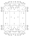
一枚のシートから組み立てられる箱として、図14に示すように、箱本体の四辺形の底壁50の四周側辺にそれぞれ側壁51、51、52、52が連接され、隣接する側壁51、52の側辺間に跨がって外方に2つ折りされる連結片53が連接され、箱本体の各側壁51、51、52、52の上縁および連結片53の外側片部上縁に外方に折り返される折り返し片54、55が連接されていると共に、この外側片部の折り返し片56が一対の対向側壁の折り返し片54の両端に連接され、他の一対の対向側壁の折り返し片55の先端に連結片と側壁との間に折り込まれる折り込み片57が連接され、この折り込み片57が折り返し片56、連結片53と側壁52との間に折り込まれた状態のもとで、一対の対向側壁上部に手掛け部が形成されるものとする段ボール箱が知られている(例えば特許文献1参照。)。 As a box assembled from one sheet, as shown in FIG. 14, side walls 51, 51, 52, 52 are connected to the four peripheral sides of a quadrilateral bottom wall 50 of the box body, and the adjacent side walls 51, 52 A connecting piece 53 that is folded outward in two across the side edges of the box body is connected to the upper edge of each side wall 51, 51, 52, 52 of the box body and the upper edge of the outer piece of the connecting piece 53. Folded pieces 54 and 55 that are folded back in the direction are connected, and a folded piece 56 of this outer piece is connected to both ends of the folded pieces 54 of the pair of opposite side walls, and the folded pieces 55 of the other pair of opposite side walls are connected. A folded piece 57 folded between the connecting piece and the side wall is connected to the tip end of the pair of opposing pieces 57 . A corrugated cardboard box is known in which a handle portion is formed on the upper part of the side wall (see, for example, Patent Document 1).

特開平10-273131号公報JP-A-10-273131

特許文献1に記載されている段ボール箱は、底壁50の四周側辺から側壁51、51、52、52を立ち上げ、隣接する側壁51、52の側辺間に跨がって連接されている連結片53を外方に2つ折りし、各側壁51、51、の上縁に連接されている折り返し片54と、連結片53の外側片部上縁に連接されている折り返し片56を外方に折り返し、外方に2つ折りされた連結片53、53と、連結片53の外側片部上縁に連接され外方に折り返される折り返し片56を側壁52,52の外面に重ね、その上から側壁52、52の上縁に連接されている折り返し片55を外方に折り返して重ね、折り返し片55の先端に連接されている折り込み片57を折り返し片56、連結片53と側壁52との間に折り込むようにして組み立てられるので、組み立てが非常に面倒であるといった問題があった。 The cardboard box described in Patent Document 1 has side walls 51, 51, 52, and 52 raised from the four peripheral sides of a bottom wall 50, and is connected across the sides of the adjacent side walls 51 and 52. A folded piece 54 connected to the upper edge of each side wall 51 and a folded piece 56 connected to the upper edge of the outer side piece of the connecting piece 53 are folded outward in two. The connecting pieces 53, 53 that are folded outward and folded in two outward, and the folded piece 56 that is connected to the upper edge of the outer piece of the connecting piece 53 and is folded outward are superimposed on the outer surfaces of the side walls 52, 52, and are placed thereon. Folded pieces 55 connected to the upper edges of the side walls 52 , 52 are folded outward and overlapped, folded pieces 57 connected to the tips of the folded pieces 55 are folded pieces 56 , and connecting pieces 53 and side walls 52 are connected to each other. There was a problem that the assembly was very troublesome because it was assembled by folding it in between.

また、隣接する側壁51,52の側辺間に跨がって連接され外方に2つ折りされた連結片53、53と、連結片53の外側片部上縁に連接され外方に折り返される折り返し片56が側壁52,52の外面に重ねられ、その上から更に側壁52、52の上縁に連接され外方に折り返される折り返し片55が重ねられるので、箱本体の側壁52,52の外面に出っ張り部ができ、取扱中に、この出っ張り部が障害になる場合があるといった問題があった。 In addition, the connecting pieces 53, 53 connected across the side edges of the adjacent side walls 51, 52 and folded in two outward, and the connecting piece 53 connected to the upper edge of the outer piece portion and folded back outward. The folded piece 56 is superimposed on the outer surfaces of the side walls 52, 52, and the folded piece 55 connected to the upper edges of the side walls 52, 52 and folded outward is superimposed on the outer surface of the side walls 52, 52 of the box body. There is a problem that a protruding portion is formed on the surface of the container, and this protruding portion may become an obstacle during handling.

本発明の目的は、一枚のシートから組み立てられる箱であって、組み立てが容易であり、また、取扱に便利な箱を提供することにある。 SUMMARY OF THE INVENTION An object of the present invention is to provide a box assembled from a single sheet, which is easy to assemble and convenient to handle.

上記の目的を達成するために、請求項1に記載の発明は、一枚のシートから組み立てられる箱であって、矩形状の底部の相対向する二辺にそれぞれ第1折線を介して連接する第1側壁部が設けられ、前記底部の他の相対向する二辺にそれぞれ第2折線を介して連接する第2側壁部が設けられ、隣り合う前記第1側壁部と前記第2側壁部の間に、両側端縁にそれぞれ第3折線、第4折線を介して連接し、前記両側端縁を2辺とする正方形に形成され、第3折線、第4折線の間の対角線を第5折線として内方に二つ折りされ三角形となって前記第2側壁部の内面側に折り込まれる折込部が設けられ、 前記折込部の2つの開放辺には突片部が設けられ、また、前記第2側壁部の開放辺に第6折線を介して連接する係止片部が設けられ、前記係止片部と前記第2側壁部の間に前記折込部に設けられた突片部が嵌合する嵌合口が形成されており、前記係止片部を第6折線から谷折りすることにより、前記嵌合口に前記第2側壁部の内面側に折り込まれた折込部の開放辺に設けられた突片部が嵌合するようにしており、前記折込部の2つの開放辺に設けられた前記突片部にあっては、前記折込部の2つの開放辺の中央部位が、シート厚を超える深さに切り取られて凹部が形成され、凹部の両側の突部を前記突片部としており、前記第2側壁部の開放辺に設けられている前記係止片部は、前記2つの突部からなる一方の前記突片部が嵌合する穴状の前記嵌合口が形成され、その両側に他方の前記突片部が嵌合する溝状の前記嵌合口が両側に形成され、穴状の前記嵌合口と溝状の前記嵌合口との間が前記第2側壁部に連接している連接部となり、前記連接部は前記折込部の2つの開放辺に形成された前記凹部に嵌合可能な幅にとなっており、さらに前記第2側壁部には、前記凹部の深さを超えない範囲で前記連接部の一部を形成する切り込みが設けられ、前記切り込みの先端を結ぶ線が前記第6折線となっていることを特徴とする。 In order to achieve the above object, the invention according to claim 1 is a box assembled from a single sheet, wherein two opposite sides of a rectangular bottom are connected to each other via first folding lines. A first side wall portion is provided, and second side wall portions are provided that are connected to the other two opposite sides of the bottom portion via second fold lines, respectively, and the first side wall portion and the second side wall portion adjacent to each other are provided. It is connected to both side edges via third and fourth folding lines, respectively, is formed in a square having the two side edges as two sides, and the diagonal line between the third and fourth folding lines is the fifth folding line. A folded portion is provided that is folded inwardly into a triangular shape and folded into the inner surface side of the second side wall portion, and two open sides of the folded portion are provided with protruding pieces. A locking piece portion is provided on the open side of the side wall portion so as to be connected via a sixth fold line, and a projecting piece portion provided on the folded portion is fitted between the locking piece portion and the second side wall portion. A fitting opening is formed, and the projection provided on the open side of the folded portion folded into the fitting opening on the inner surface side of the second side wall is formed by folding the locking piece portion along the sixth folding line. The pieces are adapted to fit together, and in the projecting pieces provided on the two open sides of the folded portion, the central portion of the two open sides of the folded portion is deeper than the sheet thickness. The projections on both sides of the recess are the projecting pieces, and the locking piece provided on the open side of the second side wall is separated from the two projections. A hole-shaped fitting opening into which one of the projecting pieces is fitted is formed, and groove-shaped fitting openings into which the other projecting piece is fitted are formed on both sides of the hole-shaped fitting opening. Between the fitting opening and the groove-shaped fitting opening is a connecting portion that is connected to the second side wall portion, and the connecting portion can be fitted into the recesses formed on the two open sides of the folded portion. Further, the second side wall portion is provided with a notch that forms a part of the connecting portion within a range not exceeding the depth of the recess, and a line connecting the tip of the notch is the second side wall portion. It is characterized by having six fold lines .

請求項1に記載の発明によれば、隣り合う前記第1側壁部と前記第2側壁部の間に設けられている前記折込部を、前記第3折線、前記第4折線を谷折りし前記第5折線を山折りして内方に二つ折りしながら、前記底部から前記第1側壁部と前記第2側壁部を前記第1折線、前記第2折線から谷折りして立ち上げ、二つ折りした前記折込部を前記第2側壁部の内面側に折り込み前記第2側壁部の内面に重ね、この状態から、前記第2側壁部の開放辺に設けられている前記係止片部を前記第6折線から谷折りして、前記係止片部と前記第2側壁部の間に形成されてる前記嵌合口に前記第2側壁部の内面側に折り込まれた前記折込部の開放辺に設けられた前記突片部を嵌合するといった簡単な作業で一枚のシートから箱を組み立てることができる。
また、組み立てられた箱の前記第1側壁部と前記第2側壁部の外面には障害となるような出っ張り部を生じさせるようなことは無いので、取扱に便利な箱を得ることができる。
また、前記折込部の開放辺に形成された前記凹部の深さがシート厚を超える深さとなっているので、前記係止片部の前記連接部を前記第6折線から谷折りし、前記折込部の前記凹部に嵌合したとき、前記係止片部の前記連接部の谷折りによって前記係止片部に形成されている前記嵌合口に嵌合した前記折込部の前記突片部の先端が前記係止片部の上面から突出した状態となることから、前記突片部と前記係止片部との間に確実な係止状態が得られ、前記第2側壁部と、前記第2側壁部の内面側に折り込まれた前記折込部を確実に固定することができ、堅牢な箱を得ることができる。
According to the invention of claim 1, the folded portion provided between the adjacent first side wall portion and the second side wall portion is formed by valley-folding the third folding line and the fourth folding line. While folding the fifth folding line into two inwardly, the first side wall portion and the second side wall portion are valley-folded from the first folding line and the second folding line from the bottom portion, raised, and folded in two. The folded portion is folded into the inner surface side of the second side wall portion and overlapped with the inner surface of the second side wall portion. It is provided on the open side of the folded portion folded into the fitting opening formed between the locking piece portion and the second side wall portion on the inner surface side of the second side wall portion by making a valley fold from the 6-fold line. In addition, the box can be assembled from one sheet by a simple operation such as fitting the projecting pieces.
In addition, since the outer surfaces of the first side wall and the second side wall of the assembled box do not have protrusions which may become obstacles, a box which is convenient to handle can be obtained.
Further, since the depth of the recess formed in the open side of the folded portion exceeds the thickness of the sheet, the connecting portion of the locking piece portion is valley-folded from the sixth folding line, and the folded portion is folded. When fitted into the recess of the part, the distal end of the projecting piece of the folded part is fitted into the fitting opening formed in the locking piece by valley folding of the connecting part of the locking piece. protrudes from the upper surface of the locking piece, a reliable locked state is obtained between the projecting piece and the locking piece, and the second side wall and the second The folded portion folded into the inner surface side of the side wall portion can be securely fixed, and a robust box can be obtained.

請求項2に記載の発明は、請求項1に記載の、前記折込部の2つの開放辺に形成された前記凹部と前記突部は、前記折込部を第5折線から二つ折りしたとき重なるように形成されていることを特徴とする。 According to the invention of claim 2, the recess and the protrusion formed on the two open sides of the folded portion according to claim 1 overlap when the folded portion is folded in two from the fifth folding line. It is characterized by being formed as follows.

請求項2に記載の発明によれば、前記折込部の2つの開放辺に形成された前記凹部と前記突部は、前記折込部を第5折線から二つ折りしたとき重なるように形成されているので、前記突片部と前記係止片部との間に確実な係止状態が得られる。 According to the second aspect of the invention, the recess and the protrusion formed on the two open sides of the folded portion are formed so as to overlap each other when the folded portion is folded in two from the fifth folding line. Therefore, a reliable locking state can be obtained between the projecting piece and the locking piece.

請求項3に記載の発明は、請求項2に記載の、前記底部と、前記底部の二辺に設けられた前記第1側壁部と、前記底部の他の相対向する二辺に設けられた第2側壁部と、隣り合う前記第1側壁部と前記第2側壁部の間に設けられた折込部と、前記折込部の2つの開放辺に設けられた突片部と、前記第1側壁部の開放辺に設けられた前記係止片部により組み立てられる箱の開口部に着脱可能に取り付けられ開口部を開閉する内蓋を備えており、前記内蓋は、箱の開口部の内側に納まる矩形状の板状体からなり、前記内蓋の前記第2側壁部側の辺には、前記係止片部に形成された穴状の前記嵌合口と溝状の前記嵌合口に嵌合し、前記係止片部から突出している前記折込部の開放辺に設けられた前記突片部の間に嵌合する嵌合片が形成されていることを特徴とする。 The invention according to claim 3 is characterized in that, according to claim 2, the bottom, the first side wall provided on two sides of the bottom, and the other two sides of the bottom facing each other a second side wall portion; a folded portion provided between the adjacent first side wall portion and the second side wall portion; projecting pieces provided on two open sides of the folded portion; An inner lid is detachably attached to the opening of the box assembled by the locking piece provided on the open side of the box and opens and closes the opening, and the inner lid is placed inside the opening of the box. The side of the inner lid on the second side wall portion side is fitted into the hole-shaped fitting opening and the groove-shaped fitting opening formed in the locking piece portion. A fitting piece is formed between the projecting pieces provided on the open side of the folded portion projecting from the locking piece.

請求項3に記載の発明によれば、組み立てられた箱の開口部に嵌め込み、箱の開口部を簡易に閉じることができる。 According to the third aspect of the invention, the opening of the box can be easily closed by fitting it into the opening of the assembled box.

請求項4に記載の発明は、請求項1または2に記載の、前記底部の相対向する二辺にそれぞれ設けられた前記第1側壁部の内の、一方又は双方の第1側壁部の開放辺に、第7折線を介して連接する内蓋部が設けられていることを特徴とする。 According to the fourth aspect of the present invention, one or both of the first sidewall portions provided on two opposite sides of the bottom portion are opened. It is characterized in that an inner lid portion is provided on the side and connected via the seventh fold line.

請求項4に記載の発明によれば、前記底部の相対向する二辺にそれぞれ設けられた一対の前記第1側壁部の内の、一方又は双方の第1側壁部の開放辺に設けられている内蓋部を第7折線から谷折りすることにより、組み立てられた箱の開口部を簡易に閉じることができる。
また、内蓋部は箱と一体となって設けられているので、別途内蓋を用意する必要が無い。
According to the fourth aspect of the invention, of the pair of first side walls provided on the two opposite sides of the bottom portion, the The opening of the assembled box can be easily closed by valley-folding the inner lid section along the seventh folding line.
In addition, since the inner lid portion is provided integrally with the box, there is no need to prepare an inner lid separately.

請求項5に記載の発明は、請求項1または2に記載の、前記底部の相対向する二辺にそれぞれ設けられた前記第1側壁部の内の、一方又は双方の第1側壁部の開放辺に、第7折線を介して連接する外蓋部が設けられていることを特徴とする。 According to the fifth aspect of the present invention, one or both of the first sidewall portions provided on two opposite sides of the bottom portion are opened. It is characterized in that an outer cover portion is provided on the side and connected via the seventh fold line.

請求項5に記載の発明によれば、前記底部の相対向する二辺にそれぞれ設けられた一対の前記第1側壁部の内の、一方又は双方の第1側壁部の開放辺に設けられている外蓋部を第7折線から谷折りすることにより、組み立てられた箱の開口部を簡易に閉じることができる。
また、外蓋部は箱と一体となって設けられているので、別途外蓋を用意する必要がない。
According to the fifth aspect of the invention, of the pair of first side wall portions provided on two opposite sides of the bottom portion, the The opening of the assembled box can be easily closed by valley-folding the outer lid portion along the seventh folding line.
In addition, since the outer lid portion is provided integrally with the box, there is no need to prepare an outer lid separately.

請求項6に記載の発明は、請求項1~5のいずれか1項に記載の、前記シートは、少なくとも内面となる一面に耐液体性加工が施されていることを特徴とする。 The invention according to claim 6 is the sheet according to any one of claims 1 to 5, wherein at least one inner surface of the sheet is subjected to liquid-resistant processing.

請求項6に記載の発明によれば、前記シートは、少なくとも内面となる一面に耐液体性加工が施されているので、内容物が液状物であっても内容物が漏れたり、また箱が脆弱化してしまうといったおそれがない。 According to the sixth aspect of the invention, at least one inner surface of the sheet is processed to be liquid-resistant. There is no danger of becoming vulnerable.

請求項7に記載の発明は、請求項1~6のいずれか1項に記載の、前記シートは、紙製であることを特徴とする。 The invention according to claim 7 is characterized in that the sheet according to any one of claims 1 to 6 is made of paper.

請求項7に記載の発明によれば、前記シートは紙製であるので、使用後の廃棄が容易で有り、また資源としての再利用が可能となる。 According to the seventh aspect of the invention, since the sheet is made of paper, it can be easily discarded after use and can be reused as a resource.

請求項8に記載の発明は、請求項1~7のいずれか1項に記載の、前記シートは、段ボールシートであることを特徴とする。 The invention according to claim 8 is characterized in that the sheet according to any one of claims 1 to 7 is a cardboard sheet.

請求項8に記載の発明によれば、前記シートは、段ボールシートであるので、軽量で且つ堅牢な箱を得ることができ、また、取扱や製造が容易である。 According to the eighth aspect of the invention, since the sheet is a corrugated cardboard sheet, a lightweight and robust box can be obtained, and handling and manufacturing are easy.

以上のように、本発明に係る箱によれば、組み立てが容易であり、また、取扱に便利な箱を得ることができる。 As described above, according to the box according to the present invention, it is possible to obtain a box that is easy to assemble and convenient to handle.

本発明に係る箱の実施の形態の第1例を示す斜視図である。BRIEF DESCRIPTION OF THE DRAWINGS It is a perspective view which shows the 1st example of embodiment of the box which concerns on this invention. 図1に示す箱の展開図である。FIG. 2 is an exploded view of the box shown in FIG. 1; 図1に示す箱を組み立てる過程を示す説明図である。It is explanatory drawing which shows the process which assembles the box shown in FIG. 図1に示す箱の開口部に取り付ける内蓋の一例を示す平面図である。FIG. 2 is a plan view showing an example of an inner lid attached to the opening of the box shown in FIG. 1; 図1に示す箱の開口部に内蓋を取り付けた状態を示す平面図である。FIG. 2 is a plan view showing a state in which an inner lid is attached to the opening of the box shown in FIG. 1; 本発明に係る箱の実施の形態の第2例を示す斜視図である。Fig. 2 is a perspective view showing a second example of an embodiment of a box according to the present invention; 図6に示す箱の展開図である。FIG. 7 is an exploded view of the box shown in FIG. 6; 本発明に係る箱の実施の形態の第3例を示す斜視図である。FIG. 11 is a perspective view showing a third embodiment of a box according to the present invention; 図8に示す箱の展開図である。FIG. 9 is an exploded view of the box shown in FIG. 8; 本発明に係る箱の実施の形態の第4例を示す斜視図である。Fig. 10 is a perspective view showing a fourth example of an embodiment of a box according to the present invention; 図10に示す箱の展開図である。FIG. 11 is an exploded view of the box shown in FIG. 10; 外蓋の一例を示す平面図である。It is a top view which shows an example of an outer cover. 図12に示す外蓋を箱に被せた状態を示す説明図である。13 is an explanatory view showing a state in which the outer lid shown in FIG. 12 is put on the box; FIG. 従来の箱を示す斜視図である。It is a perspective view showing a conventional box.

以下、本発明に係る箱の形態の一例を、図面を参照して詳細に説明する。
図1~図5は本発明に係る箱の実施の形態の第1例を示すものであり、図1は第1例の箱の斜視図、図2は図1に示す箱の展開図、図3は図1に示す箱を組み立てる過程を示す説明図、図4は図1に示す箱の開口部に取り付ける内蓋の一例を示す平面図、図5は図1に示す箱の開口部に内蓋を取り付けた状態を示す平面図である。
Hereinafter, an example of the form of the box according to the present invention will be described in detail with reference to the drawings.
1 to 5 show a first embodiment of a box according to the present invention. FIG. 1 is a perspective view of the box of the first example, and FIG. 2 is an exploded view of the box shown in FIG. 3 is an explanatory diagram showing the process of assembling the box shown in FIG. 1, FIG. 4 is a plan view showing an example of an inner lid attached to the opening of the box shown in FIG. 1, and FIG. It is a top view which shows the state which attached the lid|cover.

第1例の箱1は、一枚のシートから組み立てられる。
使用されるシートとしてはシート状の材料であれば特に限定されないが、例えば、紙製シート、プラスチック製シート等が使用される。紙製シートとしては厚紙シート、白板紙シート、紙段ボールシート等があり、またプラスチック製シートとしては、プラスチック板状シート、プラスチック段ボールシート等がある。
The box 1 of the first example is assembled from one sheet.
The sheet to be used is not particularly limited as long as it is a sheet-shaped material, and for example, a paper sheet, a plastic sheet, or the like is used. Paper sheets include cardboard sheets, white paperboard sheets, paper cardboard sheets, and the like, and plastic sheets include plastic plate sheets, plastic cardboard sheets, and the like.

また、シートには、少なくとも箱の内面となる一面に耐液体性加工が施されているものを使用することができる。耐液体性加工にあっては、厚紙シート、白板紙シート、紙段ボールシート等の紙製シートに、耐液体性のフィルムをラミネートし、或いは耐液体性の塗料をコーティングしてもよく、また、紙層に耐液性剤を含有させてもよい。
第1例では、箱1を組み立てるシートとして、箱1の内面となる一面に耐液体性の塗料がコーティングされた紙製の段ボールシートが使用されている。
In addition, the sheet may be one in which at least one surface, which is the inner surface of the box, is subjected to liquid-resistant processing. For liquid-resistant processing, paper sheets such as cardboard sheets, white paperboard sheets, paper corrugated sheets, etc. may be laminated with a liquid-resistant film or coated with a liquid-resistant paint. The paper layer may contain a liquid-resistant agent.
In the first example, as a sheet for assembling the box 1, a corrugated cardboard sheet made of paper coated with a liquid-resistant paint is used on the inner surface of the box 1. As shown in FIG.

このような段ボールシートで形成される第1例の箱1は、図2の展開図で示すように、矩形状の底部2の相対向する二辺にそれぞれ第1折線3を介して第1側壁部4が設けられ、底部2の他の相対向する二辺にそれぞれ第2折線5を介して第2側壁部6が設けられている。 The box 1 of the first example formed of such a corrugated cardboard sheet has, as shown in the developed view of FIG. A portion 4 is provided, and second side wall portions 6 are provided on the other two opposite sides of the bottom portion 2 with second folding lines 5 interposed therebetween.

隣り合う第1側壁部4と第2側壁部6の間には、両側端縁にそれぞれ第3折線7、第4折線8を介して連接し、両側端縁を2辺とする正方形に形成され、第3折線7、第4折線8の間の対角線を第5折線9として内方に二つ折りされ三角形となって第2側壁部6の内面側に折り込まれる折込部10が設けられている。 Between the first side wall portion 4 and the second side wall portion 6 which are adjacent to each other, there is formed a square having two side edges which are connected to both side edges via a third folding line 7 and a fourth folding line 8, respectively. , and a diagonal line between the third folding line 7 and the fourth folding line 8 is a fifth folding line 9, and a folded portion 10 is provided to be folded inwardly into a triangular shape on the inner surface side of the second side wall portion 6.例文帳に追加

折込部10の2つの開放辺には突片部11a,11bが設けられている。第1例では、折込部10の2つの開放辺の中央部位が、シート厚を超える深さに切り取られて凹部12が形成され、凹部12の両側の突部13a,13bを突片部11a,11bとしており、折込部10の2つの開放辺に形成された凹部12同士が、そして突部13a,13b同士が折込部10を第5折線9から二つ折りしたとき重なるように形成されている。 Two open sides of the folding portion 10 are provided with projecting pieces 11a and 11b. In the first example, the central portion of the two open sides of the folded portion 10 is cut to a depth exceeding the thickness of the sheet to form the concave portion 12. The concave portions 12 formed on the two open sides of the folded portion 10 and the protrusions 13a and 13b overlap each other when the folded portion 10 is folded in half from the fifth folding line 9. As shown in FIG.

折込部10の2つの開放辺の中央部位を切り取って形成される凹部12の切り取り深さは、シート厚の2倍から3倍の深さが好ましい。凹部12の切り取り深さがシート厚の2倍から3倍の深さであると、突片部11a,11bを後述する係止片部の嵌合口に嵌合したとき、突片部11a,11bの先端が係止片部の嵌合口から少なくともシート厚以上の幅で突出するので、突片部11a,11bと係止片部との間に確実な係止状態が得られる。また、後述する内蓋を組み立てられた箱1の開口部にしっかりと被せることができる。第1例では、凹部12の切り取り深さはシート厚の3倍の深さとなっている。 The cut depth of the recess 12 formed by cutting the central portion of the two open sides of the folded portion 10 is preferably two to three times the thickness of the sheet. When the cutout depth of the concave portion 12 is two to three times the sheet thickness, when the projecting pieces 11a and 11b are fitted into the fitting openings of the locking piece portions described later, the projecting pieces 11a and 11b are cut. protrudes from the fitting opening of the locking piece by at least a width equal to or greater than the thickness of the sheet, so that a reliable locking state can be obtained between the projecting pieces 11a and 11b and the locking piece. Also, the opening of the assembled box 1 can be tightly covered with an inner lid, which will be described later. In the first example, the cut depth of the recess 12 is three times the thickness of the sheet.

また、第2側壁部6の開放辺に第6折線14を介して連接する係止片部15が設けられ、係止片部15と第2側壁部6の間に折込部10に設けられた突片部11a,11bが嵌合する嵌合口16a,16bが形成されており、係止片部15を第6折線14から谷折りすることにより、嵌合口16a,16bに第2側壁部の内面側に折り込まれた折込部10に設けられた突片部11a,11bが嵌合するようになっている。 In addition, a locking piece 15 is provided on the open side of the second side wall 6 and connected to the open side of the second side wall 6 via a sixth folding line 14 . Fitting openings 16a and 16b into which the projecting pieces 11a and 11b are fitted are formed. Projecting pieces 11a and 11b provided on the folded portion 10 folded inward are fitted.

第2側壁部6の開放辺に設けられている係止片部15にあっては、第1例では、係止片部15の中央に第2側壁部6の開放辺に沿って、重なり合う2つの突部13a,13aからなる一方の突片部11aが嵌合する穴状の嵌合口16aが中央に形成され、係止片部15の両側に第2側壁部6の開放辺に沿って、重なり合う2つの突部13b,13bからなる他方の突片部11bが嵌合する溝状の嵌合口16bが形成されている。 As for the locking piece 15 provided on the open side of the second side wall 6, in the first example, the center of the locking piece 15 along the open side of the second side wall 6 overlaps two A hole-shaped fitting opening 16a into which one projecting piece 11a consisting of two projections 13a, 13a is fitted is formed in the center, and along the open side of the second side wall portion 6 on both sides of the locking piece portion 15, A groove-like fitting opening 16b is formed in which the other projecting piece portion 11b composed of the two overlapping projecting portions 13b, 13b is fitted.

そして、穴状の嵌合口16aと溝状の嵌合口16bとの間が第2側壁部6に連接している連接部17となり、連接部17は折込部10の2つの開放辺に形成された凹部12に嵌合可能な幅となっており、さらに第2側壁部6には、凹部12の深さを超えない範囲で連接部17の一部を形成する切り込み18が設けられ、切り込み18の先端を結ぶ線が第6折線14となっている。 A connecting portion 17 connecting to the second side wall portion 6 is formed between the hole-shaped fitting opening 16a and the groove-shaped fitting opening 16b. The second side wall portion 6 is provided with a notch 18 that forms a part of the connecting portion 17 within a range not exceeding the depth of the recess 12 . A line connecting the ends is a sixth folding line 14 .

このような展開構造を有する第1例の箱1は、次のようにして組み立てられる。
先ず、底部2の相対向する二辺に設けられている第1側壁部4を第1折線3から谷折りして立ち上げるとともに、底部2の他の相対向する二辺に設けられている第2側壁部6を第2折線5から谷折りして立ち上げ、この第1側壁部4と第2側壁部6の立ち上げと同期して、隣り合う第1側壁部4と第2側壁部6の間に設けられている正方形の折込部10を、対角線となる第5折線9を山折りし、第3折線7、第4折線8を谷折りして内方に二つ折りして三角形とし、第2側壁部6の内面側に折り込む。
折込部10を内方に二つ折りして三角形としたとき、折込部10の2つの開放辺に形成された凹部12同士と、突部13a,13b同士が重なり、重なった突部13a,13bが折込部10の開放辺に設けられる突片部11a,11bとなる(図3参照。)。
The box 1 of the first example having such a developed structure is assembled as follows.
First, the first side wall portions 4 provided on the two opposite sides of the bottom portion 2 are raised from the first folding lines 3 by valley-folding, and the other two opposite sides of the bottom portion 2 are folded. The two side walls 6 are valley-folded from the second folding line 5 and raised, and in synchronism with the raising of the first side wall 4 and the second side wall 6, the first side wall 4 and the second side wall 6 are adjacent to each other. The square folded portion 10 provided between is folded into a triangle by mountain-folding the fifth folding line 9 that is a diagonal line, valley-folding the third folding line 7 and the fourth folding line 8, and folding inward in two, It is folded inside the second side wall portion 6 .
When the folded portion 10 is folded inward to form a triangle, the concave portions 12 formed on the two open sides of the folded portion 10 and the protrusions 13a and 13b overlap each other, and the overlapping protrusions 13a and 13b overlap each other. These are projecting pieces 11a and 11b provided on the open side of the folded portion 10 (see FIG. 3).

次に、第2側壁部6の開放辺に設けられている係止片部15を第6折線14から谷折りして内方に倒し、係止片部15と第2側壁部6の間に形成されている嵌合口16a,16bに折込部10に設けられた突片部11a,11bを嵌合させる。 Next, the locking piece portion 15 provided on the open side of the second side wall portion 6 is valley-folded from the sixth fold line 14 and folded inward, so that the locking piece portion 15 and the second side wall portion 6 are separated from each other. The protrusions 11a and 11b provided in the folded portion 10 are fitted into the formed fitting openings 16a and 16b.

第1例では、係止片部15にあっては、係止片部15の中央に第2側壁部6の開放辺に沿って、重なり合う2つの突部13a,13aからなる一方の突片部11aが嵌合する穴状の嵌合口16aが係止片部15と第2側壁部6の間における中央に形成され、係止片部15の両側に第2側壁部6の開放辺に沿って、重なり合う2つの突部13b,13bからなる他方の突片部11bが嵌合する溝状の嵌合口16bが形成されており、穴状の嵌合口16aと溝状の嵌合口16bとの間が第2側壁部6に連接している連接部17となり、連接部17は折込部10の2つの開放辺に形成された凹部12に嵌合可能な幅にとなっており、さらに第2側壁部6には、凹部12の深さを超えない範囲で連接部17の一部を形成する切り込み18が設けられ、切り込み18の先端を結ぶ線が第6折線14となっており、係止片部15を第6折線14から谷折りして内方に倒し、連接部17を凹部12に嵌合することにより、折込部10に設けられた突片部11a,11bを係止片部15と第2側壁部6の間に形成されている嵌合口16a,16bに嵌合させる。
このようにして箱1の組み立てが完了する(図3参照。)。
In the first example, in the locking piece 15, one of the projections 13a, 13a is formed along the open side of the second side wall 6 at the center of the locking piece 15 and consists of two overlapping projections 13a, 13a. A hole-shaped fitting opening 16a into which 11a is fitted is formed in the center between the locking piece 15 and the second side wall 6, and is formed on both sides of the locking piece 15 along the open side of the second side wall 6 A groove-like fitting opening 16b is formed in which the other projecting piece portion 11b consisting of two overlapping projections 13b and 13b is fitted, and the gap between the hole-like fitting opening 16a and the groove-like fitting opening 16b is formed. It becomes a connecting portion 17 connected to the second side wall portion 6, and the connecting portion 17 has a width that can be fitted into the concave portions 12 formed on the two open sides of the folded portion 10, and furthermore, the second side wall portion. 6 is provided with a notch 18 that forms a part of the connecting portion 17 within a range not exceeding the depth of the recess 12, and a line connecting the tips of the notch 18 is a sixth folding line 14, and the locking piece portion 15 is bent inward from the sixth folding line 14, and the connecting portion 17 is fitted into the concave portion 12, so that the projecting pieces 11a and 11b provided in the folded portion 10 are connected The fitting openings 16a and 16b formed between the two side wall portions 6 are fitted.
Thus, the assembly of the box 1 is completed (see FIG. 3).

このように第1例の箱1は、隣り合う第1側壁部4と第2側壁部6の間に設けられている折込部10を内方に二つ折りしながら、底部2から第1側壁部4と第2側壁部6を立ち上げ、二つ折りした折込部を第2側壁部6の内面側に折り込んで第2側壁部6の内面に重ね、この状態から、第2側壁部6の開放辺に設けられている係止片部15を第6折線14から谷折りして、係止片部15と第2側壁部6の間に形成されてる嵌合口16a,16bに第2側壁部6の内面側に折り込まれた折込部10の開放辺に設けられた突片部11a,11bを嵌合させるといった簡単な作業で容易に組み立てることができる。 In this way, the box 1 of the first example can be folded from the bottom portion 2 to the first side wall portion while folding inwardly the folding portion 10 provided between the adjacent first side wall portion 4 and the second side wall portion 6 . 4 and the second side wall portion 6 are raised, the folded portion is folded into the inner surface side of the second side wall portion 6 and overlapped with the inner surface of the second side wall portion 6, and from this state, the open side of the second side wall portion 6 is The locking piece portion 15 provided in the second side wall portion 6 is folded into the fitting openings 16 a and 16 b formed between the locking piece portion 15 and the second side wall portion 6 by folding the locking piece portion 15 along the sixth folding line 14 . It can be easily assembled by a simple work of fitting the projecting pieces 11a and 11b provided on the open sides of the folded portion 10 folded inward.

また、第1例では、折込部10の2つの開放辺に設けられている突片部11a,11bは、折込部10の2つの開放辺の中央部位が、シート厚を超える深さに切り取られて凹部12が形成され、凹部12の両側の突部13a,13bを突片部11a,11bとしており、折込部10の2つの開放辺に形成された凹部12同士が、そして突部13a,13b同士が折込部10を第5折線9から二つ折りしたとき重なるように形成されている。 In the first example, the projecting pieces 11a and 11b provided on the two open sides of the folded portion 10 are cut to a depth exceeding the thickness of the sheet at the central portions of the two open sides of the folded portion 10. The recessed portion 12 is formed on both sides of the recessed portion 12, and the projecting portions 11a and 11b are formed on both sides of the recessed portion 12. They are formed so that they overlap each other when the folded portion 10 is folded in two along the fifth folding line 9 .

そして、係止片部15にあっては、係止片部15の中央に第2側壁部6の開放辺に沿って、重なり合う2つの突部13a,13aからなる一方の突片部11aが嵌合する穴状の嵌合口16aが中央に形成され、係止片部15の両側に第2側壁部6の開放辺に沿って、重なり合う2つの突部13b,13bからなる他方の突片部11bが嵌合する溝状の嵌合口16bが形成されており、穴状の嵌合口16aと溝状の嵌合口16bとの間が第2側壁部6に連接している連接部17となり、連接部17は折込部10の2つの開放辺に形成された凹部12に嵌合可能な幅にとなっており、さらに第2側壁部6には、凹部12の深さを超えない範囲で連接部17の一部を形成する切り込み18が設けられ、切り込み18の先端を結ぶ線が第6折線14となっているので、第2側壁部6の開放辺に設けられている係止片部15を第6折線14から谷折りして内方に倒し、連接部17を凹部12に嵌合させることにより、折込部10に設けられた突片部11a,11bが係止片部15と第2側壁部6の間に形成されている嵌合口16a,16bに嵌合し、嵌合口16a,16bに嵌合した突片部11a,11bは、その先端が係止片部15の嵌合口16a,16bから突出した状態となるので、突片部11a,11bと係止片部15との間に確実な係止状態が得られ、第2側壁部6と、第2側壁部6の内面側に折り込まれた折込部10を確実に固定することができ、堅牢な箱1を得ることができる。 In the locking piece portion 15, one projecting piece portion 11a composed of two overlapping projections 13a, 13a is fitted in the center of the locking piece portion 15 along the open side of the second side wall portion 6. A matching hole-shaped fitting opening 16a is formed in the center, and the other projecting piece portion 11b consists of two overlapping projecting portions 13b, 13b along the open side of the second side wall portion 6 on both sides of the locking piece portion 15. A groove-shaped fitting opening 16b into which is fitted is formed. 17 has a width that can be fitted into the recessed portions 12 formed on the two open sides of the folded portion 10, and the second side wall portion 6 has connecting portions 17 within a range not exceeding the depth of the recessed portions 12. and a line connecting the tips of the cuts 18 is the sixth folding line 14, so that the locking piece portion 15 provided on the open side of the second side wall portion 6 can be moved to the second side wall portion 6. By folding the connecting portion 17 into the concave portion 12 by making a valley fold along the 6-fold line 14 and fitting the connecting portion 17 into the concave portion 12, the projecting portions 11a and 11b provided in the folded portion 10 are connected to the locking portion 15 and the second side wall portion. The protruding pieces 11a and 11b fitted into the fitting openings 16a and 16b formed between the fitting openings 16a and 16b have their tips extending from the fitting openings 16a and 16b of the locking piece portion 15. Since it is in a protruding state, a reliable locking state is obtained between the projecting pieces 11a and 11b and the locking piece 15, and the second side wall portion 6 and the inner surface side of the second side wall portion 6 are folded. In addition, the folding part 10 can be surely fixed, and a strong box 1 can be obtained.

特に、第1例では、凹部12の切り取り深さはシート厚の3倍の深さとなっているので、嵌合口16a,16bに嵌合した突片部11a,11bは、その先端が係止片部15の嵌合口から少なくともシート厚以上の幅で突出するので、突片部11a,11bと係止片部15との間に一層確実な係止状態が得られ、一層堅牢な箱1を得ることができる。 In particular, in the first example, since the cut depth of the concave portion 12 is three times the sheet thickness, the projecting pieces 11a and 11b fitted in the fitting openings 16a and 16b have locking pieces at their tips. Since it protrudes from the fitting opening of the portion 15 with a width of at least the thickness of the sheet, a more reliable locking state can be obtained between the projecting pieces 11a, 11b and the locking piece 15, and a more robust box 1 can be obtained. be able to.

また、組み立てられた箱1の第1側壁部4と第2側壁部6の外面には障害となるような出っ張り部を生じさせるようなことは無いので、取扱に便利な箱を得ることができる。 In addition, since the outer surfaces of the first side wall portion 4 and the second side wall portion 6 of the assembled box 1 do not have protrusions which may become obstacles, a box which is convenient to handle can be obtained. .

また、第1例の箱1は、着脱可能に取り付けられる内蓋20を備えている。
内蓋20は、箱1の開口部の内側に納まる矩形状の板状体からなり、内蓋20の第2側壁部側の辺には、係止片部15に形成された穴状の嵌合口16aと溝状の嵌合口16bに嵌合し、係止片部15から突している折込部10の開放辺に設けられた突片部11aと突片部11bの間に嵌合する嵌合片21が形成されている(図4参照。)。板状体は箱1と同じシート状の材料が使用される。
Moreover, the box 1 of the first example includes an inner lid 20 that is detachably attached.
The inner lid 20 is made of a rectangular plate-like body that fits inside the opening of the box 1 . Fitted into the abutment 16a and the groove-shaped fitting opening 16b, and fitted between the projecting piece 11a and the projecting piece 11b provided on the open side of the folding portion 10 projecting from the locking piece portion 15. A joint piece 21 is formed (see FIG. 4). The same sheet-like material as the box 1 is used for the plate-like body.

このように構成された内蓋20を箱1の開口部へ取り付けて閉じる場合、内蓋20を箱1の開口部へ嵌め込む(図5参照。)。
箱1の開口部へ嵌め込まれた内蓋20は、その内面が箱1の内方に折り曲げられている係止片部15に当接するとともに、内蓋20の第2側壁部側の辺に形成されている嵌合片21が折込部10の開放辺に形成された凹部12に嵌合し、この凹部12に嵌合している係止片部15の連接部17に当接する。このようにして箱1の開口部に内蓋20が取り付けられ、箱1の開口部が閉じられる。
When the inner lid 20 configured in this manner is attached to the opening of the box 1 and closed, the inner lid 20 is fitted into the opening of the box 1 (see FIG. 5).
The inner lid 20 fitted into the opening of the box 1 abuts on the locking piece 15 bent inwardly of the box 1, and is formed on the side of the inner lid 20 on the side of the second side wall. The fitted piece 21 fits into the recess 12 formed in the open side of the folded portion 10 and abuts on the connecting portion 17 of the locking piece 15 fitted into the recess 12 . In this manner, the inner lid 20 is attached to the opening of the box 1 and the opening of the box 1 is closed.

このように箱1の開口部を閉じる場合、箱1の開口部に内蓋20を嵌合するといった簡単な作業で箱1の開口部に内蓋20を取り付け、箱1の開口部を閉じることができる。
また、箱1の開口部を閉じている内蓋20を取り外す場合は、凹部12に嵌合し、第2側壁部6の外面に現れている内蓋20の嵌合片21の端部に指を掛け、引き上げるといった簡単な作業で箱1の開口部から内蓋20を取り外し、箱1の開口部を開けることができる。
When closing the opening of the box 1 in this way, the opening of the box 1 can be closed by attaching the inner lid 20 to the opening of the box 1 by a simple operation such as fitting the inner lid 20 to the opening of the box 1. can be done.
When the inner lid 20 closing the opening of the box 1 is to be removed, the end portion of the fitting piece 21 of the inner lid 20 which is fitted in the recess 12 and appears on the outer surface of the second side wall portion 6 is The opening of the box 1 can be opened by removing the inner lid 20 from the opening of the box 1 by simple work such as hanging the lid and pulling it up.

図6、図7は本発明に係る箱の実施の形態の第2例を示すものであり、図6は第2例の箱の斜視図、図7は図6に示す箱の展開図である。
第2例の箱1は、第1例の箱1と基本構成において変わるところはなく、第1例と同一の構成については同一の符号を付して説明する。
6 and 7 show a second embodiment of the box according to the present invention. FIG. 6 is a perspective view of the box of the second example, and FIG. 7 is an exploded view of the box shown in FIG. .
The box 1 of the second example has the same basic configuration as the box 1 of the first example, and the same components as those of the first example are denoted by the same reference numerals.

第2例と第1との違いは、第2例では、折込部10の2つの開放辺に設けられている突片部11a,11bが嵌合する係止片部15と第2側壁部6の間に形成されている嵌合口16a,16bの構成にある。
第2例では、係止片部15と第2側壁部6の間における中央部位に、第2側壁部6の両側から第2側壁部6の内面側に折り込まれる2つの折込部10に設けられている突片部11a,11aをそれぞれ嵌合する2つの穴状の嵌合口16a,16aが形成されている。そして、嵌合口16a,16aの間は第2側壁部6に連接している連接部17となる。
その他の構成は、第1例と同様なので、第1例を援用し、その説明を省略する。
The difference between the second example and the first example is that, in the second example, the locking piece portion 15 and the second side wall portion 6 are engaged with the projecting piece portions 11a and 11b provided on the two open sides of the folding portion 10. The fitting openings 16a and 16b are formed between them.
In the second example, two folded portions 10 are provided at the central portion between the locking piece portion 15 and the second side wall portion 6 to be folded from both sides of the second side wall portion 6 toward the inner surface side of the second side wall portion 6. Two hole-shaped fitting openings 16a, 16a are formed for fitting the projecting pieces 11a, 11a, respectively. A connecting portion 17 connected to the second side wall portion 6 is formed between the fitting openings 16a, 16a.
Since other configurations are similar to those of the first example, the first example is used and the description thereof is omitted.

このように構成された第2例の箱1は、第1例の箱1と同様に組み立てられる。
組み立てられた第2例の箱1は、嵌合口16a,16aと突片部11a,11aとの間がしっかりした嵌合状態となり、第2側壁部6と、第2側壁部6の内面側に折り込まれた折込部10を確実に固定することができ、一層堅牢な箱1を得ることができる。
その他の作用効果は第1例と同様である。
The box 1 of the second example constructed in this manner is assembled in the same manner as the box 1 of the first example.
In the assembled box 1 of the second example, the fitting openings 16a, 16a and the projecting pieces 11a, 11a are firmly fitted, and the second side wall portion 6 and the inner surface side of the second side wall portion 6 The folded part 10 can be surely fixed, and a more robust box 1 can be obtained.
Other effects are the same as those of the first example.

図8、図9は本発明に係る箱の実施の形態の第3例を示すものであり、図8は第3例の箱の斜視図、図9は図8に示す箱の展開図である。
第3例の箱1は、第1例の箱1と基本構成において変わるところはなく、第1例と同一の構成については同一の符号を付して説明する。
8 and 9 show a third embodiment of the box according to the present invention, FIG. 8 is a perspective view of the box of the third example, and FIG. 9 is an exploded view of the box shown in FIG. .
The box 1 of the third example has the same basic configuration as the box 1 of the first example, and the same components as those of the first example are denoted by the same reference numerals.

第3例と第1例との違いは、第3例の箱1は第1例の構成にない内蓋部22が設けられているところにある。
第3例では、底部2の相対向する二辺にそれぞれ設けられた第1側壁部4の開放辺に、第7折線23を介して連接する内蓋部22が設けられている。内蓋部22は中央で2分割した形状となっている。第7折線23にあっては、第1側壁部4と折込部10が連接している第3折線7に凹部12の深さを超えない範囲で切り込み24が設けられ、切り込み24の先端を結ぶ線が第7折線23となっている。
The difference between the third example and the first example is that the box 1 of the third example is provided with an inner lid portion 22 which is not provided in the structure of the first example.
In the third example, an inner lid portion 22 is provided that connects via a seventh folding line 23 to the open sides of the first side wall portions 4 that are provided on two opposite sides of the bottom portion 2 . The inner lid portion 22 has a shape divided into two at the center. In the seventh fold line 23, a notch 24 is provided in a range not exceeding the depth of the recess 12 on the third fold line 7 where the first side wall portion 4 and the folded portion 10 are connected, and the tip of the notch 24 is connected. The line is the seventh folding line 23 .

また、内蓋部22における第2側壁部6側の開放辺には、隣接する折込部10の開放辺に形成された凹部12に嵌合可能な嵌合片25が形成されている。
その他の構成は、第1例と同様なので、第1例を援用し、その説明を省略する。
A fitting piece 25 is formed on the open side of the inner lid portion 22 on the side of the second side wall portion 6 so as to fit into the concave portion 12 formed on the open side of the adjacent folding portion 10 .
Since other configurations are similar to those of the first example, the first example is used and the description thereof is omitted.

このように構成された第3例の箱1は、第1例の箱1と同様に組み立てられる。そして、組み立てられた箱1の開口部を閉じる場合、内蓋部22を第7折線23から谷折りして内方に折り曲げ、嵌合片25を折込部10の開放辺に形成された凹部12に嵌合させる(図8参照。)。 The box 1 of the third example constructed in this manner is assembled in the same manner as the box 1 of the first example. When the opening of the assembled box 1 is to be closed, the inner lid portion 22 is folded inward along the seventh folding line 23, and the fitting piece 25 is folded into the concave portion 12 formed on the open side of the folding portion 10. (see FIG. 8).

このようにして、それぞれの第1側壁部4の開放辺設けられている内蓋部22を内方へ折り曲げ、嵌合片25を折込部10の開放辺に形成された凹部12に嵌合させることにより、箱1の開口部が閉じられる。 In this manner, the inner lid portion 22 provided on the open side of each first side wall portion 4 is bent inward, and the fitting piece 25 is fitted into the recessed portion 12 formed on the open side of the folded portion 10 . Thereby, the opening of the box 1 is closed.

このように第3例の箱1によれば、箱1の開口部を閉じる場合、それぞれの第1側壁部4の開放辺設けられている内蓋部22を内方へ折り曲げ、嵌合片25を折込部10の開放辺に形成された凹部12に嵌合するといった簡単な作業で箱1の開口部を閉じることができる。また、内蓋部22は箱1と一体となって設けられているので、別途内蓋を用意する必要が無い。 As described above, according to the box 1 of the third example, when closing the opening of the box 1, the inner lid portion 22 provided on the open side of each first side wall portion 4 is bent inward, and the fitting piece 25 is bent inward. The opening of the box 1 can be closed by a simple operation such as fitting the opening into the recess 12 formed on the open side of the folding part 10.例文帳に追加In addition, since the inner lid portion 22 is provided integrally with the box 1, there is no need to prepare an inner lid separately.

なお、第3例では、内蓋部22はそれぞれの第1側壁部4に設けているが、図示しないが、いずれか一方の第1側壁部に設けてもよい。この場合、内蓋部22は図8に示す内蓋部22の2倍の大きさとする。
その他の作用効果は第1例と同様である。
In the third example, the inner cover portion 22 is provided on each first side wall portion 4, but may be provided on either one of the first side wall portions, although not shown. In this case, the inner lid portion 22 is twice the size of the inner lid portion 22 shown in FIG.
Other effects are the same as those of the first example.

図10、図11は本発明に係る箱の実施の形態の第4例を示すものであり、図10は第4例の箱の斜視図、図11は図10に示す箱の展開図である。
第4例の箱1は、第1例の箱1と基本構成において変わるところはなく、第1例と同一の構成については同一の符号を付して説明する。
10 and 11 show a fourth embodiment of the box according to the present invention, FIG. 10 is a perspective view of the box of the fourth example, and FIG. 11 is a developed view of the box shown in FIG. .
The box 1 of the fourth example has the same basic configuration as the box 1 of the first example.

第4例と第1例との違いは、第4例の箱1は第1例の構成にない外蓋部26が設けられているところにある。
第4例では、底部2の相対向する二辺にそれぞれ設けられた第1側壁部4の開放辺に、第7折線23を介して連接する外蓋部26が設けられている。外蓋部26は中央で2分割した形状となっている。また、外蓋部26の第2側壁部6側の開放辺が、第1側壁部4より僅かに出ている。
その他の構成は、第1例と同様なので、第1例を援用し、その説明を省略する。
The difference between the fourth example and the first example is that the box 1 of the fourth example is provided with an outer lid portion 26 which is not provided in the configuration of the first example.
In the fourth example, an outer lid portion 26 is provided that connects via a seventh folding line 23 to the open sides of the first side wall portion 4 that are provided on two opposite sides of the bottom portion 2 . The outer lid portion 26 has a shape divided into two at the center. Further, the open side of the outer lid portion 26 on the side of the second side wall portion 6 protrudes slightly from the first side wall portion 4 .
Since other configurations are similar to those of the first example, the first example is used and the description thereof is omitted.

このように構成された第4例の箱1は、第1例の箱1と同様に組み立てられる。そして、組み立てられた箱1の開口部を閉じる場合、外蓋部26を第7折線23から谷折りして内方に折り曲げ、第2側壁部6側の開放辺を第2側壁部6の開放側先端に当接させる(図10参照。)。 The box 1 of the fourth example constructed in this manner is assembled in the same manner as the box 1 of the first example. When closing the opening of the assembled box 1, the outer cover 26 is folded inward along the seventh fold line 23, and the open side on the side of the second side wall 6 is opened to open the second side wall 6. Abut on the side tip (see FIG. 10).

このようにして、それぞれの第1側壁部4の開放辺設けられている外蓋部26を内方へ折り曲げ、第2側壁部6側の開放辺を第2側壁部6の開放側先端に当接させることにより、箱1の開口部が閉じられる。 In this manner, the outer lid portion 26 provided on the open side of each first side wall portion 4 is bent inward, and the open side of the second side wall portion 6 is brought into contact with the open end of the second side wall portion 6. The contact closes the opening of the box 1 .

このように第4例の箱1によれば、箱1の開口部を閉じる場合、それぞれの第1側壁部4の開放辺設けられている外蓋部26を内方へ折り曲げ、第2側壁部6側の開放辺を第2側壁部6の開放側先端に当接させるといった簡単な作業で箱1の開口部を閉じることができる。また、外蓋部26は箱1と一体となって設けられているので、別途外蓋を用意する必要が無い。 Thus, according to the box 1 of the fourth example, when closing the opening of the box 1, the outer cover 26 provided on the open side of each of the first side walls 4 is folded inward, and the second side walls are closed. The opening of the box 1 can be closed by a simple operation such as bringing the open side on the 6 side into contact with the open side tip of the second side wall portion 6 . Further, since the outer lid portion 26 is provided integrally with the box 1, there is no need to prepare an outer lid separately.

なお、第4例では、外蓋部26はそれぞれの第1側壁部4に設けているが、図示しないが、いずれか一方の第1側壁部に設けてもよい。この場合、外蓋部26は図10に示す外蓋部26の2倍の大きさとする。
その他の作用効果は第1例と同様である。
In the fourth example, the outer cover portion 26 is provided on each of the first side wall portions 4, but may be provided on either one of the first side wall portions (not shown). In this case, the outer lid portion 26 is twice the size of the outer lid portion 26 shown in FIG.
Other effects are the same as those of the first example.

図12、図13は、第1例、第2例の箱1に被せられる外蓋の一例を示すものであり、図12は本例の外蓋の平面図、図13は、図12に示す外蓋を箱1に被せた状態を示す説明図である。 12 and 13 show an example of the outer lid that is put on the box 1 of the first example and the second example, FIG. 12 is a plan view of the outer lid of this example, and FIG. 13 is shown in FIG. It is explanatory drawing which shows the state which covered the box 1 with the outer cover.

外蓋27は、箱1と同じく、一枚のシートで形成されている。使用されるシートとしては、本例では、箱1と同じシートが使用されている。一枚のシートで形成される本例の外蓋27は、図12の平面図で示すように、箱1の開口部外形と同じ大きさに形成された矩形状の天部28の4辺にそれぞれ第8折線29を介して側壁部30が設けられている。 The outer cover 27 is formed of a single sheet, like the box 1. - 特許庁As for the sheet used, the same sheet as for the box 1 is used in this example. As shown in the plan view of FIG . 12 , the outer lid 27 of this example, which is formed of a single sheet, is attached to the four sides of a rectangular top portion 28 formed to have the same size as the outer shape of the opening of the box 1. A side wall portion 30 is provided via the eighth folding line 29 .

このように構成された外蓋27は、次のようにして箱1に被せられる、
天部28の4辺にそれぞれ設けられている側壁部30を第8折線28から山折りし、この状態で、側壁部30を箱1の第1側壁部4及び第2側壁部6の外面に重ねるようにして箱1に被せ、或いは、天部28を箱1の開口部に当ててから、側壁部30を第8折線28から山折りし、側壁部30を箱1の第1側壁部4及び第2側壁部6の外面に重ねるようにして箱1に被せる(図11参照。)。
The outer lid 27 constructed in this way is put on the box 1 in the following manner.
The side wall portions 30 provided on the four sides of the top portion 28 are mountain-folded from the eighth folding line 28, and in this state, the side wall portions 30 are attached to the outer surfaces of the first side wall portion 4 and the second side wall portion 6 of the box 1. Cover the box 1 so as to overlap it, or put the top part 28 against the opening of the box 1, then fold the side wall part 30 from the eighth fold line 28 to fold the side wall part 30 into the first side wall part 4 of the box 1 and the outer surface of the second side wall portion 6 to cover the box 1 (see FIG. 11).

このようにして箱1に被せた外蓋27の側壁部30に、粘着テープを巻き付け、箱1の第1側壁部4及び第2側壁部6の外面に重ねた側壁部30が拡がらないようにする。 Adhesive tape is wound around the side wall 30 of the outer cover 27 covering the box 1 in this way so that the side wall 30 overlapping the outer surfaces of the first side wall 4 and the second side wall 6 of the box 1 does not spread. to

このように本例の外蓋27によれば、簡単な作業で箱1に被せることができる。 Thus, according to the outer cover 27 of this example, the box 1 can be covered with a simple operation.

1 箱
2 底部
3 第1折線
4 第1側壁部
5 第2折線
6 第2側壁部
7 第3折線
8 第4折線
9 第5折線
10 折込部
11a,11b 突片部
12 凹部
13a、13b 突部
14 第6折線
15 係止片部
16a,16b 嵌合口
17 連接部
18 切り込み
20 内蓋
21 嵌合片
22 内蓋部
23 第7折線
24 切り込み
25 嵌合片
26 外蓋部
27 外蓋
28 天板
29 第8折線
30 側壁部
1 box 2 bottom 3 1st folding line 4 1st side wall 5 2nd folding line 6 2nd side wall 7 3rd folding line 8 4th folding line 9 5th folding line 10 folded parts 11a, 11b projecting piece 12 recessed parts 13a, 13b projecting part 14 Sixth folding line 15 Locking piece portions 16a, 16b Fitting opening 17 Connecting portion 18 Notch 20 Inner lid 21 Fitting piece 22 Inner lid portion 23 Seventh folding line 24 Notch 25 Fitting piece 26 Outer lid portion 27 Outer lid 28 Top plate 29 8th folding line 30 side wall

Claims (8)

一枚のシートから組み立てられる箱であって、矩形状の底部の相対向する二辺にそれぞれ第1折線を介して連接する第1側壁部が設けられ、前記底部の他の相対向する二辺にそれぞれ第2折線を介して連接する第2側壁部が設けられ、隣り合う前記第1側壁部と前記第2側壁部の間に、両側端縁にそれぞれ第3折線、第4折線を介して連接し、前記両側端縁を2辺とする正方形に形成され、第3折線、第4折線の間の対角線を第5折線として内方に二つ折りされ三角形となって前記第2側壁部の内面側に折り込まれる折込部が設けられ、
前記折込部の2つの開放辺には突片部が設けられ、また、前記第2側壁部の開放辺に第6折線を介して連接する係止片部が設けられ、前記係止片部と前記第2側壁部の間に前記折込部に設けられた突片部が嵌合する嵌合口が形成されており、
前記係止片部を第6折線から谷折りすることにより、前記嵌合口に前記第2側壁部の内面側に折り込まれた折込部の開放辺に設けられた突片部が嵌合するようにしており、
前記折込部の2つの開放辺に設けられた前記突片部にあっては、前記折込部の2つの開放辺の中央部位が、シート厚を超える深さに切り取られて凹部が形成され、凹部の両側の突部を前記突片部としており、前記第2側壁部の開放辺に設けられている前記係止片部は、前記2つの突部からなる一方の前記突片部が嵌合する穴状の前記嵌合口が形成され、その両側に他方の前記突片部が嵌合する溝状の前記嵌合口が両側に形成され、穴状の前記嵌合口と溝状の前記嵌合口との間が前記第2側壁部に連接している連接部となり、前記連接部は前記折込部の2つの開放辺に形成された前記凹部に嵌合可能な幅にとなっており、さらに前記第2側壁部には、前記凹部の深さを超えない範囲で前記連接部の一部を形成する切り込みが設けられ、前記切り込みの先端を結ぶ線が前記第6折線となっていることを特徴とする箱。
A box assembled from a single sheet, having first side walls connected to two opposing sides of a rectangular bottom via a first folding line, and the other two opposing sides of the bottom is provided with a second side wall portion connected to each via a second fold line, and between the adjacent first side wall portion and the second side wall portion, both side edges are provided with a third fold line and a fourth fold line, respectively. The inner surface of the second side wall portion is formed into a square having the two side edges as two sides, and is inwardly folded in half with the diagonal line between the third and fourth folding lines as the fifth folding line to form a triangle. A folding part is provided to be folded into the side,
A projecting piece is provided on two open sides of the folded portion, and a locking piece is provided to connect to the open side of the second side wall via a sixth folding line. A fitting opening is formed between the second side walls into which the projecting piece provided in the folded portion is fitted,
By valley-folding the locking piece portion along the sixth fold line, the projecting piece portion provided on the open side of the folded portion folded into the inner surface side of the second side wall portion is fitted into the fitting opening. and
In the projecting pieces provided on the two open sides of the folded portion, the central portion of the two open sides of the folded portion is cut to a depth exceeding the thickness of the sheet to form a recess. and the locking piece provided on the open side of the second side wall is fitted with one of the two projections. The hole-shaped fitting opening is formed, and the groove-shaped fitting opening into which the other projecting piece is fitted is formed on both sides thereof, and the hole-shaped fitting opening and the groove-shaped fitting opening are formed on both sides thereof. A connecting portion is connected to the second side wall portion, and the connecting portion has a width that can be fitted into the recesses formed in the two open sides of the folded portion. The side wall portion is provided with a notch forming a part of the connecting portion within a depth not exceeding the depth of the recess, and a line connecting the tips of the notch is the sixth folding line. box.
前記折込部の2つの開放辺に形成された前記凹部と前記突部は、前記折込部を第5折線から二つ折りしたとき重なるように形成されていることを特徴とする請求項1に記載の箱。
2. The method according to claim 1, wherein the concave portion and the protrusion formed on the two open sides of the folded portion are formed so as to overlap when the folded portion is folded in half from the fifth folding line. box.
前記底部と、前記底部の二辺に設けられた前記第1側壁部と、前記底部の他の相対向する二辺に設けられた第2側壁部と、隣り合う前記第1側壁部と前記第2側壁部の間に設けられた折込部と、前記折込部の2つの開放辺に設けられた突片部と、前記第1側壁部の開放辺に設けられた前記係止片部により組み立てられる箱の開口部に着脱可能に取り付けられ開口部を開閉する内蓋を備えており、前記内蓋は、箱の開口部の内側に納まる矩形状の板状体からなり、前記内蓋の前記第2側壁部側の辺には、前記係止片部に形成された穴状の前記嵌合口と溝状の前記嵌合口に嵌合し、前記係止片部から突出している前記折込部の開放辺に設けられた前記突片部の間に嵌合する嵌合片が形成されていることを特徴とする請求項2に記載の箱。 the bottom portion, the first side wall portions provided on two sides of the bottom portion, the second side wall portions provided on the other two opposite sides of the bottom portion, and the first side wall portions and the first side wall portions adjacent to each other. It is assembled by a folded portion provided between two side wall portions, a projecting piece portion provided on two open sides of the folded portion, and the locking piece portion provided on the open side of the first side wall portion. An inner lid is detachably attached to the opening of the box and opens and closes the opening, the inner lid being a rectangular plate-like body that fits inside the opening of the box. 2 On the side of the side wall portion, the opening of the folded portion that fits into the hole-shaped fitting opening and the groove-shaped fitting opening formed in the locking piece portion and protrudes from the locking piece portion is provided. 3. The box according to claim 2, wherein fitting pieces are formed between the projecting pieces provided on the sides. 前記底部の相対向する二辺にそれぞれ設けられた前記第1側壁部の内の、一方又は双方の第1側壁部の開放辺に、第7折線を介して連接する内蓋部が設けられていることを特徴とする請求項1または2に記載の箱。 Of the first side walls provided on two opposite sides of the bottom portion, an inner lid portion is provided that is connected to one or both open sides of the first side wall portions via a seventh fold line. 3. A box according to claim 1 or 2, characterized in that it contains a 前記底部の相対向する二辺にそれぞれ設けられた前記第1側壁部の内の、一方又は双方の第1側壁部の開放辺に、第7折線を介して連接する外蓋部が設けられていることを特徴とする請求項1または2に記載の箱。 Out of the first side walls provided on two opposite sides of the bottom portion, an outer lid portion is provided that connects to one or both open sides of the first side wall portions via a seventh fold line. 3. A box according to claim 1 or 2, characterized in that it contains a 前記シートは、少なくとも内面となる一面に耐液体性加工が施されていることを特徴とする請求項1~5のいずれか1項に記載の箱。 The box according to any one of claims 1 to 5, wherein at least one inner surface of the sheet is processed to be liquid-resistant. 前記シートは、紙製であることを特徴とする請求項1~6のいずれか1項に記載の箱。 The box according to any one of claims 1 to 6, characterized in that said sheet is made of paper. 前記シートは、段ボールシートであることを特徴とする請求項1~7のいずれか1項に記載の箱。 A box according to any one of claims 1 to 7, characterized in that said sheet is a cardboard sheet.
JP2019129401A 2019-07-11 2019-07-11 box Active JP7301647B2 (en)

Priority Applications (1)

Application Number Priority Date Filing Date Title
JP2019129401A JP7301647B2 (en) 2019-07-11 2019-07-11 box

Applications Claiming Priority (1)

Application Number Priority Date Filing Date Title
JP2019129401A JP7301647B2 (en) 2019-07-11 2019-07-11 box

Publications (3)

Publication Number Publication Date
JP2021014282A JP2021014282A (en) 2021-02-12
JP2021014282A5 JP2021014282A5 (en) 2022-07-19
JP7301647B2 true JP7301647B2 (en) 2023-07-03

Family

ID=74531780

Family Applications (1)

Application Number Title Priority Date Filing Date
JP2019129401A Active JP7301647B2 (en) 2019-07-11 2019-07-11 box

Country Status (1)

Country Link
JP (1) JP7301647B2 (en)

Citations (4)

* Cited by examiner, † Cited by third party
Publication number Priority date Publication date Assignee Title
US6273847B1 (en) 1998-05-25 2001-08-14 Molson Breweries Carton insert
JP2004175433A (en) 2002-11-28 2004-06-24 Tokan Kogyo Co Ltd Packaging box
JP3218024U (en) 2015-10-02 2018-09-20 ストラ エンソ オーワイジェイ Packing box and removable lid structure integrated
JP3218023U (en) 2015-10-02 2018-09-20 ストラ エンソ オーワイジェイ Liquid-proof and liquid-tight packaging box

Family Cites Families (6)

* Cited by examiner, † Cited by third party
Publication number Priority date Publication date Assignee Title
JPS539925U (en) * 1976-07-06 1978-01-27
JPH0513712Y2 (en) * 1989-05-22 1993-04-12
AU642581B2 (en) * 1991-02-20 1993-10-21 Printpac-Ueb Limited Improvements in or relating to a stackable package
JPH11124125A (en) * 1997-10-20 1999-05-11 Chiyoda Container Corp Packaging box
JP4064519B2 (en) * 1998-03-27 2008-03-19 レンゴー株式会社 Cardboard tray
JP2002053127A (en) * 2000-08-07 2002-02-19 Chubu Oji Danbooru Kk Tray box with locked lid

Patent Citations (4)

* Cited by examiner, † Cited by third party
Publication number Priority date Publication date Assignee Title
US6273847B1 (en) 1998-05-25 2001-08-14 Molson Breweries Carton insert
JP2004175433A (en) 2002-11-28 2004-06-24 Tokan Kogyo Co Ltd Packaging box
JP3218024U (en) 2015-10-02 2018-09-20 ストラ エンソ オーワイジェイ Packing box and removable lid structure integrated
JP3218023U (en) 2015-10-02 2018-09-20 ストラ エンソ オーワイジェイ Liquid-proof and liquid-tight packaging box

Also Published As

Publication number Publication date
JP2021014282A (en) 2021-02-12

Similar Documents

Publication Publication Date Title
JP3890084B2 (en) Case made from sheet material with centering tongue and blank for manufacturing such case
JP3207310U (en) Box sheet
JP7301647B2 (en) box
JPH06298246A (en) Set-up type container
JP2022115101A (en) Lidded box
JP2022186662A (en) box
JP2019006447A (en) Lock structure and packaging box
JPS5943213Y2 (en) paper box
JP2024072655A (en) Blank sheets and boxes for assembly boxes
JP2024072659A (en) Blank sheets and boxes for assembly boxes
JP5519850B1 (en) Blank material for box and box assembly
JPS6318570Y2 (en)
JPS5855131Y2 (en) packaging box
JP3946168B2 (en) Annular lock type top face sealed box
JP7342750B2 (en) storage box
JP2019104522A (en) Packing box
JP3237290U (en) Packaging box
JP2002264920A (en) Container
JP2021014282A5 (en)
JP7292935B2 (en) packaging box
JP2021138452A (en) Lidded box
GB2345281A (en) A blank which can be folded to form a wedge shaped container
JP4153443B2 (en) Packaging box
JPS6143695Y2 (en)
JPS5917782Y2 (en) packing box

Legal Events

Date Code Title Description
A621 Written request for application examination

Free format text: JAPANESE INTERMEDIATE CODE: A621

Effective date: 20220422

A521 Request for written amendment filed

Free format text: JAPANESE INTERMEDIATE CODE: A523

Effective date: 20220707

A977 Report on retrieval

Free format text: JAPANESE INTERMEDIATE CODE: A971007

Effective date: 20230216

A131 Notification of reasons for refusal

Free format text: JAPANESE INTERMEDIATE CODE: A131

Effective date: 20230221

A521 Request for written amendment filed

Free format text: JAPANESE INTERMEDIATE CODE: A523

Effective date: 20230420

TRDD Decision of grant or rejection written
A01 Written decision to grant a patent or to grant a registration (utility model)

Free format text: JAPANESE INTERMEDIATE CODE: A01

Effective date: 20230613

A61 First payment of annual fees (during grant procedure)

Free format text: JAPANESE INTERMEDIATE CODE: A61

Effective date: 20230621

R150 Certificate of patent or registration of utility model

Ref document number: 7301647

Country of ref document: JP

Free format text: JAPANESE INTERMEDIATE CODE: R150