JP7297671B2 - Modular partition system - Google Patents
Modular partition system Download PDFInfo
- Publication number
- JP7297671B2 JP7297671B2 JP2019553864A JP2019553864A JP7297671B2 JP 7297671 B2 JP7297671 B2 JP 7297671B2 JP 2019553864 A JP2019553864 A JP 2019553864A JP 2019553864 A JP2019553864 A JP 2019553864A JP 7297671 B2 JP7297671 B2 JP 7297671B2
- Authority
- JP
- Japan
- Prior art keywords
- panel
- support
- panels
- flanges
- partition system
- Prior art date
- Legal status (The legal status is an assumption and is not a legal conclusion. Google has not performed a legal analysis and makes no representation as to the accuracy of the status listed.)
- Active
Links
- 238000005192 partition Methods 0.000 title claims description 154
- 239000002023 wood Substances 0.000 claims description 30
- 229920003023 plastic Polymers 0.000 claims description 13
- 239000004033 plastic Substances 0.000 claims description 13
- 239000007769 metal material Substances 0.000 claims description 9
- 238000002788 crimping Methods 0.000 claims description 7
- 239000003566 sealing material Substances 0.000 claims description 6
- 238000007789 sealing Methods 0.000 claims description 4
- 238000004080 punching Methods 0.000 claims description 3
- 229910000831 Steel Inorganic materials 0.000 description 82
- 239000010959 steel Substances 0.000 description 82
- 238000009413 insulation Methods 0.000 description 55
- 239000000463 material Substances 0.000 description 49
- 238000010276 construction Methods 0.000 description 45
- 239000002184 metal Substances 0.000 description 26
- 230000008901 benefit Effects 0.000 description 21
- 230000007246 mechanism Effects 0.000 description 19
- 239000000758 substrate Substances 0.000 description 18
- 239000007787 solid Substances 0.000 description 15
- 238000009434 installation Methods 0.000 description 12
- 239000011810 insulating material Substances 0.000 description 12
- 229910052602 gypsum Inorganic materials 0.000 description 11
- 239000010440 gypsum Substances 0.000 description 11
- 239000000725 suspension Substances 0.000 description 8
- 238000000034 method Methods 0.000 description 7
- 230000000295 complement effect Effects 0.000 description 6
- 239000000945 filler Substances 0.000 description 6
- 238000007667 floating Methods 0.000 description 6
- 239000006260 foam Substances 0.000 description 6
- 229920000582 polyisocyanurate Polymers 0.000 description 6
- 239000011495 polyisocyanurate Substances 0.000 description 6
- 229920002635 polyurethane Polymers 0.000 description 6
- 239000004814 polyurethane Substances 0.000 description 6
- 238000010924 continuous production Methods 0.000 description 5
- 239000012528 membrane Substances 0.000 description 5
- 239000000853 adhesive Substances 0.000 description 4
- 230000001070 adhesive effect Effects 0.000 description 4
- 230000005540 biological transmission Effects 0.000 description 4
- -1 for example Substances 0.000 description 4
- 238000004519 manufacturing process Methods 0.000 description 4
- 230000008569 process Effects 0.000 description 4
- 239000004793 Polystyrene Substances 0.000 description 3
- 238000004026 adhesive bonding Methods 0.000 description 3
- 230000009286 beneficial effect Effects 0.000 description 3
- 239000011449 brick Substances 0.000 description 3
- 239000002131 composite material Substances 0.000 description 3
- 238000009429 electrical wiring Methods 0.000 description 3
- 239000004794 expanded polystyrene Substances 0.000 description 3
- 238000001125 extrusion Methods 0.000 description 3
- 239000011094 fiberboard Substances 0.000 description 3
- 229920002223 polystyrene Polymers 0.000 description 3
- 238000010079 rubber tapping Methods 0.000 description 3
- 239000002699 waste material Substances 0.000 description 3
- 241000755266 Kathetostoma giganteum Species 0.000 description 2
- 230000001154 acute effect Effects 0.000 description 2
- 238000009435 building construction Methods 0.000 description 2
- 239000011093 chipboard Substances 0.000 description 2
- 230000001934 delay Effects 0.000 description 2
- 230000005489 elastic deformation Effects 0.000 description 2
- 239000006261 foam material Substances 0.000 description 2
- 239000012774 insulation material Substances 0.000 description 2
- 230000013011 mating Effects 0.000 description 2
- 239000011120 plywood Substances 0.000 description 2
- 230000001902 propagating effect Effects 0.000 description 2
- 230000009467 reduction Effects 0.000 description 2
- 239000011358 absorbing material Substances 0.000 description 1
- 238000010521 absorption reaction Methods 0.000 description 1
- 238000005452 bending Methods 0.000 description 1
- 230000015572 biosynthetic process Effects 0.000 description 1
- 239000011248 coating agent Substances 0.000 description 1
- 238000000576 coating method Methods 0.000 description 1
- 230000006835 compression Effects 0.000 description 1
- 238000007906 compression Methods 0.000 description 1
- 239000004567 concrete Substances 0.000 description 1
- 238000005520 cutting process Methods 0.000 description 1
- 230000001419 dependent effect Effects 0.000 description 1
- 230000000694 effects Effects 0.000 description 1
- 239000011888 foil Substances 0.000 description 1
- 238000007373 indentation Methods 0.000 description 1
- 238000011900 installation process Methods 0.000 description 1
- 238000005304 joining Methods 0.000 description 1
- 239000011490 mineral wool Substances 0.000 description 1
- 238000012986 modification Methods 0.000 description 1
- 230000004048 modification Effects 0.000 description 1
- 239000004570 mortar (masonry) Substances 0.000 description 1
- 230000003014 reinforcing effect Effects 0.000 description 1
- 238000005096 rolling process Methods 0.000 description 1
- 125000006850 spacer group Chemical group 0.000 description 1
- 239000011800 void material Substances 0.000 description 1
Images


Classifications
-
- E—FIXED CONSTRUCTIONS
- E04—BUILDING
- E04C—STRUCTURAL ELEMENTS; BUILDING MATERIALS
- E04C2/00—Building elements of relatively thin form for the construction of parts of buildings, e.g. sheet materials, slabs, or panels
- E04C2/02—Building elements of relatively thin form for the construction of parts of buildings, e.g. sheet materials, slabs, or panels characterised by specified materials
- E04C2/10—Building elements of relatively thin form for the construction of parts of buildings, e.g. sheet materials, slabs, or panels characterised by specified materials of wood, fibres, chips, vegetable stems, or the like; of plastics; of foamed products
- E04C2/24—Building elements of relatively thin form for the construction of parts of buildings, e.g. sheet materials, slabs, or panels characterised by specified materials of wood, fibres, chips, vegetable stems, or the like; of plastics; of foamed products laminated and composed of materials covered by two or more of groups E04C2/12, E04C2/16, E04C2/20
- E04C2/243—Building elements of relatively thin form for the construction of parts of buildings, e.g. sheet materials, slabs, or panels characterised by specified materials of wood, fibres, chips, vegetable stems, or the like; of plastics; of foamed products laminated and composed of materials covered by two or more of groups E04C2/12, E04C2/16, E04C2/20 one at least of the material being insulating
-
- E—FIXED CONSTRUCTIONS
- E04—BUILDING
- E04B—GENERAL BUILDING CONSTRUCTIONS; WALLS, e.g. PARTITIONS; ROOFS; FLOORS; CEILINGS; INSULATION OR OTHER PROTECTION OF BUILDINGS
- E04B1/00—Constructions in general; Structures which are not restricted either to walls, e.g. partitions, or floors or ceilings or roofs
- E04B1/38—Connections for building structures in general
- E04B1/61—Connections for building structures in general of slab-shaped building elements with each other
-
- E—FIXED CONSTRUCTIONS
- E04—BUILDING
- E04B—GENERAL BUILDING CONSTRUCTIONS; WALLS, e.g. PARTITIONS; ROOFS; FLOORS; CEILINGS; INSULATION OR OTHER PROTECTION OF BUILDINGS
- E04B1/00—Constructions in general; Structures which are not restricted either to walls, e.g. partitions, or floors or ceilings or roofs
- E04B1/02—Structures consisting primarily of load-supporting, block-shaped, or slab-shaped elements
- E04B1/14—Structures consisting primarily of load-supporting, block-shaped, or slab-shaped elements the elements being composed of two or more materials
-
- E—FIXED CONSTRUCTIONS
- E04—BUILDING
- E04C—STRUCTURAL ELEMENTS; BUILDING MATERIALS
- E04C2/00—Building elements of relatively thin form for the construction of parts of buildings, e.g. sheet materials, slabs, or panels
- E04C2/30—Building elements of relatively thin form for the construction of parts of buildings, e.g. sheet materials, slabs, or panels characterised by the shape or structure
-
- E—FIXED CONSTRUCTIONS
- E04—BUILDING
- E04B—GENERAL BUILDING CONSTRUCTIONS; WALLS, e.g. PARTITIONS; ROOFS; FLOORS; CEILINGS; INSULATION OR OTHER PROTECTION OF BUILDINGS
- E04B1/00—Constructions in general; Structures which are not restricted either to walls, e.g. partitions, or floors or ceilings or roofs
- E04B1/38—Connections for building structures in general
- E04B1/61—Connections for building structures in general of slab-shaped building elements with each other
- E04B1/6108—Connections for building structures in general of slab-shaped building elements with each other the frontal surfaces of the slabs connected together
- E04B1/6116—Connections for building structures in general of slab-shaped building elements with each other the frontal surfaces of the slabs connected together by locking means on lateral surfaces
-
- E—FIXED CONSTRUCTIONS
- E04—BUILDING
- E04B—GENERAL BUILDING CONSTRUCTIONS; WALLS, e.g. PARTITIONS; ROOFS; FLOORS; CEILINGS; INSULATION OR OTHER PROTECTION OF BUILDINGS
- E04B1/00—Constructions in general; Structures which are not restricted either to walls, e.g. partitions, or floors or ceilings or roofs
- E04B1/62—Insulation or other protection; Elements or use of specified material therefor
- E04B1/74—Heat, sound or noise insulation, absorption, or reflection; Other building methods affording favourable thermal or acoustical conditions, e.g. accumulating of heat within walls
- E04B1/76—Heat, sound or noise insulation, absorption, or reflection; Other building methods affording favourable thermal or acoustical conditions, e.g. accumulating of heat within walls specifically with respect to heat only
- E04B1/78—Heat insulating elements
- E04B1/80—Heat insulating elements slab-shaped
-
- E—FIXED CONSTRUCTIONS
- E04—BUILDING
- E04B—GENERAL BUILDING CONSTRUCTIONS; WALLS, e.g. PARTITIONS; ROOFS; FLOORS; CEILINGS; INSULATION OR OTHER PROTECTION OF BUILDINGS
- E04B1/00—Constructions in general; Structures which are not restricted either to walls, e.g. partitions, or floors or ceilings or roofs
- E04B1/62—Insulation or other protection; Elements or use of specified material therefor
- E04B1/74—Heat, sound or noise insulation, absorption, or reflection; Other building methods affording favourable thermal or acoustical conditions, e.g. accumulating of heat within walls
- E04B1/82—Heat, sound or noise insulation, absorption, or reflection; Other building methods affording favourable thermal or acoustical conditions, e.g. accumulating of heat within walls specifically with respect to sound only
- E04B1/84—Sound-absorbing elements
- E04B1/86—Sound-absorbing elements slab-shaped
-
- E—FIXED CONSTRUCTIONS
- E04—BUILDING
- E04B—GENERAL BUILDING CONSTRUCTIONS; WALLS, e.g. PARTITIONS; ROOFS; FLOORS; CEILINGS; INSULATION OR OTHER PROTECTION OF BUILDINGS
- E04B2/00—Walls, e.g. partitions, for buildings; Wall construction with regard to insulation; Connections specially adapted to walls
-
- E—FIXED CONSTRUCTIONS
- E04—BUILDING
- E04B—GENERAL BUILDING CONSTRUCTIONS; WALLS, e.g. PARTITIONS; ROOFS; FLOORS; CEILINGS; INSULATION OR OTHER PROTECTION OF BUILDINGS
- E04B5/00—Floors; Floor construction with regard to insulation; Connections specially adapted therefor
- E04B5/02—Load-carrying floor structures formed substantially of prefabricated units
- E04B5/10—Load-carrying floor structures formed substantially of prefabricated units with metal beams or girders, e.g. with steel lattice girders
-
- E—FIXED CONSTRUCTIONS
- E04—BUILDING
- E04B—GENERAL BUILDING CONSTRUCTIONS; WALLS, e.g. PARTITIONS; ROOFS; FLOORS; CEILINGS; INSULATION OR OTHER PROTECTION OF BUILDINGS
- E04B5/00—Floors; Floor construction with regard to insulation; Connections specially adapted therefor
- E04B5/02—Load-carrying floor structures formed substantially of prefabricated units
- E04B5/12—Load-carrying floor structures formed substantially of prefabricated units with wooden beams
-
- E—FIXED CONSTRUCTIONS
- E04—BUILDING
- E04B—GENERAL BUILDING CONSTRUCTIONS; WALLS, e.g. PARTITIONS; ROOFS; FLOORS; CEILINGS; INSULATION OR OTHER PROTECTION OF BUILDINGS
- E04B7/00—Roofs; Roof construction with regard to insulation
-
- E—FIXED CONSTRUCTIONS
- E04—BUILDING
- E04B—GENERAL BUILDING CONSTRUCTIONS; WALLS, e.g. PARTITIONS; ROOFS; FLOORS; CEILINGS; INSULATION OR OTHER PROTECTION OF BUILDINGS
- E04B7/00—Roofs; Roof construction with regard to insulation
- E04B7/02—Roofs; Roof construction with regard to insulation with plane sloping surfaces, e.g. saddle roofs
- E04B7/04—Roofs; Roof construction with regard to insulation with plane sloping surfaces, e.g. saddle roofs supported by horizontal beams or the equivalent resting on the walls
-
- E—FIXED CONSTRUCTIONS
- E04—BUILDING
- E04B—GENERAL BUILDING CONSTRUCTIONS; WALLS, e.g. PARTITIONS; ROOFS; FLOORS; CEILINGS; INSULATION OR OTHER PROTECTION OF BUILDINGS
- E04B7/00—Roofs; Roof construction with regard to insulation
- E04B7/02—Roofs; Roof construction with regard to insulation with plane sloping surfaces, e.g. saddle roofs
- E04B7/06—Constructions of roof intersections or hipped ends
- E04B7/063—Hipped ends
-
- E—FIXED CONSTRUCTIONS
- E04—BUILDING
- E04B—GENERAL BUILDING CONSTRUCTIONS; WALLS, e.g. PARTITIONS; ROOFS; FLOORS; CEILINGS; INSULATION OR OTHER PROTECTION OF BUILDINGS
- E04B7/00—Roofs; Roof construction with regard to insulation
- E04B7/20—Roofs consisting of self-supporting slabs, e.g. able to be loaded
- E04B7/22—Roofs consisting of self-supporting slabs, e.g. able to be loaded the slabs having insulating properties, e.g. laminated with layers of insulating material
- E04B7/225—Roofs consisting of self-supporting slabs, e.g. able to be loaded the slabs having insulating properties, e.g. laminated with layers of insulating material the slabs having non-structural supports for roofing materials
-
- E—FIXED CONSTRUCTIONS
- E04—BUILDING
- E04C—STRUCTURAL ELEMENTS; BUILDING MATERIALS
- E04C2/00—Building elements of relatively thin form for the construction of parts of buildings, e.g. sheet materials, slabs, or panels
- E04C2/02—Building elements of relatively thin form for the construction of parts of buildings, e.g. sheet materials, slabs, or panels characterised by specified materials
- E04C2/10—Building elements of relatively thin form for the construction of parts of buildings, e.g. sheet materials, slabs, or panels characterised by specified materials of wood, fibres, chips, vegetable stems, or the like; of plastics; of foamed products
- E04C2/20—Building elements of relatively thin form for the construction of parts of buildings, e.g. sheet materials, slabs, or panels characterised by specified materials of wood, fibres, chips, vegetable stems, or the like; of plastics; of foamed products of plastics
- E04C2/205—Building elements of relatively thin form for the construction of parts of buildings, e.g. sheet materials, slabs, or panels characterised by specified materials of wood, fibres, chips, vegetable stems, or the like; of plastics; of foamed products of plastics of foamed plastics, or of plastics and foamed plastics, optionally reinforced
-
- E—FIXED CONSTRUCTIONS
- E04—BUILDING
- E04C—STRUCTURAL ELEMENTS; BUILDING MATERIALS
- E04C3/00—Structural elongated elements designed for load-supporting
- E04C3/02—Joists; Girders, trusses, or trusslike structures, e.g. prefabricated; Lintels; Transoms; Braces
- E04C3/12—Joists; Girders, trusses, or trusslike structures, e.g. prefabricated; Lintels; Transoms; Braces of wood, e.g. with reinforcements, with tensioning members
- E04C3/18—Joists; Girders, trusses, or trusslike structures, e.g. prefabricated; Lintels; Transoms; Braces of wood, e.g. with reinforcements, with tensioning members with metal or other reinforcements or tensioning members
-
- E—FIXED CONSTRUCTIONS
- E04—BUILDING
- E04C—STRUCTURAL ELEMENTS; BUILDING MATERIALS
- E04C3/00—Structural elongated elements designed for load-supporting
- E04C3/02—Joists; Girders, trusses, or trusslike structures, e.g. prefabricated; Lintels; Transoms; Braces
- E04C3/29—Joists; Girders, trusses, or trusslike structures, e.g. prefabricated; Lintels; Transoms; Braces built-up from parts of different material, i.e. composite structures
- E04C3/292—Joists; Girders, trusses, or trusslike structures, e.g. prefabricated; Lintels; Transoms; Braces built-up from parts of different material, i.e. composite structures the materials being wood and metal
-
- E—FIXED CONSTRUCTIONS
- E04—BUILDING
- E04D—ROOF COVERINGS; SKY-LIGHTS; GUTTERS; ROOF-WORKING TOOLS
- E04D12/00—Non-structural supports for roofing materials, e.g. battens, boards
- E04D12/004—Battens
-
- E—FIXED CONSTRUCTIONS
- E04—BUILDING
- E04D—ROOF COVERINGS; SKY-LIGHTS; GUTTERS; ROOF-WORKING TOOLS
- E04D12/00—Non-structural supports for roofing materials, e.g. battens, boards
- E04D12/004—Battens
- E04D12/006—Batten-supporting means
- E04D12/008—Ridge-batten brackets
-
- E—FIXED CONSTRUCTIONS
- E04—BUILDING
- E04F—FINISHING WORK ON BUILDINGS, e.g. STAIRS, FLOORS
- E04F15/00—Flooring
- E04F15/02—Flooring or floor layers composed of a number of similar elements
-
- E—FIXED CONSTRUCTIONS
- E04—BUILDING
- E04C—STRUCTURAL ELEMENTS; BUILDING MATERIALS
- E04C3/00—Structural elongated elements designed for load-supporting
- E04C3/02—Joists; Girders, trusses, or trusslike structures, e.g. prefabricated; Lintels; Transoms; Braces
- E04C3/04—Joists; Girders, trusses, or trusslike structures, e.g. prefabricated; Lintels; Transoms; Braces of metal
- E04C2003/0404—Joists; Girders, trusses, or trusslike structures, e.g. prefabricated; Lintels; Transoms; Braces of metal beams, girders, or joists characterised by cross-sectional aspects
- E04C2003/0408—Joists; Girders, trusses, or trusslike structures, e.g. prefabricated; Lintels; Transoms; Braces of metal beams, girders, or joists characterised by cross-sectional aspects characterised by assembly or the cross-section
- E04C2003/0413—Joists; Girders, trusses, or trusslike structures, e.g. prefabricated; Lintels; Transoms; Braces of metal beams, girders, or joists characterised by cross-sectional aspects characterised by assembly or the cross-section being built up from several parts
- E04C2003/0417—Joists; Girders, trusses, or trusslike structures, e.g. prefabricated; Lintels; Transoms; Braces of metal beams, girders, or joists characterised by cross-sectional aspects characterised by assembly or the cross-section being built up from several parts demountable
-
- E—FIXED CONSTRUCTIONS
- E04—BUILDING
- E04C—STRUCTURAL ELEMENTS; BUILDING MATERIALS
- E04C3/00—Structural elongated elements designed for load-supporting
- E04C3/02—Joists; Girders, trusses, or trusslike structures, e.g. prefabricated; Lintels; Transoms; Braces
- E04C3/04—Joists; Girders, trusses, or trusslike structures, e.g. prefabricated; Lintels; Transoms; Braces of metal
- E04C2003/0404—Joists; Girders, trusses, or trusslike structures, e.g. prefabricated; Lintels; Transoms; Braces of metal beams, girders, or joists characterised by cross-sectional aspects
- E04C2003/0426—Joists; Girders, trusses, or trusslike structures, e.g. prefabricated; Lintels; Transoms; Braces of metal beams, girders, or joists characterised by cross-sectional aspects characterised by material distribution in cross section
- E04C2003/0439—Joists; Girders, trusses, or trusslike structures, e.g. prefabricated; Lintels; Transoms; Braces of metal beams, girders, or joists characterised by cross-sectional aspects characterised by material distribution in cross section the cross-section comprising open parts and hollow parts
-
- E—FIXED CONSTRUCTIONS
- E04—BUILDING
- E04C—STRUCTURAL ELEMENTS; BUILDING MATERIALS
- E04C3/00—Structural elongated elements designed for load-supporting
- E04C3/02—Joists; Girders, trusses, or trusslike structures, e.g. prefabricated; Lintels; Transoms; Braces
- E04C3/04—Joists; Girders, trusses, or trusslike structures, e.g. prefabricated; Lintels; Transoms; Braces of metal
- E04C2003/0404—Joists; Girders, trusses, or trusslike structures, e.g. prefabricated; Lintels; Transoms; Braces of metal beams, girders, or joists characterised by cross-sectional aspects
- E04C2003/0443—Joists; Girders, trusses, or trusslike structures, e.g. prefabricated; Lintels; Transoms; Braces of metal beams, girders, or joists characterised by cross-sectional aspects characterised by substantial shape of the cross-section
- E04C2003/0452—H- or I-shaped
- E04C2003/0456—H- or I-shaped hollow flanged, i.e. "dogbone" metal beams
Description
本発明は、パーティションおよびその部品を形成するためのモジュール式パーティションシステムに関する。とくには、パーティションは、これらに限られるわけではないが、断熱または遮音パーティションであってよい。パーティションは、例えば、建物の一部を形成することができ、屋根、壁、または床であってよい。 The present invention relates to a modular partition system for forming partitions and their parts. In particular, the partitions may be, but are not limited to, thermal or sound insulating partitions. A partition may, for example, form part of a building and may be a roof, wall or floor.
構造用断熱パネル(SIP)が、より伝統的な建設の形態に対する代案を提供する。SIPは、2つの構造パネルの間に挟まれた断熱ボードまたはパネルを備える。SIPは、屋根および壁の建設に使用可能であり、さらには床の建設にも使用可能である。 Structural insulation panels (SIP) offer an alternative to more traditional forms of construction. A SIP comprises an insulating board or panel sandwiched between two structural panels. SIP can be used in the construction of roofs and walls, and even in the construction of floors.
SIPを使用する建設の1つの利点は、建物が現場へと出荷される前に工場で製造されるオフサイト建設の促進に役立つことである。SIPを使用する建設のもう1つの利点は、一般に、SIPは通常は大きな薄板材料として製造され、したがって継ぎ目を少なくし、空気の漏れの機会を減らすことができるため、良好な断熱および密閉の建物の建設に役立つ可能性があることである。 One advantage of construction using SIP is that it helps facilitate off-site construction where buildings are factory manufactured before being shipped to the site. Another advantage of construction using SIP is that, in general, good insulation and sealing of buildings is possible because SIP is usually manufactured as a large sheet of material, thus requiring fewer seams and reducing the chance of air leakage. It may be useful for the construction of
この形式の(SIPを使用する)建設は、さまざまな利点を有するが、他のより伝統的な建設の形態と比べて高価になる可能性があるため、広くは採用されていない。したがって、SIPを使用する建設は、主として、建設の速度または外皮としての性能のいずれかが最優先の因子である場合に使用される。 Although this form of construction (using SIP) has various advantages, it can be expensive compared to other more traditional forms of construction and is therefore not widely adopted. Therefore, construction using SIP is primarily used when either speed of construction or performance as a skin is the overriding factor.
本明細書において特定されるか、あるいは他の場所で特定されるかにかかわらず、先行技術の問題のうちの1つ以上に少なくとも部分的に対処するパーティションを構築するためのシステムを提供することが望ましい。 To provide a system for building partitions that at least partially addresses one or more of the problems in the prior art, whether identified herein or elsewhere. is desirable.
本発明の第1の態様によれば、複数のパネルと、少なくとも1つの接続ストリップとを備えるモジュール式パーティションシステムが提供され、複数のパネルの各々は、このモジュール式パーティションシステムの平面におおむね垂直に延びる2つの支持部材と、これら2つの支持パネルの間を延びる中央パネルとを備え、複数のパネルは、複数のパネルの各々の中央パネルがおおむね互いに平行になり、複数のパネルの各々の1つの支持部材が隣接するパネルの支持部材に隣接するように配置され、少なくとも1つの接続ストリップは、複数の隣接するパネルのうちの2つのパネルの各々からの支持部材と協働して、複数の隣接するパネルのうちのこれら2つのパネルを接続する。 According to a first aspect of the present invention, there is provided a modular partition system comprising a plurality of panels and at least one connecting strip, each of the plurality of panels extending generally perpendicular to the plane of the modular partition system. The plurality of panels comprises two extending support members and a central panel extending between the two support panels, the plurality of panels being generally parallel to each other with the central panels of each of the plurality of panels being aligned with one another of each of the plurality of panels. The support members are positioned adjacent the support members of the adjacent panels, and the at least one connecting strip cooperates with the support members from each of two of the plurality of adjacent panels to connect the plurality of adjacent panels. Connect these two of the panels to be connected.
本明細書において使用されるとき、パネル、薄板、およびボードという用語が、比較的薄いおおむね平坦な三次元のオブジェクトまたは物体を意味するように意図されていることを、理解できるであろう。さらに、比較的薄いとは、オブジェクトまたは物体の1つの寸法が、オブジェクトまたは物体の他の2つの寸法よりも小さいことを意味することを、理解できるであろう。オブジェクトまたは物体の最小の寸法を、オブジェクトまたは物体の厚さと称することができる。オブジェクトまたは物体の最小の寸法におおむね垂直な2つの寸法は、平面(または、平行な一群の平面)を定めることができる。そのようなパネル、薄板、およびボードは、例えば、おおむね矩形であってよい。 It will be appreciated that the terms panel, lamina, and board, as used herein, are intended to mean relatively thin, generally planar, three-dimensional objects or bodies. Further, it will be understood that relatively thin means that one dimension of the object or body is smaller than the other two dimensions of the object or body. The smallest dimension of an object or body can be referred to as the thickness of the object or body. Two dimensions that are generally perpendicular to the smallest dimension of an object or body can define a plane (or group of parallel planes). Such panels, lamellae and boards may, for example, be generally rectangular.
本発明の第1の態様は、以下で説明されるように、先行技術と比べていくつかの利点をもたらすパーティションを構築するためのきわめて万能かつ費用効果に優れたシステムを提供する。 A first aspect of the present invention provides a highly versatile and cost-effective system for building partitions that offers several advantages over the prior art, as described below.
とくには、本発明の第1の態様は、自立型のパーティションを構築するためのシステムを提供する。とくには、このシステムは、例えば建物の屋根、壁、または床など、荷重に耐えることができる自立した構造体を形成する。一般に、このシステムは、複数のパネルと、2つの隣接するパネルのそれぞれからの支持部材と協働するように配置された一対の接続ストリップとを備える。各々のパネルの大部分は、使用時に荷重を支えることがなく、断熱または遮音を提供することができる。2つの隣接するパネルの支持部材ならびに2つの接続ストリップが協働して、荷重を支える自立したI字梁を形成する。 In particular, a first aspect of the invention provides a system for building self-supporting partitions. In particular, the system forms a self-supporting structure capable of bearing loads, for example the roof, walls or floor of a building. Generally, the system comprises a plurality of panels and a pair of connecting strips arranged to cooperate with support members from each of two adjacent panels. Most of each panel does not bear any load in use and can provide thermal or sound insulation. The support members of two adjacent panels as well as the two connecting strips cooperate to form a free-standing load-bearing I-beam.
第1の態様のモジュール式パーティションシステムは、例えば構造用断熱パネル(SIP)などの先行技術の建設パネルの代替物を提供する。SIPにおいては、断熱材が2つの構造パネルの間に挟まれている(すなわち、2つのパネルが建設パネルの内面および外面に配置されている)。SIPパネルは、屋根だけでなく、広く建物の壁および床にも使用される。さらに、SIPは、一般に、パーティションの全体または少なくともかなりの部分を形成することができる大きな薄板材料として製造される。これは、空気漏れの機会が少なくなることを期待して継ぎ目の数を減らすことを狙った先行技術のSIPシステムの意図的な特徴である。 The modular partition system of the first aspect provides an alternative to prior art construction panels such as structural insulation panels (SIP). In SIP, the insulation is sandwiched between two structural panels (ie, two panels are placed on the inner and outer surfaces of the construction panel). SIP panels are widely used in building walls and floors as well as roofs. Additionally, SIPs are generally manufactured as large sheets of material that can form all or at least a substantial portion of the partition. This is an intentional feature of prior art SIP systems aimed at reducing the number of seams in hopes of reducing the chance of air leaks.
好都合なことに、本発明の第1の態様によるシステムは、支持部材をモジュール式のパーティションシステムの平面におおむね垂直に延びる中央パネルの側面に配置したパネルを使用する。結果として、第1の態様によるモジュール式のシステムにおいては、使用される構造支持材料を、同等のSIPパネルにおいて必要とされるよりも大幅に少なくすることができる。結果として、第1の態様によるシステムは大幅に軽量になり、大幅に安く製造することができる。加えて、パネルの支持部材は、モジュール式パーティションシステムの平面に対しておおむね垂直に延びているため、(SIPとは対照的に)いかなる荷重も中央パネルによって伝達する必要がない。したがって、支持部材と中央パネルとの間の接続(例えば、接着による接合)が、高い完全性を必要としない。これは、先行技術と比較して、第1の態様のシステムの製造コストをさらに削減する。 Advantageously, the system according to the first aspect of the invention uses panels with support members located on the sides of a central panel extending generally perpendicular to the plane of the modular partition system. As a result, in a modular system according to the first aspect, significantly less structural support material can be used than would be required in a comparable SIP panel. As a result, the system according to the first aspect is significantly lighter and can be manufactured significantly cheaper. Additionally, since the support members of the panels extend generally perpendicular to the plane of the modular partition system, no loads need to be transferred by the central panel (as opposed to SIP). Therefore, the connection (eg, adhesive bonding) between the support member and the central panel does not require high integrity. This further reduces the manufacturing costs of the system of the first aspect compared to the prior art.
さらに、先行技術の教示とは反対に、第1の態様のモジュール式パーティションシステムは、より多数のパネル、したがってより多くの継ぎ目を有する構成に、より適している。これは、少なくとも部分的には、2つの隣接するパネルの間の構造的な接続を助けるために、複数の隣接するパネルのうちの2つのパネルのそれぞれからの支持部材と協働する少なくとも1つの接続ストリップを提供することによって、可能にされている。第1の態様のシステムは、このようなより小さなパネルを可能にするがゆえに、例えばパーティションの開口部(例えば、ドアおよび窓)およびパーティション間の継ぎ目(例えば、部屋の角部)において無駄になる材料の量を大幅に減らすことができ、完全になくすことさえ可能であるため、さらなる費用便益をもたらすことができる。 Moreover, contrary to the teachings of the prior art, the modular partition system of the first aspect is better suited for configurations with a higher number of panels and thus a higher number of seams. This is due, at least in part, to at least one support member cooperating with support members from each of two of the plurality of adjacent panels to aid in the structural connection between the two adjacent panels. This is made possible by providing connecting strips. The system of the first aspect allows for such smaller panels and is therefore wasted, for example, at partition openings (e.g. doors and windows) and at seams between partitions (e.g. room corners). The amount of material can be significantly reduced and even eliminated completely, providing additional cost benefits.
さらに、第1の態様のシステムは、このようなパネルを可能にするがゆえに、きわめて容易に設置することが可能になる。例えば、第1の態様のシステムは、パネルの手作業での設置をより容易にし、高価につく可能性があり、建設現場において(例えば、一時的に利用できない場合に)高価につく遅延を引き起こす可能性があるリフト装置(例えば、クレーンなど)を不要にすることができる。 Moreover, the system of the first aspect allows such panels to be installed very easily. For example, the system of the first aspect makes manual installation of panels easier, can be costly, and causes costly delays at the construction site (e.g., when temporarily unavailable). Possible lifting equipment (eg, cranes, etc.) can be dispensed with.
複数のパネルの各々の中央パネルは、任意の適切な材料を備えることができる。 A central panel of each of the plurality of panels can comprise any suitable material.
いくつかの実施形態において、複数のパネルの各々の中央パネルは、断熱材料を備えることができる。例えば、材料は、例えば、発泡ポリスチレン(EPS)、押出ポリスチレン(XPS)、硬質ポリウレタン(PUR)、ポリイソシアヌレート(PIR)、などの硬質断熱材料であってよい。材料は、独立気泡であっても、連続気泡であってもよい。複数のパネルの各々の中央パネルが断熱材料を備えるそのような実施形態は、パーティションが建物の屋根または外壁の一部を形成するときにとくに好適であり得る。 In some embodiments, a central panel of each of the plurality of panels can comprise insulating material. For example, the material may be a rigid insulating material such as, for example, expanded polystyrene (EPS), extruded polystyrene (XPS), rigid polyurethane (PUR), polyisocyanurate (PIR), and the like. The material may be closed cell or open cell. Such embodiments in which the central panel of each of the panels comprises insulating material may be particularly suitable when the partition forms part of the roof or exterior wall of a building.
あるいは、とくにはパーティションが建物の内壁または床の一部を形成する実施形態において、複数のパネルの各々の中央パネルは、単にパネルの2つの支持部材の間の接続を提供するだけの安価な材料を備えてもよい。例えば、材料は、ボール紙を備えることができる。 Alternatively, particularly in embodiments in which the partition forms part of an interior wall or floor of a building, the central panel of each of the panels is an inexpensive material that merely provides a connection between the two supporting members of the panel. may be provided. For example, the material can comprise cardboard.
いくつかの実施形態において、複数のパネルの各々の中央パネルは、遮音材料を備えることができる。そのような実施形態は、パーティションが建物の内壁または床の一部を形成する場合にとくに好適であり得る。 In some embodiments, a central panel of each of the plurality of panels can comprise sound insulating material. Such an embodiment may be particularly suitable when the partition forms part of an interior wall or floor of a building.
複数のパネルの支持部材の各々は、中央パネルの平面におおむね垂直に延びる支持パネルを備えることができる。 Each of the plurality of panel support members may comprise a support panel extending generally perpendicular to the plane of the central panel.
支持パネルは、任意の適切な材料から形成されてよい。適切な材料として、ハードボードおよび高密度ファイバーボード(HDF)を挙げることができる。 The support panel may be made from any suitable material. Suitable materials include hardboard and high density fiberboard (HDF).
支持パネルを、適切な接着剤を使用して中央パネルに接合することができる。これは、パネルの構成要素を一体に保ち、したがってパネルの(例えば、建設現場への)輸送をより容易にする。 A support panel can be joined to the central panel using a suitable adhesive. This keeps the components of the panel together, thus making the panel easier to transport (eg, to a construction site).
複数のパネルの支持部材の各々は、中央パネルの少なくとも一方の表面を越えて延びる突出部分を備えることができる。 Each of the support members of the plurality of panels can include a projecting portion extending beyond at least one surface of the central panel.
すなわち、パネルは、パネルの4つのエッジの各々において支持部材のうちの1つの支持部材の突出部分が中央パネルから突き出すように構成される。これは、以下で説明されるように、先行技術の構成(例えば、SIP)に対するさらなる利点をもたらす。各々の支持部材が中央パネルの表面の少なくとも1つを越えて延びているため、パーティションは滑らかで平坦な表面を持たない。むしろ、隣り合うパネルの各ペアからの支持部材の突出部分が、パーティションの各々の表面(中央パネルのおおむね互いに平行な表面によっておおむね定められる)にリッジを形成する。 That is, the panel is configured such that a protruding portion of one of the support members at each of the four edges of the panel protrudes from the central panel. This provides additional advantages over prior art arrangements (eg, SIP), as explained below. Because each support member extends beyond at least one surface of the central panel, the partition does not have a smooth, flat surface. Rather, the projecting portions of the support members from each pair of adjacent panels form ridges on the surfaces of each of the partitions (generally defined by the generally parallel surfaces of the central panels).
例えばSIPなどの先行技術の構成では、火災および電気配線の理由で、バテンを建設パネルの内面に追加する必要がある。典型的には、内部ボード(例えば、石膏ボード)が、これらのバテンに固定される。屋根として使用される場合、SIPの外面に屋根タイルを支持するためのバテンが取り付けられる。しかしながら、これらのバテンは、排水を助けるためにカウンターバテンでSIPの外面から離して保持される必要がある。第1の態様によるシステムにおいては、(隣接するパネルの各ペアからの支持パネルの突出部分によって形成されるパーティションの各表面のリッジゆえに)内部バテンおよび追加の外部カウンターバテンが不要である。 Prior art constructions such as SIP, for example, require battens to be added to the inner surface of the construction panel for fire and electrical wiring reasons. Typically, internal boards (eg, gypsum board) are secured to these battens. When used as a roof, the outer surface of the SIP is fitted with battens to support the roof tiles. However, these battens need to be kept away from the outer surface of the SIP with counterbattens to aid drainage. In the system according to the first aspect, no internal battens and no additional external counter battens are required (because of the ridges on each surface of the partition formed by the overhangs of the support panels from each pair of adjacent panels).
複数のパネルの支持部材の各々は、中央パネルの平面におおむね平行に延びるフランジ部分を備えることができる。 Each of the plurality of panel support members may include a flange portion extending generally parallel to the plane of the central panel.
そのような構成は、支持部材の各々の端部に、さまざまな理由で有益なより大きな表面積をもたらす。第1に、この構成によれば、支持部材の外形が、I字形のおおむね半分である。すなわち、互いに接触した2つの隣接するパネルからの2つの支持部材が、おおむねI字梁の形態である。フランジによってもたらされる支持部材の表面積の増加は、モジュール式パーティションシステムによって支えられる荷重をより良好に分布させる。第2に、表面積の増加により、パーティションへの内部または外部の被覆の固定をより容易にすることができる。 Such a configuration provides a greater surface area at each end of the support member which is beneficial for a variety of reasons. First, according to this configuration, the outer shape of the support member is roughly half of an I-shape. That is, two support members from two adjacent panels in contact with each other are generally in the form of an I-beam. The increased surface area of the support members provided by the flanges better distributes the load carried by the modular partition system. Second, the increased surface area can make it easier to secure the inner or outer coating to the partition.
モジュール式パーティションシステムは、隣接するパネルの各ペアの間に弾性シールをさらに備えることができる。 The modular partition system may further comprise elastic seals between each pair of adjacent panels.
例えば、2つの支持部材の一方または両方の側面に、シール材料(例えば、発泡体テープなど)を設けることができる。 For example, one or both sides of the two support members may be provided with a sealing material (eg, foam tape, etc.).
少なくとも1つの方向において、少なくとも1つの接続ストリップは、協働相手の2つの隣接するパネルからの支持部材を越えて延びる。 In at least one direction, at least one connecting strip extends beyond support members from two adjacent panels of cooperating partners.
これにより、接続ストリップを、複数のパネルを過ぎて例えば梁に重なるように延ばすことで、モジュール式パーティションシステムの梁への接続をより容易にし、梁の上面にカウンターバテンを提供することができる。 This allows the connecting strips to extend past the panels, for example to overlap the beams, making it easier to connect the modular partition system to the beams and to provide a counter batten on top of the beams.
少なくとも1つの接続ストリップは、バテンおよび/またはウォールタイとの係合のための1つ以上の係合機構を備えることができる。 At least one connecting strip may comprise one or more engagement features for engagement with battens and/or wall ties.
これにより、モジュール式パーティションシステムを使用する構造がさらに簡素化される。屋根として使用される場合、屋根タイルを支持するために、複数のバテンをモジュール式パーティションシステムの外部表面に設けることができる。壁(例えば、中空壁の内側リーフ)として使用される場合、中空壁の外側リーフ(例えば、れんが壁)への接続のために、複数のウォールタイをモジュール式パーティションシステムの外部表面に設けることができる。 This further simplifies the structure using a modular partition system. When used as a roof, multiple battens can be provided on the exterior surface of the modular partition system to support the roof tiles. When used as a wall (e.g. inner leaf of hollow wall), multiple wall ties may be provided on the exterior surface of the modular partition system for connection to the outer leaf of the hollow wall (e.g. brick wall). can.
本発明の第2の態様によれば、パーティション用のパネルが提供され、このパネルは、中央パネルと、中央パネルの両側に配置された2つの支持パネルとを備え、2つの支持パネルの各々は、中央パネルの平面におおむね垂直に延びる。 According to a second aspect of the invention, there is provided a panel for a partition, the panel comprising a central panel and two supporting panels arranged on either side of the central panel, each of the two supporting panels comprising: , extending generally perpendicular to the plane of the central panel.
このパネルは、本発明の第1の態様のモジュール式パーティションシステムにおける使用に好適であり得る。 This panel may be suitable for use in the modular partition system of the first aspect of the invention.
本発明の第2の態様は、例えば断熱材料から形成することができる中央パネルの両側に配置された2つの支持パネルによって構造的支持がもたらされる建設パネルを提供する。これは、例えば、断熱材が2つの構造パネルの間に挟まれている構造用断熱パネル(SIP)などの先行技術の断熱建設パネル(すなわち、2つのパネルが建設パネルの内側および外側表面に配置されている)と対照的である。 A second aspect of the invention provides a construction panel in which structural support is provided by two support panels located on either side of a central panel, which may be formed, for example, of insulating material. This is similar to prior art insulated construction panels such as, for example, structural insulation panels (SIP) where the insulation is sandwiched between two structural panels (i.e. two panels are placed on the inner and outer surfaces of the construction panel). in contrast to
好都合なことに、本発明の第2の態様によるパネルにおいては、使用される構造支持ボードを、同等のSIPパネルにおいて必要とされるよりも大幅に少なくすることができる。さらに、支持ボードは、SIPパネルで使用される構造支持ボードよりも薄くてよい。結果として、第2の態様によるパネルは大幅に軽量になり、大幅に安く製造することができる。 Advantageously, in panels according to the second aspect of the invention, significantly less structural support boards can be used than would be required in comparable SIP panels. Additionally, the support board may be thinner than the structural support boards used in SIP panels. As a result, panels according to the second aspect are significantly lighter and can be manufactured significantly cheaper.
いくつかの実施形態において、中央パネルは、断熱材料を備えることができる。例えば、材料は、例えば、発泡ポリスチレン(EPS)、押出ポリスチレン(XPS)、硬質ポリウレタン(PUR)、ポリイソシアヌレート(PIR)、などの硬質断熱材料であってよい。材料は、独立気泡であっても、連続気泡であってもよい。中央パネルが断熱材料を備えるそのような実施形態は、パネルが建物の屋根または外壁の一部を形成する場合にとくに好適であり得る。 In some embodiments, the central panel can comprise insulating material. For example, the material may be a rigid insulating material such as, for example, expanded polystyrene (EPS), extruded polystyrene (XPS), rigid polyurethane (PUR), polyisocyanurate (PIR), and the like. The material may be closed cell or open cell. Such embodiments in which the central panel comprises insulating material may be particularly suitable where the panel forms part of the roof or exterior wall of a building.
あるいは、とくにはパネルが建物の内壁または床の一部を形成する実施形態において、中央パネルは、単にパネルの2つの支持部材の間の接続を提供するだけの安価な材料を備えてもよい。例えば、材料は、ボール紙を備えることができる。 Alternatively, particularly in embodiments where the panel forms part of the interior wall or floor of a building, the central panel may comprise an inexpensive material that merely provides a connection between the two support members of the panel. For example, the material can comprise cardboard.
いくつかの実施形態において、中央パネルは、遮音材料を備えることができる。そのような実施形態は、パネルが建物の内壁または床の一部を形成する場合にとくに好適であり得る。 In some embodiments, the central panel can comprise sound insulating material. Such an embodiment may be particularly suitable where the panel forms part of an interior wall or floor of a building.
支持パネルは、任意の適切な材料から形成されてよい。適切な材料として、ハードボードおよび高密度ファイバーボード(HDF)を挙げることができる。 The support panel may be made from any suitable material. Suitable materials include hardboard and high density fiberboard (HDF).
支持パネルを、適切な接着剤を使用して中央パネルに接合することができる。これは、パネルの構成要素を一体に保ち、したがってパネルの(例えば、建設現場への)輸送をより容易にする。 A support panel can be joined to the central panel using a suitable adhesive. This keeps the components of the panel together, thus making the panel easier to transport (eg, to a construction site).
2つの支持パネルの各々の突出部分を、中央パネルの少なくとも一方の面を過ぎて延ばすことができる。 A projecting portion of each of the two support panels can extend past at least one side of the central panel.
すなわち、パネルは、パネルの4つのエッジの各々において支持パネルのうちの1つ支持パネルの突出部分が中央パネルから突き出すように構成される。これは、以下で説明されるように、先行技術の構成(例えば、SIP)に対するさらなる利点をもたらす。パーティションを、第2の態様による複数のパネルから形成することができ、複数のパネルは、各々のパネルの支持パネルが隣のパネルの支持パネルに隣接および接触するように並べて配置される。支持パネルの各々が、中央パネルの少なくとも一方の面を越えて延びているため、第2の態様による複数のパネルから形成されるそのようなパーティションは、滑らかで平坦な表面を有さない。むしろ、隣り合うパネルの各ペアからの支持パネルの突出部分が、パーティションの各々の表面(おおむね中央パネルの表面によって定められる)にリッジを形成する。 That is, the panels are configured such that at each of the four edges of the panel a protruding portion of one of the support panels protrudes from the central panel. This provides additional advantages over prior art arrangements (eg, SIP), as explained below. The partition may be formed from a plurality of panels according to the second aspect, the panels being arranged side by side such that the support panel of each panel abuts and touches the support panel of an adjacent panel. Such a partition formed from a plurality of panels according to the second aspect does not have a smooth, flat surface because each of the support panels extends beyond at least one side of the central panel. Rather, the support panel projections from each pair of adjacent panels form a ridge on each surface of the partition (generally defined by the surface of the central panel).
例えばSIPなどの先行技術の構成では、火災および電気配線の理由で、バテンを建設パネルの内面に追加する必要がある。典型的には、内部ボード(例えば、石膏ボード)が、これらのバテンに固定される。屋根パネルとして使用される場合、SIPの外面に屋根タイルを支持するためのバテンが取り付けられる。しかしながら、これらのバテンは、排水を助けるためにカウンターバテンでSIPの外面から離して保持される必要がある。第2の態様によるパネルにおいては、(隣接するパネルの各ペアからの支持パネルの突出部分によって形成されるパーティションの各表面のリッジゆえに)内部バテンおよび追加の外部カウンターバテンが不要である。 Prior art constructions such as SIP, for example, require battens to be added to the inner surface of the construction panel for fire and electrical wiring reasons. Typically, internal boards (eg, gypsum board) are secured to these battens. When used as a roof panel, the exterior surface of the SIP is fitted with battens to support the roof tiles. However, these battens need to be kept away from the outer surface of the SIP with counterbattens to aid drainage. Panels according to the second aspect do not require internal battens and additional external counter battens (because of the ridges on each surface of the partition formed by the projecting portions of the support panels from each pair of adjacent panels).
パネルは、2つの支持パネルの少なくとも1つの突出部分から延びるフランジをさらに備えることができ、このフランジは、中央パネルの平面におおむね平行に延びる。 The panel may further comprise a flange extending from the projecting portion of at least one of the two support panels, the flange extending generally parallel to the plane of the central panel.
各々の支持パネルおよび各々の支持パネルから延びるフランジが協働して、支持部材をもたらす。そのような支持部材を、構造的に接続される別個の支持パネルおよびフランジ部材から形成できることを、理解できるであろう。あるいは、別個の支持パネルおよびフランジ部材を一体的に形成してもよい。 Each support panel and a flange extending from each support panel cooperate to provide a support member. It will be appreciated that such support members may be formed from separate support panels and flange members that are structurally connected. Alternatively, separate support panels and flange members may be integrally formed.
そのような構成は、支持パネルの各々の端部に、さまざまな理由で有益なより大きな表面積をもたらす。第1に、この構成によれば、支持部材の外形が、I字形のおおむね半分である。すなわち、使用時に、2つの隣接するパネルからの2つの支持部材が接触すると、それらは一緒になって、おおむねI字梁の形態となる。フランジによってもたらされる支持部材の表面積の増加は、パネルから形成されたパーティションによって支えられる荷重をより良好に分布させる。第2に、表面積の増加により、パネルから形成されたパーティションへの内部または外部の被覆の固定をより容易にすることができる。 Such a configuration provides a larger surface area at each end of the support panel which is beneficial for a variety of reasons. First, according to this configuration, the outer shape of the support member is roughly half of an I-shape. That is, when in use two support members from two adjacent panels come together, they generally form an I-beam. The increased surface area of the support members provided by the flanges better distributes the loads carried by the partitions formed from the panels. Second, the increased surface area can make it easier to secure the inner or outer covering to the partition formed from the panels.
このフランジまたは各々のフランジは、金属材料から形成されて支持パネルに構造的に接続されたフランジ部材によってもたらされてよい。 The or each flange may be provided by a flange member formed from a metallic material and structurally connected to the support panel.
例えば、各々のフランジ部材は、丸められた軽量スチールストリップを支持パネル(ハードボードなどのより断熱性の高い材料から形成され得る)に機械的に取り付けて備えることができる。随意により、各々のフランジ部材は、軽量スチールストリップが周囲に丸められた木材を備えてもよい。 For example, each flange member may comprise a rolled lightweight steel strip mechanically attached to a support panel (which may be formed from a more insulating material such as hardboard). Optionally, each flange member may comprise a piece of wood with a lightweight steel strip rolled around it.
いずれかの支持パネルまたは両方の支持パネルの側面に、弾性シール材料を設けることができる。 A resilient sealing material may be provided on the side of either or both support panels.
例えば、発泡体テープなどをパネルの片側または両側に貼り付けることができる。使用時に、これは、隣接するパネルのシールを高めることができる。 For example, foam tape or the like can be applied to one or both sides of the panel. In use, this can enhance the sealing of adjacent panels.
本発明の第3の態様によれば、本発明の第1の態様のモジュール式パーティションシステムにおいて使用するための接続ストリップが提供され、この接続ストリップは、複数の隣接するパネルのうちの2つのパネルの各々からの支持部材の一部分を受け入れるための溝を定めている細長い本体を備え、細長い本体は、バテンおよび/またはウォールタイとの係合のための1つ以上の係合機構を備える。 According to a third aspect of the invention there is provided a connecting strip for use in the modular partition system of the first aspect of the invention, the connecting strip connecting two panels of a plurality of adjacent panels. the elongated body defining a groove for receiving a portion of the support member from each of the elongated bodies including one or more engagement features for engagement with the battens and/or wall ties.
係合機構を、接続ストリップに沿った任意の好都合な間隔で設けることができる。 Engagement features may be provided at any convenient spacing along the connecting strip.
各々の係合機構は、少なくとも一対の突出部を備えることができ、突出部の各々は、バテンの少なくとも一部分のためのガイドチャネルを定め、一対の突出部のガイドチャネルは、互いに面する。 Each engagement mechanism may comprise at least a pair of projections, each projection defining a guide channel for at least a portion of the batten, the guide channels of the pair of projections facing each other.
各々の突出部は、おおむねL字形であってよく、接続ストリップの表面からおおむね垂直に延びる第1の部分と、ガイドチャネルを定めるように接続ストリップのこの表面から離れて接続ストリップのこの表面におおむね平行に延びる第2の部分とを含む。 Each projection may be generally L-shaped, with a first portion extending generally perpendicularly from a surface of the connecting strip and a portion extending generally into this surface of the connecting strip away from this surface of the connecting strip to define a guide channel. and a parallel extending second portion.
各々の係合機構は、2対の突出部を備えることができる。 Each engagement mechanism may comprise two pairs of protrusions.
使用時に、バテンを、バテンの横部分が少なくとも一対の突出部によって形成されたガイドチャネルに受け入れられるように、バテンにおおむね平行な(したがって、接続ストリップにおおむね垂直な)方向に滑らせることによって設置することができる。 In use, the batten is installed by sliding it in a direction generally parallel to the batten (and thus generally perpendicular to the connecting strips) such that lateral portions of the batten are received in guide channels formed by at least one pair of projections. can do.
各々の係合機構は、バテンを受け入れるためのガイドチャネルを定める少なくとも1つのおおむねL字形の突出部を備えることができる。 Each engagement mechanism may comprise at least one generally L-shaped projection defining a guide channel for receiving the batten.
使用時に、接続ストリップは、突出部によって定められるガイドチャネルがおおむね上方を(例えば、棟木の方を)向くように設置される。 In use, the connecting strip is installed so that the guide channel defined by the projection faces generally upwards (eg, toward the purlin).
木材バテンなどを、複数の前記接続ストリップのガイドチャネルへと、バテンにおおむね垂直(したがって、接続ストリップにおおむね平行)な方向にスライドさせることによって設置することができる。 A timber batten or the like can be installed by sliding it into the guide channels of a plurality of said connecting strips in a direction generally perpendicular to the battens (and thus generally parallel to the connecting strips).
溝の両側において、細長い本体は、ワイヤウォールタイの端部との係合のための特徴の対を複数定めることができる。 On either side of the groove, the elongated body can define pairs of features for engagement with ends of wire wall ties.
本発明の第4の態様によれば、本発明の第1の態様のモジュール式パーティションシステムを備える建物が提供される。 According to a fourth aspect of the invention there is provided a building comprising the modular partition system of the first aspect of the invention.
モジュール式パーティションシステムは、建物内の屋根パーティション、壁、または床のいずれかを形成することができる。 Modular partition systems can form either roof partitions, walls or floors within a building.
本発明の第5の態様によれば、モジュール式パーティションシステムのための部品キットが提供され、この部品キットは、複数のパネルと、少なくとも1つの接続ストリップとを含み、複数のパネルの各々は、モジュール式パーティションシステムの平面におおむね垂直に延びる2つの支持部材と、これら2つの支持パネルの間を延びる中央パネルとを備え、複数のパネルは、複数のパネルの各々の中央パネルがおおむね互いに平行になり、複数のパネルの各々の1つの支持部材が隣接するパネルの支持部材に隣接するように配置され、少なくとも1つの接続ストリップは、複数の隣接するパネルのうちの2つのパネルの各々からの支持部材と協働して、複数の隣接するパネルのうちのこれら2つのパネルを接続するように配置される。 According to a fifth aspect of the present invention, there is provided a kit of parts for a modular partition system, the kit of parts including a plurality of panels and at least one connecting strip, each of the plurality of panels comprising: The panels comprise two support members extending generally perpendicular to the plane of the modular partition system and a central panel extending between the two support panels, the panels being arranged with the central panel of each of the plurality of panels generally parallel to each other. wherein one support member of each of the plurality of panels is positioned adjacent a support member of an adjacent panel, and at least one connecting strip provides support from each of two of the plurality of adjacent panels. Cooperating with a member arranged to connect two of the plurality of adjacent panels.
複数のパネルの各々は、本発明の第2の態様によるパネルを備えることができる。 Each of the plurality of panels may comprise a panel according to the second aspect of the invention.
少なくとも1つの接続ストリップは、本発明の第3の態様による接続ストリップを備えることができる。 At least one connecting strip may comprise a connecting strip according to the third aspect of the invention.
部品キットは、隣接するパネルの各対の間のすき間をシールするための少なくとも1つの弾性シールをさらに含むことができる。 The kit of parts can further include at least one resilient seal for sealing the gap between each pair of adjacent panels.
例えば、2つの支持部材の一方または両方の側面に、シール材料(例えば、発泡体テープなど)を設けることができる。 For example, one or both sides of the two support members may be provided with a sealing material (eg, foam tape, etc.).
本発明の第6の態様によれば、支持梁が提供され、この支持梁は、反対向きの第1および第2の表面を有するウェブパネルと、ウェブパネルの第1のエッジに近接してウェブパネルに取り付けられた第1のフランジと、ウェブパネルの第2のエッジに近接してウェブパネルに取り付けられた第2のフランジとを備え、第1および第2のフランジは、金属材料から形成され、第1および第2のフランジの各々は、反対向きの第1および第2の表面に取り付けられている。 According to a sixth aspect of the present invention, a support beam is provided comprising a web panel having first and second oppositely facing surfaces and a web proximate a first edge of the web panel. a first flange attached to the panel and a second flange attached to the web panel proximate a second edge of the web panel, the first and second flanges being formed from a metallic material; , the first and second flanges are each attached to oppositely facing first and second surfaces.
支持梁は、おおむねI字梁の形態である。支持梁は、床、壁、または天井などの表面の一部における根太としての使用に好適であってよい。 The support beams are generally in the form of I-beams. Support beams may be suitable for use as joists in portions of surfaces such as floors, walls, or ceilings.
本発明の第1の態様による支持梁は、以下で説明されるように、既知の支持梁よりも有利である。 The support beam according to the first aspect of the invention has advantages over known support beams, as explained below.
伝統的な床用根太は、中実の木材梁から形成される。床用根太にI字梁構造を使用することが、ますます一般的になってきている。建物の建設において床用根太として使用される1つの既知の種類のI字梁は、配向性ストランドボード(OSB)から形成されたウェブと、木材から形成された2つの中実フランジとを備える。OSBウェブは、各々の中実木材フランジの溝に部分的に収容され、せん断力に抵抗することができる接続をもたらすように接着剤を使用して各々の中実木材フランジの溝に取り付けられる。 Traditional floor joists are formed from solid timber beams. The use of I-beam construction for floor joists is becoming increasingly popular. One known type of I-beam used as floor joists in building construction comprises a web formed from oriented strand board (OSB) and two solid flanges formed from wood. The OSB web is partially contained in each solid wood flange groove and attached to each solid wood flange groove using an adhesive to provide a connection that can resist shear forces.
そのような既知のI字梁またはI字根太とは対照的に、本発明の第1の態様による支持梁は、金属材料から形成された第1および第2のフランジを使用する。これは、既知の構成と比べて著しい利点をもたらし、何故ならば、金属材料は、木材とは異なり、例えばさまざまな連続プロセスを使用して任意の長さに形成できるからである。したがって、本発明の第1の態様による支持梁は、さまざまな異なる長さへと容易に製造することができる。これにより、支持梁を、実質的に無駄を生じることなく、目的ごとの必要な長さに製造することができる。 In contrast to such known I-beams or I-joists, the support beam according to the first aspect of the invention employs first and second flanges formed from metallic material. This provides a significant advantage over known arrangements, since metal materials, unlike wood, can be formed to any length using, for example, various continuous processes. Accordingly, support beams according to the first aspect of the invention can be readily manufactured into a variety of different lengths. This allows the support beams to be manufactured to the required length for each purpose with virtually no waste.
さらに、木材フランジとは対照的に、金属フランジの使用について、コスト、重量、および成形性などの多数のさらなる利点が存在する。 Additionally, there are a number of additional advantages such as cost, weight, and formability for using metal flanges as opposed to wood flanges.
加えて、支持梁は、3つの部分(ウェブパネル、第1のフランジ、および第2のフランジ)から形成され、これらが互いに取り付けられている(第1および第2のフランジが、ウェブパネルの反対向きの第1および第2の表面に取り付けられている)。これは、例えば、典型的には全体が中実な鋼から形成される典型的な圧延スチール根太(RSJ)と比べ、顕著な利点をもたらす。支持梁が互いに取り付けられる3つの部分から形成されるこの構造は、好都合なことに、より経済的かつより軽量な材料をウェブパネルに使用することを可能にする。さらに、第1および第2のフランジを、さらなるコストおよび重量の節約をもたらすおおむね管状または中空の構造として形成することを可能にする。 In addition, the support beam is formed from three parts (a web panel, a first flange and a second flange) which are attached to each other (the first and second flanges are opposite the web panel). oriented first and second surfaces). This provides significant advantages over, for example, typical rolled steel joists (RSJ), which are typically formed entirely from solid steel. This construction, in which the support beams are formed from three parts that are attached to each other, advantageously allows more economical and lighter materials to be used for the web panels. Further, it allows the first and second flanges to be formed as generally tubular or hollow structures that provide additional cost and weight savings.
第1の態様による支持梁は、金属である第1および第2のフランジを備え、第1のフランジおよび第2のフランジは、ウェブパネルの反対向きの第1および第2の表面に取り付けられる。第1および第2のフランジのウェブパネルへの取り付けは、せん断力(支持梁のせん断面はウェブパネルの平面である)に対する抵抗をもたらす取り付けであることを、理解できるであろう。 The support beam according to the first aspect comprises first and second flanges that are metal, the first and second flanges being attached to opposite first and second surfaces of the web panel. It will be appreciated that the attachment of the first and second flanges to the web panel is an attachment that provides resistance to shear forces (the shear plane of the support beam being the plane of the web panel).
本明細書において使用されるとき、パネル、薄板、およびボードという用語が、比較的薄いおおむね平坦な三次元のオブジェクトまたは物体を意味するように意図されていることを、さらに理解できるであろう。さらに、比較的薄いとは、オブジェクトまたは物体の1つの寸法が、オブジェクトまたは物体の他の2つの寸法よりも小さいことを意味することを、理解できるであろう。オブジェクトまたは物体の最小の寸法を、オブジェクトまたは物体の厚さと称することができる。オブジェクトまたは物体の最小の寸法におおむね垂直な2つの寸法は、平面(または、平行な一群の平面)を定めることができる。そのようなパネル、薄板、およびボードは、例えば、おおむね矩形であってよい。 It will further be appreciated that the terms panel, lamina, and board, as used herein, are intended to mean relatively thin, generally planar, three-dimensional objects or bodies. Further, it will be understood that relatively thin means that one dimension of the object or body is smaller than the other two dimensions of the object or body. The smallest dimension of an object or body can be referred to as the thickness of the object or body. Two dimensions that are generally perpendicular to the smallest dimension of an object or body can define a plane (or group of parallel planes). Such panels, lamellae and boards may, for example, be generally rectangular.
第1および第2のフランジが、パネルの平面におおむね垂直な方向にウェブパネルの第1および第2の表面を越えて延びることを、理解できるであろう。 It will be appreciated that the first and second flanges extend beyond the first and second surfaces of the web panel in a direction generally perpendicular to the plane of the panel.
ウェブパネルは、エンジニアリングウッドを備えることができる。 The web panel can comprise engineered wood.
例えば、ウェブパネルは、複合材料ボードまたはパネルを備えることができる。例えば、ウェブパネルは、OSB、ハードボード、mdf、チップボード、合板、などを備えることができる。 For example, web panels can comprise composite boards or panels. For example, the web panel can comprise OSB, hardboard, mdf, chipboard, plywood, and the like.
ウェブパネルは、単一のパネルを備えることができる。 A web panel may comprise a single panel.
そのような実施形態は、例えば、2つ以上のパネルを備える実施形態よりも好ましいかもしれず、何故ならば、2つ以上のパネルを備えるそのような構成は、パネルを(ウェブパネルの平面内で)せん断力に抵抗するように互いに結び付けることができる何らかの物理的接続を必要とすると考えられるからである。 Such embodiments may, for example, be preferred over embodiments with more than one panel, because such configurations with more than one panel can be arranged between the panels (in the plane of the web panels ) would require some physical connection that can be bound together to resist shear forces.
断面において、第1および/または第2のフランジは、中空または管状構造の形態であってよい。 In cross-section, the first and/or second flanges may be in the form of hollow or tubular structures.
断面において、第1および/または第2のフランジは、第1の表面から第2の表面までの材料の連続ループを備えることができる。 In cross-section, the first and/or second flanges can comprise a continuous loop of material from the first surface to the second surface.
断面において、第1の表面から第2の表面までの材料の連続ループは、断面がおおむね一様であってよい。 In cross-section, the continuous loop of material from the first surface to the second surface may be generally uniform in cross-section.
材料の連続ループは、第1の表面に接触する第1の部分と、第2の表面に接触する第2の部分とを備えることができる。 The continuous loop of material can comprise a first portion contacting the first surface and a second portion contacting the second surface.
第1および/または第2のフランジを、金属薄板から形成することができる。 The first and/or second flanges can be formed from sheet metal.
例えば、金属薄板を、軽量スチールストリップによって形成することができる。金属薄板を、例えば第1および第2のフランジを形成するように折り曲げ、あるいは丸めることができる。 For example, sheet metal can be formed by lightweight steel strip. The sheet metal can be folded or rolled, for example, to form the first and second flanges.
あるいは、第1および第2のフランジを、例えば押し出しなどの連続プロセスなど、別のプロセスを使用して形成してもよい。 Alternatively, the first and second flanges may be formed using another process, such as a continuous process such as extrusion.
すでに述べたように、第1および第2のフランジのウェブパネルの第1および第2の表面への取り付けは、せん断力(支持梁のせん断面はウェブパネルの平面である)に対する抵抗をもたらす取り付けである。 As already mentioned, the attachment of the first and second flanges to the first and second surfaces of the web panel provides resistance to shear forces (the shear plane of the support beam is in the plane of the web panel). is.
第1および第2のフランジのウェブパネルの第1および第2の表面への取り付けは、ウェブパネルに対する第1および第2のフランジの移動を防止することができる。第1および第2のフランジのウェブパネルの第1および第2の表面への取り付けは、2.5kN程度、またはそれ以上のせん断力に抵抗するのに充分であってよい。 Attachment of the first and second flanges to the first and second surfaces of the web panel can prevent movement of the first and second flanges relative to the web panel. The attachment of the first and second flanges to the first and second surfaces of the web panel may be sufficient to resist shear forces on the order of 2.5 kN or more.
第1および第2のフランジのウェブパネルの第1および第2の表面への取り付けを、種々さまざまな方法で達成できることを、理解できるであろう。 It will be appreciated that attachment of the first and second flanges to the first and second surfaces of the web panel can be accomplished in a wide variety of ways.
第1および/または第2のフランジのウェブパネルの第1および第2の表面への取り付けは、第1または第2の表面と相補的であり、第1または第2の表面に係合する第1および/または第2のフランジの表面を介することができる。 The attachment of the first and/or second flanges to the first and second surfaces of the web panel is complementary to the first or second surfaces and the first and/or second flanges engage the first or second surfaces. It can be via the surface of the first and/or the second flange.
そのような係合を、相互に係合する表面の塑性変形(この塑性変形の前は平坦であってよい)によって達成できることを、理解できるであろう。そのような塑性変形を、例えばパンチを使用して2つの表面を互いにかしめることによって達成することができる。例えば、パンチを使用して、第1および第2のフランジをウェブパネルに食い込ませることができる。 It will be appreciated that such engagement can be achieved by plastic deformation of the mutually engaging surfaces (which may be flat prior to this plastic deformation). Such plastic deformation can be achieved, for example, by crimping the two surfaces together using a punch. For example, a punch can be used to bite the first and second flanges into the web panel.
あるいは、第1および第2のフランジのウェブパネルの第1および第2の表面への取り付けを、ねじ、釘、リベット、または他の機械的な固定具を使用して達成してもよい。 Alternatively, attachment of the first and second flanges to the first and second surfaces of the web panel may be accomplished using screws, nails, rivets, or other mechanical fasteners.
第1および/または第2のフランジは、ウェブパネルの平面におおむね垂直な壁部分を備えることができる。 The first and/or second flanges may comprise wall portions generally perpendicular to the plane of the web panel.
壁部分は、ウェブパネルの第1または第2のエッジとの係合のための特徴を備えることができる。 The wall portion can include features for engagement with the first or second edge of the web panel.
そのような係合機構を、例えば第1および第2のフランジの内面に形成することができる。 Such engagement features can be formed, for example, on the inner surfaces of the first and second flanges.
支持梁は、第1および第2のフランジのうちの少なくとも一方の壁部分上に設けられた弾性変形可能部材をさらに備えることができる。 The support beam may further comprise an elastically deformable member provided on a wall portion of at least one of the first and second flanges.
このような弾性変形可能部材は、支持梁を使用して形成された構造を通して伝達される音量の或る程度の減少をもたらすことができる。例えば、支持梁は、床用の根太を形成することができる。例えば、弾性変形可能部材を、使用時に根太の上部を形成する(さらには、床板などを支持することができる)第1および第2のフランジのうちの一方に設けることができる。弾性変形可能部材は、いくらかの音を吸収することができ、したがって、音が床を通って伝わることを少なくとも或る程度防止することができる。 Such elastically deformable members can provide some reduction in sound volume transmitted through structures formed using support beams. For example, the support beams can form joists for floors. For example, an elastically deformable member may be provided on one of the first and second flanges which, in use, form the top of the joists (and may also support floorboards, etc.). The elastically deformable member can absorb some sound and thus at least to some extent prevent sound from propagating through the floor.
弾性変形可能は、発泡材料を備えることができる。 The elastically deformable can comprise a foam material.
支持梁は、少なくとも1つの細長い金属部材をさらに備えることができ、この細長い部材は、第1または第2のフランジに可動に接続され、弾性変形可能部材は、細長い金属部材と第1または第2のフランジとの間に配置される。 The support beam may further comprise at least one elongated metal member, the elongated member movably connected to the first or second flanges, the elastically deformable member connecting the elongated metal member and the first or second flanges. is placed between the flanges of
例えば、細長い金属部材を、弾性変形可能が細長い金属部材と第1または第2のフランジとの間に閉じ込められて保持されるように、嵌め込み式の結合を使用して第1または第2のフランジに被さって係合することができるような形状の軽量スチールストリップから形成することができる。これは、好都合なことに、このような防音ソリューションの容易な設置に役立つ一体化された構成を提供する。 For example, the first or second flanges may be secured using a telescoping connection such that the elongated metal member is held captive and elastically deformable between the elongated metal member and the first or second flanges. It may be formed from a light weight steel strip shaped so that it can be engaged over the. This advantageously provides an integrated configuration that facilitates easy installation of such soundproofing solutions.
中階の床を通る音の伝達を防止するために現時点において使用されている既知の方法は、軽量Z形鋼の形態の弾性バーを、木製の床用根太の底面にねじ留めすることである。次いで、天井基材(例えば、石膏ボード)が弾性バーに取り付けられ、これにより、床から下方の空間への音の伝達が低減される。 A known method currently used to prevent the transmission of sound through a middle floor is to screw resilient bars in the form of light Z-beams to the bottom of wooden floor joists. . A ceiling substrate (eg, gypsum board) is then attached to the elastic bars, which reduces the transmission of sound from the floor to the space below.
支持梁は、弾性バーへの接続のための1つ以上の係合機構をさらに備えることができ、1つ以上の係合機構は、第1および第2のフランジのうちの少なくとも一方の壁部分上に設けられる。 The support beam may further comprise one or more engagement features for connection to the resilient bar, the one or more engagement features being a wall portion of at least one of the first and second flanges. provided above.
例えば、弾性バーへの接続のための係合機構は、壁部分からの1つ以上のおおむねL字形の突出部の形態であってよく、これらの突出部は、弾性バーの一部分を受け入れるための溝を形成する。これらの係合機構を、例えば使用時に支持梁の下部を形成する第1および第2のフランジの一方に備えることで、コンプライアンスが改善され、設置が高速化される。このような特徴を第1および第2のフランジに容易に設けることができることが、金属フランジを使用する本発明の第1の態様による支持梁のさらなる利点である。 For example, the engagement mechanism for connection to the resilient bar may be in the form of one or more generally L-shaped projections from the wall portion that are adapted to receive a portion of the resilient bar. form grooves; Providing these engagement features, for example on one of the first and second flanges that form the lower portion of the support beam in use, improves compliance and speeds up installation. It is a further advantage of the support beam according to the first aspect of the invention using metal flanges that such features can be easily provided on the first and second flanges.
支持梁は、支持梁におおむね垂直な支持構造体への接続のための1つ以上の吊り下げ機構をさらに備えることができ、この1つ以上の吊り下げ機構は、第1および第2のフランジの少なくとも一方に設けられる。 The support beam may further comprise one or more suspension mechanisms for connection to the support structure generally perpendicular to the support beam, the one or more suspension mechanisms connecting the first and second flanges. provided in at least one of
鋼製の根太ハンガーが、梁の端部を梁におおむね垂直な支持構造体(例えば、壁または垂直な支持梁)に支持するために使用される。軽量鋼が使用され、構造性能を確保するために根太ハンガーと梁との間に多数の固定具を必要とする。インストーラーの構造では、固定具を充分に入れないことが一般的である(時間の節約)。1つ以上の吊り下げ機構は、支持梁と一体に形成されているため、迅速かつ安全な設置を促進する。 Steel joist hangers are used to support the ends of the beams to support structures generally perpendicular to the beams, such as walls or vertical support beams. Light steel is used and requires numerous fasteners between the joist hanger and the beam to ensure structural performance. It is common in the construction of installers not to put enough fixtures (saving time). One or more suspension mechanisms are integrally formed with the support beams to facilitate quick and safe installation.
本発明の第7の態様によれば、互いに隣接かつ平行であるように配置された本発明の第6の態様による複数の支持梁と、複数の支持梁のすべての第1のフランジに接続されるように配置された第1の細長い接続部材と、複数の支持梁のすべての第2のフランジに接続されるように配置された第2の細長い接続部材とを備える支持梁が提供される。 According to a seventh aspect of the invention, a plurality of support beams according to the sixth aspect of the invention arranged adjacent and parallel to each other; A support beam is provided comprising a first elongate connecting member arranged to connect to the second flanges of all of the plurality of support beams.
例えば、第1および第2の細長い接続部材を、嵌め込み式の結合を使用して複数の支持梁のすべての第1または第2のフランジに被さって係合することができるように形作られた軽量スチールストリップから形成することができる。第1および第2の細長い接続部材と複数の支持梁のすべての第1または第2のフランジとの間に、追加の固定具を設けることができる。 For example, a light weight shaped so that the first and second elongate connecting members can be engaged over all the first or second flanges of the plurality of support beams using a snap-on connection. It can be formed from steel strip. Additional fasteners may be provided between the first and second elongate connecting members and all first or second flanges of the plurality of support beams.
中階の床などの設計においては、いくつかの他の梁または根太を支えるための梁が必要となり得る。本発明の第2の態様による支持梁は、そのような用途に適した大きな強度および断面二次モーメントを有する構成を提供する。 In designs such as middle floors, some other beams or beams to support the joists may be required. A support beam according to the second aspect of the present invention provides a configuration with high strength and area moment of inertia suitable for such applications.
本発明の第8の態様によれば、本発明の第6の態様による支持梁を形成する方法が提供され、この方法は、ウェブパネルを用意するステップと、金属材料から形成された第1のフランジを用意するステップと、金属材料から形成された第2のフランジを用意するステップと、第1のフランジをウェブパネルの第1のエッジの付近においてウェブパネルに取り付けるステップと、第2のフランジをウェブパネルの第2のエッジの付近においてウェブパネルに取り付けるステップとを含み、第1および第2のフランジの各々は、ウェブパネルの反対向きの第1および第2の表面に取り付けられる。 According to an eighth aspect of the invention, there is provided a method of forming a support beam according to the sixth aspect of the invention, comprising the steps of providing a web panel; providing a flange; providing a second flange formed from a metallic material; attaching the first flange to the web panel near a first edge of the web panel; and attaching to the web panel near a second edge of the web panel, each of the first and second flanges being attached to opposite first and second surfaces of the web panel.
第1のフランジをウェブパネルの第1のエッジの付近においてウェブパネルに取り付けるステップは、第1のフランジの第1の部分がウェブパネルの第1の表面に隣接し、第1のフランジの第2の部分がウェブパネルの第2の表面に隣接するように、第1のフランジをウェブパネルの第1のエッジに隣接して配置するステップと、パンチを使用して、少なくとも1つの位置において第1のフランジの第1の部分をウェブパネルの第1の表面へとかしめるステップと、パンチを使用して、少なくとも1つの位置において第1のフランジの第2の部分をウェブパネルの第2の表面へとかしめるステップとを含むことができる。 The step of attaching a first flange to the web panel about a first edge of the web panel includes a first portion of the first flange adjacent a first surface of the web panel and a second portion of the first flange placing the first flange adjacent the first edge of the web panel such that a portion of the web panel is adjacent the second surface of the web panel; to the first surface of the web panel; and using a punch to crimp the second portion of the first flange to the second surface of the web panel in at least one location. and crimping.
第2のフランジをウェブパネルの第2のエッジの付近においてウェブパネルに取り付けるステップは、第2のフランジの第1の部分がウェブパネルの第1の表面に隣接し、第2のフランジの第2の部分がウェブパネルの第2の表面に隣接するように、第2のフランジをウェブパネルの第2のエッジに隣接して配置するステップと、パンチを使用して、少なくとも1つの位置において第2のフランジの第1の部分をウェブパネルの第1の表面へとかしめるステップと、パンチを使用して、少なくとも1つの位置において第2のフランジの第2の部分をウェブパネルの第2の表面へとかしめるステップとを含むことができる。 The step of attaching the second flange to the web panel about the second edge of the web panel includes the first portion of the second flange being adjacent the first surface of the web panel and the second flange of the second flange being adjacent to the first surface of the web panel. placing a second flange adjacent the second edge of the web panel such that a portion of the web panel is adjacent the second surface of the web panel; to the first surface of the web panel; and using a punch to crimp a second portion of the second flange to the second surface of the web panel in at least one location. and crimping.
上述または後述の本発明のさまざまな態様および特徴は、当業者にとって容易に明らかであるとおり、本発明のさまざまな他の態様および特徴と組み合わせることが可能である。 Various aspects and features of the invention described above or below are combinable with various other aspects and features of the invention, as will be readily apparent to those skilled in the art.
次に、本発明の実施形態を、添付の概略図を参照してあくまでも例として説明するが、添付の概略図において、対応する参照符号は対応する部分を示している。 Embodiments of the invention will now be described, by way of example only, with reference to the accompanying schematic drawings, in which corresponding reference numerals indicate corresponding parts.
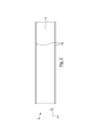
本発明の一実施形態によるパーティション用の新規なパネル2が、図1~図6に示されている。パネル2は、断熱パネル4と、断熱パネル4の両側に配置された2つの支持パネル6とを備える。
A
本明細書において使用されるとき、パネルという用語が、比較的薄いおおむね平坦な三次元のオブジェクトまたは物体を意味するように意図されていることを、理解できるであろう。さらに、比較的薄いとは、オブジェクトまたは物体の1つの寸法が、オブジェクトまたは物体の他の2つの寸法よりも小さいことを意味することを、理解できるであろう。オブジェクトまたは物体の最小の寸法を、オブジェクトまたは物体の厚さと称することができる。オブジェクトまたは物体の最小の寸法におおむね垂直な2つの寸法は、平面(または、平行な一群の平面)を定めることができる。 It will be appreciated that the term panel, as used herein, is intended to mean a relatively thin, generally flat, three-dimensional object or body. Further, it will be understood that relatively thin means that one dimension of the object or body is smaller than the other two dimensions of the object or body. The smallest dimension of an object or body can be referred to as the thickness of the object or body. Two dimensions that are generally perpendicular to the smallest dimension of an object or body can define a plane (or group of parallel planes).
図1~図6において、断熱パネル4の最小の寸法、すなわち厚さは、z方向である。断熱パネル4の厚さにおおむね垂直な2つの寸法を、x-y平面を定めると考えることができる。図1~図6において、各々の支持パネル6の最小の寸法、すなわち厚さは、x方向である。支持パネル6の厚さにおおむね垂直な2つの寸法を、y-z平面を定めると考えることができる。したがって、2つの支持パネル6の各々は、断熱パネル4の平面に対しておおむね垂直に広がっている。
1-6, the smallest dimension, or thickness, of the
断熱パネル4は、任意の適切な断熱材料を含むことができる。例えば、材料は、例えば、発泡ポリスチレン(EPS)、押出ポリスチレン(XPS)、硬質ポリウレタン(PUR)、ポリイソシアヌレート(PIR)、などの硬質断熱材料であってよい。材料は、独立気泡であっても、連続気泡であってもよい。断熱パネル4の厚さを、パネル2を組み込んだ建物が満たすことが望まれる建築規則または規準を念頭に置くことによって決定することができる。建設業界においては、パーティションに組み込まれる断熱材の厚さを増やすという一般的な傾向が存在する。あくまでも例として、断熱パネル4は、175mm程度の厚さを有することができる。
支持パネル6は、任意の適切な材料から形成されてよい。適切な材料として、ハードボードおよび高密度ファイバーボード(HDF)を挙げることができる。
図4において最もよく見て取ることができるように、2つの支持パネル6の各々の突出部分8が、断熱パネル4の面10、12を越えて延びている。本明細書において使用されるとき、パネルの面は、パネルの厚さによって隔てられた2つの表面を意味するように意図されていることを、理解できるであろう。
As best seen in FIG. 4, the protruding
したがって、パネル2は、パネル2の4つのエッジの各々において支持パネル6のうちの1つの支持パネルの突出部分8が断熱パネル4から突き出すように構成されている。
The
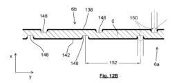
パネル2は、2つの支持パネル6の各々の突出部分8から延びるフランジをさらに備え、このフランジは、断熱パネル4の平面におおむね平行に延びている。図1~図6に示される実施形態において、そのようなフランジの各々は、巻かれた軽量スチールストリップ14および木材バテン16によってもたらされている。
The
各々の木材バテン16は、支持パネル6のうちの1つの支持パネルの突出部分8と、断熱パネル4の面10、12のうちの一方とに隣接して配置されている。各々のスチールストリップ14は、支持パネル6のうちの1つの支持パネルの外面(すなわち、支持パネル6のうちの断熱パネル4とは反対の面)に隣接する第1の部分と、断熱パネル4の平面におおむね平行に延びる第2の部分とを含む。スチールストリップ14の第2の部分を、木材バテン16を所定の場所に保持するように、木材バテン16の周りに巻き付けることができる。
Each timber batten 16 is positioned adjacent a support
各々のスチールストリップ14の第1の部分は、1つ以上の固定具18(図3を参照)によって支持パネル6のうちの1つに機械的に取り付けられている。固定具18は、例えば、パンチ、リベット、ねじ、釘、などであってよい。
A first portion of each
各々の支持パネル6および各々の支持パネル6から延びるフランジをまとめて、支持部材をもたらすと考えることができる。すなわち、1つの支持パネル6、2つのスチールストリップ14、および随意による2つの木材バテン16を、支持部材を形成すると考えることができる。
Together, each
図1~図6において、パネル2の厚さは、z方向である。パネル2の厚さにおおむね垂直な他の2つの寸法のうち、断熱パネル4および支持パネルの両方が延在する寸法(すなわち、y方向)を、パネル2の長さと考えることができ、残りの寸法(すなわち、x方向)を、パネル2の幅と考えることができる。
1-6, the thickness of the
パネル2は、任意の幅であってよい。パネル2の幅を、パネルの全体的な構造安定性に必要な支持の量、および/または使用時にパネル2が支持すべき基材の要件の両方を念頭に選択することができる。例えば、使用時に、パネルは、典型的には最大600mmの中心で支持される石膏ボードを(その内面で)支持するかもしれない。したがって、一実施形態において、パネル2は、これに対応するために、約600mmの幅を有することができる。支持パネル6は、約6mmの厚さを有することができる。パネル2の全体の厚さを600mmにするために、断熱パネル4の幅は、588mmになる。したがって、パネル2の幅全体に、12mmの支持パネル材料(例えば、ハードボード)および588mmの断熱材、すなわち2%の構造体および98%の断熱材が存在する。
図1~図6に示され、上述されたパネル2は、断熱パネル4の両側に配置された2つの支持パネル6によって構造的支持がもたらされる断熱建設パネルを提供する。これは、例えば、断熱材が2つの構造パネルの間に挟まれている構造用断熱パネル(SIP)などの先行技術の断熱建設パネル(すなわち、2つのパネルが建設パネルの内面および外面に配置されている)と対照的である。
The
好都合なことに、パネル2は、同等のSIPパネルにおいて必要とされるよりも著しく少ない構造支持ボードしか使用しない。さらに、支持ボード6は、SIPパネルで使用される構造支持ボードよりも薄くてよい。結果として、パネル2は大幅に軽量になり、大幅に安く製造することができる。
Advantageously,
絶縁パネル4の面10、12を越えて延びる2つの支持パネル6の各々の突出部分8を設けることにより、以下で説明されるように、先行技術の構成(例えば、SIP)に対するさらなる利点がもたらされる。パーティションを、複数のパネル2から形成することができ、複数のパネルは、各々のパネル2の支持パネル6が隣のパネル2の支持パネル6に隣接および接触するように並べて配置される。支持パネル6の各々が、断熱パネルの少なくとも一方の面を越えて延びているため、複数のパネル2から形成されるそのようなパーティションは、滑らかで平坦な表面を有さない。むしろ、隣り合うパネル2の各ペアからの支持パネル6の突出部分8が、パーティションの各々の表面(おおむね断熱パネル4の表面によって定められる)にリッジを形成する。
Providing a protruding
例えばSIPなどの先行技術の構成では、火災および電気配線の理由で、バテンを建設パネルの内面に追加する必要がある。典型的には、内部ボード(例えば、石膏ボード)が、これらのバテンに固定される。屋根パネルとして使用される場合、SIPの外面に屋根タイルを支持するためのバテンが取り付けられる。しかしながら、これらのバテンは、排水を助けるためにカウンターバテンでSIPの外面から離して保持される必要がある。図1~図6に示されるパネル2では、(隣接するパネルの各ペアからの支持パネルの突出部分によって形成されるパーティションの各表面のリッジゆえに)内部バテンおよび追加の外部カウンターバテンが不要である。
Prior art constructions such as SIP, for example, require battens to be added to the inner surface of the construction panel for fire and electrical wiring reasons. Typically, internal boards (eg, gypsum board) are secured to these battens. When used as a roof panel, the exterior surface of the SIP is fitted with battens to support the roof tiles. However, these battens need to be kept away from the outer surface of the SIP with counterbattens to aid drainage.
2つの支持パネル6の各々の突出部分8から延びるフランジ(巻かれた軽量スチールストリップ14および木材バテン16によってもたらされる)を設けることによって、支持パネル6の各々の端部に、さまざまな理由で有益なより大きい表面積がもたらされる。第1に、この構成によれば、支持部材の外形が、I字形のおおむね半分である。すなわち、使用時に、2つの隣接するパネル2からの2つの支持部材が接触すると、それらは一緒になって、おおむねI字梁の形態となる。フランジによってもたらされる支持部材の表面積の増加は、パネル2から形成されたパーティションによって支えられる荷重をより良好に分布させる。第2に、表面積の増加により、パネル2から形成されたパーティションへの内部または外部の被覆の固定をより容易にすることができる。
By providing a flange extending from the protruding
支持パネル6を、断熱パネル4に接合または接着することができる。これは、各々のパネル2をより容易に持ち運ぶことができるアセンブリにすることができるため、便利かもしれない。しかしながら、パネル2の支持パネル6は、パネル2の平面に対しておおむね垂直に延びているため、(SIPとは対照的に)いかなる荷重も断熱パネル4によって伝達する必要がない。したがって、支持部材6と断熱パネル4との間の接続(例えば、接着による接合)は、高い完全性を必要としない。これは、先行技術と比較して、第1の態様のシステムの製造コストをさらに削減する。
支持パネル6は、断熱パネル4と同じ熱性能を有さず、典型的には、断熱材のみによる構造と比較して、全体としてのアセンブリの熱性能を低下させると考えられる。この影響を低減するために、支持部材6の厚さを最小にでき、支持部材6を形成する材料を、構造ロールを果たしつつパネル2の熱性能を最大にするように選択することができる。
The
パネル2は、必要に応じて、任意の長さを有することができる。上述の特徴を備えたパネルは、約6.5mの距離に及ぶ可能性が明らかになっている。パネルの構造は、注文に応じた長さに切断するだけでよいような構造であってよいと考えられる。これにより、材料の無駄を大幅に削減できると期待される。
パネル2が勾配屋根を覆うべく用いられるように意図される実施形態においては、パネル2の一端に端部支持パネル20が設けられる。端部支持パネル20は、断熱パネル4に接合または接着されてよい。これに加え、あるいはこれに代えて、端部支持パネル20を、固定具22によって木材バテン16に取り付けることができる。固定具22は、例えば、パンチ、リベット、ねじ、釘、などであってよい。
In embodiments in which the
図3に見られるように、パネル2の一方の面において、端部支持パネル20は、ショルダ23を形成するように2つの支持パネル6の突出部分8を越えて延びている。使用時に、このショルダ23を、棟木上の相補的な特徴に係合させることができる。使用時に、棟木の第1の側に2つ以上のパネル2を設けることができ、棟木の第2の反対側に2つ以上のパネル2を設けることができることを、理解できるであろう。パネル2の他方の面の付近において、端部支持パネル20は、2つのフック24を備える。使用時に、これらのフック24は、棟木の両側の2つのパネル2の間を延びる1つ以上のクランプ(図12において25と標記されている)の位置詳細を提供することができる。これらのクランプは、棟木に機械的に固定されてよい。
As can be seen in FIG. 3, on one side of the
上述したように、支持パネル6を断熱パネル4に接合または接着することで、各々のパネル2をより容易に輸送することができるアセンブリにすることができる。ここで、図7および図8を参照して、代案の構成が説明される。したがって、本発明の一実施形態によるパーティション用の第2の新規なパネル26が、図7および図8に示されている。図1~図6に示したパネル2の特徴と実質的に同じである図7および図8に示されるパネル26の特徴は、共通の参照番号を共有する。図7および図8に示されるパネル26と図1~図6に示したパネル2との間の相違点のみを、ここで説明する。
As described above, the
断熱パネル4の平面におおむね平行に2つの支持パネル6の各々の突出部分8から延びるフランジが、変更版の巻かれた軽量スチールストリップ28を備えている。
A flange extending from the projecting
各々のスチールストリップ28は、支持パネル6のうちの1つの支持パネルの外面(すなわち、支持パネル6のうちの断熱パネル4とは反対の面)に隣接する第1の部分と、断熱パネル4の平面におおむね平行に延びる第2の部分32とを含む。
Each
スチールストリップの第2の部分32は、おおむね箱形梁の形態となるように巻かれ、あるいは折り曲げられている。これを達成するために、スチールストリップ28は、スチールストリップの第2の部分32が、断熱パネル4の表面におおむね平行に延び、かつ断熱パネル4の表面から離れている部分32aと、おおむね断熱パネル4の表面に向かって延びる部分32bと、断熱パネル4の表面におおむね平行に延び、かつ断熱パネル4の表面に隣接する部分32cと、おおむね断熱パネル4の表面から遠ざかるように延びる部分32dとを含むように巻かれ、あるいは折り曲げられている。スチールストリップ28を、鋼の薄板を各々の隣接部分の間の交線において丸め、あるいは折り曲げることによって形成できることを、理解できるであろう。
A
第2の部分32の遠位端34は、第1の部分30におおむね平行である。第2の部分32の遠位端34と第1の部分30とが協働して、2つの支持パネル6のうちの一方の支持パネルの突出部分8を受け入れるためのチャネルまたは溝36を定める。第2の部分32の遠位端34と第1の部分30とによって定められるこのチャネルまたは溝36を、2つの支持パネル6のうちの一方の支持パネルの突出部分8と締まり嵌めを形成するような寸法とすることができる。これは、パネルの組み立てを補助し、スチールストリップ28を(図1~図6に示したパネル2と同様のやり方で)1つ以上の固定具で保持されるまで所定の位置に保つことができる。
A
各々のスチールストリップ28の第2の部分32は、断熱パネル4の面10、12との係合のための手段を備える。とくには、各々のスチールストリップ28の第2の部分32は、断熱パネル4に刺さり、あるいは断熱パネル4を貫いて、断熱パネル4に係合するように配置された複数の不連続または断続的なかかり37を備える。かかり37は、おおむね断熱パネル4の表面に向かって延びる部分32bと、断熱パネル4の表面におおむね平行に延び、かつ断熱パネル4の表面に隣接する部分32cとの間の交線の形成時に丸められたり、あるいは折り曲げられたりしない薄板材料の複数の部分から形成される。
A
本発明のいくつかの実施形態は、複数のパネル(例えば、上述のパネル2、26)と、複数の隣接するパネルのうちの2つのパネルの各々からの支持部材と協働するように配置された少なくとも1つの接続ストリップとを備えるモジュール式パーティションシステムに関する。そのような接続ストリップは、図9A~図9Cを参照して以下で説明されるように、さまざまな異なる形態をとることができる。
Some embodiments of the present invention are arranged to cooperate with a plurality of panels (eg,
図9Aが、上述のパネル2、26の支持部材のフランジとの係合に適した接続ストリップ38を示している。接続ストリップ38は、上述のパネル2、26の支持部材のフランジを受け入れるためのチャネルまたは溝を定める。接続ストリップ38の外形は、上述のパネル2、26の支持部材のフランジと締まり嵌めを形成するような外形である。
Figure 9A shows a connecting
図9Bおよび図9Cの各々は、上述のパネルと同様のパネルの支持パネル6との係合に適した異なる接続ストリップ40、42を示している。接続ストリップ38は、パネルの2つの隣接する支持パネル6の突出部分8を受け入れるためのチャネルまたは溝を定めている。これらの実施形態において、支持パネル6にフランジが設けられていない(スチールストリップ14、28も、木材バテン16も設けられていない)ことに留意されたい。しかしながら、接続ストリップ40、42は、2つの隣接する支持パネル6の突出部分8を受け入れるためのチャネルまたは溝の両側に突出フランジ部分を備えている。接続ストリップ40、42の突出フランジ部分は、上述のパネル2、26に設けられたフランジと同様の役割を果たす。接続ストリップ40、42の外形は、2つの隣接する支持パネル6の突出部分8と締まり嵌めを形成するような外形である。
9B and 9C each show a different connecting
一般に、図9A~図9Cに示される各々の種類の接続ストリップ38、40、42は、2つの隣接するパネルのそれぞれからの支持部材と締まり嵌めを形成する。さらに、各々の接続ストリップ38、40、42は、一般に、1つ以上の固定具(例えば、パンチ、リベット、ねじ、釘、など)を使用して、隣接するパネルの両方に機械的に取り付けられる。
In general, each type of connecting
使用時に、隣接するパネルの各ペアについて、通常は2つの接続ストリップ38、40、42が設けられ、2つの接続ストリップ38、40、42は、支持部材の両端に設けられることを、理解できるであろう。
It will be appreciated that in use there are typically two connecting
次に、複数のパネルと、複数の隣接するパネルのうちの2つのパネルのそれぞれからの支持部材と協働するように配置された少なくとも1つの接続ストリップとを備えるモジュール式パーティションシステムのさらなる実施形態を、図10~図12Bを参照して説明する。 Next, a further embodiment of a modular partition system comprising a plurality of panels and at least one connecting strip arranged to cooperate with support members from each of two of the plurality of adjacent panels. will be described with reference to FIGS. 10 to 12B.
図10は、2つの隣接するパネル132と、これらのパネル132の支持部材のフランジとの係合に適した接続ストリップ134とを示している。この実施形態において、パネル132は、図1~図6に示したパネル2ならびに図7および図8に示したパネル26とは異なる。加えて、接続ストリップ134は、図9A~図9Cに示した接続ストリップ38、40、42とは異なる。ここでは、この実施形態と上述の実施形態との間の相違点のみを、詳細に説明する。したがって、図1~図6に示したパネル2ならびに図7および図8に示したパネル26の特徴と実質的に同じであるパネル132の特徴は、共通の参照番号を共有する。
FIG. 10 shows two
この実施形態のパネル132と、図1~図6に示したパネル2ならびに図7および図8に示したパネル26との間の唯一の相違点は、支持パネル6のフランジである。図7および図8に示したパネル26と同様に、この実施形態のパネル132のフランジは、木材バテン16を備えない。この実施形態のパネル132の支持パネル6のフランジは、(上述のスチールストリップ14、28とは異なる)変更版のスチールストリップ136を備え、これを図11A~図11Dを参照して説明する。
The only difference between
図11A~図11Dは、支持パネル6の一部分およびスチールストリップ136を示している。図11Aは、使用時に断熱パネル4に接触する支持パネル6の表面6a(内側表面と呼ぶことができる)を示す斜視図を示している。図11Bは、使用時に断熱パネル4から遠い支持パネル6の表面6b(外側表面と呼ぶことができる)を示す斜視図を示している。図11A~図11Dには、各々の支持パネル6の最小の寸法、すなわち厚さが、x方向であるように、図1~6に示したものと一致する1組のデカルト座標軸が示されている。支持パネル6の厚さにおおむね垂直な2つの寸法を、y-z平面を定めると考えることができる。断熱パネル(図示せず)の最小の寸法、すなわち厚さは、z方向である。図11Cは、x-z平面における支持パネル6およびスチールストリップ136の断面図であり、図11Dは、x-y平面における支持パネル6およびスチールストリップ136の断面図である。
11A-11D show a portion of
図11Cにおいて最もよく見て取ることができるように、スチールストリップ136は、支持パネル6の外側表面6bに接触し、かつ支持パネル6の外側表面6bにおおむね平行である第1の部分138と、おおむね支持パネル6の2つの対向する表面6a、6bの間を延びる第2の部分140と、支持パネル6の内側表面6aにおおむね平行な第3の部分142と、断熱パネル4(図10を参照)の表面におおむね平行に延びる第4の部分144とを含む。
As best seen in FIG. 11C, the
接続ストリップ134(図10を参照)は、上述のように2つの隣接するパネル132の支持部材6のフランジの一部分を受け入れるためのチャネルまたは溝を定める。接続ストリップ38の外形は、次に説明されるように、パネル132の支持部材6のフランジと締まり嵌めを形成するような外形である。
Connecting strips 134 (see FIG. 10) define channels or grooves for receiving portions of the flanges of
接続ストリップ134(圧延鋼から形成することができる)は、おおむね箱形梁の形態であるが、2つの支持パネルのエッジの付近の部分と、スチールストリップ136のうちの支持パネルのエッジの付近の部分とを受け入れるための開口を有する。とくに、接続ストリップ134は、中央壁部分134aと、2つのおおむねU字形の横部分134b、134cとを備える。2つの隣接するパネル132の支持部材6のフランジの一部分を受け入れるためのチャネルまたは溝が、2つの横部分134b、134cの間に形成される。
The connecting strips 134 (which may be formed from rolled steel) are generally in the form of box beams, but the portions near the edges of the two support panels and one of the steel strips 136 near the edges of the support panel. has an opening for receiving the portion. In particular, connecting
第2の部分140と第3の部分142との間に、各々のスチールストリップ136は、支持パネル6の内側表面6aから遠ざかるように延びる突出部141を備える。突出部141は、2つの隣接するパネル132の突出部141が、2つの横部分134b、134cの間に形成されるチャネルまたは溝の開口部よりもわずかに大きくなるような寸法とされている。しかしながら、接続ストリップ134は、2つの隣接するパネル132の突出部141をチャネルまたは溝に受け入れることができるように充分に弾性変形することができる。ひとたび2つの隣接するパネル132の突出部141が2つの横部分134b、134cを通過すると、接続ストリップ134は、突出部141を溝またはチャネルに捕まえて保持するように跳ね戻ることができる。
Between the
スチールストリップ136の第4の部分の遠位端に、断熱パネル4の面との係合のための手段をもたらす有刺部146が設けられている。有刺部146は、図7および図8に示した実施形態のかかり37によく似ており、断熱パネル4に刺さり、あるいは断熱パネル4を貫いて、断熱パネル4に係合するように配置されている。しかしながら、この実施形態においては、複数の不連続なかかり37ではなく、有刺部146がスチールストリップ136の実質的に全長にわたって形成されている。
A
各々のスチールストリップ136の第1の部分138は、支持パネル6のうちの1つの支持パネルの外側表面6bに機械的に取り付けられる。同様に、各々のスチールストリップ136の第3の部分142は、支持パネル6のうちの1つの支持パネルの内側表面6aに機械的に取り付けられる。この実施形態において、これは、支持パネル6の外側表面6bおよび支持パネル6の内側表面6aを図12Aおよび図12Bを参照してさらに説明されるように複数の位置において互いにパンチし、プレス接合し、あるいはかしめるように、ツールを使用してスチールストリップ136の第1の部分138を支持パネル6のうちの1つの支持パネルの外側表面6bへとかしめ、スチールストリップ136の第3の部分142を支持パネルのうちの1つの支持パネル6の内側表面6aへとかしめることで達成される。結果として、スチールストリップ136の第1および第3の部分138、142の外面に、複数のディンプルまたは凹部148を見て取ることができる。
A
図12Aは、x-z平面における支持パネル6およびスチールストリップ136の断面図であり、図12Bは、x-y平面における支持パネル6およびスチールストリップ136の断面図である。図12Aおよび図12Bには、ツール先端部150も概略的に示されている。
12A is a cross-sectional view of
ツール先端部150が、スチールストリップ136の第1および第3の部分138、142の外面へと打ち込まれ、スチールストリップの第1および第3の部分138、142ならびに支持パネル6の両方の表面の塑性変形を引き起こす(この塑性変形の前は平坦であってよい)ことを、理解できるであろう。この塑性変形の結果として、スチールストリップ136の第1および第3の部分138、142の表面は、それぞれ支持パネルの外側表面6bおよび内側表面6aと相補的になり、これらに係合する。
A
ツール先端部150は、おおむね円筒形であってよく、4~6mm程度の直径を有することができる。しかしながら、図12Aにおいて最もよく見て取ることができるように、ツール先端部150の先端は、マイナスドライバーと同様の形状の矩形のエッジへと先細りであってよい。ツール先端部を、3~4mm程度の深さまで打ち込むことができる。先の実施形態と同様に、支持パネル6は、6mm程度の厚さを有することができ、スチールストリップ136は、1mm程度の厚さを有する軽量スチールストリップであってよい。隣接する凹部148(ツール先端部150によって形成される)の中心間の距離152は、40mm程度であってよい。
The
図12Bにおいて最もよく見て取ることができるように、支持パネル6の内側表面6aに形成された凹部148は、支持パネル6の外側表面6bに形成された凹部148に対してy方向にずれている。図12A(および、図11C)には2つの凹部148が示されているが、これは単に凹部が支持パネル6の両面に設けられることを示すためのものにすぎず、実際には、これらの凹部は(図12Bおよび図11Dのように)ずれており、同じx-z平面の断面に現れることがないことを、理解できるであろう。
As best seen in FIG. 12B, the
このモジュール式パーティションシステムを使用し、複数の平行かつ隣接するパネル(例えば、パネル2、26、132)を、隣接するパネルの各ペアについて2つの接続ストリップ(例えば、接続ストリップ38、40、42、134)を使用して互いに接続することで、パーティションを形成できることを理解できるであろう。2つの隣接するパネルの支持部材6の両端に2つの接続ストリップが設けられる。
Using this modular partition system, multiple parallel and adjacent panels (e.g.,
一般に、支持部材6および接続ストリップは、2つの支持体(例えば、屋根梁)の間にまたがり、支持体間にまたがるように所望の長さ(すなわち、例えば図1~図6に示されるとおりのy方向のパネルの寸法)に製造されてよい。
Generally, the
パネルは、任意の幅であってよい。パネルの幅を、パネルの全体的な構造安定性に必要な支持の量、および/または使用時にパネルが支持すべき基材(例えば、床板、石膏ボード、など)の要件の両方を念頭に選択することができる。モジュール式のパネルシステムの組み立て後の全体としての幅(すなわち、モジュール式のシステムの例えば図1~図6に示されるとおりのx方向の寸法)が、公差のギャップを可能にするようにパーティションの幅にほぼ等しく(しかしながら、それよりもわずかに小さく)なることが望ましいかもしれないことを、理解できるであろう。パネルの幅を、パーティションの幅の整数分の一になるように選択することができる。これに加え、あるいはこれに代えて、パネルを、例えば約400mm、500mm、または600mmの幅を有する1つ以上の標準幅にて提供してもよい。これらの標準幅のうちの1つの整数倍(または、種々の標準幅の組み合わせ)ではない全体としての幅を有するパーティションの場合、モジュール式のパネルシステムの組み立て後の全体としての幅が、公差のギャップを可能にするようにパーティションの幅にほぼ等しく(しかしながら、それよりもわずかに小さく)なるように、1つ以上のオーダーメイドのパネルを形成できることを理解できるであろう。 The panels can be of any width. Panel width is chosen keeping in mind both the amount of support needed for the panel's overall structural stability and/or the requirements of the substrate (e.g. floorboard, gypsum board, etc.) that the panel should support when in use can do. of the partitions so that the overall assembled width of the modular panel system (i.e., the x-direction dimension of the modular system, eg, as shown in FIGS. 1-6) allows for tolerance gaps. It will be appreciated that it may be desirable to be approximately equal to the width (but slightly less). The width of the panel can be chosen to be an integer fraction of the width of the partition. Additionally or alternatively, the panels may be provided in one or more standard widths, for example having widths of approximately 400 mm, 500 mm, or 600 mm. For partitions with an overall width that is not an integral multiple of one of these standard widths (or a combination of the various standard widths), the overall width after assembly of the modular panel system will be within tolerance. It will be appreciated that one or more custom panels can be formed to be approximately equal to (but slightly less than) the width of the partition to allow for gaps.
以下で説明されるように、公差のギャップを可能にするために、1つ以上のエッジストリップを設けることができる。エッジストリップは、(それぞれ2つの隣接するパネルのフランジ部分に係合するように構成された接続ストリップ38、40、42、134とは対照的に)単一のパネルのフランジ部分との係合に好適であってよい。したがって、エッジストリップは、おおむね接続ストリップのうちの1つの接続ストリップの半分の形態の外形を有することができる。これが、図13Aおよび図13Bを参照して、図10~図12Bに図示して上述した実施形態について説明される。図9A~図9Cに示した実施形態についても、同様のエッジストリップを設けることができることを、理解できるであろう。
One or more edge strips may be provided to allow for tolerance gaps, as described below. The edge strips are adapted to engage flange portions of a single panel (as opposed to connecting
図13Aは、単一のパネル132と、単一のパネル132の支持部材のフランジに係合したエッジストリップ154とを示している。パネル132は、実質的に、図10~図12Bを参照して上述したとおりである。とくには、パネルは、支持パネル6に機械的に取り付けられたスチールストリップ136を備え、スチールストリップ136は、支持パネル6の内側表面から遠ざかるように延びる突出部141を有している。
FIG. 13A shows a
エッジストリップ154(圧延鋼から形成されてよい)は、おおむね接続ストリップ134の半分の形態である。エッジストリップ154は、おおむね箱形梁の形態であり、支持パネル6のエッジの付近の部分と、スチールストリップ136のうちの支持パネル6のエッジの付近の部分とを受け入れるための開口を有する。エッジストリップ154は、1つのおおむねU字形の横部分154bと1つのおおむね平坦な横部分154cとの間に配置された中央壁部分154aを含む。単一のパネル132の支持部材6のフランジの一部分を受け入れるためのチャネルまたは溝が、2つの横部分154b、154cの間に形成される。
Edge strip 154 (which may be formed from rolled steel) is generally in the form of one half of connecting
中央壁部分154aは、接続ストリップ134(図10を参照)の中央壁部分134aの長さの約半分の長さを有する。おおむねU字形の横部分154bは、接続ストリップ134の2つのおおむねU字形の横部分134b、134cのうちの一方とほぼ同じ形状である。しかしながら、他方の横部分154cは、中央壁部分154aにおおむね垂直であり、スチールストリップ136の第1の部分138に平行かつスチールストリップ136の第1の部分138に接するおおむね平坦な壁部分を含む。
エッジストリップ154は、接続ストリップ134と一対の隣接するスチールストリップ136との間の嵌まり合いと同様の嵌まり合いにて、スチールストリップ136に係合する。突出部141は、2つの横部分154b、154cの間に形成されたチャネルまたは溝の開口部よりもわずかに大きくなるように寸法付けられている。しかしながら、エッジストリップ154は、突出部141をチャネルまたは溝に受け入れることができるように充分に弾性変形することができる。ひとたびパネル132の突出部141が2つの横部分154b、154cを通過すると、エッジストリップ154は、突出部141を溝またはチャネルに捕まえて保持するように跳ね戻ることができる。
図13Bは、2つの隣接するパネル132を示しており、各々のパネル132は、パネル132の支持部材のフランジに係合したエッジストリップ154を有しており、2つのパネル132の間には公差のギャップ156が設けられている。公差のギャップ156を、適切な充てん材料158(例えば、発泡体など)で少なくとも部分的に満たすことができる。2つの隣接するパネルが、使用時にモジュール式のパネルシステムによって支持される基材(例えば、床板、石膏ボード、など)を介して接続されてよいことを、理解できるであろう。そのような基材は、両方のエッジストリップ154の中央部分154aに接触でき、機械的な固定具(例えば、釘またはねじなど)を使用してエッジストリップ154の中央部分154aに接続されてよい。
FIG. 13B shows two
勾配屋根において使用するためのモジュール式パーティションシステムに関する本発明の実施形態を、図14~図23を参照して以下で説明する。 Embodiments of the invention relating to modular partition systems for use on pitched roofs are described below with reference to Figures 14-23.
図14は、本発明の実施形態によるモジュール式パーティションシステムを組み込むことができる寄せ棟屋根44の構造の概略の斜視図である。
FIG. 14 is a schematic perspective view of the construction of a
寄せ棟屋根44は、寄せ棟屋根44の周囲を定めるように壁47の上部に沿ってそれぞれ延びる軒桁46と、寄せ棟屋根44の上端を定める棟木48とを備える。棟木48は、棟木48の端部から2つの軒桁46が出会う角部まで屋根の斜めの縁に沿ってそれぞれ延びる4つの隅木50によって支持されている。
The
次に、本発明の一実施形態によるモジュール式パーティションシステム52を、図15~図21を参照して説明する。
A
図15は、本発明の一実施形態によるモジュール式パーティションシステム52の一部分の断面図である。モジュール式パーティションシステム52は、図1~図6を参照して上述した複数のパネル2を含む。図15には3つのパネル2が示されているが、他の実施形態において、モジュール式パーティションシステム52が2つのパネル2または4つ以上のパネル2を含んでもよいことを、理解できるであろう。パネル2は、各々のパネル2の断熱パネル4がおおむね互いに平行になり、複数のパネル2の各々のパネル2の1つの支持部材(すなわち、1つの支持パネル6、2つのスチールストリップ14、および随意による2つの木材バテン16)が隣接するパネル2の支持部材に隣接するように配置される。モジュール式パーティションシステム52は、隣接するパネル2の各ペアにつき2つの接続ストリップ38をさらに備える。各々の接続ストリップ38は、おおむね図9Aに示した形態であり、複数の隣接するパネル2のうちの2つのパネル2の各々からの支持部材と協働するように配置される。
FIG. 15 is a cross-sectional view of a portion of
一般に、モジュール式パーティションシステム52の内面において、内部基材54が1つ以上の固定具(典型的には、ねじまたは釘など)を使用してパネル2に接続される。内部基材54は、例えば12.5mmの箔で裏打ちされた石膏ボードなど、石膏ボードを含むことができる。これらの固定具の各々が、1つのパネルのフランジ(すなわち、スチールストリップ14および木材バテン16)へと接続ストリップ38を通過する。
Generally, on the interior surface of the
随意により、内部基材54と各々の接続ストリップ38との間にバテン56を設けることができる。これは、例えば、内部基材54とパネル2の断熱パネル4との間に形成される空隙58のサイズを大きくしたい場合に望ましいかもしれない。
Optionally, battens 56 may be provided between the
一般に、モジュール式パーティションシステム52の外面において、外部基材または屋根構造がパネル2に接続される。技術的に知られているとおり、そのような外部基材について、種々のさまざまな選択肢が存在する。以下で2つの選択肢が説明され、これらから、どのようにモジュール式パーティションシステム52を他の種類の外部基材において使用できるのかが、当業者にとって明らかであろう。第1の選択肢は、パネル2に接続された配向性ストランドボード(OSB)の層と、そこに直接接続された屋根タイルの層とを備える。第2の選択肢は、屋根タイルが接続されるバテンの1つ以上の列(通常は屋根の勾配に対して垂直に延びる)を備える。
External substrates or roof structures are generally connected to the
図17が、モジュール式パーティションシステム52を組み込んだ(図14に示した種類の)寄せ棟屋根の斜視図である。図17は、外部基材または外被が適用される前のモジュール式パーティションシステム52の外面を示している。図18Aが、OSBボード60がパネル2に(接続ストリップ38を介して、1つのパネル2のフランジへと)固定された状態の図17に示した寄せ棟屋根の斜視図である。したがって、これは(タイルが適用される前の)第1の屋根葺きの選択肢に一致する。図18Bは、木材バテン62の列がパネル2に(接続ストリップ38を介して、1つのパネル2のフランジへと)固定された状態の図17に示した寄せ棟屋根の斜視図である。したがって、これは(タイルが適用される前の)第2の屋根葺きの選択肢に一致する。
FIG. 17 is a perspective view of a hip roof (of the type shown in FIG. 14) incorporating a
図15が、第1の屋根葺きの選択肢を示している一方で、図16は、第2の屋根葺きの選択肢を示している。 FIG. 15 shows the first roofing option, while FIG. 16 shows the second roofing option.
再び図15を参照すると、いくつかの実施形態においては、OSBボード60の層が、1つ以上の固定具(典型的には、ねじまたは釘など)を使用してパネル2(の外面)に固定される。これらの固定具の各々が、1つのパネルのフランジ(すなわち、スチールストリップ14および木材バテン16)へと接続ストリップ38を通過する。タイル64の層が、従来からのやり方でOSBボードの層へと取り付けられる。
Referring again to FIG. 15, in some embodiments, a layer of
図16は、モジュール式パーティションシステム52を組み込んだ寄せ棟屋根の断面図である。図16は、棟木48および2つの軒桁46(図14を参照)を示す断面図である。棟木48と2つの軒桁46の各々との間にまたがる屋根の断面が示されている。
FIG. 16 is a sectional view of a hipped roof incorporating a
棟木48と一方の軒桁46との間にまたがる屋根の各部分は、おおむね図15に示したモジュール式パーティションシステム52の形態である(ただし、この図では、図15に示されるOSBボード60およびタイル64とは対照的に、木材バテン62がモジュール式パーティションシステム52の外面に取り付けられている)。
Each portion of the roof that spans between the
図19~図21を参照して以下で説明されるように、モジュール式パーティションシステム52は、棟木48と、軒桁46のうちの1つとに係合する。
The
モジュール式パーティションシステム52のパネル2と棟木48との間の係合を、図19を参照して以下で説明する。図19に示されるように、棟木48は、おおむね一定の断面形状を有する。棟木48の外形は、おおむね箱形梁の形態である中央部分49と、中央部分49の各側に設けられた2つの横部分65とを含む。2つの横部分の各々は、端部支持パネル20および2つの支持パネル6の突出部分8によって形成されたショルダ23との係合のための特徴を提供する。とくには、2つの横部分65の各々は、端部支持パネル20および2つの支持パネル6の突出部分8によって形成されたショルダ23と係合するためのフランジまたはリップ63を定める。係合用のフランジまたはリップ63と、端部支持パネル20および2つの支持パネル6の突出部分8によって形成されたショルダ23との間のこの係合は、位置決め機能を提供することによってパネル2の設置を助けることができる。ひとたびパネル2を棟木48に係合させると、パネル2を、1つ以上の固定具66(例えば、セルフタップねじ)によって棟木48に機械的に取り付けることができる。固定具66は、棟木48の横部分65をパネル2へと(例えば、接続ストリップ38を貫き、スチールストリップ14および木材バテン16によって形成されたフランジへと)通過する。図19に示されるように、各々の横部分65によって定められるフランジまたはリップ63は、横部分65の主要部分から折り返され、固定具66は、パネル2へと横部分65の主要部分ならびにフランジまたはリップ63を通過する。
The engagement between the
端部支持パネル20は、支持パネル6と同じ材料から形成されてよい。あるいは、いくつかの実施形態において、端部支持パネル20は、鋼のストリップまたは薄板から形成されてよい。そのような実施形態において、(ショルダ23を形成するように)2つの支持パネル6の突出部分8を越えて延びる端部支持パネル20の一部分を、棟木48の2つの横部分65とより良好に係合するように湾曲させ、あるいはおおむねフック状とすることができる。
図14に示した形態の切妻屋根において、パネル2の少なくともいくつかが、棟木50のうちの1つと軒桁のうちの1つとの間にまたがることを、理解できるであろう。図17に見られるように、そのようなパネルは、おおむね台形の形態である(すなわち、2つの平行な辺と、2つの非平行な辺とを有する)。そのようなパネル2に、上述の棟木48との係合と同様のやり方で棟木50上の特徴と係合するためのショルダ23を定める端部支持パネル20がやはり設けられることを、理解できるであろう。
It will be appreciated that in a gable roof of the form shown in Figure 14, at least some of the
図20は、パネル2と軒桁46との間の係合を、屋根の内部から示している。見て取ることができるように、軒桁46は、パネル2を支持するフランジまたはリップ67を定める。接続ストリップ38は、軒桁46によって定められるフランジ67の直前まで延び、追加の固定クリップ68が、フランジ67に隣接して設けられる。この固定クリップ68は、接続ストリップ38の外形と同様の外形を有し、同様のやり方で2つの隣接するパネル2の各々からの支持部材と協働するように配置された第1の部分72を備える。固定クリップ68は、軒桁46によって定められるフランジ67におおむね平行な第2の部分74をさらに備える。モジュール式パーティションシステム52の軒桁46への機械的な固定は、固定クリップ68の第2の部分74を通り、軒桁46によって定められたフランジ67を通って、2つの隣接するパネル2のうちの一方の支持部材へと進入する一対の固定具70(例えば、セルフタップねじ)によって達成される。
Figure 20 shows the engagement between the
図21は、パネル2と軒桁46との間の係合を、屋根の外部から示している。見て取ることができるように、外側において、接続ストリップ38は、協働するように構成された2つの隣接するパネル2からの支持部材を過ぎて、軒桁46の表面上へと延びている。随意により、接続ストリップ38と軒桁46との間の空間に、木材バテン76を設けることができる。モジュール式パーティションシステム52の軒桁46への機械的な固定は、接続ストリップ38を通り、木材バテン76(存在する場合)を通って、軒桁46へと進入する一対の固定具78(例えば、セルフタップねじ)によって達成される。
Figure 21 shows the engagement between the
モジュール式パーティションシステム52は、以下で説明されるように、先行技術を超える多くの利点をもたらすパーティション(例えば、屋根)を構築するためのきわめて万能かつ費用効果に優れたシステムを提供する。
モジュール式パーティションシステム52は、例えば構造用断熱パネル(SIP)などの先行技術の断熱建設パネルの代替物を提供する。SIPにおいては、断熱材が2つの構造パネルの間に挟まれている(すなわち、2つのパネルが建設パネルの内面および外面に配置されている)。SIPパネルは、屋根だけでなく、広く建物の壁および床にも使用される。さらに、SIPは、一般に、パーティションの全体または少なくともかなりの部分を形成することができる大きな薄板材料として製造される。これは、空気漏れの機会が少なくなることを期待して継ぎ目の数を減らすことを狙った先行技術のSIPシステムの意図的な特徴である。
The
好都合なことに、モジュール式パーティションシステム52は、支持部材をモジュール式パーティションシステム52の平面にほぼ垂直に延びる断熱パネル4の側面に配置したパネルを使用する。結果として、モジュール式パーティションシステム52においては、使用される構造支持材料を、同等のSIPパネルにおいて必要とされるよりも大幅に少なくすることができる。結果として、パネル2が大幅に軽量になり、大幅に安く製造することができる。加えて、パネル2の支持部材は、モジュール式パーティションシステム52の平面に対しておおむね垂直に延びているため、(SIPとは対照的に)いかなる荷重も断熱パネル4によって伝達する必要がない。したがって、支持部材と断熱パネル4との間の接続(例えば、接着による接合)が、高い完全性を必要としない。実際に、図7および図8を参照して上述したように、いくつかの実施形態において、支持部材は、断熱パネル4との締まり嵌めを提供する1つ以上の特徴を備えることで、支持部材と断熱パネル4との間の接着による接合の費用を回避することができる。これは、先行技術と比較して、モジュール式パーティションシステム52のシステム製造コストをさらに削減する。
Advantageously, the
さらに、先行技術の教示とは反対に、モジュール式パーティションシステム52は、より多数のパネル、したがってより多くの継ぎ目を有する構成に、より適している。これは、少なくとも部分的には、2つの隣接するパネル2の間の構造的な接続を助けるために、複数の隣接するパネル2のうちの2つのパネルのそれぞれからの支持部材と協働するように構成された新規な接続ストリップ38を提供することによって、可能にされている。モジュール式パーティションシステム52は、このようなより小さなパネルを可能にするがゆえに、例えばパーティションの開口部(例えば、ドアおよび窓)およびパーティション間の継ぎ目(例えば、部屋の角部)において無駄になる材料の量を大幅に減らすことができ、完全になくすことさえ可能であるため、さらなる費用便益をもたらすことができる。
Moreover, contrary to the teachings of the prior art, the
いくつかの実施形態において、モジュール式パーティションシステム52は、隣接するパネルの各ペアの間に弾性シールをさらに備えることができる。例えば、2つの支持部材の一方または両方の側面(例えば、支持パネル6の外側表面)に、シール材料(例えば、発泡体テープなど)を設けることができる。あるいは、設置の最中に適切なシール材料を手作業で設けてもよい。
In some embodiments, the
さらに、モジュール式パーティションシステム52は、このようなパネル2を可能にするがゆえに、きわめて容易に設置することが可能になる。例えば、モジュール式パーティションシステム52は、パネル2の手作業での設置をより容易にし、高価につく可能性があり、建設現場において(例えば、一時的に利用できない場合に)高価につく遅延を引き起こす可能性があるリフト装置(例えば、クレーンなど)を不要にすることができる。
Moreover, the
断熱パネル4に使用される断熱材が独立気泡(例えば、XPS)である実施形態においては、モジュール式パーティションシステム52を使用する屋根について、外部(防水)膜を設ける必要はないかもしれない。
In embodiments where the insulation used in insulating
モジュール式パーティションシステム52において外部膜が使用される場合、接続ストリップ38によって所定の位置に保持することが可能である。すなわち、外部膜を、2つの隣接するパネル2へと、それらの支持部材に接続ストリップ38を係合させる前に適用することができる。あるいは、外部膜を、パネル2のスチールストリップ14によって所定の位置に保持してもよい。これは、外部膜をパネル2の製造時に適用でき、設置時間を節約できるため、とくに好都合である。
If external membranes are used in the
モジュール式パーティションシステム52が、現場の公差を許容するために変更版の接続ストリップを備えてもよいことを、理解できるであろう。例えば、一連のパネル2に沿った現場の公差ゆえに、隣接するパネル2の或るペアにおいて、パネル間にすき間が存在すると考えられる。このすき間を、通常どおり、膨張する発泡体で埋めることができ、変更版の接続ストリップを、互いに重なり合い、1つ以上の固定具を使用して互いに取り付けることができるように、延長脚を有する2つの別個の部材として提供することができる。
It will be appreciated that the
すでに説明したように、少なくともいくつかの実施形態においては、屋根タイルを支持するために、1列以上のバテン(屋根の勾配に対しておおむね垂直に延びる)が、モジュール式パーティションシステム52の外部に取り付けられる。したがって、いくつかの実施形態においては、図22および図23を参照して以下で説明されるように、接続ストリップが、バテンとの係合のための1つ以上の係合機構を備えることができる。
As discussed above, in at least some embodiments, one or more rows of battens (extending generally perpendicular to the roof slope) are external to the
図22は、上述の種類の本発明の実施形態によるモジュール式パーティションシステムを組み込んだ寄せ棟屋根の斜視図である。図22に示される実施形態は、おおむね図9Bに示した形態の接続ストリップ40を使用する。接続ストリップ40は、2つの隣接するパネルからの支持パネル6の突出部分8を受け入れるためのチャネルまたは溝を定めている。
Figure 22 is a perspective view of a hip roof incorporating a modular partition system according to an embodiment of the invention of the type described above. The embodiment shown in FIG. 22
接続ストリップ40のこのチャネルまたは溝とは反対側の表面に、金属バテン用の複数の係合機構が設けられている。各々の係合機構は、おおむねL字形の突出部80のペアを2つ含む。突出部80は、接続ストリップ40の上面からおおむね垂直に延びる第1の部分と、接続ストリップ40の上面におおむね平行に延びる接続ストリップ40の上面から離れた第2の部分とを含む。各々の突出部80の第2の部分が、金属製バテンのガイドフランジを受け入れるためのガイドチャネルを定めている。突出部の各ペアにおいて、第2の部分は、ガイドチャネルが互いに向かい合うようにお互いに向かって延びている。さらに、突出部の2つのペアの各々のガイドチャネルは、整列している。
The surface of the connecting
図22に見られるように、係合機構は、2つのサイドフランジ83と隆起した中央部分84とを備えるバテン82(例えば、圧延された軽量スチールストリップから形成される)を案内するのに適している。バテン82を、2つのサイドフランジ83の各々が突出部80によって形成されたガイドチャネルに受け入れられるように、バテン82におおむね平行な(したがって、接続ストリップにおおむね垂直な)方向に滑らせることによって設置することができる。
As seen in FIG. 22, the engagement mechanism is suitable for guiding a batten 82 (eg formed from rolled light steel strip) comprising two
係合機構は、接続ストリップ40に沿った任意の好都合な間隔で設けることができる。
Engagement features may be provided at any convenient spacing along connecting
接続ストリップ40を、軽量スチールストリップから形成することができる。突出部80を、接続ストリップ40の上面の一部分を(例えば、切断または打ち抜きによって)接続ストリップ40の上面の主要部分から部分的に分離させ、接続ストリップ40の主要面の面外へと曲げることによって形成することができる。
Connecting
図23は、上述の種類の本発明の実施形態によるモジュール式パーティションシステムを組み込んだ寄せ棟屋根の斜視図である。図23に示される実施形態も、おおむね図9Bに示した形態の接続ストリップ40を使用する。接続ストリップ40は、2つの隣接するパネルからの支持パネル6の突出部分8を受け入れるためのチャネルまたは溝を定めている。
Figure 23 is a perspective view of a hip roof incorporating a modular partition system according to an embodiment of the invention of the type described above. The embodiment shown in Figure 23 also uses a connecting
接続ストリップ40のこのチャネルまたは溝とは反対側の表面に、木材バテン62のための複数の係合機構が設けられている。各々の係合機構は、2つのおおむねL字形の突出部86を含む。突出部86は、接続ストリップ40の上面からおおむね垂直に延びる第1の部分と、接続ストリップ40の上面におおむね平行に延びる接続ストリップ40の上面から離れた第2の部分とを含む。各々の突出部80の第2の部分が、木材バテン86を受け入れるためのガイドチャネルを定めている。2つの突出部によって定められたガイドチャネルは、整列している。
A plurality of engagement features for the wood battens 62 are provided on the surface of the connecting
使用時に、接続ストリップ40は、突出部86によって定められるガイドチャネルがおおむね上方を(例えば、棟木の方を)向くように設置される。
In use, connecting
図23に見られるように、係合機構は、木材バテン62の案内に好適である。バテン62を、接続ストリップ40のガイドチャネルへと、バテン62におおむね垂直(したがって、接続ストリップ40におおむね平行)な方向にスライドさせることによって設置することができる。各々の突出部86の遠位端に、接続ストリップ40の上面の方を向いたリップまたはフランジ88が設けられている。突出部86および木材バテン62の寸法を、木材バテン62がリップまたはフランジ88を通過して接続ストリップ40のガイドチャネルに受け入れられるために突出部を撓ませなければならないように選択することができる。このような構成によって、リップまたはフランジ88は、接続ストリップ40のガイドチャネルに木材バテン62を保持するように作用する。
As seen in FIG. 23, the engagement mechanism is suitable for guiding the wood batten 62 . The
係合機構は、接続ストリップ40に沿った任意の好都合な間隔で設けることができる。
Engagement features may be provided at any convenient spacing along connecting
次に、中空壁において使用するためのモジュール式パーティションシステム90に関する本発明の実施形態を、図24~図28を参照して説明する。
An embodiment of the invention relating to a
モジュール式パーティションシステム90が、多数の特徴を図15~図21に図示して上述したモジュール式パーティションシステム52と共通に共有することを、理解できるであろう。主な違いは、用途であり、図24~図28に示されるモジュール式パーティションシステム90は、屋根ではなく壁の一部を形成する。図15~図21に示したモジュール式パーティションシステム52の特徴と実質的に同じである図24~図28に示されるモジュール式パーティションシステム90の特徴は、共通の参照番号を共有する。図24~図28に示されるモジュール式パーティションシステム90と図15~図21に示したモジュール式パーティションシステム52との間の相違点のみを、ここで説明する。
It will be appreciated that the
図24に見られるように、モジュール式パーティションシステム90の内面において、内部基材54が、モジュール式パーティションシステム52と同様のやり方で、1つ以上の固定具(典型的には、ねじまたは釘など)を使用してパネル2に接続される。しかしながら、この実施形態において、随意によるスペーサバテン56は省略されている。
As seen in FIG. 24, on the inner surface of the
モジュール式パーティションシステム90は、中空壁構造の内側リーフを形成する。したがって、モジュール式パーティションシステム90の外面には、中空壁の外側リーフ92が設けられ、両者の間に空間または空洞がもたらされる。
A
図25および図26が、それぞれモジュール式パーティションシステム90を組み込んだ建物の部分切断の斜視図および断面図である。建物は、堅固な床94と、その上方の2つの浮かんだ木造床96とを備えている。以下において、堅固な床と下側の浮かんだ木造床96との間の空間を、階下と呼び、2つの浮かんだ木造床96の間の空間を、上階と呼ぶ。堅固な床94は、コンクリートスラブを備えることができる。浮かんだ木造床96は、床基材100および天井基材102を支持する複数のおおむね平行な根太98を備える典型的な構造である。根太は、各々の端部において梁104によって支持されている。
25 and 26 are partial cutaway perspective and sectional views, respectively, of a building incorporating
図25は、内部基材(例えば、石膏ボード)が適用される前のモジュール式パーティションシステム90の内面を示している。
FIG. 25 shows the interior surface of
中空壁の内側リーフは、図27および図27を参照して次に説明されるように床94、96によって支持されるモジュール式パーティションシステム90を備える。
The inner leaf of the hollow wall comprises a
階下に位置するモジュール式パーティションシステム90のパネル2は、堅固な床94に機械的に固定されたソールプレート106によって支持される(図28を参照)。次いで、モジュール式パーティションシステム90のこれらの階下パネル2は、モジュール式パーティションシステム90の上階のパネル2および下側の浮かんだ木造床96(従来からのやり方で根太ハンガーなどを介する)を支持するための梁104を支持する。
The
このようにして、上階の壁および下側の浮かんだ木造床96の荷重は、梁104および下階の壁を介して堅固な床へと伝達される。開口部(例えば、ドアおよび窓)98が存在する場合、従来からのやり方で、まぐさ110が開口部98の真上を壁の各側の部分へと分配するために設けられる。
In this way, the loads of the upper story walls and the lower floating
中空壁の内側のリーフと外側のリーフとを機械的に結び付けることが望ましい。したがって、いくつかの実施形態においては、図29および図30を参照して以下で説明されるように、モジュール式パーティションシステム90の外側の接続ストリップが、ウォールタイとの係合のための1つ以上の係合機構を備えることができる。
It is desirable to mechanically couple the inner and outer leaves of the hollow wall. Accordingly, in some embodiments, the connecting strips on the outside of the
図29は、図25~図28に示した建物の一部分を切除した図であり、ウォールタイの係合システムを示している。図29に示される実施形態は、おおむね図9Bに示した形態である接続ストリップ40を使用し、これは、接続ストリップ40とウォールタイとの間の係合を示す図30として再掲される。接続ストリップ40は、2つの隣接するパネルからの支持パネル6の突出部分8を受け入れるためのチャネルまたは溝を定めている。
Figure 29 is a partial cut away view of the building shown in Figures 25-28 showing the wall tie engagement system. The embodiment shown in Figure 29 uses a connecting
接続ストリップ40のフランジ部分において、接続ストリップ40の両側に、ワイヤウォールタイ114の端部を係合させるための複数の特徴112が設けられている。特徴112を、接続ストリップ40に沿った任意の好都合な間隔で設けることができる。建設時に、ウォールタイ114を所望の場所で接続ストリップ40に接続することができる。続いて、外側リーフレンガ壁92の構築時に、ウォールタイ114の遠位端の付近の部分116が、レンガ壁のモルタルに差し込まれ、2つのリーフを互いに結び付ける。
A plurality of
パーティション用の上述のパネル2、26は、2つの支持パネル6の間を延びる断熱パネル4、すなわち断熱材料を含むパネルを備える。しかしながら、代案の実施形態において、断熱パネル4を断熱性ではない材料で置き換えてもよいことを、理解できるであろう。例えば、断熱が不要な内部パーティション(壁または床)に使用するためのパネルは、例えば段ボールなどのより安価な材料を使用することができる。そのような実施形態は、上述の利点の多くを依然として享受し、より安価な充てん材料は、これらのパネルを含むパーティションの設置を支援するために、荷重を支える支持部材の間の接続を単に提供する。さらなる代案として、断熱パネル4を、例えば遮音など、パーティションに望まれ得る他の特性を備えた材料で置き換えることができる。そのような構成が、図31および図32に示される。
The above-mentioned
図31および図32は、本発明の一実施形態によるモジュール式パーティションシステム118の一部分を示している。モジュール式パーティションシステム118は、変更版のパネル120および接続ストリップ121を採用しているが、上述のモジュール式パーティションシステム52によく似ている。すでに説明した実施形態の特徴と実質的に同じである図31および図32に示されるモジュール式パーティションシステム118の特徴は、共通の参照番号を共有する。図31および図32に示されるモジュール式パーティションシステム118とすでに説明した実施形態との間の相違点のみを、以下で説明する。
31 and 32 illustrate a portion of
変更版のパネル120は、上述したパネル2、26と同様の構成であるが、2つの支持パネル6の間を延びる断熱パネル4が、代替の中央パネル122によって置き換えられている。この実施形態において、中央パネル122は、2つの吸音ボード126の間に挟まれた充てん材124を含む複合パネルである。充てん材124は、必要に応じてミネラルウール絶縁材または他の吸音材を含むことができる。吸音ボード126には、吸音を助けるための複数の貫通孔が設けられている。
The modified
図32において最もよく見て取ることができるように、2つの支持パネル6の各々の突出部分から中央パネル122の平面におおむね平行に延びているフランジが、上述のパネル26の丸められた軽量スチールストリップ28と同様の丸められた軽量スチールストリップ128を備える。しかしながら、この実施形態においては、充てん材124および2つの吸音ボード126の両方を収容するために、支持パネル6の両方のエッジに設けられたフランジの間に充分な空間が存在する。したがって、吸音ボード126を収容するために、各々のスチールストリップ128と充てん材124の表面との間にスロット130が形成される。
As best seen in FIG. 32, flanges extending generally parallel to the plane of the
接続ストリップ121は、おおむね上述の接続ストリップ38(図9Aを参照)の形態であり、複数の隣接するパネル2のうちの2つのパネル2のそれぞれからの支持部材と協働するように配置される。
The connecting
上述のように、本発明のいくつかの実施形態は、パーティション(例えば、断熱または遮音パーティション)を形成するためのモジュール式パーティションシステムに関する。とくに、本発明のいくつかの実施形態は、例えば建物の屋根、壁、または床などの荷重に耐えることができる自立した構造体に関する。一般に、これらの実施形態は、複数のパネル(例えば、上述のパネル2、26、132、120)と、2つの隣接するパネルのそれぞれからの支持部材と協働するように配置された一対の接続ストリップとを備えることができる。各々のパネルの大部分は、使用時に荷重を支えることがなく、断熱または遮音を提供する。2つの隣接するパネルの支持部材が、2つの接続ストリップと協働して、I字梁を形成する。
As noted above, some embodiments of the present invention relate to modular partition systems for forming partitions (eg, thermal or sound insulating partitions). In particular, some embodiments of the present invention relate to self-supporting structures capable of bearing loads, such as roofs, walls, or floors of buildings. In general, these embodiments include a plurality of panels (eg,
本発明のいくつかの他の実施形態は、図33~図38を参照して以下で説明されるように、支持梁に関する。これらの支持梁は、断熱を備えずに形成されてもよい建物の中階の床および内壁に特定の用途を有することができる。 Some other embodiments of the invention relate to support beams, as described below with reference to Figures 33-38. These support beams may have particular application in the floors and interior walls of middle floors of buildings that may be formed without insulation.
図33および図34は、本発明の一実施形態による支持梁160の斜視図および断面図をそれぞれ示している。支持梁160は、ウェブパネル162と、第1のフランジ164と、第2のフランジ166とを備える。
33 and 34 show perspective and cross-sectional views, respectively, of a
ウェブパネル162は、エンジニアリングウッドを備えることができる。例えば、ウェブパネル162は、複合材料ボードまたはパネルを備えることができる。例えば、ウェブパネル162は、OSB、ハードボード、mdf、チップボード、合板、などを備えることができる。
図33において、ウェブパネル162の最小の寸法、すなわち厚さは、x方向である。ウェブパネル162の厚さにおおむね垂直な2つの寸法を、y-z平面を定めると考えることができる。ウェブパネル162は、反対向きの第1および第2の表面168、170を有する。反対向きの第1および第2の表面168、170は、どちらもy-z平面におおむね平行である。
In FIG. 33, the smallest dimension, or thickness, of
第1および第2の表面168、170は、どちらもおおむね矩形であり、ウェブパネル162の4つのエッジによって定められる。とくには、ウェブパネル162の第1および第2のエッジ172、174が、z方向に離れており、ウェブパネル162の高さを定めている。同様に、ウェブパネル162の第3および第4のエッジが、y方向に離れており、ウェブパネル162の長さを定めていることを、理解できるであろう。
Both the first and
ウェブパネル162の寸法が、種々の実施形態においてさまざまであってよいことを、理解できるであろう。寸法は、支持梁162の意図される用途(および、荷重)に依存し得る。一実施形態において、ウェブパネル162は、8~12mm程度の厚さを有し得る。ウェブパネルの高さ(z方向の寸法であってよい)は、240mm程度であってよい。
It will be appreciated that the dimensions of
第1のフランジ164が、ウェブパネル162の第1のエッジ172に近接してウェブパネル162に取り付けられ、第2のフランジ166が、ウェブパネル162の第2のエッジ174に近接してウェブパネル162に取り付けられる。第1および第2のフランジ164、166は、ウェブパネル162の平面におおむね垂直な方向にウェブパネル162の第1および第2の表面168、170を越えて延びる。
A
第1および第2のフランジ164、166は、金属材料から形成される。
The first and
図34において最もよく見て取ることができるように、断面において、第1および第2のフランジ164、166の各々は、第1の表面168から第2の表面170まで延びる材料の連続ループを備える。さらに、断面において、この第1の表面168から第2の表面170までの材料の連続ループは、断面がおおむね一様である。断面において、第1および第2のフランジ164、166の各々は、中空または管状構造の形態である。この中空または管状構造は、ウェブパネル162の第1または第2のエッジ172、174の一方を受け入れるための開口部、溝、またはチャネルを有する。
As best seen in FIG. 34, in cross-section each of the first and
一実施形態において、第1および第2のフランジ164、166は、金属薄板から形成される。例えば、第1および第2のフランジ164、166を、例えば1mm程度の厚さを有する軽量圧延スチールストリップから形成することができる。金属薄板を、例えば第1および第2のフランジ164、166を形成するために折り曲げ、あるいは丸めることができる。あるいは、第1および第2のフランジ164、166を、例えば押し出しなどの連続プロセスなど、別のプロセスを使用して形成してもよい。
In one embodiment, the first and
この実施形態において、第1のフランジ164の断面形状は、第2のフランジ166の断面形状と実質的に同じである。この断面形状を、図34において最もよく見て取ることができる。
In this embodiment, the cross-sectional shape of
断面において、第1および第2のフランジ164、166の各々は、第1の表面168から第2の表面170まで延びる材料の連続ループを備える。とくには、材料の連続ループは、第1の表面168に接触している第1の部分176と、第2の表面170に接触している第2の部分178とを含む。第1および第2の部分176、178の間に、連続ループまたは材料は、第1の表面168からおおむね遠ざかるように延びる第3の部分180と、第1の表面168におおむね平行に延びているが、第1の表面168から離れている第4の部分182と、ウェブパネル168の平面におおむね垂直に延びている第5の部分184と、第2の表面170におおむね平行に延びているが、第2の表面170から離れている第6の部分186と、おおむね第2の部分178と第6の部分186との間を延びている第7の部分188とを含む。
In cross section, each of the first and
第3の部分180と第4の部分182とは、おおむね互いに垂直である(第3の部分180がおおむねx-y平面内を延び、第4の部分182がおおむねz-y平面内を延びている)が、第3の部分180は、第3の部分180と第4の部分182との間の交線181が鋭角になるように、第3の部分180と第4の部分182との間の交線181の付近においてx-y平面の外へと傾いている。同様に、第7の部分188と第6の部分186とは、おおむね互いに垂直である(第7の部分188がおおむねx-y平面内を延び、第6の部分186がおおむねz-y平面内を延びている)が、第7の部分188は、第7の部分188と第6の部分186との間の交線187が鋭角になるように、第7の部分188と第6の部分186との間の交線187の付近においてx-y平面の外へと傾いている。
The
このようにして、第1および第2のフランジ164、166の各々は、中空または管状構造の形態である。この中空または管状構造は、ウェブパネル162の第1または第2のエッジ172、174の一方を受け入れるための開口部、溝、またはチャネルを有する。
As such, each of the first and
第1および第2のフランジ164、166の各々は、ウェブパネル162の第1および第2の表面168、170に取り付けられる。この取り付けは、せん断力に対する抵抗をもたらす(支持梁160のせん断面は、ウェブパネルの平面、すなわちy-z平面である)。この第1および第2のフランジ164、166のウェブパネル162の第1および第2の表面168、170への取り付けは、ウェブパネル162に対する第1および第2のフランジ164、166の移動を防止する。いくつかの実施形態において、第1および第2のフランジ164、166の第1および第2の表面168、170への取り付けは、2.5kN程度、またはそれ以上のせん断力に抵抗するのに充分である。
First and
ウェブパネル162の第1および第2の表面168、170への第1および第2のフランジ164、166の取り付けを、種々さまざまな方法で達成できることを、理解できるであろう。
It will be appreciated that the attachment of the first and
この実施形態において、ウェブパネル162の第1および第2の表面168、170への第1および第2のフランジ164、166の取り付けは、第1または第2の表面168、170に相補的であり、第1または第2の表面168、170に係合する第1および第2のフランジ164、166の表面を介する。とくには、第1および第2のフランジ164、166のそれぞれの第1の部分176が、第1の表面168に相補的であり、第1の表面168に係合する。同様に、第1および第2のフランジ164、166のそれぞれの第2の部分178が、第2の表面170に相補的であり、第2の表面170に係合する。
In this embodiment, the attachment of the first and
この係合は、第1の部分176および第1の表面168の互いに係合する表面の塑性変形(この塑性変形の前は平坦であってよい)、ならびに第2の部分178および第2の表面170の互いに係合する表面の塑性変形(やはり、この塑性変形の前は平坦であってよい)によって達成される。そのような塑性変形を、例えばパンチを使用して2つの隣接する表面を一緒にかしめることにより達成することができる。例えば、パンチを使用して、第1および第2のフランジをウェブパネルに食い込ませることができる。
This engagement involves plastic deformation of the mating surfaces of
とくには、第1および第2のフランジ164、166のいずれかのウェブパネル162への取り付けを、スチールストリップ136を支持パネル6の内側および外側表面6a、6bへと取り付ける図10~図12Bに示した本発明の実施形態について上述したプロセスと同様のやり方で達成することができる。
In particular, the attachment of either first and
したがって、第1および第2のフランジ164、166のいずれかのウェブパネル162への取り付けは、支持梁160の長さに沿った複数の位置においてウェブパネル162の第1の表面168および第2の表面170を互いにパンチし、プレス接合し、あるいはかしめるように、ツールを使用してフランジ164、166の第1の部分176をウェブパネル162の第1の表面168へとかしめ、フランジ164、166の第2の部分178をウェブパネル162の第2の表面170へとかしめることによって達成される。結果として、第1および第2のフランジ164、166の第1および第2の部分176、178の外面に、複数のディンプルまたは凹部190を見て取ることができる。図33においてはフランジ164、166の第1の部分176のみを見て取ることができるが、第1および第2のフランジ164、166の第2の部分178の外面にもくぼみまたは凹部190が見られることを、理解できるであろう。
Accordingly, the attachment of either of the first and
図12Aおよび図12Bを参照して上述したように、取り付けプロセスは、ツール先端部をフランジ164、166の第1および第2の部分176、178の外面へと打ち込み、フランジ164、166の第1および第2の部分176、178ならびにウェブパネル162の両方の表面の塑性変形(この塑性変形の前は平坦であってよい)を引き起こすことを含むことができる。
As described above with reference to FIGS. 12A and 12B, the installation process drives the tool tip into the outer surface of the first and
ツール先端部は、おおむね上述のとおりであってよく、4~6mm程度の直径を有する略円筒形であってよい。一実施形態において、ツール先端部の先端は、マイナスドライバーと同様の形状の矩形のエッジへと先細りである。ツール先端部を、3~4mm程度の深さまで打ち込むことができる。隣接する凹部190(ツール先端部によって形成される)の中心間の距離は、40mm程度であってよい。 The tool tip may be generally as described above and may be generally cylindrical with a diameter on the order of 4-6 mm. In one embodiment, the tip of the tool tip tapers to a rectangular edge shaped like a flathead screwdriver. The tip of the tool can be driven to a depth of about 3-4 mm. The distance between the centers of adjacent recesses 190 (formed by the tool tips) may be on the order of 40 mm.
図12Bを参照して上述したように、ウェブパネル162の表面168に形成された凹部190は、ウェブパネル162の第2の表面170に形成された凹部に対してy方向にずらされていてもよい。
12B, the
あるいは、ウェブパネル162の第1および第2の表面168、170への第1および第2のフランジ164、166の取り付けを、ねじ、釘、リベット、または他の機械的な固定具を使用して達成できることを、理解できるであろう。
Alternatively, the attachment of the first and
第1および第2のフランジ164、166の各々の第5の部分184を、ウェブパネル162の平面におおむね垂直な壁部分であると見なすことができる。
A
第1および第2のフランジ164、166は、ウェブパネル162の第1または第2のエッジ172、174との係合のための特徴を備える。とくには、第1および第2のフランジ164、166の各々の第5の部分184に、2つのリッジ192が形成されている。2つのリッジ192は、2つのリッジ192の間に形成された溝に受け入れられるウェブパネル162のための位置詳細を提供する。
First and
支持梁160は、おおむねI字梁の形態である。支持梁160は、床、壁、または天井などの表面の一部における根太としての使用に好適であってよい。支持梁160は、以下で説明されるように、公知の支持梁よりも有利である。
伝統的な床用根太は、中実の木材梁から形成される。床用根太にI字梁構造を使用することが、ますます一般的になってきている。建物の建設において床用根太として使用される1つの既知の種類のI字梁は、配向性ストランドボード(OSB)から形成されたウェブと、木材から形成された2つの中実フランジとを備える。OSBウェブは、各々の中実木材フランジの溝に部分的に収容され、せん断力に抵抗することができる接続をもたらすように接着剤を使用して各々の中実木材フランジの溝に取り付けられる。 Traditional floor joists are formed from solid timber beams. The use of I-beam construction for floor joists is becoming increasingly popular. One known type of I-beam used as floor joists in building construction comprises a web formed from oriented strand board (OSB) and two solid flanges formed from wood. The OSB web is partially contained in each solid wood flange groove and attached to each solid wood flange groove using an adhesive to provide a connection that can resist shear forces.
そのような既知のI字梁またはI字根太とは対照的に、上述の支持梁160は、金属材料から形成された第1および第2のフランジ164、166を使用する。これは、既知の構成と比べて著しい利点をもたらし、何故ならば、金属材料は、木材とは異なり、例えばさまざまな連続プロセスを使用して任意の長さに形成できるからである。したがって、支持梁160を、さまざまな異なる長さに容易に製造することができる。これにより、支持梁160を、実質的に無駄を生じることなく、目的ごとの必要な長さに製造することができる。
In contrast to such known I-beams or I-joists, the
さらに、木材フランジとは対照的に、金属フランジ164、166の使用について、コスト、重量、および成形性などの多数のさらなる利点が存在する。
Additionally, there are a number of additional advantages such as cost, weight, and formability for using
加えて、支持梁160は、3つの部分(ウェブパネル162、第1のフランジ164、および第2のフランジ166)から形成され、これらが互いに取り付けられている(第1および第2のフランジ164、166が、ウェブパネル162の反対向きの第1および第2の表面168、170に取り付けられている)。これは、例えば、典型的には全体が中実な鋼から形成される典型的な圧延スチール根太(RSJ)と比べ、顕著な利点をもたらす。支持梁160が互いに取り付けられる3つの部分から形成されるこの構造は、好都合なことに、より経済的かつより軽量な材料をウェブパネル162に使用することを可能にする。さらに、第1および第2のフランジ164、166を、さらなるコストおよび重量の節約をもたらすおおむね管状または中空の構造として形成することを可能にする。
In addition, the
第1および第2のフランジ164、166の形状が、他の実施形態では異なり得ることを、理解できるであろう。例として、図35が、本発明の別の実施形態による支持梁194の断面図を示している。図35に示される支持梁194は、図33および図34に示した支持梁160の特徴と共通する多くの特徴を共有する。相違点のみを、以下で詳細に説明する。図33および図34に示した支持梁160の特徴とおおむね同じである図35に示される支持梁194の特徴は、支持梁160の対応する特徴と共通の参照番号を共有する。
It will be appreciated that the shape of the first and
支持梁194は、ウェブパネル162と、第1のフランジ196と、第2のフランジ198とを備える。第1および第2のフランジ196、198は、上述の第1および第2のフランジ164、166と共通のいくつかの特徴を共有する。
断面において、第1および第2のフランジ196、198の各々は、ウェブパネル162の第1の表面168から第2の表面170まで延びる材料の連続ループを備える。さらに、断面において、この第1の表面168から第2の表面170までの材料の連続ループは、断面がおおむね一様である。断面において、第1および第2のフランジ196、198の各々は、中空または管状構造の形態である。この中空または管状構造は、ウェブパネル162の第1または第2のエッジ172、174の一方を受け入れるための開口部、溝、またはチャネルを有する。
In cross section, each of the first and
第1および第2のフランジ196、198を、金属薄板から形成することができる。例えば、第1および第2のフランジ196、198を、例えば1mm程度の厚さを有する軽量圧延スチールストリップから形成することができる。金属薄板を、例えば第1および第2のフランジ196、198を形成するために折り曲げ、あるいは丸めることができる。あるいは、第1および第2のフランジ196、198を、例えば押し出しなどの連続プロセスなど、別のプロセスを使用して形成してもよい。
The first and
第1のフランジ196の断面形状は、第2のフランジ198の断面形状と実質的に同じである。しかしながら、この断面形状は、図33および図35に示した第1および第2のフランジ164、166の断面形状とは異なる。
The cross-sectional shape of
断面において、第1および第2のフランジ196、198の各々は、第1の表面168から第2の表面170まで延びる材料の連続ループを備える。とくには、材料の連続ループは、第1の表面168に接触している第1の部分176と、第2の表面170に接触している第2の部分178とを含む。さらに、材料の連続ループは、ウェブパネル162の平面におおむね垂直な壁部分184を備え、壁部分184は、2つのリッジ192を備えている。しかしながら、この実施形態において、壁部分184は、それぞれおおむねまっすぐな壁部分200、202によって第1および第2の部分176、178に接続されている。
In cross section, each of the first and
第1および第2の部分176、178の間に、連続ループまたは材料は、第1の表面168からおおむね遠ざかるように延びる第3の部分180と、第1の表面168におおむね平行に延びているが、第1の表面168から離れている第4の部分182と、ウェブパネル168の平面におおむね垂直に延びている第5の部分184と、第2の表面170におおむね平行に延びているが、第2の表面170から離れている第6の部分186と、おおむね第2の部分178と第6の部分186との間を延びている第7の部分188とを含む。
Between the first and
いくつかの実施形態において、支持梁160、194は、図36を参照して以下で説明されるように、第1および第2のフランジの少なくとも一方の壁部分に設けられた弾性変形可能部材をさらに備えてもよい。 In some embodiments, the support beams 160, 194 comprise elastically deformable members provided on wall portions of at least one of the first and second flanges, as described below with reference to FIG. You may have more.
図36は、本発明の別の実施形態による支持梁の一部分の断面を示している。この支持梁は、図33および図34に示して上述した支持梁と実質的に同じであるが、以下で説明されるように、2つのさらなる要素をさらに備える。 Figure 36 shows a cross-section of a portion of a support beam according to another embodiment of the invention. This support beam is substantially the same as the support beam shown in Figures 33 and 34 and described above, but further comprises two additional elements, as described below.
とくには、この実施形態は、細長い金属部材204と、細長い弾性変形可能部材206とをさらに備える。弾性変形可能206は、発泡材料のストリップを備えることができる。細長い金属部材204を、弾性変形可能部材206が細長い金属部材204と第1のフランジ164との間に閉じ込められて保持されるように、嵌め込み式の結合を使用して第1のフランジ164に被さって係合することができるような形状の軽量スチールストリップから形成することができる。細長い部材204の(z方向の)内部寸法は、第1のフランジ164の外部寸法よりも大きい。したがって、細長い部材204は、弾性変形可能部材206を細長い金属部材204と第1のフランジ164との間に位置させて、第1のフランジ164に移動可能に接続される。
In particular, this embodiment further comprises an
したがって、細長い金属部材204の形状が、一般に、支持梁のフランジの形状に依存する(例えば、別の外形の細長い金属部材を図35に示した支持梁194のフランジ196、198と共に使用することができる)ことを、理解できるであろう。しかしながら、一般に、細長い金属部材204は、まっすぐな中央壁部分208と、中央壁部分208におおむね垂直に延びる2つの横壁部分210とを備えることができる。横壁部分210は、フランジ164に嵌め合わせられるように配置されたタブ部分212を備えることができる。
Accordingly, the shape of the
中央壁部分200に圧縮力が加えられると、弾性変形可能部材206の圧縮により、細長い金属部材204が第1のフランジ164に向かってz方向に移動することができる。
When a compressive force is applied to
このような弾性変形可能部材206は、支持梁を使用して形成された構造を通して伝達される音量の或る程度の減少をもたらすことができる。例えば、支持梁は、床用の根太を形成することができる。例えば、弾性変形可能部材206を、使用時に根太の上部を形成する(さらには、床板などを支持することができる)第1および第2のフランジ164、166のうちの一方に設けることができる。弾性変形可能部材206は、いくらかの音を吸収することができ、したがって、音が床を通って伝わることを少なくとも或る程度防止することができる。好都合なことに、図36に示した実施形態は、防音ソリューションの容易な設置に役立つ一体化された構成を提供する。
Such elastically
いくつかの実施形態において、支持梁160、194は、図37を参照して以下で説明されるように、弾性バーへの接続のための1つ以上の係合機構をさらに備えることができる。 In some embodiments, the support beams 160, 194 can further comprise one or more engagement mechanisms for connection to resilient bars, as described below with reference to FIG.
図36は、本発明の別の実施形態による支持梁の一部分の斜視図を示している。この支持梁は、図33および図34に示して上述した支持梁と実質的に同じであるが、以下で説明されるように、弾性バーへの接続のための1つ以上の係合機構もさらに備える。 Figure 36 shows a perspective view of a portion of a support beam according to another embodiment of the invention. This support beam is substantially the same as the support beam shown in FIGS. 33 and 34 and described above, but also has one or more engagement mechanisms for connection to the resilient bar, as described below. Prepare more.
中階の床を通る音の伝達を防止するために現時点において使用されている既知の方法は、軽量Z形鋼214の形態の弾性バーを、木製の床用根太の底面にねじ留めすることである。次いで、天井基材(例えば、石膏ボード)が弾性バー214に取り付けられ、これにより、床から下方の空間への音の伝達が低減される。
A known method currently used to prevent sound transmission through the middle floor is to screw resilient bars in the form of lightweight Z-
図36に示されるように、この実施形態においては、おおむねL字形の突出部216の形態の特徴が、第2のフランジ166の壁部分184(第5の部分184)に形成され、これらの突出部は、Z形断面の弾性バー214の一部分を受け入れるための溝を形成する。これらの係合機構を、例えば使用時に支持梁の下部を形成する第1および第2のフランジの一方に備えることで、コンプライアンスが改善され、設置が高速化される。このような特徴を第1および第2のフランジに容易に設けることができることが、金属フランジを使用する本発明の実施形態による支持梁のさらなる利点である。
As shown in FIG. 36, in this embodiment features in the form of generally L-shaped
いくつかの実施形態において、支持梁は、支持梁におおむね垂直な支持構造体への接続のための1つ以上の吊り下げ機構をさらに備えることができ、この1つ以上の吊り下げ機構は、第1および第2のフランジの少なくとも一方に設けられる。この1つ以上の吊り下げ機構は、支持梁の一端または両端(すなわち、y方向に離れた2つの端部)に設けられてよい。これらの吊り下げ機構が、おおむね任意の既知の種類の根太ハンガーの形態であってよいが、第1および第2のフランジのいずれかまたは両方に一体に形成されることを、理解できるであろう。 In some embodiments, the support beam can further comprise one or more suspension mechanisms for connection to a support structure generally perpendicular to the support beam, the one or more suspension mechanisms comprising: Provided on at least one of the first and second flanges. The one or more suspension mechanisms may be provided at one or both ends of the support beam (ie, two ends separated in the y-direction). It will be appreciated that these suspension mechanisms, which may be in the form of generally any known type of joist hanger, are integrally formed with either or both of the first and second flanges. .
鋼製の根太ハンガーが、梁の端部を梁におおむね垂直な支持構造体(例えば、壁または垂直な支持梁)に支持するために使用される。軽量鋼が使用され、構造性能を確保するために根太ハンガーと梁との間に多数の固定具を必要とする。インストーラーの構造では、固定具を充分に入れないことが一般的である(時間の節約)。1つ以上の吊り下げ機構は、支持梁と一体に形成されているため、迅速かつ安全な設置を促進する。 Steel joist hangers are used to support the ends of the beams to support structures generally perpendicular to the beams, such as walls or vertical support beams. Light steel is used and requires numerous fasteners between the joist hanger and the beam to ensure structural performance. It is common in the construction of installers not to put enough fixtures (saving time). One or more suspension mechanisms are integrally formed with the support beams to facilitate quick and safe installation.
本発明のいくつかの実施形態は、図38を参照して以下で説明されるように、上述の支持梁(例えば、支持梁160、194)を複数備える支持梁に関係し得る。 Some embodiments of the invention may relate to support beams comprising a plurality of the support beams described above (eg, support beams 160, 194), as described below with reference to FIG.
図38は、図33および図34に示して上述したような2つの支持梁160を備える支持梁218の断面図を示している。
FIG. 38 shows a cross-sectional view of
支持梁218の実施形態は、図33および図34に示したような2つの支持梁160の第1のフランジ164へと接続されるように構成された第1の細長い接続部材220をさらに備える。支持梁218の実施形態は、図33および図34に示したような2つの支持梁160の第2のフランジ166へと接続されるように構成された第2の細長い接続部材222をさらに備える。
The embodiment of
第1および第2の接続部材220、222は、実質的に同じであり、嵌め込み式の結合を使用して第1のフランジ164または第2のフランジ166に被さって係合することができるように形作られた軽量スチールストリップから形成されてよい。したがって、第1および第2の接続部材220、222の形状が、一般に、支持梁のフランジの形状に依存する(例えば、別の外形の細長い金属部材を図35に示した支持梁194のフランジ196、198と共に使用することができる)ことを、理解できるであろう。しかしながら、一般に、第1および第2の接続部材220、222は、まっすぐな中央壁部分224と、中央壁部分224におおむね垂直に延びる2つの横壁部分226とを備えることができる。横壁部分226は、2つのフランジ(2つの第1のフランジ164または2つの第2のフランジ166のいずれか)に嵌め合わせられるように配置されたタブ部分228を備えることができる。
The first and second connecting
図33および図34に示されるように、第1および第2の細長い接続部材220、222と、2つの支持梁160の第1または第2のフランジ164、166との間に、さらなる固定具を設けてもよい。
Additional fasteners are provided between the first and second elongate connecting
中階の床などの設計においては、いくつかの他の梁または根太を支えるための梁が必要となり得る。図38に示される支持梁218は、そのような用途に適した大きな強度および断面二次モーメントを有する構成を提供する。
In designs such as middle floors, some other beams or beams to support the joists may be required. The
以上、本発明の具体的な実施形態を説明したが、本発明を、上述したやり方とは異なるやり方で実施できることを、理解できるであろう。以上の説明は、限定ではなく、例示を目的としている。したがって、添付の特許請求の範囲の技術的範囲から外れることなく上述した発明に変更を加えることができることが、当業者には明らかであろう。 While specific embodiments of the invention have been described above, it will be appreciated that the invention may be practiced otherwise than as described. The descriptions above are intended to be illustrative, not limiting. Accordingly, it will be apparent to those skilled in the art that modifications may be made to the above-described invention without departing from the scope of the appended claims.
Claims (16)
第1の面と前記第1の面から複数の側面によって離間された第2の面とを有し、かつ、前記第1の面及び前記第2の面に平行な平面を規定する中央パネルと、
前記中央パネルの両側に向かい合って配置された2つの支持パネルであって、当該2つの支持パネルの各々が前記中央パネルの前記平面におおむね垂直に延びており、当該2つの支持パネルの各々が前記中央パネルから遠い外面と前記外面から離れた内面とを有し、かつ、当該記2つの支持パネルの各々の突出部分が前記中央パネルの前記第1の面及び前記第2の面の少なくとも一方の面を越えて延びている2つの支持パネルと、
前記2つの支持パネルの少なくとも1つの前記突出部分に設けられたフランジと、
を備えており、
1つまたは各々の前記フランジは、金属材料から形成され、かつ前記支持パネルの前記外面に隣接するとともに機械的に接続された第1の部分と前記中央パネルの前記平面におおむね平行に延びる第2の部分とを有するフランジ部材を備え、
1つまたは各々の前記フランジ部材の前記第1の部分および前記第2の部分が協働して前記2つの支持パネルのうちの一方の支持パネルの前記突出部分を受け入れるためのチャネルまたは溝を定める、パネル。 A partition panel,
a central panel having a first surface and a second surface spaced from said first surface by a plurality of sides and defining a plane parallel to said first surface and said second surface; ,
two support panels positioned opposite each other of said central panel, each of said two support panels extending generally perpendicular to said plane of said central panel, each of said two supporting panels having an outer surface remote from the central panel and an inner surface remote from the outer surface, and a protruding portion of each of the two support panels extending from at least one of the first surface and the second surface of the central panel; two support panels extending beyond the face;
a flange provided on the projecting portion of at least one of the two support panels;
and
One or each of said flanges is formed of a metallic material and includes a first portion adjacent and mechanically connected to said outer surface of said support panel and a second portion extending generally parallel to said plane of said central panel. a flange member having a portion of
said first portion and said second portion of one or each said flange member cooperate to define a channel or groove for receiving said projecting portion of one of said two support panels; ,panel.
前記少なくとも1つの接続ストリップの前記溝は、前記複数の隣接するパネルのうちの2つのパネルの各々からフランジ部材の一部分を受け入れて、前記複数の隣接するパネルのうちの前記2つのパネルを接続する、モジュール式パーティションシステム。 A modular partition system comprising a plurality of panels according to any one of claims 1 to 9 and at least one connecting strip comprising an elongated body defining a groove,
The groove of the at least one connecting strip receives a portion of a flange member from each of two of the plurality of adjacent panels to connect the two of the plurality of adjacent panels. , modular partition system.
請求項1~9のいずれか一項に記載の複数のパネルと、
溝を規定する細長い本体を含む少なくとも1つの接続ストリップと、
を含み、
前記溝は、前記複数の隣接するパネルのうちの2つのパネルの各々からフランジ部材の一部分を受け入れて、前記複数の隣接するパネルのうちの前記2つのパネルを接続するように配置される、部品キット。 A kit of parts for a modular partition system, comprising:
a plurality of panels according to any one of claims 1 to 9;
at least one connecting strip including an elongated body defining a groove;
including
wherein said groove is positioned to receive a portion of a flange member from each of two of said plurality of adjacent panels to connect said two of said plurality of adjacent panels; kit.
Priority Applications (1)
| Application Number | Priority Date | Filing Date | Title |
|---|---|---|---|
| JP2021204461A JP2022033986A (en) | 2017-03-31 | 2021-12-16 | Modular partition system |
Applications Claiming Priority (3)
| Application Number | Priority Date | Filing Date | Title |
|---|---|---|---|
| GBGB1705227.5A GB201705227D0 (en) | 2017-03-31 | 2017-03-31 | Modular partition system |
| GB1705227.5 | 2017-03-31 | ||
| PCT/GB2018/050896 WO2018178726A2 (en) | 2017-03-31 | 2018-03-29 | Modular partition system |
Related Child Applications (1)
| Application Number | Title | Priority Date | Filing Date |
|---|---|---|---|
| JP2021204461A Division JP2022033986A (en) | 2017-03-31 | 2021-12-16 | Modular partition system |
Publications (3)
| Publication Number | Publication Date |
|---|---|
| JP2020512495A JP2020512495A (en) | 2020-04-23 |
| JP2020512495A5 JP2020512495A5 (en) | 2021-05-13 |
| JP7297671B2 true JP7297671B2 (en) | 2023-06-26 |
Family
ID=58682860
Family Applications (2)
| Application Number | Title | Priority Date | Filing Date |
|---|---|---|---|
| JP2019553864A Active JP7297671B2 (en) | 2017-03-31 | 2018-03-29 | Modular partition system |
| JP2021204461A Pending JP2022033986A (en) | 2017-03-31 | 2021-12-16 | Modular partition system |
Family Applications After (1)
| Application Number | Title | Priority Date | Filing Date |
|---|---|---|---|
| JP2021204461A Pending JP2022033986A (en) | 2017-03-31 | 2021-12-16 | Modular partition system |
Country Status (9)
| Country | Link |
|---|---|
| US (1) | US11746525B2 (en) |
| EP (2) | EP3892785A1 (en) |
| JP (2) | JP7297671B2 (en) |
| CN (2) | CN113216507A (en) |
| CA (1) | CA3058561A1 (en) |
| ES (1) | ES2887983T3 (en) |
| GB (3) | GB201705227D0 (en) |
| PT (1) | PT3601689T (en) |
| WO (1) | WO2018178726A2 (en) |
Families Citing this family (3)
| Publication number | Priority date | Publication date | Assignee | Title |
|---|---|---|---|---|
| CN112771234B (en) * | 2018-09-28 | 2022-12-13 | Cc向导有限公司 | Construction system and method |
| USD949442S1 (en) * | 2019-04-23 | 2022-04-19 | Epic Metals Corporation | Roofing deck |
| CN112356532A (en) * | 2020-11-11 | 2021-02-12 | 安徽省浦菲尔建材有限公司 | Honeycomb panel with pre-compression function |
Citations (2)
| Publication number | Priority date | Publication date | Assignee | Title |
|---|---|---|---|---|
| JP2000064515A (en) | 1998-08-17 | 2000-02-29 | Asahi Glass Co Ltd | Roof material fixing device, roof construction using roof material fixing device, and roofing method using the device |
| US20090056255A1 (en) | 2007-09-05 | 2009-03-05 | Greensteel Technology, Inc. | Rigid wall panel system |
Family Cites Families (73)
| Publication number | Priority date | Publication date | Assignee | Title |
|---|---|---|---|---|
| US1990656A (en) * | 1933-11-14 | 1935-02-12 | Guy F Kotrbaty | Self-sustaining partition |
| US2394443A (en) | 1942-11-09 | 1946-02-05 | Jr Emile S Guignon | Plural-unit portable building |
| FR1028791A (en) | 1950-08-16 | 1953-05-27 | Foreign Invest Inc | Reinforced panel and profiles for assembly by keying of two or more contiguous panels |
| US2963825A (en) * | 1955-09-20 | 1960-12-13 | Jr David D Douglas | Prefabricated house construction |
| DE1240261B (en) | 1964-08-04 | 1967-05-11 | Mannesmann Ag | Roof rack made of steel strip |
| BE637777A (en) * | 1964-08-18 | |||
| FR1532244A (en) * | 1965-06-05 | 1968-07-12 | Perfil En Frio Sa | Improvements in the construction of prefabricated panels |
| DE1579568C3 (en) * | 1965-07-10 | 1975-02-06 | Stif Societa Tecnico Industriale Frigorifera S.P.A., Vicenza (Italien) | Prefabricated, heat-insulating panels that can be joined together using tensioning elements |
| FR1504427A (en) * | 1965-11-04 | 1967-12-08 | Use of sliding profiles in the assembly of panels constituting walls and partitions in demountable constructions | |
| US3392497A (en) * | 1966-10-21 | 1968-07-16 | Delron Company Inc | Modular enclosure with clamp joined panels |
| FR1534075A (en) * | 1967-06-16 | 1968-07-26 | Wendel & Cie De | Flanged beams or tubular members |
| FR1559156A (en) * | 1968-02-15 | 1969-03-07 | ||
| US3512819A (en) | 1968-09-13 | 1970-05-19 | Foamcor Inc | Connector structure for modular panels and the like |
| FR2036868A6 (en) * | 1969-04-11 | 1970-12-31 | Dagard & Fils | |
| US3640039A (en) | 1969-05-05 | 1972-02-08 | Ball Corp | Building structure |
| US3594028A (en) * | 1969-08-07 | 1971-07-20 | Macomber Inc | Sheet metal joint for panels and sheets |
| FR2071375A5 (en) * | 1969-12-24 | 1971-09-17 | Couvreur Robert | |
| FR2042252A5 (en) * | 1970-03-31 | 1971-02-05 | Colzani Joseph | |
| FR2131811B2 (en) * | 1971-03-29 | 1973-12-28 | Perez Joaquin | |
| US3793789A (en) * | 1972-01-24 | 1974-02-26 | Building Structural Syst Inc | Building structural system |
| AU475452B2 (en) * | 1972-03-13 | 1974-09-12 | Whisson, H.J. | Fabricated partitions |
| US4067159A (en) * | 1972-11-22 | 1978-01-10 | Industrialised Building Systems Limited | Building cluster of a plurality of building units |
| US3789567A (en) * | 1972-12-29 | 1974-02-05 | American Standard Inc | Edge seals for multiple-interfitting partitions |
| US4019302A (en) * | 1973-04-03 | 1977-04-26 | Meyer Leon J | Metal flange web connection |
| US3896598A (en) * | 1974-08-08 | 1975-07-29 | Tsukasa Yoshida | Device for fixedly connecting panels for use in building |
| FR2289694A1 (en) * | 1974-10-31 | 1976-05-28 | Est Profiles Tubes | "I" beam with double celled celled flanges - symmetrically wrt web and each formed from single plate |
| US4075811A (en) | 1976-11-11 | 1978-02-28 | Nordam | Building roof panel |
| US4114333A (en) * | 1977-04-05 | 1978-09-19 | Jones Harold E | Wall panel unit |
| FR2436226A1 (en) * | 1978-09-15 | 1980-04-11 | Dbs | Removable interconnecting partition panels for offices - have aluminium edges round facing boards joined to form support framework |
| US4261143A (en) * | 1979-07-20 | 1981-04-14 | Michael Rizzo | Pitched roof support structures |
| GB2067619A (en) | 1980-01-21 | 1981-07-30 | Marley Trident Ltd | Sound insulation panel and enclosure |
| US4435935A (en) * | 1980-10-08 | 1984-03-13 | Perfil En Frio, S.A. (Perfrisa) | Panel joining system |
| DE3132152A1 (en) * | 1980-11-10 | 1982-06-24 | Sicroman S.A., 3960 Sierre | Composite insulating layer for steep-pitched roofs |
| DE8123976U1 (en) | 1981-08-17 | 1982-02-04 | Mero-Raumstruktur GmbH & Co Würzburg, 8700 Würzburg | KIT FOR THE PRODUCTION OF A ROOF SKIN TO BE ASSEMBLED FROM INDIVIDUAL PLATE-SHAPED ROOF ELEMENTS |
| US4526024A (en) * | 1982-07-09 | 1985-07-02 | Toti Andrew J | Apparatus for forming elongated sheet metal panels |
| FR2586732B1 (en) * | 1985-08-30 | 1987-12-11 | Hepp Marcel | CONSTRUCTION ASSEMBLY FOR THE REALIZATION OF MODULAR PARTITIONS OR WALLS |
| NZ222442A (en) * | 1986-11-07 | 1991-05-28 | Shiavello Bros Vic Pty Ltd | Partition panel |
| US4872297A (en) * | 1988-09-30 | 1989-10-10 | Patio Enclosures, Inc. | Header assembly |
| JP2544861B2 (en) | 1991-12-27 | 1996-10-16 | 元旦ビューティ工業株式会社 | Metal crossbar and roof structure |
| IL100758A (en) * | 1992-01-24 | 1995-01-24 | Dan Pal Tech Plastic Ind | Extruded panel unit for constructional purposes |
| CN1078762A (en) | 1992-04-30 | 1993-11-24 | 肯登工业有限公司 | Screening assembly |
| NO942018D0 (en) * | 1994-05-31 | 1994-05-31 | Per Steinar Stroemsmo | Device for support structures for buildings |
| US5647181A (en) * | 1994-10-11 | 1997-07-15 | Hunts; Larry David | Construction system and method for connecting rigid sheet-like panels together into doll houses, play houses, utility sheds and other structures |
| US5644878A (en) | 1995-01-11 | 1997-07-08 | Sony Corporation | Reusable finish trim for prefabricated clean room wall system |
| FR2739645B1 (en) * | 1995-10-06 | 1998-02-06 | Chamayou Dit Felix Gerard | SHELTER CONSISTING OF PANELS ASSEMBLED ACCORDING TO A POLYEDRE |
| JPH09280548A (en) | 1996-04-15 | 1997-10-31 | Babcock Hitachi Kk | Support structure of boiler |
| CN1163967A (en) | 1996-04-30 | 1997-11-05 | 淇锋企业股份有限公司 | Combined partition material |
| WO1997043495A1 (en) | 1996-05-10 | 1997-11-20 | Kokuyo Co., Ltd | Movable partition wall |
| US6250042B1 (en) * | 1996-06-17 | 2001-06-26 | University Of Central Florida | Additional metal and wood composite framing members for residential and light commercial construction |
| JPH10183860A (en) | 1996-12-26 | 1998-07-14 | Matsushita Electric Works Ltd | Composite beam |
| JP3571509B2 (en) | 1997-10-22 | 2004-09-29 | 積水ハウス株式会社 | Joist support bracket |
| CA2226584A1 (en) | 1998-03-13 | 1999-09-13 | Jan Vrana | Composite structural member with sheet metal flanges |
| GB2346626A (en) | 1999-02-11 | 2000-08-16 | Schal International Management | A building panel |
| JP2001081890A (en) | 1999-07-12 | 2001-03-27 | Runesu Kenkyusho:Kk | Sound insulation floor structure in building, and its construction method |
| JP4146593B2 (en) | 1999-11-25 | 2008-09-10 | 積水化学工業株式会社 | Building unit connection structure |
| CN2403837Y (en) | 2000-01-12 | 2000-11-01 | 周嵩 | Combined partitions |
| IT1317120B1 (en) * | 2000-03-07 | 2003-05-27 | Politec Polimeri Tecnici Sa | ASSEMBLY OF PANELS AND JOINT ELEMENTS |
| US20060168904A1 (en) | 2001-06-19 | 2006-08-03 | Arkadiusz Muszynski | Building module and the method of erecting walls of building with the application of the modules |
| US20040221526A1 (en) * | 2003-04-03 | 2004-11-11 | Rinehart David M. | Glass laminates having improved structural integrity against severe stresses for use in stopless glazing applications |
| US7926236B2 (en) * | 2003-06-27 | 2011-04-19 | Konvin Associates Limited Partnership | Light transmission panels, retaining clip and a combination thereof |
| WO2005019552A1 (en) | 2003-08-25 | 2005-03-03 | Building Solutions Pty Ltd | Building panels |
| CN1328447C (en) | 2005-02-04 | 2007-07-25 | 王晓冬 | Modularized space partition installation method and partition structure |
| US8347569B1 (en) | 2006-03-09 | 2013-01-08 | Mcintyre J Andrew | Self-adjusting coplanar ACM panel mounting system secured by novel retaining clip |
| IL183898A (en) * | 2007-06-13 | 2014-07-31 | Dan Pal | Modular panel units for constructional purposes |
| BRPI0906883A2 (en) * | 2008-01-18 | 2019-03-06 | Sigma Dek Ltd. | platform system |
| US8056289B1 (en) * | 2008-04-17 | 2011-11-15 | Konvin Associates Ltd. | Dual glazing panel system |
| US8381468B2 (en) | 2008-05-05 | 2013-02-26 | Kenneth J. Koupal | Modular building structure |
| US9267521B2 (en) * | 2011-02-01 | 2016-02-23 | Baillie Tank Equipment Pty Ltd | Batten joint for an internal floating roof of a fluid tank |
| CN103814181B (en) * | 2011-06-17 | 2016-06-29 | 房屋终极解决方案私人有限公司 | modular wall system |
| GB2496130B (en) * | 2011-10-28 | 2017-03-01 | Ultraframe (Uk) Ltd | Bracket |
| BR112016005186B1 (en) * | 2013-09-13 | 2021-08-17 | Solarcity Corporation | WATERPROOFING AND TILE HOOK ASSEMBLY FOR MOUNTING PHOTOVOLTAIC MATRICES ON TILE ROOFING |
| BE1023201B1 (en) * | 2015-06-18 | 2016-12-20 | Frans Vandenhove | BUILDING ELEMENT, WALL, AND BUILDING |
| NL2023719B1 (en) * | 2019-08-28 | 2021-05-11 | Ferlem Ip Holding B V | A positioning and fastening device, an assembly and building comprising the positioning and fastening device, a method using the positioning and fastening device |
-
2017
- 2017-03-31 GB GBGB1705227.5A patent/GB201705227D0/en not_active Ceased
-
2018
- 2018-03-29 CN CN202110317307.4A patent/CN113216507A/en active Pending
- 2018-03-29 GB GB2116957.8A patent/GB2597893B/en active Active
- 2018-03-29 GB GB1915847.6A patent/GB2575406B/en active Active
- 2018-03-29 JP JP2019553864A patent/JP7297671B2/en active Active
- 2018-03-29 CN CN201880036350.XA patent/CN110998040B/en active Active
- 2018-03-29 WO PCT/GB2018/050896 patent/WO2018178726A2/en unknown
- 2018-03-29 ES ES18715951T patent/ES2887983T3/en active Active
- 2018-03-29 CA CA3058561A patent/CA3058561A1/en active Pending
- 2018-03-29 EP EP21177861.8A patent/EP3892785A1/en active Pending
- 2018-03-29 EP EP18715951.2A patent/EP3601689B1/en active Active
- 2018-03-29 US US16/499,586 patent/US11746525B2/en active Active
- 2018-03-29 PT PT187159512T patent/PT3601689T/en unknown
-
2021
- 2021-12-16 JP JP2021204461A patent/JP2022033986A/en active Pending
Patent Citations (2)
| Publication number | Priority date | Publication date | Assignee | Title |
|---|---|---|---|---|
| JP2000064515A (en) | 1998-08-17 | 2000-02-29 | Asahi Glass Co Ltd | Roof material fixing device, roof construction using roof material fixing device, and roofing method using the device |
| US20090056255A1 (en) | 2007-09-05 | 2009-03-05 | Greensteel Technology, Inc. | Rigid wall panel system |
Also Published As
| Publication number | Publication date |
|---|---|
| CN110998040A (en) | 2020-04-10 |
| EP3601689B1 (en) | 2021-06-09 |
| ES2887983T3 (en) | 2021-12-29 |
| GB2597893B (en) | 2022-05-11 |
| WO2018178726A3 (en) | 2018-11-08 |
| US20200056373A1 (en) | 2020-02-20 |
| GB201915847D0 (en) | 2019-12-18 |
| CA3058561A1 (en) | 2018-10-04 |
| CN113216507A (en) | 2021-08-06 |
| GB202116957D0 (en) | 2022-01-05 |
| GB2575406A (en) | 2020-01-08 |
| PT3601689T (en) | 2021-09-06 |
| GB2597893A (en) | 2022-02-09 |
| WO2018178726A2 (en) | 2018-10-04 |
| GB2575406B (en) | 2022-03-16 |
| EP3892785A1 (en) | 2021-10-13 |
| GB201705227D0 (en) | 2017-05-17 |
| CN110998040B (en) | 2022-02-25 |
| JP2020512495A (en) | 2020-04-23 |
| EP3601689A2 (en) | 2020-02-05 |
| US11746525B2 (en) | 2023-09-05 |
| JP2022033986A (en) | 2022-03-02 |
Similar Documents
| Publication | Publication Date | Title |
|---|---|---|
| US10273689B2 (en) | Panel and method for fabricating, installing and utilizing a panel | |
| US8534018B2 (en) | Ventilated structural panels and method of construction with ventilated structural panels | |
| US6125608A (en) | Composite insulated framing members and envelope extension system for buildings | |
| US20230383540A1 (en) | Modular Partition System | |
| US8615945B2 (en) | Ventilated structural panels and method of construction with ventilated structural panels | |
| US20100300037A1 (en) | Insulating Structure | |
| JP2022033986A (en) | Modular partition system | |
| US20090120028A1 (en) | Insulating panel and method for building and insulating walls and ceilings | |
| US9725902B1 (en) | Panel and method for fabricating, installing and utilizing a panel | |
| US20210207362A1 (en) | Ventilated structural panels and method of construction with ventilated structural panels | |
| CA2727298C (en) | An insulating building system for a building structure | |
| US7373762B2 (en) | Multi-functional assembly including a panel and stud with oppositely configured “V” notches along a cross sectional configuration | |
| CA2792344A1 (en) | Ventilated structural panels and method of construction with ventilated structural panels | |
| US11933047B2 (en) | Partition panel |
Legal Events
| Date | Code | Title | Description |
|---|---|---|---|
| RD01 | Notification of change of attorney |
Free format text: JAPANESE INTERMEDIATE CODE: A7426 Effective date: 20200121 |
|
| A521 | Request for written amendment filed |
Free format text: JAPANESE INTERMEDIATE CODE: A821 Effective date: 20200121 |
|
| A521 | Request for written amendment filed |
Free format text: JAPANESE INTERMEDIATE CODE: A523 Effective date: 20210329 |
|
| A621 | Written request for application examination |
Free format text: JAPANESE INTERMEDIATE CODE: A621 Effective date: 20210329 |
|
| A977 | Report on retrieval |
Free format text: JAPANESE INTERMEDIATE CODE: A971007 Effective date: 20220228 |
|
| A131 | Notification of reasons for refusal |
Free format text: JAPANESE INTERMEDIATE CODE: A131 Effective date: 20220315 |
|
| A601 | Written request for extension of time |
Free format text: JAPANESE INTERMEDIATE CODE: A601 Effective date: 20220615 |
|
| A521 | Request for written amendment filed |
Free format text: JAPANESE INTERMEDIATE CODE: A523 Effective date: 20220804 |
|
| A131 | Notification of reasons for refusal |
Free format text: JAPANESE INTERMEDIATE CODE: A131 Effective date: 20221206 |
|
| A521 | Request for written amendment filed |
Free format text: JAPANESE INTERMEDIATE CODE: A523 Effective date: 20230303 |
|
| TRDD | Decision of grant or rejection written | ||
| A01 | Written decision to grant a patent or to grant a registration (utility model) |
Free format text: JAPANESE INTERMEDIATE CODE: A01 Effective date: 20230516 |
|
| A61 | First payment of annual fees (during grant procedure) |
Free format text: JAPANESE INTERMEDIATE CODE: A61 Effective date: 20230614 |
|
| R150 | Certificate of patent or registration of utility model |
Ref document number: 7297671 Country of ref document: JP Free format text: JAPANESE INTERMEDIATE CODE: R150 |