JP7280161B2 - Battery state estimation device - Google Patents
Battery state estimation device Download PDFInfo
- Publication number
- JP7280161B2 JP7280161B2 JP2019182417A JP2019182417A JP7280161B2 JP 7280161 B2 JP7280161 B2 JP 7280161B2 JP 2019182417 A JP2019182417 A JP 2019182417A JP 2019182417 A JP2019182417 A JP 2019182417A JP 7280161 B2 JP7280161 B2 JP 7280161B2
- Authority
- JP
- Japan
- Prior art keywords
- battery
- state
- deterioration state
- battery cells
- deterioration
- Prior art date
- Legal status (The legal status is an assumption and is not a legal conclusion. Google has not performed a legal analysis and makes no representation as to the accuracy of the status listed.)
- Active
Links
Images


Classifications
-
- H—ELECTRICITY
- H01—ELECTRIC ELEMENTS
- H01M—PROCESSES OR MEANS, e.g. BATTERIES, FOR THE DIRECT CONVERSION OF CHEMICAL ENERGY INTO ELECTRICAL ENERGY
- H01M10/00—Secondary cells; Manufacture thereof
- H01M10/42—Methods or arrangements for servicing or maintenance of secondary cells or secondary half-cells
- H01M10/425—Structural combination with electronic components, e.g. electronic circuits integrated to the outside of the casing
-
- G—PHYSICS
- G01—MEASURING; TESTING
- G01R—MEASURING ELECTRIC VARIABLES; MEASURING MAGNETIC VARIABLES
- G01R31/00—Arrangements for testing electric properties; Arrangements for locating electric faults; Arrangements for electrical testing characterised by what is being tested not provided for elsewhere
- G01R31/36—Arrangements for testing, measuring or monitoring the electrical condition of accumulators or electric batteries, e.g. capacity or state of charge [SoC]
- G01R31/392—Determining battery ageing or deterioration, e.g. state of health
-
- G—PHYSICS
- G01—MEASURING; TESTING
- G01R—MEASURING ELECTRIC VARIABLES; MEASURING MAGNETIC VARIABLES
- G01R31/00—Arrangements for testing electric properties; Arrangements for locating electric faults; Arrangements for electrical testing characterised by what is being tested not provided for elsewhere
- G01R31/36—Arrangements for testing, measuring or monitoring the electrical condition of accumulators or electric batteries, e.g. capacity or state of charge [SoC]
- G01R31/374—Arrangements for testing, measuring or monitoring the electrical condition of accumulators or electric batteries, e.g. capacity or state of charge [SoC] with means for correcting the measurement for temperature or ageing
-
- G—PHYSICS
- G01—MEASURING; TESTING
- G01R—MEASURING ELECTRIC VARIABLES; MEASURING MAGNETIC VARIABLES
- G01R31/00—Arrangements for testing electric properties; Arrangements for locating electric faults; Arrangements for electrical testing characterised by what is being tested not provided for elsewhere
- G01R31/36—Arrangements for testing, measuring or monitoring the electrical condition of accumulators or electric batteries, e.g. capacity or state of charge [SoC]
- G01R31/382—Arrangements for monitoring battery or accumulator variables, e.g. SoC
- G01R31/3835—Arrangements for monitoring battery or accumulator variables, e.g. SoC involving only voltage measurements
-
- G—PHYSICS
- G01—MEASURING; TESTING
- G01R—MEASURING ELECTRIC VARIABLES; MEASURING MAGNETIC VARIABLES
- G01R31/00—Arrangements for testing electric properties; Arrangements for locating electric faults; Arrangements for electrical testing characterised by what is being tested not provided for elsewhere
- G01R31/36—Arrangements for testing, measuring or monitoring the electrical condition of accumulators or electric batteries, e.g. capacity or state of charge [SoC]
- G01R31/396—Acquisition or processing of data for testing or for monitoring individual cells or groups of cells within a battery
-
- H—ELECTRICITY
- H01—ELECTRIC ELEMENTS
- H01M—PROCESSES OR MEANS, e.g. BATTERIES, FOR THE DIRECT CONVERSION OF CHEMICAL ENERGY INTO ELECTRICAL ENERGY
- H01M10/00—Secondary cells; Manufacture thereof
- H01M10/42—Methods or arrangements for servicing or maintenance of secondary cells or secondary half-cells
- H01M10/48—Accumulators combined with arrangements for measuring, testing or indicating the condition of cells, e.g. the level or density of the electrolyte
- H01M10/482—Accumulators combined with arrangements for measuring, testing or indicating the condition of cells, e.g. the level or density of the electrolyte for several batteries or cells simultaneously or sequentially
-
- H—ELECTRICITY
- H01—ELECTRIC ELEMENTS
- H01M—PROCESSES OR MEANS, e.g. BATTERIES, FOR THE DIRECT CONVERSION OF CHEMICAL ENERGY INTO ELECTRICAL ENERGY
- H01M10/00—Secondary cells; Manufacture thereof
- H01M10/42—Methods or arrangements for servicing or maintenance of secondary cells or secondary half-cells
- H01M10/48—Accumulators combined with arrangements for measuring, testing or indicating the condition of cells, e.g. the level or density of the electrolyte
- H01M10/486—Accumulators combined with arrangements for measuring, testing or indicating the condition of cells, e.g. the level or density of the electrolyte for measuring temperature
-
- H—ELECTRICITY
- H02—GENERATION; CONVERSION OR DISTRIBUTION OF ELECTRIC POWER
- H02J—CIRCUIT ARRANGEMENTS OR SYSTEMS FOR SUPPLYING OR DISTRIBUTING ELECTRIC POWER; SYSTEMS FOR STORING ELECTRIC ENERGY
- H02J7/00—Circuit arrangements for charging or depolarising batteries or for supplying loads from batteries
- H02J7/0047—Circuit arrangements for charging or depolarising batteries or for supplying loads from batteries with monitoring or indicating devices or circuits
- H02J7/005—Detection of state of health [SOH]
-
- H—ELECTRICITY
- H01—ELECTRIC ELEMENTS
- H01M—PROCESSES OR MEANS, e.g. BATTERIES, FOR THE DIRECT CONVERSION OF CHEMICAL ENERGY INTO ELECTRICAL ENERGY
- H01M10/00—Secondary cells; Manufacture thereof
- H01M10/42—Methods or arrangements for servicing or maintenance of secondary cells or secondary half-cells
- H01M10/425—Structural combination with electronic components, e.g. electronic circuits integrated to the outside of the casing
- H01M2010/4271—Battery management systems including electronic circuits, e.g. control of current or voltage to keep battery in healthy state, cell balancing
-
- H—ELECTRICITY
- H01—ELECTRIC ELEMENTS
- H01M—PROCESSES OR MEANS, e.g. BATTERIES, FOR THE DIRECT CONVERSION OF CHEMICAL ENERGY INTO ELECTRICAL ENERGY
- H01M2220/00—Batteries for particular applications
- H01M2220/10—Batteries in stationary systems, e.g. emergency power source in plant
-
- Y—GENERAL TAGGING OF NEW TECHNOLOGICAL DEVELOPMENTS; GENERAL TAGGING OF CROSS-SECTIONAL TECHNOLOGIES SPANNING OVER SEVERAL SECTIONS OF THE IPC; TECHNICAL SUBJECTS COVERED BY FORMER USPC CROSS-REFERENCE ART COLLECTIONS [XRACs] AND DIGESTS
- Y02—TECHNOLOGIES OR APPLICATIONS FOR MITIGATION OR ADAPTATION AGAINST CLIMATE CHANGE
- Y02E—REDUCTION OF GREENHOUSE GAS [GHG] EMISSIONS, RELATED TO ENERGY GENERATION, TRANSMISSION OR DISTRIBUTION
- Y02E60/00—Enabling technologies; Technologies with a potential or indirect contribution to GHG emissions mitigation
- Y02E60/10—Energy storage using batteries
Landscapes
- Engineering & Computer Science (AREA)
- General Physics & Mathematics (AREA)
- Physics & Mathematics (AREA)
- Electrochemistry (AREA)
- General Chemical & Material Sciences (AREA)
- Manufacturing & Machinery (AREA)
- Chemical & Material Sciences (AREA)
- Chemical Kinetics & Catalysis (AREA)
- Power Engineering (AREA)
- Health & Medical Sciences (AREA)
- Medical Informatics (AREA)
- General Health & Medical Sciences (AREA)
- Microelectronics & Electronic Packaging (AREA)
- Charge And Discharge Circuits For Batteries Or The Like (AREA)
- Secondary Cells (AREA)
- Tests Of Electric Status Of Batteries (AREA)
Description
本発明は、2次電池セルの状態を推定する技術に関するものである。 The present invention relates to technology for estimating the state of a secondary battery cell.
2次電池の状態(例えば劣化状態(State of Health:SOH))を電池運用時において推定することは、蓄電池システム、電気自動車、その他同様の電池関連システムにおいて重要である。電池の寿命予測も電池の残寿命を推定するために重要である。 Estimating the state of a secondary battery (for example, state of health (SOH)) during battery operation is important in storage battery systems, electric vehicles, and other similar battery-related systems. Battery life prediction is also important for estimating the remaining battery life.
電池状態測定において、電池の特性は電池温度と強い関係を有している。蓄電池システムにおいて、電池セルの温度は変化する。したがって、電池温度を考慮した測定方法が必要である。具体例としては、電池温度に依拠する電池インピーダンスの温度特性をあらかじめ記録しておき、これを用いて電池状態を推定するものがある(特許文献1と2)。
In battery state measurement, battery characteristics have a strong relationship with battery temperature. In a storage battery system, the temperature of battery cells changes. Therefore, a measurement method that considers the battery temperature is required. As a specific example, the temperature characteristics of the battery impedance, which depends on the battery temperature, are recorded in advance and used to estimate the battery state (
電池システムは複数の電池セルを有しており、各電池セルのSOHは製造工程によってばらつきがある。このばらつきは電池セル内のサブモジュールの温度分布によってさらに大きくなる。この温度分布は電池セルの劣化を加速させる要因となる。温度が高い電池セルは温度が低い電池セルよりも速く劣化する。SOHが最も低い電池セルは抵抗値が最も高いので、温度上昇をさらに加速する。その結果、電池システム全体の性能は最低SOHの電池セルによって引き下げられることになる。SOHの分布を測定せず平均SOHのみを測定する場合、電池システムが急激に損耗する可能性がある。 A battery system has a plurality of battery cells, and the SOH of each battery cell varies depending on the manufacturing process. This variation is further increased by the temperature distribution of the sub-modules within the battery cell. This temperature distribution is a factor that accelerates deterioration of the battery cells. A battery cell with a high temperature deteriorates faster than a battery cell with a low temperature. Since the battery cell with the lowest SOH has the highest resistance value, it further accelerates the temperature rise. As a result, the performance of the entire battery system will be degraded by the lowest SOH battery cell. If only the average SOH is measured without measuring the SOH distribution, the battery system may wear out rapidly.
特許文献1と2は、電池温度は電池システム内で均一であると想定している。またこれら文献は、インピーダンス測定のために正弦波または矩形波を必要とするので、回路構成が複雑になる。さらに、インピーダンスの温度特性を測定するために周波数応答を処理する必要があるので、分析処理が複雑である。
温度に依存するパラメータを用いてSOHを推定する場合、測定時に電池温度を知る必要がある。特許文献1と2のように既知の関数を用いて電池状態を推定する方法は、温度が均一な電池セルの状態を個別に推定する際には有用である。しかし電池システム内のSOH分布を推定するためには、電池システム内の温度分布も考慮する必要があると考えられる。
When estimating SOH using temperature-dependent parameters, it is necessary to know the battery temperature at the time of measurement. The method of estimating the battery state using a known function as in
本発明は、上記のような課題に鑑みてなされたものであり、電池セルのSOH分布を考慮して、電池システム全体の劣化状態を正確に推定することができる電池状態推定装置を提供することを目的とする。 SUMMARY OF THE INVENTION The present invention has been made in view of the above problems, and provides a battery state estimation device capable of accurately estimating the deterioration state of the entire battery system in consideration of the SOH distribution of the battery cells. With the goal.
本発明に係る電池状態推定装置は、電池セルの休止期間における出力電圧の時間微分と電池温度との間の対応関係を用いて電池セルのSOHを推定し、複数の電池セルのSOHを用いて電池システム全体の劣化状態を推定する。 A battery state estimating device according to the present invention estimates the SOH of a battery cell using the correspondence between the time derivative of the output voltage in the rest period of the battery cell and the battery temperature, and uses the SOH of a plurality of battery cells. Estimate the state of deterioration of the entire battery system.
本発明に係る電池状態推定装置によれば、電池セルの温度分布をSOHの推定結果に対して反映することができる。これにより、電池セルのSOH分布を考慮して、電池システム全体の劣化状態を推定することができる。 According to the battery state estimation device of the present invention, the temperature distribution of the battery cells can be reflected in the SOH estimation result. This makes it possible to estimate the deterioration state of the entire battery system in consideration of the SOH distribution of the battery cells.
<本発明の基本的な考え方について>
定置型の蓄電池システムは通常、バランスコントローラによって電池システム全体の容量を均一化する。このバランスコントローラにより、劣化した電池セルの真の劣化状態が隠される可能性がある。またバランスコントローラにより、各電池セルの出力電圧のなかで最大のもの(V_max)、各電池セルの出力電圧のなかで最小のもの(V_min)、各電池セルの出力電圧の平均(V_ave)は、ほぼ一定に保たれる。
<Basic concept of the present invention>
A stationary storage battery system normally equalizes the capacity of the entire battery system by a balance controller. This balance controller may mask the true state of health of the degraded battery cells. In addition, the balance controller determines the maximum output voltage (V_max) of each battery cell, the minimum output voltage (V_min) of each battery cell, and the average output voltage of each battery cell (V_ave) as follows: kept almost constant.
本発明者は、電池セルの放電後の休止期間において、V_max、V_min、V_aveの間の差分が顕著となることを発見した。そこで本発明は、休止期間における電池電圧と電池温度との間の関係を用いて、電池システムの劣化状態を推定することを提案するものである。 The inventors discovered that the difference between V_max, V_min, and V_ave becomes significant during the rest period after the battery cell is discharged. Therefore, the present invention proposes estimating the state of deterioration of the battery system using the relationship between the battery voltage and the battery temperature during the idle period.
本発明者は、電池セルのSOHが、休止期間における電圧遷移特性と電池温度に対して強く関連していることを発見した。この電圧遷移特性は、温度依存である。休止期間における電圧遷移特性と電池温度との間の対応関係を用いることにより、電池セルのSOHを推定することができる。電圧遷移特性は、電圧の時間微分(ΔV/Δt)として表すことができる。これは休止期間の2つの時刻間における電圧差として計算できる。 The inventors have discovered that the SOH of a battery cell is strongly related to voltage transition characteristics and battery temperature during a rest period. This voltage transition characteristic is temperature dependent. The SOH of the battery cell can be estimated by using the correspondence between the voltage transition characteristics and the battery temperature in the idle period. A voltage transition characteristic can be expressed as a time derivative of voltage (ΔV/Δt). It can be calculated as the voltage difference between two times during the rest period.
例えば最大温度の電池セルのSOHと最低温度の電池セルのSOHをそれぞれ経時的にモニタリングすることにより、電池セルの活性化エネルギー(Ea)と類似する評価パラメータを、電池システム全体の劣化状態評価指標として算出することができる。Eaを用いて電池システム全体の劣化状態を分類することができる。詳細は実施形態1において説明する。 For example, by monitoring the SOH of the battery cell at the maximum temperature and the SOH of the battery cell at the minimum temperature over time, an evaluation parameter similar to the activation energy (Ea) of the battery cell can be used as a deterioration state evaluation index for the entire battery system. can be calculated as Ea can be used to classify the state of deterioration of the entire battery system. Details will be described in the first embodiment.
さらに、V_max、V_min、V_aveのうち少なくとも2つを用いて、電池セルのSOH分布を推定することができる。SOH分布のうち閾値を逸脱する部分の割合を用いて、電池システムの故障率を推定することができる。推定した故障率が劣化曲線のうちどの部分に位置しているのかを特定することにより、電池システムの将来状態を予測することができる。詳細は実施形態2において説明する。 Furthermore, at least two of V_max, V_min, and V_ave can be used to estimate the SOH distribution of the battery cells. The fraction of the SOH distribution that deviates from the threshold can be used to estimate the failure rate of the battery system. The future state of the battery system can be predicted by specifying which part of the deterioration curve the estimated failure rate is located. Details will be described in the second embodiment.
<実施の形態1>
図1は、本発明の実施形態1に係る電池状態推定装置100の構成図である。電池状態推定装置100は、電池システム200の劣化状態を推定する装置である。電池システム200は、例えば定置型蓄電池システムである。電池状態推定装置100と電池システム200との間は、通信回線によって接続されている。通信回線としては、有線・無線いずれであってもよい。例えば適当な通信線、インターネットなどの通信ネットワーク、などを用いることができる。
<
FIG. 1 is a configuration diagram of a battery
電池システム200は、電池セル210とバッテリ管理部220を備える。各電池セル210は、それぞれ測定回路を備える。測定回路は電池セル210の出力電圧と電池温度と電池電流を測定し、バッテリ管理部220に対して送信する。バッテリ管理部220は、各電池セル210から出力電圧と電池温度と電池電流を取得する。
The
バッテリ管理部220は、各電池セル210の出力電圧のなかで最大のもの(V_max)、各電池セルの出力電圧のなかで最小のもの(V_min)、各電池セルの出力電圧の平均(V_ave)、を取得する。バッテリ管理部220はさらに、各電池セル210の電池温度のなかで最高のもの(T_max)、各電池セル210の電池温度のなかで最低のもの(T_min)、各電池セル210の電池温度の平均(T_ave)、を取得する。バッテリ管理部220はさらに、電池システム200の総電流(I_tot)を取得する。I_totは各電池セル210の電池電流の総和として算出できる。バッテリ管理部220はこれら7つの値を記述した測定データ230を出力する。
The
電池状態推定装置100は、演算部110と記憶部120と出力部130を備える。演算部110は通信回線を介して測定データ230を取得する。記憶部120は、後述する対応関係データ121を格納する記憶装置である。演算部110は、後述する手順にしたがって、測定データ230と対応関係データ121を用いて、電池システム200の劣化状態を推定する。出力部130は、その推定結果を出力する。
Battery
図2は、演算部110が電池システム200の劣化状態を推定する手順を説明するフローチャートである。演算部110は、例えば所定周期ごとに本フローチャートを実施することができる。以下図2の各ステップについて説明する。
FIG. 2 is a flow chart for explaining the procedure for estimating the deterioration state of
(図2:ステップS201)
演算部110は、測定データ230を取得する。演算部110は、I_totの符号によって、電池システム200が放電期間後の休止期間であるか否かを判定できる。すなわち、I_totが正であれば放電期間であり、負であれば充電期間である。I_totが0±α(αは適当な判定閾値)であれば休止期間である。演算部110はこれらにしたがって、放電期間後の休止期間であるか否かを判定できる。演算部110は、V_aveが判定閾値V_thres未満であればステップS202へ進み、それ以外であれば本フローチャートを終了する。
(Fig. 2: Step S201)
The
(図2:ステップS202)
演算部110は、変数timeに現在時刻t0をセットする。
(Fig. 2: Step S202)
The
(図2:ステップS203)
演算部110は、時刻t0におけるV_maxと時刻(t0+t)におけるV_maxをそれぞれ取得する。演算部110は、これらの差分を時間tによって除算することにより、V_maxの時間微分(dV_max/dt)を算出する。演算部110は、V_minとV_aveについても同様に時間微分(dV_min/dt)と(dV_ave/dt)をそれぞれ算出する。各時間微分の関係については図3で例示する。
(Fig. 2: Step S203)
(図2:ステップS204)
演算部110は、S203において求めた各時間微分を用いて対応関係データ121を参照することにより、対応する電池セル210のSOHを算出する。V_maxに対応する電池セル210はSOH_minを有し、V_minに対応する電池セル210はSOH_maxを有し、V_aveに対応する電池セル210はSOH_aveを有するものとする。対応関係データ121の例については図4で説明する。
(Fig. 2: Step S204)
The
(図2:ステップS205)
演算部110は、S204において求めた3つのSOH(SOH_max、SOH_min、SOH_ave)のうち少なくとも2つを用いて、電池システム200の劣化状態を表す評価パラメータEaを算出する。Eaは例えば電池セル210の活性化エネルギーと同様の考え方にしたがって算出することができる。算出手順の具体例については図5で説明する。
(Fig. 2: Step S205)
Using at least two of the three SOHs (SOH_max, SOH_min, SOH_ave) obtained in S204, the
(図2:ステップS206)
演算部110は、S205において算出した評価パラメータEaにしたがって、電池システム200の劣化状態を表すSOHゾーンを推定する。SOHゾーンの例については図6で説明する。
(Fig. 2: Step S206)
The
図3は、電池電圧の経時変化を例示するグラフである。電池電圧の時間微分は放電期間後の休止期間において大きく変化する。また時刻t~t+t0における3つの時間微分dV_max/dt、dV_min/dt、dV_ave/dtは、それぞれ異なる値を有する。 FIG. 3 is a graph illustrating changes in battery voltage over time. The time derivative of the battery voltage changes greatly during the rest period after the discharge period. Also, the three time derivatives dV_max/dt, dV_min/dt, and dV_ave/dt at times t to t+t0 have different values.
図4は、対応関係データ121の例である。電池電圧の時間微分dV/dtとSOHとの間の関係は、1次関数(図4の点線)によって近似することができる。ただし関数の傾きは電池温度ごとに異なる。そこで対応関係データ121は、図4の対応関係を表す関数を電池温度ごとに記述することとした(または電池温度ごとの傾きを計算するための数式を併せて記述してもよい)。演算部110は、まず電池温度を用いて関数の傾きを特定することにより、図4の関数を確定する。演算部110は、確定した関数に対して、S203で求めた時間微分を代入することにより、対応するSOHを求める。
FIG. 4 is an example of the
演算部110は、V_maxを出力する電池セル210がT_minのもとで劣化すると仮定する。したがって演算部110は、T_minを用いて特定した関数に対してdV_max/dtを代入することにより、SOH_maxを求める。演算部110は、V_minを出力する電池セル210がT_maxのもとで劣化すると仮定する。したがって演算部110は、T_maxを用いて特定した関数に対してdV_min/dtを代入することにより、SOH_minを求める。演算部110は、V_aveを出力する電池セル210がT_aveのもとで劣化すると仮定する。したがって演算部110は、T_aveを用いて特定した関数に対してdV_ave/dtを代入することにより、SOH_aveを求める。
図5は、評価パラメータEaを算出する手順を説明するグラフである。ここではSOH_maxを有する電池セル210とSOH_minを有する電池セル210を用いる例を説明する。
FIG. 5 is a graph explaining the procedure for calculating the evaluation parameter Ea. Here, an example using a
SOH_maxを有する電池セル210がSOH1からSOH2へ劣化するまでの充放電サイクル数をΔN_maxとし、SOH_minを有する電池セル210がSOH1からSOH2へ劣化するまでの充放電サイクル数をΔN_minとする。電池セル210の活性化エネルギーをEaとすると、アレニウスの式から下記式1が成立する。kはボルツマン定数である。T_max_aveは、SOH1からSOH2までにおけるT_maxの平均値である。T_min_aveは、SOH1からSOH2までにおけるT_minの平均値である。さらに式1からEaを求めると、下記式2が得られる。
Let ΔN_max be the number of charge/discharge cycles until the


式2は、SOH_maxとSOH_minから算出したものであるから、電池システム200全体の状態を統計的に表していると仮定することができる。したがって式2のEaは、電池システム200全体が仮想的に有する、活性化エネルギー類似の評価パラメータとして用いることができると考えられる。そこでS205において演算部110は、Eaを電池システム200の劣化状態評価パラメータとして算出することとした。
Since
図6は、Eaと充放電サイクルの経時変化を示すグラフである。電池セル210の活性化エネルギーは、充放電サイクルを繰り返すのにともなって、図6のように経時変化することが知られている。電池システム200全体の劣化状態を表すEaも同様に経時変化すると考えられる。そこで演算部110はS206において、Eaの算出結果にしたがって電池システム200の劣化状態を推定することができる。例えば図6に示すように、劣化状態を3つのゾーンに区分し、電池システム200が現在どのゾーンにあるのかを推定することができる。
FIG. 6 is a graph showing changes over time in Ea and charge/discharge cycles. It is known that the activation energy of the
<実施の形態1:まとめ>
本実施形態1に係る電池状態推定装置100は、測定データ230から2つ以上の電池セル210について電池電圧と電池温度を取得し、それらを用いて対応関係データ121参照することにより、それら電池セル210のSOHを求める。電池状態推定装置100はそのSOHを用いて、電池システム200全体の劣化状態を推定する。これにより、dV/dtの温度特性を考慮して、劣化状態を推定することができる。また2つ以上の電池セル210のSOHを用いることにより、電池システム200全体の劣化状態を推定することができる。
<Embodiment 1: Summary>
The battery
本実施形態1に係る電池状態推定装置100は、SOH_maxとSOH_minから評価パラメータEaを算出する。Eaは電池セル210の活性化エネルギーと同様の考え方にしたがって算出したものであるので、劣化状態を表している。またEaはSOH_maxとSOH_minから算出したものであるので、電池システム200全体の状態を表している。これにより、電池システム200の温度特性を考慮して、電池システム200全体の劣化状態を推定することができる。
The battery
<実施の形態2>
実施形態1においては、活性化エネルギー類似の評価パラメータEaを用いて、電池システム200全体の劣化状態を推定することを説明した。本発明の実施形態2では、Eaに代えて、電池システム200内の各電池セル210のSOHの分布を推定し、その分布にしたがって電池システム200の故障率を推定する例を説明する。電池状態推定装置100と電池システム200の構成は実施形態1と同様である。
<
In the first embodiment, it has been described that the deterioration state of the
図7は、本実施形態2において演算部110が電池システム200の劣化状態を推定する手順を説明するフローチャートである。S201~S204は図2と同じである。演算部110は、S205~S206に代えてS701~S702を実施する。
FIG. 7 is a flowchart for explaining the procedure for the
(図7:ステップS701)
演算部110は、S204において求めた3つのSOH(SOH_max、SOH_min、SOH_ave)のうち少なくとも2つを用いて、電池システム200内における各電池セル210のSOHの分布を推定する。推定手順の具体例については図8で説明する。
(Fig. 7: Step S701)
The
(図7:ステップS702)
演算部110は、S701において算出したSOH分布にしたがって、電池システム200の故障率を推定する。故障率を推定する手順の例については、図9~図11で説明する。
(Fig. 7: Step S702)
The
図8は、電池システム200内における各電池セル210のSOHの分布の例である。演算部110は、3つのSOH(SOH_max、SOH_min、SOH_ave)のうち少なくとも2つを用いることにより、各電池セル210のSOHの度数分布(または確率分布)を推定することができる。図8においては3つのSOHを用い、下記定義にしたがって分布を推定した結果を示した。
FIG. 8 is an example of the SOH distribution of each
・SOHの平均値=SOH_ave
・SOHの中央値=(SOH_max+SOH_min)/2
・SOHの最頻値=3×中央値-2×平均値(=SOH_mod)
・Average value of SOH = SOH_ave
- Median SOH = (SOH_max + SOH_min)/2
・ Mode of SOH = 3 x median - 2 x mean (= SOH_mod)
上記例においては、3つのSOHを用いてSOH分布を推定しているが、少なくとも2つのSOHがあればSOH分布を推定することができる。例えばSOH分布が正規分布であると仮定すれば、SOH_maxとSOH_minを用いてSOH分布を推定できる。さらに、SOH_ave=(SOH_max+SOH_min)/2と仮定することにより、SOH_aveとSOH_maxまたはSOH_aveとSOH_minを用いてSOH分布を推定できる。 In the above example, the SOH distribution is estimated using three SOHs, but the SOH distribution can be estimated with at least two SOHs. For example, assuming that the SOH distribution is a normal distribution, the SOH distribution can be estimated using SOH_max and SOH_min. Furthermore, by assuming SOH_ave=(SOH_max+SOH_min)/2, SOH_ave and SOH_max or SOH_ave and SOH_min can be used to estimate the SOH distribution.
図9は、SOH分布に対して下限閾値と上限閾値をセットした例である。演算部110は例えば下記式にしたがって、SOH分布に対して下限閾値と上限閾値をセットする。SOH分布がいずれかの閾値を逸脱した場合、その逸脱部分に対応する電池セル210の劣化状態が異常であると推定することができる。Cpkは定数であり、例えばCpk=1.33である。
FIG. 9 shows an example in which a lower threshold and an upper threshold are set for the SOH distribution. The
上限閾値=SOH_mod+(SOH_max-SOH_mod)*Cpk
下限閾値=SOH_mod-(SOH_max-SOH_mod)*Cpk
Upper threshold = SOH_mod + (SOH_max - SOH_mod) * Cpk
Lower threshold = SOH_mod - (SOH_max - SOH_mod) * Cpk
図10Aは、SOHが閾値を逸脱していく過程を模式的に示す図である。時間経過にともなって、3つのSOH(SOH_max、SOH_min、SOH_ave)のうちいずれかが閾値を逸脱する場合がある。図10AにおいてはSOH_minが下限閾値を逸脱する例を示した。演算部110は、測定データ230をサンプリングするごとに図8~図9で説明したSOH分布と上下限閾値を算出し、SOHが閾値を逸脱したか否かをそのサンプリングごとに判定する。
FIG. 10A is a diagram schematically showing the process in which SOH deviates from the threshold. Any of the three SOHs (SOH_max, SOH_min, SOH_ave) may deviate from the threshold over time. FIG. 10A shows an example in which SOH_min deviates from the lower threshold. The
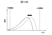
図10Bは、SOHが閾値を逸脱することによるSOH分布の変化を模式的に示す図である。例えば図10AのようにSOH_minが下限閾値を逸脱すると、SOH分布が全体的に下限閾値側へ移動し、SOH分布の一部が下限閾値未満の領域へ突出する。SOH分布の面積に対するこの突出部分(図10Bの斜線部)の面積比を、電池システム200の故障率とみなすこととする。演算部110はこの面積比を算出することにより、電池システム200の故障率を算出する。
FIG. 10B is a diagram schematically showing changes in SOH distribution due to SOH deviating from the threshold. For example, when SOH_min deviates from the lower threshold as shown in FIG. 10A, the SOH distribution as a whole moves toward the lower threshold, and part of the SOH distribution protrudes into the region below the lower threshold. The area ratio of this projecting portion (hatched portion in FIG. 10B ) to the area of the SOH distribution is regarded as the failure rate of the
図10Cは、故障率を簡易的に求める例を説明する模式図である。図10BにおいてはSOH分布の面積を用いて故障率を算出する例を示したが、SOH分布の形状を三角形で近似することにより、故障率計算を簡易化できる。例えばSOH_maxからSOH_minまでを底辺とし、SOH_modを頂点とする三角形を、SOH分布の近似形状とみなす。演算部110はこの三角形のうち閾値を逸脱した部分の面積比を、電池システム200の故障率として求めることができる。
FIG. 10C is a schematic diagram illustrating an example of simply obtaining a failure rate. Although FIG. 10B shows an example of calculating the failure rate using the area of the SOH distribution, the failure rate calculation can be simplified by approximating the shape of the SOH distribution with a triangle. For example, a triangle with the base from SOH_max to SOH_min and the vertex at SOH_mod is regarded as the approximate shape of the SOH distribution. The
図11は、故障率曲線の例である。演算部110は、電池システム200の故障率と故障率曲線を用いることにより、電池システム200の劣化状態(例:摩耗故障期にあるか否か)を判定することができる。演算部110は、電池システム200の故障率と、これを用いて判定した劣化状態を、出力部130から出力する。
FIG. 11 is an example of a failure rate curve. By using the failure rate of the
<実施の形態2:まとめ>
本実施形態2に係る電池状態推定装置100は、3つのSOH(SOH_max、SOH_min、SOH_ave)のうち少なくとも2つを用いることにより、各電池セル210のSOHの度数分布を推定する。電池状態推定装置100は、推定したSOH分布を用いて、電池システム200の劣化状態を推定する。SOH分布を推定する際に、対応関係データ121を参照してSOHを取得することにより、実施形態1と同様にdV/dtの温度特性を考慮して、劣化状態を推定することができる。また2つ以上の電池セル210のSOHを用いることにより、電池システム200全体の劣化状態を推定することができる。
<Embodiment 2: Summary>
The battery
本実施形態2に係る電池状態推定装置100は、SOH分布のうち閾値を逸脱した部分の割合を算出することにより、電池システム200の故障率を算出する。これにより、電池システム200の温度特性を考慮しつつ、電池システム200全体が摩耗故障期にあるか否かなどを判定することができる。
The battery
<本発明の変形例について>
本発明は、前述した実施形態に限定されるものではなく、様々な変形例が含まれる。例えば、上記した実施形態は本発明を分かりやすく説明するために詳細に説明したものであり、必ずしも説明した全ての構成を備えるものに限定されるものではない。また、ある実施形態の構成の一部を他の実施形態の構成に置き換えることが可能であり、また、ある実施形態の構成に他の実施形態の構成を加えることも可能である。また、各実施形態の構成の一部について、他の構成の追加・削除・置換をすることが可能である。
<Regarding Modifications of the Present Invention>
The present invention is not limited to the embodiments described above, and includes various modifications. For example, the above-described embodiments have been described in detail in order to explain the present invention in an easy-to-understand manner, and are not necessarily limited to those having all the configurations described. Also, part of the configuration of one embodiment can be replaced with the configuration of another embodiment, and the configuration of another embodiment can be added to the configuration of one embodiment. Moreover, it is possible to add, delete, or replace a part of the configuration of each embodiment with another configuration.
以上の実施形態において、SOH_maxとSOH_minを用いてEaを算出する例を説明したが、SOH_aveを用いることもできる。すなわち、3つのSOH(SOH_maxとSOH_minとSOH_ave)のうち任意の2つの組み合わせを用いることもできるし、3つのSOHを全て用いることもできる。例えば3つのSOHのうち任意の2つの組み合わせをピックアップしてEaを求め、その他の組み合わせについても同様にEaを求め、それらを平均するなどの手法が考えられる。 In the above embodiment, an example of calculating Ea using SOH_max and SOH_min has been described, but SOH_ave can also be used. That is, a combination of any two of the three SOHs (SOH_max, SOH_min, and SOH_ave) can be used, or all three SOHs can be used. For example, a method of picking up arbitrary two combinations out of three SOHs to obtain Ea, similarly obtaining Ea for other combinations, and averaging them can be considered.
以上の実施形態において、対応関係データ121はあらかじめ記憶部120内に格納しておいてもよいし、電池状態推定装置100の外部から取得して記憶部120に格納してもよい。いったん格納した対応関係データ121を更新してもよい。
In the above embodiment, the
以上の実施形態において、演算部110はその機能を実装した回路デバイスなどのハードウェアによって構成することもできるし、その機能を実装したソフトウェアをCPU(Central Processing Unit)などの演算装置が実行することによって構成することもできる。
In the above embodiment, the
以上の実施形態において、出力部130は任意の形式で推定結果を出力することができる。例えば表示装置上に画面表示する、推定結果を記述したデータを出力する、などの形態が考えられる。
In the above embodiment, the
以上の実施形態においては、電池システム200の例として定置型蓄電池システムを説明したが、その他電池システムにおいても本発明を適用することができる。例えば車載バッテリシステムなどが考えられる。また電池システム200が備える電池セルとして2次電池を例示したが、2次電池の例としては例えばリチウムイオン電池、鉛蓄電池、ニッケル水素電池、電気2重層キャパシタ、などが考えられる。
Although the stationary storage battery system has been described as an example of the
100:電池状態推定装置
110:演算部
120:記憶部
121:対応関係データ
130:出力部
200:電池システム
210:電池セル
220:バッテリ管理部
230:測定データ
100: Battery state estimation device 110: Calculation unit 120: Storage unit 121: Correspondence data 130: Output unit 200: Battery system 210: Battery cell 220: Battery management unit 230: Measurement data
Claims (14)
前記電池セルの放電直後の休止期間における出力電圧の時間微分、前記休止期間における前記電池セルの温度、および前記電池セルの劣化状態の間の対応関係を記述した対応関係データを格納する記憶部、
前記対応関係データを用いて前記電池セルの劣化状態を算出する演算部、
を備え、
前記演算部は、前記複数の電池セルの出力電圧と電池温度の測定結果を記述した測定データを取得し、
前記演算部は、前記測定データが記述している測定結果のなかから、前記電池システムが有する第1電池セルの第1出力電圧を取得するとともに、前記第1電池セルの第1温度を取得し、
前記演算部は、前記測定データが記述している測定結果のなかから、前記電池システムが有する第2電池セルの第2出力電圧を取得するとともに、前記第2電池セルの第2温度を取得し、
前記演算部は、前記第1出力電圧の時間微分と前記第1温度を用いて前記対応関係データを参照することにより、前記第1電池セルの第1劣化状態を推定し、
前記演算部は、前記第2出力電圧の時間微分と前記第2温度を用いて前記対応関係データを参照することにより、前記第2電池セルの第2劣化状態を推定し、
前記演算部は、前記第1劣化状態と前記第2劣化状態を用いて、前記第1劣化状態と前記第2劣化状態との間の差分に対応する、前記電池システム全体の劣化状態を評価するパラメータを求めることにより、前記電池システム全体の劣化状態を推定する
ことを特徴とする電池状態推定装置。 A battery state estimation device for estimating the state of a battery system having a plurality of battery cells,
a storage unit that stores correspondence data describing a correspondence between the time derivative of the output voltage in the idle period immediately after discharging the battery cell, the temperature of the battery cell in the idle period, and the deterioration state of the battery cell;
a calculation unit that calculates the deterioration state of the battery cell using the correspondence data;
with
The computing unit acquires measurement data describing measurement results of the output voltages and battery temperatures of the plurality of battery cells,
The computing unit acquires a first output voltage of a first battery cell included in the battery system and acquires a first temperature of the first battery cell from measurement results described in the measurement data. ,
The computing unit acquires a second output voltage of a second battery cell of the battery system and acquires a second temperature of the second battery cell from the measurement results described in the measurement data. ,
The computing unit estimates a first deterioration state of the first battery cell by referring to the correspondence data using the time differentiation of the first output voltage and the first temperature,
The computing unit estimates a second deterioration state of the second battery cell by referring to the correspondence data using the time differentiation of the second output voltage and the second temperature,
The computing unit uses the first deterioration state and the second deterioration state to evaluate the deterioration state of the entire battery system corresponding to the difference between the first deterioration state and the second deterioration state. A battery state estimating device for estimating a deterioration state of the entire battery system by obtaining parameters .
前記複数の電池セルそれぞれの出力電圧のうち最も大きい最大電圧、
前記複数の電池セルそれぞれの出力電圧のうち最も小さい最小電圧、または、
前記複数の電池セルそれぞれの出力電圧の平均電圧、
のうちいずれかを前記第1出力電圧として取得するとともに、残り2つのうちいずれかを前記第2出力電圧として取得し、
前記演算部は、前記第1出力電圧の時間微分と前記第2出力電圧の時間微分を用いて前記対応関係データを参照することにより、
前記複数の電池セルそれぞれの劣化状態のうち最も劣化していないもの、
前記複数の電池セルそれぞれの劣化状態のうち最も劣化しているもの、または、
前記複数の電池セルそれぞれの劣化状態の平均、
のうち少なくとも2つを取得し、それらを用いて前記電池システム全体の劣化状態を推定する
ことを特徴とする請求項1記載の電池状態推定装置。 The calculation unit is
the highest maximum voltage among the output voltages of each of the plurality of battery cells;
The smallest minimum voltage among the output voltages of the plurality of battery cells, or
an average voltage of the output voltages of the plurality of battery cells;
one of the two is obtained as the first output voltage, and one of the remaining two is obtained as the second output voltage;
The computing unit refers to the correspondence data using the time differentiation of the first output voltage and the time differentiation of the second output voltage,
the least deteriorated among the deterioration states of the plurality of battery cells;
The most deteriorated state among the plurality of battery cells, or
average deterioration state of each of the plurality of battery cells;
The battery state estimating device according to claim 1, wherein at least two of the above are acquired, and the state of deterioration of the entire battery system is estimated using them.
前記複数の電池セルそれぞれの温度のうち最も高い最高温度、
前記複数の電池セルそれぞれの温度のうち最も低い最低温度、または、
前記複数の電池セルそれぞれの温度の平均温度、
のうちいずれかを前記第1温度として取得するとともに、残り2つのうちいずれかを前記第2温度として取得し、
前記演算部は、前記第1温度と前記第2温度を用いて前記対応関係データを参照することにより、
前記複数の電池セルそれぞれの劣化状態のうち最も劣化していないもの、
前記複数の電池セルそれぞれの劣化状態のうち最も劣化しているもの、または、
前記複数の電池セルそれぞれの劣化状態の平均、
のうち少なくとも2つを取得し、それらを用いて前記電池システム全体の劣化状態を推定する
ことを特徴とする請求項1記載の電池状態推定装置。 The calculation unit is
the highest maximum temperature among the temperatures of each of the plurality of battery cells;
the lowest minimum temperature among the temperatures of each of the plurality of battery cells, or
an average temperature of the temperatures of the plurality of battery cells;
Acquire one of the two as the first temperature, and acquire one of the remaining two as the second temperature,
The computing unit refers to the correspondence data using the first temperature and the second temperature,
the least deteriorated among the deterioration states of the plurality of battery cells;
The most deteriorated state among the plurality of battery cells, or
average deterioration state of each of the plurality of battery cells;
The battery state estimating device according to claim 1, wherein at least two of the above are acquired, and the state of deterioration of the entire battery system is estimated using them.
前記演算部は、前記評価パラメータを用いて、前記電池システムが、初期劣化状態、偶発劣化状態、または摩耗劣化状態のうちいずれにあるのかを推定する
ことを特徴とする請求項1記載の電池状態推定装置。 The calculating unit uses the first deterioration state and the second deterioration state to obtain an evaluation parameter representing the deterioration state of the entire battery system,
2. The state of the battery according to claim 1, wherein the calculation unit uses the evaluation parameter to estimate whether the battery system is in an initial deterioration state, an accidental deterioration state, or a wear deterioration state. estimation device.
前記複数の電池セルそれぞれの出力電圧のうち最も大きい最大電圧、
前記複数の電池セルそれぞれの出力電圧のうち最も小さい最小電圧、または、
前記複数の電池セルそれぞれの出力電圧の平均電圧、
のうちいずれかを前記第1出力電圧として取得するとともに、残り2つのうちいずれかを前記第2出力電圧として取得し、
前記演算部は、前記第1電池セルが第3劣化状態から第4劣化状態に到達するまでに要する第1充放電サイクル数を取得し、
前記演算部は、前記第2電池セルが前記第3劣化状態から前記第4劣化状態に到達するまでに要する第2充放電サイクル数を取得し、
前記演算部は、前記第1充放電サイクル数と前記第2充放電サイクル数を用いて、前記評価パラメータを算出する
ことを特徴とする請求項4記載の電池状態推定装置。 The calculation unit is
the highest maximum voltage among the output voltages of each of the plurality of battery cells;
The smallest minimum voltage among the output voltages of the plurality of battery cells, or
an average voltage of the output voltages of the plurality of battery cells;
one of the two is obtained as the first output voltage, and one of the remaining two is obtained as the second output voltage;
The computing unit obtains a first charge/discharge cycle number required for the first battery cell to reach a fourth deterioration state from a third deterioration state,
The computing unit acquires a second charge-discharge cycle number required for the second battery cell to reach the fourth deterioration state from the third deterioration state,
The battery state estimation device according to claim 4, wherein the calculation unit calculates the evaluation parameter using the first number of charge/discharge cycles and the second number of charge/discharge cycles.
前記複数の電池セルそれぞれの温度のうち最も高い最高温度、
前記複数の電池セルそれぞれの温度のうち最も低い最低温度、または、
前記複数の電池セルそれぞれの温度の平均温度、
のうちいずれかを前記第1温度として取得するとともに、残り2つのうちいずれかを前記第2温度として取得し、
前記演算部は、前記第1電池セルが第3劣化状態から第4劣化状態に到達するまでの間は、前記第1電池セルが前記第1温度の時間平均値を有すると仮定して、前記評価パラメータを算出し、
前記演算部は、前記第2電池セルが前記第3劣化状態から前記第4劣化状態に到達するまでの間は、前記第2電池セルが前記第2温度の時間平均値を有すると仮定して、前記評価パラメータを算出する
ことを特徴とする請求項4記載の電池状態推定装置。 The calculation unit is
the highest maximum temperature among the temperatures of each of the plurality of battery cells;
the lowest minimum temperature among the temperatures of each of the plurality of battery cells, or
an average temperature of the temperatures of the plurality of battery cells;
Acquire one of the two as the first temperature, and acquire one of the remaining two as the second temperature,
The computing unit assumes that the first battery cell has the time average value of the first temperature until the first battery cell reaches the fourth deterioration state from the third deterioration state, Calculate the evaluation parameters,
The computing unit assumes that the second battery cell has the time average value of the second temperature until the second battery cell reaches the fourth deterioration state from the third deterioration state. , to calculate the evaluation parameter.
前記演算部は、前記分布を用いて、前記電池システムの故障率を推定する
ことを特徴とする請求項1記載の電池状態推定装置。 The computing unit uses the first deterioration state and the second deterioration state to estimate a distribution of the deterioration state of each of the plurality of battery cells,
The battery state estimation device according to claim 1, wherein the calculation unit estimates the failure rate of the battery system using the distribution.
前記演算部は、前記複数の電池セルそれぞれの出力電圧のうち最も小さい最小電圧を前記第2出力電圧として取得し、
前記演算部は、前記複数の電池セルそれぞれの出力電圧の平均電圧を第3電圧として取得し、
前記演算部は、前記最大電圧の時間微分を用いて前記対応関係データを参照することにより、前記複数の電池セルそれぞれの劣化状態のうち最も劣化しているものを前記第1劣化状態として取得し、
前記演算部は、前記最小電圧の時間微分を用いて前記対応関係データを参照することにより、前記複数の電池セルそれぞれの劣化状態のうち最も劣化していないものを前記第2劣化状態として取得し、
前記演算部は、前記平均電圧の時間微分を用いて前記対応関係データを参照することにより、前記複数の電池セルそれぞれの劣化状態の平均を第3劣化状態として取得し、
前記演算部は、前記第1劣化状態、前記第2劣化状態、および前記第3劣化状態を用いて、前記分布を推定する
ことを特徴とする請求項7記載の電池状態推定装置。 The computing unit acquires the highest maximum voltage among the output voltages of each of the plurality of battery cells as the first output voltage,
The computing unit acquires the smallest minimum voltage among the output voltages of each of the plurality of battery cells as the second output voltage,
The computing unit acquires an average voltage of output voltages of the plurality of battery cells as a third voltage,
The computing unit obtains the most deteriorated deterioration state of each of the plurality of battery cells as the first deterioration state by referring to the correspondence data using the time differentiation of the maximum voltage. ,
The computing unit obtains the least deteriorated deterioration state of each of the plurality of battery cells as the second deterioration state by referring to the correspondence data using the time differentiation of the minimum voltage. ,
The computing unit obtains an average deterioration state of each of the plurality of battery cells as a third deterioration state by referring to the correspondence data using the time differentiation of the average voltage,
The battery state estimation device according to claim 7, wherein the calculation unit estimates the distribution using the first deterioration state, the second deterioration state, and the third deterioration state.
ことを特徴とする請求項8記載の電池状態推定装置。 The calculating unit estimates the distribution by calculating at least the mode of the distribution using the first deterioration state, the second deterioration state, and the third deterioration state. The battery state estimating device according to claim 8.
前記演算部は、前記複数の電池セルのうち前記上限許容値を超えたものまたは前記下限許容値を下回ったものの割合にしたがって、前記電池システムの故障率を推定する
ことを特徴とする請求項7記載の電池状態推定装置。 The calculation unit uses the distribution to calculate an upper allowable value and a lower allowable value of the deterioration state of the battery cell,
8. The calculating unit estimates the failure rate of the battery system according to the ratio of the battery cells exceeding the upper allowable value or falling below the lower allowable value among the plurality of battery cells. The battery state estimating device described.
前記演算部は、前記分布の面積に対する前記第1面積の割合と、前記分布の面積に対する前記第2面積の割合とを用いて、前記複数の電池セルのうち前記上限許容値を超えたものまたは前記下限許容値を下回ったものの割合を算出する
ことを特徴とする請求項10記載の電池状態推定装置。 The calculation unit calculates a first area of a portion of the distribution that exceeds the upper allowable value and a second area of a portion of the distribution that falls below the lower allowable value,
The calculation unit uses the ratio of the first area to the area of the distribution and the ratio of the second area to the area of the distribution to determine which of the plurality of battery cells exceeds the upper allowable value or 11. The battery state estimation device according to claim 10, wherein a ratio of those below the lower limit permissible value is calculated.
ことを特徴とする請求項1記載の電池状態推定装置。 The battery state estimation device according to claim 1, further comprising an output unit that outputs an estimation result of the state of deterioration of the battery system.
ことを特徴とする請求項1記載の電池状態推定装置。 The battery state estimation device according to claim 1, wherein the battery system is a stationary battery system.
ことを特徴とする請求項1記載の電池状態推定装置。 The battery state estimation device according to claim 1, wherein the calculation unit acquires the measurement data from the battery system by communication.
Priority Applications (5)
| Application Number | Priority Date | Filing Date | Title |
|---|---|---|---|
| JP2019182417A JP7280161B2 (en) | 2019-10-02 | 2019-10-02 | Battery state estimation device |
| US17/762,390 US11841402B2 (en) | 2019-10-02 | 2020-09-14 | Battery state estimation device |
| EP20871587.0A EP4040569B1 (en) | 2019-10-02 | 2020-09-14 | Battery state estimation device |
| CN202080067579.7A CN114729969A (en) | 2019-10-02 | 2020-09-14 | Battery state estimating device |
| PCT/JP2020/034716 WO2021065443A1 (en) | 2019-10-02 | 2020-09-14 | Battery state estimation device |
Applications Claiming Priority (1)
| Application Number | Priority Date | Filing Date | Title |
|---|---|---|---|
| JP2019182417A JP7280161B2 (en) | 2019-10-02 | 2019-10-02 | Battery state estimation device |
Publications (3)
| Publication Number | Publication Date |
|---|---|
| JP2021060198A JP2021060198A (en) | 2021-04-15 |
| JP2021060198A5 JP2021060198A5 (en) | 2022-04-15 |
| JP7280161B2 true JP7280161B2 (en) | 2023-05-23 |
Family
ID=75337963
Family Applications (1)
| Application Number | Title | Priority Date | Filing Date |
|---|---|---|---|
| JP2019182417A Active JP7280161B2 (en) | 2019-10-02 | 2019-10-02 | Battery state estimation device |
Country Status (5)
| Country | Link |
|---|---|
| US (1) | US11841402B2 (en) |
| EP (1) | EP4040569B1 (en) |
| JP (1) | JP7280161B2 (en) |
| CN (1) | CN114729969A (en) |
| WO (1) | WO2021065443A1 (en) |
Families Citing this family (7)
| Publication number | Priority date | Publication date | Assignee | Title |
|---|---|---|---|---|
| JP2022170227A (en) * | 2021-04-28 | 2022-11-10 | 株式会社日立ハイテク | Battery state estimation device and power system |
| CN113659174B (en) * | 2021-06-28 | 2023-04-14 | 安徽明天新能源科技有限公司 | Method for evaluating capability index of membrane electrode manufacturing process |
| JP2023136212A (en) * | 2022-03-16 | 2023-09-29 | 株式会社日立ハイテク | Battery state estimation device, battery system, and battery state estimation method |
| JP2024029593A (en) * | 2022-08-22 | 2024-03-06 | 株式会社日立製作所 | Battery management device and battery management method |
| CN115877238B (en) * | 2022-12-06 | 2023-11-07 | 北汽福田汽车股份有限公司 | Method and device for detecting battery capacity, readable storage medium and electronic equipment |
| JP7544164B1 (en) | 2023-02-17 | 2024-09-03 | いすゞ自動車株式会社 | Deterioration monitoring device |
| CN117368763A (en) * | 2023-12-07 | 2024-01-09 | 深圳市百酷新能源有限公司 | Lithium battery management method, device, equipment and storage medium based on SOC algorithm |
Citations (7)
| Publication number | Priority date | Publication date | Assignee | Title |
|---|---|---|---|---|
| JP2000312443A (en) | 1999-04-27 | 2000-11-07 | Shin Kobe Electric Mach Co Ltd | Module battery controller, module battery unit and module battery control method |
| JP2004354050A (en) | 2002-05-14 | 2004-12-16 | Yazaki Corp | Charging state estimation method and open circuit voltage estimation method of battery, and deterioration degree calculation device and method |
| JP2011043460A (en) | 2009-08-24 | 2011-03-03 | Sanyo Electric Co Ltd | Characteristic detection method of secondary battery, and secondary battery device |
| JP2014063693A (en) | 2012-09-24 | 2014-04-10 | Toshiba Corp | Secondary battery device and battery capacity estimation system |
| WO2016135913A1 (en) | 2015-02-26 | 2016-09-01 | 株式会社 東芝 | Storage battery, storage battery monitoring method, and monitor controller |
| JP2019115088A (en) | 2017-12-20 | 2019-07-11 | 株式会社デンソー | Storage battery system |
| WO2019181764A1 (en) | 2018-03-20 | 2019-09-26 | 株式会社村田製作所 | Battery control device, battery control method, uninterruptible power supply unit, power system, and electric vehicle |
Family Cites Families (14)
| Publication number | Priority date | Publication date | Assignee | Title |
|---|---|---|---|---|
| WO2013038458A1 (en) * | 2011-09-16 | 2013-03-21 | 株式会社日立製作所 | Power distribution device |
| JP5737232B2 (en) * | 2012-07-12 | 2015-06-17 | トヨタ自動車株式会社 | Device for determining the remaining life of stationary storage batteries |
| WO2015132891A1 (en) * | 2014-03-05 | 2015-09-11 | 株式会社日立製作所 | Secondary battery module |
| DE102014204956A1 (en) * | 2014-03-18 | 2015-09-24 | Robert Bosch Gmbh | Method for detecting anomalies in a battery cell and short-circuit sensor |
| JP6312508B2 (en) | 2014-04-11 | 2018-04-18 | 日立オートモティブシステムズ株式会社 | Battery monitoring device, battery system, and electric vehicle drive device |
| KR102205841B1 (en) * | 2014-04-28 | 2021-01-21 | 삼성전자주식회사 | Method and apparatus for estimating state of battery |
| WO2016098631A1 (en) * | 2014-12-15 | 2016-06-23 | 日本電気株式会社 | Battery pack, electronic instrument, cell balance device, cell balance method, and program |
| KR102636361B1 (en) * | 2016-01-05 | 2024-02-14 | 삼성전자주식회사 | Battery control appratus and battery control system |
| JP6508729B2 (en) | 2016-12-02 | 2019-05-08 | トヨタ自動車株式会社 | Battery state estimation device |
| JP2018179684A (en) * | 2017-04-10 | 2018-11-15 | 三菱自動車工業株式会社 | Device for estimating degradation state of secondary battery and cell system and electric vehicle having the same |
| JP6834849B2 (en) | 2017-08-24 | 2021-02-24 | トヨタ自動車株式会社 | Impedance estimator |
| US11677253B2 (en) | 2018-01-16 | 2023-06-13 | Gs Yuasa International Ltd. | Monitoring device, monitoring method, computer program, deterioration determination method, deterioration determination device, and deterioration determination system |
| JP2019158666A (en) * | 2018-03-14 | 2019-09-19 | 株式会社Gsユアサ | Method for determining degradation, degradation determination device, and degradation determination system |
| JP7202958B2 (en) * | 2019-04-05 | 2023-01-12 | 株式会社日立産機システム | Storage battery condition evaluation system |
-
2019
- 2019-10-02 JP JP2019182417A patent/JP7280161B2/en active Active
-
2020
- 2020-09-14 CN CN202080067579.7A patent/CN114729969A/en active Pending
- 2020-09-14 EP EP20871587.0A patent/EP4040569B1/en active Active
- 2020-09-14 WO PCT/JP2020/034716 patent/WO2021065443A1/en unknown
- 2020-09-14 US US17/762,390 patent/US11841402B2/en active Active
Patent Citations (7)
| Publication number | Priority date | Publication date | Assignee | Title |
|---|---|---|---|---|
| JP2000312443A (en) | 1999-04-27 | 2000-11-07 | Shin Kobe Electric Mach Co Ltd | Module battery controller, module battery unit and module battery control method |
| JP2004354050A (en) | 2002-05-14 | 2004-12-16 | Yazaki Corp | Charging state estimation method and open circuit voltage estimation method of battery, and deterioration degree calculation device and method |
| JP2011043460A (en) | 2009-08-24 | 2011-03-03 | Sanyo Electric Co Ltd | Characteristic detection method of secondary battery, and secondary battery device |
| JP2014063693A (en) | 2012-09-24 | 2014-04-10 | Toshiba Corp | Secondary battery device and battery capacity estimation system |
| WO2016135913A1 (en) | 2015-02-26 | 2016-09-01 | 株式会社 東芝 | Storage battery, storage battery monitoring method, and monitor controller |
| JP2019115088A (en) | 2017-12-20 | 2019-07-11 | 株式会社デンソー | Storage battery system |
| WO2019181764A1 (en) | 2018-03-20 | 2019-09-26 | 株式会社村田製作所 | Battery control device, battery control method, uninterruptible power supply unit, power system, and electric vehicle |
Also Published As
| Publication number | Publication date |
|---|---|
| WO2021065443A1 (en) | 2021-04-08 |
| EP4040569A4 (en) | 2023-11-01 |
| EP4040569A1 (en) | 2022-08-10 |
| EP4040569B1 (en) | 2024-05-29 |
| US11841402B2 (en) | 2023-12-12 |
| CN114729969A (en) | 2022-07-08 |
| US20220381846A1 (en) | 2022-12-01 |
| JP2021060198A (en) | 2021-04-15 |
Similar Documents
| Publication | Publication Date | Title |
|---|---|---|
| JP7280161B2 (en) | Battery state estimation device | |
| CN104698385B (en) | Battery state calculating device and battery state calculating method | |
| KR102080632B1 (en) | Battery management system and its operating method | |
| US20190036356A1 (en) | Method and System for Estimating Battery Open Cell Voltage, State of Charge, and State of Health During Operation of the Battery | |
| KR100970841B1 (en) | Apparatus and Method for estimating battery's state of health based on battery voltage variation pattern | |
| WO2015041091A1 (en) | Secondary cell degradation diagnosis system, and degradation diagnosis method | |
| CN106662621B (en) | Battery state detection device, secondary battery system, program product, and battery state detection method | |
| JP6298920B2 (en) | Battery control device | |
| CN106662620B (en) | Battery state detection device, secondary battery system, storage medium, and battery state detection method | |
| US12044747B2 (en) | Apparatus and method for diagnosing battery | |
| EP3961233B1 (en) | Battery cell diagnosis device and method | |
| JP7332084B2 (en) | Apparatus and method for diagnosing battery | |
| JP6546261B2 (en) | Storage system, storage control method, and storage control program | |
| JP2017009577A (en) | State estimation device and state estimation method | |
| KR101912615B1 (en) | System for monitoring and protecting batteries | |
| JP7172013B2 (en) | BATTERY MANAGEMENT DEVICE, BATTERY MANAGEMENT METHOD AND BATTERY PACK | |
| KR20200091750A (en) | Battery management appratus, battery management method and battery pack | |
| US20230213587A1 (en) | Method and System for Efficiently Monitoring Battery Cells of a Device Battery in an External Central Processing Unit Using a Digital Twin | |
| CN114503392A (en) | Determination device, power storage system, determination method, and determination program for a plurality of batteries | |
| CN114035096A (en) | Electrochemical device SOH evaluation method, electronic device, and battery system | |
| KR100911315B1 (en) | Apparatus and method for estimating battery's resistance characteristics based on open circuit voltage estimated by battery voltage variation pattern | |
| WO2018025306A1 (en) | Estimation device, estimation program, and charging control device | |
| JP2021524127A (en) | Battery management device, battery management method and battery pack | |
| JP7168336B2 (en) | Secondary battery controller | |
| KR101835375B1 (en) | Apparatus for estimating state-of-health of battery group and method thereof |
Legal Events
| Date | Code | Title | Description |
|---|---|---|---|
| A521 | Request for written amendment filed |
Free format text: JAPANESE INTERMEDIATE CODE: A523 Effective date: 20220407 |
|
| A621 | Written request for application examination |
Free format text: JAPANESE INTERMEDIATE CODE: A621 Effective date: 20220407 |
|
| A131 | Notification of reasons for refusal |
Free format text: JAPANESE INTERMEDIATE CODE: A131 Effective date: 20230117 |
|
| A521 | Request for written amendment filed |
Free format text: JAPANESE INTERMEDIATE CODE: A523 Effective date: 20230210 |
|
| TRDD | Decision of grant or rejection written | ||
| A01 | Written decision to grant a patent or to grant a registration (utility model) |
Free format text: JAPANESE INTERMEDIATE CODE: A01 Effective date: 20230425 |
|
| A61 | First payment of annual fees (during grant procedure) |
Free format text: JAPANESE INTERMEDIATE CODE: A61 Effective date: 20230511 |
|
| R150 | Certificate of patent or registration of utility model |
Ref document number: 7280161 Country of ref document: JP Free format text: JAPANESE INTERMEDIATE CODE: R150 |