JP5737232B2 - Device for determining the remaining life of stationary storage batteries - Google Patents
Device for determining the remaining life of stationary storage batteries Download PDFInfo
- Publication number
- JP5737232B2 JP5737232B2 JP2012156808A JP2012156808A JP5737232B2 JP 5737232 B2 JP5737232 B2 JP 5737232B2 JP 2012156808 A JP2012156808 A JP 2012156808A JP 2012156808 A JP2012156808 A JP 2012156808A JP 5737232 B2 JP5737232 B2 JP 5737232B2
- Authority
- JP
- Japan
- Prior art keywords
- remaining life
- storage battery
- stationary storage
- battery
- storage unit
- Prior art date
- Legal status (The legal status is an assumption and is not a legal conclusion. Google has not performed a legal analysis and makes no representation as to the accuracy of the status listed.)
- Active
Links
Images


Classifications
-
- G—PHYSICS
- G01—MEASURING; TESTING
- G01R—MEASURING ELECTRIC VARIABLES; MEASURING MAGNETIC VARIABLES
- G01R31/00—Arrangements for testing electric properties; Arrangements for locating electric faults; Arrangements for electrical testing characterised by what is being tested not provided for elsewhere
- G01R31/36—Arrangements for testing, measuring or monitoring the electrical condition of accumulators or electric batteries, e.g. capacity or state of charge [SoC]
- G01R31/382—Arrangements for monitoring battery or accumulator variables, e.g. SoC
-
- G—PHYSICS
- G01—MEASURING; TESTING
- G01R—MEASURING ELECTRIC VARIABLES; MEASURING MAGNETIC VARIABLES
- G01R31/00—Arrangements for testing electric properties; Arrangements for locating electric faults; Arrangements for electrical testing characterised by what is being tested not provided for elsewhere
- G01R31/36—Arrangements for testing, measuring or monitoring the electrical condition of accumulators or electric batteries, e.g. capacity or state of charge [SoC]
- G01R31/392—Determining battery ageing or deterioration, e.g. state of health
-
- G—PHYSICS
- G01—MEASURING; TESTING
- G01R—MEASURING ELECTRIC VARIABLES; MEASURING MAGNETIC VARIABLES
- G01R31/00—Arrangements for testing electric properties; Arrangements for locating electric faults; Arrangements for electrical testing characterised by what is being tested not provided for elsewhere
- G01R31/36—Arrangements for testing, measuring or monitoring the electrical condition of accumulators or electric batteries, e.g. capacity or state of charge [SoC]
- G01R31/3644—Constructional arrangements
- G01R31/3648—Constructional arrangements comprising digital calculation means, e.g. for performing an algorithm
Description
本発明は、車両等に用いられた電池を再利用した定置用蓄電池の余寿命を推定する余寿命判定装置に関する。 The present invention relates to a remaining life determination device that estimates the remaining life of a stationary storage battery that reuses a battery used in a vehicle or the like.
電気自動車、ハイブリッド自動車には、車両走行用のモータに電力を供給する蓄電装置が搭載されている。この蓄電装置は、充放電を繰り返すことにより劣化する。蓄電装置の余寿命を診断する診断方法として、特許文献1は、(a)情報を記憶する情報記憶手段に、寿命に到達したバッテリである寿命バッテリの使用状態と予め定められた所定の充電シーケンスにより前記寿命バッテリが充電されたときの該寿命バッテリの充電特性である寿命充電特性とを関連付けて記憶させて準備し、(b)前記診断用バッテリの使用状態と、前記所定の充電シーケンスにより前記診断用バッテリが充電されたときの該診断用バッテリの充電特性である診断充電特性と、を取得し、(c)前記取得された診断充電特性と、前記情報記憶手段に記憶されている情報のうち前記取得された診断用バッテリの使用状態に対応する前記寿命バッテリの使用状態に関連付けられた前記寿命充電特性である対応寿命充電特性と、の関係から前記診断用バッテリの余寿命を診断する、余寿命診断方法を開示する。
Electric vehicles and hybrid vehicles are equipped with a power storage device that supplies electric power to a vehicle driving motor. This power storage device is deteriorated by repeated charging and discharging. As a diagnostic method for diagnosing the remaining life of a power storage device,
図6は、車両用電池の経時変化を推定する推定情報のデータベース構造を模式的に示している。例えば、ハイブリッド自動車では、走行条件等の変化により車両用電池の電流値が時々刻々と変化し、多数の充放電パターンが存在する。そのため、車両用電池の余寿命を判定するための余寿命マップを、充放電パターンの数に応じて多数準備しなければならならない。 FIG. 6 schematically shows a database structure of estimation information for estimating a change with time of the vehicle battery. For example, in a hybrid vehicle, the current value of the vehicle battery changes from moment to moment due to changes in driving conditions and the like, and there are many charge / discharge patterns. Therefore, many remaining life maps for determining the remaining life of the vehicle battery must be prepared according to the number of charge / discharge patterns.
しかしながら、定置用蓄電池は、図7に図示するように、充放電パターンが車両用電池程煩雑ではない。すなわち、定置用蓄電池は、定電流充放電するため、余寿命マップが車両用電池よりも少なくてよい。そのため、定置用蓄電池の余寿命を判定する際に、車両用電池の場合と同じ判定方法を用いる必要がなく、同じ判定方法を用いると判定処理が煩雑化して、無駄に時間がかかる。そこで、本願発明は、定置用蓄電池の余寿命を簡易な方法で推定可能な余寿命判定装置を提供することを目的とする。 However, as shown in FIG. 7, the charge / discharge pattern of the stationary storage battery is not as complicated as the vehicle battery. That is, since the stationary storage battery charges and discharges at a constant current, the remaining life map may be smaller than the vehicle battery. Therefore, when determining the remaining life of the stationary storage battery, it is not necessary to use the same determination method as in the case of the vehicle battery. If the same determination method is used, the determination process becomes complicated and takes time. Therefore, an object of the present invention is to provide a remaining life determination device capable of estimating the remaining life of a stationary storage battery by a simple method.
上記課題を解決するために、本願発明に係る余寿命判定装置は、(1)定電流充放電する定置用蓄電池の余寿命判定装置であって、前記定置用蓄電池の劣化状態を評価する評価値を検出する検出部と、前記定置用蓄電池のそれまでの使用履歴を記憶する第1の記憶部と、前記定置用蓄電池の使用情報に対応付けられた余寿命情報を記憶する第2の記憶部と、前記定置用蓄電池の余寿命基本情報を記憶した第3の記憶部と、前記第1の記憶部に記憶された使用履歴に対応する余寿命情報が前記第2の記憶部に記憶されている場合には、前記第1の記憶部に記憶されたそれまでの使用履歴、前記評価値及び前記対応する余寿命情報から、前記定置用蓄電池の余寿命を推定し、前記第1の記憶部に記憶された使用履歴に対応する余寿命情報が前記第2の記憶部に記憶されていない場合には、前記第1の記憶部に記憶されたそれまでの使用履歴、前記評価値及び前記第3の記憶部に記憶された余寿命基本情報から、前記定置用蓄電池の余寿命を推定するコントローラと、を有することを特徴とする。
In order to solve the above problems, the remaining life determination device according to the present invention is (1) a remaining life determination device for a stationary storage battery that charges and discharges at a constant current, and an evaluation value that evaluates the deterioration state of the stationary storage battery A first storage unit for storing the use history of the stationary storage battery, and a second storage unit for storing remaining life information associated with the usage information of the stationary storage battery And a third storage unit that stores the basic remaining life information of the stationary storage battery, and a remaining life information corresponding to the use history stored in the first storage unit is stored in the second storage unit. The remaining life of the stationary storage battery is estimated from the previous use history stored in the first storage unit, the evaluation value, and the corresponding remaining life information, and the first storage unit The remaining life information corresponding to the usage history stored in the From the previous use history stored in the first storage unit, the evaluation value, and the remaining basic life information stored in the third storage unit. And a controller for estimating the remaining life of the storage battery.
(2)上記(1)の構成において、前記定置用蓄電池は、家電製品に電力を供給することができる。 (2) In the configuration of (1) above, the stationary storage battery can supply electric power to the home appliance.
(3)上記(1)又は(2)の構成において、さらに、表示部を有し、前記コントローラは、余寿命を予測した際に、定置用蓄電池のリビルト情報を前記表示部に表示することを特徴とする。(3)の構成によれば、余寿命の予測とともに定置用蓄電池のリビルト情報が表示されるため、別途定置用蓄電池のリビルトを判定するための処理を行う必要がなくなる。 (3) In the configuration of (1) or (2), the display further includes a display unit, and the controller displays the rebuilt information of the stationary storage battery on the display unit when the remaining life is predicted. Features. According to the configuration of (3), since the rebuilding information of the stationary storage battery is displayed together with the remaining life prediction, it is not necessary to separately perform a process for determining the rebuilding of the stationary storage battery.
(4)上記(1)〜(3)の構成において、前記定置用蓄電池は、車両走行用のモータに電力を供給する車両用電池を再利用した電池であり、前記コントローラは、前記第1の記憶部に記憶される前記定置用蓄電池のそれまでの使用履歴を車両から通信により取得することができる。(4)の構成によれば、車両から使用履歴を取得できるため、車両から定置用蓄電池を取り外した後に電池の状態を調べる必要がないため、短時間で余寿命判定を行うことができる。 (4) In the configurations of (1) to (3), the stationary storage battery is a battery that reuses a vehicle battery that supplies electric power to a vehicle driving motor, and the controller includes the first battery. The use history of the stationary storage battery stored in the storage unit so far can be acquired from the vehicle by communication. According to the configuration of (4), since the use history can be acquired from the vehicle, it is not necessary to check the state of the battery after removing the stationary storage battery from the vehicle, so the remaining life can be determined in a short time.
(5)上記(1)〜(4)の構成において、前記評価値は、前記定置用蓄電池の実放電容量及び内部抵抗のうち少なくとも一つであってもよい。 (5) In the configurations of (1) to (4), the evaluation value may be at least one of an actual discharge capacity and an internal resistance of the stationary storage battery.
(6)上記(1)〜(5)の構成において、前記余寿命基本情報は、未使用の前記定置用蓄電池を対象とした余寿命情報であってもよい。 (6) In the configurations of (1) to (5), the remaining life basic information may be remaining life information for the unused stationary storage battery.
本願発明によれば、定置用蓄電池の余寿命を簡易な方法で推定可能な余寿命判定装置を提供することができる。 According to the present invention, it is possible to provide a remaining life determination device capable of estimating the remaining life of a stationary storage battery by a simple method.
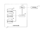
図面を参照しながら、本発明の実施形態について説明する。図1は、余寿命判定装置の機能ブロック図である。余寿命判定装置1は、検出部10と、第1の記憶部20と、第2の記憶部30と、第3の記憶部40と、コントローラ50とを有する。
Embodiments of the present invention will be described with reference to the drawings. FIG. 1 is a functional block diagram of the remaining life determination apparatus. The remaining
検出部10は、定置用蓄電池2の劣化状態を評価する評価値を取得する。ここで、評価値は、実放電容量、内部抵抗であってもよい。実放電容量は、定置用蓄電池2を満充電状態(SOC=100%)に対応する電圧値から放電終止電圧値まで放電させたときの電流積算量から算出することができる。内部抵抗は、定置用蓄電池2を放電させたときの電流値及び電圧値から算出することができる。ここで、定置用蓄電池2の内部抵抗は、SOCや温度に応じて変動するため、現在の定置用蓄電池2におけるSOCや温度に応じて、電圧値および電流値から算出された内部抵抗を補正してもよい。
The
検出部10は、電流センサ、電圧センサ、温度センサを含んでいる。電流センサは、定置用蓄電池2の電流を検出する。電圧センサは、定置用蓄電池2の総電圧を検出する。電圧センサは、定置用蓄電池2をブロック単位に分割した各ブロック電圧を検出してもよい。この場合、各ブロック電圧の総和が、定置用蓄電池2の総電圧として検出される。温度センサは、定置用蓄電池2に対して一個或いは複数個設けられていてもよい。温度センサには、サーミスタを用いることができる。なお、検出部10は、取得した電流値、電圧値から後述する評価値(実放電容量、内部抵抗)を算出する処理を行う算出部としての機能も有している。
The
定置用蓄電池2は、家電製品(例えば、エアコン、炊飯器等)に対して電力を供給する。定置用蓄電池2には、使用済の車両用電池が用いられる。ここで、車両用電池は、車両走行用モータに供給される電力を蓄電しており、車両に搭載されている。この車両用電池は、複数の電池モジュールを有している。従来、これらの電池モジュールのうち少なくとも一つのモジュールが劣化等により使用不能となった場合には、車両用電池全体を交換しなければならなかった。また、この交換された車両用電池は有効な電池モジュールが残っているにも拘わらず廃棄されていた。本実施形態によれば、従来廃棄されていた車両用電池を定置用蓄電池として再利用することができる。
The
図2に示す特性図は、ハイブリッド車両に搭載される車両用電池と家庭用電源に用いられる定置用蓄電池2の違いを示している。ハイブリッド車両とは、車両用電池と内燃機関とを動力源として兼用する車両のことである。車両用電池は、例えば、SOCが30〜70%の範囲で使用される。これに対して定置用蓄電池2は、通常、SOCが0〜100%の範囲で使用される。車両用電池は、充放電時に電流値が時々刻々と変化し、電流値の変動が非常に大きい。これに対して、定置用蓄電池2は、定電流充放電するため、車両用電池よりも電流値の変動が小さい。ここで、定電流充放電とは、同一負荷に放電される電流値がある期間内において一定であることを意味し、電流リップルなどによって電流値が変動する場合も含まれる。また、車両用電池は、SOCが30〜70%の範囲で使用されるため、電圧変動が相対的に小さく、劣化しても電池特性が把握しにくい。これに対して、定置用蓄電池2は、SOCが0〜100%の範囲で使用されるため、電圧変動が相対的に大きく、劣化した際の電池特性が把握しやすい。
The characteristic diagram shown in FIG. 2 shows the difference between a vehicle battery mounted on a hybrid vehicle and a
再び図1を参照して、第1の記憶部20は、定置用蓄電池2のそれまでの使用履歴を記憶する。ここで、使用履歴は、余寿命マップ(余寿命情報)を特定するための情報と、特定された余寿命マップから余寿命を推定する際に用いられる必要情報とを含んでいる。余寿命マップを特定するための情報は、「使用環境(温度、設置場所)」を含んでいる。余寿命マップから余寿命を推定する際に用いられる必要情報については、後述する。
Referring to FIG. 1 again, the
第2の記憶部30は、定置用蓄電池2の使用情報に対応付けられた余寿命マップを記憶する。定置用蓄電池2の使用情報は、第1の記憶部20に記憶された使用履歴に対応している。すなわち、第2の記憶部30には、定置用蓄電池2の使用環境に対応づけられた複数の余寿命マップが記憶されている。定置用蓄電池2の劣化状態は、使用環境としての温度、設置場所によって左右されるため、温度及び設置場所毎に余寿命マップが設けられる。ここで、温度は、1℃間隔であってもよいし、特定の温度範囲毎であってもよい。設置場所は、例えば、屋外、屋内などの定置用蓄電池2の設置場所を意味しており、設置場所毎に余寿命マップが設けられる。この余寿命マップは、予め実験或いはシミュレーションにより求めることができ、定置用蓄電池2の使用中に電流、電圧、温度などを計測して、随時更新することができる。ただし、定置用蓄電池2は定電流充放電などをする点で車両用電池と異なり、車両用電池のように膨大な余寿命マップがなくても、精度よく余寿命を推定することができる。
The
図3は、余寿命マップの模式図であり、横軸が実放電容量、縦軸が内部抵抗を示している。実放電容量は、原点に近づくほど高くなる。内部抵抗は、原点に近づくほど低くなる。ここで、定置用蓄電池2の余寿命は、余寿命時間T、或いは使用可能な総積算電気量Qから推定することができる。余寿命時間Tは、実放電容量、或いは内部抵抗から求めることができる。実放電容量を用いた場合に、余寿命時間Tは、下記(1)式から算出することができる。
T=Z0TAh(=Z1TAh×X0/X1)−Z1TAh・・・・・・・・(1)
ここで、「Z1TAh」は、第1の記憶部20に記憶された定置用蓄電池2のそれまでの使用時間を示している。なお、この「Z1TAh」が上述した「寿命マップから余寿命を推定する際に用いられる必要情報」に相当する。「X0」は寿命時の実放電容量を示している。「X1」は検出部10において検出された定置用蓄電池2の実放電容量を示している。
FIG. 3 is a schematic diagram of the remaining life map, in which the horizontal axis indicates the actual discharge capacity and the vertical axis indicates the internal resistance. The actual discharge capacity increases as it approaches the origin. The internal resistance decreases as it approaches the origin. Here, the remaining life of the
T = Z0TAh (= Z1TAh × X0 / X1) −Z1TAh (1)
Here, “Z1TAh” indicates the usage time of the
また、内部抵抗を用いた場合に、余寿命時間Tは、下記(2)式から算出することができる。
T=Z0TΩ(=Z1TΩ×Y0/Y1)−Z1TΩ・・・・・・・・(2)
ここで、「Z1TΩ」は、第1の記憶部20に記憶されたそれまでの使用時間を示している。なお、この「Z1TΩ」が上述した「寿命マップから余寿命を推定する際に用いられる必要情報」に相当する。「Y0」は寿命時の内部抵抗を示している。「Y1」は検出部10において検出された定置用蓄電池2の内部抵抗を示している。
Further, when the internal resistance is used, the remaining lifetime T can be calculated from the following equation (2).
T = Z0TΩ (= Z1TΩ × Y0 / Y1) −Z1TΩ (2)
Here, “Z1TΩ” indicates the use time until then stored in the
使用可能な総積算電気量Qは、実放電容量、或いは内部抵抗をから求めることができる。実放電容量を用いた場合に、使用可能な総積算電気量Qは、下記の(3)式から算出することができる。
Q=Z0SAh(=Z1SAh×X0/X1)−Z1SAh・・・・・・・・・(3)
ここで、「Z1SAh」は、第1の記憶部20に記憶されたそれまでの総積算電気量を示している。なお、この「Z1SAh」が上述した「寿命マップから余寿命を推定する際に用いられる必要情報」に相当する。「X0」及び「X1」については、説明を繰り返さない。
The total accumulated electric quantity Q that can be used can be obtained from the actual discharge capacity or the internal resistance. When the actual discharge capacity is used, the usable total accumulated electric quantity Q can be calculated from the following equation (3).
Q = Z0SAh (= Z1SAh × X0 / X1) −Z1SAh (3)
Here, “Z1SAh” indicates the total accumulated amount of electricity stored so far stored in the
内部抵抗を用いた場合に、使用可能な総積算電気量Qは、下記の(4)式から算出することができる。
Q=Z0SΩ(=Z1SΩ×Y0/Y1)−Z1SΩ・・・・・・・・・・・・(4)
ここで、「Z1SΩ」は、第1の記憶部20に記憶されたそれまでの総積算電気量を示している。なお、この「Z1SΩ」が上述した「寿命マップから余寿命を推定する際に用いられる必要情報」に相当する。「Y0」及び「Y1」については、説明を繰り返さない。
When the internal resistance is used, the usable total accumulated electric quantity Q can be calculated from the following equation (4).
Q = Z0SΩ (= Z1SΩ × Y0 / Y1) −Z1SΩ (4)
Here, “Z1SΩ” indicates the total accumulated amount of electricity stored so far stored in the
コントローラ50は、これらの(1)〜(4)のなかで最短なものを余寿命として定義することができる。ただし、コントローラ50は、(1)〜(4)の少なくとも一つを余寿命として定義してもよい。例えば、コントローラ50は、内部抵抗に基づき、(2)及び(4)のうち短い側を定置用蓄電池2の余寿命として定義することができる。この場合、検出部10において取得される評価値は、内部抵抗だけであってもよい。コントローラ50は、実放電容量に基づき、(1)及び(3)のうち短い側を定置用蓄電池2の余寿命として定義することができる。この場合、検出部10において取得される評価値は、実放電容量だけであってもよい。
The
コントローラ50は、余寿命時間Tを示す(1)及び(2)のうち短い側を定置用蓄電池2の余寿命として定義することができる。この場合、第1の記憶部20に記憶される使用履歴から総積算電気量を省略することができる。コントローラ50は、総積算電気量Qを示す(3)及び(4)のうち短い側を定置用蓄電池2の余寿命として定義することができる。この場合、第1の記憶部20に記憶される使用履歴から現在までの使用時間を省略することができる。このように、第1の記憶部20に記憶される「使用履歴」は、余寿命の算出方法に応じて変えることができる。コントローラ50は、CPU,MPU、或いはこれらのCPUなどが行う処理の少なくとも一部を回路的に実行するASIC回路を含んでいてもよい。
The
第3の記憶部40は、定置用蓄電池2の余寿命基本マップを記憶する。余寿命基本マップは、定置用蓄電池2の初期状態での余寿命マップであってもよい。定置用蓄電池2の初期状態とは、定置用蓄電池2の製造直後、つまり、車両に搭載される前の状態を意味する。余寿命基本マップは、設計情報として定められている。また、別の観点として、余寿命基本マップは、試験結果データから取得することもできる。
The
ここで、第1の記憶部20、第2の記憶部30及び第3の記憶部40は一つの記憶装置で実現してもよいし、複数の記憶装置が協働することにより実現してもよい。すなわち、余寿命を判定する際に必要な情報を読み出すことができれば、記憶装置のハードウェア構成は問わない。
Here, the
図4は、余寿命判定装置1のハードウェ構成を示した概略図である。余寿命判定装置1は、ケーブル1aを介して定置用蓄電池2に接続されており、このケーブル1aを介して、定置用蓄電池2の余寿命を判定するための種々の情報を取得する。余寿命判定装置1は、表示部1bを有する。表示部1bには、算出された定置用蓄電池2の余寿命、劣化した定置用蓄電池2の寿命改善方法(リビルト方法)を選択させる選択情報が表示される。
FIG. 4 is a schematic diagram illustrating a hardware configuration of the remaining
余寿命判定装置1は、充放電装置1cを有する。充放電装置1cは、定置用蓄電池2を満充電状態にする処理と、満充電になった定置用蓄電池2を放電終止電圧まで放電させる放電処理とを行う。これにより、上述した定置用蓄電池2の現在の実放電容量、内部抵抗が算出される。余寿命判定装置1は、電池メーカデータベース5からネットワークを介して種々の情報を取得する。
The remaining
次に、図5のフローチャートを参照しながら、コントローラ50が行う処理について説明する。ステップS101において、コントローラ50は、検出部10が検出した定置用蓄電池2の電池特性(電流、電圧、温度)を取得する。ステップS102において、コントローラ50は、第1の記憶部20から使用履歴を読み出す。ステップS103において、コントローラ50は、ステップS102において読みだした使用履歴に対応する余寿命マップが第2の記憶部30に記憶されているか否かを判別する。
Next, processing performed by the
使用履歴に対応した余寿命マップが第2の記憶部30に記憶されている場合(ステップS103、Yes)、処理はステップS104に進む。使用履歴に対応した余寿命マップが第2の記憶部30に記憶されていない場合(ステップS103、No)、処理はステップS110に進む。 When the remaining life map corresponding to the usage history is stored in the second storage unit 30 (step S103, Yes), the process proceeds to step S104. When the remaining life map corresponding to the usage history is not stored in the second storage unit 30 (No at Step S103), the process proceeds to Step S110.
ステップS104において、コントローラ50は、第2の記憶部30から使用履歴に対応した余寿命マップを読み出す。ステップS105において、コントローラ50は、第1の記憶部20に記憶されたそれまでの使用時間、電池特性から得られる実放電容量及び内部抵抗に基づき、余寿命を算出し、表示部1bに表示する。
In step S <b> 104, the
ここで、余寿命を算出した後に、ステップS106〜S109に示す処理を実行することにより、定置用蓄電池2の余寿命を回復させるリビルト処理を行ってもよい。ステップS106において、コントローラ50は、定置用蓄電池2の使用を継続するか否かを選択させるための選択画面を表示部1bに表示させる。現在の余寿命で定置用蓄電池2の使用を継続する場合(ステップS106、Yes)には、このフローを終了する。現在の余寿命で定置用蓄電池2の使用を継続しない場合(ステップS106、No)、つまり、余寿命の改善を望む場合には、処理はステップS107に進む。
Here, after calculating the remaining life, a rebuild process for recovering the remaining life of the
ステップS107において、コントローラ50は、余寿命を改善するための複数のプラン(リビルト情報に相当する)を表示部1bに表示する。これら複数のプランは、例えば、寿命を新製品の80%以上に延命させるAプラン、寿命を新製品の50〜80%に延命するBプランなどであってもよい。ステップS108において、作業員は、選択されたプランにしたがって定置用蓄電池2の一部のモジュールを交換するとともに、交換費用を算出する。このように、余寿命を予測するステップに続いて電池のリビルトが必要か否かを判別するため、別途電池のリビルトの要否を判断する必要がなくなる。ステップS109において、コントローラ50は、新しい定置用蓄電池2の余寿命を認定する。
In step S107, the
ステップS110において、コントローラ50は、第1の記憶部20に記憶されたそれまでの使用時間、電池特性から得られる実放電容量及び内部抵抗に基づき、第3の記憶部40に記憶された製造時の余寿命マップから余寿命を算出する。ステップS111において、コントローラ50は、算出された余寿命を実際の余寿命として認定する。
In step S <b> 110, the
本実施形態の余寿命算出方法によれば、余寿命マップのデータ情報が少なくてもよいため、車載用電池の余寿命を推定する場合よりも、シンプルな方法で、かつ、短時間で余寿命を算出することができる。 According to the remaining life calculation method of the present embodiment, since the remaining life map data information may be small, the remaining life is shorter in a simpler method than in the case of estimating the remaining life of the vehicle-mounted battery. Can be calculated.
(変形例)
上述の実施形態では、定置用蓄電池2の使用後に余寿命を判定する方法について説明したが、本発明はこれに限るものではなく、他の方法であってもよい。当該他の方法は、車載用電池を車両から取り外した直後(つまり、定置用蓄電池2として使用される前の状態)に、定置用蓄電池2の余寿命を判定してもよい。この場合、定置用蓄電池2の使用履歴は、車両から取得することができる。すなわち、車両に搭載された定置用蓄電池2の特性を計測し、これを使用履歴として車両のデータベースに蓄積しておくとともに、この蓄積された使用履歴を寿命判定時に第1の記憶部20に記憶させてもよい。また、第1の記憶部20に記憶される使用履歴に「使用目的」を含ませることができる。使用目的とは、車両の使用目的のことである。例えば、高速走行の頻度が高い車両と、低速走行の頻度が高い車両とでは、電池の劣化状態に差があるため、使用目的と余寿命マップとを対応付けて第2の記憶部30に記憶させておくことができる。
(Modification)
In the above-described embodiment, the method for determining the remaining life after using the
本変形例によれば、車両から電池の使用履歴を取得できるため、車両から電池を取り外した際に、電池の状態を調べる必要がなくなる。これにより、定置用蓄電池2の余寿命判定をする際の処理時間が短くなる。
According to this modification, since the battery usage history can be acquired from the vehicle, it is not necessary to check the state of the battery when the battery is removed from the vehicle. Thereby, the processing time at the time of determining the remaining life of the
1:余寿命判定装置 2:定置用蓄電池
20:第1の記憶部 30:第2の記憶部
40:第3の記憶部 50:コントローラ
1: Remaining life determination device 2: Storage battery for stationary use
20: First storage unit 30: Second storage unit
40: Third storage unit 50: Controller
Claims (6)
前記定置用蓄電池の劣化状態を評価する評価値を検出する検出部と、
前記定置用蓄電池のそれまでの使用履歴を記憶する第1の記憶部と、
前記定置用蓄電池の使用情報に対応付けられた余寿命情報を記憶する第2の記憶部と、
前記定置用蓄電池の余寿命基本情報を記憶した第3の記憶部と、
前記第1の記憶部に記憶された使用履歴に対応する余寿命情報が前記第2の記憶部に記憶されている場合には、前記第1の記憶部に記憶されたそれまでの使用履歴、前記評価値及び前記対応する余寿命情報から、前記定置用蓄電池の余寿命を推定し、前記第1の記憶部に記憶された使用履歴に対応する余寿命情報が前記第2の記憶部に記憶されていない場合には、前記第1の記憶部に記憶されたそれまでの使用履歴、前記評価値及び前記第3の記憶部に記憶された余寿命基本情報から、前記定置用蓄電池の余寿命を推定するコントローラと、
を有することを特徴とする定置用蓄電池の余寿命判定装置。 An apparatus for determining the remaining life of a stationary storage battery that charges and discharges at a constant current ,
A detection unit for detecting an evaluation value for evaluating the deterioration state of the stationary storage battery;
A first storage unit for storing a history of use of the stationary storage battery so far;
A second storage unit for storing remaining life information associated with usage information of the stationary storage battery;
A third storage unit that stores basic remaining life information of the stationary storage battery;
If the remaining life information corresponding to the usage history stored in the first storage unit is stored in the second storage unit, the previous usage history stored in the first storage unit, The remaining life of the stationary storage battery is estimated from the evaluation value and the corresponding remaining life information, and the remaining life information corresponding to the use history stored in the first storage unit is stored in the second storage unit. If not, the remaining life of the stationary storage battery is calculated from the previous use history stored in the first storage unit, the evaluation value, and the remaining basic life information stored in the third storage unit. A controller for estimating
An apparatus for determining the remaining life of a stationary storage battery, comprising:
前記コントローラは、余寿命を予測した際に、定置用蓄電池のリビルト情報を前記表示部に表示することを特徴とする請求項1又は2に記載の余寿命判定装置。 Furthermore, it has a display part,
The remaining life determination apparatus according to claim 1, wherein the controller displays rebuilding information of a stationary storage battery on the display unit when the remaining life is predicted.
前記コントローラは、前記第1の記憶部に記憶される前記定置用蓄電池のそれまでの使用履歴を車両から通信により取得することを特徴とする請求項1乃至3のうちいずれか一つに記載の余寿命判定装置。 The stationary storage battery is a battery that reuses a vehicle battery that supplies power to a motor for driving the vehicle,
4. The controller according to claim 1, wherein the use history of the stationary storage battery stored in the first storage unit is acquired from a vehicle by communication. 5. Remaining life judgment device.
Priority Applications (3)
| Application Number | Priority Date | Filing Date | Title |
|---|---|---|---|
| JP2012156808A JP5737232B2 (en) | 2012-07-12 | 2012-07-12 | Device for determining the remaining life of stationary storage batteries |
| US13/936,642 US9347996B2 (en) | 2012-07-12 | 2013-07-08 | Remaining life determining system for stationary storage battery, and method of determining remaining life of stationary storage battery |
| CN201310287991.1A CN103543407B (en) | 2012-07-12 | 2013-07-10 | Residual life for stationary storage battery determines system and determines the method for residual life of stationary storage battery |
Applications Claiming Priority (1)
| Application Number | Priority Date | Filing Date | Title |
|---|---|---|---|
| JP2012156808A JP5737232B2 (en) | 2012-07-12 | 2012-07-12 | Device for determining the remaining life of stationary storage batteries |
Publications (2)
| Publication Number | Publication Date |
|---|---|
| JP2014020804A JP2014020804A (en) | 2014-02-03 |
| JP5737232B2 true JP5737232B2 (en) | 2015-06-17 |
Family
ID=49913452
Family Applications (1)
| Application Number | Title | Priority Date | Filing Date |
|---|---|---|---|
| JP2012156808A Active JP5737232B2 (en) | 2012-07-12 | 2012-07-12 | Device for determining the remaining life of stationary storage batteries |
Country Status (3)
| Country | Link |
|---|---|
| US (1) | US9347996B2 (en) |
| JP (1) | JP5737232B2 (en) |
| CN (1) | CN103543407B (en) |
Families Citing this family (20)
| Publication number | Priority date | Publication date | Assignee | Title |
|---|---|---|---|---|
| CA2898507C (en) * | 2013-03-15 | 2021-03-16 | Allison Transmission, Inc. | System and method for balancing states of charge of energy storage modules in hybrid vehicles |
| JP6264147B2 (en) * | 2014-03-28 | 2018-01-24 | 株式会社Gsユアサ | Storage device operating state estimation device, operating state estimation method, and storage system |
| JP6149802B2 (en) * | 2014-05-26 | 2017-06-21 | トヨタ自動車株式会社 | Remaining life estimation method |
| KR102399720B1 (en) | 2014-08-06 | 2022-05-19 | 삼성전자주식회사 | Method and device to estimate battery life about user characteristic based on pattern information |
| JP6648698B2 (en) * | 2014-12-10 | 2020-02-14 | 株式会社Gsユアサ | Energy storage element state estimation device and energy storage element state estimation method |
| US10401433B2 (en) | 2015-01-21 | 2019-09-03 | Samsung Electronics Co., Ltd. | Method and apparatus for estimating battery life |
| US10338153B2 (en) * | 2015-03-03 | 2019-07-02 | Samsung Electronics Co., Ltd. | Method and apparatus for automatically estimating remaining useful life (RUL) of battery in real time |
| WO2018047376A1 (en) * | 2016-09-12 | 2018-03-15 | アルプス電気株式会社 | Remaining battery capacity estimation device, remaining battery capacity estimation method, and program |
| US10672199B2 (en) * | 2017-01-18 | 2020-06-02 | Ford Global Technologies, Llc | Method for monitoring component life |
| GB201805092D0 (en) * | 2018-03-28 | 2018-05-09 | Blancco Tech Group Ip Oy | Determining battery wear of a mobile electronioc device |
| US10788538B2 (en) | 2017-09-12 | 2020-09-29 | General Electric Company | Predictive battery test systems and methods |
| EP3560751A1 (en) | 2018-04-27 | 2019-10-30 | Panasonic Intellectual Property Corporation of America | Control method, server, in-vehicle device, and program |
| CN109001645B (en) * | 2018-09-03 | 2021-03-05 | 日立楼宇技术(广州)有限公司 | Elevator battery detection method, device, equipment and storage medium |
| CN109524048A (en) * | 2018-10-22 | 2019-03-26 | 郑州云海信息技术有限公司 | A kind of the service life method for early warning and relevant apparatus of SSD disk |
| JP7229062B2 (en) * | 2019-03-27 | 2023-02-27 | 本田技研工業株式会社 | LIFE PREDICTION DEVICE, LIFE PREDICTION METHOD, AND PROGRAM |
| CN110208705A (en) * | 2019-05-09 | 2019-09-06 | 赛尔网络有限公司 | A kind of lithium battery method for predicting residual useful life and device |
| JP7280161B2 (en) * | 2019-10-02 | 2023-05-23 | 株式会社日立製作所 | Battery state estimation device |
| JP2022038172A (en) * | 2020-08-26 | 2022-03-10 | 株式会社Gsユアサ | Power storage device and life determination method |
| US11289921B1 (en) | 2020-12-10 | 2022-03-29 | B2U Storage Solutions Inc. | Energy storage system employing second-life electric vehicle batteries |
| CN112782592A (en) * | 2021-03-26 | 2021-05-11 | 国网河南省电力公司方城县供电公司 | Storage battery life detection system |
Family Cites Families (11)
| Publication number | Priority date | Publication date | Assignee | Title |
|---|---|---|---|---|
| JP2001015180A (en) * | 1999-06-30 | 2001-01-19 | Nissan Motor Co Ltd | Battery service life deciding device |
| JP4061965B2 (en) * | 2002-05-14 | 2008-03-19 | ソニー株式会社 | Battery capacity calculation method |
| CN100486033C (en) | 2005-08-08 | 2009-05-06 | 丰田自动车株式会社 | Powertrain battery life predicting and warning apparatuses |
| JP2008126788A (en) * | 2006-11-20 | 2008-06-05 | Toyota Motor Corp | Battery service life judging device and battery service life judging system for vehicle |
| JP4703593B2 (en) * | 2007-03-23 | 2011-06-15 | 株式会社豊田中央研究所 | Secondary battery state estimation device |
| US7928735B2 (en) * | 2007-07-23 | 2011-04-19 | Yung-Sheng Huang | Battery performance monitor |
| US20130033102A1 (en) * | 2008-02-20 | 2013-02-07 | Lonnie Calvin Goff | Embedded battery management system and methods |
| JP5338591B2 (en) * | 2009-09-17 | 2013-11-13 | トヨタ自動車株式会社 | Remaining life diagnosis method and remaining life diagnosis system |
| US20110082621A1 (en) * | 2009-10-02 | 2011-04-07 | Eric Berkobin | Method and system for predicting battery life based on vehicle battery, usage, and environmental data |
| WO2011121755A1 (en) * | 2010-03-31 | 2011-10-06 | トヨタ自動車株式会社 | Method for screening used secondary battery, rebuilt battery pack, vehicle and battery operated device incorporating same, and method for manufacturing rebuilt battery pack |
| JP5777303B2 (en) * | 2010-08-05 | 2015-09-09 | 三菱重工業株式会社 | Battery deterioration detection device, battery deterioration detection method and program thereof |
-
2012
- 2012-07-12 JP JP2012156808A patent/JP5737232B2/en active Active
-
2013
- 2013-07-08 US US13/936,642 patent/US9347996B2/en active Active
- 2013-07-10 CN CN201310287991.1A patent/CN103543407B/en active Active
Also Published As
| Publication number | Publication date |
|---|---|
| US20140015532A1 (en) | 2014-01-16 |
| CN103543407B (en) | 2016-11-23 |
| US9347996B2 (en) | 2016-05-24 |
| JP2014020804A (en) | 2014-02-03 |
| CN103543407A (en) | 2014-01-29 |
Similar Documents
| Publication | Publication Date | Title |
|---|---|---|
| JP5737232B2 (en) | Device for determining the remaining life of stationary storage batteries | |
| JP5179047B2 (en) | Storage device abnormality detection device, storage device abnormality detection method, and abnormality detection program thereof | |
| JP5338591B2 (en) | Remaining life diagnosis method and remaining life diagnosis system | |
| JP6607255B2 (en) | Battery degradation degree estimation apparatus and estimation method | |
| CN102778651B (en) | Determine the system and method for battery cell capacity value in many battery | |
| JP5413087B2 (en) | Information management system and information management method | |
| KR101394867B1 (en) | Method for DTE computation of green car | |
| JP5599375B2 (en) | Deterioration monitoring method for power storage device and degradation monitoring device for the same | |
| US9201118B2 (en) | Control system for a battery assembly and corresponding method of determining whether a battery assembly can be reused | |
| KR101895619B1 (en) | State judging device, battery apparatus, state judging method | |
| EP3076518B1 (en) | Power storage system and method for charging secondary cell | |
| WO2014103705A1 (en) | Lifetime estimation device for energy storage devices and lifetime estimation method for energy storage devices | |
| JP2008309796A (en) | Diagnostic device and diagnostic method for battery | |
| WO2014115513A1 (en) | System for estimating failure in cell module | |
| CN105762427A (en) | Apparatus And Method For Controlling High Voltage Battery In Vehicle | |
| JP4372470B2 (en) | Battery diagnostic device and diagnostic method | |
| KR20150126208A (en) | Battery and battery management apparatus | |
| JP2014127404A (en) | Method for replacing battery pack | |
| JP6161133B2 (en) | Data extraction apparatus, data extraction method, and data extraction program | |
| JP6911747B2 (en) | Battery information processing device, battery manufacturing support device, assembled battery, battery information processing method, and assembled battery manufacturing method | |
| WO2021039018A1 (en) | Temperature estimation method, deterioration state estimation method, and lifespan prediction method for secondary battery module, temperature estimation device, deterioration state estimation device, and lifespan prediction device for secondary battery module, and charging device | |
| CN111051906A (en) | Energy storage device and apparatus and method for determining capacity of energy storage device | |
| WO2017002953A1 (en) | Data extracting device, data extracting method, and data extracting program | |
| JP7168336B2 (en) | Secondary battery controller | |
| KR101619620B1 (en) | Apparatus and method for calculating state of charge |
Legal Events
| Date | Code | Title | Description |
|---|---|---|---|
| A621 | Written request for application examination |
Free format text: JAPANESE INTERMEDIATE CODE: A621 Effective date: 20140217 |
|
| A977 | Report on retrieval |
Free format text: JAPANESE INTERMEDIATE CODE: A971007 Effective date: 20140605 |
|
| A131 | Notification of reasons for refusal |
Free format text: JAPANESE INTERMEDIATE CODE: A131 Effective date: 20140805 |
|
| A521 | Written amendment |
Free format text: JAPANESE INTERMEDIATE CODE: A523 Effective date: 20140925 |
|
| TRDD | Decision of grant or rejection written | ||
| A01 | Written decision to grant a patent or to grant a registration (utility model) |
Free format text: JAPANESE INTERMEDIATE CODE: A01 Effective date: 20150324 |
|
| A61 | First payment of annual fees (during grant procedure) |
Free format text: JAPANESE INTERMEDIATE CODE: A61 Effective date: 20150406 |
|
| R151 | Written notification of patent or utility model registration |
Ref document number: 5737232 Country of ref document: JP Free format text: JAPANESE INTERMEDIATE CODE: R151 |