WO2019181764A1 - Battery control device, battery control method, uninterruptible power supply unit, power system, and electric vehicle - Google Patents
Battery control device, battery control method, uninterruptible power supply unit, power system, and electric vehicle Download PDFInfo
- Publication number
- WO2019181764A1 WO2019181764A1 PCT/JP2019/010739 JP2019010739W WO2019181764A1 WO 2019181764 A1 WO2019181764 A1 WO 2019181764A1 JP 2019010739 W JP2019010739 W JP 2019010739W WO 2019181764 A1 WO2019181764 A1 WO 2019181764A1
- Authority
- WO
- WIPO (PCT)
- Prior art keywords
- battery
- secondary battery
- electrode potential
- open circuit
- discharge
- Prior art date
Links
Images


Classifications
-
- B—PERFORMING OPERATIONS; TRANSPORTING
- B60—VEHICLES IN GENERAL
- B60L—PROPULSION OF ELECTRICALLY-PROPELLED VEHICLES; SUPPLYING ELECTRIC POWER FOR AUXILIARY EQUIPMENT OF ELECTRICALLY-PROPELLED VEHICLES; ELECTRODYNAMIC BRAKE SYSTEMS FOR VEHICLES IN GENERAL; MAGNETIC SUSPENSION OR LEVITATION FOR VEHICLES; MONITORING OPERATING VARIABLES OF ELECTRICALLY-PROPELLED VEHICLES; ELECTRIC SAFETY DEVICES FOR ELECTRICALLY-PROPELLED VEHICLES
- B60L58/00—Methods or circuit arrangements for monitoring or controlling batteries or fuel cells, specially adapted for electric vehicles
- B60L58/10—Methods or circuit arrangements for monitoring or controlling batteries or fuel cells, specially adapted for electric vehicles for monitoring or controlling batteries
- B60L58/12—Methods or circuit arrangements for monitoring or controlling batteries or fuel cells, specially adapted for electric vehicles for monitoring or controlling batteries responding to state of charge [SoC]
-
- G—PHYSICS
- G01—MEASURING; TESTING
- G01R—MEASURING ELECTRIC VARIABLES; MEASURING MAGNETIC VARIABLES
- G01R31/00—Arrangements for testing electric properties; Arrangements for locating electric faults; Arrangements for electrical testing characterised by what is being tested not provided for elsewhere
- G01R31/36—Arrangements for testing, measuring or monitoring the electrical condition of accumulators or electric batteries, e.g. capacity or state of charge [SoC]
- G01R31/392—Determining battery ageing or deterioration, e.g. state of health
-
- B—PERFORMING OPERATIONS; TRANSPORTING
- B60—VEHICLES IN GENERAL
- B60L—PROPULSION OF ELECTRICALLY-PROPELLED VEHICLES; SUPPLYING ELECTRIC POWER FOR AUXILIARY EQUIPMENT OF ELECTRICALLY-PROPELLED VEHICLES; ELECTRODYNAMIC BRAKE SYSTEMS FOR VEHICLES IN GENERAL; MAGNETIC SUSPENSION OR LEVITATION FOR VEHICLES; MONITORING OPERATING VARIABLES OF ELECTRICALLY-PROPELLED VEHICLES; ELECTRIC SAFETY DEVICES FOR ELECTRICALLY-PROPELLED VEHICLES
- B60L50/00—Electric propulsion with power supplied within the vehicle
- B60L50/50—Electric propulsion with power supplied within the vehicle using propulsion power supplied by batteries or fuel cells
- B60L50/60—Electric propulsion with power supplied within the vehicle using propulsion power supplied by batteries or fuel cells using power supplied by batteries
- B60L50/64—Constructional details of batteries specially adapted for electric vehicles
-
- B—PERFORMING OPERATIONS; TRANSPORTING
- B60—VEHICLES IN GENERAL
- B60L—PROPULSION OF ELECTRICALLY-PROPELLED VEHICLES; SUPPLYING ELECTRIC POWER FOR AUXILIARY EQUIPMENT OF ELECTRICALLY-PROPELLED VEHICLES; ELECTRODYNAMIC BRAKE SYSTEMS FOR VEHICLES IN GENERAL; MAGNETIC SUSPENSION OR LEVITATION FOR VEHICLES; MONITORING OPERATING VARIABLES OF ELECTRICALLY-PROPELLED VEHICLES; ELECTRIC SAFETY DEVICES FOR ELECTRICALLY-PROPELLED VEHICLES
- B60L53/00—Methods of charging batteries, specially adapted for electric vehicles; Charging stations or on-board charging equipment therefor; Exchange of energy storage elements in electric vehicles
- B60L53/50—Charging stations characterised by energy-storage or power-generation means
-
- B—PERFORMING OPERATIONS; TRANSPORTING
- B60—VEHICLES IN GENERAL
- B60L—PROPULSION OF ELECTRICALLY-PROPELLED VEHICLES; SUPPLYING ELECTRIC POWER FOR AUXILIARY EQUIPMENT OF ELECTRICALLY-PROPELLED VEHICLES; ELECTRODYNAMIC BRAKE SYSTEMS FOR VEHICLES IN GENERAL; MAGNETIC SUSPENSION OR LEVITATION FOR VEHICLES; MONITORING OPERATING VARIABLES OF ELECTRICALLY-PROPELLED VEHICLES; ELECTRIC SAFETY DEVICES FOR ELECTRICALLY-PROPELLED VEHICLES
- B60L58/00—Methods or circuit arrangements for monitoring or controlling batteries or fuel cells, specially adapted for electric vehicles
- B60L58/10—Methods or circuit arrangements for monitoring or controlling batteries or fuel cells, specially adapted for electric vehicles for monitoring or controlling batteries
- B60L58/12—Methods or circuit arrangements for monitoring or controlling batteries or fuel cells, specially adapted for electric vehicles for monitoring or controlling batteries responding to state of charge [SoC]
- B60L58/14—Preventing excessive discharging
-
- B—PERFORMING OPERATIONS; TRANSPORTING
- B60—VEHICLES IN GENERAL
- B60L—PROPULSION OF ELECTRICALLY-PROPELLED VEHICLES; SUPPLYING ELECTRIC POWER FOR AUXILIARY EQUIPMENT OF ELECTRICALLY-PROPELLED VEHICLES; ELECTRODYNAMIC BRAKE SYSTEMS FOR VEHICLES IN GENERAL; MAGNETIC SUSPENSION OR LEVITATION FOR VEHICLES; MONITORING OPERATING VARIABLES OF ELECTRICALLY-PROPELLED VEHICLES; ELECTRIC SAFETY DEVICES FOR ELECTRICALLY-PROPELLED VEHICLES
- B60L58/00—Methods or circuit arrangements for monitoring or controlling batteries or fuel cells, specially adapted for electric vehicles
- B60L58/10—Methods or circuit arrangements for monitoring or controlling batteries or fuel cells, specially adapted for electric vehicles for monitoring or controlling batteries
- B60L58/12—Methods or circuit arrangements for monitoring or controlling batteries or fuel cells, specially adapted for electric vehicles for monitoring or controlling batteries responding to state of charge [SoC]
- B60L58/15—Preventing overcharging
-
- B—PERFORMING OPERATIONS; TRANSPORTING
- B60—VEHICLES IN GENERAL
- B60L—PROPULSION OF ELECTRICALLY-PROPELLED VEHICLES; SUPPLYING ELECTRIC POWER FOR AUXILIARY EQUIPMENT OF ELECTRICALLY-PROPELLED VEHICLES; ELECTRODYNAMIC BRAKE SYSTEMS FOR VEHICLES IN GENERAL; MAGNETIC SUSPENSION OR LEVITATION FOR VEHICLES; MONITORING OPERATING VARIABLES OF ELECTRICALLY-PROPELLED VEHICLES; ELECTRIC SAFETY DEVICES FOR ELECTRICALLY-PROPELLED VEHICLES
- B60L58/00—Methods or circuit arrangements for monitoring or controlling batteries or fuel cells, specially adapted for electric vehicles
- B60L58/10—Methods or circuit arrangements for monitoring or controlling batteries or fuel cells, specially adapted for electric vehicles for monitoring or controlling batteries
- B60L58/18—Methods or circuit arrangements for monitoring or controlling batteries or fuel cells, specially adapted for electric vehicles for monitoring or controlling batteries of two or more battery modules
-
- G—PHYSICS
- G01—MEASURING; TESTING
- G01R—MEASURING ELECTRIC VARIABLES; MEASURING MAGNETIC VARIABLES
- G01R31/00—Arrangements for testing electric properties; Arrangements for locating electric faults; Arrangements for electrical testing characterised by what is being tested not provided for elsewhere
- G01R31/005—Testing of electric installations on transport means
- G01R31/006—Testing of electric installations on transport means on road vehicles, e.g. automobiles or trucks
- G01R31/007—Testing of electric installations on transport means on road vehicles, e.g. automobiles or trucks using microprocessors or computers
-
- G—PHYSICS
- G01—MEASURING; TESTING
- G01R—MEASURING ELECTRIC VARIABLES; MEASURING MAGNETIC VARIABLES
- G01R31/00—Arrangements for testing electric properties; Arrangements for locating electric faults; Arrangements for electrical testing characterised by what is being tested not provided for elsewhere
- G01R31/36—Arrangements for testing, measuring or monitoring the electrical condition of accumulators or electric batteries, e.g. capacity or state of charge [SoC]
- G01R31/3644—Constructional arrangements
- G01R31/3648—Constructional arrangements comprising digital calculation means, e.g. for performing an algorithm
-
- H—ELECTRICITY
- H01—ELECTRIC ELEMENTS
- H01M—PROCESSES OR MEANS, e.g. BATTERIES, FOR THE DIRECT CONVERSION OF CHEMICAL ENERGY INTO ELECTRICAL ENERGY
- H01M10/00—Secondary cells; Manufacture thereof
- H01M10/42—Methods or arrangements for servicing or maintenance of secondary cells or secondary half-cells
- H01M10/44—Methods for charging or discharging
- H01M10/441—Methods for charging or discharging for several batteries or cells simultaneously or sequentially
-
- H—ELECTRICITY
- H01—ELECTRIC ELEMENTS
- H01M—PROCESSES OR MEANS, e.g. BATTERIES, FOR THE DIRECT CONVERSION OF CHEMICAL ENERGY INTO ELECTRICAL ENERGY
- H01M10/00—Secondary cells; Manufacture thereof
- H01M10/42—Methods or arrangements for servicing or maintenance of secondary cells or secondary half-cells
- H01M10/48—Accumulators combined with arrangements for measuring, testing or indicating the condition of cells, e.g. the level or density of the electrolyte
- H01M10/482—Accumulators combined with arrangements for measuring, testing or indicating the condition of cells, e.g. the level or density of the electrolyte for several batteries or cells simultaneously or sequentially
-
- H—ELECTRICITY
- H02—GENERATION; CONVERSION OR DISTRIBUTION OF ELECTRIC POWER
- H02J—CIRCUIT ARRANGEMENTS OR SYSTEMS FOR SUPPLYING OR DISTRIBUTING ELECTRIC POWER; SYSTEMS FOR STORING ELECTRIC ENERGY
- H02J7/00—Circuit arrangements for charging or depolarising batteries or for supplying loads from batteries
- H02J7/0013—Circuit arrangements for charging or depolarising batteries or for supplying loads from batteries acting upon several batteries simultaneously or sequentially
-
- H—ELECTRICITY
- H02—GENERATION; CONVERSION OR DISTRIBUTION OF ELECTRIC POWER
- H02J—CIRCUIT ARRANGEMENTS OR SYSTEMS FOR SUPPLYING OR DISTRIBUTING ELECTRIC POWER; SYSTEMS FOR STORING ELECTRIC ENERGY
- H02J7/00—Circuit arrangements for charging or depolarising batteries or for supplying loads from batteries
- H02J7/0029—Circuit arrangements for charging or depolarising batteries or for supplying loads from batteries with safety or protection devices or circuits
- H02J7/00302—Overcharge protection
-
- H—ELECTRICITY
- H02—GENERATION; CONVERSION OR DISTRIBUTION OF ELECTRIC POWER
- H02J—CIRCUIT ARRANGEMENTS OR SYSTEMS FOR SUPPLYING OR DISTRIBUTING ELECTRIC POWER; SYSTEMS FOR STORING ELECTRIC ENERGY
- H02J7/00—Circuit arrangements for charging or depolarising batteries or for supplying loads from batteries
- H02J7/0029—Circuit arrangements for charging or depolarising batteries or for supplying loads from batteries with safety or protection devices or circuits
- H02J7/00306—Overdischarge protection
-
- H—ELECTRICITY
- H02—GENERATION; CONVERSION OR DISTRIBUTION OF ELECTRIC POWER
- H02J—CIRCUIT ARRANGEMENTS OR SYSTEMS FOR SUPPLYING OR DISTRIBUTING ELECTRIC POWER; SYSTEMS FOR STORING ELECTRIC ENERGY
- H02J7/00—Circuit arrangements for charging or depolarising batteries or for supplying loads from batteries
- H02J7/007—Regulation of charging or discharging current or voltage
- H02J7/00712—Regulation of charging or discharging current or voltage the cycle being controlled or terminated in response to electric parameters
- H02J7/007182—Regulation of charging or discharging current or voltage the cycle being controlled or terminated in response to electric parameters in response to battery voltage
-
- H—ELECTRICITY
- H02—GENERATION; CONVERSION OR DISTRIBUTION OF ELECTRIC POWER
- H02J—CIRCUIT ARRANGEMENTS OR SYSTEMS FOR SUPPLYING OR DISTRIBUTING ELECTRIC POWER; SYSTEMS FOR STORING ELECTRIC ENERGY
- H02J7/00—Circuit arrangements for charging or depolarising batteries or for supplying loads from batteries
- H02J7/34—Parallel operation in networks using both storage and other dc sources, e.g. providing buffering
- H02J7/342—The other DC source being a battery actively interacting with the first one, i.e. battery to battery charging
-
- G—PHYSICS
- G01—MEASURING; TESTING
- G01R—MEASURING ELECTRIC VARIABLES; MEASURING MAGNETIC VARIABLES
- G01R31/00—Arrangements for testing electric properties; Arrangements for locating electric faults; Arrangements for electrical testing characterised by what is being tested not provided for elsewhere
- G01R31/36—Arrangements for testing, measuring or monitoring the electrical condition of accumulators or electric batteries, e.g. capacity or state of charge [SoC]
- G01R31/367—Software therefor, e.g. for battery testing using modelling or look-up tables
-
- G—PHYSICS
- G01—MEASURING; TESTING
- G01R—MEASURING ELECTRIC VARIABLES; MEASURING MAGNETIC VARIABLES
- G01R31/00—Arrangements for testing electric properties; Arrangements for locating electric faults; Arrangements for electrical testing characterised by what is being tested not provided for elsewhere
- G01R31/36—Arrangements for testing, measuring or monitoring the electrical condition of accumulators or electric batteries, e.g. capacity or state of charge [SoC]
- G01R31/382—Arrangements for monitoring battery or accumulator variables, e.g. SoC
- G01R31/3835—Arrangements for monitoring battery or accumulator variables, e.g. SoC involving only voltage measurements
-
- H—ELECTRICITY
- H01—ELECTRIC ELEMENTS
- H01M—PROCESSES OR MEANS, e.g. BATTERIES, FOR THE DIRECT CONVERSION OF CHEMICAL ENERGY INTO ELECTRICAL ENERGY
- H01M2220/00—Batteries for particular applications
- H01M2220/20—Batteries in motive systems, e.g. vehicle, ship, plane
-
- H—ELECTRICITY
- H02—GENERATION; CONVERSION OR DISTRIBUTION OF ELECTRIC POWER
- H02J—CIRCUIT ARRANGEMENTS OR SYSTEMS FOR SUPPLYING OR DISTRIBUTING ELECTRIC POWER; SYSTEMS FOR STORING ELECTRIC ENERGY
- H02J2310/00—The network for supplying or distributing electric power characterised by its spatial reach or by the load
- H02J2310/40—The network being an on-board power network, i.e. within a vehicle
- H02J2310/48—The network being an on-board power network, i.e. within a vehicle for electric vehicles [EV] or hybrid vehicles [HEV]
-
- H—ELECTRICITY
- H02—GENERATION; CONVERSION OR DISTRIBUTION OF ELECTRIC POWER
- H02J—CIRCUIT ARRANGEMENTS OR SYSTEMS FOR SUPPLYING OR DISTRIBUTING ELECTRIC POWER; SYSTEMS FOR STORING ELECTRIC ENERGY
- H02J9/00—Circuit arrangements for emergency or stand-by power supply, e.g. for emergency lighting
- H02J9/04—Circuit arrangements for emergency or stand-by power supply, e.g. for emergency lighting in which the distribution system is disconnected from the normal source and connected to a standby source
- H02J9/06—Circuit arrangements for emergency or stand-by power supply, e.g. for emergency lighting in which the distribution system is disconnected from the normal source and connected to a standby source with automatic change-over, e.g. UPS systems
-
- Y—GENERAL TAGGING OF NEW TECHNOLOGICAL DEVELOPMENTS; GENERAL TAGGING OF CROSS-SECTIONAL TECHNOLOGIES SPANNING OVER SEVERAL SECTIONS OF THE IPC; TECHNICAL SUBJECTS COVERED BY FORMER USPC CROSS-REFERENCE ART COLLECTIONS [XRACs] AND DIGESTS
- Y02—TECHNOLOGIES OR APPLICATIONS FOR MITIGATION OR ADAPTATION AGAINST CLIMATE CHANGE
- Y02E—REDUCTION OF GREENHOUSE GAS [GHG] EMISSIONS, RELATED TO ENERGY GENERATION, TRANSMISSION OR DISTRIBUTION
- Y02E60/00—Enabling technologies; Technologies with a potential or indirect contribution to GHG emissions mitigation
- Y02E60/10—Energy storage using batteries
-
- Y—GENERAL TAGGING OF NEW TECHNOLOGICAL DEVELOPMENTS; GENERAL TAGGING OF CROSS-SECTIONAL TECHNOLOGIES SPANNING OVER SEVERAL SECTIONS OF THE IPC; TECHNICAL SUBJECTS COVERED BY FORMER USPC CROSS-REFERENCE ART COLLECTIONS [XRACs] AND DIGESTS
- Y02—TECHNOLOGIES OR APPLICATIONS FOR MITIGATION OR ADAPTATION AGAINST CLIMATE CHANGE
- Y02T—CLIMATE CHANGE MITIGATION TECHNOLOGIES RELATED TO TRANSPORTATION
- Y02T10/00—Road transport of goods or passengers
- Y02T10/60—Other road transportation technologies with climate change mitigation effect
- Y02T10/70—Energy storage systems for electromobility, e.g. batteries
-
- Y—GENERAL TAGGING OF NEW TECHNOLOGICAL DEVELOPMENTS; GENERAL TAGGING OF CROSS-SECTIONAL TECHNOLOGIES SPANNING OVER SEVERAL SECTIONS OF THE IPC; TECHNICAL SUBJECTS COVERED BY FORMER USPC CROSS-REFERENCE ART COLLECTIONS [XRACs] AND DIGESTS
- Y02—TECHNOLOGIES OR APPLICATIONS FOR MITIGATION OR ADAPTATION AGAINST CLIMATE CHANGE
- Y02T—CLIMATE CHANGE MITIGATION TECHNOLOGIES RELATED TO TRANSPORTATION
- Y02T10/00—Road transport of goods or passengers
- Y02T10/60—Other road transportation technologies with climate change mitigation effect
- Y02T10/7072—Electromobility specific charging systems or methods for batteries, ultracapacitors, supercapacitors or double-layer capacitors
-
- Y—GENERAL TAGGING OF NEW TECHNOLOGICAL DEVELOPMENTS; GENERAL TAGGING OF CROSS-SECTIONAL TECHNOLOGIES SPANNING OVER SEVERAL SECTIONS OF THE IPC; TECHNICAL SUBJECTS COVERED BY FORMER USPC CROSS-REFERENCE ART COLLECTIONS [XRACs] AND DIGESTS
- Y02—TECHNOLOGIES OR APPLICATIONS FOR MITIGATION OR ADAPTATION AGAINST CLIMATE CHANGE
- Y02T—CLIMATE CHANGE MITIGATION TECHNOLOGIES RELATED TO TRANSPORTATION
- Y02T90/00—Enabling technologies or technologies with a potential or indirect contribution to GHG emissions mitigation
- Y02T90/10—Technologies relating to charging of electric vehicles
- Y02T90/12—Electric charging stations
Definitions
- the present invention relates to a battery control device, a battery control method, an uninterruptible power supply device, a power system, and an electric vehicle.
- UPS Uninterruptible Power Supply
- Lithium ion batteries and the like deteriorate as the charge / discharge cycle is repeated, and the initial performance cannot be exhibited. That is, the capacity is reduced and the charging time is increased. If the deterioration is ignored, overdischarge and overcharge may occur.
- Patent Document 1 Conventionally, it has been proposed to estimate the deterioration of a battery as described in Patent Document 1, Patent Document 2, and Non-Patent Document 1.
- Patent Document 1 Those described in Patent Document 1, Patent Document 2, and Non-Patent Document 1 are for estimating the deterioration of the lithium ion battery, and are not intended to control charge / discharge based on the estimated results.
- an object of the present invention is to provide a battery control device, a battery control method, a power system, and a battery control device capable of estimating battery deterioration and controlling charge / discharge based on the estimation result while being mounted on an electronic device. It is to provide an electric vehicle.
- the present invention provides a charge / discharge control unit that charges and / or discharges a secondary battery during diagnosis,
- An open circuit voltage curve acquisition unit that acquires an open circuit voltage curve by charging and / or discharging a secondary battery;
- a calculation unit for estimating a positive electrode potential and a negative electrode potential from an open circuit voltage curve,
- the battery control device changes the charge cut voltage and the discharge cut voltage so that the estimated positive electrode potential and negative electrode potential do not exceed the upper and lower limits of the preset potential.
- the present invention acquires an open circuit voltage curve by charging and / or discharging a secondary battery at the time of diagnosis, Estimate the positive and negative potentials from the open circuit voltage curve, In this battery control method, the charge cut voltage and the discharge cut voltage are changed so that the estimated positive electrode potential and negative electrode potential do not exceed the upper and lower limits of the preset potential.
- an open circuit voltage curve of a secondary battery in a state where it is mounted on an electronic device can be acquired, and a positive electrode potential and a negative electrode potential are estimated by calculation, so depending on the state of the secondary battery at that time The charge cut voltage and the discharge cut voltage can be changed.
- the present invention is provided with a plurality of battery modules each having a plurality of secondary batteries, Discharge one of the battery modules and charge the other battery module with the discharge current, It is configured to charge one of the plurality of battery modules with another battery module, Obtaining an open circuit voltage curve by charging and / or discharging the battery module; Estimate the positive and negative potentials from the open circuit voltage, This is an uninterruptible power supply in which the charge cut voltage and the discharge cut voltage are changed so that the estimated positive electrode potential and negative electrode potential do not exceed the upper and lower limits of the preset potential.
- a fully discharged state can be generated by using a battery module having a redundant capacity, and an open circuit voltage curve can be obtained.
- An uninterruptible power supply that is used for a relatively long time can be diagnosed at any time, and the reliability of the uninterruptible power supply can be improved.
- it is an electric power system which has a secondary battery controlled by a battery control apparatus, and a secondary battery is charged with the electric power generating apparatus which produces electric power from renewable energy.
- it is a power system which has a secondary battery controlled by a battery control apparatus, and supplies electric power to the electronic device connected to a secondary battery.
- it has the secondary battery controlled by a battery control apparatus, receives the supply of electric power from a secondary battery, and converts into the driving force of a vehicle, and based on the information regarding a secondary battery And an electric vehicle having a control device that performs information processing related to vehicle control.
- it is a power system which has a secondary battery controlled by a battery control apparatus, receives supply of electric power from a secondary battery, or supplies electric power to a secondary battery from a generator or a power network. .
- the current state of the battery can be obtained in a state of being mounted on the electronic device, and an appropriate charge cut voltage and discharge cut voltage can be set according to the state.
- an appropriate charge cut voltage and discharge cut voltage can be set according to the state.
- FIG. 1 is a block diagram showing a configuration in one embodiment.
- FIG. 2 is a flowchart illustrating the acquisition of an open circuit curve when discharging is performed at a rate of 0.05 C or less in one embodiment.
- FIG. 3 is a flowchart illustrating the acquisition of an open circuit curve when intermittent discharge is performed at a rate of 0.5 C in one embodiment.
- FIG. 4 is a flowchart showing the overall flow of analysis in one embodiment.
- FIG. 5 is a graph illustrating hide overcharge and hide overdischarge according to an embodiment.
- FIG. 6 is a graph for explaining predicted values of intermittent discharge and open circuit voltage in an embodiment.
- FIG. 7 is a graph showing the relationship between the potential of the positive electrode, the potential of the negative electrode, and the degree of discharge in the lithium ion secondary battery.
- FIG. 8 is a diagram showing the relationship between hide overcharge, hide overdischarge, and parameters in an embodiment.
- FIG. 9 is a graph for explaining the effect of the embodiment.
- FIG. 10 is a diagram illustrating a preferred example of an embodiment.
- FIG. 11 is a schematic diagram showing an application example.
- FIG. 12 is a schematic diagram showing an application example.
- FIG. 1 denotes a battery to be controlled, for example, a lithium ion secondary battery.
- the lithium ion secondary battery 1 includes a plurality of battery blocks provided in an electronic device such as a UPS.
- the voltage of the lithium ion secondary battery 1 is detected by the voltage detection unit 2, and the detected battery voltage is supplied to the control unit 3.
- the current of the lithium ion secondary battery 1 is detected by the current detection unit 4, and the detection signal of the current detection unit 4 is supplied to the control unit 3. Further, a charging DCDC converter 5 is provided, and the converted voltage or current is supplied to the lithium ion secondary battery 1.
- the control unit 3 includes a CPU (Central Processing Unit), a RAM (Random Access Memory), a ROM (Read Only Memory), and the like.
- the overall operation of the battery control device is controlled in accordance with a program stored in advance in a storage unit (ROM) 8 of the control unit 3.
- a detection voltage is supplied from the voltage detection unit 2 to the arithmetic processing unit 9 of the control unit 3, and a detection current is supplied from the current detection unit 4.
- the calculation processing unit 9 receives the detection voltage and the detection current, performs calculation as described later, and obtains the positive electrode potential and the negative electrode potential of the lithium ion secondary battery 1 in real time.
- the charging voltage / charging current control unit 6 is controlled based on the calculation result of the calculation unit 9.
- Step S1 Processing is started.
- Step S2 CC (Constant Current) charging for charging the lithium ion secondary battery 1 with a predetermined charging current of the current generator 5 is performed.
- Step S3 It is determined whether or not the battery voltage has reached the charge cut voltage during CC charging. The battery voltage is detected by the voltage detector 2. CC charging is performed until the battery voltage reaches the charge cut voltage.
- Step S4 When it is determined in step S3 that the charge cut voltage has been reached, CC charging is stopped.
- Step S5 Start CV (Constant Voltage) charging.
- Step S6 It is determined whether the current is equal to or less than a set value.
- Step S7 When it is determined that the current is equal to or less than the set value, the CV charging ends. Although the case where the current is equal to or less than the specified value is detected as full charge, full charge may be detected by another method.
- steps S1 to S7 described above are normal CC-CV charging processes, and the lithium ion secondary battery 1 is once fully charged.
- step S8 it is determined whether or not a certain time has elapsed. If it is determined that a certain time has elapsed, the process proceeds to step S9.
- Step S8 is a pause process after full charge.
- Step S9 Perform CC discharge at 0.05C or less.
- Step S10 The integrated current value q i from the fully charged state and the voltage v i at that time are measured.
- Step S11 It is determined whether or not a certain time has passed.
- Step S12 If it is determined that a certain time has elapsed, it is determined whether or not the discharge cut voltage has been exceeded.
- Step S13 When it is determined in step S12 that the voltage has fallen below, the CC discharge is stopped. Through the processing from step S9 to step S13 described above, the integrated current value q i and the voltage v i at that time are acquired while slowly discharging with a full swing (from the fully charged state to the fully discharged state).
- Step S14 Start CC charging.
- Step S15 It is determined whether or not a voltage corresponding to the SOC at the start of control has been reached.
- Step S16 When it is determined in step S15 that the voltage corresponding to the SOC at the start of control has been reached, CC charging is stopped. The battery is recharged to the original SOC through steps S14 to S16.
- Step S17 CV charging is started.
- Step S18 It is determined whether or not the current is equal to or less than a set value.
- Step S19 When it is determined that the current is equal to or less than the set value, the CV charging ends. Although the case where the current is equal to or less than the specified value is detected as full charge, full charge may be detected by another method.
- Step S20 The process ends.
- Step S21 The process is started.
- Step S22 CC charging is performed to charge the lithium ion secondary battery 1 with a predetermined charging current of the current generator 5.
- Step S23 It is determined whether or not the battery voltage has reached the charge cut voltage during CC charging. The battery voltage is detected by the voltage detector 2. CC charging is performed until the battery voltage reaches the upper limit voltage.
- Step S24 When it is determined in step S3 that the charge cut voltage has been reached, CC charging is stopped.
- Step S25 CV charging is started.
- Step S26 It is determined whether or not the current is equal to or less than a set value.
- Step S27 When it is determined that the current is equal to or less than the set value, the CV charging ends. Although the case where the current is equal to or less than the specified value is detected as full charge, full charge may be detected by another method.
- steps S21 to S27 described above are normal CC-CV charging processes, and the lithium ion secondary battery 1 is once fully charged.
- step S28 it is determined whether or not a certain time has elapsed. If it is determined that the predetermined time has elapsed, the process proceeds to step S29.
- Step S28 is a pause process after full charge. Steps S1 to S8 and steps S21 to S28 in the example of the process described above are similar processes.
- Step S29 CC discharge is performed.
- Step S30 It is determined whether or not a certain time has passed.
- Step S31 When it is determined that a certain time has elapsed, the CC discharge is stopped, and the integrated current value q i from the fully charged state to that time is calculated.
- Step S32 The voltage transient response is measured at regular time intervals immediately after the CC discharge is stopped.
- Step S33 predicting an open circuit voltage v i from excessive response of the voltage.
- Step S34 It is determined whether or not the discharge cut voltage is below.
- Step S35 When it is determined in step S34 that the voltage is lower than the discharge cut voltage, CC charging is started.
- Step S36 It is determined whether or not a voltage corresponding to the SOC at the start of control has been reached.
- Step S37 If it is determined in step S36 that the voltage corresponding to the SOC at the start of control has been reached, CC charging is stopped. The battery is recharged to the original SOC through steps S35 to S37.
- Step S38 CV charging is started.
- Step S39 It is determined whether the current is equal to or less than a set value.
- Step S40 When the current is determined to be equal to or less than the set value, the CV charging is finished.
- Step S41 The process ends. Compared with the process shown in FIG. 2 described above, the process shown in FIG. 3 can shorten the processing time.
- Step S101 Start processing.
- Step S102 An open circuit voltage curve (q i , v i ) is obtained using the method described above (discharge at a rate of 0.05 C or less or intermittent discharge at a rate of 0.5 C).
- Step S103 Fitting the open circuit curve voltage curve (q i , v i ) with calculated values (q, v) using four parameters (Q p , S p , Q n , S n ), etc. The following four parameters are obtained.
- Step 104 The degree of charge (yp , fc , yp , fd , yn , fc , yn , fd ) is calculated from the obtained four parameters.
- Step 105 For the positive electrode and the negative electrode, a charge cut voltage (V fc ) and a discharge cut voltage (V fd ) are obtained and updated so that both the positive and negative electrodes do not exceed the specified potential range.
- Step S106 The process is terminated.
- the charge / discharge of the conventional secondary battery has repeated charge / discharge between fixed voltage which uses permanently the charge cut voltage and discharge cut voltage of initial charge / discharge, for example.
- the potential of the positive electrode and the negative electrode at the charge cut voltage or the discharge cut voltage is slightly shifted from the value at the first charge / discharge, Hide overcharge and over discharge occur.
- Hide overcharge means that the potential of the positive electrode is higher than that at the first charge and the potential of the negative electrode is lower than that at the first charge at the charge cut voltage.
- the potential of the positive electrode is lower than that at the first discharge, and the potential of the negative electrode is higher than that at the first discharge.
- the horizontal axis represents the number of charge / discharge cycles, for example, as shown in FIG.
- the potentials of the positive electrode and the negative electrode are obtained by actual measurement using three electrodes including a reference electrode.
- a practical secondary battery is generally composed of two electrodes, a positive electrode and a negative electrode, and has no reference electrode. Therefore, the potential of the positive electrode and the negative electrode is estimated from the voltage at the time of charge / discharge. For estimation of this potential, for example, four parameters (Q p , S p , Q n , S n ) obtained from an open circuit voltage curve are required.
- FIG. 6 shows an example of measurement of an open circuit voltage curve when intermittent discharge is performed at 0.5C.
- the diffusion of lithium ions proceeds in the battery, and the voltage rises during the discharge pause as shown in FIG. Therefore, the value predicted from the voltage curve that increased during the discharge pause was taken as the open circuit voltage.
- the circle in FIG. 6 is the predicted open circuit voltage. That is, FIG. 6 is a plot of predicted open circuit voltage values obtained every 7 minutes.
- the predicted value of the open circuit voltage can be obtained by fitting the following equation (an equation by Professor Nishina of Yamagata University) to the voltage curve obtained during the 2-minute discharge pause shown in FIG.
- a method for obtaining the discharge capacity (q i ) and cell voltage (v i ) of the open circuit voltage curve a method of discharging at a rate of 0.05 C or less, and an intermittent discharge at a rate of 0.5 C.
- the discharge capacity (q i ) of the open circuit voltage curve and The cell voltage (v i ) can be determined.
- Q p is positive magnification (Positive Net Capacity)
- Q n is negative magnification by (Negative Net Capacity)
- the S p in the positive electrode parallel movement (Positive Slippage)
- S n is negative In translation (Negative Slippage)
- R O is an ohmic resistance.
- (q ⁇ S p ) / Q p and (q ⁇ S n ) / Q n take values from 0 to 1.
- a combination of five parameters is found by fitting (v i ) so that the residual sum of squares is minimized.
- the voltage at which charging / discharging is stopped may be updated. As the number of cycles increases, update the voltage to stop charging (charge cut voltage) lower than the initial charge / discharge, and set the voltage to stop discharging (discharge cut voltage) higher than the first charge / discharge. Update. The method is described below.
- the positive electrode potential ( ⁇ p ) and the negative electrode potential ( ⁇ n ) are expressed as a function of the degree of discharge (x), the positive electrode potential function is ⁇ p (x), and the negative electrode potential function is ⁇ n (x).
- x is the degree of charge, which ranges from 0 to 1, and the closer x is to 0, the charged state, and the closer x is 1, the more discharged state.
- the positive electrode is generally used in the range of 3.5 to 4.5 V
- the negative electrode is used in the range of approximately 0.0 to 1.5 V. Both ends were determined as follows.
- the degree of positive electrode discharge in the fully charged state is x p, fc
- the degree of positive electrode discharge in the fully discharged state is Assuming x p, fd , the degree of discharge of the negative electrode in the fully charged state is x n, fc
- the degree of discharge of the negative electrode in the fully discharged state is x n, fd , it can be expressed as equation (4).
- the degree of charging of the positive electrode in the fully charged state is yp, fc
- the degree of charging of the positive electrode in the fully discharged state is yp , fd
- the degree of charging of the negative electrode in the fully charged state is yn , fc
- the negative electrode in the fully discharged state The degree of charging is assumed to be yn , fd .
- the superscript (n) on the right shoulder such as y or Q represents the number of charge / discharge cycles.
- n 1, positive over-charge over positive electrode (7), over-discharge over positive electrode over equation (8), over-negative overcharge over equation (9) over over over negative
- the discharge can be expressed as in equation (10).
- FIG. 8 shows the relationship between these parameters and the overcharge and overdischarge.
- ⁇ p (1 ⁇ y p, fc (1) ) is the upper limit potential of the positive electrode, and if this potential is exceeded, it can be considered as overcharge
- ⁇ p (1 ⁇ y p, fd (1) ) is the positive potential of the positive electrode. It is the lower limit potential, and if it falls below this potential, it can be regarded as a hidden overdischarge.
- ⁇ n (1-y n, fc (1) ) is the lower limit potential of the negative electrode, and below this potential, it can be considered to be overcharged
- ⁇ n (1-y n, fd (1) ) is the negative electrode potential.
- Condition 1 Comparative Example: A charge / discharge cycle test is performed with the charge cut voltage and discharge cut voltage fixed.
- Condition 2 A charge / discharge cycle test is performed while sequentially updating the charge cut voltage and the discharge cut voltage set in the equation (12) so that the overcharge and the overcharge are not generated.
- the discharge capacity of the example is about 10% higher than the comparative example, and the charging time of the example is about 10% shorter than the comparative example. It has been found that the example can prevent the discharge capacity from being deteriorated and can suppress the extension of the charging time as compared with the comparative example.
- UPS example Here, a preferred example of one embodiment will be introduced.
- a suitable example is a UPS including a plurality of battery modules with sufficient capacity.
- one of a plurality of battery modules is charged and discharged, an open circuit voltage curve is acquired, and a charge cut voltage and a discharge cut voltage are estimated.
- the power that enters and exits one battery module is characterized by the interchange from other battery modules.
- the SOC of the battery module M1 is 0%. Since the discharged power is used for charging the battery modules M2 to M5, the SOC of the battery modules M2 to M5 is 100%. Thereafter, the discharged battery module M1 was charged until the SOC reached 0%, and the SOC was returned to 80%. Since the electric power at this time is supplemented by the discharge from the battery modules M2 to M5, the SOC of the battery modules M2 to M5 is also 80%. Thus, the original standby state was restored.
- Such interchange of power between battery modules can eliminate the need for extra external power for battery diagnosis such as obtaining an open circuit voltage curve and estimating charge cut voltage and discharge cut voltage. It becomes possible.
- the battery module was comprised by five, you may be comprised by four or less or six or more.
- the SOC is 80%, but the SOC may be another value.
- Storage system in a house as an application example An example in which the present invention is applied to a residential power storage system will be described with reference to FIG.
- the power storage system 100 for the house 101 electric power is stored from the centralized power system 102 such as the thermal power generation 102a, the nuclear power generation 102b, and the hydroelectric power generation 102c through the power network 109, the information network 112, the smart meter 107, the power hub 108, and the like. Supplied to the device 103.
- power is supplied to the power storage device 103 from an independent power source such as the power generation device 104.
- the electric power supplied to the power storage device 103 is stored. Electric power used in the house 101 is fed using the power storage device 103.
- the same power storage system can be used not only for the house 101 but also for buildings.
- the house 101 is provided with a power generation device 104, a power consumption device 105, a power storage device 103, a control device 110 that controls each device, a smart meter 107, and a sensor 111 that acquires various types of information.
- Each device is connected by a power network 109 and an information network 112.
- As the power generation device 104 a solar cell, a fuel cell, a windmill, or the like is used, and the generated power is supplied to the power consumption device 105 and / or the power storage device 103.
- the power consuming device 105 is a refrigerator 105a, an air conditioner 105b, a television receiver 105c, a bus 105d, and the like.
- the electric power consumption device 105 includes an electric vehicle 106.
- the electric vehicle 106 is an electric vehicle 106a, a hybrid car 106b, and an electric motorcycle 106c.
- the electric vehicle 106 may be an electric assist bicycle.
- the power storage device 103 is composed of a secondary battery or a capacitor.
- a lithium ion secondary battery may be a stationary type or used in the electric vehicle 106.
- the above-described lithium ion secondary battery 1 of the present invention can be applied to the power storage device 103.
- the smart meter 107 has a function of detecting the usage amount of commercial power and transmitting the detected usage amount to an electric power company.
- the power network 109 may be any one or a combination of DC power supply, AC power supply, and non-contact power supply.
- the various sensors 111 are, for example, human sensors, illuminance sensors, object detection sensors, power consumption sensors, vibration sensors, contact sensors, temperature sensors, infrared sensors, and the like. Information acquired by the various sensors 111 is transmitted to the control device 110. Based on the information from the sensor 111, the weather condition, the human condition, etc. can be grasped, and the power consumption device 105 can be automatically controlled to minimize the energy consumption. Furthermore, the control device 110 can transmit information regarding the house 101 to an external power company or the like via the Internet.
- the power hub 108 performs processing such as branching of power lines and DC / AC conversion.
- a communication method of the information network 112 connected to the control device 110 a method using a communication interface such as UART (Universal Asynchronous Receiver Receiver Transmitter), Bluetooth (registered trademark), ZigBee (registered trademark), There is a method of using a sensor network based on a wireless communication standard such as Wi-Fi (registered trademark).
- the Bluetooth (registered trademark) system is applied to multimedia communication and can perform one-to-many connection communication.
- ZigBee (registered trademark) uses a physical layer of IEEE (Institute of Electrical and Electronics Electronics) 802.15.4. IEEE 802.15.4 is the name of a short-range wireless network standard called PAN (Personal Area Network) or W (Wireless) PAN.
- the control device 110 is connected to an external server 113.
- the server 113 may be managed by any one of the house 101, the power company, and the service provider.
- the information transmitted and received by the server 113 is, for example, information related to power consumption information, life pattern information, power charges, weather information, natural disaster information, and power transactions. These pieces of information may be transmitted / received from a power consuming device (for example, a television receiver) in the home, or may be transmitted / received from a device outside the home (for example, a mobile phone). Such information may be displayed on a device having a display function, for example, a television receiver, a mobile phone, a PDA (Personal Digital Assistant) or the like.
- the control device 110 that controls each unit includes a CPU (Central Processing Unit), a RAM (Random Access Memory), a ROM (Read Only Memory), and the like, and is stored in the power storage device 103 in this example.
- the control device 110 is connected to the power storage device 103, the power generation device 104, the power consumption device 105, the various sensors 111, the server 113 and the information network 112, and has a function of adjusting, for example, the amount of commercial power used and the amount of power generation. is doing. In addition, you may provide the function etc. which carry out an electric power transaction in an electric power market.
- electric power is stored not only in the centralized power system 102 such as the thermal power generation 102a, the nuclear power generation 102b, and the hydroelectric power generation 102c but also in the power storage device 103 from the power generation device 104 (solar power generation, wind power generation). Can do. Therefore, even if the generated power of the power generation device 104 fluctuates, it is possible to perform control such that the amount of power to be sent to the outside is constant or discharge is performed as necessary. For example, the electric power obtained by solar power generation is stored in the power storage device 103, and midnight power with a low charge is stored in the power storage device 103 at night, and the power stored by the power storage device 103 is discharged during a high daytime charge. You can also use it.
- control device 110 is stored in the power storage device 103 .
- control device 110 may be stored in the smart meter 107 or may be configured independently.
- the power storage system 100 may be used for a plurality of homes in an apartment house, or may be used for a plurality of detached houses.
- FIG. 12 schematically shows an example of the configuration of a hybrid vehicle that employs a series hybrid system to which the present invention is applied.
- a series hybrid system is a car that runs on an electric power driving force conversion device using electric power generated by a generator driven by an engine or electric power once stored in a battery.
- the hybrid vehicle 200 includes an engine 201, a power generator 202, a power driving force conversion device 203, driving wheels 204a, driving wheels 204b, wheels 205a, wheels 205b, a battery 208, a vehicle control device 209, various sensors 210, and a charging port 211. Is installed.
- the lithium ion secondary battery 1 of the present invention described above is applied to the battery 208.
- One or more lithium ion secondary batteries 1 are applied.
- Hybrid vehicle 200 travels using electric power / driving force conversion device 203 as a power source.
- An example of the power driving force conversion device 203 is a motor.
- the electric power / driving force converter 203 is operated by the electric power of the battery 208, and the rotational force of the electric power / driving force converter 203 is transmitted to the driving wheels 204a and 204b.
- DC-AC conversion DC-AC conversion
- AC-DC conversion reverse conversion
- the power driving force conversion device 203 can be applied to either an AC motor or a DC motor.
- the various sensors 210 control the engine speed via the vehicle control device 209 and control the opening (throttle opening) of a throttle valve (not shown).
- the various sensors 210 include a speed sensor, an acceleration sensor, an engine speed sensor, and the like.
- the rotational force of the engine 201 is transmitted to the generator 202, and the electric power generated by the generator 202 by the rotational force can be stored in the battery 208.
- the resistance force at the time of deceleration is applied as a rotational force to the power driving force conversion device 203, and the regenerative power generated by the power driving force conversion device 203 by this rotational force is applied to the battery 208. Accumulated.
- the battery 208 is connected to a power source outside the hybrid vehicle, so that it can receive power from the external power source using the charging port 211 as an input port and store the received power.
- an information processing device that performs information processing related to vehicle control based on information related to the secondary battery may be provided.
- an information processing apparatus for example, there is an information processing apparatus that displays a remaining battery level based on information on the remaining battery level.
- a series hybrid vehicle that runs on a motor using electric power generated by a generator driven by an engine or electric power stored once in a battery has been described as an example.
- the present invention is also effective for a parallel hybrid vehicle in which the output of the engine and the motor are both driving sources, and the three methods of driving with only the engine, driving with the motor, and driving with the engine and motor are switched appropriately. It is applicable to.
- the present invention can be effectively applied to a so-called electric vehicle that travels only by a drive motor without using an engine.
- SYMBOLS 1 Lithium ion secondary battery, 2 ... Voltage detection part, 3 ... Control part, 4 ... Current detection part, 5 ... DCDC converter for charge, 6 ... Charge voltage / charge Current control unit, 8 ... storage unit, 9 ... arithmetic processing unit, M1 to M5 ... battery module
Landscapes
- Engineering & Computer Science (AREA)
- Power Engineering (AREA)
- Mechanical Engineering (AREA)
- Transportation (AREA)
- Sustainable Energy (AREA)
- Chemical & Material Sciences (AREA)
- Life Sciences & Earth Sciences (AREA)
- Sustainable Development (AREA)
- General Chemical & Material Sciences (AREA)
- Electrochemistry (AREA)
- Chemical Kinetics & Catalysis (AREA)
- Manufacturing & Machinery (AREA)
- Physics & Mathematics (AREA)
- General Physics & Mathematics (AREA)
- Computer Hardware Design (AREA)
- Microelectronics & Electronic Packaging (AREA)
- Combustion & Propulsion (AREA)
- Secondary Cells (AREA)
- Charge And Discharge Circuits For Batteries Or The Like (AREA)
- Tests Of Electric Status Of Batteries (AREA)
Abstract
[Problem] To estimate the positive electrode potential and negative electrode potential of a secondary battery while the secondary battery is mounted on an electronic device and prevent overcharging and overdischarging by controlling a charge cutoff voltage and a discharge cutoff voltage.
[Solution] This battery control device is provided with: a charging/discharging control unit for charging and/or discharging a secondary battery during diagnosis; an open-circuit voltage curve acquiring unit for acquiring an open-circuit voltage by charging and/or discharging the secondary battery; and a calculation unit for estimating a positive electrode potential and a negative electrode potential from the open-circuit voltage curve. The battery control device controls a charge cutoff voltage and a discharge cutoff voltage so that the estimated positive electrode potential does not exceed preset voltage upper limit and lower limit.
Description
本発明は、電池制御装置、電池制御方法、無停電電源装置、電力システム及び電動車両に関する。
The present invention relates to a battery control device, a battery control method, an uninterruptible power supply device, a power system, and an electric vehicle.
近年では、リチウムイオン電池などの二次電池の用途が、太陽電池、風力発電などの新エネルギーシステムと組み合わせた電力貯蔵用蓄電装置、自動車用蓄電池等に急速に拡大している。例えばUPS(Uninterruptible Power Supply:無停電電源装置)が使用されている。リチウムイオン電池などは、充放電サイクルを繰り返していくと、劣化し、初期の性能を発揮できなくなる。すなわち、容量の低下や、充電時間の増加などが生じる。劣化を無視すると、過放電、過充電が発生するおそれがある。
In recent years, the use of secondary batteries such as lithium-ion batteries has been rapidly expanded to power storage power storage devices combined with new energy systems such as solar batteries and wind power generation, and automobile storage batteries. For example, UPS (Uninterruptible Power Supply) is used. Lithium ion batteries and the like deteriorate as the charge / discharge cycle is repeated, and the initial performance cannot be exhibited. That is, the capacity is reduced and the charging time is increased. If the deterioration is ignored, overdischarge and overcharge may occur.
この点を考慮して、リチウムイオン電池の充放電サイクルの回数が規定の回数を超えると、充電カット電圧を徐々に下げ、放電カット電圧を徐々に上げる、という充放電制御が考えられる。しかしながら、この方法は、実際に機器に搭載されている電池の劣化の程度を推定又は測定するものではなく、必要以上に充電カット電圧を下げたり,放電カット電圧を上げたりする可能性があった。
Considering this point, when the number of charge / discharge cycles of the lithium ion battery exceeds a specified number, charge / discharge control of gradually decreasing the charge cut voltage and gradually increasing the discharge cut voltage can be considered. However, this method does not estimate or measure the degree of deterioration of the battery actually mounted on the device, and may lower the charge cut voltage or increase the discharge cut voltage more than necessary. .
従来から特許文献1及び特許文献2、並びに非特許文献1に記載されているよう電池の劣化を推定することが提案されている。
Conventionally, it has been proposed to estimate the deterioration of a battery as described in Patent Document 1, Patent Document 2, and Non-Patent Document 1.
これらの特許文献1、特許文献2及び非特許文献1に記載のものは、リチウムイオン電池の劣化を推定するものであって、推定した結果に基づいて充放電の制御を行うものではなかった。
Those described in Patent Document 1, Patent Document 2, and Non-Patent Document 1 are for estimating the deterioration of the lithium ion battery, and are not intended to control charge / discharge based on the estimated results.
したがって、本発明の目的は、電子機器に搭載されている状態で、電池の劣化を推定し、推定結果に基づいて充放電を制御することが可能な電池制御装置、電池制御方法、電力システム及び電動車両を提供することにある。
Accordingly, an object of the present invention is to provide a battery control device, a battery control method, a power system, and a battery control device capable of estimating battery deterioration and controlling charge / discharge based on the estimation result while being mounted on an electronic device. It is to provide an electric vehicle.
本発明は、診断時に、二次電池を充電及び/又は放電させる充放電制御部と、
二次電池を充電及び/又は放電させることによって開回路電圧曲線を取得する開回路電圧曲線取得部と、
開回路電圧曲線から正極電位及び負極電位を推測する演算部とを備え、
推測された正極電位及び負極電位が予め設定した電位の上限及び下限を超えないように、充電カット電圧及び放電カット電圧を変更する電池制御装置である。
また、本発明は、診断時に、二次電池を充電及び/又は放電させることによって
開回路電圧曲線を取得し、
開回路電圧曲線から正極電位及び負極電位を推測し、
推測された正極電位及び負極電位が予め設定した電位の上限及び下限を超えないように、充電カット電圧及び放電カット電圧を変更する電池制御方法である。 The present invention provides a charge / discharge control unit that charges and / or discharges a secondary battery during diagnosis,
An open circuit voltage curve acquisition unit that acquires an open circuit voltage curve by charging and / or discharging a secondary battery;
A calculation unit for estimating a positive electrode potential and a negative electrode potential from an open circuit voltage curve,
The battery control device changes the charge cut voltage and the discharge cut voltage so that the estimated positive electrode potential and negative electrode potential do not exceed the upper and lower limits of the preset potential.
Further, the present invention acquires an open circuit voltage curve by charging and / or discharging a secondary battery at the time of diagnosis,
Estimate the positive and negative potentials from the open circuit voltage curve,
In this battery control method, the charge cut voltage and the discharge cut voltage are changed so that the estimated positive electrode potential and negative electrode potential do not exceed the upper and lower limits of the preset potential.
かかる制御方法によれば、電子機器に装着された状態の二次電池の開回路電圧曲線を取得でき、計算によって正極電位及び負極電位を推測するので、そのときの二次電池の状態に応じて充電カット電圧及び放電カット電圧を変更することができる。
According to such a control method, an open circuit voltage curve of a secondary battery in a state where it is mounted on an electronic device can be acquired, and a positive electrode potential and a negative electrode potential are estimated by calculation, so depending on the state of the secondary battery at that time The charge cut voltage and the discharge cut voltage can be changed.
また、本発明は、それぞれが複数の二次電池を有する電池モジュールが複数個設けられ、
複数の電池モジュールの一つを放電させて放電電流によって他の電池モジュールを充電し、
複数の電池モジュールの一つを他の電池モジュールによって充電させる構成とされ、
電池モジュールを充電及び/又は放電させることによって開回路電圧曲線を取得し、
開回路電圧から正極電位及び負極電位を推測し、
推測された正極電位及び負極電位が予め設定した電位の上限及び下限を超えないように、充電カット電圧及び放電カット電圧を変更するようにした無停電電源装置である。 Further, the present invention is provided with a plurality of battery modules each having a plurality of secondary batteries,
Discharge one of the battery modules and charge the other battery module with the discharge current,
It is configured to charge one of the plurality of battery modules with another battery module,
Obtaining an open circuit voltage curve by charging and / or discharging the battery module;
Estimate the positive and negative potentials from the open circuit voltage,
This is an uninterruptible power supply in which the charge cut voltage and the discharge cut voltage are changed so that the estimated positive electrode potential and negative electrode potential do not exceed the upper and lower limits of the preset potential.
かかる構成によれば、容量に冗長性が持たせてある電池モジュールを利用することによって完全放電状態を生じさせることができ、開回路電圧曲線を取得することができる。比較的長期間使用される無停電電源装置を随時診断することができ、無停電電源装置の信頼性を向上できる。
According to such a configuration, a fully discharged state can be generated by using a battery module having a redundant capacity, and an open circuit voltage curve can be obtained. An uninterruptible power supply that is used for a relatively long time can be diagnosed at any time, and the reliability of the uninterruptible power supply can be improved.
また、本発明によれば、電池制御装置によって制御される二次電池を有し、二次電池が再生可能エネルギーから発電を行う発電装置によって充電される電力システムである。
また、本発明によれば、電池制御装置によって制御される二次電池を有し、二次電池に接続される電子機器に電力を供給する電力システムである。
また、本発明によれば、電池制御装置によって制御される二次電池を有し、二次電池から電力の供給を受けて車両の駆動力に変換する変換装置と、二次電池に関する情報に基づいて車両制御に関する情報処理を行なう制御装置とを有する電動車両である。
また、本発明によれば、電池制御装置によって制御される二次電池を有し、二次電池から電力の供給を受け、又は発電装置又は電力網から二次電池に電力を供給する電力システムである。 Moreover, according to this invention, it is an electric power system which has a secondary battery controlled by a battery control apparatus, and a secondary battery is charged with the electric power generating apparatus which produces electric power from renewable energy.
Moreover, according to this invention, it is a power system which has a secondary battery controlled by a battery control apparatus, and supplies electric power to the electronic device connected to a secondary battery.
Moreover, according to this invention, it has the secondary battery controlled by a battery control apparatus, receives the supply of electric power from a secondary battery, and converts into the driving force of a vehicle, and based on the information regarding a secondary battery And an electric vehicle having a control device that performs information processing related to vehicle control.
Moreover, according to this invention, it is a power system which has a secondary battery controlled by a battery control apparatus, receives supply of electric power from a secondary battery, or supplies electric power to a secondary battery from a generator or a power network. .
これらの電力システムにおいて、二次電池の状態を随時診断することによって、信頼性を向上できる。電動車両においては、二次電池の劣化を防止することができ、二次電池の長寿命化を図ることができる。
In these power systems, reliability can be improved by diagnosing the state of the secondary battery as needed. In the electric vehicle, the secondary battery can be prevented from being deteriorated, and the life of the secondary battery can be extended.
少なくとも一つの実施形態によれば、電子機器に搭載されている状態でもって電池の現時点の状態を求めることができ、その状態に応じて適切な充電カット電圧及び放電カット電圧を設定することができる。なお、ここに記載された効果は必ずしも限定されるものではなく、本開示中に記載されたいずれかの効果又はそれらと異質な効果であっても良い。
According to at least one embodiment, the current state of the battery can be obtained in a state of being mounted on the electronic device, and an appropriate charge cut voltage and discharge cut voltage can be set according to the state. . It should be noted that the effects described here are not necessarily limited, and may be any of the effects described in the present disclosure or effects different from them.
以下、本発明について図面を参照して説明する。説明は、以下の順序で行う。
<1.一実施形態>
<2.変形例>
<3.応用例>
なお、以下に説明する実施形態等は本発明の好適な具体例であり、本発明の内容がこれらの実施形態等に限定されるものではない。また、本明細書に記載された効果はあくまで例示であって限定されるものではなく、また例示した効果と異なる効果が存在することを否定するものではない。 The present invention will be described below with reference to the drawings. The description will be made in the following order.
<1. One Embodiment>
<2. Modification>
<3. Application example>
The embodiments described below are preferred specific examples of the present invention, and the contents of the present invention are not limited to these embodiments. Moreover, the effect described in this specification is an illustration to the last, is not limited, and does not deny that the effect different from the illustrated effect exists.
<1.一実施形態>
「電池制御装置の構成」
本発明の一実施形態による電池制御装置について、図1を参照して説明する。図1において、1が制御対象の電池例えばリチウムイオン二次電池である。リチウムイオン二次電池1は、後述するように、電子機器例えばUPSに設けられている複数の電池ブロックを備えている。 <1. One Embodiment>
"Battery controller configuration"
A battery control apparatus according to an embodiment of the present invention will be described with reference to FIG. In FIG. 1,reference numeral 1 denotes a battery to be controlled, for example, a lithium ion secondary battery. As will be described later, the lithium ion secondary battery 1 includes a plurality of battery blocks provided in an electronic device such as a UPS.
「電池制御装置の構成」
本発明の一実施形態による電池制御装置について、図1を参照して説明する。図1において、1が制御対象の電池例えばリチウムイオン二次電池である。リチウムイオン二次電池1は、後述するように、電子機器例えばUPSに設けられている複数の電池ブロックを備えている。 <1. One Embodiment>
"Battery controller configuration"
A battery control apparatus according to an embodiment of the present invention will be described with reference to FIG. In FIG. 1,
リチウムイオン二次電池1の電圧が電圧検出部2によって検出され、検出された電池電圧が制御部3に供給される。リチウムイオン二次電池1の電流が電流検出部4によって検出され、電流検出部4の検出信号が制御部3に対して供給される。さらに、充電用DCDCコンバータ5が設けられており、変換された電圧または電流がリチウムイオン二次電池1に供給される。
The voltage of the lithium ion secondary battery 1 is detected by the voltage detection unit 2, and the detected battery voltage is supplied to the control unit 3. The current of the lithium ion secondary battery 1 is detected by the current detection unit 4, and the detection signal of the current detection unit 4 is supplied to the control unit 3. Further, a charging DCDC converter 5 is provided, and the converted voltage or current is supplied to the lithium ion secondary battery 1.
制御部3は、CPU(Central Processing Unit)、RAM(Random Access Memory)、ROM(Read Only Memory)等で構成される。制御部3の記憶部(ROM)8に予め格納されているプログラムにしたがって電池制御装置の全体の動作が制御される。制御部3の演算処理部9に対して電圧検出部2から検出電圧が供給されると共に、電流検出部4から検出電流が供給される。
The control unit 3 includes a CPU (Central Processing Unit), a RAM (Random Access Memory), a ROM (Read Only Memory), and the like. The overall operation of the battery control device is controlled in accordance with a program stored in advance in a storage unit (ROM) 8 of the control unit 3. A detection voltage is supplied from the voltage detection unit 2 to the arithmetic processing unit 9 of the control unit 3, and a detection current is supplied from the current detection unit 4.
演算処理部9は、検出電圧及び検出電流を受け取り、後述するような演算を行い、リチウムイオン二次電池1の正極電位及び負極電位をリアルタイムで求める。演算部9の演算結果に基づいて充電電圧/充電電流制御部6が制御される。
The calculation processing unit 9 receives the detection voltage and the detection current, performs calculation as described later, and obtains the positive electrode potential and the negative electrode potential of the lithium ion secondary battery 1 in real time. The charging voltage / charging current control unit 6 is controlled based on the calculation result of the calculation unit 9.
「制御動作の一例」
制御部3の制御のもとで行われる制御動作の一例について図2のフローチャートを参照して説明する。
ステップS1:処理が開始される。
ステップS2:電流発生部5の所定の充電電流でリチウムイオン二次電池1を充電するCC(Constant Current:定電流)充電がなされる。
ステップS3:CC充電の際の充電カット電圧に電池電圧が達したかどうかが判定される。電池電圧は、電圧検出部2によって検出される。電池電圧が充電カット電圧に達するまでCC充電がなされる。
ステップS4:ステップS3において、充電カット電圧に達したと判定されると、CC充電を停止する。 "Example of control operation"
An example of the control operation performed under the control of thecontrol unit 3 will be described with reference to the flowchart of FIG.
Step S1: Processing is started.
Step S2: CC (Constant Current) charging for charging the lithium ionsecondary battery 1 with a predetermined charging current of the current generator 5 is performed.
Step S3: It is determined whether or not the battery voltage has reached the charge cut voltage during CC charging. The battery voltage is detected by thevoltage detector 2. CC charging is performed until the battery voltage reaches the charge cut voltage.
Step S4: When it is determined in step S3 that the charge cut voltage has been reached, CC charging is stopped.
制御部3の制御のもとで行われる制御動作の一例について図2のフローチャートを参照して説明する。
ステップS1:処理が開始される。
ステップS2:電流発生部5の所定の充電電流でリチウムイオン二次電池1を充電するCC(Constant Current:定電流)充電がなされる。
ステップS3:CC充電の際の充電カット電圧に電池電圧が達したかどうかが判定される。電池電圧は、電圧検出部2によって検出される。電池電圧が充電カット電圧に達するまでCC充電がなされる。
ステップS4:ステップS3において、充電カット電圧に達したと判定されると、CC充電を停止する。 "Example of control operation"
An example of the control operation performed under the control of the
Step S1: Processing is started.
Step S2: CC (Constant Current) charging for charging the lithium ion
Step S3: It is determined whether or not the battery voltage has reached the charge cut voltage during CC charging. The battery voltage is detected by the
Step S4: When it is determined in step S3 that the charge cut voltage has been reached, CC charging is stopped.
ステップS5:CV(Constant Voltage:定電圧)充電を開始する。
ステップS6:電流が設定値以下かどうかについて判定される。
ステップS7:電流が設定値以下と判定されると、CV充電が終了する。電流が規定値以下の場合を満充電として検出しているが、他の方法によって満充電を検出するようにしてもよい。 Step S5: Start CV (Constant Voltage) charging.
Step S6: It is determined whether the current is equal to or less than a set value.
Step S7: When it is determined that the current is equal to or less than the set value, the CV charging ends. Although the case where the current is equal to or less than the specified value is detected as full charge, full charge may be detected by another method.
上述したステップS1~S7の処理は、通常のCC-CV充電処理であって、リチウムイオン二次電池1を一旦満充電状態とする。次のステップS8では、一定時間経過したかどうかが判定される。一定時間経過したと判定されると、処理がステップS9に進む。ステップS8は、満充電後の休止処理である。
ステップS9:0.05C以下でのCC放電を行う。
ステップS10:満充電状態からの積算電流値qiとそのときの電圧viを測定する。 The processes in steps S1 to S7 described above are normal CC-CV charging processes, and the lithium ionsecondary battery 1 is once fully charged. In the next step S8, it is determined whether or not a certain time has elapsed. If it is determined that a certain time has elapsed, the process proceeds to step S9. Step S8 is a pause process after full charge.
Step S9: Perform CC discharge at 0.05C or less.
Step S10: The integrated current value q i from the fully charged state and the voltage v i at that time are measured.
ステップS9:0.05C以下でのCC放電を行う。
ステップS10:満充電状態からの積算電流値qiとそのときの電圧viを測定する。 The processes in steps S1 to S7 described above are normal CC-CV charging processes, and the lithium ion
Step S9: Perform CC discharge at 0.05C or less.
Step S10: The integrated current value q i from the fully charged state and the voltage v i at that time are measured.
ステップS11:一定時間経過したかどうかが判定される。
ステップS12:一定時間経過したと判定されると、放電カット電圧を下回ったかどうかが判定される。
ステップS13:下回ったとステップS12において判定されると、CC放電を停止する。
上述したステップS9からステップS13までの処理によって、フルスイング(満充電状態から完全放電状態まで)でゆっくり放電しながら積算電流値qiとそのときの電圧viが取得される。 Step S11: It is determined whether or not a certain time has passed.
Step S12: If it is determined that a certain time has elapsed, it is determined whether or not the discharge cut voltage has been exceeded.
Step S13: When it is determined in step S12 that the voltage has fallen below, the CC discharge is stopped.
Through the processing from step S9 to step S13 described above, the integrated current value q i and the voltage v i at that time are acquired while slowly discharging with a full swing (from the fully charged state to the fully discharged state).
ステップS14:CC充電を開始する。
ステップS15:制御開始時のSOCに相当する電圧に達したかどうかが判定される。
ステップS16:ステップS15において、制御開始時のSOCに相当する電圧に達したと判定されると、CC充電が停止される。ステップS14~S16によって元のSOCまで再充電される。
ステップS17:CV充電を開始する。
ステップS18:電流が設定値以下かどうかについて判定される。
ステップS19:電流が設定値以下と判定されると、CV充電が終了する。電流が規定値以下の場合を満充電として検出しているが、他の方法によって満充電を検出するようにしてもよい。
ステップS20:処理が終了する。 Step S14: Start CC charging.
Step S15: It is determined whether or not a voltage corresponding to the SOC at the start of control has been reached.
Step S16: When it is determined in step S15 that the voltage corresponding to the SOC at the start of control has been reached, CC charging is stopped. The battery is recharged to the original SOC through steps S14 to S16.
Step S17: CV charging is started.
Step S18: It is determined whether or not the current is equal to or less than a set value.
Step S19: When it is determined that the current is equal to or less than the set value, the CV charging ends. Although the case where the current is equal to or less than the specified value is detected as full charge, full charge may be detected by another method.
Step S20: The process ends.
「制御動作の他の例」
制御部3の制御のもとで行われる制御動作の他の例について図3のフローチャートを参照して説明する。 "Other examples of control action"
Another example of the control operation performed under the control of thecontrol unit 3 will be described with reference to the flowchart of FIG.
制御部3の制御のもとで行われる制御動作の他の例について図3のフローチャートを参照して説明する。 "Other examples of control action"
Another example of the control operation performed under the control of the
ステップS21:処理が開始される。
ステップS22:電流発生部5の所定の充電電流でリチウムイオン二次電池1を充電するCC充電がなされる。
ステップS23:CC充電の際の充電カット電圧に電池電圧が達したかどうかが判定される。電池電圧は、電圧検出部2によって検出される。電池電圧が上限電圧に達するまでCC充電がなされる。
ステップS24:ステップS3において、充電カット電圧に達したと判定されると、CC充電を停止する。 Step S21: The process is started.
Step S22: CC charging is performed to charge the lithium ionsecondary battery 1 with a predetermined charging current of the current generator 5.
Step S23: It is determined whether or not the battery voltage has reached the charge cut voltage during CC charging. The battery voltage is detected by thevoltage detector 2. CC charging is performed until the battery voltage reaches the upper limit voltage.
Step S24: When it is determined in step S3 that the charge cut voltage has been reached, CC charging is stopped.
ステップS22:電流発生部5の所定の充電電流でリチウムイオン二次電池1を充電するCC充電がなされる。
ステップS23:CC充電の際の充電カット電圧に電池電圧が達したかどうかが判定される。電池電圧は、電圧検出部2によって検出される。電池電圧が上限電圧に達するまでCC充電がなされる。
ステップS24:ステップS3において、充電カット電圧に達したと判定されると、CC充電を停止する。 Step S21: The process is started.
Step S22: CC charging is performed to charge the lithium ion
Step S23: It is determined whether or not the battery voltage has reached the charge cut voltage during CC charging. The battery voltage is detected by the
Step S24: When it is determined in step S3 that the charge cut voltage has been reached, CC charging is stopped.
ステップS25:CV充電を開始する。
ステップS26:電流が設定値以下かどうかについて判定される。
ステップS27:電流が設定値以下と判定されると、CV充電が終了する。電流が規定値以下の場合を満充電として検出しているが、他の方法によって満充電を検出するようにしてもよい。 Step S25: CV charging is started.
Step S26: It is determined whether or not the current is equal to or less than a set value.
Step S27: When it is determined that the current is equal to or less than the set value, the CV charging ends. Although the case where the current is equal to or less than the specified value is detected as full charge, full charge may be detected by another method.
上述したステップS21~S27の処理は、通常のCC-CV充電処理であって、リチウムイオン二次電池1を一旦満充電状態とする。次のステップS28では、一定時間経過したかどうかが判定される。一定時間経過したと判定されると、処理がステップS29に進む。ステップS28は、満充電後の休止処理である。上述した処理の一例におけるステップS1~S8とステップS21~S28は、同様の処理である。
The processes in steps S21 to S27 described above are normal CC-CV charging processes, and the lithium ion secondary battery 1 is once fully charged. In the next step S28, it is determined whether or not a certain time has elapsed. If it is determined that the predetermined time has elapsed, the process proceeds to step S29. Step S28 is a pause process after full charge. Steps S1 to S8 and steps S21 to S28 in the example of the process described above are similar processes.
ステップS29:CC放電を行う。
ステップS30:一定時間経過したかどうかが判定される。
ステップS31:一定時間経過したと判定されると、CC放電を停止し、満充電状態からその時点までの積算電流値qiを計算する。 Step S29: CC discharge is performed.
Step S30: It is determined whether or not a certain time has passed.
Step S31: When it is determined that a certain time has elapsed, the CC discharge is stopped, and the integrated current value q i from the fully charged state to that time is calculated.
ステップS32:CC放電を停止した直後から一定時間間隔で電圧の過度応答を測定する。
ステップS33:電圧の過度応答から開回路電圧viを予測する。
ステップS34:放電カット電圧を下回ったかどうかが判定される。 Step S32: The voltage transient response is measured at regular time intervals immediately after the CC discharge is stopped.
Step S33: predicting an open circuit voltage v i from excessive response of the voltage.
Step S34: It is determined whether or not the discharge cut voltage is below.
ステップS35:ステップS34において放電カット電圧を下回ったと判定されると、CC充電を開始する。
ステップS36:制御開始時のSOCに相当する電圧に達したかどうかが判定される。
ステップS37:ステップS36において、制御開始時のSOCに相当する電圧に達したと判定されると、CC充電が停止される。ステップS35~S37によって元のSOCまで再充電される。
ステップS38:CV充電を開始する。
ステップS39:電流が設定値以下かどうかについて判定される。
ステップS40:電流が設定値以下と判定されると、CV充電が終了する。電流が規定値以下の場合を満充電として検出しているが、他の方法によって満充電を検出するようにしてもよい。
ステップS41:処理が終了する。上述した図2に示す処理と比較して図3に示す処理は、処理時間を短縮化することができる。 Step S35: When it is determined in step S34 that the voltage is lower than the discharge cut voltage, CC charging is started.
Step S36: It is determined whether or not a voltage corresponding to the SOC at the start of control has been reached.
Step S37: If it is determined in step S36 that the voltage corresponding to the SOC at the start of control has been reached, CC charging is stopped. The battery is recharged to the original SOC through steps S35 to S37.
Step S38: CV charging is started.
Step S39: It is determined whether the current is equal to or less than a set value.
Step S40: When the current is determined to be equal to or less than the set value, the CV charging is finished. Although the case where the current is equal to or less than the specified value is detected as full charge, full charge may be detected by another method.
Step S41: The process ends. Compared with the process shown in FIG. 2 described above, the process shown in FIG. 3 can shorten the processing time.
続いて以下に示す、開回路電圧曲線から正極と負極の電位の推定方法、充電カット電圧と放電カット電圧の更新方法までの全体の流れについて図4に説明する。
ステップS101:処理を開始する。
ステップS102:上述した方法(0.05C以下でのレートで放電または0.5Cのレートで間欠放電)を用いて、開回路電圧曲線(qi,vi)を求める。
ステップS103:開回路曲線電圧曲線(qi,vi)について、4つのパラメーター(Qp,Sp,Qn,Sn)などを使った計算値(q,v)でフィッティングし、このときの4つのパラメーターを求める。
ステップ104:求めた4つのパラメーターから、充電の度合い(yp,fc,yp,fd,yn,fc,yn,fd)を算出する。
ステップ105:正極及び負極について、正負極共に規定の電位範囲を超えないような、充電カット電圧(Vfc)と放電カット電圧(Vfd)を求め、更新する。
ステップS106:処理を終了する。 Next, the entire flow from the open circuit voltage curve to the positive electrode and negative electrode potential estimation method and the charge cut voltage and discharge cut voltage update method will be described with reference to FIG.
Step S101: Start processing.
Step S102: An open circuit voltage curve (q i , v i ) is obtained using the method described above (discharge at a rate of 0.05 C or less or intermittent discharge at a rate of 0.5 C).
Step S103: Fitting the open circuit curve voltage curve (q i , v i ) with calculated values (q, v) using four parameters (Q p , S p , Q n , S n ), etc. The following four parameters are obtained.
Step 104: The degree of charge (yp , fc , yp , fd , yn , fc , yn , fd ) is calculated from the obtained four parameters.
Step 105: For the positive electrode and the negative electrode, a charge cut voltage (V fc ) and a discharge cut voltage (V fd ) are obtained and updated so that both the positive and negative electrodes do not exceed the specified potential range.
Step S106: The process is terminated.
[従来の充放電法の問題点]
従来の2次電池の充放電は例えば、初回充放電の充電カット電圧と放電カット電圧を永続的に利用するような、固定電圧間での充放電を繰り返してきた。しかし、この場合、サイクル数が増えるにつれ、正極や負極の劣化が進んだ結果、充電カット電圧または放電カット電圧のときの正極および負極の電位は初回充放電のときの値と比べて多少ずれ、かくれ過充電やかくれ過放電が発生する。 [Problems of conventional charge / discharge methods]
The charge / discharge of the conventional secondary battery has repeated charge / discharge between fixed voltage which uses permanently the charge cut voltage and discharge cut voltage of initial charge / discharge, for example. However, in this case, as the number of cycles increases, as a result of the deterioration of the positive electrode and the negative electrode, the potential of the positive electrode and the negative electrode at the charge cut voltage or the discharge cut voltage is slightly shifted from the value at the first charge / discharge, Hide overcharge and over discharge occur.
かくれ過充電とは、充電カット電圧のときに、正極の電位は初回充電時より高くなり、負極の電位は初回充電時より低くなることであり、かくれ過放電とは放電カット電圧のときに、正極の電位は初回放電時より低くなり、負極の電位は初回放電時より高くなることである。かくれ過充電とかくれ過放電について、横軸を充放電のサイクル数として表すと、例えば、図5のようになる。
Hide overcharge means that the potential of the positive electrode is higher than that at the first charge and the potential of the negative electrode is lower than that at the first charge at the charge cut voltage. The potential of the positive electrode is lower than that at the first discharge, and the potential of the negative electrode is higher than that at the first discharge. With respect to hide overcharge and hide overdischarge, the horizontal axis represents the number of charge / discharge cycles, for example, as shown in FIG.
このようなかくれ過充電やかくれ過放電は2次電池の劣化の可能性や発煙・発火の危険性がある。これらを防ぐためには、2次電池の正極と負極の電位を把握することが重要である。
Such hide overcharge and overdischarge may cause deterioration of the secondary battery and risk of smoke and fire. In order to prevent these, it is important to grasp the potentials of the positive electrode and the negative electrode of the secondary battery.
正極と負極の電位は本来であれば、参照極を加えた3つの電極で実測により求めるものである。しかし、実用される2次電池は正極と負極の2つの電極から構成されるのが一般的であり、参照極はない。そこで、充放電時の電圧から正極と負極の電位を推定することになる。この電位の推定には例えば、開回路電圧曲線から求めた4つのパラメーター(Qp,Sp,Qn,Sn)が必要である。
Originally, the potentials of the positive electrode and the negative electrode are obtained by actual measurement using three electrodes including a reference electrode. However, a practical secondary battery is generally composed of two electrodes, a positive electrode and a negative electrode, and has no reference electrode. Therefore, the potential of the positive electrode and the negative electrode is estimated from the voltage at the time of charge / discharge. For estimation of this potential, for example, four parameters (Q p , S p , Q n , S n ) obtained from an open circuit voltage curve are required.
[開回路電圧の予測]
開回路電圧曲線の測定として0.05C以下のレートでの充放電が提案されているが、これでは1回の充電または放電に約20時間以上かかり、実用的ではない。そこで、本技術では0.5Cのレートにて間欠放電を行った。この場合、短時間の0.5C放電を行い、その後開放状態にしたときの電圧の過渡応答から個々の開回路電圧を予測することができる。 [Prediction of open circuit voltage]
Charging / discharging at a rate of 0.05 C or less has been proposed as an open circuit voltage curve measurement, but this requires about 20 hours or more for one charge or discharge, which is not practical. Therefore, in the present technology, intermittent discharge was performed at a rate of 0.5C. In this case, each open circuit voltage can be predicted from the transient response of the voltage when a short 0.5C discharge is performed and then the circuit is opened.
0.5Cにて間欠放電を行ったときの開回路電圧曲線の測定例を図6に示す。放電を開始するとともに、急に電圧が下がっていることが分かる。これは電池内の電極付近のリチウムイオンの濃度変化に対応するものである。そこで、本技術では、例えば、5分間の0.5C放電と2分間の放電休止(=開放状態)とを繰り返すような間欠放電を行った。この放電休止中に電池内でリチウムイオンの拡散が進み、図6のように放電休止中に電圧が上昇する。そこで、放電休止中に上昇した電圧曲線から予測される値を開回路電圧とした。図6の丸印が予測された開回路電圧である。つまり、図6は7分毎に取得した開回路電圧の予測値のプロット図である。
FIG. 6 shows an example of measurement of an open circuit voltage curve when intermittent discharge is performed at 0.5C. As the discharge starts, it can be seen that the voltage suddenly drops. This corresponds to a change in the concentration of lithium ions near the electrode in the battery. Therefore, in the present technology, for example, intermittent discharge is performed such that 0.5C discharge for 5 minutes and discharge pause (= open state) for 2 minutes are repeated. During the discharge pause, the diffusion of lithium ions proceeds in the battery, and the voltage rises during the discharge pause as shown in FIG. Therefore, the value predicted from the voltage curve that increased during the discharge pause was taken as the open circuit voltage. The circle in FIG. 6 is the predicted open circuit voltage. That is, FIG. 6 is a plot of predicted open circuit voltage values obtained every 7 minutes.
開回路電圧の予測値は、図6に示される2分間の放電休止中に得られた電圧曲線に、以下の式(山形大学仁科教授による式)をフィッティングすることで求めることができる。
The predicted value of the open circuit voltage can be obtained by fitting the following equation (an equation by Professor Nishina of Yamagata University) to the voltage curve obtained during the 2-minute discharge pause shown in FIG.
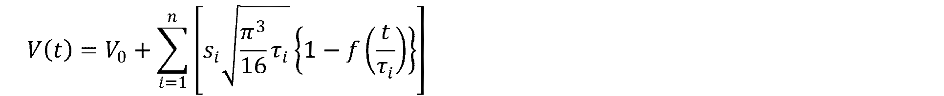

これらの式は0.5Cで間欠放電後の休止における電圧の過渡応答を記述した式であり、V0は放電休止を開始したときの電圧である。放電休止中の電圧値にフィッティングすることでsiとτiを回帰的に求め、t→∞のときのV(t)を開回路電圧とした。このフィッティングは図6で2分間の放電休止をする度に行い、開回路電圧を求めた。
These equations are equations that describe the transient response of the voltage in the pause after intermittent discharge at 0.5 C, and V 0 is the voltage when the discharge pause is started. By fitting to the voltage value during the discharge pause, s i and τ i were recursively obtained, and V (t) when t → ∞ was taken as the open circuit voltage. This fitting was performed each time the discharge was stopped for 2 minutes in FIG. 6 to obtain an open circuit voltage.
なお、開回路電圧曲線の放電容量(qi)とセル電圧(vi)を求める方法として、0.05C以下でのレートで放電を行う方法と、0.5Cでのレートで間欠放電を行う方法とを説明したが、それぞれ、0.05C以下でのレートで充電を行ったり、0.5Cでのレートで間欠充電を行ったりしても、開回路電圧曲線の放電容量(qi)とセル電圧(vi)を求めることが可能である。
In addition, as a method for obtaining the discharge capacity (q i ) and cell voltage (v i ) of the open circuit voltage curve, a method of discharging at a rate of 0.05 C or less, and an intermittent discharge at a rate of 0.5 C. However, even if charging is performed at a rate of 0.05 C or less or intermittent charging is performed at a rate of 0.5 C, the discharge capacity (q i ) of the open circuit voltage curve and The cell voltage (v i ) can be determined.
[正極と負極の電位の推定方法]
上記方法で求めた開回路電圧曲線の放電容量(qi)とセル電圧(vi)に、パラメーターを使って放電容量の計算値(q)とセル電圧の計算値(v)の関係式をフィッティングし、そのときに使用したパラメーターを使って、正極の電位(φp)と負極の電位(φn)を求めるものである。放電電流(j)における放電曲線を5つのパラメーターを使って以下のように表す。 [Method for estimating potential of positive electrode and negative electrode]
Using the parameters for the discharge capacity (q i ) and cell voltage (v i ) of the open circuit voltage curve obtained by the above method, the relational expression between the calculated value (q) of the discharge capacity and the calculated value (v) of the cell voltage is Fitting is performed, and the positive electrode potential (φ p ) and the negative electrode potential (φ n ) are obtained using the parameters used at that time. The discharge curve at the discharge current (j) is expressed as follows using five parameters.
ここで、5つのパラメーターとして、Qpは正極拡大率(Positive Net Capacity)で、Qnは負極拡大率(Negative Net Capacity)で、Spは正極平行移動(Positive Slippage)で、Snは負極平行移動(Negative Slippage)で、ROはオーム抵抗である。このとき、(q-Sp)/Qpと(q-Sn)/Qnは0から1の値をとる。この式(1)を図6のような0.5Cでの間欠放電の放電容量(qi)とセル電圧(vi)または0.05Cでの放電曲線の放電容量(qi)とセル電圧(vi)に残差平方和が最小となるようにフィッティングして、5つのパラメーターの組み合わせを見つける。
Here, as five parameters, Q p is positive magnification (Positive Net Capacity), Q n is negative magnification by (Negative Net Capacity), the S p in the positive electrode parallel movement (Positive Slippage), S n is negative In translation (Negative Slippage), R O is an ohmic resistance. At this time, (q−S p ) / Q p and (q−S n ) / Q n take values from 0 to 1. As shown in FIG. 6, the discharge capacity (q i ) and cell voltage (v i ) of intermittent discharge at 0.5 C as shown in FIG. 6 or the discharge capacity (q i ) of the discharge curve and cell voltage at 0.05 C A combination of five parameters is found by fitting (v i ) so that the residual sum of squares is minimized.
この5つのパラメーターを、例えば、過剰条件のN元連立非線形方程式を立て、ニュートン・ラフソン法によって数値解析をすることで求め、正極の電位(φp)と負極の電位(φn)を求めた。このとき、5つのパラメーターより放電容量(Q)も求まる。
These five parameters are obtained, for example, by establishing an N-ary simultaneous nonlinear equation in an excess condition and numerically analyzing by the Newton-Raphson method to obtain the positive electrode potential (φ p ) and the negative electrode potential (φ n ). . At this time, the discharge capacity (Q) is also obtained from the five parameters.
[充放電電圧の更新方法]
上述したかくれ過充電やかくれ過放電を防止するためには、充放電を停止する電圧を更新すればよい。サイクル数が増えるにつれて、充電を停止する電圧(充電カット電圧)を初回充放電時より低めに設定する更新を行い、放電を停止する電圧(放電カット電圧)を初回充放電時より高めに設定する更新を行う。以下に、その方法を述べる。 [How to update charge / discharge voltage]
In order to prevent the above-described overcharge and overdischarge, the voltage at which charging / discharging is stopped may be updated. As the number of cycles increases, update the voltage to stop charging (charge cut voltage) lower than the initial charge / discharge, and set the voltage to stop discharging (discharge cut voltage) higher than the first charge / discharge. Update. The method is described below.
以下では、正極の電位(φp)と負極の電位(φn)を放電の度合い(x)の関数として表し、正極電位関数をφp(x)、負極電位関数をφn(x)とする。xは充電の度合いであり、0から1の範囲を取り、xが0に近いほど充電状態であり、xが1に近いほど放電状態である。一般的に、正極は概ね3.5~4.5Vの範囲、負極は概ね0.0~1.5Vの範囲内で使用されるため、ここでは、例えば、xの範囲についてこれらを充放電の両端として以下の様に定めた。
In the following, the positive electrode potential (φ p ) and the negative electrode potential (φ n ) are expressed as a function of the degree of discharge (x), the positive electrode potential function is φ p (x), and the negative electrode potential function is φ n (x). To do. x is the degree of charge, which ranges from 0 to 1, and the closer x is to 0, the charged state, and the closer x is 1, the more discharged state. In general, the positive electrode is generally used in the range of 3.5 to 4.5 V, and the negative electrode is used in the range of approximately 0.0 to 1.5 V. Both ends were determined as follows.

図7に式(2)と式(3)を含んだ、正極の電位、負極の電位と放電の度合いとの関係例を示す。常に、x=0で満充電状態、x=1で完全放電状態となっている訳ではなく、満充電状態における正極の放電の度合いをxp,fc、完全放電状態における正極の放電の度合いをxp,fd、満充電状態における負極の放電の度合いをxn,fc、完全放電状態における負極の放電の度合いをxn,fdとすると式(4)のように示すことができる。
FIG. 7 shows an example of the relationship between the potential of the positive electrode, the potential of the negative electrode, and the degree of discharge, including Expression (2) and Expression (3). It is not always a fully charged state at x = 0 and a fully discharged state at x = 1. The degree of positive electrode discharge in the fully charged state is x p, fc , and the degree of positive electrode discharge in the fully discharged state is Assuming x p, fd , the degree of discharge of the negative electrode in the fully charged state is x n, fc , and the degree of discharge of the negative electrode in the fully discharged state is x n, fd , it can be expressed as equation (4).

ここで、xの右肩にある上付き文字(n)は充放電サイクル数を表している。初回の充放電についてはn=1である。充電の度合い(y)を式(5)のように定義した。
Here, the superscript (n) on the right shoulder of x represents the number of charge / discharge cycles. For the first charge / discharge, n = 1. The degree of charge (y) was defined as in equation (5).
満充電状態における正極の充電の度合いをyp,fc、完全放電状態における正極の充電の度合いをyp,fd、満充電状態における負極の充電の度合いをyn,fc、完全放電状態における負極の充電の度合いをyn,fdとする。これらの値を上述した正極と負極の電位の推定方法において求めた、正極拡大率、負極拡大率、正極平行移動、負極平行移動と放電容量を用いて、式(6)のように書き表した。
The degree of charging of the positive electrode in the fully charged state is yp, fc , the degree of charging of the positive electrode in the fully discharged state is yp , fd , the degree of charging of the negative electrode in the fully charged state is yn , fc , and the negative electrode in the fully discharged state The degree of charging is assumed to be yn , fd . These values were expressed as shown in Equation (6) using the positive electrode enlargement ratio, the negative electrode enlargement ratio, the positive electrode parallel movement, the negative electrode parallel movement, and the discharge capacity obtained in the above-described method for estimating the potential of the positive electrode and the negative electrode.

ここで、yやQなどの右肩にある上付き文字(n)は充放電サイクル数を表している。n=1のときの充電の度合いを用いて、正極のかくれ過充電を式(7)、正極のかくれ過放電を式(8)、負極のかくれ過充電を式(9)、負極のかくれ過放電を式(10)のように表せる。
Here, the superscript (n) on the right shoulder such as y or Q represents the number of charge / discharge cycles. Using the degree of charging when n = 1, positive over-charge over positive electrode (7), over-discharge over positive electrode over equation (8), over-negative overcharge over equation (9) over over over negative The discharge can be expressed as in equation (10).
これらのパラメーターとかくれ過充電およびかくれ過放電についての関係を図8に示す。φp(1-yp,fc
(1))は正極の上限電位であり、この電位を上回るとかくれ過充電と見做せ、φp(1-yp,fd
(1))は正極の下限電位であり、この電位を下回るとかくれ過放電と見做せる。φn(1-yn,fc
(1))は負極の下限電位であり、この電位を下回るとかくれ過充電と見做せ、φn(1-yn,fd
(1))は負極の上限電位であり、この電位を上回るとかくれ過放電と見做せる。このようなかくれ過充電やかくれ過放電を防止するには、nサイクル目の充放電で式(7)から式(10)を満たさないようにすればよい。それには充電カット電圧を下げ、放電カット電圧を上げる必要がある。そこで、充電カット電圧をVfcとし、放電カット電圧をVfdとし、式(11)のように設定した。
FIG. 8 shows the relationship between these parameters and the overcharge and overdischarge. φ p (1−y p, fc (1) ) is the upper limit potential of the positive electrode, and if this potential is exceeded, it can be considered as overcharge, and φ p (1−y p, fd (1) ) is the positive potential of the positive electrode. It is the lower limit potential, and if it falls below this potential, it can be regarded as a hidden overdischarge. φ n (1-y n, fc (1) ) is the lower limit potential of the negative electrode, and below this potential, it can be considered to be overcharged, and φ n (1-y n, fd (1) ) is the negative electrode potential. It is the upper limit potential, and if this potential is exceeded, it can be regarded as a hidden overdischarge. In order to prevent such over-charge and over-discharge, it is only necessary to prevent the equations (7) to (10) from being satisfied by the charge / discharge of the nth cycle. To do this, it is necessary to lower the charge cut voltage and raise the discharge cut voltage. Therefore, the charge cut voltage was set to V fc and the discharge cut voltage was set to V fd , which were set as shown in Expression (11).


[実施例および比較例]
以下の条件にて、充放電を繰り返しながら放電容量と充電時間を計測した。
条件1(比較例):充電カット電圧および放電カット電圧を固定して充放電サイクル試験を行う。
条件2(実施例):かくれ過放電とかくれ過充電が発生しないように、式(12)で設定した充電カット電圧と放電カット電圧に逐次更新しながら、充放電サイクル試験を行う。 [Examples and Comparative Examples]
Under the following conditions, discharge capacity and charge time were measured while repeating charge and discharge.
Condition 1 (Comparative Example): A charge / discharge cycle test is performed with the charge cut voltage and discharge cut voltage fixed.
Condition 2 (Example): A charge / discharge cycle test is performed while sequentially updating the charge cut voltage and the discharge cut voltage set in the equation (12) so that the overcharge and the overcharge are not generated.
その結果を図9に示す。図9から、例えばサイクル数が170回のとき、実施例の放電容量は比較例より約10%高く、実施例の充電時間は比較例より約10%短いことが分かる。実施例は比較例よりも、放電容量の劣化を防止でき、且つ、充電時間の伸長を抑制できていることが判明した。
The result is shown in FIG. From FIG. 9, it can be seen that, for example, when the number of cycles is 170, the discharge capacity of the example is about 10% higher than the comparative example, and the charging time of the example is about 10% shorter than the comparative example. It has been found that the example can prevent the discharge capacity from being deteriorated and can suppress the extension of the charging time as compared with the comparative example.
「UPSの例」
ここで、一実施の形態について好適な例を紹介する。好適な例とは、容量に余裕のある複数の電池モジュールを備えるUPSである。この例では、複数の電池モジュールの内、1つを充放電させ、開回路電圧曲線を取得し、充電カット電圧と放電カット電圧を推定する。そのときに1つの電池モジュールに出入する電力が他の電池モジュールからの融通によることに特徴がある。 "UPS example"
Here, a preferred example of one embodiment will be introduced. A suitable example is a UPS including a plurality of battery modules with sufficient capacity. In this example, one of a plurality of battery modules is charged and discharged, an open circuit voltage curve is acquired, and a charge cut voltage and a discharge cut voltage are estimated. At that time, the power that enters and exits one battery module is characterized by the interchange from other battery modules.
図10を用いて説明する。この図では5つの電池モジュールM1~M5で一組を構成していて、通常の待機状態ではSOC(State of Charge,充電率)が等しく80%である。次に、電池の劣化具合を診断するために、5つの内、1つの電池モジュール(電池モジュールM1)を選び、電池モジュールM1を充電カット電圧まで充電した。その結果、電池モジュールM1のSOCは100%である。このとき、充電のための電力を他の4つの電池モジュール(電池モジュールM2~M5)の放電により補ったため、電池モジュールM2~M5のSOCは75%となる。
This will be described with reference to FIG. In this figure, five battery modules M1 to M5 constitute a set, and SOC (State 待機 of Charge, charge rate) is equal to 80% in a normal standby state. Next, in order to diagnose the deterioration of the battery, one of the five battery modules (battery module M1) was selected, and the battery module M1 was charged to the charge cut voltage. As a result, the SOC of the battery module M1 is 100%. At this time, since the electric power for charging is supplemented by discharging the other four battery modules (battery modules M2 to M5), the SOC of the battery modules M2 to M5 is 75%.
そして、電池モジュールM1について開回路電圧曲線を取得しながら放電カット電圧まで放電した。その結果、電池モジュールM1のSOCは0%となる。放電した電力を電池モジュールM2~M5の充電に利用したため、電池モジュールM2~M5のSOCは100%となる。その後、SOCが0%になるまで放電した電池モジュールM1を充電し、SOCを80%に戻した。このときの電力を電池モジュールM2~M5からの放電で補うため、電池モジュールM2~M5のSOCも80%となる。こうして、元の待機状態に戻した。
And it discharged to the discharge cut voltage, acquiring the open circuit voltage curve about the battery module M1. As a result, the SOC of the battery module M1 is 0%. Since the discharged power is used for charging the battery modules M2 to M5, the SOC of the battery modules M2 to M5 is 100%. Thereafter, the discharged battery module M1 was charged until the SOC reached 0%, and the SOC was returned to 80%. Since the electric power at this time is supplemented by the discharge from the battery modules M2 to M5, the SOC of the battery modules M2 to M5 is also 80%. Thus, the original standby state was restored.
このような電池モジュール間での電力の融通により、開回路電圧曲線を取得し、充電カット電圧と放電カット電圧を推定するといったような電池の診断に、余計な外部の電力を不要とすることが可能になる。なお、電池モジュールは5つで構成されていたが、4つ以下または6つ以上で構成されていても良い。電池モジュールが通常の待機状態ではSOCが80%であったが、SOCは他の値であっても良い。
Such interchange of power between battery modules can eliminate the need for extra external power for battery diagnosis such as obtaining an open circuit voltage curve and estimating charge cut voltage and discharge cut voltage. It becomes possible. In addition, although the battery module was comprised by five, you may be comprised by four or less or six or more. When the battery module is in a normal standby state, the SOC is 80%, but the SOC may be another value.
<2.変形例>
以上、本技術の実施の形態について具体的に説明したが、本技術は、上述の一実施の形態に限定されるものではなく、本技術の技術的思想に基づく各種の変形が可能である。また、上述の実施の形態において挙げた構成、方法、工程、形状、材料及び数値などはあくまでも例に過ぎず、必要に応じてこれと異なる構成、方法、工程、形状、材料及び数値などを用いてもよい。例えば、間欠放電を5分の放電と2分の放電休止の繰り返しで構成していたが、放電と放電休止の時間は他の異なる数値の組み合わせであっても良い。 <2. Modification>
The embodiment of the present technology has been specifically described above, but the present technology is not limited to the above-described embodiment, and various modifications based on the technical idea of the present technology are possible. Further, the configurations, methods, processes, shapes, materials, numerical values, and the like given in the above-described embodiments are merely examples, and different configurations, methods, processes, shapes, materials, numerical values, etc. are used as necessary. May be. For example, although intermittent discharge is configured by repeating 5 minutes of discharge and 2 minutes of discharge pause, the discharge and discharge pause time may be a combination of other different values.
<3.応用例>
以下、電池制御装置の応用例について説明する。なお、電池制御装置の応用例は、以下に説明する応用例に限られることはない。 <3. Application example>
Hereinafter, application examples of the battery control device will be described. In addition, the application example of a battery control apparatus is not restricted to the application example demonstrated below.
以下、電池制御装置の応用例について説明する。なお、電池制御装置の応用例は、以下に説明する応用例に限られることはない。 <3. Application example>
Hereinafter, application examples of the battery control device will be described. In addition, the application example of a battery control apparatus is not restricted to the application example demonstrated below.
「応用例としての住宅における蓄電システム」
本発明を住宅用の蓄電システムに適用した例について、図11を参照して説明する。例えば住宅101用の蓄電システム100においては、火力発電102a、原子力発電102b、水力発電102c等の集中型電力系統102から電力網109、情報網112、スマートメータ107、パワーハブ108等を介し、電力が蓄電装置103に供給される。これと共に、発電装置104等の独立電源から電力が蓄電装置103に供給される。蓄電装置103に供給された電力が蓄電される。蓄電装置103を使用して、住宅101で使用する電力が給電される。住宅101に限らずビルに関しても同様の蓄電システムを使用できる。 "Storage system in a house as an application example"
An example in which the present invention is applied to a residential power storage system will be described with reference to FIG. For example, in thepower storage system 100 for the house 101, electric power is stored from the centralized power system 102 such as the thermal power generation 102a, the nuclear power generation 102b, and the hydroelectric power generation 102c through the power network 109, the information network 112, the smart meter 107, the power hub 108, and the like. Supplied to the device 103. At the same time, power is supplied to the power storage device 103 from an independent power source such as the power generation device 104. The electric power supplied to the power storage device 103 is stored. Electric power used in the house 101 is fed using the power storage device 103. The same power storage system can be used not only for the house 101 but also for buildings.
本発明を住宅用の蓄電システムに適用した例について、図11を参照して説明する。例えば住宅101用の蓄電システム100においては、火力発電102a、原子力発電102b、水力発電102c等の集中型電力系統102から電力網109、情報網112、スマートメータ107、パワーハブ108等を介し、電力が蓄電装置103に供給される。これと共に、発電装置104等の独立電源から電力が蓄電装置103に供給される。蓄電装置103に供給された電力が蓄電される。蓄電装置103を使用して、住宅101で使用する電力が給電される。住宅101に限らずビルに関しても同様の蓄電システムを使用できる。 "Storage system in a house as an application example"
An example in which the present invention is applied to a residential power storage system will be described with reference to FIG. For example, in the
住宅101には、発電装置104、電力消費装置105、蓄電装置103、各装置を制御する制御装置110、スマートメータ107、各種情報を取得するセンサー111が設けられている。各装置は、電力網109及び情報網112によって接続されている。発電装置104として、太陽電池、燃料電池、風車等が利用され、発電した電力が電力消費装置105及び/又は蓄電装置103に供給される。電力消費装置105は、冷蔵庫105a、空調装置105b、テレビジョン受信機105c、バス105d等である。さらに、電力消費装置105には、電動車両106が含まれる。電動車両106は、電気自動車106a、ハイブリッドカー106b、電気バイク106cである。電動車両106は、電動アシスト自転車等でもよい。
The house 101 is provided with a power generation device 104, a power consumption device 105, a power storage device 103, a control device 110 that controls each device, a smart meter 107, and a sensor 111 that acquires various types of information. Each device is connected by a power network 109 and an information network 112. As the power generation device 104, a solar cell, a fuel cell, a windmill, or the like is used, and the generated power is supplied to the power consumption device 105 and / or the power storage device 103. The power consuming device 105 is a refrigerator 105a, an air conditioner 105b, a television receiver 105c, a bus 105d, and the like. Furthermore, the electric power consumption device 105 includes an electric vehicle 106. The electric vehicle 106 is an electric vehicle 106a, a hybrid car 106b, and an electric motorcycle 106c. The electric vehicle 106 may be an electric assist bicycle.
蓄電装置103は、二次電池又はキャパシタから構成されている。例えば、リチウムイオン二次電池によって構成されている。リチウムイオン二次電池は、定置型であっても、電動車両106で使用されるものでも良い。この蓄電装置103に対して、上述した本発明のリチウムイオン二次電池1が適用可能とされる。スマートメータ107は、商用電力の使用量を検出し、検出された使用量を、電力会社に送信する機能を備えている。電力網109は、直流給電、交流給電、非接触給電の何れか一つ又は複数を組み合わせても良い。
The power storage device 103 is composed of a secondary battery or a capacitor. For example, it is constituted by a lithium ion secondary battery. The lithium ion secondary battery may be a stationary type or used in the electric vehicle 106. The above-described lithium ion secondary battery 1 of the present invention can be applied to the power storage device 103. The smart meter 107 has a function of detecting the usage amount of commercial power and transmitting the detected usage amount to an electric power company. The power network 109 may be any one or a combination of DC power supply, AC power supply, and non-contact power supply.
各種のセンサー111は、例えば人感センサー、照度センサー、物体検知センサー、消費電力センサー、振動センサー、接触センサー、温度センサー、赤外線センサー等である。各種センサー111により取得された情報は、制御装置110に送信される。センサー111からの情報によって、気象の状態、人の状態等が把握されて電力消費装置105を自動的に制御してエネルギー消費を最小とすることができる。さらに、制御装置110は、住宅101に関する情報を、インターネットを介して外部の電力会社等に送信することができる。
The various sensors 111 are, for example, human sensors, illuminance sensors, object detection sensors, power consumption sensors, vibration sensors, contact sensors, temperature sensors, infrared sensors, and the like. Information acquired by the various sensors 111 is transmitted to the control device 110. Based on the information from the sensor 111, the weather condition, the human condition, etc. can be grasped, and the power consumption device 105 can be automatically controlled to minimize the energy consumption. Furthermore, the control device 110 can transmit information regarding the house 101 to an external power company or the like via the Internet.
パワーハブ108によって、電力線の分岐、直流交流変換等の処理がなされる。制御装置110と接続される情報網112の通信方式としては、UART(Universal Asynchronous Receiver Transmitter:非同期シリアル通信用送受信回路)等の通信インタフェースを使う方法、Bluetooth(登録商標)、ZigBee(登録商標)、Wi-Fi(登録商標)等の無線通信規格によるセンサーネットワークを利用する方法がある。Bluetooth(登録商標)方式は、マルチメディア通信に適用され、一対多接続の通信を行うことができる。ZigBee(登録商標)は、IEEE(Institute of Electrical and Electronics Engineers)802.15.4の物理 層を使用するものである。IEEE802.15.4は、PAN(Personal Area Network)又はW(Wireless)PANと呼ばれる短距離無線ネットワーク規格の名称である。
The power hub 108 performs processing such as branching of power lines and DC / AC conversion. As a communication method of the information network 112 connected to the control device 110, a method using a communication interface such as UART (Universal Asynchronous Receiver Receiver Transmitter), Bluetooth (registered trademark), ZigBee (registered trademark), There is a method of using a sensor network based on a wireless communication standard such as Wi-Fi (registered trademark). The Bluetooth (registered trademark) system is applied to multimedia communication and can perform one-to-many connection communication. ZigBee (registered trademark) uses a physical layer of IEEE (Institute of Electrical and Electronics Electronics) 802.15.4. IEEE 802.15.4 is the name of a short-range wireless network standard called PAN (Personal Area Network) or W (Wireless) PAN.
制御装置110は、外部のサーバ113と接続されている。このサーバ113は、住宅101、電力会社、サービスプロバイダーの何れかによって管理されていても良い。サーバ113が送受信する情報は、たとえば、消費電力情報、生活パターン情報、電力料金、天気情報、天災情報、電力取引に関する情報である。これらの情報は、家庭内の電力消費装置(たとえばテレビジョン受信機)から送受信しても良いが、家庭外の装置(たとえば、携帯電話機等)から送受信しても良い。これらの情報は、表示機能を持つ機器、たとえば、テレビジョン受信機、携帯電話機、PDA(Personal Digital Assistants)等に、表示されても良い。
The control device 110 is connected to an external server 113. The server 113 may be managed by any one of the house 101, the power company, and the service provider. The information transmitted and received by the server 113 is, for example, information related to power consumption information, life pattern information, power charges, weather information, natural disaster information, and power transactions. These pieces of information may be transmitted / received from a power consuming device (for example, a television receiver) in the home, or may be transmitted / received from a device outside the home (for example, a mobile phone). Such information may be displayed on a device having a display function, for example, a television receiver, a mobile phone, a PDA (Personal Digital Assistant) or the like.
各部を制御する制御装置110は、CPU(Central Processing Unit)、RAM(Random Access Memory)、ROM(Read Only Memory)等で構成され、この例では、蓄電装置103に格納されている。制御装置110は、蓄電装置103、発電装置104、電力消費装置105、各種センサー111、サーバ113と情報網112により接続され、例えば、商用電力の使用量と、発電量とを調整する機能を有している。なお、その他にも、電力市場で電力取引を行う機能等を備えていても良い。
The control device 110 that controls each unit includes a CPU (Central Processing Unit), a RAM (Random Access Memory), a ROM (Read Only Memory), and the like, and is stored in the power storage device 103 in this example. The control device 110 is connected to the power storage device 103, the power generation device 104, the power consumption device 105, the various sensors 111, the server 113 and the information network 112, and has a function of adjusting, for example, the amount of commercial power used and the amount of power generation. is doing. In addition, you may provide the function etc. which carry out an electric power transaction in an electric power market.
以上のように、電力が火力発電102a、原子力発電102b、水力発電102c等の集中型電力系統102のみならず、発電装置104(太陽光発電、風力発電)の発電電力を蓄電装置103に蓄えることができる。したがって、発電装置104の発電電力が変動しても、外部に送出する電力量を一定にしたり、又は、必要なだけ放電したりするといった制御を行うことができる。例えば、太陽光発電で得られた電力を蓄電装置103に蓄えると共に、夜間は料金が安い深夜電力を蓄電装置103に蓄え、昼間の料金が高い時間帯に蓄電装置103によって蓄電した電力を放電して利用するといった使い方もできる。
As described above, electric power is stored not only in the centralized power system 102 such as the thermal power generation 102a, the nuclear power generation 102b, and the hydroelectric power generation 102c but also in the power storage device 103 from the power generation device 104 (solar power generation, wind power generation). Can do. Therefore, even if the generated power of the power generation device 104 fluctuates, it is possible to perform control such that the amount of power to be sent to the outside is constant or discharge is performed as necessary. For example, the electric power obtained by solar power generation is stored in the power storage device 103, and midnight power with a low charge is stored in the power storage device 103 at night, and the power stored by the power storage device 103 is discharged during a high daytime charge. You can also use it.
なお、この例では、制御装置110が蓄電装置103内に格納される例を説明したが、スマートメータ107内に格納されても良いし、単独で構成されていても良い。さらに、蓄電システム100は、集合住宅における複数の家庭を対象として用いられてもよいし、複数の戸建て住宅を対象として用いられてもよい。
In this example, the example in which the control device 110 is stored in the power storage device 103 has been described. However, the control device 110 may be stored in the smart meter 107 or may be configured independently. Furthermore, the power storage system 100 may be used for a plurality of homes in an apartment house, or may be used for a plurality of detached houses.
「応用例としての車両における蓄電システム」
本発明を車両用の蓄電システムに適用した例について、図12を参照して説明する。図12に、本発明が適用されるシリーズハイブリッドシステムを採用するハイブリッド車両の構成の一例を概略的に示す。シリーズハイブリッドシステムはエンジンで動かす発電機で発電された電力、あるいはそれをバッテリーに一旦貯めておいた電力を用いて、電力駆動力変換装置で走行する車である。 "Vehicle power storage system as an application example"
An example in which the present invention is applied to a power storage system for a vehicle will be described with reference to FIG. FIG. 12 schematically shows an example of the configuration of a hybrid vehicle that employs a series hybrid system to which the present invention is applied. A series hybrid system is a car that runs on an electric power driving force conversion device using electric power generated by a generator driven by an engine or electric power once stored in a battery.
このハイブリッド車両200には、エンジン201、発電機202、電力駆動力変換装置203、駆動輪204a、駆動輪204b、車輪205a、車輪205b、バッテリー208、車両制御装置209、各種センサー210、充電口211が搭載されている。バッテリー208に対して、上述した本発明のリチウムイオン二次電池1が適用される。リチウムイオン二次電池1が1又は複数適用される。
The hybrid vehicle 200 includes an engine 201, a power generator 202, a power driving force conversion device 203, driving wheels 204a, driving wheels 204b, wheels 205a, wheels 205b, a battery 208, a vehicle control device 209, various sensors 210, and a charging port 211. Is installed. The lithium ion secondary battery 1 of the present invention described above is applied to the battery 208. One or more lithium ion secondary batteries 1 are applied.
ハイブリッド車両200は、電力駆動力変換装置203を動力源として走行する。電力駆動力変換装置203の一例は、モーターである。バッテリー208の電力によって電力駆動力変換装置203が作動し、この電力駆動力変換装置203の回転力が駆動輪204a、204bに伝達される。なお、必要な個所に直流-交流変換(DC-AC変換)あるいは逆変換(AC-DC変換)を用いることによって、電力駆動力変換装置203が交流モーターでも直流モーターでも適用可能である。各種センサー210は、車両制御装置209を介してエンジン回転数を制御したり、図示しないスロットルバルブの開度(スロットル開度)を制御したりする。各種センサー210には、速度センサー、加速度センサー、エンジン回転数センサーなどが含まれる。
Hybrid vehicle 200 travels using electric power / driving force conversion device 203 as a power source. An example of the power driving force conversion device 203 is a motor. The electric power / driving force converter 203 is operated by the electric power of the battery 208, and the rotational force of the electric power / driving force converter 203 is transmitted to the driving wheels 204a and 204b. It should be noted that by using DC-AC conversion (DC-AC conversion) or reverse conversion (AC-DC conversion) at a required place, the power driving force conversion device 203 can be applied to either an AC motor or a DC motor. The various sensors 210 control the engine speed via the vehicle control device 209 and control the opening (throttle opening) of a throttle valve (not shown). The various sensors 210 include a speed sensor, an acceleration sensor, an engine speed sensor, and the like.
エンジン201の回転力は発電機202に伝えられ、その回転力によって発電機202により生成された電力をバッテリー208に蓄積することが可能である。
The rotational force of the engine 201 is transmitted to the generator 202, and the electric power generated by the generator 202 by the rotational force can be stored in the battery 208.
図示しない制動機構によりハイブリッド車両が減速すると、その減速時の抵抗力が電力駆動力変換装置203に回転力として加わり、この回転力によって電力駆動力変換装置203により生成された回生電力がバッテリー208に蓄積される。
When the hybrid vehicle decelerates by a braking mechanism (not shown), the resistance force at the time of deceleration is applied as a rotational force to the power driving force conversion device 203, and the regenerative power generated by the power driving force conversion device 203 by this rotational force is applied to the battery 208. Accumulated.
バッテリー208は、ハイブリッド車両の外部の電源に接続されることで、その外部電源から充電口211を入力口として電力供給を受け、受けた電力を蓄積することも可能である。
The battery 208 is connected to a power source outside the hybrid vehicle, so that it can receive power from the external power source using the charging port 211 as an input port and store the received power.
図示しないが、二次電池に関する情報に基づいて車両制御に関する情報処理を行なう情報処理装置を備えていても良い。このような情報処理装置としては、例えば、電池の残量に関する情報に基づき、電池残量表示を行う情報処理装置などがある。
Although not shown, an information processing device that performs information processing related to vehicle control based on information related to the secondary battery may be provided. As such an information processing apparatus, for example, there is an information processing apparatus that displays a remaining battery level based on information on the remaining battery level.
なお、以上は、エンジンで動かす発電機で発電された電力、或いはそれをバッテリーに一旦貯めておいた電力を用いて、モーターで走行するシリーズハイブリッド車を例として説明した。しかしながら、エンジンとモーターの出力がいずれも駆動源とし、エンジンのみで走行、モーターのみで走行、エンジンとモーターで走行という3つの方式を適宜切り替えて使用するパラレルハイブリッド車に対しても本発明は有効に適用可能である。さらに、エンジンを用いず駆動モーターのみによる駆動で走行する所謂、電動車両に対しても本発明は有効に適用できる。
In the above description, a series hybrid vehicle that runs on a motor using electric power generated by a generator driven by an engine or electric power stored once in a battery has been described as an example. However, the present invention is also effective for a parallel hybrid vehicle in which the output of the engine and the motor are both driving sources, and the three methods of driving with only the engine, driving with the motor, and driving with the engine and motor are switched appropriately. It is applicable to. Furthermore, the present invention can be effectively applied to a so-called electric vehicle that travels only by a drive motor without using an engine.
1・・・リチウムイオン二次電池、2・・・電圧検出部、3・・・制御部、4・・・電流検出部、5・・・充電用DCDCコンバータ、6・・・充電電圧/充電電流制御部、8・・・記憶部、9・・・演算処理部、M1~M5・・・電池モジュール
DESCRIPTION OF SYMBOLS 1 ... Lithium ion secondary battery, 2 ... Voltage detection part, 3 ... Control part, 4 ... Current detection part, 5 ... DCDC converter for charge, 6 ... Charge voltage / charge Current control unit, 8 ... storage unit, 9 ... arithmetic processing unit, M1 to M5 ... battery module
Claims (12)
- 診断時に、二次電池を充電及び/又は放電させる充放電制御部と、
前記二次電池を充電及び/又は放電させることによって開回路電圧を取得する開回路電圧曲線取得部と、
開回路電圧曲線から正極電位及び負極電位を推測する演算部とを備え、
推測された前記正極電位が予め設定した電位の上限及び下限を超えないように、充電カット電圧及び放電カット電圧を変更する電池制御装置。 A charge / discharge control unit that charges and / or discharges the secondary battery at the time of diagnosis; and
An open circuit voltage curve acquisition unit for acquiring an open circuit voltage by charging and / or discharging the secondary battery;
A calculation unit for estimating a positive electrode potential and a negative electrode potential from an open circuit voltage curve,
A battery control device that changes a charge cut voltage and a discharge cut voltage so that the estimated positive electrode potential does not exceed an upper limit and a lower limit of a preset potential. - 診断時に、二次電池を充電及び/又は放電させる充放電制御部と、
前記二次電池を充電及び/又は放電させることによって開回路電圧を取得する開回路電圧曲線取得部と、
開回路電圧曲線から正極電位及び負極電位を推測する演算部とを備え、
推測された前記負極電位が予め設定した電位の上限及び下限を超えないように、充電カット電圧及び放電カット電圧を変更する電池制御装置。 A charge / discharge control unit that charges and / or discharges the secondary battery at the time of diagnosis; and
An open circuit voltage curve acquisition unit for acquiring an open circuit voltage by charging and / or discharging the secondary battery;
A calculation unit for estimating a positive electrode potential and a negative electrode potential from an open circuit voltage curve,
A battery control device that changes a charge cut voltage and a discharge cut voltage so that the estimated negative electrode potential does not exceed an upper limit and a lower limit of a preset potential. - 前記開回路電圧曲線取得部は、前記二次電池を間欠充電及び/又は間欠放電したときの過渡応答から、前記開回路電圧を予測する請求項1または請求項2に記載の電池制御装置。 The battery control device according to claim 1 or 2, wherein the open circuit voltage curve acquisition unit predicts the open circuit voltage from a transient response when the secondary battery is intermittently charged and / or intermittently discharged.
- 診断時に、二次電池を充電及び/又は放電させることによって
開回路電圧曲線を取得し、
前記開回路電圧曲線から正極電位及び負極電位を推測し、
推測された前記正極電位が予め設定した電位の上限及び下限を超えないように、充電カット電圧及び放電カット電圧を変更する電池制御方法。 During diagnosis, an open circuit voltage curve is obtained by charging and / or discharging the secondary battery,
Inferring the positive electrode potential and the negative electrode potential from the open circuit voltage curve,
A battery control method for changing a charge cut voltage and a discharge cut voltage so that the estimated positive electrode potential does not exceed an upper limit and a lower limit of a preset potential. - 診断時に、二次電池を充電及び/又は放電させることによって
開回路電圧曲線を取得し、
前記開回路電圧曲線から正極電位及び負極電位を推測し、
推測された前記負極電位が予め設定した電位の上限及び下限を超えないように、充電カット電圧及び放電カット電圧を変更する電池制御方法。 During diagnosis, an open circuit voltage curve is obtained by charging and / or discharging the secondary battery,
Inferring the positive electrode potential and the negative electrode potential from the open circuit voltage curve,
A battery control method for changing a charge cut voltage and a discharge cut voltage so that the estimated negative electrode potential does not exceed an upper limit and a lower limit of a preset potential. - 前記二次電池を間欠充電及び/又は間欠放電したときの過渡応答からの前記開回路電圧曲線を予測する請求項4または請求項5に記載の電池制御方法。 The battery control method according to claim 4 or 5, wherein the open circuit voltage curve is predicted from a transient response when the secondary battery is intermittently charged and / or discharged intermittently.
- それぞれが複数の二次電池を有する電池モジュールが複数個設けられ、
前記複数の電池モジュールの一つを放電させて放電電流によって他の電池モジュールを充電し、
前記複数の電池モジュールの一つを他の電池モジュールによって充電させる構成とされ、
前記電池モジュールを充電及び/又は放電させることによって開回路電圧曲線を取得し、
前記開回路電圧曲線から正極電位及び負極電位を推測し、
推測された前記正極電位が予め設定した電圧の上限及び下限を超えないように、充電カット電圧及び放電カット電圧を変更するようにした無停電電源装置。 A plurality of battery modules each having a plurality of secondary batteries are provided,
Discharging one of the plurality of battery modules and charging another battery module with a discharge current;
One of the battery modules is configured to be charged by another battery module,
Obtaining an open circuit voltage curve by charging and / or discharging the battery module;
Inferring the positive electrode potential and the negative electrode potential from the open circuit voltage curve,
An uninterruptible power supply in which the charge cut voltage and the discharge cut voltage are changed so that the estimated positive electrode potential does not exceed an upper limit and a lower limit of a preset voltage. - それぞれが複数の二次電池を有する電池モジュールが複数個設けられ、
前記複数の電池モジュールの一つを放電させて放電電流によって他の電池モジュールを充電し、
前記複数の電池モジュールの一つを他の電池モジュールによって充電させる構成とされ、
前記電池モジュールを充電及び/又は放電させることによって開回路電圧曲線を取得し、
前記開回路電圧曲線から正極電位及び負極電位を推測し、
推測された前記負極電位が予め設定した電圧の上限及び下限を超えないように、充電カット電圧及び放電カット電圧を制御するようにした無停電電源装置。 A plurality of battery modules each having a plurality of secondary batteries are provided,
Discharging one of the plurality of battery modules and charging another battery module with a discharge current;
One of the battery modules is configured to be charged by another battery module,
Obtaining an open circuit voltage curve by charging and / or discharging the battery module;
Inferring the positive electrode potential and the negative electrode potential from the open circuit voltage curve,
An uninterruptible power supply apparatus configured to control a charge cut voltage and a discharge cut voltage so that the estimated negative electrode potential does not exceed an upper limit and a lower limit of a preset voltage. - 請求項1、2、4、5、7、8の何れかに記載の電池制御装置によって制御される二次電池を有し、前記二次電池が再生可能エネルギーから発電を行う発電装置によって充電される電力システム。 A secondary battery controlled by the battery control device according to any one of claims 1, 2, 4, 5, 7, and 8, wherein the secondary battery is charged by a power generation device that generates power from renewable energy. Power system.
- 請求項1、2、4、5、7、8の何れかに記載の電池制御装置によって制御される二次電池を有し、前記二次電池に接続される電子機器に電力を供給する電力システム。 An electric power system having a secondary battery controlled by the battery control device according to any one of claims 1, 2, 4, 5, 7, and 8, and supplying electric power to an electronic device connected to the secondary battery. .
- 請求項1、2、4、5、7、8の何れかに記載の電池制御装置によって制御される二次電池を有し、前記二次電池から電力の供給を受けて車両の駆動力に変換する変換装置と、前記二次電池に関する情報に基づいて車両制御に関する情報処理を行なう制御装置とを有する電動車両。 A secondary battery controlled by the battery control device according to any one of claims 1, 2, 4, 5, 7, and 8, and receives power supply from the secondary battery and converts it into a driving force of a vehicle. And a control device that performs information processing related to vehicle control based on information related to the secondary battery.
- 請求項1、2、4、5、7、8の何れかに記載の電池制御装置によって制御される二次電池を有し、前記二次電池から電力の供給を受け、又は発電装置又は電力網から前記二次電池に電力を供給する電力システム。 A secondary battery controlled by the battery control device according to claim 1, 2, 4, 5, 7, 8, receiving power supply from the secondary battery, or from a power generation device or a power network An electric power system for supplying electric power to the secondary battery.
Priority Applications (4)
| Application Number | Priority Date | Filing Date | Title |
|---|---|---|---|
| JP2020508305A JP7040601B2 (en) | 2018-03-20 | 2019-03-15 | Battery control device, battery control method, uninterruptible power supply, power system and electric vehicle |
| EP19770513.0A EP3771020A4 (en) | 2018-03-20 | 2019-03-15 | Battery control device, battery control method, uninterruptible power supply unit, power system, and electric vehicle |
| CN201980020457.XA CN111886752B (en) | 2018-03-20 | 2019-03-15 | Battery control device, battery control method, uninterruptible power supply device, power system, and electric vehicle |
| US17/023,714 US12071037B2 (en) | 2018-03-20 | 2020-09-17 | Battery control device, battery control method, uninterruptible power supply, power system, and electric vehicle |
Applications Claiming Priority (2)
| Application Number | Priority Date | Filing Date | Title |
|---|---|---|---|
| JP2018052071 | 2018-03-20 | ||
| JP2018-052071 | 2018-03-20 |
Related Child Applications (1)
| Application Number | Title | Priority Date | Filing Date |
|---|---|---|---|
| US17/023,714 Continuation US12071037B2 (en) | 2018-03-20 | 2020-09-17 | Battery control device, battery control method, uninterruptible power supply, power system, and electric vehicle |
Publications (1)
| Publication Number | Publication Date |
|---|---|
| WO2019181764A1 true WO2019181764A1 (en) | 2019-09-26 |
Family
ID=67987767
Family Applications (1)
| Application Number | Title | Priority Date | Filing Date |
|---|---|---|---|
| PCT/JP2019/010739 WO2019181764A1 (en) | 2018-03-20 | 2019-03-15 | Battery control device, battery control method, uninterruptible power supply unit, power system, and electric vehicle |
Country Status (5)
| Country | Link |
|---|---|
| US (1) | US12071037B2 (en) |
| EP (1) | EP3771020A4 (en) |
| JP (1) | JP7040601B2 (en) |
| CN (1) | CN111886752B (en) |
| WO (1) | WO2019181764A1 (en) |
Cited By (3)
| Publication number | Priority date | Publication date | Assignee | Title |
|---|---|---|---|---|
| CN111880108A (en) * | 2020-07-16 | 2020-11-03 | 蜂巢能源科技有限公司 | Battery testing method and device, storage medium and electronic equipment |
| JP2021060198A (en) * | 2019-10-02 | 2021-04-15 | 株式会社日立製作所 | Battery state estimation device |
| EP3843234A4 (en) * | 2019-09-29 | 2022-08-17 | Ningde Amperex Technology Ltd. | Method and device for cathode protection during battery cycle, and storage medium |
Families Citing this family (3)
| Publication number | Priority date | Publication date | Assignee | Title |
|---|---|---|---|---|
| JP7387660B2 (en) * | 2021-02-10 | 2023-11-28 | 株式会社東芝 | Battery diagnostic method, battery diagnostic device, battery diagnostic system, battery-equipped equipment, and battery diagnostic program |
| CN114614123B (en) * | 2022-03-28 | 2023-08-11 | 东莞新能安科技有限公司 | Electrochemical device, charging device and electronic equipment |
| CN117207837B (en) * | 2023-10-07 | 2024-02-09 | 嘉丰盛精密电子科技(孝感)有限公司 | New energy automobile battery pack load balancing scheduling method and system |
Citations (5)
| Publication number | Priority date | Publication date | Assignee | Title |
|---|---|---|---|---|
| JP2012221788A (en) * | 2011-04-11 | 2012-11-12 | Hitachi Vehicle Energy Ltd | Charge control system |
| JP2013051857A (en) * | 2011-08-31 | 2013-03-14 | Sony Corp | Power storage device, electronic apparatus, electric vehicle, and electric power system |
| JP2013247003A (en) * | 2012-05-28 | 2013-12-09 | Sony Corp | Charge control device for secondary battery, charge control method for secondary battery, charged state estimation device for secondary battery, charged state estimation method for secondary battery, deterioration degree estimation device for secondary battery, deterioration degree estimation method for secondary battery, and secondary battery device |
| JP2015087344A (en) | 2013-11-01 | 2015-05-07 | ソニー株式会社 | Capacity deterioration estimating device, power storage device, and capacity deterioration estimating method |
| JP2017083274A (en) | 2015-10-27 | 2017-05-18 | トヨタ自動車株式会社 | Control device of lithium ion secondary battery |
Family Cites Families (12)
| Publication number | Priority date | Publication date | Assignee | Title |
|---|---|---|---|---|
| WO2008084791A1 (en) * | 2007-01-11 | 2008-07-17 | Panasonic Corporation | Lithium secondary cell degradation detection method, degradation detector, degradation suppressing device, and cell pack using the same, battery charger |
| WO2011033781A1 (en) * | 2009-09-18 | 2011-03-24 | パナソニック株式会社 | Method for charging/discharging positive electrode active material in a lithium secondary battery, charging/discharging system provided with lithium secondary battery and vehicle, electronic device, battery module, battery pack |
| WO2011074196A1 (en) * | 2009-12-16 | 2011-06-23 | パナソニック株式会社 | Battery pack, discharge system, charge/discharge system, and discharge control method for lithium ion rechargeable battery |
| CN102834727B (en) * | 2010-04-09 | 2015-03-25 | 丰田自动车株式会社 | Secondary battery degradation determination device and degradation determination method |
| JP5341823B2 (en) * | 2010-06-07 | 2013-11-13 | トヨタ自動車株式会社 | Lithium ion secondary battery degradation judgment system and degradation judgment method |
| JP5485080B2 (en) * | 2010-08-27 | 2014-05-07 | 日立ビークルエナジー株式会社 | Discharge control system |
| JPWO2012046375A1 (en) * | 2010-10-04 | 2014-02-24 | パナソニック株式会社 | Non-aqueous electrolyte secondary battery charge / discharge control system and control method, and battery pack |
| EP2587614A2 (en) | 2011-08-31 | 2013-05-01 | Sony Corporation | Electric storage apparatus, electronic device, electric vehicle, and electric power system |
| JP6065561B2 (en) * | 2012-03-08 | 2017-01-25 | 日産自動車株式会社 | Secondary battery control device and SOC detection method |
| JP6119516B2 (en) * | 2013-09-02 | 2017-04-26 | ソニー株式会社 | Battery pack and electric vehicle |
| US9728995B2 (en) | 2015-04-08 | 2017-08-08 | Intel Corporation | Systems, methods and devices for adaptable battery charging |
| JP6567442B2 (en) * | 2016-02-24 | 2019-08-28 | 古河電池株式会社 | Lithium secondary battery charge / discharge method |
-
2019
- 2019-03-15 JP JP2020508305A patent/JP7040601B2/en active Active
- 2019-03-15 WO PCT/JP2019/010739 patent/WO2019181764A1/en unknown
- 2019-03-15 CN CN201980020457.XA patent/CN111886752B/en active Active
- 2019-03-15 EP EP19770513.0A patent/EP3771020A4/en active Pending
-
2020
- 2020-09-17 US US17/023,714 patent/US12071037B2/en active Active
Patent Citations (5)
| Publication number | Priority date | Publication date | Assignee | Title |
|---|---|---|---|---|
| JP2012221788A (en) * | 2011-04-11 | 2012-11-12 | Hitachi Vehicle Energy Ltd | Charge control system |
| JP2013051857A (en) * | 2011-08-31 | 2013-03-14 | Sony Corp | Power storage device, electronic apparatus, electric vehicle, and electric power system |
| JP2013247003A (en) * | 2012-05-28 | 2013-12-09 | Sony Corp | Charge control device for secondary battery, charge control method for secondary battery, charged state estimation device for secondary battery, charged state estimation method for secondary battery, deterioration degree estimation device for secondary battery, deterioration degree estimation method for secondary battery, and secondary battery device |
| JP2015087344A (en) | 2013-11-01 | 2015-05-07 | ソニー株式会社 | Capacity deterioration estimating device, power storage device, and capacity deterioration estimating method |
| JP2017083274A (en) | 2015-10-27 | 2017-05-18 | トヨタ自動車株式会社 | Control device of lithium ion secondary battery |
Non-Patent Citations (2)
| Title |
|---|
| H. M. DAHNA. J. SMITHJ. C. BURNSD. A. STEVENSJ. R. DAHN, JOURNAL OF THE ELECTROCHEMICAL SOCIETY, vol. 159, no. 9, 2012, pages A1405 - A1409 |
| See also references of EP3771020A4 |
Cited By (5)
| Publication number | Priority date | Publication date | Assignee | Title |
|---|---|---|---|---|
| EP3843234A4 (en) * | 2019-09-29 | 2022-08-17 | Ningde Amperex Technology Ltd. | Method and device for cathode protection during battery cycle, and storage medium |
| JP2021060198A (en) * | 2019-10-02 | 2021-04-15 | 株式会社日立製作所 | Battery state estimation device |
| JP7280161B2 (en) | 2019-10-02 | 2023-05-23 | 株式会社日立製作所 | Battery state estimation device |
| CN111880108A (en) * | 2020-07-16 | 2020-11-03 | 蜂巢能源科技有限公司 | Battery testing method and device, storage medium and electronic equipment |
| CN111880108B (en) * | 2020-07-16 | 2023-06-30 | 蜂巢能源科技股份有限公司 | Battery testing method and device, storage medium and electronic equipment |
Also Published As
| Publication number | Publication date |
|---|---|
| US12071037B2 (en) | 2024-08-27 |
| EP3771020A4 (en) | 2021-12-15 |
| US20210001747A1 (en) | 2021-01-07 |
| JPWO2019181764A1 (en) | 2021-02-04 |
| CN111886752B (en) | 2024-08-06 |
| JP7040601B2 (en) | 2022-03-23 |
| EP3771020A1 (en) | 2021-01-27 |
| CN111886752A (en) | 2020-11-03 |
Similar Documents
| Publication | Publication Date | Title |
|---|---|---|
| WO2019181764A1 (en) | Battery control device, battery control method, uninterruptible power supply unit, power system, and electric vehicle | |
| JP5794104B2 (en) | Battery pack, power storage system, electronic device, electric vehicle and power system | |
| JP5747491B2 (en) | Electric storage system, electric vehicle and electric power system | |
| EP2796312B1 (en) | Electrical storage device, electronic instrument, power system, and electric vehicle | |
| EP3127211B1 (en) | Charging device, charging control method, electricity storage device, power storage device, power system, and electric vehicle | |
| JP6225588B2 (en) | Power storage device and method for controlling power storage device | |
| EP3018791B1 (en) | Power storage device and power storage device control method | |
| JP5954144B2 (en) | Control device, control method, control system, and electric vehicle | |
| JP5830971B2 (en) | Battery monitor circuit, power storage device, electric vehicle, and power system | |
| JP5910129B2 (en) | Power storage device, power system, and electric vehicle | |
| JP6347212B2 (en) | Control device, power storage module, electric vehicle, power supply system, and control method | |
| WO2008065910A1 (en) | Accumulator failure detecting device, accumulator failure detecting method, accumulator failure detecting program, and computer-readable recording medium containing the accumulator failure detecting program | |
| WO2008053969A1 (en) | Abnormality detecting device for storage element, abnormality detecting method for storage element, abnormality detecting program for storage element, and computer-readable recording medium containing abnormality detecting program for storage element is recorded | |
| JP2012239357A (en) | Battery pack, electronic apparatus, electric power system and electric vehicle | |
| CN105048526A (en) | Apparatus for charging battery and method thereof | |
| WO2021193590A1 (en) | Electric power storage device, electrically powered vehicle, and electric power system |
Legal Events
| Date | Code | Title | Description |
|---|---|---|---|
| 121 | Ep: the epo has been informed by wipo that ep was designated in this application |
Ref document number: 19770513 Country of ref document: EP Kind code of ref document: A1 |
|
| ENP | Entry into the national phase |
Ref document number: 2020508305 Country of ref document: JP Kind code of ref document: A |
|
| NENP | Non-entry into the national phase |
Ref country code: DE |
|
| ENP | Entry into the national phase |
Ref document number: 2019770513 Country of ref document: EP Effective date: 20201020 |