JP7270120B2 - Liquid atomization device - Google Patents

Liquid atomization device Download PDF

Info

Publication number
JP7270120B2
JP7270120B2 JP2019073885A JP2019073885A JP7270120B2 JP 7270120 B2 JP7270120 B2 JP 7270120B2 JP 2019073885 A JP2019073885 A JP 2019073885A JP 2019073885 A JP2019073885 A JP 2019073885A JP 7270120 B2 JP7270120 B2 JP 7270120B2
Authority
JP
Japan
Prior art keywords
water
liquid atomization
air
port
humidification
Prior art date
Legal status (The legal status is an assumption and is not a legal conclusion. Google has not performed a legal analysis and makes no representation as to the accuracy of the status listed.)
Active
Application number
JP2019073885A
Other languages
Japanese (ja)
Other versions
JP2020173046A (en
JP2020173046A5 (en
Inventor
善文 末広
将秀 福本
剛也 重信
訓央 清本
Current Assignee (The listed assignees may be inaccurate. Google has not performed a legal analysis and makes no representation or warranty as to the accuracy of the list.)
Panasonic Intellectual Property Management Co Ltd
Original Assignee
Panasonic Intellectual Property Management Co Ltd
Priority date (The priority date is an assumption and is not a legal conclusion. Google has not performed a legal analysis and makes no representation as to the accuracy of the date listed.)
Filing date
Publication date
Application filed by Panasonic Intellectual Property Management Co Ltd filed Critical Panasonic Intellectual Property Management Co Ltd
Priority to JP2019073885A priority Critical patent/JP7270120B2/en
Priority to CN202310807365.4A priority patent/CN116857737A/en
Priority to PCT/JP2020/014631 priority patent/WO2020209130A1/en
Priority to CN202080024159.0A priority patent/CN113613793B/en
Publication of JP2020173046A publication Critical patent/JP2020173046A/en
Publication of JP2020173046A5 publication Critical patent/JP2020173046A5/ja
Priority to JP2022074035A priority patent/JP2022115918A/en
Application granted granted Critical
Publication of JP7270120B2 publication Critical patent/JP7270120B2/en
Active legal-status Critical Current
Anticipated expiration legal-status Critical

Links

Images

Landscapes

  • Air Humidification (AREA)
  • Nozzles (AREA)

Description

本発明は、水を微細化し、吸い込んだ空気にその微細化した水を含ませて吹き出す液体微細化装置に関する。 TECHNICAL FIELD The present invention relates to a liquid atomizing apparatus that atomizes water and blows out the sucked air containing the atomized water.

従来より、水を微細化し、吸い込んだ空気にその微細化した水を含ませて吹き出す液体微細化装置がある(例えば、特許文献1)。このような従来の液体微細化装置では、空気を吸い込む吸込口と吸い込んだ空気を吹き出す吹出口との間の風路内に、水を微細化する液体微細化室が設けられている。液体微細化室は、回転モータの回転軸に固定された揚水管を備えている。揚水管が回転モータによって回転されることで、貯水部に貯水された水が揚水管により揚水され、揚水された水が遠心方向に放射される。この放射された水が多孔部を通過することで、水が微細化される。また、従来の液体微細化装置では、運転中に、貯水部内の水位を検知して自動給水弁を制御して貯水部の水位を所定量に保持するように構成されている。 2. Description of the Related Art Conventionally, there is a liquid atomization apparatus that atomizes water and blows out air containing the atomized water in sucked air (for example, Patent Document 1). In such a conventional liquid atomization apparatus, a liquid atomization chamber for atomizing water is provided in an air passage between an air inlet for sucking air and an air outlet for blowing out the sucked air. The liquid atomization chamber has a pumping tube fixed to the rotating shaft of the rotary motor. As the pumping pipe is rotated by the rotary motor, the water stored in the water reservoir is pumped up by the pumping pipe, and the pumped water is radiated in the centrifugal direction. As the emitted water passes through the porous portion, the water is made finer. Further, the conventional liquid atomization apparatus is configured to detect the water level in the water reservoir and control the automatic water supply valve to keep the water level in the water reservoir at a predetermined level during operation.

特開2009-279514号公報JP 2009-279514 A

しかしながら、従来の液体微細化装置では、自動給水しながら連続して加湿運転を行っていると、貯水部内の水は、水のみが気化され、使用時間および使用水量に比例して給水される水に含まれるカルシウム分、マグネシウム分等のスケール成分が濃縮されていく。その結果、揚水される水の中に含まれるスケール成分が多孔部内で析出し、多孔部が目詰まりを起こしてしまうことが懸念される。また、こうした目詰まりの懸念は、液体微細化室を通過する空気に含められた水のうち水滴を捕集するためのエリミネータを備える液体微細化装置においても同様に起こり得ることである。 However, in the conventional liquid atomization device, if the humidification operation is continuously performed while automatically supplying water, only the water in the water reservoir is vaporized, and the water is supplied in proportion to the usage time and the amount of water used. Scale components such as calcium and magnesium contained in the water are concentrated. As a result, there is concern that the scale components contained in the pumped water will precipitate in the porous portions and cause clogging of the porous portions. Such clogging may also occur in a liquid atomization device equipped with an eliminator for collecting water droplets contained in the air passing through the liquid atomization chamber.

本発明は、上記課題を解決するためになされたものであり、装置を長期間継続して使用する場合に、装置内での目詰まりの発生を抑制することが可能な液体微細化装置を提供するものである。 The present invention has been made to solve the above problems, and provides a liquid atomization device capable of suppressing clogging in the device when the device is used continuously for a long period of time. It is something to do.

この目的を達成するために、本発明の液体微細化装置は、吸込口より吸い込んだ空気に微細化された水を含ませて吹出口より吹き出す液体微細化装置である。液体微細化装置は、鉛直方向下方に揚水口を有し、回転軸の回転に伴って揚水口より揚水した水を遠心方向に放出する筒状の揚水管と、揚水管から放出された水が衝突することにより、その水を微細化する衝突壁と、揚水管の鉛直方向下方に設けられ、揚水口より揚水される水を貯水する貯水部と、衝突壁と貯水部との間に設けられ、微細化された水滴の一部を捕集するエリミネータと、液体微細化装置における水の微細化動作を制御する制御部とを備える。そして、御部は、微細化動作中に貯水部への水の給水回数が所定回数となった場合に、貯水部の水を排水する第一処理を実行させることを特徴とするものである。 In order to achieve this object, the liquid atomization apparatus of the present invention is a liquid atomization apparatus that blows air sucked from a suction port containing finely divided water from a blowout port. The liquid atomization device has a pumping port vertically downward, a cylindrical pumping pipe that discharges the water pumped from the pumping port along with the rotation of the rotating shaft in the centrifugal direction, and the water discharged from the pumping pipe. A collision wall that makes the water finer by collision, a water storage section that is provided vertically below the pumping pipe and stores water pumped from the pumping port, and a water storage section that is provided between the collision wall and the water storage section. , an eliminator that collects a part of the water droplets that have been made finer, and a control unit that controls the water atomization operation in the liquid atomization device. The controller is characterized in that, when the number of times water is supplied to the water reservoir during the miniaturization operation reaches a predetermined number of times, the first process of draining the water from the water reservoir is executed. .

本発明によれば、装置を長期間継続して使用する場合に、装置内での目詰まりの発生を抑制することが可能な液体微細化装置を提供することができる。 ADVANTAGE OF THE INVENTION According to this invention, when using an apparatus continuously for a long period of time, the liquid atomization apparatus which can suppress generation|occurrence|production of clogging in an apparatus can be provided.

図1は、本発明の実施の形態1に係る液体微細化装置の概略斜視図である。FIG. 1 is a schematic perspective view of a liquid atomization apparatus according to Embodiment 1 of the present invention. 図2は、本発明の実施の形態1に係る液体微細化装置の内部構成を示す概略断面図である。FIG. 2 is a schematic cross-sectional view showing the internal configuration of the liquid atomization device according to Embodiment 1 of the present invention. 図3は、本発明の実施の形態1に係る液体微細化装置における排水管と揚水管とによる貯水部の止水機構を説明するための図である。FIG. 3 is a diagram for explaining a water stopping mechanism of the water storage section by the drain pipe and the pumping pipe in the liquid atomization apparatus according to Embodiment 1 of the present invention. 図4は、本発明の実施の形態1に係る液体微細化装置を備えた熱交換気装置の概略斜視図である。FIG. 4 is a schematic perspective view of a heat exchange gas apparatus equipped with a liquid atomization device according to Embodiment 1 of the present invention. 図5は、本発明の実施の形態1に係る液体微細化装置における加湿制御部の構成を示すブロック図である。FIG. 5 is a block diagram showing the configuration of a humidification control section in the liquid atomization apparatus according to Embodiment 1 of the present invention. 図6は、本発明の実施の形態1に係る液体微細化装置による加湿処理手順を示すフローチャートである。FIG. 6 is a flow chart showing a humidification process procedure by the liquid atomization apparatus according to Embodiment 1 of the present invention. 図7は、本発明の実施の形態1に係る液体微細化装置による加湿処理手順を示すフローチャートである。FIG. 7 is a flow chart showing a humidification process procedure by the liquid atomization device according to Embodiment 1 of the present invention. 図8は、本発明の実施の形態1に係る液体微細化装置による給水処理手順を示すフローチャートである。FIG. 8 is a flow chart showing a water supply processing procedure by the liquid atomization apparatus according to Embodiment 1 of the present invention. 図9は、本発明の実施の形態1に係る液体微細化装置による排水処理手順を示すフローチャートである。FIG. 9 is a flow chart showing a waste water treatment procedure by the liquid atomization apparatus according to Embodiment 1 of the present invention.

本発明の液体微細化装置は、吸込口より吸い込んだ空気に微細化された水を含ませて吹出口より吹き出す液体微細化装置である。液体微細化装置は、鉛直方向下方に揚水口を有し、回転軸の回転に伴って揚水口より揚水した水を遠心方向に放出する筒状の揚水管と、揚水管から放出された水が衝突することにより、その水を微細化する衝突壁と、揚水管の鉛直方向下方に設けられ、揚水口より揚水される水を貯水する貯水部と、衝突壁と貯水部との間に設けられ、微細化された水滴の一部を捕集するエリミネータと、液体微細化装置における水の微細化動作を制御する制御部とを備える。そして、吸込口は、湿度回収部を有する送風装置と連通されている。制御部は、微細化動作中に貯水部への水の給水回数が所定回数となった場合に、貯水部の水を排水する第一処理を実行させることを特徴とするものである。 The liquid atomization device of the present invention is a liquid atomization device that blows air sucked from a suction port containing finely divided water from a blower port. The liquid atomization device has a pumping port vertically downward, a cylindrical pumping pipe that discharges the water pumped from the pumping port along with the rotation of the rotating shaft in the centrifugal direction, and the water discharged from the pumping pipe. A collision wall that makes the water finer by collision, a water storage section that is provided vertically below the pumping pipe and stores water pumped from the pumping port, and a water storage section that is provided between the collision wall and the water storage section. , an eliminator that collects a part of the water droplets that have been made finer, and a control unit that controls the water atomization operation in the liquid atomization device. The suction port communicates with a blower having a humidity recovery section. The controller is characterized in that, when the number of times water is supplied to the water reservoir during the miniaturization operation reaches a predetermined number of times, the first process of draining the water from the water reservoir is executed.

こうした構成によれば、微細化動作中に貯水部への水の給水回数が所定回数となった場合には、第一処理の実行によって、貯水部の水(スケール成分が濃縮された状態の水)が排水されて除去される。このため、貯水部内の水のスケール成分の濃度上昇を抑制することができる。この結果、その後の微細化動作の際に、貯水部の水に含まれるスケール成分がエリミネータ内に入り込むことが低減される。つまり、装置を長期間継続して使用する場合に、装置内での目詰まりの発生を抑制することが可能な液体微細化装置とすることができる。 According to this configuration, when the number of times water is supplied to the water reservoir during the miniaturization operation reaches the predetermined number of times, the water in the water reservoir (the water in which the scale component is concentrated) is reduced by executing the first process. ) is drained and removed. Therefore, it is possible to suppress an increase in the concentration of scale components in the water in the water reservoir. As a result, it is possible to reduce the scale components contained in the water in the water reservoir from entering the eliminator during the subsequent micronization operation. In other words, when the device is used continuously for a long period of time, it is possible to provide a liquid atomization device capable of suppressing the occurrence of clogging within the device.

また、本発明の液体微細化装置では、制御部は、微細化動作を第一期間継続した場合に、貯水部の水を排水する第二処理を実行させることが好ましい。このようにすることで、微細化動作を第一期間継続した場合にも、第二処理の実行によって、貯水部の水(スケール成分が濃縮された状態の水)が排水されて除去される。つまり、第一処理または第二処理によって、貯水部内の水のスケール成分の濃度上昇を確実に抑制することができる。 Further, in the liquid atomization device of the present invention, it is preferable that the control unit causes the second process of draining the water from the water storage unit to be executed when the atomization operation is continued for the first period. By doing so, even when the miniaturization operation is continued for the first period, the water in the reservoir (the water in which the scale component is concentrated) is drained and removed by the execution of the second process. That is, the first treatment or the second treatment can reliably suppress an increase in the concentration of scale components in the water in the reservoir.

また、本発明の液体微細化装置では、制御部は、第二処理の終了後に、貯水部に水がない状態で微細化動作を行うとともに、送風装置からの送風を行う第三処理を実行させることが好ましい。このようにすることで、第三処理の終了後に、装置内を乾燥させることができるので、液体微細化装置の停止状態を長期間維持する場合に、装置内でのカビあるいは雑菌等の繁殖を抑制することができる。 In addition, in the liquid atomization apparatus of the present invention, after the second process is completed, the control unit performs the atomization operation with no water in the water reservoir and causes the air blower to blow air to execute the third process. is preferred. By doing so, the inside of the apparatus can be dried after the third treatment is finished, so that when the liquid atomization apparatus is kept in a stopped state for a long period of time, it is possible to prevent the growth of fungi or germs in the apparatus. can be suppressed.

また、本発明の液体微細化装置では、貯水部の底面において水を排水する排水口をさらに備え、揚水管は、微細化動作中に揚水管の内部に回転によって貯水部の水に渦を発生させ、その渦中心において揚水口と排水口との間を連通する空隙を形成して貯水部の水を止水しており、制御部は、回転を停止することにより、第一処理または第二処理における水の排水を実行させている。このようにすることで、排水弁を用いなくても、液体微細化装置での止水および排水を実行することができる。よって、排水口の開口面積を大きくしたり、排水管の内径を太くしたりできるので、排水機構に起因した目詰まりも生じにくい液体微細化装置とすることができる。 In addition, the liquid atomization apparatus of the present invention further comprises a drain port for draining water at the bottom surface of the water reservoir, and the pumping pipe rotates inside the pumping pipe during the atomization operation to generate a vortex in the water in the reservoir. At the center of the vortex, a gap communicating between the pumping port and the drain port is formed to stop the water in the reservoir. Drainage of water in the process is implemented. By doing so, it is possible to stop water and drain water in the liquid atomization device without using a drain valve. Therefore, the opening area of the drain port can be increased and the inner diameter of the drain pipe can be increased, so that the liquid atomization device can be made less prone to clogging caused by the drain mechanism.

以下、本発明を実施するための形態について添付図面を参照して説明する。なお、以下に説明する実施の形態は、いずれも本発明の好ましい一具体例を示すものである。したがって、以下の実施の形態で示される、数値、形状、材料、構成要素、構成要素の配置位置及び接続形態などは、一例であって本発明を限定する主旨ではない。よって、以下の実施の形態における構成要素のうち、本発明の最上位概念を示す独立請求項に記載されていない構成要素については、任意の構成要素として説明される。また、各図において、実質的に同一の構成に対しては同一の符号を付しており、重複する説明は省略又は簡略化する。
(実施の形態1)
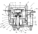
まず、図1、図2を参照して、本発明の実施の形態1に係る液体微細化装置1の概略構成について説明する。図1は、本発明の実施の形態1に係る液体微細化装置の概略斜視図である。図2は、本発明の実施の形態1に係る液体微細化装置の内部構成を示す概略断面図である。
BEST MODE FOR CARRYING OUT THE INVENTION Hereinafter, embodiments for carrying out the present invention will be described with reference to the accompanying drawings. It should be noted that each of the embodiments described below is a preferred specific example of the present invention. Therefore, the numerical values, shapes, materials, constituent elements, arrangement positions and connection forms of the constituent elements, etc. shown in the following embodiments are examples and are not intended to limit the present invention. Therefore, among the constituent elements in the following embodiments, constituent elements that are not described in independent claims representing the highest level concept of the present invention will be described as optional constituent elements. Moreover, in each figure, the same code|symbol is attached|subjected to the substantially same structure, and the overlapping description is abbreviate|omitted or simplified.
(Embodiment 1)
First, with reference to FIGS. 1 and 2, a schematic configuration of a liquid atomization device 1 according to Embodiment 1 of the present invention will be described. FIG. 1 is a schematic perspective view of a liquid atomization apparatus according to Embodiment 1 of the present invention. FIG. 2 is a schematic cross-sectional view showing the internal configuration of the liquid atomization device according to Embodiment 1 of the present invention.

図1に示すように、液体微細化装置1は、空気を吸い込む吸込口2と、吸込口2より吸い込まれた空気を吹き出す吹出口3とを備えている。吸込口2は、液体微細化装置1の側面に設けられている。吹出口3は、液体微細化装置1の上方に設けられている。 As shown in FIG. 1, the liquid atomization device 1 includes an air inlet 2 for sucking air and an outlet 3 for blowing out the air sucked from the inlet 2 . The suction port 2 is provided on the side surface of the liquid atomization device 1 . The blowout port 3 is provided above the liquid atomization device 1 .

図2に示すように、液体微細化装置1内には、吸込口2から吹出口3に至る風路4~風路6が形成されている。また、液体微細化装置1は、その風路4~風路6内に設けられた液体微細化室7を備えており、吸込口2と液体微細化室7と吹出口3とが連通している。 As shown in FIG. 2, air passages 4 to 6 extending from the inlet 2 to the outlet 3 are formed in the liquid atomization device 1 . Further, the liquid atomization device 1 is provided with a liquid atomization chamber 7 provided in the air paths 4 to 6, and the suction port 2, the liquid atomization chamber 7, and the outlet port 3 are communicated with each other. there is

液体微細化室7は、液体微細化装置1の主要部であり、水の微細化を行うところである。液体微細化装置1では、吸込口2から取り込んだ空気が、風路4を経由して液体微細化室7へ送られる。そして、液体微細化装置1は、風路4を通る空気に、液体微細化室7にて微細化された水を含ませて、その水を含んだ空気を、風路5、風路6の順に経由して吹出口3より吹き出すように構成されている。ここで、風路5は、水を含んだ空気を、液体微細化室7の鉛直方向下方に流れる向きから、その外周において鉛直方向上方に流れる向きに変わるように構成されている。風路6は、風路5を経由した空気を、そのまま鉛直方向上方に流して吹出口3より吹き出すように構成されている。 The liquid atomization chamber 7 is a main part of the liquid atomization device 1 and is where water is atomized. In the liquid atomization device 1 , the air taken in from the suction port 2 is sent to the liquid atomization chamber 7 via the air passage 4 . The liquid atomization apparatus 1 causes the air passing through the air passage 4 to contain the water atomized in the liquid atomization chamber 7, and the water-containing air is passed through the air passages 5 and 6. It is configured to blow out from the blower outlet 3 through in order. Here, the air passage 5 is configured so that the direction of the water-laden air flowing downward in the vertical direction of the liquid atomization chamber 7 is changed to the direction of flowing upward in the vertical direction at the periphery thereof. The air passage 6 is configured so that the air that has passed through the air passage 5 flows upward in the vertical direction as it is and is blown out from the outlet 3. - 特許庁

液体微細化室7には、上方及び下方が開口された筒状の衝突壁8が設けられている。衝突壁8は、液体微細化室7内に固定されている。また、液体微細化室7には、衝突壁8に囲まれた内側に、回転しながら水を汲み上げる(揚水する)筒状の揚水管9が備えられている。揚水管9は、逆円錐形の中空構造となっており、下方に円形状の揚水口9aを備えるとともに、揚水管9の上方であって逆円錐形の天面中心に、鉛直方向に向けて配置された回転軸10が固定されている。回転軸10が、液体微細化室7の外面に備えられた回転モータ11と接続されることで、回転モータ11の回転運動が回転軸10を通じて揚水管9に伝導され、揚水管9が回転する。なお、回転モータ11は、後述する加湿制御部30からの制御信号に基づいて、回転運動を実行するように構成されている。 The liquid atomization chamber 7 is provided with a cylindrical collision wall 8 which is open at the top and bottom. The impingement wall 8 is fixed within the liquid atomization chamber 7 . Further, the liquid atomization chamber 7 is provided with a cylindrical pumping pipe 9 that draws up (pumps) water while rotating inside the chamber surrounded by the collision wall 8 . The pumping pipe 9 has an inverted conical hollow structure, and is equipped with a circular pumping port 9a at the bottom. The arranged rotary shaft 10 is fixed. By connecting the rotating shaft 10 to a rotating motor 11 provided on the outer surface of the liquid atomization chamber 7, the rotating motion of the rotating motor 11 is transmitted to the pumping pipe 9 through the rotating shaft 10, and the pumping pipe 9 rotates. . The rotary motor 11 is configured to perform rotary motion based on a control signal from a humidification control section 30, which will be described later.

揚水管9は、逆円錐形の天面側に、揚水管9の外面から外側に突出するように形成された複数の回転板12を備えている。複数の回転板12は、上下で隣接する回転板12との間に、回転軸10の軸方向に所定間隔を設けて、揚水管9の外面から外側に突出するように形成されている。回転板12は、揚水管9とともに回転するため、回転軸10と同軸の水平な円盤形状が好ましい。なお、回転板12の枚数は、目標とする性能あるいは揚水管9の寸法に合わせて適宜設定されるものである。 The pumping pipe 9 is provided with a plurality of rotating plates 12 formed so as to protrude outward from the outer surface of the pumping pipe 9 on the top surface side of the inverted conical shape. The plurality of rotating plates 12 are formed to protrude outward from the outer surface of the pumping pipe 9 with a predetermined interval in the axial direction of the rotating shaft 10 between the vertically adjacent rotating plates 12 . Since the rotating plate 12 rotates together with the pumping pipe 9 , it is preferable that the rotating plate 12 has a horizontal disc shape coaxial with the rotating shaft 10 . The number of rotating plates 12 is appropriately set according to the target performance or the dimensions of the pumping pipe 9 .

また、揚水管9の壁面には、揚水管9の壁面を貫通する複数の開口13が設けられている。複数の開口13のそれぞれは、揚水管9の内部と、揚水管9の外面から外側に突出するように形成された回転板12の上面とを連通する位置に設けられている。 Further, the wall surface of the pumping pipe 9 is provided with a plurality of openings 13 passing through the wall surface of the pumping pipe 9 . Each of the plurality of openings 13 is provided at a position where the inside of the pumping pipe 9 communicates with the upper surface of the rotating plate 12 formed to protrude outward from the outer surface of the pumping pipe 9 .

液体微細化室7の下部には、揚水管9の鉛直方向下方に、揚水管9が揚水口9aより揚水する水を貯水する貯水部14が設けられている。貯水部14の深さは、揚水管9の下部の一部、例えば揚水管9の円錐高さの三分の一から百分の一程度の長さが浸るような深さに設計されている。この深さは、必要な揚水量に合わせて設計できる。また、貯水部14の底面は、揚水口9aに向けてすり鉢状に形成されている(図3参照)。 In the lower part of the liquid atomization chamber 7, vertically below the pumping pipe 9, a water storage part 14 for storing water pumped by the pumping pipe 9 from the pumping port 9a is provided. The depth of the reservoir 14 is designed such that a portion of the lower portion of the pumping pipe 9, for example, about one-third to one-hundredth of the height of the cone of the pumping pipe 9, is submerged. . This depth can be designed according to the required pumping capacity. Moreover, the bottom surface of the water storage part 14 is formed in a mortar shape toward the pumping port 9a (see FIG. 3).

貯水部14への水の供給は、給水部15により行われる。給水部15には、給水管15aが接続されており、例えば水道から水圧調整弁(給水弁15b:図示せず)を通じて、給水管15aにより直接給水される。給水部15は、貯水部14の底面よりも鉛直方向上方に設けられている。また、給水部15は、貯水部14の底面だけでなく、貯水部14の上面(貯水部14に貯水され得る最大水位の面)よりも鉛直方向上方に設けられるのが好ましい。なお、給水部15は、あらかじめ液体微細化室7外に備えられた水タンクからサイフォンの原理で必要な水量のみ汲みあげて、貯水部14へ水を供給するように構成されてもよい。 Water is supplied to the water storage unit 14 by the water supply unit 15 . A water supply pipe 15a is connected to the water supply unit 15, and water is supplied directly from the water supply pipe 15a through a water pressure control valve (water supply valve 15b: not shown), for example. The water supply portion 15 is provided vertically above the bottom surface of the water storage portion 14 . Moreover, it is preferable that the water supply portion 15 is provided vertically above not only the bottom surface of the water storage portion 14 but also the top surface of the water storage portion 14 (the maximum water level that can be stored in the water storage portion 14). The water supply unit 15 may be configured to draw up only the necessary amount of water from a water tank provided outside the liquid atomization chamber 7 in advance by the siphon principle and supply water to the water storage unit 14 .

また、液体微細化装置1には、貯水部14の水位を検知する水位検知部18が設けられている。水位検知部18は、フロートスイッチ18aを有している。フロートスイッチ18aは、貯水部14内の水が一定の水位(満水状態)に達していない場合はオフとなり、貯水部14内の水が一定の水位(満水状態)に達した場合にオンとなる。つまり、水位検知部18は、フロートスイッチ18aによって貯水部14の水が一定の水位(満水状態)か否かを検知する。そして、水位検知部18は、フロートスイッチ18aのオンまたはオフに関する情報を加湿制御部30に出力する。詳細は後述するが、加湿制御部30は、フロートスイッチ18aがオフとなり、オフの状態が所定時間(第一時間T1)継続した場合には、給水部15より貯水部14へ水が供給されるように制御し、フロートスイッチ18aがオンの場合には、給水部15から貯水部14への水の供給が停止されるように制御する。ここで、第一時間T1は、貯水部14内の水が加湿処理によって揚水できない水量まで減少させない時間に設定され、本実施の形態では、一定時間(例えば、30分)としている。 Further, the liquid atomization device 1 is provided with a water level detection unit 18 for detecting the water level of the water storage unit 14 . The water level detector 18 has a float switch 18a. The float switch 18a is turned off when the water in the water storage section 14 has not reached a certain water level (full water state), and turned on when the water in the water storage section 14 has reached a certain water level (full water state). . In other words, the water level detector 18 detects whether or not the water in the water reservoir 14 is at a constant water level (full water level) by means of the float switch 18a. The water level detection unit 18 then outputs information regarding ON or OFF of the float switch 18 a to the humidification control unit 30 . Although details will be described later, when the float switch 18a is turned off and the off state continues for a predetermined time (first time T1), the humidification control unit 30 supplies water from the water supply unit 15 to the water storage unit 14. When the float switch 18a is turned on, the water supply from the water supply unit 15 to the water storage unit 14 is stopped. Here, the first time T1 is set to a time during which the amount of water in the water storage unit 14 does not decrease to the extent that it cannot be pumped due to the humidification process, and is set to a fixed time (for example, 30 minutes) in the present embodiment.

貯水部14の底面には、排水管16が接続されている。排水管16が接続される位置に設けられた円形状の排水口16aは、すり鉢状に形成された貯水部14の底面の最も低い位置に設けられている。排水管16による止水及び排水は、揚水管9の回転によって実現される。即ち、排水管16と揚水管9とで、貯水部14の止水機構及び揚水機構を構成する。なお、排水管16と揚水管9とによる貯水部14の止水機構及び排水機構の詳細については、図3を参照して後述する。 A drain pipe 16 is connected to the bottom surface of the water reservoir 14 . A circular drainage port 16a provided at a position to which the drainage pipe 16 is connected is provided at the lowest position of the bottom surface of the water reservoir 14 formed in the shape of a mortar. Stopping and draining water by the drain pipe 16 is achieved by rotating the water pump 9 . That is, the drain pipe 16 and the water pumping pipe 9 constitute a water stopping mechanism and a water pumping mechanism for the water reservoir 14 . The details of the water stopping mechanism and the drainage mechanism of the water reservoir 14 by the drain pipe 16 and the pumping pipe 9 will be described later with reference to FIG. 3 .

また、衝突壁8の下方(衝突壁8と貯水部14との間の空間)には、液体微細化室7の内外を隔てるように配置され、微細化された水滴の一部を捕集する円筒状のエリミネータ17が設けられている。また、エリミネータ17は、空気が流通可能な多孔体で構成されている。エリミネータ17は、衝突壁8の下部に接続されたエリミネータホルダ19に内包されるように固定されている。具体的には、エリミネータホルダ19は、天面板19cと、天面板19cから鉛直方向下方に延びる第一保持部19aと、第一保持部19aよりも内側(揚水管9側)において、天面板19cから鉛直方向下方に延びる第二保持部19bとを有して構成されている。エリミネータ17は、エリミネータホルダ19の第一保持部19aと第二保持部19bとで挟持されて固定されている。なお、エリミネータホルダ19の第二保持部19bには、水流制御板20の支持部22が接続されている。 Further, below the collision wall 8 (the space between the collision wall 8 and the water reservoir 14), a liquid atomization chamber 7 is arranged to separate the inside and outside of the liquid atomization chamber 7, and part of the atomized water droplets is collected. A cylindrical eliminator 17 is provided. Also, the eliminator 17 is composed of a porous body through which air can flow. The eliminator 17 is fixed so as to be included in an eliminator holder 19 connected to the lower portion of the collision wall 8 . Specifically, the eliminator holder 19 includes a top plate 19c, a first holding portion 19a extending vertically downward from the top plate 19c, and a top plate 19c inside the first holding portion 19a (on the side of the water pump 9). and a second holding portion 19b extending downward in the vertical direction. The eliminator 17 is clamped and fixed between the first holding portion 19 a and the second holding portion 19 b of the eliminator holder 19 . A supporting portion 22 of the water flow control plate 20 is connected to the second holding portion 19b of the eliminator holder 19. As shown in FIG.

エリミネータ17は、風路5内に配置され、エリミネータ17内を流通することによって、液体微細化室7を通過する空気に含められた水のうち水滴を捕集する。これにより、風路5を流れた空気は、気化された水のみが含まれるようになる。 The eliminator 17 is arranged in the air passage 5 and collects droplets of the water contained in the air passing through the liquid atomization chamber 7 by circulating in the eliminator 17 . As a result, the air flowing through the air passage 5 contains only vaporized water.

水流制御板20は、貯水部14を覆うように、貯水部14の上方に設けられている。具体的には、水流制御板20は、外径が貯水部14の内壁径よりも小さく形成され、エリミネータ17で囲まれた空間内の下方において、貯水部14の上方を覆うように設けられている。水流制御板20は、略円板状の形状であり、中央部に揚水管9が水流制御板20を貫通できる直径に開口した開口部(図示せず)が形成されている。また、水流制御板20は、外周部(外縁)の上面側に複数の支持部22を有し、この支持部22を介してエリミネータホルダ19の第二保持部19bと固定されている。なお、水流制御板20は、揚水管9の回転に伴う水流の気泡発生による騒音上昇を防いでいる。 The water flow control plate 20 is provided above the water reservoir 14 so as to cover the water reservoir 14 . Specifically, the water flow control plate 20 has an outer diameter smaller than the inner wall diameter of the water reservoir 14, and is provided below the space surrounded by the eliminator 17 so as to cover the upper part of the water reservoir 14. there is The water flow control plate 20 has a substantially disk-like shape, and an opening (not shown) having a diameter that allows the pumping pipe 9 to pass through the water flow control plate 20 is formed in the center. Further, the water flow control plate 20 has a plurality of support portions 22 on the upper surface side of the outer peripheral portion (outer edge), and is fixed to the second holding portion 19b of the eliminator holder 19 via the support portions 22 . In addition, the water flow control plate 20 prevents an increase in noise caused by the generation of air bubbles in the water flow accompanying the rotation of the pumping pipe 9 .

さらに、液体微細化装置1には、加湿制御部30が設けられている。加湿制御部30は、液体微細化装置1の運転動作を制御することで、加湿処理における加湿動作(微細化動作)を制御する。また、加湿制御部30は、加湿動作中に貯水部14への水の給水回数が所定回数となった場合に貯水部の水を排水する排水動作(第一処理)と、加湿動作が所定時間(第二時間T2)継続した場合に貯水部の水を排水する排水動作(第二処理)とを制御する。ここで、第二期間T2は、一定時間(例えば、24時間)としている。なお、第二時間T2は、請求項の「第一期間」に相当する。さらに、加湿制御部30は、液体微細化装置1の運転動作を停止する際に行う乾燥処理における乾燥動作を制御する。 Furthermore, the liquid atomization device 1 is provided with a humidification control section 30 . The humidification control unit 30 controls the operation of the liquid atomization device 1 to control the humidification operation (miniaturization operation) in the humidification process. In addition, the humidification control unit 30 performs a water discharge operation (first process) for draining water from the water storage unit when the number of times water is supplied to the water storage unit 14 during the humidification operation reaches a predetermined number of times, and the humidification operation is performed for a predetermined time. (Second time T2) Controls the draining operation (second process) for draining the water from the water storage section if it continues. Here, the second period T2 is a fixed period of time (for example, 24 hours). In addition, the second time T2 corresponds to the "first period" in the claims. Furthermore, the humidification control unit 30 controls the drying operation in the drying process performed when the operation of the liquid atomization device 1 is stopped.

なお、液体微細化装置1は、加湿制御部30を備えず、熱交換気装置60を制御する制御部60a(図5参照)によって加湿動作、排水動作(第一処理、第二処理)、及び乾燥動作が制御される構成であってもよい。 The liquid atomization device 1 does not include the humidification control unit 30, and the control unit 60a (see FIG. 5) that controls the heat exchange device 60 performs humidification operation, drainage operation (first process, second process), and The configuration may be such that the drying operation is controlled.

次に、図2を参照して、液体微細化装置1における加湿(水の微細化)の動作原理を説明する。 Next, with reference to FIG. 2, the operating principle of humidification (refining water) in the liquid atomization device 1 will be described.

まず、外部からの空気の送風(吸込口2からの空気の吸い込み)が開始される。そして、貯水部14に水がない状態で、回転モータ11により回転軸10を第一回転数R1(例えば、2000rpm)で回転させ、それに合わせて揚水管9を回転させる。そして、給水部15から貯水部14に水を供給する。この際、貯水部14では、揚水管9の回転によって生じる遠心力により、貯水部14に供給された水が揚水管9によって汲み上げられるとともに、貯水部14に供給された水は排水口16aから排水されることなく止水される。その結果、給水部15から供給される水が貯水部14に貯水されていく。そして、貯水部14の満水後、給水部15から貯水部14への水の供給を停止する。 First, air blowing from the outside (air intake from the suction port 2) is started. Then, with no water in the water reservoir 14, the rotation motor 11 rotates the rotation shaft 10 at the first rotation speed R1 (for example, 2000 rpm), and the pumping pipe 9 is rotated accordingly. Then, water is supplied from the water supply unit 15 to the water storage unit 14 . At this time, in the water storage section 14, the water supplied to the water storage section 14 is pumped up by the water storage section 9 due to the centrifugal force generated by the rotation of the water storage section 9, and the water supplied to the water storage section 14 is drained from the drain port 16a. The water is stopped without being As a result, the water supplied from the water supply unit 15 is stored in the water storage unit 14 . After the water storage portion 14 is filled with water, the supply of water from the water supply portion 15 to the water storage portion 14 is stopped.

続いて、回転モータ11により回転軸10を第二回転数R2で回転させ、それに合わせて揚水管9を回転させると、その回転によって生じる遠心力により、貯水部14に貯水された水が揚水管9によって汲み上げられる。ここで、回転モータ11(揚水管9)の第二回転数R2は、空気への加湿量に応じて、2000-5000rpmの間に設定される。揚水管9は、逆円錐形の中空構造となっているため、回転によって汲み上げられた水は、揚水管9の内壁を伝って上部へ揚水される。そして、揚水された水は、揚水管9の開口13から回転板12を伝って遠心方向に放出され、水滴として飛散する。 Subsequently, when the rotary shaft 10 is rotated at the second rotation speed R2 by the rotary motor 11, and the pumping pipe 9 is rotated correspondingly, the centrifugal force generated by the rotation causes the water stored in the water storage part 14 to flow into the pumping pipe. pumped by 9. Here, the second rotation speed R2 of the rotary motor 11 (water pumping pipe 9) is set between 2000 and 5000 rpm according to the amount of humidification of the air. Since the pumping pipe 9 has an inverted conical hollow structure, the water pumped up by the rotation is pumped up along the inner wall of the pumping pipe 9 . Then, the pumped water is discharged in the centrifugal direction from the opening 13 of the pumping pipe 9 along the rotary plate 12 and scatters as water droplets.

回転板12から飛散した水滴は、衝突壁8に囲まれた空間(液体微細化室7)を飛翔し、衝突壁8に衝突し、微細化される。一方、液体微細化室7を通過する空気は、衝突壁8の上方から衝突壁8の内部へ移動し、衝突壁8によって破砕(微細化)された水滴を含みながら下方から衝突壁8の外部へ移動する。そして、水滴を含んだ空気は、エリミネータ17を通過する。これにより、液体微細化装置1は、吸込口2より吸い込んだ空気に対して加湿を行い、吹出口3より加湿された空気を吹き出すことができる。 Water droplets scattered from the rotating plate 12 fly in a space (liquid atomization chamber 7) surrounded by the collision wall 8, collide with the collision wall 8, and are atomized. On the other hand, the air passing through the liquid atomization chamber 7 moves from above the collision wall 8 into the interior of the collision wall 8 and, while containing water droplets crushed (miniaturized) by the collision wall 8 , moves from below to the outside of the collision wall 8 . Move to The air containing water droplets then passes through the eliminator 17 . As a result, the liquid atomization device 1 can humidify the air sucked from the suction port 2 and blow the humidified air from the blowout port 3 .

なお、微細化される液体は水以外でもよく、例えば、殺菌性あるいは消臭性を備えた次亜塩素酸水等の液体であってもよい。微細化された次亜塩素酸水を液体微細化装置1の吸込口2より吸い込まれた空気に含ませ、その空気を吹出口3より吹き出すことで、液体微細化装置1が置かれた空間の殺菌あるいは消臭を行うことができる。 The liquid to be atomized may be other than water, and may be, for example, hypochlorous acid water having sterilizing or deodorizing properties. The air sucked from the suction port 2 of the liquid atomization device 1 contains the atomized hypochlorous acid water, and the air is blown out from the blowout port 3, so that the space in which the liquid atomization device 1 is placed. It can be sterilized or deodorized.

次いで、図3を参照して、排水管16と揚水管9とによる貯水部14の止水機構及び排水機構の詳細について説明する。図3は、本発明の実施の形態1に係る液体微細化装置における排水管と揚水管とによる貯水部の止水機構を説明するための図である。 Next, with reference to FIG. 3, details of a water stopping mechanism and a drainage mechanism for the water reservoir 14 by the drain pipe 16 and the water pumping pipe 9 will be described. FIG. 3 is a diagram for explaining a water stopping mechanism of the water storage section by the drain pipe and the pumping pipe in the liquid atomization apparatus according to Embodiment 1 of the present invention.

図3に示すように、液体微細化装置1では、加湿動作が開始され、回転モータ11(揚水管9)が第三回転数R3(例えば、2000rpm)で回転されると、その回転の遠心力によって、揚水管9の内部で貯水部14の水に渦24が発生する。そして、揚水管9は、その回転によって発生する渦中心において、揚水口9aと排水口16aとの間を連通する空隙25を形成する。これにより、空隙25が排水口16aを塞ぐ状態となり、貯水部14の水が排水口16aに流れ込むのが抑制される。つまり、液体微細化装置1では、加湿動作中(回転モータ11が第二回転数R2で回転動作中)に、貯水部14の水が排水口16aから排水されることを抑制することができる。 As shown in FIG. 3, in the liquid atomization device 1, when the humidification operation is started and the rotary motor 11 (water pumping pipe 9) is rotated at the third rotation speed R3 (for example, 2000 rpm), the centrifugal force of the rotation As a result, a vortex 24 is generated in the water in the water reservoir 14 inside the pumping pipe 9 . The pumping pipe 9 forms a gap 25 that communicates between the pumping port 9a and the drain port 16a at the center of the vortex generated by its rotation. As a result, the gap 25 closes the drain port 16a, and the water in the water reservoir 14 is prevented from flowing into the drain port 16a. That is, in the liquid atomization device 1, it is possible to prevent the water in the water reservoir 14 from being drained from the drain port 16a during the humidification operation (while the rotary motor 11 is rotating at the second rotation speed R2).

一方、回転モータ11(揚水管9)の回転が停止されると、渦24とともに空隙25がなくなり、排水口16aに貯水部14の水が流れ込む。つまり、液体微細化装置1では、加湿動作(回転モータ11の回転動作)を停止することにより、貯水部14の水を排水口16aから排水することができる。 On the other hand, when the rotation of the rotary motor 11 (the pumping pipe 9) is stopped, the space 25 disappears along with the vortex 24, and the water in the reservoir 14 flows into the drain port 16a. That is, in the liquid atomization apparatus 1, the water in the water reservoir 14 can be drained from the drain port 16a by stopping the humidification operation (rotational operation of the rotary motor 11).

このように、液体微細化装置1は、排水管16に排水弁を用いなくても、加湿動作中は、貯水部14の水が排水口16aから排水されることを抑制(止水)でき、加湿動作の停止後は、貯水部14の水を排水口16aから排水できる。 As described above, the liquid atomization apparatus 1 can suppress (water stop) the water in the water storage section 14 from being drained from the drain port 16a during the humidification operation without using a drain valve in the drain pipe 16. After the humidification operation is stopped, the water in the water reservoir 14 can be drained from the drain port 16a.

次に、図4を参照して、本実施の形態1に係る液体微細化装置1を備えた熱交換気装置60について説明する。図4は、本実施の形態1に係る液体微細化装置を備えた熱交換気装置の概略斜視図である。 Next, with reference to FIG. 4, a heat exchange gas device 60 including the liquid atomization device 1 according to Embodiment 1 will be described. FIG. 4 is a schematic perspective view of a heat exchange gas apparatus equipped with a liquid atomization device according to Embodiment 1. FIG.

図4に示すように、熱交換気装置60は、液体微細化装置1と、湿度回収部65と、送風機67とを備えて構成される。熱交換気装置60は、外気吸込口63から吸い込んだ外気(湿度回収部65を通過して湿度が回収された空気)を、接続ダクト66を介して液体微細化装置1の吸込口2(図1参照)に送風する。液体微細化装置1は、吸込口2から吸い込んだ空気に対して加湿処理を行い、加湿した空気を吹出口3(図1参照)から吹き出し、給気口64を介して室内に供給する。ここで、熱交換気装置60は、請求項の「送風装置」に相当する。 As shown in FIG. 4 , the heat exchange air device 60 includes the liquid atomization device 1 , a humidity recovery unit 65 and a blower 67 . The heat exchanging air device 60 passes the outside air sucked from the outside air suction port 63 (the air whose humidity has been recovered by passing through the humidity recovery part 65 ) to the suction port 2 of the liquid atomization device 1 (Fig. 1). The liquid atomization device 1 humidifies the air sucked through the suction port 2 , blows the humidified air out of the blowout port 3 (see FIG. 1 ), and supplies the humidified air into the room through the air supply port 64 . Here, the heat exchange air device 60 corresponds to the "blower" in the claims.

熱交換気装置60は、箱型の本体ケース50を有し、例えば、床に置かれた状態で使用される。本体ケース50の天面(液体微細化装置1が搭載される面)には、内気吸込口61と、排気口62と、外気吸込口63と、給気口64とが設けられている。また、本体ケース50の天面には、液体微細化装置1が設置されている。そして、本体ケース50の内部には、湿度回収部65と、送風機67とが設けられている。 The heat exchange device 60 has a box-shaped main body case 50 and is used, for example, while being placed on the floor. An internal air intake port 61 , an exhaust port 62 , an external air intake port 63 , and an air supply port 64 are provided on the top surface of the main body case 50 (the surface on which the liquid atomization device 1 is mounted). Further, the liquid atomization device 1 is installed on the top surface of the main body case 50 . A humidity collector 65 and a blower 67 are provided inside the body case 50 .

内気吸込口61は、建物内の空気(内気)を熱交換気装置60の内部に吸い込む吸込口である。具体的には、内気吸込口61は、建物内の各空間の天井面または壁面まで延在するダクト(図示せず)を介して内気を吸い込む室内排気口と連通して接続される。 The inside air intake port 61 is an intake port for sucking the air (inside air) inside the building into the inside of the heat exchange device 60 . Specifically, the inside air intake port 61 is connected to communicate with an indoor exhaust port that draws in the inside air via a duct (not shown) extending to the ceiling surface or wall surface of each space in the building.

排気口62は、内気を熱交換気装置60から屋外に送風する吐出口である。具体的には、排気口62は、建物外壁面まで延在するダクト(図示せず)を介して内気を吹き出す室外排気口と連通して接続される。 The exhaust port 62 is a discharge port that blows the inside air from the heat exchange device 60 to the outside. Specifically, the exhaust port 62 is connected to communicate with an outdoor exhaust port that blows out the inside air via a duct (not shown) extending to the outer wall surface of the building.

外気吸込口63は、建物外の空気(外気)を熱交換気装置60の内部に吸い込む吸込口である。具体的には、外気吸込口63は、建物外壁面まで延在するダクト(図示せず)を介して外気を吸い込む室外給気口と連通して接続される。 The outside air intake port 63 is an intake port for sucking air outside the building (outside air) into the heat exchange device 60 . Specifically, the outside air intake port 63 is connected to communicate with an outdoor air supply port that draws in the outside air via a duct (not shown) extending to the outer wall surface of the building.

給気口64は、外気を熱交換気装置60から液体微細化装置1を介して室内に送風する吐出口である。具体的には、給気口64は、建物内の各空間の天井面または壁面まで延在するダクト(図示せず)を介して外気を吹き出す室内給気口と連通して接続される。なお、熱交換気装置60と液体微細化装置1の吸込口2とは、接続ダクト66を介して接続されている。 The air supply port 64 is a discharge port for blowing outside air from the heat exchange device 60 into the room through the liquid atomization device 1 . Specifically, the air supply port 64 is connected to an indoor air supply port that blows outside air via a duct (not shown) extending to the ceiling or wall surface of each space in the building. The heat exchange air device 60 and the suction port 2 of the liquid atomization device 1 are connected via a connection duct 66 .

湿度回収部65は、本体ケース50内において、送風機67の上流側に位置して設けられている。湿度回収部65は、送風機67が動作することにより吸い込まれ、熱交換気装置60の内部(特に、給気風路)を通過する空気の湿度を回収(交換)する湿度回収(湿度交換)の機能を有している。湿度回収部65は、例えば、デシカント式あるいはヒートポンプ式の熱交換器などである。 The humidity recovery unit 65 is provided upstream of the blower 67 in the main body case 50 . The humidity recovery unit 65 has a humidity recovery (humidity exchange) function of recovering (exchanging) the humidity of the air sucked by the operation of the blower 67 and passing through the inside of the heat exchange device 60 (in particular, the supply air passage). have. The humidity recovery unit 65 is, for example, a desiccant type or heat pump type heat exchanger.

給気風路は、特に図示していないが、新鮮な室外の空気(外気)を、外気吸込口63から吸い込み、湿度回収部65、送風機67、接続ダクト66、及び液体微細化装置1の順に通過させて、給気口64から室内に供給する風路である。 Although not particularly shown, the air supply air passage draws in fresh outdoor air (outside air) from the outside air suction port 63 and passes through the humidity recovery unit 65, the blower 67, the connection duct 66, and the liquid atomization device 1 in this order. It is an air passage for supplying air from the air supply port 64 to the room.

送風機67は、外気吸込口63から給気口64へと外気を送風するための装置である。送風機67は、送風することによって、湿度回収部65の内部に外気を流通させる。送風機67としては、例えば、クロスフローファンあるいはブロアファンが挙げられる。なお、送風機67は、熱交換気装置60を制御する制御部60a(図5参照)からの制御信号に基づいて、送風動作を実行するように構成されている。 The blower 67 is a device for blowing outside air from the outside air suction port 63 to the air supply port 64 . The air blower 67 circulates outside air inside the humidity recovery unit 65 by blowing air. The blower 67 may be, for example, a cross-flow fan or a blower fan. The blower 67 is configured to blow air based on a control signal from a control section 60a (see FIG. 5) that controls the heat exchange device 60. As shown in FIG.

また、熱交換気装置60には、給排水配管51が設けられている。そして、液体微細化装置1への水の供給及び排水は、給排水配管51によって行われる。具体的には、給排水配管51の一端は、液体微細化装置1の給水管15a(図2参照)と排水管16(図2参照)とそれぞれ接続されている。また、給排水配管51の他端は、住宅あるいは施設の給水設備と排水設備とにそれぞれ接続されている。 Further, the heat exchange device 60 is provided with a water supply/drainage pipe 51 . Water is supplied to and drained from the liquid atomization device 1 by a water supply/drainage pipe 51 . Specifically, one end of the water supply/drainage pipe 51 is connected to the water supply pipe 15a (see FIG. 2) and the water discharge pipe 16 (see FIG. 2) of the liquid atomization device 1, respectively. The other end of the water supply/drainage pipe 51 is connected to a water supply system and a drainage system of a house or facility, respectively.

さらに、熱交換気装置60は、送風機67の送風動作の制御を行う制御部60a(図5参照)を有している。また、制御部60aは、液体微細化装置1の加湿制御部30と電気的に接続され、加湿制御部30からの制御信号を受けて、送風機67と液体微細化装置1とを連動させて制御するように構成されている。 Furthermore, the heat exchange device 60 has a control section 60 a (see FIG. 5 ) that controls the air blowing operation of the air blower 67 . Further, the control unit 60a is electrically connected to the humidification control unit 30 of the liquid atomization device 1, receives a control signal from the humidification control unit 30, and controls the air blower 67 and the liquid atomization device 1 in conjunction with each other. is configured to

以上のように、熱交換気装置60では、換気の際に屋外へ排出する水分を室内に給気する空気に回収しつつ、さらに湿度回収部65で水分を回収しきれなかった場合には、液体微細化装置1を通過させる際に補填もしくはそれ以上に上乗せすることができるので、室内を加湿および快適な湿度範囲に維持させることができる。 As described above, in the heat exchange device 60, the moisture discharged to the outside during ventilation is recovered into the air supplied indoors, and when the moisture recovery unit 65 cannot recover the moisture, Since the liquid can be supplemented or added when passing through the liquid atomization device 1, the room can be humidified and maintained within a comfortable humidity range.

次に、図5を参照して、液体微細化装置1の加湿制御部30について説明する。図5は、本発明の実施の形態1に係る液体微細化装置における加湿制御部の構成を示すブロック図である。 Next, the humidification control section 30 of the liquid atomization device 1 will be described with reference to FIG. FIG. 5 is a block diagram showing the configuration of a humidification control section in the liquid atomization apparatus according to Embodiment 1 of the present invention.

図5に示すように、加湿制御部30は、入力部30aと、記憶部30bと、計時部30cと、処理部30dと、出力部30eとを備える。 As shown in FIG. 5, the humidification control section 30 includes an input section 30a, a storage section 30b, a clock section 30c, a processing section 30d, and an output section 30e.

入力部30aは、操作パネル31からの運転開始指示または運転停止指示に関する第一情報と、温湿度センサ32からの室内空気の温度と湿度に関する第二情報と、温度センサ33からの室外空気の温度に関する第三情報と、水位検知部18からのフロートスイッチ18aのオンまたはオフに関する第四情報とを受け付ける。入力部30aは、受け付けた第一情報~第四情報を処理部30dに出力する。 The input unit 30a receives the first information about the operation start instruction or the operation stop instruction from the operation panel 31, the second information about the temperature and humidity of the indoor air from the temperature and humidity sensor 32, and the temperature of the outdoor air from the temperature sensor 33. and fourth information about ON or OFF of the float switch 18a from the water level detection unit 18 is received. The input unit 30a outputs the received first to fourth information to the processing unit 30d.

ここで、操作パネル31は、ユーザが液体微細化装置1および熱交換気装置60に関するユーザ入力情報(例えば、風量、加湿量、吹き出し温度、等)を入力する端末であり、無線または有線により加湿制御部30と通信可能に接続されている。また、温湿度センサ32は、内気吸込口61から取り込まれた直後の室内空気の温度と湿度を感知するセンサである。また、温度センサ33は、外気吸込口63から取り込まれた直後の室外空気の温度を感知するセンサである。 Here, the operation panel 31 is a terminal for a user to input user input information (for example, air volume, humidification volume, blowing temperature, etc.) regarding the liquid atomization device 1 and the heat exchange device 60. It is communicably connected to the control unit 30 . Also, the temperature/humidity sensor 32 is a sensor that senses the temperature and humidity of the room air immediately after being taken in from the inside air suction port 61 . Also, the temperature sensor 33 is a sensor that senses the temperature of the outdoor air immediately after being taken in from the outside air intake port 63 .

記憶部30bは、加湿動作における加湿設定に関する第五情報と、排水動作(第一処理、第二処理)における排水設定に関する第六情報と、乾燥動作における乾燥設定に関する第七情報と、ユーザ入力情報に対応する設定情報に関する第八情報とを記憶する。記憶部30bは、記憶した第五情報~第八情報を処理部30dに出力する。 The storage unit 30b stores fifth information regarding humidification settings in the humidification operation, sixth information regarding drainage settings in the drainage operation (first process, second process), seventh information regarding drying settings in the drying operation, and user input information. and eighth information relating to setting information corresponding to . The storage unit 30b outputs the stored fifth to eighth information to the processing unit 30d.

計時部30cは、現在時刻に関する第九情報を処理部30dに出力する。 The timer 30c outputs ninth information about the current time to the processor 30d.

処理部30dは、入力部30aからの第一情報~第四情報と、記憶部30bからの第五情報~第八情報と、計時部30cからの第九情報とを受け付ける。処理部30dは、受け付けた第一情報~第九情報を用いて、加湿設定に基づく加湿動作、排水設定に基づく排水動作(第一処理、第二処理)、及び乾燥設定における乾燥動作に関する制御情報を特定する。処理部30dは、特定した制御情報を出力部30eに出力する。 The processing unit 30d receives the first to fourth information from the input unit 30a, the fifth to eighth information from the storage unit 30b, and the ninth information from the clock unit 30c. The processing unit 30d uses the received first information to ninth information to generate control information related to the humidification operation based on the humidification setting, the drainage operation (first process, second process) based on the drainage setting, and the drying operation in the drying setting. identify. The processing unit 30d outputs the identified control information to the output unit 30e.

出力部30eは、処理部30dからの制御情報を受け付ける。出力部30eは、熱交換気装置60(制御部60a、送風機67)と、回転モータ11と、給水弁15bと電気的に接続される。そして、出力部30eは、受け付けた制御情報に基づいて、送風機67の送風動作と、液体微細化室7での加湿動作(回転モータ11の回転動作)と、給水弁15bの開閉動作とを制御する信号(制御信号)を出力する。 The output unit 30e receives control information from the processing unit 30d. The output unit 30e is electrically connected to the heat exchange device 60 (control unit 60a, blower 67), the rotary motor 11, and the water supply valve 15b. Based on the received control information, the output unit 30e controls the air blowing operation of the air blower 67, the humidification operation (rotating operation of the rotary motor 11) in the liquid atomization chamber 7, and the opening/closing operation of the water supply valve 15b. Outputs a signal (control signal) to

そして、熱交換気装置60(制御部60a、送風機67)は、出力部30eからの信号を受け付け、制御部60aは、受け付けた信号に基づいて送風機67の制御を実行する。また、回転モータ11と給水弁15bとは、出力部30eからの信号をそれぞれ受け付け、受け付けた信号に基づいてそれぞれの制御を実行する。 Then, the heat exchange device 60 (control section 60a, blower 67) receives a signal from the output section 30e, and the control section 60a controls the blower 67 based on the received signal. Further, the rotary motor 11 and the water supply valve 15b receive signals from the output section 30e, respectively, and perform respective controls based on the received signals.

以上のようにして、加湿制御部30は、加湿処理における加湿動作の制御、第一処理または第二処理における排水動作の制御、及び乾燥処理における乾燥動作の制御をそれぞれ実行させる。 As described above, the humidification control unit 30 controls the humidification operation in the humidification process, the drainage operation control in the first process or the second process, and the drying operation control in the drying process.

次に、図6~図9を参照して、液体微細化装置1による加湿動作における処理手順について説明する。図6、図7は、本発明の実施の形態1に係る液体微細化装置による加湿処理手順を示すフローチャートである。図8は、本発明の実施の形態1に係る液体微細化装置による給水処理手順を示すフローチャートである。図9は、本発明の実施の形態1に係る液体微細化装置による排水処理手順を示すフローチャートである。なお、以下では、送風機67が、制御部60aからの制御信号ではなく、加湿制御部30からの制御信号によって送風動作を実行しているものとして説明する。 Next, with reference to FIGS. 6 to 9, the processing procedure in the humidification operation by the liquid atomization device 1 will be described. 6 and 7 are flowcharts showing the procedure of humidification processing by the liquid atomization device according to Embodiment 1 of the present invention. FIG. 8 is a flow chart showing a water supply processing procedure by the liquid atomization apparatus according to Embodiment 1 of the present invention. FIG. 9 is a flow chart showing a waste water treatment procedure by the liquid atomization apparatus according to Embodiment 1 of the present invention. In the following description, it is assumed that the blower 67 blows air according to the control signal from the humidification control section 30, not the control signal from the control section 60a.

図6に示すように、加湿制御部30に液体微細化装置1の加湿処理の運転開始に関する制御信号が入力されると、まず、加湿制御部30は、送風機67を作動させ、送風機67からの送風を開始させる(ステップS01)。これにより、液体微細化装置1(液体微細化室7)内に空気が流通するようになる。そして、加湿制御部30は、水位検知カウンタNをリセットし、水位検知カウンタNを「0」とする(ステップS02)。ここで、水位検知カウンタNは、貯水部14への水の給水回数(貯水部14が満水状態となるまでの給水を行った回数)を示す値である。そして、加湿制御部30は、貯水部14への水の給水処理を実行させる(ステップS03)。 As shown in FIG. 6 , when a control signal for starting the operation of the humidification process of the liquid atomization device 1 is input to the humidification control unit 30 , the humidification control unit 30 first operates the air blower 67 and the air from the air blower 67 Air blowing is started (step S01). As a result, air flows through the liquid atomization device 1 (liquid atomization chamber 7). Then, the humidification control unit 30 resets the water level detection counter N to "0" (step S02). Here, the water level detection counter N is a value indicating the number of times water is supplied to the water storage section 14 (the number of times water has been supplied until the water storage section 14 is filled with water). Then, the humidification control unit 30 executes the process of supplying water to the water storage unit 14 (step S03).

給水処理では、図8に示すように、加湿制御部30は、回転モータ11を第一回転数R1(例えば、2000rpm)で作動させ、止水機構が機能する状態とする(ステップS20)。次に、加湿制御部30は、給水部15の給水弁15bを開弁させ、貯水部14への水の供給を開始させる(ステップS21)。そして、加湿制御部30は、水位検知部18からのフロートスイッチ18aのオンまたはオフに関する第四情報に基づいて、貯水部14の水位が満水状態となったか否かを判断する(ステップS22)。その結果、貯水部14の水が満水状態となっていない場合(ステップS22のNo)には、加湿制御部30は、貯水部14への水の供給をそのまま継続させる(ステップS22に戻る)。一方、貯水部14の水が満水状態となった場合(ステップS22のYes)には、加湿制御部30は、給水弁15bを閉弁させ、貯水部14への水の供給を停止させる(ステップS23)。そして、加湿制御部30は、水位検知カウンタNに「1」を加算する(ステップS24)。以上の各ステップにより、貯水部14への水の給水処理が終了する。但し、給水処理は、回転モータ11を第一回転数R1で回転させた状態で終了する。図6に戻る。 In the water supply process, as shown in FIG. 8, the humidification control unit 30 operates the rotary motor 11 at the first rotation speed R1 (for example, 2000 rpm) so that the water stop mechanism functions (step S20). Next, the humidification control unit 30 opens the water supply valve 15b of the water supply unit 15 to start supplying water to the water storage unit 14 (step S21). Then, the humidification control section 30 determines whether or not the water level of the water storage section 14 has reached the full state based on the fourth information regarding ON or OFF of the float switch 18a from the water level detection section 18 (step S22). As a result, when the water storage unit 14 is not full of water (No in step S22), the humidification control unit 30 continues to supply water to the water storage unit 14 (returns to step S22). On the other hand, when the water storage unit 14 is full of water (Yes in step S22), the humidification control unit 30 closes the water supply valve 15b to stop the supply of water to the water storage unit 14 (step S23). Then, the humidification control unit 30 adds "1" to the water level detection counter N (step S24). Through the steps described above, the process of supplying water to the water storage unit 14 is completed. However, the water supply process ends with the rotary motor 11 rotating at the first rotation speed R1. Return to FIG.

貯水部14への水の給水処理(ステップS03)が終了すると、加湿制御部30は、回転モータ11を第二回転数R2で回転させ、加湿設定に基づいた加湿動作(加湿運転)を開始させる(ステップS04)。ここで、第二回転数R2は、加湿条件(例えば、加湿量)によって決められる回転数であり、少なくとも第一回転数R1以上の回転数が設定される。そして、加湿動作中に、ステップS04を起点とした所定時間(第一時間T1)が経過した場合(ステップS05のYes)には、加湿制御部30は、貯水部14への水の給水処理(図8参照)を実行させ、貯水部14を満水状態とする(ステップS06)。一方、第一時間T1が経過していない場合(ステップS05のNo)には、加湿制御部30は、加湿動作をそのまま継続させる(ステップS05に戻る)。ここで、第一時間T1は、ステップS04での回転モータ11の作動時点を開始時間として計時される時間であり、例えば、30分に設定される。 When the water supply process (step S03) to the water storage unit 14 is completed, the humidification control unit 30 rotates the rotary motor 11 at the second rotation speed R2 to start the humidification operation (humidification operation) based on the humidification setting. (Step S04). Here, the second rotation speed R2 is a rotation speed determined by humidification conditions (for example, humidification amount), and is set to a rotation speed equal to or higher than at least the first rotation speed R1. Then, during the humidification operation, when a predetermined time (first time T1) starting from step S04 has passed (Yes in step S05), the humidification control unit 30 performs water supply processing to the water storage unit 14 ( 8) is executed, and the water storage unit 14 is filled with water (step S06). On the other hand, when the first time T1 has not elapsed (No in step S05), the humidification control unit 30 continues the humidification operation (returns to step S05). Here, the first time T1 is a time measured starting from the operation time of the rotary motor 11 in step S04, and is set to 30 minutes, for example.

続いて、加湿制御部30は、ステップS02を起点とした所定時間(第二時間T2)が経過した場合(ステップS07のYes)には、ステップS10(図7参照)以降の処理を実行する。ここで、第二時間T2は、ステップS02での水位検知カウンタNのリセット時点を開始時間として計時される時間であり、例えば、24時間に設定される。なお、第二時間T2は、液体微細化装置1が起動してからの時間あるいは前回乾燥運転を行ってからの時間にであってもよい。一方、第二時間T2が経過していない場合(ステップS07のNo)には、加湿制御部30は、水位検知カウンタNに基づいて、満水状態とする給水回数がM回(例えば、10回)を超えたか否かを判断する(ステップS08)。その結果、水位検知カウンタNがM回を超えていない場合(ステップS08のNo)には、ステップS04に戻り、加湿制御部30は、加湿動作を繰り返し実行させる。一方、水位検知カウンタNがM回を超えている場合(ステップS08のYes)には、加湿制御部30は、貯水部14の水の排水処理を実行させる(ステップS09)。ここで、ステップS08とステップS09での処理が、第一処理に対応する排水動作となる。 Subsequently, when a predetermined time (second time T2) starting from step S02 has elapsed (Yes in step S07), the humidification control unit 30 executes the processes after step S10 (see FIG. 7). Here, the second time T2 is a time measured starting from the reset time of the water level detection counter N in step S02, and is set to 24 hours, for example. The second time T2 may be the time after the liquid atomization device 1 is activated or the time after the last drying operation. On the other hand, when the second time T2 has not elapsed (No in step S07), the humidification control unit 30 determines the number of water supply times to make the water full state M times (for example, 10 times) based on the water level detection counter N. is exceeded (step S08). As a result, when the water level detection counter N has not exceeded M times (No in step S08), the process returns to step S04, and the humidification control unit 30 repeats the humidification operation. On the other hand, when the water level detection counter N has exceeded M times (Yes in step S08), the humidification control unit 30 causes the water storage unit 14 to be drained (step S09). Here, the processes in steps S08 and S09 are the drain operation corresponding to the first process.

排水処理では、図9に示すように、加湿制御部30は、回転モータ11を停止させ、止水機構が機能しない状態とする(ステップS30)。これにより、貯水部14の水の排水が開始される。そして、水の排水中に、ステップS30を起点とした所定時間(第五時間T5)が経過していない場合(ステップS31のNo)には、加湿制御部30は、排水状態をそのまま継続させる(ステップS31に戻る)。一方、第五時間T5が経過した場合(ステップS31のYes)には、加湿制御部30は、貯水部14の水が排水されたと見なし、貯水部14の水の排水処理を終了させる。ここで、第五時間T5は、ステップS30での回転モータ11の停止時点を開始時間として計時される時間であり、例えば、1分に設定される。図6に戻る。 In the drainage process, as shown in FIG. 9, the humidification control unit 30 stops the rotary motor 11 so that the water stopping mechanism does not function (step S30). As a result, the water in the water reservoir 14 is started to be drained. Then, when the predetermined time (fifth time T5) starting from step S30 has not passed during the water discharge (No in step S31), the humidification control unit 30 continues the water discharge state ( return to step S31). On the other hand, when the fifth time T5 has passed (Yes in step S31), the humidification control unit 30 considers that the water in the water storage unit 14 has been drained, and terminates the water draining process of the water storage unit 14. Here, the fifth time T5 is a time measured starting from the time when the rotary motor 11 is stopped in step S30, and is set to 1 minute, for example. Return to FIG.

貯水部14の水の排水処理(ステップS09)が終了すると、加湿制御部30は、ステップS02に戻り、その後の各ステップを繰り返して実行させる。 When the water draining process (step S09) of the water storage unit 14 is completed, the humidification control unit 30 returns to step S02 and repeats the subsequent steps.

引き続き、図7を参照して、第二時間T2が経過した場合に行うステップS10以降の処理について説明する。 Subsequently, with reference to FIG. 7, the processing after step S10 performed when the second time T2 has passed will be described.

第二時間T2が経過した場合(ステップS07のYes)には、図7に示すように、加湿制御部30は、貯水部14の水の排水処理(図9参照)を実行させる(ステップS10)。ここで、ステップS07とステップS10での処理が、第二処理に対応する排水動作となる。そして、貯水部14の水の排水処理(ステップS10)が終了すると、加湿制御部30は、回転モータ11を第三回転数R3(例えば、2000rpm)で回転させ、第一乾燥運転(貯水部14に水がない状態での微細化動作)を開始させる(ステップS11)。そして、第一乾燥運転を開始してから所定時間(第三時間T3)が経過した場合(ステップS12のYes)には、加湿制御部30は、回転モータ11を停止させる(ステップS13)。一方、第三時間T3が経過していない場合(ステップS12のNo)には、加湿制御部30は、第一乾燥運転をそのまま継続させる(ステップS12に戻る)。つまり、第一乾燥運転では、貯水部14に水がない状態で揚水管9の回転動作が行われ、揚水管9等に付着して残存する水滴の除去がなされる。なお、第三時間T3は、例えば、30秒に設定される。 When the second time T2 has passed (Yes in step S07), as shown in FIG. 7, the humidification control unit 30 causes the water storage unit 14 to be drained (see FIG. 9) (step S10). . Here, the processing in steps S07 and S10 is the water discharge operation corresponding to the second processing. Then, when the water draining process (step S10) of the water storage unit 14 is completed, the humidification control unit 30 rotates the rotary motor 11 at the third rotation speed R3 (for example, 2000 rpm) to perform the first drying operation (the water storage unit 14 miniaturization operation in the absence of water) is started (step S11). Then, when the predetermined time (the third time T3) has elapsed since the first drying operation was started (Yes in step S12), the humidification control section 30 stops the rotation motor 11 (step S13). On the other hand, if the third time T3 has not elapsed (No in step S12), the humidification control unit 30 continues the first drying operation (returns to step S12). That is, in the first drying operation, the pumping pipe 9 is rotated in a state where there is no water in the water storage part 14, and water droplets remaining adhering to the pumping pipe 9 and the like are removed. In addition, the third time T3 is set to, for example, 30 seconds.

第一乾燥運転が終了すると、微細化動作が停止した状態で、液体微細化装置1(液体微細化室7)内に空気を流通させる第二乾燥運転となる。そして、第二乾燥運転を開始してから所定時間(第四時間T4)が経過していない場合(ステップS14のNo)には、加湿制御部30は、第二乾燥運転をそのまま継続させる(ステップS14に戻る)。つまり、第二乾燥運転では、液体微細化装置1(液体微細化室7)内への通風動作が行われ、装置内の乾燥(装置内に残存する水分の除去)がなされる。なお、第四時間T4は、例えば、1時間に設定される。一方、第四時間T4が経過した場合(ステップS14のYes)には、加湿制御部30は、液体微細化装置1の加湿処理の運転停止に関する制御信号が入力されているか否かを判断する(ステップS15)。その結果、加湿処理の運転停止に関する制御信号が入力されていない場合(ステップS15のNo)には、加湿制御部30は、ステップS02に戻り、液体微細化装置1の加湿処理の運転を再び開始させる。一方、加湿処理の運転停止に関する制御信号が入力されている場合(ステップS15のYes)には、加湿制御部30は、送風機67を停止させる(ステップS16)。そして、加湿制御部30は、液体微細化装置1の加湿処理の運転を終了させる。これにより、液体微細化装置1は、操作パネル31からの運転開始指示待ちの状態となる。 When the first drying operation ends, the second drying operation is performed in which air is circulated in the liquid atomization device 1 (liquid atomization chamber 7) while the atomization operation is stopped. Then, when the predetermined time (fourth time T4) has not passed since the start of the second drying operation (No in step S14), the humidification control unit 30 continues the second drying operation (step return to S14). In other words, in the second drying operation, the inside of the liquid atomization device 1 (liquid atomization chamber 7) is ventilated, and the inside of the device is dried (the moisture remaining in the device is removed). In addition, the fourth time T4 is set to, for example, one hour. On the other hand, when the fourth time T4 has passed (Yes in step S14), the humidification control unit 30 determines whether or not a control signal for stopping the operation of the humidification process of the liquid atomization device 1 has been input ( step S15). As a result, when the control signal for stopping the operation of the humidification process is not input (No in step S15), the humidification control unit 30 returns to step S02 and restarts the operation of the humidification process of the liquid atomization device 1. Let On the other hand, when the control signal for stopping the operation of the humidification process has been input (Yes in step S15), the humidification control unit 30 stops the air blower 67 (step S16). Then, the humidification control unit 30 terminates the operation of the humidification process of the liquid atomization device 1 . As a result, the liquid atomization apparatus 1 waits for an operation start instruction from the operation panel 31 .

ここで、第一乾燥運転(ステップS11~ステップS13)と第二乾燥運転(ステップS13~ステップS14)での処理が、第三処理に対応する乾燥動作となる。 Here, the processes in the first drying operation (steps S11 to S13) and the second drying operation (steps S13 to S14) are drying operations corresponding to the third process.

以上のようにして、熱交換気装置60では、液体微細化装置1による加湿動作における各処理が実行される。 As described above, in the heat exchange gas device 60, each process in the humidification operation by the liquid atomization device 1 is executed.

以上、本実施の形態1に係る液体微細化装置1によれば、以下の効果を享受することができる。 As described above, according to the liquid atomization device 1 according to Embodiment 1, the following effects can be obtained.

(1)液体微細化装置1では、加湿動作(微細化動作)中に貯水部14への水の給水回数が所定回数(M回超)となった場合に、貯水部14の水を排水する第一処理を実行させるように構成した。これにより、加湿動作中に貯水部14への水の給水回数が所定回数(M回超)となった場合には、第一処理の実行によって、貯水部14の水(スケール成分が濃縮された状態の水)が排水されて除去される。このため、貯水部14内の水のスケール成分の濃度上昇を抑制することができる。この結果、その後の加湿動作の際に、貯水部14の水に含まれるスケール成分がエリミネータ17内に入り込むことが低減される。つまり、装置を長期間継続して使用する場合に、装置内での目詰まりの発生を抑制することが可能な液体微細化装置1とすることができる。 (1) In the liquid atomization device 1, when the number of times of supplying water to the water storage unit 14 during the humidification operation (miniaturization operation) reaches a predetermined number of times (more than M times), the water in the water storage unit 14 is drained. It is configured to execute the first process. As a result, when the number of times water is supplied to the water storage unit 14 during the humidification operation reaches a predetermined number of times (more than M times), the water in the water storage unit 14 (scale components are concentrated) is executed by executing the first process. state water) is drained and removed. Therefore, it is possible to suppress an increase in the concentration of scale components in the water in the water storage section 14 . As a result, during the subsequent humidification operation, the entry of scale components contained in the water in the water reservoir 14 into the eliminator 17 is reduced. In other words, when the device is used continuously for a long period of time, it is possible to provide the liquid atomization device 1 capable of suppressing the occurrence of clogging inside the device.

(2)液体微細化装置1は、加湿動作(微細化動作)中に貯水部14への水の給水回数が所定回数(M回超)となった場合に、貯水部14の水を排水する第一処理を実行させるように構成した。第一処理では、貯水部14への水の給水回数が所定回数ごとに貯水部14の水を排水するので、毎回排水する場合に比べて、水の使用量を削減することができる。このため、液体微細化装置1のランニングコストを低減することができる。 (2) The liquid atomization device 1 drains the water from the water storage unit 14 when the number of times water is supplied to the water storage unit 14 during the humidification operation (miniaturization operation) reaches a predetermined number of times (more than M times). It is configured to execute the first process. In the first process, the water in the water storage unit 14 is drained every predetermined number of times that water is supplied to the water storage unit 14. Therefore, the amount of water used can be reduced compared to the case where water is drained every time. Therefore, the running cost of the liquid atomization device 1 can be reduced.

(3)液体微細化装置1では、加湿動作(微細化動作)を所定時間(第二時間T2)継続した場合に、貯水部14の水を排水する第二処理を実行させるように構成した。これにより、加湿動作を所定時間(第二時間T2)継続した場合にも、第二処理の実行によって、貯水部14の水(スケール成分が濃縮された状態の水)が排水されて除去される。つまり、液体微細化装置1では、第一処理または第二処理によって、貯水部14内の水のスケール成分の濃度上昇を確実に抑制することができる。 (3) The liquid atomization device 1 is configured to execute the second process of draining the water from the water reservoir 14 when the humidification operation (miniaturization operation) continues for a predetermined time (second time T2). As a result, even when the humidifying operation continues for a predetermined time (the second time T2), the water in the water reservoir 14 (the water in which the scale component is concentrated) is drained and removed by the execution of the second process. . That is, in the liquid atomization device 1, the concentration increase of the scale component of the water in the water storage section 14 can be reliably suppressed by the first treatment or the second treatment.

(4)液体微細化装置1では、第二処理の終了後に、貯水部14に水がない状態で加湿動作(微細化動作)を行うとともに、送風機67からの送風を行う第三処理を実行させるように構成した。これにより、第三処理の終了後に、装置内を乾燥させることができるので、液体微細化装置1の停止状態を長期間維持する場合に、装置内でのカビあるいは雑菌等の繁殖を抑制することができる。 (4) After finishing the second process, the liquid atomization device 1 performs the third process of performing the humidification operation (miniaturization operation) with no water in the water reservoir 14 and blowing air from the blower 67. configured as As a result, the inside of the apparatus can be dried after the third treatment is completed, so that the propagation of fungi or germs in the apparatus can be suppressed when the liquid atomization apparatus 1 is kept in a stopped state for a long period of time. can be done.

(5)液体微細化装置1では、加湿動作(微細化動作)中に、揚水管9の内部に回転によって貯水部14の水に渦24を発生させ、その渦中心において揚水口9aと排水口16aとの間を連通する空隙25を形成して貯水部の水を止水するように構成した。そして、回転モータ11の回転を停止することにより、第一処理または第二処理における水の排水を実行させるように構成した。このように構成したことで、液体微細化装置1では、排水弁を用いなくても、液体微細化装置1での止水および排水を実行することができる。よって、排水口16aの開口面積を大きくしたり、排水管16の内径を太くしたりできるので、排水機構に起因した目詰まりも生じにくい液体微細化装置1とすることができる。 (5) In the liquid atomization device 1, during the humidification operation (miniaturization operation), a vortex 24 is generated in the water in the water reservoir 14 by rotating inside the pumping pipe 9, and the pumping port 9a and the drain port are generated at the center of the vortex. A gap 25 communicating with 16a is formed to stop the water in the reservoir. By stopping the rotation of the rotary motor 11, the water is drained in the first process or the second process. With this configuration, the liquid atomization device 1 can stop water and drain water without using a drain valve. Therefore, the opening area of the drain port 16a can be increased and the inner diameter of the drain pipe 16 can be increased, so that the liquid atomization device 1 can be made less susceptible to clogging due to the drain mechanism.

(6)液体微細化装置1では、貯水部14の底面を、揚水口9aに向かってすり鉢状に形成した。これにより、揚水管9が回転した場合に、貯水部14に貯水された水に対して遠心力を与えやすくなる。そのため、揚水管9内部で貯水部14の水に渦24を発生させやすくできるとともに、発生した渦24を安定して存続させ続けることができる。また、揚水管9の回転を停止した場合には、貯水部14に貯水された水を確実に排水口16aから排水させることができる。 (6) In the liquid atomization device 1, the bottom surface of the water reservoir 14 is formed in a mortar shape toward the pumping port 9a. This makes it easier to apply centrifugal force to the water stored in the water storage section 14 when the water pumping pipe 9 rotates. Therefore, it is possible to easily generate the vortex 24 in the water of the water storage portion 14 inside the pumping pipe 9, and the generated vortex 24 can be maintained stably. Further, when the rotation of the water pumping pipe 9 is stopped, the water stored in the water storage portion 14 can be reliably drained from the drain port 16a.

(7)熱交換気装置60では、湿度回収部65を、液体微細化装置1および湿度回収部65を通過する空気の流れにおいて、液体微細化装置1より上流側に配置した。言い換えれば、熱交換気装置60では、液体微細化装置1を、湿度回収部65の下流側に配置した。このとき、湿度回収部65で湿度回収された後の空気が液体微細化装置1に流入するので、より適切に湿度コントロールすることができる。また、湿度回収部65と液体微細化装置1の2箇所で湿度制御を行うことで、湿度回収部65あるいは液体微細化装置1にヒータ等を設置していない場合でも、十分な加湿量を確保することができる。また、加湿量を確保するためのヒータが不要になることで、省エネルギーを実現できる。 (7) In the heat exchange air device 60 , the humidity recovery unit 65 is arranged upstream of the liquid atomization device 1 in the flow of air passing through the liquid atomization device 1 and the humidity recovery unit 65 . In other words, in the heat exchange device 60 , the liquid atomization device 1 is arranged downstream of the humidity recovery section 65 . At this time, since the air whose humidity has been recovered by the humidity recovery unit 65 flows into the liquid atomization device 1, the humidity can be controlled more appropriately. In addition, by performing humidity control at two locations, the humidity recovery unit 65 and the liquid atomization device 1, a sufficient amount of humidification is ensured even when a heater or the like is not installed in the humidity recovery unit 65 or the liquid atomization device 1. can do. In addition, energy saving can be achieved by eliminating the need for a heater for securing the humidification amount.

以上、実施の形態に基づき本発明を説明したが、本発明は上記実施の形態に何ら限定されるものではなく、本発明の趣旨を逸脱しない範囲内で種々の改良変形が可能であることは容易に推察できるものである。例えば、上記実施の形態で挙げた数値は一例であり、他の数値を採用することは当然可能である。 Although the present invention has been described above based on the embodiments, it should be understood that the present invention is not limited to the above-described embodiments, and that various improvements and modifications are possible without departing from the scope of the present invention. It can be easily guessed. For example, the numerical values given in the above embodiment are examples, and it is naturally possible to employ other numerical values.

本実施の形態1に係る熱交換気装置60では、湿度回収部65は、湿度だけでなく温度を回収(交換)する機能を有するように構成してもよい。具体的には、湿度回収部65を全熱交換素子とするとともに、本体ケース50の内部に排気送風機を設け、排気風路を構成する。排気風路は、排気送風機によって内気吸込口61から室内空気を吸い込み、湿度回収部65を通って排気口62から外部に排気する風路である。この際、湿度回収部65は、排気風路と給気風路が交わる位置に配置される。そして、湿度回収部65は、排気風路を通過する空気と給気風路を通過する空気との間で熱交換とともに湿度交換を行う。これにより、より快適な空気を室内に供給することが可能となる。 In the heat exchange device 60 according to Embodiment 1, the humidity recovery unit 65 may be configured to have a function of recovering (exchanging) not only humidity but also temperature. Specifically, the humidity recovery unit 65 is a total heat exchange element, and an exhaust air blower is provided inside the main body case 50 to form an exhaust air passage. The exhaust air passage is an air passage through which indoor air is sucked from the inside air suction port 61 by an exhaust air blower, passes through the humidity recovery section 65, and is exhausted to the outside from the exhaust port 62. - 特許庁At this time, the humidity recovery unit 65 is arranged at a position where the exhaust air path and the supply air path intersect. The humidity recovery unit 65 performs heat exchange and humidity exchange between the air passing through the exhaust air passage and the air passing through the supply air passage. This makes it possible to supply more comfortable air to the room.

また、本実施の形態1に係る熱交換気装置60では、湿度回収部65によって湿度回収された後の空気が液体微細化装置1を流通しないように、液体微細化装置1をバイパスして室内に供給されるように構成してもよい。これにより、液体微細化装置1は運転せず、熱交換気のみで運転するような場合に、湿度回収された後の空気を効率よく室内に供給することができる。また、液体微細化装置1に起因した圧力損失の上昇が抑制されるので、年間を通じての省エネルギーでの運転も実現することができる。 Further, in the heat exchange air device 60 according to Embodiment 1, the air after humidity recovery by the humidity recovery unit 65 bypasses the liquid atomization device 1 so that the air does not flow through the liquid atomization device 1 . may be configured to be supplied to As a result, when the liquid atomization device 1 is not operated and only the heat exchange air is operated, the air after the humidity is recovered can be efficiently supplied into the room. In addition, since an increase in pressure loss caused by the liquid atomization device 1 is suppressed, energy-saving operation can be realized throughout the year.

また、本実施の形態1に係る熱交換気装置60では、送風機67からの送風停止を、送風機67の運転を停止することによって行ったが、これに限らない。例えば、上記したバイパスへの切り替えによって液体微細化装置1への送風がなされないようにしてもよい。これにより、室内への給気を実行しつつ、独立した状態で乾燥処理における乾燥動作を実行することができる。 Further, in the heat exchange device 60 according to Embodiment 1, air blowing from the air blower 67 is stopped by stopping the operation of the air blower 67, but the present invention is not limited to this. For example, the air blowing to the liquid atomization device 1 may be prevented by switching to the above bypass. As a result, the drying operation in the drying process can be independently performed while supplying air to the room.

また、本実施の形態1に係る液体微細化装置1では、加湿制御部30は、給水部15から貯水部14への水の供給に関して、水位検知部18でのオフの状態が所定時間(第一時間T1)継続した場合に、貯水部14に水が供給されるように制御したが、これに限られない。例えば、加湿制御部30は、加湿動作によって減少する貯水部14の水の減少量が所定水量Vに達する場合に、貯水部14への水の供給を実行するように制御してもよい。この場合、所定水量Vに達するか否かは、一定時間(例えば、5分)ごとに、加湿動作の際の加湿条件(加湿量、送風量)に対応して減少する見込み水量を算出して、それらを積算して判断される。これにより、貯水部14の水量(または残量)の管理精度を向上させることができるので、不要な給水(貯水部14の水が減っていない状態での給水)を抑制することができる。 Further, in the liquid atomization apparatus 1 according to the first embodiment, the humidification control unit 30 ensures that the water level detection unit 18 is turned off for a predetermined time (second Although control is performed so that water is supplied to the water storage unit 14 when it continues for one hour T1), the present invention is not limited to this. For example, the humidification control unit 30 may control to supply water to the water storage unit 14 when the amount of water in the water storage unit 14 that decreases due to the humidification operation reaches a predetermined water amount V. In this case, whether or not the predetermined amount of water V is reached is determined by calculating the expected decrease in the amount of water corresponding to the humidification conditions (humidification amount, air flow rate) during the humidification operation at regular time intervals (for example, 5 minutes). , is determined by accumulating them. As a result, it is possible to improve the management accuracy of the amount of water (or the remaining amount) in the water reservoir 14, so that unnecessary water supply (water supply when the water in the water reservoir 14 is not reduced) can be suppressed.

本発明に係る液体微細化装置は、加湿目的での水気化装置、及び殺菌あるいは消臭目的での次亜塩素酸気化装置といった液体を気化させる装置に適用可能である。また、熱交換気装置、空気清浄機又は空気調和機において、その機能の一つとして組み込まれた水気化装置あるいは次亜塩素酸気化装置等に、本発明に係る液体微細化装置は適用可能である。 INDUSTRIAL APPLICABILITY The liquid atomization device according to the present invention can be applied to liquid vaporization devices such as water vaporization devices for humidification purposes and hypochlorous acid vaporization devices for sterilization or deodorization purposes. In addition, the liquid atomization device according to the present invention can be applied to a water vaporization device or a hypochlorous acid vaporization device incorporated as one of the functions in a heat exchange device, an air purifier, or an air conditioner. be.

1 液体微細化装置
2 吸込口
3 吹出口
4 風路
5 風路
6 風路
7 液体微細化室
8 衝突壁
9 揚水管
9a 揚水口
10 回転軸
11 回転モータ
12 回転板
13 開口
14 貯水部
15 給水部
15a 給水管
15b 給水弁
16 排水管
16a 排水口
17 エリミネータ
18 水位検知部
18a フロートスイッチ
19 エリミネータホルダ
19a 第一保持部
19b 第二保持部
19c 天面板
20 水流制御板
22 支持部
24 渦
25 空隙
30 加湿制御部
30a 入力部
30b 記憶部
30c 計時部
30d 処理部
30e 出力部
31 操作パネル
32 温湿度センサ
33 温度センサ
50 本体ケース
51 給排水配管
60 熱交換気装置
60a 制御部
61 内気吸込口
62 排気口
63 外気吸込口
64 給気口
65 湿度回収部
66 接続ダクト
67 送風機
REFERENCE SIGNS LIST 1 liquid atomization device 2 suction port 3 outlet 4 air passage 5 air passage 6 air passage 7 liquid atomization chamber 8 impingement wall 9 pumping pipe 9a pumping port 10 rotating shaft 11 rotating motor 12 rotating plate 13 opening 14 water storage section 15 water supply Part 15a Water supply pipe 15b Water supply valve 16 Drainage pipe 16a Drain port 17 Eliminator 18 Water level detector 18a Float switch 19 Eliminator holder 19a First holding part 19b Second holding part 19c Top plate 20 Water flow control plate 22 Supporting part 24 Vortex 25 Gap 30 Humidification control unit 30a Input unit 30b Storage unit 30c Clock unit 30d Processing unit 30e Output unit 31 Operation panel 32 Temperature/humidity sensor 33 Temperature sensor 50 Body case 51 Water supply/drainage piping 60 Heat exchange device 60a Control unit 61 Internal air suction port 62 Exhaust port 63 External air intake port 64 Air supply port 65 Humidity recovery unit 66 Connection duct 67 Blower

Claims (4)

吸込口より吸い込んだ空気に微細化された水を含ませて吹出口より吹き出す液体微細化装置であって、
鉛直方向下方に揚水口を有し、回転軸の回転に伴って前記揚水口より揚水した水を遠心方向に放出する筒状の揚水管と、
前記揚水管から放出された水が衝突することにより、その水を微細化する衝突壁と、
前記揚水管の鉛直方向下方に設けられ、前記揚水口より揚水される水を貯水する貯水部と、
前記衝突壁と前記貯水部との間に設けられ、微細化された水滴の一部を捕集するエリミネータと、
前記液体微細化装置における水の微細化動作を制御する制御部と、
を備え、
記制御部は、前記微細化動作中に前記貯水部への水の給水回数が所定回数となった場合に、前記貯水部の水を排水する第一処理を実行させることを特徴とする液体微細化装置。
A liquid atomization device for blowing air sucked from a suction port containing finely divided water from a blowing port,
a cylindrical water pumping pipe having a water pumping port vertically downward and discharging water pumped from the water pumping port in a centrifugal direction as the rotating shaft rotates;
a collision wall that refines the water discharged from the pumping pipe by colliding with it;
a water storage unit provided vertically below the pumping pipe for storing water pumped from the pumping port;
an eliminator provided between the collision wall and the water reservoir for collecting a portion of the water droplets that have been made finer;
a control unit for controlling a water atomization operation in the liquid atomization device;
with
The control unit executes a first process of draining the water from the water storage unit when the number of times water is supplied to the water storage unit during the miniaturization operation reaches a predetermined number of times. Miniaturization equipment.
前記制御部は、前記微細化動作を第一期間継続した場合に、前記貯水部の水を排水する第二処理を実行させることを特徴とする請求項1に記載の液体微細化装置。 2. The liquid atomization apparatus according to claim 1, wherein the control unit executes a second process of draining water from the water storage unit when the atomization operation is continued for a first period. 前記吸込口は、湿度回収部を有する送風装置と連通されており、
前記制御部は、前記第二処理の終了後に、前記貯水部に水がない状態で前記微細化動作を行うとともに、前記送風装置からの送風を行う第三処理を実行させることを特徴とする請求項2に記載の液体微細化装置。
The suction port is in communication with a blower having a humidity recovery unit,
3. The control unit, after the end of the second process, executes the third process of performing the miniaturization operation with no water in the water reservoir and blowing air from the air blower. Item 3. The liquid atomization device according to item 2.
前記貯水部の底面において水を排水する排水口をさらに備え、
前記揚水管は、前記微細化動作中に前記揚水管の内部に前記回転によって前記貯水部の水に渦を発生させ、その渦中心において前記揚水口と前記排水口との間を連通する空隙を形成して前記貯水部の水を止水しており、
前記制御部は、前記回転を停止することにより、前記第一処理または前記第二処理における水の排水を実行させることを特徴とする請求項2または3に記載の液体微細化装置。
Further comprising a drain port for draining water at the bottom surface of the water storage part,
The pumping pipe generates a vortex in the water in the reservoir by the rotation during the miniaturization operation, and a gap communicating between the pumping port and the drain port is formed at the center of the vortex. formed to stop the water in the water reservoir,
4. The liquid atomization apparatus according to claim 2, wherein the control unit causes the water to be drained in the first treatment or the second treatment by stopping the rotation.
JP2019073885A 2019-04-09 2019-04-09 Liquid atomization device Active JP7270120B2 (en)

Priority Applications (5)

Application Number Priority Date Filing Date Title
JP2019073885A JP7270120B2 (en) 2019-04-09 2019-04-09 Liquid atomization device
CN202310807365.4A CN116857737A (en) 2019-04-09 2020-03-30 Liquid micronizing device
PCT/JP2020/014631 WO2020209130A1 (en) 2019-04-09 2020-03-30 Liquid atomization device
CN202080024159.0A CN113613793B (en) 2019-04-09 2020-03-30 Liquid micronizing device
JP2022074035A JP2022115918A (en) 2019-04-09 2022-04-28 Liquid atomization device

Applications Claiming Priority (1)

Application Number Priority Date Filing Date Title
JP2019073885A JP7270120B2 (en) 2019-04-09 2019-04-09 Liquid atomization device

Related Child Applications (1)

Application Number Title Priority Date Filing Date
JP2022074035A Division JP2022115918A (en) 2019-04-09 2022-04-28 Liquid atomization device

Publications (3)

Publication Number Publication Date
JP2020173046A JP2020173046A (en) 2020-10-22
JP2020173046A5 JP2020173046A5 (en) 2022-04-27
JP7270120B2 true JP7270120B2 (en) 2023-05-10

Family

ID=72830944

Family Applications (2)

Application Number Title Priority Date Filing Date
JP2019073885A Active JP7270120B2 (en) 2019-04-09 2019-04-09 Liquid atomization device
JP2022074035A Pending JP2022115918A (en) 2019-04-09 2022-04-28 Liquid atomization device

Family Applications After (1)

Application Number Title Priority Date Filing Date
JP2022074035A Pending JP2022115918A (en) 2019-04-09 2022-04-28 Liquid atomization device

Country Status (1)

Country Link
JP (2) JP7270120B2 (en)

Families Citing this family (3)

* Cited by examiner, † Cited by third party
Publication number Priority date Publication date Assignee Title
JP2022153768A (en) * 2021-03-30 2022-10-13 パナソニックIpマネジメント株式会社 space purifier
EP4390161A1 (en) 2021-08-20 2024-06-26 NSK Ltd. Rolling bearing
EP4394270A1 (en) * 2021-08-25 2024-07-03 Panasonic Intellectual Property Management Co., Ltd. Space purification system

Citations (5)

* Cited by examiner, † Cited by third party
Publication number Priority date Publication date Assignee Title
JP2001289470A (en) 2001-01-22 2001-10-19 Fine:Kk Anion generator
JP2009264641A (en) 2008-04-24 2009-11-12 Panasonic Corp Water atomizing device and humidification apparatus using the same
WO2012026120A1 (en) 2010-08-26 2012-03-01 パナソニック株式会社 Liquid atomizing device and sauna device using same
JP2016205663A (en) 2015-04-17 2016-12-08 株式会社コロナ Mist generation device
JP6476422B1 (en) 2018-02-28 2019-03-06 パナソニックIpマネジメント株式会社 Liquid refinement device and heat exchange air device, air purifier or air conditioner using the same

Family Cites Families (1)

* Cited by examiner, † Cited by third party
Publication number Priority date Publication date Assignee Title
JPH1119537A (en) * 1997-06-30 1999-01-26 Aiwa Co Ltd Liquid atomizing device, air cleaner, minus ion generator and humidifier

Patent Citations (5)

* Cited by examiner, † Cited by third party
Publication number Priority date Publication date Assignee Title
JP2001289470A (en) 2001-01-22 2001-10-19 Fine:Kk Anion generator
JP2009264641A (en) 2008-04-24 2009-11-12 Panasonic Corp Water atomizing device and humidification apparatus using the same
WO2012026120A1 (en) 2010-08-26 2012-03-01 パナソニック株式会社 Liquid atomizing device and sauna device using same
JP2016205663A (en) 2015-04-17 2016-12-08 株式会社コロナ Mist generation device
JP6476422B1 (en) 2018-02-28 2019-03-06 パナソニックIpマネジメント株式会社 Liquid refinement device and heat exchange air device, air purifier or air conditioner using the same

Also Published As

Publication number Publication date
JP2022115918A (en) 2022-08-09
JP2020173046A (en) 2020-10-22

Similar Documents

Publication Publication Date Title
JP2022115918A (en) Liquid atomization device
JP2015222148A (en) Mist generator
JP7308383B2 (en) humidifier
JP2021046976A (en) Liquid atomization device
JP2018146123A (en) Mist generator
JP7133755B2 (en) Liquid atomization device
JP7291877B2 (en) Liquid atomization device
WO2020136986A1 (en) Humidifier
CN112092573A (en) Automobile air conditioner, control method thereof and automobile
JP7450144B2 (en) How to stop water in liquid atomization equipment
CN113613793B (en) Liquid micronizing device
WO2020059393A1 (en) Liquid atomization device and heat exchange ventilation device using same
JP2021135010A (en) Liquid atomizing device
JP2021171713A (en) Liquid micronization device
JP6346102B2 (en) Mist generator
JP2023012026A (en) space purifier
JP7493123B2 (en) Liquid atomization equipment
JP2022153766A (en) space purifier
JP7369903B2 (en) Liquid atomization device
JP5625786B2 (en) Liquid refinement device and sauna device using the same
WO2023238526A1 (en) Liquid atomization device and heat exchange ventilation device using same
JP7209146B2 (en) ventilator
JP7442031B2 (en) Humidification equipment and ventilation equipment
JP2020133972A (en) Liquid atomization device
JP5824611B2 (en) Liquid refinement device and sauna device using the same

Legal Events

Date Code Title Description
A621 Written request for application examination

Free format text: JAPANESE INTERMEDIATE CODE: A621

Effective date: 20220218

A521 Request for written amendment filed

Free format text: JAPANESE INTERMEDIATE CODE: A523

Effective date: 20220419

RD01 Notification of change of attorney

Free format text: JAPANESE INTERMEDIATE CODE: A7421

Effective date: 20221020

TRDD Decision of grant or rejection written
A01 Written decision to grant a patent or to grant a registration (utility model)

Free format text: JAPANESE INTERMEDIATE CODE: A01

Effective date: 20230314

A61 First payment of annual fees (during grant procedure)

Free format text: JAPANESE INTERMEDIATE CODE: A61

Effective date: 20230327

R151 Written notification of patent or utility model registration

Ref document number: 7270120

Country of ref document: JP

Free format text: JAPANESE INTERMEDIATE CODE: R151