JP7264825B2 - Strain relief for fast assembly for cable carriers - Google Patents
Strain relief for fast assembly for cable carriers Download PDFInfo
- Publication number
- JP7264825B2 JP7264825B2 JP2019555149A JP2019555149A JP7264825B2 JP 7264825 B2 JP7264825 B2 JP 7264825B2 JP 2019555149 A JP2019555149 A JP 2019555149A JP 2019555149 A JP2019555149 A JP 2019555149A JP 7264825 B2 JP7264825 B2 JP 7264825B2
- Authority
- JP
- Japan
- Prior art keywords
- rail
- strain relief
- sides
- closed position
- clamping
- Prior art date
- Legal status (The legal status is an assumption and is not a legal conclusion. Google has not performed a legal analysis and makes no representation as to the accuracy of the status listed.)
- Active
Links
Images


Classifications
-
- H—ELECTRICITY
- H02—GENERATION; CONVERSION OR DISTRIBUTION OF ELECTRIC POWER
- H02G—INSTALLATION OF ELECTRIC CABLES OR LINES, OR OF COMBINED OPTICAL AND ELECTRIC CABLES OR LINES
- H02G11/00—Arrangements of electric cables or lines between relatively-movable parts
- H02G11/006—Arrangements of electric cables or lines between relatively-movable parts using extensible carrier for the cable, e.g. self-coiling spring
-
- F—MECHANICAL ENGINEERING; LIGHTING; HEATING; WEAPONS; BLASTING
- F16—ENGINEERING ELEMENTS AND UNITS; GENERAL MEASURES FOR PRODUCING AND MAINTAINING EFFECTIVE FUNCTIONING OF MACHINES OR INSTALLATIONS; THERMAL INSULATION IN GENERAL
- F16G—BELTS, CABLES, OR ROPES, PREDOMINANTLY USED FOR DRIVING PURPOSES; CHAINS; FITTINGS PREDOMINANTLY USED THEREFOR
- F16G13/00—Chains
- F16G13/12—Hauling- or hoisting-chains so called ornamental chains
- F16G13/16—Hauling- or hoisting-chains so called ornamental chains with arrangements for holding electric cables, hoses, or the like
-
- F—MECHANICAL ENGINEERING; LIGHTING; HEATING; WEAPONS; BLASTING
- F16—ENGINEERING ELEMENTS AND UNITS; GENERAL MEASURES FOR PRODUCING AND MAINTAINING EFFECTIVE FUNCTIONING OF MACHINES OR INSTALLATIONS; THERMAL INSULATION IN GENERAL
- F16L—PIPES; JOINTS OR FITTINGS FOR PIPES; SUPPORTS FOR PIPES, CABLES OR PROTECTIVE TUBING; MEANS FOR THERMAL INSULATION IN GENERAL
- F16L3/00—Supports for pipes, cables or protective tubing, e.g. hangers, holders, clamps, cleats, clips, brackets
- F16L3/08—Supports for pipes, cables or protective tubing, e.g. hangers, holders, clamps, cleats, clips, brackets substantially surrounding the pipe, cable or protective tubing
- F16L3/10—Supports for pipes, cables or protective tubing, e.g. hangers, holders, clamps, cleats, clips, brackets substantially surrounding the pipe, cable or protective tubing divided, i.e. with two or more members engaging the pipe, cable or protective tubing
- F16L3/1066—Supports for pipes, cables or protective tubing, e.g. hangers, holders, clamps, cleats, clips, brackets substantially surrounding the pipe, cable or protective tubing divided, i.e. with two or more members engaging the pipe, cable or protective tubing with three or more members surrounding the pipe
-
- F—MECHANICAL ENGINEERING; LIGHTING; HEATING; WEAPONS; BLASTING
- F16—ENGINEERING ELEMENTS AND UNITS; GENERAL MEASURES FOR PRODUCING AND MAINTAINING EFFECTIVE FUNCTIONING OF MACHINES OR INSTALLATIONS; THERMAL INSULATION IN GENERAL
- F16L—PIPES; JOINTS OR FITTINGS FOR PIPES; SUPPORTS FOR PIPES, CABLES OR PROTECTIVE TUBING; MEANS FOR THERMAL INSULATION IN GENERAL
- F16L3/00—Supports for pipes, cables or protective tubing, e.g. hangers, holders, clamps, cleats, clips, brackets
- F16L3/08—Supports for pipes, cables or protective tubing, e.g. hangers, holders, clamps, cleats, clips, brackets substantially surrounding the pipe, cable or protective tubing
- F16L3/10—Supports for pipes, cables or protective tubing, e.g. hangers, holders, clamps, cleats, clips, brackets substantially surrounding the pipe, cable or protective tubing divided, i.e. with two or more members engaging the pipe, cable or protective tubing
- F16L3/1075—Supports for pipes, cables or protective tubing, e.g. hangers, holders, clamps, cleats, clips, brackets substantially surrounding the pipe, cable or protective tubing divided, i.e. with two or more members engaging the pipe, cable or protective tubing with two members, the two members being joined with a hinge on one side and fastened together on the other side
-
- F—MECHANICAL ENGINEERING; LIGHTING; HEATING; WEAPONS; BLASTING
- F16—ENGINEERING ELEMENTS AND UNITS; GENERAL MEASURES FOR PRODUCING AND MAINTAINING EFFECTIVE FUNCTIONING OF MACHINES OR INSTALLATIONS; THERMAL INSULATION IN GENERAL
- F16L—PIPES; JOINTS OR FITTINGS FOR PIPES; SUPPORTS FOR PIPES, CABLES OR PROTECTIVE TUBING; MEANS FOR THERMAL INSULATION IN GENERAL
- F16L3/00—Supports for pipes, cables or protective tubing, e.g. hangers, holders, clamps, cleats, clips, brackets
- F16L3/22—Supports for pipes, cables or protective tubing, e.g. hangers, holders, clamps, cleats, clips, brackets specially adapted for supporting a number of parallel pipes at intervals
-
- H—ELECTRICITY
- H02—GENERATION; CONVERSION OR DISTRIBUTION OF ELECTRIC POWER
- H02G—INSTALLATION OF ELECTRIC CABLES OR LINES, OR OF COMBINED OPTICAL AND ELECTRIC CABLES OR LINES
- H02G15/00—Cable fittings
- H02G15/007—Devices for relieving mechanical stress
-
- H—ELECTRICITY
- H02—GENERATION; CONVERSION OR DISTRIBUTION OF ELECTRIC POWER
- H02G—INSTALLATION OF ELECTRIC CABLES OR LINES, OR OF COMBINED OPTICAL AND ELECTRIC CABLES OR LINES
- H02G3/00—Installations of electric cables or lines or protective tubing therefor in or on buildings, equivalent structures or vehicles
- H02G3/22—Installations of cables or lines through walls, floors or ceilings, e.g. into buildings
-
- H—ELECTRICITY
- H02—GENERATION; CONVERSION OR DISTRIBUTION OF ELECTRIC POWER
- H02G—INSTALLATION OF ELECTRIC CABLES OR LINES, OR OF COMBINED OPTICAL AND ELECTRIC CABLES OR LINES
- H02G3/00—Installations of electric cables or lines or protective tubing therefor in or on buildings, equivalent structures or vehicles
- H02G3/30—Installations of cables or lines on walls, floors or ceilings
- H02G3/32—Installations of cables or lines on walls, floors or ceilings using mounting clamps
Description
本発明は、概して、ケーブル、ホース等のような複数の供給ラインの規則正しいフィードスルー(feedthrough)のためのリードスルー(lead-through)に関するものであって、特に、エネルギーチェーンのためのストレインリリーフとして使用可能なこの種のリードスルーに関するものである。 The present invention relates generally to lead-throughs for regular feedthroughs of multiple supply lines such as cables, hoses etc., in particular as strain relief for energy chains. It is about this kind of read-through that can be used.
張力緩和機能を有する、個々のラインのためのリードスルーの多くの設計が、例えば圧縮フィッティングを有するケーブルブッシングの形で知られている。個々のライン状の固定の原則はまた、エネルギーチェーンのためのストレインリリーフとして適用され、例えば、本出願人が所有する特許文献1に従う、エネルギーチェーン用のカラーバンドを参照されたい。 Many designs of leadthroughs for individual lines with strain relief are known, for example in the form of cable bushings with compression fittings. The principle of individual line-like fixing is also applied as strain relief for energy chains, see for example the color band for energy chains according to US Pat.
各ラインが個々に固定される場合、ストレインリリーフは、各ラインに最適に整合することができるが、この場合、特に、比較的多数の異なるラインが存在する場合、例えばエネルギーチェーンの場合、従来のように、アセンブリは非常に複雑である。 If each line is individually fixed, the strain relief can be optimally matched to each line, but in this case, especially when there is a relatively large number of different lines, for example in energy chains, conventional As such, the assembly is very complicated.
それゆえ、本発明のために、リードスルーは、複数の、オプションとして異なるタイプの供給ラインを、アセンブリ面を通る所望の配置で一緒に導く一般的なものとみなされる。 Therefore, for the purposes of the present invention, a leadthrough is considered generic to directing multiple, optionally different types of supply lines together in a desired arrangement through an assembly plane.
一般的な用途のためのこの種のケーブルクリンチャは、例えば、特許文献2に記載されている。この場合、スナップ接続によって製造される保持フレームによって、組み立ては単純化される。しかしながら、この解決法は、低い張力しか吸収することができず、例えば、エネルギーチェーンには適していない。 A cable clincher of this kind for general use is described, for example, in US Pat. In this case the assembly is simplified by the retaining frame manufactured by means of snap connections. However, this solution can only absorb low tensions and is not suitable for energy chains, for example.
本出願人が所有する特許文献3は、複数のラインのためのリードスルーとして、あるタイプのブロッククランプを記載し、このブロッククランプは、特に、ホース用のエネルギーチェーンのためのストレインリリーフとして適しており、組み立てをかなり単純化する。 Commonly owned US Pat. No. 6,200,403 describes a type of block clamp as a leadthrough for multiple lines, which block clamp is particularly suitable as a strain relief for energy chains for hoses. and simplifies assembly considerably.
複数のラインのためのストレインリリーフを有する以前から公知の一般的なリードスルーは、添付の図3に示される。これは、例えば、本出願人igus GmbHに属し、効果的であると判明した非特許文献1に示されている。図3に従うこのリードスルーは、請求項1のプリアンブルの文言に従って、2つの対向する水平レール(2、5)を有する、複数部品からなる略矩形の保持フレームを有し、水平レール(2、5)は、すなわち、固定するための下部のCレール(5)と、クランプ装置(3、4)によってCレールに対して張力がかけられる上部のクランプレール(2)と、である。レール(2、5)は、側部(1)、すなわち、複数の垂直に積み重ねられた保持ブロックによって接続される。アセンブリ状態において、保持ブロック(1)は、2つのレール(2、5)を互いから離して保持し、横方向にはさらにブロックタイプのスペーサ(6)を保持し、ここでは、ストレインリリーフブロックは、クランプ面においてラインに特有のカットアウトを有する。供給ライン(図示せず)は、保持フレーム内に保持されるスペーサ(6)の間を通過する。図3に従う公知の設計では、保持フレーム、特にクランプレール(2)を介してクランプ力をスペーサ(6)に及ぼすためのクランプ装置は、ラインをスペーサにフォースロッキング(force locking)で固定することによるストレインリリーフのために、Cレールのスタッドボルトと係合する2つのクランプボルト(3、4)を備える。クランプレール(2)によってCレール(5)の方に、すなわちスペーサ(6)に及ぼされる垂直方向のプリテンション力またはクランプ力は、クランプボルト(3、4)のねじ付きナットにより調整される。 A previously known generic leadthrough with strain relief for multiple lines is shown in FIG. 3 of the accompanying drawings. This is shown, for example, in Non-Patent Document 1 belonging to the Applicant igus GmbH and found to be effective. This leadthrough according to FIG. 3 has a multipart, substantially rectangular holding frame with two opposite horizontal rails (2, 5) according to the wording of the preamble of claim 1, the horizontal rails (2, 5) ), i.e. a lower C-rail (5) for fixing and an upper clamping rail (2) which is tensioned against the C-rail by clamping devices (3, 4). The rails (2, 5) are connected by sides (1), i.e. a plurality of vertically stacked retaining blocks. In the assembled state, the retaining block (1) holds the two rails (2, 5) apart from each other and laterally also holds a block-type spacer (6), where the strain relief block is , with a line-specific cutout in the clamping surface. A supply line (not shown) passes between spacers (6) held in a holding frame. In the known design according to FIG. 3, the clamping device for exerting a clamping force on the spacer (6) via the holding frame, in particular the clamp rail (2), is provided by fixing the line to the spacer with force locking. For strain relief it is provided with two clamp bolts (3, 4) that engage the stud bolts of the C-rail. The vertical pretension or clamping force exerted by the clamp rail (2) towards the C-rail (5), i.e. on the spacer (6), is adjusted by threaded nuts of the clamp bolts (3, 4).
クランプ装置としてボルトを有するクランプレールの原則は、例えば特許文献4から長い間公知であり、例えばアクティブラインガイダンス配置におけるストレインリリーフのための特許文献5にも記載されている。この原則によって、例えば、比較的多数のラインの場合でさえ、各ラインのための十分なストレインリリーフを保証するための高いクランプ力を達成することができる。 The principle of clamping rails with bolts as clamping devices has been known for a long time, for example from US Pat. This principle makes it possible, for example, to achieve high clamping forces to ensure sufficient strain relief for each line even in the case of a relatively large number of lines.
図3に従う設計は、効果的であると判明したが、一方では、組み立てに関して、すなわちフィードスルーを含むアセンブリおよびラインを固定するという最終ステップに関して非常に複雑であり、他方では、ストレインリリーフのためのクランプ力を生成するときにもまた非常に複雑である。 The design according to FIG. 3 has proven effective, but on the one hand it is very complicated with respect to assembly, i.e. the final step of fixing the assembly and the line including the feedthroughs, and on the other hand the It is also very complicated when creating the clamping force.
さらなるリードスルーが特許文献6に記載されている。これは、実際のストレインリリーフを備えないが、むしろチェーン内で2つのリンクプレートを接続するための特定の接続部品構造を備える。特定の横接続部品は、エネルギーチェーン内に設けられ、いずれの場合においても、弾性変形可能なクランプリップが配置される保持プロファイルを有する。この構造は、ラインの端でのストレインリリーフに直接的に適しているわけではない。 A further leadthrough is described in US Pat. It does not provide an actual strain relief, but rather a specific connecting piece construction for connecting two link plates in the chain. A particular transverse connecting piece is provided in the energy chain and in any case has a retaining profile on which an elastically deformable clamping lip is arranged. This structure is not directly suitable for strain relief at the ends of lines.
それゆえ、本発明の第1の目的は、組み立てを単純化する、複数の供給ラインのためのリードスルーを提案することにある。次に、ストレインリリーフの動作の単純化された調整または製造もまた、特に提供可能である。 A first object of the invention is therefore to propose a leadthrough for a plurality of supply lines which simplifies assembly. A simplified adjustment or manufacture of the operation of the strain relief can then in particular also be provided.
この目的は、請求項1に記載の装置および請求項1から独立した請求項10に記載の装置によって達成される。好適な実施形態は、従属請求項の特徴事項を構成する。 This object is achieved by a device according to claim 1 and by a device according to claim 10 independent of claim 1 . Preferred embodiments form the features of the dependent claims.
第1の態様による特に単純な実施形態では、この目的は、クランプ装置が少なくとも1つの着脱容易なクランプを有し、クランプは、その閉鎖位置では、側部および/またはレールを一緒にクランプし、クランプ力をスペーサに及ぼし、その開放位置では、ラインの挿入または除去のために、スペーサを解放または開放する場合、請求項1のプリアンブルに従うリードスルーによって達成される。 In a particularly simple embodiment according to the first aspect, the object is that the clamping device has at least one detachable clamp, which in its closed position clamps the sides and/or rails together, When exerting a clamping force on the spacer and in its open position releasing or opening the spacer for insertion or removal of a line is achieved by the leadthrough according to the preamble of claim 1 .
このようにして、特に、フレーム部が一緒に確実に接続されるアセンブリ状態は、着脱容易なクランプによっても達成でき、すなわち、着脱容易なクランプは、特に、レールおよび側部または横部を固定するようにも機能する。したがって、例えばメンテナンスの場合、ライン配置の次の変更のため、または、ラインを置換するために開放することもまた、少なくとも1つの着脱容易なクランプを用いて容易に進行することができる。同時に、着脱容易なクランプはまた、フォースロッキングの固定のためまたは供給ラインの張力に対する固定のためのクランプ力をスペーサに対して生成する。 In this way, in particular, an assembly state in which the frame parts are securely connected together can also be achieved by means of the easy-release clamps, i.e. the easy-release clamps fix the rails and the sides or transverse parts in particular. works as well. Thus, for example for maintenance, opening up for the next change in line arrangement or also for replacing the line can be easily proceeded with at least one easily removable clamp. At the same time, the detachable clamp also creates a clamping force on the spacer for force-locking fixation or for fixation against supply line tension.
着脱容易なクランプのさまざまなそれ自体で公知のモデル、例えばクランプ板および着脱容易な閉鎖を有する周方向クランプまたはカラーバンドが可能である。 Various per se known models of detachable clamps are possible, for example circumferential clamps or collar bands with clamping plates and detachable closures.
しかしながら、1つの好適な実施形態では、2つの着脱容易なレバーアクションクランプを備えるクランプ装置が提供され、レバーアクションクランプは、各々、第1のレールの2つの端領域の一方に取り付けられ、レールの横方向に配置される側部と協働する。 However, in one preferred embodiment, a clamping device is provided comprising two detachable lever-action clamps, each attached to one of the two end regions of the first rail and the It cooperates with laterally arranged sides.
1つの好適なさらなる発展形態では、2つの一体の側部が側部として提供され、これらの側部は、レールを接続し、第1のレールから第2のレールに張力を伝送することができる。 In one preferred further development, two integral sides are provided as sides, which connect the rails and are able to transmit tension from the first rail to the second rail. .
特に好適な実施形態は、第2のレールに回動可能に取り付けられる、2つの側部の各々の1つの端領域を提供し、いずれの場合においても、2つの着脱容易なクランプの1つと協働する他の端領域を提供する。この構造では、各横部は、それぞれの着脱容易なクランプによって、閉鎖位置に回動することができ、すなわち、側部は一旦閉鎖するように回動すると、クランプ力をスペーサおよびラインに及ぼす。この設計は、特に扱うのが容易であり、また、開放されているときでも、フレームおよび解放されたスペーサがばらばらにならないように、ある程度フレームの機能を依然として保持する。さらに、回転中心の位置および側部の長さに応じて、追加のレバーアクションをクランプ力のために得ることができる。 A particularly preferred embodiment provides one end region of each of the two sides pivotally attached to the second rail, in each case cooperating with one of the two easy release clamps. provide other end regions to work with. In this construction, each lateral portion can be pivoted to a closed position by its respective detachable clamp, i.e., once the lateral portions are pivoted closed, they exert a clamping force on the spacer and line. This design is particularly easy to handle and still retains some function of the frame when released, so that the frame and released spacers do not come apart. Additionally, depending on the position of the center of rotation and the length of the sides, additional lever action can be obtained for clamping force.
この場合、第2のレールは、着脱容易なクランプ機構のための固定ベースとして、および、オプションとして保持フレームを固定するための固定ベースとしても実施することができる。 In this case, the second rail can be implemented as a fixed base for the easily removable clamping mechanism and optionally also as a fixed base for fixing the holding frame.
しかしながら、代替的には、従来技術と同様に、クランプ力は、互いに引っ張られる平行なレールによって達成することもできる。これは、例えば、第2のレールが固定ベースとして、オプションとして保持フレームを固定するための固定ベースとしても実施され、第1のレールが、2つの着脱容易なクランプによって第2のレールに対して閉鎖位置に側部を介してクランプされる場合、2つの着脱容易なクランプによって達成することもできる。これはまた、公知のクランプボルトより単純な構造となり、締め過ぎることを回避する。 Alternatively, however, as in the prior art, the clamping force can be achieved by parallel rails that are pulled together. This can be implemented, for example, with the second rail as a fixed base, optionally also as a fixed base for fixing the holding frame, the first rail being clamped against the second rail by means of two detachable clamps. It can also be achieved with two easily removable clamps when clamped via the sides in the closed position. This also results in a simpler construction than known clamping bolts and avoids over-tightening.
本発明の特に好適なさらなる発展形態では、トグルレバークランプとして実施される2つの着脱容易なクランプは、クランプ装置として提供され、これらのクランプは、好ましくは、保持フレーム上に対称に配置され、対称のクランプ力を2つの側で側部に及ぼす、または、第1のレールに及ぼす。 In a particularly preferred further development of the invention, two detachable clamps embodied as toggle lever clamps are provided as clamping devices, which clamps are preferably arranged symmetrically on the holding frame and clamping force on two sides or on the first rail.
トグルレバークランプによって、少ない力の手動作動により追加の道具を使用せず、比較的高いクランプ力を生成することができる。さらに、所定の力を及ぼすために、所望の閉鎖位置における固有のロッキングを提供することができる。2つのトグルレバークランプを保持フレーム上に配置することにより、複数のライン上により均一な力を分布することを単純化する。 Toggle lever clamps allow relatively high clamping forces to be generated with low force manual actuation and no additional tools. Additionally, inherent locking in the desired closed position can be provided to exert the predetermined force. Placing the two toggle lever clamps on the holding frame simplifies distributing the force more evenly over multiple lines.
1つの機械的に好適な実施形態では、各トグルレバークランプは、クランプアームを有し、クランプアームは、保持爪として形作られる第1の端領域と、ヒンジヨークによって第1のレールに回動可能に取り付けられる第2の端領域と、を有する。ここで、ヒンジヨークは、第1のレールでの第1の回動軸およびクランプアームでの第2の回動軸を定める。保持爪は、横部上の保持ピンの形の第3の回動軸を定めることができる。ヒンジヨークは、好ましくは、アセンブリ面に垂直な2つの回動軸を定め、アセンブリ面にできるだけ正確に延在するクランプ力、すなわち、ラインのフィードスルー方向に実質的に垂直なクランプ力を生成する。この場合、すべてのヒンジジョイントまたはスイベル接続は、取り外し可能に実施することができ、特に、回動ヨークは、第1のレールに取り外し可能に取り付けることができる、および/または、クランプアームは、回動ヨークに取り外し可能に取り付けることができ、少なくとも1つのフレーム部の除去および取り付けを単純化する。すべての回動軸は、アセンブリ面に垂直に延在することができ、なかでも、アセンブリ面におけるフレーム安定性を確実にする。 In one mechanically preferred embodiment, each toggle lever clamp has a clamp arm with a first end region shaped as a retaining pawl and pivotable to the first rail by a hinge yoke. and an attached second end region. Here, the hinge yoke defines a first pivot axis at the first rail and a second pivot axis at the clamp arm. The retaining pawl can define a third pivot axis in the form of a retaining pin on the lateral portion. The hinge yoke preferably defines two pivot axes perpendicular to the assembly plane and produces a clamping force that extends as precisely as possible in the assembly plane, i.e. substantially perpendicular to the feedthrough direction of the line. In this case, all hinge joints or swivel connections can be detachably implemented, in particular the pivot yoke can be detachably attached to the first rail and/or the clamp arm can be pivoted. It can be removably attached to the motion yoke, simplifying removal and attachment of the at least one frame portion. All pivot axes can extend perpendicular to the assembly plane, which among other things ensures frame stability in the assembly plane.
好適なさらなる発展形態では、レセプタクルを有するプロファイルレールとして実施される第1のレールが提供され、レセプタクルは、ロック位置に折り曲げられる2つのトグルレバークランプのために外側に開放されている。このようにして、特に、トグルレバークランプが、トグルレバークランプの死点位置を過ぎて回動した場合(すなわち、3つの回動軸が平面内にある、または、すべての回転の点が直線上にある場合)、各トグルレバークランプは、第1のレール内に実質的に折り曲げることができる。これは、トグルレベルクランプの部分が、動作の問題となる方法で突出するのを防止し、例えば、クランプアームが他の物体にひっかかる場合、トグルレバークランプが予想外に開放されるリスクを減少する。 In a preferred further development, a first rail is provided which is embodied as a profile rail with a receptacle which is open to the outside for two toggle lever clamps which are folded into the locking position. In this way, in particular if the toggle lever clamp is pivoted past the dead center position of the toggle lever clamp (i.e. the three pivot axes are in a plane or all points of rotation are on a straight line). ), each toggle lever clamp can be folded substantially into the first rail. This prevents portions of the toggle level clamp from protruding in ways that pose operational problems, reducing the risk of unexpected opening of the toggle lever clamp, for example if the clamp arm catches on another object. .
第2の態様による特に単純な実施形態では、目的は、請求項10のプリアンブルに従うリードスルーによって達成され、2つの側部は、それらの第1の端領域では、第2のレールに回動可能に取り付けられ、それらの他の端領域では、いずれの場合においても、取り外し可能な固定のために第1のレールと協働するので、各側部は、閉鎖位置から、スペーサがラインの挿入または除去のために解放される開放位置に回動できる。これによって、着脱容易なクランプの有無にかかわらず、ラインの挿入または除去のための容易なアクセスが可能になり、また、アセンブリも単純化する。
In a particularly simple embodiment according to the second aspect the object is achieved by a leadthrough according to the preamble of
一実施形態では、第1のレールは、各端で、2つの側部のうちの一方にボルト固定できる。それゆえ、回動可能な側部のおかげで、ただ1つのボルト接続、すなわち他方の側部とのボルト接続が取り外された後、道具なしで、かつ、いかなるさらなるステップもなしで、第1のレールは、一方の側部と一緒に開閉するように折り曲げられ得る。 In one embodiment, the first rail can be bolted to one of the two sides at each end. Therefore, thanks to the rotatable side, after only one bolted connection, namely the bolted connection with the other side, has been removed, the first can be removed without tools and without any further steps. The rail can be folded to open and close with one side.
好ましくは、各側部は、第1の端領域に回動開口を有し、回動開口によって、各側部は、第2のレールの端で回動ピンに取り外し可能に保持され、第2のレールに回動可能に取り付けられる。 Preferably, each side has a pivot opening in the first end region by which each side is removably retained on the pivot pin at the end of the second rail and the second rail. is rotatably attached to the rail of the
例えば回動開口および回動ピンによって定められる、側部の回動軸は、好ましくは、フィードスルー方向に平行であるか、または、アセンブリ面もしくは保持フレームの主面に垂直である。このように、側部は、アセンブリ面において開閉するように回動する。 The lateral pivot axis, for example defined by the pivot opening and the pivot pin, is preferably parallel to the feedthrough direction or perpendicular to the assembly plane or the main plane of the holding frame. Thus, the sides pivot to open and close in the assembly plane.
閉鎖位置では、通過するラインのストレインリリーフのために、特に側部は、クランプ力をスペーサに及ぼすことができる。この場合、閉鎖位置では、側部は、フィードスルー方向に実質的に垂直かつレールに平行なクランプ力をもたらす。レールは、ボルト接続によってある程度のクランプ動作を達成することもできる。しかしながら、主要なクランプ動作は、好ましくは、側部を互いに対して閉鎖するように回動することによって達成される。このようにして、追加でレバーアクションを使用することができる。 In the closed position, especially the sides can exert a clamping force on the spacer due to the strain relief of the passing line. In this case, in the closed position the sides provide a clamping force substantially perpendicular to the feedthrough direction and parallel to the rail. Rails can also achieve some degree of clamping action with bolted connections. However, the primary clamping action is preferably accomplished by pivoting the sides closed relative to each other. In this way, additional lever actions can be used.
一実施形態では、第1のレールは、その端に、その長手方向延在部に垂直に突出する少なくとも1つのボルト用のフィードスルースリーブを有し、フィードスルースリーブは、各側部の整合するレセプタクル内に挿入できる。このように、第1のレールは、閉鎖するように回動した直後に、その係合または保持する機能を実行することができるので、ボルト固定が起こる前にさえ、クランプ力は側部の間ですでに達成される。 In one embodiment, the first rail has at its end at least one feedthrough sleeve for a bolt protruding perpendicularly to its longitudinal extension, the feedthrough sleeves being aligned on each side. Can be inserted into the receptacle. In this way, the first rail can perform its engaging or retaining function immediately after it has been pivoted closed so that the clamping force is between the sides even before bolting occurs. has already been achieved in
ボルト接続の代わりに、第1のレールは、他の接続によって、例えばスナップ式のコネクタまたは他のフォースロッキングおよび/または形状結合接続によって、特にまた着脱容易なクランプ(上記参照)によって、側部に固定することもできる。 Instead of a bolted connection, the first rail can be laterally attached by other connections, for example by snap connectors or other force-locking and/or form-locking connections, in particular also by easily removable clamps (see above). It can also be fixed.
問題の態様にかかわりなく、好ましくは、弾性変形可能で、クランプ装置の閉鎖位置に到達するとき、アセンブリ面においてフォースロッキング方法でラインを固定する多数のスペーサが設けられる。所望のクランプ力は、この場合、スペーサの特性によって予め決定することができる。 Regardless of the aspect in question, preferably a number of spacers are provided which are elastically deformable and fix the line in a force-locking manner in the assembly plane when the closed position of the clamping device is reached. The desired clamping force can in this case be predetermined by the properties of the spacer.
この点で、保持フレーム上の提案された閉鎖によって、スペーサは、通常通り、それらの長手方向延在部を水平に配置できるが、ここでは特に、保持フレーム内で垂直に配置され、これにより、組み立てがさらに容易になる。保持フレームは、特に4つの主要部品、すなわち、2つのレールおよび2つの側部からなることができ、これらの主要部品は、閉鎖位置では、アセンブリ面において実質的に四辺形のフレームを形成する。 In this respect, the proposed closure on the holding frame allows the spacers to be arranged horizontally with their longitudinal extension as usual, but here in particular vertically within the holding frame, whereby Easier to assemble. The holding frame can in particular consist of four main parts, namely two rails and two sides, which in the closed position form a substantially quadrilateral frame in the assembly plane.
異なるライン直径について、適切なクランプ力を達成するために、好ましくは、対向するクランプ面を有する細長いクランプ部品の形の比較的柔軟なスペーサが用いられる。その教示が本願明細書に参照によって組み込まれる特許文献7にて開示されているように、弾性または変形性は、特に、クランプ面の間のハニカム状のキャビティ構造で達成できる。 To achieve the proper clamping force for different line diameters, relatively flexible spacers in the form of elongated clamping pieces with opposing clamping surfaces are preferably used. Elasticity or deformability can be achieved in particular with a honeycomb-like cavity structure between the clamping surfaces, as disclosed in US Pat.
同様に、特許文献7には、2つの端固定板を有するエネルギーチェーンの端固定具がより詳細に示される。上述した実施形態の1つによるリードスルーは、この場合、ストレインリリーフとして用いることができる。このように、リードスルーは、エネルギーチェーンのための、すなわち、互いに対して可動な点の間のラインを導くためのアクティブラインガイダンスのためのストレインリリーフとしても特に適切であるが、特に、メンテナンスに集中した産業機械に限定されるわけではない。 Similarly, in US Pat. No. 5,300,000, an energy chain end fixture with two end fixing plates is shown in more detail. A leadthrough according to one of the embodiments described above can be used as a strain relief in this case. The lead-through is thus particularly suitable as a strain relief for energy chains, i.e. for active line guidance for guiding lines between points that are movable with respect to each other, but in particular for maintenance. It is not limited to centralized industrial machines.
リードスルーは、ボルト接続によっておよび/または形状結合接続によって端固定板に固定することができる。クランプジョーは、好ましくは、各側部上に配置され、形状結合固定のために閉鎖位置において端固定板に係合し、リードスルーを端固定板に固定する。このようにして、リードスルーを固定することは、着脱容易なクランプを用いて同時に進行することができる。 The leadthroughs can be fixed to the end plate by means of bolted connections and/or by means of form-locking connections. A clamping jaw is preferably arranged on each side and engages the end clamp plate in the closed position for a form-fitting fixation to secure the leadthrough to the end clamp plate. In this way, securing the leadthrough can proceed simultaneously with the easily removable clamp.
2つの態様の好ましい特徴を組み合わせることができる。 Preferred features of the two aspects can be combined.
本発明のさらなる利点および特徴は、添付の図面によって明らかとなり、図面に基づいて、本発明の好ましい例示的実施形態は、上述した説明の一般的性質を制限することなく、以下で説明される。構造的または機能的に同一の要素は、図面において同一の参照符号が付される。 Further advantages and features of the invention will become apparent from the accompanying drawings, on the basis of which preferred exemplary embodiments of the invention will be described below without limiting the general nature of the above description. Elements that are structurally or functionally identical are given the same reference numerals in the drawings.
図1から図2は、エネルギーチェーン(図示せず)の端での供給ライン(図示せず)のフィードスルーのためのストレインリリーフ10を示す。ストレインリリーフ10は、実質的に、4つのフレーム部およびフレーム部内に受容されるスペーサ16からなり、すなわち、上部の第1のレール11と、下部の第2のレール12と、同一の構造の2つの側部13、14と、からなる。レール部11、12および側部13、14は、矩形の保持フレーム15を形成し、保持フレーム15は、保持フレーム15が閉鎖するまたは組み立てられるとき、スペーサ16を保持する。この場合、側部13、14は、2つのレール11、12を平行かつ間隔を置いて保つ。本明細書では詳細に示されない供給ラインは、個々のスペーサ16の間を、図2Aから図2Bの平面に実質的に垂直に通過し、すなわち、スペーサ16は、ストレインリリーフブロックとして機能する。
Figures 1-2 show a
保持フレーム15およびスペーサ16を用いて、閉鎖位置で、通過したラインに力を及ぼすために、2つのトグルレバークランプ20からなるクランプ装置は、保持フレーム15内に組み込まれる。2つのトグルレバークランプ20は、着脱容易なクランプとして機能し、クランプ力をスペーサ16に与えることによって、ストレインリリーフを閉鎖位置(図1Aまたは図2A)に確実にする。一方、トグルレバークランプ20は、スペーサ16およびスペーサ16を通過するラインの容易な解放を可能にする。トグルレバークランプ20は、同一の構造であり、鏡面対称に配置される。
A clamping device consisting of two toggle lever clamps 20 is integrated into the holding
2つの側部13,14は、例えば射出成形のプラスチック部品として一体に製造され、2つのレール11,12を接続する。ここで、側部13,14は、水平[面]に対して鏡面対称の構造とすることができる。側部13,14は、回動軸として機能する2つの円筒状の保持ピン17を有する。保持ピン17は、各々、各側部13,14の2つの露出端領域のうちの1つにおいて、長手方向延在部に垂直に設けられている。第2のレール12において、下部の保持ピン17は、後ろから取り外し可能に回動開口18に係合し、それゆえ、第2のレール12に取り外し可能に接続される。保持ピン17は、回動開口18内にヒンジジョイントを形成し、ヒンジジョイントは、アセンブリ面(図2Aから図2B)において回動可能であり、側部13,14を開閉するように回動させる。レール11,12もまた、射出成形のプラスチック部品として製造できる。
The two
各トグルレバークランプ20は、クランプアーム22を有し、好ましくは、射出成形部品として製造される。各トグルレバークランプ20は、保持爪23または保持フックとして形作られる第1の端領域を有する。各保持爪23は、1つの側部13,14の上部保持ピン17の後ろで取り外し可能に係合する。他の端領域では、クランプアーム22は、回動ベアリングを形成するホルダ24を有する。ホルダ24によって、クランプアーム22は、少なくとも係留されるが、回転可能にヒンジヨーク25に確実にロックされる。この場合、ヒンジヨーク25は、例えばCクリップの方法で、または、閉リングの方法で完全に連続したヨークとして実施でき、耐変形材料から製造される。ヒンジヨーク25は、回転軸として機能する2つの円筒状の回動ピン26を形成する。1つの回動ピン26は、クランプアーム22のホルダ24に係合する。他の対向する回動ピン26は、第1のレール11の回動ホルダ19の後ろで取り外し可能に係合する。各回動ホルダ19は、第1のレール11のそれぞれの端領域で、断面がC形状のベアリングレセプタクルとして、好ましくは、レール11と一体に形成される。回動ホルダ19は、内側に向かって開放され、ヒンジヨーク25が第1のレール11から容易に取り外されるのを可能にする。この場合、保持ピン17、回動ホルダ19およびヒンジヨーク25の回動ピン26は、アセンブリ面(=図2Aから図2Bの図面の面)に垂直な回転軸をもって配置される。
Each
図2において最も容易に見える保持ピン17または回動ホルダ19の取り外し可能性は、フレーム部、すなわちレール部11,12および側部13,14が容易に組み立てられ、かつ、容易に分解されることを可能にする。このようにして、特に、スペーサ16およびスペーサ16間の供給ラインへのアクセスもまた単純化される。
The detachability of the retaining
図1Bから図2Bから最も容易に明らかなように、第1のレール11は、外側に開放したレセプタクルを有するプロファイルレールという形をとり、2つのトグルレバークランプ20の大部分は、閉鎖位置では、レセプタクル内に折り曲げられる。ここで、閉鎖位置では、前記アームが死点位置(=上部保持ピン17の回転軸および2つの回動ピン26の回転軸が整列配置する位置)を過ぎたロック位置に係合するように、クランプアーム22の形状は選択される。容易に開放するために、クランプアーム22は、その内側端領域で、後方に適切にカーブする作動タブ28を有し、タブを用いて、手動でアンロックすることができる。
As most readily apparent from FIGS. 1B-2B, the
すべてのフレーム部11,12,13,14は、好ましくは、内側には、例えば溝の形の受容プロファイルを有し、受容プロファイルは、スペーサ16またはストレインリリーフブロックを保持するためのスペーサ16の厚さに整合する。スペーサ16は、好ましくは、ラインをフォースロッキング方法で固定するために、弾性変形可能である。この点で、特許文献7によるスペーサ16のモジュラ構造は、すなわち、ラインのための横方向のクランプ面間のキャビティ構造を有するものは、特に好まれる。しかしながら、図3による従来のオーダーメイドの、例えばポリウレタンのストレインリリーフブロックを用いることもできる。
All
保持フレーム15を固定するために、例えば、エネルギーチェーン(図示せず)の端固定板にボルト接続するためのボルト孔を、2つの構造的に同一の側部13,14においてアセンブリ面に垂直に設けることができる。代替的および/または追加的に、下部レール12は、保持フレーム15をエネルギーチェーンに固定するために、公知のCレールに類似の固定手段を有することができる。単純化のために、特許文献7の開示は、特にスペーサ16およびエネルギーチェーンの端固定具に関して、本明細書に参照によって組み込まれる。
To fix the holding
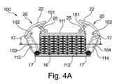
図4Aから図4Bは、エネルギーチェーンの端固定具40においてストレインリリーフとして機能するリードスルー100のさらなる変形を示す。それ自体が公知の構造において、端固定具40は、2つの鏡面対称の端固定板41,42を有し、端固定板41,42は、チェーンリンク(図示せず)にヒンジ接続するように構成される。端固定板41,42は、プラスチックからなり、横接続部品43を介して平行に一緒に保持される。両方の端固定板41,42は、可動または固定の接続領域にボルト固定するための金属のねじブッシュ45が挿入されたフレーム領域を有する。
4A-4B show a further variation of the leadthrough 100 that acts as a strain relief in the
図4Aから図4Bのリードスルー100は、2つの側部113,114の構造および第1のレール111の構造という2つの点で、図1から図2と実質的に異なる。チェーンの長手方向において、または、アセンブリ面に垂直に固定するために、側部113,114は、一体に成形されるクランプジョー103,104を有し、クランプジョー103,104は、端固定板41,42のフレーム領域内に存在する凹部を有する以前から公知の構成に適合させるように形作られる。図4Aから図4Bから明らかなように、クランプジョー103,104は、閉鎖位置(図4B)にあるとき、形状結合固定のために端固定板41,42に係合し、このことにより、保持フレーム15を端固定板41,42に対してクランプする。したがって、側部113,114は、ここでは、鏡面対称である。さらなる違いは、第1のレール111上の設定斜面101および側部113,114上の設定斜面102が協働することにあり、設定斜面101および設定斜面102は、閉鎖位置(図4B)では、トグルレベルクランプ20からの水平方向のクランプ力に加えて、第1のレール111と第2のレール112との間のスペーサ16に追加の垂直方向の接触力も及ぼす。
The
ここでは、着脱容易なクランプ20の構造は、原則、図1から図2の構造に同一である。クランプアーム20および回動ヨーク25はまた、寸法的に安定で、ねじれに耐性のある材料からなり、例えば、金属または強化プラスチックまたはそれらの組み合わせからなる。
Here, the structure of the easily attachable/
本発明による着脱容易な閉鎖は、リードスルーのオプションとしての組み立てをかなり単純化する。しかしながら、提供される解決方法は、特に、エネルギーチェーンのためのストレインリリーフとしてのみ適切というわけではない。 The easy release closure according to the invention considerably simplifies assembly of the leadthrough option. However, the solutions provided are not particularly suitable only as strain relief for energy chains.
図5Aから図5Dは、特に本発明の独立した第2の態様に従うリードスルーまたはエネルギーチェーン(図6A参照)のためのストレインリリーフ200の第3の変形を示す。ストレインリリーフ200は、2つの平行で対向する水平レール211,212および2つの垂直側部213,214の4つの部分の保持フレーム215を有する。多数のブロックタイプのスペーサ16は、保持フレーム215内に保持される。ケーブル、ホース等のような複数のラインは、垂直スペーサ16の各対の間に挿入され、クランプできる。ここで、特許文献7によるハニカム構造を有するスペーサ16を用いることもできる。2つの狭い側で、スペーサ16は突起を有し、突起によって、スペーサ16は、プロファイルのようなレール211,212内の内部長手方向の凹部の張力に対して形状結合方法で保持される。閉鎖位置において、保持フレーム215は、通過するラインのストレインリリーフのために、特に側部によって水平方向にクランプ力をスペーサ上に生成する。
Figures 5A to 5D show a third variant of
使用を単純化するために、2つの側部213,214は、各々、第2のレール212の第1の端領域に回動可能に取り付けられる。他の端領域で、2つの側部213,214は、各々、ボルト235によって第1のレール211と一緒にボルト固定され、このために、例えば適切な雌ねじまたはねじ付きナット(図示せず)のための内部のレセプタクルを有する。
To simplify use, the two
図5Aから図5Dにおいて、各側部213,214は、端に内向きに開放した回動開口218を有し、回動開口218は、着脱可能かつ回動可能に取り付けられた方法で、第2のレール212の長手方向に突出する回動ピン217と協働する。この場合、回動軸は、アセンブリ面または保持フレーム215によって定められる主面に垂直である。このようにして、各側部213,214は、スペーサ16またはラインを解放するための開放位置に回動することができる。図5Aまたは図5Cに示すように、ボルト235のうちのただ1つを取り外した後、第1のレール211は、他の側部213,214と一緒に開閉するように折り曲げることができる。図5Aまたは図5Cに従う開放位置において、スペーサ16は、広げられかつ開放されては示されない。なぜなら、ここではまだ、ラインが挿入されていないからであり、他の側部213はまた、オプションとして外向きに折り曲げられる。閉鎖位置において、レール211,212に平行なクランプ力は、主に側部213,214によってもたらされる。
5A-5D, each
第1のレール211は、各端にフィードスルースリーブ236を有し、フィードスルースリーブ236は、第1のレール211の長手方向延在部に垂直に突出し、ボルト235を整列配置させ、側部213または214のそれぞれにおいて垂直なレセプタクル237内に適合するので、ボルト235によるボルト固定が一緒に進行する前にさえ、図5から図6のレール211は、高速に閉鎖することもできる。
The
図6Aから図6Bによる例では、側部213,214は、オプションとしての保持クリップ230の形状結合の保持のために、外側に中央凹部を有する。保持クリップ230は、フレーム215を保持し、それゆえ、図4に類似の方法で、ストレインリリーフ200を、エネルギーチェーンの端固定具240の端固定板241,242で保持する(図6A)。このために、あらゆる保持クリップ230は、閉鎖位置において、端固定板241,242に形状結合方法で係合する。図6Bは、側部213,214の、かつ、オプションとしてレール211,212の角に配置される4つの垂直に貫通するボルト開口238をさらに示し、ボルトによって上から下部レール212を固定することが可能であり、または、閉鎖した保持フレーム215によってもまた、組み立ておよび分解が可能である。
In the example according to FIGS. 6A to 6B, the
レール211,212は、アルミニウムプロファイルレールという形をとることができ、オプションとして、交換可能な構成要素として実施することができ、オプションとして、回動するように取り付けるための追加パーツを有することができる。側部213,214は、交換可能な構成要素であり、好ましくは、射出成形のプラスチック部品である。それゆえ、保持フレーム215は、対称である、または、横方向に交換可能であり、いずれの側にも等しく十分に開放されて折り曲げることができる(図5A参照)。図1から図4のように、保持フレーム215は、剛性部品211,212;213,214からなり、剛性部品211,212;213,214は、ロバストに実施され、特にねじれに耐性のある断面プロファイルを有する。
The
両方の概念(図1から図4と図5から図6)に従う保持フレーム15,215によって、組み立て(およびメンテナンスのための分解)に関する時間を著しく削減することができる。ハニカム状のスペーサまたはクランプブロック16と組み合わせて、さらに、多種多様なラインを一層に一緒に挿入できる。
A holding
1 (ブロックを保持する)側部
2,5 レール(クランプレールおよびCレール)
3,4 クランプボルト
6 ストレインリリーフブロック
10 ストレインリリーフ
11,12 レール
13,14 側部
15 保持フレーム
16 スペーサ(ストレインリリーフブロック)
17 保持ピン
18 回動開口
19 回動ホルダ
20 トグルレバークランプ
22 クランプアーム
23 保持爪
24 ホルダ
25 ヒンジヨーク
26 回動ピン
28 作動タブ
40 端固定具
41,42 端固定板
43 横接続部品
45 ねじブッシュ
100 ストレインリリーフ
103,104 クランプジョー
111,112 レール
113,114 側部
200 ストレインリリーフ
211,212 レール
213,214 側部
215 フレーム
217 回動ピン
218 回動開口
230 保持クリップ
235 ボルト
236 フィードスルースリーブ
237 レセプタクル
238 ボルト開口
241,242 端固定板
240 端固定具
1 side (holding block) 2, 5 rail (clamp rail and C rail)
3, 4
17 holding
Claims (8)
側部(213,214)によって接続される第1のレール(211)および対向する第2のレール(212)を備え、
前記第1のレール(211)及び前記第2のレール(212)と前記側部(213,214)とが、閉鎖位置で、アセンブリ面において保持フレーム(215)を形成して、
該保持フレーム(215)内に保持されるとともに、ケーブル、ホース等のような複数のラインがその間をフィードスルー方向に通過可能な少なくとも2つのブロックタイプのスペーサ(16)を備え、
前記フィードスルー方向と前記アセンブリ面とは、互いに実質的に垂直であり、
通過するラインのストレインリリーフのために、前記保持フレーム(215)は、前記閉鎖位置において、前記側部(213,214)を介してクランプ力を前記スペーサ(16)に及ぼし、
前記2つの側部(213,214)の各々の第1の端領域は、前記第2のレール(212)に回動可能に取り付けられ、
2つの前記側部(213,214)の他の端領域は、いずれの場合においても、各側部(213,214)が前記閉鎖位置から、前記スペーサ(16)がラインの挿入または除去のために解放される開放位置に回動可能となるように、取り外し可能な固定のために前記第1のレール(211)と協働し、
前記スペーサ(16)は、弾性変形可能であり、前記閉鎖位置では前記ラインをフォースロッキング方法で前記アセンブリ面に固定し、対向するクランプ面を有する細長いクランプ部品とされ、前記クランプ面が前記レール(211,212)に対して横断するように前記保持フレーム(215)に配置され、
前記閉鎖位置では、前記側部(213,214)は、前記フィードスルー方向に実質的に垂直かつ前記レール(211,212)に平行な前記クランプ力をもたらすストレインリリーフ(200)。 A strain relief (200) for a plurality of lines, comprising:
comprising a first rail (211) and an opposing second rail (212) connected by sides (213, 214);
said first rail (211) and said second rail (212) and said sides (213, 214) in the closed position form a holding frame (215) in the assembly plane,
comprising at least two block-type spacers (16) held in said holding frame (215) and between which a plurality of lines such as cables, hoses, etc. can pass in feedthrough direction;
the feedthrough direction and the assembly plane are substantially perpendicular to each other;
said retaining frame (215) exerts a clamping force on said spacer (16) via said sides (213, 214 ) in said closed position for strain relief of the passing line;
a first end region of each of said two sides (213, 214) is pivotally attached to said second rail (212);
The other end regions of the two sides (213, 214) are, in any case, each side (213, 214) from the closed position and the spacer (16) for insertion or removal of a line. cooperating with said first rail (211) for releasable fixation so that it can be pivoted to an open position in which it is released to
Said spacer (16) is elastically deformable and, in said closed position, fixes said line to said assembly surface in a force-locking manner and is an elongated clamping part with opposing clamping surfaces, said clamping surfaces being in contact with said rail ( 211, 212) on the holding frame (215),
In the closed position, the sides (213, 214) are strain reliefs (200) that provide the clamping force substantially perpendicular to the feedthrough direction and parallel to the rails (211, 212).
該回動開口(218)によって、各側部(213、214)は、前記第2のレール(212)の端で回動ピン(217)に取り外し可能に保持され前記第2のレール(212)に回動可能に取り付けられ、
前記回動開口(218)および前記回動ピン(217)は、前記フィードスルー方向に平行な回動軸を定める請求項1または2に記載のストレインリリーフ。 each side (213, 214) has a pivot opening (218) in said first end region;
The pivot opening (218) allows each side (213, 214) to be removably retained on a pivot pin (217) at the end of said second rail (212) and attached to said second rail (212). is rotatably mounted on the
3. The strain relief of claim 1 or 2, wherein said pivot aperture (218) and said pivot pin (217) define a pivot axis parallel to said feedthrough direction.
該スリーブ(236)は、各側部(213,214)のレセプタクル(237)内に挿入可能で、前記レセプタクル(237)は、前記垂直スリーブ(236)に適合する請求項1または2に記載のストレインリリーフ。 at least said first rail (211) has at its end a vertical sleeve (236) for at least one bolt projecting perpendicular to its longitudinal extension,
3. A sleeve (236) according to claim 1 or 2, wherein said sleeve (236) is insertable into a receptacle (237) on each side (213, 214), said receptacle (237) fitting into said vertical sleeve (236). strain relief.
請求項1または2に記載のストレインリリーフ(10;100;200)によって特徴付けられ、リードスルー(10;100;200)は、好ましくは、前記側部(13,14)において前記アセンブリ面に垂直な方向にホールを固定することによって、前記端固定板(41,42)に一緒にボルト固定され、および/または、前記リードスルー(10;100;200)は、前記閉鎖位置において、形状結合で前記端固定板に係合するために、クランプジョー(103,104)または保持クリップ(230)を各側部(113,114;213,214)に有する端固定具(40)。 An end fixture (40) for an energy chain, comprising two end fixing plates (41; 42), comprising:
Characterized by the strain relief (10; 100; 200) according to claim 1 or 2 , the lead-through (10; 100; 200) is preferably The end fixing plates (41, 42) are bolted together by fixing holes in the vertical direction and/or the leadthroughs (10; 100; 200) are form-locked in the closed position. an end fixture (40) having clamping jaws (103, 104) or retaining clips (230) on each side (113, 114; 213, 214) for engaging said end fixture plates at .
Applications Claiming Priority (3)
| Application Number | Priority Date | Filing Date | Title |
|---|---|---|---|
| DE202017102147.5 | 2017-04-10 | ||
| DE202017102147.5U DE202017102147U1 (en) | 2017-04-10 | 2017-04-10 | Cable bushing, in particular strain relief for an energy chain |
| PCT/EP2018/059164 WO2018189182A1 (en) | 2017-04-10 | 2018-04-10 | Strain relief for quick assembly for a cable carrier |
Publications (3)
| Publication Number | Publication Date |
|---|---|
| JP2020516823A JP2020516823A (en) | 2020-06-11 |
| JP2020516823A5 JP2020516823A5 (en) | 2021-05-20 |
| JP7264825B2 true JP7264825B2 (en) | 2023-04-25 |
Family
ID=58773756
Family Applications (1)
| Application Number | Title | Priority Date | Filing Date |
|---|---|---|---|
| JP2019555149A Active JP7264825B2 (en) | 2017-04-10 | 2018-04-10 | Strain relief for fast assembly for cable carriers |
Country Status (7)
| Country | Link |
|---|---|
| US (1) | US11600981B2 (en) |
| EP (1) | EP3610541A1 (en) |
| JP (1) | JP7264825B2 (en) |
| KR (1) | KR102569726B1 (en) |
| CN (1) | CN110800179B (en) |
| DE (1) | DE202017102147U1 (en) |
| WO (1) | WO2018189182A1 (en) |
Families Citing this family (9)
| Publication number | Priority date | Publication date | Assignee | Title |
|---|---|---|---|---|
| DE202017101483U1 (en) | 2017-03-14 | 2017-03-31 | Igus Gmbh | Strain relief and end fastening part with strain relief |
| DE202018102217U1 (en) * | 2018-04-20 | 2019-07-23 | Igus Gmbh | Monitoring system for the operation of an energy supply chain |
| DE102018218426A1 (en) | 2018-10-29 | 2020-04-30 | Icotek Project Gmbh & Co. Kg | Cable entry |
| CA3122484A1 (en) * | 2018-12-18 | 2020-06-25 | Saint-Augustin Canada Electric Inc. | Clamping devices |
| DE102020105273A1 (en) | 2020-02-28 | 2021-09-02 | Audi Aktiengesellschaft | Line fixing system and method for fixing at least one line |
| DE202020102173U1 (en) | 2020-04-20 | 2021-07-21 | Igus Gmbh | Strain relief |
| CN112260174A (en) * | 2020-10-31 | 2021-01-22 | 江苏科瑞斯机件有限公司 | Quick assembly disassembly threading guide chain |
| EP4057459A1 (en) * | 2021-03-12 | 2022-09-14 | Nexans | Diameter adaptive (thread and toolless) sealing |
| EP4286908A1 (en) * | 2022-06-01 | 2023-12-06 | Kaiser GmbH & Co. KG | Holding device for holding glass fibre cables |
Citations (3)
| Publication number | Priority date | Publication date | Assignee | Title |
|---|---|---|---|---|
| JP2004156673A (en) | 2002-11-05 | 2004-06-03 | Tsubakimoto Chain Co | Cable supporting and guiding device |
| JP2012115098A (en) | 2010-11-26 | 2012-06-14 | Tsubakimoto Chain Co | Cable clamp unit |
| JP2013542587A (en) | 2010-09-10 | 2013-11-21 | フェニックス コンタクト ゲゼルシャフト ミット ベシュレンクテル ハフツング ウント コンパニー コマンディートゲゼルシャフト | Frame and frame member for cable penetration system |
Family Cites Families (139)
| Publication number | Priority date | Publication date | Assignee | Title |
|---|---|---|---|---|
| US2348096A (en) * | 1943-02-02 | 1944-05-02 | Schack William | Means and method for clamping runs of cables and the like |
| FR79737E (en) | 1961-05-05 | 1963-01-11 | Conductor clamp with removable and adjustable individual elements | |
| US3175262A (en) * | 1962-04-02 | 1965-03-30 | Harold K Wilson | Clamp |
| US3716986A (en) * | 1970-10-21 | 1973-02-20 | Gemco Electric Co | Rolling conductor support |
| US3742119A (en) * | 1971-11-11 | 1973-06-26 | Empire Prod Inc | Terminal housing |
| DE2417353C3 (en) | 1974-04-09 | 1979-11-29 | Ernst 4000 Duesseldorf Klein | Link chain |
| US3989210A (en) * | 1974-08-05 | 1976-11-02 | International Business Machines Corporation | Cable clamp and strain relief device |
| US4108527A (en) * | 1977-06-23 | 1978-08-22 | Amp Incorporated | Strain relief assembly |
| US4202457A (en) * | 1978-08-25 | 1980-05-13 | Eagle Electric Mgf. Co., Inc. | Foldable electrical outlet box |
| US4249353A (en) * | 1979-02-27 | 1981-02-10 | Crouse-Hinds Company | Fire barrier assembly for electrical cable |
| DE8018534U1 (en) * | 1980-07-10 | 1981-01-15 | Licentia Patent-Verwaltungs-Gmbh, 6000 Frankfurt | Cable entry |
| DE3318365A1 (en) * | 1983-05-20 | 1984-11-22 | Kabelschlepp Gmbh, 5900 Siegen | POWER SUPPLY CHAIN |
| DE3414412C1 (en) * | 1984-04-17 | 1987-11-12 | Kabelschlepp Gmbh, 5900 Siegen | Energy supply chain |
| DE3531066A1 (en) * | 1985-08-30 | 1987-03-12 | Igus Gmbh | ENERGY FEED CHAIN |
| DE8528258U1 (en) * | 1985-10-04 | 1985-11-14 | Kabelschlepp Gmbh, 5900 Siegen | Energy chain |
| GB2186440B (en) * | 1986-02-11 | 1990-03-14 | Hawke Cable Glands Ltd | Improved transit for cables and pipes |
| DE3617447C1 (en) * | 1986-05-23 | 1987-10-22 | Kabelschlepp Gmbh | Energy supply chain |
| DE3816870C2 (en) * | 1987-06-30 | 1993-09-30 | Heidelberger Druckmasch Ag | Device for the passage of cables |
| GB2208129B (en) * | 1987-07-01 | 1991-08-21 | Mansign Eng | Cable handling chain |
| US4902855A (en) * | 1988-10-25 | 1990-02-20 | Minnesota Mining And Manufacturing Company | End seal for splice closure |
| DE3928238C1 (en) * | 1989-08-26 | 1990-10-25 | Kabelschlepp Gmbh, 5900 Siegen, De | |
| DE3928320A1 (en) * | 1989-08-26 | 1991-03-14 | Drilltec Patents & Tech | DEVICE FOR STORING AND TRANSPORTING TUBES |
| DE8914665U1 (en) * | 1989-09-30 | 1990-02-15 | Stewing Kunststoffbetrieb Gmbh, 4270 Dorsten, De | |
| EP0440903A1 (en) * | 1990-02-09 | 1991-08-14 | RXS Schrumpftechnik-Garnituren GmbH | Adaptable sealing element for closure of an entrance opening in cable fittings, conduits or the like |
| DE4040379A1 (en) * | 1990-12-17 | 1992-07-02 | Heidelberger Druckmasch Ag | DEVICE FOR THROUGH CABLES |
| DE4105652A1 (en) * | 1991-02-22 | 1992-09-03 | Kabelschlepp Gmbh | POWER SUPPLY CHAIN |
| US5783776A (en) * | 1991-10-29 | 1998-07-21 | O-Z Gedney Company Llc | Electrical cable penetration seal with compliant module |
| DE4206682C2 (en) * | 1992-02-29 | 1994-10-27 | Krone Ag | Housing, in particular cable junction boxes |
| US5335349A (en) * | 1992-12-14 | 1994-08-02 | Telect, Inc. | Telecommunication overhead cable distribution assembly |
| BR9508857A (en) * | 1994-09-21 | 1997-10-21 | Raychem Sa Nv | Cable joint closure |
| US5535298A (en) * | 1995-01-30 | 1996-07-09 | The Whitaker Corporation | Pedestal for fiber optic cable |
| US5568584A (en) * | 1995-03-20 | 1996-10-22 | Psi Telecommunications, Inc. | Fiber optic closure with cable adapter spool |
| US5825961A (en) * | 1995-03-20 | 1998-10-20 | Psi Telecommunications, Inc. | Fiber optic closure with cable adapter spool |
| US5509099A (en) * | 1995-04-26 | 1996-04-16 | Antec Corp. | Optical fiber closure with sealed cable entry ports |
| US5724803A (en) * | 1995-05-04 | 1998-03-10 | Hubbell Incorporated | Power supply chain with roller bar carrier |
| US5613029A (en) * | 1995-05-10 | 1997-03-18 | Lucent Technologies Inc. | Fiber optic splice tray hinge adapter |
| MY125832A (en) * | 1995-11-06 | 2006-08-30 | Japan Recom Ltd | Closure for cable connection |
| US5642612A (en) * | 1995-12-19 | 1997-07-01 | Hughes; Ceiriog | Replaceable tip cable handler |
| ATE201266T1 (en) * | 1996-03-20 | 2001-06-15 | Rxs Ges Fuer Vermoegensverwalt | CABLE SLEEVE |
| DE29607172U1 (en) | 1996-04-22 | 1996-06-13 | Igus Gmbh | Strain relief |
| US6039081A (en) * | 1997-02-12 | 2000-03-21 | Pmi Industries, Inc. | Articulated bend limiter |
| DE29703721U1 (en) | 1997-03-01 | 1997-04-24 | Rose Warenhandels Gmbh | Tool for producing a branch or division of parallel cables or the like. |
| DE19710489A1 (en) * | 1997-03-13 | 1998-09-24 | Kabelschlepp Gmbh | Foldable protective element for cables |
| US6002088A (en) * | 1997-07-16 | 1999-12-14 | Murplastik System-Technik Gmbh | Cable or line guiding device |
| JP3692725B2 (en) * | 1997-09-09 | 2005-09-07 | 松下電器産業株式会社 | Cable Bear |
| US5990420A (en) * | 1997-12-12 | 1999-11-23 | Ncr Corporation | Cable securing system |
| PT1056963E (en) * | 1998-02-20 | 2003-11-28 | Igus Gmbh | ENERGY CONDUCT BELT |
| DE29907444U1 (en) | 1999-04-19 | 1999-07-29 | Igus Gmbh | Clamp |
| AUPQ350399A0 (en) * | 1999-10-18 | 1999-11-11 | Senior Thermal Engineering Australia Pty Limited | Chain for carrying hose or cable |
| DE19959185A1 (en) * | 1999-12-08 | 2001-06-28 | Bethke Kunststofftechnik Gmbh | Cable entry |
| DE10004679C2 (en) * | 2000-02-03 | 2002-10-31 | Ekd Gelenkrohr Gmbh | Device for strain relief of dynamically stressed cables that are routed in an energy chain |
| US6539161B2 (en) * | 2001-03-16 | 2003-03-25 | Adc Telecommunications, Inc. | Cable routing clip |
| KR100407547B1 (en) * | 2001-06-02 | 2003-12-06 | 대원전기 주식회사 | Electric wire removing roller for LP insulator and power distribution method of construction |
| JP3669694B2 (en) * | 2002-03-22 | 2005-07-13 | 株式会社椿本チエイン | Cable drag chain |
| JP3722477B2 (en) * | 2002-04-02 | 2005-11-30 | 株式会社椿本チエイン | Cable protection guide |
| SE524043C2 (en) * | 2002-06-05 | 2004-06-22 | Roxtec Int Ab | The compression unit |
| JP3806370B2 (en) * | 2002-06-07 | 2006-08-09 | 有限会社浜インターナショナル | Cable protection guide chain |
| GB2402195A (en) * | 2003-05-30 | 2004-12-01 | Mansign Mining Equipment Ltd | Chain link for a haulage chain for hauling cables and hoses, eg in a mine |
| US7038137B2 (en) * | 2003-06-18 | 2006-05-02 | Preformed Line Products Company | Fiber closure system |
| GB0314688D0 (en) * | 2003-06-24 | 2003-07-30 | Tyco Electronics Raychem Nv | Cable splice closure |
| WO2006031826A2 (en) * | 2004-09-14 | 2006-03-23 | The Siemon Company | Stackable rack cable manager |
| JP4197174B2 (en) * | 2004-10-05 | 2008-12-17 | 株式会社椿本チエイン | Cable protection guide device |
| DE102005037561B4 (en) * | 2004-10-13 | 2018-01-11 | Icotek Project Gmbh & Co. Kg | Power supply chain |
| JP2006275155A (en) * | 2005-03-29 | 2006-10-12 | Tsubakimoto Chain Co | Cable protective guide device |
| JP4104607B2 (en) * | 2005-03-30 | 2008-06-18 | 株式会社椿本チエイン | Cable clamp member of cable protection guide device |
| JP4104613B2 (en) * | 2005-04-22 | 2008-06-18 | 株式会社椿本チエイン | Cable clamp member of cable protection guide device |
| US8051614B1 (en) * | 2005-06-21 | 2011-11-08 | Sprint Communications Company L.P. | Intumescent structure for ducting carrying communications cabling |
| JP4476204B2 (en) * | 2005-09-29 | 2010-06-09 | 株式会社椿本チエイン | Cable protection guide device |
| DE102005056214B3 (en) * | 2005-11-25 | 2007-06-21 | Rittal Gmbh & Co. Kg | Device for guiding cables or lines |
| JP4137117B2 (en) * | 2005-12-27 | 2008-08-20 | 株式会社椿本チエイン | Cable protection guide device |
| DE102006020754A1 (en) | 2006-05-03 | 2007-11-08 | Auto Kabel Managementgesellschaft Mbh | Quick release for battery terminals |
| DE202006007155U1 (en) | 2006-05-04 | 2006-07-06 | Deckel Maho Pfronten Gmbh | Cable holder for power transmission chains has clamping element comprising soft elastic deformable material, and several separating joins formed in clamping element which divide support holes for cables |
| DE102006027258B8 (en) * | 2006-06-09 | 2009-04-23 | Flexatec Gmbh | Side tab for chain links of an energy chain |
| JP4913870B2 (en) * | 2006-07-20 | 2012-04-11 | エムセーテー・ブラットベルク・アーベー | Pressurized sealing means for cable transit |
| US7384297B2 (en) * | 2006-11-07 | 2008-06-10 | King Jr Lloyd Herbert | Wire connector |
| DE202007005566U1 (en) * | 2007-04-16 | 2007-08-02 | Igus Gmbh | Transversal bridge for joining two lateral parts of components of cable guiding unit, comprises movable joined locking and control element |
| DE202007006667U1 (en) * | 2007-05-07 | 2007-07-19 | Murrplastik Systemtechnik Gmbh | Power supply chain |
| SE531217C2 (en) * | 2007-05-29 | 2009-01-20 | Roxtec Ab | Cable entry |
| JP5197626B2 (en) * | 2007-12-10 | 2013-05-15 | 株式会社島精機製作所 | Cable drag chain |
| DE102008012460C5 (en) * | 2008-03-04 | 2013-04-25 | Berthold Sichert Gmbh | Base plate or cable distribution cabinet with a base plate and mounting method |
| ES2359861T3 (en) * | 2008-06-06 | 2011-05-27 | HAUFF-TECHNIK GMBH & CO. KG | BOQUILLA PASACONDUCTOS LAYERS WITH SEQUENCE. |
| DE202009005737U1 (en) * | 2009-04-17 | 2010-01-07 | Igus Gmbh | Crosspiece for a link in a cable routing device |
| DE202009005650U1 (en) * | 2009-04-17 | 2009-07-02 | Igus Gmbh | Power supply chain |
| JP4722207B2 (en) * | 2009-08-06 | 2011-07-13 | 株式会社椿本チエイン | Cable protection guide device |
| DE102009060988B3 (en) * | 2009-11-12 | 2011-05-19 | Icotek Project Gmbh & Co. Kg | Cable supporting unit |
| DE102010003282B4 (en) * | 2010-03-25 | 2015-08-20 | Trumpf Werkzeugmaschinen Gmbh + Co. Kg | Cable guide device, in particular energy chain |
| US8783629B2 (en) * | 2010-07-29 | 2014-07-22 | Hydac Accessories Gmbh | Attachment system for lines, in particular for cables for wind turbines |
| DE102010037463A1 (en) * | 2010-09-10 | 2012-03-15 | Phoenix Contact Gmbh & Co. Kg | Frame of a cable entry system and cable grommet for this |
| GB2483894A (en) * | 2010-09-23 | 2012-03-28 | Polypipe Civils Ltd | A cable security device for use in a catchpit |
| WO2012074685A2 (en) * | 2010-11-29 | 2012-06-07 | 3M Innovative Properties Company | Strain relief device |
| DE102011011868A1 (en) * | 2011-02-21 | 2012-08-23 | Icotek Project Gmbh & Co. Kg | Holder for power transmission cable, has strain relief unit comprising two mounting units that are provided for mounting cable that is clamped by screwing unit |
| EP2684088B1 (en) * | 2011-03-07 | 2018-01-03 | CommScope Technologies LLC | Fiber optic splice enclosures having interchangeable endplate assemblies and methods including the same |
| EA201391388A1 (en) * | 2011-03-25 | 2014-01-30 | КОБРЕКО АйПи ПТИ ЛИМИТЕД | IMPROVED LINK FOR LINEAR CABLE CHAIN |
| DE202011004785U1 (en) * | 2011-04-01 | 2011-07-07 | igus GmbH, 51147 | Energy guiding chain with deformable joint elements |
| DE202011004762U1 (en) * | 2011-04-04 | 2011-09-07 | Igus Gmbh | Power supply chain |
| ITTO20110502A1 (en) * | 2011-06-08 | 2012-12-09 | Soilmec Spa | SUPPORT AND GUIDE DEVICE FOR POWER LINES FOR DISCAVOUS DEVICES. |
| TW201306409A (en) * | 2011-07-28 | 2013-02-01 | yu-dong Hu | Waterproof electric case |
| JP5541746B2 (en) * | 2012-02-21 | 2014-07-09 | 株式会社椿本チエイン | Cable protection guide device |
| DE202012003908U1 (en) * | 2012-04-19 | 2012-05-15 | Igus Gmbh | Energy guiding chain with rollers |
| CA2876961A1 (en) * | 2012-07-02 | 2014-01-09 | Tyco Electronics Raychem Bvba | Cable sealing unit with multiple sealing modules |
| US9833858B2 (en) * | 2012-09-07 | 2017-12-05 | Illinois Tool Works Inc. | System and method for welding system cable management |
| US8739507B2 (en) * | 2012-09-21 | 2014-06-03 | Ceiriog Hughes | Interlocking cable track system |
| DE102012019490A1 (en) * | 2012-10-04 | 2014-04-10 | Hydac Accessories Gmbh | System for guiding and securing the position of strand elements |
| CA2800467C (en) * | 2012-12-21 | 2019-02-26 | Cox Metalworks Inc. | Apparatus for supporting cables |
| ES2871406T3 (en) | 2012-12-21 | 2021-10-28 | Icotek Project Gmbh & Co Kg | Cable carrier with a U-shaped frame and several cable glands for the passage of cables |
| US9478964B2 (en) * | 2013-01-14 | 2016-10-25 | Dematic Corp. | Multiple cable strain relief |
| CA2901148A1 (en) * | 2013-02-19 | 2014-08-28 | Tyco Electronics Raychem Bvba | Re-enterable enclosure and configuration for mounting |
| DE202013101462U1 (en) * | 2013-04-05 | 2013-04-19 | Igus Gmbh | Power supply chain |
| DE202013101457U1 (en) * | 2013-04-05 | 2013-04-19 | Igus Gmbh | Power supply chain |
| US9837759B2 (en) * | 2013-06-25 | 2017-12-05 | GE Lighting Solutions, LLC | Wirestrain relief to use on a light emitting diode linear module |
| WO2015003989A1 (en) * | 2013-07-12 | 2015-01-15 | Tyco Electronics Raychem Bvba | Clamping and attachment device for cable element |
| CN203352072U (en) | 2013-07-29 | 2013-12-18 | 成都亨通光通信有限公司 | Positioning and clamping tool for cable terminal stripping |
| US9012791B2 (en) * | 2013-08-23 | 2015-04-21 | Bridgeport Fittings, Inc. | Split, non-metallic electrical insulating bushing |
| DE102014102790A1 (en) * | 2014-03-03 | 2015-09-03 | Murrelektronik Gmbh | Frame for cable glands, fasteners and cable entry system |
| DE202014101274U1 (en) * | 2014-03-20 | 2014-03-31 | Igus Gmbh | Power supply chain |
| WO2015167904A1 (en) * | 2014-05-01 | 2015-11-05 | Tyco Electronics Corporation | Strain relief clamp |
| DE202014104075U1 (en) * | 2014-09-01 | 2014-09-09 | Igus Gmbh | Cable guide |
| JP6505999B2 (en) * | 2014-09-05 | 2019-04-24 | ファナック株式会社 | Filament fixing device for fixing a filament through an elastic body |
| US10471284B2 (en) * | 2014-10-14 | 2019-11-12 | Rakman International Pty Ltd | Fire and smoke containment services transit unit and an associated method |
| US10711924B2 (en) * | 2014-10-14 | 2020-07-14 | Rakman International Pty Ltd | Fire and smoke containment services transit unit and an associated method |
| US9570895B2 (en) * | 2014-11-21 | 2017-02-14 | Hon Hai Precision Industry Co., Ltd. | Cable drag chain and cable drag chain assembly |
| SE538884C2 (en) * | 2015-05-04 | 2017-01-24 | Roxtec Ab | Compression wedge for a lead-through system |
| US20150247591A1 (en) * | 2015-05-14 | 2015-09-03 | Caterpillar Inc. | System for retaining mulitple hoses |
| US10230230B2 (en) * | 2015-09-14 | 2019-03-12 | CommScope Connectivity Belgium BVBA | Sealing block arrangements for enclosures |
| SE539322C2 (en) * | 2015-11-18 | 2017-07-04 | Roxtec Ab | Transition and module |
| CN205248755U (en) * | 2015-11-20 | 2016-05-18 | 国网吉林省电力有限公司经济技术研究院 | Self -adaptation cable mount |
| CA3012224C (en) * | 2016-02-04 | 2022-12-06 | Dynatect Manufacturing, Inc. | Hybrid cable carrier chain |
| US10006566B2 (en) * | 2016-02-29 | 2018-06-26 | Ford Global Technologies, Llc | Air tight sealing support clip for attaching fluid-carrying tube to substrate |
| US10143868B2 (en) * | 2016-06-08 | 2018-12-04 | Specified Technologies Inc. | Cable firestopping apparatus |
| DE202016103494U1 (en) * | 2016-06-30 | 2017-07-06 | Conta-Clip Verbindungstechnik Gmbh | Cable wall bushing and kit |
| DE202017100200U1 (en) * | 2017-01-16 | 2017-01-25 | Igus Gmbh | Divider for energy supply chains |
| DE202017101483U1 (en) | 2017-03-14 | 2017-03-31 | Igus Gmbh | Strain relief and end fastening part with strain relief |
| DE102017212009A1 (en) * | 2017-07-13 | 2019-03-07 | Icotek Project Gmbh & Co. Kg | strain relief |
| CA3079058A1 (en) * | 2017-10-17 | 2019-04-25 | Framatome | A cable lead-through assembly, an electrical assembly, an electrical cabinet and associated method |
| DE102018101790A1 (en) * | 2018-01-26 | 2019-08-01 | Harting Electric Gmbh & Co. Kg | sealing insert |
| US11349254B2 (en) * | 2018-03-06 | 2022-05-31 | Textron Innovations Inc. | Hinged strain relief backshells, cable assemblies and methods for strain relief |
| DE102018218426A1 (en) * | 2018-10-29 | 2020-04-30 | Icotek Project Gmbh & Co. Kg | Cable entry |
| DE202020102090U1 (en) * | 2020-04-15 | 2021-05-25 | Igus Gmbh | Cable routing device and modular end fixings with flexible casing for clean room applications |
| DE102020204526A1 (en) * | 2020-04-08 | 2021-10-14 | Icotek Project Gmbh & Co. Kg | Device for the implementation and strain relief of strands |
-
2017
- 2017-04-10 DE DE202017102147.5U patent/DE202017102147U1/en active Active
-
2018
- 2018-04-10 CN CN201880031000.4A patent/CN110800179B/en active Active
- 2018-04-10 WO PCT/EP2018/059164 patent/WO2018189182A1/en unknown
- 2018-04-10 JP JP2019555149A patent/JP7264825B2/en active Active
- 2018-04-10 EP EP18717336.4A patent/EP3610541A1/en active Pending
- 2018-04-10 KR KR1020197033093A patent/KR102569726B1/en active IP Right Grant
- 2018-04-10 US US16/604,255 patent/US11600981B2/en active Active
Patent Citations (3)
| Publication number | Priority date | Publication date | Assignee | Title |
|---|---|---|---|---|
| JP2004156673A (en) | 2002-11-05 | 2004-06-03 | Tsubakimoto Chain Co | Cable supporting and guiding device |
| JP2013542587A (en) | 2010-09-10 | 2013-11-21 | フェニックス コンタクト ゲゼルシャフト ミット ベシュレンクテル ハフツング ウント コンパニー コマンディートゲゼルシャフト | Frame and frame member for cable penetration system |
| JP2012115098A (en) | 2010-11-26 | 2012-06-14 | Tsubakimoto Chain Co | Cable clamp unit |
Also Published As
| Publication number | Publication date |
|---|---|
| KR102569726B1 (en) | 2023-08-23 |
| JP2020516823A (en) | 2020-06-11 |
| DE202017102147U1 (en) | 2017-05-05 |
| US11600981B2 (en) | 2023-03-07 |
| KR20190131590A (en) | 2019-11-26 |
| CN110800179B (en) | 2022-04-05 |
| EP3610541A1 (en) | 2020-02-19 |
| CN110800179A (en) | 2020-02-14 |
| US20200161847A1 (en) | 2020-05-21 |
| WO2018189182A1 (en) | 2018-10-18 |
Similar Documents
| Publication | Publication Date | Title |
|---|---|---|
| JP7264825B2 (en) | Strain relief for fast assembly for cable carriers | |
| AU2012299719B2 (en) | Pressing device | |
| CA2645415C (en) | Fast beam clamp | |
| US4570437A (en) | Energy conductor chain | |
| EP1659297B1 (en) | Fastening device for fixing diverse elements to a support | |
| CA2630958C (en) | Adjustable roller frame | |
| JP2020516823A5 (en) | ||
| CN110364903B (en) | Plate structure type pliers swing jaw and crimping pliers with pliers swing jaw | |
| US3884100A (en) | Pipe tongs | |
| TR201807730T4 (en) | Tie bar tensioning system. | |
| US20220170530A1 (en) | Multi-part chain link of an energy chain, and transverse connecting piece and side plate therefor | |
| JP2020153218A (en) | Adapter for quick change system and quick change system provided with the adapter | |
| US20190249801A1 (en) | Power tool cable mount | |
| GB2137684A (en) | Pivot jaw clamp | |
| US20060191169A1 (en) | Arrangement for fixing an add-on piece e.g. an excavator shovel, to a boom of a shovel or a vehicle in a replaceable manner | |
| FI105662B (en) | Gripping tool for straightening a car body | |
| FI122919B (en) | Mounting device for attaching accessories | |
| CA1055364A (en) | Cable installing and adjusting method | |
| US20230174318A1 (en) | Releasable attachment of scraper modules | |
| DE19725065A1 (en) | Connection for attachment to support for office desk or shelf | |
| KR20120002032U (en) | A clamping assembly for tools | |
| IT201800007201A1 (en) | SUPPORT FOR CONNECTING A REAR VIEW MIRROR TO A CORRESPONDING VEHICLE | |
| FR2796215A1 (en) | Consolidating strap system for grouped electric cables, has strap passed round cables secured at both ends by interlocking plates and bolted together to tighten the strap |
Legal Events
| Date | Code | Title | Description |
|---|---|---|---|
| A521 | Request for written amendment filed |
Free format text: JAPANESE INTERMEDIATE CODE: A523 Effective date: 20210408 |
|
| A621 | Written request for application examination |
Free format text: JAPANESE INTERMEDIATE CODE: A621 Effective date: 20210408 |
|
| A977 | Report on retrieval |
Free format text: JAPANESE INTERMEDIATE CODE: A971007 Effective date: 20220408 |
|
| A131 | Notification of reasons for refusal |
Free format text: JAPANESE INTERMEDIATE CODE: A131 Effective date: 20220419 |
|
| A521 | Request for written amendment filed |
Free format text: JAPANESE INTERMEDIATE CODE: A523 Effective date: 20220708 |
|
| A131 | Notification of reasons for refusal |
Free format text: JAPANESE INTERMEDIATE CODE: A131 Effective date: 20221025 |
|
| A521 | Request for written amendment filed |
Free format text: JAPANESE INTERMEDIATE CODE: A523 Effective date: 20230113 |
|
| TRDD | Decision of grant or rejection written | ||
| A01 | Written decision to grant a patent or to grant a registration (utility model) |
Free format text: JAPANESE INTERMEDIATE CODE: A01 Effective date: 20230404 |
|
| A61 | First payment of annual fees (during grant procedure) |
Free format text: JAPANESE INTERMEDIATE CODE: A61 Effective date: 20230413 |
|
| R150 | Certificate of patent or registration of utility model |
Ref document number: 7264825 Country of ref document: JP Free format text: JAPANESE INTERMEDIATE CODE: R150 |