JP7253120B2 - Tank cooler - Google Patents
Tank cooler Download PDFInfo
- Publication number
- JP7253120B2 JP7253120B2 JP2022556428A JP2022556428A JP7253120B2 JP 7253120 B2 JP7253120 B2 JP 7253120B2 JP 2022556428 A JP2022556428 A JP 2022556428A JP 2022556428 A JP2022556428 A JP 2022556428A JP 7253120 B2 JP7253120 B2 JP 7253120B2
- Authority
- JP
- Japan
- Prior art keywords
- tank
- cooling
- receiving
- cooling liquid
- contact
- Prior art date
- Legal status (The legal status is an assumption and is not a legal conclusion. Google has not performed a legal analysis and makes no representation as to the accuracy of the status listed.)
- Active
Links
- 238000001816 cooling Methods 0.000 claims description 72
- 239000000110 cooling liquid Substances 0.000 claims description 56
- 239000002826 coolant Substances 0.000 claims description 37
- 229920003002 synthetic resin Polymers 0.000 claims description 6
- 239000000057 synthetic resin Substances 0.000 claims description 6
- 229920001169 thermoplastic Polymers 0.000 claims description 5
- 239000004416 thermosoftening plastic Substances 0.000 claims description 5
- 239000002828 fuel tank Substances 0.000 description 62
- 238000004519 manufacturing process Methods 0.000 description 4
- 238000000071 blow moulding Methods 0.000 description 3
- 230000001105 regulatory effect Effects 0.000 description 3
- 229910000831 Steel Inorganic materials 0.000 description 2
- 230000003028 elevating effect Effects 0.000 description 2
- 239000000463 material Substances 0.000 description 2
- 238000000034 method Methods 0.000 description 2
- 239000010959 steel Substances 0.000 description 2
- 230000008602 contraction Effects 0.000 description 1
- 230000007423 decrease Effects 0.000 description 1
- 238000007599 discharging Methods 0.000 description 1
- 230000000694 effects Effects 0.000 description 1
- 239000012530 fluid Substances 0.000 description 1
- 239000000446 fuel Substances 0.000 description 1
- 239000007788 liquid Substances 0.000 description 1
- 238000000465 moulding Methods 0.000 description 1
- 230000002093 peripheral effect Effects 0.000 description 1
- 229920005989 resin Polymers 0.000 description 1
- 239000011347 resin Substances 0.000 description 1
- 238000000926 separation method Methods 0.000 description 1
- 239000007921 spray Substances 0.000 description 1
- XLYOFNOQVPJJNP-UHFFFAOYSA-N water Substances O XLYOFNOQVPJJNP-UHFFFAOYSA-N 0.000 description 1
Images


Classifications
-
- F—MECHANICAL ENGINEERING; LIGHTING; HEATING; WEAPONS; BLASTING
- F25—REFRIGERATION OR COOLING; COMBINED HEATING AND REFRIGERATION SYSTEMS; HEAT PUMP SYSTEMS; MANUFACTURE OR STORAGE OF ICE; LIQUEFACTION SOLIDIFICATION OF GASES
- F25D—REFRIGERATORS; COLD ROOMS; ICE-BOXES; COOLING OR FREEZING APPARATUS NOT OTHERWISE PROVIDED FOR
- F25D17/00—Arrangements for circulating cooling fluids; Arrangements for circulating gas, e.g. air, within refrigerated spaces
- F25D17/02—Arrangements for circulating cooling fluids; Arrangements for circulating gas, e.g. air, within refrigerated spaces for circulating liquids, e.g. brine
-
- B—PERFORMING OPERATIONS; TRANSPORTING
- B29—WORKING OF PLASTICS; WORKING OF SUBSTANCES IN A PLASTIC STATE IN GENERAL
- B29C—SHAPING OR JOINING OF PLASTICS; SHAPING OF MATERIAL IN A PLASTIC STATE, NOT OTHERWISE PROVIDED FOR; AFTER-TREATMENT OF THE SHAPED PRODUCTS, e.g. REPAIRING
- B29C49/00—Blow-moulding, i.e. blowing a preform or parison to a desired shape within a mould; Apparatus therefor
- B29C49/42—Component parts, details or accessories; Auxiliary operations
- B29C49/64—Heating or cooling preforms, parisons or blown articles
- B29C49/66—Cooling by refrigerant introduced into the blown article
-
- B—PERFORMING OPERATIONS; TRANSPORTING
- B29—WORKING OF PLASTICS; WORKING OF SUBSTANCES IN A PLASTIC STATE IN GENERAL
- B29C—SHAPING OR JOINING OF PLASTICS; SHAPING OF MATERIAL IN A PLASTIC STATE, NOT OTHERWISE PROVIDED FOR; AFTER-TREATMENT OF THE SHAPED PRODUCTS, e.g. REPAIRING
- B29C49/00—Blow-moulding, i.e. blowing a preform or parison to a desired shape within a mould; Apparatus therefor
- B29C49/02—Combined blow-moulding and manufacture of the preform or the parison
- B29C49/04—Extrusion blow-moulding
-
- B—PERFORMING OPERATIONS; TRANSPORTING
- B29—WORKING OF PLASTICS; WORKING OF SUBSTANCES IN A PLASTIC STATE IN GENERAL
- B29C—SHAPING OR JOINING OF PLASTICS; SHAPING OF MATERIAL IN A PLASTIC STATE, NOT OTHERWISE PROVIDED FOR; AFTER-TREATMENT OF THE SHAPED PRODUCTS, e.g. REPAIRING
- B29C49/00—Blow-moulding, i.e. blowing a preform or parison to a desired shape within a mould; Apparatus therefor
- B29C49/42—Component parts, details or accessories; Auxiliary operations
- B29C49/64—Heating or cooling preforms, parisons or blown articles
-
- B—PERFORMING OPERATIONS; TRANSPORTING
- B29—WORKING OF PLASTICS; WORKING OF SUBSTANCES IN A PLASTIC STATE IN GENERAL
- B29C—SHAPING OR JOINING OF PLASTICS; SHAPING OF MATERIAL IN A PLASTIC STATE, NOT OTHERWISE PROVIDED FOR; AFTER-TREATMENT OF THE SHAPED PRODUCTS, e.g. REPAIRING
- B29C71/00—After-treatment of articles without altering their shape; Apparatus therefor
-
- B—PERFORMING OPERATIONS; TRANSPORTING
- B60—VEHICLES IN GENERAL
- B60K—ARRANGEMENT OR MOUNTING OF PROPULSION UNITS OR OF TRANSMISSIONS IN VEHICLES; ARRANGEMENT OR MOUNTING OF PLURAL DIVERSE PRIME-MOVERS IN VEHICLES; AUXILIARY DRIVES FOR VEHICLES; INSTRUMENTATION OR DASHBOARDS FOR VEHICLES; ARRANGEMENTS IN CONNECTION WITH COOLING, AIR INTAKE, GAS EXHAUST OR FUEL SUPPLY OF PROPULSION UNITS IN VEHICLES
- B60K15/00—Arrangement in connection with fuel supply of combustion engines or other fuel consuming energy converters, e.g. fuel cells; Mounting or construction of fuel tanks
- B60K15/03—Fuel tanks
-
- B—PERFORMING OPERATIONS; TRANSPORTING
- B29—WORKING OF PLASTICS; WORKING OF SUBSTANCES IN A PLASTIC STATE IN GENERAL
- B29C—SHAPING OR JOINING OF PLASTICS; SHAPING OF MATERIAL IN A PLASTIC STATE, NOT OTHERWISE PROVIDED FOR; AFTER-TREATMENT OF THE SHAPED PRODUCTS, e.g. REPAIRING
- B29C49/00—Blow-moulding, i.e. blowing a preform or parison to a desired shape within a mould; Apparatus therefor
- B29C49/42—Component parts, details or accessories; Auxiliary operations
- B29C49/64—Heating or cooling preforms, parisons or blown articles
- B29C49/6604—Thermal conditioning of the blown article
- B29C2049/6606—Cooling the article
- B29C2049/6653—Cooling the article the medium being other than cooled air
- B29C2049/6661—Water
-
- B—PERFORMING OPERATIONS; TRANSPORTING
- B60—VEHICLES IN GENERAL
- B60K—ARRANGEMENT OR MOUNTING OF PROPULSION UNITS OR OF TRANSMISSIONS IN VEHICLES; ARRANGEMENT OR MOUNTING OF PLURAL DIVERSE PRIME-MOVERS IN VEHICLES; AUXILIARY DRIVES FOR VEHICLES; INSTRUMENTATION OR DASHBOARDS FOR VEHICLES; ARRANGEMENTS IN CONNECTION WITH COOLING, AIR INTAKE, GAS EXHAUST OR FUEL SUPPLY OF PROPULSION UNITS IN VEHICLES
- B60K15/00—Arrangement in connection with fuel supply of combustion engines or other fuel consuming energy converters, e.g. fuel cells; Mounting or construction of fuel tanks
- B60K15/03—Fuel tanks
- B60K2015/03486—Fuel tanks characterised by the materials the tank or parts thereof are essentially made from
- B60K2015/03493—Fuel tanks characterised by the materials the tank or parts thereof are essentially made from made of plastics
Description
本開示は、熱可塑性合成樹脂により形成された中空のタンクを冷却するための冷却装置に関する。 The present disclosure relates to a cooling device for cooling a hollow tank made of thermoplastic synthetic resin.
自動車や船舶の燃料タンクとして、熱可塑性合成樹脂材のブロー成形によって中空に形成されたタンクが用いられることがある。ブロー成形の金型の回転率を高めるために、成形された合成樹脂製タンクを冷却する冷却装置が公知である(特許文献1)。この冷却装置は、成形金型から取り出したタンクに外接する形状保持部材を備えた治具と、治具に装着されたタンクの外面に冷却液を吹き付けるシャワーノズルと、タンクの内部に対する冷却気の流通手段とを有する。この冷却装置は、冷却液によってタンクの外側を液冷し、冷却気によってタンクの内側を空冷する。 2. Description of the Related Art A hollow tank formed by blow molding of a thermoplastic synthetic resin material is sometimes used as a fuel tank for automobiles and ships. 2. Description of the Related Art A cooling device for cooling a molded synthetic resin tank is known in order to increase the rotation rate of a mold for blow molding (Patent Document 1). This cooling device includes a jig having a shape-retaining member circumscribing the tank removed from the molding die, a shower nozzle attached to the jig that sprays cooling liquid onto the outer surface of the tank, and a cooling air flow to the inside of the tank. and distribution means. This cooling device liquid-cools the outside of the tank with cooling liquid and air-cools the inside of the tank with cooling air.
上記冷却装置においては、タンクの形状保持部材によって保持されていない部分が熱収縮によって変形する可能性があり、これを解決するための冷却装置が提案されている(特許文献2)。この冷却装置は、型閉じ可能とされ、型閉じ状態において空洞部にタンクを密着させた状態で収容可能な型を備え、タンクの外面と空洞部を形成する型面との間に冷却液を送ってタンクを冷却し、タンクの内部に冷却気を送ってタンクに内圧を付与する。 In the above-described cooling device, the portion of the tank that is not held by the shape-retaining member may be deformed due to thermal contraction. This cooling device is provided with a mold that can be closed and that can accommodate the tank in close contact with the cavity in the mold closed state, and a cooling liquid is provided between the outer surface of the tank and the mold surface that forms the cavity. Cool the tank by sending cooling air to the inside of the tank to apply internal pressure to the tank.
しかしながら、特許文献2に記載の冷却装置では、型閉じ状態においてタンクが空洞部内に収容されるため、タンクの全体を冷却することはできるが、タンクの一部を確実に冷却することはできない。また、型閉じ状態においてタンクが空洞部内に収容され、タンクの外面と型面との間に冷却液が流通するため、タンクと型との密着が維持されない虞がある。つまり、タンクの変形により、タンクの所定部位の寸法を所望の値に維持できない虞がある。 However, in the cooling device described in Patent Document 2, since the tank is housed in the cavity when the mold is closed, the entire tank can be cooled, but part of the tank cannot be reliably cooled. In addition, when the mold is closed, the tank is accommodated in the cavity, and the cooling liquid flows between the outer surface of the tank and the mold surface. In other words, there is a possibility that the dimension of a predetermined portion of the tank cannot be maintained at a desired value due to deformation of the tank.
特許文献1に記載の冷却装置は、形状保持部材をタンクの外面の一部に当接させることにより、この当接部位の形状を所望の寸法に維持することができる。一方、形状保持部材が当接する当接部位を冷却することはできない。 The cooling device described in Patent Literature 1 can maintain the shape of the abutting portion at a desired size by bringing the shape-retaining member into contact with a portion of the outer surface of the tank. On the other hand, it is not possible to cool the abutting portion with which the shape retaining member abuts.
本発明は、このような背景に鑑み、所望の部位を確実に冷却し、且つ当該部位の寸法誤差を抑制することができるタンク用冷却装置を提供することを課題とする。 In view of such a background, it is an object of the present invention to provide a tank cooling device capable of reliably cooling a desired portion and suppressing dimensional errors in the portion.
このような課題を解決するために、本発明のある実施形態は、熱可塑性合成樹脂により形成された中空のタンク(1)を冷却するための冷却装置(10)であって、前記タンクを挟み込むように相対移動可能に設けられた1対の可動フレーム(14、15)と、1対の前記可動フレームのそれぞれに設けられ、前記タンクの外面に当接する当接面(30a)を有する複数の当接部材(30)と、前記タンクの前記外面に向けて冷却液を供給するべく、前記当接部材の前記当接面に開口する複数の冷却液供給口(26a)を有する冷却液供給通路(26)と、前記冷却液供給通路に前記冷却液を供給する冷却液供給装置(27)とを備え、前記当接面のそれぞれに、対応する前記冷却液供給口から前記当接面の外縁に至る溝(50)が設けられている。 In order to solve such problems, one embodiment of the present invention is a cooling device (10) for cooling a hollow tank (1) made of a thermoplastic synthetic resin, which sandwiches the tank. a pair of movable frames (14, 15) provided so as to be able to move relative to each other, and a plurality of contact surfaces (30a) provided on each of the pair of movable frames and contacting the outer surface of the tank. an abutment member (30) and a coolant supply passage having a plurality of coolant supply ports (26a) opening into the abutment surface of the abutment member for supplying coolant toward the outer surface of the tank; (26), and a cooling liquid supply device (27) for supplying the cooling liquid to the cooling liquid supply passage. There is a groove (50) leading to the
この構成によれば、冷却液供給通路の複数の冷却液供給口が複数の当接部材の当接面に開口するため、冷却したい部位に当接部材を設け、タンクの所望の部位を確実に冷却することができる。また、各当接部材の当接面には冷却液供給口から当接面の外縁に至る溝が設けられているため、タンクと当接部材との当接が維持された状態でタンクを冷却することができる。したがって、タンクのこの当接部位の変形が抑制され、当接部位の寸法誤差が抑制される。 According to this configuration, since the plurality of cooling liquid supply ports of the cooling liquid supply passage are opened to the contacting surfaces of the plurality of contacting members, the contacting member is provided at the portion to be cooled, and the desired portion of the tank can be reliably cooled. Allow to cool. In addition, since the contact surface of each contact member is provided with a groove extending from the coolant supply port to the outer edge of the contact surface, the tank is cooled while the contact between the tank and the contact member is maintained. can do. Therefore, the deformation of the contact portion of the tank is suppressed, and the dimensional error of the contact portion is suppressed.
好ましくは、前記溝(50)が前記当接面(30a)に格子状に設けられているとよい。 Preferably, the grooves (50) are provided in a grid pattern on the contact surface (30a).
この構成によれば、当接部材が当接するタンクの部分を均等に冷却することができる。また、溝が冷却液供給口から放射状に形成される場合に比べ、冷却液が乱流を形成しやすく、冷却効率が高い。そのうえ、当接部材に対する溝の加工が容易である。 According to this configuration, the portion of the tank with which the contact member contacts can be uniformly cooled. Moreover, compared with the case where the grooves are radially formed from the cooling liquid supply port, the cooling liquid tends to form turbulent flow, and the cooling efficiency is high. In addition, it is easy to process grooves in the contact member.
好ましくは、当該冷却装置は、前記タンクの一部を受容する1対の受容半体(20L、20U)を含む受容部材(20)を更に備え、1対の前記受容半体は、1対の前記可動フレーム(14、15)に支持され、前記タンク(1)の前記外面に対して所定の空隙をおいて対向する凹面(23L、23U)をそれぞれ有し、前記当接部材(30)が前記受容部材の前記凹面から突出するように配置され、前記受容部材に冷却液排出口(28)が設けられているとよい。 Preferably, the cooling device further comprises a receiving member (20) including a pair of receiving halves (20L, 20U) for receiving a portion of the tank, wherein the pair of receiving halves comprises a pair of It is supported by the movable frames (14, 15) and has concave surfaces (23L, 23U) respectively facing the outer surface of the tank (1) with a predetermined gap, and the contact member (30) is It is preferable that the receiving member is provided with a coolant outlet (28) arranged to protrude from the concave surface of the receiving member.
当接部材の当接面に開口する冷却液供給口からタンクの外面に向けて供給された冷却液は、溝を通って受容部材の凹面とタンクの外面との間の空隙を流通し、受容部材に設けられた冷却液排出口から外部へ排出される。タンクは、受容部材の両受容半体によって受容されているため、タンクと受容部材との間の空隙を流通する冷却液によって全体的に冷却される。したがって、タンクの変形や寸法誤差を抑制しつつ、タンクの全体を短時間で冷却することができる。 The cooling liquid supplied from the cooling liquid supply port opened in the contact surface of the contact member toward the outer surface of the tank passes through the groove, flows through the gap between the concave surface of the receiving member and the outer surface of the tank, and is received. The cooling liquid is discharged to the outside from a cooling liquid outlet provided in the member. Since the tank is received by both receiving halves of the receiving member, it is generally cooled by the coolant flowing through the gap between the tank and the receiving member. Therefore, the entire tank can be cooled in a short time while suppressing deformation and dimensional errors of the tank.
好ましくは、前記受容部材(20)の前記凹面に複数の凹部(29)が設けられ、前記当接部材(30)が前記凹部に部分的に受容された状態で前記受容部材に支持されているとよい。 Preferably, the concave surface of the receiving member (20) is provided with a plurality of recesses (29), and the abutting member (30) is supported by the receiving member in a state partially received in the recesses. Good.
この構成によれば、当接部材を配置するために当接部材よりも大きな貫通孔を受容部材に設ける必要がない。したがって、冷却液が貫通孔から大量に漏洩することがなく、タンクの全体を効率的に冷却することができる。 According to this configuration, it is not necessary to provide the receiving member with a through hole larger than the contact member for arranging the contact member. Therefore, the entire tank can be efficiently cooled without a large amount of coolant leaking from the through holes.
好ましくは、前記当接部材(30)が、進退方向に位置調節可能に前記受容部材(20)に支持されているとよい。 Preferably, the abutting member (30) is supported by the receiving member (20) so as to be positionally adjustable in the advancing/retreating direction.
この構成によれば、受容部材に製造誤差があったとしても、各当接部材を所望の位置に配置することができる。これにより、冷却後のタンクを所望の寸法にすることができる。 According to this configuration, each contact member can be arranged at a desired position even if there is a manufacturing error in the receiving member. This allows the tank after cooling to have the desired dimensions.
好ましくは、前記当接部材(30)が、更に角度調節可能に前記受容部材に支持されているとよい。 Preferably, the abutment member (30) is further angularly supported on the receiving member.
この構成によれば、受容部材に製造誤差があったとしても、各当接部材を所望の向きに配置することができる。これにより、冷却後のタンクを所望の形状にすることができる。 According to this configuration, even if there is a manufacturing error in the receiving member, each contact member can be arranged in a desired direction. Thereby, the tank after cooling can be made into a desired shape.
好ましくは、1対の前記受容半体(20L、20U)には、前記タンク(1)の前記外面に突出形成されたタンク取付片(2)を挟持するための挟持部(31)が設けられているとよい。 Preferably, the pair of receiving halves (20L, 20U) are provided with clamping portions (31) for clamping tank mounting pieces (2) projecting from the outer surface of the tank (1). I hope you are.
この構成によれば、当接部材が当接するタンクの部位と挟持部が挟持するタンク取付片との相対位置を所望の関係に設定することができる。よって、タンク取付片を基準とする所望の形状を保った状態でタンクを冷却することができる。 According to this configuration, it is possible to set a desired relationship between the portion of the tank with which the abutting member abuts and the tank mounting piece held by the holding portion. Therefore, the tank can be cooled while maintaining the desired shape based on the tank mounting piece.
好ましくは、当該冷却装置は、前記タンクに内圧を付与する圧力付与装置(37)を更に備え、前記圧力付与装置が、前記受容部材(20)に設けられ、前記タンク(1)の内部に気体を供給するために前記タンクの内部に突入する気体供給管(33)を含むとよい。 Preferably, the cooling device further comprises a pressure applying device (37) for applying an internal pressure to the tank, said pressure applying device being provided on the receiving member (20) to allow a gas to flow inside the tank (1). A gas supply pipe (33) may be included which extends into the interior of the tank to supply the
この構成によれば、気体供給管からタンクの内部に供給される気体によってタンクに内圧が付与されるため、タンクと当接部材との当接を確実に維持することができる。 According to this configuration, the internal pressure is applied to the tank by the gas supplied from the gas supply pipe to the inside of the tank, so that the contact between the tank and the contact member can be reliably maintained.
好ましくは、当該冷却装置は、前記受容部材(20)が前記タンク(1)を受容した状態で、前記圧力付与装置(37)による前記内圧の付与及び前記冷却液供給装置(27)による前記冷却液の供給によって1対の前記受容半体(20L、20U)が離反するのを防止すべく、1対の前記可動フレーム(14、15)を固定するロック装置(40)を更に備えるとよい。 Preferably, the cooling device applies the internal pressure by the pressure applying device (37) and the cooling by the coolant supply device (27) while the receiving member (20) receives the tank (1). A lock device (40) for fixing the pair of movable frames (14, 15) may be further provided to prevent the pair of receiving halves (20L, 20U) from separating due to the supply of liquid.
この構成によれば、可動フレームに設けられる複数の当接部材の位置が固定されるため、冷却によってタンクの形状及び寸法が変化することを防止できる。 According to this configuration, since the positions of the plurality of contact members provided on the movable frame are fixed, it is possible to prevent the shape and dimensions of the tank from changing due to cooling.
このように本発明によれば、所望の部位を確実に冷却し、且つ当該部位の寸法誤差を抑制することができるタンク用冷却装置を提供することができる。 Thus, according to the present invention, it is possible to provide a tank cooling device capable of reliably cooling a desired portion and suppressing dimensional errors in the portion.
以下、図面を参照して、本発明の実施形態について詳細に説明する。本実施形態では、燃料タンク1のための冷却装置10に本発明が適用されている。
BEST MODE FOR CARRYING OUT THE INVENTION Hereinafter, embodiments of the present invention will be described in detail with reference to the drawings. In this embodiment, the invention is applied to a
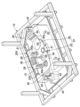
図1は、実施形態に係る冷却装置10の側面図である。冷却装置10は、図示しないブロー成形金型から取り出された、熱可塑性合成樹脂により形成された中空の樹脂成形品である燃料タンク1を冷却するために使用される。冷却装置10は、床面F上に設けられた冷却液タンク11と、冷却液タンク11の中に設けられた冷却ステージ12とを有している。冷却液タンク11には燃料タンク1を冷却するための冷却液(例えば、水)が貯留されている。
FIG. 1 is a side view of a
冷却ステージ12は、支持脚13と、支持脚13によって冷却液上に支持された下部フレーム14と、下部フレーム14の上方に配置された上部フレーム15とを有している。下部フレーム14は冷却液タンク11に固定されており、上部フレーム15は昇降装置16を介して下部フレーム14に連結されている。上部フレーム15は昇降装置16の昇降動作によって燃料タンク1を挟み込むように上下動する。下部フレーム14と上部フレーム15とにより1対の可動フレームが構成される。昇降装置16は、例えば伸縮動作を行うエアシリンダによって構成され、平面視で矩形をなす冷却ステージ12の四隅に配置される。
The cooling
下部フレーム14及び上部フレーム15には、燃料タンク1を受容する受容部材20が支持されている。受容部材20は、下部フレーム14に支持された下側受容半体20Lと、上部フレーム15に支持された上側受容半体20Uとを有している。下部フレーム14及び下側受容半体20Lによって冷却ステージ12の下半部が構成され、上部フレーム15及び上側受容半体20Uによって冷却ステージ12の上半部が構成される。
A receiving
下側受容半体20Lの上面には、燃料タンク1の下部を受容するべく下側凹面23Lが形成されている。上側受容半体20Uの下面には、燃料タンク1の上部を受容するべく上側凹面23Uが形成されている。以下、下側凹面23Lと上側凹面23Uとを合わせて凹面23ということがある。昇降装置16が短縮し、冷却ステージ12が燃料タンク1を挟み込んだ図1に示す状態において、上側受容半体20Uは下側受容半体20Lとの間に隙間を空けて、下側受容半体20Lと協働して燃料タンク1を外囲する。
A lower
冷却装置10は更に、燃料タンク1の外面に向けて冷却液を供給するべく、受容部材20の内部(凹面23内)に至る冷却液供給通路26と、冷却液供給通路26に冷却液を供給する冷却液供給装置である冷却液ポンプ27とを備えている。冷却液供給通路26は、冷却液ポンプ27と受容部材20とを接続する例えばホースからなる冷却液配管によって画定される部分と、受容部材20に形成された貫通孔からなる部分とによって構成される。冷却液供給通路26は、図1においては、2本に分岐して冷却ステージ12の下半部と上半部とに至るように示されているが、後述するように実際にはより多くの本数に分岐する。上側受容半体20Uと下側受容半体20Lとの間の隙間は冷却液排出口28となる。冷却液排出口28から排出された冷却液は、冷却液タンク11に貯まる。冷却液は燃料タンク1を冷却する際に燃料タンク1から吸熱して昇温するため、冷却液供給通路26の適宜な位置に熱交換機が設けられることが好ましい。
The
図2は図1に示す冷却ステージ12の下半部の斜視図であり、図3は図1に示す冷却ステージ12の上半部の斜視図である。図2に示すように、下部フレーム14は、井桁状に組まれた複数の角鋼管によって構成され、矩形をなしている。下側受容半体20Lは、下部フレーム14よりも小さく、下部フレーム14の略中央に支持されている。下側受容半体20Lの上面に形成された下側凹面23Lは、燃料タンク1の下部よりも大きく形成されている。図3に示すように、上部フレーム15は、井桁状に組まれた複数の角鋼管によって構成され、矩形をなしている。上側受容半体20Uは、上部フレーム15よりも小さく、上部フレーム15の略中央に支持されている。上側受容半体20Uの下面に形成された上側凹面23Uは、燃料タンク1の上部よりも大きく形成されている。
2 is a perspective view of the lower half of the cooling
図2及び図3に示すように、下側凹面23L及び上側凹面23Uには、複数のより小さな凹部29が形成されている。凹部29のそれぞれには、燃料タンク1を保持するべく燃料タンク1の外面に当接する当接面30aを有する当接部材30が、当接面30aと相反する側の一部を受容されるように設けられている。当接部材30は、対応する下側凹面23L又は上側凹面23Uから突出するように配置されており、当接面30aは当接部材30のこの突出した部分に配置される。
As shown in FIGS. 2 and 3, a plurality of
下側受容半体20L及び上側受容半体20Uの互いの対向面における外周部には、燃料タンク1の外面に突出形成されたタンク取付片2(図1参照)を挟持するための挟持部31が設けられている。本実施形態では、燃料タンク1の外周部に3つのタンク取付片2が形成されており、下側受容半体20L及び上側受容半体20Uのそれぞれに3つの挟持部31が設けられている。下側受容半体20L及び上側受容半体20Uの挟持部31が設けられる部分は、挟持部31の一部が受容されるように切り欠かれている。これにより、下側受容半体20L及び上側受容半体20Uがそれぞれの挟持部31でタンク取付片2を挟持し、燃料タンク1を外囲した状態で、上側受容半体20Uと下側受容半体20Lとの間に形成される冷却液排出口28が大きくなりすぎることが防止される。
A clamping
図4は図2に示す下側受容半体20Lの平面図である。図2及び図4に示すように、下側受容半体20Lの下側凹面23Lには、底部に複数(図示例では7つ)の当接部材30が設けられ、側周部に複数(図示例では7つ)の当接部材30が設けられている。当接部材30は、円形や円形の一部、略矩形など、様々な形状とされている。
FIG. 4 is a plan view of the
図5は図3に示す上側受容半体20Uの底面図である。図3及び図5に示すように、上側受容半体20Uの上側凹面23Uには、天井部に複数(図示例では4つ)の当接部材30が設けられ、側周部に複数(図示例では5つ)の当接部材30が設けられている。当接部材30は、円形や略矩形など、様々な形状とされている。
FIG. 5 is a bottom view of the upper receiving
また、上側凹面23Uの天井部には、燃料タンク1の内部に冷却気を供給するために燃料タンク1の内部に突入する気体供給管33が設けられている。気体供給管33は、燃料タンク1に形成されたブローピン孔から燃料タンク1の内部に挿入される。気体供給管33にはコンプレッサ34(図1参照)が接続されており、コンプレッサ34から冷却気が気体供給管33に送られる。上側凹面23Uの天井部には更に、燃料タンク1の内部の空気を排出するための排気管35が設けられている。排気管35は、蛇腹状とされ、燃料タンク1に形成されたブローピン孔の外周部に密着する。排気管35には、燃料タンク1の内圧を所定値に維持するための圧力調整弁36(図1参照)が接続されている。内圧が高くなったときに圧力調整弁36が開くことで燃料タンク1の内部の空気は排気管35を介して外部へ排出される。これらのコンプレッサ34、気体供給管33、排気管35、圧力調整弁36などにより、燃料タンク1に内圧を付与する圧力付与装置37が構成される。
A
図1に示すように、受容部材20が燃料タンク1を受容した状態で、圧力付与装置37によって燃料タンク1に内圧が付与され、冷却液ポンプ27によって冷却液が供給されると、下側受容半体20Lと上側受容半体20Uとが離反する方向に力を受ける。そこで、冷却装置10は、下側受容半体20Lと上側受容半体20Uとが離反することを防止するために、上部フレーム15を下部フレーム14に固定するロック装置40を備えている。
As shown in FIG. 1, when the fuel tank 1 is received by the receiving
図2~図5に併せて示すように、ロック装置40は、下側受容半体20Lを挟む下部フレーム14の長手方向の両端近傍に設けられた各1対の下側ロック壁41を含む。またロック装置40は、各対の下側ロック壁41の間に位置するように上部フレーム15の長手方向の両端近傍に設けられた上側ロック壁42を含む。下側ロック壁41及び上側ロック壁42には対向方向に一列に貫通孔が形成されており、これら3つの貫通孔を繋ぐ延長線上には、これらの貫通孔にロックピン43を抜き挿しするためのアクチュエータ44が設けられている。アクチュエータ44がロックピン43を貫通孔に押し込むことで、上部フレーム15が下部フレーム14に固定され、下側受容半体20Lと上側受容半体20Uとの離反が防止される。
As also shown in FIGS. 2 to 5, the locking
図6は下側受容半体20Lの要部拡大斜視図である。図6に示すように、当接部材30の当接面30aには溝50が格子状に形成されている。縦方向及び横方向に延在する溝50は、直線状をなして互いに直交し、両端が当接面30aの外縁に至っている。縦方向及び横方向の溝50は、互いに同じ幅を有し、一定の幅をもって延在している。したがって、当接面30aは、縦方向及び横方向に配列された矩形状の複数の分割部に分割されている。
FIG. 6 is an enlarged perspective view of the main parts of the
当接部材30の当接面30aには、冷却液供給通路26(図1参照)の下流端をなす冷却液供給口26aと、当接部材30を下側受容半体20Lに支持するための2つの支持孔51とが形成されている。つまり、冷却液供給通路26は、複数の当接部材30に至るように分岐し、それらの当接面30aのそれぞれに冷却液供給口26aを開口させている。冷却液供給口26aは対応する当接面30aの略中央に配置されている。2つの支持孔51は、冷却液供給口26aを挟む位置に配置され、その内部にボルトが挿入される。両ボルトが締結されることによって当接部材30は下側受容半体20Lに支持される。
The
当接部材30と下側受容半体20Lとの間にシムを挟むことにより、当接部材30の下側受容半体20Lに対する位置が変更される。したがって、シムの厚さを調節することにより、当接部材30の下側受容半体20Lに対する進退方向の位置を調節することができる。また、厚さが漸減するテーパー形状のシムを用いることにより、当接部材30の下側受容半体20Lに対する角度が変更される。したがって、シムのテーパー角度やテーパー方向(厚さが漸減する方向)を調節することにより、当接部材30の下側受容半体20Lに対する角度を調節することができる。当接部材30はこのように進退方向に位置調節可能に、且つ角度調節可能に下側受容半体20Lに支持されている。当接部材30は上側受容半体20Uに対しても同様に支持されている。
By inserting a shim between the
冷却液供給口26aは、当接面30aのうち溝50の底部、より詳細には、縦方向の溝50と横方向の溝50との交点に中心が位置するように形成されている。冷却液供給口26aの直径は溝50の幅よりも大きい。そのため、冷却液供給口26aに近接する4つの当接面30aの分割部は、冷却液供給通路26を形成する際に角の1つを削られている。
The cooling
冷却液供給口26aは複数の当接部材30の当接面30aのすべてに形成される。したがって、冷却液供給通路26は、少なくとも当接部材30の数に分岐している。図2~図5に示すように、下側受容半体20L及び上側受容半体20Uの側面には、当接部材30の冷却液供給口26aに至る通路を画定する複数の管継手52が突出している。これらの管継手52には、冷却液供給通路26の分岐した下流部を画定するホースが接続される。
The
受容部材20が燃料タンク1を受容した図1の状態では、複数の当接部材30は、それぞれ燃料タンク1の外面に当接する。また、燃料タンク1のタンク取付片2は上下の挟持部31によって挟持される。更に、気体供給管33(図3、図5)は燃料タンク1の内部に突入し、排気管35(図3、図5)は燃料タンク1の外面に密着する。この状態で、冷却液ポンプ27が冷却液を冷却液供給通路26に供給し、圧力付与装置37のコンプレッサ34が冷却気を気体供給管33に供給する。これにより、燃料タンク1は所定の形状を維持しつつ短時間で冷却される。
In the state shown in FIG. 1 in which the receiving
冷却液は、図6に示す冷却液供給口26aから燃料タンク1の外面に向けて供給され、溝50を通って当接部材30に対向する燃料タンク1の部分を確実に冷却し、当接部材30の外へ流れる。図1~図3に示すように、受容部材20に形成された凹面23(23L、23U)が、燃料タンク1の外面に対して所定の空隙をおいて対向している。そのため、当接部材30から流れ出た冷却液は、受容部材20の凹面23と燃料タンク1の外面との空隙を流通し、受容部材20に設けられた冷却液排出口28から外部へ排出される。燃料タンク1は、受容部材20の下側受容半体20L及び上側受容半体20Uによって受容されているため、燃料タンク1と受容部材20との間の空隙を流通する冷却液によって全体的に冷却される。したがって、燃料タンク1は変形や寸法誤差を抑制されながら、全体を短時間で冷却される。
The cooling liquid is supplied toward the outer surface of the fuel tank 1 from the cooling
冷却装置10は以上のように構成されている。以下、本実施形態の冷却装置10の効果を説明する。図6に示すように、冷却液供給通路26の複数の冷却液供給口26aが複数の当接部材30の当接面30aに開口するため、冷却したい部位に当接部材30が設けられることで、燃料タンク1の所望の部位が確実に冷却される。また、各当接部材30の当接面30aには冷却液供給口26aから当接面30aの外縁に至る溝50が設けられているため、燃料タンク1は当接部材30との当接が維持された状態で冷却される。したがって、燃料タンク1のこの当接部位の変形が抑制され、当接部位の寸法誤差が抑制される。
The
本実施形態では、溝50が当接面30aに格子状に設けられているため、当接部材30が当接する燃料タンク1の部分が均等に冷却される。また、溝50が冷却液供給口26aから放射状に形成される場合に比べ、冷却液が乱流を形成しやすいため、冷却効率が高い。そのうえ、当接部材30に対する溝50の加工が容易である。
In this embodiment, since the
図2~図5に示すように、受容部材20の凹面23には複数の凹部29が設けられ、当接部材30が凹部29に部分的に受容された状態で受容部材20に支持されている。そのため、当接部材30を配置するために当接部材30よりも大きな貫通孔を受容部材20に設ける必要がない。したがって、冷却液が貫通孔から大量に漏洩することがなく、燃料タンク1の全体が効率的に冷却される。
As shown in FIGS. 2 to 5, the
本実施形態では、当接部材30が進退方向に位置調節可能に受容部材20に支持されているため、受容部材20に製造誤差があったとしても、各当接部材30を所望の位置に配置することが可能である。これにより、冷却後の燃料タンク1が所望の寸法になる。
In this embodiment, since the
当接部材30は更に角度調節可能に受容部材20に支持されているため、受容部材20に製造誤差があったとしても、各当接部材30を所望の向きに配置することが可能である。これにより、冷却後の燃料タンク1が所望の形状になる。
Since the abutting
図1~図3に示すように、下側受容半体20L及び上側受容半体20Uには、タンク取付片2を挟持するための挟持部31が設けられている。そのため、当接部材30が当接する燃料タンク1の部位と挟持部31が挟持するタンク取付片2との相対位置が所望の関係に設定可能である。よって、タンク取付片2を基準とする所望の形状を保った状態で燃料タンク1を冷却することができる。
As shown in FIGS. 1 to 3, the
図3及び図5に示すように、冷却装置10は燃料タンク1に内圧を付与する圧力付与装置37を更に備え、圧力付与装置37は、受容部材20に設けられ、燃料タンク1の内部に気体を供給するために燃料タンク1の内部に突入する気体供給管33を含む。これにより、気体供給管33から燃料タンク1の内部に供給される気体によって燃料タンク1に内圧が付与されるため、燃料タンク1と当接部材30との当接が確実に維持される。
As shown in FIGS. 3 and 5, the
図1に示すように、冷却装置10は、下部フレーム14及び上部フレーム15を互いに固定するロック装置40を更に備える。そのため、受容部材20が燃料タンク1を受容した状態で、圧力付与装置37による内圧の付与及び冷却液ポンプ27による冷却液の供給によって下側受容半体20L及び上側受容半体20Uが離反するのが防止される。これにより、冷却によって燃料タンク1の形状及び寸法が変化することが防止される。
As shown in FIG. 1, the
以上で具体的実施形態の説明を終えるが、本発明は上記実施形態に限定されることなく幅広く変形実施することができる。例えば、上記実施形態では、一例として燃料タンク1の冷却装置10に適用して本発明を説明したが、本発明は、燃料以外の流体を入れるタンクの冷却にも広く適用することができる。この他、各部材や部位の具体的構成や配置、数量、材料など、本発明の趣旨を逸脱しない範囲であれば適宜変更することができる。一方、上記実施形態に示した各構成要素は必ずしも全てが必須ではなく、適宜選択することができる。
Although the specific embodiments have been described above, the present invention is not limited to the above embodiments and can be widely modified. For example, in the above-described embodiment, the present invention is applied to the
1 :燃料タンク
2 :タンク取付片
10 :冷却装置
14 :下部フレーム(可動フレーム)
15 :上部フレーム(可動フレーム)
16 :昇降装置
20 :受容部材
20L :下側受容半体
20U :上側受容半体
23 :凹面
23L :下側凹面
23U :上側凹面
26 :冷却液供給通路
26a :冷却液供給口
27 :冷却液ポンプ(冷却液供給装置)
28 :冷却液排出口
29 :凹部
30 :当接部材
30a :当接面
31 :挟持部
33 :気体供給管
37 :圧力付与装置
40 :ロック装置
50 :溝Reference Signs List 1: fuel tank 2: tank mounting piece 10: cooling device 14: lower frame (movable frame)
15: Upper frame (movable frame)
16: Elevating device 20: Receiving
28: cooling liquid outlet 29: concave portion 30:
Claims (9)
前記タンクを挟み込むように相対移動可能に設けられた1対の可動フレームと、
1対の前記可動フレームのそれぞれに設けられ、前記タンクの外面に当接する当接面を有する複数の当接部材と、
前記タンクの前記外面に向けて冷却液を供給するべく、前記当接部材の前記当接面に開口する複数の冷却液供給口を有する冷却液供給通路と、
前記冷却液供給通路に前記冷却液を供給する冷却液供給装置とを備え、
前記当接面のそれぞれに、対応する前記冷却液供給口から前記当接面の外縁に至る溝が設けられていることを特徴とするタンク用冷却装置。A cooling device for cooling a hollow tank made of thermoplastic synthetic resin,
a pair of movable frames provided so as to be relatively movable so as to sandwich the tank;
a plurality of contact members provided on each of the pair of movable frames and having contact surfaces contacting the outer surface of the tank;
a cooling liquid supply passage having a plurality of cooling liquid supply ports opening to the contact surface of the contact member for supplying cooling liquid toward the outer surface of the tank;
a cooling liquid supply device that supplies the cooling liquid to the cooling liquid supply passage;
A cooling device for a tank, wherein each of the contact surfaces is provided with a groove extending from the corresponding coolant supply port to an outer edge of the contact surface.
前記当接部材が前記受容部材の前記凹面から突出するように配置され、前記受容部材に冷却液排出口が設けられていることを特徴とする請求項1又は請求項2に記載のタンク用冷却装置。Further comprising a receiving member including a pair of receiving halves for receiving a portion of the tank, the pair of receiving halves being supported by the pair of movable frames and positioned relative to the outer surface of the tank. each having concave surfaces facing each other with a gap of
3. The tank cooling system according to claim 1, wherein the abutting member is arranged to protrude from the concave surface of the receiving member, and the receiving member is provided with a coolant outlet. Device.
Applications Claiming Priority (3)
| Application Number | Priority Date | Filing Date | Title |
|---|---|---|---|
| JP2020172326 | 2020-10-13 | ||
| JP2020172326 | 2020-10-13 | ||
| PCT/JP2021/029996 WO2022079996A1 (en) | 2020-10-13 | 2021-08-17 | Tank cooling apparatus |
Publications (2)
| Publication Number | Publication Date |
|---|---|
| JPWO2022079996A1 JPWO2022079996A1 (en) | 2022-04-21 |
| JP7253120B2 true JP7253120B2 (en) | 2023-04-05 |
Family
ID=81207926
Family Applications (1)
| Application Number | Title | Priority Date | Filing Date |
|---|---|---|---|
| JP2022556428A Active JP7253120B2 (en) | 2020-10-13 | 2021-08-17 | Tank cooler |
Country Status (4)
| Country | Link |
|---|---|
| US (1) | US11835286B2 (en) |
| JP (1) | JP7253120B2 (en) |
| CN (1) | CN116323148B (en) |
| WO (1) | WO2022079996A1 (en) |
Citations (3)
| Publication number | Priority date | Publication date | Assignee | Title |
|---|---|---|---|---|
| JP2003145576A (en) | 2001-11-12 | 2003-05-20 | Kanto Auto Works Ltd | Molding processing method for thermoplastic resin and molding apparatus therefor |
| JP2007261164A (en) | 2006-03-29 | 2007-10-11 | Nachi Fujikoshi Corp | Cooling device of tank made of synthetic resin, and cooling method of tank made of synthetic resin |
| JP2018192629A (en) | 2017-05-12 | 2018-12-06 | 有限会社浦野技研 | Mold assembly and injection molding method for molded article having hollow part |
Family Cites Families (9)
| Publication number | Priority date | Publication date | Assignee | Title |
|---|---|---|---|---|
| US5190715A (en) * | 1988-09-27 | 1993-03-02 | Ube Industries, Ltd. | Blow molding process for production of hollow type articles |
| JP2000343587A (en) * | 1999-06-02 | 2000-12-12 | Sekisui Chem Co Ltd | Forming tube for extrusion molded resin pipe |
| JP2002001799A (en) * | 2000-06-20 | 2002-01-08 | Kinugawa Rubber Ind Co Ltd | Apparatus for sizing resin molding |
| JP3628678B2 (en) * | 2002-12-24 | 2005-03-16 | 八千代工業株式会社 | Cooling device for synthetic resin tank |
| FR2934518B1 (en) * | 2008-07-31 | 2013-04-26 | Sidel Participations | SPONGIOUS MASS FOR TREATING THERMOPLASTIC CONTAINER FOUNTS, AND EQUIPMENT EQUIPPED THEREFORE FOR COOLING HOT FILLERS OF MOLDING CONTAINERS |
| JP5431878B2 (en) * | 2009-11-09 | 2014-03-05 | 株式会社浅野研究所 | Mold fixing apparatus, thermoforming apparatus, mold fixing method, and thermoforming method |
| FR2994880B1 (en) * | 2012-08-28 | 2014-08-29 | Sidel Participations | "METHOD FOR COOLING A MOLD BY CIRCULATING A HEAT PUMP FLUID IN CONTACT WITH ITS EXTERNAL SIDE" |
| JP2014154753A (en) * | 2013-02-12 | 2014-08-25 | Calsonic Kansei Corp | Semiconductor cooling device |
| JP2017065031A (en) * | 2015-09-29 | 2017-04-06 | トヨタ自動車株式会社 | Device and method for cooling resin molded article |
-
2021
- 2021-08-17 US US18/031,779 patent/US11835286B2/en active Active
- 2021-08-17 WO PCT/JP2021/029996 patent/WO2022079996A1/en active Application Filing
- 2021-08-17 JP JP2022556428A patent/JP7253120B2/en active Active
- 2021-08-17 CN CN202180069663.7A patent/CN116323148B/en active Active
Patent Citations (3)
| Publication number | Priority date | Publication date | Assignee | Title |
|---|---|---|---|---|
| JP2003145576A (en) | 2001-11-12 | 2003-05-20 | Kanto Auto Works Ltd | Molding processing method for thermoplastic resin and molding apparatus therefor |
| JP2007261164A (en) | 2006-03-29 | 2007-10-11 | Nachi Fujikoshi Corp | Cooling device of tank made of synthetic resin, and cooling method of tank made of synthetic resin |
| JP2018192629A (en) | 2017-05-12 | 2018-12-06 | 有限会社浦野技研 | Mold assembly and injection molding method for molded article having hollow part |
Also Published As
| Publication number | Publication date |
|---|---|
| CN116323148B (en) | 2023-11-17 |
| WO2022079996A1 (en) | 2022-04-21 |
| CN116323148A (en) | 2023-06-23 |
| US11835286B2 (en) | 2023-12-05 |
| US20230272960A1 (en) | 2023-08-31 |
| JPWO2022079996A1 (en) | 2022-04-21 |
Similar Documents
| Publication | Publication Date | Title |
|---|---|---|
| JPH1058499A (en) | Injection molding equipment | |
| US5894025A (en) | Valve pin actuator | |
| US5851456A (en) | Method for manufacturing a multi-layer plastic product | |
| US8241032B2 (en) | Single level manifold for an injection molding apparatus | |
| US20110277325A1 (en) | Passage block and manufacturing method thereof | |
| US9352492B2 (en) | Injection blow molding system with enhanced parison mold configuration | |
| EA012661B1 (en) | Shaping tool | |
| US11666994B2 (en) | Integrated horn structures for heat exchanger headers | |
| JP7253120B2 (en) | Tank cooler | |
| EP0677370B1 (en) | Back-to-back valve gate system | |
| TW200403115A (en) | Liquid-cooled chilled-casting | |
| JP5442349B2 (en) | Mold cooling plate and manufacturing method thereof | |
| KR100878749B1 (en) | Temperature conditioning plate and thermal transfer pressing machine | |
| JPH1058498A (en) | Injection molding equipment | |
| JP2011126171A (en) | Mold thermostat | |
| JP2006200816A (en) | Resin-made heat exchanger and its manufacturing method | |
| KR101743944B1 (en) | Mold cooling device | |
| KR102307684B1 (en) | Casting apparatus and method thereof | |
| US7445746B2 (en) | Temperable member | |
| JPS6222751B2 (en) | ||
| US20230111054A1 (en) | Cooling module with microporous cooling structure applied thereto and method of locally cooling mold using the same | |
| CN116441435B (en) | Mould cooling device for processing stamping parts of automobile support plates | |
| JP2008119938A (en) | Injection molding machine | |
| KR100738997B1 (en) | Mold cooling device | |
| KR200384813Y1 (en) | Heating Apparatus of Oil Tank for Ship |
Legal Events
| Date | Code | Title | Description |
|---|---|---|---|
| A621 | Written request for application examination |
Free format text: JAPANESE INTERMEDIATE CODE: A621 Effective date: 20230206 |
|
| A871 | Explanation of circumstances concerning accelerated examination |
Free format text: JAPANESE INTERMEDIATE CODE: A871 Effective date: 20230206 |
|
| TRDD | Decision of grant or rejection written | ||
| A01 | Written decision to grant a patent or to grant a registration (utility model) |
Free format text: JAPANESE INTERMEDIATE CODE: A01 Effective date: 20230322 |
|
| A61 | First payment of annual fees (during grant procedure) |
Free format text: JAPANESE INTERMEDIATE CODE: A61 Effective date: 20230324 |
|
| R150 | Certificate of patent or registration of utility model |
Ref document number: 7253120 Country of ref document: JP Free format text: JAPANESE INTERMEDIATE CODE: R150 |