JP7251237B2 - Spacer - Google Patents
Spacer Download PDFInfo
- Publication number
- JP7251237B2 JP7251237B2 JP2019050795A JP2019050795A JP7251237B2 JP 7251237 B2 JP7251237 B2 JP 7251237B2 JP 2019050795 A JP2019050795 A JP 2019050795A JP 2019050795 A JP2019050795 A JP 2019050795A JP 7251237 B2 JP7251237 B2 JP 7251237B2
- Authority
- JP
- Japan
- Prior art keywords
- pair
- handle
- magnet
- yokes
- flat plate
- Prior art date
- Legal status (The legal status is an assumption and is not a legal conclusion. Google has not performed a legal analysis and makes no representation as to the accuracy of the status listed.)
- Active
Links
- 125000006850 spacer group Chemical group 0.000 title claims description 38
- 238000006073 displacement reaction Methods 0.000 claims description 5
- 239000000696 magnetic material Substances 0.000 claims description 4
- XEEYBQQBJWHFJM-UHFFFAOYSA-N Iron Chemical compound [Fe] XEEYBQQBJWHFJM-UHFFFAOYSA-N 0.000 description 26
- 229910052742 iron Inorganic materials 0.000 description 13
- 239000002184 metal Substances 0.000 description 10
- 229910052751 metal Inorganic materials 0.000 description 10
- 239000000463 material Substances 0.000 description 4
- 230000003247 decreasing effect Effects 0.000 description 2
- 230000001105 regulatory effect Effects 0.000 description 2
- 239000011347 resin Substances 0.000 description 2
- 229920005989 resin Polymers 0.000 description 2
- 230000004308 accommodation Effects 0.000 description 1
- 230000015572 biosynthetic process Effects 0.000 description 1
- 230000000694 effects Effects 0.000 description 1
- 238000012423 maintenance Methods 0.000 description 1
- 229910001220 stainless steel Inorganic materials 0.000 description 1
- 239000010935 stainless steel Substances 0.000 description 1
Images


Landscapes
- Railway Tracks (AREA)
- Pinball Game Machines (AREA)
Description
本発明は、スペーサに関する。 The present invention relates to spacers.
従来、金型を床面上に載置する際、金型と床面との間には一対の枕木が介在される。また、金型の上に別の金型を載置する際においても、金型同士の間に一対の枕木が介在される(特許文献1参照)。 Conventionally, a pair of sleepers are interposed between the mold and the floor when the mold is placed on the floor. Also, when another mold is placed on top of another mold, a pair of sleepers are interposed between the molds (see Patent Document 1).
ところで、このような従来の枕木においては、以下の問題が生じる。すなわち、所定の場所に載置されている金型を別の場所へ移動させる場合、作業者は、所定の場所に配置されている一対の枕木を別の場所に移動させるか、あるいは別の一対の枕木を別の場所に配置する必要がある。そのため、枕木の移動や配置のための作業が煩雑となる。こうした問題は、金型の体格の増大に伴い枕木の体格や重量が増大するほど顕著となる。 By the way, such conventional sleepers have the following problems. That is, when moving a mold placed in a predetermined place to another place, an operator moves a pair of sleepers placed in a predetermined place to another place, or moves another pair of sleepers to another place. sleepers need to be placed elsewhere. Therefore, the work for moving and arranging the sleepers becomes complicated. These problems become more conspicuous as the physical size and weight of the sleepers increase as the physical size of the mold increases.
なお、こうした問題は、上述した枕木に限定されるものではなく、部材間に介在されるスペーサにおいては同様にして生じ得る。
本発明の目的は、スペーサの機能性を高めることである。
It should be noted that such problems are not limited to the sleepers described above, and may similarly occur in spacers interposed between members.
It is an object of the present invention to enhance the functionality of spacers.
上記目的を達成するためのスペーサは、ケース本体、前記ケース本体に設けられた第1磁石、前記ケース本体に設けられ、前記第1磁石の両磁極面を挟む一対のヨークを備えるケースと、前記ケース本体に対して変位可能に設けられたハンドル本体、及び前記ハンドル本体に設けられた第2磁石を備えるハンドルと、を備え、前記ハンドルは、前記一対のヨークから前記第2磁石が離間しており、前記一対のヨークの端面が両磁極となることで磁気吸着力を発生させる第1位置と、前記一対のヨークの間に前記第2磁石が位置しており、前記第1磁石、前記一対のヨーク、及び前記第2磁石によって閉じた磁気回路を形成することで前記ハンドルが前記第1位置にあるときに比べて前記磁気吸着力が減じられる第2位置との間で変位可能である。 A spacer for achieving the above object comprises a case body, a first magnet provided in the case body, a pair of yokes provided in the case body and sandwiching both magnetic pole faces of the first magnet, and A handle body provided displaceably with respect to the case body, and a handle provided with a second magnet provided on the handle body, the handle being separated from the pair of yokes by the second magnet. The second magnet is positioned between the pair of yokes and the first position where the end faces of the pair of yokes serve as both magnetic poles to generate a magnetic attracting force. and the second magnet to form a closed magnetic circuit, the handle is displaceable between a second position where the magnetic attraction force is reduced compared to when the handle is in the first position.
同構成によれば、ハンドルが第1位置にあるときには、一対のヨークから第2磁石が離間しており、一対のヨークの端面が両磁極となることで磁気吸着力が発生する。一方、ハンドルが第2位置にあるときには、一対のヨークの間に第2磁石が位置しており、第1磁石、一対のヨーク、第2磁石によって閉じた磁気回路が形成されることでハンドルが第1位置にあるときに比べて上記磁気吸着力が減じられる。このように、上記構成によれば、ハンドルの位置を第1位置と第2位置とで切り替えることによって、スペーサから発生する磁気吸着力を増減させることができる。これにより、ハンドルの位置を第1位置に切り替えることによって、鉄板などの対象物に対してスペーサを吸着させて取り付けることができる。また、ハンドルの位置を第2位置に切り替えることによって、対象物からスペーサを取り外すことができる。したがって、スペーサの機能性を高めることができる。 According to this configuration, when the handle is at the first position, the second magnet is separated from the pair of yokes, and the end surfaces of the pair of yokes serve as both magnetic poles, thereby generating a magnetic attracting force. On the other hand, when the handle is at the second position, the second magnet is positioned between the pair of yokes, and a closed magnetic circuit is formed by the first magnet, the pair of yokes, and the second magnet, whereby the handle is moved. The magnetic attracting force is reduced compared to when it is in the first position. Thus, according to the above configuration, by switching the position of the handle between the first position and the second position, the magnetic attracting force generated from the spacer can be increased or decreased. Accordingly, by switching the position of the handle to the first position, the spacer can be adhered to and attached to an object such as an iron plate. Also, the spacer can be removed from the object by switching the position of the handle to the second position. Therefore, the functionality of the spacer can be enhanced.
本発明によれば、スペーサの機能性を高めることができる。 According to the present invention, the functionality of the spacer can be enhanced.
以下、図1~図5を参照して、スペーサの一実施形態について説明する。
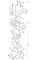
図1に示すように、スペーサ10は、ケース11と、ケース11に対してスライド可能に設けられたハンドル40とを備えている。なお、以降において、ケース11に対するハンドル40のスライド方向を単にスライド方向Yとし、スライド方向Yにおいてハンドル40がケース11に進行する側を単に奥側とし、ハンドル40がケース11から退避する側を単に手前側として説明する。
An embodiment of the spacer will be described below with reference to FIGS. 1 to 5. FIG.
As shown in FIG. 1 , the
以下、各構成について詳細に説明する。
<ハンドル40>
図1及び図2に示すように、ハンドル40は、スライド方向Yにおいて長い略長方形板状のハンドル本体41を有している。なお、以降において、ハンドル本体41の長方形の短辺の延びる方向を幅方向Xとして説明する。
Each configuration will be described in detail below.
<
As shown in FIGS. 1 and 2, the
図2に示すように、ハンドル本体41の幅方向Xの両側には、スライド方向Yに沿って延在する一対の長孔44が設けられている。一対の長孔44には、二対の円筒状のカラー34が貫通されている。なお、各長孔44のスライド方向Yの両端内面は平面視半円弧状をなしている。
As shown in FIG. 2, a pair of
ハンドル本体41における一対の長孔44の幅方向Xの内側には、スライド方向Yに沿って延在する一対のスライド孔42が設けられている。すなわち、スライド孔42の延在方向は、スライド方向Yと一致している。また、一対のスライド孔42は互いに平行に延在している。なお、各スライド孔42は、平面視長方形状をなしている。
A pair of
ハンドル本体41における一対のスライド孔42の間には、幅方向Xに沿って延在するとともにスライド孔42同士を連通する収容部43が設けられている。収容部43には、直方体状の第2磁石52が収容されている。
Between the pair of
ハンドル本体41における手前側には、幅方向Xに沿って延在する平面視略長方形状の把持孔45が設けられている。
<ケース11>
図1及び図2に示すように、ケース11は、ハンドル40を厚さ方向(図1の上下方向)において挟む一対の平板部20,30を有するケース本体12を備えている。
A
<
As shown in FIGS. 1 and 2, the
一方(図1の下側)の平板部20は、ケース11の外側から順に積層された外側平板部21、内側平板部22、及び金属板23を有している。外側平板部21及び内側平板部22は、同一の大きさの長方形板状をなしており、共に硬質樹脂材料によって形成されている。また、金属板23は、各平板部21,22よりも一回り小さい長方形板状をなしており、例えばステンレス鋼板によって形成されている。なお、外側平板部21及び内側平板部22の長方形の長辺及び短辺は、スライド方向Y及び幅方向Xと一致するように配置される。
The
図2に示すように、外側平板部21の幅方向Xの両側には、二対のナット孔29aがスライド方向Yにおいて間隔をおいて設けられている。各ナット孔29a内には、ナット37が固定されている。
As shown in FIG. 2, two pairs of
外側平板部21には、スライド方向Yに沿って延在する平面視長方形状の一対の貫通孔24が幅方向Xに互いに間隔をおいて設けられている。各貫通孔24は、各ナット孔29aよりも幅方向Xの内側に設けられている。
A pair of rectangular through-
内側平板部22における各ナット孔29aに対応する位置には、ボルト38が挿通されるボルト孔29が設けられている。
内側平板部22には、幅方向Xに沿って延在する平面視長方形状の1つの貫通孔25が設けられている。貫通孔25は、幅方向Xにおいて一対の貫通孔24の一方から他方の形成範囲にわたって延在している。
The inner
内側平板部22における貫通孔25よりも奥側には、一対の貫通孔26が幅方向Xに互いに間隔をおいて設けられている。各貫通孔26は、幅方向Xにおいて貫通孔25の両端部に対応する位置に設けられている。
A pair of through
内側平板部22における一対の貫通孔26よりも奥側、且つ一対の貫通孔26の間の部分には、幅方向Xに沿って延在する平面視長方形状の貫通孔27が設けられている。
金属板23における各ナット孔29aに対応する位置には、ボルト38が挿通されるボルト孔29が設けられている。ボルト孔29の内径は、カラー34の外径よりも小さい。
A rectangular through-
Bolt holes 29 through which
金属板23の中央部には、平面視長方形状の貫通孔28が設けられている。
他方(図1の上側)の平板部30は、ケース11の外側から順に積層された外側平板部31、内側平板部32、及び金属板33を有している。
A through-hole 28 having a rectangular shape in plan view is provided in the central portion of the
The other (upper side in FIG. 1)
外側平板部31及び内側平板部32の形状及び材質は、基本的に、上述した平板部20の外側平板部21及び内側平板部22とそれぞれ同一である。また、金属板33の形状及び材質は、基本的に、上述した金属板23と同一である。ただし、外側平板部31には、各ナット孔29aに対応する位置に、ボルト38の頭部38a全体を収容可能な段付きのボルト孔39aが設けられている。また、外側平板部31には、貫通孔24が設けられていない。
The shape and material of the outer
内側平板部32には、各ナット孔29aに対応する位置に、ボルト38が挿通されるボルト孔39が設けられている。また、内側平板部32には、貫通孔25,26,27が設けられていない。
The inner
金属板33には、各ナット孔29aに対応する位置に、ボルト38が挿通されるボルト孔39が設けられている。また、金属板33には、貫通孔28が設けられていない。
他方の平板部30のボルト孔39,39a、ハンドル本体41の長孔44を貫通するカラー34、及び一方の平板部20のボルト孔29にボルト38が挿通され、外側平板部21のナット37にボルト38の先端が螺合されている。ここで、平板部20,30同士の間に介在する4つのカラー34によって、平板部20,30は、ハンドル40を挟んで互いに平行に配置されている。また、4つのカラー34によって、平板部20,30同士の間には、ハンドル40がスライド可能な隙間が設定されている(図3(a)及び図3(b)参照)。
The
A
図2及び図3に示すように、外側平板部21の貫通孔24及び内側平板部22の貫通孔25には、一定の厚さを有する側面視T字形状の一対のヨーク54の先端部が挿入されている。各ヨーク54の先端面54aは、外側平板部21の外面に露出している。ヨーク54は、例えば、鉄などの軟質磁性材料によって形成されている(図3参照)。
As shown in FIGS. 2 and 3, the tip portions of a pair of T-shaped
図2に示すように、貫通孔25、貫通孔25に挿入された一対のヨーク54、及び外側平板部21の内面によって囲まれた空間には、第2磁石52と同一の直方体状をなす第1磁石51が収容されている。すなわち、第1磁石51の両磁極面は一対のヨーク54によって挟まれている。第1磁石51の両磁極の向きは、幅方向Xにおいて第2磁石52の両磁極の向きと逆向きとなるように上記空間に収容されている。なお、本実施形態では、第1磁石51の磁力は、第2磁石52の磁力と同一である。
As shown in FIG. 2 , in the space surrounded by the through-
図2及び図3に示すように、内側平板部22の各貫通孔26には、硬質樹脂材料によって形成された一定の厚さを有する側面視T字形状の一対の係止部材55の先端部が挿入されている。一対の係止部材55は、一対のヨーク54と同様の姿勢でスライド方向Yにおいて互いに隣り合っている。係止部材55の先端面55aは、外側平板部21の内面に当接している。
As shown in FIGS. 2 and 3, in each through-
各スライド孔42には、一対のヨーク54の頭部54b及び一対の係止部材55の頭部55bが挿入されている。スライド孔42のスライド方向Yの長さは、ヨーク54の頭部54b及び係止部材55の頭部55bのスライド方向Yの長さの和よりも大きい。これにより、一対のヨーク54及び一対の係止部材55は、一対のスライド孔42内をスライド方向Yに沿って、すなわちスライド孔42の延在方向に沿って相対変位可能に設けられている。
図2に示すように、内側平板部22の貫通孔27及び外側平板部21の内面によって囲まれた空間には、例えば鉄などの軟質磁性材料によって形成された直方体状の規制部材56が収容されている。
As shown in FIG. 2, in the space surrounded by the through
こうしたスペーサ10においては、ハンドル40はケース本体12に対して、スライド孔42の手前側端部に一対のヨーク54の手前側端部が当接される第1位置(図3(a)参照)と、スライド孔42の奥側端部に一対の係止部材55の奥側端部が当接される第2位置(図3(b)参照)との間でスライド可能である。
In such a
図4(a)に示すように、ハンドル40が第1位置にあるときには、一対のヨーク54から第2磁石52が離間しており、一対のヨーク54の先端面54aが両磁極となることで磁気吸着力が発生する。
As shown in FIG. 4A, when the
またこのとき、規制部材56が第2磁石52に磁気吸着されることによって、ハンドル40のスライドが規制されている。
一方、図4(b)に示すように、ハンドル40が第2位置にあるときには、一対のヨーク54の間に第2磁石52が位置しており、第1磁石51、一対のヨーク54、及び第2磁石52によって閉じた磁気回路が形成されることでハンドル40が第1位置にあるときに比べて上記磁気吸着力が減じられる。
Further, at this time, the
On the other hand, as shown in FIG. 4B, when the
次に、図5を参照して、スペーサ10の使用例について説明する。
本実施形態のスペーサ10は、例えば金型90を床面G上に載置する際に、金型90と床面Gとの間に介在される枕木の代わりとして使用される。なお、下型91の下面及び上型93の上面には、鉄板92,94がねじ(図示略)を介して取り付けられている。
Next, a usage example of the
The
図5(a)に示すように、鉄板92の下面の4つの角部に対して、都合4つのスペーサ10が磁気吸着により取り付けられている。
ここで、例えば金型90のメンテナンスのために上型93を上下反転させる場合には、鉄板94の上面の4つの角部に対してスペーサ10を載置するとともに当該スペーサ10のハンドル40を第1位置にスライドさせることにより、スペーサ10を鉄板94に磁気吸着により取り付ける。またこのとき、鉄板92の下面に取り付けられていたスペーサ10については、ハンドル40を第2位置にスライドさせることにより、磁気吸着力を減じることで鉄板92からスペーサ10を取り外すことができる。
As shown in FIG. 5A, a total of four
Here, for example, when the
続いて、図示しないクレーンによって上型93の側部を吊り上げることにより、金型90を90度回転させる(図5(b)参照)。このとき、第2磁石52が規制部材56に磁気吸着されているため、ハンドル40が第1位置に維持される。
Subsequently, the side portion of the
続いて、図5(c)に示すように、上型93を更に90度回転させることで、鉄板94に取り付けられた各スペーサ10を床面G上に載置する。
このように、金型90に対してスペーサ10を位置決めして取り付けた状態で一緒に移動させることができるため、金型90とは別にスペーサ10を移動させる手間や、金型90の移動先においてスペーサ10の位置決めを行う手間を省略できる。
Subsequently, as shown in FIG. 5(c), the
In this way, the
次に、本実施形態の作用効果について説明する。
(1)スペーサ10は、ケース本体12、ケース本体12に設けられた第1磁石51、ケース本体12に設けられ、第1磁石51の両磁極面を挟む一対のヨーク54を備えるケース11と、ケース本体12に対して変位可能に設けられたハンドル本体41、及びハンドル本体41に設けられた第2磁石52を備えるハンドル40とを備えている。ハンドル40は、第1位置と第2位置との間で変位可能である。第1位置では、一対のヨーク54から第2磁石52が離間しており、一対のヨーク54の先端面54aが両磁極となることで磁気吸着力を発生させる。第2位置では、一対のヨーク54の間に第2磁石52が位置しており、第1磁石51、一対のヨーク54、及び第2磁石52によって閉じた磁気回路を形成することでハンドル40が第1位置にあるときに比べて磁気吸着力が減じられる。
Next, the effects of this embodiment will be described.
(1) The
こうした構成によれば、ハンドル40の位置を第1位置と第2位置とで切り替えることによって、スペーサ10から発生する磁気吸着力を増減させることができる。これにより、ハンドル40の位置を第1位置に切り替えることによって、鉄板92,94などの対象物に対してスペーサ10を吸着させて取り付けることができる。また、ハンドル40の位置を第2位置に切り替えることによって、対象物からスペーサ10を取り外すことができる。したがって、スペーサ10の機能性を高めることができる。
With such a configuration, the magnetic attracting force generated from the
(2)ケース本体12には、鉄により形成され、ハンドル40が第1位置にあるときに第2磁石52に磁気吸着されることでハンドル40の変位を規制する規制部材56が設けられている。
(2) The
第1位置にあるハンドル40に対して外力が作用することで意図せず第2位置に変位するおそれがある。
この点、上記構成によれば、ケース本体12に設けられた規制部材56に第2磁石52が磁気吸着されることによって第1位置からのハンドル40の変位が規制されるようになる。したがって、第1位置にあるハンドル40の意図しない変位を抑制できる。
The
In this regard, according to the above configuration, the displacement of the
(3)ハンドル40は、ケース11に対してスライド可能に設けられている。
こうした構成によれば、ケース11に対してハンドル40をスライドさせるといった簡単な操作によって、ハンドル40を第1位置と第2位置との間で変位させることができる。
(3) The
With such a configuration, the
(4)ハンドル本体41は、互いに平行に延在する一対のスライド孔42と、一対のスライド孔42同士を連通して設けられ、前記第2磁石52を収容する収容部43とを有しており、一対のヨーク54は、一対のスライド孔42内をスライド孔42の延在方向に沿って相対変位する。
(4) The
こうした構成によれば、ハンドル本体41の収容部43内に収容された第2磁石52をハンドル本体41と共に各スライド孔42の延在方向に沿ってスライドさせると、ケース本体12に設けられた一対のヨーク54が一対のスライド孔42内をそれらの延在方向に沿って相対変位する。これにより、第2磁石52は、一対のヨーク54から離間した第1位置と、一対のヨーク54の間に位置する第2位置との間で変位する。したがって、ハンドル40がケース11に対してスライド可能に設けられる構成を容易に実現することができる。
According to such a configuration, when the
(5)ハンドル本体41におけるケース本体12の外側に位置する部分には、把持孔45が設けられている。
こうした構成によれば、使用者は、ハンドル本体41に設けられた把持孔45に手指を挿通することでハンドル本体41を安定して把持することができる。したがって、ハンドル40を容易に操作することができる。
(5) A gripping
With such a configuration, the user can stably grip the
<変更例>
上記実施形態は、例えば以下のように変更して実施することもできる。本実施形態及び以下の変更例は、技術的に矛盾しない範囲で互いに組み合わせて実施することができる。
<Change example>
For example, the above-described embodiment can be modified and implemented as follows. This embodiment and the following modified examples can be implemented in combination with each other within a technically consistent range.
・把持孔45に代えて、ハンドル本体41の手前側端部に使用者が把持するための把持突部を設けてもよい。また、こうした把持孔45や把持突部を省略することもできる。
・ハンドル40は、ケース11に対してスライド可能なものに限らない。例えば、ハンドル40をケース11に対して回転可能に設けることによって、第2磁石が変位される構成にすることもできる。
- Instead of the
- The
・規制部材は、ケース本体12に設けられた軟質磁性材料に限られるものではない。例えば、ハンドル本体41に凹部を設け、ハンドル40が第1位置にあるときにケース本体12に設けられた凸部が上記凹部と篏合することによって、ハンドル40の変位を規制するものであってもよい。
- The restricting member is not limited to the soft magnetic material provided in the case
10…スペーサ、11…ケース、12…ケース本体、20,30…平板部、21,31…外側平板部、22,32…内側平板部、23,33…金属板、24,25,26,27,28…貫通孔、29,39,39a…ボルト孔、29a…ナット孔、34…カラー、37…ナット、38…ボルト、38a…頭部、40…ハンドル、41…ハンドル本体、42…スライド孔、43…収容部、44…長孔、45…把持孔、51…第1磁石、52…第2磁石、54…ヨーク、54a,55a…先端面、54b,55b…頭部、55…係止部材、56…規制部材、90…金型、91…下型、92,94…鉄板、93…上型。
DESCRIPTION OF
Claims (5)
前記一対の平板部に挟まれるとともに前記一対の平板部の積層方向に直交する方向において変位可能に設けられたハンドル本体、及び前記ハンドル本体に設けられた第2磁石を備えるハンドルと、を備え、
前記ハンドルは、前記一対のヨークから前記第2磁石が離間しており、前記一対のヨークの端面が両磁極となることで磁気吸着力を発生させる第1位置と、前記一対のヨークの間に前記第2磁石が位置しており、前記第1磁石、前記一対のヨーク、及び前記第2磁石によって閉じた磁気回路を形成することで前記ハンドルが前記第1位置にあるときに比べて前記磁気吸着力が減じられる第2位置との間で変位可能である、
スペーサ。 a case comprising a case main body including a pair of flat plate portions , a first magnet provided in the case main body, and a pair of yokes provided in the case main body and sandwiching both magnetic pole faces of the first magnet;
a handle body sandwiched between the pair of flat plate portions and displaceable in a direction orthogonal to the stacking direction of the pair of flat plate portions ; and a handle provided with a second magnet provided on the handle body,
The handle is located between the pair of yokes and a first position where the second magnet is spaced apart from the pair of yokes and the end surfaces of the pair of yokes serve as both magnetic poles to generate a magnetic attracting force. The second magnet is positioned such that the first magnet, the pair of yokes, and the second magnet form a closed magnetic circuit to reduce the magnetic field relative to when the handle is in the first position. displaceable between a second position in which the attractive force is reduced;
Spacer.
請求項1に記載のスペーサ。 The case body is provided with a restricting member made of a soft magnetic material and configured to restrict displacement of the handle by being magnetically attracted to the second magnet when the handle is in the first position.
2. Spacer according to claim 1.
請求項1または請求項2に記載のスペーサ。 The handle is slidably provided with respect to the case,
3. A spacer according to claim 1 or claim 2.
前記一対のヨークは、前記一対のスライド孔内を前記スライド孔の延在方向に沿って相対変位する、
請求項3に記載のスペーサ。 The handle body has a pair of slide holes extending parallel to each other, and a housing portion provided to communicate with the pair of slide holes and housing the second magnet,
The pair of yokes are relatively displaced within the pair of slide holes along the extending direction of the slide holes.
4. Spacer according to claim 3.
請求項1~請求項4のいずれか一項に記載のスペーサ。 A gripping hole is provided in a portion of the handle body located outside the case body,
The spacer according to any one of claims 1 to 4.
Priority Applications (1)
| Application Number | Priority Date | Filing Date | Title |
|---|---|---|---|
| JP2019050795A JP7251237B2 (en) | 2019-03-19 | 2019-03-19 | Spacer |
Applications Claiming Priority (1)
| Application Number | Priority Date | Filing Date | Title |
|---|---|---|---|
| JP2019050795A JP7251237B2 (en) | 2019-03-19 | 2019-03-19 | Spacer |
Publications (2)
| Publication Number | Publication Date |
|---|---|
| JP2020152481A JP2020152481A (en) | 2020-09-24 |
| JP7251237B2 true JP7251237B2 (en) | 2023-04-04 |
Family
ID=72557654
Family Applications (1)
| Application Number | Title | Priority Date | Filing Date |
|---|---|---|---|
| JP2019050795A Active JP7251237B2 (en) | 2019-03-19 | 2019-03-19 | Spacer |
Country Status (1)
| Country | Link |
|---|---|
| JP (1) | JP7251237B2 (en) |
Family Cites Families (4)
| Publication number | Priority date | Publication date | Assignee | Title |
|---|---|---|---|---|
| JPS5431711Y2 (en) * | 1975-11-19 | 1979-10-03 | ||
| JPS59214532A (en) * | 1983-05-19 | 1984-12-04 | Fuji Jikou Kk | Permanent magnet chuck |
| JPS59224227A (en) * | 1983-05-30 | 1984-12-17 | Fuji Jikou Kk | Permanent magnet chuck |
| JPS61144929U (en) * | 1985-02-28 | 1986-09-06 |
-
2019
- 2019-03-19 JP JP2019050795A patent/JP7251237B2/en active Active
Also Published As
| Publication number | Publication date |
|---|---|
| JP2020152481A (en) | 2020-09-24 |
Similar Documents
| Publication | Publication Date | Title |
|---|---|---|
| EP3370240A1 (en) | Transformer | |
| JP3207151U (en) | Locking holding device | |
| JP6337205B2 (en) | Magnetic material holding device | |
| JP2019130237A5 (en) | ||
| CN110223869A (en) | A kind of short stroke key switch | |
| US20200313531A1 (en) | Linear vibration motor | |
| CN103311053A (en) | Electromagnetic relay | |
| JP7251237B2 (en) | Spacer | |
| JP2017185675A5 (en) | ||
| US5243314A (en) | Magnetic holding device | |
| US20230275496A1 (en) | Vibration generating device | |
| WO2017073243A1 (en) | Contact part unit and relay | |
| KR102168033B1 (en) | Work holder having electro-permanent magnetic type and work holder assembly having the same | |
| US20170222534A1 (en) | Dual diamagnetic linear resonant actuator with magnetic roller balls | |
| KR102040049B1 (en) | Permanent Electro Magnetic Chuck | |
| JP2012059942A (en) | Magnetic core and induction apparatus | |
| KR102666483B1 (en) | Actuator, output device and input device | |
| JP2015103538A (en) | Transformer core cooling structure | |
| JP2896445B2 (en) | Magnetic fixing device | |
| JP2016081720A (en) | Plug and device provided with the plug | |
| JP7700552B2 (en) | Vibration Generator | |
| KR20190138400A (en) | Braille module with latch structure and braille assembly | |
| CN207338051U (en) | A kind of high frequency steering electromagnet | |
| JP6027950B2 (en) | Solenoid device and electromagnetic relay using the same | |
| CN205092754U (en) | Linear vibrating motor |
Legal Events
| Date | Code | Title | Description |
|---|---|---|---|
| A621 | Written request for application examination |
Free format text: JAPANESE INTERMEDIATE CODE: A621 Effective date: 20210922 |
|
| A977 | Report on retrieval |
Free format text: JAPANESE INTERMEDIATE CODE: A971007 Effective date: 20220725 |
|
| A131 | Notification of reasons for refusal |
Free format text: JAPANESE INTERMEDIATE CODE: A131 Effective date: 20220823 |
|
| A521 | Request for written amendment filed |
Free format text: JAPANESE INTERMEDIATE CODE: A523 Effective date: 20221021 |
|
| TRDD | Decision of grant or rejection written | ||
| A01 | Written decision to grant a patent or to grant a registration (utility model) |
Free format text: JAPANESE INTERMEDIATE CODE: A01 Effective date: 20230221 |
|
| A61 | First payment of annual fees (during grant procedure) |
Free format text: JAPANESE INTERMEDIATE CODE: A61 Effective date: 20230306 |
|
| R151 | Written notification of patent or utility model registration |
Ref document number: 7251237 Country of ref document: JP Free format text: JAPANESE INTERMEDIATE CODE: R151 |