JP7700552B2 - Vibration Generator - Google Patents
Vibration Generator Download PDFInfo
- Publication number
- JP7700552B2 JP7700552B2 JP2021120425A JP2021120425A JP7700552B2 JP 7700552 B2 JP7700552 B2 JP 7700552B2 JP 2021120425 A JP2021120425 A JP 2021120425A JP 2021120425 A JP2021120425 A JP 2021120425A JP 7700552 B2 JP7700552 B2 JP 7700552B2
- Authority
- JP
- Japan
- Prior art keywords
- magnet
- movable
- magnetic flux
- fixed
- coil
- Prior art date
- Legal status (The legal status is an assumption and is not a legal conclusion. Google has not performed a legal analysis and makes no representation as to the accuracy of the status listed.)
- Active
Links
Images


Landscapes
- Apparatuses For Generation Of Mechanical Vibrations (AREA)
- Reciprocating, Oscillating Or Vibrating Motors (AREA)
Description
本開示は、振動発生装置に関する。 This disclosure relates to a vibration generating device.
従来、可動体と固定体(筐体)との間に配置されたバネ部材を用いて可動体を振動可能に支持する振動発生装置が知られている。このような振動発生装置では、バネ部材は、駆動用磁石と駆動用コイルとによって生成される電磁力によって可動体が初期位置から移動したときに圧縮され、その可動体を初期位置に戻そうとする復元力を発生させる。 Conventionally, there is known a vibration generating device that supports a movable body so that it can vibrate using a spring member disposed between the movable body and a fixed body (housing). In such a vibration generating device, the spring member is compressed when the movable body moves from its initial position due to the electromagnetic force generated by the drive magnet and drive coil, and generates a restoring force that attempts to return the movable body to its initial position.
しかし、このような振動発生装置では、バネ部材には金属疲労による寿命があるといった問題があった。 However, this type of vibration generating device has the problem that the spring members have a limited lifespan due to metal fatigue.
このような問題を解決できるように、バネ部材を用いずに可動体を初期位置に戻すことができるように構成されたリニア振動アクチュエータが知られている(特許文献1参照。)。このリニア振動アクチュエータは、可動体に取り付けられた駆動用磁石とは別に可動体に取り付けられた可動側磁石と筐体に取り付けられた固定側磁石との間の斥力(反発力)を利用する磁気バネを備えている。磁気バネは、バネ部材と同様に、電磁力によって可動体が初期位置から移動したときに、その可動体を初期位置に戻そうとする復元力を発生させることができるように構成されている。 To solve this problem, a linear vibration actuator is known that is configured to return the movable body to its initial position without using a spring member (see Patent Document 1). This linear vibration actuator is equipped with a magnetic spring that utilizes the repulsive force between a movable magnet attached to the movable body and a fixed magnet attached to the housing, separate from the drive magnet attached to the movable body. The magnetic spring, like the spring member, is configured to generate a restoring force that attempts to return the movable body to its initial position when the movable body is moved from its initial position by electromagnetic force.
しかしながら、上述のリニア振動アクチュエータでは、駆動用磁石が振動方向に垂直な方向に沿って二極に着磁される一方で、可動側磁石及び固定側磁石が何れも振動方向に沿って二極に着磁されている。そのため、可動側磁石は、駆動用磁石が発生させる磁束のうちの、駆動用コイルを通過する磁束の数を少なくしてしまい、駆動用磁石と駆動用コイルとによって生成される電磁力である駆動力を低下させてしまうおそれがある。 However, in the linear vibration actuator described above, the drive magnet is magnetized with two poles along a direction perpendicular to the vibration direction, while the movable magnet and the fixed magnet are both magnetized with two poles along the vibration direction. As a result, the movable magnet reduces the amount of magnetic flux that passes through the drive coil among the magnetic flux generated by the drive magnet, which may reduce the drive force, which is the electromagnetic force generated by the drive magnet and the drive coil.
そこで、このような駆動力の低下を抑制できる振動発生装置を提供することが望まれる。 Therefore, it is desirable to provide a vibration generating device that can suppress such a decrease in driving force.
本発明の実施形態に係る振動発生装置は、固定体と、前記固定体内に収容される可動体と、前記可動体を前記固定体内で左右方向に沿って往復動可能にガイドするガイド手段と、N極部分とS極部分とが上下方向に並ぶように前記可動体に対して固定されるとともに上下方向に沿う磁束を発生させる可動側磁束発生部材と、前後方向に沿って延在し左右方向に沿って並設される導電線からなり前記可動側磁束発生部材が発生させる磁束と交差するように前記固定体に対して固定されるコイルと、N極部分とS極部分とが上下方向に並ぶように前記固定体に対して固定されるとともに上下方向に沿う磁束を発生させる固定側磁束発生部材と、を備え、前記可動側磁束発生部材のN極部分は、左右方向において、前記固定側磁束発生部材のN極部分と対向するように配置され、且つ、前記可動側磁束発生部材のS極部分は、左右方向において、前記固定側磁束発生部材のS極部分と対向するように配置され、前記コイルは、左右方向に複数並ぶように配置され、前記可動側磁束発生部材は、左右方向に並ぶ複数の可動側磁石を含み、複数の前記可動側磁石は、左可動側磁石、中央可動側磁石、及び、右可動側磁石を含み、前記固定側磁束発生部材は、複数の前記可動側磁石のうちの左端に配置される前記左可動側磁石と左右方向において対向する左固定側磁石と、複数の前記可動側磁石のうちの右端に配置される前記右可動側磁石と左右方向において対向する右固定側磁石と、を含み、前記左可動側磁石のN極部分は、左右方向において、前記左固定側磁石のN極部分と対向するように配置され、前記左可動側磁石のS極部分は、左右方向において、前記左固定側磁石のS極部分と対向するように配置され、前記右可動側磁石のN極部分は、左右方向において、前記右固定側磁石のN極部分と対向するように配置され、且つ、前記右可動側磁石のS極部分は、左右方向において、前記右固定側磁石のS極部分と対向するように配置され、複数の全ての前記可動側磁石のそれぞれは、上下方向に二極に着磁された永久磁石であり、左右方向において、前記左可動側磁石の幅、及び、前記右可動側磁石の幅は、前記中央可動側磁石の幅の略2分の1である。
A vibration generator according to an embodiment of the present invention includes a fixed body, a movable body accommodated within the fixed body, guide means for guiding the movable body so that it can reciprocate in a left-right direction within the fixed body, a movable magnetic flux generating member that is fixed to the movable body so that an N-pole portion and an S-pole portion are aligned in the up-down direction and generates a magnetic flux along the up-down direction, a coil that is made of conductive wires extending in the front-rear direction and arranged in parallel in the left-right direction and is fixed to the fixed body so as to intersect with the magnetic flux generated by the movable magnetic flux generating member, and a coil that ... the N-pole portion and the S-pole portion. a fixed-side magnetic flux generating member that is fixed to the fixed body so that the movable-side magnetic flux generating member and the movable-side magnetic flux generating member are aligned in the vertical direction and generate a magnetic flux along the vertical direction, the N-pole portion of the movable-side magnetic flux generating member is arranged to face the N-pole portion of the fixed-side magnetic flux generating member in the horizontal direction, and the S-pole portion of the movable-side magnetic flux generating member is arranged to face the S-pole portion of the fixed-side magnetic flux generating member in the horizontal direction, the coils are arranged in a row in the horizontal direction, and the movable-side magnetic flux generating member includes a plurality of movable-side magnets aligned in the horizontal direction. the plurality of movable-side magnets include a left movable-side magnet, a central movable-side magnet, and a right movable-side magnet, the fixed-side magnetic flux generating member includes a left fixed-side magnet that faces in the left-right direction the left movable-side magnet that is arranged at the left end of the plurality of movable-side magnets, and a right fixed-side magnet that faces in the left-right direction the right movable-side magnet that is arranged at the right end of the plurality of movable-side magnets, the N pole portion of the left movable-side magnet is arranged to face the N pole portion of the left fixed-side magnet in the left-right direction, and the S pole portion of the left movable-side magnet is arranged to face the N pole portion of the left fixed-side magnet in the left-right direction the right movable-side magnet is arranged to face the south pole portion of the left fixed-side magnet, the north pole portion of the right movable-side magnet is arranged to face the north pole portion of the right fixed-side magnet in the left-right direction, and the south pole portion of the right movable-side magnet is arranged to face the south pole portion of the right fixed-side magnet in the left-right direction, each of the multiple movable-side magnets is a permanent magnet magnetized with two poles in the up-down direction, and the width of the left movable-side magnet and the width of the right movable-side magnet in the left-right direction is approximately half the width of the central movable-side magnet .
上述の振動発生装置は、駆動力の低下を抑制できる。 The vibration generating device described above can suppress the decrease in driving force.
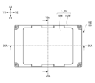
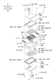
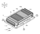
以下、図面を参照し、本発明の実施形態に係る振動発生装置101について説明する。図1A及び図1Bは、振動発生装置101の外形図である。具体的には、図1Aは、振動発生装置101の斜視図であり、図1Bは、振動発生装置101の上面図である。図2は、振動発生装置101の分解斜視図である。
The
図1A、図1B、及び図2のそれぞれにおけるX1は三次元直交座標系を構成するX軸の一方向を表し、X2はX軸の他方向を表す。また、Y1は三次元直交座標系を構成するY軸の一方向を表し、Y2は他方向を表す。同様に、Z1は三次元直交座標系を構成するZ軸の一方向を表し、Z2はZ軸の他方向を表す。本実施形態では、振動発生装置101のX1側は、振動発生装置101の前側(正面側)に相当し、振動発生装置101のX2側は、振動発生装置101の後側(背面側)に相当する。また、振動発生装置101のY1側は、振動発生装置101の左側に相当し、振動発生装置101のY2側は、振動発生装置101の右側に相当する。そして、振動発生装置101のZ1側は、振動発生装置101の上側に相当し、振動発生装置101のZ2側は、振動発生装置101の下側に相当する。他の図においても同様である。
1A, 1B, and 2, X1 represents one direction of the X axis constituting the three-dimensional orthogonal coordinate system, and X2 represents the other direction of the X axis. Furthermore, Y1 represents one direction of the Y axis constituting the three-dimensional orthogonal coordinate system, and Y2 represents the other direction. Similarly, Z1 represents one direction of the Z axis constituting the three-dimensional orthogonal coordinate system, and Z2 represents the other direction of the Z axis. In this embodiment, the X1 side of the
振動装置VEは、制御部CTR及び振動発生装置101を有する。振動発生装置101は、固定体としての筐体HSと、筐体HS内に収容される可動体MBと、筐体HSに取り付けられるコイル4と、を有する。制御部CTRは、筐体HSに固定された絶縁基板(図示せず。)上に設けられた入力端子(図示せず。)に接続されている。なお、図1Aに示す破線は、制御部CTRと絶縁基板上に設けられた入力端子とが電気的に接続されていることを模式的に示している。
The vibration device VE has a control unit CTR and a
筐体HSは、図1Aに示すように、略直方体の外形を有し、XY平面に平行な面(上面及び下面)の面積が最も広くなるように構成されている。本実施形態では、筐体HSは、ケース1及びサイドケース2で構成されている。
As shown in FIG. 1A, the housing HS has a generally rectangular parallelepiped shape and is configured so that the areas of the faces parallel to the XY plane (top and bottom faces) are the widest. In this embodiment, the housing HS is composed of a
ケース1は、図1Aに示すように、筐体HSの天面を形成する上側ケース1Uと、筐体HSの底面を形成する下側ケース1Dとを含む。上側ケース1U及び下側ケース1Dは何れも平板状の部材である。本実施形態では、上側ケース1U及び下側ケース1Dは同じ形状及び同じ大きさを有する。すなわち、上側ケース1U及び下側ケース1Dは同一部品として構成されている。
As shown in FIG. 1A, the
また、上側ケース1Uは、前後対称且つ左右対称となるように形成されている。下側ケース1Dについても同様である。そして、上側ケース1Uと下側ケース1Dとは、互いに上下対称となるように配置されている。
The
具体的には、上側ケース1Uは、上側磁性部材1UM及び上側枠体1UWを含む。同様に、下側ケース1Dは、下側磁性部材1DM及び下側枠体1DWを含む。なお、以下では、上側磁性部材1UM及び下側磁性部材1DMは磁性部材MGとも称され、上側枠体1UW及び下側枠体1DWは枠体FBとも称される。
Specifically, the
磁性部材MGは、磁束源5から離れたところに磁束源5と磁気的に引き合うように配置される部材である。本実施形態では、磁性部材MGは、可動体MBを構成する磁束源5とは接触しないように、且つ、磁束源5を所定位置に磁気的に保持できるように、枠体FBに固定されている。磁束源5が所定位置から変位している場合、磁束源5が発生させる磁力に基づく磁束源5と磁性部材MGとの間の吸引力により、磁性部材MGは、磁束源5を所定位置に引き戻すように作用する。所定位置は、例えば、可動体MBが可動範囲の中心に位置するときの磁束源5の位置である。なお、本実施形態では、可動体MBは、振動発生装置101に電力が供給されていないときに可動範囲の中心に位置するように構成されている。
The magnetic member MG is a member disposed away from the
枠体FBは、磁性部材MGを支持するための非磁性部材である。本実施形態では、枠体FBは、オーステナイト系ステンレス鋼で形成されている。但し、枠体FBは、合成樹脂で形成されていてもよい。磁性部材MGは、接着剤によって枠体FBに接合されている。 The frame body FB is a non-magnetic member for supporting the magnetic member MG. In this embodiment, the frame body FB is made of austenitic stainless steel. However, the frame body FB may be made of synthetic resin. The magnetic member MG is joined to the frame body FB by an adhesive.
サイドケース2は、筐体HSの側面を構成するように形成されている。本実施形態では、サイドケース2は、非磁性部材であり、オーステナイト系ステンレス鋼で形成されている。但し、サイドケース2は、合成樹脂で形成されていてもよい。具体的には、サイドケース2は、平板状に形成された四つの側板部2Aを備えている。より具体的には、側板部2Aは、図2に示すように、互いに対向する第1側板部2A1及び第3側板部2A3と、第1側板部2A1及び第3側板部2A3のそれぞれに垂直で且つ互いに対向する第2側板部2A2及び第4側板部2A4とを有する。
The
ケース1は、締結部材3によりサイドケース2に締結される。具体的には、締結部材3は、上側締結部材3U及び下側締結部材3Dを含む。本実施形態では、締結部材3は、プラスドライバで操作できるように構成された雄ネジであり、サイドケース2の四隅に形成された雌ネジ孔2Tとかみ合うように構成されている。サイドケース2の四隅に形成された雌ネジ孔2Tは、Z軸方向に沿ってサイドケース2の角部を貫通するように形成されており、第1雌ネジ孔2T1~第4雌ネジ孔2T4を含む。そして、上側ケース1U(上側枠体1UW)は、四つの上側締結部材3U(第1上側雄ネジ3U1~第4上側雄ネジ3U4)により、サイドケース2に締結されている。具体的には、第1上側雄ネジ3U1は、サイドケース2の右前隅に形成された第1雌ネジ孔2T1の上側開口にねじ込まれ、第2上側雄ネジ3U2は、サイドケース2の左前隅に形成された第2雌ネジ孔2T2の上側開口にねじ込まれ、第3上側雄ネジ3U3は、サイドケース2の左後隅に形成された第3雌ネジ孔2T3の上側開口にねじ込まれ、第4上側雄ネジ3U4は、サイドケース2の右後隅に形成された第4雌ネジ孔2T4の上側開口にねじ込まれる。同様に、下側ケース1D(下側枠体1DW)は、四つの下側締結部材3D(第1下側雄ネジ3D1~第4下側雄ネジ3D4)により、サイドケース2に締結されている。具体的には、第1下側雄ネジ3D1は、サイドケース2の右前隅に形成された第1雌ネジ孔2T1の下側開口にねじ込まれ、第2下側雄ネジ3D2は、サイドケース2の左前隅に形成された第2雌ネジ孔2T2の下側開口にねじ込まれ、第3下側雄ネジ3D3は、サイドケース2の左後隅に形成された第3雌ネジ孔2T3の下側開口にねじ込まれ、第4下側雄ネジ3D4は、サイドケース2の右後隅に形成された第4雌ネジ孔2T4の下側開口にねじ込まれる。
The
コイル4は、駆動手段DMを構成する部材である。本実施形態では、コイル4は、絶縁材料で表面を被覆された導電線が巻回されて形成される巻き線コイルであり、ケース1に固定されている。図2は、明瞭化のため、導電線の詳細な巻回状態の図示を省略している。コイル4を図示する他の図においても同様である。コイル4は、積層コイル又は薄膜コイル等であってもよい。具体的には、コイル4は、上側ケース1U(上側磁性部材1UM)の下側(Z2側)の面に固定される上側コイル4Uと、下側ケース1D(下側磁性部材1DM)の上側(Z1側)の面に固定される下側コイル4Dと、を含む。そして、上側コイル4Uは、Y軸方向に沿って並置され且つ直列接続される第1上側コイル4U1、第2上側コイル4U2、及び第3上側コイル4U3を含み、下側コイル4Dは、Y軸方向に沿って並置され且つ直列接続される第1下側コイル4D1、第2下側コイル4D2、及び第3下側コイル4D3を含む。なお、以下では、第1上側コイル4U1及び第1下側コイル4D1は左側コイル4Lとも称され、第2上側コイル4U2及び第2下側コイル4D2は中央コイル4Cとも称され、第3上側コイル4U3及び第3下側コイル4D3は右側コイル4Rとも称される。
The coil 4 is a member constituting the driving means DM. In this embodiment, the coil 4 is a wound coil formed by winding a conductive wire whose surface is coated with an insulating material, and is fixed to the
制御部CTRは、可動体MBの動きを制御できるように構成されている。本実施形態では、制御部CTRは、電子回路及び不揮発性記憶装置等を含む装置であり、コイル4を流れる電流の向き及び大きさを制御できるように構成されている。制御部CTRは、コンピュータ等の外部装置からの制御指令に応じてコイル4を流れる電流の向き及び大きさを制御するように構成されていてもよく、外部装置からの制御指令を受けずにコイル4を流れる電流の向き及び大きさを制御するように構成されていてもよい。なお、本実施形態では、制御部CTRは、筐体HSの外部に設置されているが、筐体HSの内部に設置されていてもよい。 The control unit CTR is configured to be able to control the movement of the movable body MB. In this embodiment, the control unit CTR is a device including an electronic circuit and a non-volatile memory device, and is configured to be able to control the direction and magnitude of the current flowing through the coil 4. The control unit CTR may be configured to control the direction and magnitude of the current flowing through the coil 4 in response to a control command from an external device such as a computer, or may be configured to control the direction and magnitude of the current flowing through the coil 4 without receiving a control command from an external device. Note that, although the control unit CTR is installed outside the housing HS in this embodiment, it may also be installed inside the housing HS.
可動体MBは、筐体HSを振動させることができるように構成されている。本実施形態では、可動体MBは、筐体HS内に取り付けられた状態で往復動することにより、筐体HSを振動させることができるように構成されている。 The movable body MB is configured to be able to vibrate the housing HS. In this embodiment, the movable body MB is configured to be able to vibrate the housing HS by reciprocating while attached inside the housing HS.
次に、図3A、図3B、及び図4を参照し、可動体MBの詳細について説明する。図3A、図3B、及び図4は、可動体MBの外形図である。具体的には、図3Aは、可動体MBの全体の斜視図であり、図3Bは、可動体MBの分解斜視図である。図4は、サイドケース2に取り付けられた可動体MBの上面図である。
Next, the details of the movable body MB will be described with reference to Figures 3A, 3B, and 4. Figures 3A, 3B, and 4 are external views of the movable body MB. Specifically, Figure 3A is an overall perspective view of the movable body MB, and Figure 3B is an exploded perspective view of the movable body MB. Figure 4 is a top view of the movable body MB attached to the
可動体MBは、磁束源5及び磁束源保持部材6を含むように構成されている。具体的には、可動体MBは、所定方向に延びる振動軸VA(図3A参照。)に沿って筐体HS(サイドケース2)に対して往復動(振動)できるように構成されている。
The movable body MB is configured to include a
磁束源5は、駆動手段DMを構成する部材であり、磁束を発生させることができるように構成されている。本実施形態では、磁束源5は、永久磁石であり、左側磁石5L、中央磁石5C、及び右側磁石5Rを含む。中央磁石5Cは、第1中央磁石5C1及び第2中央磁石5C2を含む。左側磁石5L、第1中央磁石5C1、第2中央磁石5C2、及び右側磁石5Rは何れも、Z軸方向に沿って二極に着磁された永久磁石であり、Y軸方向に沿って並置されている。なお、図2、図3A、図3B、及び図4では、明瞭化のため、磁束源5としての永久磁石には、N極部分に粗いクロスパターンが付され、S極部分に細かいクロスパターンが付されている。
The
磁束源保持部材6は、磁束源5を保持できるように構成されている。本実施形態では、磁束源保持部材6は、合成樹脂で形成された矩形枠状の部材であり、左側磁石5L、第1中央磁石5C1、第2中央磁石5C2、及び右側磁石5RをY軸方向に沿って略等間隔で保持できるように構成されている。
The magnetic flux
駆動手段DMは、可動体MBを振動軸VAに沿って振動させることができるように構成されている。本実施形態では、駆動手段DMは、コイル4及び磁束源5で構成され、制御部CTRを通じてコイル4に供給される電流の向き及び大きさに応じた、コイル4と磁束源5との間に作用する電磁力を利用し、可動体MB(磁束源5)を振動軸VAに沿って振動させることができるように構成されている。
The driving means DM is configured to vibrate the movable body MB along the vibration axis VA. In this embodiment, the driving means DM is composed of a coil 4 and a
固定側磁束源7は、磁気バネMSを構成する部材であり、サイドケース2に固定された状態で磁束を発生させることができるように構成されている。本実施形態では、固定側磁束源7は、サイドケース2に固定された永久磁石であり、左固定側磁石7L及び右固定側磁石7Rを含む。左固定側磁石7L及び右固定側磁石7Rは何れも、Z軸方向に沿って二極に着磁された永久磁石である。左固定側磁石7Lは、サイドケース2の第2側板部2A2の内面に接着剤で固定され、右固定側磁石7Rは、サイドケース2の第4側板部2A4の内面に接着剤で固定されている。なお、図4では、明瞭化のため、固定側磁束源7としての永久磁石には、N極部分に粗いクロスパターンが付され、S極部分に細かいクロスパターンが付されている。
The fixed-side
具体的には、左側磁石5LのN極部分は、左右方向(Y軸方向)において、左固定側磁石7LのN極部分と対向するように配置され、且つ、左側磁石5LのS極部分は、左右方向(Y軸方向)において、左固定側磁石7LのS極部分と対向するように配置されている。また、右側磁石5RのN極部分は、左右方向(Y軸方向)において、右固定側磁石7RのN極部分と対向するように配置され、且つ、右側磁石5RのS極部分は、左右方向(Y軸方向)において、右固定側磁石7RのS極部分と対向するように配置されている。
Specifically, the N pole of the
磁気バネMSは、駆動手段DMによって可動体MBが初期位置(可動範囲の中心)から移動したときに、可動体MBを初期位置に戻そうとする復元力を発生させることができるように構成されている。本実施形態では、磁気バネMSは、磁束源5の一部と固定側磁束源7とで構成され、可動体MBを初期位置に戻すことができるように構成されている。
The magnetic spring MS is configured to generate a restoring force that attempts to return the movable body MB to its initial position when the movable body MB is moved from its initial position (the center of the movable range) by the driving means DM. In this embodiment, the magnetic spring MS is composed of a part of the
具体的には、磁気バネMSは、左磁気バネMSL及び右磁気バネMSRを含む。左磁気バネMSLは、左側磁石5L及び左固定側磁石7Lで構成され、左側磁石5Lと左固定側磁石7Lとの間の斥力により、初期位置から左方に移動した可動体MBを初期位置に戻すことができるように構成されている。同様に、右磁気バネMSRは、右側磁石5R及び右固定側磁石7Rで構成され、右側磁石5Rと右固定側磁石7Rとの間の斥力により、初期位置から右方に移動した可動体MBを初期位置に戻すことができるように構成されている。
Specifically, the magnetic spring MS includes a left magnetic spring MSL and a right magnetic spring MSR. The left magnetic spring MSL is composed of a
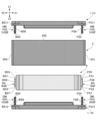
次に、図5A、図5B、図6A、図6B、図7A、及び図7Bを参照し、ガイド手段GMについて説明する。図5A及び図5Bは、ガイド手段GMを構成する部材の詳細図である。具体的には、図5Aは、分解された状態にある上側ケース1U、下側ケース1D、サイドケース2、及び磁束源保持部材6の左側面図である。図5Bは、組み合わされた状態にある上側ケース1U、下側ケース1D、及び磁束源保持部材6の左側面図である。図5A及び図5Bでは、明瞭化のため、ケース1及びサイドケース2には細かいドットパターンが付され、磁束源保持部材6には粗いドットパターンが付されている。また、図5Bでは、明瞭化のため、図5Aでは図示されているサイドケース2の図示が省略されている。図6A及び図6Bは、振動発生装置101を構成する部材の断面図である。具体的には、図6Aは、図1Bに示す切断線(一点鎖線VIA-VIA)を含むXZ平面に平行な平面における振動発生装置101の断面をY1側から見たときの図である。図6Bは、図6Aにおけるコイル4及び磁束源5の図示が省略された図である。図7A及び図7Bは、ガイド手段GMを構成する部材の斜視図である。具体的には、図7Aは、組み合わされた状態にある上側ケース1U、下側ケース1D、及び磁束源保持部材6の斜視図である。図7Bは、組み合わされた状態にある下側ケース1D及び磁束源保持部材6の斜視図である。図7A及び図7Bでは、明瞭化のため、磁束源保持部材6に粗いドットパターンが付されている。また、図7A及び図7Bでは、磁束源保持部材6と固定側磁束源7との間の位置関係を示すため、固定側磁束源7が図示されている。また、図7Bでは、図7Aにおける上側ケース1Uの図示が省略された状態が示され、磁束源保持部材6により磁束源5が保持された状態が見えるように示されている。
Next, the guide means GM will be described with reference to Figures 5A, 5B, 6A, 6B, 7A, and 7B. Figures 5A and 5B are detailed views of the members constituting the guide means GM. Specifically, Figure 5A is a left side view of the
ガイド手段GMは、可動体MBを固定体としての筐体HS内で左右方向(Y軸方向)に沿って往復動可能にガイドできるように構成されている。本実施形態では、ガイド手段GMは、上側ケース1Uと一体的に形成されるとともに上側ケース1Uから下方(Z2方向)に延設された上側ガイド部1UGと、下側ケース1Dと一体的に形成されるとともに下側ケース1Dから上方(Z1方向)に延設された下側ガイド部1DGとを含む。そして、ガイド手段GMは、可動体MBを構成する磁束源保持部材6に形成された突出部である被ガイド部6Gが上側ガイド部1UG及び下側ガイド部1DGによって左右方向に沿って摺動自在にガイドされるように構成されている。
The guide means GM is configured to guide the movable body MB so that it can reciprocate along the left-right direction (Y-axis direction) within the housing HS as a fixed body. In this embodiment, the guide means GM includes an upper guide portion 1UG formed integrally with the
具体的には、上側ガイド部1UGは、サイドケース2の第1側板部2A1(図2参照。)に対向してY軸方向に延びる上前側ガイド部1UGFと、サイドケース2の第3側板部2A3(図2参照。)に対向してY軸方向に延びる上後側ガイド部1UGBと、を含む。同様に、下側ガイド部1DGは、サイドケース2の第1側板部2A1(図2参照。)に対向してY軸方向に延びる下前側ガイド部1DGFと、サイドケース2の第3側板部2A3(図2参照。)に対向してY軸方向に延びる下後側ガイド部1DGBと、を含む。
Specifically, the upper guide portion 1UG includes an upper front guide portion 1UGF that extends in the Y-axis direction facing the first side plate portion 2A1 (see FIG. 2) of the
磁束源保持部材6に形成された被ガイド部6Gは、サイドケース2の第1側板部2A1(図2参照。)に対向してY軸方向に延びる前側被ガイド部6GFと、サイドケース2の第3側板部2A3(図2参照。)に対向してY軸方向に延びる後側被ガイド部6GBと、を含む。
The guided
そして、図5Bに示すように、上前側ガイド部1UGFの先端と下前側ガイド部1DGFの先端とは、前側被ガイド部6GFを挟んで互いに対向するように組み合わされ、且つ、上後側ガイド部1UGBの先端と下後側ガイド部1DGBの先端とは、後側被ガイド部6GBを挟んで互いに対向するように組み合わされる。 As shown in FIG. 5B, the tip of the upper front guide portion 1UGF and the tip of the lower front guide portion 1DGF are combined so as to face each other with the front guided portion 6GF in between, and the tip of the upper rear guide portion 1UGB and the tip of the lower rear guide portion 1DGB are combined so as to face each other with the rear guided portion 6GB in between.
本実施形態では、上前側ガイド部1UGFの先端、及び、下前側ガイド部1DGFの先端は何れも、前側被ガイド部6GFと接触するように組み合わされる。すなわち、前側被ガイド部6GFは、上前側ガイド部1UGFの先端と下前側ガイド部1DGFの先端との間に形成される空間と略同じ形状を有するように構成されている。具体的には、前側被ガイド部6GFは、磁束源保持部材6の長手方向の全長の大部分にわたって連続的に延びる一つの略直方体形状の突出部として形成されている。しかしながら、前側被ガイド部6GFは、磁束源保持部材6の長手方向に沿って断続的に配置される複数の突出部の組み合わせであってもよい。後側被ガイド部6GBについても同様である。また、本実施形態では、磁束源保持部材6は、前後対称となるように形成されている。すなわち、前側被ガイド部6GFと後側被ガイド部6GBとは同じ形状及び同じ大きさを有するように形成されている。但し、前側被ガイド部6GFと後側被ガイド部6GBとは異なる形状を有していてもよい。
In this embodiment, the tip of the upper front guide part 1UGF and the tip of the lower front guide part 1DGF are combined so as to come into contact with the front guided part 6GF. That is, the front guided part 6GF is configured to have approximately the same shape as the space formed between the tip of the upper front guide part 1UGF and the tip of the lower front guide part 1DGF. Specifically, the front guided part 6GF is formed as a single approximately rectangular parallelepiped-shaped protrusion that extends continuously over most of the entire length of the magnetic flux
図5に示す例では、磁束源保持部材6は、ケース1及びサイドケース2に組み合わされたときに、前側被ガイド部6GFの上面FS1が上前側ガイド部1UGFの先端面FS2と接触し、且つ、前側被ガイド部6GFの下面FS3が下前側ガイド部1DGFの先端面FS4と接触するように構成されている。また、磁束源保持部材6は、上側前面FS5(前面のうち前側被ガイド部6GFの上方に位置する部分)が上前側ガイド部1UGFの内面FS6と接触し、下側前面FS7(前面のうち前側被ガイド部6GFの下方に位置する部分)が下前側ガイド部1DGFの内面FS8と接触するように構成されている。一方で、磁束源保持部材6は、前側被ガイド部6GFの前面FS9がサイドケース2の第1側板部2A1の内面FS10(図6A参照。)と接触しないように構成されている。なお、ケース1は、上前側ガイド部1UGFの外面FS11とサイドケース2の第1側板部2A1の内面FS10とが接触し、且つ、下前側ガイド部1DGFの外面FS12とサイドケース2の第1側板部2A1の内面FS10とが接触するように構成されている。
5, the magnetic flux
同様に、磁束源保持部材6は、ケース1及びサイドケース2に組み合わされたときに、後側被ガイド部6GBの上面BS1が上後側ガイド部1UGBの先端面BS2と接触し、且つ、後側被ガイド部6GBの下面BS3が下後側ガイド部1DGBの先端面BS4と接触するように構成されている。また、磁束源保持部材6は、上側後面BS5(後面のうち後側被ガイド部6GBの上方に位置する部分)が上後側ガイド部1UGBの内面BS6と接触し、下側後面BS7(後面のうち後側被ガイド部6GBの下方に位置する部分)が下後側ガイド部1DGBの内面BS8と接触するように構成されている。一方で、磁束源保持部材6は、後側被ガイド部6GBの後面BS9がサイドケース2の第3側板部2A3の内面BS10(図6A参照。)と接触しないように構成されている。なお、ケース1は、上後側ガイド部1UGBの外面BS11とサイドケース2の第3側板部2A3の内面BS10とが接触し、且つ、下後側ガイド部1DGBの外面BS12とサイドケース2の第3側板部2A3の内面BS10とが接触するように構成されている。
Similarly, the magnetic flux
上述のように、被ガイド部6Gは、上側ガイド部1UGと下側ガイド部1DGとの間で、図7A及び図7Bのそれぞれにおける双方向矢印AR1で示す方向に摺動できるように構成されている。具体的には、被ガイド部6Gは、その上面を上側ガイド部1UGの先端面と接触させ、その下面を下側ガイド部1DGの先端面と接触させながら左右方向(Y軸方向)に往復動できるように構成されている。
As described above, the guided
この構成により、磁束源保持部材6は、前後方向及び上下方向のそれぞれにおける移動が制限される一方で、左右方向における円滑な移動が許容される。
This configuration limits the movement of the magnetic flux
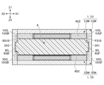
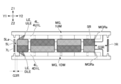
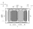
次に、図8A、図8B、図9A~図9C、及び図10A~図10Cを参照し、駆動手段DM及び磁気バネMSの詳細について説明する。図8A及び図8Bは、固定体としての筐体HSに固定されたコイル4の詳細図である。具体的には、図8Aは、下側ケース1Dに固定された下側コイル4Dの斜視図である。図8Bは、下側ケース1Dに固定された下側コイル4Dの上面図である。図8A及び図8Bでは、明瞭化のため、下側コイル4Dにドットパターンが付されている。図9Aは、図1Bに示す切断線(一点鎖線IXA-IXA)を含むYZ平面に平行な仮想平面における振動発生装置101の断面をX1側から見たときの図である。図9B及び図9Cは、図7Aに示す切断線(一点鎖線IXB-IXB)を含むYZ平面に平行な仮想平面におけるケース1、コイル4、及び磁束源5の断面をX1側から見たときの図である。具体的には、図9Aは、可動体MB(磁束源5)が可動範囲の中心に位置するときの振動発生装置101の断面図である。図9Bは、可動体MB(磁束源5)が可動範囲の右端に位置するときのケース1、コイル4、磁束源5、及び固定側磁束源7の断面図である。図9Cは、可動体MB(磁束源5)が可動範囲の左端に位置するときのケース1、コイル4、磁束源5、及び固定側磁束源7の断面図である。図9A~図9Cでは、明瞭化のため、磁束源5及び固定側磁束源7のそれぞれを構成する永久磁石には、断面を表すパターンの代わりに、N極部分に粗いクロスパターンが付され、S極部分に細かいクロスパターンが付されている。図10A~図10Cは、下側ケース1Dに固定された下側コイル4Dの上を左右方向(Y軸方向)に移動可能な磁束源5の上面図である。具体的には、図10Aは、可動体MB(磁束源5)が可動範囲の中心に位置するときの下側ケース1D、下側コイル4D、磁束源5、及び固定側磁束源7の上面図である。図10Bは、可動体MB(磁束源5)が可動範囲の右端に位置するときの下側ケース1D、下側コイル4D、磁束源5、及び固定側磁束源7の上面図である。図10Cは、可動体MB(磁束源5)が可動範囲の左端に位置するときの下側ケース1D、下側コイル4D、磁束源5、及び固定側磁束源7の上面図である。
Next, the details of the driving means DM and the magnetic spring MS will be described with reference to Figures 8A, 8B, 9A to 9C, and 10A to 10C. Figures 8A and 8B are detailed views of the coil 4 fixed to the housing HS as a fixed body. Specifically, Figure 8A is a perspective view of the lower coil 4D fixed to the
駆動手段DMの構成要素の一つであるコイル4は、図2に示すように、上側ケース1Uの下側(Z2側)の面に固定される上側コイル4Uと、下側ケース1Dの上側(Z1側)の面に固定される下側コイル4Dと、を含む。
The coil 4, which is one of the components of the driving means DM, includes an upper coil 4U fixed to the lower (Z2 side) surface of the
そして、下側コイル4Dは、図8A及び図8Bに示すように、下側ケース1Dの上面(Z1側の面)に接着剤で固定される三つのコイル(第1下側コイル4D1、第2下側コイル4D2、及び第3下側コイル4D3)を含む。なお、図8A及び図8Bを参照する以下の説明は、下側コイル4Dに関するが、上側コイル4Uにも同様に適用される。上側ケース1Uと下側ケース1Dとは同じ形状及び同じ大きさを有し、上側コイル4Uと下側コイル4Dとは同じ形状及び同じ大きさを有するためである。
The lower coil 4D includes three coils (first lower coil 4D1, second lower coil 4D2, and third lower coil 4D3) that are fixed with adhesive to the upper surface (Z1 side surface) of the
下側コイル4Dを構成している三つのコイルのそれぞれは、下側内部空間1DPを囲むように巻回されている。具体的には、第1下側コイル4D1は、左下側内部空間1DPLを囲むように巻回され、第2下側コイル4D2は、中央下側内部空間1DPCを囲むように巻回され、第3下側コイル4D3は、右下側内部空間1DPRを囲むように巻回されている。 Each of the three coils constituting the lower coil 4D is wound to surround the lower internal space 1DP. Specifically, the first lower coil 4D1 is wound to surround the lower left internal space 1DPL, the second lower coil 4D2 is wound to surround the central lower internal space 1DPC, and the third lower coil 4D3 is wound to surround the lower right internal space 1DPR.
第1下側コイル4D1は、左下側内部空間1DPLの左側(Y1側)に位置し且つ左下側内部空間1DPLに沿って延びる左側束線部4D1Lと、左下側内部空間1DPLの右側(Y2側)に位置し且つ左下側内部空間1DPLに沿って延びる右側束線部4D1Rと、を含む。なお、束線部は、コイルを構成する導電線が前後方向(X軸方向)に沿って直線状に延びる部分を意味する。 The first lower coil 4D1 includes a left bundled wire portion 4D1L located on the left side (Y1 side) of the lower left internal space 1DPL and extending along the lower left internal space 1DPL, and a right bundled wire portion 4D1R located on the right side (Y2 side) of the lower left internal space 1DPL and extending along the lower left internal space 1DPL. The bundled wire portion refers to the portion where the conductive wires that make up the coil extend linearly in the front-to-rear direction (X-axis direction).
図8Bでは、明瞭化のため、第1下側コイル4D1における左側束線部4D1L及び右側束線部4D1Rには、第1下側コイル4D1における他の部分に付されているドットパターンよりも細かいドットパターンが付されている。第2下側コイル4D2及び第3下側コイル4D3についても同様である。 In FIG. 8B, for clarity, the left bundled wire portion 4D1L and the right bundled wire portion 4D1R of the first lower coil 4D1 are given a finer dot pattern than the dot pattern given to other parts of the first lower coil 4D1. The same is true for the second lower coil 4D2 and the third lower coil 4D3.
第2下側コイル4D2は、中央下側内部空間1DPCの左側(Y1側)に位置し且つ中央下側内部空間1DPCに沿って延びる左側束線部4D2Lと、中央下側内部空間1DPCの右側(Y2側)に位置し且つ中央下側内部空間1DPCに沿って延びる右側束線部4D2Rと、を含む。 The second lower coil 4D2 includes a left bundled wire portion 4D2L located on the left side (Y1 side) of the central lower internal space 1DPC and extending along the central lower internal space 1DPC, and a right bundled wire portion 4D2R located on the right side (Y2 side) of the central lower internal space 1DPC and extending along the central lower internal space 1DPC.
同様に、第3下側コイル4D3は、右下側内部空間1DPRの左側(Y1側)に位置し且つ右下側内部空間1DPRに沿って延びる左側束線部4D3Lと、右下側内部空間1DPRの右側(Y2側)に位置し且つ右下側内部空間1DPRに沿って延びる右側束線部4D3Rと、を含む。 Similarly, the third lower coil 4D3 includes a left bundled wire portion 4D3L located on the left side (Y1 side) of the lower right internal space 1DPR and extending along the lower right internal space 1DPR, and a right bundled wire portion 4D3R located on the right side (Y2 side) of the lower right internal space 1DPR and extending along the lower right internal space 1DPR.
第1下側コイル4D1の左側束線部4D1L及び右側束線部4D1Rは、磁束源5が発生させる磁束が通過する部分、すなわち、可動体MBを左右方向に移動させるためのローレンツ力に基づく駆動力を発生させる部分である。第2下側コイル4D2の左側束線部4D2L及び右側束線部4D2R、並びに、第3下側コイル4D3の左側束線部4D3L及び右側束線部4D3Rについても同様である。
The left side wire portion 4D1L and the right side wire portion 4D1R of the first lower coil 4D1 are the portions through which the magnetic flux generated by the
駆動手段DMの構成要素の別の一つである磁束源5は、図9A~図9Cに示すように、上側コイル4Uと下側コイル4Dとの間の空間内において、左右方向(Y軸方向)に移動可能に配置されている。具体的には、磁束源5は、左側磁石5L、第1中央磁石5C1、第2中央磁石5C2、及び右側磁石5Rを含む。そして、左側磁石5L、第1中央磁石5C1、第2中央磁石5C2、及び右側磁石5Rのそれぞれは、磁束源保持部材6(図9A参照。)により、互いに所定の間隔を空けた状態で保持されている。
The
本実施形態では、図9Aに示すように、左側磁石5Lは、その幅W1が右側磁石5Rの幅W2と略同じになるように構成されている。また、第1中央磁石5C1は、その幅W3が第2中央磁石5C2の幅W4と略同じになるように構成されている。また、左側磁石5Lは、その幅W1が第1中央磁石5C1の幅W3の略2分の1となるように構成されている。
In this embodiment, as shown in FIG. 9A, the
本実施形態では、コイル4を構成している六つのコイルは、同じ形状及び同じ大きさを有するように構成されている。すなわち、図9Bに示すように、第1上側コイル4U1の左側束線部4U1Lの幅W5、第1上側コイル4U1の右側束線部4U1Rの幅W6、第2上側コイル4U2の左側束線部4U2Lの幅W7、第2上側コイル4U2の右側束線部4U2Rの幅W8、第3上側コイル4U3の左側束線部4U3Lの幅W9、第3上側コイル4U3の右側束線部4U3Rの幅W10、第1下側コイル4D1の左側束線部4D1Lの幅W11、第1下側コイル4D1の右側束線部4D1Rの幅W12、第2下側コイル4D2の左側束線部4D2Lの幅W13、第2下側コイル4D2の右側束線部4D2Rの幅W14、第3下側コイル4D3の左側束線部4D3Lの幅W15、及び、第3下側コイル4D3の右側束線部4D3Rの幅W16は全て同じ大きさである。 In this embodiment, the six coils constituting the coil 4 are configured to have the same shape and size. That is, as shown in FIG. 9B, the width W5 of the left bundled wire portion 4U1L of the first upper coil 4U1, the width W6 of the right bundled wire portion 4U1R of the first upper coil 4U1, the width W7 of the left bundled wire portion 4U2L of the second upper coil 4U2, the width W8 of the right bundled wire portion 4U2R of the second upper coil 4U2, the width W9 of the left bundled wire portion 4U3L of the third upper coil 4U3, the width W10 of the right bundled wire portion 4U3R of the third upper coil 4U3, The width W11 of the left bundled wire portion 4D1L of the lower coil 4D1, the width W12 of the right bundled wire portion 4D1R of the first lower coil 4D1, the width W13 of the left bundled wire portion 4D2L of the second lower coil 4D2, the width W14 of the right bundled wire portion 4D2R of the second lower coil 4D2, the width W15 of the left bundled wire portion 4D3L of the third lower coil 4D3, and the width W16 of the right bundled wire portion 4D3R of the third lower coil 4D3 are all the same size.
そして、左側磁石5Lは、その幅W1が第1上側コイル4U1の左側束線部4U1Lの幅W5と略同じになるように構成されている。また、第1中央磁石5C1は、その幅W3が、第1上側コイル4U1の右側束線部4U1Rの幅W6と第2上側コイル4U2の左側束線部4U2Lの幅W7との合計と略同じになるように構成されている。
The
また、振動発生装置101は、図9Aに示すように、磁束源5の幅WD1が磁性部材MGの幅WD2より大きくなるように構成されている。
Furthermore, as shown in FIG. 9A, the
この構成により、振動発生装置101では、磁性部材MGは、可動体MB(磁束源5)が可動範囲の中心に位置するときであっても、磁束源5と磁性部材MGとの間の吸引力により、磁束源5が可動範囲の中心から移動しないように磁束源5を磁気的に保持できる。この効果は、磁束源5の幅WD1と磁性部材MGの幅WD2とが同じである場合にも同様に実現される。
With this configuration, in the
また、左側磁石5L、第1中央磁石5C1、第2中央磁石5C2、及び右側磁石5Rのそれぞれは、振動発生装置101の中心を通る中心線CLを含むXY平面に平行な仮想平面がN極部分とS極部分との間の境界面となるように配置されている。左固定側磁石7L及び右固定側磁石7Rについても同様である。
The
なお、左固定側磁石7Lは、その幅W21が左側磁石5Lの幅W1よりも小さくなるように構成され、右固定側磁石7Rは、その幅W22が右側磁石5Rの幅W2よりも小さくなるように構成されている。
The left
また、振動発生装置101は、図9Aに示すように、中央磁石5Cの高さH1と、左側磁石5L及び右側磁石5Rのそれぞれの高さH2と、左固定側磁石7L及び右固定側磁石7Rのそれぞれの高さH3とが同じになるように構成されている。
As shown in FIG. 9A, the
また、振動発生装置101は、図10Aに示すように、中央磁石5Cの奥行きDP1と、左側磁石5L及び右側磁石5Rのそれぞれの奥行きDP2と、左固定側磁石7L及び右固定側磁石7Rのそれぞれの奥行きDP3とが同じになるように構成されている。
As shown in FIG. 10A, the
可動体MB(磁束源5)が可動範囲の中心に位置するときには、図9Aに示すように、左側磁石5Lは、N極部分(上側部分)が第1上側コイル4U1の左側束線部4U1Lと対向するように、且つ、S極部分(下側部分)が第1下側コイル4D1の左側束線部4D1Lと対向するように配置されている。また、第1中央磁石5C1は、S極部分(上側部分)が第1上側コイル4U1の右側束線部4U1R及び第2上側コイル4U2の左側束線部4U2Lのそれぞれと対向するように、且つ、N極部分(下側部分)が第1下側コイル4D1の右側束線部4D1R及び第2下側コイル4D2の左側束線部4D2Lのそれぞれと対向するように配置されている。また、第2中央磁石5C2は、N極部分(上側部分)が第2上側コイル4U2の右側束線部4U2R及び第3上側コイル4U3の左側束線部4U3Lのそれぞれと対向するように、且つ、S極部分(下側部分)が第2下側コイル4D2の右側束線部4D2R及び第3下側コイル4D3の左側束線部4D3Lのそれぞれと対向するように配置されている。また、右側磁石5Rは、S極部分(上側部分)が第3上側コイル4U3の右側束線部4U3Rと対向するように、且つ、N極部分(下側部分)が第3下側コイル4D3の右側束線部4D3Rと対向するように配置されている。
When the movable body MB (magnetic flux source 5) is located at the center of the movable range, as shown in FIG. 9A, the
また、図9Aに示すように、左側磁石5Lは、N極部分(上側部分)が左固定側磁石7LのN極部分(上側部分)と間隔G1Lを空けて対向するように、かつ、S極部分(下側部分)が左固定側磁石7LのS極部分(下側部分)と間隔G1Lを空けて対向するように配置されている。同様に、右側磁石5Rは、S極部分(上側部分)が右固定側磁石7RのS極部分(上側部分)と間隔G1Rを空けて対向するように、かつ、N極部分(下側部分)が右固定側磁石7RのN極部分(下側部分)と間隔G1Rを空けて対向するように配置されている。
Also, as shown in FIG. 9A, the
図10Bの破線矢印で示すように下側コイル4Dに電流が流れると、可動体MB(磁束源5)は、ガイド手段GMによってガイドされながら、右方向(Y2方向)に摺動する。具体的には、第1下側コイル4D1に上面視で反時計回りに電流が流れ、第2下側コイル4D2に上面視で時計回りに電流が流れ、且つ、第3下側コイル4D3に上面視で反時計回りに電流が流れると、可動体MB(磁束源5)は、右方向(Y2方向)に摺動する。 When a current flows through the lower coil 4D as shown by the dashed arrow in Figure 10B, the movable body MB (magnetic flux source 5) slides to the right (Y2 direction) while being guided by the guide means GM. Specifically, when a current flows counterclockwise in a top view through the first lower coil 4D1, a current flows clockwise in a top view through the second lower coil 4D2, and a current flows counterclockwise in a top view through the third lower coil 4D3, the movable body MB (magnetic flux source 5) slides to the right (Y2 direction).
下側ケース1Dに固定された下側コイル4Dを構成している導電線内を移動する荷電粒子にローレンツ力が作用し、その反力によって磁束源5としての左側磁石5L、第1中央磁石5C1、第2中央磁石5C2、及び右側磁石5Rが右方向に移動させられるためである。
The Lorentz force acts on the charged particles moving within the conductive wire that constitutes the lower coil 4D fixed to the
同様に、図10Cの破線矢印で示すように下側コイル4Dに電流が流れると、可動体MB(磁束源5)は、ガイド手段GMによってガイドされながら、左方向(Y1方向)に摺動する。具体的には、第1下側コイル4D1に上面視で時計回りに電流が流れ、第2下側コイル4D2に上面視で反時計回りに電流が流れ、且つ、第3下側コイル4D3に上面視で時計回りに電流が流れると、可動体MB(磁束源5)は、左方向(Y1方向)に摺動する。 Similarly, when a current flows through the lower coil 4D as shown by the dashed arrow in Figure 10C, the movable body MB (magnetic flux source 5) slides leftward (Y1 direction) while being guided by the guide means GM. Specifically, when a current flows clockwise in a top view through the first lower coil 4D1, a current flows counterclockwise in a top view through the second lower coil 4D2, and a current flows clockwise in a top view through the third lower coil 4D3, the movable body MB (magnetic flux source 5) slides leftward (Y1 direction).
可動体MB(磁束源5)が右方向(Y2方向)に移動すると、図9Bに示すように、右側磁石5Rの一部は、磁性部材MGの内側面(コイル4に対向する側の面)の右端REよりも右側に突出する。具体的には、右側磁石5Rの一部は、上側磁性部材1UMの内側面の右端UREよりも右側に突出し、且つ、下側磁性部材1DMの内側面の右端DREよりも右側に突出する。そして、右側磁石5Rと磁性部材MGとの間には吸引力が作用しているため、右側磁石5Rのうち、磁性部材MGの内側面の右端REよりも右側に突出した部分5Raは、磁性部材MGの内側面の右端REによって左方向に引き付けられる。この状態において、磁性部材MGの内側面の右端REは、部分5Raから最も近い位置にある、磁性部材MGの部位である。なお、図9Bでは、右側磁石5Rを磁性部材MGに引き付ける吸引力を発生させる磁界を表す磁力線(部分5Raと右端REとの間に延びる磁力線)の一部が点線で表されている。また、図9Bでは、明瞭化のため、磁束源5によって生成される磁界の他の部分を表す磁力線の図示が省略されている。
When the movable body MB (magnetic flux source 5) moves to the right (Y2 direction), as shown in FIG. 9B, a part of the
また、可動体MB(磁束源5)が右方向(Y2方向)に移動すると、図9Bに示すように、磁性部材MGの左端部分は、左側磁石5Lの左端よりも左側に突出する。具体的には、上側磁性部材1UM及び下側磁性部材1DMのそれぞれの左端部分は、左側磁石5Lの左端よりも左側に突出する。そして、左側磁石5Lと磁性部材MGとの間には吸引力が作用しているため、磁性部材MGのうち、左側磁石5Lの左端よりも左側に突出した部分MGLaは、左側磁石5Lを左側に引き付ける。この状態において、左側磁石5Lの左端は、磁性部材MGの部分MGLaから最も近い位置にある、左側磁石5Lの部位である。なお、図9Bでは、左側磁石5Lを磁性部材MGに引き付ける吸引力を発生させる磁界を表す磁力線(部分MGLaと左側磁石5Lの左端との間に延びる磁力線)の一部が点線で表されている。
When the movable body MB (magnetic flux source 5) moves to the right (Y2 direction), as shown in FIG. 9B, the left end portion of the magnetic member MG protrudes to the left of the left end of the
また、図9B及び図10Bに示すように、可動体MB(磁束源5)が右方向(Y2方向)に移動すると、左側磁石5Lと左固定側磁石7Lとの間隔G1L(図9A及び図10A参照。)が間隔G2Lまで広がる一方で、右側磁石5Rと右固定側磁石7Rとの間隔G1R(図9A及び図10A参照。)は間隔G2Rまで狭まる。その結果、右側磁石5Rと右固定側磁石7Rとの間に作用している斥力が強まり、右固定側磁石7Rは、電磁力(駆動力)が弱まったときに、右側磁石5Rを左方向に押し遣る。
Also, as shown in Figures 9B and 10B, when the movable body MB (magnetic flux source 5) moves to the right (Y2 direction), the gap G1L (see Figures 9A and 10A) between the
このように、可動範囲の中心から右方向に変位した可動体MB(磁束源5)は、可動体MB(磁束源5)を可動範囲の中心に戻そうとする力(吸引力及び斥力)を受ける。そして、可動範囲の中心から右方向に変位した可動体MB(磁束源5)は、可動体MBを右方向に移動させようとする力(電磁力)が消失したとき、すなわち、コイル4を流れる電流が消失したときに、その力(吸引力及び斥力)によって左方向に移動し、可動範囲の中心に向かって戻る。 In this way, the movable body MB (magnetic flux source 5) displaced to the right from the center of the movable range is subjected to forces (attraction and repulsion) that attempt to return the movable body MB (magnetic flux source 5) to the center of the movable range. Then, when the force (electromagnetic force) that attempts to move the movable body MB to the right disappears, that is, when the current flowing through coil 4 disappears, the movable body MB (magnetic flux source 5) displaced to the right from the center of the movable range moves to the left by the forces (attraction and repulsion) and returns to the center of the movable range.
反対に、可動体MB(磁束源5)が左方向(Y1方向)に移動すると、図9Cに示すように、左側磁石5Lの一部は、磁性部材MGの内側面(コイル4に対向する側の面)の左端LEよりも左側に突出する。そして、左側磁石5Lと磁性部材MGとの間には吸引力が作用しているため、左側磁石5Lのうち、磁性部材MGの内側面の左端LEよりも左側に突出した部分5Laは、磁性部材MGの内側面の左端LEによって右方向に引き付けられる。この状態において、磁性部材MGの内側面の左端LEは、部分5Laから最も近い位置にある、磁性部材MGの部位である。なお、図9Cでは、左側磁石5Lを磁性部材MGに引き付ける吸引力を発生させる磁界を表す磁力線(部分5Laと左端LEとの間に延びる磁力線)の一部が点線で表されている。また、図9Cでは、明瞭化のため、磁束源5によって生成される磁界の他の部分を表す磁力線の図示が省略されている。
On the other hand, when the movable body MB (magnetic flux source 5) moves leftward (Y1 direction), as shown in FIG. 9C, a part of the
また、可動体MB(磁束源5)が左方向(Y1方向)に移動すると、図9Cに示すように、磁性部材MGの右端部分は、右側磁石5Rの右端よりも右側に突出する。具体的には、上側磁性部材1UM及び下側磁性部材1DMのそれぞれの右端部分は、右側磁石5Rの右端よりも右側に突出する。そして、右側磁石5Rと磁性部材MGとの間には吸引力が作用しているため、磁性部材MGのうち、右側磁石5Rの右端よりも右側に突出した部分MGRaは、右側磁石5Rを右側に引き付ける。この状態において、右側磁石5Rの右端は、磁性部材MGの部分MGRaから最も近い位置にある、右側磁石5Rの部位である。なお、図9Cでは、右側磁石5Rを磁性部材MGに引き付ける吸引力を発生させる磁界を表す磁力線(部分MGRaと右側磁石5Rの右端との間に延びる磁力線)の一部が点線で表されている。
When the movable body MB (magnetic flux source 5) moves leftward (Y1 direction), as shown in FIG. 9C, the right end portion of the magnetic member MG protrudes to the right of the right end of the right-
また、図9C及び図10Cに示すように、可動体MB(磁束源5)が左方向(Y1方向)に移動すると、右側磁石5Rと右固定側磁石7Rとの間隔G1R(図9A及び図10A参照。)が間隔G3Rまで広がる一方で、左側磁石5Lと左固定側磁石7Lとの間隔G1L(図9A及び図10A参照。)は間隔G3Lまで狭まる。その結果、左側磁石5Lと左固定側磁石7Lとの間に作用している斥力が強まり、左固定側磁石7Lは、電磁力(駆動力)が弱まったときに、左側磁石5Lを右方向に押し遣る。
Also, as shown in Figures 9C and 10C, when the movable body MB (magnetic flux source 5) moves leftward (Y1 direction), the gap G1R (see Figures 9A and 10A) between the right-
このように、可動範囲の中心から左方向に変位した可動体MB(磁束源5)は、可動体MB(磁束源5)を可動範囲の中心に戻そうとする力(吸引力及び斥力)を受ける。そして、可動範囲の中心から左方向に変位した可動体MB(磁束源5)は、可動体MBを左方向に移動させようとする力(電磁力)が消失したとき、すなわち、コイル4を流れる電流が消失したときに、その力(吸引力及び斥力)によって右方向に移動し、可動範囲の中心に向かって戻る。 In this way, the movable body MB (magnetic flux source 5) displaced leftward from the center of the movable range is subjected to forces (attraction and repulsion) that attempt to return the movable body MB (magnetic flux source 5) to the center of the movable range. Then, when the force (electromagnetic force) that attempts to move the movable body MB leftward disappears, that is, when the current flowing through coil 4 disappears, the movable body MB (magnetic flux source 5) displaced leftward from the center of the movable range moves rightward due to the forces (attraction and repulsion) and returns toward the center of the movable range.
そのため、可動範囲の中心からずれた位置にある可動体MBは、コイル4に対する電流の供給が停止されると、磁束源5と磁性部材MGとの間の吸引力によって可動範囲の中心に戻される。このようにして、駆動手段DMは、可動体MBを左右方向に振動させることができる。
Therefore, when the supply of current to the coil 4 is stopped, the movable body MB, which is in a position shifted from the center of the movable range, is returned to the center of the movable range by the attractive force between the
上述のように、本発明の実施形態に係る振動発生装置101は、例えば図1A及び図2に示すように、固定体としての筐体HSと、筐体HS内に収容される可動体MBと、可動体MBを筐体HS内で左右方向に沿って往復動可能にガイドするガイド手段GMと、前後方向(X軸方向)に沿って延在し左右方向(Y軸方向)に沿って並設される導電線からなり磁束源5が発生させる磁束と交差するように筐体HSに対して固定されるコイル4と、N極部分とS極部分とが上下方向(Z軸方向)に並ぶように可動体MB(磁束源保持部材6)に対して固定されるとともに上下方向に沿う磁束を発生させる可動側磁束発生部材としての磁束源5と、N極部分とS極部分とが上下方向に並ぶように筐体HS(サイドケース2)に対して固定されるとともに上下方向に沿う磁束を発生させる固定側磁束発生部材としての固定側磁束源7と、を備えている。そして、磁束源5の一つである左側磁石5LのN極部分は、左右方向において、固定側磁束源7の一つである左固定側磁石7LのN極部分と対向するように配置され、且つ、左側磁石5LのS極部分は、左右方向において、左固定側磁石7LのS極部分と対向するように配置されている。また、磁束源5の別の一つである右側磁石5RのN極部分は、左右方向において、固定側磁束源7の別の一つである右固定側磁石7RのN極部分と対向するように配置され、且つ、右側磁石5RのS極部分は、左右方向において、右固定側磁石7RのS極部分と対向するように配置されている。
As described above, the vibration generating device 101 according to an embodiment of the present invention includes, as shown in, for example, Figures 1A and 2, a housing HS as a fixed body, a movable body MB accommodated in the housing HS, a guide means GM that guides the movable body MB so that it can move back and forth in the left-right direction within the housing HS, a coil 4 consisting of conductive wires extending in the front-rear direction (X-axis direction) and arranged in parallel in the left-right direction (Y-axis direction) and fixed to the housing HS so as to intersect with the magnetic flux generated by the magnetic flux source 5, a magnetic flux source 5 as a movable magnetic flux generating member that is fixed to the movable body MB (magnetic flux source holding member 6) so that the N-pole portion and the S-pole portion are aligned in the vertical direction (Z-axis direction) and generates a magnetic flux along the vertical direction, and a fixed magnetic flux source 7 as a fixed magnetic flux generating member that is fixed to the housing HS (side case 2) so that the N-pole portion and the S-pole portion are aligned in the vertical direction and generates a magnetic flux along the vertical direction. The N-pole portion of the left-
なお、可動側磁束発生部材としての磁束源5は、駆動手段DMを構成する「駆動用可動磁石」とも称される。また、固定側磁束発生部材としての固定側磁束源7は、左右方向における可動体MBの動きを規制する「規制用固定磁石」とも称される。
The
この構成により、振動発生装置101は、磁気バネ(磁束源5と固定側磁束源7との間の斥力)を利用し、電磁力によって動かされた可動体MBを可動範囲の中心に向けて戻すことができる。そのため、振動発生装置101は、バネ部材が用いられることなしに、電磁力によって動かされた可動体MBを可動範囲の中心に向けて戻すことができる。
With this configuration, the
可動側磁束発生部材としての磁束源5は、図9Aに示すように、左右方向に並ぶ複数の可動側磁石(左側磁石5L、中央磁石5C、及び右側磁石5R)を含むように構成されていてもよい。また、固定側磁束発生部材としての固定側磁束源7は、複数の可動側磁石のうちの左端に配置される左可動側磁石(左側磁石5L)と左右方向において対向する左固定側磁石7Lと、複数の可動側磁石のうちの右端に配置される右可動側磁石(右側磁石5R)と左右方向において対向する右固定側磁石7Rと、を含むように構成されていてもよい。
The
この場合、左側磁石5LのN極部分は、左右方向において、左固定側磁石7LのN極部分と対向するように配置され、且つ、左側磁石5LのS極部分は、左右方向において、左固定側磁石7LのS極部分と対向するように配置される。また、右側磁石5RのN極部分は、左右方向において、右固定側磁石7RのN極部分と対向するように配置され、且つ、右側磁石5RのS極部分は、左右方向において、右固定側磁石7RのS極部分と対向するように配置される。
In this case, the north pole portion of the
具体的には、振動発生装置101では、図11の上段に示すように、N極部分とS極部分とが上下方向(Z軸方向)に並ぶように配置された磁束源5及び固定側磁束源7によって磁気バネMSが構成されている。そのため、振動発生装置101は、図11の下段に示すようにN極部分とS極部分とが左右方向(Y軸方向)に並ぶように配置された可動側磁石50及び固定側磁石70によって磁気バネMSAが構成される場合に比べ、駆動力の低下を抑制できる。
Specifically, in the
図11は、磁気バネMSと磁気バネMSAとの違いを説明する図である。具体的には、図11の上段は、コイル4、磁束源5、及び固定側磁束源7の断面図であり、図9Aに対応している。図11の上段は、振動発生装置101における、N極部分とS極部分とが上下方向(Z軸方向)において隣接するように配置された磁束源5及び固定側磁束源7の組み合わせによって構成される磁気バネMSを示している。図11の下段は、コイル4、磁束源5、可動側磁石50、及び固定側磁石70の断面図である。図11の下段は、N極部分とS極部分とが左右方向(Y軸方向)において隣接するように配置された可動側磁石50及び固定側磁石70の組み合わせによって構成される磁気バネMSAを示す。具体的には、磁気バネMSAは、左磁気バネMSAL及び右磁気バネMSARを含む。左磁気バネMSALは、左可動側磁石50L及び左固定側磁石70Lの組み合わせによって構成され、右磁気バネMSARは、右可動側磁石50R及び右固定側磁石70Rの組み合わせによって構成されている。
11 is a diagram explaining the difference between the magnetic spring MS and the magnetic spring MSA. Specifically, the upper part of FIG. 11 is a cross-sectional view of the coil 4, the
なお、図11の上段及び下段のそれぞれでは、左側磁石5Lが発生させる磁界を表す磁力線の一部が点線で表されている。具体的には、図11の上段は、左側磁石5Lが発生させる磁界を表す磁力線が、第1上側コイル4U1の左側束線部4U1L及び第1下側コイル4D1の左側束線部4D1Lのそれぞれを垂直に横切るよう様子を示している。一方で、図11の下段は、左側磁石5Lが発生させる磁界を表す磁力線の一部が、左可動側磁石50Lの磁界の影響を受けて歪められ、左側束線部4U1L及び左側束線部4D1Lのそれぞれを斜めに横切る様子を示している。
In the upper and lower parts of FIG. 11, some of the magnetic field lines representing the magnetic field generated by the
すなわち、図11の下段に示す構成は、図11の上段に示す構成に比べ、左側束線部4U1L及び左側束線部4D1Lのそれぞれを垂直に横切る磁束の数が少なくなる。換言すれば、図11の下段に示すような可動側磁石50は、駆動用磁石(左側磁石5L)が発生させる磁束のうちの、駆動用コイル(左側束線部4U1L及び左側束線部4D1L)を垂直に横切る磁束の数を少なくしてしまい、駆動用磁石と駆動用コイルとによって生成される電磁力である駆動力を低下させてしまう。
In other words, the configuration shown in the lower part of FIG. 11 has fewer magnetic fluxes that vertically cross the left wiring section 4U1L and the left wiring section 4D1L compared to the configuration shown in the upper part of FIG. 11. In other words, the movable magnet 50 shown in the lower part of FIG. 11 reduces the number of magnetic fluxes that vertically cross the drive coils (left wiring section 4U1L and left wiring section 4D1L) among the magnetic fluxes generated by the drive magnet (left
これに対し、図11の上段に示す構成は、駆動用磁石(左側磁石5L)が発生させる磁束のうちの、駆動用コイル(左側束線部4U1L及び左側束線部4D1L)を垂直に横切る磁束の数を少なくしてしまうようなことはなく、駆動力を低下させてしまうこともない。
In contrast, the configuration shown in the upper part of Figure 11 does not reduce the number of magnetic fluxes generated by the drive magnet (left
また、振動発生装置101は、図11の下段に示すような構成では必要となる可動側磁石50を省略でき、部品点数を削減できるという効果をもたらす。
In addition, the
複数の可動側磁石(左側磁石5L、第1中央磁石5C1、第2中央磁石5C2、及び右側磁石5R)のそれぞれは、望ましくは、上下方向に沿って二極に着磁された永久磁石である。なお、上述の実施形態では、磁束源5は、四つの可動側磁石(永久磁石)で構成されているが、二つ又は三つの可動側磁石(永久磁石)で構成されてもよく、五つ以上の可動側磁石(永久磁石)で構成されてもよい。なお、複数の可動側磁石は、電磁石であってもよい。
Each of the multiple movable side magnets (
固定側磁束源7の上下方向(Z軸方向)における高さH3は、図9Aに示すように、磁束源5の上下方向における高さ(中央磁石5Cの高さH1、並びに、左側磁石5L及び右側磁石5Rのそれぞれの高さH2)と同じであってもよい。また、固定側磁束源7の前後方向(X軸方向)における長さ(奥行きDP3)は、図10Aに示すように、磁束源5の前後方向における長さ(中央磁石5Cの奥行きDP1、並びに、左側磁石5L及び右側磁石5Rのそれぞれの奥行きDP2)と同じであってもよい。
The height H3 of the fixed side
この構成は、磁気バネMSを構成する一対の磁石の互いに対向する面の面積が同じになる、すなわち、左側磁石5Lの左側面の面積と左固定側磁石7Lの右側面の面積とが同じになるという効果をもたらし、ひいては、左側磁石5Lと左固定側磁石7Lとの間で斥力を効率的に作用させることができるという効果をもたらす。
This configuration has the effect that the areas of the opposing faces of the pair of magnets that make up the magnetic spring MS are the same, i.e., the area of the left side face of the
固定側磁束源7の左右方向(Y軸方向)における幅(左固定側磁石7Lの幅W21及び右固定側磁石7Rの幅W22)は、図9Aに示すように、磁束源5の左右方向における幅(左側磁石5Lの幅W1、第1中央磁石5C1の幅W2、第2中央磁石5C2の幅W3、及び右側磁石5Rの幅W4)より小さくてもよい。
The width of the fixed side
この構成は、振動発生装置101の左右方向における幅を小さくできるという効果をもたらす。
This configuration has the effect of reducing the width of the
振動発生装置101は、筐体HSに対して固定されるとともにコイル4の外側に配置される磁性部材MGを備えていてもよい。この場合、磁性部材MGは、可動体MBの可動範囲の中心からずれた位置にある可動体MBを可動範囲の中心に引き付ける吸引力が発生するように配置されていてもよい。
The
この構成により、振動発生装置101は、磁束源5と固定側磁束源7との間の斥力に加え、磁束源5と磁性部材MGとの間の吸引力を利用し、電磁力によって動かされた可動体MBを可動範囲の中心に向けて戻すことができる。そのため、振動発生装置101は、バネ部材が用いられることなしに、電磁力によって動かされた可動体MBをより確実に可動範囲の中心に向けて戻すことができる。
With this configuration, the
また、振動発生装置101は、磁性部材MGを有するが磁気バネMSを有しない構成に比べ、可動体MBと筐体HSとの間でスティックスリップ現象が発生してしまうのを抑制できる。すなわち、振動発生装置101は、往復動する可動体MBの加速度波形に歪みが生じてしまうのを抑制できる。スティックスリップ現象の発生しやすさ(発生確率)は、磁束源5と固定側磁束源7との間の斥力、及び、磁束源5と磁性部材MGとの間の吸引力によってもたらされる仮想的なバネのバネ定数(斥力と吸引力の合力に相当)が大きいほど小さくなるためである。
Furthermore, compared to a configuration having a magnetic member MG but not a magnetic spring MS, the
振動発生装置101は、可動体MBが可動範囲の中心に位置するときには、磁束源5の左端よりも磁性部材MGの左端が左側に位置し、且つ、磁束源5の右端よりも磁性部材MGの右端が右側に位置するように構成されていてもよい。
The
そして、振動発生装置101は、可動体MBが可動範囲の左端に位置するときには磁性部材MGの左端が磁束源5の左端(左側磁石5Lの左端)よりも右側に位置し、且つ、可動体MBが可動範囲の右端に位置するときには磁性部材MGの右端が磁束源5の右端(右側磁石5Rの右端)よりも左側に位置するように構成されていてもよい。
The
この構成により、振動発生装置101は、可動体MBが可動範囲の中心から左右方向に移動しているときには、磁束源5と磁性部材MGとの間の吸引力により、可動体MBを可動範囲の中心に向けて付勢することができる。
With this configuration, when the movable body MB moves left or right from the center of the movable range, the
コイル4は、図2に示すように、可動体MBの上方に配置される上側コイル4Uと、可動体MBの下方に配置される下側コイル4Dと、を含んでいてもよい。また、磁性部材MGは、可動体MBの上方に配置される上側磁性部材1UMと、可動体MBの下方に配置される下側磁性部材1DMと、を含んでいてもよい。 The coil 4 may include an upper coil 4U arranged above the movable body MB and a lower coil 4D arranged below the movable body MB, as shown in FIG. 2. The magnetic member MG may also include an upper magnetic member 1UM arranged above the movable body MB and a lower magnetic member 1DM arranged below the movable body MB.
この構成により、振動発生装置101は、筐体HS内のスペースを有効活用しながら、駆動手段DMによる駆動力を大きくすることができる。但し、上側コイル4U及び下側コイル4Dのうちの何れか一方は省略されてもよい。また、上側磁性部材1UM及び下側磁性部材1DMのうちの何れか一方は省略されてもよい。
With this configuration, the
ガイド手段GMは、筐体HSに設けられ左右方向に沿って延在するガイド面を有するとともに被ガイド部6Gを摺動可能にガイドするガイド部を含んでいてもよい。この場合、被ガイド部6Gは、可動体MBに設けられ左右方向に沿って延在する被ガイド面を有していてもよい。
The guide means GM may include a guide portion that has a guide surface that is provided on the housing HS and extends in the left-right direction and that slidably guides the guided
具体的には、振動発生装置101では、ガイド手段GMは、図5Aに示すように、上側ケース1Uに設けられた上前側ガイド部1UGF及び上後側ガイド部1UGBと、下側ケース1Dに設けられた下前側ガイド部1DGF及び下後側ガイド部1DGBと、を含む。被ガイド部6Gは、可動体MBを構成している磁束源保持部材6に設けられた前側被ガイド部6GF及び後側被ガイド部6GBを含む。そして、前側被ガイド部6GFは、図5Bに示すように、被ガイド面としての上面FS1を、ガイド面としての上前側ガイド部1UGFの先端面FS2に接触させ、且つ、被ガイド面としての下面FS3を、ガイド面としての下前側ガイド部1DGFの先端面FS4に接触させるようにケース1に組み付けられる。後側被ガイド部6GBについても同様である。
Specifically, in the
この構成により、振動発生装置101は、少ない部品点数で、被ガイド部6Gの左右方向の移動をガイド可能なガイド手段GMを実現できる。具体的には、振動発生装置101は、上側ケース1U及び下側ケース1Dによってガイド手段GMを実現できる。
With this configuration, the
また、本発明の実施形態に係る振動発生装置101は、例えば図2に示すように、上側ケース1Uと下側ケース1Dとを有する固定体としての筐体HS(図1A参照。)と、上側ケース1Uと下側ケース1Dとの間の空間に収容される可動体MBと、可動体MBを筐体HS内で左右方向に沿って往復動可能にガイドするガイド手段GMと、可動体MBに固定された磁束源5、並びに、筐体HSに固定されたコイル4を含み、左右方向の駆動力を可動体MBに付与する駆動手段DMと、を備えている。
As shown in FIG. 2, the
そして、ガイド手段GMは、例えば図5Aに示すように、上側ケース1Uと一体的に形成されるとともに上側ケース1Uから下方に延設された上側ガイド部1UGと、下側ケース1Dと一体的に形成されるとともに下側ケース1Dから上方に延設された下側ガイド部1DGとを含む。また、ガイド手段GMは、可動体MB(磁束源保持部材6)に形成された被ガイド部6Gが上側ガイド部1UG及び下側ガイド部1DGによって左右方向に沿って摺動自在にガイドされるように構成されている。
The guide means GM includes an upper guide portion 1UG formed integrally with the
この振動発生装置101は、上側ケース1Uの一部と下側ケース1Dの一部とを利用してガイド手段GMを構成するため、可動体MBを筐体HS内で左右方向に往復動可能にガイドするガイド手段GMを備えながらも部品点数の増加を抑制できる。また、この構成は、振動発生装置101が大型化してしまうのを抑制できる。
This
ガイド手段GMは、図5A及び図5Bに示すように、被ガイド部6Gが上側ガイド部1UGと下側ガイド部1DGとの間の空間で左右方向に沿って摺動自在にガイドされるように構成されていてもよい。
As shown in Figures 5A and 5B, the guide means GM may be configured so that the guided
具体的には、例えば図5Aに示すように、上側ガイド部1UGは、上側ケース1Uの前側にある上前側ガイド部1UGFと上側ケース1Uの後側にある上後側ガイド部1UGBとを含んでいてもよい。また、下側ガイド部1DGは、下側ケース1Dの前側にある下前側ガイド部1DGFと下側ケース1Dの後側にある下後側ガイド部1DGBとを含んでいてもよい。そして、被ガイド部6Gは、可動体MBを構成する磁束源保持部材6の前側にある前側被ガイド部6GFと、可動体MBを構成する磁束源保持部材6の後側にある後側被ガイド部6GBとを含んでいてもよい。
Specifically, for example, as shown in FIG. 5A, the upper guide portion 1UG may include an upper front guide portion 1UGF located in front of the
より具体的には、磁束源保持部材6は、上前側ガイド部1UGFの先端部と下前側ガイド部1DGFの先端部との間に形成された略直方体形状の空間である凹状空間内に嵌め込まれるように、その前面から前方に突出するように形成された凸状の前側被ガイド部6GFを有していてもよい。また、磁束源保持部材6は、上後側ガイド部1UGBの先端部と下後側ガイド部1DGBの先端部との間に形成された略直方体形状の空間である凹状空間内に嵌め込まれるように、その後面から後方に突出するように形成された凸状の後側被ガイド部6GBを有していてもよい。
More specifically, the magnetic flux
この構成では、ガイド手段GMは、被ガイド部6Gが左右方向(Y軸方向)以外の方向に移動するのを抑制できる。すなわち、ガイド手段GMは、可動体MBが前後方向(X軸方向)及び上下方向(Z軸方向)に移動するのを抑制できる。
In this configuration, the guide means GM can prevent the guided
筐体HSは、上部及び下部が開放された筒状のサイドケース2を備えていてもよい。この場合、筐体HSは、図5A及び図6Aに示すように、上側ケース1Uがサイドケース2の上端部に上から当接して位置決めされるとともに、下側ケース1Dがサイドケース2の下端部に下から当接して位置決めされるように構成されていてもよい。
The housing HS may include a
この構成は、上後側ガイド部1UGBの先端部と下後側ガイド部1DGBの先端部との間に形成される凹状空間の所望のサイズが高精度に実現されるのを可能にする。そのため、この構成は、左右方向における可動体MBの滑らかな摺動を実現できる。 This configuration allows the desired size of the concave space formed between the tip of the upper rear guide part 1UGB and the tip of the lower rear guide part 1DGB to be achieved with high precision. This configuration therefore allows the movable body MB to slide smoothly in the left-right direction.
上側ケース1Uと下側ケース1Dとは、望ましくは、同じ形状及び同じ大きさを有するように構成されている。この構成は、振動発生装置101を構成する部品の点数を更に削減できる。
The
また、本発明の実施形態に係る振動発生装置101は、例えば図2に示すように、固定体としての筐体HS(図1A参照。)と、筐体HS内に収容される可動体MBと、可動体MBを筐体HS内で左右方向に沿って往復動可能にガイドするガイド手段GMと、可動体MBに固定され上下方向に沿った磁束を発生する磁束源5と、磁束源5が発生させる磁束と交差するように筐体HSに固定され、前後方向に沿って延在し左右方向に沿って並設される導電線からなるコイル4と、を備えている。
As shown in FIG. 2, the
磁束源5は、例えば図3A及び図3Bに示すように、左側磁石5L、少なくとも一つの中央磁石5C、及び右側磁石5Rを含む。左側磁石5L、少なくとも一つの中央磁石5C、及び右側磁石5Rは、左右方向に沿って並設されている。
The
コイル4は、図9Aに示すように、左側磁石5Lからの磁束と交差する左側束線部、及び、中央磁石5Cからの磁束と交差する右側束線部からなる左側コイル4Lと、中央磁石5Cからの磁束と交差する左側束線部、及び、右側磁石5Rからの磁束と交差する右側束線部からなる右側コイル4Rと、を含むように構成されている。
As shown in FIG. 9A, the coil 4 is configured to include a
また、磁束源5は、中央磁石5Cが、左右方向において左側磁石5Lの略2倍の幅寸法を有し、左側コイル4Lの右側束線部及び左側コイル4Lの右側に隣接するコイル(右側コイル4R)の左側束線部に向かって磁束を発生させるように構成されていてもよい。
Furthermore, the
この構成は、中央磁石5Cが、左側コイル4Lと同じ左右幅を有する磁石を二つ並べることで構成される場合に比べ、振動発生装置101を構成する部品の点数を削減できる。
This configuration reduces the number of components that make up the
以上、本発明の好ましい実施形態について詳説した。しかしながら、本発明は、上述した実施形態に制限されることはない。上述した実施形態は、本発明の範囲を逸脱することなしに、種々の変形又は置換等が適用され得る。また、上述の実施形態を参照して説明された特徴のそれぞれは、技術的に矛盾しない限り、適宜に組み合わされてもよい。 The above describes preferred embodiments of the present invention in detail. However, the present invention is not limited to the above-described embodiments. Various modifications or substitutions may be applied to the above-described embodiments without departing from the scope of the present invention. Furthermore, each of the features described with reference to the above-described embodiments may be combined as appropriate, provided that there is no technical contradiction.
例えば、上述の実施形態では、下側ケース1D、上側ケース1U、及びサイドケース2は互いに独立した別個の部材として形成されている。しかしながら、サイドケース2は、下側ケース1D又は上側ケース1Uに一体化されていてもよい。例えば、上側ケース1Uとサイドケース2とは、統合されて一部品として形成されていてもよい。
For example, in the above-described embodiment, the
また、上述の実施形態では、磁束源保持部材6は、上前側ガイド部1UGFの先端部と下前側ガイド部1DGFの先端部との間に形成された略直方体形状の空間である凹状空間内に嵌め込まれるように、その前面から前方に突出するように形成された凸状の前側被ガイド部6GFを有する。また、磁束源保持部材6は、上後側ガイド部1UGBの先端部と下後側ガイド部1DGBの先端部との間に形成された略直方体形状の空間である凹状空間内に嵌め込まれるように、その後面から後方に突出するように形成された凸状の後側被ガイド部6GBを有する。しかしながら、磁束源保持部材6は、凸状の被ガイド部6Gの代わりに、凹状の被ガイド部を有していてもよい。例えば、磁束源保持部材6は、凸状の前側被ガイド部6GFの代わりに、凹状の前側被ガイド部を有していてもよい。この場合、上前側ガイド部1UGF及び下前側ガイド部1DGFのそれぞれの先端部は、内側に折り曲げられ、凹状の前側被ガイド部とかみ合うように形成されていてもよい。後側被ガイド部6GBについても同様である。
In the above embodiment, the magnetic flux
また、上述の実施形態では、振動発生装置101は、磁束源5と固定側磁束源7との間の斥力に加え、磁束源5と磁性部材MGとの間の吸引力を利用し、電磁力によって動かされた可動体MBを可動範囲の中心に向けて戻すように構成されている。しかしながら、磁性部材MGは、省略されてもよい。この場合、振動発生装置101は、磁束源5と固定側磁束源7との間の斥力のみを利用し、電磁力によって動かされた可動体MBを可動範囲の中心に向けて戻すように構成されていてもよい。
In the above embodiment, the
また、上述の実施形態では、ガイド手段GMは、上側ガイド部1UG及び下側ガイド部1DGによって構成されている。しかしながら、ガイド手段GMは、ボールを利用して構成されていてもよい。例えば、ガイド手段GMは、上側ガイド部1UGの先端面に形成された溝と被ガイド部6Gの上面に形成された溝との間に配置される複数のボール、及び、下側ガイド部1DGの先端面に形成された溝と被ガイド部6Gの下面に形成された溝との間に配置される複数のボールで構成されていてもよい。
In the above embodiment, the guide means GM is composed of the upper guide portion 1UG and the lower guide portion 1DG. However, the guide means GM may be composed of balls. For example, the guide means GM may be composed of a plurality of balls arranged between a groove formed on the tip surface of the upper guide portion 1UG and a groove formed on the upper surface of the guided
また、上述の実施形態では、磁束源5は、上下方向に二極に沿って二極に着磁された四つの永久磁石で構成されているが、二つの四極永久磁石で構成されていてもよく、一つの四極永久磁石と二つの二極永久磁石で構成されていてもよい。また、左側磁石5LのN極部分と第1中央磁石5C1のS極部分とが一つの二極永久磁石で構成され、左側磁石5LのS極部分と第1中央磁石5C1のN極部分とが一つの二極永久磁石で構成されていてもよい。この場合、右側磁石5RのN極部分と第2中央磁石5C2のS極部分とが一つの二極永久磁石で構成され、右側磁石5RのS極部分と第2中央磁石5C2のN極部分とが一つの二極永久磁石で構成されていてもよい。
In the above embodiment, the
1・・・ケース 1D・・・下側ケース 1DG・・・下側ガイド部 1DGB・・・下後側ガイド部 1DGF・・・下前側ガイド部 1DM・・・下側磁性部材 1DW・・・下側枠体 1DP・・・下側内部空間 1DPC・・・中央下側内部空間 1DPL・・・左下側内部空間 1DPR・・・右下側内部空間 1U・・・上側ケース 1UG・・・上側ガイド部 1UGB・・・上後側ガイド部 1UGF・・・上前側ガイド部 1UM・・・上側磁性部材 1UW・・・上側枠体 2・・・サイドケース 2A・・・側板部 2A1・・・第1側板部 2A2・・・第2側板部 2A3・・・第3側板部 2A4・・・第4側板部 2T・・・雌ネジ孔 2T1・・・第1雌ネジ孔 2T2・・・第2雌ネジ孔 2T3・・・第3雌ネジ孔 2T4・・・第4雌ネジ孔 3・・・締結部材 3D・・・下側締結部材 3D1・・・第1下側雄ネジ 3D2・・・第2下側雄ネジ 3D3・・・第3下側雄ネジ 3D4・・・第4下側雄ネジ 3U・・・上側締結部材 3U1・・・第1上側雄ネジ 3U2・・・第2上側雄ネジ 3U3・・・第3上側雄ネジ 3U4・・・第4上側雄ネジ 4・・・コイル 4C・・・中央コイル 4D・・・下側コイル 4D1・・・第1下側コイル 4D1L・・・左側束線部 4D1R・・・右側束線部 4D2・・・第2下側コイル 4D2L・・・左側束線部 4D2R・・・右側束線部 4D3・・・第3下側コイル 4D3L・・・左側束線部 4D3R・・・右側束線部 4L・・・左側コイル 4R・・・右側コイル 4U・・・上側コイル 4U1・・・第1上側コイル 4U2・・・第2上側コイル 4U3・・・第3上側コイル 5・・・磁束源 5C・・・中央磁石 5C1・・・第1中央磁石 5C2・・・第2中央磁石 5L・・・左側磁石 5La・・・部分 5R・・・右側磁石 5Ra・・・部分 6・・・磁束源保持部材 6G・・・被ガイド部 6GB・・・後側被ガイド部 6GF・・・前側被ガイド部 7・・・固定側磁束源 7L・・・左固定側磁石 7R・・・右固定側磁石 50・・・可動側磁石 50L・・・左可動側磁石 50R・・・右可動側磁石 70・・・固定側磁石 70L・・・左固定側磁石 70R・・・右固定側磁石 101・・・振動発生装置 BS1・・・上面 BS2・・・先端面 BS3・・・下面 BS4・・・先端面 BS5・・・上側後面 BS6・・・内面 BS7・・・下側後面 BS8・・・内面 BS9・・・後面 BS10・・・内面 BS11・・・外面 BS12・・・外面 CTR・・・制御部 DLE・・・左端 DM・・・駆動手段 DRE・・・右端 FB・・・枠体 FS1・・・上面 FS2・・・先端面 FS3・・・下面 FS4・・・先端面 FS5・・・上側前面 FS6・・・内面 FS7・・・下側前面 FS8・・・内面 FS9・・・前面 FS10・・・内面 FS11・・・外面 FS12・・・外面 GM・・・ガイド手段 HS・・・筐体 LE・・・左端 MB・・・可動体 MG・・・磁性部材 MGLa、MGRa・・・部分 MS、MSA・・・磁気バネ MSL、MSAL・・・左磁気バネ MSR、MSAR・・・右磁気バネ RE・・・右端 ULE・・・左端 URE・・・右端 VA・・・振動軸 VE・・・振動装置
1...Case 1D...Lower case 1DG...Lower guide section 1DGB...Lower rear guide section 1DGF...Lower front guide section 1DM...Lower magnetic member 1DW...Lower frame 1DP...Lower internal space 1DPC...Central lower internal space 1DPL...Lower left internal space 1DPR...Lower right internal space 1U...Upper case 1UG...Upper guide section 1UGB...Upper rear guide section 1UGF...Upper front guide section 1UM...Upper magnetic member 1UW...Upper frame 2...Side case 2A...Side plate section 2A1...First side plate section 2A2...Second side plate section 2A3...Third side plate section 2A4...Fourth side plate section 2T...Female screw hole 2T1...First female screw hole 2T2...Second female screw hole 2T3...Third female screw hole 2T4...Fourth female screw hole 3...Fastening member 3D...Lower fastening member 3D1...First lower male screw 3D2...Second lower male screw 3D3...Third lower male screw 3D4...Fourth lower male screw 3U...Upper fastening member 3U1...First upper male screw 3U2...Second upper male screw 3U3...Third upper male screw 3U4...Fourth upper male screw 4...Coil 4C...Central coil 4D...Lower coil 4D1...First lower coil 4D1L...Left side bundling section 4D1R...Right side bundling section 4D2...Second lower coil 4D2L...Left side bundling section 4D2R...Right side bundling section 4D3...Third lower coil 4D3L...Left side bundling section 4D3R...Right side bundling section 4L...Left side coil 4R...Right side coil 4U...Upper coil 4U1...First upper coil 4U2...Second upper coil 4U3...Third upper coil 5...Magnetic flux source 5C...Center magnet 5C1...First center magnet 5C2...Second center magnet 5L...Left side magnet 5La...Part 5R...Right side magnet 5Ra...Part 6...Magnetic flux source holding member 6G...Guided part 6GB...Rear side guided part 6GF... Front guided
Claims (5)
前記固定体内に収容される可動体と、
前記可動体を前記固定体内で左右方向に沿って往復動可能にガイドするガイド手段と、
N極部分とS極部分とが上下方向に並ぶように前記可動体に対して固定されるとともに上下方向に沿う磁束を発生させる可動側磁束発生部材と、
前後方向に沿って延在し左右方向に沿って並設される導電線からなり前記可動側磁束発生部材が発生させる磁束と交差するように前記固定体に対して固定されるコイルと、
N極部分とS極部分とが上下方向に並ぶように前記固定体に対して固定されるとともに上下方向に沿う磁束を発生させる固定側磁束発生部材と、を備え、
前記可動側磁束発生部材のN極部分は、左右方向において、前記固定側磁束発生部材のN極部分と対向するように配置され、且つ、
前記可動側磁束発生部材のS極部分は、左右方向において、前記固定側磁束発生部材のS極部分と対向するように配置され、
前記コイルは、左右方向に複数並ぶように配置され、
前記可動側磁束発生部材は、左右方向に並ぶ複数の可動側磁石を含み、
複数の前記可動側磁石は、左可動側磁石、中央可動側磁石、及び、右可動側磁石を含み、
前記固定側磁束発生部材は、複数の前記可動側磁石のうちの左端に配置される前記左可動側磁石と左右方向において対向する左固定側磁石と、複数の前記可動側磁石のうちの右端に配置される前記右可動側磁石と左右方向において対向する右固定側磁石と、を含み、
前記左可動側磁石のN極部分は、左右方向において、前記左固定側磁石のN極部分と対向するように配置され、
前記左可動側磁石のS極部分は、左右方向において、前記左固定側磁石のS極部分と対向するように配置され、
前記右可動側磁石のN極部分は、左右方向において、前記右固定側磁石のN極部分と対向するように配置され、且つ、
前記右可動側磁石のS極部分は、左右方向において、前記右固定側磁石のS極部分と対向するように配置され、
複数の全ての前記可動側磁石のそれぞれは、上下方向に二極に着磁された永久磁石であり、
左右方向において、前記左可動側磁石の幅、及び、前記右可動側磁石の幅は、前記中央可動側磁石の幅の略2分の1である、
ことを特徴とする振動発生装置。 A fixed body;
A movable body accommodated in the fixed body;
a guide means for guiding the movable body so that the movable body can reciprocate in the left-right direction within the fixed body;
a movable magnetic flux generating member that is fixed to the movable body so that an N pole portion and an S pole portion are aligned in the vertical direction and that generates a magnetic flux along the vertical direction;
a coil including conductive wires extending in a front-rear direction and arranged in parallel in a left-right direction, the coil being fixed to the fixed body so as to intersect with the magnetic flux generated by the movable magnetic flux generating member;
a fixed-side magnetic flux generating member that is fixed to the fixed body so that an N-pole portion and an S-pole portion are aligned in the vertical direction and that generates a magnetic flux along the vertical direction,
The N-pole portion of the movable magnetic flux generating member is disposed so as to face the N-pole portion of the fixed magnetic flux generating member in the left-right direction, and
the S pole portion of the movable magnetic flux generating member is disposed so as to face the S pole portion of the fixed magnetic flux generating member in the left-right direction,
The coils are arranged in a row in the left-right direction,
The movable magnetic flux generating member includes a plurality of movable magnets aligned in the left-right direction,
The plurality of movable side magnets include a left movable side magnet, a central movable side magnet, and a right movable side magnet,
the fixed-side magnetic flux generating member includes a left fixed-side magnet that faces in the left-right direction the left movable-side magnet that is arranged at the left end of the plurality of movable-side magnets, and a right fixed-side magnet that faces in the left-right direction the right movable-side magnet that is arranged at the right end of the plurality of movable-side magnets,
the N-pole portion of the left movable magnet is disposed to face the N-pole portion of the left fixed magnet in the left-right direction,
the south pole portion of the left movable magnet is disposed opposite to the south pole portion of the left fixed magnet in the left-right direction,
The N-pole portion of the right movable magnet is disposed so as to face the N-pole portion of the right fixed magnet in the left-right direction, and
the S pole portion of the right movable magnet is disposed to face the S pole portion of the right fixed magnet in the left-right direction,
Each of the plurality of movable-side magnets is a permanent magnet magnetized with two poles in the up-down direction,
In the left-right direction, the width of the left movable magnet and the width of the right movable magnet are approximately half the width of the central movable magnet .
A vibration generating device characterized by:
請求項1に記載の振動発生装置。 In the left-right direction, the width of the left movable magnet and the width of the right movable magnet are approximately the same as the width of the bundled wire portion of the coil.
The vibration generating device according to claim 1 .
前記固定側磁束発生部材の前後方向における長さは、前記可動側磁束発生部材の前後方向における長さと同じであり、且つ/或いは、
前記固定側磁束発生部材の左右方向における幅は、前記可動側磁束発生部材の左右方向における幅より小さい、
請求項1又は請求項2に記載の振動発生装置。 The height of the fixed magnetic flux generating member in the vertical direction is the same as the height of the movable magnetic flux generating member in the vertical direction, and/or
The length of the fixed magnetic flux generating member in the front-rear direction is the same as the length of the movable magnetic flux generating member in the front-rear direction, and/or
the width of the fixed magnetic flux generating member in the left-right direction is smaller than the width of the movable magnetic flux generating member in the left-right direction;
The vibration generating device according to claim 1 or 2 .
請求項1乃至請求項3の何れかに記載の振動発生装置。 The coil includes an upper coil disposed above the movable body and a lower coil disposed below the movable body.
4. The vibration generating device according to claim 1 .
前記磁性部材は、前記可動体の可動範囲の中心からずれた位置にある前記可動体を前記可動範囲の中心に引き付ける吸引力が発生するように配置されている、
請求項1乃至請求項4の何れかに記載の振動発生装置。 a magnetic member fixed to the fixed body and disposed outside the coil;
the magnetic member is disposed so as to generate an attractive force that attracts the movable body, which is located at a position shifted from the center of the movable range of the movable body, to the center of the movable range.
5. The vibration generating device according to claim 1 .
Priority Applications (1)
| Application Number | Priority Date | Filing Date | Title |
|---|---|---|---|
| JP2021120425A JP7700552B2 (en) | 2021-07-21 | 2021-07-21 | Vibration Generator |
Applications Claiming Priority (1)
| Application Number | Priority Date | Filing Date | Title |
|---|---|---|---|
| JP2021120425A JP7700552B2 (en) | 2021-07-21 | 2021-07-21 | Vibration Generator |
Publications (2)
| Publication Number | Publication Date |
|---|---|
| JP2023016238A JP2023016238A (en) | 2023-02-02 |
| JP7700552B2 true JP7700552B2 (en) | 2025-07-01 |
Family
ID=85131615
Family Applications (1)
| Application Number | Title | Priority Date | Filing Date |
|---|---|---|---|
| JP2021120425A Active JP7700552B2 (en) | 2021-07-21 | 2021-07-21 | Vibration Generator |
Country Status (1)
| Country | Link |
|---|---|
| JP (1) | JP7700552B2 (en) |
Families Citing this family (1)
| Publication number | Priority date | Publication date | Assignee | Title |
|---|---|---|---|---|
| WO2026053614A1 (en) * | 2024-09-05 | 2026-03-12 | 株式会社村田製作所 | Vibration motor |
Citations (2)
| Publication number | Priority date | Publication date | Assignee | Title |
|---|---|---|---|---|
| WO2020195452A1 (en) | 2019-03-22 | 2020-10-01 | 株式会社村田製作所 | Linear vibration motor and electronic device using same |
| WO2021020013A1 (en) | 2019-07-30 | 2021-02-04 | アダマンド並木精密宝石株式会社 | Linear vibration actuator |
Family Cites Families (1)
| Publication number | Priority date | Publication date | Assignee | Title |
|---|---|---|---|---|
| JPH10329926A (en) * | 1997-05-30 | 1998-12-15 | Sumitomo Special Metals Co Ltd | Vibrating feeder |
-
2021
- 2021-07-21 JP JP2021120425A patent/JP7700552B2/en active Active
Patent Citations (2)
| Publication number | Priority date | Publication date | Assignee | Title |
|---|---|---|---|---|
| WO2020195452A1 (en) | 2019-03-22 | 2020-10-01 | 株式会社村田製作所 | Linear vibration motor and electronic device using same |
| WO2021020013A1 (en) | 2019-07-30 | 2021-02-04 | アダマンド並木精密宝石株式会社 | Linear vibration actuator |
Also Published As
| Publication number | Publication date |
|---|---|
| JP2023016238A (en) | 2023-02-02 |
Similar Documents
| Publication | Publication Date | Title |
|---|---|---|
| CN103534779B (en) | Electromagnetic contactor | |
| KR20040025528A (en) | Magnetic actuator with reduced magnetic flux leakage and haptic sense presenting device | |
| JP2018137920A (en) | Vibration motor | |
| JP7441977B2 (en) | Vibration generator | |
| JP7700552B2 (en) | Vibration Generator | |
| KR20220069812A (en) | Electromagnetic relay | |
| JP7489491B2 (en) | Vibration Generator | |
| TW201736894A (en) | Lens drive device | |
| JP7383178B2 (en) | Vibration generator | |
| JP7676698B2 (en) | Vibration Generator | |
| JP7615468B2 (en) | Vibration Generator | |
| JP7267556B2 (en) | Actuators and haptic devices | |
| EP4239392A1 (en) | Carrier device for an optical element | |
| JP2004112937A (en) | Magnetic actuator and tactile display device | |
| WO2024047913A1 (en) | Input device | |
| JP7521127B2 (en) | Input Devices | |
| CN216146456U (en) | Transducer for converting an electrical signal into mechanical vibrations, device for generating sound and device for generating haptic effects | |
| WO2019102718A1 (en) | Operating device | |
| JP7571357B2 (en) | Vibration Generator | |
| JP2023039797A (en) | vibration generator | |
| WO2022185818A1 (en) | Vibration-generating device | |
| WO2025046937A1 (en) | Vibration generation device | |
| US12106923B2 (en) | Arc box and electromagnetic contactor comprising same | |
| US20250053024A1 (en) | Lens drive device and camera module | |
| JP2020107547A (en) | Electromagnetic relay |
Legal Events
| Date | Code | Title | Description |
|---|---|---|---|
| A621 | Written request for application examination |
Free format text: JAPANESE INTERMEDIATE CODE: A621 Effective date: 20240227 |
|
| A977 | Report on retrieval |
Free format text: JAPANESE INTERMEDIATE CODE: A971007 Effective date: 20240806 |
|
| A131 | Notification of reasons for refusal |
Free format text: JAPANESE INTERMEDIATE CODE: A131 Effective date: 20240813 |
|
| A521 | Request for written amendment filed |
Free format text: JAPANESE INTERMEDIATE CODE: A523 Effective date: 20241015 |
|
| A131 | Notification of reasons for refusal |
Free format text: JAPANESE INTERMEDIATE CODE: A131 Effective date: 20250128 |
|
| A521 | Request for written amendment filed |
Free format text: JAPANESE INTERMEDIATE CODE: A523 Effective date: 20250225 |
|
| TRDD | Decision of grant or rejection written | ||
| A01 | Written decision to grant a patent or to grant a registration (utility model) |
Free format text: JAPANESE INTERMEDIATE CODE: A01 Effective date: 20250520 |
|
| A61 | First payment of annual fees (during grant procedure) |
Free format text: JAPANESE INTERMEDIATE CODE: A61 Effective date: 20250602 |
|
| R150 | Certificate of patent or registration of utility model |
Ref document number: 7700552 Country of ref document: JP Free format text: JAPANESE INTERMEDIATE CODE: R150 |