JP7239802B2 - Seat cushion frame structure - Google Patents
Seat cushion frame structure Download PDFInfo
- Publication number
- JP7239802B2 JP7239802B2 JP2018122732A JP2018122732A JP7239802B2 JP 7239802 B2 JP7239802 B2 JP 7239802B2 JP 2018122732 A JP2018122732 A JP 2018122732A JP 2018122732 A JP2018122732 A JP 2018122732A JP 7239802 B2 JP7239802 B2 JP 7239802B2
- Authority
- JP
- Japan
- Prior art keywords
- frame
- pair
- side frames
- end fixing
- fixing portions
- Prior art date
- Legal status (The legal status is an assumption and is not a legal conclusion. Google has not performed a legal analysis and makes no representation as to the accuracy of the status listed.)
- Active
Links
Images


Classifications
-
- B—PERFORMING OPERATIONS; TRANSPORTING
- B60—VEHICLES IN GENERAL
- B60N—SEATS SPECIALLY ADAPTED FOR VEHICLES; VEHICLE PASSENGER ACCOMMODATION NOT OTHERWISE PROVIDED FOR
- B60N2/00—Seats specially adapted for vehicles; Arrangement or mounting of seats in vehicles
- B60N2/24—Seats specially adapted for vehicles; Arrangement or mounting of seats in vehicles for particular purposes or particular vehicles
- B60N2/42—Seats specially adapted for vehicles; Arrangement or mounting of seats in vehicles for particular purposes or particular vehicles the seat constructed to protect the occupant from the effect of abnormal g-forces, e.g. crash or safety seats
-
- B—PERFORMING OPERATIONS; TRANSPORTING
- B60—VEHICLES IN GENERAL
- B60N—SEATS SPECIALLY ADAPTED FOR VEHICLES; VEHICLE PASSENGER ACCOMMODATION NOT OTHERWISE PROVIDED FOR
- B60N2/00—Seats specially adapted for vehicles; Arrangement or mounting of seats in vehicles
- B60N2/68—Seat frames
Landscapes
- Engineering & Computer Science (AREA)
- Aviation & Aerospace Engineering (AREA)
- Transportation (AREA)
- Mechanical Engineering (AREA)
- Seats For Vehicles (AREA)
Description
本発明は、乗物用シートにおけるシートクッションフレームの構造に関する。 The present invention relates to a structure of a seat cushion frame in a vehicle seat.
特許文献1には、シートクッション及びシートバックからなる乗物用シートについて開示されている。特に、シートクッションの骨格を構成するシートクッションフレームは、後部フレームと、この後部フレームの前方に配置された前部フレームと、後部フレームと前部フレームの両端部間を接続する左右一対の側部フレームと、後部フレームと前部フレームの中央部間を接続する上下に並ぶ一対の中央部フレームと、シートクッションにおけるクッションパッドを支持する複数のワイヤー(受圧部材)と、を備えている。
複数のワイヤーには、後部フレームと前部フレームとの間に架け渡される複数の前後ワイヤーと、左右一対の側部フレーム間若しくは左右一対の側部フレームと中央部フレームとの間に架け渡される複数の左右ワイヤーと、が含まれており、これら複数の前後ワイヤーと複数の左右ワイヤーは互いに交差して配置され、交差部は接合されている。
また、一対の側部フレームのシートクッション中央側には、上向きの平坦な面を構成する内側フランジが設けられており、この内側フランジの上面に、左右ワイヤーの端部が載せられて接合されている。
The plurality of wires include a plurality of front and rear wires that span between the rear frame and the front frame, and a pair of left and right side frames or a pair of left and right side frames and a center frame. A plurality of left and right wires are included, and the plurality of front and rear wires and the plurality of left and right wires are arranged to cross each other, and the crossing portions are joined.
In addition, on the center side of the seat cushion of the pair of side frames, an inner flange forming an upward flat surface is provided. there is
ところで、シートの軽量化を図る場合、クッションパッドを、前方に向かうにつれて高さが高くなるように傾斜させ、傾斜させた分だけクッションパッドの厚みを削って軽量化を図る方法がある。
このような方法を採る場合、クッションパッドを支持する複数のワイヤーのうち複数の前後ワイヤーを傾斜させることになる。ところが、複数の前後ワイヤーを傾斜させてしまうと、一対の側部フレームにおける内側フランジの上面と複数の左右ワイヤーの端部とが離間してしまい、複数の左右ワイヤーの端部を曲げ加工して高さ調整を行う必要がある。そのため、クッションパッドの軽量化を図ることができる反面、ワイヤーの組み付け作業に手間がかかることになる。
By the way, in order to reduce the weight of the seat, there is a method in which the cushion pad is inclined so that the height increases toward the front, and the thickness of the cushion pad is reduced by the amount of the inclination.
When adopting such a method, a plurality of front and rear wires of a plurality of wires supporting the cushion pad are inclined. However, if the plurality of front and rear wires are inclined, the upper surfaces of the inner flanges of the pair of side frames and the ends of the plurality of left and right wires are separated from each other. Height adjustment is required. As a result, although the weight of the cushion pad can be reduced, it takes time and effort to install the wire.
本発明は上記事情に鑑みてなされたものであり、クッションパッドの軽量化を図ることができるとともに、左右一対の側部フレームに対する複数の受圧部材の組み付け作業性を向上させることを目的とする。 SUMMARY OF THE INVENTION The present invention has been made in view of the above circumstances, and an object of the present invention is to reduce the weight of a cushion pad and to improve the workability of assembling a plurality of pressure receiving members to a pair of left and right side frames.
以上の課題を解決するため、請求項1に記載の発明は、
後部に配置された後部フレームと、
前記後部フレームの前方に配置された前部フレームと、
前記後部フレームと前記前部フレームの両端部間を接続する左右一対の側部フレームと、
前記後部フレームと前記前部フレームと前記左右一対の側部フレームに対して固定されて乗員の荷重を受ける複数の受圧部材と、を備えたシートクッションフレーム構造において、
前記左右一対の側部フレームのそれぞれは、当該左右一対の側部フレームのそれぞれにおけるシート中央側に設けられ、前記複数の受圧部材の端部が固定される複数の端部固定部を有しており、
前記複数の端部固定部は、前方に向かうにつれて高さ位置が高くなるように段状に配置されており、
前記左右一対の側部フレームのそれぞれは、前記複数の端部固定部が設けられた部位を除く位置に形成された貫通孔を有しており、
前記貫通孔が形成された部位と前記複数の端部固定部が設けられた部位の間には、段差が形成されていることを特徴とする。
In order to solve the above problems, the invention according to
a rear frame positioned at the rear;
a front frame disposed in front of the rear frame;
a pair of left and right side frames connecting between both ends of the rear frame and the front frame;
A seat cushion frame structure including a plurality of pressure receiving members fixed to the rear frame, the front frame, and the pair of left and right side frames to receive the load of an occupant,
Each of the pair of left and right side frames has a plurality of end fixing portions that are provided on the seat center side of each of the pair of left and right side frames and to which end portions of the plurality of pressure receiving members are fixed. cage,
The plurality of end fixing portions are arranged in a stepped manner so that the height position increases toward the front,
Each of the pair of left and right side frames has a through hole formed at a position other than the portions where the plurality of end fixing portions are provided,
A step is formed between the portion in which the through hole is formed and the portion in which the plurality of end fixing portions are provided.
請求項2に記載の発明は、請求項1に記載のシートクッションフレーム構造において、
前記貫通孔と前記複数の端部固定部のうちいずれかは、前後方向において同じ位置に配置されていることを特徴とする。
The invention according to
The through hole and one of the plurality of end fixing portions are arranged at the same position in the front-rear direction .
請求項3に記載の発明は、請求項2に記載のシートクッションフレーム構造において、
前記側部フレームは、当該側部フレームの下面を構成し、かつ、前記貫通孔が形成されたウェブ部を有し、
前記ウェブ部のうち前記貫通孔に隣接する箇所は下方に突出して形成されており、
前記ウェブ部と前記端部固定部が設けられた部位とは、前後方向において同じ位置に配置されていることを特徴とする。
The invention according to
The side frame has a web portion forming a lower surface of the side frame and having the through hole formed therein,
A portion of the web portion adjacent to the through hole is formed to protrude downward,
The web portion and the portion where the end fixing portion is provided are arranged at the same position in the front-rear direction .
請求項4に記載の発明は、
後部に配置された後部フレームと、
前記後部フレームの前方に配置された前部フレームと、
前記後部フレームと前記前部フレームの両端部間を接続する左右一対の側部フレームと、
前記後部フレームと前記前部フレームと前記左右一対の側部フレームに対して固定されて乗員の荷重を受ける複数の受圧部材と、を備えたシートクッションフレーム構造において、
前記左右一対の側部フレームのそれぞれは、当該左右一対の側部フレームのそれぞれにおけるシート中央側に設けられ、前記複数の受圧部材の端部が固定される複数の端部固定部を有しており、
前記複数の端部固定部は、前方に向かうにつれて高さ位置が高くなるように段状に配置されており、
前記複数の受圧部材は複数のワイヤーであり、
前記複数のワイヤーには、平面視において略U字状に曲げ加工されたワイヤーが含まれ、当該略U字状のワイヤーにおける両端部は、前記複数の端部固定部のうち二つの端部固定部に固定され、
前記二つの端部固定部は、前記左右一対の側部フレームのうち一方にだけ配置されていることを特徴とする。
The invention according to
a rear frame positioned at the rear;
a front frame disposed in front of the rear frame;
a pair of left and right side frames connecting between both ends of the rear frame and the front frame;
A seat cushion frame structure including a plurality of pressure receiving members fixed to the rear frame, the front frame, and the pair of left and right side frames to receive the load of an occupant,
Each of the pair of left and right side frames has a plurality of end fixing portions that are provided on the seat center side of each of the pair of left and right side frames and to which end portions of the plurality of pressure receiving members are fixed. cage,
The plurality of end fixing portions are arranged in a stepped manner so that the height position increases toward the front,
The plurality of pressure receiving members are a plurality of wires,
The plurality of wires include wires that are bent into a substantially U shape in plan view, and both ends of the substantially U-shaped wire are fixed to two of the plurality of end fixing portions. fixed to the part,
The two end fixing portions are arranged only on one of the pair of left and right side frames .
請求項5に記載の発明は、
後部に配置された後部フレームと、
前記後部フレームの前方に配置された前部フレームと、
前記後部フレームと前記前部フレームの両端部間を接続する左右一対の側部フレームと、
前記後部フレームと前記前部フレームと前記左右一対の側部フレームに対して固定されて乗員の荷重を受ける複数の受圧部材と、を備えたシートクッションフレーム構造において、
前記左右一対の側部フレームのそれぞれは、当該左右一対の側部フレームのそれぞれにおけるシート中央側に設けられ、前記複数の受圧部材の端部が固定される複数の端部固定部を有しており、
前記複数の端部固定部は、前方に向かうにつれて高さ位置が高くなるように段状に配置されており、
前記複数の受圧部材は複数のワイヤーであり、
前記複数のワイヤーには、前記後部フレームと前記前部フレームとの間に架け渡される複数の前後ワイヤーが含まれており、
前記複数の前後ワイヤーは、両端部が、左右のいずれか一方に突出して平面視において略コ字状に形成され、
前記複数の前後ワイヤーの両端部の突出する向きは同じであることを特徴とする。
The invention according to claim 5 ,
a rear frame positioned at the rear;
a front frame disposed in front of the rear frame;
a pair of left and right side frames connecting between both ends of the rear frame and the front frame;
A seat cushion frame structure including a plurality of pressure receiving members fixed to the rear frame, the front frame, and the pair of left and right side frames to receive the load of an occupant,
Each of the pair of left and right side frames has a plurality of end fixing portions that are provided on the seat center side of each of the pair of left and right side frames and to which end portions of the plurality of pressure receiving members are fixed. cage,
The plurality of end fixing portions are arranged in a stepped manner so that the height position increases toward the front,
The plurality of pressure receiving members are a plurality of wires,
The plurality of wires includes a plurality of front and rear wires that span between the rear frame and the front frame,
Both ends of the plurality of front and rear wires protrude to either the left or the right and are formed in a substantially U-shape in plan view,
Both ends of the plurality of front and rear wires project in the same direction .
請求項6に記載の発明は、
後部に配置された後部フレームと、
前記後部フレームの前方に配置された前部フレームと、
前記後部フレームと前記前部フレームの両端部間を接続する左右一対の側部フレームと、
前記後部フレームと前記前部フレームと前記左右一対の側部フレームに対して固定されて乗員の荷重を受ける複数の受圧部材と、を備えたシートクッションフレーム構造において、
前記左右一対の側部フレームのそれぞれは、当該左右一対の側部フレームのそれぞれにおけるシート中央側に設けられ、前記複数の受圧部材の端部が固定される複数の端部固定部を有しており、
前記複数の端部固定部は、前方に向かうにつれて高さ位置が高くなるように段状に配置されており、
前記左右一対の側部フレームの外側には、斜め上方に突出するように配置された上方突出ワイヤーが設けられており、
前記上方突出ワイヤーと前記複数の端部固定部のいずれかは、前後方向で同じ位置に配置されていることを特徴とする。
The invention according to claim 6 ,
a rear frame positioned at the rear;
a front frame disposed in front of the rear frame;
a pair of left and right side frames connecting between both ends of the rear frame and the front frame;
A seat cushion frame structure including a plurality of pressure receiving members fixed to the rear frame, the front frame, and the pair of left and right side frames to receive the load of an occupant,
Each of the pair of left and right side frames has a plurality of end fixing portions that are provided on the seat center side of each of the pair of left and right side frames and to which end portions of the plurality of pressure receiving members are fixed. cage,
The plurality of end fixing portions are arranged in a stepped manner so that the height position increases toward the front,
An upwardly protruding wire arranged to protrude obliquely upward is provided on the outer side of the pair of left and right side frames,
The upwardly projecting wire and one of the plurality of end fixing portions are arranged at the same position in the front-rear direction .
請求項7に記載の発明は、請求項1~6のいずれか一項に記載のシートクッションフレーム構造において、
前記複数の端部固定部の上端は、前記前部フレームよりも下方に配置されていることを特徴とする。
The invention according to claim 7 is the seat cushion frame structure according to any one of
Upper ends of the plurality of end fixing portions are arranged below the front frame .
請求項8に記載の発明は、請求項1~7のいずれか一項に記載のシートクッションフレーム構造において、
前記側部フレームの下面側には、シート全体を支持するフットブラケットが配置されており、
前記複数の端部固定部は、前後方向において、前記フットブラケットと重なる位置に配置されていることを特徴とする。
The invention according to claim 8 is the seat cushion frame structure according to any one of
A foot bracket for supporting the entire seat is arranged on the lower surface side of the side frame,
The plurality of end fixing portions are arranged at positions overlapping the foot bracket in the front-rear direction .
請求項9に記載の発明は、請求項6を引用する請求項7又は8に記載のシートクッションフレーム構造において、
前記上方突出ワイヤーは、下方に突出する下方突出部を有しており、
前記下方突出部は、前記複数の端部固定部よりも前方に配置されていることを特徴とする。
The invention according to claim 9 is the seat cushion frame structure according to claim 7 or 8 citing claim 6 ,
The upwardly protruding wire has a downwardly protruding portion that protrudes downward,
The downward protruding portion is arranged forward of the plurality of end fixing portions .
請求項1に記載の発明によれば、複数の受圧部材の端部が固定される複数の端部固定部が、前方に向かうにつれて高さ位置が高くなるように段状に配置されているので、複数の端部固定部に対して複数の受圧部材の端部を固定すれば、複数の受圧部材に載せられるクッションパッドを傾斜させることができる。そのため、傾斜させた分だけクッションパッドの厚みを削って軽量化を図ることができる。
さらに、段状に配置された複数の端部固定部に複数の受圧部材の端部を載せて固定すればクッションパッドを傾斜させることができるので、複数の受圧部材の端部を加工する必要がなく、左右一対の側部フレームに対する複数の受圧部材の組み付け作業性を向上させることができる。
According to the first aspect of the invention, the plurality of end fixing portions to which the ends of the plurality of pressure receiving members are fixed are arranged stepwise so that the height position increases toward the front. By fixing the ends of the plurality of pressure receiving members to the plurality of end fixing portions, the cushion pad placed on the plurality of pressure receiving members can be inclined. Therefore, it is possible to reduce the thickness of the cushion pad by the amount of inclination, thereby reducing the weight.
Furthermore, since the cushion pad can be tilted by placing and fixing the ends of the plurality of pressure receiving members onto the plurality of stepped end fixing portions, it is not necessary to process the ends of the plurality of pressure receiving members. Therefore, it is possible to improve workability of assembling the plurality of pressure receiving members to the pair of left and right side frames.
また、左右一対の側部フレームのそれぞれは、複数の端部固定部が設けられた部位を除く位置に形成された貫通孔を有するので、左右一対の側部フレームの軽量化を図ることができる。 In addition , since each of the pair of left and right side frames has a through hole formed at a position other than the portion where the plurality of end fixing portions are provided, the weight of the pair of left and right side frames can be reduced. .
請求項4に記載の発明によれば、複数の受圧部材の端部が固定される複数の端部固定部が、前方に向かうにつれて高さ位置が高くなるように段状に配置されているので、複数の端部固定部に対して複数の受圧部材の端部を固定すれば、複数の受圧部材に載せられるクッションパッドを傾斜させることができる。そのため、傾斜させた分だけクッションパッドの厚みを削って軽量化を図ることができる。
さらに、段状に配置された複数の端部固定部に複数の受圧部材の端部を載せて固定すればクッションパッドを傾斜させることができるので、複数の受圧部材の端部を加工する必要がなく、左右一対の側部フレームに対する複数の受圧部材の組み付け作業性を向上させることができる。
また、受圧部材である略コ字状のワイヤーにおける両端部が、複数の端部固定部のうち二つの端部固定部に固定されているので、一度に2本分のワイヤーを二つの端部固定部に設置することができ、複数の受圧部材におけるシートクッションフレームに対する組み付け作業性を向上できる。
According to the fourth aspect of the invention, the plurality of end fixing portions to which the end portions of the plurality of pressure receiving members are fixed are arranged stepwise so that the height position increases toward the front. By fixing the ends of the plurality of pressure receiving members to the plurality of end fixing portions, the cushion pad placed on the plurality of pressure receiving members can be inclined. Therefore, it is possible to reduce the thickness of the cushion pad by the amount of inclination, thereby reducing the weight.
Furthermore, since the cushion pad can be tilted by placing and fixing the ends of the plurality of pressure receiving members onto the plurality of stepped end fixing portions, it is not necessary to process the ends of the plurality of pressure receiving members. Therefore, it is possible to improve workability of assembling the plurality of pressure receiving members to the pair of left and right side frames.
In addition, since both ends of the approximately U-shaped wire, which is the pressure receiving member, are fixed to two of the plurality of end fixing portions, two wires can be attached to the two ends at once. It can be installed in the fixed part, and the assembling workability of the plurality of pressure receiving members to the seat cushion frame can be improved.
請求項5に記載の発明によれば、複数の受圧部材の端部が固定される複数の端部固定部が、前方に向かうにつれて高さ位置が高くなるように段状に配置されているので、複数の端部固定部に対して複数の受圧部材の端部を固定すれば、複数の受圧部材に載せられるクッションパッドを傾斜させることができる。そのため、傾斜させた分だけクッションパッドの厚みを削って軽量化を図ることができる。
さらに、段状に配置された複数の端部固定部に複数の受圧部材の端部を載せて固定すればクッションパッドを傾斜させることができるので、複数の受圧部材の端部を加工する必要がなく、左右一対の側部フレームに対する複数の受圧部材の組み付け作業性を向上させることができる。
また、複数の前後ワイヤーを、左右を逆にして後部フレームと前部フレームとの間に架け渡すことができるので、複数の前後ワイヤーにおけるシートクッションフレームに対する組み付け作業性を向上できる。
According to the fifth aspect of the invention, the plurality of end fixing portions to which the end portions of the plurality of pressure receiving members are fixed are arranged stepwise so that the height position increases toward the front. By fixing the ends of the plurality of pressure receiving members to the plurality of end fixing portions, the cushion pad placed on the plurality of pressure receiving members can be inclined. Therefore, it is possible to reduce the thickness of the cushion pad by the amount of inclination, thereby reducing the weight.
Furthermore, since the cushion pad can be tilted by placing and fixing the ends of the plurality of pressure receiving members onto the plurality of stepped end fixing portions, it is not necessary to process the ends of the plurality of pressure receiving members. Therefore, it is possible to improve workability of assembling the plurality of pressure receiving members to the pair of left and right side frames.
In addition, since the plurality of front and rear wires can be reversed left and right and spanned between the rear frame and the front frame, the workability of assembling the plurality of front and rear wires to the seat cushion frame can be improved.
請求項6に記載の発明によれば、複数の受圧部材の端部が固定される複数の端部固定部が、前方に向かうにつれて高さ位置が高くなるように段状に配置されているので、複数の端部固定部に対して複数の受圧部材の端部を固定すれば、複数の受圧部材に載せられるクッションパッドを傾斜させることができる。そのため、傾斜させた分だけクッションパッドの厚みを削って軽量化を図ることができる。
さらに、段状に配置された複数の端部固定部に複数の受圧部材の端部を載せて固定すればクッションパッドを傾斜させることができるので、複数の受圧部材の端部を加工する必要がなく、左右一対の側部フレームに対する複数の受圧部材の組み付け作業性を向上させることができる。
また、左右一対の側部フレームのうちシート外側に、斜め上方に突出するように配置された上方突出ワイヤーが設けられているので、この上方突出ワイヤーがある位置(シートクッションの両端部)に着座する乗員を支持する上での確実性が高まる。
According to the sixth aspect of the invention, the plurality of end fixing portions to which the end portions of the plurality of pressure receiving members are fixed are arranged stepwise so that the height position increases toward the front. By fixing the ends of the plurality of pressure receiving members to the plurality of end fixing portions, the cushion pad placed on the plurality of pressure receiving members can be inclined. Therefore, it is possible to reduce the thickness of the cushion pad by the amount of inclination, thereby reducing the weight.
Furthermore, since the cushion pad can be tilted by placing and fixing the ends of the plurality of pressure receiving members onto the plurality of stepped end fixing portions, it is not necessary to process the ends of the plurality of pressure receiving members. Therefore, it is possible to improve workability of assembling the plurality of pressure receiving members to the pair of left and right side frames.
In addition, since an upwardly projecting wire is arranged to project obliquely upwards from the outside of the seat of the pair of left and right side frames, the user is seated at the position (both ends of the seat cushion) where the upwardly projecting wire is located. Increased certainty in supporting occupants who
以下、図面を参照して本発明の実施の形態について説明する。ただし、以下に述べる実施形態には、本発明を実施するために技術的に好ましい種々の限定が付されているが、本発明の技術的範囲を以下の実施形態および図示例に限定するものではない。 BEST MODE FOR CARRYING OUT THE INVENTION Hereinafter, embodiments of the present invention will be described with reference to the drawings. However, the embodiments described below have various technically preferable limitations for carrying out the present invention, but the technical scope of the present invention is not limited to the following embodiments and illustrated examples. do not have.
図1において符号1は、乗物用シートを示す。乗物用シート1は、人の臀部及び大腿部を支持するシートクッション2と、背もたれとなるシートバック3と、人の頭部を支持するヘッドレスト4と、を備える。
なお、本実施形態における乗物用シート1は、乗用車のリアシート(後部座席)とされている。ただし、これに限られるものではなく、乗用車のリアシート以外のシートでもよいし、バスやトラック等の他の自動車におけるシートでもよいし、鉄道や船舶、航空機等の自動車以外の乗り物におけるシートでもよい。
本実施形態の乗物用シート1が設置される乗用車においては、乗物用シート1の後方に荷室Rが設けられている。
The
In a passenger car in which the
本実施形態における乗物用シート1は、シートクッション2が一つであるのに対し、シートバック3が二つであり、これに伴ってヘッドレスト4も二つとなっている。
二つのシートバック3は、シートクッション2の後端部に左右方向に並んで設けられている。また、ヘッドレスト4は、二つのシートバック3それぞれの上端部中央に設けられている。
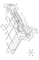
このような乗物用シート1は、概略的に、図2等に示すような、乗物用シート1の骨格を構成するシートフレーム11と、シートフレーム11によって支持されるクッションパッド(図示せず。)と、シートフレーム11及びクッションパッドを被覆する表皮材2a,3a,4aによって構成されている。
The
The two
Such a
シートフレーム11は、シートクッションの骨格を構成するシートクッションフレーム12と、シートバック3の骨格を構成するシートバックフレーム13と、ヘッドレスト4の骨格を構成するヘッドレストフレーム14と、を備えている。
クッションパッド及び表皮材2a,3a,4aは、シートクッションフレーム12、シートバックフレーム13、ヘッドレストフレーム14のそれぞれに設けられている。
The
The cushion pads and
シートクッションフレーム12は、図1~図6等に示すように、後部フレーム12aと、前部フレーム12bと、左右一対の側部フレーム12c,12dと、上下一対の中央部フレーム12e,12fと、を備える。
また、後部フレーム12aと前部フレーム12bと左右一対の側部フレーム12c,12dには、乗員の荷重を受ける複数の受圧部材30,31,32が固定されている。
さらに、シートクッションフレーム12の下面には、シートクッション2、延いては乗物用シート1全体をスライド移動させるためのスライド機構40が設けられている。
The
A plurality of
Further, a
後部フレーム12aは、シートクッションフレーム12の後部において左右方向に配置されており、大径のパイプフレームによって構成されている(すなわち、円筒状に形成されている。)。
前部フレーム12bは、シートクッションフレーム12の前部において左右方向に配置されており、パイプフレームによって構成されている(すなわち、円筒状に形成されている。)。
後部フレーム12aと前部フレーム12bは、互いに平行に配置されている。また、前部フレーム12bは、後部フレーム12aよりも上方に配置されている。
The
The
The
左右一対の側部フレーム12c,12dは、シートクッションフレーム12の右側端部と左側端部において前後方向に配置されており、後部フレーム12aと前部フレーム12bの両端部間を接続している。
より詳細に説明すると、左右一対の側部フレーム12c,12dの後端部には、高剛性のピボットブラケット15が設けられ、このピボットブラケット15に対して後部フレーム12aが設けられている。
左右一対の側部フレーム12c,12dと、ピボットブラケット15は共に、断面コ字状(断面チャンネル形ともいう。)に形成されており、左右一対の側部フレーム12c,12dの内側にピボットブラケット15が嵌合され、双方の底部同士がボルトで連結されている。つまり、後部フレーム12aと左右一対の側部フレーム12c,12dとが、ピボットブラケット15を介して連結されている。
なお、ピボットブラケット15の上端部には、シートバックフレーム13が前後方向に回転可能に設けられている。
The pair of left and right side frames 12c and 12d are arranged in the front-rear direction at the right and left ends of the
More specifically, a highly
The pair of left and right side frames 12c and 12d and the
A
上下一対の中央部フレーム12e,12fは、シートクッションフレーム12の中央部において前後方向に配置されており、後部フレーム12aと前部フレーム12bとの間に架け渡されて設けられている。また、これら上下一対の中央部フレーム12e,12fは、パイプフレームによって構成されている。
より詳細に説明すると、後部フレーム12aの中央部には、後部フレーム12aの外周面に固定されるとともにシートバックフレーム13を支持する中間強度部材20が設けられている。上下一対の中央部フレーム12e,12fは、前部フレーム12bと中間強度部材20との間に架け渡され、後端部が、後部フレーム12aよりも上側と下側に位置するようにして中間強度部材20に固定され、前端部が、前部フレーム12bに固定されている。
The pair of upper and lower center frames 12e and 12f are arranged in the front-rear direction at the center of the
More specifically, an
さらに、上下一対の中央部フレーム12e,12fのうち、上側中央部フレーム12eの前端部は潰れた状態(上下に偏平化した状態)で前部フレーム12bに溶接され、下側中央部フレーム12fの前端部は、第一ブラケット17を介して前部フレーム12bに固定されている。
第一ブラケット17は、ウェブ部とその両側縁に設けられたフランジ部とを有して断面コ字状に形成されている。より詳細には、各フランジ部が前部フレーム12bの外周面に溶接固定され、ウェブ部の下面に、下側中央部フレーム12fの前端部が潰れた状態(上下に偏平化した状態)で溶接固定されている。
上下一対の中央部フレーム12e,12fの前端部は、双方とも潰れた状態で溶接固定されているが、これにより、溶接範囲を広く確保して溶接部の強度を高めることができるとともに、上下方向におけるコンパクト化を図ることができるという利点がある。
Furthermore, of the pair of upper and lower
The
The front ends of the pair of upper and lower center frames 12e and 12f are welded and fixed in a crushed state. There is an advantage that it is possible to achieve compactness in
なお、中間強度部材20は、互いに組み合わされて中間強度部材20として一体化される第一分割体21及び第二分割体22からなる箱状体であり、上端部には、シートバックフレーム13の角度を調整するためのリクライニング機構を構成するリクライニングブラケット16が設けられている。リクライニングブラケット16には、シートバックフレーム13が前後方向に回転可能に設けられている。
また、リクライニング機構は、リクライニングブラケット16とシートバックフレーム13との間に設けられている。
リクライニング機構の操作部18は、図1,図2に示すように、二つのシートバック3それぞれの上端部におけるシート中央側に設けられている。
The
Also, the reclining mechanism is provided between the
As shown in FIGS. 1 and 2, the operating
複数の受圧部材30,31,32は、図2,図7等に示すように、複数のワイヤーとされている。
複数のワイヤー30,31,32には、後部フレーム12aと前部フレーム12bとの間に架け渡される複数の前後ワイヤー30と、左右方向に配置されて少なくとも一方の端部が左右一対の側部フレーム12c,12dのどちらかに固定される左右ワイヤー31,32とが含まれている。これら複数の前後ワイヤー30と複数の左右ワイヤー31,32は互いに交差して配置され、ワイヤー同士の交差部は接合されている。
The plurality of
The plurality of
前後ワイヤー30は、前後方向に長く形成された長尺部30aと、長尺部30aの両端部のそれぞれから斜め上方に突出する傾斜部30bと、双方の傾斜部30bそれぞれの上端部から左右のいずれか一方に突出する固定端30cと、を有しており、全体として平面視において略コ字状に形成されている。固定端30cは、後部フレーム12aと前部フレーム12bに対して溶接固定される。
つまり、二つの固定端30cは、同じ方向に突出した状態となっている。また、二つの傾斜部30bの、長尺部30aからの長さは等しく、長尺部30aに対する角度も等しく設定されている。
このような形状の前後ワイヤー30は、長尺部30aと傾斜部30bが所定の位置(設計どおりの位置)に配置されていればよく、固定端30cが左右のどちらを向いて配置されていても問題がないため、左右の向きを逆転させて使用することができる。換言すれば、前後ワイヤー30を、後部フレーム12aと前部フレーム12bとの間に架け渡して溶接固定する際は、固定端30cの向きを気にせずに作業を行うことができる。
The front/
That is, the two fixed
The front and
左右ワイヤー31,32には、第一左右ワイヤー31と、第二左右ワイヤー32と、が含まれている。
第一左右ワイヤー31は、左右方向に長尺に形成されており、本実施形態においては右側端部が、右側の側部フレーム12cに固定され、左側端部が、左側の側部フレーム12dに固定されている。また、第一左右ワイヤー31の中央部は、上下一対の中央部フレーム12e,12fのうち下側中央部フレーム12fの上面に沿って湾曲し、当該下側中央部フレーム12fの上面に溶接固定されている。すなわち、第一左右ワイヤー31は、下側中央部フレーム12fを介して、左右一対の側部フレーム12c,12dに架け渡されて設けられている。
第二左右ワイヤー32は、平面視において略U字状(平面視コ字状でもよい)に曲げ加工されている。第二左右ワイヤー32の一端部と他端部は、同一の側部フレーム12c(12d)に対して固定されている。また、第二左右ワイヤー32は、曲げ加工された部分が、上下一対の中央部フレーム12e,12fまで到達しない長さに設定されている。第二左右ワイヤー32の曲げ加工された部分から上下一対の中央部フレーム12e,12fまでの間には、受圧部材のないスペースが形成されている。そして、図示はしないが、このようなスペースを利用して、シートベルトのバックルが配置されるようになっている。
The left and
The first left-
The second left and
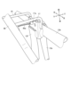
シートクッションフレーム12における受圧部材の一つとして、左右一対の側部フレーム12c,12dにおけるシートクッションフレーム12の外側には、斜め上方に突出するように配置された上方突出ワイヤー33が設けられている。
より詳細に説明すると、上方突出ワイヤー33は、両端部が、左右一対の側部フレーム12c,12dの外側面に固定され、その固定位置から斜め上方に突出するようにして設けられている。上方突出ワイヤー33は、固定端である両端部から斜め上方に突出する突出部33aと、双方の突出部33aの上端部同士を連結する連結部33bと、を備え、連結部33bの中央は、略V字状に曲げ加工されて鉛直下方に突出する下方突出部33cとされている。
上方突出ワイヤー33は、シートクッションフレーム12に載せられるクッションパッドのうち、左右一対の側部フレーム12c,12dよりも外側にはみ出した部分を下から支持することができる。そのため、上方突出ワイヤー33は、乗物用シート1の乗降時における耐久性を向上させ、クッションパッドのはみ出した部分が元の形状を保持する機能を発揮することができる。
As one pressure-receiving member of the
More specifically, the upwardly protruding
The upwardly protruding
スライド機構40は、左右一対の側部フレーム12c,12dそれぞれの下面と、乗物のフロアパネルとの間に設けられており、シートクッションフレーム12、延いては乗物用シート1全体を、乗物の前後方向に沿ってスライド移動させることができる。
このようなスライド機構40は、可動レール41と、固定レール42と、スライドロック機構と、を備えている。
The
Such a
可動レール41は、スライド方向(前後方向)に長尺に形成され、左右一対の側部フレーム12c,12dの下面に固定されるとともに、固定レール42の内側に設けられて当該固定レール42に摺動可能に支持されている。
固定レール42は、スライド方向(前後方向)に長尺に形成され、左右一対の側部フレーム12c,12dの下方に設けられるとともに、可動レール41を摺動可能に支持している。また、この固定レール42の下面には、乗物のフロアパネルに固定されてシートクッション2、延いては乗物用シート1全体を支持する前側フットブラケット43及び後側フットブラケット44が固定されている。
The
The fixed
スライドロック機構は、可動レール41と固定レール42との間に設けられ、乗物用シート1を複数の前後調整位置で選択的にロック可能な公知の機構である。各可動レール41には、スライドロック機構のロック状態を解除するレリーズレバー45が軸支されるとともに、各レリーズレバー45には、当該レリーズレバー45をスライドロック機構のロック作動方向に付勢するロックスプリング46が接続されている。
The slide lock mechanism is provided between the
左右のレリーズレバー45には、共通1本のレリーズバー47の両端が連結されている。このレリーズバー47は、1本の丸棒を屈曲させたもので、左右のレリーズレバー45から前方に延びる左右一対の腕部47aと、これら腕部47aの前端部間を一体に連結する杆部47bとを有しており、その杆部47bは、シートクッションフレーム12の下部においてシートクッションフレーム12の前縁と平行に配置されている。
Both ends of a
杆部47bの中央部にはノブ48が固定されている。ノブ48は、杆部47bの中央部前面よりシートクッションフレーム12の前面に臨むように突出するとともにコ字状に形成されており、手で握りやすい状態となっている。
ノブ48を引き上げることによって、レリーズバー47がレリーズレバー45と共に上方へ揺動して、スライドロック機構のロック状態を解除することができ、可動レール41のスライド移動、すなわち乗物用シート1の前後方向へのスライド移動が可能となる。乗物用シート1の前後位置を調節した後、ノブ48を解放することによって、ロックスプリング46の作用によりスライドロック機構は作動して、乗物用シート1を調節位置にロックすることができる。
A
By pulling up the
スライドロック機構は、ノブ48による操作だけでなく、乗物用シート1の後方からも操作可能に構成されている。
すなわち、後方用操作部材49が、乗物用シート1の後方に露出するようにして設けられており、この後方用操作部材49には、ボーデンケーブル49aが接続されている。ボーデンケーブル49aは、アウターケーブルとインナーケーブルとを備える。アウターケーブルは、上側中央部フレーム12eに沿って配線されるとともに留め付けられている。インナーケーブルは、一端部が後方用操作部材49に接続され、他端部がレリーズバー47の中央部に接続されている。そして、後方用操作部材49を引っ張るように操作することで、インナーケーブルを介してレリーズバー47が引き上げられ、スライドロック機構のロック状態を解除できるようになっている。
なお、アウターケーブルにおける前端部は、第一ブラケット17のウェブ部に形成された切欠部17aに引っ掛けられて保持されており、インナーケーブルを、レリーズバー47側にガイドできるようになっている。
また、第一ブラケット17における両側縁のフランジ部には、ノブ48のコ字状内部を通過して下方に延びる規制リング19が設けられている。規制リング19は、第一ブラケット17よりも前方に位置しており、例えば表皮材2aや、シートクッション2の下面の略全面を被覆するトリムカバー(図示せず。)がボーデンケーブル49aに干渉することを規制している。
The slide lock mechanism can be operated not only by the
That is, the
The front end portion of the outer cable is hooked and held by a
Further, the flange portions on both side edges of the
シートクッション2の前端部中央における下部には、ノブ48の位置に対応し、周囲よりも凹んだ状態に形成された凹部2bがある。ノブ48は、少なくともその基端部側(レリーズバー47側)の部分が、凹部2b内に納まるようになっている。そのため、ノブ48は、シートクッション2の前端部から前方に突出しすぎない状態にすることができる。
At the lower part of the center of the front end of the
シートクッションフレーム12には、以上のような基本構成に付属して、シート後方に設けられた荷室Rに配置された物品を支持する支持ワイヤー50と、後部フレーム12aに対する前向き荷重を吸収するエネルギー吸収ワイヤー55が設けられている。
The
支持ワイヤー50は、一本のワイヤーを曲げ加工することによって形成されており、上方に突出するように配置されている。また、支持ワイヤー50は、第二ブラケット51を介して後部フレーム12aの長さ方向両端部における後側面に固定されている。
第二ブラケット51は、ウェブ部とその両側縁に設けられたフランジ部とを有して断面コ字状に形成されている。より詳細には、各フランジ部が後部フレーム12aの後側面に溶接固定され、ウェブ部に形成された二つの貫通孔に、支持ワイヤー50の両端部が差し込まれて溶接固定されている。
支持ワイヤー50によって支持される物品には、荷室R内に配置された荷物や固定具、収納具等の種々の物品が含まれており、特に限定されるものではない。支持ワイヤー50に対しては、当該物品が引っ掛けられたり、固定されたりして、当該物品を支持ワイヤー50によって確実に支持できるようになっている。
The
The
The articles supported by the
エネルギー吸収ワイヤー55は、一本のワイヤーを曲げ加工することによって形成されており、後部フレーム12aのうち支持ワイヤー50よりも中央側に、後方斜め下向きに突出するように設けられている。また、エネルギー吸収ワイヤー55は、その両端部が、後部フレーム12aの上側面に固定されている。
The
シートバックフレーム13は、一つのシートクッションフレーム12に対して二つとされている。それぞれのシートバックフレーム13は、曲げ加工されたパイプフレームによって上辺、下辺、左右側辺が形成されたフレーム本体13aと、ピボットブラケット13bと、サイドフレーム13cと、を有する。
ピボットブラケット13bは、フレーム本体13aにおける外側の側辺に設けられ、シートクッションフレーム12におけるピボットブラケット15に対して回転可能に連結されている。
サイドフレーム13cは、フレーム本体13aにおける内側の側辺に設けられ、シートクッションフレーム12におけるリクライニングブラケット16に対して回転可能に連結されている。また、サイドフレーム13cとリクライニングブラケット16との間に、リクライニング機構が設けられている。
なお、フレーム本体13aの上辺には、ヘッドレスト4におけるヘッドレストピラー14bを保持するピラー保持部13dが設けられている。
Two seat back frames 13 are provided for one
The
The
A
ヘッドレストフレーム14は、シートバックフレーム13の上端部中央に設けられており、フレーム本体14aと、フレーム本体14aの下端部から下方に突出するヘッドレストピラー14bと、を有する。
ヘッドレストピラー14bは、シートバックフレーム13の上端部に設けられたピラー保持部13dによって保持されている。
The
The
以下、本実施形態における乗物用シート1について、より詳細に説明する。
The
[側部フレーム12c,12d及び複数の受圧部材30,31,32について]
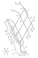
左右一対の側部フレーム12c,12dは、上述のように断面コ字状(断面チャンネル形ともいう。)に形成されている。そのため、左右一対の側部フレーム12c,12dは、図9~図11等に示すように、ウェブ部60とその両側縁に設けられたフランジ部61,62とを有する。
ウェブ部60は、左右一対の側部フレーム12c,12dにおける下面を構成し、フランジ部61,62には、シート外側に位置する外側フランジ61と、シート中央側に位置する内側フランジ62と、が含まれている。
[Regarding the side frames 12c, 12d and the plurality of
The pair of left and right side frames 12c and 12d are formed to have a U-shaped cross section (also referred to as a channel-shaped cross section) as described above. Therefore, the pair of left and right side frames 12c and 12d has a
The
外側フランジ61及び内側フランジ62の前端部(側部フレーム12c,12dの長さ方向前端部を指す。)は、中央部及び後端部(側部フレーム12c,12dの長さ方向中央部及び後端部を指す。)に比して上下方向の寸法が長く形成され、当該前端部の上端における高さ位置も、中央部及び後端部の高さ位置に比して高く設定されている。
このような外側フランジ61及び内側フランジ62の前端部上端には、前部フレーム12bが載せられる円弧部61a,62aが形成されている。円筒状に形成された前部フレーム12bは、円弧部61a,62aに載せられて溶接等により固定されている。そのため、前部フレーム12bは、後部フレーム12aよりも高い位置に配置されている。
The front ends of the
内側フランジ62の上端部は、外側フランジ61とは反対の方向(乗物用シート1中央側:シートクッションフレーム12の中央側)に、直角に曲げ加工されて補剛された状態となっている(鍔状に形成されている。)。また、内側フランジ62の上端部は、このように曲げ加工されることで補剛を図るだけでなく、例えば内側フランジ62の上端部を曲げ加工せずに使用した場合の上端部端面よりも広く設定された上向きの面を構成することが可能となっている。
そして、このように直角に曲げ加工された部分には、複数の受圧部材である左右ワイヤー31,32の端部が固定される複数の端部固定部63,64,65が含まれている。さらに、複数の端部固定部63,64,65は、前方に向かうにつれて高さ位置が高くなるように段状に配置されている。
なお、内側フランジ62の上端部における曲げ加工された部分は、上記の円弧部62aも含まれており、前部フレーム12bを安定的に支持できるようになっている。
The upper end of the
The portion thus bent at right angles includes a plurality of
The bent portion of the upper end portion of the
より詳細に説明すると、左右ワイヤー31,32には、上述のように左右方向に長尺な第一左右ワイヤー31と、平面視において略U字状に形成された第二左右ワイヤー32と、が含まれている。したがって、左右一対の側部フレーム12c,12dに対しては、二種類の左右ワイヤー31,32における三つの端部が臨んで設けられることになる。
つまり、複数の端部固定部63,64,65には、左右ワイヤー31,32における三つの端部が固定される第一端部固定部63と、第二端部固定部64と、第三端部固定部65とが含まれている。
More specifically, the left and
In other words, the plurality of
第一端部固定部63は、複数の端部固定部63,64,65のうち最も低い段(下段)とされており、複数の端部固定部63,64,65の並び順のうち最も後方に配置され、第二左右ワイヤー32の一端部が載せられて固定されている。
第二端部固定部64は、複数の端部固定部63,64,65のうちの中間の段(中段)とされており、複数の端部固定部63,64,65の並び順のうち真ん中に配置され、第二左右ワイヤー32の他端部が載せられて固定されている。
第三端部固定部65は、複数の端部固定部63,64,65のうち最も高い段(上段)とされており、複数の端部固定部63,64,65の並び順のうち最も前方に配置され、第一左右ワイヤー31の端部が載せられて固定されている。
The first
The second
The third
第一端部固定部63、第二端部固定部64、第三端部固定部65の上面のうち、第一左右ワイヤー31及び第二左右ワイヤー32の端部が載せられる部位は水平面とされており、第一左右ワイヤー31及び第二左右ワイヤー32を載せたときに安定的に支持することができ、その上で溶接等により固定することができる。
なお、本実施形態においては、第一端部固定部63の上面が段状(上下2段)に形成されており、そのうち下側の段の上面に、第二左右ワイヤー32の一端部が載せられて固定されている。第二左右ワイヤー32の一端部が載せられる下側の段の上面は水平面とされている。
Of the upper surfaces of the first
In this embodiment, the upper surface of the first
また、第一左右ワイヤー31及び第二左右ワイヤー32は、複数の受圧部材である前後ワイヤー30にも載せられるため、第一左右ワイヤー31及び第二左右ワイヤー32は、前後ワイヤー30と各端部固定部63,64,65との間に架け渡された状態となる。
そのため、第一左右ワイヤー31及び第二左右ワイヤー32を、各端部固定部63,64,65に溶接する場合も、前後ワイヤー30に溶接する場合も作業性に優れる。
In addition, since the first left and
Therefore, the workability is excellent both when welding the first left and
一方、外側フランジ61の上端部は、内側フランジ62とは反対の方向(乗物用シート1外側:シートクッションフレーム12の外側)に、直角に曲げ加工されて補剛された状態となっている(鍔状に形成されている。)。
なお、上記の円弧部61aも含まれた状態となっており、前部フレーム12bを安定的に支持できるようになっている。
On the other hand, the upper end of the
It should be noted that the
外側フランジ61及び内側フランジ62の上端部は、上述のように曲げ加工されて補剛されているとしたが、本実施形態においては、ピボットブラケット15が設けられる位置においては曲げ加工されていないものとする。
Although the upper ends of the
左右一対の側部フレーム12c,12dのそれぞれは、軽量化のために、複数の端部固定部63,64,65が設けられた部位を除く位置に形成された貫通孔66を有する。
本実施形態における貫通孔66は、左右一対の側部フレーム12c,12dの双方におけるウェブ部60に複数形成されている。ただし、これに限られるものではなく、外側フランジ61や内側フランジ62に形成されるものとしてもよい。
また、ウェブ部60のうち貫通孔66に隣接する箇所60aは下方に突出するように加工されており、剛性の向上を図ることができるようになっている。
Each of the pair of left and right side frames 12c, 12d has a through
A plurality of through
A
以上のような構成を採用することで、複数の端部固定部63,64,65によって、複数の左右ワイヤー31,32の組み付け作業に手間がかかりにくくなる。
なお、本実施形態においては、受圧部材としてワイヤー30,31,32が用いられているが、これに限られるものではなく、板状の受圧部材でもよい。ただし、このような板状の受圧部材であっても、複数の端部固定部63,64,65に載せられて固定される端部を有しているものとする。
By adopting the configuration as described above, the work of assembling the plurality of left and
In this embodiment, the
[中間強度部材20について]
図12,図13に示すように、中間強度部材20を構成する第一分割体21及び第二分割体22は、それぞれがウェブ部21a,22aとその両側縁に設けられたフランジ部21b,22b・21c,22cとを有して断面コ字状(断面チャンネル形)に形成されている。さらに、これら第一分割体21及び第二分割体22は、全体として弧状形体(U字状の形貌・形姿・外見などと換言してもよい。)とされている。そして、これら第一分割体21及び第二分割体22は、ウェブ部21a,22aと反対の開口側が向かい合わせになるように互いに組み合わされている。
また、第一分割体21と第二分割体22とが互いに組み合わされて一体化された状態の中間強度部材20は、第一分割体21と第二分割体22とが組み合わされることで箱体(箱状体)とされている。さらに、第一分割体21と第二分割体22とが弧状形体とされているため、この中間強度部材20も、全体として弧状(U字状)に形成されている。
そして、第一分割体21及び第二分割体22の、それぞれのフランジ部21b,22b・21c,22cは、「弧」の外側を構成するフランジ部21b,22b(以下、外周フランジ部21b,22bと称する。)と、「弧」の内側を構成するフランジ部21c,22c(以下、内周フランジ部21c,22cと称する。)に分けられることとなる。
[Regarding the intermediate strength member 20]
As shown in FIGS. 12 and 13, the
Further, the
The
第一分割体21及び第二分割体22におけるウェブ部21a,22aは、中間強度部材20における左右の側面を構成している。
第一分割体21のウェブ部21aと第二分割体22のウェブ部22aは、略同形状で対称的に形成されているが、第一分割体21のウェブ部21aの方が、第二分割体22のウェブ部22aよりも面積が若干(外周フランジ部21bの板厚分)広く設定されている。
また、これらウェブ部21a,22aの上端部に、上記のリクライニングブラケット16が固定されている。
なお、ウェブ部21a,22aに形成された複数の貫通孔は、リクライニングブラケット16やその他の部材との連結に用いられるボルトの軸部が挿通されるとともに、軽量化にも貢献する。
The
The
The
A plurality of through-holes formed in the
外周フランジ部21b,22bは、内周フランジ部21c,22cよりも、ウェブ部21a,22aから側方への突出寸法が長く設定されている。そして、第一分割体21と第二分割体22とを組み合わせる際は、これら外周フランジ部21b,22b同士が重ね合わせられて溶接等により接合されている。この場合、本実施形態においては、第一分割体21の外周フランジ部21bが、第二分割体22の外周フランジ部22bに対して外側に位置するように重ね合わせられているものとする。なお、このように第一分割体21の外周フランジ部21bを、第二分割体22の外周フランジ部22bに対して上から被さる状態とするために、第一分割体21のウェブ部21aが第二分割体22のウェブ部22aよりも面積が若干広く設定されているものとする。
さらに、本実施形態においては、第一分割体21の外周フランジ部21bの方が、第二分割体22の外周フランジ部22bよりも側方への突出寸法が長く設定されている。
第一分割体21の外周フランジ部21bは、このように側方への突出寸法も長く、第二分割体22の外周フランジ部22bに対して上から被さるようにして設けられるため、上下一対の中央部フレーム12e,12fの後端部は、第一分割体21の外周フランジ部21bに対して固定された状態となっている。
The outer
Furthermore, in the present embodiment, the outer
The outer
また、第一分割体21の外周フランジ部21bの前方側上端には、ボーデンケーブル49aを保持するためのケーブル保持部23が一体形成されている。ケーブル保持部23は、上方に突出して設けられ、上端部が二股に分かれており、二股に分かれた先端部によってボーデンケーブル49aを保持できるようになっている。ケーブル保持部23は、ウェブ部21a,22aの上端部に固定された左右のリクライニングブラケット16間に配置されている。
A
内周フランジ部21c,22cは、ウェブ部21a,22aから側方への突出寸法が、外周フランジ部21b,22bにおける側方への突出寸法よりも短く設定されている。
そして、第一分割体21の外周フランジ部21bが、第二分割体22の外周フランジ部22bに対して重ね合わせられた状態において、第一分割体21の内周フランジ部21cと第二分割体22の内周フランジ部22dは、端面同士が間隔を空けて、かつ対向した状態となっている。すなわち、第一分割体21及び第二分割体22の内周フランジ部21c,22c同士は、外周フランジ部21b,22bのように重なり合わないが、対称的な位置関係であって、かつ同じ弧を描くようにして設けられている。さらに換言すれば、第一分割体21及び第二分割体22の内周フランジ部21c,22c間には隙間が形成された状態となっており、これにより、中間強度部材20は、上方に向かって開口していることとなる。
なお、断面コ字状に形成された第一分割体21及び第二分割体22は、自身の延在方向の両端部(弧状・U字状の形体における両端部)も開放状態となっている。ただし、当該延在方向の両端部のうち前方側の端部(ケーブル保持部23がある端部)は、外周フランジ部21b,22bが後方に曲げ加工されており、その開放状態が、後方側の端部(ケーブル保持部23がない端部)における開放状態よりも若干狭くなっている。
このような第一分割体21及び第二分割体22の内周フランジ部21c,22cは、後部フレーム12aの外周面に固定される固定面とされている。すなわち、後部フレーム12aが、弧状に形成された中間強度部材20の内周側に配置され、内周面を構成する内周フランジ部21c,22cに接触した状態となった上で、内周フランジ部21c,22cが後部フレーム12aに対して溶接等により固定されている。
このようにして後部フレーム12aが中間強度部材20と連結されるようになっているため、内周フランジ部21c,22cは、円筒状に形成された後部フレーム12aの外周面に沿って湾曲した状態となっている。
なお、第一分割体21及び第二分割体22の内周フランジ部21c,22c間には、上述のように隙間が形成されているが、この隙間を横切って後部フレーム12aが設けられるとともに内周フランジ部21c,22cに固定されている。そのため、内周フランジ部21c,22c間に隙間が形成されていても、中間強度部材20の剛性を向上させることができる。
The inner
Then, in a state where the outer
The first divided
The inner
Since the
As described above, a gap is formed between the inner
以上のような構成を採用することで、中間強度部材20によって、後部フレーム12aの捩じり剛性を従来に比して向上させることができるようになっている。
By adopting the configuration as described above, the
本実施の形態によれば、複数の受圧部材である複数の左右ワイヤー31,32の端部が固定される複数の端部固定部63,64,65が、前方に向かうにつれて高さ位置が高くなるように段状に配置されているので、複数の端部固定部63,64,65に対して複数の左右ワイヤー31,32の端部を固定すれば、複数の左右ワイヤー31,32に載せられるクッションパッドを傾斜させることができる。そのため、傾斜させた分だけクッションパッドの厚みを削って軽量化を図ることができる。
さらに、段状に配置された複数の端部固定部63,64,65に複数の左右ワイヤー31,32の端部を載せて固定すればクッションパッドを傾斜させることができるので、複数の左右ワイヤー31,32の端部を加工する必要がなく、左右一対の側部フレーム12c,12dに対する複数の左右ワイヤー31,32の組み付け作業性を向上させることができる。
According to the present embodiment, the plurality of
Furthermore, by placing and fixing the ends of the plurality of left and
また、左右一対の側部フレーム12c,12dのそれぞれは、複数の端部固定部63,64,65が設けられた部位を除く位置に形成された貫通孔66を有するので、左右一対の側部フレーム12c,12dの軽量化を図ることができる。
In addition, since each of the pair of left and right side frames 12c and 12d has a through
また、受圧部材である略コ字状のワイヤー32における両端部が、複数の端部固定部63,64,65のうち二つの端部固定部63,64に固定されているので、一度に2本分のワイヤー32を二つの端部固定部63,64に設置することができ、複数の左右ワイヤー31,32におけるシートクッションフレーム12に対する組み付け作業性を向上できる。
Further, both ends of the substantially
また、複数の前後ワイヤー30を、左右を逆にして後部フレーム12aと前部フレーム12bとの間に架け渡すことができるので、複数の前後ワイヤー30におけるシートクッションフレーム12に対する組み付け作業性を向上できる。
Further, since the plurality of front and
また、左右一対の側部フレーム12c,12dのうちシート外側に、斜め上方に突出するように配置された上方突出ワイヤー33が設けられているので、この上方突出ワイヤー33がある位置(シートクッション2の両端部)に着座する乗員を支持する上での確実性が高まる。
In addition, since the upward projecting
また、例えば中間強度部材20を構成する第一分割体21及び第二分割体22のそれぞれがウェブ部21a,22aとその一側縁に設けられたフランジ部21b,22bとを有して断面L字状に形成されている場合に比して、第一分割体21及び第二分割体22における剛性を向上できるだけでなく、これらが互いに組み合わされて一体化された中間強度部材20においても剛性を向上できる。
さらに、断面コ字状に形成された第一分割体21及び第二分割体22のうち、後部フレーム12a側に配置された内周フランジ部21c,22cが、後部フレーム12aの外周面に固定される固定面を構成しているので、後部フレーム12aの外周面に対する接触面積が増えることになり、後部フレーム12aに対する第一分割体21及び第二分割体22の固定強度を向上できる。
Further, for example, each of the first divided
Further, of the first divided
また、湾曲している状態の固定面を構成する内周フランジ部21c,22cを、後部フレーム12aの外周面に沿って固定できるので、後部フレーム12aに対する第一分割体21及び第二分割体22の固定強度を向上できる。
In addition, since the inner
また、上下一対の中央部フレーム12e,12fと中間強度部材20と前部フレーム12bとによってトラス構造を形成できるので、シートクッションフレーム12全体の剛性を向上できる。
Further, since a truss structure can be formed by the pair of upper and lower center frames 12e and 12f, the
また、上下一対の中央部フレーム12e,12fのうち、上側中央部フレーム12eの前端部は潰れた状態で前部フレーム12bに溶接され、下側中央部フレーム12fの前端部は、第一ブラケット17を介して前部フレーム12bに固定されているので、例えば上下一対の中央部フレーム12e,12fの双方を前部フレーム12bに直接溶接する場合に比して、前部フレーム12bの撓みを抑制できる。
さらに、下側中央部フレーム12fの前端部は、第一ブラケット17を介して前部フレーム12bに固定されているので、下側中央部フレーム12fにおける前部フレーム12bに対する接合強度を向上できるとともに、当該接合部分における剛性を向上できる。
Further, of the pair of upper and lower center frames 12e and 12f, the front end of the
Furthermore, since the front end of the lower
また、後部フレーム12aに固定された支持ワイヤー50によって荷室R内に配置された荷物や固定具、収納具等の物品を支持できるので、例えば荷室Rに対して当該物品を支持するための他の構造を採用する場合に比して、当該物品を支持するための構造を簡易に形成できる。
さらに、支持ワイヤー50が、後部フレーム12aに対して第二ブラケット51を介して固定されているので、例えば支持ワイヤー50が後部フレーム12aに対して“かしめ”によって固定される場合に比して、後部フレーム12aに“かしめ”のための加工を施す必要がなく、後部フレーム12aにおける強度を向上できる。
In addition, the
Furthermore, since the
また、荷室Rに収納された荷物が後部フレーム12aに強く衝突した際の衝撃を、エネルギー吸収ワイヤー55によって軽減できるので、後部フレーム12a、延いてはシートクッションフレーム12を保護できる。
In addition, since the
1 乗物用シート
2 シートクッション
2a 表皮材
2b 凹部
3 シートバック
4 ヘッドレスト
11 シートフレーム
12 シートクッションフレーム
12a 後部フレーム
12b 前部フレーム
12c 側部フレーム
12d 側部フレーム
12e 上側中央部フレーム
12f 下側中央部フレーム
13 シートバックフレーム
14 ヘッドレストフレーム
16 リクライニングブラケット
17 第一ブラケット
19 規制リング
20 中間強度部材
21 第一分割体
21a ウェブ部
21b 外周フランジ部
21c 内周フランジ部
22 第二分割体
22a ウェブ部
22b 外周フランジ部
22c 内周フランジ部
23 ケーブル保持部
30 前後ワイヤー
30a 長尺部
30b 傾斜部
30c 固定端
31 第一左右ワイヤー
32 第二左右ワイヤー
33 上方突出ワイヤー
33a 突出部
33b 連結部
33c 下方突出部
40 スライド機構
41 可動レール
42 固定レール
43 前側フットブラケット
44 後側フットブラケット
45 レリーズレバー
46 ロックスプリング
47 レリーズバー
47a 腕部
47b 杆部
48 ノブ
49 後方用操作部材
49a ボーデンケーブル
50 支持ワイヤー
51 第二ブラケット
52 引掛部材
55 エネルギー吸収ワイヤー
60 ウェブ部
61 外側フランジ
62 内側フランジ
63 第一端部固定部
64 第二端部固定部
65 第三端部固定部
66 貫通孔
1
Claims (9)
前記後部フレームの前方に配置された前部フレームと、
前記後部フレームと前記前部フレームの両端部間を接続する左右一対の側部フレームと、
前記後部フレームと前記前部フレームと前記左右一対の側部フレームに対して固定されて乗員の荷重を受ける複数の受圧部材と、を備えたシートクッションフレーム構造において、
前記左右一対の側部フレームのそれぞれは、当該左右一対の側部フレームのそれぞれにおけるシート中央側に設けられ、前記複数の受圧部材の端部が固定される複数の端部固定部を有しており、
前記複数の端部固定部は、前方に向かうにつれて高さ位置が高くなるように段状に配置されており、
前記左右一対の側部フレームのそれぞれは、前記複数の端部固定部が設けられた部位を除く位置に形成された貫通孔を有しており、
前記貫通孔が形成された部位と前記複数の端部固定部が設けられた部位の間には、段差が形成されていることを特徴とするシートクッションフレーム構造。 a rear frame positioned at the rear;
a front frame disposed in front of the rear frame;
a pair of left and right side frames connecting between both ends of the rear frame and the front frame;
A seat cushion frame structure including a plurality of pressure receiving members fixed to the rear frame, the front frame, and the pair of left and right side frames to receive the load of an occupant,
Each of the pair of left and right side frames has a plurality of end fixing portions that are provided on the seat center side of each of the pair of left and right side frames and to which end portions of the plurality of pressure receiving members are fixed. cage,
The plurality of end fixing portions are arranged in a stepped manner so that the height position increases toward the front,
Each of the pair of left and right side frames has a through hole formed at a position other than the portions where the plurality of end fixing portions are provided,
A seat cushion frame structure, wherein a step is formed between a portion in which the through hole is formed and a portion in which the plurality of end fixing portions are provided.
前記ウェブ部のうち前記貫通孔に隣接する箇所は下方に突出して形成されており、
前記ウェブ部と前記端部固定部が設けられた部位とは、前後方向において同じ位置に配置されていることを特徴とする請求項2に記載のシートクッションフレーム構造。 The side frame has a web portion forming a lower surface of the side frame and having the through hole formed therein,
A portion of the web portion adjacent to the through hole is formed to protrude downward,
The seat cushion frame structure according to claim 2 , wherein the web portion and the portion provided with the end fixing portion are arranged at the same position in the front-rear direction.
前記後部フレームの前方に配置された前部フレームと、
前記後部フレームと前記前部フレームの両端部間を接続する左右一対の側部フレームと、
前記後部フレームと前記前部フレームと前記左右一対の側部フレームに対して固定されて乗員の荷重を受ける複数の受圧部材と、を備えたシートクッションフレーム構造において、
前記左右一対の側部フレームのそれぞれは、当該左右一対の側部フレームのそれぞれにおけるシート中央側に設けられ、前記複数の受圧部材の端部が固定される複数の端部固定部を有しており、
前記複数の端部固定部は、前方に向かうにつれて高さ位置が高くなるように段状に配置されており、
前記複数の受圧部材は複数のワイヤーであり、
前記複数のワイヤーには、平面視において略U字状に曲げ加工されたワイヤーが含まれ、当該略U字状のワイヤーにおける両端部は、前記複数の端部固定部のうち二つの端部固定部に固定され、
前記二つの端部固定部は、前記左右一対の側部フレームのうち一方にだけ配置されていることを特徴とするシートクッションフレーム構造。 a rear frame positioned at the rear;
a front frame disposed in front of the rear frame;
a pair of left and right side frames connecting between both ends of the rear frame and the front frame;
A seat cushion frame structure including a plurality of pressure receiving members fixed to the rear frame, the front frame, and the pair of left and right side frames to receive the load of an occupant,
Each of the pair of left and right side frames has a plurality of end fixing portions that are provided on the seat center side of each of the pair of left and right side frames and to which end portions of the plurality of pressure receiving members are fixed. cage,
The plurality of end fixing portions are arranged in a stepped manner so that the height position increases toward the front,
The plurality of pressure receiving members are a plurality of wires,
The plurality of wires include wires that are bent into a substantially U shape in plan view, and both ends of the substantially U-shaped wire are fixed to two of the plurality of end fixing portions. fixed to the part,
The seat cushion frame structure , wherein the two end fixing portions are arranged only on one of the pair of left and right side frames .
前記後部フレームの前方に配置された前部フレームと、
前記後部フレームと前記前部フレームの両端部間を接続する左右一対の側部フレームと、
前記後部フレームと前記前部フレームと前記左右一対の側部フレームに対して固定されて乗員の荷重を受ける複数の受圧部材と、を備えたシートクッションフレーム構造において、
前記左右一対の側部フレームのそれぞれは、当該左右一対の側部フレームのそれぞれにおけるシート中央側に設けられ、前記複数の受圧部材の端部が固定される複数の端部固定部を有しており、
前記複数の端部固定部は、前方に向かうにつれて高さ位置が高くなるように段状に配置されており、
前記複数の受圧部材は複数のワイヤーであり、
前記複数のワイヤーには、前記後部フレームと前記前部フレームとの間に架け渡される複数の前後ワイヤーが含まれており、
前記複数の前後ワイヤーは、両端部が、左右のいずれか一方に突出して平面視において略コ字状に形成され、
前記複数の前後ワイヤーの両端部の突出する向きは同じであることを特徴とするシートクッションフレーム構造。 a rear frame positioned at the rear;
a front frame disposed in front of the rear frame;
a pair of left and right side frames connecting between both ends of the rear frame and the front frame;
A seat cushion frame structure including a plurality of pressure receiving members fixed to the rear frame, the front frame, and the pair of left and right side frames to receive the load of an occupant,
Each of the pair of left and right side frames has a plurality of end fixing portions that are provided on the seat center side of each of the pair of left and right side frames and to which end portions of the plurality of pressure receiving members are fixed. cage,
The plurality of end fixing portions are arranged in a stepped manner so that the height position increases toward the front,
The plurality of pressure receiving members are a plurality of wires,
The plurality of wires includes a plurality of front and rear wires that span between the rear frame and the front frame,
Both ends of the plurality of front and rear wires protrude to either the left or the right and are formed in a substantially U-shape in plan view,
A seat cushion frame structure , wherein both ends of the plurality of front and rear wires protrude in the same direction .
前記後部フレームの前方に配置された前部フレームと、
前記後部フレームと前記前部フレームの両端部間を接続する左右一対の側部フレームと、
前記後部フレームと前記前部フレームと前記左右一対の側部フレームに対して固定されて乗員の荷重を受ける複数の受圧部材と、を備えたシートクッションフレーム構造において、
前記左右一対の側部フレームのそれぞれは、当該左右一対の側部フレームのそれぞれにおけるシート中央側に設けられ、前記複数の受圧部材の端部が固定される複数の端部固定部を有しており、
前記複数の端部固定部は、前方に向かうにつれて高さ位置が高くなるように段状に配置されており、
前記左右一対の側部フレームの外側には、斜め上方に突出するように配置された上方突出ワイヤーが設けられており、
前記上方突出ワイヤーと前記複数の端部固定部のいずれかは、前後方向で同じ位置に配置されていることを特徴とするシートクッションフレーム構造。 a rear frame positioned at the rear;
a front frame disposed in front of the rear frame;
a pair of left and right side frames connecting between both ends of the rear frame and the front frame;
A seat cushion frame structure including a plurality of pressure receiving members fixed to the rear frame, the front frame, and the pair of left and right side frames to receive the load of an occupant,
Each of the pair of left and right side frames has a plurality of end fixing portions that are provided on the seat center side of each of the pair of left and right side frames and to which end portions of the plurality of pressure receiving members are fixed. cage,
The plurality of end fixing portions are arranged in a stepped manner so that the height position increases toward the front,
An upwardly protruding wire arranged to protrude obliquely upward is provided on the outer side of the pair of left and right side frames,
The seat cushion frame structure , wherein the upwardly protruding wire and one of the plurality of end fixing portions are arranged at the same position in the front-rear direction.
前記複数の端部固定部は、前後方向において、前記フットブラケットと重なる位置に配置されていることを特徴とする請求項1~7のいずれか一項に記載のシートクッションフレーム構造。 A foot bracket for supporting the entire seat is arranged on the lower surface side of the side frame,
The seat cushion frame structure according to any one of claims 1 to 7, wherein the plurality of end fixing portions are arranged at positions overlapping the foot bracket in the front-rear direction .
前記下方突出部は、前記複数の端部固定部よりも前方に配置されていることを特徴とする請求項6を引用する請求項7又は8に記載のシートクッションフレーム構造。 The upwardly protruding wire has a downwardly protruding portion that protrudes downward,
9. The seat cushion frame structure according to claim 7 or 8, citing claim 6, wherein the downward projecting portion is arranged forward of the plurality of end fixing portions .
Priority Applications (3)
| Application Number | Priority Date | Filing Date | Title |
|---|---|---|---|
| JP2018122732A JP7239802B2 (en) | 2018-06-28 | 2018-06-28 | Seat cushion frame structure |
| PCT/JP2019/024253 WO2020004170A1 (en) | 2018-06-28 | 2019-06-19 | Seat cushion frame structure |
| JP2023031462A JP7469721B2 (en) | 2018-06-28 | 2023-03-02 | Seat cushion frame structure |
Applications Claiming Priority (1)
| Application Number | Priority Date | Filing Date | Title |
|---|---|---|---|
| JP2018122732A JP7239802B2 (en) | 2018-06-28 | 2018-06-28 | Seat cushion frame structure |
Related Child Applications (1)
| Application Number | Title | Priority Date | Filing Date |
|---|---|---|---|
| JP2023031462A Division JP7469721B2 (en) | 2018-06-28 | 2023-03-02 | Seat cushion frame structure |
Publications (2)
| Publication Number | Publication Date |
|---|---|
| JP2020001550A JP2020001550A (en) | 2020-01-09 |
| JP7239802B2 true JP7239802B2 (en) | 2023-03-15 |
Family
ID=68986559
Family Applications (2)
| Application Number | Title | Priority Date | Filing Date |
|---|---|---|---|
| JP2018122732A Active JP7239802B2 (en) | 2018-06-28 | 2018-06-28 | Seat cushion frame structure |
| JP2023031462A Active JP7469721B2 (en) | 2018-06-28 | 2023-03-02 | Seat cushion frame structure |
Family Applications After (1)
| Application Number | Title | Priority Date | Filing Date |
|---|---|---|---|
| JP2023031462A Active JP7469721B2 (en) | 2018-06-28 | 2023-03-02 | Seat cushion frame structure |
Country Status (2)
| Country | Link |
|---|---|
| JP (2) | JP7239802B2 (en) |
| WO (1) | WO2020004170A1 (en) |
Cited By (1)
| Publication number | Priority date | Publication date | Assignee | Title |
|---|---|---|---|---|
| JP2023060071A (en) * | 2018-06-28 | 2023-04-27 | テイ・エス テック株式会社 | Seat cushion frame structure |
Citations (4)
| Publication number | Priority date | Publication date | Assignee | Title |
|---|---|---|---|---|
| JP2007168621A (en) | 2005-12-22 | 2007-07-05 | Tachi S Co Ltd | Rear seat |
| JP2008049804A (en) | 2006-08-24 | 2008-03-06 | T S Tec Kk | Reclining type automotive seat |
| WO2016021554A1 (en) | 2014-08-06 | 2016-02-11 | テイ・エス テック株式会社 | Seat frame |
| JP6219683B2 (en) | 2013-11-08 | 2017-10-25 | テイ・エス テック株式会社 | Vehicle seat frame structure |
Family Cites Families (3)
| Publication number | Priority date | Publication date | Assignee | Title |
|---|---|---|---|---|
| JP4247034B2 (en) * | 2003-04-09 | 2009-04-02 | しげる工業株式会社 | Vehicle seat cushion |
| WO2013021912A1 (en) * | 2011-08-10 | 2013-02-14 | テイ・エス テック株式会社 | Vehicle seat |
| JP7239802B2 (en) * | 2018-06-28 | 2023-03-15 | テイ・エス テック株式会社 | Seat cushion frame structure |
-
2018
- 2018-06-28 JP JP2018122732A patent/JP7239802B2/en active Active
-
2019
- 2019-06-19 WO PCT/JP2019/024253 patent/WO2020004170A1/en active Application Filing
-
2023
- 2023-03-02 JP JP2023031462A patent/JP7469721B2/en active Active
Patent Citations (4)
| Publication number | Priority date | Publication date | Assignee | Title |
|---|---|---|---|---|
| JP2007168621A (en) | 2005-12-22 | 2007-07-05 | Tachi S Co Ltd | Rear seat |
| JP2008049804A (en) | 2006-08-24 | 2008-03-06 | T S Tec Kk | Reclining type automotive seat |
| JP6219683B2 (en) | 2013-11-08 | 2017-10-25 | テイ・エス テック株式会社 | Vehicle seat frame structure |
| WO2016021554A1 (en) | 2014-08-06 | 2016-02-11 | テイ・エス テック株式会社 | Seat frame |
Cited By (1)
| Publication number | Priority date | Publication date | Assignee | Title |
|---|---|---|---|---|
| JP2023060071A (en) * | 2018-06-28 | 2023-04-27 | テイ・エス テック株式会社 | Seat cushion frame structure |
Also Published As
| Publication number | Publication date |
|---|---|
| WO2020004170A1 (en) | 2020-01-02 |
| JP2023060071A (en) | 2023-04-27 |
| JP7469721B2 (en) | 2024-04-17 |
| JP2020001550A (en) | 2020-01-09 |
Similar Documents
| Publication | Publication Date | Title |
|---|---|---|
| JP6230590B2 (en) | Vehicle seat | |
| JP7518414B2 (en) | Vehicle seats | |
| JP7376826B2 (en) | vehicle seat | |
| JP2023060071A (en) | Seat cushion frame structure | |
| JP6586024B2 (en) | Body floor structure | |
| JP2018199362A (en) | Vehicular seat | |
| JP7132533B2 (en) | vehicle seat | |
| JP6634120B2 (en) | Reinforcement structure of seat cushion frame | |
| JP7152656B2 (en) | vehicle seat | |
| JP2014100936A (en) | Vehicle seat | |
| JP7386207B2 (en) | vehicle seat | |
| WO2022059792A1 (en) | Vehicle seat | |
| JP7041013B2 (en) | Vehicle seat | |
| JP3410300B2 (en) | Tilt lock mechanism for automotive seat cushion | |
| JP7352836B2 (en) | seat frame | |
| JP7157317B2 (en) | vehicle seat | |
| JP7352084B2 (en) | vehicle seat | |
| JP7436832B2 (en) | vehicle seat | |
| JP7244733B2 (en) | Reinforcement structure for vehicle seat | |
| JP7244734B2 (en) | Armrest support structure and vehicle seat | |
| JP6696346B2 (en) | Vehicle seat | |
| JP2023060140A (en) | vehicle seat | |
| JP2005001618A (en) | Seat back structure | |
| JP2023179221A (en) | vehicle seat | |
| JP4380417B2 (en) | Vehicle seat device |
Legal Events
| Date | Code | Title | Description |
|---|---|---|---|
| A621 | Written request for application examination |
Free format text: JAPANESE INTERMEDIATE CODE: A621 Effective date: 20210614 |
|
| A131 | Notification of reasons for refusal |
Free format text: JAPANESE INTERMEDIATE CODE: A131 Effective date: 20220816 |
|
| A521 | Request for written amendment filed |
Free format text: JAPANESE INTERMEDIATE CODE: A523 Effective date: 20221014 |
|
| TRDD | Decision of grant or rejection written | ||
| A01 | Written decision to grant a patent or to grant a registration (utility model) |
Free format text: JAPANESE INTERMEDIATE CODE: A01 Effective date: 20230131 |
|
| A61 | First payment of annual fees (during grant procedure) |
Free format text: JAPANESE INTERMEDIATE CODE: A61 Effective date: 20230213 |
|
| R150 | Certificate of patent or registration of utility model |
Ref document number: 7239802 Country of ref document: JP Free format text: JAPANESE INTERMEDIATE CODE: R150 |