JP7227520B2 - seat frame - Google Patents
seat frame Download PDFInfo
- Publication number
- JP7227520B2 JP7227520B2 JP2021131014A JP2021131014A JP7227520B2 JP 7227520 B2 JP7227520 B2 JP 7227520B2 JP 2021131014 A JP2021131014 A JP 2021131014A JP 2021131014 A JP2021131014 A JP 2021131014A JP 7227520 B2 JP7227520 B2 JP 7227520B2
- Authority
- JP
- Japan
- Prior art keywords
- reinforcing portion
- seat
- frame
- reinforcing
- wall portion
- Prior art date
- Legal status (The legal status is an assumption and is not a legal conclusion. Google has not performed a legal analysis and makes no representation as to the accuracy of the status listed.)
- Active
Links
Images


Description
本発明は、乗員の荷重を受け止める受圧部材が取付可能な下部フレームを備えるシートフレームに関する。 The present invention relates to a seat frame that includes a lower frame to which a pressure receiving member that receives the load of an occupant can be attached.
自動車等の乗物に搭載されるシートの骨格を成すシートフレームには、乗員の荷重を受け止める受圧部材を設けることがある。例えば下記の特許文献1では、受圧部材を、左右のサイドフレームの下部を連結する下部フレームの後壁に取り付けている。
A seat frame that forms the skeleton of a seat mounted in a vehicle such as an automobile is sometimes provided with a pressure receiving member that receives the load of an occupant. For example, in
しかしながら、下部フレームの後壁の前方にはシートバックフレームとシートクッションフレームとを回動可能に接続する回転軸が設けられており、受圧部材を下部フレームに取り付ける際の作業性が高くなかった。 However, a rotary shaft is provided in front of the rear wall of the lower frame to rotatably connect the seat back frame and the seat cushion frame, and the workability of attaching the pressure receiving member to the lower frame was not high.
本発明は、上記の課題に鑑みてなされたものであり、その目的は、乗員の荷重を受け止める受圧部材の取り付け作業性を向上したシートフレームを提供することにある。 SUMMARY OF THE INVENTION The present invention has been made in view of the above problems, and an object thereof is to provide a seat frame in which workability for mounting a pressure receiving member for receiving the load of an occupant is improved.
上記の課題は、本発明に係るシートフレームによれば、左右に配置されたサイドフレームの下部を連結する下部フレームを備えるシートフレームであって、前記下部フレームは、後方に設けられる後壁部と、前記後壁部よりも前方に設けられる前壁部と、を有し、前記前壁部に、乗員を支持する受圧部材を取り付ける取付部を設け、前記前壁部は、前記後壁部の前端から上方に延出させた部分であり、前記後壁部は断面J字状に形成されており、前記後壁部の上端は、前記前壁部の上端よりも上に位置し、前記前壁部及び前記後壁部は開断面を有するように設けられていることにより解決される。
上記シートフレームによれば、受圧部材を下部フレームに取り付ける際の作業性を向上させることができる。
According to the seat frame of the present invention, the seat frame includes a lower frame that connects the lower portions of the side frames arranged on the left and right sides, and the lower frame is connected to the rear wall portion provided rearward. and a front wall portion provided forwardly of the rear wall portion, and a mounting portion for mounting a pressure receiving member for supporting an occupant is provided on the front wall portion , the front wall portion being attached to the rear wall portion. The rear wall portion is formed to have a J-shaped cross section, and the upper end of the rear wall portion is positioned above the upper end of the front wall portion. The solution is that the wall and said rear wall are provided with an open cross-section .
According to the seat frame, it is possible to improve workability when attaching the pressure receiving member to the lower frame.
また、上記のシートフレームにおいて、前記受圧部材は、前記乗員を支持する支持部と、前記支持部と前記取付部との双方に接続する接続部と、を有し、前記取付部は、前記支持部から離間し、かつ前記支持部の下方に設けられ、前記支持部の下端は、前記後壁部の上端よりも下に位置するように設けられていることとしてよい。
こうすることで、乗員の着座感を損なうことなく、受圧部材を安定的に取り付けることができる。
Further, in the above seat frame, the pressure receiving member has a support portion that supports the occupant, and a connection portion that connects to both the support portion and the mounting portion, and the mounting portion includes the support portion. spaced apart from the rear wall portion and below the support portion, and the lower end of the support portion may be positioned below the upper end of the rear wall portion .
By doing so, the pressure receiving member can be stably attached without impairing the seating comfort of the occupant.
また、上記のシートフレームにおいて、前記取付部は、前記受圧部材の左右方向の端よりも内側に設けられていることとしてよい。
こうすることで、シートフレームを小型化することができる。
Further, in the above seat frame, the mounting portion may be provided inside the lateral ends of the pressure receiving member.
By doing so, the seat frame can be downsized.
また、上記のシートフレームにおいて、前記前壁部は、シート幅方向に延在した第1の補強部を有することとしてよい。
こうすることで、受圧部材を取り付ける下部フレームの前壁部の剛性を向上させることができる。これにより、受圧部材の取り付けを安定させることができる。
Further, in the above seat frame, the front wall portion may have a first reinforcing portion extending in the seat width direction.
By doing so, it is possible to improve the rigidity of the front wall portion of the lower frame to which the pressure receiving member is attached. Thereby, the mounting of the pressure receiving member can be stabilized.
また、上記のシートフレームにおいて、前記前壁部と前記後壁部が連結される位置に設けられた第2の補強部を有することとしてよい。
こうすることで、受圧部材を取り付ける下部フレームの剛性を向上させることができる。
Further, the seat frame described above may include a second reinforcing portion provided at a position where the front wall portion and the rear wall portion are connected.
By doing so, it is possible to improve the rigidity of the lower frame to which the pressure receiving member is attached.
また、上記のシートフレームにおいて、前記前壁部と前記支持部は、略並行に配置されることとしてよい。
こうすることで、乗員の安定した支持が可能となる。
Further, in the above seat frame, the front wall portion and the support portion may be arranged substantially parallel to each other.
By doing so, it is possible to stably support the occupant.
また、上記のシートフレームにおいて、前記第1の補強部と前記第2の補強部は、上下に対向した位置に設けられることとしてよい。
こうすることで、受圧部材を取り付ける下部フレームの前壁部の剛性を向上させることができる。これにより、受圧部材の取り付けを安定させることができる。
Further, in the above seat frame, the first reinforcing portion and the second reinforcing portion may be provided at positions facing each other vertically.
By doing so, it is possible to improve the rigidity of the front wall portion of the lower frame to which the pressure receiving member is attached. Thereby, the mounting of the pressure receiving member can be stabilized.
また、上記のシートフレームにおいて、前記取付部は、前記第1の補強部と前記第2の補強部の間に設けられることとしてよい。
こうすることで、シートフレームにおいて受圧部材を取り付ける取付部周辺の剛性を向上させることができる。
Further, in the above seat frame, the mounting portion may be provided between the first reinforcing portion and the second reinforcing portion.
By doing so, it is possible to improve the rigidity of the seat frame around the mounting portion where the pressure receiving member is mounted.
また、上記のシートフレームにおいて、前記第1の補強部のシート幅方向の端部は、前記第1の補強部と対向する前記取付部よりもシート幅方向外側に位置することとしてよい。
こうすることで、受圧部材を取り付ける取付部についてシート外側からの荷重に対する剛性を向上させることができる。
Further, in the above seat frame, the end portion of the first reinforcing portion in the seat width direction may be positioned outside the mounting portion facing the first reinforcing portion in the seat width direction.
By doing so, it is possible to improve the rigidity of the mounting portion for mounting the pressure receiving member against the load from the outside of the seat.
また、上記のシートフレームにおいて、前記第1の補強部は、前記前壁部の上縁に沿った形状であることとしてよい。
こうすることで、受圧部材を取り付ける下部フレームの前壁部の剛性を向上させることができる。これにより、受圧部材の取り付けを安定させることができる。
Further, in the above seat frame, the first reinforcing portion may have a shape along the upper edge of the front wall portion.
By doing so, it is possible to improve the rigidity of the front wall portion of the lower frame to which the pressure receiving member is attached. Thereby, the mounting of the pressure receiving member can be stabilized.
本発明によれば、受圧部材を下部フレームに取り付ける際の作業性を向上させることができる。 According to the present invention, it is possible to improve workability when attaching the pressure receiving member to the lower frame.
本発明の一側面によれば、乗員の着座感を損なうことなく、受圧部材を安定的に取り付けることができる。 ADVANTAGE OF THE INVENTION According to the one aspect of this invention, a pressure receiving member can be attached stably, without impairing a passenger|crew's seating feeling.
本発明の一側面によれば、シートフレームを小型化することができる。 According to one aspect of the present invention, the seat frame can be downsized.
本発明の一側面によれば、受圧部材を取り付ける下部フレームの前壁部の剛性を向上させることができる。 According to one aspect of the present invention, it is possible to improve the rigidity of the front wall portion of the lower frame to which the pressure receiving member is attached.
本発明の一側面によれば、受圧部材を取り付ける下部フレームの剛性を向上させることができる。 According to one aspect of the present invention, it is possible to improve the rigidity of the lower frame to which the pressure receiving member is attached.
本発明の一側面によれば、乗員の安定した支持が可能となる。 According to one aspect of the present invention, it is possible to stably support an occupant.
本発明の一側面によれば、受圧部材を取り付ける下部フレームの前壁部の剛性を向上させることができる。 According to one aspect of the present invention, it is possible to improve the rigidity of the front wall portion of the lower frame to which the pressure receiving member is attached.
本発明の一側面によれば、シートフレームにおいて受圧部材を取り付ける取付部周辺の剛性を向上させることができる。 According to one aspect of the present invention, it is possible to improve the rigidity of the seat frame around the mounting portion for mounting the pressure receiving member.
本発明の一側面によれば、受圧部材を取り付ける取付部についてシート外側からの荷重に対する剛性を向上させることができる。 According to one aspect of the present invention, it is possible to improve the rigidity of the mounting portion for mounting the pressure receiving member against the load from the outside of the seat.
本発明の一側面によれば、受圧部材を取り付ける下部フレームの前壁部の剛性を向上させることができる。 According to one aspect of the present invention, it is possible to improve the rigidity of the front wall portion of the lower frame to which the pressure receiving member is attached.
以下、図1乃至図12Dに基づき、本発明の実施の形態(以下、本実施形態)に係るシートフレーム1について説明する。シートフレーム1は、車両に搭載される車両用シートの骨格をなすものである。
なお、以下に説明する実施形態は、本発明の理解を容易にするための一例に過ぎず、本発明を限定するものではない。すなわち、以下に説明する部材の形状、寸法、配置等については、本発明の趣旨を逸脱することなく、変更、改良され得るとともに、本発明にはその等価物が含まれることは勿論である。
A
The embodiments described below are merely examples for facilitating understanding of the present invention, and do not limit the present invention. That is, the shape, size, arrangement, etc. of the members described below can be changed and improved without departing from the scope of the present invention, and the present invention naturally includes equivalents thereof.
以下の説明中、「前後方向」とは、車両用シートの着座者から見たときの前後方向を意味し、車両の走行方向と一致する方向である。
「シート幅方向」とは、車両用シートの横幅方向を意味し、車両用シートの着座者から見たときの左右方向と一致する。
また、「上下方向」とは、車両用シートの高さ方向を意味し、車両用シートを正面から見たときの上下方向と一致している。
In the following description, the term "longitudinal direction" means the longitudinal direction when viewed from a person seated in the vehicle seat, and is the direction that coincides with the running direction of the vehicle.
The "seat width direction" means the width direction of the vehicle seat, and coincides with the left-right direction when viewed from the person seated in the vehicle seat.
Further, the "vertical direction" means the height direction of the vehicle seat, and corresponds to the vertical direction when the vehicle seat is viewed from the front.
[1.シートフレーム1の概要]
まず、図1を参照しながら、シートフレーム1の構成の概要について説明する。図1に示されるように、シートフレーム1は、主にシートバックフレーム10とシートクッションフレーム20とにより構成される。シートバックフレーム10は、シートフレーム1における背もたれ部分の骨格をなし、シートクッションフレーム20は、シートフレーム1における着座部分の骨格をなす。
[1. Outline of seat frame 1]
First, an overview of the configuration of the
図1に示されるように、シートバックフレーム10は、逆さU字形の上部フレーム11と、シート幅方向左右の端部をなす一対のサイドフレーム12と、一対のサイドフレーム12の下端部を連結する下部フレーム13と、を備える。
As shown in FIG. 1, the seat back
上部フレーム11は、上部フレーム11の両側下部をなす上部フレーム側部11Aにおいて、サイドフレーム12に溶接されている。
また、上部フレーム11の上端には、ヘッドレスト取付部17が溶接により取り付けられる。ヘッドレスト取付部17は、図示しないヘッドレストから垂下する2つのヘッドレストステーが挿通される管状体である。
また、上部フレーム11の上部フレーム側部11Aより上方における両端部にクロスメンバ14が架設されている。クロスメンバ14の中央部分には、左右よりもシート上方に凹んだ凹部14Aが形成される。凹部14Aは、左右のヘッドレスト取付部17の間に設けられることとしてよい。
このようにシートフレーム1では、クロスメンバ14に凹部14Aを形成することにより、シートフレーム1の軽量化を図っている。
なお、凹部14Aは、クロスメンバ14の下端に形成しているが、上端に形成してもよい。また、凹部14Aはクロスメンバ14の上端と下端の両方に形成してもよい。
The
A
Thus, in the
Although the
図1に示されるように、左右のサイドフレーム12の下端部の間にはリクライニングユニット40の回転軸16が、左右のサイドフレーム12を貫通した状態で取り付けられる。
なお、リクライニング操作部を操作することによりリクライニングユニット40を動作させることで、シートクッションフレーム20に対するシートバックフレーム10の角度を調整可能となっている。
As shown in FIG. 1 , the rotating
The angle of the
シートバックフレーム10の中央部には、乗員からの荷重を受け止める受圧部材15が架設されている。ここで、受圧部材15は、支持部15A、ワイヤ15B、ワイヤ15Cを備える。
支持部15Aは、乗員の背部を支持し、例えば板バネやSバネ等の弾性部材により構成される。なお、支持部15Aにおいてシート前方の面を支持面と称する。
ワイヤ15Bは、支持部15Aと、下部フレーム13の前壁部13Bにそれぞれ係止される。具体的には、ワイヤ15Bは、下部フレーム13の前壁部13Bに対しては、前壁部13Bに形成された貫通孔に嵌合するクリップ50を用いて係止される。
ワイヤ15Cは、支持部15Aの側端部と、サイドフレーム12にそれぞれ係止される。
このように、支持部15Aは、ワイヤ15Bとワイヤ15Cによりシートバックフレーム10に固定される。
A pressure-receiving
The
The
The
Thus, the
次に、シートクッションフレーム20について説明する。図1に示されるように、シートクッションフレーム20は、上方から見たときに方形枠状の外形形状をなす。そして、シートクッションフレーム20は、シート幅方向左右の端部にそれぞれ構成するクッションサイドフレーム22A,22Bと、シートクッションフレーム20の前端部を構成するパンフレーム21と、左右のクッションサイドフレーム22A,22Bを連結する連結パイプ23とを主たる構成要素とする。例えば、連結パイプ23は、丸パイプ等の中空部材であり、乗員の臀部を支持する受圧部材24の後端が取り付けられる。
Next, the
図1に示されるように、左のクッションサイドフレーム22Aの後端部の上部には、第1連結ブラケット18が取り付けられている。そして、第1連結ブラケット18には、リクライニングユニット40を介して左のサイドフレーム12が連結されている。
また、図4に示されるように、右のクッションサイドフレーム22Bの後端部の上部には、第2連結ブラケット19が取り付けられている。そして、第2連結ブラケット19には、リクライニングユニット40を介して右のサイドフレーム12が連結されている。
なお、第1連結ブラケット18と第2連結ブラケット19の構成の詳細については後述する。
As shown in FIG. 1, a first connecting
Further, as shown in FIG. 4, a
Details of the configurations of the
[2.サイドフレーム12の構成]
次に、図2,図3A,図3B及び図3Cを参照しながら、サイドフレーム12の構成について説明する。
図2は、シートバックフレーム10の左側面図である。図3Aはサイドフレーム12の外側面図、図3Bはサイドフレーム12の後面図、図3Cはサイドフレーム12の内側面図である。
[2. Configuration of side frame 12]
Next, the configuration of the
FIG. 2 is a left side view of the
図2、図3A及び図3Cに示されるように、サイドフレーム12の側部を構成するサイドフレーム側部12Aには、エアバッグ取付孔31A、エアバッグ取付孔31B、エアバッグ取付孔31C、貫通孔31Dを含む複数の貫通孔が形成される。
エアバッグ取付孔31A、エアバッグ取付孔31B及びエアバッグ取付孔31Cは、エアバッグユニットの取り付けに用いられる貫通孔である。ここで、エアバッグユニットには、エアバッグ本体、エアバッグの展開方向を案内する力布、エアバッグ取付用のプレート等が含まれる。例えば、エアバッグ取付孔31B及びエアバッグ取付孔31Cは、エアバッグの力布を取り付ける孔であり、エアバッグ取付孔31Aはエアバッグ本体のリテーナから延出するボルトが挿通される孔である。
貫通孔31Dは、上部フレーム側部11Aの下端と対向する位置に形成されており、貫通孔31Dにおいてサイドフレーム12と上部フレーム11が溶接される。
As shown in FIGS. 2, 3A, and 3C, a side
The
The through-
図2、図3A及び図3Cに示されるように、サイドフレーム12の側部を構成するサイドフレーム側部12Aには、その後縁12Cに沿って延在する第1補強部30Aが形成される。なお、後縁12Cは、サイドフレーム12の側面をなすサイドフレーム側部12Aと、後面をなすサイドフレーム後部12Bとの境界に当たる屈曲部である。
第1補強部30Aは、例えばサイドフレーム側部12Aの一部をプレス加工によりシート内側に凹ませたビード部として構成される。
ここで、第1補強部30Aは、サイドフレーム側部12Aにおいて最も幅が広い幅広部12Dに少なくとも設けられる。
本実施形態では、第1補強部30Aは、後縁12Cに沿って、上下方向において貫通孔31Dと対向する位置から、エアバッグ取付孔31Cと対向する位置に渡って設けられている。
すなわち、第1補強部30Aは、サイドフレーム12と上部フレーム側部11Aとが重なる位置に少なくとも設けられており、これによりサイドフレーム12と上部フレーム11との接合部分の強度を高めることができる。
なお、第1補強部30Aの上端は、サイドフレーム12と上部フレーム11との溶接位置よりも上方に位置することとしてよい。
また、図2に示されるように、第1補強部30Aは、側面視において上部フレーム11、クッションサイドフレーム22A,22Bと上下において重なる位置に設けられている。
As shown in FIGS. 2, 3A and 3C, the side
The first reinforcing
Here, the first reinforcing
In this embodiment, the first reinforcing
That is, the first reinforcing
In addition, the upper end of the first reinforcing
Further, as shown in FIG. 2, the first reinforcing
図2、図3A及び図3Cに示されるように、サイドフレーム12の側部を構成するサイドフレーム側部12Aには、第1補強部30Aの上端と下端の間の中間位置から、シート前方に延在する第2補強部30Bが形成される。
第2補強部30Bは、第1補強部30Aと同様に、サイドフレーム側部12Aの一部をプレス加工によりシート内側に凹ませたビード部として構成される。
ここで、第2補強部30Bは、エアバッグ取付孔31Aとエアバッグ取付孔31Bとの間に形成される。
なお、第2補強部30Bの後端は、第1補強部30Aに接続し、両者が一体となっている。そして、第2補強部30Bの前端は、エアバッグ取付孔31Bよりもシート前方に位置するとともに、サイドフレーム側部12Aの前縁よりはシート後方に位置する。
As shown in FIGS. 2, 3A, and 3C, the side
Like the first reinforcing
Here, the second reinforcing
The rear end of the second reinforcing
図2、図3A及び図3Cに示されるように、サイドフレーム12の側部を構成するサイドフレーム側部12Aには、第1補強部30Aの下端から、シート前方に延在する第3補強部30Cが形成される。
第3補強部30Cは、第1補強部30Aと同様に、サイドフレーム側部12Aの一部をプレス加工によりシート内側に凹ませたビード部として構成される。
ここで、第3補強部30Cは、エアバッグ取付孔31Aとエアバッグ取付孔31Cとの間に形成される。
なお、第3補強部30Cの後端は、第1補強部30Aに接続し、両者が一体となっている。そして、第3補強部30Cの前端は、エアバッグ取付孔31Cよりもシート前方に位置するとともに、サイドフレーム側部12Aの前縁よりはシート後方に位置する。
As shown in FIGS. 2, 3A and 3C, the side
Similar to the first reinforcing
Here, the third reinforcing
In addition, the rear end of the third reinforcing
また、図2に示されるように、シートフレーム1を骨格とする車両用シートに着座する乗員を模した3次元マネキンの胴部の軸線を示すトルソラインTに対して、第2補強部30Bは略直交する角度(すなわち略直角)で、第1補強部30Aから延在している。
一方で、第3補強部30Cは、トルソラインTに対して直交しない角度(すなわち鋭角)で、第1補強部30Aから延在している。
すなわち、第2補強部30Bと第3補強部30Cとは、第1補強部30Aから延在する角度がそれぞれ異なっている。
このように、第1補強部30A、第2補強部30B、第3補強部30Cの延在角度をそれぞれ異ならせることで、様々な方向からの荷重入力に対して剛性を強化することができる。
また、第1補強部30A、第2補強部30B、第3補強部30Cはそれぞれ上下方向においてリクライニングユニット40よりも上側に設けられる。
Further, as shown in FIG. 2, the second reinforcing
On the other hand, the third reinforcing
That is, the angles extending from the first reinforcing
Thus, by varying the extension angles of the first reinforcing
Also, the first reinforcing
また、第1補強部30A、第2補強部30B、第3補強部30Cのシート内側の底部(すなわち、ビードの底部)は、サイドフレーム12の前方に設けられたフランジの端部よりもシート外側に位置する。
また、第1補強部30Aの上端部は、下端部に比べて幅を狭くすることとしてよい。
また、第2補強部30B及び第3補強部30Cの前端部は、後方部に比べて幅を狭くすることとしてよい。
また、第2補強部30B及び第3補強部30Cの前端部は、下部フレーム13の前壁部13B、受圧部材15の支持部15A、リクライニングユニット40の取付部、ヘッドレスト取付部17、回転軸16よりも前方に位置することとしてよい。
また、第1補強部30A、第2補強部30B、第3補強部30Cはいずれもヘッドレスト取付部17よりも前方に位置することとしてよい。
In addition, the bottom portions of the
Also, the width of the upper end of the first reinforcing
Also, the front end portions of the second reinforcing
The front end portions of the second reinforcing
Further, the first reinforcing
図3Bに示されるように、サイドフレーム12のサイドフレーム後部12Bの中央部分には、後面補強部30Dが形成される。サイドフレーム後部12Bには、上部と下部にそれぞれ貫通孔31Eと貫通孔31Fが形成される。
後面補強部30Dは、サイドフレーム後部12Bの一部をプレス加工によりシート内側に凹ませたビード部として構成される。後面補強部30Dは、第1補強部30Aの上端に対向する位置から、第1補強部30Aの下端より下方の位置まで延在している。
また、後面補強部30Dの上端は、サイドフレーム後部12Bに形成された貫通孔31Eよりも上方に位置し、後面補強部30Dの下端は、サイドフレーム後部12Bに形成された貫通孔31Fよりも下方に位置するように後面補強部30Dが形成される。
ここで、後面補強部30Dにおいて貫通孔31Eと貫通孔31Fとの間に位置する中央部分は、上端と下端よりも幅が広い幅広部となっている。
また、後面補強部30Dの下端は、下部フレーム13と上下方向で重なる位置にある。
このように、サイドフレーム後部12Bに後面補強部30Dを形成したことで、サイドフレーム後部12Bの広い範囲で強度を高めることができる。
As shown in FIG. 3B, a
The rear
Further, the upper end of the
Here, the central portion of the rear
In addition, the lower end of the
By thus forming the rear
以上のように、サイドフレーム12のサイドフレーム側部12Aに、第1補強部30A、第2補強部30B及び第3補強部30Cを一体に構成した逆F字状のビード部を設けたことにより、サイドフレーム側部12Aの広い範囲の強度をバランスよく向上させることができる。
また、第1補強部30Aを後縁12Cに沿って設けたことで、後縁12Cの強度を高めることができる。
また、第1補強部30Aは、サイドフレーム側部12Aにおける幅広部12Dに少なくとも設けたことで、幅広部12Dにエアバッグ等の部品が取り付けるための各種貫通孔が形成された場合においても幅広部12Dの強度を高めることができる。
また、第2補強部30Bと第3補強部30Cによりエアバッグ取付孔31Aを上下に挟む位置に形成することで、エアバッグ取付孔31Aの周囲の強度を高めることができる。
また、第2補強部30Bをエアバッグ取付孔31Aとエアバッグ取付孔31Bの間に設けたことで、エアバッグ取付孔31Aとエアバッグ取付孔31Bの周囲の強度を高めることができる。
また、第3補強部30Cをエアバッグ取付孔31Aとエアバッグ取付孔31Cの間に設けたことで、エアバッグ取付孔31Aとエアバッグ取付孔31Cの周囲の強度を高めることができる。
As described above, the side
Further, by providing the first reinforcing
In addition, since the first reinforcing
Moreover, the strength around the
Further, by providing the second reinforcing
Further, by providing the third reinforcing
[3.第1連結ブラケット18及び第2連結ブラケット19の構成]
次に、図1、図4乃至図6Cを参照しながら、第1連結ブラケット18及び第2連結ブラケット19の構成について説明する。
[3. Configuration of
Next, configurations of the
図4は、図1における視点IVからの第2連結ブラケット19周辺の部分拡大図である。
図5A、図5B、図5Cはそれぞれ、第1連結ブラケット18の外側面図、後面図、内側面図に相当する。
また、図6A、図6B、図6Cはそれぞれ、第2連結ブラケット19の外側面図、後面図、内側面図に相当する。
FIG. 4 is a partial enlarged view of the
5A, 5B, and 5C correspond to an outer side view, a rear view, and an inner side view of the
6A, 6B, and 6C correspond to an outer side view, a rear view, and an inner side view of the
図5A、図5B及び図5Cに示されるように、第1連結ブラケット18には、脆弱部18A、シャフト貫通孔18B、ボルト締結用孔18C、ボルト締結用孔18Dが設けられる。
脆弱部18Aは、シャフト貫通孔18Bとボルト締結用孔18Dとの間に設けられ、シート外側に屈曲した部分である。第1連結ブラケット18に荷重が入力された場合には、脆弱部18Aにおいて変形しやすくなっている。
シャフト貫通孔18Bは、回転軸16が挿通されるとともに、左のリクライニングユニット40が取り付けられる。第1連結ブラケット18には、左のリクライニングユニット40を介して左のサイドフレーム12が連結される。
ボルト締結用孔18C及びボルト締結用孔18Dには、ボルト及びナット等の締結具により左のクッションサイドフレーム22Aが固定される。
例えば、車両の後面衝突時においては、第1連結ブラケット18の脆弱部18Aが変形することで衝撃が吸収される。
As shown in FIGS. 5A, 5B, and 5C, the
The
The rotating
The left
For example, in the event of a rear-end collision of the vehicle, the impact is absorbed by the deformation of the
図6A、図6B及び図6Cに示されるように、第2連結ブラケット19には、脆弱部19A、シャフト貫通孔19B、ボルト締結用孔19C、ボルト締結用孔19D、脆弱部19Eが設けられる。
脆弱部19Aは、シャフト貫通孔19Bとボルト締結用孔19Dとの間に設けられ、シート外側に屈曲した部分である。第2連結ブラケット19に荷重が入力された場合には、脆弱部19Aにおいて変形しやすくなっている。
シャフト貫通孔19Bは、回転軸16が挿通されるとともに、右のリクライニングユニット40が取り付けられる。第2連結ブラケット19には、右のリクライニングユニット40を介して右のサイドフレーム12が連結される。
ボルト締結用孔19C及びボルト締結用孔19Dには、ボルト及びナット等の締結具により右のクッションサイドフレーム22Bが固定される。
また、脆弱部19Eは、シャフト貫通孔19Bとボルト締結用孔19Cとの間に設けられ、シート外側に屈曲した部分である。第2連結ブラケット19に荷重が入力された場合には、脆弱部19Eにおいて変形しやすくなっている。
例えば、車両の後面衝突時においては、第2連結ブラケット19の脆弱部19A、脆弱部19Eが変形することで衝撃が吸収される。
As shown in FIGS. 6A, 6B, and 6C, the
The
The rotating
The right
The
For example, in the event of a vehicle rear-end collision, the impact is absorbed by the deformation of the
なお、第1連結ブラケット18の脆弱部18Aに関し、シャフト貫通孔18B側との第1接続部と、ボルト締結用孔18D側の第2接続部とはシート幅方向において略同じ位置にある。すなわち、第1連結ブラケット18においては、第1接続部と第2接続部についてシート幅方向においてオフセットさせていない。
一方で、第2連結ブラケット19の脆弱部19Aに関し、シャフト貫通孔19B側との第1接続部に対して、ボルト締結用孔19D側の第2接続部はシート幅方向においてシート内側に位置している。すなわち、第2連結ブラケット19においては第1接続部と第2接続部についてシート幅方向においてオフセットさせている。
また、第1連結ブラケット18においては、シャフト貫通孔18Bとボルト締結用孔18Cとの間には脆弱部が設けられていない。
一方で、第2連結ブラケット19においては、シャフト貫通孔19Bとボルト締結用孔19Cの間には脆弱部19Eが設けられている。
このように、第1連結ブラケット18と第2連結ブラケット19とにおいて脆弱部を非対称に設けたことで、シートフレーム1に荷重が入力された場合の変形のしやすさを変えている。
Regarding the
On the other hand, regarding the
Further, in the
On the other hand, in the
In this way, by providing the fragile portions asymmetrically in the
図1に示されるように、左のクッションサイドフレーム22Aには、高さ調整ユニット41が設けられており、右のクッションサイドフレーム22Bには同様の部品が設けられていない。そのため、左のクッションサイドフレーム22Aに連結する第1連結ブラケット18には、右のクッションサイドフレーム22Bに連結する第2連結ブラケット19に比べて、後面衝突時にはより大きな荷重が入力される。
これに対し、シートフレーム1においては、上述したように第1連結ブラケット18と第2連結ブラケット19に非対称の脆弱部を設け、第1連結ブラケット18よりも第2連結ブラケット19をより変形しやすくしたことで、第1連結ブラケット18と第2連結ブラケット19の変形が同程度となるように調整することができる。
As shown in FIG. 1, the left
On the other hand, in the
[4.下部フレーム13の構成]
次に、図7乃至図11を参照しながら、下部フレーム13の構成について説明する。
図7は、シートフレーム1の正面図であって、下部フレーム13周辺の部分拡大図である。
図8は、シートフレーム1の後面図であって、下部フレーム13周辺の部分拡大図である。
図9は、図7のIX-IX断面図であり、図10は、図7のX-X断面図である。
図11は、図7の視点XIからの矢視図であり、下部フレーム13の部分拡大図である。
[4. Configuration of lower frame 13]
Next, the configuration of the
FIG. 7 is a front view of the
FIG. 8 is a rear view of the
9 is a cross-sectional view taken along line IX-IX of FIG. 7, and FIG. 10 is a cross-sectional view taken along line XX of FIG.
FIG. 11 is an arrow view from a viewpoint XI in FIG. 7 and is a partially enlarged view of the
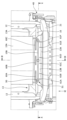
図7乃至図11に示されるように、下部フレーム13は、シート後部を構成する断面J字状に形成された後壁部13A、及び後壁部13Aの前端に連続して形成されたシート前部を構成する前壁部13Bを備える。
As shown in FIGS. 7 to 11, the
[4.1.下部フレーム13の前壁部13Bの構成]
まず、下部フレーム13の前壁部13Bの構成について主に説明する。
図7及び図9に示されるように、前壁部13Bは、支持部15Aと対向するシート幅部分を後壁部13Aの前端から上方に延出させた部分である。
図7に示されるように、支持部15Aには、下端に3つのクリップ50が取り付けられたワイヤ15Bが取り付けられる。そして、前壁部13Bには、クリップ50と嵌合する貫通孔である取付部51が3箇所形成される。
図7に示されるように、取付部51は、支持部15Aから離間し、かつ支持部15Aの下方に設けられている。また、取付部51は、支持部15Aの左右方向の端よりも内側に設けられている。
そして、ワイヤ15Bに取り付けられたクリップ50を前壁部13Bの取付部51に嵌合させることで、前壁部13Bにワイヤ15Bが固定される。
[4.1. Configuration of
First, the configuration of the
As shown in FIGS. 7 and 9, the
As shown in FIG. 7, a
As shown in FIG. 7, the mounting
The
図7に示されるように、前壁部13Bにおいて、各クリップ50の取付部51の上部には、それぞれシート幅方向に延在した上側補強部60A、上側補強部60B、上側補強部60Cが形成される。図7に示されるように、上側補強部60A、上側補強部60B、上側補強部60Cはそれぞれ略同一水平面上に形成されており、左側に上側補強部60A、中央に上側補強部60B、右側に上側補強部60Cが設けられる。
なお、上側補強部60A、上側補強部60B、上側補強部60Cは、前壁部13Bの一部をプレス加工によりシート後方に凹ませたビード部として形成されるものである。
As shown in FIG. 7, in the
The upper reinforcing
図7に示されるように、上側補強部60A、上側補強部60B、上側補強部60Cは、それぞれ前壁部13Bの上縁に沿った形状に形成される。すなわち、前壁部13Bの上縁は、中央が直線状、左右の端部が円弧状となっており、それに合わせて上側補強部60Aの左側端部が円弧状でそれ以外が直線状、上側補強部60Bは直線状、上側補強部60Cの右側端部が円弧状でそれ以外が直線状に形成される。
また、上側補強部60Aの左側端部の位置は、対向する取付部51よりもシート幅方向で外側に位置する。同様に、上側補強部60Cの右側端部の位置は、対向する取付部51よりもシート幅方向で外側に位置する。
As shown in FIG. 7, the upper reinforcing
In addition, the position of the left end portion of the upper reinforcing
図7に示されるように、前壁部13Bと後壁部13Aの境界部であって、上側補強部60Aと対向する取付部51の下方には、互いに離間した下側補強部61Aと下側補強部61Bが形成される。下側補強部61A及び下側補強部61Bは、前壁部13Bと後壁部13Aの境界部をプレス加工によりシート後方に凹ませたビード部として形成される。
図7に示されるように、上側補強部60Aと対向する取付部51は、シート上下方向において、上側補強部60Aと、下側補強部61A及び下側補強部61Bとの間に設けられる。
また、上側補強部60Aの左側端部の位置は、下側補強部61Aよりもシート幅方向外側に位置する。そして、上側補強部60Aの右側端部の位置は、下側補強部61Bよりもシート幅方向外側に位置する。
すなわち、下側補強部61Aと下側補強部61Bは、上部に設けられた上側補強部60Aに対しシート幅方向内側に形成される。そして、下側補強部61Aと下側補強部61Bの間隔は、上側補強部60Aの幅方向の長さよりも短い。
As shown in FIG. 7, at the boundary between the
As shown in FIG. 7, the mounting
Further, the position of the left end portion of the upper reinforcing
That is, the lower reinforcing
図7に示されるように、前壁部13Bと後壁部13Aの境界部であって、上側補強部60Bと対向する取付部51の下方には、互いに離間した下側補強部61Cと下側補強部61Dが形成される。下側補強部61C及び下側補強部61Dは、前壁部13Bと後壁部13Aの境界部をプレス加工によりシート後方に凹ませたビード部として形成される。
図7に示されるように、上側補強部60Bと対向する取付部51は、シート上下方向において、上側補強部60Bと、下側補強部61C及び下側補強部61Dとの間に設けられる。そして、上側補強部60Bと対向する取付部51は、シート幅方向において、下側補強部61C及び下側補強部61Dとの間に設けられる。
また、上側補強部60Bの左側端部の位置は、下側補強部61Cよりもシート幅方向外側に位置する。そして、上側補強部60Bの右側端部の位置は、下側補強部61Dよりもシート幅方向外側に位置する。
すなわち、下側補強部61Cと下側補強部61Dは、上部に設けられた上側補強部60Bに対しシート幅方向内側に形成される。そして、下側補強部61Cと下側補強部61Dの間隔は、上側補強部60Bの幅方向の長さよりも短い。
As shown in FIG. 7, at the boundary between the
As shown in FIG. 7, the mounting
Further, the position of the left end portion of the upper reinforcing
That is, the lower reinforcing
図7に示されるように、前壁部13Bと後壁部13Aの境界部であって、上側補強部60Cと対向する取付部51の下方には、互いに離間した下側補強部61Eと下側補強部61Fが形成される。下側補強部61E及び下側補強部61Fは、前壁部13Bと後壁部13Aの境界部をプレス加工によりシート後方に凹ませたビード部として形成される。
図7に示されるように、上側補強部60Cと対向する取付部51は、シート上下方向において、上側補強部60Cと、下側補強部61E及び下側補強部61Fとの間に設けられる。
また、上側補強部60Cの左側端部の位置は、下側補強部61Eよりもシート幅方向外側に位置する。そして、上側補強部60Cの右側端部の位置は、下側補強部61Fよりもシート幅方向外側に位置する。
すなわち、下側補強部61Eと下側補強部61Fは、上部に設けられた上側補強部60Cに対しシート幅方向内側に形成される。そして、下側補強部61Eと下側補強部61Fの間隔は、上側補強部60Cの幅方向の長さよりも短い。
As shown in FIG. 7, at the boundary between the
As shown in FIG. 7, the mounting
Further, the position of the left end portion of the upper reinforcing
That is, the lower reinforcing
また、図7に示されるように、上側において隣り合う上側補強部60Aと上側補強部60Bの間隔は、下側において隣り合う下側補強部61Bと下側補強部61Cの間隔よりも短い。同様に、上側において隣り合う上側補強部60Bと上側補強部60Cの間隔は、下側において隣り合う下側補強部61Dと下側補強部61Eの間隔よりも短い。
Also, as shown in FIG. 7, the interval between the adjacent upper reinforcing
例えば後壁部13Aの前面に受圧部材15を取り付ける場合には、後壁部13Aと前壁部13Bとの間には、回転軸16が設けられており、スペースが十分でないため、受圧部材15の取り付け作業が容易ではない。
一方で、シートフレーム1では、下部フレーム13の前壁部13Bに、受圧部材15のワイヤ15Bを取り付ける取付部51を設けたことで、回転軸16と作業者の手が干渉することがないため、受圧部材15の取り付けの作業性を向上させることができる。
For example, when the
On the other hand, in the
[4.2.下部フレーム13の後壁部13Aの構成]
次に、下部フレーム13の後壁部13Aの構成について主に説明する。
図9に示されるように、後壁部13Aの上端は、前壁部13Bの上端よりも上に位置している。また、支持部15Aの下端は、前壁部13Bの上端よりも上であって、且つ後壁部13Aの上端よりも下に位置している。
また、図9に示されるように、前壁部13Bは、支持部15Aと略平行に設けられる。なお、支持部15AはトルソラインTと略平行であるため、換言すれば前壁部13BはトルソラインTに対して略平行に設けられる。
[4.2. Configuration of
Next, the configuration of the
As shown in FIG. 9, the upper end of the
Further, as shown in FIG. 9, the
図8に示されるように、後壁部13Aにおけるシート幅方向両外側の上部にはそれぞれ、上方に突出する上方突出部75が設けられる。上方突出部75は、サイドフレーム12に沿った形状に形成されており、サイドフレーム12の後面補強部30Dに対向する位置に補強部74が形成されている。なお、補強部74は、シート前方に凹むビード部として形成され、後面補強部30Dと係合する形状となっている。
なお、後壁部13Aのシート幅方向の両側部は、サイドフレーム12と溶接により接合される。
As shown in FIG. 8,
Both side portions of the
以上説明した本実施形態に係るシートフレーム1によれば、サイドフレーム12のサイドフレーム側部12Aに第1補強部30A、第2補強部30B及び第3補強部30Cを設けたことにより、サイドフレーム12の剛性を向上させることができる。
ここで、第1補強部30A、第2補強部30B及び第3補強部30Cはそれぞれ延在する方向が異なるため、様々な方向からの荷重の入力に対しての剛性を向上できる。
According to the
Here, since the directions in which the first reinforcing
また、シートフレーム1によれば、下部フレーム13の前壁部13Bに受圧部材15の取付部51を設けたことにより、受圧部材15の取付作業性を向上させることができる。
また、前壁部13Bの取付部51には、上下に補強部を設けたことにより取付部51周辺の剛性を向上できる。
Further, according to the
In addition, the mounting
[5.変形例]
本発明は上記の実施形態に限定されるものではない。以下においては、図12A乃至図12Dに基づいて、サイドフレーム12のサイドフレーム側部12Aに形成される補強部(ビード形状)の変形例について説明する。
図12A乃至図12Dはそれぞれ、変形例に係るサイドフレーム12の外側面図を示している。
[5. Modification]
The invention is not limited to the embodiments described above. Modifications of the reinforcing portion (bead shape) formed on the side
12A to 12D each show an outer side view of the
まず、第1の変形例に係るサイドフレーム12について説明する。
図12Aに示されるように、第1の変形例に係るサイドフレーム12には、補強部80A、補強部80B、補強部80C、補強部80D及び補強部80Eが形成される。ここで、補強部80A、補強部80B、補強部80C、補強部80D及び補強部80Eはそれぞれ、サイドフレーム側部12Aをプレス加工によりシート内側に凹ませたビード部として形成される。
補強部80Aは、サイドフレーム側部12Aの後縁12Cに沿って設けられる。
補強部80Bは、エアバッグ取付孔31Aとエアバッグ取付孔31Bとの間においてシート前後方向に延在するように設けられる。
補強部80Cは、エアバッグ取付孔31Aとエアバッグ取付孔31Cとの間においてシート前後方向に延在するように設けられる。
補強部80Dは、エアバッグ取付孔31Cの下側にシート前後方向に延在するように設けられる。
補強部80Eは、エアバッグ取付孔31Bの上部において、サイドフレーム側部12Aの前縁に沿って設けられる。
First, a
As shown in FIG. 12A, the
The reinforcing
The reinforcing
The reinforcing
The reinforcing
The reinforcing
図12Aに示されるように、補強部80A、補強部80B、補強部80C、補強部80D及び補強部80Eをいずれも他の補強部に連結させず、各々を独立したビード部として設けることとしてよい。
また、補強部80A、補強部80B、補強部80C、補強部80D及び補強部80Eはそれぞれ延在する方向が異なることとしてよい。
As shown in FIG. 12A, none of the reinforcing
Further, the reinforcing
次に、第2の変形例に係るサイドフレーム12について説明する。
図12Bに示されるように、第2の変形例に係るサイドフレーム12には、補強部81A、補強部81B及び補強部81Cが形成される。ここで、補強部81A、補強部81B及び補強部81Cはそれぞれ、サイドフレーム側部12Aをプレス加工によりシート内側に凹ませたビード部として形成される。
補強部81Aは、サイドフレーム側部12Aの後縁12Cに沿って設けられる。ただし、補強部81Aの下端は、シート内側に向けて屈曲している。
補強部81Bは、エアバッグ取付孔31Aとエアバッグ取付孔31Bとの間においてシート前後方向に延在するように設けられる。また、補強部81Bの後端は、補強部81Aに連結している。
補強部81Cは、エアバッグ取付孔31Bの上部において、サイドフレーム側部12Aの前縁に沿って設けられる。
Next, a
As shown in FIG. 12B, a reinforcing
The reinforcing
The reinforcing
The reinforcing
次に、第3の変形例に係るサイドフレーム12について説明する。
図12Cに示されるように、第3の変形例に係るサイドフレーム12には、補強部82A、補強部82B、補強部82C及び補強部82Dが形成される。ここで、補強部82A、補強部82B、補強部82C及び補強部82Dはそれぞれ、サイドフレーム側部12Aをプレス加工によりシート内側に凹ませたビード部として形成される。
補強部82Aは、サイドフレーム側部12Aの後縁12Cに沿って設けられる。ただし、補強部82Aの下端は、シート内側に向けて屈曲している。
補強部82Bは、エアバッグ取付孔31Aとエアバッグ取付孔31Bとの間においてシート前後方向に延在するように設けられる。また、補強部82Bの後端は、補強部82Aに連結している。
補強部82Cは、補強部82Aの屈曲箇所からエアバッグ取付孔31Cに向けてシート前後方向に延在するように設けられる。また、補強部82Cの後端は、補強部82Aに連結している。
補強部82Dは、エアバッグ取付孔31Bの上部において、サイドフレーム側部12Aの前縁に沿って設けられる。
Next, a
As shown in FIG. 12C, a reinforcing
The reinforcing
The reinforcing
The reinforcing
The reinforcing
最後に、第4変形例に係るサイドフレーム12について説明する。
図12Dに示されるように、第4の変形例に係るサイドフレーム12には、補強部83A、補強部83B及び補強部83Cが形成される。ここで、補強部83A、補強部83B及び補強部83Cはそれぞれ、サイドフレーム側部12Aをプレス加工によりシート内側に凹ませたビード部として形成される。
補強部83Aは、サイドフレーム側部12Aの後縁12Cに沿って設けられる。
補強部83Bは、円環状に形成され、後端部が補強部83Aに連結する。そして、補強部83Bは、エアバッグ取付孔31Aと、エアバッグ取付孔31B及びエアバッグ取付孔31Cの間に形成され、エアバッグ取付孔31Aを内包する。
補強部83Cは、エアバッグ取付孔31Bの上部において、サイドフレーム側部12Aの前縁に沿って設けられる。
Finally, a
As shown in FIG. 12D, a reinforcing
The reinforcing
The reinforcing
The reinforcing
1 シートフレーム
10 シートバックフレーム
11 上部フレーム
11A 上部フレーム側部
12 サイドフレーム
12A サイドフレーム側部
12B サイドフレーム後部
12C 後縁
12D 幅広部
13 下部フレーム
13A 後壁部
13B 前壁部
14 クロスメンバ
14A 凹部
15 受圧部材
15A 支持部
15B ワイヤ
15C ワイヤ
16 回転軸
17 ヘッドレスト取付部
18 第1連結ブラケット
18A 脆弱部
18B シャフト貫通孔
18C ボルト締結用孔
18D ボルト締結用孔
19 第2連結ブラケット
19A 脆弱部
19B シャフト貫通孔
19C ボルト締結用孔
19D ボルト締結用孔
19E 脆弱部
20 シートクッションフレーム
21 パンフレーム
22A,22B クッションサイドフレーム
23 連結パイプ
24 受圧部材
30A 第1補強部
30B 第2補強部
30C 第3補強部
30D 後面補強部
31A エアバッグ取付孔
31B エアバッグ取付孔
31C エアバッグ取付孔
31D 貫通孔
31E 貫通孔
31F 貫通孔
40 リクライニングユニット
41 高さ調整ユニット
50 クリップ
51 取付部
52 溶接部
60A 上側補強部
60B 上側補強部
60C 上側補強部
61A 下側補強部
61B 下側補強部
61C 下側補強部
61D 下側補強部
61E 下側補強部
61F 下側補強部
74 補強部
75 上方突出部
80A 補強部
80B 補強部
80C 補強部
80D 補強部
80E 補強部
81A 補強部
81B 補強部
81C 補強部
82A 補強部
82B 補強部
82C 補強部
82D 補強部
83A 補強部
83B 補強部
83C 補強部
T トルソライン
1 seat frame 10 seatback frame 11 upper frame 11A upper frame side portion 12 side frame 12A side frame side portion 12B side frame rear portion 12C rear edge 12D wide portion 13 lower frame 13A rear wall portion 13B front wall portion 14 cross member 14A recess 15 Pressure receiving member 15A Supporting portion 15B Wire 15C Wire 16 Rotating shaft 17 Headrest mounting portion 18 First connection bracket 18A Weak portion 18B Shaft through hole 18C Bolt fastening hole 18D Bolt fastening hole 19 Second connection bracket 19A Weak portion 19B Shaft through hole 19C bolt fastening hole 19D bolt fastening hole 19E fragile portion 20 seat cushion frame 21 pan frame 22A, 22B cushion side frame 23 connecting pipe 24 pressure receiving member 30A first reinforcement portion 30B second reinforcement portion 30C third reinforcement portion 30D rear surface reinforcement Part 31A Airbag mounting hole 31B Airbag mounting hole 31C Airbag mounting hole 31D Through hole 31E Through hole 31F Through hole 40 Reclining unit 41 Height adjustment unit 50 Clip 51 Mounting part 52 Welding part 60A Upper reinforcing part 60B Upper reinforcing part 60C Upper reinforcing portion 61A Lower reinforcing portion 61B Lower reinforcing portion 61C Lower reinforcing portion 61D Lower reinforcing portion 61E Lower reinforcing portion 61F Lower reinforcing portion 74 Reinforcing portion 75 Upper projecting portion 80A Reinforcing portion 80B Reinforcing portion 80C Reinforcing portion 80D Reinforcement part 80E Reinforcement part 81A Reinforcement part 81B Reinforcement part 81C Reinforcement part 82A Reinforcement part 82B Reinforcement part 82C Reinforcement part 82D Reinforcement part 83A Reinforcement part 83B Reinforcement part 83C Reinforcement part T Torso line
Claims (10)
前記下部フレームは、
後方に設けられる後壁部と、
前記後壁部よりも前方に設けられる前壁部と、を有し、
前記前壁部に、乗員を支持する受圧部材を取り付ける取付部を設け、
前記前壁部は、前記後壁部の前端から上方に延出させた部分であり、
前記後壁部は断面J字状に形成されており、
前記後壁部の上端は、前記前壁部の上端よりも上に位置し、前記前壁部及び前記後壁部は開断面を有するように設けられていることを特徴とするシートフレーム。 A seat frame including a lower frame that connects lower portions of side frames arranged on the left and right,
The lower frame is
a rear wall portion provided at the rear;
a front wall portion provided forward of the rear wall portion,
The front wall portion is provided with a mounting portion for mounting a pressure receiving member that supports an occupant ,
The front wall portion is a portion that extends upward from the front end of the rear wall portion,
The rear wall portion is formed to have a J-shaped cross section,
The seat frame, wherein the upper end of the rear wall portion is positioned above the upper end of the front wall portion, and the front wall portion and the rear wall portion are provided so as to have an open cross section.
前記乗員を支持する支持部と、
前記支持部と前記取付部との双方に接続する接続部と、を有し、
前記取付部は、前記支持部から離間し、かつ前記支持部の下方に設けられ、
前記支持部の下端は、前記後壁部の上端よりも下に位置するように設けられていることを特徴とする請求項1に記載のシートフレーム。 The pressure receiving member is
a support portion that supports the occupant;
a connecting portion connected to both the support portion and the mounting portion;
The mounting portion is spaced apart from the support portion and provided below the support portion ,
2. The seat frame according to claim 1 , wherein the lower end of the support portion is positioned below the upper end of the rear wall portion .
Priority Applications (3)
| Application Number | Priority Date | Filing Date | Title |
|---|---|---|---|
| JP2021131014A JP7227520B2 (en) | 2020-10-14 | 2021-08-11 | seat frame |
| JP2023017855A JP7440806B2 (en) | 2020-10-14 | 2023-02-08 | seat frame |
| JP2024021374A JP2024040482A (en) | 2020-10-14 | 2024-02-15 | seat frame |
Applications Claiming Priority (2)
| Application Number | Priority Date | Filing Date | Title |
|---|---|---|---|
| JP2020173421A JP6931178B2 (en) | 2016-08-09 | 2020-10-14 | Seat frame |
| JP2021131014A JP7227520B2 (en) | 2020-10-14 | 2021-08-11 | seat frame |
Related Parent Applications (1)
| Application Number | Title | Priority Date | Filing Date |
|---|---|---|---|
| JP2020173421A Division JP6931178B2 (en) | 2016-08-09 | 2020-10-14 | Seat frame |
Related Child Applications (1)
| Application Number | Title | Priority Date | Filing Date |
|---|---|---|---|
| JP2023017855A Division JP7440806B2 (en) | 2020-10-14 | 2023-02-08 | seat frame |
Publications (2)
| Publication Number | Publication Date |
|---|---|
| JP2021183491A JP2021183491A (en) | 2021-12-02 |
| JP7227520B2 true JP7227520B2 (en) | 2023-02-22 |
Family
ID=78767706
Family Applications (3)
| Application Number | Title | Priority Date | Filing Date |
|---|---|---|---|
| JP2021131014A Active JP7227520B2 (en) | 2020-10-14 | 2021-08-11 | seat frame |
| JP2023017855A Active JP7440806B2 (en) | 2020-10-14 | 2023-02-08 | seat frame |
| JP2024021374A Pending JP2024040482A (en) | 2020-10-14 | 2024-02-15 | seat frame |
Family Applications After (2)
| Application Number | Title | Priority Date | Filing Date |
|---|---|---|---|
| JP2023017855A Active JP7440806B2 (en) | 2020-10-14 | 2023-02-08 | seat frame |
| JP2024021374A Pending JP2024040482A (en) | 2020-10-14 | 2024-02-15 | seat frame |
Country Status (1)
| Country | Link |
|---|---|
| JP (3) | JP7227520B2 (en) |
Citations (4)
| Publication number | Priority date | Publication date | Assignee | Title |
|---|---|---|---|---|
| US20090152928A1 (en) | 2007-12-14 | 2009-06-18 | Hyundai Motor Company | Seatback Frame for Vehicles |
| JP2011006024A (en) | 2009-06-29 | 2011-01-13 | Honda Motor Co Ltd | Seat back frame of vehicle seat |
| JP2012126245A (en) | 2010-12-15 | 2012-07-05 | Tachi S Co Ltd | Seat back frame structure of vehicle seat |
| JP2014172551A (en) | 2013-03-12 | 2014-09-22 | Tachi-S Co Ltd | Seat back for vehicular seat |
Family Cites Families (1)
| Publication number | Priority date | Publication date | Assignee | Title |
|---|---|---|---|---|
| JP6169525B2 (en) | 2014-04-25 | 2017-07-26 | トヨタ紡織株式会社 | Vehicle seat clip mounting structure |
-
2021
- 2021-08-11 JP JP2021131014A patent/JP7227520B2/en active Active
-
2023
- 2023-02-08 JP JP2023017855A patent/JP7440806B2/en active Active
-
2024
- 2024-02-15 JP JP2024021374A patent/JP2024040482A/en active Pending
Patent Citations (4)
| Publication number | Priority date | Publication date | Assignee | Title |
|---|---|---|---|---|
| US20090152928A1 (en) | 2007-12-14 | 2009-06-18 | Hyundai Motor Company | Seatback Frame for Vehicles |
| JP2011006024A (en) | 2009-06-29 | 2011-01-13 | Honda Motor Co Ltd | Seat back frame of vehicle seat |
| JP2012126245A (en) | 2010-12-15 | 2012-07-05 | Tachi S Co Ltd | Seat back frame structure of vehicle seat |
| JP2014172551A (en) | 2013-03-12 | 2014-09-22 | Tachi-S Co Ltd | Seat back for vehicular seat |
Also Published As
| Publication number | Publication date |
|---|---|
| JP2023053062A (en) | 2023-04-12 |
| JP2024040482A (en) | 2024-03-25 |
| JP2021183491A (en) | 2021-12-02 |
| JP7440806B2 (en) | 2024-02-29 |
Similar Documents
| Publication | Publication Date | Title |
|---|---|---|
| JP7269519B2 (en) | seat frame | |
| JP5584503B2 (en) | Vehicle seat | |
| CN108394324B (en) | Chair frame | |
| JP7099933B2 (en) | Vehicle seats | |
| CN109955920B (en) | Vehicle body rear structure | |
| JP2012106578A (en) | Seat back board, and seat for vehicle using the same | |
| JP7227520B2 (en) | seat frame | |
| JP5297054B2 (en) | Vehicle seat | |
| JP6931178B2 (en) | Seat frame | |
| JP6781372B2 (en) | Seat frame | |
| JP5989856B2 (en) | Vehicle seat | |
| JP6521660B2 (en) | Seat frame and vehicle seat | |
| JP6086302B2 (en) | Unequally divided vehicle seat structure | |
| JP2022154848A (en) | Seat frame and vehicle seat | |
| JP6624262B2 (en) | Vehicle seat | |
| JP7077041B2 (en) | Vehicle seat | |
| JP6513724B2 (en) | Vehicle seat | |
| JP6659967B2 (en) | Vehicle seat | |
| WO2019203012A1 (en) | Vehicle seat | |
| JP2023167959A (en) | vehicle seat | |
| JP2017088159A (en) | Vehicle seat | |
| JP2020011622A (en) | Vehicle seat | |
| JP2006143155A (en) | Rear body structure of vehicle | |
| JP2017081566A (en) | Vehicle seat | |
| JP2006298085A (en) | Seat cushion frame for automobile seat |
Legal Events
| Date | Code | Title | Description |
|---|---|---|---|
| A621 | Written request for application examination |
Free format text: JAPANESE INTERMEDIATE CODE: A621 Effective date: 20210909 |
|
| A131 | Notification of reasons for refusal |
Free format text: JAPANESE INTERMEDIATE CODE: A131 Effective date: 20220823 |
|
| A521 | Request for written amendment filed |
Free format text: JAPANESE INTERMEDIATE CODE: A523 Effective date: 20221006 |
|
| TRDD | Decision of grant or rejection written | ||
| A01 | Written decision to grant a patent or to grant a registration (utility model) |
Free format text: JAPANESE INTERMEDIATE CODE: A01 Effective date: 20230110 |
|
| A61 | First payment of annual fees (during grant procedure) |
Free format text: JAPANESE INTERMEDIATE CODE: A61 Effective date: 20230123 |
|
| R150 | Certificate of patent or registration of utility model |
Ref document number: 7227520 Country of ref document: JP Free format text: JAPANESE INTERMEDIATE CODE: R150 |