JP7224480B2 - Outdoor unit and refrigeration cycle equipment - Google Patents
Outdoor unit and refrigeration cycle equipment Download PDFInfo
- Publication number
- JP7224480B2 JP7224480B2 JP2021544990A JP2021544990A JP7224480B2 JP 7224480 B2 JP7224480 B2 JP 7224480B2 JP 2021544990 A JP2021544990 A JP 2021544990A JP 2021544990 A JP2021544990 A JP 2021544990A JP 7224480 B2 JP7224480 B2 JP 7224480B2
- Authority
- JP
- Japan
- Prior art keywords
- refrigerant
- compressor
- flow path
- passage
- condenser
- Prior art date
- Legal status (The legal status is an assumption and is not a legal conclusion. Google has not performed a legal analysis and makes no representation as to the accuracy of the status listed.)
- Active
Links
Images


Classifications
-
- F—MECHANICAL ENGINEERING; LIGHTING; HEATING; WEAPONS; BLASTING
- F25—REFRIGERATION OR COOLING; COMBINED HEATING AND REFRIGERATION SYSTEMS; HEAT PUMP SYSTEMS; MANUFACTURE OR STORAGE OF ICE; LIQUEFACTION SOLIDIFICATION OF GASES
- F25B—REFRIGERATION MACHINES, PLANTS OR SYSTEMS; COMBINED HEATING AND REFRIGERATION SYSTEMS; HEAT PUMP SYSTEMS
- F25B40/00—Subcoolers, desuperheaters or superheaters
-
- F—MECHANICAL ENGINEERING; LIGHTING; HEATING; WEAPONS; BLASTING
- F25—REFRIGERATION OR COOLING; COMBINED HEATING AND REFRIGERATION SYSTEMS; HEAT PUMP SYSTEMS; MANUFACTURE OR STORAGE OF ICE; LIQUEFACTION SOLIDIFICATION OF GASES
- F25B—REFRIGERATION MACHINES, PLANTS OR SYSTEMS; COMBINED HEATING AND REFRIGERATION SYSTEMS; HEAT PUMP SYSTEMS
- F25B2400/00—General features or devices for refrigeration machines, plants or systems, combined heating and refrigeration systems or heat-pump systems, i.e. not limited to a particular subgroup of F25B
- F25B2400/13—Economisers
-
- F—MECHANICAL ENGINEERING; LIGHTING; HEATING; WEAPONS; BLASTING
- F25—REFRIGERATION OR COOLING; COMBINED HEATING AND REFRIGERATION SYSTEMS; HEAT PUMP SYSTEMS; MANUFACTURE OR STORAGE OF ICE; LIQUEFACTION SOLIDIFICATION OF GASES
- F25B—REFRIGERATION MACHINES, PLANTS OR SYSTEMS; COMBINED HEATING AND REFRIGERATION SYSTEMS; HEAT PUMP SYSTEMS
- F25B2400/00—General features or devices for refrigeration machines, plants or systems, combined heating and refrigeration systems or heat-pump systems, i.e. not limited to a particular subgroup of F25B
- F25B2400/19—Pumping down refrigerant from one part of the cycle to another part of the cycle, e.g. when the cycle is changed from cooling to heating, or before a defrost cycle is started
-
- F—MECHANICAL ENGINEERING; LIGHTING; HEATING; WEAPONS; BLASTING
- F25—REFRIGERATION OR COOLING; COMBINED HEATING AND REFRIGERATION SYSTEMS; HEAT PUMP SYSTEMS; MANUFACTURE OR STORAGE OF ICE; LIQUEFACTION SOLIDIFICATION OF GASES
- F25B—REFRIGERATION MACHINES, PLANTS OR SYSTEMS; COMBINED HEATING AND REFRIGERATION SYSTEMS; HEAT PUMP SYSTEMS
- F25B2400/00—General features or devices for refrigeration machines, plants or systems, combined heating and refrigeration systems or heat-pump systems, i.e. not limited to a particular subgroup of F25B
- F25B2400/23—Separators
-
- F—MECHANICAL ENGINEERING; LIGHTING; HEATING; WEAPONS; BLASTING
- F25—REFRIGERATION OR COOLING; COMBINED HEATING AND REFRIGERATION SYSTEMS; HEAT PUMP SYSTEMS; MANUFACTURE OR STORAGE OF ICE; LIQUEFACTION SOLIDIFICATION OF GASES
- F25B—REFRIGERATION MACHINES, PLANTS OR SYSTEMS; COMBINED HEATING AND REFRIGERATION SYSTEMS; HEAT PUMP SYSTEMS
- F25B2600/00—Control issues
- F25B2600/23—Time delays
-
- F—MECHANICAL ENGINEERING; LIGHTING; HEATING; WEAPONS; BLASTING
- F25—REFRIGERATION OR COOLING; COMBINED HEATING AND REFRIGERATION SYSTEMS; HEAT PUMP SYSTEMS; MANUFACTURE OR STORAGE OF ICE; LIQUEFACTION SOLIDIFICATION OF GASES
- F25B—REFRIGERATION MACHINES, PLANTS OR SYSTEMS; COMBINED HEATING AND REFRIGERATION SYSTEMS; HEAT PUMP SYSTEMS
- F25B2600/00—Control issues
- F25B2600/25—Control of valves
-
- F—MECHANICAL ENGINEERING; LIGHTING; HEATING; WEAPONS; BLASTING
- F25—REFRIGERATION OR COOLING; COMBINED HEATING AND REFRIGERATION SYSTEMS; HEAT PUMP SYSTEMS; MANUFACTURE OR STORAGE OF ICE; LIQUEFACTION SOLIDIFICATION OF GASES
- F25B—REFRIGERATION MACHINES, PLANTS OR SYSTEMS; COMBINED HEATING AND REFRIGERATION SYSTEMS; HEAT PUMP SYSTEMS
- F25B2700/00—Sensing or detecting of parameters; Sensors therefor
- F25B2700/19—Pressures
- F25B2700/193—Pressures of the compressor
- F25B2700/1931—Discharge pressures
-
- F—MECHANICAL ENGINEERING; LIGHTING; HEATING; WEAPONS; BLASTING
- F25—REFRIGERATION OR COOLING; COMBINED HEATING AND REFRIGERATION SYSTEMS; HEAT PUMP SYSTEMS; MANUFACTURE OR STORAGE OF ICE; LIQUEFACTION SOLIDIFICATION OF GASES
- F25B—REFRIGERATION MACHINES, PLANTS OR SYSTEMS; COMBINED HEATING AND REFRIGERATION SYSTEMS; HEAT PUMP SYSTEMS
- F25B2700/00—Sensing or detecting of parameters; Sensors therefor
- F25B2700/19—Pressures
- F25B2700/193—Pressures of the compressor
- F25B2700/1933—Suction pressures
Description
この発明は、室外ユニットおよび冷凍サイクル装置に関する。 The present invention relates to an outdoor unit and a refrigerating cycle device.
特開2014-01917号公報(特許文献1)には、中間インジェクション流路と吸入インジェクション流路とを有する冷凍装置が開示されている。この冷凍装置では、凝縮器から蒸発器に向かって流れる冷媒の一部を、中間インジェクション流路を使って圧縮機の中間圧の冷媒に合流させることも、吸入インジェクション流路を使って吸入流路において圧縮機に吸入される低圧の冷媒に合流させることも可能である。このため、中間インジェクション流路を使うと運転効率が悪化する場合において、吸入インジェクション流路を使って圧縮機の吐出温度を低下させることができる。 Japanese Patent Laying-Open No. 2014-01917 (Patent Document 1) discloses a refrigeration system having an intermediate injection channel and a suction injection channel. In this refrigeration system, part of the refrigerant flowing from the condenser to the evaporator can be combined with the intermediate pressure refrigerant in the compressor using the intermediate injection channel, or the suction injection channel can be used to join the suction channel. It is also possible to join the low-pressure refrigerant sucked into the compressor at . Therefore, when the use of the intermediate injection flow path deteriorates the operating efficiency, the suction injection flow path can be used to lower the discharge temperature of the compressor.
主冷媒回路において液冷媒が流れる配管に開閉弁などを設置して、配管を遮断した状態で圧縮機を運転することによって冷媒を負荷装置から室外ユニットへ移動させ、貯蔵することをポンプダウン運転という。 In the main refrigerant circuit, an on-off valve is installed in the pipe through which the liquid refrigerant flows, and the compressor is operated with the pipe cut off to move the refrigerant from the load device to the outdoor unit and store it in the pump-down operation. .
特開2014-01917号公報(特許文献1)に記載された冷凍装置では、負荷装置が運転停止されるなどして、室内ユニット側で冷媒の流通が遮断され負荷装置側でポンプダウン運転が実行開始すると、負荷装置の冷媒が室外ユニットに回収される。このときに、冷媒回収が進み高圧部の冷媒が減少すると、凝縮温度が外気温度に近くなってしまい凝縮器では冷媒を液化しにくくなり冷媒の回収に時間がかかりポンプダウン運転の時間が長引いてしまうという問題がある。 In the refrigeration system described in Japanese Patent Application Laid-Open No. 2014-01917 (Patent Document 1), the operation of the load device is stopped, etc., and the flow of the refrigerant is interrupted on the indoor unit side, and the load device side performs the pump-down operation. Once started, refrigerant in the load device is collected in the outdoor unit. At this time, as refrigerant recovery progresses and the amount of refrigerant in the high-pressure section decreases, the condensation temperature approaches the outside air temperature, making it difficult for the condenser to liquefy. There is a problem of storage.
この発明の目的は、ポンプダウン運転時の冷媒回収時間が短縮された室外ユニットおよび冷凍サイクル装置を提供することである。 SUMMARY OF THE INVENTION An object of the present invention is to provide an outdoor unit and a refrigeration cycle apparatus in which the refrigerant recovery time during pump-down operation is shortened.
本開示は、第1膨張装置および蒸発器を含む負荷装置に接続されるように構成された冷凍サイクル装置の室外ユニットに関する。室外ユニットは、負荷装置に接続されることによって、冷媒が循環する循環流路を形成する第1流路と、第1流路に配置される、圧縮機および凝縮器と、冷媒が循環する方向において、凝縮器よりも下流の第1流路の分岐点から分岐し、凝縮器を通過した冷媒を圧縮機に戻すように構成された第2流路と、分岐点から順に第2流路に配置される第2膨張装置、受液器および流量調整弁と、第1通路および第2通路を有し、第1通路を流れる冷媒と第2通路を流れる冷媒との間で熱交換を行なうように構成された熱交換器とを備える。熱交換器の第1通路は、第1流路の凝縮器と分岐点との間に配置される。熱交換器の第2通路は、第2流路の流量調整弁と圧縮機との間に配置される。流量調整弁は、受液器からの液冷媒の排出流量を調整するように構成される。受液器に冷媒を回収するポンプダウン運転を開始する場合には、圧縮機および流量調整弁の制御状態が、第1時点において圧縮機を運転しつつ流量調整弁を閉止した第1状態となる。ポンプダウン運転中の第1時点よりも後の第2時点において、制御状態が第1状態から圧縮機を運転しつつ流量調整弁を開いた第2状態に遷移する。 The present disclosure relates to an outdoor unit of a refrigeration cycle apparatus configured to be connected to a load device including a first expansion device and an evaporator. The outdoor unit includes a first flow path forming a circulation flow path in which the refrigerant circulates by being connected to a load device, a compressor and a condenser arranged in the first flow path, and a direction in which the refrigerant circulates. , a second flow path branched from a branch point of the first flow path downstream of the condenser and configured to return the refrigerant that has passed through the condenser to the compressor, and from the branch point to the second flow path in order a second expansion device, a liquid receiver and a flow control valve disposed thereon; a first passage and a second passage; and a heat exchanger configured to A first passage of the heat exchanger is disposed between the condenser and the branch point of the first flow path. A second passageway of the heat exchanger is disposed between the flow control valve in the second flowpath and the compressor. The flow control valve is configured to adjust the discharge flow rate of the liquid refrigerant from the liquid receiver. When the pump-down operation for collecting the refrigerant in the liquid receiver is started, the control state of the compressor and the flow control valve is the first state in which the compressor is operated and the flow control valve is closed at the first time point. . At a second point in time after the first point in time during the pump-down operation, the control state transitions from the first state to a second state in which the flow control valve is opened while operating the compressor.
本開示の室外ユニットによれば、ポンプダウン運転時に冷媒回収が進み凝縮温度が外気温度に近づいた場合にも、熱交換器の効率を維持して冷媒の凝縮を行なう。このため、冷媒回収に要する時間を短くすることができる。 According to the outdoor unit of the present disclosure, the efficiency of the heat exchanger is maintained and the refrigerant is condensed even when the refrigerant recovery proceeds and the condensing temperature approaches the outside air temperature during the pump-down operation. Therefore, the time required for refrigerant recovery can be shortened.
以下、本発明の実施の形態について、図面を参照しながら詳細に説明する。以下では、複数の実施の形態について説明するが、各実施の形態で説明された構成を適宜組み合わせることは出願当初から予定されている。なお、図中同一または相当部分には同一符号を付してその説明は繰返さない。 BEST MODE FOR CARRYING OUT THE INVENTION Hereinafter, embodiments of the present invention will be described in detail with reference to the drawings. A plurality of embodiments will be described below, but appropriate combinations of the configurations described in the respective embodiments have been planned since the filing of the application. The same or corresponding parts in the drawings are denoted by the same reference numerals, and the description thereof will not be repeated.
図1は、本実施の形態に従う冷凍サイクル装置の全体構成図である。なお、図1では、冷凍サイクル装置における各機器の接続関係および配置構成を機能的に示しており、物理的な空間における配置を必ずしも示すものではない。 FIG. 1 is an overall configuration diagram of a refrigeration cycle apparatus according to this embodiment. Note that FIG. 1 functionally shows the connection relationship and arrangement configuration of each device in the refrigeration cycle apparatus, and does not necessarily show the arrangement in a physical space.
図1を参照して、冷凍サイクル装置1は、室外ユニット2と、負荷装置3と、配管84,88とを備える。室外ユニット2は、負荷装置3と接続するための冷媒出口ポートPO2および冷媒入口ポートPI2を有する。負荷装置3は、室外ユニット2と接続するための冷媒出口ポートPO3および冷媒入口ポートPI3を有する。配管84は、室外ユニット2の冷媒出口ポートPO2と負荷装置3の冷媒入口ポートPI3とを接続する。配管88は、負荷装置3の冷媒出口ポートPO3と室外ユニット2の冷媒入口ポートPI2とを接続する。
Referring to FIG. 1, the
冷凍サイクル装置1の室外ユニット2は、負荷装置3に接続されるように構成される。室外ユニット2は、吸入ポートG1、吐出ポートG2、中間圧ポートG3を有する圧縮機10と、凝縮器20と、ファン22と、熱交換器30と、配管80~82、89とを備える。熱交換器30は、第1通路H1および第2通路H2を有し、第1通路H1を流れる冷媒と第2通路H2を流れる冷媒との間で熱交換を行なうように構成される。
The
負荷装置3は、第1膨張弁50と、蒸発器60と、配管85、86,87と、開閉弁28とを含む。蒸発器60は空気と冷媒との間で熱交換を行なうように構成される。冷凍サイクル装置1では、蒸発器60は、冷却対象空間の空気からの吸熱によって冷媒を蒸発させる。第1膨張弁50は、例えば、室外ユニット2と独立して制御される温度膨張弁である。なお、第1膨張弁50は冷媒を減圧することができる電子膨張弁であってもよい。開閉弁28は、負荷装置3が運転停止するときに閉止され、冷媒を遮断する。
The
圧縮機10は、配管89から吸入される冷媒を圧縮して配管80へ吐出する。圧縮機10は、インバータ制御により駆動周波数を任意に変更することができる。また、圧縮機10には中間圧ポートG3が設けられており中間圧ポートG3からの冷媒を圧縮工程の途中部分に流入させることができる。圧縮機10は、制御装置100からの制御信号に従って回転速度を調整するように構成される。圧縮機10の回転速度を調整することで冷媒の循環量が調整され、冷凍サイクル装置1の能力を調整することができる。圧縮機10には種々のタイプのものを採用可能であり、例えば、スクロールタイプ、ロータリータイプ、スクリュータイプ等のものを採用し得る。
The
凝縮器20は、圧縮機10から吐出された高温高圧のガス冷媒が外気と熱交換(放熱)を行なうように構成される。この熱交換により、冷媒は凝縮されて液相に変化する。圧縮機10から配管80に吐出された冷媒は、凝縮器20において凝縮および液化され配管81へ流出する。熱交換の効率を上げるため外気を送るファン22が凝縮器20に取り付けられている。ファン22は、凝縮器20において冷媒が熱交換を行なう外気を凝縮器20に供給する。ファン22の回転数を調整することにより、圧縮機10の吐出側の冷媒圧力(高圧側圧力)を調整することができる。
ここで、冷凍サイクル装置1の冷媒回路に使用する冷媒はCO2とするが、過冷却度が確保しにくい状態が生じる場合は、他の冷媒を使用しても良い。Here, the refrigerant used in the refrigerant circuit of the
なお、本明細書では、説明の容易のため、超臨界状態のCO2のような冷媒を冷却する場合も凝縮器20と呼ぶこととする。また、本明細書では、説明の容易のため、超臨界状態の冷媒の基準温度からの低下量も過冷却度と呼ぶこととする。In this specification, for ease of explanation, the
冷媒入口ポートPI2から圧縮機10、凝縮器20、熱交換器30の第1通路H1を経由して冷媒出口ポートPO2に至る第1流路F1は、負荷装置3の第1膨張弁50および蒸発器60が配置される流路とともに、冷媒が循環する循環流路を形成する。以下、この循環流路を冷凍サイクルの「主冷媒回路」とも言う。
A first flow path F1 from the refrigerant inlet port PI2 to the refrigerant outlet port PO2 via the first passage H1 of the
室外ユニット2は、循環流路の第1通路H1の出口と冷媒出口ポートPO2との間の部分から、第2通路H2の入口に冷媒を流す配管91,92,94と、第2通路H2の出口から圧縮機10の中間圧ポートG3に冷媒を流す配管96とをさらに備える。以下において、主冷媒回路から分岐して第2通路H2を経由して圧縮機10に冷媒を送る第2流路F2を、「インジェクション流路」とも言う。
The
室外ユニット2は、さらに、第2流路F2に配置され、冷媒を貯留する受液器(レシーバ)73を備える。第2膨張弁71は、循環流路の第1通路H1の出口と冷媒出口ポートPO2との間の部分から分岐した配管91と受液器73の入口に接続された配管92との間に配置される。室外ユニット2は、さらに、受液器73のガス排出口と第2通路H2とを接続し受液器73内の冷媒ガスを排出するガス抜き配管93と、ガス抜き配管93と第2通路H2に通じる配管94との間に配置された絞り装置70と、受液器73の液冷媒排出口に接続された配管94の冷媒流量を調整する流量調整弁72とを備える。
The
配管91は、主冷媒回路から分岐し受液器73へ冷媒を流入させる配管である。第2膨張弁71は主冷媒回路の高圧部の冷媒を中間圧力まで低下させることができる電子膨張弁である。受液器73は、減圧され二相となった冷媒の気相と液相の分離を容器内で行ない、冷媒を貯蔵し主冷媒回路の冷媒の循環量を調整することができる容器である。受液器73の上部に接続されるガス抜き配管93と受液器73の下部に接続される配管94は、受液器73の中でガス冷媒と液冷媒に分離した冷媒を分離した状態で取り出すための配管である。流量調整弁72は、配管94から排出される液冷媒の量を調整することで受液器73の冷媒量を調整することができる。
A
このようにインジェクション流路に受液器73を設けることにより、液管である配管82,83における過冷却度を確保することが容易となる。一般に受液器73にはガス冷媒が存在するため、冷媒温度は飽和温度となるので、配管82に受液器73を配置すると過冷却度を確保できないからである。
By providing the
また、中間圧部分に受液器73を設けると、主冷媒回路の高圧部の圧力が高く冷媒が超臨界状態である場合でも受液器73の内部に中間圧の液冷媒を貯留することが可能となる。このため、受液器73の容器の設計圧を高圧部よりも低くすることができ、容器の薄肉化によるコスト低減も図れる。
Further, if the
室外ユニット2は、さらに、圧力センサ110,111と、温度センサ120~123と、圧縮機10、第2膨張弁71、および流量調整弁72を制御する制御装置100とを備える。
The
圧力センサ110は、圧縮機10の吸入ポート部分の圧力PLを検出し、その検出値を制御装置100へ出力する。圧力センサ111は、圧縮機10の吐出圧力PHを検出し、その検出値を制御装置100へ出力する。
温度センサ120は、圧縮機10の吐出温度THを検出し、その検出値を制御装置100へ出力する。温度センサ121は、凝縮器20の出口の配管81の冷媒温度T1を検出し、その検出値を制御装置100へ出力する。温度センサ122は、熱交換器30の被冷却側の第1通路H1の出口の冷媒温度T2を検出し、その検出値を制御装置100へ出力する。温度センサ123は室外ユニット2の周囲温度である外気温TAを検出し、その検出値を制御装置100へ出力する。
本実施の形態では第2流路F2は、減圧して二相となった冷媒を圧縮機10へ流入させることによって圧縮機10の吐出温度THを制御するものである。加えて第2流路F2上に設置した受液器73によって主冷媒回路の冷媒量を調整することができる。さらに、第2流路F2は、熱交換器30による熱交換による主冷媒回路の冷媒の過冷却の確保も担っている。
In the present embodiment, the second flow path F2 controls the discharge temperature TH of the
制御装置100は、CPU(Central Processing Unit)102と、メモリ104(ROM(Read Only Memory)およびRAM(Random Access Memory))と、各種信号を入出力するための入出力バッファ(図示せず)等を含んで構成される。CPU102は、ROMに格納されているプログラムをRAM等に展開して実行する。ROMに格納されるプログラムは、制御装置100の処理手順が記されたプログラムである。制御装置100は、これらのプログラムに従って、室外ユニット2における各機器の制御を実行する。この制御については、ソフトウェアによる処理に限られず、専用のハードウェア(電子回路)で処理することも可能である。
The
(通常運転時における制御)
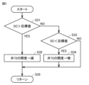
制御装置100は、第2膨張弁71を、圧縮機10の吐出温度THが目標温度に一致するようにフィードバック制御する。(Control during normal operation)
The
図2は、第2膨張弁71の制御を説明するためのフローチャートである。制御装置100は、圧縮機10の吐出温度THが目標温度より高い場合には(S21でYES)、第2膨張弁71の開度を増加させる(S22)。これによって、受液器73を経由して中間圧ポートG3に流入する冷媒が増えるため、吐出温度THが低下する。
FIG. 2 is a flow chart for explaining the control of the
一方、圧縮機10の吐出温度THが目標温度より低い場合には(S21でNOかつS23でYES)、制御装置100は、第2膨張弁71の開度を減少させる(S24)。これによって、受液器73を経由して中間圧ポートG3に流入する冷媒が減るため、吐出温度THが上昇する。
On the other hand, when the discharge temperature TH of the
吐出温度TH=目標温度であれば(S21でNOかつS23でNO)、制御装置100は、第2膨張弁71の開度を現在の状態に維持する。
If the discharge temperature TH=the target temperature (NO in S21 and NO in S23), the
このように、制御装置100は、圧縮機10の吐出温度THが目標温度に近づくように第2膨張弁71の開度を制御する。
In this manner, the
また、制御装置100は、通常運転では凝縮器20の出口の冷媒の過冷却度SCを確保するため、凝縮器20の出口の冷媒温度T1が目標温度に一致するように流量調整弁72をフィードバック制御する。
In order to ensure the subcooling degree SC of the refrigerant at the outlet of the
図3は、流量調整弁72の制御を説明するためのフローチャートである。凝縮器20の出口の冷媒温度T1と凝縮器20の圧力(PHで近似)とによって定まる過冷却度SCが目標値より大きい場合には(S31でYES)、制御装置100は、流量調整弁72の開度を減少させる(S32)。これによって、受液器73から排出される液冷媒の量が減少し、受液器73内の液冷媒量が増加するため、主冷媒回路を循環する冷媒量が減少し、冷媒温度T1が上昇するので過冷却度SCが減少する。
FIG. 3 is a flow chart for explaining the control of the
一方、凝縮器20の出口の冷媒温度T1と凝縮器20の圧力(PHで近似)によって定まる過冷却度SCが目標値より小さい場合には(S31でNOかつS33でYES)、制御装置100は、流量調整弁72の開度を増加させる(S34)。これによって、受液器73から排出される液冷媒の量が増加し、受液器73に貯留される液冷媒量が減るため、主冷媒回路を循環する冷媒量が増加し、冷媒温度T1が低下するので過冷却度SCが増加する。
On the other hand, when the degree of supercooling SC determined by the refrigerant temperature T1 at the outlet of the
過冷却度SC=目標値であれば(S31でNOかつS33でNO)、制御装置100は、流量調整弁72の開度を現在の状態に維持する。
If the degree of supercooling SC=the target value (NO in S31 and NO in S33), the
このように、制御装置100は、凝縮器20の出口の冷媒温度T1が目標温度に近づくように流量調整弁72の開度を制御する。
Thus, the
(ポンプダウン運転時における制御)
また、制御装置100は、通常運転では凝縮器20の出口の冷媒の過冷却度SCを確保するため、凝縮器20の出口の冷媒温度T1が目標温度に一致するように流量調整弁72をフィードバック制御するとともに、ポンプダウン運転では流量調整弁72を閉じて受液器73に液冷媒を回収する。(Control during pump-down operation)
In order to ensure the subcooling degree SC of the refrigerant at the outlet of the
主冷媒回路において液冷媒が流れる配管85に開閉弁28などを設置して、配管85を遮断した状態で圧縮機10を運転することによって冷媒を負荷装置3から室外ユニット2へ移動させ、貯蔵することをポンプダウン運転という。ポンプダウン運転は、例えば、運転停止前に第1膨張弁50を閉じたり、開閉弁28を閉じたりした後に圧縮機10を運転することなどによって行なわれる。
An on-off
一般に、ポンプダウン運転の開始を指示する信号は、特に負荷装置3側から室外ユニット2には送信されておらず、室外ユニット2では圧力センサ110によって検出された低圧部の圧力PLがしきい値PAまで低下したときに通常の運転が継続されることによってポンプダウン運転が実行される。
In general, the signal instructing the start of the pump-down operation is not particularly transmitted from the
ポンプダウン運転では、開閉弁28が閉止され圧力センサ110によって検出された低圧部の圧力PLがしきい値PBまで低下すると、制御装置100は、圧縮機10を停止してポンプダウンを停止する仕組みとなっている。圧縮機10は、停止状態では冷媒が通過しないように構成されているので、冷媒は負荷装置3には逆流しない。
In the pump-down operation, when the on-off
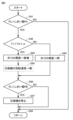
図4は、ポンプダウン運転時の制御を説明するためのフローチャートである。まずステップS41において、制御装置100は、圧力センサ110によって検出された低圧部の圧力PLがしきい値PAよりも低いか否かを判断する。PL<しきい値PAが成立した場合(S41でYES)、ステップS42以降のポンプダウン運転が実行される。一方、PL<しきい値PAが成立しない場合(S41でNO)、ポンプダウン運転は実行されずに、ステップS47において、制御は通常運転の処理に戻される。
FIG. 4 is a flowchart for explaining control during pump-down operation. First, in step S41,
ステップS42においては、制御装置100は、凝縮器20における冷媒温度T1がTA+αよりも低いか否かを判断する。ここでαは、冷媒と外気との温度差がこれ以上小さくなると凝縮器20における冷媒の凝縮の効率が著しく低下してしまう温度差を示し、適宜定められる値である。
In step S42,
T1<TA+αでない場合(S42でNO)、制御装置100は、ステップS43において、流量調整弁72を閉じる。これにより、受液器73からはガス冷媒がガス抜き配管93から排出され、受液器73に液冷媒が回収される。
If not T1<TA+α (NO in S42), the
一方、T1<TA+αである場合(S42でYES)、制御装置100は、ステップS44において、流量調整弁72の開度を微増させる。これにより、受液器73に貯留されている液冷媒が熱交換器30の第2通路H2に流れる。流量調整弁72を閉止していると、熱交換器30の第2通路H2は、ガス抜き配管93からガス冷媒が流れている。ガス冷媒が流れる状態では、第2通路H2における冷媒と熱交換器との間の熱伝達率は低い。
On the other hand, if T1<TA+α (YES in S42),
ここで、流量調整弁72を少し開くことによって液冷媒が混じるようになれば、第2通路H2における冷媒と熱交換器との間の熱伝達率は10倍以上に改善される。これにより、液冷媒の回収がある程度進んだ段階で凝縮器20では凝縮されにくくなった冷媒を、熱交換器30で凝縮させることによって、液冷媒の回収を進めることができる。なお、流量調整弁72の開度をあまり大きくしすぎると液冷媒の回収量が増加しなくなるので、ステップS44における流量調整弁72の開度は、受液器73における液冷媒の回収量が増加する範囲内とする。
Here, if the liquid refrigerant is mixed by slightly opening the
必ずしも行なわなくても良いが、好ましくは、制御装置100は、さらにステップS45において圧縮機10の回転速度を増加させる。これにより、回収が進み凝縮しにくくなった残りの冷媒の回収の時間を短縮することができる。
Although not necessarily performed, preferably,
続いて、ステップS46において、制御装置100は、圧力センサ110によって検出された低圧部の圧力PLがしきい値PBまで低下したか否かを判断する。しきい値PBは、しきい値PAよりも低い値であり、負荷装置3の冷媒の回収が完了したことを判定する判定値である。圧力PLがしきい値PBまで低下しないうちは(S46でNO)、制御装置100は圧縮機10の運転を継続してポンプダウン運転を続行する。
Subsequently, in step S46,
一方、圧力PLがしきい値PBまで低下すると(S46でYES)、ステップS47において制御装置100は、圧縮機10を停止してポンプダウンを終了する。
On the other hand, when pressure PL has decreased to threshold value PB (YES in S46),
このように制御することによって、ポンプダウン運転を開始する第1時点においては、制御装置100は流量調整弁72を閉じて受液器73に液冷媒を貯留するようにする。そして、受液器73の液冷媒の量が増加して、凝縮器20の効率が低下した第2時点において、制御装置100は、流量調整弁72を少し開いて熱交換器30の効率を改善して第1通路H1における冷媒の凝縮を促進させる。これにより、ポンプダウン運転を完了させるまでの時間を短縮することができる。
By controlling in this way, the
最後に、本実施の形態について再び図面を参照して総括する。図1に示すように、本開示は、「第1膨張装置」に相当する第1膨張弁50および蒸発器60を含む負荷装置3に接続されるように構成された冷凍サイクル装置1の室外ユニット2に関する。室外ユニット2は、負荷装置3に接続されることによって、冷媒が循環する循環流路を形成する第1流路F1と、第1流路F1に配置される、圧縮機10および凝縮器20と、冷媒が循環する方向において、凝縮器20よりも下流の第1流路F1の分岐点から分岐し、凝縮器20を通過した冷媒を圧縮機10に戻すように構成された第2流路F2と、分岐点から順に第2流路F2に配置される、「第2膨張装置」に相当する第2膨張弁71、受液器73および流量調整弁72と、第1通路H1および第2通路H2を有し、第1通路H1を流れる冷媒と第2通路H2を流れる冷媒との間で熱交換を行なうように構成された熱交換器30と、制御装置100とを備える。
Finally, the present embodiment will be summarized with reference to the drawings again. As shown in FIG. 1, the present disclosure provides an outdoor unit of a
熱交換器30の第1通路H1は、第1流路F1の凝縮器20と分岐点との間に配置される。熱交換器30の第2通路H2は、第2流路F2の流量調整弁72と圧縮機10との間に配置される。流量調整弁72は、受液器73からの液冷媒の排出流量を調整するように構成される。
The first passage H1 of the
制御装置100は、圧縮機10と流量調整弁72とを制御するように構成される。制御装置100は、受液器73に冷媒を回収するポンプダウン運転を開始する場合には、圧縮機10および流量調整弁72の制御状態を、第1時点において圧縮機10を運転しつつ流量調整弁72を閉止した第1状態に制御する。制御装置100は、ポンプダウン運転中の第1時点よりも後の第2時点において、第1状態から圧縮機10を運転しつつ流量調整弁72を開いた第2状態に遷移させるように構成される。
ポンプダウン運転が進行すると、受液器73への冷媒の回収が進むので、受液器73の液冷媒の量は次第に増加する。したがって、第2時点における受液器73の液冷媒の量は、第1時点における受液器73の液冷媒の量よりも多い。
As the pump-down operation progresses, recovery of the refrigerant to the
好ましくは、制御装置100は、凝縮器20における冷媒の凝縮温度と外気温との差がしきい値よりも小さくなった場合に、圧縮機10および流量調整弁72の制御状態を第2状態に制御する。これにより、受液器73への液冷媒の回収が進行した段階において、凝縮器20における冷媒温度T1と外気温TAとの差が小さくなって凝縮器20の効率が低下した場合においても、熱交換器30の効率を向上させて液冷媒の回収をさらに進めることができる。
Preferably,
なお、第2状態における流量調整弁72の開度は長時間全開にすると、受液器73の液冷媒の量が減少してしまう。したがって、第2状態では、熱交換器30の第2通路H2に液冷媒の環状流が発生する程度のわずかな開度で流量調整弁72を開くかまたは、短時間の開閉を繰返す程度で良い。これにより、熱交換器30の熱交換の効率が改善し、熱交換器30において第1通路H1を通過する冷媒が凝縮するので、液冷媒の回収が促進される。
If the opening degree of the
より好ましくは、制御装置100は、第2状態における圧縮機10の回転速度を第1状態における圧縮機10の回転速度よりも高くするように構成される。これにより、回収が進み凝縮しにくくなった残りの冷媒の回収の時間を短縮することができる。
More preferably,
以上、冷凍サイクル装置1を備える冷凍機を例示して本実施の形態を説明したが、冷凍サイクル装置1は、空気調和機などに利用されても良い。
Although the refrigerator including the refrigerating
今回開示された実施の形態は、すべての点で例示であって制限的なものではないと考えられるべきである。本発明の範囲は、上記した実施の形態の説明ではなくて請求の範囲によって示され、請求の範囲と均等の意味および範囲内でのすべての変更が含まれることが意図される。 The embodiments disclosed this time should be considered as examples and not restrictive in all respects. The scope of the present invention is indicated by the scope of the claims rather than the description of the above-described embodiments, and is intended to include all modifications within the meaning and scope equivalent to the scope of the claims.
1 冷凍サイクル装置、2 室外ユニット、3 負荷装置、10 圧縮機、20 凝縮器、22 ファン、28 開閉弁、30 熱交換器、71 第2膨張弁、50 第1膨張弁、60 蒸発器、70 絞り装置、72 流量調整弁、73 受液器、80,81,82,83,84,85,88,89,91,92,94,96 配管、93 ガス抜き配管、100 制御装置、104 メモリ、110,111 圧力センサ、120,121,122,123 温度センサ、F1 第1流路、F2 第2流路、G1 吸入ポート、G2 吐出ポート、G3 中間圧ポート、H1 第1通路、H2 第2通路。
Claims (5)
前記負荷装置に接続されることによって、冷媒が循環する循環流路を形成する第1流路と、
前記第1流路に配置される、圧縮機および凝縮器と、
前記冷媒が循環する方向において、前記凝縮器よりも下流の前記第1流路の分岐点から分岐し、前記凝縮器を通過した冷媒を前記圧縮機に戻すように構成された第2流路と、
前記分岐点から順に前記第2流路に配置される第2膨張装置、受液器および流量調整弁と、
第1通路および第2通路を有し、前記第1通路を流れる冷媒と前記第2通路を流れる冷媒との間で熱交換を行なうように構成された熱交換器とを備え、
前記熱交換器の前記第1通路は、前記第1流路の前記凝縮器と前記分岐点との間に配置され、
前記熱交換器の前記第2通路は、前記第2流路の前記流量調整弁と前記圧縮機との間に配置され、
前記流量調整弁は、前記受液器からの液冷媒の排出流量を調整するように構成され、
前記受液器に冷媒を回収するポンプダウン運転を開始する場合には、前記圧縮機および前記流量調整弁の制御状態が、第1時点において前記圧縮機を運転しつつ前記流量調整弁を閉止した第1状態となり、
前記ポンプダウン運転中の前記第1時点よりも後の第2時点において、前記制御状態が前記第1状態から前記圧縮機を運転しつつ前記流量調整弁を開いた第2状態に遷移する、室外ユニット。An outdoor unit of a refrigeration cycle device configured to be connected to a load device including a first expansion device and an evaporator,
a first flow path forming a circulation flow path in which a coolant circulates by being connected to the load device;
a compressor and a condenser disposed in the first flow path;
a second flow path branched from a branch point of the first flow path downstream of the condenser in the direction in which the refrigerant circulates and configured to return the refrigerant that has passed through the condenser to the compressor; ,
a second expansion device, a receiver, and a flow control valve arranged in the second flow path in order from the branch point;
a heat exchanger having a first passage and a second passage and configured to exchange heat between the refrigerant flowing through the first passage and the refrigerant flowing through the second passage;
the first passage of the heat exchanger is disposed between the condenser and the branch point of the first flow path;
the second passage of the heat exchanger is arranged between the flow control valve of the second flow path and the compressor;
The flow rate adjustment valve is configured to adjust the discharge flow rate of the liquid refrigerant from the liquid receiver,
When starting the pump-down operation for collecting the refrigerant in the liquid receiver, the control state of the compressor and the flow control valve is such that the flow control valve is closed while the compressor is operated at a first time point. becomes the first state,
At a second time point after the first time point during the pump-down operation, the control state transitions from the first state to a second state in which the flow control valve is opened while operating the compressor. unit.
Applications Claiming Priority (1)
| Application Number | Priority Date | Filing Date | Title |
|---|---|---|---|
| PCT/JP2019/035373 WO2021048901A1 (en) | 2019-09-09 | 2019-09-09 | Outdoor unit and refrigeration cycle device |
Publications (3)
| Publication Number | Publication Date |
|---|---|
| JPWO2021048901A1 JPWO2021048901A1 (en) | 2021-03-18 |
| JPWO2021048901A5 JPWO2021048901A5 (en) | 2022-04-08 |
| JP7224480B2 true JP7224480B2 (en) | 2023-02-17 |
Family
ID=74866219
Family Applications (1)
| Application Number | Title | Priority Date | Filing Date |
|---|---|---|---|
| JP2021544990A Active JP7224480B2 (en) | 2019-09-09 | 2019-09-09 | Outdoor unit and refrigeration cycle equipment |
Country Status (7)
| Country | Link |
|---|---|
| EP (1) | EP4030116B1 (en) |
| JP (1) | JP7224480B2 (en) |
| CN (1) | CN114341567B (en) |
| DK (1) | DK4030116T3 (en) |
| ES (1) | ES2964488T3 (en) |
| FI (1) | FI4030116T3 (en) |
| WO (1) | WO2021048901A1 (en) |
Families Citing this family (3)
| Publication number | Priority date | Publication date | Assignee | Title |
|---|---|---|---|---|
| CN113294925A (en) * | 2021-05-21 | 2021-08-24 | 浙江国祥股份有限公司 | Evaporative condensation type water chilling unit with combined economizer |
| WO2023199511A1 (en) * | 2022-04-15 | 2023-10-19 | 三菱電機株式会社 | Refrigeration cycle device |
| WO2024023993A1 (en) * | 2022-07-27 | 2024-02-01 | 三菱電機株式会社 | Refrigeration cycle device |
Citations (3)
| Publication number | Priority date | Publication date | Assignee | Title |
|---|---|---|---|---|
| JP2009156531A (en) | 2007-12-27 | 2009-07-16 | Mitsubishi Electric Corp | Refrigeration system |
| JP2014102008A (en) | 2012-11-16 | 2014-06-05 | Panasonic Corp | Refrigeration apparatus |
| WO2017175299A1 (en) | 2016-04-05 | 2017-10-12 | 三菱電機株式会社 | Refrigeration cycle device |
Family Cites Families (7)
| Publication number | Priority date | Publication date | Assignee | Title |
|---|---|---|---|---|
| US5187940A (en) * | 1991-02-19 | 1993-02-23 | Standard Motor Products, Inc. | Refrigerant recovery and purification system |
| JP4734161B2 (en) * | 2006-04-19 | 2011-07-27 | 日立アプライアンス株式会社 | Refrigeration cycle apparatus and air conditioner |
| US8424326B2 (en) * | 2007-04-24 | 2013-04-23 | Carrier Corporation | Refrigerant vapor compression system and method of transcritical operation |
| CN201892359U (en) * | 2010-11-30 | 2011-07-06 | 青岛金华工业集团有限公司 | Refrigerant recycling filling machine with two cooling modes |
| JP5500240B2 (en) | 2012-05-23 | 2014-05-21 | ダイキン工業株式会社 | Refrigeration equipment |
| JP5855312B2 (en) * | 2013-03-12 | 2016-02-09 | 三菱電機株式会社 | Air conditioner |
| JP6935720B2 (en) * | 2017-10-12 | 2021-09-15 | ダイキン工業株式会社 | Refrigeration equipment |
-
2019
- 2019-09-09 DK DK19944704.6T patent/DK4030116T3/en active
- 2019-09-09 ES ES19944704T patent/ES2964488T3/en active Active
- 2019-09-09 WO PCT/JP2019/035373 patent/WO2021048901A1/en unknown
- 2019-09-09 FI FIEP19944704.6T patent/FI4030116T3/en active
- 2019-09-09 CN CN201980099962.8A patent/CN114341567B/en active Active
- 2019-09-09 JP JP2021544990A patent/JP7224480B2/en active Active
- 2019-09-09 EP EP19944704.6A patent/EP4030116B1/en active Active
Patent Citations (3)
| Publication number | Priority date | Publication date | Assignee | Title |
|---|---|---|---|---|
| JP2009156531A (en) | 2007-12-27 | 2009-07-16 | Mitsubishi Electric Corp | Refrigeration system |
| JP2014102008A (en) | 2012-11-16 | 2014-06-05 | Panasonic Corp | Refrigeration apparatus |
| WO2017175299A1 (en) | 2016-04-05 | 2017-10-12 | 三菱電機株式会社 | Refrigeration cycle device |
Also Published As
| Publication number | Publication date |
|---|---|
| CN114341567A (en) | 2022-04-12 |
| EP4030116A1 (en) | 2022-07-20 |
| WO2021048901A1 (en) | 2021-03-18 |
| JPWO2021048901A1 (en) | 2021-03-18 |
| DK4030116T3 (en) | 2023-11-13 |
| ES2964488T3 (en) | 2024-04-08 |
| CN114341567B (en) | 2024-01-02 |
| FI4030116T3 (en) | 2023-11-02 |
| EP4030116A4 (en) | 2022-09-07 |
| EP4030116B1 (en) | 2023-10-11 |
Similar Documents
| Publication | Publication Date | Title |
|---|---|---|
| US9759475B2 (en) | Outdoor unit and air-conditioning apparatus | |
| JP4725387B2 (en) | Air conditioner | |
| US10088206B2 (en) | Air-conditioning apparatus | |
| JP7224480B2 (en) | Outdoor unit and refrigeration cycle equipment | |
| US11384965B2 (en) | Refrigeration cycle apparatus performing a refrigerant circulation operation using a liquid pump | |
| WO2017061010A1 (en) | Refrigeration cycle device | |
| WO2014091909A1 (en) | Heat pump-type heating device | |
| WO2017037771A1 (en) | Refrigeration cycle device | |
| JP7150148B2 (en) | Outdoor unit, refrigeration cycle device and refrigerator | |
| JP5812726B2 (en) | Heat pump water heater | |
| JP5872052B2 (en) | Air conditioner | |
| JP4082435B2 (en) | Refrigeration equipment | |
| JP7378561B2 (en) | Outdoor unit and refrigeration cycle equipment | |
| US11041667B2 (en) | Refrigeration cycle apparatus | |
| JP7195449B2 (en) | Outdoor unit and refrigeration cycle equipment | |
| JP2010054192A (en) | Refrigerating device | |
| JP6554903B2 (en) | Air conditioner | |
| JP2009293887A (en) | Refrigerating device | |
| JP7183381B2 (en) | refrigeration cycle equipment | |
| JP2009236430A (en) | Compression type refrigerating machine and its capacity control method | |
| WO2024023993A1 (en) | Refrigeration cycle device | |
| WO2023233452A1 (en) | Outdoor unit and refrigeration cycle device |
Legal Events
| Date | Code | Title | Description |
|---|---|---|---|
| A521 | Request for written amendment filed |
Free format text: JAPANESE INTERMEDIATE CODE: A523 Effective date: 20220121 |
|
| A621 | Written request for application examination |
Free format text: JAPANESE INTERMEDIATE CODE: A621 Effective date: 20220121 |
|
| TRDD | Decision of grant or rejection written | ||
| A01 | Written decision to grant a patent or to grant a registration (utility model) |
Free format text: JAPANESE INTERMEDIATE CODE: A01 Effective date: 20230110 |
|
| A61 | First payment of annual fees (during grant procedure) |
Free format text: JAPANESE INTERMEDIATE CODE: A61 Effective date: 20230207 |
|
| R150 | Certificate of patent or registration of utility model |
Ref document number: 7224480 Country of ref document: JP Free format text: JAPANESE INTERMEDIATE CODE: R150 |