CN113294925A - Evaporative condensation type water chilling unit with combined economizer - Google Patents
Evaporative condensation type water chilling unit with combined economizer Download PDFInfo
- Publication number
- CN113294925A CN113294925A CN202110559118.8A CN202110559118A CN113294925A CN 113294925 A CN113294925 A CN 113294925A CN 202110559118 A CN202110559118 A CN 202110559118A CN 113294925 A CN113294925 A CN 113294925A
- Authority
- CN
- China
- Prior art keywords
- economizer
- compressor
- evaporative
- outlet
- pressure
- Prior art date
- Legal status (The legal status is an assumption and is not a legal conclusion. Google has not performed a legal analysis and makes no representation as to the accuracy of the status listed.)
- Pending
Links
- XLYOFNOQVPJJNP-UHFFFAOYSA-N water Substances O XLYOFNOQVPJJNP-UHFFFAOYSA-N 0.000 title claims abstract description 26
- 238000009833 condensation Methods 0.000 title claims abstract description 10
- 230000005494 condensation Effects 0.000 title abstract description 8
- 239000007788 liquid Substances 0.000 claims abstract description 69
- 239000003507 refrigerant Substances 0.000 claims abstract description 55
- 239000002131 composite material Substances 0.000 claims abstract description 28
- 150000001875 compounds Chemical class 0.000 claims description 7
- 239000012530 fluid Substances 0.000 claims description 6
- 239000011552 falling film Substances 0.000 claims description 3
- 230000001502 supplementing effect Effects 0.000 claims description 3
- 238000004891 communication Methods 0.000 claims description 2
- 238000005339 levitation Methods 0.000 claims 2
- 238000001704 evaporation Methods 0.000 abstract description 7
- 230000008020 evaporation Effects 0.000 abstract description 7
- 239000013526 supercooled liquid Substances 0.000 abstract description 3
- 239000011555 saturated liquid Substances 0.000 description 9
- 238000001816 cooling Methods 0.000 description 8
- 239000000498 cooling water Substances 0.000 description 6
- 238000005057 refrigeration Methods 0.000 description 5
- 230000002238 attenuated effect Effects 0.000 description 2
- 230000007547 defect Effects 0.000 description 2
- 238000000034 method Methods 0.000 description 2
- 229920006395 saturated elastomer Polymers 0.000 description 2
- 239000000725 suspension Substances 0.000 description 2
- 238000004378 air conditioning Methods 0.000 description 1
- 238000010586 diagram Methods 0.000 description 1
- 238000001035 drying Methods 0.000 description 1
- 238000004781 supercooling Methods 0.000 description 1
- 239000013589 supplement Substances 0.000 description 1
Images
Classifications
-
- F—MECHANICAL ENGINEERING; LIGHTING; HEATING; WEAPONS; BLASTING
- F25—REFRIGERATION OR COOLING; COMBINED HEATING AND REFRIGERATION SYSTEMS; HEAT PUMP SYSTEMS; MANUFACTURE OR STORAGE OF ICE; LIQUEFACTION SOLIDIFICATION OF GASES
- F25B—REFRIGERATION MACHINES, PLANTS OR SYSTEMS; COMBINED HEATING AND REFRIGERATION SYSTEMS; HEAT PUMP SYSTEMS
- F25B1/00—Compression machines, plants or systems with non-reversible cycle
-
- F—MECHANICAL ENGINEERING; LIGHTING; HEATING; WEAPONS; BLASTING
- F25—REFRIGERATION OR COOLING; COMBINED HEATING AND REFRIGERATION SYSTEMS; HEAT PUMP SYSTEMS; MANUFACTURE OR STORAGE OF ICE; LIQUEFACTION SOLIDIFICATION OF GASES
- F25B—REFRIGERATION MACHINES, PLANTS OR SYSTEMS; COMBINED HEATING AND REFRIGERATION SYSTEMS; HEAT PUMP SYSTEMS
- F25B43/00—Arrangements for separating or purifying gases or liquids; Arrangements for vaporising the residuum of liquid refrigerant, e.g. by heat
- F25B43/006—Accumulators
Abstract
The invention discloses an evaporation condensing type water chilling unit with a combined economizer, which comprises a compressor, a condenser and a condenser, wherein the compressor is used for compressing water; the outlet of the compressor is communicated with the inlet of the evaporative condenser; the outlet of the evaporative condenser is communicated with the high-pressure liquid inlet of the composite economizer; according to the invention, the medium-temperature and medium-pressure gas-liquid mixed refrigerant entering the inner side of the heat exchange tube of the composite economizer exchanges heat with the high-pressure liquid refrigerant outside the heat exchange tube, and after the high-pressure liquid refrigerant outside the heat exchange tube is deeply cooled to become the high-pressure supercooled liquid refrigerant, the high-pressure liquid refrigerant enters the main throttle valve from the high-pressure liquid outlet of the supercooler inside the composite economizer through the main channel, so that the operation energy efficiency of the evaporative condensation type water chilling unit is improved, and the operation stability of the unit is ensured.
Description
Technical Field
The invention belongs to the technical field of refrigeration machinery, and particularly relates to an evaporation-condensation type water chilling unit with a combined economizer.
Background
The evaporative condensation type water chilling unit combines the advantages of water-cooling and air-cooling water chilling units, air and circulating water are used as cooling media, the latent heat of evaporation of evaporative circulating cooling water is used for directly condensing high-temperature and high-pressure gas refrigerant discharged by a compressor, a heat exchange link in cooling water of the water chilling unit is omitted, the power consumption of a cooling water pump is saved, and the water chilling unit can be directly placed outdoors without a special machine room.
Compared with a conventional water cooling system (a water cooling unit, a cooling water pump and a cooling tower), the refrigeration energy efficiency of the evaporative condensation type water chilling unit can be improved by about 20%; compared with an air cooling unit, the evaporative condensing water chilling unit can improve the refrigeration energy efficiency by about 60 percent, so that the evaporative condensing water chilling unit is the host type with the highest energy efficiency ratio in the existing refrigeration and air conditioning system, and can well solve the defects of high condensation temperature and low refrigeration energy efficiency of the conventional air cooling and water chilling unit.
Some water chilling unit design manufacturers add a liquid storage device between the evaporative condenser and the evaporator, and set a balance pipe between the top of the liquid storage device and the inlet of the evaporative condenser, so that the liquid storage device can store liquid refrigerant, and simultaneously, the liquid refrigerant in the condenser can rapidly and smoothly flow into the liquid storage device. However, the upper part of the liquid storage device is saturated gas refrigerant, the lower part of the liquid storage device is saturated liquid refrigerant, and high-pressure saturated liquid from the liquid storage device inevitably generates local resistance and on-way resistance when passing through the drying filter, the stop valve, the electromagnetic valve and the high-pressure liquid pipe, so that the refrigerant generates a flash evaporation phenomenon, part of the saturated liquid is changed into saturated gas, the circulation capacity of the throttle valve is attenuated, the flow rate of the refrigerant is reduced, the evaporation temperature of the unit is reduced, and finally the refrigerating capacity and the refrigerating energy efficiency of the unit are attenuated.
Disclosure of Invention
Aiming at the defects of the prior art, the invention provides the evaporative condensation type water chilling unit with the combined economizer, which can effectively improve the refrigerating capacity and the refrigerating energy efficiency of the unit and can ensure the stable operation of the unit.
The invention provides an evaporation and condensation type water chilling unit with a combined economizer to achieve the aim, which comprises the following technical scheme
A compressor;
the outlet of the compressor is communicated with the inlet of the evaporative condenser;
the outlet of the evaporative condenser is communicated with the high-pressure liquid inlet of the composite economizer;
an evaporator, the high pressure liquid outlet of the compound economizer and the inlet of the evaporator being in communication through the primary channel;
the main throttle valve is arranged on the main channel;
also comprises
The subcooler is arranged in the composite economizer; the subcooler is a heat exchanger, the fluid on the inner side of the heat exchange tube is medium-temperature medium-pressure gas-liquid mixed refrigerant subjected to throttling and pressure reduction by the auxiliary throttle valve, and the fluid on the outer side of the heat exchange tube is high-pressure liquid entering the subcooler from the interior of the composite economizer;
the inlet of the auxiliary channel is connected with the main channel, and the outlet of the auxiliary channel is communicated with the inlet of the inner side of the heat exchange tube of the subcooler;
and an auxiliary throttle valve is arranged on the auxiliary channel.
And the inlet of the connecting channel is communicated with the gas outlet on the inner side of the heat exchange tube of the subcooler, and the outlet of the connecting channel is communicated with the medium-pressure gas supplementing port of the compressor.
The connection position of the auxiliary channel and the main channel is positioned between the main throttle valve and a high-pressure liquid outlet of the combined economizer.
The subcooler is arranged at the bottom of the composite economizer.
The main throttle valve is set to be one of an electronic expansion valve, an electric butterfly valve, an electric ball valve, a thermal expansion valve, a fixed orifice plate and a variable orifice plate or the combination of the above various types; the auxiliary throttle valve is one or the combination of various types of electronic expansion valves, electric butterfly valves, electric ball valves, thermal expansion valves, fixed orifice plates and variable orifice plates.
The compressor is one of a conventional constant-rotating-speed centrifugal compressor, a screw compressor, a magnetic suspension variable-frequency centrifugal compressor, an air suspension variable-frequency centrifugal compressor and a variable-frequency direct-drive centrifugal compressor, and other types of compressors can also be adopted.
The evaporative condenser is one of a plate-type evaporative condenser, a plate-tube evaporative condenser, a coil-type evaporative condenser or other types of evaporative condensers or a combination of the above types.
The evaporator can be one of a flooded evaporator, a falling film evaporator and a dry evaporator, and other types of evaporators can also be adopted.
In summary, the invention connects an auxiliary channel to the main channel in front of the main throttle valve inlet, and then part of the high pressure liquid refrigerant in the main channel flows into the auxiliary channel, after the high pressure liquid refrigerant is throttled and depressurized by the auxiliary throttle valve on the auxiliary channel, the high pressure liquid refrigerant is changed into medium temperature and medium pressure gas-liquid mixed refrigerant, and then enters the inner side of the heat exchange tube of the subcooler at the bottom of the composite economizer, the medium temperature and medium pressure gas-liquid mixed refrigerant entering the heat exchange tube exchanges heat with the high pressure liquid refrigerant outside the heat exchange tube, after the high pressure liquid refrigerant outside the heat exchange tube is deeply cooled into high pressure subcooled liquid refrigerant, the high pressure subcooled liquid refrigerant entering the main throttle valve from the high pressure liquid outlet of the subcooler inside the composite economizer, and during the flowing process in the main channel, the high pressure subcooled liquid refrigerant after deep cooling can effectively avoid the flash evaporation phenomenon caused by the local and along-way pressure drop in the pipeline, therefore, the refrigerant before entering the main throttle valve is all high-pressure supercooled liquid or high-pressure saturated liquid, so that the operation energy efficiency of the evaporative condensing water chilling unit is improved, and the operation stability of the unit is ensured; the medium-temperature medium-pressure gas-liquid two-phase mixed refrigerant absorbs the heat of the high-pressure liquid refrigerant and is completely gasified into medium-pressure gas, and then the medium-pressure gas enters the compressor, so that the refrigerating capacity and the refrigerating energy efficiency of the unit are effectively improved; therefore, the combined economizer has the functions of a liquid storage device and a supercooling type economizer, can effectively improve the refrigerating capacity and the refrigerating energy efficiency of the unit, and ensures the operation stability of the unit.
Drawings
FIG. 1 is a schematic structural diagram of the present invention.
Detailed Description
In order to make the technical solutions of the present invention better understood, the technical solutions in the embodiments of the present invention will be clearly and completely described below with reference to the drawings in the embodiments of the present invention.
In the prior art, a liquid refrigerant in the liquid storage device is a saturated liquid refrigerant, and in the process that the saturated liquid refrigerant flows into the throttle valve from the liquid storage device, part of high-pressure liquid refrigerant is flashed into gas refrigerant due to local resistance and on-way resistance in a pipeline, so that the flow capacity of the throttle valve and the flow rate of the refrigerant are reduced, and the refrigerating capacity and the refrigerating efficiency of the unit are reduced.
Therefore, one path of high-pressure liquid is led from a high-pressure liquid pipeline at the outlet of the composite economizer, is throttled by a throttle valve and then is changed into a medium-temperature medium-pressure gas-liquid mixed refrigerant, and then enters the inner side of a subcooler heat exchange tube at the bottom of the composite economizer to cool the high-pressure liquid refrigerant outside the subcooler heat exchange tube, so that the flash evaporation phenomenon caused by local and on-way pressure drop of the pipeline after the high-pressure liquid refrigerant flows out of the composite economizer is avoided.
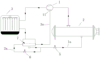
Referring to fig. 1, an evaporative condensing water chilling unit with a composite economizer comprises a compressor 1, an evaporator 2, an evaporative condenser 3 and a composite economizer 4, wherein an outlet of the compressor 1 is connected with an inlet of the evaporative condenser 3, an outlet of the evaporative condenser 3 is connected with a high-pressure liquid inlet of the composite economizer 4, and the high-pressure liquid outlet of the composite economizer 4 is communicated with the evaporator 2 through a main channel 1 a.
The evaporator 2, the compressor 1, the evaporative condenser 3 and the composite economizer 4 can be connected through pipelines, valves and the like, and the structures are communicated with each other, so that the structure belongs to the prior art and is not described any more.
Wherein, the high-pressure liquid outlet of the composite economizer 4 is communicated with the inlet of the evaporator 2 through a main channel 1a, and a main throttle valve 5 is arranged on the main channel 1 a.
Furthermore, the upper part of the composite economizer 4 is a hollow cylinder body which can store high-pressure liquid, has the function of a liquid storage device and can balance the difference of the required refrigerant filling amount when the unit operates under variable working conditions;
further, a subcooler 7 is arranged in the composite economizer 4, the subcooler 7 is positioned at the bottom of the composite economizer 4, the subcooler 7 is a heat exchanger, the fluid on the inner side of the heat exchange tube is a medium-temperature medium-pressure gas-liquid mixed refrigerant which is throttled and depressurized by the auxiliary throttle valve 6, and the fluid on the outer side of the heat exchange tube is a high-pressure liquid which enters the subcooler 7 from the interior of the composite economizer 4. An auxiliary channel 2a is connected to the main channel 1a connected to the high-pressure liquid outlet of the combined economizer 4, wherein the inlet of the auxiliary channel 2a is connected to the main channel 1a, and the outlet of the auxiliary channel 2a is connected to the inlet of the inner side of the heat exchange tube of the subcooler 7. Therefore, the medium-temperature and medium-pressure gas-liquid mixed refrigerant sent from the sub-channel 2a is entirely sent to the heat exchange tube of the subcooler 7.
Further, the inlet of the auxiliary channel 2a is connected between the main throttle valve 5 and the high-pressure liquid outlet of the combined economizer 4, and the auxiliary throttle valve 6 is further arranged on the auxiliary channel 2 a.
Further, an outlet on the inner side of the heat exchange tube of the subcooler 7 is connected with a connecting channel 3a, one end of the connecting channel 3a is connected with an outlet on the inner side of the heat exchange tube, and the other end is connected with a medium-pressure air supplement port 11 of the compressor 1.
The operation of the present invention will be described with reference to the actual case.
High-temperature and high-pressure gas refrigerant generated by the compressor 1 enters the evaporative condenser 3 from the inlet of the evaporative condenser 3, and after the high-temperature and high-pressure gas refrigerant is condensed into high-pressure liquid refrigerant by outdoor air and circulating cooling water in the evaporative condenser 3, the high-pressure liquid refrigerant enters the composite economizer 4 from the outlet of the evaporative condenser 3; the high-pressure saturated liquid refrigerant enters the outer side of a heat exchange tube of a subcooler 7 at the bottom of a composite economizer 4 and exchanges heat with medium-temperature and medium-pressure gas-liquid mixed refrigerant at the inner side of the heat exchange tube, the high-pressure saturated liquid refrigerant at the outer side of the heat exchange tube is deeply cooled to become high-pressure subcooled liquid, then flows into a main channel 1a from a high-pressure liquid outlet of the subcooler 7 in the composite economizer 4, is throttled by a main throttle valve 5 on the main channel 1a to become low-temperature and low-pressure gas-liquid mixed refrigerant, then enters an evaporator 2 from an inlet of the evaporator 2, exchanges heat with chilled water with relatively high temperature, cools the chilled water to become low-pressure gas refrigerant, then sends the low-temperature and low-pressure gas refrigerant into a compressor 1 to be compressed into high-temperature and high-pressure gas refrigerant, and the cycle is repeated.
Meanwhile, one path of auxiliary channel 2a is led from the main channel 1a, part of high-pressure supercooled liquid in the main channel 1a flows into the auxiliary channel 2a, is throttled by an auxiliary throttle valve 6 and then becomes medium-temperature and medium-pressure gas-liquid mixed refrigerant, the medium-temperature and medium-pressure gas-liquid mixed refrigerant enters the inner side of a heat exchange tube of a subcooler 7 from an outlet of the auxiliary channel 2a, exchanges heat with high-pressure saturated liquid refrigerant outside the heat exchange tube of the subcooler 7, absorbs the heat of the high-pressure liquid refrigerant outside the heat exchange tube, cools the high-temperature liquid refrigerant to become medium-temperature and medium-pressure gas, and then the medium-pressure gas enters the compressor 1 from a medium-pressure gas supplementing port 11 of the compressor 1 through a connecting channel 3 a.
In some embodiments, the main throttle 5 may be one of an electronic expansion valve, an electric butterfly valve, an electric ball valve, a thermal expansion valve, a fixed orifice plate, a variable orifice plate, or a combination of the above.
In some embodiments, the auxiliary throttle 6 may be one of an electronic expansion valve, an electric butterfly valve, an electric ball valve, a thermostatic expansion valve, a fixed orifice plate, a variable orifice plate, or a combination of the above.
In some embodiments, the compressor may be one of a constant rotational speed centrifugal compressor, a screw compressor, a magnetically levitated variable frequency centrifugal compressor, an air levitated variable frequency centrifugal compressor, an variable frequency direct drive centrifugal compressor, or other types of compressors may be used.
In some embodiments, the evaporator can be a flooded evaporator, a falling film evaporator, a dry evaporator, although other forms of evaporators can be used.
In some embodiments, the evaporative condenser may be one of a plate-fin evaporative condenser, a plate-tube evaporative condenser, a coil evaporative condenser, or other types of evaporative condensers or combinations thereof.
It is to be understood that the described embodiments are merely a few embodiments of the invention and not all embodiments. All other embodiments, which can be derived by a person skilled in the art from the embodiments given herein without making any creative effort, shall fall within the protection scope of the present invention.
Claims (7)
1. An evaporation-condensation type water chilling unit with a combined economizer comprises
A compressor (1);
the outlet of the compressor (1) is communicated with the inlet of the evaporative condenser (3);
the outlet of the evaporative condenser (3) is communicated with the high-pressure liquid inlet of the composite economizer (4);
an evaporator (2), the high pressure liquid outlet of the combined economizer (4) and the inlet of the evaporator (2) being in communication through the main channel (1 a);
the main throttle valve (5) is arranged on the main channel (1 a);
it is characterized by also comprising
The subcooler (7) is arranged in the composite economizer (4); the subcooler (7) is a heat exchanger, the fluid on the inner side of the heat exchange tube is medium-temperature medium-pressure gas-liquid mixed refrigerant subjected to throttling and pressure reduction by the auxiliary throttle valve (6), and the fluid on the outer side of the heat exchange tube is high-pressure liquid entering the subcooler (7) from the interior of the composite economizer (4);
the inlet of the auxiliary channel (2a) is connected with the main channel (1a), and the outlet of the auxiliary channel (2a) is communicated with the inlet of the inner side of the heat exchange tube of the subcooler (7);
and an auxiliary throttle valve (6) is arranged on the auxiliary channel (2 a).
The inlet of the connecting channel (3a) is communicated with the gas outlet on the inner side of the heat exchange tube of the subcooler (7), and the outlet of the connecting channel (3a) is communicated with the medium-pressure air supplementing port (11) of the compressor (1).
2. Evaporative condensing water chilling unit with compound economizer according to claim 1, characterized by the fact that the connection of the secondary channel (2a) to the main channel (1a) is located between the main throttle valve (5) and the high-pressure liquid outlet of the compound economizer (4).
3. The evaporative condensing chiller with compound economizer of claim 1 wherein the subcooler (7) is located at the bottom of the compound economizer (4).
4. The evaporative condensing chiller with a compound economizer of claim 1 wherein the main throttle valve (5) is one or a combination of various types of electronic expansion valve, electric butterfly valve, electric ball valve, thermostatic expansion valve, fixed orifice plate and variable orifice plate; the auxiliary throttle valve (6) is one or the combination of various types of electronic expansion valves, electric butterfly valves, electric ball valves, thermal expansion valves, fixed orifice plates and variable orifice plates.
5. The evaporative condensing chiller with a compound economizer of claim 1 wherein the compressor (1) is one of a conventional fixed speed centrifugal compressor, a screw compressor, a magnetic levitation variable frequency centrifugal compressor, an air levitation variable frequency centrifugal compressor, an variable frequency direct drive centrifugal compressor, and other types of compressors can be used.
6. Evaporative condensing water chilling unit with combined economizer according to claim 1, characterized in that the evaporative condenser (3) is one of plate evaporative condenser, plate-tube evaporative condenser, coil evaporative condenser or other evaporative condenser or a combination of the above mentioned types.
7. The evaporative condensing chiller according to claim 1 wherein the evaporator is one or the other of a flooded evaporator, a falling film evaporator, and a dry evaporator.
Priority Applications (1)
| Application Number | Priority Date | Filing Date | Title |
|---|---|---|---|
| CN202110559118.8A CN113294925A (en) | 2021-05-21 | 2021-05-21 | Evaporative condensation type water chilling unit with combined economizer |
Applications Claiming Priority (1)
| Application Number | Priority Date | Filing Date | Title |
|---|---|---|---|
| CN202110559118.8A CN113294925A (en) | 2021-05-21 | 2021-05-21 | Evaporative condensation type water chilling unit with combined economizer |
Publications (1)
| Publication Number | Publication Date |
|---|---|
| CN113294925A true CN113294925A (en) | 2021-08-24 |
Family
ID=77323809
Family Applications (1)
| Application Number | Title | Priority Date | Filing Date |
|---|---|---|---|
| CN202110559118.8A Pending CN113294925A (en) | 2021-05-21 | 2021-05-21 | Evaporative condensation type water chilling unit with combined economizer |
Country Status (1)
| Country | Link |
|---|---|
| CN (1) | CN113294925A (en) |
Citations (10)
| Publication number | Priority date | Publication date | Assignee | Title |
|---|---|---|---|---|
| US4696168A (en) * | 1986-10-01 | 1987-09-29 | Roger Rasbach | Refrigerant subcooler for air conditioning systems |
| JPH06331223A (en) * | 1993-05-21 | 1994-11-29 | Mitsubishi Electric Corp | Refrigerating cycle unit |
| US20070074536A1 (en) * | 2002-11-11 | 2007-04-05 | Cheolho Bai | Refrigeration system with bypass subcooling and component size de-optimization |
| US20130042640A1 (en) * | 2010-03-31 | 2013-02-21 | Mitsubishi Electric Corporation | Refrigeration cycle apparatus and refrigerant circulation method |
| US20150285539A1 (en) * | 2014-04-04 | 2015-10-08 | Johnson Controls Technology Company | Heat pump system with multiple operating modes |
| US20190017730A1 (en) * | 2016-02-19 | 2019-01-17 | Mitsubishi Heavy Industries Thermal Systems, Ltd. | Refrigerating machine and control method thereof |
| CN112050490A (en) * | 2020-09-25 | 2020-12-08 | 浙江国祥股份有限公司 | Evaporative cooling centrifugal water chilling unit |
| WO2021048901A1 (en) * | 2019-09-09 | 2021-03-18 | 三菱電機株式会社 | Outdoor unit and refrigeration cycle device |
| CN212901796U (en) * | 2020-05-28 | 2021-04-06 | 浙江思科制冷股份有限公司 | Evaporative cooling type heat pump air conditioning system |
| US20210123646A1 (en) * | 2019-10-23 | 2021-04-29 | Lg Electronics Inc. | Gas-liquid separator and air conditioner having the same |
-
2021
- 2021-05-21 CN CN202110559118.8A patent/CN113294925A/en active Pending
Patent Citations (10)
| Publication number | Priority date | Publication date | Assignee | Title |
|---|---|---|---|---|
| US4696168A (en) * | 1986-10-01 | 1987-09-29 | Roger Rasbach | Refrigerant subcooler for air conditioning systems |
| JPH06331223A (en) * | 1993-05-21 | 1994-11-29 | Mitsubishi Electric Corp | Refrigerating cycle unit |
| US20070074536A1 (en) * | 2002-11-11 | 2007-04-05 | Cheolho Bai | Refrigeration system with bypass subcooling and component size de-optimization |
| US20130042640A1 (en) * | 2010-03-31 | 2013-02-21 | Mitsubishi Electric Corporation | Refrigeration cycle apparatus and refrigerant circulation method |
| US20150285539A1 (en) * | 2014-04-04 | 2015-10-08 | Johnson Controls Technology Company | Heat pump system with multiple operating modes |
| US20190017730A1 (en) * | 2016-02-19 | 2019-01-17 | Mitsubishi Heavy Industries Thermal Systems, Ltd. | Refrigerating machine and control method thereof |
| WO2021048901A1 (en) * | 2019-09-09 | 2021-03-18 | 三菱電機株式会社 | Outdoor unit and refrigeration cycle device |
| US20210123646A1 (en) * | 2019-10-23 | 2021-04-29 | Lg Electronics Inc. | Gas-liquid separator and air conditioner having the same |
| CN212901796U (en) * | 2020-05-28 | 2021-04-06 | 浙江思科制冷股份有限公司 | Evaporative cooling type heat pump air conditioning system |
| CN112050490A (en) * | 2020-09-25 | 2020-12-08 | 浙江国祥股份有限公司 | Evaporative cooling centrifugal water chilling unit |
Similar Documents
| Publication | Publication Date | Title |
|---|---|---|
| EP2543941B1 (en) | Chiller | |
| CN111043781A (en) | Compressor and fluorine pump combined air conditioning system | |
| CN112050490A (en) | Evaporative cooling centrifugal water chilling unit | |
| CN108759138B (en) | Operation method and system of secondary throttling middle incomplete cooling refrigerating system | |
| CN111365896B (en) | Oilless bearing external cooling system with secondary supercooling function | |
| CN113654132A (en) | Heat pump set | |
| CN110849044A (en) | Refrigeration system | |
| CN215675710U (en) | Heat recovery type split air conditioner | |
| CN213778222U (en) | Air conditioning system | |
| CN113294925A (en) | Evaporative condensation type water chilling unit with combined economizer | |
| CN114909725A (en) | High-efficiency energy-saving multi-split system | |
| CN113465198A (en) | Evaporative condensing water chilling unit with super-cooling liquid reservoir | |
| CN109682105B (en) | Air Conditioning System | |
| CN108709333B (en) | Operation method and system of secondary throttling middle complete cooling refrigerating system | |
| CN210035929U (en) | Outdoor low-temperature vortex parallel air-cooled condensation compressor unit with air supply and enthalpy increase functions | |
| CN212657902U (en) | Evaporative cooling centrifugal water chilling unit | |
| CN211451472U (en) | Air-cooled magnetic suspension water chilling unit using micro-channel condenser | |
| CN207279844U (en) | Air conditioner | |
| CN111141049A (en) | Cascade high temperature heat pump laboratory bench | |
| CN112146300A (en) | Cooling unit serving great temperature difference change environment | |
| CN111964188B (en) | Thermosiphon-vapor compression composite refrigeration system | |
| CN109737626A (en) | The air-cooled condensate compressor group of low-temperature vortex parallel-connection of the outdoor version with Gas-supplying enthalpy-increasing | |
| CN219577638U (en) | Refrigerating system and data center | |
| CN216924585U (en) | Water chilling unit | |
| CN219955525U (en) | Sewage source magnetic suspension centrifugal multi-split air conditioning system |
Legal Events
| Date | Code | Title | Description |
|---|---|---|---|
| PB01 | Publication | ||
| PB01 | Publication | ||
| SE01 | Entry into force of request for substantive examination | ||
| SE01 | Entry into force of request for substantive examination |