JP7219780B2 - Vacuum deposition equipment and method for substrate coating - Google Patents
Vacuum deposition equipment and method for substrate coating Download PDFInfo
- Publication number
- JP7219780B2 JP7219780B2 JP2020569119A JP2020569119A JP7219780B2 JP 7219780 B2 JP7219780 B2 JP 7219780B2 JP 2020569119 A JP2020569119 A JP 2020569119A JP 2020569119 A JP2020569119 A JP 2020569119A JP 7219780 B2 JP7219780 B2 JP 7219780B2
- Authority
- JP
- Japan
- Prior art keywords
- substrate
- vapor
- injector
- metal
- injectors
- Prior art date
- Legal status (The legal status is an assumption and is not a legal conclusion. Google has not performed a legal analysis and makes no representation as to the accuracy of the status listed.)
- Active
Links
Images


Classifications
-
- C—CHEMISTRY; METALLURGY
- C23—COATING METALLIC MATERIAL; COATING MATERIAL WITH METALLIC MATERIAL; CHEMICAL SURFACE TREATMENT; DIFFUSION TREATMENT OF METALLIC MATERIAL; COATING BY VACUUM EVAPORATION, BY SPUTTERING, BY ION IMPLANTATION OR BY CHEMICAL VAPOUR DEPOSITION, IN GENERAL; INHIBITING CORROSION OF METALLIC MATERIAL OR INCRUSTATION IN GENERAL
- C23C—COATING METALLIC MATERIAL; COATING MATERIAL WITH METALLIC MATERIAL; SURFACE TREATMENT OF METALLIC MATERIAL BY DIFFUSION INTO THE SURFACE, BY CHEMICAL CONVERSION OR SUBSTITUTION; COATING BY VACUUM EVAPORATION, BY SPUTTERING, BY ION IMPLANTATION OR BY CHEMICAL VAPOUR DEPOSITION, IN GENERAL
- C23C14/00—Coating by vacuum evaporation, by sputtering or by ion implantation of the coating forming material
- C23C14/04—Coating on selected surface areas, e.g. using masks
-
- C—CHEMISTRY; METALLURGY
- C23—COATING METALLIC MATERIAL; COATING MATERIAL WITH METALLIC MATERIAL; CHEMICAL SURFACE TREATMENT; DIFFUSION TREATMENT OF METALLIC MATERIAL; COATING BY VACUUM EVAPORATION, BY SPUTTERING, BY ION IMPLANTATION OR BY CHEMICAL VAPOUR DEPOSITION, IN GENERAL; INHIBITING CORROSION OF METALLIC MATERIAL OR INCRUSTATION IN GENERAL
- C23C—COATING METALLIC MATERIAL; COATING MATERIAL WITH METALLIC MATERIAL; SURFACE TREATMENT OF METALLIC MATERIAL BY DIFFUSION INTO THE SURFACE, BY CHEMICAL CONVERSION OR SUBSTITUTION; COATING BY VACUUM EVAPORATION, BY SPUTTERING, BY ION IMPLANTATION OR BY CHEMICAL VAPOUR DEPOSITION, IN GENERAL
- C23C14/00—Coating by vacuum evaporation, by sputtering or by ion implantation of the coating forming material
- C23C14/06—Coating by vacuum evaporation, by sputtering or by ion implantation of the coating forming material characterised by the coating material
- C23C14/14—Metallic material, boron or silicon
- C23C14/16—Metallic material, boron or silicon on metallic substrates or on substrates of boron or silicon
-
- C—CHEMISTRY; METALLURGY
- C23—COATING METALLIC MATERIAL; COATING MATERIAL WITH METALLIC MATERIAL; CHEMICAL SURFACE TREATMENT; DIFFUSION TREATMENT OF METALLIC MATERIAL; COATING BY VACUUM EVAPORATION, BY SPUTTERING, BY ION IMPLANTATION OR BY CHEMICAL VAPOUR DEPOSITION, IN GENERAL; INHIBITING CORROSION OF METALLIC MATERIAL OR INCRUSTATION IN GENERAL
- C23C—COATING METALLIC MATERIAL; COATING MATERIAL WITH METALLIC MATERIAL; SURFACE TREATMENT OF METALLIC MATERIAL BY DIFFUSION INTO THE SURFACE, BY CHEMICAL CONVERSION OR SUBSTITUTION; COATING BY VACUUM EVAPORATION, BY SPUTTERING, BY ION IMPLANTATION OR BY CHEMICAL VAPOUR DEPOSITION, IN GENERAL
- C23C14/00—Coating by vacuum evaporation, by sputtering or by ion implantation of the coating forming material
- C23C14/22—Coating by vacuum evaporation, by sputtering or by ion implantation of the coating forming material characterised by the process of coating
- C23C14/225—Oblique incidence of vaporised material on substrate
-
- C—CHEMISTRY; METALLURGY
- C23—COATING METALLIC MATERIAL; COATING MATERIAL WITH METALLIC MATERIAL; CHEMICAL SURFACE TREATMENT; DIFFUSION TREATMENT OF METALLIC MATERIAL; COATING BY VACUUM EVAPORATION, BY SPUTTERING, BY ION IMPLANTATION OR BY CHEMICAL VAPOUR DEPOSITION, IN GENERAL; INHIBITING CORROSION OF METALLIC MATERIAL OR INCRUSTATION IN GENERAL
- C23C—COATING METALLIC MATERIAL; COATING MATERIAL WITH METALLIC MATERIAL; SURFACE TREATMENT OF METALLIC MATERIAL BY DIFFUSION INTO THE SURFACE, BY CHEMICAL CONVERSION OR SUBSTITUTION; COATING BY VACUUM EVAPORATION, BY SPUTTERING, BY ION IMPLANTATION OR BY CHEMICAL VAPOUR DEPOSITION, IN GENERAL
- C23C14/00—Coating by vacuum evaporation, by sputtering or by ion implantation of the coating forming material
- C23C14/22—Coating by vacuum evaporation, by sputtering or by ion implantation of the coating forming material characterised by the process of coating
- C23C14/24—Vacuum evaporation
- C23C14/243—Crucibles for source material
-
- C—CHEMISTRY; METALLURGY
- C23—COATING METALLIC MATERIAL; COATING MATERIAL WITH METALLIC MATERIAL; CHEMICAL SURFACE TREATMENT; DIFFUSION TREATMENT OF METALLIC MATERIAL; COATING BY VACUUM EVAPORATION, BY SPUTTERING, BY ION IMPLANTATION OR BY CHEMICAL VAPOUR DEPOSITION, IN GENERAL; INHIBITING CORROSION OF METALLIC MATERIAL OR INCRUSTATION IN GENERAL
- C23C—COATING METALLIC MATERIAL; COATING MATERIAL WITH METALLIC MATERIAL; SURFACE TREATMENT OF METALLIC MATERIAL BY DIFFUSION INTO THE SURFACE, BY CHEMICAL CONVERSION OR SUBSTITUTION; COATING BY VACUUM EVAPORATION, BY SPUTTERING, BY ION IMPLANTATION OR BY CHEMICAL VAPOUR DEPOSITION, IN GENERAL
- C23C14/00—Coating by vacuum evaporation, by sputtering or by ion implantation of the coating forming material
- C23C14/22—Coating by vacuum evaporation, by sputtering or by ion implantation of the coating forming material characterised by the process of coating
- C23C14/34—Sputtering
-
- C—CHEMISTRY; METALLURGY
- C23—COATING METALLIC MATERIAL; COATING MATERIAL WITH METALLIC MATERIAL; CHEMICAL SURFACE TREATMENT; DIFFUSION TREATMENT OF METALLIC MATERIAL; COATING BY VACUUM EVAPORATION, BY SPUTTERING, BY ION IMPLANTATION OR BY CHEMICAL VAPOUR DEPOSITION, IN GENERAL; INHIBITING CORROSION OF METALLIC MATERIAL OR INCRUSTATION IN GENERAL
- C23C—COATING METALLIC MATERIAL; COATING MATERIAL WITH METALLIC MATERIAL; SURFACE TREATMENT OF METALLIC MATERIAL BY DIFFUSION INTO THE SURFACE, BY CHEMICAL CONVERSION OR SUBSTITUTION; COATING BY VACUUM EVAPORATION, BY SPUTTERING, BY ION IMPLANTATION OR BY CHEMICAL VAPOUR DEPOSITION, IN GENERAL
- C23C14/00—Coating by vacuum evaporation, by sputtering or by ion implantation of the coating forming material
- C23C14/22—Coating by vacuum evaporation, by sputtering or by ion implantation of the coating forming material characterised by the process of coating
- C23C14/56—Apparatus specially adapted for continuous coating; Arrangements for maintaining the vacuum, e.g. vacuum locks
- C23C14/562—Apparatus specially adapted for continuous coating; Arrangements for maintaining the vacuum, e.g. vacuum locks for coating elongated substrates
-
- C—CHEMISTRY; METALLURGY
- C23—COATING METALLIC MATERIAL; COATING MATERIAL WITH METALLIC MATERIAL; CHEMICAL SURFACE TREATMENT; DIFFUSION TREATMENT OF METALLIC MATERIAL; COATING BY VACUUM EVAPORATION, BY SPUTTERING, BY ION IMPLANTATION OR BY CHEMICAL VAPOUR DEPOSITION, IN GENERAL; INHIBITING CORROSION OF METALLIC MATERIAL OR INCRUSTATION IN GENERAL
- C23C—COATING METALLIC MATERIAL; COATING MATERIAL WITH METALLIC MATERIAL; SURFACE TREATMENT OF METALLIC MATERIAL BY DIFFUSION INTO THE SURFACE, BY CHEMICAL CONVERSION OR SUBSTITUTION; COATING BY VACUUM EVAPORATION, BY SPUTTERING, BY ION IMPLANTATION OR BY CHEMICAL VAPOUR DEPOSITION, IN GENERAL
- C23C16/00—Chemical coating by decomposition of gaseous compounds, without leaving reaction products of surface material in the coating, i.e. chemical vapour deposition [CVD] processes
- C23C16/06—Chemical coating by decomposition of gaseous compounds, without leaving reaction products of surface material in the coating, i.e. chemical vapour deposition [CVD] processes characterised by the deposition of metallic material
Description
本発明は、金属又は金属合金から形成されたコーティングを、基板上に連続的に蒸着させるための方法に関する。本発明はまた、この方法で使用される真空蒸着設備に関する。 The present invention relates to a method for continuously depositing a coating formed from a metal or metal alloy onto a substrate. The invention also relates to the vacuum deposition equipment used in this method.
最終的に合金で構成される金属コーティングを、鋼ストリップなどの基板上に蒸着させるための様々な工程が知られている。これらの中でも、溶融コーティング、電着並びに真空蒸発及びマグネトロンスパッタリングなどの様々な真空蒸着工程を挙げることができる。 Various processes are known for depositing metallic coatings, which ultimately consist of alloys, on substrates such as steel strip. Among these, mention may be made of melt coating, electrodeposition and various vacuum deposition processes such as vacuum evaporation and magnetron sputtering.
国際公開第97/47782号によれば、500m/sを超える速度で推進される金属蒸気スプレーを基板と接触させて、鋼基板を連続的にコーティングする方法が知られている。この方法はジェット蒸着と呼ばれている。 From WO 97/47782 it is known to continuously coat a steel substrate by contacting the substrate with a metal vapor spray propelled at a velocity of more than 500 m/s. This method is called jet deposition.
欧州特許第2048261号明細書は、金属基板上にコーティングを蒸着させるための蒸気発生器を開示しており、蒸気発生器は、外部環境に対して低気圧状態を確保するためのユニットと、基板の出入りを可能にするユニットとを具備するエンクロージャ形態の真空チャンバを備える。エンクロージャは、蒸着のためのヘッドと、基板表面に垂直な方向に音速で金属蒸気ジェットを生成するための噴射器とを備える。噴射器は、供給管によってるつぼと密封可能に接続される。るつぼは、液体状の金属混合物を収容し、真空チャンバの外側に配置され、ポンピング、又は大気圧に置かれた溶解炉から得られる溶解物の気圧効果によって供給される。ユニットは、噴射器内の金属蒸気の流れ、圧力及び/又は速度を調節するように構成される。調節ユニットは、管内に構成されたバタフライ型比例弁及び/又は圧力降下装置を備える。噴射器は、基板の全幅に延在する蒸気出口用ソニックカラーとしての長手方向のスリットと、噴射器から出る蒸気の速度を標準化し補正するための焼結フィルタ媒体又は圧力損失体とを備える。 EP 2048261 discloses a steam generator for depositing a coating on a metal substrate, the steam generator comprising a unit for ensuring low pressure conditions with respect to the external environment, a substrate a vacuum chamber in the form of an enclosure comprising a unit that allows access to the The enclosure contains a head for vapor deposition and an injector for producing a metal vapor jet at the speed of sound in a direction perpendicular to the substrate surface. The injector is sealably connected to the crucible by a feed tube. The crucible contains the metal mixture in liquid form and is located outside the vacuum chamber and fed by pumping or pneumatic effect of the melt from a melting furnace placed at atmospheric pressure. The unit is configured to regulate the flow, pressure and/or velocity of the metal vapor within the injector. The regulating unit comprises a butterfly proportional valve and/or a pressure drop device arranged in the pipe. The injector includes a longitudinal slit as a sonic collar for the vapor exit that extends the full width of the substrate, and a sintered filter media or pressure loss body to normalize and correct the vapor velocity exiting the injector.
欧州特許第2048261号明細書において、好ましくは、発生器は、噴射器の長手方向のスリットの長さを、基板の幅に調整するための手段を備える。特に、噴射器をその軸の周りで回転させることにより、蒸気ジェットスロットをストリップの幅に調整するための簡単なシステムが開示されている。したがって、蒸気ジェットの端部と基板端部とは同一平面内にあり、つまり、蒸気ジェットの端部と基板端部との間の距離は0mmである。発生器は、金属基板の両面に配置された2つの噴射器を備えることができる。
In
それにもかかわらず、このような発生器を使用することによって、蒸着工程中に金属蒸気が金属基板上に不均一に堆積するおそれがある。実際、金属基板の一部の領域、例えば基板端部に、蒸気が蓄積する傾向があることが観察されている。 Nevertheless, the use of such generators can lead to non-uniform deposition of metal vapor on the metal substrate during the vapor deposition process. In practice, it has been observed that vapor tends to accumulate in some areas of metal substrates, such as the edges of the substrate.
したがって、本発明の目的は、金属蒸気が金属基板の両面に均一に堆積される、走行する基板上にコーティングを蒸着させる方法を提供することである。 SUMMARY OF THE INVENTION It is therefore an object of the present invention to provide a method of depositing a coating on a moving substrate in which the metal vapor is uniformly deposited on both sides of the metal substrate.
これは、請求項1による、走行する基板上にコーティングを蒸着させるための方法を提供することによって達成される。本方法はまた、請求項2~13のいずれか一項の特徴を備えることができる。 This is achieved by providing a method according to claim 1 for depositing a coating on a moving substrate. The method may also comprise the features of any one of claims 2-13.
また、本発明は、請求項14~16に記載のコーティングされた基板も網羅する。 The invention also covers coated substrates according to claims 14-16.
また、本発明は、請求項17又は18に記載の真空設備も網羅する。 The invention also covers a vacuum installation according to claim 17 or 18.
本発明を説明するために、特に以下の図を参照して、非限定的な実施例の、様々な実施形態及び試験を説明する。 In order to illustrate the present invention, various embodiments and tests of non-limiting examples are described with particular reference to the following figures.
本発明の他の特徴及び利点は、以下の本発明の詳細な説明から明らかになるであろう。 Other features and advantages of the invention will become apparent from the detailed description of the invention that follows.
本発明は、真空蒸着設備内で、走行する基板上に少なくとも1つの金属から形成されたコーティングを連続的に蒸着させる方法に関し、方法は、
-前記真空チャンバ内で、金属蒸気が、走行する基板の両面に向かって、少なくとも2つの蒸気噴射器を通して噴射され、噴射された蒸気の凝縮によって、少なくとも1つの金属の層が各面に形成され、互いに対向する少なくとも2つの蒸気噴射器が基板の両面に配置され、これら蒸気噴射器は、基板平面内にある軸線Aであって、基板の走行方向に直角な軸線Aと蒸気噴射器との角度α及びα’でそれぞれが位置決めされ、α及びα’は以下の式、
The present invention relates to a method for continuously depositing a coating made of at least one metal on a moving substrate in a vacuum deposition installation, the method comprising:
- in said vacuum chamber, metal vapor is jetted through at least two vapor injectors towards both sides of the running substrate, and at least one layer of metal is formed on each side by condensation of the jetted vapor; , at least two vapor injectors facing each other are arranged on both sides of the substrate, the vapor injectors being aligned with an axis A lying in the plane of the substrate and perpendicular to the direction of travel of the substrate and the vapor injectors. are positioned at angles α and α', respectively, where α and α' are defined by the following equations:
![]()
![]()
![]()
ここでα及びα’は絶対値で0°より大きく、
D1及びD2は、軸線(A)に沿った、噴射器と各基板端部との間の小さい方の距離であり、Wsは基板の幅であり、D1及びD2は0mmより大きい工程を備え、
-前記蒸気噴射器は細長形状を有し、スロットを備え、スロットの長さLeとスロットの幅Weとによって画定され、前記蒸気噴射器は同じ回転軸を有する。
![]()
where α and α' are greater than 0° in absolute value,
with D1 and D2 being the smaller distance between the injector and each substrate edge along the axis (A), Ws being the width of the substrate, and D1 and D2 being greater than 0 mm;
- said steam injectors have an elongated shape and are provided with slots, defined by a slot length Le and a slot width We, said steam injectors having the same axis of rotation;
いかなる理論にも拘束されることを望まないが、本発明による方法では、均一な厚さを有するコーティングを得ることができると考えられる。実際、本発明者らは、少なくとも2つの蒸気噴射器は、金属蒸気がほとんど損失無しで噴射されるように、特定の角度α及びα’でそれぞれが位置決めされなければならないことを見出した。α及びα’が数式を満たす場合、噴射された金属蒸気の軌跡は、金属基板の両面の全面に堆積するように良好に制御される。したがって、堆積した金属蒸気の歩留まりが非常に改善される。さらに、金属蒸気は走行する基板の両面に均一に堆積し、一定の厚さを有するコーティングをもたらす。 While not wishing to be bound by any theory, it is believed that the method according to the invention makes it possible to obtain coatings of uniform thickness. In fact, the inventors have found that at least two vapor injectors must each be positioned at specific angles α and α' so that the metal vapor is injected with little loss. When α and α' satisfy the formulas, the trajectory of the injected metal vapor is well controlled to deposit all over both sides of the metal substrate. Therefore, the yield of deposited metal vapor is greatly improved. Furthermore, the metal vapor deposits evenly on both sides of the running substrate, resulting in a coating with constant thickness.
図1を参照すると、本発明による設備1は、まず、真空チャンバ2と、チャンバを通して基板を走行させるための手段とを備える。真空チャンバ2は、好ましくは10-8~10-3バールの圧力に保たれた密閉可能なボックスである。ボックスは、例えば鋼ストリップなどの基板Sが所定の経路Pに沿って走行方向に走行可能な、入口ロックと出口ロック(これらは図示せず)とを有する。
With reference to FIG. 1, the installation 1 according to the invention firstly comprises a
少なくとも2つの蒸気噴射器3、3’は、走行する基板の両面に金属蒸気を音速で噴射する。両方の蒸気噴射器は、基板平面内にあって基板の走行方向に直角な軸線Aと蒸気噴射器との角度α及びα’でそれぞれが位置決めされ、α及びα’は、共に以下の式、
At least two
![]()
![]()
![]()
![]()
蒸気噴射器は、長方形又は台形などの様々な形状を有することができる。図1に示すように、D1及びD2の異なる距離の値が考えられる。好ましくは、D1及びD2は、軸線Aに沿った、噴射器端部と基板端部との最小距離を表す。 Steam injectors can have various shapes, such as rectangular or trapezoidal. As shown in FIG. 1, different distance values for D1 and D2 are possible. Preferably, D1 and D2 represent the minimum distance along axis A between the injector end and the substrate end.
本発明によれば、D1及びD2は、0mmより大きい、つまり、噴射器端部は基板端部を超えない。いかなる理論にも拘束されることを望まないが、D1及びD2が0mm以下である場合、蒸気噴射器を通して噴射される金属蒸気の軌跡が制御されず、不均一なコーティングの蒸着をもたらすおそれがあると考えられる。D1及びD2がゼロ未満である場合、それは、図2に示すように、蒸気噴射器の端部が基板端部を越えて延在していることを意味する。 According to the invention D1 and D2 are greater than 0 mm, ie the injector edge does not exceed the substrate edge. Without wishing to be bound by any theory, if D1 and D2 are less than or equal to 0 mm, the trajectory of the metal vapor injected through the vapor injector is uncontrolled and can lead to non-uniform coating deposition. it is conceivable that. If D1 and D2 are less than zero, it means that the edge of the vapor injector extends beyond the edge of the substrate, as shown in FIG.
好ましくは、D1及びD2は、互いに独立しており、1mm超、有利には5mm~100mm、より好ましくは30mm~70mmである。 Preferably, D1 and D2 are independent of each other and are greater than 1 mm, advantageously between 5 mm and 100 mm, more preferably between 30 mm and 70 mm.
好ましい実施形態では、D1はD2と同じである。 In the preferred embodiment, D1 is the same as D2.
好ましくは、噴射器スプリットの長さLeは、5mm~50mmである。 Preferably, the injector split length Le is between 5 mm and 50 mm.
好ましくは、基板幅Wsは最大2200mmである。有利には、Wsは最小200mmである。例えば、Wsは1000~1500mmである。 Preferably, the substrate width Ws is up to 2200 mm. Advantageously, Ws is at least 200 mm. For example, Ws is 1000-1500 mm.
好ましくは、Weは最大2400mmである。有利には、Weは最小400mmである。 Preferably, We is at most 2400 mm. Advantageously, We is at least 400 mm.
好ましい実施形態では、WsはWe以下である。 In preferred embodiments, Ws is less than or equal to We.
好ましくは、α’は、絶対値でα-α’<10°、より好ましくはα-α’<5°、有利にはα-α’<3°となるような値である。例えば、α-α’は0°である。 Preferably, α' is such that in absolute value α-α'<10°, more preferably α-α'<5°, advantageously α-α'<3°. For example, α-α' is 0°.
好ましくは、αは、絶対値で5~80°であり、有利には20~60°であり、例えば絶対値で35~55°である。 Preferably, α is between 5 and 80° in absolute value, advantageously between 20 and 60°, for example between 35 and 55° in absolute value.
真空チャンバは、走行する基板の両面に位置決めされた3つ又は複数の蒸気噴射器を備えることができる。例えば、真空チャンバは、金属基板の各面に位置決めされた2つの蒸気噴射器を備えることができる。 The vacuum chamber can be equipped with three or more vapor injectors positioned on opposite sides of the traveling substrate. For example, the vacuum chamber can include two vapor injectors positioned on each side of the metal substrate.
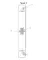
図3に示すように、基板Sは、前記基板の性質及び形状に応じて、任意の好適な手段によって走行させることができる。特に、鋼ストリップを搬送可能な回転支持ローラ4を用いてもよい。 As shown in FIG. 3, the substrate S can be moved by any suitable means, depending on the nature and shape of said substrate. In particular, rotating support rollers 4 may be used, which can carry the steel strip.
図4を参照すると、本発明による2つの蒸気噴射器3、3’は、走行する基板(図示せず)上に金属蒸気ジェット5を音速で噴射する。少なくとも2つの蒸気噴射器は細長形状を有し、スロットを備え、スロットの長さLe、スロットの幅Weによって画定される。
Referring to FIG. 4, two
図5に示すように、真空チャンバ2は、さらに中央ケーシング6を備えてもよい。ケーシングは、走行方向の所定の長さの基板経路Pを囲むボックスであり、典型的には、面あたり1つの噴射器がある場合には2~8mの長さである。その壁は空洞を区切る。それは、中央ケーシングの2つの反対側に配置された2つの開口部、つまり、基板入口7及び基板出口8を備える。好ましくは、中央ケーシングは、コーティングされる基板よりも、幅がわずかに大きい平行六面体である。
The
好ましくは、中央ケーシングの内壁は、金属又は金属合金の蒸気の凝縮温度よりも高い温度で加熱されるのに適している。加熱は、例えば、誘導加熱器、加熱抵抗器、電子ビームなどの任意の好適な手段によって行うことができる。加熱手段は、中央ケーシングの内壁を、金属又は金属合金の蒸気がその上に凝縮することを回避するために十分に高い温度で加熱するのに適している。好ましくは、中央ケーシングの内壁は、亜鉛蒸気又は亜鉛マグネシウム合金蒸気の凝縮を回避するために、コーティングを形成する蒸着金属元素の凝縮温度よりも高く、典型的には500℃よりも高く、例えば500℃~700℃で加熱されるのに適している。これらの加熱手段のおかげで、中央ケーシングの内壁が詰まることが無くなり、設備を、清掃のために頻繁に停止させる必要がない。さらに、金属又は金属合金の蒸気の内壁への凝縮を回避する。 Preferably, the inner wall of the central casing is suitable to be heated above the condensation temperature of the vapor of the metal or metal alloy. Heating can be by any suitable means such as, for example, induction heaters, heating resistors, electron beams, and the like. The heating means are suitable for heating the inner wall of the central casing to a sufficiently high temperature to avoid condensation of metal or metal alloy vapors thereon. Preferably, the inner wall of the central casing has a temperature higher than the condensation temperature of the vapor-deposited metal elements forming the coating, typically higher than 500°C, for example higher than 500°C, to avoid condensation of zinc or zinc-magnesium alloy vapors. It is suitable to be heated from 0°C to 700°C. Thanks to these heating means, clogging of the inner wall of the central casing is avoided and the installation does not have to be stopped frequently for cleaning. Furthermore, condensation of metal or metal alloy vapor on the inner wall is avoided.
特に、本発明による方法では、平均厚さを有する基板の両面に、少なくとも1つの金属でコーティングされた金属基板を得ることができ、最大コーティング厚が、最大15%の平均厚さを超え得るように均一にコーティングが蒸着される。 In particular, the method according to the invention makes it possible to obtain a metallic substrate coated with at least one metal on both sides of the substrate with an average thickness such that the maximum coating thickness can exceed the average thickness by up to 15%. A uniform coating is deposited on the
本発明において、少なくとも1つの金属は、好ましくは、亜鉛、クロム、ニッケル、チタン、マンガン、マグネシウム、ケイ素、アルミニウム、又はそれらの混合物から選択される。好ましくは、金属は、任意にマグネシウムを含む亜鉛である。 In the present invention, at least one metal is preferably selected from zinc, chromium, nickel, titanium, manganese, magnesium, silicon, aluminum or mixtures thereof. Preferably the metal is zinc optionally with magnesium.
好ましくは、金属基板は鋼基板である。実際、いかなる理論にも拘束されることを望まないが、鋼基板を使用すると、平坦性がさらに改善されると考えられる。 Preferably, the metal substrate is a steel substrate. In fact, without wishing to be bound by any theory, it is believed that using a steel substrate further improves flatness.
コーティング厚は、好ましくは0.1μm~20μmである。一方では、0.1μm未満では、基板の防食性が不十分になるおそれがある。他方では、特に、自動車又は建設分野で要求されるレベルの耐食性を得るために、20μmを超える必要はない。一般に、自動車用途には、厚さは10μmに制限される場合がある。 The coating thickness is preferably between 0.1 μm and 20 μm. On the other hand, if the thickness is less than 0.1 μm, the corrosion resistance of the substrate may be insufficient. On the other hand, it need not exceed 20 μm in order to obtain the required level of corrosion resistance, especially in the automotive or construction sector. Generally for automotive applications the thickness may be limited to 10 μm.
最終的に、本発明は、走行する基板上に、少なくとも1つの金属から形成されたコーティングを連続的に蒸着させるための本発明による方法のための真空蒸着設備に関し、設備は、基板が所定の経路に沿って走行可能な真空チャンバを備え、真空チャンバは、
-基板の両面に配置され、互いに対向する少なくとも2つの蒸気噴射器であって、これら蒸気噴射器は基板平面内にある軸線Aであって、基板の走行方向に直角な軸線Aと蒸気噴射器との角度α及びα’でそれぞれが位置決めされ、α及びα’は以下の式、
Finally, the invention relates to a vacuum deposition installation for the method according to the invention for the continuous deposition of a coating made of at least one metal on a moving substrate, the installation comprising a A vacuum chamber is provided that can travel along the path, the vacuum chamber comprising:
- at least two vapor injectors located on both sides of the substrate and facing each other, with an axis A lying in the plane of the substrate and perpendicular to the direction of travel of the substrate and vapor injectors; are positioned at angles α and α', respectively, where α and α' are defined by the following equations:
![]()
![]()
![]()
α及びα’(αは絶対値)は0°より大きく、
D1及びD2は、軸線(A)に沿った、噴射器と各基板端部との間の小さい方の距離であり、Wsは基板幅であり、D1及びD2は0mmより大きい少なくとも2つの蒸気噴射器を備え、
蒸気噴射器は細長形状を有し、スロットを備え、スロットの長さLeとスロットの幅Weとによって画定され、前記蒸気噴射器は、同じ回転軸を有する。
![]()
α and α' (α is an absolute value) are greater than 0°,
D1 and D2 are the smaller distances between the injectors and each substrate edge along the axis (A), Ws is the substrate width, and D1 and D2 are at least two vapor jets greater than 0 mm. equipped with
The steam injector has an elongated shape and is provided with a slot, defined by a slot length Le and a slot width We, said steam injectors having the same axis of rotation.
好ましい実施形態では、少なくとも2つの蒸気噴射器は、α及びα’が調整されるように、蒸気源に連結された供給管を中心に回転可能に取り付けられる。 In a preferred embodiment, at least two steam injectors are rotatably mounted about a supply tube connected to the steam source such that α and α' are adjusted.
実施例
亜鉛蒸気を噴射する2つの蒸気噴射器を含む方法の効率を評価するために、真空蒸着設備でテストを実施した。幅Wsが1300mmの鋼基板の両面に、Le=24mmかつWe=1750mmの2つの蒸気噴射器を備える真空チャンバ内で、亜鉛蒸気を堆積させた。試験では、D1及びD2は同じであり、-10mm~+20mmの間に固定した。ここで、-10mmとは、蒸気の端部が基板端部を10mm超えて延在していることを意味し、α及びα’は、本発明による数式を用いて、各試験について算出した。真空圧は10-1ミリバールであった。亜鉛コーティングの所望の厚さは8μmであり、100%に相当する。金属の厚さは、蛍光X線分光法によって測定した。結果を以下の表1に示す。
EXAMPLES Tests were conducted in a vacuum deposition facility to evaluate the efficiency of a method involving two vapor injectors for injecting zinc vapor. Zinc vapor was deposited on both sides of a steel substrate with a width Ws of 1300 mm in a vacuum chamber equipped with two vapor injectors with Le=24 mm and We=1750 mm. In the test, D1 and D2 were the same and fixed between -10 mm and +20 mm. where −10 mm means that the edge of the vapor extends 10 mm beyond the edge of the substrate, α and α′ were calculated for each test using the formulas according to the invention. The vacuum pressure was 10 −1 mbar. The desired thickness of the zinc coating is 8 μm, corresponding to 100%. Metal thickness was measured by X-ray fluorescence spectroscopy. The results are shown in Table 1 below.

試験2及び試験3のコーティングは、試験1と比較して均一に蒸着された。
The coatings of
Claims (14)
-前記真空チャンバ内で、金属蒸気が、走行する基板の両面に向かって、少なくとも2つの蒸気噴射器(3、3’)を通して噴射され、噴射された蒸気の凝縮によって、少なくとも1つの金属の層が各面に形成され、互いに対向する少なくとも2つの蒸気噴射器が基板の両面に配置され、これら蒸気噴射器は基板平面内にある軸線(A)であって、基板の走行方向に直角な軸線(A)と蒸気噴射器との角度α及びα’でそれぞれが位置決めされ、α及びα’は以下の式、
α及びα’は絶対値で0°より大きく、α’が、絶対値でα-α’<10°であり、
D1及びD2は、軸線(A)に沿った、噴射器と各基板端部との間の小さい方の距離であり、Wsは基板幅であり、D1及びD2は0mmより大きく、すなわち、噴射器端部が基板端部を超えず、前記蒸気噴射器は細長形状を有し、スロットを備え、スロットの長さLeとスロットの幅Weとによって画定され、前記蒸気噴射器が同じ回転軸を有する工程を備える方法。 A method for continuously depositing a coating made of at least one metal on a moving substrate (S) in a vacuum deposition installation (1) comprising a vacuum chamber (2), the method comprising:
- in said vacuum chamber, metal vapor is injected through at least two vapor injectors (3, 3') towards both sides of the running substrate, and condensation of the injected vapors results in at least one layer of metal; is formed on each side, and at least two vapor injectors facing each other are arranged on both sides of the substrate, the vapor injectors having an axis (A) lying in the plane of the substrate and perpendicular to the direction of travel of the substrate. respectively positioned at angles α and α' between (A) and the steam injector, where α and α' are the following equations:
α and α' are greater than 0° in absolute value, α' is α-α'<10° in absolute value,
D1 and D2 are the smaller distances between the injector and each substrate edge along the axis (A), Ws is the substrate width, and D1 and D2 are greater than 0 mm, i.e. the injector The vapor injector has an elongated shape with an edge not extending beyond the substrate edge and is provided with a slot, defined by a slot length Le and a slot width We, the vapor injectors having the same axis of rotation. A method comprising a process.
-基板の両面に配置され、互いに対向する少なくとも2つの蒸気噴射器をさらに備え、これら蒸気噴射器は基板平面内にある軸線(A)であって、基板の走行方向に直角な軸線(A)と蒸気噴射器との角度α及びα’でそれぞれが位置決めされ、α及びα’は以下の式、
α及びα’は0°より大きく、α’が、絶対値でα-α’<10°であり、
D1及びD2は、軸線(A)に沿った、噴射器と各基板端部との間の小さい方の距離であり、Wsは基板幅であり、D1及びD2は0mmより大きく、すなわち、噴射器端部が基板端部を超えず、前記蒸気噴射器は、細長形状を有し、スロットを備え、スロットの長さLeとスロットの幅Weとによって画定され、前記蒸気噴射器が、同じ回転軸を有する、真空蒸着設備。 A vacuum deposition installation for the method according to any one of claims 1 to 12 for the continuous deposition of a coating made of at least one metal on a moving substrate (S), , the installation (1) comprises a vacuum chamber (2) in which the substrate (3) can travel along a predetermined path, the vacuum chamber
- further comprising at least two vapor injectors arranged on both sides of the substrate and facing each other, the vapor injectors having an axis (A) lying in the plane of the substrate and perpendicular to the direction of travel of the substrate; and the steam injector at angles α and α', respectively, where α and α' are given by the following equations:
α and α′ are greater than 0°, α′ is α−α′<10° in absolute value,
D1 and D2 are the smaller distances between the injector and each substrate edge along the axis (A), Ws is the substrate width, and D1 and D2 are greater than 0 mm, i.e. the injector The vapor injector has an elongated shape and is provided with a slot, defined by a slot length Le and a slot width We, wherein the vapor injector has the same axis of rotation. A vacuum deposition facility.
Applications Claiming Priority (3)
| Application Number | Priority Date | Filing Date | Title |
|---|---|---|---|
| IBPCT/IB2018/054299 | 2018-06-13 | ||
| PCT/IB2018/054299 WO2019239185A1 (en) | 2018-06-13 | 2018-06-13 | Vacuum deposition facility and method for coating a substrate |
| PCT/IB2019/053339 WO2019239228A1 (en) | 2018-06-13 | 2019-04-23 | Vacuum deposition facility and method for coating a substrate |
Publications (2)
| Publication Number | Publication Date |
|---|---|
| JP2021526589A JP2021526589A (en) | 2021-10-07 |
| JP7219780B2 true JP7219780B2 (en) | 2023-02-08 |
Family
ID=62904530
Family Applications (1)
| Application Number | Title | Priority Date | Filing Date |
|---|---|---|---|
| JP2020569119A Active JP7219780B2 (en) | 2018-06-13 | 2019-04-23 | Vacuum deposition equipment and method for substrate coating |
Country Status (12)
| Country | Link |
|---|---|
| US (1) | US11492695B2 (en) |
| EP (1) | EP3807438A1 (en) |
| JP (1) | JP7219780B2 (en) |
| KR (1) | KR102486851B1 (en) |
| CN (1) | CN112262226B (en) |
| BR (1) | BR112020025035A2 (en) |
| CA (1) | CA3103071C (en) |
| MA (1) | MA52865A (en) |
| MX (1) | MX2020013546A (en) |
| RU (1) | RU2755327C1 (en) |
| WO (2) | WO2019239185A1 (en) |
| ZA (1) | ZA202007535B (en) |
Citations (3)
| Publication number | Priority date | Publication date | Assignee | Title |
|---|---|---|---|---|
| JP2004311065A (en) | 2003-04-02 | 2004-11-04 | Sanyo Electric Co Ltd | Manufacturing method of organic el display |
| WO2010067603A1 (en) | 2008-12-10 | 2010-06-17 | パナソニック株式会社 | Method for forming thin film |
| US20110000431A1 (en) | 2007-10-12 | 2011-01-06 | Arcelormittal France | Industrial vapour generator for the deposition of an alloy coating onto a metal strip |
Family Cites Families (29)
| Publication number | Priority date | Publication date | Assignee | Title |
|---|---|---|---|---|
| JPH0723535B2 (en) * | 1985-06-12 | 1995-03-15 | 三菱重工業株式会社 | Composite film forming equipment |
| JPS6296669A (en) | 1985-10-23 | 1987-05-06 | Nisshin Steel Co Ltd | Manufacture of galvanizing steel sheet by alloying vapor deposition |
| JPS6326351A (en) * | 1986-07-18 | 1988-02-03 | Kawasaki Steel Corp | Evaporating source device for vacuum deposition |
| DD287615A7 (en) * | 1988-04-27 | 1991-03-07 | ��@ �K@�K@������� k�� | METHOD FOR BAND STEAMING WITH AN ELECTRON RADIANT EVAPORATOR |
| JPH024963A (en) | 1988-06-23 | 1990-01-09 | Kawasaki Steel Corp | Ion plating apparatus |
| JPH06102828B2 (en) * | 1990-10-23 | 1994-12-14 | 日本鋼管株式会社 | Strip coating device |
| JP3463693B2 (en) * | 1992-10-29 | 2003-11-05 | 石川島播磨重工業株式会社 | Vacuum evaporation equipment for continuous strips |
| JP3371454B2 (en) | 1993-01-13 | 2003-01-27 | 石川島播磨重工業株式会社 | Continuous vacuum deposition equipment |
| US5803976A (en) * | 1993-11-09 | 1998-09-08 | Imperial Chemical Industries Plc | Vacuum web coating |
| BE1010351A6 (en) * | 1996-06-13 | 1998-06-02 | Centre Rech Metallurgique | Method and device for coating continuous substrate in motion with a metal vapor. |
| US6202591B1 (en) * | 1998-11-12 | 2001-03-20 | Flex Products, Inc. | Linear aperture deposition apparatus and coating process |
| WO2003012161A1 (en) * | 2001-08-01 | 2003-02-13 | Danieli Technology, Inc. | Metal vapor coating |
| SE527385C2 (en) * | 2003-11-04 | 2006-02-21 | Sandvik Intellectual Property | Coated stainless steel tape product for use in load-carrying applications |
| NO20040302D0 (en) * | 2004-01-23 | 2004-01-23 | Juell Per A | Kvickskate. Shooter for use on ice and other surfaces, including roller skates |
| WO2006007706A1 (en) * | 2004-07-16 | 2006-01-26 | Dofasco Inc. | Monitor system for coating apparatus |
| JP2007262540A (en) * | 2006-03-29 | 2007-10-11 | Jfe Steel Kk | Nozzle for supplying source gas in chemical vapor deposition treatment, film-forming method and grain-oriented electromagnetic steel sheet |
| DE102006056984A1 (en) | 2006-11-30 | 2008-06-05 | Leybold Optics Gmbh | Running coating |
| US20080245300A1 (en) * | 2006-12-04 | 2008-10-09 | Leybold Optics Gmbh | Apparatus and method for continuously coating strip substrates |
| EP1972699A1 (en) | 2007-03-20 | 2008-09-24 | ArcelorMittal France | Method of coating a substrate under vacuum |
| EP2199425A1 (en) | 2008-12-18 | 2010-06-23 | ArcelorMittal France | Industrial steam generator for depositing any alloy coating on a metal band (II) |
| US8557328B2 (en) | 2009-10-02 | 2013-10-15 | Ppg Industries Ohio, Inc. | Non-orthogonal coater geometry for improved coatings on a substrate |
| KR20120029895A (en) | 2010-09-17 | 2012-03-27 | 삼성모바일디스플레이주식회사 | Apparatus for thin layer deposition and method for manufacturing of organic light emitting display apparatus using the same |
| KR101439694B1 (en) | 2012-12-26 | 2014-09-12 | 주식회사 포스코 | Zn-Mg ALLOY COATED STEEL SHEET AND MEHTDOD FOR MANUFACTURING THE SAME |
| JP2014132102A (en) | 2013-01-04 | 2014-07-17 | Panasonic Corp | Vapor deposition apparatus |
| DE102013206598B4 (en) * | 2013-04-12 | 2019-06-27 | VON ARDENNE Asset GmbH & Co. KG | Vacuum coating system |
| KR101746956B1 (en) * | 2015-10-29 | 2017-06-14 | 주식회사 포스코 | Particle generation apparatus and coating system including the same |
| CN107723663B (en) * | 2017-09-26 | 2019-11-12 | 常州大学 | A kind of device and method in high strength steel surface continuous vacuum evaporation metal antimony |
| WO2019239186A1 (en) | 2018-06-13 | 2019-12-19 | Arcelormittal | Vacuum deposition facility and method for coating a substrate |
| WO2019239184A1 (en) | 2018-06-13 | 2019-12-19 | Arcelormittal | Vacuum deposition facility and method for coating a substrate |
-
2018
- 2018-06-13 WO PCT/IB2018/054299 patent/WO2019239185A1/en active Application Filing
-
2019
- 2019-04-23 RU RU2021100364A patent/RU2755327C1/en active
- 2019-04-23 WO PCT/IB2019/053339 patent/WO2019239228A1/en unknown
- 2019-04-23 MX MX2020013546A patent/MX2020013546A/en unknown
- 2019-04-23 US US15/734,911 patent/US11492695B2/en active Active
- 2019-04-23 KR KR1020207035591A patent/KR102486851B1/en active IP Right Grant
- 2019-04-23 BR BR112020025035-0A patent/BR112020025035A2/en unknown
- 2019-04-23 CN CN201980039219.3A patent/CN112262226B/en active Active
- 2019-04-23 EP EP19726752.9A patent/EP3807438A1/en active Pending
- 2019-04-23 JP JP2020569119A patent/JP7219780B2/en active Active
- 2019-04-23 CA CA3103071A patent/CA3103071C/en active Active
- 2019-04-23 MA MA052865A patent/MA52865A/en unknown
-
2020
- 2020-12-03 ZA ZA2020/07535A patent/ZA202007535B/en unknown
Patent Citations (3)
| Publication number | Priority date | Publication date | Assignee | Title |
|---|---|---|---|---|
| JP2004311065A (en) | 2003-04-02 | 2004-11-04 | Sanyo Electric Co Ltd | Manufacturing method of organic el display |
| US20110000431A1 (en) | 2007-10-12 | 2011-01-06 | Arcelormittal France | Industrial vapour generator for the deposition of an alloy coating onto a metal strip |
| WO2010067603A1 (en) | 2008-12-10 | 2010-06-17 | パナソニック株式会社 | Method for forming thin film |
Also Published As
| Publication number | Publication date |
|---|---|
| US11492695B2 (en) | 2022-11-08 |
| US20210230736A1 (en) | 2021-07-29 |
| CN112262226B (en) | 2023-03-21 |
| WO2019239185A1 (en) | 2019-12-19 |
| CA3103071A1 (en) | 2019-12-19 |
| ZA202007535B (en) | 2021-10-27 |
| JP2021526589A (en) | 2021-10-07 |
| EP3807438A1 (en) | 2021-04-21 |
| RU2755327C1 (en) | 2021-09-15 |
| CN112262226A (en) | 2021-01-22 |
| WO2019239228A1 (en) | 2019-12-19 |
| CA3103071C (en) | 2022-10-25 |
| KR20210008071A (en) | 2021-01-20 |
| BR112020025035A2 (en) | 2021-03-23 |
| MX2020013546A (en) | 2021-02-26 |
| MA52865A (en) | 2021-04-21 |
| KR102486851B1 (en) | 2023-01-09 |
Similar Documents
| Publication | Publication Date | Title |
|---|---|---|
| JP7165755B2 (en) | Vacuum deposition equipment and method for substrate coating | |
| CN109496240A (en) | For vacuum-deposited device and method | |
| JP7299927B2 (en) | Vacuum deposition equipment and method for substrate coating | |
| JP7301889B2 (en) | Vacuum deposition equipment and method for substrate coating | |
| JP7219780B2 (en) | Vacuum deposition equipment and method for substrate coating | |
| KR102503599B1 (en) | Vacuum Deposition Equipment and Methods for Coating Substrates |
Legal Events
| Date | Code | Title | Description |
|---|---|---|---|
| A621 | Written request for application examination |
Free format text: JAPANESE INTERMEDIATE CODE: A621 Effective date: 20210201 |
|
| A977 | Report on retrieval |
Free format text: JAPANESE INTERMEDIATE CODE: A971007 Effective date: 20220127 |
|
| A131 | Notification of reasons for refusal |
Free format text: JAPANESE INTERMEDIATE CODE: A131 Effective date: 20220208 |
|
| A521 | Request for written amendment filed |
Free format text: JAPANESE INTERMEDIATE CODE: A523 Effective date: 20220428 |
|
| A131 | Notification of reasons for refusal |
Free format text: JAPANESE INTERMEDIATE CODE: A131 Effective date: 20220719 |
|
| A521 | Request for written amendment filed |
Free format text: JAPANESE INTERMEDIATE CODE: A523 Effective date: 20221018 |
|
| TRDD | Decision of grant or rejection written | ||
| A01 | Written decision to grant a patent or to grant a registration (utility model) |
Free format text: JAPANESE INTERMEDIATE CODE: A01 Effective date: 20230117 |
|
| A61 | First payment of annual fees (during grant procedure) |
Free format text: JAPANESE INTERMEDIATE CODE: A61 Effective date: 20230127 |
|
| R150 | Certificate of patent or registration of utility model |
Ref document number: 7219780 Country of ref document: JP Free format text: JAPANESE INTERMEDIATE CODE: R150 |