<第一実施形態>
以下、本発明に係る遊技機を適用した各実施形態について、図面を参照しながら説明する。まず、図1から図3を参照して、本発明の第一実施形態におけるパチンコ機1の外観構成を説明する。
<First embodiment>
Hereinafter, each embodiment to which the gaming machine according to the present invention is applied will be described with reference to the drawings. First, referring to FIGS. 1 to 3, the external configuration of a pachinko machine 1 according to the first embodiment of the present invention will be described.
(1.パチンコ機1の概略構成)
図1に示すように、パチンコ機1は、遊技者が遊技可能な遊技機であり、遊技施設に設置される。パチンコ機1は、縦長の固定外郭保持枠をなす外枠2により構成の各部を保持する。外枠2には、左側の上下の位置に設けたヒンジ11を介して結合された前枠3及び内枠4(図3参照)が設けられる。これら前枠3及び内枠4は、シリンダ錠12により外枠2に閉鎖ロックされる。内枠4は、シリンダ錠12に所定の鍵を挿入し、鍵を時計回りに操作することにより開放され、内枠4が開放された状態で鍵を反時計回りに操作することにより前枠3が開放される。
(1. Outline configuration of pachinko machine 1)
As shown in FIG. 1, a pachinko machine 1 is a gaming machine that can be played by a player, and is installed in a gaming facility. A pachinko machine 1 is configured by an outer frame 2 forming a vertically long fixed outer shell holding frame. The outer frame 2 is provided with a front frame 3 and an inner frame 4 (see FIG. 3) which are connected via hinges 11 provided at upper and lower positions on the left side. These front frame 3 and inner frame 4 are closed and locked to the outer frame 2 by a cylinder lock 12 . The inner frame 4 is opened by inserting a predetermined key into the cylinder lock 12 and operating the key clockwise. is released.
前枠3には、板ガラス31が嵌め込まれ、その板ガラス31の奥側には、内枠4に着脱可能に保持された遊技盤5(図2参照)が設けられる。そして、前枠3の上部の左右両側位置には、遊技音を出力するスピーカ32が設けられる。さらに、前枠3には、遊技状態に応じて発光する複数の枠側装飾ランプ33や、遊技の異常を報知するLED類が設けられる。
A plate glass 31 is fitted in the front frame 3 , and a game board 5 (see FIG. 2 ) detachably held by the inner frame 4 is provided on the far side of the plate glass 31 . Speakers 32 for outputting game sounds are provided on both left and right sides of the upper portion of the front frame 3 . Further, the front frame 3 is provided with a plurality of frame-side decoration lamps 33 that emit light according to the game state, and LEDs for informing abnormalities in the game.
前枠3の下半部には、上皿34及び下皿35が配置される。上皿34には、遊技盤5に設けられた各種入賞口に入球した賞球が払い出される。下皿35は、上皿34の下方に設けられ、上皿34から溢れた賞球を受ける。遊技者は、下皿35に設けられた球抜きレバー(図示せず)を操作することにより、下皿35に溜まった遊技球をホールに備えられた別箱(ドル箱)へ移すことができる。
An upper plate 34 and a lower plate 35 are arranged in the lower half of the front frame 3 . Prize balls entered into various prize-winning ports provided on the game board 5 are paid out to the upper plate 34.例文帳に追加The lower plate 35 is provided below the upper plate 34 and receives prize balls overflowing from the upper plate 34.例文帳に追加A player can move game balls accumulated in the lower tray 35 to another box (dollar box) provided in the hall by operating a ball extracting lever (not shown) provided in the lower tray 35. .
下皿35の右側には、発射ハンドル36が設けられる。発射ハンドル36を時計回りに操作すると、発射装置が作動し、上皿34から供給された遊技球が遊技領域50(図2参照)へ向けて発射される。また、上皿34の中央位置には、遊技者が操作可能な演出ボタン37と、演出ボタン37の外周を囲むように設けられたジョグダイヤル38とが設けられる。
A firing handle 36 is provided on the right side of the lower plate 35 . When the shooting handle 36 is operated clockwise, the shooting device is activated and game balls supplied from the upper tray 34 are shot toward the game area 50 (see FIG. 2). At the central position of the upper plate 34, a performance button 37 that can be operated by the player and a jog dial 38 provided so as to surround the performance button 37 are provided.
パチンコ機1は、いわゆるCR機であり、パチンコ機1の左側には、プリペイドカードの読み書きを行うCRユニット70が隣接して設けられる。また、上皿34の右側には、貸出ボタン71、精算ボタン72及び残高表示器73が設けられる。
The pachinko machine 1 is a so-called CR machine, and on the left side of the pachinko machine 1, a CR unit 70 for reading and writing prepaid cards is provided adjacently. A lending button 71 , a checkout button 72 and a balance display 73 are provided on the right side of the upper tray 34 .
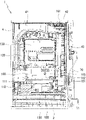
図2に示すように、遊技盤5には、外レール51と内レール52とにより囲まれた略円形の遊技領域50が形成され、遊技領域50の中央部には、大型のセンターケース53が装着される。遊技領域には、多数の遊技釘が植設され、センターケース53の中央部分には、演出図柄表示装置54のLCDパネルが設けられ、LCDパネルの周囲には、周知のセンターケースと同様のワープ口、ワープ樋(遊技球通路)、ステージ等が設けられる。
As shown in FIG. 2, the game board 5 is formed with a substantially circular game area 50 surrounded by an outer rail 51 and an inner rail 52, and a large center case 53 is provided at the center of the game area 50. be worn. A large number of game nails are planted in the game area, an LCD panel of a production pattern display device 54 is provided in the central part of the center case 53, and a warp similar to the well-known center case is provided around the LCD panel. A mouth, a warp gutter (game ball passage), a stage, etc. are provided.
センターケース53の左側には、普図始動口55が設けられる。普図始動口55は、遊技球が通過可能なゲートであり、遊技球が普図始動口55を通過すると、普通図柄(普図)の当否判定が行われる。
A normal figure start opening 55 is provided on the left side of the center case 53 . The normal pattern starting port 55 is a gate through which the game ball can pass, and when the game ball passes through the normal pattern starting port 55, the normal pattern (normal pattern) determination is performed.
センターケース53の左右方向における中央下方位置には、上方へ向かって開口する第一特図始動口56が設けられる。第一特図始動口56は、遊技球が常時入球可能な始動口であり、パチンコ機1は、第一特図始動口56への遊技球の入球に基づいて、第一特別図柄(以下「第一特図」と称す)の当否判定を実行する。具体的に、第一特図始動口56に遊技球が入球すると、複数種の乱数が抽出され、抽出された乱数は、第一特図の保留記憶として記憶される。
A first special figure starting port 56 that opens upward is provided at a center lower position in the left-right direction of the center case 53 . The first special figure start opening 56 is a start opening in which the game ball can be entered at all times, and the pachinko machine 1 is based on the entry of the game ball to the first special figure start opening 56, the first special symbol ( hereinafter referred to as "first special figure") is executed. Concretely, when the game ball enters the first special figure starting port 56, a plurality of kinds of random numbers are extracted, and the extracted random numbers are stored as the reserved memory of the first special figure.
さらに、第一特図始動口56の下方には、普通電動役物57と、第二特図始動口58とが設けられる。普通電動役物57は、第二特図始動口58を開閉する電動役物であり、普通電動役物57の閉鎖時において第二特図始動口58への遊技球の入球は不能である。その一方、普図の当否判定で当たりになると、普通電動役物57が所定時間開放され、第二特図始動口58への遊技球の入球が可能となる。そして、パチンコ機1は、第二特図始動口58への遊技球の入球に基づき、第二特別図柄(以下「第二特図」と称す)の当否判定を実行する。具体的に、第二特図始動口58に遊技球が入球すると、複数種の乱数が抽出され、抽出された乱数は、第二特図の保留記憶として記憶される。
Furthermore, below the first special figure starting port 56, a normal electric accessory 57 and a second special figure starting port 58 are provided. The ordinary electric accessory 57 is an electric accessory that opens and closes the second special figure starting port 58, and when the ordinary electric accessory 57 is closed, it is impossible to enter the game ball into the second special figure starting port 58. . On the other hand, when it hits in the judgment of the general figure, the normal electric accessory 57 is opened for a predetermined time, and the game ball can be entered into the second special figure start port 58. Then, the pachinko machine 1 executes the propriety determination of the second special symbol (hereinafter referred to as the “second special symbol”) based on the entry of the game ball into the second special symbol starting port 58 . Concretely, when the game ball enters the second special figure starting port 58, a plurality of kinds of random numbers are extracted, and the extracted random numbers are stored as the reserved memory of the second special figure.
また、第二特図始動口58の下方には、開閉板により開閉可能される大入賞口59が設けられる。大入賞口59は、開閉板により閉鎖された状態において、遊技球の入球が不能である。
Also, below the second special figure start opening 58, a large winning opening 59 that can be opened and closed by an opening/closing plate is provided. A game ball cannot enter the big winning opening 59 when it is closed by an opening/closing plate.
第一特図及び第二特図の当否判定で大当たりになると、パチンコ機1は、大当たり遊技を開始する。パチンコ機1に設けられた役物連続作動装置は、大当たり遊技時に特別電動役物を連続して作動させる。そして、特別電動役物が作動すると、大入賞口59が所定時間開放される。これにより、大入賞口59への遊技球の入球が可能な状態となる。
When the first special symbol and the second special symbol are judged to be successful or not, the pachinko machine 1 starts a big winning game. The accessory continuous operating device provided in the pachinko machine 1 continuously operates the special electric accessory during a big winning game. Then, when the special electric accessory is activated, the big winning opening 59 is opened for a predetermined time. As a result, a game ball can be entered into the big winning hole 59 .
遊技領域50の左側下部には、入球率が変化しない入賞口である複数の普通入賞口60が設けられる。そして、遊技領域50の最下部には、上記した各種始動口や各種入賞口に入球しなかった遊技球を取り込み、遊技球を遊技領域50から遊技盤5の裏面側へ排出するアウト口61が設けられる。
A plurality of normal winning openings 60, which are winning openings in which the ball-entering rate does not change, are provided in the lower left portion of the game area 50.例文帳に追加At the bottom of the game area 50, an out port 61 for taking in game balls that have not entered the above-described various starting ports and various winning ports and discharging the game balls from the game region 50 to the back side of the game board 5. is provided.
遊技盤5の右下端部には、第一特図の変動表示及び確定表示を行う第一特図表示装置62A、第二特図の変動表示及び確定表示を行う第二特図表示装置62B、普通図柄の変動表示及び確定表示を行う普通図柄表示装置62C、第一特図の保留記憶数を表示する第一特図保留数表示装置63A、第二特図の保留記憶数を表示する第二特図保留数表示装置63B、及び、普通図柄の保留記憶数を表示する普通図柄保留数表示装置63Cがそれぞれ設けられる。
At the lower right end of the game board 5, there are a first special figure display device 62A that performs variable display and final display of the first special figure, a second special figure display device 62B that performs variable display and final display of the second special figure, Normal symbol display device 62C for variable display and fixed display of normal symbols, first special symbol reservation number display device 63A for displaying the number of retention memories of the first special symbol, second to display the number of retention memories for the second special symbol A special figure reservation number display device 63B and a normal design reservation number display device 63C for displaying the reservation memory number of normal symbols are respectively provided.
図3に示すように、内枠4には、球タンク41、タンクレール42及び払出ユニット43が設けられ、払出ユニット43には、遊技球を払い出す払出装置(図示せず)が設けられる。球タンク41には、遊技球が貯留され、払出ユニット43は、遊技盤5に設けられた各種入賞口等に遊技球が入球すると、球タンク41から所定個数の遊技球を賞球として払い出し、払い出された遊技球は、タンクレール42を介して上皿34に払い出される。
なお、払出ユニット43は、貸出ボタン71への操作に基づく貸球の払出も行う。また、球タンク41の右側には、遊技状態や遊技結果を示す信号をホールコンピュータHC(図4参照)や試射試験装置(図示せず)へ送る外部接続端子板161が設けられる。
As shown in FIG. 3, the inner frame 4 is provided with a ball tank 41, a tank rail 42 and a payout unit 43, and the payout unit 43 is provided with a payout device (not shown) for paying out game balls. Game balls are stored in the ball tank 41, and the payout unit 43 pays out a predetermined number of game balls as prize balls from the ball tank 41 when the game balls enter various winning holes provided on the game board 5. , the put-out game balls are put out to the upper tray 34 via the tank rail 42. - 特許庁
Note that the payout unit 43 also pays out the rented ball based on the operation of the rent button 71 . Also, on the right side of the ball tank 41, an external connection terminal plate 161 is provided for sending signals indicating the game state and game results to the hall computer HC (see FIG. 4) and a test firing tester (not shown).
そして、パチンコ機1の裏側には、主制御装置100、払出制御装置110、サブ統合制御装置120、演出図柄制御装置130、発射制御装置140(図4参照)及び電源基板150が設けられる。主制御装置100、サブ統合制御装置120及び演出図柄制御装置130は、遊技盤5に設けられる一方、払出制御装置110、発射制御装置140及び電源基板150は、内枠4に設けられる。なお、発射制御装置140は、払出制御装置110の下に設けられている。また、電源基板150には、パチンコ機1の電源をON又はOFFに切り替える際に操作される電源SW155が設けられる。
On the back side of the pachinko machine 1, a main control device 100, a payout control device 110, a sub-integrated control device 120, a performance symbol control device 130, a launch control device 140 (see FIG. 4) and a power board 150 are provided. The main control device 100 , the sub-integrated control device 120 and the performance symbol control device 130 are provided on the game board 5 , while the payout control device 110 , the launch control device 140 and the power board 150 are provided on the inner frame 4 . Note that the launch control device 140 is provided below the payout control device 110 . Also, the power board 150 is provided with a power switch 155 operated when switching the power of the pachinko machine 1 between ON and OFF.
また、主制御装置100には、RWMクリアSW101及び設定キーSW102が設けられる。RWMクリアSW101は、主として、主制御装置100に内蔵されたRWM330(RAM)に記憶された遊技情報等をクリアする際に操作される。なお、RWMクリアSW101は、払出制御装置110や電源基板150に設けてもよい。
Main controller 100 is also provided with RWM clear SW101 and setting key SW102. The RWM clear SW 101 is operated mainly when game information and the like stored in the RWM 330 (RAM) built in the main controller 100 are cleared. Note that the RWM clear SW 101 may be provided in the payout control device 110 or the power board 150 .
設定キーSW102は、鍵穴に挿入した鍵を一方向へ回転させることでONとなる鍵スイッチ機構である。パチンコ機1は、ホール従業員等の操作によって大当たり確率の設定を変更可能な設定機能を有する遊技機であり、ホール従業員等は、設定キーSW102をONにした状態で電源を投入することにより、大当たり確率の設定変更及び設定確認を行うことができる。なお、RWMクリアSW101は、大当たり確率の設定変更を行う際にも操作される。
The setting key SW 102 is a key switch mechanism that is turned on by rotating the key inserted in the keyhole in one direction. The pachinko machine 1 is a gaming machine having a setting function that allows the setting of the jackpot probability to be changed by the operation of a hall employee or the like. , the setting of the jackpot probability can be changed and the setting can be confirmed. Incidentally, the RWM clear SW 101 is also operated when changing the setting of the big win probability.
さらに、主制御装置100には、4つの7セグメントLED表示器からなる性能表示装置103が設けられている。パチンコ機1は、性能表示装置103をパチンコ機1の裏面側に設けることにより、遊技中の遊技者から見えない位置に性能表示装置103を配置することができる。
Furthermore, the main controller 100 is provided with a performance display device 103 consisting of four 7-segment LED indicators. By providing the performance display device 103 on the back side of the pachinko machine 1, the pachinko machine 1 can arrange the performance display device 103 at a position invisible to the player during the game.
また、払出制御装置110には、不正があったと主制御装置100が判断した場合に、LEDを点灯し、不正があった旨をホール関係者等に報知する不正報知ランプ111が設けられている。
Further, the payout control device 110 is provided with a fraud notification lamp 111 that lights an LED and notifies the persons involved in the hall that fraud has occurred when the main controller 100 determines that fraud has occurred. .
続いて、図2に戻り、パチンコ機1の作動について説明する。パチンコ機1は、普図始動口55に遊技球が入球すると、普通図柄の当否判定に関する複数種の乱数値を抽出し、抽出した乱数値に基づいて当否判定を行う。この当否判定の結果に基づき、パチンコ機1は、普通図柄表示装置62Cにおいて普図の変動表示を開始し、所定時間後に確定表示を行う。
Next, referring back to FIG. 2, the operation of the pachinko machine 1 will be described. The pachinko machine 1, when a game ball enters the normal pattern starting port 55, extracts a plurality of types of random number values relating to the normal pattern right/wrong determination, and performs right/wrong determination based on the extracted random number values. Based on the result of this winning/failure determination, the pachinko machine 1 starts variable display of normal symbols on the normal symbol display device 62C, and performs final display after a predetermined period of time.
そして、当否判定の結果が当たりであれば、パチンコ機1は、普通電動役物57を駆動して第二特図始動口58を開放とする。普通電動役物57による第二特図始動口58の開放時間及び開放回数は、通常状態で0.2秒×1回、遊技者にとって有利な特典遊技状態(確変状態及び時短状態)では、2秒×1回に設定される。
Then, if the result of the success/failure determination is hit, the pachinko machine 1 drives the normal electric accessory 57 to open the second special figure start port 58.例文帳に追加The opening time and number of openings of the second special figure start port 58 by the normal electric accessory 57 is 0.2 seconds × 1 time in the normal state, and 2 in the privilege game state (probability variable state and time saving state) advantageous to the player. It is set to seconds x 1 time.
パチンコ機1は、第一特図始動口56に遊技球が入球すると、第一特図の当否判定に関する複数種の乱数値を抽出し、抽出した乱数値を第一特図の保留記憶として所定数記憶する。そして、パチンコ機1は、保留記憶された乱数値に基づいて当否判定を行う。この当否判定の結果に基づき、パチンコ機1は、第一特図表示装置62Aにおいて第一特図の変動表示を開始し、所定時間経過後に確定表示を行う。また、パチンコ機1は、演出図柄表示装置54において第一特図に対応する疑似演出図柄400(図16参照)の変動表示を開始し、所定時間経過後に確定表示を行う。
The pachinko machine 1, when a game ball enters the first special symbol starting port 56, extracts a plurality of types of random numbers relating to the determination of whether or not the first special symbol is valid, and stores the extracted random numbers as a reserved memory of the first special symbol. A predetermined number is stored. Then, the pachinko machine 1 performs a win/fail judgment based on the reserved and stored random number value. Based on the result of this judgment, the pachinko machine 1 starts the variable display of the first special figure on the first special figure display device 62A, and after a predetermined period of time has elapsed, the pachinko machine 1 performs the definite display. In addition, the pachinko machine 1 starts variable display of a pseudo effect symbol 400 (see FIG. 16) corresponding to the first special symbol on the effect symbol display device 54, and performs a fixed display after a predetermined period of time has elapsed.
同様に、パチンコ機1は、第二特図始動口58に遊技球が入球すると、第二特図の当否判定に関する複数種の乱数値を抽出し、抽出した乱数値を第二特図の保留記憶として所定数記憶する。そして、パチンコ機1は、保留記憶された第二特図の乱数値に基づいて当否判定を行う。この当否判定に基づき、パチンコ機1は、第二特図表示装置62Bにおいて第二特図の変動表示を開始し、所定時間経過後に第二特図の確定表示を行う。また、パチンコ機1は、演出図柄表示装置54において第二特図に対応する疑似演出図柄400の変動表示を開始し、所定時間経過後に疑似演出図柄400の確定表示を行う。
Similarly, the pachinko machine 1, when the game ball enters the second special figure start hole 58, extracts a plurality of random numbers related to the determination of whether the second special figure A predetermined number of data are stored as reserved storage. Then, the pachinko machine 1 performs a win-or-fail decision based on the stored random number value of the second special figure. Based on this determination, the pachinko machine 1 starts the variable display of the second special figure on the second special figure display device 62B, and performs the fixed display of the second special figure after the elapse of a predetermined time. In addition, the pachinko machine 1 starts variable display of the pseudo performance symbols 400 corresponding to the second special symbol on the performance symbol display device 54, and performs the fixed display of the pseudo performance symbols 400 after the lapse of a predetermined time.
なお、第一特図及び第二特図の変動表示及び確定表示は、遊技盤5の隅に小さく表示される。そこで、パチンコ機1は、遊技領域50の中央に設けた演出図柄表示装置54において第一特図及び第二特図に対応する疑似演出図柄400による疑似演出表示を行い、疑似演出表示を通して遊技者に当否判定の結果を報知する。
パチンコ機1は、疑似演出表示において、3つの疑似演出図柄400の変動表示を行い、当否判定の結果が大当たりであれば、3つの疑似演出図柄400を同一図柄で停止させる。また、パチンコ機1は、疑似演出表示において、2つの疑似演出図柄400を同じ図柄で停止させた状態で残り1つの疑似演出図柄400の変動表示を行うリーチ演出を行うことにより、当否判定において大当たりになることの期待感を遊技者に与えることができる。
Incidentally, the variable display and fixed display of the first special symbol and the second special symbol are displayed small in the corners of the game board 5 . Therefore, the pachinko machine 1 performs a pseudo performance display by a pseudo performance pattern 400 corresponding to the first special symbol and the second special symbol in the performance symbol display device 54 provided in the center of the game area 50, and through the pseudo performance display. to notify the result of the pass/fail judgment.
The pachinko machine 1 performs variable display of three pseudo performance patterns 400 in the pseudo performance display, and stops the three pseudo performance patterns 400 with the same pattern if the result of winning/failure determination is a big hit. In addition, in the pseudo performance display, the pachinko machine 1 performs a ready-to-win performance in which two pseudo performance patterns 400 are stopped at the same pattern and the remaining one pseudo performance pattern 400 is variably displayed, thereby achieving a big hit in the win/fail judgment. It is possible to give the player a sense of expectation of becoming
ここで、パチンコ機1は、第一特図始動口56と第二特図始動口58への入球順に関係なく、第二特図の当否判定を第一特図の当否判定に優先して行う。具体的に、第一特図の保留記憶がある場合、第一特図の当否判定は、第二特図の変動が停止し、且つ、第二特図の保留記憶がない状態となってから行われる。
Here, the pachinko machine 1 prioritizes the validity determination of the second special figure over the validity determination of the first special figure, regardless of the order of the ball entering the first special figure start port 56 and the second special figure start port 58. conduct. Specifically, if there is a pending memory of the first special symbol, the validity of the first special symbol will be determined after the fluctuation of the second special symbol has stopped and there is no pending memory of the second special symbol. done.
第一特図及び第二特図の何れか一方の当否判定で大当たりとなった場合、パチンコ機1は、大当たり種別及び大当たり図柄を決定すると共に、演出図柄表示装置54に大当たり図柄の変動表示及び確定表示を行い、大当たり遊技(特別遊技)を開始する。この大当たり遊技時において、パチンコ機1は、大入賞口59の開閉を行う。具体的に、パチンコ機1は、大入賞口59の開放を開始してから所定時間が経過した際、或いは、大入賞口59の開放を開始してから入球した遊技球が規定入賞数(本実施形態では10個)に到達した際に、大入賞口59を閉鎖する、といった一連の動作を1ラウンドとするラウンド遊技を所定回数行う。
When a jackpot is determined in either the first special pattern or the second special pattern, the pachinko machine 1 determines the jackpot type and the jackpot pattern, and displays the fluctuation of the jackpot pattern on the production pattern display device 54 Confirmation display is performed, and a jackpot game (special game) is started. During this jackpot game, the pachinko machine 1 opens and closes the big winning opening 59 . Specifically, the pachinko machine 1, when a predetermined time has passed since the start of opening the large winning opening 59, or after the opening of the large winning opening 59 has started, the number of game balls entering the specified winning number ( In this embodiment, when reaching 10), a round game is performed a predetermined number of times, in which a series of actions such as closing the big winning opening 59 is set as one round.
パチンコ機1は、いわゆる確率変動機であり、大入賞口59が閉鎖された遊技状態と大入賞口59が開放された遊技状態との2つの遊技状態に大別される。さらに、大入賞口59が閉鎖された遊技状態には、通常状態(低確率状態)と、通常状態よりも遊技者にとって有利な確変状態(高確率状態)との2つの遊技状態が含まれる。
なお、確変状態とは、第一特図及び第二特図の当否判定で大当たりとなる確率が通常状態よりも高く設定された遊技状態である。さらに、確変状態では、普通図柄で当たりとなると普通電動役物57により開放される第二特図始動口58の開放時間が、通常時よりも延長される。
The pachinko machine 1 is a so-called stochastic variation machine, and is roughly divided into two game states: a game state in which the big winning opening 59 is closed and a game state in which the big winning opening 59 is open. Further, the game state in which the big winning hole 59 is closed includes two game states, a normal state (low probability state) and a variable probability state (high probability state) which is more advantageous to the player than the normal state.
It should be noted that the variable probability state is a gaming state in which the probability of becoming a big hit in the determination of whether the first special figure and the second special figure is higher than the normal state. Furthermore, in the definite variable state, the opening time of the second special figure starting port 58 that is opened by the ordinary electric accessory 57 when it hits in the normal pattern is extended more than the normal time.
また、パチンコ機1は、確変大当たりと通常大当たりとの2つの大当たり種別を含む。パチンコ機1は、第一特図又は第二特図の当否判定で確変大当たりとなった場合に、大当たり図柄として確変図柄を選択する。この場合、パチンコ機1は、大当たり遊技後に確変状態へ移行する。一方、パチンコ機1は、第一特図又は第二特図の当否判定で通常大当たりとなった場合に、大当たり図柄として非確変図柄を選択する。この場合、パチンコ機1は、大当たり遊技後に、第一特図、第二特図及び普図の変動時間が短縮されると共に、普通電動役物57の開放時間が通常状態よりも延長される時短状態へ移行する。この時短状態において、パチンコ機1は、一定時間内で行われる第一特図、第二特図及び普図の変動表示回数を増やすことができる。
In addition, the pachinko machine 1 includes two types of jackpots, variable probability jackpots and normal jackpots. A pachinko machine 1 selects a probability variable pattern as a jackpot pattern when a probability variable big win is obtained in the winning/failure determination of the first special symbol or the second special symbol. In this case, the pachinko machine 1 shifts to the probability variable state after the jackpot game. On the other hand, the pachinko machine 1 selects a non-variable pattern as a jackpot pattern when the first special pattern or the second special pattern results in a normal jackpot. In this case, the pachinko machine 1 shortens the fluctuation time of the first special pattern, the second special pattern, and the normal pattern after the jackpot game, and shortens the opening time of the normal electric accessory 57 longer than the normal state. state. In this time-saving state, the pachinko machine 1 can increase the number of variable display times of the first special figure, the second special figure, and the normal figure performed within a certain period of time.
(2.パチンコ機1の電気的構成)
次に、図4を参照して、パチンコ機1の電気的構成を説明する。なお、図4には、単に信号を中継するだけのいわゆる中継基板及び電源回路等の図示が省略されている。主制御装置100、払出制御装置110、サブ統合制御装置120及び演出図柄制御装置130は、何れもCPU、ROM、RWM、入力ポート及び出力ポート等を備える。各々のCPUは、2ms周期又は4ms周期の割り込み信号に基づき、ROMに搭載されたメインルーチン及びサブルーチンからなるプログラムを開始し、各種制御を実行する。一方、本実施形態において、発射制御装置140には、CPU、ROM及びRWMが設けられていないが、発射制御装置140にCPU、ROM及びRWM等が設けられてもいてもよい。
(2. Electrical Configuration of Pachinko Machine 1)
Next, the electrical configuration of the pachinko machine 1 will be described with reference to FIG. It should be noted that FIG. 4 omits illustration of a so-called relay board, a power supply circuit, and the like, which merely relay signals. Each of the main control device 100, the payout control device 110, the sub-integrated control device 120 and the performance symbol control device 130 is provided with a CPU, a ROM, an RWM, an input port and an output port. Each CPU starts a program consisting of a main routine and subroutines stored in a ROM based on an interrupt signal with a period of 2 ms or 4 ms, and executes various controls. On the other hand, in the present embodiment, the launch control device 140 is not provided with a CPU, ROM, and RWM, but the launch control device 140 may be provided with a CPU, ROM, RWM, and the like.
(2-1:主制御装置100)
図4に示すように、パチンコ機1の電気的構成は、主として遊技の制御を司る主制御装置100を中心に構成される。主制御装置100は、裏配線中継端子板162及び外部接続端子板161を介してホールコンピュータHC又は試射試験装置(図示せず)に電気的に接続される。そして、主制御装置100からの出力信号は、裏配線中継端子板162及び外部接続端子板161を介してホールコンピュータHC又は試射試験装置に送られる。
(2-1: Main controller 100)
As shown in FIG. 4, the electrical configuration of the pachinko machine 1 is mainly composed of a main control device 100 that controls games. The main controller 100 is electrically connected to a hall computer HC or a test firing tester (not shown) via a back wiring relay terminal board 162 and an external connection terminal board 161 . An output signal from the main controller 100 is sent to the hall computer HC or the test firing test apparatus via the back wiring relay terminal board 162 and the external connection terminal board 161 .
主制御装置100には、裏配線中継端子板162を介して、前枠3(図1参照)が開放しているか否かを検出する前枠開放SW201、及び、内枠4(図3参照)が開放しているか否かを検出する内枠開放SW202が接続される。これら前枠開放SW201及び内枠開放SW202は、各々の検出信号を主制御装置100に出力する。
The main controller 100 includes a front frame open SW 201 for detecting whether or not the front frame 3 (see FIG. 1) is open via the back wiring relay terminal board 162, and an inner frame 4 (see FIG. 3). An inner frame open SW 202 is connected to detect whether or not is open. These front frame opening SW201 and inner frame opening SW202 output each detection signal to the main control unit 100. FIG.
また、主制御装置100には、遊技盤中継端子板163を介して、第一特図始動口56(図2参照)への入球を検出する第一始動口SW203、第二特図始動口58(図2参照)への入球を検出する第二始動口SW204、普図始動口55(図2参照)への入球を検出する普図始動口SW205、普通入賞口60(図2参照)への入球を検出する普通入賞口SW206、大入賞口59(図2参照)への入球数をカウントするカウントSW207及びアウト口61に取り込まれた遊技球を検出するアウト口SW208が接続される。そして、これら第一始動口SW203、第二始動口SW204、普図始動口SW205、普通入賞口SW206、カウントSW207及びアウト口SW208は、各々の検出信号を主制御装置100に出力する。
In addition, the main controller 100 includes a first start opening SW203 for detecting a ball entering the first special figure start opening 56 (see FIG. 2) via the game board relay terminal plate 163, and a second special figure start opening. 58 (see FIG. 2) second start opening SW204 to detect the ball into the normal figure start opening SW205 (see FIG. 2) to detect the entry ball into the normal figure start opening SW205, normal winning opening 60 (see FIG. 2) ), a count SW 207 that counts the number of balls entered into the big winning hole 59 (see FIG. 2), and an out hole SW 208 that detects a game ball taken into the out hole 61 are connected. be done. These first starting opening SW203, second starting opening SW204, normal drawing starting opening SW205, normal winning opening SW206, count SW207 and out opening SW208 output respective detection signals to main control unit 100.
さらに、主制御装置100は、遊技盤中継端子板163を介して大入賞口ソレノイド209を駆動し、大入賞口59(図2参照)の開閉制御を行うと共に、普電役物ソレノイド210を駆動し、普通電動役物57(図2参照)の開閉制御を行う。
Furthermore, the main controller 100 drives the large winning prize opening solenoid 209 via the game board relay terminal plate 163, controls the opening and closing of the large winning prize opening 59 (see FIG. 2), and drives the general electric accessory solenoid 210. Then, the opening/closing control of the normal electric accessory 57 (see FIG. 2) is performed.
主制御装置100は、搭載されたプログラムに従って動作する。そして、主制御装置100は、各種検出信号等に基づいて遊技の進行に関わる各種コマンドを生成し、払出制御装置110及びサブ統合制御装置120にコマンドを出力する。さらに、主制御装置100は、図柄表示装置中継端子板164を介して接続された第一特図表示装置62A、第一特図保留数表示装置63A、第二特図表示装置62B、第二特図保留数表示装置63B、普通図柄表示装置62C及び普通図柄保留数表示装置63Cの表示制御を行う。
Main controller 100 operates according to the installed program. Then, the main control device 100 generates various commands related to the progress of the game based on various detection signals and outputs the commands to the payout control device 110 and the sub-integrated control device 120 . Furthermore, the main control device 100 is connected via the symbol display device relay terminal board 164, the first special figure display device 62A, the first special figure reservation number display device 63A, the second special figure display device 62B, the second special figure The display control of the figure reserved number display device 63B, the normal symbol display device 62C and the normal symbol reserved number display device 63C is performed.
(2-1-1:MPU300の概略構成)
ここで、図5を参照しながら、主制御装置100に搭載されるMPU300(Micro Processing Unit)について説明する。図5に示すように、MPU300は、CPU310と、ROM320と、RAM330と、カウンタ回路340と、タイマ回路350と、乱数回路360とを主に備える。CPU310、ROM320、RAM330、カウンタ回路340、タイマ回路350及び乱数回路360の各々は、内部バス301を介して接続され、内部バス301は、外部バスインターフェイス302を介して、パチンコ機1に設けられた各種SWや各種装置等に通信可能に接続されている(図4参照)。
(2-1-1: General configuration of MPU 300)
Here, the MPU 300 (Micro Processing Unit) mounted on the main controller 100 will be described with reference to FIG. As shown in FIG. 5, the MPU 300 mainly includes a CPU 310, a ROM 320, a RAM 330, a counter circuit 340, a timer circuit 350, and a random number circuit 360. The CPU 310, ROM 320, RAM 330, counter circuit 340, timer circuit 350, and random number circuit 360 are each connected via an internal bus 301, and the internal bus 301 is provided in the pachinko machine 1 via an external bus interface 302. It is communicably connected to various SWs and various devices (see FIG. 4).
(2-1-2:ROM320)
ROM320には、第一特図用当否判定テーブル321aと、第一特図用図柄選択テーブル322aと、第一特図用変動パターン選択テーブル323aと、第二特図用当否判定テーブル321bと、第二特図用図柄選択テーブル322bと、第二特図用変動パターン選択テーブル323bと、リーチ判定テーブル324とが記憶される。
(2-1-2: ROM320)
The ROM 320 contains a first special figure suitability determination table 321a, a first special figure symbol selection table 322a, a first special figure variation pattern selection table 323a, a second special figure suitability determination table 321b, and a second special figure suitability determination table 321b. A second special figure symbol selection table 322b, a second special figure variation pattern selection table 323b, and a reach determination table 324 are stored.
第一特図用当否判定テーブル321aは、第一特図の当否判定に用いる。第一特図用当否判定テーブル321aは、遊技状態や後述する段階設定値に応じて使い分けられる複数の当否判定テーブルを含む。第一特図用図柄選択テーブル322aは、第一特図の当否判定の結果として第一特図表示装置62Aに確定表示する図柄を決定する際に用いる。第一特図用変動パターン選択テーブル323aは、第一特図表示装置62Aに変動表示する変動パターンを選択する際に用いる。なお、第一特図用変動パターン選択テーブル323aは、第一特図の当否判定の結果や、実行中の遊技状態等に応じて使い分けられる複数の変動パターン選択テーブルを含む。
The first special figure propriety determination table 321a is used for the propriety determination of the first special figure. The first special figure propriety determination table 321a includes a plurality of propriety determination tables that can be selectively used according to the game state and the step setting value described later. The symbol selection table 322a for the first special figure is used when determining the symbol to be confirmed and displayed on the first special figure display device 62A as a result of the suitability determination of the first special figure. The first special figure fluctuation pattern selection table 323a is used when selecting the fluctuation pattern to be variably displayed on the first special figure display device 62A. It should be noted that the first special figure variation pattern selection table 323a includes a plurality of variation pattern selection tables that are selectively used according to the result of the first special figure suitability determination, the game state during execution, and the like.
第二特図用当否判定テーブル321bは、第二特図の当否判定に用いる。第二特図用当否判定テーブル321bは、遊技状態や設定段階値等に応じて使い分けられる複数の当否判定テーブルを含む。第二特図用図柄選択テーブル322bは、第二特図の当否判定の結果として第二特図表示装置62Bに確定表示する図柄を決定する際に用いる。第二特図用変動パターン選択テーブル323bは、第二特図表示装置62Bに変動表示する変動パターンを選択する際に用いる。なお、第二特図用変動パターン選択テーブル323bは、第二特図の当否判定の結果や、実行中の遊技状態等に応じて使い分けられる複数の変動パターン選択テーブルを含む。
The second special figure propriety determination table 321b is used for the propriety determination of the second special figure. The second special figure propriety determination table 321b includes a plurality of propriety determination tables that can be selectively used according to the game state, the set stage value, and the like. The symbol selection table 322b for the second special figure is used when determining the symbol to be confirmed and displayed on the second special figure display device 62B as a result of the suitability determination of the second special figure. The second special figure variation pattern selection table 323b is used when selecting the variation pattern to be variably displayed on the second special figure display device 62B. It should be noted that the second special figure variation pattern selection table 323b includes a plurality of variation pattern selection tables that can be selectively used according to the result of the second special figure suitability determination, the game state during execution, and the like.
リーチ判定テーブル324は、第一特図及び第二特図の当否判定に用いる。リーチ判定テーブル324は、第一特図及び第二特図の変動表示に伴って演出図柄表示装置54に表示する疑似演出図柄400(図16参照)において、リーチ演出後にはずれを示す疑似演出図柄400を確定表示させるリーチ外れ演出を行うか否かの決定に用いる。
The reach determination table 324 is used for the validity determination of the first special figure and the second special figure. The ready-to-win determination table 324 is a pseudo-performance design 400 (see FIG. 16) displayed on the performance design display device 54 along with the variable display of the first special design and the second special design. is used to determine whether or not to perform the out-of-reach effect for confirming display.
また、ROM320には、普図用当否判定テーブル321cと、普図用図柄選択テーブル322cと、普図用変動パターン選択テーブル323cとが更に記憶される。普図用当否判定テーブル321cは、普通図柄の当否判定に用いる。普図用図柄選択テーブル322cは、普通図柄の当否判定の結果として普通図柄表示装置62Cに確定表示する図柄を決定する際に用いる。普図用変動パターン選択テーブル323cは、普通図柄表示装置62Cに変動表示する変動パターンを選択する際に用いる。
In addition, the ROM 320 further stores a general pattern suitability determination table 321c, a general pattern selection table 322c, and a general pattern variation pattern selection table 323c. The normal figure propriety determination table 321c is used for normal symbol propriety determination. The normal symbol selection table 322c is used when determining a symbol to be confirmed and displayed on the normal symbol display device 62C as a result of the determination of whether the normal symbol is appropriate. The normal pattern variation pattern selection table 323c is used when selecting a variation pattern to be displayed in the normal symbol display device 62C.
(2-1-3:RWM330)
RWM330には、第一特図用保留記憶領域331と、第二特図用保留記憶領域332と、普図用保留記憶領域333と、確変カウンタ334と、時短カウンタ335と、段階設定値格納領域336と、モード値格納領域337とが記憶される。
(2-1-3: RWM330)
The RWM 330 includes a first special figure reservation storage area 331, a second special figure reservation storage area 332, a normal figure reservation storage area 333, a probability variable counter 334, a time reduction counter 335, and a stage setting value storage area 336 and a mode value storage area 337 are stored.
第一特図用保留記憶領域331は、第一特図の保留球数を記憶し、第二特図用保留記憶領域332は、第二特図の保留球数を記憶する。普図用保留記憶領域333は、普図の保留球数を記憶する。なお、第一特図用保留記憶領域331、第二特図用保留記憶領域332及び普図用保留記憶領域333に記憶される保留球数の上限は、何れも4個である。
The first special figure reservation storage area 331 stores the number of reservation balls of the first special figure, and the second special figure reservation storage area 332 stores the number of reservation balls of the second special figure. The reservation storage area 333 for the normal pattern stores the number of reserved balls for the normal pattern. The upper limit of the number of reserved balls stored in the first special figure reservation storage area 331, the second special figure reservation storage area 332, and the general figure reservation storage area 333 is all four.
確変カウンタ334は、確変回数Mのカウントに用いられる。上記したように、パチンコ機1は、第一特図又は第二特図の当否判定において確変大当たりとなると、大当たり遊技終了後に、当否判定で大当たりとなる確率が通常状態(低確率状態)よりも高くなる確変状態(高確率状態)へ移行する。このとき、確変カウンタ334には、所定値(本実施形態では、10000)が確変回数Mの値として設定される。
この確変回数Mの値は、当否判定が1回行われる毎に1ずつ減少し、確変回数Mが0になると、遊技状態が確変状態から通常状態へ移行する。なお、RWM330には、遊技状態が確変状態であることを示す確変フラグが設けられる。この確変フラグは、遊技状態が確変状態であるときに「1」がセットされ、遊技状態が確変状態ではないときに「0」がセットされる。
The probability variation counter 334 is used for counting the probability variation number M. As described above, when the pachinko machine 1 becomes a probability variable jackpot in the hit/fail judgment of the first special pattern or the second special pattern, the probability of hitting a jackpot in the hit/fail judgment after the jackpot game ends is higher than the normal state (low probability state). It shifts to a higher probability variable state (high probability state). At this time, a predetermined value (10000 in this embodiment) is set as the value of the probability variation count M in the probability variation counter 334 .
The value of the probability variable count M is decreased by 1 each time the success/failure determination is performed, and when the probability variable count M becomes 0, the game state shifts from the probability variable state to the normal state. In addition, the RWM 330 is provided with a variable probability flag indicating that the gaming state is a variable probability state. This variable probability flag is set to "1" when the game state is the variable probability state, and is set to "0" when the game state is not the variable probability state.
時短カウンタ335は、時短回数Nのカウントに用いられる。上記したように、パチンコ機1は、第一特図又は第二特図の当否判定において通常大当たりになると、大当たり遊技終了後に時短状態へ移行する。このとき、時短カウンタ335には、所定値(本実施形態では、10000又は100)が時短回数Nの値として設定される。この時短回数Nの値は、当否判定が1回行われる毎に1ずつ減少し、時短回数Nが0になると、遊技状態が時短状態から通常状態へ移行する。なお、RWM330には、遊技状態が時短状態であることを示す時短フラグが設けられる。この時短フラグは、遊技状態が時短状態であるときに「1」がセットされ、遊技状態が時短状態ではないときに「0」がセットされる。
The time saving counter 335 is used for counting the number of times N of time saving. As described above, the pachinko machine 1 shifts to the time-saving state after the end of the jackpot game when the first special prize or the second special prize is determined to be a normal jackpot. At this time, a predetermined value (in the present embodiment, 10000 or 100) is set as the value of the number of times N of time saving in the time saving counter 335 . The value of the time saving frequency N is decremented by 1 each time the success/failure determination is performed, and when the time saving frequency N becomes 0, the game state shifts from the time saving state to the normal state. In addition, the RWM 330 is provided with a time-saving flag indicating that the gaming state is the time-saving state. This time-saving flag is set to "1" when the game state is the time-saving state, and is set to "0" when the game state is not the time-saving state.
(2-1-4:段階設定値)
段階設定値格納領域336には、当否判定での大当たり確率に関する値である段階設定値が格納される。上記したように、パチンコ機1は、設定機能を有する遊技機である。即ち、パチンコ機1は、段階設定値格納領域336に対し、当否判定での大当たり確率に応じて6段階に分けられた段階設定値1~6を設定する。そして、主制御装置100は、段階設定値格納領域336に格納された段階設定値に基づき、第一特図又は第二特図の当否判定で用いる当否判定テーブルを決定する。
(2-1-4: step setting value)
The staged set value storage area 336 stores a staged set value, which is a value relating to the probability of a big hit in the win/fail judgment. As described above, the pachinko machine 1 is a gaming machine having a setting function. That is, the pachinko machine 1 sets stepped set values 1 to 6, which are divided into six steps, in the stepped set value storage area 336 according to the jackpot probability in the win/fail judgment. Then, main controller 100 determines the success/failure determination table used in the success/failure determination of the first special symbol or the second special symbol, based on the step set values stored in the stage set value storage area 336 .
図6に示すように、本実施形態では、段階設定値格納領域336に格納された段階設定値が「1」のとき、通常状態での大当たり確率は、1/300に設定され、確変状態での大当たり確率は、1/30に設定される。また、段階設定値格納領域336に段階設定値が「2」のとき、通常状態での大当たり確率は、1/290に設定されると共に、確変状態での大当たり確率は、1/29に設定され、段階設定値格納領域336に段階設定値が「3」のとき、通常状態での大当たり確率は、1/280に設定されると共に、確変状態での大当たり確率は、1/28に設定される。
As shown in FIG. 6, in this embodiment, when the step set value stored in the step set value storage area 336 is "1", the jackpot probability in the normal state is set to 1/300, and in the variable probability state is set to 1/30. Further, when the step setting value in the step setting value storage area 336 is "2", the jackpot probability in the normal state is set to 1/290, and the jackpot probability in the variable probability state is set to 1/29. When the stage set value is "3" in the stage set value storage area 336, the jackpot probability in the normal state is set to 1/280, and the jackpot probability in the variable probability state is set to 1/28. .
同様に、段階設定値が「4」に設定されたとき、通常状態での大当たり確率は、1/270に設定されると共に、確変状態での大当たり確率は、1/27に設定され、段階設定値が「5」に設定されたとき、通常状態での大当たり確率は、1/260に設定されると共に、確変状態での大当たり確率は、1/26に設定され、段階設定値が「6」に設定されたとき、通常状態での大当たり確率は、1/250に設定されると共に、確変状態での大当たり確率は、1/25に設定される。
Similarly, when the step setting value is set to "4", the jackpot probability in the normal state is set to 1/270, and the jackpot probability in the variable probability state is set to 1/27. When the value is set to "5", the jackpot probability in the normal state is set to 1/260, the jackpot probability in the variable probability state is set to 1/26, and the stage setting value is "6". , the jackpot probability in the normal state is set to 1/250, and the jackpot probability in the variable probability state is set to 1/25.
なお、本実施形態において、段階設定値は、通常状態での大当たり確率と確変状態での大当たり確率とが連動しているが、これに限られるものではない。例えば、パチンコ機1は、通常状態での大当たり確率及び確変状態での大当たり確率の何れか一方を段階設定値に関係なく一定としつつ、何れか他方のみが段階設定値に応じて変更されるものであってもよい。また、パチンコ機1は、段階設定値を変更した場合に、通常状態での大当たり確率及び確変状態での大当たり確率の何れか一方を上昇させつつ、何れか他方を低下させてもよい。
In addition, in the present embodiment, the step set value is linked to the jackpot probability in the normal state and the jackpot probability in the variable probability state, but it is not limited to this. For example, in the pachinko machine 1, one of the jackpot probability in the normal state and the jackpot probability in the variable probability state is constant regardless of the step setting value, and only the other is changed according to the step setting value. may be Further, when the step setting value is changed, the pachinko machine 1 may increase one of the jackpot probability in the normal state and the jackpot probability in the variable probability state and decrease the other.
ここで、主制御装置100が段階設定値格納領域336に格納する段階設定値として、「1~6」までの値を設定する仕様となっているのに対し、パチンコ機1は、段階設定値格納領域336に格納する段階設定値として、「7」を設定することも可能である。そして、主制御装置100は、段階設定値格納領域336に「7」が格納された場合に、何等かの不正行為、又は、RWM330の異常が発生したと判断する。この場合、主制御装置100は、RWM330のクリア処理及び段階設定値の再設定が行われるまで、遊技の開始を不能とする。
Here, as the step setting values stored in the step setting value storage area 336 by the main controller 100, the pachinko machine 1 is designed to set a value from "1 to 6", whereas the pachinko machine 1 has a step setting value It is also possible to set “7” as the step setting value stored in the storage area 336 . Then, when "7" is stored in the staged set value storage area 336, main controller 100 determines that some kind of fraudulent act or abnormality of RWM 330 has occurred. In this case, main controller 100 disables the start of the game until the RWM 330 is cleared and the stage set value is reset.
(2-1-5:移行モード)
モード値格納領域337は、パチンコ機1が電源投入後に移行する4つの移行モードのうち何れの移行モードであるかを示す「モード値」が格納される。
(2-1-5: Transition mode)
The mode value storage area 337 stores a "mode value" indicating which one of the four transition modes the pachinko machine 1 transitions to after power-on.
具体的には、図7に示すように、パチンコ機1の電源が投入され、所定の準備処理が終了すると、パチンコ機1は、「遊技モード」、「設定確認モード」、「設定変更モード」及び「遊技停止モード」の何れかの移行モードに移行する。
Specifically, as shown in FIG. 7, when the pachinko machine 1 is powered on and a predetermined preparatory process is completed, the pachinko machine 1 enters a "game mode", a "setting confirmation mode", and a "setting change mode". and the transition mode to any of the "game stop mode".
遊技モードは、パチンコ機1が遊技可能な状態となったときに設定される移行モードである。また、遊技モードは、直前の電源断発生時においてRWM330に保存したバックアップデータを復帰させた後に遊技モードへ移行する「バックアップ復帰モード」と、直前の電源断発生時においてRWM330に保存したバックアップデータを消去した後に遊技モードへ移行する「RWMクリアモード」とを含む。なお、モード値格納領域337に格納されたモード値が「0」のとき、主制御装置100は、遊技モードへ移行する。
The game mode is a transition mode that is set when the pachinko machine 1 is in a playable state. In addition, the game mode is a "backup return mode" in which the backup data saved in the RWM 330 is restored at the time of the previous power failure, and then the game mode is shifted to, and the backup data saved in the RWM 330 at the time of the previous power failure. It includes "RWM clear mode" that shifts to the game mode after erasing. When the mode value stored in the mode value storage area 337 is "0", main controller 100 shifts to the game mode.
設定確認モードは、パチンコ機1に現在設定されている段階設定値をホール従業員等が確認する場合に設定される移行モードである。設定変更モードは、パチンコ機1に設定されている段階設定値を変更する場合に設定される移行モードである。なお、パチンコ機1は、移行モードとして設定確認モード又は設定変更モードが設定された状態において、遊技を不能とする。
The setting confirmation mode is a transition mode set when a pachinko hall employee or the like confirms the step setting values currently set in the pachinko machine 1 . The setting change mode is a transition mode set when changing the step setting value set in the pachinko machine 1 . Note that the pachinko machine 1 disables the game when the setting confirmation mode or the setting change mode is set as the transition mode.
また、モード値格納領域337に格納されたモード値が「1」のとき、主制御装置100は、設定確認モードへ移行し、モード値格納領域337に格納されたモード値が「2」のとき、主制御装置100は、設定変更モードへ移行する。そして、設定確認モード及び設定変更モードは、ホール従業員等による所定の操作があった場合に終了する。設定確認モード又は設定変更モードの終了後、主制御装置100は、遊技モードへ移行すると共に、モード値格納領域337に「0」を格納する。
When the mode value stored in the mode value storage area 337 is "1", main controller 100 shifts to the setting confirmation mode, and when the mode value stored in the mode value storage area 337 is "2". , main controller 100 shifts to the setting change mode. Then, the setting confirmation mode and the setting change mode are terminated when a hall employee or the like performs a predetermined operation. After completing the setting confirmation mode or the setting change mode, main controller 100 shifts to the game mode and stores “0” in mode value storage area 337 .
なお、設定確認モード、設定変更モード及び遊技停止モードは、電源投入時にのみ移行可能な移行モードである。つまり、パチンコ機1は、電源投入後に設定確認モード及び設定変更モードの何れかへ移行した後、遊技モード以外の移行モードへ移行することはない。また、パチンコ機1は、遊技モードへ移行した後、設定確認モード、設定変更モード及び遊技停止モードの何れかへ移行することはない。
The setting confirmation mode, the setting change mode, and the game stop mode are transition modes that can be shifted only when the power is turned on. In other words, the pachinko machine 1 does not shift to a transition mode other than the game mode after transitioning to either the setting confirmation mode or the setting change mode after the power is turned on. Moreover, the pachinko machine 1 does not shift to any of the setting confirmation mode, the setting change mode, and the game stop mode after shifting to the game mode.
遊技停止モードは、RWM330に異常が発生したと判断された場合に設定される移行モードである。なお、移行モードとして遊技停止モードが設定されたとき、モード値格納領域337には、モード値として「3」が格納される。
The game stop mode is a transition mode that is set when it is determined that an abnormality has occurred in the RWM 330 . Incidentally, when the game stop mode is set as the transition mode, the mode value storage area 337 stores "3" as the mode value.
(2-1-6:電源投入時の操作と移行モードとの関係)
ここで、ホール従業員等が電源投入後のパチンコ機1に設定する移行モードを選択するにあたり、電源投入と同時に行う操作について説明する。ホール従業員等は、以下に示す所定の操作を電源投入と同時に行うことにより、パチンコ機1の電源投入後に移行するモードを選択することができる。
(2-1-6: Relationship between operation at power-on and transition mode)
Here, an operation performed at the same time when the power is turned on when the pachinko hall employee or the like selects the transition mode to be set in the pachinko machine 1 after the power is turned on will be described. A pachinko hall employee or the like can select a mode to be shifted to after turning on the power of the pachinko machine 1 by performing the following predetermined operation at the same time when the power is turned on.
具体的に、パチンコ機1は、主制御装置100に設けられた設定キーSW102をONにした状態でパチンコ機1の電源が投入された場合に、設定確認モード又は設定変更モードに移行する。一方、設定キーSW102をOFFにした状態でパチンコ機1の電源が投入されると、パチンコ機1は、遊技モードに移行する。
Specifically, when the power of the pachinko machine 1 is turned on with the setting key SW102 provided on the main controller 100 turned on, the pachinko machine 1 shifts to the setting confirmation mode or the setting change mode. On the other hand, when the power of the pachinko machine 1 is turned on with the setting key SW102 turned off, the pachinko machine 1 shifts to the game mode.
また、パチンコ機1は、主制御装置100に設けられたRWMクリアSW101を押し下げながら(ONにした状態で)電源が投入された場合に、RWMクリアモード又は設定変更モードに移行する。このとき、主制御装置100は、遊技モード又は設定変更モードへ移行する前に、直前の電源断発生時にRWM330に保存したバックアップデータを消去する。一方、RWMクリアSW101をOFFにした状態でパチンコ機1の電源が投入された場合、パチンコ機1は、遊技モードへ移行する前に、直前の電源断発生時にRWM330に保存したバックアップデータを復帰させる。
Also, the pachinko machine 1 shifts to the RWM clear mode or the setting change mode when the power is turned on while pushing down the RWM clear SW 101 provided in the main controller 100 (in the ON state). At this time, the main controller 100 erases the backup data saved in the RWM 330 at the time of the last power failure before shifting to the game mode or the setting change mode. On the other hand, when the power of the pachinko machine 1 is turned on with the RWM clear SW 101 turned off, the pachinko machine 1 restores the backup data stored in the RWM 330 when the power was interrupted immediately before shifting to the game mode. .
より具体的には、図8及び図9に示すように、主制御装置100は、設定キーSW102をOFFに、且つ、RWMクリアSW101をOFFにした状態で電源をONに切り替えると、バックアップ復帰を実行した後に遊技モードへ移行する(図8に示す矢印<1>)。
More specifically, as shown in FIGS. 8 and 9, when main controller 100 switches power to ON with setting key SW 102 turned OFF and RWM clear SW 101 turned OFF, backup recovery is performed. After execution, it shifts to the game mode (arrow <1> shown in FIG. 8).
また、主制御装置100は、設定キーSW102をOFFに、且つ、RWMクリアSW101をONにした状態で電源SW155をONに切り替えると、RWM330のクリア処理を実行した後に遊技モードへ移行する(図8に示す矢印<2>)。
In addition, when main controller 100 switches power supply SW 155 to ON with setting key SW 102 turned OFF and RWM clear SW 101 turned ON, main controller 100 executes clear processing of RWM 330 and then shifts to game mode (FIG. 8). <2>).
一方、主制御装置100は、設定キーSW102をONに、且つ、RWMクリアSW101をOFFにした状態で電源SW155をONに切り替えると、設定確認モードへ移行する(図8に示す矢印<3>)。そして、主制御装置100は、移行モードが設定確認モードに設定された状態で設定キーSW102がOFFに切り替えられると、バックアップ復帰をした旨の報知処理を実行した後、遊技モードへ移行する。
On the other hand, when main controller 100 switches power supply SW 155 to ON with setting key SW 102 ON and RWM clear SW 101 OFF, it shifts to the setting confirmation mode (arrow <3> shown in FIG. 8). . Then, when the setting key SW102 is switched to OFF while the transition mode is set to the setting confirmation mode, the main controller 100 executes notification processing to the effect that the backup has been restored, and then transitions to the game mode.
また、主制御装置100は、設定キーSW102をONに、且つ、RWMクリアSW101をONにした状態で電源SW155をONに切り替えると、設定変更モードへ移行する(図8に示す矢印<4>)。そして、主制御装置100は、移行モードが設定変更モードに設定された状態で設定キーSW102がOFFに切り替えられると、RWM330のクリア処理をした旨の報知処理を実行した後、遊技モードへ移行する。
Further, when main controller 100 switches power supply SW 155 to ON with setting key SW 102 ON and RWM clear SW 101 ON, it shifts to the setting change mode (arrow <4> shown in FIG. 8). . Then, when the setting key SW 102 is switched to OFF while the transition mode is set to the setting change mode, the main controller 100 executes notification processing to the effect that the RWM 330 has been cleared, and then transitions to the game mode. .
ここで、本実施形態において、主制御装置100は、RWM330に異常が発生していると判断した場合に、RWM330のクリア処理及び段階設定値の再設定を必要とする。よってこの場合、主制御装置100は、RWM330に異常が発生していると判断した場合に、遊技停止モードへ移行する。
Here, in the present embodiment, when main controller 100 determines that the RWM 330 is abnormal, it needs to clear the RWM 330 and reset the step set value. Therefore, in this case, when main controller 100 determines that RWM 330 is abnormal, it shifts to the game stop mode.
この点に関して、図10に示すように、遊技停止モードは、バックアップ復帰モード、RWMクリアモード及び設定確認モードに優先する。つまり、主制御装置100は、電源投入時に、バックアップ復帰モード、RWMクリアモード又は設定確認モードへ移行するようにRWMクリアSW101及び設定キーSW102の操作が行われたとしても、主制御装置100がRWM330に異常が発生したと判断した場合には、遊技停止モードに移行する。
In this regard, as shown in FIG. 10, the game stop mode has priority over the backup return mode, RWM clear mode, and setting confirmation mode. That is, even if the RWM clear SW 101 and the setting key SW 102 are operated so as to shift to the backup return mode, the RWM clear mode, or the setting confirmation mode when the power is turned on, the main controller 100 will be in the RWM 330 state. When it is determined that an abnormality has occurred in the game, it shifts to the game stop mode.
これに対し、設定変更モードは、遊技停止モードに優先する。つまり、パチンコ機1が遊技停止モードへ移行した場合に、ホール従業員等は、電源投入と同時に設定変更モードへ移行するようにRWMクリアSW101及び設定キーSW102を操作し、段階設定値の再設定及びRWM330のクリア処理を実行する。これにより、ホール従業員等は、パチンコ機1を遊技可能な状態へ復帰させることができる。
On the other hand, the setting change mode has priority over the game stop mode. That is, when the pachinko machine 1 shifts to the game stop mode, the pachinko hall employee or the like operates the RWM clear SW 101 and the setting key SW 102 so as to shift to the setting change mode at the same time as the power is turned on, and resets the stepped set values. And clear processing of the RWM 330 is executed. As a result, the pachinko hall employee or the like can restore the pachinko machine 1 to a playable state.
具体的に、ホール従業員等は、パチンコ機1が遊技停止モードへ移行した場合、まず電源を一旦OFFにする。その後、ホール従業員等は、再度電源を投入する際に、設定キーSW102をONにし、且つ、RWMクリアSW101をONにした状態で電源SW155をONに切り替える。これにより、パチンコ機1は、設定変更モードに移行する。そして、ホール従業員等は、設定変更モードにおいて所望の段階設定値を設定し、設定変更モードを終了させる。これにより、パチンコ機1において、段階設定値の再設定及びRWM330のクリア処理が行われ、移行モードが遊技モードに設定される。
Specifically, when the pachinko machine 1 shifts to the game stop mode, the pachinko hall employee or the like first turns off the power. Thereafter, when turning on the power again, the hall employee or the like turns on the setting key SW102 and turns on the power SW155 with the RWM clear SW101 turned on. As a result, the pachinko machine 1 shifts to the setting change mode. Then, the hall employee or the like sets the desired gradual set values in the setting change mode, and terminates the setting change mode. As a result, in the pachinko machine 1, resetting of the step setting values and clearing of the RWM 330 are performed, and the transition mode is set to the game mode.
このように、パチンコ機1は、RWM330に異常が発生した場合に、設定キーSW102をONに、且つ、RWMクリアSW101をONにした状態で電源SW155がONに切り替えられた場合(図8に示す矢印<4>)を除き、遊技停止モードへ移行する(図8に示す矢印<5>)。この場合、パチンコ機1は、遊技停止モードから遊技モードへ移行できず、電源断処理へ移行する以外の選択肢はなく、ホール従業員等は、電源を再投入し、設定変更モードにおいて段階設定値の再設定及びRWM330のクリア処理を実行することにより、パチンコ機1を遊技可能な状態とすることができる。
In this way, when an abnormality occurs in the RWM 330, the pachinko machine 1 turns on the setting key SW 102 and turns on the RWM clear SW 101 while the power switch 155 is turned on (see FIG. 8). Except for the arrow <4>), it shifts to the game stop mode (arrow <5> shown in FIG. 8). In this case, the pachinko machine 1 cannot shift from the game stop mode to the game mode, and there is no choice but to shift to power-off processing. , and clearing the RWM 330, the pachinko machine 1 can be brought into a playable state.
なお、パチンコ機1において、設定変更モード中に電源断処理が行われた場合、その後の電源投入後に移行するモードは、電源投入時においてRWM330に異常がないと判断した場合、設定キーSW102及びRWMクリアSW101の操作内容に関わらず、設定変更モードとなるように構成されている(図8に示す矢印<4>)。しかしながらこの場合、主制御装置100は、電源投入時においてRWM330に異常が発生していると判断した場合において、電源導入時の操作において設定変更モードが選択されていなければ、パチンコ機1は、遊技停止モードへ移行する(図8に示す矢印<5>)。
In addition, in the pachinko machine 1, when the power-off process is performed during the setting change mode, the mode to be shifted after the power is turned on is the setting key SW102 and RWM Regardless of the operation content of the clear SW 101, the setting change mode is set (arrow <4> shown in FIG. 8). However, in this case, when the main controller 100 determines that an abnormality has occurred in the RWM 330 when the power is turned on, if the setting change mode is not selected in the operation when the power is turned on, the pachinko machine 1 does not play the game. It shifts to the stop mode (arrow <5> shown in FIG. 8).
この点に関して、主制御装置100は、設定変更モードの終了処理が行われる前に(即ち、設定キーSW102をONからOFFへ切り替える前に)電源断処理が行われた場合に、設定キーSW102をロックする。よって、設定変更モード中に電源断処理が行われた後の電源投入時において、設定キーSW102は、必然的にONに設定される。そしてこの場合、パチンコ機1は、電源投入時にRWMクリアSW101がONに設定されていなくても、RWM330に異常がなければ、設定変更モードへ移行する。
またこの場合、RWM330に異常が発生し、移行モードとして遊技停止モードが設定されたとしても、ホール従業員等は、RWMクリアSW101を押し下げながら電源を投入することで、電源投入後に設定変更モードへ移行させることができる。
In this regard, main controller 100 turns setting key SW 102 on when power-off processing is performed before setting change mode termination processing is performed (that is, before switching setting key SW 102 from ON to OFF). lock. Therefore, the setting key SW 102 is inevitably set to ON when the power is turned on after the power-off process is performed in the setting change mode. In this case, even if the RWM clear SW 101 is not set to ON when the power is turned on, the pachinko machine 1 shifts to the setting change mode if there is no abnormality in the RWM 330 .
Also, in this case, even if an abnormality occurs in the RWM 330 and the game stop mode is set as the transition mode, the hall employee or the like can turn on the power while pressing down the RWM clear SW 101 so that the setting change mode can be entered after the power is turned on. can be transferred.
なお、段階設定値格納領域336に格納された段階設定値に格納された段階設定値は、RWM330のクリア処理が実行されたとしても消去されない。一方、モード値格納領域337に格納されたモード値は、RWM330のクリア処理により消去される。
Note that the stepped set values stored in the stepped set values stored in the stepped set value storage area 336 are not erased even if the RWM 330 is cleared. On the other hand, the mode value stored in the mode value storage area 337 is erased by the clear processing of the RWM 330. FIG.
この点に関し、CPU310には、汎用レジスタ311が設けられる。そして、主制御装置100は、RWM330のクリア処理を実行する前に、モード値格納領域337に格納されたモード値を汎用レジスタ311に格納する。これにより、主制御装置100は、RWM330のクリア処理によってモード値格納領域337に格納されたモード値が消去されたとしても、汎用レジスタ311を参照することにより、電源断発生時においてモード値格納領域337に格納されていたモード値を確認できる。
In this regard, the CPU 310 is provided with a general purpose register 311 . Then, main controller 100 stores the mode value stored in mode value storage area 337 in general-purpose register 311 before executing the clearing process of RWM 330 . As a result, even if the mode value stored in the mode value storage area 337 is erased by the clearing process of the RWM 330, the main controller 100 can refer to the general-purpose register 311 to restore the mode value storage area when power failure occurs. The mode value stored in 337 can be confirmed.
(2-1-7:遊技モード開始表示)
次に、遊技モード開始表示について説明する。遊技モード開始表示は、遊技を開始可能な状態(以下「遊技開始可能状態」と称す)となった場合に、第一特図表示装置62A及び第二特図表示装置62Bに表示する図柄である。そして、遊技モード開始表示として第一特図表示装置62A及び第二特図表示装置62Bに表示される図柄は、バックアップ復帰モード、RWMクリアモード、設定確認モード及び設定変更モードの何れを経由して遊技モードへ移行したかに関係なく常に同一である。
(2-1-7: Game mode start display)
Next, the game mode start display will be described. The game mode start display is a pattern displayed on the first special figure display device 62A and the second special figure display device 62B when the game can be started (hereinafter referred to as "game start possible state"). . And, the pattern displayed on the first special figure display device 62A and the second special figure display device 62B as a game mode start display goes through any of the backup return mode, the RWM clear mode, the setting confirmation mode and the setting change mode. It is always the same regardless of whether the game mode is shifted.
この点に関し、RWM330には、バックアップデータとして、電源断発生時において第一特図表示装置62A及び第二特図表示装置62B(図2参照)に表示されていた図柄に関するデータが保存される。従って、パチンコ機1は、バックアップ復帰を実行した後に遊技モードへ移行した場合に、電源断処理が行われたときに表示されていた図柄を第一特図表示装置62A及び第二特図表示装置62Bに表示できる。
一方、パチンコ機1は、RWM330のクリア処理を実行した後に遊技モードへ移行した場合、電源断発生時において第一特図表示装置62A及び第二特図表示装置62Bに表示されていた図柄に関するデータが消去される。よってこの場合、パチンコ機1は、電源断発生時において第一特図表示装置62A及び第二特図表示装置62Bに表示されていた図柄を表示できないため、予め設定された初期図柄を表示することが、従来において一般的に行われている。
In this regard, the RWM 330 stores, as backup data, data related to the symbols displayed on the first special figure display device 62A and the second special figure display device 62B (see FIG. 2) at the time of power failure. Therefore, when the pachinko machine 1 shifts to the game mode after executing the backup return, the symbols that were displayed when the power-off process was performed are displayed on the first special figure display device 62A and the second special figure display device. 62B.
On the other hand, when the pachinko machine 1 shifts to the game mode after executing the clearing process of the RWM 330, data related to the symbols displayed on the first special figure display device 62A and the second special figure display device 62B at the time of power failure occurrence is erased. Therefore, in this case, since the pachinko machine 1 cannot display the symbols displayed on the first special symbol display device 62A and the second special symbol display device 62B at the time of power failure, the preset initial symbols are displayed. is commonly practiced in the past.
こうした従来のパチンコ機1は、遊技開始可能状態にあるパチンコ機1の第一特図表示装置62A又は第二特図表示装置62Bに対し、初期図柄が表示されているか否かを確認すれば、RWM330のクリア処理が実行されたか否かを判別できる。つまり、初期図柄として第一特図表示装置62A又は第二特図表示装置62Bに表示される図柄を遊技者が把握している場合、その遊技者は、例えば、ホールの開店時等に第一特図表示装置62A又は第二特図表示装置62Bを確認することにより、RWM330のクリア処理が実行されたパチンコ機1であるか否かを判別できる。
If such a conventional pachinko machine 1 confirms whether or not initial symbols are displayed on the first special figure display device 62A or the second special figure display device 62B of the pachinko machine 1 in a state where the game can be started, It can be determined whether or not the RWM 330 has been cleared. That is, when the player grasps the pattern displayed on the first special symbol display device 62A or the second special symbol display device 62B as the initial symbol, the player, for example, when the hall is opened, etc. By confirming the special figure display device 62A or the second special figure display device 62B, it is possible to determine whether or not it is the pachinko machine 1 in which the clearing process of the RWM 330 has been executed.
つまり、多くのホールには、パチンコ機1毎の過去数日間の出玉データ等を閲覧可能なデータ表示装置(図示せず)が設けられている。そして、遊技者は、データ表示装置を閲覧することにより、過去数日間にパチンコ機1に設定された段階設定値を予測することができ、直前(例えば前日)においてパチンコ機1に設定されていた段階設定値が変更されているか否かは、遊技者にとって有益な情報であると考えられる。
In other words, many halls are provided with a data display device (not shown) that allows viewing of data such as the past several days' payout data for each pachinko machine 1 . By browsing the data display device, the player can predict the step setting values set in the pachinko machine 1 in the past several days, and the values set in the pachinko machine 1 just before (for example, the day before). Whether or not the step set value has been changed is considered to be useful information for the player.
一方、上記したように、パチンコ機1は、段階設定値を変更する際、RWM330のクリア処理を実行する必要がある。つまり、RWM330のクリア処理が行われたか否かについての情報は、直前においてパチンコ機1に設定されていた段階設定値が変更されているか否かを判別するにあたり、大きな手がかりとなる情報である。しかしながら、設定変更を行ったパチンコ機1であるか否かについて、遊技者に予測されることをホール関係者等が望まない場合がある。
On the other hand, as described above, the pachinko machine 1 needs to clear the RWM 330 when changing the step setting value. In other words, the information as to whether or not the RWM 330 has been cleared is information that serves as a great clue in determining whether or not the stepped set value set in the pachinko machine 1 immediately before has been changed. However, there are cases where the people involved in the hall do not want the player to predict whether or not the pachinko machine 1 has undergone the setting change.
そこで、本実施例のパチンコ機1は、バックアップ復帰を実行した後に遊技モードへ移行した場合に、予め定められた一定の確率でRWM330のクリア処理が行われた場合と同じ初期図柄を第一特図表示装置62A及び第二特図表示装置62Bに表示する処理を行う。一定の確率は、本実施例では、1/3~1/2とするが、適宜変更可能である。
また、この確率は、遊技状態に応じて、又は設定により変更可能としても良い。
初期図柄を表示しないときには、従来通り、電源断処理が行われたときに表示されていた図柄を第一特図表示装置62A及び第二特図表示装置62Bに表示する処理を行う。
なお、遊技開始可能状態となった場合、RWM330のクリア処理を行っているときには、従来通り、初期図柄を第一特図表示装置62A及び第二特図表示装置62Bに表示する処理を行う。
これにより、パチンコ機1は、初期図柄が表示されていれば、設定変更を行っていないときでも、設定変更を行っているかもしれないと遊技者に推測させ、遊技に対する期待感を抱かせることができる効果を発揮する。
また、遊技開始可能状態において、設定変更が行われたか否かを遊技者に予測されることを困難にする効果も有する。
Therefore, when the pachinko machine 1 of the present embodiment shifts to the game mode after executing the backup return, the same initial pattern as when the RWM 330 is cleared is performed with a predetermined certain probability. Processing to display on the figure display device 62A and the second special figure display device 62B is performed. The certain probability is 1/3 to 1/2 in this embodiment, but can be changed as appropriate.
Also, this probability may be changeable according to the game state or by setting.
When the initial pattern is not displayed, the pattern displayed when the power-off process is performed is displayed on the first special figure display device 62A and the second special figure display device 62B as usual.
In addition, when it becomes a game start possible state, when performing the clearing process of RWM330, as before, the process which displays an initial design on 1st special figure display device 62A and 2nd special figure display device 62B is performed.
As a result, the pachinko machine 1 makes the player guess that the setting may be changed even when the setting is not changed if the initial pattern is displayed, and makes the player feel expectation for the game. effect that can be achieved.
It also has the effect of making it difficult for the player to predict whether or not the setting has been changed in the game-startable state.
なお、遊技モード開始表示で第一特図表示装置62A及び第二特図表示装置62Bに表示する初期図柄としては、第一特図表示装置62A及び第二特図表示装置62Bを構成する全てのLEDを点灯することや、全てのLEDを消灯すること、他の図柄として、特定のLEDのみを点灯させることが例示される。
In addition, as the initial pattern displayed on the first special figure display device 62A and the second special figure display device 62B in the game mode start display, all of the first special figure display device 62A and the second special figure display device 62B are configured Turning on LEDs, turning off all LEDs, and turning on only specific LEDs as other patterns are exemplified.
そして、パチンコ機1は、遊技開始可能状態となってから第一始動口SW203、第二始動口SW204及び普図始動口SW205が遊技球を最初に検出したとき、遊技モード開始表示を終了する。
Then, the pachinko machine 1 ends the game mode start display when the first start opening SW203, the second start opening SW204, and the normal figure start opening SW205 detect a game ball for the first time after entering the game start ready state.
また、RWM330には、遊技モード開始表示を行うタイミングであるか否かを示す開始表示フラグが設けられる。主制御装置100は、遊技開始可能状態へ移行したときに開始表示フラグを「1」にし、第一始動口SW203、第二始動口SW204及び普図始動口SW205が遊技球を最初に検出したときに開始表示フラグを「0」にする。
In addition, the RWM 330 is provided with a start display flag indicating whether or not it is time to perform the game mode start display. The main controller 100 sets the start display flag to "1" when shifting to the game startable state, and when the first start opening SW 203, the second start opening SW 204 and the normal figure start opening SW 205 detect the game ball for the first time. , the start display flag is set to "0".
ここで、本実施形態において、パチンコ機1は、遊技開始可能状態となった場合に、遊技モード開始表示を第一特図表示装置62A及び第二特図表示装置62Bに表示する場合について説明したが、遊技モード開始表示を普通図柄表示装置62C(図2参照)に表示してもよい。つまり、RWM330には、バックアップデータとして、電源断発生時において普通図柄表示装置62Cに表示されていた図柄に関するデータが保存される。
これに対し、本実施例のパチンコ機1は、バックアップ復帰を実行した後に遊技モードへ移行したとき、予め定められた一定の確率でRWM330のクリア処理が行われた場合と同じ初期図柄を普通図柄表示装置62C表示し、初期図柄を表示しないときには従来通り電源断処理が行われたときに表示されていた図柄を普通図柄表示装置62C表示するのである。
これにより、設定変更が行われたパチンコ機1であるか否かを遊技者に予測されることを困難にする効果を発揮する。
Here, in the present embodiment, when the pachinko machine 1 is in a state where the game can be started, the game mode start display is displayed on the first special figure display device 62A and the second special figure display device 62B. However, the game mode start display may be displayed on the normal symbol display device 62C (see FIG. 2). In other words, the RWM 330 stores, as backup data, data relating to the symbols displayed on the normal symbol display device 62C at the time of power failure.
On the other hand, when the pachinko machine 1 of the present embodiment shifts to the game mode after executing the backup recovery, the same initial symbols as when the RWM 330 has been cleared are displayed in normal symbols at a predetermined certain probability. The display device 62C displays the initial pattern, and when the initial pattern is not displayed, the normal pattern display device 62C displays the pattern that was displayed when the power-off process was performed as before.
This makes it difficult for the player to predict whether or not the pachinko machine 1 has undergone setting changes.
(2-1-8:遊技性能及び遊技性能の表示)
次に、図11から図14を参照して、性能表示装置103に表示する遊技性能について説明する。遊技性能とは、所定期間における射幸性の度合いを示す指標であり、主制御装置100は、遊技性能の演算を行うと共に、演算した遊技性能を性能表示装置103に表示する。
(2-1-8: Display of game performance and game performance)
Next, game performances displayed on the performance display device 103 will be described with reference to FIGS. 11 to 14. FIG. The game performance is an index indicating the degree of gambling in a predetermined period. Main controller 100 calculates the game performance and displays the calculated game performance on performance display device 103 .
最初に、主として性能表示装置103に表示するベース値について説明する。図11に示すように、「ベース値」は、「通常遊技でのアウト数」に対する「通常遊技での払出球数」の比率である。「通常遊技でのアウト数」は、「総アウト数(遊技状態に関わらず、遊技領域50へ発射した遊技球の総数)」から「大当たり遊技状態及び特典遊技状態(確変状態及び時短状態)でのアウト数」を除いたアウト数である。「通常状態での払出球数」は、「総払出球数(遊技状態に関わらず、払い出された賞球数)」から「大当たり遊技状態及び特典遊技状態での払出球数」を除いた賞球数である。
First, the base value displayed on the performance display device 103 will be mainly described. As shown in FIG. 11, the "base value" is the ratio of the "number of payout balls in the normal game" to the "number of outs in the normal game". "Number of outs in normal game" is changed from "total number of outs (total number of game balls fired to game area 50 regardless of game state)" to "jackpot game state and privilege game state (probability variable state and time saving state) This is the number of outs excluding the number of outs for "Number of balls paid out in normal state" is obtained by subtracting "Number of balls paid out in jackpot game state and bonus game state" from "Total number of balls paid out (number of prize balls paid out regardless of game state)". It is the number of prize balls.
そして、主制御装置100は、第一始動口SW203、第二始動口SW204、普図始動口SW205、普通入賞口SW206、カウントSW207及びアウト口SW208(図4参照)から出力された検出信号に基づき、総アウト数をカウントする。また、主制御装置100は、払出SW212から出力された検出信号に基づき、総払出球数をカウントする。なお、主制御装置100は、第一特図始動口56、第二特図始動口58、大入賞口59、普通入賞口60及びアウト口61(図2参照)に取り込まれ、遊技領域50から排出された遊技球をまとめて排出する排出路を設け、その排出路を通過した遊技球を検出する排出SWから出力された検出信号に基づき、総アウト数をカウントしてもよい。
Then, the main controller 100 is based on the detection signals output from the first start opening SW203, the second start opening SW204, the normal figure start opening SW205, the normal winning opening SW206, the count SW207 and the out opening SW208 (see FIG. 4). , to count the total number of outs. Further, main controller 100 counts the total number of balls to be paid out based on the detection signal output from payout SW 212 . In addition, the main controller 100 is taken into the first special figure start opening 56, the second special figure start opening 58, the big winning opening 59, the normal winning opening 60 and the out opening 61 (see FIG. 2), and from the game area 50 A discharge path for collectively discharging the discharged game balls may be provided, and the total number of outs may be counted based on the detection signal output from the discharge switch that detects the game balls that have passed through the discharge path.
次に、図12を参照しながら、ベース値の演算手順を説明する。図12に示すように、主制御装置100は、工場から出荷後、初めて電源投入時から起算した総アウト数が300個に到達するまでの区間を「テスト区間」とみなし、テスト区間中の遊技結果をベース値の演算対象から除外する。
Next, the procedure for calculating the base value will be described with reference to FIG. As shown in FIG. 12, main controller 100 regards a section from when the power is turned on for the first time after shipment from the factory until the total number of outs reaches 300 as a "test section". Exclude the result from the calculation target of the base value.
主制御装置100は、テスト区間の終了後から起算した「通常状態でのアウト数」と「通常遊技での払出球数」とに基づき、ベース値を演算する。また、主制御装置100は、テスト期間の終了後から起算した総アウト数が60000個に到達した時点でベース値を演算し、演算したベース値を「最終ベース値」としてRWM330に記憶する。その後、主制御装置100は、「通常状態でのアウト数」と「通常遊技での払出球数」を一旦リセットし、改めてベース値の演算を開始する。そして、主制御装置100は、総アウト数が再び60000個に到達した時点で最終ベース値を演算し、RWM330に記憶する。
Main controller 100 calculates the base value based on the "number of outs in normal state" and the "number of payout balls in normal game" calculated after the end of the test section. Further, main controller 100 calculates a base value when the total number of outs counted from the end of the test period reaches 60000, and stores the calculated base value in RWM 330 as a "final base value". After that, the main controller 100 once resets the "number of outs in the normal state" and the "number of payout balls in the normal game", and starts calculating the base value again. Then, when the total number of outs reaches 60000 again, main controller 100 calculates the final base value and stores it in RWM 330 .
以下同様に、主制御装置100は、総アウト数が60000個に到達する毎にベース値を演算し、演算した値を最終ベース値としてRWM330に記憶する。なお、RWM330には、3回分の最終ベース値が記憶される。そして、主制御装置100は、新たに演算した最終ベース値を記憶する際に、RWM330に記憶された3回分の最終ベース値のうち最も古い最終ベース値をRWM330から消去する。なお、本実施形態において、RWM330には3回分の最終ベース値が記憶されるが、記憶する最終ベース値の数は、適宜変更可能である。
Likewise, main controller 100 calculates a base value each time the total number of outs reaches 60000, and stores the calculated value in RWM 330 as the final base value. Note that the RWM 330 stores the final base values for three times. Then, when storing the newly calculated final base value, main controller 100 erases from RWM 330 the oldest final base value among the three final base values stored in RWM 330 . In this embodiment, the RWM 330 stores three final base values, but the number of final base values to be stored can be changed as appropriate.
続いて、図13を参照しながら、性能表示装置103に表示する遊技性能の表示態様を説明する。図13に示すように、性能表示装置103は、横並びに設けられた4つの7セグメントLED表示器(以下「表示器」と称す)から構成される。性能表示装置103を構成する4つの表示器のうち、右側2つの表示器は、演算したベース値(%)を表示する性能表示部103aであり、左側2つの表示器は、性能表示部103aに表示するベース値を演算した区間を示す識別子を表示する識別表示部103bである。
Next, a display mode of game performance displayed on the performance display device 103 will be described with reference to FIG. As shown in FIG. 13, the performance display device 103 is composed of four 7-segment LED indicators (hereinafter referred to as "indicators") arranged side by side. Of the four indicators that make up the performance display device 103, the two indicators on the right side are the performance display section 103a that display the calculated base value (%), and the two indicators on the left side are the performance display section 103a. This is the identification display portion 103b that displays an identifier that indicates the interval in which the base value to be displayed is calculated.
次に、図14を参照しながら、性能表示装置103に表示する遊技性能の表示態様の具体例を説明する。なお、テスト区間の終了後から起算した総アウト数が60000個に到達するまでの期間を「区間A」、区間A終了後から起算した総アウト数が60000個に到達するまでの期間を「区間B」、区間B終了後から起算した総アウト数が60000個に到達するまでの期間を「区間C」、区間C終了後から起算した総アウト数が60000個に到達するまでの期間を「区間D」、区間D終了後から起算した総アウト数が60000個に到達するまでの期間を「区間E」とする。
Next, a specific example of a display mode of game performance displayed on the performance display device 103 will be described with reference to FIG. "Section A" is the period from the end of the test section until the total number of outs reaches 60000, and the period from the end of section A until the total number of outs reaches 60000 is "Section B", the period until the total number of outs calculated after the end of section B reaches 60000 is "section C", the period until the total number of outs calculated after the end of section C reaches 60000 is "section D", and the period from the end of section D until the total number of outs reaches 60000 is defined as "section E".
最初に、区間Dにおいて性能表示装置103に表示されるベース値の表示態様を説明する。このとき、性能表示装置103には、計測中である区間Dのベース値と、直前にRWM330に記憶した3回分の最終ベース値(即ち、区間Cのベース値、区間Bのベース値及び区間Aの最終ベース値)とが、5秒間隔で順次、且つ、繰り返し表示される。
First, the display mode of the base value displayed on the performance display device 103 in section D will be described. At this time, the performance display device 103 displays the base value of section D, which is being measured, and the final base values for three times stored in the RWM 330 immediately before (that is, the base value of section C, the base value of section B, and the base value of section A ) are sequentially and repeatedly displayed at intervals of 5 seconds.
具体的に、計測中のベース値(上記の例では区間Dのベース値)を性能表示装置103にリアルタイムで表示する際、識別表示部103bには、識別子として「bL」が点灯表示される。例えば、性能表示装置103に「bL35」と表示されていた場合、計測中(区間D)のベース値が35(%)であることを示す。なお、計測中の区間(区間D)での総アウト数が6000個に到達していない場合、識別表示部103bにおいて「bL」が点滅表示される。また、主制御装置100は、ベース値が100(%)を超える場合、性能表示部103aには「99.」と表示される。
Specifically, when the base value being measured (the base value of section D in the above example) is displayed in real time on the performance display device 103, the identification display section 103b lights and displays "bL" as an identifier. For example, when "bL35" is displayed on the performance display device 103, it indicates that the base value during measurement (section D) is 35(%). Note that when the total number of outs in the section (section D) being measured has not reached 6000, "bL" is flashed on the identification display section 103b. Further, when the base value exceeds 100(%), main controller 100 displays "99." on performance display section 103a.
また、直前(1回前)の区間の最終ベース値(区間Dの計測中であれば、区間Cの最終ベース値)を性能表示装置103に表示する際、識別表示部103bには、識別子として「b1」が点灯表示される。例えば、性能表示装置103に「b135」と表示されていた場合、直前の区間(区間C)の最終ベース値が35(%)であることを示す。
Further, when displaying the final base value of the immediately preceding (one previous) section (the final base value of section C if section D is being measured) on the performance display device 103, the identification display unit 103b displays the identifier "b1" is lit and displayed. For example, when "b135" is displayed on the performance display device 103, it indicates that the final base value of the immediately preceding section (section C) is 35(%).
同様に、2回前の区間の最終ベース値(区間Dを計測中であれば、区間Bの最終ベース値)を性能表示装置103に表示する際、識別表示部103bには、識別子として「b2」が点灯表示される。例えば、性能表示装置103に「b235」と表示されていた場合、2回前の区間(区間B)の最終ベース値が35(%)であることを示す。さらに、3回前の区間の最終ベース値(区間Dを計測中である場合は、区間Aのベース値)を性能表示装置103に表示する際、識別表示部103bには、識別子として「b3」が点灯表示される。例えば、性能表示装置103に「b335」と表示されていた場合、直前の区間(区間A)の最終ベース値が35(%)であることを示す。
Similarly, when displaying the final base value of the section two times before (if the section D is being measured, the final base value of the section B) is displayed on the performance display device 103, the identifier "b2 ” lights up. For example, when "b235" is displayed on the performance display device 103, it indicates that the final base value of the section (section B) two times before is 35(%). Furthermore, when displaying the final base value of the section three times before (the base value of section A when section D is being measured) on the performance display device 103, the identifier "b3" is displayed on the identification display unit 103b. lights up. For example, when "b335" is displayed on the performance display device 103, it indicates that the final base value of the immediately preceding section (section A) is 35(%).
その後、区間Dでの総アウト数が60000個に到達すると、主制御装置100は、区間Dの最終ベース値を演算する。そして、主制御装置100は、RWM330に記憶された最終ベース値の中で最も古い区間Aの最終ベース値をRWM330から消去し、新たに演算した区間Dの最終ベース値をRWM330に記憶する。
After that, when the total number of outs in section D reaches 60000, main controller 100 calculates the final base value for section D. Then, main controller 100 erases from RWM 330 the final base value of section A, which is the oldest among the final base values stored in RWM 330 , and stores the newly calculated final base value of section D in RWM 330 .
その後、区間Eの計測中に区間Eのベース値をリアルタイムで表示する際、識別表示部103bには、識別子として「bL」が表示される。同様に、1回前の区間である区間Dの最終ベース値を表示する際、識別表示部103bには、識別子として「b1」が表示される。また、2回前の区間である区間Cの最終ベース値を表示する際、識別表示部103bには、識別子として「b2」が表示され、3回前の区間である区間Bの最終ベース値を表示する際、識別表示部103bには、識別子として「b3」が表示される。
After that, when the base value of the section E is displayed in real time during the measurement of the section E, "bL" is displayed as an identifier on the identification display section 103b. Similarly, when displaying the final base value of the section D, which is the section immediately before, "b1" is displayed as an identifier in the identification display section 103b. Further, when displaying the final base value of the interval C, which is the interval two times before, the identification display unit 103b displays "b2" as an identifier, and the final base value of the interval B, which is the three times before, is displayed. When displaying, "b3" is displayed as an identifier in the identification display section 103b.
なお、テスト区間、区間A、区間B及び区間Cにおいて、RWM330には、区間Aよりも前の区間の最終ベース値が記憶されていない。従って、区間Aよりも前の区間について性能表示装置103に表示する際、主制御装置100は、識別表示部103bにおいて識別子を点滅表示し、性能表示部103aに「--」と表示する。
Note that in the test section, section A, section B, and section C, the final base value of the section before section A is not stored in the RWM 330 . Therefore, when the section before section A is displayed on the performance display device 103, the main controller 100 blinks the identifier in the identification display section 103b and displays "--" in the performance display section 103a.
ここで、主制御装置100は、遊技性能の演算に伴ってRWM330に記憶する総アウト数、通常状態でのアウト数、通常状態での払出総数及びベース値等は、RWM330をクリアしたとしても消去されない。つまり、パチンコ機1は、RWM330のクリア操作を行ったとしても、RWM330のクリア操作が行われる前の状態からベース値等の計測を再開できる。よって、パチンコ機1は、RWM330のクリア処理を行ったとしても、RWM330のクリア処理を行う際にRWM330に記憶されていた最終ベース値及び計測中のベース値を性能表示装置103に表示できる。
Here, the main controller 100 deletes the total number of outs, the number of outs in the normal state, the total number of payouts in the normal state, the base value, and the like stored in the RWM 330 along with the calculation of the game performance, even if the RWM 330 is cleared. not. That is, even if the RWM 330 is cleared, the pachinko machine 1 can restart the measurement of the base value and the like from the state before the RWM 330 is cleared. Therefore, even if the RWM 330 is cleared, the pachinko machine 1 can display the final base value stored in the RWM 330 and the base value being measured on the performance display device 103 when the RWM 330 is cleared.
なお、上記したように、パチンコ機1は、総アウト数が60000個に到達する毎に最終ベース値を演算し、RWM330に記憶する。これに加え、パチンコ機1は、最終ベース値を演算するタイミングとは異なるタイミングで演算した参考ベース値を、最終ベース値とは別個に記憶してもよい。
As described above, the pachinko machine 1 calculates the final base value and stores it in the RWM 330 each time the total number of outs reaches 60,000. In addition to this, the pachinko machine 1 may store, separately from the final base value, a reference base value calculated at a timing different from the timing for calculating the final base value.
例えば、パチンコ機1は、アウト球が30000個に到達した時点でのベース値を演算し、参考ベース値としてRWM330に記憶してもよい。また、パチンコ機1は、通常状態でのアウト数が所定個数に到達した時点でのベース値を演算し、演算したベース値を参考ベース値としてRWM330に記憶してもよい。
For example, the pachinko machine 1 may calculate a base value at the point when 30,000 out balls are reached, and store it in the RWM 330 as a reference base value. Further, the pachinko machine 1 may calculate a base value when the number of outs in the normal state reaches a predetermined number, and store the calculated base value in the RWM 330 as a reference base value.
そしてこの場合、パチンコ機1は、RWM330に記憶した参考ベース値を性能表示装置103に表示可能な構成としてもよい。この場合、ホール従業員等は、様々な視点でパチンコ機1の遊技性能を確認することができる。例えば、パチンコ機1は、主制御装置100に切替ボタン等を設け、その切替ボタン等の操作により、性能表示装置103に表示する遊技性能の内容を切替可能としてもよい。なおこの場合、パチンコ機1は、RWMクリアSW101を切替ボタンとして併用することもできる。
In this case, the pachinko machine 1 may be configured to display the reference base value stored in the RWM 330 on the performance display device 103 . In this case, hall employees and the like can confirm the game performance of the pachinko machine 1 from various viewpoints. For example, the pachinko machine 1 may be provided with a switching button or the like in the main control device 100 so that the contents of the game performance displayed on the performance display device 103 can be switched by operating the switching button or the like. In this case, the pachinko machine 1 can also use the RWM clear SW 101 as a switching button.
さらに、パチンコ機1は、ベース値以外の遊技性能を演算し、性能表示装置103に表示してもよい。例えば、パチンコ機1は、図11に例示するベース値以外の遊技性能を演算し、RWM330に記憶してもよい。また、パチンコ機1は、RWM330に記憶したベース値以外の遊技性能を性能表示装置103に表示可能としてもよい。
Furthermore, the pachinko machine 1 may calculate game performance other than the base value and display it on the performance display device 103 . For example, the pachinko machine 1 may calculate game performance other than the base value illustrated in FIG. 11 and store it in the RWM 330 . Moreover, the pachinko machine 1 may display game performance other than the base value stored in the RWM 330 on the performance display device 103 .
図11に示すように、パチンコ機1は、遊技性能として、「総払出球数」に対する「役物による払出球数」の比率を示す「役物比率」を所定のタイミング(例えば、最終ベース値を演算するタイミング)で演算し、RWM330に記憶してもよい。また、パチンコ機1は、遊技性能として、「総払出球数」に対する「連続役物による払出球数」の比率を示す「連続役物比率」を所定のタイミング(例えば、最終ベース値を演算するタイミング)で演算し、RWM330に記憶してもよい。
As shown in FIG. 11, the pachinko machine 1 sets, as game performance, a "character ratio" indicating the ratio of the "number of balls to be paid out by the character" to the "total number of balls to be paid out" at a predetermined timing (for example, the final base value may be calculated and stored in the RWM 330. In addition, the pachinko machine 1 sets the "continuous role ratio" indicating the ratio of "the number of balls paid out by the continuous role" to the "total number of balls paid out" as the game performance at a predetermined timing (for example, by calculating the final base value). timing) and stored in the RWM 330 .
また、パチンコ機1は、遊技性能として、「直近1時間での総アウト数」に対する「総払出球数」の比率を示す「短時間出玉率」を演算し、RWM330に記憶してもよい。同様に、パチンコ機1は、遊技性能として、「直近10時間での総アウト数」に対する「総払出球数」の比率を示す「中時間出玉率」を演算し、RWM330に記憶してもよい。さらに、パチンコ機1は、遊技性能として、特典遊技状態での総アウト数に対する特典遊技状態での総払出球数の比率を示す「高ベース出玉率」を演算し、RWM330に記憶してもよい。
In addition, the pachinko machine 1 may calculate a "short-time ball payout rate" indicating the ratio of the "total number of balls paid out" to the "total number of outs in the last hour" as the game performance, and store it in the RWM 330. . Similarly, the pachinko machine 1 may calculate, as game performance, a "middle-time ball-out rate" that indicates the ratio of the "total number of balls paid out" to the "total number of outs in the last 10 hours" and store it in the RWM 330. good. Furthermore, the pachinko machine 1 may calculate, as the game performance, a "high base ball payout rate" indicating the ratio of the total number of payout balls in the privilege game state to the total number of outs in the privilege game state, and store it in the RWM 330. good.
また、パチンコ機1は、所定時間内における総払出総数をRWM330に記憶してもよい。なおこの場合、総払出総数が3桁以上となる場合、性能表示部103aに総払出総数を1度に表示することができないため、性能表示装置103は、例えば、一万の位の値から一の位の値まで順次、2桁ずつ表示することにより、ホール従業員等に把握可能な態様で総払出総数を表示する。
Moreover, the pachinko machine 1 may store the total number of payouts within a predetermined time in the RWM 330 . In this case, if the total number of payouts is three digits or more, the performance display unit 103a cannot display the total number of payouts at once. The total number of payouts is displayed in a manner that can be grasped by pachinko hall employees, etc., by sequentially displaying two digits up to the value of the decimal place.
また、パチンコ機1は、遊技性能として、「総アウト数」に対する「各入賞口への入球数」の比率を示す「入賞口別入賞球率」を入賞口毎に演算し、RWM330に記憶してもよい。同様に、パチンコ機1は、遊技性能として、一定時間内で払い出した球数を示す「払出球数」を演算し、RWM330に記憶してもよい。
In addition, the pachinko machine 1 calculates, for each winning hole, a "percentage of winning balls by winning hole" indicating the ratio of the "number of balls entering each winning hole" to the "total number of outs", and stores it in the RWM 330. You may Similarly, the pachinko machine 1 may calculate a “number of balls paid out” indicating the number of balls paid out within a certain period of time as game performance and store it in the RWM 330 .
さらに、パチンコ機1は、遊技性能として、「総アウト数に所定の係数1を乗じた値」に対する「通常状態での払出球数」の比率を示す「ベース近似値」を演算し、RWM330に記憶してもよい。同様に、パチンコ機1は、遊技性能として、「総アウト数に所定の係数2を乗じた値」に対する「特典遊技状態での払出球数」の比率を示す「高ベース近似値」を演算し、RWM330に記憶してもよい。
Furthermore, the pachinko machine 1 calculates a "base approximation value" indicating the ratio of "the number of payout balls in the normal state" to "the value obtained by multiplying the total number of outs by a predetermined coefficient 1" as game performance, You can remember. Similarly, the pachinko machine 1 calculates a "high base approximation value" indicating the ratio of "the number of payout balls in the privilege game state" to "the value obtained by multiplying the total number of outs by a predetermined coefficient 2" as the game performance. , RWM 330 .
そして、パチンコ機1は、RWM330に記憶した上記遊技性能に関する演算結果を、性能表示装置103に表示可能としてもよい。この場合、性能表示装置103は、例示した上記各遊技性能に対応する識別子を識別表示部103bに表示する。これにより、ホール従業員等は、性能表示部103aに表示された数値がどのような遊技性能を示しているかを把握することができる。そして、多種多様な遊技性能を性能表示装置103に表示可能とすることで、ホール従業員等は、パチンコ機1の遊技性能をより正確に把握することができ、パチンコ機1が不正に改造されている場合に、その不正を容易に発見することができる。
Then, the pachinko machine 1 may be capable of displaying, on the performance display device 103, the calculation result relating to the game performance stored in the RWM 330. FIG. In this case, the performance display device 103 displays an identifier corresponding to each game performance illustrated above on the identification display section 103b. As a result, the pachinko parlor staff or the like can grasp what kind of game performance the numerical value displayed on the performance display section 103a indicates. By enabling a wide variety of game performances to be displayed on the performance display device 103, hall employees and the like can more accurately grasp the game performance of the pachinko machine 1, and the pachinko machine 1 can be illegally remodeled. fraud can be easily detected.
また、パチンコ機1は、ベース値及びベース値以外の各遊技性能に関して、遊技性能として適正と考えられる範囲を予め設定し、演算により求めた遊技性能が適正と考えられる範囲に含まれなかった場合に、性能表示部103aを点滅表示させてもよい。この場合、ホール従業員等は、性能表示部103aが点滅表示された性能表示装置103を確認することにより、パチンコ機1が不正に改造されたおそれのあることを早期に発見できる。
In addition, the pachinko machine 1 preliminarily sets a range considered appropriate as the base value and each game performance other than the base value, and when the game performance obtained by calculation is not included in the range considered appropriate In addition, the performance display section 103a may blink. In this case, a pachinko hall employee or the like can quickly discover that the pachinko machine 1 may have been illegally modified by checking the performance display device 103 with the performance display portion 103a blinking.
なお、本実施形態において、主制御装置100は、所定時間内(例えば60秒間)に普通入賞口60に入球した遊技球数が規定数(例えば10個)よりも2個以上多かった場合に、普通入賞口60への入球頻度が異常であり、不正が行われたと判定する。このとき、主制御装置100は、払出制御装置110及びサブ統合制御装置120に不正報知コマンドを送信する。
In this embodiment, when the number of game balls entering the normal winning hole 60 within a predetermined time (for example, 60 seconds) is two or more than the prescribed number (for example, 10), the main controller 100 , it is determined that the frequency of ball entry into the normal winning opening 60 is abnormal and that fraud has been committed. At this time, the main controller 100 transmits a fraud notification command to the payout controller 110 and the sub-integrated controller 120 .
そして、払出制御装置110は、不正報知コマンドを受信すると、払出制御装置110に設けられた不正報知ランプ111(図3参照)を点灯する。また、サブ統合制御装置120は、不正報知コマンドを受信すると、枠側装飾ランプ33の点灯や点滅、スピーカ32からの音声出力等によるエラー報知を行う。また、サブ統合制御装置120から不正報知コマンドを受信した演出図柄制御装置130は、演出図柄表示装置54に対し、不正が行われた旨のエラー表示(警告表示)を行う(図17参照)。
When the payout control device 110 receives the fraud notification command, the payout control device 110 turns on the fraud notification lamp 111 (see FIG. 3) provided in the payout control device 110 . Further, when receiving the fraud notification command, the sub-integrated control device 120 performs error notification by lighting or blinking the frame-side decorative lamp 33, outputting sound from the speaker 32, or the like. In addition, the performance symbol control device 130 that has received the fraud notification command from the sub-integrated control device 120 performs an error display (warning display) to the effect that fraud has been performed on the performance symbol display device 54 (see FIG. 17).
なお、本実施形態において、主制御装置100は、所定時間内に普通入賞口60に入球した遊技球数が規定数よりも2個以上を超えた場合に、不正が行われたと判断する場合について説明したが、これに限られるものではない。即ち、主制御装置100は、所定時間内に各種始動口や大入賞口59に入球した遊技球数が所定数を超えた場合に、不正が行われたと判断してもよい。
In the present embodiment, when the number of game balls entered into the normal winning hole 60 within a predetermined time exceeds the prescribed number by two or more, the main controller 100 determines that fraud has been committed. has been described, but it is not limited to this. That is, main controller 100 may determine that fraud has been committed when the number of game balls that enter the various starting openings or big winning opening 59 within a predetermined time exceeds a predetermined number.
(2-1-9:段階設定値の表示)
ここで、性能表示装置103は、移行モードとして設定確認モード又は設定変更モードが設定されている場合に段階設定値を表示する装置を兼用する。
(2-1-9: Display of step setting value)
Here, the performance display device 103 also serves as a device for displaying stepped set values when the setting confirmation mode or the setting change mode is set as the transition mode.
つまり、性能表示装置103は、移行モードとして設定確認モードが設定されている場合に、現在設定されている段階設定値を性能表示部103aに点灯表示する。具体的に、性能表示装置103は、識別表示部103bに「--」を点灯表示し、性能表示部103aに「-1」~「-6」の何れか一を点灯表示する。例えば、現在設定されている段階設定値が「3」であれば、性能表示装置103には、段階設定値として「---3」が表示される。
That is, when the setting confirmation mode is set as the transition mode, the performance display device 103 lights and displays the currently set stepped setting value on the performance display section 103a. Specifically, the performance display device 103 lights up "--" in the identification display section 103b, and lights up any one of "-1" to "-6" in the performance display section 103a. For example, if the currently set stage setting value is "3", the performance display device 103 displays "---3" as the stage setting value.
また、性能表示装置103は、移行モードとして設定変更モードが設定されている場合に、仮設定された段階設定値を性能表示部103aに点滅表示する。例えば、仮設定された段階設定値が「5」であるとき、性能表示装置103には、「---5」が点滅表示される。
In addition, the performance display device 103 blinks the provisionally set stepped set values on the performance display section 103a when the setting change mode is set as the transition mode. For example, when the provisionally set stepped value is "5", the performance display device 103 flashes "---5".
続いて、段階設定値の変更手順を説明する。主制御装置100は、移行モードとして設定変更モードが設定されているとき、性能表示装置103に仮設定された段階設定値を点滅表示する。そして、主制御装置100は、RWMクリアSW101が1回押される毎に仮設定された段階設定値に1を加算する。例えば、仮設定された段階設定値が「5」であるときにRWMクリアSW101が一回押し下げられると、仮設定される段階設定値が「5」から「6」に切り替わると共に、性能表示装置103の表示は、「---5」から「---6」に切り替わる。
Next, a procedure for changing the gradual set value will be described. When the setting change mode is set as the transition mode, the main controller 100 blinks the provisionally set stepped setting values on the performance display device 103 . Then, main controller 100 adds 1 to the provisionally set stepped set value each time RWM clear SW 101 is pressed. For example, if the RWM clear SW 101 is pushed down once when the provisionally set stepped set value is "5", the provisionally set stepped set value is switched from "5" to "6", and the performance display device 103 is switched from "---5" to "---6".
さらに、仮設定された段階設定値が「6」であるときにRWMクリアSW101が1回押し下げられると、仮設定された段階設定値が「1」に切り替わると共に、性能表示装置103の表示は、「---6」から「---1」に切り替わる。つまり、本実施形態におけるパチンコ機1において、設定可能な段階設定値の上限値が「6」である。よって、仮設定された段階設定値が「6」である状態でRWMクリアSW101が1回押し下げられると、設定可能な段階設定値の下限値である「1」が、段階設定値として仮設定される。
Further, when the RWM clear SW 101 is pushed down once when the provisionally set step setting value is "6", the provisionally set step setting value is switched to "1", and the display of the performance display device 103 is It switches from "---6" to "---1". That is, in the pachinko machine 1 of this embodiment, the upper limit of the settable step setting value is "6". Therefore, when the RWM clear SW 101 is pushed once in a state where the temporarily set stepped set value is "6", the lower limit of the settable stepped set value, "1", is temporarily set as the stepped set value. be.
(2-1-10:カウンタ回路)
図5に戻り、MPU300の説明を続ける。カウンタ回路340は、パチンコ機1に設けられた各種カウンタの計時処理を行い、タイマ回路350は、パチンコ機1に設けられた各種タイマの計時処理を行う。例えば、タイマ回路350は、選択された変動パターンに応じて設定される第一特図又は第二特図の変動時間が設定される変動時間タイマ351を備える。主制御装置100は、変動時間タイマ351が0になるまで第一特図又は第二特図の変動表示を行い、変動時間タイマ351が0になると、第一特図及び第二特図の確定表示を行う。
(2-1-10: Counter circuit)
Returning to FIG. 5, the description of the MPU 300 is continued. The counter circuit 340 performs timing processing of various counters provided in the pachinko machine 1 , and the timer circuit 350 performs timing processing of various timers provided in the pachinko machine 1 . For example, the timer circuit 350 includes a variable time timer 351 in which the variable time of the first special figure or the second special figure set according to the selected variation pattern is set. The main controller 100 performs variable display of the first special symbol or the second special symbol until the variable time timer 351 reaches 0, and when the variable time timer 351 reaches 0, the first special symbol and the second special symbol are determined. display.
(2-1-11:乱数回路360)
乱数回路360は、主制御装置100が行う処理の中で用いるハードウェア乱数を生成する。なお、乱数回路360で生成される乱数としては、第一特図及び第二特図の当否判定に用いる大当たり判定用乱数、普通図柄の当否判定で用いる当たり判定用乱数が例示される。そして、主制御装置100は、抽出した大当たり判定用乱数が、第一特図用当否判定テーブル321a又は第二特図用当否判定テーブル321bに設定された乱数値と一致した場合に、当否判定の結果が大当たりであると判定する。
(2-1-11: random number circuit 360)
The random number circuit 360 generates hardware random numbers used in the processing performed by main controller 100 . Incidentally, as the random number generated by the random number circuit 360, the random number for judging the jackpot used for judging whether the first special figure and the second special figure are right or wrong, and the random number for judging the hit used for judging whether the normal symbol is right or wrong are exemplified. Then, the main control device 100, when the extracted random number for judging a big hit matches the random number value set in the first special figure right or wrong judgment table 321a or the second special figure right or wrong judgment table 321b, It is determined that the result is a jackpot.
なお、主制御装置100は、第一特図始動口56に遊技球が入球すると、抽出した大当たり決定用乱数を第一特図用保留記憶領域331に記憶する。同様に、主制御装置100は、第二特図始動口58に遊技球が入球すると、抽出した大当たり決定用乱数を第二特図用保留記憶領域332に記憶する。また、主制御装置100は、普図始動口55に遊技球が入球すると、抽出した当たり決定用乱数を普図用保留記憶領域333に記憶する。
When a game ball enters the first special figure starting port 56, the main controller 100 stores the extracted jackpot determination random number in the first special figure reservation storage area 331. Similarly, when a game ball enters the second special figure starting port 58, the main controller 100 stores the extracted jackpot determination random number in the second special figure reservation storage area 332. Further, when a game ball enters the normal pattern starting port 55, the main controller 100 stores the extracted hit determination random number in the normal pattern reservation storage area 333.
乱数回路360は、第一特図表示装置62A又は第二特図表示装置62Bに表示する特別図柄の選択に用いる大当たり図柄決定用乱数1及び大当たり決定用乱数2を生成する。そして、主制御装置100は、抽出した大当たり図柄決定用乱数1及び大当たり図柄決定用乱数2と、第一特図用図柄選択テーブル322a又は第二特図用図柄選択テーブル322bに設定された乱数値と基づき、第一特図表示装置62A又は第二特図表示装置62Bに表示する特別図柄を決定する。
The random number circuit 360 generates a jackpot symbol determining random number 1 and a jackpot determining random number 2 used for selecting a special symbol to be displayed on the first special symbol display device 62A or the second special symbol display device 62B. Then, the main controller 100 extracts the extracted jackpot symbol determination random number 1 and jackpot symbol determination random number 2, and the random number set in the first special symbol selection table 322a or the second special symbol selection table 322b. Based on this, the special symbol to be displayed on the first special figure display device 62A or the second special figure display device 62B is determined.
同様に、乱数回路360は、普通図柄表示装置62Cに表示する普通図柄の選択に用いる当たり決定用乱数を生成する。そして、主制御装置100は、抽出した当たり図柄決定用乱数と、普図用図柄選択テーブル322cに設定された乱数値とに基づき、普通図柄表示装置62Cに表示する普通図柄を決定する。
Similarly, the random number circuit 360 generates a winning determination random number used for selecting a normal symbol to be displayed on the normal symbol display device 62C. Then, main controller 100 determines a normal symbol to be displayed on normal symbol display device 62C based on the extracted winning symbol determination random number and the random number value set in normal symbol selection table 322c.
さらに、乱数回路360は、リーチ外れ演出を行うか否かの決定に用いるリーチ判定用乱数を生成する。そして、主制御装置100は、抽出したリーチ判定用乱数と、リーチ判定テーブル324に設定された乱数値とに基づき、リーチ外れ演出を行うか否かを決定する。
Further, the random number circuit 360 generates a reach determination random number used for determining whether or not to perform the out-of-reach effect. Based on the extracted reach determination random number and the random number value set in the reach determination table 324, main controller 100 determines whether or not to perform the out-of-reach effect.
また、乱数回路360は、第一特図表示装置62A又は第二特図表示装置62Bに変動表示する変動パターンの選択に用いる特図変動パターン決定用乱数1及び特図変動パターン決定用乱数2を生成する。そして、主制御装置100は、抽出した特図変動パターン決定用乱数1及び特図変動パターン決定用乱数2と、第一特図用変動パターン選択テーブル323a又は第二特図用変動パターン選択テーブル323bに設定された乱数値とに基づき、第一特図表示装置62A又は第二特図表示装置62Bに変動表示する変動パターンを決定する。
In addition, the random number circuit 360 uses the special figure variation pattern determination random number 1 and the special figure variation pattern determination random number 2 used for selecting the variation pattern to be displayed in the first special figure display device 62A or the second special figure display device 62B. Generate. Then, the main controller 100 extracts the special figure variation pattern determination random number 1 and the special figure variation pattern determination random number 2, and the first special figure variation pattern selection table 323a or the second special figure variation pattern selection table 323b Based on the random number value set to, to determine the fluctuation pattern to be variably displayed on the first special figure display device 62A or the second special figure display device 62B.
さらに、乱数回路360は、普通図柄表示装置62Cに変動表示する変動パターンの選択に用いる普図変動パターン決定用乱数を生成する。そして、主制御装置100は、抽出した普図変動パターン決定用乱数2と、普図用変動パターン選択テーブル323cに設定された乱数値とに基づき、普通図柄表示装置62Cに変動表示する変動パターンを決定する。
Further, the random number circuit 360 generates a random number for determining a normal pattern variation pattern used for selecting a variation pattern to be displayed on the normal symbol display device 62C. Then, the main control device 100, based on the extracted normal pattern fluctuation pattern determination random number 2 and the random number value set in the normal pattern fluctuation pattern selection table 323c, the fluctuation pattern to be displayed on the normal pattern display device 62C. decide.
図15に示すように、乱数回路360は、乱数生成回路361と、3つの乱数値レジスタ362A~362Cと、乱数値取り込みレジスタ363と、乱数ラッチフラグレジスタ364A~364Cとを備える。乱数生成回路361は、MPU300の通電と同時に起動し、タイマ回路350(図5参照)からのシステムクロック信号(SCLK)を適宜分周してなるタイミングで乱数値を更新する。
As shown in FIG. 15, the random number circuit 360 includes a random number generation circuit 361, three random number registers 362A-362C, a random number capture register 363, and random number latch flag registers 364A-364C. The random number generation circuit 361 is started at the same time when the MPU 300 is energized, and updates the random number at the timing obtained by appropriately dividing the system clock signal (SCLK) from the timer circuit 350 (see FIG. 5).
各々の乱数値レジスタ362A~362Cは、乱数生成回路361が生成した乱数値を格納する。乱数値取り込みレジスタ363は、乱数値を格納する乱数値レジスタ362A~362Cの指定を行う際に用いる。例えば、乱数値を乱数値レジスタ362Aに格納する場合、主制御装置100は、乱数値取り込みレジスタ363に「1」をセットする。同様に、主制御装置100は、乱数値を乱数値レジスタ362Bに格納する場合に、乱数値取り込みレジスタ363に「2」をセットし、乱数値を乱数値レジスタ362Cに格納する場合に、乱数値取り込みレジスタ363に「3」をセットする。
Each random number register 362A-362C stores a random number generated by the random number generating circuit 361. FIG. The random value capture register 363 is used when specifying random value registers 362A to 362C that store random values. For example, when storing a random number in random number register 362A, main controller 100 sets "1" in random number capture register 363A. Similarly, main controller 100 sets "2" in random value capture register 363 when storing a random value in random value register 362B, and sets "2" in random value register 362C when storing a random value in random value register 362C. "3" is set in the capture register 363;
乱数ラッチフラグレジスタ364A~364Cは、各々の乱数値レジスタ362A~362Cに乱数値が取り込まれているか否かを示す。具体的に、乱数値レジスタ362A~362Cに乱数値が取り込まれると、主制御装置100は、対応する乱数ラッチフラグレジスタ364A~Cに「1」をセットする。そして、主制御装置100は、乱数値レジスタ362A~362Cの各々に格納された乱数値を参照すると、参照した乱数ラッチフラグレジスタ364A~Cに「0」をセットする。これにより、主制御装置100は、各々の乱数値レジスタ362A~362Cに乱数値が格納されているか否かを把握することができる。
Random number latch flag registers 364A-364C indicate whether or not a random number is loaded in each of random number registers 362A-362C. Specifically, when the random number registers 362A to 362C receive random numbers, main controller 100 sets "1" to the corresponding random number latch flag registers 364A to 364C. When main controller 100 refers to the random numbers stored in random number registers 362A to 362C, it sets "0" to the referenced random number latch flag registers 364A to 364C. Thereby, main controller 100 can grasp whether or not a random number is stored in each of random number registers 362A to 362C.
(2-2:払出制御装置110)
図4に戻り、払出制御装置110について説明する。払出制御装置110は、主制御装置100に対して双方向通信可能に接続される。払出制御装置110には、払出中継端子板165及び裏配線中継端子板162を介して前枠開放SW201及び内枠開放SW202に接続される。そして、払出制御装置110は、外部接続端子板161を介して賞球に関する情報、前枠3及び内枠4の開閉状態に関する情報等をホールコンピュータHC又は試射試験装置(図示せず)に送信する。また、払出制御装置110は、必要に応じて、遊技球の発射を停止させるための発射停止信号を発射制御装置140に送信する。
(2-2: Payout control device 110)
Returning to FIG. 4, the payout control device 110 will be described. The payout control device 110 is connected to the main control device 100 so as to be capable of two-way communication. The payout control device 110 is connected to the front frame opening SW 201 and the inner frame opening SW 202 via the payout relay terminal board 165 and the back wiring relay terminal board 162 . Then, the payout control device 110 transmits information on prize balls, information on the open/close state of the front frame 3 and the inner frame 4, etc. to the hall computer HC or a test firing test device (not shown) via the external connection terminal plate 161. . In addition, the payout control device 110 transmits a firing stop signal for stopping the firing of game balls to the firing control device 140 as necessary.
また、払出制御装置110は、裏配線中継端子板162を介して、球タンク41(図3参照)が空状態になったことを検出する球切れSW211が接続される。球切れSW211は、球タンク41(図3参照)が空状態になったことを検出すると、検出信号を払出制御装置110に出力する。
Also, the payout control device 110 is connected via the back wiring relay terminal plate 162 to a ball out SW 211 for detecting that the ball tank 41 (see FIG. 3) has become empty. Ball out SW211, when detecting that the ball tank 41 (see FIG. 3) has become empty, outputs a detection signal to the payout control device 110.
さらに、払出制御装置110には、払出中継端子板165を介して、遊技球の払出を行う払出モータ112と、遊技球が払い出されたことを検出する払出SW212とが接続される。払出制御装置110は、主制御装置100から送られるコマンドに応じて払出モータ112を駆動し、遊技球の払出を行い、払出SW212は、遊技球が払い出されたことを検出すると、検出信号を払出制御装置110に出力する。さらに、払出制御装置110には、下皿35が満杯状態になったことを検出する満杯SW213が接続される。満杯SW213は、下皿35が満杯状態になったことを検出すると、検出信号を払出制御装置110に出力する。
Further, the payout control device 110 is connected via a payout relay terminal plate 165 to a payout motor 112 for paying out game balls and a payout SW 212 for detecting that the game balls have been paid out. The payout control device 110 drives the payout motor 112 in response to a command sent from the main control device 100 to pay out the game ball. When the payout SW 212 detects that the game ball has been paid out, it outputs a detection signal. Output to the payout control device 110 . Further, the payout control device 110 is connected with a full SW 213 for detecting that the lower tray 35 is full. When the full SW 213 detects that the lower tray 35 is full, it outputs a detection signal to the payout control device 110 .
払出制御装置110は、球切れSW211から検出信号が入力された場合、及び、満杯SW213から検出信号が入力された場合、払出モータ112を停止する。これにより、払出ユニット43による賞球の払出動作が停止される。球切れSW211は、球切れ状態が解消されるまで検出信号を出力し続け、満杯SW213は、下皿35の満杯状態が解除されるまで検出信号を出力し続ける。そして、払出制御装置110は、球切れSW211及び満杯SW213からの検出信号の入力が停止すると、払出モータ112の駆動を再開する。
The payout control device 110 stops the payout motor 112 when a detection signal is input from the out-of-sphere SW211 and when a detection signal is input from the full SW213. As a result, the payout operation of the prize balls by the payout unit 43 is stopped. The out-of-ball SW 211 keeps outputting the detection signal until the out-of-ball state is resolved, and the full SW 213 continues to output the detection signal until the full state of the lower tray 35 is released. Then, the payout control device 110 restarts the drive of the payout motor 112 when the input of the detection signal from the out-of-sphere SW211 and the full SW213 is stopped.
なお、機内に封入した遊技球を循環させて遊技を行う封入式遊技機等に本発明を採用する場合、主制御装置100から払出制御装置110(封入式遊技機の場合では、遊技球の払出が行われないため、枠制御装置と称するのが好適)への一方向通信としてもよい。この場合、遊技機は、不正されにくい構成とすることができる。
When the present invention is applied to an enclosed gaming machine or the like in which games are played by circulating game balls enclosed in the machine, the payout control device 110 (in the case of an enclosed gaming machine, the payout control device 110 for game balls) is connected to the main control device 100. is preferably referred to as the frame controller). In this case, the gaming machine can be configured to be less likely to be cheated.
さらに、払出制御装置110には、CRユニット端子板166を介して、CRユニット70及び精算表示SW214に双方向通信可能に接続される。精算表示SW214には、遊技者により操作される球貸SW215及び精算SW216が接続される。球貸SW215は、遊技者が遊技球の貸出を要求する際に操作されるスイッチであり、精算SW216は、遊技者が精算を要求する際に操作されるスイッチである。
Further, the payout control device 110 is connected to the CR unit 70 and the settlement display SW 214 through the CR unit terminal board 166 so as to be capable of two-way communication. A ball lending SW 215 and a settlement SW 216 operated by the player are connected to the settlement display SW 214 . The ball lending SW 215 is a switch operated when the player requests the lending of game balls, and the settlement SW 216 is a switch operated when the player requests settlement.
球貸SW215は、遊技者による貸出ボタン71の操作を検知すると、貸出要求の操作信号を出力する。球貸SW215が出力した貸出要求信号は、精算表示SW214を介してCRユニット70に入力され、CRユニット70から払出制御装置110へ貸出要求信号が発信される。そして、払出制御装置110は、CRユニット70から貸出要求信号を受けると、払出モータ112を駆動し、遊技球の払出を行うと共に、CRユニット70に挿入されたプリペイドカードの残高表示を制御する。
The ball lending SW 215 outputs a lending request operation signal upon detecting the player's operation of the lending button 71 . The lending request signal output by the ball lending SW 215 is input to the CR unit 70 via the settlement display SW 214 , and the CR unit 70 transmits the lending request signal to the payout control device 110 . When the payout control device 110 receives a lending request signal from the CR unit 70 , it drives the payout motor 112 to pay out game balls and controls the balance display of the prepaid card inserted in the CR unit 70 .
精算SW216は、遊技者による精算ボタン72の操作を検知すると、精算要求の操作信号を出力する。精算SW216が出力した精算要求信号は、精算表示SW214を介してCRユニット70に入力され、CRユニット70は、精算要求信号に応じて、CRユニット70に挿入されたプリペイドカードの残高管理及び残高表示に関する制御を行う。
The settlement SW 216 outputs an operation signal requesting settlement upon detecting the operation of the settlement button 72 by the player. The settlement request signal output by the settlement SW 216 is input to the CR unit 70 via the settlement display SW 214, and the CR unit 70 manages and displays the balance of the prepaid card inserted in the CR unit 70 according to the settlement request signal. control.
また、払出制御装置110には、普通入賞口60への入球頻度が異常であると判断され場合に、点灯するLEDである不正報知ランプ111が設けられる。払出制御装置110は、主制御装置100から不正コマンドを受信すると、不正報知ランプ111を点灯させることにより、ホール従業員等に対し、不正が行われたおそれがあることを報知できる。
Further, the payout control device 110 is provided with a fraud notification lamp 111 which is an LED that lights up when it is determined that the frequency of balls entering the normal winning opening 60 is abnormal. When the payout control device 110 receives a fraudulent command from the main controller 100, it lights the fraud notification lamp 111, thereby informing hall employees or the like that there is a possibility of fraud.
(2-3:サブ統合制御装置120及び演出図柄制御装置130)
サブ統合制御装置120は、演出中継端子板167を介して主制御装置100に接続されると共に、主制御装置100からサブ統合制御装置120への通信を可能とする。そして、サブ統合制御装置120は、主制御装置100から受信したコマンドに基づいて演出制御を行う。サブ統合制御装置120には、演出ボタン37(図1参照)の操作を検出するボタン操作検出SW221、ジョグダイヤル38(図1参照)の操作を検出するジョグダイヤル操作検出SW222が接続される。それらボタン操作検出SW221及びジョグダイヤル操作検出SW222は、各々の検出信号をサブ統合制御装置120に入力する。
(2-3: Sub-integrated control device 120 and production pattern control device 130)
The sub-integrated control device 120 is connected to the main control device 100 via the effect relay terminal board 167 and enables communication from the main control device 100 to the sub-integrated control device 120 . Then, the sub-integrated control device 120 performs effect control based on commands received from the main control device 100 . Connected to the sub-integrated control device 120 are a button operation detection SW 221 for detecting operation of the production button 37 (see FIG. 1) and a jog dial operation detection SW 222 for detecting operation of the jog dial 38 (see FIG. 1). The button operation detection SW 221 and the jog dial operation detection SW 222 input respective detection signals to the sub-integrated control device 120 .
そして、サブ統合制御装置120は、スピーカ32の駆動により音声の出力を制御すると共に、枠側装飾ランプ33を含む各種LEDやランプの点灯及び消灯等を制御する。さらに、サブ統合制御装置120には、スピーカ32から出力する音量を調節する音量調節SW121が設けられる。サブ統合制御装置120は、音量調節SW121から入力された操作信号に基づいて、スピーカ32から出力する音量を制御する。
The sub-integrated control device 120 controls the output of sound by driving the speaker 32 and controls the lighting and extinguishing of various LEDs and lamps including the frame-side decoration lamp 33 . Furthermore, the sub-integrated control device 120 is provided with a volume adjustment SW 121 for adjusting the volume output from the speaker 32 . The sub-integrated control device 120 controls the volume output from the speaker 32 based on the operation signal input from the volume control SW 121 .
演出図柄制御装置130は、サブ統合制御装置120に対して双方向通信可能に接続される。サブ統合制御装置120は、演出図柄制御装置130に対し、キャラクタ等を表示する疑似演出や特図の疑似図柄の表示態様に関するコマンドを送信する。一方、演出図柄制御装置130は、サブ統合制御装置120から送られるコマンドに応じた疑似演出図柄400(図16参照)を演出図柄表示装置54のLCDパネルに表示する。
The effect symbol control device 130 is connected to the sub-integrated control device 120 so as to be capable of two-way communication. The sub-integrated control device 120 transmits to the performance symbol control device 130 a command related to the display mode of the pseudo performance of displaying a character or the like and the pseudo symbols of special symbols. On the other hand, the effect symbol control device 130 displays a pseudo effect symbol 400 (see FIG. 16) corresponding to the command sent from the sub-integrated control device 120 on the LCD panel of the effect symbol display device 54 .
また、サブ統合制御装置120は、普通入賞口60への入球頻度が異常であると判断され場合に、スピーカ32、枠側装飾ランプ33及び演出図柄表示装置54によるエラー報知を行う。
In addition, the sub-integrated control device 120 performs error notification by the speaker 32, the frame-side decoration lamp 33 and the effect symbol display device 54 when it is determined that the frequency of entering the normal winning hole 60 is abnormal.
ここで、図16及び図17を参照しながら、第一特図又は第二特図の変動表示中に演出図柄表示装置54に表示される演出図柄の表示態様と、普通入賞口60への入球頻度が異常であると判断された場合に演出図柄表示装置54に表示されるエラー報知の一例を説明する。
Here, referring to FIGS. 16 and 17, the display mode of the production design displayed on the production design display device 54 during the variable display of the first special design or the second special design, and the entry into the normal winning opening 60 An example of the error notification displayed on the effect symbol display device 54 when it is determined that the ball frequency is abnormal will be described.
図16に示すように、演出図柄制御装置130は、第一特図又は第二特図の変動表示中において、演出図柄表示装置54の表示画面のほぼ中央部分に、第一特図又は第二特図に対応する疑似演出図柄400の変動表示を行う。なお、疑似演出図柄400は、3桁の数字により構成される。また、演出図柄表示装置54の表示画面の左下部には、第一特図の保留記憶数を示す第一特図保留表示401が表示され、表示画面の右下部には、第二特図の保留記憶数を示す第二特図保留表示402が表示される。
As shown in FIG. 16, the performance symbol control device 130 displays the first special symbol or the second A variable display of the pseudo performance pattern 400 corresponding to the special figure is performed. It should be noted that the pseudo effect pattern 400 is composed of a three-digit number. In addition, in the lower left part of the display screen of the effect symbol display device 54, a first special figure pending display 401 indicating the number of pending memories of the first special figure is displayed, and in the lower right part of the display screen, the second special figure is displayed. A second special figure pending display 402 showing the number of pending memories is displayed.
一方、図17に示すように、サブ統合制御装置120が主制御装置100から不正報知コマンドを受信した場合に、演出図柄制御装置130は、演出図柄表示装置54の表示画面に対し、普通入賞口60への入球頻度が異常であると判断された旨を表示するエラー報知を実行する。
On the other hand, as shown in FIG. 17, when the sub-integrated control device 120 receives a fraud notification command from the main control device 100, the effect symbol control device 130 displays the normal winning opening on the display screen of the effect symbol display device 54. An error notification is executed to indicate that the frequency of entering the ball into the 60 is determined to be abnormal.
なおこのとき、サブ統合制御装置120は、スピーカ32からの音声出力によるエラー報知及び枠側装飾ランプ33によるエラー報知を併せて行う。なお、スピーカ32からの音声出力によるエラー報知は、エラー報知を開始してから30秒後に終了し、演出図柄表示装置54における警告表示及び枠側装飾ランプ33によるエラー報知は、エラー報知を開始してから5分後に終了する。
At this time, the sub-integrated control device 120 also performs error notification by sound output from the speaker 32 and error notification by the frame-side decoration lamp 33 . In addition, the error notification by voice output from the speaker 32 ends 30 seconds after the error notification is started, and the error notification by the warning display on the production pattern display device 54 and the frame side decoration lamp 33 starts the error notification. It ends after 5 minutes.
(2-4:発射制御装置140)
発射制御装置140は、払出制御装置110に接続され、払出制御装置110から発射制御装置140への通信を可能とする。発射制御装置140は、払出制御装置110を介して主制御装置100から送られるコマンドや、発射ハンドル36の回動信号に基づいて発射モータ141を制御し、遊技球の発射及び発射停止を行う。
(2-4: Launch control device 140)
Launch control device 140 is connected to payout control device 110 and allows communication from payout control device 110 to launch control device 140 . The shooting control device 140 controls the shooting motor 141 based on commands sent from the main control device 100 via the payout control device 110 and rotation signals of the shooting handle 36 to shoot and stop shooting game balls.
また、発射制御装置140には、発射ハンドル36に設けられた発射停止SW241、及び、発射ハンドル36に遊技者が接触していることを検出するタッチSW242が接続される。タッチSW242は、遊技者による発射ハンドル36の接触を検出した場合に、検出信号を発射制御装置140に入力する。そして、発射制御装置140は、タッチSW242から検出信号が入力されている場合に、遊技球を発射する。一方、発射停止SW241は、遊技者による操作があった場合に、検出信号を発射制御装置140に入力する。そして、発射制御装置140は、発射停止SW241から検出信号が入力されると、タッチSW242から検出信号が入力されている場合であっても、遊技球の発射を停止する。
Also connected to the shooting control device 140 are a shooting stop SW 241 provided on the shooting handle 36 and a touch SW 242 for detecting that the shooting handle 36 is in contact with the player. The touch SW 242 inputs a detection signal to the firing control device 140 when detecting contact of the firing handle 36 by the player. Then, the shooting control device 140 shoots the game ball when the detection signal is input from the touch SW 242 . On the other hand, the firing stop SW 241 inputs a detection signal to the firing control device 140 when operated by the player. When the detection signal is input from the firing stop SW 241 , the shooting control device 140 stops shooting the game ball even if the detection signal is input from the touch SW 242 .
(2-5:電源基板150)
図18に示すように、電源基板150は、電源回路151と、受電回路152と、停電検出回路153と、バックアップ用電源回路154とを備える。電源回路151は、外部に設けられたAC電源(主電源AC24V)から供給される交流電圧を変換し、直流電圧を生成する。受電回路152には、電源SW155が設けられ、電源回路151は、受電回路152を介してAC電源に接続される。電源SW155をONにすると、電源回路151は、AC電源と導通し、電源回路151に主電源AC24Vが供給される。そして、電源回路151は、必要な直流電圧各種制御装置やアクチュエータ等に供給する。
(2-5: Power supply board 150)
As shown in FIG. 18 , the power supply board 150 includes a power supply circuit 151 , a power receiving circuit 152 , a power failure detection circuit 153 , and a backup power supply circuit 154 . The power supply circuit 151 converts an AC voltage supplied from an AC power supply (main power supply AC 24 V) provided outside to generate a DC voltage. A power supply SW 155 is provided in the power receiving circuit 152 , and the power supply circuit 151 is connected to an AC power supply via the power receiving circuit 152 . When the power switch 155 is turned on, the power supply circuit 151 is electrically connected to the AC power supply, and the main power supply AC 24V is supplied to the power supply circuit 151 . The power supply circuit 151 supplies necessary DC voltages to various control devices, actuators, and the like.
停電検出回路153は、電源回路151から供給される電圧を監視する。そして、停電検出回路153は、供給された電圧が所定電圧未満となった場合に、電源SW155のOFFへの切替、或いは、停電に伴う電源の遮断が発生したと判断し、主制御装置100及び払出制御装置110に出力する停電検出信号をハイレベル(ON)にする。その一方、停電検出回路153は、電源回路151から供給される電圧が所定電圧以上に上昇した場合に、停電検出信号をローレベル(OFF)にする。
A power failure detection circuit 153 monitors the voltage supplied from the power supply circuit 151 . Then, when the supplied voltage is less than a predetermined voltage, the power failure detection circuit 153 determines that the power supply SW 155 is switched to OFF or that the power supply is cut off due to the power failure, and the main controller 100 and The power failure detection signal output to the payout control device 110 is set to high level (ON). On the other hand, the power failure detection circuit 153 turns the power failure detection signal to low level (OFF) when the voltage supplied from the power supply circuit 151 rises above a predetermined voltage.
なお、本実施形態において、停電検出回路153は、停電検出信号を主制御装置100及び払出制御装置110に送信する場合を例に挙げて説明したが、必ずしもこれに限られるものではない。例えば、停電検出回路153は、停電検出信号を主制御装置100及び払出制御装置110の何れか一方のみに送信し、主制御装置100から払出制御装置110に、或いは、払出制御装置110から主制御装置100に対し、停電用のコマンドを送信する構成としてもよい。
In addition, in the present embodiment, the power failure detection circuit 153 has been described as an example of transmitting a power failure detection signal to the main control device 100 and the payout control device 110, but it is not necessarily limited to this. For example, the power failure detection circuit 153 transmits a power failure detection signal to only one of the main control device 100 and the payout control device 110, and from the main control device 100 to the payout control device 110, or from the payout control device 110 to the main control A power failure command may be transmitted to the device 100 .
バックアップ用電源回路154は、コンデンサ等により構成される。バックアップ用電源回路154は、電源回路151がAC電源から電力を供給しながら生成したDC5Vの電力を充電し、停電となった場合に、バックアップ電源(DC5V)を主制御装置100のRWM330及び払出制御装置110のRWM等に供給する。
The backup power supply circuit 154 is composed of a capacitor or the like. The backup power supply circuit 154 charges the power of DC 5V generated while the power supply circuit 151 supplies power from the AC power supply, and in the event of a power failure, the backup power supply (DC 5V) is supplied to the RWM 330 of the main controller 100 and the payout control. It is supplied to the RWM and the like of the device 110 .
本実施形態において、バックアップ電源は、主制御装置100のRWM330及び払出制御装置110のRWMに供給される。よって、パチンコ機1は、電源が遮断された後においても一定時間に亘り、電源断発生時に主制御装置100及び払出制御装置110に記憶されていた内容、例えば、パチンコ機1の遊技状態や賞球として払い出す遊技球の数等の情報を保持できる。
In this embodiment, backup power is supplied to the RWM 330 of the main controller 100 and the RWM of the payout controller 110 . Therefore, the pachinko machine 1 is kept for a certain period of time even after the power is cut off, and the contents stored in the main control device 100 and the payout control device 110 at the time of the power cut, for example, the game state of the pachinko machine 1 and the prize Information such as the number of game balls to be put out as balls can be held.
その一方、バックアップ電源は、サブ統合制御装置120のRWMには供給されない。よって、パチンコ機1への電力供給が停止されると、サブ統合制御装置120のRWMに記憶されていた内容は、消去される。
On the other hand, backup power is not supplied to the RWM of the sub-integrated controller 120 . Therefore, when the power supply to the pachinko machine 1 is stopped, the contents stored in the RWM of the sub-integrated control device 120 are erased.
(3.パチンコ機1の仕様)
次に、図19を参照しながら、パチンコ機1の基本的仕様を説明する。図19に示すように、パチンコ機1において、通常状態での大当たり確率は、1/300(段階設定値が1である場合)~1/250(段階設定値が6である場合)であり、確変状態での大当たり確率は、1/30(段階設定値が1である場合)~1/25(段階設定値が6である場合)である(図6参照)。
(3. Specifications of pachinko machine 1)
Next, basic specifications of the pachinko machine 1 will be described with reference to FIG. As shown in FIG. 19, in the pachinko machine 1, the jackpot probability in the normal state is 1/300 (when the step setting value is 1) to 1/250 (when the step setting value is 6), The jackpot probability in the variable probability state is 1/30 (when the step setting value is 1) to 1/25 (when the step setting value is 6) (see FIG. 6).
パチンコ機1の賞球に関して、第一特図始動口56及び第二特図始動口58に1個の遊技球が入球したときの賞球は、3個であり、普通入賞口60に1個の遊技球が入球したときの賞球は、10個であり、大入賞口59に1個の遊技球が入球したときの賞球は、15個である。
With respect to the prize balls of the pachinko machine 1, when one game ball enters the first special figure start hole 56 and the second special figure start hole 58, the number of prize balls is three, and the number of prize balls is one in the normal winning hole 60. The number of prize balls when one game ball enters is ten, and the number of prize balls when one game ball enters the big winning hole 59 is fifteen.
パチンコ機1の規定入賞数に関して、第二特図始動口58の規定入賞数は、4個であり、大入賞口59の規定入賞数は、10個である。つまり、普電役物ソレノイド210により第二特図始動口58が開放されてから所定時間が経過するまでの間に第二特図始動口58に遊技球が4個入球すると、普電役物ソレノイド210は、第二特図始動口58を閉鎖する。また、大入賞口ソレノイド209により大入賞口59が開放されてから所定時間が経過するまでの間に大入賞口59に遊技球が10個入球すると、大入賞口ソレノイド209は、第二特図始動口58を閉鎖する。
Regarding the specified number of winnings of the pachinko machine 1, the specified number of winnings of the second special figure starting port 58 is four, and the specified number of winnings of the big winning port 59 is ten. That is, when four game balls enter the second special figure start opening 58 during the time from when the second special figure start opening 58 is opened by the general electric role solenoid 210 until the predetermined time elapses, the general electric role The thing solenoid 210 closes the second special figure starting port 58 . In addition, when 10 game balls enter the large winning opening 59 during the time from when the large winning opening 59 is opened by the large winning opening solenoid 209 until a predetermined time elapses, the large winning opening solenoid 209 operates as a second special. Close the start port 58 .
普通図柄の当否判定における当たり確率に関して、通常状態での当たり確率は、1/6であり、特典遊技状態での当たり確率は、5/6である。また、第二特図始動口58の開放時間及び開放回数に介して、通常状態での開放時間は、0.2×1回であり、特典遊技状態での開放時間は、2秒×1回である。
With respect to the winning probability in the determination of whether or not normal symbols are accepted, the winning probability in the normal state is 1/6, and the winning probability in the privilege game state is 5/6. In addition, the opening time in the normal state is 0.2 × 1 times, and the opening time in the privilege game state is 2 seconds × 1 time through the opening time and the number of times of opening the second special figure start port 58 is.
パチンコ機1の大当たり種別に関して、パチンコ機1は、3パターンの大当たり種別を含む。具体的に、パチンコ機1は、ラウンド遊技を15ラウンド行った後に確変状態へ移行する15R確変大当たりと、ラウンド遊技を10ラウンド行った後に確変状態へ移行する10R確変大当たりと、ラウンド遊技を5ラウンド行った後に時短状態へ移行する5R通常大当たりとの3種類の大当たり種別を含む。
Regarding the jackpot types of the pachinko machine 1, the pachinko machine 1 includes three patterns of jackpot types. Specifically, the pachinko machine 1 performs 5 rounds of the round game with a 15R probability variable jackpot that shifts to the probability variable state after performing 15 rounds of the round game, a 10R probability variable jackpot that shifts to the probability variable state after performing 10 rounds of the round game. Includes 3 types of jackpots, including a 5R normal jackpot that shifts to a time-saving state after going.
なお、第一特図の当否判定で大当たりとなった場合に、15R確変大当たりとなる確率は、30%であり、10R確変大当たりとなる確率は、30%であり、5R通常大当たりとなる確率は、40%である。一方、第二特図の当否判定で大当たりとなった場合に、15R確変大当たりとなる確率は、40%であり、10R確変大当たりとなる確率は、20%であり、5R通常大当たりとなる確率は、40%である。また、15R確変大当たり及び10R確変大当たりとなった場合、大当たり遊技後に付与される確変回数は、10000回である。一方、5R通常大当たりとなった場合、大当たり遊技後に移行する時短状態において付与される時短回数は、100回である。
It should be noted that, when the first special figure hits the jackpot, the probability of becoming a 15R variable jackpot is 30%, the probability of a 10R variable jackpot is 30%, and the probability of a 5R normal jackpot is , 40%. On the other hand, if the second special figure hits a jackpot, the probability of a 15R variable jackpot is 40%, the probability of a 10R variable jackpot is 20%, and the probability of a 5R normal jackpot is , 40%. In addition, when the 15R probability variation jackpot and the 10R probability variation jackpot are obtained, the probability variation number given after the jackpot game is 10000 times. On the other hand, when the 5R normal jackpot is achieved, the number of times of time saving given in the time saving state to be shifted after the jackpot game is 100 times.
(4.起動処理)
次に、図20に示すフローチャートを参照しながら、主制御装置100により実行される起動処理について説明する。起動処理は、パチンコ機1の電源投入時に実行される処理である。
(4. Startup processing)
Next, the startup process executed by main controller 100 will be described with reference to the flowchart shown in FIG. The activation process is a process executed when the power of the pachinko machine 1 is turned on.
図20に示すように、主制御装置100は、起動処理の最初の処理として、スタックアドレスにスタックポインタを設定する(S1)。続いて、主制御装置100は、割込みベクタテーブルの割込みベクタアドレスを、対応するレジスタに設定する(S2)と共に、内蔵レジスタを設定する(S3)なお、割込みベクタアドレスは、アドレス空間(メモリ空間)の中で、後述する割込み処理のプログラムに係る開始番地の指定に使用される。
As shown in FIG. 20, main controller 100 sets the stack pointer to the stack address as the first process of the activation process (S1). Subsequently, main controller 100 sets the interrupt vector address of the interrupt vector table to the corresponding register (S2) and sets the internal register (S3). , it is used to specify the start address of an interrupt processing program, which will be described later.
次に、主制御装置100は、入力ポートのレジスタを読込み(S4)、停電停止信号がOFFであるか否かを判定する(S5)。そして、停電検出信号がONのままであれば(S5:No)、主制御装置100は、電源回路151から供給される電圧が所定電圧に到達していないと判断する。この場合、主制御装置100は、S4処理に戻り、停電停止信号がOFFになるまでS4及びS5の処理を繰り返し実行される。
Next, main controller 100 reads the register of the input port (S4) and determines whether or not the power failure stop signal is OFF (S5). If the power failure detection signal remains ON (S5: No), main controller 100 determines that the voltage supplied from power supply circuit 151 has not reached the predetermined voltage. In this case, main controller 100 returns to S4 and repeats S4 and S5 until the power failure stop signal is turned OFF.
一方、停電検出信号がOFFに切り替わった場合(S5:Yes)、主制御装置100は、電源回路151から供給される電圧が所定電圧以上となり、安定的に電圧が供給される状態になったと判断し、RWM330への書込みを許可する(S6)。
On the other hand, when the power failure detection signal is switched to OFF (S5: Yes), the main controller 100 determines that the voltage supplied from the power supply circuit 151 is equal to or higher than the predetermined voltage, and the voltage is stably supplied. and permits writing to the RWM 330 (S6).
S6の処理後、主制御装置100は、初期設定処理(S7)を実行する。この初期設定処理(S7)は、主に、移行モードの設定を行うと共に、遊技開始可能状態へ移行した場合に、第一特図表示装置62A及び第二特図表示装置62Bに遊技モード開始表示の設定を行う。なお、初期設定処理(S7)の詳細については、図40に示すフローチャートを参照しながら後述する。
After the process of S6, main controller 100 executes the initial setting process (S7). This initial setting process (S7) mainly sets the transition mode, and when the transition to the game start possible state is performed, the game mode start display is performed on the first special figure display device 62A and the second special figure display device 62B. settings. Details of the initial setting process (S7) will be described later with reference to the flowchart shown in FIG.
S7の処理後、主制御装置100は、割込みを禁止する(S8)と共に、レジスタ退避を実行する(S9)。その後、主制御装置100は、ベース値等の遊技性能を演算する遊技性能演算処理を実行する(S10)。つまり、主制御装置100は、遊技性能に関する演算をRWM330の領域外で行う。
After the process of S7, main controller 100 prohibits interrupts (S8) and saves registers (S9). After that, main controller 100 executes game performance calculation processing for calculating game performance such as a base value (S10). That is, main controller 100 performs calculations related to game performance outside the area of RWM 330 .
S10の処理後、主制御装置100は、レジスタ復帰を実行する(S11)と共に割込みを許可し(S12)、S8の処理へ戻る。このように、主制御装置100は、起動処理において、S8からS12までの処理を繰り返し実行する。その一方で、主制御装置100は、S12の処理が実行されてからS8の処理が再度実行されるまでの間に、後述する割込み処理(図21参照)を周期的に(例えば4ms周期で)実行する。
After the process of S10, main controller 100 executes register restoration (S11), permits interrupts (S12), and returns to the process of S8. In this manner, main controller 100 repeatedly executes the processes from S8 to S12 in the activation process. On the other hand, main controller 100 performs an interrupt process (see FIG. 21), which will be described later, periodically (for example, every 4 ms) after the process of S12 is executed and before the process of S8 is executed again. Run.
(5:割込み処理)
次に、図21に示すフローチャートを参照しながら、主制御装置100により実行される割込み処理について説明する。図21に示すように、主制御装置100は、割込み処理で実行する最初の処理として、タイマ及びウォッチドッグタイマを設定する(S21)。S21の処理において、主制御装置100は、主制御装置100に設けられた各種タイマの設定や、ウォッチドッグタイマのクリア及びリスタートを行う。
(5: Interrupt processing)
Next, the interrupt processing executed by main controller 100 will be described with reference to the flowchart shown in FIG. As shown in FIG. 21, main controller 100 sets a timer and a watchdog timer as the first process executed in interrupt processing (S21). In the process of S21, main controller 100 sets various timers provided in main controller 100 and clears and restarts the watchdog timer.
S21の処理後、主制御装置100は、モード値格納領域337に格納されたモード値が「3」であるか否かを判定する(S22)。その結果、モード値が「3」であれば(S22:Yes)、パチンコ機1は、移行モードとして、遊技停止モードが設定されていると判断できる。つまり、パチンコ機1は、遊技開始不能な状態であって、電源SW155のOFFへの切替を待機している状態であると判断できる。よってこの場合、主制御装置100は、割込み許可(S35)を行い、起動処理(図20参照)へリターンする。
After the process of S21, main controller 100 determines whether or not the mode value stored in mode value storage area 337 is "3" (S22). As a result, if the mode value is "3" (S22: Yes), the pachinko machine 1 can determine that the game stop mode is set as the shift mode. In other words, it can be determined that the pachinko machine 1 is in a state in which the game cannot be started and is in a state of waiting for the power switch 155 to be turned off. Therefore, in this case, main controller 100 permits an interrupt (S35) and returns to the activation process (see FIG. 20).
一方、モード値格納領域337に格納されたモード値が「3」でなければ(S22:No)、主制御装置100は、主制御装置100に設けられた各種タイマを更新するタイマ更新処理を実行する(S23)。続いて、主制御装置100は、各種始動口及び各種入賞口への遊技球の入球に関する処理である入力判定処理(S24)を実行する。なお、入力判定処理(S24)の詳細は、図23に示すフローチャートを参照しながら後述する。S24の処理後、主制御装置100は、当否判定及び大当たり遊技に関する処理である当否判定処理(S25)を実行する。なお、当否判定処理(S25)の詳細は、図26に示すフローチャートを参照しながら後述する。
On the other hand, if the mode value stored in the mode value storage area 337 is not "3" (S22: No), main controller 100 executes timer update processing for updating various timers provided in main controller 100. (S23). Subsequently, main controller 100 executes an input determination process (S24), which is a process related to the entry of game balls into various starting holes and various winning holes. Details of the input determination process (S24) will be described later with reference to the flowchart shown in FIG. After the process of S24, main controller 100 executes a win/fail determination process (S25), which is a process related to win/fail determination and a jackpot game. The details of the success/failure determination process (S25) will be described later with reference to the flowchart shown in FIG.
S25の処理後、主制御装置100は、遊技状態が移行した場合に、その旨の信号をホールコンピュータHCに送信する遊技状態設定処理(S26)を実行する。S26の処理において、主制御装置100は、例えば、上記した当否判定処理(S25)において大当たり遊技(特別遊技)や当たり遊技(普通遊技)が終了した後、所定時間経過後にホールコンピュータHCに信号を送信する。なお、パチンコ機1が図示しない試射試験装置に接続されている場合に、主制御装置100は、S26の処理において、遊技状態が移行したことを示す試験信号を試射試験装置(図示せず)に送信する。
After the processing of S25, main controller 100 executes a game state setting process (S26) for transmitting a signal to that effect to hall computer HC when the game state has changed. In the process of S26, the main controller 100, for example, after the jackpot game (special game) or the winning game (ordinary game) is completed in the above-described winning/failure determination process (S25), sends a signal to the hall computer HC after a lapse of a predetermined time. Send. Note that when the pachinko machine 1 is connected to a test-firing test device (not shown), the main controller 100 sends a test signal indicating that the game state has changed to the test-firing test device (not shown) in the process of S26. Send.
S26の処理後、主制御装置100は、エラーが発生したか否かを監視するエラー監視処理(S27)を行う。なお、エラー監視処理(S27)において主制御装置100が監視するエラーとしては、前枠3や内枠4が開放されていることを示す開放エラーや、図示しない電波センサにより異常な電波が検出されたことを示す電波エラーや、図示しない振動センサにより異常な振動が検出されたことを示す振動エラー等が例示される。
After the processing of S26, main controller 100 performs error monitoring processing (S27) for monitoring whether or not an error has occurred. The errors monitored by main controller 100 in the error monitoring process (S27) include open errors indicating that the front frame 3 and inner frame 4 are open, and abnormal radio waves detected by a radio wave sensor (not shown). Examples include a radio wave error indicating that an abnormal vibration has been detected by a vibration sensor (not shown), and a vibration error indicating that an abnormal vibration has been detected.
S27の処理後、主制御装置100は、払出制御装置110に賞球コマンドを送信する賞球コマンド送信処理(S28)を実行する。そして、払出制御装置110は、受信した賞球コマンドに基づき、入球があった各種始動口又は各種入賞口毎に設定された賞球の払い出しを実行する。
After the processing of S27, the main controller 100 executes a prize ball command transmission process (S28) for transmitting a prize ball command to the payout control device 110. FIG. Then, based on the received ball command, the payout control device 110 executes the payout of the prize balls set for each of the various starting openings or the various prize winning openings in which the balls have entered.
S28の処理後、主制御装置100は、実行中に遊技内容に応じた画像データや音声データ等を作成し、サブ統合制御装置120に出力する演出用データ出力処理(S29)を実行する。さらに、主制御装置100は、上記したエラー監視処理(S27)においてエラーの発生を検出した場合に、検出したエラーの内容に応じて、演出図柄表示装置54におけるエラー表示や、枠側装飾ランプ33の点灯や点滅、スピーカ32からの音声出力等のエラー報知を適宜行う。
After the process of S28, the main controller 100 creates image data, sound data, etc. according to the content of the game during execution, and executes an effect data output process (S29) for outputting to the sub-integrated controller 120. FIG. Furthermore, when detecting the occurrence of an error in the error monitoring process (S27) described above, the main control device 100 displays an error on the effect symbol display device 54, displays the error on the frame side decoration lamp 33, or , and error notification such as sound output from the speaker 32 is performed as appropriate.
S29の処理後、主制御装置100は、外部接続端子板161を介してホールコンピュータHCに外部出力処理(S30)を実行する。S30の処理において、主制御装置100は、上記した当否判定処理(S25)での処理内容に基づき、大入賞口ソレノイド209及び普電役物ソレノイド210に関するデータをホールコンピュータHCに送信する。また、S30の処理において、主制御装置100は、上記したエラー監視処理(S27)でエラーの発生を検出した場合に、セキュリティ信号をホールコンピュータHCに送信する。なお、パチンコ機1に試射試験装置が接続されている場合、主制御装置100は、S30の処理において、大入賞口ソレノイド209及び普電役物ソレノイド210に関するデータやセキュリティ信号を試射試験装置に送信する。
After the processing of S29, main controller 100 executes external output processing (S30) to hall computer HC via external connection terminal board 161. FIG. In the processing of S30, the main controller 100 transmits the data regarding the big winning opening solenoid 209 and the general electrical accessory solenoid 210 to the hall computer HC based on the processing contents of the above-described success/failure determination processing (S25). In addition, in the processing of S30, main controller 100 transmits a security signal to hall computer HC when the occurrence of an error is detected in the error monitoring processing (S27) described above. When the pachinko machine 1 is connected to a test-fire test device, the main controller 100 transmits data and security signals related to the grand prize opening solenoid 209 and the general electric accessory solenoid 210 to the test-fire test device in the process of S30. do.
図22に示すように、S30の処理後、主制御装置100は、レジスタ退避(S31)を行い、性能表示用データ作成処理(S32)を実行する。S32の処理において、主制御装置100は、起動処理(S20参照)においてRWM330の領域外で実行した性能表示用除算処理(S10)の算出結果や、試射試験の試験結果を性能表示装置103に表示するためのデータを作成する。S31の処理後、主制御装置100は、レジスタ復帰(S33)を実行する。
As shown in FIG. 22, after the process of S30, main controller 100 saves the register (S31) and executes performance display data creation process (S32). In the process of S32, main controller 100 displays the calculation result of the performance display division process (S10) executed outside the area of RWM 330 in the startup process (see S20) and the test result of the test firing test on performance display device 103. Create data for After the process of S31, main controller 100 executes register restoration (S33).
S33の処理後、主制御装置100は、セグメントデータ作成処理(S34)を実行する)。S34の処理において、主制御装置100は、S31の処理で作成したデータを性能表示装置103に表示する準備として、性能表示装置103に設けられた各種LEDのコモン(LEDセグメントに係る8bit単位の表示領域)毎の発光制御を行うためのセグメントデータを作成する。
After the processing of S33, main controller 100 executes segment data creation processing (S34)). In the process of S34, in preparation for displaying the data created in the process of S31 on the performance display device 103, main controller 100 sets the common of various LEDs provided in the performance display device 103 (8-bit unit display related to the LED segment). Create segment data for light emission control for each area).
S34の処理後、主制御装置100は、各種表示装置に対する表示処理(S35)として、性能表示装置103における遊技性能や試射試験データの表示を行う。また、S35の処理において、主制御装置100は、実行中の遊技状況に応じて、第一特図表示装置62A、第二特図表示装置62B、普通図柄表示装置62Cにおける各種図柄の変動表示や確定表示等を行う。S35の処理後、主制御装置100は、割込みを許可し(S36)、起動処理(図20参照)へリターンする。
After the process of S34, the main controller 100 displays the game performance and the trial shooting test data on the performance display device 103 as display processing (S35) for various display devices. In addition, in the process of S35, the main control device 100, depending on the game situation during execution, the first special figure display device 62A, the second special figure display device 62B, the normal symbol display device 62C variable display of various symbols, Confirmation display, etc. are performed. After the process of S35, main controller 100 permits the interrupt (S36) and returns to the startup process (see FIG. 20).
なお、主制御装置100は、性能表示用演算処理(S10)を起動処理(S20)で実行するのに対し、性能表示用演算処理(S10)での演算結果の表示に関する処理を割込み処理で行う。この点に関し、主制御装置100は、処理量が多い性能表示用演算処理(S10)を起動処理で行うことにより、性能表示用演算処理(S10)が終了する前に割込み禁止(S8、図20参照)が実行されることを防止できる。一方、主制御装置100は、性能表示装置103に対する表示処理を、第一特図表示装置62A等に対する表示処理と同じタイミングで実行することで、表示制御の効率化を図ることができる。
Note that while main controller 100 executes performance display calculation processing (S10) in startup processing (S20), main controller 100 performs processing related to display of calculation results in performance display calculation processing (S10) in interrupt processing. . In this respect, main controller 100 performs the performance display calculation processing (S10), which requires a large amount of processing, in the startup process, thereby prohibiting interrupts (S8, FIG. 20) before the performance display calculation processing (S10) ends. ) can be prevented from being executed. On the other hand, the main controller 100 can improve the efficiency of display control by executing the display processing for the performance display device 103 at the same timing as the display processing for the first special figure display device 62A and the like.
(6.入力判定処理)
次に、図23に示すフローチャートを参照しながら、割込み処理(図21参照)の中で実行される入力判定処理(S24)について説明する。図23に示すように、主制御装置100は、入力判定処理(S24)の最初の処理として、特図入球確認処理(S41)を実行する。特図入球確認処理(S41)は、第一特図始動口56又は第二特図始動口58に遊技球が入球した場合に実行される処理である。なお、特図入球確認処理(S41)の詳細は、図24に示すフローチャートを参照しながら後述する。
(6. Input determination processing)
Next, the input determination process (S24) executed in the interrupt process (see FIG. 21) will be described with reference to the flowchart shown in FIG. As shown in FIG. 23, main controller 100 executes a special figure entry confirmation process (S41) as the first process of the input determination process (S24). The special figure entry ball confirmation process (S41) is a process executed when a game ball enters the first special figure start opening 56 or the second special figure start opening 58. The details of the special figure entry confirmation process (S41) will be described later with reference to the flowchart shown in FIG.
S41の処理後、主制御装置100は、普図入球確認処理(S42)を実行する。普図入球確認処理(S42)は、普図始動口55に遊技球が入球した場合に実行される処理である。なお、普図入球確認処理(S42)の詳細は、図25に示すフローチャートを参照しながら後述する。
After the process of S41, main controller 100 executes a normal game entry confirmation process (S42). The normal pattern entry ball confirmation process (S42) is a process executed when a game ball enters the normal pattern start port 55. In addition, the details of the regular pattern entry confirmation process (S42) will be described later with reference to the flowchart shown in FIG.
S42の処理後、主制御装置100は、入賞数カウント処理(S43)を実行する。入賞数カウント処理(S43)は、大入賞口59又は普通入賞口60に遊技球が入球した場合に実行される処理である。具体的に、S43の処理において、主制御装置100は、普通入賞口SW206又はカウントSW207が遊技球を検出した場合に、大入賞口59又は普通入賞口60へ入球した遊技球の数をカウントするカウンタの値に1を加算する。
After the processing of S42, main controller 100 executes winning number counting processing (S43). The winning number counting process (S43) is a process executed when a game ball enters the big winning hole 59 or the normal winning hole 60. FIG. Specifically, in the process of S43, main controller 100 counts the number of game balls entering the big winning opening 59 or normal winning opening 60 when the normal winning opening SW 206 or the count SW 207 detects a game ball. Add 1 to the value of the counter that
S43の処理後、主制御装置100は、アウト数カウント処理(S44)を実行する。アウト数カウント処理(S44)は、遊技性能の演算に利用するアウト数の集計を行う処理である。具体的に、S44の処理において、主制御装置100は、第一始動口SW203、第二始動口SW204、普図始動口SW205、普通入賞口SW206、カウントSW207及びアウト口SW208が遊技球を検出した場合に、アウト数をカウントするカウンタの値に1を加算する。
After the process of S43, main controller 100 executes out number counting process (S44). The number-of-outs count process (S44) is a process of totaling the number of outs used for calculation of game performance. Specifically, in the process of S44, the main controller 100 detects the game ball through the first starting hole SW203, the second starting hole SW204, the normal figure starting hole SW205, the normal winning hole SW206, the count SW207, and the out hole SW208. 1 is added to the value of the counter that counts the number of outs.
S44の処理後、主制御装置100は、普通入賞口60への入球頻度が異常であるか否かを判定する(S45)。具体的に、主制御装置100は、S44の処理において、所定時間内(例えば60秒間)に普通入賞口60に入球した遊技球数が規定数(例えば10個)を超えた場合に、不正が行われたと判定する。その結果、主制御装置100は、入球頻度が正常であれば(S45:No)、そのまま本処理を終了する。
After the processing of S44, main controller 100 determines whether or not the frequency of entering the normal winning hole 60 is abnormal (S45). Specifically, in the process of S44, main controller 100 detects that the number of game balls entered into normal winning hole 60 within a predetermined time (for example, 60 seconds) exceeds a specified number (for example, 10). is determined to have been performed. As a result, if the ball-entering frequency is normal (S45: No), main controller 100 ends this process.
一方、入球頻度が異常であれば(S45:Yes)、主制御装置100は、払出制御装置110及びサブ統合制御装置120に対して不正報知コマンドを送信し(S46)、本処理を終了する。S46の処理において、主制御装置100から不正報知コマンドを受信した払出制御装置110は、払出制御装置110に設けられた不正報知ランプ111(図3参照)を点灯する。
On the other hand, if the ball-entering frequency is abnormal (S45: Yes), the main control device 100 transmits a fraud notification command to the payout control device 110 and the sub-integrated control device 120 (S46), and terminates this process. . In the process of S46, the payout control device 110 that has received the fraud notification command from the main control device 100 turns on the fraud notification lamp 111 (see FIG. 3) provided in the payout control device 110. FIG.
また、主制御装置100から不正報知コマンドを受信したサブ統合制御装置120は、枠側装飾ランプ33の点灯や点滅、スピーカ32からの音声出力等によるエラー報知を行う。さらに、サブ統合制御装置120から不正報知コマンドに受信した演出図柄制御装置130は、演出図柄表示装置54において、不正が行われた旨の警告表示を行う(図17参照)。なお、スピーカ32からの音声出力によるエラー報知は、エラー報知を開始してから30秒後に終了し、演出図柄表示装置54における警告表示及び枠側装飾ランプ33によるエラー報知は、エラー報知を開始してから5分後に終了する。
In addition, the sub-integrated control device 120 that has received the fraud notification command from the main control device 100 performs error notification by lighting or blinking the frame-side decoration lamp 33, sound output from the speaker 32, or the like. Furthermore, the performance symbol control device 130 that has received the fraud notification command from the sub-integrated control device 120 displays a warning that fraud has been done in the performance symbol display device 54 (see FIG. 17). In addition, the error notification by voice output from the speaker 32 ends 30 seconds after the error notification is started, and the error notification by the warning display on the production pattern display device 54 and the frame side decoration lamp 33 starts the error notification. It ends after 5 minutes.
(6-1:特図入球確認処理)
次に、図24に示すフローチャートを参照しながら、入力判定処理(S24、図23参照)の中で実行される特図入球確認処理(S41)について説明する。図24に示すように、主制御装置100は、特図入球確認処理(S41)で実行する最初の処理として、第一特図始動口56に遊技球が入球したか否かの判定を行う(S51)。具体的に、主制御装置100は、第一始動口SW203が遊技球を検出したか否かを判定する。そして、第一特図始動口56に遊技球が入球していなければ(S51:No)、主制御装置100は、S58の処理へスキップする。
(6-1: Special figure entry confirmation process)
Next, with reference to the flowchart shown in FIG. 24, the special figure entry confirmation process (S41) executed in the input determination process (S24, see FIG. 23) will be described. As shown in FIG. 24, the main controller 100 determines whether or not the game ball has entered the first special figure start port 56 as the first process executed in the special figure entry confirmation process (S41). (S51). Concretely, the main controller 100 determines whether or not the first starting port SW203 has detected a game ball. Then, if the game ball has not entered the first special figure starting port 56 (S51: No), the main controller 100 skips to the process of S58.
一方、第一特図始動口56に遊技球が入球した場合(S51:Yes)、主制御装置100は、第一特図の保留記憶数が満杯(4個)であるか否かを判定する(S52)。その結果、第一特図の保留記憶数が満杯であれば(S52:Yes)、主制御装置100は、S55の処理へスキップする。
On the other hand, when the game ball enters the first special figure starting port 56 (S51: Yes), the main controller 100 determines whether or not the number of reserved memories of the first special figure is full (four pieces). (S52). As a result, if the reserved storage number of the first special figure is full (S52: Yes), main controller 100 skips to the process of S55.
これに対し、第一特図の保留記憶数が満杯でない(3個以下)場合(S52:No)、主制御装置100は、第一特図始動口56への入球に起因して抽出した複数の乱数値(大当たり決定用乱数、大当たり図柄決定用乱数1、大当たり図柄決定用乱数2、リーチ判定用乱数、変動パターン決定用乱数等)を保留記憶として記憶する第一特図抽出乱数保留記憶処理(S53)を実行する。
On the other hand, if the number of pending memories of the first special figure is not full (three or less) (S52: No), the main controller 100 extracts due to the ball entering the first special figure starting port 56 1st special-pick-extraction random-number retention memory for storing a plurality of random numbers (random number for determining jackpot, random number for determining jackpot pattern 1, random number for determining jackpot pattern 2, random number for reach determination, random number for determining variation pattern, etc.) Processing (S53) is executed.
続いて、主制御装置100は、第一特図保留数表示装置63Aに点灯する保留記憶数を1つ増加させると共に、サブ統合制御装置120に対して現在の第一特図の保留記憶数を送信する第一特図保留数コマンドの送信処理を行う(S54)。そして、サブ統合制御装置120は、演出図柄制御装置130に第一特図保留数コマンドを送信し、演出図柄表示装置54における第一特図保留表示401の表示内容を更新する。S54の処理後、主制御装置100は、S55の処理へ移行する。
Subsequently, the main control unit 100 increases by one the number of pending storage that lights up on the first special figure pending number display device 63A, and the number of pending storage of the current first special figure to the sub-integrated control device 120 Perform transmission processing of the first special figure pending number command to be transmitted (S54). Then, the sub-integrated control device 120 transmits the first special figure pending number command to the production design control device 130 and updates the display contents of the first special figure reservation display 401 in the production design display device 54 . After the process of S54, main controller 100 shifts to the process of S55.
S55の処理において、主制御装置100は、開始表示フラグが1であるか否かの判定を行う。そして、開始表示フラグが1であれば(S55:Yes)は、主制御装置100は、第一特図表示装置62A及び第二特図表示装置62Bにおいて、遊技モード開始表示が表示されていると判断する。よってこの場合、主制御装置100は、遊技モード開始表示を終了させる開始表示終了処理を実行する(S56)と共に、開始表示フラグを0にし(S57)、S58の処理へ移行する。
一方、開始表示フラグが0であれば(S55:No)、主制御装置100は、第一特図表示装置62A及び第二特図表示装置62Bにおいて、遊技モード開始表示が表示されていないと判断する。よって、主制御装置100は、S56及びS57の処理をスキップし、S58の処理へ移行する。
In the process of S55, main controller 100 determines whether the start display flag is 1 or not. And, if the start display flag is 1 (S55: Yes), the main control device 100 determines that the game mode start display is displayed in the first special figure display device 62A and the second special figure display device 62B. to decide. Therefore, in this case, main controller 100 executes start display end processing for ending the game mode start display (S56), sets the start display flag to 0 (S57), and proceeds to the processing of S58.
On the other hand, if the start display flag is 0 (S55: No), the main control device 100 determines that the game mode start display is not displayed in the first special figure display device 62A and the second special figure display device 62B. do. Therefore, main controller 100 skips the processes of S56 and S57 and proceeds to the process of S58.
S58の処理において、主制御装置100は、第二特図始動口58に遊技球が入球したか否かの判定を行う。具体的に、主制御装置100は、第二始動口SW204が遊技球を検出したか否かを判定する。そして、第二特図始動口58に遊技球が入球していなければ(S58:No)、主制御装置100は、S62の処理へ移行する。
In the process of S58, the main controller 100 determines whether or not the game ball has entered the second special figure starting port 58. Specifically, main controller 100 determines whether or not second starting port SW204 has detected a game ball. Then, if the game ball has not entered the second special figure start port 58 (S58: No), the main controller 100 proceeds to the process of S62.
一方、第二特図始動口58に遊技球が入球した場合(S58:Yes)、主制御装置100は、第二特図の保留記憶数が満杯(4個)であるか否かを判定する(S59)。その結果、第二特図の保留記憶数が満杯であれば(S59:Yes)、主制御装置100は、S62の処理へスキップする。
On the other hand, when a game ball enters the second special figure starting port 58 (S58: Yes), the main control device 100 determines whether or not the number of pending memories of the second special figure is full (four pieces). (S59). As a result, if the reserved storage number of the second special figure is full (S59: Yes), main controller 100 skips to the process of S62.
これに対し、第二特図の保留記憶数が満杯でなければ(S59:No)、主制御装置100は、第二特図始動口58への入球に起因して抽出した複数の乱数値(大当たり決定用乱数、大当たり図柄決定用乱数1、大当たり図柄決定用乱数2、リーチ判定用乱数、変動パターン決定用乱数等)を保留記憶として記憶する第二特図抽出乱数保留記憶処理(S60)を実行する。
On the other hand, if the reserved storage number of the second special figure is not full (S59: No), the main controller 100 extracts a plurality of random values due to the ball entering the second special figure starting port 58. Second special-pick-extracted random-number pending storage process (S60) for storing (random number for determining jackpot, random number for determining jackpot pattern 1, random number for determining jackpot pattern 2, random number for reach determination, random number for determining variation pattern, etc.) to run.
続いて、主制御装置100は、第二特図保留数表示装置63Bに点灯する保留記憶数を1つ増加させると共に、サブ統合制御装置120に対して現在の第二特図の保留記憶数を送信する第二特図保留数コマンドの送信処理を行う(S61)。そして、サブ統合制御装置120は、演出図柄制御装置130に第二特図保留数コマンドを送信し、演出図柄表示装置54における第二特図保留表示402の表示内容を更新する。S61の処理後、主制御装置100は、S62の処理へ移行する。
Subsequently, the main controller 100 increases by one the number of pending memories that light up on the second special figure pending number display device 63B, and the current second special figure pending storage number for the sub integrated control device 120 The transmission process of the second special figure reservation number command to be transmitted is performed (S61). Then, the sub-integrated control device 120 transmits the second special figure reservation number command to the production design control device 130 and updates the display contents of the second special figure reservation display 402 in the production design display device 54 . After the process of S61, main controller 100 proceeds to the process of S62.
S62からS64の処理は、上記したS55からS57までの処理と同様である。つまり、主制御装置100は、遊技モード開始表示が表示されていると判断した場合に(S62:Yes)、遊技モード開始表示を終了させる開始表示終了処理(S63)を実行すると共に、開始表示フラグを0にする(S64)。S64の処理後、主制御装置100は、本処理を終了し、入力判定処理(S24、図23参照)へリターンする。
The processing from S62 to S64 is the same as the processing from S55 to S57 described above. That is, when the main controller 100 determines that the game mode start display is displayed (S62: Yes), the start display end processing (S63) for ending the game mode start display is executed, and the start display flag is set to 0 (S64). After the process of S64, main controller 100 ends this process and returns to the input determination process (S24, see FIG. 23).
なお、本実施形態において、主制御装置100は、第一特図の保留記憶数又は第二特図の保留記憶数が満杯である場合に、第一特図保留数コマンド又は第二特図保留数コマンドの送信を行わない場合を例に挙げて説明したが、必ずしもこれに限られるものではない。即ち、主制御装置100は、満杯であっても第一特図始動口56又は第二特図始動口58に入球があったことを知らせたい場合には、第一特図保留数コマンド又は第二特図保留数コマンドの送信を行ってもよい。また、主制御装置100は、記憶された第一特図及び第二特図の保留記憶に基づき、大当たりやリーチ等の可能性があるか否かを先読み判定してもよい。なおこの場合、主制御装置100は、先読みコマンドをサブ統合制御装置120に送信することが望ましい。
In this embodiment, the main controller 100, when the number of reserved memories of the first special figure or the number of reserved memories of the second special figure is full, the first special figure reserved number command or the second special figure reserved Although the case where several commands are not transmitted has been described as an example, the present invention is not necessarily limited to this. That is, if the main controller 100 wants to notify that the first special figure start port 56 or the second special figure start port 58 has been hit even if it is full, the first special figure reservation number command or You may transmit the second special figure pending number command. Further, main controller 100 may pre-read and determine whether or not there is a possibility of a big hit or reach based on the reserved storage of the stored first special symbol and second special symbol. In this case, it is desirable that main controller 100 transmits a prefetch command to sub-integrated controller 120 .
(6-2:普図入球確認処理)
次に、図25に示すフローチャートを参照しながら、入力判定処理(S24、図23参照)の中で実行される普図入球確認処理(S42)について説明する。図25に示すように、主制御装置100は、普図入球確認処理(S42)で実行する最初の処理として、普図始動口55に遊技球が入球したか否かを判定する(S71)。具体的に、主制御装置100は、普図始動口SW205が遊技球を検出したか否かを判定する。そして、普図始動口55に遊技球が入球していなければ(S71:No)、主制御装置100は、そのまま本処理を終了し、入力判定処理(S24)へリターンする。
(6-2: Normal map entry confirmation process)
Next, with reference to the flow chart shown in FIG. 25, the general pattern entering ball confirmation process (S42) executed in the input determination process (S24, see FIG. 23) will be described. As shown in FIG. 25, main controller 100 determines whether or not a game ball has entered the normal pattern starting port 55 as the first process executed in the normal pattern entry confirmation process (S42) (S71). ). Specifically, main controller 100 determines whether or not normal figure starting port SW205 has detected a game ball. Then, if the game ball has not entered the normal figure starting port 55 (S71: No), the main controller 100 ends this process as it is and returns to the input determination process (S24).
一方、普図始動口55に遊技球が入球した場合(S71:Yes)、主制御装置100は、普通図柄の保留記憶数が満杯(4個)であるか否かを判定する(S72)。そして、普通図柄の保留記憶数が満杯であれば(S72:Yes)、主制御装置100は、S75の処理へスキップする。
On the other hand, when a game ball enters the normal pattern starting port 55 (S71: Yes), the main controller 100 determines whether or not the number of reserved memory of normal patterns is full (4) (S72). . Then, if the reserved storage number of normal symbols is full (S72: Yes), main controller 100 skips to the process of S75.
一方、普通図柄の保留記憶数が満杯でない(3個以下)場合(S72:No)、主制御装置100は、普図始動口55への入球に起因して抽出した乱数値(当たり決定用乱数、当たり図柄決定用乱数、変動パターン決定用乱数等)を保留記憶として記憶する普図抽出乱数保留記憶処理(S73)を実行する。
On the other hand, if the number of reserved and stored normal symbols is not full (three or less) (S72: No), main controller 100 extracts a random value (for determining random numbers, random numbers for determining winning patterns, random numbers for determining variation patterns, etc.) are stored as retained storage (S73).
続いて、主制御装置100は、普通図柄保留数表示装置63Cに点灯する保留記憶数を1つ増加させると共に、サブ統合制御装置120に対して現在の普通図柄の保留記憶数を送信する普図保留数コマンドの送信処理を行う(S74)。S74の処理後、主制御装置100は、S75の処理へ移行する。
Subsequently, the main control unit 100 increases by one the number of reserved storage that lights up the normal symbol reserved number display device 63C, and the normal pattern that transmits the number of reserved storage of the current normal symbol to the sub-integrated control device 120 A pending number command transmission process is performed (S74). After the process of S74, main controller 100 proceeds to the process of S75.
S75からS77の処理は、上記したS55からS57までの処理及びS62からS64までの処理と同様である。つまり、主制御装置100は、遊技モード開始表示が表示されていると判断した場合に(S75:Yes)、遊技モード開始表示を終了させる開始表示終了処理(S76)を実行すると共に、開始表示フラグを0にする(S77)。S77の処理後、主制御装置100は、本処理を終了し、入力判定処理(S24)にリターンする。一方、主制御装置100は、遊技モード開始表示が行われていないと判断した場合(S75:No)、そのまま本処理を終了し、入力判定処理(S24)にリターンする。
The processing from S75 to S77 is the same as the processing from S55 to S57 and the processing from S62 to S64 described above. That is, when the main controller 100 determines that the game mode start display is displayed (S75: Yes), the start display end processing (S76) for ending the game mode start display is executed, and the start display flag is set to 0 (S77). After the process of S77, main controller 100 ends this process and returns to the input determination process (S24). On the other hand, when main controller 100 determines that the game mode start display is not performed (S75: No), it ends this process and returns to the input determination process (S24).
(7.当否判定処理)
次に、図26に示すフローチャートを参照しながら、割込み処理の中で実行される当否判定処理(S25)について説明する。図26に示すように、主制御装置100は、当否判定処理(S25)で実行する最初の処理として、第一特図又は第二特図の当否判定、及び、大当たり遊技(特別遊技)に関する処理である特図当否判定処理(S100)を実行する。なお、特図当否判定処理(S100)の詳細は、図27から図33に示すフローチャートを参照しながら後述する。
(7. Appropriateness determination processing)
Next, the success/failure determination process (S25) executed in the interrupt process will be described with reference to the flowchart shown in FIG. As shown in FIG. 26 , main controller 100 performs the first process to be executed in the success/failure determination process (S25). The special figure propriety determination process (S100) is executed. The details of the special figure suitability determination process (S100) will be described later with reference to the flowcharts shown in FIGS. 27 to 33 .
続いて、主制御装置100は、普通図柄の当否判定及び当たり遊技(普図遊技)に関する処理である普図当否判定処理(S200)を実行する。なお、普図当否判定処理(S200)の詳細は、図34から図38に示すフローチャートを参照しながら後述する。
Subsequently, main controller 100 executes a general pattern success/failure determination process (S200), which is a process related to a normal symbol success/failure determination and a winning game (general symbol game). In addition, the details of the universal figure right/wrong determination process (S200) will be described later with reference to the flowcharts shown in FIGS. 34 to 38 .
(7-1:特図当否判定処理)
次に、図27から図33に示すフローチャートを参照しながら、当否判定処理(S25)の中で実行される特図当否判定処理(S100)について説明する。なお、特図当否判定処理(S100)は、第一特図における当否判定及び第二特図における当否判定の双方で共通して実行される。
(7-1: special figure right or wrong determination process)
Next, the special figure propriety determination process (S100) executed in the propriety determination process (S25) will be described with reference to the flowcharts shown in FIGS. It should be noted that the special figure suitability determination process (S100) is executed in common for both the suitability determination in the first special figure and the suitability determination in the second special figure.
図27に示すように、主制御装置100は、特図当否判定処理(S100)で実行する最初の処理として、大当たり遊技中に作動する役物連続作動装置が作動中であるか否かを判定する(S101)。S101の処理において、役物連続作動装置が作動していれば(S101:Yes)、主制御装置100は、大当たり遊技中であると判断し、特別遊技処理(S150)へ移行する(図30参照)。
As shown in FIG. 27, main controller 100 determines whether or not the accessory continuous operating device that operates during the jackpot game is in operation, as the first process executed in the special figure success/failure determination process (S100). (S101). In the process of S101, if the accessory continuous actuating device is operating (S101: Yes), the main controller 100 determines that the jackpot game is in progress, and shifts to the special game process (S150) (see FIG. 30). ).
一方、役物連続作動装置が作動していなければ(S101:No)、主制御装置100は、第一特図表示装置62A(第二特図表示装置62B)において第一特図(第二特図)を変動表示中であるか否かを判定する(S102)。そして、第一特図(第二特図)の変動表示中であれば(S102:Yes)、主制御装置100は、変動表示中である第一特図(第二特図)の変動時間が経過したか否かを判定する(S103)。
On the other hand, if the role product continuous operating device is not operating (S101: No), the main control device 100 displays the first special figure (second special figure) in the first special figure display device 62A (second special figure display device 62B) ) is being variably displayed (S102). Then, if the first special figure (second special figure) is being variably displayed (S102: Yes), the main controller 100 determines that the variation time of the first special figure (second special figure) that is being variably displayed is It is determined whether it has passed (S103).
そして、変動表示中である第一特図(第二特図)の変動時間が経過していれば(S103:Yes)、主制御装置100は、第一特図(第二特図)の変動表示を停止し、確定表示を行う確定表示処理を実行し(S104)、特別遊技処理(S150)へ移行する。一方、変動表示中である第一特図(第二特図)の変動時間が経過していなければ(S103:No)、主制御装置100は、S104の処理をスキップして、特別遊技処理(S150)へ移行する。
Then, if the variation time of the first special figure (second special figure) being displayed in a variable display has elapsed (S103: Yes), main controller 100 changes the first special figure (second special figure) The display is stopped, a confirmation display process is executed for confirmation display (S104), and the process proceeds to a special game process (S150). On the other hand, if the variation time of the first special figure (second special figure) that is being displayed in a variable display has not passed (S103: No), the main controller 100 skips the processing of S104 and special game processing ( S150).
S102の処理において、第一特図(第二特図)の変動表示中でなければ(S102:No)、主制御装置100は、第一特図表示装置62A(第二特図表示装置62B)に第一特図(第二特図)の確定表示中であるか否かを判定する(S105)。
In the process of S102, if the first special figure (second special figure) is not being displayed (S102: No), the main control device 100 controls the first special figure display device 62A (second special figure display device 62B). It is determined whether or not the first special figure (second special figure) is currently being displayed (S105).
その結果、第一特図(第二特図)の確定表示中であれば(S105:Yes)、主制御装置100は、第一特図(第二特図)の確定表示時間が経過したか否かを判定する(S106)。その結果、確定表示時間が経過していなければ(S106:No)、主制御装置100は、特別遊技処理(S150)へ移行する。一方、第一特図(第二特図)の確定表示時間が経過した場合(S106:Yes)、主制御装置100は、確定表示終了処理(S107)を実行する。
As a result, if the first special figure (second special figure) is being displayed (S105: Yes), main controller 100 determines whether the first special figure (second special figure) confirmation display time has elapsed. It is determined whether or not (S106). As a result, if the fixed display time has not elapsed (S106: No), main controller 100 proceeds to special game processing (S150). On the other hand, when the fixed display time for the first special figure (second special figure) has passed (S106: Yes), main controller 100 executes the confirmed display end process (S107).
S107の処理において、主制御装置100は、第一特図表示装置62A又は第二特図表示装置62Bにおいて確定表示中である第一特図又は第二特図の表示終了設定を行う。また、S107の処理において、主制御装置100は、演出図柄表示装置54において確定表示中である疑似演出図柄400の表示を終了させるためのコマンドをサブ統合制御装置120に送信する。そして、S107の処理後、主制御装置100は、図28に示すS108の処理へ移行する。
In the process of S107, the main controller 100 performs the display end setting of the first special figure or the second special figure that is being confirmed and displayed on the first special figure display device 62A or the second special figure display device 62B. In addition, in the process of S107, the main controller 100 transmits to the sub-integrated control device 120 a command for ending the display of the pseudo effect symbol 400 which is being confirmed and displayed on the effect symbol display device . After the process of S107, main controller 100 proceeds to the process of S108 shown in FIG.
図28に示すように、主制御装置100は、S108の処理として、第一特図(第二特図)の当否判定の結果が特図大当たりであるか否かを判定する。その結果、第一特図(第二特図)の当否判定の結果が特図大当たりであれば(S108:Yes)、主制御装置100は、大当たり遊技を開始するための処理を行う。
As shown in FIG. 28, main controller 100 determines whether or not the result of the win/deny determination of the first special figure (second special figure) is a special figure jackpot as the process of S108. As a result, if the result of the winning/failure determination of the first special figure (second special figure) is a special figure jackpot (S108: Yes), main controller 100 performs processing for starting a jackpot game.
具体的に、主制御装置100は、確変フラグが「1」であるか否かを判定する(S109)。そして、確変フラグが「1」であれば(S109:Yes)、主制御装置100は、確変フラグを「0」にセットし(S110)、S111の処理へ移行する。一方、確変フラグが「0」であれば(S109:No)、主制御装置100は、S110の処理をスキップしてS111の処理へ移行する。
Specifically, main controller 100 determines whether or not the variable probability flag is "1" (S109). Then, if the variable probability flag is "1" (S109: Yes), main controller 100 sets the variable probability flag to "0" (S110), and proceeds to the process of S111. On the other hand, if the variable probability flag is "0" (S109: No), main controller 100 skips the process of S110 and proceeds to the process of S111.
S111の処理において、主制御装置100は、時短フラグが「1」であるか否かを判定する。そして、時短フラグが「1」であれば(S111:Yes)、主制御装置100は、時短フラグを「0」にセットし(S112)、S113の処理へ移行する。一方、時短フラグが「0」であれば(S111:No)、主制御装置100は、S112の処理をスキップしてS113の処理へ移行する。
In the process of S111, main controller 100 determines whether or not the time saving flag is "1". If the time saving flag is "1" (S111: Yes), main controller 100 sets the time saving flag to "0" (S112), and proceeds to the process of S113. On the other hand, if the time saving flag is "0" (S111: No), main controller 100 skips the process of S112 and proceeds to the process of S113.
S113の処理において、主制御装置100は、条件装置の作動を開始するための処理である条件装置作動開始処理を実行する。続いて、主制御装置100は、役物連続作動装置の作動を開始するための処理である役物連続作動装置作動開始処理(S114)を実行する。その後、主制御装置100は、大当たり遊技演出の開始を指示する大当たり遊技開始コマンドをサブ統合制御装置120に送信する(S115)と共に、大当たり遊技の開始演出時間の計時を開始する。そして、大当たり遊技開始コマンドを受信したサブ統合制御装置120は、大当たり遊技の開始演出を行う。
In the process of S113, main controller 100 executes a conditional device operation start process, which is a process for starting the operation of the conditional device. Subsequently, main controller 100 executes a role product continuous operating device operation start process (S114), which is a process for starting the operation of the role product continuous operating device. After that, the main control device 100 transmits a jackpot game start command instructing the start of the jackpot game effect to the sub-integrated control device 120 (S115), and starts timing the start effect time of the jackpot game. Then, the sub-integrated control device 120 that has received the jackpot game start command performs a jackpot game start effect.
一方、S108の処理において、第一特図(第二特図)が特図大当たりでなければ(S108:No)、主制御装置100は、確変フラグが「1」であるか否かを判定する(S116)。
On the other hand, in the processing of S108, if the first special figure (second special figure) is not a special figure jackpot (S108: No), main controller 100 determines whether the probability variation flag is "1". (S116).
そして、確変フラグが「0」であれば(S116:No)、主制御装置100は、現在の遊技状態が確変状態でないと判断できる。この場合、主制御装置100は、S120の処理へ移行する。これに対し、確変フラグが「1」であれば(S116:Yes)、主制御装置100は、現在の遊技状態が確変状態であると判断できる。この場合、主制御装置100は、確変回数Mから1を減算する(S117)。その後、主制御装置100は、確変回数Mが0になったか否かを判定する(S118)。
Then, if the variable probability flag is "0" (S116: No), main controller 100 can determine that the current gaming state is not the variable probability state. In this case, main controller 100 proceeds to the process of S120. On the other hand, if the variable probability flag is "1" (S116: Yes), main controller 100 can determine that the current gaming state is the variable probability state. In this case, main controller 100 subtracts 1 from probability variable number M (S117). After that, main controller 100 determines whether or not probability variation count M has reached 0 (S118).
その結果、確変回数Mが0であれば(S118:Yes)、主制御装置100は、大当たり遊技後に確変状態へ移行してからの第一特図及び第二特図の変動回数が、大当たり遊技後に設定した確変回数(本実施形態では10000回)に到達したと判断する。即ち、確変状態から通常状態へ移行するタイミングであると判断できるので、主制御装置100は、確変フラグを「0」にセットし(S119)、S120の処理へ移行する。一方、S118の処理において、確変回数Mが0でなければ(S118:No)、主制御装置100は、確変状態から通常状態へ移行するタイミングではないと判断できるので、S119の処理をスキップし、S120の処理へ移行する。
As a result, if the probability variation number M is 0 (S118: Yes), the main control device 100 determines that the number of fluctuations of the first special figure and the second special figure after shifting to the probability variation state after the jackpot game It is determined that the probability variation number set later (10000 times in this embodiment) has been reached. That is, since it can be determined that it is time to shift from the variable probability state to the normal state, main controller 100 sets the variable probability flag to "0" (S119), and proceeds to the process of S120. On the other hand, in the processing of S118, if the variable probability count M is not 0 (S118: No), the main control device 100 can determine that it is not the timing to shift from the variable probability state to the normal state, so skip the processing of S119, The process proceeds to S120.
S120の処理において、主制御装置100は、時短フラグが「1」であるか否かを判定する。その結果、時短フラグが「0」であれば(S120:No)、主制御装置100は、現在の遊技状態が時短状態でないと判断できる。この場合、主制御装置100は、S124の処理へ移行する。これに対し、時短フラグが「1」であれば(S120:Yes)、主制御装置100は、現在の遊技状態が時短状態であると判断できる。この場合、主制御装置100は、時短回数Nから1を減算する(S121)。その後、主制御装置100は、時短回数Nが0になったか否かを判定する(S122)。
In the process of S120, main controller 100 determines whether or not the time saving flag is "1". As a result, if the time saving flag is "0" (S120: No), main controller 100 can determine that the current gaming state is not the time saving state. In this case, main controller 100 proceeds to the process of S124. On the other hand, if the time saving flag is "1" (S120: Yes), main controller 100 can determine that the current gaming state is the time saving state. In this case, main controller 100 subtracts 1 from the number of time reductions N (S121). After that, main controller 100 determines whether or not the number of time reductions N has reached 0 (S122).
その結果、時短回数Nが0であれば(S122:Yes)、主制御装置100は、大当たり遊技後に時短状態へ移行してからの第一特図及び第二特図の変動回数が、大当たり遊技後に設定した時短回数(本実施形態では100回)に到達したと判断する。即ち、時短状態から通常状態へ移行するタイミングであると判断できるので、主制御装置100は、時短フラグを「0」にセット(S123)、S124の処理へ移行する。一方、時短回数Nが0でなければ(S122:No)、主制御装置100は、時短状態から通常状態へ移行するタイミングではないと判断できるので、S123の処理をスキップし、S124の処理へ移行する。
As a result, if the number of times of time saving N is 0 (S122: Yes), the main control device 100 determines that the number of fluctuations of the first special figure and the second special figure after shifting to the time saving state after the jackpot game is It is determined that the number of times of time saving set later (100 times in this embodiment) has been reached. That is, since it can be determined that it is time to shift from the time-saving state to the normal state, main controller 100 sets the time-saving flag to "0" (S123), and proceeds to the process of S124. On the other hand, if the time reduction count N is not 0 (S122: No), main controller 100 can determine that it is not the time to shift from the time reduction state to the normal state, so skip the process of S123 and proceed to the process of S124. do.
S124の処理において、主制御装置100は、確変フラグ及び時短フラグの情報等を含む状態指定コマンドをサブ統合制御装置120に送信する。S124の処理後、主制御装置100は、特別遊技処理(S150、図27参照)へ移行する。
In the process of S<b>124 , main controller 100 transmits to sub-integrated controller 120 a state designation command including information on the variable probability flag and the time saving flag. After the processing of S124, main controller 100 shifts to special game processing (S150, see FIG. 27).
図27に戻り、特図当否判定処理(S100)の説明を続ける。S105の処理において、第一特図(第二特図)の確定表示中でなければ(S105:No)、主制御装置100は、第二特図の保留記憶があるか否かを判定する(S125)。
Returning to FIG. 27, the description of the special figure propriety determination process (S100) is continued. In the process of S105, if the first special figure (second special figure) is not being displayed (S105: No), main controller 100 determines whether or not there is pending storage of the second special figure ( S125).
その結果、第二特図の保留記憶があれば(S125:Yes)、主制御装置100は、第二特図の保留記憶のシフト処理を行い(S126)、第二特図の保留記憶のうち最も古い保留記憶に基づく当否判定を行う。このS126の処理に伴い、主制御装置100は、第二特図の保留記憶数から1を減算する。S126の処理後、図29に示すS129の処理へ移行する。
As a result, if there is pending storage of the second special symbol (S125: Yes), the main control device 100 performs shift processing of the pending storage of the second special symbol (S126), and out of the pending storage of the second special symbol A decision is made based on the oldest reserved memory. Along with the process of S126, main controller 100 subtracts 1 from the number of reserved storage of the second special figure. After the process of S126, the process proceeds to the process of S129 shown in FIG.
一方、S125の処理において、第二特図の保留記憶がなければ(S125:No)、主制御装置100は、第一特図の保留記憶があるか否かを判定する(S127)。その結果、第一特図の保留記憶がなければ(S127:No)、主制御装置100は、特別遊技処理(S150)へ移行する。
On the other hand, in the process of S125, if there is no pending storage of the second special symbol (S125: No), main controller 100 determines whether or not there is pending storage of the first special symbol (S127). As a result, if there is no reserved storage of the first special figure (S127: No), main control device 100 proceeds to special game processing (S150).
これに対し、S127の処理において、第一特図の保留記憶があれば(S127:Yes)、主制御装置100は、第一特図の保留記憶のシフト処理を行い(S128)、第一特図のうち最も古い保留記憶に基づく当否判定を行う。このS128の処理に伴い、主制御装置100は、第一特図の保留記憶数から1を減算する。S128の処理後、図29に示すS129の処理へ移行する。
On the other hand, in the process of S127, if there is a pending storage of the first special figure (S127: Yes), the main control unit 100 shifts the pending storage of the first special figure (S128), Judgment is made based on the oldest reserved memory in the figure. Along with the process of S128, main controller 100 subtracts 1 from the number of pending storage of the first special figure. After the process of S128, the process proceeds to the process of S129 shown in FIG.
図29に示すように、S129の処理において、主制御装置100は、確変フラグが「1」であるか否かを判定する。その結果、確変フラグが「1」であれば(S129:Yes)、主制御装置100は、現在の遊技状態が確変状態であると判断できる。よってこの場合、主制御装置100は、段階設定値格納領域336に格納された段階設定値に対応した当否判定用テーブルであって、確変状態である場合に用いる当否判定用テーブル(確変テーブル)と大当たり決定用乱数とに基づく当否判定を行う(S130)。
As shown in FIG. 29, in the process of S129, main controller 100 determines whether or not the variable probability flag is "1". As a result, if the variable probability flag is "1" (S129: Yes), main controller 100 can determine that the current gaming state is the variable probability state. Therefore, in this case, the main controller 100 is a right or wrong determination table corresponding to the staged set values stored in the staged set value storage area 336, and a right or wrong determination table (variable probability table) used when the variable probability state A decision is made based on the random number for determining the jackpot (S130).
一方、確変フラグが「0」であれば(S129:No)、主制御装置100は、現在の遊技状態が確変状態でないと判断できる。よってこの場合、主制御装置100は、段階設定値格納領域336に格納された段階設定値に対応した当否判定用テーブルであって、通常状態又は時短状態である場合に用いる当否判定用テーブル(通常テーブル)と大当たり決定用乱数とに基づく当否判定を行う(S131)。
On the other hand, if the variable probability flag is "0" (S129: No), main controller 100 can determine that the current gaming state is not the variable probability state. Therefore, in this case, main controller 100 is a success/failure determination table corresponding to the staged set values stored in staged set value storage area 336, and is a success/failure determination table (normal (S131).
S130又はS131の処理に関して、当否判定の結果が大当たりであれば(S132:Yes)、主制御装置100は、大当たり図柄決定用乱数に基づき、第一特図(第二特図)の大当たり図柄を決定する(S133)と共に、変動パターン決定用乱数に基づいて変動パターンを決定する(S134)。その後、主制御装置100は、大当たり設定処理(S135)を実行する。S135の処理において、主制御装置100は、S133の処理で決定した大当たり図柄に基づき、大当たり遊技(特別遊技)に関する設定(オープニング時間、大入賞口59の開放パターン、ラウンド数、エンディング時間等の設定)や、大当たり種別に応じた設定(大当たり遊技後に移行する遊技状態(確変状態又は時短状態)に関する設定)を行う。
Regarding the process of S130 or S131, if the result of the winning/failure determination is a jackpot (S132: Yes), main controller 100 determines the jackpot pattern of the first special pattern (second special pattern) based on the jackpot pattern determination random number. Along with determining (S133), the variation pattern is determined based on the random number for determining the variation pattern (S134). After that, main controller 100 executes a jackpot setting process (S135). In the processing of S135, main controller 100 sets the jackpot game (special game) settings (opening time, opening pattern of the big winning port 59, number of rounds, ending time, etc.) based on the jackpot pattern determined in the processing of S133. ) and settings according to the jackpot type (settings related to the game state (probability variable state or time saving state) to be shifted after the jackpot game).
一方、当否判定の結果がはずれであれば(S132:No)、主制御装置100は、はずれ図柄を決定する(S136)と共に、変動パターン決定用乱数に基づいて変動パターンを決定する(S137)。
On the other hand, if the result of the success/failure determination is no (S132: No), main controller 100 determines the winning symbol (S136) and determines the variation pattern based on the variation pattern determination random number (S137).
S135又はS137の処理後、主制御装置100は、保留記憶の減少に示す情報を含む保留記憶情報をサブ統合制御装置120に送信する(S138)。そして、保留記憶情報を受信したサブ統合制御装置120は、演出図柄制御装置130に保留記憶情報を送信し、演出図柄表示装置54の表示画面における第一特図保留表示401又は第二特図保留表示402の表示内容を更新する。
After the processing of S135 or S137, main controller 100 transmits reserved storage information including information indicating a decrease in reserved storage to sub-integrated control device 120 (S138). Then, the sub-integrated control device 120 that has received the pending storage information transmits the pending storage information to the performance symbol control device 130, and the first special symbol suspension display 401 or the second special symbol suspension on the display screen of the performance symbol display device 54 The display contents of the display 402 are updated.
S138の処理後、主制御装置100は、サブ統合制御装置120に対し、特図変動開始コマンドを送信する(S139)。S139の処理は、第一特図表示装置62A(第二特図表示装置62B)において第一特図(第二特図)の変動表示を行うのに伴い、変動表示を行う第一特図(第二特図)に対応する疑似演出図柄400の変動表示を演出図柄表示装置54において行うための前処理である。
具体的に、主制御装置100は、サブ統合制御装置120に対し、特図変動開始コマンドとして、当否判定の結果や第一特図(第二特図)の変動パターン等を含む図柄変動開始コマンドや、S133又はS136の処理で決定した大当たり図柄又ははずれ図柄に応じた疑似演出図柄400を指定する図柄指定コマンドを送信する。S139の処理後、主制御装置100は、特別遊技処理(S150、図27)を実行する。
After the process of S138, main controller 100 transmits a special figure variation start command to sub-integrated controller 120 (S139). In the process of S139, as the first special figure (second special figure) is variably displayed in the first special figure display device 62A (second special figure display device 62B), the first special figure ( It is a pre-processing for performing the variable display of the pseudo production design 400 corresponding to the second special design in the production design display device 54.
Specifically, the main control unit 100, for the sub-integrated control unit 120, as a special figure variation start command, the symbol variation start command including the result of the success or failure determination, the variation pattern of the first special figure (second special figure), etc. Alternatively, a symbol designation command for designating a pseudo-effect symbol 400 corresponding to the jackpot symbol or winning symbol determined in the process of S133 or S136 is transmitted. After the process of S139, main controller 100 executes a special game process (S150, FIG. 27).
次に、図30に示すフローチャートを参照しながら、特図当否判定処理(S91)の中で実行される特別遊技処理(S150)について説明する。図30に示すように、主制御装置100は、特別遊技処理(S150)で実行する最初の処理として、役物連続作動装置が作動中であるか否かを判定する(S151)。そして、役物連続作動装置が作動中でなければ(S151:No)、主制御装置100は、大当たり遊技(特別遊技)中ではないと判断する。よって、主制御装置100は、そのまま本処理及び特図当否判定処理(S100)を終了し、割込み処理(図21参照)へリターンする。
Next, with reference to the flowchart shown in FIG. 30, the special game process (S150) to be executed in the special figure suitability determination process (S91) will be described. As shown in FIG. 30, main controller 100 determines whether or not the accessory continuous actuating device is in operation (S151) as the first process executed in the special game process (S150). If the accessory continuous actuating device is not in operation (S151: No), main controller 100 determines that the jackpot game (special game) is not in progress. Therefore, main controller 100 ends this process and the special figure suitability determination process (S100) as it is, and returns to the interrupt process (see FIG. 21).
これに対し、役物連続作動装置が作動中であれば(S151:Yes)、主制御装置100は、大当たり遊技中であると判断できる。よってこの場合、主制御装置100は、続いて、大入賞口59が開放中であるか否かを判定する(S152)。そして、大入賞口59が開放中であれば(S152:Yes)、主制御装置100は、図31に示すS153の処理へ移行する。
On the other hand, if the accessory continuous actuating device is in operation (S151: Yes), main controller 100 can determine that the jackpot game is in progress. Therefore, in this case, main controller 100 subsequently determines whether or not big winning opening 59 is open (S152). Then, if the big winning opening 59 is open (S152: Yes), main controller 100 proceeds to the process of S153 shown in FIG.
図31に示すように、S153の処理において、主制御装置100は、大入賞口59に遊技球が15個入球したか否かを判定する。そして、大入賞口59に入球した遊技球が15個に到達していなければ(S153:No)、続けて、主制御装置100は、大入賞口59を開放してから所定時間が経過したか否かを判定する(S154)。その結果、大入賞口59を開放してから所定時間が経過していなければ(S154:No)、主制御装置100は、そのまま本処理及び特図当否判定処理(S100、図27参照)を終了し、割込み処理(図21参照)へリターンする。
As shown in FIG. 31 , in the process of S153, main controller 100 determines whether or not 15 game balls have entered the big winning hole 59 . Then, if the number of game balls that have entered the big winning hole 59 has not reached 15 (S153: No), then main controller 100 determines that a predetermined time has passed since the big winning hole 59 was opened. It is determined whether or not (S154). As a result, if the predetermined time has not passed since the big winning opening 59 was opened (S154: No), the main controller 100 terminates this process and the special figure win/loss determination process (S100, see FIG. 27). and returns to interrupt processing (see FIG. 21).
一方、大入賞口59に入球した遊技球が15個に到達した場合(S153:Yes)、又は、大入賞口59を開放してから所定時間が経過した場合(S154:Yes)、主制御装置100は、大入賞口ソレノイド209を駆動して大入賞口59を閉鎖する(S155)。次に、主制御装置100は、インターバル演出開始処理(S156)を行う。S156の処理において、主制御装置100は、次のラウンド遊技を開始するまでのインターバル時間の計時を開始すると共に、インターバル演出開始コマンドをサブ統合制御装置120に送信する。そして、インターバル演出開始コマンドを受信したサブ統合制御装置120は、大当たり遊技のラウンド間で実行するインターバル演出を開始する。S156の処理後、主制御装置100は、特別遊技処理(S150)及び特図当否判定処理(S100)を終了し、割込み処理へリターンする。
On the other hand, when the number of game balls entering the big winning opening 59 reaches 15 (S153: Yes), or when a predetermined time has passed since the opening of the big winning opening 59 (S154: Yes), the main control The device 100 drives the large winning opening solenoid 209 to close the large winning opening 59 (S155). Next, main controller 100 performs interval effect start processing (S156). In the process of S<b>156 , main controller 100 starts timing the interval time until the start of the next round game, and transmits an interval production start command to sub-integrated controller 120 . Then, the sub-integrated control device 120 having received the interval production start command starts the interval production to be executed between the rounds of the jackpot game. After the process of S156, main controller 100 ends the special game process (S150) and the special figure suitability determination process (S100), and returns to the interrupt process.
図30に戻り、特別遊技処理(S150)の説明を続ける。S152の処理において、大入賞口59を開放中でなければ(S152:No)、主制御装置100は、大入賞口59を閉鎖してから、次のラウンド遊技を開始するまでのインターバル中であるか否かを判定する(S157)。その結果、インターバル中であれば(S157:Yes)、主制御装置100は、図32に示すS158の処理へ移行する。
Returning to FIG. 30, the explanation of the special game process (S150) is continued. In the process of S152, if the big winning opening 59 is not open (S152: No), main controller 100 is in the interval from closing the big winning opening 59 to starting the next round game. It is determined whether or not (S157). As a result, if it is during the interval (S157: Yes), main controller 100 proceeds to the process of S158 shown in FIG.
図32に示すように、S158の処理において、主制御装置100は、インターバル時間が経過したか否かを判定する。そして、インターバル時間が経過していなければ(S158:No)、主制御装置100は、そのまま本処理及び特図当否判定処理(S100)を終了し、割込み処理(図21参照)へリターンする。一方、インターバル時間が経過した場合(S158:Yes)、主制御装置100は、直前に終了したラウンド遊技が最終ラウンドであったか否かを判定する(S159)。
As shown in FIG. 32, in the process of S158, main controller 100 determines whether or not the interval time has elapsed. Then, if the interval time has not elapsed (S158: No), main controller 100 ends this process and the special figure propriety determination process (S100) as it is, and returns to the interrupt process (see FIG. 21). On the other hand, if the interval time has passed (S158: Yes), main controller 100 determines whether or not the round game that ended immediately before was the final round (S159).
その結果、直前に終了したラウンド遊技が最終ラウンドであった場合に(S159:Yes)、主制御装置100は、サブ統合制御装置120に対し、大当たり遊技終了コマンドを送信する(S160)。これに伴い、主制御装置100は、大当たり遊技の終了演出時間の計時を開始する。そして、大当たり遊技終了コマンドを受信したサブ統合制御装置120は、大当たり遊技の終了演出を実行する。
As a result, when the round game ended immediately before is the final round (S159: Yes), the main control device 100 transmits a jackpot game end command to the sub-integrated control device 120 (S160). Along with this, main controller 100 starts timing the end effect time of the jackpot game. Then, the sub-integrated control device 120 that has received the jackpot game end command executes the jackpot game end effect.
一方、S159の処理において、直前に終了したラウンド遊技が最終ラウンドでなければ(S159:No)、主制御装置100は、次のラウンドに移行すべく、大入賞口ソレノイド209を駆動して大入賞口59を開放する(S161)。S160又はS161の処理後、主制御装置100は、特別遊技処理(S150、図27参照)及び特図当否判定処理(S100、図27)を終了し、割込み処理(図21参照)へリターンする。
On the other hand, in the process of S159, if the round game that has just ended is not the final round (S159: No), main controller 100 drives big winning opening solenoid 209 to move to the next round, and wins big. The mouth 59 is opened (S161). After the process of S160 or S161, the main controller 100 ends the special game process (S150, see FIG. 27) and the special figure win/loss determination process (S100, see FIG. 27), and returns to the interrupt process (see FIG. 21).
図30に戻り、特別遊技処理(S150)の説明を続ける。S157の処理において、インターバル中でなければ(S157:No)、主制御装置100は、大当たり遊技の終了演出中であるか否かを判定する(S162)。その結果、大当たり遊技の終了演出中であれば(S162:Yes)、主制御装置100は、図33に示すS163の処理へ移行する。
Returning to FIG. 30, the explanation of the special game process (S150) is continued. In the processing of S157, if it is not during the interval (S157: No), main control device 100 determines whether or not the jackpot game ending effect is being performed (S162). As a result, if the jackpot game ending effect is being performed (S162: Yes), main controller 100 proceeds to the process of S163 shown in FIG.
図33に示すように、S163の処理において、主制御装置100は、大当たり遊技の終了演出時間が経過したか否かを判定する。その結果、大当たり遊技の終了演出時間が経過していなければ(S163:No)、主制御装置100は、特別遊技処理(S150、図27参照)及び特図当否判定処理(S100、図27参照)を終了し、割込み処理(図21参照)へリターンする。
As shown in FIG. 33, in the process of S163, main controller 100 determines whether or not the jackpot game end effect time has elapsed. As a result, if the end effect time of the jackpot game has not passed (S163: No), the main control device 100 performs special game processing (S150, see FIG. 27) and special figure winning/failure determination processing (S100, see FIG. 27). and return to interrupt processing (see FIG. 21).
これに対し、大当たり遊技の終了演出時間が経過した場合(S163:Yes)、主制御装置100は、役物連続作動装置の作動を停止する(S164)と共に、条件装置の作動を停止する(S165)。その後、主制御装置100は、今回の大当たり種別が確変大当たり(15R確変大当たり又は10R確変大当たり)であるか否かを判定する(S166)。その結果、今回の大当たり種別が確変大当たりであれば(S166:Yes)、主制御装置100は、確変回数Mの値に「10000」を設定する(S167)と共に、確変フラグを「1」にする(S168)。
On the other hand, when the jackpot game end effect time has elapsed (S163: Yes), the main control device 100 stops the operation of the accessory continuous operation device (S164) and also stops the operation of the condition device (S165). ). Thereafter, main controller 100 determines whether or not the current jackpot type is a variable probability jackpot (15R variable probability jackpot or 10R variable probability jackpot) (S166). As a result, if the jackpot type of this time is the variable probability jackpot (S166: Yes), the main controller 100 sets the value of the variable probability number M to "10000" (S167) and sets the variable probability flag to "1". (S168).
一方、S166の処理において、今回の大当たり種別が確変大当たりでなければ(S166:No)、主制御装置100は、今回の大当たり種別が通常大当たり(5R通常)であったと判断できる。よってこの場合、主制御装置100は、時短回数Nの値に「100」を設定する(S169)と共に、時短フラグを「1」にする(S170)。
On the other hand, in the processing of S166, if the current jackpot type is not the variable probability jackpot (S166: No), main controller 100 can determine that the current jackpot type was the normal jackpot (5R normal). Therefore, in this case, main controller 100 sets "100" to the value of the number of time reductions N (S169) and sets the time reduction flag to "1" (S170).
S168又はS170の処理後、主制御装置100は、大当たり遊技終了コマンドをサブ統合制御装置120に送信する(S171)。そして、大当たり遊技終了コマンドを受信したサブ統合制御装置120は、大当たり遊技の終了演出を終了する。S171の処理後、主制御装置100は、特別遊技処理(S150、図27参照)及び特図当否判定処理(S100、図27参照)を終了し、割込み処理(図21参照)へリターンする。
After the processing of S168 or S170, the main control device 100 transmits a jackpot game end command to the sub-integrated control device 120 (S171). Then, the sub-integrated control device 120 that has received the jackpot game end command ends the jackpot game end effect. After the process of S171, main controller 100 ends the special game process (S150, see FIG. 27) and special figure suitability determination process (S100, see FIG. 27), and returns to the interrupt process (see FIG. 21).
図30に戻り、特別遊技処理(S150)の説明を続ける。S162の処理において、大当たり遊技の終了演出中でなければ(S162:No)、主制御装置100は、大当たり遊技の開始演出時間が経過したか否かを判定する(S172)。その結果、大当たり遊技の開始演出時間が経過していなければ(S172:No)、主制御装置100は、本処理及び特図当否判定処理(S100、図27参照)を終了し、割込み処理(図21参照)にリターンする。
Returning to FIG. 30, the explanation of the special game process (S150) is continued. In the process of S162, if the end effect of the big win game is not in progress (S162: No), main control device 100 determines whether or not the start effect time of the big win game has elapsed (S172). As a result, if the start effect time of the jackpot game has not passed (S172: No), the main control device 100 ends this process and the special figure validity determination process (S100, see FIG. 27), interrupt process (Fig. 21).
これに対し、大当たり遊技の開始演出時間が経過した場合(S172:Yes)、主制御装置100は、1ラウンド目のラウンド遊技を開始するタイミングであると判断し、大入賞口59を開放する(S173)。S173の処理後、主制御装置100は、本処理及び特図当否判定処理(S100)を終了し、割込み処理へリターンする。
On the other hand, when the start effect time of the jackpot game has passed (S172: Yes), the main controller 100 determines that it is time to start the round game of the first round, and opens the big winning opening 59 ( S173). After the process of S173, main controller 100 ends this process and the special figure suitability determination process (S100), and returns to the interrupt process.
(7-2:普図当否判定処理)
続いて、図34から図38に示すフローチャートを参照しながら、当否判定処理(S25、図26参照)の中で実行される普図当否判定処理(S200)について説明する。
(7-2: Normal figure right/wrong determination process)
Next, the general-purpose right/wrong determination process (S200) executed in the right/wrong determination process (S25, see FIG. 26) will be described with reference to the flowcharts shown in FIGS.
図34に示すように、主制御装置100は、普図当否判定処理(S200)で実行する最初の処理として、当たり遊技(普通遊技)中に作動する普通電動役物57(普電)が作動中であるか否かを判定する(S201)。S201の処理において、普通電動役物57が作動していれば(S201:Yes)、主制御装置100は、当たり遊技中であると判断し、普通遊技処理(S250)へ移行する。
As shown in FIG. 34, the main controller 100, as the first process to be executed in the normal figure suitability determination process (S200), the normal electric accessory 57 (normal electric) that operates during the winning game (normal game) is activated. It is determined whether or not it is in the middle (S201). In the process of S201, if the normal electric accessory 57 is operating (S201: Yes), the main controller 100 determines that the winning game is in progress, and shifts to the normal game process (S250).
一方、普通電動役物57が作動していなければ(S201:No)、主制御装置100は、普通図柄表示装置62Cにおいて普通図柄を変動表示中であるか否かの判定を行う(S202)。その結果、普通図柄の変動表示中であれば(S202:Yes)、主制御装置100は、変動表示中である普通図柄の変動時間が経過したか否かを判定する(S203)。
On the other hand, if the normal electric accessory 57 is not operating (S201: No), the main control device 100 determines whether or not the normal symbol display device 62C is displaying the normal symbols in a variable manner (S202). As a result, if the normal symbols are being variably displayed (S202: Yes), main controller 100 determines whether or not the normal symbol variability time has elapsed (S203).
そして、変動表示中である普通図柄の変動時間が経過した場合(S203:Yes)、主制御装置100は、普通図柄の変動を停止し、確定表示する確定表示処理を実行し(S203)、普通遊技処理(S250)へ移行する。一方、変動表示中である普通図柄の変動時間が経過していなければ(S203:No)、主制御装置100は、S204の処理をスキップして、普通遊技処理(S250)へ移行する。
Then, when the fluctuation time of the normal symbol being displayed in fluctuation has passed (S203: Yes), main control device 100 stops the fluctuation of the normal symbol and executes a fixed display process for fixed display (S203). It shifts to game processing (S250). On the other hand, if the variation time of the normal symbols being displayed in variation has not elapsed (S203: No), main controller 100 skips the processing of S204 and proceeds to the normal game processing (S250).
S202の処理において、普通図柄の変動表示中でなければ(S202:No)、主制御装置100は、普通図柄表示装置62Cにおいて普通図柄を確定表示中であるか否かを判定する(S205)。
In the processing of S202, if the normal symbols are not being displayed in a variable manner (S202: No), main control device 100 determines whether or not the normal symbols are being definite displayed in the normal symbol display device 62C (S205).
そして、普通図柄の確定表示中であれば(S205:Yes)、主制御装置100は、普通図柄の確定表示時間が経過したか否かを判定する(S206)。その結果、確定表示時間が経過していなければ(S206:No)、主制御装置100は、普通遊技処理(S250)へ移行する。一方、普通図柄の確定表示時間が経過した場合(S206:Yes)、主制御装置100は、確定表示終了処理(S207)を実行する。
Then, if normal symbols are being displayed as finalized (S205: Yes), main controller 100 determines whether or not the normal symbol finalized display time has elapsed (S206). As a result, if the fixed display time has not elapsed (S206: No), main controller 100 shifts to normal game processing (S250). On the other hand, when the fixed display time of the normal symbol has passed (S206: Yes), main controller 100 executes the fixed display end process (S207).
S207の処理において、主制御装置100は、普通図柄表示装置62Cにおいて確定表示中である普通図柄の表示終了設定を行う。また、主制御装置100は、演出図柄表示装置54における疑似演出図柄400の確定表示を終了させるためのコマンドをサブ統合制御装置120に送信する。S207の処理後、主制御装置100は、図35に示すS208の処理へ移行する。
In the process of S207, the main controller 100 performs the display end setting of the normal symbol that is being confirmed and displayed on the normal symbol display device 62C. In addition, the main controller 100 transmits a command to the sub-integrated controller 120 for ending the finalized display of the pseudo effect symbol 400 on the effect symbol display device 54 . After the process of S207, main controller 100 proceeds to the process of S208 shown in FIG.
図35に示すように、S208の処理において、主制御装置100は、普通図柄の当否判定の結果が当たりであるか否かを判定する。そして、普通図柄の当否判定の結果が当たりであれば(S208:Yes)、主制御装置100は、当たり遊技(普通遊技)を開始するための処理を行う。具体的に、主制御装置100は、普通電動役物57の作動を開始するための処理(S209)を行う。また、主制御装置100は、当たり遊技演出の開始を指示する当たり遊技開始コマンドをサブ統合制御装置120に送信する(S210)と共に、当たり遊技の開始インターバル時間の計時を開始する。S210の処理後、主制御装置100は、普通遊技処理(S250、図34参照)へ移行する。
As shown in FIG. 35, in the process of S208, main controller 100 determines whether or not the result of the determination of whether or not the normal symbol wins. Then, if the result of the judgment of whether or not the normal symbol wins (S208: Yes), main control device 100 performs a process for starting a winning game (normal game). Specifically, main controller 100 performs a process (S209) for starting the operation of normal electric accessory 57. FIG. In addition, the main control device 100 transmits a winning game start command for instructing the start of a winning game effect to the sub-integrated control device 120 (S210), and starts counting the winning game start interval time. After the process of S210, main controller 100 shifts to the normal game process (S250, see FIG. 34).
一方、S208の処理において、普通図柄の当否判定の結果がはずれであれば(S208:No)、主制御装置100は、S209及びS210の処理をスキップし、普通遊技処理(S250)へ移行する。
On the other hand, in the process of S208, if the result of the determination of whether or not the normal symbol is correct (S208: No), the main controller 100 skips the processes of S209 and S210, and shifts to the normal game process (S250).
図34に戻り、普図当否判定処理(S200)の説明を続ける。S205の処理において、普通図柄の確定表示中でなければ(S205:No)、主制御装置100は、普通図柄の保留記憶があるか否かを判定する(S211)。
Returning to FIG. 34, the description of the general-purpose right/wrong determination process (S200) will be continued. In the processing of S205, if the normal symbol is not being displayed definite (S205: No), main controller 100 determines whether or not there is a normal symbol pending memory (S211).
その結果、普通図柄の保留記憶がなければ(S211:No)、主制御装置100は、普通遊技処理(S250)へ移行する。一方、普通図柄の保留記憶があれば(S211:Yes)、主制御装置100は、普通図柄の保留記憶のシフト処理を行い(S212)、普通図柄の保留記憶のうち最も古い保留記憶に基づく当否判定を行う。また、このS212の処理に伴い、主制御装置100は、普通図柄の保留記憶数から1を減算する。そして、S212の処理後、図36に示すS213の処理へ移行する。
As a result, if there is no reserved memory for normal symbols (S211: No), main control device 100 shifts to normal game processing (S250). On the other hand, if there is a normal design reserved memory (S211: Yes), the main control device 100 performs shift processing of the normal design reserved memory (S212), and whether or not it is based on the oldest reserved memory of the normal design reserved memory. make a judgment. In addition, along with the process of S212, main controller 100 subtracts 1 from the number of reserved and stored normal symbols. After the process of S212, the process proceeds to the process of S213 shown in FIG.
図36に示すように、S213の処理において、主制御装置100は、普通図柄で用いる当否判定テーブル(普通テーブル)と当たり決定用乱数とに基づく当否判定を行う。その結果、当否判定の結果が当たりであれば(S214:Yes)、主制御装置100は、当たり図柄決定用乱数に基づいて普通図柄の当たり図柄を決定する(S215)と共に、変動パターン決定用乱数に基づいて変動パターンを決定する(S216)。その後、主制御装置100は、当たり遊技の開始インターバル時間及び終了インターバル時間を設定する当たり設定処理(S217)を実行する。
As shown in FIG. 36, in the process of S213, main controller 100 performs a win/fail decision based on a win/fail decision table (normal table) used in normal symbols and a win determination random number. As a result, if the result of the success/failure determination is winning (S214: Yes), main control device 100 determines the winning pattern of the normal symbols based on the winning symbol determination random number (S215), and the variation pattern determination random number A variation pattern is determined based on (S216). Thereafter, main controller 100 executes winning setting processing (S217) for setting the start interval time and the end interval time of the winning game.
一方、当否判定の結果がはずれであれば(S214:No)、主制御装置100は、当たり図柄決定用乱数に基づいてはずれ図柄を決定する(S218)と共に、変動パターン決定用乱数に基づいて変動パターンを決定する(S219)。
On the other hand, if the result of the success/failure determination is no (S214: No), main controller 100 determines the winning symbol based on the winning symbol determining random number (S218), and varies based on the variation pattern determining random number. A pattern is determined (S219).
なお、S216及びS219の処理において、主制御装置100は、特典遊技中であれば、通常状態よりも普通図柄の変動時間が短縮されるように変動パターンを決定する。例えば、主制御装置100は、通常遊技中であれば、変動時間を30秒とする変動パターンを選択し、特典遊技中であれば、変動時間を通常遊技中よりも短い0.5秒とする変動パターンを選択する。
In addition, in the processing of S216 and S219, main controller 100 determines the variation pattern so that the variation time of the normal symbols is shortened compared to the normal state during the privilege game. For example, the main controller 100 selects a variation pattern with a variation time of 30 seconds during a normal game, and sets the variation time to 0.5 seconds, which is shorter than during a normal game, during a bonus game. Choose a variation pattern.
S217又はS219の処理後、主制御装置100は、普図保留記憶の減少を示す情報等を含む保留記憶情報をサブ統合制御装置120に送信する(S220)。そして、保留記憶情報を受信したサブ統合制御装置120は、演出図柄制御装置130に保留記憶情報を送信し、演出図柄表示装置54における普通図柄保留表示(図示せず)の表示内容を更新する。
After the processing of S217 or S219, the main controller 100 transmits the reserved storage information including the information indicating the reduction of the normal map reserved storage to the sub-integrated control device 120 (S220). Then, the sub-integrated control device 120 that has received the pending memory information transmits the pending memory information to the performance symbol control device 130, and updates the display contents of the normal symbol pending display (not shown) in the performance symbol display device 54.
S220の処理後、主制御装置100は、サブ統合制御装置120に対し、普図変動開始コマンドを送信する(S221)。S221の処理は、普通図柄表示装置62Cにおいて普通図柄の変動表示を行うのに伴い、普通図柄に対応する疑似演出図柄400の変動表示(図示せず)を演出図柄表示装置54において行うための前処理である。具体的に、主制御装置100は、サブ統合制御装置120に対し、普図変動開始コマンドとして、当否判定の結果や普通図柄の変動パターン等を含む図柄変動開始コマンドや、S215又はS218の処理で決定した当たり図柄又ははずれ図柄に応じた疑似演出図柄400を指定する図柄指定コマンドを送信する。S221の処理後、主制御装置100は、普通遊技処理(S250、図34)を実行する。
After the process of S220, main control device 100 transmits a normal pattern fluctuation start command to sub-integrated control device 120 (S221). The process of S221 is performed before performing the variable display (not shown) of the pseudo production pattern 400 corresponding to the normal pattern in the production pattern display device 54 in accordance with the fluctuation display of the normal pattern in the normal pattern display device 62C. processing. Specifically, the main control unit 100, for the sub-integrated control unit 120, as a normal pattern fluctuation start command, a pattern fluctuation start command including the result of the success or failure determination, a normal pattern fluctuation pattern, etc., S215 or S218 processing A symbol specifying command for specifying a pseudo performance symbol 400 corresponding to the determined winning symbol or losing symbol is transmitted. After the process of S221, main controller 100 executes the normal game process (S250, FIG. 34).
次に、図37に示すフローチャートを参照しながら、普図当否判定処理(S200)の中で実行される普通遊技処理(S250)について説明する。図37に示すように、主制御装置100は、普通遊技処理(S250)で実行する最初の処理として、第二特図始動口58を開放中であるか否かを判定する(S251)。そして、第二特図始動口58が開放されていれば(S251:Yes)、主制御装置100は、図38に示すS252の処理へ移行する。
Next, while referring to the flowchart shown in FIG. 37, the normal game process (S250) executed in the normal game suitability determination process (S200) will be described. As shown in FIG. 37, main controller 100 determines whether or not the second special figure starting port 58 is being opened as the first process executed in the normal game process (S250) (S251). Then, if the second special figure start port 58 is open (S251: Yes), main controller 100 proceeds to the process of S252 shown in FIG.
図38に示すように、S252の処理において、主制御装置100は、第二特図始動口58に遊技球が4個入球したか否かを判定する。そして、第二特図始動口58に入球した遊技球が4個に到達していなければ(S252:No)、主制御装置100は、第二特図始動口58を開放してから所定時間が経過したか否かを判定する(S253)。そして、第二特図始動口58を開放してから所定時間が経過していなければ(S253:No)、主制御装置100は、そのまま普通遊技処理(S250、図34参照)を終了し、割込み処理(図21参照)へリターンする。
As shown in FIG. 38 , in the process of S252, main controller 100 determines whether or not four game balls have entered the second special figure starting port 58 . And, if the number of game balls entering the second special figure starting port 58 has not reached four (S252: No), the main controller 100 opens the second special figure starting port 58 for a predetermined time. has elapsed (S253). And, if the predetermined time has not passed since the opening of the second special figure starting port 58 (S253: No), the main control device 100 ends the normal game processing (S250, see FIG. 34) as it is, interrupts Return to processing (see FIG. 21).
一方、第二特図始動口58に入球した遊技球が4個に到達した場合(S252:Yes)、又は、第二特図始動口58を開放してから所定時間が経過した場合(S253:Yes)、主制御装置100は、普電役物ソレノイド210を駆動して第二特図始動口58を閉鎖する(S254)。続いて、主制御装置100は、終了インターバル時間の計時を開始する終了インターバル処理(S255)を実行する。S255の処理後、主制御装置100は、普通遊技処理(S250)を終了し、割込み処理へリターンする。
On the other hand, when the number of game balls entering the second special figure starting port 58 reaches four (S252: Yes), or when a predetermined time has passed after opening the second special figure starting port 58 (S253 : Yes), the main controller 100 drives the general electric accessory solenoid 210 to close the second special figure starting port 58 (S254). Subsequently, main controller 100 executes end interval processing (S255) to start timing of the end interval time. After the processing of S255, main control device 100 terminates the normal game processing (S250) and returns to the interrupt processing.
図37に戻り、普通遊技処理(S250)の説明を続ける。S251の処理において、第二特図始動口58の開放中でなければ(S251:No)、主制御装置100は、終了インターバル中であるか否かを判定する(S256)。その結果、終了インターバル中であれば(S256:Yes)、続いて、主制御装置100は、終了インターバル時間が経過したか否かを判定する(S257)。
Returning to FIG. 37, the description of the normal game process (S250) is continued. In the processing of S251, if the second special figure starting port 58 is not open (S251: No), main controller 100 determines whether it is during the end interval (S256). As a result, if it is during the end interval (S256: Yes), then main controller 100 determines whether or not the end interval time has passed (S257).
その結果、終了インターバル時間が経過していれば(S257:Yes)、主制御装置100は、普通電動役物57の作動停止処理(S258)を実行すると共に、当たり遊技終了コマンドをサブ統合制御装置120に送信する(S259)。そして、当たり遊技終了コマンドを受信したサブ統合制御装置120は、当たり遊技演出を終了する。S259の処理後、主制御装置100は、普通遊技処理(S250、図34参照)を終了し、割込み処理(図21参照)へリターンする。一方、終了インターバル時間が経過していなければ(S257:No)、主制御装置100は、そのまま普通遊技処理(S250)を終了し、割込み処理へリターンする。
As a result, if the end interval time has passed (S257: Yes), the main control device 100 executes the operation stop processing (S258) of the normal electric accessory 57, and sends the winning game end command to the sub-integrated control device. 120 (S259). Then, the sub-integrated control device 120 having received the winning game end command ends the winning game effect. After the processing of S259, main controller 100 ends the normal game processing (S250, see FIG. 34) and returns to the interrupt processing (see FIG. 21). On the other hand, if the end interval time has not elapsed (S257: No), main control device 100 ends the normal game process (S250) and returns to the interrupt process.
また、S256の処理において、終了インターバル中でなければ(S256:No)、主制御装置100は、開始インターバル時間が経過したか否かを判定する(S260)。その結果、開始インターバル時間が経過していれば(S260:Yes)、主制御装置100は、普電役物ソレノイド210を駆動し、第二特図始動口58を開放する(S261)。一方、S260の処理において、開始インターバル時間が経過していなければ(S260:No)、主制御装置100は、そのまま普通遊技処理(S250)を終了し、割込み処理へリターンする。
Further, in the processing of S256, if it is not during the end interval (S256: No), main controller 100 determines whether or not the start interval time has elapsed (S260). As a result, if the start interval time has passed (S260: Yes), the main control device 100 drives the general electric accessory solenoid 210 and opens the second special figure start port 58 (S261). On the other hand, in the process of S260, if the start interval time has not elapsed (S260: No), main control device 100 ends the normal game process (S250) and returns to the interrupt process.
(8.電源断発生時処理)
次に、図39に示すフローチャートを参照しながら、割込み処理の中で実行される電源断発生時処理(S300)について説明する。電源断発生時処理(S300)は、電源断が発生した場合に、次回の電源投入に備え、現在のRWM330に記憶された情報をバックアップしておくための処理である。
(8. Processing when Power Failure Occurs)
Next, with reference to the flowchart shown in FIG. 39, the power failure processing (S300) executed in the interrupt processing will be described. The power-off occurrence process (S300) is a process for backing up the current information stored in the RWM 330 in preparation for the next power-on when a power-off occurs.
なお、電源断発生時処理(S300)は、停電検出回路153から出力された停電検出信号がONとなった場合に実行されるノンマスカブル割込み処理(NMI割込み処理)である。即ち、停電検出信号がONに切り替わると、主制御装置100は、CPU310にリセット信号(NMI信号)を出力し、CPU310は、リセット信号を受信すると、直ちに電源断発生時処理(S300)を実行する。また、停電検出信号は、払出制御装置110に対しても出力されており、停電検出回路153から出力された停電検出信号がONに切り替わると、電源断発生時処理(S300)と同様の処理が、払出制御装置110において実行される。
The processing (S300) when power failure occurs is non-maskable interrupt processing (NMI interrupt processing) executed when the power failure detection signal output from the power failure detection circuit 153 is turned ON. That is, when the power failure detection signal is switched to ON, main controller 100 outputs a reset signal (NMI signal) to CPU 310, and upon receiving the reset signal, CPU 310 immediately executes power failure occurrence processing (S300). . In addition, the power failure detection signal is also output to the payout control device 110, and when the power failure detection signal output from the power failure detection circuit 153 is switched to ON, the same processing as the power failure occurrence processing (S300) is performed. , is executed in the payout control device 110 .
図39に示すように、主制御装置100は、電源断発生時処理(S300)で実行する最初の処理として、モード値格納領域337に格納されたモード値が「3」であるか否かを判定する(S301)。その結果、モード値格納領域337に格納されたモード値が「3」であれば(S301:Yes)、主制御装置100は、S305の処理へ移行する。
As shown in FIG. 39, main controller 100 determines whether or not the mode value stored in mode value storage area 337 is "3" as the first process executed in the power failure occurrence process (S300). Determine (S301). As a result, if the mode value stored in the mode value storage area 337 is "3" (S301: Yes), main controller 100 proceeds to the process of S305.
一方、モード値格納領域337に格納されたモード値が「3」でなければ(S301:No)、主制御装置100は、バックアップフラグに「1」をする(S302)。S302の処理後、主制御装置100は、チェックサムを算出し、算出したチェックサムをRWM330に記憶する(S303)と共に、電源断の発生情報をRWM330に記憶する(S304)。S304の処理後、主制御装置100は、S305の処理へ移行する。
On the other hand, if the mode value stored in the mode value storage area 337 is not "3" (S301: No), main controller 100 sets the backup flag to "1" (S302). After the process of S302, main controller 100 calculates a checksum, stores the calculated checksum in RWM 330 (S303), and stores power failure occurrence information in RWM 330 (S304). After the process of S304, main controller 100 proceeds to the process of S305.
S305の処理において、主制御装置100は、RWM330への書込みを禁止し(S304)、電源が遮断されるまで待機する。このように、主制御装置100は、移行モードとして遊技停止モードが設定されている場合に、S302からS304の処理を省略する。その結果、再度電源が投入された際に実行される起動処理(図20参照)において、主制御装置100は、RWM330に異常が発生したと判断する。
In the process of S305, main controller 100 prohibits writing to RWM 330 (S304) and waits until the power is cut off. Thus, main controller 100 omits the processes from S302 to S304 when the game stop mode is set as the transition mode. As a result, main controller 100 determines that an abnormality has occurred in RWM 330 in the startup process (see FIG. 20) that is executed when the power is turned on again.
(9.初期設定処理)
続いて、図40に示すフローチャートを参照しながら、起動処理(図20)の中で実行される初期設定処理(S7)について説明する。図40に示すように、主制御装置100は、初期設定処理(S7)の最初の処理として、RWM異常判定処理(S311)を実行する。主制御装置100は、RWM異常判定処理(S311)において、RWM330に異常が発生したか否かを判定する。なお、RWM異常判定処理(S311)の詳細は、図41に示すフローチャートを参照しながら後述する。
(9. Initial setting processing)
Next, the initial setting process (S7) executed in the activation process (FIG. 20) will be described with reference to the flowchart shown in FIG. As shown in FIG. 40, main controller 100 executes the RWM abnormality determination process (S311) as the first process of the initialization process (S7). Main controller 100 determines whether or not an abnormality has occurred in RWM 330 in the RWM abnormality determination process (S311). Details of the RWM abnormality determination process (S311) will be described later with reference to the flowchart shown in FIG.
S311の処理後、主制御装置100は、RWMクリアSW101がONであるか(押し下げられているか)否かを判定する(S312)。その結果、RWMクリアSW101がOFFであれば(S312:No)、主制御装置100は、続いて、汎用レジスタ311の値が「3」であるか否かを判定する(S313)。
After the processing of S311, main controller 100 determines whether or not RWM clear SW 101 is ON (depressed) (S312). As a result, if the RWM clear SW 101 is OFF (S312: No), main controller 100 subsequently determines whether or not the value of general-purpose register 311 is "3" (S313).
その結果、RWMクリアSW101がONであれば(S312:Yes)、或いは、汎用レジスタ311の値が「3」であれば(S313:Yes)、主制御装置100は、RWM330のクリア処理(S314)を行うと共に、RWM330の初期設定(S315)を行う。また、S315の処理に伴い、主制御装置100は、払出制御装置110にRWMクリアコマンドを送信する。そして、RWMクリアコマンドを受信した払出制御装置110は、払出制御装置110に内蔵されたRWMのクリア処理を実行する。S315の終了後、主制御装置100は、S316の処理へ移行する。
As a result, if the RWM clear SW 101 is ON (S312: Yes), or if the value of the general-purpose register 311 is "3" (S313: Yes), the main controller 100 clears the RWM 330 (S314). and initialize the RWM 330 (S315). In addition, along with the processing of S315, the main control device 100 transmits the RWM clear command to the payout control device 110. Then, the payout control device 110 that has received the RWM clear command executes the clear processing of the RWM built in the payout control device 110 . After S315 ends, main controller 100 proceeds to the process of S316.
一方、S313の処理において、汎用レジスタ311の値が「3」でなければ、主制御装置100は、RWM330のクリア処理が不要であると判断する。よって、主制御装置100は、S314及びS315の処理をスキップし、S316の処理へ移行する。
On the other hand, in the process of S313, if the value of general-purpose register 311 is not "3", main controller 100 determines that clearing of RWM 330 is unnecessary. Therefore, main controller 100 skips the processes of S314 and S315 and proceeds to the process of S316.
S316の処理において、主制御装置100は、モード値設定処理を実行する。モード値設定処理(S316)は、モード値格納領域337に格納するモード値を決定する処理である。なお、モード値設定処理(S316)の詳細は、図42に示すフローチャートを参照しながら後述する。
In the process of S316, main controller 100 executes a mode value setting process. The mode value setting process (S316) is a process of determining the mode value to be stored in the mode value storage area 337. FIG. Details of the mode value setting process (S316) will be described later with reference to the flowchart shown in FIG.
S316の処理後、主制御装置100は、モード値格納領域337に格納されたモード値が「1」であるか否かを判定する(S317)。その結果、モード値格納領域337に格納されたモード値が「1」であれば(S317:Yes)、主制御装置100は、移行モードとして設定確認モードが選択されたと判断する。よってこの場合、主制御装置100は、設定確認モードが選択された場合に実行する設定確認処理(S318)へ移行する。なお、設定確認処理(S318)の詳細は、図43に示すフローチャートを参照しながら後述する。
After the process of S316, main controller 100 determines whether or not the mode value stored in mode value storage area 337 is "1" (S317). As a result, if the mode value stored in the mode value storage area 337 is "1" (S317: Yes), main controller 100 determines that the setting confirmation mode has been selected as the transition mode. Therefore, in this case, main controller 100 proceeds to the setting confirmation process (S318) which is executed when the setting confirmation mode is selected. Details of the setting confirmation process (S318) will be described later with reference to the flowchart shown in FIG.
一方、S317の処理において、モード値格納領域337に格納されたモード値が「1」でなければ(S317:No)、主制御装置100は、S318の処理をスキップし、S319の処理へ移行する。
On the other hand, in the process of S317, if the mode value stored in the mode value storage area 337 is not "1" (S317: No), main controller 100 skips the process of S318 and shifts to the process of S319. .
S319の処理において、主制御装置100は、モード値格納領域337に格納されたモード値が「2」であるか否かを判定する。その結果、モード値格納領域337に格納されたモード値が「2」であれば(S319:Yes)、主制御装置100は、移行モードとして設定変更モードが選択されたと判断する。よってこの場合、主制御装置100は、設定変更モードが選択された場合に実行する設定変更処理(S320)へ移行する。なお、設定変更処理(S320)の詳細は、図44に示すフローチャートを参照しながら後述する。一方、S319の処理において、モード値格納領域337に格納されたモード値が「2」でなければ(S319:No)、主制御装置100は、S320の処理をスキップし、S321の処理へ移行する。
In the process of S319, main controller 100 determines whether or not the mode value stored in mode value storage area 337 is "2". As a result, if the mode value stored in the mode value storage area 337 is "2" (S319: Yes), main controller 100 determines that the setting change mode has been selected as the transition mode. Therefore, in this case, main controller 100 proceeds to the setting change process (S320) that is executed when the setting change mode is selected. Details of the setting change process (S320) will be described later with reference to the flowchart shown in FIG. On the other hand, in the process of S319, if the mode value stored in the mode value storage area 337 is not "2" (S319: No), main controller 100 skips the process of S320 and shifts to the process of S321. .
S321の処理において、主制御装置100は、遊技モード移行処理を実行する。遊技モード移行処理(S321)は、遊技モードへ移行する場合に実行される処理である。なお、遊技モード移行処理(S321)の詳細は、図45に示すフローチャートを参照しながら後述する。
In the processing of S321, main controller 100 executes game mode transition processing. The game mode shift process (S321) is a process executed when shifting to the game mode. Details of the game mode transition process (S321) will be described later with reference to the flowchart shown in FIG.
(9-1:RWM異常判定処理)
次に、図41に示すフローチャートを参照しながら、初期設定処理(S7)の中で実行されるRWM異常判定処理(S311)について説明する。図41に示すように、主制御装置100は、RWM異常判定処理(S311)で実行する最初の処理として、バックアップフラグが「0」であるか否かを判定する(S331)。S331の処理において、主制御装置100は、バックアップフラグが「0」であれば、直前の電源断発生時における移行モードが遊技停止モードであると判断できる。
(9-1: RWM abnormality determination processing)
Next, the RWM abnormality determination process (S311) executed in the initialization process (S7) will be described with reference to the flowchart shown in FIG. As shown in FIG. 41, main controller 100 determines whether or not the backup flag is "0" as the first process executed in the RWM abnormality determination process (S311) (S331). In the processing of S331, if the backup flag is "0", main controller 100 can determine that the transition mode at the time of the last power failure is the game stop mode.
S331の処理において、バックアップフラグが「1」であれば(S331:No)、続いて、主制御装置100は、電源断の発生情報が異常であるか否かを判定する(S332)。S332の処理において、主制御装置100は、RWM330に電源断の発生情報が記憶されていない場合、例えば、初回の電源投入時や、時間の経過により電源断の発生情報が揮発した場合等に、電源断の発生情報に異常があると判定する。
In the process of S331, if the backup flag is "1" (S331: No), then main controller 100 determines whether or not the power failure occurrence information is abnormal (S332). In the process of S332, when the RWM 330 does not store power failure occurrence information, for example, when the power is turned on for the first time, or when the power failure occurrence information volatilizes over time, main controller 100 It is determined that there is an abnormality in the power failure occurrence information.
S332の処理において、電源断の発生情報が正常であれば(S332:No)、主制御装置100は、続けて、チェックサムを算出すると共に、電源断発生時処理(S300)の中で実行したS303の処理においてRWM330に記憶したチェックサムを取得する(S333)。そして、主制御装置100は、チェックサムが異常であるか否かを判定する(S334)。
In the processing of S332, if the power failure occurrence information is normal (S332: No), main controller 100 continues to calculate the checksum and executes the power failure occurrence processing (S300). The checksum stored in the RWM 330 in the process of S303 is acquired (S333). Then, main controller 100 determines whether the checksum is abnormal (S334).
S334の処理において、主制御装置100は、S333の処理で算出したチェックサムの値が、電源断発生時処理(S300)におけるS303の処理でRWM330に記憶したチェックサムの値と一致するか否かを判定し、チェックサムが不一致である場合に、チェックサムが異常であると判断する。つまり、主制御装置100は、チェックサムが不一致である場合に、RWM330に保存されている内容が、電源断発生時におけるRWM330に保存された内容と不一致であり、電源断発生時の状態に復帰することができないと判断する。
In the process of S334, main controller 100 determines whether the checksum value calculated in the process of S333 matches the checksum value stored in the RWM 330 in the process of S303 in the power failure occurrence process (S300). is determined, and if the checksums do not match, it is determined that the checksum is abnormal. In other words, when the checksums do not match, the main controller 100 determines that the contents saved in the RWM 330 do not match the contents saved in the RWM 330 at the time of the power failure, and returns to the state at the time of the power failure. decide that it is not possible.
S334の処理において、チェックサムが正常であると判定した場合(S334:No)、主制御装置100は、続けて、段階設定値が「6」を超えた値である否かを判定する(S335)。つまり、主制御装置100は、S335の処理において、段階設定値が「7」であるか否かを判定する。その結果、段階設定値が「6」以下であれば(S335:No)、主制御装置100は、RWM330が正常であると判断する。この場合、主制御装置100は、モード値格納領域337に格納されたモード値を汎用レジスタ311に格納する(S336)。なお、S336の処理時において、モード値格納領域337には、電源断発生時においてモード値格納領域337に格納されていたモード値が格納されている。S336の処理後、主制御装置100は、本処理を終了し、初期設定処理(S7、図40参照)へリターンする。
In the process of S334, if it is determined that the checksum is normal (S334: No), main controller 100 continues to determine whether the step setting value exceeds "6" (S335 ). That is, main controller 100 determines whether or not the step set value is "7" in the process of S335. As a result, if the step set value is "6" or less (S335: No), main controller 100 determines that RWM 330 is normal. In this case, main controller 100 stores the mode value stored in mode value storage area 337 in general-purpose register 311 (S336). Note that the mode value stored in the mode value storage area 337 at the time of power failure is stored in the mode value storage area 337 at the time of processing of S336. After the process of S336, main controller 100 ends this process and returns to the initial setting process (S7, see FIG. 40).
一方、RWM異常判定処理(S311)において、バックアップフラグが0である場合(S331:Yes)、電源断の発生情報に異常がある場合(S332:Yes)、チェックサムが異常である場合(S334:Yes)、又は、段階設定値が6を超える場合(S335:Yes)、主制御装置100は、RWM330に異常が発生したと判断する。よってこの場合、主制御装置100は、モード値格納領域337に格納されたモード値とは関係なく、汎用レジスタに「3」を格納する(S337)。
On the other hand, in the RWM abnormality determination process (S311), if the backup flag is 0 (S331: Yes), if there is an abnormality in the power failure occurrence information (S332: Yes), if the checksum is abnormal (S334: Yes), or if the step set value exceeds 6 (S335: Yes), main controller 100 determines that an abnormality has occurred in RWM 330 . Therefore, in this case, main controller 100 stores "3" in the general-purpose register regardless of the mode value stored in mode value storage area 337 (S337).
なお、S337の処理は、遊技を開始不能な状態であって、RWM330のクリア処理及び段階設定値の再設定が必要な状態である場合に実行される処理である。そこで、主制御装置100は、S337の処理において汎用レジスタ311に「3」を格納し、RWM330のクリア処理及び段階設定値の再設定が実行されない場合には、遊技停止モードへ移行し、ホール従業員等に対してRWM330のクリア処理及び段階設定値の再設定の実行を促す。
The process of S337 is executed when the game cannot be started and the RWM 330 needs to be cleared and the stage set value must be reset. Therefore, the main controller 100 stores "3" in the general-purpose register 311 in the processing of S337, and when the clear processing of the RWM 330 and the resetting of the step setting value are not executed, the game stop mode is entered, and the hall staff It prompts the staff to clear the RWM 330 and reset the step setting values.
(9-2:モード値設定処理)
次に、図42に示すフローチャートを参照しながら、初期設定処理(S7)の中で実行されるモード値設定処理(S316)について説明する。図42に示すように、主制御装置100は、モード値設定処理(S316)で実行する最初の処理として、汎用レジスタ311に格納されたモード値が「3」であるか否かを判定する(S341)。
(9-2: Mode value setting processing)
Next, the mode value setting process (S316) executed in the initial setting process (S7) will be described with reference to the flowchart shown in FIG. As shown in FIG. 42, main controller 100 determines whether or not the mode value stored in general-purpose register 311 is "3" as the first process executed in the mode value setting process (S316) ( S341).
S341の処理において、汎用レジスタ311に格納されたモード値が「3」でなければ(S341:No)、主制御装置100は、RWM異常判定処理(S311)においてRWM330が正常であると判定されたと判断できる。よって、主制御装置100は、続いて、汎用レジスタ311に格納されたモード値が「2」であるか否かを判定する(S342)。
In the process of S341, if the mode value stored in the general-purpose register 311 is not "3" (S341: No), main controller 100 determines that the RWM 330 is normal in the RWM abnormality determination process (S311). I can judge. Therefore, main controller 100 subsequently determines whether or not the mode value stored in general-purpose register 311 is "2" (S342).
そして、汎用レジスタ311に格納されたモード値が「2」でなければ(S342:No)、主制御装置100は、設定キーSW102がONであるか否かを判定する(S343)。その結果、設定キーSW102がOFFであれば(S343:No)、主制御装置100は、RWMクリアSW101がONであるか否かを判定する(S344)。
If the mode value stored in general-purpose register 311 is not "2" (S342: No), main controller 100 determines whether setting key SW102 is ON (S343). As a result, if the setting key SW102 is OFF (S343: No), main controller 100 determines whether or not the RWM clear SW101 is ON (S344).
その結果、RWMクリアSW101がOFF(S344:No)であれば、主制御装置100は、移行モードとしてバックアップ復帰モードが選択されたと判断できる(図8及び図9参照)。よってこの場合、主制御装置100は、サブ統合制御装置120に電源復帰コマンドを送信するバックアップ復帰処理(S345)を実行する。つまり、サブ統合制御装置120に内蔵されたRWMに記憶された情報は、バックアップされず、電源が遮断されることで消去されるに対し、パチンコ機1は、バックアップ復帰処理(S345)を行うことにより、サブ統合制御装置120を電源断発生時の状態に戻すことができる。また、サブ統合制御装置120は、バックアップ復帰が実行された場合に、その旨をスピーカ32による音声出力や枠側装飾ランプ33の点灯等により報知する。
As a result, if the RWM clear SW 101 is OFF (S344: No), main controller 100 can determine that the backup return mode has been selected as the transition mode (see FIGS. 8 and 9). Therefore, in this case, main controller 100 executes a backup recovery process (S345) for transmitting a power recovery command to sub-integrated controller 120. FIG. In other words, the information stored in the RWM built in the sub-integrated control device 120 is not backed up, and is erased when the power is turned off, whereas the pachinko machine 1 performs backup restoration processing (S345). Thus, the sub-integrated control device 120 can be returned to the state at the time when the power failure occurred. Further, when the backup restoration is executed, the sub-integrated control device 120 notifies the effect by outputting sound from the speaker 32, lighting the frame-side decoration lamp 33, or the like.
その後、主制御装置100は、パチンコ機1が遊技モードへ移行可能な状態になったと判断し、モード値格納領域337に「0」を格納する(S346)。S346の処理後、主制御装置100は、初期設定処理(S7、図40参照)へリターンする。
After that, main controller 100 determines that pachinko machine 1 is ready to shift to the game mode, and stores "0" in mode value storage area 337 (S346). After the process of S346, main controller 100 returns to the initial setting process (S7, see FIG. 40).
一方、S344の処理において、RWMクリアSW101がON(S344:Yes)であれば、主制御装置100は、移行モードとしてRWMクリアモードが選択されたと判断できる(図8及び図9参照)。よってこの場合、主制御装置100は、RWMクリア報知処理(S347)を実行する。S347の処理において、主制御装置100は、サブ統合制御装置120に対し、RWMクリアが実行されたことを報知するRWMクリア報知コマンドを送信する。そして、RWMクリア報知コマンドを受信したサブ統合制御装置120は、スピーカ32による音声出力や枠側装飾ランプ33の点灯等により、RWMクリアが実行された旨の報知を行う。
On the other hand, if the RWM clear SW 101 is ON (S344: Yes) in the process of S344, main controller 100 can determine that the RWM clear mode has been selected as the transition mode (see FIGS. 8 and 9). Therefore, in this case, main controller 100 executes RWM clear notification processing (S347). In the process of S347, main controller 100 transmits to sub-integrated controller 120 an RWM clear notification command for notifying that RWM clear has been executed. After receiving the RWM clear notification command, the sub-integrated control device 120 notifies that the RWM clear has been executed by outputting sound from the speaker 32, lighting the frame-side decoration lamp 33, or the like.
その後、主制御装置100は、パチンコ機1が遊技モードへ移行可能な状態になったと判断し、モード値格納領域337に「0」を格納する(S348)。S348の処理後、主制御装置100は、初期設定処理(S7)へリターンする。
Thereafter, main controller 100 determines that pachinko machine 1 is ready to shift to the game mode, and stores "0" in mode value storage area 337 (S348). After the process of S348, main controller 100 returns to the initial setting process (S7).
また、S343の処理において、設定キーSW102がONであれば(S343:Yes)、主制御装置100は、続けて、RWMクリアSW101がONであるか否かを判定する(S349)。
Also, in the processing of S343, if the setting key SW102 is ON (S343: Yes), main controller 100 subsequently determines whether or not the RWM clear SW101 is ON (S349).
その結果、RWMクリアSW101がOFFであれば(S349:No)、主制御装置100は、移行モードとして設定確認モードが選択されたと判断できる(図8及び図9参照)。この場合、主制御装置100は、設定確認報知処理(S350)を実行する。S350の処理において、主制御装置100は、サブ統合制御装置120に対し、移行モードとして設定確認モードが設定されていることを報知するための設定確認報知コマンドを送信する。そして、設定確認報知コマンドを受信したサブ統合制御装置120は、スピーカ32による音声出力や枠側装飾ランプ33の点灯等により、移行モードとして設定確認モードが設定されており、遊技を開始不能な状態である旨の報知を行う。その後、主制御装置100は、モード値格納領域337に「1」を格納し(S351)、初期設定処理(S7)へリターンする。
As a result, if the RWM clear SW 101 is OFF (S349: No), main controller 100 can determine that the setting confirmation mode has been selected as the transition mode (see FIGS. 8 and 9). In this case, main controller 100 executes setting confirmation notification processing (S350). In the process of S350, main controller 100 transmits to sub-integrated controller 120 a setting confirmation notification command for notifying that the setting confirmation mode is set as the transition mode. When the sub-integrated control device 120 receives the setting confirmation notification command, the setting confirmation mode is set as the transition mode by voice output from the speaker 32, lighting of the frame-side decoration lamp 33, etc., and the game cannot be started. to that effect. Thereafter, main controller 100 stores "1" in mode value storage area 337 (S351), and returns to the initial setting process (S7).
これに対し、RWMクリアSW101がONであれば(S349:Yes)、主制御装置100は、移行モードとして設定変更モードが選択されたと判断できる(図8及び図9参照)。この場合、主制御装置100は、設定変更報知処理(S352)を実行する。S352の処理において、主制御装置100は、サブ統合制御装置120に対し、移行モードとして設定変更モードが設定されていることを報知するための設定変更報知コマンドを送信する。そして、設定変更報知コマンドを受信したサブ統合制御装置120は、スピーカ32による音声出力や枠側装飾ランプ33の点灯等により、移行モードとして設定変更モードが設定されており、遊技を開始不能な状態である旨の報知を行う。その後、主制御装置100は、モード値格納領域337に「2」を格納し(S353)、初期設定処理(S7)へリターンする。
On the other hand, if the RWM clear SW 101 is ON (S349: Yes), main controller 100 can determine that the setting change mode has been selected as the transition mode (see FIGS. 8 and 9). In this case, main controller 100 executes setting change notification processing (S352). In the process of S352, main controller 100 transmits to sub-integrated controller 120 a setting change notification command for notifying that the setting change mode is set as the transition mode. When the sub-integrated control device 120 receives the setting change notification command, the setting change mode is set as the transition mode due to voice output from the speaker 32, lighting of the frame side decoration lamp 33, etc., and the game cannot be started. to that effect. Thereafter, main controller 100 stores "2" in mode value storage area 337 (S353), and returns to the initial setting process (S7).
また、S342の処理において、汎用レジスタ311に格納されたモード値が「2」であれば(S342:Yes)、主制御装置100は、電源断発生時において、移行モードとして設定変更モードが設定されていたと判断できる。この場合、主制御装置100は、設定変更報知処理(S352)へ移行すると共に、モード値格納領域337に「2」を格納する(S353)。即ち、主制御装置100は、電源投入時においてRWM330に異常がなく、且つ、直前の電源断発生時において移行モードとして設定変更モードが設定されていた場合には、RWMクリアSW101及び設定キーSW102の操作内容に関わらず、移行モードが設定変更モードに設定される。
In addition, in the process of S342, if the mode value stored in the general-purpose register 311 is "2" (S342: Yes), main controller 100 sets the setting change mode as the transition mode when power failure occurs. It can be determined that In this case, main controller 100 shifts to setting change notification processing (S352) and stores "2" in mode value storage area 337 (S353). That is, when the main controller 100 detects that there is no abnormality in the RWM 330 when the power is turned on, and the setting change mode was set as the transition mode when the power was interrupted immediately before, the RWM clear SW 101 and the setting key SW 102 are activated. Regardless of the operation content, the transition mode is set to the setting change mode.
一方、S341の処理において、汎用レジスタ311に格納されたモード値が「3」であれば(S341:Yes)、今回の電源投入時にRWM330に異常があったと判断できる。この場合、主制御装置100は、続けて、設定キーSW102がONであるか否かを判定する(S354)。その結果、設定キーSW102がONであれば(S354:Yes)、主制御装置100は、RWMクリアSW101がONであるか否かを判定する(S355)。
On the other hand, in the processing of S341, if the mode value stored in the general-purpose register 311 is "3" (S341: Yes), it can be determined that there was an abnormality in the RWM 330 when the power was turned on this time. In this case, main controller 100 subsequently determines whether or not setting key SW102 is ON (S354). As a result, if the setting key SW102 is ON (S354: Yes), main controller 100 determines whether or not the RWM clear SW101 is ON (S355).
その結果、RWMクリアSW101がONであれば(S355:Yes)、主制御装置100は、移行モードとして設定変更モードが選択されたと判断できる(図8及び図10参照)。よってこの場合、主制御装置100は、設定変更報知処理(S352)を実行すると共に、モード値格納領域337に「2」を格納する(S353)。
As a result, if the RWM clear SW 101 is ON (S355: Yes), main controller 100 can determine that the setting change mode has been selected as the transition mode (see FIGS. 8 and 10). Therefore, in this case, main controller 100 executes setting change notification processing (S352) and stores "2" in mode value storage area 337 (S353).
この点に関して、上記したように、設定変更モードは、遊技停止モードに優先する。よって、主制御装置100は、RWM異常判定処理(S311)において汎用レジスタ311に「3」が格納されていたとしても、移行モードとして設定変更モードが選択されていた場合には、モード値格納領域337に「2」を格納する。
In this regard, as described above, the setting change mode takes precedence over the game stop mode. Therefore, even if "3" is stored in the general-purpose register 311 in the RWM abnormality determination process (S311), when the setting change mode is selected as the transition mode, main controller 100 stores the mode value storage area "2" is stored in 337.
これに対し、設定キーSW102がOFFである場合(S354:No)、又は、RWMクリアSW101がOFFである場合(S355:NO)、主制御装置100は、遊技停止報知処理(S356)を実行する。S356の処理において、主制御装置100は、サブ統合制御装置120に対し、移行モードとして遊技停止モードが設定されていることを報知するための遊技停止報知コマンドを送信する。そして、遊技停止報知コマンドを受信したサブ統合制御装置120は、スピーカ32による音声出力や枠側装飾ランプ33の点灯等により、及び、演出図柄表示装置54に対する表示により、RWM330に異常が発生している旨の報知を行う。このとき、パチンコ機1は、演出図柄表示装置54において、RWM330のクリア処理及び段階設定値の再設定が必要である旨の報知を併せて行ってもよい。
On the other hand, if the setting key SW102 is OFF (S354: No), or if the RWM clear SW101 is OFF (S355: NO), the main controller 100 executes the game stop notification process (S356). . In the process of S356, the main control device 100 transmits a game stop notification command to the sub-integrated control device 120 to notify that the game stop mode is set as the transition mode. Then, the sub-integrated control device 120, which has received the game stop notification command, outputs sound from the speaker 32, lights the frame side decoration lamp 33, etc., and displays on the production pattern display device 54, and an abnormality occurs in the RWM 330. We will inform you that there is. At this time, the pachinko machine 1 may perform the clear processing of the RWM 330 and the notification to the effect that resetting of the step setting value is necessary in the performance symbol display device 54 .
この点に関して、上記したように、遊技停止モードは、バックアップ復帰モード、RWMクリアモード及び設定確認モードに優先する(図10参照)。よって、主制御装置100は、設定キーSW102及びRWMクリアSW101の操作により、バックアップ復帰モード、RWMクリアモード及び設定確認モードの何れかが選択されていたとしても、RWM異常判定処理(S311)において汎用レジスタ311に「3」が格納されていた場合には、遊技を開始不能な状態であると判断し、モード値格納領域337に「3」を格納する(S357)。S357の処理後、主制御装置100は、本処理を終了し、初期設定処理(S7)へリターンする。
In this regard, as described above, the game stop mode has priority over the backup return mode, RWM clear mode, and setting confirmation mode (see FIG. 10). Therefore, even if any one of the backup recovery mode, the RWM clear mode, and the setting confirmation mode is selected by operating the setting key SW102 and the RWM clear SW101, the main controller 100 performs the general purpose mode in the RWM abnormality determination process (S311). When "3" is stored in the register 311, it is determined that the game cannot be started, and "3" is stored in the mode value storage area 337 (S357). After the process of S357, main controller 100 ends this process and returns to the initial setting process (S7).
このように、モード値設定処理(S316)において、主制御装置100は、汎用レジスタ311に「3」が格納されている場合には、設定キーSW102及びRWMクリアSW101の双方がONである場合を除き、遊技停止モードへ移行する。一方この場合において、主制御装置100は、設定キーSW102及びRWMクリアSW101の双方がONである場合に、設定変更モードへ移行する。
In this way, in the mode value setting process (S316), when "3" is stored in the general-purpose register 311, main controller 100 determines whether both setting key SW102 and RWM clear SW101 are ON. Except, it shifts to the game stop mode. On the other hand, in this case, main controller 100 shifts to the setting change mode when both setting key SW102 and RWM clear SW101 are ON.
(9-3:設定確認処理)
次に、図43に示すフローチャートを参照しながら、初期設定処理(S7、図40参照)の中で実行される設定確認処理(S318)について説明する。図43に示すように、主制御装置100は、設定確認処理(S318)で実行する最初の処理として、現在設定されている段階設定値を性能表示装置103に点灯表示する(S361)。これにより、性能表示装置103を見たホール従業員等は、パチンコ機1に現在設定されている段階設定値を確認することができる。
(9-3: Setting Confirmation Processing)
Next, the setting confirmation process (S318) executed in the initial setting process (S7, see FIG. 40) will be described with reference to the flowchart shown in FIG. As shown in FIG. 43, main controller 100 lights and displays the currently set staged set value on performance display device 103 as the first process executed in the setting confirmation process (S318) (S361). As a result, a pachinko parlor employee or the like who sees the performance display device 103 can confirm the step setting value currently set in the pachinko machine 1.例文帳に追加
その後、主制御装置100は、設定キーSW102がOFFに切り替わったか否かを判定する(S362)。その結果、設定キーSW102がONのままであれば(S362:No)、主制御装置100は、設定キーSW102がOFFに切り替わるまでS362の処理を繰り返し実行する。
Thereafter, main controller 100 determines whether or not setting key SW102 has been switched to OFF (S362). As a result, if the setting key SW102 remains ON (S362: No), main controller 100 repeats the process of S362 until the setting key SW102 is switched to OFF.
そして、設定キーSW102がOFFに切り替わった場合(S362:Yes)、主制御装置100は、設定確認モードの終了が選択されたと判断できる。よってこの場合、主制御装置100は、バックアップ復帰処理(S363)を実行する。なお、S363の処理は、上記したS345の処理(図42参照)と同様である。その後、主制御装置100は、パチンコ機1が遊技モードへ移行可能な状態になったと判断し、モード値格納領域337に「0」を格納する(S364)。S364の処理後、主制御装置100は、初期設定処理(S7)へリターンする。
Then, when the setting key SW102 is switched to OFF (S362: Yes), main controller 100 can determine that termination of the setting confirmation mode has been selected. Therefore, in this case, main controller 100 executes backup recovery processing (S363). The processing of S363 is the same as the processing of S345 (see FIG. 42) described above. Thereafter, main controller 100 determines that pachinko machine 1 is ready to shift to the game mode, and stores "0" in mode value storage area 337 (S364). After the process of S364, main controller 100 returns to the initial setting process (S7).
(9-4:設定変更処理)
次に、図44に示すフローチャートを参照しながら、初期設定処理(S7、図40参照)の中で実行される設定変更処理(S320)について説明する。図44に示すように、主制御装置100は、設定変更処理(S320)で実行する最初の処理として、現在設定されている段階設定値を性能表示装置103に点滅表示する(S371)。これにより、性能表示装置103を見たホール従業員等は、パチンコ機1に現在仮設定されている段階設定値を確認することができる。
(9-4: Setting Change Processing)
Next, the setting change process (S320) executed in the initial setting process (S7, see FIG. 40) will be described with reference to the flowchart shown in FIG. As shown in FIG. 44, main controller 100 blinks the currently set step setting value on performance display device 103 as the first process executed in the setting change process (S320) (S371). As a result, the pachinko parlor staff or the like who sees the performance display device 103 can confirm the step setting values currently provisionally set in the pachinko machine 1.例文帳に追加
S371の処理後、主制御装置100は、RWMクリアSW101が押し下げられたことを検出したか否かを判定する(S372)。具体的に、S372の処理において、主制御装置100は、RWMクリアSW101の押し下げが一旦解除された後、再度RWMクリアSW101が押し下げられたか否かを検出する。例えば、S372の処理において、RWMクリアSW101が電源投入時から継続して押し下げられている場合(継続して長押しされている場合)、主制御装置100は、RWMクリアSW101が押し下げられていないと判定する。
After the processing of S371, main controller 100 determines whether or not it has detected that RWM clear SW 101 has been pushed down (S372). Specifically, in the process of S372, main controller 100 detects whether or not RWM clear SW 101 is pressed again after the pressing of RWM clear SW 101 is released. For example, in the processing of S372, if the RWM clear SW 101 has been continuously pressed since the power was turned on (continued long pressing), the main controller 100 determines that the RWM clear SW 101 has not been pressed. judge.
その結果、RWMクリアSW101が押し下げられたことを検出した場合(S372:Yes)、主制御装置100は、仮設定されている段階設定値の値に1を加算する(S373)。続けて、主制御装置100は、段階設定値が6を超えたか否かを判定し(S374)、段階設定値が6を超えた場合(S374:Yes)、段階設定値を1に設定し(S375)、S376の処理へ移行する。一方、主制御装置100は、段階設定値が6を超えていなければ(S374:No)、S375の処理をスキップしてS376の処理へ移行する。そして、S376の処理において、主制御装置100は、性能表示装置103に点滅表示する段階設定値を更新する段階設定更新処理を実行する。
As a result, when it is detected that the RWM clear SW 101 has been pushed down (S372: Yes), main controller 100 adds 1 to the provisionally set stepped set value (S373). Subsequently, main controller 100 determines whether or not the step setting value exceeds 6 (S374), and if the step setting value exceeds 6 (S374: Yes), sets the step setting value to 1 ( S375), the process proceeds to S376. On the other hand, if the step set value does not exceed 6 (S374: No), main controller 100 skips the process of S375 and proceeds to the process of S376. Then, in the process of S376, main controller 100 executes a step setting update process for updating the step setting value blinking on performance display device 103. FIG.
なお、S372からS376の処理は、段階設定値を変更可能な状態において、RWMクリアSW101を押し下げた場合に実行される処理である。具体的に、主制御装置100は、RWMクリアSW101が一回押し下げられる毎に、仮設定されている段階設定値に1を加算し、段階設定値が上限値である「6」を超えた場合(即ち、段階設定値が「7」となった場合)、段階設定値を1に戻す。そして、主制御装置100は、RWMクリアSW101の押し下げによって変更された後の仮設定された段階設定値を性能表示装置103に点滅表示する。
Note that the processing from S372 to S376 is processing executed when the RWM clear SW 101 is pressed in a state in which the step setting value can be changed. Specifically, each time the RWM clear SW 101 is pushed down, main controller 100 adds 1 to the provisionally set stepped set value. (ie, when the step setting value becomes "7"), the step setting value is returned to "1". Then, main controller 100 blinks on performance display device 103 the provisionally set stepped set value after being changed by pressing RWM clear SW 101 .
一方、S372の処理において、RWMクリアSW101の押し下げが検出されなければ(S372:No)、主制御装置100は、S373からS376の処理をスキップし、S377の処理へ移行する。
On the other hand, in the process of S372, if pressing of the RWM clear SW 101 is not detected (S372: No), main controller 100 skips the processes of S373 to S376 and proceeds to the process of S377.
S377の処理において、主制御装置100は、設定キーSW102がOFFに切り替わったか否かを判定する。その結果、設定キーSW102がONのままであれば(S377:No)、主制御装置100は、S372の処理へ戻る。
In the process of S377, main controller 100 determines whether or not setting key SW102 has been switched to OFF. As a result, if the setting key SW102 remains ON (S377: No), main controller 100 returns to the process of S372.
これに対し、設定キーSW102がOFFに切り替わった場合(S377:Yes)、主制御装置100は、設定変更モードの終了が選択されたと判断できる。この場合、主制御装置100は、RWMクリア報知処理(S378)を実行する。なお、S378の処理は、上記したS347の処理(図42参照)と同様である。その後、主制御装置100は、パチンコ機1が遊技モードへ移行可能な状態になったと判断し、モード値格納領域337に「0」を格納する(S379)。S379の処理後、主制御装置100は、初期設定処理(S7)へリターンする。
On the other hand, when the setting key SW102 is switched to OFF (S377: Yes), main controller 100 can determine that termination of the setting change mode has been selected. In this case, main controller 100 executes RWM clear notification processing (S378). The processing of S378 is the same as the processing of S347 (see FIG. 42) described above. After that, main controller 100 determines that pachinko machine 1 is ready to shift to the game mode, and stores "0" in mode value storage area 337 (S379). After the process of S379, main controller 100 returns to the initial setting process (S7).
なお、設定変更モードにおいて、段階設定値は、設定キーSW102がOFFに切り替わった時点で確定する。このとき、主制御装置100は、パチンコ機1においてリーチ演出や大当たり演出等の中で段階設定値に関する示唆演出等を行う場合に、確定した段階設定値に関するデータをサブ統合制御装置120に送信してもよい。
It should be noted that in the setting change mode, the stepped setting value is determined when the setting key SW 102 is switched to OFF. At this time, the main control device 100 transmits data regarding the determined step setting value to the sub-integrated control device 120 when the pachinko machine 1 performs a suggestive effect or the like regarding the step setting value in a ready-to-win effect, a jackpot effect, or the like. may
次に、図45に示すフローチャートを参照しながら、初期設定処理(S7、図40)の中で実行される遊技モード移行処理(S321)について説明する。図45に示すように、主制御装置100は、遊技モード移行処理(S321)で実行する最初の処理として、モード値格納領域337に格納されたモード値が「0」であるか否かを判定する(S381)。
Next, the game mode transition process (S321) executed in the initial setting process (S7, FIG. 40) will be described with reference to the flowchart shown in FIG. As shown in FIG. 45, main controller 100 determines whether or not the mode value stored in mode value storage area 337 is "0" as the first process executed in the game mode transition process (S321). (S381).
その結果、モード値格納領域337に格納されたモード値が「0」でなければ(S381:No)、主制御装置100は、移行モードとして遊技停止モードが設定され、遊技が開始不能な状態であると判断できる。よってこの場合、主制御装置100は、遊技モードへ移行することなく初期設定処理(S7)を終了し、起動処理(図20参照)へリターンする。
As a result, if the mode value stored in the mode value storage area 337 is not "0" (S381: No), the main controller 100 sets the game stop mode as the transition mode, and the game cannot be started. It can be determined that there is Therefore, in this case, main controller 100 terminates the initial setting process (S7) without shifting to the game mode, and returns to the activation process (see FIG. 20).
一方、モード値格納領域337に格納されたモード値が「0」であれば(S381:Yes)、主制御装置100は、遊技モードへ移行する。具体的に、主制御装置100は、バックアップフラグを「0」にする(S382)と共に、割込み処理(図21参照)に備えた前処理として、タイマ割込みレジスタの設定を行う(S383)。これにより、パチンコ機1は、遊技開始可能状態となる。その後、主制御装置100は、第一特図表示装置62A及び第二特図表示装置62Bに遊技モード開始表示を設定する(S384)と共に、開始表示フラグを「1」にする(S385)。S385の処理後、主制御装置100は、初期設定処理(S7)を終了し、起動処理へリターンする。
On the other hand, if the mode value stored in the mode value storage area 337 is "0" (S381: Yes), main controller 100 shifts to the game mode. Specifically, main controller 100 sets the backup flag to "0" (S382), and sets a timer interrupt register as preprocessing for interrupt processing (see FIG. 21) (S383). As a result, the pachinko machine 1 enters a game-startable state. After that, the main controller 100 sets the game mode start display to the first special figure display device 62A and the second special figure display device 62B (S384), and sets the start indication flag to "1" (S385). After the process of S385, main controller 100 ends the initial setting process (S7) and returns to the startup process.
このように、主制御装置100は、初期設定処理(S7)において遊技開始可能状態へ移行すると、第一特図表示装置62A及び第二特図表示装置62Bに遊技モード開始表示を表示する。そして、パチンコ機1は、遊技開始可能状態へ移行後、最初に遊技が開始されたときに遊技モード開始表示を終了する。
Thus, when the main controller 100 shifts to the game startable state in the initial setting process (S7), the game mode start display is displayed on the first special figure display device 62A and the second special figure display device 62B. Then, the pachinko machine 1 ends the game mode start display when the game is first started after shifting to the game startable state.
なお、パチンコ機1は、遊技モードへ移行すると、電源が遮断されるまで他の移行モードへ移行することがなく、主制御装置100は、遊技モードへ移行した後、電源が遮断されるまでモード値格納領域337に格納されたモード値を参照することがない。また、パチンコ機1は、電源投入時にRWM330に異常がなく、且つ、電源断発生時において移行モードが設定変更モードでなかった限りにおいて、電源投入時における設定キーSW102及びRWMクリアSW101の操作内容に基づき、移行するモードを決定する。そのため、本実施形態において、遊技モードへ移行後にモード値格納領域337に格納されたモード値のクリア処理等が行われていないが、必要に応じて、モード値格納領域337に格納されたモード値のクリア処理を行ってもよい。
In addition, when the pachinko machine 1 shifts to the game mode, it does not shift to another transition mode until the power is cut off. The mode value stored in the value storage area 337 is never referred to. In addition, as long as there is no abnormality in the RWM 330 when the power is turned on, and the transition mode is not the setting change mode when the power is turned off, the pachinko machine 1 can be operated according to the operation contents of the setting key SW 102 and the RWM clear SW 101 when the power is turned on. Based on this, the mode to shift to is determined. Therefore, in this embodiment, the mode value stored in the mode value storage area 337 is not cleared after shifting to the game mode, but if necessary, the mode value stored in the mode value storage area 337 may be cleared.
以上説明したように、パチンコ機1は、遊技モードへ移行した後、遊技が開始される前(各種始動口への遊技球の入球が検出される前)の状態、即ち、遊技開始可能状態において、第一特図表示装置62A及び第二特図表示装置62Bに対し、遊技モード開始表示を設定する。これにより、パチンコ機1は、遊技開始可能状態において、バックアップ復帰モード、RWMクリアモード、設定確認モード及び設定変更モードの何れを経由して遊技モードへ移行したかについての判別を不能とすることができる。
As described above, the pachinko machine 1 is in the state before the game is started after shifting to the game mode (before the entry of the game ball into various starting ports is detected), that is, the game start ready state. In, the game mode start display is set for the first special figure display device 62A and the second special figure display device 62B. As a result, the pachinko machine 1, in the game-startable state, can make it impossible to discriminate through which of the backup return mode, RWM clear mode, setting confirmation mode, and setting change mode the transition to the game mode has occurred. can.
つまり、遊技者は、遊技開始状態にあるパチンコ機1の第一特図表示装置62A及び第二特図表示装置62Bを確認したとしても、段階設定値が変更された可能のあるパチンコ機1であるか否かについて、判別することができなくなる。よって、パチンコ機1は、遊技開始可能状態において、設定変更が行われたか否かを遊技者に推認されることを防止できる。
That is, even if the player confirms the first special figure display device 62A and the second special figure display device 62B of the pachinko machine 1 in the game start state, the pachinko machine 1 in which the step setting value may have been changed It is impossible to determine whether or not there is. Therefore, the pachinko machine 1 can prevent the player from guessing whether or not the setting has been changed in the game-startable state.
<第二実施形態>
次に、第二実施形態について説明する。上記した第一実施形態では、遊技開始可能状態へ移行した際に、第一特図表示装置62A及び第二特図表示装置62Bに遊技モード開始表示を表示する場合について説明した。これに対し、第二実施形態では、演出図柄表示装置54に遊技モード開始表示を表示すると共に、遊技モード開始表示を表示する前に、RWM330のクリア処理が行われたか否かを判別可能な態様で疑似演出図柄400を表示する記憶消去判別表示500を演出図柄表示装置54に表示する。なお、上記した第一実施形態と同一の部品には同一の符号を付し、その説明を省略する。
<Second embodiment>
Next, a second embodiment will be described. In the above-described first embodiment, the case where the game mode start display is displayed on the first special figure display device 62A and the second special figure display device 62B when shifting to the game startable state has been described. On the other hand, in the second embodiment, the game mode start display is displayed on the effect symbol display device 54, and before the game mode start display is displayed, it is possible to determine whether or not the RWM 330 has been cleared. A memory erasing determination display 500 for displaying a pseudo performance pattern 400 is displayed on the performance pattern display device 54.例文帳に追加In addition, the same code|symbol is attached|subjected to the same component as above-described 1st embodiment, and the description is abbreviate|omitted.
(10.記憶消去判別表示500)
最初に、記憶消去判別表示500について説明する。記憶消去判別表示500は、遊技開始可能状態へ移行してから所定時間経過するまでの間、演出図柄表示装置54に表示される疑似演出図柄400であり、RWM330のクリア処理が行われたか否かをホール従業員等が判別可能な態様で表示される。
(10. Memory deletion determination display 500)
First, the memory erasure determination display 500 will be described. The memory erasing discrimination display 500 is a pseudo performance symbol 400 displayed on the performance symbol display device 54 until a predetermined time elapses from the transition to the game startable state, and whether or not the RWM 330 has been cleared. is displayed in a manner that can be identified by hall employees.
例えば、図46に示すように、RWM330のクリア処理が実行された後に遊技モードへ移行した場合、演出図柄表示装置54には、記憶消去判別表示500を示す疑似演出図柄400として「357」が表示される。
For example, as shown in FIG. 46, when the game mode is shifted to after the RWM 330 is cleared, the performance symbol display device 54 displays "357" as the pseudo performance symbol 400 indicating the memory erasure discrimination display 500. be done.
一方、図47に示すように、RWM330のクリア処理が実行されずに遊技モードへ移行した場合、即ち、バックアップ復帰処理が実行された後に遊技モードへ移行した場合、演出図柄表示装置54の表示画面には、記憶消去判別表示500を示す疑似演出図柄400として「246」が表示される。
On the other hand, as shown in FIG. 47, when the game mode is shifted to the game mode without executing the clearing process of the RWM 330, that is, when the game mode is shifted to after the backup return process is executed, the display screen of the effect symbol display device 54. , "246" is displayed as the pseudo effect pattern 400 indicating the memory erasure determination display 500.
このように、パチンコ機1は、記憶消去判別表示500として、RWM330のクリア処理を実行した場合と実行していない場合とで、異なる疑似演出図柄400を表示する。よって、記憶消去判別表示500を確認したホール従業員等は、RWM330のクリア処理が実行されたか否かを容易に判別することができる。
In this manner, the pachinko machine 1 displays different pseudo performance symbols 400 as the memory erasure discrimination display 500 depending on whether the clear processing of the RWM 330 is executed or not. Therefore, a hall employee or the like who has confirmed the memory erasure determination display 500 can easily determine whether or not the RWM 330 has been cleared.
なお、図48に示すように、記憶消去判別表示500を開始してから所定時間(例えば10秒)経過すると、演出図柄表示装置54の表示画面には、遊技モード開始表示600を示す疑似演出図柄400として「???」が表示される。
Incidentally, as shown in FIG. 48, when a predetermined time (for example, 10 seconds) has elapsed since the start of the memory erasure determination display 500, the display screen of the performance symbol display device 54 displays a pseudo performance symbol showing a game mode start display 600. "???" is displayed as 400.
バックアップ復帰時には、所定時間経過後に、演出図柄表示装置54の表示画面には、遊技モード開始表示600を示す疑似演出図柄400として「???」が一定の確率で表示される。
疑似演出図柄400として「???」を表示しないときには、演出図柄表示装置54の表示画面には、記憶消去判別表示500を示す疑似演出図柄400として「246」が表示される。
なお、バックアップ復帰に表示する「246」は、演出図柄制御装置130にバックアップ機能が搭載されている場合には、電源断処理が行われたときに表示されていた疑似演出図柄を表示しても良い。
即ち、本実施形態では所定時間経過後に、RWM330のクリア処理が実行された後に遊技モードへ移行した場合には、必ず疑似演出図柄400として「???」が表示され、バックアップ復帰処理が実行された後に遊技モードへ移行した場合には、一定の確率で疑似演出図柄400として「???」が表示され、「???」を表示しないときには、「???」と相違する疑似図柄が表示される。
At the time of backup recovery, "???" is displayed with a certain probability on the display screen of the performance symbol display device 54 as the pseudo performance symbol 400 indicating the game mode start display 600 after the lapse of a predetermined time.
When "???" is not displayed as the pseudo effect pattern 400, "246" is displayed as the pseudo effect pattern 400 indicating the memory erasure determination display 500 on the display screen of the effect pattern display device 54.例文帳に追加
It should be noted that "246" to be displayed in the backup return, if the effect pattern control device 130 is equipped with a backup function, even if the pseudo effect pattern that was displayed when the power-off processing was performed is displayed. good.
That is, in the present embodiment, when the game mode is shifted to the game mode after the RWM 330 is cleared after a predetermined period of time has passed, "???" is always displayed as the pseudo effect symbol 400, and the backup return process is executed. When the mode is shifted to the game mode after that, "???" is displayed as the pseudo production pattern 400 with a certain probability, and when "???" is not displayed, a pseudo pattern different from "???" is displayed. Is displayed.
このように、パチンコ機1は、記憶消去判別表示500を開始してから所定時間経過後に、遊技モード開始表示600を開始する。よって、例えば、ホール従業員等がホールの開店前にパチンコ機1の電源を投入した後、遊技者がホールへ入場するまでの間に、演出図柄表示装置54に表示される疑似演出図柄400は、記憶消去判別表示500を示す疑似演出図柄400から、遊技モード開始表示600を示す疑似演出図柄400に切り替わる。よって、パチンコ機1は、ホール従業員等がRWM330のクリア処理が実行されたか否かの判別することを容易としつつ、遊技開始可能状態において、設定変更が行われたか否かを遊技者に予測されることを困難にする。
In this way, the pachinko machine 1 starts the game mode start display 600 after a predetermined period of time has elapsed since the memory erasure determination display 500 was started. Therefore, for example, after the pachinko machine 1 is powered on before the opening of the hall by a hall employee or the like, until the player enters the hall, the pseudo performance symbols 400 displayed on the performance symbol display device 54 are , the pseudo effect pattern 400 showing the memory erasure determination display 500 is switched to the pseudo effect pattern 400 showing the game mode start display 600. - 特許庁Therefore, the pachinko machine 1 makes it easy for pachinko hall employees and the like to determine whether or not the RWM 330 has been cleared, and predicts to the player whether or not the settings have been changed in the game-startable state. make it difficult to be
なお、上記した記憶消去判別表示500及び遊技モード開始表示600の表示態様は、一例であり、他の表示態様を採用することは当然可能である。例えば、パチンコ機1は、記憶消去判別表示500及び遊技モード開始表示600の表示態様として、「246」、「357」、「???」以外の数字や文字等を停止表示させてもよい。
It should be noted that the display mode of the memory erasure determination display 500 and the game mode start display 600 described above are only examples, and it is of course possible to employ other display modes. For example, the pachinko machine 1 may stop displaying numbers, characters, etc. other than "246", "357", and "???" as the display mode of the memory erasure determination display 500 and the game mode start display 600.
また、パチンコ機1は、記憶消去判別表示500において、3つの数字のうち何れか1つの数字を変動表示させると共に、何れの数字が変動表示されているかを確認することにより、RWM330のクリア処理が実行されたか否かを判別可能に表示してもよい。例えば、バックアップ復帰モードを経由して遊技可能開始状態となった場合には、3つの数字のうち左側に位置する数字を変動表示し、RWMクリアモードを経由して遊技可能開始状態となった場合には、3つの数字のうち右側に位置する数字を変動表示してもよい。さらにこの場合、パチンコ機1は、設定変更モードを経由して遊技可能開始状態となった場合に、3つの数字のうち中央に位置する数字を変動表示させることにより、ホール従業員等は、段階設定値が変更されたか否かを判別することができる。
In addition, the pachinko machine 1 variably displays one of the three numbers in the memory erasure discrimination display 500, and confirms which number is variably displayed, thereby clearing the RWM 330. It may be displayed so that it can be determined whether or not it has been executed. For example, when the game is started via the backup return mode, the number on the left side of the three numbers is variably displayed, and when the game is started via the RWM clear mode. , the number located on the right side of the three numbers may be variably displayed. Furthermore, in this case, when the pachinko machine 1 enters a playable start state via the setting change mode, the number in the center of the three numbers is variably displayed so that the pachinko hall employees and the like can step by step. It can be determined whether or not the set value has been changed.
なお、RWM330には、RWM330のクリア処理が実行されたか否かを示すRWMクリア時表示フラグが設けられている。具体的に、RWMクリア時表示フラグが「1」の場合、RWM330のクリア処理が実行されたことを示し、RWMクリア時表示フラグが「0」の場合、RWM330のクリア処理が実行されなかったこと、即ち、バックアップ復帰処理が実行されたことを示す。
The RWM 330 is provided with an RWM-clearing display flag indicating whether or not the RWM 330 has been cleared. Specifically, when the RWM clear display flag is "1", it indicates that the RWM 330 has been cleared, and when the RWM clear display flag is "0", it indicates that the RWM 330 has not been cleared. , that is, indicates that the backup restoration process has been executed.
(11.初期設定処理2)
次に、図49に示すフローチャートを参照しながら、起動処理の中で実行される初期設定処理2について説明する。初期設定処理2は、第一実施形態における初期設定処理(S7)の代わりに実行される処理である。なお、初期設定処理2で実行されるS411からS415までの処理、及び、S418からS422までの処理は、それぞれ第一実施形態における初期設定処理で実行されるS311からS315までの処理、及び、S316からS320と同様であるため、説明を省略する。
(11. Initial setting process 2)
Next, with reference to the flowchart shown in FIG. 49, the initial setting process 2 executed during the activation process will be described. The initial setting process 2 is a process executed instead of the initial setting process (S7) in the first embodiment. The processing from S411 to S415 and the processing from S418 to S422 executed in the initial setting processing 2 are respectively the processing from S311 to S315 executed in the initial setting processing in the first embodiment, and the processing from S316. to S320, the description is omitted.
図49に示すように、主制御装置100は、S412の処理において、RWMクリアSW101がONであった場合(S412:Yes)、S415の処理後、RWM330に設けられたRWMクリア時表示フラグを「1」にする(S416)。一方、S412の処理において、RWMクリアSW101がOFFであった場合(S412:No)、主制御装置100は、RWM330に設けられたRWMクリア時表示フラグを「0」にする(S417)。
As shown in FIG. 49, when the RWM clear SW 101 is ON in the process of S412 (S412: Yes), main controller 100 sets the RWM clear time display flag provided in the RWM 330 to " 1” (S416). On the other hand, in the process of S412, if the RWM clear SW 101 is OFF (S412: No), main controller 100 sets the RWM clear display flag provided in RWM 330 to "0" (S417).
そして、S422までの処理が終了した後、主制御装置100は、遊技モード移行処理2(S423)を実行する。この遊技モード移行処理2は、第一実施形態における遊技モード移行処理(S321)の代わりに実行される処理である。
After the processing up to S422 is completed, main controller 100 executes game mode transition processing 2 (S423). This game mode transition process 2 is a process executed instead of the game mode transition process (S321) in the first embodiment.
(11-1:遊技モード移行処理2)
続いて、図50に示すフローチャートを参照しながら、初期設定処理2の中で実行される遊技モード移行処理2(S423)について説明する。なお、遊技モード移行処理2(S423)で実行されるS481からS483までの処理は、第一実施形態における遊技モード移行処理で実行されるS381からS383までの処理と同様であるため、説明を省略する。
(11-1: Game Mode Transition Processing 2)
Next, the game mode transition process 2 (S423) executed in the initial setting process 2 will be described with reference to the flowchart shown in FIG. In addition, since the processing from S481 to S483 executed in the game mode transition processing 2 (S423) is the same as the processing from S381 to S383 executed in the game mode transition processing in the first embodiment, the explanation is omitted. do.
図50に示すように、主制御装置100は、S481の処理において、モード値格納領域337に格納されたモード値が「0」である場合(S481:Yes)、S483の処理後にRWMクリア時表示フラグが1であるか否かを判定する(S484)。
As shown in FIG. 50, in the process of S481, when the mode value stored in the mode value storage area 337 is "0" (S481: Yes), main controller 100 displays when the RWM is cleared after the process of S483. It is determined whether the flag is 1 (S484).
その結果、RWMクリア表示フラグが1であれば(S484:Yes)、主制御装置100は、RWM330のクリア処理が実行されたと判断できる。よってこの場合、主制御装置100は、サブ統合制御装置120に対し、RWM330のクリア処理が実行されたことを示す記憶消去判別表示を行うためのコマンドを送信する(S485)。そして、記憶消去判別表示コマンドを受信したサブ統合制御装置120は、演出図柄制御装置130にコマンドを送信し、演出図柄制御装置130は、演出図柄表示装置54において、RWM330のクリア処理が実行されたことを示す疑似演出図柄400を、記憶消去判別表示500として表示する(図46参照)。
As a result, if the RWM clear display flag is 1 (S484: Yes), main controller 100 can determine that the RWM 330 has been cleared. Therefore, in this case, main controller 100 transmits to sub-integrated controller 120 a command for performing memory erasure determination display indicating that the RWM 330 has been cleared (S485). Then, the sub-integrated control device 120 having received the memory erasure determination display command transmits the command to the performance symbol control device 130, and the performance symbol control device 130 executes the clearing process of the RWM 330 in the performance symbol display device 54. A pseudo effect pattern 400 indicating that is displayed as a memory erasure determination display 500 (see FIG. 46).
これに対し、RWMクリア表示フラグが0であれば(S484:No)、主制御装置100は、RWM330のクリア処理が実行されず、バックアップ復帰処理が実行されたと判断できる。よってこの場合、主制御装置100は、サブ統合制御装置120に対し、バックアップ復帰処理が実行されたことを示す記憶消去判別表示を行うためのコマンドを送信する(S486)。そして、コマンドを受信したサブ統合制御装置120は、演出図柄制御装置130にコマンドを送信し、演出図柄制御装置130は、演出図柄表示装置54において、バックアップ復帰処理が実行されたことを示す疑似演出図柄400を、記憶消去判別表示500として表示する(図47参照)。
On the other hand, if the RWM clear display flag is 0 (S484: No), main controller 100 can determine that the RWM 330 clearing process has not been executed and the backup restoration process has been executed. Therefore, in this case, the main controller 100 transmits a command to the sub-integrated controller 120 to perform a memory erasure determination display indicating that the backup recovery process has been executed (S486). Then, the sub-integrated control device 120 that has received the command transmits the command to the production pattern control device 130, and the production pattern control device 130 is a pseudo production indicating that the backup restoration process has been executed in the production pattern display device 54. The pattern 400 is displayed as a memory erasure determination display 500 (see FIG. 47).
S485又はS486の処理後、主制御装置100は、RWM330に設けられた開始表示待機タイマに「10」をセットする(S487)。なお、開始表示待機タイマは、演出図柄表示装置54に表示される疑似演出図柄400を、記憶消去判別表示500を示す疑似演出図柄400から遊技モード開始表示600を示す疑似演出図柄400へ切り替えるまでの残り時間を計時するカウントダウンタイマである。
After the process of S485 or S486, main controller 100 sets the start display standby timer provided in RWM 330 to "10" (S487). It should be noted that the start display standby timer is set to switch the pseudo effect pattern 400 displayed on the effect pattern display device 54 from the pseudo effect pattern 400 indicating the memory erasure determination display 500 to the pseudo effect pattern 400 indicating the game mode start display 600. A countdown timer that counts the remaining time.
S487の処理後、主制御装置100は、開始表示待機タイマが0になったか否かの判定を行い(S488)、開始表示待機タイマが0でなければ(S488:No)、主制御装置100は、開始表示待機タイマが0になるまでS488の処理を繰り返し実行する。そして、開始表示待機タイマが0になると(S488:Yes)、主制御装置100は、演出図柄表示装置54に遊技モード開始表示600を設定する(S489)と共に、開始表示フラグを1にする(S490)。S490の処理後、主制御装置100は、本処理を終了し、起動処理へリターンする。
After the process of S487, main controller 100 determines whether or not the start display standby timer has reached 0 (S488), and if the start display standby timer is not 0 (S488: No), main controller 100 , the process of S488 is repeatedly executed until the start display waiting timer reaches zero. Then, when the start display standby timer reaches 0 (S488: Yes), the main control device 100 sets the game mode start display 600 on the effect symbol display device 54 (S489) and sets the start display flag to 1 (S490). ). After the process of S490, main controller 100 ends this process and returns to the startup process.
このように、主制御装置100は、S487からS490までの処理において、記憶消去判別表示500を開始してから10秒経過後に記憶消去判別表示500を終了し、遊技モード開始表示600を開始する。これにより、パチンコ機1は、ホール従業員等がRWM330のクリア処理が実行されたか否かの判別することを容易としつつ、遊技開始可能状態において、段階設定値の変更が行われたか否かを遊技者に予測されることを防止できる。
Thus, in the processing from S487 to S490, main controller 100 ends memory erasure judgment display 500 and starts game mode start display 600 after 10 seconds have passed since memory erasure judgment display 500 started. As a result, the pachinko machine 1 makes it easy for pachinko hall employees and the like to determine whether or not the RWM 330 has been cleared, and at the same time, it is possible to determine whether or not the step setting value has been changed in the game startable state. It is possible to prevent the prediction by the player.
また、パチンコ機1は、記憶消去判別表示500が演出図柄表示装置54に表示されている状態で、発射ハンドル36や演出ボタン37が操作された場合に、記憶消去判別表示500を終了し、遊技モード開始表示600を開始してもよい。この場合、ホール従業員等は、時間の経過を待たずに記憶消去判別表示500を終了させることができる。
Further, when the shooting handle 36 or the effect button 37 is operated while the memory erasure determination display 500 is being displayed on the performance symbol display device 54, the pachinko machine 1 terminates the memory erasure determination display 500, and the game is played. Enter mode display 600 may be initiated. In this case, the hall employee or the like can terminate the memory erasure determination display 500 without waiting for the passage of time.
<第三実施形態>
次に、第三実施形態について説明する。
第三実施形態では、図18に示す電源回路150として、図51に示す電源回路を用いる。第三実施形態では、停電検出回路153から出力される停電検出信号は演出図柄制御装置130にも出力され、バックアップ用電源回路154から供給されるバックアップ電源は演出図柄制御装置130にも供給される。なお、停電検出信号及びバックアップ電源は、演出図柄制御装置130ではなくサブ統合制御装置120に出力するよう構成しても良い。また、バックアップ電源は、演出図柄制御装置130又はサブ統合制御装置120で生成する構成でも良い。これにより、演出図柄制御装置130は停電発生時の演出図柄(疑似図柄)を記憶し、バックアップ復帰時には停電発生時の演出図柄を表示することが可能となる。
第三実施形態では、図5に示すMPU300のタイマ回路350の一部を停電時にも時間の経過を測定できる停電時タイマ回路として構成する。
第三実施形態では、第二実施形態で行われる処理の一部が相違し、停電時間が短い所謂「瞬停時の処理」を追加する。
<Third embodiment>
Next, a third embodiment will be described.
In the third embodiment, the power supply circuit shown in FIG. 51 is used as the power supply circuit 150 shown in FIG. In the third embodiment, the power failure detection signal output from the power failure detection circuit 153 is also output to the performance symbol control device 130, and the backup power supplied from the backup power supply circuit 154 is also supplied to the performance symbol control device 130. . It should be noted that the power failure detection signal and the backup power source may be configured to be output to the sub-integrated control device 120 instead of the performance symbol control device 130 . Also, the backup power supply may be configured to be generated by the performance symbol control device 130 or the sub-integrated control device 120 . As a result, the performance symbol control device 130 can store the performance symbols (pseudo symbols) at the time of the power failure, and can display the performance symbols at the time of the power failure at the time of backup recovery.
In the third embodiment, part of the timer circuit 350 of the MPU 300 shown in FIG. 5 is configured as a power failure timer circuit capable of measuring the passage of time even in the event of a power failure.
In the third embodiment, a part of the processing performed in the second embodiment is different, and a so-called "process at the time of instantaneous power failure" with a short power failure time is added.
第3実施形態では、図39に示した「電源断発生時処理」として図52に示す「電源断発生時処理2」、図50に示した「遊技モード移行処理2」として図53に示す「遊技モード移行処理3」、を実行する。
図52に示す「電源断発生時処理2」は、図39に示した「電源断発生時処理」にS505の処理を追加したものであり、S505以外の処理は図39のS301~S305と同じ処理を行う。同様に、 図53に示す「遊技モード移行処理3」は、図50に示した「遊技モード移行処理2」にS514~S516の処理を追加したものであり、S514~S516以外の処理は図50のS481~S490と同じ処理を行う。
In the third embodiment, as the "power-off occurrence processing" shown in FIG. 39, "power-off occurrence processing 2" shown in FIG. Game mode transition processing 3” is executed.
The "processing when power failure occurs 2" shown in FIG. 52 is obtained by adding the process of S505 to the "processing when power failure occurs" shown in FIG. process. Similarly, "game mode transition processing 3" shown in FIG. 53 is obtained by adding processing of S514 to S516 to "game mode transition processing 2" shown in FIG. The same processing as S481 to S490 of is performed.
図52のS505では、停電時タイマ回路を起動させる処理を行う。
図53のS514では、停電時タイマ回路の値から瞬停であるか否かの判断が実行される。本実施例では、停電から5秒以内に復電した場合を瞬停とするが、その値は適宜変更可能である。
S514の処理が済めば、停電時タイマ回路の起動を停止し、タイマの値をクリアする(S515又はS516)。
S515の処理が済めばS523の処理に移行し、S516の処理が済めばS517の処理に移行する。
In S505 of FIG. 52, processing for activating the power failure timer circuit is performed.
At S514 in FIG. 53, it is determined whether or not there is an instantaneous power failure based on the value of the power failure timer circuit. In this embodiment, a momentary power failure is defined as a power recovery within 5 seconds after a power failure, but the value can be changed as appropriate.
When the process of S514 is completed, the activation of the power failure timer circuit is stopped, and the value of the timer is cleared (S515 or S516).
When the process of S515 is completed, the process proceeds to S523, and when the process of S516 is completed, the process proceeds to S517.
第三実施形態では、バックアップ復帰時であって瞬停と判断されたときには、図47に示すように、演出図柄表示装置54の表示画面には、記憶消去判別表示500を示す疑似演出図柄400として「246」が表示される。
演出図柄制御装置130がバックアップされていれば、停電時に記憶された図柄を表示する。
一方、瞬停でなく(S514のNO)、且つ、RWMクリア時表示フラグが1であれば(S518のYes)、図46に示すように、演出図柄表示装置54には、記憶消去判別表示500を示す疑似演出図柄400として「357」が表示される。
RWMクリア時表示フラグが0であれば(S517のno)、演出図柄表示装置54の表示画面には、記憶消去判別表示500を示す疑似演出図柄400として「246」が表示される。なお、演出図柄制御装置130がバックアップされていれば、停電時に記憶された図柄が表示される。
In the third embodiment, when it is determined that there is an instantaneous power failure at the time of backup recovery, as shown in FIG. "246" is displayed.
If the production pattern control device 130 is backed up, the patterns stored at the time of power failure are displayed.
On the other hand, if it is not an instantaneous power failure (NO in S514) and the RWM clearing display flag is 1 (Yes in S518), as shown in FIG. "357" is displayed as the pseudo effect pattern 400 indicating .
If the RWM clear display flag is 0 (no in S517), "246" is displayed on the display screen of the performance symbol display device 54 as the pseudo performance symbol 400 indicating the memory erasure discrimination display 500. It should be noted that, if the performance symbol control device 130 is backed up, the stored symbols are displayed at the time of power failure.
<第四実施形態>
第三実施形態では、演出図柄表示装置54に遊技モード開始表示を表示することを説明した。これに対し、第四実施形態では、第一特図表示装置62A及び第二特図表示装置62B又は普通図柄表示装置62Cに遊技モード開始表示を表示する。
表示装置が相違するだけであり、行われる処理は第三実施形態と同じであり、バックアップ復帰時に瞬停と判断されたときには、停電発生時に記憶された図柄が表示される。その他の処理は第一実施形態と同じ処理を行う。
<Fourth embodiment>
In the third embodiment, it has been explained that the game mode start display is displayed on the effect symbol display device 54 . On the other hand, in the fourth embodiment, the game mode start display is displayed on the first special figure display device 62A and the second special figure display device 62B or the normal symbol display device 62C.
The only difference is the display device, and the processing performed is the same as in the third embodiment. When it is determined that an instantaneous power failure has occurred at the time of backup recovery, the pattern stored at the time of the power failure is displayed. Other processes are the same as those in the first embodiment.
瞬停によるバックアップ復帰時には、遊技者は停電発生時の疑似図柄、特別図柄又は普通図柄を記憶していると考えられる。このようなとき、第一実施形態又は第二実施形態に示されるように、一定の確率ではあってもRWMクリア時の初期図柄を表示すると、遊技者は違和感やパチンコ機1に対する不信感を抱く虞が考えられる。
第三実施形態又は第四実施形態では、バックアップ復帰で瞬停と判断されたときには、停電発生時の図柄を表示することができる。停電発生時の図柄から遊技が再開されるので、遊技者が違和感又は不信感を抱く虞を未然に防止することができる効果を有する。
瞬停でないバックアップ復帰時には、第一実施形態又は第二実施形態と同様に、第三実施形態では一定の確率でRWMクリア時の疑似演出図柄「???」、第四実施形態では一定の確率でRWMクリア時の初期図柄を表示するので、第一実施形態又は第二実施形態と同様の効果を発揮する。
At the time of backup recovery due to an instantaneous power failure, the player is considered to have memorized the pseudo symbols, special symbols, or normal symbols at the time of the power failure. In such a case, as shown in the first embodiment or the second embodiment, if the initial pattern at the time of RWM clearing is displayed even with a certain probability, the player feels uncomfortable and distrustful of the pachinko machine 1. There is a possibility.
In the third embodiment or the fourth embodiment, when it is determined that an instantaneous power failure has occurred during backup recovery, the pattern at the time of power failure can be displayed. Since the game is restarted from the pattern at the time of power failure, it has the effect of preventing the player from having a sense of discomfort or distrust.
At the time of backup recovery without momentary power failure, similarly to the first embodiment or the second embodiment, in the third embodiment there is a certain probability that the pseudo effect symbol "???" Since the initial pattern at the time of RWM clear is displayed in , the same effect as in the first embodiment or the second embodiment is exhibited.
<12.その他>
以上、上記各実施形態に基づき本発明を説明したが、本発明は上記各形態に何ら限定されるものではなく、本発明の趣旨を逸脱しない範囲内で種々の変形改良が可能であることは容易に推察できるものである。例えば、本発明は、発射された遊技球を回収し、再び発射装置により発射すると共に、ICカード等の記憶媒体を用いて遊技球の持ち球和をデータとして管理する封入式遊技機に適用することも可能である。また、本発明は、価値媒体としてメダルを利用して遊技を行う回胴式遊技機(スロット遊技機)に適用することも可能である。さらに、本発明は、価値媒体として遊技球を利用してスロット遊技機と同様の遊技を行う回胴式遊技機(パロット遊技機)に適用することも可能である。
<12. Others>
Although the present invention has been described based on the above embodiments, the present invention is by no means limited to the above embodiments, and various modifications and improvements are possible without departing from the scope of the present invention. It can be easily guessed. For example, the present invention can be applied to an enclosed game machine that collects shot game balls, shoots them again from a shooting device, and uses a storage medium such as an IC card to manage the total number of balls possessed as data. is also possible. The present invention can also be applied to a reel-type gaming machine (slot gaming machine) in which games are played using medals as value media. Furthermore, the present invention can also be applied to a reel-type gaming machine (parrot gaming machine) that uses game balls as value media to play the same game as a slot gaming machine.
上記各実施形態において、段階設定値が当否判定での大当たり確率に応じて6段階に分けられ、パチンコ機1は、段階設定値格納領域336に対し、1~6までの段階設定値を設定可能な場合について説明したが、これに限られるものではなく、段階設定値は、2段階以上であればよい。また、例えば、段階設定値が3段階に分けられ、段階設定値格納領域336に対して1~3までの段階設定値を設定可能な場合において、段階設定値格納領域336に4以上の段階設定値が設定されていた場合に、主制御装置100は、RWM330に異常が発生したと判断する。なおこの処理は、RWM異常判定処理(S311)におけるS335の処理(図41参照)に対応する。
In each of the above-described embodiments, the step setting values are divided into six steps according to the jackpot probability in the win/fail judgment, and the pachinko machine 1 can set step setting values from 1 to 6 in the step setting value storage area 336. Although the case has been described, the present invention is not limited to this, and the step setting value may be two or more steps. Further, for example, when the stepped set values are divided into three stages and stepped set values from 1 to 3 can be set in the stepped set value storage area 336, four or more steps are set in the stepped set value storage area 336. If a value has been set, main controller 100 determines that an abnormality has occurred in RWM 330 . This process corresponds to the process of S335 (see FIG. 41) in the RWM abnormality determination process (S311).
上記した第二実施形態において、記憶消去判別表示500や遊技モード開始表示600が疑似演出図柄400を用いて行われる場合について説明したが、RWM330のクリア処理によって疑似演出図柄の代わりにキャラクタを用いた記憶消去判別表示500や遊技モード開始表示600を行ってもよい。
In the above-described second embodiment, the case where the memory erasing determination display 500 and the game mode start display 600 are performed using the pseudo production pattern 400 has been described, but a character is used instead of the pseudo production pattern by clearing the RWM 330 A memory erasure determination display 500 and a game mode start display 600 may be performed.
上記実施形態において、モード値格納領域337に格納されたモード値が、RWM330のクリア処理により消去される場合について説明したが、モード値格納領域337に格納されたモード値が消去されない構成を採用してもよい。この場合、パチンコ機1は、初期設定処理(S7、図40)において、RWM330のクリア処理(S314)を行う前の処理として、RWM異常判定処理(S311、図41参照)の中で、モード値格納領域337に格納されたモード値を汎用レジスタ311に格納する処理(S336、S337)を行うことを不要とすることができる。
In the above embodiment, the case where the mode value stored in the mode value storage area 337 is erased by the clearing process of the RWM 330 has been described, but a configuration is adopted in which the mode value stored in the mode value storage area 337 is not erased. may In this case, the pachinko machine 1 performs mode value It is possible to eliminate the need to store the mode value stored in the storage area 337 in the general-purpose register 311 (S336, S337).
なお、上記第一実施形態において、S317からS320までの処理が初期設定処理(S7)の中で実行される場合を例に挙げて説明したが、S317からS320までの処理は、割込み処理の中で行ってもよい。同様に、S419からS422までの処理が初期設定処理2の中で実行される場合を例に挙げて説明したが、S419からS422までの処理は、上記第一実施形態に倣い、割込み処理の中で行ってもよい。なお、これらの場合において、主制御装置100は、割込み処理の中で実行されるS10の処理を、移行モードが遊技モードである(モード値が「0」である)場合に限り、実行すればよい。
In the above-described first embodiment, the case where the processes from S317 to S320 are executed in the initial setting process (S7) has been described as an example, but the processes from S317 to S320 are executed during the interrupt process. You can go with Similarly, the case where the processing from S419 to S422 is executed in the initial setting processing 2 has been described as an example, but the processing from S419 to S422 follows the first embodiment and is performed during the interrupt processing. You can go with In these cases, main controller 100 executes the process of S10 in the interrupt process only when the transition mode is the game mode (the mode value is "0"). good.
また、上記の場合において、設定確認処理(S318、S420)の中で実行されるS362の処理において、設定キーSW102がONのままであれば(S362:No)、主制御装置100は、S362の処理に戻らず、そのまま設定確認処理(S318、S420)を終了し、初期設定処理(S7)又は初期設定処理2にリターンする。同様に、設定変更処理(S320、S422)の中で実行されるS362の処理において、設定キーSW102がONのままであれば(S377:No)、主制御装置100は、S372の処理に戻らず、そのまま設定変更処理(S320、S422)を終了し、初期設定処理(S7)又は初期設定処理2にリターンする。
In the above case, if the setting key SW102 remains ON in the process of S362 executed in the setting confirmation process (S318, S420) (S362: No), main controller 100 Without returning to the process, the setting confirmation process (S318, S420) is terminated, and the process returns to the initial setting process (S7) or the initial setting process 2. Similarly, in the process of S362 executed in the setting change process (S320, S422), if the setting key SW102 remains ON (S377: No), main controller 100 does not return to the process of S372. , the setting change process (S320, S422) is terminated, and the process returns to the initial setting process (S7) or the initial setting process 2.
上記各実施形態において、電源断発生時処理がノンマスカブル処理で実行される場合について説明したが、これに限られるものではなく、電源断発生時処理に相当する処理を割込み処理の中で実行してもよい。例えば、主制御装置100は、S21の処理後、S22の処理を実行する前に、停電検出回路153から出力された停電検出信号がONに切り替わった否かを判定し、停電検出信号がONに切り替わったと判断した場合に、電源断発生時処理に相当する処理を行ってもよい。
In each of the above-described embodiments, a case has been described in which the power failure processing is executed as non-maskable processing. good too. For example, main controller 100 determines whether or not the power failure detection signal output from power failure detection circuit 153 is switched to ON after the process of S21 and before executing the process of S22. When it is determined that the switching has occurred, a process corresponding to the power failure process may be performed.
また、第三実施例又は第四実施例では、図52に示すS505、図53に示すS514~S516の処理により瞬停を判断する構成としたが、この構成に何等限定されるものではない。例えば、瞬停の判断を図20に示す「起動処理」の中で行っても良い。或は、電源SW155の操作による起動時と、電源SW155が操作されることなく復電による起動時とを区別し、停電から復帰した場合には強制的に停電発生時に記憶した図柄により再開するよう構成しても良い。この場合の復電は必ずしも瞬停ではないが、今日、電気設備の充実により長時間停電の発生が少ないと考えられ、第三実施形態又は第四実施形態の効果を損なうことはないと考えられる。
In addition, in the third or fourth embodiment, the instantaneous power failure is determined by the processing of S505 shown in FIG. 52 and S514 to S516 shown in FIG. 53, but the configuration is not limited in any way. For example, the momentary power failure may be determined during the "startup process" shown in FIG. Alternatively, the start-up by operating the power switch 155 is distinguished from the start-up by power recovery without the power switch 155 being operated, and when the power is restored from the power failure, the system is forcibly restarted using the pattern stored at the time of the power failure. may be configured. The power restoration in this case is not necessarily an instantaneous power failure, but it is thought that the occurrence of long-term power failures is rare today due to the enhancement of electrical equipment, and it is thought that the effects of the third embodiment and the fourth embodiment will not be impaired. .
ここで、図53に示すS514~S516の処理に替わる処理として、図54に示す「瞬停判断処理」を例示する。この処理は、図20に示す「起動処理」の「初期設定処理S7」の中又は直前に実行される。
図54のS550では、停電時タイマ回路の値から瞬停であるか否かの判断が実行され、瞬停と判断されれば瞬停フラグが立てられた後(S551)、瞬停でなければ瞬停フラグが立てられることなく、処理はS552に移行して「リターン」に抜ける。S552の処理は、図53のS515と同じ処理である。瞬停フラグが立てられていれば瞬停であり、瞬停フラグが立てられていなければ瞬停でなく、各々の場合に図53に示す第三実施形態と同じ処理を行う。
なお、瞬停フラグは、図52に示すS505の処理を行う直前にクリアされる。
Here, as an alternative to the processes of S514 to S516 shown in FIG. 53, the "instantaneous power failure determination process" shown in FIG. 54 will be exemplified. This process is executed during or immediately before the "initial setting process S7" of the "startup process" shown in FIG.
At S550 in FIG. 54, it is determined whether or not there is an instantaneous power failure from the value of the power failure timer circuit. Without setting the momentary power failure flag, the process proceeds to S552 and exits to "RETURN". The processing of S552 is the same processing as S515 of FIG. If the instantaneous power failure flag is set, there is an instantaneous power failure, and if the instantaneous power failure flag is not set, there is no instantaneous power failure. In each case, the same processing as in the third embodiment shown in FIG.
Note that the momentary power failure flag is cleared immediately before the process of S505 shown in FIG. 52 is performed.
上記実施形態の説明で用いた用語と、特許請求の範囲の記載に用いた用語との対応関係を説明する。
パチンコ機1が、遊技機に相当する。
設定キーSW102をONにしつつ、RWMクリアSW101をONにする操作が、第一操作の一例に相当する。
主制御装置100のRWM330及び払出制御装置110のRWMに記憶されていた情報が、所定の記憶情報の一例に相当する。
設定変更モードが、第一モードの一例に相当する。
遊技モードが、第二モードの一例に相当する。
RWMクリアSW101をOFFにする操作が、第二操作の一例に相当する。
初期設定処理(S7、図40参照)及び初期設定処理2(図49参照)が、初期設定手段の一例に相当する。
第一特図表示装置62A、第二特図表示装置62B、普通図柄表示装置62C及び演出図柄表示装置54が、表示装置の一例に相当する。
遊技モード開始表示が、遊技開始表示の一例に相当する。
第一実施形態及び第四実施形態の初期図柄、第二実施形態及び第三実施形態の疑似演出図柄「???」が初期表示に対応する。
遊技モード移行処理(S321、図45参照)の中で実行されるS384の処理、遊技モード移行処理2(S423、図50参照)の中で実行されるS489の処理、及び遊技モード移行処理3(S510、図53参照)の中で実行されるS522の処理が、遊技開始表示手段の一例に相当する。
第一特図表示装置62A、第二特図表示装置62B及び普通図柄表示装置62Cが、第一表示装置の一例に相当する。
サブ統合制御装置120が、サブ制御装置の一例に相当する。
演出図柄表示装置54が、第二表示装置の一例に相当する。
遊技モード移行処理2(S423、図50参照)の中で実行されるS485の処理及びS486の処理、遊技モード移行処理3(S510、図53参照)の中で実行されるS518の処理及びS519の処理が、記憶消去判別表示手段の一例に相当する。
電源断発生時処理2(S500、図52参照)の中で実行されるS505及び遊技モード移行処理3(S510、図53参照)の中で実行されるS514~S516の処理又は図54に示す「瞬停判断処理」が、瞬停判断手段の一例に相当する。
The correspondence relationship between the terms used in the description of the above embodiments and the terms used in the description of the claims will be described.
The pachinko machine 1 corresponds to a game machine.
An operation of turning on the RWM clear SW 101 while turning on the setting key SW 102 corresponds to an example of the first operation.
The information stored in the RWM 330 of the main controller 100 and the RWM of the payout controller 110 corresponds to an example of predetermined stored information.
The setting change mode corresponds to an example of the first mode.
The game mode corresponds to an example of the second mode.
An operation of turning off the RWM clear SW 101 corresponds to an example of the second operation.
The initial setting process (S7, see FIG. 40) and the initial setting process 2 (see FIG. 49) correspond to an example of the initial setting means.
The first special figure display device 62A, the second special figure display device 62B, the normal design display device 62C and the production design display device 54 correspond to an example of the display device.
The game mode start display corresponds to an example of the game start display.
The initial symbols in the first and fourth embodiments, and the pseudo effect symbols "???" in the second and third embodiments correspond to the initial display.
The processing of S384 executed in the game mode transition processing (S321, see FIG. 45), the processing of S489 executed in the game mode transition processing 2 (S423, see FIG. 50), and the game mode transition processing 3 ( The processing of S522 executed in S510 (see FIG. 53) corresponds to an example of game start display means.
The first special figure display device 62A, the second special figure display device 62B and the normal symbol display device 62C correspond to an example of the first display device.
The sub-integrated control device 120 corresponds to an example of a sub-control device.
The effect symbol display device 54 corresponds to an example of the second display device.
The processing of S485 and the processing of S486 executed in the game mode transition processing 2 (S423, see FIG. 50), the processing of S518 and the processing of S519 executed in the game mode transition processing 3 (S510, see FIG. 53) The process corresponds to an example of memory erasure determination display means.
S514 to S516 executed in S505 and game mode transition processing 3 (S510, see FIG. 53) executed in power failure occurrence process 2 (S500, see FIG. 52) or shown in FIG. “Momentary power failure determination process” corresponds to an example of the instantaneous power failure determination means.