JP7208914B2 - Thermal bath heat exchanger for superconducting magnets - Google Patents
Thermal bath heat exchanger for superconducting magnets Download PDFInfo
- Publication number
- JP7208914B2 JP7208914B2 JP2019551647A JP2019551647A JP7208914B2 JP 7208914 B2 JP7208914 B2 JP 7208914B2 JP 2019551647 A JP2019551647 A JP 2019551647A JP 2019551647 A JP2019551647 A JP 2019551647A JP 7208914 B2 JP7208914 B2 JP 7208914B2
- Authority
- JP
- Japan
- Prior art keywords
- thermal
- liquid helium
- superconducting magnet
- heat exchanger
- fluid
- Prior art date
- Legal status (The legal status is an assumption and is not a legal conclusion. Google has not performed a legal analysis and makes no representation as to the accuracy of the status listed.)
- Active
Links
- 239000001307 helium Substances 0.000 claims description 100
- 229910052734 helium Inorganic materials 0.000 claims description 100
- SWQJXJOGLNCZEY-UHFFFAOYSA-N helium atom Chemical compound [He] SWQJXJOGLNCZEY-UHFFFAOYSA-N 0.000 claims description 100
- 239000007788 liquid Substances 0.000 claims description 65
- 239000012530 fluid Substances 0.000 claims description 64
- 239000012080 ambient air Substances 0.000 claims description 15
- 238000004804 winding Methods 0.000 claims description 12
- 238000002595 magnetic resonance imaging Methods 0.000 claims description 11
- 238000004891 communication Methods 0.000 claims description 8
- 238000000034 method Methods 0.000 claims description 8
- 239000000463 material Substances 0.000 claims description 4
- 230000003068 static effect Effects 0.000 claims description 4
- WYTGDNHDOZPMIW-RCBQFDQVSA-N alstonine Natural products C1=CC2=C3C=CC=CC3=NC2=C2N1C[C@H]1[C@H](C)OC=C(C(=O)OC)[C@H]1C2 WYTGDNHDOZPMIW-RCBQFDQVSA-N 0.000 claims description 3
- 238000007514 turning Methods 0.000 claims description 2
- 238000001816 cooling Methods 0.000 description 17
- 230000008901 benefit Effects 0.000 description 14
- 229910052751 metal Inorganic materials 0.000 description 9
- 239000002184 metal Substances 0.000 description 9
- 238000005516 engineering process Methods 0.000 description 4
- 239000007789 gas Substances 0.000 description 4
- 230000008569 process Effects 0.000 description 4
- 238000010791 quenching Methods 0.000 description 4
- 230000000171 quenching effect Effects 0.000 description 4
- 238000012546 transfer Methods 0.000 description 4
- 229910000838 Al alloy Inorganic materials 0.000 description 3
- 238000001704 evaporation Methods 0.000 description 3
- 230000008020 evaporation Effects 0.000 description 3
- 238000012423 maintenance Methods 0.000 description 3
- 238000004519 manufacturing process Methods 0.000 description 3
- 230000004048 modification Effects 0.000 description 3
- 238000012986 modification Methods 0.000 description 3
- 239000007787 solid Substances 0.000 description 3
- IJGRMHOSHXDMSA-UHFFFAOYSA-N Atomic nitrogen Chemical compound N#N IJGRMHOSHXDMSA-UHFFFAOYSA-N 0.000 description 2
- RYGMFSIKBFXOCR-UHFFFAOYSA-N Copper Chemical compound [Cu] RYGMFSIKBFXOCR-UHFFFAOYSA-N 0.000 description 2
- 229910000881 Cu alloy Inorganic materials 0.000 description 2
- 238000009835 boiling Methods 0.000 description 2
- 238000003384 imaging method Methods 0.000 description 2
- 230000007774 longterm Effects 0.000 description 2
- 238000003754 machining Methods 0.000 description 2
- 230000007246 mechanism Effects 0.000 description 2
- 238000005057 refrigeration Methods 0.000 description 2
- 230000004075 alteration Effects 0.000 description 1
- 229910052782 aluminium Inorganic materials 0.000 description 1
- XAGFODPZIPBFFR-UHFFFAOYSA-N aluminium Chemical compound [Al] XAGFODPZIPBFFR-UHFFFAOYSA-N 0.000 description 1
- 238000013459 approach Methods 0.000 description 1
- 238000005219 brazing Methods 0.000 description 1
- 238000005266 casting Methods 0.000 description 1
- 239000004020 conductor Substances 0.000 description 1
- 229910052802 copper Inorganic materials 0.000 description 1
- 239000010949 copper Substances 0.000 description 1
- 230000008878 coupling Effects 0.000 description 1
- 238000010168 coupling process Methods 0.000 description 1
- 238000005859 coupling reaction Methods 0.000 description 1
- 238000005553 drilling Methods 0.000 description 1
- 230000009977 dual effect Effects 0.000 description 1
- 238000003780 insertion Methods 0.000 description 1
- 230000037431 insertion Effects 0.000 description 1
- 238000002955 isolation Methods 0.000 description 1
- 229910052757 nitrogen Inorganic materials 0.000 description 1
- 238000012545 processing Methods 0.000 description 1
- 230000009467 reduction Effects 0.000 description 1
- 230000007704 transition Effects 0.000 description 1
- 238000003466 welding Methods 0.000 description 1
Images


Classifications
-
- H—ELECTRICITY
- H01—ELECTRIC ELEMENTS
- H01F—MAGNETS; INDUCTANCES; TRANSFORMERS; SELECTION OF MATERIALS FOR THEIR MAGNETIC PROPERTIES
- H01F6/00—Superconducting magnets; Superconducting coils
- H01F6/04—Cooling
-
- F—MECHANICAL ENGINEERING; LIGHTING; HEATING; WEAPONS; BLASTING
- F25—REFRIGERATION OR COOLING; COMBINED HEATING AND REFRIGERATION SYSTEMS; HEAT PUMP SYSTEMS; MANUFACTURE OR STORAGE OF ICE; LIQUEFACTION SOLIDIFICATION OF GASES
- F25D—REFRIGERATORS; COLD ROOMS; ICE-BOXES; COOLING OR FREEZING APPARATUS NOT OTHERWISE PROVIDED FOR
- F25D19/00—Arrangement or mounting of refrigeration units with respect to devices or objects to be refrigerated, e.g. infrared detectors
- F25D19/006—Thermal coupling structure or interface
-
- G—PHYSICS
- G01—MEASURING; TESTING
- G01R—MEASURING ELECTRIC VARIABLES; MEASURING MAGNETIC VARIABLES
- G01R33/00—Arrangements or instruments for measuring magnetic variables
- G01R33/20—Arrangements or instruments for measuring magnetic variables involving magnetic resonance
- G01R33/28—Details of apparatus provided for in groups G01R33/44 - G01R33/64
- G01R33/38—Systems for generation, homogenisation or stabilisation of the main or gradient magnetic field
- G01R33/381—Systems for generation, homogenisation or stabilisation of the main or gradient magnetic field using electromagnets
- G01R33/3815—Systems for generation, homogenisation or stabilisation of the main or gradient magnetic field using electromagnets with superconducting coils, e.g. power supply therefor
-
- G—PHYSICS
- G01—MEASURING; TESTING
- G01R—MEASURING ELECTRIC VARIABLES; MEASURING MAGNETIC VARIABLES
- G01R33/00—Arrangements or instruments for measuring magnetic variables
- G01R33/20—Arrangements or instruments for measuring magnetic variables involving magnetic resonance
- G01R33/28—Details of apparatus provided for in groups G01R33/44 - G01R33/64
- G01R33/38—Systems for generation, homogenisation or stabilisation of the main or gradient magnetic field
- G01R33/385—Systems for generation, homogenisation or stabilisation of the main or gradient magnetic field using gradient magnetic field coils
- G01R33/3856—Means for cooling the gradient coils or thermal shielding of the gradient coils
Description
以下は、概して、超電導磁石技術、磁気共鳴撮像(MRI)技術、熱管理技術及び関連技術に関する。 The following generally relates to superconducting magnet technology, magnetic resonance imaging (MRI) technology, thermal management technology and related technology.
磁気共鳴撮像(MRI)システムの典型的な超電導磁石では、超電導巻線が、真空ジャケットに周りを囲まれた液体ヘリウム(LHe)タンク内の液体ヘリウムに浸漬されている。シート材料の高伝導性サーマルシールドが真空ジャケット内に配置されて、LHeタンクの周りを囲む。製造後、真空が引かれ、LHeタンクが液体ヘリウムで満たされる。液体ヘリウムを極低温(即ち、4K以下)に保持するために、コールドヘッドを使用してLHe容器が冷凍される。コールドヘッドの第1ステージが、真空ボリュームを貫通し、第1ステージコールドステーションが、サーマルシールドに取り付けられたサーマルバスに接続する高熱伝導性リンクによってサーマルシールドに接続される。コールドヘッドの第2ステージが、LHeタンク内の液体ヘリウムの液面の上方の気体ヘリウム超過圧力内に配置されるように液体ヘリウムボリューム内へと続く。 In a typical superconducting magnet for a magnetic resonance imaging (MRI) system, superconducting windings are immersed in liquid helium in a liquid helium (LHe) tank surrounded by a vacuum jacket. A highly conductive thermal shield of sheet material is placed within the vacuum jacket to surround the LHe tank. After fabrication, a vacuum is pulled and the LHe tank is filled with liquid helium. A coldhead is used to freeze the LHe container in order to keep the liquid helium at a cryogenic temperature (ie below 4K). A first stage of the coldhead penetrates the vacuum volume and the first stage cold station is connected to the thermal shield by a high thermal conductivity link that connects to a thermal bus attached to the thermal shield. A second stage of coldhead continues into the liquid helium volume such that it is positioned in a gaseous helium overpressure above the liquid helium level in the LHe tank.
以下に、新規かつ改良されたシステム及び方法を開示する。 A new and improved system and method are disclosed below.
1つの開示される態様では、超電導磁石が、液体ヘリウムタンクと、液体ヘリウムタンク内に配置された超電導磁石巻線と、液体ヘリウムタンクの周りを囲む真空ボリュームを含む真空ジャケット壁と、真空ボリューム内に配置され、液体ヘリウムタンクの周りを囲むサーマルシールドとを含む。熱交換器がサーマルシールドに固定され、流体通路が、液体ヘリウムタンクと流体連通する入口と、周囲空気と流体連通する出口とを有する。熱交換器はサーマルバスであってよい。第1ステージコールドステーションが真空ボリューム内に配置され、第2ステージコールドステーションが液体ヘリウムタンク内に配置された状態で、コールドヘッドを真空ジャケット壁に溶接することができ、サーマルバスは、熱伝導性接続部によって第1ステージコールドステーションに適切に接続される。 In one disclosed aspect, the superconducting magnet comprises a liquid helium tank, a superconducting magnet winding disposed within the liquid helium tank, a vacuum jacket wall including a vacuum volume surrounding the liquid helium tank, and a vacuum jacket wall within the vacuum volume. and a thermal shield positioned in and surrounding the liquid helium tank. A heat exchanger is secured to the thermal shield and a fluid passageway has an inlet in fluid communication with the liquid helium tank and an outlet in fluid communication with ambient air. The heat exchanger may be a thermal bath. With the first stage cold station located in the vacuum volume and the second stage cold station located in the liquid helium tank, the coldhead can be welded to the vacuum jacket wall and the thermal bath is thermally conductive. A connection suitably connects to the first stage cold station.
別の開示される態様では、磁気共鳴撮像(MRI)デバイスが、前段に説明される超電導磁石を含む。超電導磁石は、ほぼ円筒形で、水平方向ボアを画定する。超電導磁石によって水平方向ボア内に生成された静磁場に傾斜磁場を重ね合わせるために、1組の傾斜磁場コイルが配置される。別の開示される態様では、前段に説明される超電導磁石と併せて行われる方法が、コールドヘッドをオフにするステップと、コールドヘッドがオフにされている間に、サーマルバスを通る流体通路を介して、液体ヘリウムタンクから周囲空気に気体ヘリウムを流すステップとを含む。次に、コールドヘッドがオフにされている間に、超電導磁石が輸送され、これにより、サーマルバスを通る流体通路を介した液体ヘリウムタンクから周囲空気中への気体ヘリウムの流れが、輸送中のヘリウムボイルオフを低減する。 In another disclosed aspect, a magnetic resonance imaging (MRI) device includes a superconducting magnet as described in the preceding paragraph. The superconducting magnet is generally cylindrical and defines a horizontal bore. A set of gradient coils are arranged to superimpose a magnetic field gradient on the static magnetic field generated in the horizontal bore by the superconducting magnet. In another disclosed aspect, a method performed in conjunction with the superconducting magnets described in the preceding paragraph includes the steps of turning off the coldhead and, while the coldhead is turned off, opening a fluid passage through the thermal bath. and flowing gaseous helium from the liquid helium tank to the ambient air via. Then, while the coldhead is turned off, the superconducting magnet is transported, whereby the flow of gaseous helium from the liquid helium tank into the ambient air through the fluid passageway through the thermal bath is maintained during transport. Reduce helium boil-off.
別の開示される態様では、液体ヘリウムタンク内に配置された超電導巻線を含む超電導磁石の上記液体ヘリウムタンクを熱遮蔽するためのサーマルシールド装置が開示される。サーマルシールド装置は、液体ヘリウムタンクの周りを囲むようなサイズ及び形状のアルミニウム合金板金の1つ以上のサーマルシールド層を含むサーマルシールドと、サーマルシールドに固定されるサーマルバスとを含む。サーマルバスは、サーマルバスを通る流体通路を含む一体型熱交換器を含む。 In another disclosed aspect, a thermal shield apparatus is disclosed for thermally shielding a liquid helium tank of a superconducting magnet including superconducting windings disposed within the liquid helium tank. The thermal shield apparatus includes a thermal shield including one or more thermal shield layers of aluminum alloy sheet metal sized and shaped to encircle the liquid helium tank, and a thermal bus secured to the thermal shield. The thermal bath includes an integral heat exchanger that includes fluid passageways through the thermal bath.
1つの利点は、液体ヘリウム(LHe)のボイルオフが少ない超電導磁石が提供される点にある。 One advantage resides in providing a superconducting magnet with low liquid helium (LHe) boil-off.
別の利点は、コールドヘッドが遮断される長い期間中にクエンチが発生する可能性が低減された超電導磁石が提供される点にある。 Another advantage resides in providing a superconducting magnet that has a reduced likelihood of quenching during long periods when the coldhead is shut off.
別の利点は、熱漏れの少ない気体ヘリウムベントを有する超電導磁石が提供される点にある。 Another advantage resides in providing a superconducting magnet having gaseous helium vents with low heat leakage.
別の利点は、液体ヘリウムチャージで長距離輸送が可能な超電導磁石が提供される点である。 Another advantage is the provision of a superconducting magnet that can be transported over long distances with a liquid helium charge.
別の利点は、長距離の輸送、長時間メンテナンス等を容易にするために、長期間コールドヘッドを遮断することができる超電導磁石が提供される点である。 Another advantage is that a superconducting magnet is provided that can shut off the coldhead for an extended period of time to facilitate long-distance transportation, long-term maintenance, and the like.
別の利点は、本明細書に開示される一体型熱交換器を有するサーマルバスによるサーマルシールドの冷却により、コールドヘッドがオフにされている期間又は動作できない期間中の液体ヘリウム蒸発が低減された超電導磁石が提供される点にある。 Another advantage is that the cooling of the thermal shield by the thermal bath with integrated heat exchanger disclosed herein reduces liquid helium evaporation during periods when the coldhead is turned off or inoperable. A superconducting magnet is provided.
別の利点は、本明細書に開示される一体型熱交換器を有するサーマルバスによるサーマルシールドの追加冷却により、より小さく及び/又はよりエネルギー効率の良いコールドヘッドを有する超電導磁石が提供される点である。 Another advantage is that the additional cooling of the thermal shield by the thermal bath with integrated heat exchanger disclosed herein provides a superconducting magnet with a smaller and/or more energy efficient coldhead. is.
本開示を読み理解すれば当業者には明らかとなるように、所定の実施形態は、前述の利点のいずれも提供しない、又は、1つ、2つ以上若しくはすべてを提供するか、及び/又は、他の利点を提供することができる。 As will be apparent to one of ordinary skill in the art upon reading and understanding this disclosure, certain embodiments provide none, one, two or more or all of the aforementioned advantages, and/or , can provide other advantages.
本発明は、様々なコンポーネント及びコンポーネントの構成、また、様々なステップ及びステップの構成の形を取ってよい。図面は、好適な実施形態を例示することのみを目的とし、本発明を限定するものと解釈されるべきではない。 The invention may take form in various components and arrangements of components, and in various steps and arrangements of steps. The drawings are for purposes of illustrating preferred embodiments only and are not to be construed as limiting the invention.
LHeタンクが充填された後、コールドヘッドがオフにされ、MR磁石は、液体ヘリウムチャージが投入され、真空が引かれた状態で、目的地に出荷される。航空便の場合、コールドヘッドは、輸送期間中ずっとオフのままにされる。船便の場合、MR磁石は冷凍される。しかし、この場合でも、積み下ろし及び造船所へのトラック輸送中にコールドヘッドの電源が切られている時間が長い。液体ヘリウムは、能動的に冷凍されないと、ゆっくりとボイルオフする。通常、ヘリウムベントベローズといったベント経路が、ボイルオフによって生成された任意の気体ヘリウム超過圧力の圧力除去経路として設けられている。進入流路及び放出流路(例えば液体ヘリウム充填ライン及び圧力除去ベント経路)は、熱が漏れる経路である。これらの懸念事項により、出荷距離が制限されるか、又は、出荷オプションが制約される可能性がある。 After the LHe tank is filled, the coldhead is turned off and the MR magnet is shipped to its destination with a liquid helium charge and a vacuum drawn. For airmail, the coldhead is left off for the entire transit period. For shipping by sea, the MR magnets are frozen. However, even in this case, the coldhead is de-energized for a long time during unloading and trucking to the shipyard. Liquid helium boils off slowly unless it is actively refrigerated. A vent path, such as a helium vent bellows, is typically provided as a pressure relief path for any gaseous helium overpressure created by boil-off. Inlet and discharge channels (eg, liquid helium fill lines and pressure relief vent channels) are heat leak paths. These concerns may limit shipping distances or constrain shipping options.
同様の問題は、超電導磁石のコールドヘッドが長時間にわたって、例えばメンテナンス中、長時間の停電、MRIシステムの再配置中等に電源が切られているときにいつでも発生する可能性がある。超電導コイルは、超電導電流を継続的に流すので、液体ヘリウムの減少は、MR磁石の「クエンチ」と呼ばれる超電導状態からの転移を引き起こす可能性がある。 A similar problem can occur whenever the superconducting magnet coldhead is powered off for an extended period of time, such as during maintenance, extended power outages, relocation of the MRI system, and the like. Since the superconducting coil continuously carries a superconducting current, the depletion of liquid helium can cause a transition from the superconducting state, called "quenching," of the MR magnet.
本明細書において開示する改良点では、サーマルシールドのバスバーが、一体型熱交換器を含むように変更される。一体型熱交換器の入口は、LHeタンク内の気体ヘリウム超過圧力へのパイプ又は他の流体導管に接続され、一体型熱交換器の出口は、雰囲気中へと放出する。したがって、気体ヘリウム(LHeタンク内では、液体ヘリウムの沸点(つまり、~4K)に近い低温にある)は、大気中への放出前にサーマルバスの熱交換器を流れる。これは、気体ヘリウム超過圧力ベント経路を提供する利点があり、これにより、低温の気体ヘリウムの顕熱冷却能力を利用して、コールドヘッドがオフになっている期間のサーマルシールドの継続的な冷却が提供される。 In the refinement disclosed herein, the thermal shield busbar is modified to include an integral heat exchanger. The inlet of the integrated heat exchanger is connected to a pipe or other fluid conduit to the gaseous helium overpressure in the LHe tank and the outlet of the integrated heat exchanger vents to the atmosphere. Thus, gaseous helium (in the LHe tank, which is at a low temperature close to the boiling point of liquid helium (ie, ~4K)) flows through the heat exchanger of the thermal bath before being discharged to the atmosphere. This has the advantage of providing a gaseous helium overpressure vent path, which utilizes the sensible cooling capacity of cold gaseous helium to provide continuous cooling of the thermal shield during periods when the coldhead is off. is provided.
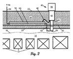
図1を参照すると、超電導磁石を使用する磁気共鳴撮像(MRI)デバイス10の側断面図が示されている。磁石は、大部分が液体ヘリウムで満たされているが、液体ヘリウムの液面16の上方にガス状のヘリウム(気体ヘリウム)超過圧力がある液体ヘリウム(LHe)タンク14内に配置された超電導巻線12を含む。例示するMRIデバイス10は、水平方向ボア磁石を使用する。水平方向ボア磁石では、超電導磁石は、ほぼ円筒形で、水平方向ボア18の周りを囲む(即ち、画定する)。しかし、他の磁石形状も考えられる。LHeタンク14の熱的分離を提供するために、周囲の真空ジャケットは、内側真空ジャケット壁20と、外側真空ジャケット壁22とを有し、その間に排気された真空ボリューム24がある。つまり、真空ジャケット壁、例えば内側真空ジャケット壁20及び外側真空ジャケット壁22と、任意選択的に側面真空ジャケット壁26といった追加の壁とは、真空ボリューム24を含む。内側真空ジャケット壁20は、真空ボリューム24とLHeタンク14とを隔てる。外側真空ジャケット壁22は、真空ボリューム24と周囲空気とを隔てる。(図示しない変形実施形態では、外側真空壁22の周りを囲む、例えば液体窒素を含む外側低温ジャケットがあることが考えられる)。図1に、真空ボリューム24はハッチングで示されている。アルミニウム合金板金(又は銅合金板金又は他の高熱伝導性板金)といった頑丈な熱伝導性材料で作られたサーマルシールド30が、真空ボリューム24内に配置され、LHeタンク14の周りを囲む。サーマルシールド30は、内側真空ジャケット壁20から離間されて、サーマルシールド30からLHeタンク14への熱伝導が回避される。幾つかの実施形態では、サーマルシールド30は、互いから離間され、最も内側のシールド層が内側真空ジャケット壁20から離間されている2つ以上のサーマルシールド層を含んでもよい(変形例は図示せず)。
Referring to FIG. 1, a side cross-sectional view of a magnetic resonance imaging (MRI)
図1を引き続き参照し、更に図2を参照すると、コールドヘッド40が、ヘリウムを作動流体として使用して冷凍サイクルを実行して、サーマルシールド30及びLHeタンク14の能動的冷却が提供される。このために、コールドヘッド40は、外側真空壁22を貫通して真空ボリューム24の中に入り込む第1ステージ42を含む。第1ステージ42は、溶接、ろう付け又は他の方法によってサーマルシールド30に固定されたサーマルバス50と接続する高伝導性サーマルリンク46によってサーマルシールド30に接続される第1ステージコールドステーション44を有する。コールドヘッド40は更に、内側真空壁20を通過してLHeタンク14に入る第2ステージ52を含み、第2ステージ52は、LHeタンク14内の液体ヘリウムの液面16の上方の気体ヘリウムの超過圧力内に配置される第2ステージコールドステーション54を有する。コールドヘッド40は、1つ以上の内部ピストン(図示せず)を駆動して作動ヘリウムを周期的に圧縮して、第1コールドステーション44及び第2コールドステーション54を冷却する冷凍サイクルを行う電動ヘッド又は他の機械的機構56を含む。(なお、コールドヘッド40のコンポーネント42、44、52、54、56は、図2の拡大図にのみ示す)。コールドヘッド40は、第2ステージコールドステーション54をヘリウムの液化温度未満まで、また、第1ステージコールドステーション44をより高い温度(ただし、サーマルシールド30がLHeタンク14の効果的な熱遮蔽を提供するのに十分に冷たい)まで冷却するようデザイン及び操作される。コールドヘッド40は、真空気密シールを提供するために、通常、外側真空壁22及び内側真空壁20に溶接される。
With continued reference to FIG. 1 and further reference to FIG. 2,
更に、真空ボリューム24を排気するために適切な真空ライン接続(図示せず)が設けられ、また、充填ライン(図示せず)が溶接シールを介して真空壁20、22を貫通し、液体ヘリウムチャージをLHeタンク14に投入するための進入経路が設けられる。充填ライン又は適切な溶接シールを有する別の進入経路は、磁石巻線12に接続し、磁石巻線12を励磁するためのリード線等を挿入することも可能にする。これらの巻線12を流れる静電流は、水平方向ボア磁石の例示する場合では、図1に示されるように、水平方向である静磁場B0を生成する。磁石巻線12の電流を所望の磁場強度|B0|を提供するように選択されたレベルまで上昇させた後、接点が引き抜かれ、その後の超電導磁石巻線12のゼロ電気抵抗によって、電流が持続的に流れ続けることが保証される。この時点以降、LHeタンク14内の液体ヘリウムチャージは保持されるべきである。さもなければ、超電導巻線12は、磁石巻線12の超電導臨界温度を超える温度まで温まって、磁石のクエンチをもたらす可能性がある。(液体ヘリウムチャージを取り去らなければならない場合に制御された運転停止を提供するためには、リード線を再度挿入し、液体ヘリウムチャージを取り去る前に磁石電流をゼロまで下げることが好適である)。
In addition, suitable vacuum line connections (not shown) are provided to evacuate the
MRIデバイスは、x、y及び/又はz方向においてB0磁場に選択された傾斜磁場を重ね合わせるための1組の傾斜磁場コイル58、磁気共鳴信号を励起及び/又は検出するための全身無線周波数(RF)コイル(図示せず)、患者又は他の撮像対象を、撮像のためにMRIデバイス10のボア18内に入れるための患者台(図示せず)等といった当技術分野において知られている様々な他のコンポーネントを任意選択的に含む。
The MRI device includes a set of gradient coils 58 for superimposing selected magnetic field gradients on the B0 magnetic field in the x , y and/or z directions, whole body radio frequency for exciting and/or detecting magnetic resonance signals. (RF) coils (not shown), patient tables (not shown) for bringing a patient or other imaging subject into the
従来では、第1ステージコールドステーション44をサーマルシールド30に(例えば編組銅線46により)接続するサーマルバスは、アルミニウム、銅、アルミニウム合金、銅合金、又は、サーマルシールド30への取付けに適している他の高熱伝導性金属の固体棒又は他の固体片である。
Conventionally, the thermal bus that connects the first stage cold station 44 to the thermal shield 30 (eg, by braided copper wire 46) is aluminum, copper, an aluminum alloy, a copper alloy, or suitable for attachment to the
図1及び図2を引き続き参照すると、サーマルシールド30のサーマルバス50は、前述の従来の固体金属サーマルバスに対して改良されて、熱交換器が組み込まれている。つまり、サーマルバス50は熱交換器を含む。又は、別の言い方では、サーマルバス50は一体型熱交換器を含む。このために、サーマルバス50は、サーマルバス50を通る流体通路60を含む。流体通路60は、LHeタンク14と流体連通する入口を有する。例示する実施形態では、気密開口部を介して内側真空壁20を通るパイプ又は他の入口流体導管62を経由して、LHeタンク14内の気体ヘリウムの超過圧力から流入する気体ヘリウムを受け取るように接続される入口を有する。流体通路60は、周囲空気と流体連通する出口を有する。例示する実施形態では、溶接開口部を介して外側真空壁22を通るパイプ又は他の出口流体導管64を経由して周囲空気中へと放出するように接続される出口を有する。流体通路60は、サーマルバス50の材料が流体通路60の壁を画定するように、サーマルバス50を通る開口部であってもよい。又は、他の実施形態では、流体通路60は、流体通路60の壁を形成するようにサーマルバス50に埋め込まれた別個のパイプ又は他の別個の導管であってもよい。
With continued reference to FIGS. 1 and 2, the
サーマルバス50に流入するサーマルシールド30からの熱は、流体通路60を流れる低温気体ヘリウムに流れ込むことができるため、流体通路60及びサーマルバス50は熱交換器として動作し、これにより、熱は、気体ヘリウムの流れを介して放出ライン64から運び出される。有利には、この熱伝達プロセスは、コールドヘッド40がオフにされたときに作動している。コールドヘッド40の動作によるサーマルバス50の能動的冷却の欠如は、熱交換器を介した熱伝達を駆動するための温度差を提供する。
Heat from the
サーマルバス50の一体型熱交換器は、気体ヘリウム超過圧力ベント経路を提供することと、低温気体ヘリウムの顕熱冷却能力を利用して、コールドヘッド40がオフにされている期間にサーマルシールド30の継続的な冷却を提供することとの二重の利点を有する。有利には、一体型熱交換器を含めるためのサーマルバス50の変更は最小限で済み、流体通路60を追加し、流路62、64を、真空壁20、22を通る溶接通路に接続することが必要である。サーマルバス50は、コンパクトなコンポーネントであり、例えば通常は、サーマルシールド30に溶接された1つの金属棒又は金属横材(beam)(又は、幾つかの実施形態では、追加の熱的接触を提供するように複数の棒又は横材)のフォームファクタを有し、流体通路60を組み込むためにサーマルバス50を機械加工する又は処理するための取り扱いが便利になる。サーマルバスが複数の棒又は横材を含む実施形態では、これらの棒又は横材のそれぞれを通るか又はこれらの一部のみを通る流体通路60を設けることが考えられる。
The integrated heat exchanger of the
サーマルバス50の一体型熱交換器はまた、ヘリウムガスが熱交換器を流れ続けるように磁石がゼロボイルオフ(ZBO)磁石でなければ、コールドヘッドがオンにされても追加の冷却力を提供することができる。他方で、磁石がZBO磁石であるならば、サーマルバス50の一体型熱交換器は、この状態では、一体型熱交換器をヘリウムガスが流れないため、追加の冷却力を提供しない。
The integrated heat exchanger of the
原則として、入口流体導管62、サーマルバス50を通る流体通路60及び出口流体導管64を含む流体経路は、周囲空気がLHeタンク14に入る可能性がある流路をもたらす。実際には、液体ヘリウムは、この流路62、60、64を通る流れが(周囲空気がLHeタンク14に流れ込むのではなくて)LHeタンク14から周囲空気に流れる気体ヘリウムを含むことを保証する気体ヘリウムの超過圧力をLHeタンク14内で発生させる。しかし、流路62、60、64に1つの逆止弁(又は2つの逆止弁からなる冗長セット)を含めて、周囲空気のLHeタンク14への「逆流」の可能性を阻止することが考えられる。考えられる別の変形例では、流路62、60、64に手動弁又は自動弁が取り付けられて、(例えばコールドヘッド40が動作しているときに)超電導磁石の通常の動作中に流路62、60、64を閉じることが可能にされる。
In principle, the fluid path including
図3を参照すると、一体型熱交換器を有するサーマルバス50の第1の非限定的な例示的実施形態が示されている。図3の実施形態では、サーマルバス501は単一の蛇行流体通路601を含む。当該手法は、構造的に簡単であるが、蛇行流体通路601を、サーマルバス501を形成するブロック内に形成することができる製造プロセスを必要とする。又は、蛇行流体通路601を形成する別個のパイプを、サーマルバス501を形成するブロックに埋め込むことができる製造プロセスを必要とする。これは、通常、例えば流体通路601の経路を画定する型を使用して鋳造することにより、サーマルバス501が形成されるのと同時に流体通路601を形成又は導入することが伴う。流体通路601の蛇行経路は、直線経路と比較して、熱伝達のための大幅に大きな表面積を有利に提供する。
Referring to FIG. 3, a first non-limiting exemplary embodiment of a
図4の実施形態では、サーマルバス502は、入口マニホルド72によって入口が外側で接続され、出口マニホルド74によって出口が外側で接続された例示的な3つの並列直線流体通路602を含む。並列流体通路602の数は、2つ、3つ、4つ、5つ又はそれ以上であってよく、好適には、サーマルバス502の構造的完全性を維持しながら、熱伝達のための十分な表面積を提供するように選択される。直線流体通路602の利点は、サーマルバス502の金属ブロックを形成した後に行われる穿孔プロセス又は他の機械加工プロセスによって直線流体通路が形成可能である点である。マニホルド72、74は、溶接、ろう付け又は別のプロセスによって流体通路602に適切に接続される。
In the embodiment of FIG . 4, the
図4の実施形態の変形例(図示せず)では、入口マニホルド及び出口マニホルドをサーマルバス50内に一体に形成することができる。これにより、流体通路60は、サーマルバス50を単一の入口及び単一の出口として通るが、サーマルバス内の複数の流路に分岐する。なお、図3及び図4の実施形態は、サーマルバス50を通る流体通路60が、複数の蛇行流体通路を含むことができるように、様々に組み合わせられてもよい。
In a variation (not shown) of the embodiment of FIG. 4, the inlet and outlet manifolds can be integrally formed within the
例示する実施形態は、低温気体ヘリウムの顕熱冷却能力を利用して、コールドヘッド40がオフにされている期間にサーマルシールド30を継続的に冷却する熱交換器として動作する二次機能を行うように変更されたサーマルバス50を有利に利用する。しかし、サーマルバスとは別箇のコンポーネントとして熱交換器を設けることが考えられる。例えばサーマルバスとは別箇の熱交換器を、その入口が液体ヘリウムタンクに流体連通し、出口が周囲空気と流体連通した状態で、サーマルバス又はサーマルシールドに追加的に取り付けることもできる。
The illustrated embodiment utilizes the sensible cooling capacity of the cryogenic helium gas to perform a secondary function of acting as a heat exchanger to continuously cool the
図5を参照して、図1のMRIデバイス10の液体ヘリウムチャージを投入して、超電導磁石を輸送するプロセスを説明する。磁石が製造された状態から開始して、ステップ80において、真空ボリューム24は、外側真空壁22上の適切な真空連結器(図1には図示せず)を使用して排気される。ステップ81において、LHeタンク14を排気する。ステップ82において、コールドヘッド40がオンにされ、ステップ84において、液体ヘリウム(LHe)チャージが、外側真空壁22を通る充填ライン(図1には図示せず)を介して投入される。当然ながら、ステップ82、84は、異なる順序で行われてもよく、及び/又は、当技術分野において知られている追加のステップが行われてもよい。通常、ステップ84は、液体ヘリウムをLHeタンク14に入れる前に、LHeタンク14から空気を抜くことが伴う。超電導磁石を液体ヘリウムでチャージした後、ステップ86において、コールドヘッド40がオフにされた後、輸送ステップ90において、(液体ヘリウムチャージが充填された)超電導磁石が輸送される。ステップ90の間、サーマルバス50の熱交換器は、サーマルシールド30の冷却を提供すると共に、LHeタンク14内の気体ヘリウムの超過圧力のためのベント経路を提供するように動作する。LHeタンク14内の気体ヘリウムは、液体ヘリウムの液面16の上方の超過圧力であるため、気体ヘリウムは、液体ヘリウムの沸点より高いが比較的近い温度、つまり、大気圧において(大気圧の近くで)で約4Kにある。したがって、コールドヘッド40が動作していなくても、サーマルバス50の熱交換器が、サーマルシールド30を冷却するための受動的機構を提供するように動作し、これは、次に、LHeタンク14内の液体ヘリウムの蒸発率を減少させる。液体ヘリウム蒸発率のこの減少により、より長い輸送時間が可能になり、したがって、より長い輸送距離を達成することができる。目的地に到着した後、ステップ92において、コールドヘッド40が再びオンにされ、その後、LHeタンク14の能動的冷却が提供される。磁石がZBO磁石である場合、サーマルバス50の熱交換器によって提供されていた追加の冷却は、ヘリウムガス流の停止により、ゼロボイルオフ状態が達成されると停止される。他方、磁石がZBO磁石ではない場合、サーマルバス50の熱交換器は、ステップ92においてコールドヘッド40がオンにされた後も追加の冷却力を提供し続ける。したがって、非ZBO磁石の場合、サーマルバス50の熱交換器は、よりエネルギー効率の良いコールドヘッド、例えばより小さいコールドヘッドを、及び/又は、より低い電気エネルギー入力で使用することを可能にする。
Referring to FIG. 5, the process of charging the liquid helium charge of the
図5を参照して、磁石の輸送中の一体型熱交換器を有するサーマルバス50によってもたらされる利点が説明されたが、当然ながら、例えばメンテナンス中にコールドヘッド40がオフにされる間、長時間の停電の間、若しくは、コールドヘッドを介する能動的冷却に支障を来す若しくは妨げるコールドヘッド40の故障中の間等、コールドヘッド40がオフにされるか、若しくは、長時間の間動作させられる任意の手順又は状況について、同様の利点が得られる。このような状況では、液体ヘリウムの蒸発が少ないため、液体ヘリウムチャージが過度に枯渇する可能性が低くなり、液体ヘリウムの枯渇による磁石のクエンチが生じる可能性が低くなる。
While the advantages provided by the
本発明は、好適な実施形態を参照して説明された。前述の詳細な説明を読んで理解すると、他の人が修正態様及び変更態様を想到することができるであろう。本発明は、添付の特許請求の範囲又はその均等物の範囲内にある限り、このようなすべての修正態様及び変更態様を含むと解釈されることが意図されている。 The invention has been described with reference to preferred embodiments. Modifications and alterations will occur to others upon reading and understanding the preceding detailed description. It is intended that the invention be construed as including all such modifications and variations insofar as they come within the scope of the appended claims or the equivalents thereof.
Claims (13)
前記液体ヘリウムタンク内に配置された超電導磁石巻線と、
前記液体ヘリウムタンクの周りを囲む真空ボリュームを含む真空ジャケット壁と、
前記真空ボリューム内に配置され、前記液体ヘリウムタンクの周りを囲むサーマルシールドと、
前記サーマルシールドに固定され、前記液体ヘリウムタンクと流体連通する入口及び周囲空気と流体連通する出口を有する流体通路を含む熱交換器と、
を含む、超電導磁石であって、
前記超電導磁石は、前記真空ジャケット壁に溶接され、前記真空ボリューム内に配置された第1ステージコールドステーション及び前記液体ヘリウムタンク内に配置された第2ステージコールドステーションを有するコールドヘッドを更に含み、
前記熱交換器は、熱伝導性接続部によって、前記第1ステージコールドステーションに接続されるサーマルバスである、超電導磁石。 a liquid helium tank;
a superconducting magnet winding disposed within the liquid helium tank;
a vacuum jacket wall including a vacuum volume surrounding the liquid helium tank;
a thermal shield disposed within the vacuum volume and surrounding the liquid helium tank;
a heat exchanger secured to the thermal shield and including a fluid passageway having an inlet in fluid communication with the liquid helium tank and an outlet in fluid communication with ambient air;
A superconducting magnet comprising
the superconducting magnet further comprising a coldhead welded to the vacuum jacket wall and having a first stage cold station located within the vacuum volume and a second stage cold station located within the liquid helium tank;
A superconducting magnet, wherein the heat exchanger is a thermal bus connected to the first stage cold station by thermally conductive connections.
前記複数の流体通路の出口を接続する出口マニホルドと、
を更に含む、請求項7に記載の超電導磁石。 an inlet manifold connecting the inlets of the plurality of fluid passages;
an outlet manifold connecting the outlets of the plurality of fluid passages;
8. The superconducting magnet of claim 7, further comprising:
前記超電導磁石によって前記水平方向ボア内に生成された静磁場に傾斜磁場を重ね合わせるように配置された1組の傾斜磁場コイルと、
を含む、磁気共鳴撮像(MRI)デバイス。 A superconducting magnet according to any one of claims 1 to 10, cylindrical in shape and defining a horizontal bore;
a set of gradient coils arranged to superimpose a magnetic field gradient on the static magnetic field generated in the horizontal bore by the superconducting magnet;
A magnetic resonance imaging (MRI) device, comprising:
前記コールドヘッドをオフにするステップと、
前記コールドヘッドがオフにされている間に、前記サーマルバスを通る流体通路を介して、前記液体ヘリウムタンクから周囲空気中へと気体ヘリウムを流すステップと、
を含む、方法。 a liquid helium tank; a superconducting magnet winding disposed within said liquid helium tank; a vacuum jacket wall including a vacuum volume surrounding said liquid helium tank; a coldhead having a first stage cold station located within the liquid helium tank and a second stage cold station located within the liquid helium tank; a thermal shield located within the vacuum volume and surrounding the liquid helium tank; a thermal bus fixed to a thermal shield and thermally connected to the first stage cold station, comprising:
turning off the coldhead;
flowing gaseous helium from the liquid helium tank into ambient air through a fluid passageway through the thermal bath while the coldhead is turned off;
A method, including
Applications Claiming Priority (3)
| Application Number | Priority Date | Filing Date | Title |
|---|---|---|---|
| US201762475287P | 2017-03-23 | 2017-03-23 | |
| US62/475,287 | 2017-03-23 | ||
| PCT/EP2018/056642 WO2018172200A1 (en) | 2017-03-23 | 2018-03-16 | Thermal bus heat exchanger for superconducting magnet |
Publications (3)
| Publication Number | Publication Date |
|---|---|
| JP2020513977A JP2020513977A (en) | 2020-05-21 |
| JP2020513977A5 JP2020513977A5 (en) | 2021-04-22 |
| JP7208914B2 true JP7208914B2 (en) | 2023-01-19 |
Family
ID=61899171
Family Applications (1)
| Application Number | Title | Priority Date | Filing Date |
|---|---|---|---|
| JP2019551647A Active JP7208914B2 (en) | 2017-03-23 | 2018-03-16 | Thermal bath heat exchanger for superconducting magnets |
Country Status (5)
| Country | Link |
|---|---|
| US (1) | US20200058423A1 (en) |
| EP (1) | EP3602579A1 (en) |
| JP (1) | JP7208914B2 (en) |
| CN (1) | CN110462760B (en) |
| WO (1) | WO2018172200A1 (en) |
Families Citing this family (1)
| Publication number | Priority date | Publication date | Assignee | Title |
|---|---|---|---|---|
| US11442124B2 (en) | 2019-09-26 | 2022-09-13 | Shanghai United Imaging Healthcare Co., Ltd. | Superconducting magnet |
Citations (3)
| Publication number | Priority date | Publication date | Assignee | Title |
|---|---|---|---|---|
| JP2003303713A (en) | 2002-04-12 | 2003-10-24 | Hitachi Ltd | Cryogenic device |
| US20100236260A1 (en) | 2005-07-08 | 2010-09-23 | Bruker Biospin Gmbh | Undercooled horizontal cryostat configuration |
| JP2011235090A (en) | 2010-05-06 | 2011-11-24 | General Electric Co <Ge> | System and method for removing heat generated by heat sink of magnetic resonance imaging system |
Family Cites Families (11)
| Publication number | Priority date | Publication date | Assignee | Title |
|---|---|---|---|---|
| DE3406859C1 (en) * | 1984-02-25 | 1985-04-04 | Messerschmitt-Bölkow-Blohm GmbH, 8012 Ottobrunn | Device for very deep freezing of objects |
| JPH03101504U (en) * | 1990-01-31 | 1991-10-23 | ||
| GB9016184D0 (en) * | 1990-07-24 | 1990-09-05 | Oxford Magnet Tech | Magnet assembly |
| JPH06163251A (en) * | 1992-11-25 | 1994-06-10 | Sumitomo Electric Ind Ltd | Cryogenic vessel |
| JPH10189327A (en) * | 1996-12-24 | 1998-07-21 | Hitachi Ltd | Quench protection device for superconducting coil |
| GB0305146D0 (en) * | 2003-03-06 | 2003-04-09 | Coated Conductors Consultancy | Superconducting coil testing |
| US7170377B2 (en) * | 2004-07-28 | 2007-01-30 | General Electric Company | Superconductive magnet including a cryocooler coldhead |
| DE102004061869B4 (en) * | 2004-12-22 | 2008-06-05 | Siemens Ag | Device for superconductivity and magnetic resonance device |
| JP2007194258A (en) * | 2006-01-17 | 2007-08-02 | Hitachi Ltd | Superconductive magnet apparatus |
| US7646272B1 (en) * | 2007-10-12 | 2010-01-12 | The United States Of America As Represented By The United States Department Of Energy | Freely oriented portable superconducting magnet |
| WO2013172148A1 (en) * | 2012-05-14 | 2013-11-21 | 株式会社 日立メディコ | Magnetic resonance imaging device, gas recovery unit for magnetic resonance imaging device, and method for operating magnetic resonance imaging device |
-
2018
- 2018-03-16 US US16/495,860 patent/US20200058423A1/en not_active Abandoned
- 2018-03-16 WO PCT/EP2018/056642 patent/WO2018172200A1/en unknown
- 2018-03-16 EP EP18715506.4A patent/EP3602579A1/en not_active Withdrawn
- 2018-03-16 CN CN201880020349.8A patent/CN110462760B/en not_active Expired - Fee Related
- 2018-03-16 JP JP2019551647A patent/JP7208914B2/en active Active
Patent Citations (3)
| Publication number | Priority date | Publication date | Assignee | Title |
|---|---|---|---|---|
| JP2003303713A (en) | 2002-04-12 | 2003-10-24 | Hitachi Ltd | Cryogenic device |
| US20100236260A1 (en) | 2005-07-08 | 2010-09-23 | Bruker Biospin Gmbh | Undercooled horizontal cryostat configuration |
| JP2011235090A (en) | 2010-05-06 | 2011-11-24 | General Electric Co <Ge> | System and method for removing heat generated by heat sink of magnetic resonance imaging system |
Also Published As
| Publication number | Publication date |
|---|---|
| WO2018172200A1 (en) | 2018-09-27 |
| JP2020513977A (en) | 2020-05-21 |
| CN110462760B (en) | 2022-12-27 |
| EP3602579A1 (en) | 2020-02-05 |
| CN110462760A (en) | 2019-11-15 |
| US20200058423A1 (en) | 2020-02-20 |
Similar Documents
| Publication | Publication Date | Title |
|---|---|---|
| US20090275478A1 (en) | Method and apparatus for maintaining a superconducting system at a predetermined temperature during transit | |
| JP5809391B2 (en) | Apparatus and method for cooling a superconducting magnet | |
| JP2010245524A (en) | Apparatus and method of cooling superconducting magnetic assembly | |
| US11573279B2 (en) | Displacer in magnetic resonance imaging system | |
| CN107430176A (en) | Cooling system and method for MR imaging apparatus | |
| US20170115366A1 (en) | System and method for cooling a magnetic resonance imaging device | |
| JP7208914B2 (en) | Thermal bath heat exchanger for superconducting magnets | |
| JP2010262950A (en) | Superconducting electromagnet and transport method therefor | |
| CN110998759B (en) | Superconducting magnet with cold head thermal path cooled by heat exchanger | |
| JP6440922B1 (en) | Superconducting magnet | |
| JPH11248326A (en) | Chiller | |
| CN213483505U (en) | Refrigerant cooling system for superconducting magnet | |
| US20220236349A1 (en) | Accelerated cooldown of low-cryogen magnetic resonance imaging (mri) magnets | |
| CN112992465B (en) | Superconducting magnet and magnetic resonance imaging system | |
| JP6021791B2 (en) | Permanent current switch and superconducting device equipped with it | |
| JP2008091802A (en) | Cryogenic container | |
| US11749435B2 (en) | Pre-cooling and removing ice build-up from cryogenic cooling arrangements | |
| US20160071638A1 (en) | Superconducting magnet device including a cryogenic cooling bath and cooling pipes | |
| JPH0599580A (en) | Looped heat pipe |
Legal Events
| Date | Code | Title | Description |
|---|---|---|---|
| A521 | Request for written amendment filed |
Free format text: JAPANESE INTERMEDIATE CODE: A523 Effective date: 20210311 |
|
| A621 | Written request for application examination |
Free format text: JAPANESE INTERMEDIATE CODE: A621 Effective date: 20210311 |
|
| A977 | Report on retrieval |
Free format text: JAPANESE INTERMEDIATE CODE: A971007 Effective date: 20220126 |
|
| A131 | Notification of reasons for refusal |
Free format text: JAPANESE INTERMEDIATE CODE: A131 Effective date: 20220210 |
|
| A521 | Request for written amendment filed |
Free format text: JAPANESE INTERMEDIATE CODE: A523 Effective date: 20220509 |
|
| A131 | Notification of reasons for refusal |
Free format text: JAPANESE INTERMEDIATE CODE: A131 Effective date: 20220729 |
|
| A521 | Request for written amendment filed |
Free format text: JAPANESE INTERMEDIATE CODE: A523 Effective date: 20221020 |
|
| TRDD | Decision of grant or rejection written | ||
| A01 | Written decision to grant a patent or to grant a registration (utility model) |
Free format text: JAPANESE INTERMEDIATE CODE: A01 Effective date: 20221212 |
|
| A61 | First payment of annual fees (during grant procedure) |
Free format text: JAPANESE INTERMEDIATE CODE: A61 Effective date: 20230106 |
|
| R150 | Certificate of patent or registration of utility model |
Ref document number: 7208914 Country of ref document: JP Free format text: JAPANESE INTERMEDIATE CODE: R150 |