JP7208840B2 - Method for shear reinforcement of reinforced concrete walls - Google Patents
Method for shear reinforcement of reinforced concrete walls Download PDFInfo
- Publication number
- JP7208840B2 JP7208840B2 JP2019055206A JP2019055206A JP7208840B2 JP 7208840 B2 JP7208840 B2 JP 7208840B2 JP 2019055206 A JP2019055206 A JP 2019055206A JP 2019055206 A JP2019055206 A JP 2019055206A JP 7208840 B2 JP7208840 B2 JP 7208840B2
- Authority
- JP
- Japan
- Prior art keywords
- hole
- shear
- filler
- reinforced concrete
- shear reinforcement
- Prior art date
- Legal status (The legal status is an assumption and is not a legal conclusion. Google has not performed a legal analysis and makes no representation as to the accuracy of the status listed.)
- Active
Links
Images


Description
本発明は、既設の鉄筋コンクリート壁を、後施工で、せん断補強部材により補強する、せん断補強方法に関する。 The present invention relates to a shear reinforcement method for reinforcing an existing reinforced concrete wall with a shear reinforcement member in post-construction.
構造物の老朽化や建築基準の見直し等により、耐震強度向上のため、既設の構造体に対して、せん断補強鉄筋などのせん断補強部材を定着させるせん断補強が行われている。 Due to the deterioration of structures and the review of building standards, shear reinforcement is being carried out by fixing shear reinforcement members such as shear reinforcement bars to existing structures in order to improve seismic strength.
既設の鉄筋コンクリート壁、例えば地中埋設のボックスカルバート側壁のせん断補強は、一般的に、次のような手順で行われている。 Shear reinforcement of existing reinforced concrete walls, for example, side walls of underground box culverts, is generally performed in the following procedure.
(1)鉄筋コンクリート壁に、その内壁面から外壁面に向かって、水平方向に、せん断補強部材挿入用の有底の孔を削孔する。
(2)削孔された孔に、せん断補強部材定着用の充填材(グラウト材)を注入し、充填する。
(3)充填材が注入された孔に、せん断補強鉄筋などのせん断補強部材を挿入し、充填材の固化により、定着させる。
(1) In a reinforced concrete wall, a bottomed hole for inserting a shear reinforcing member is drilled in the horizontal direction from the inner wall surface toward the outer wall surface.
(2) A filling material (grout material) for fixing the shear reinforcing member is injected into the drilled hole to fill the hole.
(3) A shear reinforcing member such as a shear reinforcing reinforcing bar is inserted into the hole into which the filler has been injected, and the filler is fixed by solidification.
また、特許文献1は、このような鉄筋コンクリート壁のせん断補強方法に関するもので、せん断補強部材挿入用の孔が水平方向に形成されていることで、充填した充填材がその入口から漏れてしまうことを防止するため、充填材の注入・充填に先立って、孔の入口側に充填材の貯留槽を設置することを提案している。
Further,
しかしながら、従来の一般的な方法では、充填材は、水平削孔した孔に注入・充填するため、漏れ出さないように、粘性の高いものとする必要がある。よって、その分、注入は容易ではない。 However, in the conventional general method, the filling material needs to be highly viscous so as not to leak out because it is injected and filled into the horizontally drilled hole. Therefore, injection is not so easy.
また、充填材が孔の先端から隙間なく(空気溜りなく)充填されていないと、定着性が悪化するため、注入ホースを奥まで挿入しての奥からの充填となる。この場合、削孔径との関係で、細い注入ホースを使用せざるを得ず、ホースの内径が小さくなることから、充填材が高粘性であることと合わせ、充填材の注入に時間がかかる。尚、削孔径を大きくすると、削孔のコスト及び時間が増加し、また、充填材の量が増えることからコストアップとなる。 Also, if the filler is not filled from the tip of the hole without gaps (without air pockets), fixability will deteriorate, so the injection hose must be inserted all the way to fill from the back. In this case, there is no choice but to use a thin injection hose due to the diameter of the drilled hole, and since the inner diameter of the hose is small, it takes time to inject the filler together with the high viscosity of the filler. It should be noted that increasing the drilling diameter increases the drilling cost and time, and increases the amount of filler material, resulting in an increase in cost.
また、全長にわたって確実に充填するため、せん断補強部材の挿入に伴って充填材が溢れてくるように施工する。このため、孔の入口側に、特許文献1に記載のような貯留槽などを設置する。従って、必要以上の充填材が使用されることになり、コストアップにつながる。また、廃棄せず、回収して、次の削孔に転用するとしても、作業性は悪化する。
In addition, in order to ensure the filling over the entire length, the filling material should overflow as the shear reinforcing member is inserted. For this reason, a storage tank or the like as described in
本発明は、このような実状に鑑み、粘性の低い充填材を使用可能として注入を容易化することができ、しかも必要以上の充填材の使用を抑制することができる、鉄筋コンクリート壁のせん断補強方法を提供することを課題とする。 In view of such circumstances, the present invention is a method for shear reinforcement of reinforced concrete walls, which makes it possible to use a low-viscosity filler to facilitate injection and to suppress the use of an excessive amount of filler. The task is to provide
本発明に係る鉄筋コンクリート壁のせん断補強方法は、
既設の鉄筋コンクリート壁に、その一方の壁面から他方の壁面に向かって、下り勾配で、せん断補強部材挿入用の有底の孔を削孔する、削孔工程と、
前記孔内に、後からせん断補強部材が挿入された状態においても、前記孔の開口部から溢れ出ない程度の量、充填材を注入する、充填材1次注入工程と、
前記充填材が注入された孔内に、せん断補強部材を挿入する、せん断補強部材挿入工程と、
前記せん断補強部材挿入後に、前記孔の開口部に、該開口部の上縁より高位置に充填材注入口を有するキャップ部材を設置する、キャップ部材設置工程と、
前記キャップ部材設置後に、前記孔内に、その開口部の上縁まで、充填材を前記充填材注入口より追加注入する、充填材2次注入工程と、
前記追加注入された充填材がある程度固化した段階で、前記キャップ部材を前記孔の開口部から取外す、キャップ部材取外し工程と、
を含む。
A method for shear reinforcement of a reinforced concrete wall according to the present invention comprises:
A drilling step of drilling a bottomed hole for inserting a shear reinforcing member in an existing reinforced concrete wall at a downward slope from one wall surface to the other wall surface;
a primary filling material injection step of injecting the filling material into the hole in such an amount that the filling material does not overflow from the opening of the hole even in a state in which the shear reinforcing member is inserted later;
a shear reinforcing member inserting step of inserting a shear reinforcing member into the hole into which the filler is injected;
a cap member installation step of installing a cap member having a filler injection port at a position higher than the upper edge of the opening in the opening of the hole after the shear reinforcing member is inserted;
a second filling material injection step of additionally injecting a filling material from the filling material injection port into the hole up to the upper edge of the opening after the cap member is installed ;
a cap member removing step of removing the cap member from the opening of the hole when the additionally injected filler solidifies to some extent;
Including .
本発明によれば、水平方向に対し下り勾配を持つように削孔するため、粘性の低い充填材を使用可能として注入を容易化することができる。
また、水平方向に対し下り勾配を持つように削孔することから、せん断補強部材の挿入の前と後に、2回に分けて注入することで、必要以上の充填材の使用を抑制しつつ、確実に充填することができる。
According to the present invention, since the hole is drilled so as to have a downward slope with respect to the horizontal direction, it is possible to use a low-viscosity filler and facilitate injection.
In addition, since the hole is drilled so as to have a downward slope in the horizontal direction, by injecting it in two steps, before and after inserting the shear reinforcing member, it is possible to suppress the use of more filler than necessary, can be reliably filled.
以下、本発明の実施の形態について、詳細に説明する。
図1は補強対象として例示する地中埋設のボックスカルバートの断面図であり、このようなボックスカルバートでは、ボックスカルバート側壁1、1の上部UL、UR及び下部LL、LRをせん断補強することが有効とされている。
BEST MODE FOR CARRYING OUT THE INVENTION Hereinafter, embodiments of the present invention will be described in detail.
FIG. 1 is a cross-sectional view of an underground box culvert exemplified as a reinforcement object. In such a box culvert, it is effective to shear-reinforce the upper parts UL and UR and the lower parts LL and LR of the box
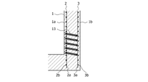
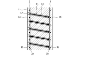
図2は図1中のLR部に適用されるせん断補強構造を示す断面図であり、更に図3は図2の要部拡大図である。 2 is a cross-sectional view showing a shear reinforcing structure applied to the LR portion in FIG. 1, and FIG. 3 is an enlarged view of a main part of FIG.
これらの図から解るように、既設の鉄筋コンクリート壁(例えばボックスカルバート側壁)1は、その内部に、内壁面1aに沿って、規定のかぶり厚分内側に、多数の縦鉄筋2aと横鉄筋2bが格子状に配筋されてなる内側鉄筋2を有し、また外壁面1bに沿って、規定のかぶり厚分内側に、多数の縦鉄筋3aと横鉄筋3bが格子状に配筋されてなる外側鉄筋3を有している。
As can be seen from these figures, an existing reinforced concrete wall (for example, a box culvert side wall) 1 has a large number of
既設の鉄筋コンクリート壁1に対するせん断補強は、せん断補強鉄筋などの棒状のせん断補強部材13を後施工することにより行う。
Shear reinforcement for the existing reinforced
以下に、最終的なせん断補強構造を示す図3と、せん断補強の手順を示す図4とを参照して、既設の鉄筋コンクリート壁1に対するせん断補強方法について、(1)~(4)の工程順に、説明する。
Below, referring to FIG. 3 showing the final shear reinforcement structure and FIG. 4 showing the procedure of shear reinforcement, the shear reinforcement method for the existing reinforced
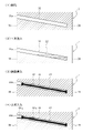
(1)削孔工程
図4(1)に示されるように、既設の鉄筋コンクリート壁1に、その内壁面1aから外壁面1bに向かって、下り勾配で、せん断補強部材13挿入用の有底の孔11を削孔する。
(1) Drilling process As shown in Fig. 4 (1), a bottomed hole for inserting the
ここでの孔11の削孔に際しては、障害となる内側鉄筋2(縦鉄筋2a及び横鉄筋2b)の位置をRCレーダー(鉄筋探査機)などで予め調査することで、内側鉄筋2の無い位置、すなわち、縦鉄筋2aと横鉄筋2bとによる格子の中央部を狙って、ハンマードリル等で斜め下向きに削孔する。
When drilling the
孔11の先端は、削孔により外側鉄筋3(縦鉄筋3a及び横鉄筋3b)を損傷することがないように、外側鉄筋3の手前までとする。せん断補強部材13の先端が外側鉄筋3に達するようにすることが望ましいが、外側鉄筋3(縦鉄筋3a及び横鉄筋3b)の格子の位置を内壁面1a側から知ることはできないからである。
従って、鉄筋コンクリート壁1の構築時の設計図面などから、内壁面1aから外側鉄筋3までの距離を知り、これと下り勾配の角度とから、外側鉄筋3の手前までの削孔長を算出し、これに基づいて削孔する。
The tip of the
Therefore, the distance from the
孔11の径(削孔径)については、例えば、せん断補強鉄筋の呼び径がD16(最外径18mm)で、両端の定着部(拡径部)の径が27mmとすると、30~33mm程度とする。
Regarding the diameter (drilling diameter) of the
孔11の下り勾配の角度については、水平方向に対し、3°~7°の範囲とし、例えば5°とする。但し、作図上、図2~図4などでは、壁厚と比較すると相対的に孔11の径を大きく描いていることから、孔11の下り勾配の角度を大きめに描いている。
The downward slope angle of the
削孔終了後、エアコンプレッサの圧縮空気などを用いて、孔11内の削孔屑を吹き飛ばすことで、孔11内の清掃を行う。
After the completion of drilling, the inside of the
(2)充填材1次注入工程
図4(2)に示されるように、孔11内に、後からせん断補強部材が挿入された状態においても、孔11の開口部11aから溢れ出ない程度の量、充填材(グラウト材)12を注入する。
(2) Filler Primary Injection Process As shown in FIG. 4(2), even when the shear reinforcing member is inserted into the
充填材12としては、樹脂、又はセメントミルク(セメント+水)を用いる。特に孔11が下り勾配を有していて、漏れ出しを防止できることから、注入しやすい流動性の高い(粘性の低い)充填材12を使用することができる。例えば、従来の水平削孔の場合に、充填材として、骨材(ガラス)入りの樹脂、又はモルタル(セメント+水+砂)を用いていたとすると、下り勾配としたことで、骨材を入れない樹脂、又は、セメントミルク(セメント+水)を用いることができる。
As the
(3)せん断補強部材挿入工程
図4(3)に示されるように、充填材12が1次注入された孔11内に、せん断補強鉄筋などの棒状のせん断補強部材(後打ちアンカー)13を押込んで挿入する。
(3) Shear reinforcing member inserting step As shown in FIG. 4(3), a rod-shaped shear reinforcing member (post-strike anchor) 13 such as a shear reinforcing reinforcing bar is inserted into the
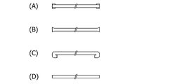
せん断補強部材13としては、せん断補強鉄筋の両端に定着用の拡径部を設けたものを好適に用いることができる。
図5はせん断補強部材13の形状例を示し、これらは安価に実施できる。(A)は鉄筋の端部に鋼管をカシメ加工より取付けたものである。(B)は鉄筋の端部を800℃程度に加熱し軸方向にプレス加工して膨らませたものである。(C)は鉄筋の端部を800℃程度に加熱し曲げ加工したものである。(D)はいわゆる直筋で、鉄筋の生材を切断しただけのものである。(D)は拡径部を有しないが、直筋であっても一定の効果をもたらすことは実験的に確認されている。
As the
FIG. 5 shows an example of the shape of the
せん断補強部材13としては、比較的高価ではあるが、セラミックキャップバー(CCb)工法で用いる、せん断補強鉄筋の両端にセラミック製の定着体(セラミックアンカー)を取付けたもの、あるいは、ポストヘッドバー(PHb)工法で用いる、せん断補強鉄筋の両端に矩形や円形のプレートあるいは継手を取付けたものを用いることもできる。
As the
充填材12が1次注入されている孔11内にせん断補強部材13を挿入した時点で、孔11内の充填材12の液面が孔11の開口部11aの下縁近傍に達することとなる。
When the
(4)充填材2次注入工程
図4(4)に示されるように、せん断補強部材13の挿入後に、孔11内に、その開口部11aの上縁まで、充填材12を追加注入し、孔11内を充填材12で満たす。尚、図4(4)では、1次注入された充填材を「12-1」、2次注入された充填材を「12-2」と記載している。
(4) Filler secondary injection step As shown in FIG. 4(4), after inserting the
孔11内への充填材12の追加注入を確実なものとするため、上記(3)のせん断補強部材挿入工程と上記(4)の充填材2次注入工程との間に、下記のような、キャップ設置工程を設けるとよい。
In order to ensure the additional injection of the
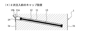
(*)キャップ設置工程
図6に示されるように、せん断補強部材挿入工程後で、充填材2次注入工程の前に、孔11の開口部11aに、充填材注入口14bを有するキャップ部材14を設置する。
キャップ部材14の充填材注入口14bは、孔11の開口部11aの上縁より高位置に設けられる。
(*) Cap installation process As shown in FIG. 6, after the shear reinforcement member insertion process and before the filler secondary injection process, the
The
図7はキャップ部材の正面図及び断面図である。
キャップ部材14は、鉄筋コンクリート壁における孔11の開口面にあてがわれてボルト15等により固定される鋼製又は樹脂製の閉止プレート14aを主体として構成され、閉止プレート14aの上側で幅方向中央部をアヒル口状に突出させて、孔11の開口部11aの上縁より高位置に、充填材注入口14bを形成してある。
FIG. 7 is a front view and cross-sectional view of the cap member.
The
従って、孔11内に、充填材12を1次注入し、せん断補強部材13を挿入した後、孔11の開口部11aに図7に示したようなキャップ部材14を設置してから、キャップ部材14の充填材注入口14bより充填材12を追加注入する。これにより、孔11内にその開口部11aの上縁まで一杯に充填材12を満たすことができる。
Therefore, after the filling
キャップ部材14は、充填材12の追加注入後、充填材12がある程度固化した段階で取外す。取外したキャップ部材14は、他のせん断補強箇所での2次注入用として、転用することができる。
After the additional injection of the
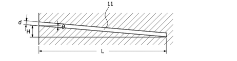
図8を参照して、孔11の径、下り勾配の角度などについて更に詳しく説明する。
孔11の径(削孔径)dについては、せん断補強鉄筋の呼び径がD16(最外径18mm)で、両端の定着部(拡径部)の径が27mmのとき、30~33mm程度とする。
The diameter of the
The diameter (drilling diameter) d of the
孔11の下り勾配の角度θについては、3°~7°(例えば5°)とする。
削孔幅(孔11の水平方向の長さ)Lを1000mmとすると、孔11の両端の高低差Hは、52mm(3°のとき)~122mm(7°のとき)となり、5°のときは、87mmとなる。
The downward slope angle θ of the
If the drilling width (the horizontal length of the hole 11) L is 1000 mm, the height difference H between both ends of the
削孔幅L=1000mm、削孔径d=30mm、下り勾配θ=5°、鉄筋の呼び径D16の場合、充填材の1次注入量を404ccとすると、鉄筋(181cc)の挿入で、孔の開口部の下縁まで、充填材の液面が上がってくる。
同様に、削孔幅L=1000mm、削孔径d=36mm、下り勾配θ=5°、鉄筋の呼び径D22の場合、充填材の1次注入量を466ccとすると、鉄筋(342cc)の挿入で、孔の開口部の下縁まで、充填材の液面が上がってくる。
When drilling width L = 1000 mm, drilling diameter d = 30 mm, downgradient θ = 5°, and reinforcing bar nominal diameter D16, if the primary injection amount of the filler is 404 cc, insertion of the reinforcing bar (181 cc) will result in The liquid surface of the filler rises up to the lower edge of the opening.
Similarly, when drilling width L = 1000 mm, drilling diameter d = 36 mm, downward slope θ = 5°, and reinforcing bar nominal diameter D22, if the primary injection amount of the filler is 466 cc, the insertion of the reinforcing bar (342 cc) , the liquid surface of the filler rises up to the lower edge of the opening of the hole.
本実施形態によれば、ほぼ水平方向に後施工されるせん断補強部材挿入用の孔11に下り勾配を持たせることから、流動性に優れた低粘性の充填材12を用いることが可能となり、注入ホース無しで削孔口から流し込むことができ、しかも最奥から完全に充填できるようになる。
According to this embodiment, since the
また、本実施形態によれば、充填材12の充填に特別の設備がいらないことから、多数の削孔を終わり、清掃した後、連続しての充填材12の注入が可能となる。
Further, according to the present embodiment, since no special equipment is required for filling the
また、本実施形態によれば、後打ちアンカーであるせん断補強部材13は、充填材12の中に挿入されるので、確実に付着が維持され、せん断補強部材13の挿入作業も連続して行うことができる。
Further, according to this embodiment, since the
また、本実施形態によれば、充填材12がオーバーフローしない状態でキャップ部材14を設置でき、キャップ部材14の上側の充填材注入口14bから充填材12を流し込むだけで、2次注入を行うことができ、作業は容易である。
Further, according to the present embodiment, the
また、本実施形態によれば、基本的には充填材12のオーバーフローは無く、充填材12に無駄がない。
Further, according to the present embodiment, the filling
上記の実施形態では、地中埋設のボックスカルバート側壁など、内側から施工する方法について説明したが、気中部の鉄筋コンクリート壁については、内外両面から施工することが可能である。
かかる場合は、例えば図9に示すように、奇数段を内側から、偶数段を外側から行うことで、より効果的な補強が可能となる。
もちろんではあるが、外側からのみ施工可能な場合は、外壁面から内壁面に向かって、下り勾配で有底の孔を削孔することにより、外側から補強すればよい。
In the above embodiment, a method of construction from the inside of a box culvert side wall buried in the ground, etc., has been described.
In such a case, for example, as shown in FIG. 9, more effective reinforcement can be achieved by performing odd-numbered steps from the inside and even-numbered steps from the outside.
Of course, if it is possible to work only from the outside, it is possible to reinforce the structure from the outside by drilling bottomed holes with downward slopes from the outer wall surface to the inner wall surface.
また、橋梁の橋脚のような平面視長方形(橋軸直角方向に長い長方形あるいは楕円形)断面の構造物についても、両側から補強することが可能である。特に橋脚については橋軸方向の両側(2方向)から補強するとよい。このような橋脚は橋軸方向のせん断力に対して補強が必要となることが多く、橋軸直角方向については幅が大きく補強が不要な場合が多いからである。 In addition, it is possible to reinforce both sides of a structure having a rectangular cross section in plan view (long rectangular or elliptical in the direction perpendicular to the bridge axis) such as a bridge pier. In particular, piers should be reinforced from both sides (two directions) in the direction of the bridge axis. This is because such bridge piers often require reinforcement against shear forces in the direction of the bridge axis, and in many cases the width in the direction perpendicular to the axis is large and reinforcement is unnecessary.
また、平面視ほぼ正方形、又は円形の柱状構造物については、4方向から補強するようにしてもよい。 Also, a substantially square or circular columnar structure in plan view may be reinforced from four directions.
尚、図示の実施形態はあくまで本発明を概略的に例示するものであり、本発明は、説明した実施形態により直接的に示されるものに加え、特許請求の範囲内で当業者によりなされる各種の改良・変更を包含するものであることは言うまでもない。
尚、出願当初の請求項は以下のとおりであった。
[請求項1]
既設の鉄筋コンクリート壁を、後施工で、せん断補強部材により補強する、せん断補強方法であって、
既設の鉄筋コンクリート壁に、その一方の壁面から他方の壁面に向かって、下り勾配で、せん断補強部材挿入用の有底の孔を削孔する、削孔工程と、
前記孔内に、後からせん断補強部材が挿入された状態においても、前記孔の開口部から溢れ出ない程度の量、充填材を注入する、充填材1次注入工程と、
前記充填材が注入された孔内に、せん断補強部材を挿入する、せん断補強部材挿入工程と、
前記せん断補強部材挿入後に、前記孔内に、その開口部の上縁まで、充填材を追加注入する充填材2次注入工程と、
を含むことを特徴とする、鉄筋コンクリート壁のせん断補強方法。
[請求項2]
前記せん断補強部材挿入工程の後で、前記充填材2次注入工程の前に、前記孔の開口部に、該開口部の上縁より高位置に充填材注入口を有するキャップ部材を設置する、キャップ部材設置工程を更に含むことを特徴とする、請求項1記載の鉄筋コンクリート壁のせん断補強方法。
[請求項3]
前記下り勾配は、水平方向に対し、3°~7°の範囲とすることを特徴とする、請求項1又は請求項2記載の鉄筋コンクリート壁のせん断補強方法。
It should be noted that the illustrated embodiment is only a schematic illustration of the present invention, and that the present invention, in addition to what is directly indicated by the described embodiment, can also be made by those skilled in the art within the scope of the claims. Needless to say, it includes the improvement and change of
The claims as originally filed were as follows.
[Claim 1]
A shear reinforcement method for reinforcing an existing reinforced concrete wall with a shear reinforcement member in post-construction,
A drilling step of drilling a bottomed hole for inserting a shear reinforcing member in an existing reinforced concrete wall at a downward slope from one wall surface to the other wall surface;
a primary filling material injection step of injecting the filling material into the hole in such an amount that the filling material does not overflow from the opening of the hole even in a state in which the shear reinforcing member is inserted later;
a shear reinforcing member inserting step of inserting a shear reinforcing member into the hole into which the filler is injected;
a second filling material injection step of additionally injecting a filling material into the hole up to the upper edge of the opening after the shear reinforcing member is inserted;
A method for shear reinforcement of a reinforced concrete wall, comprising:
[Claim 2]
After the shear reinforcing member insertion step and before the filler secondary injection step, a cap member having a filler injection port at a position higher than the upper edge of the opening is installed in the opening of the hole. 2. The method for shear reinforcement of a reinforced concrete wall according to
[Claim 3]
3. The shear reinforcement method for a reinforced concrete wall according to
1 既設の鉄筋コンクリート壁(ボックスカルバート側壁)
1a 内壁面
1b 外壁面
2 内側鉄筋(2a:縦鉄筋、2b:横鉄筋)
3 外側鉄筋(3a:縦鉄筋、3b:横鉄筋)
11 孔
11a 開口部
12 充填材(12-1:1次充填材、12-2:2次充填材)
13 せん断補強部材(せん断補強鉄筋)
14 キャップ部材
14a 閉止プレート
14b 充填材注入口
1 Existing reinforced concrete wall (side wall of box culvert)
1a
3 outer reinforcing bar (3a: vertical reinforcing bar, 3b: horizontal reinforcing bar)
11
13 Shear reinforcing member (shear reinforcing bar)
14
Claims (4)
既設の鉄筋コンクリート壁に、その一方の壁面から他方の壁面に向かって、下り勾配で、せん断補強部材挿入用の有底の孔を削孔する、削孔工程と、
前記孔内に、後からせん断補強部材が挿入された状態においても、前記孔の開口部から溢れ出ない程度の量、充填材を注入する、充填材1次注入工程と、
前記充填材が注入された孔内に、せん断補強部材を挿入する、せん断補強部材挿入工程と、
前記せん断補強部材挿入後に、前記孔の開口部に、該開口部の上縁より高位置に充填材注入口を有するキャップ部材を設置する、キャップ部材設置工程と、
前記キャップ部材設置後に、前記孔内に、その開口部の上縁まで、充填材を前記充填材注入口より追加注入する、充填材2次注入工程と、
前記追加注入された充填材がある程度固化した段階で、前記キャップ部材を前記孔の開口部から取外す、キャップ部材取外し工程と、
を含む、鉄筋コンクリート壁のせん断補強方法。 A shear reinforcement method for reinforcing an existing reinforced concrete wall with a shear reinforcement member in post-construction,
A drilling step of drilling a bottomed hole for inserting a shear reinforcing member in an existing reinforced concrete wall at a downward slope from one wall surface to the other wall surface;
a primary filling material injection step of injecting the filling material into the hole in such an amount that the filling material does not overflow from the opening of the hole even in a state in which the shear reinforcing member is inserted later;
a shear reinforcing member inserting step of inserting a shear reinforcing member into the hole into which the filler is injected;
a cap member installation step of installing a cap member having a filler injection port at a position higher than the upper edge of the opening in the opening of the hole after the shear reinforcing member is inserted;
a second filling material injection step of additionally injecting a filling material from the filling material injection port into the hole up to the upper edge of the opening after the cap member is installed ;
a cap member removing step of removing the cap member from the opening of the hole when the additionally injected filler solidifies to some extent;
A method for shear reinforcement of reinforced concrete walls , comprising:
Priority Applications (1)
| Application Number | Priority Date | Filing Date | Title |
|---|---|---|---|
| JP2019055206A JP7208840B2 (en) | 2019-03-22 | 2019-03-22 | Method for shear reinforcement of reinforced concrete walls |
Applications Claiming Priority (1)
| Application Number | Priority Date | Filing Date | Title |
|---|---|---|---|
| JP2019055206A JP7208840B2 (en) | 2019-03-22 | 2019-03-22 | Method for shear reinforcement of reinforced concrete walls |
Publications (2)
| Publication Number | Publication Date |
|---|---|
| JP2020153195A JP2020153195A (en) | 2020-09-24 |
| JP7208840B2 true JP7208840B2 (en) | 2023-01-19 |
Family
ID=72558071
Family Applications (1)
| Application Number | Title | Priority Date | Filing Date |
|---|---|---|---|
| JP2019055206A Active JP7208840B2 (en) | 2019-03-22 | 2019-03-22 | Method for shear reinforcement of reinforced concrete walls |
Country Status (1)
| Country | Link |
|---|---|
| JP (1) | JP7208840B2 (en) |
Citations (8)
| Publication number | Priority date | Publication date | Assignee | Title |
|---|---|---|---|---|
| JP2001193064A (en) | 2000-01-14 | 2001-07-17 | Sumitomo Constr Co Ltd | Anchoring method for ground anchor |
| JP2005105808A (en) | 2003-09-09 | 2005-04-21 | Taisei Corp | Shearing force reinforcing method |
| JP2006016893A (en) | 2004-07-02 | 2006-01-19 | Taisei Corp | Shearing reinforcing method of existing structure |
| JP2010007247A (en) | 2008-06-24 | 2010-01-14 | Taisei Corp | Filling method for filler, and plug member |
| JP2011080197A (en) | 2009-10-02 | 2011-04-21 | Okabe Co Ltd | Method for constructing lock bolt |
| JP2012197572A (en) | 2011-03-18 | 2012-10-18 | Kajima Corp | Shear reinforce member fixation method |
| JP2012241332A (en) | 2011-05-16 | 2012-12-10 | Kajima Corp | Method for fixing shear reinforcement component |
| JP2018150742A (en) | 2017-03-14 | 2018-09-27 | 成和リニューアルワークス株式会社 | Concrete member reinforcing method and lid member |
Family Cites Families (1)
| Publication number | Priority date | Publication date | Assignee | Title |
|---|---|---|---|---|
| JPS60164088A (en) * | 1984-02-06 | 1985-08-27 | 鹿島建設株式会社 | Grout method of piping penetrating section and executing device thereof |
-
2019
- 2019-03-22 JP JP2019055206A patent/JP7208840B2/en active Active
Patent Citations (8)
| Publication number | Priority date | Publication date | Assignee | Title |
|---|---|---|---|---|
| JP2001193064A (en) | 2000-01-14 | 2001-07-17 | Sumitomo Constr Co Ltd | Anchoring method for ground anchor |
| JP2005105808A (en) | 2003-09-09 | 2005-04-21 | Taisei Corp | Shearing force reinforcing method |
| JP2006016893A (en) | 2004-07-02 | 2006-01-19 | Taisei Corp | Shearing reinforcing method of existing structure |
| JP2010007247A (en) | 2008-06-24 | 2010-01-14 | Taisei Corp | Filling method for filler, and plug member |
| JP2011080197A (en) | 2009-10-02 | 2011-04-21 | Okabe Co Ltd | Method for constructing lock bolt |
| JP2012197572A (en) | 2011-03-18 | 2012-10-18 | Kajima Corp | Shear reinforce member fixation method |
| JP2012241332A (en) | 2011-05-16 | 2012-12-10 | Kajima Corp | Method for fixing shear reinforcement component |
| JP2018150742A (en) | 2017-03-14 | 2018-09-27 | 成和リニューアルワークス株式会社 | Concrete member reinforcing method and lid member |
Also Published As
| Publication number | Publication date |
|---|---|
| JP2020153195A (en) | 2020-09-24 |
Similar Documents
| Publication | Publication Date | Title |
|---|---|---|
| KR100920204B1 (en) | Constructing method of precast pier footing for bridge | |
| US20160298329A1 (en) | Inverted Grout Tube with Angled Fill Spout | |
| JP5654725B2 (en) | Shear reinforcement member | |
| KR101415106B1 (en) | The back feel grouting apparatus for upper part of tunnel | |
| JP4472729B2 (en) | Reinforced structure | |
| KR20090100867A (en) | The method construction work and unit metal tubing constructing system for the road underground driveway | |
| KR20190101610A (en) | Groutable waterstop and construction method | |
| KR20090007826A (en) | Process of blocking water penetration and blocking earth collapsing by using impermeable wall without strut | |
| KR101038945B1 (en) | A filling structure of upper part of a tunnel and its procedure | |
| JP7208840B2 (en) | Method for shear reinforcement of reinforced concrete walls | |
| CA2892704C (en) | Reinforced blockwork construction method | |
| KR102156793B1 (en) | Top-down method for underground structure to prevent sinkhole | |
| CN110359430A (en) | A kind of Gravity Dam Foundation discharge structure | |
| JP3700980B1 (en) | Shear force reinforcement method, shear force reinforcement structure, and shear reinforcement member | |
| KR101066899B1 (en) | Pipe module and water pipe using the same | |
| KR100891617B1 (en) | The steel box for the concrete filling type closed conduit construction | |
| CN210686015U (en) | Tunnel deformation joint structure | |
| KR20070109423A (en) | Assembled precast reinforced concrete culverts with steel bar | |
| JP5827102B2 (en) | Precast member installation method and precast member used therefor | |
| KR200375669Y1 (en) | Expansion joint equipment in jointing point of structure | |
| CN105863125A (en) | Mounting joint for external wall panel | |
| CN105863134A (en) | Outer wall plate mounting node | |
| CN105971152A (en) | Installation joint for outer wallboards | |
| JP2005256571A (en) | Continuous wall body and its construction method | |
| CN109680719A (en) | A kind of jigsaw assembled pipe gallery and construction method |
Legal Events
| Date | Code | Title | Description |
|---|---|---|---|
| A621 | Written request for application examination |
Free format text: JAPANESE INTERMEDIATE CODE: A621 Effective date: 20211108 |
|
| A977 | Report on retrieval |
Free format text: JAPANESE INTERMEDIATE CODE: A971007 Effective date: 20220921 |
|
| A131 | Notification of reasons for refusal |
Free format text: JAPANESE INTERMEDIATE CODE: A131 Effective date: 20220927 |
|
| A521 | Request for written amendment filed |
Free format text: JAPANESE INTERMEDIATE CODE: A523 Effective date: 20221017 |
|
| TRDD | Decision of grant or rejection written | ||
| A01 | Written decision to grant a patent or to grant a registration (utility model) |
Free format text: JAPANESE INTERMEDIATE CODE: A01 Effective date: 20221227 |
|
| A61 | First payment of annual fees (during grant procedure) |
Free format text: JAPANESE INTERMEDIATE CODE: A61 Effective date: 20230106 |
|
| R150 | Certificate of patent or registration of utility model |
Ref document number: 7208840 Country of ref document: JP Free format text: JAPANESE INTERMEDIATE CODE: R150 |