JP7201570B2 - Resistance spot welding method - Google Patents
Resistance spot welding method Download PDFInfo
- Publication number
- JP7201570B2 JP7201570B2 JP2019209877A JP2019209877A JP7201570B2 JP 7201570 B2 JP7201570 B2 JP 7201570B2 JP 2019209877 A JP2019209877 A JP 2019209877A JP 2019209877 A JP2019209877 A JP 2019209877A JP 7201570 B2 JP7201570 B2 JP 7201570B2
- Authority
- JP
- Japan
- Prior art keywords
- energization
- welding
- current value
- nugget
- steel plates
- Prior art date
- Legal status (The legal status is an assumption and is not a legal conclusion. Google has not performed a legal analysis and makes no representation as to the accuracy of the status listed.)
- Active
Links
Images


Description
本発明は抵抗スポット溶接方法に係る。特に、本発明は、他の鋼板に対して電気抵抗値が異なる少なくとも1枚の鋼板を含む3枚以上の鋼板を互いに重ね合わせて接合する抵抗スポット溶接方法の改良に関する。 The present invention relates to a resistance spot welding method. In particular, the present invention relates to an improvement in a resistance spot welding method for overlapping and joining three or more steel sheets, including at least one steel sheet having a different electrical resistance value with respect to other steel sheets.
従来、自動車の車体等を製造するに当たり、複数の金属板を互いに接合する手段として抵抗スポット溶接が利用されている。この抵抗スポット溶接は、一対の電極で複数の金属板(被溶接材)を挟持しながら通電を行い、金属板自身の電気抵抗等により発生するジュール熱を利用して金属板同士を溶融させて接合するものである。 2. Description of the Related Art Conventionally, resistance spot welding is used as a means for joining a plurality of metal plates to each other in manufacturing automobile bodies and the like. In this resistance spot welding, a pair of electrodes hold a plurality of metal plates (materials to be welded) while energizing them. It is to be joined.
抵抗スポット溶接において溶接品質を良好に得るためにはスパッタ(溶融金属が飛散する散り)の発生を抑制する必要がある。 In order to obtain good welding quality in resistance spot welding, it is necessary to suppress the occurrence of spatter (spattering of molten metal).
特許文献1には、スパッタの発生を抑制することを目的とした亜鉛めっき高張力鋼板の抵抗スポット溶接方法が開示されている。この特許文献1では、抵抗スポット溶接時におけるスパッタの発生を抑制することを目的として、電極間の本通電に先立って行われる初期通電に際し、重ね合わせた各金属板(鋼板)の合計厚みと電極対の中心間距離との関係を定めることが開示されている。
しかしながら、他の鋼板に対して電気抵抗値(以下、単に抵抗という場合もある)が異なる少なくとも1枚の鋼板を含む3枚以上の鋼板を互いに重ね合わせて抵抗スポット溶接を行う場合、初期通電を開始した際、材料抵抗差が大きくなっている鋼板同士の間の界面にあっては、他の鋼板同士の間の界面よりも抵抗が大きくなることに伴って発熱量が大きくなる。その結果、この界面の周辺では他の界面の周辺よりも早期に溶接ナゲットの成形が開始されることになる。そして、材料抵抗は温度が高いほど大きくなるため、この早期に溶接ナゲットが成形される部分(発熱量が大きくなっている部分)では、その後の本通電の開始に伴って溶接ナゲットが更に拡大し、スパッタが発生してしまう可能性がある。 However, when three or more steel plates including at least one steel plate having a different electrical resistance value (hereinafter, sometimes simply referred to as resistance) from other steel plates are superimposed on each other and resistance spot welding is performed, initial energization is required. At the start, at the interface between the steel sheets where the difference in material resistance is large, the amount of heat generated increases as the resistance becomes greater than at the interface between the other steel sheets. As a result, the formation of the weld nugget begins earlier around this interface than around other interfaces. Since the material resistance increases as the temperature rises, the weld nugget expands further at the portion where the weld nugget is formed at this early stage (the portion where the amount of heat generated is large) as the main energization is started thereafter. , spatter may occur.
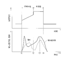
図9は、従来の抵抗スポット溶接における溶接電流値の推移(図9における上側の図)、および、それに伴う電気抵抗値および温度の変化の一例(図9における下側の図)を示す図である。下側の図における太い実線は電気抵抗値の変化を示し、細い実線は温度の変化を示している。この図9に示すように、抵抗スポット溶接では、初期通電が所定期間行われた後(図中のタイミングt1~t2)、連続して本通電(図中のタイミングt2~t4)が行われる。初期通電では、徐々に溶接電流値を高くしていく。また、本通電は、初期通電の通電期間における最大電流値よりも高い電流値で行われる。このような従来の溶接電流値の推移にあっては、前述したように材料抵抗差が大きくなっている鋼板同士の間の界面の周辺において早期に溶接ナゲットの成形が開始され、本通電の開始に伴って当該溶接ナゲットが更に拡大し、抵抗が大きくなることに伴う発熱量の増大に起因して本通電の実施期間中にスパッタが発生してしまう可能性がある。図9にあっては、本通電の実施期間中におけるタイミングt3でスパッタが発生している。 FIG. 9 is a diagram showing changes in welding current value (upper diagram in FIG. 9) in conventional resistance spot welding, and an example of accompanying changes in electrical resistance value and temperature (lower diagram in FIG. 9). be. A thick solid line in the lower diagram indicates changes in electrical resistance, and a thin solid line indicates changes in temperature. As shown in FIG. 9, in resistance spot welding, after initial energization is performed for a predetermined period (timings t1 to t2 in the figure), main energization is continuously performed (timings t2 to t4 in the figure). In the initial energization, the welding current value is gradually increased. Further, the main energization is performed at a current value higher than the maximum current value during the energization period of the initial energization. In such a transition of the conventional welding current value, as described above, the formation of the welding nugget is started early around the interface between the steel plates where the material resistance difference is large, and the main energization is started. As a result, the welding nugget further expands, and there is a possibility that spatter will occur during the period of main energization due to an increase in the amount of heat generated due to the increase in resistance. In FIG. 9, spatter occurs at timing t3 during the period of main energization.
このため、スパッタの発生を抑制するためには、本通電における溶接電流値を低く抑える必要がある。つまり、本通電での溶接電流値におけるスパッタ発生限界(スパッタの発生を抑制するための本通電での溶接電流値の上限)が低くなってしまい、抵抗スポット溶接に要する時間が長くなってしまう。 Therefore, in order to suppress the generation of spatter, it is necessary to keep the welding current value in the main energization low. In other words, the spatter generation limit (the upper limit of the welding current value in main energization for suppressing the generation of spatter) in the welding current value in main energization becomes low, and the time required for resistance spot welding becomes long.
このため、従来技術にあっては、スパッタの発生を抑制しながらも効率良く溶接ナゲットを成形することが困難であった。 For this reason, in the prior art, it was difficult to form a weld nugget efficiently while suppressing the generation of spatter.
本発明は、かかる点に鑑みてなされたものであり、その目的とするところは、スパッタの発生を抑制しながらも効率良く溶接ナゲットを成形することが可能な抵抗スポット溶接方法を提供することにある。 The present invention has been made in view of the above points, and its object is to provide a resistance spot welding method capable of efficiently forming a weld nugget while suppressing the generation of spatter. be.
前記の目的を達成するための本発明の解決手段は、他の鋼板に対して電気抵抗値が異なる少なくとも1枚の鋼板を含む3枚以上の鋼板を互いに重ね合わせ、これら鋼板を電極によって挟持し、該電極間に、徐々に溶接電流値を高くしていく初期通電を行った後、該初期通電の通電期間における最大電流値よりも高い電流値で本通電を行うことで前記鋼板同士を溶融して接合する抵抗スポット溶接方法を前提とする。そして、この抵抗スポット溶接方法は、前記初期通電により、前記各鋼板の基材を構成している鉄が溶融した後に冷却されることで成形され且つ前記初期通電の継続に伴って前記各鋼板の延在方向に平行な方向での外形寸法が拡大していく溶接ナゲットにおける当該外形寸法、および、該溶接ナゲットの外側に成形され且つ前記各鋼板の表面に存在するめっき層の構成材料を前記鉄に拡散させて両成分から決定される固相線温度を上昇させることにより生成され前記初期通電の継続に伴って前記方向での外形寸法が拡大していく合金層における当該外形寸法の関係が、以下の式(1)
1.2≦合金層の外形寸法/溶接ナゲットの外形寸法≦1.5 …(1)
となっている状態で、前記電極間の通電を停止することにより、前記初期通電と前記本通電との間に通電の停止期間であるインターバルを設けることを特徴とする。
A solution of the present invention for achieving the above object is to stack three or more steel plates including at least one steel plate having a different electrical resistance value with respect to other steel plates and sandwich these steel plates between electrodes. After the initial energization is performed by gradually increasing the welding current value between the electrodes, the steel sheets are melted by performing the main energization at a current value higher than the maximum current value in the energization period of the initial energization. The premise is a resistance spot welding method that joins by In this resistance spot welding method, the iron constituting the base material of each steel plate is melted by the initial energization and then cooled to form a shape . The outer dimensions of the welding nugget whose outer dimensions in the direction parallel to the extension direction expand , and the constituent material of the plating layer formed on the outside of the welding nugget and existing on the surface of each steel plate are the iron The relationship between the outer dimensions of the alloy layer , which is generated by increasing the solidus temperature determined by the two components and increases the outer dimensions in the direction as the initial energization continues, is Equation (1) below
1.2 ≤ external dimension of alloy layer / external dimension of welding nugget ≤ 1.5 (1)
By stopping the energization between the electrodes in this state, an interval, which is a period during which energization is stopped, is provided between the initial energization and the main energization.
他の鋼板に対して電気抵抗値が異なる少なくとも1枚の鋼板を含んでいることに伴って材料抵抗差が大きくなっている鋼板同士の間の界面にあっては、他の鋼板同士の間の界面よりも抵抗が大きくなる。これに伴って、初期通電を開始した際には、この界面(材料抵抗差が大きくなっている鋼板同士の間の界面)の周辺での発熱量が大きくなる。その結果、この界面の周辺では他の界面の周辺よりも早期に溶接ナゲットの成形が開始されることになる。このような状況において、前記式(1)が成立した状態にあっては、合金層の外形寸法と溶接ナゲットの外形寸法との比が適正に維持される(鋼板同士の接合強度を十分に確保しながらも溶接ナゲットが大きくなり過ぎる状態にはない)ことによってスパッタは発生し難くなっている。また、この状態で電極間の通電を停止し、この通電の停止期間である所定のインターバルが経過するまで本通電の開始を遅延させているため、前記成形された溶接ナゲットが、このインターバルの間に冷却されることになる。つまり、この溶接ナゲットが成形されている領域での電気抵抗値が低くなる。このため、その後に本通電を開始しても、電気抵抗値が高いことに起因して局部的に溶接ナゲットが拡大してしまうといったことは抑制されて、スパッタの発生を抑制することができる。つまり、本通電での溶接電流値におけるスパッタ発生限界を高くすることができ(従来技術に比べてスパッタ発生限界を高くすることができ)、スパッタの発生を抑制しながらも効率良く溶接ナゲットを成形することが可能になる。 At the interface between steel plates that have a large material resistance difference due to the inclusion of at least one steel plate that has a different electrical resistance value than the other steel plates, the difference between the other steel plates Resistance becomes larger than the interface. Along with this, when the initial energization is started, the amount of heat generated around this interface (the interface between the steel plates having a large material resistance difference) increases. As a result, the formation of the weld nugget begins earlier around this interface than around other interfaces. In such a situation, when the above formula (1) is established, the ratio between the outer dimensions of the alloy layer and the outer dimensions of the welding nugget is properly maintained (the joint strength between the steel plates is sufficiently secured). However, the weld nugget does not become too large), thereby making it difficult for spatter to occur. In this state, the energization between the electrodes is stopped, and the start of the main energization is delayed until the predetermined interval, which is the period during which the energization is stopped, has passed. will be cooled to In other words, the electrical resistance value in the area where this weld nugget is formed becomes low. Therefore, even if main energization is started after that, local expansion of the welding nugget due to the high electrical resistance is suppressed, and the occurrence of spatter can be suppressed. In other words, it is possible to increase the spatter generation limit at the welding current value in the main energization (the spatter generation limit can be increased compared to the conventional technology), and the welding nugget can be formed efficiently while suppressing the generation of spatter. it becomes possible to
本発明では、初期通電において、以下の式(1)
1.2≦合金層の外形寸法/溶接ナゲットの外形寸法≦1.5 …(1)
となっている状態で、電極間の通電を停止することにより、初期通電と本通電との間に通電の停止期間であるインターバルを設けるようにしている。これにより、前記インターバルの間に溶接ナゲットが冷却されることになり、この溶接ナゲットが成形されている領域での電気抵抗値を低くすることができる。このため、その後に本通電を開始しても局部的な溶接ナゲットの拡大は抑制されて、スパッタの発生を抑制することができる。従って、本通電での溶接電流値におけるスパッタ発生限界を高くすることができ、スパッタの発生を抑制しながらも効率良く溶接ナゲットを成形することが可能になる。
In the present invention, in the initial energization, the following formula (1)
1.2 ≤ external dimension of alloy layer / external dimension of welding nugget ≤ 1.5 (1)
By stopping the energization between the electrodes in this state, an interval, which is the energization stop period, is provided between the initial energization and the main energization. As a result, the weld nugget is cooled during the interval, and the electrical resistance in the area where the weld nugget is formed can be lowered. Therefore, even if main energization is started after that, local expansion of the welding nugget is suppressed, and the occurrence of spatter can be suppressed. Therefore, it is possible to increase the spatter generation limit at the welding current value in the main energization, and it is possible to efficiently form a welding nugget while suppressing the generation of spatter.
以下、本発明の実施の形態を図面に基づいて説明する。本実施形態は、亜鉛を主成分とするめっき層(より具体的には、溶融亜鉛めっき層)を有する3枚の鋼板を重ね合わせて抵抗スポット溶接(以下、単に溶接という場合もある)する場合を例に挙げて説明する。一例として、自動車の車体の製造において3枚の鋼板同士を抵抗スポット溶接する場合が挙げられる。 BEST MODE FOR CARRYING OUT THE INVENTION Hereinafter, embodiments of the present invention will be described with reference to the drawings. This embodiment is a case where three steel sheets having a zinc-based coating layer (more specifically, a hot-dip galvanizing layer) are superimposed and resistance spot welded (hereinafter, sometimes simply referred to as welding). will be described as an example. An example is the case where three steel plates are resistance spot welded together in the manufacture of automobile bodies.
-抵抗スポット溶接装置の構成-
抵抗スポット溶接方法について説明する前に、この抵抗スポット溶接方法を実施するための抵抗スポット溶接装置の概略について説明する。
- Configuration of Resistance Spot Welding Equipment -
Before describing the resistance spot welding method, an outline of a resistance spot welding apparatus for carrying out this resistance spot welding method will be described.
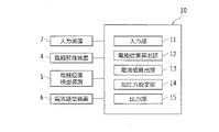
図1は本実施形態に係る抵抗スポット溶接装置の溶接ガンGを示す概略構成図である。また、図2は、溶接ガンGの制御に用いる制御装置10の概略構成を示す図である。
FIG. 1 is a schematic configuration diagram showing a welding gun G of a resistance spot welding apparatus according to this embodiment. 2 is a diagram showing a schematic configuration of a
溶接ガンGは、ロボットアームRAに保持されたガン本体1と、上部電極2と、ガン本体1の下部1aに立設された下部電極3と、上部電極2を保持して昇降させる電動式の上部電極昇降装置(以下、単に電極昇降装置という)4と、電極位置検出装置5と、上部電極2と下部電極3との間に流す溶接電流値(以下、単に電流値という場合もある)を調整する電流調整装置6とを主要構成要素として構成されている。
The welding gun G has a
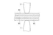
なお、図1において、溶接される3枚の鋼板W1,W2,W3は、例えば最も上側に位置する鋼板W1が溶融亜鉛めっき層を有するホットスタンプ材(超高張力鋼板)であり、下側に位置する2枚の鋼板W2,W3が合金化溶融亜鉛めっき層を有する所謂GA材である。また、本実施形態では、各鋼板W1,W2,W3の板厚寸法は共に同一である(例えば1.2mm)。なお、本発明にあっては、各鋼板W1,W2,W3それぞれの種類は前述したものには限定されず、適宜選択が可能である。また、各鋼板W1,W2,W3の板厚寸法は必ずしも同一である必要はない。例えば、特定の1枚の鋼板W1の板厚寸法に対する他の鋼板W2,W3の板厚寸法の比がそれぞれ0.7~1.5の範囲となっている鋼板W1,W2,W3が適用可能である。 In FIG. 1, the three steel plates W1, W2, and W3 to be welded are, for example, the steel plate W1 positioned on the uppermost side is a hot stamp material (ultra-high tensile strength steel plate) having a hot dip galvanized layer, and the lower side The two steel sheets W2 and W3 positioned are so-called GA materials having an alloyed hot-dip galvanized layer. Further, in this embodiment, the plate thickness dimensions of the steel plates W1, W2, and W3 are all the same (for example, 1.2 mm). In addition, in the present invention, the types of the steel plates W1, W2, and W3 are not limited to those described above, and can be appropriately selected. Further, the plate thickness dimensions of the steel plates W1, W2, and W3 do not necessarily have to be the same. For example, steel plates W1, W2, and W3 in which the ratio of the thickness dimension of the other steel plates W2 and W3 to the thickness dimension of a specific steel plate W1 is in the range of 0.7 to 1.5, respectively, can be applied. is.
また、各亜鉛めっき層は、溶融めっきによって成形されたものに限らず、電気めっきによって成形されたものであってもよい。つまり、各鋼板W1,W2,W3としては、溶融亜鉛めっき鋼板、合金化溶融亜鉛めっき鋼板、電気亜鉛めっき鋼板、電気合金亜鉛めっき鋼板の何れであっても本発明に係る抵抗スポット溶接方法を適用することが可能である。なお、本発明にあっては、各鋼板W1,W2,W3の種類や枚数はこれに限定されるものではない。また、前記めっき層を構成する材料(本実施形態にあっては亜鉛)は、各鋼板W1,W2,W3の基材を構成している鉄(Fe)よりも融点の低い材料が採用される。 Further, each galvanized layer is not limited to being formed by hot-dip plating, and may be formed by electroplating. In other words, the steel sheets W1, W2, and W3 may be hot-dip galvanized steel sheets, alloyed hot-dip galvanized steel sheets, electro-galvanized steel sheets, or electro-alloy galvanized steel sheets, and the resistance spot welding method according to the present invention is applied. It is possible to In the present invention, the types and number of steel plates W1, W2, and W3 are not limited to these. In addition, the material (zinc in this embodiment) constituting the plating layer is a material having a melting point lower than that of iron (Fe) constituting the base material of each of the steel sheets W1, W2, and W3. .
ガン本体1は、図1に示すように、概略コ字状の部材とされ、その下部1aの上面に下部電極3が着脱自在に立設されている。また、ガン本体1の上部1bの先端には、電極昇降装置4が装着されている。
As shown in FIG. 1, the
電極昇降装置4は、ガン本体1の上部1bの先端に装着されているサーボモータ41と、このサーボモータ41の駆動軸(図示省略)と結合している昇降部材42とを備えており、この昇降部材42の下端部42aに上部電極2が着脱自在に装着されている。
The
電極位置検出装置5は、例えばエンコーダによって構成され、前記サーボモータ41の上端部41aに装着されている。そして、その検出値は制御装置10へ送信される。
The electrode
電流調整装置6は、制御装置10から送信される電流指令値に応じて上部電極2と下部電極3との間に流す電流値を調整するものである。この電流調整装置6としては、例えば可変抵抗器を備えたものやコンバータを備えたもの等の周知の装置が適用される。
The
制御装置10は、各鋼板W1,W2,W3の板厚等を入力する入力装置7(図2を参照)からの情報を取得する入力部11と、電極位置検出装置5の検出値により電極位置を算出する電極位置算出部12と、上部電極2と下部電極3との間に通電を行う際の電流値を算出する電流値算出部13と、溶接に必要な加圧力(上部電極2と下部電極3とによる鋼板W1,W2,W3への加圧力)を設定する加圧力設定部14と、前記電流値算出部13で算出された電流値の情報および加圧力設定部14で設定された加圧力の情報を出力する出力部15とを主要部として備えている。
The
この制御装置10は、CPUを中心としてROM、RAM、入出力インターフェース等を備えて成るものに、前記機能に対応したプログラムをROMに格納することにより実現される。また、RAMには電極位置検出装置5からの検出値や板厚等の情報が一時的に格納される。なお、制御装置10のその他の構成は、従来より溶接ガンGについて用いられているものと同様であるので、その詳細な説明は省略する。
The
-抵抗スポット溶接方法-
次に、本実施形態の特徴である抵抗スポット溶接方法について説明する。
-Resistance spot welding method-
Next, a resistance spot welding method, which is a feature of this embodiment, will be described.
この抵抗スポット溶接方法では、電極昇降装置4の作動によって上部電極2と下部電極3との間で鋼板W1,W2,W3を所定の加圧力(加圧力設定部14によって設定された加圧力)で挟持することにより、各鋼板W1,W2,W3同士が隙間無く密着(各電極2,3の先端径以内の範囲で密着)された状態で、電流値算出部13で算出された電流値による通電を行う。
In this resistance spot welding method, the steel plates W1, W2, and W3 are pressed between the
図3は、各鋼板W1,W2,W3が上部電極2および下部電極3によって挟持された状態を示す断面図である。この状態で、上部電極2と下部電極3との間の通電として、初期通電(プレ通電とも呼ばれる)と本通電とが行われる。
FIG. 3 is a cross-sectional view showing a state in which the steel plates W1, W2, W3 are sandwiched between the
初期通電は、例えば鋼板W1,W2,W3の表面に酸化膜(電気抵抗が高い膜)が存在する場合に、この酸化膜を除去または小さくして本通電での鋼板W1,W2,W3の溶融を容易にすること等を目的として実施される。また、この初期通電は、各鋼板W1,W2,W3同士の当接部分に、後述する合金層の成形を開始させると共に、溶接ナゲットの成形を開始させるために実施される。 In the initial energization, for example, when an oxide film (a film with high electrical resistance) exists on the surface of the steel plates W1, W2, and W3, the oxide film is removed or reduced to melt the steel plates W1, W2, and W3 in the main energization. It is implemented for the purpose of facilitating Also, this initial energization is performed to start forming an alloy layer, which will be described later, at the contact portions of the steel plates W1, W2, and W3, and to start forming a weld nugget.
また、本通電は、鋼板W1,W2,W3を溶融させて接合させるための通電であって、前記合金層および溶接ナゲットを成長させるために実施される。また、この本通電における溶接電流値は、前記初期通電での溶接電流値よりも高く設定される。これら初期通電および本通電それぞれの形態(電流値および移行タイミング)については後述する。 Further, the main energization is for melting and joining the steel plates W1, W2, W3, and is performed for growing the alloy layer and the welding nugget. Also, the welding current value in this main energization is set higher than the welding current value in the initial energization. The form (current value and transition timing) of each of these initial energization and main energization will be described later.
図4は、これら初期通電と本通電とが行われたことで、各鋼板W1,W2,W3が互いに接合された状態を示す断面図である。この図4に示すように、各鋼板W1,W2,W3の接合部分(溶接部分)にあっては、溶接ナゲットNと、該溶接ナゲットNの外周側に成形された(溶接ナゲットNの外周囲を囲むように成形された)合金層Aとが存在している。溶接ナゲットNは、各鋼板W1,W2,W3の基材を構成している鉄(Fe)が溶融した後に冷却されることで成形される。合金層Aは、各鋼板W1,W2,W3の表面のめっき層を構成している亜鉛と各鋼板W1,W2,W3の基材を構成している鉄とが高温反応することによって成形される(これら溶接ナゲットNおよび合金層Aの成形過程およびその成長については後述する)。なお、図4における寸法T1は合金層の外形寸法であり、寸法T2は溶接ナゲットの外形寸法である。 FIG. 4 is a cross-sectional view showing a state in which the steel plates W1, W2, and W3 are joined together by performing the initial energization and the main energization. As shown in FIG. 4, in the joint portion (welded portion) of each of the steel plates W1, W2, and W3, there are a weld nugget N and a weld nugget N formed on the outer peripheral side of the weld nugget N (outer periphery of the weld nugget N). There is an alloy layer A formed so as to surround the The weld nugget N is formed by cooling after melting the iron (Fe) forming the base material of each of the steel plates W1, W2, and W3. The alloy layer A is formed by a high-temperature reaction between zinc forming the coating layer on the surface of each of the steel sheets W1, W2 and W3 and iron forming the base material of each of the steel sheets W1, W2 and W3. (The formation process and growth of these weld nuggets N and alloy layer A will be described later). Note that the dimension T1 in FIG. 4 is the outer dimension of the alloy layer, and the dimension T2 is the outer dimension of the weld nugget.
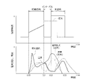
以下、初期通電と本通電とが順に行われることに伴う合金層Aおよび溶接ナゲットNの成形過程の概略について説明する。図5は、溶接電流値(初期通電での電流値および本通電での電流値)の推移(図5における上側の図)、および、それに伴う溶接ナゲットNの成形領域での電気抵抗値および温度の変化の一例(図5における下側の図)を示す図である。下側の図では、本実施形態における電気抵抗値を太い実線で示し、温度を細い実線で示している。また、従来技術との比較を容易にするために、上側の図では、従来技術における溶接電流値の推移を破線で示し、下側の図では、従来技術における電気抵抗値を太い破線で示し、温度を細い破線で示している。 The outline of the forming process of the alloy layer A and the weld nugget N accompanying the initial energization and the main energization in order will be described below. Fig. 5 shows transitions in the welding current value (the current value in the initial energization and the current value in the main energization) (the upper diagram in Fig. 5), and the accompanying electric resistance value and temperature in the forming region of the weld nugget N. 6 is a diagram showing an example of change in (lower diagram in FIG. 5). FIG. In the lower diagram, the electrical resistance value in this embodiment is indicated by a thick solid line, and the temperature is indicated by a thin solid line. In addition, in order to facilitate comparison with the conventional technology, the upper diagram shows the transition of the welding current value in the conventional technology with a dashed line, and the lower diagram shows the electric resistance value in the conventional technology with a thick dashed line. Temperature is indicated by a thin dashed line.
先ず、初期通電が開始され(図5におけるタイミングt10)、各鋼板W1,W2,W3が加熱されて、上部電極2と下部電極3との間の領域において各鋼板W1,W2,W3同士の境界部分の温度が上昇していく。この初期通電にあっては溶接電流値が予め設定された勾配によって次第に上昇(漸増)される(図5におけるタイミングt10~t11)。この際、実際には、材料抵抗差が大きくなっている鋼板W1,W2同士の間の界面において抵抗が大きくなることに伴って発熱量が大きくなっている。
First, the initial energization is started (timing t10 in FIG. 5), the steel plates W1, W2, W3 are heated, and the boundaries between the steel plates W1, W2, W3 are formed in the region between the
この初期通電の具体的な一例としては、1~50cyc(サイクル)、好ましくは2~40cycの時間で、1.5~10kA、好ましくは2~8kAの範囲の所定の電流値から通電が開始され、この初期通電の開始時の電流値に対して1.05~2.5倍程度の電流値まで次第に上昇されるものとなっている。これらの値はこれに限定されるものではなく、初期通電の通電期間において要求される合金層Aおよび溶接ナゲットNそれぞれの大きさや成長速度が達成できるように実験やシミュレーションによって適宜設定される。 As a specific example of this initial energization, energization is started from a predetermined current value in the range of 1.5 to 10 kA, preferably 2 to 8 kA, for a period of 1 to 50 cyc (cycle), preferably 2 to 40 cyc. , the current value is gradually increased to about 1.05 to 2.5 times the current value at the start of the initial energization. These values are not limited to these, and are appropriately set through experiments and simulations so that the sizes and growth rates of the alloy layer A and the welding nugget N required during the energization period of the initial energization can be achieved.
そして、この初期通電による各鋼板W1,W2,W3同士の境界部分の温度上昇に伴い、各鋼板W1,W2,W3の表面のめっき層を構成している亜鉛と各鋼板W1,W2,W3の基材を構成している鉄とが高温反応することで合金が生成される。具体的には表面層(めっき層)の主成分である亜鉛を各鋼板W1,W2,W3の基材(鉄)に拡散させ、両成分から決定される固相線温度を上昇させることにより行われる。 As the temperatures at the boundaries between the steel sheets W1, W2, and W3 rise due to this initial energization, the zinc forming the coating layers on the surfaces of the steel sheets W1, W2, and W3 and the steel sheets W1, W2, and W3 An alloy is produced by a high-temperature reaction with the iron that constitutes the base material. Specifically, zinc, which is the main component of the surface layer (coating layer), is diffused into the base material (iron) of each of the steel sheets W1, W2, and W3, and the solidus temperature determined by both components is increased. will be
この初期通電が継続されることで、この合金によって成形される合金層Aが成長していき、該合金層Aの外形寸法が大きくなっていく。 By continuing this initial energization, the alloy layer A formed by this alloy grows and the external dimensions of the alloy layer A increase.
更に初期通電が継続されると、合金層Aの中央部において鉄が溶融することによる溶接ナゲットNの生成が開始される。つまり、溶融金属の中心部分には鉄による溶接ナゲットN(溶融状態の鉄)が、該溶接ナゲットNの外周側には合金層Aがそれぞれ生成され、これら溶接ナゲットNおよび合金層Aが拡大していくことになる。なお、この溶接ナゲットN(溶融状態の鉄)の領域では温度が約1400℃程度になっている。 When the initial energization is further continued, iron melts in the central portion of the alloy layer A, thereby starting the formation of a weld nugget N. That is, a weld nugget N (molten iron) made of iron is formed in the central portion of the molten metal, and an alloy layer A is formed on the outer peripheral side of the weld nugget N, and the weld nugget N and the alloy layer A expand. I will go. The temperature in the area of the welding nugget N (molten iron) is approximately 1400°C.
そして、図5におけるタイミングt11において初期通電が終了し、この時点から電極間の通電を停止する。この電極間の通電を停止する目的は、前記成形された溶接ナゲットNの冷却期間を設け、これによって、この溶接ナゲットNが成形されている領域での電気抵抗値を低くすることである。図5の下側の図からも解るように、初期通電が終了し電極間の通電を停止した時点から温度が低下し始め、それに伴って電気抵抗も低下している。 Then, the initial energization ends at timing t11 in FIG. 5, and the energization between the electrodes is stopped from this point. The purpose of stopping the current flow between the electrodes is to provide a cooling period for the formed weld nugget N, thereby lowering the electrical resistance in the region where the weld nugget N is formed. As can be seen from the lower part of FIG. 5, the temperature begins to drop when the initial energization is completed and the energization between the electrodes is stopped, and the electrical resistance is accordingly lowered.
この初期通電を終了させるタイミング(図5におけるタイミングt11)としては、各鋼板W1,W2,W3の延在方向に平行な方向での溶接ナゲットNの外形寸法および合金層Aの外形寸法の関係が、以下の式(1)
1.2≦合金層の外形寸法/溶接ナゲットの外形寸法≦1.5 …(1)
となっている状態で、初期通電を終了させるように設定されている。
As for the timing (timing t11 in FIG. 5) to end this initial energization, the relationship between the external dimensions of the welding nugget N and the external dimensions of the alloy layer A in the direction parallel to the extending direction of each of the steel plates W1, W2, and W3 is , the following equation (1)
1.2 ≤ external dimension of alloy layer / external dimension of welding nugget ≤ 1.5 (1)
It is set so that the initial energization is terminated in this state.
具体的には、前述したように溶接ナゲットNの成形が開始されると、合金層Aの成長と共に溶接ナゲットNも成長していく。溶接ナゲットNの成形が開始された初期時にあっては、溶接ナゲットNの外形寸法に対して合金層Aの外形寸法が大幅に大きくなっている。そして、溶接ナゲットNの成形が開始された後、所定期間を経過すると、合金層Aの外形寸法の拡大速度に対して、溶接ナゲットNの外形寸法の拡大速度が大きくなっていき、溶接ナゲットNの外形寸法に対する合金層Aの外形寸法の比率が1.5以下の値となる。本実施形態では、この溶接ナゲットNの外形寸法に対する合金層Aの外形寸法の比率が1.2以上で且つ1.5以下の範囲にある状態で初期通電を終了させるようにしている。例えば前記比率が1.3となったタイミングで初期通電を終了させるようにしている。この初期通電を終了させるタイミングは前記比率が1.3となったタイミングに限定されるものではなく、前述したように1.2以上で且つ1.5以下の範囲における任意の値に設定可能である。 Specifically, when the formation of the weld nugget N is started as described above, the weld nugget N grows together with the growth of the alloy layer A. At the initial stage when forming of the weld nugget N is started, the external dimensions of the alloy layer A are significantly larger than the external dimensions of the weld nugget N. Then, after a predetermined period of time has passed since the welding nugget N started to be formed, the speed of expansion of the external dimensions of the weld nugget N becomes greater than the speed of expansion of the external dimensions of the alloy layer A, and the welding nugget N The ratio of the outer dimensions of the alloy layer A to the outer dimensions of the alloy layer A is 1.5 or less. In this embodiment, the initial energization is terminated when the ratio of the external dimensions of the alloy layer A to the external dimensions of the welding nugget N is in the range of 1.2 or more and 1.5 or less. For example, the initial energization is terminated when the ratio becomes 1.3. The timing for ending the initial energization is not limited to the timing when the ratio becomes 1.3, but can be set to any value within the range of 1.2 or more and 1.5 or less as described above. be.
初期通電を終了させるタイミングにおける溶接ナゲットNの外形寸法に対する合金層Aの外形寸法の比率を式(1)のように規定した理由について説明すると、この比率が1.2未満であった場合には、本通電の開始に伴って溶接ナゲットNが更に拡大することに起因してスパッタが発生してしまう可能性があるためであり、この値は実験やシミュレーションによって求められた値である。また、この比率が1.5を超えている場合には、本通電によって十分な大きさの溶接ナゲットNを成形することが困難になり、鋼板W1,W2,W3同士の接合強度を十分に確保することができないためであり、この値も実験やシミュレーションによって求められた値である。 The reason why the ratio of the external dimensions of the alloy layer A to the external dimensions of the welding nugget N at the timing of ending the initial energization is defined as in formula (1) is as follows. This is because there is a possibility that spatter will occur due to further expansion of the welding nugget N with the start of main energization, and this value is obtained by experiments and simulations. In addition, when this ratio exceeds 1.5, it becomes difficult to form a sufficiently large welding nugget N by main energization, and the bonding strength between the steel plates W1, W2, and W3 is sufficiently secured. This value is also obtained through experiments and simulations.
また、この初期通電の終了時点において要求される溶接ナゲットNの外形寸法は、各鋼板W1,W2,W3の材質、板厚、要求される接合強度等に応じて予め実験的に設定されている。例えば、最終的に得ようとする溶接ナゲットNの外形寸法(本通電終了時の外形寸法)に対して約1/2程度の外形寸法に達するまで初期通電は継続されることになる。この値はこれに限定されるものではなく、適宜設定される。 Further, the outer dimensions of the welding nugget N required at the end of the initial energization are experimentally set in advance according to the material, plate thickness, required joint strength, etc. of the steel plates W1, W2, and W3. . For example, the initial energization is continued until the outer dimensions of the welding nugget N to be finally obtained (the outer dimensions at the end of the main energization) reach about 1/2. This value is not limited to this, and is set as appropriate.
このようにして前記比率が1.2以上で且つ1.5以下の範囲となっている状態で初期通電を終了させ、この時点から電極間の通電を停止する。つまり、初期通電と本通電との間に通電の停止期間であるインターバルを設ける。このインターバル(通電の停止期間;図5におけるタイミングt11~t12)は、例えば5~20cyc、好ましくは8~15cycの時間に設定される。これら値はこれに限定されるものではない。 In this way, the initial energization is terminated when the ratio is in the range of 1.2 or more and 1.5 or less, and the energization between the electrodes is stopped from this point. In other words, an interval is provided between the initial energization and the main energization. This interval (the period during which energization is stopped; timings t11 to t12 in FIG. 5) is set to, for example, 5 to 20 cyc, preferably 8 to 15 cyc. These values are not limited to this.
そして、所定のインターバルが経過した後、本通電が開始される(タイミングt12)。この本通電での電流値は、初期通電の通電期間における最大電流値よりも高い電流値に設定されている。つまり、前述の如く所定の勾配で上昇されていく初期通電の電流値の最終電流値に対し、更に電流値が上昇されることで本通電に移行されることになる。この本通電での電流値として具体的には、初期通電の最終電流値に対して0.1~8.0kAの範囲、好ましくは1.0~5.0kAの範囲から設定される所定値だけ高い値に設定される。この最終電流値の具体的な一例としては、表面抵抗の高い材料の場合は、小さい値を用いるのが好適である。この値はこれに限定されるものではなく、所定期間内に所定の大きさの合金層Aおよび溶接ナゲットNが成形されるように実験やシミュレーションによって適宜設定される。 Then, after a predetermined interval has passed, main energization is started (timing t12). The current value in this main energization is set to a current value higher than the maximum current value in the energization period of the initial energization. That is, as described above, the main energization is started by further increasing the current value with respect to the final current value of the current value of the initial energization which is increased at a predetermined gradient. Specifically, the current value in this main energization is a predetermined value set from the range of 0.1 to 8.0 kA, preferably 1.0 to 5.0 kA, with respect to the final current value of the initial energization. set to a high value. As a specific example of this final current value, it is preferable to use a small value in the case of a material with high surface resistance. This value is not limited to this value, and is appropriately set through experiments and simulations so that the alloy layer A and the welding nugget N of a predetermined size are formed within a predetermined period of time.
この本通電が開始されることにより、更に溶接ナゲットNおよび合金層Aが拡大していく。また、この本通電に先立って前述したインターバルが設けられて、温度の低下および電気抵抗の低下がなされていることにより、当該本通電の実施期間中においても温度や電気抵抗の過上昇は抑えられることになる。 By starting this main energization, the welding nugget N and the alloy layer A further expand. In addition, since the above-described interval is provided prior to the main energization to reduce the temperature and the electrical resistance, an excessive increase in temperature and electrical resistance can be suppressed even during the period of the main energization. It will be.
そして、この本通電が所定期間継続(図5におけるタイミングt12~t13)されることで、所定の外形寸法を有する溶接ナゲットNおよび合金層Aが成形されることになる。例えば、各鋼板W1,W2,W3全体の板厚寸法をtとした場合に、溶接ナゲットNの外形寸法が3√t以上に達するまで本通電が継続されることになる。その後、本通電が終了され、溶接ナゲットNおよび合金層Aが凝固し、所定の溶接部分が成形されることになる。 By continuing this energization for a predetermined period (timings t12 to t13 in FIG. 5), the welding nugget N and the alloy layer A having predetermined external dimensions are formed. For example, if the total plate thickness of each of the steel plates W1, W2, and W3 is t, main energization is continued until the external size of the welding nugget N reaches 3√t or more. After that, the main energization is terminated, the weld nugget N and the alloy layer A are solidified, and a predetermined welded portion is formed.
前記インターバルが経過した後に実施される本通電では、前述したように初期通電の通電期間における最大電流値よりも僅かに高い電流値であって、一定の溶接電流が通電され、これによって、前述したように、溶接ナゲットNおよび合金層Aが更に拡大していく。この際の本通電での溶接電流値の値は、前記式(1)が成立し続けるように、つまり、溶接ナゲットNの外形寸法に対する合金層Aの外形寸法の比率が1.2を下回ることがないように、予め実験またはシミュレーションによって設定されている。 In the main energization performed after the interval has elapsed, a constant welding current is energized that is slightly higher than the maximum current value in the energization period of the initial energization as described above. , the weld nugget N and the alloy layer A further expand. The value of the welding current value in the main energization at this time is such that the above formula (1) continues to hold, that is, the ratio of the external dimensions of the alloy layer A to the external dimensions of the welding nugget N is less than 1.2. It is set in advance by experiments or simulations so that there is no
従来技術にあっては、他の鋼板に対して電気抵抗値が異なる少なくとも1枚の鋼板を含む3枚以上の鋼板を互いに重ね合わせて抵抗スポット溶接を行う場合、初期通電を開始した際、材料抵抗差が大きくなっている鋼板同士の間の界面にあっては、他の鋼板同士の間の界面よりも抵抗が大きくなることに伴って発熱量が大きくなる。その結果、この界面の周辺では他の界面の周辺よりも早期に溶接ナゲットの成形が開始されることになる。そして、材料抵抗は温度が高いほど大きくなるため、この早期に溶接ナゲットが成形される部分(発熱量が大きくなっている部分)では、その後の本通電の開始に伴って溶接ナゲットが更に拡大し、スパッタが発生してしまう可能性があった。このため、スパッタの発生を抑制するためには、本通電における溶接電流値を低く抑える必要があった。つまり、本通電での溶接電流値におけるスパッタ発生限界が低くなってしまい、効率良く溶接ナゲットを成形することが困難であった。 In the prior art, when three or more steel plates including at least one steel plate having a different electrical resistance value with respect to other steel plates are superimposed and resistance spot welding is performed, when the initial energization is started, the material At the interface between steel plates with a large resistance difference, the amount of heat generated increases as the resistance increases compared to the interface between other steel plates. As a result, the formation of the weld nugget begins earlier around this interface than around other interfaces. Since the material resistance increases as the temperature rises, the weld nugget expands further at the portion where the weld nugget is formed at this early stage (the portion where the amount of heat generated is large) as the main energization is started thereafter. , there was a possibility that spatter would occur. Therefore, in order to suppress the generation of spatter, it was necessary to keep the welding current value in the main energization low. In other words, the spatter generation limit at the welding current value in the main energization is lowered, making it difficult to form the welding nugget efficiently.
これに対し、本実施形態にあっては、前述したように、前記式(1)が成立した状態にあっては、合金層Aの外形寸法T1と溶接ナゲットNの外形寸法T2との比が適正に維持される(鋼板W1,W2,W3同士の接合強度を十分に確保しながらも、溶接ナゲットNが大きくなり過ぎる状態にはない)ことによってスパッタは発生し難くなっている。また、この状態で電極間の通電を停止し、この通電の停止期間である所定のインターバルが経過するまで本通電の開始を遅延させているため、前記成形された溶接ナゲットNが、このインターバルの間に冷却されることになる。つまり、この溶接ナゲットNが成形されている領域での電気抵抗値が低くなる。このため、その後に本通電を開始しても、電気抵抗値が高いことに起因して局部的に溶接ナゲットNが拡大してしまうといったことは抑制されて、スパッタの発生を抑制することができる。つまり、本通電での溶接電流値におけるスパッタ発生限界を高くすることができ(従来技術に比べてスパッタ発生限界を高くすることができ)、スパッタの発生を抑制しながらも効率良く溶接ナゲットNを成形することが可能になる。 On the other hand, in the present embodiment, as described above, when the formula (1) is established, the ratio between the outer dimension T1 of the alloy layer A and the outer dimension T2 of the weld nugget N is Spatter is less likely to occur because the welding nugget N is properly maintained (the welding nugget N is not excessively large while ensuring sufficient bonding strength between the steel plates W1, W2, and W3). In this state, the energization between the electrodes is stopped, and the start of the main energization is delayed until the predetermined interval, which is the period during which the energization is stopped, has passed. It will be cooled in between. In other words, the electric resistance value in the region where this weld nugget N is formed becomes low. Therefore, even if the main energization is started after that, local expansion of the welding nugget N due to the high electrical resistance value is suppressed, and the occurrence of spatter can be suppressed. . In other words, it is possible to increase the spatter generation limit at the welding current value in the main energization (the spatter generation limit can be increased compared to the conventional technology), and the welding nugget N can be efficiently removed while suppressing the generation of spatter. It is possible to mold.
-実験例-
次に、前述した効果を確認するために行った実験例について説明する。この実験例では、前記インターバルを設けない場合とインターバルを設けた場合とのそれぞれについて合金層Aおよび溶接ナゲットNの形状を比較するものとした。
-Experimental example-
Next, an example of an experiment conducted to confirm the above effects will be described. In this experimental example, the shapes of the alloy layer A and the welding nugget N were compared between the case where the interval was not provided and the case where the interval was provided.
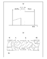
図6は、比較例として初期通電と本通電との間にインターバルを設けない場合における、溶接電流値の推移(図6(a))、合金層Aおよび溶接ナゲットNの形状の一例を示す各鋼板W1,W2,W3の断面図(図6(b))である。また、図7は、初期通電と本通電との間にインターバルを設けた場合であって、そのインターバルを比較的短くした場合における、溶接電流値の推移(図7(a))、合金層Aおよび溶接ナゲットNの形状の一例を示す各鋼板W1,W2,W3の断面図(図7(b))である。また、図8は、初期通電と本通電との間にインターバルを設けた場合であって、そのインターバルを比較的長くした場合における、溶接電流値の推移(図8(a))、合金層Aおよび溶接ナゲットNの形状の一例を示す各鋼板W1,W2,W3の断面図(図8(b))である。また、これら比較例および各実施形態にあっては、初期通電の期間を互いに同一(例えば20cyc)とし、本通電の期間も互いに同一(例えば30cyc)とした。 FIG. 6 shows transitions in welding current values (FIG. 6(a)) and an example of the shapes of the alloy layer A and the welding nugget N when no interval is provided between the initial energization and the main energization as a comparative example. It is sectional drawing (FIG.6(b)) of the steel plates W1, W2, and W3. Moreover, FIG. 7 shows the transition of the welding current value (FIG. 7(a)) and the alloy layer A when an interval is provided between the initial energization and the main energization, and the interval is relatively short. 7A and 7B are cross-sectional views of the steel plates W1, W2, and W3 showing an example of the shape of the welding nugget N (FIG. 7B). Moreover, FIG. 8 shows the transition of the welding current value (FIG. 8(a)) and the alloy layer A when an interval is provided between the initial energization and the main energization, and the interval is relatively long. 8A and 8B are cross-sectional views of steel plates W1, W2, and W3 showing an example of the shape of a welding nugget N (FIG. 8B). Further, in these comparative examples and each embodiment, the initial energization period is set to be the same (for example, 20 cyc), and the main energization period is also set to be the same (for example, 30 cyc).
また、溶接電流値として具体的には、図6の比較例にあっては、初期通電の開始電流値を2.0kA、最終電流値を5.0kAとし、本通電の電流値を5.5kAとした。図7の実施形態にあっては、初期通電の開始電流値を2.0kA、最終電流値を5.0kAとし、本通電の電流値を6.0kAとした。また、インターバルを9cycとした。図8の実施形態にあっては、初期通電の開始電流値を2.0kA、最終電流値を5.0kAとし、本通電の電流値を7.0kAとした。また、インターバルを10cycとした。比較例および各実施形態それぞれにおける本通電の電流値は、スパッタ発生限界に相当する値としてそれぞれ規定されたものである。 As for the welding current value, specifically, in the comparative example of FIG. and In the embodiment of FIG. 7, the starting current value of the initial energization was 2.0 kA, the final current value was 5.0 kA, and the current value of the main energization was 6.0 kA. Also, the interval was set to 9 cyc. In the embodiment of FIG. 8, the starting current value for initial energization was 2.0 kA, the final current value was 5.0 kA, and the current value for main energization was 7.0 kA. Also, the interval was set to 10 cyc. The current value of main energization in each of the comparative example and each of the embodiments is defined as a value corresponding to the limit of spatter generation.
各図における溶接ナゲットNの形状を比較すると、図6の比較例のものに比べて図7の実施形態のものの方が大型の溶接ナゲットNが成形されている。具体的に、図6の比較例にあっては溶接ナゲットNの外形寸法が約4.0mmであり、図7の実施形態にあっては溶接ナゲットNの外形寸法が約5.2mmであった。つまり、図6の比較例のものでは、スパッタを発生させないために初期通電の最終電流値に対して本通電での電流値を0.5kAしか高めることができないのに対し、図7の実施形態のものでは、初期通電の最終電流値に対して本通電での電流値を1.0kA高めることができ、これによって、大型の(外形寸法が大きい)溶接ナゲットNを成形することができている。 Comparing the shapes of the weld nuggets N in each figure, the larger weld nugget N is formed in the embodiment of FIG. 7 than in the comparative example of FIG. Specifically, in the comparative example of FIG. 6, the outer dimension of the weld nugget N is about 4.0 mm, and in the embodiment of FIG. 7, the outer dimension of the weld nugget N is about 5.2 mm. . That is, in the comparative example of FIG. 6, the current value in the main energization can be increased by only 0.5 kA with respect to the final current value in the initial energization in order not to generate spatter, whereas the embodiment of FIG. In the case, the current value in the main energization can be increased by 1.0 kA relative to the final current value in the initial energization, and as a result, a large-sized (large external dimension) welding nugget N can be formed. .
また、図7の実施形態のものに比べて図8の実施形態のものの方が大型の溶接ナゲットNが成形されている。具体的に、図8の実施形態にあっては溶接ナゲットNの外形寸法が約5.8mmであった。つまり、図8の実施形態のものでは、初期通電の最終電流値に対して本通電での電流値を2.0kA高めることができ、これによって、より大型の(外形寸法が大きい)溶接ナゲットNを成形することができている。 Also, the weld nugget N is formed larger in the embodiment of FIG. 8 than in the embodiment of FIG. Specifically, in the embodiment of FIG. 8, the outside dimension of the weld nugget N was approximately 5.8 mm. That is, in the embodiment shown in FIG. 8, the current value in the main energization can be increased by 2.0 kA relative to the final current value in the initial energization. can be molded.
このように、インターバルを設けないものに比べてインターバルを設けた方がスパッタ発生限界の電流値が高くなることで溶接ナゲットNの大型化を図ることができ、また、インターバルを長く設けるほどスパッタ発生限界の電流値が高くなることで溶接ナゲットNの更なる大型化を図ることができることが確認できた。これにより、本実施形態の効果を確認することができた。 In this way, when the interval is provided compared to when the interval is not provided, the current value at the spatter generation limit becomes higher, so that the size of the welding nugget N can be increased. It has been confirmed that the welding nugget N can be further enlarged by increasing the limit current value. As a result, the effect of this embodiment could be confirmed.
-他の実施形態-
なお、本発明は、前記実施形態に限定されるものではなく、特許請求の範囲および該範囲と均等の範囲で包含される全ての変形や応用が可能である。
-Other embodiments-
It should be noted that the present invention is not limited to the above-described embodiments, and all modifications and applications within the scope of the claims and their equivalents are possible.
例えば、前記実施形態では、自動車の車体の製造に利用される抵抗スポット溶接に本発明を適用した場合について説明した。本発明はこれに限らず、その他の製品の製造に利用される抵抗スポット溶接に対しても適用が可能である。 For example, in the above-described embodiment, the case where the present invention is applied to resistance spot welding used for manufacturing automobile bodies has been described. The present invention is not limited to this, and can be applied to resistance spot welding used for manufacturing other products.
また、前記実施形態では、亜鉛を主成分とするめっき層を有する鋼板W1,W2,W3同士を抵抗スポット溶接する場合について説明した。本発明はこれに限らず、Al-Siめっき層を有する鋼板同士を抵抗スポット溶接する場合にも適用することが可能である。また、亜鉛酸化膜を表面層として有する鋼板同士を抵抗スポット溶接する場合にも適用することが可能である。 Further, in the above-described embodiment, the case where the steel sheets W1, W2, and W3 having the plating layer containing zinc as a main component are resistance spot-welded has been described. The present invention is not limited to this, and can also be applied to resistance spot welding of steel plates having Al—Si plating layers. It can also be applied to resistance spot welding of steel sheets having a zinc oxide film as a surface layer.
また、前記実施形態では、全ての鋼板W1,W2,W3が、その表面にめっき層を有するものであった。本発明はこれに限らず、一部の鋼板のみが、その表面にめっき層を有するものであってもよい。 Moreover, in the above-described embodiment, all the steel sheets W1, W2, and W3 have a plated layer on their surfaces. The present invention is not limited to this, and only some steel sheets may have a plating layer on the surface thereof.
本発明は、他の鋼板に対して電気抵抗値が異なる少なくとも1枚の鋼板を含む3枚以上の鋼板を互いに重ね合わせて接合する抵抗スポット溶接方法に適用可能である。 INDUSTRIAL APPLICABILITY The present invention is applicable to a resistance spot welding method in which three or more steel plates including at least one steel plate having an electrical resistance value different from that of another steel plate are overlapped and joined together.
2 上部電極
3 下部電極
6 電流調整装置
10 制御装置
13 電流値算出部
W1,W2,W3 鋼板
N 溶接ナゲット
A 合金層
2
Claims (1)
前記初期通電により、前記各鋼板の基材を構成している鉄が溶融した後に冷却されることで成形され且つ前記初期通電の継続に伴って前記各鋼板の延在方向に平行な方向での外形寸法が拡大していく溶接ナゲットにおける当該外形寸法、および、該溶接ナゲットの外側に成形され且つ前記各鋼板の表面に存在するめっき層の構成材料を前記鉄に拡散させて両成分から決定される固相線温度を上昇させることにより生成され前記初期通電の継続に伴って前記方向での外形寸法が拡大していく合金層における当該外形寸法の関係が、以下の式(1)
1.2≦合金層の外形寸法/溶接ナゲットの外形寸法≦1.5 …(1)
となっている状態で、前記電極間の通電を停止することにより、前記初期通電と前記本通電との間に通電の停止期間であるインターバルを設けることを特徴とする抵抗スポット溶接方法。 Three or more steel plates including at least one steel plate having an electrical resistance value different from that of other steel plates are superimposed on each other, these steel plates are sandwiched between electrodes, and the welding current value is gradually increased between the electrodes. In a resistance spot welding method in which the steel plates are melted and joined together by performing a main energization at a current value higher than the maximum current value in the energization period of the initial energization after performing several initial energizations,
Due to the initial energization, the iron constituting the base material of each steel plate is melted and then cooled to be shaped, and with the continuation of the initial energization , the The outer dimensions of the welding nugget whose outer dimensions are increasing , and the constituent material of the plating layer formed on the outside of the welding nugget and existing on the surface of each steel plate are diffused into the iron and are determined from both components. The relationship between the outer dimensions of the alloy layer , which is generated by increasing the solidus temperature and whose outer dimensions in the above direction increase with the continuation of the initial energization, is expressed by the following equation (1).
1.2 ≤ external dimension of alloy layer / external dimension of welding nugget ≤ 1.5 (1)
A resistance spot welding method characterized by providing an interval, which is an energization stop period, between the initial energization and the main energization by stopping the energization between the electrodes in this state.
Priority Applications (1)
| Application Number | Priority Date | Filing Date | Title |
|---|---|---|---|
| JP2019209877A JP7201570B2 (en) | 2019-11-20 | 2019-11-20 | Resistance spot welding method |
Applications Claiming Priority (1)
| Application Number | Priority Date | Filing Date | Title |
|---|---|---|---|
| JP2019209877A JP7201570B2 (en) | 2019-11-20 | 2019-11-20 | Resistance spot welding method |
Publications (2)
| Publication Number | Publication Date |
|---|---|
| JP2021079416A JP2021079416A (en) | 2021-05-27 |
| JP7201570B2 true JP7201570B2 (en) | 2023-01-10 |
Family
ID=75963690
Family Applications (1)
| Application Number | Title | Priority Date | Filing Date |
|---|---|---|---|
| JP2019209877A Active JP7201570B2 (en) | 2019-11-20 | 2019-11-20 | Resistance spot welding method |
Country Status (1)
| Country | Link |
|---|---|
| JP (1) | JP7201570B2 (en) |
Families Citing this family (4)
| Publication number | Priority date | Publication date | Assignee | Title |
|---|---|---|---|---|
| WO2023008263A1 (en) * | 2021-07-30 | 2023-02-02 | Jfeスチール株式会社 | Resistance spot welding method |
| JP7364113B2 (en) * | 2021-11-02 | 2023-10-18 | Jfeスチール株式会社 | Resistance spot welding member and its resistance spot welding method |
| WO2023228924A1 (en) * | 2022-05-24 | 2023-11-30 | トヨタ自動車株式会社 | Resistance spot welding method |
| CN115055797B (en) * | 2022-05-28 | 2023-10-31 | 一汽丰田汽车(成都)有限公司长春丰越分公司 | Method capable of eliminating splashing generated by robot resistance welding |
Citations (6)
| Publication number | Priority date | Publication date | Assignee | Title |
|---|---|---|---|---|
| JP2003236674A (en) | 2002-02-15 | 2003-08-26 | Mazda Motor Corp | Method and equipment of spot welding of high tensile steel |
| JP2010247215A (en) | 2009-04-20 | 2010-11-04 | Sumitomo Metal Ind Ltd | Resistance welding method of high tensile steel sheet |
| WO2014045431A1 (en) | 2012-09-24 | 2014-03-27 | 新日鐵住金株式会社 | Spot welding method for high-strength steel sheet excellent in joint strength |
| WO2015049998A1 (en) | 2013-10-04 | 2015-04-09 | Jfeスチール株式会社 | Resistance spot welding method |
| US20160016252A1 (en) | 2014-07-16 | 2016-01-21 | Honda Motor Co., Ltd. | Method and apparatus for resistive spot welding |
| JP2018171649A (en) | 2017-03-31 | 2018-11-08 | Jfeスチール株式会社 | Resistance spot-welding method and welding condition determination method for resistance spot welding |
-
2019
- 2019-11-20 JP JP2019209877A patent/JP7201570B2/en active Active
Patent Citations (6)
| Publication number | Priority date | Publication date | Assignee | Title |
|---|---|---|---|---|
| JP2003236674A (en) | 2002-02-15 | 2003-08-26 | Mazda Motor Corp | Method and equipment of spot welding of high tensile steel |
| JP2010247215A (en) | 2009-04-20 | 2010-11-04 | Sumitomo Metal Ind Ltd | Resistance welding method of high tensile steel sheet |
| WO2014045431A1 (en) | 2012-09-24 | 2014-03-27 | 新日鐵住金株式会社 | Spot welding method for high-strength steel sheet excellent in joint strength |
| WO2015049998A1 (en) | 2013-10-04 | 2015-04-09 | Jfeスチール株式会社 | Resistance spot welding method |
| US20160016252A1 (en) | 2014-07-16 | 2016-01-21 | Honda Motor Co., Ltd. | Method and apparatus for resistive spot welding |
| JP2018171649A (en) | 2017-03-31 | 2018-11-08 | Jfeスチール株式会社 | Resistance spot-welding method and welding condition determination method for resistance spot welding |
Also Published As
| Publication number | Publication date |
|---|---|
| JP2021079416A (en) | 2021-05-27 |
Similar Documents
| Publication | Publication Date | Title |
|---|---|---|
| JP7201570B2 (en) | Resistance spot welding method | |
| CN107000109B (en) | Resistance spot welding method | |
| CN108857013B (en) | Spot welding method | |
| US8253056B2 (en) | Resistance welding method and resistance welding apparatus | |
| US20150352658A1 (en) | Intruding feature in aluminum alloy workpiece to improve al-steel spot welding | |
| US10946470B2 (en) | Resistance spot welding method and welded member production method | |
| CN104511687A (en) | Resistance spot welding steel and aluminum workpiece with hot welding electrode at aluminum workpiece | |
| JP7376458B2 (en) | Resistance spot welding method | |
| JP5261984B2 (en) | Resistance spot welding method | |
| KR20190014073A (en) | Resistance spot welding method | |
| JP2011088197A (en) | Different material joined body and different material resistance spot welding method | |
| EP3342524B1 (en) | Resistance spot welding method and method for manufacturing welded member | |
| KR102303694B1 (en) | Resistance spot welding method and weld member production method | |
| JP5609966B2 (en) | Resistance spot welding method | |
| US11135671B2 (en) | Resistance spot welding method | |
| US20080041922A1 (en) | Hybrid Resistance/Ultrasonic Welding System and Method | |
| JP7201569B2 (en) | Resistance spot welding method | |
| JP7242112B2 (en) | Solid point welding method and solid point welding apparatus | |
| KR101771147B1 (en) | Welding power control method, apparatus and computer-readable medium recording the method | |
| WO2021070835A1 (en) | Resistance spot welding method and method for manufacturing welded member | |
| JP6913062B2 (en) | Resistance spot welding method and welding member manufacturing method | |
| CN112638567B (en) | Method for producing at least one defined connection layer between two components made of different metals | |
| JP6904479B2 (en) | Resistance spot welding method and welding member manufacturing method | |
| WO2024057602A1 (en) | Resistance spot welding method | |
| JP7360610B2 (en) | Spot welding method |
Legal Events
| Date | Code | Title | Description |
|---|---|---|---|
| A621 | Written request for application examination |
Free format text: JAPANESE INTERMEDIATE CODE: A621 Effective date: 20211111 |
|
| A977 | Report on retrieval |
Free format text: JAPANESE INTERMEDIATE CODE: A971007 Effective date: 20220930 |
|
| A131 | Notification of reasons for refusal |
Free format text: JAPANESE INTERMEDIATE CODE: A131 Effective date: 20221004 |
|
| A521 | Request for written amendment filed |
Free format text: JAPANESE INTERMEDIATE CODE: A523 Effective date: 20221118 |
|
| TRDD | Decision of grant or rejection written | ||
| A01 | Written decision to grant a patent or to grant a registration (utility model) |
Free format text: JAPANESE INTERMEDIATE CODE: A01 Effective date: 20221206 |
|
| A61 | First payment of annual fees (during grant procedure) |
Free format text: JAPANESE INTERMEDIATE CODE: A61 Effective date: 20221222 |
|
| R151 | Written notification of patent or utility model registration |
Ref document number: 7201570 Country of ref document: JP Free format text: JAPANESE INTERMEDIATE CODE: R151 |