JP7200811B2 - Steel continuous casting method - Google Patents
Steel continuous casting method Download PDFInfo
- Publication number
- JP7200811B2 JP7200811B2 JP2019076463A JP2019076463A JP7200811B2 JP 7200811 B2 JP7200811 B2 JP 7200811B2 JP 2019076463 A JP2019076463 A JP 2019076463A JP 2019076463 A JP2019076463 A JP 2019076463A JP 7200811 B2 JP7200811 B2 JP 7200811B2
- Authority
- JP
- Japan
- Prior art keywords
- molten steel
- long nozzle
- tundish
- steel
- metallic inclusions
- Prior art date
- Legal status (The legal status is an assumption and is not a legal conclusion. Google has not performed a legal analysis and makes no representation as to the accuracy of the status listed.)
- Active
Links
Images


Description
本発明は、取鍋からタンディッシュに向けて溶鋼を注入し、このタンディッシュから連続鋳造用鋳型に前記溶鋼を供給し、鋳片を連続的に鋳造する鋼の連続鋳造方法に関するものである。 TECHNICAL FIELD The present invention relates to a steel continuous casting method in which molten steel is poured from a ladle into a tundish, supplied from the tundish to a mold for continuous casting, and cast slabs are continuously cast.
例えば、自動車用外板向け極低炭素鋼板、缶用低炭ブリキ鋼板向けの低炭アルミキルド鋼板、鋼管向け熱延鋼板、自動車用の構造部材等に用いられるハイテン鋼においては、高加工性や良好な表面形状が求められる。
これらの高加工性や良好な表面形状を実現するためには、鋼中の非金属介在物およびそれらを含む表面や内部欠陥が大きな課題となる。したがって、高加工性、良好な表面形状が必要な場合、溶鋼から非金属介在物を除去して清浄性を高めることが必要である。
For example, ultra-low-carbon steel sheets for automobile outer panels, low-carbon aluminum-killed steel sheets for low-carbon tinplates for cans, hot-rolled steel sheets for steel pipes, and high-tensile steel used for structural members for automobiles have high workability and good performance. A good surface shape is required.
Non-metallic inclusions in steel and surface and internal defects containing them are major issues in order to achieve such high workability and good surface shape. Therefore, when high workability and good surface shape are required, it is necessary to remove non-metallic inclusions from molten steel to improve cleanliness.
従来は、タンディッシュに堰を設けて溶鋼の上昇流を形成したり、連続鋳造の鋳型内で電磁ブレーキを用いて浸漬ノズルからの吐出流を制動させたりすることで、非金属介在物の浮上除去を行っていたが、十分に除去されておらず、非金属介在物が最終成品である薄鋼板まで持ち込まれ、有害なアルミナクラスターや、非金属介在物が一定量残存している。 Conventionally, non-metallic inclusions are floated by forming a weir in the tundish to form an upward flow of molten steel, or by braking the discharge flow from the submerged nozzle using an electromagnetic brake in the continuous casting mold. Although it was removed, it was not sufficiently removed, and the non-metallic inclusions were brought into the final product, the thin steel sheet, and a certain amount of harmful alumina clusters and non-metallic inclusions remained.
そこで、非金属介在物のさらなる除去を行うために、例えば、特許文献1~4に示すように、タンディッシュ内の溶鋼において非金属介在物の浮上分離を促進する技術が提案されている。
特許文献1においては、スラグ・非金属介在物起因の欠陥を生じさせないために、タンディッシュの注入流落下領域に凹部を形成して撹拌することによって、スラグの浮上を図るものである。
Therefore, in order to further remove non-metallic inclusions, for example, as shown in
In
特許文献2においては、タンディッシュに溶鋼を注入するロングノズルについて底部を持つ構造とするとともに横方向に開口した横孔を形成し、この横孔から溶鋼を吐出することによって上昇流を生じさせ、タンディッシュ内での非金属介在物の浮上を効果的に行う溶鋼注入方法を提案している。
特許文献3においては、特許文献2と同様に、ロングノズルの下端部を閉塞し、側面に上向きの吐出口を持つロングノズルを提案し、タンディッシュ内における溶鋼の滞留時間を長くし、非金属介在物の浮上分離を効果的に行うものとしている。
特許文献4においては、特許文献2、3と同様の考え方をもつものであり、ノズルに底とその周面に形成された吐出用開口部1個を持つロングノズルを提案することで、タンディッシュ内において溶鋼中の介在物が浮上するのに十分な時間を確保するようにしている。
In
Similarly to
ところで、特許文献1のように、タンディッシュに凹部を形成した場合には、連続鋳造が終わった後、タンディッシュ内に残存する溶鋼量が多くなり、溶鋼歩留の低下に繋がるため、実生産プロセスとしては、コスト的に成り立たない。
また、特許文献2~4に示すように、ロングノズルの下端を閉塞した場合には、取鍋から溶鋼の注入を開始する際に、大きな溶鋼静圧を持った運動量の大きな溶鋼落下によって大きな衝撃力がかかり、ロングノズルが損傷し、損傷したロングノズルの破片がタンディッシュ内に落下するトラブルが発生するおそれがあった。また、上述の衝撃力がロングノズルを把持する把持力よりも大きくなってロングノズルと取鍋下部に隙間があき、隙間から溶鋼が漏れるおそれがあった。このように、操業上の問題があるため、実用化が出来ていない。
By the way, when a concave portion is formed in the tundish as in
In addition, as shown in
本発明は、前述した状況に鑑みてなされたものであって、ロングノズルの損傷、溶鋼漏れ等のトラブルを生じさせずに、また、溶鋼歩留りも悪化させることなく、非金属介在物の除去を十分に行うことができ、清浄度の高い鋼鋳片を製造可能な鋼の連続鋳造方法を提供することを目的とする。 The present invention has been made in view of the above-mentioned circumstances, and is capable of removing non-metallic inclusions without causing problems such as damage to the long nozzle and leakage of molten steel, and without deteriorating the yield of molten steel. It is an object of the present invention to provide a continuous casting method for steel capable of sufficiently performing and producing steel slabs with high cleanliness.
上記課題を解決するために、本発明者らが鋭意検討した結果、以下に示すような知見を得た。
本発明者らは、上記課題を解決するためには、ロングノズルを活用することが重要であると考えた。すなわち、ロングノズル内で溶鋼を乱流、撹拌状態に保ち、微細な非金属介在物の凝集を促進する機能を持たせることを、損傷、溶鋼漏れ等のトラブルを生じさせずに活用する方法を見つけ出すことである。ロングノズル内で非金属介在物を凝集させて浮上しやすくすれば、タンディッシュに凹部を形成する必要がなくなるため、溶鋼歩留りも悪化させることなく、非金属介在物の除去を行うことができる。
そこで、ロングノズルの下方の溶鋼の吐出口を変化させて、ロングノズルの損傷、溶鋼漏れ等のトラブルを生じさせることなく、ロングノズル内の乱流、撹拌エネルギーを用いることによって、非金属介在物の凝集を促進して、非金属介在物を効率的に浮上分離して個数密度を減少させることができる、ロングノズルの形状を解明することを試みた。
In order to solve the above problems, the present inventors have made intensive studies, and as a result, have obtained the following findings.
The present inventors considered that it is important to utilize a long nozzle in order to solve the above problems. In other words, the long nozzle keeps the molten steel in a turbulent and stirred state, and has the function of promoting the agglomeration of fine non-metallic inclusions. It's about finding out. If the non-metallic inclusions are agglomerated in the long nozzle and easily floated, there is no need to form a recess in the tundish, so the non-metallic inclusions can be removed without lowering the molten steel yield.
Therefore, by changing the molten steel discharge port below the long nozzle and using the turbulent flow and stirring energy in the long nozzle without causing problems such as damage to the long nozzle and molten steel leakage, non-metallic inclusions can be eliminated. We tried to clarify the shape of the long nozzle, which promotes the agglomeration of the non-metallic inclusions and efficiently floats and separates the non-metallic inclusions to reduce the number density.
本発明者は、連続鋳造装置において低炭アルミキルド鋼を鋳造する際に、ロングノズル内溶鋼流速v(m/s)、および、ロングノズルの下方の溶鋼の吐出口を変化させて、取鍋、タンディッシュ、鋳片で、溶鋼メタルのサンプリング、鋳片サンプルの採取を行い、それらの成分分析、非金属介在物の調査、解析を詳細に行った。非金属介在物の調査は、スライム抽出法で行った。鋳片の表層から60mm程度の深さの位置にある介在物の集積帯位置から、サンプルを切り出して30μm以上の大きさの非金属介在物を捕集する網の中で、塩化第一鉄水溶液中で約500g電気分解を行って非金属介在物を電解抽出しスライムとして捕集した。捕集したスライムを水簸(水洗しながら非金属介在物のみを分離捕集すること)、分級したのちに、非金属介在物の粒径分布、最大粒径を求めた。 When casting low-carbon aluminum-killed steel in a continuous casting apparatus, the present inventor changed the molten steel flow velocity v (m/s) in the long nozzle and the molten steel discharge port below the long nozzle to change the ladle, In the tundish and slab, molten steel metal was sampled and slab samples were collected, and their component analysis and non-metallic inclusions were investigated and analyzed in detail. Investigation of non-metallic inclusions was carried out by the slime extraction method. A sample is cut from the position of the accumulation zone of inclusions at a depth of about 60 mm from the surface of the cast slab, and a ferrous chloride aqueous solution is added in a net that collects non-metallic inclusions with a size of 30 μm or more. About 500 g of the sludge was electrolyzed to extract non-metallic inclusions electrolytically and collect them as slime. The collected slime was elutriated (separating and collecting only non-metallic inclusions while washing with water), and after classification, the particle size distribution and maximum particle size of the non-metallic inclusions were determined.
鋭意研究の結果、取鍋下部に設置したロングノズル下方の溶鋼の吐出口に開口孔を有する底面部を設けることで、取鍋の溶鋼がロングノズル内を落下してくる運動エネルギーを止めることになり、その急激な運動エネルギーの変化がロングノズルの内部の溶鋼を乱流撹拌状態にして、非金属介在物の凝集を促進できるとともに、底面部に設けた開口孔の分、溶鋼の衝突力を低減することができ、ロングノズルの損傷や溶鋼漏れを防止できることを知見した。
また、底面開口孔の開口面積を大きくしすぎると、ロングノズル内での溶鋼の乱流状態が不十分になり、底面開口孔の開口面積を小さくしすぎると、溶鋼が落下する運動エネルギーによる衝突力で、ロングノズルが損傷したり、溶鋼漏れが発生したりして、操業トラブルとなるため、両者を両立するためには底面開口孔の開口面積を適正化することが重要であることを知見した。
As a result of intensive research, the kinetic energy of the molten steel from the ladle falling through the long nozzle was stopped by providing a bottom part with an opening at the molten steel discharge port below the long nozzle installed at the bottom of the ladle. The rapid change in kinetic energy makes the molten steel inside the long nozzle into a turbulent stirring state, which promotes the aggregation of non-metallic inclusions, and at the same time, the impact force of the molten steel is reduced by the amount of the opening provided in the bottom part. It has been found that it is possible to reduce it and prevent damage to the long nozzle and leakage of molten steel.
Also, if the opening area of the bottom opening is too large, the turbulence of the molten steel in the long nozzle will be insufficient, and if the opening area of the bottom opening is too small, the collision due to the kinetic energy of the falling molten steel will occur. It is important to optimize the opening area of the bottom opening hole in order to achieve both of the above. bottom.
さらに、タンディッシュ内の底部に沿った流れによって、非金属介在物が鋳型に直接流入する現象を抑制する為に、ロングノズルの側面に側面開口孔を設けて、直接、底面開口孔から流出する溶鋼量を制限することで、最終成品である薄鋼板まで持ち込まれる非金属介在物量、大きさを、品質に必要な値を超えないように鋳造することができることを知見した。
こうして、ロングノズルの破損、溶鋼漏れ等のトラブルを引き起こすことなく、非金属介在物の十分な除去が可能で、高品質の鋼鋳片を鋳造することができる、ロングノズルを用いた鋼の連続鋳造方法を見出した。
Furthermore, in order to suppress the phenomenon that non-metallic inclusions flow directly into the mold due to the flow along the bottom of the tundish, a side opening hole is provided on the side surface of the long nozzle so that the nonmetallic inclusions directly flow out from the bottom opening hole. It has been found that by limiting the amount of molten steel, the amount and size of non-metallic inclusions brought into the final steel sheet can be cast so as not to exceed the values necessary for quality.
In this way, it is possible to sufficiently remove non-metallic inclusions without causing troubles such as breakage of the long nozzle and leakage of molten steel, and to cast high-quality steel slabs. Found a casting method.
本発明は、上述の知見に基づいてなされたものであって、本発明の鋼の連続鋳造方法は、取鍋からタンディッシュへ溶鋼を注入し、このタンディッシュから連続鋳造用鋳型に前記溶鋼を供給し、鋳片を連続的に鋳造する鋼の連続鋳造方法であって、前記取鍋の下端に、有底筒状のロングノズルが配設され、このロングノズルを介して、前記取鍋から前記タンディッシュへの前記溶鋼が注入される構成とされており、前記ロングノズルは、底面部に開口する底面開口孔と、側面に開口する側面開口孔と、を有しており、前記ロングノズルの前記底面部の全面積をS(m2)、前記底面開口孔の面積をSB(m2)、前記側面開口孔の総開口面積をST(m2)、定常時における前記ロングノズル内の流速をv(m/s)とした場合に、以下の(1)~(3)式を満足するとともに、
(1)式:0.14≦SB/S
(2)式:0<SB/(SB+ST)≦0.55
(3)式:v2×(S-SB)≧0.0035
定常鋳造時における前記底面開口孔からの溶鋼流出量が3t/minを超えないように、前記取鍋から前記タンディッシュに向けて前記溶鋼を注入することを特徴としている。
The present invention has been made based on the above findings, and the method for continuous casting of steel according to the present invention comprises pouring molten steel from a ladle into a tundish, and pouring the molten steel from the tundish into a mold for continuous casting. A steel continuous casting method for supplying and continuously casting slabs, wherein a long cylindrical nozzle with a bottom is disposed at the lower end of the ladle, and through this long nozzle, from the ladle The molten steel is poured into the tundish, and the long nozzle has a bottom opening hole that opens to a bottom surface portion and a side opening hole that opens to a side surface, and the long nozzle S (m 2 ) is the total area of the bottom portion of the bottom portion, SB (m 2 ) is the area of the bottom opening hole, ST (m 2 ) is the total opening area of the side opening hole, and ST (m 2 ) is the total opening area of the side opening hole. When the flow velocity is v (m / s), the following expressions (1) to (3) are satisfied,
(1) Formula: 0.14≦SB/S
(2) Formula: 0<SB/(SB+ST)≦0.55
(3) Formula: v 2 × (S-SB) ≥ 0.0035
The molten steel is poured from the ladle toward the tundish so that the molten steel flow rate from the bottom opening does not exceed 3 t/min during steady casting.
この構成の鋼の連続鋳造方法によれば、取鍋からタンディッシュに対して溶鋼の注入を開始する際に、大きな溶鋼静圧を持った運動量の大きな溶鋼落下によっても、ロングノズルの破損、溶鋼漏れ等のトラブルの発生を抑制でき、安定して鋳造を行うことができる。また、底面部を有することでロングノズル内の溶鋼が乱流状態となり、非金属介在物を効率的に凝集させることができ、かつ、側面開口孔からの吐出流によって温度差による対流を促し、非金属介在物の浮上分離を促進することができ、清浄度が十分に高い鋼鋳片を製造することが可能となる。 According to the continuous casting method for steel with this configuration, when the molten steel is started to be poured from the ladle into the tundish, even if the molten steel falls with a large static pressure of the molten steel and a large momentum, the long nozzle is damaged and the molten steel is dropped. The occurrence of troubles such as leakage can be suppressed, and casting can be performed stably. In addition, since the bottom part is provided, the molten steel in the long nozzle is in a turbulent state, and non-metallic inclusions can be efficiently agglomerated. It is possible to promote flotation and separation of non-metallic inclusions, and to produce steel slabs with sufficiently high cleanliness.
また、本発明の鋼の連続鋳造方法においては、前記タンディッシュ内の前記溶鋼の湯面を、フラックス及び不活性ガスの一方又は両方で覆う構成とすることが好ましい。
この場合、前記タンディッシュ内の前記溶鋼の湯面を、フラックス及び不活性ガスで覆うことにより、タンディッシュ内の溶鋼の酸化を抑制でき、非金属介在物の生成を抑制することが可能となる。よって、さらに清浄度が十分に高い鋼鋳片を製造することが可能となる。
Further, in the continuous casting method for steel according to the present invention, it is preferable that the surface of the molten steel in the tundish is covered with one or both of flux and inert gas.
In this case, by covering the surface of the molten steel in the tundish with flux and inert gas, it is possible to suppress the oxidation of the molten steel in the tundish and suppress the formation of non-metallic inclusions. . Therefore, it becomes possible to manufacture steel slabs with sufficiently high cleanliness.
上述のように、本発明によれば、ロングノズルの損傷、溶鋼漏れ等のトラブルを生じさせずに、また、溶鋼歩留りも悪化させることなく、非金属介在物の除去を十分に行うことができ、清浄度の高い鋼鋳片を製造可能な鋼の連続鋳造方法を提供することができる。 As described above, according to the present invention, it is possible to sufficiently remove non-metallic inclusions without causing problems such as damage to the long nozzle and leakage of molten steel, and without deteriorating the yield of molten steel. It is possible to provide a steel continuous casting method capable of producing steel slabs with high cleanliness.
以下に、本発明の実施形態について、添付した図面を参照して説明する。なお、本発明は、以下の実施形態に限定されるものではない。 Embodiments of the present invention will be described below with reference to the attached drawings. In addition, this invention is not limited to the following embodiment.
図1に示す連続鋳造装置10においては、取鍋11によって転炉から溶鋼を移送し、ロングノズル20を介してタンディッシュ13に溶鋼2を注入し、このタンディッシュ13において大きな介在物を浮上分離した後、浸漬ノズル14を介して鋳型15に溶鋼を供給し、鋳型15内で凝固シェルを形成し、得られた鋳片1を連続的に鋳造するものである。そして、鋳型15から製出された鋳片1は、複数のサポートロール18からなるサポートロール群17によって引き抜かれ、2次冷却手段(図示なし)によってさらに冷却することで凝固シェルを成長させて完全凝固させる。
In a
そして、本発明の実施形態である鋼の連続鋳造方法においては、取鍋11からタンディッシュ13へ溶鋼を注入する際に用いられるロングノズル20に特徴を有している。図2に、本発明の実施形態である鋼の連続鋳造方法において用いられるロングノズル20を示す。
The continuous steel casting method according to the embodiment of the present invention is characterized by the
本実施形態におけるロングノズル20は、図2に示すように、有底筒状をなし、具体的には、概略円筒形状をなしており、その上端に、取鍋へ取り付けるためのフランジ部21が形成されている。
また、ロングノズル20は、軸線O沿って延在する溶鋼経路22を有しており、この溶鋼経路22の下端に底面部23が形成されている。そして、ロングノズル20には、底面部23に開口する底面開口孔24と、溶鋼経路22の側面に開口する側面開口孔25と、が設けられている。なお、側面開口孔25は、周方向に間隔をあけて複数設けられており、本実施形態では、図2(b)に示すように、4つの側面開口孔25が周方向に等間隔に配設されている。
As shown in FIG. 2, the
The
ここで、ロングノズル20においては、底面部23の内面積をS(m2)、底面開口孔24の面積をSB(m2)、側面開口孔25の総開口面積をST(m2)、定常時における前記ロングノズル内の流速をv(m/s)とした場合に、以下の(1)式~(3)式を満足するように構成されている。なお、(3)式の左辺を攪拌パラメータ指数と定義する。
(1)式:0.14≦SB/S
(2)式:0<SB/(SB+ST)≦0.55
(3)式:v2×(S-SB)≧0.0035
Here, in the
(1) Formula: 0.14≦SB/S
(2) Formula: 0<SB/(SB+ST)≦0.55
(3) Formula: v 2 × (S-SB) ≥ 0.0035
さらに、本実施形態では、定常鋳造時における底面開口孔24からの溶鋼流出量が3t/minを超えないように、取鍋11からタンディッシュ13への溶鋼の注入量を制御するように構成されている。
なお、底面開口孔24からの溶鋼流出量は、全体の溶鋼流量に全ての開口孔の面積に対する底面開口孔24の面積の割合(SB/(SB+ST))を乗じて算出されるものである。
Furthermore, in this embodiment, the molten steel injection amount from the
The molten steel outflow rate from the bottom opening holes 24 is calculated by multiplying the total molten steel flow rate by the ratio of the area of the bottom opening holes 24 to the area of all the opening holes (SB/(SB+ST)).
以下に、本実施形態において、上述の(1)~(3)式、及び、定常鋳造時における底面開口孔24からの溶鋼流出量、を規定した理由について説明する。
In the following, the reasons for defining the above equations (1) to (3) and the flow rate of molten steel from the
本実施形態においては、ロングノズル20の溶鋼流路22の下端に、底面部23を設けることで、ロングノズル20の内部(溶鋼経路22内)を乱流攪乱状態にして、非金属介在物を凝集させ、非金属介在物の浮上分離の促進を図っている。
また、底面部23に底面開口孔24を設けることにより、鋳造開始時の取鍋開孔時の溶鋼落下による衝突力を低減することにより、ロングノズル20の損傷や、ロングノズル20の位置ずれによる溶鋼漏れ等の大きな操業トラブルの抑制を図っている。
そこで、実験を繰り返して、上述のトラブルを回避するために必要な底面開口孔の条件について検討した。
In the present embodiment, by providing the
In addition, by providing the
Therefore, by repeating experiments, the conditions for the bottom opening holes necessary to avoid the above-described troubles were examined.
図3に、取鍋11の下部に設置してタンディッシュ13へ注入するロングノズル20の底面部への衝撃力を説明する概略図を示す。
取鍋11からタンディッシュ13に溶鋼注入を開始するときに、取鍋11の下部にあるスラインディングノズルを開放する。溶鋼は、取鍋11の溶鋼高さH(m)による溶鋼静圧Pから求められる初速度v0でロングノズル20内(溶鋼経路22)を自由落下する。ロングノズル20内(溶鋼経路22)を自由落下した溶鋼は、重力加速度gを受けて加速し、ロングノズル20の底面部へ衝突する。
FIG. 3 shows a schematic diagram for explaining the impact force on the bottom surface of the
When starting to pour molten steel from the
溶鋼流出初速度v0、溶鋼流出初期流量Q0(kg/s)とすると、
Q0(kg/s)=ロングノズル断面積×v0×溶鋼密度
ロングノズル20の下端での出口溶鋼流出速度vとすると、
v=v0+g×t,x=v0×t+0.5×g×t2
ロングノズルの長さLとし、x=Lを代入することで、ロングノズル20の上部から下端までの落下時間t(s)が求まり、v(m/s)が求まる。さらに、ロングノズル20の下端での溶鋼流出流量Q(kg/s)が求まる。
Assuming the molten steel outflow initial velocity v 0 and the molten steel outflow initial flow rate Q 0 (kg/s),
Q 0 (kg/s) = cross-sectional area of long nozzle x v 0 x density of molten steel Assuming an exit molten steel flow velocity v at the lower end of the
v = v0+g*t, x =v0*t + 0.5*g*t2
By setting the length of the long nozzle to L and substituting x=L, the fall time t(s) from the top to the bottom end of the
ロングノズル20の下端における溶鋼流の衝撃力Fは、以下の式で算出される。
衝撃力F(N)=溶鋼流出流量Q(kg/s)×溶鋼流出速度v(m/s)
取鍋11の溶鋼高さH(m)は、製鋼工場によって異なるため、初速度v0が変わり、ロングノズル20の底面部への衝突力Fも変わる。
The impact force F of the molten steel flow at the lower end of the
Impact force F (N) = molten steel flow Q (kg/s) × molten steel outflow velocity v (m/s)
Since the molten steel height H (m) of the
本実施形態においては、取鍋11内の溶鋼量が約100tから400tの異なる製鋼工場で、底面部の全面積S(m2)と前記底面開口孔の面積SB(m2)を変えたロングノズルを用いて実機実験を行った。その時の、ロングノズル20の損傷状況、溶鋼漏れ状況を確認し、図4を実験的に得た。横軸に、各製鋼工場で用いて実験を行ったロングノズル20のSB/Sを取り、その時の溶鋼漏れトラブル回数と、ロングノズル20の損傷本数を縦軸に取って示した。
この結果から、溶鋼漏れトラブルを発生させることが無く、かつ、ロングノズル20の損傷を発生させることのない条件として、SB/S≧0.14を得た。
In the present embodiment, in a different steelmaking factory where the amount of molten steel in the ladle 11 is from about 100 to 400 t , a long An actual machine experiment was conducted using the nozzle. At that time, the state of damage to the
From this result, SB/S≧0.14 was obtained as a condition under which no molten steel leakage trouble occurs and the
次に、溶鋼漏れ、ロングノズル20の損傷トラブルを生じさせないSB/S≧0.14の範囲で、非金属介在物の凝集効果を十分に得るために必要な要件について、検討を行った。
ここで、本実施形態においては、「撹拌エネルギー指数v2×(S-SB)」を考案した。その定義は、開口のある底面部23において遮蔽され、下向きに流れていた溶鋼流が反対方向(上向き)の流れに変えられ、消失した運動エネルギーを指数とした。下向き運動エネルギーの消失した分が、ロングノズル20の内部の溶鋼に撹拌エネルギーとして働くと考察した。すなわち、底面部23から流出しようとした溶鋼流にせん断力が働き、そのせん断力の大小によって、非金属介在物の凝集エネルギーの大小を指数化しようと考察したものである。
Next, a study was conducted on the requirements necessary to obtain a sufficient agglomeration effect of non-metallic inclusions within the range of SB/S≧0.14 that does not cause problems such as molten steel leakage and damage to the
Here, in the present embodiment, "stirring energy index v 2 ×(S-SB)" was devised. The definition is that the molten steel flow that was shielded at the
この指数で整理した結果を図5に示す。ロングノズル20内の撹拌エネルギー指数と凝集効果が働く100μm以下の非金属介在物の個数密度の関係である。
図5に示すように、撹拌エネルギー指数v2×(S-SB)≧0.0035とすることで、非金属介在物の凝集効果を十分に得られることを確認した。
FIG. 5 shows the results sorted by this index. It is the relationship between the stirring energy index in the
As shown in FIG. 5, it was confirmed that a sufficient agglomeration effect of non-metallic inclusions can be obtained by setting the stirring energy index v 2 ×(S−SB)≧0.0035.
本実施形態においては、上述のように、ロングノズル20の損傷、溶鋼漏れ等のトラブルを発生させず、非金属介在物の凝集効果を得るために、底面部23に底面開口孔24を設けることを考案した。底面開口孔24があることで、ロングノズル20の損傷は免れるが、底面開口孔20の開口面積SBの増大に従い、従来のストレート型のノズルのように、タンディッシュ13の底部を這って、直接鋳型に流れ込む溶鋼流れによって、比較的大きな非金属介在物が流入する課題が残った。
これについては、本実施形態においては、ロングノズル20の底面部23に設けた底面開口孔24とロングノズル20の側面に設けた側面開口孔25で、溶鋼流を適切に分配することで解決した。この時、底面開口孔24の開口面積SBと側面開口孔25の総開口面積STとの比は、次のような実験で求めた。
In this embodiment, as described above, the
In this embodiment, this problem is solved by appropriately distributing the molten steel flow through the
側面開口孔25からの流出する溶鋼流が大きくなるとタンディッシュ13内で上向きの流れが生じ、比較的大きな非金属介在物が浮上除去されやすくなると考えられる。
そこで、底面開口孔24と側面開口孔25のそれそれから流出する溶鋼流の分配比を示す指標として、SB/(SB+ST)を定義し、SB/(SB+ST)を変化させたロングノズル20を用いて連続鋳造を行い、鋳片1中の非金属介在物の最大径を調査した。図6に、SB/(SB+ST)に対する非金属介在物最大径の関係を示す。
SB/(SB+ST)を0.55以下に制御することで、鋳片1に巻き込まれる非金属介在物を100μm程度まで小さくすることができることがわかった。
It is considered that when the flow of molten steel flowing out from the
Therefore, SB/(SB+ST) is defined as an index indicating the distribution ratio of the molten steel flows flowing out from the
It was found that by controlling SB/(SB+ST) to be 0.55 or less, the non-metallic inclusions caught in the
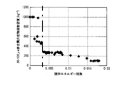
一方、底面開口孔24からの溶鋼流出流量が大きくなると、直接、鋳型15に流れ込む非金属介在物が多くなる。そこで、底面開口孔24からの溶鋼流出流量と、特に製品で問題となる鋳片1中の100μm超の非金属介在物の個数密度の関係を調査した。図7に、底面開口孔24からの溶鋼流出流量と100μm超の非金属介在物の個数密度の関係を示す。ここで、底面開口孔24からの溶鋼流出流量は、全溶鋼流出流量に全ての開口孔の面積に対する底面開口孔24の面積の割合(SB/(SB+ST))を乗じて求める。
底面開口孔24からの溶鋼流出流量が3t/minを超えないように制御することで、100μm超の非金属介在物の個数密度を小さくすることが可能なことを知見した。
On the other hand, when the molten steel outflow rate from the
It has been found that the number density of non-metallic inclusions exceeding 100 μm can be reduced by controlling the molten steel outflow rate from the
以上のような実験結果から、本実施形態では、上述の(1)~(3)式、及び、定常鋳造時における底面開口孔24からの溶鋼流出量、を規定した。
Based on the experimental results as described above, in the present embodiment, the above-mentioned equations (1) to (3) and the flow rate of molten steel from the
また、本実施形態においては、ロングノズル20からタンディッシュ13内に溶鋼が流れ出た後の再酸化を防ぐために、タンディッシュ13の溶鋼表面をタンディッシュ13内の大気雰囲気から遮断して酸素濃度を低減することが好ましい。
このため、タンディッシュ13内の溶鋼の湯面を、フラックス及び不活性ガスの一方又は両方で覆うことが好ましい。高級鋼においては、不活性ガスシールとフラックスシールの両方を適用することが望ましい。低級鋼においては、不活性ガスシールもしくは、フラックスシールのどちらかによって、確実にシールできることが望ましい。
Further, in the present embodiment, in order to prevent reoxidation after the molten steel flows into the
Therefore, it is preferable to cover the surface of the molten steel in the
フラックスにはCaO-Al2O3-SiO2系をベースとした、低融点組成で、溶鋼温度で十分溶融し、溶鋼表面を覆うことが可能なものを用いることが望ましい。
こうして、非金属介在物を凝集合体させ浮上を強化させるような高清浄鋼の溶製においては、溶鋼表面の酸素濃度を制御して再酸化を抑制しつつ、非金属介在物の除去を図ることで、大きなアルミナクラスターの低減効果を得ることができる。なお、酸素濃度は、酸素分圧でPO2=10-14(atm)以下とすることが好ましい。
As the flux, it is desirable to use a CaO--Al 2 O 3 --SiO 2 -based flux that has a low melting point composition, sufficiently melts at the molten steel temperature, and is capable of covering the surface of the molten steel.
In this way, in the melting of high-cleanliness steel in which non-metallic inclusions are agglomerated and coalesced to strengthen flotation, it is possible to control the oxygen concentration on the surface of the molten steel to suppress re-oxidation while removing non-metallic inclusions. , the effect of reducing large alumina clusters can be obtained. The oxygen concentration is preferably P O2 =10 −14 (atm) or less in oxygen partial pressure.
以上のような構成とされた本実施形態である鋼の連続鋳造方法によれば、底面部23に開口する底面開口孔24と、側面に開口する側面開口孔25と、を有するロングノズル20を用いて、上述の(1)~(3)式を満足するとともに、定常鋳造時における底面開口孔24からの溶鋼流出量が3t/minを超えないように、取鍋11からタンディッシュ13に向けて溶鋼を注入する構成とされているので、取鍋11からタンディッシュ13に対して溶鋼の注入を開始する際に、大きな溶鋼静圧を持った運動量の大きな溶鋼落下によっても、ロングノズル20の破損、位置ずれに溶鋼漏れの発生を抑制でき、安定して鋳造を行うことができる。
また、底面部23を有することでロングノズル20内の溶鋼が乱流状態となり、非金属介在物を効率的に凝集させることができ、かつ、側面開口孔25からの吐出流によって温度差による対流を促し、非金属介在物の浮上分離を促進することができ、清浄度が十分に高い鋳片1を製造することが可能となる。
According to the continuous steel casting method of the present embodiment configured as described above, the
In addition, since the
また、本実施形態において、タンディッシュ13内の溶鋼の湯面を、フラックス及び不活性ガスの一方又は両方で覆う構成とした場合には、タンディッシュ13内の溶鋼の酸化を抑制でき、非金属介在物の生成を抑制することが可能となる。よって、さらに清浄度の高い鋳片を製造することが可能となる。
Further, in the present embodiment, if the surface of the molten steel in the
以上、本発明の実施形態である鋼の連続鋳造方法について、具体的に説明したが、本発明はこれに限定されることはなく、その発明の技術的思想を逸脱しない範囲で適宜変更可能である。 Although the method for continuous steel casting, which is an embodiment of the present invention, has been specifically described above, the present invention is not limited to this, and can be modified as appropriate without departing from the technical idea of the invention. be.
例えば、本実施形態では、側面開口孔を4つ設けたものとして説明したが、これに限定されることはなく、側面開口孔の個数は4,6,8,・・・のように偶数個設けることが好ましい。
タンディッシュから2つのストランドに溶鋼を供給する場合、側面開口孔を、タンディッシュの長手方向別に半分ずつ(2,3,4,・・・)、かつ、両ストランド左右で対照に配置することにより、両ストランドに対照な流れを得て、なおかつタンディッシュの壁に直接向かう流れや、鋳型内に直接向かう直送流を避けることが可能となる。
For example, in the present embodiment, four side openings are provided, but the number of side openings is not limited to this, and the number of side openings is an even number such as 4, 6, 8, . It is preferable to provide
When supplying molten steel from a tundish to two strands, by arranging side openings in halves (2, 3, 4, . , it is possible to obtain symmetrical flows in both strands and yet avoid direct flow towards the walls of the tundish and direct flow into the mould.
また、本実施形態においては、側面開口孔の吐出角度について言及していないが、タンディッシュ底に這う流れが生じることをさらに抑制するためには、側面開口孔の吐出角度を水平面(上向き0°)とすることが好ましい。 In this embodiment, no reference is made to the discharge angle of the side openings. ) is preferable.
本発明の効果について検証するために実施した検証試験について説明する。
自動車用に用いられる低炭アルミキルド鋼を転炉出鋼、RH二次精錬工程で、脱ガス処理を行い、その後、表1に示す条件のロングノズルを用いて、表1に示す溶鋼流量で取鍋からタンディッシュに溶鋼を注入し、連続鋳造を行った。なお、ロングノズルは、いずれも側面開口孔が4個水平面に開口しているものを用いた。
Verification tests conducted to verify the effects of the present invention will be described.
Low-carbon aluminum-killed steel used for automobiles is discharged from a converter and subjected to degassing in the RH secondary refining process. Continuous casting was performed by pouring molten steel from the pot into the tundish. The long nozzle used had four side openings opening in the horizontal plane.
鋳造途中でのノズル破損、溶鋼漏れのトラブルが発生したものは、トラブル発生時点で鋳造を中止し、非金属介在物の調査は実施しなかった。トラブルなく鋳造できた鋳片については、非金属介在物の調査を前述したスライム抽出法で行い、非金属介在物の粒径分布、最大粒径を求めた。鋳片サンプルの採取を行い、スライム法を用いて、非金属介在物個数密度を調査した。試験結果を表2に示す。 If troubles such as nozzle breakage or molten steel leakage occurred during casting, casting was stopped at the time of trouble occurrence, and non-metallic inclusions were not investigated. For slabs that could be cast without any trouble, the non-metallic inclusions were examined by the slime extraction method described above, and the particle size distribution and maximum particle size of the non-metallic inclusions were obtained. A slab sample was collected, and the number density of nonmetallic inclusions was investigated using the slime method. Table 2 shows the test results.

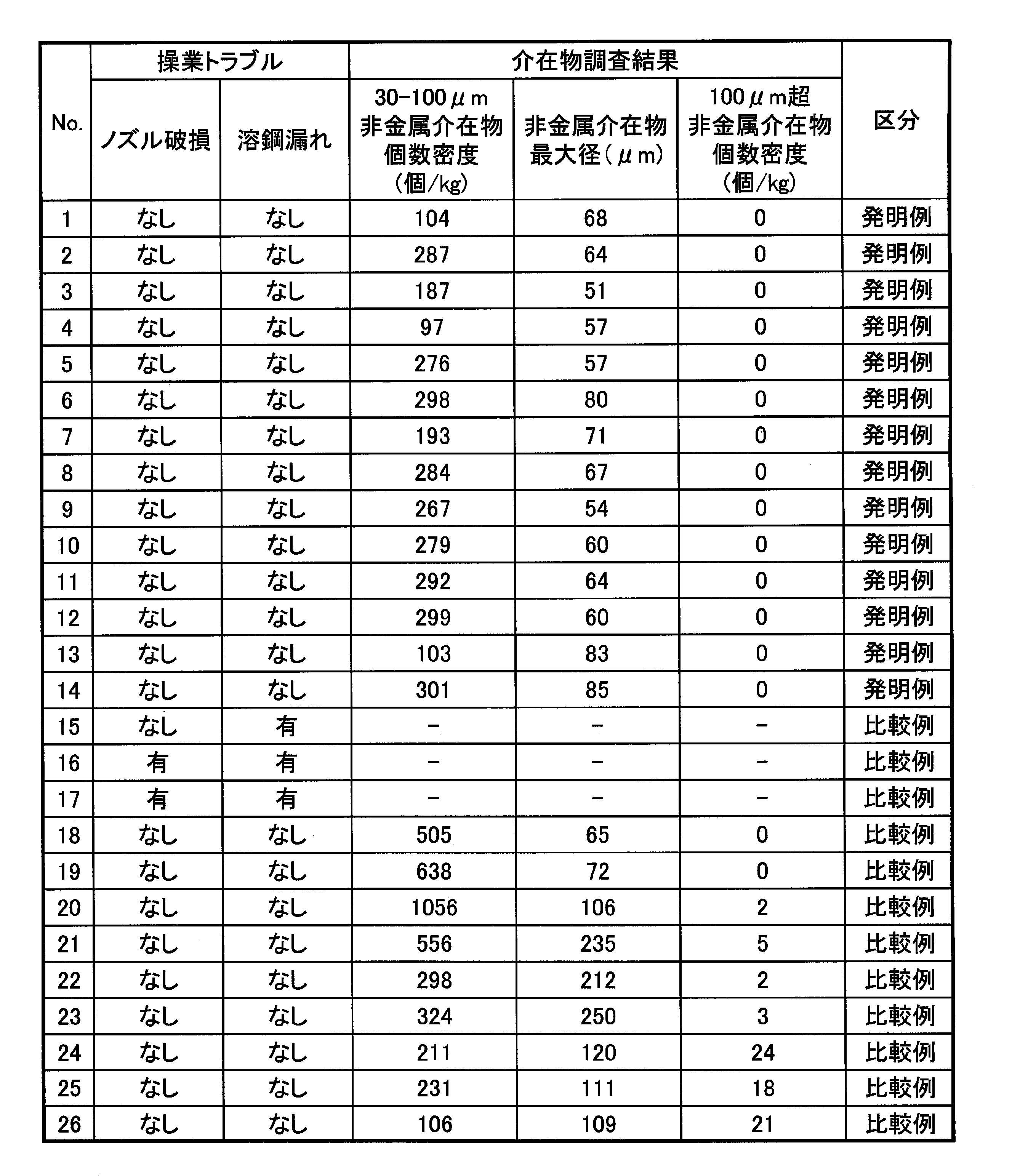
No.1~14は発明例であり、ノズル破損や溶鋼漏れのトラブルなく鋳造でき、非金属介在物個数密度も少なく、直径200μmを超えるような粗大な介在物も見られなかった。
No.15~17はSB/Sが小さすぎる比較例であり、ロングノズル底面開口孔が小さすぎるためにノズル破損や溶鋼漏れのトラブルが発生した。
No.18~20は撹拌エネルギーが小さすぎる比較例であり、500個/kgを超える直径30~100μmの非金属介在物が存在した。
No.21~23はSB/(SB+ST)が大きすぎる比較例であり、直径200μmを超える非金属介在物が存在した。
No.24~26は、底面開口孔からの溶鋼流出流量が3.0t/minを超える比較例であり、直径100μm超の大きな非金属介在物が10個/kg以上存在した。
No. Nos. 1 to 14 are invention examples, which could be cast without problems such as nozzle breakage and molten steel leakage, the number density of non-metallic inclusions was low, and coarse inclusions exceeding 200 μm in diameter were not observed.
No. Nos. 15 to 17 are comparative examples in which SB/S is too small, and problems such as nozzle breakage and molten steel leakage occurred because the long nozzle bottom opening hole was too small.
No. Nos. 18 to 20 are comparative examples with too small stirring energy, and more than 500 pieces/kg of nonmetallic inclusions with a diameter of 30 to 100 μm were present.
No. Nos. 21 to 23 are comparative examples in which SB/(SB+ST) is too large, and non-metallic inclusions exceeding 200 μm in diameter were present.
No. Nos. 24 to 26 are comparative examples in which the flow rate of molten steel outflow from the bottom opening exceeded 3.0 t/min, and 10 or more large non-metallic inclusions with a diameter of over 100 μm were present/kg.
1 鋳片
10 連続鋳造装置
11 取鍋
13 タンディッシュ
15 鋳型
20 ロングノズル
22 溶湯経路
23 底面部
24 底面開口孔
25 側面開口孔
1
Claims (2)
前記取鍋の下端に、有底筒状のロングノズルが配設され、このロングノズルを介して、前記取鍋から前記タンディッシュへの前記溶鋼が注入される構成とされており、
前記ロングノズルは、底面部に開口する底面開口孔と、側面に開口する側面開口孔と、を有しており、
前記ロングノズルの前記底面部の全面積をS(m2)、前記底面開口孔の面積をSB(m2)、前記側面開口孔の総開口面積をST(m2)、定常時における前記ロングノズル内の流速をv(m/s)とした場合に、以下の(1)~(3)式を満足するとともに、
(1)式:0.14≦SB/S
(2)式:0<SB/(SB+ST)≦0.55
(3)式:v2×(S-SB)≧0.0035
定常鋳造時における前記底面開口孔からの溶鋼流出量が3t/minを超えないように、前記取鍋から前記タンディッシュに向けて前記溶鋼を注入することを特徴とする鋼の連続鋳造方法。 A steel continuous casting method in which molten steel is poured from a ladle into a tundish, the molten steel is supplied from the tundish to a continuous casting mold, and a slab is continuously cast,
A bottomed cylindrical long nozzle is disposed at the lower end of the ladle, and the molten steel is poured from the ladle into the tundish through the long nozzle,
The long nozzle has a bottom opening hole that opens to the bottom surface and a side opening hole that opens to the side,
The total area of the bottom surface of the long nozzle is S (m 2 ), the area of the bottom opening holes is SB (m 2 ), the total opening area of the side opening holes is ST (m 2 ), and the long When the flow velocity in the nozzle is v (m/s), the following expressions (1) to (3) are satisfied,
(1) Formula: 0.14≦SB/S
(2) Formula: 0<SB/(SB+ST)≦0.55
(3) Formula: v 2 × (S-SB) ≥ 0.0035
A continuous casting method for steel, characterized in that the molten steel is poured from the ladle toward the tundish so that the molten steel flow rate from the bottom opening does not exceed 3 t/min during steady casting.
Priority Applications (1)
| Application Number | Priority Date | Filing Date | Title |
|---|---|---|---|
| JP2019076463A JP7200811B2 (en) | 2019-04-12 | 2019-04-12 | Steel continuous casting method |
Applications Claiming Priority (1)
| Application Number | Priority Date | Filing Date | Title |
|---|---|---|---|
| JP2019076463A JP7200811B2 (en) | 2019-04-12 | 2019-04-12 | Steel continuous casting method |
Publications (2)
| Publication Number | Publication Date |
|---|---|
| JP2020171955A JP2020171955A (en) | 2020-10-22 |
| JP7200811B2 true JP7200811B2 (en) | 2023-01-10 |
Family
ID=72829654
Family Applications (1)
| Application Number | Title | Priority Date | Filing Date |
|---|---|---|---|
| JP2019076463A Active JP7200811B2 (en) | 2019-04-12 | 2019-04-12 | Steel continuous casting method |
Country Status (1)
| Country | Link |
|---|---|
| JP (1) | JP7200811B2 (en) |
Citations (5)
| Publication number | Priority date | Publication date | Assignee | Title |
|---|---|---|---|---|
| JP2001113347A (en) | 1999-10-19 | 2001-04-24 | Sumitomo Metal Ind Ltd | Molten metal supplying device and method for continuously casting steel |
| JP2013529551A (en) | 2010-07-02 | 2013-07-22 | ベスビウス クルーシブル カンパニー | Immersion nozzle |
| JP2013208641A (en) | 2012-03-30 | 2013-10-10 | Nisshin Steel Co Ltd | Continuous casting method |
| JP2013208643A (en) | 2012-03-30 | 2013-10-10 | Nisshin Steel Co Ltd | Continuous casting method |
| JP2015066559A (en) | 2013-09-27 | 2015-04-13 | 日新製鋼株式会社 | Continuous casting method |
Family Cites Families (2)
| Publication number | Priority date | Publication date | Assignee | Title |
|---|---|---|---|---|
| JPS6325255U (en) * | 1986-08-02 | 1988-02-19 | ||
| JP3134019B2 (en) * | 1992-09-14 | 2001-02-13 | 東芝セラミックス株式会社 | Nozzle for casting |
-
2019
- 2019-04-12 JP JP2019076463A patent/JP7200811B2/en active Active
Patent Citations (5)
| Publication number | Priority date | Publication date | Assignee | Title |
|---|---|---|---|---|
| JP2001113347A (en) | 1999-10-19 | 2001-04-24 | Sumitomo Metal Ind Ltd | Molten metal supplying device and method for continuously casting steel |
| JP2013529551A (en) | 2010-07-02 | 2013-07-22 | ベスビウス クルーシブル カンパニー | Immersion nozzle |
| JP2013208641A (en) | 2012-03-30 | 2013-10-10 | Nisshin Steel Co Ltd | Continuous casting method |
| JP2013208643A (en) | 2012-03-30 | 2013-10-10 | Nisshin Steel Co Ltd | Continuous casting method |
| JP2015066559A (en) | 2013-09-27 | 2015-04-13 | 日新製鋼株式会社 | Continuous casting method |
Also Published As
| Publication number | Publication date |
|---|---|
| JP2020171955A (en) | 2020-10-22 |
Similar Documents
| Publication | Publication Date | Title |
|---|---|---|
| CN110035844B (en) | Continuous casting method | |
| JP2006035272A (en) | Method for removing inclusion in tundish for continuous casting, and tundish for continuous casting | |
| JP2007090424A (en) | Tundish for continuous casting | |
| JP7200811B2 (en) | Steel continuous casting method | |
| JP4411945B2 (en) | Slab continuous casting method for ultra-low carbon steel | |
| CN112272593B (en) | In-mold flow control device and in-mold flow control method in thin slab casting | |
| JP2011143449A (en) | Method for removing inclusion in tundish for continuous casting | |
| JP2009154172A (en) | Continuous casting method of aluminum killed steel | |
| JPH09295109A (en) | Method for continuously casting clean molten metal | |
| JP5044981B2 (en) | Steel continuous casting method | |
| JP4998705B2 (en) | Steel continuous casting method | |
| Gushchin et al. | Technical solutions for controlling flows of melts in the tundishes of continuous casters. | |
| JP4474948B2 (en) | Steel continuous casting method | |
| JP2022189431A (en) | Continuous casting method of steel | |
| JP5791234B2 (en) | Continuous casting method for steel slabs | |
| JP6904132B2 (en) | Tandish for continuous casting | |
| JP6287901B2 (en) | Steel continuous casting method | |
| JP4714624B2 (en) | Method of electromagnetic stirring of molten steel in mold | |
| JPH10249498A (en) | Method for continuously casting high cleanliness steel with tundish providing field weir closing bottom part | |
| JP3558815B2 (en) | High cleanliness steel continuous casting method with tundish equipped with fixed weir with closed bottom | |
| JPS5924903B2 (en) | Continuous casting method for weakly deoxidized steel slabs | |
| JPH08229670A (en) | Cleaning method of molten metal to remove bubble and impurities and device therefor | |
| JP2023066986A (en) | nozzle system | |
| JP2024043884A (en) | nozzle system | |
| JPH11320054A (en) | Continuous caster and continuous casting method |
Legal Events
| Date | Code | Title | Description |
|---|---|---|---|
| A621 | Written request for application examination |
Free format text: JAPANESE INTERMEDIATE CODE: A621 Effective date: 20211206 |
|
| A977 | Report on retrieval |
Free format text: JAPANESE INTERMEDIATE CODE: A971007 Effective date: 20221107 |
|
| TRDD | Decision of grant or rejection written | ||
| A01 | Written decision to grant a patent or to grant a registration (utility model) |
Free format text: JAPANESE INTERMEDIATE CODE: A01 Effective date: 20221122 |
|
| A61 | First payment of annual fees (during grant procedure) |
Free format text: JAPANESE INTERMEDIATE CODE: A61 Effective date: 20221205 |
|
| R151 | Written notification of patent or utility model registration |
Ref document number: 7200811 Country of ref document: JP Free format text: JAPANESE INTERMEDIATE CODE: R151 |