JP6287901B2 - Steel continuous casting method - Google Patents
Steel continuous casting method Download PDFInfo
- Publication number
- JP6287901B2 JP6287901B2 JP2015049191A JP2015049191A JP6287901B2 JP 6287901 B2 JP6287901 B2 JP 6287901B2 JP 2015049191 A JP2015049191 A JP 2015049191A JP 2015049191 A JP2015049191 A JP 2015049191A JP 6287901 B2 JP6287901 B2 JP 6287901B2
- Authority
- JP
- Japan
- Prior art keywords
- molten steel
- slab
- continuous casting
- steel
- mold
- Prior art date
- Legal status (The legal status is an assumption and is not a legal conclusion. Google has not performed a legal analysis and makes no representation as to the accuracy of the status listed.)
- Active
Links
- 229910000831 Steel Inorganic materials 0.000 title claims description 121
- 239000010959 steel Substances 0.000 title claims description 121
- 238000009749 continuous casting Methods 0.000 title claims description 55
- 238000000034 method Methods 0.000 title claims description 16
- 238000003756 stirring Methods 0.000 claims description 42
- 238000007654 immersion Methods 0.000 claims description 24
- 238000007711 solidification Methods 0.000 claims description 12
- 230000008023 solidification Effects 0.000 claims description 12
- 239000002436 steel type Substances 0.000 claims description 11
- 238000005266 casting Methods 0.000 claims description 5
- 238000001816 cooling Methods 0.000 claims description 3
- XKRFYHLGVUSROY-UHFFFAOYSA-N Argon Chemical compound [Ar] XKRFYHLGVUSROY-UHFFFAOYSA-N 0.000 description 60
- 230000007547 defect Effects 0.000 description 32
- 229910052786 argon Inorganic materials 0.000 description 30
- 238000005096 rolling process Methods 0.000 description 13
- 230000000052 comparative effect Effects 0.000 description 11
- 239000007789 gas Substances 0.000 description 6
- 229910001209 Low-carbon steel Inorganic materials 0.000 description 5
- 239000010960 cold rolled steel Substances 0.000 description 3
- 238000004519 manufacturing process Methods 0.000 description 3
- OKTJSMMVPCPJKN-UHFFFAOYSA-N Carbon Chemical compound [C] OKTJSMMVPCPJKN-UHFFFAOYSA-N 0.000 description 2
- 238000000137 annealing Methods 0.000 description 2
- 229910052799 carbon Inorganic materials 0.000 description 2
- 238000005097 cold rolling Methods 0.000 description 2
- 230000003247 decreasing effect Effects 0.000 description 2
- 230000004907 flux Effects 0.000 description 2
- 238000005098 hot rolling Methods 0.000 description 2
- 239000000843 powder Substances 0.000 description 2
- RTAQQCXQSZGOHL-UHFFFAOYSA-N Titanium Chemical compound [Ti] RTAQQCXQSZGOHL-UHFFFAOYSA-N 0.000 description 1
- 238000010276 construction Methods 0.000 description 1
- 238000005520 cutting process Methods 0.000 description 1
- 238000005516 engineering process Methods 0.000 description 1
- 238000007667 floating Methods 0.000 description 1
- 239000012535 impurity Substances 0.000 description 1
- 238000007689 inspection Methods 0.000 description 1
- 229910052758 niobium Inorganic materials 0.000 description 1
- 239000010955 niobium Substances 0.000 description 1
- GUCVJGMIXFAOAE-UHFFFAOYSA-N niobium atom Chemical compound [Nb] GUCVJGMIXFAOAE-UHFFFAOYSA-N 0.000 description 1
- 239000011148 porous material Substances 0.000 description 1
- 238000007670 refining Methods 0.000 description 1
- 230000003068 static effect Effects 0.000 description 1
- 239000010936 titanium Substances 0.000 description 1
- 229910052719 titanium Inorganic materials 0.000 description 1
Images


Landscapes
- Continuous Casting (AREA)
Description
本発明は、湾曲型連続鋳造機を用いた鋼の連続鋳造方法において、鋳造された鋳片を圧延して得られる鋼板でのふくれ欠陥の発生を抑える技術に関する。 The present invention relates to a technique for suppressing occurrence of blister defects in a steel sheet obtained by rolling a cast slab in a continuous casting method of steel using a curved continuous casting machine.
冷延鋼板、冷延メッキ鋼板や電磁鋼板における加工性向上の要求がますます強まっており、この要求に応えるべく、極低炭素鋼に対する需要がますます増大している。冷延鋼板は一般に鋳片を熱間圧延した後、冷間圧延し、その後、焼鈍工程を経て製造されるが、焼鈍した鋼板には、鋳片内部に含まれるブローホールに起因して、表面が隆起したふくれ欠陥が発生することが多く、該欠陥は冷延鋼板製造工程の最終段階で発見されるので、原価上または工程上の被害が大きなものとなる。 The demand for improved workability in cold-rolled steel sheets, cold-rolled plated steel sheets and electromagnetic steel sheets is increasing, and the demand for ultra-low carbon steel is increasing in order to meet these demands. A cold-rolled steel sheet is generally produced by hot rolling a slab and then cold rolling and then undergoing an annealing process, but the annealed steel sheet has a surface due to blowholes contained in the slab. In many cases, the bulging defect is raised at the final stage of the cold-rolled steel sheet manufacturing process, resulting in a large cost or process damage.
ふくれ欠陥が発生する原因として、連鋳パウダーの巻込みや浸漬ノズルの詰まり防止として溶鋼に吹きこまれるアルゴンの気泡が鋳片の凝固シェルに取り込まれることが考えられる。連続鋳造機のうち、湾曲型連続鋳造機には、マシン高さが低く建設費が安く、更には、溶鋼静圧が少なくなる結果、ロール間でのバルジング量が少なく、高品質な鋳片を製造しやすい利点があるが、この湾曲型連続鋳造機を用いる場合、湾曲内側にあたる鋳片上面側に前記アルゴン気泡が偏在しやすくなり、気泡によるふくれ欠陥が、鋳片を圧延後の鋼板に発生しやすくなるという欠点がある。 As a cause of blister defects, it is considered that bubbles of argon blown into the molten steel are taken into the solidified shell of the slab to prevent the continuous casting powder from being caught or the immersion nozzle from clogging. Among the continuous casting machines, the curved continuous casting machine has a low machine height and low construction costs, and furthermore, as a result of less molten steel static pressure, the amount of bulging between rolls is small and high quality slabs are produced. There is an advantage that it is easy to manufacture, but when this curved type continuous casting machine is used, the argon bubbles tend to be unevenly distributed on the upper surface side of the slab, which is inside the curve, and blistering defects due to bubbles occur in the steel plate after rolling the slab. There is a drawback that it is easy to do.
特許文献1には、湾曲型連続鋳造機を用い、極低炭素鋼を連続鋳造する場合には、鋳片内で表面から厚み方向に30mm以内に存在するアルゴン気泡のみが圧延後の鋼板でふくれ欠陥になることが記載されており、表面から30mm以内の部位の鋳片中の凝固シェルと溶鋼との界面にアルゴン気泡が捕捉されないように、鋳型直下から、鋳片内で表面から30mmの部位が前記界面となる鋳片位置までの範囲で、湾曲内側に電磁撹拌装置を設置し、該電磁撹拌装置により鋳片内の界面で溶鋼を流動させることが記載されている。これにより、圧延後の鋼板にふくれ欠陥の発生が防がれるとされている。
In
湾曲型連続鋳造機で鋳造された、炭素Cが0.01mass%未満の極低炭素鋼の鋳片を冷延工程で焼鈍する場合、焼鈍の条件によっては、特許文献1に記載の技術内容を適用して鋳片を鋳造しても、該鋳片を圧延した後の鋼板にふくれ欠陥が発生していた。前述の特定の鋼種の連続鋳造を行う場合においては、圧延後の鋼板におけるふくれ欠陥の発生が抑えられる鋳片を鋳造する方法が確立できていないというのが実情である。
When an ultra-low carbon steel slab having a carbon C content of less than 0.01 mass% cast by a curved continuous casting machine is annealed in a cold rolling process, depending on the annealing conditions, the technical content described in
本発明は上記実情に鑑みてなされたもので、その目的とするところは、特定の鋼種の連続鋳造を行う場合において、圧延後の鋼板におけるふくれ欠陥の発生が抑えられる鋳片を製造可能な鋼の連続鋳造方法を提供することである。 The present invention has been made in view of the above circumstances, and the object thereof is steel capable of producing a slab capable of suppressing occurrence of blister defects in a steel sheet after rolling when performing continuous casting of a specific steel type. It is to provide a continuous casting method.
本発明者らは、その発生の原因を調査した結果、鋳片内で表面から40〜60mmに存在するアルゴン気泡がふくれ欠陥の原因になることを把握した。表面から浅い位置の凝固界面は、鋳造中において鋳型に近い位置にあり、鉛直面に近く、表面からある程度浅い40mm未満のアルゴン気泡は凝固界面に付着しにくい。特に、湾曲型連続鋳造機の場合で湾曲半径が大きくなると凝固界面が鉛直面に更に近づき、表面からある程度浅い40mm未満のアルゴン気泡は更に付着しにくくなる。表面から60mm程度を超えた深さに存在するアルゴン気泡は、鋼板厚みが大きく強度が高いのでふくれ欠陥とならないと推察される。 As a result of investigating the cause of the occurrence, the present inventors have grasped that argon bubbles present at 40 to 60 mm from the surface in the slab cause blistering defects. The solidification interface at a position shallow from the surface is close to the mold during casting, is close to the vertical plane, and argon bubbles of less than 40 mm that are somewhat shallow from the surface are less likely to adhere to the solidification interface. In particular, in the case of a curved continuous casting machine, when the radius of curvature increases, the solidification interface becomes closer to the vertical surface, and argon bubbles of less than 40 mm shallower than the surface become more difficult to adhere. It is presumed that argon bubbles existing at a depth exceeding about 60 mm from the surface do not cause blistering defects because the steel plate thickness is large and the strength is high.
そこで、特許文献1に記載の技術内容を応用し、凝固シェルと溶鋼との界面が、鋳片において表面から厚み方向に40〜60mmの部位に形成されている間に、その部位の鋳片内の溶鋼を流動させて、鋼の連続鋳造を行った。しかしながら、前記界面が、鋳片内で表面から40〜60mmの部位に形成されている場合には、鋳型中の溶鋼湯面から離れ過ぎ、やはり、鋳片の圧延後の鋼板にはふくれ欠陥が発生していた。
Therefore, while applying the technical contents described in
本発明者らは、ふくれ欠陥の発生を抑える方法を鋭意検討した結果、凝固シェルと溶鋼との界面が、鋳片の表面から厚み方向において40〜60mm離れた部位に形成されている鋳片の位置で、鋳片内の溶鋼に攪拌流れを発生させるとともに、鋳型中に溶鋼を浸漬ノズルの吐出口から略水平方向に流出させ且つ吐出孔から流出している溶鋼に攪拌流れを発生させることによって、アルゴン気泡の浮上を促進させることに想到した。 As a result of intensive studies on a method for suppressing the occurrence of blister defects, the present inventors have found that the interface between the solidified shell and the molten steel is formed at a site 40 to 60 mm away from the surface of the slab in the thickness direction. At the position, a stirring flow is generated in the molten steel in the slab, and the molten steel is caused to flow into the mold from the discharge port of the immersion nozzle in a substantially horizontal direction and to the molten steel flowing out of the discharge hole. It was conceived to promote the floating of argon bubbles.
すなわち、前述の課題を解決するための本発明の要旨は以下の通りである。
湾曲型連続鋳造機の鋳型に浸漬ノズルから溶鋼を注入し、前記鋳型を冷却して凝固シェルを形成し、該凝固シェルを引き抜いて鋳片を製造する鋼の連続鋳造方法であって、水平面に対して0°〜10°の角度下方に向けて前記溶鋼を流出させる吐出孔が前記浸漬ノズルに設けられ、前記吐出孔から流出している溶鋼に、電磁攪拌装置で水平方向に沿った流れを発生させ、前記鋳型中の溶鋼湯面から、前記湾曲型連続鋳造機の中央線に沿って下記(1)式を満足する距離L分離れたいずれかの位置の鋳片内の溶鋼に、前記電磁攪拌装置とは別の電磁攪拌装置で流れを発生させることを特徴とする鋼の連続鋳造方法。
Vc×(40/k)2≦L≦Vc×(60/k)2 (1)
ここで、Vcは、鋳片引き抜き速度[m/分]であり、kは、鋳造する鋼種の凝固定数[mm/分1/2]であり、Lは、前記湾曲型連続鋳造機の中央線に沿う前記鋳型中の溶鋼湯面からの距離[m]であり、定数40または60は、凝固シェルの厚み[mm]である。
That is, the gist of the present invention for solving the above-described problems is as follows.
A continuous casting method of steel in which molten steel is poured into a mold of a curved continuous casting machine from an immersion nozzle, the mold is cooled to form a solidified shell, and the solidified shell is pulled out to produce a slab. On the other hand, a discharge hole for allowing the molten steel to flow out downward from 0 ° to 10 ° is provided in the immersion nozzle, and the molten steel flowing out from the discharge hole is subjected to a flow along the horizontal direction by an electromagnetic stirring device. To the molten steel in the slab at any position separated from the molten steel surface in the mold by a distance L that satisfies the following formula (1) along the center line of the curved continuous casting machine, A continuous casting method for steel, wherein a flow is generated by an electromagnetic stirring device different from the electromagnetic stirring device.
Vc × (40 / k) 2 ≦ L ≦ Vc × (60 / k) 2 (1)
Here, Vc is the slab drawing speed [m / min], k is the solidification constant [mm / min 1/2 ] of the steel type to be cast, and L is the center line of the curved continuous casting machine And the constant 40 or 60 is the thickness [mm] of the solidified shell.
本発明によれば、特定の鋼種の連続鋳造を行う場合であっても、圧延後の鋼板におけるふくれ欠陥の発生を抑えることが可能となる。 According to the present invention, even when continuous casting of a specific steel type is performed, it is possible to suppress the occurrence of blister defects in the steel sheet after rolling.
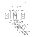
まずは、従来技術における湾曲型連続鋳造機を用いた鋼の連続鋳造について説明する。電磁攪拌装置が設置された湾曲型連続鋳造機を図5に示す。一般に、転炉や二次精錬プロセスにて溶製された溶鋼が収容されている取鍋を湾曲型連続鋳造機100に搬送する。次いで、取鍋からタンディッシュ101を経由して連続鋳造用の鋳型103内へ浸漬ノズル102を用いて溶鋼を注入する。溶鋼が鋳型103で冷却され、鋳型103の内壁近傍で凝固シェル105が形成される。未凝固の溶鋼とともに凝固シェル105を引き抜いて鋳片を製造する。鋳片(凝固シェル105)をロール104で保持しながら、更に冷却し、連続鋳造機内にて完全に凝固させた後、切断機にて所定の長さに切断し、下工程の熱延プロセスに送る。
First, continuous casting of steel using a curved continuous casting machine in the prior art will be described. A curved continuous casting machine provided with an electromagnetic stirring device is shown in FIG. In general, a ladle containing molten steel melted in a converter or secondary refining process is conveyed to the curved
浸漬ノズル102は、気体が通過可能な多孔質材料などからなっており、浸漬ノズル102自体が詰まることの対策として、アルゴンガスが浸漬ノズル102を通過する溶鋼に吹込まれる。このアルゴンガスからなるアルゴン気泡109が浸漬ノズル102からの溶鋼流107によって下方に流されることになるが、アルゴン気泡109自体が浮上するので、上側の凝固シェル105に捕捉され、下工程のプロセスにて、アルゴン気泡109で膨れ、鋳片が圧延されて得られる鋼板の表面にふくれ欠陥が生じる。例えば、チタン添加またはニオブ・チタン添加の極低炭素鋼の鋼板の検査で観察されるふくれ欠陥とは、幅1〜4mm、長さ数〜数百mmにも亘って鋼板の表面に隆起したものであり、湾曲型連続鋳造機にて鋳造された場合に顕著に発生する。
The
鋳型103の出口よりも下方で、湾曲型連続鋳造機100の中央線に沿って鋳型103中の溶鋼湯面から、鋳片表面から30mm中心側の部位が凝固シェル105と溶鋼との界面である鋳片の位置までの間で、湾曲内側に電磁撹拌装置106が設置されている。電磁撹拌装置106の磁場印加によって、界面近傍の溶鋼に、溶鋼流107とは異なる攪拌流れ108が生じる。これにより、アルゴン気泡109が凝固シェル105の界面に捕捉されず、浮力によって、アルゴン気泡109が上方に向かうこととなる。これにより、鋳片を圧延して得られる鋼板において、ふくれ欠陥の発生が防がれる。
Below the outlet of the
但し、上記の通りに、電磁撹拌によって凝固シェル105内の界面で溶鋼に攪拌流れ108を発生させて、自動車用鋼板や電磁鋼板となるCが0.01mass%未満の特定の鋼種を連続鋳造しても、圧延後の鋼板にふくれ欠陥が発生していた。本発明者らは、その発生の原因を調査した結果、鋳片内で表面から40〜60mmに存在するアルゴン気泡がふくれ欠陥の原因になることを把握した。表面からある程度浅く40mm未満のアルゴン気泡は、凝固界面が鉛直面に近く、凝固界面に付着しにくく、表面から60mm程度を超えた深さに存在するアルゴン気泡は、鋼板厚みが大きく強度が高いのでふくれ欠陥となりにくいものと推察される。
However, as described above, the stirring
そこで、本発明者らは、凝固シェルと溶鋼との界面が、鋳片の表面から厚み方向に40〜60mmの部位に形成されている間に、その部位の鋳片内の溶鋼に攪拌流れを発生させ、鋳片を製造し、該鋳片を圧延して得られる鋼板に発生するふくれ欠陥の数を確認した。確かに、鋳片を圧延して得られる鋼板において、ふくれ欠陥の発生をある程度防止することができたことを確認したが、ふくれ欠陥の数を劇的に減らすことはできなかった。本発明者らは、更に、鋼板でのふくれ欠陥の発生を効果的に抑える方法を鋭意検討した結果、界面が、鋳片内で表面から40〜60mmの部位に形成されている間に、その部位の鋳片内の溶鋼に攪拌流れを発生させつつ、鋳型中に溶鋼を浸漬ノズルの吐出口から、鋳造方向ではなく鋳型の幅方向に流出させるとともに、吐出孔から流出している溶鋼に鋳型の幅方向に沿った流れを発生させ、アルゴン気泡を浮上させ、鋳型を出た鋳片に補足されるアルゴン気泡の量を劇的に抑えることに想到した。 Therefore, the present inventors made a stirring flow to the molten steel in the slab at the site while the interface between the solidified shell and the molten steel was formed at a site of 40 to 60 mm in the thickness direction from the surface of the slab. The slab was produced, and the number of blister defects generated in the steel sheet obtained by rolling the slab was confirmed. Certainly, it was confirmed that the occurrence of blister defects could be prevented to some extent in the steel sheet obtained by rolling the slab, but the number of blister defects could not be reduced dramatically. Furthermore, as a result of earnestly studying a method for effectively suppressing the occurrence of blister defects in a steel sheet, the present inventors have found that while the interface is formed at a site of 40 to 60 mm from the surface in the slab, While the agitating flow is generated in the molten steel in the slab at the site, the molten steel flows into the mold from the discharge port of the immersion nozzle in the width direction of the mold, not in the casting direction, and in the molten steel flowing out of the discharge hole. It was conceived that a flow along the width direction of the gas was generated, the argon bubbles were floated, and the amount of argon bubbles captured by the slab exiting the mold was drastically suppressed.
本発明の実施形態の一例となる、電磁攪拌装置が設置された湾曲型連続鋳造機を図1に示す。図1に示す構成のうち、図5と共通する構成については、図5の符号と同じ符号で示し、かつ、説明を省略する。図1に示す湾曲型連続鋳造機1では、鋳型103の外側に、吐出孔が、磁場印加領域3a(図2参照)に入るように、電磁攪拌装置3が配置されている。この電磁攪拌装置3によって、吐出孔から流出する溶鋼に攪拌流れ8が生じ、該攪拌流れ8によってアルゴン気泡109が、溶鋼流107とともに下方(鋳片引き抜き方向)に向かうことが防がれ、浮力によって上方に向かう。
FIG. 1 shows a curved continuous casting machine provided with an electromagnetic stirrer as an example of an embodiment of the present invention. Of the configurations shown in FIG. 1, configurations that are the same as those in FIG. 5 are denoted by the same reference numerals as those in FIG. 5, and description thereof is omitted. In the curved
また、鋳型103中の溶鋼湯面から、湾曲型連続鋳造機1の中央線に沿って下記(1)式を満足する距離L分離れたいずれかの位置の鋳片上面側に、電磁攪拌装置3とは別の電磁攪拌装置6が配置されている。該電磁攪拌装置6を作動させることにより、距離L分離れた位置の鋳片上面側の凝固シェルの界面に、攪拌流れ8が生じる。該攪拌流れ8によって、アルゴン気泡109が、溶鋼流107とともに鋳片引き抜き方向に向かうことが防がれ、浮力によって、鋳片引き抜き方向とは反対方向に向かうことになる。
Vc×(40/k)2≦L≦Vc×(60/k)2 (1)
In addition, an electromagnetic stirrer is placed on the upper surface side of the slab at any position separated by a distance L satisfying the following expression (1) along the center line of the curved
Vc × (40 / k) 2 ≦ L ≦ Vc × (60 / k) 2 (1)
(1)式において、Vcは、鋳片引き抜き速度[m/分]であり、Lは、湾曲型連続鋳造機1の中央線に沿う鋳型3中の溶鋼湯面からの距離[m]である。kは、鋳造する鋼種の凝固定数[mm/分1/2]であり、凝固定数kは、厳密には鋼種成分や二次冷却の条件でおよそ25〜29の範囲で変化するものの、通常の冷却条件では、k=27と想定してよい。定数40または60は、鋳片中の凝固シェルの厚み[mm]であり、Lが上記(1)式を満たせば、溶鋼湯面から、湾曲型連続鋳造機1の中央線に沿って距離L分離れた位置の鋳片において、凝固シェル105は厚みが40〜60mmとなる。この位置において、表面から40〜60mm中心側の鋳片の部位が凝固シェルと未凝固の溶鋼との界面となる。
In the formula (1), Vc is a slab drawing speed [m / min], and L is a distance [m] from the molten steel surface in the mold 3 along the center line of the curved
鋳型103内での浸漬ノズル102の吐出口からの溶鋼流れを図2に示す。図2において、(a)には、電磁攪拌装置が鋳型103の外側に配置されていない状態を示し、(b)には、電磁攪拌装置3(図1参照)が配置されている状態を示してある。図2(a)に示す溶鋼の吐出口は、水平面に対して20°程度の角度下方に向けて溶鋼を流出させるように浸漬ノズル102に形成されている。図2(b)に示す溶鋼の吐出口は、水平面に対して0°〜10°の角度下方に向けて溶鋼を流出させるように浸漬ノズル102に形成されている。
The flow of molten steel from the discharge port of the
通常、図2(a)に示すように、水平方向ではなく、ある程度、鋳型の下方(鋳造方向)に向けて溶鋼を流出させるように吐出口浸漬ノズル102に形成されている。水平方向に向けると、鋳型103の内壁の特定の部位に溶鋼が向かい、溶鋼湯面のモールドパウダーを巻き込むおそれがある。図2(a)の場合には、浸漬ノズル102の吐出口から流出している溶鋼には磁場が印加されず、単に吐出口から溶鋼が流出されているに過ぎない。よって、溶鋼に含まれるアルゴン気泡109(図1参照)は、溶鋼流れに伴って下方に向かう傾向がある。
Usually, as shown in FIG. 2A, the discharge
一方、図2(b)に示すように電磁攪拌装置で印加される磁場印加領域3aに吐出口が入るように、電磁攪拌装置は鋳型103の外側に配置される。電磁攪拌装置3によって、浸漬ノズル102の吐出口の溶鋼には、磁場が印加され、溶鋼に鋳型の幅方向に沿う攪拌流れ(旋回流)8が生じている(図1参照)。これにより、アルゴン気泡109が、溶鋼流れとともに下方に搬送されずに、浮力によって上方に向かう傾向がある。また、溶鋼が、水平面に対して0°〜10°の角度下方に向けて流出するようになっていても、電磁攪拌装置3による攪拌流れによって、鋳型103の内壁に溶鋼が分散され、溶鋼流れの流速が遅くなり、気泡が溶鋼流れから離れて、浮上し易くなる。なお、磁場印加領域3aに吐出口が入るようにするには、吐出口の高さ位置に、電磁攪拌装置3のコイルの中心を配置するように、電磁攪拌装置3を設置すればよい。
On the other hand, as shown in FIG. 2 (b), the electromagnetic stirring device is disposed outside the
図1及び図2(b)に示すように、鋳片において、表面から中心方向へ40〜60mm離れた部位における湾曲内側の凝固界面で溶鋼を流動させるとともに、鋳型中に溶鋼を浸漬ノズルの吐出口から略水平方向に流出させ、吐出孔から流出している溶鋼に略水平方向に沿う流れを発生させることによって、アルゴン気泡をより確実に浮上させることが可能となる。これにより、圧延後の鋼板にふくれ欠陥を発生させ易い特定の鋼種の連続鋳造を行う場合であっても、その鋳片の圧延後の鋼板におけるふくれ欠陥の発生を劇的に抑えることが可能となる。 As shown in FIGS. 1 and 2 (b), in the slab, the molten steel is caused to flow at the solidification interface on the curved inner side at a position 40 to 60 mm away from the surface toward the center, and the molten steel is discharged into the mold by the immersion nozzle. By causing the molten steel flowing out from the outlet to flow in a substantially horizontal direction and generating a flow along the substantially horizontal direction in the molten steel flowing out from the discharge hole, the argon bubbles can be more reliably floated. This makes it possible to dramatically suppress the occurrence of blister defects in the steel sheet after rolling of the slab, even when performing continuous casting of a specific steel type that easily causes blister defects in the steel sheet after rolling. Become.
まず、図5に示す湾曲型連続鋳造機100で、Cが0.005mass%以下、Siが3.0〜3.5mass%、Mnが0.06〜0.08mass%、Pが0.02mass%以下、Sが0.01mass%以下、Alが0.02〜0.03mass%、Nが70〜100massppm、残部がFe及び不可避不純物である極低炭素鋼の連続鋳造を行った(基準例)。但し、基準例においては、電磁攪拌装置106を使用しなかった。基準例において、浸漬ノズル102は、水平面より20°下向きに溶鋼を流出させる吐出孔が2つ設けられており、該吐出孔は、70mm×70mmの矩形状である。浸漬ノズル102へ吹き込まれるアルゴンガスを5Nl/分とした。また、鋳片引き抜き速度は1.0m/分とし、鋳片の幅は1450mmである。
First, in the curved
次に、図5に示す湾曲型連続鋳造機100で、電磁攪拌装置106を使用した以外は、基準例と同じ条件で、鋼の連続鋳造を行った(比較例)。比較例では、電磁攪拌装置106を、鋳片内で凝固シェル105の厚みが30mmとなる位置の鋳片における湾曲内側に配置した。
Next, with the curved
また、湾曲型連続鋳造機100で鋼の連続鋳造を行った(参考例)。参考例では、電磁攪拌装置106の位置を変更した以外は比較例と同じ条件で鋼の連続鋳造を行った。電磁攪拌装置106によって、鋳型103中の溶鋼湯面から、湾曲型連続鋳造機1の中央線に沿って、Vc×(58/k)2で求まるL分離れた位置(凝固シェル105の厚みが58mmとなる位置)の鋳片内部の溶鋼に流れが生じるように、鋳片上面側に配置した。ここで、この鋼種の凝固定数kは、約27.1mm/分1/2であり、鋳片引き抜き速度Vcは1.0m/分であり、距離Lは約4.6mと算出された。電磁攪拌装置106に供給する電流は、磁束密度が0.06T、電流値が800Aで、周波数が1.3Hzの交流とした。
Moreover, continuous casting of steel was performed with the curved continuous casting machine 100 (reference example). In the reference example, continuous casting of steel was performed under the same conditions as in the comparative example except that the position of the
最後に、図1に示す湾曲型連続鋳造機1で鋼の連続鋳造を行った(本発明例)。本発明例では、浸漬ノズル102には、水平面より5°下向きに溶鋼を流出させる吐出孔が2つ設けられ、電磁攪拌装置3と電磁攪拌装置6との両方を使用した以外は参考例と同じ条件で鋼の連続鋳造を行った。湾曲型連続鋳造機1における電磁攪拌装置6の位置は、参考例の湾曲型連続鋳造機100における電磁攪拌装置106の配置位置に対応している。
電磁攪拌装置3は、コイルの中心が吐出口の高さとなるように配置した。電磁攪拌装置3に供給する電流は、磁束密度が0.06T、電流値が600Aで、周波数が3.0Hzの交流とした。
Finally, continuous casting of steel was performed with the curved
The electromagnetic stirring device 3 was arranged so that the center of the coil was the height of the discharge port. The current supplied to the electromagnetic stirring device 3 was an alternating current with a magnetic flux density of 0.06 T, a current value of 600 A, and a frequency of 3.0 Hz.
基準例、比較例、参考例及び本発明例の各々で得られた鋳片の上表面から40〜60mm中心側の部位における気泡の数を超音波探傷装置で測定した。基準例における気泡密度を1とした場合における、比較例、参考例及び本発明例の気泡密度を、気泡密度指数として求めた。比較例、参考例及び本発明例の気泡密度指数を図3に示す。また、鋳片の上表面に対応する鋼板表面のうち、ふくれている箇所を観察し、基準例における単位面積当たりのふくれ欠陥の個数となるふくれ欠陥発生密度[個/m3]を1とした場合における、比較例、参考例及び本発明例のふくれ欠陥発生密度を、ふくれ欠陥発生密度指数として求めた。比較例、参考例及び本発明例のふくれ欠陥発生密度指数を図4に示す。 The number of bubbles at the center side of 40-60 mm from the upper surface of the slab obtained in each of the reference example, the comparative example, the reference example, and the example of the present invention was measured with an ultrasonic flaw detector. The bubble density of the comparative example, the reference example, and the example of the present invention when the bubble density in the reference example was set to 1 was obtained as a bubble density index. The bubble density index of the comparative example, the reference example and the example of the present invention is shown in FIG. In addition, the portion of the steel plate corresponding to the upper surface of the slab was observed for the bulging portion, and the bulging defect generation density [pieces / m 3 ], which was the number of bulging defects per unit area in the reference example, was set to 1. In each case, the blister defect density of the comparative example, the reference example, and the example of the present invention was obtained as a blister defect density index. FIG. 4 shows the blister defect occurrence density index of the comparative example, the reference example, and the example of the present invention.
図3のグラフからわかるように、比較例では、電磁攪拌装置で鋳片の溶鋼流れを攪拌することのない基準例に比べて、鋳片の上表面から40〜60mm中心側の気泡の数は減少している。参考例では、比較例に比べて、鋳片の上表面から40〜60mm中心側の気泡の数は更に減少しているが、劇的という程に減少はしていない。 As can be seen from the graph of FIG. 3, in the comparative example, the number of bubbles on the center side of 40 to 60 mm from the upper surface of the slab is smaller than that in the reference example in which the molten steel flow of the slab is not stirred by the electromagnetic stirring device. is decreasing. In the reference example, the number of bubbles on the center side of 40 to 60 mm from the upper surface of the slab is further reduced as compared with the comparative example, but it is not drastically reduced.
電磁攪拌装置3と電磁攪拌装置6との両方を使用した本発明例では、比較例及び参考例に比べて、鋳片の上表面から厚み方向に40〜60mmの部位におけるの気泡の数は劇的に減少していることがわかる。鋳片表面から厚み方向に40〜60mmの部位における鋳片の湾曲内側の凝固界面で溶鋼を流動させるとともに、鋳型中に溶鋼を浸漬ノズルの吐出口から鋳型の幅方向に流出させ、吐出孔から流出している溶鋼に鋳型の幅方向に沿う流れを発生させることによって、アルゴン気泡をより確実に浮上させることが可能となることがわかる。図4のグラフからわかるように、特定の鋼種の連続鋳造を行う場合であっても、鋳片の圧延後の鋼板におけるふくれ欠陥の発生を劇的に抑えることが可能となっている。 In the present invention example using both the electromagnetic stirrer 3 and the electromagnetic stirrer 6, the number of bubbles in the region of 40 to 60 mm in the thickness direction from the upper surface of the slab is dramatic compared to the comparative example and the reference example. It can be seen that it is decreasing. The molten steel is caused to flow at the solidification interface on the curved inner side of the slab at a site of 40 to 60 mm in the thickness direction from the slab surface, and the molten steel is caused to flow into the mold from the discharge port of the immersion nozzle in the width direction of the mold and from the discharge hole. It can be seen that by generating a flow along the width direction of the mold in the flowing molten steel, the argon bubbles can be more reliably floated. As can be seen from the graph of FIG. 4, even when a specific steel type is continuously cast, it is possible to dramatically suppress the occurrence of blister defects in the steel sheet after rolling the slab.
1 湾曲型連続鋳造機(本発明)
3 電磁攪拌装置(本発明)
3a 磁場印加領域
6 電磁攪拌装置(本発明)
8 攪拌流れ(旋回流)
100 湾曲型連続鋳造機(従来技術)
101 タンディッシュ
102 浸漬ノズル
103 鋳型
104 ロール
105 凝固シェル
106 電磁攪拌装置(従来技術)
107 溶鋼流
108 攪拌流れ
109 アルゴン気泡
1 Curved continuous casting machine (present invention)
3 Electromagnetic stirrer (present invention)
3a Magnetic field application region 6 Electromagnetic stirrer (present invention)
8 Stirring flow (swirl flow)
100 Curved continuous casting machine (prior art)
101
107
Claims (1)
水平面に対して0°〜10°の角度下方に向けて前記溶鋼を流出させる吐出孔が前記浸漬ノズルに設けられ、
前記吐出孔から流出している溶鋼に、電磁攪拌装置で水平方向に沿った流れを発生させ、
前記鋳型中の溶鋼湯面から、前記湾曲型連続鋳造機の中央線に沿って下記(1)式を満足する距離L分離れたいずれかの位置の鋳片内の溶鋼に、前記電磁攪拌装置とは別の電磁攪拌装置で流れを発生させることを特徴とする鋼の連続鋳造方法。
Vc×(40/k)2≦L≦Vc×(60/k)2 (1)
ここで、Vcは、鋳片引き抜き速度[m/分]であり、
kは、鋳造する鋼種の凝固定数[mm/分1/2]であり、
Lは、前記湾曲型連続鋳造機の中央線に沿う前記鋳型中の溶鋼湯面からの距離[m]であり、
定数40または60は、凝固シェルの厚み[mm]である。 A steel continuous casting method for injecting molten steel into a mold of a curved continuous casting machine from an immersion nozzle, cooling the mold to form a solidified shell, and drawing the solidified shell to produce a slab,
A discharge hole for allowing the molten steel to flow out downward from an angle of 0 ° to 10 ° with respect to a horizontal plane is provided in the immersion nozzle,
In the molten steel flowing out from the discharge hole, a flow along the horizontal direction is generated by an electromagnetic stirring device,
The electromagnetic stirrer is applied to the molten steel in the slab at any position separated from the molten steel surface in the mold by a distance L that satisfies the following expression (1) along the center line of the curved continuous casting machine. A method for continuously casting steel, characterized in that a flow is generated by an electromagnetic stirring device different from the above.
Vc × (40 / k) 2 ≦ L ≦ Vc × (60 / k) 2 (1)
Here, Vc is the slab drawing speed [m / min],
k is the solidification constant [mm / min 1/2 ] of the steel type to be cast;
L is the distance [m] from the molten steel surface in the mold along the center line of the curved continuous casting machine,
The constant 40 or 60 is the thickness [mm] of the solidified shell.
Priority Applications (1)
| Application Number | Priority Date | Filing Date | Title |
|---|---|---|---|
| JP2015049191A JP6287901B2 (en) | 2015-03-12 | 2015-03-12 | Steel continuous casting method |
Applications Claiming Priority (1)
| Application Number | Priority Date | Filing Date | Title |
|---|---|---|---|
| JP2015049191A JP6287901B2 (en) | 2015-03-12 | 2015-03-12 | Steel continuous casting method |
Publications (2)
| Publication Number | Publication Date |
|---|---|
| JP2016168603A JP2016168603A (en) | 2016-09-23 |
| JP6287901B2 true JP6287901B2 (en) | 2018-03-07 |
Family
ID=56982846
Family Applications (1)
| Application Number | Title | Priority Date | Filing Date |
|---|---|---|---|
| JP2015049191A Active JP6287901B2 (en) | 2015-03-12 | 2015-03-12 | Steel continuous casting method |
Country Status (1)
| Country | Link |
|---|---|
| JP (1) | JP6287901B2 (en) |
Family Cites Families (7)
| Publication number | Priority date | Publication date | Assignee | Title |
|---|---|---|---|---|
| JPS59159257A (en) * | 1983-02-28 | 1984-09-08 | Kobe Steel Ltd | Production of middle and high carbon killed steel by continuous casting method |
| JPS60238071A (en) * | 1984-05-11 | 1985-11-26 | Kobe Steel Ltd | Electromagnetic stirring method in secondary cooling zone of continuous casting machine |
| JP3375862B2 (en) * | 1997-09-19 | 2003-02-10 | 新日本製鐵株式会社 | Method for producing ultra-low carbon steel without blowholes |
| JPH11320052A (en) * | 1998-05-20 | 1999-11-24 | Nippon Steel Corp | Method for controlling fluid of molten steel in continuous casting |
| JP4203167B2 (en) * | 1999-01-11 | 2008-12-24 | 新日本製鐵株式会社 | Continuous casting method for molten steel |
| JP4216659B2 (en) * | 2003-06-27 | 2009-01-28 | 新日本製鐵株式会社 | Continuous casting method for molten steel |
| JP5073531B2 (en) * | 2007-04-10 | 2012-11-14 | 新日本製鐵株式会社 | Slab continuous casting apparatus and method for continuous casting |
-
2015
- 2015-03-12 JP JP2015049191A patent/JP6287901B2/en active Active
Also Published As
| Publication number | Publication date |
|---|---|
| JP2016168603A (en) | 2016-09-23 |
Similar Documents
| Publication | Publication Date | Title |
|---|---|---|
| JP6129435B1 (en) | Continuous casting method | |
| CN107107175A (en) | The continuous casing of steel | |
| WO2008126928A1 (en) | Continuous casting device of slab and its continuous casting method | |
| CN108025354B (en) | Continuous casting method of slab | |
| US11027331B2 (en) | Molding facility | |
| JP6287901B2 (en) | Steel continuous casting method | |
| JP2005152954A (en) | Method for continuously casting ultralow carbon steel slab | |
| CN110573271B (en) | Method for continuously casting steel | |
| JP4912945B2 (en) | Manufacturing method of continuous cast slab | |
| JP5044981B2 (en) | Steel continuous casting method | |
| JP4553639B2 (en) | Continuous casting method | |
| JP4714624B2 (en) | Method of electromagnetic stirring of molten steel in mold | |
| JP5443203B2 (en) | Continuous casting method using a cooling method for rolls arranged in an air cooling zone | |
| JP6497200B2 (en) | Immersion nozzle for strip casting apparatus and strip casting apparatus | |
| JP6484856B2 (en) | Continuous casting mold | |
| JP7256386B2 (en) | Continuous casting method | |
| JP4983320B2 (en) | Method and apparatus for continuous casting of steel | |
| JP7200722B2 (en) | In-mold flow control method in curved continuous casting equipment | |
| JP5791234B2 (en) | Continuous casting method for steel slabs | |
| JP7200811B2 (en) | Steel continuous casting method | |
| JP7265129B2 (en) | Continuous casting method | |
| JP2022165468A (en) | Method of continuously casting carbon-steel slab | |
| JP5359653B2 (en) | Steel continuous casting method | |
| JP5018144B2 (en) | Steel continuous casting method | |
| JP2016150343A (en) | Continuous casting method of steel |
Legal Events
| Date | Code | Title | Description |
|---|---|---|---|
| A621 | Written request for application examination |
Free format text: JAPANESE INTERMEDIATE CODE: A621 Effective date: 20161025 |
|
| A977 | Report on retrieval |
Free format text: JAPANESE INTERMEDIATE CODE: A971007 Effective date: 20170804 |
|
| A131 | Notification of reasons for refusal |
Free format text: JAPANESE INTERMEDIATE CODE: A131 Effective date: 20170822 |
|
| TRDD | Decision of grant or rejection written | ||
| A01 | Written decision to grant a patent or to grant a registration (utility model) |
Free format text: JAPANESE INTERMEDIATE CODE: A01 Effective date: 20180109 |
|
| A61 | First payment of annual fees (during grant procedure) |
Free format text: JAPANESE INTERMEDIATE CODE: A61 Effective date: 20180122 |
|
| R150 | Certificate of patent or registration of utility model |
Ref document number: 6287901 Country of ref document: JP Free format text: JAPANESE INTERMEDIATE CODE: R150 |
|
| R250 | Receipt of annual fees |
Free format text: JAPANESE INTERMEDIATE CODE: R250 |
|
| R250 | Receipt of annual fees |
Free format text: JAPANESE INTERMEDIATE CODE: R250 |
|
| R250 | Receipt of annual fees |
Free format text: JAPANESE INTERMEDIATE CODE: R250 |
|
| R250 | Receipt of annual fees |
Free format text: JAPANESE INTERMEDIATE CODE: R250 |