JP7194963B2 - game machine - Google Patents
game machine Download PDFInfo
- Publication number
- JP7194963B2 JP7194963B2 JP2018113209A JP2018113209A JP7194963B2 JP 7194963 B2 JP7194963 B2 JP 7194963B2 JP 2018113209 A JP2018113209 A JP 2018113209A JP 2018113209 A JP2018113209 A JP 2018113209A JP 7194963 B2 JP7194963 B2 JP 7194963B2
- Authority
- JP
- Japan
- Prior art keywords
- game
- effect
- vibration
- player
- special
- Prior art date
- Legal status (The legal status is an assumption and is not a legal conclusion. Google has not performed a legal analysis and makes no representation as to the accuracy of the status listed.)
- Active
Links
Images


Landscapes
- Pinball Game Machines (AREA)
- Display Devices Of Pinball Game Machines (AREA)
Description
本発明は、遊技盤に形成された遊技領域に向けて遊技球を発射することによって遊技を行う遊技機(パチンコ機)に関する。 TECHNICAL FIELD The present invention relates to a game machine (pachinko machine) in which games are played by shooting game balls toward a game area formed on a game board.
遊技盤に形成された遊技領域に向けて遊技球を発射することで遊技を行う遊技機では、液晶表示器などの演出実行手段を備えているのが一般的であり、遊技興趣を高めるために遊技に伴って種々の演出(遊技演出)を実行することが可能となっている。このような遊技機では、遊技者が押圧などの操作を行うことが可能な操作手段(例えば、演出ボタン)が設けられており、操作手段が操作されたことに基づいて所定の遊技演出を実行するものが知られている。また、1回の遊技演出の中で操作手段の操作が複数回可能とされ、操作手段の操作毎に遊技演出が段階的に進行する場合があり、遊技者は、操作手段を操作することによって、遊技演出に関与することが可能である。 A game machine in which a game is played by shooting game balls toward a game area formed on a game board is generally provided with an effect execution means such as a liquid crystal display, and is intended to increase the interest in the game. Various effects (game effects) can be executed along with the game. Such gaming machines are provided with operation means (for example, effect buttons) that allow the player to perform operations such as pressing, and a predetermined game effect is executed based on the operation of the operation means. known to do. In addition, the operating means can be operated a plurality of times during one game effect, and the game effect may progress step by step for each operation of the operating means. , it is possible to participate in the game production.
さらに、こうした操作手段が設けられた遊技機では、遊技興趣の更なる向上を図るべく、操作手段を振動させることが可能な振動手段を付加し、遊技者による操作に伴って操作手段に振動を発生させることが提案されている(例えば、特許文献1)。 Furthermore, in a game machine provided with such operation means, a vibration means capable of vibrating the operation means is added in order to further improve the enjoyment of the game, and the operation means is vibrated according to the operation by the player. It has been proposed to generate this (for example, Patent Literature 1).
しかし、上述のように操作手段を振動させることが可能な遊技機では、1回の遊技演出の中で操作手段の押圧操作が複数回行われる場合に、先の押圧操作に対する振動が停止する前に次の押圧操作が行われることで振動が繋がってしまうことがあり、結果として、押圧操作毎に振動が発生することを遊技者が体感できなくなるため、遊技興趣を十分に高めることができないという問題があった。 However, in a game machine capable of vibrating the operating means as described above, when the pressing operation of the operating means is performed a plurality of times in one game performance, the vibration for the previous pressing operation stops. When the next pressing operation is performed, the vibration may be connected. I had a problem.
本発明は、上述した課題を解決するためになされたものであり、1回の遊技演出に対する操作手段の複数回の操作毎に振動が発生することを遊技者に体感させることにより、遊技興趣を更に高めることが可能な遊技機の提供を目的とする。 SUMMARY OF THE INVENTION The present invention has been made to solve the above-mentioned problems. To provide a game machine capable of further improving.
上述した課題の少なくとも一部を解決するために、本発明の遊技機は次の構成を採用した。すなわち、
遊技盤に形成された遊技領域に遊技球を発射することによって遊技を行う遊技機において、
前記遊技に伴って種々の遊技演出を実行可能な演出実行手段と、
遊技者が操作可能な操作手段と、
前記操作手段を振動させることが可能な振動手段と
を備え、
前記遊技演出が、連続する複数の段階で構成された操作連動演出である場合には、該操作連動演出内で前記操作手段の操作が有効とされる複数の操作有効期間が設定され、前記演出実行手段は、前記操作有効期間毎に前記操作手段が操作されると、該操作に基づいて前記操作連動演出を次の段階に進行させ、
前記振動手段は、前記操作有効期間毎に前記操作手段が操作されると、該操作手段に振動を発生させ、
前記操作有効期間と次の前記操作有効期間との間隔は、前記操作有効期間の長さよりも短く設定されており、
前記操作連動演出内に設定された前記複数の操作有効期間のうち、最終よりも前の前記操作有効期間で発生させる途中振動の振動時間は、前記操作有効期間の長さよりも短い第1時間に設定されており、最終の前記操作有効期間で発生させる最終振動の振動時間は、前記第1時間よりも長い第2時間に設定されている
ことを特徴とする。
In order to solve at least part of the above problems, the gaming machine of the present invention employs the following configuration. i.e.
In a gaming machine in which a game is played by shooting game balls into a game area formed on a game board,
an effect execution means capable of executing various game effects in conjunction with the game;
an operation means that can be operated by a player;
and a vibrating means capable of vibrating the operating means,
When the game effect is an operation-linked effect composed of a plurality of consecutive stages, a plurality of operation valid periods are set during which the operation of the operating means is valid within the operation-linked effect, and the effect is performed. the executing means advances the operation-linked effect to the next stage based on the operation when the operation means is operated for each operation valid period;
The vibration means causes the operation means to vibrate when the operation means is operated for each operation valid period,
an interval between the operation valid period and the next operation valid period is set shorter than the operation valid period,
Among the plurality of operation valid periods set in the operation interlocking effect, the vibration time of the midway vibration generated in the operation valid period before the final one is set to a first time shorter than the length of the operation valid period. and the vibration time of the final vibration generated in the last valid operation period is set to a second time longer than the first time.
本発明によれば、1回の遊技演出に対する操作手段の複数回の操作毎に振動が発生することを遊技者に体感させることにより、遊技興趣を更に高めることができる。 According to the present invention, the game amusement can be further enhanced by allowing the player to feel that the vibration is generated every time the operation means is operated a plurality of times for one game presentation.
上述した本発明の内容を明確にするために、本発明を「セブン機」や「デジパチ」と呼ばれるタイプのパチンコ機(遊技機)に適用した実施例について説明する。尚、実施例において、「前」および「表」は「遊技機を基準とする前方」、つまり「遊技者に近接する方向(遊技者から見て手前側)」を示し、「後」および「裏」は「遊技機を基準とする後方」、つまり「遊技者から離間する方向(遊技者から見て奥側)」を示す。また、「上」とは遊技者から見て「上」であることを示し、「下」とは遊技者から見て「下」であることを示し、「左」とは遊技者から見て「左」であることを示し、「右」とは遊技者から見て「右」であることを示す。 In order to clarify the content of the present invention described above, an embodiment in which the present invention is applied to a pachinko machine (game machine) of the type called "seven machine" or "digi-pachi" will be described. In the embodiment, "front" and "front" indicate "front with respect to the gaming machine", that is, "direction approaching the player (front side as viewed from the player)", and "back" and "front". "Back" indicates "rear side with respect to the gaming machine", that is, "direction away from the player (back side as seen from the player)". "Upper" means "upper" as seen from the player, "lower" means "lower" as seen from the player, and "left" as seen from the player. It indicates "left", and "right" indicates "right" as seen from the player.
A.パチンコ機の装置構成 :
A-1.装置前面側の構成 :
図1は、本実施例のパチンコ機1の正面図である。図1に示すように、パチンコ機1の前面部には、前面枠4が設けられている。前面枠4は、一端(図1における左側)が中枠3に対して回動可能に軸支されている。中枠3の前面側には遊技盤20(図2参照)が着脱可能に取り付けられており、前面枠4が中枠3に対してパチンコ機1の前方側に回動(開放)されると、遊技盤20が露出した状態となる。中枠3は、一端(図1における左側)が本体枠2に対して回動可能に軸支されている。本体枠2は、木製の板状部材を組み立てて構成された略長方形の枠体であり、パチンコ機1の外枠を形成している。
A. Equipment configuration of pachinko machine:
A-1. Configuration of the front side of the device:
FIG. 1 is a front view of a
前面枠4の略中央部には窓部4aが形成されており、この窓部4aにはガラス板等の透明板4bが嵌め込まれている。遊技者は、窓部4a(透明板4b)を通して奥側に配置される遊技盤20の後述する遊技領域を視認可能である。また、前面枠4における窓部4aの右下方には、小窓部4cが形成されており、この小窓部4cには合成樹脂板等の透明板4dが嵌め込まれている。遊技者は、小窓部4c(透明板4d)を通して奥側に配置された遊技盤20の後述するセグメント表示部を視認可能である。
A
前面枠4における窓部4aの上方には上部ランプ5aが設けられ、窓部4aの右側の周縁部には右サイドランプ5bが設けられ、窓部4aの左側の周縁部には左サイドランプ5cが設けられている。また、窓部4aの上方の左右には一対の上部スピーカー6aが設けられており、本体枠2の下部の前面側には下部スピーカー6bが設けられている。これらの上部ランプ5a、右サイドランプ5b、左サイドランプ5c、上部スピーカー6a、および下部スピーカー6bは、遊技上の演出効果を高めるために駆動される。
An
前面枠4における窓部4aの下方には、上皿部7が設けられている。上皿部7には、カードユニット242(図3参照)を介して貸し出される遊技球や、パチンコ機1から払い出される遊技球が貯留される。また、上皿部7の下方には下皿部8が設けられており、上皿部7の容量を超えて貸し出された遊技球や、上皿部7の容量を超えて払い出された遊技球が貯留される。
An
前面枠4における下皿部8の右方には、遊技者による回転操作が可能な発射ハンドル9が設けられている。発射ハンドル9の回転軸は、発射ハンドル9の奥側に搭載された発射装置ユニット261(図3参照)に接続されている。この発射装置ユニット261には、上皿部7に貯留された遊技球が供給される。遊技者が発射ハンドル9を回転させると、その回転が発射装置ユニット261に伝達され、発射装置ユニット261に内蔵された発射モーターが作動して、発射ハンドル9の回転角度に応じた強さで遊技球が発射される。
A firing handle 9 that can be rotated by the player is provided on the right side of the
また、上皿部7の手前側の縁部には、遊技者による押下操作が可能な演出ボタン10が設けられている。さらに、下皿部8の左方には、遊技者による押込操作や回転操作が可能なジョグシャトル11が設けられている。これらの演出ボタン10やジョグシャトル11は、何れも遊技者によって操作される演出操作部であり、所定の条件成立時に遊技者によって操作されると、所定の遊技演出が行われる。
A
A-2.遊技盤の構成 :
図2は、遊技盤20の盤面構成を示す説明図である。前述したように遊技盤20は、中枠3の前面側に着脱可能に取り付けられている。図2に示すように、遊技盤20の中央には略円形状の遊技領域21が形成されている。発射装置ユニット261(図3参照)から発射された遊技球は、外レール22と内レール23との間を通って遊技領域21に放出され、遊技領域21の上方から下方へと流下する。遊技領域21は、前面枠4の窓部4a(透明板4b)を通して遊技者に視認されるので、当然ながら、遊技領域21を流下する遊技球の様子も窓部4aを通して遊技者が視認可能である。
A-2. Game board configuration:
FIG. 2 is an explanatory diagram showing the board configuration of the
遊技領域21の略中央には中央装置40が設けられており、中央装置40のほぼ中央には、演出表示装置41が設けられている。演出表示装置41は液晶表示器によって構成されており、その表示画面上には、演出用の種々の画像を表示することが可能である。尚、本実施例の演出表示装置41は、本発明の「演出実行手段」に相当している。また、演出表示装置41の表示内容については別図を用いて後述する。
A
遊技領域21における中央装置40(演出表示装置41)の右方には、普通図柄作動ゲート27が設けられている。遊技球が普通図柄作動ゲート27を通過すると、内蔵のゲートセンサー27s(図3参照)によって検知されて、下方へと流下していく。
A normal
遊技領域21における中央装置40(演出表示装置41)の下方には、第1始動口24が設けられている。第1始動口24は、遊技球の入球可能性が不変(一定)であり、遊技球が常時入球可能になっている。第1始動口24に入球した遊技球は、通路を通って遊技盤20の裏面側に導かれて、第1始動口センサー24s(図3参照)によって検知される。
Below the central device 40 (effect display device 41) in the
遊技領域21における第1始動口24の下方には、遊技球の入球可能性が変化可能な第2始動口25が設けられている。本実施例の第2始動口25は、下端側を軸に上端側を前方に傾けて回動可能な開閉扉26を備えており、開閉扉26が略直立して遊技球が入球不能(または入球困難)な閉鎖状態と、開閉扉26が前方に回動して遊技球が入球可能(または入球容易)な開放状態とに変化可能である。図2では、第2始動口25が開放状態となっている様子が示されている。第2始動口25に入球した遊技球は、通路を通って遊技盤20の裏面側に導かれて、第2始動口センサー25s(図3参照)によって検知される。
Below the first starter opening 24 in the
遊技領域21における第1始動口24の右方には、前方に向けて略長方形状に大きく開口した大入賞口28が設けられている。大入賞口28は、下端側を軸に上端側を前方に傾けて回動可能な開閉扉29を備えており、開閉扉29が略直立して遊技球が入球不能な閉鎖状態と、開閉扉29が前方に回動して遊技球が入球可能な開放状態とに変化可能である。図2では、大入賞口28が開放状態となっている様子が示されている。大入賞口28に入球した遊技球は、通路を通って遊技盤20の裏面側に導かれて、大入賞口センサー28s(図3参照)によって検知される。
On the right side of the
また、上述した各遊技装置の周辺には、遊技球が入球可能なその他入賞口30や、遊技球が流下する経路に影響を与える風車型ホイール31や多数の遊技釘32などが設けられている。その他入賞口30に入球した遊技球は、通路を通って遊技盤20の裏面側に導かれて、その他入賞口センサー30s(図3参照)によって検知される。さらに、遊技領域21の最下部には、アウト口33が設けられており、上述した第1始動口24、第2始動口25、大入賞口28、その他入賞口30の何れにも入球しなかった遊技球は、アウト口33から遊技盤20の裏側に排出される。
Also, in the vicinity of each of the above-described gaming devices, there are provided other
本実施例のパチンコ機1において、複数の遊技釘32の配置などにより、上述した第1始動口24には、中央装置40(演出表示装置41)の左方の領域を流下する遊技球が入球可能である。これに対して、普通図柄作動ゲート27、第2始動口25、大入賞口28には、中央装置40(演出表示装置41)の右方の領域を流下する遊技球が通過または入球可能である。以下では、中央装置40の左方の領域を流下させるように遊技球を発射することを「左打ち」とも表現し、中央装置40の右方の領域を流下させるように遊技球を発射することを「右打ち」とも表現する。尚、本実施例のパチンコ機1では、第1始動口24、第2始動口25、その他入賞口30の何れかに遊技球が入球した場合は、賞球として3個の遊技球が払い出され、大入賞口28に遊技球が入球した場合は、13個の遊技球が払い出される。
In the
さらに、遊技盤20における遊技領域21の右下方には、複数のLEDの組み合わせによって遊技に係る情報を表示するセグメント表示部50が設けられている。セグメント表示部50は、前面枠4に設けられた小窓部4c(図1参照)を通して遊技者が視認可能である。尚、セグメント表示部50の表示内容については別図を用いて後述する。
Furthermore, a
A-3.制御回路の構成 :
次に、本実施例のパチンコ機1における制御回路の構成について説明する。図3は、本実施例のパチンコ機1における制御回路の構成を示したブロック図である。図示されているようにパチンコ機1の制御回路は、多くの制御基板や、各種基板などから構成されている。機能に着目して大別すると、遊技の基本的な進行に係る制御を司る主制御基板200と、遊技の演出に係る制御を司るサブ制御基板220と、サブ制御基板220の制御下で画像の表示や音声の出力に係る制御を司る画像音声制御基板230と、サブ制御基板220の制御下でランプの発光に係る制御を司るランプ制御基板226と、遊技球の貸し出しや払い出しに係る制御を司る払出制御基板240と、遊技球の発射に係る制御を司る発射制御基板260などから構成されている。これら制御基板は、各種論理演算および算出演算を実行するCPU(図3におけるCPU201、221、231等)や、CPUで実行される各種プログラムやデータが記憶されているROM(図3におけるROM202、222、232等)、プログラムの実行に際してCPUが一時的なデータを記憶するRAM(図3におけるRAM203、223、233等)、入出力用回路など、種々の周辺LSIがバスで相互に接続されて構成されている。
A-3. Control circuit configuration:
Next, the configuration of the control circuit in the
主制御基板200には、第1始動口24へ入球した遊技球を検知する第1始動口センサー24sや、第2始動口25へ入球した遊技球を検知する第2始動口センサー25s、大入賞口28へ入球した遊技球を検知する大入賞口センサー28s、普通図柄作動ゲート27を通過する遊技球を検知するゲートセンサー27s、その他入賞口30へ入球した遊技球を検知するその他入賞口センサー30sなどが接続されている。主制御基板200のCPU201は、第1始動口センサー24sや、第2始動口センサー25s、大入賞口センサー28s、ゲートセンサー27s、その他入賞口センサー30sなどから遊技球の検知信号の入力があると、その検知信号の入力のあったセンサーに対応したコマンドを、サブ制御基板220や、払出制御基板240などに向けて送信する。
The
また、主制御基板200には、第2始動口25の開放状態と閉鎖状態とを切り換え可能な開閉扉26を駆動する始動口ソレノイド26mや、大入賞口28の開放状態と閉鎖状態とを切り換え可能な開閉扉29を駆動する大入賞口ソレノイド29m、セグメント表示部50などが接続されている。主制御基板200のCPU201は、始動口ソレノイド26m、大入賞口ソレノイド29m、セグメント表示部50に向けて駆動信号を送信することにより、これらの動作の制御を行う。
The
サブ制御基板220には、画像音声制御基板230や、ランプ制御基板226、演出操作基板228などが接続されている。サブ制御基板220のCPU221は、主制御基板200からの各種コマンドを受信すると、コマンドの内容を解析して、その内容に応じた遊技演出を行う。すなわち、画像音声制御基板230に対して、表示画像や出力音声を指定するコマンドを送信したり、ランプ制御基板226に対して、上部ランプ5a、右サイドランプ5b、左サイドランプ5c(以下「各種ランプ5a~5c」ともいう)の発光パターンを指定するコマンドを送信したりすることによって、遊技演出を行う。
The
また、サブ制御基板220のCPU221は、演出操作基板228を介して、演出ボタン10やジョグシャトル11(以下「演出操作部10,11」ともいう)に対する遊技者の操作を検知すると、その操作に対応する遊技演出を行う。さらに、本実施例の演出ボタン10には、振動モーター10mが内蔵されており、サブ制御基板220のCPU221は、演出操作基板228を介して振動モーター10mに駆動信号を送信することにより、演出ボタン10を振動させることが可能である。尚、本実施例の演出ボタン10は、本発明の「操作手段」に相当しており、本実施例の振動モーター10mは、本発明の「振動手段」に相当している。
In addition, when the
画像音声制御基板230は、CPU231、ROM232、RAM233に加えて、VDP234、画像ROM235、音声ROM236を備えている。画像音声制御基板230のCPU231は、サブ制御基板220からコマンドを受信すると、そのコマンドに対応した画像の表示をVDP234に指示する。VDP234は、指示された画像の表示に利用する画像データ(例えば、スプライトデータや動画データなど)を画像ROM235から読み出して画像を生成し、演出表示装置41の表示画面に出力する。また、画像音声制御基板230のCPU231は、サブ制御基板220からコマンドを受信すると、そのコマンドに対応した音声データを音声ROM236から読み出して、その音声データの信号をアンプ基板224に送信することにより、上部スピーカー6aおよび下部スピーカー6b(以下「各種スピーカー6a,6b」ともいう)から音声を出力する。
The image/
払出制御基板240には、上皿部7に設けられた球貸ボタン241(図1では図示省略)や、パチンコ機1に並設されたカードユニット242、払出モーター243などが接続されている。球貸ボタン241が操作されると、その検知信号は、払出制御基板240を介してカードユニット242に伝達される。カードユニット242は、払出制御基板240とデータを通信しながら、払出モーター243を駆動して遊技球の貸し出しを行う。また、払出制御基板240は、主制御基板200から遊技球の払い出しを指示する払出コマンドを受信すると、払出モーター243を駆動して遊技球の払い出しを行う。
The
また、払出制御基板240には発射制御基板260が接続されており、発射制御基板260には発射装置ユニット261が接続されている。発射装置ユニット261は、遊技球を発射するための発射モーター262や、遊技者が発射ハンドル9に触れていることを検知するタッチスイッチ263などを有している。遊技者が発射ハンドル9に触れていることをタッチスイッチ263で検知すると、発射モーター262の作動が可能となり、発射ハンドル9の回転角度に応じた強さで遊技球を発射する。
A firing
B.遊技の概要 :
本実施例のパチンコ機1では、次のようにして遊技が進行する。上皿部7に遊技球が貯留された状態で遊技者が発射ハンドル9を回転させると、上皿部7に貯留された遊技球が1球ずつ発射装置ユニット261に供給されて、図2を用いて前述した遊技領域21に向けて発射される。遊技球を打ち出す強さは発射ハンドル9の回転角度に対応するので、遊技者は発射ハンドル9の回転角度を変化させることによって、遊技者の所望する領域に遊技球を流下させることができる。例えば、中央装置40(演出表示装置41)の左方の領域を流下するように遊技球を発射したり(左打ちを行ったり)、中央装置40の右方の領域を流下するように遊技球を発射したり(右打ちを行ったり)することができる。
B. Game overview:
In the
前述したように第1始動口24には、左打ちされた遊技球が入球可能である。遊技球が第1始動口24に入球して、第1始動口センサー24sによって検知されると、所定の判定乱数(大当り判定乱数など)を取得し、その判定乱数の値に基づいて大当りか外れかを判定する大当り判定を行った後、セグメント表示部50にて第1の特別図柄(以下「第1特図」ともいう)の変動表示を行う。また、第2始動口25には、右打ちされた遊技球が入球可能である。遊技球が第2始動口25に入球して、第2始動口センサー25sによって検知されると、判定乱数を取得して大当り判定を行った後、セグメント表示部50にて第2の特別図柄(以下「第2特図」ともいう)の変動表示を行う。尚、以下では、第1特図と第2特図とを特に区別する必要がない場合には、単に「特別図柄」と称することがある。
As described above, a left-handed game ball can enter the
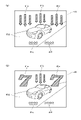
図4は、セグメント表示部50を拡大して示した説明図である。前述したようにセグメント表示部50は、前面枠4に設けられた小窓部4c(図1参照)を通して遊技者が視認可能である。図示されるようにセグメント表示部50には、第1特図を表示する第1特図表示部51と、第2特図を表示する第2特図表示部52とが設けられており、それぞれ9個のLEDで構成されている。第1特図および第2特図は、対応する表示部51,52で9個のLEDを点滅させる(点灯させるLEDを切り換える)ことによって変動表示され、所定の組み合わせのLEDを点灯させた状態で停止表示される。このとき、大当り判定の結果が大当りであれば、大当り図柄に対応する組み合わせのLEDを点灯させ、外れであれば、外れ図柄に対応する組み合わせのLEDを点灯させる。
FIG. 4 is an explanatory diagram showing an enlarged
また、第1始動口24または第2始動口25に遊技球が入球しても、第1特図や第2特図の変動表示中などで新たな変動表示の開始条件が満たされていない場合には、第1始動口24への入球で取得した判定乱数の値を第1特図保留として記憶し、第2始動口25への入球で取得した判定乱数の値を第2特図保留として記憶する。その後、特別図柄(第1特図または第2特図)の新たな変動表示の開始条件が満たされると、第1特図保留または第2特図保留に基づいて大当り判定を行い、対応する特別図柄の変動表示を行う。本実施例のパチンコ機1では、このような第1特図保留および第2特図保留を、それぞれ最大4つまで記憶可能である。
In addition, even if the game ball enters the
図4に示されるようにセグメント表示部50には、第1特図保留の記憶数(第1特図保留数)を表示する第1特図保留表示部53と、第2特図保留の記憶数(第2特図保留数)を表示する第2特図保留表示部54とが設けられており、それぞれ2個のLEDで構成されている。これらの保留表示部53,54では、保留数が0個であればLEDが2個とも消灯し、保留数が1個であれば1個のLEDが点灯し、保留数が2個であれば2個のLEDが点灯し、保留数が3個であれば1個のLEDが点滅し、保留数が4個であれば、2個のLEDが点滅する。
As shown in FIG. 4, the
第1特図または第2特図が大当り図柄で停止表示されると、大入賞口28が開放状態となる大当り遊技を実行する。大当り遊技では、開放した大入賞口28を、規定個数(例えば9個)の遊技球が入球するか、あるいは所定の開放時間(例えば30秒)が経過したら閉鎖するラウンド遊技が複数回(例えば15回)繰り返される。前述したように大入賞口28に遊技球が入球すると、賞球として13個の遊技球が払い出されることから、大当り遊技によって遊技者は多量の賞球を獲得することが可能である。
When the first special symbol or the second special symbol is stop-displayed as a big win symbol, a big win game is executed in which the big winning
また、前述したように、中央装置40(演出表示装置41)の右方には、普通図柄作動ゲート27が設けられており、右打ちされた遊技球が普通図柄作動ゲート27を通過可能である。普通図柄作動ゲート27を通過する遊技球がゲートセンサー27sによって検知されると、所定の判定乱数(普図当り判定乱数など)を取得し、その判定乱数の値に基づいて普図当りか外れかを判定する普図当り判定を行った後、セグメント表示部50にて普通図柄の変動表示を行う。
Further, as described above, the normal
図4に示されるようにセグメント表示部50には、左右2個のLEDで構成された普図表示部56が設けられている。普通図柄は、普図表示部56で2個のLEDを点滅させる(点灯させるLEDを切り換える)ことによって変動表示され、一方のLEDを点灯させた状態で停止表示される。このとき、普図当り判定の結果が普図当りであれば、普図当り図柄に対応する左側のLEDを点灯させ、外れであれば、外れ図柄に対応する右側のLEDを点灯させる。そして、普通図柄が普図当り図柄で停止表示された場合は、第2始動口25が所定時間だけ開放状態となった後に閉鎖状態に戻る普図当り遊技が行われるので、第2始動口25に遊技球が入球する可能性(すなわち、第2特図の変動表示が行われる可能性)が高まる。
As shown in FIG. 4, the
また、遊技球が普通図柄作動ゲート27を通過しても、普通図柄の変動表示中などで新たな変動表示の開始条件が満たされていない場合には、取得した判定乱数の値を普図保留として最大4つまで記憶することが可能である。その後、普通図柄の新たな変動表示の開始条件が満たされると、普図保留に基づいて普図当り判定や、普通図柄の変動表示を行う。図4に示されるようにセグメント表示部50には、2個のLEDで構成された普図保留表示部57が設けられており、普図保留の記憶数(普図保留数)は普図保留表示部57に表示される。
In addition, even if the game ball passes through the normal
普図当り遊技における第2始動口25の開放時間は、「電サポ状態」であるか「非電サポ状態」であるかで異なる。電サポ状態では、非電サポ状態よりも第2始動口25の開放時間が長く設定される。また、電サポ状態では、非電サポ状態よりも普図当り判定の結果が普図当りとなる確率(普図当り確率)が高く、且つ、普通図柄の変動時間が短く設定される。従って、電サポ状態では、非電サポ状態に比べて第2始動口25に遊技球が入球する可能性(すなわち、第2特図の変動表示が行われる可能性)が高まる。図4に示されるようにセグメント表示部50には、3個のLEDで構成された電サポ表示部58が設けられており、電サポ表示部58で3個のLEDを点灯することで電サポ状態中であることを表す。
The opening time of the
本実施例のパチンコ機1では、複数の大当り図柄が設けられると共に「通常当り図柄」と「確変当り図柄」とに大別されており、特別図柄(第1特図または第2特図)が何れの大当り図柄で停止表示された場合でも、大当り遊技の終了後に電サポ状態が設定される。そして、通常当り図柄である場合は、大当り遊技の終了後に、大当り判定の結果が大当りとなる確率(大当り確率)が所定の通常確率(低確率)に設定され、特別図柄の変動回数が所定回数(例えば100回)に達すると非電サポ状態に設定される。一方、確変当り図柄である場合は、大当り遊技の終了後に大当り確率が通常確率よりも高い高確率に設定され、電サポ状態と共に次回の大当り遊技まで継続される。以下では、大当り確率が高確率に設定された状態を「確変状態」と称することがある。また、電サポ状態では、非電サポ状態よりも特別図柄(第1特図および第2特図)の変動時間が短く設定されることから、電サポ状態であって、且つ大当り確率が通常確率に設定された状態を「時短状態」と称することがある。
In the
また、前述した特別図柄(第1特図および第2特図)の変動表示と連動して、演出表示装置41では、演出用の種々の画像が表示される。図5は、演出表示装置41における表示の一態様を例示した説明図である。演出表示装置41の表示画面上には、演出用の図柄として3つの識別図柄41a,41b,41cや、その背景となる背景画像41dなどを表示可能である。セグメント表示部50の第1特図表示部51あるいは第2特図表示部52で特別図柄の変動表示が開始されると、演出表示装置41においても、識別図柄41a,41b,41cが複数の数字(例えば「1」~「9」の9つの数字)を次々と切り換えて変動表示する演出(以下「図柄変動演出」ともいう)が行われる。尚、識別図柄は、数字以外にも、文字、図形、記号等を意匠化した図柄であってもよく、遊技者が種類を識別できる形態であればよい。
Further, in conjunction with the variable display of the special symbols (first special symbol and second special symbol) described above, the
図5(a)には、3つの識別図柄41a,41b,41cが一斉に変動表示している様子が概念的に示されている。変動表示が開始された後、所定時間が経過すると、初めに左識別図柄41aが「1」~「9」の何れかで停止表示され、次に右識別図柄41cが停止表示され、最後に中識別図柄41bが停止表示される。そして、3つの識別図柄41a,41b,41cは、特別図柄(第1特図または第2特図)が外れ図柄で停止表示される場合は、同じ数字で揃わない組み合わせ(バラケ目)で停止表示されるのに対して、特別図柄が大当り図柄で停止表示される場合は、同じ数字で揃った組み合わせ(ゾロ目)で停止表示される。特に、特別図柄が遊技者にとって通常当り図柄よりも有利な確変当り図柄で停止表示される場合は、識別図柄41a,41b,41cが同じ奇数の数字で揃って停止表示される。
FIG. 5(a) conceptually shows how the three
こうして演出表示装置41における識別図柄41a,41b,41cの表示内容を、特別図柄の表示内容と対応させることにより、図5(b)に示されるように3つの識別図柄のうち2つが停止表示されたときに同じ数字であると、最後に停止表示される識別図柄も同じ数字で揃うのではないかと、遊技者は識別図柄の変動表示(図柄変動演出)を注視することになる。このように、2つの識別図柄が同じ図柄で停止表示された状態で最後の識別図柄を変動表示させながら行われる演出は「リーチ演出」と呼ばれており、リーチ演出を発生させることで遊技興趣を高めることが可能である。
By making the display contents of the
また、演出表示装置41の表示画面の下部には、第1特図保留数を表示するための第1保留表示領域41eと、第2特図保留数を表示するための第2保留表示領域41fとが設定されている。本実施例のパチンコ機1では、第1特図保留数と同数の保留シンボル(図中の丸印)を第1保留表示領域41eに表示し、第2特図保留数と同数の保留シンボルを第2保留表示領域41fに表示する。図5の例では、第1特図保留数および第2特図保留数が共に4個であることを示している。尚、当然ながら、演出表示装置41に表示される保留数は、セグメント表示部50の第1特図保留表示部53および第2特図保留表示部54に表示される保留数と一致する。
In addition, at the bottom of the display screen of the
さらに、本実施例の演出表示装置41では、遊技者による演出ボタン10の押下と連動して進行する演出(操作連動演出)を実行することが可能となっている。本実施例の操作連動演出は、複数の段階で構成された段階演出であると共に、操作連動演出内で演出ボタン10の操作が有効とされる複数の操作有効期間が設定され、操作有効期間毎に演出ボタン10が操作されると、その操作に基づいて操作連動演出を次の段階に進行させる。
Furthermore, in the
図6は、演出表示装置41で実行される操作連動演出の一例を示した説明図である。図示した操作連動演出は、識別図柄41a,41b,41cが同じ偶数の数字(例えば「6」)で揃って停止表示された状態(特別図柄が通常当り図柄で停止表示されたことを表す停止態様)から、特別図柄の変動表示とは独立して再び識別図柄41a,41b,41cの変動表示を開始する。図6(a)には、識別図柄41a,41b,41cが一斉に変動表示している様子が示されている。尚、本実施例の識別図柄41a,41b,41cは、本発明の「演出情報」に相当している。
FIG. 6 is an explanatory diagram showing an example of an operation-linked effect executed by the
また、識別図柄41a,41b,41cで同じ奇数の数字「7」の停止表示を狙う旨の指示表示が行われ、変動表示している識別図柄41a,41b,41cの各々に対応して、演出ボタン10を模したボタン画像42a,42b,42cの表示や、演出ボタン10の操作が有効とされる所定の操作有効期間の残り状況を示す残り状況表示部43a,43b,43cが下方に追加される。
In addition, an instruction display to the effect that a stop display of the same odd number "7" is aimed at the
図6(a)では、左識別図柄41aを停止表示させるために左ボタン画像42aで演出ボタン10の操作が指示されると共に、左残り状況表示部43aで操作有効期間の残りを表すハッチングを付した部分を減衰させる減衰表示が行われている。そして、操作有効期間が経過して左残り状況表示部43aでの減衰表示が終了する前に、遊技者によって演出ボタン10が押下されると、その操作に基づいて左識別図柄41aが停止表示され、図6(b)に示した例では、数字「7」で停止表示されている。
In FIG. 6A, the operation of the
また、左識別図柄41aの停止表示に続いて、図6(b)では、中識別図柄41bを停止表示させるために中ボタン画像42bで演出ボタン10の操作が指示されると共に、中残り状況表示部43bで操作有効期間の減衰表示が行われている。そして、中残り状況表示部43bでの減衰表示が終了する前に、遊技者によって演出ボタン10が押下されると、その操作に基づいて中識別図柄41bが停止表示され、図6(c)に示した例では、左識別図柄41aと同様に数字「7」で停止表示されている。
Further, following the stop display of the
さらに、図6(c)では、最後の右識別図柄41cを停止表示させるために右ボタン画像42cで演出ボタン10の操作が指示されると共に、右残り状況表示部43cで操作有効期間の減衰表示が行われている。そして、右残り状況表示部43cでの減衰表示が終了する前に、遊技者によって演出ボタン10が押下されると、その操作に基づいて右識別図柄41cが停止表示される。
Further, in FIG. 6(c), the
図6(d)に示した例では、識別図柄41a,41b,41cが同じ奇数の数字「7」で揃って停止表示されており、特別図柄が通常当り図柄よりも遊技者にとって有利な確変当り図柄で停止表示されたことを表す停止態様であることから、いわゆる「昇格」を遊技者に印象付ける表示が行われる。尚、操作連動演出が行われても、識別図柄41a,41b,41cが必ずしも同じ奇数の数字「7」で揃って停止表示されるとは限らず、揃わない場合もあり、揃わなければいわゆる「昇格」を表す表示は行われない。また、本実施例のパチンコ機1では、演出ボタン10が押下されないまま、操作有効期間が経過した場合でも、識別図柄41a,41b,41cが停止表示される。
In the example shown in FIG. 6(d), the
C.本実施例のパチンコ機の制御内容 :
C-1.遊技制御処理 :
図7は、主制御基板200のCPU201が、遊技の進行に係る制御として行う遊技制御処理の大まかな流れを示したフローチャートである。主制御基板200のCPU201は、所定周期で(例えば、4msec毎に)発生するタイマ割り込みに基づいて図7の遊技制御処理を実行する。尚、以下の説明では、CPU201の初期化処理や、割り込み禁止処理、割り込み許可処理などの周知の処理については説明を省略する。
C. Control contents of the pachinko machine of this embodiment:
C-1. Game control processing:
FIG. 7 is a flowchart showing a rough flow of game control processing performed by the
主制御基板200のCPU201は、遊技制御処理を開始すると、まず、出力処理(S10)を行う。本実施例の主制御基板200では、後述する各処理において、サブ制御基板220を初めとする各種制御基板に向けて送信する各種コマンドを、RAM203に確保された出力バッファに一旦記憶するようになっており、出力処理(S10)では、出力バッファに記憶されている各種コマンドを各種制御基板に向けて送信する。こうすることにより、例えば、サブ制御基板220では、遊技の進行に合わせた演出の制御が行われ、払出制御基板240では、遊技球の払い出しが行われることになる。
When the game control process is started, the
主制御基板200のCPU201は、出力処理(S10)に続いて、入力処理(S20)を行う。前述したように、第1始動口24、第2始動口25、大入賞口28、その他入賞口30の何れかに遊技球が入球すると、賞球として遊技球を払い出すようになっている。そこで、入力処理(S20)では、入球を検知する各種センサー(第1始動口センサー24s、第2始動口センサー25s、大入賞口センサー28s、その他入賞口センサー30sなど)について、遊技球を検知したか否かを判断する。そして、遊技球を検知した場合は、遊技球の払い出しを指示する払出コマンドを、上述した出力バッファに記憶する。こうして出力バッファに記憶された払出コマンドは、次回の出力処理(S10)で払出制御基板240に向けて送信される。コマンドを受信した払出制御基板240は、前述したように遊技球の入球が第1始動口24、第2始動口25、その他入賞口30の何れかであれば、3個の遊技球を払出し、大入賞口28であれば、13個の遊技球を払い出す。
After the output process (S10), the
入力処理(S20)を終了すると、次に、乱数更新処理(S30)を行う。前述したように、普図当り判定や特別図柄の大当り判定は、所定の判定乱数の値に基づいて行われる。また、これ以外にも、後述する各種の決定が専用の乱数の値に基づいて行われる。乱数更新処理(S30)では、これらの乱数の更新を行う。尚、乱数の更新は、遊技制御処理の中の乱数更新処理(S30)においてだけでなく、遊技制御処理を一旦終了してから次回の遊技制御処理を開始する(タイマ割り込みが発生する)までの間に行うこととしてもよい。また、乱数更新のための専用回路を設けて、この専用回路で乱数を更新してもよい。 After completing the input process (S20), next, a random number update process (S30) is performed. As described above, the general pattern hit determination and the special symbol jackpot determination are performed based on a predetermined determination random number value. In addition to this, various decisions to be described later are made based on the value of the dedicated random number. These random numbers are updated in the random number update process (S30). In addition, the update of the random number is not only in the random number update process (S30) in the game control process, but also from the time the game control process is once finished until the next game control process is started (timer interrupt occurs). It may be done in between. Alternatively, a dedicated circuit for updating the random number may be provided, and the random number may be updated by this dedicated circuit.
乱数更新処理(S30)を終了したら、ゲートセンサー検知処理(S40)を行う。ゲートセンサー検知処理(S40)では、普通図柄作動ゲート27を通過する遊技球をゲートセンサー27sで検知すると、普図保留数が上限値(本実施例では「4」)に達しているか否かを判断して、達していなければ、普図当り判定乱数などを取得し、取得した乱数値を普図保留としてRAM203に記憶する。
After completing the random number update process (S30), the gate sensor detection process (S40) is performed. In the gate sensor detection process (S40), when the game ball passing through the normal
ゲートセンサー検知処理(S40)に続いて、始動口センサー検知処理(S50)を行う。始動口センサー検知処理(S50)では、第1始動口24に入球した遊技球を第1始動口センサー24sで検知すると、第1特図保留数が上限値(本実施例では「4」)に達しているか否かを判断して、達していなければ、所定の判定乱数を取得し、取得した乱数値を第1特図保留としてRAM203に記憶する。また、第2始動口25に入球した遊技球を第2始動口センサー25sで検知すると、第2特図保留数が上限値(本実施例では「4」)に達しているか否かを判断して、達していなければ、所定の判定乱数を取得し、取得した乱数値を第2特図保留としてRAM203に記憶する。ここで、判定乱数としては、大当り判定を行うための大当り判定乱数や、大当りの場合に特別図柄で停止表示する大当り図柄の種類を決定するための図柄決定乱数や、特別図柄の変動表示の開始から停止表示までの変動パターンを決定するための変動パターン決定乱数などを取得する。
Following the gate sensor detection process (S40), the starting door sensor detection process (S50) is performed. In the starting hole sensor detection process (S50), when the game ball entering the
始動口センサー検知処理(S50)を終了すると、次に、普通動作処理(S60)を行う。普通動作処理(S60)では、主に次のような処理を行う。まず、普通図柄の変動表示中または普図当り遊技の実行中であるか否かを判断する。普通図柄の変動表示中および普図当り遊技の実行中の何れでもない場合は、普通図柄の停止表示から所定の確定時間が経過していることを確認した後、普図保留が記憶されているか否かを判断する。普図保留が記憶されていれば、最先に記憶された普図保留を読み出し、その読み出した普図保留(普図当り判定乱数の値)に基づいて普図当り判定を行う。この普図当り判定では、普図保留として読み出した普図当り判定乱数の値が所定の当り値であれば、普図当りと判定し、当り値以外の外れ値であれば、外れと判定する。尚、前述したように電サポ状態では、非電サポ状態よりも普図当り確率が高く設定され、例えば、非電サポ状態では普図当り確率が100分の1に設定されるのに対して、電サポ状態では普図当り確率が100分の99に設定される。 When the starting port sensor detection process (S50) ends, next, normal operation process (S60) is performed. In the normal operation process (S60), mainly the following processes are performed. First, it is determined whether or not normal symbols are being displayed in a variable manner or a game per normal pattern is being executed. When neither normal pattern variable display nor normal pattern winning game is being executed, after confirming that a predetermined fixed time has passed since normal pattern stop display, whether normal pattern suspension is stored determine whether or not If the general pattern reservation is stored, the first stored general pattern reservation is read, and the normal pattern per determination is performed based on the read general pattern reservation (normal pattern per determination random number value). In this normal pattern hit determination, if the value of the normal pattern hit determination random number read as a normal pattern hold is a predetermined hit value, it is determined to be a normal pattern hit, and if it is an outlier value other than the hit value, it is determined to be out. . In addition, as described above, in the electric sapo state, the probability per normal is set higher than in the non-electrical support state, for example, in the non-electrical support state, the probability per normal is set to 1/100 , In the electric sapo state, the probability per normal pattern is set to 99/100.
そして、普図当り判定の結果に基づき、普通図柄を普図当り図柄で停止表示するか、外れ図柄で停止表示するかを決定する。さらに普通図柄の変動時間を設定して、普通図柄の変動表示を開始する。前述したように電サポ状態では、非電サポ状態よりも普通図柄の変動時間が短く設定され、例えば、非電サポ状態では変動時間が20秒に設定されるのに対して、電サポ状態では変動時間が1秒に設定される。 Then, based on the result of the normal pattern hit determination, it is determined whether the normal pattern should be stop-displayed as a normal pattern-hit pattern or should be stop-displayed as a losing pattern. Further, the fluctuation time of the normal design is set, and the fluctuation display of the normal design is started. As described above, in the electric support state, the fluctuation time of the normal pattern is set shorter than in the non-electric support state. Variation time is set to 1 second.
普通図柄の変動表示中である場合は、変動時間が経過したか否かを判断して、変動時間が経過すると、決定しておいた普図当り図柄または外れ図柄で普通図柄を停止表示し、普図保留数から「1」を減算する。そして、確定時間の経過を待って、停止表示された普通図柄が外れ図柄である場合は、再び普通図柄の変動表示を開始する処理を行う。一方、停止表示された普通図柄が普図当り図柄である場合は、普図当り遊技を開始する。 When the variable display of the normal pattern is being performed, it is determined whether or not the variable time has passed, and when the variable time has passed, the normal pattern is stopped and displayed with the determined normal pattern hit pattern or the lost pattern, Subtract "1" from the number of normal patterns reserved. Then, after waiting for the fixed time to pass, if the stopped and displayed normal symbol is a lost symbol, the process of starting the variable display of the normal symbol again is performed. On the other hand, when the stopped and displayed normal symbol is a normal per pattern, a normal per per pattern game is started.
普図当り遊技中は、始動口ソレノイド26mを駆動して第2始動口25を開放状態とした後、開放時間が経過したら閉鎖状態に戻す処理を行う。前述したように電サポ状態では、非電サポ状態よりも第2始動口25の開放時間が長く設定され、例えば、非電サポ状態では開放時間が0.3秒(0.1秒×3回開放)に設定されるのに対して、電サポ状態では開放時間が4.5秒(1.5秒×3回開放)に設定される。
During the regular game, after driving the starting port solenoid 26m to open the
普通動作処理(S60)を終了したら、続いて、特別動作処理(S70)を行う。特別動作処理(S70)では、主に次のような処理を行う。まず、特別図柄(第1特図または第2特図)の変動表示中、特別図柄の確定表示中、大当り遊技中の何れかであるか否かを判断する。これらの何れでもない場合は、第2特図保留が記憶されているか否かを判断し、記憶されていれば、最先に第2特図保留として記憶された各種の判定乱数(すなわち、大当り判定乱数、図柄決定乱数、変動パターン決定乱数など)の値を読み出す。また、第2特図保留が記憶されていない場合は、第1特図保留が記憶されているか否かを判断し、記憶されていれば、最先に第1特図保留として記憶された各種の判定乱数の値を読み出す。 After the normal operation process (S60) ends, the special operation process (S70) is performed. In the special operation process (S70), mainly the following processes are performed. First, it is determined whether the special symbols (the first special symbol or the second special symbol) are being displayed in a variable manner, the special symbols are being fixedly displayed, or the jackpot game is being played. If neither of these is the case, it is determined whether or not the second special figure reservation is stored, and if it is stored, various judgment random numbers (that is, the big hit Judgment random number, pattern determination random number, variation pattern determination random number, etc.) Read out the value. Also, if the second special figure suspension is not stored, it is determined whether or not the first special figure suspension is stored. Reads the decision random number value of .
こうして第2特図保留または第1特図保留として読み出した大当り判定乱数の値を用いて、大当り判定テーブルを参照しながら大当り判定を行う。大当り判定テーブルは、大当り判定乱数の値に「大当り」または「外れ」の大当り判定結果が対応付けられたテーブルであり、主制御基板200のROM202に予め記憶されている。また、前述したように確変状態中は、大当り確率が通常確率よりも高い高確率に設定され、非確変状態に比べて大当りが発生し易いことから、大当り判定テーブルには、確変状態用と非確変状態用とが設けられている。
Using the value of the big hit determination random number read as the second special figure reservation or the first special figure reservation in this way, the big hit judgment is performed while referring to the big hit judgment table. The jackpot determination table is a table in which the value of the jackpot determination random number is associated with the jackpot determination result of “big hit” or “loss”, and is stored in the
図8は、本実施例の大当り判定テーブルを概念的に示した説明図である。図8(a)に示されるように非確変状態用の大当り判定テーブルでは、0~65535の乱数値のうち0~217の乱数値に「大当り」が設定されており、残りの乱数値に「外れ」が設定されている。一方、図8(b)に示されるように確変状態用の大当り判定テーブルでは、0~65535の乱数値のうち0~655の乱数値に「大当り」が設定されており、残りの乱数値に「外れ」が設定されている。
FIG. 8 is an explanatory diagram conceptually showing the jackpot determination table of this embodiment. As shown in FIG. 8(a), in the jackpot determination table for the non-probable variable state,
大当り判定では、確変状態中であるか否かに応じて選択した大当り判定テーブルを参照して、第2特図保留または第1特図保留として読み出した大当り判定乱数の値が「大当り」に対応する値(大当り値)なのか、「外れ」に対応する値(外れ値)なのかを判定する。これにより、図8に示した例では、非確変状態であれば約300分の1の確率で「大当り」の判定結果が得られるのに対して、確変状態であれば約100分の1の確率で「大当り」の判定結果が得られる。 In the jackpot judgment, the value of the jackpot judgment random number read out as the second special figure hold or the first special figure hold corresponds to "jackpot" by referring to the big hit judgment table selected according to whether the variable probability state It is determined whether it is a value (jackpot value) or a value (outlier) corresponding to "outlier". Thereby, in the example shown in FIG. You can get a judgment result of "big hit" with probability.
そして、大当り判定の結果が「大当り」である場合は、停止表示する大当り図柄を決定する。前述したように大当り図柄は複数設けられており、通常当り図柄と確変当り図柄とに大別される。大当り図柄の決定は、第1特図保留または第2特図保留として読み出した図柄決定乱数の値を用いて、大当り図柄決定テーブル(図示せず)を参照しながら行う。大当り図柄決定テーブルは、図柄決定乱数の値と複数の大当り図柄とが対応付けられたテーブルであり、主制御基板200のROM202に予め記憶されている。これに対して、大当り判定の結果が「外れ」である場合は、特別図柄を外れ図柄で停止表示することを決定する。
Then, when the result of the big-hit determination is "big-hit", the big-hit symbol to be stopped and displayed is determined. As described above, a plurality of jackpot symbols are provided, and are roughly divided into normal winning symbols and odd winning symbols. The determination of the jackpot design is performed while referring to a jackpot design determination table (not shown) using the value of the design determination random number read as the first special design reservation or the second special design reservation. The jackpot symbol determination table is a table in which the value of the symbol determination random number is associated with a plurality of jackpot symbols, and is stored in advance in the
こうして特別図柄で停止表示する図柄を決定したら、特別図柄の変動パターンを決定する。変動パターンとは、特別図柄(第1特図または第2特図)が変動表示を開始してから停止表示するまでの時間(変動時間)を識別するためのものであり、予め用意された複数の変動パターンは、互いに設定されている変動時間が異なっている。変動パターンの決定は、第1特図保留または第2特図保留として読み出した変動パターン決定乱数の値を用いて、変動パターン決定テーブルを参照しながら行う。 After determining the symbols to be stopped and displayed in the special symbols in this way, the variation pattern of the special symbols is determined. The variation pattern is for identifying the time (variation time) from when the special symbol (the first special figure or the second special figure) starts the variable display to the stop display, and is prepared in advance. are different from each other in the set fluctuation time. Determination of the variation pattern is performed while referring to the variation pattern determination table using the value of the variation pattern determination random number read as the first special figure suspension or the second special figure suspension.
図9は、変動パターン決定テーブルを概念的に例示した説明図である。図示されるように変動パターン決定テーブルには、変動パターン決定乱数の値と、複数の変動パターンの各々に付された変動パターンIDとが対応付けられており、複数の変動パターンに設定されている変動時間は互いに異なっている。このような変動パターン決定テーブルは、遊技状態に応じて、確変状態用のテーブルと、時短状態用のテーブルと、確変状態および時短状態の何れでもない通常状態用のテーブルとに大別され、主制御基板200のROM202に予め記憶されている。前述したように確変状態および時短状態では電サポ状態が設定されているのに対して、通常状態では電サポ状態が設定されていない。また、電サポ状態では、非電サポ状態よりも特別図柄(第1特図および第2特図)の変動時間が短く設定される。そのため、確変状態用や時短状態用の変動パターン決定テーブルには、通常状態用の変動パターン決定テーブルに比べて変動時間が短めの変動パターンが設定されている。
FIG. 9 is an explanatory diagram conceptually exemplifying the variation pattern determination table. As shown in the figure, in the variation pattern determination table, the value of the variation pattern determination random number is associated with the variation pattern ID assigned to each of the plurality of variation patterns, and is set for the plurality of variation patterns. The variable times are different from each other. Such a variation pattern determination table is roughly divided into a table for a variable probability state, a table for a time saving state, and a table for a normal state that is neither a variable probability state nor a time saving state, depending on the game state. It is pre-stored in the
また、遊技状態に応じて大別された変動パターン決定テーブルは、大当り判定の結果に応じて、それぞれ大当り用テーブルと外れ用テーブルとに細分化されている。大当り判定の結果が大当りの場合は、前述したリーチ演出などが行われることが多く、その実行時間の確保を容易とするために、大当り用テーブルには、外れ用テーブルに比べて変動時間が長めの変動パターンが設定されている。また、各種の変動パターン決定テーブルの細分化は、これに限られず、例えば、特別図柄の種類(第1特図か第2特図か)に応じて細分化されていてもよい。さらに、記憶されている特図保留数に応じて細分化されていてもよく、特図保留数が多いほど、保留の消化を早めるために、変動時間が短めの変動パターンが設定された変動パターン決定テーブルとしてもよい。 The variation pattern determination table, which is broadly classified according to the game state, is subdivided into a big win table and a losing table according to the result of the big win determination. When the result of judging a big hit is a big hit, the above-mentioned ready-to-win effect is often performed, and in order to make it easier to secure the execution time, the table for big wins has a longer fluctuation time than the table for winning. fluctuation pattern is set. Further, the subdivision of various variation pattern determination tables is not limited to this, and may be subdivided according to the type of special symbol (first special symbol or second special symbol), for example. Furthermore, it may be subdivided according to the number of special figure reservations that are stored, and as the number of special figure reservations increases, the variation pattern in which the variation pattern with a shorter variation time is set in order to expedite the digestion of the reservation A decision table may also be used.
変動パターンを決定すると、特別図柄の変動表示を開始する。また、変動表示の開始に伴って、特別図柄の変動パターンを指定する変動パターン指定コマンドや、停止表示する図柄を指定する停止図柄指定コマンドをRAM203の出力バッファに記憶する。これらのコマンドは、次回の出力処理(S10)でサブ制御基板220に向けて送信される。サブ制御基板220のCPU221は、これらのコマンドを受信することで、特別図柄の変動表示に合わせて演出表示装置41で図柄変動演出を実行する。
When the variation pattern is determined, the variation display of the special symbols is started. In addition, along with the start of the variable display, the variable pattern designation command for designating the variable pattern of the special design and the stop design designation command for designating the design to be stopped and displayed are stored in the output buffer of the
特別図柄の変動表示中である場合は、変動時間が経過したか否かを判断する。前述したように変動時間は、変動パターンに設定されており、変動時間が経過すると、決定しておいた大当り図柄または外れ図柄で特別図柄を停止表示する。そして、特別図柄の停止表示を示す特図変動停止コマンドをRAM203の出力バッファに記憶しておき、次回の出力処理(S10)でサブ制御基板220に向けて送信する。サブ制御基板220のCPU221は、特図変動停止コマンドに基づいて、演出表示装置41の図柄変動演出を終了する。また、特別図柄の変動表示の終了に伴って、第2特図の停止表示であれば第2特図保留数から「1」を減算し、第1特図の停止表示であれば第1特図保留数から「1」を減算する。さらに、停止表示した特別図柄を確定表示しておく時間(確定時間)を設定する。
When the special symbols are displayed in a variable manner, it is determined whether or not the variable time has elapsed. As described above, the variation time is set in the variation pattern, and when the variation time elapses, the special symbol is stopped and displayed with the determined big hit symbol or the winning symbol. And, the special figure fluctuation stop command which shows the special design stop indication is remembered in the output buffer of RAM203, it transmits toward
特別図柄の確定表示中は、確定時間が経過したか否かを判断し、確定時間が経過したら、停止表示された特別図柄が大当り図柄および外れ図柄の何れであるかを判断する。その結果、外れ図柄であった場合は、時短状態(非確変状態かつ電サポ状態)であるか否かを判断し、時短状態であれば、時短状態中の特別図柄の変動回数を計数する。そして、計数した変動回数が所定回数(例えば100回)に達すると、電サポ状態を終了して遊技状態を通常状態に設定する。 During the fixed display of the special pattern, it is judged whether or not the fixed time has passed, and when the fixed time has passed, it is judged whether the stopped and displayed special pattern is a jackpot pattern or a losing pattern. As a result, if the pattern is out, it is determined whether or not it is in the time saving state (non-probability variable state and electric sapo state), and if it is in the time saving state, the number of variations of the special pattern in the time saving state is counted. When the counted number of fluctuations reaches a predetermined number (for example, 100 times), the electric support state is ended and the game state is set to the normal state.
一方、停止表示された特別図柄が大当り図柄であった場合は、大当り遊技における大入賞口28の開放パターン(ラウンド回数、開放時間、閉鎖時間など)を設定して、大当り遊技を開始する。また、大当り遊技の開始を示す大当り遊技開始コマンドをRAM203の出力バッファに記憶しておき、次回の出力処理(S10)でサブ制御基板220に向けて送信する。
On the other hand, when the stop-displayed special pattern is a jackpot pattern, an opening pattern (number of rounds, opening time, closing time, etc.) of the
大当り遊技中は、大入賞口ソレノイド29mを駆動して大入賞口28を開放状態とすることでラウンド遊技を開始する。その後、開放時間が経過するか、あるいは大入賞口28に規定個数の遊技球が入球すると、大入賞口28を閉鎖状態としてラウンド遊技を終了し、閉鎖時間の経過を待って次のラウンド遊技を開始する。そして、設定されたラウンド回数を全て消化したら、大当り遊技を終了する。また、大当り遊技の終了を示す大当り遊技終了コマンドをRAM203の出力バッファに記憶しておき、次回の出力処理(S10)でサブ制御基板220に向けて送信する。
During the jackpot game, the round game is started by driving the
さらに、停止表示された大当り図柄の種類に応じて大当り遊技の終了後の遊技状態を設定する。すなわち、大当り図柄が確変当り図柄であれば、確変状態(大当り確率が高確率に設定された電サポ状態)に設定し、大当り図柄が通常当り図柄であれば、時短状態(大当り確率が通常確率に設定された電サポ状態)に設定する。また、遊技状態を示す遊技状態指定コマンドをRAM203の出力バッファに記憶しておき、次回の出力処理(S10)でサブ制御基板220に向けて送信する。
Furthermore, the game state after the end of the big win game is set according to the type of the stopped and displayed big win symbol. That is, if the jackpot pattern is a probability variation pattern, it is set to a probability variation state (an electric sapo state in which the jackpot probability is set to a high probability), and if the jackpot pattern is a normal hit pattern, the time saving state (the jackpot probability is a normal probability (Electric support state set to ). Also, a game state designation command indicating the game state is stored in the output buffer of the
特別動作処理(S70)を終了したら、保留数処理(S80)を行う。保留数処理(S80)では、記憶されている第1特図保留数および第2特図保留数を確認し、これらの保留数を示す保留数伝達コマンドをRAM203の出力バッファに記憶する。この保留数伝達コマンドは、次回の出力処理(S10)でサブ制御基板220に向けて送信され、サブ制御基板220のCPU221は、コマンドを受信すると、第1特図保留数および第2特図保留数と同数の保留シンボルを演出表示装置41の第1保留表示領域41eや第2保留表示領域41fに表示する。
After finishing the special action process (S70), the pending number process (S80) is performed. In the pending number process (S80), the stored first special figure pending number and second special figure pending number are confirmed, and a pending number transmission command indicating these pending numbers is stored in the output buffer of the RAM203. This pending number transmission command is transmitted toward the
保留数処理(S80)を行うと、図7の遊技制御処理を一旦終了する。そして、4msec毎のタイマ割り込みが発生すると、再び図7の遊技制御処理を開始し、出力処理(S10)以降の上述した一連の処理を行う。 When the number of reservations processing (S80) is performed, the game control processing of FIG. 7 is temporarily terminated. Then, when a timer interrupt occurs every 4 msec, the game control process of FIG. 7 is started again, and the above-described series of processes after the output process (S10) are performed.
主制御基板200のCPU201は、以上のような遊技制御処理を繰り返し行うことによって、パチンコ機1での遊技を進行させる。また、前述したように主制御基板200のCPU201は、遊技制御処理を実行する中で各種コマンドをサブ制御基板220に向かって送信する。そして、サブ制御基板220のCPU221は、受信したコマンドに基づいて具体的な演出の内容を決定し、画像音声制御基板230やランプ制御基板226に表示内容や音声内容を指定することにより、演出表示装置41、各種スピーカー6a,6b、各種ランプ5a~5cを用いた様々な遊技演出を実行している。また、前述したように演出表示装置41では、振動モーター10mを内蔵した演出ボタン10が遊技者によって押下されると、その操作に連動して進行する操作連動演出を実行することが可能となっている。以下では、操作連動演出の制御のためにサブ制御基板220のCPU221が実行する処理(操作連動演出処理)について説明する。
The
C-2.操作連動演出処理 :
図10は、サブ制御基板220のCPU221が行う操作連動演出処理を示したフローチャートである。この処理は、主制御基板200から受信した変動パターン指定コマンドで特定の変動パターンが指定されており、その特定の変動パターンに基づいて識別図柄41a,41b,41cの変動表示を行い、同じ偶数の数字(例えば「6」)で揃えて停止表示させた後に行われる。
C-2. Operation-linked effect processing:
FIG. 10 is a flowchart showing operation-linked effect processing performed by the
サブ制御基板220のCPU221は、操作連動演出処理を開始すると、まず、識別図柄41a,41b,41cの変動表示を開始し(S100)、続いて、操作有効期間の開始タイミングか否かを判断する(S101)。前述したように演出ボタン10の操作が有効とされる操作有効期間は、操作連動演出内で複数(本実施例では3回)設定されるようになっており、1回目の操作有効期間の開始タイミングではない場合は(S101:no)、1回目の操作有効期間の開始タイミングとなるまで待機状態となる。
When the operation-linked effect processing is started, the
その後、1回目の操作有効期間の開始タイミングとなった場合は(S101:yes)、演出ボタン10の操作を有効化すると共に(S102)、左残り状況表示部43aでの操作有効期間の減衰表示を開始して(S103)、演出ボタン10の押下が検知されたか否かを判断する(S104)。演出ボタン10の押下が検知されていない場合は(S104:no)、次に、操作有効期間が経過したか否かを判断する(S105)。本実施例のパチンコ機1では、3回の操作有効期間の長さが何れも1.5秒に設定されており、未だ操作有効期間が経過していない場合は(S105:no)、S104の処理に戻って演出ボタン10の押下が検知されたか否かを再び判断する。
After that, when it is time to start the first operation valid period (S101: yes), the operation of the
そして、操作有効期間が経過する前に演出ボタン10の押下が検知された場合は(S104:yes)、操作有効期間の回数に応じて演出ボタン10の振動時間を設定する(S106)。本実施例のパチンコ機1では、3回の操作有効期間のうち、1回目および2回目の操作有効期間であれば振動時間を0.5秒に設定し、最終の3回目の操作有効期間であれば振動時間を5秒に設定するようになっている。ここでは、1回目の操作有効期間であることから、振動時間を0.5秒に設定して(S106)、振動モーター10mの駆動によって演出ボタン10を振動させる(S107)。
Then, if the depression of the
一方、演出ボタン10が操作されないまま操作有効期間が経過した場合は(S105:yes)、S106およびS107の処理を省略し、演出ボタン10を振動させることなく、演出ボタン10の操作を無効化した後(S108)、停止順序に従って左識別図柄41aを停止表示させる(S109)。本実施例の操作連動演出では、左識別図柄41a、中識別図柄41b、右識別図柄41cの順に停止表示させるようになっている。
On the other hand, when the operation effective period has passed without the
こうして左識別図柄41aを停止表示させると、識別図柄41a,41b,41cの全てを停止表示させたか否かを判断する(S110)。そして、未だ中識別図柄41bおよび右識別図柄41cが変動表示中であるため(S110:no)、S101の処理に戻って、2回目の操作有効期間の開始タイミングとなるまで待機状態となる。本実施例のパチンコ機1では、3回の操作有効期間が連続して設定されているため、1回目の操作有効期間の終了に続けて2回目の操作有効期間が開始される。
When the
そして、2回目の操作有効期間の開始タイミングとなった場合は(S101:yes)、演出ボタン10の操作を再び有効化すると共に(S102)、中残り状況表示部43bでの操作有効期間の減衰表示を開始する(S103)。その後、操作有効期間が経過する前に演出ボタン10の押下が検知された場合は(S104:yes)、2回目の操作有効期間であることから、振動時間を0.5秒に設定して(S106)、演出ボタン10を振動させる(S107)。
Then, when it is time to start the second operation effective period (S101: yes), the operation of the
一方、演出ボタン10が操作されないまま操作有効期間が経過した場合は(S105:yes)、演出ボタン10を振動させることなく、演出ボタン10の操作を無効化した後(S108)、停止順序に従って中識別図柄41bを停止表示させる(S109)。そして、未だ右識別図柄41cが変動表示中であることから(S110:no)、S101の処理に戻って、最終の3回目の操作有効期間の開始タイミングとなるまで待機状態となる。
On the other hand, if the operation effective period has passed without the
その後、3回目の操作有効期間の開始タイミングとなった場合は(S101:yes)、演出ボタン10の操作を再び有効化すると共に(S102)、右残り状況表示部43cでの操作有効期間の減衰表示を開始する(S103)。そして、操作有効期間が経過する前に演出ボタン10の押下が検知された場合は(S104:yes)、3回目の操作有効期間であることから、振動時間を5秒に設定して(S106)、演出ボタン10を振動させる(S107)。
After that, when it is time to start the third operation valid period (S101: yes), the operation of the
一方、演出ボタン10が操作されないまま操作有効期間が経過した場合は(S105:yes)、演出ボタン10を振動させることなく、演出ボタン10の操作を無効化した後(S108)、停止順序に従って右識別図柄41cを停止表示させる(S109)。こうして識別図柄41a,41b,41cの全てを停止表示させると(S109:yes)、図10の操作連動演出処理を終了する。
On the other hand, if the operation effective period has passed without the
図11は、上述した操作連動演出処理に従って本実施例の操作連動演出が行われる様子を例示したタイムチャートである。前述したように、本実施例の操作連動演出では、まず、演出表示装置41で識別図柄41a,41b,41cの変動表示が開始される。また、操作連動演出内で演出ボタン10の操作が有効とされる3回の操作有効期間が連続して設定され、各操作有効期間の長さは何れも1.5秒となっている。
FIG. 11 is a time chart illustrating how the operation-linked effect of the present embodiment is performed according to the operation-linked effect process described above. As described above, in the operation-linked effect of the present embodiment, first, the
そして、1回目の操作有効期間に遊技者による演出ボタン10の押下が検知されると、その操作に基づいて左識別図柄41aが停止表示されると共に、振動モーター10mの駆動によって演出ボタン10に振動が発生する。この1回目の操作有効期間で発生させる振動の継続時間(振動時間)は0.5秒に設定されており、操作有効期間の長さよりも短くなっている。そのため、図示した例のように1回目の操作有効期間が始まった初期に遊技者が演出ボタン10を押下すれば、演出ボタン10の振動を2回目の操作有効期間の開始タイミングよりも前に終了することができる。
When the pressing of the
ここで、本実施例とは異なり、演出ボタン10の振動時間を予め設定しておくことなく、遊技者による演出ボタン10の押下が検知されている間は、演出ボタン10の振動を継続することとした場合、振動の継続中は何か発展があるかもしれないと遊技者が推測して演出ボタン10を押下し続けてしまうことがある。また、遊技者による演出ボタン10の押下が瞬間的であると、遊技者に演出ボタン10の振動を十分に体感させることができない。これに対して、本実施例のパチンコ機1では、演出ボタン10の振動を所定の振動時間が経過すると停止するので、遊技者が演出ボタン10を押下し続けてしまうことを抑制する(振動の停止に伴って遊技者に演出ボタン10の押下を一旦解除させる)ことができる。また、遊技者による演出ボタン10の押下が瞬間的であっても遊技者が演出ボタン10に手を添えたままであれば、遊技者に演出ボタン10の振動を所定の振動時間だけ体感させることが可能となる。
Here, unlike the present embodiment, the vibration of the
続いて、2回目の操作有効期間に遊技者による演出ボタン10の押下が検知されると、その操作に基づいて中識別図柄41bが停止表示されると共に、振動モーター10mの駆動によって演出ボタン10に振動が発生する。この2回目の操作有効期間で発生させる振動も1回目と同様に振動時間が0.5秒に設定されている。図示した例では遊技者による演出ボタン10の押下が2回目の操作有効期間の後半に入ってから行われているものの、振動時間が操作有効期間の長さの半分よりも短くなっているため、演出ボタン10の振動を3回目の操作有効期間の開始タイミングよりも前に終了することができる。尚、演出ボタン10の振動中に遊技者が演出ボタン10の押下を止めても、所定の振動時間が経過するまでは振動が継続される。
Subsequently, when the depression of the
さらに、3回目の操作有効期間に遊技者による演出ボタン10の押下が検知されると、その操作に基づいて右識別図柄41cが停止表示されると共に、振動モーター10mの駆動によって演出ボタン10の振動が発生する。最終となる3回目の操作有効期間で発生させる振動は、1回目や2回目に比べて振動時間が長い5秒に設定されており、操作有効期間よりも長く遊技者に演出ボタン10の振動を体感させることが可能となっている。
Further, when the pressing of the
以上に説明したように本実施例のパチンコ機1では、操作連動演出内で3回の操作有効期間が設定され、操作有効期間毎に遊技者によって演出ボタン10が押下されると、その操作に基づいて識別図柄41a,41b,41cが順番に停止表示されると共に、演出ボタン10に振動が発生する。そして、1回目および2回目の操作有効期間で発生する演出ボタン10の振動(途中振動)は、操作有効期間の長さよりも振動時間が短く設定されている。そのため、操作有効期間が始まった初期に遊技者が演出ボタン10を押下すれば、次の操作有効期間の開始タイミングよりも前に演出ボタン10の振動は終了する。これにより、演出ボタン10の振動中に遊技者による次の押下が有効とされて振動が繋がってしまうことを抑制し、2回目や3回目の操作有効期間においても遊技者が演出ボタン10を押下する毎に振動が発生することを遊技者に体感させることができるので、操作連動演出における遊技興趣を高めることが可能となる。特に、本実施例のパチンコ機1では、1回目および2回目の操作有効期間で発生する演出ボタン10の途中振動の振動時間が操作有効期間の長さの半分よりも短くなっているため、遊技者による演出ボタン10の押下が遅れて操作有効期間の後半に入ってから押下が行われた場合でも、次の操作有効期間の開始タイミングよりも前に演出ボタン10の振動が終了することにより、次の操作有効期間での遊技者による演出ボタン10の押下に伴い振動の発生を遊技者に体感させることが可能となる。
As described above, in the
そして、操作連動演出内で最終となる3回目の操作有効期間で発生する演出ボタン10の振動(最終振動)については、その後に再び演出ボタン10の押下が有効とされることがないので振動時間を長くすることが可能であり、1回目や2回目の操作有効期間での振動に比べて振動時間を長く設定することにより、遊技者に演出ボタン10の振動を十分に体感させることができる。特に、本実施例のパチンコ機1では、3回目の操作有効期間で演出ボタン10の振動が発生すると、振動時間が操作有効期間の長さよりも長くなっていることから、操作連動演出が最終段階に達したことを印象付ける最終振動を、操作有効期間の終了後も残しておくことができる。
As for the vibration (final vibration) of the
また、本実施例のパチンコ機1では、操作連動演出で変動表示している識別図柄41a,41b,41cの各々に対応して、操作有効期間の残り状況を示す残り状況表示部43a,43b,43cが設けられており、各操作有効期間の開始タイミングになると、操作有効期間の減衰表示を開始するようになっている。これにより、操作有効期間が始まったことや操作有効期間の終了までどのくらいかを遊技者に把握させることができるので、各操作有効期間で遊技者に演出ボタン10の早めの押下を促すことが可能となる。
In addition, in the
D.変形例 :
以上、本実施例のパチンコ機1について説明したが、実施態様はこれに限られるわけではなく、次のような変形例の態様で実施することも可能である。尚、変形例の説明にあたっては、上述した実施例と同様の構成部分については、実施例と同様の符号を付し、詳細な説明を省略する。
D. Variant:
Although the
図12は、変形例の操作連動演出が行われる様子を例示したタイムチャートである。変形例の操作連動演出においても、前述した実施例と同様に、まず、演出表示装置41で識別図柄41a,41b,41cの変動表示が開始される。また、操作連動演出内で演出ボタン10の操作が有効とされる3回の操作有効期間が設定されるものの、3回の操作有効期間は連続しておらず、1回目と2回目との間、および2回目と3回目との間のそれぞれに演出ボタン10の操作が無効とされる所定のインターバル期間が設けられており、変形例のパチンコ機1では、何れのインターバル期間も0.6秒に設定されている。
FIG. 12 is a time chart illustrating how the operation-linked effect of the modification is performed. Also in the operation-linked effect of the modified example, first, the variable display of the
そして、図示した例では、1回目の操作有効期間の終了間際に遊技者による演出ボタン10の押下が検知されており、振動モーター10mの駆動によって演出ボタン10に振動が発生する。このときの演出ボタン10の振動時間は0.5秒に設定されるものの、インターバル期間の長さが振動時間よりも長く確保されているため、演出ボタン10の振動を2回目の操作有効期間の開始タイミングよりも前に終了することができる。従って、図示した例のように2回目の操作有効期間が始まって直ぐに遊技者による演出ボタン10の押下が検知された場合でも、演出ボタン10の振動が停止している状態から新たに振動が発生することになり、振動が繋がってしまうことはない。
In the illustrated example, the pressing of the
また、図示した例では、2回目の操作有効期間と3回目の操作有効期間との間のインターバル期間に演出ボタン10の押下が検知されているものの、インターバル期間は演出ボタン10の操作が無効とされるため、右識別図柄41cが停止表示されることはなく、振動モーター10mの駆動によって演出ボタン10に振動が発生することもない。そして、3回目の操作有効期間に演出ボタン10の操作が検知されることで、右識別図柄41cが停止表示されると共に、振動モーター10mの駆動によって演出ボタン10の最終振動が発生する。
Further, in the illustrated example, the pressing of the
以上のように変形例のパチンコ機1では、3回の操作有効期間の各々の間にインターバル期間が設けられており、このインターバル期間の長さは、1回目や2回目の操作有効期間で演出ボタン10を振動させる場合の振動時間よりも長くなっている。このため、操作有効期間内で遊技者が演出ボタン10を押下するタイミングにかかわらず、次の操作有効期間の開始タイミングよりも前に演出ボタン10の振動が終了し、次の操作有効期間での遊技者による演出ボタン10の押下に伴って振動の発生を遊技者に確実に体感させることが可能となる。
As described above, in the
以上、本発明の実施例および変形例について説明したが、本発明はこれに限定されるものではなく、各請求項に記載した範囲を逸脱しない限り、各請求項の記載文言に限定されず、当業者がそれらから容易に置き換えられる範囲にも及び、かつ、当業者が通常有する知識に基づく改良を適宜付加することができる。 Although the embodiments and modifications of the present invention have been described above, the present invention is not limited to these, and is not limited to the wording of each claim as long as it does not depart from the scope described in each claim. A person skilled in the art can easily replace them, and improvements based on the knowledge that a person skilled in the art usually has can be added as appropriate.
例えば、前述した実施例および変形例では、遊技者による演出ボタン10の押下と連動して操作連動演出を進行させる(変動表示している識別図柄41a,41b,41cを順番に停止表示させる)ようになっていた。しかし、遊技者による操作は、これに限られず、ジョグシャトル11に振動モーターを内蔵しておくこととして、遊技者によるジョグシャトル11の回転操作や押し込み操作の実行毎に操作連動演出を進行させると共に、ジョグシャトル11に振動を発生させてもよい。
For example, in the above-described embodiment and modification, the operation-linked effect is progressed in conjunction with the pressing of the
また、前述した実施例および変形例では、識別図柄41a,41b,41cが同じ偶数の数字(例えば「6」)で揃って停止表示された状態から、特別図柄の変動表示とは独立して再び識別図柄41a,41b,41cを変動表示させて操作連動演出を行うようになっていた。しかし、操作連動演出は、特別図柄の変動表示に伴って識別図柄41a,41b,41cを変動表示させる図柄変動演出として行ってもよい。
In addition, in the above-described embodiment and modification, the
また、操作連動演出は、複数の段階で構成された段階演出であれば、変動表示している識別図柄41a,41b,41cを順番に停止表示させていく演出に限られず、例えば、段階が進行するに連れて大当り信頼度が上昇するステップアップ演出であってもよい。加えて、操作連動演出は、演出表示装置41を用いたものに限られず、可動役物を用いて段階的に移動させるものであってもよい。さらに、操作連動演出内で設定される操作有効期間は、複数であれば3回に限られず、操作連動演出を構成する段階の数に応じて設定すればよい。
Further, the operation-linked effect is not limited to the effect of sequentially stopping and displaying the
また、前述した実施例および変形例では、3回の操作有効期間の長さが均一に設定されていたが、それぞれ異なっていてもよい。その場合は、1回目および2回目の操作有効期間の各々で演出ボタン10の振動を発生させる際の振動時間を、操作有効期間の長さ(あるいは長さの半分)よりも短く設定すればよい。
Also, in the above-described embodiment and modified example, the length of the effective period of three operations is set to be uniform, but they may be different. In that case, the vibration time for generating the vibration of the
さらに、前述した変形例では、2回のインターバル期間の長さが均一に設定されていたが、それぞれ異なっていてもよい。その場合は、インターバル期間の直前の操作有効期間で演出ボタン10の振動を発生させる際の振動時間よりも、インターバル期間の長さを長く設定しておけばよい。
Furthermore, in the modified example described above, the lengths of the two interval periods are set to be uniform, but they may be different. In that case, the length of the interval period may be set longer than the vibration time when the
また、上述した実施例では、遊技ホールの島設備から供給される遊技球を払い出すことによって、遊技の結果としての利益(遊技価値)を遊技者に付与するパチンコ機1に本発明を適用した例を説明した。これに限らず、「遊技球の払い出し」とは異なる形態で遊技上の利益を付与するタイプの遊技機にも、本発明を適用することができる。例えば、各種入球口への遊技球の入球が発生することで、その入球に対応する利益の量(遊技価値の大きさ)を示すデータを記憶することによって、遊技上の利益(遊技価値)を遊技者に付与するタイプのパチンコ機にも本発明を適用することができ、この場合にも、上述した実施例と同様の効果を得ることができる。なお、遊技上の利益(遊技価値)をデータ化して遊技者に付与するタイプのパチンコ機としては、パチンコ機に内蔵された複数個の遊技球を循環させて使用する遊技機、具体的には、各種入球口あるいはアウト口を経て遊技盤の裏面に排出された遊技球を、再度、発射位置に戻して発射するように構成されたパチンコ機(いわゆる封入式遊技機)を例示できる。
Further, in the above-described embodiment, the present invention is applied to the
<上述した実施例および変形例から抽出できる遊技機A1~A5>
上述した実施例および変形例のパチンコ機1は、次のような遊技機A1~A6として捉えることができる。
<Gaming machines A1 to A5 that can be extracted from the above-described embodiment and modifications>
The
<遊技機A1>
遊技盤に形成された遊技領域に遊技球を発射することによって遊技を行う遊技機において、
前記遊技に伴って種々の遊技演出を実行可能な演出実行手段と、
遊技者が操作可能な操作手段と、
前記操作手段を振動させることが可能な振動手段と
を備え、
前記遊技演出が複数の段階で構成された操作連動演出である場合には、該操作連動演出内で前記操作手段の操作が有効とされる複数の操作有効期間が設定され、前記演出実行手段は、前記操作有効期間毎に前記操作手段が操作されると、該操作に基づいて前記操作連動演出を次の段階に進行させ、
前記振動手段は、前記操作有効期間毎に前記操作手段が操作されると、該操作手段に振動を発生させ、前記操作連動演出内で設定された前記複数の操作有効期間のうち、最終の前記操作有効期間で発生させる最終振動の振動時間を、最終よりも前の前記操作有効期間で発生させる途中振動の振動時間に比べて長くすると共に、該途中振動の振動時間を前記操作有効期間の長さよりも短くする
ことを特徴とする遊技機。
<Game machine A1>
In a gaming machine in which a game is played by shooting game balls into a game area formed on a game board,
an effect execution means capable of executing various game effects in conjunction with the game;
an operation means that can be operated by a player;
and a vibrating means capable of vibrating the operating means,
When the game effect is an operation-linked effect composed of a plurality of stages, a plurality of operation valid periods are set during which the operation of the operation means is valid within the operation-linked effect, and the effect execution means , when the operation means is operated for each operation effective period, the operation-linked effect proceeds to the next stage based on the operation;
When the operation means is operated for each operation effective period, the vibration means causes the operation means to vibrate, and during the plurality of operation effective periods set in the operation-linked effect, the final operation is performed. The vibration time of the final vibration generated in the effective operation period is made longer than the vibration time of the intermediate vibration generated in the operation effective period before the final, and the vibration time of the intermediate vibration is lengthened in the operation effective period. A gaming machine characterized by being shorter than the length.
このような遊技機A1では、操作有効期間が始まった初期に遊技者が操作手段を操作すれば、次の操作有効期間の開始タイミングよりも前に操作手段の振動(途中振動)は終了する。これにより、操作手段の振動中に遊技者による次の操作が有効とされて振動が繋がってしまうことを抑制し、2回目以降の操作有効期間においても遊技者が操作手段を操作する毎に振動が発生することを遊技者に体感させることができるので、操作連動演出における遊技興趣を高めることが可能となる。そして、操作連動演出内で最終となる操作有効期間で発生させる最終振動については、その後に再び操作手段の操作が有効とされることがないので振動時間を長くすることが可能であり、途中振動に比べて振動時間を長く設定することにより、遊技者に操作手段の振動を十分に体感させることができる。 In such a game machine A1, if the player operates the operating means at the beginning of the valid operation period, the vibration of the operating means (mid-way vibration) ends before the start timing of the next valid operation period. As a result, it is suppressed that the next operation by the player is validated during the vibration of the operation means and the vibration is connected, and even during the operation valid period after the second time, the operation means is vibrated each time the player operates the operation means. Since it is possible for the player to experience the occurrence of , it is possible to increase the interest in the game in the operation-linked presentation. As for the final vibration generated during the final operation effective period in the operation-linked effect, the vibration time can be lengthened because the operation of the operation means will not be valid again after that. By setting the vibration time longer than , the player can fully experience the vibration of the operating means.
<遊技機A2>
遊技機A1において、
前記振動手段は、前記途中振動の振動時間を前記操作有効期間の長さの半分よりも短くする
ことを特徴とする遊技機。
<Game machine A2>
In gaming machine A1,
The game machine is characterized in that the vibration means makes the vibration time of the midway vibration shorter than half the length of the valid operation period.
このような遊技機A2では、遊技者による操作手段の操作が遅れて操作有効期間の後半に入ってから操作が行われた場合でも、次の操作有効期間の開始タイミングよりも前に操作手段の振動が終了することにより、次の操作有効期間での遊技者による操作手段の操作に伴い振動の発生を遊技者に体感させることが可能となる。 In such a game machine A2, even if the operation of the operation means by the player is delayed and the operation is performed after the operation valid period has entered the latter half, the operation means is operated before the start timing of the next operation valid period. By the end of the vibration, it becomes possible for the player to experience the generation of vibration accompanying the player's operation of the operating means during the next operation valid period.
<遊技機A3>
遊技機A1または遊技機A2において、
前記振動手段は、前記最終振動の振動時間を前記操作有効期間の長さよりも長くする
ことを特徴とする遊技機。
<Game machine A3>
In gaming machine A1 or gaming machine A2,
The game machine, wherein the vibration means makes the vibration time of the final vibration longer than the length of the valid operation period.
このような遊技機A3では、最終の操作有効期間で操作手段の最終振動が発生すると、振動時間が操作有効期間の長さよりも長くなっていることから、操作連動演出が最終段階に達したことを印象付ける最終振動を、操作有効期間の終了後も残しておくことができる。 In such a game machine A3, when the final vibration of the operating means occurs in the final valid operation period, the vibration time is longer than the length of the valid operation period, so that the operation interlocking performance has reached the final stage. The final vibration that impresses can be left even after the expiration of the operation validity period.
<遊技機A4>
遊技機A1ないし遊技機A3の何れか1つの遊技機において、
前記演出実行手段は、前記操作連動演出を開始すると、複数の演出情報を変動表示させると共に、該操作連動演出を次の段階に進行させる毎に変動表示中の何れかの前記演出情報を停止表示させ、前記複数の演出情報を全て同じ態様で停止表示させることで、遊技者にとって有利な特典が付与されることを示唆する
ことを特徴とする遊技機。
<Game machine A4>
In any one gaming machine from gaming machines A1 to A3,
When the operation-linked effect is started, the effect executing means variably displays a plurality of effect information, and stops displaying any of the effect information that is being variably displayed every time the operation-linked effect is advanced to the next stage. and stopping and displaying all of the plurality of performance information in the same mode, suggesting that a privilege advantageous to the player is given.
このような遊技機A4では、遊技者が自ら操作手段を複数回操作することで複数の演出情報が同じ態様で揃ったために有利な特典を獲得できたように遊技者に印象付けることができ、その上、操作手段の複数回の操作毎に振動の発生を遊技者に体感させることにより、遊技興趣を更に高めることが可能となる。 In such a game machine A4, it is possible to impress the player as if he or she could obtain an advantageous privilege by operating the operation means by himself/herself a plurality of times, thereby obtaining a plurality of pieces of performance information in the same manner. In addition, it is possible to make the player feel the vibration each time the operation means is operated a plurality of times, thereby further enhancing the amusement of the game.
<遊技機A5>
遊技機A1ないし遊技機A4の何れか1つの遊技機において、
前記操作有効期間の残り状況を表示可能な残り状況表示部が設けられている
ことを特徴とする遊技機。
<Game machine A5>
In any one gaming machine from gaming machines A1 to A4,
A gaming machine, comprising a remaining status display unit capable of displaying a remaining status of the operation valid period.
このような遊技機A5では、残り状況表示部で操作有効期間の残り状況を表示することにより、操作有効期間が始まったことや、操作有効期間の終了までどのくらいかを遊技者に把握させることができるので、各操作有効期間で遊技者に操作手段の早めの操作を促すことが可能となる。 In such a game machine A5, by displaying the remaining status of the valid operation period in the remaining status display section, it is possible for the player to grasp when the valid operation period has started and how long it is until the end of the valid operation period. Therefore, it is possible to prompt the player to operate the operation means early in each operation valid period.
<遊技機A6>
遊技機A1ないし遊技機A5の何れか1つの遊技機において、
前記操作連動演出内で設定された前記複数の操作有効期間の各々の間に、前記操作手段の操作が無効とされるインターバル期間が設けられており、
前記インターバル期間の長さは、前記途中振動の振動時間よりも長く設定されている
ことを特徴とする遊技機。
<Game machine A6>
In any one gaming machine from gaming machines A1 to A5,
Between each of the plurality of operation valid periods set in the operation-linked effect, an interval period is provided during which the operation of the operation means is invalid,
A gaming machine, wherein the length of the interval period is set longer than the vibration time of the intermediate vibration.
このような遊技機A6では、操作有効期間内で遊技者が操作手段を操作するタイミングにかかわらず、次の操作有効期間の開始タイミングよりも前に操作手段の振動が終了し、次の操作有効期間での遊技者による操作手段の操作に伴って振動の発生の遊技者に確実に体感させることが可能となる。 In such a game machine A6, regardless of the timing at which the player operates the operation means within the operation valid period, the vibration of the operation means ends before the start timing of the next operation valid period, and the next operation becomes valid. It becomes possible for the player to surely feel the occurrence of vibration accompanying the operation of the operating means by the player during the period.
<上述した実施例および変形例から抽出できる遊技機B1>
上述した実施例および変形例のパチンコ機1は、次のような遊技機B1として捉えることができる。
<Gaming machine B1 that can be extracted from the above-described embodiment and modification>
The
<遊技機B1>
遊技盤に形成された遊技領域に遊技球を発射することによって遊技を行う遊技機において、
前記遊技に伴って種々の遊技演出を実行可能な演出実行手段と、
遊技者が操作可能な操作手段と、
前記操作手段を振動させることが可能な振動手段と
を備え、
前記遊技演出が複数の段階で構成された操作連動演出である場合には、該操作連動演出内で前記操作手段の操作が有効とされる複数の操作有効期間が設定され、前記演出実行手段は、前記操作有効期間毎に前記操作手段が操作されると、該操作に基づいて前記操作連動演出を次の段階に進行させ、
前記振動手段は、前記操作有効期間毎に前記操作手段が操作されると、該操作手段に振動を発生させ、前記操作連動演出内で設定された前記複数の操作有効期間のうち、最終の前記操作有効期間で発生させる最終振動の振動時間に比べて、最終よりも前の前記操作有効期間で発生させる途中振動の振動時間を短くする
ことを特徴とする遊技機。
<Game machine B1>
In a gaming machine in which a game is played by shooting game balls into a game area formed on a game board,
an effect execution means capable of executing various game effects in conjunction with the game;
an operation means that can be operated by a player;
and a vibrating means capable of vibrating the operating means,
When the game effect is an operation-linked effect composed of a plurality of stages, a plurality of operation valid periods are set during which the operation of the operation means is valid within the operation-linked effect, and the effect execution means , when the operation means is operated for each operation effective period, the operation-linked effect proceeds to the next stage based on the operation;
When the operation means is operated for each operation effective period, the vibration means causes the operation means to vibrate, and during the plurality of operation effective periods set in the operation-linked effect, the final operation is performed. A gaming machine characterized by shortening the vibration time of the midway vibration generated in the operation effective period before the final compared to the vibration time of the final vibration generated in the operation effective period.
本発明は、遊技ホールで用いられる遊技機に利用することができる。 INDUSTRIAL APPLICABILITY The present invention can be used for gaming machines used in gaming halls.
1…パチンコ機(遊技機)、 10…演出ボタン(操作手段)、
10m…振動モーター(振動手段)、 20…遊技盤、 21…遊技領域、
24…第1始動口、 25…第2始動口、 27…普通図柄作動ゲート、
28…大入賞口、 41…演出表示装置(演出実行手段)、
41a,41b,41c…識別図柄、 42a,42b,42c…ボタン画像、
43a,43b,43c…残り状況表示部、 50…セグメント表示部、
200…主制御基板、 201…CPU、 220…サブ制御基板、
221…CPU。
1... Pachinko machine (gaming machine), 10... Effect button (operating means),
10m... Vibration motor (vibration means), 20... Game board, 21... Game area,
24... First starting port, 25... Second starting port, 27... Normal symbol operation gate,
28... Large winning opening, 41... Effect display device (effect executing means),
41a, 41b, 41c... identification pattern, 42a, 42b, 42c... button image,
43a, 43b, 43c...remaining status display section, 50...segment display section,
200... Main control board, 201... CPU, 220... Sub control board,
221 CPU.
Claims (1)
前記遊技に伴って種々の遊技演出を実行可能な演出実行手段と、
遊技者が操作可能な操作手段と、
前記操作手段を振動させることが可能な振動手段と
を備え、
前記遊技演出が、連続する複数の段階で構成された操作連動演出である場合には、該操作連動演出内で前記操作手段の操作が有効とされる複数の操作有効期間が設定され、前記演出実行手段は、前記操作有効期間毎に前記操作手段が操作されると、該操作に基づいて前記操作連動演出を次の段階に進行させ、
前記振動手段は、前記操作有効期間毎に前記操作手段が操作されると、該操作手段に振動を発生させ、
前記操作有効期間と次の前記操作有効期間との間隔は、前記操作有効期間の長さよりも短く設定されており、
前記操作連動演出内に設定された前記複数の操作有効期間のうち、最終よりも前の前記操作有効期間で発生させる途中振動の振動時間は、前記操作有効期間の長さよりも短い第1時間に設定されており、最終の前記操作有効期間で発生させる最終振動の振動時間は、前記第1時間よりも長い第2時間に設定されている
ことを特徴とする遊技機。 In a gaming machine in which a game is played by shooting game balls into a game area formed on a game board,
an effect execution means capable of executing various game effects in conjunction with the game;
an operation means that can be operated by a player;
and a vibrating means capable of vibrating the operating means,
When the game effect is an operation-linked effect composed of a plurality of consecutive stages, a plurality of operation valid periods are set during which the operation of the operating means is valid within the operation-linked effect, and the effect is performed. the executing means advances the operation-linked effect to the next stage based on the operation when the operation means is operated for each operation valid period;
The vibration means causes the operation means to vibrate when the operation means is operated for each operation valid period,
an interval between the operation valid period and the next operation valid period is set shorter than the operation valid period,
Among the plurality of operation valid periods set in the operation interlocking effect, the vibration time of the midway vibration generated in the operation valid period before the final one is set to a first time shorter than the length of the operation valid period. and a vibration time of the final vibration generated in the final operation valid period is set to a second time longer than the first time.
Priority Applications (1)
| Application Number | Priority Date | Filing Date | Title |
|---|---|---|---|
| JP2018113209A JP7194963B2 (en) | 2018-06-13 | 2018-06-13 | game machine |
Applications Claiming Priority (1)
| Application Number | Priority Date | Filing Date | Title |
|---|---|---|---|
| JP2018113209A JP7194963B2 (en) | 2018-06-13 | 2018-06-13 | game machine |
Publications (2)
| Publication Number | Publication Date |
|---|---|
| JP2019213745A JP2019213745A (en) | 2019-12-19 |
| JP7194963B2 true JP7194963B2 (en) | 2022-12-23 |
Family
ID=68919170
Family Applications (1)
| Application Number | Title | Priority Date | Filing Date |
|---|---|---|---|
| JP2018113209A Active JP7194963B2 (en) | 2018-06-13 | 2018-06-13 | game machine |
Country Status (1)
| Country | Link |
|---|---|
| JP (1) | JP7194963B2 (en) |
Families Citing this family (1)
| Publication number | Priority date | Publication date | Assignee | Title |
|---|---|---|---|---|
| JP7239842B2 (en) * | 2020-09-30 | 2023-03-15 | サミー株式会社 | pachinko machine |
Citations (3)
| Publication number | Priority date | Publication date | Assignee | Title |
|---|---|---|---|---|
| JP2016041169A (en) | 2014-08-18 | 2016-03-31 | 株式会社藤商事 | Game machine |
| JP2017042564A (en) | 2015-08-28 | 2017-03-02 | 株式会社三共 | Game machine |
| JP6338716B1 (en) | 2017-02-06 | 2018-06-06 | 京楽産業.株式会社 | Game machine |
-
2018
- 2018-06-13 JP JP2018113209A patent/JP7194963B2/en active Active
Patent Citations (3)
| Publication number | Priority date | Publication date | Assignee | Title |
|---|---|---|---|---|
| JP2016041169A (en) | 2014-08-18 | 2016-03-31 | 株式会社藤商事 | Game machine |
| JP2017042564A (en) | 2015-08-28 | 2017-03-02 | 株式会社三共 | Game machine |
| JP6338716B1 (en) | 2017-02-06 | 2018-06-06 | 京楽産業.株式会社 | Game machine |
Also Published As
| Publication number | Publication date |
|---|---|
| JP2019213745A (en) | 2019-12-19 |
Similar Documents
| Publication | Publication Date | Title |
|---|---|---|
| JP6288733B2 (en) | Game information display system | |
| JP6998598B2 (en) | Pachinko machine | |
| JP7156664B2 (en) | game machine | |
| JP7158703B2 (en) | game machine | |
| JP7194963B2 (en) | game machine | |
| JP7246058B2 (en) | game machine | |
| JP7205849B2 (en) | game machine | |
| JP2019154824A (en) | Game machine | |
| JP7109775B2 (en) | game machine | |
| JP7248263B2 (en) | game machine | |
| JP7372665B2 (en) | gaming machine | |
| JP7180910B2 (en) | game machine | |
| JP7349701B2 (en) | gaming machine | |
| JP7156662B2 (en) | game machine | |
| JP6785507B2 (en) | Game machine | |
| JP6831577B2 (en) | Game machine | |
| JP7246065B2 (en) | game machine | |
| JP7357329B2 (en) | gaming machine | |
| JP2022155017A (en) | game machine | |
| JP2023094144A (en) | game machine | |
| JP2023019938A (en) | game machine | |
| JP2023019907A (en) | game machine | |
| JP2021168793A (en) | Game machine | |
| JP2023075839A (en) | game machine | |
| JP2023102216A (en) | game machine |
Legal Events
| Date | Code | Title | Description |
|---|---|---|---|
| A621 | Written request for application examination |
Free format text: JAPANESE INTERMEDIATE CODE: A621 Effective date: 20210611 |
|
| A521 | Request for written amendment filed |
Free format text: JAPANESE INTERMEDIATE CODE: A523 Effective date: 20211210 |
|
| A977 | Report on retrieval |
Free format text: JAPANESE INTERMEDIATE CODE: A971007 Effective date: 20220425 |
|
| A131 | Notification of reasons for refusal |
Free format text: JAPANESE INTERMEDIATE CODE: A131 Effective date: 20220524 |
|
| A521 | Request for written amendment filed |
Free format text: JAPANESE INTERMEDIATE CODE: A523 Effective date: 20220721 |
|
| TRDD | Decision of grant or rejection written | ||
| A01 | Written decision to grant a patent or to grant a registration (utility model) |
Free format text: JAPANESE INTERMEDIATE CODE: A01 Effective date: 20221115 |
|
| A61 | First payment of annual fees (during grant procedure) |
Free format text: JAPANESE INTERMEDIATE CODE: A61 Effective date: 20221206 |
|
| R150 | Certificate of patent or registration of utility model |
Ref document number: 7194963 Country of ref document: JP Free format text: JAPANESE INTERMEDIATE CODE: R150 |