JP7192746B2 - Lubricator - Google Patents

Lubricator Download PDF

Info

Publication number
JP7192746B2
JP7192746B2 JP2019205118A JP2019205118A JP7192746B2 JP 7192746 B2 JP7192746 B2 JP 7192746B2 JP 2019205118 A JP2019205118 A JP 2019205118A JP 2019205118 A JP2019205118 A JP 2019205118A JP 7192746 B2 JP7192746 B2 JP 7192746B2
Authority
JP
Japan
Prior art keywords
nozzle
diameter
fuel
diameter nozzle
opening
Prior art date
Legal status (The legal status is an assumption and is not a legal conclusion. Google has not performed a legal analysis and makes no representation as to the accuracy of the status listed.)
Active
Application number
JP2019205118A
Other languages
Japanese (ja)
Other versions
JP2021075224A (en
JP2021075224A5 (en
Inventor
博之 波賀野
徳彦 石原
Current Assignee (The listed assignees may be inaccurate. Google has not performed a legal analysis and makes no representation or warranty as to the accuracy of the list.)
Toyoda Gosei Co Ltd
Original Assignee
Toyoda Gosei Co Ltd
Priority date (The priority date is an assumption and is not a legal conclusion. Google has not performed a legal analysis and makes no representation as to the accuracy of the date listed.)
Filing date
Publication date
Application filed by Toyoda Gosei Co Ltd filed Critical Toyoda Gosei Co Ltd
Priority to JP2019205118A priority Critical patent/JP7192746B2/en
Priority to US17/095,273 priority patent/US11597269B2/en
Publication of JP2021075224A publication Critical patent/JP2021075224A/en
Publication of JP2021075224A5 publication Critical patent/JP2021075224A5/ja
Application granted granted Critical
Publication of JP7192746B2 publication Critical patent/JP7192746B2/en
Active legal-status Critical Current
Anticipated expiration legal-status Critical

Links

Images

Description

本開示は、燃料タンクへ給油するための給油ノズルを受け入れる給油装置に関する。 The present disclosure relates to a refueling device that receives a refueling nozzle for refueling a fuel tank.

自動車に給油するための給油施設では、ガソリンと軽油など、異なる燃料を給油する設備があり、給油の際に誤って、意図しない燃料を自動車に給油することがないよう、給油施設における給油用ノズルの外径を燃料毎に異ならせている。最近では、ディーゼル車の触媒用にアドブルー(尿素水溶液)を給油することもあり、これらの液体供給用ノズルも、異なるノズル径とされている。具体的には、日本国では、ガソリン用のノズル径は約21.0mm、軽油用のノズル径は23.5mmである。こうしたノズル径自体は、国によっても異なるが、自動車に供給されることが想定される液体の種別毎に、ノズル径を異ならせることが多い。国によっては、給油施設におけるノズル径を燃料等の種別毎に異ならせ、自動車側の給油装置に、異種の燃料等が供給されない機構を設けることを法令等で定めている。ノズル径の違いにより給油の可否を判別して対応する装置として、例えば特許文献1、2の技術が知られている。 At refueling facilities for refueling automobiles, there are facilities for refueling different fuels such as gasoline and light oil. has different outer diameters for each fuel. Recently, Adblue (aqueous solution of urea) is sometimes used as fuel for catalysts in diesel vehicles, and these liquid supply nozzles also have different nozzle diameters. Specifically, in Japan, the nozzle diameter for gasoline is about 21.0 mm, and the nozzle diameter for light oil is 23.5 mm. The diameter of the nozzle itself varies depending on the country, but it is often the case that the diameter of the nozzle is varied for each type of liquid expected to be supplied to automobiles. In some countries, laws and ordinances stipulate that nozzle diameters in refueling facilities are made different for each type of fuel, etc., and a mechanism is provided in a refueling device on the side of a vehicle so that different types of fuels, etc. are not supplied. For example, the techniques disclosed in Patent Literatures 1 and 2 are known as devices for determining whether or not to supply oil based on the difference in nozzle diameter.

米国特許第8,714,214B2公報U.S. Pat. No. 8,714,214 B2 特開2015-74409号公報JP 2015-74409 A

しかしながら、こうしたノズル径の違いは、国によっても異なり、場合によっては1mm程度の差しかない場合もあり得る。例えば、日本において、アドブルー用のノズル径は19mmであり、ガソリン用のノズル径との違いは2mm程度である。こうした僅かな径の違いを精度良く弁別して、ノズルの誤挿入を抑制する装置の開発が求められている。 However, such a difference in nozzle diameter differs depending on the country, and in some cases the difference may be as small as about 1 mm. For example, in Japan, the nozzle diameter for AdBlue is 19 mm, and the difference from the nozzle diameter for gasoline is about 2 mm. There is a demand for the development of a device that can discriminate such a slight difference in diameter with high accuracy and suppress erroneous insertion of the nozzle.

本開示は、以下の形態又は適用例として実現することが可能である。 The present disclosure can be implemented as the following forms or application examples.

(1)本開示の一実施形態として、燃料の給油を行なう際に給油ノズルを受け入れる給油装置が提供される。この給油装置は、給油ノズルを受け入れる給油口を備え、前記給油口から燃料タンクに至る燃料通路の一部を形成する給油口形成部と、前記給油口から挿入される前記給油ノズルの到達範囲に設けられ、当該給油装置に適合する給油ノズルよりも外径の小さな小径ノズルの外径に対応した開口である第1部分と、当該給油装置に適合する大径ノズルの外径に対応した形状の開口である第2部分とからなる一続きの開口部を構成する弁別部と、前記弁別部の前記開口部よりも前記燃料タンク側に設けられ、前記第1部分に導かれた前記小径ノズルの先端が突き当たる突当部材と、前記弁別部よりも前記燃料タンク側に設けられ、前記燃料タンクの側から閉方向に付勢され、前記開口部を通過した前記大径ノズルにより開状態とされる開閉部材とを備える。ここで、前記弁別部は、前記第2部分に前記小径ノズルが挿入された場合に、前記挿入された前記小径ノズルを前記第1部分に導く作動部材を備えてよい。
かかる給油装置は、給油装置に適合しない外径の小径ノズルが開口部から挿入されたとき、第1部分と第2部分とからなる一続きの開口部を構成する弁別部に設けられた作動部材により、この小径ノズルを第1部分に導き、突当部材により、小径ノズルの進入を阻止する。従って、給油装置に適合しない小径ノズルが誤挿入されることを抑制することができる。
(2)こうした給油装置において、前記作動部材は、前記給油口側の第1の位置と前記第1の位置より前記燃料タンク側の第2の位置とでは、前記第2の位置の方が内径が狭くなる形状で前記開口部を取り囲むようにしてもよい。こうすれば、作動部材が、給油口側で広く、反対側で狭くできるので、給油ノズルを第1部分,第2部分に導きやすくなる。こうした形状としては、いわゆる漏斗形状(ファンネル形状)や、螺旋形状などが考えられる。
(3)こうした給油装置において、前記弁別部は、前記第2部分において、前記小径ノズルの外径より小さな内寸箇所を有し、前記作動部材は、前記第2部分への前記小径ノズルの挿入によっては移動せず、前記大径ノズルの挿入によって移動する移動部材を備え、前記移動部材は、前記移動によって前記第2部分の前記内寸箇所を前記大径ノズルの外径を越えて拡張するものとしてよい。こうすれば、大径ノズルが挿入された場合に、移動部材を移動させて、大径ノズルを第2部分に導くことができ、こうした移動を、小径ノズルによっては生じさせないようにして、小径ノズルの進入を阻止することができる。
(4)こうした給油装置において、前記移動部材は、前記給油口側の第1の位置と前記第1の位置より前記燃料タンク側の第2の位置とでは、前記第2の位置の方が内径が狭くなる形状で前記開口部を取り囲む開口形成部材としてよい。移動部材が、給油口側で広く、反対側で狭くできるので、給油ノズルを第1部分に導きやすくなる。こうした形状としては、いわゆる漏斗形状(ファンネル形状)の一部に相当する形状や、螺旋形状の一部に相当する形状などが考えられる。
(5)こうした給油装置において、前記弁別部の前記第1部分と前記第2部分とが接続する位置に、前記給油口側に所定高さに形成された案内部材を備え、前記案内部材に当接した前記大径ノズルの挿入によって、前記移動部材の前記移動を実現するものとしてもよい。こうすれば、移動部材の移動を実現しやすくなる。
(6)こうした給油装置において、前記作動部材は、前記給油口から挿入された前記給油ノズルの先端が当接する起動部材を備え、前記起動部材は、前記第2部分が、前記大径ノズルの外径より小さな内寸箇所を有するものとなる位置に配置され、前記起動部材に前記小径ノズルの先端が当接した場合は、前記突当部材を前記起動部材側に移動させ、前記起動部材に前記大径ノズルが当接した場合は、前記起動部材が移動することによって前記第2部分の前記内寸箇所を前記大径ノズルの外径を越えて拡張するものとしてよい。こうすれば、起動部材により確実に小径ノズルと大径ノズルとの弁別を行なうことができる。
(7)こうした給油装置において、前記弁別部の前記第1部分と前記第2部分とが接続する位置に、前記給油口側に所定高さに形成された案内部材を備え、前記給油口から挿入された前記大径ノズルの先端の一部が前記案内部材に当接することで、前記起動部材の移動を実現するものとしてよい。こうすれば、起動部材の移動を実現しやすくなる。
(8)こうした給油装置において、前記案内部材は、前記小径ノズルが前記起動部材に当接した状態では、前記小径ノズルとは離間しており、前記作動部材は、前記給油口側の第1の位置と前記第1の位置より前記燃料タンク側の第2の位置とでは、前記第2の位置の方が内径が狭くなる形状で前記開口部を取り囲み、前記小径ノズルが前記起動部材に当接して挿入される際、前記小径ノズルによる前記起動部材の前記移動に要する力よりも小さな力で前記突当部材を移動するものとしてよい。こうすれば、起動部材により、小径ノズルと大径ノズルとの弁別を容易に実現でき、小径ノズルの進入を確実に阻止できる。
(1) As one embodiment of the present disclosure, there is provided a fueling device that receives a fueling nozzle when fueling. This fueling device includes a fueling port for receiving a fueling nozzle, a fueling port forming portion forming a part of a fuel passage from the fueling port to a fuel tank, and a reaching range of the fueling nozzle inserted from the fueling port. A first portion having an opening corresponding to the outer diameter of a small-diameter nozzle having an outer diameter smaller than that of a fueling nozzle compatible with the fueling device, and a shape corresponding to the outer diameter of the large-diameter nozzle compatible with the fueling device. a discriminating portion that constitutes a series of openings consisting of a second portion that is an opening; an abutment member with a tip abutted thereon; and an abutment member provided closer to the fuel tank than the discriminating portion. and an opening/closing member. Here, the discriminating section may include an operating member that guides the inserted small-diameter nozzle to the first portion when the small-diameter nozzle is inserted into the second portion.
In such a lubricating device, when a small-diameter nozzle having an outer diameter incompatible with the lubricating device is inserted through the opening, the actuating member provided in the discriminating portion that forms a continuous opening composed of the first portion and the second portion. guides the small-diameter nozzle to the first portion, and the abutting member prevents entry of the small-diameter nozzle. Therefore, erroneous insertion of a small-diameter nozzle that is not compatible with the fueling device can be suppressed.
(2) In such a fuel supply device, the actuating member has a larger inner diameter at the second position than the first position on the fuel filler port side and the second position on the fuel tank side from the first position. may surround the opening in a narrowed shape. In this way, the operating member can be wide on the filler port side and narrow on the opposite side, making it easier to guide the fuel filler nozzle to the first and second portions. As such a shape, a so-called funnel shape (funnel shape), a spiral shape, or the like can be considered.
(3) In such a fuel supply device, the discriminating portion has an inner dimension smaller than the outer diameter of the small-diameter nozzle in the second portion, and the actuating member inserts the small-diameter nozzle into the second portion. a moving member that is not moved by the large-diameter nozzle but is moved by the insertion of the large-diameter nozzle, the moving member expanding the inner dimension portion of the second portion beyond the outer diameter of the large-diameter nozzle by the movement Good as a thing. In this way, when the large-diameter nozzle is inserted, the moving member can be moved to guide the large-diameter nozzle to the second portion. entry can be prevented.
(4) In such a fuel supply device, the moving member has a larger inner diameter at the second position than the first position on the fuel filler port side and the second position on the fuel tank side from the first position. The opening forming member may be formed so as to surround the opening in a narrowed shape. Since the moving member can be wider on the filler port side and narrower on the opposite side, it becomes easier to guide the filler nozzle to the first portion. As such a shape, a shape corresponding to a part of a so-called funnel shape, a shape corresponding to a part of a spiral shape, or the like can be considered.
(5) In such a fuel supply device, a guide member formed at a predetermined height on the fuel filler port side is provided at a position where the first portion and the second portion of the discriminating portion are connected, and the guide member abuts against the guide member. The movement of the moving member may be realized by inserting the large-diameter nozzle in contact with the nozzle. This makes it easier to move the moving member.
(6) In such a fueling device, the actuating member includes a starting member with which the tip of the fueling nozzle inserted from the fueling port abuts, and the second portion of the starting member is outside the large-diameter nozzle. When the tip of the small-diameter nozzle abuts against the activating member, the abutment member is moved toward the activating member, and the activating member moves the abutting member toward the activating member. When the large-diameter nozzle abuts, the movement of the activating member may expand the inner dimension portion of the second portion beyond the outer diameter of the large-diameter nozzle. By doing so, it is possible to reliably discriminate between the small-diameter nozzle and the large-diameter nozzle by the activating member.
(7) In such a fuel supply device, a guide member formed at a predetermined height on the fuel filler port side is provided at a position where the first portion and the second portion of the discriminating portion are connected, and is inserted from the fuel filler port. A part of the tip of the large-diameter nozzle that has been moved may be brought into contact with the guide member, thereby realizing the movement of the activating member. This makes it easier to move the activating member.
(8) In such a fuel supply device, the guide member is separated from the small-diameter nozzle when the small-diameter nozzle is in contact with the activating member, and the operating member is located at the first position on the fuel filler port side. At the second position, the opening is surrounded by a shape with a narrower inner diameter, and the small-diameter nozzle abuts the activating member. The abutment member may be moved by a force smaller than the force required for the movement of the actuating member by the small diameter nozzle when the nozzle is inserted. In this way, the activating member can easily discriminate between small diameter nozzles and large diameter nozzles, and reliably prevent entry of small diameter nozzles.

実施形態の給油装置全体の構成を示す概略構成図。BRIEF DESCRIPTION OF THE DRAWINGS The schematic block diagram which shows the structure of the whole lubricating apparatus of embodiment. 第1実施形態のフィラーネックの内部構造を示す一部破断斜視図。FIG. 4 is a partially broken perspective view showing the internal structure of the filler neck of the first embodiment; 弁別部のデフォルトの形態を示す斜視図。FIG. 4 is a perspective view showing the default configuration of the discriminator; 弁別部の動作状態の形態を示す斜視図。FIG. 4 is a perspective view showing a form of an operating state of the discriminating section; 弁別部の側面を示すV矢視図。FIG. 4 is a view in the direction of arrow V showing a side surface of the discriminating section; 弁別部の背面図。Rear view of the discriminating unit. 小径ノズルが挿入された場合の動作状態を示す説明図。Explanatory drawing which shows the operation state when a small diameter nozzle is inserted. 図7AのVIIBーVIIB断面図。VIIB-VIIB sectional view of FIG. 7A. 小径ノズルを第1部分に挿入して、作動部材を移動させた場合の動作状態を示す説明図。FIG. 5 is an explanatory view showing an operation state when the small diameter nozzle is inserted into the first portion and the operating member is moved; 図8AのVIIIBーVIIIB断面図。VIIIB-VIIIB sectional view of FIG. 8A. 小径ノズルを第2部分に挿入した状態を示す説明図。Explanatory drawing which shows the state which inserted the small diameter nozzle in the 2nd part. 小径ノズルを第2部分に挿入して、案内部材によって移動部材を移動しようとする場合の動作状態を示す説明図。FIG. 5 is an explanatory view showing an operation state when the small diameter nozzle is inserted into the second portion and the moving member is moved by the guide member; 図9BのXーX断面図。XX sectional view of FIG. 9B. 案内部材の他の形態を示す断面図。Sectional drawing which shows the other form of a guide member. 小径ノズルを第2部分側に挿入した場合の動作状態を示す説明図。Explanatory drawing which shows the operation state at the time of inserting a small diameter nozzle in the 2nd part side. 大径ノズルを第2部分に挿入した状態を示す説明図。Explanatory drawing which shows the state which inserted the large diameter nozzle in the 2nd part. 大径ノズルを更に挿入した状態を示す説明図。Explanatory drawing which shows the state which inserted the large diameter nozzle further. 大径ノズルを更に奥まで挿入した状態を示す説明図。Explanatory drawing which shows the state which inserted the large diameter nozzle further. ゲージ部材の第1部分と第2部分の関係を、小径ノズルと大径ノズルとに対応させて示す説明図。FIG. 4 is an explanatory view showing the relationship between the first portion and the second portion of the gauge member, corresponding to the small diameter nozzle and the large diameter nozzle; 第2実施形態の給油装置が組み込まれたフィラーネックの外観を示す斜視図。The perspective view which shows the external appearance of the filler neck by which the lubricating apparatus of 2nd Embodiment was incorporated. 第2実施形態のフィラーネックに組み込まれた弁別部のデフォルトの形態を示す説明図。FIG. 11 is an explanatory diagram showing the default configuration of the discriminating section incorporated in the filler neck of the second embodiment; 小径ノズルが第1部分に差し込まれた場合の小径ノズルの位置の一例を示す説明図。FIG. 4 is an explanatory view showing an example of the position of the small diameter nozzle when the small diameter nozzle is inserted into the first portion; 第1部分に差し込まれた小径ノズルと案内部材間の離間距離との関係を示す説明図。Explanatory drawing which shows the relationship between the clearance between the small diameter nozzle inserted in the 1st part, and a guide member. 小径ノズルを第2部分に差し込んだ状態を示す説明図。Explanatory drawing which shows the state which inserted the small diameter nozzle in the 2nd part. 図20におけるXXI-XXI断面図。XXI-XXI sectional view in FIG. 小径ノズルを更に差し込んだ状態を示す断面図。Sectional drawing which shows the state which inserted the small diameter nozzle further. 小径ノズルを更に奥まで差し込んだ状態を示す断面図。Sectional drawing which shows the state which inserted the small diameter nozzle further deeply. 大径ノズルが第2部分に差し込まれた場合の状態を示す説明図。FIG. 5 is an explanatory diagram showing a state in which the large-diameter nozzle is inserted into the second portion; 図24におけるXXV-XXV断面図。XXV-XXV sectional view in FIG. 第2部分に差し込まれた大径ノズルと案内部材間の離間距離との関係を示す説明図。Explanatory drawing which shows the relationship between the large diameter nozzle inserted in the 2nd part, and the separation distance between a guide member. 大径ノズルを更に差し込んだ状態を示す断面図。Sectional drawing which shows the state which inserted the large diameter nozzle further. 大径ノズルを更に奥まで差し込んだ状態を示す断面図。Sectional drawing which shows the state which inserted the large diameter nozzle further. 大径ノズルが開閉部材に到達した状態を示す説明図。FIG. 4 is an explanatory diagram showing a state in which the large-diameter nozzle has reached the opening/closing member;

A.第1実施形態:
図1は第1実施形態の給油装置FSの概要を示す説明図である。給油装置FSは、車両に装着され、給油ノズルFNから供給される燃料を燃料タンクFTに導く。図1には、鉛直方向を示す矢印Gが記載されている。給油装置FSは、給油口形成部材であるフィラーネック100と、燃料蒸気ポート26と、フィラーパイプFPと、逆止弁TVと、燃料蒸気チューブNTと、ガス放出弁BVと、装着部材FEと、を備えている。フィラーネック100は、装着部材FEにより車両の給油室FRに装着され、給油口22への給油ノズルFNの挿入を受け付ける。なお、図示する装着部材FEに代わり、中央にフィラーネック100の一部が挿入される円孔が形成された円板状の基板を用いて、フィラーネック100を給油室FRに装着してもよい。
A. First embodiment:
FIG. 1 is an explanatory diagram showing the outline of the fueling system FS of the first embodiment. The fueling device FS is mounted on the vehicle and guides the fuel supplied from the fueling nozzle FN to the fuel tank FT. FIG. 1 shows an arrow G indicating a vertical direction. The fueling device FS includes a filler neck 100 which is a member forming a filler port, a fuel vapor port 26, a filler pipe FP, a check valve TV, a fuel vapor tube NT, a gas release valve BV, a mounting member FE, It has Filler neck 100 is attached to fuel chamber FR of the vehicle by attachment member FE, and receives insertion of fuel nozzle FN into fuel filler port 22 . Instead of the illustrated mounting member FE, the filler neck 100 may be mounted in the oil supply chamber FR using a disk-shaped substrate having a circular hole formed in the center into which a portion of the filler neck 100 is inserted. .

フィラーネック100は、燃料タンクFTと、フィラーパイプFPおよび燃料蒸気チューブNTにより接続されている。そして、フィラーネック100は、給油口22に挿入された給油ノズルFN(図1参照)からガソリンなどの液体燃料を、フィラーパイプFPを介して接続される燃料タンクFTへと導く。フィラーパイプFPは、例えば、2箇所に蛇腹構造を有する樹脂製のチューブであり、一定の範囲において、伸縮し、湾曲可能である。このフィラーパイプFPは、逆止弁TVを介して、燃料タンクFTと接続されている。給油口22に挿入された給油ノズルFNから吐出された燃料は、フィラーネック100が形成する後述の燃料通路とフィラーパイプFPを経て、逆止弁TVから、燃料タンクFTに導かれる。逆止弁TVは、燃料タンクFTからフィラーパイプFPへの燃料の逆流を防止する。 Filler neck 100 is connected to fuel tank FT by filler pipe FP and fuel vapor tube NT. The filler neck 100 guides liquid fuel such as gasoline from the fuel nozzle FN (see FIG. 1) inserted into the fuel filler port 22 to the fuel tank FT connected via the filler pipe FP. The filler pipe FP is, for example, a resin tube having a bellows structure at two locations, and can expand, contract and bend within a certain range. This filler pipe FP is connected to the fuel tank FT via a check valve TV. The fuel discharged from the fuel nozzle FN inserted into the fuel filler port 22 is led to the fuel tank FT from the check valve TV through the fuel passage formed by the filler neck 100 and the filler pipe FP, which will be described later. The check valve TV prevents backflow of fuel from the fuel tank FT to the filler pipe FP.

燃料蒸気チューブNTは、一端がガス放出弁BVを介して燃料タンクFTと接続され、他端がフィラーネック100から突出した燃料蒸気ポート26に接続されている。ガス放出弁BVは、燃料蒸気チューブNTを燃料タンクFTに接続する継手としても機能する。燃料蒸気が含まれるタンク内エアーは、ガス放出弁BVから、燃料蒸気チューブNTに流れ込む。燃料蒸気は、給油ノズルFNからの給油時に、供給された燃料と共にフィラーパイプFPを通って燃料タンクFTに導かれる。以下、フィラーネック100について詳述する。 The fuel vapor tube NT has one end connected to the fuel tank FT via the gas release valve BV and the other end connected to the fuel vapor port 26 projecting from the filler neck 100 . The gas release valve BV also functions as a joint connecting the fuel vapor tube NT to the fuel tank FT. Air in the tank containing fuel vapor flows from the gas release valve BV into the fuel vapor tube NT. The fuel vapor is guided to the fuel tank FT through the filler pipe FP together with the supplied fuel during refueling from the refueling nozzle FN. The filler neck 100 will be described in detail below.

図2は、フィラーネック100の内部構造を示す一部破断斜視図である。図では、燃料通路形成部20の手前側を破断している。燃料通路形成部20、フィラーネック100全体の外形を形成し、内部に燃料通路90を形成する部材である。このフィラーネック100には、給油口22を形成するカバー部材24側から、第1開閉機構40、第2開閉機構30が内蔵されている。第1開閉機構40および第2開閉機構30は、いずれも給油ノズルFNの到達範囲にあり、給油装置FSに適合する給油ノズルFNを差し込むことにより開かれる。 FIG. 2 is a partially broken perspective view showing the internal structure of the filler neck 100. As shown in FIG. In the drawing, the front side of the fuel passage forming portion 20 is cut away. The fuel passage forming portion 20 is a member that forms the outer shape of the entire filler neck 100 and forms the fuel passage 90 inside. The filler neck 100 incorporates a first opening/closing mechanism 40 and a second opening/closing mechanism 30 from the side of the cover member 24 that forms the fuel filler port 22 . Both the first opening/closing mechanism 40 and the second opening/closing mechanism 30 are within reach of the fuel nozzle FN, and are opened by inserting the fuel nozzle FN that fits the fuel supply device FS.

第2開閉機構30は、図示するように、最も燃料タンク側において燃料通路形成部20の下部に配設され、燃料通路90を開閉する。この第2開閉機構30は、燃料通路90を開閉する第2開閉弁31と、燃料通路形成部20に固定されて第2開閉弁31を付勢するスプリング(図示省略)と、を備える。第2開閉弁31は、燃料タンク側から挿入側への液体燃料の逆流を防止するフラップであり、シール用のシール部材33を備える。第2開閉弁31は、燃料通路形成部20に設けられた回転軸32で回転可能に支持され、スプリングにより、第2開閉弁31を燃料通路90が閉まる方向に付勢されている。 As illustrated, the second opening/closing mechanism 30 is arranged below the fuel passage forming portion 20 on the side closest to the fuel tank, and opens and closes the fuel passage 90 . The second opening/closing mechanism 30 includes a second opening/closing valve 31 that opens and closes the fuel passage 90 , and a spring (not shown) that is fixed to the fuel passage forming portion 20 and biases the second opening/closing valve 31 . The second on-off valve 31 is a flap that prevents backflow of liquid fuel from the fuel tank side to the insertion side, and includes a sealing member 33 for sealing. The second on-off valve 31 is rotatably supported by a rotary shaft 32 provided in the fuel passage forming portion 20, and is biased by a spring in a direction in which the fuel passage 90 is closed.

第2開閉機構30よりも給油口22側に設けられた第1開閉機構40は、挿入される給油ノズルFNの外径を弁別する弁別部50と、この弁別部50よりも燃料タンクFT側に設けられた開閉部材70と、を備える。弁別部50は、本実施形態では、全て樹脂により形成されている。弁別部50の構成を、図3から図6を用いて説明する。弁別部50は、給油装置FSに適合する給油ノズルが進入し得る円形の開口を有し、内側にテーパ状の錐形ガード51とその下部に移動可能に組み込まれた移動部材52とを備える。錐形ガード51は、上端外周に上縁部59を、下端外周の半分に固定フランジ部56を、それぞれ備える。この上縁部59は、図2に示したように、カバー部材24の給油口22の内側に形成された返し部23に固定されている。従って、錐形ガード51は、給油ノズルFNの挿入時に、給油ノズルFNの先端が当たっても移動しない。 The first opening/closing mechanism 40 provided closer to the filler port 22 than the second opening/closing mechanism 30 includes a discriminating portion 50 that discriminates the outer diameter of the inserted fuel nozzle FN, and a discriminating portion 50 that is closer to the fuel tank FT than the discriminating portion 50. and an opening/closing member 70 provided. The discriminating section 50 is entirely made of resin in this embodiment. The configuration of the discriminating section 50 will be described with reference to FIGS. 3 to 6. FIG. The discriminating portion 50 has a circular opening into which a fueling nozzle that fits the fueling device FS can enter, and is provided with a tapered conical guard 51 inside and a moving member 52 movably incorporated below it. The conical guard 51 has an upper edge 59 on its upper perimeter and a fixed flange 56 on half of its lower perimeter. The upper edge portion 59 is fixed to a return portion 23 formed inside the fuel filler port 22 of the cover member 24, as shown in FIG. Therefore, the conical guard 51 does not move even if the tip of the fuel nozzle FN hits it when the fuel nozzle FN is inserted.

錐形ガード51は径方向内側に向かって窄まるテーパ形状とされており、かつ移動部材52が配置される部位は、テーパの部分が存在しない。つまり錐形ガード51の下半分は、移動部材52の配置される部位を除いた形状となっている。錐形ガード51の下端は給油口22とは反対側に位置している。固定フランジ部56は、テーパ形状の部分の先端から外方に所定長だけ延出され、フランジ形状をしている。 The conical guard 51 has a tapered shape that narrows inward in the radial direction, and the portion where the moving member 52 is arranged does not have a tapered portion. That is, the lower half of the conical guard 51 has a shape excluding the portion where the moving member 52 is arranged. The lower end of the conical guard 51 is located on the side opposite to the filler port 22 . The fixed flange portion 56 extends outward by a predetermined length from the tip of the tapered portion and has a flange shape.

錐形ガード51の外側のテーパ部の中程には、図5に示したように、バネ部材41,43を支える支柱部材44の根元が固定されている。支柱部材44は、略T字形状をしており、錐形ガード51に固定された部位から外方に延出され、両側に延びた腕部の先端に、樹脂製のバネ部材41,43が取付けられている。バネ部材41,43の反対側の先端は、移動部材52の端部46に固定されている。従って、このバネ部材41,43が延びる範囲内で、移動部材52は、図示DI方向に移動可能である。図4に、移動部材52が移動した状態を示した。なお、バネ部材41,43は、金属製のコイルばねや、板ばねなどにより実現することも可能である。 As shown in FIG. 5, the base of the support member 44 supporting the spring members 41 and 43 is fixed in the middle of the outer tapered portion of the conical guard 51 . The post member 44 has a substantially T-shape, and extends outward from a portion fixed to the conical guard 51. Resin spring members 41 and 43 are attached to the tips of the arms extending to both sides. installed. Opposite ends of the spring members 41 and 43 are fixed to the end portion 46 of the moving member 52 . Therefore, the moving member 52 can move in the DI direction in the drawing within the range in which the spring members 41 and 43 extend. FIG. 4 shows a state in which the moving member 52 has moved. It should be noted that the spring members 41 and 43 can also be realized by metal coil springs, leaf springs, or the like.

移動部材52の内側には、上端から下方にテーパ状の傾斜部58と、この傾斜部58の周方向両端に配置された案内部材53,54と、傾斜部58の下端において内方に突き出した突当部57とが設けられている。移動部材52の外方には、傾斜部58の下端において外方に突き出した半円形の移動フランジ部55が設けられている。 Inside the moving member 52 , there are a tapered portion 58 tapered downward from the upper end, guide members 53 and 54 arranged at both ends of the inclined portion 58 in the circumferential direction, and guide members 53 and 54 protruding inward from the lower end of the inclined portion 58 . Abutting portion 57 is provided. A semicircular moving flange portion 55 projecting outward is provided at the lower end of the inclined portion 58 on the outside of the moving member 52 .

上述した固定フランジ部56と移動フランジ部55とは、図2に示したように、その下側が燃料通路形成部20の内側に形成された支持部材27の上面に接している。従って、弁別部50は、上端が、カバー部材24の返し部23に固定され、下端が支持部材27の上面に接し、返し部23と支持部材27との間で、移動部材52が支持部材27の面上で移動するように保持されている。図4に示したように、移動部材52が矢印DI方向に移動した状態では、固定フランジ部56と移動フランジ部55とは、距離D1だけ離れた状態となる。この距離D1は、上述した突当部57の径方向の幅、つまり移動部材52の移動方向に沿った長さより大きい。 As shown in FIG. 2 , the fixed flange portion 56 and the movable flange portion 55 are in contact with the upper surface of the support member 27 formed inside the fuel passage forming portion 20 at their lower sides. Therefore, the discriminating portion 50 has an upper end fixed to the return portion 23 of the cover member 24 , a lower end in contact with the upper surface of the support member 27 , and a moving member 52 between the return portion 23 and the support member 27 . is held to move on the surface of the As shown in FIG. 4, when the moving member 52 moves in the direction of the arrow DI, the fixed flange portion 56 and the moving flange portion 55 are separated by a distance D1. This distance D1 is greater than the radial width of the abutting portion 57 described above, that is, the length along the moving direction of the moving member 52 .

移動部材52の内側2箇所に設けられた案内部材53,54は、図3および図4に示したように、給油口22である上半分は上方に向かって細くなる錐柱形状を備え、給油口22とは反対側である下半分は下方に向かって細くなる錐柱形状を備える。案内部材53の上半分は、給油口22側から径方向内側に下って行く二つの斜面61,62を備える。斜面62を、以下、第1案内斜面62と呼び、斜面61を、以下、第2案内斜面62と呼ぶ。また、案内部材53の下半分は、第1,第2案内斜面62,61の終端から、それぞれ外方に向かって後退する形状とされている。第1案内斜面62の下の斜面を第1拡張下面67と呼び、第2案内斜面61の下の斜面を第2拡張下面66と呼ぶ。図3,図4では、案内部材54側の全体形状は示されていないが、案内部材53と案内部材54とは、鏡像関係の形状をしており、移動部材52の傾斜部58の両端に、互いに向き合うように配置されている。この案内部材53,54の詳細な形状と働きを図7A以下を用いて順次説明する。 As shown in FIGS. 3 and 4, the guide members 53 and 54 provided at two positions inside the moving member 52 have a conical column shape tapering upward in the upper half, which is the fuel filler port 22, so as to fill the fuel. The lower half, which is the side opposite the mouth 22, has a conical shape tapering downward. The upper half of the guide member 53 has two slopes 61 and 62 that descend radially inward from the filler port 22 side. The slope 62 is hereinafter referred to as the first guide slope 62 and the slope 61 is hereinafter referred to as the second guide slope 62 . Also, the lower half of the guide member 53 is shaped to recede outward from the ends of the first and second guide slopes 62 and 61, respectively. The slope below the first guide slope 62 is called a first extended bottom surface 67 , and the slope below the second guide slope 61 is called a second extended bottom surface 66 . Although the overall shape of the guide member 54 side is not shown in FIGS. , which are arranged facing each other. Detailed shapes and functions of the guide members 53 and 54 will be sequentially described with reference to FIG. 7A and subsequent figures.

案内部材53,54は、図7Aに示すように、案内部材53の右端(径方向内側端部)と案内部材54の左端(径方向内側端部)とが構成する内寸箇所が、離間距離GD1だけ隔てて配置されている。この離間距離GD1は、後述する小径ノズルFNSの外径より僅かに大きく、大径ノズルFNLの外径より少し小さい。図7Aでは、小径の給油ノズルを参考用として破線で示した。案内部材53の上半分には、既に説明した様に、互いに傾きの方向が異なる斜面である第1案内斜面62および第2案内斜面61が設けられ、案内部材54の上半分には、互いに傾きの方向が異なる第1案内斜面64および第2案内斜面63が設けられている。この案内部材53,54の第1案内斜面62,64は、案内部材53および54の中心側を向いており、案内部材53,54の第2案内斜面61,63は、移動部材52の移動方向と反対側を向いている。 As shown in FIG. 7A , the guide members 53 and 54 have an inner dimension portion formed by the right end (the radially inner end) of the guide member 53 and the left end (the radially inner end) of the guide member 54 so that the separation distance They are spaced apart by GD1. This clearance GD1 is slightly larger than the outer diameter of the small-diameter nozzle FNS, which will be described later, and slightly smaller than the outer diameter of the large-diameter nozzle FNL. In FIG. 7A, the small-diameter refueling nozzle is indicated by a dashed line for reference. As already described, the upper half of the guide member 53 is provided with the first guide slope 62 and the second guide slope 61, which are slopes with different inclination directions. A first guide slope 64 and a second guide slope 63 with different directions are provided. The first guide slopes 62, 64 of the guide members 53, 54 face the center of the guide members 53, 54, and the second guide slopes 61, 63 of the guide members 53, 54 face the moving direction of the moving member 52. and facing the opposite direction.

移動部材52の突当部57は、図7Bに示したように、傾斜部58の下端に形成され、しかも第2案内斜面61,63の下端より下方に形成されている。図7Aに示したように、傾斜部58と突当部57とが接する箇所は円弧形状をしている。また、錐形ガード51の下端は、上縁部59より小径の円弧形状をしていている。移動部材52が移動していない状態、つまり固定フランジ部56と移動フランジ部55とが接している状態で、この突当部57と案内部材53,54と錐形ガードの下端とが形成する略円形の部分を、弁別部50の第1部分と呼ぶ。この第1部分は、この給油装置FSに適合する給油ノズルFNより小径の給油ノズルが納まるように設計されている。以下の説明では、この給油装置FSに適合しない小径の給油ノズル(ノズル径19.0mmの給油ノズル)を小径ノズルFNSと呼び、この給油装置FSに適合する大径の給油ノズル(ガソリン用のノズル径20.5mmの給油ノズル)を大径ノズルFNLと呼ぶ。本実施形態では、離間距離GD1は、19.75mmとされている。 The abutting portion 57 of the moving member 52 is formed at the lower end of the inclined portion 58 and below the lower ends of the second guide slopes 61 and 63, as shown in FIG. 7B. As shown in FIG. 7A, the portion where the inclined portion 58 and the abutment portion 57 contact each other has an arc shape. The lower end of the conical guard 51 has an arcuate shape with a diameter smaller than that of the upper edge 59 . When the moving member 52 is not moved, that is, when the fixed flange portion 56 and the moving flange portion 55 are in contact with each other, the abutment portion 57, the guide members 53 and 54, and the lower end of the cone-shaped guard form an approximate distance. A circular portion is called a first portion of the discriminating portion 50 . This first portion is designed to accommodate a fuel nozzle having a diameter smaller than that of the fuel nozzle FN that fits this fueling device FS. In the following description, a small-diameter fuel nozzle (a fuel nozzle with a nozzle diameter of 19.0 mm) that is not compatible with this fueling system FS will be referred to as a small-diameter nozzle FNS, and a large-diameter fueling nozzle (gasoline nozzle) that is compatible with this fueling system FS will be referred to as a small-diameter nozzle FNS. A fuel nozzle with a diameter of 20.5 mm) is called a large-diameter nozzle FNL. In this embodiment, the separation distance GD1 is 19.75 mm.

図7Aに示したように、小径ノズルFNSは、移動部材52が移動していない位置(以下、デフォルトの位置とも言う)にある場合の弁別部50の第1部分に納まる。小径ノズルFNSの挿入位置が第1部分に対して、多少ずれていても、案内部材53,54の第1案内斜面62,64により、小径ノズルFNSは、第1部分に誘導される。この状態では、図7AにおけるVIIB-VIIB断面図である図7Bに示したように、小径ノズルFNSの先端は、デフォルトの位置にある移動部材52の突当部57に当り、小径ノズルFNSは、それ以上、燃料通路90に進入することはできない。弁別部50の下方、つまり燃料タンクFT側に、弁別部50に隣接して設けられた開閉部材70は、図7Aにおける第1部分を閉塞する弁体71、この弁体71を回転可能に燃料通路形成部20に保持する保持軸73、一端が保持軸73に固定され他端が弁体71の下面に接するよう配置されたスプリング75、を備える。弁体71は、スプリング75によって、閉塞方向に付勢されているから、外力が働かなければ、燃料通路90を閉塞する位置に保たれる。小径ノズルFNSが給油装置FSに挿入された場合であって、小径ノズルFNSの先端が、錐形ガード51や移動部材52の傾斜部58等に接することなく、第1部分に挿入された場合は、小径ノズルFNSの先端は、突当部57に突き当たり、それ以上進入できないので、開閉部材70の弁体71を開方向に移動させることはない。 As shown in FIG. 7A, the small diameter nozzle FNS fits in the first portion of the discriminating section 50 when the moving member 52 is in the non-moving position (hereinafter also referred to as the default position). Even if the insertion position of the small-diameter nozzle FNS is slightly deviated from the first portion, the small-diameter nozzle FNS is guided to the first portion by the first guide slopes 62 and 64 of the guide members 53 and 54 . In this state, as shown in FIG. 7B, which is a VIIB-VIIB cross-sectional view in FIG. Further entry into the fuel passage 90 is not possible. An opening/closing member 70 provided adjacent to the discrimination section 50 below the discrimination section 50, that is, on the side of the fuel tank FT, has a valve body 71 that closes the first portion in FIG. 7A. A holding shaft 73 held in the passage forming portion 20 and a spring 75 having one end fixed to the holding shaft 73 and the other end contacting the lower surface of the valve body 71 are provided. Since the valve body 71 is biased in the closing direction by the spring 75, it is kept in the position of closing the fuel passage 90 unless an external force acts. When the small-diameter nozzle FNS is inserted into the fuel supply device FS, and the tip of the small-diameter nozzle FNS is inserted into the first portion without coming into contact with the conical guard 51 or the inclined portion 58 of the moving member 52, , the tip of the small-diameter nozzle FNS hits the abutting portion 57 and cannot enter any further, so that the valve body 71 of the opening/closing member 70 is not moved in the opening direction.

図7A,図7Bに示した状態から、小径ノズルFNSを無理に移動部材52の移動可能方向DIに押した場合を、図8AとそのVIIIB-VIIIB断面図である図8Bに示した。小径ノズルFNSで移動部材52を径方向外側に押すと、バネ部材41,43は延び、移動部材52は径方向外側に移動する。しかし、移動部材52の移動につれて、その下端に設けられた突当部57も移動するので、図8A,図8Bに示したように、小径ノズルFNSの先端は、移動部材52の突当部57により進入を阻止され、開閉部材70の弁体71を開く位置まで至れない。 FIG. 8A and FIG. 8B, which is a sectional view taken along the line VIIIB-VIIIB, show the case where the small-diameter nozzle FNS is forcibly pushed in the movable direction DI of the moving member 52 from the state shown in FIGS. 7A and 7B. When the moving member 52 is pushed radially outward by the small-diameter nozzle FNS, the spring members 41 and 43 extend and the moving member 52 moves radially outward. However, as the moving member 52 moves, the abutting portion 57 provided at the lower end thereof also moves. Therefore, as shown in FIGS. As a result, the opening/closing member 70 cannot reach the position where the valve body 71 is opened.

図7A,図7Bに示した状態から、小径ノズルFNSを、移動部材52とは反対側に押した場合は、固定されて移動しない錐形ガード51が小径ノズルFNSの移動を許容しない。小径ノズルFNSの先端を錐形ガード51の傾斜部に当てたまま、移動部材52の案内部材53,54を同時に押して移動部材52を移動させようとしても、図9Aに示したように、案内部材53,54の離間距離GD1は、小径ノズルFNSの外径より僅かに大きいから、錐形ガード51の傾斜部に小径ノズルFNSの一端を当てて、小径ノズルFNSの先端反対側で、案内部材53,54の第2案内斜面61,63を同時に押すことはできない。したがって、小径ノズルFNSをそのまま押し込んでいくと、小径ノズルFNSは錐形ガード51の傾斜部に沿って移動部材52側に移動し、最後は、図7A,図7Bに示した状態となり、小径ノズルFNSの進入は、突当部57より阻止される。 From the state shown in FIGS. 7A and 7B, when the small-diameter nozzle FNS is pushed to the opposite side of the moving member 52, the conical guard 51 which is fixed and does not move does not allow the small-diameter nozzle FNS to move. Even if the guide members 53 and 54 of the moving member 52 are pressed at the same time while the tip of the small diameter nozzle FNS is in contact with the inclined portion of the conical guard 51 to move the moving member 52, as shown in FIG. Since the separation distance GD1 between 53 and 54 is slightly larger than the outer diameter of the small-diameter nozzle FNS, one end of the small-diameter nozzle FNS is brought into contact with the inclined portion of the conical guard 51, and the guide member 53 is placed on the side opposite to the tip of the small-diameter nozzle FNS. , 54 cannot be pushed at the same time. Therefore, when the small-diameter nozzle FNS is pushed in as it is, the small-diameter nozzle FNS moves along the inclined portion of the conical guard 51 toward the moving member 52, and finally enters the state shown in FIGS. 7A and 7B. The entry of the FNS is blocked by the abutting portion 57 .

仮に、小径ノズルFNSの先端を錐形ガード51の傾斜部に当てた状態で、小径ノズルFNSを、図9Bに示すように、案内部材53方向に偏位させ、案内部材53の第2案内斜面61を押した場合を想定する。この場合、小径ノズルFNSを押し込んでいくと、小径ノズルFNSの先端は、移動部材52方向に移動しつつ、案内部材53の第2案内斜面61の端に当たり、移動部材52を弁別部50の径方向外側(矢印DI方向)に移動させる可能性がある。最大限移動させた状態を、図11に示した。この状態では、小径ノズルFNSの先端は、まだ案内部材53の第2案内斜面61に接し、案内部材53を介して移動部材52全体を径方向外側に押している。 Assuming that the tip of the small-diameter nozzle FNS is in contact with the inclined portion of the conical guard 51, the small-diameter nozzle FNS is displaced toward the guide member 53 as shown in FIG. Assume that 61 is pressed. In this case, when the small-diameter nozzle FNS is pushed in, the tip of the small-diameter nozzle FNS moves toward the moving member 52 and hits the end of the second guide slope 61 of the guide member 53 . direction outward (arrow DI direction). FIG. 11 shows the state of maximum movement. In this state, the tip of the small-diameter nozzle FNS is still in contact with the second guide slope 61 of the guide member 53 and pushes the entire moving member 52 radially outward through the guide member 53 .

しかし、図9のXーX断面図である図10Aに示すように、小径ノズルFNSが錐形ガード51の下端まで到達する直前または到達すると同時に、小径ノズルFNSの先端は、案内部材53の第2案内斜面61の最下端を通過する。第2案内斜面61の最下端より下側は、第2拡張下面66として、外方に向かって後退する形状とされているので、小径ノズルFNSの先端を案内部材53の第2案内斜面61に当てて、これを押すことは、もはやできない。このため、それまで図10Aに示した状態まで移動していた移動部材52は、バネ部材41,43の復元力により、図7Bに示した位置まで、つまりデフォルトの位置まで、引き戻される。この結果、移動部材52の突当部57が小径ノズルFNSの下に配置されることになり、小径ノズルFNSのそれ以上の進入は阻止される。 However, as shown in FIG. 10A, which is a cross-sectional view taken along the line X-X of FIG. 2 It passes through the bottom end of the guide slope 61 . Since the portion below the lowermost end of the second guide slope 61 is formed as a second extended lower surface 66 that is recessed outward, the tip of the small-diameter nozzle FNS is aligned with the second guide slope 61 of the guide member 53 . You can no longer guess and press this. Therefore, the moving member 52, which has moved to the state shown in FIG. 10A until then, is pulled back to the position shown in FIG. As a result, the abutting portion 57 of the moving member 52 is arranged below the small-diameter nozzle FNS, and further entry of the small-diameter nozzle FNS is prevented.

案内部材53の形状は、図10Aに示した形状に限らず、例えば第1案内斜面62と第2案内斜面61の下側、つまり開閉部材70側の第1拡張下面67と第2拡張下面66とを形成せず、図10Bに例示したように、ここを単なる空間68としてもよい。こうしても小径ノズルFNSの先端が通過したときに、同様に移動部材52を移動させることができる。なお、図10Bに示した例では、第2案内斜面61,第1案内斜面62の空間68側端部は、1mm程度の平坦部66a,67aとしているが、この平坦部66a,67aはなくてもよい。平坦部66a,67aを設けることで、案内部材53の端部の強度を高めることができる。平坦部66a,67aは、小径ノズルFNSの先端が滑りやすいように丸味を漬けることも有用である。また、案内部材53の第2案内斜面61,第1案内斜面62の下側は、小径ノズルFNSの先端が通過したときに、案内部材53を押せない形状であればよく、単なる空間部68とする形状の他、外側に向かって平面的に後退する形状、曲面により後退する形状、ステップ状に後退する形状など、種々の形状が可能である。 The shape of the guide member 53 is not limited to the shape shown in FIG. 10A. This may be simply a space 68, as illustrated in FIG. 10B. Even in this way, the moving member 52 can be similarly moved when the tip of the small-diameter nozzle FNS passes. In the example shown in FIG. 10B, the space 68 side end portions of the second guide slope 61 and the first guide slope 62 are flat portions 66a and 67a of about 1 mm. good too. By providing the flat portions 66a and 67a, the strength of the end portion of the guide member 53 can be increased. It is also useful to round the flat portions 66a and 67a so that the tip of the small-diameter nozzle FNS slides easily. Further, the lower side of the second guide slope 61 and the first guide slope 62 of the guide member 53 may be any shape that does not push the guide member 53 when the tip of the small-diameter nozzle FNS passes through. Various shapes are possible, such as a shape that recedes planarly toward the outside, a shape that recedes due to a curved surface, and a shape that recedes in a step-like manner.

上記の動作は、小径ノズルFNSの先端を、案内部材53に当てて、無理に移動部材52を移動させた場合を例にとって説明したが、案内部材54も同じ形状をしているので、小径ノズルFNSの先端を案内部材54に押し当てて、無理に移動部材52を移動させた場合でも、移動部材52は同様に動作し、小径ノズルFNSの進入を阻止することは勿論である。もとより、案内部材53と案内部材54とは全く同一の形状にする必要はなく、形状は異なっていても良い。例えば案内部材54の第2案内斜面63,第1案内斜面64の形状や向き、更には下側の空間部の形状のうち、少なくとも一つが異なっていてもよい。利用者が給油ノズルFNを給油口22に差し込む場合を考えると、利き手によって、給油口22対する給油ノズルFNの角度は左右対称にならないことが多いから、こうした点を考慮して、案内部材53,54の形状を決定してもよい。 In the above operation, the tip of the small-diameter nozzle FNS is brought into contact with the guide member 53 and the moving member 52 is forcibly moved. Even if the tip of the FNS is pressed against the guide member 54 and the moving member 52 is forcibly moved, the moving member 52 operates in the same manner to prevent the entry of the small-diameter nozzle FNS. Of course, the guide members 53 and 54 do not have to have exactly the same shape, and may have different shapes. For example, at least one of the shape and direction of the second guide slope 63 and the first guide slope 64 of the guide member 54 and the shape of the lower space may be different. Considering the case where the user inserts the fuel nozzle FN into the fuel filler port 22, the angle of the fuel filler nozzle FN with respect to the fuel filler port 22 is often not symmetrical depending on the dominant hand. The shape of 54 may be determined.

以上説明したように、本実施形態の弁別部50は、給油装置FSに適合する外径20.5mmの給油ノズルより小径(例えば外径19.0mm)の小径ノズルFNSを挿入すると、どのようにしても、移動部材52の突当部57がノズルの先端に突き当たり、その進入を阻止する。従って、誤って、給油装置FSに適合しない給油ノズルを挿入して、誤った燃料や液体を供給してしまうといった事態の発生を抑制できる。 As described above, when a small-diameter nozzle FNS having a smaller diameter (for example, an outer diameter of 19.0 mm) than a fueling nozzle with an outer diameter of 20.5 mm that is compatible with the fueling device FS is inserted, how does the discrimination unit 50 of the present embodiment perform? However, the abutting portion 57 of the moving member 52 abuts against the tip of the nozzle to block its entry. Therefore, it is possible to suppress the occurrence of a situation in which an incorrect fuel or liquid is supplied by mistakenly inserting a refueling nozzle that is not compatible with the refueling device FS.

次に、給油装置FSに適合する給油ノズルを挿入した場合の弁別部50の動作を説明する。給油装置FSに適合する給油ノズルとして、外径20.5mmの軽油用供給ノズル、つまり大径ノズルFNLを用いる。図12に、大径ノズルFNLを給油口22に差し込んだ状態を示す。大径ノズルFNLは、その大きさからして、弁別部50の第1部分には入らない。図7Aに示した案内部材53と案内部材54との離間距離GD1は、大径ノズルFNLの外径より小さいので、大径ノズルFNLを第1部分に差し込もうとしても、大径ノズルFNLを最も移動部材52の傾斜部58側に当てても、大径ノズルFNLの他端は、案内部材53,54の第1案内斜面62,64には当たらず、これを越えて、案内部材53,54の先端に当たってしまうからである。そこで、図13に示したように、大径ノズルFNLは、弁別部50の移動部材52とは反対側、つまり錐形ガード51と案内部材53と案内部材54とで囲まれた部分(この範囲を第2部分と呼ぶ)に差し込まれることになる。 Next, the operation of the discriminating section 50 when a fueling nozzle suitable for the fueling device FS is inserted will be described. A light oil supply nozzle having an outer diameter of 20.5 mm, that is, a large diameter nozzle FNL is used as a fuel supply nozzle suitable for the fuel supply device FS. FIG. 12 shows a state in which the large-diameter nozzle FNL is inserted into the filler port 22. As shown in FIG. The large diameter nozzle FNL does not enter the first portion of the discriminating section 50 because of its size. The distance GD1 between the guide member 53 and the guide member 54 shown in FIG. 7A is smaller than the outer diameter of the large diameter nozzle FNL. Even if the other end of the large-diameter nozzle FNL hits the inclined portion 58 side of the moving member 52, the other end of the large diameter nozzle FNL does not hit the first guide slopes 62, 64 of the guide members 53, 54. This is because the tip of 54 is hit. Therefore, as shown in FIG. 13, the large-diameter nozzle FNL is located on the opposite side of the discriminating portion 50 from the moving member 52, that is, the portion surrounded by the conical guard 51, the guide member 53, and the guide member 54 (this range is called the second part).

この場合、大径ノズルFNLの先端は、錐形ガード51の傾斜部と、案内部材53の第2案内斜面61と、案内部材54の第2案内斜面63とに接する。この状態から、大径ノズルFNLを更に押し込んでいくと、各部は径方向外側に向かう力を受けるが、錐形ガード51はカバー部材24の返し部23に固定されているので移動せず、第2案内斜面61,63が力を受けて、錐形ガード51に対して移動部材52を移動する。この移動の様子を、図13,図14に示した。移動部材52が径方向外側に移動するに連れて、バネ部材41,43は延び、移動部材52下端の突当部57も外側に移動する。 In this case, the tip of the large-diameter nozzle FNL is in contact with the inclined portion of the conical guard 51, the second guide slope 61 of the guide member 53, and the second guide slope 63 of the guide member . From this state, when the large-diameter nozzle FNL is further pushed in, each part receives a force directed radially outward. The two guide slopes 61 and 63 receive forces to move the moving member 52 relative to the conical guard 51 . This movement is shown in FIGS. 13 and 14. FIG. As the moving member 52 moves radially outward, the spring members 41 and 43 extend, and the abutting portion 57 at the lower end of the moving member 52 also moves outward.

この結果、図14に示したように、大径ノズルFNLの先端が、錐形ガード51の下端に到達した状態では、図4に示したように、移動部材52の移動フランジ部55は、錐形ガード51の固定フランジ部56から最大D1だけ離間する。この距離D1は、突当部57の径方向の幅より大きいので、突当部57は、大径ノズルFNLの下方の位置から径方向外側に外れ、大径ノズルFNLの真下にはもはや突当部57は存在しない。しかもこの状態でも、案内部材53と案内部材54との離間距離は、大径ノズルFNLの外径より小さいから、移動部材52がデフォルトの位置に戻ることはできない。従って、大径ノズルFNLは、突当部57に阻止されることなく弁別部50を越えて、開閉部材70側に進入し、開閉部材70の弁体71に当たり、スプリング75の付勢力に抗して、これを燃料タンクFT側に押し開く。小径ノズルFNSが移動部材52を径方向外側に移動させつつ挿入された状態を示す図8Bでは、小径ノズルFNSが錐形ガード51の下端に達すると、案内部材53または案内部材54が小径ノズルFNSから外れ、移動部材52はデフォルトの位置に戻って、小径ノズルFNSの進入を阻んだ。これに対して、大径ノズルFNLを挿入した場合は、案内部材53および54の第2案内斜面61,63の最下端が大径ノズルFNLに当接したままとなるので、移動部材52は図10Aに示した位置に留められ、大径ノズルFNLはそのまま進入でき、開閉部材70を押し開く。開閉部材70を押し開いて進入した大径ノズルFNLは、燃料通路90を更に進み、第2開閉機構30を押し開いて、給油可能な位置に至る。 As a result, as shown in FIG. 14, when the tip of the large-diameter nozzle FNL reaches the lower end of the conical guard 51, as shown in FIG. It is separated from the fixed flange portion 56 of the shape guard 51 by a maximum D1. Since this distance D1 is greater than the radial width of the impingement portion 57, the impingement portion 57 deviates radially outward from a position below the large diameter nozzle FNL and no longer abuts directly below the large diameter nozzle FNL. Part 57 does not exist. Moreover, even in this state, since the separation distance between the guide members 53 and 54 is smaller than the outer diameter of the large-diameter nozzle FNL, the moving member 52 cannot return to the default position. Therefore, the large-diameter nozzle FNL passes over the discriminating portion 50 without being blocked by the abutting portion 57, enters the opening/closing member 70 side, hits the valve body 71 of the opening/closing member 70, and resists the biasing force of the spring 75. and push it open toward the fuel tank FT side. In FIG. 8B showing a state in which the small diameter nozzle FNS is inserted while moving the moving member 52 radially outward, when the small diameter nozzle FNS reaches the lower end of the conical guard 51, the guide member 53 or the guide member 54 moves toward the small diameter nozzle FNS. , the moving member 52 returned to its default position and prevented the entry of the small diameter nozzle FNS. On the other hand, when the large-diameter nozzle FNL is inserted, the lowermost ends of the second guide slopes 61, 63 of the guide members 53 and 54 remain in contact with the large-diameter nozzle FNL. 10A, the large-diameter nozzle FNL can enter and push open the opening/closing member 70 open. The large-diameter nozzle FNL, which pushes open the opening/closing member 70 and enters, further advances through the fuel passage 90, pushes open the second opening/closing mechanism 30, and reaches a position where refueling is possible.

以上説明したフィラーネック100では、弁別部50が次のように動作して、給油ノズルFNの外径を弁別している。
[1]給油口22から挿入された給油ノズルFNが、この給油装置FSに適合しない給油ノズルである小径ノズルFNSである場合は、図15上段に示したように、小径ノズルFNSを、案内部材53,54から見て突当部57側の第1部分に追い込んで、その進入を突当部57で阻止する。このとき、小径ノズルFNSを第1部分の辺りに挿入すると、挿入位置が第1部分に対して、多少ずれていても、案内部材53,54の第1案内斜面62,64により、小径ノズルFNSは、第1部分に誘導される。小径ノズルFNSの下方に突当部57が位置するのは、案内部材53と案内部材54との離間距離GD1が、小径ノズルFNSの外径より大きいので、小径ノズルFNSにより、案内部材53および54を、錐形ガード51との当接部を支点として、径方向外側に移動させることができないからである。また、無理に移動させても、小径ノズルFNSの先端が案内部材53,54の第2案内斜面61,63を通り過ぎると、第2案内斜面61,63の下方の第2拡張下面66は、外方に向かって後退する形状を備えるので、案内部材53,54と小径ノズルFNSの係合が解け、移動部材52はデフォルトの位置に戻り、突当部57により、小径ノズルFNSの進入は阻止される。
In the filler neck 100 described above, the discriminating portion 50 operates as follows to discriminate the outer diameter of the fuel nozzle FN.
[1] If the fuel nozzle FN inserted from the fuel filler port 22 is a small diameter nozzle FNS that is not compatible with this fuel filler device FS, as shown in the upper part of FIG. It is driven into the first portion on the side of the abutting portion 57 when viewed from 53 and 54, and the abutting portion 57 blocks the entry. At this time, if the small-diameter nozzle FNS is inserted around the first portion, even if the insertion position is slightly deviated from the first portion, the first guide slopes 62 and 64 of the guide members 53 and 54 allow the small-diameter nozzle FNS to is directed to the first part. The abutting portion 57 is positioned below the small-diameter nozzle FNS because the separation distance GD1 between the guide members 53 and 54 is greater than the outer diameter of the small-diameter nozzle FNS. cannot be moved radially outward with the contact portion with the conical guard 51 as a fulcrum. Further, even if the small-diameter nozzle FNS is forced to move, if the tip of the small-diameter nozzle FNS passes through the second guide slopes 61, 63 of the guide members 53, 54, the second expanded lower surface 66 below the second guide slopes 61, 63 will Since the guide members 53 and 54 are disengaged from the small-diameter nozzle FNS, the moving member 52 returns to its default position, and the abutment 57 prevents the small-diameter nozzle FNS from entering. be.

[2]他方、給油口22から挿入された給油ノズルFNが、この給油装置FSに適合する給油ノズルである大径ノズルFNLである場合は、図15下段に示したように、大径ノズルFNLは、案内部材53,54の第2案内斜面61,63にガイドされて、案内部材53,54から見て突当部57とは反対側の第2部分に追い込まれる。このとき、案内部材53と案内部材54との離間距離GD1が、大径ノズルFNLの外径より小さいので、大径ノズルFNLにより、案内部材53および54を、錐形ガード51との当接部を支点として押し、移動部材52を径方向外側に移動させることができる。これにより、大径ノズルFNLの下方から、突当部57を移動させることができ、大径ノズルFNLは弁別部50を越えて燃料通路90に進入し、開閉部材70を開弁する。 [2] On the other hand, when the fuel nozzle FN inserted from the fuel filler port 22 is a large diameter nozzle FNL that is a fuel nozzle suitable for this fueling device FS, as shown in the lower part of FIG. are guided by the second guide slopes 61 and 63 of the guide members 53 and 54 and driven into the second portion on the side opposite to the abutting portion 57 when viewed from the guide members 53 and 54 . At this time, since the separation distance GD1 between the guide members 53 and 54 is smaller than the outer diameter of the large-diameter nozzle FNL, the large-diameter nozzle FNL moves the guide members 53 and 54 into contact with the conical guard 51. can be pushed as a fulcrum to move the moving member 52 radially outward. As a result, the abutting portion 57 can be moved from below the large diameter nozzle FNL, and the large diameter nozzle FNL passes over the discriminating portion 50 and enters the fuel passage 90 to open the opening/closing member 70 .

図15に示したように、小径ノズルFNSを導いて進入を阻止する第1部分と大径ノズルFNLを導いて進入を許容する第2部分とは連続しており、両者を合わせた形状が一続きの開口部に相当する。 As shown in FIG. 15, the first portion that guides the small-diameter nozzle FNS to prevent entry and the second portion that guides the large-diameter nozzle FNL to allow entry are continuous, and the combined shape of the two is the same. Corresponds to a continuous opening.

以上説明したように、第1実施形態の給油装置FSは、給油ノズルの外径を、案内部材53と案内部材54との離間距離GD1を、あたかもゲージのように利用して、精度良く弁別することができる。このため、製造公差を含めれば、差異が1mm程度のアドブルー用給油ノズル(外径19.0mm)とガソリン用の給油ノズル(外径20.5mm)とを精度良く弁別し、給油装置FSに適合しない給油ノズルの進入を妨げ、誤って、異なる種類の燃料を供給する虞を低減できる。この場合、第2部分の大きさを外径20.5mmを越えるノズルが通過出来ないようにしておけば、軽油用の給油ノズルの進入を許さないようにすることも容易である。他方、給油装置FSを軽油用に設計し、案内部材53,54の離間距離を、小径ノズルFNSであるガソリン用のノズル径20.5mmより僅かに大きく、大径ノズルFNLである軽油用のノズル径23.5mmより小さく、例えば22.0mmに設定し、これに合わせて、第1部分と第2部分の径を設計すれば、同様の構成で、軽油用給油ノズルは進入でき、ガソリン用のノズルは進入できない給油装置FSを構成することも容易である。なお、この場合、アドブルー用のノズル(外径19mm)であっても、これを適合しないノズルとして弁別し、進入を許さないことは、小径ノズルFNSと同様である。 As described above, the fueling device FS of the first embodiment accurately discriminates the outer diameter of the fueling nozzle by using the separation distance GD1 between the guide member 53 and the guide member 54 as if it were a gauge. be able to. For this reason, if manufacturing tolerances are included, AdBlue refueling nozzles (outer diameter 19.0mm) and gasoline refueling nozzles (outer diameter 20.5mm), which have a difference of about 1mm, can be discriminated with high accuracy, making them compatible with refueling system FS. It is possible to reduce the risk of incorrectly supplying a different type of fuel by preventing the entry of an improper fueling nozzle. In this case, if the size of the second portion is set so that a nozzle having an outer diameter exceeding 20.5 mm cannot pass through, it is easy to prevent the entry of the light oil refueling nozzle. On the other hand, the fueling device FS is designed for light oil, and the separation distance between the guide members 53 and 54 is slightly larger than the nozzle diameter 20.5 mm for gasoline, which is the small-diameter nozzle FNS, and the nozzle for light oil, which is the large-diameter nozzle FNL. If the diameter is set to be smaller than 23.5 mm, for example 22.0 mm, and the diameters of the first portion and the second portion are designed accordingly, a fueling nozzle for light oil can enter and a fueling nozzle for gasoline can enter with a similar configuration. It is also easy to construct a fueling system FS in which the nozzle cannot enter. In this case, even if it is an AdBlue nozzle (outside diameter of 19 mm), it is discriminated as an unsuitable nozzle and is not allowed to enter, as in the case of the small diameter nozzle FNS.

B.第2実施形態:
次に、第2実施形態としての給油装置FSに用いるフィラーネック200について説明する。図16は、第2実施形態としてのフィラーネック200の概略構成を示す斜視図である。図16も図2同様、燃料通路を形成する部材の図示手前側を外した状態で描かれている。第2実施形態のフィラーネック200には、給油口122を形成するカバー部材124側から、第1開閉機構140、第2開閉機構130が内蔵されている。第1開閉機構140および第2開閉機構130は、いずれも給油ノズルFNの到達範囲にあり、給油装置FSに適合する給油ノズルFNを差し込むことにより開かれることは第1実施形態と同様である。但し、第2実施形態の給油装置FSは、軽油用に設計されており、軽油用の給油ノズル(外径23.5mm)がこの給油装置FS適合する大径ノズルFNLであり、ガソリン用の給油ノズル(外径20.5)やそれ以下の外径の給油ノズルは、適合しない小径ノズルFNSであるとして弁部される。
B. Second embodiment:
Next, the filler neck 200 used in the fueling system FS as the second embodiment will be described. FIG. 16 is a perspective view showing a schematic configuration of a filler neck 200 as a second embodiment. As in FIG. 2, FIG. 16 is drawn with the front side of the member forming the fuel passage removed. The filler neck 200 of the second embodiment incorporates a first opening/closing mechanism 140 and a second opening/closing mechanism 130 from the side of the cover member 124 that forms the filler port 122 . Both the first opening/closing mechanism 140 and the second opening/closing mechanism 130 are within reach of the fuel nozzle FN, and are opened by inserting the fuel nozzle FN that fits the fueling device FS, as in the first embodiment. However, the fueling device FS of the second embodiment is designed for light oil, and the fueling nozzle for light oil (23.5 mm in outer diameter) is a large diameter nozzle FNL suitable for this fueling device FS. Refueling nozzles with an outer diameter of 20.5 or less are valved as non-conforming small diameter nozzles FNS.

第2開閉機構130は、図示するように、最も燃料タンク側において燃料通路形成部120の下部に配設され、燃料通路190を開閉する。この第2開閉機構130は、燃料通路190を開閉する第2開閉弁131と、燃料通路形成部120に固定されて第2開閉弁131を付勢するスプリング(図示省略)と、を備える。第2開閉弁131は、燃料タンク側から挿入側への液体燃料の逆流を防止するフラップであり、シール用のシール部材を備える。第2開閉弁131は、燃料通路形成部120に設けられた回転軸132で回転可能に支持され、スプリングにより、第2開閉弁131を燃料通路190が閉まる方向に付勢されている。 As shown, the second opening/closing mechanism 130 is arranged below the fuel passage forming portion 120 on the side closest to the fuel tank, and opens and closes the fuel passage 190 . The second opening/closing mechanism 130 includes a second opening/closing valve 131 that opens and closes the fuel passage 190 and a spring (not shown) that is fixed to the fuel passage forming portion 120 and biases the second opening/closing valve 131 . The second on-off valve 131 is a flap that prevents backflow of liquid fuel from the fuel tank side to the insertion side, and includes a sealing member for sealing. The second on-off valve 131 is rotatably supported by a rotating shaft 132 provided in the fuel passage forming portion 120, and is biased by a spring in a direction in which the fuel passage 190 is closed.

第2開閉機構130よりも給油口122側に設けられた第1開閉機構140は、ゲージ部材および作動部材として機能する弁別部150と、この弁別部150よりも燃料タンクFT側に設けられた開閉部材170と、を備える。弁別部150は全て樹脂により形成されている。弁別部150の構成を、図17から図29を用いて説明する。弁別部150は、給油装置FSに適合する給油ノズルが進入し得る円形の開口を有し、内側にテーパ状の錐形ガード151と、この錐形ガード151を移動可能に保持すると円環形状の保持部材145と、錐形ガード151の途中に設けられた起動部材110とを備える。錐形ガード151は、上端外周に上縁部を有するが、第1実施形態と異なり、錐形ガード151の上端は固定されていない。このため、錐形ガード151は、給油ノズルFNの挿入時に、給油ノズルFNの先端の当たり方によっては、後述する様に移動する。 The first opening/closing mechanism 140 provided closer to the filler port 122 than the second opening/closing mechanism 130 includes a discrimination portion 150 that functions as a gauge member and an operating member, and an opening/closing mechanism provided closer to the fuel tank FT than the discrimination portion 150. a member 170; The discriminating portion 150 is entirely made of resin. The configuration of the discriminating section 150 will be described with reference to FIGS. 17 to 29. FIG. The discriminating portion 150 has a circular opening into which a fueling nozzle suitable for the fueling device FS can enter. It comprises a holding member 145 and an activating member 110 provided in the middle of the conical guard 151 . The conical guard 151 has an upper edge on the outer periphery of the upper end, but unlike the first embodiment, the upper end of the conical guard 151 is not fixed. Therefore, when the fuel nozzle FN is inserted, the conical guard 151 moves as described later, depending on how the tip of the fuel nozzle FN hits.

第2実施形態の錐形ガードは151は、起動部材110が設けられている点を除けば、概ね、第1実施形態の錐形ガード51と移動部材52とが合体した形状をしている。このため、錐形ガード151の内側には案内部材153,154が、錐形ガード151の下端には突当部157が、第1実施形態と同様、設けられている。案内部材153と案内部材154とは、所定の距離だけ隔てて、互いに向き合っている。図18では、小径の給油ノズルを参考用として破線で示している。案内部材153の上半分には、互いに傾きの方向が異なる斜面である第2案内斜面161および第1案内斜面162が設けられ、案内部材154の上半分には、互いに傾きの方向が異なる第2案内斜面163および第1案内斜面164が設けられている。また、案内部材153の下半分は、図17に示したように、第1,第2案内斜面162,161の終端から、それぞれ外方に向かって後退する形状とされている。第1案内斜面162の下の斜面を第1拡張下面167と呼び、第2案内斜面161の下の斜面を第2拡張下面166と呼ぶ。図18~図20では、案内部材154側の下半分の形状は示されていないが、案内部材153,154は、第1実施形態の案内部材53,54と同様の形状を備え、両者は、鏡像関係の形状をしている。この案内部材153,154の第1案内斜面162,164は、突当部157側を向いており、第2案内斜面161,163は、突当部157とは反対側を向いている。 The conical guard 151 of the second embodiment generally has a shape in which the conical guard 51 and the moving member 52 of the first embodiment are combined, except that the activating member 110 is provided. For this reason, guide members 153 and 154 are provided inside the conical guard 151, and an abutting portion 157 is provided at the lower end of the conical guard 151, as in the first embodiment. The guide member 153 and the guide member 154 face each other with a predetermined distance therebetween. In FIG. 18, the small-diameter refueling nozzle is indicated by a dashed line for reference. The upper half of the guide member 153 is provided with a second guide slope 161 and a first guide slope 162, which are slopes with different directions of inclination. A guide ramp 163 and a first guide ramp 164 are provided. Also, as shown in FIG. 17, the lower half of the guide member 153 is shaped to recede outward from the ends of the first and second guide slopes 162 and 161, respectively. The slope below the first guide slope 162 is called a first extended bottom surface 167 , and the slope below the second guide slope 161 is called a second extended bottom surface 166 . 18 to 20 do not show the shape of the lower half of the guide member 154 side, but the guide members 153, 154 have the same shape as the guide members 53, 54 of the first embodiment, and both It has a mirror-image relationship. The first guide slopes 162 and 164 of the guide members 153 and 154 face the abutting portion 157 side, and the second guide slopes 161 and 163 face the side opposite to the abutting portion 157 .

錐形ガード151下部の突当部157は、錐形ガード151の下端において、錐形ガード151の内側に所定距離だけ突き出した円弧形状をしている。また、錐形ガード151を給油口122側から平面視した場合の錐形ガード151の開口部の形状を、図19に示した。図において、突当部157が存在しないと仮定した場合の、錐形ガード151の下端側開口を、実線で、開口部形状GLとして示した。平面視においては、案内部材153,154と錐形ガード151の下端とが一続きの開口部を形成する開口部形状GLのうち、突当部157の存在する側を弁別部150の第1部分と呼ぶ。この第1部分は、この給油装置FSに適合する給油ノズルFNより小径の給油ノズルが納まるように設計されている。第2実施形態において、案内部材153の径方向内側端部と案内部材154の径方向内側端部とが構成する内寸箇所の離間距離GD2も、22mmとされている。離間距離GD2は、小径ノズルFNSの外径より僅かに大きく、大径ノズルFNLの外径より少し小さい。 The abutting portion 157 at the bottom of the conical guard 151 has an arc shape that protrudes inside the conical guard 151 by a predetermined distance at the lower end of the conical guard 151 . FIG. 19 shows the shape of the opening of conical guard 151 when conical guard 151 is viewed from the filler port 122 side. In the drawing, the opening on the lower end side of the conical guard 151 assuming that the abutting portion 157 does not exist is indicated by a solid line as an opening shape GL. In plan view, of the opening shape GL in which the guide members 153 and 154 and the lower end of the conical guard 151 form a continuous opening, the side on which the abutting portion 157 exists is the first portion of the discriminating portion 150 . call. This first portion is designed to accommodate a fuel nozzle having a diameter smaller than that of the fuel nozzle FN that fits this fueling device FS. In the second embodiment, the distance GD2 between the radially inner ends of the guide members 153 and the radially inner ends of the guide members 154 is also 22 mm. The separation distance GD2 is slightly larger than the outer diameter of the small diameter nozzle FNS and slightly smaller than the outer diameter of the large diameter nozzle FNL.

錐形ガード151には、突当部157と反対側に、起動部材110が設けられている。この起動部材110は、図16,図17に示したよう、錐形ガード51の傾斜部よりはやや小さく角度に保持されている。起動部材110はこの位置から下方、つまり開閉部材170方向に回動可能に、回転軸111により錐形ガード51に保持されている。また、起動部材110はスプリング112により、上方、つまり給油口122側に所定の弾発力F1で、付勢されている。 The conical guard 151 is provided with an activation member 110 on the side opposite to the abutment 157 . The actuating member 110 is held at an angle slightly less than the slope of the conical guard 51, as shown in FIGS. The activating member 110 is held by the conical guard 51 by a rotating shaft 111 so as to be rotatable downward from this position, that is, in the direction of the opening/closing member 170 . Further, the starting member 110 is urged upward, that is, toward the fuel filler port 122 side, by a spring 112 with a predetermined elastic force F1.

起動部材110を備えた錐形ガード51は、係合部143により、全体として、保持部材145に保持されている。この保持部材145は、起動部材110および突当部157の中心を通る軸に沿った2箇所に設けられたスライド部材145b,145fを備える。このスライド部材145b,145fは、燃料通路形成部120に固定された支持柱146,147に設けられた溝に、スライド可能に嵌まり合っている。従って、保持部材145は、スライド部材145bまたはスライド部材145f方向に移動可能に支承されている。 Conical guard 51 with actuating member 110 is generally retained on retaining member 145 by engagement portion 143 . The holding member 145 includes slide members 145b and 145f provided at two locations along an axis passing through the centers of the activating member 110 and the abutting portion 157. As shown in FIG. The slide members 145b and 145f are slidably fitted into grooves provided in support columns 146 and 147 fixed to the fuel passage forming portion 120. As shown in FIG. Therefore, the holding member 145 is movably supported in the direction of the slide member 145b or the slide member 145f.

保持部材145の移動は、錐形ガード151の傾斜部または起動部材110を、給油ノズルFNの先端が押すことによって生じる。錐形ガード151の傾斜部または起動部材110を押すことで、保持部材145を、燃料通路190の径方向にスライドさせるのに必要な力を、ここでは移動力F2と呼ぶ。本実施形態では、保持部材145を、径方向のいずれかの方向にスプリングなどで付勢していないので、スプリング112による弾発力F1とこの移動力F2とには、
F1>>F2
の関係が成り立っている。なお、錐形ガード151や起動部材110に移動力F2が掛かっていない状態で、保持部材145が最も支持柱147側に位置するように、支持柱146と保持部材145との間にコイルバネなどを配置し、支持柱146に対して保持部材145を支持柱147側に付勢してもよい。保持部材145が最も支持柱147側となる位置を、本実施形態では、錐形ガード151のデフォルト位置と呼ぶ。
Movement of the retaining member 145 is caused by the tip of the refueling nozzle FN pressing against the ramp of the conical guard 151 or the actuating member 110 . The force required to slide the retaining member 145 radially in the fuel passage 190 by pressing on the ramp of the conical guard 151 or the actuating member 110 is referred to herein as the displacement force F2. In this embodiment, since the holding member 145 is not biased in any radial direction by a spring or the like, the elastic force F1 by the spring 112 and the moving force F2 are:
F1>>F2
relationship is established. A coil spring or the like is inserted between the supporting column 146 and the holding member 145 so that the holding member 145 is positioned closest to the supporting column 147 when the conical guard 151 and the activating member 110 are not subjected to the moving force F2. , and the holding member 145 may be biased toward the support column 147 with respect to the support column 146 . The position where the holding member 145 is closest to the support column 147 is called the default position of the conical guard 151 in this embodiment.

こうした錐形ガード151や保持部材145を備える弁別部150の下側、つまり燃料タンクFT側に設けられた開閉部材170は、図19における第1部分を閉塞する弁体171、この弁体171を回転可能に燃料通路形成部20に保持する保持軸173、一端が保持軸173に固定され他端が弁体171の下面に接するよう配置されたスプリング175、を備える。弁体171は、スプリング175によって、閉塞方向に付勢されているから、外力が働かなければ、燃料通路190を閉塞する位置に保たれる。 An opening/closing member 170 provided on the lower side of the discriminating portion 150 including the conical guard 151 and the holding member 145, that is, on the side of the fuel tank FT, has a valve body 171 that closes the first portion in FIG. A holding shaft 173 rotatably held in the fuel passage forming portion 20 and a spring 175 having one end fixed to the holding shaft 173 and the other end contacting the lower surface of the valve body 171 are provided. Since the valve body 171 is biased in the closing direction by the spring 175, it is kept in the position of closing the fuel passage 190 if no external force acts.

以上説明した第2実施形態のフィラーネック200の動作について説明する。小径ノズルFNSが給油装置FSに挿入された場合であって、小径ノズルFNSの先端が、錐形ガード151の傾斜部58等に接することなく、第1部分に挿入された場合には、図18に示したように、小径ノズルFNSの先端は、錐形ガード151下端の突当部157に突き当たり、それ以上進入できないので、開閉部材170の弁体171を開方向に移動させることはない。小径ノズルFNSの挿入位置が第1部分に対して、多少ずれていても、案内部材153,154の第1案内斜面162,164により、小径ノズルFNSは、第1部分に誘導される。これらは第1実施形態と同様である。 The operation of the filler neck 200 of the second embodiment described above will be described. When the small-diameter nozzle FNS is inserted into the fuel supply device FS and the tip of the small-diameter nozzle FNS is inserted into the first portion without coming into contact with the inclined portion 58 or the like of the cone-shaped guard 151, FIG. 2, the tip of the small-diameter nozzle FNS hits the abutting portion 157 at the lower end of the conical guard 151 and cannot enter any further, so that the valve body 171 of the opening/closing member 170 is not moved in the opening direction. Even if the insertion position of the small-diameter nozzle FNS is slightly deviated from the first portion, the small-diameter nozzle FNS is guided to the first portion by the first guide slopes 162 and 164 of the guide members 153 and 154 . These are the same as in the first embodiment.

他方、図20に示したように、小径ノズルFNSが突当部157を避けた位置で、給油口122から進入した場合には、小径ノズルFNSの突当部157側とは反対側の端部が、錐形ガード151に設けられた起動部材110に当接する。この状態では、図20のXXI-XXI断面図である図21に示したように、小径ノズルFNSの先端は、起動部材110に当たり、これを下方向、つまり開閉部材170側に押す。このとき、起動部材110は、スプリング112により弾発力F1で上方向に付勢されているので、小径ノズルFNSにより起動部材110を押す力FFが働き、この力が、
FF>F2
であれば、起動部材110が押し下げられる前に、保持部材145、延いては錐形ガード151を支持柱146側に移動する。
On the other hand, as shown in FIG. 20, when the small-diameter nozzle FNS enters from the filler port 122 at a position avoiding the impinging portion 157, the end of the small-diameter nozzle FNS opposite to the impinging portion 157 side abuts the actuating member 110 provided on the conical guard 151 . In this state, as shown in FIG. 21, which is a cross-sectional view taken along line XXI-XXI of FIG. 20, the tip of the small-diameter nozzle FNS hits the starting member 110 and pushes it downward, that is, toward the opening/closing member 170 side. At this time, since the starting member 110 is urged upward by the spring 112 with an elastic force F1, a force FF is applied to the starting member 110 by the small-diameter nozzle FNS.
FF > F2
If so, the holding member 145 and thus the conical guard 151 are moved toward the support column 146 before the activation member 110 is pushed down.

この結果、図22に示したように、保持部材145の移動と共に、錐形ガード151も支持柱146側に移動し、錐形ガード151下端の突当部157も、矢印DR方向に移動し、結果的に小径ノズルFNSの下に位置する。従って、このまま小径ノズルFNSを奥に押し込んでいくと、やがて小径ノズルFNSは、110を矢印DR方向に押しやり、図23に示したように、先端が突当部157に突き当たってそれ以上進入できなくなる。 As a result, as shown in FIG. 22, along with the movement of the holding member 145, the conical guard 151 also moves toward the support column 146, and the abutting portion 157 at the lower end of the conical guard 151 also moves in the direction of the arrow DR. As a result, it is located below the small diameter nozzle FNS. Therefore, if the small-diameter nozzle FNS is pushed inward in this state, the small-diameter nozzle FNS eventually pushes the 110 away in the direction of the arrow DR, and as shown in FIG. Gone.

このように、第2実施形態のフィラーネック200は、給油装置FSに適合しない小径ノズルFNSを給油口122から挿入すると、小径ノズルFNSは、錐形ガード151の開口のどこに挿入しても、図20に示した第1部分に導かれることになり、突当部157によって、それ以上の進入を阻まれることになる。なお、第1実施形態と同様、小径ノズルFNSの先端を無理に片側の案内部材153の第2案内斜面161に押し当てて、起動部材110を押下げた場合でも、小径ノズルFNSの先端が、第2案内斜面161の最下端を通り過ぎると、第2案内斜面161の最下端より下側は、第2拡張下面166として、外方に向かって後退する形状とされているので、小径ノズルFNSの先端を案内部材153の第2案内斜面161に当てて、これを押すことは、もはやできない。このため、押し下げられていた起動部材110はスプリング112の力により元の位置に戻り、保持部材145、延いては錐形ガード151は支持柱146側に移動する。この結果、突当部157が小径ノズルFNSの下に配置されることになり、小径ノズルFNSのそれ以上の進入は阻止される。案内部材153の第2案内斜面161,第1案内斜面162より下側、つまり開閉部材170側の形状については、第1実施形態と同様に、第2拡張下面166,第1拡張下面167以外の形状、例えば単なる空間部とした形状などであっても差し支えない。案内部材154についても同様である。 In this way, in the filler neck 200 of the second embodiment, when the small diameter nozzle FNS that is not compatible with the fuel supply device FS is inserted from the filler port 122, the small diameter nozzle FNS can be inserted anywhere in the opening of the conical guard 151. It will be guided to the first portion shown at 20 and will be prevented from entering further by the abutment 157 . As in the first embodiment, even if the tip of the small-diameter nozzle FNS is forcibly pressed against the second guide slope 161 of the guide member 153 on one side to push down the activating member 110, the tip of the small-diameter nozzle FNS After passing the lowermost end of the second guide slope 161, the area below the lowermost end of the second guide slope 161 is formed as a second extended lower surface 166 that recedes outward. It is no longer possible to apply the tip to the second guide bevel 161 of the guide member 153 and push it. As a result, the actuating member 110 that has been pushed down returns to its original position by the force of the spring 112, and the holding member 145 and the conical guard 151 move toward the support column 146 side. As a result, the abutting portion 157 is arranged below the small-diameter nozzle FNS, and further entry of the small-diameter nozzle FNS is prevented. The shape of the guide member 153 below the second guide slope 161 and the first guide slope 162, that is, on the side of the opening/closing member 170, is the same as in the first embodiment except for the second extended bottom surface 166 and the first extended bottom surface 167. A shape, for example, a shape of a simple space may be used. The same applies to the guide member 154 as well.

これに対して、この給油装置FSに適合する外径を備えた大径ノズルFNLを、給油口122から挿入した場合は、大径ノズルFNLは、錐形ガード151の開口の第1部分には、案内部材153,154が邪魔して差し入れられないので、図24に示すように、錐形ガード151の開口の第2部分に差し入れることになる。この状態を、大径ノズルFNLは、図24のXXV-XXV断面図である図25にしめした。この状態から、更に大径ノズルFNLを押し込んでいくと、大径ノズルFNLの突当部157側の端部は、案内部材153,154の第2案内斜面161,163に当たり、大径ノズルFNLの反対側は、起動部材110に当たる。この状態では、大径ノズルFNLが案内部材153,154に当たっているので、ここを起点に、起動部材110が押されることになり、保持部材145による錐形ガード151の移動は生じない。大径ノズルFNLを押し込む力FFが、起動部材110を付勢するスプリング112の弾発力F1に対して、
FF>F1
であれば、起動部材110は、開閉部材170側に回転していく。起動部材110の回転につれて、大径ノズルFNLを受け入れる第2部分から、平面視において、起動部材110は後退していき、図26に示したように、大径ノズルFNLは、やがて錐形ガード151の開口部の第2部分に挿入される。
On the other hand, when a large-diameter nozzle FNL having an outer diameter suitable for this fueling device FS is inserted from the fueling port 122, the large-diameter nozzle FNL is positioned at the first portion of the opening of the conical guard 151. Since the guide members 153 and 154 cannot be inserted in the way, they are inserted into the second portion of the opening of the conical guard 151, as shown in FIG. This state of the large-diameter nozzle FNL is shown in FIG. When the large-diameter nozzle FNL is further pushed in from this state, the end of the large-diameter nozzle FNL on the abutting portion 157 side hits the second guide slopes 161 and 163 of the guide members 153 and 154, and the large-diameter nozzle FNL is pushed in. The opposite side abuts the actuation member 110 . In this state, the large-diameter nozzle FNL is in contact with the guide members 153 and 154, so that the activating member 110 is pushed from there, and the conical guard 151 is not moved by the holding member 145. The force FF that pushes the large-diameter nozzle FNL is
FF > F1
If so, the activating member 110 rotates toward the opening/closing member 170 side. As the activating member 110 rotates, the activating member 110 retreats from the second portion that receives the large diameter nozzle FNL in plan view, and as shown in FIG. is inserted into the second portion of the opening of the

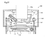
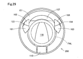
このときの各部の動きを、図27,図28に示した。大径ノズルFNLを給油口122に挿入して、その先端が、案内部材153,154の第2案内斜面161,163と起動部材110とに当たる(図22)。更に大径ノズルFNLを挿入すると、これに連れて、起動部材110が回転して、その先端は矢印DD方向(図27)、つまり開閉部材170側で、かつ径方向外側に移動する。更に、大径ノズルFNLを挿入すると、起動部材110の先端は、大径ノズルFNLの側面に当たる位置まで開く(図28)。この間、錐形ガード151は、大径ノズルFNLが案内部材153,154の第2案内斜面161,163に当接していることから、移動することはなく、大径ノズルFNLの下に、突当部157が移動してくることはない。この結果、図29に示すように、給油装置FSに適合する給油ノズルFNである大径ノズルFNLは、案内部材153,154および起動部材110の回転した先端によって囲まれる領域、つまり図26に示した第2部分に嵌まり、突当部157に突き当たることなく進入し、開閉部材170の弁体171当たってこれを押し開き、燃料通路190に進入する。開閉部材170を押し開いて進入した大径ノズルFNLは、燃料通路90を更に進み、第2開閉機構130を押し開いて、給油可能な位置に至る。 The movement of each part at this time is shown in FIGS. 27 and 28. FIG. A large-diameter nozzle FNL is inserted into the filler port 122, and the tip thereof contacts the second guide slopes 161, 163 of the guide members 153, 154 and the activating member 110 (Fig. 22). When the large-diameter nozzle FNL is further inserted, the activating member 110 rotates, and its tip moves in the direction of the arrow DD (FIG. 27), that is, toward the opening/closing member 170 and radially outward. Furthermore, when the large-diameter nozzle FNL is inserted, the tip of the activating member 110 opens to a position where it contacts the side surface of the large-diameter nozzle FNL (FIG. 28). During this time, the conical guard 151 does not move because the large diameter nozzle FNL is in contact with the second guide slopes 161 and 163 of the guide members 153 and 154, and it abuts under the large diameter nozzle FNL. Part 157 never moves. As a result, as shown in FIG. 29, the large-diameter nozzle FNL, which is the fueling nozzle FN suitable for the fueling device FS, is located in the area surrounded by the guide members 153, 154 and the rotated tip of the actuating member 110, that is, as shown in FIG. The valve body 171 of the opening/closing member 170 is pushed open by the valve body 171 of the opening/closing member 170 , and enters the fuel passage 190 . The large-diameter nozzle FNL, which pushes open the opening/closing member 170 and enters, further advances through the fuel passage 90, pushes open the second opening/closing mechanism 130, and reaches a position where refueling is possible.

以上説明したフィラーネック200では、弁別部150が次のように動作して、給油ノズルFNの外径を弁別している。
(A)給油口122から挿入された給油ノズルFNが、この給油装置FSに適合しない給油ノズルである小径ノズルFNSである場合は、小径ノズルFNSを、案内部材153,154から見て突当部157側の第1部分に追い込んで、その進入を突当部157で阻止する。このとき、小径ノズルFNSを第1部分の辺りに挿入すると、挿入位置が第1部分に対して、多少ずれていても、案内部材153,154の第1案内斜面162,164により、小径ノズルFNSは、第1部分に誘導される。小径ノズルFNSの下方に突当部157が位置するのは、案内部材153と案内部材154との離間距離GD2が、小径ノズルFNSの外径より大きいので、小径ノズルFNSにより、起動部材110との当接部を支点として、錐形ガード151を径方向外側(矢印DR方向)に移動させることができないからである。このため、突当部157より、小径ノズルFNSの進入は阻止される。また、無理に移動させても、小径ノズルFNSの先端が案内部材153,154の第2案内斜面161,163を通り過ぎると、第2案内斜面161,63の下方の第2拡張下面166は、外方に向かって後退する形状を備えるので、案内部材153,154と小径ノズルFNSの係合が解け、保持部材145はデフォルトの位置に戻り、突当部157により、小径ノズルFNSの進入は阻止される。
In the filler neck 200 described above, the discriminating portion 150 operates as follows to discriminate the outer diameter of the fuel nozzle FN.
(A) If the fuel nozzle FN inserted from the fuel filler port 122 is a small-diameter nozzle FNS that is not compatible with this fueling device FS, the small-diameter nozzle FNS is positioned at the abutment portion when viewed from the guide members 153 and 154. It is driven into the first portion on the 157 side, and its entry is blocked by the abutting portion 157. - 特許庁At this time, if the small-diameter nozzle FNS is inserted around the first portion, even if the insertion position is slightly deviated from the first portion, the small-diameter nozzle FNS is is directed to the first part. The abutting portion 157 is positioned below the small diameter nozzle FNS because the separation distance GD2 between the guide member 153 and the guide member 154 is larger than the outer diameter of the small diameter nozzle FNS. This is because the conical guard 151 cannot be moved radially outward (in the direction of the arrow DR) with the contact portion as a fulcrum. Therefore, the abutting portion 157 prevents the entry of the small-diameter nozzle FNS. Moreover, even if it is forced to move, if the tip of the small diameter nozzle FNS passes through the second guide slopes 161, 163 of the guide members 153, 154, the second expanded lower surface 166 below the second guide slopes 161, 63 will Since the guide members 153 and 154 are disengaged from the small-diameter nozzle FNS, the holding member 145 returns to its default position, and the abutment 157 prevents the small-diameter nozzle FNS from entering. be.

(B)他方、給油口122から挿入された給油ノズルFNが、この給油装置FSに適合する給油ノズルである大径ノズルFNLである場合は、案内部材153と案内部材154との離間距離GD2が、大径ノズルFNLの外径より小さいので、大径ノズルFNLは、必ず案内部材153,154の第2案内斜面161,163に当接する。この結果、大径ノズルFNLが進入しても、錐形ガード151の移動は生じず、他方、起動部材110の回転は生じるので、大径ノズルFNLは、突当部157が存在しない第2部分に進入する。これにより、大径ノズルFNLは弁別部150を越えて燃料通路190に進入し、開閉部材170を開弁する。 (B) On the other hand, when the fuel nozzle FN inserted from the fuel filler port 122 is the large-diameter nozzle FNL, which is a fuel nozzle suitable for this fuel filler FS, the distance GD2 between the guide member 153 and the guide member 154 is , is smaller than the outer diameter of the large-diameter nozzle FNL, the large-diameter nozzle FNL always abuts on the second guide slopes 161 and 163 of the guide members 153 and 154 . As a result, even if the large-diameter nozzle FNL enters, the cone-shaped guard 151 does not move, while the activating member 110 rotates. enter the As a result, the large-diameter nozzle FNL passes over the discriminating portion 150 and enters the fuel passage 190 to open the opening/closing member 170 .

以上説明したように、第2実施形態の給油装置FSは、給油ノズルの外径を、案内部材153と案内部材154との離間距離GD2を、あたかもゲージのように利用して、精度良く弁別することができる。このため、製造公差を含めれば、差異が2mm程度のガソリン用給油ノズル(外径20.5mm)と軽油用の給油ノズル(外径23.5mm)とを精度良く弁別し、給油装置FSに適合しない給油ノズルの進入を妨げ、誤って、異なる種類の燃料を供給する虞を低減できることは、第1実施形態と同様である。なお、上述したフィラーネック200であれば、アドブルー用のノズル(外径19.0mm)であっても、これを適合しないノズルとして弁別し、進入を許さないことは、小径ノズルFNSと同様である。他方、給油装置FSをガソリン用に設計し、案内部材153,154の離間距離を、アドブルー用のノズル径である19.0mmより僅かに大きく、ガソリン用のノズル径20.5mmより小さく、例えば19.75mmに設定し、これに併せて、第1部分と第2部分の径を設計すれば、同様の構成で、ガソリン用給油ノズルは進入でき、アドブルー用のノズルは進入できない給油装置FSを構成することも容易である。この場合、第2部分の大きさを外径22mm以上のノズルが通過出来ないようにしておけば、軽油用給油ノズルの進入を許さないようにすることも容易である。 As described above, the fueling device FS of the second embodiment accurately discriminates the outer diameter of the fueling nozzle by using the separation distance GD2 between the guide member 153 and the guide member 154 as if it were a gauge. be able to. For this reason, including the manufacturing tolerance, it is possible to accurately discriminate between gasoline refueling nozzles (outer diameter 20.5mm) and light oil refueling nozzles (outer diameter 23.5mm), which have a difference of about 2mm, and is compatible with the refueling system FS. As is the case with the first embodiment, it is possible to reduce the risk of incorrectly supplying a different type of fuel by preventing the entry of an improper fuel nozzle. In the case of the filler neck 200 described above, even if it is a nozzle for AdBlue (outer diameter 19.0 mm), it is discriminated as an unsuitable nozzle and is not allowed to enter, which is the same as the small diameter nozzle FNS. . On the other hand, the fueling system FS is designed for gasoline, and the separation distance between the guide members 153 and 154 is slightly larger than the AdBlue nozzle diameter of 19.0 mm and smaller than the gasoline nozzle diameter of 20.5 mm, for example 19 mm. 75 mm, and designing the diameters of the first and second portions in accordance with this, a fueling device FS is constructed in which a gasoline fueling nozzle can enter, but an AdBlue nozzle cannot enter, with a similar configuration. It is also easy to In this case, if the size of the second portion is set so that a nozzle having an outer diameter of 22 mm or more cannot pass through, it is easy to prevent the light oil refueling nozzle from entering.

C.他の実施形態:
以上説明したいくつかの実施形態では、案内部材53,54や153,154には、第1案内斜面62,64や162,164と第2案内斜面61,63や161,163を設けたが、第1案内斜面または第2案内斜面の一方のみを設けるものとしてもよい。また、案内部材53,54や153,154の第1案内斜面62,64や162,164、あるいは第2案内斜面61,63や161,163は、平面形状の斜面としたが、曲面形状としてもよい。この場合、外側に凸の曲面としてもよいし、内側に凹の曲面としてもよい。もとより、複数の平面を組み合わせて、第2案内斜面を構成するものとしてもよい。本実施例では、左右一対の案内部材を、第1部分と第2部分との接続箇所に設けたが、これに加えて、第2部分の外縁に更に案内部材を増設してもよい。また左右の一対の案内部材の第2案内斜面は、鏡像関係としたが、大径ノズルFNLを第2部分に導くことができれば、斜面の方向や角度が左右の案内部材で異なっていてもよい。
C. Other embodiments:
In the several embodiments described above, the guide members 53, 54 and 153, 154 are provided with the first guide slopes 62, 64, 162, 164 and the second guide slopes 61, 63, 161, 163. Only one of the first guide slope and the second guide slope may be provided. Further, the first guide slopes 62, 64 and 162, 164 of the guide members 53, 54 and 153, 154, or the second guide slopes 61, 63, 161, 163 are planar slopes, but curved slopes may also be used. good. In this case, it may be a curved surface that is convex outward or a curved surface that is concave inward. Of course, a plurality of planes may be combined to constitute the second guide slope. In this embodiment, a pair of left and right guide members are provided at the joint between the first portion and the second portion, but in addition to this, another guide member may be added to the outer edge of the second portion. Further, the second guide slopes of the pair of left and right guide members are in a mirror image relationship, but the direction and angle of the slopes may be different between the left and right guide members as long as the large diameter nozzle FNL can be guided to the second portion. .

上記実施形態では、案内部材53,54や153,153の下半分は、二つの平面、例えば第2拡張下面66と第1拡張下面67あるいは第2拡張下面166と第1拡張下面167から構成したが、第1拡張下面67や第1拡張下面167を備えない構成としてもよい。また、案内部材53,54や153,154の下半分は、下方に尖った円錐または円錐台形状としてもよい。あるいは、段差をもって、外方に後退する形状としてもよい。もとより、傾斜や段差によって後退する形状に限る必要はなく、開口部の内周縁から外方に向かう所定の範囲に、空間が形成される形状とされていればよく、この結果、開口部を透過した小径ノズルFNSの先端が、案内部材53,54にもはや接し得ない形状となっていれば良い。 In the above embodiments, the lower halves of the guide members 53, 54 and 153, 153 consist of two planes, e.g. However, a configuration without the first extended lower surface 67 or the first extended lower surface 167 may be employed. Also, the lower halves of the guide members 53, 54 and 153, 154 may be conical or truncated cone-shaped with downward sharpening. Alternatively, it may have a shape that retreats outward with a step. Of course, it is not necessary to be limited to a shape that recedes due to an inclination or a step, as long as it is a shape in which a space is formed in a predetermined range from the inner peripheral edge of the opening toward the outside. It is sufficient that the tip of the small-diameter nozzle FNS that has been formed has a shape that can no longer come into contact with the guide members 53 and 54 .

上記実施形態では、弁別部50,150は樹脂により形成したが、給油装置FSに適合しない給油ノズルが挿入された場合に、その進入を止める突当部57,157には、挿入される給油ノズルの先端が直接ぶつかるので、突当部57,157を含む移動部材52や錐形ガード151を、樹脂より強い材質、例えば金属などで形成してもよい。あるいは、突当部57,157のみを金属とし、樹脂製の移動部材52や錐形ガード151にインサート成形するようにしてもよい。 In the above embodiment, the discriminating portions 50 and 150 are made of resin. , the moving member 52 including the abutting portions 57 and 157 and the conical guard 151 may be made of a material stronger than resin, such as metal. Alternatively, only the abutting portions 57 and 157 may be made of metal and may be insert-molded into the moving member 52 and conical guard 151 made of resin.

第1実施形態において、移動部材52は樹脂製のバネ部材41で移動可能に錐形ガード51に取付けたが、板ばねなどを用いてもよい。あるいは、移動部材52をその後方から、移動フランジ部55を固定フランジ部56当接する方向に付勢するよう、スプリングを設けてもよい。この場合、スプリングに代えて、弾性体などを用いることも可能である。 In the first embodiment, the moving member 52 is movably attached to the conical guard 51 by the resin spring member 41, but a plate spring or the like may be used. Alternatively, a spring may be provided so as to urge the moving member 52 from behind in the direction in which the moving flange portion 55 comes into contact with the fixed flange portion 56 . In this case, it is also possible to use an elastic body or the like instead of the spring.

第2実施形態において、起動部材110は、略直方体形状としたが、形状は問わない。錐形ガード151が下方に向かうほど開口部が狭くなることに合わせて、先端ほど細くなる形状としてもよい。また、起動部材110は必ずしも回転しなくてもよい。例えば110の先端に、錐形ガード151の傾斜部と同じ程度の傾斜を形成し、大径ノズルFNLの先端が起動部材110の先端に当たったとき、起動部材110が、錐形ガード151に対して図22に示した矢印DR方向に移動するようにしてもよい。このときの起動部材の移動に要する力F1を、起動部材110が取付けられた錐形ガード151がDR方向に移動するのに必要な力F2より大きくしておけば、第2実施形態と同様の作用効果を奏することは容易である。 In the second embodiment, the activating member 110 has a substantially rectangular parallelepiped shape, but the shape does not matter. The conical guard 151 may have a shape tapering toward the tip in accordance with the fact that the opening becomes narrower as it goes downward. Also, the activating member 110 does not necessarily have to rotate. For example, the tip of the cone guard 151 is inclined at the same degree as the slope of the conical guard 151, and when the tip of the large-diameter nozzle FNL hits the tip of the activating member 110, the activating member 110 moves against the conical guard 151. 22 may be moved in the direction of the arrow DR shown in FIG. If the force F1 required to move the activating member at this time is made larger than the force F2 required to move the conical guard 151 to which the activating member 110 is attached in the DR direction, the same operation as in the second embodiment can be achieved. It is easy to achieve the effect.

第1実施形態の錐形ガード51や移動部材52、あるいは第2実施形態の錐形ガード151は、燃料通路90,190側に行くほど窄まる、いわゆる漏斗(ファンネル)形状としたが、給油口側の第1の位置と第1の位置より燃料タンク側の第2の位置とでは、第2の位置の方が内径が狭くなる形状であればよく、螺旋形状であってもよい。あるいはそれぞれ傾斜した複数の段差を組み合わせた形状であってもよい。 The conical guard 51 and the moving member 52 of the first embodiment, or the conical guard 151 of the second embodiment have a so-called funnel shape that narrows toward the fuel passages 90 and 190. The first position on the side and the second position closer to the fuel tank than the first position may have a shape in which the inner diameter is narrower at the second position, and may be a spiral shape. Alternatively, the shape may be a combination of a plurality of steps each inclined.

上記実施形態では、給油装置FSは、いわゆるキャップレスの構成を備え、給油時以外では給油口22,122を閉鎖するフラップと開閉部材70,170とを兼用している。開閉部材70,170は、キャップレス給油装置FSのためのフラップとは別に独立に設けてもよい。あるいは、第2開閉機構30,130に設けるものとしてもよい。 In the above-described embodiment, the fueling device FS has a so-called capless structure, and the opening/closing members 70 and 170 serve as flaps for closing the fueling ports 22 and 122 except when fueling. The opening/closing members 70, 170 may be provided independently of the flap for the capless fueling system FS. Alternatively, it may be provided in the second opening/closing mechanisms 30 and 130 .

本開示は、上述の実施形態に限られるものではなく、その趣旨を逸脱しない範囲において種々の構成で実現することができる。例えば、発明の概要の欄に記載した各形態中の技術的特徴に対応する実施形態中の技術的特徴は、上述の課題の一部又は全部を解決するために、あるいは、上述の効果の一部又は全部を達成するために、適宜、差し替えや、組み合わせを行うことが可能である。また、その技術的特徴が本明細書中に必須なものとして説明されていなければ、適宜、削除することが可能である。 The present disclosure is not limited to the embodiments described above, and can be implemented in various configurations without departing from the scope of the present disclosure. For example, the technical features in the embodiments corresponding to the technical features in the respective modes described in the Summary of the Invention column may be used to solve some or all of the above problems, or Substitutions and combinations may be made as appropriate to achieve part or all. Also, if the technical features are not described as essential in this specification, they can be deleted as appropriate.

20…燃料通路形成部、22…給油口、23…返し部、24…カバー部材、26…燃料蒸気ポート、27…支持部材、30…第2開閉機構、31…第2開閉弁、32…回転軸、33…シール部材、40…第1開閉機構、41,43…バネ部材、44…支柱部材、46…端部、50…弁別部、51…錐形ガード、52…移動部材、53,54…案内部材、55…移動フランジ部、56…固定フランジ部、57…突当部、58…傾斜部、59…上縁部、61,63…第2案内斜面、62,64…第1案内斜面、66…第2拡張下面、67…第1拡張下面、68…空間部、70…開閉部材、71…第1開閉弁、73…保持軸、75…スプリング、90…燃料通路、100…フィラーネック、110…起動部材、111…回転軸、112…スプリング、120…燃料通路形成部、122…給油口、130…第2開閉機構、131…第2開閉弁、132…回転軸、140…第1開閉機構、143…係合部、145…保持部材、145b,145f…スライド部材、146,147…支持柱、150…弁別部、151…錐形ガード、153,154…案内部材、157…突当部、161,163…第2案内斜面、162,164…第1案内斜面、166…第2拡張下面、167…第1拡張下面、170…開閉部材、171…弁体、173…保持軸、175…スプリング、190…燃料通路、200…フィラーネック 20... Fuel passage forming part 22... Refueling port 23... Return part 24... Cover member 26... Fuel vapor port 27... Supporting member 30... Second opening/closing mechanism 31... Second opening/closing valve 32... Rotation Axle 33 Sealing member 40 First opening/closing mechanism 41, 43 Spring member 44 Strut member 46 End 50 Discriminating portion 51 Conical guard 52 Moving member 53, 54 Guide member 55 Moving flange portion 56 Fixed flange portion 57 Abutting portion 58 Inclined portion 59 Upper edge portion 61, 63 Second guide slope 62, 64 First guide slope , 66... Second expansion lower surface 67... First expansion lower surface 68... Space part 70... Opening/closing member 71... First opening/closing valve 73... Holding shaft 75... Spring 90... Fuel passage 100... Filler neck , 110...Starting member 111...Rotating shaft 112...Spring 120...Fuel passage forming part 122...Fuel inlet 130...Second opening/closing mechanism 131...Second opening/closing valve 132...Rotating shaft 140...First Opening/closing mechanism 143 Engagement portion 145 Holding member 145b, 145f Slide member 146, 147 Support column 150 Discrimination portion 151 Conical guard 153, 154 Guide member 157 Strike Parts 161, 163... Second guide slope 162, 164... First guide slope 166... Second expansion lower surface 167... First expansion lower surface 170... Opening/closing member 171... Valve body 173... Holding shaft 175 ... spring, 190 ... fuel passage, 200 ... filler neck

Claims (8)

燃料の給油を行なう際に給油ノズルを受け入れる給油装置であって、
給油ノズルを受け入れる給油口を備え、前記給油口から燃料タンクに至る燃料通路の一部を形成する給油口形成部と、
前記給油口から挿入される前記給油ノズルの到達範囲に設けられ、当該給油装置に適合する給油ノズルよりも外径の小さな小径ノズルの外径に対応した開口である第1部分と、当該給油装置に適合する大径ノズルの外径に対応した形状の開口である第2部分とからなる一続きの開口部を構成する弁別部と、
前記弁別部の前記開口部よりも前記燃料タンク側に設けられ、前記第1部分に導かれた前記小径ノズルの先端が突き当たる突当部材と、
前記弁別部よりも前記燃料タンク側に設けられ、前記燃料タンクの側から閉方向に付勢され、前記開口部を通過した前記大径ノズルにより開状態とされる開閉部材と
を備え、
前記弁別部は、前記第2部分に前記小径ノズルが挿入された場合に、前記挿入された前記小径ノズルを前記第1部分に導く作動部材を備え
前記弁別部は、前記開口部の前記第2部分は、前記大径ノズルの外形より小さく、かつ前記第2部分と前記第1部分との境界が、前記大径ノズルの外径より小さく前記小径ノズルの外径より大きな内寸箇所であり、
前記作動部材は、前記第2部分への前記小径ノズルの挿入によっては移動せず、前記大径ノズルの挿入によって移動する移動部材を備え、
前記移動部材は、前記移動によって前記内寸箇所を前記第1部分方向に移動し、前記第2部分を、前記大径ノズルの外形を越えて拡張する、給油装置。
A refueling device that receives a refueling nozzle when refueling fuel,
a fuel filler opening forming part including a fuel filler opening for receiving a fuel filler nozzle and forming a part of a fuel passage from the fuel filler opening to the fuel tank;
a first portion which is an opening corresponding to an outer diameter of a small-diameter nozzle provided in a reachable range of the fueling nozzle inserted from the fueling port and having an outer diameter smaller than that of the fueling nozzle compatible with the fueling device; and the fueling device. a discriminating portion that constitutes a series of openings consisting of a second portion that is an opening having a shape corresponding to the outer diameter of a large-diameter nozzle that conforms to
an abutting member provided closer to the fuel tank than the opening of the discriminating portion and with which the tip of the small-diameter nozzle guided to the first portion abuts;
an opening/closing member provided closer to the fuel tank than the discriminating portion, biased in a closing direction from the fuel tank side, and opened by the large-diameter nozzle that has passed through the opening;
The discriminating section includes an operating member that guides the inserted small diameter nozzle to the first section when the small diameter nozzle is inserted into the second section ,
In the discriminating portion, the second portion of the opening is smaller than the outer diameter of the large-diameter nozzle, and the boundary between the second portion and the first portion is smaller than the outer diameter of the large-diameter nozzle. The inner dimension is larger than the outer diameter of the nozzle,
the operating member includes a moving member that does not move when the small diameter nozzle is inserted into the second portion but moves when the large diameter nozzle is inserted;
The moving member moves the inner dimension portion in the direction of the first portion by the movement, and expands the second portion beyond the outer shape of the large-diameter nozzle .
前記作動部材は、前記給油口側の第1の位置と前記第1の位置より前記燃料タンク側の第2の位置とでは、前記第2の位置の方が内径が狭くなる形状で前記開口部を取り囲む、請求項1に記載の給油装置。 The actuating member has a shape in which an inner diameter is narrower at the second position than at a first position on the filler port side and at a second position on the fuel tank side from the first position. 2. The refueling system of claim 1, enclosing a . 前記移動部材は、前記給油口側の第1の位置と前記第1の位置より前記燃料タンク側の第2の位置とでは、前記第2の位置の方が内径が狭くなる形状で前記開口部を取り囲む開口形成部材である、請求項1に記載の給油装置。 The moving member has a shape in which an inner diameter is narrower at the second position than at a first position on the fuel filler side and at a second position on the fuel tank side from the first position. 2. The fueling system according to claim 1 , wherein the opening forming member surrounds the . 前記弁別部の前記第1部分と前記第2部分とが接続する位置に、前記給油口側に所定高さに形成された案内部材を備え、
前記案内部材に当接した前記大径ノズルの挿入によって、前記移動部材の前記移動を実現する
請求項1または請求項3に記載の給油装置。
a guide member formed at a predetermined height on the fuel filler port side at a position where the first portion and the second portion of the discriminating portion are connected,
The movement of the moving member is realized by inserting the large-diameter nozzle in contact with the guide member.
The lubricating device according to claim 1 or 3.
燃料の給油を行なう際に給油ノズルを受け入れる給油装置であって、
給油ノズルを受け入れる給油口を備え、前記給油口から燃料タンクに至る燃料通路の一部を形成する給油口形成部と、
前記給油口から挿入される前記給油ノズルの到達範囲に設けられ、当該給油装置に適合する給油ノズルよりも外径の小さな小径ノズルの外径に対応した開口である第1部分と、当該給油装置に適合する大径ノズルの外径に対応した形状の開口である第2部分とからなる一続きの開口部を構成する弁別部と、
前記弁別部の前記開口部よりも前記燃料タンク側に設けられ、前記第1部分に導かれた前記小径ノズルの先端が突き当たる突当部材と、
前記弁別部よりも前記燃料タンク側に設けられ、前記燃料タンクの側から閉方向に付勢され、前記開口部を通過した前記大径ノズルにより開状態とされる開閉部材と
を備え、
前記弁別部は、前記第2部分に前記小径ノズルが挿入された場合に、前記挿入された前記小径ノズルを前記第1部分に導く作動部材を備え、
前記作動部材は、前記給油口から挿入された前記給油ノズルの先端が当接する起動部材を備え、
前記起動部材は、前記第2部分が、前記大径ノズルの外径より小さな内寸箇所を有するものとなる位置に配置され、
前記起動部材に前記小径ノズルの先端が当接した場合は、前記突当部材を前記起動部材側に移動させ、前記起動部材に前記大径ノズルが当接した場合は、前記起動部材が移動することによって前記第2部分の前記内寸箇所を前記大径ノズルの外径を越えて拡張する
油装置。
A refueling device that receives a refueling nozzle when refueling fuel,
a fuel filler opening forming part including a fuel filler opening for receiving a fuel filler nozzle and forming a part of a fuel passage from the fuel filler opening to the fuel tank;
a first portion which is an opening corresponding to an outer diameter of a small-diameter nozzle provided in a reachable range of the fueling nozzle inserted from the fueling port and having an outer diameter smaller than that of the fueling nozzle compatible with the fueling device; and the fueling device. a discriminating portion that constitutes a series of openings consisting of a second portion that is an opening having a shape corresponding to the outer diameter of a large-diameter nozzle that conforms to
an abutting member provided closer to the fuel tank than the opening of the discriminating portion and with which the tip of the small-diameter nozzle guided to the first portion abuts;
an opening/closing member provided closer to the fuel tank than the discriminating portion, biased in a closing direction from the fuel tank side, and opened by the large-diameter nozzle passing through the opening;
with
The discriminating section includes an operating member that guides the inserted small diameter nozzle to the first section when the small diameter nozzle is inserted into the second section,
The actuating member includes an activating member with which the tip of the fuel nozzle inserted from the fuel filler port abuts,
the activating member is positioned such that the second portion has an inner dimension that is smaller than the outer diameter of the large diameter nozzle;
When the tip of the small diameter nozzle comes into contact with the starting member, the abutment member is moved toward the starting member, and when the large diameter nozzle comes into contact with the starting member, the starting member moves. thereby expanding the inner dimension of the second portion beyond the outer diameter of the large diameter nozzle ;
refueling device.
前記作動部材は、前記給油口側の第1の位置と前記第1の位置より前記燃料タンク側の第2の位置とでは、前記第2の位置の方が内径が狭くなる形状で前記開口部を取り囲む、請求項5に記載の給油装置。 The actuating member has a shape in which an inner diameter is narrower at the second position than at a first position on the filler port side and at a second position on the fuel tank side from the first position. 6. A refueling system according to claim 5, enclosing a . 前記弁別部の前記第1部分と前記第2部分とが接続する位置に、前記給油口側に所定高さに形成された案内部材を備え、
前記給油口から挿入された前記大径ノズルの先端の一部が前記案内部材に当接することで、前記起動部材の移動を実現する、
請求項5または請求項6に記載の給油装置。
a guide member formed at a predetermined height on the fuel filler port side at a position where the first portion and the second portion of the discriminating portion are connected,
A part of the tip of the large-diameter nozzle inserted from the fuel inlet contacts the guide member, thereby realizing movement of the activating member.
The lubricating device according to claim 5 or 6 .
前記案内部材は、前記小径ノズルが前記起動部材に当接した状態では、前記小径ノズルとは離間しており、
前記作動部材は、
前記給油口側の第1の位置と前記第1の位置より前記燃料タンク側の第2の位置とでは、前記第2の位置の方が内径が狭くなる形状で前記開口部を取り囲み、
前記小径ノズルが前記起動部材に当接して挿入される際、前記小径ノズルによる前記起動部材の前記移動に要する力よりも小さな力で前記突当部材を移動する、
請求項7に記載の給油装置。
The guide member is separated from the small-diameter nozzle when the small-diameter nozzle is in contact with the activating member,
The actuating member is
between a first position on the filler port side and a second position on the fuel tank side from the first position, the second position surrounds the opening with a narrower inner diameter,
When the small-diameter nozzle is inserted in contact with the activating member, the impingement member is moved by a force smaller than the force required for the movement of the activating member by the small-diameter nozzle.
The lubricating device according to claim 7.
JP2019205118A 2019-11-13 2019-11-13 Lubricator Active JP7192746B2 (en)

Priority Applications (2)

Application Number Priority Date Filing Date Title
JP2019205118A JP7192746B2 (en) 2019-11-13 2019-11-13 Lubricator
US17/095,273 US11597269B2 (en) 2019-11-13 2020-11-11 Fuel device

Applications Claiming Priority (1)

Application Number Priority Date Filing Date Title
JP2019205118A JP7192746B2 (en) 2019-11-13 2019-11-13 Lubricator

Publications (3)

Publication Number Publication Date
JP2021075224A JP2021075224A (en) 2021-05-20
JP2021075224A5 JP2021075224A5 (en) 2022-01-14
JP7192746B2 true JP7192746B2 (en) 2022-12-20

Family

ID=75898815

Family Applications (1)

Application Number Title Priority Date Filing Date
JP2019205118A Active JP7192746B2 (en) 2019-11-13 2019-11-13 Lubricator

Country Status (1)

Country Link
JP (1) JP7192746B2 (en)

Citations (5)

* Cited by examiner, † Cited by third party
Publication number Priority date Publication date Assignee Title
DE10051212A1 (en) 2000-10-16 2002-07-11 Volkswagen Ag Tank filler socket for motor vehicles has blocking device to prevent filling with unsuitable fuels and inner diameter to fit correctly sized pump nozzle only
US20080092986A1 (en) 2004-07-16 2008-04-24 Markus Buchgraber Filler Tube For The Fuel Tank Of A Motor Vehicle With Selective Opening
JP2010195344A (en) 2009-02-27 2010-09-09 Toyoda Gosei Co Ltd Opening/closing device of fuel tank
WO2011062193A1 (en) 2009-11-18 2011-05-26 株式会社ニフコ Device for preventing fueling error
JP2015063294A (en) 2013-08-30 2015-04-09 豊田合成株式会社 Opening/closing device of fuel tank

Patent Citations (5)

* Cited by examiner, † Cited by third party
Publication number Priority date Publication date Assignee Title
DE10051212A1 (en) 2000-10-16 2002-07-11 Volkswagen Ag Tank filler socket for motor vehicles has blocking device to prevent filling with unsuitable fuels and inner diameter to fit correctly sized pump nozzle only
US20080092986A1 (en) 2004-07-16 2008-04-24 Markus Buchgraber Filler Tube For The Fuel Tank Of A Motor Vehicle With Selective Opening
JP2010195344A (en) 2009-02-27 2010-09-09 Toyoda Gosei Co Ltd Opening/closing device of fuel tank
WO2011062193A1 (en) 2009-11-18 2011-05-26 株式会社ニフコ Device for preventing fueling error
JP2015063294A (en) 2013-08-30 2015-04-09 豊田合成株式会社 Opening/closing device of fuel tank

Also Published As

Publication number Publication date
JP2021075224A (en) 2021-05-20

Similar Documents

Publication Publication Date Title
KR101578514B1 (en) Mis-fuel inhibitor
US20070267099A1 (en) Inlet fitting for fuel tank of diesel motor vehicles
EP2994329B1 (en) Fuel-dispensing nozzle inhibitor
CN105437956B (en) Oiling appurtenance
KR101554972B1 (en) Fueling portion structure of fuel tank
US20050051216A1 (en) Pressure opening and closing valve
JP2604383B2 (en) Vent cut valve for filler tube for automobile
JP7192746B2 (en) Lubricator
JP7131529B2 (en) Lubricator
JP7131530B2 (en) Lubricator
WO2018193883A1 (en) Fuel fill opening structure
WO2003043887A1 (en) Fuel fill tube assembly
JP6646423B2 (en) Valve device for fuel tank
WO2021085122A1 (en) Valve device
US11597269B2 (en) Fuel device
JP2528517B2 (en) Flap valve device
JP2011046369A (en) Fuel shutting-off valve
US20210260991A1 (en) Refueling port
JP7184012B2 (en) Lubricator
JPS6021500Y2 (en) Fuel reservoir pressure regulator in vehicles
JPS6027827B2 (en) Evaporated fuel recovery equipment for motorcycles, etc.
JP7332396B2 (en) one way valve
CN113748038B (en) Over-oil supply prevention valve
WO2020105508A1 (en) Gas-liquid separation device with check valve
CN217001325U (en) Small fuel filling door assembly for vehicle

Legal Events

Date Code Title Description
A621 Written request for application examination

Free format text: JAPANESE INTERMEDIATE CODE: A621

Effective date: 20211028

A521 Request for written amendment filed

Free format text: JAPANESE INTERMEDIATE CODE: A523

Effective date: 20220105

A131 Notification of reasons for refusal

Free format text: JAPANESE INTERMEDIATE CODE: A131

Effective date: 20220726

A977 Report on retrieval

Free format text: JAPANESE INTERMEDIATE CODE: A971007

Effective date: 20220729

A521 Request for written amendment filed

Free format text: JAPANESE INTERMEDIATE CODE: A523

Effective date: 20220921

TRDD Decision of grant or rejection written
A01 Written decision to grant a patent or to grant a registration (utility model)

Free format text: JAPANESE INTERMEDIATE CODE: A01

Effective date: 20221108

A61 First payment of annual fees (during grant procedure)

Free format text: JAPANESE INTERMEDIATE CODE: A61

Effective date: 20221121

R151 Written notification of patent or utility model registration

Ref document number: 7192746

Country of ref document: JP

Free format text: JAPANESE INTERMEDIATE CODE: R151