JP7190870B2 - Bottle - Google Patents
Bottle Download PDFInfo
- Publication number
- JP7190870B2 JP7190870B2 JP2018205996A JP2018205996A JP7190870B2 JP 7190870 B2 JP7190870 B2 JP 7190870B2 JP 2018205996 A JP2018205996 A JP 2018205996A JP 2018205996 A JP2018205996 A JP 2018205996A JP 7190870 B2 JP7190870 B2 JP 7190870B2
- Authority
- JP
- Japan
- Prior art keywords
- bottle
- sealing material
- protruding wall
- mouth
- end surface
- Prior art date
- Legal status (The legal status is an assumption and is not a legal conclusion. Google has not performed a legal analysis and makes no representation as to the accuracy of the status listed.)
- Active
Links
Images
Description
本発明は、ボトルに関する。 The present invention relates to bottles.
従来から、合成樹脂製ボトルとして、パリソンを利用した押出しブロー成形によって形成される押出しブローボトルが知られている。この種の押出しブローボトルにおいて、口部を形成する場合には、押出しブロー成形後の後加工によって口部を形成する場合と、押出しブロー成形と同時に口部を形成する場合と、に大別される。
後加工によって口部を形成する方法としては、例えばクリンプカット加工やドリル加工等が知られているが、いずれの方法であっても後加工で行うので、ボトル内への異物混入に繋がる可能性がある。
BACKGROUND ART Conventionally, as a synthetic resin bottle, an extrusion blow bottle formed by extrusion blow molding using a parison is known. In this type of extrusion blow-molded bottle, the formation of the mouth can be broadly divided into the formation of the mouth by post-processing after extrusion blow molding and the formation of the mouth at the same time as extrusion blow molding. be.
For example, crimp cutting and drilling are known methods for forming the mouth portion by post-processing, but since any method is performed in post-processing, there is a possibility that foreign matter may enter the bottle. There is
これに対して、押出しブロー成形と同時に口部を形成する方法としては、例えばUPI(アッパープラグイン)成形等が挙げられ、ボトル内への異物混入の可能性が低い方法として知られている。一般的にUPI成形は、成形金型に挟持されたパリソンの上方からプラグを押し込み、成形金型とプラグとによって構成される喰切り部分によって、不要部分を切断、除去することで口部を形成する方法である。 On the other hand, as a method of forming the mouth portion at the same time as extrusion blow molding, for example, UPI (upper plug-in) molding, etc., is known as a method with a low possibility of contamination in the bottle. Generally, in UPI molding, a plug is pushed in from above a parison sandwiched between molding dies, and an unnecessary part is cut and removed by a cutting part composed of the molding die and the plug to form an opening. It is a way to
例えば下記特許文献1には、口筒部がUPI成形によって形成された押出しブローボトルが開示されている。口筒部の上端面は、内側周部に比較して外側周部が下位に位置するように形成されている。また、内側周部の外周縁部には、UPI成形時に除去した不要部分の切断痕が形成されている。
For example,
ところで、押出しブローボトルにおいて、口部に対してアルミシール等のシール材を熱融着等により固着させて、口部を封止する場合がある。この場合には、シール材のスムーズな開封作業を可能とさせるために、シール材の開封強度(固着強度)を高くしすぎないことが望まれる。 By the way, in the extrusion blow bottle, there is a case where the opening is sealed by fixing a sealing material such as an aluminum seal to the opening by heat-sealing or the like. In this case, it is desired that the opening strength (fixing strength) of the sealing material is not excessively high in order to enable smooth opening of the sealing material.
しかしながら、上記従来の押出しブローボトルの口部にシール材を固着することを想定した場合、外側周部よりも上方に位置する内側周部の上面にシール材を固着することになるので、内側周部に形成されている切断痕に対してもシール材が固着されてしまう。そのため、シール材を剥離する際に、シール材に連られて切断痕が上方に持ち上がり易く、シール材が切断痕から剥れ難くなってしまう。これにより、シール材の開封強度が大きくなってしまう傾向があった。
さらにシール材の剥離時、切断痕が上方に持ち上がる前に、シール材が切断痕から剥れる場合も考えられる。従って、シール材の剥離時に、シール材に連られて切断痕が上方に持ち上がる場合と、持ち上がらない場合と、のいずれかが生じることが想定され、開封強度にばらつきが生じ易いうえ、剥離の安定性に欠けるものであった。
However, when it is assumed that the sealing material is fixed to the mouth portion of the conventional extrusion blow bottle, the sealing material is fixed to the upper surface of the inner peripheral portion located higher than the outer peripheral portion. The sealing material is also adhered to the cut marks formed on the part. Therefore, when the sealing material is peeled off, the cut marks are likely to be lifted upward by the sealing material, making it difficult for the sealing material to separate from the cut marks. This tends to increase the unsealing strength of the sealing material.
Furthermore, when the sealing material is peeled off, the sealing material may peel off from the cut marks before the cut marks are lifted upward. Therefore, when the sealing material is peeled off, it is assumed that the cut mark may or may not be lifted up by the sealing material. It lacked sex.
本発明は、このような事情に鑑みてなされたものであって、その目的は、シール材の開封強度を抑制することができ、シール材を抵抗少なくスムーズに剥離することができるボトルを提供することである。 The present invention has been made in view of such circumstances, and its object is to provide a bottle in which the opening strength of the sealing material can be suppressed and the sealing material can be peeled off smoothly with little resistance. That is.
(1)本発明に係るボトルは、口部を有する合成樹脂製の容器本体を備えたボトルであって、前記口部は、ボトル軸方向に延びる口筒部と、前記口筒部の上端開口縁から前記ボトル軸方向の上方に向けて突出するように形成されると共に、上端面に熱融着可能なアルミシートが固着される環状の突出壁と、を備え、前記突出壁は、該突出壁よりも径方向の外側において前記上端開口縁を露出させるように、前記口筒部の外径よりも小さい外径で形成され、前記口筒部の外周面には、前記上端開口縁に連設されると共に径方向の外側に向けて突出した切断痕が形成され、前記突出壁は、前記突出壁の外周面と前記切断痕の外端部との間の径方向に沿った間隔よりも、前記突出壁の上端面と前記口筒部の上端開口縁との間の前記ボトル軸方向に沿った間隔の方が大きくなるように形成されている。 (1) A bottle according to the present invention is a bottle having a container body made of synthetic resin and having a mouth portion, wherein the mouth portion is a mouth portion extending in the axial direction of the bottle and an upper end opening of the mouth portion. an annular protruding wall formed to protrude upward in the axial direction of the bottle from the rim and to which a heat-sealable aluminum sheet is fixed to the upper end surface, the protruding wall being the protruding wall; It is formed with an outer diameter smaller than the outer diameter of the mouthpiece so as to expose the top opening rim outside the wall in the radial direction. A cut mark is provided and protrudes radially outward, and the protruding wall is wider than the distance along the radial direction between the outer peripheral surface of the protruding wall and the outer end of the cut mark. , the gap along the axial direction of the bottle between the upper end surface of the projecting wall and the upper end opening edge of the mouth tube portion is formed to be larger .
本発明に係るボトルによれば、シール材(アルミシート)が固着される突出壁の上端面を、切断痕よりも上方に位置させているので、突出壁の上端面に対してシール材を熱融着等によって固着するときに、シール材と切断痕とが接触し難い。そのため、切断痕に対するシール材の固着を抑制しながら、シール材を突出壁の上端面に固着することが可能である。そのため、従来のように切断痕によってシール材が剥れ難くなるような不都合が生じ難い。従って、シール材の開封強度(固着強度)を抑制して、高くなり過ぎてしまうことを防止できるので、シール材を抵抗少なくスムーズに剥離することができる。さらに、切断痕に対するシール材の固着を抑制できるので、シール材の剥離の確実性を向上することができると共に、開封強度のばらつきも抑えることができる。 According to the bottle of the present invention, since the upper end surface of the protruding wall to which the sealing material (aluminum sheet) is fixed is positioned above the cut mark, the sealing material is heated against the upper end surface of the protruding wall. It is difficult for the sealing material and the cut marks to come into contact with each other when they are fixed by fusion or the like. Therefore, it is possible to fix the sealing material to the upper end surface of the protruding wall while suppressing the fixing of the sealing material to the cut marks. Therefore, it is difficult to cause the inconvenience that the sealing material is difficult to peel off due to the cut marks as in the conventional art. Therefore, the unsealing strength (fixing strength) of the sealing material can be suppressed to prevent it from becoming too high, so that the sealing material can be peeled off smoothly with little resistance. Furthermore, since the sealing material can be prevented from adhering to the cut marks, the reliability of peeling of the sealing material can be improved, and variation in the unsealing strength can be suppressed.
さらに、突出壁の上端面にシール材を固着させるので、突出壁における径方向の幅を変化させることで、口筒部の肉厚を変化させることなくシール材の固着面積を調整することができる。そのため、例えば口筒部の肉厚自体を薄肉にすることなく、シール材の固着面積を小さくすることが可能である。従って、口筒部の肉厚を維持して、口筒部の強度を適切に維持したまま、突出壁における径方向の幅の変化によってシール材の固着面積を適切に調整することができ、シール材を剥離し易いボトルとすることができる。 Furthermore, since the sealing material is fixed to the upper end surface of the protruding wall, by changing the radial width of the protruding wall, the fixing area of the sealing material can be adjusted without changing the thickness of the mouth tube portion. . Therefore, for example, it is possible to reduce the fixing area of the sealing material without reducing the wall thickness of the mouth tube portion itself. Therefore, it is possible to appropriately adjust the fixing area of the sealing material by changing the radial width of the protruding wall while maintaining the thickness of the mouthpiece and appropriately maintaining the strength of the mouthpiece. The bottle can be easily peeled off.
さらに、突出壁の外周面と切断痕の外端部との間の径方向に沿った間隔よりも、口筒部の上端開口縁と突出壁の上端面との間のボトル軸方向に沿った段差を大きくすることができるので、突出壁の上端面にシール材を固着する際に、切断痕に対してシール材をさらに接触し難くすることができる。特に、突出壁の外径よりも若干大きいサイズのシール材を固着する場合には、シール材の外周縁部側が突出壁よりも径方向の外側に飛び出てしまう。このような場合であっても、突出壁の段差を大きくすることができるので、シール材の外周縁部側が切断痕に対して接触することを効果的に抑制することができる。
さらに、突出壁の段差を大きくすることができるので、シール材を突出壁の上端面に例えば熱融着によって固着する場合であっても、加熱等の影響によって段差が潰れ難い。そのため、上述した作用効果を適切に奏功することができる。
Furthermore , the distance along the bottle axis direction between the upper end opening edge of the mouth cylinder and the upper end surface of the projecting wall is greater than the distance along the radial direction between the outer peripheral surface of the projecting wall and the outer end of the cut mark. Since the step can be increased, it is possible to make it more difficult for the sealing material to come into contact with the cut marks when the sealing material is fixed to the upper end surface of the protruding wall. In particular, when a sealing material having a size slightly larger than the outer diameter of the protruding wall is fixed, the outer peripheral edge side of the sealing material protrudes radially outward from the protruding wall. Even in such a case, since the step of the projecting wall can be increased, it is possible to effectively prevent the outer peripheral edge side of the sealing material from coming into contact with the cut marks.
Furthermore, since the step of the protruding wall can be made large, even if the sealing material is fixed to the upper end face of the protruding wall by, for example, heat sealing, the step is less likely to collapse due to the influence of heating or the like. Therefore, the effects described above can be achieved appropriately.
(2)前記突出壁の上端面は、径方向の沿った幅が0.8mm以上、1.5mm以下の範囲内とされても良い。 ( 2 ) The upper end surface of the protruding wall may have a width in the range of 0.8 mm or more and 1.5 mm or less along the radial direction.
この場合には、シール材を固着する際の固着幅を0.8mm以上、1.5mm以下の範囲内とすることができるので、シール材の固着面積を適切に確保することができる。従って、シール材を剥離する際の開封強度を抑制しつつ、シール材が不意に剥れてしまうことを防止することができる。従って、シール材の固着の安定性と、シール材の容易な剥離性とを両立させることができる。 In this case, since the fixing width when fixing the sealing material can be set within the range of 0.8 mm or more and 1.5 mm or less, the fixing area of the sealing material can be appropriately secured. Therefore, it is possible to prevent the sealing material from being unintentionally peeled off while suppressing the unsealing strength when the sealing material is peeled off. Therefore, it is possible to achieve both the stability of adhesion of the sealing material and the easy peelability of the sealing material.
本発明に係るボトルによれば、シール材の開封強度を抑制することができ、シール材を抵抗少なくスムーズに剥離することができる。 According to the bottle of the present invention, the opening strength of the sealing material can be suppressed, and the sealing material can be peeled off smoothly with little resistance.
以下、本発明に係るボトルの実施形態について図面を参照して説明する。
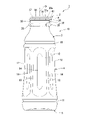
図1に示すように、本実施形態の押出しブローボトル(ボトル)1は合成樹脂製のボトルであって、口部2、肩部3、胴部4及び底部5を有する有底筒状の容器本体10を備えている。なお、押出しブローボトル1は、パリソンを利用した押出しブロー成形によって形成される。
EMBODIMENT OF THE INVENTION Hereinafter, embodiment of the bottle which concerns on this invention is described with reference to drawings.
As shown in FIG. 1, the extrusion blow bottle (bottle) 1 of this embodiment is a bottle made of synthetic resin, and is a bottomed cylindrical container having a
合成樹脂としては、例えばポリプロピレン(PP)、ポリエチレンやポリエチレンテレフタレート(PET)等が挙げられる。ただし、本実施形態の押出しブローボトル1は、1種類の合成樹脂により形成される場合に限定されるものではなく、異種の合成樹脂を積層することで形成されても構わない。
例えば、主材樹脂及びバリア性樹脂の2種類の合成樹脂を積層することで押出しブローボトル1を形成しても構わない。この場合、主材樹脂としては、例えば上述したPP等の樹脂が挙げられる。また、バリア性樹脂は、例えばガス(酸素や二酸化炭素等)や、湿気等の水分や、紫外線等の光や、香り等の匂い成分等が主材樹脂を透過することを規制するバリア性を有する樹脂であり、バリアする対象物に応じて適宜選択される樹脂とされる。例えば、ガスに対するバリア性を発揮させる場合には、ナイロン系樹脂やエチレンビニルアルコール共重合体樹脂等が挙げられ、水分に対するバリア性を発揮させる場合には、環状ポリオレフィン系樹脂等が挙げられる。
Examples of synthetic resins include polypropylene (PP), polyethylene, and polyethylene terephthalate (PET). However, the
For example, the
ただし、本実施形態の押出しブローボトル1において、異種の合成樹脂を積層することで容器本体10を形成した場合、互いに積層される各層同士は接着され、それによって剥離不能とされている。
However, in the
なお、押出ブローボトル1内に充填される内容物としては、例えば調味料等の食品、粉末状の医薬品、液体ヨーグルト、栄養ドリンク等の飲料が挙げられるが、この場合に限定されるものではない。
特に本実施形態の押出ブローボトル1は、バージンシール性(未開封性)や、高いバリア性及び密封性等が要求される場合に好適に利用することができる。特に内容物の品質等を適切に維持するためには、高いバリア性及び密封性が求められ、例えば内容物が食品の場合にはその傾向がより強くなる。本実施形態の押出ブローボトル1は、このような要求に応えることができるボトルとして好適に利用することが可能である。なお、押出しブローボトル1の内容量としては、例えば600ml以下とされている。
The contents to be filled in the extruded
In particular, the
口部2、肩部3、胴部4及び底部5は、それぞれの中心軸線を共通軸上に位置させた状態で、この順に連設されている。以下、この共通軸をボトル軸Oといい、ボトル軸O方向に沿って口部2側を上方、その反対側を下方という。また、ボトル軸O方向から見た平面視で、ボトル軸Oに交差する方向を径方向といい、ボトル軸O回りに周回する方向を周方向という。
The
口部2、肩部3及び底部5は、それぞれ径方向に沿う横断面視形状が円形状とされている。ただし口部2、肩部3及び底部5の形状は、この場合に限定されるものではなく、例えば横断面視で楕円状或いは多角形状に形成されていても構わない。
胴部4は、後述する複数のパネル面12が周方向に並んだ横断面視多角形状に形成されている。ただし、胴部4の形状についてもこの場合に限定されるものではなく、適宜変更して構わない。
The
The
肩部3と胴部4との接続部分、及び胴部4と底部5との接続部分には、それぞれ径方向内側に向けて凹んだ凹溝11が全周に亘って連続して形成されている。ただし、凹溝11は、連続する環状である必要がなく、例えば周方向に間隔をあけて複数形成し、各凹溝11を周方向に延びた周溝状に形成しても良い。さらに凹溝11の数は、2つに限定されるものではなく、1つだけ形成しても構わないし、ボトル軸O方向に間隔をあけて3つ以上形成しても構わない。さらには、凹溝11は必須なものではなく、具備しなくても構わない。
A connecting portion between the
胴部4には、減圧吸収用のパネル面12が周方向に間隔をあけて複数形成されている。さらに、胴部4において周方向で隣り合うパネル面12同士の間に位置する部分は、ボトル軸O方向に沿って延びる柱部13とされている。つまり、胴部4には、パネル面12と柱部13とが胴部4のほぼ全長に亘って周方向に交互に配設されている。
A plurality of panel surfaces 12 for absorbing reduced pressure are formed on the
パネル面12は、ボトル軸O方向を長手方向とする矩形状に形成され、その中央部分には径方向内側に向けて凹んだ凹部14が形成されている。図示の例では、凹部14はボトル軸O方向に沿って延びるように形成されている。ただし、凹部14は必須なものではなく具備しなくても構わない。さらに、凹部14に代えて例えば径方向外側に膨らんだ凸部を形成しても構わない。
The
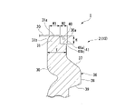
図1及び図2に示すように、口部2は、肩部3の上端部から上方に向かって突出する円筒状に形成され、シール材20によって封止可能とされている。さらに本実施形態では、シール材20によって封止された口部2に対して図示しない打栓キャップを装着することが可能とされている。なお、図1ではシール材20の図示を省略している。
As shown in FIGS. 1 and 2 , the
打栓キャップは、少なくとも口部2の内側に密に嵌合される図示しない内筒部と、口部2を径方向外側から囲む図示しない外筒部と、を備えた有頂筒状のキャップとされ、口部2に対して上方から所定の打栓力(押圧力)で押圧されることによって(すなわち打栓によって)口部2に装着される。具体的には、打栓キャップは、後述する係合突起36に対して外筒部がアンダーカット嵌合することで、上方に抜け止めされた状態で口部2に装着可能とされている。
ただし、打栓キャップは必須なものではなく、具備しなくても構わない。さらには、打栓キャップに代えて、例えば口部2に螺着されるネジキャップを採用しても構わない。
The plugging cap is a truncated cylindrical cap that includes an inner cylindrical portion (not shown) that is closely fitted to the inside of the
However, the plugging cap is not essential and may be omitted. Furthermore, instead of the plugging cap, for example, a screw cap that is screwed onto the
口部2は、肩部3の上端部から上方に向かって延びた口筒部30と、口筒部30の上端開口縁30aからさらに上方に向けて突出するように形成され、上端面31aにシール材20が固着される環状の突出壁31と、を備えている。
The
口筒部30の外周面には、ネックリング35及び係合突起36がボトル軸O方向に間隔をあけて形成されている。
ネックリング35は、口筒部30の外周面から径方向外側に向かって突出すると共に、周方向に延びるように形成されている。図示の例では、ネックリング35は周方向に延びる平面視円弧状に形成されると共に、周方向に等間隔をあけて並ぶように形成されている。ただし、この場合に限定されるものではなく、例えば周方向の全周に亘って延びるようにネックリング35を環状に形成しても構わない。
A
The
係合突起36はネックリング35よりも上方に配置され、口筒部30の外周面から径方向外側に向かって突出すると共に、周方向の全周に亘って延びる環状に形成されている。
図示の例では、係合突起36は、上方から下方に向かうにしたがって径方向外側に向けて延びるように形成され、斜め上方を向いた断面テーパ状の傾斜面37と、傾斜面37の下端部から下方に向けてボトル軸O方向に沿って延びた接触面38と、接触面38の下端部から下方に向かうにしたがって径方向内側に向けて延びるように形成され、斜め下方を向いた断面テーパ状の係合面39と、を備えている。
The engaging
In the illustrated example, the engaging
上述のように係合突起36が形成されているので、容器本体10の口部2に対して打栓キャップを上方から押圧(打栓)すると、打栓キャップの外筒部が傾斜面37上を摺動しながら拡径し、係合突起36を上方から下方に向けて乗り越えた後、係合面39に対して下方から係合する。
これにより、打栓キャップは、係合突起36に対して外筒部がアンダーカット嵌合された状態で口部2に装着可能とされている。
Since the engaging
As a result, the plugging cap can be attached to the
突出壁31は、口筒部30における上端開口縁30aのうち内周面寄りに配置され、突出壁31よりも径方向外側において上端開口縁30aを上方に露出させるように、口筒部30の外径よりも小さい外径で形成されている。
これにより、突出壁31よりも径方向外側に位置する部分には、口部2の全周に亘って凹んだ環状の段差部40が形成されている。
The protruding
As a result, an annular stepped
また突出壁31は、口筒部30の外径よりも小さい外径で形成されているので、突出壁31の上端面31aにおける径方向に沿った幅W1は、口筒部30における上端部の肉厚Tよりも小さい。
突出壁31の上端面31aにおける径方向に沿った幅W1は、例えば0.8mm以上、1.5mm以下とされている。また口筒部30における上端部の肉厚Tは、例えば1.1mm以上、2.5mm以下とされている。さらに突出壁31の上端面31aと口筒部30の上端開口縁30aとの間のボトル軸O方向に沿った間隔(すなわち段差部40の高さ)Hは、例えば0.4mm以上、1.0mm以下とされている。
Further, since the protruding
A width W1 along the radial direction of the
なお、突出壁31の内周面は、上方に向かうにしたがって径方向外側に向けて延びた断面テーパ状の傾斜面31bとされている。ただし、傾斜面31bは必須なものではなく、具備しなくても構わない。
The inner peripheral surface of the projecting
上述のように構成された突出壁31の上端面31aには、先に述べたようにシール材20が例えば熱融着等によって固着される。シール材20としては、例えば熱融着(ヒートシール)可能なアルミシート等が挙げられるが、特に限定されるものではない。なお、内容物に対するバリア性の向上のため、アルミシート等の高いバリア性を具備するシール材を用いることが好ましい。
As described above, the sealing
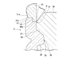
さらに、口筒部30の外周面のうち上端開口縁30aとの接続部分には、上端開口縁30aに連設されると共に、径方向外側に向けて突出した環状の切断痕41が形成されている。切断痕41は、口筒部30の上端開口縁30aと面一状に連設された上端面41aと、上端面41aにおける外周縁部(すなわち切断痕41の外端部)から下方に向かうにしたがって径方向内側に向かって延びることで、斜め下方を向いた傾斜面41bと、を有し、断面三角形状に形成されている。
Furthermore, an
上述の切断痕41が形成された口部2において、突出壁31の外周面と切断痕41における上端面41aの外周縁部との間の径方向に沿った間隔(すなわち段差部40及び切断痕41の合計幅)W2は、例えば0.3mm以上、0.7mm以下とされている。
従って、突出壁31は、先に述べた間隔H(段差部40の高さ)の方が、間隔W2(段差部40及び切断痕41の合計幅)よりも大きくなるように形成されている。
In the
Therefore, the projecting
具体的に、本実施形態では、突出壁31の上端面31aにおける径方向に沿った幅W1は、1mmとされている。突出壁31の外周面と切断痕41における上端面41aの外周縁部との間の径方向に沿った間隔W2(段差部40及び切断痕41の合計幅)は、0.67mmとされている。さらに突出壁31の上端面31aと口筒部30の上端開口縁30aとの間のボトル軸O方向に沿った間隔H(段差部40の高さ)は、0.7mmとされている。
Specifically, in the present embodiment, the width W1 along the radial direction of the
なお、切断痕41は、図3に示すように押出しブロー成形する際に、パリソンを挟持する成形金型50と、パリソンに対して上方から押し込まれるプラグ51に設けられた切断用凸部52と、の当接による喰い切りによって不要部分Dが切断、除去されることで形成される。
As shown in FIG. 3, the
(ボトルの作用)
上述のように構成された押出しブローボトル1によれば、図2に示すように、シール材20が固着される突出壁31の上端面31aを、切断痕41よりも上方に位置させているので、突出壁31の上端面31aに対してシール材20を熱融着等によって固着するときに、シール材20と切断痕41とを接触させ難くすることができる。そのため、切断痕41に対するシール材20の固着を抑制しながら、シール材20を突出壁31の上端面31aに固着することが可能である。
(Action of bottle)
According to the
これにより、従来のように切断痕41によってシール材20が剥れ難くなるような不都合が生じ難い。従って、シール材20の開封強度(固着強度)を抑制して、高くなり過ぎてしまうことを防止できるので、シール材20を抵抗少なくスムーズに剥離することができる。さらに、切断痕41に対するシール材20の固着を抑制できるので、シール材20の剥離の確実性を向上することができると共に、開封強度のばらつきも抑えることができる。
As a result, unlike the prior art, the
以上説明したように、本実施形態の押出しブローボトル1によれば、シール材20の開封強度を抑制することができ、シール材20を抵抗少なくスムーズに剥離することができる。従って、シール材20による封止に対応したUPI成形可能な口部2を具備する押出しブローボトル1とすることができ、バージンシール性(未開封性)や、高いバリア性及び密封性等が要求されるボトルとして好適に利用することができる。
As described above, according to the
また、突出壁31の上端面31aにシール材20を固着させるので、突出壁31における径方向の幅を変化させることで、口筒部30の肉厚を変化させることなくシール材20の固着面積を調整することが可能である。そのため、例えば口筒部30の肉厚自体を薄肉にすることなく、シール材20の固着面積を小さくすることが可能である。従って、口筒部30の肉厚を維持して、該口筒部30の強度を適切に維持したまま、突出壁31における径方向の幅の変化によってシール材20の固着面積を適切に調整することができ、シール材20を剥離し易いボトルとすることができる。
In addition, since the sealing
また、口筒部30の上端開口縁30aと突出壁31の上端面31aとの間のボトル軸O方向に沿った間隔H(段差部40の高さ)を大きくすることができるので、突出壁31の上端面31aにシール材20を固着する際に、切断痕41に対してシール材20をさらに接触し難くすることができる。
特に、突出壁31の外径よりも若干大きいサイズのシール材20を固着する場合には、図2に示すようにシール材20の外周縁部側が突出壁31よりも径方向外側に飛び出てしまう。このような場合であっても、段差部40の段差を大きくすることができるので、シール材20の外周縁部側が切断痕41に対して接触することを効果的に抑制することができる。
In addition, since the distance H (the height of the stepped portion 40) between the upper
In particular, when the sealing
さらに、段差部40の段差を大きくすることができるので、シール材20を突出壁31の上端面31aに例えば熱融着によって固着する場合であっても、加熱等の影響によって段差が潰れ難い。従って、上述した各作用効果を適切に奏功することができる。
Furthermore, since the step of the stepped
さらに、突出壁31の上端面31aにおける径方向に沿った幅を、0.8mm以上、1.5mm以下としているので、シール材20の固着面積を適切に確保することができる。従って、シール材20を剥離する際の開封強度を抑制しつつ、シール材20が不意に剥れてしまうことを防止することができる。そのため、シール材20の固着の安定性と、シール材20の容易な剥離性とを両立させることができる。
Furthermore, since the width along the radial direction of the
以上、本発明の実施形態を説明したが、これらの実施形態は例として提示したものであり、発明の範囲を限定することは意図していない。実施形態は、その他様々な形態で実施されることが可能であり、発明の要旨を逸脱しない範囲で、種々の省略、置き換え、変更を行うことができる。実施形態やその変形例には、例えば当業者が容易に想定できるもの、実質的に同一のもの、均等の範囲のものなどが含まれる。 Although embodiments of the present invention have been described above, these embodiments are presented as examples and are not intended to limit the scope of the invention. Embodiments can be implemented in various other forms, and various omissions, replacements, and modifications can be made without departing from the scope of the invention. Embodiments and modifications thereof include, for example, those that can be easily imagined by those skilled in the art, those that are substantially the same, and those within an equivalent range.
例えば上記実施形態において、突出壁31の上端面31aにおける径方向に沿った幅W1を適切に確保することができれば、例えば突出壁31よりも径方向内側に段差部が形成されても構わない。
For example, in the above-described embodiment, a stepped portion may be formed radially inward of the protruding
さらに、上記実施形態では、突出壁31の上端面31aと口筒部30の上端開口縁30aとの間のボトル軸O方向に沿った間隔H(段差部40の高さ)の方が、突出壁31の外周面と切断痕41における上端面41aの外周縁部との間の径方向に沿った間隔W2(段差部40及び切断痕41の合計幅)よりも大きくなるように形成した場合を例に挙げて説明したが、この場合に限定されるものではない。
例えば、間隔H(段差部40の高さ)は、間隔W2(段差部40及び切断痕41の合計幅)と同等であっても構わないし、小さくても構わない。
Furthermore, in the above-described embodiment, the distance H (the height of the stepped portion 40) between the
For example, the interval H (the height of the stepped portion 40) may be equal to or smaller than the interval W2 (the total width of the stepped
H…突出壁の上端面と口筒部の上端開口縁との間のボトル軸方向に沿った間隔
O…ボトル軸
W1…突出壁の上端面における径方向に沿った幅
W2…突出壁の外周面と切断痕の外端部との間の径方向に沿った間隔
1…押出しブローボトル(ボトル)
2…口部
20…シール材
30…口筒部
30a…口筒部の上端開口縁
31…突出壁
31a…突出壁の上端面
41…切断痕
H... Distance along the axial direction of the bottle between the upper end surface of the protruding wall and the upper end opening edge of the mouthpiece O... Bottle axis W1... Width along the radial direction of the upper end surface of the protruding wall W2... Periphery of the protruding wall Distance along the radial direction between the face and the outer edge of the
2
Claims (2)
前記口部は、
ボトル軸方向に延びる口筒部と、
前記口筒部の上端開口縁から前記ボトル軸方向の上方に向けて突出するように形成されると共に、上端面に熱融着可能なアルミシートが固着される環状の突出壁と、を備え、
前記突出壁は、該突出壁よりも径方向の外側において前記上端開口縁を露出させるように、前記口筒部の外径よりも小さい外径で形成され、
前記口筒部の外周面には、前記上端開口縁に連設されると共に径方向の外側に向けて突出した切断痕が形成され、
前記突出壁は、前記突出壁の外周面と前記切断痕の外端部との間の径方向に沿った間隔よりも、前記突出壁の上端面と前記口筒部の上端開口縁との間の前記ボトル軸方向に沿った間隔の方が大きくなるように形成されている、ボトル。 A bottle comprising a synthetic resin container body having a mouth,
The mouth is
a mouthpiece extending in the axial direction of the bottle;
an annular protruding wall formed to protrude upward in the axial direction of the bottle from the upper end opening edge of the mouthpiece, and to which a heat-sealable aluminum sheet is fixed to the upper end surface;
The protruding wall is formed with an outer diameter smaller than the outer diameter of the mouth tube portion so as to expose the upper end opening edge radially outside the protruding wall,
The outer peripheral surface of the mouthpiece portion is formed with cut marks that are continuous with the upper end opening edge and protrude outward in the radial direction ,
The protruding wall has a greater distance between the upper end surface of the protruding wall and the upper opening edge of the mouth tube portion than the space along the radial direction between the outer peripheral surface of the protruding wall and the outer end of the cut mark. The bottle is formed such that the distance between the bottles along the bottle axis direction is larger .
前記突出壁の上端面は、径方向の沿った幅が0.8mm以上、1.5mm以下の範囲内とされている、ボトル。 A bottle according to claim 1 ,
The bottle, wherein the upper end surface of the projecting wall has a width along the radial direction of 0.8 mm or more and 1.5 mm or less.
Priority Applications (1)
| Application Number | Priority Date | Filing Date | Title |
|---|---|---|---|
| JP2018205996A JP7190870B2 (en) | 2018-10-31 | 2018-10-31 | Bottle |
Applications Claiming Priority (1)
| Application Number | Priority Date | Filing Date | Title |
|---|---|---|---|
| JP2018205996A JP7190870B2 (en) | 2018-10-31 | 2018-10-31 | Bottle |
Publications (2)
| Publication Number | Publication Date |
|---|---|
| JP2020070074A JP2020070074A (en) | 2020-05-07 |
| JP7190870B2 true JP7190870B2 (en) | 2022-12-16 |
Family
ID=70546993
Family Applications (1)
| Application Number | Title | Priority Date | Filing Date |
|---|---|---|---|
| JP2018205996A Active JP7190870B2 (en) | 2018-10-31 | 2018-10-31 | Bottle |
Country Status (1)
| Country | Link |
|---|---|
| JP (1) | JP7190870B2 (en) |
Families Citing this family (1)
| Publication number | Priority date | Publication date | Assignee | Title |
|---|---|---|---|---|
| JP7349060B2 (en) * | 2019-07-26 | 2023-09-22 | キョーラク株式会社 | double container |
Citations (4)
| Publication number | Priority date | Publication date | Assignee | Title |
|---|---|---|---|---|
| JP2008110791A (en) | 2006-10-31 | 2008-05-15 | Yoshino Kogyosho Co Ltd | Opening cylinder part of container made of synthetic resin |
| JP2010179948A (en) | 2009-02-06 | 2010-08-19 | Toyo Seikan Kaisha Ltd | Sealing structure of container spout |
| JP2014129125A (en) | 2012-12-28 | 2014-07-10 | Yoshino Kogyosho Co Ltd | Pouring container |
| JP2016069038A (en) | 2014-09-30 | 2016-05-09 | 株式会社吉野工業所 | Delamination container |
Family Cites Families (1)
| Publication number | Priority date | Publication date | Assignee | Title |
|---|---|---|---|---|
| JPH0637113U (en) * | 1992-10-16 | 1994-05-17 | 株式会社吉野工業所 | Blow molded container |
-
2018
- 2018-10-31 JP JP2018205996A patent/JP7190870B2/en active Active
Patent Citations (4)
| Publication number | Priority date | Publication date | Assignee | Title |
|---|---|---|---|---|
| JP2008110791A (en) | 2006-10-31 | 2008-05-15 | Yoshino Kogyosho Co Ltd | Opening cylinder part of container made of synthetic resin |
| JP2010179948A (en) | 2009-02-06 | 2010-08-19 | Toyo Seikan Kaisha Ltd | Sealing structure of container spout |
| JP2014129125A (en) | 2012-12-28 | 2014-07-10 | Yoshino Kogyosho Co Ltd | Pouring container |
| JP2016069038A (en) | 2014-09-30 | 2016-05-09 | 株式会社吉野工業所 | Delamination container |
Also Published As
| Publication number | Publication date |
|---|---|
| JP2020070074A (en) | 2020-05-07 |
Similar Documents
| Publication | Publication Date | Title |
|---|---|---|
| CN103562089B (en) | Cutting and distribution closure member | |
| KR101812907B1 (en) | Delamination container | |
| EP2663505B1 (en) | Drink-through spout cap for a beverage bottle, set of a cover and such a drink-through spout cap, a drinking device, and methods of manufacturing and preparing a drinking device | |
| US20140319142A1 (en) | Membrane, and a neck including such membrane | |
| JP7190870B2 (en) | Bottle | |
| JP5064941B2 (en) | Attaching the plastic cap | |
| JP2002068229A (en) | Sealing structure for upper surface of laminate bottle mouth | |
| JP6537392B2 (en) | Double container | |
| BR112015027469B1 (en) | assembly, packaging, method of assembling a container and sealing ring, and container and sealing ring | |
| CA3031871C (en) | A container including a cap having a tamper evident band | |
| WO2018047711A1 (en) | Plastic cap | |
| JP7038568B2 (en) | Bottle | |
| WO2015194040A1 (en) | Resin cap | |
| JP5968746B2 (en) | Ring cap for preventing gas filling of double container and double container including the same | |
| JP2005088954A (en) | Opening end part and preform of synthetic resin bottle body for hot warmer preservation | |
| WO2019106905A1 (en) | Synthetic resin container, preform, and method for producing synthetic resin container | |
| JP6651416B2 (en) | Double container | |
| JP6566772B2 (en) | Double container | |
| JP2023080982A (en) | Preform of double container molding and double container | |
| WO2022230868A1 (en) | Preform for forming double container | |
| JP7242405B2 (en) | discharge container | |
| WO2022091586A1 (en) | Double-layered container | |
| JP2023050603A (en) | double container | |
| JP2023123020A (en) | double container | |
| JP2005271928A (en) | Fraudulent unsealing preventing bottle |
Legal Events
| Date | Code | Title | Description |
|---|---|---|---|
| A621 | Written request for application examination |
Free format text: JAPANESE INTERMEDIATE CODE: A621 Effective date: 20210506 |
|
| A977 | Report on retrieval |
Free format text: JAPANESE INTERMEDIATE CODE: A971007 Effective date: 20220322 |
|
| A131 | Notification of reasons for refusal |
Free format text: JAPANESE INTERMEDIATE CODE: A131 Effective date: 20220510 |
|
| A521 | Request for written amendment filed |
Free format text: JAPANESE INTERMEDIATE CODE: A523 Effective date: 20220706 |
|
| TRDD | Decision of grant or rejection written | ||
| A01 | Written decision to grant a patent or to grant a registration (utility model) |
Free format text: JAPANESE INTERMEDIATE CODE: A01 Effective date: 20221108 |
|
| A61 | First payment of annual fees (during grant procedure) |
Free format text: JAPANESE INTERMEDIATE CODE: A61 Effective date: 20221206 |
|
| R150 | Certificate of patent or registration of utility model |
Ref document number: 7190870 Country of ref document: JP Free format text: JAPANESE INTERMEDIATE CODE: R150 |