JP6566772B2 - Double container - Google Patents
Double container Download PDFInfo
- Publication number
- JP6566772B2 JP6566772B2 JP2015151971A JP2015151971A JP6566772B2 JP 6566772 B2 JP6566772 B2 JP 6566772B2 JP 2015151971 A JP2015151971 A JP 2015151971A JP 2015151971 A JP2015151971 A JP 2015151971A JP 6566772 B2 JP6566772 B2 JP 6566772B2
- Authority
- JP
- Japan
- Prior art keywords
- introduction hole
- outside air
- air introduction
- layer body
- fitting position
- Prior art date
- Legal status (The legal status is an assumption and is not a legal conclusion. Google has not performed a legal analysis and makes no representation as to the accuracy of the status listed.)
- Active
Links
Images


Description
本発明は、容器の外殻を形成する外層体と、該外層体の内側に収められた内層体と、外層体を貫通する外気導入孔とを備える二重容器に関し、特に、容器を潰して廃棄するに際し、その潰した状態を保持できるようにするものである。 The present invention relates to a double container including an outer layer body that forms an outer shell of the container, an inner layer body that is housed inside the outer layer body, and an outside air introduction hole that penetrates the outer layer body. When discarded, the crushed state can be maintained.
従来、口部、胴部及び底部を有するボトル状をなすと共に容器の外殻を形成する外層体と、該外層体の内側に収められた内層体と、外層体を貫通する外気導入孔とを備え、内層体の減容変形に伴い外気導入孔から外層体と内層体との間に形成される内部空間に外気を導入可能な二重容器(デラミ容器とも言う)が知られている(例えば特許文献1参照)。 Conventionally, an outer layer body forming a bottle shape having a mouth portion, a body portion and a bottom portion and forming an outer shell of a container, an inner layer body housed inside the outer layer body, and an outside air introduction hole penetrating the outer layer body A double container (also referred to as a delamination container) capable of introducing outside air into the internal space formed between the outer layer body and the inner layer body from the outside air introduction hole in accordance with volume reduction deformation of the inner layer body is known (for example, Patent Document 1).
しかしながら、前記したような構造の二重容器は、使い終わって容器を廃棄する際、一度容器を潰しても、時間が経つと徐々に外気を取り込んで元の形状に復元してしまう性質があり、廃棄時に容積が大きくなってしまうという問題があった。 However, the double container having the structure as described above has a property that when the container is used and discarded, even after the container is crushed, outside air is gradually taken in and restored to its original shape over time. There is a problem that the volume becomes large at the time of disposal.
本発明は、前記の課題を解決するために開発されたもので、容器の外殻を形成する外層体と、該外層体の内側に収められた内層体と、外層体を貫通する外気導入孔とを備える二重容器において、容器を潰して廃棄するに際し、その潰した状態を保持できるようにすることを目的とする。 The present invention has been developed to solve the above-described problems, and includes an outer layer body that forms an outer shell of a container, an inner layer body that is housed inside the outer layer body, and an outside air introduction hole that penetrates the outer layer body. When the container is crushed and discarded, the object is to hold the crushed state.
すなわち、本発明の要旨構成は以下のとおりである。
1.口部、胴部及び底部を有するボトル状をなすと共に容器の外殻を形成する外層体と、該外層体の内側に収められた内層体と、前記外層体を貫通する外気導入孔とを備え、前記内層体の減容変形に伴い前記外気導入孔から前記外層体と前記内層体との間に形成される内部空間に外気を導入可能な二重容器において、
前記外気導入孔に挿入され、該外気導入孔の周縁部に一段目の嵌合位置と該嵌合位置とは挿入深さが異なる二段目の嵌合位置とで嵌合可能なエア弁を備え、
前記一段目の嵌合位置では、少なくとも前記胴部のスクイズ解除時には、前記エア弁と前記外気導入孔の周縁部との間に通気路となる隙間が形成され、
前記二段目の嵌合位置では、前記エア弁と前記外気導入孔の周縁部との間が封止されることを特徴とする二重容器。
That is, the gist configuration of the present invention is as follows.
1. An outer layer body that forms a bottle shape having a mouth portion, a body portion, and a bottom portion and forms an outer shell of a container, an inner layer body that is housed inside the outer layer body, and an outside air introduction hole that penetrates the outer layer body In the double container capable of introducing the outside air into the internal space formed between the outer layer body and the inner layer body from the outside air introduction hole in accordance with the volume reduction deformation of the inner layer body,
An air valve that is inserted into the outside air introduction hole and can be fitted to a peripheral portion of the outside air introduction hole at a first-stage fitting position and a second-stage fitting position having a different insertion depth from the fitting position. Prepared,
In the first-stage fitting position, at least when releasing the squeeze of the body portion, a gap serving as a ventilation path is formed between the air valve and the peripheral portion of the outside air introduction hole,
In the second-stage fitting position, a space between the air valve and the peripheral portion of the outside air introduction hole is sealed.
2.前記エア弁は、前記一段目の嵌合位置で前記外気導入孔の周縁部に嵌合する環状の嵌合溝を備える、前記1の二重容器。 2. The said double valve of said 1 provided with the cyclic | annular fitting groove fitted to the peripheral part of the said external air introduction hole in the said 1st step | paragraph fitting position.
3.前記エア弁は、前記嵌合溝を横断する少なくとも1本のエア溝を備え、該少なくとも1本のエア溝は、前記一段目の嵌合位置で前記外気導入孔の周縁部との間に通気路となる前記隙間を形成する、前記2の二重容器。 3. The air valve includes at least one air groove that crosses the fitting groove, and the at least one air groove vents between a peripheral portion of the outside air introduction hole at the first-stage fitting position. The double container according to 2 above, wherein the gap serving as a path is formed.
4.前記エア弁は、前記外気導入孔に挿入される筒状をなす挿入部と、該挿入部の一端を閉塞する蓋部とを備え、
前記蓋部の外周縁部は、前記挿入部からフランジ状に突出すると共に、前記二段目の嵌合位置で前記外気導入孔の周縁部に当接する、前記1〜3のいずれかの二重容器。
4). The air valve includes a cylindrical insertion portion that is inserted into the outside air introduction hole, and a lid portion that closes one end of the insertion portion,
The outer peripheral edge portion of the lid portion protrudes in a flange shape from the insertion portion, and contacts the peripheral edge portion of the outside air introduction hole at the second-stage fitting position. container.
5.前記一段目の嵌合位置で前記エア弁を回転させることで、前記外気導入孔の周縁部と前記嵌合溝との間に通気路となる前記隙間が形成される、前記2の二重容器。 5. The second double container in which the gap serving as a ventilation path is formed between a peripheral edge of the outside air introduction hole and the fitting groove by rotating the air valve at the first-stage fitting position. .
6.前記外気導入孔及び前記嵌合溝は、いずれも楕円形状をなしている、前記5の二重容器。 6). The double container according to 5 above, wherein the outside air introduction hole and the fitting groove are both elliptical.
7.前記エア弁は、前記外気導入孔に挿入される筒状をなす挿入部と、該挿入部の一端を閉塞する蓋部と、該蓋部に立設された摘み部とを備え、
前記蓋部の外周縁部は、前記挿入部からフランジ状に突出すると共に、前記二段目の嵌合位置で前記外気導入孔の周縁部に当接する、前記5又は6の二重容器。
7). The air valve includes a cylindrical insertion portion that is inserted into the outside air introduction hole, a lid that closes one end of the insertion portion, and a knob that is erected on the lid.
5. The double container according to 5 or 6, wherein an outer peripheral edge portion of the lid portion protrudes in a flange shape from the insertion portion, and abuts on a peripheral edge portion of the outside air introduction hole at the second-stage fitting position.
本発明によれば、エア弁を一段目の嵌合位置に配置することで、胴部を押圧(スクイズ)して内容物を吐出するに際し、少なくとも胴部のスクイズ解除時に外気をエア弁と外気導入孔の周縁部との間の隙間を通じて外層体と内層体との間の内部空間に導入することができる。また、容器を潰して廃棄するに際しては、容器を潰した状態でエア弁を二段目の嵌合位置に移動させることで、エア弁と外気導入孔の周縁部との間を封止し、その潰した状態を保持することが可能となる。 According to the present invention, by disposing the air valve at the first-stage mating position, when the body is pressed (squeezed) to discharge the contents, at least when the squeeze of the body is released, the outside air is separated from the air valve and the outside air. It can introduce | transduce into the internal space between an outer layer body and an inner layer body through the clearance gap between the peripheral parts of an introduction hole. Further, when the container is crushed and discarded, the air valve is moved to the second-stage fitting position in a state where the container is crushed, thereby sealing between the air valve and the peripheral portion of the outside air introduction hole, The crushed state can be maintained.
したがって、本発明によれば、容器の外殻を形成する外層体と、該外層体の内側に収められた内層体と、外層体を貫通する外気導入孔とを備える二重容器において、容器を潰して廃棄するに際し、その潰した状態を保持できるようにすることができる。 Therefore, according to the present invention, in a double container comprising an outer layer body that forms an outer shell of a container, an inner layer body that is housed inside the outer layer body, and an outside air introduction hole that penetrates the outer layer body, When crushed and discarded, the crushed state can be maintained.
以下、図1〜図4を参照して、本発明の一実施形態に係る二重容器1について詳細に例示説明する。
なお、本明細書において、上下方向とは、二重容器1の正立状態を基準とし、外層体10の口部11が位置する側を上方(例えば、図1の上方)、外層体10の底部13が位置する側を下方(例えば、図1の下方)とする。
Hereinafter, with reference to FIGS. 1-4, the double container 1 which concerns on one Embodiment of this invention is illustrated and demonstrated in detail.
In this specification, the vertical direction is based on the upright state of the double container 1, and the side on which the
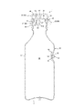
図1に示すように、本実施形態に係る二重容器1は、容器の外殻を形成する外層体10と、外層体10の内側に収められる減容変形自在な内層体20とを備えている。なお、本実施形態では、外層体10と内層体20の間には、これら外層体10及び内層体20を互いに部分的に接合する接着帯(図示省略)が設けられているが、接着帯を設けない構成とすることも可能である。
As shown in FIG. 1, the double container 1 according to the present embodiment includes an
ここで、本実施形態における二重容器1は、合成樹脂製の外層体10と、外層体10に対して相溶性が低い合成樹脂にて形成される内層体20と、外層体10及び内層体20に対して接着性を有する合成樹脂にて形成される帯状の接着層、すなわち、接着帯とを積層させたものであり、これらの合成樹脂を積層して形成したパリソンを、ブロー成形することによって得られたものである。ここで、本実施形態の二重容器1においては、外層体10を外側の低密度ポリエチレン(LDPE)と内側のポリプロピレン樹脂(PP)の2層構造とし、内層体20を外側のエチレンビニルアルコール共重合樹脂(EVOH)と内側の変性ポリオレフィン樹脂(三井化学株式会社製「アドマー」(登録商標))の2層構造としている。また、接着帯を変性ポリオレフィン樹脂(「アドマー」(登録商標))で構成している。なお、本実施形態では、スクイズ性を付与するため、外層体10の外側の層を低密度ポリエチレン(LDPE)で構成しているが、ポリプロピレン樹脂(PP)、中密度ポリエチレン樹脂(MDPE)、又は高密度ポリエチレン樹脂(HDPE)とすることも可能である。また、本実施形態の外層体10を構成するポリプロピレン樹脂(PP)の層は、内層体20の剥離性を向上するために設けたものであり、必ずしも必要なものではない。さらに、上記の層構成は一例であり、外層体10に対して内層体20が剥離可能であれば、外層体10、内層体20、及び接着帯の材料は特に限定されるものではなく、それぞれ単層構造としても良いし、多層構造としても良い。また、接着帯は必ずしも設ける必要はない。
Here, the double container 1 in this embodiment includes a synthetic resin
外層体10は、口部11、胴部12及び底部13を有するボトル状をなすと共に復元自在な可撓性を有するものである。なお、本実施形態において胴部12は、横断面が円形であり、口部11に向けて上部が縮径する筒形状としているが、これに限定されず、例えば、横断面が多角形や楕円形等の形状とすることができる。
The
内層体20は、その内側に内容物(図示省略)を充填可能な充填空間Mを有しており、積層された外層体10から剥離させることで減容変形させることができる。すなわち、外層体10は外層体10を貫通する外気導入孔14を備えており、内容物の取り出しに伴う内層体20の減容変形に従い、外気導入孔14から外層体10と内層体20との間に形成される内部空間Nに外気が導入されるようになっている。
The
本実施形態では、外層体10の胴部12は局所的に内側に向けて凹む凹部15を備え、外気導入孔14は凹部15に形成されている。また、外気導入孔14には、エア弁30が挿入されている。エア弁30は、図3に示すように、外気導入孔14の周縁部に一段目の嵌合位置で嵌合可能であると共に、図4に示すように、一段目の嵌合位置とは挿入深さが異なる二段目の嵌合位置で嵌合可能である。エア弁30は、一段目の嵌合位置において外側から押し込むことで二段目の嵌合位置に移動させることができる。エア弁30は、例えば合成樹脂製とすることができる。なお、エア弁30は、一段目の嵌合位置において凹部15に収まるように配置されている。したがって、製造ライン上での輸送時等においてエア弁30が外部と接触して移動してしまうことが防止される。
In the present embodiment, the
また、エア弁30は、円形の外気導入孔14に挿入される円筒状をなす挿入部31と、該挿入部31の一端を閉塞する円板状の蓋部32とを備えている。蓋部32の外周縁部32aは、挿入部31からフランジ状に突出している。挿入部31には、一段目の嵌合位置で外気導入孔14の周縁部に嵌合する円環状の嵌合溝31aが形成されている。また、挿入部31には、嵌合溝31aを横断する4本のエア溝31bが形成されている。4本のエア溝31bは周方向に等間隔を空けて配置されている。また、4本のエア溝31bは、一段目の嵌合位置で外気導入孔14の周縁部との間に通気路となる隙間を形成する。なお、エア溝31bは、4本に限らず、3本以下又は5本以上設けるようにしてもよい。ここに、エア溝31bの本数や断面積を適宜設定することで、胴部12のスクイズ時には内部空間Nからの空気の漏れを抑制して内容物のスムーズな吐出を可能にする一方、胴部12のスクイズ解除時には十分な外気が導入されるようにすることができる。
The
また、図1に示したように、二重容器1は、注出キャップ40を備えている。注出キャップ40は、口部11に係合保持される注出栓41と、注出栓41にヒンジ42を介して連結され、当該注出栓41の開閉を行う蓋体43とを備えている。なお、ヒンジ42を設けずに、蓋体43を別体として形成し、注出栓41にねじ係合やアンダーカット係合させる構成としてもよい。
Further, as shown in FIG. 1, the double container 1 includes a pouring
注出栓41は、口部11の外周面に対してアンダーカット係合する装着筒44と、装着筒44の上部を覆う隔壁45と、隔壁45から上方に立設し、内側が充填空間Mに繋がる注出筒46とを備える。注出筒46の下方には、円筒壁47が連なっており、円筒壁47の内周面には、周方向に間隔をあけて設けられる複数の縦リブ48を設けている。縦リブ48の径方向内側には、球状体49が配置され、縦リブ48の上端に設けた膨出部によって抜け止め保持されている。円筒壁47の下部には、下方に向けて縮径する傾斜壁47aを設けている。ここで、球状体49は、縦リブ48に沿って自重にて移動するものであり、図1に示すように二重容器1が正立姿勢にあるときは傾斜壁47aと全周にわたって当接して、内層体20の充填空間Mを封止している。
The
蓋体43は、注出栓41の上方を覆う頂壁50の外縁部に周壁51を連結したものであり、周壁51はヒンジ42によって装着筒44に連結されている。また、頂壁50の下面には、注出筒46と液密に当接するシール筒52を設けている。また、シール筒52の径方向内側には、下方に向けて延びるピン53を設けている。ピン53は、球状体49が上方へ変位する際、上限に至る手前で球状体49に当接するように設けられている。これにより、二重容器1の使用後に蓋体43を閉じることで球状体49を確実に落下させて、傾斜壁47aに当接させ、充填空間Mを封止することができる。
The
かかる二重容器1の使用に際しては、まず、蓋体43を開いて二重容器1を傾倒或いは倒立姿勢にすることで、球状体49が注出筒46側に変位する。そして、胴部12を両側から挟むようにして外層体10をスクイズすれば、外気導入孔14にエア弁30が一段目の嵌合位置で取付けられていることで、内部空間Nからの空気の漏れが抑制されるため、内容物をスムーズに吐出することができる。また、スクイズを解除すれば、内部空間Nには外気が十分に導入される。
When the double container 1 is used, first, the
また、二重容器1を潰して廃棄するに際しては、図2及び図4に示すように、二重容器1を潰した状態でエア弁30を奥まで押し込み二段目の嵌合位置に移動させることで、エア弁30の挿入部31と外気導入孔14の周縁部との間を封止し、その潰した状態を保持することが可能となる。
When the double container 1 is crushed and discarded, as shown in FIGS. 2 and 4, the
以上説明したように、本実施形態に係る二重容器1は、口部11、胴部12及び底部13を有するボトル状をなすと共に容器の外殻を形成する外層体10と、該外層体10の内側に収められた内層体20と、外層体10を貫通する外気導入孔14とを備え、内層体20の減容変形に伴い外気導入孔14から外層体10と内層体20との間に形成される内部空間Nに外気を導入可能な二重容器1において、外気導入孔14に挿入され、該外気導入孔14の周縁部に一段目の嵌合位置と該嵌合位置とは挿入深さが異なる二段目の嵌合位置とで嵌合可能なエア弁30を備え、一段目の嵌合位置では、少なくとも胴部12のスクイズ解除時には、エア弁30と外気導入孔14の周縁部との間に通気路となる隙間が形成され、二段目の嵌合位置では、エア弁30と外気導入孔14の周縁部との間が封止されるという構成になっている。
As described above, the double container 1 according to the present embodiment is formed in a bottle shape having the
また、本実施形態に係る二重容器1は、エア弁30が、一段目の嵌合位置で外気導入孔14の周縁部に嵌合する環状の嵌合溝31aを備えるという構成になっている。したがって、エア弁30を安定して一段目の嵌合位置に保持することができる。
Moreover, the double container 1 which concerns on this embodiment becomes a structure that the
また、本実施形態に係る二重容器1は、エア弁30が、嵌合溝31aを横断する少なくとも1本のエア溝31bを備え、該少なくとも1本のエア溝31bは、一段目の嵌合位置で外気導入孔14の周縁部との間に通気路となる隙間を形成するという構成になっている。したがって、簡単な構成により、スクイズ時に内部空間Nからの空気の漏れを抑制すると共にスクイズ解除時に外気を内部空間Nに十分に導入することができる。
Further, in the double container 1 according to the present embodiment, the
さらに、本実施形態に係る二重容器1は、エア弁30が、外気導入孔14に挿入される筒状をなす挿入部31と、該挿入部31の一端を閉塞する蓋部32とを備え、蓋部32の外周縁部32aは、挿入部31からフランジ状に突出すると共に、二段目の嵌合位置で外気導入孔14の周縁部に当接するという構成になっている。したがって、容器の廃棄時に、エア弁30を奥まで押し込むという簡単な操作で、エア弁30を一段目の嵌合位置から二段目の嵌合位置に移動させることができる。
Further, in the double container 1 according to the present embodiment, the
次に、図5〜図7を参照して、本発明の他の実施形態に係る二重容器2について詳細に例示説明する。
本実施形態に係る二重容器2は、内容物の熱充填工程及びシャワー水による冷却工程に対応したものである。すなわち、醤油、醤油含有調味料、食酢、料理酒等の液体食品等を内容物とする場合に、その内容物を容器に充填して製品化するに際し、高温状態の内容物を充填する熱充填工程と、該工程の後にシャワー水を用いて容器及び内容物を冷却する冷却工程とを設けることがあるが、本実施形態に係る二重容器2は、そのような冷却工程においてシャワー水が外層体10と内層体20の間の内部空間Nに入り込まないようにできるものである。
Next, with reference to FIGS. 5-7, the double container 2 which concerns on other embodiment of this invention is illustrated and demonstrated in detail.
The double container 2 which concerns on this embodiment respond | corresponds to the heat filling process of the content, and the cooling process by shower water. That is, when filling liquid foods such as soy sauce, soy sauce-containing seasonings, vinegar, cooked liquor, etc., when filling the contents into a container and making it into a product, heat filling that fills the high temperature contents There may be a process and a cooling process for cooling the container and contents using shower water after the process, but the double container 2 according to the present embodiment has the shower water as an outer layer in such a cooling process. The internal space N between the
図5に示すように、本実施形態に係る二重容器2は、前述した実施形態の場合と比べると、エア弁60の構成、外気導入孔14’の形状、及び胴部12におけるエア弁60の取付け位置が異なるが、その他の構成は同一となっている。
As shown in FIG. 5, the double container 2 according to the present embodiment has a configuration of the
本実施形態では、前述した実施形態の場合と同様に胴部12の上部12aが口部11に向けて縮径しているが、この上部12aに、局所的に内側に向けて凹む凹部15’を備えている。また、外気導入孔14’はこの凹部15’に形成されている。外気導入孔14’は本実施形態では楕円形状をなしている。
In the present embodiment, the
エア弁60は、外気導入孔14’に挿入される楕円筒状をなす挿入部61と、該挿入部61の一端を閉塞する円板状の蓋部62と、該蓋部62に立設された平板状の摘み部63とを備えている。挿入部61は、一段目の嵌合位置で外気導入孔14’の周縁部に嵌合する楕円形状の嵌合溝61aを備えている。また、蓋部62の外周縁部62aは、挿入部61からフランジ状に突出している。エア弁60は、例えば合成樹脂製とすることができる。
The
エア弁60は、図5に示した状態では、楕円形状をなす嵌合溝61aの長軸と、同じく楕円形状をなす外気導入孔14’の長軸とが一致する回転位置で、一段目の嵌合位置に配置されている。したがって、この状態では、外気導入孔14’の周縁部と嵌合溝61aとの間は封止されている。したがって、この状態で冷却工程を経ることで、シャワー水が内部空間Nに侵入することを防止することができる。
In the state shown in FIG. 5, the
そして、冷却工程直後又は二重容器2の使用開始時に、図5に示した状態から摘み部63を摘まんで、図6に示すように、エア弁60を90°回転させることで、外気導入孔14’の周縁部と嵌合溝61aとの間に通気路となる隙間(斜線で示す部分)を形成することができる。したがって、前述した実施形態の場合と同様に、胴部12をスクイズすることで内容物をスムーズに吐出することが可能となる。
Then, immediately after the cooling process or at the start of use of the double container 2, the
なお、エア弁60は、一段目の嵌合位置において、胴部12の上部12aを除く部分から径方向外側に飛び出さないように配置されている。したがって、製造ライン上での輸送時等においてエア弁60が外部と接触して移動してしまうことが防止される。
In addition, the
また、二重容器2を潰して廃棄するに際しては、図7に示すように、二重容器2を潰した状態でエア弁60を奥まで押し込み二段目の嵌合位置に移動させることで、エア弁60の挿入部61と外気導入孔14’の周縁部との間を封止し、その潰した状態を保持することが可能となる。
Further, when the double container 2 is crushed and discarded, as shown in FIG. 7, the
以上説明したように、本実施形態に係る二重容器2は、口部11、胴部12及び底部13を有するボトル状をなすと共に容器の外殻を形成する外層体10と、該外層体10の内側に収められた内層体20と、外層体10を貫通する外気導入孔14’とを備え、内層体20の減容変形に伴い外気導入孔14’から外層体10と内層体20との間に形成される内部空間Nに外気を導入可能な二重容器2において、外気導入孔14’に挿入され、該外気導入孔14’の周縁部に一段目の嵌合位置と該嵌合位置とは挿入深さが異なる二段目の嵌合位置とで嵌合可能なエア弁60を備え、一段目の嵌合位置では、少なくとも胴部12のスクイズ解除時には、エア弁60と外気導入孔14’の周縁部との間に通気路となる隙間が形成され、二段目の嵌合位置では、エア弁60と外気導入孔14’の周縁部との間が封止されるという構成になっている。
As described above, the double container 2 according to the present embodiment has a bottle shape having the
また、本実施形態に係る二重容器2は、エア弁60が、一段目の嵌合位置で外気導入孔14’の周縁部に嵌合する環状の嵌合溝61aを備えるという構成になっている。
Further, the double container 2 according to the present embodiment has a configuration in which the
また、本実施形態に係る二重容器2は、一段目の嵌合位置でエア弁60を回転させることで、外気導入孔14’の周縁部と嵌合溝61aとの間に通気路となる隙間が形成されるという構成になっている。したがって、一段目の嵌合位置でエア弁60を回転させるまでの状態では、内容物の熱充填後のシャワー水が内部空間Nに侵入することを防止することができる。
Further, the double container 2 according to the present embodiment forms a ventilation path between the peripheral edge of the outside
また、本実施形態に係る二重容器2は、外気導入孔14’及び嵌合溝61aは、いずれも楕円形状をなしているという構成になっている。したがって、一段目の嵌合位置でエア弁60を回転させる操作をスムーズに行うことができる。
Further, the double container 2 according to the present embodiment is configured such that the outside
また、本実施形態に係る二重容器2は、エア弁60が、外気導入孔14’に挿入される筒状をなす挿入部61と、該挿入部61の一端を閉塞する蓋部62と、該蓋部62に立設された摘み部63とを備え、蓋部62の外周縁部62aは、挿入部61からフランジ状に突出すると共に、二段目の嵌合位置で外気導入孔14’の周縁部に当接するという構成になっている。したがって、摘み部63を用いることで一段目の嵌合位置においてエア弁60を回転させる操作を簡単に行うことができる。また、容器の廃棄時には、エア弁60を奥まで押し込むという簡単な操作で、エア弁60を一段目の嵌合位置から二段目の嵌合位置に移動させることができる。
Further, the double container 2 according to the present embodiment includes a
前述したところは本発明の一実施形態を示したにすぎず、特許請求の範囲において、種々の変更を加えることができる。例えば、注出キャップ40は、口部11にアンダーカット係合するものとして説明したが、例えば、ねじ係合するものとしてもよい。また、二重容器1,2を、内層体20が外層体10の内側に剥離可能に積層されたいわゆるデラミ容器であるものとして説明したが、これに限定されるものではなく、例えば、内層体20と外層体10とが個別に形成され、形成後に組み合わされた二重容器であってもよい。
The above description shows only one embodiment of the present invention, and various modifications can be made within the scope of the claims. For example, although the dispensing
1,2 二重容器
10 外層体
11 口部
12 胴部
12a 胴部の上部
13 底部
14 外気導入孔
15,15’ 凹部
20 内層体
30 エア弁
31 挿入部
31a 嵌合溝
31b エア溝
32 蓋部
32a 蓋部の外周縁部
40 注出キャップ
41 注出栓
42 ヒンジ
43 蓋体
44 装着筒
45 隔壁
46 注出筒
47 円筒壁
47a 傾斜壁
48 縦リブ
49 球状体
50 頂壁
51 周壁
52 シール筒
53 ピン
60 エア弁
61 挿入部
61a 嵌合溝
62 蓋部
62a 蓋部の外周縁部
63 摘み部
M 充填空間
N 内部空間
DESCRIPTION OF SYMBOLS 1, 2
Claims (7)
前記外気導入孔に挿入され、該外気導入孔の周縁部に一段目の嵌合位置と該嵌合位置とは挿入深さが異なる二段目の嵌合位置とで嵌合可能なエア弁を備え、
前記一段目の嵌合位置では、少なくとも前記胴部のスクイズ解除時には、前記エア弁と前記外気導入孔の周縁部との間に通気路となる隙間が形成され、
前記二段目の嵌合位置では、前記二重容器を潰した状態を保持可能に、前記エア弁と前記外気導入孔の周縁部との間が封止されることを特徴とする二重容器。 An outer layer body that forms a bottle shape having a mouth portion, a body portion, and a bottom portion and forms an outer shell of a container, an inner layer body that is housed inside the outer layer body, and an outside air introduction hole that penetrates the outer layer body In the double container capable of introducing the outside air into the internal space formed between the outer layer body and the inner layer body from the outside air introduction hole in accordance with the volume reduction deformation of the inner layer body,
An air valve that is inserted into the outside air introduction hole and can be fitted to a peripheral portion of the outside air introduction hole at a first-stage fitting position and a second-stage fitting position having a different insertion depth from the fitting position. Prepared,
In the first-stage fitting position, at least when releasing the squeeze of the body portion, a gap serving as a ventilation path is formed between the air valve and the peripheral portion of the outside air introduction hole,
In the second-stage fitting position, a space between the air valve and the peripheral portion of the outside air introduction hole is sealed so that the state in which the double container is crushed can be maintained. .
前記蓋部の外周縁部は、前記挿入部からフランジ状に突出すると共に、前記二段目の嵌合位置で前記外気導入孔の周縁部に当接する、請求項1〜3のいずれか一項に記載の二重容器。 The air valve includes a cylindrical insertion portion that is inserted into the outside air introduction hole, and a lid portion that closes one end of the insertion portion,
The outer peripheral edge portion of the lid portion protrudes in a flange shape from the insertion portion, and abuts on the peripheral edge portion of the outside air introduction hole at the second-stage fitting position. Double container as described in.
前記蓋部の外周縁部は、前記挿入部からフランジ状に突出すると共に、前記二段目の嵌合位置で前記外気導入孔の周縁部に当接する、請求項5又は6に記載の二重容器。
The air valve includes a cylindrical insertion portion that is inserted into the outside air introduction hole, a lid that closes one end of the insertion portion, and a knob that is erected on the lid.
The double edge according to claim 5 or 6, wherein an outer peripheral edge portion of the lid portion protrudes in a flange shape from the insertion portion and abuts on a peripheral edge portion of the outside air introduction hole at the second-stage fitting position. container.
Priority Applications (1)
| Application Number | Priority Date | Filing Date | Title |
|---|---|---|---|
| JP2015151971A JP6566772B2 (en) | 2015-07-31 | 2015-07-31 | Double container |
Applications Claiming Priority (1)
| Application Number | Priority Date | Filing Date | Title |
|---|---|---|---|
| JP2015151971A JP6566772B2 (en) | 2015-07-31 | 2015-07-31 | Double container |
Publications (2)
| Publication Number | Publication Date |
|---|---|
| JP2017030782A JP2017030782A (en) | 2017-02-09 |
| JP6566772B2 true JP6566772B2 (en) | 2019-08-28 |
Family
ID=57987581
Family Applications (1)
| Application Number | Title | Priority Date | Filing Date |
|---|---|---|---|
| JP2015151971A Active JP6566772B2 (en) | 2015-07-31 | 2015-07-31 | Double container |
Country Status (1)
| Country | Link |
|---|---|
| JP (1) | JP6566772B2 (en) |
Families Citing this family (1)
| Publication number | Priority date | Publication date | Assignee | Title |
|---|---|---|---|---|
| WO2018151132A1 (en) * | 2017-02-14 | 2018-08-23 | キョーラク株式会社 | Cap and delamination container |
Family Cites Families (4)
| Publication number | Priority date | Publication date | Assignee | Title |
|---|---|---|---|---|
| JPH03111258A (en) * | 1989-09-26 | 1991-05-13 | Midori Itou | Packaging container |
| JP4232174B2 (en) * | 2002-10-31 | 2009-03-04 | 株式会社吉野工業所 | Isobaric maintenance / leakage prevention mechanism between inner and outer layers in Delami bottle containers |
| JP6295701B2 (en) * | 2013-11-27 | 2018-03-20 | キョーラク株式会社 | Delamination container |
| JP6531371B2 (en) * | 2013-11-27 | 2019-06-19 | キョーラク株式会社 | Peeling container |
-
2015
- 2015-07-31 JP JP2015151971A patent/JP6566772B2/en active Active
Also Published As
| Publication number | Publication date |
|---|---|
| JP2017030782A (en) | 2017-02-09 |
Similar Documents
| Publication | Publication Date | Title |
|---|---|---|
| JP6639088B2 (en) | Double container | |
| JP2017517449A (en) | Mixing closure device for containers | |
| JP6345062B2 (en) | Delamination container | |
| JP2016101970A (en) | Double container | |
| JP2018144840A (en) | Cap unit and container with cap | |
| JP2019177908A (en) | Delamination container | |
| JP6396192B2 (en) | Double container | |
| JP6521747B2 (en) | Method for filling contents and double container | |
| JP6537392B2 (en) | Double container | |
| JP6566772B2 (en) | Double container | |
| US9493284B2 (en) | Capped spout | |
| JP6659221B2 (en) | Double container | |
| JP6553363B2 (en) | Double container | |
| JP2007223657A (en) | Compound hinge cap | |
| JP6396191B2 (en) | Double container | |
| JP6410654B2 (en) | Double container | |
| JP6125955B2 (en) | Blow molded double container | |
| JP6085936B2 (en) | Pouch container | |
| JP5982547B2 (en) | Cosmetic container | |
| JP6534329B2 (en) | Double container | |
| JP6340712B2 (en) | Discharge container | |
| JP2018002231A (en) | Double container | |
| JP7345968B2 (en) | container cap | |
| JP2004067184A (en) | Container with spout, and spout | |
| JP2016120938A (en) | Composite liquid discharge cap capable of discharging by small amount |
Legal Events
| Date | Code | Title | Description |
|---|---|---|---|
| A621 | Written request for application examination |
Free format text: JAPANESE INTERMEDIATE CODE: A621 Effective date: 20180202 |
|
| A977 | Report on retrieval |
Free format text: JAPANESE INTERMEDIATE CODE: A971007 Effective date: 20190111 |
|
| A131 | Notification of reasons for refusal |
Free format text: JAPANESE INTERMEDIATE CODE: A131 Effective date: 20190122 |
|
| A521 | Written amendment |
Free format text: JAPANESE INTERMEDIATE CODE: A523 Effective date: 20190322 |
|
| TRDD | Decision of grant or rejection written | ||
| A01 | Written decision to grant a patent or to grant a registration (utility model) |
Free format text: JAPANESE INTERMEDIATE CODE: A01 Effective date: 20190730 |
|
| A61 | First payment of annual fees (during grant procedure) |
Free format text: JAPANESE INTERMEDIATE CODE: A61 Effective date: 20190730 |
|
| R150 | Certificate of patent or registration of utility model |
Ref document number: 6566772 Country of ref document: JP Free format text: JAPANESE INTERMEDIATE CODE: R150 |