JP7188311B2 - Gyro sensors, electronic devices, and mobile objects - Google Patents
Gyro sensors, electronic devices, and mobile objects Download PDFInfo
- Publication number
- JP7188311B2 JP7188311B2 JP2019140790A JP2019140790A JP7188311B2 JP 7188311 B2 JP7188311 B2 JP 7188311B2 JP 2019140790 A JP2019140790 A JP 2019140790A JP 2019140790 A JP2019140790 A JP 2019140790A JP 7188311 B2 JP7188311 B2 JP 7188311B2
- Authority
- JP
- Japan
- Prior art keywords
- axis
- detection
- gyro sensor
- mass
- fixed
- Prior art date
- Legal status (The legal status is an assumption and is not a legal conclusion. Google has not performed a legal analysis and makes no representation as to the accuracy of the status listed.)
- Active
Links
Images


Classifications
-
- G—PHYSICS
- G01—MEASURING; TESTING
- G01C—MEASURING DISTANCES, LEVELS OR BEARINGS; SURVEYING; NAVIGATION; GYROSCOPIC INSTRUMENTS; PHOTOGRAMMETRY OR VIDEOGRAMMETRY
- G01C19/00—Gyroscopes; Turn-sensitive devices using vibrating masses; Turn-sensitive devices without moving masses; Measuring angular rate using gyroscopic effects
- G01C19/56—Turn-sensitive devices using vibrating masses, e.g. vibratory angular rate sensors based on Coriolis forces
- G01C19/5705—Turn-sensitive devices using vibrating masses, e.g. vibratory angular rate sensors based on Coriolis forces using masses driven in reciprocating rotary motion about an axis
- G01C19/5712—Turn-sensitive devices using vibrating masses, e.g. vibratory angular rate sensors based on Coriolis forces using masses driven in reciprocating rotary motion about an axis the devices involving a micromechanical structure
Landscapes
- Physics & Mathematics (AREA)
- Engineering & Computer Science (AREA)
- General Physics & Mathematics (AREA)
- Radar, Positioning & Navigation (AREA)
- Remote Sensing (AREA)
- Gyroscopes (AREA)
- Micromachines (AREA)
Description
本発明は、ジャイロセンサー、電子機器、及び移動体に関する。 The present invention relates to a gyro sensor, an electronic device, and a moving body.
近年、シリコンMEMS(Micro Electro Mechanical System)技術で製造したジャイロセンサー素子を用いたジャイロスコープ又はジャイロセンサーが開発されている。
このようなジャイロスコープとして、例えば、特許文献1に、中心に位置する駆動アクチュエーターが、駆動アクチュエーターの両側に接続された2つの質量素子を駆動し回動運動をさせることで駆動アクチュエーターの駆動方向の軸回りの角速度を検出するジャイロスコープが開示されている。このジャイロスコープは、質量素子の一方の端部が駆動アクチュエーターに接続され、他方の端部が基板に固定された固定部に弾性ばねを介して接続されている。弾性ばねは、固定部を中心とする面内回動運動を許容すると同時に、捻りばねの機能も有する。従って、駆動アクチュエーターにより質量素子が面内回動運動をしている際に、駆動アクチュエーターの駆動方向の軸回りに回転運動を受けると、面内回動運動の速度や変位量に応じて質量素子にコリオリ力が加わる。このコリオリ力は、弾性ばねを捻る方向に作用し、2つの質量素子を逆位相で変位させ、その変位量を基板上に配置された検知電極で差動的に検知することで、駆動アクチュエーターの駆動方向の軸回りの角速度を検出することができる。
In recent years, gyroscopes or gyro-sensors using gyro-sensor elements manufactured by silicon MEMS (Micro Electro Mechanical System) technology have been developed.
As such a gyroscope, for example, in
しかしながら、特許文献1に記載のジャイロセンサーのうち回転駆動振動を与えるジャイロセンサーは、固定部から伸びる弾性ばねが駆動アクチュエーター側の方向へ伸びているので、質量素子の回転半径が短くなっている。そのため、駆動アクチュエーターの駆動に伴う質量素子の面内回動運動の変位量が小さくなり、駆動アクチュエーターの駆動方向の軸回りに回転運動を受けても、質量素子の検知電極側への変位量が小さくなり、検出感度が低下するという課題があった。
However, among the gyro sensors described in
ジャイロセンサーは、基板と、前記基板に固定されている固定部と、前記基板の主面と平行な第1軸に沿って変位する質量部と、前記質量部を前記第1軸に沿って駆動する駆動部と、前記質量部に接続され、前記第1軸と交差する第2軸のまわりに回動可能で、且つ、前記基板に水平な回動運動に作用するコリオリ力により前記第2軸に沿って変位可能な検出部と、前記検出部と前記固定部とを接続している弾性部と、を有し、前記固定部は、平面視で、前記検出部の重心と前記質量部との間に配置されていることを特徴とする。 The gyro sensor includes a substrate, a fixed portion fixed to the substrate, a mass portion displaceable along a first axis parallel to the main surface of the substrate, and a mass portion driven along the first axis. and a drive portion connected to the mass portion and rotatable about a second axis that intersects the first axis and that is driven by a Coriolis force acting on a rotational movement horizontal to the substrate. and an elastic portion connecting the detection portion and the fixed portion, and the fixed portion is, in plan view, the center of gravity of the detection portion and the mass portion. characterized by being arranged between
上記のジャイロセンサーにおいて、前記固定部は、前記弾性部と前記質量部との間に配置されていることが好ましい。 In the above gyro sensor, it is preferable that the fixed portion is arranged between the elastic portion and the mass portion.
上記のジャイロセンサーにおいて、前記検出部から前記第1軸と前記第2軸とに交差する第3軸に沿って延在し、前記弾性部と前記検出部とを接合する接合部は、前記検出部の重心と前記質量部との間に配置されていることが好ましい。 In the gyro sensor described above, the joint portion extending from the detection portion along a third axis intersecting the first axis and the second axis and joining the elastic portion and the detection portion It is preferably arranged between the center of gravity of the part and the mass part.
上記のジャイロセンサーにおいて、前記検出部は、前記検出部の前記質量部側と反対側の端部より、前記弾性部に近い位置に配置された溝を有することが好ましい。 In the gyro sensor described above, it is preferable that the detection section has a groove arranged at a position closer to the elastic section than the end of the detection section opposite to the mass section.
上記のジャイロセンサーにおいて、前記溝は、前記溝の前記第1軸方向の中心が前記接合部の前記第1軸方向の中心を通る前記第3軸に沿った延長線と重ならない位置に配置されていることが好ましい。 In the above gyro sensor, the groove is arranged at a position where the center of the groove in the first axial direction does not overlap with an extension line along the third axis passing through the center of the joint in the first axial direction. preferably.
ジャイロセンサーは、基板と、前記基板の主面と平行な第1軸に沿って変位する質量部と、前記質量部を前記第1軸に沿って駆動する駆動部と、前記基板に固定されている固定部と、前記固定部の前記第1軸に交差する第2軸に沿った第1方向に配置され、前記質量部に接続され、前記第1軸と前記第2軸とに交差する第3軸まわりに回動可能で、且つ、前記基板に水平な回動運動に作用するコリオリ力により前記第3軸に沿って変位可能な第1検出部と、前記固定部の前記第1方向と反対の第2方向に配置され、前記質量部に接続され、前記第3軸まわりに回動可能で、且つ、前記基板に水平な回動運動に作用するコリオリ力により前記第3軸に沿って前記第1検出部と逆相で変位可能な第2検出部と、前記第1検出部と前記固定部とを接続している第1弾性部と、前記第2検出部と前記固定部とを接続している第2弾性部と、を有し、前記固定部は、平面視で、前記第1検出部の重心と前記第2検出部の重心とを結ぶ仮想直線と、前記質量部と、の間に配置されていることを特徴とする。 A gyro sensor includes a substrate, a mass portion that displaces along a first axis parallel to a main surface of the substrate, a drive portion that drives the mass portion along the first axis, and a gyro sensor fixed to the substrate. a fixed portion disposed in a first direction along a second axis that intersects the first axis of the fixed portion, connected to the mass, and a second axis that intersects the first axis and the second axis; a first detector rotatable about three axes and displaceable along the third axis by a Coriolis force acting on the horizontal rotational movement of the substrate; and the first direction of the fixed part. Disposed in a second opposite direction, connected to the mass, rotatable about the third axis, and rotatable along the third axis by a Coriolis force acting on a rotational movement horizontal to the substrate. a second detection section capable of being displaced in a phase opposite to that of the first detection section; a first elastic section connecting the first detection section and the fixed section; and a second detection section and the fixed section. a connecting second elastic portion, wherein the fixing portion includes, in plan view, an imaginary straight line connecting the center of gravity of the first detection portion and the center of gravity of the second detection portion; characterized by being arranged between
電子機器は、上記のジャイロセンサーを備えていることを特徴とする。 An electronic device is characterized by comprising the above gyro sensor.
移動体は、上記のジャイロセンサーを備えていることを特徴とする。 A moving body is characterized by comprising the above gyro sensor.
1.第1実施形態
先ず、第1実施形態に係るジャイロセンサー1について、図1~図4を参照して説明する。
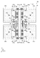
図1は、第1実施形態に係るジャイロセンサー1を示す平面図である。図2は、図1のA-A線での断面図である。図3は、図1のB部の拡大図である。図4は、ジャイロセンサー1の動作を説明する平面図である。なお、図1では、基板2は概略的に図示し、また、蓋部3の図示を省略している。また、上記各図では、説明の便宜上、一部の構成要素を省略してある。例えば、電気信号を取り出す配線や過大な振動・衝撃を緩衝するストッパーと呼ばれる保護構造等である。また、各図において、分かり易くするために、各構成要素の寸法比率は実際と異なる。また、図中のX軸、Y軸、Z軸は、互いに直交する座標軸であり、X軸に沿う方向を「X方向」、Y軸に沿う方向を「Y方向」、Z軸に沿う方向を「Z方向」とし、矢印の方向がプラス方向である。また、本実施形態では、第1軸をX軸、第2軸をZ軸、第3軸をY軸として説明する。
1. First Embodiment First, a
FIG. 1 is a plan view showing a
図1に示すジャイロセンサー1は、X軸まわりの角速度を検知することのできる角速度センサーである。このジャイロセンサー1は、図2に示すように、素子部4と、素子部4を収納しているパッケージ10と、を有している。
A
パッケージ10は、素子部4を支持している基板2と、基板2に接合されている蓋部3と、を有し、基板2と蓋部3との間には、素子部4を収納している空間Sが形成されている。
The
基板2及び蓋部3は、それぞれ、板状をなし、X軸及びY軸を含む平面であるXY平面に沿って配置されている。
The
基板2には、素子部4側となる上方に開放する凹部21が設けられている。凹部21の中央部には、凹部21の底面22から突出した突出部24が設けられている。また、突出部24の上面となる主面23には、素子部4の一部である後述する固定部48が固定されている。また、凹部21には、底面22から突出した複数の図示しない突出部が設けられ、素子部4の一部である後述する固定部43や固定駆動部27,28の一部が固定されている。また、凹部21の底面22には、素子部4の一部である後述する検出部45との間で静電容量を生じる固定検出部25が設けられている。
The
蓋部3には、基板2側となる下方に開放する凹部31が設けられている。蓋部3は、素子部4を非接触で覆うようにして基板2上に設けられており、凹部31を除く下面33が基板2の凹部21を囲む主面23に接合している。
The
また、空間Sは、凹部21と凹部31とで形成された気密空間であり、減圧状態、例えば、1×10+2Pa~1×10⁻²Pa程度となっている。これにより、角速度の検出感度を向上させることができる。
Further, the space S is an airtight space formed by the
基板2の構成材料としては、特に限定されないが、絶縁性を有する材料を用いることが好ましく、具体的には、高抵抗なシリコン材料、ガラス材料を用いるのが好ましく、例えば、アルカリ金属イオンを一定量含むガラス材料、例えば、パイレックス(登録商標)ガラスのような硼珪酸ガラスを用いるのが好ましい。これにより、素子部4がシリコンを主材料として構成されている場合、基板2と素子部4とを陽極接合することができる。陽極接合することにより、素子部4を強固に基板2へ固定することができる。よって、剥離が発生し難い高信頼性のジャイロセンサー1を提供できる。それ以外に、石英基板、水晶基板、或いはSOI(Silicon on Insulator)基板であっても良い。
The constituent material of the
また、蓋部3の構成材料としては、特に限定されず、例えば、前述した基板2と同様の材料を用いることができる。
Moreover, the constituent material of the
このような基板2と蓋部3との接合方法としては、基板2及び蓋部3の構成材料によっても異なり、特に限定されず、例えば、接着剤、ロウ材、ガラスフリット材等の接合材を用いた接合法、直接接合、陽極接合等の固体接合法等を用いることができる。特に、ガラスフリット材では、凹凸がある表面であってもガラスフリット材が流れ出し、良好に気密空間を確保することができる。特に、ジャイロセンサー1の場合は、気密空間を減圧状態にして保持する必要があるため、ガラスフリット材が好適に用いられる。
The method for joining the
素子部4は、図1に示すように、基板2に固定される固定部48と、基板2の主面23と平行なX方向に変位する質量部41と、質量部41をX方向に駆動する駆動部40と、質量部41に接続され、Z軸のまわりに回動可能で、且つ、基板2に水平な回動運動に作用するコリオリ力によりZ方向に変位可能な検出部45と、検出部45と固定部48とを接続している弾性部47と、を有している。なお、本実施形態では、固定部48、検出部45、及び弾性部47は、それぞれ一対であり、質量部41の両側にそれぞれ対称に配置、所謂、Y軸に対して線対称に配置されている。
As shown in FIG. 1, the
質量部41は、X方向を長辺とする矩形状で、中央に開口部49aを有している。開口部49aには、質量部41に接続している複数の駆動部40と、基板2に固定されている複数の固定駆動部27,28と、が配置されている。
The
駆動部40及び固定駆動部27,28は、それぞれX方向に延在する複数の梁部を有し、櫛歯状に配置されている。固定駆動部27は、駆動部40のX方向のプラス側に配置され、駆動部40及び固定駆動部27のそれぞれの梁部が噛合うように配置されている。また、固定駆動部28は、駆動部40のX方向のマイナス側に配置され、駆動部40及び固定駆動部28のそれぞれの梁部が噛合うように配置されている。
The driving
質量部41は、X方向の両端が折り返し形状の4つの駆動ばね42を介して、基板2に固定している4つの固定部43にそれぞれ接続している。なお、駆動ばね42は、X方向から印加される外力によりX方向に撓む、又は、変形するように形成されている。そのため、駆動ばね42は、質量部41をX方向に変位可能としている。
The
質量部41のX方向の中央部でY方向のプラス側の開口部49aと反対側の端部からY軸のプラス方向に延在する結合ばね44が設けられており、結合ばね44の質量部41側と反対側の端部に検出部45が接続されている。また、質量部41のX方向の中央部でY方向のマイナス側の開口部49aと反対側の端部からY軸のマイナス方向に延在する結合ばね44が設けられており、結合ばね44の質量部41側と反対側の端部に検出部45が接続されている。
A
検出部45は、X方向に長い矩形状で、X方向の中央部で、検出部45の重心Gより質量部41側に近い位置に開口部49bを有している。開口部49bには、基板2に固定されている固定部48と、固定部48に接続している弾性部47と、弾性部47からY方向に延在し、検出部45と接合する接合部46と、が配置されている。
The
弾性部47は、固定部48からそれぞれX方向のプラス方向とマイナス方向に折り返しながらY方向に延在し、接合部46に接続されている。弾性部47は、X方向やY方向から印加される外力によりX方向やY方向に撓む、又は、変形するように形成されている。なお、Z方向から印加される外力に対しては変形し難い構造となっている。そのため、質量部41がX方向に変位した際に、検出部45は、図3に示す、弾性部47と固定部48との接続点を中心軸Jとし、J軸まわりに基板2と水平に回動、又は、変位可能となる。
The
接合部46は、検出部45の重心Gと質量部41との間に配置され、弾性部47からY方向に延在し検出部45と接合している。そのため、固定部48と検出部45までの長さを長くすることができ、検出部45の中心軸Jからの回転半径を長くすることができ、駆動部40の駆動に伴う検出部45の面内回動運動の変位量を大きくすることができる。
The
また、接合部46は、Y軸まわりに捻じれるように形成されている。そのため、検出部45が面内回動運動している際に、X軸まわりの角速度ωxが加わると、検出部45の面内回動運動に作用するコリオリ力が検出部45のX方向のプラス側と、検出部45のX方向のマイナス側と、にそれぞれ逆方向に加わり、検出部45がZ方向に変位可能となる。具体的には、検出部45のX方向のプラス側がZ軸のプラス方向に変位すると、検出部45のX方向のマイナス側がZ軸のマイナス方向に変位する。逆に、検出部45のX方向のプラス側がZ軸のマイナス方向に変位すると、検出部45のX方向のマイナス側がZ軸のプラス方向に変位する。また、Y軸のプラス方向に配置された検出部45とY軸のマイナス方向に配置された検出部45は、逆位相で変位する。
Also, the
なお、基板2の凹部21の底面22で検出部45と対向する位置に検出部45と離間して固定検出部25が設けられており、X軸まわりの角速度ωxが加わり検出部45がZ方向に変位することで、固定検出部25との間隔の変化を静電容量変化として検出することで、X軸まわりの角速度ωxを検知することができる。
A fixed
また、固定検出部25の形状は、Y方向に平行な上底と下底を有する台形形状で、Y方向の長さが長い下底が固定部48側になるように配置されている。このように配置することで、検出部45の回転運動の際に、検出部45と固定検出部25とが常に重なっているので、検出部45と固定検出部25との対向面積を一定に保つことができ、X軸まわりの角速度ωxの検出精度を維持することができる。
Further, the fixed detecting
固定部48は、検出部45の開口部49b内に配置され、平面視で、検出部45の重心Gと質量部41との間、及び、弾性部47と質量部41との間に配置されている。そのため、固定部48と検出部45とを接続する弾性部47を質量部41側から遠ざかる方向に配置することができ、検出部45の中心軸Jからの回転半径を長くすることができる。従って、駆動部40の駆動に伴う検出部45の面内回動運動の変位量が大きくなり、X軸まわりの角速度ωxが加わると、作用するコリオリ力により検出部45のZ方向への変位量が大きくなるので、検出感度を高めることができる。
The fixing
検出部45には、検出部45の質量部41側と反対側の端部より、弾性部47に近い位置に配置された溝50,51を有している。また、溝50は、図3に示すように、溝50のX方向の中心P2が接合部46のX方向の中心P1を通るY軸に沿った延長線Lと重ならない位置に配置されている。また、溝51についても同様に、溝51の中心が接合部46の中心を通る延長線と重ならない位置に配置されている。このように、検出部45に溝50,51を設けることで、弾性部47の加工誤差に伴う、X軸方向の駆動振動以外の異なる振動成分である不要振動成分、所謂、クアドラチャ信号の増大を低減することができる。一般的に、不要振動成分の要因となる加工誤差は、所望の加工形状に対して対称性を持たないため、上述のようにX軸、Y軸、Z軸に対して回転対称、線対称、点対称などの対称性を持たない溝50,51を用いて補償するのが好ましい。
The detecting
上述したような素子部4は、リン、ボロン等の不純物がドープされた導電性のシリコン基板をエッチングによってパターニングすることで一括形成されている。
The
また、固定検出部25の構成材料としては、例えば、アルミニウム、金、白金、ITO(Indium Tin Oxide)、ZnO(酸化亜鉛)等を用いることができる。
Moreover, as a constituent material of the fixed
次に、上述した構成のジャイロセンサー1は、次のようにしてX軸まわりの角速度ωxを検出することができる。
Next, the
まず、ジャイロセンサー1が有する駆動部40と固定駆動部27,28との間に駆動電圧を印加すると、固定駆動部27,28と駆動部40との間に周期的に強度が変化する静電引力が生じる。これにより、図4に示すように、駆動ばね42の弾性変形を伴って駆動部40がX方向に振動し、矢印X1の方向に変位すると、駆動部40と同様に矢印X1の方向に変位する質量部41に接続された2つの検出部45は、それぞれが接続された固定部48と弾性部47との接点を中心にZ軸まわりに逆位相で回転運動をする。
First, when a drive voltage is applied between the
質量部41のY方向のプラス側に位置する検出部45は、検出部45のX方向のプラス側が矢印Y1方向に変位し、検出部45のX方向のマイナス側が矢印Y2の方向に変位する。なお、変位した検出部45を図4では、破線で示している。逆に、質量部41のY方向のマイナス側に位置する検出部45は、検出部45のX方向のマイナス側が矢印Y1方向に変位し、検出部45のX方向のプラス側が矢印Y2の方向に変位する。つまり、質量部41のY方向のプラス側に位置する検出部45は、反時計回りに回転し、質量部41のY方向のマイナス側に位置する検出部45は、時計回りに回転する。なお、駆動部40と質量部41とが矢印X1と逆方向に変位すると、質量部41のY方向のプラス側に位置する検出部45は、時計回りに回転し、質量部41のY方向のマイナス側に位置する検出部45は、反時計回りに回転する。
The detecting
このように検出部45がZ軸回りに面内回動運動している状態で、ジャイロセンサー1にX軸まわりの角速度ωxが加わると、コリオリ力が働き、検出部45がZ方向に変位する。このとき、質量部41のY方向のプラス側に位置する検出部45は、検出部45のX方向のプラス側が矢印Z2方向に変位し、検出部45のX方向のマイナス側が矢印Z1の方向に変位する。逆に、質量部41のY方向のマイナス側に位置する検出部45は、検出部45のX方向のマイナス側が矢印Z2方向に変位し、検出部45のX方向のプラス側が矢印Z1の方向に変位する。
When an angular velocity ωx about the X axis is applied to the
なお、駆動部40と質量部41とが矢印X1と逆方向に変位すると、質量部41のY方向のプラス側に位置する検出部45は、検出部45のX方向のプラス側が矢印Z1方向に変位し、検出部45のX方向のマイナス側が矢印Z2の方向に変位する。逆に、質量部41のY方向のマイナス側に位置する検出部45は、検出部45のX方向のマイナス側が矢印Z1方向に変位し、検出部45のX方向のプラス側が矢印Z2の方向に変位する。
When the
このように検出部45がZ方向に変位することにより、検出部45と固定検出部25との間の距離が変化する。この距離の変化に伴って、検出部45と固定検出部25との間の静電容量が変化する。そして、この静電容量の変化量に基づいて、ジャイロセンサー1に加わったX軸まわりの角速度ωxを検出することができる。
By displacing the
上述のように、本実施形態のジャイロセンサー1は、固定部48を質量部41に近い位置に配置し、固定部48と検出部45とを接続する弾性部47を質量部41側から遠ざかる方向に配置する構成とすることで、検出部45の中心軸Jからの回転半径を長くすることができる。そのため、駆動部40の駆動に伴う検出部45の面内回動運動の変位量が大きくなり、X軸まわりの角速度ωxが加わると、作用するコリオリ力により検出部45のZ方向への変位量が大きくなるので、ジャイロセンサー1の検出感度を高めることができる。従って、高い検出感度を有するジャイロセンサー1を得ることができる。また、固定部48と検出部45とを接続する弾性部47を質量部41側から遠ざかる方向に配置する構成とすることで、弾性部47とその周辺に掛かる応力集中を分散させることができる。従って、疲労破壊等の要因により信頼性が低下することを防ぐことができる。よって、高性能で高信頼性のジャイロセンサー1を提供することができる。
As described above, in the
2.第2実施形態
次に、第2実施形態に係るジャイロセンサー1aについて、図5を参照して説明する。
図5は、第2実施形態に係るジャイロセンサー1aの概略構成を示す平面図である。なお、図5では、基板2及び蓋部3の図示を省略している。また、図5は、説明の便宜上、一部の構成要素を省略してあり、分かり易くするために、各構成要素の寸法比率は実際と異なる。また、図中のX軸、Y軸、Z軸は、互いに直交する座標軸であり、X軸に沿う方向を「X方向」、Y軸に沿う方向を「Y方向」、Z軸に沿う方向を「Z方向」とし、矢印の方向がプラス方向である。また、本実施形態では、第1軸をX軸、第2軸をY軸、第3軸をZ軸とし、また、第1方向をY軸のプラス方向、第2方向をY軸のマイナス方向として説明する。
2. Second Embodiment Next, a
FIG. 5 is a plan view showing a schematic configuration of a
本実施形態のジャイロセンサー1aは、第1実施形態のジャイロセンサー1と同様に、X軸まわりの角速度を検知することのできる角速度センサーである。ジャイロセンサー1aは、第1実施形態のジャイロセンサー1に比べ、素子部4aの構成が異なり、質量部81の周辺に4つの検出部85a,85bを有している。
The
本実施形態の素子部4aは、図5に示すように、基板2に固定される固定部88と、基板2の主面23と平行なX方向に変位する質量部81と、質量部81をX方向に駆動する複数の駆動部80と、固定部88の第1方向としてのY軸のプラス方向に配置し、質量部81に接続され、Z軸のまわりに回動可能で、且つ、基板2に水平な回動運動に作用するコリオリ力によりZ方向に変位可能な第1検出部85aと、固定部88の第2方向としてのY軸のマイナス方向に配置し、質量部81に接続され、Z軸のまわりに回動可能で、且つ、基板2に水平な回動運動に作用するコリオリ力によりZ方向に変位可能な第2検出部85bと、第1検出部85aと固定部88とを接続している第1弾性部87aと、第2検出部85bと固定部88とを接続している第2弾性部87bと、を有している。なお、本実施形態では、固定部88、第1検出部85a、第2検出部85b、第1弾性部87a、第2弾性部87b、及び2つの駆動部80は、それぞれ一対であり、質量部81の両側にそれぞれ対称に配置、所謂、Y軸に対して線対称に配置されている。
As shown in FIG. 5, the
質量部81は、Y方向を長辺とする矩形状の角柱部81aと、角柱部81aのY方向の両端にX方向を長辺とする矩形状の接続部81bと、を有している。角柱部81aには、Y方向の中央部でX方向の両端にそれぞれX方向のプラス方向とマイナス方向に折り返しながらX方向に延在し、固定部88に接続されている駆動ばね82が設けられている。また、角柱部81aには、X方向の両端にX方向に延在する梁部を櫛歯状に有する駆動部80が4つ設けられている。
角柱部81aのY方向のプラス側に配置された接続部81bのX方向の両端側には、それぞれ、Y方向のマイナス側に延在し、第1検出部85aに接続されている結合ばね84が設けられており、角柱部81aのY方向のマイナス側に配置された接続部81bのX方向の両端側には、それぞれ、Y方向のプラス側に延在し、第2検出部85bに接続されている結合ばね84が設けられている。
The
On both end sides in the X direction of the connecting
接続部81bには、Y方向の角柱部81a側とは反対を開口する切欠き部81cが設けられており、切欠き部81cのX方向の中央部に固定部83が配置され、切欠き部81cのX方向の両端に接続部81bと固定部83とを接続する弾性ばね89が設けられている。なお、駆動ばね82及び弾性ばね89は、X方向から印加される外力によりX方向に撓む、又は、変形するように形成されている。そのため、質量部81は、X方向に変位可能となる。
The
角柱部81aのX方向のプラス側とマイナス側には、それぞれ、X方向に延在する複数の梁部を櫛歯状に有し、駆動部80の有する複数の梁部とそれぞれ噛合うように配置された4つの固定駆動部29が配置されている。なお、固定駆動部29の一部は基板2に固定されている。駆動部80と固定駆動部29との間に駆動電圧を印加すると、固定駆動部29と駆動部80との間に周期的に強度が変化する静電引力が生じ、これにより、駆動ばね82の弾性変形を伴って駆動部80がX方向に振動し、駆動部80と同様に変位する質量部81に接続された第1検出部85aと第2検出部85bとが、面内回動運動をする。
A plurality of beams extending in the X direction are provided in the form of comb teeth on the positive side and the negative side in the X direction of the
駆動ばね82が接続されている固定部88は、Y方向のプラス側に第1弾性部87aと、第1弾性部87aからY方向に延在し、第1検出部85aと接合する接合部86aと、が接続され、Y方向のマイナス側に第2弾性部87bと、第2弾性部87bからY方向に延在し、第2検出部85bと接合する接合部86bと、が接続されている。
The fixed
第1弾性部87a及び第2弾性部87bは、固定部88からそれぞれX方向のプラス方向とマイナス方向に折り返しながらY方向に延在し、接合部86a,86bにそれぞれ接続されている。第1弾性部87a及び第2弾性部87bは、X方向やY方向から印加される外力によりX方向やY方向に撓む、又は、変形するように形成されている。なお、Z方向から印加される外力に対しては変形し難い構造となっている。そのため、質量部81がX方向に変位した際に、第1検出部85aは、第1弾性部87aと固定部88との接続点を中心軸とし、その軸まわりに基板2と水平に回動、又は、変位可能となり、第2検出部85bは、第2弾性部87bと固定部88との接続点を中心軸とし、その軸まわりに基板2と水平に回動、又は、変位可能となる。また、X方向の外力が印加されると、第1検出部85aが時計回りに回転すると、第2検出部85bは、反時計回りに回転し、第1検出部85aが反時計回りに回転すると、第2検出部85bは、時計回りに回転する。また、Y方向のプラス側とマイナス側に配置された第1検出部85a及び第2検出部85bは、それぞれ逆位相で回転する。
The first
接合部86a,86bは、Y軸まわりに捻じれるように形成されている。そのため、第1検出部85a及び第2検出部85bが面内回動運動している際に、X軸まわりの角速度ωxが加わると、第1検出部85aと第2検出部85bとにそれぞれ逆方向のコリオリ力が加わり、第1検出部85a及び第2検出部85bがZ方向に変位可能となる。具体的には、第1検出部85aがZ軸のプラス方向に変位すると、第2検出部85bがZ軸のマイナス方向に変位する。逆に、第1検出部85aがZ軸のマイナス方向に変位すると、第2検出部85bがZ軸のプラス方向に変位する。また、Y方向のプラス側とマイナス側に配置された第1検出部85a及び第2検出部85bは、それぞれ逆位相で変位する。
The
基板2の凹部21の底面22に、第1検出部85aと対向する位置に第1検出部85aと離間して第1固定検出部25aを設け、第2検出部85bと対向する位置に第2検出部85bと離間して第2固定検出部25bを設けることで、X軸まわりの角速度ωxが加わり第1検出部85a及び第2検出部85bがZ方向に変位することで、第1固定検出部25a及び第2固定検出部25bとの間隔の変化を静電容量変化として検出することで、X軸まわりの角速度ωxを検知することができる。
On the
固定部88は、平面視で、第1検出部85aの重心Gaと第2検出部85bの重心Gbとを結ぶ仮想直線Laと、質量部81と、の間に配置されているので、固定部88が仮想直線Laより質量部81と反対側に配置されている場合に比べ、第1検出部85a及び第2検出部85bの回転半径を長くすることができる。そのため、駆動部80の駆動に伴う第1検出部85a及び第2検出部85bの面内回動運動の変位量が大きくなり、X軸まわりの角速度ωxが加わると、作用するコリオリ力により第1検出部85a及び第2検出部85bのZ方向への変位量が大きくなるので、検出感度を高めることができる。
The fixed
第1検出部85a及び第2検出部85bには、接合部86a,86bに近い位置に配置された溝90,91,92,93が設けられている。このように、第1検出部85a及び第2検出部85bに溝90,91,92,93を設けることで、第1弾性部87a及び第2弾性部87bの加工誤差に伴う、X軸方向の駆動振動以外の異なる振動成分である不要振動成分、所謂、クアドラチャ信号の増大を低減することができる。前述の通り、不要振動成分の要因となる加工誤差は、所望の加工形状に対して対称性を持たないため、上述のようにX軸、Y軸、Z軸に対して回転対称、線対称、点対称などの対称性を持たない溝90,91,92,93を用いて補償するのが好ましい。
The
上述したように、本実施形態のジャイロセンサー1aは、固定部88が第1検出部85aの重心Gaと第2検出部85bの重心Gbとを結ぶ仮想直線Laと、質量部81と、の間に配置されているので、第1検出部85a及び第2検出部85bの回転半径を長くすることができる。そのため、駆動部80の駆動に伴う第1検出部85a及び第2検出部85bの面内回動運動の変位量が大きくなり、X軸まわりの角速度ωxが加わると、作用するコリオリ力により第1検出部85a及び第2検出部85bのZ方向への変位量が大きくなるので、検出感度を高めることができる。従って、高い検出感度を有するジャイロセンサー1aを得ることができる。また、第1検出部85a及び第2検出部85bの回転半径を長くすることで、接合部86a,86bやその周辺に掛かる応力集中を分散させることができる。従って、疲労破壊等の要因により信頼性が低下することを防ぐことができる。よって、高性能で高信頼性のジャイロセンサー1aを提供することができる。
As described above, in the
3.第3実施形態
次に、第3実施形態に係るジャイロセンサー1,1aを備えている電子機器の一例として、携帯電話1200を挙げて説明する。なお、以下の説明では、ジャイロセンサー1を適用した構成を例示して説明する。
図6は、ジャイロセンサー1を備えている携帯電話1200の構成を示す斜視図である。
図6に示すように、携帯電話1200は、複数の操作ボタン1202、受話口1204及び送話口1206を備え、操作ボタン1202と受話口1204との間には、表示部1201が配置されている。
このような携帯電話1200には、ジャイロセンサー1が内蔵されている。
3. Third Embodiment Next, a
FIG. 6 is a perspective view showing the configuration of a
As shown in FIG. 6, a
Such a
このような電子機器は、上述したジャイロセンサー1を備えていることから、上記実施形態で説明した効果が反映され、性能に優れている。
なお、上述したジャイロセンサー1,1aを備えている電子機器としては、携帯電話1200以外に、例えば、インクジェットプリンターなどのインクジェット式吐出装置、ラップトップ型やモバイル型のパーソナルコンピューター、テレビ、デジタルスチルカメラ、ビデオカメラ、ビデオテープレコーダー、各種ナビゲーション装置、ページャー、通信機能付も含む電子手帳、電子辞書、電卓、電子ゲーム機器、ワードプロセッサー、ワークステーション、テレビ電話、防犯用テレビモニター、電子双眼鏡、POS端末、魚群探知機、各種測定機器、計器類、フライトシミュレーターなどや電子体温計、血圧計、血糖計、心電図計測装置、超音波診断装置、電子内視鏡などの医療機器が挙げられる。いずれの場合にも、これらの電子機器は、上述したジャイロセンサー1,1aを備えていることから、上記実施形態で説明した効果が反映され、性能に優れている。
Since such an electronic device includes the
In addition to the
4.第4実施形態
次に、第4実施形態に係るジャイロセンサー1,1aを備えている移動体の一例として、自動車1500を挙げて説明する。なお、以下の説明では、ジャイロセンサー1を適用した構成を例示して説明する。
図7は、ジャイロセンサー1を備えている自動車1500を示す斜視図である。
図7に示すように、自動車1500は、ジャイロセンサー1を、例えば、搭載されているナビゲーション装置、姿勢制御装置などの姿勢検出センサーとして用いている。
これによれば、自動車1500は、上述したジャイロセンサー1を備えていることから、上記実施形態で説明した効果が反映され、性能に優れている。
4. Fourth Embodiment Next, an
FIG. 7 is a perspective view showing an
As shown in FIG. 7, an
According to this, since the
上述したジャイロセンサー1,1aは、自動車1500に限らず、自走式ロボット、自走式搬送機器、列車、船舶、飛行機、人工衛星などを含む移動体の姿勢検出センサーなどとして好適に用いることができ、いずれの場合にも、上記実施形態で説明した効果が反映され、性能に優れた移動体を提供することができる。
The
以下、実施形態から導き出される内容を記載する。 Content derived from the embodiment will be described below.
ジャイロセンサーは、基板と、前記基板に固定されている固定部と、前記基板の主面と平行な第1軸に沿って変位する質量部と、前記質量部を前記第1軸に沿って駆動する駆動部と、前記質量部に接続され、前記第1軸と交差する第2軸のまわりに回動可能で、且つ、前記基板に水平な回動運動に作用するコリオリ力により前記第2軸に沿って変位可能な検出部と、前記検出部と前記固定部とを接続している弾性部と、を有し、前記固定部は、平面視で、前記検出部の重心と前記質量部との間に配置されていることを特徴とする。 The gyro sensor includes a substrate, a fixed portion fixed to the substrate, a mass portion displaceable along a first axis parallel to the main surface of the substrate, and a mass portion driven along the first axis. and a drive portion connected to the mass portion and rotatable about a second axis that intersects the first axis and that is driven by a Coriolis force acting on a rotational movement horizontal to the substrate. and an elastic portion connecting the detection portion and the fixed portion, and the fixed portion is, in plan view, the center of gravity of the detection portion and the mass portion. characterized by being arranged between
この構成によれば、固定部が検出部の重心と質量部との間に配置されているので、固定部と検出部とを接続する弾性部を質量部側から遠ざかる方向に配置することができ、検出部の回転半径を長くすることができる。そのため、駆動部の駆動に伴う検出部の面内回動運動の変位量が大きくなり、第1軸まわりの外力を受けると、作用するコリオリ力により検出部の第2軸に沿った変位量が大きくなるので、検出感度を高めることができる。 According to this configuration, since the fixed portion is arranged between the center of gravity of the detection portion and the mass portion, the elastic portion connecting the fixed portion and the detection portion can be arranged in a direction away from the mass portion side. , the radius of rotation of the detector can be lengthened. Therefore, the amount of displacement of the in-plane rotational motion of the detection section due to the driving of the driving section increases, and when an external force around the first axis is received, the applied Coriolis force causes the amount of displacement of the detection section along the second axis. Since it becomes large, detection sensitivity can be improved.
上記のジャイロセンサーにおいて、前記固定部は、前記弾性部と前記質量部との間に配置されていることが好ましい。 In the above gyro sensor, it is preferable that the fixed portion is arranged between the elastic portion and the mass portion.
この構成によれば、固定部が弾性部と質量部との間に配置されているので、固定部を質量部側に近づけ、また、弾性部が固定部の質量部側とは反対側で、質量部側から遠ざかる方向に配置することができる。そのため、検出部の回転半径を長くすることができ、駆動部の駆動に伴う検出部の面内回動運動の変位量を大きくすることができる。 According to this configuration, since the fixing portion is arranged between the elastic portion and the mass portion, the fixing portion is brought closer to the mass portion side, and the elastic portion is on the side opposite to the mass portion side of the fixing portion. It can be arranged in a direction away from the mass part side. Therefore, it is possible to lengthen the radius of rotation of the detection section and increase the amount of displacement of the in-plane rotational movement of the detection section accompanying the driving of the drive section.
上記のジャイロセンサーにおいて、前記検出部から前記第1軸と前記第2軸とに交差する第3軸に沿って延在し、前記弾性部と前記検出部とを接合する接合部は、前記検出部の重心と前記質量部との間に配置されていることが好ましい。 In the gyro sensor described above, the joint portion extending from the detection portion along a third axis intersecting the first axis and the second axis and joining the elastic portion and the detection portion It is preferably arranged between the center of gravity of the part and the mass part.
この構成によれば、弾性部と検出部とを接合する接合部が検出部の重心と質量部との間に配置されているので、固定部と接合部が接合する検出部までの長さを長くすることができる。そのため、検出部の回転半径をより長くすることができ、駆動部の駆動に伴う検出部の面内回動運動の変位量をより大きくすることができる。 According to this configuration, since the joint portion that joins the elastic portion and the detection portion is arranged between the center of gravity of the detection portion and the mass portion, the length to the detection portion where the fixed portion and the joint portion are joined can be increased. can be longer. Therefore, the radius of rotation of the detection section can be made longer, and the amount of displacement of the in-plane rotational movement of the detection section accompanying the driving of the driving section can be made larger.
上記のジャイロセンサーにおいて、前記検出部は、前記検出部の前記質量部側と反対側の端部より、前記弾性部に近い位置に配置された溝を有することが好ましい。 In the gyro sensor described above, it is preferable that the detection section has a groove arranged at a position closer to the elastic section than the end of the detection section opposite to the mass section.
この構成によれば、検出部の弾性部に近い位置に溝が配置されているので、弾性部の加工誤差に伴う、第1軸に沿った駆動振動以外の異なる振動成分である不要振動成分、所謂、クアドラチャ信号の増大を低減することができる。 According to this configuration, since the groove is arranged at a position close to the elastic portion of the detecting portion, an unnecessary vibration component, which is a different vibration component than the drive vibration along the first axis due to the processing error of the elastic portion, An increase in so-called quadrature signals can be reduced.
上記のジャイロセンサーにおいて、前記溝は、前記溝の前記第1軸方向の中心が前記接合部の前記第1軸方向の中心を通る前記第3軸に沿った延長線と重ならない位置に配置されていることが好ましい。 In the above gyro sensor, the groove is arranged at a position where the center of the groove in the first axial direction does not overlap with an extension line along the third axis passing through the center of the joint in the first axial direction. preferably.
この構成によれば、検出部が第2軸まわりに回動するので、溝を接合部の延長線と重ならない位置に配置することで、第2軸まわりの回動振動以外の異なる振動成分である不要振動成分、所謂、クアドラチャ信号の増大を低減することができる。 According to this configuration, since the detector rotates around the second axis, by arranging the groove at a position that does not overlap with the extension line of the joint, vibration components other than the rotary vibration around the second axis can be detected. A certain unwanted vibration component, a so-called quadrature signal increase, can be reduced.
ジャイロセンサーは、基板と、前記基板の主面と平行な第1軸に沿って変位する質量部と、前記質量部を前記第1軸に沿って駆動する駆動部と、前記基板に固定されている固定部と、前記固定部の前記第1軸に交差する第2軸に沿った第1方向に配置され、前記質量部に接続され、前記第1軸と前記第2軸とに交差する第3軸まわりに回動可能で、且つ、前記基板に水平な回動運動に作用するコリオリ力により前記第3軸に沿って変位可能な第1検出部と、前記固定部の前記第1方向と反対の第2方向に配置され、前記質量部に接続され、前記第3軸まわりに回動可能で、且つ、前記基板に水平な回動運動に作用するコリオリ力により前記第3軸に沿って前記第1検出部と逆相で変位可能な第2検出部と、前記第1検出部と前記固定部とを接続している第1弾性部と、前記第2検出部と前記固定部とを接続している第2弾性部と、を有し、前記固定部は、平面視で、前記第1検出部の重心と前記第2検出部の重心とを結ぶ仮想直線と、前記質量部と、の間に配置されていることを特徴とする。 A gyro sensor includes a substrate, a mass portion that displaces along a first axis parallel to a main surface of the substrate, a drive portion that drives the mass portion along the first axis, and a gyro sensor fixed to the substrate. a fixed portion disposed in a first direction along a second axis that intersects the first axis of the fixed portion, connected to the mass, and a second axis that intersects the first axis and the second axis; a first detector rotatable about three axes and displaceable along the third axis by a Coriolis force acting on the horizontal rotational movement of the substrate; and the first direction of the fixed part. Disposed in a second opposite direction, connected to the mass, rotatable about the third axis, and rotatable along the third axis by a Coriolis force acting on a rotational movement horizontal to the substrate. a second detection section capable of being displaced in a phase opposite to that of the first detection section; a first elastic section connecting the first detection section and the fixed section; and a second detection section and the fixed section. a connecting second elastic portion, wherein the fixing portion includes, in plan view, an imaginary straight line connecting the center of gravity of the first detection portion and the center of gravity of the second detection portion; characterized by being arranged between
この構成によれば、固定部が第1検出部の重心と第2検出部の重心とを結ぶ仮想直線と、質量部と、の間に配置されているので、固定部が仮想直線より質量部と反対側に配置されている場合に比べ、第1検出部及び第2検出部の回転半径を長くすることができる。そのため、駆動部の駆動に伴う第1検出部及び第2検出部の面内回動運動の変位量が大きくなり、第1軸まわりの外力を受けると、作用するコリオリ力により第1検出部及び第2検出部の第2軸に沿った変位量が大きくなるので、検出感度を高めることができる。 According to this configuration, since the fixed portion is arranged between the virtual straight line connecting the center of gravity of the first detection portion and the center of gravity of the second detection portion and the mass portion, the fixed portion is located closer to the mass portion than the virtual straight line. The rotation radii of the first detection section and the second detection section can be made longer than when they are arranged on the opposite side. Therefore, the amount of displacement of the in-plane rotational motion of the first detection section and the second detection section accompanying the driving of the driving section increases, and when an external force about the first axis is received, the Coriolis force acts on the first detection section and the second detection section. Since the amount of displacement of the second detector along the second axis is increased, the detection sensitivity can be enhanced.
電子機器は、上記のジャイロセンサーを備えていることを特徴とする。 An electronic device is characterized by comprising the above gyro sensor.
この構成によれば、高い感度特性を有し、高精度なジャイロセンサーを備えているため、高性能な電子機器を提供することができる。 According to this configuration, since the gyro sensor has high sensitivity characteristics and high accuracy, it is possible to provide a high-performance electronic device.
移動体は、上記のジャイロセンサーを備えていることを特徴とする。 A moving body is characterized by comprising the above gyro sensor.
この構成によれば、高い感度特性を有し、高精度なジャイロセンサーを備えているため、高性能な移動体を提供することができる。 According to this configuration, since it has high sensitivity characteristics and includes a highly accurate gyro sensor, it is possible to provide a high-performance moving body.
1,1a…ジャイロセンサー、2…基板、3…蓋部、4…素子部、23…主面、25…固定検出部、27,28…固定駆動部、40…駆動部、41…質量部、42…駆動ばね、43…固定部、44…結合ばね、45…検出部、46…接合部、47…弾性部、48…固定部、50,51…溝、1200…電子機器としての携帯電話、1500…移動体としての自動車、G…重心、J…中心軸、L…延長線、P1,P2…中心。
DESCRIPTION OF
Claims (11)
基板と、
前記Z軸のプラス側に位置している前記基板の上面に支持され、静電容量の変化に基づ
いて角速度を検出する素子部と、
を含み、
前記素子部は、
前記基板の前記上面に固定されている固定部と、
前記基板の前記上面と平行であり、前記X軸に沿ったX軸方向に変位可能な質量部と、
前記質量部を前記X軸方向に駆動する駆動部と、
前記質量部に接続され、前記Z軸に沿ったZ軸方向に変位可能な第1検出部と、
前記質量部に接続され、前記Z軸方向に変位可能な第2検出部と、
前記第1検出部と前記固定部とを接続している第1弾性部と、
前記第2検出部と前記固定部とを接続している第2弾性部と、
を含み、
前記第1弾性部は、前記X軸方向のプラス側とマイナス側に折り返しを含み、
前記第2弾性部は、前記X軸方向のプラス側とマイナス側に折り返しを含み、
前記第1検出部と前記第2検出部は、前記X軸及び前記Y軸を含む平面に沿って、それ
ぞれ逆位相で回転する、
ジャイロセンサー。 When the three mutually orthogonal axes are the X-axis, the Y-axis and the Z-axis,
a substrate;
an element unit supported on the upper surface of the substrate located on the positive side of the Z axis and detecting an angular velocity based on a change in capacitance;
including
The element part is
a fixing portion fixed to the upper surface of the substrate;
a mass parallel to the upper surface of the substrate and displaceable in an X-axis direction along the X-axis;
a drive unit that drives the mass unit in the X-axis direction;
a first detection unit connected to the mass unit and displaceable in a Z-axis direction along the Z-axis;
a second detection unit connected to the mass unit and displaceable in the Z-axis direction;
a first elastic portion connecting the first detection portion and the fixing portion;
a second elastic portion connecting the second detection portion and the fixing portion;
including
the first elastic portion includes folds on the plus side and the minus side in the X-axis direction,
the second elastic portion includes folds on the plus side and the minus side in the X-axis direction,
The first detection section and the second detection section are arranged along a plane including the X-axis and the Y-axis.
rotating in opposite phases,
gyro sensor.
前記Z軸方向からの平面視で、前記固定部は、前記第1検出部と前記第2検出部との間
に配置されている、
ジャイロセンサー。 In claim 1 ,
In a plan view from the Z-axis direction, the fixed portion is arranged between the first detection portion and the second detection portion,
gyro sensor.
前記第1検出部は、前記Y軸のプラス側に配置され、
前記第2検出部は、前記Y軸のマイナス側に配置されている、
ジャイロセンサー。 In claim 1 or claim 2 ,
The first detection unit is arranged on the plus side of the Y axis,
The second detection unit is arranged on the minus side of the Y-axis,
gyro sensor.
前記第1検出部と前記第1弾性部とを接続している第1接合部と、
前記第2検出部と前記第2弾性部とを接続している第2接合部と、
を含む、
ジャイロセンサー。 In any one of claims 1 to 3 ,
a first joint portion connecting the first detection portion and the first elastic portion;
a second joint portion connecting the second detection portion and the second elastic portion;
including,
gyro sensor.
前記第1検出部の前記第1接合部との接続側に第1溝が設けられている、
ジャイロセンサー。 In claim 4 ,
A first groove is provided on the connection side of the first detection unit with the first joint,
gyro sensor.
前記第2検出部の前記第2接合部との接続側に第2溝が設けられている、
ジャイロセンサー。 In claim 4 or claim 5 ,
A second groove is provided on the connection side of the second detection unit with the second joint,
gyro sensor.
前記Z軸方向からの平面視で、前記固定部は、前記第1検出部の重心と前記第2検出部
の重心とを結ぶ仮想直線と、前記質量部と、の間に配置されている、
ジャイロセンサー。 In any one of claims 1 to 6 ,
In a plan view from the Z-axis direction, the fixed portion is arranged between an imaginary straight line connecting the center of gravity of the first detection portion and the center of gravity of the second detection portion and the mass portion.
gyro sensor.
前記第1弾性部は、
前記固定部から前記第1検出部へ前記Y軸に沿ったY軸方向に延在し、
前記X軸のプラス方向からマイナス方向に折り返している折り返し部を有する、
ジャイロセンサー。 In any one of claims 1 to 7 ,
The first elastic portion is
extending in the Y-axis direction along the Y-axis from the fixed portion to the first detection portion;
Having a folded portion that is folded back from the positive direction of the X axis to the negative direction,
gyro sensor.
前記第2弾性部は、
前記固定部から前記第2検出部へ前記Y軸に沿ったY軸方向に延在し、
前記X軸のプラス方向からマイナス方向に折り返している折り返し部を有する、
ジャイロセンサー。 In any one of claims 1 to 8 ,
The second elastic portion is
extending in the Y-axis direction along the Y-axis from the fixed portion to the second detection portion;
Having a folded portion that is folded back from the positive direction of the X axis to the negative direction,
gyro sensor.
電子機器。 A gyro sensor according to any one of claims 1 to 9 ,
Electronics.
移動体。 A gyro sensor according to any one of claims 1 to 9 ,
Mobile.
Priority Applications (9)
| Application Number | Priority Date | Filing Date | Title |
|---|---|---|---|
| JP2019140790A JP7188311B2 (en) | 2019-07-31 | 2019-07-31 | Gyro sensors, electronic devices, and mobile objects |
| CN202410403102.1A CN118293895A (en) | 2019-07-31 | 2020-07-28 | Gyroscope sensor, electronic device and moving body |
| CN202010737300.3A CN112325870B (en) | 2019-07-31 | 2020-07-28 | Gyroscope sensor, electronic device and moving body |
| US16/943,102 US11187529B2 (en) | 2019-07-31 | 2020-07-30 | Gyro sensor, electronic device, and vehicle |
| US17/504,919 US11754396B2 (en) | 2019-07-31 | 2021-10-19 | Gyro sensor, electronic device, and vehicle |
| JP2022189904A JP7364017B2 (en) | 2019-07-31 | 2022-11-29 | Gyro sensors, electronic devices, and moving objects |
| US18/321,191 US11953324B2 (en) | 2019-07-31 | 2023-05-22 | Gyro sensor, electronic device, and vehicle |
| JP2023171150A JP2023175892A (en) | 2019-07-31 | 2023-10-02 | Gyro sensor, electronic apparatus, and mobile body |
| US18/588,401 US20240200945A1 (en) | 2019-07-31 | 2024-02-27 | Gyro Sensor, Electronic Device, And Vehicle |
Applications Claiming Priority (1)
| Application Number | Priority Date | Filing Date | Title |
|---|---|---|---|
| JP2019140790A JP7188311B2 (en) | 2019-07-31 | 2019-07-31 | Gyro sensors, electronic devices, and mobile objects |
Related Child Applications (1)
| Application Number | Title | Priority Date | Filing Date |
|---|---|---|---|
| JP2022189904A Division JP7364017B2 (en) | 2019-07-31 | 2022-11-29 | Gyro sensors, electronic devices, and moving objects |
Publications (3)
| Publication Number | Publication Date |
|---|---|
| JP2021025774A JP2021025774A (en) | 2021-02-22 |
| JP2021025774A5 JP2021025774A5 (en) | 2022-06-03 |
| JP7188311B2 true JP7188311B2 (en) | 2022-12-13 |
Family
ID=74258342
Family Applications (3)
| Application Number | Title | Priority Date | Filing Date |
|---|---|---|---|
| JP2019140790A Active JP7188311B2 (en) | 2019-07-31 | 2019-07-31 | Gyro sensors, electronic devices, and mobile objects |
| JP2022189904A Active JP7364017B2 (en) | 2019-07-31 | 2022-11-29 | Gyro sensors, electronic devices, and moving objects |
| JP2023171150A Pending JP2023175892A (en) | 2019-07-31 | 2023-10-02 | Gyro sensor, electronic apparatus, and mobile body |
Family Applications After (2)
| Application Number | Title | Priority Date | Filing Date |
|---|---|---|---|
| JP2022189904A Active JP7364017B2 (en) | 2019-07-31 | 2022-11-29 | Gyro sensors, electronic devices, and moving objects |
| JP2023171150A Pending JP2023175892A (en) | 2019-07-31 | 2023-10-02 | Gyro sensor, electronic apparatus, and mobile body |
Country Status (3)
| Country | Link |
|---|---|
| US (4) | US11187529B2 (en) |
| JP (3) | JP7188311B2 (en) |
| CN (2) | CN118293895A (en) |
Families Citing this family (2)
| Publication number | Priority date | Publication date | Assignee | Title |
|---|---|---|---|---|
| CN113970324B (en) * | 2020-07-23 | 2023-09-05 | 昇佳电子股份有限公司 | Structure of gyroscope |
| CN114858152A (en) * | 2022-03-30 | 2022-08-05 | 瑞声开泰科技(武汉)有限公司 | MEMS (micro-electromechanical system) uniaxial gyroscope |
Citations (2)
| Publication number | Priority date | Publication date | Assignee | Title |
|---|---|---|---|---|
| JP2013234904A (en) | 2012-05-09 | 2013-11-21 | Seiko Epson Corp | Gyro sensor and manufacturing method for the gyro sensor, and electronic apparatus |
| JP2019117099A (en) | 2017-12-27 | 2019-07-18 | セイコーエプソン株式会社 | Physical quantity sensor, manufacturing method of physical quantity sensor, composite sensor, inertial measurement unit, portable electronic device, electronic device, and mobile device |
Family Cites Families (98)
| Publication number | Priority date | Publication date | Assignee | Title |
|---|---|---|---|---|
| DE19639946B4 (en) * | 1996-09-27 | 2006-09-21 | Robert Bosch Gmbh | Micromechanical component |
| DE60044293D1 (en) | 1999-03-25 | 2010-06-10 | Draper Lab Charles S | DYNAMICALLY BALANCED MICROELECTROMECHANICAL DEVICES |
| CN1241021C (en) * | 2001-06-21 | 2006-02-08 | 三菱电机株式会社 | Acceleration sensor and method of manufacture thereof |
| JP3941694B2 (en) * | 2001-11-19 | 2007-07-04 | 三菱電機株式会社 | Acceleration sensor |
| JP2005241500A (en) | 2004-02-27 | 2005-09-08 | Mitsubishi Electric Corp | Angular velocity sensor |
| EP1626283B1 (en) * | 2004-08-13 | 2011-03-23 | STMicroelectronics Srl | Micro-electromechanical structure, in particular accelerometer, with improved insensitivity to thermomechanical stresses |
| WO2006039560A2 (en) * | 2004-09-30 | 2006-04-13 | University Of Southern California | Silicon inertial sensors formed using mems |
| JP4385938B2 (en) * | 2004-12-15 | 2009-12-16 | セイコーエプソン株式会社 | Actuator |
| US7240552B2 (en) * | 2005-06-06 | 2007-07-10 | Bei Technologies, Inc. | Torsional rate sensor with momentum balance and mode decoupling |
| US7228738B2 (en) * | 2005-06-06 | 2007-06-12 | Bei Technologies, Inc. | Torsional rate sensor with momentum balance and mode decoupling |
| US7222533B2 (en) * | 2005-06-06 | 2007-05-29 | Bei Technologies, Inc. | Torsional rate sensor with momentum balance and mode decoupling |
| JP4193817B2 (en) * | 2005-06-22 | 2008-12-10 | セイコーエプソン株式会社 | Actuator |
| US7562573B2 (en) * | 2005-07-21 | 2009-07-21 | Evigia Systems, Inc. | Integrated sensor and circuitry and process therefor |
| JP4337862B2 (en) * | 2006-01-05 | 2009-09-30 | セイコーエプソン株式会社 | Optical device, optical scanner, and image forming apparatus |
| EP1832841B1 (en) * | 2006-03-10 | 2015-12-30 | STMicroelectronics Srl | Microelectromechanical integrated sensor structure with rotary driving motion |
| KR20090052832A (en) * | 2006-03-10 | 2009-05-26 | 콘티넨탈 테베스 아게 운트 코. 오하게 | Rate-of-rotation sensor having a coupling bar |
| US7461552B2 (en) * | 2006-10-23 | 2008-12-09 | Custom Sensors & Technologies, Inc. | Dual axis rate sensor |
| DE102006059928A1 (en) * | 2006-12-19 | 2008-08-21 | Robert Bosch Gmbh | Accelerometer with comb electrodes |
| US8141424B2 (en) * | 2008-09-12 | 2012-03-27 | Invensense, Inc. | Low inertia frame for detecting coriolis acceleration |
| DE102007017209B4 (en) * | 2007-04-05 | 2014-02-27 | Fraunhofer-Gesellschaft zur Förderung der angewandten Forschung e.V. | Micromechanical inertial sensor for measuring rotation rates |
| US20080306581A1 (en) | 2007-06-07 | 2008-12-11 | Medtronic Vascular, Inc. | Streamlined Stents |
| DE102007057042A1 (en) * | 2007-09-10 | 2009-03-12 | Continental Teves Ag & Co. Ohg | Micromechanical rotation rate sensor with coupling bars and suspension elements for quadrature suppression |
| US8042394B2 (en) * | 2007-09-11 | 2011-10-25 | Stmicroelectronics S.R.L. | High sensitivity microelectromechanical sensor with rotary driving motion |
| DE102007047592B4 (en) * | 2007-10-05 | 2022-01-05 | Robert Bosch Gmbh | Accelerometer |
| CN101910789B (en) * | 2008-01-07 | 2012-02-29 | 株式会社村田制作所 | Angular velocity sensor |
| FI122397B (en) * | 2008-04-16 | 2011-12-30 | Vti Technologies Oy | A vibrating micromechanical angular velocity sensor |
| DE102008002606B4 (en) * | 2008-06-24 | 2020-03-12 | Robert Bosch Gmbh | Micromechanical acceleration sensor with open seismic mass |
| DE102008002748A1 (en) * | 2008-06-27 | 2009-12-31 | Sensordynamics Ag | Microgyroscope |
| US8371167B2 (en) * | 2008-07-29 | 2013-02-12 | Pixart Imaging Inc. | In-plane sensor, out-of-plane sensor, and method for making same |
| US8207586B2 (en) * | 2008-09-22 | 2012-06-26 | Alps Electric Co., Ltd. | Substrate bonded MEMS sensor |
| IT1391972B1 (en) * | 2008-11-26 | 2012-02-02 | St Microelectronics Rousset | MICROELETTROMECHANICAL GYROSCOPE WITH ROTARY DRIVE MOVEMENT AND IMPROVED ELECTRICAL CHARACTERISTICS |
| IT1392741B1 (en) * | 2008-12-23 | 2012-03-16 | St Microelectronics Rousset | MICROELETTROMECHANICAL GYROSCOPE WITH IMPROVED REJECTION OF ACCELERATION DISORDERS |
| US8256290B2 (en) * | 2009-03-17 | 2012-09-04 | Minyao Mao | Tri-axis angular rate sensor |
| JP2010223854A (en) * | 2009-03-25 | 2010-10-07 | Panasonic Corp | Three-axis detection angular velocity sensor |
| DE102009002066A1 (en) * | 2009-03-31 | 2010-10-07 | Sensordynamics Ag | Method for detecting accelerations and yaw rates and MEMS sensor |
| IT1394007B1 (en) * | 2009-05-11 | 2012-05-17 | St Microelectronics Rousset | MICROELETTROMECANICAL STRUCTURE WITH IMPROVED REJECTION OF ACCELERATION DISORDERS |
| ITTO20090597A1 (en) * | 2009-07-31 | 2011-02-01 | St Microelectronics Srl | Z AXIS MICROELETTROMECHANICAL DETECTION STRUCTURE WITH REDUCED THERMAL DERIVATIONS |
| DE102010040514A1 (en) * | 2009-09-09 | 2011-04-21 | Continental Teves Ag & Co. Ohg | Double-axial, shock-resistant rotation rate sensor with linear and rotary seismic elements |
| US8453504B1 (en) * | 2010-01-23 | 2013-06-04 | Minyao Mao | Angular rate sensor with suppressed linear acceleration response |
| US8368476B2 (en) * | 2010-03-19 | 2013-02-05 | Seiko Epson Corporation | Resonator element, resonator device and electronic device |
| US8584522B2 (en) * | 2010-04-30 | 2013-11-19 | Qualcomm Mems Technologies, Inc. | Micromachined piezoelectric x-axis gyroscope |
| DE102010029634B4 (en) * | 2010-06-02 | 2024-04-11 | Robert Bosch Gmbh | Angular rate sensor |
| JPWO2012014792A1 (en) * | 2010-07-27 | 2013-09-12 | アルプス電気株式会社 | Physical quantity sensor and manufacturing method thereof |
| JP5678741B2 (en) * | 2011-03-11 | 2015-03-04 | セイコーエプソン株式会社 | Acceleration detector, acceleration detection device, and electronic apparatus |
| JP2012237664A (en) * | 2011-05-12 | 2012-12-06 | Seiko Epson Corp | Physical quantity sensor and electronic apparatus |
| US8833162B2 (en) * | 2011-09-16 | 2014-09-16 | Invensense, Inc. | Micromachined gyroscope including a guided mass system |
| US9863769B2 (en) * | 2011-09-16 | 2018-01-09 | Invensense, Inc. | MEMS sensor with decoupled drive system |
| US10914584B2 (en) * | 2011-09-16 | 2021-02-09 | Invensense, Inc. | Drive and sense balanced, semi-coupled 3-axis gyroscope |
| US9714842B2 (en) * | 2011-09-16 | 2017-07-25 | Invensense, Inc. | Gyroscope self test by applying rotation on coriolis sense mass |
| JP5896114B2 (en) * | 2011-10-31 | 2016-03-30 | セイコーエプソン株式会社 | Physical quantity detection device, physical quantity detector, and electronic device |
| JP2013122375A (en) * | 2011-11-07 | 2013-06-20 | Seiko Epson Corp | Physical quantity detection device, physical quantity detector and electronic apparatus |
| FR2985029B1 (en) * | 2011-12-22 | 2014-10-24 | Commissariat Energie Atomique | MICRO / NANO MULTIMETERIAL INERTIAL SENSOR DEVICE FOR MOVEMENTS |
| DE102011057032B4 (en) * | 2011-12-23 | 2019-09-19 | Hanking Electronics, Ltd. | Micro gyroscope and method for operating a micro gyroscope |
| DE102011057081A1 (en) * | 2011-12-28 | 2013-07-04 | Maxim Integrated Products, Inc. | Micro rotation rate sensor and method for operating a micro yaw rate sensor |
| US8978475B2 (en) * | 2012-02-01 | 2015-03-17 | Fairchild Semiconductor Corporation | MEMS proof mass with split z-axis portions |
| CN103245340B (en) * | 2012-02-01 | 2016-07-13 | 苏州敏芯微电子技术股份有限公司 | A kind of single-chip tri-axial gyroscope |
| US20130239679A1 (en) * | 2012-03-13 | 2013-09-19 | Pavel Kornilovich | Three-axis gyroscope |
| JP5962900B2 (en) * | 2012-04-02 | 2016-08-03 | セイコーエプソン株式会社 | Physical quantity sensor and electronic equipment |
| JP5943192B2 (en) * | 2012-04-10 | 2016-06-29 | セイコーエプソン株式会社 | PHYSICAL QUANTITY SENSOR, MANUFACTURING METHOD THEREOF, AND ELECTRONIC DEVICE |
| JP6098780B2 (en) | 2012-04-19 | 2017-03-22 | セイコーエプソン株式会社 | Gyro sensor and electronics |
| US9212908B2 (en) * | 2012-04-26 | 2015-12-15 | Analog Devices, Inc. | MEMS gyroscopes with reduced errors |
| KR101366990B1 (en) * | 2012-12-28 | 2014-02-24 | 삼성전기주식회사 | Angular velocity sensor |
| DE102013212056A1 (en) * | 2013-06-25 | 2015-01-08 | Robert Bosch Gmbh | Rotation rate sensor and method for operating a rotation rate sensor |
| FI126199B (en) * | 2013-06-28 | 2016-08-15 | Murata Manufacturing Co | CAPACITIVE MICROMECHANICAL SENSOR STRUCTURE AND MICROMECHANICAL ACCELERATOR SENSOR |
| KR101454122B1 (en) * | 2013-07-31 | 2014-10-22 | 삼성전기주식회사 | Sensing Module and Angular Velocity Sensor having the same |
| US9360319B2 (en) * | 2013-09-05 | 2016-06-07 | Freescale Semiconductor, Inc. | Multiple sense axis MEMS gyroscope having a single drive mode |
| WO2015045621A1 (en) * | 2013-09-26 | 2015-04-02 | 株式会社村田製作所 | Angular velocity detection element |
| JP6248576B2 (en) * | 2013-11-25 | 2017-12-20 | セイコーエプソン株式会社 | Functional element, electronic device, and moving object |
| US9958271B2 (en) * | 2014-01-21 | 2018-05-01 | Invensense, Inc. | Configuration to reduce non-linear motion |
| JP2015184009A (en) * | 2014-03-20 | 2015-10-22 | セイコーエプソン株式会社 | Vibration element, electronic apparatus, and mobile entity |
| JP6398348B2 (en) * | 2014-06-12 | 2018-10-03 | セイコーエプソン株式会社 | Functional element, method for manufacturing functional element, electronic device, and moving body |
| US10247554B2 (en) * | 2014-09-24 | 2019-04-02 | The Regents Of The University Of California | Fully balanced micro-machined inertial sensor |
| JP6543918B2 (en) | 2014-11-14 | 2019-07-17 | セイコーエプソン株式会社 | Inertial sensor |
| FI20146153A (en) | 2014-12-29 | 2016-06-30 | Murata Manufacturing Co | Micromechanical gyroscope structure |
| FI20155095A (en) * | 2015-02-11 | 2016-08-12 | Murata Manufacturing Co | Micromechanical angle sensor |
| FI127203B (en) * | 2015-05-15 | 2018-01-31 | Murata Manufacturing Co | Vibrating micromechanical sensor of the angular velocity |
| JP6657626B2 (en) * | 2015-07-10 | 2020-03-04 | セイコーエプソン株式会社 | Physical quantity sensors, electronic devices and moving objects |
| ITUA20161498A1 (en) * | 2016-03-09 | 2017-09-09 | St Microelectronics Srl | MICROMECHANICAL DETECTION STRUCTURE OF A MEMS SENSOR DEVICE, IN PARTICULAR OF A MEMS GYRO, WITH IMPROVED DRIVE CHARACTERISTICS |
| ITUA20162160A1 (en) * | 2016-03-31 | 2017-10-01 | St Microelectronics Srl | MICROMECHANICAL STRUCTURE FOR DETECTION OF A MEMS MULTI-FACTORY GYROSCOPE, HAVING REDUCED DERIVED FROM RELATED ELECTRICAL CHARACTERISTICS |
| TWI632345B (en) | 2016-05-27 | 2018-08-11 | 日商村田製作所股份有限公司 | Continuous monitoring of drive amplitude in vibrating microelectromechanical gyroscopes and associated method |
| US10234477B2 (en) * | 2016-07-27 | 2019-03-19 | Google Llc | Composite vibratory in-plane accelerometer |
| US20180031603A1 (en) * | 2016-07-27 | 2018-02-01 | Lumedyne Technologies Incorporated | Systems and methods for detecting inertial parameters using a vibratory accelerometer with multiple degrees of freedom |
| US20180031602A1 (en) * | 2016-07-27 | 2018-02-01 | Lumedyne Technologies Incorporated | Converting rotational motion to linear motion |
| JP6819216B2 (en) | 2016-10-26 | 2021-01-27 | セイコーエプソン株式会社 | Gyro sensor, manufacturing method of gyro sensor, electronic device and mobile body |
| US10551191B2 (en) * | 2017-02-17 | 2020-02-04 | Invensense, Inc. | Deformation rejection mechanism for offset minimization of out-of-plane sensing MEMS device |
| WO2018152507A1 (en) * | 2017-02-17 | 2018-08-23 | Invensense, Inc. | Anchoring structure for a sensor insensitive to anchor movement |
| JP6689227B2 (en) * | 2017-03-15 | 2020-04-28 | 株式会社日立製作所 | Gyroscope |
| JP2018185188A (en) | 2017-04-25 | 2018-11-22 | セイコーエプソン株式会社 | Physical quantity sensor, method for manufacturing physical quantity sensor, physical quantity sensor device, electronic apparatus, and mobile body |
| JP6627912B2 (en) * | 2017-05-24 | 2020-01-08 | 株式会社村田製作所 | Piezoelectric rotating MEMS resonator |
| JP6610706B2 (en) * | 2017-05-24 | 2019-11-27 | 株式会社村田製作所 | Piezoelectric gyroscope with lateral drive transducer |
| JP2019100727A (en) * | 2017-11-28 | 2019-06-24 | セイコーエプソン株式会社 | Physical quantity sensor, physical quantity sensor device, composite sensor device, inertia measuring device, mobile body positioning device, portable electronic apparatus, electronic apparatus, mobile body, and method for manufacturing physical quantity sensor |
| US10571268B2 (en) * | 2017-11-30 | 2020-02-25 | Invensense, Inc. | MEMS sensor with offset anchor load rejection |
| JP6787304B2 (en) * | 2017-12-19 | 2020-11-18 | セイコーエプソン株式会社 | Physical quantity sensors, composite sensors, inertial measurement units, portable electronic devices, electronic devices, and mobile objects |
| US10760909B2 (en) * | 2018-06-18 | 2020-09-01 | Nxp Usa, Inc. | Angular rate sensor with in-phase drive and sense motion suppression |
| JP6922961B2 (en) * | 2018-10-18 | 2021-08-18 | 株式会社村田製作所 | Micro electromechanical device for rotational motion detection |
| JP2020101429A (en) * | 2018-12-21 | 2020-07-02 | セイコーエプソン株式会社 | Vibration element, method of manufacturing vibration element, physical quantity sensor, inertial measurement unit, electronic apparatus, and moving body |
| CN109489648B (en) * | 2018-12-30 | 2022-07-01 | 瑞声声学科技(深圳)有限公司 | Gyroscope |
| US10823569B1 (en) * | 2019-08-22 | 2020-11-03 | Nxp Usa, Inc. | Multiple axis sensing device based on frequency modulation and method of operation |
-
2019
- 2019-07-31 JP JP2019140790A patent/JP7188311B2/en active Active
-
2020
- 2020-07-28 CN CN202410403102.1A patent/CN118293895A/en active Pending
- 2020-07-28 CN CN202010737300.3A patent/CN112325870B/en active Active
- 2020-07-30 US US16/943,102 patent/US11187529B2/en active Active
-
2021
- 2021-10-19 US US17/504,919 patent/US11754396B2/en active Active
-
2022
- 2022-11-29 JP JP2022189904A patent/JP7364017B2/en active Active
-
2023
- 2023-05-22 US US18/321,191 patent/US11953324B2/en active Active
- 2023-10-02 JP JP2023171150A patent/JP2023175892A/en active Pending
-
2024
- 2024-02-27 US US18/588,401 patent/US20240200945A1/en active Pending
Patent Citations (2)
| Publication number | Priority date | Publication date | Assignee | Title |
|---|---|---|---|---|
| JP2013234904A (en) | 2012-05-09 | 2013-11-21 | Seiko Epson Corp | Gyro sensor and manufacturing method for the gyro sensor, and electronic apparatus |
| JP2019117099A (en) | 2017-12-27 | 2019-07-18 | セイコーエプソン株式会社 | Physical quantity sensor, manufacturing method of physical quantity sensor, composite sensor, inertial measurement unit, portable electronic device, electronic device, and mobile device |
Also Published As
| Publication number | Publication date |
|---|---|
| JP2021025774A (en) | 2021-02-22 |
| US20220034658A1 (en) | 2022-02-03 |
| CN112325870A (en) | 2021-02-05 |
| US20240200945A1 (en) | 2024-06-20 |
| US11187529B2 (en) | 2021-11-30 |
| CN112325870B (en) | 2024-03-26 |
| US20210033397A1 (en) | 2021-02-04 |
| JP7364017B2 (en) | 2023-10-18 |
| JP2023029339A (en) | 2023-03-03 |
| US11754396B2 (en) | 2023-09-12 |
| JP2023175892A (en) | 2023-12-12 |
| US11953324B2 (en) | 2024-04-09 |
| CN118293895A (en) | 2024-07-05 |
| US20230304798A1 (en) | 2023-09-28 |
Similar Documents
| Publication | Publication Date | Title |
|---|---|---|
| US8739626B2 (en) | Micromachined inertial sensor devices | |
| JP7364017B2 (en) | Gyro sensors, electronic devices, and moving objects | |
| EP2462408B1 (en) | Micromachined inertial sensor devices | |
| US9383383B2 (en) | Physical quantity sensor, manufacturing method thereof, and electronic apparatus | |
| JP6897663B2 (en) | Sensor devices, electronics, and mobiles | |
| JP6020793B2 (en) | Physical quantity sensor and electronic equipment | |
| JP6206650B2 (en) | Functional element, electronic device, and moving object | |
| JP6380737B2 (en) | Electronic devices, electronic devices, and moving objects | |
| JP6911444B2 (en) | Physical quantity sensors, electronics, and mobiles | |
| JP6897224B2 (en) | Physical quantity sensors, electronics, and mobiles | |
| CN103424108A (en) | Gyro sensor and electronic apparatus | |
| JP6623634B2 (en) | Physical quantity sensors, electronic devices and moving objects | |
| JP6812830B2 (en) | Gyro sensors, electronics, and mobiles | |
| JP2021032801A (en) | Inertial sensor unit, electronic apparatus, and movable body | |
| JP6766861B2 (en) | Physical quantity sensors, electronics and mobiles | |
| JP6801492B2 (en) | Gyro sensors, electronics, and mobiles | |
| JP2020016599A (en) | Physical quantity sensor, electronic apparatus, and movable body | |
| US20230138452A1 (en) | Physical Quantity Sensor and Inertial Measurement Unit | |
| JP6855853B2 (en) | Physical quantity sensors, physical quantity sensor devices, electronic devices and mobiles | |
| JP2024015689A (en) | Physical quantity sensor and inertia measurement device | |
| JP2021021596A (en) | Electronic device, manufacturing method for electronic device, electronic apparatus, and moving body | |
| JP2016161531A (en) | Physical quantity sensor, electronic apparatus, and mobile body | |
| CN115727840A (en) | Inertial sensor and electronic device | |
| CN116068223A (en) | Physical quantity sensor and inertial measurement device | |
| JP2020016557A (en) | Physical quantity sensor, electronic apparatus, and movable body |
Legal Events
| Date | Code | Title | Description |
|---|---|---|---|
| RD07 | Notification of extinguishment of power of attorney |
Free format text: JAPANESE INTERMEDIATE CODE: A7427 Effective date: 20200817 |
|
| RD04 | Notification of resignation of power of attorney |
Free format text: JAPANESE INTERMEDIATE CODE: A7424 Effective date: 20210917 |
|
| RD03 | Notification of appointment of power of attorney |
Free format text: JAPANESE INTERMEDIATE CODE: A7423 Effective date: 20211101 |
|
| A521 | Request for written amendment filed |
Free format text: JAPANESE INTERMEDIATE CODE: A523 Effective date: 20220525 |
|
| A621 | Written request for application examination |
Free format text: JAPANESE INTERMEDIATE CODE: A621 Effective date: 20220525 |
|
| A871 | Explanation of circumstances concerning accelerated examination |
Free format text: JAPANESE INTERMEDIATE CODE: A871 Effective date: 20220525 |
|
| A131 | Notification of reasons for refusal |
Free format text: JAPANESE INTERMEDIATE CODE: A131 Effective date: 20220726 |
|
| A521 | Request for written amendment filed |
Free format text: JAPANESE INTERMEDIATE CODE: A523 Effective date: 20220825 |
|
| TRDD | Decision of grant or rejection written | ||
| A01 | Written decision to grant a patent or to grant a registration (utility model) |
Free format text: JAPANESE INTERMEDIATE CODE: A01 Effective date: 20221101 |
|
| A61 | First payment of annual fees (during grant procedure) |
Free format text: JAPANESE INTERMEDIATE CODE: A61 Effective date: 20221114 |
|
| R150 | Certificate of patent or registration of utility model |
Ref document number: 7188311 Country of ref document: JP Free format text: JAPANESE INTERMEDIATE CODE: R150 |